construction of residential & non … of residential & non-residential buildings of the...
TRANSCRIPT
CONSTRUCTION OF RESIDENTIAL & NON-RESIDENTIAL BUILDINGS OF THE RAISING 53RD BATTALION FOR ITBP AT KALIKIRI, CHITTOOR (A.P).
Page 1 / 88
CONSTRUCTION OF GO’S MESS WITH SUITES /SO’S MESS WITH SUITES / 120 MEN’S BARRACK / COMBINED ADMIN BLOCK, QUARTER GUARD& STORE BLOCK/ M.I. ROOM/ BINTYPE MEGAZINE/ RESIDENTIAL BUILDINGS -TYPE II - 80 QUARTERS, TYPE III - 32 QUARTERS, TYPE IV - 08 QUARTERS, TYPE V - 01 QUARTERS, BOUNDARY WALL/ ENTRANCE GATEWAY & DORMITORY BLOCK & SIDE GATEWAY & EXTERNAL DEVELOPMENT & BULK SERVICES OF THE RAISING 53
rd BATTALION FOR INDO-
TIBETAN BORDER POLICE (ITBP) AT KALIKIRI, CHITTOOR (A.P).
ISSUED TO: M/s …………………………………………... …………………………………………….
…………………………………………...
CLIENT: INDO TIBETAN BORDER POLICE

CONSTRUCTION OF RESIDENTIAL & NON-RESIDENTIAL BUILDINGS OF THE RAISING 53RD BATTALION FOR ITBP AT KALIKIRI, CHITTOOR (A.P).
Page 2 / 88
CONSTRUCTION OF GO’S MESS WITH SUITES /SO’S MESS WITH SUITES / 120 MEN’S BARRACK / COMBINED ADMIN BLOCK, QUARTER GUARD& STORE BLOCK/ M.I. ROOM/ BINTYPE MEGAZINE/ RESIDENTIAL BUILDINGS -TYPE II - 80 QUARTERS, TYPE III - 32 QUARTERS, TYPE IV - 08 QUARTERS, TYPE V - 01 QUARTERS, BOUNDARY WALL/ ENTRANCE GATEWAY & DORMITORY BLOCK & SIDE GATEWAY & EXTERNAL DEVELOPMENT & BULK SERVICES OF THE RAISING 53
rd BATTALION FOR INDO-
TIBETAN BORDER POLICE (ITBP) AT KALIKIRI, CHITTOOR (A.P).
SPECIAL CONDITIONS OF CONTRACT (SCC) & TECHNICAL SPECIFICATIONS & LIST OF MAKE
VOLUME-II
CLIENT: INDO TIBETAN BORDER POLICE
CONSTRUCTION OF RESIDENTIAL & NON-RESIDENTIAL BUILDINGS OF THE RAISING 53RD BATTALION FOR ITBP AT KALIKIRI, CHITTOOR (A.P).
Page 3 / 88
CONSTRUCTION OF GO’S MESS WITH SUITES /SO’S MESS WITH SUITES / 120 MEN’S BARRACK / COMBINED ADMIN BLOCK, QUARTER GUARD& STORE BLOCK/ M.I. ROOM/ BINTYPE MEGAZINE/ RESIDENTIAL BUILDINGS -TYPE II - 80 QUARTERS, TYPE III - 32 QUARTERS, TYPE IV - 08 QUARTERS, TYPE V - 01 QUARTERS, BOUNDARY WALL/ ENTRANCE GATEWAY & DORMITORY BLOCK & SIDE GATEWAY & EXTERNAL DEVELOPMENT & BULK SERVICES OF THE RAISING 53
rd BATTALION FOR INDO-
TIBETAN BORDER POLICE (ITBP) AT KALIKIRI, CHITTOOR (A.P).
INDEX
S.NO.
DESCRIPTION
PAGE
1. NOTICE INVITING TENDER -
2. INSTRUCTIONS TO TENDERER -
2. SPECIAL CONDITIONS OF CONTRACT -
3. PERTICULAR SPECIFICATIONS 4
4 TECHNICAL SPECIFICATIONS 5-81
5. LIST OF APPROVED MAKES 82-88
CONSTRUCTION OF RESIDENTIAL & NON-RESIDENTIAL BUILDINGS OF THE RAISING 53RD BATTALION FOR ITBP AT KALIKIRI, CHITTOOR (A.P).
Page 4 / 88
PARTICULAR SPECIFICATIONS
CIVIL WORKS
1. General : The work shall be carried out strictly in accordance with particular
specifications and drawings. The drawings, specifications BOQ etc. shall be taken
complementary and also supplementary to each other and shall form part this
contract. Any work or material shown on drawings and not specifically included in
BOQ/specification or vice versa shall be executed and deemed to be included in
the scope of work of Item rate. However, the steel for reinforcement work
shall be TMT-BARS of Fe-500.
2. In case there are no specifications for items shown on the drawings or where
items are not exhaustively described, the general specifications of CPWD shall be
followed for which nothing extra shall be paid. In case, no details are available
even in CPWD specification, then decision of owner/EPIL is final & binding on the
contractor.
3. Scope of works : The scope of work for buildings under this contract includes
for full & final and entire completion of all works including all internal and
external services in all respects described in particular specification and as
shown on drawings forming part of the contract.
4. Although all the details of construction have been by and large covered in these
documents, any item or details of construction not specifically covered but
obviously implied and essential to consider Civil works and all internal and
external services complete and functional, shall be deemed to have been covered
in the rates quoted. The cost of external development works pertaining to a
particular contract shall also be carried out on a final lump sum price based on
the rates quoted for each item. The tenderer may however, consider a minimum
level of specifications conforming to IS code or National Building Code to cover
any missing details.
5. Sample of Materials: The Contractor shall produce samples of all materials and
shall obtain approval of these in writing from Architect/ Project Engineer before
he places bulk order for the materials for incorporation in the works. The samples
must be produced atleast six week before they are to be incorporated in sample
dwelling units. Materials to be incorporated in the work shall conform to latest
relevant ISI. The items should be ISI marked where manufactured.
6. Slopes : Adequate slope shall be provided in areas where there is likelihood of
ingress of water such as toilets, balconies, verandah, kitchens, terraces, top of
chajjas, window cills, plinth protections etc. though these may not be expressly
shown in drawings.
7. Curing: Exposed surfaces of all cement works viz. cement concrete, brick work,
flooring, plastering, pointing and the like shall be cured by keeping the surface
adequately and continuously wet as directed by Architect and Project Engineer for
at least seven days where ordinary portland cement has been used.

CONSTRUCTION OF RESIDENTIAL & NON-RESIDENTIAL BUILDINGS OF THE RAISING 53RD BATTALION FOR ITBP AT KALIKIRI, CHITTOOR (A.P).
Page 5 / 88
TECHNICAL SPECIFICATIONS
NON-SCHEDULE ITEMS
1. Earth for Filling
The earth used for filling shall be free from salts, organic or other deterious matter.
Highly expansive soils like black cotton soil shall not be used, unless so specified. All
clods of earth exceeding 50mm shall be broken or removed. Earth obtained from
borrow pits and surplus earth from excavation, if any, shall be directly used for filling
and avoid double handling.
2. Flush shutters for doors & cupboards:
Flush shutter for doors & cupboards shutters shall be solid core types with block
board core as indicated in Bill of Quantity and shall conform to IS-2202 and ISI
marked with blockboard (conforming to the requirements as per IS-1659 -1969 with
frame of 1st class Hardwood and well matched commercial 3 ply veneering with
vertical grains or cross bands and both faces decorative lamination 1mm thick.
3. Ceramic Designer (Highlighter) Tiles
Ceramic Designer tiles of 1st Quality conforming to IS-15622 (thickness to be
specified by the manufacturer) & of approved make/colour as approved by the
Project Manager/Architect having compressive strength of 350kg/cm sq., water
absorption 10% maximum by weight and Abrasion resistance 2mm average,2.5mm
individual specimen. Dimensional tolerance maximum 1mm.
a. Laying instructions for Floor:
1. Prepare base mortar with cement and sand in the ration of 1:4
2. Set the levels for floor (i.e dead level or slope as specified by the Project
Engineer/Architect ).
3. Prepare cement slurry i.e mixture of cement and water to form a thick paste and
spread it on the levelled base mortar.
4. Wet the backside of the tile with water. Complete immersion of tile in water is
not required.
5. If tiles are square or rectangular in shape, set the right angles for the area and
place the first tile along the right angle line and place it in on base mortar .Tap
gently only with a rubber or wooden mallet to obtain perfect levels.
6. Clean the surface of the tile with clean water immediately after laying with wet
sponge. Ensure that the base mortar cement which squeezes through the joints,
does not settle on the tile. Also ensure that the water used is not hard of
brackish.
7. Do not use the area laid for at least 24 hours.
8. Fill in the joints with pointing material which is mixture of white cement and
desired colour pigment. For higher quality of finishes, you could use. If required,
a polymer based cementitious tilling joint filler like Roffe rainbow. To get the
desired colour/shade. Mix the same with water to form a smooth paste which
should be applied to the joints, preferably with the use of rubber squeeze or
rubber sheet. Donot apply the pointing material all over the surface.
9. Allow pointing material to set for 15 minutes and then clean the surface of the
tile with a clean wet sponge, removing the excess pigment on tile surface.

CONSTRUCTION OF RESIDENTIAL & NON-RESIDENTIAL BUILDINGS OF THE RAISING 53RD BATTALION FOR ITBP AT KALIKIRI, CHITTOOR (A.P).
Page 6 / 88
10. Wash the surface with soap water or mild detergent to obtain a clean surface and
wipe it.
b. Laying instruction for walls
1. Plaster the surface to be tiles with mortar (Cement and sand in the ration of 1:3)
2. Prepare cement mortar i.e mixture of cement sand and water to form a thick
past and spread it on the back side of the tile after wetting the tile with sponge.
3. Instructions given for Floor (Nos 4,5,6,7,8,9,10 above) should be followed.
c. Desired site conditions for laying of Ceramic Designer Tiles
The following works are to be completed prior to commencing laying of Ceramic
Designer Tiles.
1. Final painting of ceiling in rooms.
2. Two coats of wall painting in all rooms ( the final painting should be done only
after laying of floor tile)
3. Wiring and Fixing of all electrical components.
4. Plumbing work.
5. Fixing of grills for windows.
6. Fixing and Polishing of windows/windows frames /door frames and doors.
7. Bathrooms floor and wall tiles should be laid after all the work in the bathroom is
completed.
8. Fixing of wall and platform slabs.
If mosaic/marble/any other natural stone which needs machining and polishing is
being used in any other part of the floor, it is necessary that this work be completed
before commencing the laying of Ultra Tiles.
If all the above precautions are taken and the instructions followed, your Ultra Tiles
will give you decades of trouble-free services.
4. Chicken Wire Mesh:
Chicken Wire Mesh shall be of galvanized mild steel wire cloth conforming for IS
1568-1970. Wire Cloth shall be regularly woven wire with a number of equally
spaced parallel wire in both warp and weft direction for produce uniformly openings.
The wire cloth shall be properly selvedge by one or more wires in each edge.
5. Antitermite Treatment
Chemical Chlorpyriphos /Lindane emulsifiable concentrate 20% conforming to
relevant IS specification in water emulsion shall be applied uniformly at the
prescribed rate in all stages of treatment.
Concentration of the chemical as emulsifiable concentrate is indicated on the sealed
containers. For obtaining the specified concentration. Chemical shall be diluted with
water in the required ‘quantity before it is used. Graduated containers shall be used
for the dilution of the chemical.
6. ACOUSTICAL SUSPENDED CEILING SYSTEM
Mineral Fibre acoustical suspended ceiling system with Fire Fissured Tiles having MICRO
LOOK XL 15MM in modules size of 600mm x 600mm x 15mm with B10 Block Casting laid
on grid system of hot dipped galvanised steel suspension system with 15mm wide T-Section

CONSTRUCTION OF RESIDENTIAL & NON-RESIDENTIAL BUILDINGS OF THE RAISING 53RD BATTALION FOR ITBP AT KALIKIRI, CHITTOOR (A.P).
Page 7 / 88
Flanges colour white having rotary stitching on the main runners spaced at 1200mm &
600mm cross tees fixed to the soffit by approved hangers [G.I wire 4.0mm dia] at 1200mm
max. centre all as per nomenclature.
INSTALLATION:
To comprise main runner spaced at 1200mm centres securely fixed to the structural soffit using
suspension system (specifications below) at 1200mm maximum centre. The First/Last
suspension system at the end of each main runner should not be greater than 450mm from the
adjacent wall.
Flush fitting 1200mm long cross tees to be interlocked between main runners at 600mm centre to
form 1200 x 600 mm module. Perimeter trim wall angles of size 3000x19x19mm, secured to walls
at 450 mm maximum centres.
7. STRUCTURAL GLAZING Structural glazing at Façade of ground plus three buildings using glazing section on direct stick mullion & transom system of which mullion shall be of 80x50x.8 mm with notch & transom to be of 50x50x1.8 mm with notch , Aluminum Glazing sections shall be powder coated with heat treatment on three surfaces in Ivory/Black colour using 6mm thick SSG EVO Star ET 425 AURA GREEN HEAT REFLECTIVE GLASS ULT -24%, Solar Factor – 0.25% and U-Value-3.72 W Sq.M of approved colour of Make Saint Gobain to be pasted with 12mm x 6 mm both side adhesive Spacer foam tape & structural silicon of Dow Corning 995 grade or it‟s equivalent. The Weather /water sealing of glass joints shall be done with 10 mm wide Dow Corning make weather sealant of grade 789 or its equivalent. The Mullion of Aluminum structure is to be fastened with R.C.C. Slab/beam with help of Powder coated/ Galvanized MS Brackets of 75 mm length with help of M10 x 100 mm Mechanical tempered Dash Fasteners. The job Includes all necessary hardware, cleat, Screws, nut washers etc. Complete job with as per direction of Engineer-in-charge and the job should be water tight.
8. ALUMINIUM WORK
A) ALUMINIUM GRILL Anodized Aluminium Grill of 7.5 mm thick of approved pattern (Pan type) (minimum thickness of powder coating 50 microus) shall be fixed as per manufacturer instructions. B) ALUMINIUM DOORS, WINDOWS AND VENTILATORS: Aluminium work for doors, windows, ventilators and partitions with extruded built up standard tubular and other sections of approved make conforming to IS: 733 and IS : 1285, fixed with rawl plugs and screws or with fixing clips, or with expansion hold fastners including necessary filling up of gaps at junctions, at top, bottom and sides with required PVC/neoprene felt etc. Aluminium sections shall be smooth, rust free, straight, mitered and jointed mechanically wherever required including cleat angle. Aluminium snap beading for glazing / paneling, C.P. brass / stainless steel screws, all complete as per architectural drawings and the directions of Engineer-in-charge. (Glazing and panelling to be paid for separately. Powder coated aluminium (minimum thickness of powder coating 50 micron). All Sections of Aluminium work being used in the work will be Powder coated minimum thickness of powder coating 50 micron Codes and Standards: The Codes and standards generally applicable to the work of this section are listed herein under: IS: 733 Wrought aluminium and aluminium alloy bars, rods and sections (for general engineering purpose). IS: 1285 Wrought aluminium and aluminium alloy extruded round tube and hollow sections (for general engineering purpose). IS: 1362 Dimension for screw thread for general purpose.

CONSTRUCTION OF RESIDENTIAL & NON-RESIDENTIAL BUILDINGS OF THE RAISING 53RD BATTALION FOR ITBP AT KALIKIRI, CHITTOOR (A.P).
Page 8 / 88
IS:1761 Transparent sheet glass for glazing and framing purposes. IS:1948 Aluminium doors, window and ventilators. IS:1949 Aluminium windows for industrial buildings. The following clauses are intended to amplify the requirements of the references/ documents listed above and the contractor shall comply with these clauses. SAMPLES AND SHOP DRAWINGS All aluminium doors, windows and ventilators shall be furnished by an approved manufacturer and shall be conforming to IS:1948. Before placing their order, the contractor shall submit shop drawings and samples for the approval of the Engineer. If required, the contractor shall also submit the necessary engineering calculations. Shop drawings shall clearly show all work including mechanical systems, the arrangement of components, the sequence and details of fabrications, assembly and erection. These drawings shall also give full size details, all dimensions and thickness anchoring devices and accessories.
9. TOUGHENED GLASS GENERAL
Toughened glass is 4 to 5 times stronger than its equivalent thickness of normal annealed float
of sheet glass. It offers great resistance to sudden temperature changes and sudden impacts.
Toughening, which shall be carried out horizontally (without tong-marks), shall conform to ASTM
1048.
All works such as cutting, grounding, drilling etc. On glass shall be carried out prior to
toughening. Once tempering is done, no work will be allowed on the glass.
SGG(SAINT GOBIN GLASS) Antelio-Plus is an advanced solar control glass that is
manufactured by depositing layers of metallic nitrides on to clear or body tinted float glass by
magnetically enhanced cathodic sputtering under vacuum conditions.
SGG Antelio-Plus is manufactured to meet the most exacting standards in order to deliver high
performance with ease in processing.
SGG Antelio-Plus is versatile and satisfies several designer criteria including solar control (to
reduce the cooling cost) and optimum light transmittance (to reduce glare).
Glass Application- Façade Glazing
SPECIFICATION Performance
Glass Name SGG Antelio Plus Blue Green ST 450
Processing Single Glazed Toughened
Light Transmission/LT 42
Reflection External % 0.14
Reflection Internal 0.16
UV % 10
Solar Factor `0.41
Shading Coefficient 0.48
Relative Heat Gain W/sqm K 5.67
Values in accordance with ISO 9050 Values have been certified by the Institute of Solar Energie of Farunhofer Corporation
10. PATCH FITTING GLASS DOOR
Patch Fitting Glass door Cum Fixed window with 12mm thick toughened glass and PSS/SSS finish of Dorman equivalent make approved make as per manufacturer's/ drawing and as approved by Architect/ Engineer-in-charge.

CONSTRUCTION OF RESIDENTIAL & NON-RESIDENTIAL BUILDINGS OF THE RAISING 53RD BATTALION FOR ITBP AT KALIKIRI, CHITTOOR (A.P).
Page 9 / 88
11. SURFACE TEXTURE PAINT Application Process/Methology
1. Acrylic Primer (Duracoat) added with water 1:1 ratio and than applied with Roller and Brush. The purpose of pure acrylic primer is to reduce the absorption of the plaster, act as a water proof agent and highlight the repairs.
2. Minor Repair check or a coat (As required) With Exterior grade Putty. 3. One Coat of Duracoat with spray & Pressed (As a base Coat). 4. Two coats of Pure acrylic emulsion, Ultrashield in desired shade.
The above product has salient features:
Anti Fungal
Breathes out trapped moisture
Flexibility and elasticity
Long shade Life
Dust Repellent
Water Repellant 12. ALUMINIUM COATED METAL SHEET ROOFING LYZAC High Rib Baregal volume 0.5mm thick zink Aluminium coated metal roofing sheet in longest joint system to be fixed with hilti make shelf. Drilling and topping screen with EPDM metal bonded washer including all flashing & ceiling joints with silicon/epoxy as directed by Engineer-in-charge. 13. WOODEN FLOORING Wooden flooring of 25mm thick with pre laminated flat pressed three layer Engineered Hard Wood Flooring on Stage exterior grade including edge profiles as may be required in desired shape and size of approved colour and texture including front cladding of stage riser laid over leveled floor surfaces as per manufacturer‟s instructions. 14. STAINLESS STEEL BUILDERS HARDWARE FITTINGS/ FIXTURES
Builder‟s Hardware such as sliding Door Bolts, Tower Bolts Handles, Door Stopper shall be of stainless Matt finish fixed with necessary screws etc. complete.
15. VITRIFIED TILE FLOORING
Vitrified Tiles 200/300x200x10mm thick of Décor Series as shown on drawings of Johnson make or equivalent of any other makes as mentioned in Appx “A‟ of makes here in before shall be provided at locations indicated. The tiles shall be fixed with adhesive “FAIR FIX” STP laid on 20mm thick CM 1:4 [1cement: 4 coarse sand] including pointing the joints with White cement and matching pigment etc. complete.
16. STAINLESS STEEL RAILING
Stainless Steel Railing of SS 304 grade railing made of 38mm baluster and 38mm top rail of 1.6mm thickness with 3 mid rails of 12 OD tube connected with CNC machine made. Modular connectors fixed with dash fastners. All as per manufacturer‟s specification.
17. STAINLESS STEEL RAILING WITH TOUGHENED GLASS
Stainless Steel Railing with ozone Baluster Model - OZ-BF-SS-44 Stainless Steel 304 grade in 1.6 mm thickness made of CNC components and modular system accessories along with SS Grade 304 Pipe Top Rail - 50 mm of 1.6 MM THICK NESS IN Matt Finish along with 2 Nos. Glass Holders OZ-BF-SS-ACC-GH-22 on each Baluster which are to be installed with C2C distance of 1mt. and 10mm Toughened Glass of 600 ht. with required holes fixed all as per manufactured instructions.

CONSTRUCTION OF RESIDENTIAL & NON-RESIDENTIAL BUILDINGS OF THE RAISING 53RD BATTALION FOR ITBP AT KALIKIRI, CHITTOOR (A.P).
Page 10 / 88
18. CRYSTALLINE BASED WATER PROOFING TREATMENT
Cementaious crystalline based waterproofing treatment for concrete wall and flooring with krystol T1 system.The application to be done from +ve ( positive) side on a wet open pore concrete surface with brush @ 1 kg/sqm. In accordance with manufacture,s specification , drawing and directed by project Manager.
19. DRAPERY RODS.
Drapery rods 30mm dia of M.S Pipe of thickness 1.6mm with powder coating (wooden finish) including metal brackets, rings and ends all as specified. Fixed to brick walls/RCC lintels with dash fastners.
20. MULTICELL POLYCARBONATE SHEET ROOFING
16mm thick multicell polycarbonate sheet (with minimum1040mm wide) with standing seam on both sides & double tooth snap on locking system to ensure maximum uplift capability. The panels will be UV protected and antiglare/softlight. The cross section of one cell should not be more than 4mmX4mm & weight of single panel shall not be less than 3250 per square metre. The system will be fitted on purlins with spacing as specified by manufacturer.
21. ALUMINIUM COMPOSITE PANELS
Fabricating and fixing in position wall cladding with 4mm thick (0.5mm +3.0mm + 0.5mm) with virgin polyethylene core, belonging to the 3xxx H24 Alloy series, 0.5mm aluminium skins (Front side: stove lacquered, PVDF quality with peel-off protective film - back side: wash coat without peel-off protective film, composite panels of Alucobond make as detailed in structural and architectural concept drawings and approved in shop drawing; aluminium cladding to be of sizes and panels as per conceptual Architectural drawings and finished in approved shade and colour, including required fixtures and fittings achor fasteners and sealing with approved silicon sealant, finishing junctions with steel, concrete, stone, timber, aluminium, glass, MS structural steel all complete. Further include reqired preparation of shop drawings with structual consultants, providing samples, mockups, taking actual site measurements and modifying and coordinating with site and (Measurement and payment shall be made on the actual finished area).
22. EXTERIOR WOOD HIGH PRESSURE LAMINATE WALL CLADDING
Reznoclad HPL Panel for Exterior or equivalent, Exterior Decorative Panels meeting European norm compliance of CE mark having standard dimensions of 3050mm x 1300 x 6mm, to be installed on aluminium framework using matching-colour coated rivets complete as per the manufacturer‟s specification. Aluminium tube 75/50/38x25x1.6mm to be fixed on 'L' clamps in only vertical directions should be fixed in interval on max 600mm. Panels cut to size to be fixed on aluminium tube along with rivets, leaving 6mm expansion joint between two panels in both horizontal and vertical direction. The product to conform to highest quality level meeting the following values / parameters:
a) Flexural Strength as per EN438-6/7 : 80 Mpa
b) Flexural modulus as per EN438-6/7 : 9000 Mpa
c) Tensile Strength as per EN438-2 : 60 Mpa
d) Resistance against wet conditions as per EN438-2 : Rating 4
e) Flame reaction as per EN13501-1 : B-s2-d0
f) Resistance against climatic conditions as per
EN438-6
: Contrast :3
:
Appearance :4

CONSTRUCTION OF RESIDENTIAL & NON-RESIDENTIAL BUILDINGS OF THE RAISING 53RD BATTALION FOR ITBP AT KALIKIRI, CHITTOOR (A.P).
Page 11 / 88
TECHNICAL SPECIFICATION
PLUMBING/SANITARY WORKS
1.0 GENERAL: 1.1 The work shall be carried out in the accordance with the drawings and design as would be
issued to the Contractor by the Design Consultant duly signed and stamped by him. The Contractor shall not take cognizance of any drawings, designs, specifications etc. not bearing Design Consultant signature and stamp. Similarly the Contractor shall not take cognizance of instructions given by any other Authority except the instructions given by the Client‟s Representative in writing.
1.2 The work shall be executed and measured as per metric dimensions given in the Bill of Quantities, drawings etc.
1.3 The Contractor shall acquaint himself fully with the partial provisions for supports that may or may not be available in the structure and if are available then utilize them to the extent possible. In any case the Contractor shall provide all the supports regardless of provisions that they have been already made. Nothing extra shall be payable for situations where insert plates (for supports) are not available or are not useful.
1.4 Shop coats of paint that may be damaged during shipment or erection shall be cleaned off with mineral spirits, wire brushed and spot primed over the affected areas, then coated with paint to match the finish over the adjoining shop painted surface.
1.5 The Contractor shall protect / handle the material carefully and if any damage occurred while handling by the Contractor then the sole responsibility shall be of the Contractor. Such damages shall be rectified/recovered by the Contractor at no extra cost whatsoever.
1.6 The Contractor shall, within twenty one (21) days of receipt of the Notice of Award for the Project, where applicable, complete the submission of shop drawings to the Client‟s Representative for approval by the Design Consultants in order to conform to the contract schedule.
1.7 Preparation of shop drawings and approvals authorized body prior and after the execution of works as required.
1.8 This is the GMP contract, all the tenders should be sealed and the summary of quantities shall be based on Tender drawings, recheck and confirm. Nothing shall be paid extra to complete the work after the award of tenders. The vendor shall comply to all the documents of NBC/ IS/ TAC/ Local Fire Authority while quoting the tender.
1.9. Contractor to comply with the waste management plan (attached). 1.10 Measurements: All measurements shall be taken in accordance with relevant IS codes, unless otherwise
specified. 2.0 APPLICABLE CODES AND STANDARDS:
All equipment, supply, erection, testing and commissioning shall comply with the requirements of Indian Standards and code of practice given below as amended upto the date of submission of Tender. All equipment and material being supplied shall meet the requirements of BIS and other relevant standard and codes. Plumbing Works: Vitreous Chinaware - IS:2556 - 1974 (Part - I) - IS:2556 - 1981 (Part - II) - IS:2556 - 2556 (Part - III) Ball Valve - IS:1703 - 1977 Cistern Brackets - IS: 775 - 1970 Toilet Seat Cover - IS:2548 - 1983 Vitreous China Cistern - IS:2326 - 1987 Sand Cast Iron Pipes and Fittings - IS:1729 - 1979 Spun Cast Iron Pipes and Fittings - IS:3989 - 1984 GI Pipes - IS:1239 - 1979 Galvanising for GI Pipes - IS:4736 - 1986 Pipe Threads - IS: 554 - 1985 Milleable Iron Fittings - IS:1879 - 1987 Cast Iron Sluice Valves - IS: 780 - 1984 Full Way Valves - IS: 778 - 1984

CONSTRUCTION OF RESIDENTIAL & NON-RESIDENTIAL BUILDINGS OF THE RAISING 53RD BATTALION FOR ITBP AT KALIKIRI, CHITTOOR (A.P).
Page 12 / 88
Brass Ferrule - IS:2692 - 1978 Stone Ware Gully Trap - IS: 651 - 1980 RCC Pipes - IS: 458 - 1971 Cast Iron Class LA Pipes - IS:1536 - 1989 Cast (Spun) Iron Fittings - IS:1538 - 1976 Pig Lead - IS: 782 - 1966 Induction Motors - IS:4691 Code for Measurements - IS:1200 UPVC Pipes and Fittings - IS:4984 Specification for Caulking Lead - IS:782 Code of Practice for laying of concrete - IS:783
3.0 QUALITY ASSURANCE AND QUALITY CONTROL: 3.1 The work shall conform to high standard of design and workmanship, shall be structurally
sound and aesthetically pleasing. Quality standards prescribed shall form the backbone for the quality assurance and quality control system. In case quality standard prescribed does not appear in the quality standard, it shall be taken & considered as per relevant BIS/ International standard/ Manufacturer standard.
3.2 At the site, the Contractor shall arrange the materials and their stacking/ storage in appropriate manner to ensure the quality. Contractor shall provide equipment and manpower to test continuously the quality of material, assemblies etc. as directed by the Client‟s Representative. The test shall be conducted continuously and the result of tests maintained. In addition the Contractor shall keep appropriate tools and equipment for checking alignments, levels, slopes and evenness of surface.
3.3 The Client‟s Representative shall be free to carry out such tests as may be decided by him at this sole direction, from time to time, in addition to those specified in this Document or Requires by Statutory authority. The Contractor shall provide the samples and labour for collecting the samples. Nothing extra shall be payable to the Contractor for samples or for the collection of the samples.
3.4 The test shall be conducted at Standard Laboratory selected by Client‟s Representative. Contractor shall keep the necessary testing equipment such as hydraulic testing machine, smoke testing machine, gauges and other necessary equipment required.
3.5 The Client‟s Representative shall transport the samples to the laboratory. 3.6 Testing charges shall be borne by the Contractor. 3.7 Testing may be witnessed by the Contractor or his Authorised Representative. Whether
witnessed by the Contractor or not, the test results shall be binding on the Contractor. 3.8 Statutory approvals of drawing and installation of equipment shall be taken by the contractor,
from statutory authority/TAC, as required. 4.0 SANITARY FIXTURES & C.P. FITTINGS:
4.1 SCOPE: 4.1.1 Work under this section shall consist of transportation, furnishing, installation, testing and
commissioning and all labour as necessary as required to completely install all sanitary fixtures, brass and chromium plated fittings and accessories as required by the drawings and specified hereinafter or given in the Bill of Quantities. Or other vise considered essentials to make the installation complete in all respect.
4.2 General Requirements 4.2.1 All fixtures and fittings shall be fixed with all such accessories as are required to complete the
item in working condition whether specifically mentioned or not in the Bill of Quantities, specifications, drawings or not.
4.2.2 All fixtures and accessories shall be fixed in accordance with a set pattern matching the tiles or interior finish as per architectural designe requirements. Wherever necessary the fittings shall be centered to dimensions and pattern desired.
4.2.3 Fixing screws shall be half round head chromium plated brass with C.P. washers wherever required as per directions of Client‟s Representative.
4.2.4 All fittings and fixtures shall be fixed in a neat workmanlike manner true to levels and heights shows on the drawings and in accordance with the manufacturers recommendations. Care

CONSTRUCTION OF RESIDENTIAL & NON-RESIDENTIAL BUILDINGS OF THE RAISING 53RD BATTALION FOR ITBP AT KALIKIRI, CHITTOOR (A.P).
Page 13 / 88
shall be taken to fix all inlet and outlet pipes at correct positions. Faulty locations shall be made good and any damage to the finished floor, wall or ceiling surfaces shall be made good at Contractors cost.
4.2.5 All fixtures of the similar materials shall be by the same manufacturers. 4.2.6 All fittings shall be of the chromium plated materials. 4.3 Without restricting to the generally of the foregoing the sanitary fixtures shall include all
sanitary fixtures, C.P. fittings and accessories etc. necessary and required for the building. 4.4 Whether specifically mentioned or not all fixtures and appliances shall be provided with
approved fixing devices, nuts, bolts, screws, hangers as required. These supports shall have the necessary adjustment to allow for irregularities in the building area construction.
4.5 For the installation of the CP fittings, teflon tape shall be used. 4.6 EUROPEAN W.C: 4.6.1 European W.C. of glazed vitreous china shall be wash down, single or double siphonic
type, floor or wall mounted set, flushed by means of flush valve as specified in Bill of Quantities. Flush pipe/bend shall be connected to the W.C. by means of suitable rubber adopter. Wall hung W.C. shall be supported by C.I. floor mounted chair.
4.6.2 Each W.C. seat cover shall be so fixed that it remains absolutely stationary in vertical position without falling down on the W.C. Seat cover shall be of white solid plastic, elongated open front with heavy duty hinges. Exposed fixture trims shall be Chrome plated, and trims of similar function shall be by the same manufacturer.
4.6.3 Flush valves shall be of the best approved quality procurable with C.P. control valve and C.P. flush pipe.
4.6.4 The flush pipe/bend shall be connected to the WC by means of a suitable rubber adopter. 4.6.5 Dual flushing cistern to be used and shall conform to the requirements of IS:774-1971. High
level cisterns shall be of cast iron unless otherwise specified. Low level cistern shall be of the same material as the water closet or as instructed by the Owner/Architect/ Consultant. The cisterns shall be mosquito proof & shall fulfill the requirements of the local Authority.
4.6.6 The levels of the WC should be checked by placing sprit level on the W.C. W.C. should be tested on completion of fixing by putting small paper balls and flushing out. If all the paper balls are not flushed out. The fixing will have to be rectified/ re-aligned.
4.7 KITCHEN /PANTRY SINKS:
4.7.1 Sinks shall be of stainless steel material as specified in the Bill of Quantities/Drawings. 4.7.2 Each sink shall be provided with R. S. brackets and clips and securely fixed. Counter top
sinks shall be fixed with suitable angle iron clips or brackets as recommended by the manufacturer. Each sink shall be provided with 40 mm dia Chromium Plated waste with chain and plug or P.V.C. waste with Escutcheon plates. Fixing shall be done as directed by Client‟s Representative.
4.7.3 Supply fittings for sinks shall be mixing fittings or C.P. taps, angle cocks etc. all as specified in the Bill of Quantities/Drawings.
4.8 WASH BASINS:
4.8.1 Wash basin shall be of white vitreous china of best quality manufactured by an approved firm
and sizes as specified in the Bill of Quantities. 4.8.2 Wash basin shall be of under counter drop in type shall be supported on a pair of rolled steel
brackets of approved design and shall be mounted on a countertop. So that rim and basin bowl is exposed from top.
4.8.3 Wash basin shall be provided with single lever mixer with chain and rubber plug, chromium plated brass bottle trap of approved quality, design and make where hot water required. Single tap where hot water is not required.
4.8.4 Wash basin shall be fixed at proper location and height and truly horizontal as shown on drawing or as directed by Client‟s Representative.
4.9 HOSE BIBB’S:
4.9.1 Hose Bib of Chromium Plate tap is draw off tap with horizontal inlet and free outlet knurling
on outer face to fix the hose pipe. Hose bib shall be of specified size and shall be of screw down type and shall conform to IS:781-1984. The closing device shall work by means of a

CONSTRUCTION OF RESIDENTIAL & NON-RESIDENTIAL BUILDINGS OF THE RAISING 53RD BATTALION FOR ITBP AT KALIKIRI, CHITTOOR (A.P).
Page 14 / 88
disc carrying a renewable non-metalic washer which shuts against the water pressure on a seating at right angle to the axis of the threaded spindle which operate it. The handle shall be either crutch or butterfly type securely
4.10 URINALS: Half stall wall hung urinals of glazed vitreous china shall be provided with 15mm dia, C.P.
brass spreader, 32mm dia C.P. domical waste and C.P. cast brass bottle trap with pipe and wall flange and shall fixed to wall by one C.I. bracket and two C.I. clips as recommended by manufacturers complete as directed by the Client‟s Representative.
Urinals shall be flushed by means of “NO-TOUCH” infrared operated flush valves. Waste pipes for urinals shall be any one of the given material as directed by the Client‟s
Representative:
a) uPVC Pipes
b) Rigid PVC/High density polyethylene. Waste pipes may be exposed on wall or concealed in chase as directed by the Client‟s
Representative. 4.11 MEASUREMENTS: 4.11.1 Rate for providing and fixing of sanitary fixtures, accessories, urinal partitions shall include all
items and operations stated in the respective specifications and Bill of Quantities, and nothing extra is payable.
4.11.2 Rates for all items under specifications para above shall be inclusive of cutting holes and chases and making good the same, C.P. screws, nuts, bolts and any fixing arrangement required.
5.0 WATER SUPPLY: 5.1 SCOPE: 5.1.1 Work under this section consists of furnishing all labour, materials equipment and appliances
necessary and required to completely install the water supply system as required by the drawings, specified hereinafter and given in the bill of quantities.
5.1.2 Without restricting to the generality of the foregoing, the water supply system shall include the following:- i. Pipe protection & painting. ii. Connections to all plumbing fixtures, tanks, pumps etc. iii. Providing hot water pipe lines and supply point with isolation valves, wherever required. iv. Control valves, masonry chambers and other appurtenances. v. Connections to all plumbing fixtures, tanks and appliances. vi. Excavation and refilling of pipe trenches, wherever necessary. vii. Internal galvanized water supply piping inside the toilets shaft/plant room/terrace. viii. Testing all line and fixtures as specified.
5.2 GENERAL REQUIREMENTS: 5.2.1 All materials shall be new of the best quality and shall be furnished, delivered, erected,
connected and finished in every detail conforming to specifications and subject to the approval of Client‟s Representative.
5.2.2 Pipes and fittings shall be fixed truly vertical, horizontal or in slopes as required in a neat workmanlike manner.
5.2.3 Short or long bends shall be used on all main pipe lines as far as possible. Use of elbows shall be restricted for short connections.
As far as possible all bends shall be formed by means of hydraulic pipe bending machine for pipes upto 65mm dia.
5.2.4 Pipes shall be fixed in a manner as to provide easy accessibility for repair and maintenance and shall not cause obstruction in shafts, passages etc. and shall be selected and arranged so as to fit properly into the allocated building space.
5.2.5 Pipes shall be securely fixed to walls by suitable clamps at intervals specified. 5.2.6 Valves and other appurtenances shall be located to provide easy accessibility for operation,
maintenance and repairs. 5.2.7 Connection between dissimilar materials. 5.2.8 Drawings illustrating block out and penetration of pipes in the wall/floor/slab. 5.2.9 Unions: Contractor shall provide adequate no. of unions on all pipes to enable dismantling
later and for servicing. Union shall be provided near each gunmetal valves.

CONSTRUCTION OF RESIDENTIAL & NON-RESIDENTIAL BUILDINGS OF THE RAISING 53RD BATTALION FOR ITBP AT KALIKIRI, CHITTOOR (A.P).
Page 15 / 88
5.3 INTERNAL & EXTERNAL WORKS: 5.3.1 Materials (CPVC pipes, fittings & valves): 5.3.1.1 All pipes inside the buildings and where specified, outside the building shall be CPVC pipes
tubes conforming to Specific Gravity ASTM D 792 at 23oC should be 1.55 as specified. With
Tensile Strength as per ASTM D 638 at 23oC should be 55 N/mm
2
5.3.1.2 All special fittings and accessories like internally or externally threaded brass adaptors, ball
valves, globe valves, unions, diaphragm valves, butterfly valves, etc shall be made of CPVC by Licensee.
5.3.1.3 The CPVC solvent cement used for installing CPVC piping systems shall conform to ASTM
F493. Pipes from ½” upto 2” pipes and fittings, single step medium bodied CPVC solvent cement should be used. For CPVC pipes and fittings upwards of 2”, a primer shall be used followed by heavy bodied solvent cement conforming to ASTM F493. PVC solvent cement should not be used.
5.3.2 Concealed Piping
All internal concealed plumbing for water supply shall be done with CPVC. The pipes & fittings shall conform to CTS (copper tube size) SDR-11 as per ASTM D2846 OR SDR-13.5. All pipes and fittings from ½” upto 2” shall come under this category. Medium body CPVC solvent cement conforming to ASTM F493 should be used for joining pipes to fittings.
5.3.3 External Piping: All external plumbing for water supply and distribution shall be done with CPVC pipes. The CPVC pipes above 2” for external water supply lines shall conform to ASTM F441 CPVC Schedule 40 & 80 pipe and will be the CPVC brand. The fittings above 2” size shall conform to ASTM F438 (Schedule 40 CPVC fittings) or ASTM F 439 (Schedule 80 CPVC fittings). All threaded CPVC fittings shall conform to ASTM F437 (threaded CPVC fittings schedule). Heavy bodied CPVC solvent cement shall be used along with a primer. IPS brand primer and heavy bodied CPVC solvent cement only should be used conforming to ASTM F493. All external CPVC pipes shall be coated with water based acrylic paint emulsion for enhanced UV protection.
5.3.4 Installation procedure: All parameters pertaining to the installation of CPVC plumbing system such as cutting, joining, support spacing, expansion loops, insulation, type of support, special connections, etc. shall be as per the manufacturer‟s specifications.
5.3.5 All pipes shall be fixed in accordance with layout and alignment shown on the drawings. Care
shall be taken to avoid air pockets. 5.3.6 Clamps CPVC Pipes in shafts and other locations shall be supported by galvanized M.S. clamps of
design approved by Project Manager. Pipes in wall chases shall be anchored by G.I. hooks. Pipes at ceiling level shall be supported on structural clamps fabricated from M.S. structurals. Pipes in typical shafts shall be supported on slotted angles/channels as per standard drawings.
5.3.7 Spacing of clamps, hooks etc. shall be as per good engineering practice approved by the
Project Manager. 5.3.8 Unions Contractor shall provide adequate number of unions on pipes 50 mm and below to enable
easy dismantling later when required. Unions shall be provided near each gunmetal valve, stop cock, or check valve and on straight runs as necessary at appropriate locations as required and/or directed by Project Manager.
5.3.9 Testing:
After laying and jointing, the pipes and fittings shall be inspected under working condition of pressure and flow. Any joint found leaking shall be redone and all leaking pipes removed

CONSTRUCTION OF RESIDENTIAL & NON-RESIDENTIAL BUILDINGS OF THE RAISING 53RD BATTALION FOR ITBP AT KALIKIRI, CHITTOOR (A.P).
Page 16 / 88
and replaced without extra cost. Use of any compound or stop leak compound will not permit. The pipes and fittings after they are laid shall be tested to hydraulic pressure of 1.5 times the working pressure or 7.5 Kg/Sq.cm which ever is more. The pipes shall be slowly and carefully charged with water allowing all air to escape and avoiding all shock or water hammer. The draw of taps and stop cocks shall then be closed and specified hydraulic pressure shall be applied gradually. Pressure gauge must be accurate and preferably should have been recalibrated before the test. The test pump having been stopped, the test pressure should be maintained without loss for at least two hours. The pipes and fittings shall be tested in sections as the work of laying proceeds, having the joints exposed for inspection during the testing.
5.4 Measurements: The length above ground shall be measured in running meter correct to a cm for the finished
work, which shall include CPVC pipe and CPVC fittings such as bends, tees, elbows, reducers, crosses, plugs, sockets, nipples and nuts, unions etc.. Deductions for length of valves shall be made. Rate quoted shall be inclusive of all fittings, clamps, cutting holes chased and making good the same and all items mentioned in the specifications and Bill of Quantities.
5.5 VALVES: 5.5.1 Butterfly Valves: All the isolation valve 50cm and above on the equipment and water lines, where specified or
shown on drawings shall be wafer type butterfly valves. They shall be designed to fit without gaskets, the water tight seal being obtained by EPDM seat projection at the faces compressed between the flanges. The valves shall be supplied inclusive of M.S. pipe flanges and high tensile steel bolts of dimensions recommended by suppliers of valves. The valves shall comply with following specifications:
a) Test Pressure : Body 24 Bar, Seat 16 Bar
b) Valve Component : Material of Construction
i) Body : Cast Iron, Gr. FG 260, IS:210
ii) Disc : Nylon or Epoxy powder coated high duty iron, Gr, FG 260
iii) Stem : Stainless Steel or carbon steel IS:1570, Part-II.
iv) Seat : EPDM
v) Hand Lever : Cast Iron (Mechanical Memory Stop)
vi) Bearings : PTFE or Nylon covered S.S. bush bearings at stem and pivot.
vii) Primary Seal : Reinforced PTEE slide bearings
viii) Temperature : 80 Degree C (max.)
5.5.2 Installation: Valve shall be install in a manner that allows future removal and service of the valve. Packing and gasket shall not contain asbestos. The valve shall be of the same size as the pipe to which they are install. Valve above 150mm diameter shall be self locking warm gear type water proof and protory
lubricated. Provide chain operators with chain cleats for all valves more than 2.4 meter above floor. 5.5.3 Non Return Valves: All non-return valves shall be provided as shown in the drawings conforming to relevant
Indian Standards and in accordance with the following specifications.
Size Construction Ends
Upto 50 mm. Gun metal Screwed 65 mm and above Gun metal/cast iron Flanged
Non-return valves shall be of approved make. Flap type non-return valve shall be used and tested to 15 Kg/Sq.cm. pressure.
5.5.4 Ball Valves (Float Valve): The ball valve shall be of high pressure class and shall be confirm to IS:1703 of sizes as
specified. The nominal size of a ball valve shall be that corresponding to the size of the pipe to which it is fixed. The ball shall be of brass or gun metal as specified and the float shall be

CONSTRUCTION OF RESIDENTIAL & NON-RESIDENTIAL BUILDINGS OF THE RAISING 53RD BATTALION FOR ITBP AT KALIKIRI, CHITTOOR (A.P).
Page 17 / 88
of polythene sheet. The minimum gauge of copper sheet used for making the float shall be 0.45mm for float upto 115mm dia and 0.55mm for float exceeding 115mm dia and shall be special in shape. The valve shall be constructed to permit replacing without console of the valve body from the valve line and the system shall not blow out under pressure. The jointing of the float shall be made by efficiently burnished, lapped and soldered seam or by bracing. Plastic float may also be used if specified. The body of ball valve when assembled in working conditions with the float immersed to not more than half of it‟s volume shall remain closed against a test pressure of 10.5 Kg/Sq.cm. All ball valves shall be capable of withstanding a pressure of 14 Kg/Sq.cm.
The ball valve shall generally conform to IS specifications No. 1703-1962. 5.5.5 Ball Valves: The ball valve shall be of Brass or Gunmetal as specified conforming to IS:1703. The ball
valve shall be as given below: High Pressure: Indicated by the abbreviation „HP‟ for use on mains having pressure. These shall remain
closed at a test pressure of 10.5 Kg/Sq.cm.
Nominal Size of Ball Valve S. No. 15mm 20mm 25mm 32mm 40mm 50mm
1. Diameter of spherical float (mm)
High Pressure 127 152 203 229 254 305 Low Pressure 114 127 178 203 203 254 Minimum weight of ball
valve including back nut, body and piston (gms)
283 446 823 1149 1589 1852
The ball valves shall be of following nominal sizes 15mm, 20mm, 25mm, 32mm, 40mm and 50mm. The nominal size shall correspond with the nominal bore of the inlet shanks.
5.5.6 Air Valves: Air valves shall be provided in all high points in the system to prevent air locks as shown on
the drawings or directed by Client‟s Representatives. 5.5.7 Testing:
All valves shall be tested while installed in pipe by hydrostatic pressure of 1.5 time of the working pressure 7.5 Kg/Sq.cm which ever is more .
5.5.8 Measurements: All valves as mentioned in Bill of Quantities shall be measured by numbers and shall include
all items mentioned in the Bill of Quantities. 5.6 CHLORINATION OF DOMESTIC WATER LINES: 5.6.1 After the completion of all the hot and cold water service piping, disinfect all the fresh water
supply work and water reservoirs using a chlorine solution. 5.6.2 Chlorinated Systems Shall Include: Domestic fresh water tanks
i. Fire water tanks ii. All pipe work systems receiving suction from the above mentioned tanks apart from the
fire systems. 5.7.3 Before handover of the system, submit to the consultant copies of the certification of
performance and laboratory report ( if required) 5.7.4 Under no circumstances the use of any portion of the fresh water system until it is properly
disinfected, flushed and certified shall be permitted. 5.7.5 During the Chlorination work the Contractor shall take all necessary precautions to prevent
site staff from drinking the system water. Such precautions shall include looking doors to „wet‟ areas and providing warning signs in English and Hindi
6.0 INTERNAL DRAINAGE: (SOIL, WASTE, VENT AND RAIN WATER PIPES)

CONSTRUCTION OF RESIDENTIAL & NON-RESIDENTIAL BUILDINGS OF THE RAISING 53RD BATTALION FOR ITBP AT KALIKIRI, CHITTOOR (A.P).
Page 18 / 88
6.1 SCOPE: 6.1.1 Work under this section shall consist of furnishing all labour, materials, equipment and
appliances necessary and required to completely install all soil, waste, vent and rainwater pipes as required by the drawings, specified hereinafter and given in the Bill of Quantities.
6.1.2 Without restricting to the generality of the foregoing, the soil, waste, vent and rainwater pipes system shall include the followings:- i. UPVC vertical and horizontal soil, waste and vent pipes, rainwater pipes and fittings,
joints clamps and connections to fixtures. ii. Floor traps, floor drain clean out plugs, inlet fittings and rainwater roof drain, area/local
drains, trench drain.. iii. Waste pipes connections from all fixtures e.g. wash basins, sinks, kitchen equipment. iv. Testing of all pipes. v. Connection of main.
6.2 GENERAL REQUIREMENTS 6.2.1 All materials shall be new of the best quality conforming to specifications and subject to the
approval of Client‟s Representative. 6.2.2 Pipes and fittings shall be fixed truly vertical, horizontal or in slopes as required in a neat
workmanlike manner. 6.2.3 Pipes shall be fixed in a manner as to provide easy accessibility for repair and maintenance
and shall not cause obstruction in shafts, passages etc. 6.2.4 Pipes shall be securely fixed to walls by suitable clamps at intervals specified. 6.2.5 Access doors for fittings and cleanouts shall be so located that they are easily accessible for
repair and maintenance. 6.2.6 All works shall be executed as directed by Client‟s Representative. 6.3.7 Pipes, Hangers, Supports, Clamps, Brackets etc.: All vertical pipes shall be fixed by M.S. Clamps truly vertical. Branch pipes shall be connected
to the stack at the same angle as that of the fittings. No collars shall be used on vertical stacks. Each stack shall be terminated at top with a cowl (terminal guard).
Inclined pipes running along ceiling shall be fixed on M.S. adjustable hangers of special design shown on the drawings or as directed. Pipes shall be laid to uniform slope and the hangers adjusted to the proper levels so that the pipes fully rest on them.
M.S. clamps shall be of standard design and fabricated from M.S. flat 40mm x 3mm x 3mm thick. They shall be painted with two coats of black bitumen paint before fixing.
Structural clamps shall be fabricated from M.S. structural members e.g. rods, angles, channels, flats, as per detailed drawing or as directed. Contractor shall provide all nuts, bolts, welding and paint the clamps with one coat of red oxide. Wooden saddles shall be provided free of cost.
Slotted angle/channel supports on walls shall be provided wherever shown on drawings or as required. Angles/channels shall be fixed to brick walls and bolts embedded in cement concrete blocks and to RCC walls with suitable anchor fasteners. Holes required in RCC walls shall be neatly drilled by electric drills and no manual chiseling will be allowed. The spacing of supports horizontally shall not exceed 1.8 M.
Wherever M.S. clamps are required to be anchored directly to brick walls, concrete slabs, beams or columns, nothing extra shall be payable for clamping arrangement and for making good with cement concrete 1:2:4 (mix 1 cement :2 coarse sand :4 stone aggregate 20mm nominal size) as directed by the Client‟s Representative.
6.3.8 Testing: All pipe work shall be tested before connecting any appliances and then again after
connection of appliances. Pipe shall be tested after installation by one of the test given below as directed by the Client‟s Representative.
Before use at site, all u-PVC soil pipes shall be tested by filling up with water for at least 10
minutes at 3 meter head. After filling, pipes shall be struck with a hammer and inspected for blow holes and cracks. All defective pipes shall be rejected and removed from the site within 48 hours.
Water Test: Pipes shall be tested after installation by filling up the stack with water. All openings and
CONSTRUCTION OF RESIDENTIAL & NON-RESIDENTIAL BUILDINGS OF THE RAISING 53RD BATTALION FOR ITBP AT KALIKIRI, CHITTOOR (A.P).
Page 19 / 88
connections shall be suitable plugged. The total head in the stack shall however not exceed 3 M. The level of water in the stack shall not drop within 8 hours. If there is a drop in level of water the leak shall be detected and rectified and test shall be re-conducted until satisfactory result is achieved.
Smoke Test: Contractor may test all soil and waste stacks by a smoke testing machine. Smoke shall be
pumped into the stack after plugging all inlet and outlet connections. The stack shall then be observed for leakages and all defective pipes and fittings removed or
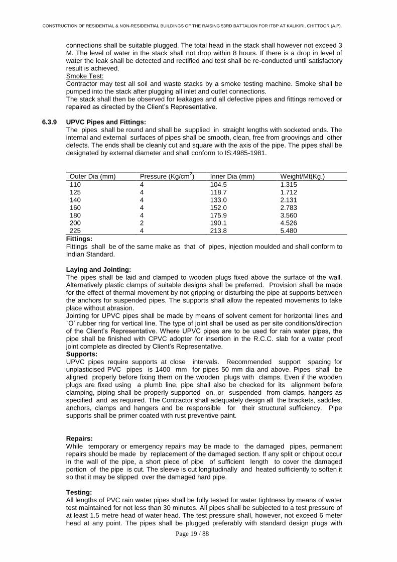
repaired as directed by the Client‟s Representative. 6.3.9 UPVC Pipes and Fittings: The pipes shall be round and shall be supplied in straight lengths with socketed ends. The
internal and external surfaces of pipes shall be smooth, clean, free from groovings and other defects. The ends shall be cleanly cut and square with the axis of the pipe. The pipes shall be designated by external diameter and shall conform to IS:4985-1981.
Outer Dia (mm) Pressure (Kg/cm2) Inner Dia (mm) Weight/Mt(Kg.)
110 4 104.5 1.315 125 4 118.7 1.712 140 4 133.0 2.131 160 4 152.0 2.783 180 4 175.9 3.560 200 2 190.1 4.526 225 4 213.8 5.480
Fittings: Fittings shall be of the same make as that of pipes, injection moulded and shall conform to Indian Standard.
Laying and Jointing: The pipes shall be laid and clamped to wooden plugs fixed above the surface of the wall. Alternatively plastic clamps of suitable designs shall be preferred. Provision shall be made for the effect of thermal movement by not gripping or disturbing the pipe at supports between the anchors for suspended pipes. The supports shall allow the repeated movements to take place without abrasion. Jointing for UPVC pipes shall be made by means of solvent cement for horizontal lines and `O‟ rubber ring for vertical line. The type of joint shall be used as per site conditions/direction of the Client‟s Representative. Where UPVC pipes are to be used for rain water pipes, the pipe shall be finished with CPVC adopter for insertion in the R.C.C. slab for a water proof joint complete as directed by Client‟s Representative. Supports: UPVC pipes require supports at close intervals. Recommended support spacing for unplasticised PVC pipes is 1400 mm for pipes 50 mm dia and above. Pipes shall be aligned properly before fixing them on the wooden plugs with clamps. Even if the wooden plugs are fixed using a plumb line, pipe shall also be checked for its alignment before clamping, piping shall be properly supported on, or suspended from clamps, hangers as specified and as required. The Contractor shall adequately design all the brackets, saddles, anchors, clamps and hangers and be responsible for their structural sufficiency. Pipe supports shall be primer coated with rust preventive paint.
Repairs: While temporary or emergency repairs may be made to the damaged pipes, permanent repairs should be made by replacement of the damaged section. If any split or chipout occur in the wall of the pipe, a short piece of pipe of sufficient length to cover the damaged portion of the pipe is cut. The sleeve is cut longitudinally and heated sufficiently to soften it so that it may be slipped over the damaged hard pipe.
Testing: All lengths of PVC rain water pipes shall be fully tested for water tightness by means of water test maintained for not less than 30 minutes. All pipes shall be subjected to a test pressure of at least 1.5 metre head of water head. The test pressure shall, however, not exceed 6 meter head at any point. The pipes shall be plugged preferably with standard design plugs with
CONSTRUCTION OF RESIDENTIAL & NON-RESIDENTIAL BUILDINGS OF THE RAISING 53RD BATTALION FOR ITBP AT KALIKIRI, CHITTOOR (A.P).
Page 20 / 88
rubber plugs on both ends. The upper end shall, however, be connected to a pipe for filling with water and getting the required head.
6.3.10 Waste Pipe from Appliances:
i) Waste pipe from appliances e.g. wash basins, sinks, urinals, chrome plate where seen water coolers shall be of galvanized steel (heavy class) conforming to IS:1239-1979.
ii) All pipes shall be fixed in gradient towards the outfalls of drains. Pipes inside a toilet room shall be in chase unless otherwise shown on drawings. Where required pipes may be run at ceiling level in suitable gradient and supported on structural clamps. Spacing for clamps for such pipes shall be as follows:- Vertical Horizontal P.V.C. Pipes 180 cms 120 cms
6.3.11 Measurements: UPVC/ CPVC waste/soil, waste, vent and rain water pipes shall be measured over all along
the centre line correct to a centimeter including all fittings along its length. The rate for these pipes shall be inclusive of all fittings, holder bat clamps, lead caulked joint for UPVC and cement joints for UPVC and all other items described in the Bill or Quantities. The portion of the pipe within the collar for C.I/UPVC pipe at the joint shall not be included in the length of the pipe work.
6.4 TRAPS: 6.4.1 Nahani Trap or Floor Traps: Nahani traps or floor traps shall be cast iron, deep seal with an effective seal of 50 mm. The
trap and waste pipes shall be set in cement concrete blocks firmly supported on the structural floor. The blocks shall be in 1:2:3 mix (1 cement: 2 coarse sand: 4 stone aggregate 20 mm nominal size) mixed with water proof compound and extended to 40 mm below finished floor level. Contractor shall provide all necessary shuttering and centering for the blocks. Size of the block shall be 30 x 30 cms. of the required depth. The trap shall be installed at lowest point ensure no ponding occurs at perimeters of the drain.
6.5 Floor Trap Inlet Bath room traps and connections shall ensure free and silent flow of discharging water.
Where specified, the Contractor shall provide a special type galvanized iron inlet fitting without or with one, two or three inlet sockets to receive the waste pipe. Joint between waste and fitting shall be connected to a UPVC „P‟ or „S‟ trap with at least 50mm seal traps shall be paid for separately). Floor trap inlet fittings and the trap shall be set in cement concrete blocks.
6.6 C.P./Stainless Steel Gratings Floor and Urinal traps shall be provided with 100-150mm square or round C.P./Stainless
steel grating as approved by Client‟s Representative with rim, of approved design and shape. Minimum thickness shall be 4-5mm or as specified in the Bill of Quantities.
6.7 Cleanout Plugs: Contractor shall provide cast brass cleanout plugs in all horizontal run more than 15 mtr
length required one cleanout plugs shall be threaded and provided with key holes for opening. Cleanout plugs shall be fixed to the pipe by a CPVC socket and lead caulked joint.
6.8 Pipe Sleeves: Pipe sleeves 50mm larger diameter than pipes shall be provided wherever pipes pass
through walls and slabs and annular space filled with fire proof materials like putty, fire seal etc. All pipes shall be accurately cut to the required sizes in accordance with relevant BIS codes and burs removed before laying. Open ends of the pipe shall be closed as the pipe is installed to avoid entrance of foreign matters. Vertical sleeve shall finish 50mm above finish floor level.
7.0 EXTERNAL DRAINAGE SYSTEM : (SEWERAGE & STORM WATER): 7.1 SCOPE:
i. Work under this section shall consist of furnishing all labour, materials, equipment and appliances necessary and required to completely install the drainage system as required by the drawings and specified hereinafter or given in the Bill of Quantities.

CONSTRUCTION OF RESIDENTIAL & NON-RESIDENTIAL BUILDINGS OF THE RAISING 53RD BATTALION FOR ITBP AT KALIKIRI, CHITTOOR (A.P).
Page 21 / 88
ii. Without restricting to the generality of the foregoing, the drainage system shall include: Sewer lines including excavations, pipe lines, man holes, drop connections, underground storm water drains, including pipes, man holes, catch basins and open drains, thrust blocks.
7.2 GENERAL REQUIREMENTS:
All materials shall be new of the best quality conforming to specifications and subject to the approval of the Client‟s Representatives.
Drainage lines shall be laid to the required gradients and profiles. All drainage work shall be done in accordance with the local municipal bye-laws. Contractor shall obtain necessary approval and permission for the drainage system from the
municipal or any other competent authority and also existing invert levels required to enter sanitary system.
Location of all manholes, catch basins, etc. shall be confirmed by the Client‟s Representatives before the actual execution of work at site.
All excavation, trenches etc shall be barricaded as per instruction of the Client's Representatives.
All works shall be executed as directed by the Client‟s Representatives.] 7.3 TRENCHES FOR PIPE & DRAINS: 7.3.1 Alignment and Grade:
The drains are to be laid to alignment and gradients in continuous shown on the drawings but subject to such modifications, as shall be ordered by the Client‟s Representative from time to time to meet the requirements of the works. No deviations from the line, depths of cutting or gradients of sewers shown in the plans and sections shall be permitted except by the express direction in writing of the Client‟s Representative.
7.3.2 Opening out Trenches: In excavating the trenches at the road metaling, pavement kerbing etc. are to be placed on one side and preserved for rein statement when the trench or other excavation shall be filled-up. Before any road metal is replaced, it shall be carefully shifted. The surface of all trenches and holes shall be restored and maintained to the satisfaction of the Client‟s Representative. The Contractor shall not cut or break down any live fence or trees in the line of the proposed works but shall tunnel under them unless the Client‟s Representative shall order to the contrary.
Trench to be excavated to alignment + depth required. Trench to be properly dressed and de-watered. Trench shall be kept free of water at all time. Discharge of water shall be into nearest drainage channel not on the road. All under ground pipe to be laid in trench. Pipes to be laid and maintained at required levels and grade during course of work. All joints to be aligned and complete. Trench shall be of 450mm wide than pipe. Concrete anchors at change in direction for C.I. pipe shall be provided. Pipe shall be rest on cushion in the trench. The Contractor shall scrub up and clear the surface over the trenches and other excavations of all stumps, roots and all other encumbrances affecting execution of the work and shall remove them from the site to the approval of the Client‟s Representative.
7.3.3 Construction Across the Roads: All the pipe line or drain crossing existing road, the road crossing shall be excavated at a time, the second half being commenced after the pipes have been laid in the first half and the trench refilled. Necessary safety measure for traffic as directed shall be adopted. All type of pipes, water mains, cables etc. met within the course of excavation shall be carefully protected and supported. Care shall be taken not to disturb the electrical and communication cable removal of which is necessary, shall be arranged by the Client‟s Representative or the Contractor shall arrange to support and protect them during excavation.
7.3.4 Excavation to be Taken to Proper Depth: The trenches shall be excavated to such depth and width that the sewers pipe shall rest on cushion so that the inverts may be at the levels given on the section/plan. In bad ground the Client‟s Representative may order the Contractor to excavate to a greater depth than that shown on the drawings and to fill up the excavation to the level of the sewer with such

CONSTRUCTION OF RESIDENTIAL & NON-RESIDENTIAL BUILDINGS OF THE RAISING 53RD BATTALION FOR ITBP AT KALIKIRI, CHITTOOR (A.P).
Page 22 / 88
materials as decided by Client‟s Representative in writing.
7.3.5 Refilling: The filling shall be done in layers not exceeding 15mm in depth. Each layer shall be watered, rammed and consolidated. Ramming shall be done with iron rammers where possible and with blunt end of the crow brass where rammers can not be used. Special care shall be taken to ensure that no damage is caused to the pipes, drains, masonry or concrete in the trenches. Filling in trenches shall be commenced soon after the joints of pipes, cables, conduits etc. have been tested and approved by Client‟s Representative. The space around the pipes shall be cleared of all debris where the trenches are excavated in hard/soft soil. The filling shall be done with earth on the sides and tops of pipes in layers not exceeding 15mm in depth. Each layer shall be watered rammed and consolidated. The clods and lumps of earth exceeding 8cm in any direction shall be broken or removed before the excavated earth is used for filling. Generally no test is done to determine the instu diversity of filled earth but on the discretion of Client‟s Representative the 95 proctor‟s compaction test may be done to ensure the in situ density after filling. Consolidation is removal of water from the pores and compaction is the explosion of air from the pores. In case of refilling consolidation places most important role as the watering of the each layer is being done properly. If required by the Client‟s Representative proctors needle may also be used for the proper checking of the refilling items of in situ density.
7.3.6 Contractor Shall Restore Settlement and Damages: The Contractor shall at his own cost make good promptly during the whole period the works are in hand, any settlements that may occur in the surfaces or roads, beams, footpaths, gardens, open spaces etc. Whether public or private caused by his trenches or by his other excavations due to not using the method of compaction as given in clause 7.3.5 and he shall be liable for any accidents caused thereby. He shall also at his own expense and charges, repair and make good any damage done to the building and other properties.
7.3.7 Disposal of Surplus Soil:
The Contractor shall at his own cost and charge, dispose off from the site all surplus excavated material not required to be used on the works. i. The width of excavated trench shall be as per table given below:
Excavation upto Upto 100 mm Upto 150 mm dia pipe dia pipe
90 cms depth 33 cms 33 cms 90 - 150 cms depth 60 cms 60 cms 150 - 300 cms depth 75 cms 75 cms 300 - 500 cms depth 90 cms 100 cms
7.3.8 Protection of Existing Services:
All pipes, water mains, cables etc encountered in the course of excavation shall be carefully protected and supported. In case of any damage caused the same shall be made good at no extra cost failing which necessary works will be carried out by the Clients Representative and contract charged to the Contractor.
7.4 RCC PIPES: 7.4.1 All underground storm water drainage pipes and sewer lines where specified (other than
those specified cast iron) shall be centrifugally spun RCC pipes NP2 for general and NP3 where road crossing. Pipes shall be true and straight with uniform bore throughout. Cracked, wraped pipes shall not be used on the work. All pipes shall be tested by the manufacturer and the Contractor shall produce, prior to use on site, a certificate to that effect from the manufacturer.
The pipes shall be with or without reinforcement as required and of the class as specified. These shall conform to IS:458 - 1971. The reinforced cement concrete pipes shall be manufactured by centrifugal (or spun) process.
All pipes shall be true to shape, straight, perfectly sound and free from cracks and flaws. The external and internal surface of the pipes shall be smooth and hard. The pipes shall be free from defects resulting from imperfect grading of the aggregate mixing or moulding.

CONSTRUCTION OF RESIDENTIAL & NON-RESIDENTIAL BUILDINGS OF THE RAISING 53RD BATTALION FOR ITBP AT KALIKIRI, CHITTOOR (A.P).
Page 23 / 88
The pipes shall be R.C.C. light duty, NP2 and NP3 type. 7.4.2 Laying: R.C.C. spun pipes shall be laid on cement concrete bed or cradles as specified and shown
on the detailed drawings. The cradles may be pre-cast and sufficiently cured to prevent cracks and breakage in handling. The invert of the cradles shall be left 12mm below the invert level of the pipe and properly placed on the soil to prevent any disturbance. The pipe shall then be placed on the bed concrete or cradles and set for the line and gradient by means of sight rails and boning rods, etc. Cradles or concrete bed may be omitted, if directed by the Client‟s Representatives.
7.4.3 Jointing: (Rigid Spigot and Socket Joint): Hemp rope soaked in neat cement wash shall be passed round the joint and inserted in it
by means of caulking tool. More skein of yarn shall be added and rammed home. Cement mortar with one part of cement and one part of sand and with minimum water content but on no account soft or sloppy, shall be carefully inserted, punched and caulked into the joint and more cement mortar added until the space of the joint has been filled completely with tightly caulked mortar. The joint shall then be finished off neatly outside the socket at an angle of 45 degree.
7.4.4 Curing: The joint shall be cured for at least seven days. 7.4.5 Cement Concrete for Pipe Supports:
a) Unless otherwise directed by the Client‟s Representative cement concrete for bed, all round or in haunches shall be laid as follows:
Upto 1.5m depth (5‟)
Upto 3m depth (10‟)
Beyond 3m depth (10‟)
Pipes in open ground (no sub soil water)
all round (1:5:10)
in haunches (1:3:6)
all round (1:5:10)
RCC/C.I pipes in sub soil water
all round (1:3:6)
in haunches (1:3:6)
in haunches (1:3:6)
RCC/C.I. pipes (in all conditions)
all round (1:3:6)
in haunches (1:3:6)
in haunches (1:3:6)
RCC/C.I pipes under road or building all round (1:3:6)
all round (1:3:6)
all round (1:3:6)
b) RCC pipes or CI pipes may be supported on brick masonry or pre-cast RCC or in situ cradles. Cradles shall be as shown on the drawings.
c) Pipes in loose soil or above ground shall be supported on brick or stone masonry pillars as shown on the drawings.
7.4.6 Testing: All lengths of the sewer and drain shall be fully tested for water tightness by means of water
head maintained for not less than 30 minutes. Testing shall be carried out from manhole to manhole. All pipes shall be subjected to a test pressure of at least 1.5 metres head of water at the highest point of the section under test. The pipes shall be plugged preferably with standard drain plugs (with rubber rings) on both ends. The upper end shall, however, be connected to a pipe for filling with water and getting the required head.
Permissible drops in water head should not exceed …………………….. 7.4.7 Measurement:
a) Excavation: Measurement for excavation of pipes trenches shall be made per linear meter.
b) Trenches shall be measurement between outside walls of manholes at top and the depth shall be the average depth between the two ends to the nearest cm. The rate quoted shall be for a depth upto 1.5 metre or as given in the Bill of Quantities.
Payment for trenches more than 1.5 m in depth shall be made for extra depth as given in the Bill of Quantities and above the rate for depth upto 1.5 m.
c) RCC pipes shall be measured for the length of the pipe line per linear meter i.e.: i. Length between manholes shall be recorded from inside of one manhole to inside of

CONSTRUCTION OF RESIDENTIAL & NON-RESIDENTIAL BUILDINGS OF THE RAISING 53RD BATTALION FOR ITBP AT KALIKIRI, CHITTOOR (A.P).
Page 24 / 88
other manhole. ii. Length between gully trap and manhole shall be recorded between socket of pipe
near gully trap and inside of manhole. 7.5 Sewer Appurtenances: Inspection Chambers and Manholes:
i. Size of Chambers/Manholes: The size given in Bill of Quantities and drawings shall be internal finished size of
chamber. The work shall be done strictly as per standard drawing and following specifications.
ii. Bed Concrete: Shall be in 1:4:8 cement concrete 200 mm thick). iii. Brick Work: Brick work shall be with best quality bricks in 1:6 cement mortar. iv. Plaster: Inside of the walls of chamber/manhole shall be plastered with 12/15 mm thick cement
plaster 1:3 (1 cement :3 coarse sand) and finished smooth with a floating coat of neat cement. Manholes shall be plastered from out side as above but with rough plaster.
Water proofing compound as approved by the Client‟s Representative shall be added in the cement sand mortar ratio as specified by manufacturer.
v. Benching: Channel and benching shall be done in cement concrete 1:2:4 rendered smooth with
neat cement. The following depth of channel and benching shall be adopted:
Top of channel at Depth of benching Size of Drain the centre above at side walls above
bed conc. bed conc.
10 cm 15 cm 20 cm 15 cm 20 cm 30 cm 20 cm 25 cm 35 cm 25 cm 30 cm 40 cm 30 cm 35 cm 45 cm
Manhole Covers and Frames:
The covers and frames shall conform to IS:1726-1960 and shall be of the following grades and types: a) Heavy Duty: These shall be denoted by the letters „HD‟ circular solid type for use under heavy
vehicular traffic conditions. b) Medium Duty:
These shall be denoted by the letter „MD‟ circular or rectangular solid type for use under light traffic conditions such as foot paths, carriage drives and cycle tracks.
c) Light Duty: These shall be denoted by the letters „LD‟ or rectangular size for use in domestic
premises of where they are not subjected to wheeled traffic loads. The covers and frames shall be leanly cast and they shall be free from air and sand
holes and from cold shuts. They shall be nearly dressed and carefully trimmed. All castings shall be free from voids whether due to shrinkage gas inclusion or other causes. Covers shall have a raised chequered design on the top surface to provide an adequate non-slip grip.
The covers shall be capable of easy opening and closing and it shall be fitted in the frame in workmanship like manner. The cover shall be gas tight and water tight.
The size of covers specified shall be taken as the clear internal dimensions of the frame.
The approximate weights of the various type of manhole covers and frames shall be as in table given below:

CONSTRUCTION OF RESIDENTIAL & NON-RESIDENTIAL BUILDINGS OF THE RAISING 53RD BATTALION FOR ITBP AT KALIKIRI, CHITTOOR (A.P).
Page 25 / 88
Description of C.I. Manhole Cover
Weight of Cover Kg.
Weight of Frame Kg.
Total Weight of Cover and Frame Kg.
HD 560 mm dia 108 100 208 LD, rectangular 455x610mm (single seal)
23 15 38
MD 500 mm dia 58 58 116
2 ½% variation in weight shall be permissible on either side. Covers and frames shall be coated with a black bituminous composition. The coating shall be smooth tepacious. It shall not flow when exposed to a temperature of 63 Deg. and shall not be brittle as to chip off temp. of 0 Deg. C. The frame of manhole cover shall be firmly embedded to correct alignment and levels in RCC slab or plain concrete, as the case may be on the top of the masonry. After completion of the work, manhole covers shall be sealed by means of thick grease .
vii. Foot Rests: All manholes deeper more than 0.6 m shall be provided with plastic foot rests (Polypropylene is injection moulded around a 12mm dia steel reinforcing bar). These shall be embedded 20cm, deep with 20 x 20 x 10cm blocks of cement concrete 1:2:4 (1 cement :2 coarse sand :4 graded stone aggregate 20cm, nominal size). The block with plastic foot rest placed it‟s centre shall be cast in situ along the masonry and surface finished with 12mm thick cement plaster 1:3 (1 cement :3 coarse sand) finished smooth.
viii. All cast iron and Mild Steel items shall be provided with two coats of bitumastic paint.
Measurement: Manhole shall be measured in numbers as indicated in the Bill of Quantity. The depth of
manhole shall be measured from invert of channel to the top of manhole cover. Quoted rate shall cover the range of ± 0.24 metre on the depth specified in schedule and also the cost of items specified in the Bill of Quantities and Specifications viz.
Bed concrete. i. Brick work. ii. Plastering. iii. R.C.C. top slab, benching and channeling including drop connections. iv. Supply and fix M.S. foot rests. v. Keeping holes and embedding pipes for all the connections. vi. Excavation, refilling, necessary dewatering and disposing off surplus soil to a place as
directed by Client‟s Representative. vii. Curing. viii. Cost of frame and cast iron cover including reinforcement, angle frame and embedding
the frame in concrete bed. ix. Testing. x. De-watering of chambers.
Gully Trap: Gully traps shall be fixed in cement concrete 1:5:10 mix and a brick masonry chamber 30 x
30cms C.I. sealed cover and frame weighting not less than 7.3 Kgs to be constructed as per standard drawings. Where necessary, sealed cover shall be replaced with C.I. grating of the same size (1 cement : 5 coarse sand : 10 stone aggregate : 40mm nominal size).
Measurements: Gully traps shall be measured by the number and rate which shall include all excavation,
foundation, concrete, brick masnory, cement plaster inside and outside, CI grating and sealed cover and frame.
7.6 DROP CONNECTIONS:

CONSTRUCTION OF RESIDENTIAL & NON-RESIDENTIAL BUILDINGS OF THE RAISING 53RD BATTALION FOR ITBP AT KALIKIRI, CHITTOOR (A.P).
Page 26 / 88
7.6.1 In case where branch pipe sewer enters the manhole of main sewer, a drop connection should be provided. H.C.I. pipes and specials conforming to IS:1729-1964 as revised from time to IS:1729-1964 as revised from time to time shall be of the size same as of the branch pipe sewer.
For 150 x 250mm main line, if the difference in level between the water line (peak-flow-level) and the invert level of branch line is less than 60cm, a drop connection may be provided within the manhole by giving ramp. If the different in level is more than 60 cm the drop should be provided externally.
7.6.2 Excavation: The excavation shall be done for the drop connection at the place where the branch line
meets the manhole. The excavation shall be carried upto the bed concrete of the manhole and to the full width of the branch line.
7.6.3 Laying: At the ends of branch sewer line Cast Iron tee shall be fixed to the line which shall be
extended through wall of the manhole by horizontal piece of Cast Iron pipe form an inspection on cleaning eye, the open end shall be provided with chain and lid. The Cast Iron drop pipe shall be connected to the tee at the top and to Cast Iron bend at the bottom. The end shall be extended through the wall of the manhole by a piece of Cast Iron pipe which shall discharge into the channel. Necessary channel shall be made with cement concrete 1:2:4 (1 cement :2 coarse sand :4 graded stone aggregate to 20mm nominal size) and finished smooth to connect the main channel. The joint between Cast Iron pipe to fittings shall be lead caulked. The joint between Cast Iron tee and RCC branch line shall be made with cement mortar 1:1 (1 cement :1 fine sand). The exposed portion of the drop connection shall be encased alround with minimum 15 cm thick concrete 1:3:6 (1 cement :3 fine sand :6 graded stone aggregate 40mm nominal size) and cured. For encasing the concrete around the drop connection, necessary centering and shuttering shall be provided.
The holes made in the walls of manholes shall be made good with brick work in cement
mortar 1:5 (1 cement :5 fine sand) and plastered with cement mortar 1:3 (1 cement :3 coarse sand) on the inside of the manhole wall. The excavated earth shall be back filled in the trench in level with the original ground level.
7.7 Making Connections: The Contractor shall connect the new sewer line to the existing manhole by cutting the walls,
benching and restoring them to the original conditions. A new channel shall be cut in the benching of the existing manhole for a new connections. The Contractor shall remove all sewage and water if encountered in making the connection without additional cost to the Owner.
7.7.1 Measurements: Item for making connection to municipal sewer shall be paid for by number and shall include
all items given in the Bill of Quantities. 8.0 TUBE WELL: 8.1 Scope: Work under this section shall consist of providing materials and labour necessary and
required for boring of tube well as per drawings and specified hereinafter in the Schedule of Quantities.
Whether specifically mentioned or not, all fixtures, fittings and appliances shall be provided with necessary devices as required.
8.2 General Requirements: 8.2.1 The work in general shall comprise of the following operations:
a) Obtaining any approval from the Municipal or other relevant authorities for sinking of the tube well.

CONSTRUCTION OF RESIDENTIAL & NON-RESIDENTIAL BUILDINGS OF THE RAISING 53RD BATTALION FOR ITBP AT KALIKIRI, CHITTOOR (A.P).
Page 27 / 88
b) Boring the necessary hole of required dia with sinking of necessary casing pipe and removal of the same after the work is over or completing the bore to required depth without casing pipe.
c) Shrouding with graded gravel around the slotted, blind and housing pipes as described in the schedule.
d) Giving yield tests as directed by the Owner and other works as described in the schedule. Tube well yield shall be minimum capacity 20 m
3/hour, or as stated in Schedule of
Quantities. e) The entire work shall be carried out in a workman like manner and strictly in accordance
with IS:2800. f) The boring of the tube well shall be done by rotary/percussion or any standard method by
means of drilling rig or manually subject to site conditions. g) The tube well pipe shall be shrouded with pea gravel of size 1/6” to 3/16” size.
8.2.2 The rates quoted shall be as per running metre depth of boring through the soils. The casing
pipe will not be paid for and will be the property of the contractors. No compensation will be paid for the casing pipe if left within the ground or after commissioning of the tube well.
8.2.3 The Contractor shall make his own arrangement for the supply of water and power necessary for the work and workman.
8.2.4 All other necessary materials and equipment shall be arranged by the Contractor without any additional cost to the Owner.
8.2.5 In case it is necessary to abandon (with approval of the Owner) the tube well at any stage of construction, no payment will be made to the Contractor for the transport of his plant and equipment or for boring and sinking of casing pipe. No compensation on any account is admissible in this regard.
8.2.6 The Contractor shall not be entitled for any compensation for delay of completion on account of any break-down or dropping of tools, tackles in the bore hole or the time of lowering housing pipe/blind/slotted pipe or lifting the casing pipe.
8.2.7 The time for completion shall be two months from the date of placing firm order. 8.3 Performance Guarantee: The contractor shall guarantee the system to maintain flow requirements as per the
specifications and drawings. 8.4 Information to be furnished by the Tenderer:
The tenderer shall furnish the following information: i) Method of drilling adopted ii) Date of starting drilling iii) Date of completion iv) Pilot hole or test hole Bit Type Bit Size hours from To
v) Boring done Bit Type Bit Size hours from To
vi) Reeming Bit Type Bit Size hours from To
vii) Lithological log from to formation viii) Assembly of production well size Length Type Perforation per meter Housing pipe Blind pipe Strainer Bail Plug ix) Type of tube well/above/below ground level

CONSTRUCTION OF RESIDENTIAL & NON-RESIDENTIAL BUILDINGS OF THE RAISING 53RD BATTALION FOR ITBP AT KALIKIRI, CHITTOOR (A.P).
Page 28 / 88
x) Size of gravel Quantity used before development xi) Method used for development Testing xii) Total hours of development Total hours of testing xiii) Stage draw down test: Type of test:
Speed RPM
Discharge Period run xiv) Aquiffer performance test: Time of test Spend Rev/minutes LPM Discharge xv) Static water level xvi) Rated discharge in litres/minute xvii) Depression head of the production well xviii) Sand contents at the rate of discharge after 20
minutes of the start of pump
xix) Sand contents in RPM at 1.5 times the normal depression after 20 minutes of the start of pump.
xx) Sand contents in RPM @ 20% in excess of rated discharge, if 50% extra depression can not be arranged.
xxi) Samples of starts neatly packed in sample bags (They shall be obtained from the bore hole and collected in glass jars indicating the depth at which it is encountered).
xxii) Chart of pipe assembly lowered – state the variations in diameter of pipe at different depths.
xxiii) Results of mechanical analysis of samples of unconsolidated starts.
xxiv) Verticality test on prescribed form. xxv) Physical/Chemical and bacteriological analysis
of tube well water.
9.0 RAIN WATER HARVESTING: 9.1 General: 9.1.1 Surface water is inadequate to meet our daily water demand and we have to depend on
ground water. Due to rapid urbanization, infiltration of rain water into the sub-soil has decreased drastically and recharging of ground water has diminished. The result of this in decline in water levels in most of the country.
9.1.2 Two overcome with the problem mentioned above. The right solution is to use the rain water harvesting techniques.
9.2 Definition of Water Harvesting: 9.2.1 In scientific terms, water harvesting refers to collection and storage of main water and also
other activities aimed at harvesting surface and ground water, prevention of losses through evaporation and seepage and all other hydrological studies and engineering interventions, aimed at conservation and efficient utilization of the limited water endowment of physiographic unit such as a water shed.
9.2.2 In general, water harvesting is the activity of direct collection of rain water. The rain water from the roof or from the surface can be directly stored for direct use or can be recharged in the ground water.
9.2.3 Most of the people are not aware that the rain water is the first form of water in the hydrological cycle, hence is a primary source of water for us. The other source like rivers, lakes and groundwater are all secondary source of water. In present times, we depend entirely on such secondary sources of water. In the process, it is forgotten that rain is the ultimate source that feed the water to all the secondary sources and remain ignorant of its value. Water harvesting means to understand the value of rain and to make optimum of rain water at the place where it falls.
CONSTRUCTION OF RESIDENTIAL & NON-RESIDENTIAL BUILDINGS OF THE RAISING 53RD BATTALION FOR ITBP AT KALIKIRI, CHITTOOR (A.P).
Page 29 / 88
9.3 Necessity of Water Harvesting: 9.3.1 In India there is a lot of rain, yet there is no water. The annual rainfall over India is higher
compared to the global average rainfall. However, this rainfall occurs during short spells of high intensity. Due to such high intensities and short duration of heavy rain, most of the rain falling on the surface tends to flow away rapidly to these secondary sources as mentioned above, and very little rain water is left for the recharging of the ground water.
9.3.2 It is necessary to implement measures to ensure that rain falling over a region is tapped as much as possible through water harvesting, either by recharging it into the ground water aquifers or storing it for direct use.
9.4 Amount of Water Harvested: 9.4.1 The total amount of water that is received in the form of rainfall over an area is called rain
water endowment of the area. Now out of this the amount that can be effectively harvesting is called the water harvesting potential. Water harvesting potential is rainfall (mm) x collection efficiency.
9.4.2 The collection efficiency accounts for the fact that all the rain water falling over an area
cannot be effectively harvested because of evaporation, spillage etc. Factor like runoff coefficient and the first flush wastage are taken into account when estimating the collection efficiency.
9.5 Advantages of Rain Water Harvesting: 9.5.1 The advantages by adopting Rain Water Harvesting is as under:
i) Provides self-sufficiency to water supply system. ii) Reduce the cost for pumping of ground water. iii) Provides high quality water, soft and low in minerals. iv) Improves the quality of ground water through dilution when recharged to ground water. v) Reduces soil erosion in urban areas. vi) The roof top rain water harvesting is less expensive. vii) Rain Water harvesting system is simple which can be adopted by individuals. viii) An ideal solution of water problem in areas having inadequate water resources.
ix) Reduces the runoff which chokes the storm water drains.
9.6 Method of Rain Water Harvesting: 9.6.1 The method of rain water harvesting are of two types. One by storage of rain water on
surface for future use. Second by recharging to ground water. 9.6.2 The storage of rain water on surface is a traditional technique and structures used were
underground tanks, ponds, check dams, weirs etc. and recharge to ground water is a new concept of rain water harvesting and name of few of them are recharge pits, trenches, dug wells, hand pumps, recharge wells, recharge shafts, lateral shaft and borewells shaft with borewells etc.

CONSTRUCTION OF RESIDENTIAL & NON-RESIDENTIAL BUILDINGS OF THE RAISING 53RD BATTALION FOR ITBP AT KALIKIRI, CHITTOOR (A.P).
Page 30 / 88
TECHNICAL SPECIFICATIONS
INTERNAL ELECTRICAL WORKS
Internal & External electrical works will be carried out as per CPWD specifications and will be paid accordingly.
A. CABLES MEDIUM VOLTAGE 1.1 kV GRADE XLPE INSULATED / PVC INSULATED CABLES as per IS 1554 Part-I. The Hi potential test 2.5 time of the of designed voltage is to be carried out at works
1. GENERAL
The MV cables shall be supplied, inspected, laid, tested and commissioned in accordance with drawings, Specifications, relevant Indian Standard and cable manufacturer's instruction.
2. MATERIAL
Specifications of PVC insulated, sheathed aluminum / copper conductor cable shall be as follows:
a. Conductor
Stranded compacted circular conductor shall be of electrical grade high conductivity aluminum/ copper conductor as per IS: 8130 / 84.
b. Insulation The insulation shall be compounded PVC, application shall be by extrusion process insulation type C (85deg.C) conforming to IS: 5831-1984. The thickness of insulation will be as per the relevant Indian codes.
c. Laying-up Insulated conductors of multi core cables shall be with thermoplastic fillers in the interstices. The phase identification of cores shall be by colored strips.
d. Inner Sheath Cores shall be surrounded either by a wrapped or an extruded PVC sheath. The thickness of the inner sheath shall be as per relevant Indian codes.
e. Armouring The armouring shall be provided over the inner sheath. Single core cable shall have non-magnetic armouring. Multi core cables shall have either galvanized round steel wires or flat steel strip armouing. Steel wires and strips for armouring confirm to IS: 3975. The direction of lay of armouring shall be opposite to that of cores.
f. Outer Sheath Single and multi core cables are provided with an extruded PVC outer-sheath. The thickness of the sheath shall be as per IS: 1554-1988. The PVC compound for the outer-sheath shall confirm to Type ST1 of IS 5831. The colour of the outer sheath shall be black.
3. Specifications for XLPE insulated HR PVC sheathed aluminum / copper conductor cable shall be as follows:

CONSTRUCTION OF RESIDENTIAL & NON-RESIDENTIAL BUILDINGS OF THE RAISING 53RD BATTALION FOR ITBP AT KALIKIRI, CHITTOOR (A.P).
Page 31 / 88
a. Conductor Stranded compacted circular conductor shall be of electrical grade high conductivity aluminum / copper conductor per IS: 8130/84.
b. Insulation The insulation shall be of natural unfilled chemically cross linked polyethylene conforming to IS: 7098. The thickness of insulation shall be as per the relevant Indian codes.
c. Laying-up Insulated conductors of multi core cables shall be with plastic fiber in the interstices. The phase identification of cores shall be by colored strips.
d. Inner Sheath The cores shall be surrounded by either a wrapped or by an extruded PVC sheath. The thickness of the inner sheath shall be as indicated in the relevant codes.
e. Armoring The armouring shall be provided over the inner sheath. Single core cable shall have non-magnetic armouring. Multi core cables shall have either galvanized round steel wires or flat steel strip. Steel wires and strips for armouring confirm to IS: 3975. The direction of lay of armouring shall be opposite to that of cores.
f. Outer Sheath Single and multi core cables are provided with an extruded PVC outer-sheath. The thickness of the sheath shall be as per IS: 1554-1988. The PVC compound for the outer-sheath shall confirm to Type ST2 of IS: 5831. The colour of the outer sheath shall be black.
4. CABLE LAYING AND HANDLING It should be ensured that both ends of the cable are properly sealed to prevent ingress / absorption of moisture.
5. CABLE HANDLING
When cable drums have to be moved over short distance, they should be rolled in the direction of the arrow marked on the drum. While removing cables, the drums shall be properly mounted on jacks or on a cable wheels or any other suitable means, making sure the spindle, jack etc. are strong enough to take the weight of the drum. The cables shall not be given a sharp bend to a small radius. The minimum safe bending radius for all types of PVC/XLPE cables shall be taken as 12 times the overall diameter of the cable. Wherever practicable, larger radius should be adopted. At joints and terminations, the bending radius of individual cores of a multicore cable shall not be less than 15 times its overall diameter. Cable with kinks and straightened kinks, or with similar apparent defects like defective armoring etc. shall not be installed / laid. Cables of different voltages as well as power and control cables should be kept in different trenches/racks with adequate separation. Where available space is restricted, LV/MV cable shall be laid above HV cables. Where cables cross over cannot be avoided, the cable of higher voltage shall be laid at a lower level than the cable of lower voltage.

CONSTRUCTION OF RESIDENTIAL & NON-RESIDENTIAL BUILDINGS OF THE RAISING 53RD BATTALION FOR ITBP AT KALIKIRI, CHITTOOR (A.P).
Page 32 / 88
Installation of cables including jointing shall be carried out as per IS: 1255 amended and revised to date. Power and communication cables shall, as far as possible cross at right angles. Where power cables are laid in proximity to communication cables, the horizontal and vertical clearances shall not normally be less than 60 cm. Cables shall be laid direct in ground, in pipes / closed ducts, in open ducts or on surface depending on environmental conditions, and as required in schedule of quantities. During the preliminary stages of laying the cable, consideration should be given to proper location of the joint position so that when the cable is actually laid, the joints are made in the most suitable places and as approved by Consultant. As far as possible, water logged locations, carriage ways, pavements, proximity to telephone cables, gas or water mains, inaccessible places, ducts, pipes, racks, etc. shall be avoided. The cable shall not in any circumstances be bent so as to form an abrupt right angle but must be rounded off at the corners to a radius not less than 12 times the overall diameter of the cable. In case, where there are chances of any damage to the wiring/cables, such wiring/cables shall be covered with a sheet metal protective covering (not less than 16 SWG), the base of the covering being flush with the plaster or brickwork as the case may be, or the wiring /cables shall be drawn through a heavy gauge metal conduit pipe by complying with all the requirements of conduit wiring system. Such protective covering shall, in all cases, be fitted on all down drops within 1.5 m from the floor or from floor level upto the switch board, whichever is less. While cutting and stripping of the outer sheathing of the cable, care shall be taken that the sharp edge of the cutting instrument does not touch the inner insulation of the conductors. The protective outer covering of the cable shall be stripped off near connecting terminal and this protective covering shall be maintained upto close proximity of connecting terminals. The cables laid near junction boxes shall be made moisture proof with a plastic compound.
6. CABLE JOINTING & TERMINATION
Jointing shall be as per the manufacturer‟s recommendations using standard kits. Cable joints shall be made in suitable, approved cable joint boxes, jointing of cables in the joint boxes and filling of compound shall be done as per manufacturer‟s recommendations. Heat shrinkable joints shall be made. Cables shall be terminated onto the terminals of switchgear through crimping lugs of proper size and of heavy duty. Cable lugs shall be fitted onto the cable by crimping or compression jointing. Continuity of cable armouring is to be maintained. Double compression glands to be used. Proper crimping tools to be used.
7. TRENCHING & CABLE LAYING
The minimum width of trench shall be 45 cm and depth shall be 75cm for laying of cable. Where more than one cable is to be laid in the same trench in horizontal formation, the width of trench shall be increased such that the minimum gap between the cables is one diameter of the cable unless specified otherwise. The clearance between axis of the end cables and the sides of the trench shall be minimum 1.5 D (diameter) of the end cable. The trenches shall be excavated in reasonably straight lines. Wherever there is a change in direction, suitable curvature shall be provided.

CONSTRUCTION OF RESIDENTIAL & NON-RESIDENTIAL BUILDINGS OF THE RAISING 53RD BATTALION FOR ITBP AT KALIKIRI, CHITTOOR (A.P).
Page 33 / 88
Where gradients and changes in depth are unavoidable, these shall be gradual. The bottom of the trenches shall be level and free from stone, brick bats etc. The trench shall then be provided with a layer of clean, dry sand cushion of not less than 9 cm in depth. Cable laid in trenches in a single tier formation shall have a covering of clean, dry sand of not less than 20 cms. above the base cushion of sand before the protective cover is laid. In the case of vertical multi-tier formation, after the first cable has been laid, a sand cushion of 30 cms shall be provided over the initial bed before second tier is laid. If additional tiers are formed, each of the subsequent tiers shall have a sand cushion of 30 cms as stated above. The top-most cable shall have final sand covering not less than 17 cms before the protective cover is laid. Unless otherwise specified, the cables shall be protected by second class bricks of not less than 20 cm x 10 cm x 10 cm (nominal size) as per CPWD building specification, or protection covers placed on top of the sand, (brick to be laid breadth wise) for the full length of the cable to satisfaction of the owner. Where more than one cable is to be laid in the same trench, this protective covering shall cover all the cables and project at least 5 cm over the sides of and cables. The trenches shall be then back filled with excavated earth free from stone or other sharp-edged debris and shall be rammed and watered, if necessary, in successive layers not exceeding 30 cm. Unless otherwise specified, a crown of earth not less than 50 mm in the center and tapering towards the sides of the trench shall be left to allow for subsidence. The crown of earth, however, should not exceed 10 cms. Where road bends or lawns have been cut or kerb stones displaced, the same shall be repaired to the satisfaction of the architect and all surplus earth or rock removed to places as specified. In locations such as road crossing, entry to building in paved areas etc. cables shall be laid in pipes or closed ducts. All cable entry/exit points into the building through pipe sleeves shall be properly sealed with water and fire safe sealants in an approved manner to avoid any seepage of water into the building. Manholes of adequate size, as decided by the Architect, shall be provided to facilitate of adequate strength feeding/drawing in of cables and to provide working space for persons. Suitable manhole covers with frame of proper design shall cover Manholes. CABLE LOOPS: Sufficient cable loop length shall be left.
8. CABLES ON HANGERS OR RACKS / TRAYS
The contractor shall provide and install all iron hangers racks, or racks with die-cast cleat, with fixing rag bolts or girder clamps or other specialist fixing as required. Where hangers or racks are to be fixed to wall sides ceiling and other concrete structures, the contractor shall be responsible for cutting away, fixing and grouting in rag bolts and making good the damages as required. The hangers or racks shall be designed to leave at least 25 mm clearance between the cables and the face to which it fixed. Multiple hangers shall have two or more fixing holes. All cables shall be saddled at not more than 500 mm intervals. These shall be designed to keep provision of some spare capacity for future development. Minimum spacing between the cables shall be one diameter of the cable or as specified.
9. CABLE TRAY
a) The MS cable trays should have undergone rigorous rust proofing process, which should comprise of alkaline, degreasing, descaling in diluted sulpharic acid and a recognized

CONSTRUCTION OF RESIDENTIAL & NON-RESIDENTIAL BUILDINGS OF THE RAISING 53RD BATTALION FOR ITBP AT KALIKIRI, CHITTOOR (A.P).
Page 34 / 88
phosphating process. The sheet work shall then be given two coats of oxide primer before two coats of final painting. Cable trays shall be either painted (Stove enameled) or hot dip galvanized as called for in the schedule of quantities.
b) Cable trays shall be complete with bends, joints, coupler plates and accessories as may be
required for joining the cable trays.
c) Cable trays shall be either perforated or ladder type as called for in the schedule of
quantities. 10. PERFORATED CABLE TRAYS
Standard Technical details of perforated cable tray shall be as follows:
S. No.
Description Thickness
1. 150mm to 450mm width 2mm thick & 40mm collar
2. 600mm to 750mm width 2mm thick & 50mm collar
3. 900mm to 1200mm width 3mm thick & 75mm collar
Minimum 10mm dia GI rod suspender shall be used @ 1500mm intervals.
11. LADDER TYPE CABLE TRAYS
Standard technical details of ladder type cable trays shall be as follows:
S. No.
SIZE OF TRAY (Width)
SIZE OF MAIN CHANNEL
SIZE OF RUNG & SPACING
BETWEEN RUNGS
SIZE OF ANGLE FOR SUPPORT
1. 900mm to 1500mm 25 x100 x 25 x 3mm 20 x 50 x 20 x 3mm @ 250C/C
50x50x5mm @150mm C/C
2. 600mm to 750mm 25 x 75 x 25 x 2.5mm 20 x 40 x 20 x 2.5mm @ 250C/C
40X40x5mm @180mm C/C
3. 150mm to 450mm 5 x 75 x 25 x 2mm 20 x 30 x 20 x 2.5mm @ 250C/C
32X32x4mm @180mm C/C
Fixing arrangement shall be as approved by the Consultant / Owner / PMC Hardware to be used in cable tray system shall be galvanized or zinc passivated.
a. Quality of Zinc
Zinc to be used shall conform to minimum Zn 98 grade as per requirement of IS: 209-1992. b. Coating Requirement
Minimum weight of zinc coating for mild steel flats with thickness upto 6 mm in accordance with IS:6745-1972 shall be 400 g/sqm.
The weight of coating expressed in grams per square meter shall be calculated by dividing the total weight of Zinc by total area (both sides) of the coated surface.
The Zinc coating shall be uniform, smooth and free from imperfections as flux, ash and dross inclusions, bare patches black spots, pimples, lumpiness, runs; rust stains bulky white deposits, blisters.
Mild steel flats / wires shall undergo a process of degreasing, pickling in acid, cold rinsing and then galvanizing.
12. TESTING OF CABLES

CONSTRUCTION OF RESIDENTIAL & NON-RESIDENTIAL BUILDINGS OF THE RAISING 53RD BATTALION FOR ITBP AT KALIKIRI, CHITTOOR (A.P).
Page 35 / 88
The Meggar value in normal dry weather shall be 50 mega ohm for 1.1 kV grade cable. Cables shall be tested at works for the following tests before being dispatched to site by the project team:
a. Insulation Resistance Test. b. Continuity resistance test. c. Sheathing continuity test. d. Earth test.(in armoured cables) e. Hi Pot Test.
Test shall also be conducted at site for insulation between phases and between phase and earth for each length of cable, before and after jointing. On completion of cable laying work, the following tests shall be conducted in the presence of the Owner‟s site representative: a. Insulation Resistance Test( Sectional and overall) b. Continuity resistance test. c. Sheathing continuity test. d. Earth test. All tests shall be carried out in accordance with relevant Standard Code of Practice and Electricity Rules. The Contractor shall provide necessary instruments, equipment and labour for conducting the above tests and shall bear all expenses in connection with such tests. All tests shall be carried out in the presence of the PMC / Owner representative.
13. CABLE TAGS
Cable tags shall be made out of 2mm thick aluminum sheets. Each tag shall be 2” in dia or 3” x 3” square with one hole of 2.5mm dia, 6 mm below the periphery, or as approved by Consultant. Cable designations are to be punched with letters / number punches and the tags are to be tied to cables with piano wires of approve quality & size. Tags shall be tied inside the panels beyond the glanding as well as above the glands at cable entries. Along trays tags are to be tied at all bends. On straight lengths, tags shall be provided at every 5 meters. Cables shall be secured to cable trays with 3mm thick x 25mm wide aluminum strips/suitable GI clamp, or as approved by Consultant, at 1000 mm intervals and screwed by means of rust proof screws, washers and bolts, of adequate but not excessive lengths. Cable trays for horizontal runs suspended from the ceiling will be supported with mild steel straps or brackets, at 1000 mm intervals and the overall tray arrangement shall be of a rigid construction. External cabling route marker with GI plate marked with “DANGER 1.1 kV CABLE” with 1 meter long GI angle iron grouting bracket including 1:3:6 ratio cement concrete base block of minimum size 200 x 200 x 350 mm to be provided or as approved by Elect. Supply Company.
B. EARTHING 1. SYSTEM OF EARTHING
The system shall be TNS with 4 wires supply system (R, Y, B, N and 2 Nos. E) brought from the main LT Panel. All non-current carrying metal parts of the electrical installation shall be earthed as per IS: 3043 – 1987 with latest amendment. All metal conduits, cable sheath, switchgear, DBs, light fixture, equipment and all other parts made of metal shall be bonded together and connected to earth electrodes. Earthing shall be in conformity with provisions of rules 32, 61, 62, 67 and 68 of Indian Electricity Rules, 1956. All earthing conductors shall be of high conductivity copper or GI, as specified in the schedule of quantities & shall have protection against mechanical damage. The cross-sectional area of earth conductors shall not be smaller than half that of the largest current carrying conductor. Main earthing conductors shall be taken from the earth connections at the main L T panel to an earth electrode with which the connection is to be made. All joints in tapes shall be with four rivets and shall be brazed in case of copper and by welding bolting in case of GI. Wires

CONSTRUCTION OF RESIDENTIAL & NON-RESIDENTIAL BUILDINGS OF THE RAISING 53RD BATTALION FOR ITBP AT KALIKIRI, CHITTOOR (A.P).
Page 36 / 88
shall be connected with crimping lugs, all bolts shall have spring washers. Sub- mains earthing conductors shall run from the main distribution panel to the sub distribution panel. Final distribution panel earthing conductors shall run from sub-distribution panel. Circuit earthing conductor shall run from the exposed metal of equipment and shall be connected to any point on the main earthing conductor, or its distribution panel. Metal conduits, cable sheathing and armouring shall be earthed at the ends adjacent to distribution panel at which they originate, or otherwise at the commencement of the run by an earthing conductor in effective electrical contact with cable sheathing. Where equipment is connected by flexible cord, all exposed metal parts of the equipment shall be earthed by means of an earthing conductor enclosed with the current carrying conductors within the flexible cord. Switches, accessories, lighting fitting etc. which are rigidly secured in effective electrical contact with a run of metallic conduit shall not be considered as a part of the earthing conductor for earthing purposes, even though the run of metallic conduit is earthed. a. All Lighting fixtures, sockets outlets, fans, switch boxes and junction boxes etc. shall
be earthed with copper wire as specified in schedule of quantities. The earth wire ends shall be connected with solderless/bottle type copper lugs.
All the earth wires in switch boxes, sockets outlets, DB‟s and light fixtures shall be of green Colour (PVC insulated).
Main earth bus shall be taken from the L.T. switch board to earth electrodes. The electrical resistance of earthing conductors shall be low enough to permit passage of fault current necessary to operate fuse or circuit breaker, and it shall not exceed 1 ohm.
2. SIZING OF EARTHING CONDUCTORS
The cross sectional area of earthing conductor shall not be smaller than half of the largest current carrying conductor subject to an upper limit of 80 Sq.mm. If the area of the largest current carrying conductor or bus bar exceeds 160 sq.mm then two or more earthing conductors shall be used in parallel, to provide at least half the cross sectional area of the current carrying conductor or bus bars. All fixtures, outlet boxes, junction boxes and power circuits upto 15 amps shall be earthed with PVC insulated copper wire. All 3 phase switches and distribution panels upto 60 amps rating shall be earthed with 2 Nos. distinct and independent 4 mm dia copper / GI wires. All 3 phase switches and distribution panels upto 100 amps rating shall be earthed with 2 Nos. distinct and independent 6 mm dia copper / GI wires. All switches, bus bar, ducts and distribution panels of rating 200 amps and above shall be earthed with minimum of 2 nos separate and independent 25 mm x 3 mm copper / GI tape. Earthing details given in Table – A & B shall be referred to as a general guidance. Exact sizes to be worked out by the contractor as per relevant IS Codes.
Table - A
Size of earth leads
(a) For Transformer/Generator Neutral Point Earthing:
Electrolytic Galvanized Transformer/ Bare copper Iron

CONSTRUCTION OF RESIDENTIAL & NON-RESIDENTIAL BUILDINGS OF THE RAISING 53RD BATTALION FOR ITBP AT KALIKIRI, CHITTOOR (A.P).
Page 37 / 88
DG Set Conductor Wire Conductor wire Rating or strip or strip
50kVA & below/4mm dia 4mm dia 25mm x 6.0mm 75 kVA 25mm x 3.0mm 25mm x 6.0mm 100 kVA 25mm x 6.0mm 32mm x 6.0mm 150 kVA 25mm x 6.0mm 40mm x 6.0mm 200 kVA 25mm x 6.0mm 40mm x 6.0mm 250 kVA 25mm x 6.0mm 40mm x 6.0mm 300 kVA 25mm x 6.0mm 40mm x 6.0mm 500 kVA 40mm x 6.0mm 40mm x 6.0mm 750 kVA 40mm x 6.0mm 50mm x 6.0mm 1000 kVA 40mm x 6.0mm 50mm x 6.0mm 1250 kVA 50mm x 6.0mm 50mm x 6.0mm 1500 kVA 50mm x 6.0mm 75mm x 6.0mm 2000 kVA 50mm x 6.0mm 75mm x 6.0mm
NOTE: - EXACT SIZE OF EARTH LEAD TO BE DETERMINED AS PER LATEST IS CODES.
TABLE – B
(b) For Equipment Earthing (Applicable to Transformer, Generators, Switchgears, Panels, DB‟s, Motors etc.)
Rating of Bare Electrolytic Galvanised 400-V, 3ph Copper conductor Iron Wire / Strip 50 cy. Equipment Wire / Strip In kVA
upto 5 2mm dia 2mm dia 6 to 15 3mm dia 3mm dia 16 to 30 4mm dia 4mm dia 31 to 50 6mm dia 6mm dia 51 to 100 25mm x 3.0mm 25mm x 6.0mm 101 to 125 25mm x 3.0mm 32mm x 6.0mm 126 to 150 25mm x 3.0mm 32mm x 6.0mm 151 to 200 25mm x 6.0mm 40mm x 6.0mm 201 to 300 25mm x 6.0mm 50mm x 6.0mm 301 to 500 32mm x 6.0mm 50mm x 6.0mm 501 to 800 40mm x 6.0mm 50mm x 6.0mm Above 800 50mm x 6.0mm 50mm x 6.0mm
NOTE: EXACT SIZE OF EARTH LEAD TO BE DETERMINED AS PER LATEST IS CODES. NOTE: ALL THREE PHASE EQUIPMENT SHALL BE DOUBLE EARTHED
3. PROHIBITED CONNECTIONS
Neutral conductor, sprinkler pipes, or pipes conveying gas, water, or inflammable liquid, structural steel work, metallic enclosures, metallic conduits and lighting protection system conductors shall not be used as a earthing conductor.
4. CONNECTION/JOINTS
The earthing connections/joints should be bolted, riveted, welded, brazed type.

CONSTRUCTION OF RESIDENTIAL & NON-RESIDENTIAL BUILDINGS OF THE RAISING 53RD BATTALION FOR ITBP AT KALIKIRI, CHITTOOR (A.P).
Page 38 / 88
In case of bolted joints, GI/Passivated hardware‟s of adequate size/nos. should be used for firm connections. The minimum contact area should be equal to the width of the strip or cross-sectional area of earthing lead. Welded/brazed joints should be smooth and continues. All welded/brazed joints should be treated with anti-corrosive paints to protect it from corrosion/rusting. All bolted connections/joints of Cu strip should be tinned. Wherever, flexible earthing connection is must, it should be hydraulically crimped lugs of Copper/Aluminum. The effective earthing connection surface should be smooth & free from paints and oxide coatings.
5. EARTHING
The following must always be ensured in earthing system: All earths must be interconnected. This includes transformer neutrals, Transformer body, HT Panels, LT Panels, lightning protection system earths, UPS earths etc and provision for interconnection with other services earthing grid etc. shall be made. All earth pits should be at equi - potential. Extraneous conductive parts such as gas pipes, other service pipes and ducting risers and pipes of fire protection equipment and exposed metallic parts of the building structure. The Contractor shall get the soil resistivity test done at his own cost of the area where earthing pits are to be located before starting the installation.
6. RESISTANCE TO EARTH
The resistance of earthing system shall not exceed 1 ohm. SPECIFICATION FOR HOT DIP GALVANIZING PROCESS FOR MILD STEEL USED FOR EARTHING FOR ELECTRICAL INSTALLATION
7. GENERAL REQUIREMENTS a. Quality of Zinc
Zinc to be used shall conform to minimum Zn 98 grade as per requirement of IS: 209-1992.
b. Coating Requirement
Minimum weight of zinc coating for mild steel flats with thickness upto 6 mm in accordance with IS:6745-1972 shall be 400 g/sqm. The weight of coating expressed in grams per square meter shall be calculated by dividing the total weight of Zinc by total area (both sides) of the coated surface. The Zinc coating shall be uniform, smooth and free from imperfections as flux, ash and dross inclusions, bare patches black spots, pimples, lumpiness, runs; rust stains bulky white deposits, blisters. Mild steel flats / wires shall undergo a process of degreasing pickling in acid, cold rinsing and then galvanizing. Jointing of earthing tape shall be by welding. All joints and cut ends shall be properly painted with aluminum paint.
8. MAINTENANCE FREE CHEMICAL EARTHING:
Maintenance Free Chemical Earthing shall be done strictly as per manufacturer‟s recommendations. It shall be completely maintenance free, long life close to 25 years, environmentally safe, non corrosive & electrically conductive. The earth resistance results shall be less than one ohm.

CONSTRUCTION OF RESIDENTIAL & NON-RESIDENTIAL BUILDINGS OF THE RAISING 53RD BATTALION FOR ITBP AT KALIKIRI, CHITTOOR (A.P).
Page 39 / 88
C. MV PANELS: 1.0 GENERAL
Medium voltage power control centres (generally termed as switchboard panels) shall be in sheet steel clad cubicle pattern, free floor standing, totally enclosed, compartmentalized design having multitier arrangement of the incomers and feeders as per details given in the schedule of quantities. All panels shall conform to the requirements of the latest addition of IS and shall be suitable for 415 V, 3 phase AC supply or 230 V single phase AC supply as required. The drawing of panel mmay got approved from Engineer En-charge before placing order.
2.0 CONSTRUCTIONAL FEATURES
The Switch Boards shall be totally enclosed, sheet steel cubicle pattern, extensible on either side, dead front, floor mounting type (wall mounting if specifically asked for in BOQ) and shall have a bus bar chamber at the top and the cable entry from the bottom. (For panel requiring top cable entries if any, refer to BOQ). The cable terminations should be in side the feeder compartment only.
The Switch Boards shall be completely dust and vermin proof. Synthetic rubber gaskets between all adjacent units and beneath all covers shall be provided to render the joints dust and vermin proof to provide a degree of ingress protection of IP 43. All doors and covers shall also be fully gasketed with synthetic rubber. All the live parts shall be properly shrouded with FRP sheets.
The Switch Board shall be fabricated with CRCA Sheet Steel of thickness not less than 2.0mm and shall be folded and braced as necessary to provide a rigid support for all components. The doors and covers shall be constructed from CRCA sheet steel of thickness not less than 1.6 mm. Joints of any kind in sheet metal shall be seam welded and all welding slag ground off and welding pits wiped smooth with plumber metal. Base channel shall be fabricated from ISMC 75 and door shall be provided at the bottom with arrangement for fixing bolts in the foundation.
All panels and door covers shall be properly fitted and square with the frame. The cutouts in the panel shall be correctly positioned.
Lifting lugs of adequate strength shall be provided on each transport section of the panels. Fixing screws shall enter holes tapped into an adequate thickness of metal or provided with
hank nuts. Self threading screws shall not be used in the construction of the Switch Boards.
3.0 SWITCHBOARD DIMENSIONAL LIMITATIONS
A base channel 75 mm x 5 mm thick shall be provided at the bottom.
The overall height of the Switch Board shall be limited to 2200 mm
The height of the operating handle, push buttons etc shall be restricted between 300 mm and 1900 mm from finished floor level.
4.0 BUS BARS
The bus bars shall be suitable for 4 wire, 415 volts, 50 Hz, system. The main bus bar shall be made of high conductivity electrolytic grade AL 91E Aluminium. The bus bars shall have uniform cross section throughout the panel. The bus bars shall be capable of carrying the rated current at 415 volts continuously. The bus bar will run in a separate busbar chamber using bus insulators made of non-deteriorating, vermin proof, non hygroscopic materials such as epoxy fiber, reinforced polyester or moulding compound (min. 25mm clearance between phase to phase & phase to neutral busbars shall be provided). The interval between the two insulators will be designed after considering the following: a) Strength and safe load rating of the insulator, b) The vibrating force generated during a fault, c) A Factor of safety of 1.25 d) A set of insulators at both ends of the bus.

CONSTRUCTION OF RESIDENTIAL & NON-RESIDENTIAL BUILDINGS OF THE RAISING 53RD BATTALION FOR ITBP AT KALIKIRI, CHITTOOR (A.P).
Page 40 / 88
Bus bars shall be sized considering maximum current density of 1 Amps/ cross section Sq.mm area. The size of the bus bar calculations must be approved by the consultants. The
bus bars shall be designed to withstand a temperature rise of 45oC above the ambient. To limit the temperature rise in the bus bar chamber a set of louvers can be provided at strategical places considering the air circulation.
All the bus bars shall be insulated with PVC heat shrinking sleeves throughout (except at joints) the length of the panel. The electro-galvanised high tensile steel nuts, bolts, plain or spring washers of suitable size will be used in connecting the various section of the bus bars.
5.0 SWITCH BOARD INTERCONNECTIONS
All connections between the bus bars/Breakers terminations shall be through solid Aluminium strips of adequate size to carry full rated current which shall be PVC/fibre glass insulated.
For switch unit ratings upto 63A PVC insulated copper conductor wires of adequate size to carry full load current can be used. The terminations of all such interconnections shall be properly crimped.
6.0 CABLE TERMINATIONS
Knockout holes of appropriate size and number shall be provided in the Switch Board in conformity with the location of incoming and outgoing conduits/cables. All cable entries shall be from bottom until & unless specifically asked for in the BOQ.
The cable terminations of the circuit breakers shall be brought out to terminal cable sockets suitably located in the panel.
All outgoing links for FSU\MCB feeders shall be in the feeder compartment only. The Switch Boards shall be complete with tinned brass cable sockets, tinned brass
compression glands, gland plates, supporting clamps and brackets etc for termination of 1100 volt grade aluminium conductor PVC cables.
7.0 EARTHING
The panels shall be provided with an aluminium earth bus of suitable size running through out the length of the switchboard. Suitable earthling eyes/bolts (at min. two points) shall be provided on the main earthing bus to connect the same to the earth grid at the site. Sufficient number of star washers shall be provided at the joints to achieve earth continuity between the panels and the sheet metal parts.
8.0 INTERLOCKING The panels shall be provided with the following interlocking arrangement.
a) The door of the switch-fuse compartments is so interlocked with the switch drive or handle that the door can be opened only if the switch is in `OFF' position. De-interlocking arrangement shall also be provided for occasional inspection.
b) It shall not be possible for the breaker to be withdrawn when in `ON' position. c) It shall not be possible for the breakers to be switched on unless it is either in fully
inserted positions or for testing purposes in fully isolated position. d) The breaker shall be capable of being raked in to `testing' `isolated' and `maintenance'
positions and kept locked in any of these position. e) A safety latch to ensure that the movement of the breaker as it is withdrawn, is checked
before it is completely out of the cubicle shall be provided.
9.0 WIRING All wiring for relays and meters shall be with PVC insulated copper conductor wires. The
wiring shall be coded and labeled with approved ferrules for identification. The minimum size of copper conductor control wires shall be 1.5 sq.mm except for the circuits related to current transformers or circuits with current carrying capacity more than 5 Amps (for which min. 2.5 Sq.mm copper conductor wires shall be used).

CONSTRUCTION OF RESIDENTIAL & NON-RESIDENTIAL BUILDINGS OF THE RAISING 53RD BATTALION FOR ITBP AT KALIKIRI, CHITTOOR (A.P).
Page 41 / 88
10.0 SHEET STEEL TREATMENT AND PAINTING
Sheet Steel materials used in the construction of these units should have undergone a rigorous rust proofing process comprising of alkaline degreasing, descaling in dilute sulfuric acid and a recognised phosphating process. The steel work shall then receive two coats of oxide primer before final painting. Castings shall be scrupulously cleaned and fettled before receiving a similar oxide primer coat.
All sheet steel shall after metal treatment shall be powder coated with shade RAL 7032 (Siemens Gray) on the outside of the panel and mounting plates shall be of orange shade . Each coat of paint shall be properly stoved and the paint thickness shall not be less than 50 microns (shade of paint may be changed if the Engineer In charge so desires).
11.0 NAME PLATES AND LABELS Suitable engraved white on black name plates and identification labels of metal for all Switch
Boards and Circuits shall be provided. These shall indicate the feeder number and feeder designation.
12.0 INSTALLATION Installation shall be done by erection Contractor. 13.0 TESTING AND COMMISSIONING Copies of type tests and routine test as per relevant specification, carried out at
manufacturer‟s work shall be submitted to the ENGINEER IN CHARGE as required. Wiring and connections including earthing shall be checked for continuity and tightness. Insulation shall be measured with a 500 V megger and insulation resistance shall not be less
than 100 Mega ohms Interlocking operation to be checked as per requirement.
Tests shall be performed in presence of authorized representative of the ENGINEER IN CHARGE for which the contractor shall give due prior notice.
14.0 HIGH VOLTAGE TEST A high voltage test with 2.5 KV for one minute shall be applied between the poles and earth.
Test shall be carried out on each pole in turn with the remaining poles earthed, all units raked in position and the breakers closed. Original test certificate shall be submitted along with panel.
15.0 PRE-COMMISSION TESTS:
Panels shall be commissioned only after the successful completion of the following tests. The tests shall be carried in the presence of Architect's/Consultant's or their representatives. i) All main and auxiliary bus bar connections shall be checked and tightened. ii) All wiring termination and bus bar joints shall be checked and tightened. iii) Wiring shall be checked to ensure that it is according to the drawing. iv) All wiring shall be tested for insulation resistance by a 1000 volts meggar.
v) Phase rotation tests shall be conducted
vi) All relays and protective devices shall be tested for correctness of settings and operation by introducing a current generator and an ammeter in the circuit.
16.0 CLIMATIC CONDITIONS:
The panels & switch gear components shall be suitable for following climatic conditions:
CONSTRUCTION OF RESIDENTIAL & NON-RESIDENTIAL BUILDINGS OF THE RAISING 53RD BATTALION FOR ITBP AT KALIKIRI, CHITTOOR (A.P).
Page 42 / 88
Maximum Minimum
DBT 45
OC 3
OC
RH 90% 20% 17.0 HEATING ARRANGEMENT:
The panel shall be provided with a thermostatically controlled heating arrangement for
monsoon (200 Watt) to take care of high humidity conditions. A 6/16A service socket
outlet (single phase) shall be provided in one of the compartments in all the panels.
18.0 METERING, INSTRUMENTATION AND PROTECTION
1.0 The specifications hereinafter laid down shall cover all the meters, instrumentation and protective devises required for the electrical work. The ratings, type and quantity of meters, instruments and protective devices shall be as per the schedule of quantities and drawings.
Measuring Instruments General Direct reading electrical instruments shall be in conformity with IEC-51, BS: 89 or IS: 1248.
The accuracy of direct reading shall be 1.0 for voltmeters and 1.5 for ammeters. Other type of instruments shall have accuracy of 1.5. The error due to variations in temperature shall be limited to a minimum. The meter shall be enclosed in a dust tight housing. The housing shall be of steel or phenolic mould. The design and manufacture of the meters shall ensure the prevention of fogging of instrument glass. Instrument meters shall be sealed in such a way that access to the measuring element and to the accessories within the case shall not be possible without removal of the seal. The meters shall be provided with white dials and black scale marking. The pointer shall be black in colour and shall have zero position adjustment device which could be operated from outside. The direction of deflection shall be from left to right. Suitable selector switches shall be provided for all ammeters and voltmeters intended to be used on three phase supply.
a) Ammeters
Ammeters shall be moving iron type. The moving part assembly shall be with jewel bearings. The jewel bearing shall be mounted on a spring to prevent damage to pivot due to vibrations and shocks. The ammeters shall be manufactured and calibrated as per the latest edition of IS 1248 or BS 89. Ammeters shall be instrument transformer operated, and shall be suitable for 5 A. Secondary of instrument transformer. The scales shall be calibrated to indicate primary current, unless otherwise specified. The ammeters shall be capable of carrying sustained overloads during fault conditions without damage or loss of accuracy.
b) Voltmeters
Voltmeter shall be of moving iron type. The range for 400 volts, 3 phase voltmeters shall be
to 0 to 500 volts. Suitable selector switch shall be provided for each voltmeter to read voltage between any two lines of the system. The voltmeter shall be provided with protection fuse of suitable capacity.
2.0 INSTRUMENT TRANSFORMERS Current Transformers Current transformers shall be in conformity with IS:2705 (Part-I, II, & III) in all respects. All
current transformers to be used in the L.T. Electrical panels shall be low tension, ring type resin cast current transformer with the requisite currents ratio having secondary of the current transformers selected will be based on the following;
1. For energy measuring : 1.0 class of accuracy. 2. For other metering : 1.5 class of accuracy.

CONSTRUCTION OF RESIDENTIAL & NON-RESIDENTIAL BUILDINGS OF THE RAISING 53RD BATTALION FOR ITBP AT KALIKIRI, CHITTOOR (A.P).
Page 43 / 88
3. For protects on : 3.0 class of accuracy. Where a common CT is used for different functions the CT accuracy class will be equal to the best class required by any of those function.
Current transformers shall be capable of withstanding without damage, magnetic and thermal
stresses due to short circuit fault of 35 MVA on medium voltage system. Terminals of the current transformers shall be marked permanently for easy identification of poles. Current transformers shall be provided with earthing terminals for earthing chassis frame work and fixed part of the metal casing (if any). Each CT shall be provided with rating plate indicating the following:
1. Name and make 2. Serial Number 3. Transformation ratio 4. Rated burden 5. Rated voltage 6. Accuracy class
The current transformers to be selected for this panel will have at least 20% extra VA capacity available over the normal capacity based on the following details ;
1. For ammeters : 3 VA 2. For current coils of KW & KWHR, PF, KVAR meters or for all recorders : 5 VA. 3. For normal wiring : 2 VA. 4. For current coil of protection relays: 10 VA under; no circumstances the VA rating of the
CT's will be less than 15 VA.
Current transformers shall be mounted such that they are easily accessible for inspection, maintenance and replacement. The wiring for CTs shall be copper conductor, PVC insulated wires with proper termination lugs and wiring shall be bunched with cable straps and fixed to the panel structure in a neat manner.
3.0 CONTROL DEVICES
a) Push Buttons
The push buttons used in the panels will be rated for more than 415 volts and 2 amps. All the push buttons will be mounted on the front door and the assembly will be in two parts. All the push buttons will be mounted on the front door of the cubicle in regular symmetrical fashion as per the general norms being practiced. Only one make of push buttons will be used in the assembly of all the panels. The selection of the colour of the push buttons will be as follows
Function Colour Starting/Switching ON Green Stopping/Switching OFF Red Resetting Black Forward ON Yellow Reverse ON Blue Emergency OFF Red/Mushroom
b) Indicating Lights
The indicating lights used in the panel will be pleasant looking and round shape having the following features;
1. A separate front lens for it's easy replacement. 2. Facility to replace the bulb from the front. 3. Baynet pin cap bulbs of standard size to be used. 4. The shape of the lens to allow viewing from sides. 5. Series resistance with use of low voltage bulb for longer life. 6. Clear and distinct indication for light ON and OFF with differences of brightness of the
lens.
CONSTRUCTION OF RESIDENTIAL & NON-RESIDENTIAL BUILDINGS OF THE RAISING 53RD BATTALION FOR ITBP AT KALIKIRI, CHITTOOR (A.P).
Page 44 / 88
The selection of the colours of the indicating lamps will be as follows: - Red for system in operation - Amber for system ready for operation. - Green for system being put off. - Red, yellow and blue for incoming supply.
5.0 TESTING 5.1 Instrument transformers shall be tested at factory as per IS:2705 & IS:3156. The test shall
incorporate the following: a) Type tests b) Routine tests
Original test certificates in triplicate shall be provided. 5.2 Meters shall be tested as per IS: 1248. The tests shall include both type tests and routine
tests. Original test certificate in triplicate shall be furnished. 5.3 a) Suitable injection tests shall be applied to the secondary circuit of every instrument to
establish the correctness of calibration and working order. b) All relays and protective devices shall be tested to establish correctness of setting and
operation by introducing a current generator and an ammeter in the circuit.
19.0 MINIATURE CIRCUIT BREAKERS
The MCB's shall be of the completely moulded design suitable for operation at 240/415 Volts 50 Hz system. MCB‟s shall be quick make and break type conforming to relevant IS. Housing shall be heat resistant and have a high impact strength. MCB‟s shall be flush mounting type and shall be provided with trip free manual operating liver with ON/OFF indications
MCB‟s shall be provided with magnetic thermal releases for overcurrent and short circuit protection. The overload or short circuit device shall have a common trip bar in case of DP and TPN MCB‟s. The MCB's shall have inverse time delayed thermal overload and instantaneous magnetic short circuit protection. The MCB time current characteristic shall coordinate with H.R.C. fuse/PVC cable characteristic.
The MCB's shall have a minimum breaking capacity of 10 kA at 230/415 volts in accordance with IEC : 898 - 1995 and IS : 8828 – 1996
20.0 MOULDED CASE CIRCUIT BREAKERS 1.0 GENERAL
Moulded case circuit breakers shall be incorporated in the switch board wherever specified.
MCCB shall conform to IEC:947-II or IS:13947-II in all respects. MCCB shall be suitable for three phase 415 volts AC. Suitable discrimination shall be provided between upstream and down stream breakers in the range of 10-20 milli seconds. All MCCBs will have earth fault module (if specifically asked) and front operated. All four pole MCCB shall be suitable for three phase four wire system, with the neutral clearly identified and capable of first make last break feature.
2.0 CONSTRUCTION
The MCCB cover and case shall be made of high strength heat-resistant and flame retardant
thermosetting insulating material, operating handle shall be quick make/quick break. The operating handle shall have suitable `ON' `OFF' and `TRIPPED' mechanical indicators notable from outside. All MCCBs shall have a common operating handle for simultaneous operation and tripping of all the three phases. The MCCB should be suitable for disconnection and isolation with marking on front name plate.
Suitable arc extinguishing device shall be provided for each contact. Tripping unit shall be
thermal-magnetic type provided on each pole and connected by a common trip bar such that
CONSTRUCTION OF RESIDENTIAL & NON-RESIDENTIAL BUILDINGS OF THE RAISING 53RD BATTALION FOR ITBP AT KALIKIRI, CHITTOOR (A.P).
Page 45 / 88
tripping of any one pole operates all three poles to open simultaneously. Thermal magnetic tripping device shall have IDMT characteristics for sustained over load and short circuits. All MCCBs above 250 Amps will also have short circuit magnetic pickup level adjustment.
MCCBs
All MCCBs shall have variable thermal overload releases which can be adjusted at site. 3.0 Contact tips shall be made of suitable arc resistant, sintered alloy for long electrical life.
Terminals shall be of liberal design with adequate clearances. All MCCBs of higher ratings above 250 Amps, shall be provided with separate extended arcing contacts.
4.0 INTERLOCKING
Moulded case circuit breakers shall be provided with the following interlocking devices for interlocking the door of a switch board. a) Handle interlock to prevent unnecessary manipulations of the breaker.
b) Door interlock to prevent the door being opened when the breaker is in ON or OFF
position.
c) Defeat-interlocking device to open the door even if the breaker is in ON position. 5.0 BREAKING CAPACITY The moulded case circuit breaker shall have a rated service. Short circuit breaking capacity
of not less than 25 KA rms at 415 volts AC. Wherever required, higher breaking capacity breakers to meet the system short circuit fault shall be used.
6.0 ACCESSORIES All the accessories like shunt, undervoltage contact blocks shall be of snap fitting possible at
site. 7.0 TESTING
a) Original test certificate of the MCCB shall be furnished.
b) Pre-commissioning tests on the switch board panel incorporating the MCCB shall be done as per standard specifications.
21.0 MEDIUM VOLTAGE AIR CIRCUIT BREAKER 1.0 GENERAL
Air circuit breakers shall be incorporated in the panels wherever specified. ACB shall
conform to IEC 947-II or IS: 13947-II in all respects. ACBs shall be suitable for operation on 415 volts, 3 phase, 50 Hz, AC supply. All air circuit breakers using in the panel will be mounted in separate cubicles and will be of the same make to maintain the uniformity.
2.0 TYPE AND CONSTRUCTION
Air circuit breakers shall be of enclosed pattern, dead front air break type with trip free operating mechanism. All ACBs will be thermal magnetic type. Air Circuit breakers shall be of with drawable type and will be mounted on a rigid steel frame. The ACBs shall be strong and robust in construction with suitable arrangement for anchoring when in fully engaged or fully drawn out positions. There shall be no dependence upon the panel board frame for any critical alignment. The withdrawal arrangement shall be such as to allow smooth and easy movement. The ACB shall have minimum four positions service, test , isolated and maintenance.

CONSTRUCTION OF RESIDENTIAL & NON-RESIDENTIAL BUILDINGS OF THE RAISING 53RD BATTALION FOR ITBP AT KALIKIRI, CHITTOOR (A.P).
Page 46 / 88
All the current carrying parts of the circuit breakers shall be silver plated. Suitable arcing
contacts shall be provided to protect the main contacts. The contacts shall be of spring loaded design. The sequence of operation of the contacts shall be such that arcing contacts `make before' and break after the main contacts. Arcing contacts shall be provided with efficient are chutes on each pole. The contact tips and arc chutes shall be suitable for ready replacement. Self aligning isolating contacts with automatic shutters to screen the live parts shall be provided. The design of the breaker shall be such that all the components are easily accessible for inspection, maintenance and replacement.
Operating Mechanism Air circuit breaker shall be provided with a quick-make, trip free operating mechanism. The
operating mechanism shall be strain-free spring operated. The system will have horizontal, self aligning, isolating pairs of moving and stationary power and control contracts. The unit will have three horizontal positions corresponding to:
a) Plugged in Position
Here both the power and control contacts are in made position and the breakers gets mechanically locked in this position. The breaker can go in ON position only after being locked in this position.
b) Test Position
Here the power contacts gets isolated where as the control contacts can be kept in made status. The breakers can be mechanically locked in this position and made ON and off for testing purposes.
c) With drawn Position
In this position the power and control connections are in isolated status and the moving portion of the breaker can be dismantled from the panel. An isolating shutter or set of shutters are to be provided for the automatic coverage of live power and control fixed isolating contacts in the withdrawn position. All the breakers with remote closing arrangement will have a spring charging motor of single phase 230 V and a closing coil. In case of power failure the spring charging can be done manually with the help of button or lever. The circuit breaker should switch on only when the spring is charged fully which should be able to store energy for one closing and one tripping operation. The spring will also get fully charged when the breaker is in closed position. In this case the spring should store enough energy to make first tripping, one re-closing and the second tripping. The ACB should have an anti pumping feature.
The breaker will have quick making trip free closing mechanism. The operation of the
mechanism will be independent of the speed of the closing lever or the duration of the closing signal.
The breaker will have following indications distinctly not able from out side :- - Mechanical indicator for spring fully charged. - Mechanical indicator for spring discharged. - Electrical indication of breaker ON status. - Electrical indication of breaker OFF status. - Electrical indication of trip circuit healthy. - Separate trip indication for overload and short circuit.
All breakers will have switching ON and OFF time of less than 4 cycles and will have the following interlocks for the safe operation of the equipment. Breakers to ON only when mechanically locked many of the three horizontal isolation position.

CONSTRUCTION OF RESIDENTIAL & NON-RESIDENTIAL BUILDINGS OF THE RAISING 53RD BATTALION FOR ITBP AT KALIKIRI, CHITTOOR (A.P).
Page 47 / 88
When the breaker is in plugged in position it will ON only with the front door closed. The breakers will be provided with 6 Nos. each of type NO and NC auxiliary contacts rated for 10 Amps AC at 415 V and 6 Amps DC at 48 V. These contacts are in addition to the ones already in use for the operation of the breaker and will be required for subsequent interlocks incorporated in near future. When ever requested mechanical positive inter locks will be provided between the operation of different breakers with the help of individually unique and matched castle key locks. Rating The rating of the circuit breaker shall be as per the drawings and schedule of quantities. The rated breaking capacity of the breakers shall be minimum 50 KA or as specified at 415 volts AC. The rated making capacity shall be as per relevant standard. Accessories Circuit breakers shall be provided with the following Accessories. a) Under-voltage relay for the incoming ACB. b) Overload release with IDMT characteristics. c) Instantaneous over current relays. d) Alarm switches (if specifically asked for) e) Auxiliary switches f) Circuit breaker position indicators ON/OFF/TEST/ ISOLATED.
Testing
Testing of each circuit breaker shall be carried out at the works as per IS:13947-II and the original test certificate shall be furnished in triplicate. The tests shall incorporate at least the following: a) Impulse withstand test b) Power frequency withstand test c) Short circuit test d) Temperature-rise test under rated conditions.
9.1 ADDITIONAL REQUIREMENTS
1 The contractor shall submit the original manufacturer‟s test certificates in respect of, ACB,
Pumping Sets, Motors, Starters, Main switches etc.
2 The aluminium copper conductor cable (heavy) should be ISI marked PVC insulated,
armored and should be confirming to relevant IS-Specifications, codes with latest
amendments.
3 Test Certificate:-
A test certificate from the manufacturers shall be handed over to the department before
installation of the equipment specifying that the equipment conforms to relevant I.S. S/P.W.D.
specifications.
4 Wiring Diagram:-
After completion of the work a complete drawing showing connections to the various
equipments is to be prepared by the tenderer and to be submitted to the department
alongwith final bill of the work.
5 Connections:-

CONSTRUCTION OF RESIDENTIAL & NON-RESIDENTIAL BUILDINGS OF THE RAISING 53RD BATTALION FOR ITBP AT KALIKIRI, CHITTOOR (A.P).
Page 48 / 88
Inter connections from the bus-bar chamber to the different main switches/Air circuit breakers
should be through solid copper bars of the required capacity duly insulated for which no extra
payment will be made.
6 The rates quoted should be F.O.R. at site of work including cost of installation, freight, octroi
taxes and other charges. Nothing extra over and above rates will be admissible.
7 Superflous conditions and conditional tender will be rejected.
8 Telegraphic tenders and tenders without earnest money in shape of deposit at call will not be
accepted.
9 The machinery will be installed as per standard P.W.D. specifications and to the entire
satisfaction of the Engineer-in-charge.
10 The quantity of electrical equipments and pumping sets can be increased/ decreased by the
department.
11 The tender submitted by the firms shall be valid for 90 days (3 months) from the date of
opening of Price Bid.
12 In case any mistake is found in the N.I.T. the same shall be rectifiable even after the opening
of the tender and execution of contract agreement as per requirement and site conditions.
13 Pump, Motor, Generator, Starters, ACB shall be inspected by Department officers at the
factory premises before being transported to the store or agency/work place.
9.2 OPERATION & MAINTENANCE
9.2.1 The contractor shall maintain all Independent Feeders erected under this contract for a period
of 12 months during the Defect Liability Period. Details of staff to be deputed during the
maintenance period shall be submitted to the Engineer-in-Charge and prior approval shall be
taken.

CONSTRUCTION OF RESIDENTIAL & NON-RESIDENTIAL BUILDINGS OF THE RAISING 53RD BATTALION FOR ITBP AT KALIKIRI, CHITTOOR (A.P).
Page 49 / 88
FIRE FIGHTING
TECHNICAL SPECIFICATION SECTION- I:: FIRE PROTECTION SYSTEM 1. SCOPE The scope of this section consists of following but is not limited and required as per site conditions, to supply, installation, testing and commissioning of the fire protection system. The philosophy of the system is as follows : a. The Fire Suppression System shall comprise the Fire Hydrants System, and Hand Appliances. i. Fire Hydrant System (Pressurised) for the internal landing valves and the hose reels at landings. b. The Hydrant System under normal conditions shall be pressurized by means of the electric
motor driven Jockey Pump. c. The Hydrant shall be provided with two pump sets, one of which will be diesel engine driven and
the other electric motor driven. d. The starting and stopping of the Jockey pump shall be automatic based on the pressure
switches at preset low and high pressure. e. Terrace Pump f. The electric motor driven Hydrant starts automatically at a preset pressure by means of a
pressure switch. As soon as the Hydrant Pump starts, the Jockey Pump Stops. If for any reason or electric failure the electric motor driven Hydrant Pump does not start at the preset pressure or is unable to maintain the pressure, the diesel engine driven Hydrant Pump starts at the preset pressure.
g. The Hydrant Pump, whether electric motor driven or the diesel engine driven shall be stopped
only manually. h Tenderer shall ensure Hydro Testing of the complete system. i The Tenderer shall obtain the necessary approval of the drawings and the schemes from the
local authority / Fire Depptt. as per the requirement at his own cost. The tenderer shall also take care of any other requirement so that insurance cover can be obtained, if required at minimum premium at later date. After completion of work completion certification for fire officer /local authority.
j. The tenderer shall design and after approval of Services Consultant/ Engineer In Charge/
Engineer-In-Charge display a glass covered framed floor plan clearly showing the locations of all landing valves, hose reels, hand appliances, as well as the DO‟s and DON‟T‟s near each stair case landing for the personnel and the exit direction in case of an emergency. The dimensions of the floor plan, its scale, lettering size, colour scheme etc shall be as directed by the Services Consultant/Engineer In Charge/Engineer-In-Charge.
k. Cost for getting Approval of Fire Hydrant and Sprinkler system from local fire authority and any
other relevant statutory authority at initial and various other stages of work, including preparation of report/drawings as per fire authority shall be included. Contractor shall include cost of all liason work which are not explicity mentioned above but are mandatory to have fire authority approval.

CONSTRUCTION OF RESIDENTIAL & NON-RESIDENTIAL BUILDINGS OF THE RAISING 53RD BATTALION FOR ITBP AT KALIKIRI, CHITTOOR (A.P).
Page 50 / 88
2. PIPE WORK 2.1 GENERAL REQUIREMENTS All materials shall be of the best quality conforming to the specifications and subject to the approval of the Consultants. Pipes shall be fixed in a manner as to provide easy accessibility for repair and maintenance and shall not cause obstruction in shafts, passages etc. Pipes shall be securely fixed to walls and ceilings by suitable clamps and supports (galvanised after fabrication) at intervals specified. Only approved type of anchor fasteners shall be used for RCC slabs and walls / floors etc. Valves and other appurtenances shall be so located that they are easily accessible for operations, repairs and maintenance. Pipes and fittings shall be fixed truly vertical, horizontal or in slopes as required in a neat workman like manner. Pipe accessories such as gauges, meters, control devices, etc. shall have the same working pressure rating as the associated pipework. All pipework shall be free from burrs, rust and scale and shall be cleaned before installation. All personnel engaged on welding operations must possess a certificate of competence issued by an acceptable / recognized authority. 2.2 PIPING Pipes of following types are to be used: Sprinkler and Hydrant system pipes shall be Mild Steel black pipes as per IS: 1239 heavy grade (for pipes of sizes 150 mm N.B. and below) and IS: 3589 heavy grade (for pipe sizes above 150 mm NB). M.S. pipes buried below ground shall be primered by anticorrosive pyp kote primer and suitably wrapped with bitumin base 4 mm pyp kote wrapping ang coating. All pipe clamps and supports shall be fabricated from MS steel sections and shall be factory galvanised before use at site. Welding of galvanised clamps and supports shall not be permitted. Pipes shall be hung by means of expandable anchor fastener of approved make and design. The hangers and clamps shall be fastened by means of galvanised nuts and bolts. The size/diameter of the anchor fastener and the clamps shall be suitable to carry the weight of water filled pipe and dead load normally encountered. Hangers and supports shall be throughly galvanised after fabrication. The selection and design of the hanger & support shall be capable of carrying the sum of all concurrently acting loads. They shall be designed to provide the required supporting effects and allow pipeline movements as necessary. All guides, anchor braces, dampener, expansion joint and structural steel to be attached to the building/structure trenches etc. shall be provided. Hangers and components for all piping shall be approved by the Consultants. The piping system shall be tested for leakages at 2 times the operating pressure or 1.5 time shut-off pressure, which ever is highest including testing for water hammer effects. Flanged joints shall be used for connections for vessels, equipment, flanged valves and also on two straight lengths of pipelines of strategic points to facilitate erection and subsequent maintenance work. For pipes under ground installation the pipes shall be buried at least one meter below ground level and shall have 230 mm x 230 mm masonry or concrete supports at least 300 mm high at 3m intervals. Masonry work to have plain cement concrete foundation (1 cement: 4 coarse sand: 8 stone aggregate) of size 380x380x75 thick resting on firm soil. Mains below ground level shall be supported at regular intervals not exceeding 3.0 metres and shall be laid at least 2.0 metre away from the building.

CONSTRUCTION OF RESIDENTIAL & NON-RESIDENTIAL BUILDINGS OF THE RAISING 53RD BATTALION FOR ITBP AT KALIKIRI, CHITTOOR (A.P).
Page 51 / 88
2.3 PIPING INSTALLATION & SUPPORT Tender drawings indicate schematically the size and location of pipes. The Contractor, on the award of the work, shall prepare detailed working drawings, showing the cross-sections, longitudinal sections, details of fittings, locations of isolating and control valves, drain and air valves, and all pipe supports. He must keep in view the specific openings in buildings and other structure through which pipes are designed to pass. Piping shall be properly supported on, or suspended from, on stands, clamps, hangers as specified and as required. The Contractor shall adequately design all the brackets, saddles, anchor, clamps and hangers, and be responsible for their structural stability. Pipe work and fittings shall be supported by hangers or brackets so as to permit free expansion and contraction. Risers shall be supported at each floor with Galvanised steel clamps. To permit free movement of common piping support shall be from a common hanger bar fabricated from Galvanised steel sections. Pipe hangers shall be provided at the following maximum spacings:
Pipe Dia (mm)
Hanger Rod Dia (mm)
Spacing between Supports (m)
Up to 25
6
2
32 to 50
10
2.7
80 to 100
12
2.7
125 to 150
16
3.6
200 to 300
19
5.3
The end of the steel rods shall be threaded and not welded to the threaded bolt. All pipe work shall be carried out in a proper workman like manner, causing minimum disturbance to the existing services, buildings, roads and structure. The entire piping work shall be organized in consultation with other agencies work, so that area can be carried out in one stretch. Cut-outs in the floor slab for installing the various pipes area are indicated in the drawings. Contractor shall carefully examine the cut-outs provided and clearly point out wherever the cut-outs shown in the drawings, do not meet with the requirements. Pipe sleeves, larger diameter than pipes, shall be provided wherever pipes pass through walls and slab and annular space filled with fibreglass and finished with retainer rings. The contractor shall make sure that the clamps, brackets, saddles and hangers provided for pipe supports are adequate or as specified / approved by Consultants. Piping layout shall take due care for expansion and contraction in pipes and include expansion joints where required. All pipes shall be accurately cut to the required sizes in accordance with relevant BIS codes and burrs removed before laying. Open ends of the piping shall be closed as the pipe is installed to avoid entrance of foreign matter. Where reducers are to be made in horizontal runs, eccentric reduces shall be used for the piping to drain freely. In other locations, concentric reduces may be used. Automatic air valves shall be provided at all high points in the piping system for venting. All valves shall be of 15mm pipe size and shall be associated with an equal size gate valves. Automatic air valves shall be provided on hot water risers.
Discharge from the air valves shall be piped through a pipe to the nearest drain or sump. All pipes shall be pitched towards drain points.

CONSTRUCTION OF RESIDENTIAL & NON-RESIDENTIAL BUILDINGS OF THE RAISING 53RD BATTALION FOR ITBP AT KALIKIRI, CHITTOOR (A.P).
Page 52 / 88
Pressure gauges shall be provided as shown on the approved drawings. Care shall be taken to protect pressure gauges during pressure testing. 2.4 PIPE FITTINGS Pipe fittings mean tees, elbows, couplings, unions, flanges, reducers etc and all such connecting devices that are needed to complete the piping work in its totality. Fabricated fittings shall not be permitted for pipes diameters 50mm and below. When fabricated fittings are used, they shall be fabricated, welded in workshops. They shall be inspected by Engineer-In-Charge before dispatch from the workshop. The welding procedures of the workshop should have been approved by the rules for sprinkler system and applicable to hydrant and sprinkler system. For “T” connection, pipes shall be drilled and reamed. Cutting by gas or electrical welding shall not be permitted. 2.5 JOINTING 2.5.1 WELDED JOINTS : Joints between MS pipes and fittings shall be made with the pipes and fittings having “V” groove and welded with electrical resistance welding in an approved manner. But welding without “V” groove shall not be permitted. All joints in the pipe line with screwed fittings shall be seal welded after testing and the weld plus the adjoining portion shall be given two coats of zinc rich primer. 2.5.2 FLANGED JOINTS (65 MM DIA AND ABOVE) Flanged joints with flanges conforming to IS: 6392 shall be provided on A. Straight runs at intervals not exceeding 25-30m on pipe lines of 50 mm dia and above and as directed by the Engineer-In-Charge. B. For jointing all types of valves, appurtenances, pumps, connections with other type of pipes, to water tanks and other places necessary and as required for good engineering practice and as shown/noted on the drawings. C. Flanges shall be with GI bolts and nuts and 3mm insertion gasket of natural rubber conforming to IS: 11149. 2.5.3 UNIONS (UPTO 50 MM DIA) Approved type of dismountable unions shall be provided on pipe lines of 40 mm dia and smaller dia, in locations similar to those specified for flanges. 3. AIR VESSEL The air vessel shall be provided to compensate for slight loss of pressure in the system and to provide an air cushion for counter-acting pressure, surges, whenever the pumping sets come into operation. Air vessel shall conform to IS:3844. It shall be normally half full of water, when the system is in normal operation. Air vessel shall be fabricated with 8 mm thick M.S. plate with dished ends and suitable supporting legs. It shall be provided with one 100 mm dia flanged connection from pump, one 25 mm drain with valve, one water level gauge and 25 mm sockets for pressure switches. The air vessel shall be tested to pressure for 12 hours at 2 times the operating pressure or 1.5 times the shut-off. 4. AIR CUSHION TANK Every wet riser shall be provided with an air cushion tank at its top most point. The air cushion shall be provided with an automatic air release cock, 20 mm dia drain pipe, drain valve and shut off valve.
CONSTRUCTION OF RESIDENTIAL & NON-RESIDENTIAL BUILDINGS OF THE RAISING 53RD BATTALION FOR ITBP AT KALIKIRI, CHITTOOR (A.P).
Page 53 / 88
5 SYSTEM DRAINAGE The system shall be provided with suitable drainage arrangement with drain valves complete with all accessories. 6 VALVE CHAMBERS Provision of suitable brick masonary chambers in cement mortar 1:5 (1 cement: 5 coarse sand) on cement concrete foundations 150 mm thick 1:5:10 mix (1 cement: 5 fine sand: 10 graded stone aggregate 20 mm nominal size) with 15 mm thick cement plaster inside and outside finished with a plaster inside and outside finished with a floated coat of neat cement inside with cast iron surface box approved by fire brigade including excavation, back-filling complete shall be made. 7. VALVES 7.1 SLUICE VALVES Sluice valves shall be double flanged valves with cast iron body. The spindle, wall seat and wedge nuts shall be of bronze. They shall generally have non-rising spindle and shall be of the particular duty and design called for. The valves shall be supplied with suitable flanges, non- corrosive bolts and asbestos fibre gaskets. Sluice valves shall conform to Indian Standard IS: 780-1969 and IS: 2906. 7.2 BUTTERFLY VALVE The butterfly valve shall be suitable for waterworks and rated for 300 P.S.I The body shall be of cast iron to IS: 210 in circular shape and of high strength to take the water pressure. The disc shall be heavy duty cast iron with anti corrosive epoxy or nickel coating. The valve seat shall be of high grade elastomer or nitrile rubber. The valve is closed position shall have complete contact between the seat and the disc throughout the perimeter. The elastomer rubber shall have a long life and shall not give away on continuous applied water pressure. The shaft shall be EN 8 grade carbon steel. The valve shall be fitted between two flanges on either side of pipe flanges. The valve edge rubber shall be projected outside such that they are wedged within the pipe flanges to prevent leakages. 7.3 BALL VALVE The ball valve shall be made forged brass and suitable for test pressure of pipe line. The valve shall be internally threaded to receive pipe connections. The ball shall be made from brass and machined to perfect round shape and subsequently chrome plated. The seat of the valve body-bonnet gasket and gland packing shall be of Teflon. The handle shall be provided with PVC jacket. The handle shall also indicate the direction of „open‟ and „closed‟ situations. The gap between the ball and the Teflon packing shall be sealed to prevent water seeping. The handle shall also be provided with a lug to keep the movement of the ball valve within 90°. The lever shall be operated smoothly and without application of any unnecessary force. 7.4 GUN METAL VALVES Gun metal Valves shall be used for smaller dia pipes, and for threaded connections. The Valves shall bear certification as per IS: 778

CONSTRUCTION OF RESIDENTIAL & NON-RESIDENTIAL BUILDINGS OF THE RAISING 53RD BATTALION FOR ITBP AT KALIKIRI, CHITTOOR (A.P).
Page 54 / 88
The body and bonnet shall be of gun metal to IS: 318. The stem gland and gland nut shall be of forged brass to IS: 6912. The hand wheel shall be of cast iron to IS: 210. The Hand wheel shall be of high quality finish to avoid hand abrasions. Movement shall also be easy. The spindle shall be non rising type. 7.5 NON-RETURN VALVE Non-Return valves shall be cast iron double flanged with cast iron body and gunmetal internal parts conforming to IS: 5312. 7.6 PRESSURE RELIEF VALVE Each System shall be provided with a Pressure Relief Valves. The Valve shall be spring actuated and set to operate as per field requirement. The Valve shall be constructed of bronze and provided with an open discharge orifice for releasing the water. The Valve shall be open lift type. 8. PRESSURE SWITCH The pressure switches shall be employed for starting and shutting down operation of pumps automatically, dictated by line pressure. The Pressure Switch shall be diaphragm type. The housing shall be die cast aluminium, with SS 316 movement, pressure element and socket. The set pressure shall be adjustable. The Switch shall be suitable for consistent and repeated operations without change in values. It shall be provided with IP: 55 water and environment protection. 9 PRESSURE GAUGE Pressure gauge shall be provided near all individual connections of the hydrant system with isolation valves and near each flow switch assembly of the sprinkler system. Pressure gauge shall be 50 mm dia gunmetal bourdon type with gunmental isolation ball valve, tapping and connecting pipe and nipple. The gauge shall be installed at appropriate height for easy readability. 10 PAINTING All Hydrant and Sprinkler pipes shall be painted with post office red colour paint. All M S pipes shall first be cleaned thoroughly before application of primer coat. After application of primer coat two coats of enamel paint shall be applied. Each coat shall be given minimum 24 hours drying time. No thinners shall be used. Wherever required all pipe headers shall be worded indicating the direction of the pipe and its purpose such as "TO RISER NO.1" etc. Painting shall be expertly applied; the paint shall not over run on surfaces not requiring painting such as walls, surfaces etc. Nuts and bolts shall be painted black, while valves shall be painted blue. 11. FIRE HYDRANTS 11.1.1 INTERNAL HYDRANTS A. Contractor shall provide on each landing and other locations as shown on the drawings double headed gunmetal landing valve with 100 mm dia inlet as per IS:5290, with shut off valves having cast iron wheels as shown on the drawings. Landing valve shall have flanged inlet and instantaneous type outlets as shown on the drawings. B. Instantaneous outlets for fire hydrants shall be standard pattern and suitable for fire hoses. C. Contractor shall provide for each internal fire hydrant station two numbers of 63 mm dia. 15 m long ruberized fabric lined hose pipes with gunmetal male and female instantaneous type coupling machine would with GI wire (hose to IS:636 type 2 and couplings to IS:903 with IS certification), fire hose reel, gunmetal branch pipe with nozzle to IS:903. This shall be measured and paid for separately. D. Contractor shall provide standard fire hose reels of 20mm dia high pressure dunlop rubber hose 36.5 m long with gunmetal nozzle, all mounted on a circular hose reel of heavy duty mild steel construction having cast iron brackets. Hose reel shall be connected directly to the wet riser with an isolating valve.

CONSTRUCTION OF RESIDENTIAL & NON-RESIDENTIAL BUILDINGS OF THE RAISING 53RD BATTALION FOR ITBP AT KALIKIRI, CHITTOOR (A.P).
Page 55 / 88
Hose reel shall conform to IS:884 and shall be mounted vertically . This shall be measured and paid for separately. E. Each internal hydrant hose cabinet shall be provided with a drain in the bottom plate. The drain point shall be lead away to the nearest general drain. F. Each internal hydrant hose cabinet containing items as above shall also be provided with a nozzle spanner and a Fireman‟s Axe. The cabinet shall be recessed in the wall as directed. This shall be measured and paid for separately. G. Each hose cabinet shall be conspicuously painted with the letters “FIRE HOSE”. 11.1.2 HOSE REEL Hose reel shall conform to IS : 884, heavy duty, 20 mm dia length shall be 36 metre long fitted with gun metal chromium plated nozzle, mild steel pressed reel drum which can swing upto 170 degree with wall brackets of cast iron finished with red and black enamel complete. 11.1.3 FIRE HOSE All hose pipes shall be of 63 mm diameter RRL/ CP as required, conforming to IS : 636 or IS : 8423. The hose shall be provided with copper alloy delivery coupling. The hose shall be capable of withstanding a bursting pressure of 35.7 Kg/Sq.cm without undue leakage or sweating. Hose shall be provided with instantaneous spring-lock, type couplings. 11.1.4 BRANCH PIPE, NOZZLE Branch pipes shall be of gun metal with loaded tin bronze ring at the discharge and to receive the nozzle and provided at the other with a leaded tin bronze ring to fit into the instantaneous coupling. Nozzle shall be of spray type of diameter of not less than 16 mm and not more than 25 mm. Nozzle shall be of loaded tin bronze branch pipe and nozzle shall be of instantaneous pattern conforming to Indian Standard - 903. 11.1.5 HOSE CABINET Hose cabinet shall be provided for all internal and external fire hydrants. Hose cabinets shall be fabricated from 16 gauge MS powder coated sheet of fully welded constrcution with hinged double front door partially glazed (3 mm glass panel) with locking arrangement, stove enamelled fire red paint (shade No. 536 of IS:5) with “FIRE HOSE” written on it prominently (size as given in the schedule of quantities). Cabinet surfaces in contact with the walls shall not be powder coated but instead given two coats of anti-corrosive bitumastic paint. 11.1.6 INTERNAL HOSE CABINET Hose cabinet shall be of glass fronted with hinged door & lock. The cabinet shall be made of 16 gauge thick MS sheet and spray painted to shade No. 536 of IS: 5. The hose cabinet shall be of size to accommodate the following: A. Landing Valves (Single/double headed) B. Hose pipe
C. Hose reel (36.5 mtr.) D. Branch pipes, nozzles (2 sets) E. Fire man's axe and hand appliances

CONSTRUCTION OF RESIDENTIAL & NON-RESIDENTIAL BUILDINGS OF THE RAISING 53RD BATTALION FOR ITBP AT KALIKIRI, CHITTOOR (A.P).
Page 56 / 88
FIRE DETECTION & ALARM SYSTEM (FDA)
TECHNICAL SPECIFICATION
1.0 GENERAL 1.1 DESCRIPTION:
The fire alarm system shall comply with requirements of NFPA Standard 72 for Protected Premises Signaling Systems except as modified and supplemented by this specification. The system shall be electrically supervised and monitor the integrity of all conductors. The system and its components shall be Underwriters Laboratories, Inc. listed under the appropriate UL testing standard as listed herein for fire alarm applications and the installation shall be in compliance with the UL listing.
1.2 SCOPE: A new intelligent reporting, microprocessor controlled fire detection system shall be installed in accordance to the project specifications and drawings.
1.2.1 Basic Performance: Alarm, trouble and supervisory signals from all intelligent reporting devices shall be encoded on NFPA Style 6 (Class A) Signaling Line Circuits (SLC). Initiation Device Circuits (IDC) shall be wired Class A (NFPA Style D) as part of an addressable device connected by the SLC Circuit. Notification Appliance Circuits (NAC) shall be wired Class A (NFPA Style Z) as part of an addressable device connected by the SLC Circuit. On Style 6 or 7 (Class A) configurations a single ground fault or open circuit on the system Signaling Line Circuit shall not cause system malfunction, loss of operating power or the ability to report an alarm.
Alarm signals arriving at the FACP shall not be lost following a primary power failure (or outage) until the alarm signal is processed and recorded. NAC speaker circuits shall be arranged such that there is a minimum of one speaker circuit per floor of the building or smoke zone which ever is greater. Audio amplifiers and tone generating equipment shall be electrically supervised for normal and abnormal conditions. NAC speaker circuits and control equipment shall be arranged such that loss of any one (1) speaker circuit will not cause the loss of any other speaker circuit in the system. Two-way telephone communication circuits shall be supervised for open and short circuit conditions.
2.0 DRAWINGS & TECHNICAL SUBMITTALS 2.1 General:
Two copies of all submittals shall be submitted to the Architect/Engineer for review. All references to manufacturer's model numbers and other pertinent information herein is intended to establish minimum standards of performance, function and quality. Equivalent compatible UL-listed equipment from other manufacturers may be substituted for the specified equipment as long as the minimum standards are met. For equipment other than that specified, the contractor shall supply proof that such substitute equipment equals or exceeds the features, functions, performance, and quality of the specified equipment.
2.1.1 Shop Drawings: Sufficient information, clearly presented, shall be included to determine compliance with drawings and specifications. Include manufacturer's name(s), model numbers, ratings, power requirements, equipment layout, device arrangement, complete wiring point-to-point diagrams, and conduit layouts. Show annunciator layout, configurations, and terminations.
2.1.2 Manuals:

CONSTRUCTION OF RESIDENTIAL & NON-RESIDENTIAL BUILDINGS OF THE RAISING 53RD BATTALION FOR ITBP AT KALIKIRI, CHITTOOR (A.P).
Page 57 / 88
Submit simultaneously with the shop drawings, complete operating and maintenance manuals listing the manufacturer's name(s), including technical data sheets. Wiring diagrams shall indicate internal wiring for each device and the interconnections between the items of equipment. Provide a clear and concise description of operation that gives, in detail, the information required to properly operate the equipment and system.
2.1.3 Software Modifications :
Provide the services of a factory trained and authorized technician to perform all system software modifications, upgrades or changes. Response time of the technician to the site shall not exceed 4 hours. Provide all hardware, software, programming tools and documentation necessary to modify the fire alarm system on site. Modification includes addition and deletion of devices, circuits, zones and changes to system operation and custom label changes for devices or zones. The system structure and software shall place no limit on the type or extent of software modifications on-site.
2.1.4 Certifications:
Together with the shop drawing submittal, submit a certification from the major equipment manufacturer indicating that the proposed supervisor of the installation and the proposed performer of contract maintenance is an authorized representative of the major equipment manufacturer. Include names and addresses in the certification.
2.1.5 WARRANTY:
All work performed and all material and equipment furnished under this contract shall be free from defects and shall remain so for a period of at least one (1) year from the date of acceptance. The full cost of maintenance, labor and materials required to correct any defect during this one year period shall be included in the submittal bid.
3.0 APPLICABLE STANDARDS AND SPECIFICATIONS: 3.1 The specifications and standards listed below form a part of this specification. The
system shall fully comply with the latest issue of these standards, if applicable.
A) National Fire Protection Association (NFPA) - USA: NFPA 13 Sprinkler Systems NFPA 16 Foam/Water Deluge and Spray Systems NFPA 17 Dry Chemical Extinguishing Systems NFPA 17A Wet Chemical Extinguishing Systems NFPA 2001 Clean Agent Extinguishing Systems NFPA 72 National Fire Alarm Code NFPA 76 Telecommunication Facilities NFPA 318 Clean Room Applications NFPA 101 Life Safety Code NFPA 90A Air conditioning & ventilation system B) Underwriters Laboratories Inc. (UL) - USA: UL 268 Smoke Detectors for Fire Protective Signaling Systems
UL 864 Control Units for Fire Protective Signaling Systems 9th
Edition Listed
UL 268 A Smoke Detectors for Duct Applications UL 521 Heat Detectors for Fire Protective Signaling Systems UL 464 Audible Signaling Appliances UL 38 Manually Actuated Signaling Boxes UL 346 Waterflow Indicators for Fire Protective Signaling Systems UL 1971 Visual Notification Appliances UL 228 Door Holders

CONSTRUCTION OF RESIDENTIAL & NON-RESIDENTIAL BUILDINGS OF THE RAISING 53RD BATTALION FOR ITBP AT KALIKIRI, CHITTOOR (A.P).
Page 58 / 88
3.2 NATIONAL BUILDING CODES
3.2.1 DELHI FIRE CODES
The Video Display Terminal (VDT) shall comply with Swedish magnetic emission and X-radiation guidelines MPR 1990:10.
3.2.2 APPROVALS:
The system shall have proper listing and/or approval from the following nationally recognized agencies: UL Underwriters Laboratories Inc (9
th Edition)
The fire alarm control panel shall meet UL Standard 864 9th Edition (Control Units)
The system shall be listed by the national agencies as suitable for extinguishing release applications. The system shall support release of high and low pressure CO2.
4.0 PRODUCTS
4.1 EQUIPMENT AND MATERIAL, GENERAL:
All equipment and components shall be new, and the manufacturer's current model. The materials, appliances, equipment and devices shall be tested and listed by a nationally recognized approvals agency for use as part of a protective signaling system, meeting the National Fire Alarm Code. All equipment and components shall be installed in strict compliance with manufacturers' recommendations. Consult the manufacturer's installation manuals for all wiring diagrams, schematics, physical equipment sizes, etc., before beginning system installation. All equipment shall be attached to walls and ceiling/floor assemblies and shall be held firmly in place (e.g., detectors shall not be supported solely by suspended ceilings). Fasteners and supports shall be adequate to support the required load.
5.0 CONDUIT AND WIRE:
5.1 Conduit: Conduit shall be in accordance with The National Electrical Code (NEC), local and state requirements. Where required, all wiring shall be installed in conduit or raceway. Conduit fill shall not exceed 40 percent of interior cross sectional area where three or more cables are contained within a single conduit. Cable must be separated from any open conductors of power, or Class 1 circuits, and shall not be placed in any conduit, junction box or raceway containing these conductors, per NEC Article 760-29. Wiring for 24 volt DC control, alarm notification, emergency communication and similar power-limited auxiliary functions may be run in the same conduit as initiating and signaling line circuits. All circuits shall be provided with transient suppression devices and the system shall be designed to permit simultaneous operation of all circuits without interference or loss of signals. Conduit shall not enter the fire alarm control panel, or any other remotely mounted control panel equipment or backboxes, except where conduit entry is specified by the FACP manufacturer. Conduit shall be 3/4-inch (19.1 mm) minimum.
5.2 Wire:
All fire alarm system wiring shall be new. Wiring shall be in accordance with local, state and national codes (e.g., NEC Article 760) and as recommended by the manufacturer of the fire alarm system. Number and size of conductors shall be as recommended by the fire alarm system manufacturer, but not less than 18 AWG (1.02 mm) for Initiating Device Circuits and Signaling Line Circuits, and 14 AWG (1.63 mm) for Notification Appliance Circuits.
CONSTRUCTION OF RESIDENTIAL & NON-RESIDENTIAL BUILDINGS OF THE RAISING 53RD BATTALION FOR ITBP AT KALIKIRI, CHITTOOR (A.P).
Page 59 / 88
All wire and cable shall be listed and/or approved by a recognized testing agency for use with a protective signaling system. Wire and cable shall have a fire resistance rating suitable for the installation as indicated in NFPA 70 (e.g., FPLR). Wiring used for the multiplex communication circuit (SLC) shall be twisted and unshielded and support a minimum wiring distance of 12,500 feet. The design of the system shall permit use of IDC and NAC wiring in the same conduit with the SLC communication circuit. All field wiring shall be electrically supervised for open circuit and ground fault. The fire alarm control panel shall be capable of t-tapping Class B (NFPA Style 4) Signaling Line Circuits (SLCs). Systems that do not allow or have restrictions in, for example, the amount of t-taps, length of t-taps etc., are not acceptable. Terminal Boxes, Junction Boxes and Cabinets: All boxes and cabinets shall be UL listed for their use and purpose. Initiating circuits shall be arranged to serve like categories (manual, smoke, waterflow). Mixed category circuitry shall not be permitted except on signaling line circuits connected to intelligent reporting devices. The fire alarm control panel shall be connected to a separate dedicated branch circuit, maximum 20 amperes. This circuit shall be labeled at the main power distribution panel as FIRE ALARM. Fire alarm control panel primary power wiring shall be 12 AWG. The control panel cabinet shall be grounded securely to either a cold water pipe or grounding rod.
6.0 MAIN FIRE ALARM CONTROL PANEL OR NETWORK NODE: The main FACP Central Console shall contain a microprocessor based Central Processing Unit (CPU). The CPU shall communicate with and control the following types of equipment used to make up the system: intelligent addressable smoke and thermal (heat) detectors, addressable modules, panel modules including initiating circuits, control circuits, and notification appliance circuits, local and remote operator terminals, printers, annunciators, and other system controlled devices.
6.1. In conjunction with intelligent Loop Control Modules and Loop Expander Modules, the main FACP shall perform the following functions: a. Supervise and monitor all intelligent addressable detectors and monitor modules
connected to the system for normal, trouble and alarm conditions. b. Supervise all initiating signaling and notification circuits throughout the facility by way
of connection to monitor and control modules. c. Detect the activation of any initiating device and the location of the alarm condition.
Operate all notification appliances and auxiliary devices as programmed. In the event of CPU failure, all SLC loop modules shall fallback to degrade mode. Such degrade mode shall treat the corresponding SLC loop control modules and associated detection devices as conventional two-wire operation. Any activation of a detector in this mode shall automatically activate associated Notification Appliance Circuits.
d. Visually and audibly annunciate any trouble, supervisory, security or alarm condition on operator's terminals, panel display, and annunciators. 1. When a fire alarm condition is detected and reported by one of the system
initiating devices or appliances, the following functions shall immediately occur:
a. The system alarm LED shall flash. b. A local piezo-electric audible device in the control panel shall sound
a distinctive signal. c. The 640-character backlit LCD display shall indicate all information
associated with the fire alarm condition, including the type of alarm point and its location within the protected premises.
d. Printing and history storage equipment shall log and print the event information along with a time and date stamp.
e. All system outputs assigned via preprogrammed equations for a particular point in alarm shall be executed, and the associated system outputs (alarm notification appliances and/or relays) shall be activated.
2. When a trouble condition is detected and reported by one of the system initiating devices or appliances, the following functions shall immediately occur:
a. The system trouble LED shall flash.
CONSTRUCTION OF RESIDENTIAL & NON-RESIDENTIAL BUILDINGS OF THE RAISING 53RD BATTALION FOR ITBP AT KALIKIRI, CHITTOOR (A.P).
Page 60 / 88
b. A local piezo-electric audible device in the control panel shall sound a distinctive signal.
c. The 640-character backlit LCD display shall indicate all information associated with the trouble condition, including the type of trouble point and its location within the protected premises.
d. Printing and history storage equipment shall log and print the event information along with a time and date stamp.
e. All system outputs assigned via preprogrammed equations for a particular point in trouble shall be executed, and the associated system outputs (trouble notification appliances and/or relays) shall be activated.
3. When a supervisory condition is detected and reported by one of the system initiating devices or appliances, the following functions shall immediately occur:
a. The system trouble LED shall flash. b. A local piezo-electric audible device in the control panel shall sound
a distinctive signal.
c. The 640-character backlit LCD display shall indicate all information associated with the supervisory condition, including the type of trouble point and its location within the protected premises.
d. Printing and history storage equipment shall log and print the event information along with a time and date stamp.
e. All system outputs assigned via preprogrammed equations for a particular point in trouble shall be executed, and the associated system outputs (notification appliances and/or relays) shall be activated.
4. When a security alarm condition is detected and reported by one of the system initiating devices or appliances, the following functions shall immediately occur:
a. The system security LED shall flash. b. A local piezo-electric audible device in the control panel shall sound
a distinctive signal. c. The 640-character backlit LCD display shall indicate all information
associated with the fire alarm condition, including the type of alarm point and its location within the protected premises.
d. Printing and history storage equipment shall log and print the event information along with a time and date stamp.
e. All system outputs assigned via preprogrammed equations for a particular point in alarm shall be executed, and the associated system outputs (alarm notification appliances and/or relays) shall be activated.
5. When a pre-alarm condition is detected and reported by one of the system initiating devices or appliances, the following functions shall immediately occur:
a. The system pre-alarm LED shall flash. b. A local piezo-electric audible device in the control panel shall sound
a distinctive signal. c. The 640-character backlit LCD display shall indicate all information
associated with the fire alarm condition, including the type of alarm point and its location within the protected premises.
d. Printing and history storage equipment shall log and print the event information along with a time and date stamp.
e. All system outputs assigned via preprogrammed equations for a particular point in alarm shall be executed, and the associated system outputs (alarm notification appliances and/or relays) shall be activated.
7.0 Operator Control 1. Acknowledge Switch:
a. Activation of the control panel acknowledge switch in response to new alarms and/or troubles shall silence the local panel piezo electric signal and
CONSTRUCTION OF RESIDENTIAL & NON-RESIDENTIAL BUILDINGS OF THE RAISING 53RD BATTALION FOR ITBP AT KALIKIRI, CHITTOOR (A.P).
Page 61 / 88
change the alarm and trouble LEDs from flashing mode to steady-ON mode. If multiple alarm or trouble conditions exist, depression of this switch shall advance the LCD display to the next alarm or trouble condition. In addition, the FACP shall support Block Acknowledge to allow multiple trouble conditions to be acknowledged with a single depression of this switch.
b. Depression of the Acknowledge switch shall also silence all remote annunciator piezo sounders.
7.0 Signal Silence Switch:
Depression of the Signal Silence switch shall cause all programmed alarm notification
appliances and relays to return to the normal condition. The selection of notification circuits and relays that are silence able by this switch shall be fully field programmable within the confines of all applicable standards. The FACP software shall include silence inhibit and auto-silence timers.
1. Drill Switch: Depression of the Drill switch shall activate all programmed notification appliance circuits. The drill function shall latch until the panel is silenced or reset.
2. System Reset Switch: Depression of the System Reset switch shall cause all electronically latched initiating devices to return to their normal condition. Initiating devices shall re-report if active. Active notification appliance circuits shall not silence upon Reset. Systems that de-activate and subsequently re-activate notification appliance circuits shall not be considered equal. All programmed Control-By-Event equations shall be re-evaluated after the reset sequence is complete if the initiating condition has cleared. Non-latching trouble conditions shall not clear and re-report upon reset.
3. Lamp Test: The Lamp Test switch shall activate all local system LEDs, light each segment of the liquid crystal display and display the panel software revision for service personal.
4. Scroll Display Keys: There shall be Scroll Display keys for FIRE ALARM, SECURITY, SUPERVISORY, TROUBLE, and OTHER EVENTS. Depression of the Scroll Display key shall display the next event in the selected queue allowing the operator to view events by type.
5. Print Screen: Depression of the PRINT SCREEN switch shall send the information currently displayed on the 640-character display to the printer.
9.0 System Capacity and General Operation
1. The control panel shall be capable of expansion via up to 10 SLC modules. Each module shall support a maximum of 318 analog/addressable devices for a maximum system capacity of 3180 points. The system shall be capable of 3072 annunciation points per system regardless of the number of addressable devices.
2. The Fire Alarm Control Panel shall include a full featured operator interface control and annunciation panel that shall include a backlit 640-character liquid crystal display, individual, color coded system status LEDs, and a QWERTY style alphanumeric keypad for the field programming and control of the fire alarm system. Said LCD shall also support graphic bit maps capable of displaying the company name and logo of either the Engineer In charge or installing company.
3. All programming or editing of the existing program in the system shall be achieved without special equipment and without interrupting the alarm monitoring functions of the fire alarm control panel.
10.0 The FACP shall be able to provide the following software and hardware features:
10.1 a. Pre-signal and Positive Alarm Sequence: The system shall provide means to cause
alarm signals to only sound in specific areas with a delay of the alarm from 60 to up to 180 seconds after start of alarm processing. In addition, a Positive Alarm Sequence selection shall be available that allows a 15-second time period for acknowledging an alarm signal from a fire detection/initiating device. If the alarm is not acknowledged within 15 seconds, all local and remote outputs shall automatically activate immediately.

CONSTRUCTION OF RESIDENTIAL & NON-RESIDENTIAL BUILDINGS OF THE RAISING 53RD BATTALION FOR ITBP AT KALIKIRI, CHITTOOR (A.P).
Page 62 / 88
b. Smoke Detector Pre-alarm Indication at Control Panel: To obtain early warning of incipient or potential fire conditions, the system shall support a programmable option to determine system response to real-time detector sensing values above the programmed setting. Two levels of Pre-alarm indication shall be available at the control panel: alert and action.
c. Alert: It shall be possible to set individual smoke detectors for pre-programmed pre-
alarm thresholds. If the individual threshold is reached, the pre-alarm condition shall be activated.
d. Action: If programmed for action, and the detector reaches a level exceeding the pre-
programmed level, the control panel shall indicate an action condition. Sounder bases installed with either heat or smoke detectors shall automatically activate on action Pre-Alarm level, with general evacuation on alarm level.
e. The system shall support a detector response time to meet world annunciation
requirements of less than 3 seconds. f. Device Blink Control: Means shall be provided to turn off detector/module LED
strobes for special areas. g. NFPA 72 Smoke Detector Sensitivity Test: The system shall provide an automatic
smoke detector test function that meet the requirements of NFPA 72.
h. Programmable Trouble Reminder: The system shall provide means to automatically initiate a reminder that troubles exist in the system. The reminder will appear on the system display and (if enabled) will sound a piezo alarm.
i. On-line or Off-line programming: The system shall provide means to allow panel
programming either through an off-line software utility program away from the panel or while connected and on-line. The system shall also support upload and download of programmed database and panel executive system program to a Personal Computer/laptop.
j. History Events: The panel shall maintain a history file of the last 4000 events, each
with a time and date stamp. History events shall include all alarms, troubles, operator actions, and programming entries. The control panels shall also maintain a 1000 event Alarm History buffer, which consists of the 1000 most recent alarm events from the 4000 event history file.
k. Smoke Control Modes: The system shall provide means to perform FSCS mode
Smoke Control to meet NFPA-92A and 90B and HVAC mode to meet NFPA 90A. l. The system shall provide means for all SLC devices on any SLC loop to be auto
programmed into the system by specific address. The system shall recognize specific device type ID‟s and associate that ID with the corresponding address of the device.
m. Drill: The system shall support means to activate all silenceable fire output circuits in
the event of a practice evacuation or “drill”. If enabled for local control, the front panel switch shall be held for a minimum of 2 seconds prior to activating the drill function
n. Passwords and Users: The system shall support two password levels, master and
user. Up to 9 user passwords shall be available, each of which may be assigned access to the programming change menus, the alter status menus, or both. Only the master password shall allow access to password change screens.
o. Block Acknowledge: The system shall support a block Acknowledge for Trouble
Conditions. p. Sensitivity Adjust: The system shall provide Automatic Detector Sensitivity Adjust
based on Occupancy schedules including a Holiday list of up to 15 days.

CONSTRUCTION OF RESIDENTIAL & NON-RESIDENTIAL BUILDINGS OF THE RAISING 53RD BATTALION FOR ITBP AT KALIKIRI, CHITTOOR (A.P).
Page 63 / 88
r. Environmental Drift Control: The system shall provide means for setting Environmental Drift Compensation by device. When a detector accumulates dust in the chamber and reaches an unacceptable level but yet still below the allowed limit, the control panel shall indicate a maintenance alert warning. When the detector accumulates dust in the chamber above the allowed limit, the control panel shall indicate a maintenance urgent warning.
s. Custom Action Messages: The system shall provide means to enter up to 100
custom action messages of up to 160 characters each. It shall be possible to assign any of the 100 messages to any point.
t. Print Functions: The system shall provide means to obtain a variety of reports listing
all event, alarm, trouble, supervisory, or security history. Additional reports shall be available for point activation for the last Walk Test performed, detector maintenance report containing the detector maintenance status of each installed addressable detector, all network parameters, all panel settings including broad cast time, event ordering, and block acknowledge, panel timer values for Auto Silence, Silence Inhibit, AC Fail Delay time and if enabled, Proprietary Reminder, and Remote Reminder timers, supervision settings for power supply and printers, all programmed logic equations, all custom action messages, all non-fire and output activations (if pre-programmed for logging) all active points filtered by alarms only, troubles only, supervisory alarms, prealarms, disabled points and activated points, all installed points filtered by SLC points, panel circuits, logic zones, annunicators, releasing zones, spal zones, and trouble zones.
u. Local Mode: If communication is lost to the central processor the system shall
provide added survivability through the intelligent loop control modules. Inputs from devices connected to the SLC and loop control modules shall activate outputs on the same loop when the inputs and outputs have been set with point programming to participate in local mode or when the type codes are of the same type: that is, an input with a fir alarm type code shall activate an output with a fire alarm type code.
v. Resound based on type for security or supervisory: The system shall indicate a
Security alarm when a monitor module point programmed with a security Type Code activates. If silenced alarms exist, a Security alarm will resound the panel sounder. The system shall indicate a Supervisory alarm when a monitor module point programmed with a supervisory Type Code activates. If there are silenced alarms, a Supervisory alarm will resound the panel sounder.
w. Read status preview - enabled and disabled points: Prior to re-enabling points, the
system shall inform the user that a disabled device is in the alarm state. This shall provide notice that the device must be reset before the device is enabled thereby avoiding activation of the notification circuits.
x. Custom Graphics: When fitted with an LCD display, the panel shall permit uploading
of a custom bit-mapped graphic to the display screen. Graphic shall display when all systems are normal.
y. Multi-Detector and Cooperating Detectors: The system shall provide means to link
one detector to up to two detectors at other addresses on the same loop in cooperative multi-detector sensing. There shall be no requirement for sequential addresses on the detectors and the alarm event shall be a result or product of all cooperating detectors chamber readings.
z. Tracking/Latching Duct : The system shall support both tracking and latching duct
detectors. aa. ACTIVE EVENT: The system shall provide a Type ID called FIRE CONTROL for
purposes of air-handling shutdown, which shall be intended to override normal operating automatic functions. Activation of a FIRE CONTROL point shall cause the control panel to (1) initiate the monitor module Control-by-Event, (2) send a message to the panel display, history buffer, installed printer and annunciators, (3) shall not
CONSTRUCTION OF RESIDENTIAL & NON-RESIDENTIAL BUILDINGS OF THE RAISING 53RD BATTALION FOR ITBP AT KALIKIRI, CHITTOOR (A.P).
Page 64 / 88
light an indicator at the control panel, (4) Shall display ACTIVE on the LCD as well a display a FIRE CONTROL Type Code and other information specific to the device.
bb. NON-FIRE Alarm Module Reporting: A point with a type ID of NON-FIRE shall be
available for use for energy management or other non-fire situations. NON-FIRE point operation shall not affect control panel operation nor shall it display a message at the panel LDC. Activation of a NON-FIRE point shall activate control by event logic but shall not cause any indication on the control panel.
cc. Security Monitor Points: The system shall provide means to monitor any point as a
type security. dd. One-Man Walk Test: The system shall provide both a basic and advanced walk test
for testing the entire fire alarm system. The basic walk test shall allow a single operator to run audible tests on the panel. All logic equation automation shall be suspended during the test and while annunciators can be enabled for the test, all shall default to the disabled state. During an advanced walk test, field-supplied output point programming will react to input stimuli such as CBE and logic equations. When points are activated in advanced test mode, each initiating event shall latch the input. The advanced test shall be audible and shall be used for pull station verification, magnet activated tests on input devices, input and output device and wiring operation/verification.
ee. Control By Event Functions: CBE software functions shall provide means to program
a variety of output responses based on various initiating events. The control panel shall operate CBE through lists of zones. A zone shall become listed when it is added to a point‟s zone map through point programming. Each input point such as detector, monitor module or panel circuit module shall support listing of up to 10 zones into its programmed zone map.
ff. Permitted zone types shall be general zone, releasing zone and special zone. Each
output point (control module, panel circuit module) can support a list of up to 10 zones including general zone, logic zone, releasing zone and trouble zone. It shall be possible for output points to be assigned to list general alarm. Non-Alarm or Supervisory points shall not activate the general alarm zone.
gg. 1000 General Zones: The system shall support up to 1000 general purpose software
zones for linking inputs to outputs. When an input device activates, any general zone programmed into that device‟s zone map will be active and any output device that has an active general zone in its map will be active. It shall also be possible to use general zone as arguments in logic equations.
hh. 1000 Logic Equations: The system shall support up to 1000 logic equations for AND,
OR, NOT, ONLY1, ANYX, XZONE or RANGE operators that allow conditional I/O linking. When any logic equation becomes true, all output points mapped to the logic zone shall activate.
ii. 10 trouble equations per device: The system shall provide support for up to 10
trouble equations for each device, which shall permit programming parameters to be altered, based on specific fault conditions. If the trouble equation becomes true, all output points mapped to the trouble zone shall activate.
jj. Control-By-Time: A time based logic function shall be available to delay an action for
a specific period of time based upon a logic input with tracking feature. A latched version shall also be available. Another version of this shall permit activation on specific days of the week or year with ability to set and restore based on a 24 hour time schedule on any day of the week or year.
kk. Multiple agent releasing zones: The system shall support up to 10 releasing zones to
protect against 10 independent hazards. Releasing zones shall provide up to three cross-zone with four abort options to satisfy any local jurisdiction requirements.

CONSTRUCTION OF RESIDENTIAL & NON-RESIDENTIAL BUILDINGS OF THE RAISING 53RD BATTALION FOR ITBP AT KALIKIRI, CHITTOOR (A.P).
Page 65 / 88
ll. Alarm Verification, by device, with timer and tally: The system shall provide a user-defined global software timer function that can be set for a specific detector or indicating panel module input. The timer function shall delay an alarm signal for a user-specified time period and the control panel shall ignore the alarm verification timer if another alarm is detected during the verification period. It shall also be possible to set a maximum verification count between 0 and 20 with the “0” setting producing no alarm verification. When the counter exceeds the threshold value entered, a trouble shall be generated to the panel.
10.2 Central Processing Unit 10.2.1. The Central Processing Unit shall communicate with, monitor, and control all other modules
within the control panel. Removal, disconnection or failure of any control panel module shall be detected and reported to the system display by the Central Processing Unit.
10.2.2. The Central Processing Unit shall contain and execute all control-by-event (including Boolean
functions including but not limited to AND, OR, NOT, ANYx, and CROSSZONE) programs for specific action to be taken if an alarm condition is detected by the system. Such control-by-event programs shall be held in non-volatile programmable memory, and shall not be lost with system primary and secondary power failure.
10.2.3. The Central Processing Unit shall also provide a real-time clock for time annotation, to the second, of all system events. The time-of-day and date shall not be lost if system primary and secondary power supplies fail.
10.2.4 The CPU shall be capable of being programmed on site without requiring the use of any
external programming equipment. Systems that require the use of external programmers or change of EPROMs are not acceptable.
10.2.5 Consistent with UL864 standards, the CPU and associated equipment are to be protected so
that voltage surges or line transients will not affect them. 10.2.6 Each peripheral device connected to the CPU shall be continuously scanned for proper
operation. Data transmissions between the CPU and peripheral devices shall be reliable and error free. The transmission scheme used shall employ dual transmission or other equivalent error checking techniques.
10.2.7 The CPU shall provide an EIA-232 interface between the fire alarm control panel and the UL
Listed Electronic Data Processing (EDP) peripherals. 10.2.8 The CPU shall provide two EIA-485 ports for the serial connection to annunciation and
control subsystem components. 10.2.9 The EIA-232 serial output circuit shall be optically isolated to assure protection from earth
ground. 10.2.10 The CPU shall provide one high-speed serial connection for support of network
communication modules. 10.2.11 The CPU shall provide double pole relays for FIRE ALARM, SYSTEM TROUBLE,
SUPERVISORY, and SECURITY. The SUPERVISORY and SECURITY relays shall provide selection for additional FIRE ALARM contacts.
10.3 Display 10.3.1 The system display shall provide all the controls and indicators used by the system operator
and may also be used to program all system operational parameters. 10.3.2 The display assembly shall contain, and display as required, custom alphanumeric labels for
all intelligent detectors, addressable modules, and software zones.

CONSTRUCTION OF RESIDENTIAL & NON-RESIDENTIAL BUILDINGS OF THE RAISING 53RD BATTALION FOR ITBP AT KALIKIRI, CHITTOOR (A.P).
Page 66 / 88
10.3.3 The system display shall provide a 640-character backlit alphanumeric Liquid Crystal Display (LCD). It shall also provide ten Light-Emitting-Diodes (LEDs), that indicate the status of the following system parameters: AC POWER, FIRE ALARM, PREALARM, SECURITY, SUPERVISORY, SYSTEM TROUBLE, OTHER EVENT, SIGNALS SILENCED, POINT DISABLED, and CPU FAILURE.
10.3.4 The system display shall provide a QWERTY style keypad with control capability to command
all system functions, entry of any alphabetic or numeric information, and field programming. Two different password levels with up to ten (one Master and nine User) passwords shall be accessible through the display interface assembly to prevent unauthorized system control or programming.
10.3.5 The system display shall include the following operator control switches: ACKNOWLEDGE,
SIGNAL SILENCE, RESET, DRILL, and LAMP TEST. Additionally, the display interface shall allow scrolling of events by event type including, FIRE ALARM, SECURITY, SUPERVISORY, TROUBLE, and OTHER EVENTS. A PRINT SCREEN button shall be provided for printing the event currently displayed on the 640-character LCD.
10.4 Loop (Signaling Line Circuit) Control Module: 10.4.1 The Loop Control Module shall monitor and control a minimum of 318 intelligent addressable
devices. This includes 159 intelligent detectors (Photoelectric, Thermal etc.) and 159 monitor or control modules.
10.4.2 The Loop Control Module shall contain its own microprocessor and shall be capable of
operating in a local/degrade mode (any addressable device input shall be capable of activating any or all addressable device outputs) in the unlikely event of a failure in the main CPU.
10.4.3 The Loop Control Module shall provide power and communicate with all intelligent
addressable detectors and modules on a single pair of wires. This SLC Loop shall be capable of operating as a NFPA Style 6 (Class B) circuit.
10.4.4 The SLC interface board shall be able to drive an NFPA Style 6 twisted shielded circuit up to
12,500 feet in length. The SLC Interface shall also be capable of driving an NFPA Style 6, no twist, no shield circuit up to 3,000 feet in length. In addition, SLC wiring shall meet the listing requirements for it to exit the building or structure. "T"-tapping shall be allowed in either case.
10.4.5 The SLC interface board shall receive analog or digital information from all intelligent
detectors and shall process this information to determine whether normal, alarm, or trouble conditions exist for that particular device. Each SLC Loop shall be isolated and equipped to annunciate an Earth Fault condition. The SLC interface board software shall include software to automatically maintain the detector's desired sensitivity level by adjusting for the effects of environmental factors, including the accumulation of dust in each detector. The analog information may also be used for automatic detector testing and the automatic determination of detector maintenance requirements.
10.5 Enclosures: 10.5.1 The control panel shall be housed in a UL-listed cabinet suitable for surface or semi-flush
mounting. The cabinet and front shall be corrosion protected, given a rust-resistant prime coat, and manufacturer's standard finish.
10.5.2 The back box and door shall be constructed of 0.060 steel with provisions for electrical
conduit connections into the sides and top. 10.5.3 The door shall provide a key lock and shall include a glass or other transparent opening for
viewing of all indicators. For convenience, the door may be site configured for either right or left hand hinging.
10.5.4 The control unit shall be modular in structure for ease of installation, maintenance, and future
expansion.

CONSTRUCTION OF RESIDENTIAL & NON-RESIDENTIAL BUILDINGS OF THE RAISING 53RD BATTALION FOR ITBP AT KALIKIRI, CHITTOOR (A.P).
Page 67 / 88
10.6 Power Supply: 10.6.1 The Addressable Main Power Supply shall operate on 120/240 VAC, 50/60 Hz, and shall
provide all necessary power for the FACP. 10.6.2 The Addressable Main Power Supply shall provide sufficient power to the CPU, using a
switching 24 VDC regulator and shall incorporate a battery charger for 24 hours of standby power using dual-rate charging techniques for fast battery recharge.
10.6.3 The Addressable Main Power Supply shall provide a battery charger for 24 hours of standby
using dual-rate charging techniques for fast battery recharge. The supply shall be capable of charging batteries ranging in capacity from 25-200 amp-hours within a 48-hour period.
10.6.4 The Addressable Main Power Supply shall provide a very low frequency sweep earth detect
circuit, capable of detecting earth faults. 10.6.5 The Addressable Main Power Supply shall be power-limited per 1995 UL864 requirements. 10.7 Universal Digital Alarm Communicator Transmitter (UDACT).
The UDACT is an interface for communicating digital information between a fire alarm control panel and an UL-Listed central station.
10.7.1 The UDACT shall be compact in size, mounting in a standard module position of the fire alarm control cabinet. Optionally, the UDACT shall have the ability for remote mounting, up to 6,000 feet from the fire alarm control panel. The wire connections between the UDACT and the control panel shall be supervised with one pair for power and one pair for multiplexed communication of overall system status. Systems that utilize relay contact closures are not acceptable.
10.7.2 The UDACT shall include connections for dual telephone lines (with voltage detect), per
UL/NFPA/FCC requirements. It shall include the ability for split reporting of panel events up to three different telephone numbers.
10.7.3 The UDACT shall be completely field programmable from a built-in keypad and 4 character
red, seven segment display. 10.7.4 The UDACT shall be capable of transmitting events in at least 15 different formats. This
ensures compatibility with existing and future transmission formats. 10.7.5 Communication shall include vital system status such as: - Independent Zone (Alarm, trouble, non-alarm, supervisory) - Independent Addressable Device Status - AC (Mains) Power Loss - Low Battery and Earth Fault - System Off Normal - 12 and 24 Hour Test Signal - Abnormal Test Signal (per UL requirements) - EIA-485 Communications Failure - Phone Line Failure 10.7.6 The UDACT shall support independent zone/point reporting when used in the Contact ID
format. In this format the UDACT shall support transmission of up to 2,040 points. This enables the central station to have exact details concerning the origin of the fire or response emergency.
11.0 Stand Alone Voice Evacuation Control Panel 11.1 A stand alone Voice Evacuation Control Panel shall be available from the same manufacturer
of the main fire alarm system. 11.2 This Voice Control Panel shall work stand alone or as a slave to the Main Control Panel.

CONSTRUCTION OF RESIDENTIAL & NON-RESIDENTIAL BUILDINGS OF THE RAISING 53RD BATTALION FOR ITBP AT KALIKIRI, CHITTOOR (A.P).
Page 68 / 88
11.3 Shall have as minimum requirements: a. Integral 25 Watt, 25 Vrms audio amplifier. b. Speaker circuit that can be wired both Class A or B.
c. Integral Digital Message Generator with a capacity of up to 60 seconds. The Digital Message Generator shall be capable of primary and secondary messages (30 seconds each). These messages shall field programmable without the use of additional equipment.
d. Built in alert tone generators with steady, slow woop, high/low and chime tone field programmable.
e. Integral Diagnostic LEDs for Power, System Trouble, Message Generator Trouble, Tone Generator Trouble, and Alarm.
The Voice Control Panel shall be fully supervised including microphone, amplifier output, message generator, speaker wiring, and tone generators. Speaker outputs shall be fully power-limited.
12.0 Auxiliary Field Power Supply – Addressable 12.1 The auxiliary addressable power supply is a remote 24 VDC power supply used to power
Notification Devices and field devices that require regulated 24VDC power. The power supply shall also include and charge backup batteries.
12.2 The addressable power supply for the fire alarm system shall provide up a minimum of 6.0
amps of 24 volt DC regulated power for Notification Appliance Circuit (NAC) power or 5 amps of 24 volt DC general power. The power supply shall have an additional .5 amp of 24 VDC auxiliary power for use within the same cabinet as the power supply. It shall include an integral charger designed to charge 7.0 - 25.0 amp hour batteries.
12.3 The addressable power supply shall provide four individually addressable Notification
Appliance Circuits that may be configured as two Class "A" and two Class "B" or four Class "B" only circuits. All circuits shall be power-limited per UL 864 requirements.
12.4 The addressable power supply shall provide built-in synchronization for certain Notification
Appliances on each circuit without the need for additional synchronization modules. The power supply's output circuits shall be individually selected for synchronization. A single addressable power supply shall be capable of supporting both synchronized and non-synchronized Notification Devices at the same time.
12.5 The addressable power supply shall operate on 120 or 240 VAC, 50/60 Hz. 12.6 The interface to the power supply from the Fire Alarm Control Panel (FACP) shall be via the
Signaling Line Circuit (SLC) or other multiplexed means. Power supplies that do not use an intelligent interface are not suitable substitutes. The required wiring from the FACP to the addressable power supply shall be a single unshielded twisted pair wire.
12.7 The addressable power supply shall supervise for battery charging failure, AC power loss,
power brownout, battery failure, NAC loss, and optional ground fault detection. In the event of a trouble condition, the addressable power supply shall report the incident and the applicable address to the FACP via the SLC.
12.8 The addressable power supply shall have an AC Power Loss Delay option. If this option is
utilized and the addressable power supply experiences an AC power loss, reporting of the incident to the FACP will be delayed. A delay time of eight or sixteen hours shall be Dip-switch selected.
12.9 The addressable power supply shall have an option for Canadian Trouble Reporting and this
option shall be Dip-switch selectable. 12.10 The addressable power supply mounts in either the FACP backbox or it's own dedicated
surface mounted backbox with cover.

CONSTRUCTION OF RESIDENTIAL & NON-RESIDENTIAL BUILDINGS OF THE RAISING 53RD BATTALION FOR ITBP AT KALIKIRI, CHITTOOR (A.P).
Page 69 / 88
12.11 Each of the power supply's four output circuits shall be DIP-switch selected for Notification
Appliance Circuit or General Purpose 24 VDC power. Any output circuit shall be able to provide up to 2.5 amps of 24 VDC power.
12.12 The addressable power supply's output circuits shall be individually supervised when they are
selected to be either a Notification Appliance Circuit when wired Class "A" or by the use of and end-of-line resistor. When the power supply's output circuit is selected as General 24VDC power, the circuit shall be individually supervised when an end-of-line relay is used.
12.13 When selected for Notification Appliance Circuits, the output circuits shall be individually DIP-switch selectable for Steady, March Time, Dual Stage or Temporal.
12.14 When selected as a Notification Appliance Circuit, the output circuits of the addressable
power supply shall have the option to be coded by the use of a universal zone coder. 12.15 The addressable power supply shall interface and synchronize with other power supplies of
the same type. The required wiring to interface multiple addressable power supplies shall be a single unshielded, twisted pair wire.
12.16 An individual or multiple interfaced addressable power supplies shall have the option to use
an external charger for battery charging. Interfaced power supplies shall have the option to share backup battery power.
13.0 Field Charging Power Supply: The FCPS is a device designed for use as either a remote
24 volt power supply or to power Notification Appliances and provide synchronization signals to visual strobe devices.
13.1 The FCPS shall be available in two models offering either up to 6.0 amps (4.0 amps
continuous) or 8.0 amps (6.0 amps continuous) of regulated 24-volt power. It shall include an integral charger designed to charge 7.0 amp hour batteries and to support 60-hour standby.
13.2 The Field Charging Power Supply shall have two input triggers. The input trigger shall be a
Notification Appliance Circuit (from the fire alarm control panel) or a relay. Four outputs (two Style Y or Z and two style Y) shall be available for connection to the Notification devices.
13.3 The FCPS shall include an attractive surface mount backbox. 13.4 The Field Charging Power Supply shall include the ability to delay the AC fail delay per NFPA
requirements. 13.5 The FCPS include power limited circuitry, per 1995 UL standards. 14.0 System Circuit Supervision: 14.1 The FACP shall supervise all circuits to intelligent devices, annunciators and conventional
peripherals and annunciate loss of communications with these devices. The CPU shall continuously scan above devices for proper system operation and upon loss of response from a device shall sound an audible trouble, indicate that device or devices are not responding and print the information in the history buffer and on a printer.
14.2 Sprinkler system valves, standpipe control valves, PIV and main gate valves shall be
supervised for off-normal position. 15.0 Field Wiring Terminal Blocks: All wiring terminal blocks shall be the plug-in/removable type and shall be capable of
terminating up to 12 AWG wire. Terminal blocks that are permanently fixed to the PC board are not acceptable.
15.1 Printer 15.1.1 Printers shall be of the automatic type, printing code, time, date, location, category, and
condition.

CONSTRUCTION OF RESIDENTIAL & NON-RESIDENTIAL BUILDINGS OF THE RAISING 53RD BATTALION FOR ITBP AT KALIKIRI, CHITTOOR (A.P).
Page 70 / 88
15.1.2 The printer shall provide hard-copy printout of all changes in status of the system and shall
time-stamp such printouts with the current time-of-day and date. The printer shall be standard carriage with 80-characters per line and shall use standard pin-feed paper. The printer shall be enclosed in a separate cabinet suitable for placement on a desktop or table and UL, ULC listed for use with the NFS-3030. The printer shall communicate with the control using an interface complying with Electrical Industries Association standard EIA-232D. The printer power shall be 120 VAC @ 60 Hz.
15.1.3 Thermal printers are not acceptable. 15.1.4 The system shall have a strip printer capable of being mounted directly in the main FACP
enclosure. Alarms shall be printed in easy-to-read RED, other messages, such as a trouble, shall be printed in BLACK. This printer shall receive power from the system power supply and shall operate via battery back up if AC mains are lost. The strip printer shall be UL 864 listed.
16.0 Transponders (Remotely Located Control Panels): (Repeater Panel) 16.1 Transponders shall be listed under UL category UOJZ as an independent, local fire alarm
control unit as well as being listed as a critical component in a multiplex fire alarm system. Transponders shall be located where shown on the plans.
The transponder shall serve as the interface between conventional initiating fire devices, controlled signaling devices, and the FACP. The supervised multiplex communication port shall be an integral part of the transponder.
16.2 Each Transponder shall be powered from a local Power Supply, and shall provide all power
necessary for its own operation, including standby power. 16.3 Transponders shall be used to house batteries and power supplies to allow a true distributed
processing and amplification. 16.4 Each transponder shall have the following indicators and operator Controls: a. Alarm Acknowledge/Signal Silence/Reset Switch b. Power LED c. System alarm LED d. System trouble LED e. Local piezoelectric signal f. Red alarm per Initiating Device Circuit g. Green on/off LED per notification appliance circuit or relay 16.5 Each transponder will be capable of expansion of up to 24 field circuits of the following types
in any mix: 16.6 a. Initiating Device Circuits (IDC): IDCs may be added to the transponder in groups of 8
Style B (Class B), or 4 Style D (Class A) circuits. Each circuit shall be capable of monitoring up to 30 compatible 2-wire smoke detectors, and/or any number of contact type initiating devices.
b. Auxiliary Control Relay Outputs: Auxiliary relay outputs may be added to the
transponder in groups of eight individually controlled single Form-C circuits. Alternately, the eight independent relays may be configured as four dual Form-C. All relay contacts shall be rated 2 A @ 30 VDC.
c. Notification Applicance Circuits: Notification Appliance Circuit outputs may be added
to the transponder in groups of 8 Class B (Style Y), or 4 Class A (Style Z) circuits. Each circuit shall be capable of being configured as a Telephone, Horn, Strobe or Speaker Circuit.
17.0 Remote Transmissions: 17.1 Provide local energy or polarity reversal or trip circuits as required. 17.2 The system shall be capable of operating a polarity reversal or local energy or fire alarm
transmitter for automatically transmitting fire information to the fire department.

CONSTRUCTION OF RESIDENTIAL & NON-RESIDENTIAL BUILDINGS OF THE RAISING 53RD BATTALION FOR ITBP AT KALIKIRI, CHITTOOR (A.P).
Page 71 / 88
17.3 Provide capability and equipment for transmission of zone alarm and trouble signals to remote operator's terminals, system printers and annunciators.
17.4 Transmitters shall be compatible with the systems and equipment they are connected to such as timing, operation and other required features.
17.5 System Expansion: Design the main FACP and transponders so that the system can be expanded in the future (to include the addition of twenty percent more circuits or zones) without disruption or replacement of the existing control panel. This shall include hardware capacity, software capacity and cabinet space.
18.0 Field Programming 18.1 The system shall be programmable, configurable and expandable in the field without the
need for special tools, laptop computers, or other electronic interface equipment. There shall be no firmware changes required to field modify the system time, point information, equations, or annunciator programming/information.
18.2 It shall be possible to program through the standard FACP keyboard all system functions. 18.3 All field defined programs shall be stored in non-volatile memory. 18.4 Two levels of password protection shall be provided in addition to a key-lock cabinet. One
level shall be used for status level changes such as point/zone disable or manual on/off commands(Building Manager). A second (higher-level) shall be used for actual change of the life safety program (installer). These passwords shall be five (5) digits at a minimum. Upon entry of an invalid password for the third time within a one minute time period an encrypted number shall be displayed. This number can be used as a reference for determining a forgotten password.
18.5 The system programming shall be "backed" up on a 3.5" floppy diskette utilizing an
upload/download program. This system back-up disk shall be completed and given in duplicate to the building Engineer In charge and/or operator upon completion of the final inspection. The program that performs this function shall be "non-proprietary", in that, it shall be possible to forward it to the building Engineer In charge/operator upon his or her request.
The installer's field programming and hardware shall be functionally tested on a computer against known parameters/norms which are established by the FACP manufacturer. A software program shall test Input-to-Output correlations, device Type ID associations, point associations, time equations, etc. This test shall be performed on an IBM-compatible PC with a verification software package. A report shall be generated of the test results and two copies turned in to the engineer(s) on record. It shall be the responsibility of the equipment supplier /installer to ensure that all equipment supplied will fit in locations designated on plans and in the specifications.
19.0 Specific System Operations 19.1 Smoke Detector Sensitivity Adjust: Means shall be provided for adjusting the sensitivity of
any or all analog intelligent smoke detectors in the system from the system keypad or from the keyboard of the video terminal. Sensitivity range shall be within the allowed UL window.
19.2 Alarm Verification: Each of the Intelligent Addressable Smoke Detectors in the system may
be independently selected and enabled to be an alarm verified detector. The alarm verification function shall be programmable from 5 to 50 seconds and each detector shall be able to be selected for verification during the field programming of the system or anytime after system turn-on. Alarm verification shall not require any additional hardware to be added to the control panel. The FACP shall keep a count of the number of times that each detector has entered the verification cycle. These counters may be displayed and reset by the proper operator commands.
19.3 System Point Operations:

CONSTRUCTION OF RESIDENTIAL & NON-RESIDENTIAL BUILDINGS OF THE RAISING 53RD BATTALION FOR ITBP AT KALIKIRI, CHITTOOR (A.P).
Page 72 / 88
a. Any addressable device in the system shall have the capability to be enabled or disabled through the system keypad or video terminal.
b. System output points shall be capable of being turned on or off from the system keypad or the video terminal.
19.4 Point Read: The system shall be able to display the following point status diagnostic functions
without the need for peripheral equipment. Each point shall be annunciated for the parameters listed:
a. Device Status. b. Device Type. c. Custom Device Label. d. Software Zone Label. e. Device Zone Assignments. f. Analog Detector Sensitivity. g. All Program Parameters. 19.5 System Status Reports: Upon command from an operator of the system, a status report will
be generated and printed, listing all system statuses: 19.6 System History Recording and Reporting: The fire alarm control panel shall contain a history
buffer that will be capable of storing up to 4000 system events. Each of these events will be stored, with time and date stamp, until an operator requests that the contents be either displayed or printed. The contents of the history buffer may be manually reviewed, one event at a time, and the actual number of activations may also be displayed and or printed.
The history buffer shall use non-volatile memory. Systems that use volatile memory for history storage are not acceptable.
19.7 Automatic Detector Maintenance Alert: The fire alarm control panel shall automatically
interrogate each intelligent system detector and shall analyze the detector responses over a period of time.
If any intelligent detector in the system responds with a reading that is below or above normal
limits, then the system will enter the trouble mode, and the particular Intelligent Detector will be annunciated on the system display, and printed on the optional system printer. This feature shall in no way inhibit the receipt of alarm conditions in the system, nor shall it require any special hardware, special tools or computer expertise to perform.
19.8 The system shall include the ability (programmable) to indicate a "pre-alarm" condition. This
will be used to alert maintenance personal when a detector is at 80% of its alarm threshold in a 60 second period.
20.0 Network Control Annunciator
A network control annunciator shall be provided to display all system intelligent points. The NCA shall be capable of displaying all information for all 200,000 possible points on the network. Network display devices, which are only capable of displaying a subset of network points, shall not be suitable substitutes. The NCA shall include a minimum of 640 characters, backlit by a long life, solid state LCD display. It shall also include a full QWERTY style keypad with tactile feel. Additionally, the network display shall include ten soft-keys for screen navigation and the ability to scroll events by type. i.e. Fire Alarm, Supervisory Alarm, Trouble, etc. The network control annunciator shall have the ability to display up to eight events in order of priority and time of occurrence. Counters shall be provided to indicate the total number of events by type. The NCA shall mount in any of the network node fire alarm control panels. Optionally, the network display may mount in a backbox designed for this use. The network shall support a minimum of 103 network control annunciators (not to exceed total node capacity) and shall connect to the network over either a wire or fiber interface. The network control annunciator shall have an event history buffer capable of storing a minimum of 1000 events in non-volatile memory. Additionally, the NCA shall have a fire alarm history buffer capable of storing a minimum of 200 events in non-volatile memory.

CONSTRUCTION OF RESIDENTIAL & NON-RESIDENTIAL BUILDINGS OF THE RAISING 53RD BATTALION FOR ITBP AT KALIKIRI, CHITTOOR (A.P).
Page 73 / 88
Systems that do not protect fire alarm events from being overwritten by other events are not suitable substitutes. The NCA shall include two optically isolated, 9600 baud, industry standard EIA-232 ports for UL864 listed printers and CRT's. These peripheral devices shall print or display network activity. The network control annunciator shall include control switches for system wide control of Acknowledge, Signal Silence, System Reset, Drill, and local Lamp Test. A mechanical means by which the controls switches are "locked out", such as a key, shall be available. The NCA shall include long life LEDs to display Power, Fire Alarm, Pre-Alarm, Security Alarm, System Trouble, Supervisory, Signals Silenced, Disabled Points, Other (non-fire) Events, and CPU Failure. The network control annunciator shall include a Master password and up to nine User passwords. Each password shall be up to eight alpha-numeric characters in length. The Master password shall be authorized to access the programming and alter status menus. Each User password may have different levels of authorization assigned by the Master password. The NCA shall allow editing of labels for all points within the network; control on/off of outputs; enable/disable of all network points; alter detector sensitivity; clear detector verification counters for any analog addressable detector within the network; clear any history log within the network; change the Time/Date settings; initiate a Walk Test.
The network control annunciator shall support an optional WindowsTM based program utility. This utility shall allow the user create an NCA database, upload/download an NCA database, and download an upgrade to the NCA executive. To ensure program validity, this utility shall check stored databases for errors. A compare function shall be included to identify differences between databases. For time keeping purposes the NCA shall include a time of day clock. Each NCA shall support up to 32 additional 80 character remote display annunciators for displaying network activity. These "Terminal Mode" displays will mimic the activity appearing on the corresponding NCA.
21.0 Digital Voice Command Center The Digital Voice Command Center located with the FACP, shall contain all equipment
required for all audio control, emergency telephone system control, signaling and supervisory functions. This shall include speaker zone indication and control, telephone circuit indication and control, digital voice units, microphone and main telephone handset.
Function: The Voice Command Center equipment shall perform the following functions: Operate as a supervised multi-channel emergency voice communication system. Operate as a two-way emergency telephone system control center. Audibly and visually annunciate the active or trouble condition of every speaker circuit and
emergency telephone circuit. Audibly and visually annunciate any trouble condition for digital tone and voice units required
for normal operation of the system. Provide all-call Emergency Paging activities through activation of a single control switch. As required, provide vectored paging control to specific audio zones via dedicated control
switches. Provide a factory recorded “library” of voice messages and tones in standard WAV. File
format, which may be edited and saved on a PC running a current Windows® operating system.
Provide a software utility capable of off-line programming for the VCC operation and the
audio message files. This utility shall support the creation of new programs as well as editing and saving existing program files. Uploading or downloading the VCC shall not inhibit the emergency operation of other nodes on the fire alarm network.
CONSTRUCTION OF RESIDENTIAL & NON-RESIDENTIAL BUILDINGS OF THE RAISING 53RD BATTALION FOR ITBP AT KALIKIRI, CHITTOOR (A.P).
Page 74 / 88
Support an optional mode of operation with four analog audio outputs capable of being used with UL 864 fire-listed analog audio amplifiers and SCL controlled switching.
The Digital Voice Command shall be modular in construction, and shall be capable of being
field programmable without requiring the return of any components to the manufacturer and without requiring use of any external computers or other programming equipment.
The Digital Voice Command and associated equipment shall be protected against unusually high voltage surges or line transients.
22.0 Audio Amplifiers 22.1 The Audio Amplifiers will provide Audio Power (@70 Volts RMS) for distribution to speaker
circuits.
Multiple audio amplifiers may be mounted in a single enclosure, either to supply incremental audio power, or to function as an automatically switched backup amplifier(s).
The audio amplifier shall include an integral power supply, and shall provide built-in LED indicators for the following conditions:
Earth Fault on DAP A (Digital Audio Port A) Earth Fault on DAP B (Digital Audio Port B) Audio Amplifier Failure Detected Trouble Active Alarm Bus input Audio Detected on Aux Input A Audio Detected on Aux Input B Audio Detected on FireFighter‟s Telephone Riser Receiving Audio from digital audio riser Short circuit on speaker circuit 1 Short circuit on speaker circuit 2 Short circuit on speaker circuit 3 Short circuit on speaker circuit 4 Data Transmitted on DAP A Data Received on DAP A Data Transmitted on DAP B Data Received on DAP B Board failure Active fiberoptic media connection on port A (fiberoptic media applications) Active fiberoptic media connection on port B (fiberoptic media applications) Power supply Earth Fault Power supply 5V present Power supply conditions – Brownout, High Battery, Low Battery, Charger Trouble The audio amplifier shall provide the following built-in controls: Amplifier Address Selection Switches Signal Silence of communication loss annunciation Reset Level adjustment for background music Enable/Disable for Earth Fault detection on DAP A Enable/Disable for Earth Fault detection on DAP A Switch for 2-wire/4-wire FFT riser
Adjustment of the correct audio level for the amplifier shall not require any special tools or test equipment.
Includes audio input and amplified output supervision, back up input, and automatic switch over function, (if primary amplifier should fail).
System shall be capable of backing up digital amplifiers.
23.0 Audio Message Generator (Prerecorded Voice)/Speaker Control:

CONSTRUCTION OF RESIDENTIAL & NON-RESIDENTIAL BUILDINGS OF THE RAISING 53RD BATTALION FOR ITBP AT KALIKIRI, CHITTOOR (A.P).
Page 75 / 88
Each initiating zone or intelligent device shall interface with an emergency voice communication system capable of transmitting a prerecorded voice message to all speakers in the building.
Actuation of any alarm initiating device shall cause a prerecorded message to sound over the speakers. The message shall be repeated four (4) times. Pre- and post-message tones shall be supported.
A built-in microphone shall be provided to allow paging through speaker circuits.
24.0 Speakers:
All speakers shall operate on 70 VRMS or with field selectable output taps from 0.5 to 2.0 Watts.
Speakers in corridors and public spaces shall produce a nominal sound output of 84 dBA at 10 feet (3m).
Frequency response shall be a minimum of 400 HZ to 4000 HZ.
The back of each speaker shall be sealed to protect the speaker cone from damage and dust.
25.0 System paging from emergency telephone circuits shall be supported.
The audio message generator shall have the following indicators and controls to allow for proper operator understanding and control:
LED Indicators: Lamp Test Trouble Off-Line Trouble Microphone Trouble Phone Trouble Busy/Wait Page Inhibited Pre/Post Announcement Tone
Controls with associated LED Indicators: Speaker Switches/Indicators
The speaker circuit control switches/indicators shall include visual indication of active and trouble status for each speaker circuit in the system.
The speaker circuit control panel shall include switches to manually activate or deactivate each speaker circuit in the system.
26.0 Fire Fighters Telephone System
The emergency telephone circuit control panel shall include visual indication of active and trouble status for each telephone circuit in the system.
The telephone circuit control panel shall include switches to manually activate or deactivate each telephone circuit in the system.
27.0 Waterflow Operation
An alarm from a waterflow detection device shall activate the appropriate alarm message on the main panel display, turn on all programmed notification appliance circuits and shall not be affected by the signal silence switch.
27.1 Supervisory Operation

CONSTRUCTION OF RESIDENTIAL & NON-RESIDENTIAL BUILDINGS OF THE RAISING 53RD BATTALION FOR ITBP AT KALIKIRI, CHITTOOR (A.P).
Page 76 / 88
An alarm from a supervisory device shall cause the appropriate indication on the system display, light a common supervisory LED, but will not cause the system to enter the trouble mode.
27.2 Signal Silence Operation
The FACP shall have the ability to program each output circuit (notification, relay, speaker etc) to deactivate upon depression of the signal silence switch.
28.0 Sprinkler and Standpipe Valve Supervisory Switches:
Each sprinkler system water supply control valve riser, zone control valve, and standpipe system riser control valve shall be equipped with a supervisory switch. Standpipe hose valves, and test and drain valves shall not be equipped with supervisory switches. PIV (post indicator valve) or main gate valves shall be equipped with a supervisory switch. The switch shall be mounted so as not to interfere with the normal operation of the valve and adjusted to operate within two revolutions toward the closed position of the valve control, or when the stem has moved no more than one-fifth of the distance from its normal position. The supervisory switch shall be contained in a weatherproof aluminum housing, which shall provide a 3/4 inch (19 mm) conduit entrance and incorporate the necessary facilities for attachment to the valves. The switch housing shall be finished in red baked enamel. The entire installed assembly shall be tamper proof and arranged to cause a switch operation if the housing cover is removed, or if the unit is removed from its mounting. Valve supervisory switches shall be provided and connected under this section and installed by mechanical contractor.
29.0 Non-Alarm Input Operation
Any addressable initiating device in the system may be used as a non-alarm input to monitor normally open contact type devices. Non-alarm functions are a lower priority than fire alarm initiating devices. Combo Zone A special type code shall be available to allow waterflow and supervisory devices to share a common addressable module. Waterflow devices shall be wired in parallel, supervisory devices in series.
30.0 SYSTEM COMPONENTS: 30.1 Printer
The printer shall provide hard-copy printout of all changes in status of the system and shall time-stamp such printouts with the current time-of-day and date. The printer shall be standard carriage with 80-characters per line and shall use standard pin-feed paper. The printer shall be enclosed in a separate cabinet suitable for placement on a desktop or table. The printer shall communicate with the control panel using an interface complying with Electrical Industries Association standard EIA-232D. Power to the printer shall be 120 VAC @ 60 Hz. The system shall have a strip printer capable of being mounted directly in the main FACP enclosure. Alarms shall be printed in easy-to-read RED, other messages, such as a trouble, shall be printed in BLACK. This printer shall receive power from the system power supply and shall operate via battery back-up if AC mains are lost. The strip printer shall be UL 864 listed.
30.2 Video Display Terminal
The Video Display Terminal shall provide a visual display and an audible alert of all changes in status of the system and shall annotate such displays with the current time-of-day and date. The Video Display Terminal shall be enclosed in a cabinet suitable for placement on a desktop or table.

CONSTRUCTION OF RESIDENTIAL & NON-RESIDENTIAL BUILDINGS OF THE RAISING 53RD BATTALION FOR ITBP AT KALIKIRI, CHITTOOR (A.P).
Page 77 / 88
A detachable keyboard shall be provided that may be used for programming, testing, and control of the system. Individual keys shall be provided on the keyboard for the ACKNOWLEDGE, RESET, LAMP TEST, SYSTEM TEST, and SIGNAL SILENCE functions of the control panel. The video display terminal shall include a count of all alarms and troubles in the system, as well as a count of all alarms and trouble requiring acknowledgment. These counts shall be continuously displayed during all FACP operations.
31.0 SYSTEM COMPONENTS - ADDRESSABLE DEVICES
Addressable Devices - General Addressable devices shall use simple to install and maintain decade, decimal address switches. Devices shall be capable of being set to an address in a range of 001 to 159. Addressable devices, which use a binary-coded address setting method, such as a DIP-switch, are not an allowable substitute. Detectors shall be intelligent (analog) and addressable, and shall connect with two wires to the fire alarm control panel Signaling Line Circuits.
Addressable smoke and thermal detectors shall provide dual alarm and power/polling LEDs. Both LEDs shall flash green under normal conditions, indicating that the detector is operational and in regular communication with the control panel, and both LEDs shall be placed into steady red illumination by the control panel, indicating that an alarm condition has been detected. If required, the LED flash shall have the ability to be removed from the system program. An output connection shall also be provided in the base to connect an external remote alarm LED. The fire alarm control panel shall permit detector sensitivity adjustment through field programming of the system. The panel on a time-of-day basis shall automatically adjust sensitivity. Using software in the FACP, detectors shall automatically compensate for dust accumulation and other slow environmental changes that may affect their performance. The detectors shall be listed by UL as meeting the calibrated sensitivity test requirements of NFPA Standard 72, Chapter 7. The detectors shall be ceiling-mount and shall include a separate twist-lock base with tamper proof feature. Bases shall include a sounder base with a built-in (local) sounder rated at 85 DBA minimum, a relay base and an isolator base designed for Style 7 applications.
The detectors shall provide a test means whereby they will simulate an alarm condition and report that condition to the control panel. Such a test may be initiated at the detector itself (by activating a magnetic switch) or initiated remotely on command from the control panel. Detectors shall also store an internal identifying type code that the control panel shall use to identify the type of device . Detectors will operate in an analog fashion, where the detector simply measures its designed environment variable and transmits an analog value to the FACP based on real-time measured values. The FACP software, not the detector, shall make the alarm/normal decision, thereby allowing the sensitivity of each detector to be set in the FACP program and allowing the system operator to view the current analog value of each detector. Addressable devices shall store an internal identifying code that the control panel shall use to identify the type of device. A magnetic test switch shall be provided to test detectors and modules. Detectors shall report an indication of an analog value reaching 100% of the alarm threshold. Addressable modules shall mount in a 4-inch square (101.6 mm square), 2-1/8 inch (54 mm) deep electrical box. An optional surface mount Lexan enclosure shall be available.
32.0 Programmable Electronic Exit Point Directional Sounders:
Electronic sounders shall operate on 24 VDC nominal. Electronic sounders shall be field programmable without the use of special tools, at a sound level of at least 90 dBA measured at 10 feet from the device. Shall be flush or surface mounted as shown on plans. Shall produce broad band directional sound to guide occupants to safe exists even in complete darkness. Strobe lights shall meet the requirements of the ADA, UL Standard 1971, be fully synchronized, and shall meet the following criteria: The maximum pulse duration shall be 2/10 of one second.

CONSTRUCTION OF RESIDENTIAL & NON-RESIDENTIAL BUILDINGS OF THE RAISING 53RD BATTALION FOR ITBP AT KALIKIRI, CHITTOOR (A.P).
Page 78 / 88
Strobe intensity shall meet the requirements of UL 1971. The flash rate shall meet the requirements of UL 1971. Field Wiring Terminal Blocks For ease of service all panel I/O wiring terminal blocks shall be removable, plug-in types and have sufficient capacity for #18 to #12 AWG wire. Terminal blocks that are permanently fixed are not acceptable.
33.0 Addressable Manual Fire Alarm Box (manual station)
Addressable manual fire alarm boxes shall, on command from the control panel, send data to the panel representing the state of the manual switch and the addressable communication module status. They shall use a key operated test-reset lock, and shall be designed so that after actual emergency operation, they cannot be restored to normal use except by the use of a key.
All operated stations shall have a positive, visual indication of operation and utilize a key type reset.
Manual fire alarm boxes shall be constructed of Lexan with clearly visible operating instructions provided on the cover. The word FIRE shall appear on the front of the stations in raised letters, 1.75 inches (44 mm) or larger.
34.0 Intelligent Multi-Co-Operative Sensing type Photoelectric Smoke Detector
The detectors shall use the photoelectric (light-scattering) principal to measure smoke density and shall be in position to work in advance multi Co-Operative Sensing, on command from the control panel, send data to the panel representing the analog level of smoke density.
35.0 Intelligent Thermal Detectors
Thermal detectors shall be intelligent addressable devices rated at 135 degrees Fahrenheit (58 degrees Celsius) and have a rate-of-rise element rated at 15 degrees F (9.4 degrees C) per minute. It shall connect via two wires to the fire alarm control panel signaling line circuit.
36.0 Intelligent Laser Photo Smoke Detector 36.1 The intelligent laser photo smoke detector shall be a spot type detector that incorporates an
extremely bright laser diode and an integral lens that focuses the light beam to a very small volume near a receiving photo sensor. The scattering of smoke particles shall activate the photo sensor.
36.2. The laser detector shall have conductive plastic so that dust accumulation is reduced
significantly. 36.3. The intelligent laser photo detector shall have nine sensitivity levels and be sensitive to a
minimum obscuration of 0.03 percent per foot. 36.4. The laser detector shall not require expensive conduit, special fittings or PVC pipe. 36.5. The intelligent laser photo detector shall support standard, relay, isolator and sounder
detector bases.
36.6. The laser photo detector shall not require other cleaning requirements than those listed in NFPA 72. Replacement, refurbishment or specialized cleaning of the detector head shall not be required.
36.7. The laser photo detector shall include two bicolor LEDs that flash green in normal operation
and turn on steady red in alarm.

CONSTRUCTION OF RESIDENTIAL & NON-RESIDENTIAL BUILDINGS OF THE RAISING 53RD BATTALION FOR ITBP AT KALIKIRI, CHITTOOR (A.P).
Page 79 / 88
37.0 Intelligent Multi Criteria Acclimating Detector 37.1 The intelligent multi criteria Acclimate detector shall be an addressable device that is
designed to monitor a minimum of photoelectric and thermal technologies in a single sensing device. The design shall include the ability to adapt to its environment by utilizing a built-in microprocessor to determine it's environment and choose the appropriate sensing settings. The detector design shall allow a wide sensitivity window, no less than 1 to 4% per foot obscuration. This detector shall utilize advanced electronics that react to slow smoldering fires and thermal properties all within a single sensing device.
37.2 The microprocessor design shall be capable of selecting the appropriate sensitivity levels
based on the environment type it is in (office, manufacturing, kitchen etc.) and then have the ability to automatically change the setting as the environment changes (as walls are moved or as the occupancy changes).
37.3 The intelligent multi criteria detection device shall include the ability to combine the signal of
the thermal sensor with the signal of the photoelectric signal in an effort to react hastily in the event of a fire situation. It shall also include the inherent ability to distinguish between a fire condition and a false alarm condition by examining the characteristics of the thermal and smoke sensing chambers and comparing them to a database of actual fire and deceptive phenomena.
38.0 Intelligent Duct Smoke Detector 38.1 The smoke detector housing shall accommodate either an intelligent ionization detector or an
intelligent photoelectric detector, of that provides continuous analog monitoring and alarm verification from the panel.
38.2 When sufficient smoke is sensed, an alarm signal is initiated at the FACP, and appropriate
action taken to change over air handling systems to help prevent the rapid distribution of toxic smoke and fire gases throughout the areas served by the duct system.
39.0 Hostile-Area Smoke Detector 39.1 The detector shall be designed to provide early warning smoke detection in environments
where traditional smoke detectors are not practical. 39.2 The detector shall have a filter system to remove particles down to 25 microns. 39.3 This filter system shall remove unwanted airborne particles and water mist. This shall allow
the detector to operate in environments where traditional smoke detectors would have nuisance alarms.
39.4 The filter system shall consist of 2 filters one of which is field replaceable. 39.5 The filter system shall have an intake fan to draw air and smoke through the filters into the
sensing chamber. 39.6 The filter system shall be supervised so that if the filter is clogged or the fan fails the control
panel reports trouble. 39.7 The filter system shall be powered from 24 VDC separate from the SLC communications. 39.8 The detector shall utilize a photoelectric sensing chamber. 40.0 Two Wire Detector Monitor Module 40.1 Addressable monitor modules shall be provided to connect one supervised IDC zone of
conventional 2-wire smoke detectors or alarm initiating devices (any N.O. dry contact device). 40.2 The IDC zone may be wired for Class A or B (Style D or Style B) operation. An LED shall be
provided that shall flash under normal conditions, indicating that the monitor module is operational and in regular communication with the control panel.

CONSTRUCTION OF RESIDENTIAL & NON-RESIDENTIAL BUILDINGS OF THE RAISING 53RD BATTALION FOR ITBP AT KALIKIRI, CHITTOOR (A.P).
Page 80 / 88
41.0 Addressable Control Module 41.1 Addressable control modules shall be provided to supervise and control the operation of one
conventional NACs of compatible, 24 VDC powered, polarized audio/visual notification appliances.
41.2. The control module NAC may be wired for Style Z or Style Y (Class A/B) with up to 1 amp of
inductive A/V signal, or 2 amps of resistive A/V signal operation. 41.3. Audio/visual power shall be provided by a separate supervised power circuit from the main
fire alarm control panel or from a supervised UL listed remote power supply. 41.4. The control module shall be suitable for pilot duty applications and rated for a minimum of 0.6
amps at 30 VDC. 42.0 Addressable Relay Module 42.1 Addressable Relay Modules shall be available for HVAC control and other building functions.
The relay shall be form C and rated for a minimum of 2.0 Amps resistive or 1.0 Amps inductive. The relay coil shall be magnetically latched to reduce wiring connection requirements, and to insure that 100% of all auxiliary relay or NACs may be energized at the same time on the same pair of wires.
43.0 Isolator Module 43.1 Isolator modules shall be provided to automatically isolate wire-to-wire short circuits on an
SLC Class A or Class B branch. The isolator module shall limit the number of modules or detectors that may be rendered inoperative by a short circuit fault on the SLC loop segment or branch. At least one isolator module shall be provided for each floor or protected zone of the building.
43.2 If a wire-to-wire short occurs, the isolator module shall automatically open-circuit (disconnect)
the SLC. When the short circuit condition is corrected, the isolator module shall automatically reconnect the isolated section.
43.3 The isolator module shall not require address-setting, and its operations shall be totally
automatic. It shall not be necessary to replace or reset an isolator module after its normal operation.
43.4 The isolator module shall provide a single LED that shall flash to indicate that the isolator is
operational and shall illuminate steadily to indicate that a short circuit condition has been detected and isolated.
44.0 BATTERIES:
The battery shall have sufficient capacity to power the fire alarm system for not less than twenty-four hours plus 5 minutes of alarm upon a normal AC power failure.
The batteries are to be completely maintenance free. No liquids are required. Fluid level checks for refilling, spills, and leakage shall not be required. If necessary to meet standby requirements, external battery and charger systems may be used.
45.0 EXECUTION 45.1 INSTALLATION:
Installation shall be in accordance with the NEC, NFPA 72, local and state codes, as shown on the drawings, and as recommended by the major equipment manufacturer. All conduit, junction boxes, conduit supports and hangers shall be concealed in finished areas and may be exposed in unfinished areas. Smoke detectors shall not be installed prior to the system programming and test period. If construction is ongoing during this period,

CONSTRUCTION OF RESIDENTIAL & NON-RESIDENTIAL BUILDINGS OF THE RAISING 53RD BATTALION FOR ITBP AT KALIKIRI, CHITTOOR (A.P).
Page 81 / 88
measures shall be taken to protect smoke detectors from contamination and physical damage. All fire detection and alarm system devices, control panels and remote annunciators shall be flush mounted when located in finished areas and may be surface mounted when located in unfinished areas. Manual fire alarm boxes shall be suitable for surface mounting or semi-flush mounting as shown on the plans, and shall be installed not less than 42 inches (1067 mm), nor more than 48 inches (122 mm) above the finished floor.
45.2 TEST:
The service of a competent, factory-trained engineer or technician authorized by the manufacturer of the fire alarm equipment shall be provided to technically supervise and participate during all of the adjustments and tests for the system. All testing shall be in accordance with NFPA 72, Chapter 7. Before energizing the cables and wires, check for correct connections and test for short circuits, ground faults, continuity, and insulation. Close each sprinkler system flow valve and verify proper supervisory alarm at the FACP. Verify activation of all waterflow switches. Open initiating device circuits and verify that the trouble signal actuates. Open and short signaling line circuits and verify that the trouble signal actuates. Open and short notification appliance circuits and verify that trouble signal actuates. Ground all circuits and verify response of trouble signals. Check presence and audibility of tone at all alarm notification devices. Check installation, supervision, and operation of all intelligent smoke detectors using the walk test.
Each of the alarm conditions that the system is required to detect should be introduced on the system. Verify the proper receipt and the proper processing of the signal at the FACP and the correct activation of the control points. When the system is equipped with optional features, the manufacturer's manual shall be consulted to determine the proper testing procedures. This is intended to address such items as verifying controls performed by individually addressed or grouped devices, sensitivity monitoring, verification functionality and similar.
45.3 FINAL INSPECTION:
At the final inspection, a factory-trained representative of the manufacturer of the major equipment shall demonstrate that the system functions properly in every respect.
46.0 INSTRUCTION:
Instruction shall be provided as required for operating the system. Hands-on demonstrations of the operation of all system components and the entire system including program changes and functions shall be provided.
The contractor and/or the systems manufacturer's representatives shall provide a typewritten "Sequence of Operation."

CONSTRUCTION OF RESIDENTIAL & NON-RESIDENTIAL BUILDINGS OF THE RAISING 53RD BATTALION FOR ITBP AT KALIKIRI, CHITTOOR (A.P).
Page 82 / 88
LIST OF APPROVED MAKES/BRANDS/AGENCIES
S.
no.
Item Manufacturer's Name
Civil and Interior Works
1 Grey Cement (OPC 43 Grade) ACC, Ultratech, Ramco,JSW,Birla,Jay-Pee
2 White Cement J.K. Birla or equivalent
3 Reinforcement Steel (TMT bars) Tata, sail, Jindal,JSW Steel,Rashtriya Ispat Nigam
4 Structural Steel sections Sail, Vizag, Tata
5 Concrete Additives Fosroc, Choksey, SikKa
6 Anti termite Chemical Pest Control India Ltd., Pest Con India, or Equivalent
7 Tile grouts, Joint Filler Laticrete, Bal Endura, GE Bayer Silicon
8 Polysulphide Sealant Fosroc, Choksey, Pidilite
9 Silicone Sealant GE Bayer Silicone, Dow Corning, Wacker.
10 Epoxy Fosroc, Sika, Choksey , BASF
11 Water Proofing Membrane – Bitumen Based Sikka, Fosroc, BASF
12 Admixture Choksey , BASF , Fosroc
13 Formwork Release Agent Choksey, MBT, BASF
14 Non Shrink grouts Fosroc, Sikka
15 Non Metallic Floor Hardeners Fosroc, Choksey, BASF
16 Bitumen Shalimar tar products, Mathura oil refinery
17 Synthetic Enamel Paints Berger , Nerolac, Asian , ICI Dulux ,
18 Oil Bound Distemper Berger , Nerolac, Asian , ICI Dulux ,
19 Cement Paint Snowcem Plus, Berger, Nerolac ,
20 Plastic Emulsion Paint Berger, ICI, Nerolac, Asian
21 Other Paints & Primer ICI Dulux, Asian, Berger, Nerolac
22 Textured Coating/Paint Heritage, Unitile , Spectrum
23 Melamine ICI Dulux, Timberstone Melamine Coating,
24 Polyurethane Paint MRF , Nerolac , Texfin
25 Silicon Water Repellent Solution GE Bayer Silicon, Choksy chemicals, Bal Endura, BASF
26 Ceramic Tiles (Glazed , Matt , Others) Kajaria, RAK. NITCO,SOMANY,JOHNSON
27 Vitrified Tiles Kajaria, Rak, , NITCO,SOMANY,JOHNSON
28 Laminated Wooden flooring Pergo, Berry. Floor Master
29 PVC/Vinyl Flooring Polyflor, Ger Floor , Tarkett ,
30 Terrazzo Tile NITCO, Unistone, Hindustan
31 Interlock Tiles, Grass Paver Block Nimco Prefab, K K Manhole, Hindustan
32 Cement Concrete Tiles, Designer Tiles Unistone, Dazzle, Eurocorn, .
33 Laminates & veneers Century, Greenply ,Merino ,Archidply
34 MDF Grade-I as per IS-12406& Ecomark Century, Greenply ,Merino ,Archidply
35 Adhesive for wood work Dunlop, Fevicol,
36 Pre Laminated Particle Board Century, Greenply ,Merino ,Archidply
37 Plywood, Block Board, Soft Board Century, Greenply ,Merino ,Archidply
38 Paving Stones Unistone , Nimco Prefab, K K Manhole, Hindustan
39 Wax Polish Mansion , Reckitt & Colman
40 Polyethane Sealant MBT, Choksey, Fosroc, Pidilite
41 Polyethelene Board,Back Up Rod Supreme Industries or Equivalent
42 Stainless Steel Hinges Hettich , Doorset , Godrej ,Dorma
43 Mirror & Float Glass Modi Float Glass, Asahi Glass, Saint Gobain
44 Door Hardware Godrej,Dorset,Dorma, Hettich.
45 Furniture hardware Hettich.,Blum
46 Aluminum Building Expansion Joints Vexcolt, Watson Bowman, Acme, , Z- Tech India, JMetco.
47 Water Stopper Fixopan, Caliplast or equivalent
48 Aluminium Composite Panel Alucobond , Alstrong , Aludecor.
49 Asphalt Emulsion STP, Karnak Chemical Corporation.
50 Expansion Fastener Hilti, Fischer , Canon
51 Stainless Steel Salem, Jindal, Cavelier

CONSTRUCTION OF RESIDENTIAL & NON-RESIDENTIAL BUILDINGS OF THE RAISING 53RD BATTALION FOR ITBP AT KALIKIRI, CHITTOOR (A.P).
Page 83 / 88
52 Anchor Fastener , Anchor Bolts Hilti, Fischer , Canon
53 Gypsum Partition & Gypsum Ceiling with
frame
Saint Gobin , Boral , Lafarge,Vans
54 Impregnated Fibre Board STP or equivalent
55 Joint Filler and Bitumen Products STP or equivalent
56 Electrodes Advani-Overlikon, ESAB, Dwekam
57 Mineral Fibre Ceiling System Aura, AMF, USG, Decosonic
58 H.T. Bolts Unbrako or equivalent
59 Steel Doors (General purpose) Shakti Met-Dor or equivalent
60 Steel Doors (Fire rated) Global Fire Protection Company, Radient safe Fire Doors,
Godrej, Navair, Shakti Met-Dor
61 Fire Door ( Wooden ) Navair , Aadhunic , Radient
62 Aluminum Sections Jindal, Hindalco, Indo Alusys
63 Rolling Shutter Shivam, Milestones, Rama, Prakash
64 Pre-coated Roof Sheeting Multicolor, BHP, Bluescope, Japan Metal Systems, Lloyds,
CRIL
65 Glass wool and related products, Mineral
wool
UP-Twiga, Owens Corning, Lloyds
66 Polycarbonate sheets GE Plastics , Danpalon, Polygal
67 Self drilling Screws Hilti, Builtex or equivalent
68 Logo, Signs, Name plates D-Line,Sign Sutra , Sameer
69 Pre - Engineered Building Kirby Building , Tiger Steel or equivalent
70 Flush Doors Merino ,Greenlam, Century, Archidply,
71 MS Sliding Motorized Door Shivam Associates - Beninca RI524 K System or equivalent
72 Water proofing compound Pidilite, Cico , Fosroc, Choksey, Mapei
73 Fasteners Gun, Atul , Hilti , Canon
74 Aluminum fittings Crown , Nulite, Mccoy
75 Extruded vitrified clay tile Duvtex , Unistone, Pioneer
76 POP Sriram or equivalent
77 outdoor furniture ( sitting bench, dustbin ) Arihant or equivalent
78 Modular furniture Godrej, HNI, Featherlite
79 Chairs and Sofas Godrej, HNI, Featherlite
80 Acoustical paneling Absound overseas, Anutone,Armstrong
81 Modular Toilets Merino ,Dorma,Trespa
82 Mosaic tiles Nitco, surya, Laxmi
83 Acoustical False Ceiling Absound overseas, Anutone,Armstrong
84 Exterior tiles Duvtex , Unistone, Pioneer
85 Patch Fitting/ Spider Fitting D-Line, Hettich ,Dorma
86 UPVC Door & Window Fenesta or Equivalent
87 Acid and alkali resistent tiles Kajaria, NITCO , Durato
88 Ceramic Rainscreen ventilated faced tile/
Teracotta
Terrial , Soladrilho
89 Roller Blinds Hunter Douglas / Mac/Vista
90 GRC Jali Unistone , Birla GRC , Grasim
91 Metal Ceiling Aura,Unimet, Hunter Douglas
92 Decking Sheet Tata Bluescope Corus or equivalent
93 Glass bricks/Blocks Solaris, Seves or Equivalent
94 Aluminium standing Seam roofing Kalzip/Bemo/Sanko/Kingspan
95 Foam Concrete Valifoam/Salifoam/AE Foam
96 Expansion Joints 3R Joints & seals , sandfield , vexcolt
97 Raised/False Access Flooring Unifloor, Tate,Kingspan
98 Lifts Kone ,Otis, Mitsubishi, Schinder
99 Calcium Silicate False Ceiling Aerolite, Armstrong (Mylar/Newtone)
100 “T” Grid For calcium Silicate False Ceiling RK, Grid System, Gridline
101 Sewage Treatment Plant(STP) Organic Solutions or Equivalent

CONSTRUCTION OF RESIDENTIAL & NON-RESIDENTIAL BUILDINGS OF THE RAISING 53RD BATTALION FOR ITBP AT KALIKIRI, CHITTOOR (A.P).
Page 84 / 88
ELECTRICAL A. ELECTRICAL HIGH SIDE EQUIPMENT
1 UPS SYSTEM EMERSON/3 M POWER / SOCOMAC
2 INVERTOR LUMINOUS / MICROTEK / SU-KAM
B. ELECTRICAL SYSTEM/ PANELS
1 FUSES & SWITCH FUSE UNIT L&T/ ABB/ SCHNEIDER/ GE
2 ACB / MCCB / CONTACTOR L&T/ ABB/ SCHNEIDER/ GE
3 METAL CLAD SOCKET SIEMENS/ MDS/ BHARTIA CUTLUR HAMMER
4 RISING MAINS / BUS DUCT ABB/ SPC ELECTROTECH /SCHNEIDER
5 LED'S LIGHT PHILIPS/ WIPRO/BAJAJ
6 ISOLATORS FOR MOTORS MDS/ SIEMENS/ SCHNEIDER/ ABB/GE
7 CHANGE OVER SWITCH HH-ELCON/ HPL SOCOMAC / GE
8 CONTACTOR, TIMER, SINGLE PHASE
PREVENTOR & OVER LOAD RELAY
L&T/ ABB/ SCHNEIDER/ GE
9 METERS - DIGITAL TYPE AE/ L&T/ RISHAB/ GE
10 PROTECTIVE & APFC RELAYS ASLTOM/ ASHIDA/ L&T
11 CT's / PT's- DRY TYPE-EPOXY AE/ KAPPA
12 INDICATING LAMP / PUSH BUTTON
ACTUATERS - LED CLUSTER TYPE
L&T/ SIEMENS/ BCH
13 ROTARY SWITCHES L&T/ KAYCEE/ BCH
14 TERMINAL BLOCK ELEMEX/ WAGO
15 LT PANELS TRICOLITE INDUSTRIES / SPC ELECTROTECH / ADLEC
/ SCHNEIDER ELECTRIC/ C&S/ ABB
16 LIGHTNING ARRESTER ERICO/ ESE
17 GAS FIRE SUSPERSSION SYSTEM FIRE LINE/ TYCO FIRE
C. CABLES/ TERMINATIONS/
ACCESSORIES
1 LUGS DOWELLS/ COMET
2 BRASS CABLE GLANDS COMMET/ BELIGA
3 LT POWER CABLE (ALUMINIUM/
COPPER)
UNIVERSAL/ NICCO/ POLYCAB / SKYTONE/HAVELLS
4 CONTROL CABLE (COPPER) UNIVERSAL/ NICCO/ POLYCAB / SKYTONE/HAVELLS
5 HT XLPE CABLE UNIVERSAL / RPG CABLES / NICCO/SKYTONE
6 H.T. CABLE END TERMINATION BIRLA 3 M/ REYCHEM/ FRONTEC
7 Fire Survival Cable AFW FRTEK PRYSMIAN BELDEN
D. CONDUITING & WIRING ACCESSORIES
1 MS CONDUIT / GI CONDUIT (ISI
MARKED)
BEC/ POLYPACK/ AKG/ATUL
2 PVC CONDUIT (ISI MARKED) BEC/ POLYPACK/ AKG /ATUL
3 PVC INSULATED COPPER CONDUCTOR
FRLS WIRE
FINOLEX / HAVELLS/ SKYTONE
4 PLATE TYPE - SWITCHES / SOCKETS /
TV & TELEPHONE SOCKETS AND ALL
OTHER WIRING ACCESSORIES
M.K/ LEGRAND/ ANCHOR-ROMA
5 ACCESSORIES FOR METALIC / GI
CONDUIT ( ISI MARKED )
SHRMA STEEL CORPORATION / PRAKASH
ENGINEERING WORKS / SUPER SALES CORPORATION
6 PVC INSULATION TAPE STEEL GRIP/ ANCHOR
7 PHENOL LAMINATED SHEET HYLUM/ FORMICA
8 RACEWAYS & CABLE TRAY CTM ENGG/SWIFT/OBO BEHERMAN
E. LIGHTING DBs & MCBs
1 MCB,10KA ABB/ GE/ HAGER/ MERLIN GERIN
2 DISTRIBUTION BOARD MDS/ SPC ELECTROTECH/ L&T/ EATON
3 ELCB / ELMCB / RCCB MDS/ GE/ HAGER/ MERLIN GERIN

CONSTRUCTION OF RESIDENTIAL & NON-RESIDENTIAL BUILDINGS OF THE RAISING 53RD BATTALION FOR ITBP AT KALIKIRI, CHITTOOR (A.P).
Page 85 / 88
F. LIGHTING FIXTURES & FANS
1 BULK HEAD FITTINGS BAJAJ/ CROMPTON/ PHILIPS
2 EXHAUST FANS / CEILING FAN / WALL
MOUNTED FAN
CROMPTON/ POLAR/ ALMONARD/KHAITAN
3 LIGHTING FIXTURES PHILIPS/ BAJAJ/ WIPRO.
4 LIGHTING CONTROL SYSTEM SCHNIDER/ PHILIPS/ LUTRON
G. ELV- TELEPHONE/ CCTV/ DOOR ACCESS/ FIRE ALARM/ PUBLIC ADDRESS & MISC. SYSTEMS
1 SMOKE DETECTORS NOTIFIER/ HONEYWELL(Eclipse series )/ Ansul
(Tyco)/COOPER
2 HEAT DETECTORS NOTIFIER/ HONEYWELL(Eclipse series )/ Ansul
(Tyco)/COOPER
3 MANUAL CALL BOX NOTIFIER/ HONEYWELL(Eclipse series )/ Ansul
(Tyco)/COOPER
4 HOOTER/ SOUNDER NOTIFIER/ HONEYWELL(Eclipse series )/ Ansul
(Tyco)/COOPER
5 RESPONSE INDICATOR Sterling wilson /Tyco/Agni/Sudhir
6 FIRE PANEL NOTIFIER/ HONEYWELL(Eclipse series )/ Ansul
(Tyco)/COOPER
7 PA AMPLIFIER Bosch EV / Paso / Digiton
8 PA SPEAKERS Bosch EV / Paso / Digiton
9 LINE MATCHING TRANSFORMER Bosch EV / Paso / Digiton
10 GOOSE NECK MIKE Bosch EV / Paso / Digiton
11 INVERTER TOPAZ INTERNATIONAL/ LUMINOUS/ HYTES
12 CAMERA WITH ALL ACCESSORIES HONEYWELL /PELCO/BOSCH
13 ROAD BARRIER NICE/ MAGNETICS/ GODREJ/ GE
14 CARD READER SENSORMATIC-USA/ MOTOROLA /HONEYWELL(XLS-
3000)
15 MONITOR LG/ SAMSUNG/SONY
16 MULTIPLEXER SENSORMATIC OR EQUIVALENT
17 SEQUENCER ALBA/ VANTAGE
18 PROXIMITY CARD MOTOROLA/ HUGHES/ HONEYWELL/GE/SIEMENS
19 TELEPHONE TAG BLOCK CTM ENGG/SYSTIMAX/SCHNEIDER/PANDUIT
20 TELEPHONE CABLES DELTON / SKYTONE/ CLIPSAL
21 CO-AXIAL CABLES FINOLEX/ DELTON/SKYTONE
22 EPABX ALKATEL/ SIEMENS/ NORTEL
23 CCTV SYSTEM HONEYWELL/ SIEMENS /PELCO
24 IT & TELECOM SYSTEM SCHNEIDER/ SYSTIMAX/ PANDUIT
25 FIRE ALARM SYSTEM NOTIFIER/ HONEYWELL(Eclipse series )/ Ansul
(Tyco)/COOPER
26 ACCESS CONTROL SYSTEM HONEYWELL/ SIEMENS/GE
27 Fire Survival Cable AFW FRTEK PRYSMIAN BELDEN
28 Feedback Supressor Bosch EV / Paso / Digiton
29 Mixer Band Equilizer Bosch Dynacord / Paso / Digiton
30 Projector Barco/ Vivitek / Christie
31 Ceiling mounting kit for projector Drapper /Red Leaf / Suvira
32 Fixed screen Drapper /Red Leaf / Suvira
H. MISCELLANEOUS SYSTEMS
1 BATTERIES EXIDE/ STANDARD
2 BATTERY CHARGER KELTRON/ NELCO/ EXIDE/ HBL NIFE
3 EARTHING (ALL TYPE) Nutech Products, Mahavir Industrial Corporation, Pranav
Energy.
I DG/PANEL/TRANSFORMER
1 ALTERNATOR STAMFORD/ CATERPILLAR/ KIRLOSKER/CROMPTON
2 ENGINE CUMMINS/ CATERPILLAR/ KIRLOSKER
3 HT PANELS ABB/ GE/SPC ELECTROTECH
4 TRANSFORMER VOLTAMP/ ABB/ AREVA / KIRLOSKER/SUDHIR
5 UNITISED / COMPACT SUB-STATION ABB/SIEMENS/ SCHNIEDER/SUDHIR

CONSTRUCTION OF RESIDENTIAL & NON-RESIDENTIAL BUILDINGS OF THE RAISING 53RD BATTALION FOR ITBP AT KALIKIRI, CHITTOOR (A.P).
Page 86 / 88
PLUMBING SYSTEM
1 VITREOUS CHINA SANITARYWARE PARRYWARE,ROCA ,HINDWARE /JAQUAR
2 PLASTIC W.C.SEATS & COVERS PARRYWARE,ROCA ,HINDWARE/ JAQUAR
3
C.P. FITTINGS: BIB COCK (LONG
BODY/SHORT BODY), PILLAR COCK,
SINGLE HOLE BASIN MIXTURE, WALL
MIXER, SHOWER MIXER, ANGLE
VALVE, CONCEALED STOP COCK,
SHOWER WITH WALL FLANGE, C.P.
WASTE 32-40 mm DIA,BOTTLE TRAP,
HEALTH FAUCET WITH STEEL BEDED
CONNECTING PIPE.
JAQUAR /ESS ESS /GROHE
4
AUTOMATIC WATER TAPS,
AUTOMATIC URINAL FLUSHING
SYSTEM
JAQUAR /ESS ESS /GROHE
5 TOWEL RING, TOWEL ROD, TOWEL
RACK, COAT HOOK etc. (304 Grade S.S.)
JAQUAR /ESS ESS /GROHE
6
CHROMIUM PLATED / STAINLESS
STEEL / POLY VENIEL CHLORIDE
GRATING
Cummun, Neer, Chilly
7 STAINLESS STEEL SINK JAINA /NEELKANT/ANUPAM
8
SAND CAST IRON SPUN
PIPE,CENTIFUGALLY CASTED S & S AS
PER IS: 3989
NECO / RAJ IRON FOUNDRY/ RIF/SKF
9
CAST IRON PIPE, HORIZONTALLY /
VERTICALLY CASTED S & S AS PER
IS:1729
NECO / RAJ IRON FOUNDRY/ RIF/SKF
10
G.I. & M.S. PIPES PART-I IS: 1239 UPTO
150 mm AND M.S. PIPES PART-II IS:
3589 ABOVE 150 mm
TATA STEEL (TUBE DIVISION)/ JINDAL PIPES LIMITED
11 G.I. AND M.S. FITTINGS UNIQUE./ ZOLOTO / KENT
12
uPVC PIPES & FITTINGS 4 kg./sqm, 6
kg./sqm, 10 kg./sqm PRESSURE.
SUPREME INDUSTRIES LIMITED/ FINOLEX
INDUSTRIES/ PRINCE PIPES & FITTINGS PRIVATE
LIMITED
13
cPVC PIPES SDR12.5 SCHEDULE-40 ASTRAL POLYTECHNIC PRIVATE LIMITED/ ASHIRVAD
ENTERPRISES PRIVATE LIMITED/ JAIN PLASTICS &
CHEMICALS LIMITED /FINOLEX INDUSTRIES
14
HDPE PIPE JAIN PLASTICS & CHEMICALS LIMITED/ CHEMI PLAST
INDUSTRIES STUROY POLYMERS LIMITED/ KISAN
GROUP OF COMPANIES /FINOLEX INDUSTRIES
15
C.I.CLASS LA PIPES SFMC TRADING CO, HYDERABAD/
KESORMA SPUN PIPE & FOUNDRIES, CALCUTTA/
SUPER ENTERPRISES/ INDIAN IRON & CO. LTD.
CALCUTTA.
16
R.C.C. PIPES HINDUSTAN CEMENT PIPE COMPANY, HYDERABAD/
PRAGATI CONCRETE UDYOG/ K.K. SPUN PIPES/ J. K.
SPUN PIPES/SOOD &SOOD
17 STONEWARE PIPES & GULLY TRAP MITRA PIPES PVT LTD
18
GUNMETAL VALVES(FULLWAY,
CHECK, GLOBE AND NON RETURN
VALVES)
LEADER VALVES LIMITED/ ARKAY SALSE
CARPORATION DELHI
19
BALL VALVE TBS ENGINEERS PVT. LTD./ VIRGO ENGINEERING
LTD./ GOOJARMAL GANPATRAI/ AUDCO INDIA
LIMITED
20 BUTTERFLY VALVE (LEVER TYPE) LEADER VALVES LIMITED/ CASTLE VALVES
LIMITED/ AUDCO INDIA LIMITED
21
BUTTERFLY VALVE (GEAR TYPE) LEADER VALVES LIMITED/ CASTLE VALVES
LIMITED/ AUDCO INDIA LIMITED/ GUOJARMAL
GANPATRAI
22 C.I.DOUBLE FLANGED SLUICE VALVE
& GATE VALVES
KIRLOSKAR BROTHERS LIMITED/ AARKO
MANUFACTURING COMPANY/ ARROW ENGG.LTD
23 FLOAT VALVE (GUNMETAL) UPTO 40M SANT INDUSTRIAL CONTROLS (P) LIMITED/ BOMBAY

CONSTRUCTION OF RESIDENTIAL & NON-RESIDENTIAL BUILDINGS OF THE RAISING 53RD BATTALION FOR ITBP AT KALIKIRI, CHITTOOR (A.P).
Page 87 / 88
METAL & ALLOYS/ LEADER VALVES LIMITED
24 FLOAT VALVE (CI) 50M AND ABOVE LEADER VALVES LIMITED/ INDIAN VALVE CO. LTD.
25
FOOT VALVE / CHECK VALVES
(BRASS)
LEADER VALVES LIMITED/ INDIAN VALVE CO. LTD.
CALCUTTA/ ADVANCE VALVES (P) LIMITED/
GOOJARMAL GANPATRAI,/ AARKO MANUFACTURING
COMPANY
26
AIR RELEASE VALVES (BRASS / CAST
IRON)
LEADER VALVES LIMITED/ ADVANCE VALVES (P)
LIMITED/ AARKO MANUFACTURING COMPANY/
GOOJARMAL GANPATRAI
27
C.I. MANHOLES COVER & G.I.
GRATING
K. K. MANHOLE & GRATING CO. PRIVATE LIMITED/
BANGAL IRON COMPANY WEST BANGAL/ SHINING
ENGINEERING WORKS (FOUNDRY) AGRA.
28 HAND DRIER (304 Grade S.S.) THE VEERA TRADING COMPANY/ KOPAL ENGG.
CORPN.NEW DELHI/ ASKON ENGINEERS BOMBAY
29 LIQUID SOAP DISPENSER (304 Grade
S.S.)
THE VEERA TRADING COMPANY/ ASKON ENGINEERS
BOMBAY
30 STORAGE TYPE WATER HEATER VENUS / RACOLD/BAJAJ OR EQUIVALENT
31 INSULATION THERMAFLEX OR EQUIVALENT
32 SOLAR HOT WATER EQUIPMENT TATA -BP/ SOLAHART
33 ELECTRICAL HOT WATER HEATER VENUS/ KINGSTON
34 PVC FOOT REST &SFRC COVERS KK MANHOLES OR EQUIVALENT
PUMPS AND EQUIPMENTS
1 WATER TRANSFER PUMPS ABB/ GROUNDFOS/ KIRLOSKAR/ SIEMENS/
CROMPTON
2 IRRIGATION PUMP GROUNDFOS/ KIRLOSKAR
3 SUMP PUMP SALMSON/ ZENIT/ KSB/ GROUNDFOS
4 WATER LEVEL INDICATOR ADVANCE OR EQUIVALENT
5 WATER LEVEL CONTROLLER ADVANCE OR EQUIVALENT
6 ELECTRONIC SENSING PROBE ADVANCE OR EQUIVALENT
7 CHLORINATOR ASIA LMI Pvt. Ltd/ TOSHNIWAL
8 WATER METER CRESENT/ KAYEE/ KAPSTAN/ ANAND AASHI
9 SOUNDER PATTERN VALVE FOR
FILTER AND SOFTENER
LABLINE/ AIP (AGRICULTURE AND INDUSTRIAL
PUMPS.
10 PRESSURE GAUGE FIEBIG/ H. GURU
11 ELECTRICAL PANEL ABB/ SPC ELECTROTECH /SCHNEIDER /EATON
12 NON RETURN VALVE (65mm DIA &
ABOVE)
KIRLOSKAR/ LEADER
13 BUTTERFLY VALVE (LEVER TYPE) LEADER VALVE LIMITED/ CASTLE VALVE LIMITED/
AUDCO INDIA LIMITED
14 BUTTERFLY VALVE (GEAR TYPE) LEADER VALVE LIMITED/ CASTLE VALVE LIMITED/
AUDCO INDIA LIMITED
15 FILTER AND SOFTENER THERMAX/ WATCON/ BHARTIYA TECHNO CRAFT/
MIGRANI
16 MOTORIZED VALVE DANFOSS/ HONEYWELL
17 VIBRATION PAD RESISTOFLEX/ KANWAL INDUSTRIES
18 VIBRATION ELIMINATOR RESISTOFLEX/ KANWAL INDUSTRIES
FIRE FIGHTING SYSTEM
1 ELECTRIC DRIVEN MOTOR AND
PUMPS
GRUNDFOS / MATHER PLATT / EBARA / WILO / EMU /
DP
2 ELECTRIC DRIVEN MOTOR AND
PUMPS (INDIAN STANDARD)
GRUNDFOS / MATHER PLATT / EBARA / WILO / EMU /
DP
3 DIESEL ENGINE KIRLOSKAR / ASHOK LEYLAND / CUMMINS
4 G.I. AND M.S. PIPES TATA / JINDAL HISAR / PRAKASH
5 FIRE HOSE PIPES / R R.L. HOSE PIPE NEWAGE / CRC / PADMINI / G. TECH / INDIAN RAYON.
/ SUPEREME
6 FIRST AID FIRE HOSE REEL WITH
BRACKET, DRUM AND NOZZLE
JYOTI / TIGER / PADMINI
7 G.I. AND M.S. FITTINGS KS / UNIK / DRP / ZOLOTO

CONSTRUCTION OF RESIDENTIAL & NON-RESIDENTIAL BUILDINGS OF THE RAISING 53RD BATTALION FOR ITBP AT KALIKIRI, CHITTOOR (A.P).
Page 88 / 88
Note:
1. Wherever equivalent makes are referred, the same shall be as per BIS and as per
approval of Engineer- in-charge/Consultant.
2. Contractor shall be required to get the items/products approved in respect of their make,
finish, texture, colour & such parameters, which are essential.
8 C.I.DOUBLE FLANGED SLUICE / GATE
VALVE / NON-RETURN VALVES
H.SARKAR / KIRLOSKAR / SANT / LEADER / KALPANA
/ KARTAR
9 SLIM SEAL BUTTERFLY VALVES (PN-
1.6)
AUDCO / SANT / C&R / KSB / INTERVALVE / CASTLE /
ARROW
10 C. I. BODY BUTTERFLY VALVE AUDCO / SANT / INTERVALVE / CASTLE / ARROW /
DANFOSS
11 GUN METAL BODY BUTTERFLY
VALVE
AUDCO / SANT / INTERVALVE / CASTLE / ARROW /
DANFOSS
12 ALARM GONG HD OR EQUIVALENT
13 QB. SPRINKLER TYCO / GRINNEL / KIDDE / CENTRAL / GTECH
14 WRAPPING AND COATING PYPECOAT / RUSTECH / COALTEK
15 FABRICATED FIRE HOSE CABINET STEELAGE / NEWAGE / G. TECH
16
BRANCH PIPE / NOZZLES (GUN METAL
/ BRASS / COPPER & BRASS /
ALUMINIUM)
MINMAX / NEWAGE / G. TECH
17 FIRE EXTINGUISHERS MINIMAX / NEWAGE / G. TECH
18 FIRE BRIGADE CONNECTION NEWAGE / MINIMAX / G. TECH / SUPEREX
19 SUCTION STRAINER JATPEE / GRANDPRIT / DASHMESH
20 VIBRATION ELIMINATOR
CONNECTORS
RESISTOFLEX / KHANWAL / D. WREN
21 SINGLE PHASING PREVENTOR
(CURRENT OPERATED)
L & T / SIEMENS / MINILEC
22 FLOW METER SCINTIFIC EQUIPMENT. (P) LTD. SHALI BANDA
HYDRABAD – 500263
23 ELECTRICAL SWITCHGEAR &
STARTERS
SIEMENS / L & T / ABB
24 CABLES SKYTONE / GLOSTER / NICCO / ASIAN / (RPG)
UNIVERSAL / POLY CAB
25 FLOW SWITCH POTTER / SYSTEM SENSOR / JHONSON CONTROL
26 MAIN CONTROL PANEL (POWDER
COATED)
SPC ELECTROTECH/ABB/SCHNEIDER/EATON
27 PRESSURE SWITCHES INDFOSS / SWITZER
28 PRESSURE GAUGE H.GURU / FIEBIG
29 BATTERY EXIDE / PRESTOLITE
30 PAINT ENAMEL OF PIPES ETC. J&N / ASIAN / NEROLAC / BERGER
31 ANNUNCIATION PANEL FOR
SPRINKLER SYSTEM
PCD / SAFEWAY / AGNI (INDIA)
32 ALARM VALVE & HYDRAULIC ALARM
MOTOR WITH COVERING
MATHER & PLATT / HD
33 CONTACTOR L&T / SIEMENS / SCHNEIDE / GE / ABB
34 THIMBLES / FERRULES (TINNED
COPPER)
DOWEL OR EQUIVALENT
35 CABLE GLANDS COMMEX / POWER / GRIPWELL
36 POWER CAPACITOR L&T / CROMPTON / ASIAN / DUCATTI
37 MEASURING METER (DIGITAL) L&T / SIEMENS / AE / ENERCON
38 DASH FASTENER HILTI / FISHER
39 PAINT PRIMERS ASIAN / JENSON NICHOLSON
40 WELDING ELECTRODES ADVANI / ESAB / VICTOR
41 PIPE HANGERS CHILLY / GMGR
42 MCB, DBs MDS / LEGRAND / SPC ELECTROTECH