construction standard for transportation pipelines ... · construction standard for transportation...
TRANSCRIPT

IPS-C-PI-370
CONSTRUCTION STANDARD
FOR
TRANSPORTATION PIPELINES (ONSHORE)
PRESSURE TESTING

IPS-C-PI-370
1
CONTENTS : PAGE No.
1. SCOPE ..................................................................................................................................... 3
2. REFERENCES ......................................................................................................................... 3
3. DEFINITIONS AND TERMINOLOGY...................................................................................... 3
4. UNITS ....................................................................................................................................... 4
5. MATERIALS, EQUIPMENT AND PERSONNEL FOR TESTING........................................... 4
6. TESTING PROCEDURE AND PROGRAM ............................................................................. 5
7. TEST PREPARATION.............................................................................................................. 6
8. CLEANING AND GAGING OPERATIONS.............................................................................. 7
9. TESTING OPERATIONS.......................................................................................................... 8
9.1 Filling Line with Water................................................................................................... 8
9.2 Installation of Instruments ............................................................................................. 9
9.3 Calibration of Instruments ............................................................................................. 9
9.4 Strength and Leak Tests ............................................................................................... 9
9.4.1 Test pressure and length of test sections ....................................................... 10
9.4.2 Temperature-pressure stabilization and test detail ........................................... 11
10. DEFECTS, REPAIR OR RENEWALS AND RETESTING.................................................. 11
11. FINAL TESTING................................................................................................................... 12
12. TESTING OF UNCHECKED JOINTS, FABRICATED ASSEMBLIES AND VALVES....... 12
13. DEWATERING AND DRYING ............................................................................................. 12
14. RECORDING TEST DATA AND REPORTING TEST RESULTS...................................... 14
15. SAFETY CONSIDERATION DURING TESTS.................................................................... 14

IPS-C-PI-370
2
TABLES:
TABLE 1 VOLUME OF SLUG OF METHANOL REQUIRED FOR DEWATERING ONE KILOMETER OF GAS LINE OF VARIOUS SIZES (IF USE OF GAS IS SPECIFIED FOR DEWATERING) .................................... 15
TABLE 2 VOLUME OF SLUG OF METHANOL REQUIRED FOR DRYING ONE KILOMETER OF GAS LINE OF VARIOUS SIZES .................................. 16
FORMS & FIGURES:
FORM No. 1 PIPELINE FAILURE REPORT FORM............................................................... 19
FORM No. 2 TYPICAL TEST REPORT FORM ..................................................................... 18
FIGURE 1 CONNECTION OF TEMPERATURE RECORDER (TO BE INSTALLED WITHIN 30 m OF EITHER END OF TEST SECTION)................................ 19
APPENDICES:
APPENDIX A REMOVAL OF AIR AND CHECK FOR AIR CONTENT IN TEST WATER ......................................................................... 20
APPENDIX B HYDROSTATIC TESTING OF ABOVE GROUND PIPELINES .................... 20

IPS-C-PI-370
3
1. SCOPE
This Standard covers the minimum requirements of hydrostatic pressure test to be carried out on off plot piping.
Upon Completion of pipeline and before purging and commissioning operations, the line shall be high pressure tested,in order to prove the strength of the pipeline, its tightness (absence of leaks) and he integrity of weldments and materi-als.
The test is also intended to confirm acceptability of pipeline for the service.
2. REFERENCES
Throughout this Standard the following Standards and Codes are referred to. The editions of these standards and codesthat are in effect at the time of publication of this Standard shall, to the extent specified herein, form a part of this Stan-dard. The applicability of changes in Standards and Codes that occur after the date of this Standard shall be mutuallyagreed upon by the Company and the Vendor/Consultant.
API(AMERICAN PETROLEUM INSTITUTE)
API RP 1110 "Recommended Practice for Pressure Testing of Liquid Petroleum Pipeline"
IPS (IRANIAN PETROLEUM STANDARDS)
IPS-M-IN-110 "Pressure Instruments"IPS-M-IN-120 "Temperature Instruments"
3. DEFINITIONS AND TERMINOLOGY
For the purpose of this standard, the following definitions shall hold:
3.1 Engineer
The Engineer referred to in this standard is a person or persons appointed and approved in writing by the client.
3.2 Executor
The executor is the party which carries out all or part of construction and/or commissioning for the project.
3.3 Shall and Should
The word "shall" is to be understood as mandatory and the word "should" as strongly recommended to comply with therequirements of this standard.
3.4 Off Plot Piping
By off plot piping is meant pipeline systems including flow lines, transfer lines, gathering and transmission lines in Oiland Gas service.
3.5 S.M.Y.S. shall hold for specified minimum yield stress.

IPS-C-PI-370
4
4. UNITS
International System of Units (SI) in accordance with IPS-E-GN-100 shall be used.
5. MATERIALS, EQUIPMENT AND PERSONNEL FOR TESTING
Equipment for the hydrostatic test should be properly selected and in good working order. Equipment affecting the ac-curacy of the measurements used to validate the specified test pressure should be designed to measure the pressure to beencountered during the hydrostatic test. Equipment and personnel for conducting the hydrostatic test may include thefollowing:
a) compressor, centrifugal filling pump with required filters to fill the section of the line to be tested with therequired filling rate;
b) portable reciprocating test pump to provide test pressure to the section of the line to be tested. The pumpshall be suitable to provide maximum pressure indicated in the hydrostatic test pressure diagram;
c) flow meters and measuring containers as required;
d) portable water tank if needed;
e) two sets of circular chart pressure recorder for 24 hours pressure test recording Portable type, 300 mm (12inch) chart with stainless steel pressure element, suitable range for the test pressure required, one week mechani-cal spring loaded chart winding clock with flexible capillary inking system. Minimum accuracy shall be one per-cent with minimum sensitivity of 0.5 percent. The recorder shall be complete with ½" process connection andadequate numbers of charts. The recorder shall conform to IPS-M-IN-110;
f) two sets of circular chart temperature recorder for 24 hours temperature recording, portable type, 300 mm (12inch) chart recording with temperature element complete with bellows/and capillary, fully compensated, range0°C to 60°C, one week mechanical spring loaded chart winding clock with flexible capillary attached to the tem-perature element. The capillary tubing shall be 5 meter long. The temperature recorder shall provide recording to0.5°C. The recorder shall conform to IPS-M-IN-120. Inking system shall be similar to that described for item "e"above;
g) direct reading 150 mm (6 inch) pressure gages. The gage shall comply with requirements of IPS-M-IN-110with span of 1.5 to 4/3 of the maximum test pressure;
h) dead weight tester with valid calibration certificate suitable range for the test pressure required, minimumaccuracy 0.1 percent of reading. The tester shall conform to IPS-M-IN-110;
i) several thermometers suitable for measurement of 0°C to 60°C. The thermometer shall conform to IPS-M-IN-120;
j) temporary Connections and scraper traps, branch and service lines, loop lines, end caps, manifolds, exceptmainline pipe and all accessories. In providing these parts, the executor shall ensure the stress in the piping shallnever exceed 110% of design pressure;
k) filter and all spare parts required;
l) pig and spheres when requested shall be equipped with a device enabling the fitting of an acoustic or depletedradioactive source;
m) water, air, electricity, fuel and lubricants as required;
n) corrosion inhibitors, drying chemicals, together with the means for injection and measuring of these chemi-cals;

IPS-C-PI-370
5
o) means of transport and telecommunication between test and check sites;
p) the necessary equipment and qualified personnel and technicians to be utilized in conducting the pressuretests and dealing rapidly with an emergency repair.
The Engineer’s approval shall be obtained prior to use of materials, equipment, products and apparatus intended for theexecution of the pressure test. Therefore, the executor is required to prepare a list of all items to be used in execution ofthe testing and submit it to the Engineer for his approval at least one month before starting the test.
The Engineer shall have the right to reject any item which, in his opinion, does not conform to the required specifica-tion and the executor shall replace any item rejected by the Engineer.
6. TESTING PROCEDURE AND PROGRAM
Before commencing hydrostatic testing, the executor shall prepare and submit for the Engineer’s approval a detailed testprocedure together with test pressure diagram.
If a portion of a piping system can not be hydrostatically tested because of the presence of water is objectionable, theEngineer shall give written instruction to the executor indicating that hydrostatic testing is prohibited. A notation shallbe made on the pressure test flowsheets in this respect.
The executor shall provide a testing technician to supervise all the executor’s testing activities, record all test data, andprovide liason with the Engineer throughout the testing operation.
The gas transmission pipeline shall be tested hydrostatically in sections prior to tie-in of block valves.
With regard to the liquid petroleum pipeline, test sections may include block valve provided the test pressure of the lineis not more than test pressure specified for the assembled valve and that prior approval of the Engineer is obtained.
In addition to manufacturer’s test certificate, each assembled valve shall be hydrostatically tested prior to installation.The test shall include shell test and seat leakage test.
6.1 Testing Plan and Procedure
6.1.1 Testing procedure shall be based on requirements of this standard. Other than profile of the line, the followingfactors shall be taken into account when a detailed hydrostatic test procedure is prepared by the executor:
a) design pressure anticipated throughout the life of the line;
b) the length and location of the sections to be tested;
c) location of pipe and other piping components in the test section by size, wall thickness, material grade orpressure rating;
d) specified maximum and minimum test pressure as well as maximum and minimum stress to be imposed inthe piping, in terms of percentage of S.M.Y.S.;
e) pressure rating and location of all pipeline valve, if its presence in test section is practically inevitable, and airvent as well as connections to the test sections;
f) each sectioning test schedule with drawings showing the distribution of all test equipment such as vent valves,pressure measuring instruments (recorder and gages) and the temperature measuring instruments (recorder andgages) along the line;
g) source of water to be used for the test;
h) any requirements for inhibition, purification or treatment of water to be used for the test;

IPS-C-PI-370
6
i) procedure for cleaning, gaging and filling the line, indicating rate of filling;
j) procedure for pressurization of the test sections including location of injection point(s);
k) minimum duration of time for test sections;
l) anticipated temperature of test water, in over and under ground piping;
m) procedure for water evacuation from the pipeline, method of its disposal and location for disposal of testwater
n) safety precautions to be taken and safety practices to be adopted;
o) the complete schedule of proposed equipment and materials and where they will be installed;
p) the list of personnel and their qualifications, responsible for carrying out the test program.
6.1.2 In the course of preparing test procedure, it shall be born in mind that after testing operations, each test sectionshall:
a) either remain full of water until the construction of the entire pipeline is complete between two scraper traps,and until the tie-ins are being made and then dewatering between scraper traps is carried out;
b) or be dewatered and dried, the test water being transferred from test section to test section.
6.1.3 During preparation of test procedure, the executor shall consider that no test section shall be allowed to standpartially full of water or filled with water saturated air.
6.1.4 The executor shall take into account the fact that he is responsible for any damage and loss caused from improperdisposal of test water.
6.1.5 In the course of preparing test procedure, it shall be born in mind that all major river crossings shall be pretestedat 95% of S.M.Y.S. before installation. During such pretesting, test pressure shall be held for two (2) hours.
6.1.6 Consideration shall also be given, in prepared procedure, to the fact that pipeline sections which have been as-sembled and tested separately such as crossings, shall be retested along with the remainder of the whole pipeline, as ifthey had not been previously tested.
7. TEST PREPARATION
7.1 All sections to be tested shall be isolated by blind flanges, weld caps or blanking plates with a design workingpressure exceeding the maximum test pressure.
7.2 Testing shall be carried out only when the Engineer or his authorized representative is present to witness the test.
7.3 Provision shall be made for filling, bleeding and complete drainage of the test water from each test section. Drainpoints shall be at the lowest points and bleed off points shall be at the highest points in each test section, if practical.
7.4 Prior to commencement of the test, a thorough check shall be made to ensure all fittings, caps, flanges etc. are inplace. All flanges and flanged fittings shall be bolted and bolts shall be properly torqued.
7.5 The executor shall obtain sufficient and satisfactory water to hydrostatically test the pipeline.
Bore water shall not be used, except as approved by the Engineer for cases in which surface water is not practicallyavailable.
7.6 The executor shall pump, filter and measure the fill water required for hydrostatic testing.

IPS-C-PI-370
7
7.7 The executor shall, at his own expense, carry out the water analysis at each water supply point and hand over theanalysis results to the Engineer. The executor shall treat the water, if necessary, at each water supply point with chemi-cals as directed by the Engineer.
The executor shall supply all chemicals necessary for water treatment at his cost.
7.8 Before water is taken by the executor from any source for testing, the company will obtain the necessary permis-sion or grants from the requisite authorities, public or private. The executor shall submit request for the permission onemonth in advance of the test date.
7.9 Water shall be filtered before entering the pipeline with a filter arrangement in which filter can be cleaned withoutdisconnecting the piping. Water filters shall be used equipped with one hundred mesh screens the filter shall be capableof removing 99 percent of all particles that are 140 microns or more in diameter.
7.10 Measuring equipment for pressure and temperature shall be supplied complete with their calibration certificatefrom a laboratory acceptable to the Engineer.
7.11 The executor shall ensure that all piping components and accessories within the test section are correctly posi-tioned, that all end caps on the test section including those on offtakes are adequately braced to withstand any move-ment and that elbows within the test section are adequately padded or otherwise supported to prevent movement.
7.12 Before commencement of test on any section, the executor shall give the Engineer a written notice at least oneweek in advance of the test date. Any changes to the test date shall be relayed to the Engineer as soon as such changesare known.
7.13 All block valves shall be in open position throughout the duration of the test. Check valves used in liquid petro-leum pipeline shall be full-opening, swing type to permit running pigs.
8. CLEANING AND GAGING OPERATIONS
All debris such as soil, welding rods, hand tools, etc. introduced into the line, accidentally or intentionally, shall beremoved by running pigs. Dents shall be located and rectified by gaging operation, prior to commencement of hydro-static test.
8.1 The cleaning and gaging operation shall be carried out only when:
a) The trench containing the section to be tested has been backfield, and major clean up of the right of way hasbeen completed.
b) The pipeline has been securely fixed into the supports at exposed sections and the concrete blocks properlycured.
c) The headers have been supplied and installed by the executor on either end of the test section.
d) All equipment and materials mentioned in section 5 hereabove are ready for the operations.
8.2 The executor shall insert and run air propelled scraper pigs to clean the pipeline section of all debris and foreignmatters.
8.3 After the pipeline section has been cleaned to the satisfaction of the Engineer the executor shall insert and run anair propelled scraper with attached gaging plate. The gaging plate of the pig shall have a diameter not less than 95% ofinside diameter of the pipe having the smallest internal diameter in each section of pipeline being gaged.
8.4 Scrapers which become lodged in the pipeline and cannot be forced through by the application of increased airpressure shall be located and removed from the test section by cutting out the pipe. The defective portion of pipe caus-ing the scraper to stick shall be cut out and a new piece of pipe welded into the section. The scraper with gaging plate

IPS-C-PI-370
8
shall then be rerun through the entire length of the test section. All expenses in this respect shall be born by the execu-tor.
If the pig successfully travels through the line in entire length of the test section, the condition of gaging plate shall beexamined. The gaging plate shall be in good condition without sustaining damage and shall have no sharp edges andconcavities and its condition shall be acceptable to the Engineer.
If however, the gaging plate sustains damage, then it must be assumed that the line contains fault. Then the executorshall locate the fault and define whether a reduced pipe diameter, dent or obstruction exists in the pipeline.
The executor shall furnish all labor, equipment and materials for making the necessary temporary connection for insert-ing, propelling and removing the pig and for repairing all defects in the pipe as determined by the running cleaning andgaging pig.
Executor may elect to clean and gage the line with the same pig.
Executor may elect to run the scrapers by inserting water.
9. TESTING OPERATIONS
Filling the pipeline with water shall be made in a controlled way at a reasonably slow rate and in a manner that ensuresall air is excluded from the system. Air shall be vented at the high points in the system.
Inclusion of air leads to inaccurate test results. Filling shall be carried out using pigs to give adequate control and effi-cient removal of air. Water shall contain suitable corrosion inhibitor, approved by the Engineer, and biocides speciallyin cases when the project execution requires the pipeline to be left flooded with water for an extended period after thecompletion of testing.
9.1 Filling Line with Water
9.1.1 Filling shall be made in a manner to ensure absence of air in the line. Cleaned filtered water shall be used for linefilling and conducting the test. The filling unit shall be also equipped with flow meter to measure the amount of waterpumped into the pipeline.
9.1.2 The executor shall install the necessary temporary launcher and receiver scraper traps. During the filling opera-tion a sufficient back pressure shall be held at the discharge test header to prevent the fill pigs from running away fromthe fill water.
If the next section is to be tested by the water used in the previous section, executor shall also provide interconnectionpiping for transferring water from one section to the next section.
Cleaned, filtered fresh water with no more than 500 PPM suspended solids shall be used for the test. If the temperatureof the water is likely to fall to zero degrees celcius(0°C) or below, glycol or another antifreeze, approved by the Engi-neer, shall be used.
9.1.3 If river water is intended for use, the executor shall carry out, at his own expense, a water analysis and submit theresult to the Engineer prior to the commencement of the test. Corrosion inhibitor shall be added to the filling water inthe suction of water filling pump at the rate recommended by the manufacturer of the inhibitor. Before use, the executorshall obtain approval of the Engineer for the use of proposed inhibitor. Where site conditions make the use of sea waterinevitable, the executor may use sea water to fill the line for the test provided that prior approval of the Engineer isobtained.
Under such circumstance use of special corrosion inhibitor containing additives to prevent marine growth (bactericide)is essential.
Here again approval of the Engineer for the inhibitor and additives to be used is required.

IPS-C-PI-370
9
9.1.4 Executor shall pump water into the test section ahead of the fill pigs to fill the line for a distance of approxi-mately 100 meters; then pump water behind the fill pigs at a rate agreed by the Engineer.
The pumps used to fill the line should have minimum capacity in order to fill the line at a rate of about 1600 meters perhour. However, filling rate shall be such as to run the pigs at a constant velocity to be decided by the Engineer depend-ing on profile of terrain and the diameter of the line.
The test section shall be filled continuously until reasonably clean water is obtained at the discharge test header. Alltemporary riser valves shall be closed and blind flanges shall be installed on all unused connections. Any entrapped airshall be vented.
9.1.5 The executor shall bear all costs for locating a blocked fill pig, cutting the pipeline, removing the pig and repair-ing the pipeline.
9.2 Installation of Instruments
9.2.1 Pressure recorder
At least one such recorder is to be used on each test section located at the test section control point. The recorder is tobe connected to the test section with ½ inch pipe connection with block and bleed valves. The manifold is to be capableof isolating all instruments from the section of pipe to be tested.
9.2.2 Temperature recorder
At least one such recorder is to be used at each end of test section.
The Engineer’s representative shall approve the test rig before commencing tests on the first section.
9.3 Calibration of Instruments
The dead weight tester used shall have a valid calibration certificate.
Pressure recorder to be calibrated before start of test, mid point of test and at the end of test before releasing pressure.Calibration to be "In situ" by the dead weight tester.
Pressure gage : To be calibrated as per pressure recorder.
Temperature Recorder : To be calibrated before start of test by laboratory check and during test by comparison with mercury "in situ" thermometers.
Measuring tanks and/or meters shall be calibrated.
The Engineer may request calibration certificates or other additional tests before or during testing.
9.4 Strength and Leak Tests
All pipelines shall be given field tests, to prove strength and tightness after construction, and before being placed inoperation. During the test period the pressure and temperature of the line content shall be recorded versus time.
Where the pipeline traverses hilly terrain, the elevation gradient must be carefully considered in selecting the pipelinetest sections. The test gradient shall be plotted to ensure the test pressures fall within the specified prescribed pressurelimits.
IPS-C-PI-370
10
In this case, the test gradient must include water head in meters. Water pressure (in bar) may be calculated by multiply-ing the head (in meter) by 0.098. If sea water is being used as the test medium, the multiplying factor of 0.101 should beused, this assumes a specific gravity of 1.03 for sea water.
A high pressure pump capable of delivering 400 to 600 liters per minute at a pressure exceeding the required maximumtest pressure shall be used in the pressurizing operation. The pumping rate shall be such as to minimize cycling or surg-ing.
Once the test section is filled with water and all air eliminated to the satisfaction of the Engineer all bleeds shall beclosed. Then the system shall be pressurized to the value equal to 30% of S.M.Y.S. level.
Then after the line shall be gradually pressurized and the test section shall be subjected to the prescribed test pressure.
Dead weight pressure and temperature readings are recorded after the prescribed test pressure has been reached and thepressures and temperatures have stabilized. A pressure versus time plot shall also be made. Readings should be made atfifteen minutes intervals for the first hour and at thirty minutes intervals thereafter.
A pressure-volume plot shall be made specially if the test pressure approach or exceeds the S.M.Y.S. of the pipe. Theplot is made manually during the pressurizing operation by recording pump strokes on the X-axis and pressure on theY-axis. A straight line will be produced until a leak occurs.
The prescribed test pressure are specified here below:
9.4.1 Test pressure and length of test sections
Locations and lengths of individual test sections shall be agreed upon between the Engineer and the executor accordingto the specified maximum and minimum test pressure (based on percent of S.M.Y.S, design pressure and maximumoperating pressure as cited hereinafter) and to the locations of water sources and to the profile of the section to betested.
9.4.1.1 Test pressure and section length for petroleum liquid pipeline
9.4.1.1.1 The maximum pressure at the lowest elevation point of any test section shall not be greater than the pressureat which the hoop stress in the pipe having the smallest nominal wall thickness in the section, computed from BAR-LOW’s formula, equals 95% of S.M.Y.S. (Specified Minimum Yield Stress).
9.4.1.1.2 The minimum pressure at the highest elevation point of any test section shall not be less than 1.25 times thedesign pressure.
To achieve this minimum pressure, each test section shall be limited in length to the distance between two consecutiveblock valves or the maximum length containing an elevation difference corresponding to water pressure differenceequal to that between the maximum and minimum test pressure, whichever is lesser.
9.4.1.2 Minimum hydrostatic test pressure for gas pipeline depends on location in which the pipeline is laid as cited inTable below:
Class Location Minimum Test Pressure
1 1.1 × maximum operating pressure
2 1.25 × maximum operating pressure
3 and 4 1.40 × maximum operating pressure
For test fluid other than water reference shall be made to ANSI / ASME B 31.8.
9.4.1.3 The length of section in flat area shall not exceed 20 kilometers.

IPS-C-PI-370
11
9.4.2 Temperature-pressure stabilization and test detail
The executor shall subject the test section to the required test pressure, as specified in clauses 9.4.1.1 and 9.4.1.2 here-above and as indicated hereafter:
Pressure increases from the 30% S.M.Y.S. level shall be continuously plotted by the executor at 0.5 bar (seven psi)intervals against water volume added.
The executor shall raise the pressure to that required to induce a hoop stress of 50% of S.M.Y.S. at the lowest elevationin the test section. The pumping rate shall be such as to minimize cycling or surging. All flanges, valves and appurte-nances shall be checked for leaks at this pressure to ensure tightness of the line. The leak test follows line pressure andtemperature stabilizing period.
The executor shall raise the Pressure at a rate of 0.5 bar per minute from the pressure corresponding to 50% of S.M.Y.S.to the maximum test pressure which shall be defined as the maximum pressure.
The maximum test pressure shall be held for a period determined by the Engineer without deviation of more than ± 0.5bar. If temperature effects are such that the test pressure increases by more than 0.5 bar above maximum test pressure,the test pressure shall be decreased to the maximum test pressure by bleeding water from the test section. The volume ofwater pumped into or bled from the test section shall be determined by the Engineer and recorded. Dead weight pres-sure readings shall be recorded every 30 minutes during this hold period.
Period for strength and leak tests shall be determined by the Engineer. However, duration of both tests shall not be lessthan 24 hours.
After the section has passed the hold period the pressure will be reduced to that corresponding to 90% of S.M.Y.S. atthe lowest elevation and held for a minimum additional 16 hours. Dead weight pressure readings shall be recordedevery hour during this 16 hour hold period.
The test will be accepted if the average pressure loss over the last three hours of the 16 hour hold period is not greaterthan as approved by the Engineer and can be correlated to temperature change.
After the hydrostatic test has been accepted for a test section, the test water shall be relieved into an adjoining untestedsection; Water filling will then continue unless the plan calls for disposal of test water.
10. DEFECTS, REPAIR OR RENEWALS AND RETESTING
10.1 Should a failure occur under this test or the difference in pressure is appreciable, the executor shall make a thor-ough survey along the line, locate, uncover and repair all pipe failures and backfill all pipe repairs.
The test after repair and temperature/pressure stabilization shall be performed as per clause 9.4.
10.2 If a leak occurs in the test section but does not immediately reduce the test pressure to the corresponding 90% ofS.M.Y.S., the executor shall immediately reduce the test pressure to that level by bleeding water from the test section. Apressure range corresponding to 70% to 90% S.M.Y.S. shall be maintained while the executor searches for the leak.
10.3 The executor shall employ whatever methods, labor and equipment as required to locate pipe failures. In the eventof small leaks these methods may include:
a) patrolling the test section on foot;b) progressively sectioning and repressurizing the line;c) use of sonic equipment;d) use of detectable additives in the test water.
10.4 The executor shall remove the defective pipe as directed by the Engineer. The pipe removed shall be marked fororientation with respect to its position in the trench and with the approximate km post and survey station of the failure.

IPS-C-PI-370
12
The executor shall not cut nor damage the edge of the pipe failure. The failure shall be photographed. The executorshall transport damaged pipe to the company’s warehouse as directed by the Engineer.
10.5 If any pipe defect causing failure is determined to be of mill origin, the executor shall be reimbursed for the timethe executor’s personnel, equipment and material used in locating, uncovering and repairing the pipe failure, coatingand backfilling the pipe repair, replenishing the fill water, venting and/or repigging the test section, if necessary, theraising the pressure to the pressure level at which failure occurred.
10.6 If defect is attributed to the executor’s activities, he shall bear all expenses involved and mentioned hereabove.
10.7 After repair or renewal, the section shall be tested again using the same procedure until satisfactory results areobtained. A report documenting the failure and the suspected reasons for the failure should be completed. A typicalform is shown in Form No. 1.
11. FINAL TESTING
This test is not mandatory and shall be carried out at the Engineer’s discretion and option.
After completion of tests on all sections of the mainline and following the completion of tie-ins between all tested sec-tions, the Engineer may decide to conduct leak test on the whole installation. Upon receiving such instruction, the ex-ecutor shall carry out leak test under requirements specified for leak test of individual test sections.
12. TESTING OF UNCHECKED JOINTS, FABRICATED ASSEMBLIES AND VALVES
Pressure testing of valves shall be Carried out in accordance with its relevant code or specification, to which they weremanufactured, but not in excess of the test pressures appropriate to the section of the line in which they are situated.
All scraper trap assemblies and block valve assemblies shall be tested separately as specified hereabove, provided thatthey have not been tested with the line.
Valves shall be in fully open position during the test and duration of test shall not be less than two (2) hours. Testingagainst a closed valve is not permissible. When the valve manufacturer’s rating is lower than the test pressure, a spoolpiece shall replace the valve during the test.
13. DEWATERING AND DRYING
Upon Completion of testing, the test pressure should be bled off to achieve zero bar ga (one bar abs) in the test section.Dewatering may be accomplished using air compressors and swabbing pigs.
Air compressors will be required to remove the water once the testing is complete. The compressors will need to havesufficient capacity to remove the water at rate agreed by the Engineer.
Swabbing pigs of highly flexible material, e.g. polyurethane foam, should be used for effective removal of test water.
The hydrotest or fill water shall be removed sufficiently to allow commissioning and subsequent effective operation ofthe pipeline. The degree to which this water removal must be taken depends upon the eventual service of the pipeline.
With the gas transmission pipelines the water removal and effective drying is more severe when it is compared to Oilpipelines due to freezing of water and formation of gas hydrates.
Therefore type of drying operation must be carefully selected by the Engineer taking into consideration the water dew-point of the gas specification and amount of dryness required.
Combination of two methods may be used to achieve a dry gas pipeline (drying with air and methanol).

IPS-C-PI-370
13
Prior to dewatering operation the executor shall ensure that drain and vent Connections are installed on the line at loca-tions indicated on the drawings or designated by the Engineer. He shall make sure that some temporary connections orblinds, if required to facilitate operation, are removed and/or certain vent and drains are opened and no water is trappedat lowpoints, bends or valve bodies.
Proper disposal of test water shall include removal or neutralisation of inhibitor, hydrazine, ammonia and or magnetitefrom the test water before it is released to the environment so that contamination of river, agricultural or live stok isobviated.
The location and rate of disposal is subject to the written approval of the Engineer. However, the executor shall be re-sponsible for all the damages done to public, property by wrong doing in respect of dewatering.
The time laps between Filling line for hydrostatic test and displacement of water by product, e.g. oil or gas, shall bespecified in the Contract document.
13.1 Dewatering and Drying of Gas Line
Unless otherwise specified, compressed air shall be used for dewatering and drying.
13.1.1 Dewatering of gas line
a) If dewatering is accomplished from scraper trap assembly to scraper trap station, it shall take place only afterhydrostatic testing and tie-ins have been accepted for all test sections, between the scraper traps.
b) In case dewatering shall be done in a continuous operation, water shall be displaced by a pig train consistingof two four-cup pigs. Pig cups and pig brushes will be furnished by the executor and the executor shall installpig cups and pig brushes and maintain pigs in satisfactory condition.
c) If the executor elects to move test water from test section to test section, dewatering shall take place immedi-ately after the hydrostatic test has been accepted for the upstream test section. In such a case, the executor shallfurnish all equipment and material as well as compressed air.
d) The executor shall properly dispose test water at the receiving end as directed by the Engineer.
e) The Executor shall furnish and install sufficient pipe to transport the water away from the pipeline as directedby the Engineer;
13.1.2 Drying of gas line
a) For drying, the executor shall launch a pig train consisting of two four-cups pigs and a slug of methanol.Volume of methanol slug shall be located between the two pigs. The volume of methanol slug to be furnished bythe executor shall be in accordance with Table 2.
b) After receiving the first drying pig train and blowing down the pipeline to atmospheric pressure, the executorshall launch a second drying pig train consisting of two pigs and a slug of methanol. This practice shall be re-peated to achieve water dew point of -5°C.
The executor shall continue to blow air or gas through the test section until tests performed by the Engineer onthe expelled air (or gas) indicate that the test section is satisfactorily dried. If the use of natural gas is specified, itwill be supplied by the Company.
13.2 Dewatering of Oil Line
Following the successful completion and acceptance of the hydrostatic test, batching pig shall be launched with air fordewatering purpose.

IPS-C-PI-370
14
After complete drainage of the water has been carried out the executor shall blow hot compressed air into the sectionwhich is subject to dewatering to get the line free of water and moisture.
14. RECORDING TEST DATA AND REPORTING TEST RESULTS
The executor shall prepare test reports and pipeline failure reports for the complete line and submit to the Engineer inthree copies. The reports shall be made in the form which will be indicated by the Engineer in the detailed testing proce-dure manual.
All test data shall be accurately recorded by the executor. Test documentation submitted by the executor for each testsection shall include the followings:
i) A comprehensive test summary, on a form approved by the Engineer which also indicates test procedureadopted.
ii) Log of dead weight pressure readings, ambient temperature and elapsed time.
iii) Log of test water temperature observed at the same time observing pressure figures (item ii above).
iv) Recording charts for pressure and temperature for duration of the test.
v) Log of volumes of water added or removed from the line during the test (quantities and time).
vi) Pressure-volume plot and calculations of temperature corrections.
vii) Failures developed during and following the test together with reason for the failures.
viii) Profile of the entire test section of pipeline showing the elevation, test sites and maximum and minimumtest pressure.
All pressure and temperature charts shall clearly indicate:
a) the date and hour the chart was placed on and taken from the recorder;b) the location of the recorder;c) the test section number or the code signifying the appurtenance;d) the signatures of the executor’s representative and the Engineer’s testing Supervisor. The test chartshall be furnished to the Engineer within twenty-four (24) hours of the completed test.
An accurate and complete documentation of test data becomes a permanent record which must be retained for as long asthe facility tested remains in operation. In addition to the aforesaid information, a typical test report similar to thatshown in Form No. 2 shall be submitted by the executor.
15. SAFETY CONSIDERATION DURING TESTS
All testing of pipelines after construction shall be done with due regard to the safety of personnel, the public and prop-erty. Testing procedure prepared by the executor and approved by the Engineer shall contain full details of the arrange-ments to be made and precautions to be taken. warning signs shall be posted at all points of access to the right-of-waysand the areas where lines are exposed. Areas shall be roped off where necessary. Only the personnel required for thetesting or directly involved with the testing shall be allowed to enter the areas during the test duration.
IPS-C-PI-370
15
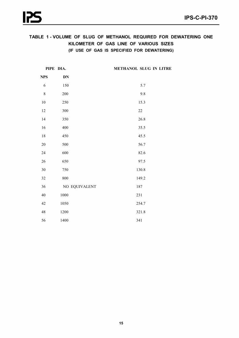
TABLE 1 - VOLUME OF SLUG OF METHANOL REQUIRED FOR DEWATERING ONEKILOMETER OF GAS LINE OF VARIOUS SIZES(IF USE OF GAS IS SPECIFIED FOR DEWATERING)
PIPE DIA. METHANOL SLUG IN LITRE
NPS DN
6 150 5.7
8 200 9.8
10 250 15.3
12 300 22
14 350 26.8
16 400 35.5
18 450 45.5
20 500 56.7
24 600 82.6
26 650 97.5
30 750 130.8
32 800 149.2
36 NO EQUIVALENT 187
40 1000 231
42 1050 254.7
48 1200 321.8
56 1400 341
IPS-C-PI-370
16
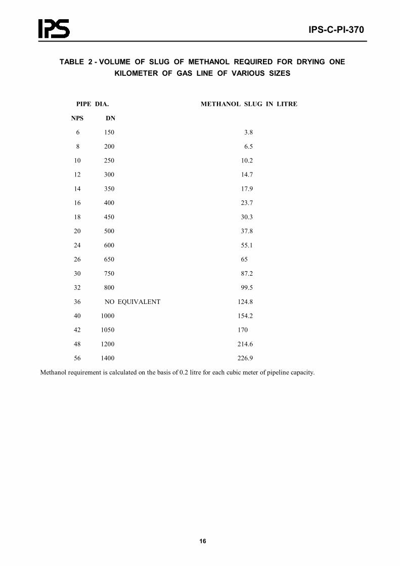
TABLE 2 - VOLUME OF SLUG OF METHANOL REQUIRED FOR DRYING ONEKILOMETER OF GAS LINE OF VARIOUS SIZES
PIPE DIA. METHANOL SLUG IN LITRE
NPS DN
6 150 3.8
8 200 6.5
10 250 10.2
12 300 14.7
14 350 17.9
16 400 23.7
18 450 30.3
20 500 37.8
24 600 55.1
26 650 65
30 750 87.2
32 800 99.5
36 NO EQUIVALENT 124.8
40 1000 154.2
42 1050 170
48 1200 214.6
56 1400 226.9
Methanol requirement is calculated on the basis of 0.2 litre for each cubic meter of pipeline capacity.

IPS-C-PI-370
17
FORM No. 1PIPELINE FAILURE REPORT FORM
1 Company : .........................................................................................................................................................
2 Section tested : ...................................................................................................................................................
3 Time of failure :................................................................ a.mp.m , Date ....................................................................
4 Location of failure: ............................................................................................................................................
5 Pressure in Bar at point of failure: ......................................................................................................................
6 Description of failure: Leak............................Break.......................Length of failure.................................................
7 If leak, fill in blanks:........................................................................................................................liter lost per hour
8 Describe any peculiarities of defects on failed part, such as mill defects, corrosion or evidence of prior damage, etc.: ...................................................................................................................................................................
9 Possible cause of failure : ...................................................................................................................................
10 Pipe size, DN:......................w.t............., grade...............Mfg by .........................................................................
11 Repairs: pipe installed, DN:......... w.t.........., grade........... Mfg by.......................length of joint or pup ................
12 Date repaired :...............................by ..................................................................................................................
13 Damages to property, persons injured etc.: .........................................................................................................
14 Other remarks:

IPS-C-PI-370
18
FORM No. 2TYPICAL TEST REPORT FORM
FIELD PRESSURE AND TEST REPORT
Page.........of..............
Executor: ....................................................................................................................................................................
Pipeline Description: ...................................................................................................................................................
Section Tested: from:.................................................to: ...............................................................................................
Test Section No.:..........................................Length ......................................................................................................
Type and size of pipe DN:........................w.t........................, grade ..............................................................................
Manufacturer: .............................................................................................................................................................
Pressure measuring/recording unit location:..........................................water source .....................................................
Time and date test started: a.mp.m ..................................................................................................Test pressure (maximum
................................barg. Test pressure (minimum)......................................................................................................barg
Time and date test ended: a.mp.m ........................................................Pressure volume plot Yes............. No.............
Section Accepted :.....................................section leaking..............................................section ruptured............................
Temperature Beginning Maximum Minimum Completion
Ambient
Skin

IPS-C-PI-370
19
CONNECTION OF TEMPERATURE RECORDER(TO BE INSTALLED WITHIN 30 m OF EITHER END OF TEST SECTION)
Fig. 1

IPS-C-PI-370
20
APPENDICES
APPENDIX AREMOVAL OF AIR AND CHECK FOR AIR CONTENT IN TEST WATER
To minimize trapped air and check for acceptability of air content in the test water, following procedure shall beadopted:
a) Pumping of water should continue until the filling pig has been received at the receiving header and water isdrained off the line for about 15 minutes.
b) Drain valves should then be closed and test conducted in manner described below:
Drain a certain volume of water off the line and note pressure reduction ( ∆P1) using dead weight tester.
Calculate the pressure reduction ( ∆Po) using formula No. 1
c) The air content in test water is acceptable if 4 P14 Po
meets the following conditions
4 P14 Po
≥ 90% for line sizes ≤ DN 400 (NPS 16 )
4 P14 Po
≥ 95% for line sizes > DN 400
4 Po = mV (X + DEe )
(1)
Where:
∆Po Calculated pressure drop
∆P1 Pressure drop measured by dead weight tester
m Volume of water removed from the line
V Volume of test section
X Compressibility factor of water related to temperature of water
D Outside diameter of the line in mm.
E=2.11 kg/cm2 Young modulus
e Pipe wall thickness in mm.
R.B.
1) Same unit shall be used for m and V
2) When pipes of different wall thickness is used in a test section, value of DEe for each wall thickness
is calculated and the average value shall be inserted in the formula
APPENDIX B

IPS-C-PI-370
21
HYDROSTATIC TESTING OF ABOVE GROUND PIPELINES
Except when specified otherwise in the project specification procedure and test pressure for hydrostatic testing of bur-ied lines shall apply to above ground pipeline. The procedure includes cleaning, gaging, filling, strength test, leak testand dewatering as indicated in previous sections of this standard. Being above ground, acoustic or depleted radioactivesource is not required to locate pig.
Due attention shall be paid to the effect of temperature change on pressure during test period. Use of pressure and tem-perature recorders are not necessary for pressure test of above ground pipelines.
Pipes and connections (flanged or screwed) must not be painted before completion of the test.
For hydrostatic testing all pipe supports shall be in position and completed before testing is undertaken.
Large adjacent lines shall not be tested simultaneously where the weight of the combined test water load may exceedthe load taking of supports.
Care must be exercised to avoid overloading any parts of supporting during hydrostatic testing.
In certain cases (e.g. piping intended for gas service) temporary or additional supporting may be required to adequatelysupport pipeline against weight of the testing medium. After lines have been drained, the temporary piping supportsshall be removed.