contents components for power factor correctionksafelectric.com/pdf/circutor/r1_gb.pdf · computer...
TRANSCRIPT

Page
Automatic regulators introduction 3
Basic concepts for a reactive energy regulator 3
Computer Reactive energy regulators 4
Regulators for contactors 5
Computer 6M MAGIC Series 6
Computer 9G-3T Multi-tariff Series 6-7
Computer D Series and E Series 7
Static Regulators (real time) 8
DF Series, Fast Series and accessories 9
Capacitors
Prismatic capacitors 10-11
CS, CS-6B/Dual voltage, CV and CQ 12-13
Capacitors for rejection fi ltering 14
CF and CF 6B 15
Cilindrical capacitors 16-17
CLZ-FPT and CLZ-FP 18-19
Reactors for rejection fi ltering: R, RB, RX, RBX, RBC, RE and RBE 20-21
Static (real time) operation units EM: EMF and EMB 22-23
RACK 24
Accessories 25
Recommendations for the assembly of capacitor banks 26-28
CLZ Cilyndrical capacitors and reactors for making electro-mechanical rejection fi lters 29
Components for making steps using a static system (real time) 29
Dimensions 30-32
CONTENTS
Com
pone
nts
for
pow
er fa
ctor
cor
rect
ion
R1/2-2R1/2-2
R.1/2

Automatic regulators introduction
Computer reactive energy regulators measure cos ϕ in the installation, checking the connection and disconnection of the steps or power fractions into which the capacitor bank is divided. By doing this, the target programmed cos ϕ is achieved.
The whole range of computer regulators is based on the FCP system (Fast Computerized Program), which gives the regulator the capacity to accurately inform on the status of the system and to take decisions to obtain the best regulation.
The FCP system also allows:The minimisation of a number of operations, increasing the life
of the parts in the capacitor bankThe increase of the equipment’s response speed improving
energy and saving costs
•
•
Basic concepts for a reactive energy regulator
Measurement function
Regulators operate by measuring current and voltage in the power system.Current measurement is carried out single-phase using a current transformer located in a phase at the start of the installation.Voltage measurement is by direct connection to the other two phases.
It is necessary to respect the sequence order (L1, L2, L3) of the phases depending on the type of regulator for it to operate properly.
First step current and C/K
In order to operate, the computer regulators need to know the ratio between the current measurement transformer (k) and the current in the fi rst step of the bank (Ic). This ratio is known as the C/K parameter.
This value may be given in two ways:Entering the current of the fi rst step and the current transformer primary.Directly calculating the coeffi cient.
Connection programs
The capacitor banks are divided into power steps. The connection program defi nes the existing proportion between the fi rst step in the remaining steps in the bank.The usual connection programs are:
The reason for the different connection programs is to facilitate better setting for reactive power demand in the installation.
Number of steps or regulator outputs
This is the number of steps or fractions which the regulator may operate.
••
1:1:1:1 1:2:2:2 1:2:4:4 1:2:4:8 1:1:2:2
R1/2-3R1/2-3
Com
pone
nts
for
pow
er fa
ctor
cor
rect
ion
R.1/2

Connection and safety time.
The regulator operates with two basic parameters for the capacitors to work properly: connection time and safety time.
Connection time (Tr).In order to avoid an excessive number of operations, the regulator waits are a few seconds before giving the connection command. In this way the computer regulator avoids connection at an instant power point.
Safety or reconnection time (Ts).Once a step has been disconnected, a discharge time is required to prevent the capacitor being quickly reconnected without having had time to discharge. This is the reconnection time.As a general criterion, there is a relationship between connection time (Tr) and safety time (Ts) of Ts = 5 Tr
Four quadrant regulator.
Capacity for measuring cos ϕ and regulating capacitor banks even if active power fl ows:From system to load, i.e. the usual installation.From load to system, i.e. energy generating installations
•
•
••
Computer reactive energy regulators
Regulators for banks with static contactors
Multi-tariff reactive system regulation + 3 cos ϕ settings
Reactive regulation Real time correction (20 ms)
Reactive regulation +
measurement functions
Fast correction (100 ms) + measurement
functions
Regulators for banks with electro-mechanical contactors
e Series Magic Series
computer6e
computer6m
computer12e
computer12m
dSeries
computer8d
computer14d
9G-3TSeries
computer9G-3T
FastComSeries
computerFastCom 12rt
dfSeries
computer8df
computer14df
Com
pone
nts
for
pow
er fa
ctor
cor
rect
ion
R1/2-4R1/2-4
R.1/2

Regulators for Contactors
For power factor correction in variable loads, the computer regulators accurately track the existing load curve making cos ϕ attain programmed target values.
The computer regulators give the operation command to the bank’s steps with a minimum connection response time of 4 seconds (programmable).
The bank’s reactive power will be disconnected if it is not required.
Computer MAGIC Series
The MAGIC series regulators are a new range of high technology regulators designed for simple and effective regulation.The MAGIC series has also been designed for easy and intuitive handling.
The performance of MAGIC:
High accuracy regulationParameter confi guration in RUN-TIME, i.e. without having to
disconnect the unitTotally digital setting and handling4 Alarm Levels:
- Low load current or current transformer not connected - Wrong phase connection - Over correction - Lack of correction
Parameters on display
MAGIC includes an LCD display where the following data may be shown:
Cos ϕ in the installationSignalling the connected stepsNature of the load, inductive or capacitiveProgramming menu tracking cursorAlarm
••
••
•••••Connections
Connecting the MAGIC is very easy, as shown in the diagram. MAGIC has to be connected at the head of the installation where all loads in installation are measured. For it to work correctly it is important to maintain the phase sequence in the connection, as shown. If this is not the case, the regulator will set off the relevant alarm.A current transformer also has to be mounted for the installation’s current signal.This diagram is also valid for other operating voltages.
Computer 8d / 14d SeriesMain features
Current and THD (I) measurement function where the measurement is taken. Alarm functions: overcurrent, harmonic distortion, lack of correction, overvoltage and wrong correction.Option for remote signalling using alarm relay
•••
R1/2-5R1/2-5
Com
pone
nts
for
pow
er fa
ctor
cor
rect
ion
R.1/2

COMPUTER MULTI-TARIFF 9G-3T Series
The MULTI-TARIFF regulators are designed to check reactive energy in electrical systems with three target cos ϕ.To do this, the regulator independently measures and regulates cos ϕ in each hourly slot.This regulator is for energy generating stations.That is to say, for wind power generation stations, solar power stations and hydraulic stations.
Main features
3 target cos ϕ settings.
Changing the cos ϕ setting is done via a pulse from an energy meter. There are three terminals for this. The use of CIRWATT energy meters is recommended.
4 quadrant regulationConnection type selection (situation of the current transformer).Measurement of power consumed and generated.Display in the event of an alarm.9 available steps.
Parameters on display
In addition to the functions which the MAGIC series includes the multi-tariff regulator also has T1, T2, T3 signalling the period in which it is operating.
•
•
•••••
T1 0,95 Inductive T2 1 T3 0,95 Capacitive
Computer 8d / 14d Computer 6m / 12m Computer 6e / 12e Computer 9G-3T
8d 14d 6m 12m 6e 12e
Voltage circuit
Power supply voltage 230 / 400 V a.c. 400 V a.c. (*) 230 V a.c./ 400 V a.c.
400 V a.c. (*) 400 V a.c. (*)
Voltage tolerance ±15 % +15% / -10% ±15 % ±15 %
Consumption with all relays connected 5 V·A 10 V·A 3 V·A 4 V·A 5 V·A 6 V·A 4V·A
Frequency 45...65 Hz
Current circuit
Consumption 0,5 V·A 0,5 V·A 0,5 V·A 0,5 V·A
Rated current (In) 5 A 5 A 5 A 5 A
Output relay
Maximum voltage 400 V a.c. 250 V a.c. 250 V a.c. 250 V a.c.
Rated current 10 A 10 A 10 A 10 A
Electrical life (no. of operations at full load) 100 000 100 000 500 000 100 000
Alarm relay
Maximum voltage 400 V a.c. - - -
Rated current 10 A - - -
Electrical life (no. of operations at full load) 100 000 - - -
Assembly features
Working temperature -10 / +50 ºC -10 oC / +50 oC -10 oC / +50 oC -10 oC / +50 oC
Mounting Panel
Connection Plug type terminal bloock Terminal block
Protection grade IP 54 (front) IP 31 (rear)
IP 52 (front)IP 31 (rear)
Performance
Built in control system FCP
Cos ϕ setting 0,80 L - 0,95 C 0,85 L - 0,95 C 0,85 L - 0,95 C 0,85 L - 0,95 C
Cos ϕ display Display (3 digits) Display (3 digits) Display (2 digits) Display (3 digits)
Connection programs 1.1.1.1 / 1.2.2.2 / 1.2.4.4 / 1.2.4.8 / 1.1.2.2
No. of output relays 3 / 6 / 8 10 / 12 / 14 6 12 3 / 6 8 / 10 / 12 9
Connection delay Tr 4 a 999 s 4 a 999 s 4 ; 10 ; 30 ; 60 s 4 a 999 s
Safety delay Ts 5 · Tr
Standards EN 61010, IEC 1010-1, EN 50081-2, EN 50082-2
Features
(*) Other voltages on request
Com
pone
nts
for
pow
er fa
ctor
cor
rect
ion
R1/2-6R1/2-6
R.1/2

110 V a.c. 6 - 144 x 144 computer 6m R10811001
110 V a.c. 12 - 144 x 144 computer 12m R10812001
230 V a.c. 6 - 144 x 144 computer 6m R10811002
230 V a.c. 12 - 144 x 144 computer 12m R10812002
400 V a.c. 6 - 144 x 144 computer 6m R10811
400 V a.c. 12 - 144 x 144 computer 12m R10812
480 V a.c. 6 - 144 x 144 computer 6m R10811001
480 V a.c. 12 - 144 x 144 computer 12m R10812004
Magic Series
D Series
Power supply voltage
No. of steps Alarm Dimensions Type Code
230 / 400 V a.c. 3 - 96 x 96 computer 8d-3-96 R10111
230 / 400 V a.c. 6 - 96 x 96 computer 8d-6-96 R10112
230 / 400 V a.c. 8 - 96 x 96 computer 8d-8-96 R10113
230 / 400 V a.c. 6 yes 96 x 96 computer 8d-6-96a R10114
230 / 400 V a.c. 8 yes 96 x 96 computer 8d-8-96a R10115
230 / 400 V a.c. 3 - 144 x 144 computer 8d-3-144 R10121
230 / 400 V a.c. 6 - 144 x 144 computer 8d-6-144 R10122
230 / 400 V a.c. 8 - 144 x 144 computer 8d-8-144 R10123
230 / 400 V a.c. 6 yes 144 x 144 computer 8d-6-144a R10124
230 / 400 V a.c. 8 yes 144 x 144 computer 8d-8-144a R10125
230 / 400 V a.c. 10 yes 144 x 144 computer 14d-10-144a R10211
230 / 400 V a.c. 12 yes 144 x 144 computer 14d-12-144a R10212
230 / 400 V a.c. 14 yes 144 x 144 computer 14d-14-144a R10213
E Series
230 / 400 V a.c. 3 - 144 x 144 computer 6e-3 R10511
230 / 400 V a.c. 6 - 144 x 144 computer 6e-6 R10512
400 V a.c. 8 - 144 x 144 computer 12e-8 R10711
400 V a.c. 10 - 144 x 144 computer 12e-10 R10712
400 V a.c. 12 - 144 x 144 computer 12e-12 R10713
9G-3T Series
110 V a.c. 9 - 144 x 144 9G-3T R11100001
400 V a.c. 9 - 144 x 144 9G-3T R11100
R1/2-7R1/2-7
Com
pone
nts
for
pow
er fa
ctor
cor
rect
ion
R.1/2

Features
computer 8df / 14df computer Fast-comp 12rt
Voltage circuit 8df 14df
Power supply voltage 230 / 400 V a.c. 400 V a.c. (*)
Voltage tolerance ±15 %
Consumption 5 V·A 10 V·A 3 V·A
Frequency 45...65 Hz
Current circuit
Consumption 0,5 V·A 0,5 V·A
Rated current (In) 5 A 5 A
Static regulators (real time)
Regulating reactive energy using a static system is ideal for installations which are sensitive to transients or with very fast reactive power fl uctuations (< 0.2 s).
In order to do so, instant regulation and/or free of transient connection is required.
There are two types of fast regulators depending on the speed of load fl uctuation:
Computer 8df/14df regulators. Response time 0.1 seconds.Computer Fast-comp regulators, real time regulation from 20 ms.
•
•
(*) Other voltages on request
Fast-comp series regulators is a new range of rapid regulators with a 20 ms response time especially for real time correction requirements.
Main features
Adjustable response time from 20 ms.Regulation in 2 or 4 quadrants in terms of load requirements.Option for correcting using a FCP or lineal system.Connection selection (current transformer wiring).12 steps available.
Parameters on display.
The Fast-comp regulator includes MAGIC series functions plus type of connection monitoring.
Applications
Installations such as, foundries, lifts and lifting equipment, cranes, welding installations, hospitals, etc.
•••••
Computer Fast-Comp 12rt Series
computer 8df / 14df computer Fast-comp 12rt
Outputs
N° of outputs 8 14 12
Maximum voltage 200 V d.c. / 200 VPEAHK a.c.
Maximum current 100 mA 100mA
Alarm relay
Maximum voltage 400 V a.c. -
Rated current 10 A -
Electrical life (No. of operations at full load) 100 000 -
Computer 8df / 14df Series
Main features
Current and THD (I) measurement function where the measurement is taken. Alarm functions: overcurrent, harmonic distortion, lack of correction, overvoltage and wrong correction.Option for remote signalling using alarm relayResponse time 0.1 seconds.
••••
Com
pone
nts
for
pow
er fa
ctor
cor
rect
ion
R1/2-8R1/2-8
R.1/2

Power supply voltage
No. of steps Alarm Dimensions Type Code
230 / 400 V a.c. 8 yes 96 x 96 computer 8df-8-96a R10311
230 / 400 V a.c. 8 yes 144 x 144 computer 8df-8-144a R10321
230 / 400 V a.c. 14 yes 144 x 144 computer 14df-14-144a R10411
DF Series
Power supply voltage
No. of steps Alarm Dimensions Type Code
400 V a.c. 12 -- 144 x 144 Fast-Comp 12 rt-144 R10912
FAST Series
Accessories
Rated current (In)
Trip time (settable) Type Code
10 A 0,5 ... 30 s WDH / 010-30 P32022
20 A 0,5 ... 30 s WDH / 020-30 P32023
50 A 0,5 ... 30s WDH / 050-30 P32024
100 A 0,5 ... 30 s WDH / 100-30 P32025
... / 5 A* 0,5 ... 30 s WDH / TS-30 P32020
*Separate current transformer – Trip setting 5 ... 50% In – Maximum current: 2 In permanent
RS-485 Communications module(Includes EASYCOMM Software)(for 14d and 14df computer only)
R18011
Current harmonic relay
Fig. 1
Dimensions Type Code Figura
6 mód. Royal A4-P M20241 fi g.1
96 x 48 Royal A4 M20242 fi g.2
- Measuring de V, A, Hz, W, V·A, var, cos ϕ demand, THD in single-phase or three-phase balanced systems
Reactive current and harmonic relays
Fig. 2
Computer 8df / 14df Computer Fast Comp 12rt
Assembly features
Working temperature -10 / +50 ºC -10oC / +50oC
Mounting Panel
Connection Plug type terminal block Terminal block
Protection grade IP 54 (front) IP 31 (rear)
IP 52 (front)IP 31 (rear)
Standards EN 61010, IEC 1010-1, EN 50081-2, EN 50082-2
(*) Other voltages on request
Computer 8df / 14df Computer Fast Comp 12rt
Performance
Built in control system FCP FCP and linear
Cos ϕ setting 0,80 L - 0,95 C 0,85 L - 0,95 C
Cos ϕ display Display (3 digits)
Connection programs 1.1.1.1 / 1.2.2.2 / 1.2.4.4 / 1.2.4.8 / 1.1.2.2
No. of output relays 8 14 12
Connection delay Tr 0,1 to 9,99 s 20 ms to 2 s
Safety delay Ts 0,1 to 9,99 s 20 ms to 2 s
Phase selection yes
R1/2-9R1/2-9
Com
pone
nts
for
pow
er fa
ctor
cor
rect
ion
R.1/2

Prismatic capacitors
CS prismatic capacitors are dry capacitors covering every power and voltage range at both 50 and 60 Hz.
Their design as well as their manufacturing process and testing give the CS prismatic capacitors a high degree of quality and an extremely long life.
Technology
The prismatic capacitors are equipped with different basic capacities. These capacities are confi gured to obtain the required voltage and power.
Basic coils
The basic coils are made with metalised polypropylene and are encapsulated in heat resistant polyethylene resin. The system gives the basic capacity great electrical and mechanical strength.
CS prismatic capacitor
The basic coil set is located in a metal casing fi lled with vermiculite. This component offers a great degree of safety given its dielectric property as an inert, non fl ammable material.
Connection cable
Silver fuse wire
Hardened resin
Metalised polypropylene fi lm
Thermostable resin
Protection levels
In the event of a fault:Level 1. The zinc coating evaporates at the point of the “ fault” and therefore the arc disappearsLevel 2. If the current is large (high-voltage, harmonics) the internal fuse disconnects the basic capacityLevel 3. If the fault is not limited by the fuse, gases are generated inside the faulty capacitor
and raising the overpressure cover disconnects the basic capacitor.Level 4. For better safety, the VERMICULITE (inert and fi reproof) prevents any form of fi re.
•••
•
Level 1. Self-regeneration Level 2. Internal fuse Level 3. Over pressure table
Demetalised area Zinc coating
Demetalised strip Fault
Level 4. Vermiculite
Com
pone
nts
for
pow
er fa
ctor
cor
rect
ion
R1/2-10R1/2-10
R.1/2
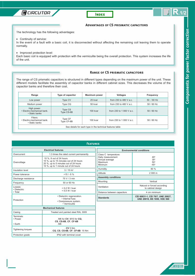
Electrical features
Overcurrent 1.3 times the rated current permanently
Overvoltage
10 %, 8 out of 24 hours15 %, up to 15 minutes out of 24 hours20 %, up to 5 minutes out of 24 hours15 %, up to 1 minute out of 24 hours
Insulation level 3 / 15 kV
Power tolerance +15 / -5 %
Discharge resistance 75 V / 3 min
Frequency 50 or 60 Hz
Losses:• Dielectric• Total
< 0,2 W / kvar< 0,5 W / kvar
Protection
• Dielectric regeneration.• Internal fuse.
• Overpressure system.• Vermiculite
Mechanical features
Casing Treated and painted steel RAL 3005
Terminals:• Power
• Earth
. M6 for CV, M10 for CQ, CS, CS-6B, CF, CF-6B . M6
Tightening torques . CV 5 Nm . CQ, CS, CS-6B, CF, CF-6B: 15 Nm
Protection grade IP42 with terminal cover
Features
Environmental conditions
Class C temperature:Daily measurementAnnual averageMaximumMinimum
40o
30o
50o
-40o
Humidity 80 %
Altitude 2 000 m
Assembly conditions
Mounting Vertical
Ventilation Natural or forced according to cabinet design
Distance between capacitors 4 cm minimum
Standards CEI 60831-1, CEI 70/7, UNE 20827, UNE 20010, BS 1650, VDE 560
Advantages of CS prismatic capacitors
The technology has the following advantages:
Continuity of service:In the event of a fault with a basic coil, it is disconnected without affecting the remaining coil leaving them to operate normally.
Improved protection level:Each basic coil is equipped with protection with the vermiculite being the overall protection. This system increases the life of the unit.
•
•
Range of CS prismatic capacitors
The range of CS prismatic capacitors is structured in different types depending on the maximum power of the unit. These different models facilitate the assembly of capacitor banks in different cabinet sizes. This decreases the volume of the capacitor banks and therefore their cost.
Range Type of capacitor Maximum power Voltages Frequency
Low power Type CV 25 kvar from 230 to 480 V a.c. 50 / 60 Hz
Medium power Type CQ 50 kvar from 230 to 480 V a.c. 50 / 60 Hz
High power:• Electro-mechanical bank.
• Static banks
Type CSType CS-6B 100 kvar from 230 to 1 000 V a.c. 50 / 60 Hz
Filters:• Electro-mechanical bank.
• Static banks
Type CFType CF-6B 100 kvar from 230 to 1 000 V a.c. 50 / 60 Hz
See details for each type in the technical features table
R1/2-11R1/2-11
Com
pone
nts
for
pow
er fa
ctor
cor
rect
ion
R.1/2

CS
50 Hz 60 Hz 230 Vkvar kg Dimensions Type Code
10 12,5 6,5 360 x 390 x 120 CS-23/10 R2021C
12,5 15 8 360 x 390 x 120 CS-23/12,5 R2021D
15 17,5 8 360 x 390 x 120 CS-23/15 R2021E
20 25 11,5 360 x 390 x 120 CS-23/20 R2021F
25 30 13 360 x 390 x 120 CS-23/25 R2021G
30 35 14,5 360 x 610 x 120 CS-23/30 R2021H
40 50 15 360 x 610 x 120 CS-23/40 R2021J
50 60 16,5 360 x 760 x 120 CS-23/50 R2021K
50 Hz 60 Hz 400 Vkvar kg Dimensions Type Code
15 17,5 6,5 360 x 390 x 120 CS-40/15 R2023E
20 25 7,5 360 x 390 x 120 CS-40/20 R2023F
25 30 7,5 360 x 390 x 120 CS-40/25 R2023G
30 35 8 360 x 390 x 120 CS-40/30 R2023H
40 50 9,5 360 x 390 x 120 CS-40/40 R2023J
50 60 12 360 x 390 x 120 CS-40/50 R2023K
60 70 13 360 x 610 x 120 CS-40/60 R2023L
80 95 15 360 x 610 x 120 CS-40/80 R2023Q
100 120 18,5 360 x 760 x 117 CS-40/100 R2023R
50 Hz 60 Hz 440 Vkvar kg Dimensions Type Code
15 17,5 4,1 360 x 390 x 120 CS-44/15 R2024E
20 25 4,9 360 x 390 x 120 CS-44/20 R2024F
25 30 4,9 360 x 390 x 120 CS-44/25 R2024G
30 35 4,9 360 x 390 x 120 CS-44/30 R2024H
40 50 6,4 360 x 390 x 120 CS-44/40 R2024J
50 60 9,5 360 x 390 x 120 CS-44/50 R2024K
60 70 9,5 360 x 390 x 120 CS-44/60 R2024L
80 95 12,5 360 x 610 x 120 CS-44/80 R2024Q
100 120 15,6 360 x 610 x 120 CS-44/100 R2024R
50 Hz 60 Hz 460 Vkvar kg Dimensions Type Code
15 17,5 6 360 x 390 x 120 CS-46/15 R2025E
20 25 6,5 360 x 390 x 120 CS-46/20 R2025F
25 30 7 360 x 390 x 120 CS-46/25 R2025G
30 35 8 360 x 390 x 120 CS-46/30 R2025H
40 50 9,5 360 x 390 x 120 CS-46/40 R2025J
50 60 12 360 x 610 x 120 CS-46/50 R2025K
60 70 13 360 x 610 x 120 CS-46/60 R2025L
80 95 15 360 x 760 x 120 CS-46/80 R2025Q
100 120 18,5 360 x 760 x 120 CS-46/100 R2025R
50 Hz 60 Hz 480 Vkvar kg Dimensions Type Code
8 10 4,9 360 x 390 x 120 CS-48/10 R288AC
12,5 15 4,9 360 x 390 x 120 CS-48/15 R288AE
16,7 20 4,9 360 x 390 x 120 CS-48/20 R288AF
20,8 25 6,4 360 x 390 x 120 CS-48/25 R288AG
25 30 7,9 360 x 390 x 120 CS-48/30 R288AH
33,3 40 7,9 360 x 610 X 120 CS-48/40 R288AJ
41,7 50 11 360 x 610 X 120 CS-48/50 R288AK
50 60 14 360 x 610 X 120 CS-48/60 R288AL
66,7 80 17,1 360 x 760 X 120 CS-48/80 R288AQ
83,8 100 17,1 360 x 760 X 120 CS-48/100 R288AR
50 Hz 60 Hz 500 Vkvar kg Dimensions Type Code
10 12,5 7 360 x 390 x 120 CS-50/10 R202CD
15 17,5 8 360 x 390 x 120 CS-50/15 R202CE
20 25 8,5 360 x 390 x 120 CS-50/20 R202CF
25 30 9 360 x 390 x 120 CS/50/25 R202CG
30 35 9 360 x 390 x 120 CS-50/30 R202CH
40 50 14 360 x 390 x 120 CS-50/40 R202CJ
50 60 15 360 x 390 x 120 CS-50/50 R202CK
60 70 17 360 x 390 x 120 CS-50/60 R202CL
80 95 22 360 X 760 X 120 CS-50/80 R202CQ
100 - 24 360 X 760 X 120 CS-50/100 R202CR
50 Hz 60 Hz 690 Vkvar kg Dimensions Type Code
10 12,5 4,9 360 x 390 x 120 CS-69/10 R202BC
15 17,5 4,9 360 x 390 x 120 CS-69/15 R202BE
20 25 4,9 360 x 390 x 120 CS-69/20 R202BF
25 30 6,4 360 x 390 x 120 CS-69/25 R202BG
30 35 7,9 360 x 610 X 120 CS-69/30 R202BH
40 50 7,9 360 x 390 x 120 CS-69/40 R202BJ
50 60 11 360 x 390 x 120 CS-69/50 R202BK
60 70 14 360 x 390 x 120 CS-69/60 R202BL
80 95 17,1 360 x 610 X 120 CS-69/80 R202BQ
100 - 22 360 x 610 X 120 CS-69/100 R202BR
50 Hz 60 Hz 1 100 Vkvar kg Dimensions Type Code
10 17,5 5.5 360 x 390 x 120 CS-110/10 R2027C
20 30 7.5 360 x 390 x 120 CS-110/20 R2027F
30 50 9.5 360 x 610 X 120 CS-110/30 R2027H
40 60 12 360 x 610 X 120 CS-110/40 R2027J
50 70 17 360 x 610 X 120 CS-110/50 R2027K
60 95 17,5 360 x 610 X 120 CS-110/60 R2027L
70 120 18,5 360 x 760 X 120 CS-110/70 R2027M
Com
pone
nts
for
pow
er fa
ctor
cor
rect
ion
R1/2-12R1/2-12
R.1/2

CS-6B / DUAL VOLTAGE
kvar 230 / 400 V50 Hz 60 Hz kg Dimensions Type Code
5 6 6,5 360 x 390 x 120 CS-2340/5 R20288
7,5 9 6,5 360 x 390 x 120 CS-2340/7,5 R2028A
10 12,5 8 360 x 390 x 120 CS-2340/10 R2028C
12,5 15 9 360 x 390 x 120 CS-2340/12,5 R2028D
15 17,5 9 360 x 390 x 120 CS-2340/15 R2028E
20 25 12 360 x 390 x 120 CS-2340/20 R2028F
25 30 14,5 360 x 390 x 120 CS-2340/25 R2028G
30 35 15 360 x 610 x 120 CS-2340/30 R2028H
40 50 15,5 360 x 610 x 120 CS-2340/40 R2028J
kvar 400 / 690 V50 Hz 60 Hz kg Dimensions Type Code
5 6 2,5 360 x 610 x 120 CS-4069/5 R20298
7,5 9 3,5 360 x 610 x 120 CS-4069/7,5 R2029A
10 12,5 4,5 360 x 610 x 120 CS-4069/10 R2029C
12,5 15 5 360 x 610 x 120 CS-4069/12,5 R2029D
15 17,5 6 360 x 610 x 120 CS-4069/15 R2029E
20 25 6,5 360 x 610 x 120 CS-4069/20 R2029F
25 30 7 360 x 610 x 120 CS-4069/25 R2029G
30 35 7,5 360 x 610 x 120 CS-4069/30 R2029H
40 50 8,5 360 x 610 x 120 CS-4069/40 R2029J
50 60 10,5 360 x 610 x 120 CS-4069/50 R2029K
60 70 13,5 360 x 610 x 120 CS-4069/60 R2029L
80 95 15 360 x 610 x 120 CS-4069/75 R2029
CV CQ
50 Hz 60 Hz 230 Vkvar kg Dimensions Type Code
2,5 3 3 204 x 435 x 75 CV-23/2,5 R20114
3,75 4,5 3,5 204 x 435 x 75 CV-23/3,75 R20116
5 6 3,5 204 x 435 x 75 CV-23/5 R20118
7,5 9 4 204 x 435 x 75 CV-23/7,5 R2011A
10 12,5 4 204 x 435 x 75 CV-23/10 R2011C
12,5 15 4,5 204 x 435 x 75 CV-23/12,5 R2011D
15 17,5 4,5 204 x 435 x 75 CV-23/15 R2011E
50 Hz 60 Hz 230 Vkvar kg Dimensions Type Code
10 12,5 4,9 360 x 520 x 75 CQ-23/10 R2031C
12,5 15 4,9 360 x 520 x 75 CQ-23/12,5 R2031D
15 17,5 4,9 360 x 520 x 75 CQ-23/15 R2031E
20 25 6,4 360 x 520 x 75 CQ-23/20 R2031F
25 30 7,9 360 x 520 x 75 CQ-23/25 R2031G
30 35 7,9 360 x 520 x 75 CQ-23/30 R2031H
50 Hz 60 Hz 400 Vkvar kg Dimensions Type Code
2,5 3 2,5 204 x 435 x 75 CV-40/2,5 R20134
5 4,5 2,5 204 x 435 x 75 CV-40/5 R20138
7,5 9 3 204 x 435 x 75 CV-40/7,5 R2013A
10 12,5 3 204 x 435 x 75 CV-40/10 R2013C
12,5 15 3,5 204 x 435 x 75 CV-40/12,5 R2013D
15 17,5 4,5 204 x 435 x 75 CV-40/15 R2013E
20 25 4,5 204 x 435 x 75 CV-40/20 R2013F
25 30 6,5 204 x 435 x 75 CV-40/25 R2013G
50 Hz 60 Hz 400 Vkvar kg Dimensions Type Code
10 12,5 4 360 x 520 x 75 CQ-40/10 R2033C
12,5 15 4,5 360 x 520 x 75 CQ-40/12,5 R2033D
15 17,5 5 360 x 520 x 75 CQ-40/15 R2033E
20 25 6 360 x 520 x 75 CQ-40/20 R2033F
25 30 6 360 x 520 x 75 CQ-40/25 R2033G
30 35 6 360 x 520 x 75 CQ-40/30 R2033H
40 50 7 360 x 520 x 75 CQ-40/40 R2033J
50 60 9 360 x 520 x 75 CQ-40/50 R2033K
50 Hz 60 Hz 460 Vkvar kg Dimensions Type Code
2,5 3 1 204 x 435 x 75 CV-46/2,5 R20154
5 6 1 204 x 435 x 75 CV-46/5 R20158
7,5 9 1,5 204 x 435 x 75 CV-46/7,5 R2015A
10 12,5 1,5 204 x 435 x 75 CV-46/10 R2015C
12,5 15 2 204 x 435 x 75 CV-46/12,5 R2015D
15 17,5 3 204 x 435 x 75 CV-46/15 R2015E
50 Hz 60 Hz 460 Vkvar kg Dimensions Type Code
10 12,5 4,1 360 x 520 x 75 CQ-46/10 R2035C
12,5 15 4,1 360 x 520 x 75 CQ-46/12,5 R2035D
15 17,5 4,1 360 x 520 x 75 CQ-46/15 R2035E
20 25 4,9 360 x 520 x 75 CQ-46/20 R2035F
25 30 4,9 360 x 520 x 75 CQ-46/25 R2035G
30 35 4,9 360 x 520 x 75 CQ-46/30 R2035H
40 50 7,9 360 x 520 x 75 CQ-46/40 R2035J
50 60 7,9 360 x 520 x 75 CQ-46/50 R2035K
6 Terminals
R1/2-13R1/2-13
Com
pone
nts
for
pow
er fa
ctor
cor
rect
ion
R.1/2

Capacitors for detuned fi lters, CF series
CF capacitors are designed to be assembled with RB series reactors. This means, reactors for rejection fi lters at 7% (189 Hz).
CF capacitors for rejection fi lters have been designed to take into account the following:
• System operating voltage.• Increase in voltage caused by the fi lter reactance.• Capacitive power used by the reactor.• Safety margin for possible overloads by harmonics.
Therefore, the capacitor is sized so that power stated in the data tables is given the system’s service voltage.
System voltageThe CF capacitor range is divided into two types in terms of their confi guration:Three terminal CF capacitor for electro-mechanical banksSix terminal CF -6B capacitor for static banks
50 Hz SystemSystem voltage (V) Serie Capacitor voltage (V) Type of operation
400 CF 46 460 Electro-mechanical
400 CF 46-6B 460 Static
690 CF 79 790 Electro-mechanical
60 Hz System230 CF 26 260 Electro-mechanical
440 CF 50 500 Electro-mechanical
460 CF 55 525 Electro-mechanical
480 CF 55 550 Electro-mechanical
The following table proposes an explanatory example for the use of a CF capacitor with RB reactor.
Power delivered by the capacitor + reactor: 80 kvar at 400 V.Power delivered by the capacitor: 75 kvar at 400 V.
RB-70-400 reactor set with CF-46/100 capacitor:
. Rated voltage CF, 460 V at 50 HZ
. Rated power 100 kvar
. Effective power at 400 V with 80 kvar reactor in series
CF-46/100 capacitor:
. Rated voltage 460 V at 50 Hz
. Rated power 100 kvar
. Effective power at 400 V, 74 kvar
80 kvar at 400 V
Com
pone
nts
for
pow
er fa
ctor
cor
rect
ion
R1/2-14R1/2-14
R.1/2

CF 790 Vkvar(*)
Weight kg Dimensions Type Code
5 6 360 x 390 x 120 CF 79/6 R211DA
10 6 360 x 390 x 120 CF 79/12,5 R211DD
15 6,5 360 x 390 x 120 CF 79/19 R211DF
20 7,5 360 x 390 x 120 CF 79/25 R211DG
25 8 360 x 390 x 120 CF 79/30 R211DH
30 9,5 360 x 390 x 120 CF 79/37 R211DT
40 12 360 x 390 x 120 CF 79/50 R211DK
50 16 360 x 390 x 120 CF 79/62 R211DL
60 18,5 360 x 610 x 120 CF 79/74 R211DP
80 19 360 x 610 x 120 CF 79/100 R211DR
CF 460Vkvar(*)
Weight kg Dimensions Type Code
5 6 360 x 390 x 120 CF 46/6 R2115A
10 6 360 x 390 x 120 CF 46/12,5 R2115D
12,5 6,5 360 x 390 x 120 CF 46/15 R2115E
15 6,5 360 x 390 x 120 CF 46/19 R2115F
20 7 360 x 390 x 120 CF 46/25 R2115G
25 8 360 x 390 x 120 CF 46/30 R2115H
30 9,5 360 x 390 x 120 CF 46/37 R2115J
40 12 360 x 610 x 120 CF 46/50 R2115K
50 16 360 x 610 x 120 CF 46/62 R2115L
60 18,5 360 x 610 x 120 CF 46/74 R2115P
80 20 360 x 760 x 117 CF 46/100 R2115R
CF 260 Vkvar(*)
Weight kg Dimensions Type Code
5 7 360 x 390 x 120 CF 26/5 R2112C001
10 8 360 x 390 x 120 CF 26/10 R2112I001
12,5 8,5 360 x 390 x 120 CF 26/15 R2112D001
15 8,5 360 x 390 x 120 CF 26/20 R2112M001
20 9,5 360 x 390 x 120 CF 26/25 R2112P001
25 9,5 360 x 390 x 120 CF 26/30 R2112G001
30 13 360 x 610 x 120 CF 26/40 R2112H001
40 16,5 360 x 610 x 120 CF 26/50 R2112Q001
CF 500 V kvar(*)
Weight kg Dimensions Type Code
5 6 360 x 390 x 120 CF 50/6 R211CA001
10 6 360 x 390 x 120 CF 50/12,5 R211CD001
12,5 6,5 360 x 390 x 120 CF 50/15 R211CE001
15 6,5 360 x 390 x 120 CF 50/19 R211CF001
20 8 360 x 390 x 120 CF 50/25 R211CG001
25 8 360 x 390 x 120 CF 50/30 R211CH001
30 9,5 360 x 390 x 120 CF 50/37 R211CJ001
40 12 360 x 610 x 120 CF 50/50 R211CK001
50 16 360 x 610 x 120 CF 50/62 R211CL001
60 18,5 360 x 610 x 120 CF 50/74 R211CP001
80 21 360 x 760 x 120 CF 50/100 R211CR001
CF 525 Vkvar(*)
Weight kg Dimensions Type Code
5 6 360 x 390 x 120 CF 55/7 R2116C001
10 6 360 x 390 x 120 CF 55/15 R2116E001
12,5 6,5 360 x 390 x 120 CF 55/18 R2116F001
15 6,5 360 x 390 x 120 CF 55/22 R2116G001
20 8 360 x 390 x 120 CF 55/29 R2116H001
25 10 360 x 390 x 120 CF 55/37 R2116J001
30 11 360 x 610 x 120 CF 55/44 R2116K001
45 14 360 x 610 x 120 CF 55/59 R2116L001
55 17,1 360 x 610 x 120 CF 55/73 R2116P001
65 20,2 360 x 760 x 120 CF 55/88 R2116S001
90 21,7 360 x 760 x 120 CF 55/117 R2116T001
CF 550 V kvar(*)
Weight kg Dimensions Type Code
5 6 360 x 390 x 120 CF 55/7 R2116C001
12,5 6 360 x 390 x 120 CF 55/15 R2116E001
15 6,5 360 x 390 x 120 CF 55/18 R2116F001
17,5 6,5 360 x 390 x 120 CF 55/22 R2116G001
25 8 360 x 390 x 120 CF 55/29 R2116H001
30 10 360 x 390 x 120 CF 55/37 R2116J001
35 11 360 x 610 x 120 CF 55/44 R2116K001
50 14 360 x 610 x 120 CF 55/59 R2116L001
60 17,1 360 x 610 x 120 CF 55/73 R2116P001
70 20,2 360 x 760 x 120 CF 55/88 R2116S001
95 21,7 360 x 760 x 120 CF 55/117 R2116T001
CF 50 Hz CF 60 Hz
CF 6B 50 Hz
CF 460-6B V kvar(*)
Weight kg Dimensions Type Code
5 6 360 x 390 x 120 CF- 46/6-6B R2125A
10 6 360 x 390 x 120 CF 46/12,5-6B R2125D
15 6,5 360 x 390 x 120 CF 46/19-6B R2125F
20 7 360 x 390 x 120 CF 46/25-6B R2125G
25 8 360 x 390 x 120 CF 46/30-6B R2125H
30 9,5 360 x 390 x 120 CF 46/37-6B R2125J
40 12 360 x 610 x 120 CF 46/50-6B R2125K
50 16 360 x 610 x 120 CF 46/62-6B R2125L
60 18,5 360 x 610 x 120 CF 46/74-6B R2125P
80 18,5 360 x 760 x 120 CF 46/6/100-6B R2125R
(*) System voltage, as per previous page table R1/2-15R1/2-15
Com
pone
nts
for
pow
er fa
ctor
cor
rect
ion
R.1/2

Demetalised area Zinc coating
Demetalised strip Fault
Cilyndrical capacitors, CLZ series
CLZ cilyndrical capacitors are dry capacitors with a tubular casing covering a wide range of powers and voltages both in 50 Hz and 60 Hz.Its design, manufacturing and testing processes mean that CLZ cilyndrical capacitors have a high degree of quality and have an extremely long life.
Technology
CLZ capacitors comprise three basic capacities in a metal cylindrical casing which is fi lled with gel for the dielectric and mechanical support functions.
CLZ capacitors have the following components:
Cable connection terminal according to type.Metal tube with an expansion foldMounting boltOption for attaching an additional cover for a higher
degree of protection.
••••
Protection levels
Corrugated metal tube for expansion through pressure
Polyurethane resin
M12 mounting bolt
Terminal block
3 metalised polypropylene
coils connected as a triangle
In the event of a fault:Level 1. The metallic coating evaporates at the point of the “fault” and therefore the arc disappears.Level 2. If the dielectric regeneration system is insuffi cient the pressure created inside forces the
capacitor to expand, the power cables are disconnected and the unit does not operate.
••
Level 1. Dielectric regeneration
Internal coil fault
Expansion and disconnection
Level 2. Expansion system
Com
pone
nts
for
pow
er fa
ctor
cor
rect
ion
R1/2-16R1/2-16
R.1/2

Electrical features
Overcurrent 1.3 times the rated current permanently
Overvoltage
10 %, 8 out of 24 hours15 %, up to 15 minutes out of 24 hours20 %, up to 5 minutes out of 24 hours15 %, up to 1 minute out of 24 hours
Insulation level 3 / 15 kV
Tolerance +15 / -5 %
Discharge resistance 75 V / 3 min
Frequency 50or 60 Hz
Losses:• Dielectric• Total
< 0,2 W / kvar< 0,5 W / kvar
Protection CLZ system levels:• Dielectric regeneration.• Expansion system
Mechanical features
Casing Aluminium
Power terminals M10
Mounting bolt M12
Protection gradeIP 00 for CLZ-FPT y CLZ-FP >30 kvar
IP 20 for CLZ-FP ≤ 30 kvarIP 54 for CLZ-FP with terminal cover
Features
Cilyndrical capacitor range
CLZ capacitors are built in two ways:
• CLZ-FPT with IP00 protection grade. Electrical connection using FASTON terminals.• CLZ-FP with IP20 protection grade. Electrical connection using connection terminals.
Higher protection grades using the TLCZ terminal covers
Range Type of capacitor Maximum power Voltages Frequency
Low power Type CLZ-FPT 2 kvar from 230 to 480 V 50 / 60 Hz
High power Type CLZ-FP 50 kvar from 230 to 520 V 50 / 60 Hz
• FASTON TERMINALSFor CLZ-FPT capacitors with powers equal to or less than 2 kvar
• MULTI-MARKED LABELSUse of information plates with power equivalents at 220/230/240V, 3 8 0 / 4 0 0 / 4 1 5 V, 4 4 0 / 4 6 0 V, 480/520/550 V (50 or 60 Hz)
• IP20 PROTECTION GRADEUse of terminals with board makes terminal cover unnecessary (CLZ-FP)
Environmental conditions
Class D temperature:Daily measurementAnnual averageMaximumMinimum
45o
35o
55o
-25o
Humidity 80 % Hr
Altitude 2 000 m
Assembly conditions
Mounting Vertical
Ventilation Natural or forced according to cabinet design
Distance between capacitors 2 cm minimum
Standards CEI 60831-1, CEI 70/7, UNE 20827, UNE 20010, BS 1650, VDE 560
R1/2-17R1/2-17
Com
pone
nts
for
pow
er fa
ctor
cor
rect
ion
R.1/2

CLZ-FPT / CLZ-FP
CLZ-FPT
Type50 Hz 60 Hz Dimensions
mm (d x h)Weight
kg Type Code380 V 400 V 415 V 380 V 400 V
CLZ-FPT-40/0,5 0,45 0,5 0,54 0,5 0,6 50 x 158 0,4 A R20430
CLZ-FPT-40/1 0,9 1 1,1 1,1 1,2 50 x 158 0,4 A R20431
CLZ-FPT-40/1,5 1,4 1,5 1,6 1,6 1,8 50 x 158 0,4 A R20432
CLZ-FPT-40/2 1,8 2 2,2 2,2 2,4 50 x 158 0,4 A R20433
CLZ-FP
Type50 Hz 60 Hz Dimensions
mm (d x h)Weight
kg Type Code220 V 230 V 240 V 220 V 230 V
CLZ-FP-23/2,5 2,3 2,5 2,7 2,7 3 85 x 175 1,2 B R20514
CLZ-FP-23/4 3,7 4 4,4 4,4 4,8 85 x 245 1,6 C R20517
CLZ-FP-23/5 4,6 5 5,4 5,5 6 85 x 245 1,6 C R20518
CLZ-FP-23/7,5 5,7 7,5 8,2 8,2 9 85 x 245 1,6 C R2051A
CLZ-FP-23/10 9,1 10 10,9 11 12 85 x 245 1,6 C R2051C
CLZ-FP-23/12.5 11,4 12,5 13,6 - - 110 x 245 2,6 E R2051D
CLZ-FP-23/15 13,7 25 - - - 110 x 245 2,6 E R2051E
CLZ-FP
Type50 Hz 60 Hz Dimensions
mm (d x h) Weight Type Code380 V 400 V 415 V 380 V 400 V
CLZ-FP-40/2 1,8 2 2,2 2,2 2,4 85 x 175 1,2 B R20533
CLZ-FP-40/2,5 2,3 2,5 2,7 2,7 3 85 x 175 1,2 B R20534
CLZ-FP-40/3 2,7 3 3,2 3,2 3,6 85 x 175 1,2 B R20535
CLZ-FP-40/4 3,6 4 4,3 4,3 4,8 85 x 175 1,2 B R20537
CLZ-FP-40/5 4,5 5 5,4 5,4 6 85 x 175 1,2 B R20538
CLZ-FP-40/6,25 5,6 6,25 6,7 6,7 7,5 85 x 175 1,2 B R20539
CLZ-FP-40//7,5 6,8 7,5 8,1 8,1 9 85 x 245 1,6 C R2053A
CLZ-FP-40/8 7,2 8 8,6 8,6 9,6 85 x 245 1,6 C R2053B
CLZ-FP-40/10 9 10 10,8 10,8 12 85 x 245 1,6 C R2053C
CLZ-FP-40/12,5 11,3 12,5 13,5 13,5 15 85 x 245 1,6 C R2053D
CLZ-FP-40/15 13,5 15 16,3 16,1 18 110 x 245 2,6 E R2053E
CLZ-FP-40/20 18,1 20 21,5 21,5 24 110 x 245 2,6 E R2053F
CLZ-FP-40/25 22,6 25 26,9 - - 110 x 261 2,6 F R2053G
CLZ-FP-40/30 27,1 30 32,3 - - 136 x 220 3,8 G R2053H
CLZ-FP-40/40 36,1 40 - - - 136 x 261 4,4 H R2053J
CLZ-FP-40/50 45,1 50 - - - 136 x 355 6,2 I R2053K
Com
pone
nts
for
pow
er fa
ctor
cor
rect
ion
R1/2-18R1/2-18
R.1/2

CLZ-FP
CLZ-FP
Type50 Hz 60 Hz Dimensions
mm (d x h) Weight Type Code400 V 415 V 380 V 400 V
CLZ-FP-44/2 2 2,2 2,4 2,6 85 x 175 1,2 B R20543
CLZ-FP-44/2,5 2,5 2,7 3 3,3 85 x 175 1,2 B R20544
CLZ-FP-43/3 3 3,3 3,6 3,9 85 x 175 1,2 B R20545
CLZ-FP-44/4 4 4,4 4,8 5,2 85 x 175 1,2 B R20547
CLZ-FP-44/5 5 5,5 6 6,6 85 x 175 1,2 B R20548
CLZ-FP-44/6,25 6,25 6,8 7,5 8,2 85 x 175 1,2 B R20549
CLZ-FP-44/7,5 7,5 8,2 9 9,8 85 x 175 1,2 B R2054A
CLZ-FP-44/8 8 8,7 9,6 10,5 85 x 245 1,2 C R2054B
CLZ-FP-44/10 10 10,9 12 13,1 85 x 245 1,6 C R2054C
CLZ-FP-44/12,5 12,5 13,7 15 16,4 85 x 245 1,6 C R2054D
CLZ-FP-44/15 15 16,4 18 19,7 110 x 245 2,6 E R2054E
CLZ-FP-44/20 20 21,9 24 26,2 110 x 245 2,6 E R2054F
CLZ-FP-44/25 25 27,3 - - 110 x 245 2,6 E R2054G
CLZ-FP-44/30 30 - - 136 x 220 3,8 G R2054H
CLZ-FP-44/40 40 - - - 136 x 261 4,4 H R2054J
CLZ-FP-44/50 50 - - - 136 x 355 6,2 I R2054K
CLZ-FP
Type50 Hz 60 Hz Dimensions
mm (d x h) Weight Type Code480 V 525 V 550 V 480 V 525 V
CLZ-FP-52/2 1,7 2 2,2 2 2,4 85 x 175 1,2 B R20553
CLZ-FP-52/2,5 2,1 2,5 2,7 2,5 3 85 x 175 1,2 B R20554
CLZ-FP-52/3 2,5 3 3,3 3 3,6 85 x 175 1,2 B R20555
CLZ-FP-52/4 3,3 4 4,4 4 4,8 85 x 175 1,2 B R20557
CLZ-FP-52/5 4,2 5 5,5 5 6 85 x 175 1,2 B R20558
CLZ-FP-52/6,25 5,2 6,25 6,8 6,2 7,5 85 x 175 1,2 B R20559
CLZ-FP-52/7,5 6,3 7,5 8,2 7,5 9 85 x 245 1,6 C R2055A
CLZ-FP-52/8 6,7 8 8,7 8 9,6 85 x 245 1,6 C R2055B
CLZ-FP-52/10 8,4 10 11 10 12 85 x 245 1,6 C R2055C
CLZ-FP-52/12,5 10,4 12,5 13,7 12,5 15 110 x 220 2,2 D R2055D
CLZ-FP-52/15 12,5 15 16,5 15 18 110 x 245 2,6 E R2055E
CLZ-FP-52/20 16,7 20 22 20,1 24 110 x 245 2,6 E R2055F
IP54 covers for CLZ-FP
Type Code
TLCZ-FP85 R29911
TLCZ-FP110 R29912
TLCZ-FP110B (25 kvar) R29913
R1/2-19R1/2-19
Com
pone
nts
for
pow
er fa
ctor
cor
rect
ion
R.1/2

Reactors for fi ltering
Capacitor banks with rejection fi lters are designed for systems with a signifi cant harmonic content. They avoid possible resonances with the system and capacitor overload.
In order to do this they have a series of reactors and capacitors tuned to a frequency which does not coincide with any harmonic range.
Rejection fi lters may be defi ned in different ways:
By the increase in voltage produce by the reactor on the capacitor (overvoltage factor).
By the tuned fi lter frequency value in HzBy the range or relative frequency to which it has been tuned
•
••
The following table shows the relationship between the two ways of selecting the fi lter in the most common equipment.
p Order or relative frequency
Frequency for 50 Hz systems
Frequency for 60 Hz systems
Reactor for electro-mechanical contactor
Reactor for static contactor
14 (%) 2,7 134 Hz 162 Hz RBC -
7 (%) 3,8 189 Hz 227 Hz R/RB, RX/RBX RE/ RBE
The reactor wiring depens on the aplication
Banks with electro-mechanical contactors Banks with static contactors
Features
R / RX/ RE RB / RBX /RBE
Assembly conditions
Mounting Vertical
Connections Using terminals Using aluminium plate
Minimum distances between reactors 4 cm
Termostato de protección Trip temperature 90 °C
Assembly features
Core material Orientated grain coating Orientated grain coating with multiple scatters
Conductor material Copper wire Aluminium band
Insulation Vacuum varnish impregnation
Protection grade IP 00
Dimensions Ver tablas
Temperature category Class F (155 ºC)
Standards IEC 289, IEC 076
R / RX/ RE RB / RBX /RBE
Electrical features
Voltage 400 V a.c.
Frequency 50 or 60 Hz
Power According to table
Overcurrent:PermanentTransient (1 min)
1,17 In2 In
Tolerance 3 %
Insulation voltage 4 kV
Linearity (5% de L) 1,8 In
Environmental features
Maximum ambient temperature 45 oC
Altitude 1 000 m
80 kvar at 400 V80 kvar at 400 V
Com
pone
nts
for
pow
er fa
ctor
cor
rect
ion
R1/2-20R1/2-20
R.1/2

Reactors iii for FR Series400 V a.c. , 50 Hz , p = 7 %
Type Code kvar For capacitor In Losses
R-5-400 P70110 5 CF 46 / 6 7,5 A 25 W
R-10-400 P70115 10 CF 46 / 12,5 15 A 50 W
R-15-400 P70117 15 CF 46 / 19 22 A 57 W
RB-20-400 P70125 20 CF 46 / 25 30 A 76 W
RB-25-400 P70130 25 CF 46 / 30 37 A 90 W
RB-30-400 P70135 30 CF 46 / 37 45 A 120 W
RB-40-400 P70140 40 CF 46 / 50 60 A 145 W
RB-50-400 P70145 50 CF 46 / 62 75 A 185 W
RB-60-400 P70150 60 CF 46 / 74 90 A 205 W
RB-80-400 P70155 80 CF 46 / 100 120 A 235 W
RB-100-400 P70160 100 CF 46 / 62 (x2) 145 A 250 W
RB-120-400 P70165 120 CF 46 / 74 (x2) 175 A 295 W
Type Code kvar For capacitor In Losses
RX-6,25-400 P7101F 6,25 CF 46 / 7,5 9 36 W
RX-12,5-400 P70013 12,5 CF 46 / 15 18 53 W
RX-25-400 P70016 25 CF 46 / 30 37 92 W
RBX-50-400 P70019 50 CF 46 / 63 75 187 W
Reactors iii for FRE Series (static banks)400 V a.c. , 50 Hz , p = 7 %
Type Code kvar For capacitors In Losses
RE-5-400 P70210 5 CF 46 / 6-6B 7.5 A 25 W
RE-10-400 P70215 10 CF 46 / 12,5-6B 15 A 50 W
RE-15-400 P70220 15 CF 46 / 19-6B 22 A 57 W
RBE-20-400 P70225 20 CF 46 / 25-6B 30 A 76 W
RBE-25-400 P70230 25 CF 46 / 30-6B 37 A 90 W
RBE-30-400 P70235 30 CF 46 / 37-6B 45 A 120 W
RBE-40-400 P70240 40 CF 46 / 50-6B 60 A 145 W
RBE-50-400 P70245 50 CF 46 / 62-6B 75 A 185 W
RBE-60-400 P70250 60 CF 46 / 74-6B 90 A 205 W
RBE-80-400 P70255 80 CF 46 / 100-6B 120 A 235 W
Reactors iii for R / RBC Series 400 V a.c. , 50 Hz , p = 14 %
Type Code kvar In L (mH) Losses
R-5-400-14% P70110 00 003 5 7,5 A 16,31 31 W
R-10-400-14% P70115 00 003 10 15 A 8,15 61 W
R-12.5-400-14% P70117 00 003 12.5 18 A 6,52 65 W
R-15-400-14% P70120 00 003 15 22 A 5,43 71 W
R-20-400-14% P70125 00 003 20 30 A 4,07 110 W
R-25-400-14% P70130 00 003 25 37 A 3,26 112 W
RBC-30-400-14% P70135 00 003 30 45 A 2,71 146 W
RBC-40-400-14% P70140 00 003 40 60 A 2,03 181 W
RBC-50-400-14% P70145 00 003 50 75 A 1,63 225 W
RBC-60-400-14% P70150 00 003 60 90 A 1,35 254 W
R type reactor: Cu wireRBC type reactor: Cu foil
R1/2-21R1/2-21
Com
pone
nts
for
pow
er fa
ctor
cor
rect
ion
R.1/2

EM Static operation units (real time)
EM static operation units include all the necessary parts in a compact format for operation using thyristors in a static system capacitor bank step.
EM modules are divided into two basic blocks:
Static power block.Control block
The two blocks are assembled in a small frame to be installed on an electrical switchboard.
The EM modules have two options depending on the design of the board:
EMF modules equipped with general protection using fusesEMB modules without general protection. This has to be taken
into account on the board where the module is to be assembled.
••
••
Static power block
On the static power block there are the necessary step operation and protection as shown in the following summary table.
Power block6 thyristors, 2 per phaseFan and thermostat
Control cardControls the connection and
disconnection of the thyristors.
••
•
EMBEMFPower block
6 thyristors, 2 per phaseGeneral protection fusesFan and thermostat
Control cardControls the connection and
disconnection of the thyristors.
•••
•
Control block
The control block is formed by the control board. This board controls the connection of the thyristors with voltage passing through zero avoiding any type of transient event.
The card connection order is sent by the Computer 8d-f, Computer 14d-f or Fast-com reactive regulators.
rs.
Com
pone
nts
for
pow
er fa
ctor
cor
rect
ion
R1/2-22R1/2-22
R.1/2
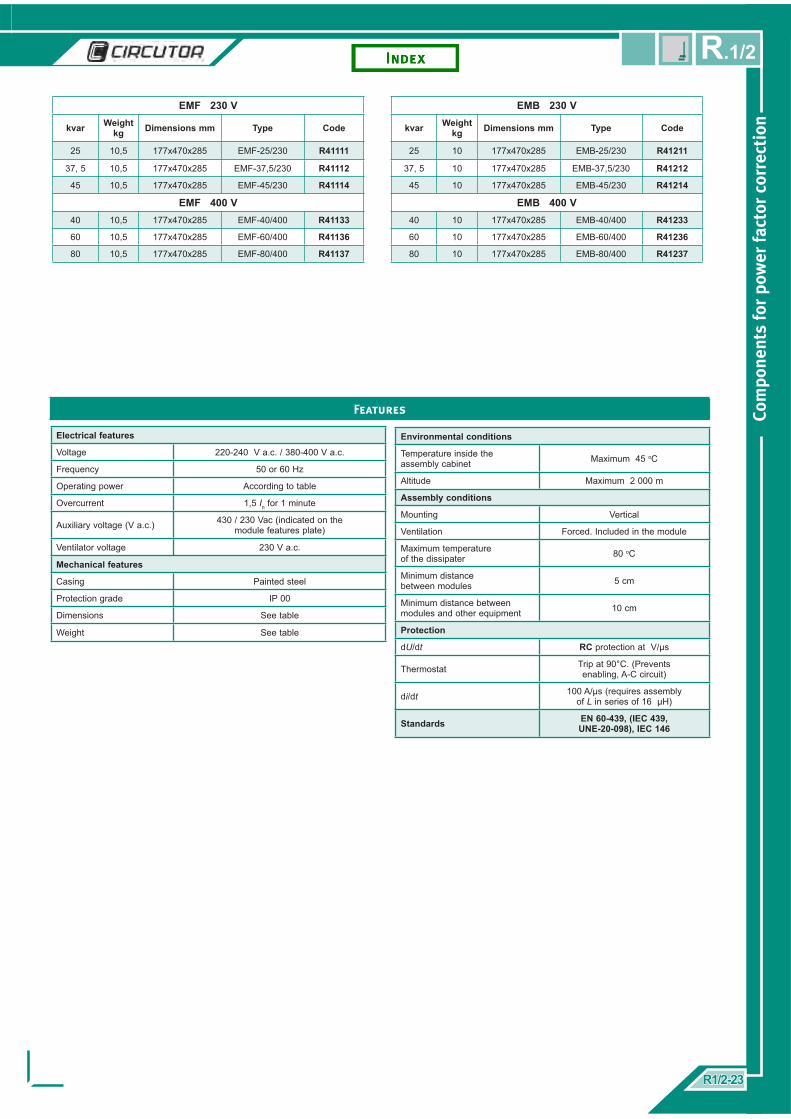
Electrical features
Voltage 220-240 V a.c. / 380-400 V a.c.
Frequency 50 or 60 Hz
Operating power According to table
Overcurrent 1,5 In for 1 minute
Auxiliary voltage (V a.c.) 430 / 230 Vac (indicated on the module features plate)
Ventilator voltage 230 V a.c.
Mechanical features
Casing Painted steel
Protection grade IP 00
Dimensions See table
Weight See table
Features
Environmental conditions
Temperature inside the assembly cabinet Maximum 45 oC
Altitude Maximum 2 000 m
Assembly conditions
Mounting Vertical
Ventilation Forced. Included in the module
Maximum temperature of the dissipater 80 oC
Minimum distance between modules 5 cm
Minimum distance between modules and other equipment 10 cm
Protection
dU/dt RC protection at V/µs
Thermostat Trip at 90°C. (Prevents enabling, A-C circuit)
di/dt 100 A/µs (requires assembly of L in series of 16 µH)
Standards EN 60-439, (IEC 439, UNE-20-098), IEC 146
EMF 230 V
kvar Weightkg Dimensions mm Type Code
25 10,5 177x470x285 EMF-25/230 R41111
37, 5 10,5 177x470x285 EMF-37,5/230 R41112
45 10,5 177x470x285 EMF-45/230 R41114
EMF 400 V40 10,5 177x470x285 EMF-40/400 R41133
60 10,5 177x470x285 EMF-60/400 R41136
80 10,5 177x470x285 EMF-80/400 R41137
EMB 230 V
kvar Weightkg Dimensions mm Type Code
25 10 177x470x285 EMB-25/230 R41211
37, 5 10 177x470x285 EMB-37,5/230 R41212
45 10 177x470x285 EMB-45/230 R41214
EMB 400 V40 10 177x470x285 EMB-40/400 R41233
60 10 177x470x285 EMB-60/400 R41236
80 10 177x470x285 EMB-80/400 R41237
R1/2-23R1/2-23
Com
pone
nts
for
pow
er fa
ctor
cor
rect
ion
R.1/2

RACK
The correction system using RACKS grouped in modules assembled and cabled with all the necessary parts for capacitor bank step to operate. Therefore, the composition of the bank is by attaching a RACK with the appropriate power.
Composition
The racks comprise:Step protection fuses.Operation contactor CLZ-FP capacitorsRejection reactors. (For RACK-F only)Support frame.
•••••
Connections
Each module has terminals for connecting the regulator operation and for the auxiliary command voltage.Connection between racks has to be via a copper plate
Range
There are two types of RACK:RACK for standard banks without fi lters. Designed for 600 mm wide cabinetsRACK-F for rejection fi lter banks tuned to 189 Hz. Designed for 800 mm wide cabinets
••
••
RACK 400 / 415 V a 50 HZ
kvar Composition (fuse+contactor) Nº of steps Weight
(kg)Dimensions
(mm) Type Code
5 1 + 1 1 x 5 13,2 492 x 330 x 280 RACK-1x5-400 R20918
10 1 + 1 1 x 10 13,5 492 x 330 x 280 RACK-1x10-400 R2091C
12,5 1 + 1 1 x 12,5 13,8 492 x 330 x 280 RACK-1x12,5-400 R2091D
15 1 + 1 1 x 15 14 492 x 330 x 280 RACK-1x15-400 R2091E
20 1 + 1 1 x 20 14,5 492 x 330 x 280 RACK-1x20-400 R2091F
25 1 + 1 1 x 25 14,7 492 x 330 x 280 RACK-1x25-400 R2091G
30 1 + 1 1 x 30 16,1 492 x 330 x 280 RACK-1x30-400 R2091H
40 1 + 1 1 x 40 17,1 492 x 330 x 280 RACK-1x40-400 R2091J
50 1 + 2 2 x 25 20,3 492 x 330 x 280 RACK-2x25-400 R2092G
50 1 + 1 1 x 50 17,4 492 x 330 x 280 RACK-1x50-400 R2091K
60 2 + 2 2 x 30 22,2 492 x 330 x 280 RACK-2x30-400 R2092H
100 2 + 2 2 x 50 24,8 492 x 330 x 280 RACK-2x50-400 R2092K
RACK-FR 400 / 415 V a 50 HZ
kvar Composition (fuse+contactor) Nº of steps Weight
(kg)Dimensions
(mm) Type Code
5 1 + 1 1 x 5 30 692 x 275 x 430 RACK-FR-7%-1x5-400 R21018
10 1 + 1 1 x 10 32,5 692 x 275 x 430 RACK-FR-7%-1x10-400 R2101C
12,5 1 + 1 1 x 12,5 34 692 x 275 x 430 RACK-FR-7%-1x12,5-400 R2101D
15 1 + 1 1 x 15 35,2 692 x 275 x 430 RACK-FR-7%-1x15-400 R2101E
20 1 + 1 1 x 20 39,5 692 x 275 x 430 RACK-FR-7%-1x20-400 R2101F
25 1 + 1 1 x 25 42 692 x 275 x 430 RACK-FR-7%-1x25-400 R2101G
30 1 + 1 1 x 30 47,4 692 x 275 x 430 RACK-FR-7%-1x30-400 R2101H
40 1 + 1 1 x 40 48,4 692 x 275 x 430 RACK-FR-7%-1x40-400 R2101J
50 1 + 2 1 x 50 57,4 692 x 275 x 430 RACK-FR-7%-1x50-400 R2101K
50 1 + 1 2 x 25 71,3 692 x 275 x 430 RACK-FR-7%-2x25-400 R2102G
60 2 + 2 2 x 30 74,8 692 x 275 x 430 RACK-FR-7%-2x30-400 R2102H
100 2 + 2 2 x 50 95,8 692 x 275 x 430 RACK-FR-7%-2x50-400 R2102K
Com
pone
nts
for
pow
er fa
ctor
cor
rect
ion
R1/2-24R1/2-24
R.1/2

Impedances limiting inrush currents. IR Series
The connection of capacitors has a signifi cant current peak associated with it. These values may be up to 275 times the capacitor nominal current.
There are two possible solutions to limit these transients to tolerable levels for the contactors and capacitors:
Use of special contactors for capacitive cut off with limiting resistancesUse of IR series limiting impedances.
IR impedances are assembled in each of the three power cables between the contactor and capacitor.The selection of the IR impedances is done in terms of the diameter of the cable used as shown in the following table.
••
Accessories
Type Cable diameter (mm) Code
IR-6 6 R3Z310
IR-10 10 R3Z320
IR-25 25 R3Z330
IR-35 35 R3Z340
IR-50 50 R3Z350
IR-70 70 R3Z360
Fast discharge reactors. RD Series
RD series fast discharge resistance steps have to be installed for a faster and therefore a more accurate regulation of the bank.
With RD resistances, the step discharge time is less than 10 seconds. Therefore regulation can be done is a shorter time than that stated in the IEC60831-1 standard which proposes a residual voltage of 75 V in 3 minutes.
Resistances are connected using an auxiliary contact which is normally closed from the contactor in such a way that when the capacitor is disconnected the RD resistance remains connected.
Type Power (kvar) Resistance (Ω) Dissipated power (W) Code
RD-25 1 - 25 2 x 1 500 10 R3Z210
RD-60 25 -60 2 x 1 000 10 R3Z220
RD-100 60/100 2 x 1 000 15 R3Z230
R1/2-25R1/2-25
Com
pone
nts
for
pow
er fa
ctor
cor
rect
ion
R.1/2

Recommendations for the assembly of capacitor banks
General standards
On assemblyThe capacitors and reactors must be vertically assembled.Capacitor terminals must not be used as a connection bridge for other capacitors.
DistancesMaintenance minimum distances between parts is vital for guaranteeing proper working. The following table shows the minimum distances between the parts
Horizontal distance between parts Comments
Prismatic capacitors 4 cm
CLZ capacitors 2 cm between edges• The upper part of the capacitor may expand 2 cm in the event of a fault.• Connection must be made using a fl exible cable.
RB/RBX/RBE fi lter reactors 4 cmAssemble capacitors below the fi lter reactors. This way over heating of the capacitors is prevented and improves the available space in the cabinet.
Assembly features
The operating temperature inside the board between parts must not exceed the values stated in the IEC 60831-1 standard
Ambient temperature, °C according to the IEC 60831-1 standard
Type of capacitor Category Maximum temperature (*)
Highest measurement in 24 hours
Highest measurement in 1 year
CV-CQ-CS-CF C 50 40 30
CLZ D 55 45 35
Connection of the steps
Limiting connection currentsIn order to protect the capacitors and operating equipment, the connection current points have to be limited.Different solutions are recommended for this:
Contactors with preload resistanceIR series inductancesSeries reactance using cable connection returns (in terms of the step current).
Fast reconnection In order to increase connection operations the use of RD resistance is recommended.
•••
Com
pone
nts
for
pow
er fa
ctor
cor
rect
ion
R1/2-26R1/2-26
R.1/2

Design of components for bank steps
The rated current for the components is defi ned in accordance with the criteria stated in the IEC 60831 standard.A rated current between 1.4 and 1.5 times the bank’s rated current is recommended.
Fuse calibre is calculated using a sizing of 1.6 times the rated current.Capacitor cables must be sized to permanently support 1.43 times its rated current as a minimum.Cables have been calculated for an operating temperature of 40 °C. Possible cable groupings have not been taken into
account. Therefore in terms of the assembly and the actual operating conditions, the express calculation of the diameters to be used is advised.
•
•••
DESIGN OF COMPONENTS FOR BANK STEPS WITH REJECT FILTERS
Power kvar
(at system voltage)
System 230 V – 60 Hz System 400 V – 50 Hz System 460 V – 60 Hz System 480 V – 60 Hz
In Diameter Fuse In Diameter Fuse In Diameter Fuse In Diameter Fuse
A mm² A A mm² A A mm² A A mm² A
7,5 18,8 6 35 10,8 6 20 9,4 6 20 9,0 6 20
10 25,1 10 50 14,5 6 25 12,6 6 25 12,0 6 20
12,5 31,4 10 63 18,1 6 35 15,7 6 25 15,1 6 25
15 37,7 10 63 21,7 6 50 18,8 6 35 18,1 6 35
20 50,3 25 100 28,9 10 50 25,1 10 50 24,1 10 50
25 62,8 25 125 36,1 10 63 31,4 10 50 30,1 10 50
30 75,4 35 125 43,4 16 80 37,7 10 63 36,1 10 63
35 88,0 50 160 50,6 25 100 44,0 16 80 42,1 16 80
37,5 94,2 50 160 54,2 25 100 47,1 16 80 45,2 16 80
40 100,5 50 160 57,8 25 100 50,3 25 100 48,2 25 80
50 125,7 70 200 72,3 35 125 62,8 25 100 60,2 25 100
60 - - 250 86,7 50 160 75,4 35 125 72,3 35 125
70 - - - 101,16 50 160 88,0 50 160 84,3 50 160
80 - - - 115,61 70 160 100,5 50 160 96,3 50 160
DESIGN OF COMPONENTS FOR BANK STEPS WITH REJECT FILTERS
Power kvar
(at system voltage)
System 230 V – 60 Hz System 400 V – 50 Hz System 460 V – 60 Hz System 480 V – 60 Hz
In Diameter Fuse In Diameter Fuse In Diameter Fuse In Diameter Fuse
A mm² A A mm² A A mm² A A mm² A
7,5 18,8 10 35 10,8 6 20 9,4 6 20 9,0 6 20
10 25,1 10 50 14,5 6 25 12,6 6 25 12,0 6 20
12,5 31,4 16 63 18,1 10 35 15,7 6 25 15,1 6 25
15 37,7 16 63 21,7 10 50 18,8 10 35 18,1 6 35
20 50,3 25 100 28,9 10 50 25,1 10 50 24,1 10 50
25 62,8 35 125 36,1 16 63 31,4 16 50 30,1 10 50
30 75,4 50 125 43,4 25 80 37,7 16 63 36,1 16 63
35 88,0 70 160 50,6 35 100 44,0 25 80 42,1 25 80
37,5 94,2 70 160 54,2 35 100 47,1 35 80 45,2 25 80
40 100,5 70 160 57,8 35 100 50,3 35 100 48,2 35 80
50 125,7 95 200 72,3 35 125 62,8 35 100 60,2 35 100
60 - - - 86,7 50 160 75,4 50 125 72,3 35 125
70 - - 101,16 70 160 88,0 50 160 84,3 50 160
80 - - - 115,61 95 160 100,5 70 160 96,3 70 160
R1/2-27R1/2-27
Com
pone
nts
for
pow
er fa
ctor
cor
rect
ion
R.1/2

Capacitor voltage 260 V
Powerkvar
Capacitor type Code Reactor type Code
5 CF 26/6,3 R2112A R-5-230 P70110001
10 CF 26/12,5 R2112D R-10-230 P70115001
12,5 CF 26/16 R2112F R-12,5-230 P70117001
15 CF 26/18 R2112E R-15-230 P70120001
20 CF 26/25 R2112G RB-20-230 P70125001
25 CF 26/30 R2112H RB-25-230 P70130001
30 CF 26/37 R2112J RB-30-230 P70135001
40 CF 26/48 R2112K RB-40-230 P70140001
50 CF 26/60 R2112L RB-50-230 P70145001
System voltage 230 V at 50 Hz and 7 % reactors
Capacitor voltage 260 V
Powerkvar
Capacitor type Code Reactor type Code
5 CF 26/5 R2112C001 R-5-230 P701100011
10 CF 26/10 R2112I001 R-10-230 P701150011
12,5 CF 26/15 R2112D001 R-12,5-230 P701170011
15 CF 26/20 R2112M001 R-15-230 P701200011
20 CF 26/25 R2112P001 RB-20-230 P701250011
25 CF 26/30 R2112G001 RB-25-230 P701300011
30 CF 26/40 R2112H001 RB-30-230 P701350011
40 CF 26/50 R2112Q001 RB-40-230 P701400011
System voltage 230 V at 60 Hz and 7 % reactors
Capacitor voltage 460 V
Powerkvar
Capacitor type Code Reactor type Code
5 CF 46/6 R2115A R-5-400 P70110
10 CF 46/12,5 R2115D R-10-400 P70115
12,5 CF 46/15 R2115E R-12,5-400 P70117
15 CF 46/19 R2115F R-15-400 P70120
20 CF 46/25 R2115G RB-20-400 P70125
25 CF 46/30 R2115H RB-25-400 P70130
30 CF 46/37 R2115J RB-30-400 P70135
40 CF 46/50 R2115K RB-40-400 P70140
50 CF 46/62 R2115L RB-50-400 P70145
60 CF 46/74 R2115P RB-60-400 P70150
80 CF 46/100 R2115R RB-80-400 P70155
Capacitor voltage 500 V
Powerkvar
Capacitor type Code Reactor type Code
5 CF 50/6 R211CA001 R-5-400 P70110
10 CF 50/12,5 R211CD001 R-10-400 P70115
12,5 CF 50/15 R211CE001 R-12,5-400 P70117
15 CF 50/19 R211CF001 R-15-400 P70120
20 CF 50/25 R211CG001 RB-20-400 P70125
25 CF 50/30 R211CH001 RB-25-400 P70130
30 CF 50/37 R211CJ001 RB-30-400 P70135
40 CF 50/50 R211CK001 RB-40-400 P70140
50 CF 50/62 R211CL001 RB-50-400 P70145
60 CF 50/74 R211CP001 RB-60-400 P70150
80 CF 50/100 R211CR001 RB-80-400 P70155
System voltage 400 V at 50 Hz and 7 % reactors System voltage 440 V at 60 Hz and 7 % reactors
System voltage 690 V at 50 Hz and 7 % reactors
System voltage 460 V at 60 Hz and 7 % reactors
Capacitor voltage 550 V
Powerkvar
Capacitor type Code Reactor type Code
5 CF 55/7 R2116C001 R-5-400 P70110001
12,5 CF 55/15 R2116E001 R-10-400 P70115001
15 CF 55/18 R2116F001 R-12,5-400 P70117001
17,5 CF 55/22 R2116G001 R-15-400 P70120001
25 CF 55/29 R2116H001 RB-20-400 P70125001
30 CF 55/37 R2116J001 RB-25-400 P70130001
35 CF 55/44 R2116K001 RB-30-400 P70135001
50 CF 55/59 R2116L001 RB-40-400 P70140001
60 CF 55/73 R2116P001 RB-50-400 P70145001
70 CF 55/88 R2116S001 RB-60-400 P70150001
95 CF 55/117 R2116T001 RB-80-400 P70155001
Capacitor voltage 790 V
Powerkvar
Capacitor type Code Reactor type Code
5 CF 79/6 R211DA RE-5-400 P70210
10 CF 79/12,5 R211DD RE-10-400 P70215
15 CF 79/19 R211DF RE-15-400 P70220
20 CF 79/25 R211DG RE-20-400 P70225
25 CF 79/30 R211DH RE-25-400 P70230
30 CF 79/37 R211DT RE-30-400 P70235
40 CF 79/50 R211DK RE-40-400 P70240
50 CF 79/62 R211DL RBE-50-400 P70245
60 CF 79/74 R211DP RBE-60-400 P70250
80 CF 79/100 R211DR RBE-80-400 P70255
System voltage 480 V at 60 Hz and 7 % reactors
Capacitor voltage 525 V
Powerkvar
Capacitor type Code Reactor type Code
5 CF 55/7 R2116C001 R-5-400 P70110001
10 CF 55/15 R2116E001 R-10-400 P70115001
12,5 CF 55/18 R2116F001 R-12,5-400 P70117001
15 CF 55/22 R2116G001 R-15-400 P70120001
20 CF 55/29 R2116H001 RB-20-400 P70125001
25 CF 55/37 R2116J001 RB-25-400 P70130001
30 CF 55/44 R2116K001 RB-30-400 P70135001
45 CF 55/59 R2116L001 RB-40-400 P70140001
55 CF 55/73 R2116P001 RB-50-400 P70145001
65 CF 55/88 R2116S001 RB-60-400 P70150001
90 CF 55/117 R2116T001 RB-80-400 P70155001
Com
pone
nts
for
pow
er fa
ctor
cor
rect
ion
R1/2-28R1/2-28
R.1/2

CLZ Cilyndrical capacitors and reactors for making electro-mechanical rejection fi lters
Operating voltage 400 V / 50 Hz and 6 % reactors
Powerkvar
Powerkvar design Capacitor type Code Reactor type Code
5,5 6,25 CLZ-FP-6,25/44 R20549 RX-6,25-400 P7101F
11 12,5 CLZ-FP-12,5/44 R2054D RX-12,5-400 P70013
22 25 CLZ-FP-25/44 R2054G RX-25-400 P70016
44 50 2 x CLZ-FP-25/44 2 x R2054G RBX-50-400 P70019
Operating voltage 440 V / 60 Hz and 7 % reactors
Powerkvar
Powerkvar design Capacitor type Code Reactor type Code
6,25 5,5 CLZ-FP-52/2,5 + CLZ-FP-52/3 R20555 + R20557 RX-6,25-400 P7101F
12,5 14 CLZ-FP-52/4 + CLZ-FP-52/10 R20557 + R2055C RX-12,5-400 P70013
25 28 CLZ-FP-52/20 + CLZ-FP-52/8 R2055F + R2055B RX-25-400 P70016
50 55 2 x CLZ-FP-52/20+ CLZ-FP-52/15 2 X R2055F + R2055E RBX-50-400 P70019
Operating voltage 460 V / 60 Hz and 7 % reactors
Powerkvar
Powerkvar design Capacitor type Code Reactor type Code
6,25 5,5 CLZ-FP-52/2,5 + CLZ-FP-52/3 R20555 + R20557 RX-6,25-400 P7101F
12,5 14 CLZ-FP-52/4 + CLZ-FP-52/10 R20557 + R2055C RX-12,5-400 P70013
25 28 CLZ-FP-52/20 + CLZ-FP-52/8 R2055F + R2055B RX-25-400 P70016
50 55 2 x CLZ-FP-52/20+ CLZ-FP-52/15 2 X R2055F + R2055E RBX-50-400 P70019
Operating voltage 480 V / 60 Hz and 7 % reactors
Powerkvar
Powerkvar design Capacitor type Code Reactor type Code
7,5 5,5 CLZ-FP-52/2,5 + CLZ-FP-52/3 R20555 + R20557 RX-6,25-400 P7101F
15 14 CLZ-FP-52/4 + CLZ-FP-52/10 R20557 + R2055C RX-12,5-400 P70013
30 28 CLZ-FP-52/20 + CLZ-FP-52/8 R2055F + R2055B RX-25-400 P70016
60 55 2 x CLZ-FP-52/20+ CLZ-FP-52/15 2 X R2055F + R2055E RBX-50-400 P70019
Components for making steps using the static system
The following diagram is required for making parts for static rejection fi lters.As stated, the components to select are:
Static operation moduleCF-6B capacitorsRBE reactors
•••
Operating voltage 400 V / 50 Hz and 7 % reactors (*)
Powerkvar
Capacitor Reactor EMF module EMB module
Type Code Type Code Type Code Type Code
5 CF 46/6 – 6B R2125A RE-5-400 P70210 EMF-40-400 R41133 EMB-40-400 R41233
10 CF 46/12,5-6B R2125D RE-10-400 P70215 EMF-40-400 R41133 EMB-40-400 R41233
15 CF 46/19-6B R2125F RE-15-400 P70220 EMF-40-400 R41133 EMB-40-400 R41233
20 CF 46/25-6B R2125G RBE-20-400 P70225 EMF-40-400 R41133 EMB-40-400 R41233
25 CF 46/30-6B R2125H RBE-25-400 P70230 EMF-40-400 R41133 EMB-40-400 R41233
30 CF 46/37-6B R2125J RBE-30-400 P70235 EMF-40-400 R41133 EMB-40-400 R41233
40 CF 46/50-6B R2125K RBE-40-400 P70240 EMF-40-400 R41133 EMB-40-400 R41233
50 CF 46/62-6B R2125L RBE-50-400 P70245 EMF-60-400 R41136 EMB-60-400 R41236
60 CF 46/74-6B R2125P RBE-60-400 P70255 EMF-60-400 R41136 EMB-60-400 R41236
80 CF 46/6/100-6B R2125R RBE-80-400 P70250 EMF-80-400 R41137 EMB-80-400 R41237
(*) Other upon request
R1/2-29R1/2-29
Com
pone
nts
for
pow
er fa
ctor
cor
rect
ion
R.1/2
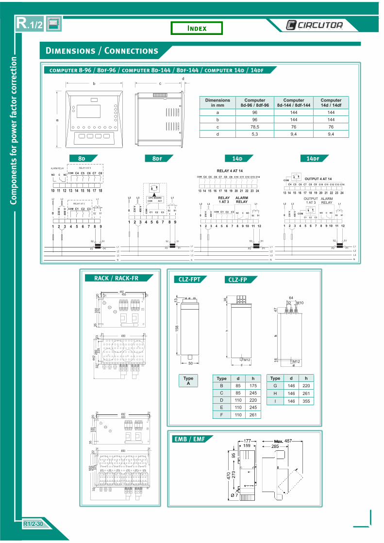
Dimensions / Connections
Dimensionsin mm
Computer8d-96 / 8df-96
Computer8d-144 / 8df-144
Computer14d / 14df
a 96 144 144b 96 144 144c 78,5 76 76d 5,3 9,4 9,4
Type d hG 146 220
H 146 261
I 146 355
computer 8-96 / 8df-96 / computer 8d-144 / 8df-144 / computer 14d / 14df
8d 8df 14d 14df
RACK / RACK-FR CLZ-FPCLZ-FPT
EMB / EMF
Type d hB 85 175C 85 245D 110 220E 110 245
F 110 261
Type A
Com
pone
nts
for
pow
er fa
ctor
cor
rect
ion
R1/2-30R1/2-30
R.1/2

Dimensions / Conexiones
computer 6e / 12e
computer 6m / 12m / FastComp 12rt / 9G-3T
6m 12m FastComp 12rt
9G-3T
CV CQ CS / CF
Relé Relé
Relé
Entrada cablesEntrada cables
R1/2-31R1/2-31
Com
pone
nts
for
pow
er fa
ctor
cor
rect
ion
R.1/2

Dimensions
Type Amm
Bmm
Cmm
D*mm
E*mm
Fmm
Gmm kg
R-5-400 155 112 165 75 85 7 --- 6
R-10-400 180 102 190 90 75 7 --- 8
R-12,5-400 180 112 192 90 85 7 -- 9,2
R-15-400 180 112 190 90 85 7 --- 9,5
RB-20-400 260 124 174 150 90 7 150 14
RB-25-400 260 124 174 150 90 7 150 14
RB-30-400 290 124 231 160 90 9 150 19
RB-40-400 293 124 231 160 90 9 150 20
RB-50-400 310 144 233 160 110 9 175 27
RB-60-400 305 146 260 160 110 11 180 31
RB-80-400 335 155 280 180 120 11 185 38
RB-100-400 338 170 300 180 135 11 215 50
RB-120-400 355 170 350 200 135 13 220 58
RX-6,25-400 180 102 190 90 75 7 -- 8
RX-12,5-400 180 112 192 90 85 7 -- 9,2
RBX-25-400 180 137 196 90 110 7 -- 15
RBX-50-400 292 144 232 160 110 9 175 26
* Distance between fi xing screws
R / RB / RX / RBX-7%
Type R / RX Type RB / RBX
RE / RBE
Type Amm
Bmm
Cmm
D*mm
E*mm
Fmm
Gmm kg
RE-5-400 155 92 165 75 75 7 -- 6
RE-10-400 180 102 190 90 75 7 -- 8
RE-15-400 180 112 190 90 85 7 -- 9,5
RE-20-400 180 122 190 90 95 7 -- 11,5
RE-25-400 240 122 250 130 90 9 -- 17
RE-30-400 240 132 250 130 100 9 -- 20,5
RE-40-400 240 147 250 130 115 9 -- 25,5
RBE-50-400 310 154 233 160 120 9 185 29
RBE-60-400 310 154 234 160 120 9 185 30
RBE-80-400 338 165 280 180 130 11 195 41
* Distance between fi xing screws
Type RE Type RBE
Type Amm
Bmm
Cmm
D*mm
E*mm
Fmm
Gmm kg
R-5-400-14% 180 102 197 90 75 7 - 9.5
R-10-400-14% 180 122 197 90 95 7 - 13
R-12,5-400-14% 180 137 197 90 110 7 - 16
R-15-400-14% 250 122 250 130 90 9 - 21.5
R-20-400-14% 250 132 250 130 100 9 - 25
R-25-400-14% 250 147 256 130 115 9 - 30.5
RBC-30-400-14% 285 154 233 160 120 9 181 35
RBC-40-400-14% 290 159 233 160 125 9 184 41
RBC-50-400-14% 307 164 233 160 130 9 194 48
RBC-60-400-14% 335 196 280 280 150 11 197 60
*Distance between fi xing screws
R-14% / RBC-14%
Type R-14% Type RB-14%
R1/2-32R1/2-32
cod.
C3R
123-
01
Com
pone
nts
for
pow
er fa
ctor
cor
rect
ion
R.1/2
Vial Sant Jordi s/n08232 Viladecavalls
Barcelona (Spain)Tel. (+34) 93 745 29 00
Fax: (+34) 93 745 29 14e-mail: [email protected]
web: www.circutor.com
Design: Comunication • CIRCUTOR, SA
CIRCUTOR reserves the right to change the content of this catalogue without prior warning.CIRCUTOR does not assume any responsibility for any damage caused to persons or materials due to improper or unsuitable use of its equipment.