contents introduction figures blowouts · it is interesting to note that although abnormal...
TRANSCRIPT
Circular 17 – Page 1 of 17
GEOLOGICAL SURVEY DIVISION
Circular 17 BLOWOUT PREVENTION
Equipment, Use and Testing
by Daniel T. Bertalan
Lansing, Michigan 1979
Contents INTRODUCTION............................................................... 1 BLOWOUTS ..................................................................... 1 BLOWOUT PREVENTERS - FUNCTION ........................ 3 RAM PREVENTERS......................................................... 3 ANNULAR PREVENTERS............................................... 5 BLOWOUT PREVENTER STACK ARRANGEMENTS ... 7 TESTING........................................................................... 8 GENERAL INFORMATION ON TESTING ..................... 11 CLOSING UNITS ............................................................ 11 SPECIAL EQUIPMENT .................................................. 11 IN PARTING.................................................................... 13 SPECIAL ORDER NO. 2-73, AMENDED....................... 13 GLOSSARY .................................................................... 15
Figures Figure 1. Shaffer dual body ram preventer - cutaway view, top
ram closed. (Courtesy of NL Shaffer) ..............................3
Figure 2. Cutaway view of shear ram cutting drill pipe. (Courtesy of NL Shaffer)...................................................4
Figure 3. Partial cutaway view, pipe ram in closed position. (Courtesy of NL Shaffer)...................................................4
Figure 4. Pipe ram blocks, white portion is rubber sealing element. (Courtesy of NL Shaffer) ...................................4
Figure 5. Cutaway view of locking shaft on ram preventer (note arrow). (Courtesy of NL Shaffer) ............................5
Figure 6. Cutaway view of Hydril annular preventers. (Courtesy of NL Shaffer)...................................................5
Figure 7. Cutaway view of annular element closing movement (Hydril). (Courtesy of NL Shaffer) ....................................5
Figure 8. Partial cutaway of Shaffer spherical annular preventer. (Courtesy of NL Shaffer).................................6
Figure 9. Cutaway view of Shaffer spherical closed on drill pipe. (Courtesy of NL Shaffer) .........................................6
Figure 10. Partial cutaway of Shaffer annular preventer sealing element, white portion is steel skeleton. (Courtesy of NL Shaffer)...................................................6
Figure 11. Common BOP stack arrangement for Michigan
operations, (Courtesy of NL Shaffer)................................7
Figure 12. Time/pressure chart of BOP system test. (Courtesy of Double Check) .............................................................9
Figure 13. Pressure test of blind rams and outer valves on spool. (Courtesy of NL Shaffer).......................................9
Figure 14. Pressure test of blind rams and inner valves on spool. (Courtesy of NL Shaffer).....................................10
Figure 15. Test plug set on drill pipe and pipe rams closed. (Courtesy of NL Shaffer) ................................................10
Figure 16. Pressure test of annular preventer closed on drill pipe. (Courtesy NL Shaffer)...........................................10
Figure 17. Example of BOP Test Report. (Courtesy of Double Check)............................................................................11
Figure 18. Trip Tank Work Sheet. .........................................12
Figure 19. Tables for use with Trip Tank Work Sheet. ..........12
Figure 20. 24-hour chart from Pit Volume Totalizer...............13
Figure 21. 24-hour chart from Flow Sensor...........................13
INTRODUCTION This circular has been prepared as a basic guide for the installation, testing and use of blowout prevention equipment in Michigan. 'Kick’ detection, causes of blowouts, and the use of special monitoring equipment are also discussed.
Contents of this circular have been designed to familiarize the field geologist with the blowout preventer systems, with particular emphasis on the methods of installation, inspection, and testing.
BLOWOUTS
DEFINITION A well blowout is the uncontrolled flow of oil, gas, salt water, or any combination of these three substances from a wellbore. This uncontrolled flow can occur at the surface from the wellbore or, if the well is shut in, can fracture underground formations, causing a subsurface blowout. Whether it is a dramatic well fire roaring through the twisted steel of a half-melted rig or gas cratering the ground miles from the well, a blowout is a great waste of resources. Human life, surface values, ground and surface waters, drilling rigs and equipment, and nonrenewable hydrocarbons are all threatened when a well ‘indicates’ the possibility of a blowout.
CAUSES Oil, gas, and salt water exist in sedimentary rocks through the process of deposition. Several geologic processes cause these substances to exist under pressure in porous and permeable formations. This pressure varies with depth and location but usually increases in increments that average 0.465 pounds per

Circular 17 – Page 2 of 17
square inch (psi) for each foot of depth. Although 0.465 psi/ft depth is the average formation pressure gradient, many geographical areas have substantially higher pressure gradients. Any substance that is capable of flowing will move from a higher-pressure to a lower-pressure environment whenever possible. With this in mind it is easy to understand how a blowout can occur when the pressure in the penetrated permeable formation is greater than the hydrostatic pressure of the wellbore. There are five major causes of blowouts in which wellbore pressures are allowed to become less than formation pressures. These five causes are: 1) not keeping the hole full; 2) swabbing; 3) insufficient mud weight; 4) lost circulation; and 5) abnormal formation pressure. Of these five causes, two account for a major portion of all kicks. They are: 1) not keeping the hole full, and 2) swabbing. Swabbing and not keeping the hole full happen during trips, making this a potentially hazardous part of operations especially after penetrating pay sections. A ‘kick’ is a bubble of gas (or slug of oil/gas/salt water) that enters the wellbore. As this bubble rises or is circulated upward in the wellbore, it expands at an increasing rate, eventually blowing a slug of fluid from the hole. A kick which blows fluid from the hole is usually the LAST indicator that a blowout is imminent.
It is interesting to note that although abnormal formation pressure is mentioned as one of the major causes of well-control problems, most blowouts occur when normal formation pressures are involved. Abnormally high formation pressures are usually recognized in advance and extra care and special equipment are used when drilling. Many hydrocarbon-bearing formations in Michigan exhibit abnormally high formation pressures. Niagaran reefs have an average formation pressure of 0.540 to 0.580 psi/ft of depth, and the A-1 Carbonate has been found to have 1.0 psi/ft depth in some areas.
As mentioned earlier, most kicks occur when the drill pipe is being tripped from the hole. There are several reasons why tripping is an extremely delicate operation when done in high pressure formations or pay sections. These will be discussed in greater detail under SPECIAL EQUIPMENT-TRIP TANKS.
INDICATIONS Blowouts do not usually happen instantly or without warning. Often, one or more circumstances indicate that a problem is developing long before the first kick is seen at the surface. Briefly, these indications and their related causes are discussed in the following paragraphs.
PIT GAIN. A gain in the fluid level of the circulating pits during drilling operations may mean an invasion of formation fluid or gas into the wellbore and circulating system. The invading gas or fluid, by displacement, reduces the volume of hole that can be occupied by drilling mud; this shows up directly as an increased volume of mud in the pit. During tripping operations, formation fluid invasion is not measured by a gain in the
pit but by the unequal amount of fluid needed for hole fill-up during drill pipe withdrawal. Put more simply, the volume of fluid needed to keep the hole full should equal the volume of drill pipe pulled out. If fill-up fluid volume is less than the volume of withdrawn pipe, the chances are that formation fluid or gas has entered the wellbore. Special equipment such as pit volume totalizers, flow sensors, and trip tanks are designed to detect these potential problems and will be discussed under SPECIAL EQUIPMENT.
WATER CUT MUD. Water cut mud during drilling operations is an indication that formation water may have entered the wellbore (providing some ‘weevil’ isn't fooling around with watering the mud system). Formation water entering the wellbore may lighten the drilling fluid, thus reducing the hydrostatic pressure and allowing more formation fluid to invade the hole at an increasing rate.
DRILLING BREAK. When porosity and/or formation pressure greater than the hydrostatic pressure of the wellbore are encountered, a noticeable increase in penetration rate will usually show up on the geolograph. This increase in penetration rate is called a "drilling break”. Penetration rate through porous zones will often increase as formation pressure causes a reduction of the hydrostatic overbalance, allowing cuttings and liberated formation gas or fluids to surge upward away from the bit. A drilling break may be an advance warning of a potential kick, thus providing time to implement precautionary action.
DECREASE IN CIRCULATING PRESSURE. Invading formation fluid and/or gas will lighten the weight of the mud being circulated back up the hole, resulting in a decrease in circulating pressure. Decreased circulating pressure is another indicator that a kick may be expected. Although other conditions such as partial lost circulation zones or a hole in the drill pipe can cause a reduction in circulating pressure, any pressure decrease should be monitored and accounted for.
GAS-CUT MUD. Gas-cut mud indicates that formation pressure is greater than hydrostatic pressure. Formation gas entering the wellbore expands as it rises uphole, lightening the mud column. This reduction in mud weight allows more gas to enter the hole, often at an increasing rate. Gas-cut mud can show up as ‘frog eyes’ in the pits, foaming mud, or simply a minor loss of mud weight. Gas-cut mud can be a late indicator that a kick is pending, or it can represent gas liberated with the cuttings during drilling, which by itself presents little problem. Like any of the other kick indicators, gas-cut mud must be carefully watched and defensive action should be taken.
If any of the above-mentioned kick indicators show up during drilling, the operator should be prepared to monitor and assess the situation accurately, and begin any necessary corrective action to bring the well under control. No one particular indicator can be used to determine definitely that a kick is occurring. Generally, a

combination of indicators is used to detect potential well control problems. The significance of these indicators will vary depending upon local conditions.
General practice for drilling operations where kick indicators are experienced is to:
1. Pull off bottom - This should be done so the pipe rams can be closed on the drill pipe if necessary. Pulling off bottom also provides an opportunity to install additional equipment (stabbing or control valves) on the drill string and allows for movement of the drill pipe if necessary.
2. Shut down the pump - Circulation must be stopped in order to monitor the well accurately under static conditions.
3. Check for flow - A visual check for flow in the annulus will reveal if formation fluid and/or gas is continuing to invade the wellbore or if a kick is beginning to unload the hole.
4. If no flow, circulate bottoms up - Even if the well does not flow from the annulus after shutting down the pumps, a serious problem may be 'waiting’ downhole in the annulus. It is safe practice to circulate bottoms up if any of the kick indicators show up. This will allow the operator to check for invading fluids or a gas bubble in the well.
5. Shut in the well and check for pressures - A flow of fluids from the annulus after shutting down the pumps indicates real trouble. If this is the case, the blowout preventers should be shut in and pressure readings taken on the drill pipe and casing.
This general practice must be tempered with judgment and flexibility to adapt to changing situations. At this point there are 101 things that can and should be done to resolve the well control problem. This text cannot and will not attempt to explain well control or kill procedures as too many variables and combinations of problems may exist in a well.
Although many things should be done, one thing which is often done should be avoided. After receiving a kick and shutting in the blowout preventers, many operators settle back to study the problem, thinking they have eternity to come up with lacking needed equipment or a plan of action. A well should not be shut in any longer than is necessary to begin kill operations. When a well is shut in after receiving a gas kick, the gas will rise in the wellbore. Without being able to expand, the rising gas maintains the bottom hole pressure it had when entering the wellbore. If given enough time this gas bubble can rise all the way uphole, exerting extreme or excessive pressure on the BOPS, casing, and exposed formations. If this happens, a number of things can, and often do, go wrong. Well control techniques can be implemented whereby the well can be kept shut in and the pressure caused by the rising gas bled off. Time is of the essence when initiating kill operations.
BLOWOUT PREVENTERS - FUNCTION Up to this point we have discussed what a blowout is, how it can occur, and what some of its indicators are. Lastly, we outlined a general practice to be followed when a well indicates it is taking a kick. Closing of the blowout preventers is a must in most serious well control situations, and when closed, the BOP's must contain anticipated wellbore pressures.
Blowout preventers are devices installed on the well head which can close and maintain an effective seal on drill pipe, line, kelly, or open hole when the drill string is out of the hole. For practical purposes we will limit our text to modern preventers, specifically annular preventers and ram-type preventers. Explanation of preventer operation and function is based on the assumption that the preventer is in proper working condition.
RAM PREVENTERS Ram preventers are blowout preventers that obtain shut-off by sealing assemblies, generally called rams, moving horizontally inward across the wellbore from two sides. Ram preventers commonly used in Michigan are hydraulically operated and also have manual operating controls. There are two common types of ram assemblies used in ram blowout preventers: pipe rams and blind rams (Figure 1). Another type is the blind/shear ram. This ram performs the same function as a blind ram but it can cut the drillpipe and effect a seal across the wellbore if required. Shear rams are most commonly used in offshore drilling operations. In a number of cases, blowouts through drillpipe have been shut in with the use of shear rams.
Figure 1. Shaffer dual body ram preventer - cutaway view, top ram closed. (Courtesy of NL Shaffer)
BLIND RAMS Blind rams are designed to close when drill pipe is out of the hole. When activated by hydraulic pressure, two pistons move horizontally toward each other across the wellbore forcing the two ram blocks together. These ram blocks each contain a rubber sealing element on the
Circular 17 – Page 3 of 17

face of the block. An effective seal is obtained when the two ram seals are forced firmly together. Blind rams are designed to close without drill pipe in the hole, but in some instances are capable of crimping casing which may be in the hole. The disadvantage of blind rams is that they can be shut effectively only when drill pipe, casing, or lines are out of the hole. Most kicks occur when pipe is in the hole, making blind rams an added safety feature most of the time. Although blind rams cannot be used in many situations, the ram body will accept pipe ram blocks of different sizes and can be converted easily to pipe rams if the need arises.
Another type of rams, BLIND/SHEAR RAMS, are specifically designed for crimping and shearing off drill pipe or casing in the hole. Closely resembling blind rams, shear rams have a shear blade which crushes pipe in the hole as the seal is made (Figure 2). The operation of blind shear rams requires greater-than-normal hydraulic pressure and a special ram body capable of holding the longer-than-normal blind shear ram blocks. Except for special situations, blind shear rams are not used in Michigan oil-field operations.
Figure 2. Cutaway view of shear ram cutting drill pipe. (Courtesy of NL Shaffer)
PIPE RAMS Operation of pipe rams is very similar to that of blind rams, but the ram blocks and seals are different. Pipe rams can close around drill pipe in the hole (Figure 3). Each block is formed to fit snugly around half of the drill pipe and against the other ram block (Figure 4). Pipe rams effect a seal on drill pipe with only 1/8-inch tolerance between the steel of ram blocks and the pipe. The rubber sealing element occupies this 1/8-inch tolerance space and, when closed, seals the annular space around the pipe. This precise fit requires that RAM BLOCKS FIT THE SIZE OF THE PIPE IN THE HOLE. Pipe rams of 4½” size will not seal on 6" drill collars or 5½" casing which may be in the hole when a well starts kicking. Proper size pipe rams should be installed in the ram body before using a different size pipe. Pipe rams cannot effect a seal on anything other than the proper size drill pipe or casing.
Figure 3. Partial cutaway view, pipe ram in closed position. (Courtesy of NL Shaffer)
Figure 4. Pipe ram blocks, white portion is rubber sealing element. (Courtesy of NL Shaffer)
Ram preventers are restricted in their single use but used in conjunction offer a good system for containing a kicking well under varying conditions. The blind and pipe ram blocks in a ram preventer are interchangeable, offering a variety of possible system changes or alterations if needed. Ram preventers can be used and tested extensively to rated working pressure without putting damaging stress on the sealing elements. BOP manufacturers contend that rams closed in on a well under pressure can maintain an effective seal even if the closing line pressure is relieved by mechanical or human failure. Although rams can hold a seal under these conditions, intentional relieving of closing line pressure in a wellbore pressure situation is NOT recommended. Wellbore pressure under the rams aids in sealing, and will hold a seal by forcing the rams upward and in toward each other. Although wellbore pressure will maintain the ram preventer in the closed position, operators should not rely on this in their daily operations.
Although wellbore pressures assist rams in holding a seal, locking shafts are designed to hold the rams in a closed position (Figure 5). A locking shaft is a threaded
Circular 17 – Page 4 of 17

shaft incorporated in the hydraulic closing cylinder. This shaft can be used to lock the rams in a closed position or to manually screw the rams closed without the aid of hydraulic pressure. These shafts are an important part of the ram preventers and should be regarded as such. When ram preventers are installed and tested, the locking shafts should also have proper connections to allow testing. Universal joints attached to the shaft should be rigged up with extensions and large hand wheels to allow manual closing of the rams. Without proper extensions and closing wheels, there is no way the rams could be closed quickly or locked in an emergency situation, such as closing unit or line failure when the well is kicking. True, this emergency situation should never happen; but it is the exception that usually results in a serious problem.
Figure 5. Cutaway view of locking shaft on ram preventer (note arrow). (Courtesy of NL Shaffer)
ANNULAR PREVENTERS Annular blowout preventers are the most versatile type of preventer in that they can seal and even strip on pipe of any size or shape which may be in the hole. An annular preventer can be shut in and seal on various shaped kellys, different size drill pipe, collars, casing, or even seal without pipe in the hole. Many people commonly refer to the annular preventer as the "Hydril", as this company had a virtual monopoly on the annular BOP market from the mid 40's to the 70fs. Although Hydril is understood to mean annular preventer, the proper term "annular preventer” will be used in this text, as preventers made by other companies will be discussed.
HYDRIL Hydril annular preventers are closed by hydraulic pressure pushing upward a large single piston which encircles the wellbore. The top of this piston is beveled inward; and in the bevelled top rests the doughnut-like sealing element which surrounds the open wellbore (Figure 6). When hydraulic pressure pushes the beveled
piston upward, the rubber element is stopped by the preventer top and is forced inward in all directions, effecting a seal on whatever may (or may not) be in the hole (Figure 7). Excessive pressure, or pressure greater than necessary to effect a seal, may cause undue stress and fatigue on the rubber sealing element. It is recommended that closing pressure be regulated to accomodate pipe sizes and wellbore pressures to increase element life. Wellbore pressures contained under the element force it further upward, giving a tighter seal than necessary which, if excessive, may reduce element life. When the piston moves down, the element opens because of the natural, stored energy in the rubber sealing element.
Figure 6. Cutaway view of Hydril annular preventers. (Courtesy of NL Shaffer)
Figure 7. Cutaway view of annular element closing movement (Hydril). (Courtesy of NL Shaffer)
SHAFFER Shaffer spherical annular preventers also seal by a large hydraulic piston pushing upward on the circular sealing element (Figure 8). Unlike the Hydril, the Shaffer preventer piston pushes the element upward into a spherical-shaped head. The spherical contour of the preventer top causes the rubber element to be forced inward in all directions as it is pushed upward (Figure 9).
Circular 17 – Page 5 of 17

To open the preventer the piston is hydraulically pushed down and stored energy in the rubber element causes it to expand back to its original shape. Full closing pressure can be used on this preventer without affecting the normal element life.
Annular preventers do not have mechanical closing or locking devices. The only way to close this type of preventer is by hydraulic pressure under the piston. The preventer can be locked in the closed position by sealing in the hydraulic closing fluid under pressure, using a valve on the closing fluid line. Canadian requirements call for a valve on the closing line which can be used to lock the annular preventer in the closed position if necessary.
Figure 8. Partial cutaway of Shaffer spherical annular preventer. (Courtesy of NL Shaffer)
SEALING ELEMENTS Failure of blowout preventers to hold an effective seal can usually be attributed directly or indirectly to the rubber sealing element. The most commonly used material in blowout preventer sealing elements is NITRILE. This special rubber is resistant to deterioration from hydrocarbons and is almost as resilient as natural rubber. Natural rubber elements are most resilient but have the disadvantage of being susceptible to deterioration from hydrocarbons. All types of preventer sealing elements are susceptible to hardening from hydrogen sulfide (H2S). The sulfur in H2S 'cures’ the rubber in a sealing element, making it harder. If an element has been cured by H2S, it will be less resilient and may develop cracks on the sealing surface. Such hardening will greatly reduce the effective life of the sealing element.
Another factor that affects the life of a sealing element is repeated testing. Ram preventer elements can obtain a seal without excessive deformation of the rubber because of the small amount of element exposed. This allows for extensive pressure testing to rated preventer working pressure without damage to the sealing element. Annular preventer elements on the other hand do not enjoy such testing freedom. Shaped steel
segments make up the 'skeleton’ of the doughnut-like annular preventer element (Figure 10). Incorporated inside the rubber, these segments help maintain the element’s shape and keep the rubber from being extruded during high pressure use. Although the steel skeleton keeps the element from being squeezed out of the preventer during use, the rubber portion must undergo great deformation to obtain a seal. Element deformation can be moderate when closed on drill collars, or it can be extreme when closed without pipe in the hole. Extreme deformation of the element combined with high testing pressures can greatly reduce the effective life of the annular element in certain types of commonly used preventers. Manufacturers of some brand name annular preventers recommend use and testing to rated working pressures.
Figure 9. Cutaway view of Shaffer spherical closed on drill pipe. (Courtesy of NL Shaffer)
Figure 10. Partial cutaway of Shaffer annular preventer sealing element, white portion is steel skeleton. (Courtesy of NL Shaffer)
Testing of blowout preventers should be done to insure their reliability, but without damaging the preventer element. To insure testing without element damage, it is recommended that annular preventers be tested to only 50% of their rated working pressure, and never pressure
Circular 17 – Page 6 of 17
tested without pipe in the hole. Exact pressure and procedure will be discussed under TESTING.
HYDROGEN SULPHIDE, EFFECTS Hydrogen sulphide not only reduces the effective life of the rubber sealing elements in preventers but can weaken the preventer body by embrittlement. All preventers used in known or potential hydrogen sulfide areas in Michigan must conform to NACE (National Association of Corrosion Engineers) standards for metals acceptable for use in H2S atmospheres (NACE Standard MR-01-75, replaces NACE Publication F 166). NACE standards call for HRC (Rockwell C hardness scale) between 22 and 26. Contact local preventer representatives concerning acceptability of various preventer models.
BLOWOUT PREVENTER STACK ARRANGEMENTS Thus far we have discussed separately how ram and annular preventers function to seal the wellbore. Although some situations exist where just one type of preventer may be installed as blowout prevention equipment, most wells drilled have, or are required to have, a multiple preventer system. Specifically, this means they must have a blowout preventer system capable of obtaining a single seal when drill pipe is out of the hole and a double seal when drill pipe is in the hole. This is achieved by using one annular preventer in conjunction with two ram preventers (one blind, one pipe). These three preventers assembled on a drilling spool make up a blowout preventer stack.
A blowout preventer stack or system must be capable of four major functions involving well control problems:
1. Shutting in the well - A blowout preventer stack must be able to obtain an effective closure of the well under varying hole conditions. A well shut-in must be obtainable even if kelly, drill pipe, wire line, or nothing is in the wellbore.
2. Removing wellbore pressure - A blowout prevention system which only allows the well to be shut in has dangerously limited value. It's like holding the door closed on a caged hungry lion - eventually he will have to be released and the longer you wait, the more dangerous the end result. We have previously outlined the problems associated with shutting in a kicking well and doing nothing more. To correct a pressure control problem, a blowout preventer system must have connections that allow removal of a wellbore pressure, which may be in the form of gas, oil, drilling mud, or brine (possibly all). This is accomplished by a choke manifold which is used to bleed off wellbore pressures and allow circulation of a well with a controlled back pressure.
3. Pumping fluid into the wellbore - Most well control operations involve pumping additional mud into the
wellbore through the drill pipe and/or kill line. The kill line is a high-pressure mud line connected to the drilling spool which makes it possible to pump mud directly into the wellbore at the surface.
4. Allowing drill string movement - Lastly, a blowout preventer system should allow for movement of the drill string in or out of the well under pressure. This pipe movement is called "stripping” and is done by allowing a small amount of the wellbore fluid under pressure to escape past the preventers as the pipe is moved. This reduces frictional wear on the sealing element by lubricating it.
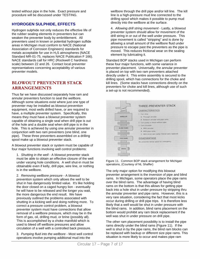
Standard BOP stacks used in Michigan can perform these four major functions, with some variance in preventer placement. Universally, the annular preventer is placed on top with two ram preventers attached directly under it. This entire assembly is secured to the drilling spool, which has connections for the choke and kill lines. (Some stacks have connections directly on the preventers for choke and kill lines, although use of such a set-up is not recommended).
Figure 11. Common BOP stack arrangement for Michigan operations, (Courtesy of NL Shaffer)
The only major option for modifying this blowout preventer arrangement is the inversion of pipe and blind rams. In Michigan, some operators place the pipe rams over the blind rams. The advantage of having blind rams on the bottom is that this allows for getting pipe back into a hole shut in under pressure by stripping thru the annular preventer and pipe rams. However, this is a very rare situation, considering the fact that most kicks occur during drilling or drill pipe trips. It is therefore less likely that a well would be shut in under pressure with the blind rams. In addition, blind rams placement on the bottom would prohibit any ram block replacement if the well was shut in under pressure on drill pipe.
The other ram placement possibility is to install the pipe rams directly under the blind rams (Figure 11). If the well is shut in by the pipe rams, the blind ram blocks can be replaced with backup or different size pipe rams. This situation is more likely to occur and makes pipe ram
Circular 17 – Page 7 of 17

Circular 17 – Page 8 of 17
placement on the bottom of the stack arrangement a sensible alternative. If a well control problem develops that cannot be handled by the existing stack, most annular preventers are made to accept additional BOP stacking on the top. This can be extremely important in special high-pressure stripping operations or where H2S gas is involved.
TESTING Installation of blowout prevention equipment is only the first major step in achieving a workable pressure-control system. The second step is making sure the equipment will work. After blowout preventers are installed they must be pressure tested to insure complete performance in a well control situation. Without prescribed, periodic pressure testing, one can only assume that the system will function properly. Assumptions are dangerous things on which to risk life and resources. The function in many phases of a regulatory field geologist's work is to 'assume nothing', and this should be emphasized where blowout prevention is involved.
Act 61, P. A. 1939, as amended, specifically requires testing of blowout prevention equipment. Rule 302, section e) states:
Blowout prevention equipment shall be tested to a pressure commensurate with the objective formation before drilling the plug on the surface pipe, before encountering the objective formation, and at other intervals in accordance with good oil field practice. A record of each pressure test and each mechanical test of the casings, blowout preventers, surface connections and fittings, and auxiliary well head equipment shall be entered in the log book, signed by the driller, and kept available for inspection by the supervisor or his authorized representative.
“. . . pressure commensurate with the objective formation . . .” simply means equal to the known or anticipated formation pressure. Note that this rule calls for testing blowout prevention equipment "before drilling the plug on the surface pipe, before encountering the objective formation, and at other intervals. . .”. There is a dual advantage in having the blowout preventers tested just prior to drilling the objective formation. First, it enables the crew that will likely be drilling the pay section to become more aware and confident of the preventer system and its operation. Secondly, this test usually finds leaks or problems that have developed since the first pressure test several days or weeks previously. Some of the problems that can develop between preventer tests are such things as: 1) flanges or seals developing leaks from vibration; 2) salt, mud, and/or cuttings accumulating on preventer seals; or 3) system alterations.
Additional blowout preventer testing procedures are required for wells drilled below the base of the Detroit River Group. These requirements, set forth in SPECIAL ORDER No. 2-73, AMENDED, (Pages 32-34) most
commonly involve wells drilled to the Niagaran formation in the northern and southern reef trends. SPECIAL ORDER 2-73, AMENDED, defines casing, cementing, blowout preventer equipment, and testing requirements. This order requires three complete pressure tests of the blowout prevention equipment: 1) before drilling the plug on surface casing; 2) before drilling the plug on intermediate casing; and 3) prior to drilling potential producing zones. A record of each test and notation in the log book of any failures and/or repairs is also required. The following discussion will deal with standard procedures for testing in accordance with SPECIAL ORDER 2-73, AMENDED.
Before blowout prevention equipment can be installed, a suitable string of surface casing must be set and cemented. SPECIAL ORDER 2-73, AMENDED, requires surface casing to be set at least 100f below all fresh water aquifers and cemented to the surface. In some areas this is deeper than 100’ below the glacial drift, as fresh water aquifers are found in some bedrock formations. A blowout preventer stack comprised of an annular preventer over two ram preventers is then installed on the surface casing. Before drilling the surface casing plug, the blowout preventers and surface casing are pressure tested in accordance with good oil field practice. Testing is usually accomplished by using the rig mud pumps. Blind rams are first tested by closing them on the open hole and pressuring up from the kill line. This provides a pressure test upward against the closed rams and pressure tests the surface casing. After testing the blind rams, drill pipe (with bit & collars) is run in the hole to the cement plug depth. The pipe rams and annular preventer are individually tested by closing them on the drill pipe and pressuring up through the kill line or drill string. Pressures involved for testing the surface casing and preventers are between 1000 and 1500 psi.
The second test of the blowout preventers is done before drilling the plug on the intermediate casing. Unless an exception has been granted prior to permit issuance, intermediate casing is set below all porous or lost circulation zones between the Amherstburg Formation and within the top 50 feet of the Salina A-2 Carbonate. Intermediate casing is cemented with a minimum of 500 feet fill-up above the casing shoe, and this must be confirmed by a verified temperature survey. Prior to drilling the cement plug, the blowout preventers, kill line, choke line and assembly, and intermediate casing are each tested to 1500 psi for at least 20 minutes. This testing can be done with the rig pumps, a service company pump truck, or by a blowout preventer testing company. Procedure for testing blowout preventers at this point is basically the same as that used in the first test on the surface casing.
The final pressure test required by SPECIAL ORDER 2-73, AMENDED, is prior to drilling potential producing zones. "Prior to" is understood to be anytime after drilling a well into the B salt but prior to penetrating the A-1 Carbonate on Niagaran wells. After drilling to this

point, the drill string is tripped out to allow testing. Because of today's rig time costs and special needs for complete blowout preventer system testing, many operators have found it advantageous to use the services of specialized blowout preventer testing companies. This testing service will be discussed in explaining the final test procedure prior to drilling potential pay.
Most service company testing of blowout preventers is accomplished by use of a truck-mounted testing unit. The truck is equipped with a triplex pump which is used for pressuring up the blowout preventer system through a high pressure rubber hose to well head connections. Time/pressure recording clocks are used on the testing unit to provide an impartial and accurate recorded chart of test times and pressures. Figure 12 is an example of a chart recording of a blowout preventer system and casing pressure test. A water tank which holds green colored test water used in pressuring up the preventers is also mounted on the testing unit.
Figure 12. Time/pressure chart of BOP system test. One hour chart time is actually 20 minutes. (Courtesy of Double Check)
Before any pressure testing is done, the blowout preventers, kill line, and choke assembly are flushed free of drilling muds. Mud is a poor test fluid because solid and colloidal particles in the mud will aid in sealing a leak which may not hold water or gas under pressure. A special test water which aids in leak detection is used in pressuring up the blowout preventers. A green fluorescent dye (developed by the Navy in World War II) is added to test water in the holding tank. Even slight weeping-type leaks in flange connections are easily detected by this green-dyed water. Water also has very low compressibility, a characteristic which makes it a desirable medium for pressure testing.
A sensible principle employed in testing blowout
preventer systems is to restrict the portion tested to the smallest possible area of the system. Testing small or isolated parts reduces the possible places where leaks might occur, aids in leak detection, and saves time in testing which, of course, is money.
Many operators, and all prudent operators, test the entire blowout preventer system and all related equipment which may be subject to well pressure. A well control system is only as good or bad as its weakest point. The following paragraphs describe parts of the system which are tested, and these are presented in the general testing sequence.
KILL LINE. The entire length of the kill line from the mud pump connection to the valves on the drilling spool is tested to the rated working pressure but not less than 1500 psi for 20 minutes. Pressure is applied (test water pumped) into the auxiliary kill line which is tied to the main kill line. This auxiliary 2”-valved kill line should be available for service company hook-up in the event the mud pumps fail or cannot handle the well control operation. Testing the kill line in this manner does not allow for a pressure test on the kill line check valve, which must be tested later from the well-bore toward the check valve. The two recommended valves between the check valve and drilling spool are each individually tested with 3000 psi pressure, applied from the spool toward the valves.
STAND PIPE & KELLY COCKS. The entire system from mud pump discharge to the kelly is pressure tested by pumping back up the kelly. A special fitting which screws onto the kelly sub allows pressure testing of the kelly cocks, swivel, drilling hose, stand pipe, and line to the mud pumps.
Figure 13. Pressure test of blind rams and outer valves on spool. Darkened portion under pressure. (Courtesy of NL Shaffer)
CHOKE LINE & MANIFOLD. The choke line and manifold (including all valves) are pressure tested to 3000 psi. This can be accomplished by pumping test water through the choke pressure-gauge fitting on the choke manifold without the loss of rig time. Test
Circular 17 – Page 9 of 17

pressure can also be applied from the wellbore. Like the kill line valves, both choke line valves which are flanged to the spool should be tested (3000 psi), with pressure applied from the wellbore toward the valves. This is accomplished when testing the preventers (Figure 13). It must be noted when referring to Figures 12, 13, 14 and 15 that the spool with kill and choke line connections is located between the blind and pipe rams. This type of system is not commonly used in Michigan operations.
BLIND RAMS. Blind Rams are the first preventers to be tested. This is accomplished by setting a boll weevil-type test plug down in the casing spool which will seal off the casing and wellbore. After closing the blind rams, pressure is applied from the kill or choke line and held at 3000 psi for 20 minutes (Figure 14). Caution must be exercised when testing the blind rams because a leaking test plug could result in exertion of excessive pressure on casing and formations in the open hole section. This problem can be eliminated by opening the valve on the casing spool below the rams.
Figure 14. Pressure test of blind rams and inner valves on spool. Darkened portion under pressure. (Courtesy of NL Shaffer)
PIPE RAMS. In testing the pipe rams, a test plug or cup packer is again set in the casing spool or top few feet of casing. This plug, or cup packer, is screwed onto a joint of drill pipe and lowered into the casing spool. The drill pipe is securely set in the slips to prevent pumping it and the test packer down the hole when pressure is applied. After closing the pipe rams, pressure is applied from the kill or choke line and held at 3000 psi for 20 minutes (Figure 15). A leaking cup packer on this test cannot damage casing or open hole formations as leaking fluid would simply flow out the open ended joint of drill pipe.
ANNULAR PREVENTER. Pressure testing the annular preventer is done in a manner similar to the procedure used for testing pipe rams. With the joint of drill pipe and cup packer still set, the annular preventer is closed on the drill pipe. An annular preventer should never be pressure tested without pipe in the hole as this could result in stress which could damage the preventer
element. Test pressure applied through the kill or choke lines should be limited to 50% of the working pressure of the annular preventer. This is commonly 1500 psi and should be held for 20 minutes (Figure 16).
Figure 15. Test plug set on drill pipe and pipe rams closed. (Courtesy of NL Shaffer)
Figure 16. Pressure test of annular preventer closed on drill pipe. Darkened portion under pressure. (Courtesy NL Shaffer)
INTERMEDIATE CASING. Pressure testing the intermediate casing prior to drilling the potential pay is required by SPECIAL ORDER 2-73, AMENDED. This test is performed by running a hook-wall packer on drill pipe into the casing and setting it at some point between the cement top (indicated by temperature survey) and casing shoe. Most operators set the hook-wall packer 100’ above the casing shoe. This provides a margin for error in counting stands of pipe. The hook-wall packer, which has slips and three sealing elements, is set by turning the drill pipe and exerting drill pipe weight. Setting the packer seals off the open hole below from the casing/drill pipe annulus. Pipe rams are closed on the drill pipe and the casing is pressure tested by pumping into the kill or choke line. Surface test pressure is usually held between 1000 and 1500 psi for 20 minutes, depending on mud weight and casing quality. Caution must be used in selecting a test pressure as it is possible to damage (split) casing by testing with
Circular 17 – Page 10 of 17

excessive surface pressure. After all pressure testing is completed a copy of the test results or entry in the log book must be available for inspection at the rig. Figure 17 is an example of a blowout preventer test report provided to the operator by the testing service company.
Figure 17. Example of BOP Test Report. (Courtesy of Double Check)
GENERAL INFORMATION ON TESTING We have discussed blowout preventer testing without venturing into the realms of possible failures, problems, and testing variables. These lessons are learned through practical experience and increased knowledge of blowout prevention. It may be helpful to note that on most preventer or system tests, a pressure loss of a few hundred psi occurs within the first five minutes (refer to
Figure 12). This pressure loss is due to compression of the sealing elements and valve packing. However, if minor pressure fall-off continues, a leak should be suspected. A pressure loss during a test is critical proportionately to the volume of space being tested. For example, a kelly cock test which loses 50 psi every five minutes would probably have a leak so small it would be undetectable. But a 50 psi loss in five minutes on an intermediate casing test should merit consideration of factors involved, such as length and size of casing string or whether testing with a packer or against a cement plug. Most common leaks found during blowout preventer testing are small in nature and occur around flanges, connections, preventer seals, and packings.
There are two types of pressure tests not currently used in Michigan which merit mention.
A formation integrity test is required by the USGS on many off-shore drilling operations. This test is designed to find the integrity limit of exposed formations below the casing shoe so that maximum allowable mud weights can be calculated. The test is performed by drilling below the casing shoe and pressuring up on the exposed formation until it begins to take fluid. This measured formation leak-off pressure is used to determine maximum mud weights that can be used without risk of formation breakdown.
Although not required in Michigan, low pressure blowout preventer testing warrants mention. Low pressure testing of preventers will often reveal leaks that hold a seal at high pressure. As previously discussed, rams and annular preventers seal more effectively at higher test pressures, since wellbore pressures assist in obtaining a seal. In most well control situations it is common to have relatively low (200 to 500 psi) initial shut-in pressures. With this in mind it is reasonable to expect that blowout preventers should be capable of holding lower wellbore pressures.
CLOSING UNITS The most complete blowout preventer system ever designed would be of little value if the closing unit did not function when it was needed. Our current State regulations do not require any specific closing unit tests other than the obvious ability to close the preventers under test conditions. Although we have no requirements concerning closing units, we recommend referring to Section 5-A in API RP 53, API RECOMMENDED PRACTICES FOR BLOWOUT PREVENTION EQUIPMENT SYSTEMS.
SPECIAL EQUIPMENT Blowout prevention begins with maintaining primary control of a well through hydrostatic overbalance. If proper mud weight and hydrostatic column height are maintained, there should be little or no need for blowout preventers. Primary blowout prevention is kick
Circular 17 – Page 11 of 17

prevention and kick prevention is avoiding the mistakes that result in kicks. As discussed in the beginning portions of this circular, there are five major causes of blowouts, two of which are identified as main troublemakers. These two major causes are: 1) not keeping the hole full, and 2) swabbing. Both occur during trips. Swabbing is a form of not keeping the hole full. Avoiding these troublemakers and preventing kicks is a much easier task than attempting to regain control of a kicking well. Potential problems can be avoided through careful monitoring of the operations with the aid of special equipment.
Figure 18. Trip Tank Work Sheet.
TRIP TANK A trip tank is potentially one of the most valuable pieces of equipment in kick detection. "Potentially" is used as a modifier because if the trip tank is not used properly (or not used at all) it does no good. A trip tank is an open tank which is marked for gauging volume (barrels) of mud pumped from the tank during tripping operations. The value of a trip tank is that it allows exact monitoring of mud volume needed to keep the hole full related to
pipe volume withdrawn from the hole. The volume of mud needed to fill the hole must equal the volume of pipe pulled out. If the volume of mud needed to keep the hole full is less than the volume of pipe pulled, it can be expected that something else has occupied that volume, such as swabbed gas. Figures 18 and 19 are trip tank work sheets and tables used for mud/pipe volume calculations.
Figure 19. Tables for use with Trip Tank Work Sheet.
Keeping the hole "full" during trips by continuously filling or filling after every five stands of pipe are pulled without using a trip tank can cause problems. These methods allow for swabbing-in of gas, oil, or brine without detection until the hole starts unloading fluid at the surface. The word "full" must be used as it relates to mud volume and pipe volume involved in tripping.
Circular 17 – Page 12 of 17

PIT VOLUME TOTALIZER AND FLOW SENSOR Two other pieces of equipment which can aid in kick detection are the pit volume totalizer (PVT), and the flow sensor. These instruments gauge and record on a time chart pit volume and flow from the wellbore.
PVT. Changes in pit volume during the drilling of a well can indicate possible well control or related problems. A PVT with high/low alarm can detect an increase in fluid volume in the pit caused by formation fluid or gas invading the wellbore. These invading fluids displace mud from the wellbore which shows up proportionately as a mud volume increase in the drilling pit. Gradual formation fluid invasion into the wellbore which may not be noticeable during drilling can also be detected by a PVT. This is valuable information, considering that any change in the mud properties can affect primary well control. Gradual fluid loss into porous or weak zones is also important information that may be detectable only on a PVT. Figure 20 is a PVT chart recording of pit mud volume changes.
Figure 20. 24-hour chart from Pit Volume Totalizer showing pit volume in barrels. (Note: 3 days continuous record of pit volume).
FLOW SENSOR. A flow sensor is very much like a PVT, showing increases or decreases in amount of mud coming from the wellbore. Unlike a PVT, which indicates total volume in barrels, a flow sensor records percent of mud flow coming from the well. The flow sensor also records on a time chart and can be installed with high/low alarms. Changes in flow occur normally during drilling operations when making connections, increasing circulating pressure, and during other operations. Although these flow changes are normal, a sudden increase or decrease during drilling, tripping, or
circulating can alert crews to an unpredicted change in flow which may relate to primary well control. Figure 21 is a flow sensor chart recording of flow variations during drilling operations. The use of trip tanks, PVTs, and flow sensors is not generally required in Michigan operations, although many prudent operators use some or all of them. Special requirements for drilling in particular areas call for their use.
IN PARTING It is hoped that the material presented has provided the basic information for a better understanding of blowout preventers. Further, it must be understood that all of the equipment presented not only has specific advantages and applications, but also has certain limitations. The key to blowout prevention is the knowledge and understanding of primary well control combined with the proper use of detection and prevention equipment.
Figure 21. 24-hour chart from Flow Sensor showing percent (%) of flow. 40% flow during normal drilling, 0% when making connections.
STATE OF MICHIGAN DEPARTMENT OF NATURAL RESOURCES
SUPERVISOR OF WELLS
SPECIAL ORDER NO. 2-73, AMENDED CASING AND SEALING REQUIREMENTS FOR WELLS DRILLED BELOW THE BASE OF THE DETROIT RIVER GROUP WITH ROTARY TOOLS
Pursuant to a public hearing held in Lansing, Michigan,
Circular 17 – Page 13 of 17

Circular 17 – Page 14 of 17
on February 21, 1974, and review of the evidence and testimony presented and in consideration of the recommendation of the Oil Advisory Board, the Supervisor of Wells has determined the following procedure and minimum casing and sealing requirements are necessary to insure the health, welfare, and safety of the public. These requirements are hereby issued in conjunction with and in addition to the provisions of Rule 301, 302, and 306 of the General Rules promulgated June 21, 1971, under the authority of Act No. 61, Public Acts, 1939, as amended.
1) Casing shall be run from the surface to a depth no less than 100 feet into the bedrock and in all instances shall be run at least 100 feet below all fresh water aquifers; shall be cemented to the surface by the pump and plug method; shall be equipped with blowout preventer equipment in accordance with the provisions of the General Rules; and pressure tested in accordance with good oil field practice.
2) An intermediate string of casing of sufficient weight and quality to withstand the maximum anticipated pressure is to be run from the surface to a point below all porous or lost circulation zones between the Amherstburg Formation of the Detroit River Group and a point within the top fifty (50) feet of the Salina A2 Carbonate or equivalent. The minimum size hole for any given size casing is to be one and three-quarters inches (1 3/4") larger in diameter than the outside diameter of the casing run. The casing is to be equipped with centralizers and scratchers in accord with good oil field practice and be cemented with a minimum of 150 sacks of cement of the proper class and such additives as may be necessary to provide a positive seal in the annulus for a minimum distance of 500 feet above the casing shoe. Additional cement shall be used if unusual drilling or well bore conditions are encountered or upon the direction of the Supervisor or his agent. A temperature survey shall be run in order to determine the top of the cement if the cement is not circulated to the surface. Verification of the survey, signed by the service company representative, designating the depth at which he found the top of the cement, shall be left at the rig and be available for inspection by the Supervisor's agent. A copy of the temperature survey and copy of the cementing service ticket shall be filed promptly at the office of the Supervisor.
3) Blowout prevention equipment shall be installed to provide positive SINGLE shut-off protection when the drill pipe is out of the hole; to provide positive DOUBLE shut-off protection when drill pipe is in the hole; to provide connections separate of those of the casinghead for choke and kill line assemblies; and to provide protection against casing wear.
4) All outlets, fittings, and connections on the casing, blowout preventers, and auxiliary well head equipment which may be subject to well head pressure shall be of such material construction designed to withstand the maximum anticipated
pressure at the well head. All lines from outlets on or below the blowout preventers shall be securely anchored. All outlets below the blowout preventers shall be the flange type.
5) Before drilling the plug, the blowout preventers, surface connections and fittings, auxiliary well head equipment, and the intermediate casing is to be satisfactorily pressure tested for a period of at least 20 minutes at a stabilized pressure of not less than 1,500 psig. A representative of the Supervisor shall be notified a minimum of 12 hours prior to commencement of the test.
6) Prior to drilling potential producing zones the blowout preventers, surface connections and fittings, auxiliary well head equipment, and intermediate casing are to be satisfactorily pressure tested for a period of at least 20 minutes at a pressure commensurate to the maximum rated working pressure. A representative of the Supervisor shall be notified a minimum of 12 hours prior to commencement of the test.
7) Mechanical tests shall be made by each crew on every tour to insure that the blowout preventers are in working order and will close properly.
8) A record of each pressure test and each mechanical test of the casings, blowout preventers, surface connections and fittings, and auxiliary well head equipment shall be entered in the log book and kept available for inspection by the Supervisor of Wells or his authorized representative.
9) Any failure of the casings, blowout preventers, surface connections and fittings, or auxiliary well head equipment during the required pressure or mechanical tests shall be corrected or repaired and retested. The nature of the failure, its repair, and retesting shall be recorded in the log book before drilling is resumed.
10) The development of any hazardous condition during drilling operations such as lost circulation, threatened blowouts, casing or cement failure or failure of any secondary control equipment must be reported promptly to the Supervisor of Wells.
The requirements and procedures set forth are applicable to all wells drilled below the base of the Detroit River Group with rotary tools except where special rules are adopted pursuant to public hearings scheduled for such purpose; or in instances where subsequent to receipt of written supportive data and upon review and evaluation and where deemed appropriate exceptions may be granted by the Supervisor or his authorized representative; or in instances where the Supervisor finds them inadequate or inappropriate and adopts such requirements as he may deem appropriate and necessary; or in the event unusual geological conditions or mechanical problems are encountered during drilling operations.
This order amends and supersedes Special Order No. 2-

Circular 17 – Page 15 of 17
73 dated May 21, 1973, and Casing and Sealing Directives issued December 21, 1967, and January 30, 1970, pertaining to the Albion-Scipio Trenton-Black River Formation Trend Field in Calhoun, Jackson, and Hillsdale Counties and Specified Areas of Calhoun County and directive effective June 1, 1968, pertaining to St. Clair and Macomb Counties.
Signed and ordered published this 15th day of April, 1974.
s/ A. Gene Gazlay A. GENE GAZLAY SUPERVISOR OF WELLS
SECTION 12 GLOSSARY ACCUMULATOR. A pressure vessel charged with nitrogen gas and used to store hydraulic fluid under pressure for operation of blowout preventers.
ANNULAR PREVENTER. A device which can seal around any object in the wellbore or upon itself. Compression of a reinforced elastomer packing element by hydraulic pressure effects the seal.
BELL NIPPLE (MUD RISER, FLOW NIPPLE). A piece of pipe, with inside diameter equal to or greater than the blowout preventer bore, connected to the top of the blowout preventer or marine riser with a side outlet to direct the drilling fluid returns to the shale shaker or pit. Usually has a second side outlet for the fill-up line connection.
BLIND RAMS (BLANK, MASTER). Rams whose ends are not intended to seal against any drill pipe or casing. They seal against each other to effectively close the hole.
BLIND/SHEAR RAMS. Blind rams with a built-in cutting edge that will shear tubulars that may be in the hole, thus allowing the blind rams to seal the hole. Used primarily in subsea systems.
BLOWOUT. An uncontrolled flow of well fluids and/or formation fluids from the wellbore or into lower pressured subsurface zones (underground blowout).
BLOWOUT PREVENTER. A device attached to the casinghead that allows the well to be sealed to confine the well fluids in the wellbore.
BLOWOUT PREVENTER DRILL. A training procedure to determine that rig crews are completely familiar with correct operating practices to be followed in the use of blowout prevention equipment. A "dry run" of blowout preventive action.
BLOWOUT PREVENTER OPERATING AND CONTROL SYSTEM (CLOSING UNIT). The assembly of pumps, valves, lines, accumulators, and other items necessary to open and close the blowout preventer equipment.
BLOWOUT PREVENTER STACK. The assembly of
well control equipment including preventers, spools, valves, and nipples connected to the top of the casinghead.
BLOWOUT PREVENTER TEST TOOL. A tool to allow pressure testing of the blowout preventer stack and accessory equipment by sealing the wellbore immediately below the stack (refer to Section 8-A).
CASINGHEAD/SPOOL. The part of the wellhead to which the blowout preventer stack is connected.
CHOKE. A device with either a fixed or variable aperture used to control the rate of flow of liquids and/or gas.
CHOKE LINE VALVE. The valve(s) connected to and a part of the blowout preventer stack that controls the flow to the choke manifold.
CHOKE MANIFOLD. An assembly of valves, chokes, gauges, and lines used to control the rate of flow from the well when the blowout preventers are closed.
CLAMP CONNECTION. A pressure sealing device used to join two items without using conventional bolted flange joints. The two items to be sealed are prepared with clamp hubs. These hubs are held together by a clamp containing two to four bolts. These are not API connections.
CLOSING RATIO. The ratio of the wellhead pressure to the pressure required to close the blowout preventer.
CONDUCTOR PIPE. A relatively short string of large diameter pipe which is set to keep the top of the hole open and provide a means of returning the upflowing drilling fluid from the well-bore to the surface drilling fluid system until the first casing string is set in the well. Conductor pipe is usually cemented.
CONTROL MANIFOLD. The system of valves and piping to control the flow of hydraulic fluid to operate the various components of the blowout preventer stack.
CONTROL PANEL, REMOTE. A panel containing a series of controls that will operate the valves on the control manifold from a remote point.
CONTROL POD. An assembly of subsea valves and regulators which when activated from the surface will direct hydraulic fluid through special apertures to operate blowout preventer equipment.
DIVERTER. A device attached to the wellhead or marine riser to close the vertical access and direct any flow into a line away from the rig. Diverters differ from blowout preventers in that flow is not stopped but rather the flow path is redirected away from the rig.
DRILLING SPOOL. A connection component with ends either flanged or hubbed. It must have an internal diameter at least equal to the bore of the blowout preventer and can have smaller side outlets for connecting auxiliary lines.
DRILL PIPE SAFETY VALVE. An essentially full-opening valve located on the rig floor with threads to

Circular 17 – Page 16 of 17
match the drill pipe in use. This valve is used to close off the drill pipe to prevent flow.
DRILL STRING FLOAT. A check valve in the drill string that will allow fluid to be pumped into the well but will prevent flow from the well through the drill pipe.
DRIVE PIPE. A relatively short string of large diameter pipe driven or forced into the ground to function as "conductor pipe" (refer to Par. 12.18).
FILL-UP LINE. A line usually connected into the bell nipple above the blowout preventers to allow adding drilling fluid to the hole while pulling out of the hole to compensate for the metal volume displacement of the drill string being pulled.
GATE VALVE. A valve which employs a sliding gate to open or close the flow passage. The valve may or may not be full-opening.
HYDROSTATIC HEAD. The pressure which exists at any point in the wellbore due to the weight of the column of fluid above that point.
INSIDE BLOWOUT PREVENTER. A device that can be installed in the drill string that acts as a check valve allowing drilling fluid to be circulated down the string but prevents back flow.
KELLY COCK. A valve immediately above the kelly that can be closed to confine pressures inside the drill string.
KELLY VALVE, LOWER. An essentially full-opening valve installed immediately below the kelly, with outside diameter equal to the tool joint outside diameter. Valve can be closed to remove the kelly under pressure and can be stripped in the hole for snubbing operations.
KICK. Intrusion of formation liquids or gas that results in an increase in pit volume. Without corrective measures, this condition can result in a blowout.
KILL LINE. A high pressure line between the pumps and some point below a blowout preventer. This line allows fluids to be pumped into the well or annulus with the blowout preventer closed.
LOST RETURNS. Loss of drilling fluids into the formation resulting in a decrease in pit volume.
MINIMUM INTERNAL YIELD PRESSURE. The lowest pressure at which permanent deformation will occur.
DRILLING FLUID WEIGHT RECORDER. An instrument in the drilling fluid system which continuously measures drilling fluid density.
OPENING RATIO. The ratio of the well pressure to the pressure required to open the blowout preventer.
OVERBURDEN. The pressure on a formation due to the weight of the earth material above that formation. For practical purposes this pressure can be estimated at 1 psi/ft of depth.
PACKOFF OR STRIPPER. A device with an elastomer packing element that depends on pressure below the packing to effect a seal in the annulus. Used primarily to
run or pull pipe under low or moderate pressures. This device is not dependable for service under high differential pressures.
PIPE RAMS. Rams whose ends are contoured to seal around pipe to close the annular space. Separate rams are necessary for each size (outside diameter) pipe in use.
PIT VOLUME INDICATOR. A device installed in the drilling fluid tank to register the fluid level in the tank.
PIT VOLUME TOTALIZER. A device that combines all of the individual pit volume indicators (refer to Par. 12.42) and registers the total drilling fluid volume in the various tanks.
PLUG VALVE. A valve whose mechanism consists of a plug with a hole through it on the same axis as the direction of fluid flow. Turning the plug 90° opens or closes the valve. The valve may or may not be full-opening.
PRESSURE GRADIENT, NORMAL. The subsurface pressure proportional to depth, which is roughly equal to the hydrostatic pressure of a column of salt water (0.465 psi/ft).
RELIEF WELL. An offset well drilled to intersect the subsurface formation to combat a blowout.
ROTATING HEAD. A rotating, pressure-sealing device used in drilling operations utilizing air, gas, foam, or any other drilling fluid whose hydrostatic pressure is less than the formation pressure.
SALT WATER FLOW. An influx of formation salt water into the wellbore.
SHEAR RAMS. Refer to Par. 12.5.
SWABBING. The lowering of the hydrostatic pressure in the hole due to upward movement of pipe and/or tools.
TARGET. A bull plug or blind flange at the end of a tee to prevent erosion at a point where change in flow direction occurs.
TRIP GAS. An accumulation of gas which enters the hole while a trip is made.
WIRELINE PREVENTERS. Preventers installed on top of the well or drill string as a precautionary measure while running wirelines. The preventer packing will close around the wireline.
Glossary is from American Petroleum Institute (API) Recommended Practices for Blowout Prevention Equipment Systems, RP 53 first edition 1978, reprinted with permission.

Circular 17 – Page 17 of 17
STATE OF MICHIGAN William G. Milliken, Governor
DEPARTMENT OF NATURAL RESOURCES
Howard A. Tanner, Director
GEOLOGICAL SURVEY DIVISION Arthur E. Slaughter, Chief and State Geologist
NATURAL RESOURCES COMMISSION Hilary F. Snell, Chairman, Grand Rapids
Jacob A. Hoefer, East Lansing Carl T. Johnson, Cadillac
E. M. Laitala, Hancock Harry H. Whiteley, Rogers City (Mrs.) Joan L. Wolfe, Belmont
Charles G. Younglove, Allen Park John M. Robertson, Executive Assistant
Published by authority of State of Michigan CL ‘70 s.321.6 Printed by Reproduction Services Section, Office Services Division, Department of Management and Budget
Available from the Information Services Center, Michigan Department of Natural Resources, Box 30028, Lansing, Michigan 48909
On deposit in public libraries, state libraries, and university libraries in Michigan and other selected localities.