controlling arc welding risk to persons with...
TRANSCRIPT
International Journal of Sciences and Techniques of Automatic control & computer engineering IJ-STA, Volume 1, N° 2, December 2007, pp. 213−225.
This paper was recommended for publication in revised form by the editor Staff. Edition: CPU of Tunis, Tunisia, ISSN: 1737-7749
Controlling Arc Welding Risk to Persons with Pacemaker
Dr. Nuri Bhieh, Eng. Esmaiel Elsghier,
Eng. Marai Ali Khalifa and Eng. Mohammed Salem Elamari
Welding Technology Center, Tripoli – Libya Tel. :00218-21-3697242 ; Fax. :00218-21-3697243
Abstract. The primary welding processes are oxyfuel gas, arc and resistance welding. Also there is another technique such like laser and electron beam welding. In arc welding, the heat is produced by an electrical discharge. The welding arc is discharged through an ionized gas, with the arc produced between the tip of the electrode and the work piece to be welded. Either ac or dc power supplies can be used, as well as either a consumable or no consumable electrode, which is usually a rod or wire. This paper focuses the light on the precaution for persons with pacemakers near electrical arc welding, and new techniques to improve the performance of the pacemaker instruments using a special design involves both hardware, software, and the programmer, to use the pacemaker device as a sensor that will detect the arc welding rays.
Keywords. Pacemaker, electromagnetic fields, arc radiations, welding risks.
1. Introduction
Electrical arc welding produces intense electric and magnetic interference which may, in some cases, interrupt the function of cardiac pacemakers. Welding interference not permanently damage the pacemaker. Persons with a pacemaker should not go near electric welding until they have discussed this matter with their physicians, to prevent any further risks. These recommendations are intended only for conventional electric welders. Welders over 400 amps, automated spot welding, and similar industrial equipment require additional precautions. People are often concerned about the possibility of arc welding rays interfering with pacemakers, and other sensitive devices. The ability of electrical and electronic systems to operate in an electromagnetic environment without interference is known as electromagnetic compatibility. In fact, all electrical systems can be disturbed if exposed to sufficiently high emissions. For this reason, it is achieved by limiting or controlling electromagnetic emissions as well as ensuring that electrical systems are adequately immune to electromagnetic interactions.
Controlling Arc Welding Risk to Persons with Pacemaker − N. Bhieh et al. 214
The work done is to be focused on the way that safe the operation of the pacemaker devices. We have to use a software program to improve the performance of pacemaker devices, to be protected against arc welding radiations, and allow users to work in a safe situation. So, in case of normal state, it will indicate a signal in safe mode of operation. While when it reaches a high level of arc radiation it gives alarming signal to switch the system off.
The safety and health of welders The safety and health of industrial and construction workers are receiving
increasing attention. All workers engaged in production and construction are continually exposed to potential hazards.
There are several potential health and safety problems associated with welding. However, with properly instituted precautionary measures, welding is a safe occupation. Health officials state that welding, as an occupation, is no more hazardous or injurious to the health than other metal working occupations.
The more common hazards, which apply to all metal working occupations, are accidents resulting from falling, from being hit by moving objects, from exposure to excessive noise, from working around moving machinery, from exposure to hot metals, …etc.
Electricity level in arc welding Electricity can cause electric shock, burns, explosions and fires. In the welding
environment, power supplies are frequently fed from mains, sometimes at high voltages (>400V). The welding circuit itself will run at a low voltage and high current, but in order to strike the arc, the welding set will generally have a relatively high voltage open circuit (of order 100 V), which can cause fatal shock, particularly
when welding in a conducting environment, such as damp conditions or inside metal vessels.
Risk of welding electric shock In welding, the voltage to earth may be high enough to cause fatal shock, if
welders make contact with a live part with one part of their body and an earth with another part. This can easily happen in damp conditions, if their gloves are faulty or if their head makes contact with an earthed object such as a steel girder. The hazards of electric shock are known to be less with a DC supply, but some welding sets have a substantial AC ripple, rendering them less safe than true DC.
Where welding sets have been connected to different phases of the supply to the welding shop, there is an increased risk of electric shock, because the differences in voltage between two welders on different phases is much greater than either to earth. Great care should be taken to avoid the situation where they can touch one another’s equipment.
Dry skin offers an appreciable resistance, whereas damp or sweaty skin makes a much better connection, much increasing the hazard.
Dry clothing, boots and other personal protective equipment can provide almost perfect insulation at normal welding voltages. Hence the welder working at a bench can touch live parts while standing clear of metalwork, insulated by his or her boots, without coming to any harm.
215 IJ-STA, Volume 1, N° 2 , December 2007.
Medical Monitoring Because welding emissions are so hazardous, the recommends that all workers
who may be exposed to welding processes should receive medical exams at least once a year. The doctor should examine the lungs, skin and eyes, heart, and hearing, in addition to any other tests that are appropriate.
Welding radiations Radiation includes light, heat and ionizing radiation, all of which are found
within, or associated with, the welding environment. Arc welding produces large quantities of light, from the ultraviolet to infrared
radiation. Ultraviolet radiation from a welding arc is intense – for example a metal inert gas (MIG) weld using helium gas running at 300 A typically produces 5Wm-2 at a distance of one meter. This is many times the intensity of the sun at noon. The visible radiation is also intense. Oxyacetylene welding produces less ultraviolet light, but still produces substantial quantities of visible and infrared radiation.
Protection of welding radiations The welder is generally protected by clothing and those further away should be
protected by screens and curtains. Clothing should cover all the skin, to protect not only from radiation, but also spatter, electrical contact and sparks. Depending on the demands of the task this clothing will include a boiler suit and cap, gloves, shoes or boots.
For heavy work aprons, shoulder covers, jacket and leggings or spats may be added.
Personal clothing should be made from wool or cotton, so that it cannot melt. Additional protective clothing, such as aprons, is frequently made from leather. Protective clothing should not have external pockets, unless they have a closeable flap to completely overlap the opening. Clothing should be designed to avoid openings or folds where spatter can lodge.
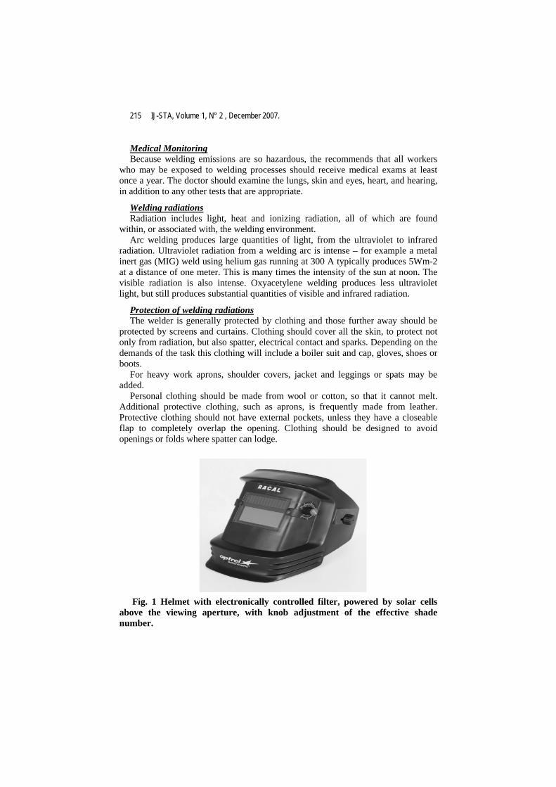
Fig. 1 Helmet with electronically controlled filter, powered by solar cells
above the viewing aperture, with knob adjustment of the effective shade number.

Controlling Arc Welding Risk to Persons with Pacemaker − N. Bhieh et al. 216
Gloves should protect against electrical contact and radiation. Most welding gloves are made from leather. Cotton gloves may be worn inside as liners. The seams should be inside (to avoid the thread being burnt) and the materials should be suitable for the temperature range to which they are exposed.
Protective screens should be used to shield adjacent welding stations from one another, and also others in the environment. Screens are available in a wide range of colors, each being suited to particular welding operations. The materials from which screens are made should be non-combustible or flame resistant.
In the next paragraph, we will discuss the pacemaker new system performance design, and the suitable way to monitor arc radiations.
2. The pacing system
Fig. 2 Pacemaker connects to patients with heart failure
Recent clinical studies have shown that excessive ventricular pacing may be
harmful to some patients, possibly leading to congestive heart failure and arterial fibrillation. The next generation pacemaker contains a managed ventricular pacing function, which enables the device to be programmed to deliver pacing pulses to the heart’s lower right chamber (ventricle) only when necessary. These clinical studies have suggested that reducing this pacing stimulation may reduce the patient’s risk of developing congestive heart failure and arterial fibrillation, a potentially life- threatening irregular heartbeat.
Pacemaker environmental interactions The pacemaker industry has concentrated significant resources into the
prevention of environmental interaction with pacemaker systems. However, increasing environmental sources of electromagnetic radiation makes this challenging.
Electromagnetic interference has the potential to cause a pacemaker to respond in a number of ways: inappropriate inhibition or triggering of pacemaker output,

217 IJ-STA, Volume 1, N° 2 , December 2007.
asynchronous pacing, reprogramming to backup mode, or even irreversible damage to pacemaker components (table 1).
Advice Potential interaction Environmental interaction
Patient advised to move through devices quickly
Pacemaker inhibition, under sensing or over sensing
Electronic antitheft devices
Use of contra lateral ear to device or use "hands free" device
Temporary asynchronous pacing or inhibition (only if device placed directly over generator)
Cellular devices
Work environmental assessed to quantify any possible interference
Inhabitation of pacing High voltage generators or arc welding
Avoid Inhibition or asynchronous pacing, irreversible device malfunction, or lead displacement
Magnetic resonance imaging (MRI)
Use of bipolar diathermy, programming of device postoperatively
Inhibition of pacing and irreversible device malfunction. Increased pacing threshold
Electrocoulery devices and diathermy
Shielding of device if close to irradiation field
Problems very rare but theoretically could cause irreversible malfunction
Therapeutic irradiation
No interaction Diagnostic radiology Maintain defibrillation paddles as far from pulse generator as possible. Consider anteroposterior paddle position
Potential irreversible device malfunction
Defibrillation
Table 1. Potential sources of electromagnetic interference of pacemaker systems.
Device advisories and recalls There is a certain inevitability that as pacemaker technology progresses there
will be some device failures. When these are likely that the next phase in development of the technology might be in advances in physiological data obtained from devices. Increasingly ICD technology provides us with biomedical data such as heart rate variability, Tranthoracic impedance, etc. As sensors are developed to assess cardiac output and blood pressure it is likely that pacemaker follow up will involve more clinical interpretation of these types of data rather than the mostly technical data that are presented at the moment. In response to this there is a trend to increasing the automatic management of such technical aspects of device function.
Controlling Arc Welding Risk to Persons with Pacemaker − N. Bhieh et al. 218
Detailed design The design involves both hardware and software design for the pacemaker and
the programmer.
Pacemaker
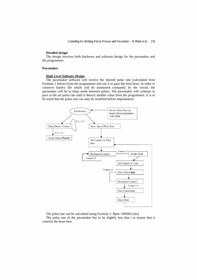
High Level Software Design The pacemaker software will receive the desired pulse rate (calculated from
Formula 1 below) from the programmer and use it to pace the fetal heart. In order to conserve battery life which will be monitored constantly by the circuit, the pacemaker will be in sleep mode between pulses. The pacemaker will continue to pace at the set pulse rate until it detects another value from the programmer. It is to be noted that the pulse rate can only be modified before implantation.
The pulse rate can be calculated using Formula 1: Bpm= 60000/t (ms) The pulse rate of the pacemaker has to be slightly less that t to ensure that it
controls the heart beat.
219 IJ-STA, Volume 1, N° 2 , December 2007.
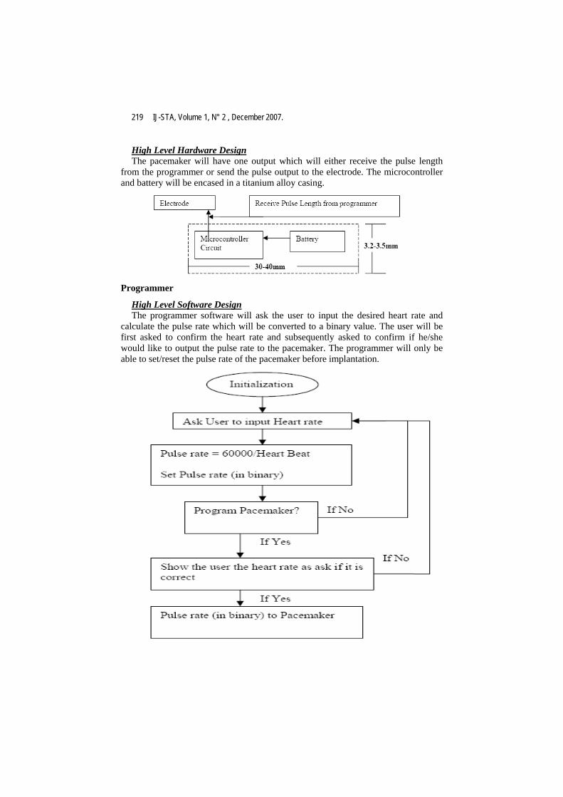
High Level Hardware Design The pacemaker will have one output which will either receive the pulse length
from the programmer or send the pulse output to the electrode. The microcontroller and battery will be encased in a titanium alloy casing.
Programmer
High Level Software Design The programmer software will ask the user to input the desired heart rate and
calculate the pulse rate which will be converted to a binary value. The user will be first asked to confirm the heart rate and subsequently asked to confirm if he/she would like to output the pulse rate to the pacemaker. The programmer will only be able to set/reset the pulse rate of the pacemaker before implantation.
Controlling Arc Welding Risk to Persons with Pacemaker − N. Bhieh et al. 220
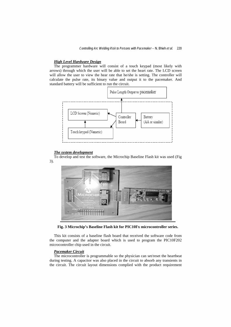
High Level Hardware Design The programmer hardware will consist of a touch keypad (most likely with
arrows) through which the user will be able to set the heart rate. The LCD screen will allow the user to view the hear rate that he/she is setting. The controller will calculate the pulse rate, its binary value and output it to the pacemaker. And standard battery will be sufficient to run the circuit.
The system development To develop and test the software, the Microchip Baseline Flash kit was used (Fig
3).
Fig. 3 Microchip’s Baseline Flash kit for PIC10Fx microcontroller series. This kit consists of a baseline flash board that received the software code from
the computer and the adapter board which is used to program the PIC10F202 microcontroller chip used in the circuit.
Pacemaker Circuit The microcontroller is programmable so the physician can set/reset the heartbeat
during testing. A capacitor was also placed in the circuit to absorb any transients in the circuit. The circuit layout dimensions complied with the product requirement

221 IJ-STA, Volume 1, N° 2 , December 2007.
(Fig. 4). The flat flex header connected circuit to the Baseline Flash kit for programming the microcontroller.
Fig. 4 Pacemaker electronic circuit.
Software The software was written in assembly language and has two components to it, the
include file (Fetal_pacemaker_interface.inc) and the pacing file (Fetal_Pacemaker.asm).
The include file is an interface file which the physician will use to set the heart rate. Due to the arithmetic abilities of the microcontroller, calculating the rate (formula 1) and converting it into a binary number will be done by the programmer. Therefore, in the include file the physician will have to directly enter the rate as a binary number.
The Fetal_Pacemaker.asm software is designed to output a 1.2ms pulse “high” pulse and a “low” pulse for the remainder of the pulse width. For example, if the heart rate is set to 120bpm this gives a pulse rate of 500ms. Thus the output will be high for 1.2ms and low for 498.8ms. Also due to time constraints, the pacing circuit does not manage the battery voltage or sleep mode as indicated in the detailed design section. However, once the ideal battery has been chosen for the pacemaker, assembly code for battery management can be added to the software.
Improvements There are a few improvements that can be applied to the pacemaker. One of this
that we will introduce a control program that will indicate the warning level of the arc current whiles the pacemaker device in operation.
The program will be written in "c++" programming language, and entering the arc current as parameters to the microcomputer processor.
Prog.1 # include "stdafx.h" # include "iostream.h" main ( ) { int current parameters

Controlling Arc Welding Risk to Persons with Pacemaker − N. Bhieh et al. 222
char warning level; cin>>parameter; if (parameter>=500 amp) { warning level ="A"; { else if (parameter>=400 amp) { warning level ="B"; { else if (parameter>=300 amp) { warning level ="C"; { else if (parameter>=200 amp) { warning level ="D"; { else if parameter>=100 amp) { warning level ="E"; } cout <<warning level return o; } The programmed parameters for arc welding level are as follows:
500 amp "very risk level" 400 amp "risk level 1" 300 amp "risk level 2" 200 amp "risk level 3" 100 amp "risk level 4"
Then the microprocessor will proceed these parameters, and indicates a warning level according to each state.
Welders in particular should be mindful of additional energy-related issues, such as the distance people should stay clear of work being done (table 2). Also remember:
♦ Don't perform housekeeping duties near exposed energized parts unless a barrier or insulating device is used.
♦ Keep weld-initiating control circuits less than 120 volts AC root mean square (RMS) for stationary equipment, and not over 36 VAC RMS for portable equipment.
♦ For welding capacitors, insulate and enclose (via doors with interlocks and wired contacts into the control circuit) resistance welding equipment and
223 IJ-STA, Volume 1, N° 2 , December 2007.
control panels (with over 550 V RMS). Design contacts and doors to interrupt power when opened. Add a manual switch or positive device as an extra safety measure. *
♦ Lock, interlock, or guard remote welding control panels on overhead platforms or in separate rooms by physical barriers and signage when not being serviced.
♦ When working with electrical circuits, use circuit breakers to open, reverse, or close circuits under load conditions. Make sure circuits are checked before they're re-energized and over current protection can't be modified.
♦ Inspect the cords on portable electrical equipment to ensure safety, and never pick up or hang equipment by its cord.
These procedures are essential. According to the international health organizations, the policy prevents approximately 120 fatalities and more than 28,000 lost workdays each year. Welding carries risks, but when we take responsibility for our own safety, we can control those risks.
Keeping appropriate distance:
When authorized employees are performing service on machines or equipment that has been locked out and tagged out, it's vital that other qualified individuals maintain a certain distance from the welding machine as guideline. The distance depends on the voltage range in use. When conducting work, we use the following chart (table 2):
Minimum approach distance
Voltage range (Ac)
1' (30.5 cm) < 300 V 1'6" (46 cm) > 300 V, < 750 V 2' (61 cm) > 750 V, < 2 kV 2'6" (91 cm) > 2 kV, < 15 kV 3'6" (107 cm) > 15 kV, < 37 kV 4' (122 cm) > 37 kV, < 87.5 kV 4'6" (137 cm) > 87.5 kV, < 121 kV 4'6" (137 cm) > 121 kV, < 140 kV
Note: Unqualified employees are required to adhere to the 10-ft. minimum at all
times.
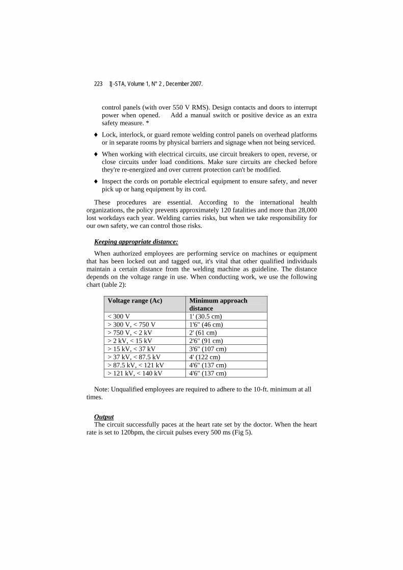
Output The circuit successfully paces at the heart rate set by the doctor. When the heart
rate is set to 120bpm, the circuit pulses every 500 ms (Fig 5).
Controlling Arc Welding Risk to Persons with Pacemaker − N. Bhieh et al. 224
Fig. 5 Pulse Frequency when the heart rate is set to 120bpm
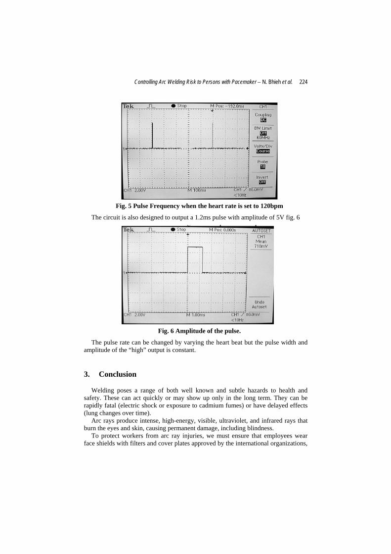
The circuit is also designed to output a 1.2ms pulse with amplitude of 5V fig. 6
Fig. 6 Amplitude of the pulse.
The pulse rate can be changed by varying the heart beat but the pulse width and amplitude of the “high” output is constant.
3. Conclusion
Welding poses a range of both well known and subtle hazards to health and safety. These can act quickly or may show up only in the long term. They can be rapidly fatal (electric shock or exposure to cadmium fumes) or have delayed effects (lung changes over time).
Arc rays produce intense, high-energy, visible, ultraviolet, and infrared rays that burn the eyes and skin, causing permanent damage, including blindness.
To protect workers from arc ray injuries, we must ensure that employees wear face shields with filters and cover plates approved by the international organizations,

225 IJ-STA, Volume 1, N° 2 , December 2007.
as well as safety glasses underneath face shields or helmets. Workers' heads must be kept a safe distance from the arc rays. Consider using "cheaters," magnifiers that help welders see better from a safer distance.
The development of the pacemaker device was responsible for: • The creation of the test designs and test cases for portions of the pacemaker, the wireless communications protocol, and the programmer. • The verification testing of diagnostic heart information stored on the pacemaker. • The verification testing of the functions involving the format of messages between the pacemaker and the programmer. • The verification testing of the error detection and device reset features of the pacemaker.
4. References
[1] Health and Safety in Welding, October 2006; pp: 4, 7. [2] http://www.avistainc.com/avista_22_next_generation_pacemaker.pdf [3] Wladimiroff JW, Stewart PA, Tonge HM. Fetal bradyarrhythmia: diagnosis
and outcome. Prinat Diagn 1988; 8:53-7. [4] http://www.emedicine.com/ped/topic1042.htm