conversion kit u552 - modell-uboot · ings ( german: wellenhose = trousers for the shafts). their...
TRANSCRIPT

N o r b e r t b r ü g g e NE n t w i c k l u n g u n d V e r t r i e b v o n elektronischen und mechanischen Bauteilen
B e n d e r s t r a ß e 3 941065 MönchengladbachG e r m a n yT e l . : +49 2161 48 18 51
m a i l @ m o d e l l u b o o t . d e
instructions
conversion kitU552
edition 3.2012
page 2 i n s t r u c t i o n s c o n v e r s i o n k i t U 5 5 2
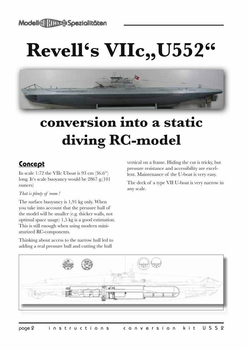
ConceptIn scale 1:72 the VIIc Uboat is 93 cm (36.6“) long. It‘s scale buoyancy would be 2867 g.(101 ounces)
That is plenty of room !
The surface buoyancy is 1,91 kg only. When you take into account that the pressure hull of the model will be smaller (e.g. thicker walls, not optimal space usage) 1,5 kg is a good estimation. This is still enough when using modern mini-aturized RC-components.
Thinking about access to the narrow hull led to adding a real pressure hull and cutting the hull
vertical on a frame. Hiding the cut is tricky, but pressure resistance and accessibility are excel-lent. Maintenance of the U-boat is very easy.
The deck of a type VII U-boat is very narrow in any scale.
Revell‘s VIIc„U552“
conversion into a static diving RC-model
i n s t r u c t i o n s c o n v e r s i o n k i t U 5 5 2 p a g e 3
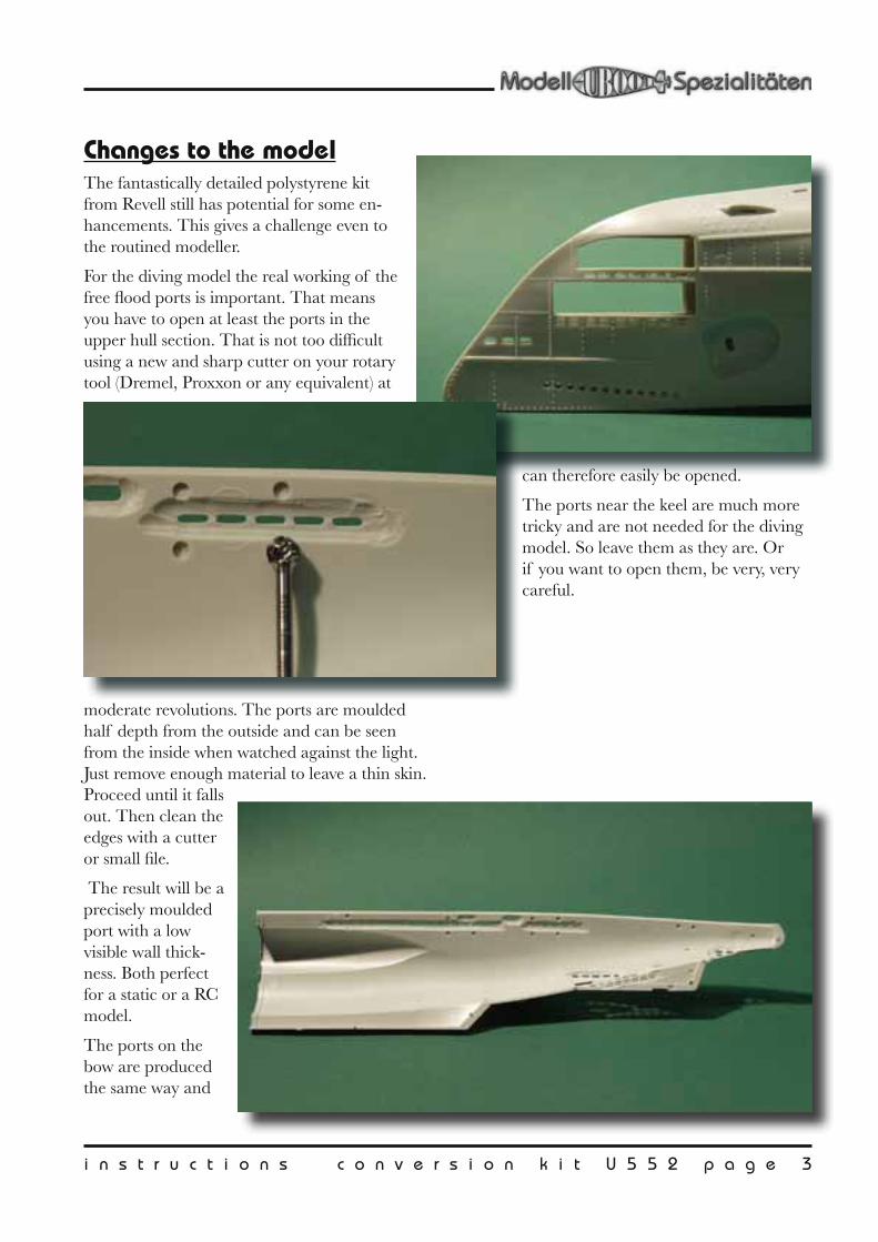
Changes to the modelThe fantastically detailed polystyrene kit from Revell still has potential for some en-hancements. This gives a challenge even to the routined modeller.
For the diving model the real working of the free flood ports is important. That means you have to open at least the ports in the upper hull section. That is not too difficult using a new and sharp cutter on your rotary tool (Dremel, Proxxon or any equivalent) at
moderate revolutions. The ports are moulded half depth from the outside and can be seen from the inside when watched against the light. Just remove enough material to leave a thin skin. Proceed until it falls out. Then clean the edges with a cutter or small file.
The result will be a precisely moulded port with a low visible wall thick-ness. Both perfect for a static or a RC model.
The ports on the bow are produced the same way and
can therefore easily be opened.
The ports near the keel are much more tricky and are not needed for the diving model. So leave them as they are. Or if you want to open them, be very, very careful.
page 4 i n s t r u c t i o n s c o n v e r s i o n k i t U 5 5 2
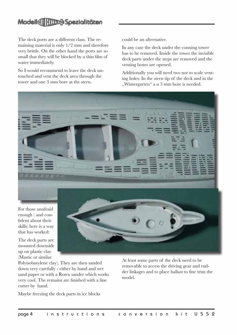
The deck ports are a different class. The re-maining material is only 1/2 mm and therefore very brittle. On the other hand the ports are so small that they will be blocked by a thin film of water immediately.
So I would recommend to leave the deck un-touched and vent the deck area through the tower and one 3 mm bore at the stern.
For those unafraid enough ( and con-fident about their skills) here is a way that has worked:
The deck parts are mounted downside up on plastic clay (Mastic or similar Polyisobutylene clay). They are then sanded down very carefully - either by hand and wet sand paper or with a Rotex sander which works very cool. The remains are finished with a fine cutter by hand.
Maybe freezing the deck parts in ice blocks
could be an alternative.
In any case the deck under the conning tower has to be removed. Inside the tower the invisible deck parts under the steps are removed and the venting boxes are opened.
Additionally you will need two not to scale vent-ing holes: In the stern tip of the deck and in the „Wintergarten“ a ø 3 mm bore is needed.
At least some parts of the deck need to be removable to access the driving gear and rud-der linkages and to place ballast to fine trim the model.

i n s t r u c t i o n s c o n v e r s i o n k i t U 5 5 2 p a g e 5
CutInside the hull two frames are planned. Al-though the frames are not used in the converted model their marking is used as a guide for cut-ting.
Attention: In newer kits the frames were changed. Always
check the position with the plan!
The cut will be in front of the double line of the stern frame. Cut with a thin saw like a jigsaw and sand the hull parts to plane on a piece of sandpaper on the desk. When done carefully the cut will be less than 1mm wide.
The frame markings are removed finally.

page 6 i n s t r u c t i o n s c o n v e r s i o n k i t U 5 5 2
Pressure hullThe pressure hull mainly consists of 3 pipes of different diameters. The middle and bow sec-tions are glued to the bow section of the hull. The stern section, which contains servos and the motor remains demountable.
The sections are joint and sealed with a special kind of bayonet lock. The seal carrier is a loose ring between the parts. This way the full access diam-eter to both sections stays open. The locking is done by 3 screw heads and keyholes.
The pipes and milled parts are made from polystyrene. Gluing them can be done with „Uhu acrylit“, „Loctite 406“, „Stabilit Express“ or any slow curing (> 20 min) Epoxy glue. The usual polysty-rene glue used for plastic models will work too.
The mounting of the pressure hull bow section should be done „in one heat“. That means try if everything fits with-out glue (especially the deck, although mounted later), eventually file some corners and then mount all parts and let dry.
The stern pressure
hull has only one frame glued to it. This frame fits tight into the hull, but is not glued to it. It is mounted to a second hull connected frame by screws. This way the gear and propeller shafts remain serviceable.
step of thepressure hull
bow to mid
locking framebow
with mounting aid
pressure hullbulkhead alternative
pressure hullbulkhead stern
seal carrier(glued from 3 parts)
locking framestern
pressure hull part
locking framestern
hull part
base
8.8
gun
motor base
stand
stand stern


page 8 i n s t r u c t i o n s c o n v e r s i o n k i t U 5 5 2
Servo linkagesThe stern contains all rudder linkages. Because of this the deck in this area should be remov-able.
The rudders are actuated via a auxiliary lever,
just as in the original U-boat. Levers and base-
plate can be found in the 2mm cut plate. The rudder shafts are 2mm brass and the linkages ø 1 mm St/St. The corresponding holes have to be bored following the markings on the parts.
i n s t r u c t i o n s c o n v e r s i o n k i t U 5 5 2 p a g e 9
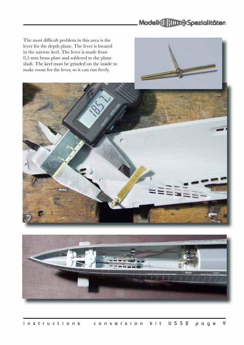
The most difficult problem in this area is the lever for the depth plane. The lever is located in the narrow keel. The lever is made from 0,5 mm brass plate and soldered to the plane shaft. The keel must be grinded on the inside to make room for the lever, so it can run freely.

page 10 i n s t r u c t i o n s c o n v e r s i o n k i t U 5 5 2
GearOne mayor problem with small submarine models are the seals for the motor shafts. Indus-trial seals at reasonable prices are only available for ≥ ø 3mm. Their friction will stop small mo-tors completely.
A practical concept for this VIIc uboat uses one relatively big, slow turning motor with a ø 3 mm shaft seal. A gear in the free flood area distrib-utes the power to the propellers and rises their revolutions. By this means the propellers turn higher than the seal.
The motor shaft is ø 2,35 mm and is thickened to ø 3 mm by a special made add on shaft. It is ø 4 mm at the tip to hold the gearwheel. The transitions are heavily rounded, so it can pass the seal without damaging it.
The gearwheels have ø 4 mm bores and are mounted to the ø 2 mm shafts by spacer sleeves. They are fixed by glue, or (better) by M3 grub-screws if you can make the threaded bores.
The bushings in the smaller gear plate are only used during mounting and testing. They should be removed later.
The prop shaft bushings can be bored to
ø 3,5 mm and equipped with the bushings. These special plastic bushings have excellent wear resistance when used with water as lubri-cant.
The hull pass threw for the prop shafts are liber-ally machined to give enough clearance.
When the motor / gear unit runs satisfactory it is glued to the stern part of the pressure hull. This is done inside the hull, so all fits well.
The last thing to mount are the prop shaft hous-ings ( german: Wellenhose = trousers for the shafts). Their bore should be about 2,5 mm to give some clearance to the shafts.

page 12 i n s t r u c t i o n s c o n v e r s i o n k i t U 5 5 2
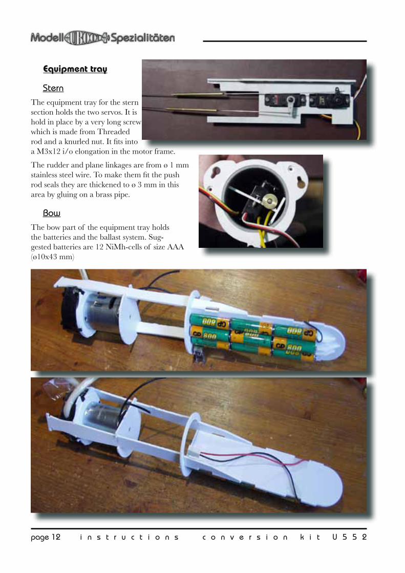
Equipment tray
SternThe equipment tray for the stern section holds the two servos. It is hold in place by a very long screw which is made from Threaded rod and a knurled nut. It fits into a M3x12 i/o elongation in the motor frame.
The rudder and plane linkages are from ø 1 mm stainless steel wire. To make them fit the push rod seals they are thickened to ø 3 mm in this area by gluing on a brass pipe.
BowThe bow part of the equipment tray holds the batteries and the ballast system. Sug-gested batteries are 12 NiMh-cells of size AAA (ø10x43 mm)

i n s t r u c t i o n s c o n v e r s i o n k i t U 5 5 2 p a g e 1 3
Ballast systemThe ballast system is a peristaltic pump / gum-misack system, specially adapted to the small model.
The necessary ballast water weight is about 150 - 200 g. The Type VII U-boats were dedi-
cated quick-divers. Taking this into account the biggest possible pump is installed into the model. It is tricky to mount, but will let the model dive within 30 sec.
The prototype had two balloons stuffed one into the other as diving tank. Although this defini-tively was a quick and dirty solution it proved to be quite durable. Inside the dark hull the balloons can stand 3 years before they become brittle. If you change them yearly you are on the safe side.
A full size BTS (BallastTankSwitch) will not fit into the small model. For the same reason there is no pressure switch to limit the tank fill. The pump is actuated by a small motor controller without any safety circuits. This is a trade-off you have to make in a miniaturized model.
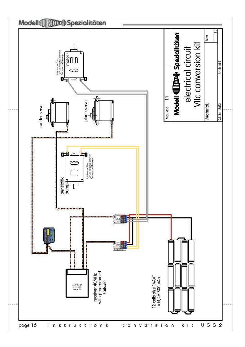
ElectronicsMost of the recommended safety features for a RC submarine can be realised by using an „intelligent“ (= containing a microprocessor) receiver.
On the prototype this was „Schulze alpha 8.40“
with integrated Fail safe and programmable under voltage behaviour.
A recommended component is a pitch control-ler as the LR3. Without this the model will behave resistive when diving.
Further components on the prototype were 2 motor controllers „Robustregler 2A“ for motor and pump and a magnetic switch.

page 14 i n s t r u c t i o n s c o n v e r s i o n k i t U 5 5 2
Stückliste VIIc72
Seite 121.12.12
Pos. num. name size/ material
group: pressure hull
1 1 pressure hull mid ABS ø63,5 x 3,2 x 190mm long
2 1 pressure hull bow + stern ABS ø50,8 x 2 x 160+140mm
3 1 hemispherical head ABS ø50,8
4 1 PS cut plate (thick) PS 318 x 218 x 6mm, 17 parts
5 1 PS cut plate (thin) PS 319 x 229 x 2mm, 30 parts
6 3 O-ring (1xReserve) ø40 x 2,5 55Shore
7 3 screw M3x12 V2A Inbus
8 2 screw M2,5x8
motor assembly9 1 Motor 385 (600 /min V) Igarashi 385 24V
10 2 gearwheel m0,5 20Z Acetal
11 2 gearwheel m0,5 25Z Acetal12 3 space sleeve ø4/ø2x10 Ms13 1 ad on shaft ø3 / ø4 Drehteil ø4/ø2,37x2014 2 screw M2,5x1015 3 screw M3x8 DIN84 VA16 5 threaded sleeve M3x12 in/out M3 x12 Ms17 8 bushing ø2 GSM-0203-0318 4 grub screw M3x3 VA19 1 shaft Ø2mm V2a x15
20 2 prop shaft Ø2mm V2a x16021 1 shaft seal 3-10-6 BAOF22 2 pushrod seal SW9x15 für 3mm23 2 thickenning MS-Rohr ø3/ø1,6x50
24 0,5 m wire St/St ø1mm25 1 rudder shaft bras ø2mm*10026 1 depth plane lever brass plate 25x6x0,4mm27 2 set collar ø3+VA grubscrew28 1 threaded rod M3x13829 1 knurled nut DIN 466 high M3 Ms
1 instructions and plan 11 pages A4 +1x A0
30 1 Ballast 250g e.g. soldering tin Sn25Pb
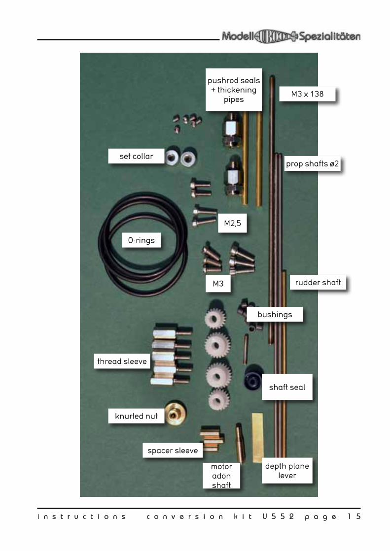
i n s t r u c t i o n s c o n v e r s i o n k i t U 5 5 2 p a g e 1 5
O-rings
M3 x 138
prop shafts ø2
rudder shaft
spacer sleeve
knurled nut
thread sleeve
bushings
M3
M2,5
pushrod seals + thickening
pipes
set collar
shaft seal
depth plane lever
motor adon shaft
page 16 i n s t r u c t i o n s c o n v e r s i o n k i t U 5 5 2
Maß
stab
Blat
t
Bl.
Maß
stab
Blat
t
Bl.
Scha
ltpla
n VI
IcA
usba
usat
z
1:1
Mat
eria
l:
Unt
itled
131
. Jan
201
2
peris
talti
c pu
mp
inte
rfer
ence
filt
er 2
x47n
F so
lder
ed b
etw
een
Term
ina
l and
hou
sing
mot
or
inte
rfer
ence
filt
er 2
x47n
F so
lder
ed b
etw
een
Term
ina
l and
hou
sing
plan
e se
rvo
rudd
er s
ervo
Empfänger>4 Kanalreceiver≥>= 4
channels
RobustRegler
modelluboot.de
-
MM
+
7,2 V - 24 V2 A Dauerlast7 A Spitze
RobustRegler
modelluboot.de
-
MM
+
7,2 V - 24 V2 A Dauerlast7 A Spitze
12 c
ells
siz
e "A
AA
"=
14,4
V 80
0mA
h
rece
iver
40M
Hz
with
pro
gram
med
Fails
afe
elec
trica
l circ
uit
VIIc
con
vers
ion
kit