conveyor equipment manufacturers association - home - · pdf file ·...
TRANSCRIPT

THE VOICE OF THE NORTH AMERICAN CONVEYOR INDUSTRY
AGENDA OF THE CEMA ENGINEERING CONFERENCE
CONVEYOR CHAIN AND SPROCKET COMMITTEE MEETING
Tuesday, June 27, 2017 – 1:00 PM
1. Call to order – Tom Perdue, Chair
2. Meeting Attendance and Introductions
3. Review and Approval of 2016 Engineering Conference Committee Minutes (Attached)
4. Old Business – Review status and work remaining for previously defined section tasks.• Installation, Maintenance, and Best Practices Document – Final Edits & Review• Conveyor Chain Types – Final Edits and Review
5. New Business• Development of Sprocket Types and Definition Document• Other
6. Next Meeting: La Playa Hotel, June 26, 2018, 1:00 p.m.
7. Adjourn
Conveyor Equipment Manufacturers Association

Conveyor Chain, Working Group Chain Types – Compilation, Draft #3 June 6, 2017 NOTE: This DRAFT is for CEMA Committee USE ONLY. No further distribution w/out permission CEMA.
Page 1 of 9
Conveyor Chain
Chain Types Compilation
Chair: Tom Perdue / Vice-Chair: Roger Bruere
The CEMA Conveyor Chain Working Group has prepared this document in an effort to provide a common level of understanding and terminology of the various types of conveying chains used in industry today. Descriptions and definitions of several chain types have been included below along with some typical applications. This list is not intended to be exhaustive, but it does cover most of the typical chains used in conveying applications.
Precision Power Transmission Roller Chains
Precision Power Transmission Roller Chains are manufactured in many different types. Examples of the many types include single strand and multiple strand in standard and heavy series. Most roller chains have rollers that engage with the teeth of the sprocket(s). Normally, roller chain is used in continuous lengths with connecting links to provide an even number of pitches. If an odd number of pitches is required, offset links are used along with a connecting link to provide an odd number of pitches. Roller chains consist of alternating pin links and roller links. Roller Chain components include pin link plates, roller link plates, pins, bushings, and rollers (with exception of rollerless chains). Common Precision Power Transmission Roller Chains include the following listed chains:
25 (0.250” Pitch) 100 (1.250” Pitch) 35 (0.375” Pitch) 120 (1.500” Pitch) 40 (0.500” Pitch) 140 (1.750” Pitch) 41 (0.500” Pitch) 160 (2.000” Pitch) 50 (0.625” Pitch) 180 (2.250” Pitch) 60 (0.750” Pitch) 200 (2.500” Pitch) 80 (1.000” Pitch) 240 (3.000” Pitch)

Conveyor Chain, Working Group Chain Types – Compilation, Draft #3 June 6, 2017 NOTE: This DRAFT is for CEMA Committee USE ONLY. No further distribution w/out permission CEMA.
Page 2 of 9
Double Pitch Conveyor Roller Chains
Double Pitch Conveyor Chains are provided with standard rollers or oversized rollers. Conveyor roller chains with standard rollers are typically used for light to moderate conveyor applications. Conveyor Roller Chains with oversized rollers reduce friction by providing rolling action. Normally, Double Pitch Conveyor Roller Chains are used in continuous lengths with connecting links to provide an even number of pitches. If an odd number of pitches is required, offset links are used along with a connecting link to provide an odd number of pitches. Conveyor Roller Chains consist of alternating pin links and roller links. Conveyor Roller Chain components include pin link plates, roller link plates, pins, bushings, and rollers. Double Pitch Conveyor Roller Chains are available with steel rollers or plastic/Delrin rollers. They are also available in standard and heavy series with heavy series commonly starting at C2060H. Heavy series chains feature the same bushings, pins, and rollers of the standard chain, but utilize the heavier thickness of the side plates found in the chain that is one size larger in pitch. The “C” designation for these chains denotes straight side plates as compare to the more common “Figure 8” shaped plates of standard precision roller chains. Common Double Pitch Power Transmission Roller Chains include the following described chains:
C2040 (1.000” pitch with standard roller) C2050 (1.250” pitch with standard roller) C2060 (1.500” pitch with standard roller) C2060H (1.500” pitch heavy series with standard roller) C2080H (2.000” pitch heavy series with standard roller) C2100H (2.500” pitch heavy series with standard roller) C2120H (3.000” pitch heavy series with standard roller) C2160H (4.000” pitch heavy series with standard roller) C2042 (1.000” pitch with oversized roller) C2052 (1.250” pitch with oversized roller) C2062H (1.500” pitch heavy series with oversized roller) C2082H (2.000” pitch heavy series with oversized roller) C2102H (2.500” pitch heavy series with oversized roller) C2122H (3.000” pitch heavy series with oversized roller) C2162H (4.000” pitch heavy series with oversized roller)

Conveyor Chain, Working Group Chain Types – Compilation, Draft #3 June 6, 2017 NOTE: This DRAFT is for CEMA Committee USE ONLY. No further distribution w/out permission CEMA.
Page 3 of 9
Forged Conveyor Chains
Forged conveyor chains, or drop forged chain as they are often known, are a reliable solution for a diverse range of conveying applications in industries such as power generation, hazardous waste incineration, minerals and mining, cement, pulp and paper, grain handling and food processing. They are commonly utilized in severe duty, en masse drag conveyors for moving material horizontally, on an incline, or vertically, using a skeletal chain flight through a flat-bottom, rectangular conveyor section. The chain links are made of heat treated forged steel with a typical internal core hardness of 300-400 BHN and a surface hardness of 500-700 BHN. Flights or attachments for these chains can be either welded or bolted directly onto the drop forged links. The exceptional combination of internal ductility, external hardness and high strength, make forged chains a highly versatile, durable, and dependable conveying medium.
Cast Chains
Cast chains are designed for severe, rugged, abrasive, and demanding environments. Cast chains are either riveted construction or cottered construction. The pins will vary by manufacturer for material used which typically includes medium carbon steel, low carbon steel, alloy steels, etc. Applications for these chains include wastewater, lumber, paper and pulp, paper industries, sugar mills, fertilizer, etc. Combination cast chains are built using a cast block link and steel sidebars. Combination chains are designed to handle very abrasive, corrosive, gritty, and generally demanding environments. The sidebars, barrels and pins feature heat treatment which may vary from one chain manufacturer to another. These chains are built with riveted construction or cottered connecting pins. Applications for combination cast chains include aggregates, cement, fertilizer, limestone, etc.
Drop forged chain with bolt-on nylon flights Drop forged chain with welded steel flights

Conveyor Chain, Working Group Chain Types – Compilation, Draft #3 June 6, 2017 NOTE: This DRAFT is for CEMA Committee USE ONLY. No further distribution w/out permission CEMA.
Page 4 of 9
Most cast chains and combination case chains are interchangeable with other standard makes of corresponding sizes and numbers, but this should be confirmed with the particular manufacturer.
Welded Steel Chains
Welded steel mill chains are designed for rugged, abrasive and demanding environments. Welded steel mill chains are riveted construction with cottered connecting pins. Pins, barrels/bushings and sidebars feature heat treat, which can vary by chain manufacturer. Sidebars for these chains are offset. Applications for welded steel chains include wood yards, paper mills, OSB plants, grain systems, ethanol processing, etc. Welded steel drag chains are designed for rugged, abrasive and demanding environments. The sidebars, barrels and pins are heat treated, though the heat treatment may vary by chain manufacturer. The chains are built with riveted construction or cottered connecting pins. Welded steel mill chains and welded steel drag chains are interchangeable with other standard makes of corresponding sizes and numbers.
Agricultural, Pintle, and Detachable Chains
Agricultural Roller Chains: Similar to other roller chains, these chains feature a series of alternately assembled roller links and pin links in which the pins articulate inside the bushings and the rollers are free to turn on the bushings. The pitch of these chains are derived from the pitch of the Steel Detachable Link Chains. These chains commonly feature formed attachments which are integral to the chain sidebars. These attachments allow paddles or slats to be attached to the chains to make them more efficient at conveying materials. Many Agricultural Equipment Manufacturers use proprietary attachments with Agricultural Roller Chains for specific applications. However, many standard attachments exist. Agricultural Roller Chains are rapidly replacing Steel Detachable Link Chains in most applications.
Open Barrel Steel Pintle Chains: These chains are produced by a series of one-piece formed links, connected by pins, which articulate within the barrel of adjacent links. The barrels are open, leaving the pins exposed on one side. This allows debris to be cleared from the chain joint. Open Barrel Steel Pintle chains are commonly found with welded attachments that allow paddles, slats, or other devices to be attached to the chains to make them more efficient at conveying bulk materials. Occasionally, Open Barrel Steel Pintle chains are used for unit handling applications. The benefits of Open Barrel Steel Pintle chains are that they are self-cleaning due to the open barrel allowing them to run in very dirty environments. The most common application is live bottom trailers used to move manure, salt, sand, or other materials.

Conveyor Chain, Working Group Chain Types – Compilation, Draft #3 June 6, 2017 NOTE: This DRAFT is for CEMA Committee USE ONLY. No further distribution w/out permission CEMA.
Page 5 of 9
Steel Detachable Link Chains: A series of successively assembled steel links in which the end bars articulate inside the hook. The chain is detached by flexing it and driving the end bar out of the adjoining hook. Steel Detachable chain links are commonly formed with an integrated attachment tab that allows paddles or slats to be attached to the links to make them more efficient at conveying bulk materials. The main benefit of Steel Detachable Link Chains is that they are very easy to assemble and disassemble without the use of tools. Chain sections can be removed easily in the field.
700 Series Chains
700 Series chains are used extensively in water and wastewater treatment plants or similar sewage treatment applications. This series of chain is offered in a variety of different materials from medium carbon steel, medium carbon alloy, stainless steel, cast iron, or non-metallic depending on the requirements of the application. In typical applications of the 700 Series chains, the chains are run in a dual strand arrangement with a flight attached to the strands of chain which are conveyed through a tank. This series of chain is interchangeable with other standard makes of corresponding sizes and part numbers.
Steel Bushed Conveyor Chains & Attachments
Steel Bushed Roller and Conveyor chains are used for a broad range of conveyor and elevator applications. They are the appropriate selection for long life and heavy-duty service where difficult operating conditions prevail. Steel Bushed Conveyor chains typically feature either straight or offset sidebars with heat treated rollers, pins and bushings. The rollers provide lower operating frictions, which help to increase chain life and reduce conveyor design requirements. Rollers may be flanged in dual strand applications for tracking purposes or plain. Steel Bushed Roller elevator chains feature straight sidebars with a heat treated roller, pins and bushings. Hardened Steel Bushed elevator chains typically feature straight sidebars with heat treated pins and bushings. These types of chains are used for centrifugal discharge and continuous discharge chain bucket elevators, along with super capacity, dual strand, gravity-discharge chain bucket elevators. Chain Attachment Types K-style attachments – Double-sided attachment used on single strand and double strands of chain attached to the back of the bucket. The attachment on each side of the chain allows a bucket, pan, slat or rake to be bolted to the K-style attachment. K-style double sided attachments may be welded on tab or angle. They are most commonly offered as an integral sidebar and usually contain two or three bolt holes in varying patterns. This is the most common

Conveyor Chain, Working Group Chain Types – Compilation, Draft #3 June 6, 2017 NOTE: This DRAFT is for CEMA Committee USE ONLY. No further distribution w/out permission CEMA.
Page 6 of 9
type of attachment and is primarily used for centrifugal discharge and continuous discharge bucket elevators.
A-style attachments – Single-sided attachment, typically used in dual strand applications where a left and right hand strand of chain contains attachments with bolt holes to accept a pan, belt, slat or rake. A-style single sided attachments may be a welded on tab or angle clip on the sidebar. They are also offered as an integral sidebar formed during the
manufacturing process. A-style attachments typically have one or two bolt holes in varying patterns, and are typically used on centrifugal discharge and continuous discharge elevators. G-style attachments – Are used on dual strand super capacity gravity discharge chain bucket elevators. The attachments are mounted to the side bars of the chain in dual strand applications where a left and right hand strand of chain is necessary. G-style attachments typically have two holes to accept a bolted-on bucket, pan, rake or slat. Tabs may be welded to the inside sidebars to make up for the thickness of the outside sidebar when the attachment is present on every pitch. M-Style attachments - M-style attachment serve as a high sidebar or mid-pitch holes. M-style high sidebar attachments extend above the roller, allowing material to ride on the sidebars and keep material off chain components. M-style high sidebar chains are also used to accept slats in drag or scrapping applications. A slat slides into the notch in the high sidebar and is welded in place. M-style mid pitch holes, located on each side of the chain, are used to accept stub shafts for outboard rollers. M-style mid pitch holes are used in dual strand leak-proof apron pan applications to help carry heavy loads and track the chain properly.
Floating attachments - This type of attachment is used primarily by European original equipment manufacturers. The attachments are bolted to the back of the bucket and then slide on to a holding pin with a retaining ring or pin. This type of attachment is primarily used for centrifugal discharge and continuous discharge bucket elevators.

Conveyor Chain, Working Group Chain Types – Compilation, Draft #3 June 6, 2017 NOTE: This DRAFT is for CEMA Committee USE ONLY. No further distribution w/out permission CEMA.
Page 7 of 9
Chain Drive Belts
Chain drive wire mesh belts are defined as an assembly of parallel strands of standard roller or pintle chains (steel or stainless) combined with woven wire spirals of the same or similar material. The strands of chain effectively transmit the load or tension in the belt and are positively driven by sprockets. The woven wire mesh is constructed to match the product support needs of the particular application. Cross members are used to provide lateral support to the wire mesh while also attaching the mesh to the two parallel strands of chain. In this way, the components come together to act as a single unit. This combination of components results in a product that is extremely versatile for both process and material handling conveyor applications. Belts of this type are available in a wide array of pitches, widths, and wire mesh densities.
Plastic Chain Types
Plastic chains are molded polymer, interconnecting, hinge-like modules (links) of various sizes and configurations which are connected end to end to form a continuous, flexible conveying element on which, when installed on a conveyor frame, product in unit form may be transported. Plastic conveyor chains consist of rigid plastic links which are molded from any one of a variety of durable plastics and mechanically connected by means of a steel pin. Links may be designed such that the pinned connection flexes in the longitudinal direction or in both longitudinal and lateral directions, which are commonly referred to a side flexing (also known as multiflex and double flex chain). A unique hybrid, two-piece chain design consists of a steel base-chain onto which rigid plastic top plates are snapped in place.

Conveyor Chain, Working Group Chain Types – Compilation, Draft #3 June 6, 2017 NOTE: This DRAFT is for CEMA Committee USE ONLY. No further distribution w/out permission CEMA.
Page 8 of 9
Plastic chains are manufactured in a variety of forms including:
Slat top chain Low back-pressure chain Side flexing chain Case chain Snap-on chain
Chain materials may include the following, which may also include special additives to improve a particular physical property i.e., abrasion resistance, reduced friction, etc.:
Polyacetal; “Acetal”, “POM” (Polyoxymethylene) Polyamide PBT (Polybutylene Terephthalate) Polycarbonate Polypropylene Fluorinated thermoplastic Carbon steel*
*Although not a plastic, this all steel variant shares the design of the basic slat-top chain and is, therefore, included in the family of plastic conveyor chains.
SNAP-ON

Conveyor Chain, Working Group Chain Types – Compilation, Draft #3 June 6, 2017 NOTE: This DRAFT is for CEMA Committee USE ONLY. No further distribution w/out permission CEMA.
Page 9 of 9
Plastic chain is employed in conveying unit loads in a wide array of applications in various industries including:
Automotive Baking Beverage Canning Cardboard mfg. Material handling Packaging Pharmaceutical Textile
Accessories common to plastic chain can include:
Molded inserts Chain sliding supports Guides and guide track Wear strips Sprockets

Conveyor Chain, Working Group Installation, Maintenance & Best Practices – Compilation, Draft #3 June 6, 2017 NOTE: This DRAFT is for CEMA Committee USE ONLY. No further distribution w/out permission CEMA
Page 1 of 23
Conveyor Chain
Installation, Maintenance,
and
Best Practices Compilation
Chair: Tom Perdue / Vice-Chair: Roger Bruere
Introduction
The careful and correct installation of chains along with a good inspection and maintenance program will typically help improve both the performance and longevity of chains of any type. Obviously, it is better to correct problems found during an inspection than to have to repair the chain after a breakdown; regular inspection and maintenance often costs less than repairs and the associated downtime. Most chains will show signs of trouble long before needing repair or replacement. If problems are found during regular inspections, those problems can possibly be corrected before an unexpected breakdown occurs, thereby reducing the costs associated with component replacement and lost production time. Furthermore, collateral damage caused by a breakdown may not always be found during repairs, leading to additional component failure later and even more unexpected downtime.
To reduce the frequency of untimely breakdowns and the necessary repairs, an inspection program for each chain installation should be established and followed. A checklist of items to inspect should be made and a record of maintenance action kept. Trends can be tracked in that manner and the chain can be adjusted or replaced before a costly failure occurs.
This document has been prepared by the CEMA Conveyor Chain Working Group in an effort to provide a basic level of understanding of the Best Practices associated with the Installation and Maintenance of some of the various types of conveying chains used in industry today. For each type of chain included in this guide, the main emphasis is on operator safety, though this is not intended to be a Safety Manual for
Conveyor Chain, Working Group Installation, Maintenance & Best Practices – Compilation, Draft #3 June 6, 2017 NOTE: This DRAFT is for CEMA Committee USE ONLY. No further distribution w/out permission CEMA
Page 2 of 23
the use of these chains. Where applicable, local plant Standard Operating Practices for safety and maintenance should take precedence. But where those defined practices are absent or otherwise insufficient, the practices presented in this document may be helpful and can provide a solid basis for the proper installation and maintenance of the conveyor chains that have been included in this guide.
General Safety Precautions
Serious personal injury can result if safety rules are not followed. Observe the following safety precautions when inspecting, maintaining, or replacing a chain. • Shut-off the power to the equipment and lock-out the power switches before inspecting, adjusting,
repairing, or replacing chains.
• Always wear safety glasses to protect your eyes.
• Wear protective clothing, gloves, and safety shoes as appropriate.
• Support the chain to prevent uncontrolled movement of the chain or parts.
• Restrain shafts and sprockets from free rotation where such rotation could permit uncontrolled chain movement and cause personal injury or equipment damage.
• Use pressing equipment to remove or install press fit pins or link plates. Keep tooling in good condition and use it properly. If pressing equipment is not available, contact the chain manufacturer for additional guidance.
• Know and understand chain construction, including the correct direction for pin removal and insertion, before connecting or disconnecting a chain.
General Inspection Program
All inspection programs should include the items listed below. These items apply to both drives and conveyors.
• Inspect for signs of interference.
• Inspect for chain or sprocket damage.
• Inspect for signs of misalignment of the shafts, sprockets, or ways.
• Inspect for dirt or corrosion.
• Inspect for proper lubrication.
• Inspect for sprocket wear.
• Inspect for chain wear.
• Inspect for correct chain initial tension.
• Inspect for good guarding condition.

Conveyor Chain, Working Group Installation, Maintenance & Best Practices – Compilation, Draft #3 June 6, 2017 NOTE: This DRAFT is for CEMA Committee USE ONLY. No further distribution w/out permission CEMA
Page 3 of 23
This is a list of only the major items that should be inspected regularly. There may be more items that apply to a given application. Any other items should be added to the list. Many typical chain and sprocket problems are listed and described in general troubleshooting manuals or other pertinent information directly available from CEMA member chain manufacturers. An additional printed resource that can be very helpful is the Standard Handbook of Chains available for purchase from the American Chain Association (ACA). It is advisable for maintenance personnel to have one or more of these troubleshooting guides on hand when inspecting a chain drive or conveyor. These guides provide not only a list of some of the more common chain problems, but they also provide possible causes and associated remedies. The following Table lists some of the more common types of chain failures along with the associated causes and recommended corrections. It has been included here to provide a good basis and foundation for the basic chain troubleshooting topics discussed below. (It should be noted this Table is taken from the aforementioned ACA Standard Handbook of Chains and has been used here with permission.)
PROBLEM POSSIBLE CAUSE WHAT TO DOMissing Parts • Missing at assembly Replace chain.
• Broken and lost Find and correct cause of broken parts. Replace chain.
Missing or Broken Cotters or Spring Clips
• Cotters or spring clip not installed correctly
Install new cotters or spring clip per manufacturer’s instructions
Excessive Noise • Chain striking an object Eliminate interference. Replace Chain.
• Loose casing or shaft mounts Tighten fasteners.
• Too much chain slack Reset initial chain tension.
• Chain badly worn Replace chain. Reset initial chain tension.
• Sprockets badly worn Replace sprockets. Realign sprockets. Replace chain, if not done before.
• Sprockets misaligned Replace chain and sprockets, if needed. Realign sprockets.
• Inadequate Lubrication Re-establish proper lubrication. Clean and re-lubricate chains. Replace chain, if needed.
• Chain pitch too large Redesign to use smaller pitch chain.
• Too few sprocket teeth Install larger sprockets, if the design permits. Otherwise, redesign to use larger sprockets.
Wear on Inside if Sidebars or Roller Link Plates and on One Side of Sprocket Teeth
• Sprockets misaligned Replace chain and sprockets, if needed. Realign sprockets

Conveyor Chain, Working Group Installation, Maintenance & Best Practices – Compilation, Draft #3 June 6, 2017 NOTE: This DRAFT is for CEMA Committee USE ONLY. No further distribution w/out permission CEMA
Page 4 of 23
PROBLEM POSSIBLE CAUSE WHAT TO DOUneven Wear Across Chain • Shaft Misaligned Replace chain and sprockets, if needed.
Realign shafts.
• Tracks misaligned Replace chain and tracks, if needed. Realign tracks.
• Chain exposed to corrosive substance
Find and eliminate source of corrosion. Replace chain.
• Corrosive substance (acid) in lubricant
Change oil. Find and eliminate source of corrosion. Replace chain.
Pins Eroded • Chain exposed to corrosive and abrasive substances
Find and eliminate source of corrosives and abrasives. Replace chain.
Worn Link Plate or Sidebar Edges • Drive chain rubbing against object Find and eliminate source of corrosives and abrasives. Replace chain.
• Conveyor chain rubbing against track
Replace chain when worn 5% or more. Redesign conveyor to use chain with large conveyor rollers.
Battered Link Plate Edges • Drive chain striking and object Find and remove interfering object. Replace chain.
Tight Joints (Will Not Flex) • Dirt or foreign material packed in joints
Clean and re-lubricate chain. Replace chain if needed.
• Joints badly rusted or corroded Find and eliminate source of corrosion. Clean and re-lubricate chain. Replace chain if needed.
• Chain severely overloaded Eliminate cause of overloading. Replace chain.
Turned Pins • Dirt or foreign material packed in joints
Replace chain. Shield chain from dirt.
• Joints badly rusted or corroded Replace chain. Find and eliminate source of corrosion.
• Chain overloaded Replace chain. Eliminate cause of overloading.
Cracked Link Plate (Fatigue) • Loads more than chain's dynamic strength
Replace chain. Reduce dynamic loads or redesign for a larger chain.
Pins Cracked or Broken (Corrosion Fatigue)
UNEVEN WEAR ON PIN
PIN PITTED AND CRACKED

Conveyor Chain, Working Group Installation, Maintenance & Best Practices – Compilation, Draft #3 June 6, 2017 NOTE: This DRAFT is for CEMA Committee USE ONLY. No further distribution w/out permission CEMA
Page 5 of 23
PROBLEM POSSIBLE CAUSE WHAT TO DOBroken Link Plate • Extreme overload (not suddenly
applied) (often with larger than standard pins)
Replace chain. Reduce loads or redesign for larger chain.
Broken Pin • Extreme overload
Pin Shear • Extreme overload; suddenly applied; shock load. Pin usually shears near inside edge of outer link plate or sidebar
Replace chain. Find and eliminate cause of extreme overload
Pin Break • Extreme overload; not suddenly applied. Pin usually breaks in middle third of length.
Replace chain. Reduce loads or redesign for larger chain.
Pin Fatigue • Loads more than chain's dynamic strength (slightly more than for link plate fatigue). Pin usually fatigues near center of length.
Replace chain. Reduce dynamic loads or redesign for larger chain.
Galled Pins • Speed or load too high Reduce speed or load. Redesign for smaller pitch chain or multiple strand chain.
• Poor Lubrication Correct or improve lubrication system.
Cracked or Broken Rollers • Speed and load more than roller's impact capacity
Replace chain. Reduce speed or redesign for smaller pitch multiple strand chain.
• Too few teeth on sprockets Replace chain. Use sprockets with more teeth or redesign for smaller pitch multiple strand chain.

Conveyor Chain, Working Group Installation, Maintenance & Best Practices – Compilation, Draft #3 June 6, 2017 NOTE: This DRAFT is for CEMA Committee USE ONLY. No further distribution w/out permission CEMA
Page 6 of 23
Engineered Class Chain Installation and Maintenance Guide
Chain Installation:
The information below is for guidance only. You MUST always follow the equipment manufacturer’s safety, installation, and maintenance instructions that were provided with the conveyor. Consult your CEMA Conveyor Manufacturer for more details. Warning: Observe proper lock-out and tag-out procedures when working on or around the conveyor. The following list of general instructions is provided to assist with the safe and proper installation of Engineered Class Chains:
1. Locations for connecting lengths of chain together should be limited to those links that are intended by the manufacturer for the purpose of repair or replacement. Modifications or repairs to other chain links should be left to or authorized by the chain manufacturer.
2. All conveyor tensioning devices should be adequately loosened before attempting to install the chain on a conveyor.
3. The drive shaft on the conveyor should be locked in place to prevent unintended rotation prior to the attempted chain installation.
4. When possible, connect sections of loose chain together on the floor prior to the installation of the chain on the conveyor.
5. Final connection of the chain to make it endless should preferably be performed at the sprockets. The sprockets can provide adequate support and also help to align the adjoining chain components. This is not always possible, so any location on the conveyor where the chain is adequately supported may suffice.
6. Engineered Class Chains can be large and quite heavy. The following list of tools and equipment is typically recommended for making chain connections. More specialized assembly tools are usually available from the chain manufacturer. Note: it is extremely important that tools and equipment used for chain installation be properly maintained and in good working condition.
PROBLEM POSSIBLE CAUSE WHAT TO DORoller Seams Open • Too few teeth on sprockets (as on
a hoist) and loads too highUse sprockets with more teeth. Or replace chain with a high-strength chain having seamless rollers.
• Chain riding too high on sprocket teeth
Reset initial chain tension. Replace chain if worn too much.
Note: Table shows only some of the more common chain problems and possible causes and cures. It is only a generalguide for troubleshooting. The user should always consult the chain manufacturer when a chain fails.

Conveyor Chain, Working Group Installation, Maintenance & Best Practices – Compilation, Draft #3 June 6, 2017 NOTE: This DRAFT is for CEMA Committee USE ONLY. No further distribution w/out permission CEMA
Page 7 of 23
a. Hydraulic chain press or hydraulic jack b. Chain vice c. “C” Clamps d. Parallel spacers e. Pliers f. Grinder g. Hacksaw h. Hammer
7. When connecting chain sections together, use only new pins or connecting links. Previously used components should be discarded and not re-used.
8. Avoid damaging chain components during the installation of the chain through excessive heating or grinding of the chain while attempting to shorten the chain prior to making final connection.
9. For chains that require only a single pin to make a connection: a. Bring the loose ends of the chains together such that the pin holes are aligned. b. Insert the chain connecting pin through the mating links. Align the pin to match the shape
of the pin hole if necessary. c. Support the opposite side of the chain, but allow space for the connecting pin to be fully
inserted. d. Press or otherwise drive the chain pin completely through the mating links until it is
properly seated. Support the internal part of the chain link with a spacer if needed. e. Install the cotter pin (if applicable) or rivet the end of the chain pin to form a head.
Riveting can be done by heating the end of the pin until the end is red in color, then peening the pin with a hammer to form the riveted end.
f. Check for free and sufficient articulation of the chain joint. Correct as needed.
10. For chains that require a connecting link for assembly:
a. Bring the loose ends of the chains together such that the mating links are aligned but properly spaced (one chain pitch apart) in order to accept the insertion of the connecting link.
b. Insert the chain connecting link through the loose ends of the chains to be connected.
c. Place the outer connecting sidebar onto the ends of the connecting link and press it onto the ends of the pins. Support the opposite side of the pins on the connecting link during this pressing operation. Support the internal part of the chain link with a spacer if needed. Do not press the outer sidebar too far onto the pins as this will make the connecting link too tight and limit the free articulation of the chain joint.
d. Install the cotter pins (if applicable) or rivet the ends of the chain pin to form a head. Riveting can be done by heating the end of the pin until the end is red in color, then peening the pin with a hammer to form the riveted end.
e. Check for free and sufficient articulation of the chain joint. Correct as needed.
11. Once the chain has been connected endless on the conveyor, release the lock on the drive shaft if applicable. Make an initial adjustment to the chain tension to remove excess chain length if needed.

Conveyor Chain, Working Group Installation, Maintenance & Best Practices – Compilation, Draft #3 June 6, 2017 NOTE: This DRAFT is for CEMA Committee USE ONLY. No further distribution w/out permission CEMA
Page 8 of 23
12. Slowly start the conveyor; watch the chain and listen to it run. Investigate unusual or suspicious noises on the conveyor while the chain is running. Also re-adjust the chain tension if necessary. The chain should be tight enough to run smoothly, but no tighter. Over-tensioned chain can result in accelerated chain and sprocket wear.
Chain Maintenance:
The information below is for guidance only. You MUST follow the equipment manufacturer’s safety, installation, and maintenance instructions that were provided with the conveyor. Consult your CEMA Conveyor Manufacturer for more details. Warning: Observe proper lock-out and tag-out procedures when working on or around the conveyor. The following checklists emphasize key areas for which inspections and maintenance may be needed as it pertains to Engineered Class chains.
Chain or Sprocket Damage: Inspect the chain for any missing, cracked, deformed, corroded, or broken parts. If any are found, search for the cause and correct it. Then replace the entire damaged chain. Even though the rest of the chain may appear to be in good condition, there may be hidden damage.
Inspect the sprockets for chipped, broken, or deformed teeth. If any of these problems are found, find the cause and correct it. Then replace the damaged sprocket. Carefully inspect the other sprockets in the drive. If they show any signs of damage, consider replacing them too. When replacing a complete chain, it is a good idea to replace the sprockets also.
Misalignment: Inspect chains for unusual wear on the inside of the sidebars. Inspect all chains for signs of uneven wear of the pins from one side of the chain to the other. Also, inspect the sprockets of chains for unusual wear on one side of the teeth. Correct alignment issues immediately and replace the chain/sprockets as needed.
Interference: Check for signs of interference between the chain or sprockets and any other parts of the machine. One sign of interference is a damaged link or sidebar edges. Other signs of interference include damaged pin ends, bent pins, and broken rollers.
Rubbing between the chain or sprockets and other objects can cause unusual wear. Impact between the chain and a solid object can cause the chain to break from fatigue.
Material and Corrosion: Inspect the chain for material packed between sidebars. Also check for tight rollers or tight joints. This could indicate that material is packed between the rollers and bushings or that material is packed between the pin and bushings. Material in these clearance spaces can prevent lubricant from entering critical bearing areas. If found, correct the problem or replace the chain as needed.
Inspect the drive for dirt packed between the sprocket teeth and the rollers of roller or engineering steel chains. Dirt in these spaces can stretch the chain or damage rollers.
Inspect the chain for cracked link plates or sidebars. Inspect the chain for discolored or pitted parts. These are signs that the chain may have been exposed to a corrosive substance or that the lubricant has

Conveyor Chain, Working Group Installation, Maintenance & Best Practices – Compilation, Draft #3 June 6, 2017 NOTE: This DRAFT is for CEMA Committee USE ONLY. No further distribution w/out permission CEMA
Page 9 of 23
been contaminated. If any of these issues are evident on the chain, clean and re-lubricate the chain or replace. Sprocket Wear: Inspect the sprockets for signs of worn teeth. As sprocket teeth wear, the teeth begin to take on a “hooked” shape. A typical badly worn sprocket is shown below.
It is very hard to measure sprocket wear directly. Some sprockets with less wear than shown in the above figure may also need to be replaced.
If a new chain sticks, clings, or binds as it disengages from a sprocket tooth, the tooth may be worn out and the sprocket may need to be replaced. If a high-speed drive is very noisy or runs rough, the sprockets may be worn badly enough that they need to be replaced.
Reversing the sprocket on the shaft can sometimes extend the life of a worn sprocket. But this is only possible if the flange is centered on the hub, or if there is space to do so. Chain Wear: Rotate two sprockets opposite each other to get a tight section of chain. Measure that tight section of chain, as shown below. The section of chain that is measured should be at least 1 ft. long or contain at least eight pitches of chain.
In most chains, the chain is considered worn out when wear elongation reaches 3%, (though in certain applications the practical limit for allowable chain elongation may be considerably less). In other words, when the measured length is 3% more than the nominal length, the chain is worn out. For example, the nominal length over 24 pitches of 1/2" pitch chain is 12 in. When the measured length over 24 pitches of that chain reaches 12 in., the chain is worn out. Three-eighths of an inch is 3.1% of 1 ft. In most engineering steel chain drives, the chain is considered worn out when wear elongation reaches 4% or 5%.
Conveyor Chain, Working Group Installation, Maintenance & Best Practices – Compilation, Draft #3 June 6, 2017 NOTE: This DRAFT is for CEMA Committee USE ONLY. No further distribution w/out permission CEMA
Page 10 of 23
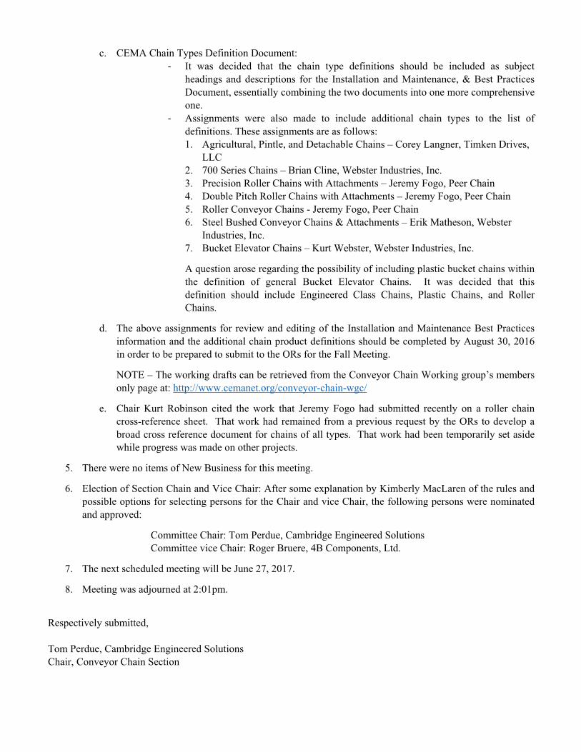
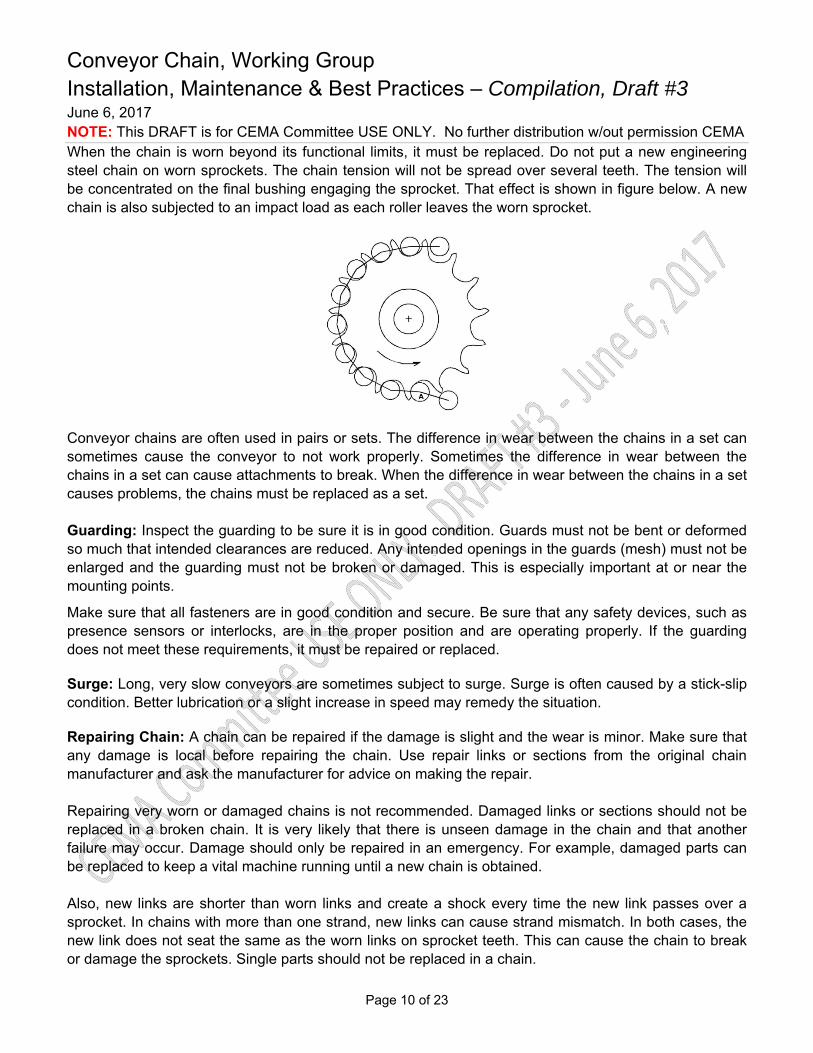
When the chain is worn beyond its functional limits, it must be replaced. Do not put a new engineering steel chain on worn sprockets. The chain tension will not be spread over several teeth. The tension will be concentrated on the final bushing engaging the sprocket. That effect is shown in figure below. A new chain is also subjected to an impact load as each roller leaves the worn sprocket.
Conveyor chains are often used in pairs or sets. The difference in wear between the chains in a set can sometimes cause the conveyor to not work properly. Sometimes the difference in wear between the chains in a set can cause attachments to break. When the difference in wear between the chains in a set causes problems, the chains must be replaced as a set. Guarding: Inspect the guarding to be sure it is in good condition. Guards must not be bent or deformed so much that intended clearances are reduced. Any intended openings in the guards (mesh) must not be enlarged and the guarding must not be broken or damaged. This is especially important at or near the mounting points.
Make sure that all fasteners are in good condition and secure. Be sure that any safety devices, such as presence sensors or interlocks, are in the proper position and are operating properly. If the guarding does not meet these requirements, it must be repaired or replaced.
Surge: Long, very slow conveyors are sometimes subject to surge. Surge is often caused by a stick-slip condition. Better lubrication or a slight increase in speed may remedy the situation.
Repairing Chain: A chain can be repaired if the damage is slight and the wear is minor. Make sure that any damage is local before repairing the chain. Use repair links or sections from the original chain manufacturer and ask the manufacturer for advice on making the repair. Repairing very worn or damaged chains is not recommended. Damaged links or sections should not be replaced in a broken chain. It is very likely that there is unseen damage in the chain and that another failure may occur. Damage should only be repaired in an emergency. For example, damaged parts can be replaced to keep a vital machine running until a new chain is obtained. Also, new links are shorter than worn links and create a shock every time the new link passes over a sprocket. In chains with more than one strand, new links can cause strand mismatch. In both cases, the new link does not seat the same as the worn links on sprocket teeth. This can cause the chain to break or damage the sprockets. Single parts should not be replaced in a chain.

Conveyor Chain, Working Group Installation, Maintenance & Best Practices – Compilation, Draft #3 June 6, 2017 NOTE: This DRAFT is for CEMA Committee USE ONLY. No further distribution w/out permission CEMA
Page 11 of 23
Lubricating Chain: A well lubricated chain will have an operating life much longer than that of an unlubricated chain. The lubricant should have a viscosity to enable it to reach internal surfaces under normal conditions. For temperatures up to 160 degrees Fahrenheit, SAE 30 oil is recommended.
Applying a lubricant to Engineered Class chains is often difficult, as they are usually operated in the open and exposed to material being conveyed. The nature of the surrounding atmosphere is the principle consideration in selecting the method of lubrication to be used.
Chains operating in a relatively clean atmosphere can be lubricated by brush or drip-feed oilers, or by applying the lubricant manually with a brush or oil can. Where large volumes of lint or non-abrasive dust are present, a brush or wiper can be used to clean the chain and apply new lubricant. Otherwise, the lint or dust will clog the chain joint clearance and prevent penetration of the oil into the joints. If abrasives come in contact with the chain, lubrication becomes more difficult. When lubricants are applied externally, abrasive particles tend to adhere to the chain surfaces and act as a lapping or grinding compound. Under extreme conditions it is sometimes advisable to avoid chain lubrication. Petroleum oils should not be used to lubricate chain operating in temperatures exceeding 300°F. Under certain conditions, chain operating in high temperature atmospheres can be effectively lubricated using finely divided graphite or molybdenum disulfide in a volatile carrier which upon evaporation of the volatile carrier, leaves a thin deposit of solid lubricant on the chain joint surfaces. Consult a lubricant manufacturer for recommendations when chains are required to operate at elevated temperatures or under other difficult conditions.
Forged Conveyor Chain Installation and Maintenance Guide Forged conveyor chains, or drop forged chains as they are often known, are a reliable solution for a diverse range of conveying applications in industries such as power generation, wood pellet production, hazardous waste incineration, mineral processing, mining, cement, pulp and paper, grain handling, and food processing. They are commonly utilized in drag and en-masse conveyors for moving material horizontally or on an incline up to 90 degrees; using a skeletal chain and flight assembly that is drawn along the bottom section of an enclosed housing. The flights are either welded or bolted onto the chain links. The links are made of heat treated forged steel with typical internal core hardness of 300-400 BHN and surface hardness of 500-700 BHN. Its exceptional combination of internal ductility, external hardness, and high strength-to-weight ratio makes drop forged chain a durable, dependable, versatile, and severe duty conveying medium.
Conveyor Chain, Working Group Installation, Maintenance & Best Practices – Compilation, Draft #3 June 6, 2017 NOTE: This DRAFT is for CEMA Committee USE ONLY. No further distribution w/out permission CEMA
Page 12 of 23
Chain Installation:
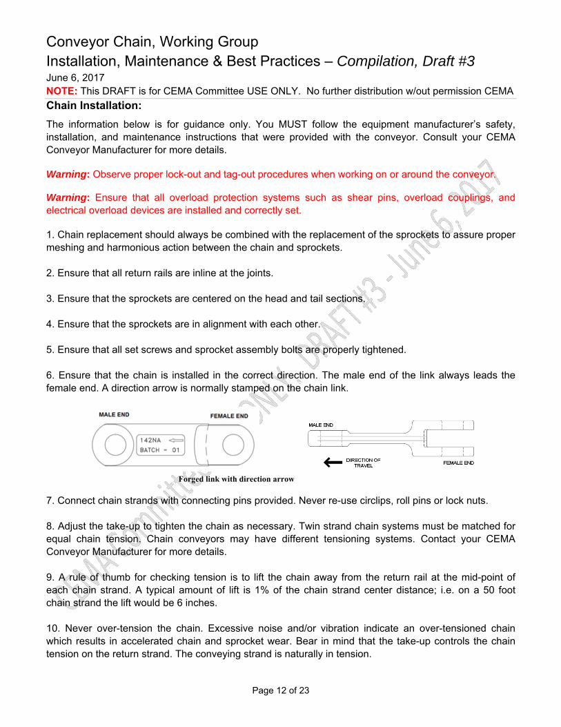
The information below is for guidance only. You MUST follow the equipment manufacturer’s safety, installation, and maintenance instructions that were provided with the conveyor. Consult your CEMA Conveyor Manufacturer for more details. Warning: Observe proper lock-out and tag-out procedures when working on or around the conveyor. Warning: Ensure that all overload protection systems such as shear pins, overload couplings, and electrical overload devices are installed and correctly set. 1. Chain replacement should always be combined with the replacement of the sprockets to assure proper meshing and harmonious action between the chain and sprockets. 2. Ensure that all return rails are inline at the joints. 3. Ensure that the sprockets are centered on the head and tail sections. 4. Ensure that the sprockets are in alignment with each other. 5. Ensure that all set screws and sprocket assembly bolts are properly tightened. 6. Ensure that the chain is installed in the correct direction. The male end of the link always leads the female end. A direction arrow is normally stamped on the chain link.
Forged link with direction arrow
7. Connect chain strands with connecting pins provided. Never re-use circlips, roll pins or lock nuts. 8. Adjust the take-up to tighten the chain as necessary. Twin strand chain systems must be matched for equal chain tension. Chain conveyors may have different tensioning systems. Contact your CEMA Conveyor Manufacturer for more details. 9. A rule of thumb for checking tension is to lift the chain away from the return rail at the mid-point of each chain strand. A typical amount of lift is 1% of the chain strand center distance; i.e. on a 50 foot chain strand the lift would be 6 inches. 10. Never over-tension the chain. Excessive noise and/or vibration indicate an over-tensioned chain which results in accelerated chain and sprocket wear. Bear in mind that the take-up controls the chain tension on the return strand. The conveying strand is naturally in tension.
Conveyor Chain, Working Group Installation, Maintenance & Best Practices – Compilation, Draft #3 June 6, 2017 NOTE: This DRAFT is for CEMA Committee USE ONLY. No further distribution w/out permission CEMA
Page 13 of 23
11. Run the conveyor empty and listen for unusual snapping, snagging, or popping noises. The chain should operate smoothly. 12. Inspect the chain regularly, especially during the start-up period. Contact your CEMA Conveyor Manufacturer for more details.
Chain Maintenance:
The information below is for guidance only. You MUST follow the equipment manufacturer’s safety, installation, and maintenance instructions that were provided with the conveyor. Consult your CEMA Conveyor Manufacturer for more details. Warning: Observe proper lock-out and tag-out procedures when maintaining the drag conveyor. Warning: Ensure that all overload protection systems such as shear pins, overload couplings, and electrical overload devices are installed and correctly set. 1. Check for chain elongation by measuring the length of a used strand (10 pitches minimum) and comparing it to the equivalent length of a new strand. Measurements must be taken while chain is in tension. Chain replacement is recommended at 2% elongation. 2. Check for chain link wear by measuring the height of the link. Chain replacement is recommended when the original height has worn by 20%. 3. Inspect chain for damaged flights. 4. Inspect connecting pins for damaged or missing retainers. 5. Inspect sprockets for damaged or worn teeth. 6. Inspect groove depth of idler/trailer wheel. Replace if groove is too shallow to maintain chain engaged to idler wheel. 7. Inspect sprockets for material build-up in pockets. Replace or repair sprocket cleaner if necessary. 8. Inspect shaft keys and re-torque hub setscrews and sprocket assembly bolts. 9. Inspect chain rails for damage and wear. 10. Damaged links, pins, retainers and flights MUST be replaced; otherwise it may result in further damage to chain, sprockets and conveyor system.

Conveyor Chain, Working Group Installation, Maintenance & Best Practices – Compilation, Draft #3 June 6, 2017 NOTE: This DRAFT is for CEMA Committee USE ONLY. No further distribution w/out permission CEMA
Page 14 of 23
Chain Drive Wire Mesh Belt Installation and Maintenance Guide
Chain drive wire mesh belts consist of three major components: wire mesh belt, cross rod supports, and parallel strands of chain. The density of the wire mesh is selected to provide sufficient product support, while the cross rod supports are sized and positioned to provide adequate lateral support to the wire mesh while at the same time connecting the two parallel strands of chain together. This way, the components come together to act as a single conveyor belt unit. Belt Installation:
The information below is for guidance only. You MUST follow the equipment manufacturer’s safety, installation, and maintenance instructions that were provided with the conveyor. Consult your CEMA Conveyor Manufacturer for more details. Warning: Observe proper lock-out and tag-out procedures when working on or around the conveyor. Safety: The installation of a wire belt on a unit handling conveyor presents a number of risks for which precautions must be taken. First, it is usually necessary to remove some or all of the conveyor guards during the belt installation process. This exposes the installer to moving components which would normally be shielded. Second, belts of this type are often quite heavy and difficult to handle. Also there may be sharp edges from ends of the wires at the belt edges and/or the old belt to be replaced may have broken or damaged sections with exposed wires that can cut or puncture. As a result, the following minimum safety precautions are strongly advised:
Wear the proper personal protective equipment. Practice the proper Lock-out / Tag-out procedures when working on a conveyor belt installation. Do not attempt to make adjustments to the conveyor or the belt while the conveyor is running or when the belt is moving. For elevated temperature applications, allow sufficient time for the belt and conveyor to cool prior to making adjustments.
The following general guidelines are suggested for the proper installation of a typical chain drive conveyor belt:
1. Pull the belt into the conveyor with a cable or rope. The cable should be attached to a rigid pull bar which is attached to the belt at the chains only. Secure the leading edge of the woven mesh to the pull bar with wire ties to keep it from becoming damaged during installation, but allow it to remain slightly slack.
2. Pull the belt into the conveyor slowly; apply even tension to both chains, and do not jerk the belt. Be very careful not to allow one strand of chain to take all of the tension.
3. Watch the belt carefully as it comes out of the crate. Remove any kinks from the chain or wire mesh fabric as the belt leaves the crate and before it enters the conveyor.
Conveyor Chain, Working Group Installation, Maintenance & Best Practices – Compilation, Draft #3 June 6, 2017 NOTE: This DRAFT is for CEMA Committee USE ONLY. No further distribution w/out permission CEMA
Page 15 of 23
4. As the belt enters the conveyor, make sure all the spirals on the woven mesh are lying flat. Any spirals that are turned up and creating a hump in the fabric must be turned to lie flat. If these spirals are not turned as the belt is installed, they may become permanently deformed as tension is developed in the belt.
5. Thread the belt completely through the conveyor, top and bottom passes. Join the belt ends together, preferably on a flat surface, where the two ends can be brought together under no tension. Connect the woven mesh first, then connect the chains. The chains will generally connect in one of two ways. Either a cross rod for the belt will be provided that acts as a chain pin, or a standard chain connector link will be provided. If a cross rod is used, slacken the woven mesh and connect the ends together. Then, insert the cross rod to act as a chain pin and weld the washers provided to each end of the cross rod (depending on the type, some belts will have cottered ends on the cross rods). If a standard chain connector is provided, slacken the fabric and connect the ends together. Then, install the connector link so that the free side plate is on the outside of each strand of chain.
6. Prior to running the belt, inspect all sprockets for proper engagement with the belt. Pay close attention to the drive sprockets to ensure that each strand of chain on the belt is engaged in the same sprocket tooth relative to the chain pitch and/or cross rods. If one strand of chain is installed ahead or behind the other, the belt may be damaged at start-up. All tail and idler shafts should have only one sprocket keyed to the shaft. The other sprocket should be free to float rotationally, but constrained from moving laterally.
7. Whenever possible, chains should be lubricated while in operation. For most room temperature applications, a good grade of light mineral oil should be sufficient. For elevated temperatures, freezing temperatures,and other special processess, a lubricant manufacturer should be consulted for selection of the most effective lubricant.
Belt Maintenance:
The information below is for guidance only. You MUST follow the equipment manufacturer’s safety, installation, and maintenance instructions that were provided with the conveyor. Consult your CEMA Conveyor Manufacturer for more details. Warning: Observe proper lock-out and tag-out procedures when working on or around the conveyor. As most if not all of the belt tension is carried by the parallel strands of chain, probably the most important maintenance practice to extend the service life of the belt is to keep the chains clean and lubricated. The type of oil selected depends on the operating temperature of the application, but in most non-elevated temperature applications, a suitable grade of mineral oil works best. Some mineral oils specifically intended for chain lubricants also include wear inhibiting additives of which there are also food grade types. Both the strands of chain and the woven wire mesh will elongate over time and hours of service. Depending on the application and construction of the conveyor, it may be necessary at times to remove small sections of belt. This is normal and to be expected. It is also a good time to check the chain length over a given section on each side of the belt and compare the results. In general, chain lengths from one
Conveyor Chain, Working Group Installation, Maintenance & Best Practices – Compilation, Draft #3 June 6, 2017 NOTE: This DRAFT is for CEMA Committee USE ONLY. No further distribution w/out permission CEMA
Page 16 of 23
side of the belt to the other should be the same to within 1/16” across 10 ft of belt or more. If this is not the case, then it is likely that the strand of chain that is the longest is also under the most load and/or is getting less lubrication. Remedying this problem sooner rather than later is strongly recommended to preserve the remaining service life of the chain drive belt. In general, the overall belt can be considered to have reached the end of its useful service life when the strands of chain will no longer match the sprockets. For most chains, this may be at 2.5 - 3% elongation. However, the belt may also be in need of replacement if the wire mesh has been sufficiently damaged or worn. Ideally, one should expect the chains to elongate to the point of creating a severe enough mismatch with the drive sprockets, but the condition of the mesh may be an even more important consideration when deciding to replace the belt.
Following are some specific guidelines for addressing specific problems or issues with chain drive conveyor belts:
1. Chain Binding: A chain drive belt is subjected to all of the typical issues that can go wrong with standard chain, plus the additional complexities caused by the wire mesh itself and the general construction of the overall belt. Because the strands of chain and the mesh and cross rods must function as a single unit, a problem or issue on one side of the belt can cause problems on the opposite side. Chain binding can be the result of an issue with the chain itself, such as lack of sufficient lubrication, or it can result from any or all of the following:
a. Offset in the sprocket engagement between one side of the belt and the other. b. Cross rod ends that extend from the side of the chain and are dragging on the side of the
conveyor. c. Drive sprockets that are out of proper position. d. Bent or twisted cross rod(s).
If necessary, the belt should be placed in proper alignment with the sprockets and the conveyor should be checked to make sure it is square. If the welds on some of the cross rods have broken and/or the belt has become twisted or distorted, the belt may need to be replaced unless the damage is limited to a small portion of the overall belt. If the damage is limited, then possibly that section can be replaced.
2. Chain Wear: Excessive chain wear can be caused by insufficient lubrication, interference with the conveyor or a guide component, excessive chain tension, or belt/conveyor misalignment. Depending on the type of wear, check for any interference between the chain(s) and the conveyor itself; also watch the belt as it tracks to determine if it has a tendency to shift to one side or the other, which may indicate an alignment issue. Make certain the belt has not been over-tightened (too little belt on the conveyor, excessive counterweight, etc.). The belt should run with minimum tension possible in order to maximize its service life. If the chains seem dry and debris-filled, they may lack sufficient lubrication.
3. Chain Jumping Sprockets: This is generally caused by excessive chain elongation or some misalignment with the sprockets. The chain should be measured (under load) to determine if the elongation has reached a value where it no longer matches the pitch diameter of the sprockets (approximately 2.5 - 3% elongation). If the chain pitch is still acceptable, then check the position
Conveyor Chain, Working Group Installation, Maintenance & Best Practices – Compilation, Draft #3 June 6, 2017 NOTE: This DRAFT is for CEMA Committee USE ONLY. No further distribution w/out permission CEMA
Page 17 of 23
and alignment of the sprockets. The sprockets may be too close together or too far apart to match the width of the assembled belt.
The belt may also have a tracking issue causing it to move to one side or the other. The conveyor alignment should be checked to make sure the unit is square with the shafts and the shafts are parallel to each other. Check for any interference in the path of the belt which may be forcing it to shift laterally.
4. Woven Mesh Shifting: This is usually related to a belt tracking problem or an issue with the location/orientation of the support(s) under the wire mesh portion of the belt. The contact between the supports and the wire mesh may be causing the mesh to shift to one side or the other. This may be causing an open area on the belt as the mesh is being pulled away from the chain. Check the position of the supports to see if the mesh is getting caught or restricted, also check the orientation. If possible, the supports should be oriented in a long, herringbone pattern which points in the direction of travel. Additionally, check for bent or distorted mesh in the location where the problem is occurring. Lastly, verify proper alignment of the conveyor support bed with the drive shaft.
5. Sprockets Wearing: Typically caused by the same problems that lead to the chain jumping the sprockets. Generally a result of chain/belt misalignment, improperly placed sprockets, conveyor misalignment, or distorted/damaged belt. First check to make certain the correct sprockets have been used. Attempt to re-position the sprockets if side wear is the issue. If this does not ease the problem, examine the conveyor for an alignment issue and/or check the chains for excessive elongation. Replace the belt and/or sprockets as necessary.
6. Slack Mesh: In general, other than on a pocket belt, the mesh should be slightly slack to slightly taut. Excessive slack in the mesh may be the result of an insufficient number of cross rod supports or a belt that was manufactured with too much lead in the mesh. The mesh may also have become excessively worn due to high tension or distorted due to interaction with the conveyor. If the problem is excessive and is causing issues with product support, the belt may require replacement.
7. Chain Strands Uneven: Presuming there was not an issue with the strands of new chain, then it is likely the chains have developed unequal wear and elongation. This is most likely due to uneven tension from one side of the belt to the other or insufficient lubrication of one of the chains. If chain lubrication is acceptable, then the alignment of the conveyor should be checked and corrected. Depending on the severity of the problem, the entire belt may need to be replaced.

Conveyor Chain, Working Group Installation, Maintenance & Best Practices – Compilation, Draft #3 June 6, 2017 NOTE: This DRAFT is for CEMA Committee USE ONLY. No further distribution w/out permission CEMA
Page 18 of 23
Plastic Conveyor Chain Installation and Maintenance Guide
Plastic chains are molded polymer, interconnecting, hinge-like modules (links) of various sizes and configurations which are connected end to end to form a continuous, flexible conveying element on which, when installed on a conveyor frame, product in unit form may be transported. Plastic conveyor chains consist of rigid plastic links which are molded from any one of a variety of durable plastics and mechanically connected by means of a steel pin. Links may be designed such that the pinned connection flexes in the longitudinal direction or in both longitudinal and lateral directions, which are commonly referred to as side flexing (also known as multiflex and double flex chain). A unique hybrid, two-piece chain design consists of a steel base-chain onto which rigid plastic top plates are snapped in place. Plastic conveyor chain is widely used in various product transport applications in industry from single strand to multi-strand configurations; whether they are straight-running or curved. Its high strength, rigid polymer construction and array of design features provide for relatively simple installation and low maintenance operation. Chain Installation:
The information below is for guidance only. You MUST follow the equipment manufacturer’s safety, installation, and maintenance instructions that were provided with the conveyor. Consult your CEMA Conveyor Manufacturer for more details. Warning: Observe proper lock-out and tag-out procedures when working on or around the conveyor. Safety: As with any power equipment or conveyor system, flat top chain conveyors contain inherent hazards that must be safe guarded. Protection around the areas where the chain engages the drive sprockets as well as sprockets and/or idlers at both the infeed and discharge ends is advisable. Interaction of personnel with a moving plastic chain should be avoided. When necessary, however, such interaction should be in accordance with ASME, OSHA and CEMA safety standards.
The installation of a plastic chain on a unit handling conveyor presents a number of risks for which precautions must be taken. Such risks include (but not limited to):
Removing some or all of the protective guarding from the conveyor during the chain installation process exposes the installer to moving components which would normally be shielded;
Pinch points on conveyor and chain, sharp edges of damaged and/or broken links and/or attachments, etc.;
Handling plastic chain that is quite heavy and/or cumbersome; Handling conveyor components that have recently been operational, including plastic chain
belt(s) which is to be removed, and carry residual effects such as heat, product contamination, damage, etc.

Conveyor Chain, Working Group Installation, Maintenance & Best Practices – Compilation, Draft #3 June 6, 2017 NOTE: This DRAFT is for CEMA Committee USE ONLY. No further distribution w/out permission CEMA
Page 19 of 23
Consequently, the following minimum safety precautions are strongly advised:
Wear appropriate and proper personal protective equipment. Implement proper Lock-out / Tag-out procedures when working on a conveyor belt installation. Do not attempt to make adjustments to the conveyor or the belt while the conveyor is running or
when the belt is moving. Employ proper tools and/or enlist an assistant when attempting to manipulate and managing a
large plastic chain alone. For elevated temperature applications, allow sufficient time for the belt and conveyor to cool prior
to making adjustments.
The following general guidelines are suggested for the proper installation of a typical plastic chain conveyor belt:
1. Pull a short section of the chain through the entire conveyor to detect any obstructions or areas of tight clearance.
2. Check conveyor for loose components and fasteners; projections including frame components, welding splash; and contamination on sliding surfaces i.e., metal chips, paint, etc.
3. Ensure wear strip joints and the supporting elements are even, and that the clearance between chain and chain guides is correct.
4. Establish proper alignment of sprockets and idlers.
5. Properly lubricate entire length of chain, as per manufacturer’s guidelines, with lubricant that is appropriate for operating conditions and environment. Consult lubricant manufacturer for proper lubricant selection for high and low temperature applications.
6. Relieve any kinks from the chain and inspect involved links as the belt leaves the crate and before it enters the conveyor.
7. Thread the chain completely through the conveyor’s top and bottom paths. Join the ends together, preferably where chain is sufficiently supported so to be managed effectively and ends can be brought together under minimal tension.
8. Inspect all sprockets for proper engagement with the chain prior to start-up.
9. Where multiple chains are installed on common shafts, all tail and idler shafts should have only one sprocket keyed to the shaft; remaining sprockets should be free to rotate about the shaft, but constrained from moving laterally.
10. Upon start-up, run the conveyor without product for 30 minutes to an hour listening for peculiar sounds i.e., clicking, knocking, squeaking, and look for signs of unusual operation.
11. Repeat step 10 while conveying product.
12. Check catenary sag while belt is in operation to ensure it is within the manufacturer’s recommended requirements.

Conveyor Chain, Working Group Installation, Maintenance & Best Practices – Compilation, Draft #3 June 6, 2017 NOTE: This DRAFT is for CEMA Committee USE ONLY. No further distribution w/out permission CEMA
Page 20 of 23
Chain Maintenance:
The information below is for guidance only. You MUST follow the equipment manufacturer’s safety, installation, and maintenance instructions that were provided with the conveyor. Consult your CEMA Conveyor Manufacturer for more details. Warning: Observe proper lock-out and tag-out procedures when working on or around the conveyor. Periodic inspection of the chain, sprocket and conveyor system is required. The conveyor should be inspected while the system is running as well as when it is shut-off. Items to check for are:
Survey the conveyor for excessive or unusual wear patterns on the chain, track, or wearstrip; look for unusual or excessive debris deposits, such as wear debris accumulation on or beneath the conveyor.
Listen for and locate the source of any unusual noises such as squeaking, clicking or knocking.
Inspect chain for top surface flatness and unusual and/or excessive wear or grooves.
Examine sprockets for signs of excessive wear and debris deposits.
Check that supporting rollers are turning freely.
Review joints in guide track and/or wear strip to ensure there are no irregular offsets either vertically or horizontally.
Look for excessive gaps between links commonly resulting from overload during operation.
Periodically measure the chain length for inordinate elongation and check height of chain catenary.
Observe the operation of the chain to detect pulsation or jerky motion.
Check chain guide track and dead plate clearances to ensure they meet manufacturer’s guidelines.
Review the insides of corner wear strips and chain guides and note that excessive heat may indicate tight clearance or high friction.
Ensure that corner turn discs, if used, are properly aligned and turning freely.
Check for excessive heat especially in the curves which may indicate an obstruction, impingement, or high friction area.
Verify that lubrication system is working correctly.

Conveyor Chain, Working Group Installation, Maintenance & Best Practices – Compilation, Draft #3 June 6, 2017 NOTE: This DRAFT is for CEMA Committee USE ONLY. No further distribution w/out permission CEMA
Page 21 of 23
General Maintenance Guidelines One of the most important maintenance practices to extend the service life of the plastic chain is to keep it clean; free of the accumulation of debris. For the most part, plastic chain operates without the need for supplemental or externally applied lubrication. Guide track and wear strip materials are commonly available with intrinsic lubrication such as oil infused Nylon and other similar materials. Supplemental lubrications can cause the accumulation of debris on the chain and guide materials and accelerate abrasion of the same. When externally applied lubrication is required, such as when running chain in conjunction with metallic guide track or wear strips, consult your plastic chain supplier for recommendations of appropriate lubricants.
Plastic will elongate over its time in service. Depending on the application, length of chain, and construction of the conveyor it may be necessary to remove a link or short sections from belt to maintain proper tension and sprocket engagement. Elongation due to wear and thermal expansion is normal and to be expected. In general, the length of a chain in use should not exceed 2-3% of the original length. Greater length differential can lead to engagement failure at the drive sprocket.
It is also necessary to check the length of multiple chain strands running in parallel; measuring individual lengths along a particular span of conveyor and compare the results. A difference in length can indicate that the longer strand is being subjected to greater loading. Such added load may be the consequence of chain binding resulting from improper clearances or lack of lubrication. In order to avoid further operational complications, it is advisable to search out the cause and correct the problem as soon as it is detected. Prompt attention to the matter will further serve to preserve the remaining service life of the chain. If an exorbitant difference in chain length exists, it is not advisable to shorten the longer chain to offset the difference; this accomplished by the catenary pocket at the drive.
A plastic chain may be considered to have reached the end of its useful service life when it will no longer properly mesh (engage) with the sprocket. This effect occurs, generally, at approximately 2% elongation. It may be necessary, however, to replace the plastic chain if the links have been sufficiently damaged or worn negatively affecting its mesh with the sprocket. Principally, the condition of the mesh will dictate the appropriate time to replace the plastic chain to best serve the operation of the conveyor and service life objectives. It’s important to note that as the chain/sprocket engagement degrades, the stresses of driving the chain resolve to fewer and fewer teeth thereby accelerating sprocket wear and fatigue.
The following guidelines present typical measures for addressing specific performance problems with plastic chain conveyor belts:
1. Chain Binding: A plastic chain conveyor belt is subject to many of the typical operating influences and maladies associated with standard chain along with the additional complexities inherent to the unique construction of the plastic chain design. Chain binding can cause erratic operation resulting in problems with throughput and product quality. Following are a number of typical conditions that can cause binding of the chain:
a. Offset in the sprocket engagement between one side of the belt and the other. b. Drive sprockets that are out of proper position. c. Hinge pin(s) protruding from the side of the chain and dragging on guide track. d. Damaged hinge pin(s). e. Improper clearance between chain and guide track, wearstrip, or accessories i.e., dead
plates.

Conveyor Chain, Working Group Installation, Maintenance & Best Practices – Compilation, Draft #3 June 6, 2017 NOTE: This DRAFT is for CEMA Committee USE ONLY. No further distribution w/out permission CEMA
Page 22 of 23
f. Offset or damaged guide track g. Insufficient lubrication
Properly align the sprockets (and idlers) with each other – in both the horizontal and vertical planes. Shafts should be adjusted to be parallel and level with each other. Sprocket alignment is also function of proper conveyor frame alignment; consequently, the conveyor should be checked to ensure it is square and level.
Prior to chain installation, slide a short section of chain through the conveying path, along the guide track and/or wear strip in order to detect any areas which bind or create inordinate noise and make necessary adjustments or corrections.
2. Chain Wear: Excessive chain wear can be caused by interference with the conveyor or a guide component(s), conveyor and/or component misalignment, excessive chain tension, or lack of sufficient lubrication. Depending on the type of wear, check appropriate locations on the conveyor for interference between the chain(s) and the various components. Observing chain movement during operation will enable the observer to pinpoint areas of irregular motion and focus in on specific elements which require maintenance or other attention. Verify that the chain has not been tensioned beyond the recommended limit. Excessive tension could result from insufficient catenary sag, excessive counterweight, chain length being too short, etc. The belt should run through its path with as little tension possible in order to minimize power consumption and maximize its service life. If the chain is debris-filled, check to verify whether lubrication is present (or is recommended).
3. Chain Jumping Sprockets: This is generally caused by misalignment with the sprockets, improper tension, or excessive chain elongation. Check the position and alignment of the sprockets as well as the depth of the catenary. The chain should be measured (under load) to determine if the elongation has reached a value where it no longer matches the pitch diameter of the sprockets (approximately 2-3% elongation).
For conveyors with multiple chain strands in parallel, all but one of the sprockets on the tail (idling) shaft must rotate freely about the shaft; the center sprocket alone being keyed. If all sprockets on the tail shaft were keyed, chain and sprocket disengagement will result as the individual strands wear and elongate differently in time. Disengagement of chain and sprocket may also result from component misalignment; commonly causing in miss-tracking. The conveyor alignment should be checked to ensure that the frame is square, the shafts square to the frame, and that they are parallel and level with each other. Check for any interference(s) along the chain paths (conveying and return) that may be forcing it laterally.
4. Sprockets Wearing: Typically brought about by the same influences that lead to chain/sprocket disengagement. Generally, sprocket wear follows as a consequence of conveyor and/or component misalignment, improperly placed sprockets, improper tension, or distorted/damaged chain. First check to make certain the correct sprockets have been used. Should side wear be the problem, examine the conveyor for areas of misalignment and the chains for excessive elongation. If these are found to be within normal limits, reposition the sprockets if possible. Replace the belt and/or sprockets as necessary.
Conveyor Chain, Working Group Installation, Maintenance & Best Practices – Compilation, Draft #3 June 6, 2017 NOTE: This DRAFT is for CEMA Committee USE ONLY. No further distribution w/out permission CEMA
Page 23 of 23
5. Uneven Chain Strand Lengths: Presuming the strands of new chain were properly constructed, it is likely the chains developed unequal wear and elongation over the course of operation. This is commonly due to uneven tension across the various chain strands or insufficient lubrication of one or more chains. If chain lubrication is acceptable, check the alignment of the conveyor and correct as necessary. Depending on the severity of the unevenness, the entire chain set may require replacement.