copper and fiber optics solutions for networks · ... copper solutions copper solutions 1 cat.6 |...
TRANSCRIPT
Copper and Fiber Optics solutions for networks

Table of contents3
Copper and Fiber Optics solutions for networks
1 Copper Solutions 5
2 Fiber Optic Solutions 47
3 Data Center Solutions 63
4 Industrial Connectors 73
5 Pre-Terminated Assemblies 145
6 METZ CONNECT worldwide 154
7 Contact 155

4
Christian and Jochen Metz in the local Blumberg
Preface
5
Dear business partners,dear customers,
We are continuing where history left off and will still rely on optimal connections in the future!
Jochen MetzManaging Partner
Christian MetzManaging Partner
The family-owned company METZ CONNECT has stood for precision, reliability and ingenuity for more than four decades. Virtues that we put into practice every day at all of our worldwide production and distribution sites.
As pioneers in the communication between people and equip- ment, it goes without saying that we also pass on our expe-rience and knowledge across generations. And grow steadily in the process!
The METZ CONNECT range is divided into three core areas and offers a wide range of solutions for the most demanding needs:
P|Cabling Copper and glass fiber components as well as automated infrastructure management for structured network cabling
U|Contact PCB connection technology for the connection of devices and controls in building and industrial automation
C|Logline Intelligent system and switch cabinet components for building and process automation.
You will encounter products from METZ CONNECT several times a day, often without seeing them: whether PCB com-ponents or connection terminals in control elements, copper and fiber optic components for network cabling or intelligent I/O components in the control cabinet for building automation. Many areas of everyday life, including complex industrial supply and production chains, require the intelligent networ-king of the involved devices and components. For all these application situations, METZ CONNECT offers full service, from the printed circuit board to the Internet.
As a partner of numerous international companies, we offer expertise resulting from 40 years of experience in standardised and, above all, customer-specific system solutions for a variety of applications in connection technology. We see ourselves as a problem solver and do not settle for the second-best solution. The search for perfection may seem expensive, but it is worth it.
Join us in mutual projects concerning equipment and plant construction as well as the structured cabling of buildings and industrial sites. We are looking forward to working with you!
Best regards
and the entire team from METZ CONNECT.
6
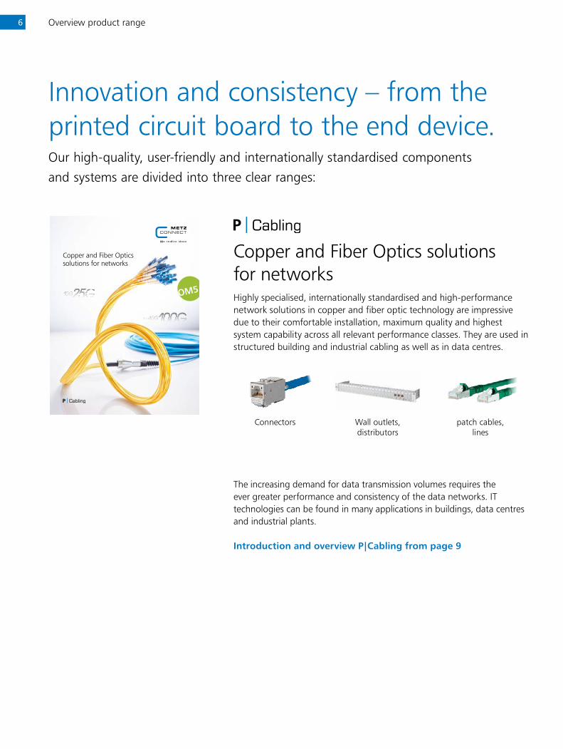
Copper and Fiber Optics solutions for networks
Copper and Fiber Optics solutions for networksHighly specialised, internationally standardised and high-performance network solutions in copper and fiber optic technology are impressive due to their comfortable installation, maximum quality and highest system capability across all relevant performance classes. They are used in structured building and industrial cabling as well as in data centres.
Connectors Wall outlets,distributors
patch cables, lines
The increasing demand for data transmission volumes requires the ever greater performance and consistency of the data networks. IT technologies can be found in many applications in buildings, data centres and industrial plants.
Introduction and overview P|Cabling from page 9
Overview product range
Innovation and consistency – from the printed circuit board to the end device.Our high-quality, user-friendly and internationally standardised components
and systems are divided into three clear ranges:
7
Connection systemsfor printed circuit boards
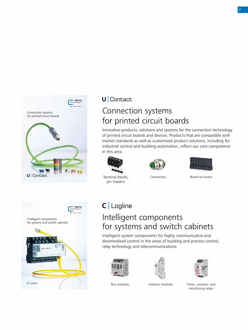
Connection systems for printed circuit boardsInnovative products, solutions and systems for the connection technology of printed circuit boards and devices. Products that are compatible with market standards as well as customised product solutions, including for industrial control and building automation, reflect our core competence in this area.
Terminal blocks, pin headers
Connectors Board-to-board
Intelligent components for systems and switch cabinetsIntelligent system components for highly communicative and decentralised control in the areas of building and process control, relay technology and telecommunications
Bus modules Inteface modules Timer-, process- and monitoring relays
Intelligent components for systems and switch cabinets
Notes8C
op
per
So
luti
on
s

Table of contents | Copper Solutions
Copper Solutions
1 Cat.6 | Cable ............................................. 10
2 Cat.6 | Adapter ......................................... 11
3 Cat.6 | Modules ........................................ 12
4 Cat.6 | RJ45 field plugs ............................ 13
5 Cat.6 | Patch panels ................................. 14
6 RJ45 | Configurator
(Application neutral connection cable) ..... 15
7 Cat.6A | Cables ......................................... 16
8 Cat.6A | Modules UTP ............................... 17
9 Cat.6A | Modules ...................................... 18
10 Cat.6A | RJ45 field plugs ........................... 20
11 Cat.6A | DIN RAIL Products ....................... 21
12 Cat.6A | Panels .......................................... 22
13 RJ45 | Configurator
(Trunk- and consolidation point link cable) .. 24
14 Cat.6A | Patch Cables................................ 26
15 Cat.7 | Cables ........................................... 27
16 Cat.7A | Cables ......................................... 28
17 Accessories | Cat.6 .................................... 29
18 Accessories | Cat.6A .................................. 32
19 Accessories | Cat.6A Color coding ............. 39
20 Accessories | Cat.6A Dust protection ........ 40
21 Accessories | Cable connectors ................. 42
22 Accessories ................................................ 43
23 Tools ......................................................... 45
9

Cat.6 | Cable
GC400 SL23 Cat.6 U/UTP LSHF
P/N Color Feature 1 Feature 21308406032140 blue 305 m
(1000 ft)box
1308406032141 blue 500 m (1640 ft)
drum
1308406032142 blue 1000 m (3280 ft)
drum
Principle diagram
• 1 GBit installation cable, simplex• unshielded installation cable Cat.6 class E AWG 23 U/UTP• 4 pairs with separator (spline)• outer diameter 5.3 mm• coupling attenuation not less than 40 dB• applicable standards: EN 50173-1:2011-09; ISO/IEC 11801
Ed.2.2:2011-06; EN 50288-6-1, IEC 61156-5, EIA/TIA 568B• cable jacket: LSHF (LSOH)• flame-retardant to IEC 60332-1; IEC 60754-2 and IEC 61034• fire behaviour: Class Eca (classification acc. to EN 13501-6)
Shipping Units:1000 ft (305 m) in a box1640 ft (500 m) on drum3280 ft (1000 m) on drum
10C
op
per
So
luti
on
s
Matching accessoriesfor GC400 SL23 Cat.6 U/UTP LSHF
Page46Jokari dismantle tool
Cat.6 | Adapter
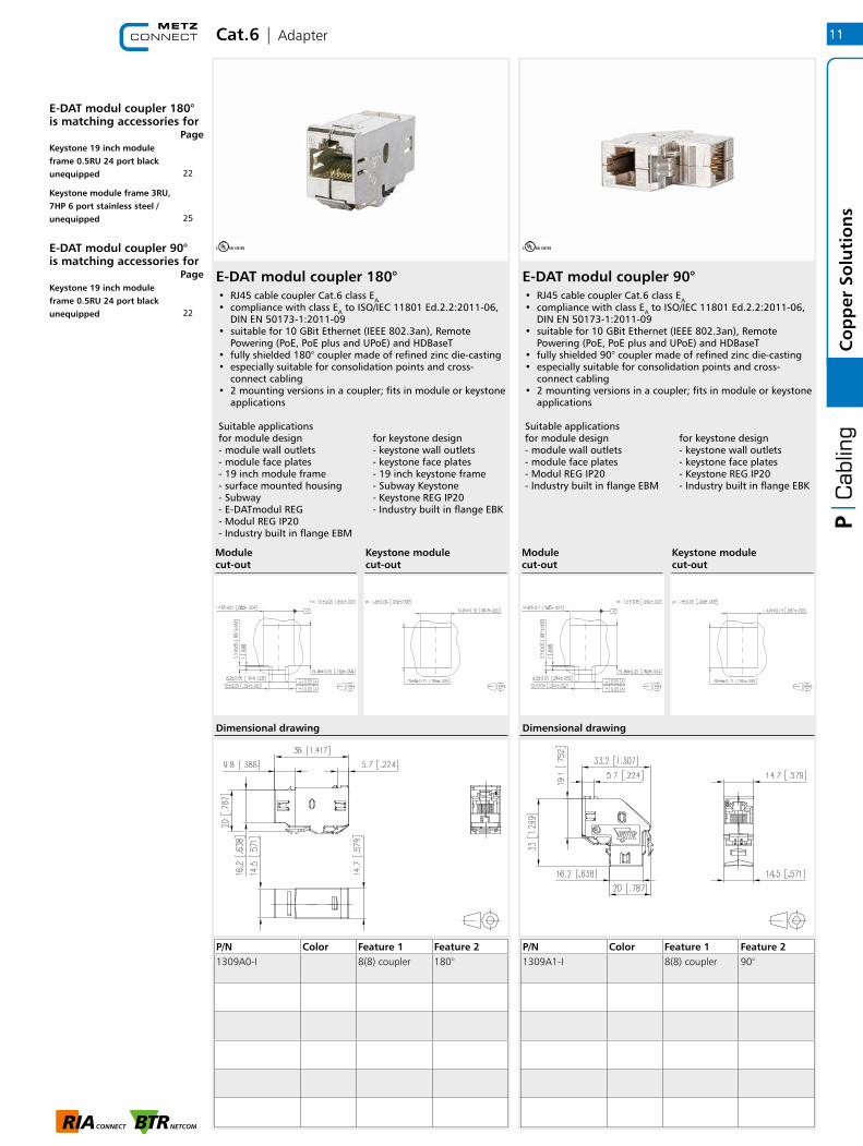
E-DAT modul coupler 180° E-DAT modul coupler 90°• RJ45 cable coupler Cat.6 class EA• compliance with class EA to ISO/IEC 11801 Ed.2.2:2011-06,
DIN EN 50173-1:2011-09• suitable for 10 GBit Ethernet (IEEE 802.3an), Remote
Powering (PoE, PoE plus and UPoE) and HDBaseT • fully shielded 180° coupler made of refined zinc die-casting• especially suitable for consolidation points and cross-
connect cabling• 2 mounting versions in a coupler; fits in module or keystone
applications
Suitable applications for module design for keystone design- module wall outlets - keystone wall outlets- module face plates - keystone face plates- 19 inch module frame - 19 inch keystone frame- surface mounted housing - Subway Keystone- Subway - Keystone REG IP20- E-DATmodul REG - Industry built in flange EBK- Modul REG IP20 - Industry built in flange EBM
• RJ45 cable coupler Cat.6 class EA• compliance with class EA to ISO/IEC 11801 Ed.2.2:2011-06,
DIN EN 50173-1:2011-09• suitable for 10 GBit Ethernet (IEEE 802.3an), Remote
Powering (PoE, PoE plus and UPoE) and HDBaseT • fully shielded 90° coupler made of refined zinc die-casting• especially suitable for consolidation points and cross-
connect cabling• 2 mounting versions in a coupler; fits in module or keystone
applications
Suitable applications for module design for keystone design- module wall outlets - keystone wall outlets- module face plates - keystone face plates- Modul REG IP20 - Keystone REG IP20- Industry built in flange EBM - Industry built in flange EBK
P/N Color Feature 1 Feature 21309A0-I 8(8) coupler 180°
P/N Color Feature 1 Feature 21309A1-I 8(8) coupler 90°
Dimensional drawing Dimensional drawing
Module cut-out
Module cut-out
Keystone module cut-out
Keystone module cut-out
11
Co
pp
er S
olu
tio
ns
E-DAT modul coupler 180° is matching accessories for
Page
E-DAT modul coupler 90° is matching accessories for
Page
22
Keystone 19 inch module frame 0.5RU 24 port black unequipped
25
Keystone module frame 3RU, 7HP 6 port stainless steel / unequipped
22
Keystone 19 inch module frame 0.5RU 24 port black unequipped

Cat.6 | Modules
UTP module Cat.6 | keystone | pearl white
UTP module Cat.6 | keystone | black
• unshielded Cat.6 class E UTP module• for Gigabit Ethernet• compliance with class E to ISO/IEC 11801 Ed.2.2:2011-06,
DIN EN 50173-1:2011-09• suitable for Power over Ethernet (PoE, PoE plus and UPoE)• easy to install connection of 2 to 4-pair data lines AWG 24/1
- 22/1 and stranded wires with 7 copper conductors AWG 26/7 to BTR 8-fold insulation displacement connectors (IDC)
• optional strain relief with cable tie at UTP module• installation shape: Keystone
P/N Color Feature 1 Feature 2130A10-I-B1 pearl white Cat.6 T568B Keystone
module cut-out
P/N Color Feature 1 Feature 2130A10-29-I-B1 black Cat.6 T568B Keystone
module cut-out
Dimensional drawing Dimensional drawing
Keystone module cut-out Keystone module cut-out
12C
op
per
So
luti
on
s
UTP module Cat.6 | keystone | pearl white is matching accessories for
Page
UTP module Cat.6 | keystone | black is matching accessories for
Page
22
Keystone 19 inch module frame 0.5RU 24 port black unequipped
22
Keystone 19 inch module frame 0.5RU 24 port black unequipped
Cat.6 | RJ45 field plugs
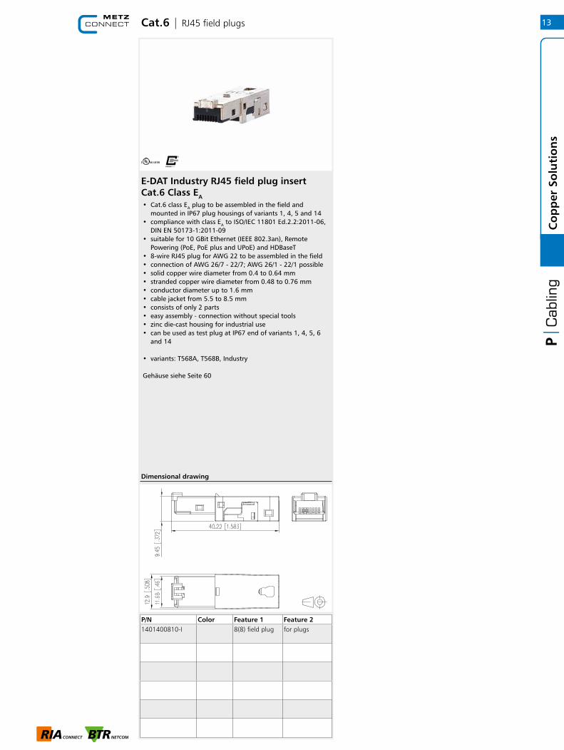
E-DAT Industry RJ45 field plug insert Cat.6 Class EA• Cat.6 class EA plug to be assembled in the field and
mounted in IP67 plug housings of variants 1, 4, 5 and 14• compliance with class EA to ISO/IEC 11801 Ed.2.2:2011-06,
DIN EN 50173-1:2011-09• suitable for 10 GBit Ethernet (IEEE 802.3an), Remote
Powering (PoE, PoE plus and UPoE) and HDBaseT• 8-wire RJ45 plug for AWG 22 to be assembled in the field• connection of AWG 26/7 - 22/7; AWG 26/1 - 22/1 possible• solid copper wire diameter from 0.4 to 0.64 mm• stranded copper wire diameter from 0.48 to 0.76 mm• conductor diameter up to 1.6 mm• cable jacket from 5.5 to 8.5 mm• consists of only 2 parts• easy assembly - connection without special tools• zinc die-cast housing for industrial use• can be used as test plug at IP67 end of variants 1, 4, 5, 6
and 14
• variants: T568A, T568B, Industry
Gehäuse siehe Seite 60
P/N Color Feature 1 Feature 21401400810-I 8(8) field plug for plugs
Dimensional drawing
13
Co
pp
er S
olu
tio
ns

Cat.6 | Patch panels
19 inch Module frame 1RU aluminum unequipped for UTP Keystone
UTP 24 port 1RU LSA Cat.6 patch panel
• 19 inch 1RU module frame for 24 individual modules; Keystone design
• module frame front made of black anodized aluminum• plastic module support with dust protection covers (other
colors available as accessory); detachable to the front• integrated cable support with optional strain relief• label window for enclosed identification labels• label sheet 210 x 297 mm see accessory• grounding bolt M6 x 10 with nut and lock washer
• 19 inch 1RU Cat.6 patch panel with 24 RJ45 ports 8(8)• 19 inch module frame made of black sheet steel • 4 individual 6 port connection blocks, unshielded • connection of the unshielded data cables to LSA insulation
displacement connectors (AWG 22 to 26)• wire connection possible according to T568A and T568B • with 4 clip-in plastic cable brackets• punch down patch panel
P/N Color Feature 1 Feature 2130A20-BK-E black 24 Port w/o
modulesKeystone module cut-out
130A20-00-E light grey 24 Port w/o modules
Keystone module cut-out
P/N Color Feature 1 Feature 2130A10-AP29-E black 24 Port
Dimensional drawing Dimensional drawing
Keystone module cut-out
14C
op
per
So
luti
on
s
Matching accessoriesfor 19 inch Module frame 1RU aluminium unequipped for UTP Keystone
Page
41
Dust protection covers for Modul patch panels / subway / REG yellow
41
Dust protection covers for Modul patch panels / subway / REG blue
41
Dust protection covers for Modul patch panels / subway / REG green
41
Dust protection covers for Modul patch panels / subway / REG red
RJ45 | Configurator
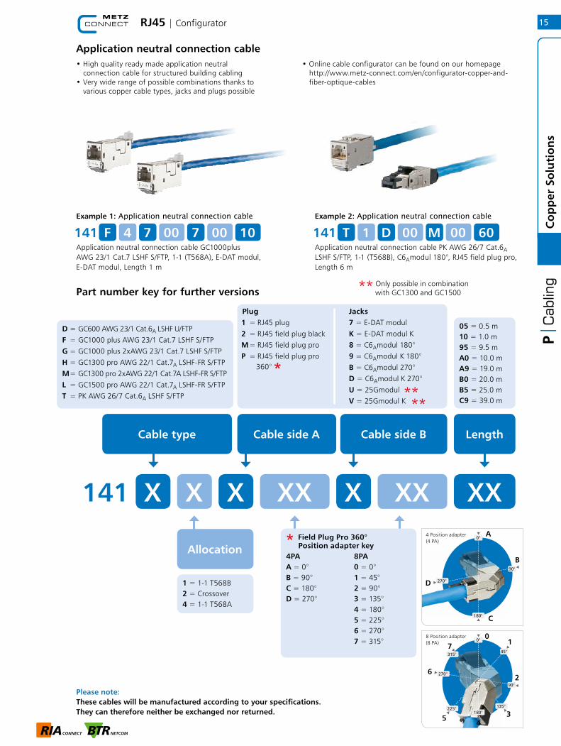
Application neutral connection cable• High quality ready made application neutral connection cable for structured building cabling• Very wide range of possible combinations thanks to various copper cable types, jacks and plugs possible
• Online cable configurator can be found on our homepage http://www.metz-connect.com/en/configurator-copper-and- fiber-optique-cables
Example 1: Application neutral connection cable
Application neutral connection cable GC1000plus AWG 23/1 Cat.7 LSHF S/FTP, 1-1 (T568A), E-DAT modul, E-DAT modul, Length 1 m
141 F 4 7 00 7 00 10Example 2: Application neutral connection cable
Application neutral connection cable PK AWG 26/7 Cat.6A LSHF S/FTP, 1-1 (T568B), C6Amodul 180°, RJ45 field plug pro, Length 6 m
141 T 1 D 00 M 00 60
Part number key for further versions
180°4
Plug1 = RJ45 plug2 = RJ45 field plug blackM = RJ45 field plug proP = RJ45 field plug pro
360°
*
Jacks7 = E-DAT modulK = E-DAT modul K8 = C6Amodul 180°9 = C6Amodul K 180°B = C6Amodul 270°D = C6Amodul K 270°U = 25GmodulV = 25Gmodul K
05 = 0.5 m10 = 1.0 m95 = 9.5 mA0 = 10.0 mA9 = 19.0 mB0 = 20.0 mB5 = 25.0 mC9 = 39.0 m
Cable type Cable side A
141 X X
Allocation
1 = 1-1 T568B 2 = Crossover 4 = 1-1 T568A
Cable side B Length
X XX X XX XX4 Position adapter (4 PA)
0°
180°
90°
270°
0°
135°
270°
90°
45°
225°
8 Position adapter (8 PA)
315°
* Field Plug Pro 360°
Position adapter key
4PA 8PAA = 0° 0 = 0°B = 90° 1 = 45°C = 180° 2 = 90°D = 270° 3 = 135° 4 = 180° 5 = 225° 6 = 270° 7 = 315°
A
B
C
D
01
2
35
6
7
****
** Only possible in combination
with GC1300 and GC1500
180°
4
15
Co
pp
er S
olu
tio
ns
D = GC600 AWG 23/1 Cat.6A LSHF U/FTPF = GC1000 plus AWG 23/1 Cat.7 LSHF S/FTPG = GC1000 plus 2xAWG 23/1 Cat.7 LSHF S/FTPH = GC1300 pro AWG 22/1 Cat.7A LSHF-FR S/FTPM = GC1300 pro 2xAWG 22/1 Cat.7A LSHF-FR S/FTPL = GC1500 pro AWG 22/1 Cat.7A LSHF-FR S/FTPT = PK AWG 26/7 Cat.6A LSHF S/FTP
Please note: These cables will be manufactured according to your specifications. They can therefore neither be exchanged nor returned.
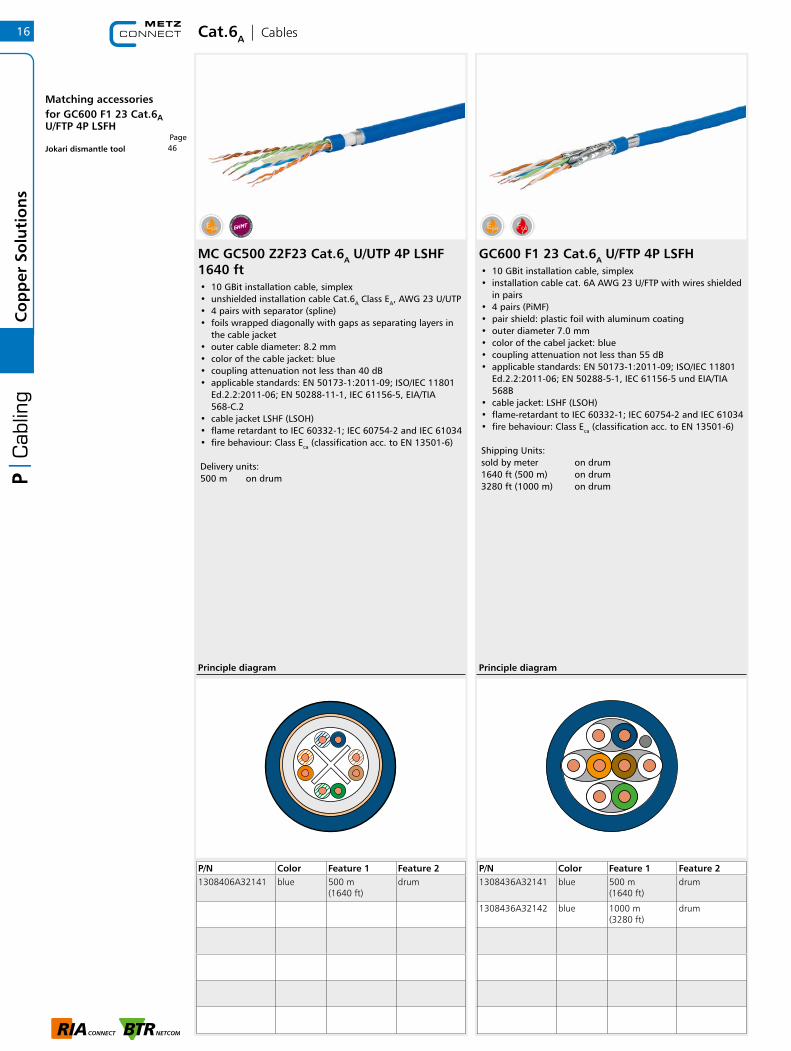
MC GC500 Z2F23 Cat.6A U/UTP 4P LSHF 1640 ft• 10 GBit installation cable, simplex• unshielded installation cable Cat.6A Class EA, AWG 23 U/UTP• 4 pairs with separator (spline)• foils wrapped diagonally with gaps as separating layers in
the cable jacket • outer cable diameter: 8.2 mm• color of the cable jacket: blue• coupling attenuation not less than 40 dB• applicable standards: EN 50173-1:2011-09; ISO/IEC 11801
Ed.2.2:2011-06; EN 50288-11-1, IEC 61156-5, EIA/TIA 568-C.2
• cable jacket LSHF (LSOH)• flame retardant to IEC 60332-1; IEC 60754-2 and IEC 61034• fire behaviour: Class Eca (classification acc. to EN 13501-6)
Delivery units:500 m on drum
Cat.6A | Cables
P/N Color Feature 1 Feature 21308406A32141 blue 500 m
(1640 ft)drum
Principle diagram
GC600 F1 23 Cat.6A U/FTP 4P LSFH• 10 GBit installation cable, simplex• installation cable cat. 6A AWG 23 U/FTP with wires shielded
in pairs• 4 pairs (PiMF)• pair shield: plastic foil with aluminum coating• outer diameter 7.0 mm• color of the cabel jacket: blue• coupling attenuation not less than 55 dB• applicable standards: EN 50173-1:2011-09; ISO/IEC 11801
Ed.2.2:2011-06; EN 50288-5-1, IEC 61156-5 und EIA/TIA 568B
• cable jacket: LSHF (LSOH)• flame-retardant to IEC 60332-1; IEC 60754-2 and IEC 61034• fire behaviour: Class Eca (classification acc. to EN 13501-6)
Shipping Units: sold by meter on drum1640 ft (500 m) on drum3280 ft (1000 m) on drum
P/N Color Feature 1 Feature 21308436A32141 blue 500 m
(1640 ft)drum
1308436A32142 blue 1000 m (3280 ft)
drum
Principle diagram
16C
op
per
So
luti
on
s
Matching accessoriesfor GC600 F1 23 Cat.6A U/ FTP 4P LSFH
Page46Jokari dismantle tool

UTP modul 8(8) Cat.6A keystone pearl white UTP modul 8(8) Cat.6A keystone black• unshielded modular termination unit Cat.6A, RJ45• component testing for Cat.6A to ISO/IEC 11801 Ed.2.2:2011-06,
DIN EN 50173-1:2011-09, TIA/EIA-568-C.2 (2009-08) and IEC 60603-7-41 Ed.1 (12/2008), certified by GHMT
• component testing for Cat.6A to TIA/EIA-568-C.2 and IEC 60512-27-100, certified by GHMT
• compliance with class EA to ISO/IEC 11801 Ed.2.2:2011-06, DIN EN 50173-1:2011-09, certified by GHMT
• tested: component up to 600 MHz, link up to 800 MHz• suitable for 10 GBit Ethernet (IEEE 802.3an), Remote
Powering (PoE, PoE plus and UPoE) and HDBaseT• easy to install connection of 2 to 4 pair data cables AWG
26/1 to 22/1 (solid wire) and stranded wires with 7 Cu strands AWG 26/7 to 22/7 (stranded wire) to insulation displacement connectors (IDC)
• marking of conductor assignment T568A and T568B• easy and rapid insertion of the wire pairs into the UTP
stuffer cap• plastic module housing • mounting without special tool• strain relief possible with cable ties at the module • mounting of colored dust protection covers to the module
possible • design: Keystone• cable feed 180°• variants: white and black
• unshielded modular termination unit Cat.6A, RJ45• component testing for Cat.6A to ISO/IEC 11801 Ed.2.2:2011-06,
DIN EN 50173-1:2011-09, TIA/EIA-568-C.2 (2009-08) and IEC 60603-7-41 Ed.1 (12/2008), certified by GHMT
• component testing for Cat.6A to TIA/EIA-568-C.2 and IEC 60512-27-100, certified by GHMT
• compliance with class EA to ISO/IEC 11801 Ed.2.2:2011-06, DIN EN 50173-1:2011-09, certified by GHMT
• tested: component up to 600 MHz, link up to 800 MHz• suitable for 10 GBit Ethernet (IEEE 802.3an), Remote
Powering (PoE, PoE plus and UPoE) and HDBaseT• easy to install connection of 2 to 4 pair data cables AWG
26/1 to 22/1 (solid wire) and stranded wires with 7 Cu strands AWG 26/7 to 22/7 (stranded wire) to insulation displacement connectors (IDC)
• marking of conductor assignment T568A and T568B• easy and rapid insertion of the wire pairs into the UTP
stuffer cap• plastic module housing • mounting without special tool• strain relief possible with cable ties at the module • mounting of colored dust protection covers to the module
possible • design: Keystone• cable feed 180°• variants: white and black
Cat.6A | Modules UTP
P/N Color Feature 1 Feature 2130A11KI 180° Keystone
module cut-out
P/N Color Feature 1 Feature 2130A11-29KI 270° Keystone
module cut-out
Dimensional drawing Dimensional drawing
17
Co
pp
er S
olu
tio
ns
UTP modul 8(8) Cat.6A keystone pearl white is matching accessories for
Page
UTP modul 8(8) Cat.6A keystone black is matching accessories for
Page
22
Keystone 19 inch module frame 0.5RU 24 port black unequipped
22
Keystone 19 inch module frame 0.5RU 24 port black unequipped
Cat.6A | Modules
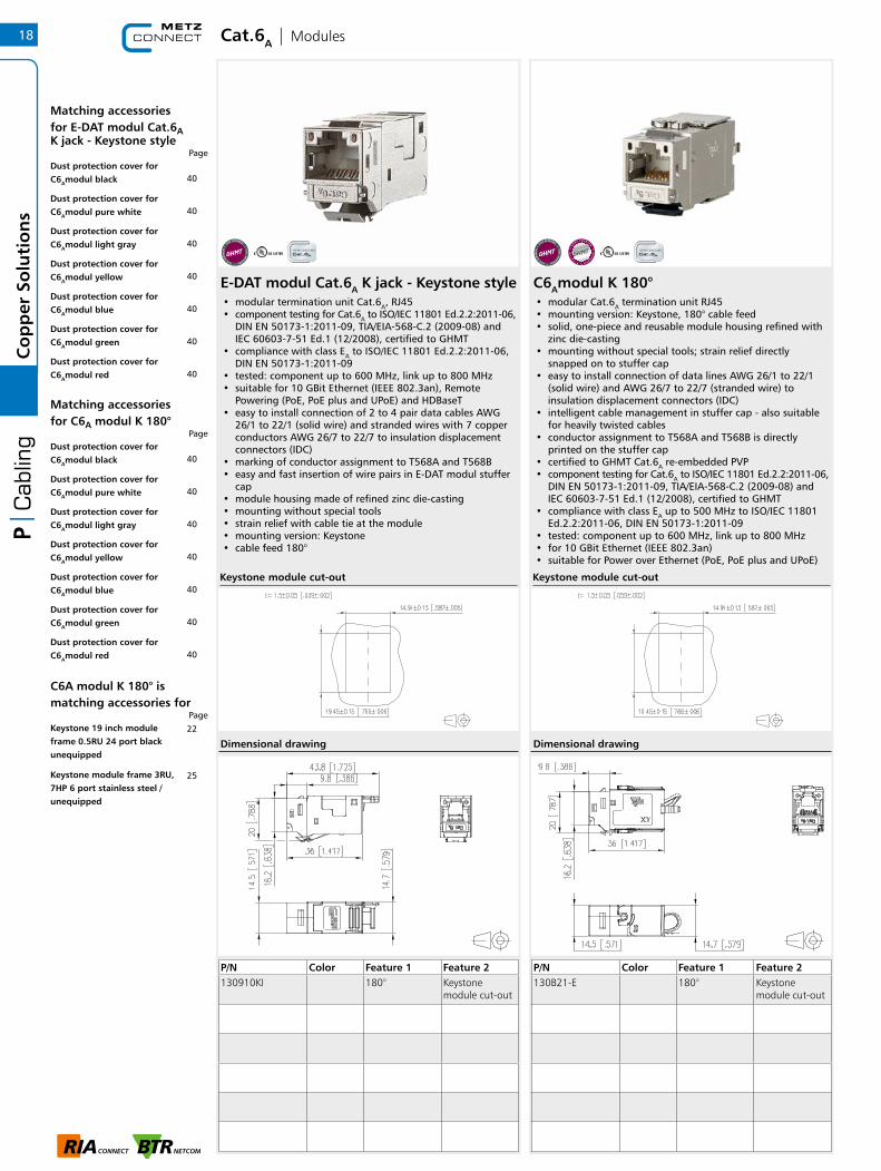
C6Amodul K 180°• modular Cat.6A termination unit RJ45• mounting version: Keystone, 180° cable feed• solid, one-piece and reusable module housing refined with
zinc die-casting• mounting without special tools; strain relief directly
snapped on to stuffer cap• easy to install connection of data lines AWG 26/1 to 22/1
(solid wire) and AWG 26/7 to 22/7 (stranded wire) to insulation displacement connectors (IDC)
• intelligent cable management in stuffer cap - also suitable for heavily twisted cables
• conductor assignment to T568A and T568B is directly printed on the stuffer cap
• certified to GHMT Cat.6A re-embedded PVP• component testing for Cat.6A to ISO/IEC 11801 Ed.2.2:2011-06,
DIN EN 50173-1:2011-09, TIA/EIA-568-C.2 (2009-08) and IEC 60603-7-51 Ed.1 (12/2008), certified to GHMT
• compliance with class EA up to 500 MHz to ISO/IEC 11801 Ed.2.2:2011-06, DIN EN 50173-1:2011-09
• tested: component up to 600 MHz, link up to 800 MHz• for 10 GBit Ethernet (IEEE 802.3an)• suitable for Power over Ethernet (PoE, PoE plus and UPoE)
P/N Color Feature 1 Feature 2130B21-E 180° Keystone
module cut-out
Dimensional drawing
Keystone module cut-out
E-DAT modul Cat.6A K jack - Keystone style• modular termination unit Cat.6A, RJ45• component testing for Cat.6A to ISO/IEC 11801 Ed.2.2:2011-06,
DIN EN 50173-1:2011-09, TIA/EIA-568-C.2 (2009-08) and IEC 60603-7-51 Ed.1 (12/2008), certified to GHMT
• compliance with class EA to ISO/IEC 11801 Ed.2.2:2011-06, DIN EN 50173-1:2011-09
• tested: component up to 600 MHz, link up to 800 MHz• suitable for 10 GBit Ethernet (IEEE 802.3an), Remote
Powering (PoE, PoE plus and UPoE) and HDBaseT• easy to install connection of 2 to 4 pair data cables AWG
26/1 to 22/1 (solid wire) and stranded wires with 7 copper conductors AWG 26/7 to 22/7 to insulation displacement connectors (IDC)
• marking of conductor assignment to T568A and T568B• easy and fast insertion of wire pairs in E-DAT modul stuffer
cap• module housing made of refined zinc die-casting• mounting without special tools• strain relief with cable tie at the module• mounting version: Keystone• cable feed 180°
P/N Color Feature 1 Feature 2130910KI 180° Keystone
module cut-out
Dimensional drawing
Keystone module cut-out
18C
op
per
So
luti
on
s
Matching accessoriesfor E-DAT modul Cat.6A K jack - Keystone style
Page
40Dust protection cover for C6Amodul black
40Dust protection cover for C6Amodul pure white
40Dust protection cover for C6Amodul light gray
40Dust protection cover for C6Amodul yellow
40Dust protection cover for C6Amodul blue
40Dust protection cover for C6Amodul green
40Dust protection cover for C6Amodul red
Matching accessoriesfor C6A modul K 180°
Page
40Dust protection cover for C6Amodul black
40Dust protection cover for C6Amodul pure white
40Dust protection cover for C6Amodul light gray
40Dust protection cover for C6Amodul yellow
40Dust protection cover for C6Amodul blue
40Dust protection cover for C6Amodul green
40Dust protection cover for C6Amodul red
22Keystone 19 inch module frame 0.5RU 24 port black unequipped
25Keystone module frame 3RU, 7HP 6 port stainless steel / unequipped
C6A modul K 180° ismatching accessories for
Page

Cat.6A | Modules
C6Amodul K 90° - Keystone• modular Cat.6A termination unit RJ45• mounting version: Keystone, 90° cable feed• solid, one-piece and reusable module housing refined with
zinc die-casting• mounting without special tools; strain relief directly
snapped on to stuffer cap• easy to install connection of data lines AWG 26/1 to 22/1
(solid wire) and AWG 26/7 to 22/7 (stranded wire) to insulation displacement connectors (IDC)
• intelligent cable management in stuffer cap - also suitable for heavily twisted cables
• conductor assignment to T568A and T568B is directly printed on the stuffer cap
• certified to GHMT Cat.6A re-embedded PVP• component testing for Cat.6A to ISO/IEC 11801 Ed.2.2:2011-06,
DIN EN 50173-1:2011-09, TIA/EIA-568-C.2 (2009-08) and IEC 60603-7-51 Ed.1 (12/2008), certified to GHMT
• compliance with class EA up to 500 MHz to ISO/IEC 11801 Ed.2.2:2011-06, DIN EN 50173-1:2011-09
• tested: component up to 600 MHz, link up to 800 MHz• for 10 GBit Ethernet (IEEE 802.3an)• suitable for Power over Ethernet (PoE, PoE plus and UPoE)
P/N Color Feature 1 Feature 2130B23-E 90° Keystone
module cut-out
Dimensional drawing
Keystone module cut-out
C6Amodul K 270°• modular Cat.6A termination unit RJ45• mounting version: Keystone, 270° cable feed• solid, one-piece and reusable module housing refined with
zinc die-casting• mounting without special tools; strain relief directly
snapped on to stuffer cap• easy to install connection of data lines AWG 26/1 to 22/1
(solid wire) and AWG 26/7 to 22/7 (stranded wire) to insulation displacement connectors (IDC)
• intelligent cable management in stuffer cap - also suitable for heavily twisted cables
• conductor assignment to T568A and T568B is directly printed on the stuffer cap
• certified to GHMT Cat.6A re-embedded PVP• component testing for Cat.6A to ISO/IEC 11801 Ed.2.2:2011-06,
DIN EN 50173-1:2011-09, TIA/EIA-568-C.2 (2009-08) and IEC 60603-7-51 Ed.1 (12/2008), certified to GHMT
• compliance with class EA up to 500 MHz to ISO/IEC 11801 Ed.2.2:2011-06, DIN EN 50173-1:2011-09
• tested: component up to 600 MHz, link up to 800 MHz• for 10 GBit Ethernet (IEEE 802.3an)• suitable for Power over Ethernet (PoE, PoE plus and UPoE)
P/N Color Feature 1 Feature 2130B22-E 270° Keystone
module cut-out
Dimensional drawing
Keystone module cut-out
19
Co
pp
er S
olu
tio
ns
Matching accessoriesfor C6A modul K 270°
Page
C6A modul K 270° is matching accessories for
Page
40Dust protection cover for C6Amodul black
40Dust protection cover for C6Amodul pure white
40Dust protection cover for C6Amodul light gray
40Dust protection cover for C6Amodul yellow
40Dust protection cover for C6Amodul blue
40Dust protection cover for C6Amodul green
40Dust protection cover for C6Amodul red
22
Keystone 19 inch module frame 0.5RU 24 port black unequipped

Cat.6A | RJ45 field plugs
C6A RJ45 field plug pro C6A RJ45 field plug pro 360
P/N Color Feature 1 Feature 2130E405032-E black 8(8) field plug
P/N Color Feature 1 Feature 2130E405042-E black 8(8) field plug
• Cat.6A class EA RJ45 plug to be assembled in the field• fully shielded and multi-port capable• straight (180°) cable feed• easy assembly - connection without special tools• wire connection: stranded wire AWG 27/7 to 22/7,
wire diameter from 0.46 to 0.76 mm• wire connection: solid wire AWG 26/1 to 22/1,
wire diameter from 0.4 to 0.64 mm• transmission characteristics Cat.6A per ISO/IEC 11801
Ed.2.2:2011-06• compliance with class EA to ISO/IEC 11801 Ed.2.2:2011-06,
DIN EN 50173-1:2011-09• 10 GBit suitable according to IEEE 802.3an• suitable for Power over Ethernet (PoE, PoE plus and UPoE)• degree of protection IP20• for cable jacket diameter from 5.5 to 10.5 mm• zinc die-cast housing for industrial use consists of only
2 parts• strain relief by latching clip directly on the stuffer cap• protected locking hook• reconnectable
• Cat.6A class EA RJ45 plug to be assembled in the field• fully shielded and multi-port capable• variable (360°) cable feed, freely selectable• easy assembly - connection without special tools• wire connection: stranded wire AWG 27/7 to 22/7,
wire diameter from 0.46 to 0.76 mm• wire connection: solid wire AWG 26/1 to 22/1,
wire diameter from 0.4 to 0.64 mm• transmission characteristics Cat.6A per ISO/IEC 11801
Ed.2.2:2011-06• compliance with class EA to ISO/IEC 11801 Ed.2.2:2011-06,
DIN EN 50173-1:2011-09• 10 GBit suitable according to IEEE 802.3an• suitable for Power over Ethernet (PoE, PoE plus and UPoE)• degree of protection IP20• for cable jacket from 5.5 to 10.5 mm• zinc die-cast housing for industrial use• strain relief by latching clip directly on the stuffer cap• protected locking hook• reconnectable
Dimensional drawing Dimensional drawing
20C
op
per
So
luti
on
s
Cat.6A | DIN RAIL Products
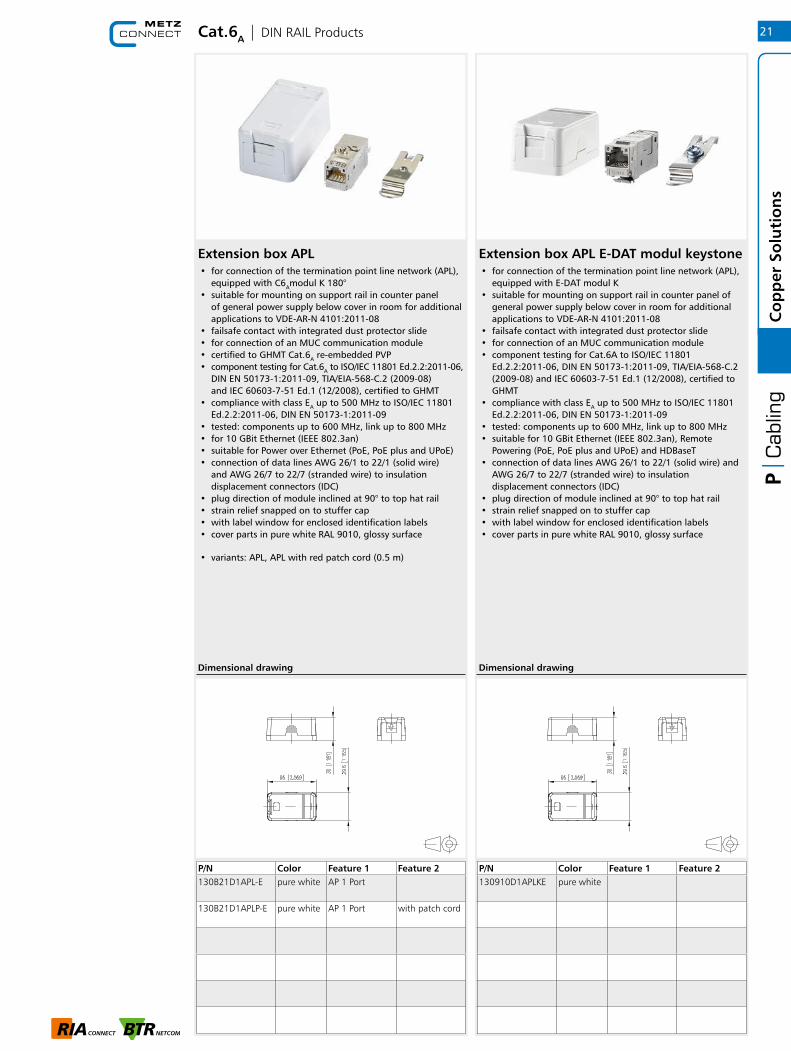
Extension box APL• for connection of the termination point line network (APL),
equipped with C6Amodul K 180° • suitable for mounting on support rail in counter panel
of general power supply below cover in room for additional applications to VDE-AR-N 4101:2011-08
• failsafe contact with integrated dust protector slide • for connection of an MUC communication module • certified to GHMT Cat.6A re-embedded PVP • component testing for Cat.6A to ISO/IEC 11801 Ed.2.2:2011-06,
DIN EN 50173-1:2011-09, TIA/EIA-568-C.2 (2009-08) and IEC 60603-7-51 Ed.1 (12/2008), certified to GHMT
• compliance with class EA up to 500 MHz to ISO/IEC 11801 Ed.2.2:2011-06, DIN EN 50173-1:2011-09
• tested: components up to 600 MHz, link up to 800 MHz • for 10 GBit Ethernet (IEEE 802.3an) • suitable for Power over Ethernet (PoE, PoE plus and UPoE) • connection of data lines AWG 26/1 to 22/1 (solid wire)
and AWG 26/7 to 22/7 (stranded wire) to insulation displacement connectors (IDC)
• plug direction of module inclined at 90° to top hat rail • strain relief snapped on to stuffer cap • with label window for enclosed identification labels • cover parts in pure white RAL 9010, glossy surface
• variants: APL, APL with red patch cord (0.5 m)
P/N Color Feature 1 Feature 2130B21D1APL-E pure white AP 1 Port
130B21D1APLP-E pure white AP 1 Port with patch cord
Dimensional drawing
Extension box APL E-DAT modul keystone• for connection of the termination point line network (APL),
equipped with E-DAT modul K• suitable for mounting on support rail in counter panel of
general power supply below cover in room for additional applications to VDE-AR-N 4101:2011-08
• failsafe contact with integrated dust protector slide• for connection of an MUC communication module• component testing for Cat.6A to ISO/IEC 11801
Ed.2.2:2011-06, DIN EN 50173-1:2011-09, TIA/EIA-568-C.2 (2009-08) and IEC 60603-7-51 Ed.1 (12/2008), certified to GHMT
• compliance with class EA up to 500 MHz to ISO/IEC 11801 Ed.2.2:2011-06, DIN EN 50173-1:2011-09
• tested: components up to 600 MHz, link up to 800 MHz• suitable for 10 GBit Ethernet (IEEE 802.3an), Remote
Powering (PoE, PoE plus and UPoE) and HDBaseT• connection of data lines AWG 26/1 to 22/1 (solid wire) and
AWG 26/7 to 22/7 (stranded wire) to insulation displacement connectors (IDC)
• plug direction of module inclined at 90° to top hat rail• strain relief snapped on to stuffer cap• with label window for enclosed identification labels• cover parts in pure white RAL 9010, glossy surface
P/N Color Feature 1 Feature 2130910D1APLKE pure white
Dimensional drawing
21
Co
pp
er S
olu
tio
ns

Cat.6A | Panels
Keystone 19 inch module frame 0.5RU 24 port black unequipped• 19 inch module frame 0.5RU 24 port unequipped, black• for 24 individual modules in Keystone design• additional strain relief on patch panel possible by cable ties,
cable ties included in delivery• suitable modules: E-DAT modul K, UTP modul Cat.6A,
UTP modul Cat.6, UTP modul Cat.5e• design: Keystone
P/N Color Feature 1 Feature 2130925-BKKE black 24 port
unequippedKeystone module cut-out
Keystone module cut-out
Dimensional drawing
19 inch module frame 1RU aluminium unequipped for shielded Keystone• 19 inch 1RU module frame for 24 individual modules;
Keystone design• module frame front made of black anodized aluminum• plastic module support with dust protection covers (other
colors available as accessories); detachable to the front• integrated cable support with optional strain relief• label window for identification labels• label sheet 210 x 297 mm see accessories• grounding bolt M6 x 10 with nut and lock washer• incl. 30 cm grounding cable• all fully shielded modules connected by means of grounding
rail
P/N Color Feature 1 Feature 2130920-BKKE black 24 port
unequippedKeystone module cut-out
130920-00KE grey 24 port unequipped
Keystone module cut-out
Keystone module cut-out
Dimensional drawing
22C
op
per
So
luti
on
s
Matching accessoriesfor Keystone 19 inch module frame 0.5RU 24 port black unequipped
Page
11E-DAT modul Coupler 8(8) 180° Cat.6
11E-DAT modul Coupler 8(8) 90° Cat.6
12UTP modul 8(8) Cat.6 pearl white
12UTP modul 8(8) Cat.6 black
17UTP modul 8(8) Cat.6A keystone pearl white
17UTP modul 8(8) Cat.6A keystone black
18C6Amodul K 180° jack - Keystone style
19C6Amodul K 270° jack - Keystone style
19C6Amodul K 90° jack - keystone style
Cat.6A | Panels
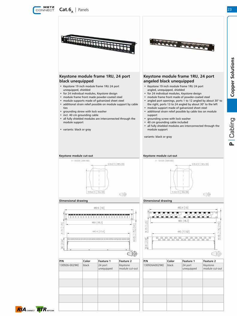
Keystone module frame 1RU, 24 port black unequipped• Keystone 19 inch module frame 1RU 24 port
unequipped, shielded • for 24 individual modules, Keystone design• module frame front made powder-coated steel• module supports made of galvanized sheet steel• additional strain relief possible on module support by cable
ties• grounding skrew with lock washer• incl. 40 cm grounding cable• all fully shielded modules are interconnected through the
module support
• variants: black or gray
P/N Color Feature 1 Feature 2130926-0029KE black 24 port
unequippedKeystone module cut-out
Keystone module frame 1RU, 24 port angeled black unequipped• Keystone 19 inch module frame 1RU 24 port
angled, unequipped, shielded• for 24 individual modules, Keystone design• module frame front made of powder-coated steel• angled port openings, ports 1 to 12 angled by about 30° to
the right, ports 13 to 24 angled by about 30° to the left• module support made of galvanized sheet steel• additional strain relief possible by cable ties on module
support • grounding screw with lock washer• 40 cm grounding cable included• all fully shielded modules are interconnected through the
module support
variants: black or gray
P/N Color Feature 1 Feature 2130926A0029KE black 24 port
unequippedKeystone module cut-out
Keystone module cut-out Keystone module cut-out
23
Co
pp
er S
olu
tio
ns
Dimensional drawing Dimensional drawing
RJ45 | Configurator
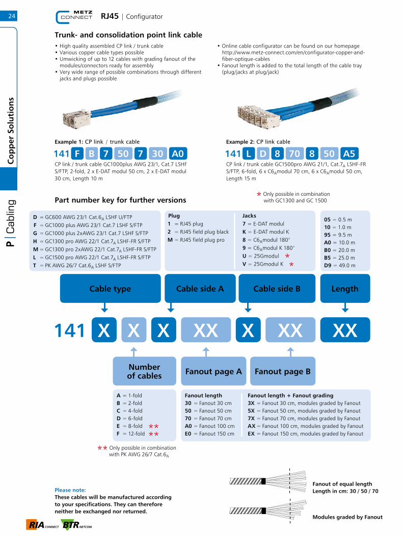
Trunk- and consolidation point link cable• High quality assembled CP link / trunk cable• Various copper cable types possible• Umwicking of up to 12 cables with grading fanout of the modules/connectors ready for assembly• Very wide range of possible combinations through different jacks and plugs possible
• Online cable configurator can be found on our homepage http://www.metz-connect.com/en/configurator-copper-and- fiber-optique-cables• Fanout length is added to the total length of the cable tray (plug/jacks at plug/jack)
Example 1: CP link / trunk cable
CP link / trunk cable GC1000plus AWG 23/1, Cat.7 LSHF S/FTP, 2-fold, 2 x E-DAT modul 50 cm, 2 x E-DAT modul 30 cm, Length 10 m
141 F B 7 50 7 30 A0Example 2: CP link cable
CP link / trunk cable GC1500pro AWG 21/1, Cat.7A LSHF-FR S/FTP, 6-fold, 6 x C6Amodul 70 cm, 6 x C6Amodul 50 cm, Length 15 m
141 L D 8 70 8 50 A5
Part number key for further versions
D = GC600 AWG 23/1 Cat.6A LSHF U/FTP F = GC1000 plus AWG 23/1 Cat.7 LSHF S/FTP G = GC1000 plus 2xAWG 23/1 Cat.7 LSHF S/FTPH = GC1300 pro AWG 22/1 Cat.7A LSHF-FR S/FTPM = GC1300 pro 2xAWG 22/1 Cat.7A LSHF-FR S/FTPL = GC1500 pro AWG 22/1 Cat.7A LSHF-FR S/FTPT = PK AWG 26/7 Cat.6A LSHF S/FTP
Cable type Cable side A
141 X X
A = 1-foldB = 2-foldC = 4-foldD = 6-foldE = 8-foldF = 12-fold
Plug1 = RJ45 plug2 = RJ45 field plug blackM = RJ45 field plug pro
Jacks7 = E-DAT modulK = E-DAT modul K8 = C6Amodul 180°9 = C6Amodul K 180°U = 25GmodulV = 25Gmodul K
Cable side B
05 = 0.5 m10 = 1.0 m95 = 9.5 mA0 = 10.0 mB0 = 20.0 mB5 = 25.0 mD9 = 49.0 m
Length
X XX X XX XX
Fanout length30 = Fanout 30 cm50 = Fanout 50 cm70 = Fanout 70 cmA0 = Fanout 100 cmE0 = Fanout 150 cm
Fanout page A Fanout page B
Modules graded by Fanout
Fanout of equal length Length in cm: 30 / 50 / 70
* Only possible in combination
with GC1300 and GC 1500
**
****
Fanout length + Fanout grading3X = Fanout 30 cm, modules graded by Fanout5X = Fanout 50 cm, modules graded by Fanout7X = Fanout 70 cm, modules graded by FanoutAX = Fanout 100 cm, modules graded by FanoutEX = Fanout 150 cm, modules graded by Fanout
24C
op
per
So
luti
on
s
Please note: These cables will be manufactured according to your specifications. They can therefore neither be exchanged nor returned.
Number of cables
** Only possible in combination
with PK AWG 26/7 Cat.6A

Cat.6A | Panels
Module frame 6 port 3RU 7HP unequipped for Keystone• stainless steel module frame for 6 individual modules in
Keystone design• strain relief at the module• 3RU 7HP module frame with very short dimensions • mounts in OpDAT REGpro, OpDAT REGpro24, OpDAT CM or
3HP module frame• additional strain relief possible by cable tie • grounding possible by flat plug
P/N Color Feature 1 Feature 2130B20E2E-E stainless
steel6 port empty Keystone
module cut-out
Dimensional drawing
Keystone module cut-out
25
Co
pp
er S
olu
tio
ns
Matching accessoriesfor Module frame 6 port 3RU 7HP unequipped for Keystone
Page
Module frame 6 port 3RU 7HP unequipped for Keystone is matching accessories for
Page
11E-DAT modul Coupler 8(8) 180° Cat.6
18C6Amodul K 180° jack - Keystone style
117OpDAT REGpro24 housing w/o splice tray
117OpDAT REGpro housing w/o splice tray
117OpDAT REGpro housing with splice tray
19 inch module frame 1RU stainless steel unequipped for Keystone• 19 inch 1RU stainless steel module frame for 24 individual
modules; Keystone design• optional strain relief on patch panel using cable ties• grounding bolt M6 x 10 with nut and lock washer• incl. 30 cm grounding cable• all fully shielded Keystone modules are connected by means
of the stainless steel module frame
P/N Color Feature 1 Feature 2130A21-00-E stainless
steel24 port unequipped
Keystone module cut-out
Keystone module cut-out
Dimensional drawing
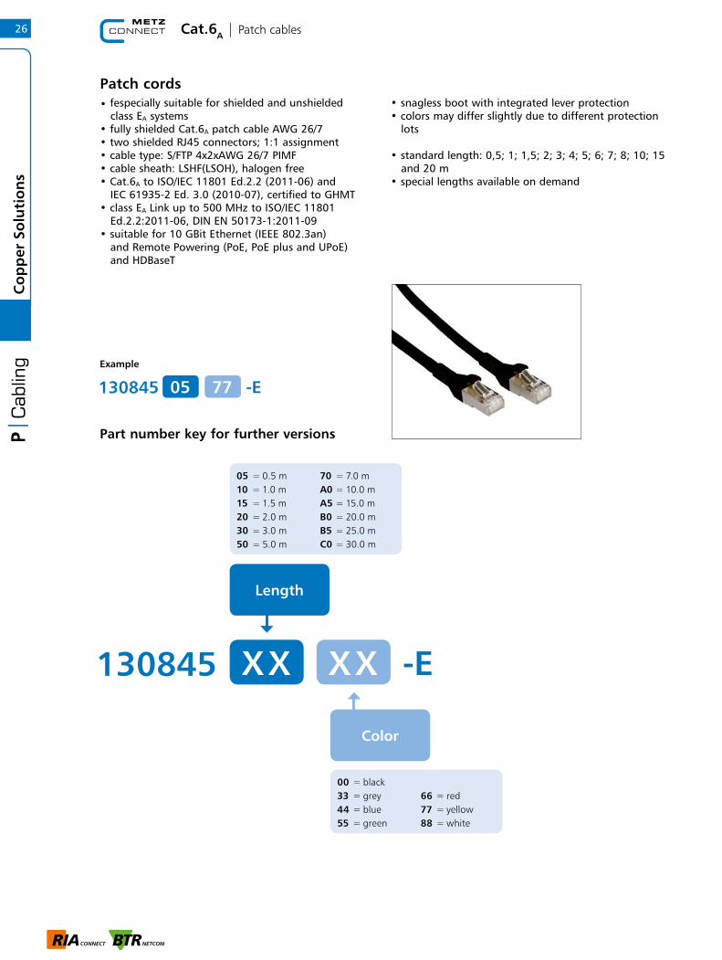
Cat.6A | Patch cables
130845 X X
Length
05 = 0.5 m 10 = 1.0 m 15 = 1.5 m 20 = 2.0 m 30 = 3.0 m 50 = 5.0 m
70 = 7.0 m A0 = 10.0 m A5 = 15.0 m B0 = 20.0 m B5 = 25.0 m C0 = 30.0 m
Color
-EX X
00 = black33 = grey 44 = blue 55 = green
66 = red 77 = yellow 88 = white
Example
Part number key for further versions
130845 05 -E77
• fespecially suitable for shielded and unshielded class EA systems• fully shielded Cat.6A patch cable AWG 26/7• two shielded RJ45 connectors; 1:1 assignment• cable type: S/FTP 4x2xAWG 26/7 PIMF• cable sheath: LSHF(LSOH), halogen free• Cat.6A to ISO/IEC 11801 Ed.2.2 (2011-06) and IEC 61935-2 Ed. 3.0 (2010-07), certified to GHMT• class EA Link up to 500 MHz to ISO/IEC 11801 Ed.2.2:2011-06, DIN EN 50173-1:2011-09• suitable for 10 GBit Ethernet (IEEE 802.3an) and Remote Powering (PoE, PoE plus and UPoE) and HDBaseT
• snagless boot with integrated lever protection• colors may differ slightly due to different protection lots
• standard length: 0,5; 1; 1,5; 2; 3; 4; 5; 6; 7; 8; 10; 15 and 20 m• special lengths available on demand
Patch cords
26C
op
per
So
luti
on
s

Cat.7 | Cables
GC1000 pro23 Cat.7 S/FTP 4P LSHF-FR• 10 GBit installation cable, simplex• installation cable Cat.7 AWG 23 S/FTP with wires shielded in
pairs• 4 pairs (PiMF)• pair shield: plastic foil with aluminum coating• overall shield: tinned copper braid• outer diameter 7.5 mm• color of the cabel jacket: blue• coupling attenuation 85 dB• applicable standards: EN 50173-1:2011-09; ISO/IEC 11801
Ed.2.2:2011-06; EN 50288-4-1 and IEC 61156-5• cable jacket: LSHF-FR (LSOH-FR)• flame-retardant to IEC 60332-1; IEC 60332-3-24;
IEC 60754-2 and IEC 61034• fire behaviour: Class Dca s2 d1 a1 acc. to EN 50399
(classification acc. to EN 13501-6)
Shipping Units:sold by meter on drum1640 ft (500 m) on drum3280 ft (1000 m) on drum
GC1000 plus23 Cat.7 S/FTP 4P LSHF• 10 GBit installation cable, simplex• installation cable Cat.7 AWG 23 S/FTP with wires shielded in
pairs• 4 pairs (PiMF)• pair shield: plastic foil with aluminum coating• overall shield: tinned copper braid• outer diameter 7.3 mm• color of the cabel jacket: blue• coupling attenuation 75 dB• applicable standards: EN 50173-1:2011-09; ISO/IEC 11801
Ed.2.2:2011-06; EN 50288-4-1 and IEC 61156-5• cable jacket: LSHF (LSOH)• flame-retardant to IEC 60332-1; IEC 60754-2 and IEC 61034• fire behaviour: Class Eca (classification acc. to EN 13501-6)
Shipping Units:sold by meter on drum1640 ft (500 m) on drum3280 ft (1000 m) on drum
P/N Color Feature 1 Feature 21308427034141 blue 500 m
(1640 ft)drum
1308427034142 blue 1000 m (3280 ft)
drum
P/N Color Feature 1 Feature 21308427032141 blue 500 m
(1640 ft)drum
1308427032142 blue 1000 m (3280 ft)
drum
Principle diagram Principle diagram
27
Co
pp
er S
olu
tio
ns
Matching accessoriesfor GC1000 pro23 Cat.7 S/ FTP 4P LSHF-FR
Page
Matching accessoriesfor GC1000 plus23 Cat.7 S/ FTP 4P LSHF
Page
46Jokari dismantle tool
46Jokari dismantle tool
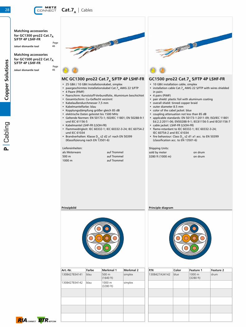
Cat.7A | Cables
GC1500 pro22 Cat.7A S/FTP 4P LSHF-FR• 10 GBit installation cable, simplex• installation cable Cat.7A AWG 22 S/FTP with wires shielded
in pairs• 4 pairs (PiMF)• pair shield: plastic foil with aluminum coating• overall shield: tinned copper braid• outer diameter 8.5 mm• color of the cabel jacket: blue• coupling attenuation not less than 85 dB• applicable standards: EN 50173-1:2011-09; ISO/IEC 11801
Ed.2.2:2011-06; EN50288-9-1; IEC61156-5 and IEC61156-7• cable jacket: LSHF-FR (LSOH-FR)• flame-retardant to IEC 60332-1; IEC 60332-3-24;
IEC 60754-2 and IEC 61034• fire behaviour: Class Dca s2 d1 a1 acc. to EN 50399
(classification acc. to EN 13501-6)
Shipping Units:sold by meter on drum3280 ft (1000 m) on drum
P/N Color Feature 1 Feature 21308427A34142 blue 1000 m
(3280 ft)drum
Principle diagram
28C
op
per
So
luti
on
s
Matching accessoriesfor GC1300 pro22 Cat.7A S/ FTP 4P LSHF-FR
Page
Matching accessoriesfor GC1500 pro22 Cat.7A S/ FTP 4P LSHF-FR
Page
46Jokari dismantle tool
46Jokari dismantle tool
MC GC1300 pro22 Cat.7A S/FTP 4P LSHF- FR• 25 GBit / 10 GBit Installationskabel, simplex • paargeschirmtes Installationskabel Cat.7A AWG 22 S/FTP • 4 Paare (PiMF) • Paarschirm: Kunststoff-Verbundfolie, Aluminium beschichtet • Gesamtschirm: Cu-Geflecht verzinnt • Kabelaußendurchmesser 7,5 mm • Kabelmantelfarbe: blau • Kopplungsdämpfung größer gleich 85 dB • elektrische Daten getestet bis 1500 MHz • Geltende Normen: EN 50173-1; ISO/IEC 11801; EN 50288-9- 1
und IEC 61156-5 • Kabelmantel LSHF-FR (LSOH-FR) • Flammwidrigkeit: IEC 60332-1; IEC 60332-3-24; IEC 60754- 2
und IEC 61034 • Brandverhalten: Klasse Dca s2 d2 a1 nach EN 50399
(Klassifizierung nach EN 13501-6)
Liefereinheiten: als Meterware auf Trommel 500 m auf Trommel 1000 m auf Trommel
Art.-Nr. Farbe Merkmal 1 Merkmal 21308427B34141 blau 500 m
(1640 ft)simplex
1308427B34142 blau 1000 m (3280 ft)
simplex
Prinzipbild

Accessories | Cat.6
Keystone wall outlet EU style• flush-mounted termination unit for two individual Keystone
modules• EU style 86 x 86mm • straight plug direction• strain relief with cable tie at the module• label window for identification labels
(labels included in the delivery)• integrated dust protection shutter• cover parts in color similar to pure white RAL 9010, glossy
surface
P/N Color Feature 1 Feature 21309142502KE white 1 Port w/o
modulesKeystonemodule cut-out
Dimensional drawing
Keystone module cut-out
Keystone wall outlet EU style• flush-mounted termination unit for two individual Keystone
modules• EU style 86 x 86mm • straight plug direction• strain relief with cable tie at the module• label window for identification labels
(labels included in the delivery)• integrated dust protection shutter• cover parts in color similar to pure white RAL 9010, glossy
surface
P/N Color Feature 1 Feature 21309152502KE white 2 Port empty Keystone
module cut-out
Dimensional drawing
Keystone module cut-out
29
Co
pp
er S
olu
tio
ns
Accessories | Cat.6
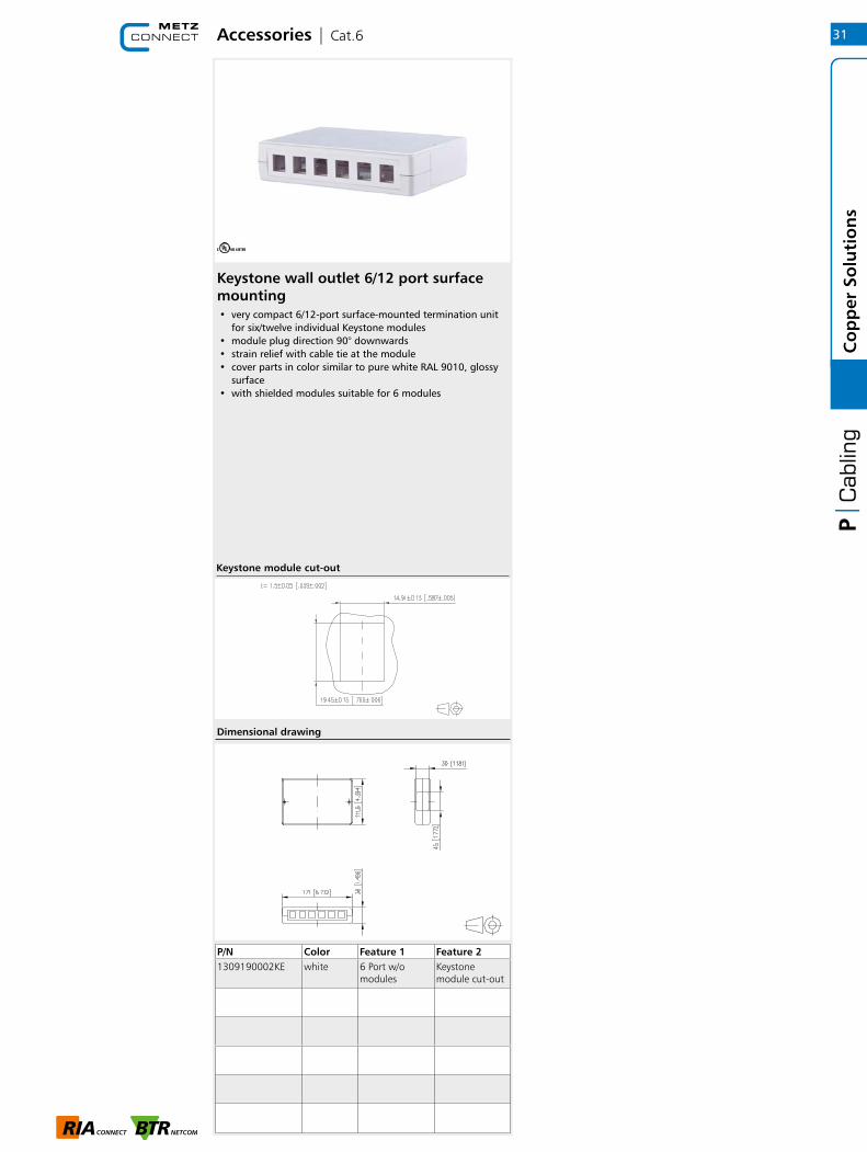
Keystone wall outlet AP | surface mounting• very compact 1-port surface-mounted termination unit for
one individual Keystone module• module plug direction 90° downwards• strain relief with cable tie at the module• label window for identification labels
(labels included in the delivery)• integrated dust protection shutter• cover parts in color similar to pure white RAL 9010, glossy
surface• not suitable for 180° couplers (anti-bend sleeves for patch
cables usually too long)
• variants: 1 port, 2 ports
P/N Color Feature 1 Feature 21309140002KE white 1 Port w/o
modulesKeystone module cut-out
1309150002KE white 2 Port empty Keystone module cut-out
Dimensional drawing
Keystone module cut-out
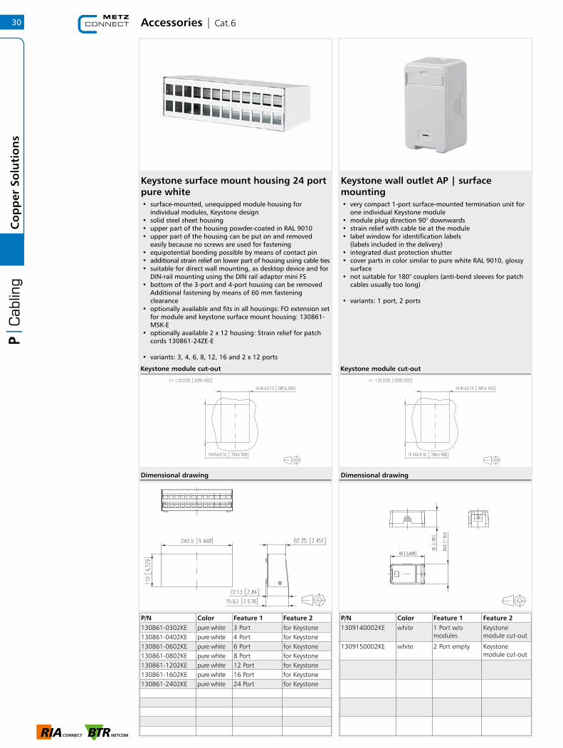
Keystone surface mount housing 24 port pure white• surface-mounted, unequipped module housing for
individual modules, Keystone design• solid steel sheet housing• upper part of the housing powder-coated in RAL 9010• upper part of the housing can be put on and removed
easily because no screws are used for fastening• equipotential bonding possible by means of contact pin• additional strain relief on lower part of housing using cable ties• suitable for direct wall mounting, as desktop device and for
DIN-rail mounting using the DIN rail adapter mini FS• bottom of the 3-port and 4-port housing can be removed
Additional fastening by means of 60 mm fastening clearance
• optionally available and fits in all housings: FO extension set for module and keystone surface mount housing: 130861-MSK-E
• optionally available 2 x 12 housing: Strain relief for patch cords 130861-24ZE-E
• variants: 3, 4, 6, 8, 12, 16 and 2 x 12 ports
Keystone module cut-out
P/N Color Feature 1 Feature 2130861-0302KE pure white 3 Port for Keystone130861-0402KE pure white 4 Port for Keystone130861-0602KE pure white 6 Port for Keystone130861-0802KE pure white 8 Port for Keystone130861-1202KE pure white 12 Port for Keystone130861-1602KE pure white 16 Port for Keystone130861-2402KE pure white 24 Port for Keystone
Dimensional drawing
30C
op
per
So
luti
on
s
Accessories | Cat.6
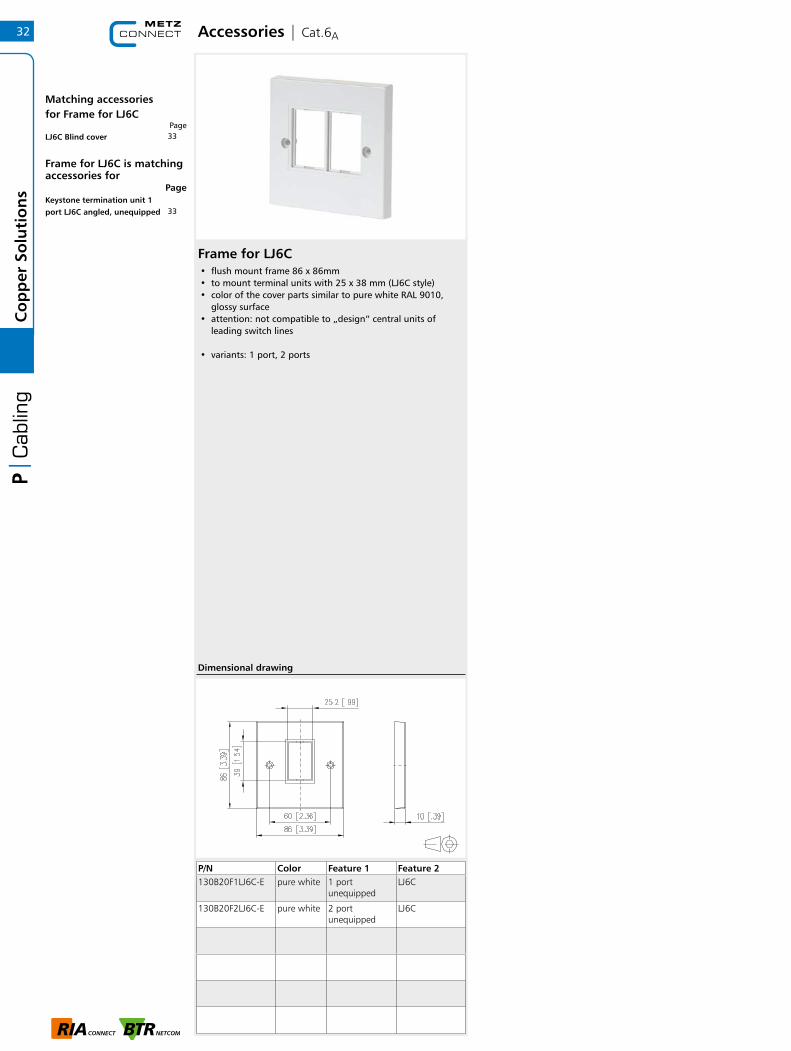
Keystone wall outlet 6/12 port surface mounting• very compact 6/12-port surface-mounted termination unit
for six/twelve individual Keystone modules• module plug direction 90° downwards• strain relief with cable tie at the module• cover parts in color similar to pure white RAL 9010, glossy
surface• with shielded modules suitable for 6 modules
P/N Color Feature 1 Feature 21309190002KE white 6 Port w/o
modulesKeystone module cut-out
Dimensional drawing
Keystone module cut-out
31
Co
pp
er S
olu
tio
ns
Accessories | Cat.6A
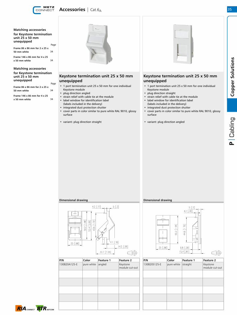
Frame for LJ6C• flush mount frame 86 x 86mm• to mount terminal units with 25 x 38 mm (LJ6C style)• color of the cover parts similar to pure white RAL 9010,
glossy surface• attention: not compatible to „design“ central units of
leading switch lines
• variants: 1 port, 2 ports
P/N Color Feature 1 Feature 2130B20F1LJ6C-E pure white 1 port
unequippedLJ6C
130B20F2LJ6C-E pure white 2 port unequipped
LJ6C
32C
op
per
So
luti
on
s
Matching accessoriesfor Frame for LJ6C
Page
Frame for LJ6C is matching accessories for
Page
33LJ6C Blind cover
33Keystone termination unit 1 port LJ6C angled, unequipped
Dimensional drawing

Accessories | Cat.6A
Blind cover for LJ6C• blind cover 1 piece 25 x 38 mm (LJ6C format) • color similar to pure white RAL 9010, glossy surface
P/N Color Feature 1 Feature 2130B20B1LJ6C-E pure white Blind cover LJ6C
Keystone termination unit LJ6C unequipped• 1 port termination unit 25 x 38 mm (LJ6C format) for one
individual Keystone module• module plug direction approx 45° downwards• strain relief with cable tie at the module• label window for identification label
(labels included in the delivery)• integrated dust protection shutter• cover parts in color similar to pure white RAL 9010, glossy
surface
P/N Color Feature 1 Feature 2130B20A1LJ6C-E pure white angled LJ6C
33
Co
pp
er S
olu
tio
ns
Matching accessoriesfor Keystone termination unit LJ6C unequipped
Page
Blind cover for LJ6C is matching accessories for
Page
32Frame 86 x 86 mm for 1 x LJ6C white
32Frame 86 x 86 mm for 2 x LJ6C white
32Frame 86 x 86 mm for 1 x LJ6C white
32Frame 86 x 86 mm for 2 x LJ6C white

Accessories | Cat.6A
Frame for 50 mm, pure white• flush mount frame with a height of 86 mm• to mount terminal units with 25 x 50 mm• color of the cover parts similar to pure white RAL 9010,
glossy surface• attention: not compatible to „design“ central units of
leading switch lines
• variants: 2 ports (width 86 mm), 4 ports (width 146 mm)
P/N Color Feature 1 Feature 2130B20F125-E pure white 2 port
unequipped25 x 50 mm
130B20F225-E pure white 4 port unequipped
25 x 50 mm
Frame for 50 mm, chrome• flush mount frame with a height of 86 mm• to mount terminal units with 25 x 50 mm• color of the cover parts chrome, high glossy surface• attention: not compatible to „design“ central units of
leading switch lines
• variants: 2 ports (width 86 mm), 4 ports (width 146 mm)
P/N Color Feature 1 Feature 2130B20F125CE chrome 2 port
unequipped25 x 50 mm
130B20F225CE chrome 4 port unequipped
25 x 50 mm
Dimensional drawing Dimensional drawing
34C
op
per
So
luti
on
s
Matching accessoriesfor Frame for 50 mm, pure white
Page
Frame for 50 mm, pure white is matching accessories for
Page
362 x 12.5 x 50 mm Blind cover
3625 x 50 mm Blind cover
35Keystone termination unit 1 port 25 x 50 mm unequipped
Keystone termination unit 25 x 50 mm unequipped• 1 port termination unit 25 x 50 mm for one individual
Keystone module• plug direction straight• strain relief with cable tie at the module• label window for identification label
(labels included in the delivery)• integrated dust protection shutter• cover parts in color similar to pure white RAL 9010, glossy
surface
• variant: plug direction angled
P/N Color Feature 1 Feature 2130B20S125-E pure white straight Keystone
module cut-out
Accessories | Cat.6A
Keystone termination unit 25 x 50 mm unequipped• 1 port termination unit 25 x 50 mm for one individual
Keystone module• plug direction angled• strain relief with cable tie at the module• label window for identification label
(labels included in the delivery)• integrated dust protection shutter• cover parts in color similar to pure white RAL 9010, glossy
surface
• variant: plug direction straight
P/N Color Feature 1 Feature 2130B20A125-E pure white angled Keystone
module cut-out
Dimensional drawing Dimensional drawing
35
Co
pp
er S
olu
tio
ns
Matching accessoriesfor Keystone termination unit 25 x 50 mm unequipped
Page
Matching accessoriesfor Keystone termination unit 25 x 50 mm unequipped
Page
34Frame 86 x 86 mm for 2 x 25 x 50 mm white
34Frame 146 x 86 mm for 4 x 25 x 50 mm white
34Frame 86 x 86 mm for 2 x 25 x 50 mm white
34Frame 146 x 86 mm for 4 x 25 x 50 mm white

Accessories | Cat.6A
Blind cover for 50 mm• blind cover 50 mm frame• color similar to pure white RAL 9010, glossy surface
• variant: 2 x 12.5 x 50 mm
P/N Color Feature 1 Feature 2130B20B0525-E pure white Blind cover 2 x 12 x 50 mm
Blind cover for 50 mm• blind cover 50 mm frame• color similar to pure white RAL 9010, glossy surface
• variant: 1 x 25 x 50 mm
P/N Color Feature 1 Feature 2130B20B125-E pure white Blind cover 25 x 50 mm
36C
op
per
So
luti
on
s
Blind cover for 50 mm is matching accessories for
Page
Blind cover for 50 mm is matching accessories for
Page
34Frame 86 x 86 mm for 2 x 25 x 50 mm white
34Frame 146 x 86 mm for 4 x 25 x 50 mm white
34Frame 86 x 86 mm for 2 x 25 x 50 mm white
34Frame 146 x 86 mm for 4 x 25 x 50 mm white

Accessories | Cat.6A
Cable manager 19 inch 0.5RU 56 mm RAL 9005 black• 19 inch 0.5RU distribution panel for horizontal organization
of the patch cables• cable brackets approx. 42 mm • 5 open cable brackets• steel powder-coated, black RAL9005
P/N Color Feature 1 Feature 2130894-05-29-E black 56 mm
Dimensional drawing
Cable manager 19 inch 1RU 75 mm RAL 9005 black• 19 inch 1 RU distribution panel for horizontal organization
of the patch cables• cable brackets approx. 75 mm • 5 cable brackets• steel powder-coated
• variants: black or gray
P/N Color Feature 1 Feature 2130894-03-29-E black 75 mm
37
Co
pp
er S
olu
tio
ns
Dimensional drawing

Accessories | Cat.6A
Label strip for cable manager 1RU• black clip-on label strip for 19 inch 1RU distribution panel• for large labeling• included in the delivery: label strip, 2 fastening clips, paper
strips and transparent foil
430
43.6
17
P/N Color Feature 1 Feature 2130894-BS-29-E black slip-on
Dimensional drawing
Cable manager 1RU 56 mm and 100 mm• 19 inch 1RU distribution panel for horizontal organization
of the patch cables• 56 and 100 mm cable bracket• especially suitable for fiber optic patch cables• 5 black plastic cable brackets with large contact surfaces• easy mounting of the cable brackets by twisting• Available as option: plug-mounted nomenclature strip
• variants: steel powder-coated grey or black, aluminum silver anodized, stainless steel
P/N Color Feature 1 Feature 2130894-01-29-E black 56 mm
130894-02-29-E black 100 mm
130894-01-03-E grey 56 mm
130894-02-03-E grey 100 mm
483 66
440
465
56
100 100100100
11
31
43
.6
Dimensional drawing (56 mm)
Dimensional drawing (100 mm)
38C
op
per
So
luti
on
s
Matching accessoriesfor Cable manager 1RU 56 mm and 100 mm
Page
Label strip for cable manager 1RU is matching accessories for
Page
38Label strip for cable manager 19 inch 1RU RAL 9005
38Cable manager 19 inch 1RU 56 mm RAL 9005 black
38Cable manager 19 inch 1RU 100 mm RAL 9005 black
38Cable manager 19 inch 1RU 56 mm RAL 7035 gray
38Cable manager 19 inch 1RU 100 mm RAL 7035 gray
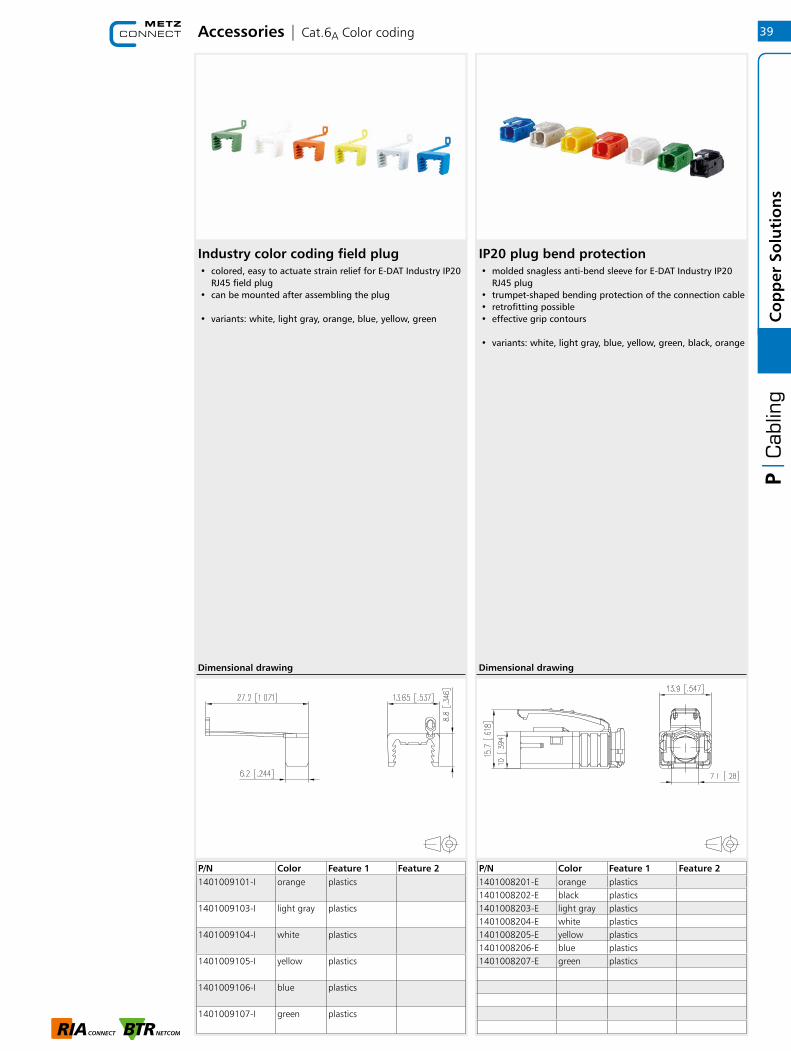
Industry color coding field plug• colored, easy to actuate strain relief for E-DAT Industry IP20
RJ45 field plug • can be mounted after assembling the plug
• variants: white, light gray, orange, blue, yellow, green
P/N Color Feature 1 Feature 21401008201-E orange plastics1401008202-E black plastics1401008203-E light gray plastics1401008204-E white plastics1401008205-E yellow plastics1401008206-E blue plastics1401008207-E green plastics
IP20 plug bend protection• molded snagless anti-bend sleeve for E-DAT Industry IP20
RJ45 plug • trumpet-shaped bending protection of the connection cable • retrofitting possible • effective grip contours
• variants: white, light gray, blue, yellow, green, black, orange
Accessories | Cat.6A Color coding
P/N Color Feature 1 Feature 21401009101-I orange plastics
1401009103-I light gray plastics
1401009104-I white plastics
1401009105-I yellow plastics
1401009106-I blue plastics
1401009107-I green plastics
Dimensional drawing Dimensional drawing
39
Co
pp
er S
olu
tio
ns
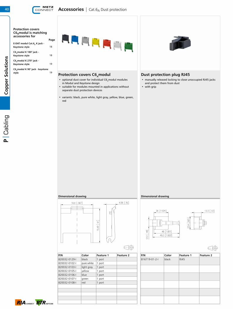
P/N Color Feature 1 Feature 2820032-0129-I black 1 port820032-0102-I pure white 1 port820032-0103-I light gray 1 port820032-0105-I yellow 1 port820032-0106-I blue 1 port820032-0107-I green 1 port820032-0108-I red 1 port
Protection covers C6Amodul• optional dust cover for individual C6Amodul modules
in Modul and Keystone design • suitable for modules mounted in applications without
separate dust protection devices • variants: black, pure white, light gray, yellow, blue, green,
red
Dust protection plug RJ45• manually released locking to close unoccupied RJ45 jacks
and protect them from dust • with grip
Accessories | Cat.6A Dust protection
P/N Color Feature 1 Feature 2816719-01-2-I black RJ45
Dimensional drawing Dimensional drawing
40C
op
per
So
luti
on
s
Protection covers C6Amodul is matching accessories for
Page
18E-DAT modul Cat.6A K jack - Keystone style
18C6Amodul K 180° jack - Keystone style
19C6Amodul K 270° jack - Keystone style
19C6Amodul K 90° jack - keystone style
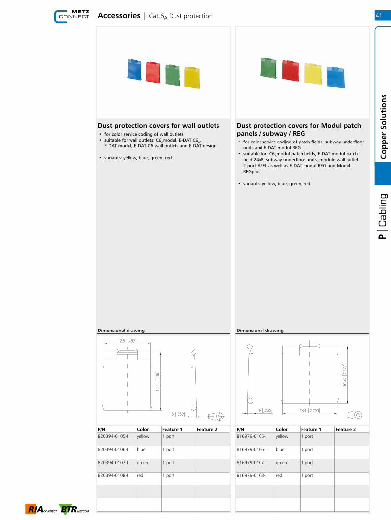
Dust protection covers for wall outlets• for color service coding of wall outlets • suitable for wall outlets: C6Amodul, E-DAT C6A,
E-DAT modul, E-DAT C6 wall outlets and E- DAT design • variants: yellow, blue, green, red
Accessories | Cat.6A Dust protection
P/N Color Feature 1 Feature 2820394-0105-I yellow 1 port
820394-0106-I blue 1 port
820394-0107-I green 1 port
820394-0108-I red 1 port
Dimensional drawing
Dust protection covers for Modul patch panels / subway / REG• for color service coding of patch fields, subway underfloor
units and E-DAT modul REG • suitable for: C6Amodul patch fields, E-DAT modul patch
field 24x8, subway underfloor units, module wall outlet 2 port APFL as well as E-DAT modul REG and Modul REGplus
• variants: yellow, blue, green, red
P/N Color Feature 1 Feature 2816979-0105-I yellow 1 port
816979-0106-I blue 1 port
816979-0107-I green 1 port
816979-0108-I red 1 port
Dimensional drawing
41
Co
pp
er S
olu
tio
ns

Accessories | Cable connectors
Cable connector class FA• cable connector for field assembly Class FA for 8 wire cables• to connect / extend / repair / relocate copper data cables up
to Cat.7A
• compliance to Class FA up to 1000 MHz according to ISO/IEC 11801 Ed.2.2:2011-06 in connection with Cat.7A copper cables *1
• GHMT certified to ISO/IEC 11801 Ed.2.2:2011-06 and IEC 61156-5 Ed.2.1:2012-12
• suitable for 10 GBit Ethernet (IEEE 802.3an), Remote Powering (PoE, PoE plus and UPoE) and HDBaseT
• compact design: diameter 16.8 mm x length 64 mm• IP67 protected housing in combination with IP67
appropriate cables *2• refined zinc die-cast housing• easy and fast assembly without special tools• shield connection and strain relief integrated• easy connection of data cables AWG 26/1 to 22/1 (solid
wire) and AWG 26/7 to 22/7 (stranded wire) to insulation displacement connectors (IDC)
• solid copper wire diameter 0.4 to 0.64 mm• stranded copper wire diameter 0.48 to 0.76 mm• conductor diameter up to 1.6 mm• suitable for cables with an overall diameter of 5.0 to
9.7 mm *2• fully shielded version according to DIN EN 50173-1
P/N Color Feature 1 Feature 2130863-02-E 4x2 IP
Dimensional drawing
Cat.7 cable connector• for connecting/extending data cables up to Cat.7A
• class E to ISO/IEC 11801 Ed.2.2:2011-06 is complied with in combination with Cat.6, Cat.6A, Cat.7 and Cat.7A cables and Cat.6 connectors
• connection of data lines AWG 26/1 to 22/1 (solid wire)• cable feed from one or two sides• cable sharing, i.e. splitting one 8-wire cable into two 4-wire
cables (one cable tie required each on input and output side)
• fully shielded metal housing• strain relief and separate captive 360° shield connection• 2 bore holes for wall mounting
P/N Color Feature 1 Feature 2130863-E 4x2
Dimensional drawing
42C
op
per
So
luti
on
s
Accessories
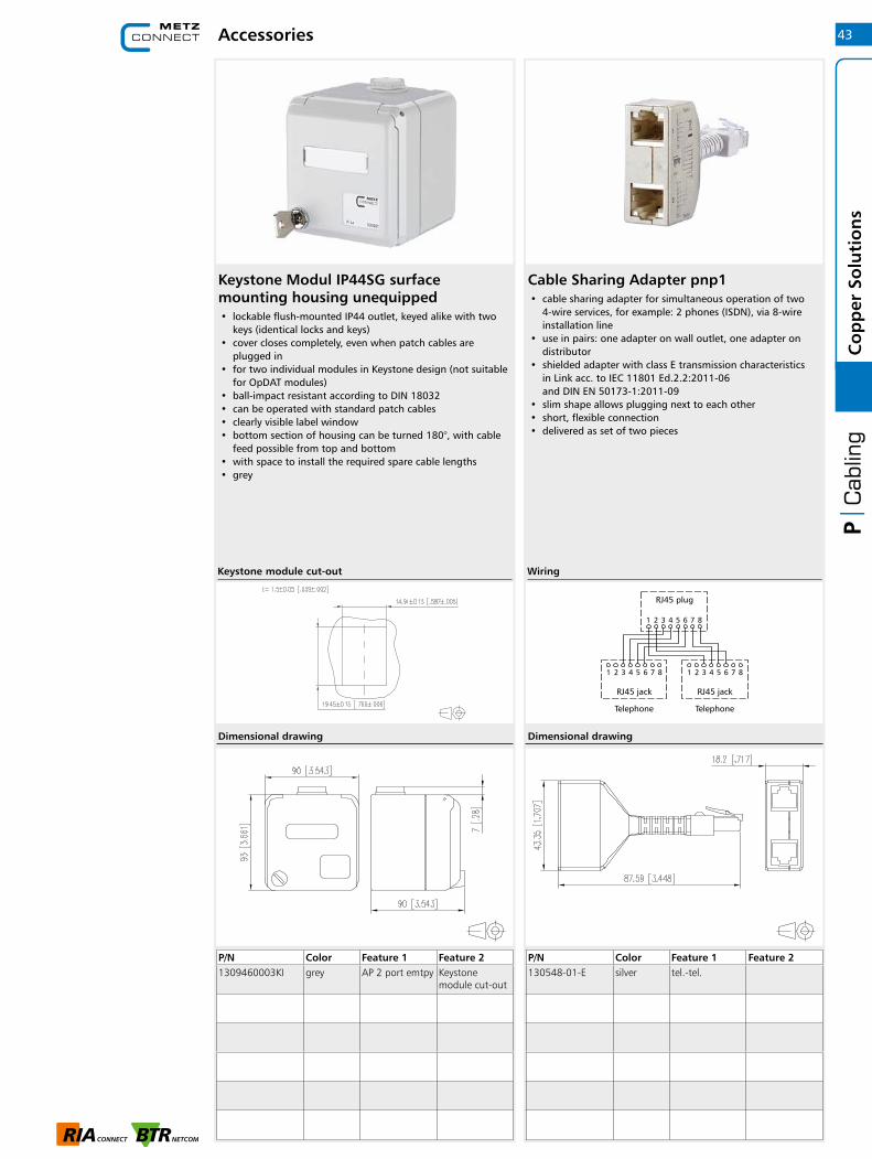
Keystone Modul IP44SG surface mounting housing unequipped• lockable flush-mounted IP44 outlet, keyed alike with two
keys (identical locks and keys)• cover closes completely, even when patch cables are
plugged in• for two individual modules in Keystone design (not suitable
for OpDAT modules)• ball-impact resistant according to DIN 18032• can be operated with standard patch cables• clearly visible label window• bottom section of housing can be turned 180°, with cable
feed possible from top and bottom• with space to install the required spare cable lengths• grey
P/N Color Feature 1 Feature 21309460003KI grey AP 2 port emtpy Keystone
module cut-out
Cable Sharing Adapter pnp1• cable sharing adapter for simultaneous operation of two
4-wire services, for example: 2 phones (ISDN), via 8-wire installation line
• use in pairs: one adapter on wall outlet, one adapter on distributor
• shielded adapter with class E transmission characteristics in Link acc. to IEC 11801 Ed.2.2:2011-06 and DIN EN 50173-1:2011-09
• slim shape allows plugging next to each other• short, flexible connection• delivered as set of two pieces
P/N Color Feature 1 Feature 2130548-01-E silver tel.-tel.
Dimensional drawing
WiringKeystone module cut-out
Dimensional drawing
43
Co
pp
er S
olu
tio
ns

Accessories
Cable Sharing Adapter pnp2• cable sharing adapter for simultaneous operation of two
4-wire services, here: 1 x Ethernet and 1 x telephone (ISDN), via an 8-wire installation wire
• use in pairs: one adapter on wall outlet, one adapter on distributor
• shielded adapter with class E transmission characteristics in Link acc. to IEC 11801 Ed.2.2:2011-06 and DIN EN 50173-1:2011-09
• 1 x Ethernet up to 100 MBit E / Fast Ethernet• slim shape allows plugging next to each other• short, flexible connection• delivered as set of two pieces
P/N Color Feature 1 Feature 2130548-02-E silver tel.-eth.
Wiring
Dimensional drawing
Cable Sharing Adapter pnp3• cable sharing adapter for simultaneous operation of two
4-wire services, here: 2 x Ethernet, via an 8-wire installation line
• use in pairs: one adapter on wall outlet, one adapter on distributor
• shielded adapter with class E transmission characteristics in Link acc. to IEC 11801 Ed.2.2:2011-06 and DIN EN 50173-1:2011-09
• 2 x Ethernet up to 100 MBit E / Fast Ethernet• slim shape allows plugging next to each other• short, flexible connection• delivered as set of two pieces
P/N Color Feature 1 Feature 2130548-03-E silver eth.-eth.
Wiring
Dimensional drawing
44C
op
per
So
luti
on
s
Tools
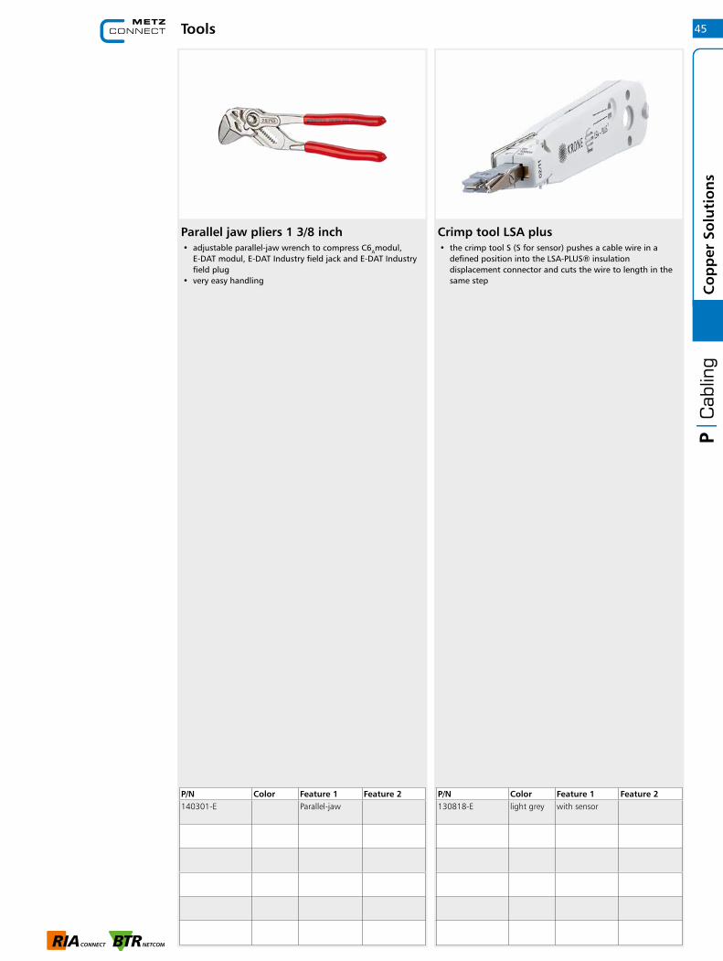
Parallel jaw pliers 1 3/8 inch• adjustable parallel-jaw wrench to compress C6Amodul,
E-DAT modul, E-DAT Industry field jack and E-DAT Industry field plug
• very easy handling
P/N Color Feature 1 Feature 2140301-E Parallel-jaw
Crimp tool LSA plus• the crimp tool S (S for sensor) pushes a cable wire in a
defined position into the LSA-PLUS® insulation displacement connector and cuts the wire to length in the same step
P/N Color Feature 1 Feature 2130818-E light grey with sensor
45
Co
pp
er S
olu
tio
ns

Tools
Jokari dismantle tool• for fast and precise stripping of data cables• with adjustable stop
P/N Color Feature 1 Feature 2140302-01-E white dismantle tool
46C
op
per
So
luti
on
s
Jokari dismantle tool is matching accessories for
Page
10MC GC400 SL23 Cat.6 U/UTP LSHF 1000 ft
10MC GC400 SL23 Cat.6 U/UTP LSHF 1640 ft
10MC GC400 SL23 Cat.6 U/UTP LSHF 3280 ft
16MC GC600 F1 23 Cat.6A U/FTP 4P LSHF 1640 ft
16MC GC600 F1 23 Cat.6A U/FTP 4P LSHF 3280 ft
27MC GC1000 pro23 Cat.7 S/FTP 4P LSHF-FR 1640 ft
27MC GC1000 pro23 Cat.7 S/FTP 4P LSHF-FR 3280 ft
27MC GC1000 plus23 Cat.7 S/FTP 4P LSHF 1640 ft
27MC GC1000 plus23 Cat.7 S/FTP 4P LSHF 3280 ft
28MC GC1200 pro22 Cat.7A S/FTP 4P LSHF-FR 1640 ft
28MC GC1200 pro22 Cat.7A S/FTP 4P LSHF-FR 3280 ft
28MC GC1500 pro22 Cat.7A S/FTP 4P LSHF-FR 1640 ft
28MC GC1500 pro22 Cat.7A S/FTP 4P LSHF-FR 3280 ft
Table of contents | Fiber Optic Solutions
Fiber Optic Solutions
1 Installation cables |
Single mode/multi mode 48
2 Adapter 50
3 Pigtails | Single mode/multi mode 52
4 Pigtails | Configurator 53
5 Patch panels fixed installation |
Single mode/multi mode 54
6 Patch panels for fixed installation |
Configurators 55
7 Patch panels withdrawable |
Single mode/multi mode 56
8 Patch panels withdrawable |
Configurators 57
9 Patch cords | Single mode/multi mode 58
10 Patch cords | Configurator 59
11 OM5 | The future of multimode fiber 60
47

OpDAT universal cable SM• installation cable U-DQ(ZN)BH • universal fiber optic cable for indoors/outdoors with central
loose tube • bending resistant fiber • UV-resistant, metal-free, longitudinally waterproof, tensile
strength, rodent-protected • cable jacket: LSHF • cable structure: filled loose tube • with more loose tubes: loose tubes arranged around
Ø 2.5 mm bar made of fiber glass reinforced plastic • loose tubes Ø 2.8 mm with 2-12 fibers per loose tube • loose tubes Ø 3.5 mm with 18-24 fibers per loose tube • strain relief: longitudinally waterproof lapping, glass roving
elements • for indoor cabling • for laying in tubes or directly in the ground in suitable layer
of sand • applicable standards: EN 50173-1, ISO 11801 2nd edition,
IEC 60794-1, EN 187000• fire behaviour: Class Eca (classification acc. to EN 13501-6)
variants:number of OS2 fibers 1x4, 1x8, 1x12, 1x24, 4x12
Others on request
OpDAT universal cable MM• installation cable U-DQ(ZN)BH • universal fiber optic cable for indoors/outdoors with central
loose tube • laser-optimized, bending-resistant fiber • bending resistant fiber • UV-resistant, metal-free, longitudinally waterproof, tensile
strength, rodent-protected • cable jacket: LSHF • cable structure: filled loose tube • with more loose tubes: loose tubes arranged around
Ø 2.5 mm bar made of fiber glass reinforced plastic • loose tubes Ø 2.8 mm with 2-12 fibers per loose tube • loose tubes Ø 3.5 mm with 18-24 fibers per loose tube • strain relief: longitudinally waterproof lapping, glass roving
elements • for indoor cabling • for laying in tubes or directly in the ground in suitable layer
of sand • applicable standards: EN 50173-1, ISO 11801 2nd edition,
IEC 60794-1, EN 187000• fire behaviour: Class Eca (classification acc. to EN 13501-6)
variants:number of OM5 fibers 1x4, 1x8, 1x12, 1x24 number of OM4 fibers 1x4, 1x8, 1x12, 1x24, 4x12number of OM3 fibers 1x4, 1x8, 1x12, 1x24, 4x12
Others on request
P/N Color Feature 1 Feature 2150U049000000M yellow 4 fibers 9/125 (OS2)
150U089000000M yellow 8 fibers 9/125 (OS2)
150U129000000M yellow 12 fibers 9/125 (OS2)
150U249000000M yellow 24 fibers 9/125 (OS2)
150U489000000M blue or yellow
48 fibers 9/125 (OS2)
Principle diagram Principle diagram
Installation cables | Single mode/multi mode48Fi
ber
Op
tic
Solu
tio
ns
P/N Color Feature 1 Feature 2150U048000000M lime green 4 fibers 50/125 (OM5)150U088000000M lime green 8 fibers 50/125 (OM5)150U128000000M lime green 12 fibers 50/125 (OM5)150U248000000M lime green 24 fibers 50/125 (OM5)150U047000000M violet 4 fibers 50/125 (OM4)150U087000000M violet 8 fibers 50/125 (OM4)150U127000000M violet 12 fibers 50/125 (OM4)150U247000000M violet 24 fibers 50/125 (OM4)150U487000000M blue or violet 48 fibers 50/125 (OM4)150U045000000M aqua 4 fibers 50/125 (OM3)150U085000000M aqua 8 fibers 50/125 (OM3)150U125000000M aqua 12 fibers 50/125 (OM3)150U245000000M aqua 24 fibers 50/125 (OM3)150U485000000M blue or aqua 48 fibers 50/125 (OM3)

P/N Color Feature 1 Feature 2150M049000000 M yellow 4 fibers 9/125 (OS2)150M129000000 M yellow 12 fibers 9/125 (OS2)150M249000000 M yellow 24 fibers 9/125 (OS2)150M048000000 M lime green 4 fibers 50/125 (OM5)150M128000000 M lime green 12 fibers 50/125 (OM5)150M047000000 M violet 4 fibers 50/125 (OM4)150M127000000 M violet 12 fibers 50/125 (OM4)150M247000000 M violet 24 fibers 50/125 (OM4)150M045000000 M aqua 4 fibers 50/125 (OM3)150M125000000 M aqua 12 fibers 50/125 (OM3)150M245000000 M aqua 24 fibers 50/125 (OM3)
OpDAT mini breakout cable• installation cable mini-breakout (MBO) for universal cabling
systems • laser-optimized, bending-resistant fiber • UV-resistant, metal-free, waterproof and moisture-resistant • longitudinally water blocked and suitable for operation
down to -40 °C • cable sheath: LSHF-FR (low smoke halogen free - flame
redardent) • cable structure: 4, 12 or 24 tight buffered cables (Ø 0,9 mm) • strain relief: Glasroving elements • to be laid in tubes and cable ducts indoors and outdoors • applicable standards: EN 50173-1, ISO 11801 2nd edition,
IEC 60794-2, IEC 60794-2-20, EN 187000• fire behaviour: Class Dca s1 d0 a1 acc. to EN 50399
(classification acc. to EN 13501-6)
Variants:number of OS2 fibers 4, 12 or 24number of OM5 fibers 4, or 12number of OM4 fibers 4, 12 or 24number of OM3 fibers 4, 12 or 24
Others on request
OpDAT breakout cable• connection cable I-V(ZN)HH• breakout cable for direct connector termination for indoors
and outdoors • laser optimized fiber• bend insensitive fiber • cable jacket: LSHF-FR• UV resistant, metal-free, longitudinally watertight • cable structure: several separately strain relieved cables in
one outer jacket • strain relief: Aramid• applicable standards: EN 50173-1, ISO 11801 2nd edition,
IEC 60794-2, IEC 60794-2-10, EN 187000• fire behaviour: class Dca s1 d1 a1 acc. to EN 50399
(classification acc. to EN 13501-6)
Variants:Number of OS2 fibers 4x1, 8x1, 12x1, 24x1Number of OM5 fibers 4x1, 8x1, 12x1Number of OM4 fibers 4x1, 8x1, 12x1, 24x1Number of OM3 fibers 4x1, 8x1, 12x1, 24x1
Others on request
Principle diagram Principle diagram
Installation cables | Single mode/multi mode
P/N Color Feature 1 Feature 2150B049000000M yellow 4 fibers 9/125 (OS2)150B089000000M yellow 8 fibers 9/125 (OS2)150B129000000M yellow 12 fibers 9/125 (OS2)150B249000000M yellow 24 fibers 9/125 (OS2)150B048000000M lime green 4 fibers 50/125 (OM5)150B088000000M lime green 8 fibers 50/125 (OM5)150B128000000M lime green 12 fibers 50/125 (OM5)150B047000000M violet 4 fibers 50/125 (OM4)150B087000000M violet 8 fibers 50/125 (OM4)150B127000000M violet 12 fibers 50/125 (OM4)150B247000000M violet 24 fibers 50/125 (OM4)150B045000000M aqua 4 fibers 50/125 (OM3)150B085000000M aqua 8 fibers 50/125 (OM3)150B125000000M aqua 12 fibers 50/125 (OM3)150B245000000M aqua 24 fibers 50/125 (OM3)
49
Fib
er O
pti
c So
luti
on
s

LC-D adapter• LC duplex plastic adapter, SC simplex design with metal clip• slotted ceramic guide sleeves for single mode and
multimode applications• with transparent dust protection caps for a better visibility
during red light test• high material stability, surface quality and durability• durability min. 1000 mating cycles with a ceramic guide
sleeve• screws and nuts included
• variants: blue (OS2), green (OS2 APC), lime green (OM5), violet (OM4), aqua (OM3), each variant available in packing units of 1 piece or 50 pieces
LC-Q adapter• LC Quad plastic adapter, SC duplex design with metal clip• slotted ceramic guide sleeves for single mode and
multimode applications• with transparent dust protection caps for a better visibility
during red light test• high material stability, surface quality and durability• durability min. 1000 mating cycles with a ceramic guide
sleeve• screws and nuts included
• variants: blue (OS2), green (OS2 APC), lime green (OM5), violet (OM4), aqua (OM3), each variant available in packing units of 1 piece or 30 pieces
P/N Color Feature 1 Feature 215090076-I green LC-D APC (SM) 1 pieces15090076-50 green LC-D APC (SM) 50 pieces15090074-I blue LC-D (SM) 1 pieces15090074-50 blue LC-D (SM) 50 pieces1509007M-I lime green LC-D (MM) 1 pieces1509007M-50 lime green LC-D (MM) 50 pieces15090075-I violet LC-D (MM) 1 pieces15090075-50 violet LC-D (MM) 50 pieces15090077-I aqua LC-D (MM) 1 pieces15090077-50 aqua LC-D (MM) 50 pieces
P/N Color Feature 1 Feature 21509007A-I green LC-Q APC (SM) 1 pieces1509007A-30 green LC-Q APC (SM) 30 pieces15090071-I blue LC-Q (SM) 1 pieces15090071-30 blue LC-Q (SM) 30 pieces1509007L-I lime green LC-Q (MM) 1 pieces1509007L-30 lime green LC-Q (MM) 30 pieces15090079-I violet LC-Q (MM) 1 pieces15090079-30 violet LC-Q (MM) 30 pieces15090078-I aqua LC-Q (MM) 1 pieces15090078-30 aqua LC-Q (MM) 30 pieces
Dimensional drawing
Adapter
Dimensional drawing
50Fi
ber
Op
tic
Solu
tio
ns

P/N Color Feature 1 Feature 2150900F2-I green SC-D APC (SM) 1 pieces150900F2-30 green SC-D APC (SM) 30 pieces150900E2-I blue SC-D (SM) 1 pieces150900E2-30 blue SC-D (SM) 30 pieces150900BM-I lime green SC-D (MM) 1 pieces150900BM-30 lime green SC-D (MM) 30 pieces150900BB-I violet SC-D (MM) 1 pieces150900BB-30 violet SC-D (MM) 30 pieces150900BA-I aqua SC-D (MM) 1 pieces150900BA-30 aqua SC-D (MM) 30 pieces
SC-D adapter• SC duplex plastic adapter with metal clip• slotted ceramic guide sleeves for single mode and
multimode applications• with transparent dust protection caps for a better visibility
during red light test• high material stability, surface quality and durability• durability min. 1000 mating cycles• screws and nuts included
• variants: blue (OS2), green (OS2 APC), lime green (OM5), violet (OM4), aqua (OM3), each variant available in packing units of 1 piece or 30 pieces
Adapter
Dimensional drawing
ST-D adapter• ST duplex adapter made of zinc die-cast• slotted ceramic guide sleeves for single mode and
multimode applications• high material stability, surface quality and durability• durability min. 1000 mating cycles• screws included
• variants: packing units of 1 piece or 30 pieces
P/N Color Feature 1 Feature 2150900D1-I metallike ST-D
(SM + MM)1 pieces
150900D1-30 metallike ST-D (SM + MM)
30 pieces
Dimensional drawing
51
Fib
er O
pti
c So
luti
on
s
Pigtails, 12 colors• Pigtails with all variations of connector types LC, SC and ST• Fiber types: OM3, OM4, OM5, OS2. All fibers are bend
insensitive• Single mode fiber OS2, E9/125 µm, bend insensitive cording
to IEC 60793-2-50 type B6_a and B6_b and G.657.A2 and B2, compatible to G.652.D or Multi mode fiber G50/125 µm, bend insensitive according to IEC 60793-2-10 type A1a.2 (OM3) / A1a.3 (OM4) / A1a.4 (OM5)
• Compact loose tube fiber with dia. 0.9 mm, length 2.0 m• Color sequence in sets according to IEC 60304: red, green,
blue, yellow, white, gray, brown, violet, turquois, black, orange, pink. Secondary and primary coating same color
• Plug connector mounted on one side• With test report, insertion loss and return loss tested at 100 %
• all available variants can be created with the cable configurator
Pigtails | Single mode/multi mode
Dimensional drawing
Pigtails, single color• Pigtails with all variations of connector types LC, SC and ST• Fiber types: OM3, OM4, OM5, OS2. All fibers are bend
insensitive• Single mode fiber OS2, E9/125 µm, bend insensitive
according to IEC 60793-2-50 type B6_a and B6_b and G.657.A2 and B2, compatible to G.652.D or Multi mode fiber G50/125 µm, bend insensitive according to IEC 60793-2-10 type A1a.2 (OM3) / A1a.3 (OM4) / A1a.4 (OM5)
• Compact loose tube fiber with dia. 0.9 mm, length 2.0 m• Secondary and primary coating same color• Plug connector mounted on one side• With test report, insertion loss and return loss tested at 100 %
• all available variants can be created with the cable configurator
Dimensional drawing
P/N Color Feature 1 Feature 2150Q1JO0020E blue 2.0 m LC-SM (OS2)150Q1JA0020E green 2.0 m LC-SM APC (OS2)150Q1CO0020E blue 2.0 m SC-SM (OS2)150Q1CA0020E green 2.0 m SC-SM APC (OS2)150Q1AO0020E metallike 2.0 m ST-SM (OS2)150R1JO0020E beige 2.0 m LC-MM (OM5)150R1CO0020E beige 2.0 m SC-MM (OM5)150N1JO0020E violet 2.0 m LC-MM (OM4)150N1CO0020E violet 2.0 m SC-MM (OM4)150N1AO0020E metallike 2.0 m ST-MM (OM4)150M1JO0020E aqua 2.0 m LC-MM (OM3)150M1CO0020E aqua 2.0 m SC-MM (OM3)150M1AO0020E metallike 2.0 m ST-MM (OM3)
P/N Color Feature 1 Feature 2150Q1JO0020S blue 2.0 m LC-SM APC (OS2)150Q1JA0020S green 2.0 m LC-SM (OS2)150Q1CO0020S blue 2.0 m SC-SM APC (OS2)150Q1CA0020S green 2.0 m SC-SM (OS2)150Q1AO0020S metallike 2.0 m ST-SM (OS2)150R1JO0020S lime green 2.0 m LC-MM (OM5)150R1CO0020S lime green 2.0 m SC-MM (OM5)150R1AO0020S lime green 2.0 m ST-MM (OM5)150N1JO0020S violet 2.0 m LC-MM (OM4)150N1CO0020S violet 2.0 m SC-MM (OM4)150N1AO0020S metallike 2.0 m ST-MM (OM4)150M1JO0020S aqua 2.0 m LC-MM (OM3)150M1CO0020S aqua 2.0 m SC-MM (OM3)150M1AO0020S metallike 2.0 m ST-MM (OM3)
52Fi
ber
Op
tic
Solu
tio
ns
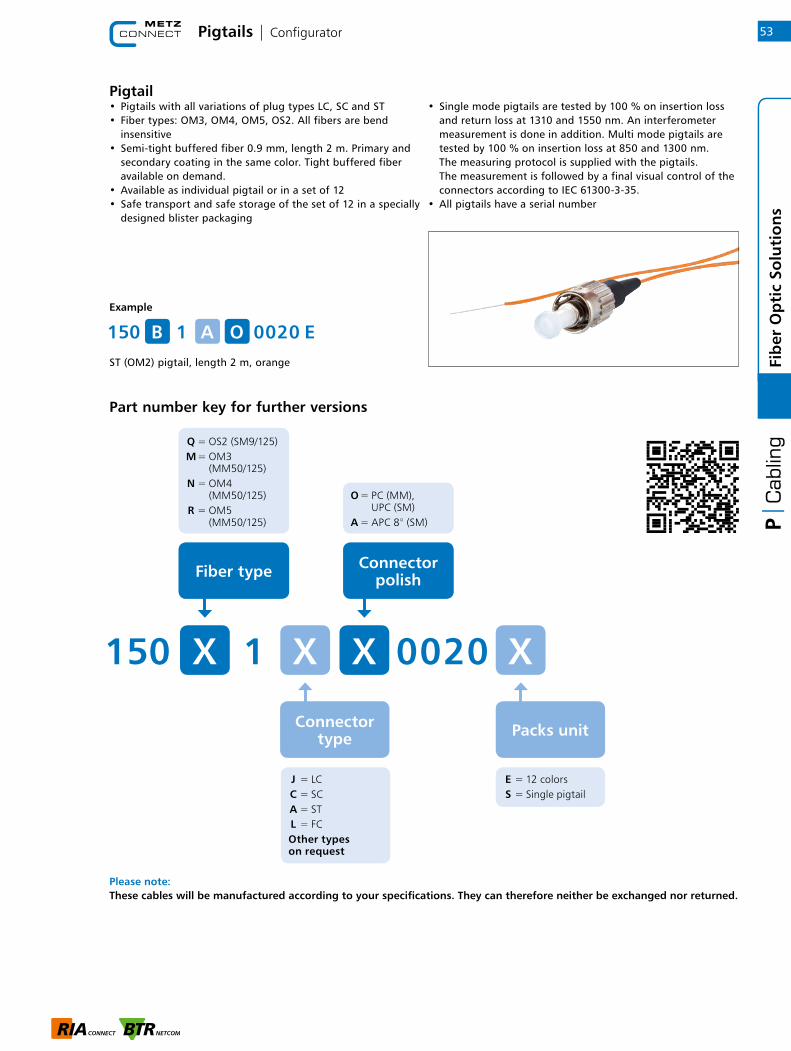
Pigtail• Pigtails with all variations of plug types LC, SC and ST• Fiber types: OM3, OM4, OM5, OS2. All fibers are bend insensitive• Semi-tight buffered fiber 0.9 mm, length 2 m. Primary and secondary coating in the same color. Tight buffered fiber available on demand.• Available as individual pigtail or in a set of 12• Safe transport and safe storage of the set of 12 in a specially designed blister packaging
• Single mode pigtails are tested by 100 % on insertion loss and return loss at 1310 and 1550 nm. An interferometer measurement is done in addition. Multi mode pigtails are tested by 100 % on insertion loss at 850 and 1300 nm. The measuring protocol is supplied with the pigtails. The measurement is followed by a final visual control of the connectors according to IEC 61300-3-35.• All pigtails have a serial number
Please note: These cables will be manufactured according to your specifications. They can therefore neither be exchanged nor returned.
Example
ST (OM2) pigtail, length 2 m, orange
Part number key for further versions
150 OB 0 0 2 0 E1 A
Connector type
J = LC C = SC A = ST L = FC Other types on request
Fiber type Connector polish
O = PC (MM), UPC (SM) A = APC 8° (SM)
Q = OS2 (SM9/125) M = OM3 (MM50/125) N = OM4 (MM50/125) R = OM5 (MM50/125)
0 0 2 0 X150 XX 1 X
Packs unit
E = 12 colors S = Single pigtail
Pigtails | Configurator 53
Fib
er O
pti
c So
luti
on
s
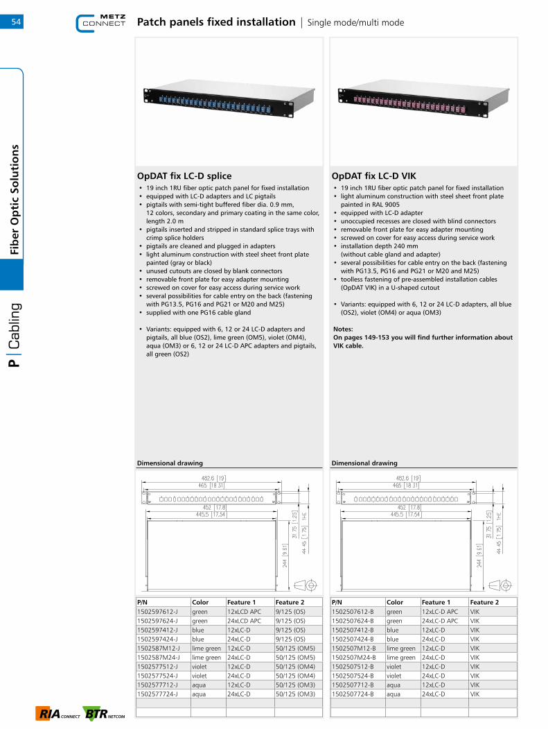
Patch panels fixed installation | Single mode/multi mode
P/N Color Feature 1 Feature 21502597612-J green 12xLCD APC 9/125 (OS)1502597624-J green 24xLCD APC 9/125 (OS)1502597412-J blue 12xLC-D 9/125 (OS)1502597424-J blue 24xLC-D 9/125 (OS)1502587M12-J lime green 12xLC-D 50/125 (OM5)1502587M24-J lime green 24xLC-D 50/125 (OM5)1502577512-J violet 12xLC-D 50/125 (OM4)1502577524-J violet 24xLC-D 50/125 (OM4)1502577712-J aqua 12xLC-D 50/125 (OM3)1502577724-J aqua 24xLC-D 50/125 (OM3)
OpDAT fix LC-D splice• 19 inch 1RU fiber optic patch panel for fixed installation• equipped with LC-D adapters and LC pigtails• pigtails with semi-tight buffered fiber dia. 0.9 mm,
12 colors, secondary and primary coating in the same color, length 2.0 m
• pigtails inserted and stripped in standard splice trays with crimp splice holders
• pigtails are cleaned and plugged in adapters• light aluminum construction with steel sheet front plate
painted (gray or black)• unused cutouts are closed by blank connectors• removable front plate for easy adapter mounting• screwed on cover for easy access during service work• several possibilities for cable entry on the back (fastening
with PG13.5, PG16 and PG21 or M20 and M25)• supplied with one PG16 cable gland
• Variants: equipped with 6, 12 or 24 LC-D adapters and pigtails, all blue (OS2), lime green (OM5), violet (OM4), aqua (OM3) or 6, 12 or 24 LC-D APC adapters and pigtails, all green (OS2)
Dimensional drawing
P/N Color Feature 1 Feature 21502507612-B green 12xLC-D APC VIK1502507624-B green 24xLC-D APC VIK1502507412-B blue 12xLC-D VIK1502507424-B blue 24xLC-D VIK1502507M12-B lime green 12xLC-D VIK1502507M24-B lime green 24xLC-D VIK1502507512-B violet 12xLC-D VIK1502507524-B violet 24xLC-D VIK1502507712-B aqua 12xLC-D VIK1502507724-B aqua 24xLC-D VIK
OpDAT fix LC-D VIK• 19 inch 1RU fiber optic patch panel for fixed installation• light aluminum construction with steel sheet front plate
painted in RAL 9005• equipped with LC-D adapter• unoccupied recesses are closed with blind connectors• removable front plate for easy adapter mounting• screwed on cover for easy access during service work• installation depth 240 mm
(without cable gland and adapter)• several possibilities for cable entry on the back (fastening
with PG13.5, PG16 and PG21 or M20 and M25) • toolless fastening of pre-assembled installation cables
(OpDAT VIK) in a U-shaped cutout
• Variants: equipped with 6, 12 or 24 LC-D adapters, all blue (OS2), violet (OM4) or aqua (OM3)
Notes: On pages 149-153 you will find further information about VIK cable.
Dimensional drawing
54Fi
ber
Op
tic
Solu
tio
ns

Example
OpDAT fix patch panel equipped with 24 LC-D (SM) adapter, 48 pigtails (OS2) inserted and stripped in four splice trays with shrink splice holders
Part number key for further versions
15025 9 74 -J24
Patch panels for fixed installation | Configurators
OpDAT fix• Fiber optic patch panels for 19-inch systems, 1 rack unit (RU• Service-friendly mounting by removable cover or an extendible drawer• Light construction with steel sheet front plate• Front plates available in gray (RAL 7035) or black (RAL 9005)• All front plates are available with 12 or 24 adapter cutouts. Unused cutouts in the front plate are covered by blank plugs• Available with the following adapters: LC, SC, E2000 and ST in duplex version. All adapters with ceramic sleeves. Other types available on demand.
• Pigtails are available with fiber types OM3, OM4, OM5 and OS2. All pigtails are inspected and cleaned before inserted into the adapters according to IEC 61300-3-35
0 = variant "VIK" (without pigtails) 9 = OS2 (SM9/125) 5 = OM3 (MM50/125) 7 = OM4 (MM50/125) 8 = OM5 (MM50/125)
Adapters
74 = LC-D, duplex, SM, blue, ceramic sleeves 76 = LC-D APC, duplex, SM, green, ceramic sleeves 75 = LC-D, duplex, OM4, violet, ceramic sleeves 77 = LC-D, duplex, OM3, aqua, ceramic sleeves E2 = SC-D, duplex, SM, blue, ceramic sleeves F2 = SC-D APC, duplex, SM, green, ceramic sleeves BB = SC-D, duplex, OM4, violet, ceramic sleeves BA = SC-D, duplex, OM3, aqua, ceramic sleeves D1 = ST-D, duplex, SM, metal, ceramic sleeves
Pigtail fiber type Number of adapters
15025 X X X -X X
Front plate and splice protection holder
X
E = gray front plate for max. 24 adaptersF = gray front plate for max. 12 adaptersB = black front plate for max. 24 adaptersC = black front plate for max. 12 adapters
For variant "VIK" and variant "splice" with holder for crimp splice protection
S = gray front plate for max. 24 adaptersH = gray front plate for max. 12 adaptersJ = black front plate for max. 24 adaptersK = black front plate for max. 12 adapters
For variant "splice" with holder for shrink splice protections
55
Fib
er O
pti
c So
luti
on
s

Patch panels withdrawable | Single mode/multi mode
P/N Color Feature 1 Feature 21502697612-J green 12xLC-D APC 9/125 (OS2)1502697624-J green 24xLC-D APC 9/125 (OS2)1502697412-J blue 12xLC-D 9/125 (OS2)1502697424-J blue 24xLC-D 9/125 (OS2)1502687M12-J lime green 12xLC-D 50/125 (OM5)1502687M24-J lime green 24xLC-D 50/125 (OM5)1502677512-J violet 12xLC-D 50/125 (OM4)1502677524-J violet 24xLC-D 50/125 (OM4)1502657712-J aqua 12xLC-D 50/125 (OM3)1502657724-J aqua 24xLC-D 50/125 (OM3)
OpDAT slide LC-D splice• 19 inch 1RU fiber optic patch panel with pull-out splice tray
/ front cover (gray or black)• equipped with LC-D adapters and LC pigtails• pigtails with semi-tight buffered fiber dia. 0.9 mm, 12
colors, secondary and primary coating in the same color, length 2.0 m
• pigtails inserted and stripped in standard splice trays with crimp splice holders
• pigtails are cleaned and plugged in adapters• splice tray can be tilted and completely removed to
facilitate fitting (end stop)• unused cutouts are closed by blank plugs• installation depth 240 mm (without cable gland and
adapters)• several possibilities for cable entry on the back (fastening
with PG13.5, PG16 and PG21 or M20 and M25)• a PG16 mounting kit is included in delivery
• variants: equipped with 6, 12 or 24 LC-D adapters and pigtails, all blue (OS2), lime green (OM5), heather violet (OM4), aqua (OM3) or 6, 12 or 24 LC-D APC adapters and pigtails, all green (OS2)
Dimensional drawing
P/N Color Feature 1 Feature 21502607612-B green 12xLC-D APC VIK1502607624-B green 24xLC-D APC VIK1502607412-B blue 12xLC-D VIK1502607424-B blue 24xLC-D VIK1502607M12-B lime green 12xLC-D VIK1502607M24-B lime green 24xLC-D VIK1502607512-B violet 12xLC-D VIK1502607524-B violet 24xLC-D VIK1502607712-B aqua 12xLC-D VIK1502607724-B aqua 24xLC-D VIK
OpDAT slide LC-D VIK• 19 inch 1RU fiber optic patch panel with pull-out splice tray
/ front cover in black (RAL 9005)• splice tray can be tilted and removed completely for better
mounting (end stop)• equipped with LC-D couplers• unused cutouts are closed by blank plugs• installation depth 240 mm
(without cable gland and coupler)• several possibilities for cable entry on the back (fastening
with PG13.5, PG16 and PG21 or M20 and M25)
• variants: equipped with 6, 12 or 24 LC-D adapters, all blue (OS2), lime green (OM5), heather violet (OM4) or aqua (OM3) or with 6, 12 or 24 SC-D APC adapters, all green (OS2)
Notes: On pages 149-153 you will find further information about VIK cable.
Dimensional drawing
56Fi
ber
Op
tic
Solu
tio
ns

Example
OpDAT slide patch panel equipped with 24 LC-D (SM) adapter,48 pigtails (OS2) inserted and stripped in a splice tray with shrink splice holders
Part number key for further versions
15026 9 75 24 -J
Patch panels withdrawable | Configurators
0 = variant "VIK" (without pigtails) 9 = OS2 (SM9/125) 5 = OM3 (MM50/125) 7 = OM4 (MM50/125) 8 = OM5 (MM50/125)
Adapters
74 = LC-D, duplex, SM, blue, ceramic sleeves 76 = LC-D APC, duplex, SM, green, ceramic sleeves 75 = LC-D, duplex, OM4, violet, ceramic sleeves 77 = LC-D, duplex, OM3, aqua, ceramic sleeves E2 = SC-D, duplex, SM, blue, ceramic sleeves F2 = SC-D APC, duplex, SM, green, ceramic sleeves BB = SC-D, duplex, OM4, violet, ceramic sleeves BA = SC-D, duplex, OM3, aqua, ceramic sleevesD1 = ST-D, duplex, SM, metal, ceramic sleeves
Pigtail fiber type Number of adapters
15026 X X X -X X
Front plate and splice protection holder
X
E = gray front plate for max. 24 adaptersF = gray front plate for max. 12 adaptersB = black front plate for max. 24 adaptersC = black front plate for max. 12 adapters
For variant "VIK" and variant "splice" with holder for crimp splice protection
S = gray front plate for max. 24 adaptersH = gray front plate for max. 12 adaptersJ = black front plate for max. 24 adaptersK = black front plate for max. 12 adapters
For variant "splice" with holder for shrink splice protections
OpDAT slide• Fiber optic patch panels for 19-inch systems, 1 rack unit (RU• Service-friendly mounting by removable cover or an extendible drawer• Light construction with steel sheet front plate• Front plates available in gray (RAL 7035) or black (RAL 9005)• All front plates are available with 12 or 24 adapter cutouts. Unused cutouts in the front plate are covered by blank plugs• Available with the following adapters: LC, SC, E2000 and ST in duplex version. All adapters with ceramic sleeves. Other types available on demand.
• Pigtails are available with fiber types OM3, OM4, OM5 and OS2. All pigtails are inspected and cleaned before inserted into the adapters according to IEC 61300-3-35
57
Fib
er O
pti
c So
luti
on
s
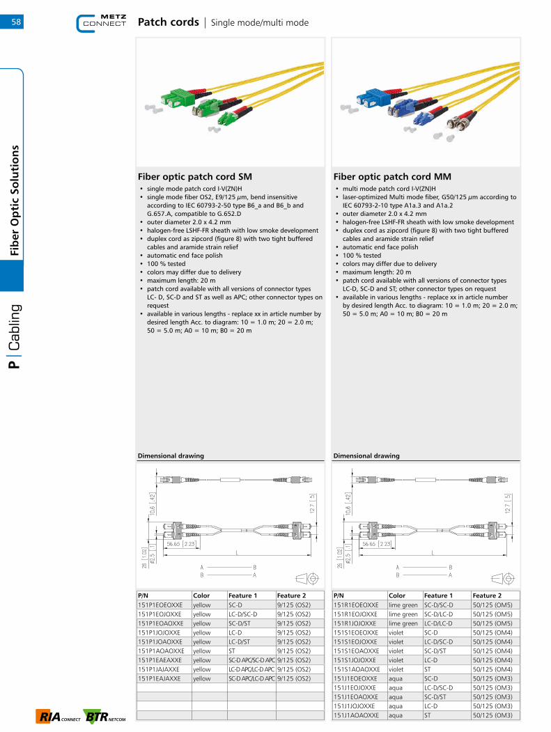
P/N Color Feature 1 Feature 2151P1EOEOXXE yellow SC-D 9/125 (OS2)151P1EOJOXXE yellow LC-D/SC-D 9/125 (OS2)151P1EOAOXXE yellow SC-D/ST 9/125 (OS2)151P1JOJOXXE yellow LC-D 9/125 (OS2)151P1JOAOXXE yellow LC-D/ST 9/125 (OS2)151P1AOAOXXE yellow ST 9/125 (OS2)151P1EAEAXXE yellow SC-D APC/SC-D APC 9/125 (OS2)151P1JAJAXXE yellow LC-D APC/LC-D APC 9/125 (OS2)151P1EAJAXXE yellow SC-D APC/LC-D APC 9/125 (OS2)
Fiber optic patch cord SM• single mode patch cord I-V(ZN)H• single mode fiber OS2, E9/125 µm, bend insensitive
according to IEC 60793-2-50 type B6_a and B6_b and G.657.A, compatible to G.652.D
• outer diameter 2.0 x 4.2 mm• halogen-free LSHF-FR sheath with low smoke development• duplex cord as zipcord (figure 8) with two tight buffered
cables and aramide strain relief• automatic end face polish• 100 % tested• colors may differ due to delivery• maximum length: 20 m• patch cord available with all versions of connector types
LC- D, SC-D and ST as well as APC; other connector types on request
• available in various lengths - replace xx in article number by desired length Acc. to diagram: 10 = 1.0 m; 20 = 2.0 m; 50 = 5.0 m; A0 = 10 m; B0 = 20 m
Fiber optic patch cord MM• multi mode patch cord I-V(ZN)H• laser-optimized Multi mode fiber, G50/125 µm according to
IEC 60793-2-10 type A1a.3 and A1a.2• outer diameter 2.0 x 4.2 mm• halogen-free LSHF-FR sheath with low smoke development• duplex cord as zipcord (figure 8) with two tight buffered
cables and aramide strain relief• automatic end face polish• 100 % tested• colors may differ due to delivery• maximum length: 20 m• patch cord available with all versions of connector types
LC-D, SC-D and ST; other connector types on request• available in various lengths - replace xx in article number
by desired length Acc. to diagram: 10 = 1.0 m; 20 = 2.0 m; 50 = 5.0 m; A0 = 10 m; B0 = 20 m
P/N Color Feature 1 Feature 2151R1EOEOXXE lime green SC-D/SC-D 50/125 (OM5)151R1EOJOXXE lime green SC-D/LC-D 50/125 (OM5)151R1JOJOXXE lime green LC-D/LC-D 50/125 (OM5)151S1EOEOXXE violet SC-D 50/125 (OM4)151S1EOJOXXE violet LC-D/SC-D 50/125 (OM4)151S1EOAOXXE violet SC-D/ST 50/125 (OM4)151S1JOJOXXE violet LC-D 50/125 (OM4)151S1AOAOXXE violet ST 50/125 (OM4)151J1EOEOXXE aqua SC-D 50/125 (OM3)151J1EOJOXXE aqua LC-D/SC-D 50/125 (OM3)151J1EOAOXXE aqua SC-D/ST 50/125 (OM3)151J1JOJOXXE aqua LC-D 50/125 (OM3)151J1AOAOXXE aqua ST 50/125 (OM3)
Patch cords | Single mode/multi mode
Dimensional drawing Dimensional drawing
58Fi
ber
Op
tic
Solu
tio
ns
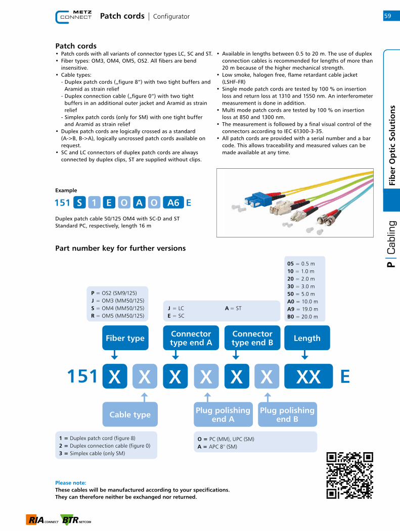
Example
Duplex patch cable 50/125 OM4 with SC-D and STStandard PC, respectively, length 16 m
Part number key for further versions
151 EOS A61 E A O
Patch cords• Patch cords with all variants of connector types LC, SC and ST.• Fiber types: OM3, OM4, OM5, OS2. All fibers are bend insensitive.• Cable types: - Duplex patch cords („figure 8“) with two tight buffers and Aramid as strain relief - Duplex connection cable („figure 0“) with two tight buffers in an additional outer jacket and Aramid as strain relief - Simplex patch cords (only for SM) with one tight buffer and Aramid as strain relief• Duplex patch cords are logically crossed as a standard (A->B, B->A), logically uncrossed patch cords available on request.• SC and LC connectors of duplex patch cords are always connected by duplex clips, ST are supplied without clips.
• Available in lengths between 0.5 to 20 m. The use of duplex connection cables is recommended for lengths of more than 20 m because of the higher mechanical strength.• Low smoke, halogen free, flame retardant cable jacket (LSHF-FR)• Single mode patch cords are tested by 100 % on insertion loss and return loss at 1310 and 1550 nm. An interferometer measurement is done in addition. • Multi mode patch cords are tested by 100 % on insertion loss at 850 and 1300 nm.• The measurement is followed by a final visual control of the connectors according to IEC 61300-3-35.• All patch cords are provided with a serial number and a bar code. This allows traceability and measured values can be made available at any time.
Patch cords | Configurator
Please note: These cables will be manufactured according to your specifications.They can therefore neither be exchanged nor returned.
Cable type
J = LC E = SC
A = ST
05 = 0.5 m10 = 1.0 m20 = 2.0 m30 = 3.0 m50 = 5.0 mA0 = 10.0 mA9 = 19.0 mB0 = 20.0 m
Fiber type
151 X X XX XX
Length
Plug polishing end A
O = PC (MM), UPC (SM)A = APC 8° (SM)
XX E
P = OS2 (SM9/125) J = OM3 (MM50/125) S = OM4 (MM50/125) R = OM5 (MM50/125)
Plug polishing end B
1 = Duplex patch cord (figure 8)2 = Duplex connection cable (figure 0)3 = Simplex cable (only SM)
59
Fib
er O
pti
c So
luti
on
s
Connector type end A
Connector type end B
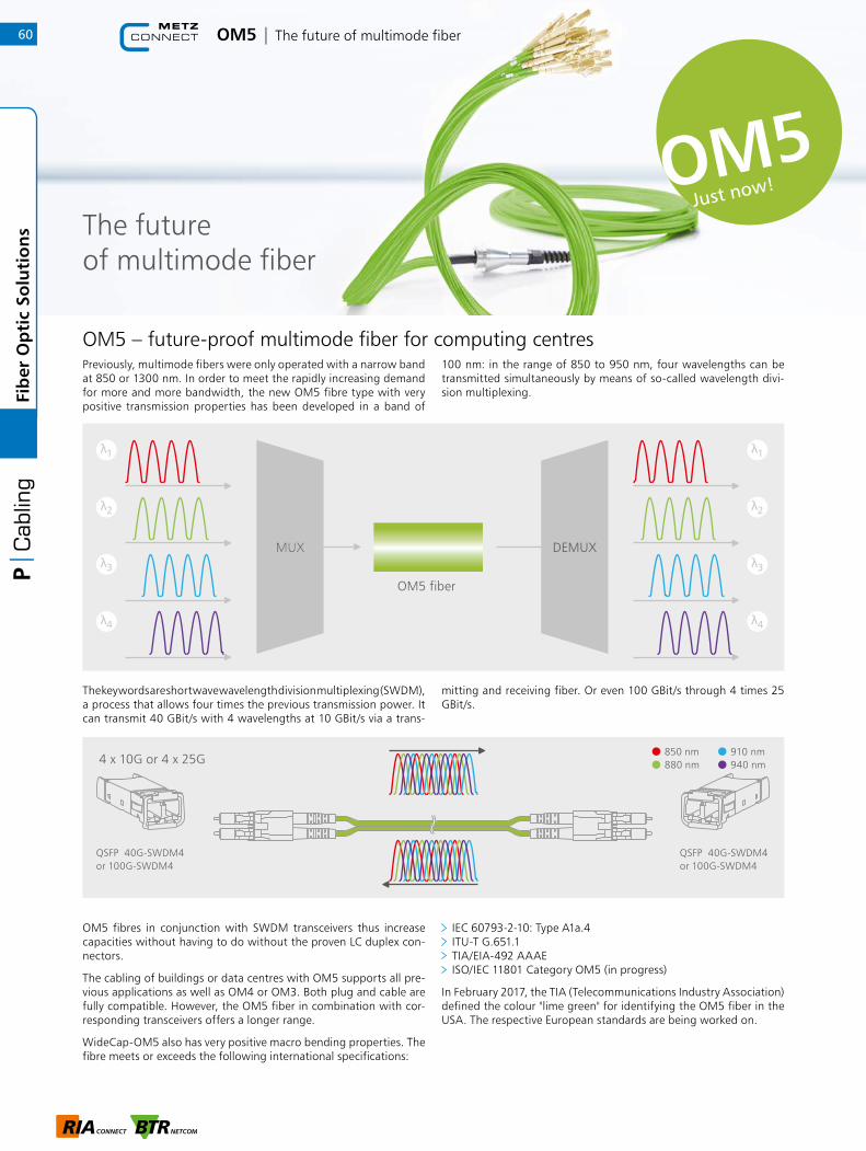
OM5 – future-proof multimode fiber for computing centresPreviously, multimode fibers were only operated with a narrow band at 850 or 1300 nm. In order to meet the rapidly increasing demand for more and more bandwidth, the new OM5 fibre type with very positive transmission properties has been developed in a band of
100 nm: in the range of 850 to 950 nm, four wavelengths can be transmitted simultaneously by means of so-called wavelength divi-sion multiplexing.
The keywords are shortwave wavelength division multiplexing (SWDM), a process that allows four times the previous transmission power. It can transmit 40 GBit/s with 4 wavelengths at 10 GBit/s via a trans-
mitting and receiving fiber. Or even 100 GBit/s through 4 times 25 GBit/s.
OM5 fibres in conjunction with SWDM transceivers thus increase capacities without having to do without the proven LC duplex con-nectors.
The cabling of buildings or data centres with OM5 supports all pre-vious applications as well as OM4 or OM3. Both plug and cable are fully compatible. However, the OM5 fiber in combination with cor-responding transceivers offers a longer range.
WideCap-OM5 also has very positive macro bending properties. The fibre meets or exceeds the following international specifications:
IEC 60793-2-10: Type A1a.4 ITU-T G.651.1 TIA/EIA-492 AAAE ISO/IEC 11801 Category OM5 (in progress)
In February 2017, the TIA (Telecommunications Industry Association) defined the colour "lime green" for identifying the OM5 fiber in the USA. The respective European standards are being worked on.
1
2
3
4
MUXMUX
1
2
3
4
DEMUX
OM5 fiber
QSFP 40G-SWDM4 or 100G-SWDM4
4 x 10G or 4 x 25G850 nm880 nm
910 nm 940 nm
QSFP 40G-SWDM4 or 100G-SWDM4
The future of multimode fiber
OM5 | The future of multimode fiber
Just now!
60Fi
ber
Op
tic
Solu
tio
ns

Just use our configurators, which you can find on our homepage www.metz-connect.com/en/configurators. In it you will find all available variants.
With the new OM5 multimode fiber... you have 4-times more capacity than with OM4 you can reduce the number of fibres 4 fold the bandwidth is specified for the optical window of 850
to 950nm (OM4 is only specified for 850nm)
OM5 multimode fibers support... new WDM technologies in order to meet the capacity requi-
rements of the next ten years Cable solutions for 40, 100 and 200G WDM systems with
only 2 fibers in the future, 400 and 800G over 4 fiber pairs (MPO)
VIK
DCCS
Pigtails Adapter
Patch panels
OM5 | The future of multimode fiber
Patch cable
61
Fib
er O
pti
c So
luti
on
s
Notes62Fi
ber
Op
tic
Solu
tio
ns

Table of contents | Data Center Solutions
Data Center Solutions
1 RJ45 | Cat.6A 64
2 RJ45 | Configurator 66
3 Fiber optic | Single mode/multi mode 67
4 Accessories 70
5 25G System | The RJ45 building cabling
with future 71
63
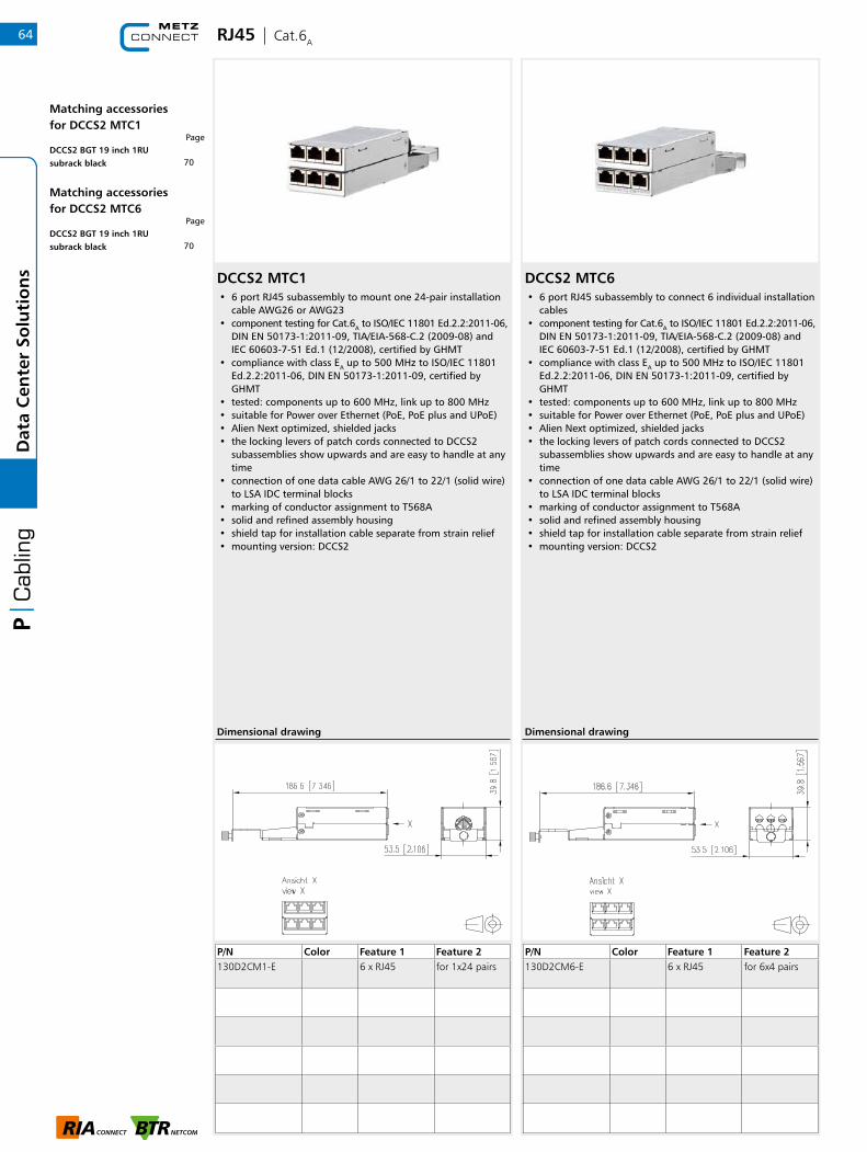
RJ45 | Cat.6A
DCCS2 MTC1• 6 port RJ45 subassembly to mount one 24-pair installation
cable AWG26 or AWG23 • component testing for Cat.6A to ISO/IEC 11801 Ed.2.2:2011-06,
DIN EN 50173-1:2011-09, TIA/EIA-568-C.2 (2009-08) and IEC 60603-7-51 Ed.1 (12/2008), certified by GHMT
• compliance with class EA up to 500 MHz to ISO/IEC 11801 Ed.2.2:2011-06, DIN EN 50173-1:2011-09, certified by GHMT
• tested: components up to 600 MHz, link up to 800 MHz • suitable for Power over Ethernet (PoE, PoE plus and UPoE) • Alien Next optimized, shielded jacks • the locking levers of patch cords connected to DCCS2
subassemblies show upwards and are easy to handle at any time
• connection of one data cable AWG 26/1 to 22/1 (solid wire) to LSA IDC terminal blocks
• marking of conductor assignment to T568A • solid and refined assembly housing • shield tap for installation cable separate from strain relief • mounting version: DCCS2
DCCS2 MTC6• 6 port RJ45 subassembly to connect 6 individual installation
cables • component testing for Cat.6A to ISO/IEC 11801 Ed.2.2:2011-06,
DIN EN 50173-1:2011-09, TIA/EIA-568-C.2 (2009-08) and IEC 60603-7-51 Ed.1 (12/2008), certified by GHMT
• compliance with class EA up to 500 MHz to ISO/IEC 11801 Ed.2.2:2011-06, DIN EN 50173-1:2011-09, certified by GHMT
• tested: components up to 600 MHz, link up to 800 MHz • suitable for Power over Ethernet (PoE, PoE plus and UPoE) • Alien Next optimized, shielded jacks • the locking levers of patch cords connected to DCCS2
subassemblies show upwards and are easy to handle at any time
• connection of one data cable AWG 26/1 to 22/1 (solid wire) to LSA IDC terminal blocks
• marking of conductor assignment to T568A • solid and refined assembly housing • shield tap for installation cable separate from strain relief • mounting version: DCCS2
P/N Color Feature 1 Feature 2130D2CM1-E 6 x RJ45 for 1x24 pairs
P/N Color Feature 1 Feature 2130D2CM6-E 6 x RJ45 for 6x4 pairs
Dimensional drawing Dimensional drawing
64D
ata
Cen
ter
Solu
tio
ns
Matching accessoriesfor DCCS2 MTC1
Page
Matching accessoriesfor DCCS2 MTC6
Page
70DCCS2 BGT 19 inch 1RU subrack black
70DCCS2 BGT 19 inch 1RU subrack black
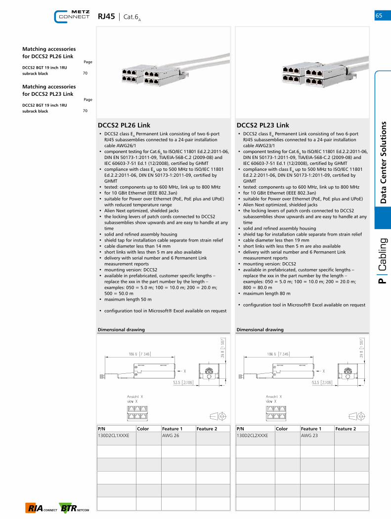
RJ45 | Cat.6A
DCCS2 PL26 Link• DCCS2 class EA Permanent Link consisting of two 6-port
RJ45 subassemblies connected to a 24-pair installation cable AWG26/1
• component testing for Cat.6A to ISO/IEC 11801 Ed.2.2:2011-06, DIN EN 50173-1:2011-09, TIA/EIA-568-C.2 (2009-08) and IEC 60603-7-51 Ed.1 (12/2008), certified by GHMT
• compliance with class EA up to 500 MHz to ISO/IEC 11801 Ed.2.2:2011-06, DIN EN 50173-1:2011-09, certified by GHMT
• tested: components up to 600 MHz, link up to 800 MHz • for 10 GBit Ethernet (IEEE 802.3an) • suitable for Power over Ethernet (PoE, PoE plus and UPoE)
with reduced temperature range • Alien Next optimized, shielded jacks • the locking levers of patch cords connected to DCCS2
subassemblies show upwards and are easy to handle at any time
• solid and refined assembly housing • shield tap for installation cable separate from strain relief • cable diameter less than 14 mm • short links with less then 5 m are also available • delivery with serial number and 6 Permanent Link
measurement reports • mounting version: DCCS2 • available in prefabricated, customer specific lengths –
replace the xxx in the part number by the length – examples: 050 = 5.0 m; 100 = 10.0 m; 200 = 20.0 m; 500 = 50.0 m
• maximum length 50 m
• configuration tool in Microsoft® Excel available on request
DCCS2 PL23 Link• DCCS2 class EA Permanent Link consisting of two 6-port
RJ45 subassemblies connected to a 24-pair installation cable AWG23/1
• component testing for Cat.6A to ISO/IEC 11801 Ed.2.2:2011-06, DIN EN 50173-1:2011-09, TIA/EIA-568-C.2 (2009-08) and IEC 60603-7-51 Ed.1 (12/2008), certified by GHMT
• compliance with class EA up to 500 MHz to ISO/IEC 11801 Ed.2.2:2011-06, DIN EN 50173-1:2011-09, certified by GHMT
• tested: components up to 600 MHz, link up to 800 MHz • for 10 GBit Ethernet (IEEE 802.3an) • suitable for Power over Ethernet (PoE, PoE plus and UPoE) • Alien Next optimized, shielded jacks • the locking levers of patch cords connected to DCCS2
subassemblies show upwards and are easy to handle at any time
• solid and refined assembly housing • shield tap for installation cable separate from strain relief • cable diameter less then 19 mm • short links with less then 5 m are also available • delivery with serial number and 6 Permanent Link
measurement reports • mounting version: DCCS2 • available in prefabricated, customer specific lengths –
replace the xxx in the part number by the length – examples: 050 = 5.0 m; 100 = 10.0 m; 200 = 20.0 m; 800 = 80.0 m
• maximum length 80 m
• configuration tool in Microsoft® Excel available on request
P/N Color Feature 1 Feature 2130D2CL1XXXE AWG 26
P/N Color Feature 1 Feature 2130D2CL2XXXE AWG 23
Dimensional drawing Dimensional drawing
65
Dat
a C
ente
r So
luti
on
s
Matching accessoriesfor DCCS2 PL26 Link
Page
Matching accessoriesfor DCCS2 PL23 Link
Page
70DCCS2 BGT 19 inch 1RU subrack black
70DCCS2 BGT 19 inch 1RU subrack black

RJ45 | Configurator
DCCS2 RJ45-Link• Class EA Permanent Link consisting of 2 subassemblies 6 ports RJ45 mounted to a 24-pair installation cable• Cat.6A component testing as per ISO/IEC 11801 Ed.2.2:2011-06, DIN EN 50173-1:2011-09, TIA/EIA-568-C.2 (2009-08) and IEC 60603-7-51 Ed.1 (12/2008), GHMT certified• Class EA up to 500 MHz as per ISO/IEC 11801 Ed.2.2:2011-06, DIN EN 50173-1:2011-09, GHMT certified• Component testing: up to 600 MHz, link up to 800 MHz• For up to 10 GBit Ethernet (IEEE 802.3an)• Suitable for Power over Ethernet (PoE, PoE plus and UPoE)• Solid, refined subassembly housing • Shield tap for installation cable separate from strain relief • Delivery with serial number and 6 Permanent Link measuring reports• Installation shape: DCCS2• Also short links with less than 5 m possible• Configuration tool in Microsoft ® Excel upon request
Please note: These cables will be manufactured according to your specifications. They can therefore neither be exchanged nor returned.
Example
DCCS2 RJ45 link to 24-pair AWG23/1 S/FTP cablelength 66.0 m
Part number key for further versions
Length
1 = 24P AWG 26/1 S/FTP (up to 50 m) 2 = 24P AWG 23/1 S/FTP (up to 80 m)
E = DCCS2 Link O = open on one side
Cable type
050 = 5.0 m 095 = 9.5 m 100 = 10.0 m 150 = 15.0 m
200 = 20.0 m 500 = 50.0 m 795 = 79.5 m 800 = 80.0 m
130D2CL X
Link structure
XX X X
130D2CL 2 6 6 0 E
66D
ata
Cen
ter
Solu
tio
ns

DCCS2 6 x LC-D Link• prefabricated fiber optic link consisting of 2 subassemblies
DCCS2 with 6 LC-D adapter mounted to a 12 fiber mini breakout cable
• port numbering of the DCCS2 19" subassembly frame remains in place when installing the FO subassemblies
• for 10 GBit Ethernet (IEEE 802.3an) • the locking levers of patch cords connected to DCCS2
subassemblies show upwards and are easy to handle at any time
• solid and refined assembly housing • cable diameter less then 6.5 mm • delivery with serial number and 12 attenuation
measurement reports • mounting version: DCCS2 • available in prefabricated, customer specific lengths –
replace xxxx in the part number by the length – examples: 0050 = 5.0 m; 0100 = 10.0 m; 0995 = 99.5 m; 2000 = 200.0 m
• maximum length: 500 m • configuration tool in Microsoft® Excel available on request • variants: SM (OS2), SM (OS2 APC), MM (OM5), MM (OM4),
MM (OM3)
DCCS2 6 x LC-D VIK Link• prefabricated fiber optic cable divider link consisting on one
side of one subassembly DCCS 2 with 6 LC-D adapter mounted to a 12 fiber mini breakout cable. The other side is configured with 12 LC plugs with a dismantle measure of about 30 cm, in installation tube about 35 cm and a diameter of about 47 mm
• especially suited to be combined with DCCS2 subassemblies 6xLC-D
• port numbering of the DCCS2 19" subassembly frame remains in place when installing the FO subassemblies
• for 10 GBit Ethernet (IEEE 802.3an) • the locking levers of patch cords connected to DCCS2
subassemblies show upwards and are easy to handle at any time
• solid and refined assembly housing • cable diameter less then 6.5 mm • delivery with serial number and 12 attenuation
measurement reports • mounting version: DCCS2 • available in prefabricated, customer specific lengths –
replace xxxx in the part number by the length – examples: 0050 = 5.0 m; 0100 = 10.0 m; 0995 = 99.5 m; 2000 = 200.0 m
• maximum length: 500 m
• configuration tool in Microsoft® Excel available on request
• variants: SM (OS2), SM (OS2 APC), MM (OM5), MM (OM4), MM (OM3)
Fiber optic | Single mode/multi mode
P/N Color Feature 1 Feature 2130D2F572XXXXE aqua 6 x LC-D 50/125 (OM3)
130D2F772XXXXE violet 6 x LC-D 50/125 (OM4)
130D2F87MXXXXE lime green 6 x LC-D 50/125 (OM5)
130D2F971XXXXE blue 6 x LC-D 9/125 (OS2)
130D2F976XXXXE green 6 x LC-D APC 9/125 (OS2)
P/N Color Feature 1 Feature 2130D2F572XXXXZ aqua 6 x LC-D EVZ cable divider
130D2F772XXXXZ violet 6 x LC-D EVZ 50/125 (OM4)
130D2F87MXXXXZ lime green 6 x LC-D EVZ 50/125 (OM5)
130D2F971XXXXZ blue 6 x LC-D EVZ 9/125 (OS2)
130D2F976XXXXZ green 6 x LC-D APC EVZ
9/125 (OS2)
Dimensional drawing
67
Dat
a C
ente
r So
luti
on
s
Matching accessoriesfor DCCS2 6 x LC-D Link
Page
Matching accessoriesfor DCCS2 6 x LC-D VIK Link
Page
70DCCS2 BGT 19 inch 1RU subrack black
70DCCS2 BGT 19 inch 1RU subrack black

DCCS2 6 x LC-D• DCCS2 fiber optic subassembly mounted with 6 LC-D
adapter • port numbering of the DCCS2 19" subassembly frame
remains in place when installing the FO subassembly • the locking levers of patch cords connected to DCCS2
subassemblies show upwards and are easy to handle at any time
• for prefabricated mini breakout cables in customer specific lengths
• solid and refined assembly housing • mounting version: DCCS2
• variants: blue (SM), green (SM APC), lime gree (OM5), violet (OM4), aqua (OM3)
Fiber optic | Single mode/multi mode
P/N Color Feature 1 Feature 2130D2FB51-E aqua 6 x LC-D MM (ceramic)
130D2FB71-E violet 6 x LC-D MM (ceramic)
130D2FB81-E lime green 6 x LC-D MM (ceramic)
130D2FB91-E blue 6 x LC-D SM
130D2FBA1-E green 6 x LC-D APC SM
Dimensional drawing
DCCS2 6 x LC-D / 1 x MPO• DCCS2 fiber optic subassembly MPO with 6 mounted LC-D
adapter • port numbering of the DCCS2 19" subassembly frame
remains in place when the fiber optic subassembly is installed
• all locking levers of patch cords connected to DCCS2 subassemblies show upwards and are easy to handle at any time
• on the back 1 x MPO coupler (exterior: key up) polarity, Method A
• solid and refined subassembly housing • mounting version: DCCS2
• variants: SM (OS2), SM (OS2 APC), MM (OM4), MM (OM3)
P/N Color Feature 1 Feature 2130D2FM51A-E aqua 6 x LC-D 50/125 (OM3)
130D2FM71A-E violet 6 x LC-D 50/125 (OM4)
130D2FM91A-E blue 6 x LC-D 9/125 (OS2)
130D2FMA1A-E green 6 x LC-D APC 9/125 (OS2)
Dimensional drawing
68D
ata
Cen
ter
Solu
tio
ns
Matching accessoriesfor DCCS2 6 x LC-D
Page
Matching accessoriesfor DCCS2 6 x LC-D / 1 x MPO
Page
70DCCS2 BGT 19 inch 1RU subrack black
70DCCS2 BGT 19 inch 1RU subrack black

Fiber optic | Single mode/multi mode
DCCS2 6 x MPO• 6 port MPO subassembly for 10 / 40 / 100 MBit/s• 6x MPO adapters Key up / Key down• with optional strain relief • fastening in a 19-inch subrack by a knurled screw• easy mounting/dismounting to/from 19-inch subracks in
19-inch cabinets (plug and play)• design: DCCS2
variants: OM3: aqua; OM4: violet; OS2 APC: green
P/N Color Feature 1 Feature 2130D2FBM5A-E aqua 6xMPO MM
130D2FBM7A-E violet 6xMPO MM
130D2FBMAA-E green 6xMPO SM APC
69
Dat
a C
ente
r So
luti
on
s
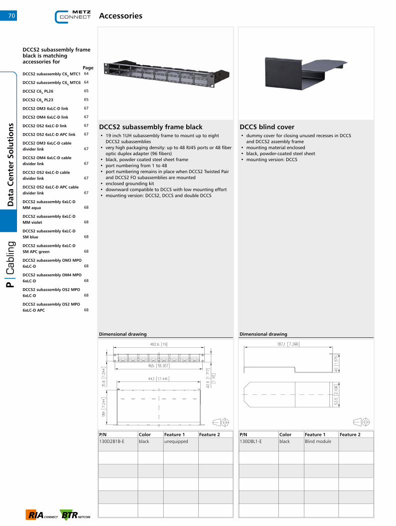
DCCS2 subassembly frame black• 19 inch 1UH subassembly frame to mount up to eight
DCCS2 subassemblies • very high packaging density: up to 48 RJ45 ports or 48 fiber
optic duplex adapter (96 fibers) • black, powder coated steel sheet frame • port numbering from 1 to 48 • port numbering remains in place when DCCS2 Twisted Pair
and DCCS2 FO subassemblies are mounted • enclosed grounding kit • downward compatible to DCCS with low mounting effort • mounting version: DCCS2, DCCS and double DCCS
Accessories
P/N Color Feature 1 Feature 2130D2B1B-E black unequipped
Dimensional drawing
DCCS blind cover• dummy cover for closing unused recesses in DCCS
and DCCS2 assembly frame • mounting material enclosed • black, powder-coated steel sheet • mounting version: DCCS
P/N Color Feature 1 Feature 2130DBL1-E black Blind module
Dimensional drawing
70D
ata
Cen
ter
Solu
tio
ns
DCCS2 subassembly frame black is matching accessories for
Page64DCCS2 subassembly C6A MTC1
64DCCS2 subassembly C6A MTC6
65DCCS2 C6A PL26
65DCCS2 C6A PL23
67DCCS2 OM3 6xLC-D link
67DCCS2 OM4 6xLC-D link
67DCCS2 OS2 6xLC-D link
67DCCS2 OS2 6xLC-D APC link
67DCCS2 OM3 6xLC-D cable divider link
67DCCS2 OM4 6xLC-D cable divider link
67DCCS2 OS2 6xLC-D cable divider link
67DCCS2 OS2 6xLC-D APC cable divider link
68DCCS2 subassembly 6xLC-D MM aqua
68DCCS2 subassembly 6xLC-D MM violet
68DCCS2 subassembly 6xLC-D SM blue
68DCCS2 subassembly 6xLC-D SM APC green
68DCCS2 subassembly OM3 MPO 6xLC-D
68DCCS2 subassembly OM4 MPO 6xLC-D
68DCCS2 subassembly OS2 MPO 6xLC-D
68DCCS2 subassembly OS2 MPO 6xLC-D APC

25G System | The RJ45 building cabling with future
25G System – The RJ45 building cabling with future
Intelligent system solution for the highest-performing, future-oriented, structured cabling The need today for high data transfer rates is enormous. On 12 September 2017, the Internet node in Frankfurt reported a new record of 5.88 terabits per second. By mid-March 2018, just under 6.4 terabits per second had already been measured. Five years ago, it was not even 2 terabits per second.A forward-looking, intelligent building cabling for a wide variety of uses has a high priority among investors as basic home and building control. Investments are secured over the years, construction and maintenance costs are minimized.
System components
25GBit high-speed data transmission requires the performance of all the components. In addition to the connection components, this also includes the installation and patch cords. With products from METZ CONNECT, you have the right components to provide you with a complete and end-to-end solution from the server to the end device.
25Gmodul- RJ45 pursuant to 60603-7-1- 25GBASE-T pursuant to DTR-11801-9905 in channel link with 30 m (50 m in progres)- Completely backward compatible through compliance with Class EA pursuant to ISO/IEC 11801-1 and DIN EN
50173-1 (in permanent link up to 90 m; in channel link to 100 m)- without special tools migratable from C6Amodul of 25Gmodul by swapping the metal case
Variants 25modul K (mounting cut-out construction keystone)
GC1300 pro22 and GC1500 pro22 (P/N please refer Page 24)- 25/10 GBit Installation cable (GC1300 pro22), 10 GBit Installation cable (GC1500 pro22)- Reaction to fire: Class Dca after EN 50399- pair shielded Cat.7A AWG 22 S/FTP- overall shield: Cu tinned braid, coupling loss ≥ 85 dB
Patch cable 25G AWG 26 (P/N 13084G20xx-E)- pair shielded 25G patch cable AWG 26/7, halogen-free- for 25 GBit/s (IEEE 802.3bq); 10 GBit/s (IEEE 802.3an)- two shielded RJ45 plugs, wiring, 1 - 1- 2 m (no further standard lengths for 25 GBit possible)
25Gmodul K - P/N Individual module package 130B21-25-E 12 Unit module package 130B21-25-Z
71
Dat
a C
ente
r So
luti
on
s

25G System | The RJ45 building cabling with future
Patch panelServer
Storage
Patch cord
Patch cord
Installation cabel
Patch panel
The highest compatibility for efficient useOur new 25G System is consistent and compatible – a prerequisite for the transparent, efficient and individual use of future-oriented network and cabling systems. Build today the network infrastructure of tomorrow. The minimum additional monetary cost provides you with 2.5 times the transmission speed.
High performance The 25G system offers high performance by fulfilling the DTR-11801-9905 for 25GBASE-T pursuant to IEEE 802.3bq (in the channel link up to 30 m) for the highest performance applications up to 1250 MHz bandwidthand 25 GBit Ethernet as well as ISO/IEC 11801- 1 Class EA in permanent and channel link up to link lengths of 100 m for demanding applications in the range up to 500 MHz bandwidth and 10 GBit Ethernet pursuant to IEEE 802.3an. The high-quality product quality is further enhanced by a robust die-cast zinc housing.
Independent certification The connection system meets international requirements for future-oriented copper-based data highways.
- RJ45 pursuant to 60603-7-1 - GHMT certified pursuant to DTR-11801-9905 for 25GBaseT in channel link with 30 m (50 m in progress).- GHMT certified pursuant to Class EA in permanent link up to 90 m pursuant to ISO/IEC 11801-1 and
DIN EN 50173-1
The requirements of Class EA are also complied with in channel link pursuant to the above-mentioned standard.
72D
ata
Cen
ter
Solu
tio
ns
RJ45 patch cord RJ45 patch cord
RJ45 module
Installation cable
RJ45 module
Channel link up to 100 m
Permanent link up to 90 m
Channel link up to 30 m
RJ45 patch cord RJ45 patch cord
RJ45 module
Installation cable
RJ45 module
Channel link up to 50 m (in progress)
RJ45 patch cord RJ45 patch cord
RJ45 module
Installation cable
RJ45 module

Industrial Connectors
1 IP PC | Performance specifications 74
2 IP PC | RJ45 plug inserts (for IP67 housings) 76
3 IP PC | Fiber Optic inserts (for IP67 housings) 76
4 IP PC | RJ45 jack & coupler inserts 79
5 IP PC | Fiber Optic adapter inserts 80
6 IP PC | USB adapter inserts 81
7 IP PC | Variant 1 plug/flange housing 82
8 IP PC | Var. 1 wall outlet & coupler housing 84
9 IP PC | Variant 4 plug/flange housing 85
10 IP PC | Var. 4 wall outlet & coupler housing 86
11 IP PC | Variant 5 plug/flange housing 87
12 IP PC | Variant 14 plug/flange housing 88
13 IP PC | Var. 14 fiber optic flange housing set 89
14 IP PC | Variant 6 plug & cable 90
15 IP PC | Variant 6 cable & flange housing 91
16 IP PC | Var. 6 wall outlet & coupler housing 92
17 IP PC | Var. 6 locking clamp / IP67 metal outlet 93
18 IP PC | Protective caps for IP67 housings 94
19 IP PC | Universal test jack housing
for Steadytec inserts 96
20 RJ45 Plug | Field plug pro 97
21 RJ45 Plug | Field plug pro 360 98
22 RJ45 Plug | E-DAT Industry IP20
RJ45 field plug 99
23 RJ45 Plug | Color coding for E-DAT
Industry IP20 RJ45 field plug 100
24 RJ45 Plug | E-DAT Industry IP20 RJ45
plug & color coding 101
25 Cable connector | Cable connector 102
26 Mod. wall outlets | TH35 rail & wall outlet 103
27 Modular wall outlets | Modular wall
outlets 104 + 106
28 Modular wall outlets | Flush mount
built-in outlet 105
29 Standard rail | Standard rail REG
for RJ45 jacks & adapter 107
30 Standard rail | Dust protection covers &
Standard rail REG for fiber optic E2000 108
31 Standard rail | E-DAT Industry
terminal rail TS35 RJ45 109
32 Standard rail | E-DAT Industry
terminal rail TS35 fiber optic 110
33 Standard rail | E-DAT Industry
terminal rail TS35 fiber optic & USB 111
34 Standard rail | DIN rail adapter &
suitable 6 Port module frame 112
35 Standard rail | DIN rail adapter 113
36 Standard rail | Fiber optic 114
37 Standard rail | Fiber optic
standard rail accessories 116
38 Standard rail | Fiber optic front cover 117
39 Standard rail | OpDAT REG Splice
Distributor for fiber optic & RJ45 119
40 Industrial Ethernet |
Overview M12 products 120
41 Ethernet M12 | D- & X-coded jacks 122
42 Ethernet M12 | M12 connectors
for field assembly 128
43 Ethernet M12 | Panel feed through
adapters M12 X-coded to RJ45 131
44 Ethernet M12 | Cable and connection line 132
45 Ethernet Device | Industry switche 143
Table of contents | Industrial Connectors 73

IP protected connectors | Performance specifications74In
du
stri
al C
on
nec
tors
Industry cables / IP protected connectors• High-quality pre-assembled patch or connection cables• Different copper cable types possible• Very large range of combination options thanks to the STEADYTEC ® Fit-for-All principle• IP20 up to IP67 solutions• IP67 variants will be supplied with plug protection caps• Online cable configurator can be found on our homepage http://www.metz-connect.com/en/configurator-copper-and-fiber-optique-cables
141 B 0 0 1 M C 84 8 3
Please note: These cables will be manufactured according to your specifications. They can therefore neither be exchanged nor returned.
Example
Connection cable AWG23/1 Cat.7 PUR S/FTP, 1-1 (T568A), C6Amodul – IP20, RJ45 field plug insert – V1 metal, length: 38 m
Part number key for further versions
Allocation Plug housing A
Plug housing B
B = IC1000 4P AWG 23/1 Cat.7 PUR S/FTP F = GC1000 plus 4P AWG 23/1 Cat.7 LSHF S/FTP N = PK AWG 26/7 Cat.6A PUR S/FTP T = PK AWG 26/7 Cat.6A LSHF S/FTP
IP67 plug housing1M = V1 metall2M = V1 metall bend protected1K = V1 plastic2K = V1 plastic bend protected4K = V4 plastic5K = V4 plastic bend protected6M = V5 metall8M = V14 metallwithout plug housing00 = IP20
IP67 cable coupler/wall outletfor E-DAT insert field jack/profinet3Q = V1 plastic cable coupler3R = V4 plastic cable coupler3U = V1 plastic wall outlet3V = V4 plastic wall outletIP67 cable coupler/wall outletfor E-DAT modul jack3T = V6 plastic cable coupler3W = V6 plastic wall outlet
Cable type Cable side A Cable side B Length
05 = 0.5 m 10 = 1.0 m 95 = 9.5 m A0 = 10.0 m A5 = 15.0 m A9 = 19.0 m B0 = 20.0 m E0 = 50.0 m I0 = 90.0 m
1 = 1–1 T568B 3 = 1-1 Profinet 4 = 1–1 T568A
141 X X X X X X XX X X
Inserts for IP67 plug housings 3 = RJ45 field plug insert 4 = RJ45 plug insert O = RJ45 field plug insert profinetIP20 plug1 = RJ45 plug 2 = RJ45 field plug black M = RJ45 field plug pro
Inserts for IP67 plug housing5 = E-DAT insert field jack6 = E-DAT insert field jack profinet7 = E-DAT modulIP20 jacks8 = C6Amodul 180°9 = C6Amodul K 180°B = C6Amodul 270°D = C6Amodul K 270°K = E-DAT modul K
Cable coupler A/B
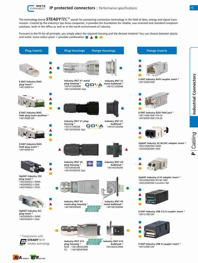
16375IP protected connectors | Performance specifications
3
Ind
ust
rial
Co
nn
ecto
rs
* Components withSTEADYTEC®reliable technology
E-DAT Industry RJ45 plug insert *1401500810-I
E-DAT Industry RJ45 coupler insert *1401200810MI
E-DAT Industry RJ45 field jack *1401100810MI (TIA-A)1401800810MI (TIA-B)
OpDAT Industry SC-RJ/2SC adapter insert *1402100820MI (MM)1402K00820MI (SM)
OpDAT Industry LC-D adapter insert *1402300820MI (Ph-Br) MM1402L00820MI (ceramic) SM
Industry IP67 V1 plug housing *1401015002KE1401025002KE (bp)
Industry IP67 V1bulkhead *
1401013302KE
Industry IP67 V4plug housing *1401045002KE1401055002KE (bp)
Industry IP67 V4bulkhead *
1401043302KE
Industry IP67 V14plug housing *RJ45 – 14010850C0ME FO – 14010850F0ME
Industry IP67 V14bulkhead *
14010833C0MN
Industry IP67 V5metal plug housing *1401065000ME
Industry IP67 V5metal bulkhead *
1401063300ME
E-DAT Industry RJ45 field plug insert *1401400810-I
OpDAT Industry 2LC plug insert *1402800820-I (MM)1402900820-I (SM)
OpDAT Industry 2SC plug insert *1402500822-I (MM)1402600822-I (SM)1402700822-I (POF)
Industry IP67 V1 metal plug housing *1401015000ME1401025000ME (bp)
Industry IP67 V1metal bulkhead *
1401013300ME
E-DAT Industry USB 3.0 A coupler insert *1401U10812KI
E-DAT Industry USB A coupler insert *1401U00812KI
E-DAT Industry RJ45 field plug insert profinet *1401400810PI
The technology brand STEADYTEC ® stands for pioneering connection technology in the field of data, energy and signal trans-mission. Created by the industry's top three companies, it provides the foundation for reliable, user-oriented and standard-compliant solutions, both in the office as well as in the harsh environment of industry.
Pursuant to the fit-for-all principle, you simply select the required housing and the desired material! You can choose between plastic and metal. Same colour point = possible combination
Plug inserts Plug housings Flange housings Flange inserts

IP protected connectors | RJ45 plug inserts (for IP67 housings)
E-DAT Industry RJ45 plug insert Cat.6 Class EA• Cat.6 class EA plug to be mounted in IP67 plug housings
of variants 1, 4, 5 and 14• compliance with class EA to ISO/IEC 11801 Ed.2.2:2011-06,
DIN EN 50173-1:2011-09• suitable for 10 GBit Ethernet(IEEE 802.3an), Remote
Powering (PoE, PoE plus and UPoE) and HDBaseT• connection of AWG 27/7 - 24/7 and AWG 24/1 possible• solid copper wire diameter from 0.36 to 0.51 mm• solid copper wire diameter from 0.46 to 0.61 mm• conductor diameter 0.85 mm to 1.05 mm• cable jacket up to 7.3 mm• without lock lever• connection of crimp contacts and shield in one step using
crimping tool• color may differ from figure
P/N Color Feature 1 Feature 21401500810-I 8(8) plug
Dimensional drawing
E-DAT Industry RJ45 field plug insert Cat.5 Class D PROFINET• Cat.5 plug to be assembled in the field and mounted
in IP67 plug housings of variants 1, 4, 5 and 14• 100 MBit suitable according to IEEE 802.3• suitable for Remote Powering (PoE, PoE plus and UPoE)
and HDBaseT• 4-wire RJ45 plug for AWG 22 to be assembled in the field• connection of AWG 26/7 - 22/7; AWG 26/1 - 22/1 possible• solid copper wire diameter from 0.4 to 0.64 mm• stranded copper wire diameter from 0.48 to 0.76 mm• conductor diameter up to 1.6 mm• cable jacket from 5.5 to 8.5 mm• consists of only 2 parts• easy assembly - connection without special tools• zinc die-cast housing for industrial use• protected locking hook• can be used as test plug at IP67 end of variants 1, 4, 5, 6
and 14
P/N Color Feature 1 Feature 21401400810PI green 8(8) field plug for Profinet
plugs
Dimensional drawing
76In
du
stri
al C
on
nec
tors

IP protected connectors | RJ45 plug inserts (for IP67 housings)
E-DAT Industry RJ45 field plug insert Cat.6 Class EA• Cat.6 class EA plug to be assembled in the field and
mounted in IP67 plug housings of variants 1, 4, 5 and 14• compliance with class EA to ISO/IEC 11801 Ed.2.2:2011-06,
DIN EN 50173-1:2011-09• suitable for 10 GBit Ethernet (IEEE 802.3an), Remote
Powering (PoE, PoE plus and UPoE) and HDBaseT• 8-wire RJ45 plug for AWG 22 to be assembled in the field• connection of AWG 26/7 - 22/7; AWG 26/1 - 22/1 possible• solid copper wire diameter from 0.4 to 0.64 mm• stranded copper wire diameter from 0.48 to 0.76 mm• conductor diameter up to 1.6 mm• cable jacket from 5.5 to 8.5 mm• consists of only 2 parts• easy assembly - connection without special tools• zinc die-cast housing for industrial use• can be used as test plug at IP67 end of variants 1, 4, 5, 6
and 14
• variants: T568A, T568B, Industry
P/N Color Feature 1 Feature 21401400810-I metallike 8(8) field plug for plugs
Dimensional drawing
77
1
Ind
ust
rial
Co
nn
ecto
rs

IP protected connectors | Fiber Optic inserts (for IP67 housings)
OpDAT Industry 2LC MM plug insert• 2LC plug for mounting in IP67 plug housing of variants 1,
4 and 14• compliance with EN 50173-1:2011-09 and ISO/IEC 24702
with regard to limit values for insertion and return loss• convex pre-polished pin made of zirconium oxide ceramics• flame-retardant and halogen-free plastic pin body• nickel-plated zinc die-cast plug receptacle• fiber fastened by means of adhering• cable fastened by means of crimping to pin body and/or to
plug receptacle for breakout and mini breakout cables• min. scope for tension relief 100 N• anti-bend sleeve made of flame-retardant, halogen-free
elastomer• Service life: min. 500 plug-in cycles• operating temperature -40 °C to +70 °C
• variants: 2LC (SM), 2LC (MM)
P/N Color Feature 1 Feature 21402800820-I beige 2LC (MM)
1402900820-I blue 2LC (SM)
Dimensional drawing
78In
du
stri
al C
on
nec
tors
OpDAT Industry 2SC MM plug insert• SC-RJ/2SC plug for mounting in IP67 plug housing of
variants 1, 4 and 14• compliance with EN 50173-1:2011-09 and ISO/IEC 24702
with regard to limit values for insertion and return loss• convex pre-polished pin made of zirconium oxide ceramics• plastic plug body• nickel-plated zinc die-cast plug receptacle• fiber fastened by means of adhering• cable fastened by means of crimping to pin body and/or to
plug receptacle for breakout and mini breakout cables• suitable for connection to cables acc. to PROFINET
specification• min. scope for tension relief 100 N• anti-bend sleeve and dust protection cover made of flame-
retardant, halogen-free elastomer• Service life: min. 500 plug-in cycles• operating temperature -40 °C...+65 °C
• variants: SC-RJ/2SC (SM), SC-RJ/2SC (MM), SC-RJ/2SC (POF)
P/N Color Feature 1 Feature 21402500822-I black 2SC (MM)
1402600822-I black 2SC (SM)
Dimensional drawing

IP protected connectors | RJ45 jack & coupler inserts
E-DAT Industry RJ45 field jack insert Cat.6 Class EA, T568• RJ45 jack Cat.6 class EA to be assembled in the field and
mounted in IP67 flange housings of variants 1, 4, 5 and 14• use for ingress protection IP65 in combination with
Universal test jack• compliance with class EA to ISO/IEC 11801 Ed.2.2:2011-06,
DIN EN 50173-1:2011-09• suitable for 10 GBit Ethernet (IEEE 802.3an), Remote
Powering (PoE, PoE plus and UPoE) and HDBaseT• no special tools required• AWG 26/7 - 22/7; AWG 26/1 - 22/1 possible• no protruding contours• 2 x FS 2.8 mm grounding connection for equipotential
bonding at cable end• increased resistance to vibrations and shocks due to 4
springs on the shield plates• consists of only 2 parts; easy to assemble• solid zinc die-cast housing• can be reconnected easily
• variants: pin assignment to T568A, T568B or PROFINET
P/N Color Feature 1 Feature 21401100810MI metallike 8(8) T568A
1401800810MI metallike 8(8) T568B
Dimensional drawing
79
1
Ind
ust
rial
Co
nn
ecto
rs
E-DAT Industry RJ45 coupler insert Cat.6 Class E• Cat.6 class E RJ45 jack for mounting in IP67 flange housings
of variants 1, 4, 5 and 14• use for ingress protection IP65 in combination with
Universal test jack• compliance with class E to ISO/IEC 11801 Ed.2.2:2011-06,
DIN EN 50173-1:2011-09• suitable for 10 GBit Ethernet (IEEE 802.3an), Remote
Powering (PoE, PoE plus and UPoE) and HDBaseT• very compact design• symmetrical structure; can be mounted in any position• FS 2.8 grounding connection for equipotential bonding
at both front ends• increased resistance to vibrations and shocks due to 4
springs on the shield plates• solid zinc die-cast housing
P/N Color Feature 1 Feature 21401200810MI metallike 8(8) coupler
Dimensional drawing

IP protected connectors | Fiber Optic adapter inserts
OpDAT Industry LC-D MM adapter insert• LC-D adapter• slotted ceramics sleeve for single mode applications• slotted metal sleeve (Ph-Br) for multi mode applications• conformity with relevant IEC framework specifications with
regard to testing conditions and connector compatibility to connector version LC to IEC 61754-20
• compliance with EN 50173-1:2011-09 and ISO/IEC 24702 with regard to limit values for insertion loss
• flame-retardant and halogen-free plastic housing• flame-retardant and halogen-free dust cover• in flange or wall outlet of var. 1 and 4 - suitable for
integration• variant 14 only available in sets• Service life: min. 500 plug-in cycles• operating temperature -40 °C to +70 °C
• variants: blue (SM), beige (MM)
P/N Color Feature 1 Feature 21402300820MI beige LC-D (MM)
1402L00820MI blue LC-D (ceramic) SM
Dimensional drawing
80In
du
stri
al C
on
nec
tors
OpDAT Industry SC-RJ/2SC MM adapter insert• SC-RJ/2SC adapter• slotted ceramics sleeve for single mode applications• slotted metal sleeve (Ph-Br) for multi mode applications• conformity with relevant IEC framework specifications with
regard to testing conditions and connector compatibility unilaterally to connector version SC to IEC 61754-4, IEC 60874-14 and SC-RJ to IEC 61745-24, EN 50377-6-1
• compliance with EN 50173-1:2011-09 and ISO/IEC 24702 with regard to limit values for insertion loss
• flame-retardant and halogen-free plastic housing• flame-retardant and halogen-free dust cover• in flange or wall outlet of var. 1 and 4 - suitable for
integration• variant 14 only available in sets• Service life: min. 500 plug-in cycles• operating temperature -40°C to +70°C
• variants: blue (SM), beige (MM)
P/N Color Feature 1 Feature 21402100820MI beige SC-RJ/2SC (MM)
1402K00820MI blue SC-RJ/2SC (SM)
Dimensional drawing
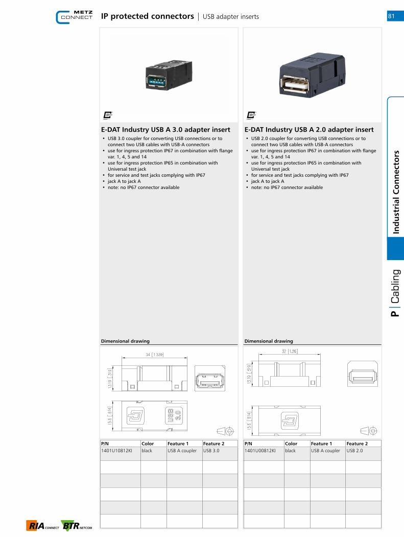
IP protected connectors | USB adapter inserts
E-DAT Industry USB A 2.0 adapter insert• USB 2.0 coupler for converting USB connections or to
connect two USB cables with USB-A connectors• use for ingress protection IP67 in combination with flange
var. 1, 4, 5 and 14• use for ingress protection IP65 in combination with
Universal test jack• for service and test jacks complying with IP67• jack A to jack A• note: no IP67 connector available
P/N Color Feature 1 Feature 21401U00812KI black USB A coupler USB 2.0
Dimensional drawing
81
1
Ind
ust
rial
Co
nn
ecto
rs
E-DAT Industry USB A 3.0 adapter insert• USB 3.0 coupler for converting USB connections or to
connect two USB cables with USB-A connectors• use for ingress protection IP67 in combination with flange
var. 1, 4, 5 and 14• use for ingress protection IP65 in combination with
Universal test jack• for service and test jacks complying with IP67• jack A to jack A• note: no IP67 connector available
P/N Color Feature 1 Feature 21401U10812KI black USB A coupler USB 3.0
Dimensional drawing
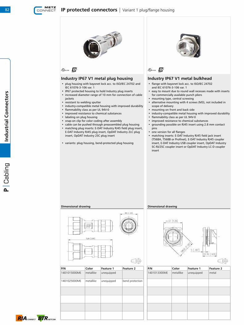
IP protected connectors | Variant 1 plug/flange housing
Industry IP67 V1 metal plug housing• plug housing with bayonet lock acc. to ISO/IEC 24702 and
IEC 61076-3-106 var. 1• IP67 protected housing to hold Industry plug inserts• increased diameter range of 10 mm for connection of cable
jackets• resistant to welding sputter• industry-compatible metal housing with improved durability• flammability class as per UL 94V-0• improved resistance to chemical substances• labeling on plug housing• snap-on clip for color coding after assembly• cable can be pushed through preassembled plug housing• matching plug inserts: E-DAT Industry RJ45 field plug insert,
E-DAT Industry RJ45 plug insert, OpDAT Industry 2LC plug insert, OpDAT Industry 2SC plug insert
• variants: plug housing, bend-protected plug housing
P/N Color Feature 1 Feature 21401015000ME metallike unequipped
1401025000ME metallike unequipped bend protection
Dimensional drawing
Industry IP67 V1 metal bulkhead• flange with bayonet lock acc. to ISO/IEC 24702
and IEC 61076-3-106 var. 1• easy to mount due to round wall recesses made with inserts
for commercially available punch pliers• mounting type, central screwing• alternative mounting with 4 screws (M3), not included in
scope of delivery• mounting on front and back side• industry-compatible metal housing with improved durability• flammability class as per UL 94V-0• improved resistance to chemical substances• grounding possible on RJ45 insert using 2.8 mm contact
pins• one version for all flanges• matching inserts: E-DAT Industry RJ45 field jack insert
(T568A, T568B or Profinet), E-DAT Industry RJ45 coupler insert, E-DAT Industry USB coupler insert, OpDAT Industry SC-RJ/2SC coupler insert or OpDAT Industry LC-D coupler insert
P/N Color Feature 1 Feature 21401013300ME metallike unequipped metal
Dimensional drawing
82In
du
stri
al C
on
nec
tors

IP protected connectors | Variant 1 plug/flange housing
Industry IP67 V1 plug housing• plug housing with bayonet lock acc. to ISO/IEC 24702
and IEC 61076-3-106 var. 1• IP67 protected housing to hold Industry plug inserts• increased diameter range of 10 mm for connection of cable
jackets• resistant to welding sputter• industry-compatible plastic housing with improved
durability• flammability class as per UL 94V-0• improved resistance to chemical substances• labeling on plug housing• snap-on clip for color coding after assembly• cable can be pushed through preassembled plug housing• matching plug inserts: E-DAT Industry RJ45 field plug insert,
E-DAT Industry RJ45 plug insert, OpDAT Industry 2LC plug insert, OpDAT Industry 2SC plug insert
• variants: plug housing, bend-protected plug housing
P/N Color Feature 1 Feature 21401015002KE black unequipped
1401025002KE black unequipped bend protection
Dimensional drawing
Industry IP67 V1 bulkhead• flange with bayonet lock acc. to ISO/IEC 24702
and IEC 61076-3-106 var. 1• easy to mount due to round wall recesses made with inserts
for commercially available punch pliers• mounting type, central screwing• alternative mounting with 4 screws (M3), not included in
scope of delivery• mounting on front and back side• industry-compatible plastic housing with improved
durability• flammability class as per UL 94V-0• improved resistance to chemical substances• grounding possible on RJ45 insert using 2.8 mm contact
pins• one version for all flanges• matching inserts: E-DAT Industry RJ45 field jack insert
(T568A, T568B or Profinet), E-DAT Industry RJ45 coupler insert, E-DAT Industry USB coupler insert, OpDAT Industry SC-RJ/2SC adapter insert or OpDAT Industry LC-D adapter insert
P/N Color Feature 1 Feature 21401013302KE black unequipped plastics
Dimensional drawing
83
1
Ind
ust
rial
Co
nn
ecto
rs
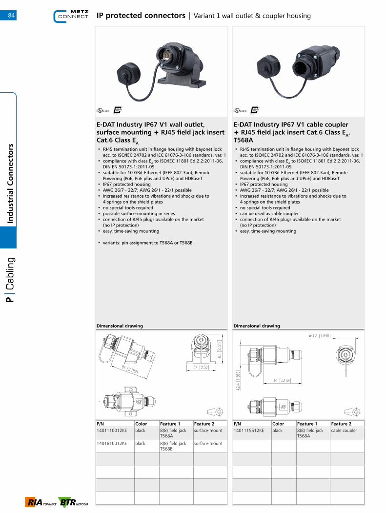
IP protected connectors | Variant 1 wall outlet & coupler housing
E-DAT Industry IP67 V1 wall outlet, surface mounting + RJ45 field jack insert Cat.6 Class EA
• RJ45 termination unit in flange housing with bayonet lock acc. to ISO/IEC 24702 and IEC 61076-3-106 standards, var. 1
• compliance with class EA to ISO/IEC 11801 Ed.2.2:2011-06, DIN EN 50173-1:2011-09
• suitable for 10 GBit Ethernet (IEEE 802.3an), Remote Powering (PoE, PoE plus and UPoE) and HDBaseT
• IP67 protected housing• AWG 26/7 - 22/7; AWG 26/1 - 22/1 possible• increased resistance to vibrations and shocks due to
4 springs on the shield plates• no special tools required• possible surface-mounting in series• connection of RJ45 plugs available on the market
(no IP protection)• easy, time-saving mounting
• variants: pin assignment to T568A or T568B
P/N Color Feature 1 Feature 21401110012KE black 8(8) field jack
T568Asurface-mount
1401810012KE black 8(8) field jack T568B
surface-mount
Dimensional drawing
E-DAT Industry IP67 V1 cable coupler+ RJ45 field jack insert Cat.6 Class EA, T568A• RJ45 termination unit in flange housing with bayonet lock
acc. to ISO/IEC 24702 and IEC 61076-3-106 standards, var. 1• compliance with class EA to ISO/IEC 11801 Ed.2.2:2011-06,
DIN EN 50173-1:2011-09• suitable for 10 GBit Ethernet (IEEE 802.3an), Remote
Powering (PoE, PoE plus and UPoE) and HDBaseT• IP67 protected housing• AWG 26/7 - 22/7; AWG 26/1 - 22/1 possible• increased resistance to vibrations and shocks due to
4 springs on the shield plates• no special tools required• can be used as cable coupler• connection of RJ45 plugs available on the market
(no IP protection)• easy, time-saving mounting
P/N Color Feature 1 Feature 21401115512KE black 8(8) field jack
T568Acable coupler
Dimensional drawing
84In
du
stri
al C
on
nec
tors
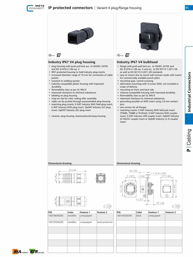
IP protected connectors | Variant 4 plug/flange housing
Industry IP67 V4 plug housing• plug housing with push-pull-lock acc. to ISO/IEC 24702
and IEC 61076-3-106 var. 4• IP67 protected housing to hold Industry plug inserts• increased diameter range of 10 mm for connection of cable
jackets• resistant to welding sputter• industry-compatible plastic housing with improved
durability• flammability class as per UL 94V-0• improved resistance to chemical substances• labeling on plug housing• snap-on clip for color coding after assembly• cable can be pushed through preassembled plug housing• matching plug inserts: E-DAT Industry RJ45 field plug insert,
E-DAT Industry RJ45 plug insert, OpDAT Industry 2LC plug insert, OpDAT Industry 2SC plug insert
• variants: plug housing, bend-protected plug housing
P/N Color Feature 1 Feature 21401045002KE metallike unequipped
1401055002KE metallike unequipped bend protection
Dimensional drawing
Industry IP67 V4 bulkhead• flange with push-pull-lock acc. to ISO/IEC 24702 and
IEC 61076-3-106 var. 4 and acc. to EN 50173-1:2011-09 as well as EN 50173-3:2011-09 standards
• easy to mount due to round wall recesses made with inserts for commercially available punch pliers
• mounting type, central screwing• alternative mounting with 4 screws (M3), not included in
scope of delivery• mounting on front and back side• industry-compatible housing with improved durability• flammability class as per UL 94V-0• improved resistance to chemical substances• grounding possible on RJ45 insert using 2.8 mm contact
pins• one version for all flanges• matching inserts: E-DAT Industry RJ45 field jack insert
(T568A, T568B or Profinet), E-DAT Industry RJ45 coupler insert, E-DAT Industry USB coupler insert, OpDAT Industry SC-RJ/2SC coupler insert or OpDAT Industry LC-D coupler insert
P/N Color Feature 1 Feature 21401043302KE black unequipped
Dimensional drawing
85
1
Ind
ust
rial
Co
nn
ecto
rs

IP protected connectors | Variant 4 wall outlet & coupler housing
E-DAT Industry IP67 V4 AP + RJ45 field jack insert Cat.6 Class EA, T568A• RJ45 termination unit in flange housing with push-pull-lock
acc. to ISO/IEC 24702 and IEC 61076-3-106 standards, var. 4• compliance with class EA to ISO/IEC 11801 Ed.2.2:2011-06,
DIN EN 50173-1:2011-09• suitable for 10 GBit Ethernet (IEEE 802.3an), Remote
Powering (PoE, PoE plus and UPoE) and HDBaseT• IP67 protected housing• AWG 26/7 - 22/7; AWG 26/1 - 22/1 possible• increased resistance to vibrations and shocks due to
4 springs on the shield plates• no special tools required• possible surface-mounting in series• connection of RJ45 plugs available on the market
(no IP protection)• easy, time-saving mounting
P/N Color Feature 1 Feature 21401140012KE black 8(8) field jack
T568Asurface-mount
Dimensional drawing
E-DAT Industry IP67 V4 cable coupler+ RJ45 field jack insert Cat.6 Class EA, T568A• RJ45 termination unit in flange housing with push-pull-lock
acc. to ISO/IEC 24702 and IEC 61076-3-106 standards, var. 4• compliance with class EA to ISO/IEC 11801 Ed.2.2:2011-06,
DIN EN 50173-1:2011-09• suitable for 10 GBit Ethernet (IEEE 802.3an), Remote
Powering (PoE, PoE plus and UPoE) and HDBaseT• IP67 protected housing• AWG 26/7 - 22/7; AWG 26/1 - 22/1 possible• increased resistance to vibrations and shocks due to
4 springs on the shield plates• no special tools required• can be used as cable coupler• connection of RJ45 plugs available on the market
(no IP protection)• easy, time-saving mounting
• variants: marking of conductor assignment to T568A or T568B
P/N Color Feature 1 Feature 21401145512KE black 8(8) field jack
T568Acable coupler
1401845512KE black 8(8) field jack T568B
cable coupler
1401045512KE black unequipped cable coupler
Dimensional drawing
86In
du
stri
al C
on
nec
tors

IP protected connectors | Variant 5 plug/flange housing
Industry IP67 V5 metal plug housing• plug housing with clamp lock acc. to ISO/IEC 24702
and IEC 61076-3-106 var. 5• IP67 protected housing to hold Industry plug inserts• increased diameter range of 10 mm for connection of cable
jackets• resistant to welding sputter• industry-compatible metal housing with improved durability• flammability class as per UL 94V-0• improved resistance to chemical substances• snap-on clip for color coding after assembly• cable can be pushed through preassembled plug housing• matching plug inserts: E-DAT Industry RJ45 field plug insert,
E-DAT Industry RJ45 plug insert
P/N Color Feature 1 Feature 21401065000ME gray unequipped
Dimensional drawing
Industry IP67 V5 metal bulkhead• flange with clamp lock acc. to IEC 61076-3-106 Var. 5• IP67 protected housing for receiving E-DAT Industry flange
inserts• easy to mount due to standard fastening by means of two
screws (M3), not included in scope of delivery• industry-compatible housing with improved durability• flammability class as per UL 94V-0• improved resistance to chemical substances• grounding possible on RJ45 insert using 2.8 mm contact
pins• matching inserts: E-DAT Industry RJ45 field jack insert
(T568A, T568B or Profinet), E-DAT Industry RJ45 coupler insert or E-DAT Industry USB coupler insert
P/N Color Feature 1 Feature 21401063300ME gray unequipped
Dimensional drawing
87
1
Ind
ust
rial
Co
nn
ecto
rs
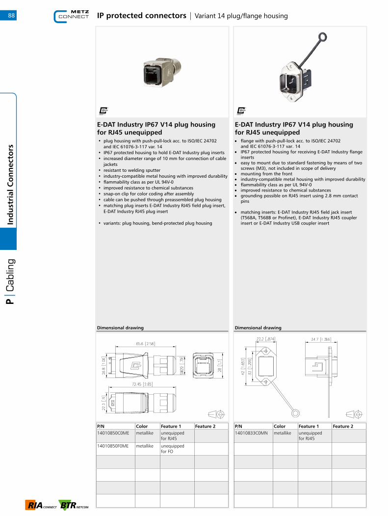
IP protected connectors | Variant 14 plug/flange housing
E-DAT Industry IP67 V14 plug housing for RJ45 unequipped• plug housing with push-pull-lock acc. to ISO/IEC 24702
and IEC 61076-3-117 var. 14• IP67 protected housing to hold E-DAT Industry plug inserts• increased diameter range of 10 mm for connection of cable
jackets• resistant to welding sputter• industry-compatible metal housing with improved durability• flammability class as per UL 94V-0• improved resistance to chemical substances• snap-on clip for color coding after assembly• cable can be pushed through preassembled plug housing• matching plug inserts E-DAT Industry RJ45 field plug insert,
E-DAT Industry RJ45 plug insert
• variants: plug housing, bend-protected plug housing
P/N Color Feature 1 Feature 214010850C0ME metallike unequipped
for RJ45
14010850F0ME metallike unequipped for FO
Dimensional drawing
E-DAT Industry IP67 V14 plug housing for RJ45 unequipped• flange with push-pull-lock acc. to ISO/IEC 24702
and IEC 61076-3-117 var. 14• IP67 protected housing for receiving E-DAT Industry flange
inserts• easy to mount due to standard fastening by means of two
screws (M3), not included in scope of delivery• mounting from the front• industry-compatible metal housing with improved durability• flammability class as per UL 94V-0• improved resistance to chemical substances• grounding possible on RJ45 insert using 2.8 mm contact
pins
• matching inserts: E-DAT Industry RJ45 field jack insert (T568A, T568B or Profinet), E-DAT Industry RJ45 coupler insert or E-DAT Industry USB coupler insert
P/N Color Feature 1 Feature 214010833C0MN metallike unequipped
for RJ45
Dimensional drawing
88In
du
stri
al C
on
nec
tors

IP protected connectors | Variant 14 fiber optic flange housing set
OpDAT Industry IP67 V14 bulkhead normative mounting + LC-D SM adapter insert• flange with push-pull-lock acc. to ISO/IEC 24702
and IEC 61076-3-117 var. 14• fiber optic cable adapter made of plastic• slotted zirconium oxide ceramics sleeve (ZrO2) for single
mode applications• slotted metal sleeve (Ph-Br) for multi mode applications• compliance with EN 50173-1:2011-09 and ISO/IEC 24702
with regard to limit values for insertion loss• flame-retardant and halogen-free plastic housing and
adapter dust covers• easy to mount due to standard fastening by means of two
screws (M3)• mounting from the front• industry-compatible metal housing with improved durability• flammability class as per UL 94V-0• improved resistance to chemical substances
• variants: LC-D blue (SM), beige (MM) SC-RJ/2SC blue (SM), beige (MM)
P/N Color Feature 1 Feature 21402L93320ME metallike LC-D (ceramic)
SM
1402K93320ME metallike 2SC (SM)
1402393320ME metallike LC-D (MM)
1402193320ME metallike 2SC (MM)
Dimensional drawing
OpDAT Industry IP67 V14 bulkhead central screw mounting+ LC-D SM adapter insert• flange with push-pull-lock acc. to ISO/IEC 24702
and IEC 61076-3-117 var. 14• fiber optic cable adapter made of plastic• slotted zirconium oxide ceramics sleeve (ZrO2) for single
mode applications• slotted metal sleeve (Ph-Br) for multi mode applications• compliance with EN 50173-1:2011-09 and ISO/IEC 24702
with regard to limit values for insertion loss• flame-retardant and halogen-free plastic housing and
adapter dust covers• easy to mount due to round wall recesses made with inserts
for commercially available punch pliers• mounting from the front• industry-compatible metal housing with improved durability• flammability class as per UL 94V-0• improved resistance to chemical substances
• variants: LC-D blue (SM), beige (MM) SC-RJ/2SC blue (SM), beige (MM)
P/N Color Feature 1 Feature 21402L83320ME metallike LC-D (ceramic)
SM
1402K83320ME metallike 2SC (SM)
1402383320ME metallike LC-D (MM)
1402183320ME metallike 2SC (MM)
Dimensional drawing
89
1
Ind
ust
rial
Co
nn
ecto
rs

IP protected connectors | Variant 6 plug & cable
E-DAT Industry IP67 V6 plug• Cat.6 class EA connector in connector housing
to IEC 61076-3-106 var. 6• compliance with class EA to ISO/IEC 11801 Ed.2.2:2011-06,
DIN EN 50173-1:2011-09• suitable for 10 GBit Ethernet(IEEE 802.3an) and Remote
Powering(PoE, PoE plus and UPoE) and HDBaseT• complies with ingress protection IP67 when plugged in• AWG 27/7 - 24/7 and AWG 24/1 connection possible• solid copper wire diameter from 0.36 to 0.51 mm• stranded copper wire diameter from 0.46 to 0.61 mm• conductor diameter from 0.85 to 1.05 mm• cable jacket up to 7.3 mm can be connected• large 360° shield contact• locking clip can also be upgraded in its installed state• protected against unintentional opening by means of
locking clip (also colored)• crimping of the internal and external conductors with
professional crimp pliers in one process• professional crimping tool available in the tools section
P/N Color Feature 1 Feature 2130906-03-E light gray 8(8)
Dimensional drawing
E-DAT Industry patch cord V6 IP67 - IP67• fully shielded Cat.6 patch cable AWG 26/7 S/FTP with PUR
cable sheath• RJ45-IP67-V6 connector shielded on both ends• 1:1 assignment• compliance with class E to ISO/IEC 11801 Ed.2.2:2011-06,
DIN EN 50173-1:2011-09• yellow cable, gray connector• cable colors may differ• other lengths available
• variants: 1, 2, 5, 10, 15 and 20 m
P/N Color Feature 1 Feature 2141N113K13K10 yellow 1.0 m IP67-IP67
141N113K13K20 yellow 2.0 m IP67-IP67
141N113K13K50 yellow 5.0 m IP67-IP67
141N113K13KA0 yellow 10.0 m IP67-IP67
141N113K13KA5 yellow 15.0 m IP67-IP67
141N113K13KB0 yellow 20.0 m IP67-IP67
Dimensional drawing
90In
du
stri
al C
on
nec
tors

IP protected connectors | Variant 6 cable & flange housing
E-DAT Industry patch cord V6 IP67 - RJ45• fully shielded Cat.6 patch cable AWG 26/7 S/FTP with PUR
cable sheath• 1 x RJ45 and 1 x RJ45-IP67-V6 connector, shielded• 1:1 assignment• compliance with class E to ISO/IEC 11801 Ed.2.2:2011-06,
DIN EN 50173-1:2011-09• yellow cable, gray connector• cable colors may differ• other lengths available
• variants: 1, 2, 3, 5, 10, 15 and 20 m
P/N Color Feature 1 Feature 2141N113K10010 yellow 1.0 m IP67-RJ45
141N113K10020 yellow 2.0 m IP67-RJ45
141N113K10050 yellow 5.0 m IP67-RJ45
141N113K100A0 yellow 10.0 m IP67-RJ45
141N113K100A5 yellow 15.0 m IP67-RJ45
141N113K100B0 yellow 20.0 m IP67-RJ45
Dimensional drawing
E-DAT Industry IP67 V6 EbM• for mounting individual modules in Modul design• IP67 plug face pursuant to IEC 61076-3-106 (Variant 6)• connection of RJ45 plugs available on the market (no IP
protection)• easy mounting• versions with and without solid counterplate made of zinc
die-cast (also available as accessory)• color: RAL 7035 (light gray)• 13094130-E: mounting set consisting of solid counterplate
with 4 screws• not suited to E-DAT industry modules and adapter
• variants: with and without mounting set
P/N Color Feature 1 Feature 21309413003-E lightgray w/o mounting
setModule cut-out
1309413203-E lightgray with mounting set
Module cut-out
Dimensional drawing
91
1
Ind
ust
rial
Co
nn
ecto
rs
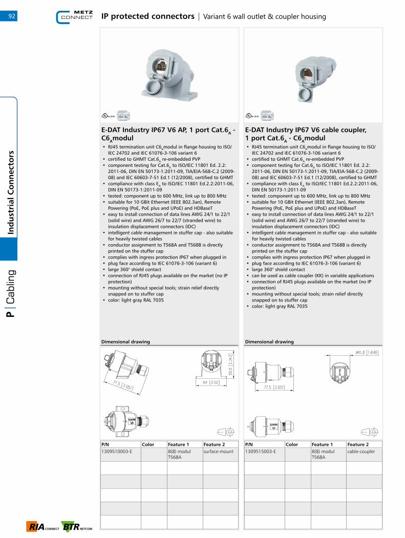
IP protected connectors | Variant 6 wall outlet & coupler housing
E-DAT Industry IP67 V6 AP, 1 port Cat.6A - C6Amodul• RJ45 termination unit C6Amodul in flange housing to ISO/
IEC 24702 and IEC 61076-3-106 variant 6• certified to GHMT Cat.6A re-embedded PVP• component testing for Cat.6A to ISO/IEC 11801 Ed. 2.2:
2011-06, DIN EN 50173-1:2011-09, TIA/EIA-568-C.2 (2009-08) and IEC 60603-7-51 Ed.1 (12/2008), certified to GHMT
• compliance with class EA to ISO/IEC 11801 Ed.2.2:2011-06, DIN EN 50173-1:2011-09
• tested: component up to 600 MHz, link up to 800 MHz• suitable for 10 GBit Ethernet (IEEE 802.3an), Remote
Powering (PoE, PoE plus and UPoE) and HDBaseT• easy to install connection of data lines AWG 24/1 to 22/1
(solid wire) and AWG 26/7 to 22/7 (stranded wire) to insulation displacement connectors (IDC)
• intelligent cable management in stuffer cap - also suitable for heavily twisted cables
• conductor assignment to T568A and T568B is directly printed on the stuffer cap
• complies with ingress protection IP67 when plugged in• plug face according to IEC 61076-3-106 (variant 6)• large 360° shield contact• connection of RJ45 plugs available on the market (no IP
protection)• mounting without special tools; strain relief directly
snapped on to stuffer cap• color: light gray RAL 7035
P/N Color Feature 1 Feature 21309510003-E 8(8) modul
T568Asurface-mount
Dimensional drawing
E-DAT Industry IP67 V6 cable coupler, 1 port Cat.6A - C6Amodul• RJ45 termination unit C6Amodul in flange housing to ISO/
IEC 24702 and IEC 61076-3-106 variant 6• certified to GHMT Cat.6A re-embedded PVP• component testing for Cat.6A to ISO/IEC 11801 Ed. 2.2:
2011-06, DIN EN 50173-1:2011-09, TIA/EIA-568-C.2 (2009-08) and IEC 60603-7-51 Ed.1 (12/2008), certified to GHMT
• compliance with class EA to ISO/IEC 11801 Ed.2.2:2011-06, DIN EN 50173-1:2011-09
• tested: component up to 600 MHz, link up to 800 MHz• suitable for 10 GBit Ethernet (IEEE 802.3an), Remote
Powering (PoE, PoE plus and UPoE) and HDBaseT• easy to install connection of data lines AWG 24/1 to 22/1
(solid wire) and AWG 26/7 to 22/7 (stranded wire) to insulation displacement connectors (IDC)
• intelligent cable management in stuffer cap - also suitable for heavily twisted cables
• conductor assignment to T568A and T568B is directly printed on the stuffer cap
• complies with ingress protection IP67 when plugged in• plug face according to IEC 61076-3-106 (variant 6)• large 360° shield contact• can be used as cable coupler (KK) in variable applications• connection of RJ45 plugs available on the market (no IP
protection)• mounting without special tools; strain relief directly
snapped on to stuffer cap• color: light gray RAL 7035
P/N Color Feature 1 Feature 21309515003-E 8(8) modul
T568Acable-coupler
Dimensional drawing
92In
du
stri
al C
on
nec
tors

IP protected connectors | Variant 6 locking clamp / IP67 metal outlet
Locking clamp for IP67 V6 plug• protection against unintentional opening• locking clip can also be upgraded in its installed state
• variants: light gray, yellow, blue, green, red
P/N Color Feature 1 Feature 2130906-V3-I light gray plastics
130906-V5-I yellow plastics
130906-V6-I blue plastics
130906-V7-I green plastics
130906-V8-I red plastics
Dimensional drawing
E-DAT Industry IP67 V1 2 port metal outlet• IP67 wall outlets for flexible connection of networks in
industrial areas• 2 complete ports with flange covers and cable glands• with the output directions pointing straight downwards
(with cable feed from above) or output direction to right (with cable feed from above)
• metal flange with bayonet to ISO/IEC 24702 and IEC 61076-3-106 standards, var. 1
• unequipped, without inserts• for wall and floor mounting• aluminum housing made of AL-Si 12• solid powder coating in RAL 7001• dimensions, 2 ports: 124 x 78 x 57 mm (without flanges
and cable glands)• matching inserts: E-DAT Industry RJ45 field jack insert
(T568A, T568B or Profinet), E-DAT Industry RJ45 coupler insert, E-DAT Industry USB coupler insert, OpDAT Industry SC-RJ/2SC coupler insert or OpDAT Industry LC-D coupler insert
P/N Color Feature 1 Feature 21401010620ME gray 2 port straight unequipped
1401040620ME gray 2 port straight unequipped
1401060320ME gray 2 port straight unequipped
Dimensional drawing
93
1
Ind
ust
rial
Co
nn
ecto
rs

IP protected connectors | Protective caps for IP67 housings
Industry IP67 V1 plug protective cap• good ingress protection also if not plugged in due to tight
IP67 protective cap• flammability class as per UL 94V-0• improved resistance to chemical substances• captive, attached protective cap
• variants: protective cap for plug or flange
P/N Color Feature 1 Feature 21401018002KI black plastic for plugs
1401018102KI black plastic for flange
Dimensional drawing
Industry IP67 V4 plug protective cap• good ingress protection also if not plugged in due to tight
IP67 protective cap• flammability class as per UL 94V-0• improved resistance to chemical substances• captive, attached protective cap• grip to remove it
• variants: protective cap for plug or flange
P/N Color Feature 1 Feature 21401048002KI black plastic for plugs
1401048102KI black plastic for flange
Dimensional drawing
94In
du
stri
al C
on
nec
tors
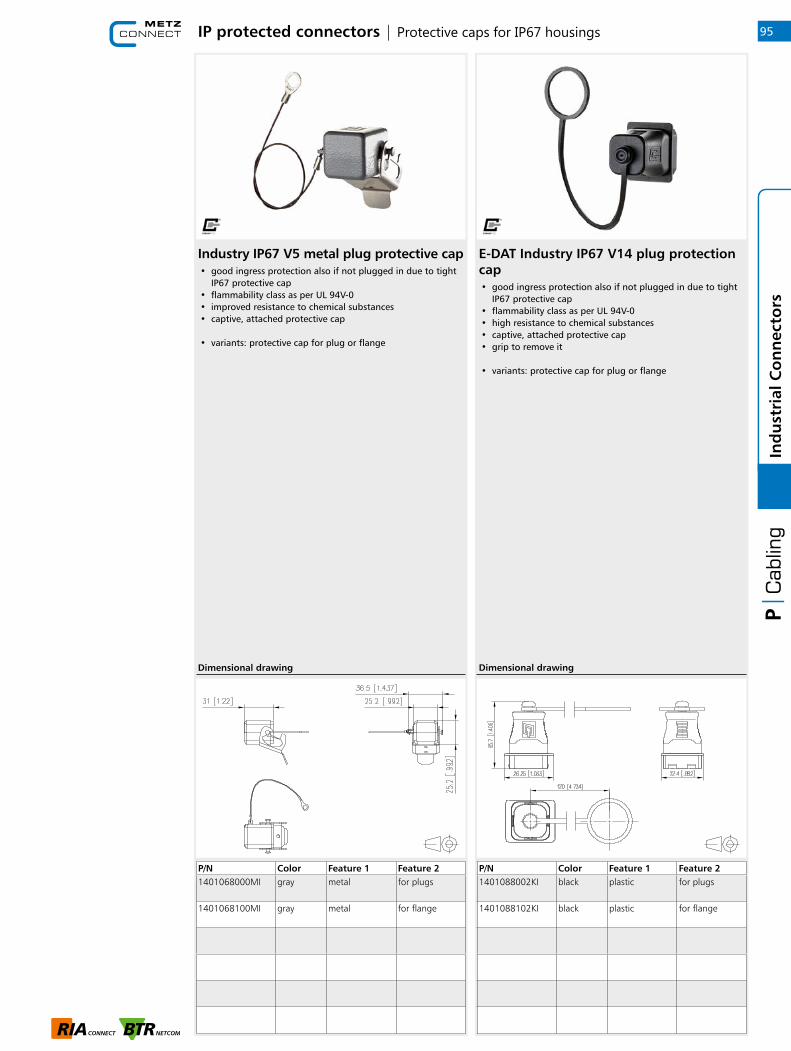
IP protected connectors | Protective caps for IP67 housings
Industry IP67 V5 metal plug protective cap• good ingress protection also if not plugged in due to tight
IP67 protective cap• flammability class as per UL 94V-0• improved resistance to chemical substances• captive, attached protective cap
• variants: protective cap for plug or flange
P/N Color Feature 1 Feature 21401068000MI gray metal for plugs
1401068100MI gray metal for flange
Dimensional drawing
E-DAT Industry IP67 V14 plug protection cap• good ingress protection also if not plugged in due to tight
IP67 protective cap• flammability class as per UL 94V-0• high resistance to chemical substances• captive, attached protective cap• grip to remove it
• variants: protective cap for plug or flange
P/N Color Feature 1 Feature 21401088002KI black plastic for plugs
1401088102KI black plastic for flange
Dimensional drawing
95
1
Ind
ust
rial
Co
nn
ecto
rs

IP protected connectors | Universal test jack housing for Steadytec inserts
E-DAT Industry universal test jack IP65, unequipped• for programming and setting parameters of an installation,
a computer is accessed via standardized interfaces, such as RJ45 and USB. For industrial PCs (IPC), however, these interfaces are located in the interior of the switch cabinet.
• practical service interface for safe and flexible access to the interior of the switch cabinet
• faster, easier and more targeted start-up, service work, monitoring and system expansions
• suitable for switch cabinet walls, distributor panels and switchboards
• mounting with central screw joint in standard round hole of just 22 mm
• ingress protection IP65• captive sealing plug• very easy handling• unequipped - without inserts• matching inserts: E-DAT Industry RJ45 field jack insert
(T568A, T568B or Profinet), E-DAT Industry RJ45 coupler insert or E-DAT Industry USB coupler insert
P/N Color Feature 1 Feature 2140UPB-E black unequipped
Dimensional drawing
96In
du
stri
al C
on
nec
tors

RJ45 Plug | Field plug pro
C6A RJ45 field plug pro• Cat.6A class EA RJ45 plug to be assembled in the field• fully shielded and multi-port capable• straight (180°) cable feed• easy assembly - connection without special tools• wire connection: stranded wire AWG 27/7 to 22/7,
wire diameter from 0.46 to 0.76 mm• wire connection: solid wire AWG 26/1 to 22/1,
wire diameter from 0.4 to 0.64 mm• transmission characteristics Cat.6A per ISO/IEC 11801
Ed.2.2:2011-06• compliance with class EA to ISO/IEC 11801 Ed.2.2:2011-06,
DIN EN 50173-1:2011-09• suitable for 10 GBit Ethernet (IEEE 802.3an), Remote
Powering (PoE, PoE plus, UPoE and 4PPoE) and HDBaseT• degree of protection IP20• for cable jacket diameter from 5.5 to 10.5 mm• zinc die-cast housing for industrial use consists of only
2 parts• strain relief by latching clip directly on the stuffer cap• protected locking hook• reconnectable
P/N Color Feature 1 Feature 2130E405032-E black 8(8) field plug 180°
Dimensional drawing
C5 RJ45 field plug pro 2P PROFINET
P/N Color Feature 1 Feature 2130E405032PE green Profinet 180°
Dimensional drawing
• Cat.5 class D RJ45 plug, 2 pairs, to be assembled in the field• fully shielded and multi-port capable• straight (180°) cable feed• easy assembly - connection without special tools• wire connection: stranded wire AWG 27/7 to 22/7,
wire diameter from 0.46 to 0.76 mm• wire connection: solid wire AWG 26/1 to 22/1,
wire diameter from 0.4 to 0.64 mm• transmission characteristics Cat.5 per ISO/IEC 11801
Ed.2.2:2011-06• compliance with class D to ISO/IEC 11801 Ed.2.2:2011-06,
DIN EN 50173-1:2011-09• 100 MBit suitable according to IEEE 802.3• suitable for Remote Powering (PoE and PoE plus)
and HDBaseT• degree of protection IP20• for cable jacket diameter from 5.5 to 10.5 mm• zinc die-cast housing for industrial use consists of only
2 parts• strain relief by latching clip directly on the stuffer cap• protected locking hook• reconnectable
97
1
Ind
ust
rial
Co
nn
ecto
rs

RJ45 Plug | Field plug pro 360
C6A RJ45 field plug pro 360
P/N Color Feature 1 Feature 2130E405042-E black 8(8) field plug 360°
Dimensional drawing
• Cat.6A class EA RJ45 plug to be assembled in the field• fully shielded and multi-port capable• variable (360°) cable feed, freely selectable• easy assembly - connection without special tools• wire connection: stranded wire AWG 27/7 to 22/7,
wire diameter from 0.46 to 0.76 mm• wire connection: solid wire AWG 26/1 to 22/1,
wire diameter from 0.4 to 0.64 mm• transmission characteristics Cat.6A per ISO/IEC 11801
Ed.2.2:2011-06• compliance with class EA to ISO/IEC 11801• Ed.2.2:2011-06, DIN EN 50173-1:2011-09• suitable for 10 GBit Ethernet (IEEE 802.3an), Remote
Powering (PoE, PoE plus, UPoE and 4PPoE) and HDBaseT• degree of protection IP20• for cable jacket from 5.5 to 10.5 mm• zinc die-cast housing for industrial use• strain relief by latching clip directly on the stuffer cap• protected locking hook• reconnectable
C5 RJ45 field plug pro 2P 360 PROFINET
P/N Color Feature 1 Feature 2130E405042PE green Profinet 360°
Dimensional drawing
• Cat.5 class D RJ45 plug, 2 pairs, to be assembled in the field• fully shielded and multi-port capable• variable (360°) cable feed, freely selectable• easy assembly - connection without special tools• wire connection: stranded wire AWG 27/7 to 22/7,
wire diameter from 0.46 to 0.76 mm• wire connection: solid wire AWG 26/1 to 22/1,
wire diameter from 0.4 to 0.64 mm• transmission characteristics Cat.5 per ISO/IEC 11801
Ed.2.2:2011-06• compliance with class D to ISO/IEC 11801• Ed.2.2:2011-06, DIN EN 50173-1:2011-09• 100 MBit suitable according to IEEE 802.3• suitable for Remote Powering (PoE and PoE plus)
and HDBaseT• degree of protection IP20• for cable jacket from 5.5 to 10.5 mm• zinc die-cast housing for industrial use• strain relief by latching clip directly on the stuffer cap• protected locking hook• reconnectable
98In
du
stri
al C
on
nec
tors
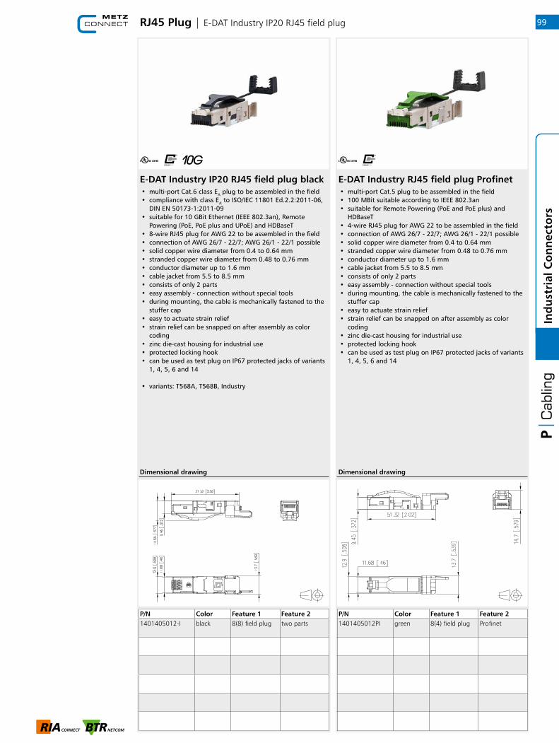
E-DAT Industry IP20 RJ45 field plug black E-DAT Industry RJ45 field plug Profinet
RJ45 Plug | E-DAT Industry IP20 RJ45 field plug
P/N Color Feature 1 Feature 21401405012-I black 8(8) field plug two parts
P/N Color Feature 1 Feature 21401405012PI green 8(4) field plug Profinet
Dimensional drawing Dimensional drawing
• multi-port Cat.6 class EA plug to be assembled in the field• compliance with class EA to ISO/IEC 11801 Ed.2.2:2011-06,
DIN EN 50173-1:2011-09• suitable for 10 GBit Ethernet (IEEE 802.3an), Remote
Powering (PoE, PoE plus and UPoE) and HDBaseT• 8-wire RJ45 plug for AWG 22 to be assembled in the field• connection of AWG 26/7 - 22/7; AWG 26/1 - 22/1 possible• solid copper wire diameter from 0.4 to 0.64 mm• stranded copper wire diameter from 0.48 to 0.76 mm• conductor diameter up to 1.6 mm• cable jacket from 5.5 to 8.5 mm• consists of only 2 parts• easy assembly - connection without special tools• during mounting, the cable is mechanically fastened to the
stuffer cap• easy to actuate strain relief• strain relief can be snapped on after assembly as color
coding• zinc die-cast housing for industrial use• protected locking hook• can be used as test plug on IP67 protected jacks of variants
1, 4, 5, 6 and 14
• variants: T568A, T568B, Industry
• multi-port Cat.5 plug to be assembled in the field• 100 MBit suitable according to IEEE 802.3an• suitable for Remote Powering (PoE and PoE plus) and
HDBaseT• 4-wire RJ45 plug for AWG 22 to be assembled in the field• connection of AWG 26/7 - 22/7; AWG 26/1 - 22/1 possible• solid copper wire diameter from 0.4 to 0.64 mm• stranded copper wire diameter from 0.48 to 0.76 mm• conductor diameter up to 1.6 mm• cable jacket from 5.5 to 8.5 mm• consists of only 2 parts• easy assembly - connection without special tools• during mounting, the cable is mechanically fastened to the
stuffer cap• easy to actuate strain relief• strain relief can be snapped on after assembly as color
coding• zinc die-cast housing for industrial use• protected locking hook• can be used as test plug on IP67 protected jacks of variants
1, 4, 5, 6 and 14
99
1
Ind
ust
rial
Co
nn
ecto
rs
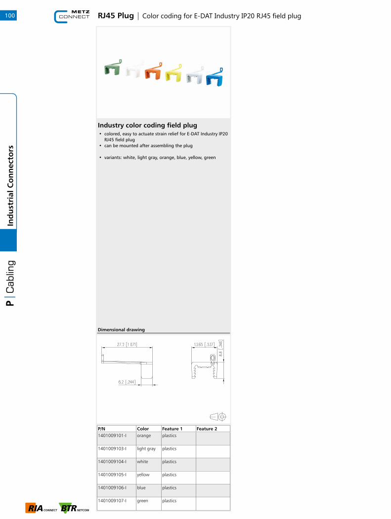
Industry color coding field plug• colored, easy to actuate strain relief for E-DAT Industry IP20
RJ45 field plug • can be mounted after assembling the plug
• variants: white, light gray, orange, blue, yellow, green
RJ45 Plug | Color coding for E-DAT Industry IP20 RJ45 field plug
P/N Color Feature 1 Feature 21401009101-I orange plastics
1401009103-I light gray plastics
1401009104-I white plastics
1401009105-I yellow plastics
1401009106-I blue plastics
1401009107-I green plastics
Dimensional drawing
100In
du
stri
al C
on
nec
tors
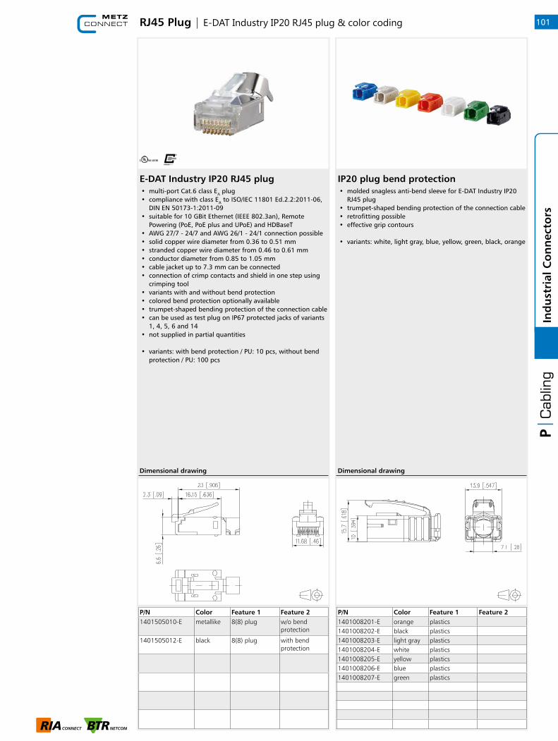
P/N Color Feature 1 Feature 21401008201-E orange plastics1401008202-E black plastics1401008203-E light gray plastics1401008204-E white plastics1401008205-E yellow plastics1401008206-E blue plastics1401008207-E green plastics
IP20 plug bend protection• molded snagless anti-bend sleeve for E-DAT Industry IP20
RJ45 plug • trumpet-shaped bending protection of the connection cable • retrofitting possible • effective grip contours
• variants: white, light gray, blue, yellow, green, black, orange
RJ45 Plug | E-DAT Industry IP20 RJ45 plug & color coding
Dimensional drawing
P/N Color Feature 1 Feature 21401505010-E metallike 8(8) plug w/o bend
protection
1401505012-E black 8(8) plug with bend protection
E-DAT Industry IP20 RJ45 plug
Dimensional drawing
• multi-port Cat.6 class EA plug• compliance with class EA to ISO/IEC 11801 Ed.2.2:2011-06,
DIN EN 50173-1:2011-09• suitable for 10 GBit Ethernet (IEEE 802.3an), Remote
Powering (PoE, PoE plus and UPoE) and HDBaseT• AWG 27/7 - 24/7 and AWG 26/1 - 24/1 connection possible• solid copper wire diameter from 0.36 to 0.51 mm• stranded copper wire diameter from 0.46 to 0.61 mm• conductor diameter from 0.85 to 1.05 mm• cable jacket up to 7.3 mm can be connected• connection of crimp contacts and shield in one step using
crimping tool• variants with and without bend protection• colored bend protection optionally available• trumpet-shaped bending protection of the connection cable• can be used as test plug on IP67 protected jacks of variants
1, 4, 5, 6 and 14• not supplied in partial quantities
• variants: with bend protection / PU: 10 pcs, without bend protection / PU: 100 pcs
101
1
Ind
ust
rial
Co
nn
ecto
rs
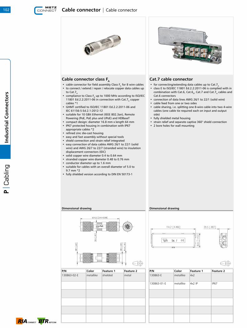
Cable connector class FA• cable connector for field assembly Class FA for 8 wire cables• to connect / extend / repair / relocate copper data cables up
to Cat.7A
• compliance to Class FA up to 1000 MHz according to ISO/IEC 11801 Ed.2.2:2011-06 in connection with Cat.7A copper cables *1
• GHMT certified to ISO/IEC 11801 Ed.2.2:2011-06 and IEC 61156-5 Ed.2.1:2012-12
• suitable for 10 GBit Ethernet (IEEE 802.3an), Remote Powering (PoE, PoE plus and UPoE) and HDBaseT
• compact design: diameter 16.8 mm x length 64 mm• IP67 protected housing in combination with IP67
appropriate cables *2• refined zinc die-cast housing• easy and fast assembly without special tools• shield connection and strain relief integrated• easy connection of data cables AWG 26/1 to 22/1 (solid
wire) and AWG 26/7 to 22/7 (stranded wire) to insulation displacement connectors (IDC)
• solid copper wire diameter 0.4 to 0.64 mm• stranded copper wire diameter 0.48 to 0.76 mm• conductor diameter up to 1.6 mm• suitable for cables with an overall diameter of 5.0 to
9.7 mm *2• fully shielded version according to DIN EN 50173-1
P/N Color Feature 1 Feature 2130863-02-E metallike shielded metal
Dimensional drawing
Cable connector | Cable connector
Cat.7 cable connector• for connecting/extending data cables up to Cat.7A
• class E to ISO/IEC 11801 Ed.2.2:2011-06 is complied with in combination with Cat.6, Cat.6A, Cat.7 and Cat.7A cables and Cat.6 connectors
• connection of data lines AWG 26/1 to 22/1 (solid wire)• cable feed from one or two sides• cable sharing, i.e. splitting one 8-wire cable into two 4-wire
cables (one cable tie required each on input and output side)
• fully shielded metal housing• strain relief and separate captive 360° shield connection• 2 bore holes for wall mounting
P/N Color Feature 1 Feature 2130863-E metallike 4x2
130863-01-E metallike 4x2 IP IP67
Dimensional drawing
102In
du
stri
al C
on
nec
tors

Modular wall outlets | TH35 rail & wall outlet
Extension box APL Keystone• for connection of the termination point line network (APL),
equipped with C6Amodul K 180° • suitable for mounting on support rail in counter panel
of general power supply below cover in room for additional applications to VDE-AR-N 4101:2011-08
• failsafe contact with integrated dust protector slide • for connection of an MUC communication module • certified to GHMT Cat.6A re-embedded PVP • component testing for Cat.6A to ISO/IEC 11801 Ed.2.2:2011-06,
DIN EN 50173-1:2011-09, TIA/EIA-568-C.2 (2009-08) and IEC 60603-7-51 Ed.1 (12/2008), certified to GHMT
• compliance with class EA up to 500 MHz to ISO/IEC 11801 Ed.2.2:2011-06, DIN EN 50173-1:2011-09
• tested: components up to 600 MHz, link up to 800 MHz • for 10 GBit Ethernet (IEEE 802.3an) • suitable for Power over Ethernet (PoE, PoE plus and UPoE) • connection of data lines AWG 26/1 to 22/1 (solid wire)
and AWG 26/7 to 22/7 (stranded wire) to insulation displacement connectors (IDC)
• plug direction of module inclined at 90° to top hat rail • strain relief snapped on to stuffer cap • with label window for enclosed identification labels • cover parts in pure white RAL 9010, glossy surface
• variants: APL, APL with red patch cord (0.5 m)
P/N Color Feature 1 Feature 2130B21D1APL-E pure white AP 1 Port
equippedC6Amodul Keystone
130B21D1APLP-E pure white AP 1 Port equipped
with patch cord C6Amodul Key.
130910D1APLKE pure white equipped E-DAT modul Keystone
Dimensional drawing
Modul wall outlet APFL 2 port pure white unequipped
P/N Color Feature 1 Feature 21309150102-E pure white AP 2 Port
unequippedModule cut-out
Dimensional drawing
• flat surface-mounted housing for two individual modules in Modul design (E-DAT modul, C6Amodul)
• label window for identification labels (labels included in the delivery)
• mounting in underfloor false floors• colored coding of the ports (red/blue)• ideal for implementing consolidation points
103
1
Ind
ust
rial
Co
nn
ecto
rs

Modular wall outlets | Modular wall outlets
Modul IP44SG surface mounting housing unequipped
P/N Color Feature 1 Feature 21309460003-I gray AP 2 port
unequippedModule cut-out
1309460003KI gray AP 2 port unequipped
Keystonemodule cut-out
Dimensional drawing
• lockable flush-mounted IP44 outlet, keyed alike with two keys (identical locks and keys)
• cover closes completely, even when patch cables are plugged in
• for two individual modules in Modul design (not suitable for OpDAT modules)
• ball-impact resistant according to DIN 18032• can be operated with standard patch cables• clearly visible label window• bottom section of housing can be turned 180°, with cable
feed possible from top and bottom• with space to install the required spare cable lengths• gray
E-DAT modul IP44SG UP housing pure white unequipped
P/N Color Feature 1 Feature 21309461002-I pure white UP 2 Port
unequippedModule cut-out
1309461003-I pure white UP 2 Port unequipped
Module cut-out
Dimensional drawing
• lockable IP44 outlet, with two keys with lock with instantaneous locking action (identical locks and keys)
• cover closes completely, even when patch cables are plugged in
• UP housing for sill duct installation, or in conjunction with the flush-mounted UP installation outlet
• for two individual modules in Modul design• ball-throw proof according to DIN 18032• can be operated with standard patch cables• clearly visible nomenclature panel
• variants: pure white, gray
104In
du
stri
al C
on
nec
tors

Modular wall outlets | Flush mount built-in outlet
Flush mount built-in outlet gray• UP installation outlet for flush mounting of the IP44SG UP
housing
P/N Color Feature 1 Feature 21309441903-I gray
105
1
Ind
ust
rial
Co
nn
ecto
rs
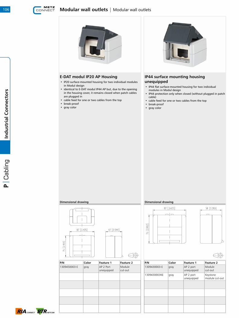
IP44 surface mounting housing unequipped• IP44 flat surface-mounted housing for two individual
modules in Modul design• IP44 protection only when closed (without plugged in patch
cable)• cable feed for one or two cables from the top• break-proof• gray color
P/N Color Feature 1 Feature 21309430003-E gray AP 2 port
unequippedModule cut-out
1309430003KE gray AP 2 port unequipped
Keystone module cut-out
Dimensional drawing
E-DAT modul IP20 AP Housing
P/N Color Feature 1 Feature 21309450003-E gray AP 2 Port
unequippedModule cut-out
Dimensional drawing
• IP20 surface-mounted housing for two individual modules in Modul design
• identical to E-DAT modul IP44 AP but, due to the opening in the housing cover, it remains closed when patch cables are plugged in
• cable feed for one or two cables from the top• break-proof• gray color
Modular wall outlets | Modular wall outlets106In
du
stri
al C
on
nec
tors
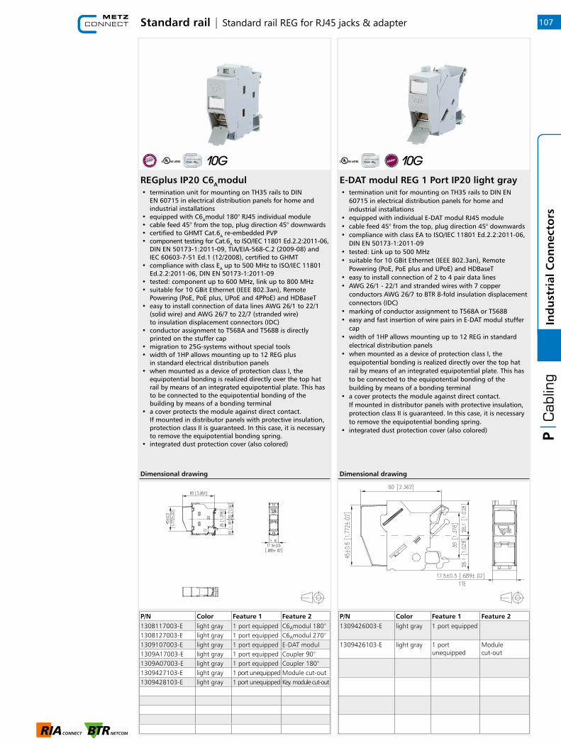
REGplus IP20 C6Amodul
P/N Color Feature 1 Feature 2130B117003-E light gray 1 port equipped C6Amodul 180°130B127003-E light gray 1 port equipped C6Amodul 270°1309107003-E light gray 1 port equipped E-DAT modul1309A17003-E light gray 1 port equipped Coupler 90°1309A07003-E light gray 1 port equipped Coupler 180°1309427103-E light gray 1 port unequipped Module cut-out1309428103-E light gray 1 port unequipped Key. module cut-out
Dimensional drawing
Standard rail | Standard rail REG for RJ45 jacks & adapter
• termination unit for mounting on TH35 rails to DIN EN 60715 in electrical distribution panels for home and industrial installations
• equipped with C6Amodul 180° RJ45 individual module• cable feed 45° from the top, plug direction 45° downwards• certified to GHMT Cat.6A re-embedded PVP• component testing for Cat.6A to ISO/IEC 11801 Ed.2.2:2011-06,
DIN EN 50173-1:2011-09, TIA/EIA-568-C.2 (2009-08) and IEC 60603-7-51 Ed.1 (12/2008), certified to GHMT
• compliance with class EA up to 500 MHz to ISO/IEC 11801 Ed.2.2:2011-06, DIN EN 50173-1:2011-09
• tested: component up to 600 MHz, link up to 800 MHz• suitable for 10 GBit Ethernet (IEEE 802.3an), Remote
Powering (PoE, PoE plus, UPoE and 4PPoE) and HDBaseT• easy to install connection of data lines AWG 26/1 to 22/1
(solid wire) and AWG 26/7 to 22/7 (stranded wire) to insulation displacement connectors (IDC)
• conductor assignment to T568A and T568B is directly printed on the stuffer cap
• migration to 25G-systems without special tools• width of 1HP allows mounting up to 12 REG plus
in standard electrical distribution panels• when mounted as a device of protection class I, the
equipotential bonding is realized directly over the top hat rail by means of an integrated equipotential plate. This has to be connected to the equipotential bonding of the building by means of a bonding terminal
• a cover protects the module against direct contact. If mounted in distributor panels with protective insulation, protection class II is guaranteed. In this case, it is necessary to remove the equipotential bonding spring.
• integrated dust protection cover (also colored)
E-DAT modul REG 1 Port IP20 light gray
P/N Color Feature 1 Feature 21309426003-E light gray 1 port equipped
1309426103-E light gray 1 port unequipped
Module cut-out
Dimensional drawing
• termination unit for mounting on TH35 rails to DIN EN 60715 in electrical distribution panels for home and industrial installations
• equipped with individual E-DAT modul RJ45 module• cable feed 45° from the top, plug direction 45° downwards• compliance with class EA to ISO/IEC 11801 Ed.2.2:2011-06,
DIN EN 50173-1:2011-09• tested: Link up to 500 MHz• suitable for 10 GBit Ethernet (IEEE 802.3an), Remote
Powering (PoE, PoE plus and UPoE) and HDBaseT• easy to install connection of 2 to 4 pair data lines• AWG 26/1 - 22/1 and stranded wires with 7 copper
conductors AWG 26/7 to BTR 8-fold insulation displacement connectors (IDC)
• marking of conductor assignment to T568A or T568B• easy and fast insertion of wire pairs in E-DAT modul stuffer
cap• width of 1HP allows mounting up to 12 REG in standard
electrical distribution panels• when mounted as a device of protection class I, the
equipotential bonding is realized directly over the top hat rail by means of an integrated equipotential plate. This has to be connected to the equipotential bonding of the building by means of a bonding terminal
• a cover protects the module against direct contact. If mounted in distributor panels with protective insulation, protection class II is guaranteed. In this case, it is necessary to remove the equipotential bonding spring.
• integrated dust protection cover (also colored)
107
1
Ind
ust
rial
Co
nn
ecto
rs

Standard rail | Dust protection covers & Standard rail REG for fiber optic E2000
Dust protection covers for Modul patch panels / subway / REG• for color service coding of patch fields, subway underfloor
units and E-DAT modul REG • suitable for: C6Amodul patch fields, E-DAT modul patch
field 24x8, subway underfloor units, module wall outlet 2 port APFL as well as E-DAT modul REG and Modul REGplus
• variants: yellow, blue, green, red
P/N Color Feature 1 Feature 2816979-0105-I yellow 1 port
816979-0106-I blue 1 port
816979-0107-I green 1 port
816979-0108-I red 1 port
Dimensional drawing
REGplus IP20 E2000 DC H&S
P/N Color Feature 1 Feature 2130F5B7003-E light gray E2000 DC SM
130F5C7003-E light gray E2000 DC SM APC
130F5A7003-E light gray E2000 DC MM
Dimensional drawing
• termination with an E2000 DC adapter for mounting on TH35 rail to DIN EN 60715
• slotted zirconium oxide ceramics sleeve (ZrO2)• high material stability and surface quality and long service
life• service life: min. 1000 plug cycles• cable feed 45° from the top, plug direction 45° downwards• width of 1HP allows mounting up to 12 REG in standard
electrical distribution panels• to install the adapter, the existing dust protection cover
must be removed
• variants: blue (SM), green (SM APC), beige (MM)
108In
du
stri
al C
on
nec
tors
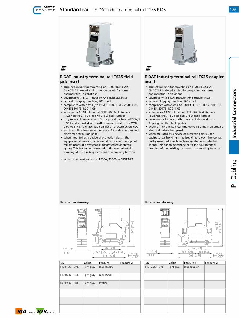
E-DAT Industry terminal rail TS35 field jack insert
P/N Color Feature 1 Feature 21401106113KE light gray 8(8) T568A
1401806113KE light gray 8(8) T568B
1401906113KE light gray Profinet
Dimensional drawing
• termination unit for mounting on TH35 rails to DIN EN 60715 in electrical distribution panels for home and industrial installations
• equipped with E-DAT Industry RJ45 field jack insert• vertical plugging direction, 90° to rail• compliance with class EA to ISO/IEC 11801 Ed.2.2:2011-06,
DIN EN 50173-1:2011-09• suitable for 10 GBit Ethernet (IEEE 802.3an), Remote
Powering (PoE, PoE plus and UPoE) and HDBaseT• easy to install connection of 2 to 4 pair data lines AWG 24/1
- 22/1 and stranded wires with 7 copper conductors AWG 26/7 to BTR 8-fold insulation displacement connectors (IDC)
• width of 1HP allows mounting up to 12 units in a standard electrical distribution panel
• when mounted as a device of protection class I, the equipotential bonding is realized directly over the top hat rail by means of a switchable integrated equipotential spring. This has to be connected to the equipotential bonding of the building by means of a bonding terminal
• variants: pin assignment to T568A, T568B or PROFINET
E-DAT Industry terminal rail TS35 coupler insert
P/N Color Feature 1 Feature 21401206113KE light gray 8(8) coupler
Dimensional drawing
• termination unit for mounting on TH35 rails to DIN EN 60715 in electrical distribution panels for home and industrial installations
• equipped with E-DAT Industry RJ45 coupler insert• vertical plugging direction, 90° to rail• compliance with class E to ISO/IEC 11801 Ed.2.2:2011-06,
DIN EN 50173-1:2011-09• suitable for 10 GBit Ethernet (IEEE 802.3an), Remote
Powering (PoE, PoE plus and UPoE) and HDBaseT• increased resistance to vibrations and shocks due to
4 springs on the shield plates• width of 1HP allows mounting up to 12 units in a standard
electrical distribution panel• when mounted as a device of protection class I, the
equipotential bonding is realized directly over the top hat rail by means of a switchable integrated equipotential spring. This has to be connected to the equipotential bonding of the building by means of a bonding terminal
Standard rail | E-DAT Industry terminal rail TS35 RJ45 109
1
Ind
ust
rial
Co
nn
ecto
rs

OpDAT Industry terminal rail TS35 fiber LC-D
P/N Color Feature 1 Feature 21402L06113KE light gray LC-D (ceramic) SM
1402306113KE light gray LC-D (Ph-BR) MM
Dimensional drawing
• termination unit with LC-D adapter on TH35 rail to DIN EN 60715
• slotted zirconium oxide ceramics sleeve (ZrO2) for single mode applications
• slotted metal sleeve (Ph-Br) for multi mode applications• width of 1HP allows mounting up to 12 units in a standard
electrical distribution panel• vertical plugging direction, 90° to rail
• variants: SM, MM
OpDAT Industry terminal rail TS35 fiber SC-D
P/N Color Feature 1 Feature 21402Q06113KE light gray SC-D (ceramic) SM
1402P06113KE light gray SC-D (PH-BR) MM
Dimensional drawing
• termination unit with SC-D adapter on TH35 rail to DIN EN 60715
• slotted zirconium oxide ceramics sleeve (ZrO2) for single mode applications
• slotted metal sleeve (Ph-Br) for multi mode applications• width of 1HP allows mounting up to 12 units in a standard
electrical distribution panel• vertical plugging direction, 90° to rail
• variants: SM, MM
Standard rail | E-DAT Industry terminal rail TS35 fiber optic110In
du
stri
al C
on
nec
tors
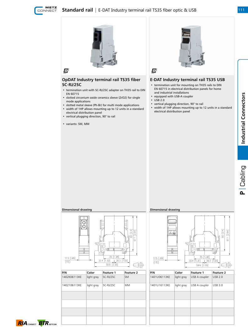
Standard rail | E-DAT Industry terminal rail TS35 fiber optic & USB
OpDAT Industry terminal rail TS35 fiber SC-RJ/2SC
P/N Color Feature 1 Feature 21402K06113KE light gray SC-RJ/2SC SM
1402106113KE light gray SC-RJ/2SC MM
Dimensional drawing
• termination unit with SC-RJ/2SC adapter on TH35 rail to DIN EN 60715
• slotted zirconium oxide ceramics sleeve (ZrO2) for single mode applications
• slotted metal sleeve (Ph-Br) for multi mode applications• width of 1HP allows mounting up to 12 units in a standard
electrical distribution panel• vertical plugging direction, 90° to rail
• variants: SM, MM
E-DAT Industry terminal rail TS35 USB
P/N Color Feature 1 Feature 21401U06113KE light gray USB A coupler USB 2.0
1401U16113KE light gray USB A coupler USB 3.0
Dimensional drawing
• termination unit for mounting on TH35 rails to DIN EN 60715 in electrical distribution panels for home and industrial installations
• equipped with USB-A coupler• USB 2.0• vertical plugging direction, 90° to rail• width of 1HP allows mounting up to 12 units in a standard
electrical distribution panel
111
1
Ind
ust
rial
Co
nn
ecto
rs
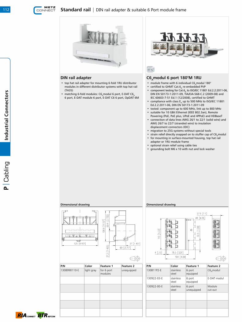
DIN rail adapter
P/N Color Feature 1 Feature 21308990110-E light gray for 6 port
modulesunequipped
Dimensional drawing
• top hat rail adapter for mounting 6-fold 1RU distributor modules in different distributor systems with top hat rail (TH35)
• matching 6-fold modules: C6Amodul 6 port, E-DAT C6A
6 port, E-DAT module 6 port, E-DAT C6 6 port, OpDAT 6M
Standard rail | DIN rail adapter & suitable 6 Port module frame
C6Amodul 6 port 180°M 1RU• module frame with 6 individual C6Amodul 180°• certified to GHMT Cat.6A re-embedded PVP• component testing for Cat.6A to ISO/IEC 11801 Ed.2.2:2011-06,
DIN EN 50173-1:2011-09, TIA/EIA-568-C.2 (2009-08) and IEC 60603-7-51 Ed.1 (12/2008), certified to GHMT
• compliance with class EA up to 500 MHz to ISO/IEC 11801 Ed.2.2:2011-06, DIN EN 50173-1:2011-09
• tested: component up to 600 MHz, link up to 800 MHz• suitable for 10 GBit Ethernet (IEEE 802.3an), Remote
Powering (PoE, PoE plus, UPoE and 4PPoE) and HDBaseT• connection of data lines AWG 26/1 to 22/1 (solid wire) and
AWG 26/7 to 22/7 (stranded wire) to insulation displacement connectors (IDC)
• migration to 25G-systems without special tools• strain relief directly snapped on to stuffer cap of C6Amodul• for mounting in surface-mounted housing, top hat rail
adapter or 1RU module frame• optional strain relief using cable ties• grounding bolt M6 x 10 with nut and lock washer
P/N Color Feature 1 Feature 2130B11P2-E stainless
steel6 port equipped
C6Amodul
130922-03-E stainless steel
6 port equipped
E-DAT modul
130922-00-E stainless steel
6 port unequipped
Module cut-out
Dimensional drawing
112In
du
stri
al C
on
nec
tors

Standard rail | DIN rail adapter
DIN rail adapter mini
P/N Color Feature 1 Feature 21308990111-I metallike metal
Dimensional drawing
• to fasten heavy devices on a top hat rail (TH35)• fastening screws are not included in the delivery
DIN rail adapter mini FS• to fasten light devices, such as wall outlets, on a top hat rail
(TH35)• packing unit: adapter and screw (M4x6)• two top hat rail adapters mini FS are required for fastening
one wall outlet
P/N Color Feature 1 Feature 21308990112-I metallike metal
Dimensional drawing
113
1
Ind
ust
rial
Co
nn
ecto
rs

OpDAT REGplus 2xSC-D MM (ceramic), 1xM20, with crimp splice holder• splice distributor for TH35 rail• equipped with SC-D (MM) adapters made of zinc
die-casting• slotted ceramic sleeve for multi mode applications• with fiber reservoir• custom-labeled identification strips• various mounting versions on rail• splice tray with crimp splice holder• front plate can be completely removed• cable feed from top or bottom, straight or inclined, with
M20 cable gland (up to 2 possible)• feed of preassembled cables is possible• one cable gland M20 with strain relief included in the
delivery• housing cover fastening by means of just one captive screw• unoccupied adapter recesses are closed with special blind
plugs
• variants: equipped with 2, 3, 4 or 6 SC-D adapters
P/N Color Feature 1 Feature 2150240C20210E metallike 2xSC-D
(ceramic)MM
150240C20310E metallike 2xSC-D (ceramic)
MM
150240C20410E metallike 2xSC-D (ceramic)
MM
150240C20610E metallike 2xSC-D (ceramic)
MM
Dimensional drawing
OpDAT REGplus 2xSC/ST-D MM (ceramic), 1xM20, with crimp splice holder• splice distributor for TH35 rail• equipped with SC-D/ST-D (MM) adapters made of zinc
die-casting• slotted ceramic sleeve for multi mode applications• with fiber reservoir• custom-labeled identification strips• various mounting versions on rail• splice tray with crimp splice holder• front plate can be completely removed• cable feed from top or bottom, straight or inclined, with
M20 cable gland (up to 2 possible)• feed of preassembled cables is possible• one cable gland M20 with strain relief included in the
delivery• housing cover fastening by means of just one captive screw• unoccupied adapter recesses are closed with special blind
plugs
• variants: equipped with 2, 3, 4 or 6 SC-D/ST-D adapters (SC-D interior, ST-D exterior)
• please note: if you use preassembled cables with ST plugs, use the unequipped version of the OpDAT REG plus. The ST-D adapters required in this case are available as accessory. Before mounting the adapters in the housing, plug the preassembled ST plugs in the adapters for reasons of space.
P/N Color Feature 1 Feature 2150240C30210E metallike 2xSC/ST-D
(Ph-Br)MM
150240C30310E metallike 2xSC/ST-D (Ph-Br)
MM
150240C30410E metallike 2xSC/ST-D (Ph-Br)
MM
150240C30610E metallike 2xSC/ST-D (Ph-Br)
MM
Dimensional drawing
Standard rail | Fiber optic114In
du
stri
al C
on
nec
tors

OpDAT REGpro24 splice distributor
P/N Color Feature 1 Feature 215024A10-24-E gray unequipped w/o splice tray
• splice distributor for TH35 rail without front cover• to mount pigtails or pre-assembled installation cables • gray housing• with crimp splice holder for up to 24 splices• installation of two shrink splice holders on splice tray is
possible• with fiber reservoir• custom-labeled identification strips• fastening on top hat rail by means of very sturdy top hat
rail holder• various mounting versions on rail• for different front plates 3RU/7HP• cable feed from top or bottom, straight or inclined,
with M20 cable gland (up to 2 possible)• width: 61 mm, height: 128 mm, depth: 132.5 mm
(from rail, without adapter)• one cable gland M20 with strain relief included
in the delivery• housing cover fastening by just one screw
Dimensional drawing
OpDAT REGpro splice distributor• splice distributor for TH35 rail without front cover • gray housing • with or without splice tray with crimp splice holder for up
to 12 splices • installation of two shrink splice holders on splice tray
is possible • with fiber reservoir • custom-labeled identification strips • fastening on top hat rail by means of very sturdy top hat
rail holder • various mounting versions on rail • for different front plates 3RU/7HP • cable feed from top or bottom, straight or inclined,
with PG11 cable gland (up to 2 possible) • width: 50 mm, height: 128 mm, depth: 132.5 mm
(from rail, without adapter) • feed of preassembled cables is possible • one cable gland PG11 with strain relief included
in the delivery • housing cover fastening by means of just one screw
• variants: with and without splice tray
• Please note: not all front plates 3RU/7HP available on the market can be used for OpDAT REGpro. If preassembled cables are used, we recommend the version without splice tray.
P/N Color Feature 1 Feature 215024A10-E gray unequipped w/o splice tray
15024A10S-E gray unequipped with splice tray
Dimensional drawing
Standard rail | Fiber optic 115
1
Ind
ust
rial
Co
nn
ecto
rs

Standard rail | Fiber optic standard rail accessories
OpDAT REG strain relief M20
P/N Color Feature 1 Feature 2150240M20Z-E gray
• additional tension relief for OpDAT REGplus and/or OpDAT REGpro splice distributor
• M20 screw connection• with tension relief for Kevlar• additional strain relief for each splice distributor possible
Dimensional drawing
OpDAT REGpro splice tray with shrink splice holder• splice tray for OpDAT REGpro • with shrink splice holder for up to 12 splices
P/N Color Feature 1 Feature 215024ASK-S gray Splice tray for shrink splice
Dimensional drawing
116In
du
stri
al C
on
nec
tors
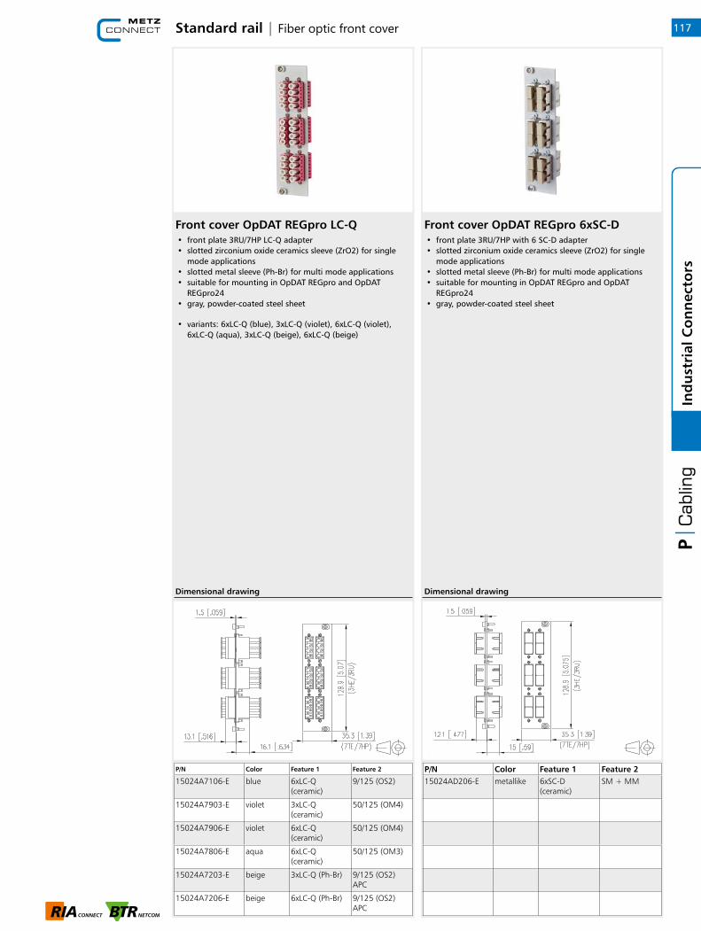
Standard rail | Fiber optic front cover
Front cover OpDAT REGpro LC-Q• front plate 3RU/7HP LC-Q adapter • slotted zirconium oxide ceramics sleeve (ZrO2) for single
mode applications • slotted metal sleeve (Ph-Br) for multi mode applications • suitable for mounting in OpDAT REGpro and OpDAT
REGpro24 • gray, powder-coated steel sheet
• variants: 6xLC-Q (blue), 3xLC-Q (violet), 6xLC-Q (violet), 6xLC-Q (aqua), 3xLC-Q (beige), 6xLC-Q (beige)
P/N Color Feature 1 Feature 2
15024A7106-E blue 6xLC-Q (ceramic)
9/125 (OS2)
15024A7903-E violet 3xLC-Q (ceramic)
50/125 (OM4)
15024A7906-E violet 6xLC-Q (ceramic)
50/125 (OM4)
15024A7806-E aqua 6xLC-Q (ceramic)
50/125 (OM3)
15024A7203-E beige 3xLC-Q (Ph-Br) 9/125 (OS2) APC
15024A7206-E beige 6xLC-Q (Ph-Br) 9/125 (OS2) APC
Dimensional drawing
Front cover OpDAT REGpro 6xSC-D• front plate 3RU/7HP with 6 SC-D adapter • slotted zirconium oxide ceramics sleeve (ZrO2) for single
mode applications • slotted metal sleeve (Ph-Br) for multi mode applications • suitable for mounting in OpDAT REGpro and OpDAT
REGpro24 • gray, powder-coated steel sheet
P/N Color Feature 1 Feature 215024AD206-E metallike 6xSC- D
(ceramic)SM + MM
Dimensional drawing
117
1
Ind
ust
rial
Co
nn
ecto
rs
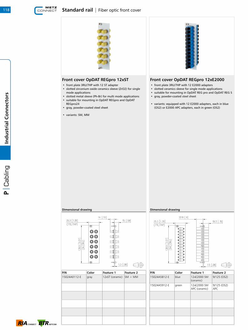
Standard rail | Fiber optic front cover
Front cover OpDAT REGpro 12xST• front plate 3RU/7HP with 12 ST adapter • slotted zirconium oxide ceramics sleeve (ZrO2) for single
mode applications • slotted metal sleeve (Ph-Br) for multi mode applications • suitable for mounting in OpDAT REGpro and OpDAT
REGpro24 • gray, powder-coated steel sheet
• variants: SM, MM
P/N Color Feature 1 Feature 215024A0112-E gray 12xST (ceramic) SM + MM
Dimensional drawing
Front cover OpDAT REGpro 12xE2000• front plate 3RU/7HP with 12 E2000 adapters• slotted ceramics sleeve for single mode applications• suitable for mounting in OpDAT REG pro and OpDAT REG S• gray, powder-coated steel sheet
• variants: equipped with 12 E2000 adapters, each in blue (OS2) or E2000 APC adapters, each in green (OS2)
P/N Color Feature 1 Feature 215024A5812-E blue 12xE2000 SM
(ceramic)9/125 (OS2)
15024A5912-E green 12xE2000 SM APC (ceramic)
9/125 (OS2) APC
Dimensional drawing
118In
du
stri
al C
on
nec
tors

Standard rail | OpDAT REG Splice Distributor for fiber optic & RJ45
OpDAT REG Splice Distributor for pre-terminated cables• Very compact splice distributor for TH35 rail• Flat design with an inclined outlet (connections facing
downward) and a large cabling space• Great ease of use even with high cable channels in the
immediate surroundings• To mount pigtails or pre-terminated installation cables
(VIKs)• Modular design: housing, equipped front plate and splice
tray are to be ordered separately• Visible area with label strip• The rail bracket can be mounted in different positions to
the housing to allow for several mounting variants.• Cable feed from top or bottom with a strain relief M20
(available as an option).• Front plate (3RU/7HP) with LC-Quad, SC-Duplex, ST or
E2000 adapters. Other types available on demand.• 3 variants available:• OpDAT REG S V = for pre-terminated cables• OpDAT REG S Splice C = for 12 splices with crimp splice
holders• OpDAT REG S Splice S = for 12 splices with shrink splice
holders• Particularly solid rail bracket• With one captive screw of the cover• Suitable for mixed equipment with fiber optic and copper
based technology• With a mounted blind plate it can be used on the rail as
splice box only or also as a transit splice box with up to 12 (24) fibers
P/N Color Feature 1 Feature 215024B10-E gray unequipped VIK
15024B10S-S gray unequipped for shrink splice holder
15024B10S-E gray unequipped for crimp splice holder
Dimensional drawing
Modul module frame 3RU, 7HP 6 port stainless steel unequipped• stainless steel module frame for 6 individual modules in
Modul design• strain relief at the module• 3RU 7HP module frame with very short dimensions• mounts in OpDAT REGpro, OpDAT REGpro24, OpDAT CM,
OpDAT REG S or 3HP module frame• additional strain relief possible by cable tie• grounding possible by flat plug
P/N Color Feature 1 Feature 2130B10E2E-E stainless
steel6 port unequipped
Module cut-out
130B20E2E-E stainless steel
6 port unequipped
Keystone module cut-out
Dimensional drawing
119
1
Ind
ust
rial
Co
nn
ecto
rs
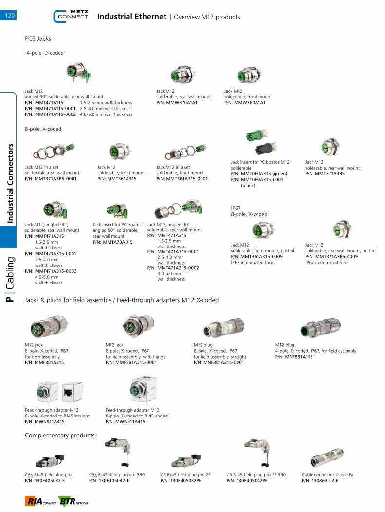
Industrial Ethernet | Overview M12 products
PCB Jacks
4-pole, D-coded
IP67 8-pole, X-coded
Jack M12, angled 90°,solderable, rear wall mountP/N: MMT471A315 1.5-2.5 mm wall thicknessP/N: MMT471A315-0001 2.5-4.0 mm wall thicknessP/N: MMT471A315-0002 4.0-5.0 mm wall thickness
Jack M12, angled 90°,solderable, rear wall mountP/N: MMT471A315 1.5-2.5 mm wall thicknessP/N: MMT471A315-0001 2.5-4.0 mm wall thicknessP/N: MMT471A315-0002 4.0-5.0 mm wall thickness
Jack insert for PC boards angled 90°, solderable, rear wall mountP/N: MMTA70A315
Jack M12 in a setsolderable, front mountP/N: MMT361A315-0001
Jack M12solderable, front mountP/N: MMT361A315
Jack insert for PC boards M12solderableP/N: MMT060A315 (green)P/N: MMT060A315-0001 (black)
Jack M12solderable, rear wall mountP/N: MMT371A3B5
Jack M12 in a setsolderable, rear wall mountP/N: MMT371A3B5-0001
8-pole, X-coded
Jacks & plugs for field assembly / Feed-through adapters M12 X-coded
Complementary products
Jack M12angled 90°, solderable, rear wall mountP/N: MMT471A115 1.5-2.5 mm wall thicknessP/N: MMT471A115-0001 2.5-4.0 mm wall thicknessP/N: MMT471A115-0002 4.0-5.0 mm wall thickness
Jack M12solderable, rear wall mountP/N: MMW370A1A1
Jack M12solderable, front mountP/N: MMW360A1A1
Jack M12 solderable, rear wall mount, pottedP/N: MMT371A3B5-0009 IP67 in unmated form
Jack M12solderable, front mount, pottedP/N: MMT361A315-0009IP67 in unmated form
M12 jack8-pole, X-coded, IP67for field assemblyP/N: MMF881A315
M12 jack8-pole, X-coded, IP67 for field assembly, with flangeP/N: MMF881A315-0001
M12 plug 8-pole, X-coded, IP67for field assembly, straightP/N: MNF881A315-0001
M12 plug4-pole, D-coded, IP67, for field assemblyP/N: MNF881A115
Feed-through adapter M12 8-pole, X-coded to RJ45 straightP/N: MWN811A415
Feed-through adapter M12 8-pole, X-coded to RJ45 angledP/N: MWN911A415
C6A RJ45 field plug pro 360P/N: 130E405042-E
C6A RJ45 field plug proP/N: 130E405032-E
Cable connector Classe FAP/N: 130863-02-E
C5 RJ45 field plug pro 2PP/N: 130E405032PE
C5 RJ45 field plug pro 2P 360P/N: 130E405042PE
120In
du
stri
al C
on
nec
tors
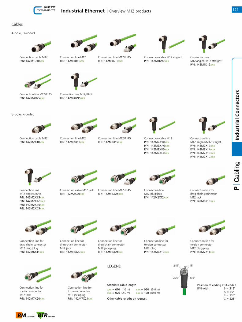
Industrial Ethernet | Overview M12 products
Cables
4-pole, D-coded
8-pole, X-coded
0° 45°315°
225° 135°
LEGEND
Connection line M12P/N: 142M1D11xxx
Connection cable M12P/N: 142M1D10xxx
Connection line M12/RJ45P/N: 142M4D15xxx
Connection cable M12 angled P/N: 142M1D90xxx
Connection line M12 angled-M12 straightP/N: 142M1D19xxx
Connection line M12/RJ45 P/N: 142M4D25xxx
Connection line M12/RJ45 P/N: 142M4D95xxx
Connection cable M12 P/N: 142M2X10xxx
Connection line M12P/N: 142M2X11xxx
Connection line M12/RJ45 P/N: 142M2X15xxx
Connection cable M12 P/N: 142M2X90xxxP/N: 142M2XA0xxxP/N: 142M2XB0xxxP/N: 142M2XC0xxx
Connection line M12 angled/M12 staightP/N: 142M2X19xxxP/N: 142M2X1AxxxP/N: 142M2X1BxxxP/N: 142M2X1Cxxx
Connection line M12 angled/RJ45P/N: 142M2X95xxxP/N: 142M2XA5xxxP/N: 142M2XB5xxxP/N: 142M2XC5xxx
Connection cable M12 jackP/N: 142M2X20xxx
Connection line M12-RJ45P/N: 142M2X25xxx
Connection line M12 plug/jackP/N: 142M2X12xxx
Connection line for drag chain connectorM12 jackP/N: 142M6X10xxx
Connection line for drag chain connectorM12 plug/plugP/N: 142M6X11xxx
Connection line for drag chain connectorM12 jackP/N: 142M6X20xxx
Connection line for drag chain connector M12 jack/plugP/N: 142M6X21xxx
Connection line fortorsion connectorM12-plugP/N: 142M7X10xxx
Connection line fortorsion connectorM12 plug/plugP/N: 142M7X11xxx
Connection line fortorsion connectorM12 jackP/N: 142M7X20xxx
Connection line fortorsion connectorM12 jack/plugP/N: 142M7X21xxx
Standard cable length
xxx = 010 (1.0 m) xxx = 050 (5.0 m)xxx = 020 (2.0 m) xxx = 100 (10.0 m)
Other cable lengths on request.
Position of coding at X-codedP/N with: 9 = 315° A = 45° B = 135° C = 225°
121
1
Ind
ust
rial
Co
nn
ecto
rs

Ethernet M12 | D- & X-coded jacks122In
du
stri
al C
on
nec
tors
Jack M12 solderable 90° 4-pole D-coded IP67 <2.5 mm wall thickness• Ethernet M12 jack for PC boards• 4-pole, D-coded as per IEC 61076-02-101• angled 90°• solderable THR• side entry• protection degree IP67 in mated condition• suitable for applications in the railway industry
• Variants: suitable for a wall thickness up to 2.5 mm, up to 4 mm, up to 5 mm
P/N Color Feature 1 Feature 2MMT471A115 metallike D-coded 90° <2.5 mm
MMT471A115-0001
metallike D-coded 90° <4 mm
MMT471A115-0002
metallike D-coded 90° <5 mm
Dimensional drawing
Jack M12 solderable through hole mounting 4-pole D-coded• Ethernet M12 female connector for PC boards• 4-pole, D-coded as per IEC 61076-02-101• solderable• through hole mounting• green PC board insert for THR• suitable for applications in the railway industry
P/N Color Feature 1 Feature 2MMW370A1A1 metallike D-coded
Dimensional drawing

Ethernet M12 | D- & X-coded jacks
Jack M12 solderable front mounting 4-pole D-coded• Ethernet M12 female connector for PC boards• 4-pole, D-coded as per IEC 61076-02-101• solderable• front mounting• green PC board insert for THR• suitable for applications in the railway industry
P/N Color Feature 1 Feature 2MMW360A1A1 metallike D-coded
Dimensional drawing
Jack M12 solderable 8-pole X-coded IP67, potted• Ethernet M12 jack Cat.6A for PC boards• 8-pole, X-coded as per IEC 61076-02-109• for 10 GBit Ethernet (IEEE 802.3an)• wave solderable• top entry• green PC board insert• protection degree IP67 in unmated condition• suitable for applications in the railway industry
P/N Color Feature 1 Feature 2MMT361A315-0009
metallike X-coded potted
Dimensional drawing
123
1
Ind
ust
rial
Co
nn
ecto
rs
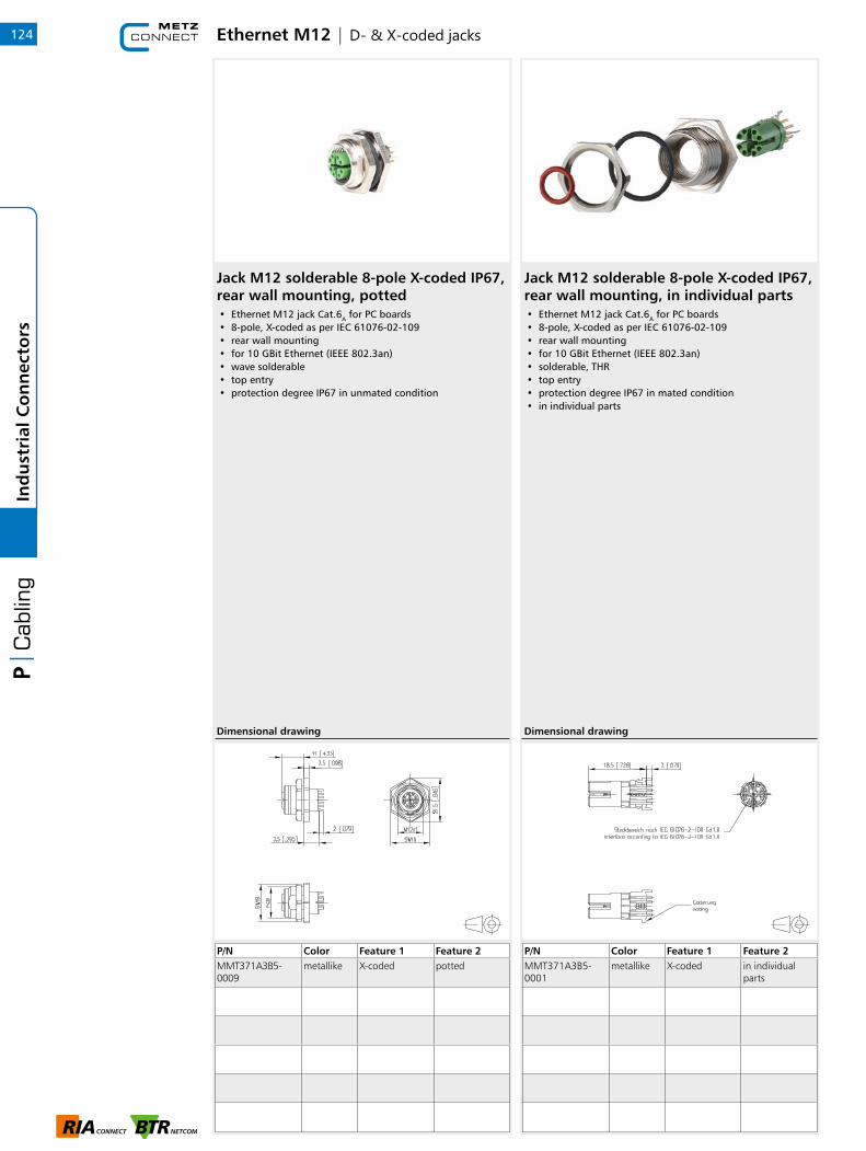
Ethernet M12 | D- & X-coded jacks
Jack M12 solderable 8-pole X-coded IP67, rear wall mounting, potted• Ethernet M12 jack Cat.6A for PC boards• 8-pole, X-coded as per IEC 61076-02-109• rear wall mounting• for 10 GBit Ethernet (IEEE 802.3an)• wave solderable• top entry• protection degree IP67 in unmated condition
P/N Color Feature 1 Feature 2MMT371A3B5- 0009
metallike X-coded potted
Dimensional drawing
124In
du
stri
al C
on
nec
tors
Jack M12 solderable 8-pole X-coded IP67, rear wall mounting, in individual parts• Ethernet M12 jack Cat.6A for PC boards• 8-pole, X-coded as per IEC 61076-02-109• rear wall mounting• for 10 GBit Ethernet (IEEE 802.3an)• solderable, THR• top entry• protection degree IP67 in mated condition• in individual parts
P/N Color Feature 1 Feature 2MMT371A3B5- 0001
metallike X-coded in individual parts
Dimensional drawing
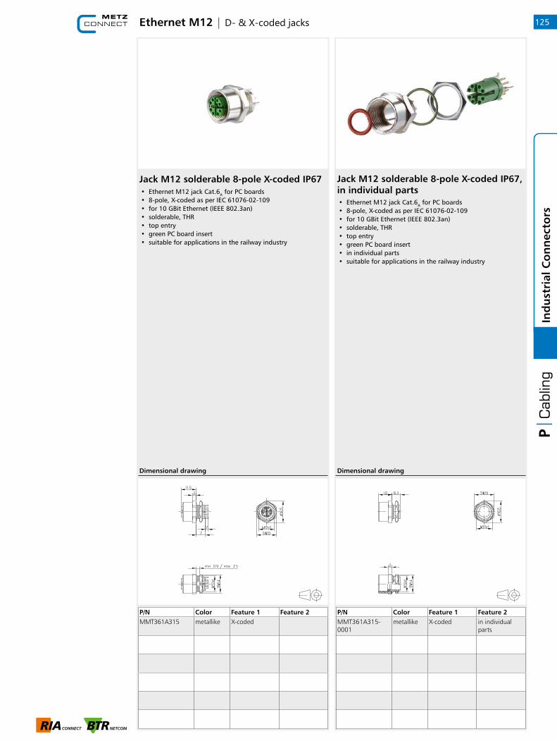
Ethernet M12 | D- & X-coded jacks
Jack M12 solderable 8-pole X-coded IP67• Ethernet M12 jack Cat.6A for PC boards• 8-pole, X-coded as per IEC 61076-02-109• for 10 GBit Ethernet (IEEE 802.3an)• solderable, THR• top entry• green PC board insert• suitable for applications in the railway industry
P/N Color Feature 1 Feature 2MMT361A315 metallike X-coded
Dimensional drawing
Jack M12 solderable 8-pole X-coded IP67, in individual parts• Ethernet M12 jack Cat.6A for PC boards• 8-pole, X-coded as per IEC 61076-02-109• for 10 GBit Ethernet (IEEE 802.3an)• solderable, THR• top entry• green PC board insert• in individual parts• suitable for applications in the railway industry
P/N Color Feature 1 Feature 2MMT361A315-0001
metallike X-coded in individual parts
Dimensional drawing
125
1
Ind
ust
rial
Co
nn
ecto
rs

Ethernet M12 | D- & X-coded jacks
PC board insert M12 solderable 8-pole X-coded, green• Ethernet M12 jack insert for PC boards• 8-pole, X-coded as per IEC 61076-02-109• for 10 GBit Ethernet (IEEE 802.3an)• solderable (THR)• plug-in direction vertical• variants: green or black contact carrier
P/N Color Feature 1 Feature 2MMT060A315 metallike X-coded
MMT060A315-0001
metallike X-coded
Dimensional drawing
126In
du
stri
al C
on
nec
tors
Jack M12 solderable 8-pole X-coded IP67, rear wall mounting• Ethernet M12 jack Cat.6A for PC boards• 8-pole, X-coded as per IEC 61076-02-109• rear wall mounting• for 10 GBit Ethernet (IEEE 802.3an)• solderable, THR• top entry• protection degree IP67 in mated condition
P/N Color Feature 1 Feature 2MMT371A3B5 metallike X-coded
Dimensional drawing
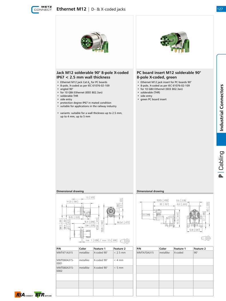
Ethernet M12 | D- & X-coded jacks
Jack M12 solderable 90° 8-pole X-coded IP67 < 2.5 mm wall thickness• Ethernet M12 jack Cat.6A for PC boards• 8-pole, X-coded as per IEC 61076-02-109• angled 90°• for 10 GBit Ethernet (IEEE 802.3an)• solderable THR• side entry• protection degree IP67 in mated condition• suitable for applications in the railway industry
• variants: suitable for a wall thickness up to 2.5 mm, up to 4 mm, up to 5 mm
P/N Color Feature 1 Feature 2MMT471A315 metallike X-coded 90° < 2.5 mm
MMT060A315-0001
metallike X-coded 90° < 4 mm
MMT060A315-0002
metallike X-coded 90° < 5 mm
Dimensional drawing
127
1
Ind
ust
rial
Co
nn
ecto
rs
PC board insert M12 solderable 90° 8-pole X-coded, green• Ethernet M12 jack insert for PC boards 90°• 8-pole, X-coded as per IEC 61076-02-109• for 10 GBit Ethernet (IEEE 802.3an)• solderable (THR)• side entry• green PC board insert
P/N Color Feature 1 Feature 2MMTA70A315 metallike X-coded 90°
Dimensional drawing

Ethernet M12 | M12 connectors for field assembly
Jack M12 solderable 90° 8-pole X-coded IP67 wall thickness, in individual parts• Ethernet M12 jack Cat.6A for PC boards• 8-pole, X-coded as per IEC 61076-02-109• angled 90°• for 10 GBit Ethernet (IEEE 802.3an)• solderable THR• side entry• protection degree IP67 in mated condition• in individual parts• suitable for applications in the railway industry
• variants: suitable for a wall thickness up to 2.5 mm, up to 4 mm, up to 5 mm
P/N Color Feature 1 Feature 2MMT471A315-0003
metallike X-coded 90° < 2.5 mm, in individual parts
MMT471A315-0004
metallike X-coded 90° < 4 mm, in individual parts
MMT471A315-0005
metallike X-coded 90° < 5 mm, in individual parts
Dimensional drawing
128In
du
stri
al C
on
nec
tors
M12 Jack X-coded IP67, field assembly• 8-pole M12 jack for field assembly Cat.6A
per IEC/PAS 61076-2-109• suitable for 10 GBit as per IEEE 802.3an• AWG 26/1-22/1, AWG 26/7-22/7 can be connected• solid copper wire diameter 0.4 to 0.64 mm• stranded copper wire diameter 0.48 to 0.76 mm• wire diameter with isolation up to 1.6 mm• overall cable diameter from 5.0 to 9.7 mm• jack consists of only two parts• easy assembly without special tools• industry-compatible zinc die-cast housing• suitable for applications in the railway industry
P/N Color Feature 1 Feature 2MMF881A315 X-coded
Dimensional drawing

Ethernet M12 | M12 connectors for field assembly
M12 Jack X-coded IP67, field assembly with flange• 8-pole M12 jack for field assembly Cat.6A
• per IEC/PAS 61076-2-109 with flange• suitable for 10 GBit as per IEEE 802.3an• AWG 26/1 to 22/1, AWG 26/7 to 22/7 can be connected• solid copper wire diameter 0.4 to 0.64 mm• stranded copper wire diameter 0.48 to 0.76 mm• wire diameter with isolation up to 1.6 mm• overall cable diameter from 5.0 to 9.7 mm• jack consists of only two parts• easy assembly without special tools• industry-compatible zinc die-cast housing• suitable for applications in the railway industry
P/N Color Feature 1 Feature 2MMF881A315-0001
X-coded
Dimensional drawing
129
1
Ind
ust
rial
Co
nn
ecto
rs
M12 field plug X-coded, straight• M12 Cat.6A X-coded plug based on IEC PAS 61076-2-109
and suitable for field assembly• suitable for 10 GBit Ethernet (IEEE 802.3an), Remote
Powering (PoE, PoE plus and UPoE) and HDBaseT• for a 8-wire M12 plug for AWG 22• connection of AWG 26/1 - 22/1; AWG 26/7 - 22/7 possible• solid copper wire diameter from 0.4 to 0.64 mm• stranded copper wire diameter from 0.48 to 0.76 mm• core diameter up to 1.6 mm• cable jacket from 5.0 to 9.7 mm• consists of only 2 parts• easy assembly - connection without special tools• zinc die-cast housing for industrial use• suitable for applications in the railway industry
P/N Color Feature 1 Feature 2MNF881A315-0001
X-coded
Dimensional drawing
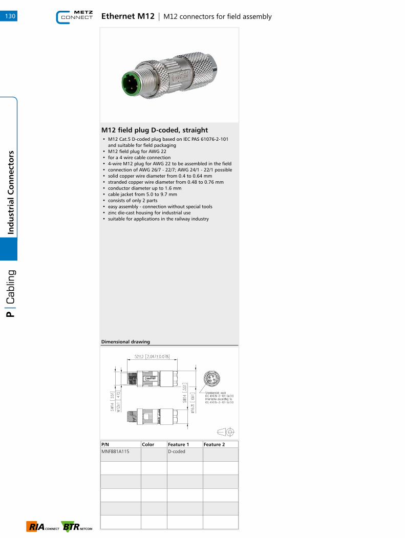
Ethernet M12 | M12 connectors for field assembly
M12 field plug D-coded, straight• M12 Cat.5 D-coded plug based on IEC PAS 61076-2-101
and suitable for field packaging• M12 field plug for AWG 22• for a 4 wire cable connection• 4-wire M12 plug for AWG 22 to be assembled in the field• connection of AWG 26/7 - 22/7; AWG 24/1 - 22/1 possible• solid copper wire diameter from 0.4 to 0.64 mm• stranded copper wire diameter from 0.48 to 0.76 mm• conductor diameter up to 1.6 mm• cable jacket from 5.0 to 9.7 mm• consists of only 2 parts• easy assembly - connection without special tools• zinc die-cast housing for industrial use• suitable for applications in the railway industry
P/N Color Feature 1 Feature 2MNF881A115 D-coded
Dimensional drawing
130In
du
stri
al C
on
nec
tors
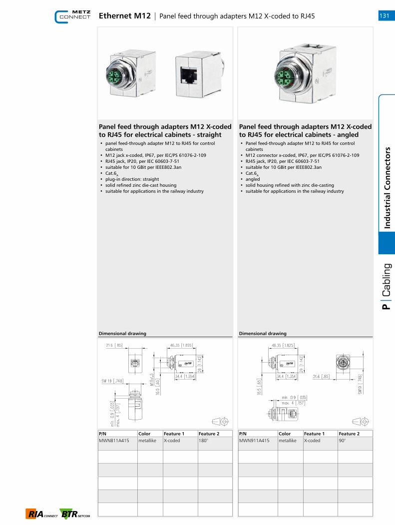
Ethernet M12 | Panel feed through adapters M12 X-coded to RJ45
Panel feed through adapters M12 X-coded to RJ45 for electrical cabinets - angled• Panel feed-through adapter M12 to RJ45 for control
cabinets• M12 connector x-coded, IP67, per IEC/PS 61076-2-109• RJ45 jack, IP20, per IEC 60603-7-51• suitable for 10 GBit per IEEE802.3an• Cat.6A
• angled• solid housing refined with zinc die-casting• suitable for applications in the railway industry
P/N Color Feature 1 Feature 2MWN911A415 metallike X-coded 90°
Dimensional drawing
131
1
Ind
ust
rial
Co
nn
ecto
rs
Panel feed through adapters M12 X-coded to RJ45 for electrical cabinets - straight• panel feed-through adapter M12 to RJ45 for control
cabinets• M12 jack x-coded, IP67, per IEC/PS 61076-2-109• RJ45 jack, IP20, per IEC 60603-7-51• suitable for 10 GBit per IEEE802.3an• Cat.6A
• plug-in direction: straight• solid refined zinc die-cast housing• suitable for applications in the railway industry
P/N Color Feature 1 Feature 2MWN811A415 metallike X-coded 180°
Dimensional drawing

Ethernet M12 | Cable and connection line
Connection line M12 plug straight - M12 plug straight 4-pole, D-coded• shielded M12 Ethernet connection line• Cat.5e, 4-pole, D-coded to IEC 61076-2-101• side 1: M12-plug, straight• side 2: M12-plug, straight• extrusion-coated cable on M12 connectors• 2x2xAWG22/7, tinned with plastic foil• inner sheath FRNC, aluminum-coated plastic foil• overall shield: tinned copper braid, approx. 85% covered• Profinet (WS-GE-BL-OR) wiring• green cable, PUR
• standard variants: 1.0 m, 2.0 m, 5.0 m, 10.0 m• other cable lenghts on request
P/N Color Feature 1 Feature 2142M1D11010 green 1 m
142M1D11020 green 2 m
142M1D11050 green 5 m
142M1D11100 green 10 m
Dimensional drawing
132In
du
stri
al C
on
nec
tors
Connection line M12 plug straight - RJ45 plug straight AWG 26 4-pole, D-coded• shielded M12 to RJ45 Ethernet connection line• Cat.5e, 4-pole, D-coded (IEC 61076-2-101)• side 1: M12 plug, straight• side 2: RJ45 plug, straight• extrusion-coated cable on M12 and RJ45 connector• stranded wires 4x1xAWG26/19• overall shield tinned copper braid• pin assignment per Profinet• green cable, PUR
• standard variants: 1.0 m, 2.0 m, 5.0 m, 10.0 m• other cable lengths on request
P/N Color Feature 1 Feature 2142M4D15010 green 1 m
142M4D15020 green 2 m
142M4D15050 green 5 m
142M4D15100 green 10 m
Dimensional drawing
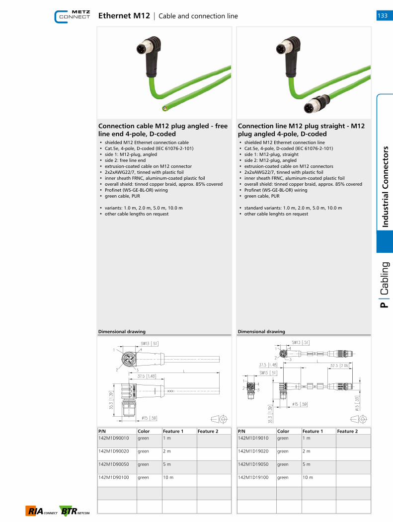
Ethernet M12 | Cable and connection line 133
1
Ind
ust
rial
Co
nn
ecto
rs
Connection cable M12 plug angled - free line end 4-pole, D-coded• shielded M12 Ethernet connection cable• Cat.5e, 4-pole, D-coded (IEC 61076-2-101)• side 1: M12-plug, angled• side 2: free line end• extrusion-coated cable on M12 connector• 2x2xAWG22/7, tinned with plastic foil• inner sheath FRNC, aluminum-coated plastic foil• overall shield: tinned copper braid, approx. 85% covered• Profinet (WS-GE-BL-OR) wiring• green cable, PUR
• variants: 1.0 m, 2.0 m, 5.0 m, 10.0 m• other cable lengths on request
P/N Color Feature 1 Feature 2142M1D90010 green 1 m
142M1D90020 green 2 m
142M1D90050 green 5 m
142M1D90100 green 10 m
Dimensional drawing
Connection line M12 plug straight - M12 plug angled 4-pole, D-coded• shielded M12 Ethernet connection line• Cat.5e, 4-pole, D-coded (IEC 61076-2-101)• side 1: M12-plug, straight• side 2: M12-plug, angled• extrusion-coated cable on M12 connectors• 2x2xAWG22/7, tinned with plastic foil• inner sheath FRNC, aluminum-coated plastic foil• overall shield: tinned copper braid, approx. 85% covered• Profinet (WS-GE-BL-OR) wiring• green cable, PUR
• standard variants: 1.0 m, 2.0 m, 5.0 m, 10.0 m• other cable lenghts on request
P/N Color Feature 1 Feature 2142M1D19010 green 1 m
142M1D19020 green 2 m
142M1D19050 green 5 m
142M1D19100 green 10 m
Dimensional drawing
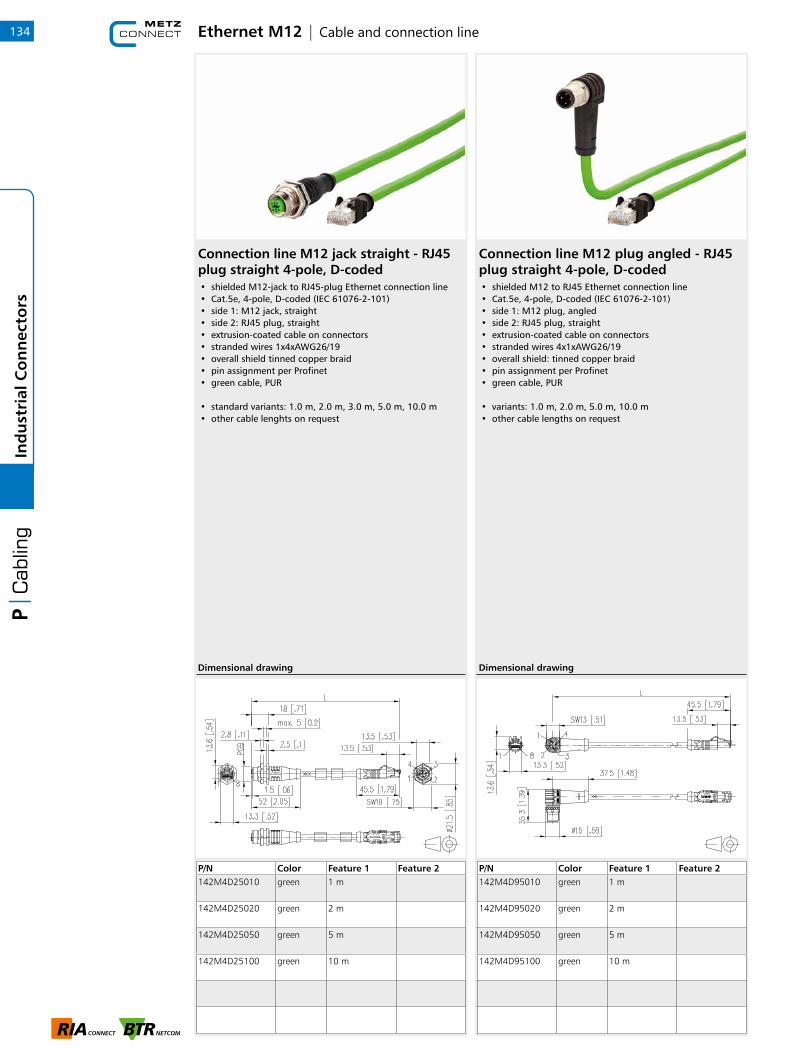
Ethernet M12 | Cable and connection line134In
du
stri
al C
on
nec
tors
Connection line M12 jack straight - RJ45 plug straight 4-pole, D-coded• shielded M12-jack to RJ45-plug Ethernet connection line• Cat.5e, 4-pole, D-coded (IEC 61076-2-101)• side 1: M12 jack, straight• side 2: RJ45 plug, straight• extrusion-coated cable on connectors• stranded wires 1x4xAWG26/19• overall shield tinned copper braid• pin assignment per Profinet• green cable, PUR
• standard variants: 1.0 m, 2.0 m, 3.0 m, 5.0 m, 10.0 m• other cable lenghts on request
P/N Color Feature 1 Feature 2142M4D25010 green 1 m
142M4D25020 green 2 m
142M4D25050 green 5 m
142M4D25100 green 10 m
Dimensional drawing
Connection line M12 plug angled - RJ45 plug straight 4-pole, D-coded• shielded M12 to RJ45 Ethernet connection line• Cat.5e, 4-pole, D-coded (IEC 61076-2-101)• side 1: M12 plug, angled• side 2: RJ45 plug, straight• extrusion-coated cable on connectors• stranded wires 4x1xAWG26/19• overall shield: tinned copper braid• pin assignment per Profinet• green cable, PUR
• variants: 1.0 m, 2.0 m, 5.0 m, 10.0 m• other cable lengths on request
P/N Color Feature 1 Feature 2142M4D95010 green 1 m
142M4D95020 green 2 m
142M4D95050 green 5 m
142M4D95100 green 10 m
Dimensional drawing
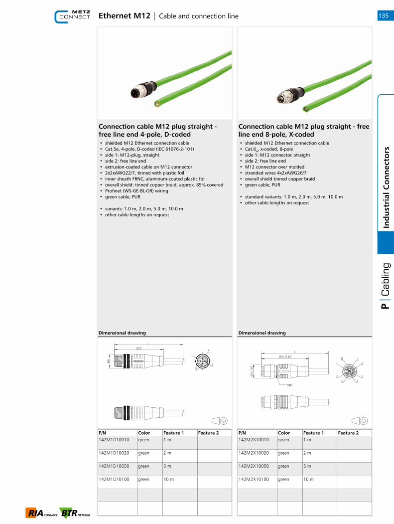
Ethernet M12 | Cable and connection line 135
1
Ind
ust
rial
Co
nn
ecto
rs
Connection cable M12 plug straight - free line end 4-pole, D-coded• shielded M12 Ethernet connection cable• Cat.5e, 4-pole, D-coded (IEC 61076-2-101)• side 1: M12-plug, straight• side 2: free line end• extrusion-coated cable on M12 connector• 2x2xAWG22/7, tinned with plastic foil• inner sheath FRNC, aluminum-coated plastic foil• overall shield: tinned copper braid, approx. 85% covered• Profinet (WS-GE-BL-OR) wiring• green cable, PUR
• variants: 1.0 m, 2.0 m, 5.0 m, 10.0 m• other cable lengths on request
P/N Color Feature 1 Feature 2142M1D10010 green 1 m
142M1D10020 green 2 m
142M1D10050 green 5 m
142M1D10100 green 10 m
Dimensional drawing
Connection cable M12 plug straight - free line end 8-pole, X-coded• shielded M12 Ethernet connection cable• Cat.6A, x-coded, 8-pole• side 1: M12 connector, straight• side 2: free line end• M12 connector over molded• stranded wires 4x2xAWG26/7• overall shield tinned copper braid• green cable, PUR
• standard variants: 1.0 m, 2.0 m, 5.0 m, 10.0 m• other cable lengths on request
P/N Color Feature 1 Feature 2142M2X10010 green 1 m
142M2X10020 green 2 m
142M2X10050 green 5 m
142M2X10100 green 10 m
Dimensional drawing
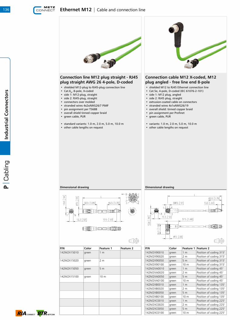
Ethernet M12 | Cable and connection line136In
du
stri
al C
on
nec
tors
Connection line M12 plug straight - RJ45 plug straight AWG 26 4-pole, D-coded• shielded M12-plug to RJ45-plug connection line• Cat.6A, 8-pole, X-coded• side 1: M12-plug, straight• side 2: RJ45-plug, straight• connectors over molded• stranded wires 4x2xAWG26/7 PiMF• pin assignment per T568B• overall shield tinned copper braid• green cable, PUR
• standard variants: 1.0 m, 2.0 m, 5.0 m, 10.0 m• other cable lengths on request
P/N Color Feature 1 Feature 2142M2X15010 green 1 m
142M2X15020 green 2 m
142M2X15050 green 5 m
142M2X15100 green 10 m
Dimensional drawing
Connection cable M12 X-coded, M12 plug angled - free line end 8-pole• shielded M12 to RJ45 Ethernet connection line• Cat.5e, 4-pole, D-coded (IEC 61076-2-101)• side 1: M12 plug, angled• side 2: RJ45 plug, straight• extrusion-coated cable on connectors• stranded wires 4x1xAWG26/19• overall shield: tinned copper braid• pin assignment per Profinet• green cable, PUR
• variants: 1.0 m, 2.0 m, 5.0 m, 10.0 m• other cable lengths on request
P/N Color Feature 1 Feature 2142M2X90010 green 1 m Position of coding 315°142M2X90020 green 2 m Position of coding 315°142M2X90050 green 5 m Position of coding 315°142M2X90100 green 10 m Position of coding 315°142M2XA0010 green 1 m Position of coding 45°142M2XA0020 green 2 m Position of coding 45°142M2XA0050 green 5 m Position of coding 45°142M2XA0100 green 10 m Position of coding 45°142M2XB0010 green 1 m Position of coding 135°142M2XB0020 green 2 m Position of coding 135°142M2XB0050 green 5 m Position of coding 135°142M2XB0100 green 10 m Position of coding 135°142M2XC0010 green 1 m Position of coding 225°142M2XC0020 green 2 m Position of coding 225°142M2XC0050 green 5 m Position of coding 225°142M2XC0100 green 10 m Position of coding 225°
Dimensional drawing
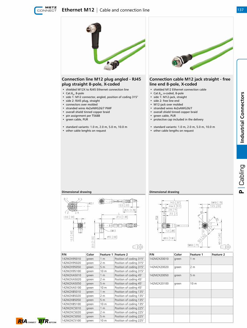
Ethernet M12 | Cable and connection line 137
1
Ind
ust
rial
Co
nn
ecto
rs
Connection line M12 plug angled - RJ45 plug straight 8-pole, X-coded• shielded M12X to RJ45 Ethernet connection line• Cat.6A, 8-pole• side 1: M12 connector, angled, position of coding 315°• side 2: RJ45 plug, straight• connectors over molded• stranded wires 4x2xAWG26/7 PiMF• overall shield tinned copper braid• pin assignment per T568B• green cable, PUR
• standard variants: 1.0 m, 2.0 m, 5.0 m, 10.0 m• other cable lenghts on request
P/N Color Feature 1 Feature 2142M2X95010 green 1 m Position of coding 315°142M2X95020 green 2 m Position of coding 315°142M2X95050 green 5 m Position of coding 315°142M2X95100 green 10 m Position of coding 315°142M2XA5010 green 1 m Position of coding 45°142M2XA5020 green 2 m Position of coding 45°142M2XA5050 green 5 m Position of coding 45°142M2XA5100 green 10 m Position of coding 45°142M2XB5010 green 1 m Position of coding 135°142M2XB5020 green 2 m Position of coding 135°142M2XB5050 green 5 m Position of coding 135°142M2XB5100 green 10 m Position of coding 135°142M2XC5010 green 1 m Position of coding 225°142M2XC5020 green 2 m Position of coding 225°142M2XC5050 green 5 m Position of coding 225°142M2XC5100 green 10 m Position of coding 225°
Dimensional drawing
Connection cable M12 jack straight - free line end 8-pole, X-coded• shielded M12 Ethernet connection cable• Cat.6A, x-coded, 8-pole• side 1: M12-jack, straight• side 2: free line end• M12-jack over molded• stranded wires 4x2xAWG26/7• overall shield tinned copper braid• green cable, PUR• protective cap included in the delivery
• standard variants: 1.0 m, 2.0 m, 5.0 m, 10.0 m• other cable lengths on request
P/N Color Feature 1 Feature 2142M2X20010 green 1 m
142M2X20020 green 2 m
142M2X20050 green 5 m
142M2X20100 green 10 m
Dimensional drawing

Ethernet M12 | Cable and connection line138In
du
stri
al C
on
nec
tors
Connection line M12 jack straight - RJ45 plug straight 4-pole, D-coded• shielded M12-jack to RJ45-plug connection line• Cat.6A, 8-pole, x-coded• side 1: M12-jack, straight• side 2: RJ45-plug, straight• connectors over molded• stranded wires 4x2xAWG26/7 PiMF• overall shield tinned copper braid• pin assignment per T568B• green cable, PUR
• standard variants: 1.0 m, 2.0 m, 5.0 m, 10.0 m• other cable lengths on request
P/N Color Feature 1 Feature 2142M2X25010 green 1 m
142M2X25020 green 2 m
142M2X25050 green 5 m
142M2X25100 green 10 m
Dimensional drawing
Connection line M12 plug straight - M12 jack straight 8-pole, X-coded• shielded M12 Ethernet connection line• Cat.6A, 8 pole, X-coded• side 1: M12-plug, straight• side 2: M12-jack, straight• extrusion-coated cable on M12 connectors• stranded wires 4x2xAWG26/7 PiMF• overall shield tinned copper braid• 1:1 pin assignment• green cable, PUR• a protective cap is included in scope of delivery
• variants: 1.0 m, 2.0 m, 5.0 m, 10.0 m• other cable lengths on request
P/N Color Feature 1 Feature 2142M2X12010 green 1 m
142M2X12020 green 2 m
142M2X12050 green 5 m
142M2X12100 green 10 m
Dimensional drawing

Ethernet M12 | Cable and connection line 139
1
Ind
ust
rial
Co
nn
ecto
rs
Connection cable M12 plug straight - free line end drag chain suitable, 8-pole, X-coded• shielded M12 Ethernet connection cable• drag chain suitable• Cat.6A, 8 pole, X-coded• side 1: M12-plug, straight• side 2: free line end• extrusion-coated cable on M12 connector• stranded wires 4x2xAWG26/19• overall shield tinned copper braid• 1:1 pin assignment• green cable, PUR
• variants: 1.0 m, 2.0 m, 5.0 m, 10.0 m• other cable lengths on request
P/N Color Feature 1 Feature 2142M6X10010 green 1 m drag chain
suitable
142M6X10020 green 2 m drag chain suitable
142M6X10050 green 5 m drag chain suitable
142M6X10100 green 10 m drag chain suitable
Dimensional drawing
Connection line M12 plug straight - M12 plug straight 4-pole, D-coded• shielded M12 Ethernet connection cable• drag chain suitable• Cat.6A, 8 pole, X-coded• side 1: M12-plug, straight• side 2: M12-plug, straight• extrusion-coated cable on M12 connectors• stranded wires 4x2xAWG26/19• overall shield tinned copper braid• 1:1 pin assignment• green cable, PUR
• variants: 1.0 m, 2.0 m, 5.0 m, 10.0 m• other cable lengths on request
P/N Color Feature 1 Feature 2142M6X11010 green 1 m
142M6X11020 green 2 m
142M6X11050 green 5 m
142M6X11100 green 10 m
Dimensional drawing

Ethernet M12 | Cable and connection line140In
du
stri
al C
on
nec
tors
Connection cable M12 jack straight - free line end drag chain suitable, 8-pole, X-coded• shielded M12 Ethernet connection cable• drag chain suitable• Cat.6A, 8 pole, X-coded• side 1: M12-jack, straight• side 2: free line end• extrusion-coated cable on M12 connector• stranded wires 4x2xAWG26/19• overall shield tinned copper braid• 1:1 pin assignment• green cable, PUR
• variants: 1.0 m, 2.0 m, 5.0 m, 10.0 m• other cable lengths on request
P/N Color Feature 1 Feature 2142M6X20010 green 1 m drag chain
suitable
142M6X20020 green 2 m drag chain suitable
142M6X20050 green 5 m drag chain suitable
142M6X20100 green 10 m drag chain suitable
Dimensional drawing
Connection line M12 plug straight - M12 jack straight drag chain suitable, 8-pole, X-coded• shielded M12 Ethernet connection cable• drag chain suitable• Cat.6A, 8 pole, X-coded• side 1: M12-plug, straight• side 2: M12-jack, straight• extrusion-coated cable on M12 connectors• stranded wires 4x2xAWG26/19• overall shield tinned copper braid• 1:1 pin assignment• green cable, PUR
• variants: 1.0 m, 2.0 m, 5.0 m, 10.0 m• other cable lengths on request
P/N Color Feature 1 Feature 2142M6X21010 green 1 m drag chain
suitable
142M6X21020 green 2 m drag chain suitable
142M6X21050 green 5 m drag chain suitable
142M6X21100 green 10 m drag chain suitable
Dimensional drawing

Ethernet M12 | Cable and connection line 141
1
Ind
ust
rial
Co
nn
ecto
rs
Connection cable M12 plug straight - free line end 8-pole, X-coded• shielded M12 Ethernet connection cable• torsion resistant• Cat.6A, 8 pole, X-coded• side 1: M12 plug, straight• side 2: free line end• extrusion-coated cable on M12 connector• stranded wires 4x2xAWG24/7• overall shield tinned copper braid• 1:1 pin assignment• green cable, PUR
• variants: 1.0 m, 2.0 m, 5.0 m, 10.0 m• other cable lengths on request
P/N Color Feature 1 Feature 2142M7X10005 green 0,5 m
142M7X10010 green 1 m
142M7X10020 green 2 m
142M7X10050 green 5 m
142M7X10100 green 10 m
Dimensional drawing
Connection line M12 plug straight - M12 plug straight 4-pole, D-coded• shielded M12 Ethernet connection line• torsion resistant• Cat.6A, 8 pole, X-coded• side 1: M12 jack, straight• side 2: M12 jack, straight• extrusion-coated cable on M12 connectors• jacks with vibration-resistance• stranded wires 4x2xAWG26/7• overall shield tinned copper braid• 1:1 pin assignment• green cable, PUR
• variants: 1.0 m, 2.0 m, 5.0 m, 10.0 m• other cable lengths on request
P/N Color Feature 1 Feature 2142M7X11005 green 0,5 m
142M7X11010 green 1 m
142M7X11020 green 2 m
142M7X11050 green 5 m
142M7X11100 green 10 m
Dimensional drawing
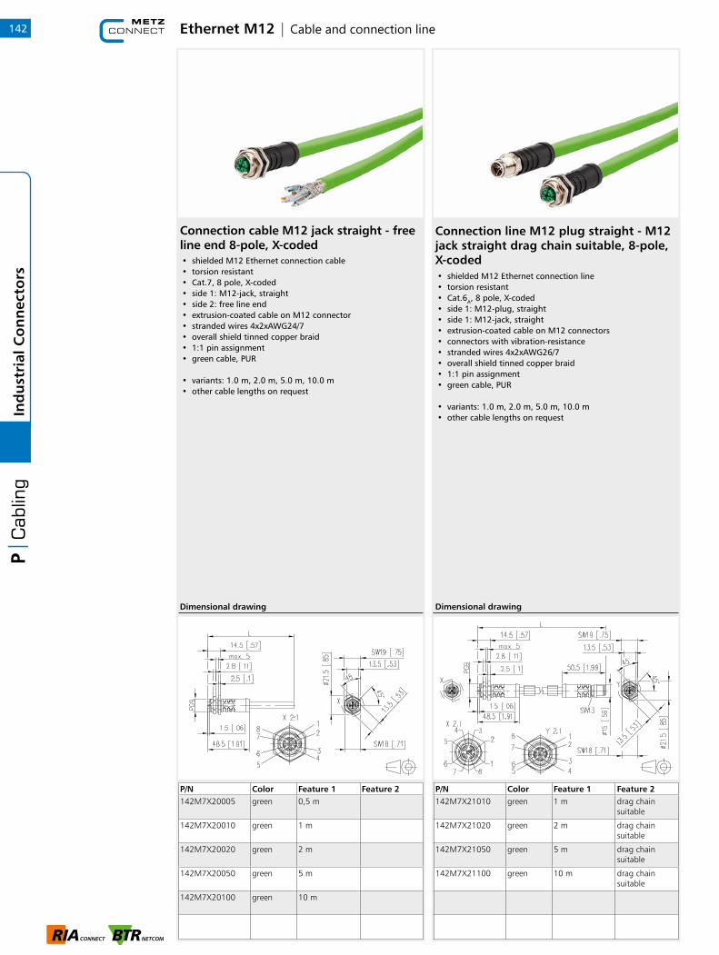
Ethernet M12 | Cable and connection line142In
du
stri
al C
on
nec
tors
Connection cable M12 jack straight - free line end 8-pole, X-coded• shielded M12 Ethernet connection cable• torsion resistant• Cat.7, 8 pole, X-coded• side 1: M12-jack, straight• side 2: free line end• extrusion-coated cable on M12 connector• stranded wires 4x2xAWG24/7• overall shield tinned copper braid• 1:1 pin assignment• green cable, PUR
• variants: 1.0 m, 2.0 m, 5.0 m, 10.0 m• other cable lengths on request
P/N Color Feature 1 Feature 2142M7X20005 green 0,5 m
142M7X20010 green 1 m
142M7X20020 green 2 m
142M7X20050 green 5 m
142M7X20100 green 10 m
Dimensional drawing
Connection line M12 plug straight - M12 jack straight drag chain suitable, 8-pole, X-coded• shielded M12 Ethernet connection line• torsion resistant• Cat.6A, 8 pole, X-coded• side 1: M12-plug, straight• side 1: M12-jack, straight• extrusion-coated cable on M12 connectors• connectors with vibration-resistance• stranded wires 4x2xAWG26/7• overall shield tinned copper braid• 1:1 pin assignment• green cable, PUR
• variants: 1.0 m, 2.0 m, 5.0 m, 10.0 m• other cable lengths on request
P/N Color Feature 1 Feature 2142M7X21010 green 1 m drag chain
suitable
142M7X21020 green 2 m drag chain suitable
142M7X21050 green 5 m drag chain suitable
142M7X21100 green 10 m drag chain suitable
Dimensional drawing
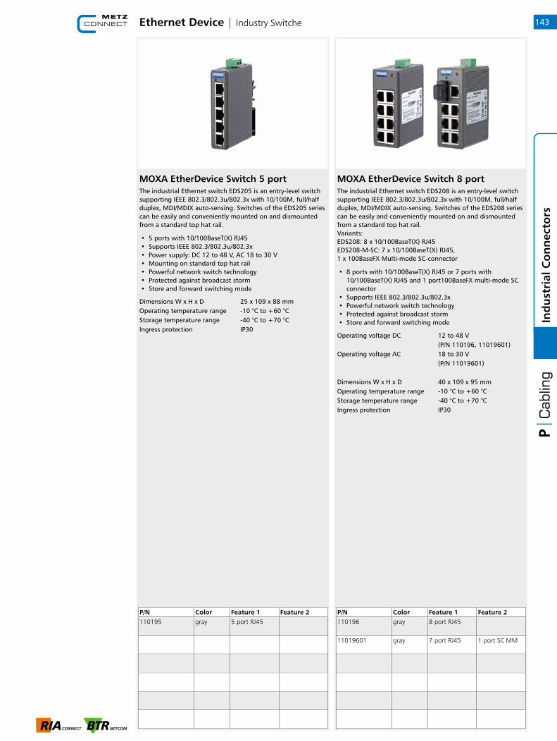
Ethernet Device | Industry Switche
MOXA EtherDevice Switch 5 portThe industrial Ethernet switch EDS205 is an entry-level switch supporting IEEE 802.3/802.3u/802.3x with 10/100M, full/half duplex, MDI/MDIX auto-sensing. Switches of the EDS205 series can be easily and conveniently mounted on and dismounted from a standard top hat rail.
• 5 ports with 10/100BaseT(X) RJ45• Supports IEEE 802.3/802.3u/802.3x• Power supply: DC 12 to 48 V, AC 18 to 30 V• Mounting on standard top hat rail• Powerful network switch technology• Protected against broadcast storm• Store and forward switching mode
MOXA EtherDevice Switch 8 portThe industrial Ethernet switch EDS208 is an entry-level switch supporting IEEE 802.3/802.3u/802.3x with 10/100M, full/half duplex, MDI/MDIX auto-sensing. Switches of the EDS208 series can be easily and conveniently mounted on and dismounted from a standard top hat rail.Variants:EDS208: 8 x 10/100BaseT(X) RJ45EDS208-M-SC: 7 x 10/100BaseT(X) RJ45,1 x 100BaseFX Multi-mode SC-connector
• 8 ports with 10/100BaseT(X) RJ45 or 7 ports with 10/100BaseT(X) RJ45 and 1 port100BaseFX multi-mode SC connector
• Supports IEEE 802.3/802.3u/802.3x• Powerful network switch technology• Protected against broadcast storm• Store and forward switching mode
Dimensions W x H x D 25 x 109 x 88 mmOperating temperature range -10 °C to +60 °CStorage temperature range -40 °C to +70 °CIngress protection IP30
Operating voltage DC 12 to 48 V(P/N 110196, 11019601)
Operating voltage AC 18 to 30 V(P/N 11019601)
Dimensions W x H x D 40 x 109 x 95 mmOperating temperature range -10 °C to +60 °CStorage temperature range -40 °C to +70 °CIngress protection IP30
P/N Color Feature 1 Feature 2110195 gray 5 port RJ45
P/N Color Feature 1 Feature 2110196 gray 8 port RJ45
11019601 gray 7 port RJ45 1 port SC MM
143
1
Ind
ust
rial
Co
nn
ecto
rs

Notes144In
du
stri
al C
on
nec
tors
Table of contents | Pre-Terminated Assemblies
Pre-Terminated Assemblies
1 Fiber optic | Configurators 146
2 Product information | OpDAT VIK
with universal cable 149
3 Product information | OpDAT VIK
with breakout cable 151
4 Product information | OpDAT VIK
with mini breakout cable 152
5 Product information | OpDAT VIK
with mini breakout cable compact 153
145
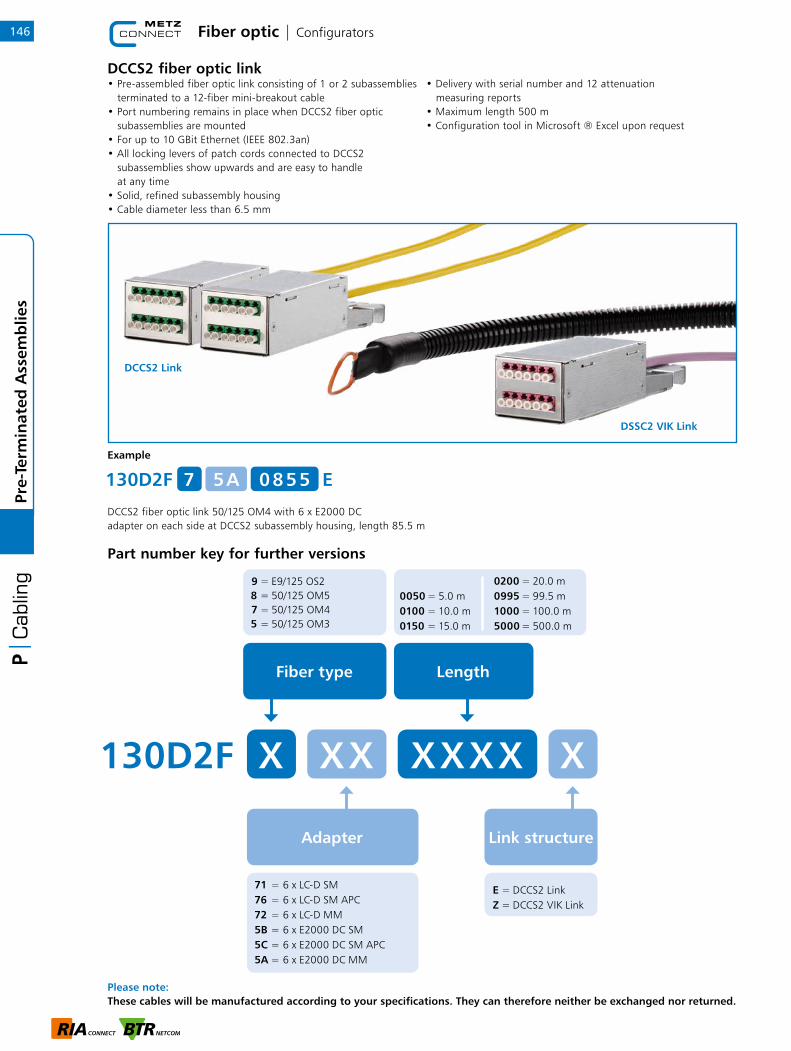
Fiber optic | Configurators
Please note: These cables will be manufactured according to your specifications. They can therefore neither be exchanged nor returned.
146Pr
e-Te
rmin
ated
Ass
emb
lies
Example
DCCS2 fiber optic link 50/125 OM4 with 6 x E2000 DCadapter on each side at DCCS2 subassembly housing, length 85.5 m
Part number key for further versions
0 8 5 5130D2F E7 5 A
DCCS2 fiber optic link• Pre-assembled fiber optic link consisting of 1 or 2 subassemblies terminated to a 12-fiber mini-breakout cable• Port numbering remains in place when DCCS2 fiber optic subassemblies are mounted• For up to 10 GBit Ethernet (IEEE 802.3an)• All locking levers of patch cords connected to DCCS2 subassemblies show upwards and are easy to handle at any time• Solid, refined subassembly housing• Cable diameter less than 6.5 mm
• Delivery with serial number and 12 attenuation measuring reports• Maximum length 500 m• Configuration tool in Microsoft ® Excel upon request
Adapter Link structure
9 = E9/125 OS28 = 50/125 OM5 7 = 50/125 OM45 = 50/125 OM3
E = DCCS2 Link Z = DCCS2 VIK Link
Fiber type Length
X X X X130D2F X XX X
71 = 6 x LC-D SM 76 = 6 x LC-D SM APC 72 = 6 x LC-D MM 5B = 6 x E2000 DC SM 5C = 6 x E2000 DC SM APC 5A = 6 x E2000 DC MM
0050 = 5.0 m 0100 = 10.0 m 0150 = 15.0 m
0200 = 20.0 m 0995 = 99.5 m 1000 = 100.0 m 5000 = 500.0 m
DCCS2 Link
DSSC2 VIK Link
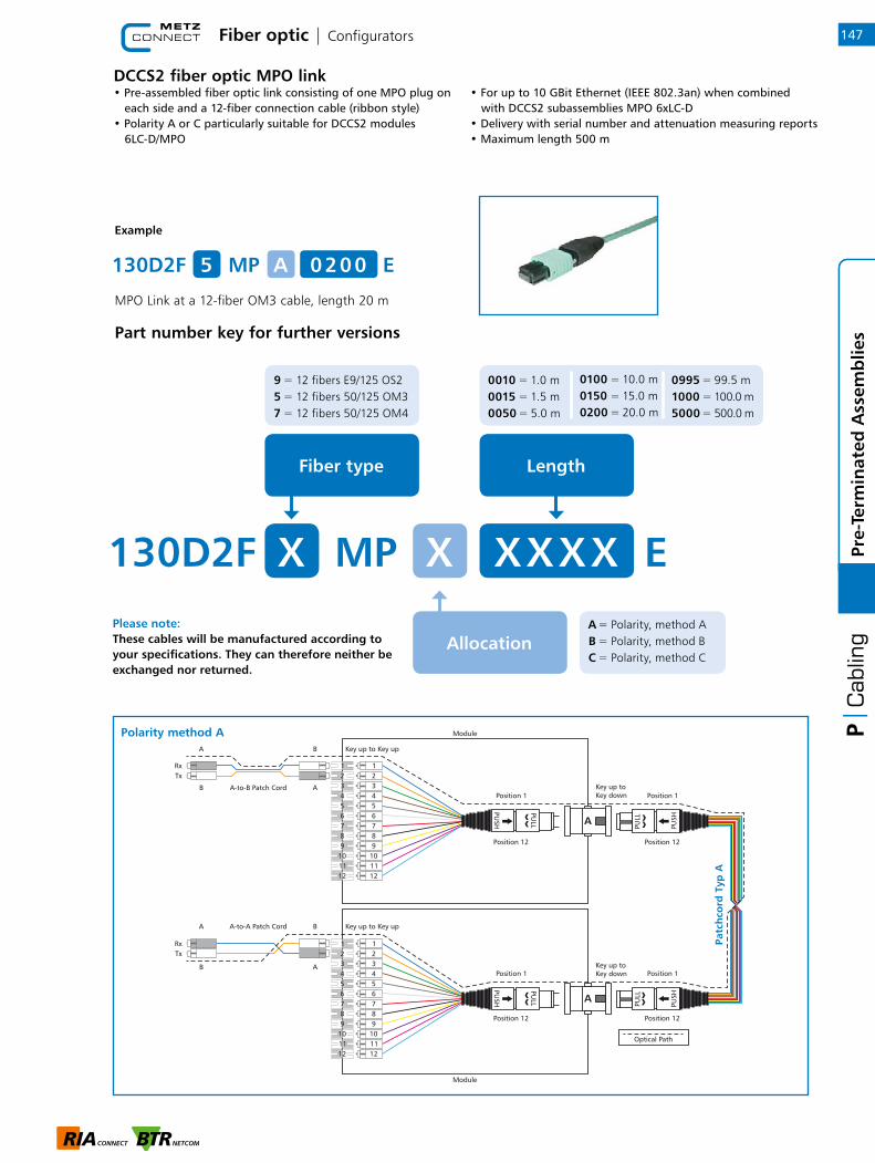
Fiber optic | Configurators
Please note: These cables will be manufactured according to your specifications. They can therefore neither be exchanged nor returned.
147
1
Pre-
Term
inat
ed A
ssem
blie
s
DCCS2 fiber optic MPO link• Pre-assembled fiber optic link consisting of one MPO plug on each side and a 12-fiber connection cable (ribbon style) • Polarity A or C particularly suitable for DCCS2 modules 6LC-D/MPO
• For up to 10 GBit Ethernet (IEEE 802.3an) when combined with DCCS2 subassemblies MPO 6xLC-D• Delivery with serial number and attenuation measuring reports• Maximum length 500 m
Example
MPO Link at a 12-fiber OM3 cable, length 20 m
Part number key for further versions
Allocation A = Polarity, method A B = Polarity, method B C = Polarity, method C
9 = 12 fibers E9/125 OS2 5 = 12 fibers 50/125 OM3 7 = 12 fibers 50/125 OM4
Fiber type
130D2F MP EX X X X X X
Length
0010 = 1.0 m 0015 = 1.5 m 0050 = 5.0 m
0100 = 10.0 m 0150 = 15.0 m 0200 = 20.0 m
0995 = 99.5 m 1000 = 100.0 m 5000 = 500.0 m
130D2F MP E5 A 0 2 0 0
Optical Path
Key up toKey down
Key up toKey down
A-to-A Patch Cord
A-to-B Patch Cord
A
A
A
A
B
B
B
B
Key up to Key up
Key up to Key up
A
A
Polarity method APa
tch
cord
Typ
A

Please note: These cables will be manufactured according to your specifications. They can therefore neither be exchanged nor returned.
Fiber optic | Configurators148Pr
e-Te
rmin
ated
Ass
emb
lies
Optical Path
Key up toKey down
Key up toKey down
A-to-B Patch Cord
A-to-B Patch Cord
A
A
A
A
B
B
B
B
Key up to Key up
Key up to Key up
A
A
Optical Path
Key up toKey up
Key down toKey down
A-to-B Patch Cord
A-to-B Patch Cord
A
A
B
B
B
B
A
A
Key down to Key down
Key up to Key up
B
B
Polarity method C
Polarity method B
Patc
hco
rd T
yp B
Patc
hco
rd T
yp C
(F
iber
s cr
oss
ed in
pai
rs)

Product information | OpDAT VIK with universal cable
OpDAT VIK with universal cable
Specifications
up to 12 fibers up to 24 fibers up to 48 fibers
Cable divider Size S M L
Length 65 mm 65 mm 80 mm
Max. outer diameter 23 mm 29 mm 36 mm
Type of fixation slot or PG11 slot or PG21 slot or PG21
Drilling for fixation 19 ± 0.2 mm 28.8 ± 0.2 mm 28.8 ± 0.2 mm
Cable Cable type U-DQ(ZN)BH
Cable structure (loose tube x number of fibers) 1x4, 1x8, 1x12 1x24 4x12
Outer diameter 7.5 mm 8.0 mm 11.0 mm
Cable weight 55 kg/km 60 kg/km 130 kg/km
Min. bending radius 60 mm 60 mm 150 mm
Fire behaviorFlame retardant according to IEC 60332-1-2Halogene-free according to IEC 60754-1Smoke density according to IEC 61034-2
Fanout Individual cables 2.1 mm, loose tube
Length if graded(with pull-in aid)
LFmax [mm] 4F: 6808F: 920
6F: 80012F: 1160
24F: 1040 mm16F: 920 mm
48F: 1280 mm36F: 1100 mm
LFmin [mm] 500 mm 500 mm 500 mm
Length if not graded(with bubble wrap or protection net) 1000 mm
Marking Numbered, 1 = LFmax
Material and color of the loose tubeI-V(ZN)H, FRNCOS2 = yellow, OM4= violet, OM3= aqua, OM5= lime green
Pull-in aid Max. outer diameter IP50IP67
29.5 mm31.5 mm
37 mm39 mm
44 mm46 mm
Max. tensile strength IP50IP67
500 N700 N
500 N650 N
500 N700 N
Delivery Length LG 2 to 100 m101 to 1000 m
Cable coilDrum dia. 600 mm
Cable coilDrum dia. 600 mm
-
Length LG 2 to 50 m51 to 150 m151 to 500 m
- -Cable coilDrum dia. 600 mmDrum dia. 710 mm
149
1
Pre-
Term
inat
ed A
ssem
blie
s

Product information | OpDAT VIK with universal cable
OpDAT VIK with universal cable
Order information
Please note: These cables will be manufactured according to your specifications. They can therefore neither be exchanged nor returned. Technically, it is not possible to produce all possible combinations.Just use our cable configurator available on our web site at www.metz-connect.com/en/cable-configurator. There you can find all variants available.
Number offibers
Fanout protection
U = universal cable / U-DQ(ZN)BH
9 = E9/125 OS2 8 = 50/125 OM5 7 = 50/125 OM4 5 = 50/125 OM3
2 = bubble wrap both ends 3 = protection net one end 4 = protection net both ends 5 = pull-in aid IP50 one end 6 = pull-in aid IP50 both ends 7 = pull-in aid IP67 one end 8 = pull-in aid IP67 both ends
Cable type Fiber type
Length LG
152 U X X X X X X GX X X
02 = 2 fibers 04 = 4 fibers 06 = 6 fibers 08 = 8 fibers
12 = 12 fibers16 = 16 fibers 24 = 24 fibers 48 = 48 fibers
J = LC K = LC APC E = SC F = SC APC
A = ST P = E2000 Q = E2000 APC 0 = without connector
002 = 2 m 010 = 10 m 050 = 50 m
100 = 100 m999 = 999 m A00 = 1.000 m
Cable endA and B
Product descriptionPre-terminated installation cables (VIK) are fiber optic cables with connectors on one or both ends that are made in manual singleitem production at METZ CONNECT in Blumberg by res-pecting highest quality demands. Combined with universal cables they are suitable for mechanically demanding indoor or outdoor use.
VIKs are often used together with OpDAT patch panels. They allow a rapid and easy to install point-to-point connection of passive and active network components. Thus, installation time and cost are considerably reduced compared to an installation requiring splicing and pigtails or a cabling with different patch cords.
150Pr
e-Te
rmin
ated
Ass
emb
lies
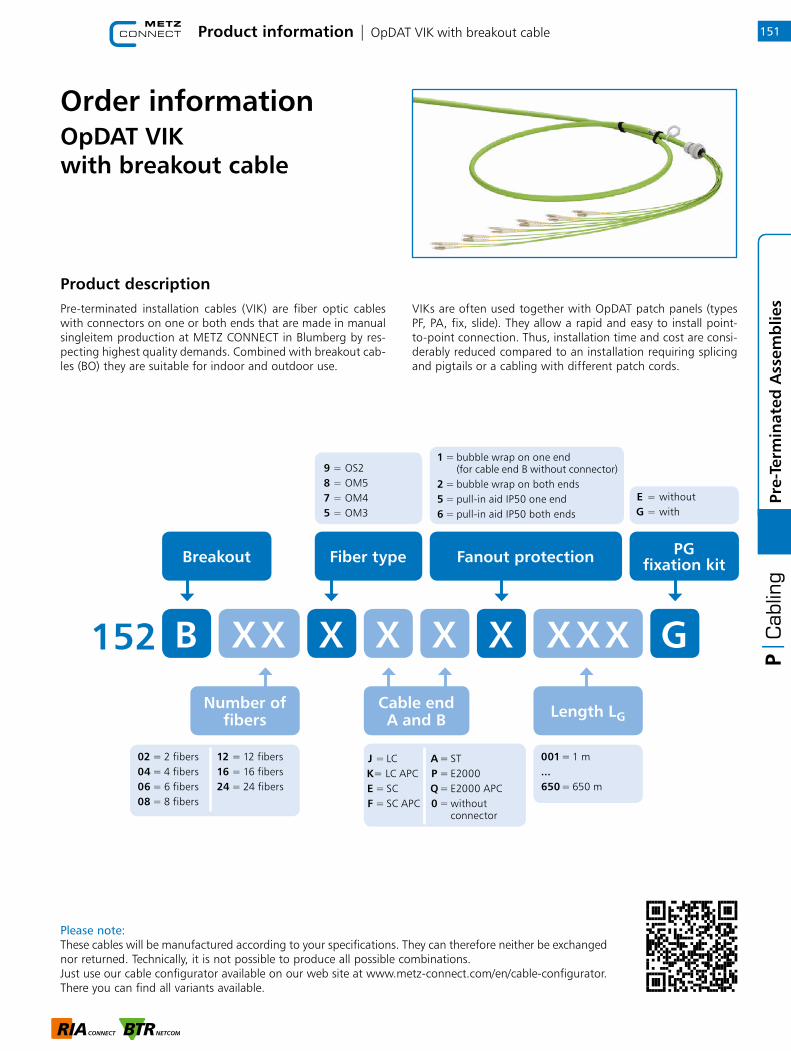
Product information | OpDAT VIK with breakout cable 151
1
Pre-
Term
inat
ed A
ssem
blie
s
OpDAT VIK with breakout cable
Order information
Fanout protection
9 = OS2 8 = OM5 7 = OM4 5 = OM3
Breakout Fiber type
Length LG
152 B X X X X X X GX X X
PG fixation kit
02 = 2 fibers 04 = 4 fibers 06 = 6 fibers 08 = 8 fibers
12 = 12 fibers16 = 16 fibers 24 = 24 fibers
J = LC K = LC APC E = SC F = SC APC
A = ST P = E2000 Q = E2000 APC 0 = without connector
001 = 1 m ... 650 = 650 m
Cable endA and B
1 = bubble wrap on one end (for cable end B without connector) 2 = bubble wrap on both ends 5 = pull-in aid IP50 one end 6 = pull-in aid IP50 both ends
E = without G = with
Product descriptionPre-terminated installation cables (VIK) are fiber optic cables with connectors on one or both ends that are made in manual singleitem production at METZ CONNECT in Blumberg by res-pecting highest quality demands. Combined with breakout cab-les (BO) they are suitable for indoor and outdoor use.
VIKs are often used together with OpDAT patch panels (types PF, PA, fix, slide). They allow a rapid and easy to install point-to-point connection. Thus, installation time and cost are consi-derably reduced compared to an installation requiring splicing and pigtails or a cabling with different patch cords.
Please note: These cables will be manufactured according to your specifications. They can therefore neither be exchanged nor returned. Technically, it is not possible to produce all possible combinations.Just use our cable configurator available on our web site at www.metz-connect.com/en/cable-configurator. There you can find all variants available.
Number offibers
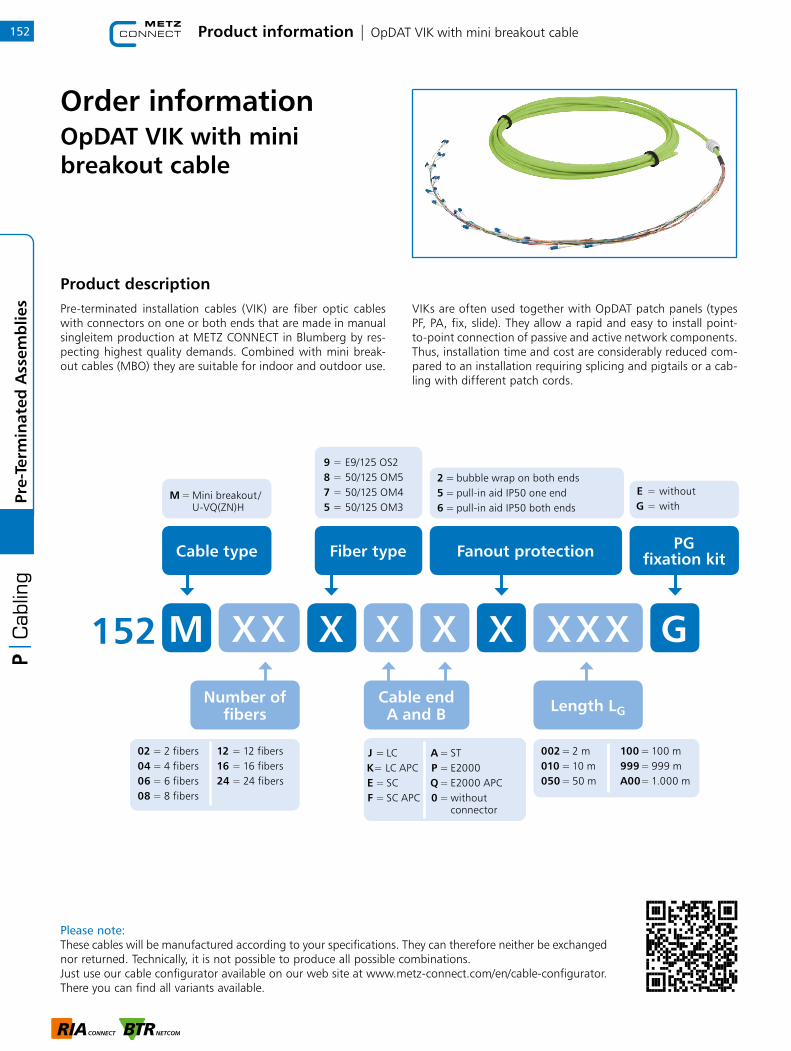
Product information | OpDAT VIK with mini breakout cable152Pr
e-Te
rmin
ated
Ass
emb
lies
OpDAT VIK with mini breakout cable
Order information
Fanout protection
M = Mini breakout / U-VQ(ZN)H
9 = E9/125 OS2 8 = 50/125 OM5 7 = 50/125 OM4 5 = 50/125 OM3
Cable type Fiber type
Length LG
152 M X X X X X X GX X X
PG fixation kit
02 = 2 fibers 04 = 4 fibers 06 = 6 fibers 08 = 8 fibers
12 = 12 fibers16 = 16 fibers 24 = 24 fibers
J = LC K = LC APC E = SC F = SC APC
A = ST P = E2000 Q = E2000 APC 0 = without connector
002 = 2 m 010 = 10 m 050 = 50 m
100 = 100 m999 = 999 m A00 = 1.000 m
Cable endA and B
2 = bubble wrap on both ends 5 = pull-in aid IP50 one end 6 = pull-in aid IP50 both ends
E = without G = with
Product descriptionPre-terminated installation cables (VIK) are fiber optic cables with connectors on one or both ends that are made in manual singleitem production at METZ CONNECT in Blumberg by res-pecting highest quality demands. Combined with mini break-out cables (MBO) they are suitable for indoor and outdoor use.
VIKs are often used together with OpDAT patch panels (types PF, PA, fix, slide). They allow a rapid and easy to install point-to-point connection of passive and active network components. Thus, installation time and cost are considerably reduced com-pared to an installation requiring splicing and pigtails or a cab-ling with different patch cords.
Please note: These cables will be manufactured according to your specifications. They can therefore neither be exchanged nor returned. Technically, it is not possible to produce all possible combinations.Just use our cable configurator available on our web site at www.metz-connect.com/en/cable-configurator. There you can find all variants available.
Number offibers
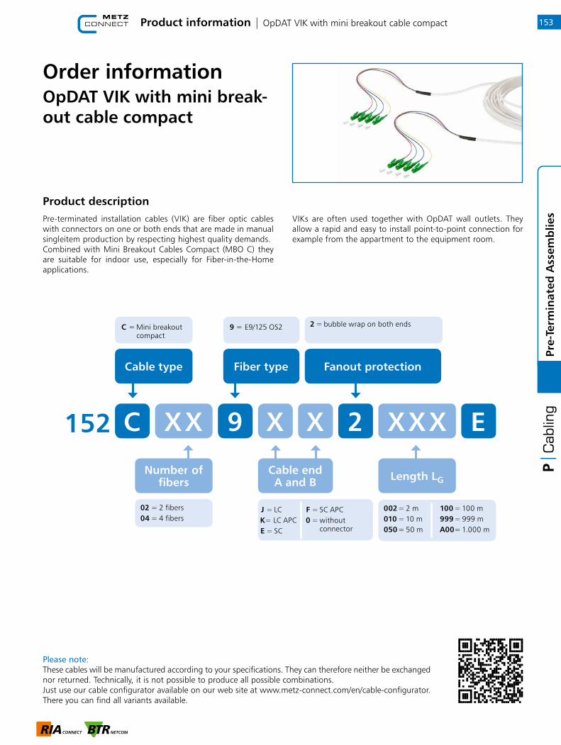
Product information | OpDAT VIK with mini breakout cable compact
OpDAT VIK with mini break-out cable compact
Order information
Product descriptionPre-terminated installation cables (VIK) are fiber optic cables with connectors on one or both ends that are made in manual singleitem production by respecting highest quality demands.Combined with Mini Breakout Cables Compact (MBO C) they are suitable for indoor use, especially for Fiber-in-the-Home applications.
VIKs are often used together with OpDAT wall outlets. They allow a rapid and easy to install point-to-point connection for example from the appartment to the equipment room.
Number offibers
Fanout protection
C = Mini breakout compact
9 = E9/125 OS2
Cable type Fiber type
Length LG
152 C X X 9 X X 2 EX X X
02 = 2 fibers 04 = 4 fibers
J = LC K = LC APC E = SC
F = SC APC 0 = without connector
002 = 2 m 010 = 10 m 050 = 50 m
100 = 100 m999 = 999 m A00 = 1.000 m
Cable endA and B
2 = bubble wrap on both ends
Please note: These cables will be manufactured according to your specifications. They can therefore neither be exchanged nor returned. Technically, it is not possible to produce all possible combinations.Just use our cable configurator available on our web site at www.metz-connect.com/en/cable-configurator. There you can find all variants available.
153
1
Pre-
Term
inat
ed A
ssem
blie
s

154
Tinton Falls
Strasbourg Kunszentmiklós
Hong KongZhongshan
BLUMBERG
METZ CONNECT worldwide
PRODUCTION SITES
MCQ TECH GmbH
Ottilienweg 9 78176 Blumberg Germany
Phone + 49 77 02 533-0 Fax + 49 77 02 533-433
www.metz-connect.com
MC Termelo Kft.
Vásár tér 16/A 6090 Kunszentmiklós Hungary
Phone +36 76 350524
METZ CONNECT Zhongshan Ltd.
Ping Chang Road Ping Pu Industrial Park Sanxiang Town Zhongshan City, 528 463 Guangdong Province China
Phone + 86 760 86365 055 Fax + 86 760 86365 050 www.metz-connect.com
”
SALES OFFICES
METZ CONNECT USA Inc.
200 Tornillo Way Tinton Falls, NJ 07712 USA
Phone + 1 732 389 1300 Fax + 1 732 389 9066
www.metz-connect.com
METZ CONNECT France SAS
28, Rue Schweighaeuser 67000 Strasbourg France
Phone + 33 3 886 170 73 Fax + 33 3 886 194 73
www.metz-connect.com
METZ CONNECT GmbH
Im Tal 2 78176 Blumberg Germany
Phone + 49 7702 533-0 Fax + 49 7702 533-189
www.metz-connect.com
METZ CONNECT Zhongshan Ltd.
Ping Chang Road Ping Pu Industrial Park Sanxiang Town Zhongshan City, 528 463 Guangdong Province China
Phone + 86 760 86365 055 Fax + 86 760 86365 050
www.metz-connect.com
METZ CONNECT Asia Pacific Limited
Suite 1803, 18/F, Chinachem Hollywood Centre 1 Hollywood Road Central Hong Kong
Phone + 852 26 027 300 Fax + 852 27 257 522
www.metz-connect.com

155
Contact
ContactsYou will find your responsible contacts for your sector in your region at our website: http://www.metz-connect.com/en/contact-search

8993
94 |
07/
2018
METZ CONNECT GmbHIm Tal 278176 BlumbergGermany
Phone +49 7702 533- 0Fax +49 77 02 533-189
METZ CONNECT GmbH is member of the following organizations and associations.
METZ CONNECT USA Inc.
200 Tornillo Way Tinton Falls, NJ 07712 USAPhone + 1-732-389-1300 Fax + 1-732-389-9066
METZ CONNECT France SAS
28, Rue Schweighaeuser 67000 Strasbourg FrancePhone + 33 38 86 170 73 Fax + 33 38 86 194 73
METZ CONNECT Zhongshan Ltd.
Ping Chang Road Ping Pu Industrial Park Sanxiang Town Zhongshan City, 528 463 Guangdong Province ChinaPhone + 86 760 86365 055 Fax + 86 760 86365 050
METZ CONNECT Asia Pacific Ltd.
Suite 1803, 18/F Chinachem Hollywood Centre, 1 Hollywood Road, Central Hong KongPhone + 852 26 027 300 Fax + 852 27 257 522