coppusrla manualfgdgdfg
DESCRIPTION
dfgdfgdfgdfgdfgTRANSCRIPT

Dresser-Rand RLA Turbine
Instruction Manual
Feb 2007 591113400 Revision H


RLA Instruction Manual How to Use This Manual
How to Use This Manual
THIS MANUAL APPLIES TO RLA-12L, RLA-12M, RLA-16E, RLA-16L, RLA-20L, RLA-22L, AND RLA-23L TURBINES. This instruction manual contains installation, operation, and maintenance instructions for the Dresser-Rand Turbine identified on the Turbine Data Sheet included with this manual. It should be reviewed thoroughly by the user before attempting to install and operate the turbine, and should be kept in a location convenient to the user for ready reference during operation and maintenance.
WARNING
A complete reading of this manual by personnel in contact with the steam turbine is essential to safety. INCORRECT INSTALLATION, OPERATION, MAINTENANCE, OR PARTS REPLACEMENT CAN RESULT IN INJURY TO PERSONNEL, AND DAMAGE TO THE TURBINE, DRIVEN MACHINERY, AND PLANT.
The Instruction Manual consists of 14 sections, as listed in the Table of Contents. Each section is further broken down into subsections. This is a general instruction manual, describing a standard ring oiled turbine with hydraulic Woodward TG governor, the description and illustrations contained herein may differ in minor details from the unit actually supplied, all general installation, operation, and maintenance procedures are applicable. For turbines supplied with options such as forced or circulating lubrication systems, alternative speed control systems, accessories, instrumentation, speed reducers or other special configurations, refer to the appropriate accessory manuals and turbine certified drawing package included in the Supplemental Documentation section, supplied as a part of this manual.
RLA Instruction Manual Revision H 1

How to Use This Manual RLA Instruction Manual
WARNING
Throughout this manual it is assumed that the motive flow applied at the turbine inlet is high-pressure steam, therefore, the word “steam” is used in reference to various aspects of turbine installation, operation and maintenance. For some specialized applications, high-pressure gases such as Freon, natural gas or other vapors may provide the motive flow in these cases, it can generally be assumed, that the name of the gas in use may be used to replace the word “steam”. The user of the equipment must address all hazards associated with the nature of the specific motive flow in use with the turbine. Explosive gas mixtures must not be used as the motive fluid.
The instructions contained in this manual do not attempt to cover all details, nor provide for every possible contingency to be met in connection with installation, operation, or maintenance of the supplied equipment. The supplying of instructions does not imply in any manner that Dresser-Rand accepts liability for work carried out by a customer or contractor personnel. Liability is limited to and as stated in our Terms and Conditions of Sale. Should further information be desired, or should particular problems arise which are not covered sufficiently for the purchaser’s purposes, the matter should be referred to Dresser-Rand. All inquiries regarding installation, operation, maintenance, spare parts, or service should be directed to your Dresser-Rand manufacturer’s representative, or to:
DRESSER-RAND
Steam Turbine Business Unit
www.dresser-rand.com
880-268-8726 508-595-1700
Refer to Section M, Replacement Parts/Factory Service, for information on how to request factory service or order replacement parts.
2 Revision H RLA Instruction Manual

RLA Instruction Manual EU Compliance
EU COMPLIANCE
The following warning and notes apply only to turbines for which compliance with European Union Directives has been specified.
NOTE
If there is a CE mark on this turbine nameplate it indicates compliance with the ATEX Directive. Machinery Directive Compliance and Machinery Directive CE marking of the turbine and driven equipment is the responsibility of the assembler or installer. See the Machinery Directive Declaration of Incorporation.
NOTE
Refer to the Machinery Directive - List of Residual Risks and the ATEX Directive-Risk Assessment Summary List for warnings related to EU Compliance.
Additional cautions and warnings are located throughout this manual and in the safety precautions section.
WARNING
ATEX Certified turbines will have a mark – c °C X on the turbine nameplate. This indicates that the turbine casing temperature will become that of the steam inlet temperature, this may exceed the ignition temperature of some gasses. See the ATEX Directive – Risk Assessment Summary List.
RLA Instruction Manual Revision H 3
EU Compliance RLA Instruction Manual
WARNING
Modification of, incorrect repair of, or use of non DRESSER-RAND repair parts on this turbine could result in a serious malfunction or explosion that could result in serious injury or death. Such actions will also invalidate ATEX Directive & Machinery Directive Certifications for turbines that are in compliance with those European Directives. Refer to Section M – Replacement Parts/Factory Service
4 Revision H RLA Instruction Manual

RLA Instruction Manual Table of Contents
Table of Contents
How to Use This Manual ........................................................................................................... 1
EU COMPLIANCE ...................................................................................................................... 3
Table of Contents ...................................................................................................................... 5
List of Figures............................................................................................................................ 11
List of Tables ............................................................................................................................. 13
Safety Precautions .................................................................................................................... 15
Warranty ..................................................................................................................................... 23
Section A Introduction and General Description .................................................................. 25 A.1 Turbine Description................................................................................................. 25 A.2 Construction............................................................................................................ 25 A.3 Main Components................................................................................................... 26 A.4 Factory Test............................................................................................................ 31 A.5 Shipping Preparation/Crating ................................................................................. 31 A.6 Uncrating and Inspection........................................................................................ 32 A.7 Short-term Storage ................................................................................................. 32 A.8 Long-term Storage.................................................................................................. 33 A.9 Dresser-Rand Factory Service/Replacement Parts ............................................... 34 A.10 Re-Rating and Upgrades........................................................................................ 34 A.11 Nameplate Information ........................................................................................... 35
Section B Technical Data......................................................................................................... 37 B.1 General ................................................................................................................... 37 B.2 Lifting ...................................................................................................................... 37 B.3 Alignment................................................................................................................ 39 B.4 Thermal Growth ...................................................................................................... 39 B.5 Lubricants ............................................................................................................... 40 B.6 Major Fits, Clearances, and Rotor Balance Criteria ............................................... 40 B.7 Piping Forces.......................................................................................................... 40 B.8 Bolt Torques and Materials..................................................................................... 43 B.9 Sealants and Joint Compounds.............................................................................. 44 B.10 Cooling Water to Bearing Housing Water Jackets ................................................. 45 B.11 Steam Pressure and Temperature Limits............................................................... 45
RLA Instruction Manual Revision H 5

Table of Contents RLA Instruction Manual
B.12 Steam Quality and Steam Purity .............................................................................46 B.13 Turbine Rotor Data..................................................................................................47
Section C Installation................................................................................................................49 C.1 General....................................................................................................................49 C.2 Foundation ..............................................................................................................52 C.3 Piping ......................................................................................................................54 C.3.1 Piping Forces ..........................................................................................................54 C.3.2 Isolating Valves .......................................................................................................57 C.3.3 Full Flow Relief Valve..............................................................................................57 C.3.4 Inlet Piping...............................................................................................................58 C.3.5 Exhaust Piping ........................................................................................................59 C.3.6 Piping Blow Down ...................................................................................................60 C.3.7 Steam Strainer ........................................................................................................60 C.3.8 Check Valve ............................................................................................................60 C.3.9 Expansion Joints .....................................................................................................61 C.3.10 Drain Piping.............................................................................................................63 C.3.11 Leak-Off Piping........................................................................................................64 C.3.12 Cooling Water Piping to Bearing Housing Water Jackets.......................................64 C.3.13 Gland Seal Piping....................................................................................................65 C.3.14 Suggested Inlet, Exhaust, and Drain Piping Schematics........................................66 C.4 Alignment Requirements .........................................................................................67 C.5 Couplings ................................................................................................................69 C.6 Preparation for Alignment .......................................................................................71 C.7 Compensation for Thermal Movement....................................................................73 C.8 Cold Alignment Check.............................................................................................74 C.8.1 Angular Alignment ...................................................................................................74 C.8.2 Parallel Alignment ...................................................................................................75 C.9 Grouting...................................................................................................................75 C.10 Hot Alignment Check...............................................................................................76 C.11 Decommissioning ....................................................................................................77
Section D Speed Control System ............................................................................................79 D.1 General....................................................................................................................79 D.2 Standard Governor..................................................................................................79 D.3 Lubrication and Maintenance ..................................................................................80 D.4 Speed Range and Droop Adjustment .....................................................................81 D.5 Optional Governors .................................................................................................81 D.6 Throttle Valve ..........................................................................................................81 D.7 Throttle Linkage.......................................................................................................83 D.8 Handvalves..............................................................................................................84
Section E Overspeed Trip System ..........................................................................................85 E.1 General....................................................................................................................85 E.2 Warnings .................................................................................................................86 E.3 Description and Function ........................................................................................87 E.3.1 Overspeed Trip Collar Assembly ............................................................................87 E.3.2 Trip Valve ................................................................................................................88 E.3.3 Trip Linkage.............................................................................................................90 E.4 Trip System Operation ............................................................................................93 E.5 Adjustment of Trip Speed........................................................................................94 E.5.1 Trip Speed Setting (refer to Figure E-3, Collar in Tripped Position) .......................94
6 Revision H RLA Instruction Manual

RLA Instruction Manual Table of Contents
E.5.2 Magnetic Pickup Clearances .................................................................................. 95 E.6 Testing the Overspeed Trip Mechanism................................................................. 96 E.6.1 General ................................................................................................................... 96 E.6.2 Overspeed Trip Test Procedure ............................................................................. 97
Section F Lubrication System................................................................................................. 99 F.1 General ................................................................................................................... 99 F.2 Lubrication Requirements....................................................................................... 99 F.3 Oil Ring Lubrication ................................................................................................ 100 F.4 Oil Mist Lubrication ................................................................................................. 101 F.5 Cooling Water to Bearing Housing Water Jackets ................................................. 102 F.5.1 Bearing Housing Cooling Water Requirements...................................................... 103 F.6 Constant Level Oiler ............................................................................................... 105 F.7 Bearing Housing Oil Levels and Capacities ........................................................... 105 F.8 Maintenance/Oil Changes ...................................................................................... 105 F.9 Lubricating Oil Selection Guidelines....................................................................... 106 F.10 Seal Ring Adjustment ............................................................................................. 107 F.11 Air Purge of Bearing Housings ............................................................................... 108
Section G Optional Gland Condensers, Eductors and Ejectors.......................................... 109
Section H Optional Instruments and Controls ...................................................................... 111 H.1 Sentinel Warning Valve .......................................................................................... 111 H.2 Pressure and Temperature Gauges ....................................................................... 111 H.3 Solenoid Trip........................................................................................................... 112 H.4 Other Optional Instruments and Controls ............................................................... 112
Section I Start-Up and Operation............................................................................................ 113 I.1 Warnings................................................................................................................. 113 I.2 General ................................................................................................................... 117 I.3 Turbine Installation and Start-Up Checklist ............................................................ 119 I.3.1 Turbine Information................................................................................................. 119 I.3.2 Site Information....................................................................................................... 120 I.3.3 Installation............................................................................................................... 120 I.3.4 Start Up - Uncoupled .............................................................................................. 122 I.3.5 Start Up - Coupled.................................................................................................. 123 I.4 Start-Up Procedure................................................................................................. 125 I.4.1 Restoration of Turbine from Shipping Condition .................................................... 125 I.4.1.1 Flushing/Filling of Bearing Housings ...................................................................... 125 I.4.1.2 Gland Housings ...................................................................................................... 126 I.4.2 Initial Start-Up Procedure ....................................................................................... 126 I.5 Turbine Vibration Limits .......................................................................................... 128 I.5.1 Shaft Displacement Measured with Proximity Probes............................................ 128 I.5.2 Bearing Housing Vibration...................................................................................... 129 I.6 Testing the Overspeed Trip Mechanism................................................................. 130 I.7 Governor Speed Adjustment .................................................................................. 130 I.8 Governor Droop Adjustment................................................................................... 130 I.9 Handvalve Adjustments.......................................................................................... 131 I.10 Shutdown................................................................................................................ 132 I.11 Restart Procedure................................................................................................... 133 I.11.1 Non-Condensing Turbines...................................................................................... 133
RLA Instruction Manual Revision H 7
Table of Contents RLA Instruction Manual
I.11.2 Condensing Turbines ..............................................................................................134 I.12 Standby Operation ..................................................................................................135 I.13 Auto Start Operation................................................................................................138 I.14 Manual Start Operation ...........................................................................................138 I.15 Quick Start...............................................................................................................138 I.16 Function Check of Sentinel Warning Valve.............................................................138
Section J Maintenance, Maintenance Schedule and Inspection Schedule.........................141 J.1 Introduction..............................................................................................................141 J.2 Maintenance and Inspection Schedule ...................................................................142 J.3 Major Inspection ......................................................................................................144 J.4 Inspection Checklist ................................................................................................145 J.5 Factory Service .......................................................................................................146 J.6 Factory Replacement Parts.....................................................................................146
Section K Troubleshooting ......................................................................................................149 K.1 Introduction..............................................................................................................149 K.2 Troubleshooting.......................................................................................................149
Section L Disassembly and Parts Replacement....................................................................159 L.1 Warnings/Cautions ..................................................................................................159 L.2 General....................................................................................................................162 L.3 Gland Housings/Carbon Ring Repair and Replacement ........................................162 L.3.1 Gland Housng/Carbon Ring Disassembly...............................................................163 L.3.2 Gland Housing/Carbon Ring Assembly...................................................................166 L.4 Bearing Housings/Bearings.....................................................................................167 L.4.1 Seal Ring Replacement (applies to standard design only) .....................................172 L.4.2 Governor End Bearing Replacement ......................................................................173 L.4.2.1 RLA-12M and -12L Turbines...................................................................................173 L.4.2.2 RLA-16L, -16E, -20L, -22L, and -23L Turbines.......................................................175 L.4.3 Drive End Bearing Replacement.............................................................................177 L.4.3.1 RLA-12M and -12L Turbines...................................................................................177 L.4.3.2 RLA-16L, -16E, -20L, -22L, and -23L Turbines.......................................................178 L.5 Turbine Rotor & Turbine Wheel Removal & Replacement .....................................179 L.5.1 Turbine Rotor Removal & Replacement .................................................................180 L.5.2 Turbine Wheel Removal and Replacement ............................................................181 L.5.2.1 Turbine Wheel Removal..........................................................................................181 L.5.2.2 Turbine Wheel Replacement...................................................................................182 L.5.3 Turbine Rotor Balancing .........................................................................................184 L.5.4 Turbine Rotor Installation ........................................................................................184 L.6 Governor Removal and Replacement.....................................................................184 L.6.1 General....................................................................................................................185 L.6.2 Governor Removal (Direct Drive)............................................................................185 L.6.3 Governor Replacement (Direct Drive).....................................................................186 L.7 Throttle Linkage Adjustment ...................................................................................187 L.8 Throttle Valve and Stem Maintenance....................................................................188 L.8.1 Throttle Valve and Stem Removal ..........................................................................189 L.8.2 Throttle Valve and Stem Replacement ...................................................................189 L.9 Throttle Valve and Seal Maintenance .....................................................................190 L.10 Overspeed Trip Mechanism Maintenance ..............................................................191 L.10.1 Trip Bolt and Collar Removal ..................................................................................192 L.10.2 Trip Bolt and Collar Replacement ...........................................................................193
8 Revision H RLA Instruction Manual

RLA Instruction Manual Table of Contents
L.11 Overspeed Trip Valve Maintenance ....................................................................... 195 L.11.1 Overspeed Trip Valve Disassembly ....................................................................... 195 L.11.2 Overspeed Trip Valve Assembly ............................................................................ 196 L.12 Overspeed Trip Linkage Maintenance.................................................................... 197 L.12.1 Overspeed Trip Linkage Disassembly.................................................................... 197 L.12.2 Overspeed Trip Linkage Assembly......................................................................... 198 L.13 Overspeed Trip Linkage Adjustment ...................................................................... 199 L.14 Handvalve Removal and Replacement .................................................................. 200 L.14.1 Handvalve Removal................................................................................................ 201 L.14.2 Handvalve Replacement ........................................................................................ 201 L.14.3 Handvalve Adjustment............................................................................................ 201 L.15 Casing Joints .......................................................................................................... 201
Section M Replacement Parts/Factory Service ..................................................................... 203 M.1 Factory Replacement Parts .................................................................................... 203 M.2 Turbine Identification .............................................................................................. 203 M.3 Parts Identification .................................................................................................. 204 M.4 Parts List................................................................................................................. 204 M.5 Recommended Spare Parts - The VIP Program.................................................... 205 M.5.1 Vital Parts ............................................................................................................... 205 M.5.2 Ideal Parts............................................................................................................... 206 M.5.3 Preventative Parts .................................................................................................. 207 M.5.4 Interchangeability Lists ........................................................................................... 208 M.6 Ordering Parts ........................................................................................................ 208 M.7 Factory Service....................................................................................................... 209 M.8 Rerates ................................................................................................................... 209 M.9 Upgrades ................................................................................................................ 210 M.10 Factory Start-Ups.................................................................................................... 211 M.11 Parts Catalog .......................................................................................................... 211
Section N User Notes and Maintenance Records ................................................................. 229
RLA Instruction Manual Revision H 9


RLA Instruction Manual List of Figures
List of Figures
Figure A-1 Dresser-Rand RLA Turbine, General View............................................ 30 Figure B-1 Recommended Lifting Arrangement for Dresser-Rand RLA Turbines ... 38 Figure B-2 Major Fits and Clearances, Standard RLA Turbine ............................... 42 Figure C-1 Suggested Steam Inlet and Exhaust Piping Arrangement ..................... 56 Figure C-2 Unrestrained Expansion Joint (Not Recommended).............................. 61 Figure C-3 Expansion Joint with Tie Rods (Acceptable).......................................... 62 Figure C-4 Expansion Joint with Tie Rods for Non-Condensing Operation
(Preferred) ............................................................................................. 62 Figure C-5 Gland Seal Piping for Vacuum Exhaust................................................. 65 Figure C-6 Suggested Steam Inlet, Exhaust, and Drain Piping, Manual Start ......... 66 Figure C-7 Suggested Inlet, Exhaust, and Drain Piping, Automatic Start ................ 67 Figure C-8 Angular Misalignment ............................................................................ 68 Figure C-9 Parallel Misalignment............................................................................. 69 Figure C-10 Alignment Using Dial Indicators............................................................. 72 Figure D-1 Woodward Oil Relay Governor Features ............................................... 80 Figure D-2 Throttle Valve Features ......................................................................... 83 Figure E-1 Overspeed Trip Collar Assembly (A015) ............................................... 87 Figure E-2 Trip System ........................................................................................... 89 Figure E-3 Collar in Tripped Position....................................................................... 92 Figure E-4 Air Gap between Signal Gear and Magnetic Pickup.............................. 96 Figure F-1 Lubrication Requirements for RLA Turbines........................................ 100 Figure F-2 Cooling Water Piping with Optional Interconnecting Pipe.................... 104 Figure I-1 Radial Shaft Displacement .................................................................. 129 Figure L-1 4-Ring Gland Housing, Cross Section ................................................. 164 Figure L-2 6-Ring Gland Housing, Cross Section ................................................. 165 Figure L-3 RLA Bearing Housings Cross Section Standard Design, 12L/12M...... 168 Figure L-4 RLA Bearing Housings Cross Section Standard Design, 16L thru 23L
............................................................................................................. 169 Figure L-5 RLA Bearing Housings Cross Section Optional Inproseal Design,
12L/12M............................................................................................... 170 Figure L-6 RLA Bearing Housings Cross Section Optional Inproseal Design 16L–
23L....................................................................................................... 171 Figure L-7 Bearing and Bearing Washer Removal................................................ 175 Figure L-8 Direct Drive Governor Assembly.......................................................... 186
RLA Instruction Manual Revision H 11

List of Figures RLA Instruction Manual
Figure L-9 Throttle Linkage Adjustment ................................................................ 188 Figure L-10 Overspeed Trip Collar Assembly ......................................................... 192 Figure L-11 Bolt Head Shanks, Old and New Designs............................................ 192 Figure M-0 RLA Turbine--General View (Sheet 1 of 2) .......................................... 212 Figure M-0 RLA Turbine--General View (Sheet 2 of 2) .......................................... 213 Figure M-1 Overspeed Trip Valve Assembly.......................................................... 215 Figure M-2 Throttle Valve Assembly ...................................................................... 217 Figure M-3 Governor, Mounting Housing, and Bolt Trip Components.................... 219 Figure M-4 Bearing Housing and Components – Governor End............................ 221 Figure M-5 Yoke, Gland Housing, and Sealing Elements – Cover End ................. 223 Figure M-6 Cover, Casing, and Casing End Components ..................................... 225 Figure M-7 Bearing Housing and Components – Casing End................................ 227
12 Revision H RLA Instruction Manual
RLA Instruction Manual List of Tables
List of Tables
Table B-1 Major Fits, Clearances, & Rotor Balance Criteria - RLA ........................ 41 Table B-2 Bolt Material & Markings........................................................................ 43 Table B-3 Standard Bolt Torques for Turbine Bolting............................................. 44 Table B-4 Recommended Limits for Boiler Water .................................................. 47 Table B-5 RLA Turbine Rotor Data ........................................................................ 47 Table F-1 Cooling Water Requirements, RLA Turbine......................................... 102 Table F-2 Recommended Bearing Oil Sump Temperatures ................................ 103 Table F-3 Bearing Housing Oil Capacity .............................................................. 105 Table F-4 Bearing Housing Oil Levels ................................................................. 105 Table F-5 Lubricating Oil Selection Guidelines .................................................... 107 Table F-6 Viscosity Comparisons ........................................................................ 107 Table I-2 Bearing Housing Vibration ................................................................... 130 Table J-1 Suggested Maintenance and Inspection Schedule.............................. 143 Table J-1 Suggested Maintenance and Inspection Schedule (Cont’d) ................ 144 Table J-2 Inspection Checklist............................................................................. 145 Table J-2 Inspection Checklist (Cont’d) ............................................................... 146 Table K-1 Troubleshooting Guide ........................................................................ 150 Table K-1 Troubleshooting Guide (Cont.) ............................................................ 151 Table K-1 Troubleshooting Guide (Cont’d)........................................................... 152 Table K-1 Troubleshooting Guide (Cont’d)........................................................... 153 Table K-1 Troubleshooting Guide (Cont’d)........................................................... 154 Table K-1 Troubleshooting Guide (Cont’d)........................................................... 155 Table K-1 Troubleshooting Guide (Cont’d)........................................................... 156 Table K-1 Troubleshooting Guide (Cont’d)........................................................... 157 Table K-1 Troubleshooting Guide (Cont’d)........................................................... 158 Table M-1 Overspeed Trip Valve Assembly Parts List.......................................... 214 Table M-2 Throttle Valve Assembly Parts List ...................................................... 216 Table M-3 Governor, Mounting Housing, and Bolt Trip Components, Parts List .. 218 Table M-4 Bearing Housing and Components – Governor End, Parts List........... 220 Table M-6 Cover, Casing, and Casing End Components, Parts List .................... 224 Table M-7 Bearing Housing and Components – Casing End, Parts List............... 226
RLA Instruction Manual Revision H 13

RLA Instruction Manual
THIS PAGE WAS LEFT BLANK INTENTIONALLY
14 Revision H RLA Instruction Manual

RLA Instruction Manual Safety Precautions
Safety Precautions
This turbine has been designed to provide safe and reliable service within the designed specifications. It is a pressure containing, rotating machine; therefore, responsible and qualified personnel must exercise good judgment and proper safety practices to avoid damage to the equipment and surroundings and/or possible serious or painful injuries. It is assumed that your company's safety department has an established safety program based on a thorough analysis of industrial hazards. Before installing, operating, or performing maintenance on the turbine, it is suggested that you review your safety program to ensure it covers the hazards arising from rotating machinery and pressure vessels. It is important that due consideration be given to all hazards resulting from the presence of electrical power, hot oil, high pressure and temperature steam, toxic gasses, and flammable liquids and gasses. Proper installation and continued maintenance of protective guards, shutdown devices, and overpressure protection are also necessary for safe turbine operation. The turbine should never be operated by bypassing, overriding, or in any way rendering inoperative, guards, protective shutdown equipment, or other safety devices. When internal maintenance work is in progress, it is essential that the turbine be isolated from all utilities to prevent the possibility of applying power or steam to the turbine. When performing internal turbine maintenance, always ensure that isolating valves in the steam inlet and exhaust lines are locked closed and tagged, and all drains are opened to depressurize the turbine casing and steam chest. Precautions must also be taken to prevent turbine rotation due to reverse flow through the driven machinery. In general, you should be guided by all of the basic safety rules associated with the turbine, driven equipment and plant process. This manual contains four types of hazard seriousness messages. They are as follows: DANGER: Immediate hazards which WILL result in severe personal injury or death. WARNING: Hazards which COULD result in serious injury to the turbine operator and others, or extensive damage to the turbine, driven equipment, or the surroundings.
RLA Instruction Manual Revision H 15

Safety Precautions RLA Instruction Manual
CAUTION: Hazards which COULD result in damage or malfunction to the turbine or its parts, leading to subsequent downtime and expense. NOTE: A message to clarify or simplify an operation or technique, or to avoid a
common mistake.
DANGERS
DO NOT attempt to ADJUST, REPAIR, DISASSEMBLE OR MODIFY this turbine WHILE IT IS IN OPERATION, unless such action is expressly described in this instruction manual.
NEVER DISCONNECT inlet or exhaust piping of the turbine without first CLOSING and TAGGING the ISOLATING VALVES and then OPENING DRAIN VALVES SLOWLY to relieve any pressure within the turbine. Failure to do so may expose PERSONNEL to SERIOUS INJURY if steam were to be introduced into the piping or captured in the turbine. As an added precaution, always install blank flanges on inlet and exhaust lines after removing the turbine.
DO NOT REMOVE ANY COVERS, GUARDS, GLAND HOUSINGS, DRAIN COVERS, etc. while the unit is OPERATING.
Under no circumstances should the TRIP VALVE be blocked or held open to render the trip system inoperative. Overriding the trip system, and allowing the turbine to exceed the rated (nameplate) trip speed, may result in FATAL INJURY to personnel and extensive turbine damage. In the event the trip system malfunctions, immediately SHUT DOWN the turbine and correct the cause.
NEVER BLOCK OR DISABLE THE TURBINE TRIP SYSTEM OR ATTEMPT TO ADJUST OR REPAIR IT WHILE THE TURBINE IS OPERATING.
16 Revision H RLA Instruction Manual

RLA Instruction Manual Safety Precautions
DANGERS(Cont’d)
This turbine is equipped with an OVERSPEED TRIP to protect against dangerous overspeeding. It is absolutely essential that the complete trip system be MAINTAINED in such a condition that it will operate perfectly if required. It must be thoroughly INSPECTED AND TESTED WEEKLY. Inspection must include all elements of the trip system. Dresser-Rand Turbine recommends that all TESTS BE RECORDED.
Keep body parts (fingers, hands, etc.) away from shaft, couplings, linkage or other moving parts to prevent contact and possible serious injury. NEVER WEAR NECKTIES OR LOOSE CLOTHING while in the proximity of the turbine or auxiliary equipment. These could become entangled in the shaft, coupling, linkage or other moving parts and cause serious injury.
A coupling guard must be installed at the coupling between the turbine and driven equipment.
Wear proper eye protection when working on or around the turbines.
The turbine must be grounded.
WARNINGS
Modification of, incorrect repair of, or use of non DRESSER-RAND repair parts on this turbine could result in a serious malfunction or explosion that could result in serious injury or death. Such actions will invalidate ATEX Directive & Machinery Directive Certifications for turbines that are in compliance with those European Directives. Refer to Section M – Replacement Parts/Factory Service.
RLA Instruction Manual Revision H 17

Safety Precautions RLA Instruction Manual
WARNINGS (Cont’d)
Throughout this manual it is assumed that the motive flow applied at the turbine inlet is high-pressure steam, therefore, the word “steam” is used in reference to various aspects of turbine installation, operation and maintenance. For some specialized applications, high-pressure gases such as Freon, natural gas or other vapors may provide the motive flow in these cases, it can generally be assumed, that the name of the gas in use may be used to replace the word “steam”. The user of the equipment must address all hazards associated with the nature of the specific motive fluid in use with the turbine. If flammable or toxic gasses are ued as the motive fluid or oil vapor could be emitted. The user/installer must pipe leak-offs and drains to a safe location.
Explosive gas mixtures must not be used as the motive fluid.
DO NOT START OR OPERATE this turbine unless the INSTALLATION has been VERIFIED TO BE CORRECT and all pre-startup SAFETY AND CONTROL FUNCTIONS have been CHECKED.
DO NOT START OR OPERATE this turbine unless you have a COMPLETE UNDERSTANDING of the location and function of ALL COMPONENTS in the steam supply and exhaust systems, including block and relief valves, bypasses, drains, and any upstream or downstream equipment that may affect the flow of steam to or from the steam turbine.
DO NOT START OR OPERATE this turbine unless you have a complete understanding of the control system, the overspeed trip system, the drain and leakoff systems, the lubrication system, and all auxiliary mechanical, electrical, hydraulic and pneumatic systems, as well as the meaning and significance of all monitoring gages, meters, digital readouts, and warning devices.
DO NOT MAKE ANY MODIFICATIONS OR REPAIRS that are not described in this manual.
18 Revision H RLA Instruction Manual

RLA Instruction Manual Safety Precautions
WARNINGS (Cont’d)
WHEN STARTING the turbine, BE PREPARED TO execute an EMERGENCY SHUTDOWN in the event of failure of the governor, overspeed control systems, linkage or valves.
It is the USER’S RESPONSIBILITY to INSTALL A FULL-FLOW RELIEF VALVE in the exhaust line between the turbine exhaust casing and the first shut-off valve. This relief valve should be sized to relieve the FULL AMOUNT OF STEAM THAT THE TURBINE WILL PASS, in the event that the exhaust line is blocked.
VERIFICATION of proper functioning and setting of the OVERSPEED TRIP SYSTEM during initial start-up is mandatory. This should be accomplished with the turbine DISCONNECTED from the driven equipment. Turbine speed should be increased SLOWLY in a controlled manner during trip testing.
If the turbine is operated on a motive fluid other than steam due consideration must be given to safety issues that might relate to the medium used, including but not limited to the ignition, explosion or poisoning of personnel.
The surface temperature of the turbine will become that of the steam inlet temperature. This could exceed the ignition temperature of some gasses. Therefore if the turbine is installed where explosive gasses could be present it is the user’s responsibility to insure that this does not create a hazardous situation.
Steam quality must be DRY AND SATURATED OR SUPERHEATED. There must be provision to REMOVE MOISTURE AND CONDENSATE from the steam supply system to AVOID DAMAGING the turbine. Steam purity should meet or exceed American Boiler Manufactureres Association Guidleline.
RLA Instruction Manual Revision H 19

Safety Precautions RLA Instruction Manual
WARNINGS (Cont’d)
The surface temperature of the turbine and piping will become that of the steam inlet temperature. Personnel should wear gloves and protective clothing to avoid burns.
Lighting must be provided in the installation to insure that the operators can see the turbine and its controls.
Should an explosion occur in the vicinity of the turbine it is the user/installer’s responsibility to halt it immediately and/or limit the range of the exposive flame and explosive pressures to a sufficient level of safety.
Shown below are turbine noise levels that were measured at three feet (1 meter), while operating at a normal load and exhausting to a positive backpressure. These noise levels are not guaranteed and are published for informational purposes only.
This noise data is based on test measurements that were taken on similar equipment being operated on the factory test stand, and have been extrapolated and/or corrected for backround noise as appropriate.
When the turbine is operated under actual field conditions, noise generated in or by the piping, foundation, baseplate, couplings, driven equipment, background and other sources, can add significantly to the turbine noise level and to the overall noise levels in the area.
It is recommended that the equipment user assess the noise level(s) of the completed installation and determine if additional sound attenation and/or hearing protection for operating personnel is required.
20 Revision H RLA Instruction Manual

RLA Instruction Manual Safety Precautions
Turbine Sound Level Data
Model RLA
Octave Band Frequency HZ – Sound Pressure Level Sound Power Level
Frame Size 63 125 250 500 1K 2K 4K 8K dBa dBa 12M/L 65 65 65 63 66 70 74 70 77 94 16L/E 65 66 66 64 67 71 75 71 78 95 20L 68 68 68 67 69 73 77 73 80 97 22L 68 69 69 67 69 74 78 74 81 98 23L/E 68 69 69 67 69 74 78 74 81 98
RLA Instruction Manual Revision H 21

RLA Instruction Manual
THIS PAGE WAS LEFT BLANK INTENTIONALLY
22 Revision H RLA Instruction Manual

RLA Instruction Manual Warranty
Warranty
Seller warrants to Buyer that the goods at the time of shipment will be free from material defects in material and workmanship, and that the goods will conform in all material respects to Seller's specifications. This warranty shall be ineffective and shall not extend to goods subjected to misuse, neglect, accident or improper installation or maintenance, goods which have been altered or repaired by anyone other than the Seller or its authorized representative, or if more than one year has elapsed from the date of shipment. Any model or sample provided to Buyer was used merely to illustrate the general type and quality of goods and not to warrant that goods shipped would be of that type or quality. No agent, employee or representative of Seller has any authority to bind Seller to any affirmation, representation or warranty concerning the goods and/or services sold hereunder, and any such affirmation, representation or warranty has not formed a part of the basis of the bargain and shall be unenforceable. Seller's sole obligation under the foregoing warranty is limited to, at Seller's option, replacing or repairing defective goods or refunding the purchase price. Buyer's exclusive remedy for breach of warranty will be enforcement of such obligation of Seller. The warranty contained herein is made only to and for the exclusive benefit of Buyer, and does not extend to any subsequent purchaser or user of the goods or of any product of which the goods may be a component part. THE ABOVE WARRANTY COMPRISES THE SELLER'S SOLE AND ENTIRE WARRANTY OBLIGATION AND LIABILITY. ALL OTHER WARRANTIES EXPRESS OR IMPLIED, INCLUDING WITHOUT LIMITATION, WARRANTIES OF MERCHANTABILITY AND FITNESS FOR A PARTICULAR PURPOSE, ARE EXPRESSLY EXCLUDED.
RLA Instruction Manual Revision H 23

RLA Instruction Manual
THIS PAGE WAS LEFT BLANK INTENTIONALLY
24 Revision H RLA Instruction Manual
RLA Instruction Manual Introduction and General Description
Section A
Introduction and General Description
THIS MANUAL APPLIES TO RLA-12M, RLA-12L, RLA-16L, RLA-16E, RLA-20L, RLA-22L, and RLA-23L.
A.1 Turbine Description
Standard Dresser-Rand RLA Turbines are single-stage, impulse-type turbines with a two-row, velocity-compounded rotor and one row of stationary reversing blades between the rotating blades. The rotor is enclosed between the turbine cover, which contains the steam inlet connection, and the turbine casing, which contains the steam exhaust connection. The rotor is supported and positioned axially between two ball bearings. Steam enters the turbine cover after first passing through the built-in steam strainer, the overspeed trip valve, and the throttle valve. Cast into the turbine cover is the steam chest, which contains several individual steam nozzles. Some of these nozzles are controlled by handvalves for partial load or overload conditions. Steam flowing through the nozzles expands and is directed at high velocity against the rotating blades of the first row on the turbine rotor. After passing through the first row, the stationary blades redirect the steam against the second row of rotating blades. The steam is then discharged into the exhaust casing and from there into the user’s exhaust piping, at the exhaust system pressure. Optionally the turbine may be supplied with a single row rotor, in which case standard reversing blades are not provided.
A.2 Construction
Dresser-Rand RLA Turbines are ruggedly constructed, suitable for a wide range of mechanical drive applications and comply with all basic API-611 and NEMA SM23 requirements. The casing, valve bodies, shaft, wheel, blades, nozzles, valve components, and fasteners are constructed of high-grade alloy steel, stainless steel, carbon steel, and cast iron, assuring a long and dependable service life. Depending on the steam conditions, horsepower, and speed, materials used in turbine construction may vary. Always consult the turbine data sheet or nameplate on the turbine before connecting it to a steam inlet or exhaust supply, to ensure that the
RLA Instruction Manual Revision H 25

Introduction and General Description RLA Instruction Manual
turbine is rated for the prospective conditions. Never run the turbine in excess of the maximum allowable speed, maximum inlet or exhaust pressure, maximum inlet temperature, or above the rated horsepower, as specified on the nameplate.
WARNING
Materials used in turbine construction (cast iron, steel, stainless steel, special alloys) vary with steam conditions, speed, and power. These materials were selected according to the original rating of the turbine. NEVER attempt to RE-RATE a turbine without the assistance of a Dresser-Rand manufacturer’s representative and/or the factory. MISAPPLICATION of materials COULD result in serious equipment damage and/or personal injury.
Some Dresser-Rand turbines can be re-rated for different steam conditions, powers, and speeds. Consult your Dresser-Rand manufacturer’s representative or the factory for further information.
WARNING
NEVER connect the turbine to inlet or exhaust sources of UNKNOWN PRESSURE OR TEMPERATURE or to sources whose pressure or temperature EXCEED limits stated on the NAMEPLATE.
CAUTION
Turbines should not be subjected to temperatures in a non-running ambient condition of less than 20 degrees F unless special LOW TEMPERATURES have been specified and low temperature materials have been provided.
A.3 Main Components
Figure A-1, Dresser-Rand RLA Turbine, General View, shows major components, as seen on the exterior of a standard turbine. Each major component is described in detail below.
Inlet Flange. This is the connection to the steam supply. It is part of the Overspeed Trip Valve. Flange type, size, and material are a function of steam conditions and
26 Revision H RLA Instruction Manual

RLA Instruction Manual Introduction and General Description
customer specification. Refer to the certified drawings in the Supplemental Documentation section, supplied at the end of this manual. Overspeed Trip Valve. This is a mechanically actuated valve that interrupts the supply of steam to the turbine during an overspeed condition or other emergency, thereby bringing the turbine to a complete stop. In the event of overspeed, the valve is activated by the overspeed trip collar, which is attached to the turbine shaft inside the Governor Mounting Housing. In the event of other emergencies, the valve can be activated using the Overspeed Trip Lever, which protrudes from the Governor Mounting Housing.
WARNING
The Overspeed Trip Lever releases the TRIP LINKAGE, which is energized by a POWERFUL SPRING. When activated, it MOVES SUDDENLY WITH GREAT FORCE. Serious injury COULD occur by exposure to this linkage. Operators or other personnel who may be exposed to this hazard must be thoroughly familiar with the mechanism and exercise due caution.
Trip Linkage This linkage connects the Overspeed Trip Valve to the trip mechanism inside the Governor Mounting Housing. The Trip Linkage is activated by the turbine shaft mounted overspeed trip collar, the manual Overspeed Trip Lever or an optional electric or electric/pneumatic trip actuator.
Optional constructions may include separate throttle and/or overspeed trip valves or other equipment configurations. Refer to the certified drawings in the Supplemental Documentation section, supplied at the end of this manual.
Throttle Valve. The Throttle Valve is downstream of the Overspeed Trip Valve and upstream of the Steam Chest. It controls the amount of steam entering the turbine and thereby determines the speed and power produced by the turbine. Governor. The Governor senses the speed of the turbine and opens or closes the Throttle Valve, as appropriate, to maintain the set speed. A variety of hydraulic and electronic governors are available for different applications.
Throttle Linkage. This is the linkage between the Governor and Throttle Valve. Governor Mounting Housing. This is the structure which supports the shaft driven hydraulic governor and connects it to the Non-Drive End Bearing Housing. The Overspeed Trip Collar, Overspeed Trip Lever, and Governor Drive Coupling are contained within the Governor Mounting Housing.
RLA Instruction Manual Revision H 27

Introduction and General Description RLA Instruction Manual
Overspeed Trip Lever. The Overspeed Trip Lever is part of the Trip Linkage, allowing manual activation of the Overspeed Trip Valve. Optional electric or electric/pneumatic trip actuators and/or limit switches may be provided to work in concert with the Overspeed Trip Lever.
WARNING
The Overspeed Trip Lever releases the TRIP LINKAGE, which is energized by a POWERFUL SPRING. When activated, it MOVES SUDDENLY WITH GREAT FORCE. Serious injury COULD occur by exposure to this linkage. Operators or other personnel who may be exposed to this hazard must be thoroughly familiar with the mechanism and exercise due caution.
Governer End Bearing Housing. The ball bearing supporting the turbine shaft is contained within this housing. The housing also contains oil rings, seals, the oil reservoir and the cooling water jacket. An Oil Level Gauge and Constant Level Oiler are mounted on the bearing housing, along with the oil filler/vent, oil drain plug, and plugs for cooling water inlet and outlet openings. The Casing End Bearing Housing is similar to the Governor End Bearing Housing. The ball bearing in the Casing End Bearing Housing also serves as the thrust bearing. Oil Level Gauge. The Oil Level Gauge indicates the oil level in the bearing housing. This level corresponds with a mark inscribed on the bearing housing. Constant Level Oiler. The Constant Level Oiler is an oil reservoir that is set to maintain a constant oil level in the bearing housing. For turbines with force feed lubrication or circulating oil cooling systems, oil levels are established by use of stand pipes.
Yoke. A Yoke fastens the Governor End Bearing Housing to the Cover and the Casing End Bearing Housing to the Exhaust Casing. Open sides on the Yoke allow disassembly and maintenance of the Gland Housing and Carbon Ring Seals. Yokes and Bearing Housings are integral on RLA12L and RLA12M turbines. Gland Housings. Gland Housings of the standard RLA turbine contain Carbon Ring Seals that prevent steam from leaking along the shaft to atmosphere. Some steam will escape past the carbon rings, lubricating them. This steam is conveyed by the gland leakoff connection to a safe location.
Cover. The Cover is the turbine component that contains the high-pressure steam. The steam is actually within a donut-shaped ring called the Steam Chest. Steam enters the Steam Chest from the Throttle Valve and exits through nozzles.
28 Revision H RLA Instruction Manual
RLA Instruction Manual Introduction and General Description
Handvalves (optional). Handvalves allow the operator to open or close the passages from the Steam Chest to a portion of the nozzles--thereby turning some nozzles on and off. This permits the operator to improve turbine efficiency at partial load. The reasoning behind this is as follows: the Throttle Valve opens or closes in response to the Governor in an attempt to maintain a constant speed as the load imposed on the turbine varies. At low loads, the Throttle Valve is almost closed, resulting not only in reduced steam flow through the turbine, but in reduced steam pressure in the Steam Chest. When steam pressure in the chest is low, then according to the laws of thermodynamics, turbine efficiency is low. By closing some nozzles, power can be decreased by reducing steam flow, without throttling and reducing pressure. The number of handvalves on the turbine is determined by operating conditions and customer requirements. To avoid steam cutting damage to the handvalve seats, handvalves must be either completely open or completely closed, and never used as a throttle.
Exhaust Casing. The Exhaust Casing contains the exhaust steam and is integral with the Turbine Support and Exhaust Flange. The Exhaust Casing supports the Yoke and Casing End Bearing Housing at the shaft extension (drive) end of the turbine. Turbine Suport. The Turbine Support consists of two legs that are cast integral with the Exhaust casing. The legs are drilled for mounting bolts and dowel pins that hold the turbine in position and help maintain alignment with the driven equipment. The legs are also drilled and tapped with vertical jack screws included. Exhaust Flange. This flange connects the turbine to the user’s exhaust steam line. Flange type, size, and material are a function of steam conditions and customer requirements. Refer to the certified drawings in the Supplemental Documentation section, supplied at the end of this manual. Shaft Extension. This is the output shaft of the turbine, which is ground and keyed to accept a coupling. Sentinel Warning Valve. If specified, the turbine is supplied with a Sentinel Warning Valve. The valve will open when exhaust casing pressure is excessive (high). The valve warns the operator only; it is not intended to relieve the casing pressure.
RLA Instruction Manual Revision H 29

Introduction and General Description RLA Instruction Manual
Figure A-1 Dresser-Rand RLA Turbine, General View
30 Revision H RLA Instruction Manual

RLA Instruction Manual Introduction and General Description
A.4 Factory Test
All Dresser-Rand turbines are given a mechanical no-load run test at the factory prior to shipment. The purpose of the test is to ensure the mechanical integrity of the turbine and to adjust its controls, overspeed trip, and accessories, as required.
The standard test includes the following:
• Turbine is run on shop steam conditions at rated speed, maximum continuous
speed and just below the overspeed trip speed. • Vibration levels are measured and recorded at each test speed. • Turbine rotation & exhaust location are confirmed • Governor and speed control operation are checked • The overspeed trip is set and tested • Turbine is checked for steam and lubrication leaks • Sentinel Warning Valve is checked (if supplied) • To the extent practical, operation of auxiliary/optional equipment is verified.
The complete test report is included in Supplemental Documentation, at the end of this manual.
A.5 Shipping Preparation/Crating
Turbines are prepared for shipment and short-term storage (6 months) using the following procedure. After testing, the turbine is allowed to cool and all moisture is drained from the casing and valves. It is then masked and painted. All unpainted surfaces not inherently corrosion-resistant, such as exposed portions of the shaft, are coated with a rust-preventative and/or wrapped. Flange covers are installed on all open-flanged connections. Rust inhibitor is sprayed inside the turbine. Oil in bearing housings is drained and these cavities are partially filled with a rust inhibiting and vaporizing oil. The turbine is mounted on a heavy wooden skid, and depending on the shipping destination, is placed in a wooden container, covered or wrapped with plastic. Just prior to crating, the turbine is given a final inspection by a quality inspector, who checks for completeness and appearance. Photographs of every turbine and the accessories shipped with it are taken and become a part of the factory order file for the turbine. Refer to Section A.8, Long-term Storage, for additional measures taken if the turbine is prepared for long-term storage.
RLA Instruction Manual Revision H 31

Introduction and General Description RLA Instruction Manual
A.6 Uncrating and Inspection
Remove the packing material and check all items against the packing list. Ensure that parts are not missing or damaged. Handle all parts carefully. If inspection shows that the turbine has been damaged during shipment, contact the carrier and file a claim immediately. If any parts are missing from the shipment, contact your Dresser-Rand manufacturer’s representative. Take care to ensure that loose parts are not discarded with the packing material.
CAUTION
Do not lift on the turbine shaft, as this could damage seals and/or bearings, or may bend the turbine shaft.
Refer to Figure B-1, Recommended Lifting Arrangement for Dresser-Rand RLA Turbines, for the recommended lifting arrangement for Dresser-Rand RLA Turbines supplied without a baseplate.
A.7 Short-term Storage
Dresser-Rand turbines shipped to United States destinations are prepared for short-term storage of up to 6 months. The turbine should be stored in a clean, non-corrosive atmosphere and protected against damage, loss, weather, and foreign material, such as dust or sand. The equipment should remain on its shipping skid, with all preservatives and covering left intact. Indoor storage is preferred, where the temperature and humidity are maintained at a level preventing condensation. When stored outdoors, the turbine skid should be raised sufficiently so as to avoid contact with excessive moisture.
CAUTION
Turbines should not be subjected to temperatures in a non-running ambient condition of less that 20 degrees F unless special LOW TEMPERATURES have been specified and low temperature materials have been provided.
Dresser-Rand turbines shipped to overseas destinations are prepared for short-term storage of up to 6 months. The same general instructions stipulated for domestic US shipments also apply here.
32 Revision H RLA Instruction Manual

RLA Instruction Manual Introduction and General Description
A.8 Long-term Storage
Long-term storage is defined as storage exceeding 6 months.
Long-term storage must be carried out in a warehouse maintained at constant temperature, thereby preventing condensation. As with short-term storage, the turbine should be protected against damage, loss, weather, and foreign material such as sand or dust. The turbine should remain on its shipping skid and be raised sufficiently so as to avoid contact with excessive moisture. Following is the Dresser-Rand long-term storage procedure. This procedure should be performed on turbines that will be subjected to long-term storage, if they were not so prepared at the factory. The procedure should be repeated after the first 18 months of storage and at 6-month intervals thereafter: a. Remove the inlet and exhaust flange covers and spray the interior of the turbine
with rust-inhibiting and vaporizing oil; then replace the covers securely. b. Partially fill bearing housings to a level corresponding to the bottom of the sight
glass with a rust inhibiting and vaporizing oil. c. Fill governor with a rust inhibiting and vaporizing oil. d. Spray the exposed bonnet, seal blocks, and linkage areas of the throttle valve
and safety trip valve assemblies with a rust inhibiting and vaporizing oil. e. Apply a rust-preventative coating on all exposed machined surfaces of the
turbine. Do not apply this material to chrome plated areas of the turbine shaft. f. For removable gland housing designs, disassemble the carbon ring gland
housings at each end of the turbine, and then remove the carbon rings, garter springs and stop washers. Coat the inside and machined surfaces of the gland housings, along with casing and cover flanges exposed by the removal of the gland housings, with a rust-preventative grease. Reinstall garter rings and stop washers on the shaft. Reassemble gland housings to the turbine. Store the carbon rings separately and in original matched sets until the turbine is ready for installation. This procedure will help protect chrome-plated areas of the turbine shaft from corrosion damage. Turbines supplied with dry gas shaft seals should not have the seals disassembled. The outer surfaces of the gas seal may be coated to help prevent external corrosion.
RLA Instruction Manual Revision H 33

Introduction and General Description RLA Instruction Manual
Removable gland housing design turbines, when prepared by Dresser-Rand for long-term storage, have had the carbon rings, garter springs, and stop washers removed as their removal helps protect the shaft from corrosion. These components are packaged separately in a box attached to the skid, and the turbine labeled with a long-term storage warning tag. Installation of these components is necessary before the initial turbine start up. Refer to Section L.3, Gland Housings/Carbon Ring Repair and Replacement.
A.9 Dresser-Rand Factory Service/Replacement Parts
Dresser-Rand provides a wide range of services to all its customers, including in-house factory rebuilding of turbines, factory trained field service personnel, replacement parts interchangeability lists, optimum replacement parts inventory recommendations, and replacement parts. Vital spare parts, such as carbon rings, gaskets, bearings, and valve components, are available for next-day shipment. Selected Dresser-Rand manufacturer’s representatives maintain factory-authorized repair facilities at locations throughout the world. For assistance with service or spare parts, contact your local Dresser-Rand manufacturer’s representative. Refer to Section M, Replacement Parts/Factory Service, for additional information regarding identification of turbine parts.
WARNING
Modification of, incorrect repair of, or use of non DRESSER-RAND repair parts on this turbine could result in a serious malfunction or explosion that could result in serious injury or death. Such actions will also invalidate ATEX Directive & Machinery Directive Certifications for turbines that are in compliance with those European Directives. Refer to Section M – Replacement Parts/Factory Service
A.10 Re-Rating and Upgrades
Most Dresser-Rand turbines can be re-rated for different steam conditions, speed, or power. Contact your local Dresser-Rand manufacturer’s representative to determine if a re-rate can meet your needs.
34 Revision H RLA Instruction Manual

RLA Instruction Manual Introduction and General Description
WARNING
Materials used in turbine construction (cast iron, steel, stainless steel, special alloys) vary with steam conditions, speed, and power. These materials were selected according to the original rating of the turbine. NEVER attempt to RE-RATE a turbine without the assistance of a Coppus manufacturer’s representative and/or the factory. Misapplication of materials COULD result in serious equipment damage and/or personal injury.
Dresser-Rand turbines incorporate start-of-the-art technology and Dresser-Rand is dedicated to making continuous improvements in its equipment to enhance efficiency, maintainability and safety. In an effort to make improvements available to owners of older Dresser-Rand steam turbines, the factory offers upgrade kits for incorporating major design improvements into existing units. Consult your Dresser-Rand manufacturer’s representative for information regarding factory upgrades.
A.11 Nameplate Information
The following information is included on the turbine nameplate. Turbine Sierial Number Turbine Type (Model) Turbine Size Power Speed – RPM Normal Inlet Pressure Normal Inlet Temperature Normal Exhaust Pressure Maximum Inlet Pressure Maximum Inlet Temperature Maximum Exhaust Pressure Calculated First Critical Speed Maximum Continuous Speed - RPM Minimum Allowable Speed – RPM Trip Speed Nozzle Design number Purchaser’s Equipment number – If Specified CE Mark – Follwed by Notified Body Number when ATEX Category 2 is specified by Purchaser
RLA Instruction Manual Revision H 35

Introduction and General Description RLA Instruction Manual
EX Mark – Followed by ATEX Group, Category, Atmosphere and EN 13463-1 warning related to User/Installer determined Inlet Temperature. Manufacture Date Manufacturer’s name and location
36 Revision H RLA Instruction Manual

RLA Instruction Manual Techincal Data
Section B
Technical Data
B.1 General
Your Dresser-Rand single-stage turbine has been built specifically for your application. Frame size, materials used in construction, nozzling, rotor construction, and other items are based on steam conditions, power, and speed specified in the original purchase order. This information is recorded in three locations: 1) on the turbine nameplate; 2) on the turbine data sheet found at the beginning of this manual; and 3) on the certified drawing found in Supplemental Documentation at the end of this manual. These documents also provide other important information, such as installation dimensions, connection identification, connection sizes, weight, component removal clearances, etc. The turbine nameplate, data sheet, and certified drawing all specify the turbine serial number. This number is a unique identifier for the turbine; it must be specified when ordering replacement parts and in all correspondence with your local manufacturer’s representative, the factory, and service personnel. The number is also stamped on the radial flange where the cover and casing are joined together. The following subsections discuss important technical considerations that must be addressed when installing, operating, maintaining, or repairing the turbine.
B.2 Lifting
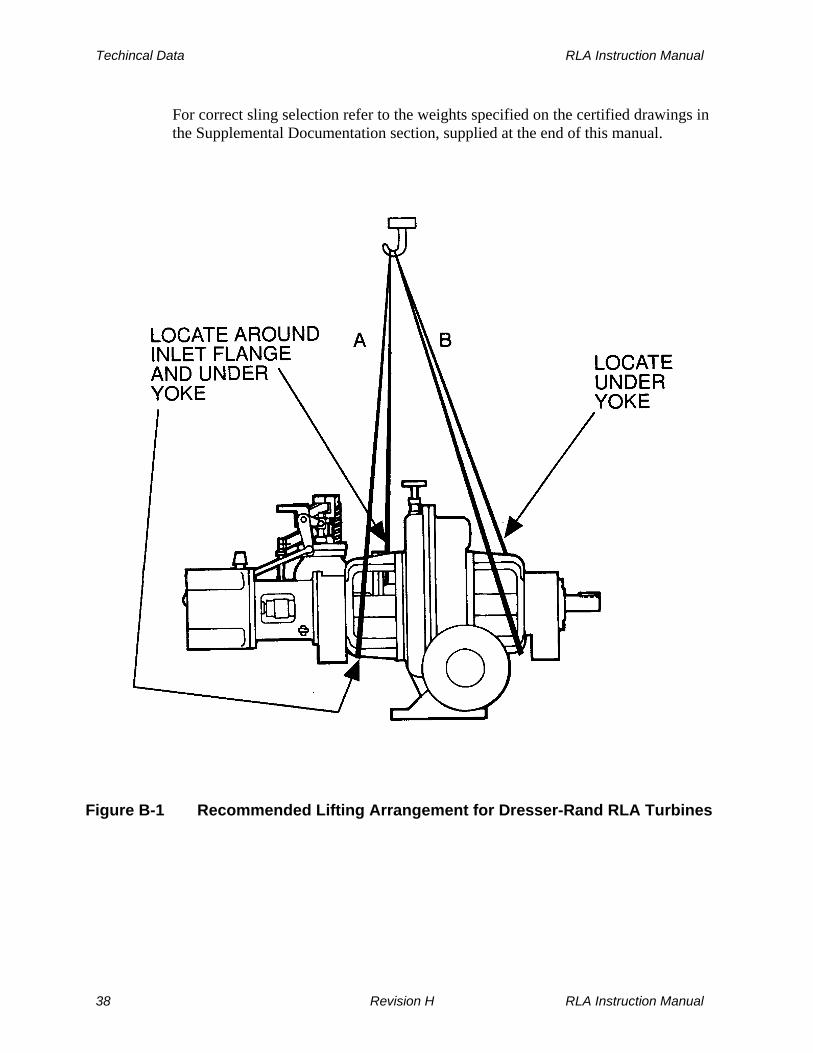
Turbines shipped on wooden skids should remain on their respective skids until placement onto their permanent foundations. When a turbine is on its skid, the skid should be used for lifting. Turbines shipped on baseplates can be lifted using lifting provisions on the baseplate. Do not attempt to lift the turbine and baseplate by lifting on the turbine or other baseplate mounted equipment. When lifting the turbine itself, use slings extending around the yokes or the turbine casing as illustrated in Figure B-1, Recommended Lifting Arrangement for Dresser-Rand RLA Turbines. Do not use the turbine shaft, mounting housing, governor, safety trip valve or throttle valve for lifting purposes. Lift slowly and carefully to ensure stablility and safety.
RLA Instruction Manual Revision H 37
Techincal Data RLA Instruction Manual
For correct sling selection refer to the weights specified on the certified drawings in the Supplemental Documentation section, supplied at the end of this manual.
Figure B-1 Recommended Lifting Arrangement for Dresser-Rand RLA Turbines
38 Revision H RLA Instruction Manual
RLA Instruction Manual Techincal Data
B.3 Alignment
Correct alignment of the turbine to the driven equipment is a primary consideration in turbine installation. Improper alignment can result in vibration, as well as wear and premature failure of bearings, seals, couplings, and shafts. Such failures can occur not only in the turbine but in the driven equipment as well. Alignment should be performed both under cold conditions and with the turbine at operating temperature, using personnel experienced in turbine alignment. Refer to Section C, Installation, for cold and hot alignment procedures. Alignment may be affected not only by turbine positioning with respect to the driven equipment, but also by thermal growth of the turbine, piping or the driven equipment, and by mechanical forces imposed by the piping. All of these factors must be considered when installing the turbine.
WARNING
Misalignment with driven equipment or overload due to driven equipment could result in excessive wear and bearing failure. This could create sparks or hot surfaces could ignite lubricant or flammable gasses.
CAUTION
Never put a steam turbine into service without first carefully ALIGNING it to the driven equipment under cold conditions and then again at operating temperature. Failure to do so may result in premature FAILURE of both TURBINE and DRIVEN EQUIPMENT components.
B.4 Thermal Growth
Thermal growth of the turbine casing, supports, inlet/exhaust piping, and driven equipment may result in misalignment and/or application of external forces on the turbine. To avoid vibration and premature wear/failure of bearings, seals, couplings and shafts, along with distortion of the turbine casing, the thermal expansion of mating components must be carefully analyzed and compensated for by careful alignment (both hot and cold), as well as the use of flexible shaft couplings, expansion joints in piping, and proper maintenance of these components. Refer to Section C, Installation, for cold and hot alignment procedures.
RLA Instruction Manual Revision H 39
Techincal Data RLA Instruction Manual
Refer to the certified drawings in the Supplemental Documentation section, supplied at the end of this manual, for turbine thermal movement data.
B.5 Lubricants
The importance of using a proper lubricant cannot be overemphasized. High quality turbo machinery oils are required. Dresser-Rand does not recommend specific brands of oil. Turbine owners should consult reliable oil suppliers regarding the proper selection of turbine oils. As a minimum, the selected oil should be a premium quality rust- and oxidation-inhibited turbine or circulating oil that will readily separate from water and have minimum tendency to emulsify or foam when agitated at actual operating temperatures. Since the proper grade of lubricant may not be available locally, it should be ordered in advance of the initial start-up of the equipment. Consult Section F, Lubrication for viscosity recommendations, bearing housing oil capacities, oil levels, and maintenance of lubrication systems. In addition, a careful review of the certified drawings in the Supplemental Documentation section, supplied at the end of this manual, must be made to ensure any specific lubricant requirement applying to the supplied equipment package are accommodated.
B.6 Major Fits, Clearances, and Rotor Balance Criteria
Dresser-Rand steam turbines are precision machines. The fits of the turbine wheel to its shaft, bearings on the shaft and in their housings, and other fits are selected and controlled so as to ensure long, efficient, trouble-free operation, as well as ease of maintenance. Whenever a turbine is disassembled and reassembled for inspection or parts replacement, factory fits and clearances must be checked and maintained. If parts do not fit properly on reassembly, the reason must be determined and the problem corrected. Some major fits and clearances are listed below in Table B-1, Major Fits, Clearances, & Rotor Balance Criteria – RLA and associated Figure B-1 Major Fits and Clearances, Standard RLA Turbine, while others are specified in the appropriate subsection of Section L, Disassembly and Parts Replacement. Table B-1 also specifies balancing limits. Rotors should be dynamically balanced using 2 planes-one on each side of the wheel.
B.7 Piping Forces
Steam piping, if improperly designed or installed, can impose severe mechanical or thermal forces and moments on the inlet and exhaust flanges of a steam turbine. Such forces and moments can misalign the turbine with its driven equipment, or
40 Revision H RLA Instruction Manual

RLA Instruction Manual Techincal Data
distort the turbine casing, resulting in internal misalignment of the turbine shaft with bearings, seals, and other components. Such misalignment can cause vibration and premature wear or failure. To prevent excessive piping forces or moments, the customer must ensure that the piping is designed and installed so as to comply with NEMA SM-23, Section 8, Allowable Forces and Moments on Steam Turbines. The maximum allowable forces and moments are a function of pipe sizes and are tabulated in the certified drawings in the Supplemental Documentation section, supplied at the end of this manual. Additional piping information, including suggested piping layouts, can be found in Section C, Installation.
Required Value
Frame Size Ref. No. Fit/Tolerance Description
12L/ 12M
16L/ 16E 20L 22L 23L
1 Wheel runout, radial, maximum (in.) 0.016 TIR 2 Shaft runout, maximum (in.) 0.002
3 (not shown) Governor coupling spider clearance (in) 0.030/0.060
4 Shaft endplay (in) 0.000-0.0135
0.0023-0.016
0.0025-0.016
0.0045-0.0187
0.0045-0.0187
5 Wheel/shaft diametric interference (in) 0.0022-0.0012
0.0025-0.0015
0.0027-0.0017
0.0032-0.0022
0.0032-0.0022
6 Bearing interference fit to shaft, loose (in) 0.0001 0.0001 0.0001 0.0002 0.0002 Bearing interference fit to shaft, tight (in) 0.0007 0.0007 0.0007 0.0007 0.0007
7 Carbon ring to shaft clearance, cold 0.0015-0.0004
0.0025-0.005
0.0025-0.005
0.0035-0.006
0.0035-0.006
8 Nozzle to bucket clearance (in) 0.046/0.074 9 Sector to bucket clearance (in) 0.062/0.094
Rotor dynamic unbalance (max.) per plane (in-oz):
0-2500 RPM 0.02 0.05 0.07 0.11 0.11 2501-4000 RPM 0.015 0.03 0.035 0.06 0.06 4001-4500 RPM 0.01 0.02 0.03 0.05 0.05 Throttle valve endplay, maximum (in) 0.003
Table B-1 Major Fits, Clearances, & Rotor Balance Criteria - RLA
RLA Instruction Manual Revision H 41

Techincal Data RLA Instruction Manual
Figure B-2 Major Fits and Clearances, Standard RLA Turbine
42 Revision H RLA Instruction Manual

RLA Instruction Manual Techincal Data
B.8 Bolt Torques and Materials
The bolts used in Dresser-Rand turbines are carefully selected to ensure adequate strength at the maximum temperatures and pressures the turbine is subjected to. The following general application guidelines are used when selecting bolt materials.
Turbine Construction Bolt Material Bolt Marking
A
Cast iron casing (200 construction)
All bolts
GR8
B
Steel inlet/iron exhaust casings (201 construction)
Bolts on trip and throttle valves All other bolts
B7
GR8
B7
C
Steel casings (202 construction)
All pressure-containing components All other bolts
B7
GR8
B7
Table B-2 Bolt Material & Markings In some applications special bolting is supplied. If bolts do not have the marking shown on Table B-2, consult the factory before replacing or torquing the bolts.
RLA Instruction Manual Revision H 43

Techincal Data RLA Instruction Manual
WARNING
NEVER REPLACE THE ORIGINALLY SUPPLIED BOLT WITH A SUBSTITUTE BOLT OF UNKNOWN or LESSER GRADE. DO NOT MIX BOLTS during disassembly. Failure to use the proper grade bolt could result in serious failure of pressure-containing component.
If the applicable bolt torque is not specified in the Assembly/Disassembly section, the following table may be used as a guideline.
Torque ft-lbs. (N-m)
Bolt Grade Bolt or Nut
Size (Inches) GR8 GR5/B7/B16 Ungraded
1/2 103 (140) 73 (99) 41 (56)
5/8 203 (275) 150 (203) 84 (114)
3/4 333 (451) 242 (328) 135 (183)
7/8 532 (721) 384 (521) 181 (245)
1 804 (1090) 580 (786) 270 (366)
1 1/8 1260 (1708) 902 (1223) 427 (579)
1 1/4 1757 (2382) 1257 (1704) 585 (793) Table B-3 Standard Bolt Torques for Turbine Bolting
The above torques are based on the thread and nut or bolt seating areas being lubricated with FEL-PRO C5-A high-temperature, anti-seize compound or its equivalent.
B.9 Sealants and Joint Compounds
The following sealants and joint compounds are recommended for the joined areas specified.
WARNING
Follow the manufacturer’s instructions for application of sealants and joint compounds. Insure that personnel are aware of and take precautions to avoid any hazards described by the manufacturer.
44 Revision H RLA Instruction Manual

RLA Instruction Manual Techincal Data
RLA Instruction Manual Revision H 45
Turbo R and Temp-Tite Copaltite and Temp-Tite Hylomar and Temp-Tite
2. All flanges and joints sealing steam at greater than 60 PSIG (41.4 BAR)
Turbo R and Temp-Tite Copaltite and Temp-Tite
3. All flanges and joints sealing gas
Locktite Superflex Silicone Sealant
4. Bolt and Stud Threads – Either of the following:
Never-Seez Fel-Pro C-5A
5. Bearing Housing Cover to Base
Locktite Superflex Silicone Sealant
B.10 Cooling Water to Bearing Housing Water Jackets
Depending on the service conditions and the type of lubrication system supplied with the turbine, bearing housings may require water cooling to maintain an acceptable bearing oil temperature. Refer to Section F, Lubrication, for cooling water requirements.
B.11 Steam Pressure and Temperature Limits
The steam temperature and pressure limits of Dresser-Rand turbines are limited by the materials used in construction and the design of valve bodies, casings, casing joints, seals, gaskets, and bolts. Steel turbines are rated for higher pressures and temperatures than cast iron turbines.
Applicable Joints and Recommended Sealants and Joint Compounds 1. All flanges and joints sealing steam at 600 PSIG (41.4 BAR) or less – Any of
the following:
Silver Seal and Temp-Tite

Techincal Data RLA Instruction Manual
WARNING
NEVER CONNECT the steam turbine to inlet or exhaust sources of UNKNOWN PRESSURE OR TEMPERATURE, or to sources whose pressure or temperature EXCEED limits stated on the NAMEPLATE
Dresser-Rand turbines can be re-rated for different steam conditions, powers and speeds. Consult your Dresser-Rand manufacturer’s representative or the factory for further information.
B.12 Steam Quality and Steam Purity
Steam quality must be dry and saturated or superheated. There must be provision to remove moisture and condensate from the steam supply system to avoid damaging the turbine. The performance and reliability of a steam turbine can be adversely affected by the admission of contaminated steam. When contaminants enter the turbine with the steam supply, the usual result is the accumulation of deposits, which can be either inert or highly reactive, depending on the contaminants present. If the contaminants are reactive, they can cause serious damage by corrosive attack on the turbine materials. To avoid these deposits, adequate boiler water chemistry control and other precautions are required along with the need for constant surveillance during operation and inspections. When deposits or material attach are noted during inspection, investigations into the nature and origin of the contaminants should be conducted and a program for corrective action begun. The boiler water limits shown in Table B-4, Recommended Limits for Boiler Water, are recommended for Dresser-Rand steam turbines to avoid the likelihood of adverse affects from deposits and harmful ions. These limits are based on operating history and recommendations from various consultants.
46 Revision H RLA Instruction Manual

RLA Instruction Manual Techincal Data
Pressure at Outlet of Steam Generating Unit, PSIG
Total Solids ppm
OH Alkalinity
ppm
Silica ppm
Phosphate ppm
Hardness ppm
Chloride ppm
0-150 2000 200 50 50 0 250 151-450 1500 100 35 50 0 200 451-750 1000 60 25 25 0 150 750-900 750 55 10 25 0 50
Table B-4 Recommended Limits for Boiler Water
B.13 Turbine Rotor Data
Table B-5, RLA Turbine Rotor Data, provides basic turbine rotor data. If further information is required, consult the factory.
Frame Size Rotor Weightlb (kg)
Moment Of Inertia
lb-ft2 (kg-m2)
Shaft Torsional Stiffnesslbs-in/RAD (N-m/RAD)
12M/12L 37 (16.8) 2.6 (0.1096) 0.253 x 10⁶ (28.6 x 10³) 16L/16E 70 (31.7) 7.8 (0.329) 0.788 x 10⁶ (89.0 x 10³) 20L 88 (39.9) 18.0 (0.759) 0.788 x 10⁶ (89.0 x 10³) 22L/23L 150 (68.8) 33.7 (1.420) 1.893 x 10⁶ (214 x 103) 22LH/23LH 156 (70.7) 37.4 (1.576) 3.520 x 10⁶ (398 x 103)
Table B-5 RLA Turbine Rotor Data
For applications with RATEAU rotors and/or NON-STANDARD shaft extensions, Consult Factory.
RLA Instruction Manual Revision H 47

RLA Instruction Manual
THIS PAGE WAS LEFT BLANK INTENTIONALLY
48 Revision H RLA Instruction Manual

RLA Instruction Manual Installation
Section C
Installation
C.1 General
WARNINGS
Throughout this manual it is assumed that the motive flow applied at the turbine inlet is high-pressure steam, therefore, the word “steam” is used in reference to various aspects of turbine installation, operation and maintenance. For some specialized applications, high-pressure gases such as Freon, natural gas or other vapors may provide the motive flow in these cases, it can generally be assumed, that the name of the gas in use may be used to replace the word “steam”. The user of the equipment must address all hazards associated with the nature of the specific motive fluid in use with the turbine. If flammable or toxic gasses are ued as the motive fluid or oil vapor could be emitted. The user/installer must pipe leak-offs and drains to a safe location.
If the turbine is operated on a motive fluid other than steam due consideration must be given to safety issues that might relate to the medium used, including but not limited to the ignition, explosion or poisoning of personnel.
The surface temperature of the turbine will become that of steam inlet temperature. This could exceed the ignition temperature of some gasses. Therefore if the turbine is installed where explosive gasses could be present it is the user’s responsibility to insure that this does not create a hazardous situation.
RLA Instruction Manual Revision H 49

Installation RLA Instruction Manual
WARNINGS (Cont’d)
The turbine must be properly grounded, thereby by preventing electrical shock or sparks that could cause injury or ignition of flammable gasses or liquids in the event of failure of electrical accessories, driven equipment or the creation of a static electrical charge.
If the turbine is supplied with oil mist lubrication, oil mist could escape from the bearing housing vents or constant level oiler. If there is the possibility that these could be ignited by equipment of processes in the proximity of the turbine they should be piped to a safe area.
Lighting must be installed in the installation area to insure that operators can see the turbine and its controls.
Do not install the turbine where ambient temperature could be 20 deg F or less unless this was specified in the original order and LOW TEMPERATURE materials have been provided.
Refer to Section 7, Lubrication System, for ambient temperature limits based on lubrication.
Refer to the Accessory Instruction Manual included with the final instruction manual to determine minimum and maximum ambient temperature limits for accessories.
Proper installation of the turbine and driven equipment is vital for successful operation of the system. It is for this reason that competent, experienced personnel should be employed during installation. Before installing turbine refer to the certified drawings in the Supplemental Documentation section, supplied at the end of this manual. Dresser-Rand recommends that API Recommended Practice RP-686 be consulted for additional guidance in regard to the installation of the turbine and driven equipment package. It provides recommended procedures, practices and quality assurance checklists covering the installation and de-commissioning of turbines, compressors, fans, motors, gear reducers and pumps for use in petroleum, chemical, gas industry and other facilities. It may be purchased through the API
50 Revision H RLA Instruction Manual

RLA Instruction Manual Installation
web site at “www.API.org” or call 1-800-624-3974 (U.S. & Canada) or 303-792-2181 (International). The following subsections, C.2 through C.11, provide basic installation and decommissioning procedures. Follow them in the indicated sequence for complete and correct installation or decommissioning. These recommendations and instructions are provided to assist the purchaser and/or his contractor. Fully qualified labor, including qualified supervision, is required for proper installation, start-up, and subsequent operation of the equipment. The services of a Dresser-Rand serviceman are recommended for the final on site installation review and the initial commissioning & start-up of the turbine. As a minimum the following steps must be carried out in sequence to achieve satisfactory operation.
WARNINGS
NEVER CONNECT the steam turbine to inlet or exhaust sources of UNKNOWN PRESSURE OR TEMPERATURE, or to sources whose pressure or temperature EXCEED limits stated on the NAMEPLATE.
Misalignment with driven equipment or overload due to driven equipment could result in excessive wear and bearing failure. This could create sparks or hot surfaces could ignite lubricant or flammable gasses.
a. Refer to the certified drawings in the Supplemental Documentation section, supplied at the end of this manual, and carefully read all installation notes, piping connection details, dimensions and clearances, and any other special data.
b. Provide a proper and adequate foundation for the turbine. c. Provide a proper piping installation, in accordance with NEMA SM23, that will
accommodate pressure forces and thermal growth without imposing excessive force on the turbine.
d. Remove all protective coatings and foreign matter from the turbine and all
piping. If the turbine was prepared for long-term storage, reinstall the matched carbon ring sets, springs and washers into the turbine gland housings.
e. Refer to coupling alignment instructions supplied by the coupling
manufacturer, as well as those supplied in this manual.
RLA Instruction Manual Revision H 51

Installation RLA Instruction Manual
f. Perform an accurate cold alignment. g. Grout the baseplate or soleplate to the foundation, as required. h. Carefully check hot alignment at operating temperature and adjust it, if
necessary, to establish accurate alignment. i. Dowel turbine and driven machine in place to maintain proper alignment.
C.2 Foundation
WARNING
If the turbine is installed in a location where there is the possibility of an earthquake this must be considered in the design of the piping and foundation.
The foundation is one of the most influential factors governing overall reliability of a turbine. A foundation must maintain alignment under all normal and abnormal conditions. This includes the way a foundation is supported on the soil and/or superstructure, soil settling, soil resonances, thermal distortion, piping forces, and vacuum pull or pressure forces in expansion joints. The turbine, gear reducer (if used), and driven equipment should all be mounted on a common foundation. Sufficient space should be provided around and above the foundation to allow for proper installation and maintenance. The foundation must minimize vibration by being as heavy as possible and non-resonant. It is important that the turbine be isolated from external vibration. Neither the foundation nor related support structure should be resonant within the operating range of the turbine. Vibration transmissions may occur from the unit to the surroundings, or vice versa; vibration may also be aggravated by resonance at transmission frequencies. Piping, stairways, and ducts may also transmit vibration, which should be prevented by proper isolation. A certified outline drawing is furnished with each Dresser-Rand turbine and is included in this manual in the Supplemental Documentation section, supplied at the end of this manual. This drawing includes dimensions for locating anchor bolts, equipment turbine weights, and general information required for determining foundation dimensions and design.
52 Revision H RLA Instruction Manual

RLA Instruction Manual Installation
A generous safety factor should be used when determining foundation thickness. The foundation length and width should extend at least 6 inches (152 mm) beyond the anchor bolts. Anchor bolts must be positioned accurately and provided with sleeves. The sleeve bore diameter should be approximately twice the bolt diameter, but should provide not less than 1/2” (13 mm) clearance all around the bolt. Carefully constructed templates are required to hold bolts and sleeves in position while the foundation is cast. Templates are usually made of wood and secured to the foundation forms. Skilled craftsman should be able to set anchor bolts to a tolerance of 1/8” (3 mm) by locating and drilling holes in the template after they have been secured to the braced forms. Anchor bolts should be threaded at both ends and be of sufficient length to extend one-and-a-half to twice the bolt diameter above the top of securing holes in the baseplate or the sole plate. The lower end of each bolt is enclosed in a sleeve and passes through an anchor plate, where it is secured by a nut to which it is welded. Anchor plates can be either washers or plates of cast iron or steel. They should have a diameter or side dimensions of approximately twice to two-and-a-half the outside diameter of the sleeves. Notes:
1. Templates must be rigid enough to prevent bolts from shifting while the concrete is being poured.
2. After concrete has been poured and before it has hardened, recheck positions of the anchor bolts.
3. Allow a 1-1/2” (38 mm) gap above the top of the foundation surface for grouting under edges of the baseplate or sole plates.
RLA Instruction Manual Revision H 53

Installation RLA Instruction Manual
C.3 Piping
WARNINGS
If the turbine is installed in a location where there is the possibility of an earthquake this must be considered in the design of the piping and foundation.
Improperly designed or installed piping can lead to turbine misalignment and failure of the turbine or driven equipment. It is the user/installers responsibility to insure that the piping system is properly designed, installed and that it meets local codes and regulations. All references to piping design in this Section are for reference only.
Proper piping of a steam turbine is essential. Correctly designed and installed piping contributes to safe, trouble-free operation and can improve ease of turbine operation and maintenance. Before installing any piping, installation personnel should read and become thoroughly familiar with this section.
C.3.1 Piping Forces
Any pipe connected to the steam turbine casing, valves, gland housing, or bearing housings can exert forces and/or moments on the turbine. This can misalign the turbine with its driven equipment or distort the turbine casing, resulting in internal misalignment of the turbine shaft with bearings, seals, and other components. Such misalignment can cause vibration, premature wear or failure of bearings, seals, couplings and shafts, and casing leaks. Steam supply (inlet) and exhaust piping, being relatively large and subjected to higher temperatures and pressures, can, if improperly installed, exert relatively large forces and moments on a steam turbine. Leak-off, drain, lube, cooling water and gland seal piping do not normally transmit significant piping forces. To prevent excessive piping forces or moments, the customer must ensure that the piping is designed and installed so as to comply with NEMA SM-23, Section 8, Allowable Forces and Moments on Steam Turbines. The maximum allowable forces and moments are a function of inlet and exhaust flange sizes. Flange sizes are tabulated on the certified drawings appearing in Supplemental Documentation section at the end of this manual.
54 Revision H RLA Instruction Manual

RLA Instruction Manual Installation
Piping forces can be reduced or eliminated with proper piping design, the use of expansion joints, and correct piping support systems. Figure C-1, Suggested Steam Inlet and Exhaust Piping Arrangement, illustrates proper inlet and exhaust piping systems, showing typical expansion joints, piping loops, and spring supports in the piping system. Optional constructions, which include third-party throttle and/or overspeed trip valves or other equipment configurations, may require the use of additional supports. Refer to the certified drawings in the Supplemental Documentation section, supplied at the end of this manual. Refer to the certified drawings in the Supplemental Documentation section, supplied at the end of this manual, for the estimated thermal movement of the inlet flange and exhaust flange. The estimated thermal movements of the inlet and exhaust flanges are used in the design and analysis of the piping support system.
RLA Instruction Manual Revision H 55

Installation RLA Instruction Manual
Figure C-1 Suggested Steam Inlet and Exhaust Piping Arrangement
56 Revision H RLA Instruction Manual

RLA Instruction Manual Installation
C.3.2 Isolating Valves
Inlet and exhaust lines to a steam turbine must be provided with isolating valves. The purpose of these valves is to isolate the turbine from inlet and exhaust systems, allowing the turbine to be shut down, along with sealing inlet and exhaust lines if the turbine is to be moved or serviced.
DANGER
NEVER DISCONNECT inlet or exhaust piping of the turbine without first CLOSING and TAGGING the ISOLATING VALVES and then OPENING DRAIN VALVES SLOWLY to relieve any pressure within the turbine. Failure to do so may expose PERSONNEL to SERIOUS INJURY if steam were to be introduced into the piping or captured in the turbine. As an added precaution, always install blank flanges on inlet and exhaust lines after removing the turbine.
The inlet piping block valve should be installed immediately upstream of the turbine. Refer to Figure C-1, Suggested Steam Inlet and Exhaust Piping Arrangement. The exhaust piping block valve should be installed immediately downstream of the full flow relief valve. Refer to Figure C-1, Suggested Steam Inlet and Exhaust Piping Arrangement.
C.3.3 Full Flow Relief Valve
An atmospheric relief valve must be installed between the turbine exhaust flange and the first exhaust line shut-off valve (Refer to Figure C-1, Suggested Steam Inlet and Exhaust Piping Arrangement). The purpose of this relief valve is to protect the turbine casing from excessive exhaust pressure. The relief valve must be of ample size to pass the maximum quantity of steam flowing through the turbine at the maximum inlet temperature and pressure steam conditions without allowing the turbine casing pressure to exceed the limit defined below. It is the user’s responsibility to install the relief valve in the piping. The full flow relief valve shall begin to open at 10% or 10 PSIG (69 kPag) above maximum exhaust pressure, whichever is greater, for non-condensing turbines; and at not more than 10 PSIG (60 kPag) for condensing turbines. The valve shall be fully open with an additional rise in pressure not to exceed 10%. Refer to NEMA-23, Steam Turbines For Mechanical Drive Service, for further details.
RLA Instruction Manual Revision H 57

Installation RLA Instruction Manual
WARNINGS
It is the USER’S RESPONSIBILITY to INSTALL A FULL-FLOW RELIEF VALVE in the exhaust line between the turbine exhaust casing and the first shut-off valve. This relief valve should be sized to relieve the FULL AMOUNT OF STEAM THAT THE TURBINE WILL PASS, in the event that the exhaust line is blocked.
The optional SENTINEL WARNING VALVE, located on the turbine casing, DOES NOT SERVE as a RELIEF VALVE. The sentinel warning valve WILL NOT PASS SUFFICIENT STEAM FLOW to relieve the turbine casing of EXCESSIVE EXHAUST PRESSURE. The purpose of the sentinel warning valve is to warn visually and audibly that excessive pressure is building in the turbine exhaust casing.
C.3.4 Inlet Piping
As shown in Figure C-1, Suggested Steam Inlet and Exhaust Piping Arrangement, inlet piping should come off the top of the steam header and form an expansion relieving loop or other strain relieving device, before coming down to the turbine. A valved condensate drain (not shown) should be installed in the inlet line upstream of the isolating valve, allowing condensate to drain prior to opening the isolating valve and feeding steam to the turbine. Piping must be supported in such a manner as to allow thermal growth of the turbine and piping, without imposing excessive forces and moments on the inlet flange. Properly installed piping should mate squarely to the turbine inlet flange, without any need to force flanges by twisting them into alignment when connecting them. The inlet line should be well lagged to prevent heat loss and to avoid burns. Pipe sizes should be large enough to maintain rated steam pressure at the turbine inlet flange under maximum load conditions. In determining pipe size, proper allowance should be made for pressure drop due to long sections of pipe, elbows, valves, or other fittings between the boiler and the turbine. If wet or saturated steam is used, it is very important that piping be arranged so that condensate cannot be carried over into the turbine. A steam separator of the proper size, with a trap of ample capacity, should be installed before the turbine inlet. All horizontal runs must be sloped up in the direction of steam flow, with drains at the low points.
58 Revision H RLA Instruction Manual

RLA Instruction Manual Installation
The importance of protecting the turbine against slugs of water cannot be overemphasized. The issue is not “wetness” of the steam, but with condensate, which is separated out as water. The harmful effects of water are: 1. Rapid erosion of blading and valves. 2. In the case of turbine wheels with inserted blades, water may have a hammer-
blow effect, tearing out the blades and destroying the rotor. 3. Governing is adversely affected. 4. The rotor may be permanently distorted and/or the turbine may be seriously
damaged. 5. A danger of thrust bearing failure and consequent destruction of the turbine.
C.3.5 Exhaust Piping
Figure C-1, Suggested Steam Inlet and Exhaust Piping Arrangement, shows exhaust piping together with the full flow relief valve and support system. Note that the exhaust line should slope down toward the header or create an overhead loop, to prevent condensate at the header from flowing back toward the turbine. Valved drains (not shown) should be installed before and after the exhaust isolating valve. On each installation, the length of run, elbows, valves, and other fittings in the pipe must be considered, together with all factors, which may cause backpressure on non-condensing turbines or reduced vacuum on condensing turbines, and a final decision on piping size made accordingly. On non-condensing turbines, backpressure higher than that the turbine was designed for will cause reduction of power and an increase in steam consumption. It may also cause gland leakage, and in extreme cases, can rupture the turbine casing. On condensing turbines, decreased vacuum will have an even greater effect on capacity and economy. The exhaust pipe must be installed and anchored so that no excessive stress is placed on the turbine from either the weight of the pipe or its expansion and contraction. In cases where such an arrangement cannot be made with certainty, an expansion joint near the turbine can be useful in low pressure lines and is usually required on large pipe sizes. The use of an expansion joint does not of itself avoid undue stress. It is not as flexible as many people assume and when installed, it must be properly aligned and not indiscriminately exposed to shear or torsion. In the majority of applications, axial thrust created on the cross-sectional area of the largest bellows, by internal pressure, must be restricted by the use of tie rods. They are most effective when the expansion joint is used in shear, instead of tension or compression. When used in either a vacuum or a pressure line, tie rods must be arranged accordingly. They are useless where a joint moves under tension or compression, as they bypass the joint and transmit pipe forces directly to the
RLA Instruction Manual Revision H 59

Installation RLA Instruction Manual
turbine. Provision must be made to anchor the piping in such a way that excessive forces will not be transmitted to the turbine during shut-down and operational running. Connection to a header must be made at the top, never from the bottom or side, and great care must be taken to avoid draining water back into the turbine. All horizontal runs must be sloped away from the turbine exhaust connection. Properly installed piping should mate squarely to the turbine exhaust flange, without any need to force flanges by twisting them into alignment when connecting them. The exhaust line should be well lagged to prevent heat loss and avoid burns.
C.3.6 Piping Blow Down
Newly constructed steam piping should be blown-down to remove scale, weld slag and any other foreign material. Such material can cause severe damage if it enters the steam turbine. After inlet piping has been installed, but before connecting it to the turbine, steam should be blown through the line and into the exhaust line to remove welding slag and debris. Refer to NEMA SM-23, Steam Turbines For Mechanical Drive Service or a reliable piping contractor for a blow-down procedure. NEMA standards may be purchased through the NEMA web site at “www.NEMA.org”.
CAUTION
INLET STEAM LINES MUST BE BLOWN DOWN PRIOR TO CONNECTING them to the turbine. Debris and welding slag can cause serious damage to valves, nozzles, and turbine blading if allowed to enter the turbine.
C.3.7 Steam Strainer
Standard RLA Dresser-Rand Turbines are provided with integral inlet steam strainers to prevent entry of foreign material into the turbine. Part of the throttle valve is located in the same chamber with the steam strainer. The steam strainer will allow small debris particles to pass through the turbine and does not preclude the need for inlet piping blowdown prior to connecting the turbine. When a turbine is supplied without an integral or separate y-type strainer, the purchaser must install an appropriate steam strainer in the inlet steam piping.
C.3.8 Check Valve
Where a turbine exhausts or bleeds steam into another system, and a check valve is installed for prevention of reverse flow to the turbine, adequate bracing must be
60 Revision H RLA Instruction Manual
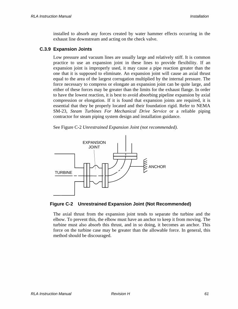
RLA Instruction Manual Installation
installed to absorb any forces created by water hammer effects occurring in the exhaust line downstream and acting on the check valve.
C.3.9 Expansion Joints
Low pressure and vacuum lines are usually large and relatively stiff. It is common practice to use an expansion joint in these lines to provide flexibility. If an expansion joint is improperly used, it may cause a pipe reaction greater than the one that it is supposed to eliminate. An expansion joint will cause an axial thrust equal to the area of the largest corrugation multiplied by the internal pressure. The force necessary to compress or elongate an expansion joint can be quite large, and either of these forces may be greater than the limits for the exhaust flange. In order to have the lowest reaction, it is best to avoid absorbing pipeline expansion by axial compression or elongation. If it is found that expansion joints are required, it is essential that they be properly located and their foundation rigid. Refer to NEMA SM-23, Steam Turbines For Mechanical Drive Service or a reliable piping contractor for steam piping system design and installation guidance. See Figure C-2 Unrestrained Expansion Joint (not recommended).
T U R B I N E ANCHOR
E X P A NSIONJ O I NT
Figure C-2 Unrestrained Expansion Joint (Not Recommended)
The axial thrust from the expansion joint tends to separate the turbine and the elbow. To prevent this, the elbow must have an anchor to keep it from moving. The turbine must also absorb this thrust, and in so doing, it becomes an anchor. This force on the turbine case may be greater than the allowable force. In general, this method should be discouraged.
RLA Instruction Manual Revision H 61

Installation RLA Instruction Manual
Figure C-3 Expansion Joint with Tie Rods (Acceptable) below shows the same piping arrangement as in the previous figure, except for the addition of tie rods on the expansion joint.
TURBINE
EXPANSIONJOINT
Figure C-3 Expansion Joint with Tie Rods (Acceptable)
The tie rods limit elongation of the joint and take the axial thrust created by the internal pressure so it is not transmitted to the turbine flange. The tie rods eliminate any axial flexibility, but the joint is still flexible in shear, meaning that the flanges may move in parallel planes. The location of this type of joint in the piping should be such that movement of the pipe puts the expansion joint in shear instead of tension or compression. Figure C-4 Expansion Joint with Tie Rods for Non-condensing Operation (Preferred) below is an arrangement frequently used, with tie rods as indicated.
TURBINE
Figure C-4 Expansion Joint with Tie Rods for Non-Condensing Operation (Preferred)
62 Revision H RLA Instruction Manual

RLA Instruction Manual Installation
This arrangement will prevent any thrust, due to internal pressure, from being transmitted to the exhaust flange. It retains the axial flexibility of the joint and may be used for either vacuum or pressure service.
C.3.10 Drain Piping
WARNINGS
DRAIN PIPING flanges and valves must be SELECTED AND INSTALLED BY EXPERIENCED PERSONNEL, taking into account the MAXIMUM OPERATING STEAM PRESSURE AND TEMPERATURE. Improperly designed or installed drain systems could FREEZE, become PLUGGED AND RUPTURE, causing serious personal injury or equipment damage.
Leak-off and drain connections of turbines operated on flamable or noxious gas must be piped to a safe location to avoid the possibility of ignition of the gas or poisoning of operating personnel.
LEAK-OFF AND DRAIN LINES MUST NOT BE INTERCONNECTED. A leak-off from high pressure upstream location connected to a steam chest drain or throttle valve leak-off/drain could supply sufficient steam TO ALLOW THE TRIPPED TURBINE TO CONTINUE RUNNING, since such interconnection would bypass the overspeed trip valve.
Drains are low-point piping connections at valves and casings that allow release of condensed water. Drains are opened before starting the turbine, to allow any accumulated water to escape. They are left open during the start-up cycle to allow water condensing in the cold casings to exit. Once the turbine reaches normal operating temperature, drains should be closed. Drain valves must be installed by the user when not supplied by Dresser-Rand. Drains can be automated with properly sized steam traps, if desire. Refer to C-6 Suggested Steam Inlet, Exhaust and Drain Piping, Manual Start and Figure C-7 Suggested Inlet, Exhaust and Drain Piping, - Auto Start. Sizes and locations of drains are shown on the certified drawing in the Supplementatl Documentation section, supplied at the end of this manual.
RLA Instruction Manual Revision H 63

Installation RLA Instruction Manual
C.3.11 Leak-Off Piping
Standard RLA Dresser-Rand Turbines are supplied with leak-off connections at the Gland Housings, Throttle Valve, and Overspeed Trip Valve. Leak-offs are piping connections that allow steam leaking past seals to be carried away to a safe area. Shaft and valve steam seals depend on some leakage for lubrication and to minimize wear. Leakage is therefore acceptable and necessary. The leak-offs must be pitched down and away from the turbine and connected to open, unrestricted, separate, non-manifolded drain lines, which discharge to a safe and visible area. There should not be any valves on leak-off lines. Leak-off piping should be arranged to ensure that no pressure build-up occurs in the system, avoiding low points where condensate could accumulate and may be connected to a gland condenser, educator or ejector. No vertical upward pipe runs are to be included in leak-off piping. Unavoidable low points should be trapped. On gas operated turbines, leak-offs must be piped to a safe area away from the turbine site.
WARNING
Leak-off and drain connections of turbines operated on flamable or noxious gas must be piped to a safe location to avoid the possibility of ignition of the gas or poisoning of operating personnel.
LEAK-OFF AND DRAIN LINES MUST NOT BE INTERCONNECTED. A leak-off from a high pressure upstream location connected to a steam chest drain or throttle valve leak-off/drain could supply sufficient steam TO ALLOW THE TRIPPED TURBINE TO CONTINUE RUNNING, since such an interconnection would bypass the overspeed trip valve.
LEAK-OFF PIPES that are left UNCONNECTED will allow the escape of HIGH TEMPERATURE STEAM that could cause PERSONAL INJURY or contamination of lubricating oil.
C.3.12 Cooling Water Piping to Bearing Housing Water Jackets
Depending on service conditions and the type of lubrication system supplied with the turbine, bearing housings may require water cooling to maintain an acceptable bearing oil temperature.
64 Revision H RLA Instruction Manual

RLA Instruction Manual Installation
Refer to Section F, Lubrication, for cooling water application requirements, suggested piping, water flow, pressure and temperature requirements, and oil sump temperature.
C.3.13 Gland Seal Piping
On turbines exhausting to a vacuum, sealing steam at 5 to 10 PSIG (34 to 69 kPag) must be furnished through carbon ring glands to prevent air from entering the exhaust casing. If gland seal piping is not furnished with the turbine, sealing steam connections should be piped via a common connection to the user’s steam supply. A recommended piping diagram for gland seal piping is shown in Figure C-5, Gland Seal Piping for Vacuum Exhaust.
VALVE TO ADJUSTSEALING STEAM
PRESSURE
PRESSURE GAUGE
SHUT OFF VALVE RELIEF VALVE
SEALING STEAMFROM SOURCE
Figure C-5 Gland Seal Piping for Vacuum Exhaust
RLA Instruction Manual Revision H 65

Installation RLA Instruction Manual
C.3.14 Suggested Inlet, Exhaust, and Drain Piping Schematics
�����
�������
�������
�����
�������
�����
�������
�����
����������� �
������ ������
����������������
�����
�����
�������� ������
���������
������� ���������
� � � �
��������������
��� �������
��� ��������������������
� ������� ������ �������������������� ������ ��� ���������� ���� ��
Figure C-6 Suggested Steam Inlet, Exhaust, and Drain Piping, Manual Start
66 Revision H RLA Instruction Manual
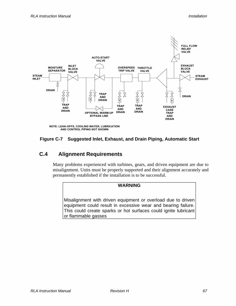
RLA Instruction Manual Installation
�����
�������
�������
�����
�������
�����
������������
����������� �
������ ������
����������������
�����
�����
�������� ������
���������
������� ���������
� � � �
��������������
��� �������
��� ��������������������
� ������� ������ �������������������� ������ ��� ���������� ���� ��
�������
�����
�
��� ����������
Figure C-7 Suggested Inlet, Exhaust, and Drain Piping, Automatic Start
C.4 Alignment Requirements
Many problems experienced with turbines, gears, and driven equipment are due to misalignment. Units must be properly supported and their alignment accurately and permanently established if the installation is to be successful.
WARNING
Misalignment with driven equipment or overload due to driven equipment could result in excessive wear and bearing failure. This could create sparks or hot surfaces could ignite lubricant or flammable gasses
RLA Instruction Manual Revision H 67

Installation RLA Instruction Manual
CAUTIONS
ALIGNMENTS performed by the factory on turbines with gears or other driven equipment mounted on baseplates MAY SHIFT during rigging or shipment. These alignments must be RECHECKED before startup.
Never put a steam turbine into service without first carefully ALIGNING it to the driven equipment under cold conditions and then again at operating temperature. Failure to do so may result in premature FAILURE of both TURBINE and DRIVEN EQUIPMENT components.
Excessive vibration, bearing edge loading, and high shaft loads can result from incorrect alignment. Factors affecting alignment can be settling of the foundation, growth in shaft heights due to temperature changes, machine movement of either unit with respect to the foundation due to vibration, worn bearings, or distortion of the casing due to loads from connecting structures (such as piping). A dependable turbine drive system requires that all of these factors be given proper attention prior to and during alignment. The turbine and driven equipment should always be aligned cold, checked later at operating temperature, and re-aligned if necessary. Both shafts should be parallel and their axes concentric so that there is no offset at operating temperature. Two types of misalignment can be identified and must be corrected to be within defined limits. Angular misalignment occurs when shaft centerlines intersect at an angle.
Figure C-8 Angular Misalignment
68 Revision H RLA Instruction Manual

RLA Instruction Manual Installation
Parallel misalignment occurs when shaft centerlines are parallel to each other, but do not intersect.
Figure C-9 Parallel Misalignment
As previously noted, alignment is influenced by the thermal growth of both the turbine and the driven equipment. This must be compensated for during cold alignment by calculating the growth of each machine and intentionally creating a parallel offset that will disappear when the equipment is hot.
C.5 Couplings
WARNING
A coupling guard must be installed at the coupling between the turbine and driven equipment.
When the coupling guard is installed, refer to the coupling guard manufacturer’s instructions to ensure that it does not contact the running shaft or coupling which could cause a spark that could ignite hazardous gasses in the environment in which the turbine is installed.
CAUTION
Coupling Weights should not exceed the Certified Drawing Limits without approval from the Dresser-Rand Factory. A heavier than allowed Coupling could create a lower critical speed, which could cause excessive vibration within the operating range of the turbine.
RLA Instruction Manual Revision H 69

Installation RLA Instruction Manual
A flexible coupling is required to connect the turbine to the driven machine. Couplings should be selected based on power, speed, and characteristics of the driven machine, using selection and balancing guidelines established by the coupling manufacturer. Correct installation of the coupling hubs is vital to proper operation of the turbine and driven unit; great care must be exercised in assembling hubs onto shafts. Before mounting a coupling, check the coupling bore and shaft diameter with a micrometer to determine that the interference fit is as specified by the coupling manufacturer. Also, inspect the key and keyways, making sure that the key is a drive fit into the shaft keyway and a push fit into the coupling hub keyway. The key should also sit positively on the bottom of the shaft keyway, with clearance on the top of the key to allow expansion within the hub keyway. If the shaft key extends beyond the back of the coupling hub, the key should fill the entire keyway. The exposed portion of the key must be removed so that it is flush with the coupling back face and must be profiled flush to the circumference of the shaft so that only the keyway in the shaft is filled, maintaining shaft balance. When installing coupling hubs on shafts, it is important to heat them uniformly, taking great care to avoid overheating. A recommended method is to use an oil bath with a temperature control or an induction heater. When fitting the coupling onto the shaft, it is helpful to have a chamfer on the sides and top of the key, making alignment easy with the hub keyway. Also, a temporary block should be used, to prevent the hub from sliding too far onto the shaft. Do not use hammers to drive coupling hubs onto the shaft, as this would damage the coupling, shaft, or bearings. As coupling hubs are frequently used for reference in alignment, runout or eccentricity of hubs, which may be caused by damage to the shaft, hubs, or badly fitted keys, must be avoided.
CAUTION
DO NOT drive the coupling on or off the shaft with a HAMMER. The force of the hammer will damage the rotor locating bearing, resulting in internal turbine damage.
70 Revision H RLA Instruction Manual
RLA Instruction Manual Installation
NOTE
Axial clearance between the coupling hubs and shaft end faces should be in accordance with recommendations of the coupling manufacturer, when shafts are in their normal running condition.
Lubricate the coupling as required, by following the coupling manufacturer’s instructions.
C.6 Preparation for Alignment
Use the following procedure: a. Clean turbine mating support surfaces and mount turbine on the foundation. b. Do not connect the turbine to inlet and exhaust piping. c. Disconnect the coupling by removing the coupling spacer (if provided) and
pulling coupling sleeves away from the hub. d. Insert suitable shim packs between supporting surfaces of the turbine and/or
driven equipment and their respective mounting surfaces. It is important to insert sufficient shims under the equipment so that shims can be removed to lower either piece of equipment if required during hot final alignment. A minimum of 1/16 inch (1.6 mm) is recommended.
e. Level and square the turbine with respect to the driven equipment. f. Check for base distortion and improper shimming by placing dial indicators in
vertical and horizontal planes on the driven equipment, with the indicators detecting turbine shaft movement. Each turbine foot anchor bolt should then be loosened and tightened, while observing the dial indicator reading. Readings should not exceed 0.003 in. (0.075 mm); if they are exceeded, the cause must be determined. Repeat this procedure for driven equipment.
g. Check that all anchor bolts (i.e., turbine, driven equipment, and supports) are
tightened. h. Check coupling hub face runout using the following procedure:
1. Install dial indicator (refer to Figure C-10, Alignment Using Dial Indicators) to read a point nearest to the outside circumference on the face of one hub.
RLA Instruction Manual Revision H 71

Installation RLA Instruction Manual
2. Rotate the shaft and hub on which the dial indicator is touching and record the maximum and minimum indicator readings. Axial runout is the difference between the two readings.
3. Re-position the dial indicator to read on the external outside diameter of
the same hub as in step 1 and measure coupling hub diametral runout, as shown in Figure C-10, Alignment Using Dial Indicators.
4. Rotate hub and record the maximum and minimum indicator readings.
Lateral runout is 1/2 of the difference between the two readings.
5. Repeat steps 1 through 4 for the other coupling hub.
6. Any runout exceeding 0.0015 inch (0.038 mm) should be corrected by reinstallation of the hub and keys or their replacement.
7. Hub runout values should be subtracted from the desired alignment setting.
INDICATORBASE
INDICATOR
COUPLING HUBS
CouplingHub FaceRunout
CouplingHub DiametralRunout
CouplingBack SurfaceRunout
INDICATOR
Figure C-10 Alignment Using Dial Indicators
72 Revision H RLA Instruction Manual
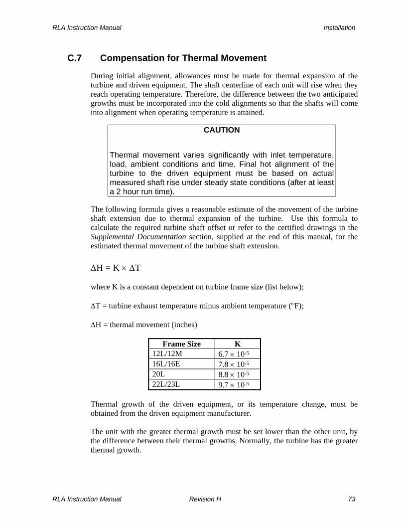
RLA Instruction Manual Installation
C.7 Compensation for Thermal Movement
During initial alignment, allowances must be made for thermal expansion of the turbine and driven equipment. The shaft centerline of each unit will rise when they reach operating temperature. Therefore, the difference between the two anticipated growths must be incorporated into the cold alignments so that the shafts will come into alignment when operating temperature is attained.
CAUTION
Thermal movement varies significantly with inlet temperature, load, ambient conditions and time. Final hot alignment of the turbine to the driven equipment must be based on actual measured shaft rise under steady state conditions (after at least a 2 hour run time).
The following formula gives a reasonable estimate of the movement of the turbine shaft extension due to thermal expansion of the turbine. Use this formula to calculate the required turbine shaft offset or refer to the certified drawings in the Supplemental Documentation section, supplied at the end of this manual, for the estimated thermal movement of the turbine shaft extension. ΔH = K × ΔT where K is a constant dependent on turbine frame size (list below); ΔT = turbine exhaust temperature minus ambient temperature (°F); ΔH = thermal movement (inches)
Frame Size K 12L/12M 6.7 × 10⁻⁵ 16L/16E 7.8 × 10⁻⁵ 20L 8.8 × 10⁻⁵ 22L/23L 9.7 × 10⁻⁵
Thermal growth of the driven equipment, or its temperature change, must be obtained from the driven equipment manufacturer. The unit with the greater thermal growth must be set lower than the other unit, by the difference between their thermal growths. Normally, the turbine has the greater thermal growth.
RLA Instruction Manual Revision H 73

Installation RLA Instruction Manual
CAUTION
The initial alignment established with this estimated thermal growth is only approximate. An actual hot alignment must be performed prior to putting the turbine into service.
C.8 Cold Alignment Check
Cold alignment must be completed at ambient temperature (turbine and driven machine in cold condition) and in the proper sequence, with angular misalignment corrected first, followed by correction of parallel misalignment.
C.8.1 Angular Alignment
Use the following procedure: a. Clamp a dial indicator to one coupling hub and place the finger (contact point)
against the finished face of the other hub, as shown in Figure C-10, Alignment Using Dial Indicators.
b. Scribe a reference mark on the coupling hub at the point where the finger
touches the hub face. c. Rotate both shafts simultaneously (in the direction they were designed to
operate), keeping the finger against the reference mark on the coupling hub. Note the dial indicator reading at each one-quarter revolution.
d. Angular misalignment of the shafts must not exceed the coupling
manufacturer’s recommendations or a total indicator reading of 0.001 inch (0.025 mm) for each radial inch of the coupling hub.
e. When the distance between coupling hubs does not permit the use of dial
indicators, angular alignment can be established using one of the two following methods:
1. Use feeler gauges to determine the gap between coupling faces at four
locations, 90° apart. Adjust the turbine or driven equipment to obtain equal clearance within 0.001 inch (0.025 mm) between coupling faces at each 90° location.
2. Use a dial indicator mounted on a flexible arm to measure runout on the
back surface of the coupling hub, as shown in Figure C-10, Alignment Using Dial Indicators.
74 Revision H RLA Instruction Manual

RLA Instruction Manual Installation
C.8.2 Parallel Alignment
Use the following procedure: a. Mark both hub rims so that their relative positions can be maintained at all
times during the alignment check. b. Mount the dial indicator on one of the coupling hubs and position the indicator
finger on the rim of the opposite coupling hub, as shown in Figure C-10, Alignment Using Dial Indicators.
c. Scribe a reference mark on the machined diameter of the coupling hub at the
point of indicator finger contact, or align match marks on the hub rims. d. Rotate both shafts at the same time, while retaining the indicator finger at the
reference mark and the two match points aligned. e. Note indicator readings at 90° locations (90°, 180°, 270°, 360°). Remember to
zero the indicator at the starting point. f. Repeat steps d and e two or three times to verify accuracy of readings.
In installations where there is excessive coupling gap (when a coupling spacer is used), it may be necessary to make a reading correction when determining vertical parallel misalignment.
g. Hot parallel misalignment must not exceed the coupling manufacturer’s
recommendations or a total indicator reading of 0.002 inch (0.051 mm). When parallel alignment is complete, connect inlet and exhaust piping, and recheck angular and parallel alignment thoroughly.
C.9 Grouting
When cold alignment is satisfactory, grout the baseplate or soleplate to the foundation using the guidelines specified below. (Epoxy grout procedures may differ-follow manufacturer’s instructions.) Mix a test batch of ready-to-use grouting material to verify that the material overcomes settlement and drying shrinkage. This type of material is normally used for clearances less than one inch in thickness, and where the size and shape of the space make placement difficult. Coarse aggregate is normally used for clearances over one inch (2.5 cm) in thickness, where free passage of the grout will not be obstructed. One part of pea
RLA Instruction Manual Revision H 75

Installation RLA Instruction Manual
gravel or peastone may be added to two parts of the ready-to-use grouting material to form coarse aggregate grout.
CAUTION
Do not disturb alignment by removing shims or wedges under the baseplate or soleplate.
Grouting must be done with all steam and exhaust piping disconnected from the turbine. When prepared grout mixes are used, follow the manufacturer’s instructions and applicable safety precautions. A suitable form should be built around the baseplate or soleplate before grout is applied. With either of the above described mixes, use the minimum amount of water required to create a flowable grout that completely fills the required space. Excessive water causes segregation and bleeding. Apply grout quickly and continuously to avoid the undesirable effects from overworking. Once the grout has acquired its initial set, all exposed edges should be cut off vertically to coincide with the baseplate. Paint the grout with waterproof paint after the grout has thoroughly dried, or apply plaster with Portland cement-sand mortar.
C.10 Hot Alignment Check
After installation is complete, the grout is fully set, and the tightness of all hold-down bolts has been checked, bring the turbine and driven machine up to operating temperature (this normally take about a 2 hour run time), shut down the unit, and make a careful and final check of the alignment using the procedure outlined in Section C.8. This should be done as soon as possible after shut down, to avoid erroneous readings due to cooling. Final adjustments should be made so that both shafts are parallel and their axes concentric, resulting in zero offset at operating temperature, consistent with the coupling manufacturer’s limits. If the alignment is not satisfactory, check the following for possible causes: a. Pipe strains distorting or shifting machines due to thermal growth (disconnect
piping and re-check alignment).
76 Revision H RLA Instruction Manual
RLA Instruction Manual Installation
b. Springing of the baseplate or soleplates by heat from the turbine, from a heat source close to the turbine, or due to soft shims or partial shims.
c. Loose hold-down bolts. d. Shifting of the entire structure due to variable loading, a change in the
foundation due to concrete curing, or improper grouting causing non-continuous support.
When final alignment is satisfactory, dowel the turbine and driven equipment in place to maintain proper alignment.
C.11 Decommissioning
WARNING
Prior to commencing the decommissioning operation, ensure that the inlet and exhaust stop valve are shut, locked out and tagged to eliminate the possibility of inadvertent start-up during the decommissioning operation.
The decommissioning procedure is as follows:
1. Remove bolts from the inlet and exhaust flanges.
2. Disconnect all turbine piping from permanently installed piping.
3. Drain oil from the bearing housings and the governor. Dispose of the oil in an environmentally responsible manner.
4. Drain cooling water from the cooling system and bearing housings.
5. Remove carbon rings, springs and stops from the gland housings.
6. Remove coupling guard.
7. Disconnect drive half coupling from driven half coupling. Remove spacer
coupling if one is installed.
8. Remove hold down bolts/nuts from the baseplate.
9. Sling the turbine and move it to a position where the inlet and exhaust are exposed.
RLA Instruction Manual Revision H 77
Installation RLA Instruction Manual
10. Spray the internals with a rust preventative through all available openings.
11. Coat the non-painted machined surfaces with a water-soluble rust preventative.
12. Seal all flanged connections with a rubber gasket, steel plate and 4 through
bolts and nuts.
13. Move the turbine to the selected storage location suitable for this type of machinery.
78 Revision H RLA Instruction Manual
RLA Instruction Manual Speed Control System
Section D
Speed Control System
D.1 General
Your Dresser-Rand turbine has been designed to produce the rated power, at its rated speed, under the specified steam conditions. This information can be found on the turbine nameplate, on the turbine data sheet at the beginning of this manual, or on the certified drawings in the Supplemental Documentation section supplied at the end of this manual. When the turbine has been provided with a droop-type governor (WOODWARD TG-13 governor or similar), and the load created by the driven equipment is less than the rated power, the turbine would tend to run faster than the rated speed; when the load is greater than the rated power, the turbine would tend to run slower than the rated speed. These tendencies can be counteracted by regulating the amount of steam admitted to the turbine. The Governor and Throttle Valve provide this function. The Governor senses the speed at which the turbine is running and opens or closes the Throttle Valve accordingly to maintain the turbine at its predetermined (set) speed.
WARNING
Never operate the turbine with the governor or governor system disabled.
D.2 Standard Governor
The standard governor is the Woodward TG Mechanical-Hydraulic Speed Control Governor. The Governor is attached to the Governor Mounting Housing and couples to the turbine shaft via a flexible coupling. The Governor is connected to the Throttle Valve by the Governor Linkage. The instruction manual for the standard or optional governor is found in Supplemental Documentation section at the end of this manual.
RLA Instruction Manual Revision H 79

Speed Control System RLA Instruction Manual
Figure D-1 shows external features of the Woodward TG Governor.
DRAIN
BREATHER
INPUTSHAFT
OUTPUT SHAFT
OIL LEVELINDICATOR
SPEED ADJUSTINGSCREW
Figure D-1 Woodward Oil Relay Governor Features
Breather--this is a vent for the oil reservoir and also serves as a plug for the oil filler hole. Oil Level Indicator--a sight gauge on the side of the Governor for checking the oil level. Speed Adjusting Screw--this screw, located on the rear of the Governor, increases the turbine speed setpoint when turned clockwise. Output Shaft--opens and closes the Throttle Valve via the throttle linkage. Input Shaft--is connected to turbine shaft, sensing turbine speed. Drain Plug--oil drain on the bottom of the Governor.
D.3 Lubrication and Maintenance
The TG Governor has a self-contained, 1.75 quart oil reservoir. Oil level can be checked by viewing the oil level indicator on the side of the Governor. The turbine is shipped with the Governor reservoir filled with oil. Oil level should be checked before starting the turbine and should be maintained at the proper level. Oil should be changed according to recommendations in the Woodward manual, included with this manual. If oil should become contaminated, a quality turbomachinery oil is recommended. Refer to Section F, Lubrication System, for oil selection guidelines.
80 Revision H RLA Instruction Manual

RLA Instruction Manual Speed Control System
WARNING
Operating the GOVERNOR with DIRTY OIL or with a LOW OIL LEVEL can cause the Governor to MALFUNCTION, resulting in possible damage to the governor and possible overspeed causing damage to the turbine and personal injury.
Refer to the Woodward manual for governor oil selection guidelines and for any additional maintenance information.
D.4 Speed Range and Droop Adjustment
The TG Governor speed is preset at the factory, at the purchaser’s specified turbine rated speed. The speed set point may be varied by the user within the allowable range of the supplied governor by turning the speed adjusting screw on the rear of the Governor. Clockwise rotation of the speed adjusting screw increases turbine speed. Droop, the variation in speed from no load to full load, can affect speed stability and may need adjustment if the turbine hunts or surges. Refer to the Woodward manual for details on droop adjustment.
D.5 Optional Governors
Dresser-Rand turbines can be supplied with a variety of optional governors, depending on customer needs. If your turbine is equipped with an optional governor, refer to the appropriate vendor manual in the Supplemental Documentation section, supplied at the end of this manual.
WARNING
NEVER attempt to START the steam TURBINE without first reading about and UNDERSTANDING the GOVERNOR CONTROLS.
D.6 Throttle Valve
The RLA Throttle Valve (refer to Figure D-2) consists of a double-seated plug contained within the valve body. The valve stem extends through the valve bonnet, which contains a carbon seal sleeve. The seal sleeve is captured by the seal block, which is provided with a leak-off to direct any steam that escapes past the stem carbon seal sleeve away from the valve. A drain hole at the bottom of the valve is used to connect piping, which drains condensate from the valve. The turbine is
RLA Instruction Manual Revision H 81

Speed Control System RLA Instruction Manual
shipped with a pipe plug in the drain hole. Refer to Section C for leak-off and drain piping recommendations. The Throttle Valve needs no regular maintenance other than replacement of the seal sleeve if leakage becomes excessive. Valve stem freedom of movement should be checked prior to starting a turbine that has been out of service for any significant length of time. Optional construction may include throttle and/or overspeed trip valves or other equipment configurations. Refer to the certified drawings in the Supplemental Documentation section, supplied at the end of this manual. When a turbine is supplied without an integral or separate Y-type strainer, the purchaser must install an appropriate steam strainer in the inlet steam piping.
82 Revision H RLA Instruction Manual

RLA Instruction Manual Speed Control System
SEAL BLOCK
LEAK-OFF
STEAMFLOWINTOTURBINE
CARBON SEALSLEEVE
VALVE SEAT
DRAIN PLUG
VALVESTEM
BONNET
VALVEBODY
THROTTLEVALVE
Figure D-2 Throttle Valve Features
D.7 Throttle Linkage
The linkage between the Governor and Throttle Valve needs no lubrication or maintenance. However, it should be checked periodically for freedom of movement and for worn parts.
RLA Instruction Manual Revision H 83

Speed Control System RLA Instruction Manual
D.8 Handvalves
The steam turbine may be equipped with one or more handvalves, located on the steam chest. The purpose of the handvalves is to allow the operator to open or close passages to one or more of the turbine nozzles. Since the turbine is more efficient when operating at the highest possible steam chest pressure, it is advised to operate the turbine with the Throttle Valve open as wide as possible, while regulating power with the handvalves. If operating at lower power is necessary, this is accomplished by closing handvalves one at a time until the Governor and Throttle Valve are no longer capable of maintaining speed (Throttle Valve is wide open), and then opening one handvalve. If the load should increase while operating in this mode (more power is required), it will be necessary to open additional handvalves to maintain speed. Handvalves must be fully open or fully closed. Operation with a partially open handvalve is equivalent to throttling, meaning that efficiency is lower. It will also cause steam cutting damage to the valve seats. When closing handvalves, close the valve furthest from the inlet flange first. Open handvalves using the opposite sequence. This will prevent interrupted flow from nozzles to the blades, which would subject blades to unnecessary stress cycles and could reduce turbine efficiency.
84 Revision H RLA Instruction Manual

RLA Instruction Manual Overspeed Trip System
Section E
Overspeed Trip System
E.1 General
In the event of an overspeed condition, caused by a sudden loss of load or failure of the speed control system, the supply of steam to the turbine must be quickly and positively interrupted, preventing damage to or destruction of the turbine or driven equipment and possible personal injury. The turbine has a fixed amount of stored energy in the steam or gas already downstream of the trip valve at the time that the trip valve is closed. The turbine converts that energy to rotating mechanical energy and transmits it to the driven machine. As it does so , with no additional energy entering the turbine, the turbine slows down and comes to a stop. An overspeed trip valve, activated by the overspeed trip collar assembly and/or electronic trip system, performs this function. Per NEMA SM23, Steam Turbines For Mechanical Drive Service, normal turbine trip speed is 15% over maximum continuous speed for NEMA A (Woodward TG) governors and 10% over maximum continuous speed for NEMA D governors. Maximum continuous speed is 5% over rated speed; therefore, trip speed is 16% (NEMA D) or 21% (NEMA A) over rated speed. Occasionally the trip speed set point may be lower or higher than normal due to a customer request and/or technical reason. The factory trip setting speed appears on the turbine nameplate. Standard RLA turbines are supplied with an overspeed trip collar assembly (refer to Figure E-1, Overspeed Trip Collar Assembly), located within the mounting housing on the non-drive end of the turbine shaft, which contains a spring-loaded bolt, within which resides a speed-adjusting setscrew. The bolt, spring, and setscrew are selected and set at the factory so that the bolt snaps out of the collar at a predetermined trip speed. This trip speed is recorded on the turbine data sheet, the certified drawing, and the turbine nameplate. When the bolt snaps out of the overspeed trip collar assembly (refer to Figures E-2, Trip System, and E-3, Collar in Tripped Position), it strikes the trip lever, which in turn releases the trip linkage, causing the trip valve to close. As turbine speed decreases, the bolt is pulled back into the collar by spring action. The trip valve can
RLA Instruction Manual Revision H 85

Overspeed Trip System RLA Instruction Manual
then be manually reset to the open position under full inlet pressure by pressing down on the operator lever. The turbine can also be tripped by pressing down the manual trip lever, which protrudes from the mounting housing.
E.2 Warnings
DANGER
NEVER BLOCK OR DISABLE THE TURBINE TRIP SYSTEM OR ATTEMPT TO ADJUST OR REPAIR IT WHILE THE TURBINE IS OPERATING.
WARNINGS
The OVERSPEED TRIP SYSTEM must always be TESTED and adjusted, if necessary, when STARTING the steam turbine.
The OVERSPEED TRIP SYSTEM must be TESTED WEEKLY on turbines that operate continuously. This prevents build-up of foreign material in the trip linkage and alerts the operator to deterioration that may affect trip system performance.
TESTING, REPAIR AND MAINTENANCE of overspeed trip systems must be performed by only trained and EXPERIENCED PERSONNEL.
Always determine and CORRECT the cause of an OVERSPEED TRIP BEFORE RESETTING THE VALVE AND MECHANISM.
DO NOT SET THE OVERSPEED TRIP SYSTEM to a speed HIGHER than the factory setting without first consulting the factory.
86 Revision H RLA Instruction Manual
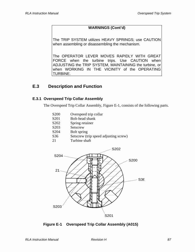
RLA Instruction Manual Overspeed Trip System
WARNINGS (Cont’d)
The TRIP SYSTEM utilizes HEAVY SPRINGS; use CAUTION when assembling or disassembling the mechanism.
The OPERATOR LEVER MOVES RAPIDLY WITH GREAT FORCE when the turbine trips. Use CAUTION when ADJUSTING the TRIP SYSTEM, MAINTAINING the turbine, or when WORKING IN THE VICINITY of the OPERATING TURBINE.
E.3 Description and Function
E.3.1 Overspeed Trip Collar Assembly
The Overspeed Trip Collar Assembly, Figure E-1, consists of the following parts.
S200 Overspeed trip collar S201 Bolt-head shank S202 Spring retainer S203 Setscrew S204 Bolt spring S36 Setscrew (trip speed adjusting screw) 21 Turbine shaft
S202
S200
S36
S201
S203
21
S204
Figure E-1 Overspeed Trip Collar Assembly (A015)
RLA Instruction Manual Revision H 87
Overspeed Trip System RLA Instruction Manual
The bolt-head shank (S201), which is contained within the overspeed trip collar (S200), passes through a clearance hole in the turbine shaft (21). The overspeed trip collar assembly is held in position on the turbine shaft by a setscrew (S203). The bolt-head shank is heavy at the head end (lower part of Figure E-1, Overspeed Trip Collar Assembly). As the shaft and trip collar assembly rotate, centrifugal force tends to move the bolt head out of the collar, compressing the bolt spring (S204). When turbine speed reaches the trip speed, centrifugal force at the bolt head exceeds spring retention force, causing the bolt head to snap out, tripping the trip linkage. The speed at which the bolt trips the linkage is a function of bolt head shank (S201) shape and material, spring rate of the bolt spring (S204), and the size, material, and position of setscrew (S36). These components are selected by the factory, based on the desired trip speed. In the field, trip speed is adjusted by changing the position of setscrew (S36). Refer to Section E.5, Adjustment of Trip Speed, for adjustment and maintenance instructions.
WARNING
Bolt head shank (S201), bolt spring (S204), and setscrew (S36) are a FACTORY-CONFIGURED SET, selected to obtain the proper trip speed for a specific turbine. DO NOT MIX OR INTERCHANGE THESE PARTS with similar parts from other turbines or attempt to modify these components. Consult your local Coppus manufacturer’s representative or the factory if replacement parts are needed.
E.3.2 Trip Valve
The standard RLA turbine trip valve (Figure E-2, Trip System) is a positive shut-off, single seated piloted valve that is spring-loaded to ensure fast action. Major components are listed below (a complete list of components appears in Section M, Replacement Parts/Factory Service). A030 Pilot valve and stem assembly MT008 Strainer screen MT128 Bonnet gasket MT137 Valve lifting pin MT151 Valve body MT152 Bonnet MT153 Guide bushing (2) MT157 Retainer plate
88 Revision H RLA Instruction Manual

RLA Instruction Manual Overspeed Trip System
MT158 Retainer plate screw (3) MT162 Valve MT192 Valve seat (optional)
DANGER
Under no circumstances should the TRIP VALVE be blocked or held open to render the trip system inoperative. Overriding the trip system, and allowing the turbine to exceed the rated (nameplate) trip speed, may result in FATAL INJURY to personnel and extensive turbine damage. In the event the trip system malfunctions, immediately SHUT DOWN the turbine and correct the cause.
Figure E-2 Trip System
RLA Instruction Manual Revision H 89

Overspeed Trip System RLA Instruction Manual
When the turbine is running, the trip valve is fully open, with the uppermost surface of the pilot valve (A030) seated against the lower guide bushing (MT153). Backseating of the pilot valve prevents excessive steam leakage past the pilot valve stem. The valve (MT162) is held open by the valve lifting pin (MT137), which links it with the pilot valve. When the trip linkage is tripped, lever spring (MT131) forces the pilot valve and stem assembly (A030), along with the valve, into the closed position, isolating the turbine from the steam supply. The pilot valve allows valve (MT162) to be opened with full inlet pressure upstream of the valve. The pilot valve, exposing only a small surface area to the inlet pressure, is easily lifted by the stem. As the pilot valve opens, it relieves pressure above trip valve (MT162) and balances the pressure drop across it. The valve is then easily lifted by the valve lifting pin (MT137). The steam strainer screen (MT008) prevents foreign matter from entering the turbine. If foreign matter does appear in the steam chest, turbine nozzles, exhaust casing, or if blading is damaged, then the steam strainer may be defective. Foreign matter that gets past an intact steam strainer generally has a small particle size or comes from within the turbine itself or its valves.
The drain hole on the bottom of the valve body is used to connect piping for draining of condensate. The turbine is shipped with a pipe plug in the drain hole. There is also an intermediate stem leak-off connection on the bonnet (not shown). Refer to Section C, for recommended drain and leak-off piping configurations.
E.3.3 Trip Linkage
The trip linkage, set in motion by movement of the bolt-head shank (S201) in the overspeed trip collar assembly (A015), controls closing of the trip valve. The linkage also allows the valve to be opened and latched in the open position.
WARNING
NEVER OPEN A CLOSED TRIP VALVE without first preparing the turbine and driven equipment for operation.
90 Revision H RLA Instruction Manual
RLA Instruction Manual Overspeed Trip System
The trip linkage consists of the following components (see Figures E-2 and E-3).
MT129 Trunnion spring MT130 Trunnion spring pin MT131 Lever spring MT132 Snap ring MT133 Lever pivot pin MT134 Spring link MT135 Trunnion spring cotter pin MT136 Lever pivot cotter pin MT148 Trip latch shoulder screw MT149 Trip lever shoulder screw MT150 Trip lever MT155 Lever stand MT170 Trunnion pin MT173 Operator lever MT180 Trunnion box MT185 Connecting rod end MT186 Connecting rod bolt (2) MT189 Connecting rod end locknut (2) MT190 Connecting rod locknut MT194 Trip latch MT197 Connecting rod MT201 Trip lever spring
RLA Instruction Manual Revision H 91

Overspeed Trip System RLA Instruction Manual
PLUG
S200
21
S36
MT150
S201
S202
MT148MT194
MT197
Figure E-3 Collar in Tripped Position
The trip linkage operates as follows: Refer to Figures E-1, Overspeed Trip Collar Assembly, E-2, Trip System, and E-3, Collar in Tripped Position. As the valve (MT162) approaches the fully open position, the end of the operator lever (MT173) pushes connecting rod (MT197) down, rotating trip latch (MT194) about the trip latch shoulder screw (MT148). The latch then engages the trip lever (MT150) via a knife edge, holding the valve in the open position. Lever spring (MT131), operating in the valve closing direction, applies tension to operator lever (MT173). This tension is transferred to the knife edge, holding the linkage in the open position. With the valve in the open position, inlet steam can now flow into the turbine.
92 Revision H RLA Instruction Manual

RLA Instruction Manual Overspeed Trip System
The trip valve can then be tripped, either manually or by an overspeed condition. If overspeed occurs, the bolt-head shank (S201) will snap out of the overspeed trip collar (S200), striking the trip lever (MT150), causing it to release trip latch (MT194). The operator lever is now free to move; lever spring (MT131) brings the operator lever down, closing the valve. Since spring (MT131) is very strong, valve closing will occur suddenly and with great force.
WARNING
The OPERATOR LEVER MOVES RAPIDLY WITH GREAT FORCE when the turbine trips. Use CAUTION when ADJUSTING the trip system, MAINTAINING the turbine, or when WORKING IN THE VICINITY of the OPERATING TURBINE.
E.4 Trip System Operation
For RLA turbines supplied with the standard trip linkage, if the overspeed trip valve is tripped shut and the turbine stopped, either by an overspeed trip condition or manual activation of the trip lever, the trip valve must be reset manually, as described below. Use the following procedure to manually reset the overspeed trip valve: a. Close shut-off valve in inlet steam line as soon as possible after the turbine trips. b. Determine cause of the trip condition. It may be due to loss of the driven
machine load, a turbine fault, or a governor problem. Remedy the cause using procedures detailed in Section K, Troubleshooting.
c. If the turbine is not at a complete stop, listen for bolt retraction into the shaft
collar, or wait for turbine speed to drop to 75% of its rated value to ensure resetting of the trip bolt.
d. Push down on the operator lever (MT173) slightly (approximately 10-15 angular
degrees) to open pilot valve (A030). e. Wait for pressure in the valve body to be bled off by the pilot clapper valve. f. When pressure in the valve body has bled off, continue pushing down the
operating lever using minimal force, until the trip valve (MT162) opens and the trip lever latches.
RLA Instruction Manual Revision H 93

Overspeed Trip System RLA Instruction Manual
CAUTION
DO NOT try to FORCE or jerk open the TRIP VALVE
g. Gradually open shut-off valve in inlet steam line to bring turbine up to normal operating speed, allowing the governor to take control. Then open shut-off valve to full open position and back off one-quarter turn.
E.5 Adjustment of Trip Speed
E.5.1 Trip Speed Setting (refer to Figure E-3, Collar in Tripped Position)
It may become necessary to change the factory speed setting of the trip system due to a change in the normal operating speed of the turbine. This setting can be changed by adjusting the position of the set screw (S36) inside the bolt-shank (S201). Use the following procedure to set turbine trip speed: a. Test the overspeed trip system per the Overspeed Trip Test Procedure specified
in Section E.6.2. Record speed at which the trip bolt triggers the overspeed trip valve, stopping the turbine. Close block valve in inlet steam line to prevent accidental restart.
b. Remove mounting housing cover (B100). Remove plug (S58) from governor
mounting housing access hole, located above collar (S200).
c. Manually rotate turbine shaft (21) to align female-threaded bore of bolt (S201) at access hole.
d. Remove trip lever shoulder screw (MT149), trip lever (MT150) and trip lever
spring (MT201). e. Determine whether set screw (S36) has an Allen hex-socket head or a
screwdriver slot. Insert 5/32” hex key (Allen) wrench or screwdriver tip into bore of bolt-shank (S201) to engage set screw (S36).
f. Hold bolt-shank (S201) with 1/2” socket wrench at hex-head spring retainer
(S202) while adjusting set screw (S36). Turning the set screw in increases tripping speed; backing it out decreases tripping speed. Use caution when backing out so as not to loosen S202 retainer from S201 bolt shank. One complete revolution of the set screw (S36) represents approximately 200 RPM.
g. Check the tightness of the spring retainer (S36 to the bolt shank (S201) by
using a 5/16 hex key and torque wrench with a ½ inch socket. The torque must be 200 ± 15 in.-lb. (22.6 ± 1.7 N-m)
94 Revision H RLA Instruction Manual

RLA Instruction Manual Overspeed Trip System
WARNING
Do not start the turbine without checking the spring retainer torque. A loose spring retainer could cause damage to the trip collar which could result in failure of the trip system should there be an overspeed.
h. Replace trip lever (MT150), trip lever spring (MT201) and trip lever shoulder screw (MT149).
i. Open the inlet block valve and test the overspeed trip system per the Overspeed
Trip Test Procedure specified in Section E.6.2. Close inlet block valve after testing.
j. Repeat steps d through i, above, in sequence, until adjustments to screw (S36)
provide the tripping speed (±2%) indicated on the turbine nameplate. The first one or two “cut and try” adjustments of this type will indicate both the direction and magnitude of screw adjustment required to obtain the tripping speed.
The new trip setting should be approximately 21% above the rated speed for a NEMA A (Woodward TG) governor and 16% above the rated speed for a NEMA D governor.
CAUTION
REINSTALL PLUG in mounting housing access hole after final screw adjustment. Reinstall mounting housing cover.
k. Open inlet block valve and test turbine tripping several times after final adjustment. If the trip speed is not repeatable within ±2%, or if erratic operation occurs, investigate and correct the problem before placing the turbine in normal service.
l. If possible, carry out a daily check of the tripping mechanism during the first
week after adjustment, by overspeeding the turbine. Optional construction may include an electronic overspeed trip system. Refer to the certified drawings and the appropriate vendor instruction manual in the Supplemental Documentation section, supplied at the end of this manual, for instruction on how to adjust the trip speed set point.
E.5.2 Magnetic Pickup Clearances
When supplied, maintaining the proper clearance between the magnetic pickups (located on the turbine mounting housing) and the turbine shaft mounted signal
RLA Instruction Manual Revision H 95
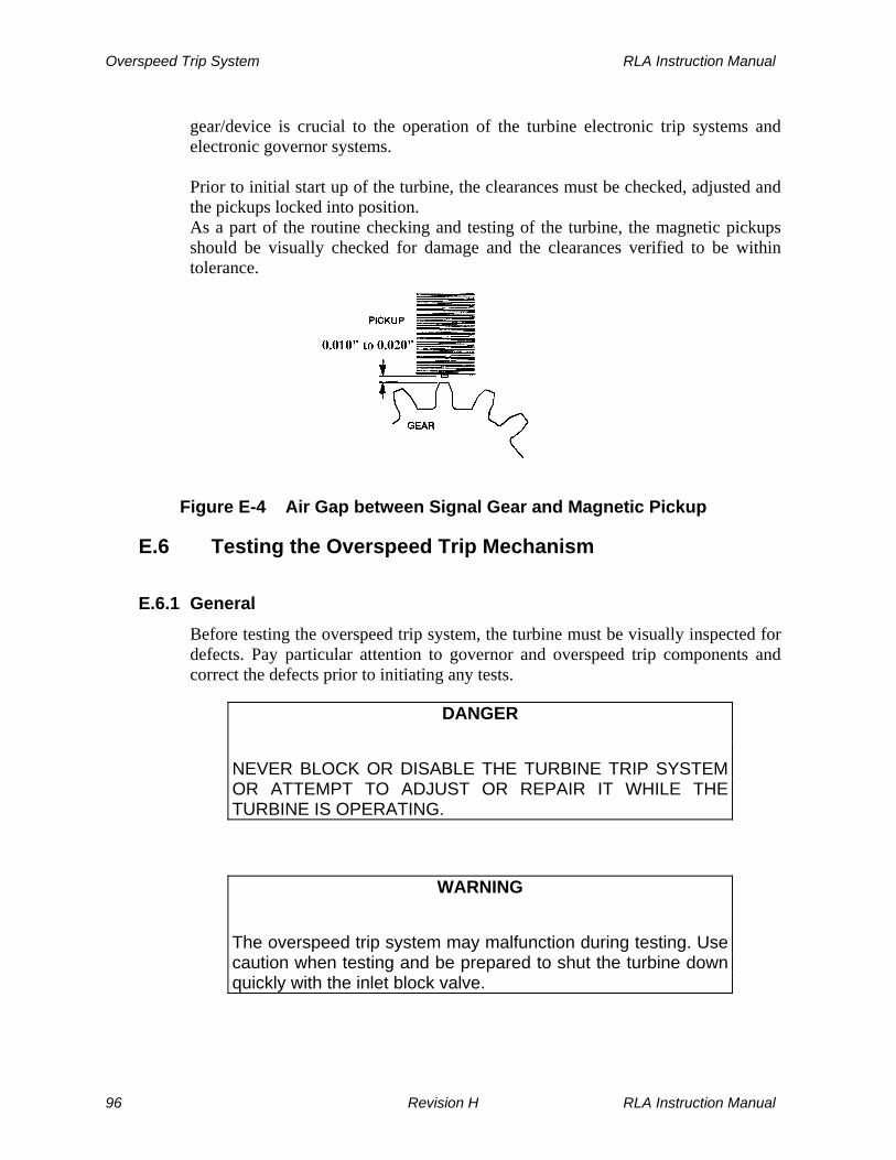
Overspeed Trip System RLA Instruction Manual
gear/device is crucial to the operation of the turbine electronic trip systems and electronic governor systems. Prior to initial start up of the turbine, the clearances must be checked, adjusted and the pickups locked into position. As a part of the routine checking and testing of the turbine, the magnetic pickups should be visually checked for damage and the clearances verified to be within tolerance.
Figure E-4 Air Gap between Signal Gear and Magnetic Pickup
E.6 Testing the Overspeed Trip Mechanism
E.6.1 General
Before testing the overspeed trip system, the turbine must be visually inspected for defects. Pay particular attention to governor and overspeed trip components and correct the defects prior to initiating any tests.
DANGER
NEVER BLOCK OR DISABLE THE TURBINE TRIP SYSTEM OR ATTEMPT TO ADJUST OR REPAIR IT WHILE THE TURBINE IS OPERATING.
WARNING
The overspeed trip system may malfunction during testing. Use caution when testing and be prepared to shut the turbine down quickly with the inlet block valve.
96 Revision H RLA Instruction Manual

RLA Instruction Manual Overspeed Trip System
The overspeed trip system should be tested weekly to verify its operation, to prevent build-up of foreign material on the trip linkage, and to alert the operator to deterioration that may affect trip system performance. Dresser-Rand recommends incorporation of testing into the plant operating/maintenance program and the keeping of a log to record tests. Any malfunction of the trip system should be investigated and corrected prior to returning the turbine to service.
E.6.2 Overspeed Trip Test Procedure
Before testing the overspeed trip system, the turbine must be visually inspected for defects. Pay particular attention to governor and overspeed trip components and correct any defects prior to initiating any tests. Use the following procedure to test the standard RLA Turbine overspeed trip system: a. Start up the turbine per Section I.4.2, Initial Start-Up Procedure. b. Manually trip the turbine by pressing on the trip lever (MT150). The overspeed
trip valve should close, shutting off the turbine steam supply and bringing it to a stop. This confirms operation of the linkage and valve, but not the collar assembly. If the valve does not close, refer to Section K, Troubleshooting. Otherwise, proceed to Step c.
WARNING
The OPERATOR LEVER MOVES UPWARD VERY RAPIDLY and abruptly through its full travel when the turbine is TRIPPED. To guard against serious hazards to operating personnel, they must STAY CLEAR OF THE LEVER.
c. Open and latch the overspeed trip valve according to Section E.4, Trip System Operation.
d. Increase turbine speed using the governor speed adjusting screw until trip
speed is reached. The turbine should trip within ±2% of the trip speed setting on the turbine nameplate, and come to a complete stop.
e. If the turbine fails to trip at a speed 5% greater than the trip speed setting,
manually trip the turbine by pressing down on the trip lever. Refer to Section K, Troubleshooting, to determine why the turbine fails to trip properly.
RLA Instruction Manual Revision H 97

Overspeed Trip System RLA Instruction Manual
Optional construction may include an electronic overspeed trip system. Refer to the certified drawings and the appropriate vendor instruction manual in the Supplemental Documentation section, supplied at the end of this manual, for instruction on how to test the overspeed trip system.
98 Revision H RLA Instruction Manual

RLA Instruction Manual Lubrication System
Section F
Lubrication System
F.1 General
Proper lubrication of turbine bearings and the governor is essential for long, trouble-free service. Turbine oil must be clean, of the proper viscosity and quantity, and maintained at the proper temperature. Oil levels should be checked before starting the turbine and on a daily basis for turbines running continuously.
WARNING
Lack of lubricant or contaminated lubricant could result in bearing failure. This could create sparks or hot surfaces which could ignite lubricant or flammable gasses.
CAUTIONS
Overloading the turbine drive shaft will cause the turbine to slow down – possibly resulting in insufficient lubrication and/or reduced function and damage to the driven equipment.
If the ambient temperature exceeds 110° F (43° C), cooling water must be provided to the bearing housings to limit the maximum temperature of the lubricating oil to 180° F (82°C). If the ambient temperature falls below freezing a means must be provided to maintain the lubricating oil in the bearing housings to a minimum temperature of 130°F (54°C) and to prevent cooling water from freezing and possibly cracking the bearing housings.
F.2 Lubrication Requirements
Lubrication requirements for an RLA turbine are a function of the rated operating speed. In most cases, several lubrication options are feasible at a rated RPM; the customer determines the selected method.
RLA Instruction Manual Revision H 99

Lubrication System RLA Instruction Manual
Figure F-1 Lubrication Requirements for RLA Turbines
CAUTIONS
CLEANLINESS is ESSENTIAL for long and trouble free service from BEARINGS and GOVERNOR. Care must be taken to ensure that no foreign material enters bearing housings, the governor, constant level oilers or oil reservoirs when performing maintenance, checking oil, adding oil, or making adjustments.
Overloading the turbine drive shaft will cause the turbine to slow down – possibly resulting in insufficient lubrication and/or reduced function and damage to the driven equipment.
F.3 Oil Ring Lubrication
The standard method of lubrication for RLA turbines is oil ring lubrication. Brass oil rings running on the turbine shaft pick up oil from reservoirs in the bearing housings. As the shaft and oil rings rotate together, oil flows from oil rings onto the shaft, ultimately flowing into the ball bearings, providing lubrication. The oil level within bearing housings must be maintained at a sufficient level to allow the oil rings to run in the oil. An oil level that is too high results in oil leakage past the shaft seals. Oil rings cease to rotate sufficiently when the shaft runs below 900 RPM, no longer providing adequate lubrication. Therefore, the turbine should not be run at speeds less than 900 RPM. It is recommended that the oil hole cover (111) be removed and the oil rings checked for proper rotation when running at less than 1000 RPM.
100 Revision H RLA Instruction Manual
RLA Instruction Manual Lubrication System
CAUTIONS
DO NOT RUN turbines equipped with oil ring lubrication at speeds LESS THAN 900 RPM. The OIL RINGS WILL NOT OPERATE CORRECTLY at these speeds, causing BEARING FAILURE due to lack of lubrication.
The presence of oil in the constant level oilers does not necessarily mean that oil in the bearing housings is at the proper level.
F.4 Oil Mist Lubrication
WARNING
If the turbine is supplied with oil mist lubrication, oil mist could escape from the bearing housing vents or oiler. If there is the possibility that these could be ignited by equipment or processes in the proximity of the turbine they should be piped to a safe area.
Oil mist lubrication is offered as an option on RLA turbines. Two types of oil mist are available for RLA turbines, “pure” oil mist and “purge” oil mist. When “pure” oil mist lubrication is used, oil rings and constant level oilers are not supplied, directional condensing type fittings are required and the lubricant is supplied to the dry sump bearing housings by an oil mist generator. The turbine must not be operated without the oil mist system in operation, as it is the sole source of lubrication. Application of water cooling of the bearing housings is not required for turbines lubricated by a pure oil mist lubrication system. When “purge” oil mist is used, oil rings and constant level oilers are supplied, mist type fittings are required and the oil mist is supplied to the bearing housings as a positive pressure purge over the bearing housing oil reservoir. The turbine can be operated without the oil mist system in operation, provided there is sufficient oil in the bearing housing reservoirs for proper operation of the turbine oil rings. Turbine bearing housings may be supplied with or without oil mist fittings, as selected by the customer. When oil mist lubrication is implemented, oil mist is supplied at the top of the bearing housing and oil is removed continuously from a drain and may be returned to the oil mist generator. When the oil drain piping is
RLA Instruction Manual Revision H 101
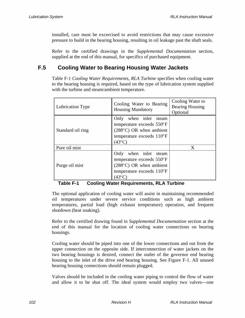
Lubrication System RLA Instruction Manual
installed, care must be excercised to avoid restrictions that may cause excessive pressure to build in the bearing housing, resulting in oil leakage past the shaft seals. Refer to the certified drawings in the Supplemental Documentation section, supplied at the end of this manual, for specifics of purchased equipment.
F.5 Cooling Water to Bearing Housing Water Jackets
Table F-1 Cooling Water Requirements, RLA Turbine specifies when cooling water to the bearing housing is required, based on the type of lubrication system supplied with the turbine and steam/ambient temperature.
Lubrication Type Cooling Water to Bearing Housing Mandatory
Cooling Water to Bearing Housing Optional
Standard oil ring
Only when inlet steam temperature exceeds 550°F (288°C) OR when ambient temperature exceeds 110°F (43°C)
Pure oil mist X
Purge oil mist
Only when inlet steam temperature exceeds 550°F (288°C) OR when ambient temperature exceeds 110°F (43°C)
Table F-1 Cooling Water Requirements, RLA Turbine
The optional application of cooling water will assist in maintaining recommended oil temperatures under severe service conditions such as high ambient temperatures, partial load (high exhaust temperature) operation, and frequent shutdown (heat soaking). Refer to the certified drawing found in Supplemental Documentation section at the end of this manual for the location of cooling water connections on bearing housings. Cooling water should be piped into one of the lower connections and out from the upper connection on the opposite side. If interconnection of water jackets on the two bearing housings is desired, connect the outlet of the governor end bearing housing to the inlet of the drive end bearing housing. See Figure F-1. All unused bearing housing connections should remain plugged. Valves should be included in the cooling water piping to control the flow of water and allow it to be shut off. The ideal system would employ two valves—one
102 Revision H RLA Instruction Manual
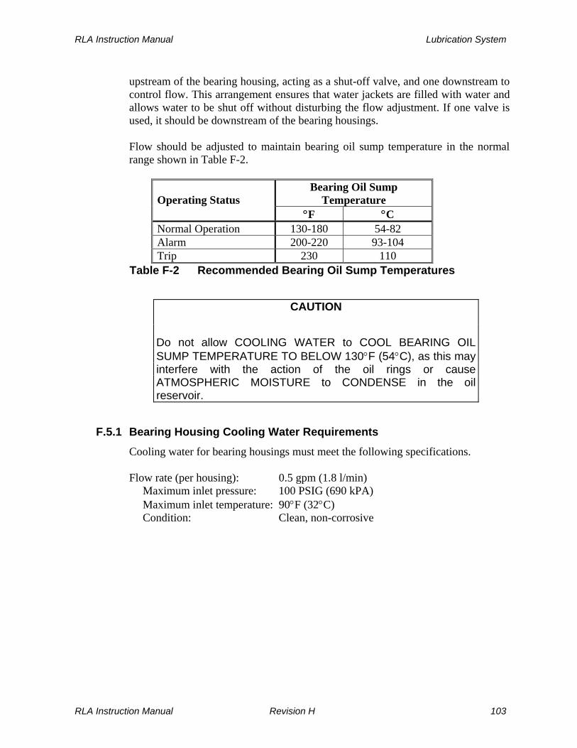
RLA Instruction Manual Lubrication System
upstream of the bearing housing, acting as a shut-off valve, and one downstream to control flow. This arrangement ensures that water jackets are filled with water and allows water to be shut off without disturbing the flow adjustment. If one valve is used, it should be downstream of the bearing housings. Flow should be adjusted to maintain bearing oil sump temperature in the normal range shown in Table F-2.
Bearing Oil Sump
Temperature Operating Status °F °C
Normal Operation 130-180 54-82 Alarm 200-220 93-104 Trip 230 110
Table F-2 Recommended Bearing Oil Sump Temperatures
CAUTION
Do not allow COOLING WATER to COOL BEARING OIL SUMP TEMPERATURE TO BELOW 130°F (54°C), as this may interfere with the action of the oil rings or cause ATMOSPHERIC MOISTURE to CONDENSE in the oil reservoir.
F.5.1 Bearing Housing Cooling Water Requirements
Cooling water for bearing housings must meet the following specifications. Flow rate (per housing): 0.5 gpm (1.8 l/min) Maximum inlet pressure: 100 PSIG (690 kPA) Maximum inlet temperature: 90°F (32°C) Condition: Clean, non-corrosive
RLA Instruction Manual Revision H 103

Lubrication System RLA Instruction Manual
Figure F-2 Cooling Water Piping with Optional Interconnecting Pipe
104 Revision H RLA Instruction Manual

RLA Instruction Manual Lubrication System
F.6 Constant Level Oiler
Turbines lubricated with oil rings are equipped with constant level oilers. The purpose of these oilers is to maintain the correct oil level in the bearing housings. Instructions for Constant Level Oilers may be found in Supplemental Documentation section at the end of this manual.
F.7 Bearing Housing Oil Levels and Capacities
Note: For governor oil requirements, refer to the governor instruction manual found in Supplemental Documentation section at the end of this manual. The following table shows the approximate oil quantities required to fill bearing housings, according to RLA frame size. In addition, each constant level oiler has a capacity of about 4 oz. of oil.
Frame Size Governor End Capacity Casing End Capacity
12M - 12L 15 oz. (0.48 l) 15 oz. (0.48 l) 16L - 20L 16 oz. (0.48 l) 23 oz. (0.68 l) 22L - 23L 16 oz. (0.48 l) 27 oz. (0.80 l)
Table F-3 Bearing Housing Oil Capacity
The following table shows the required oil levels that should be maintained by proper adjustment of constant level oilers. The oil level gauge on the side of the bearing housing indicates the oil level. A mark inscribed on the bearing housing indicates the proper oil level. If the mark is obscured, refer to the following table.
Frame Size Distance Below Shaft Centerline in Inches
RLA-12M/L 1.12 (2.84 cm) RLA-16L/E 1.44 (3.66 cm) RLA-20L 1.44 (3.66 cm) RLA-22L 2.75 (7.0 cm) RLA-23L 2.75 (7.0 cm) RLA-22LH 3.00 (7.62 cm)
Table F-4 Bearing Housing Oil Levels
F.8 Maintenance/Oil Changes
Note: For governor oil requirements, refer to the governor instruction manual found in Supplemental Documentation section at the end of this manual.
RLA Instruction Manual Revision H 105

Lubrication System RLA Instruction Manual
Oil levels in both bearing housings and the governor should be checked daily. Low point drains should be checked weekly for water. Establish an oil change frequency based on oil tests. Otherwise, oil in bearing housings should be changed monthly; or earlier, if there is reason to believe that the oil has been contaminated with water, dirt, or by overheating.
CAUTIONS
The presence of oil in the constant level oilers does not necessarily mean that oil in the bearing housings is at the proper level.
CLEANLINESS is ESSENTIAL for long and trouble free service from BEARINGS and the GOVERNOR. Care must be taken to ensure that no foreign material enters bearing housings, the governor, or constant level oilers when performing maintenance, checking oil, adding oil, or making adjustments.
F.9 Lubricating Oil Selection Guidelines
The importance of using a proper lubricant cannot be overemphasized. High quality turbine oils are required. Dresser-Rand does not recommend specific brands of oil. Turbine owners should consult reliable oil suppliers regarding the proper selection of turbine oils. As a minimum, the selected oil should be a premium quality rust- and oxidation-inhibited turbine or circulating oil which will readily separate from water and have minimum tendency to emulsify or foam when agitated at actual operating temperatures. EP additives are not recommended. Since the proper grade of lubricant may not be available locally, it should be ordered in advance of start-up time.
106 Revision H RLA Instruction Manual

RLA Instruction Manual Lubrication System
Comparisons between different viscosity grading systems are shown in Table F-5.
Oil Temperature 100°F (40°C)
Viscosity, Saybolt Universal, seconds 300 @ 100 °F (40. °C)
Viscosity, Metric, mm2/sec, Centistokes 68 @ 100 °F (40. °C)
Minimum Flashpoint 350°F/175°C
Viscosity Index Above 90 Table F-5 Lubricating Oil Selection Guidelines
Centistokes
(CST, CS, or CTS) at 40°C
Saybolt Universal Seconds (SUS)
Nominal at 100°F ISO V.G.
15 80 15 22 106 22 32 151 32 46 214 46 68 310 68 100 463 100 150 696 150 220 1020 220 320 1483 320 460 2133 460
Table F-6 Viscosity Comparisons
F.10 Seal Ring Adjustment
Tightness of the washer plate/seal ring is adjusted at the factory prior to shipment. Readjustment of washer plate bolts may be necessary if leakage occurs after start-up. These bolts should only be tightened enough to prevent loss of lubricant. Local wetting of the seal and shaft contact surfaces is acceptable.
RLA Instruction Manual Revision H 107

Lubrication System RLA Instruction Manual
CAUTION
(Refer to Figures M-5 and M-6 in Section M, Replacement Parts/Factory Service.) DO NOT OVERTIGHTEN BOLTS retaining the WASHER PLATE (26). These bolts should be tightened only enough to bring the plate snugly against the seal ring (40). If too tight, the seal ring WILL WEAR RAPIDLY and may OVERHEAT and SCORE THE SHAFT. Refer to Section L, Disassembly and Parts Replacement.
F.11 Air Purge of Bearing Housings
An air purge connection can be furnished as an option on the bearing housing for the supply of low pressure, dry, filtered air. The positive pressure (relative to atmospheric pressure) will prevent the intrusion of dust, moisture, and other contaminants into the bearing housing. The supply pressure should not exceed a 1 inch (25.4 mm) water column.
108 Revision H RLA Instruction Manual

RLA Instruction Manual Optional Gland Condensers, Eductors and Ejectors
Section G
Optional Gland Condensers, Eductors and Ejectors
For some applications, optional ejectors, educators or gland condensers may be supplied with turbine package for the removal and recovery of leakage past the turbine shaft seals. Motive flow is applied to the inlet of the educator or ejector, creating a slight vacuum, which is applied at the turbine gland leak-off connections. The discharge of the educator, ejector and/or gland condenser is then typically returned to the plant water system when the motive fluid is steam or a safe area when the motive is fluid gas. These items normally ship loose for piping and installation by others. Refer to the certified drawings and optional equipment manuals in the Supplemental Documentation section, for details of any items supplied with the turbine package.
RLA Instruction Manual Revision H 109

RLA Instruction Manual
THIS PAGE WAS LEFT BLANK INTENTIONALLY
110 Revision H RLA Instruction Manual

RLA Instruction Manual Optional Instruments and Controls
Section H
Optional Instruments and Controls
NOTE
Refer to the Supplemental Documentation section, supplied at the end of this manual, for instructions/operation data on non Dresser-Rand instruments and controls, which are provided when available.
H.1 Sentinel Warning Valve
If specified as an accessory (applies to turbines to be operated on steam only), the turbine will be furnished with a Sentinel warning valve to alert the operator when excessive pressure arises in the exhaust casing.
WARNINGS
The SENTINEL WARNING VALVE will ONLY WARN that excessive pressure exists in the casing. It will NOT RELIEVE THIS PRESSURE.
It is the USER’S RESPONSIBILITY to INSTALL A FULL-FLOW RELIEF VALVE in the exhaust line between the turbine exhaust casing and the first shut-off valve. This relief valve should be sized to relieve the FULL AMOUNT OF STEAM THAT THE TURBINE WILL PASS, in the event that the exhaust line is blocked.
H.2 Pressure and Temperature Gauges
If specified as accessories, the turbine will be furnished with inlet and exhaust pressure and/or temperature gauges. Inlet and exhaust gauges must be connected to the user’s inlet and exhaust steam piping just upstream and/or downstream of the turbine inlet and exhaust flange connections as appropriate. Steam chest pressure
RLA Instruction Manual Revision H 111
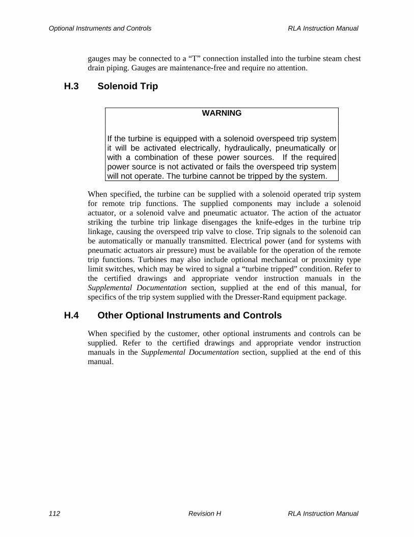
Optional Instruments and Controls RLA Instruction Manual
gauges may be connected to a “T” connection installed into the turbine steam chest drain piping. Gauges are maintenance-free and require no attention.
H.3 Solenoid Trip
WARNING
If the turbine is equipped with a solenoid overspeed trip system it will be activated electrically, hydraulically, pneumatically or with a combination of these power sources. If the required power source is not activated or fails the overspeed trip system will not operate. The turbine cannot be tripped by the system.
When specified, the turbine can be supplied with a solenoid operated trip system for remote trip functions. The supplied components may include a solenoid actuator, or a solenoid valve and pneumatic actuator. The action of the actuator striking the turbine trip linkage disengages the knife-edges in the turbine trip linkage, causing the overspeed trip valve to close. Trip signals to the solenoid can be automatically or manually transmitted. Electrical power (and for systems with pneumatic actuators air pressure) must be available for the operation of the remote trip functions. Turbines may also include optional mechanical or proximity type limit switches, which may be wired to signal a “turbine tripped” condition. Refer to the certified drawings and appropriate vendor instruction manuals in the Supplemental Documentation section, supplied at the end of this manual, for specifics of the trip system supplied with the Dresser-Rand equipment package.
H.4 Other Optional Instruments and Controls
When specified by the customer, other optional instruments and controls can be supplied. Refer to the certified drawings and appropriate vendor instruction manuals in the Supplemental Documentation section, supplied at the end of this manual.
112 Revision H RLA Instruction Manual

RLA Instruction Manual Start-Up and Operation
Section I
Start-Up and Operation
I.1 Warnings
The operator should read Sections A through H of this manual to become familiar with the turbine, before attempting to start and operate it.
WARNINGS
The surface temperature of the turbine will become that of the steam inlet temperature. This could exceed the ignition temperature of some gasses. Therefore if the turbine is installed where explosive gasses could be present it is the user's responsibility to ensure that this does not create a hazardous situation.
Should an explosion occur in the vicinity of the turbine it is the user/installer’s responsibility to halt it immediately and/or limit the range of the exposive flames and explosive pressures to a sufficient level of safety.
DO NOT START OR OPERATE this turbine unless the INSTALLATION has been VERIFIED TO BE BE CORRECT and all pre-startup SAFETY AND CONTROL FUNCTION have been CHECKED.
DO NOT START OR OPERATE this turbine unless you have a COMPLETE UNDERSTANDING of the location and function of ALL COMPONENTS in the steam supply and exhaust systems, including block and relief valves, bypasses, drains, and any upstream or downstream equipment that may affect the flow of steam to or from the steam turbine.
RLA Instruction Manual Revision H 113

Start-Up and Operation RLA Instruction Manual
DANGERS
NEVER WEAR NECKTIES OR OTHER LOOSE CLOTHING while in the proximity of the turbine or auxiliary equipment. These could be become entangled in the shaft, coupling, linkage or other moving parts and cause serious injury.
Keep bodyparts (fingers, hands, etc.) away from shaft, coupling, linkage or other moving parts to prevent contact and possible serious injury.
Wear proper eye protection when working on or around the turbine.
WARNING
Never operate the turbine with the governor or governor system disabled.
CAUTION
If the ambient temperature exceeds 110°F (43°C), cooling water must be provided to the bearing housings to limit the maximum temperature of the lubricating oil to 180°F (82°C). If the ambient temperature falls below freezing a means must be provided to maintain the lubricating oil in the bearing housings to a minimum temperature of 130°F (54°C) and to prevent cooling water from freezing and possibly cracking the bearing housings.
114 Revision H RLA Instruction Manual

RLA Instruction Manual Start-Up and Operation
DANGER
NEVER BLOCK OR DISABLE THE TURBINE TRIP SYSTEM OR ATTEMPT TO ADJUST OR REPAIR IT WHILE THE TURBINE IS OPERATING.
CAUTIONS
Overloading the turbine drive shaft will cause the turbine to slow down possibly resulting in insufficient lubrication and/or reduced function and damage to the driven equipment.
Turbines should not be subjected to temperatures in a non-running ambient condition of less than 20 degrees F unless special LOW TEMPERATURE have been specified and low temperature materials have been provided.
WARNINGS
DO NOT START OR OPERATE this turbine unless you have a COMPLETE UNDERSTANDING of the CONTROL SYSTEM, the OVERSPEED TRIP SYSTEM, the drain and leakoff systems, the lubrication system, and all auxiliary mechanical, electrical, hydraulic and pneumatic systems, as well as the meaning and significance of all monitoring gauges, meters, digital readouts, and warning devices.
When STARTING the turbine, be prepared to execute an EMERGENCY SHUTDOWN in the event of FAILURE of the GOVERNOR, OVERSPEED CONTROL SYSTEMS, linkage, or valves.
The surface temperature of the turbine and piping will become that of the steam inlet temperature. Personnel should wear gloves and protective clothing to avoid burns.
RLA Instruction Manual Revision H 115
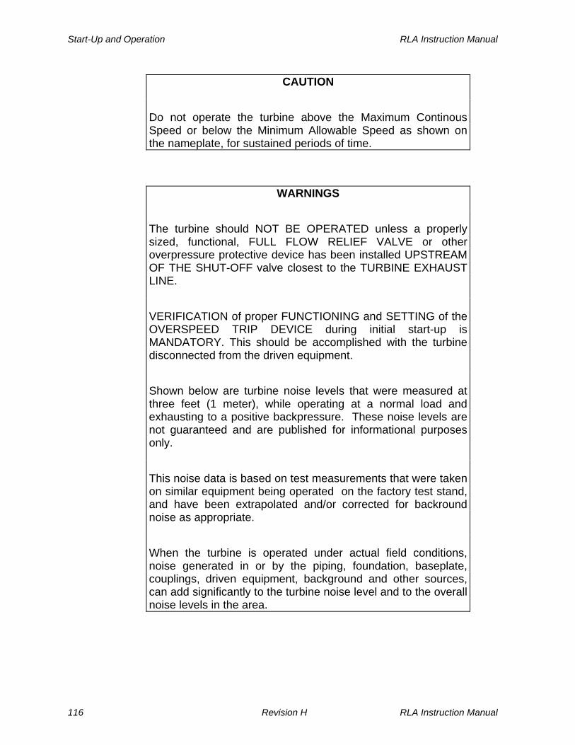
Start-Up and Operation RLA Instruction Manual
CAUTION
Do not operate the turbine above the Maximum Continous Speed or below the Minimum Allowable Speed as shown on the nameplate, for sustained periods of time.
WARNINGS
The turbine should NOT BE OPERATED unless a properly sized, functional, FULL FLOW RELIEF VALVE or other overpressure protective device has been installed UPSTREAM OF THE SHUT-OFF valve closest to the TURBINE EXHAUST LINE.
VERIFICATION of proper FUNCTIONING and SETTING of the OVERSPEED TRIP DEVICE during initial start-up is MANDATORY. This should be accomplished with the turbine disconnected from the driven equipment.
Shown below are turbine noise levels that were measured at three feet (1 meter), while operating at a normal load and exhausting to a positive backpressure. These noise levels are not guaranteed and are published for informational purposes only.
This noise data is based on test measurements that were taken on similar equipment being operated on the factory test stand, and have been extrapolated and/or corrected for backround noise as appropriate.
When the turbine is operated under actual field conditions, noise generated in or by the piping, foundation, baseplate, couplings, driven equipment, background and other sources, can add significantly to the turbine noise level and to the overall noise levels in the area.
116 Revision H RLA Instruction Manual

RLA Instruction Manual Start-Up and Operation
WARNINGS (Cont’d)
It is recommended that the equipment user assess the noise level(s) of the completed installation and determine if additional sound attenuation and/or hearing protection for operating personnel is required.
Turbine Sound Level Data Model RLA
Octave Band Frequency HZ – Sound Pressure Level Sound Power Level
Frame Size
63 125 250 500 1K 2K 4K 8K dBa dBa
12M/L 65 65 65 63 66 70 74 70 77 94 16L/E 65 66 66 64 67 71 75 71 78 95 20L 68 68 68 67 69 73 77 73 80 97 22L 68 69 69 67 69 74 78 74 81 98 23L/E 68 69 69 67 69 74 78 74 81 98
I.2 General
The following recommended start-up and operating procedures apply to the basic turbine (ring-oiled, TG governor, without reduction gear). For information on any optional equipment, refer to the appropriate vendor instruction manual in the Supplemental Documentation section, supplied at the end of this manual.
WARNINGS
None of the recommended start-up and operating procedures contained in this manual shall be construed in any way as relieving the user of his responsibility for compliance with the requirements of any regulatory body, or for the exercise of normal good judgment in the start-up, operation, and care of the turbine.
If a coupling guard is to be installed, refer to the coupling guard manufacturer’s instructions to ensure that it does not contact the running shaft or coupling which could cause a spark that could ignite hazardous gasses in the environment in which the turbine is installed.
RLA Instruction Manual Revision H 117

Start-Up and Operation RLA Instruction Manual
To ensure trouble-free operation, the turbine must be: a. Cleaned thoroughly prior to start-up, and kept clean at all times. b. Properly lubricated at regular intervals. c. Subjected to regular checks for the correct functioning of protective devices. d. Regularly inspected and maintained according to a scheduled preventive
maintenance program. e. Operated according to the procedures specified in this instruction manual.
118 Revision H RLA Instruction Manual

RLA Instruction Manual Start-Up and Operation
I.3 Turbine Installation and Start-Up Checklist
The following turbine installation and start-up checklist is provided as a guide on the following pages. Although intended for use by Dresser-Rand servicemen, this checklist is suitable as a guide for end-users as well.
Turbine Installation and Start-Up Checklist
I.3.1 Turbine Information
Customer _________________ Location ______________
Serviceman _________________ CustomerContact ______________
Start Date _________________ CompleteDate _________________
Nameplate Data:
Turbine Driven Equipment
Serial Number _________________ __________________
Rated Speed [RPM] _________________ __________________
Overspeed Trip [RPM]________________ __________________
Power [HP] _________________ __________________
Governor Lube System Manufacturer _________________ __________________
Serial Number _________________ __________________
Part Number _________________ __________________
Application:
Use: Continuous _______ Standby _________ Autostart _________
RLA Instruction Manual Revision H 119

Start-Up and Operation RLA Instruction Manual
I.3.2 Site Information
Actual Steam Conditions: Inlet press. (P1) ______ Inlet Temp. (T1) ______ Exhaust Press. (P2) _____
Yes No Is the base provided level and adequate to support the turbine?
Is piping deadweight supported by hangers or supports?
Do inlet and exhaust flanges line up with piping flanges?
Does the steam inlet pipe have a top take-off from the main header to minimize moisture induction?
Is there a piping run or dead leg beyond the take-off? Have expansion joints been used?
Has the piping been blown down with steam (including exhaust for backpressure units)?
Has inlet and exhaust piping been drained at low points or trapped to avoid water legs?
Has a full-flow relief valve been installed in the exhaust system upstream of the first shut-off valve? Setting? ___________
I.3.3 Installation
Yes No Is the turbine in good condition without signs of improper storage, mishandling or shipping damage?
Are foundation and base plate securing bolts adequate?
Is the turbine properly secured to the base plate?
Has the base plate been grouted?
Was rust preventative removed from the shaft and other exposed surfaces?
If the turbine was prepared for long-term storage, was the inside of gland housings wiped clean and carbon ring sets installed?
120 Revision H RLA Instruction Manual

RLA Instruction Manual Start-Up and Operation
Yes No Were bearing housings flushed and drained with a light oil prior to filling?
Are lubricating oil levels correct? Turbine Governor
Lubricating Oil Used: Turbine -- Brand _______________ Type __________ Governor -- Brand _______________ Type __________
Is the coupling properly lubricated and free to oscillate by hand?
Does the turbine rotate freely when turned by hand?
Do the oil rings rotate with the shaft?
Is the turbine rotation correct?
Do the throttle valve, overspeed trip valve and associated linkage move freely?
Does the Overspeed Trip lever reset easily and trip when operated by hand?
Does the bolt trip move freely in the collar assembly?
Has the lube system been site flushed?
Are lube oil return lines pitched to the sump?
Is there a Sentinel warning valve? Setting? _________
Is the turbine adequately drained at all points?
Are water cooling lines to bearing housings properly installed? Are there provisions for regulating cooling water flow?
Are steam leak-off connections piped correctly and unrestricted? (i.e., with no valves, manifolds, water legs or pipe size reduction).
Does the user understand the following: Overspeed Trip System operation? Overspeed Trip Valve reset procedure? Overspeed Trip exercising requirement and procedure?
RLA Instruction Manual Revision H 121

Start-Up and Operation RLA Instruction Manual
I.3.4 Start Up - Uncoupled
Drive shaft run out? ________ Driven equipment shaft run out? __________
Cold alignment method? (attach print out if available)
Rim & Face( ) Reverse Indicator ( ) Laser ( ) Other ( )
R IM FAC E
Indicator mounted on _______________ coupling reading ________________ Turbine ___________________ inches low to driven equip. Coupling Manufacturer _________________ Model ________
Yes No Did governor operate properly?
Is the running speed satisfactory?
Trip speed checks #1 _______ #2 ________ #3 ________ RPM
Overspeed test witnessed by _______________________
Bearing Oil Temp (sump) Gov End _______ Drive end__________
Lube oil pressure to bearing ________ psig
Lube oil temp- Into Cooler ___________ Out ____________
Are protective devices operating properly?
122 Revision H RLA Instruction Manual

RLA Instruction Manual Start-Up and Operation
I.3.5 Start Up - Coupled
Actual Steam Conditions: Inlet press. (P1) ______ Inlet Temp. (T1) ______ Exhaust Press. (P2) _____
Yes No Does the turbine operate at rated speed?
Speed variation? _____________ RPM
Does auxiliary equipment operate properly?
Is steam leakage within acceptable limits?
Vibration: (in/sec) (mils) filtered unfiltered (Indicate speed if mils are used __________ rpm)
Turbine (Vert/Horiz/Axial) Gov Bearing ___/__/___ Coupling Bearing __/___/___
Driven equipment Driven End Bearing ___/___/__ Non-Driven End Bearing ___/___/__
Are oil levels correct with no evidence of leakage?
Oil temp at discharge? Gov. End _______ Drive End ________
Hot alignment method? (attach print out if available)
Rim & Face ( ) Reverse Indicator ( ) Laser ( ) Other ( )
R IM FAC E
Indicator mounted on _______________coupling reading _________________ Turbine ___________________ inches low to driven equip.
RLA Instruction Manual Revision H 123

Start-Up and Operation RLA Instruction Manual
Yes No Were piping changes required to correct hot alignment readings? To turbine? Describe ___________________________________
To driven equipment? Describe __________________________
Is turbine doweled to baseplate? Is driven equipment doweled?
Was a copy of this report left with the customer?
Comments:
124 Revision H RLA Instruction Manual

RLA Instruction Manual Start-Up and Operation
I.4 Start-Up Procedure
WARNING
Turbine installation, operation, repair and service must be performed by EXPERIENCED PERSONNEL ONLY. Read and understand this instruction manual before installing, operating, repairing or servicing RLA turbines.
I.4.1 Restoration of Turbine from Shipping Condition
After factory testing, turbines are prepared for shipping and storage. The following two sections describe activities to be performed prior to initial start-up.
CAUTION
(Refer to Figures M-5 and M-6 in Section M, Replacement Parts/Factory Service.) DO NOT OVERTIGHTEN BOLTS retaining the WASHER PLATE (26). These bolts should be tightened only enough to bring the plate snugly against the seal ring (40). If too tight, the seal ring may OVERHEAT AND SCORE THE SHAFT. Refer to Section L, Disassembly and Parts Replacement.
I.4.1.1 Flushing/Filling of Bearing Housings
Before starting the turbine for the first time, open bearing housing drains and allow any residual oil to drain. Then close the drains and fill bearing housings with a light, warm oil. Rotate shaft by hand and then drain this oil. The oil recommended for permanent operation should now be added to the turbine through the oil hole covers, until levels shown on oil gauges reach their respective permanent marks on bearing housings. Add oil as necessary to constant level sight feed oilers mounted at each bearing housing. Note that a low oil level may result in improper lubrication and a high oil level may cause leakage past the seals and/or overheating. Refer to Section F, Lubrication System, for oil recommendations.
RLA Instruction Manual Revision H 125
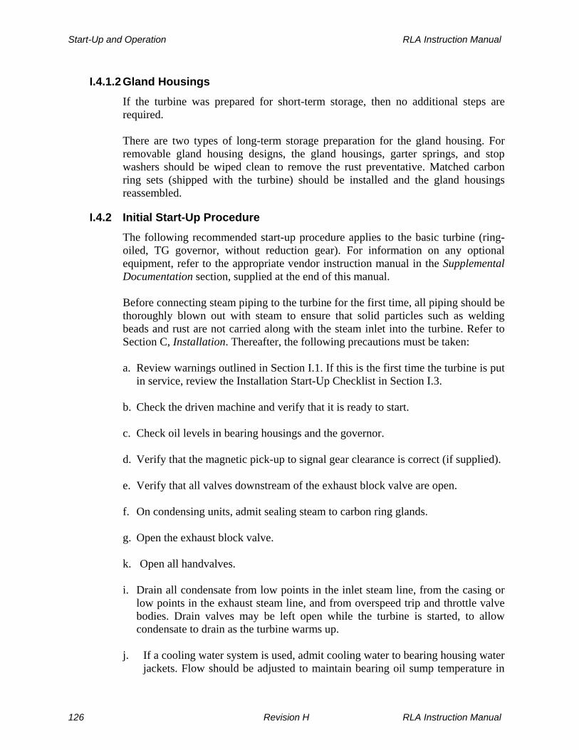
Start-Up and Operation RLA Instruction Manual
I.4.1.2 Gland Housings If the turbine was prepared for short-term storage, then no additional steps are required. There are two types of long-term storage preparation for the gland housing. For removable gland housing designs, the gland housings, garter springs, and stop washers should be wiped clean to remove the rust preventative. Matched carbon ring sets (shipped with the turbine) should be installed and the gland housings reassembled.
I.4.2 Initial Start-Up Procedure
The following recommended start-up procedure applies to the basic turbine (ring-oiled, TG governor, without reduction gear). For information on any optional equipment, refer to the appropriate vendor instruction manual in the Supplemental Documentation section, supplied at the end of this manual. Before connecting steam piping to the turbine for the first time, all piping should be thoroughly blown out with steam to ensure that solid particles such as welding beads and rust are not carried along with the steam inlet into the turbine. Refer to Section C, Installation. Thereafter, the following precautions must be taken: a. Review warnings outlined in Section I.1. If this is the first time the turbine is put
in service, review the Installation Start-Up Checklist in Section I.3. b. Check the driven machine and verify that it is ready to start. c. Check oil levels in bearing housings and the governor. d. Verify that the magnetic pick-up to signal gear clearance is correct (if supplied). e. Verify that all valves downstream of the exhaust block valve are open. f. On condensing units, admit sealing steam to carbon ring glands. g. Open the exhaust block valve. k. Open all handvalves. i. Drain all condensate from low points in the inlet steam line, from the casing or
low points in the exhaust steam line, and from overspeed trip and throttle valve bodies. Drain valves may be left open while the turbine is started, to allow condensate to drain as the turbine warms up.
j. If a cooling water system is used, admit cooling water to bearing housing water
jackets. Flow should be adjusted to maintain bearing oil sump temperature in
126 Revision H RLA Instruction Manual

RLA Instruction Manual Start-Up and Operation
the normal range, as shown in Table F-2, Recommended Bearing Oil Sump Temperatures. Refer to Section F. Lubrication System.
k. If a gland seal condenser is used, admit cooling water. If a steam ejector or
water eductor is used, admit the motive flow. l. Verify that the overspeed trip lever is latched, and the overspeed trip valve is
fully open, by pressing down on the connecting rod end of the operator lever (See Figure E-2).
DANGER
NEVER BLOCK OR DISABLE THE TURBINE TRIP SYSTEM OR ATTEMPT TO ADJUST OR REPAIR IT WHILE THE TURBINE IS OPERATING.
m. Provide a means for measuring turbine speed, either with a tachometer or with a stroboscope.
WARNING
Never operate the turbine with the governor or governor system disabled.
n. Turn governor-adjusting screw on end of governor fully counterclockwise to the low speed position. Refer to Figure D-1, Woodward Oil Relay Governor Features, for screw location.
o. Admit sufficient steam through the inlet block valve to turn the turbine over
slowly (900 RPM minimum) and continue to operate at this speed until the turbine is fully warmed. Close all drain valves when condensate no longer drains. Some of the incoming steam will condense on the “cold” turbine walls.
CAUTIONS
Do not operate the turbine above Maximum Continuous Speed or below Minimum Allowable Speed as shown on the nameplate, for sustained periods of time.
DO NOT RUN turbines equipped with oil ring lubrication at speeds LESS THAN 900 RPM. The OIL RINGS WILL NOT OPERATE CORRECTLY at these speeds, causing BEARING FAILURE due to lack of lubrication.
RLA Instruction Manual Revision H 127

Start-Up and Operation RLA Instruction Manual
p. Listen for uneven running or vibration. Shut down and correct, if required. Refer to Section I.5, Turbine Vibration Limits, when measuring shaft axial displacement, shaft radial displacement, or bearing housing vibration.
q. Open isolating valve in the inlet steam line gradually, bringing turbine speed
up slowly until the governor takes control at the low speed setting. If the governor has not assumed speed control by the time rated speed is reached, shut down immediately and refer to Section K, Troubleshooting.
r. Once speed control has been established, open the throttle valve by adjusting
the speed setting screw on the governor clockwise to bring the turbine up to the required operating speed of the driven equipment.
s. Monitor turbine operation until stable operation is attained.
I.5 Turbine Vibration Limits
I.5.1 Shaft Displacement Measured with Proximity Probes
Radial Displacement: When the turbine has been provided with provisions for radial proximity probes, the turbine shaft has been burnished and degaussed at the probe locations to limit the electrical and mechanical runout of the shaft. API 611 specifies that when the turbine is brand new and operated on the factory test stand that the vibration level must be at or below the “shop limit + runout”. Actual coupled, loaded field conditions tend to be higher. Radial displacement in any plane during coupled, loaded, field conditions should be at or below the alarm level as shown in Figure I-1. If the level of vibration increases to greater than the trip level, the turbine should be stopped and the cause of the vibration identified and corrected.
128 Revision H RLA Instruction Manual

RLA Instruction Manual Start-Up and Operation
0.00
1.00
2.00
3.00
4.00
5.00
6.00
7.00
8.00
9.00
10.00
0 1000 2000 3000 4000 5000 6000 7000
Rated Speed [rpm]
Displacement Peak to Peak, Unfiltered [mils]
Shop Limit+ Runout
Alarm
Trip
Figure I-1 Radial Shaft Displacement
Axial Displacement: For turbines provided with standard ball thrust bearings, the shaft axial position is typically not measured. Refer to Tables B-1, Major Fits, Clearances, & Rotor Balance Criteria - RLA, and B-5, Turbine Rotor Data
I.5.2 Bearing Housing Vibration When shaft proximity probes are not installed, the bearing housing vibration can be used as an indirect measure of the shaft displacement. API 611 specifies that when the turbine is brand new and operated on the factory test stand, the peak vibration measured on the bearing housing while it operates at the maximum continuous speed shall not exceed 0.12 inches per second [unfiltered] and 0.08 inches per second [filtered]. When measuring bearing housing vibration, the Alarm and Trip set points are specified in the Table I-2 . If the level of vibration increases to greater than the trip level, the turbine should be stopped and the cause of the vibration identified and corrected.
RLA Instruction Manual Revision H 129

Start-Up and Operation RLA Instruction Manual
Bearing Housing Vibration
(inches per second, unfiltered)
Turbine Model Alarm Trip
RLA 12 – 22L 0.24 0.36
Table I-2 Bearing Housing Vibration
I.6 Testing the Overspeed Trip Mechanism
Refer to Section E.6, Testing the Overspeed Trip Mechanism.
I.7 Governor Speed Adjustment
Standard RLA turbines are supplied with WOODWARD TG-type hydraulic governors. Operating speed of the turbine is adjusted using the TG governor speed adjustment screw, located in the cover plate of the governor. Refer to Figure D-1, Woodward Oil Relay Governor Features, for adjusting screw location. The speed adjustment mechanism is provided with sufficient internal friction to eliminate the need to externally lock the screw. A screwdriver, coin, or key may be used to adjust speed, and only light torque is required to turn the adjusting screw. Turning the adjustment screw clockwise increases the turbine speed setting. Exercise care when increasing the speed setting, to ensure that driven machine speed limits or trip speed are not inadvertently exceeded as a result of such increases. Turning the adjustment screw counterclockwise decreases the turbine speed setting. Continuous governing below 1100 RPM for the low speed governor, below 2200 RPM for the medium speed governor, or below 4000 RPM for the high-speed governor is not recommended because governor oil pressure may not be sufficient to actuate the governor valve. Optional construction may include alternate governor configurations. Refer to the certified drawings and appropriate vendor manual in the Supplemental Documentation section, supplied at the end of this manual, for complete description.
I.8 Governor Droop Adjustment
For WOODWARD TG-type hydraulic governors, droop is factory adjusted to provide a no-load speed of approximately 106% to 110% of the full-load or normal speed. If it becomes necessary to alter droop from this initial setting, follow
130 Revision H RLA Instruction Manual

RLA Instruction Manual Start-Up and Operation
instructions in the Woodward Governor Manual, supplied in Supplemental Documentation at the end of this manual. Exercise caution whenever the governor is opened. The TG governor is a precise hydraulic mechanism, and the entry of dirt or any other foreign material can cause the governor to malfunction. Optional construction may include alternate governor configurations. Refer to the certified drawings and appropriate vendor instruction manual in the Supplemental Documentation section, supplied at the end of this manual, for complete description.
WARNING
GOVERNORS should NOT be DISMANTLED OR REPAIRED by INEXPERIENCED PERSONNEL. Governors contain powerful springs that could cause PERSONAL INJURY and have delicate components which, if damaged, could result in GOVERNOR FAILURE.
I.9 Handvalve Adjustments
Whenever possible, Dresser-Rand turbines are supplied with enough nozzles to allow at least 10% capacity above rated horsepower. Handvalves are provided to allow efficient operation down to at least 20% below rated horsepower. Some turbines are supplied with a plugged reserve nozzle to accommodate future changes in operating conditions. The turbine will operate most efficiently when the pressure in the steam chest is at a maximum (approximately 90% of line pressure). The highest chest pressure occurs when the fewest number of handvalves are open which will allow the desired operating speed. To adjust handvalves for maximum efficiency, proceed as follows: With all handvalves open and the normal load applied, adjust the governor to the required operating speed. Close one handvalve at a time until the turbine speed falls off sharply. Then reopen the last handvalve that was closed. The speed should return to the required value. If both handvalves are closed and no sharp drop in speed occurs, leave both handvalves closed.
RLA Instruction Manual Revision H 131

Start-Up and Operation RLA Instruction Manual
CAUTION
Do not leave any handvalve partially open, as this may result in steam cutting off the valve and seat. Handvalves should be completely open or completely closed. Turbine speed should not be controlled by the handvalves, this is the function of the governor.
I.10 Shutdown
The following recommended shutdown procedure applies to the basic turbine (ring-oiled, TG governor, without reduction gear). For information on any optional equipment, refer to the appropriate vendor instruction manual in the Supplemental Documentation section, supplied at the end of this manual. Shutting down the turbine may be accomplished as follows: a. Check shutdown instructions for the driven equipment. b. Trip the overspeed trip lever manually. c. Close the block valve in the inlet steam line.
WARNING
Do NOT USE the OVERSPEED TRIP VALVE as a permanent SHUT-OFF VALVE.
d. If cooling water is used, turn off cooling water to the bearing housings after the turbine has cooled down, unless on standby or automatic start.
CAUTION
WATER COOLING JACKETS must be DRAINED if there is a possibility of FREEZING TEMPERATURES.
e. Close the exhaust isolating valve. f. For condensing units, turn off sealing steam to carbon rings. g. If a gland seal condenser is used, turn-off cooling water. If a steam ejector or
water eductor is used, turn-off the motive flow.
132 Revision H RLA Instruction Manual

RLA Instruction Manual Start-Up and Operation
h. Open all condensate drains. i. If the turbine is on standby service, or is to be shut down for an extended time
period, it should be started up, or at least turned over one or two times by hand, once or twice each month to distribute oil to bearings, preventing rust.
j. Turbines in standby service, where bearing housing cooling water continues to
be supplied, must be checked periodically to ensure that moisture is not condensing in the lubricating oil. Refer to Section F, Lubrication System.
WARNING
After operating the turbine, allow sufficient time for the turbine to cool down prior to performing an inspection, repair or maintenance functions.
I.11 Restart Procedure
Before restarting the turbine, refer to Section I.1, Warnings.
I.11.1 Non-Condensing Turbines
The following recommended procedure applies to the basic turbine (ring-oiled, TG governor, without reduction gear). For information on any optional equipment, refer to the appropriate vendor instruction manual in the Supplemental Documentation section, supplied at the end of this manual. Use the following procedure: a. Check all oil levels. Fill lubricators as necessary. Start lube oil system, if
applicable. b. Place any controls, trip mechanisms, or other safety devices in their operating
positions. c. Open all drain valves on steam lines, turbine casing, and steam chest, and fully
open handvalves, if furnished. d. Open the turbine exhaust isolating valve. e. If cooling water is used, introduce cooling water to bearing housing cooling
chambers to prevent overheating. Cooling water flow should be adjusted to maintain bearing oil sump temperature in the normal range, as shown in Table F-2, Recommended Oil Sump and Bearing Temperatures.
RLA Instruction Manual Revision H 133

Start-Up and Operation RLA Instruction Manual
f. Open the steam inlet isolating valve and bring the turbine up to desired speed. g. Make necessary governor adjustments to attain desired speed as load is applied
to the turbine. h. Close all drain valves when drain lines show the system is free of condensate. i. Close handvalves, as appropriate, to attain maximum efficiency. When closing
handvalves start with the handvalve located furthest from the inlet flange. j. Check bearing temperatures and overall operation for any abnormal conditions. k. Monitor turbine operation until stable operation is attained.
I.11.2 Condensing Turbines
The following recommended procedure applies to the basic turbine (ring-oiled, TG governor, without reduction gear). For information on any optional equipment, refer to the appropriate vendor instruction manual in the Supplemental Documentation section, supplied at the end of this manual. Use the following procedure: a. Check all oil levels. Fill lubricators as necessary. Start lube oil system, if
applicable. b. Place any controls, trip mechanisms, or other safety devices in their operating
positions. c. Open all drain valves on steam lines, turbine casing, and steam chest, and fully
open handvalves, if furnished. d. Turn on sealing steam to carbon rings. Open supply valve until a wisp of steam
coming out of the outboard leak off is observed. e. If a gland seal condenser is used, admit cooling water. If a steam ejector or
water eductor is used, admit the motive flow. f. Open the turbine exhaust block valve. g. If cooling water is used, introduce cooling water to bearing housing cooling
chambers to prevent overheating. Cooling water flow should be adjusted to maintain bearing oil sump temperature in the normal range, as shown in Table F-2, Recommended Oil Sump and Bearing Temperatures.
134 Revision H RLA Instruction Manual

RLA Instruction Manual Start-Up and Operation
h. For turbines supplied with intermediate gland housing leak-off connections, open the leak-off atmospheric valve. Refer to Section G.1, Leak-Off Piping.
i. Open the steam inlet block valve and bring the turbine up to desired speed. j. Make necessary governor adjustments to attain desired speed as load is applied
to the turbine. k. Close all drain valves when drain lines show the system is free of condensate. l. Close handvalves starting with the handvalve furthest from the inlet flange to
attain maximum efficiency. m. Check bearing temperatures and overall operation for any abnormal conditions. n. Monitor turbine operation until stable operation is attained.
I.12 Standby Operation
Turbines that are not running continuously are often in standby operation where they must be ready to operate at any time with little or no advance notice. Turbines in standby service must be capable of starting quickly and reliably in emergency situations to prevent damage to large, costly systems, such as boilers or large rotating machinery. Turbines in standby operation present unique operational and maintenance situations that must be understood and addressed. Listed below are the most frequently encountered issues: • Need to prevent collection of condensate in piping, valves or turbine casing.
Such condensate could slug or otherwise damage the turbine. • Need to avoid thermal shock (casing and rotor stress) on rapid start-up. • The need to start quickly with little or no intervention or effort by an operator. • Avoidance of corrosion and fouling of control linkages, valves, glands,
packings, seals, etc., through lack of use. • Degradation of lubricant by leakage, oxidation due to excessive heat, or
contamination from water, condensate, dirt or chemicals. • Freezing of condensate or lack of lubrication due to extremely cold ambient
conditions.
RLA Instruction Manual Revision H 135

Start-Up and Operation RLA Instruction Manual
Some methods and equipment employed to deal with the problems above are: STEAM TRAPS - Steam traps are "smart valves" used in turbine drains and inlet piping. Traps sense the presence of condensate and automatically open to allow it to drain. When the condensate is drained the traps automatically close. Steam traps are rated by pressure, temperature and flow. The amount of condensate passed will vary, depending on the steam conditions and the steam piping design. Steam traps should be valved to allow for maintenance and isolation. Manual drains that bypass the trap are also recommended. When specifying steam traps the highest pressure and temperature the trap might be exposed to should be taken into account. This is often inlet pressure and temperature. AUTO START VALVE - A valve in the inlet steam piping which can be automatically and remotely opened to start the turbine. The auto start valve actuation speed should be sufficiently slow to minimize thermal shock to the turbine and to allow sufficient time for the turbine governor to establish speed control. BYPASS VALVE - A small valve typically used to pass a small amount of steam around an auto start or block valve to provide warming and in some instances slow roll of the rotor. IDLING NOZZLE - A special nozzle, usually piped separately via a bypass valve that is optimally chosen to provide warming and slow roll of the rotor with minimal steam consumption. SLOW ROLL - The steam powered slow turning of a turbine rotor, usually several hundred RPM. Slow rolling a turbine will maintain the bearings, seals and carbon rings free and operable. It provides warming that will reduce thermal shock on start up, and prevent freezing of condensate. Slow rolling maintains lubricant moisture free and flowing. Some types of driven equipment cannot be slow rolled. When a turbine is slow rolled special considerations may be required for lubrication depending on turbine design, lubrication design, speed, exhaust temperature and ambient conditions. Consult factory if slow roll operation is under consideration. EXHAUST WARMING - A means of warming a turbine by closing the inlet block or auto start valve and opening the exhaust block valve. This is only effective when exhaust pressure is greater than atmospheric. Precautions are necessary to prevent introduction of foreign material into the turbine via the exhaust steam and excessive exhaust pressure that might exceed the turbine's rated exhaust pressure. No slow roll occurs. Condensate must be drained or trapped prior to auto starting.
136 Revision H RLA Instruction Manual
RLA Instruction Manual Start-Up and Operation
When operating on standby, the following practices and precautions are necessary: • The turbine should be started periodically to verify that it is in proper operating
condition. This must include test and exercise of the overspeed trip system. • Steam traps should be checked periodically to ensure that they are operating. • An idling nozzle provides more efficient operation than a simple bypass valve
for slow roll. • To prevent excessive bearing temperatures, bearing housing cooling water may
be required during slow roll or exhaust warming operation. • Excessive cooling water flow during standby operation could cause
condensation to contaminate lubrication oil. Maintain bearing oil sump temperature in the normal range, as shown in Table F-2, Recommended Oil Sump and Bearing Temperatures.
• Lubrication oil levels in the bearing housings and governor must be checked
periodically. • When a standby turbine is started, cooling water must be turned on if required. • Prior to start up, standby turbines must be drained of all condensate using traps
or manual valves. • The exhaust block valve on a turbine with auto start must be open at all times
to prevent overpressurization of the exhaust casing on start up. • Hydraulically governed Dresser-Rand RLA turbines are provided with a built-
in spring that holds the throttle valve partially open in the "at rest" condition. This feature allows steam to pass through the valve during auto start, until the governor comes up to speed and takes control.
• When it is not possible to periodically operate or slow roll a standby turbine, it
should be periodically turned by hand. • If a turbine in standby operation is exposed to freezing temperatures,
provisions must be made to prevent damage and clogging of drains with frozen condensate.
RLA Instruction Manual Revision H 137
Start-Up and Operation RLA Instruction Manual
I.13 Auto Start Operation
If a standby turbine must be started quickly and automatically or from a remote location, then the turbine must be equipped with an auto start valve and trapped drains. The exhaust block valve must be kept open. Refer to Section I.12, Standby Operation, for additional information and considerations. Refer to Section C.3.14, Suggested Inlet Exhaust and Drain Piping auto start.
I.14 Manual Start Operation
If a standby turbine is to be started manually the inlet block valve is normally closed, drains do not require steam traps and the turbine is put into service by manually opening these valves. Refer to Section I.12, Standby Operation, for additional information and considerations. Refer to Section C.3.14, Suggested Inlet Exhaust and Drain Piping auto start.
I.15 Quick Start
In some applications, it is desirable to start up the turbine rapidly. Auxiliary oil pumps and boiler feed pumps are often called upon to start quickly in emergency situations. In such applications, condensate ingestion (slugging) and thermal shock to the casing and rotor are concerns. Piping should be carefully designed and trapped to prevent accumulation of condensate upstream on the inlet. Turbine drains should be trapped as well. A small amount of inlet steam should be bled into the inlet line to heat the turbine. Exercise care to ensure that the line, supplying this warming steam, is not large enough to supply enough steam to drive the turbine. Exhaust backpressure can be used for this purpose as well. Refer to Section I.12, Standby Operation, and I.13, Auto Start Operation, for additional information. Dresser-Rand recommends that turbines be quick-started infrequently and only for periodic testing and true emergencies. Dresser-Rand does not recommend quick starting cast iron (200 construction) or cast iron exhaust casing (201 construction) turbines. Dresser-Rand does not recommend quick starting turbines that are in locations where the ambient temperature is less than 0°F (-18°C).
I.16 Function Check of Sentinel Warning Valve
A sentinel warning valve (when provided) is mounted on the turbine casing to warn of excessive exhaust pressure. It is not a pressure-relieving device. The following test of this valve can be performed when the turbine is not running and should be
138 Revision H RLA Instruction Manual

RLA Instruction Manual Start-Up and Operation
carried out at least yearly. The sentinel warning valve should be set to operate just before the full-flow relief valve starts to open. The sentinel warning valve can be tested as follows: a. Close the inlet block valve. b. Open the exhaust block valve. c. Latch the overspeed trip mechanism. d. Open exhaust casing drain valve two turns. e. Slowly open inlet block valve until a little steam flow is visible from the exhaust
casing drain. f. Close the exhaust drain valve. g. Slowly close block valve in exhaust line and observe pressure on a pressure
gauge mounted to the turbine casing, or in the exhaust line before the block valve. The sentinel warning valve should open at the pressure value stamped on it.
CAUTION
DO NOT allow EXHAUST PRESSURE to EXCEED the stamped setting value by more than 10 PSIG (69 kPag).
h. Relieve pressure in casing by rapidly and fully opening block valve in exhaust line.
i. Close the inlet block valve. j. Open all drains. k. If sentinel warning valve does not function properly, replace it and repeat the
above test procedure.
RLA Instruction Manual Revision H 139

RLA Instruction Manual
THIS PAGE WAS LEFT BLANK INTENTIONALLY
140 Revision H RLA Instruction Manual

RLA Instruction Manual Maintenance, Maintenance Schedule and Inspection Schedule
Section J
Maintenance, Maintenance Schedule and Inspection Schedule
J.1 Introduction
The Dresser-Rand RLA Turbine is a high-quality prime mover that has been carefully assembled and thoroughly tested at the factory. As with any machinery, the turbine requires periodic maintenance and service. This section discusses periodic maintenance requirements and procedures. Please refer to Section L, Disassembly and Parts Replacement, for major service and overhaul instructions.
DANGER
DO NOT attempt to SERVICE, REPAIR, OR ADJUST A RUNNING TURBINE, unless explicitly recommended in this manual.
WARNINGS
MAINTENANCE PERSONNEL should be THOROUGHLY FAMILIAR with the TURBINE, its CONTROLS and ACCESSORIES, before attempting any maintenance or service. Thorough familiarity with this manual is recommended.
If INTERNAL COMPONENTS of the turbine require REPAIR or replacement, CLOSE, SEAL AND TAG INLET AND EXHAUST ISOLATING VALVES and open all turbine drain valves, thereby isolating the unit and preventing ACCIDENTAL INTRODUCTION OF STEAM into it. Ensure that driven equipment cannot rotate turbine shaft or uncouple the turbine from the driven equipment.
RLA Instruction Manual Revision H 141
Maintenance, Maintenance Schedule and Inspection Schedule RLA Instruction Manual
WARNINGS (Cont’d)
When RESTARTING a turbine that was stopped for maintenance or service, TESTING of the OVERSPEED TRIP SYSTEM is MANDATORY prior to returning the unit to service.
After operating the turbine, allow sufficient time for the turbine to cool down prior to performing and inspection, repair or maintenance functions.
J.2 Maintenance and Inspection Schedule
Maintenance requirements and the corresponding schedule will vary with the application and service conditions. The following maintenance and inspection guidelines are recommended for turbines operated under normal conditions.
142 Revision H RLA Instruction Manual

RLA Instruction Manual Maintenance, Maintenance Schedule and Inspection Schedule
RLA Instruction Manual Revision H 143
Frequency
Maintenance or Inspection Procedure
Check oil levels in bearing housings and governor. Add oil if required. Check for smoothness of operation, unusual noises, or other changes in operating conditions.
Daily
Check overall appearance of turbine for steam, oil, or coolant leaks, and for external damage.
Weekly Test the overspeed trip system. Refer to Section E, Overspeed Trip System, for the test procedure. This exercise will not only confirm operation of the trip system, but will prevent sticking of the overspeed trip valve and linkage due to corrosion or steam deposits.
Check throttle valve and valve linkage for freedom of movement. Sample the lubricating oil and replace it, if necessary. Check bearing housings for sludge, sediment, or water (condensate). Flush and refill, as required. Check that oil rings rotate freely and smoothly.
Monthly
Check throttle and overspeed trip linkage for looseness, wear, and freedom of movement.
Table J-1 Suggested Maintenance and Inspection Schedule
WARNING DO NOT attempt to MEASURE COUPLING TEMPERATURE while the turbine is RUNNING.

Maintenance, Maintenance Schedule and Inspection Schedule RLA Instruction Manual
Frequency Maintenance or Inspection Procedure (cont’d)
Yearly Change oil in the Woodward TG governor.
Remove and clean the steam strainer.
Inspect internal components of the throttle valve for wear. Replace, if required. Replace valve stem seals.
Clean and inspect the overspeed trip valve. Replace worn parts. Replace valve stem seals.
Thoroughly inspect the throttle linkage and overspeed trip linkage for wear. Replace as required.
Inspect, clean, and flush bearing housings, oil reservoirs, and cooling water chambers.
Inspect carbon ring gland seals. Replace as required.
Check operation of the Sentinel warning valve.
Check alignment and foundation.
Check calibration of all instrumentation. Table J-1 Suggested Maintenance and Inspection Schedule (Cont’d)
WARNING
Modification of, incorrect repair of, or use of non-DRESSER-RAND repair parts on this turbine could result in a serious malfunction or explosion that could result in serious injury or death. Such actions will also invalidate ATEX Directive & Machinery Directive Certifications for turbines that are in compliance with those European Directives. Refer to Section M – Replacement Parts/Factory Service
J.3 Major Inspection
Dresser-Rand recommends that the turbine be periodically shut down and subjected to a major tear-down and inspection. The frequency of this inspection will depend on turbine service conditions, its maintenance history, the convenience of scheduling a shutdown, and the user’s experience with this or similar machines.
144 Revision H RLA Instruction Manual

RLA Instruction Manual Maintenance, Maintenance Schedule and Inspection Schedule
J.4 Inspection Checklist
The following list summarizes parts that should be inspected during a major inspection.
Parts to be Inspected
Area to Be Examined Inspect for Action Required
Turbine and sector blades Shrouds Cracks, poor rivet
heads Consult manufacturer’s rep. or Dresser-Rand factory
Blades Corrosion, cracks, erosion
File or grind smooth (Note: removal of excessive material will affect balance and blade integrity. Consult manufacturer’s rep. or Dresser-Rand factory if in doubt.)
Bearings Bearing Housings
Races and balls Oil Resevoir
Pitting, corrosion, or galling and excessive radial play Fouling, scale, rust and water
Replace if defective Drain oil & clean thoroughly. Refill with new oil
Bearing housing oil seals Seal rings Leakage Replace
Glands Carbon rings Breakage, wear Replace
Chrome plating on shaft Blistering, peeling Replace shaft
Throttle valve Stem Scale Remove with solvent and/or crocus cloth
Galling, wear Replace
Seal sleeves Wear, excessive clearance Replace
Valve Wear, galling, pitting Replace Table J-2 Inspection Checklist
RLA Instruction Manual Revision H 145

Maintenance, Maintenance Schedule and Inspection Schedule RLA Instruction Manual
Parts to be Inspected
Area to Be Examined Inspect for Action Required
Governor linkage Connecting rod ends
Wear, excessive clearance/play Replace
Overspeed trip valve
Pilot valve and stem assembly Scale Remove with solvent and/or
crocus cloth Galling, wear Replace
Seal sleeves Wear, excessive clearance Replace
Valve Wear, galling, pitting Replace Pilot valve Wear Replace assembly
Steam strainer Cracks, dents, or obstructions
Remove obstructions and dents. Replace if cracked or broken. Determine cause of damage and correct.
Overspeed trip system
Trip collar assembly
Binding, scale, corrosion, wear
Disassemble and clean; inspect for wear; replace worn/defective parts.
Linkage, connecting rod ends, bushings, pins, trunnion block
Foreign material, wear, corrosion, freedom of movement
Clean and inspect. Replace worn and defective parts. Adjust and confirm correct operation before returning turbine to service.
Handvalves Stem and packing
Corrosion, foreign material, wear
Replace packing; remove foreign material from stem; replace stem if pitted or worn.
Table J-2 Inspection Checklist (Cont’d)
Refer to the certified drawings and the appropriate vendor manual in the Supplemental Documentation section, supplied at the end of this manual, for Inspection & Maintenance Requirements for optional equipment.
J.5 Factory Service
Dresser-Rand maintains repair and rebuild facilities worldwide. In addition, factory-trained servicemen are available for start-up, field service, and troubleshooting. Consult your Dresser-Rand manufacturer’s representative or the factory for service needs. Refer to Section M, Replacement Parts/Factory Service.
J.6 Factory Replacement Parts
Dresser-Rand recommends that only Dresser-Rand-supplied parts be used in Dresser-Rand turbines. The use of Dresser-Rand parts ensures that replacement
146 Revision H RLA Instruction Manual

RLA Instruction Manual Maintenance, Maintenance Schedule and Inspection Schedule
components are manufactured from the highest quality materials, to exacting tolerances and specifications, thereby assuring safe efficient, long-lasting, and maintenance-free operation, under service conditions that the turbine was built for. Dresser-Rand and selected Dresser-Rand manufacturer’s representatives maintain a supply of the most frequently requested spare parts for immediate shipment worldwide. Parts requested less frequently can be manufactured quickly on an emergency basis when required. Your Dresser-Rand manufacturer’s representative can supply you with an interchangeability list and a suggested stocking list of recommended spare parts for your turbine or turbines, allowing you to stock spare parts at your facility. Refer to Section M, Replacement Parts/Factory Service.
WARNING
Modification of, incorrect repair of, or use of non-DRESSER-RAND repair parts on this turbine could result in a serious malfunction or explosion that could result in serious injury or death. Such actions will also invalidate ATEX Directive & Machinery Directive Certifications for turbines that are in compliance with those European Directives. Refer to Section M – Replacement Parts/Factory Service
RLA Instruction Manual Revision H 147

RLA Instruction Manual
THIS PAGE WAS LEFT BLANK INTENTIONALLY
148 Revision H RLA Instruction Manual
RLA Instruction Manual Troubleshooting
Section K
Troubleshooting
K.1 Introduction
This section should be consulted when the turbine is not operating satisfactorily. The table in Section K.2 lists the more common symptoms, probable causes, and corrective actions in each case. If the problem cannot be completely remedied using the table, refer all questions to your local Dresser-Rand manufacturer’s representative, or to:
Dresser-Rand
Steam Turbine Business Unit www.dresser-rand.com
888-268-8726 If corrective actions specified in items 5 through 8 of Section K.2 are attempted and are not successful, and if the factory must be consulted, it is imperative to provide exhaust pressure, speed, horsepower, and chest pressure. Chest pressure is determined by removing the nozzle pipe plug from one of the nozzle chambers controlled by a handvalve and installing a pressure gauge in its place, leaving the handvalve open. By closing the handvalve, the chest pressure can be read.
K.2 Troubleshooting
The following table lists common problems, possible causes, and the appropriate corrective action.
RLA Instruction Manual Revision H 149

Troubleshooting RLA Instruction Manual
No. Symptom Probable Cause Corrective Action 1 Excessive
vibration or noise
Misalignment Disconnect coupling between turbine and driven machine; run the turbine alone. If the turbine runs smoothly, there is either misalignment, a worn coupling, or the driven equipment is at fault. To check alignment, refer to Section C.
Worn bearings Replace bearings. Refer to Section L.
Worn coupling to driven machine
Check condition of coupling. Replace if necessary.
Unbalanced coupling to driven machine
Remove coupling halves and check for unbalance.
Unbalanced wheel Check if turbine wheel has become unbalanced due to fouling, overspeeding, or loss/damage to shrouds or blades. Check if turbine has been standing idle for a long period without drainage of the exhaust casing; solid matter can build up in the lower half of the wheel, causing unbalance. Turbine wheel must be cleaned, rebalanced or replaced. Refer to Section L.
Piping Strain Both inlet and exhaust steam lines should be properly supported to prevent strains from being imposed on the turbine. Sufficient allowance should be made for thermal expansion. Refer to Section C.
Excessive End Play Check axial position of rotor. If end play exceeds 0.020”, replace thrust bearing. Verify that coupling is cleaned and installed properly so that excessive thrust is not imposed on turbine from driven equipment.
Bent Shaft Check shaft runout near the center, as well as at the shaft extension. Replace shaft if runout is excessive. Refer to Section L.
Table K-1 Troubleshooting Guide
150 Revision H RLA Instruction Manual

RLA Instruction Manual Troubleshooting
No. Symptom Probable Cause Corrective Action 2 Bearing
Failure Improper lubrication Refer to Section F to verify that the
proper lubricant is being used. Check oil periodically to ensure that it is free of condensate and sediment.
Improper water cooling
When water cooling is required, water flow should be adjusted to maintain bearing oil sump temperature in the normal range, as shown in Table F-2.
Bearing fit Ball bearings should fit on the turbine shaft with a light press fit. Too tight a fit can cause cramping; too loose a fit will allow the inner race to turn on the shaft. Either condition results in wear, vibration, overheating, and ultimate bearing failure. Replace the shaft if worn undersize. Refer to Section L.
Bearing Failure (con’t)
Excessive thrust Verify that the coupling is clean and is installed so that excessive thrust is not imposed on the turbine from the driven equipment. If a fairly high thrust is imposed on the turbine, consult the factory to determine whether the thrust bearing is suitable for the application.
Excessive belt pull On belt driven units, verify that belts are not too tight and consult the factory to determine whether the turbine bearing is suitable for the application.
Unbalance See Unbalanced Wheel under Vibration above. Unbalance can cause excessive bearing wear and early failure.
Table K-1 Troubleshooting Guide (Cont.)
RLA Instruction Manual Revision H 151
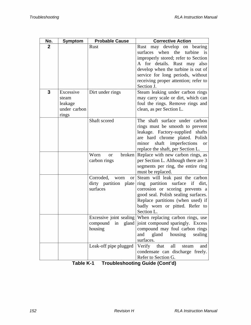
Troubleshooting RLA Instruction Manual
No. Symptom Probable Cause Corrective Action 2 Rust Rust may develop on bearing
surfaces when the turbine is improperly stored; refer to Section A for details. Rust may also develop when the turbine is out of service for long periods, without receiving proper attention; refer to Section J.
3 Excessive steam leakage under carbon rings
Dirt under rings Steam leaking under carbon rings may carry scale or dirt, which can foul the rings. Remove rings and clean, as per Section L.
Shaft scored The shaft surface under carbon rings must be smooth to prevent leakage. Factory-supplied shafts are hard chrome plated. Polish minor shaft imperfections or replace the shaft, per Section L.
Worn or broken carbon rings
Replace with new carbon rings, as per Section L. Although there are 3 segments per ring, the entire ring must be replaced.
Corroded, worn or dirty partition plate surfaces
Steam will leak past the carbon ring partition surface if dirt, corrosion or scoring prevents a good seal. Polish sealing surfaces. Replace partitions (when used) if badly worn or pitted. Refer to Section L.
Excessive joint sealing compound in gland housing
When replacing carbon rings, use joint compound sparingly. Excess compound may foul carbon rings and gland housing sealing surfaces.
Leak-off pipe plugged Verify that all steam and condensate can discharge freely. Refer to Section G.
Table K-1 Troubleshooting Guide (Cont’d)
152 Revision H RLA Instruction Manual

RLA Instruction Manual Troubleshooting
No. Symptom Probable Cause Corrective Action 4 Oil leaks
past seal ring
High oil level Reduce oil level to coincide with marks on bearing housings. Refer to Section F.
Scratched or rough shaft under seal ring
Polish shaft under seal ring and install a new ring. Refer to Sections F and L.
Washer plate too tight
Polish shaft under seal ring, if necessary, and install a new ring. Adjust washer plate screws. Refer to Sections F and L.
Seal improperly installed
Refer to Sections F and L for proper installation procedure.
Shaft vibration Refer to all causes under Vibration above. Install a new seal ring, if necessary, as per Sections F and L.
5 Insufficient power (turbine does not run at rated speed)
Too many handvalves closed
Open additional handvalves. Refer to Section I for proper adjustment of handvalves.
Oil relay governor set too low
Refer to Section D for speed adjustment and speed range limits.
Inlet steam pressure too low or exhaust pressure too high
Check steam pressure at the turbine inlet and exhaust pressure close to the exhaust casing, using accurate gauges. Refer to the turbine nameplate for intended steam conditions. Low inlet pressure may be the result of auxiliary control equipment such as a pump governor which is too small, improper piping size, excessive piping length, etc.
Load higher than turbine rating
Determine actual load requirements of the driven equipment. Sometimes available turbine power can be increased by modifying a few components. Consult the factory for this determination.
Table K-1 Troubleshooting Guide (Cont’d)
RLA Instruction Manual Revision H 153

Troubleshooting RLA Instruction Manual
No. Symptom Probable Cause Corrective Action 5 Throttle valve not
opening fully Close main inlet valve and disconnect throttle linkage. The valve lever should move freely from fully open to fully closed. If not, disassemble the throttle per Section L and free up the assembly, as required.
Low governor oil level
Refill--see Section D, Speed Control System.
Insufficient power (turbine does not run at rated speed) (Cont’d)
Overspeed trip valve not fully open
Verify that the trip lever and trip latch are properly engaged so that the valve is held fully open. Refer to Section L for proper rigging of the overspeed trip linkage.
Nozzles plugged Remove nozzle pipe plugs and handvalves. Shine a flashlight through nozzle hole to see if any nozzles are plugged. Clean nozzles as required.
Steam strainer Remove all foreign matter from steam strainer. Refer to Section L.
6 Speed increases excessively as load is decreased
Throttle valve not closing fully
Refer to Throttle valve not opening fully under Insufficient power above.
Throttle valve and valve seats cut or worn
Remove throttle valve, as per Section L. Check valve and seats for wear or steam cutting. Replace if necessary.
7 Excessive speed variation
Governor droop adjustment
An increase in the internal droop setting will reduce speed variation or hunting. Refer to Droop Adjustment in the Woodward Governor Manual.
Table K-1 Troubleshooting Guide (Cont’d)
154 Revision H RLA Instruction Manual

RLA Instruction Manual Troubleshooting
No. Symptom Probable Cause Corrective Action 7 Governor lubrication Low governor oil level, or dirty or
foamy oil may cause poor governor operation. Drain, flush, and refill governor with the proper oil. Refer to Section D.
Throttle assembly friction
Disassemble throttle per Section L. Inspect for free and smooth movement of all moving parts. If required, polish throttle valve, seats, and valve stem with very fine Emery cloth. Inspect valve stem for straightness and for build-up of foreign material. Replace components as required.
Excessive speed variation (cont’d)
Throttle seal friction Check valve stem for free and smooth motion through the throttle bonnet assembly. If friction or binding occurs, disassemble throttle bonnet assembly and repair or replace seal components, as necessary. Refer to Section L.
Throttle valve looseness
For cast iron throttle assemblies with floating throttle valves, end play of the throttle valve on the valve stem should not exceed 0.003” (0.076 mm). Replace or repair throttle valve and stem, as necessary. Refer to Section L.
Light load and high inlet steam pressure
In some cases, where the turbine provides a large amount of reserve power and the inlet steam pressure is quite high, there is a tendency for excessive speed variation. Try operating the turbine with additional handvalves closed. This condition can sometimes be corrected by installing a smaller-than-standard throttle valve in a new valve body. Consult the factory, providing details of the application.
Table K-1 Troubleshooting Guide (Cont’d)
RLA Instruction Manual Revision H 155
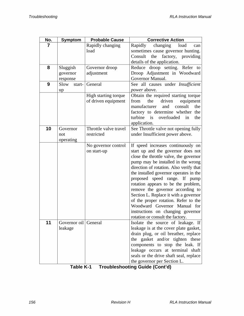
Troubleshooting RLA Instruction Manual
No. Symptom Probable Cause Corrective Action 7 Rapidly changing
load Rapidly changing load can sometimes cause governor hunting. Consult the factory, providing details of the application.
8 Sluggish governor response
Governor droop adjustment
Reduce droop setting. Refer to Droop Adjustment in Woodward Governor Manual.
9 Slow start-up
General See all causes under Insufficient power above.
High starting torque of driven equipment
Obtain the required starting torque from the driven equipment manufacturer and consult the factory to determine whether the turbine is overloaded in the application.
10 Governor not operating
Throttle valve travel restricted
See Throttle valve not opening fully under Insufficient power above.
No governor control on start-up
If speed increases continuously on start up and the governor does not close the throttle valve, the governor pump may be installed in the wrong direction of rotation. Also verify that the installed governor operates in the proposed speed range. If pump rotation appears to be the problem, remove the governor according to Section L. Replace it with a governor of the proper rotation. Refer to the Woodward Governor Manual for instructions on changing governor rotation or consult the factory.
11 Governor oil leakage
General Isolate the source of leakage. If leakage is at the cover plate gasket, drain plug, or oil breather, replace the gasket and/or tighten these components to stop the leak. If leakage occurs at terminal shaft seals or the drive shaft seal, replace the governor per Section L.
Table K-1 Troubleshooting Guide (Cont’d)
156 Revision H RLA Instruction Manual

RLA Instruction Manual Troubleshooting
No. Symptom Probable Cause Corrective Action 11 Drive assembly
vibration Vibration of the turbine shaft or governor drive coupling may induce leakage at the governor drive shaft seal. See all causes under Excessive vibration or noise above. Inspect and tighten the coupling per Section L. Check for misalignment or bent turbine or governor shaft.
12 Overspeed trip actuates on load changes
Overspeed trip set too close to turbine operating speed
The overspeed trip should be set at approximately 16% OR 21% above the rated speed, depending on the NEMA rating (D or A) of the governor. Refer to Section E.
General See all causes under Speed increases excessively as load is decreased above.
Light load and high inlet steam pressure
See Light load and high inlet steam pressure under Excessive speed variation above.
13 Overspeed trip actuates at normal operating speed
Excessive vibration Replace trip lever and/or trip latch if latching surfaces are worn, after resolving cause of excessive vibration.
Trip speed setting too low
If the turbine consistently trips at or close to the same speed, the trip setting may be set too low. The setting should be approximately 16% OR 21% over rated speed, depending on the NEMA rating (D or A) of the governor. Refer to Section E for adjustment procedures.
14 Overspeed trip does not actuate at overspeed
Trip speed setting too high
If the overspeed trip has not actuated when the turbine reaches 25% above rated speed, the trip speed setting may be too high. The setting should be approximately 16% OR 21% over rated speed, depending on the NEMA rating (D or A) of the governor. Refer to Section E for adjustment procedures.
Table K-1 Troubleshooting Guide (Cont’d)
RLA Instruction Manual Revision H 157
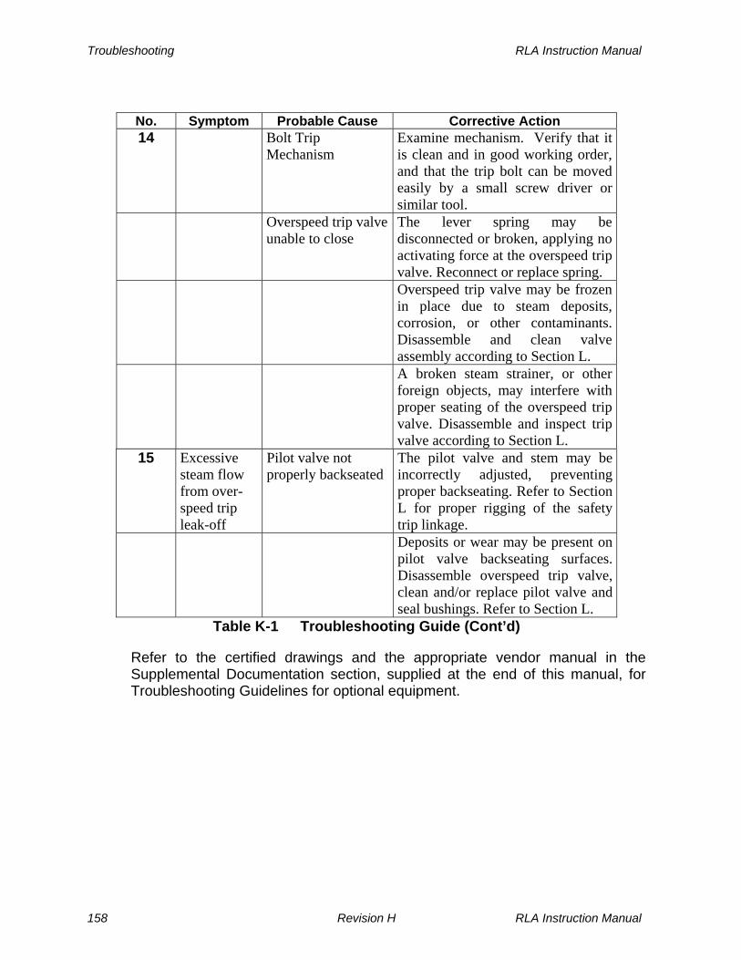
Troubleshooting RLA Instruction Manual
No. Symptom Probable Cause Corrective Action 14 Bolt Trip
Mechanism Examine mechanism. Verify that it is clean and in good working order, and that the trip bolt can be moved easily by a small screw driver or similar tool.
Overspeed trip valve unable to close
The lever spring may be disconnected or broken, applying no activating force at the overspeed trip valve. Reconnect or replace spring.
Overspeed trip valve may be frozen in place due to steam deposits, corrosion, or other contaminants. Disassemble and clean valve assembly according to Section L.
A broken steam strainer, or other foreign objects, may interfere with proper seating of the overspeed trip valve. Disassemble and inspect trip valve according to Section L.
15 Excessive steam flow from over-speed trip leak-off
Pilot valve not properly backseated
The pilot valve and stem may be incorrectly adjusted, preventing proper backseating. Refer to Section L for proper rigging of the safety trip linkage.
Deposits or wear may be present on pilot valve backseating surfaces. Disassemble overspeed trip valve, clean and/or replace pilot valve and seal bushings. Refer to Section L.
Table K-1 Troubleshooting Guide (Cont’d)
Refer to the certified drawings and the appropriate vendor manual in the Supplemental Documentation section, supplied at the end of this manual, for Troubleshooting Guidelines for optional equipment.
158 Revision H RLA Instruction Manual

RLA Instruction Manual Disassembly and Parts Replacement
Section L
Disassembly and Parts Replacement
L.1 Warnings/Cautions
DANGERS
DO NOT attempt to ADJUST, REPAIR, DISASSEMBLE OR MODIFY this turbine WHILE IT IS IN OPERATION, unless such action is expressly described in this instruction manual.
NEVER DISCONNECT INLET OR EXHAUST FLANGES of the turbine without first isolating the turbine from inlet and exhaust systems by CLOSING AND TAGGING ISOLATING VALVES and de-pressurizing the turbine casing and steam chest by opening all drains. Open connections not protected by isolating valves should be covered with blank flanges.
DO NOT REMOVE ANY COVERS, GUARDS, GLAND HOUSINGS, DRAIN COVERS, etc. while the unit is OPERATING
WARNING
After operating the turbine, allow sufficient time for the turbine to cool down prior to performing an inspection, repair or maintenance functions.
RLA Instruction Manual Revision H 159
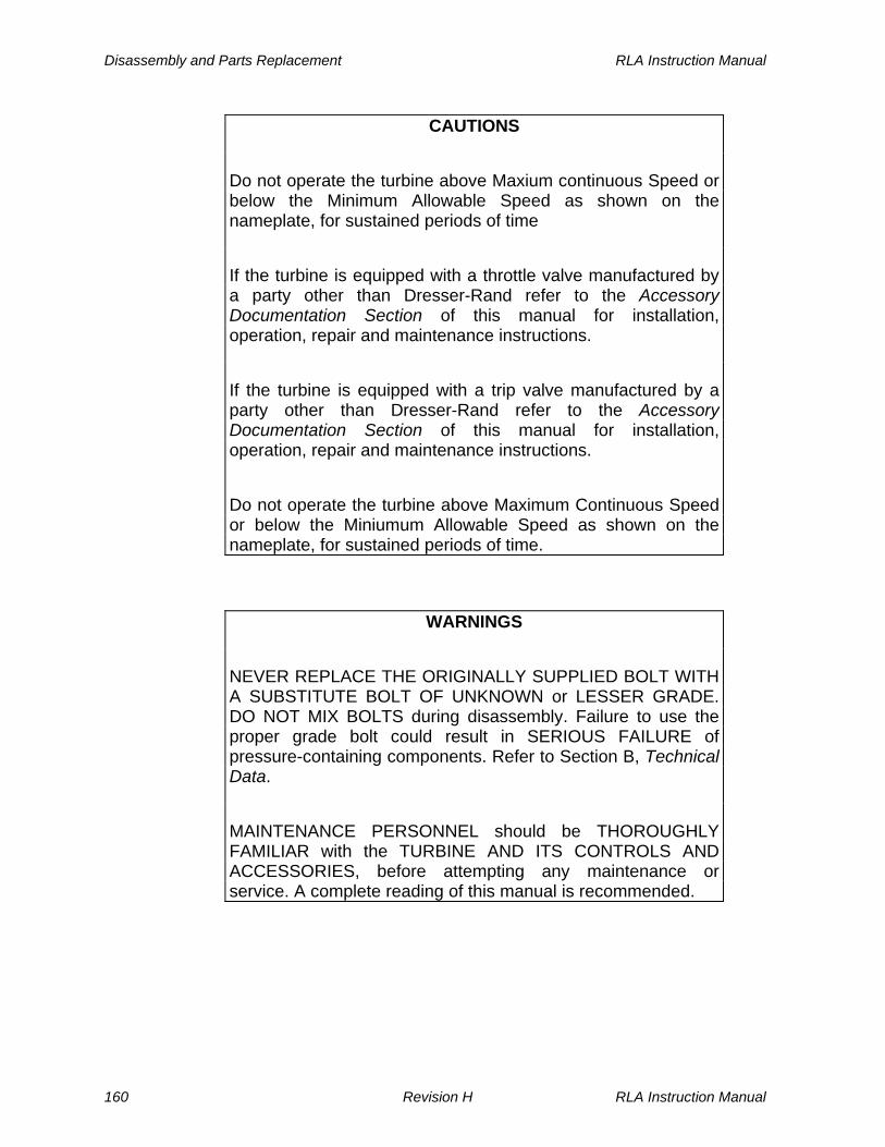
Disassembly and Parts Replacement RLA Instruction Manual
CAUTIONS
Do not operate the turbine above Maxium continuous Speed or below the Minimum Allowable Speed as shown on the nameplate, for sustained periods of time
If the turbine is equipped with a throttle valve manufactured by a party other than Dresser-Rand refer to the Accessory Documentation Section of this manual for installation, operation, repair and maintenance instructions.
If the turbine is equipped with a trip valve manufactured by a party other than Dresser-Rand refer to the Accessory Documentation Section of this manual for installation, operation, repair and maintenance instructions.
Do not operate the turbine above Maximum Continuous Speed or below the Miniumum Allowable Speed as shown on the nameplate, for sustained periods of time.
WARNINGS
NEVER REPLACE THE ORIGINALLY SUPPLIED BOLT WITH A SUBSTITUTE BOLT OF UNKNOWN or LESSER GRADE. DO NOT MIX BOLTS during disassembly. Failure to use the proper grade bolt could result in SERIOUS FAILURE of pressure-containing components. Refer to Section B, Technical Data.
MAINTENANCE PERSONNEL should be THOROUGHLY FAMILIAR with the TURBINE AND ITS CONTROLS AND ACCESSORIES, before attempting any maintenance or service. A complete reading of this manual is recommended.
160 Revision H RLA Instruction Manual

RLA Instruction Manual Disassembly and Parts Replacement
WARNINGS (Cont’d)
Modification of, incorrect repair of, or use of non-DRESSER-RAND repair parts on this turbine could result in serious malfunction or explosion that could result in serious injury or death. Such actions will also invalidate ATEX Directive & Machinery Directive Certifications for turbines that are in compliance with European Directives. Refer to Section M – Replacement Parts/Factory Service.
CAUTION
CLEANLINESS is ESSENTIAL for long, trouble-free service from BEARINGS and the GOVERNOR. Take care to ensure that no foreign material enters bearing housings, the governor or constant level oilers when performing maintenance, checking oil, adding oil, or making adjustments.
WARNINGS
Dresser-Rand turbine components are manufactured from a variety of materials, depending on steam pressure, steam temperature, speed and horsepower. Before replacing any components, be absolutely certain that the REPLACEMENT PART was INTENDED for use in the TURBINE UNDER REPAIR.
When RESTARTING a turbine after repair, maintenance or rebuilding, always TREAT the turbine as if it were a NEW TURBINE being started for the first time. Refer to Section I, Start-Up and Operation.
RLA Instruction Manual Revision H 161
Disassembly and Parts Replacement RLA Instruction Manual
L.2 General
This section describes disassembly and parts replacement for Dresser-Rand RLA turbines. Any parts of an RLA turbine can be replaced in the field using instructions presented in this section, if qualified personnel and facilities are available. If not, it is recommended that a Dresser-Rand service representative be employed to make the field repairs, or that the turbine be returned to the factory, where a complete inspection can be made. If returned, the factory will prepare an estimate of the cost of cleaning the turbine, replacing parts as required, and restoring the turbine to practically new condition. After factory repair, the turbine will be no-load tested and preserved just as a new machine would be. A factory-rebuilt turbine receives a new turbine warranty.
L.3 Gland Housings/Carbon Ring Repair and Replacement
Refer to the following figures:
L-1 4-Ring Gland Housing, Cross Section
L-2 6-Ring Gland Housing, Cross Section
M-5 Yoke, Gland Housing and Sealing Elements--Cover End
M-6 Cover, Casing, and Casing End Components
RLA turbines are equipped with either 4-ring gland housings (exhaust pressures to 105 PSIG [725 kPag]) or 6-ring gland housings (exhaust pressures from 106 to 175 PSIG [725 to 1208 kPag]). Refer to cross sections in Figures L-1 and L-2 for details. Construction of both gland housing types is similar, with the 6-ring design incorporating 2 additional active carbon rings. The outboard ring in both designs has an atmosphere leak-off upstream of it and is not subject to steam pressure. Its purpose is to prevent condensate from leaking up the shaft toward the bearing housing.
Gland housings are secured to the cover at the non-drive end and to the casings at the drive end. In order to gain access to carbon ring seals, Gland Housings must be detached from the cover or casing and split into two halves. Since the parts in gland housings at both ends of the turbine are identical, the procedure described below applies to both gland housings. Each Carbon Ring consists of three segments; when a Carbon Ring is replaced, all three segments must be replaced.
162 Revision H RLA Instruction Manual

RLA Instruction Manual Disassembly and Parts Replacement
L.3.1 Gland Housng/Carbon Ring Disassembly
Use the following procedure to disassemble Gland Housings and Carbon Rings:
a. Disconnect leak-off piping system (or steam seal pipes on turbines exhausting to vacuum) from Gland Housing leak-off pipe and remove leak-off pipe from Gland Housing.
b. Remove 6 cap screws securing Gland Housing (211) to the turbine cover (at governor end) or to the casing (at casing end).
Note: On turbines with 6-ring gland housings, remove the outer gland housing (211A) before removing the inner gland housing (211B).
c. Insert two removed cap screws into the two jack holes in the Gland Housing flange and use them to loosen the Gland Housing from the cover (or casing).
d. Slide Gland Housing (211) along the shaft until all four cap screws holding the two Gland Housing halves are accessible through the Yoke opening.
e. Remove the four cap screws holding the Gland Housing halves together and insert two of these screws into jack holes. Separate the two Gland Housing halves.
f. Remove Garter Springs (216) and Stop Washers (214) to separate each Carbon Ring (215) into three segments.
Note: 6-ring gland housings incorporate partition plates (212) between the carbon rings (these are integral with the gland housing on 4-ring gland housings). Disassembly is similar to that for 4-ring housings, with the exception that partition plates are removable.
RLA Instruction Manual Revision H 163

Disassembly and Parts Replacement RLA Instruction Manual
211GLAND HOUSING
214STOP WASHER
21SHAFT
215CARBON RING
216GARTERSPRING
Figure L-1 4-Ring Gland Housing, Cross Section
164 Revision H RLA Instruction Manual

RLA Instruction Manual Disassembly and Parts Replacement
216GARTERSPRING
214STOP
WASHER
21SHAFT
212PARTITION
PLATE
211AOUTERGLAND
HOUSING
211BINNERGLAND
HOUSING
215CARBON
RING
Figure L-2 6-Ring Gland Housing, Cross Section
RLA Instruction Manual Revision H 165

Disassembly and Parts Replacement RLA Instruction Manual
L.3.2 Gland Housing/Carbon Ring Assembly
Use the following procedure:
a. Thoroughly clean the gland housing and partition plates (when used). Be certain to remove all rust, corrosion and foreign material. Inspect the carbon ring sealing surfaces on the gland housing or partition plates; replace them if they are badly pitted, scored or worn.
b. Using new Carbon Rings (215), maintain the proper relationship between the three segments by aligning matching dots on each segment.
c. Inspect the chrome sealing surface on the shaft, removing any foreign material. If the plating is damaged, the shaft must be replaced or replated.
d. Replace Garter Spring (216) and Stop Washer (214) to secure the three segments of each Carbon Ring. Check to ensure that carbon rings move freely and seat against the shaft and partitions.
e. Place two halves of the Gland Housing over the carbon ring set, ensuring that Stop Washers (214) are properly positioned within Gland Housing slots. Use sealant as specified in Section B.9 Sealants and Joint Compounds. Avoid using excess sealant, which could prevent free movement and seating of carbon rings.
f. Replace and tighten cap screws holding the two Gland Housing halves together.
g. Apply sealant as specified in Section B.9 Sealant and Joint Compounds to mating flanges of the Gland Housing and the Cover (or Casing).
h. Slide Gland Housing along the shaft towards the Cover (or Casing) and re-assemble it to Cover (or Casing) using 6 cap screws.
Note: On turbines with 6-ring gland housings, the outer Gland Housing (211A) should be replaced at this point.
i. Replace leak-off pipe in Gland Housing and connect its opposite end to leak-off piping. Check carbon rings closely for leakage when the turbine is restarted.
166 Revision H RLA Instruction Manual

RLA Instruction Manual Disassembly and Parts Replacement
L.4 Bearing Housings/Bearings
Refer to the following figures:
M-4 Bearing Housing and Components--Governor End
M-5 Yoke, Gland Housing and Sealing Elements--Cover End
M-6 Cover, Casing, and Casing End Components
M-7 Bearing Housing and Components--Casing End
L-3 RLA Bearing Housings-Cross Section-Standard Design 12L/12M
L-4 RLA Bearing Housings-Cross Section-Standard Design 16L/16E/20L/22L/23L
L-5 RLA Bearing Housings-Cross Section-Optional Inproseal Design 12L/12M
L-6 RLA Bearing Housings-Cross Section-Standard Optional Design 16L/16E/20L/22L/23L
RLA Instruction Manual Revision H 167

Disassembly and Parts Replacement RLA Instruction Manual
OPTIONAL OILMIST FITTING
111OIL
HOLECOVER
21SHAFT
45THROW
RING
40SEALRING
33BALL
BEARING
26WASHER
PLATE
27ABEARINGWASHER
71OIL
DRAIN
OPTIONAL OILMIST BREATHER
112OIL
RING
262AOIL
RINGSLEEVE
25WASHER
PLATE
23SHAFT
ENDNUT
41SEALRING
9BEARINGHOUSING
ENCLOSURE
113LOCKWASHER
5AYOKE
OPTIONAL OILMIST FITTING
OPTIONAL OILMIST BREATHER
111OIL
HOLECOVER
21SHAFT
45THROW
RING
40SEALRING
34BALL
BEARING
26WASHER
PLATE
27BBEARINGWASHER
71OIL
DRAIN
112OIL
RING
262BOIL
RINGSLEEVE
223RETAINING
RING
5BYOKE
315MOUNTINGHOUSING
Non-Drive End Drive-End
Figure L-3 RLA Bearing Housings Cross Section Standard Design, 12L/12M
168 Revision H RLA Instruction Manual

RLA Instruction Manual Disassembly and Parts Replacement
OPTIONAL OILMIST FITTING
111OIL
HOLECOVER
21SHAFT
45THROW
RING
40SEALRING
33BALL
BEARING
26WASHER
PLATE
27BEARINGWASHER
71OIL
DRAIN
OPTIONAL OILMIST BREATHER
112OIL
RING
262AOIL
RINGSLEEVE
25WASHER
PLATE
23SHAFT
ENDNUT
41SEALRING
9BEARINGHOUSING
ENCLOSURE
113LOCKWASHER
5AYOKE
8BEARINGHOUSING
OPTIONAL OILMIST FITTING
OPTIONAL OILMIST BREATHER
111OIL
HOLECOVER
21SHAFT
45THROW
RING
40SEALRING
34BALL
BEARING
26WASHER
PLATE
71OIL
DRAIN
112OIL
RING
262BOIL
RINGSLEEVE
223RETAINING
RING
5BYOKE
315MOUNTINGHOUSING
A015COLLAR
ASSEMBLY
10BEARINGHOUSING
Non-Drive End Drive End
Figure L-4 RLA Bearing Housings Cross Section Standard Design, 16L thru 23L
RLA Instruction Manual Revision H 169
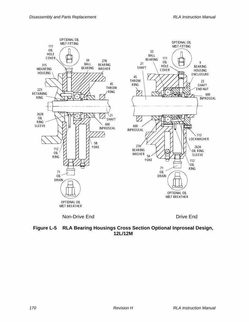
Disassembly and Parts Replacement RLA Instruction Manual
OPTIONAL OILMIST FITTING
111OIL
HOLECOVER
21SHAFT
45THROW
RING
600INPROSEAL
33BALL
BEARING
27ABEARINGWASHER
71OIL
DRAIN
OPTIONAL OILMIST BREATHER
112OIL
RING
262AOIL RINGSLEEVE
23SHAFT
END NUT
9BEARINGHOUSING
ENCLOSURE
113LOCKWASHER
5AYOKE
600INPROSEAL
OPTIONAL OILMIST FITTING
OPTIONAL OILMIST BREATHER
111OIL
HOLECOVER
21SHAFT
45THROW
RING
34BALL
BEARING
27BBEARINGWASHER
71OIL
DRAIN
112OIL
RING
262BOIL
RINGSLEEVE
223RETAINING
RING
5BYOKE
315MOUNTINGHOUSING
600INPROSEAL
Non-Drive End Drive End
Figure L-5 RLA Bearing Housings Cross Section Optional Inproseal Design, 12L/12M
170 Revision H RLA Instruction Manual

RLA Instruction Manual Disassembly and Parts Replacement
OPTIONAL OILMIST FITTING
111OIL
HOLECOVER
21SHAFT
45THROW
RING
600INPROSEAL
33BALL
BEARING
27BEARINGWASHER
71OIL
DRAIN
OPTIONAL OILMIST BREATHER
112OIL
RING
262AOIL RINGSLEEVE
23SHAFT
ENDNUT
9BEARINGHOUSING
ENCLOSURE
113LOCKWASHER
5AYOKE
8BEARINGHOUSING
600INPROSEAL
OPTIONAL OILMIST FITTING
OPTIONAL OILMIST BREATHER
111OIL
HOLECOVER
21SHAFT
45THROW
RING600
INPROSEAL
34BALL
BEARING
71OIL
DRAIN
112OIL
RING
262BOIL
RINGSLEEVE
223RETAINING
RING
5BYOKE
315MOUNTINGHOUSING
A015COLLAR
ASSEMBLY
10BEARINGHOUSING
Non-Drive End Drive End
Figure L-6 RLA Bearing Housings Cross Section Optional Inproseal Design 16L–23L
RLA Instruction Manual Revision H 171

Disassembly and Parts Replacement RLA Instruction Manual
L.4.1 Seal Ring Replacement (applies to standard design only)
Use the following procedure to replace the seal ring (40) outboard of the gland housing at each end of the turbine:
a. Mark installed position of throw ring (45) and set screw on the shaft. Then loosen set screw in the throw ring and slide throw ring along shaft towards gland housing.
b. Remove screws holding washer plate (26) to the yoke and slide washer plate along shaft towards gland housing.
c. Remove old seal ring (40) and inspect the shaft and seal ring seat to verify that they are clean and smooth.
d. Insert the new seal ring, verifying that the split is at the top when the ring is installed.
e. Return washer plate (26) to its original position and secure it to yoke using screws. Tighten screws only enough to bring the plate snugly against the seal ring.
CAUTION
DO NOT OVERTIGHTEN BOLTS retaining the WASHER PLATE (26). These bolts should be tightened only enough to bring the plate snugly against the seal ring (40). If too tight, the seal ring may OVERHEAT AND SCORE THE SHAFT.
f. Return throw ring (45) to its original marked position and tighten its set screw.
Use the following procedure to replace the shaft seal ring (41) at the drive end of the turbine:
a. Remove screws holding washer plate (25) to the bearing housing enclosure (9).
b. Remove old seal ring (41) and inspect the shaft and seal ring seat to verify that they are clean and smooth.
c. Insert the new seal ring, verifying that the split is at the top when the ring is installed.
d. Return washer plate (25) to its original position and secure it to the bearing housing enclosure (9) using screws. Tighten screws only enough to bring the plate snugly against the seal ring.
172 Revision H RLA Instruction Manual

RLA Instruction Manual Disassembly and Parts Replacement
CAUTION
DO NOT OVERTIGHTEN BOLTS retaining WASHER PLATES (25 and 26). These bolts should be tightened only enough to bring plates snugly against seal rings (40 and 41). If too tight, seal rings may OVERHEAT AND SCORE THE SHAFT.
e. Observe seal ring area closely for oil leakage when the turbine is restarted. If leakage occurs, readjust washer plate screws.
L.4.2 Governor End Bearing Replacement
CAUTION
When removing or replacing ball bearings mounted on a shaft, NEVER PRESS OR APPLY FORCE to the OUTER RACE, as this may damage the races or balls. NEVER HAMMER on either the inner or outer races. Bearings should be pressed on or off shafts with a steady force. Always inspect the shaft for burrs or foreign material and remove them as necessary, prior to removal or installation of bearings. If a BEARING BINDS during installation or removal, DETERMINE THE CAUSE AND CORRECT it rather than apply more force. Installation should be performed by heating bearings prior to assembly. Heat bearings slowly and evenly to a temperature not exceeding 250°F (120°C). Special electrical heaters are available from industrial suppliers for bearing heating. Alternatively, bearings may be heated in an oil bath.
L.4.2.1 RLA-12M and -12L Turbines
Refer to the following figures:
M-1 Overspeed Trip Valve Assembly
M-3 Governor, Mounting Housing and Bolt Trip Components
L-3 RLA Bearing Housings –Cross Section–Standard Design, 12L/12M
RLA Instruction Manual Revision H 173
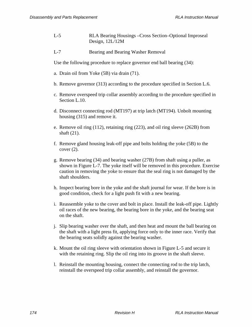
Disassembly and Parts Replacement RLA Instruction Manual
L-5 RLA Bearing Housings –Cross Section–Optional Improseal Design, 12L/12M
L-7 Bearing and Bearing Washer Removal
Use the following procedure to replace governor end ball bearing (34):
a. Drain oil from Yoke (5B) via drain (71).
b. Remove governor (313) according to the procedure specified in Section L.6.
c. Remove overspeed trip collar assembly according to the procedure specified in Section L.10.
d. Disconnect connecting rod (MT197) at trip latch (MT194). Unbolt mounting housing (315) and remove it.
e. Remove oil ring (112), retaining ring (223), and oil ring sleeve (262B) from shaft (21).
f. Remove gland housing leak-off pipe and bolts holding the yoke (5B) to the cover (2).
g. Remove bearing (34) and bearing washer (27B) from shaft using a puller, as shown in Figure L-7. The yoke itself will be removed in this procedure. Exercise caution in removing the yoke to ensure that the seal ring is not damaged by the shaft shoulders.
h. Inspect bearing bore in the yoke and the shaft journal for wear. If the bore is in good condition, check for a light push fit with a new bearing.
i. Reassemble yoke to the cover and bolt in place. Install the leak-off pipe. Lightly oil races of the new bearing, the bearing bore in the yoke, and the bearing seat on the shaft.
j. Slip bearing washer over the shaft, and then heat and mount the ball bearing on the shaft with a light press fit, applying force only to the inner race. Verify that the bearing seats solidly against the bearing washer.
k. Mount the oil ring sleeve with orientation shown in Figure L-5 and secure it with the retaining ring. Slip the oil ring into its groove in the shaft sleeve.
l. Reinstall the mounting housing, connect the connecting rod to the trip latch, reinstall the overspeed trip collar assembly, and reinstall the governor.
174 Revision H RLA Instruction Manual
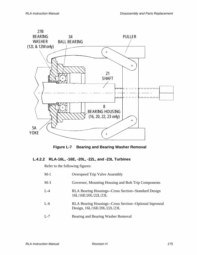
RLA Instruction Manual Disassembly and Parts Replacement
PULLER
21SHAFT
8BEARING HOUSING(16, 20, 22, 23 only)
5AYOKE
27BBEARINGWASHER
(12L & 12M only)
34BALL BEARING
Figure L-7 Bearing and Bearing Washer Removal
L.4.2.2 RLA-16L, -16E, -20L, -22L, and -23L Turbines
Refer to the following figures:
M-1 Overspeed Trip Valve Assembly
M-3 Governor, Mounting Housing and Bolt Trip Components
L-4 RLA Bearing Housings--Cross Section--Standard Design 16L/16E/20L/22L/23L
L-6 RLA Bearing Housings--Cross Section--Optional Inproseal Design, 16L/16E/20L/22L/23L
L-7 Bearing and Bearing Washer Removal
RLA Instruction Manual Revision H 175
Disassembly and Parts Replacement RLA Instruction Manual
Use the following procedure to replace non-drive end ball bearing (34):
a. Drain oil from bearing housing (10) via drain (71).
b. Remove governor (313) according to the procedure specified in Section L.6.
c. Remove overspeed trip collar (A015) according to the procedure specified in Section L.10.
d. Disconnect connecting rod (MT197) at trip latch (MT194). Unbolt mounting housing (315) from the bearing housing and remove it.
e. Remove retaining ring (223), and slide oil ring sleeve (262B) off the shaft (21), bringing oil ring (112) with it. When the oil ring clears the retaining lug in the bearing housing, it can be lifted out. Unbolt the bearing housing and slide it off the ball bearing.
f. Remove gland housing leak-off pipe and bolts holding the yoke (5B) to the cover (2).
g. Remove bearing (34) from the shaft using a puller, as shown in Figure L-7. The yoke itself will be removed in this procedure. Exercise caution in removing the yoke to ensure that the seal ring (40) is not damaged by the shaft shoulders.
h. Inspect bearing bore in the bearing housing and the shaft journal for wear. If the bore is in good condition, check for a light push fit with a new bearing.
i. Reassemble yoke to the cover and bolt in place. Install the leak-off pipe. Lightly oil races of the new bearing, the bearing bore in the bearing housing, and the bearing seat on the shaft.
j. Heat and mount the ball bearing on the shaft with a light press fit, applying force only to the inner race. Verify that the bearing seats solidly against the shaft shoulder.
k. Install the bearing housing and bolt it in place. Slide the oil ring sleeve/oil ring combination over the shaft, properly oriented as shown in Figure L-6, with the flat side against the bearing, and reinstall the retaining ring.
l. Reinstall the mounting housing, connect the connecting rod to the trip latch, reinstall the overspeed trip collar assembly, and reinstall the governor.
176 Revision H RLA Instruction Manual

RLA Instruction Manual Disassembly and Parts Replacement
L.4.3 Drive End Bearing Replacement
CAUTION
When removing or replacing ball bearings mounted on a shaft, NEVER PRESS OR APPLY FORCE to the OUTER RACE, as this may damage the races or balls. NEVER HAMMER on either the inner or outer races. Bearings should be pressed on or off shafts with a steady force. Always inspect the shaft for burrs or foreign material and remove them as necessary, prior to removal or installation of bearings. If a BEARING BINDS during installation or removal, DETERMINE THE CAUSE AND CORRECT it rather than apply more force. Installation should be performed by heating bearings prior to assembly. Heat bearings slowly and evenly to a temperature not exceeding 250°F (120°C). Special electrical heaters are available from industrial suppliers for bearing heating. Alternatively, bearings may be heated in an oil bath.
L.4.3.1 RLA-12M and -12L Turbines
Refer to the following figures:
L-3 RLA Bearing Housings-Cross Section--Standard Design, 12L/12M
L-5 RLA Bearing Housings-Cross Section--Optional Inproseal Design 12L/12M
L-7 Bearing and Bearing Washer Removal
M-7 Bearing Housing and Components--Casing End
Use the following procedure to replace drive end ball bearing (33):
a. Remove the coupling from the turbine shaft extension. If the coupling is fitted tightly to the shaft, use a wheel puller, applying heat evenly to the coupling if necessary.
b. Drain oil from Yoke (5A) via drain (71).
c. Remove bearing housing enclosure (9).
d. Bend up prongs on lockwasher (113) and unscrew shaft end nut (23). Remove the lockwasher, oil ring (112), and oil ring sleeve (262A).
RLA Instruction Manual Revision H 177

Disassembly and Parts Replacement RLA Instruction Manual
e. Remove gland housing leak-off pipe and cap screws holding the yoke (5A) to the casing (1)
f. Remove yoke (5A) from the shaft, using the wheel puller tool shown in Figure L-7, bringing the bearing washer (27A) and the bearing (33) ahead of it. Exercise caution in removing the bearing housing enclosure and yoke to ensure that seal rings (40) are not damaged by the shaft shoulders.
g. Inspect bearing bore in the yoke and the shaft journal for wear. If the bore is in good condition, check for a light push fit with a new bearing.
h. Reassemble yoke to the casing and bolt in place. Install the leak-off pipe. Place bearing washer on the shaft against the shaft shoulder. Lightly oil races of the new bearing, the bearing bore in the yoke, and the bearing seat on the shaft.
i. Heat and mount the ball bearing on the shaft with a light press fit, applying force only to the inner race. Verify that the bearing seats solidly against the bearing washer.
j. Mount the oil ring sleeve and tighten the shaft nut in place to achieve a solid stackup against the shaft shoulder. Remove the shaft nut, install a new lockwasher, and retighten the shaft nut snugly in place, verifying that the beveled side of the nut faces the oil ring sleeve.
k. Bend prongs of the lockwasher against flats of the nut, locking it in place. Slip the oil ring into its groove in the oil ring sleeve. Replace the bearing housing enclosure.
l. Replace the shaft extension coupling.
L.4.3.2 RLA-16L, -16E, -20L, -22L, and -23L Turbines
Refer to the following figures:
L-4 RLA Bearing Housings-Cross Section--Standard Design16L/16E/20L/22L/23L
L-6 RLA Bearing Housings--Cross Section--Optional Inproseal Design, 16L/16E/20L/22L/23L
M-7 Bearing Housing and Components--Casing End
Use the following procedure to replace drive end ball bearing (33):
a. Drain oil from bearing housing (8) via drain (71).
b. Remove bearing housing enclosure (9) and oil ring (112).
178 Revision H RLA Instruction Manual

RLA Instruction Manual Disassembly and Parts Replacement
c. Remove cap screws holding bearing housing (8) and slide it off the outer race ofbearing (33). Bend up prongs on lockwasher (113) and unscrew shaft end nut (23), which has a right-hand thread. Remove the lockwasher and oil ring sleeve (262A), bringing oil ring (112) with it.
d. Remove gland housing leak-off pipe and cap screws holding the yoke (5A) to the casing (1).
e. Remove yoke (5A) from the shaft, using the wheel puller tool shown in Figure L-7, bringing the bearing washer (27A) and the bearing (33) ahead of it on sizes -22L and -23L. Exercise caution in removing the bearing housing enclosure and yoke to ensure that seal rings (40) are not damaged by the shaft shoulders.
f. Inspect bearing bore in the bearing housing and the shaft journal for wear. If the bore is in good condition, check for a light push fit with a new bearing.
g. Reassemble yoke to the casing and bolt in place. Install the leak-off pipe. On sizes -22L and -23L, place bearing washer solidly against the shaft shoulder.
h. Heat and mount the ball bearing on the shaft with a light press fit, applying force only to the inner race.
i. Mount the oil ring sleeve, properly mounted as shown in Figure L-6, and tighten the shaft nut in place to achieve a solid stackup against the bearing inner race. Lightly oil the bearing bore in the bearing housing, slip the bearing housing over the bearing, and bolt it in place.
j. Slip the oil ring into its groove in the oil ring sleeve. Replace the bearing housing enclosure.
k. Replace the shaft extension coupling
L.5 Turbine Rotor & Turbine Wheel Removal & Replacement
Refer to the following figures: M-1 Overspeed Trip Valve Assembly M-3 Governor, Mounting Housing and Bolt Trip Components M-4 Bearing Housing and Components--Governor End M-5 Yoke, Gland Housing and Sealing Elements--Cover End M-6 Cover, Casing, and Casing End Components
RLA Instruction Manual Revision H 179

Disassembly and Parts Replacement RLA Instruction Manual
M-7 Bearing Housing and Components--Casing End
L.5.1 Turbine Rotor Removal & Replacement
Using the following procedure to remove the turbine wheel (14) and shaft (21) as a subassembly (rotor):
a. Remove governor (313) according to the procedure specified in Section L.6.
b. Remove overspeed trip collar (A015) according to the procedure specified in Section L.10. Verify that operator lever (MT173) is in the tripped position by pressing trip lever (MT150) where the marking TRIP appears.
WARNING
The OPERATOR LEVER MOVES RAPIDLY AND WITH GREAT FORCE when the turbine is tripped. Use care to AVOID BEING STRUCK.
c. Disconnect connecting rod (MT197) at trip latch (MT194). Unbolt mounting housing (315) and remove it.
d. Remove the trip and throttle valves from the cover as an assembly.
e. Disassemble cover end components, including bearing (34), yoke (5B), and associated components according to the procedure specified in Section L.4.2. Remove throw ring (45) and disassemble the cover end carbon ring gland assembly according to the procedure specified in Section L.3.
f. Remove bolts holding cover (2) to casing (1) and remove the cover using two of these bolts as jack screws against the casing flange. Remove the cover-to-casing gasket (218), if installed. The throttle valve assembly may remain attached to the cover during its removal from the casing. Remove cap screws holding sector (15) to the casing. (Sector cap screws vary in length. When reassembling, use cap screws in the location from which they were removed.)
g. Before proceeding further, block up or suspend the exposed cover end of the shaft to ensure that the wheel and shaft subassembly is properly supported at all times. Remove drive end ball bearing (33), yoke (5A) and associated components according to the procedure specified in Section L.4.3. Remove throw ring (45) from shaft and disassemble the drive end carbon ring gland assembly according to the procedure specified in Section L.3.
h. Remove wheel and shaft subassembly from the casing, bringing the sector with it. Note that on turbine sizes of -20L and larger, there may be more than one sector segment. Sector segments are number stamped for proper location.
180 Revision H RLA Instruction Manual

RLA Instruction Manual Disassembly and Parts Replacement
L.5.2 Turbine Wheel Removal and Replacement
The turbine wheel is secured to the shaft with an interference fit and a key. Separation of the wheel and shaft requires heating the wheel and pressing the shaft from it.
L.5.2.1 Turbine Wheel Removal
a. Position rotor with the shaft vertical, and the coupling suspended downward.
b. Carefully, evenly and rapidly heat the inner rim area of the wheel to 500-600°F (260-315°C). The wheel material will begin to take on a bluish coloration at about 500°F (260°C).
WARNINGS
DO NOT allow the heating FLAME TO IMPINGE on turbine BLADES, as this could anneal and WEAKEN them.
Exercise appropriate CAUTION in handling the HOT WHEEL during disassembly and assembly.
c. Slide the shaft out of the wheel bore, using a press at the governor end of the shaft. Do not use excessive force on the shaft. Damage to both components will likely result.
d. If the shaft cannot be removed, consult the factory. (Applies only to turbines supplied with Ductile Iron wheels in 20, 22, and 23 frame sizes)
RLA 20, 22, and 23L model turbines with ductile iron wheels have shrink rings included in the shaft assembly. This shrink ring can be about 3.5” to 4.0” in diameter and 0.75” thick. The shrink ring is located on the shaft directly ahead, or upstream, of the turbine wheel. The shrink ring will have to be removed before the turbine wheel can be disassembled from the shaft.
The proper procedure to remove the shrink ring is as follows:
a.1 Apply concentrated heat evenly to the shrink ring only. Heat the ring until it is loose and slides on the shaft.
a.2 Use extreme caution while removing the hot shrink ring. The possibility of scoring the shaft, gouging or damaging the wheel, or burning yourself should be recognized. Removing the shrink ring will in all cases, destroy the ring. A new shrink ring is
RLA Instruction Manual Revision H 181

Disassembly and Parts Replacement RLA Instruction Manual
required to properly reassemble the turbine wheel on the shaft. Dresser-Rand Corporation – Dresser-Rand Turbine Division supplies a new shrink ring with replacement wheels and shafts.
a.3 Continue to step (b).
L.5.2.2 Turbine Wheel Replacement
Use the following procedure to replace the wheel:
a. Verify that the wheel key is a free fit in the wheel to avoid hang-up on reassembly.
b. Position the wheel horizontally, with the shorter (smaller) row of blades downward.
CAUTION
Be certain to assemble the wheel and shaft with THE SHORTER BLADES TOWARD the GOVERNOR END OF THE SHAFT. Otherwise, the rotor cannot be installed.
c. Carefully, evenly and rapidly heat the wheel to 500-600°F (260-315°C) or until the wheel bore is at least 0.002 (0.05 mm) inches larger than the shaft diameter.
d. Drop the shaft and installed wheel key (378) into the wheel bore until the shaft shoulder seats solidly against the face of the wheel. Note that the shaft shoulder is always on the same side of the wheel as the second, or longer, row of blades.
e. If the shaft hangs up in the wheel before the shaft shoulder is solidly seated, a moderate press may be used to complete the assembly operation. If this fails, allow the assembly to cool and then start over by disassembling the wheel and shaft, as described above.
f. Allow the assembled wheel to reach room temperature before moving the assembly.
g. Rebalance the rotor per Section L.5.3, Rotor Balancing.
(The following applies only to turbines supplied with Ductile Iron wheels in 20, 22, & 23 frame sizes)
182 Revision H RLA Instruction Manual
RLA Instruction Manual Disassembly and Parts Replacement
RLA 20, 22, and 23L model turbines with ductile iron wheels require a shrink ring with the wheel and shaft assembly. A new shrink ring must be used every time the wheel is assembled to the shaft. The shrink ring is designed with an interference fit. Therefore, the shrink ring will have to be heated significantly in order to position the shrink ring next to the wheel. Dresser-Rand Corporation – Dresser-Rand Turbine Division supplies a new shrink ring with replacement wheels and shafts.
The proper procedure to install the shrink ring is as follows:
e.1 Check to see if the Ductile wheel has been positioned correctly and has had sufficient time to cool to room temperature.
e.2 Heat the shrink ring to about 700 - 1000°F (371 - 537°C) or until it begins to glow dark red.
e.3 Quickly slip the shrink ring on to the shaft and press it against the wheel as it cools.
e.4 Allow the shrink ring to cool to near room temperature. Check the position of the shrink ring, it must fit snugly against the shaft and wheel.
e.5 Continue to step (f) L.5.2.2.
RLA Instruction Manual Revision H 183
Disassembly and Parts Replacement RLA Instruction Manual
L.5.3 Turbine Rotor Balancing
Whenever a wheel or shaft is replaced, the replacement wheel and shaft subassembly should be dynamically balanced, as follows: Rotors should be dynamically balanced using two planes (one on each side of the wheel) to within the limits given in Table B-1, Major Fits and Tolerances. Consult the factory for detailed wheel and rotor balancing procedures.
L.5.4 Turbine Rotor Installation
Use the following procedure:
a. Place the sector between the two rows of blades on the wheel and slide the shaft, wheel, and sector(s) into the casing. Verify that the shaft and wheel are solidly supported during this operation.
b. Place new sealing washers under sector cap screw heads and engage sector cap
screws in the sector. Tap the sector to ensure that it is solidly seated against the casing shoulder and then tighten sector cap screws.
c. Reassemble the drive end carbon ring gland assembly and slide the throw ring
on the shaft. Reinstall the drive end bearing, yoke, and associated components. d. Replace the cover and gasket, if originally installed. Use sealant as specified in
Section B.9-Sealant and Joint Compounds. Reinstall the non-drive end carbon ring gland assembly.
e. Replace the trip and throttle valve assembly. f. Reinstall the non-drive end bearing, yoke, and associated components. Reinstall
the mounting housing. Connect the connecting rod to the trip latch. Reinstall the safety trip collar assembly and the governor.
g. After the turbine has been reassembled, check radial runout of the shaft
extension and end play of the shaft. Refer to Table B-1, Major Fits and Tolerances, for acceptable clearances and runouts.
L.6 Governor Removal and Replacement
Refer to the following figures: M-2 Throttle Valve Assembly M-3 Governor, Mounting Housing and Bolt Trip Components
184 Revision H RLA Instruction Manual

RLA Instruction Manual Disassembly and Parts Replacement
L.6.1 General
Field service on the oil relay governor (313) is normally limited to yearly oil changes per Section J, and droop setting adjustment, which is described in the Woodward Governor Manual provided in Supplemental Documentation at the end of this manual. In the event that the governor exhibits operational problems, Dresser-Rand recommends that the governor be removed as a unit and returned to the factory for repair or overhaul, as required. In the meantime, a replacement oil relay governor can be quickly and easily installed to keep the turbine in operation. The Dresser-Rand factory maintains a stock of replacement governors for rapid field delivery, and is equipped to perform comprehensive repair, overhaul, and testing of oil relay governors. For shipment, care should be exercised to support the governor by its mounting flange and not by its shaft extension. Some governors are direct-drive types coupled to the end of the turbine shaft by couplings, as shown in Figure L-8. Others, due to speed requirements, are connected by right-angle gear reduction units, as shown in Figure L-13.
L.6.2 Governor Removal (Direct Drive)
a. Drain oil from governor (313) at drain. b. Disconnect connecting rod (197) at governor level (265) by removing c. Connecting rod bolt. Do not disturb position of rod end bearing on rod (to
preserve open/close stroke adjustment). d. Rotate shaft (21), if necessary, to disengage coupling hub (314) by loosening
coupling setscrew. e. Prop or support governor (313); then, unbolt governor from mounting housing
(315) and slide governor out of mounting housing. Be careful not to lose the governor key (319).
f. Remove governor level (265) (if same governor is not to be used as a temporary
replacement) by loosening its setscrew.
RLA Instruction Manual Revision H 185
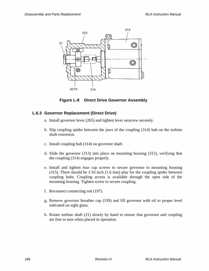
Disassembly and Parts Replacement RLA Instruction Manual
Figure L-8 Direct Drive Governor Assembly
L.6.3 Governor Replacement (Direct Drive)
a. Install governor lever (265) and tighten lever setscrew securely. b. Slip coupling spider between the jaws of the coupling (314) hub on the turbine
shaft extension. c. Install coupling hub (314) on governor shaft. d. Slide the governor (313) into place on mounting housing (315), verifying that
the coupling (314) engages properly. e. Install and tighten four cap screws to secure governor to mounting housing
(315). There should be 1/16 inch (1.6 mm) play for the coupling spider between coupling hubs. Coupling access is available through the open side of the mounting housing. Tighten screw to secure coupling.
f. Reconnect connecting rod (197). g. Remove governor breather cap (339) and fill governor with oil to proper level
indicated on sight glass. h. Rotate turbine shaft (21) slowly by hand to ensure that governor and coupling
are free to turn when placed in operation.
186 Revision H RLA Instruction Manual
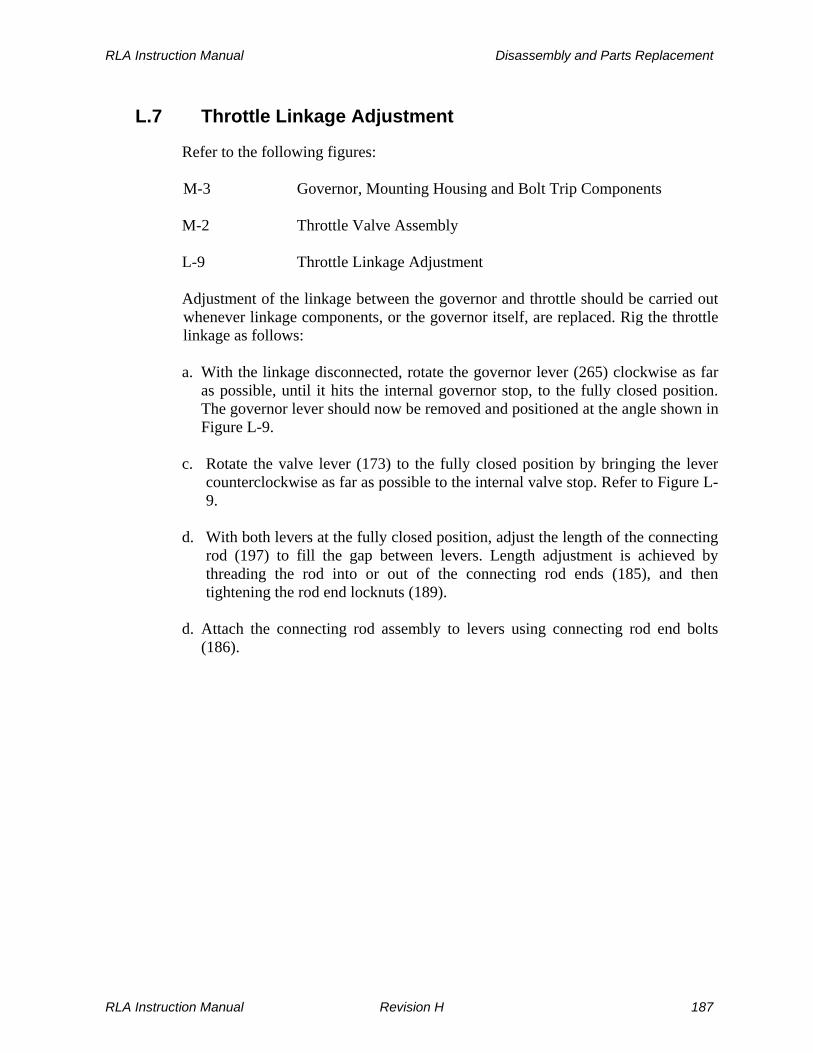
RLA Instruction Manual Disassembly and Parts Replacement
L.7 Throttle Linkage Adjustment
Refer to the following figures: M-3 Governor, Mounting Housing and Bolt Trip Components M-2 Throttle Valve Assembly L-9 Throttle Linkage Adjustment Adjustment of the linkage between the governor and throttle should be carried out whenever linkage components, or the governor itself, are replaced. Rig the throttle linkage as follows:
a. With the linkage disconnected, rotate the governor lever (265) clockwise as far as possible, until it hits the internal governor stop, to the fully closed position. The governor lever should now be removed and positioned at the angle shown in Figure L-9.
c. Rotate the valve lever (173) to the fully closed position by bringing the lever
counterclockwise as far as possible to the internal valve stop. Refer to Figure L-9.
d. With both levers at the fully closed position, adjust the length of the connecting
rod (197) to fill the gap between levers. Length adjustment is achieved by threading the rod into or out of the connecting rod ends (185), and then tightening the rod end locknuts (189).
d. Attach the connecting rod assembly to levers using connecting rod end bolts
(186).
RLA Instruction Manual Revision H 187
Disassembly and Parts Replacement RLA Instruction Manual
INCREASE
265
INCREASE
173
FRAME SIZE
ANGLE A
12M 12L 16 20 22 23
30° 32° 36° 39° 46° 46°
A°±5°
Figure L-9 Throttle Linkage Adjustment
L.8 Throttle Valve and Stem Maintenance
Refer to the following figure: M-2 Throttle Valve Assembly
CAUTION
If the turbine is equipped with a throttle valve manufactured by a party other than Dresser-Rand refer to the accessory documentation section of this manual for installation, operation, repair and maintenance instructions.
188 Revision H RLA Instruction Manual

RLA Instruction Manual Disassembly and Parts Replacement
The throttle valve (162) and stem (163) should be removed and replaced as a subassembly. When working with throttle components, provide proper support to prevent damage during disassembly or assembly.
L.8.1 Throttle Valve and Stem Removal
WARNING
BEFORE SERVICING ANY COMPONENT of the throttle valve, verify that the ISOLATING VALVE in the INLET LINE is CLOSED AND TAGGED. If the turbine is connected to the exhaust steam header, CLOSE the ISOLATING VALVE in the EXHAUST LINE AND TAG IT. OPEN ALL TURBINE DRAINS to ensure venting of all pressure before disassembly begins.
Use the following procedure: a. Disconnect the throttle linkage by removing connecting rod end bolt (186) from
valve lever (173). b. Remove cap screws holding valve bonnet (152) to valve body (151). These cap
screws may be used as jack screws to remove the bonnet from the valve body. c. Remove valve and stem subassembly from valve body along with the bonnet.
Also remove gasket (128) at this time. d. Drive out two roll pins (106C) holding the trunnion sleeve to the valve stem.
Remove valve and stem unit by pulling it through the trunnion sleeve, return spring (168), and the valve bonnet.
L.8.2 Throttle Valve and Stem Replacement
Use the following procedure: a. Insert long end of the valve stem (163) through the bonnet (152), carefully
avoiding damage to seal sleeve (193) and seal ring (128) components of the bonnet assembly.
b. Slip return spring (168) and trunnion sleeve (175) over the valve stem. Insert
two roll pins (106C) to secure the trunnion sleeve in place. Trunnions (180) must be engaged in the trunnion sleeve before pin insertion.
c. Reinstall the entire assembly into the throttle valve body (151), ensuring that the throttle valve slides smoothly in the valve seats and gasket (128) is in good condition. Tighten cap screws holding bonnet (152) to valve body (151).
RLA Instruction Manual Revision H 189

Disassembly and Parts Replacement RLA Instruction Manual
d. Move valve lever (173) by hand to ensure that the entire assembly exhibits freedom of movement throughout the entire valve stroke. Reinstall throttle linkage to valve lever (173) by inserting rod end bolt (186). Verify that no changes occurred to the throttle linkage rigging.
L.9 Throttle Valve and Seal Maintenance
WARNING
BEFORE SERVICING ANY COMPONENT of the throttle valve, verify that the ISOLATING VALVE in the INLET LINE is CLOSED AND TAGGED. If the turbine is connected to the exhaust steam header, CLOSE the ISOLATING VALVE in the EXHAUST LINE AND TAG IT. OPEN ALL TURBINE DRAINS to ensure venting of all pressure before disassembly begins.
Refer to the following figure: M-2 Throttle Valve Assembly Throttle valve seals are removed and replaced after the valve stem is removed. Refer to Section L.8.1 for the valve stem removal procedure. Use the following procedure: a. Remove the seven socket head cap screws holding seal block (156) to bonnet
(152) and lift the seal block from the bonnet. b. Remove retaining ring (120) from seal block (156). Seal block washer (157) and
seal ring (158) can now be removed. If necessary, install a new seal ring (158), using care to avoid damaging the carbon material. Reassemble seal block washer (157) and retaining ring (120).
c. Remove loose-fitting seal sleeve (193) from the bonnet. If necessary, install a
new seal sleeve (193), using care to avoid damaging the carbon material. d. Re-install seal block (156) using a new gasket (128F). Secure seal block to
bonnet (152) using 7 socket head cap screws. e. Reassemble valve and stem unit along with the bonnet, using the procedure
described in Section L.8.2.
190 Revision H RLA Instruction Manual

RLA Instruction Manual Disassembly and Parts Replacement
L.10 Overspeed Trip Mechanism Maintenance
Refer to the following figures: M-3 Governor, Mounting Housing, and Bolt Trip Components L-10 Overspeed Trip Collar Assembly L-11 Bolt Head Shanks, Old and New Designs The overspeed trip mechanism may be readily disassembled or assembled at a work bench and then mounted to the turbine as a subassembly. Prerequisites for this process are removal of the governor and coupling according to the procedure described in Section L.6, followed by removal of the overspeed trip collar assembly (A015) from shaft (21), as described below. The governor mounting housing (315) can then be removed for bench disassembly of the parts.
WARNING
The PROCEDURES described below APPLY ONLY to Dresser-Rand RLA turbines using the improved bolt trip employing self locking “SPIRALOCK” THREADS in bolt head shank (S201) to retain spring retainer (S202). This design is readily identified by the groove surrounding the hex slot in the head of the bolt head shank (refer to Figure L-11). If this groove is not present, this section does not apply to the turbine being worked on. Use the appropriate manual or consult the factory. When replacing bolt trip parts, ALWAYS UPGRADE TO THE NEW “SPIRALOCK” DESIGN.
CAUTION
If the Overspeed Trip Collar Assembly is replaced, the rotor may need to be balanced with the new assembly attached.
RLA Instruction Manual Revision H 191

Disassembly and Parts Replacement RLA Instruction Manual
SpringRetainer(S202)
Set Screw(S36)
TurbineShaft(21)
Bolt-HeadShank(S201)
BoltSpring(S204)
Set Screw(S203)
TripCollar(S200)
Figure L-10 Overspeed Trip Collar Assembly
OLD DESIGN NEW SPIRALOCKDESIGN
Figure L-11 Bolt Head Shanks, Old and New Designs
L.10.1 Trip Bolt and Collar Removal
If only bolt head shank (S201) needs to be removed for inspection and/or part replacement, carry out only steps a through d, leaving the collar on the shaft. Use the following procedure: a. Remove plug (S58) from mounting housing (315). b. Remove trip lever shoulder screw (MT149) attaching trip lever (MT150) and
spring (MT201) to mounting housing (315). Remove trip lever and spring from mounting housing, thereby allowing access to trip collar (A015) from below.
192 Revision H RLA Instruction Manual

RLA Instruction Manual Disassembly and Parts Replacement
c. Rotate shaft (21) to align hex head spring retainer (S202) so that it coincides with the plug hole.
d. Insert 5/16 inch hex key wrench into bolt head shank (S201) and unscrew spring
retainer (S202). Remove bolt head shank (S201) and bolt spring (S204) from shaft (21) and collar (S200).
WARNING
Bolt head shank (S201) is threaded with self locking “Spiralock” threads. DO NOT attempt to RETAP these threads since this will DESTROY the locking nature of the THREADS.
Do not disturb adjusting screw (S36) within the bolt head shank (S201), unless it has lost its locking torque. e. Unscrew and remove set screw (S203). Slide collar (S200) from shaft (21).
L.10.2 Trip Bolt and Collar Replacement
Assemble collar (S200) and trip bolt assembly only if mounting housing (315) is installed on the turbine and the tripping mechanism is installed on the mounting housing (315). Use the following procedure: a. If collar (S200) was removed, degrease it with safety solvent or an equivalent
chlorinated solvent. b. Slide collar (S200) on shaft (21), aligning tapped-through hole with set screw
detent in shaft. The stamped face of the trip collar should face the governor end of the shaft.
c. Install supplied 1/4-20 by 1/2 inch cup-point, socket head, set screw (S203) into shaft detent. Turn it tightly to seat it firmly in detent.
CAUTION
USE ONLY a 1/4-20 by 1/2 inch knurled, cup-point, socket head, set screw; otherwise UNBALANCE WILL OCCUR.
d. Degrease bolt head shank (S201) and bolt spring (S204) using safety solvent. e. Rotate shaft (21) to align bolt trip bore in collar (S200) with access plug hole in
governor mounting housing (315). Verify that the side of the collar with the smallest diameter bore faces the access plug hole.
RLA Instruction Manual Revision H 193

Disassembly and Parts Replacement RLA Instruction Manual
f. Drop bolt head shank (S201) through access plug hole and into bore in collar. g. Rotate shaft 180 degrees while holding bolt head shank (S201) in collar bore.
Drop bolt spring (S204) through access plug hole and into collar bore so that spring (S204) seats between bolt head shank (S201) and collar bore.
h. Insert hex head spring retainer screw (S202) through access plug hole, into
accepting threads of bolt head shank (S201), and engage screw threads. If the spring retainer screw (S202) protrudes beyond the outside diameter of the collar, then it has been assembled incorrectly. Return to step e above and repeat.
CAUTION
The BOLT HEAD SHANK/SPRING combination HAS BEEN PRESET at the factory for the trip speed originally set when the turbine was shipped. Refer to Section E if minor trip speed changes are to be made.
i. Insert 5/16 inch hex socket wrench into bolt head of (S201). Insert a torque wrench with a 1/2 inch socket onto spring retainer screw (S202) and tighten spring retainer screw firmly to 200 ± 15 in-lbs. (22.6 ± 1.7 N-m) torque.
WARNING
Do not start the turbine without checking the spring retainer torque. A loose spring retainer could cause damage to the trip collar which could result in failure of the trip system should there be an overspeed.
j. Press down on spring-loaded, hex head screw spring retainer (S202) with socket wrench to verify freedom of movement. Turn bolt head shank (S201) a few times to assure proper seating of the bolt assembly. If the bolt shank assembly exhibits binding, remove the bolt shank and collar, ream the hole in the shaft with a 0.4687 inch standard reamer to ensure that the hole is clean and that there is proper clearance between the hole and bolt shank (S201), and then re-assemble the collar and bolt shank.
k. Re-install trip lever (MT150), spring (MT201), and bolt (MT149). l. Re-install plug (S58) in mounting housing access hole.
194 Revision H RLA Instruction Manual

RLA Instruction Manual Disassembly and Parts Replacement
L.11 Overspeed Trip Valve Maintenance
Refer to the following figure: M-1 Overspeed Trip Valve Assembly
CAUTION
If the turbine is equipped with a trip valve manufactured by a party other than Dresser-Rand refer to the accessory documentation section of this manual for installation, operation, repair and maintenance instructions.
L.11.1 Overspeed Trip Valve Disassembly
WARNING
BEFORE DISASSEMBLY of the overspeed trip valve is attempted, verify that the ISOLATING VALVE IN FRONT OF THE TURBINE IS CLOSED AND TAGGED. If the turbine is connected to the exhaust steam header, close the isolating valve in the exhaust line and tag it. OPEN ALL TURBINE DRAINS to ensure venting of all pressure before disassembly begins.
Use the following procedure: a. Close the overspeed trip valve by pressing down on the trip lever. Open all
steam drains and allow the turbine to cool. b. Disconnect operating lever (MT173) from connecting rod (MT185) by removing
connecting rod bolt (MT186). c. Remove cap screws holding bonnet (MT152) to valve body (MT151) and lift
entire bonnet assembly from the valve body. d. Remove strainer (MT008) from valve body (MT151). Inspect strainer and
replace it if there are visible signs of dents or breaks between the holes. e. Inspect valve seat (MT192), if provided, for wear or damaged surfaces. If
necessary, replace valve seat by unscrewing it using the wrenching holes provided for that purpose.
f. Drive out valve lifting pin (MT137) to separate pilot valve and stem (A030)
from valve (MT162).
RLA Instruction Manual Revision H 195

Disassembly and Parts Replacement RLA Instruction Manual
g. Inspect seating surfaces of pilot valve and stem assembly (A030), where it
makes contact with guide bushing (MT153) and the valve (MT162). Clean and/or replace components, as necessary.
h. Inspect guide bushings (MT153) for signs of wear and deposits of steam
contaminants. Clean and/or replace bushings, as necessary. If replacement is necessary, remove retainer plate (MT157) by removing screws (MT158). Press out guide bushings. When installing a new guide bushing (MT153), verify that the end with the lead (undersize diameter) is inserted first, thereby ensuring proper alignment.
i. Insert pin through hole in the valve stem (A030) to secure the stem and loosen
locknut (MT164).
WARNING
DO NOT USE PLIERS OR other gripping tools to turn the pilot valve stem. Doing so may CAUSE DAMAGE to the stem and possible MALFUNCTION of the OVERSPEED TRIP VALVE.
j. Unscrew pilot valve and stem assembly (A030) from trunnion box (MT180). If the stem is scored, replace it with a new pilot valve and stem assembly.
L.11.2 Overspeed Trip Valve Assembly
Use the following procedure: a. If a guide bushing (MT153) was replaced, secure retainer plate (MT157) to
bonnet using retainer plate screws (MT158). b. If it was removed, insert pilot valve and stem assembly (A030) through bonnet
and screw locknut (MT164) onto stem. Screw valve stem into trunnion box (MT180).
c. Insert pilot valve and stem assembly (A030) into valve (MT162) and re-insert
valve lifting pin (MT137). d. Insert strainer (MT008) into valve body (MT151). e. Insert entire bonnet assembly into valve body, using a new bonnet gasket
(MT128). f. Insert and tighten bonnet cap screws in a criss-cross pattern to the final torques
listed below:
196 Revision H RLA Instruction Manual

RLA Instruction Manual Disassembly and Parts Replacement
g. Carry out a final back seat adjustment on the pilot valve (A030) according to the
procedure specified in Section L.13.
L.12 Overspeed Trip Linkage Maintenance
WARNING
BEFORE SERVICING ANY COMPONENT of the overspeed trip system, verify that the ISOLATING VALVE in the INLET LINE is CLOSED AND TAGGED. If the turbine is connected to the exhaust steam header, CLOSE the ISOLATING VALVE in the EXHAUST LINE AND TAG IT. OPEN ALL TURBINE DRAINS to ensure venting of all pressure before disassembly begins.
Refer to the following figures: M-1 Overspeed Trip Valve Assembly M-3 Governor, Mounting Housing, and Bolt Trip Components
L.12.1 Overspeed Trip Linkage Disassembly
Use the following procedure: a. Close the overspeed trip valve by pressing down on the trip lever. Open all
steam drains and allow the turbine to cool. b. Disconnect operating lever (MT173) from connecting rod (MT185) by removing
connecting rod bolt (MT186). c. Remove cotter pin (MT136) from pivot pin (MT133) and remove pivot pin
(MT133). d. Disconnect tension spring (MT131) from spring link (MT134) at one end and
from operating lever (MT173) at the other.
Cap Screw Size Torque (ft-lb) Torque (N-m)
1/2” 60 ± 5 81 ± 6
5/8” 120 ± 10 163 ± 13
RLA Instruction Manual Revision H 197

Disassembly and Parts Replacement RLA Instruction Manual
e. Grip operating lever (MT173) at its right hand end and slide it out from the trunnion box (MT180).
f. Remove cotter pin (MT135) from trunnion spring pin (MT130). Remove
trunnion spring pin (MT130) and trunnion spring (MT129). g. Disconnect rod end (MT185) from trip latch (MT194) by removing connecting
rod bolt (MT186). h. Unscrew socket head shoulder screw (MT148) from mounting housing (315)
and remove trip latch (MT194). i. Unscrew socket head shoulder screw (MT149) from mounting housing (315)
and remove trip lever (MT150) together with trip lever spring (MT201). j. Inspect knife edges of trip latch (MT194) and trip lever (MT150). If worn or
damaged, replace both parts.
L.12.2 Overspeed Trip Linkage Assembly
Use the following procedure: a. Assemble trip lever (MT150) and spring (MT201) to mounting housing (315)
using shoulder screw (MT149) b. Assemble trip latch (MT194) to mounting housing (315) using shoulder screw
(MT148). c. Connect rod end (MT185) to trip latch (MT194) using connecting rod bolt
(MT186). d. Place trunnion spring (MT129) in trunnion box (MT180) and secure it by
inserting trunnion spring pin (MT130). Secure trunnion spring pin (MT130) using cotter pin (MT135).
e. Insert operating lever (MT173) by sliding it into trunnion box (MT180) f. Connect lever spring (MT131) to spring link (MT134) at one end and to
operating lever (MT173) at the other. g. Insert pivot pin (MT133) through lever stand (MT155) and operating lever
(MT173). Secure pivot pin (MT133) using cotter pin (MT136). h. Carry out a final back seat adjustment on the pilot valve (A030)according to the
procedure specified in Section L.13
198 Revision H RLA Instruction Manual

RLA Instruction Manual Disassembly and Parts Replacement
L.13 Overspeed Trip Linkage Adjustment
Refer to the following figures: E-2 Trip System M-1 Overspeed Trip Valve Assembly M-3 Governor, Mounting Housing, and Bolt Trip Components Check the clearance between the bolt trip collar (A015) and trip lever (MT150). It should be 0.050-0.070 inch (1.27-1.78 mm). If not within limits, replace defective parts. The most likely cause is a damaged trip lever (MT150). The valve and linkages are factory assembled and normally do not require adjustment. This procedure checks position of the pilot valve and stem assembly (A030) to ensure that it properly back seats against guide bushing (MT153). Use the following procedure: a. Press firmly down on operating lever (MT173) so that trip latch (MT194)
engages trip lever (MT150). If, for some reason, trip latch (MT194) cannot be engaged, proceed with the following adjustment:
1. Disconnect operating lever (MT173) from rod end (MT185). 2. Loosen the two locknuts (MT190) on connecting rod (MT197). 3. Screw or unscrew connecting rod (MT197) from both rod ends (MT185),
using only a few turns, thus increasing or decreasing the length of the connecting rod assembly. Tighten the locknuts.
4. Reconnect rod end (MT185) to operating lever (MT173). 5. Press operating lever (MT173) down and check to verify that trip latch
(MT194) fully engages. If not, repeat steps 3 and 4. 6. When the trip latch (MT194) is fully engaged, turn locknuts (MT190) so
that they lock against rod ends (MT185). 7. When the trip latch (MT194) is engaged, the tension spring (MT134)
should measure 6-5/8” ±1/8” (168 ±3 mm).
b. Check the gap between trunnion pin (MT170) and the upper surface of the trunnion box (MT180) slot. The gap should be 0.040” to 0.060” (1.01 to 1.52 mm).
RLA Instruction Manual Revision H 199

Disassembly and Parts Replacement RLA Instruction Manual
c. The gap can be adjusted by loosening locknut (MT164) and threading the pilot valve and stem assembly (A030) into or out of the trunnion box (MT180). Insert a pin through the stem hole below the threads to turn the stem.
CAUTION
DO NOT USE PLIERS or other gripping tools to turn the pilot valve stem. Doing so may CAUSE DAMAGE to the stem and possible MALFUNCTION of the OVERSPEED TRIP VALVE.
d. Tighten locknut (MT164) on the pilot valve stem and check the gap again. e. Check the linkage for freedom of motion. Manually latch and unlatch the trip
system by pressing down on the operating lever (MT173) and then on trip lever (MT150).
WARNING
The OPERATOR LEVER MOVES RAPIDLY WITH GREAT FORCE when the turbine trips. Use CAUTION when ADJUSTING the trip system, MAINTAINING the turbine, or when WORKING IN THE VICINITY of the OPERATING TURBINE.
f. Test the overspeed trip system according to Section E.5, Testing the Overspeed Trip System and adjust the speed setting per Section E.4, Adjustment, if required.
L.14 Handvalve Removal and Replacement
The number of handvalves provided depend on steam conditions, required power and speed, and initial customer requirements. The purpose of handvalves is to isolate a nozzle from inlet steam, thereby allowing the turbine to operate at reduced power output without excessive throttling. When operated at reduced power in this fashion, the turbine is more efficient than it would be if all nozzles were active. Handvalves should either be fully open or fully closed, never in between. Operating with a partially closed handvalve is not only inefficient, but it could result in steam cutting of the seat and excessive leakage.
200 Revision H RLA Instruction Manual

RLA Instruction Manual Disassembly and Parts Replacement
L.14.1 Handvalve Removal
WARNING
Close and tag inlet and exhaust isolating valves and open drains to depressurize the turbine casing and steam chest before maintaining handvalves
Remove the entire handvalve assembly from the cover by unscrewing the handvalve body.
L.14.2 Handvalve Replacement
a. Coat screw threads of handvalve body with anti-galling compound. b. Back off valve stem from valve body until fully open. c. Screw valve body into turbine casing and tighten.
L.14.3 Handvalve Adjustment
a. Keep valve stem packing tight by adjusting packing nut. b. Replace packing and packing washer when packing nut adjustment no longer
prevents steam leakage along valve stem. c. The valve system should be screwed fully closed or fully open; do not leave in
an intermediate position.
L.15 Casing Joints
Upon cover reassembly, particular attention must be paid to proper casing joint make-up and bolting. Refer to Section B, Technical Data, for correct bolt application, torques, and recommended joint compounds. Where gaskets are used, be certain that a gasket of the correct size and design is employed. Dresser-Rand stocks the proper gaskets for all Dresser-Rand turbines. Before assembling a joint, be certain that it is flat, free of nicks and scratches, and that all old sealant and gasket materials have been removed. Minor imperfections may be removed by stoning, but care must be exercised to avoid creating low spots and subsequent leak paths. Consult the factory before attempting to remachine mating surfaces, so as to avoid disrupting critical dimensions, possibly creating interferences. Make up joints by torquing bolts in an alternating criss-cross pattern, with a minimum of three passes around the joint as the final torque is attained.
RLA Instruction Manual Revision H 201

RLA Instruction Manual
THIS PAGE WAS LEFT BLANK INTENTIONALLY
202 Revision H RLA Instruction Manual
RLA Instruction Manual Replacement Parts/Factory Service
Section M
Replacement Parts/Factory Service
M.1 Factory Replacement Parts
Dresser-Rand Turbine Division recommends that only Dresser-Rand-supplied parts be used in Dresser-Rand turbines. The use of Dresser-Rand parts ensures that replacement components are manufactured from the highest quality materials, to exacting tolerances and specifications, thereby assuring safe, efficient, long-lasting, and maintenance-free operation, under service conditions for which the turbine was designed and built. Dresser-Rand and selected Dresser-Rand manufacturer’s representatives maintain a supply of the most frequently requested spare parts for immediate shipment worldwide. Parts requested less frequently can be manufactured quickly on an emergency basis when required. Your Dresser-Rand manufacturer’s representative can supply you with a stocking list of recommended spare parts for your turbine or turbines, allowing you to stock spare parts at your facility. Refer to Section M.5, Recommended Spare Parts – The VIP Program.
M.2 Turbine Identification
Dresser-Rand RLA turbines are marked with a serial number, which appears on the nameplate and is also stamped on rim of the cover. This serial number is used by the factory to identify the turbine and should be used in all inquiries and parts orders. The serial number has the following form: YYTXXXX Where: YY is the last two digits of the year in which the turbine was ordered. If YY is 92, then that turbine was ordered in 1992. T indicates that the turbine is an RLA or RLVA turbine (Dresser-Rand RLHA or RLHB turbines are represented by a H). XXXX is a four-digit sequential number assigned by the factory.
RLA Instruction Manual Revision H 203

Replacement Parts/Factory Service RLA Instruction Manual
M.3 Parts Identification
The drawings, illustrations, and text of this manual identify individual parts by description and by reference number. The reference number is a generic number common to many Dresser-Rand parts having the same description, but different Dresser-Rand part numbers. An example is the turbine shaft, which has a reference number of 21. This number is the same for all RLA turbine shafts, although there are many 9-digit Dresser-Rand part numbers representing individual shafts used in the various frame sizes. Dresser-Rand 9-digit part numbers have the form XXXXXXXXX. There is no significance to the digits in these numbers. Occasionally, on some documents, one or both of the last two digits are omitted and the number appears as XXXXXXXX or XXXXXXX. When inquiring to determine parts availability, or when placing an order for spare parts, the following minimum information is required:
Item Typical Example
Turbine serial number: 90T 5298
Part description: Shaft
Reference number: 21
If the turbine parts list is available (it is included with this manual), then the Dresser-Rand 9-digit part number should also be specified. An example of a 9-digit part number is 210347902.
WARNING
Modification of, incorrect repair of, or use of non-DRESSER-RAND repair parts on this turbine could result in serious malfunction or explosion that could result in serious injury or death. Such actions will also invalidate ATEX Directive & Machinery Directive Certifications for turbines that are in compliance with those European Directives. Refer to Section M – Replacement Parts/Factory Service
M.4 Parts List
A parts list is included with this manual, providing a description, quantity, reference number, and Dresser-Rand 9-digit part number for each part. This list represents the as-built parts list when the turbine leaves the factory. It includes
204 Revision H RLA Instruction Manual

RLA Instruction Manual Replacement Parts/Factory Service
parts, sets, and assemblies that are sold as replacement parts, with the exception of commercially available fasteners. Note that all turbine components are included; however, some are included as sets or assemblies for the sake of convenience, reasons of safety, or method of manufacture.
M.5 Recommended Spare Parts - The VIP Program
The VIP Program for turbine owners is a three-phase inventory program, identifying spare parts as Vital, Ideal, or Preventative. The inventory recommendation for each class of parts is based on Dresser-Rand’s long experience with turbine applications.
M.5.1 Vital Parts
Vital spare parts comprise a set of relatively few but critical spare parts that should always be kept on hand. The Vital Parts Inventory ensures that lack of a small component does not result in costly turbine downtime. These parts are especially important to have on hand during initial start-up and for the first 100 hours of operation. Vital parts are:
Ref. No. Description
A031 Internal Trip Valve Components Including (Ref. No.): A030 Pilot Valve and Stem
Assy MT008 Strainer Screen MT137 Valve Lifting Pin MT162 Valve Assembly P203 Drive End Bearing Set Including (Ref. No.): 27 Bearing Washer 33 Ball Bearing 40 Seal Ring 41 Seal Ring P204 Governor End Bearing Set Including (Ref. No.): 34 Ball Bearing 40 Seal Ring 223 Retaining Ring P207 Carbon Ring Set Including (Ref. No.): 214 Stop Washers (8) 215 Carbon Rings (8) 216 Garter Springs (8) 45 Throw Ring Set 112 Oil Ring Set 158 Seal Ring
RLA Instruction Manual Revision H 205
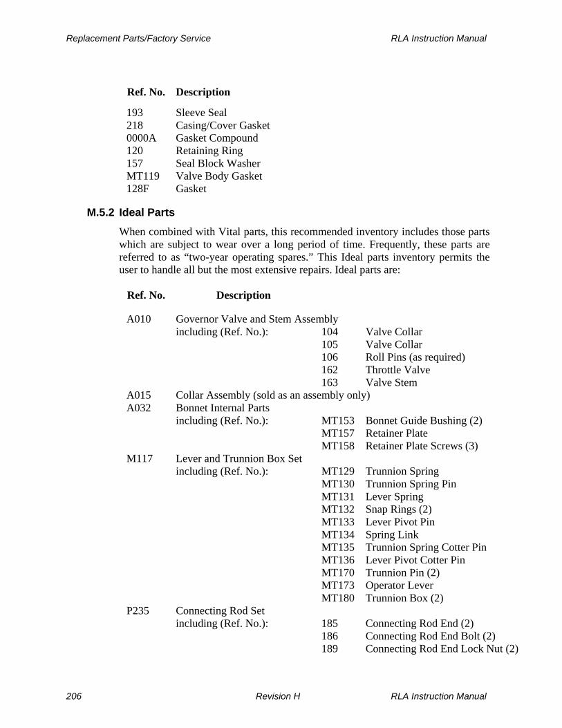
Replacement Parts/Factory Service RLA Instruction Manual
Ref. No. Description
193 Sleeve Seal 218 Casing/Cover Gasket 0000A Gasket Compound 120 Retaining Ring 157 Seal Block Washer MT119 Valve Body Gasket 128F Gasket
M.5.2 Ideal Parts
When combined with Vital parts, this recommended inventory includes those parts which are subject to wear over a long period of time. Frequently, these parts are referred to as “two-year operating spares.” This Ideal parts inventory permits the user to handle all but the most extensive repairs. Ideal parts are:
Ref. No. Description
A010 Governor Valve and Stem Assembly including (Ref. No.): 104 Valve Collar 105 Valve Collar 106 Roll Pins (as required) 162 Throttle Valve 163 Valve Stem A015 Collar Assembly (sold as an assembly only) A032 Bonnet Internal Parts including (Ref. No.): MT153 Bonnet Guide Bushing (2) MT157 Retainer Plate MT158 Retainer Plate Screws (3) M117 Lever and Trunnion Box Set including (Ref. No.): MT129 Trunnion Spring MT130 Trunnion Spring Pin MT131 Lever Spring MT132 Snap Rings (2) MT133 Lever Pivot Pin MT134 Spring Link MT135 Trunnion Spring Cotter Pin MT136 Lever Pivot Cotter Pin MT170 Trunnion Pin (2) MT173 Operator Lever MT180 Trunnion Box (2) P235 Connecting Rod Set including (Ref. No.): 185 Connecting Rod End (2) 186 Connecting Rod End Bolt (2) 189 Connecting Rod End Lock Nut (2)
206 Revision H RLA Instruction Manual
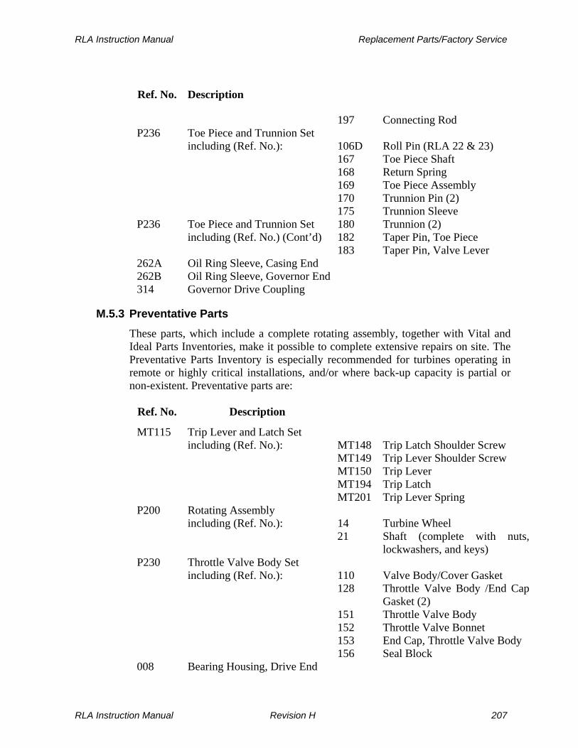
RLA Instruction Manual Replacement Parts/Factory Service
Ref. No. Description
197 Connecting Rod P236 Toe Piece and Trunnion Set including (Ref. No.): 106D Roll Pin (RLA 22 & 23) 167 Toe Piece Shaft 168 Return Spring 169 Toe Piece Assembly 170 Trunnion Pin (2) 175 Trunnion Sleeve P236 Toe Piece and Trunnion Set 180 Trunnion (2) including (Ref. No.) (Cont’d) 182 Taper Pin, Toe Piece 183 Taper Pin, Valve Lever 262A Oil Ring Sleeve, Casing End 262B Oil Ring Sleeve, Governor End 314 Governor Drive Coupling
M.5.3 Preventative Parts
These parts, which include a complete rotating assembly, together with Vital and Ideal Parts Inventories, make it possible to complete extensive repairs on site. The Preventative Parts Inventory is especially recommended for turbines operating in remote or highly critical installations, and/or where back-up capacity is partial or non-existent. Preventative parts are:
Ref. No. Description
MT115 Trip Lever and Latch Set including (Ref. No.): MT148 Trip Latch Shoulder Screw MT149 Trip Lever Shoulder Screw MT150 Trip Lever MT194 Trip Latch MT201 Trip Lever Spring P200 Rotating Assembly including (Ref. No.): 14 Turbine Wheel 21 Shaft (complete with nuts,
lockwashers, and keys) P230 Throttle Valve Body Set including (Ref. No.): 110 Valve Body/Cover Gasket 128 Throttle Valve Body /End Cap
Gasket (2) 151 Throttle Valve Body 152 Throttle Valve Bonnet 153 End Cap, Throttle Valve Body 156 Seal Block 008 Bearing Housing, Drive End
RLA Instruction Manual Revision H 207

Replacement Parts/Factory Service RLA Instruction Manual
Ref. No. Description
009 Bearing Housing Enclosure, Drive End 010 Bearing Housing, Governor End 015 Sector Set 038 Hand Valve Assembly 211 Gland Housing Assembly (2) 313 Oil Relay Governor (see exchange plan below) B100 Mounting Housing Cover
M.5.4 Interchangeability Lists
These lists are designed to maximize the effectiveness of your spare parts inventory, while at the same time minimizing your inventory costs, without losing critical parts coverage. Computer generated, they are designed to provide a quick, easy reference to those parts that can be used on more than one installed machine.
M.6 Ordering Parts
Contact your local Dresser-Rand manufacturer’s representative to order parts. Your representative will be pleased to provide any assistance you may require, as well as to quote prices and delivery dates. The following information is required when placing a parts order: 1. Your purchase order number. 2. Complete marking, shipping, and billing instructions. 3. Turbine serial number--from nameplate or horizontal flange of inlet casing
(YYTXXXX). 4. Turbine frame size--from nameplate, i.e., RLA-12L, RLA-16E, RLA-22L, etc. 5. Quantity of each part, set, or assembly. 6. Part, set, or assembly reference number from drawing, illustration, or text. 7. Description of part, set, or assembly. 8. Dresser-Rand 9-digit part number, if known (optional).
208 Revision H RLA Instruction Manual

RLA Instruction Manual Replacement Parts/Factory Service
M.7 Factory Service
Dresser-Rand maintains repair and rebuild facilities worldwide. In addition, factory-trained servicemen are available for start-up, field service, and troubleshooting. Consult your Dresser-Rand manufacturer’s representative or the factory for service needs. When contacting the representative or factory, please specify the turbine serial number, frame size, nature of the problem or service requirement, and date that service is required.
M.8 Rerates
WARNING
Materials used in turbine construction (cast iron, steel, stainless steel, special alloys) vary with steam conditions, speed, and power. These materials were selected according to the original rating of the turbine. Never attempt to re-rate a turbine without the assistance of a Coppus manufacturer’s representative and/or the factory. Misapplication of materials may result in serious equipment damage and/or personal injury.
Often customers will find that their steam conditions or power and speed requirements change. Frequently, an existing turbine can be renozzled and rerated to the new steam conditions and/or power and speed requirements, at significantly less expense than the cost of a new turbine. Contact your local Dresser-Rand manufacturer’s representative to request a rerate quotation, specifying the following information: 1. Turbine serial number--YYTXXXX 2. Frame size--RLA-12L, RLA-16E, RLA-22L, etc. 3. Existing rated steam conditions:
Inlet pressure Inlet temperature Exhaust temperature
4. Existing horsepower (kW) and speed 5. New steam conditions:
RLA Instruction Manual Revision H 209

Replacement Parts/Factory Service RLA Instruction Manual
Inlet Pressure Inlet Temp. Exhaust Pressure
Minimum
Normal
Maximum 6. New horsepower (kW) and speed required.
M.9 Upgrades
From time to time, Dresser-Rand creates conversion kits to add improved features to older Dresser-Rand turbines. If you own other Dresser-Rand turbines that lack features present on your new Dresser-Rand turbine, you may want to upgrade the older turbines. Installation of conversion kits can produce higher efficiency, improved reliability, decreased maintenance, improved safety, and greater interchangeability of spare parts among turbines.
Dresser-Rand Turbine Upgrade Summary 1. Turbine Re-rate for New Operating Conditions 2. Constant Speed to Variable Speed Governor Conversion 3. Solenoid Trip Kit 4. Sentinel Warning Valve Kit 5. Programmable Digital Tachometer Kit 6. Lagging Jacket 7. Oil Lubricant System 8. Sealant Kit 9. Inpro Seals 10.Mounting Housing Guard 11.Seal Block Upgrade 12.Oil Mist Kit
210 Revision H RLA Instruction Manual

RLA Instruction Manual Replacement Parts/Factory Service
Listed below are just some of the conversion kits available for Dresser-Rand turbines.
Conversion Kit Benefit N to L Wheel Conversions Increased efficiency for turbines
manufactured prior to 1968 Governor Conversion Kits Changes from mechanical flyball governor to
hydraulic Woodward Governor, improving reliability and reducing maintenance
Mechanical Trip Conversion Kit
Converts steam-actuated overspeed trip valve (used until 1983) to the positive-seated, mechanically activated valve described in this manual, increasing reliability
Your Dresser-Rand Manufacturer’s representative can quote these and other conversion kits and will notify you when other conversion kits become available. When requesting information on upgrades, be sure to specify the following information: 1. Turbine serial number--YYTXXXX 2. Frame size--RLA-12L, RLA-16E, RLA-22L, etc. 3. Type of upgrade desired
M.10 Factory Start-Ups
Authorized Dresser-Rand servicemen are available for start-up service and to train operating personnel in the operation and maintenance of Dresser-Rand steam turbines. An experienced serviceman will review your installation prior to start-up, following established Dresser-Rand procedures. Piping, alignment, lubrication, overspeed trip, etc. will be carefully checked. Upon commissioning the new installation, operating personnel will be trained. Consult your Dresser-Rand manufacturer’s representative to schedule a start-up.
M.11 Parts Catalog
Figures M-0 through M-7 and Tables M-1 through M-7 provide an illustrated parts breakdown for Dresser-Rand RLA turbines. Use this parts catalog to identify reference numbers of RLA parts.
RLA Instruction Manual Revision H 211

Replacement Parts/Factory Service RLA Instruction Manual
Figure M-0 RLA Turbine--General View (Sheet 1 of 2)
212 Revision H RLA Instruction Manual

RLA Instruction Manual Replacement Parts/Factory Service
Figure M-0 RLA Turbine--General View (Sheet 2 of 2)
RLA Instruction Manual Revision H 213

Replacement Parts/Factory Service RLA Instruction Manual
Reference
Designation Description Qty Notes
A030 Pilot Valve and Stem Assembly 1 MT008 Strainer Screen 1 MT119 Valve Body Gasket 1 MT128 Bonnet Gasket 1 MT129 Trunnion Spring 1 MT130 Trunnion Spring Pin 1 MT131 Lever Spring 1 MT132 Snap Ring 2 MT133 Lever Pivot Pin 1 MT134 Spring Link 1 MT135 Spring Cotter Pin 1 MT136 Lever Pivot Cotter Pin 1 MT137 Valve Lifting Pin 1 MT151 Valve Body 1 MT152 Bonnet 1 MT153 Bonnet Guide Bushing 2 MT155 Lever Stand 1 MT157 Retainer Plate 1 MT158 Retainer Plate Screws 3 MT162 Valve Assembly 1 MT164 Pilot Valve Locknut 1 Sold with A030 MT170 Trunnion Pin 1 MT173 Operating Lever Assembly 1 MT180 Trunnion Box 1 MT185 Connecting Rod End 2 MT186 Connecting Rod Bolt 2 MT187 Connecting Rod Locknut 2 MT188 Connecting Rod End Nut 2 MT190 Connecting Rod Locknut 2
MT192 Valve Body Seat 1 Optional (Standard on 200 Construction)
MT194 Trip Latch Assembly 1 MT197 Connecting Rod 1
Bushing 1 Sold with MT 173 Table M-1 Overspeed Trip Valve Assembly Parts List
214 Revision H RLA Instruction Manual

RLA Instruction Manual Replacement Parts/Factory Service
Figure M-1 Overspeed Trip Valve Assembly
RLA Instruction Manual Revision H 215

Replacement Parts/Factory Service RLA Instruction Manual
Reference
Designation Description Qty Notes
104 Valve Collar 1 105 Valve Collar 1
106A Roll Pin 1 106B Roll Pin 1 106C Roll Pin 2 106D Roll Pin 1 22L and 23L only 110 Valve Body/Cover Gasket 1 120 Retaining Ring 1 128 Throttle Valve Body/End Cap Gasket 2
128F Gasket 1 151 Throttle Valve Body 1 152 Valve Bonnet 1
152A Toe Piece Shaft Bushing 1 153 Throttle Valve Body End Cap 1 155 Linkage Stand 1 156 Seal Block 1 157 Seal Block Washer 1 158 Seal Ring 1 162 Throttle Valve 1 163 Valve Stem 1 167 Toe Piece Shaft 1 168 Return Spring 1 169 Toe Piece Assembly 1 170 Trunnon Pin 2 173 Lever 1 175 Trunnion Sleeve 1 180 Trunnion 2 182 Toe Piece Taper Pin 1 183 Valve Lever Taper Pin 1 184 Set Screw, Valve Lever 1 185 Connecting Rod End 2 186 Connecting Rod End Bolt 2 189 Connecting Rod End Locknut 2 193 Seal Sleeve 1 197 Connecting Rod 1
Table M-2 Throttle Valve Assembly Parts List
216 Revision H RLA Instruction Manual

RLA Instruction Manual Replacement Parts/Factory Service
Figure M-2 Throttle Valve Assembly
RLA Instruction Manual Revision H 217

Replacement Parts/Factory Service RLA Instruction Manual
Reference
Designation Description Qty Notes
142 Key, Governor 1 265 Governor Lever 1 313 Oil Relay Governor 1 314 Governor Drive Coupling 1 315 Mounting Housing 1 336 Drain Plug, Oil Relay Governor 1
A015 Collar Assembly, Overspeed Trip 1 B100 Mounting Housing Cover 1
MT148 Trip Latch Shoulder Screw 1 MT149 Trip Lever Shoulder Screw 1 MT150 Trip Lever 1 MT194 Trip Latch 1 MT201 Trip Lever Spring 1 S200 Trip Collar, Overspeed 1 S201 Bolt Head Shank 1 S202 Spring, Return 1 S203 Set Screw 1 S204 Bolt Spring 1 S36 Set Screw 1 S58 Plug 1
Table M-3 Governor, Mounting Housing, and Bolt Trip Components, Parts List
218 Revision H RLA Instruction Manual

RLA Instruction Manual Replacement Parts/Factory Service
Figure M-3 Governor, Mounting Housing, and Bolt Trip Components
RLA Instruction Manual Revision H 219
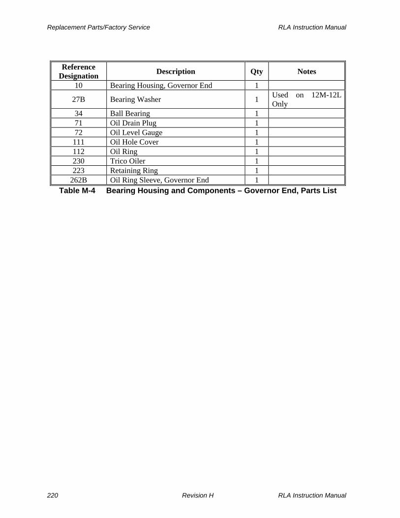
Replacement Parts/Factory Service RLA Instruction Manual
Reference
Designation Description Qty Notes
10 Bearing Housing, Governor End 1
27B Bearing Washer 1 Used on 12M-12L Only
34 Ball Bearing 1 71 Oil Drain Plug 1 72 Oil Level Gauge 1 111 Oil Hole Cover 1 112 Oil Ring 1 230 Trico Oiler 1 223 Retaining Ring 1
262B Oil Ring Sleeve, Governor End 1 Table M-4 Bearing Housing and Components – Governor End, Parts List
220 Revision H RLA Instruction Manual

RLA Instruction Manual Replacement Parts/Factory Service
Figure M-4 Bearing Housing and Components – Governor End
RLA Instruction Manual Revision H 221

Replacement Parts/Factory Service RLA Instruction Manual
Reference
Designation Description Qty Notes
5B Yoke, Cover End 1 26 Washer Plate 1 40 Seal Ring 1 45 Throw Ring 1
211 Gland Housing Assembly 1 Consists of two matching halves
214 Stop Washer 4 4 gland style 215 Carbon Ring 4 4 gland style 216 Garter Spring 4 4 gland style
Table M-5.Yoke, Gland Housing, and Sealing Elements – Cover End, Parts List
222 Revision H RLA Instruction Manual

RLA Instruction Manual Replacement Parts/Factory Service
Figure M-5 Yoke, Gland Housing, and Sealing Elements – Cover End
RLA Instruction Manual Revision H 223

Replacement Parts/Factory Service RLA Instruction Manual
Reference
Designation Description Qty Notes
1 Casing 1 2 Cover Assembly 1
5A Yoke, Casing End 1 14 Turbine Wheel Assembly 1 15 Sector Assembly 1 21 Shaft Assembly 1 26 Washer Plate 1 38 Hand Valve Assembly N/A Varies 40 Seal Ring 1 45 Throw Ring 1
211 Gland Housing Assembly 1 Consists of two matching halves
214 Stop Washer 4 4 gland style 215 Carbon Ring 4 4 gland style 216 Garter Spring 4 4 gland style 218 Casing/Cover Gasket 1 319 Key 1 377 Shaft Extension Key 1 378 Turbine Wheel Key 1
Table M-6 Cover, Casing, and Casing End Components, Parts List
224 Revision H RLA Instruction Manual

RLA Instruction Manual Replacement Parts/Factory Service
Figure M-6 Cover, Casing, and Casing End Components
RLA Instruction Manual Revision H 225

Replacement Parts/Factory Service RLA Instruction Manual
Reference
Designation Description Qty Notes
8 Bearing Housing, Drive End 1 9 Bearing Housing Enclosure 1 23 Shaft Nut 1 26 Washer Plate 1 27 Bearing Washer 1 22L/23L only
27A Bearing Washer 1 12L/12M only 33 Ball Bearing 1 41 Seal Ring 1 71 Oil Drain Plug 1 72 Oil Level Gauge 1 111 Oil Hole Cover 1 112 Oil Ring 1 113 Lock Washer 1 230 Trico Oiler 1
262A Oil Ring Sleeve, Drive End 1 Table M-7 Bearing Housing and Components – Casing End, Parts List
226 Revision H RLA Instruction Manual

RLA Instruction Manual Replacement Parts/Factory Service
Figure M-7 Bearing Housing and Components – Casing End
RLA Instruction Manual Revision H 227

RLA Instruction Manual
THIS PAGE WAS LEFT BLANK INTENTIONALLY
228 Revision H RLA Instruction Manual

RLA Instruction Manual User Notes and Maintenance Records
Section N
User Notes and Maintenance Records
Date Observation or Service Performed Comments By
RLA Instruction Manual Revision H 229

User Notes and Maintenance Records RLA Instruction Manual
Date Observation or Service Performed Comments By
230 Revision H RLA Instruction Manual