copyright 2007 by...models part number model numbers description 315-081-000 pl72d box, grader,...
TRANSCRIPT


�
COPYRIGHT 2007 byATI CorporationNew Holland, PA 17557 U.S.A.
DISCLAIMERTHEINFORMATIONINTHISMANUALISPROVIDEDTOPROMOTETHESAFEUSEOF,ANDASSISTTHEOPERATORINACHIEVINGTHEBESTPERFORMANCEFROM,THEPRODUCTSDESCRIBEDHEREINWHENUSEDFORTHEINTENDEDAPPLICATION.

��
MODELS
Part Number
Model Numbers Description
315-081-000 PL72D Box,Grader,Para-Levelw�thSlope-Tach,6',Cyl�nderOnly
315-082-000 PL84D Box,Grader,Para-Levelw�thSlope-Tach,7',Cyl�nderOnly
315-083-000 PL96D Box,Grader,Para-Levelw�thSlope-Tach,8',Cyl�nderOnly
000-166-475 K�t,Hydraul�c,Double,ApacheControls,IncludesValveAssembly,Hoses,F�tt�ngs&Soleno�dCable
000-200-188 K�t,LaserControls,IncludesControlPanel,two360°Sensors,Cables(Power,Sensor&Soleno�d)&RemoteSw�tch
NOTE:Optionalaccessories,ScarifierAssembly,installationandpartsmanualcanbeobtainedfromATICorporationordownloadfromwebsite,www.level-best.com.

���
TAbLE Of CONTENTS
MODELS..........................................................................................................................................................��
TABLEOFCONTENTS.................................................................................................................................���
SAFETyINFORMATION...............................................................................................................................v
Safety Precaution Definitions....................................................................................................................v
WARRANTy...................................................................................................................................................v�
LISTOFILLUSTRATIONS..........................................................................................................................v��
LISTOFTABLES.........................................................................................................................................v���
SySTEMSFEATURESANDBASICOPERATION......................................................................................1
Purpose......................................................................................................................................................1
Components...............................................................................................................................................1
ControlPanel.............................................................................................................................................2
Controls..............................................................................................................................................2
Operat�on............................................................................................................................................5
UserSetup..........................................................................................................................................7
Rotat�ngLaser..........................................................................................................................................10
LaserSensor............................................................................................................................................. 11
Cables...................................................................................................................................................... 11
Equ�pmentSetup......................................................................................................................................14
JobS�teSet-Up........................................................................................................................................16
Set-UpforLevelGrad�ng.................................................................................................................16
Set-UpforSlopedGrad�ng...............................................................................................................16
Bench�ngAndOperat�ng.........................................................................................................................19
Bench�ng...........................................................................................................................................19
Bench�ngw�thaRodEye.................................................................................................................20
Operat�on..........................................................................................................................................20
TROUBLESHOOTING..................................................................................................................................22
SPECIFICATIONSANDMAINTENANCE.................................................................................................25
Specifications...........................................................................................................................................25
D�mens�ons.......................................................................................................................................25
ControlPanelCB52..........................................................................................................................25
LaserSensorBULLSEyE5MC.......................................................................................................25

�v
Ma�ntenance.............................................................................................................................................26
StorageandTransport.......................................................................................................................26
Clean�ng............................................................................................................................................26
CablesandHoses..............................................................................................................................26
Mach�ne............................................................................................................................................26
Cal�brat�on........................................................................................................................................26
Serv�ce.....................................................................................................................................................26
NOTES............................................................................................................................................................28
REGISTRATIONCARD................................................................................................................................29
TAbLE Of CONTENTS

v
Th�smanual�sfurn�shedtoyou,theowner/opera-tor, as a guide to get the greatest benefit from your Grad�ngBox.ATICorporat�onwantsyoutobeabletogetthemostuseoutofyourGrad�ngBoxthrough safe and efficient operation.
Beforeattempt�ngtooperatetheGrad�ngBox,carefullyreadallsect�onsofth�smanual.Besurethatyouthoroughlyunderstandallofthesafety�nformat�onandoperat�ngprocedures.
SAfETY PRECAUTION DEfINITIONS
Dangers,Warnings,Cautions,andNotesarestrateg�callyplacedthroughoutth�smanualtofur-theremphas�zethe�mportanceofpersonalsafety,qualifications of operating personnel, and proper useofthegrad�ngbox�n�ts�ntendedappl�cat�on.Theseprecaut�onssupplementand/orcomplementthe safety information decals affixed to the unit and include headings that are defined as follows:
Indicates an imminently hazardous situation which, if not avoided, will result in death or serious injury.
Indicates a potentially hazardous situation or practice which, if not avoided, could result in death or serious injury.
Indicates a potentially hazardous situation or practice which, if not avoided, will result in damage to equipment and/or minor injury.
NOTE: Indicatesanoperatingprocedure,practice.etc.,orportionthereof,whichisessentialtohighlight.
• Alwaysusecaut�onandsafeoperat�ngprac-t�ceswhenoperat�ngth�sequ�pment.
• AlwayssettheAutomat�c/ManualSw�tchontheControlPaneltoMANUALbeforeleav�ngtheoperator’sseatorwheneverthemach�ne�snotmov�ng.
SAfETY INfORMATION
• Alwaysallowforclearanceunderthecutt�ngedgeofthemach�newhentun�ngthesystemorwhensw�tch�ngtoautomat�ccontrol.Insufficient clearance could cause the machine tol�ft�tselfoffthegroundas�tscutt�ngedgeattemptstoach�evetheprogrammedslope.
• Neveradjustthepos�t�onoftheLaserSensorwhenthesystem�s�nautomat�ccontrol.
• Neverperformserv�ceworkonyourmach�neortheAutomat�cControlSystemwhenthesystem�s�nautomat�ccontrol.
• Installallsafetypanelsandguardsbeforeoperat�ngyourequ�pment.
• Stayclearofallmov�ngpartswhenthemach�ne�s�noperat�on.
• Keepallpeopleclearofthemach�newhen�t�srunn�ng.
• Keepfeetandotherbodypartsfromunderthecutt�ngedgesofthemach�neatallt�mes.
• Readandcomplyw�thallsafetyrecommenda-t�onsofyourTractor/Sk�dSteermanufacturer,asoutl�ned�n�tsoperatorandserv�cemanuals.
NOTE: Referencesmadetoleft,right,front,andreararethosedirectionsviewedfrombe-hindthepowerunitandgradingbox.
NOTE: Someequipmentdepictedinillustrationsmaynotreflectexactproductionmodelconfigurations.
NOTE: Allsafety,operating,andservicinginfor-mationreflectscurrentproductionmodelsatthetimeofpublicationofthismanual.
NOTE: ATICorporationreservestherighttodiscontinuemodelsatanytime,changespecifications,andimprovedesignwithoutnoticeandwithoutincurringobligationongoodspreviouslypurchasedandtodiscon-tinuesupplyinganypartlisted,whenthedemanddoesnotwarrantproduction.

v�
Th�sLaserGrad�ngBox�sdes�gnedandmanufac-turedtoh�ghqual�tystandards.ATICorporat�on,therefore,guaranteesth�sLaserGrad�ngBoxtobefreefromdefect�nworkmansh�pandmater�alsforone(1)yearfrompurchasedate.Ifthemach�ne�susedforrentalpurposes,thewarranty�sl�m�tedton�nety(90)days.
WARRANTY
LaserControls,VendoredComponentsandControlValvePartsarewarrantedseparatelybythe�rrespect�vemanufacturers.
Doesnotcovernormalwearorfa�lureduetohydraul�co�lcontam�nat�on.
M�suse,abuse,m�sappl�cat�on,andunauthor�zedalterat�onsw�llvo�dth�swarranty.

v��
LIST Of ILLUSTRATIONS
F�gure1.PlaneofLaserL�ghtw�thComponentsoftheAutomat�cControlSystem......................................1
F�gure2.FrontV�ewoftheControlPanel.......................................................................................................3
F�gure3.RearV�ewoftheControlPanel........................................................................................................4
F�gure4.ControlPanelD�splay.......................................................................................................................4
F�gure5.SensorPos�t�onInd�cator..................................................................................................................4
F�gure6.LEDGradeD�splay..........................................................................................................................5
F�gure7.UserSetupD�splayScreen...............................................................................................................7
F�gure8.LCDBr�ghtnessandContrastEd�tMode.........................................................................................8
F�gure9.DeadbandEd�tMode........................................................................................................................8
F�gure10.ValveSpeedEd�tMode..................................................................................................................8
F�gure11.ReferenceElevat�onEd�tMode......................................................................................................9
F�gure12.Un�tsofMeasureEd�tMode..........................................................................................................9
F�gure13.StoreandRecallEd�tMode............................................................................................................9
F�gure14.Rotat�ngLaser..............................................................................................................................10
F�gure15.Bullseye5MC............................................................................................................................... 11
F�gure16.PowerCable..................................................................................................................................12
F�gure17.SensorJunct�onCable..................................................................................................................12
F�gure18.SensorCable.................................................................................................................................12
F�gure19.ValveCable...................................................................................................................................13
F�gure20.RemoteSw�tchesCable................................................................................................................13
F�gure21.ControlPanelMount�ng...............................................................................................................14
F�gure22.ComponentsoftheAutomat�cControlSystemonaSk�dSteer...................................................15
F�gure23.RemoteSw�tchMount�ng............................................................................................................15
F�gure24.Junct�onBlockandLaserSensorCables......................................................................................16
Figure 25. Method One: Align Rotating Laser with Grade Stakes................................................................17
F�gure26.S�ghtOverRotat�ngLaser............................................................................................................17
F�gure27.GradeStakew�thElevat�onMark................................................................................................17
Figure 28. Method Two: Align Rotating Laser with Grade Stakes................................................................18
F�gure29.Bench�ngthePara-LevelLGBw�thaLevelPlane......................................................................19
F�gure30.LubeandMa�ntenanceChart........................................................................................................27

v���
LIST Of TAbLES
Table1.Un�ts...................................................................................................................................................9

1
SYSTEMS fEATURES AND bASIC OPERATION
PURPOSE
TheLevelBestLaserGrad�ngBox(LGB)�sacost-efficient method for fine grading. Various capacities sized to fit the skid steer or tractor with a cho�ceofautomat�ccontrolsystemsareava�lable.Th�smanual�sforsk�dsteersystemsequ�ppedw�thanApacheTechnolog�es,Inc.CB52Automat�cControlSystem.
Laser-gu�deddepthcontrolprov�desunmatchedmeasurementofplanefromas�nglereferencepo�nt.Grade�nformat�onfromarotat�nglaser�sprocessedandautomat�callyd�rectsthegrad�ngbox’shydraul�cstoma�nta�ntheelevat�onofthecutt�ngedge.
Whenused�nconjunct�onw�thaSlope-Tachadapter,thePara-LevelLGBalsoprov�dess�de-to-side grading which is often difficult when using a sk�dsteerloader.
TheGradePos�t�onLEDsontheLaserSensor�nd�-catethelocat�onofthebox’scutt�ngedgerelat�veto the required finished grade (The Control Panel hasasetofLEDsthatm�m�ctheLaserSensor’sLEDs).
• Inmanualcontrol,theoperatorwatchestheGradePos�t�onLEDsandusesthecontrolstokeepthecenterLEDsl�t,therebykeep�ngthebox“OnGrade”.
• Inautomat�ccontrol,theAutomat�cControlSystemcontrolsthebox’shydraul�ccyl�ndertokeepthecenterLEDsl�t,therebykeep�ngthebox“OnGrade”.
• Thecontrolsystemusedw�ththeSlope-Tachadapterusestwolasersensors.Onelasersen-sorprov�desgrade�nformat�onforthecenterelevat�onoftheLGB,thesecondlasersensorensuresthepropert�ltangle�sma�nta�nedbymeasur�ngtheelevat�onatoneendoftheLGB.
COMPONENTS
The control system consists of 4 components:
Rotat�ngLaser–Prov�desareferencePlaneofLaserL�ghtoverthejobs�te(refertoF�gure1).Thel�ghtplanemaybelevelorsetatanangletomatchtheslopeoftheground.
Laser Sensors – Mounted at a specific height on amastontheLaserGrad�ngBox,�tdeterm�nesthed�fference�ndepthbasedonthePlaneofLaserL�ght.Whenusedw�ththeSlope-Tachadapter,twolasersensorsarerequ�red.
NOTE: ApacheTechnologieshasavailableseveralLaserSensormodelsthatfunctionwiththeCB52ControlPanel.ThismanualcoverstheBULLSEYE5MConlyalthoughotherBULLSEYEmodelsmaybeused.
ControlPanel–MountedontheGrad�ngBox,theControlPanelprocessesdatarece�vedfromtheLaserSensorsandfromtheoperator.LEDs�nd�catethelocat�onofthebox’scutt�ngedgerelative to the desired finish grade. When set toAutomat�c,�tprov�dess�gnalstotheValveAssemblytoe�therextendorretractthecyl�n-dersontheLaserGrad�ngBoxorSlope-Tachadapter.
F�gure1.PlaneofLaserL�ghtw�thComponentsoftheAutomat�cControlSystem

2
cally,w�ththeControlPanelcontroll�ngdepthandt�lt,ormanually,w�ththeoperatorcontroll�ngthebladedepthandt�lt.
NOTE:TheCB52ControlPanelcanbeconfig-uredseveraldifferentways.ThismanualassumestheATIfactorydefaultsettingdisplayingthecenterlasersensordata,orelevation,ontheleftsideoftheLCDandright-sidelasersensordata,ortilt,ontherightsideoftheLCD.ApacheTechnolo-giesreferencesthisasdualelevationmodebecausebothlasersensorsreferenceeleva-tionandtheLCDdisplayselevationdata.
Controls
Tworemotesw�tchesaremounted�ns�dethesk�dsteerloader'soperatorstat�onw�ththecablesdownward.Thesetwosw�tchesm�m�cthejoyst�ckcontrolslocatedontheCB52ControlPanelforoperat�onofthera�se,lower,andt�ltfunct�onsandselect�onofautomat�cormanualcontrol.Refertothesect�ononEqu�pmentSetupformore�nforma-t�onregard�ngproper�nstallat�onoftheremotesw�tches.
NOTE: Thismanualrefersonlytothejoysticksonthecontrolpanel.Anyactionormotionrequiredbythejoystickscanbeassumedtocausethesamefunction/reactionwhenusingtheremoteswitches,providedtheremoteswitcheshavebeenmountedinthecorrectorientation.
The following identifies the indicators, switches andtypeofsw�tchontheControlPanel.
ValveAssembly–W�redtotheControlPanel,thevalvemetershydraul�co�ltothehydraul�ccyl�ndersforelevat�onandt�ltcontrol.
Inadd�t�on,w�resandcablestoconnectthecom-ponentsare�ncludedw�ththeun�t.Tworemotesw�tchesprov�decontrolfromw�th�nthesk�dsteerloader’soperatorstat�onwh�lema�nta�n�ngv�s�blecontactoftheControlPanelscreenmountedontheLGB.
CONTROL PANEL
TheControlPanel�sessent�allyacomputerw�thbu�lt-�nlog�cforthe�nputsandoutputsconnectedto�t.TheControlPanelprov�desmanyadjustmentstoallowcompat�b�l�tyw�thd�fferentmach�neryandappl�cat�onrequ�rements.
TheControlPanelusesanLCDscreentoprov�de�nformat�ontotheoperator.Ones�deofthescreend�splayselevat�on,orbladedepth,atthecenteroftheLGBandothers�de�sforelevat�onatther�ght-s�deoftheblade.
Select�onsaremadev�atwomult�ple-funct�onsw�tches(joyst�cks)thatmoveupordownandleftorr�ght,canberotated�ne�therd�rect�on,andpressed.Betweeneachjoyst�ckandthepowersw�tch�sasupport,orhandrest,tohelpsteadytheoperator'shandashemovesthecontrols.GradeLEDsareusedto�nd�cated�rect�onofgrade.
Thelasersensor,locatedatther�ghts�deoftheLGB,controlsthet�lt,orslope,ofthecutt�ngedgebymeasur�ngelevat�onofthegradeatad�fferentlocat�onthanthecenterlasersensor.
NOTE: ThismanualreferencesthePara-Level’sabilitytofollowslope.Thisdoesnotimplythataslopelasersensorisrequiredtopro-videthisfunctionality.Thetiltcapabilityisobtainedbymeasuringelevationattwodifferentpositionsrelativetotherotatinglaser.
TheControlPanelhastwomodesaccess�bletotheuser;Operat�onandUserSetup.InUserSetupmode,�temssuchasvalvespeedandLCDbr�ghtnesscanbeadjusted.Operat�onmodeallowsoperat�onofthePara-LevelLGBe�therautomat�-
SYSTEMS fEATURES AND bASIC OPERATION

3
FrontControlPanelSw�tches
F�gure2.FrontV�ewoftheControlPanel
LCDD�splay(1)–�nd�catesthevar�ousopera-tion and configuration modes. The items d�splayedchangebasedonthemodeandUserSetupparameterschosen.Refertothesection on LCD display for more specific �nformat�on.
LEDGradeD�splayforT�ltFunct�on(2)–�nd�-cateswherethecutt�ngedge�s�nrelat�ontotheon-gradepos�t�on.Refertothesect�ononGradeInd�catorsformore�nformat�on.
Mount�ngKnobs(3)–securesthecontrolpaneltothemount�ngbracketsonthePara-LevelLaserGrad�ngBox.
Auto/ManualLEDforT�lt(4)–green“A”LED�llum�nateswhen�nAutomat�coperat�onandamber“M”LED�llum�nateswhen�nManualoperat�on.
T�ltJoyst�ck(5)–left/r�ghtmovementselectsAuto/Manualcontrolfortheslopefunct�onandup/downmovementt�ltstheblade.Rotat�on�ncreases/decreasesthecontrolsetpo�nt.Press�ng“�n”enableselevat�onandslopematch�ng.Whenreleased,thejoyst�ckreturnstoacenter,neutralpos�t�on.
Th�sjoyst�ckalsonav�gatesthroughtheUserSetupmenus.
AccessPanelScrews(6)–Reta�nsaccesspaneltotheControlPanel.
AccessPanel(7)–Panelconta�nsafuse,rotarysw�tchandDIPsw�tchused�nfactorysetups.
PowerSw�tch(8)–Turnspoweronandoff.Alsoprov�desaccesstoHelpscreensbypress�ngupwh�leoperat�ng.
Elevat�onJoyst�ck(9)–left/r�ghtmovementselectsAuto/Manualcontrolfortheeleva-t�onfunct�onandup/downmovementra�sesandlowerstheblade.Rotat�on�ncreases/decreasesthecontrolsetpo�nt.Press�ng“�n”enableselevat�onandslopematch�ng.Whenreleased,thejoyst�ckreturnstoacenter,neutralpos�t�on.
Th�sjoyst�ckalsonav�gatesthroughtheUserSetupmenus.
Auto/ManualLEDforElevat�on(10)–green“A”LED�llum�nateswhen�nAutomat�coperat�onandamber“M”LED�llum�nateswhen�nManualoperat�on.
LEDGradeD�splayforElevat�onFunct�on(11)–�nd�cateswherethecutt�ngedge�s�nrelat�ontotheon-gradepos�t�on.Refertothesect�ononRefertothesect�ononGradeInd�catorsformore�nformat�on.
Do not change or modify the Rotary or DIP switch positions. These switches are set at the factory before shipment. Contact the installa-tion technician for additional information, if required.
RotarySw�tch(12)–Usedforfactorysetup.Donotadjustth�sunlessd�rectedtobyATICorporat�onserv�cedepartment.
DIPSw�tch(13)–Usedforfactorysetup.Donotadjustth�sunlessd�rectedtobyATICorporat�onserv�cedepartment.
Fuse(14)–Automot�ve-style,25ampfuseprotectsaga�nstpowersurges.
SYSTEMS fEATURES AND bASIC OPERATION

4
RearControlPanelConnect�ons
F�gure3.RearV�ewoftheControlPanel
RemoteSw�tch(15)–7-p�nconnectorfortheremotesw�tchw�reharness.
Hydraul�cValveOutput(16)–10-p�nconnectorforthevalvew�reharness.
Mach�nePowerInput(17)–4-p�nconnectorforthepowerw�reharness.
LaserSensor(18)–7-p�nconnectorforlasersensor�nput.Th�sconnectstothejunct�onbox.
Beeper(19)–beeperforaud�ble�nd�cat�onofalarmsandsw�tchengagement.As�nglebeep�sact�vatedwhenasw�tchcommand�saccepted.Adoublebeep�sact�vatedwhenaselectedfunct�on�snotava�lableor�s�ncorrect.Beepervolumecanbeadjustedbyrotat�ngthebeeper.
Ser�alNumberPlate(20)–recordsbu�ldandmodeldatafortroubleshoot�ngpurposes.
ControlPanelD�splay
TheControlPanelD�splayprov�des�nformat�onto the operator for efficient control of the LGB in e�therAutomat�corManualcontrol.Inputsfromthejoyst�cklocatedonthelefts�deared�splayedonthelefts�deofthescreenandv�ce-versa.
ThedefaultATICorporat�onsetupofthePara-Levelw�thSlope-Tachcontrolsystemd�splaysdataastwod�fferentelevat�ons.Elevat�on�nformat�onforthecenterlasersensor�sshownonthelefts�de
oftheControlPanelLCDandelevat�on�nforma-t�onforther�ghtlasersensor�sshownonther�ghts�deoftheLCD.
NOTE:`Therightlasersensorissometimesre-ferredtoasaslopeortiltsensorbecauseitcontrolstheSlope-TachhydrauliccylinderwhichallowsthePara-LevelLGBtocreateaslopedgrade.However,actualdataisbasedonelevation,notslope.
F�gure4.ControlPanelD�splay
ReferenceElevat�on(1)–�nd�catesthereferenceelevat�on.Thevalue�sreferencedfromthelastbenchmark.
Un�ts(2)–d�splaystheun�tsofthereferenceelevat�on.Canbechanged�nUserSetupmode.
SensorPos�t�onInd�cator(3)–�nd�catestheelevat�onrelat�vetothevert�calrecept�onrangeoftherece�ver.The+�nd�catorbl�nkswhenrecept�on�slost.
F�gure5.SensorPos�t�onInd�cator
SYSTEMS fEATURES AND bASIC OPERATION

5
Theon-gradesetrangew�llvarydepend�ngonthew�dthofthedeadband.Thesmallerthedeadband,thelargertherange.Thelargerthedeadband,thesmallertherange.
ControlSetpo�nt(4)–�nd�cateswhereon-grade�ssetrelat�vetothevert�calrecept�onrange.
Automat�c/ManualInd�cator(5)–�nd�cates�fthecontrolsystem�s�nmanual(M)orautomat�c(A)mode.
Joyst�ckFunct�onIcon(6)–�nd�catesthecurrentmodeofthejoyst�ck.Press�ngthejoyst�ckalternatescontrolbetweenslopematch�ng/bench�ngandslopecontrolsetpo�nt.
Ra�se/LowerInd�cator(7)–�nd�catesthed�rec-t�onofmovementoftheblade.
Operat�ngModeInd�cator(8)–�nd�catestheoperat�ngmodeofeachs�deoftheControlPanel.Dualelevat�oncontrol�sshown.
ControlSourceInd�cator(9)–�nd�catesthesourceofcontrol.Starburst�con�nd�cates�nput�sbe�ngrece�vedfromalaserrece�ver.
L�nked/Unl�nkedElevat�onMode(10)–onlyused�ndualelevat�onmode.
GradeInd�cators
Oneachs�deoftheLCD�sagrade�nd�cator.Thegrade�nd�cator�sasetofredandgreenLEDsthat�nd�caterelat�vepos�t�ontograde.Whenalaser�sstr�k�ngthesensor,thereare5poss�blepos�t�onsofgrade�nformat�on�nd�cated.
H�ghCoarse-3topredLED’sform�ngdownarrow.
H�ghF�ne-3topredLED’sand3greenon-gradeLED’s.
On-Grade-3greenLED’sform�nghor�zontalbar.
LowF�ne-3bottomredLED’sand3greenongradeLED’s.
LowCoarse-3bottomredLED’sform�nguparrow.
F�gure6.LEDGradeD�splay
Ifthelasermovesofftherecept�onrangeofthesensor,anout-of-beamw�llbe�nd�catedontheLEDs.Ifthelastlaserrecept�onwasonthebottomof the sensor, the top 3 LEDs will flash indicating tomovethesensordown.Ifthelastlaserrecep-tion was on the top, the bottom 3 LEDs will flash �nd�cat�ngtomovethesensorup.Theout-of-beam�nd�cat�onlastsfor2m�nutes.
Operation
ControlofthePara-LevelLaserGrad�ngBox�saccompl�shedthroughtheControlPanel.Theoper-atorplacesthesystem�ne�therAutomat�ccontrol,wherethesystemra�ses/lower/t�ltstheLGBbasedon�nputsfromthelasersystem,orManually,wheretheoperatormovestheLGBus�ngthecontrolsontheControlPanel(orremotesw�tches).
Always turn the system to manual before leav-ing the skid steer loader. Move both joysticks toward the middle (inward) to activate manual mode.
Toturnthesystemon,togglethePowersw�tchtotheI(on)pos�t�on.TheLEDsandLCDw�lll�ghtto confirm power. The Control Panel will perform a d�agnost�cchecktoensurethesystemcomponentsarepresentandrespond�ngcorrectly.Ifthelasersensorsarepresent,theLEDsonthesensorsw�lll�ghtasasystemcheck.Ifcomponentsarenotfound,a“NoSensorsFound”message�sd�splayed.
NOTE: Thesystemmustberestartedifsensorsorcomponentsareconnected/added.
SYSTEMS fEATURES AND bASIC OPERATION

6
Automat�c/ManualControl
ToplacethePara-LevelLGBunderAutomat�ccontrol,movetheleftjoyst�cktotheleft(outward)andther�ghtjoyst�cktother�ght(out-ward)andreleaseeachtoneutral.Thegreen“A”LEDsontheControlPanelw�lll�ghtto�nd�cateAutomat�ccontrol.
UnderAutomat�ccontrol,theControlPanelsendstheappropr�ates�gnalstothevalvetora�se/lower/t�lttheLGBtoobta�nandma�nta�nanon-gradepos�t�on.Ifthesensor�souts�detherangeofthelasers�gnal,�tmustbemovedw�th�nrangetostartrece�v�ngs�gnals.
ToplacethePara-LevelLGBunderManualcon-trol,movetheleftjoyst�cktother�ght(�nward)andther�ghtjoyst�cktotheleft(�nward)andreleaseeachtoneutral.Theamber“M”LEDsontheControlPanelw�lll�ghtto�nd�cateManualcontrol.
UnderManualcontrol,theLEDGradeD�splayw�ll�nd�categrade�nformat�onbutw�llnotsendadjust-ments�gnalstothevalve.AdjustmentoftheLGBelevat�onandslopecanbeaccompl�shedmanually.
Ra�se/Lower
Theleft-s�dejoyst�ckra�sesorlowerstheLGBwhenunderManualcontrol.Movethejoyst�ckuptora�sethebladeanddowntolowertheblade.
WhenunderAutomat�ccontrol,theleft-s�dejoyst�ckw�lltemporar�lyra�seorlowertheLGB.Whenthejoyst�ck�sreleased,theLGBreturnstoAutomat�ccontrol.
T�lt
Ther�ght-s�dejoyst�ckadjuststheslopeangleoftheLGBwhenunderManualcontrol.WhenunderAutomat�ccontrol,ther�ght-s�dejoyst�ckw�lltemporar�lychangetheslopeangleoftheLGB.Whenthejoyst�ck�sreleased,theLGBreturnstoAutomat�ccontrol.
Elevat�on/SlopeOffset(ReferenceAdjustment)
TheCB52hasthecapab�l�tytoadjusttheon-gradepo�ntw�thoutadjust�ngthelasersensor(s)tow�th�none�nchoftheendof�tsrange.Th�sfeaturecanbeusedtora�sethegradefor�n�t�alrough-cutandthenreturntheLGBtodes�redgradefor finishing.
Theon-gradereferencepo�nt�sadjustedfromtheControlPanelbyrotat�ngtheappropr�atejoyst�ck.Rotatethejoyst�ckclockw�se�ncreasestheeleva-t�on,counterclockw�sedecreasestheelevat�on.Theoffsetw�llnotgobeyondal�m�tprogrammed�ntothelasersensor.
Whenthereference�sadjusted,theLCDd�splaystheactualelevat�onchangefromthebenchmark.
Ifl�nk�ng�senabled,e�therjoyst�ckcanberotatedandtheon-gradereference�sadjustedequallyforbothelevat�onandt�lt.WhenunderAutomat�ccontrol,theLGBw�llbeg�ntomove�mmed�ately.WhenunderManualcontrol,thebladew�llnotmoveunt�lplacedunderAutomat�ccontrol.
Elevat�on/SlopeMatch�ng
Elevat�on/Slopematch�ngallowsthecurrentlasers�gnaltobetemporar�lysettotheon-gradereference.Th�sallowsadjustmentoftheon-gradeelevat�onforan�n�t�alcutoftheareatobegradedatasetd�stanceabovetheeng�neeredplane.
Whenthelaserstr�kes�gnal�sw�th�nrangeofthelasersensorandatleastone�nchfromtheouterl�m�t,pressandholdtheappropr�atejoyst�ckforapprox�mately1secondandreleasewhenas�nglebeep�sheardfromtheControlPanel.TheLCDandgradeLEDsw�ll�nd�catetheLGB�son-grade.Ifouts�detheacceptablelasersensorrange,twobeepsaresoundedto�nd�catethecommandwasnotaccepted.
SYSTEMS fEATURES AND bASIC OPERATION
7
SYSTEMS fEATURES AND bASIC OPERATION
Toresettheelevat�ontothedefaultcenteron-gradeposition, press and hold the joystick for five sec-onds. The first beep is heard at approximately one secondandthesecondbeep�sheardat5seconds,whentheelevat�on�sresettothedefault.Theelevat�oncontrolsetpo�ntreturnstothecenterpos�-t�onandtheLCD�nd�catestheelevat�on�nrelat�ontothedefault.
L�nk
TheL�nkcapab�l�tyw�th�ntheControlPanelallowsthetwod�fferentelevat�onsoftheLGBtobeadjusted/moveds�multaneously.Whenact�vated,th�sfunct�onappl�estochang�ngAutomat�c/Manualcontrol,adjust�ngelevat�onoffset,andadjust�ngorresett�ngtheelevat�onmatch�ngfeatures.
Beforel�nk�ng,settheLGB�nthedes�redpos�t�ontoensuretherelat�vepos�t�on�ngofthetwolasersensors.Th�s�susuallyparalleltothelaserplane.W�ththeControlPanel�ndualelevat�onmode(default),movebothjoyst�cks�nward(manualpos�-t�on)andholdfor3seconds.Thel�nk�conontheLCDw�llchangefromabrokenl�nktoaconnectedl�nk(cha�n).
Aud�oAlerts
ThebeeperonthebackoftheControlPanelcanberotatedtoadjustthevolumeofthetonesem�tted.
As�ngle,shortbeep�ssoundedto�nd�catean�nput,orcommand,�saccepted.Adoublebeep�nd�catesacommandwasnotaccepted.Atr�plebeep�ssounded when the Control Panel is first powered up.
User Setup
WhenpurchasedfromATICorporat�onw�ththePara-Level, the control system is setup specifically fortheun�tpurchased.Some�temsmaybecustom-ized to suit the operator's specific needs or operat-ing conditions. Up to three separate configurations can be saved. A fourth configuration returns the unit tothefactorydefaultsett�ngs
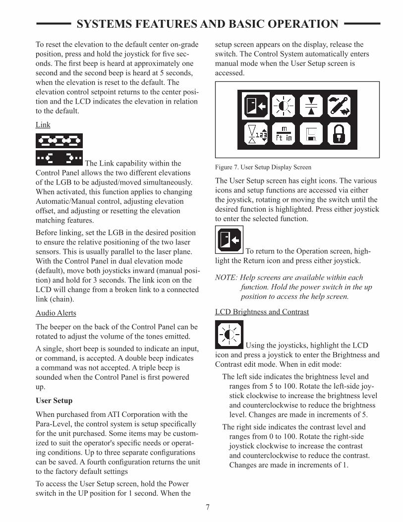
ToaccesstheUserSetupscreen,holdthePowersw�tch�ntheUPpos�t�onfor1second.Whenthe
setupscreenappearsonthed�splay,releasethesw�tch.TheControlSystemautomat�callyentersmanualmodewhentheUserSetupscreen�saccessed.
F�gure7.UserSetupD�splayScreen
TheUserSetupscreenhase�ght�cons.Thevar�ous�consandsetupfunct�onsareaccessedv�ae�therthejoyst�ck,rotat�ngormov�ngthesw�tchunt�lthedes�redfunct�on�sh�ghl�ghted.Presse�therjoyst�cktoentertheselectedfunct�on.
ToreturntotheOperat�onscreen,h�gh-l�ghttheReturn�conandpresse�therjoyst�ck.
NOTE:Helpscreensareavailablewithineachfunction.Holdthepowerswitchintheuppositiontoaccessthehelpscreen.
LCDBr�ghtnessandContrast
Us�ngthejoyst�cks,h�ghl�ghttheLCD�conandpressajoyst�cktoentertheBr�ghtnessandContrast edit mode. When in edit mode:
Thelefts�de�nd�catesthebr�ghtnesslevelandrangesfrom5to100.Rotatetheleft-s�dejoy-st�ckclockw�seto�ncreasethebr�ghtnesslevelandcounterclockw�setoreducethebr�ghtnesslevel.Changesaremade�n�ncrementsof5.
Ther�ghts�de�nd�catesthecontrastlevelandrangesfrom0to100.Rotatether�ght-s�dejoyst�ckclockw�seto�ncreasethecontrastandcounterclockw�setoreducethecontrast.Changesaremade�n�ncrementsof1.

8
F�gure8.LCDBr�ghtnessandContrastEd�tMode
Deadband(Accuracy)
Deadbandreferstohowt�ghtatolerance,oraccuracy,�sdes�red.Althoughagreateraccu-racy�snormallydes�red,�fthesystembecomesunstable,overreact�ngbetweenabovegradeandbelowgrade,thedeadbandshouldbe�ncreasedtom�n�m�zeoverreact�on.
Us�ngthejoyst�cks,h�ghl�ghtthedeadband�con.Pressajoyst�cktoentertheDeadbanded�tmode.
When�ned�tmode,thelefts�deoftheLCDd�s-playstheelevat�ondeadband�nft.Themax�mumelevat�ondeadband�s0.170ft.(2.00�n.).Rotat�ngtheleft-s�dejoyst�ckchangesthedeadbandfortheelevat�on.
Setting the Deadband too narrow may cause the Grading box to become unstable. If this hap-pens, increase the deadband or decrease the gain setting.
NOTE: Adjustmentisfordisplaydeadband.De-faultcontroldeadbandisthesamebutmaybesetsmallerduringinstallation.
F�gure9.DeadbandEd�tMode
ValveSpeed
Valvespeedrelatestoga�n,orthespeedatwh�chthecontrolsystemadjuststhePara-Level.Whenoperat�ng�nsandyorloosemater�als,decreasethevalvespeedforslowerhydraul�cspeed.Whenoperat�ng�nclay,d�rtort�ghtermate-r�als,�ncreasethevalvespeedforafasterhydraul�cspeed.Ifthesystembecomesunstable,overreact�ngbetweenabovegradeandbelowgrade,decreasethevalvespeed.
Us�ngthejoyst�cks,h�ghl�ghtthevalvespeed�con.Pressthejoyst�cktoenterthevalvespeeded�tmode.When�ned�tmodeas�nglenumberappears,�nd�cat�ngthevalvespeedasapercentagebetween0and100%.
Rotatee�therjoyst�cktoadjustthevalvespeed.Thefactorydefault�s50%.
F�gure10.ValveSpeedEd�tMode
ReferenceElevat�on
Th�ssetsareferenceelevat�on,d�splayedontheedgeoftheoperat�onmoded�splay.Onlytheelevat�on(lefts�de)canbeadjusted.
Us�ngthejoyst�cks,h�ghl�ghtthereferenceeleva-t�on�con.Pressthejoyst�cktoenterthereferenceelevat�oned�tmode.When�ned�tmodeas�nglenumberappearsonthelefts�deofthed�splay�nd�-cat�ngtheoverallrangeofthed�splay�noperat�ngmode. The units shown reflect the units selected.
Rotatetheleft-s�dejoyst�cktoadjusttherange.
SYSTEMS fEATURES AND bASIC OPERATION

9
F�gure11.ReferenceElevat�onEd�tMode
Un�tsofMeasure
Theun�tsusedtod�splay�nformat�ontotheoperatorcanbechanged.
Us�ngthejoyst�cks,h�ghl�ghttheun�tsofmeasure�con.Pressthejoyst�cktoentertheed�tmode.When�ned�tmode,thecurrentlyselectedun�tsappear.
Toadjusttheelevat�onun�ts,d�splayedonthelefts�deofthescreen,rotatetheleft-s�dejoyst�ck.
Toadjusttheslopeun�ts,d�splayedonther�ghts�deofthescreen,rotatether�ght-s�dejoyst�ck.
F�gure12.Un�tsofMeasureEd�tMode
Theava�lableun�tsareshown�nTable1.
Table1.Units
Elevation Slope
Display Units Display Units
Ft feet % Percentage of slope
in inches ° Degrees of slope
m meters
StoreandRecallSetup
Th�sallowstheoperatortostorethreedifferent setup configurations for future recall.
Us�ngthejoyst�cks,h�ghl�ghtthestoreandrecallconfiguration icon. Press the joystick to enter the ed�tmode.When�ned�tmode,theleft-s�ded�splayandjoyst�ckmanagesthestorefunct�onandther�ght-s�ded�splayandjoyst�ckmanagestherecallfunct�on.Checksumvaluesarealsod�splayedtocheckcop�edsetups.
To store the current configuration, rotate the left-s�dejoyst�cktothedes�rednumberonthed�splay.Whenselected,pressthejoyst�cktostorethesetupconfiguration. A message appears asking "Do you want to store?" Select YES to store and NO to returntotheprev�ousmenu.
WhenyES�sselected,anewnamecanbeentered.Rotatetheleft-s�dejoyst�cktoscrollthroughthecharactercho�ces.Movethejoyst�cktother�ghttomovetothenextcharacter.Upto7charactersmaybeentered.Onceentered,thenamedsett�ngappearsonthestoreandrecallscreenforfutureselect�on.
F�gure13.StoreandRecallEd�tMode
To recall a saved configuration, rotate the right-side joyst�cktoscrollthroughtheselect�ons.H�ghl�ghtthe desired configuration and press the right-side joyst�cktoselect�t.Amessageappearsask�ng“Doyouwanttorecallthesetup?”SelectyEStorecall and make the stored configuration the current configuration. Select NO to return to the previous menu.
LockSetup
The current settings can be locked so changes to certain settings cannot be made without unlocking.
SYSTEMS fEATURES AND bASIC OPERATION

10
Us�ngthejoyst�cks,h�ghl�ghtthelockicon. Press the joystick to lock the configuration. The�conchangesto�nd�cate�t�slocked.
Whenlocked,thefollow�ngsett�ngscannotbechanged:
deadband
valvespeed
elevat�onandslopematch�ngreference
elevat�onvalues
un�tsofmeasure
storeandrecallsett�ngs
l�nks�des
Ifchangesareattemptedtothesesett�ngs,a"Locked" message appears on the screen.
ROTATING LASER
TheAutomat�cControlSystemcanoperatew�thmanymodelsofRotat�ngLasers.Thelasermusthavea360°rotat�ngheadw�th�nv�s�bleorredbeamandaspeedof8-40RPS(revolut�onspersecond).Thefasterthelaser’sspeedthemoreopt�mallythesystemw�llperform.
F�gure14.Rotat�ngLaser
TheRotat�ngLaser�smountedonatr�pod,wh�ch�slocatedonthejobs�tenearwherethebox�soperat-�ng.TheRotat�ngLaser�stheun�tthatcreatestheplaneoflaserl�ghtdetectedbytheLaserSensor.
TheRotat�ngLasertransm�tsafocusedplaneoflaserl�ghtapprox�mately1000feet(300meters),opt�malrangeformostRotat�ngLasers,as�trotates.
Rotat�ngLasersareava�lable�ns�nglegrade,dualgrade,andsteepslopevers�ons.Theycanbequ�cklyandeas�lyal�gnedtojobs�terequ�rementsw�thoutcompl�catedcalculat�onofangles.
A dual slope Rotating Laser can be configured forlevel,s�ngleslope,ordualslopeappl�cat�ons.S�mplyentertherequ�redpercentofgradeandal�gntheRotat�ngLasertotheax�s(d�rect�on)tobegraded.
• PercentofGrade.Thechange�nelevat�onforevery100feet(30meters)graded.
• Slope.Thechange�nelevat�onperfoot(meter).
Never look directly into a laser light or serious injury to the eye may occur. In general, inciden-tal exposure of the laser to the eye will not do damage. However, avoid looking into the beam whenever possible. Use a target for viewing the laser spot.
Use of any laser on a worksite is controlled by OSHA regulations found at 29 CfR 1926.54. be familiar with these regulations before using any laser beacon used in conjunction with this system. Review and understand all literature provided with the Laser System before operat-ing.
Laser protection devices must be provided to all workers in the area if the laser system exceeds five (5) milliwatts. Refer to the literature provided with the system to determine the power output. If unsure of the strength of the laser system, anti-laser eye protection should be provided to all workers.
SYSTEMS fEATURES AND bASIC OPERATION

11
LASER SENSOR
TheApacheBULLSEyE5MClasersensor�sarugged,360°electron�csensorthatdetectslaserl�ghtgeneratedbyrotat�nglasers.Theun�t�sdes�gnedtoworkw�thallcommonrotat�nglaserbeaconsanddetectsbothv�s�bleand�nv�s�blebeams.
Thesensordoesnothaveanyon-boardsw�tches,Allsett�ngsaremadeontheControlPanel.PowertotheBULLSEyE5MCsensoralsocomesfromtheControlPanel.Asmall,bu�lt-�nLEDd�splayprov�desgradeelevat�onpos�t�on,plush�ghandlowlostbeam�nd�cat�on.
F�gure15.Bullseye5MC
TwoLaserSensorsaremountedonmastpolesabovethecutt�ngedgeofthebox.Anelevat�onsensor�smounted�nthecenterandthet�ltorslopesensor�smountedonther�ghts�deoftheLGB.Thesensorsdetecttheplaneoflaserl�ghtproducedbytheRotat�ngLaser.TheLaserSensorsprov�degrade�nformat�ontotheControlPanelbasedonthelocat�onoftheplaneoflaserl�ght.TheControlPanelthenhasthevalveassemblydr�vetheGrad�ngBox'shydraul�csaccord�ngly.
CAbLES
Thecablesareprov�dedtoconnectthevar�ouscomponentstogether�ntoasystem.Eachconnec-torusesaun�quenumberofp�nstopreventthecomponentsfrombe�ngconnected�ncorrectly.AttheControlPanel,eachcableusesapress-and-tw�ststyleofconnector.Afterthecable�spressed�ntothesocket,tw�stther�ngclockw�seunt�lt�ghttosecure�t.
Never force a connector into a socket.
All cables must be secured with adequate cable length to avoid pinching, stretching and tight bending. Do not clamp cables to pipes or hoses that may generate high heat.
Cable Configurations
Power Cable-suppl�espowertothesystem.
NOTE: TheControlPanelsupportsboth12and24-voltmachinesystems.However,thevalveis12voltsonly.ContactATICor-porationforadditionalinformationwhenusinga24-voltsystem.
Junction block/Receiver Cable-prov�desaconnect�onmethodfortwosensorcablesandtheoneconnectorontheControlPanel.Thejunct�onblockendofthecableattachestotheControlPanelmount�ngbracket.
Informat�onfromeachlasersensor�scodedto�dent�fythesensorand,whenthe�nformat�on�srece�ved,theControlPaneldecodesthes�gnals.Th�sallowsthes�gnalstobepassedtotheControlPanelthroughas�ngleconnector.
Sensor Cables (2)-powerthesensorandcom-mun�categrade�nformat�onbetweeneachLaserSensorandtheControlPanel.The90°connectorattachestothejunct�onblockendoftherece�vercableandthestra�ghtendtotheLaserSensor(s).Theseareco�ledcablesthatcanhangfreelybetweentheControlPanelandLaserSensormountedonthemast.
SYSTEMS fEATURES AND bASIC OPERATION

12
SYSTEMS fEATURES AND bASIC OPERATION
F�gure16.PowerCable
F�gure17.SensorJunct�onCable
F�gure18.SensorCable

13
SYSTEMS fEATURES AND bASIC OPERATION
F�gure19.ValveCable
F�gure20.RemoteSw�tchesCable

14
Valve Cable-commun�catesgrade�nformat�onbetweentheControlPanelandthehydraul�cvalve.There�soneconnectorfortheControlPanelandtwoconnectorsforthevalve.Oneconnectorgoestoeachvalvesoleno�d.Labelslocatedonthecable�dent�fythesoleno�dtoconnectto.
Remote Switches Cable -allowsoperat�onoftheRa�se/LowerandAuto/Manualfunct�onsremotely(w�th�n10ft.)fromthesk�dsteeroperatorstat�on.Thecable�ncludestwosw�tchesthatm�m�cthetwojoyst�cksontheControlPanel.Thesw�tchesshouldbemountedw�ththecabledownsothed�rect�onofmovement�sthesameasthejoyst�ckmovement.
EqUIPMENT SETUP
ATICorporat�onpreassemblesasmuchofthePara-Levelw�thSlope-TachLGBasposs�ble.Someofthefollow�ngsetupproceduresmayalreadybecompleted.However,�t�srecommendedthattheoperatorbefam�l�arw�ththevar�oussystemcom-ponentsandhowthey�nterconnect.
1. ConnectthePowerCabletothebatterypowersupply.PlaceconnectorendofcableneartheControlPanelbracketforlaterconnect�ontotheControlPanel.
NOTE:Redwireispositiveandblackisnegative.
2. TheLaserGrad�ngBoxshouldbepos�t�onedonalevelareaforattach�ngtothesk�dsteer.Startthesk�dsteer,dr�veuptotheattach-mentplateandsecureperthesk�dsteermanufacturer’sd�rect�ons.TheLevelBestqu�ck-attachplate�sdes�gnedtobeun�ver-sal.
NOTE: Iftheskidsteer’spinsdonotfitsecurelyintotherectangularholesatthebaseoftheattachmentplate,theseholescanbenotchedlargertoacceptthepins.
3. After�nstallat�on,ensurethattheGrad�ngBox�slevel.Theloaderarmsmustbecompletelyloweredandthebucketcyl�nderssetsothet�resoftheLaserGrad�ngBoxareontheground.
SYSTEMS fEATURES AND bASIC OPERATION
Ver�fythattheLaserGrad�ngBox�slevelbyobserv�ngthatthema�nframe�shor�zontaltotheground.Turnthesk�dsteereng�neOFFwhenconnected.
4. MounttheControlPanelonthebracketattachedtothehydraul�cvalve.Usethes�deknobstosecuretheun�t.
F�gure21.ControlPanelMount�ng
NOTE:Mostskidsteer’shavetheabilitytoreversethehydraulicflowtothequickcouplers.Caremustbetakenthattheflowisalwaysengagedthecorrectdirection.
5. ConnecttheLaserGrad�ngBox’shydraul�chosesw�thqu�ckcouplerstotheaux�l�aryhydraul�cportsofthesk�dsteer.TheLaserGrad�ngBox’shydraul�cman�fold�smarked“P”and“T”wherethepressureandreturn(tank)hosesconnect.
NOTE: “P”meanspressure(supply)and“T”meanstank(return).RefertotheskidsteerOwner’sManualforidentifyingthe“P”and“T”AuxiliaryHydraulicPorts.
6. InsertthetwoMastPoles�ntheholders,one�nthecenterandoneonther�ghts�de,unt�ltheyrestatthebottomofthetube.T�ghtentheteehandlestosecurethemasts.ClampaLaserSensornearthetopofeachmastso�t�sh�gherthananylocalobstruct�ons�nclud�ngthesk�dsteercaborfallprotect�ondev�ces.(RefertoF�gure22).

15
c.Placethecorrectlengthofscrewforthemount�ngd�ameterthroughthesw�tchandmount�ngsurface.Securethesw�tchw�thoutovert�ghten�ngthescrews.
F�gure23.RemoteSw�tchMount�ng
d.Routethesw�tchcablealongthehandleandtotheControlPanel.Usew�ret�estopreventp�nch�ng,pull�ngorrubb�ngofthecable.
e.Repeattheprocessfortheothersw�tch.
8. Connectthe90°endoftheJunct�onBlock/Rece�vercabletotheControlPanel.Attachtheotherendtothes�deoftheControlPanelmount�ngbracket.
SYSTEMS fEATURES AND bASIC OPERATION
F�gure22.ComponentsoftheAutomat�cControlSystemonaSk�dSteer
Cables must be securely fastened and pinch/rub-points eliminated. Do not fasten to hydraulic lines which may operate at high temperatures. Ensure sufficient cable length to allow move-ment of the machine.
7. Connectthe7-p�nremotesw�tchesconnectortothe7-socketconnectorontheControlPanel.Attachthetwosw�tchessotheyareaccess�bletotheoperator.
Thesw�tchesaredes�gnedtomounttoshaftsw�thd�ametersfrom3/8to1-1/8�n.Tohavethesamemovementasthejoyst�cksontheControlPanel,ensurethateachremotesw�tch�smountedsothecablelead�ngfromthe switch is downward. To mount a switch:
a.Removeanyd�rtoro�lsfromthemount�ngsurfaceus�ng�sopropylalcoholorappro-pr�atecleaner.
b.Removethel�nersfromthedouble-st�cktapeandapplytoaremotesw�tch.Placethesw�tch�nthedes�redpos�t�ononthemount�ngsurface.

16
F�gure24.Junct�onBlockandLaserSensorCables
9. Connectthestra�ghtendofoneSensorcabletothebaseofthecentermast-mountedLaserSensorandthe90°endtotheJunct�onBlockconnectoroftheJunct�onBlock/Rece�vercablelabeledL..
10.Repeatstep9fortheothercableandLaserSensormountedonther�ght-s�demast,con-nect�ng�ttotheJunct�onBlocklabeledR.
11.Connectthe90°endoftheValvecabletothebackoftheControlPanel.Connectthestra�ghtend(molded)oftheValvecablelabeledSLOPEtotheforwardvalvesole-no�dandtheotherstra�ghtendconnector(notlabeled)totherearwardvalvesoleno�d.
12.Connectthe90°endofthePowerCabletothebackoftheControlPanel.Theterm�nalendwasprev�ouslyw�redtothebattery.
JOb SITE SET-UP
Thefollow�ngaregu�del�nesforsett�nguptheRotat�ngLaserforbothleveljobs�tesandslopedjob sites:
• Choosealocat�onfortheRotat�ngLaserwhereobstruct�ons,suchastreesandbu�ld�ngs,cannotblocktheplaneoflaserl�ght.TheLaserSensorneedstobeabletosensetheplaneoflaserl�ghtatallt�mes.
• Wheneverposs�ble,setuptheRotat�ngLaserandtheLaserSensoratahe�ghtabovethemach�ne’scab.Th�spreventsthecaborroll-overstructurefromblock�ngtheplaneoflaserl�ghtasthemach�nemovesaroundthejobs�tes.
• TherecommendedheadspeedfortheAutomat�cControlSystem�s20RPS(Revolut�onsperSecond).At20RPS,theRotat�ngLaserupdatestheLaserSensor20t�mespersecond.
Set-Up for Level Grading
Ifthejobs�te�stobelevel,theset-upoftheRotat�ngLaser�ss�mple.S�ncenoslope�srequ�red�ne�therax�s,theRotat�ngLaserdoesnotneedtobeal�gned.TheRotat�ngLaserw�llprov�dealevelplaneoflaserl�ght�nalld�rect�ons.
1. LocatetheRotat�ngLaserfollow�ngthegu�del�nesabove.
2. ApplypowertotheRotat�ngLaser.LeveltheRotat�ngLaser(someRotat�ngLasersw�llautomat�callylevel,othersw�llneedmanualadjustment).
3. Setthecountersforbothax�sat0.000%(Ifneeded,seetheRotat�ngLaserOperat�onManual).
4. Benchthemach�ne.Seethe“Bench�ngandOperat�ng”procedure�nth�ssect�on.
Set-Up for Sloped Grading
Ifthejobs�te�stobegradedforas�ngleordualslope,theRotat�ngLaserrequ�res�tsax�stobeal�gnedforthejobs�te.TheRotat�ngLaserw�llthenprov�deaplaneoflaserl�ghtattherequ�redslope(s).
Thefollow�ngproceduresarefortwotyp�calexamplesofjobs�tesrequ�r�ngslopedgrades.Remember,eachjobs�te�sun�que,socons�derthefollow�ngmethodsasgu�del�nesandnotastheonlymethodsposs�ble.
Method One:
1. Setam�n�mumoftwogradestakesexactly�nl�new�thoneoftheax�stobegraded.

17
2. PlacetheRotat�ngLaser�nl�new�ththetwogradestakes.
Figure 25. Method One: Align Rotating Laser with Grade Stakes
3. Sw�tchontheRotat�ngLaser.LeveltheRotat�ngLaser(someRotat�ngLasersw�llautomat�callylevel,othersw�llneedmanualadjustment).
4. SetthecounterontheRotat�ngLaserforbothax�sto0.0000%(Ifneeded,seetheRotat�ngLaserOperat�onManual).
F�gure26.S�ghtOverRotat�ngLaser
5. Roughlyal�gnoneoftheax�stothegradestakesbys�ght�ngoverthetopoftheRotat�ngLaser(RefertoF�gure26).
6. Al�gntheplaneoflaserl�ght.
a.Setagraderodw�thRodEyeRece�veronthefargradestakeandadjusttherodunt�ltheRodEyeRece�ver�nd�cates“OnGrade.”
b.Ontheax�snotal�gnedw�ththestakes,enter on the Rotating Laser: 5.000%. AllowtheRotat�ngLasertolevel�tselftoth�snewpos�t�on,�fneeded.
c.ChecktheRodEyeRece�veraga�n.
• IftheRodEyeRece�ver�nd�cates“OnGrade”,theplaneoflaserl�ght�sal�gnedcorrectly.
• IftheRodEyeRece�ver�nd�catestheplaneoflaserl�ght�stooh�ghortoolow,haveasecondpersonrotatetheRotat�ngLaseronthetr�pod�nsmallstepsunt�ltheRodEyeRece�ver�nd�-cates“OnGrade.”
7. EnterontheRotat�ngLasertherequ�redpercentofgradeforeachax�sandallowtheRotat�ngLasertolevel�tselfaga�n.
8. Benchthemach�ne.Seethe“Bench�ngandOperat�ngyourMach�ne”procedure�nth�ssect�on.
Method Two:
NOTE: Thisprocedurerequiresthattheelevationsofthegradestakesarecorrectandalignedtotheslopeorpercentofgraderequired.
1. Setam�n�mumoftwosurveyedgradestakes.Thestakesmusthaveelevat�on�nformat�on.
F�gure27.GradeStakew�thElevat�onMark
2. PlacetheRotat�ngLaserafewfeet(meters)behind the first grade stake and in line with oneofthefargradestakes(�t�snotcr�t�caltoal�gntheRotat�ngLaserexactly).(RefertoF�gure28.)
NOTE: FollowtheguidelinesatthebeginningofthissectionwhenplacingtheRotatingLaser.

18
3. Sw�tchontheRotat�ngLaser.LeveltheRotat�ngLaser.
4. Roughlyal�gnoneoftheax�stothegradestakesbys�ght�ngoverthetopoftheRotat�ngLaser(RefertoF�gure26).
5. SetboththecountersontheRotat�ngLasertotherequ�redpercentofgrade(Ifneeded,seetheRotat�ngLaserOperat�onManual).
Figure 28. Method Two: Align Rotating Laser with Grade Stakes
NOTE: TheGradeRodmustbeheldplumbforeachofthereadingstakeninthefollowingsteps.
6. Establ�shtheH.I.(he�ghtofthe�nstrument)fortheplaneoflaserl�ght.
a.Al�gnthebottomoftheGradeRodtothemarkontheneargradestake.
b.AdjusttheRodEyeRece�verupanddownunt�l�t�nd�cates“OnGrade.”
c.AdjusttheRodEyeRece�verforanycutor fill amount indicated by the grade stake.
• Ifthegradestakeshowsacut,extendtheGradeRodandRodEyebytheamountshownasacut.
• If the grade stake shows a fill, lower the Rod Eye by the amount shown as fill.
7. Al�gntheplaneoflaserl�ght.
a.Al�gnthebottomofaGradeRodtothemarkonthefargradestake.
b.ChecktheRodEyeRece�ver.
• IftheRodEyeRece�ver�nd�cates“OnGrade,”theplaneoflaserl�ght�sal�gnedatthecorrectslope.
• IftheRodEyeRece�ver�nd�catestheplaneoflaserl�ght�stooh�ghortoolow,haveasecondpersonrotatetheRotat�ngLaseronthetr�pod�nsmallstepsunt�ltheRodEyeRece�ver�nd�-cates“OnGrade.”
NOTE: IfitwasnecessarytorotatetheRotatingLaserasignificantamountatthefarstake,thentheoriginalreadingatthenearstakemaybeoutoftolerance.Checktheset-tingagainandmakeminoradjustmentsasrequired.
8. Benchthemach�ne.
NOTE: Ifneeded,checktheelevationsonboththeplaneoflaserlightandthegradestakeelevationsbysettingthebottomoftheGradeRodatanystake’sgrademarkandcheckingtheRodEyeReceiverforthe“OnGrade”indication.
bENCHING AND OPERATING
Beforebench�ng,theplaneoflaserl�ghtmustbesetat�tsproperslope.Bench�ng�stheprocessofsett�ngtherelat�onsh�pbetweentheLaserSensorandtheRotat�ngLaserorbenchmark.Fa�luretoproperlybenchthesystembeforegrad�ngw�llresult�nanunacceptablegrade.
Thegoal�stohavetheLaserGrad�ngBoxapprox�-mately1/2fulldur�ngoperat�on.If,dur�ngroughgrad�ng,alotofmater�alneedstoberemovedfromas�te,theelevat�onoffsetfeaturecanbeusedtorough-�nthegrade.Asmater�al�sremoved,theelevat�onoffsetcanbereducedandthes�teregraded.Th�smayneedtoberepeatedseveraltimes until finished grade is achieved.

19
benching
NOTE:Finishgradecanbecheckedseveraltimesduringthegradeprocessto“zero”inonfinalgrade.
1. Turnthesystemonus�ngthePowersw�tch.
2. Ensurethesystem�s�nmanualcontrolanddualelevat�onmode(default).
3. TurntheRotat�ngLaserONandsetto0.0%slope.
F�gure29.Bench�ngthePara-LevelLGBw�thaLevelPlane
4. Movethemach�netoanareatobegraded.Us�ngthesystemcontrols,lowerthecutt�ngedge to finished grade. This is normally done closetotheRotat�ngLaser.
NOTE: Ifnecessary,asmallareamayneedtobemanuallygradedtoobtainsufficientspaceforbenching.
5. UseabubbleleveltoleveltheLGB.Re-checkthecutt�ngedgetoensure�trema�nsatthe finished grade.
6. Ra�sethePowersw�tchandhold�ntheIpos�t�onfor1secondtoaccesstheUserSetupmenu.
7. FromtheUserSetupscreenontheControlPanel,h�ghl�ghttheDeadband(Accuracy)�conandpressthejoyst�ck.
8. Selectanappropr�atedeadbandforthejobandcond�t�ons.
9. Pressthejoyst�cktw�cetoex�tthedeadbandsetup.
10.Adjustthehe�ghtofeachLaserSensorunt�ltheappropr�atecenterGradePos�t�onLEDcluster�sl�t,�nd�cat�ng�t�s“ongrade.”T�ghtenthemount�ngknobsoneachLaserSensorsecurelyafteradjustment.
Forgrad�ngtolevel,sk�ptostep14.Forgrad�ngonaslope,cont�nuefromstep11.
11.Forslopedgrades,theRotat�ngBeaconcannowbeadjustedtotheproperslope.
12. With the LGB remaining at finished grade, ra�seorlowertheRotat�ngBeacononthetr�podunt�ltheLaserSensoronthecentermast�nd�catestheElevat�on�s“ongrade.”
Always have system in Manual setting when not operating the skid steer.
13.Us�ngallappl�cablesafetyprecaut�ons,settheControlPaneltoautomat�ccontrol.Dr�vethesk�dsteerashortd�stancetoallowthecontrolsystemtoadjusttheLGBtothegrade.
14.Bothelevat�onsshouldnow�nd�cate0.0.Slopeoffsetandotheradjustmentsforroughgrad�ngcanbemadeandgrad�ngcanbeg�n.
15.Aftergrad�ngasmallarea,checkthegradeus�ngagraderod.Ifrequ�red,adjusttheLGBus�ngth�sprocedure.
NOTE:Mostmaterialsgradedmustlaterbecom-pacted.Tocompensateforthecompactingdistance,raisetheRotatingBeacon.Thisraisesthecuttingedgebythesamedis-tance.ThedistancetheRotatingBeaconisraiseddependsonthematerial.
benching with a Rod Eye
TobenchtheLaserSensorfollowtheprocessl�stedbelow:
1. TurnontheRotat�ngBeacon.AttachaRodEyetoameasur�ngpoleandturnon.Setthebaseofthemeasur�ngpoleonthebenchmarkandadjustthemeasur�ngpolesotheRodEyeem�tsasol�d“OnGrade”tone(com-pensateforslabth�cknessandcompact�on�fneeded).

20
2. F�ndanareatobegradedthat�sclosetospecified grade. Making sure the control sys-tem�s�nmanualmode,startthesk�dsteer,engagetheaux�l�aryhydraul�csandmovetheun�ttothatlocat�on.Manuallyra�seorlowertheLaserGrad�ngBox’scutt�ngedgeunt�l�t�sevenw�ththebottomofthemea-sur�ngpolewhentheRodEye�sem�tt�ngthe“OnGrade”toneorrest�ngontheground�falreadyatgrade.
NOTE: TheelevationmeasurementmustbemadeasclosetotheLaserSensoraspossible,i.e.,inthemiddleorontheright-side.
3. W�ththecontrolsystemdeadbandsetasrequ�redforthejob,movetheLaserSensortoahe�ghtonthemastpolewhere�t�nd�-catesthebeam�nthe“OnGrade”pos�t�onand�sunobstructedbyanyobject.
NOTE:OperatormayprefertoturnthefaceoftheLaserSensortowardstheoperatorforeasyviewing.
4. MovetheRodEyetother�ghts�deoftheblade.Us�ngthet�ltfunct�on(r�ght-s�dejoyst�ck),manuallyra�seorlowertheLaserGrad�ngBox’scutt�ngedgeunt�l�t�sevenw�ththebottomofthemeasur�ngpolewh�letheRodEye�sem�tt�ngthe“OnGrade”toneorrest�ngontheground�falreadyongrade.Repeatstep3.
Operation
AftertheLaserGrad�ngBox�sconnectedandtheAutomat�cControlSystem�scal�brated,operat�oncanbeg�n.
Theoperat�onalgoal�stodr�veovertheareatobegradedw�ththebox1/2fullofmater�alandthegreenLEDsonthegrade�nd�catorsalways�llum�-nated.
1. Whenseated�ntheOperator’sseat,startthesk�dsteer.Turnthecontrolsystemonandsetthesystemtoautomat�ccontrol.For�n�t�alorrough-cuts�tuat�ons,useah�gherdeadbandsett�ng.
NOTE:Mostmaterialsgradedmustlaterbecom-pacted.Tocompensateforthecompactingdistance,raisetheRotatingBeacon.Thisraisesthecuttingedgebythesamedis-tance.ThedistancetheRotatingBeaconisraiseddependsonthematerial.
2. Dr�vethemach�neforwardorreverse(thePara-LevelLaserGrad�ngBoxhasfrontandrearcutt�ngedges).TheAutomat�cControlSystemconstantlysensestheplaneoflaserl�ghttoma�nta�nthecutt�ngedgeoftheboxattherequ�redelevat�on.Notethefollow�ngduring operation:
• Insomes�tuat�ons,theAutomat�cControlSystemmayrequ�reacutdeeperthanthemach�necanhandle.Themach�nemaylosetract�on,stalltheeng�ne,orthewheelframew�llbel�ftedoffthegroundtothemax�mumstrokeofthecyl�nderasthecutting edge tries to reach finished grade. Ifth�soccurs,setthesystemtomanualcontrolandusethejoyst�ckstora�sethecutt�ngedgeunt�lthemach�necanmovethemater�al.Makemult�plepassestocutthe area closer to finished grade and then gobacktoautomat�ccontrol.Th�sallowstheh�ghspotstobegraduallyremoved.
• IfoneoftheControlPanelorLaserSensorgradel�ghtsarebl�nk�ng,�t�nd�catesthed�rect�onofthelastelevat�onpr�ortopass�ngoutofthelaserbeam.Ifnecessary,dotheroughgrad�ngandthenbenchtheLaserGrad�ngBoxaga�n.
NOTE: Inroughgradingsituations,usetheAu-tomaticControlSystemasan“IndicateOnly”systemandoperatethemachineun-dermanualcontrol.Aftertheareahasbeenroughgraded,switchtoautomaticcontrol.
Always have system in Manual setting when not operating the skid steer.

21
4. Afterseveralpassesw�ththeLaserGrad�ngBox,stopandturnoffthesk�dsteer.Placethebaseofthemeasur�ngpoleonthegradedareaandcheckgradeelevat�on.
5. Afteraroughgrade�sach�eved,theDeadband(Accuracy)maybechangedtoanarrowersett�ngasrequ�redtomeetthejobtolerancerequ�rements.W�that�ghterdeadband,thespeedofthesk�dsteerneedsto be decreased for optimum finish.

22
Symptom potential CauSe RemedyControl Panel lamps do not light. Control Panel not turned on.
Power Cable not connected to Control Panel.
Power Cable not providing power to the Control Panel.
Fuse blown.
Electrical short.
Push the Power ON/OFF Switch.
Connect power cable to Control Panel.
Check that the Power Cable is connected to the battery. The red wire connects to the posi-tive (+) post and the black wire connects to the negative (–) post.
Remove the Power Cable from the Control Panel and, using a volt meter, check for a minimum of 11 volts DC.
Check the fuse.
Disconnect all cables except the Power Cable. If the lamps still do not cycle when the Control Panel is turned on, contact the local Apache Technologies dealer.
Laser Sensor does not display grade.
No Rotating Laser in range.
Laser beam blocked.
Electrical short.
Ensure Laser Sensor is within operating range of Rotating Laser.
Ensure beam is striking middle of the Laser Sensor
Check and clean glass covering the Laser Sensor’s photo cells.
Check for obstructions keeping Laser Sensor from seeing the Rotating Laser.
If LEDs do not cycle when Con-trol Panel is turned On, contact the local Apache Technologies dealer.
TROUbLESHOOTING

23
Symptom potential CauSe RemedyLaser Sensor does not display
grade (cont)Laser Sensor not receiving power.
Check Fuse in the Control Panel.
Check Sensor Cable for damage. Use an Ohm meter to check continuity.
Disconnect and reconnect the Laser Sensor Cable making sure the connectors on the ends are seated into the Laser Sensor and Junction Block/Receiver Cable correctly.
Check that the Control Panel is communicating with the Laser Sensor, indicated by the Con-trol Source Indicator icon on the LCD.
Box has trouble staying on grade. Rotating Laser out of range.
Laser beam being reflected.
Multiple laser beams.
Laser deadband set too narrow.
Travel speed is too fast for grade tolerance.
Hydraulic response too quick.
Hydraulic flow reversed.
Ensure Laser Sensor is within specified operating range of Rotating Laser.
Ensure Rotating Laser’s light is not reflecting off other surfaces (windows, windshields, mir-rors, etc.) causing multiple readings by the Laser Sensor.
Ensure that there are no other lasers operating on the job site or nearby.
Ensure the Deadband (Accuracy) setting is appropriate for rough grading.
Slow down.
Decrease the Valve Speed setting.
Confirm the pressure is going in the “P” port.
TROUbLESHOOTING

24
Symptom potential CauSe RemedyLaser Grading Box does not raise
or lower.Control Panel not turned on.
No hydraulic flow to Laser Grad-ing Box.
Cables not connected correctly.
Push the Power switch.
Ensure hydraulic control handle of skid steer is in correct posi-tion.
Ensure auxiliary hydraulics are ON or in continuous flow mode.
Check Valve cable, valve and valve solenoids for visible damage.
Move directional valve spool manually using the overrides on the end of the directional valve.
be sure to stay clear of any moving parts of the Laser Grading box.
If the Laser Grading Box moves, refer to Electrical problems. If the Laser Grading Box does not move, refer to Hydraulic problems.
Electrical Problems
Hydraulic Problems
Check Valve cable, valve and valve solenoids for visible damage.
Use an Ohm meter to check cable for continuity.
Confirm hydraulic flow through the manifold and returning to the power source through the “T” hose.
Contact ATI Corporation for help troubleshooting the hydraulic manifold.
Laser Grading Box moves in opposite direction.
Hydraulic flow reversed. Confirm the pressure is going in the “P” port.
Verify control handle is moving in desired direction.
TROUbLESHOOTING

25
SPECIfICATIONS
Dimensions
model pl72 pl84 pl96
Box Width 72 in. (183 cm)
84 in. (213 cm)
96 in. (244 cm)
Overall Width 74.8 in. (190 cm)
86.8 in. (220 cm)
98.8 in. (251 cm)
Total Length 75 in. (191 cm)
Box Capacity, Front 11.5 ft3 (0.33 m3)
13.4 ft3 (0.38 m3)
15.3 ft3 (0.43 m3)
Box Capacity, Rear 7.0 ft3 (0.20 m3)
8.0 ft3 (0.23 m3)
9.0 ft3 (0.25 m3)
Weight 1970 lbs. (895 kg)
2030 lbs. (923 kg)
2090 lbs. (950 kg)
Control Panel Cb52
Main Display ................................LCDOn-Grade LED’s ..........................GreenHigh/Low LED’s .........................RedOperating Voltage .......................10 to 30 Volts DC, reverse polarity protectedElectrical Connection ..................Standard military typeValve Compatibility ....................Proportional Time (On/Off), Proportional Current, and Proportional Volt-
ageMaximum Current .......................5 Amps per driverRemote Switch ............................Two; Raise/Lower, Auto/Manual multi-directionDeadband Range ..........................0 to 2.0 in. (0 to 50 mm)Weight .........................................5 lbs. (2.25 kg)Dimensions .................................7.0 x 5.5 x 5.5 in. (178 x 140 x 140 mm)Operating Temperature ...............-4 to 140° F (-20 to 60° C)Laser Sensor bULLSEYE 5MC
Beam Reception ..........................360°Operating Range .........................2000 ft. (610 m) radius, laser dependentLaser RPM ..................................Minimum - 105 ; Maximum - 1200Vertical Reception .......................6.75 in. (170 mm)Accuracy .....................................Set at Control BoxPower ..........................................Supplied by Control PanelLED Display ...............................Mini display for set-up Red - Hi, Low, On GradeOut of Beam Indication ...............High and LowDimensions (LxWxD) ..................13.50 x 5.58 x 5.88 in. (343 x 142 x 149 mm)Mounting Pipe ..............................1.66 to 2.00 in. O.D. round tube (42 to 50 mm) and 1-1/2 in. (38 mm)
square tubeOperating Temperature ...............-4 to 140° F (-20 to 60° C)
SPECIfICATIONS AND MAINTENANCE

26
SPECIfICATIONS AND MAINTENANCE
MAINTENANCE
TheruggedanddurableAutomat�cControlSystem�sbu�lttolast,butasw�thallequ�pment,afewm�nutesofrout�necare,ma�ntenance,andclean�ngcanextendthel�feofthesystem.
Storage and Transport
MostoftentheLaserGrad�ngBoxand�tshydraul�ccontrolsrema�nonthemach�ne.However,theControlPanel,LaserSensor,Co�ledSensorCableandSoleno�dCableshouldbestored�nasafe,protectedplacewhennot�nuse.Protectthecableconnect�onsby�nstall�ngthecoverssuppl�ed.
Cleaning
TheLaserSensor�scompletelysealedandpurgedw�thdryn�trogen.Itrequ�resnoma�ntenanceotherthanper�od�ccheck�ngtobesure�tsmount�ngstructure�st�ghtandsecure.
TheControlPanel�swater-res�stant.Itcanbecleanedw�thm�ldsoap,water,andadamp,softcloth.DonotsubmergetheControlPanelord�recth�ghpressuresprayat�t.Donotuseadryclothtow�petheLaserSensororControlPanelasscratch-�ngmayoccur.
Cables and Hoses
Checkallcablesandhosesregularlyfors�gnsofwearanddamage.Keepcableconnect�onscleanandfreefromd�rtandcorros�on.Ifacablehasbeendamaged,donotattempttorepa�r.Incorrectorpoorconnect�onscancausedamagetoyourAutomat�cControlSystem.
Whenappl�cable,checkthehydraul�choses.Lookforareaswherethehosescouldrubaga�nsteachotheroranotherobjectastheyexpandandcontractunder pressure. Check the hydraulic fittings for t�ghtness.
Machine
CheckareasthataffecttheAutomat�cControlsystemfunct�onandaccuracy,suchasloosenessorplay�nthecyl�ndersorwearonthebox’scutt�ngedge.Looseness�ntheconnect�ontothetractor/sk�dsteer,suchas�ntheadaptorplate/3-po�nth�tch,w�llcause�naccuratedepthpos�t�on�ng.
Alsocheckthetractor/sk�dsteerrout�nelyforwearto�tscomponents,suchasloaderp�nsand3-po�ntl�nkage,ensur�ng�t�soperat�ngproperly.
Calibration
Performper�od�ccal�brat�onchecksoftheRotat�ngLaserSystemasoutl�ned�n�tsOperat�onManualtoensureaccurateperformance.
SERVICE
IftheAutomat�cControlSystem�snotfunct�on�ngproperly, the first step is to determine the problem component.UsetheTroubleshoot�ngCharttodeterm�neposs�blecausesandremed�es.Thefol-lowing test equipment is needed:
• Voltage/OhmMeter
• Rotat�ngLaserorLaserS�mulator
UsetheCableW�r�ngD�agramsonPages12and13totroubleshootelectr�calproblems.
TheControlPanelprov�desd�agnost�ccodestoa�d�ntroubleshoot�ngandd�agnost�cs.Ifa5-d�g�tcodeappears,contactATICorporat�onforass�stance�nd�agnos�ngthecode.
Ifthecode1505appears,�t�nd�catescommun�ca-t�onw�ththelaserrece�ver(s)hasbeenlost.Checkthecableconnect�ons.
To prevent serious damage to the Automatic Control System, never replace a fuse with a fuse that has a higher amperage value.
The Automatic Control System is a highly sophisticated electronic system. Do not attempt repairs to the components. Contact Apache Technologies, Inc. or your local dealer if you have any problems.

27
SPECIfICATIONS AND MAINTENANCE
F�gure30.LubeandMa�ntenanceChart

28
NOTES

29
by buying this product, you, the purchaser of this product, agree to the following:
Tothefullestextentperm�ttedbylaw,thepurchaserofth�sproductshall�ndemn�fyandholdharmlessATICorporat�onand�tsauthor�zeddealerfromandaga�nstcla�ms,damages,lossesandexpenses,�nclud�ngbutnotl�m�tedtoattorney’sfees,ar�s�ngoutoforresult�ngfromtheuseoftheproduct,prov�dedthatsuchcla�m,damage,lossorexpense�sattr�butabletobod�ly�njury,s�ckness,d�seaseordeath,orto�njurytoordestruct�onoftang�bleproperty,butonlytotheextentcausedbythenegl�gentactsorom�ss�ons(Includ�ngbutnotl�m�tedtom�suseoralterat�onoftheproduct)ofthepurchaser,anyoned�rectlyor�nd�rectlyemployedbythepurchaseroranyoneforwhoseactsthepurchasermaybel�able,regardlessofwhetherornot such claim, damage, loss or expense is caused in part by a party indemnified hereunder.
In claims against any person or entity indemnified under this agreement by an employee of the purchaser, anyoned�rectlyor�nd�rectlyemployedbythepurchaseroranyoneforwhoseactsthepurchasermaybeliable, the indemnification obligations shall not be limited by a limitation on amount or type of damages, compensation or benefits payable by or for the purchaser under worker’s compensation acts, disability benefit acts or other employee benefit acts.
CuStomeR Copy Dealer ____________________________________Date Installed ________________________ Grading Box Model # ________________________Serial # _____________________________ Control Panel Model # _______________________Serial # _____________________________ Laser Sensor Model # ________________________Serial # _____________________________ Dealer Name ___________________________________________________________________ Street _________________________________________________________________________ City, State, Zip _________________________________________________________________ Telephone _________________________________Fax_________________________________ Signature ______________________________________________________________________
manuFaCtuReR’S Copy Dealer ____________________________________Date Installed ________________________ Grading Box Model # ________________________Serial # _____________________________ Control Panel Model # _______________________Serial # _____________________________ Laser Sensor Model # ________________________Serial # _____________________________ Customer Name ________________________________________________________________ Street _________________________________________________________________________ City, State, Zip _________________________________________________________________ Telephone _________________________________ Fax_________________________________ Signature _____________________________________________________________________
DETACH AND MAIL TO ATI CORPORATION • 250 EARLAND DRIVE • NEW HOLLAND, PA 17557 or FAX to (717) 354-2162
REGISTRATION CARD