corner montreal and victoria streets … · detailed engineering evaluation of an earthquake...
TRANSCRIPT

DETAILED ENGINEERING EVALUATION
OF AN EARTHQUAKE AFFECTED BUILDING
VICTORIA JUBILEE CLOCK TOWER CORNER MONTREAL AND VICTORIA STREETS
CHRISTCHURCH
PREPARED FOR
CHRISTCHURCH CITY COUNCIL
September 29th 2011
Ground Floor, CRFU Building, 5 Durham Street, PO Box 12294, Christchurch, New Zealand
P: +643 366 7714 F: +643 366 7715 E: [email protected] W: www.ruamoko.co.nz
VICTORIA JUBILEE CLOCK TOWER
CHRISTCHURCH
DETAILED ENGINEERING EVALUATION
OF AN EARTHQUAKE AFFECTED
BUILDING
SEPTEMBER 2011
1.0 Preamble
2.0 Description of the Building
3.0 Description of the Structural System
4.0 Description of the Foundation System
5.0 Drawings Available and Prediction of ‘Hot-Spots’
6.0 Summary of Damage Sustained
7.0 Intrusive Investigations (if any)
8.0 Implications / Reasons for the Damage
9.0 Generic Building / Material / Configuration Issues
10.0 Elements Specifically Reviewed versus Elements Simply Inferred
11.0 Original Lateral Load Resistance
12.0 Post Earthquake Damage Capacity
13.0 Failure Mechanisms
14.0 Temporary Stabilisation Work
15.0 Items to be Repaired and / or Strengthened
16.0 Design Feature Report
17.0 Recommended Timeframe for Strengthening
18.0 Retrofit Sketches or Drawings
19.0 Disclaimer and Limitation of Liability
Appendix A: Selected Photographs of Damaged Structure
Appendix B: Proposed Seismic Strengthening Work
Appendix C: Preliminary Geotechnical Assessment Report

Ground Floor, CRFU Building, 5 Durham Street, PO Box 12294, Christchurch, New Zealand
P: 03 3667714 F: 03 3667715 E: [email protected] W: www.ruamoko.co.nz
PAGE 1
D E T A I L E D E N G I N E E R I N G E V A L U A T I O N
O F A N E A R T H Q U A K E A F F E C T E D B U I L D I N G
For:
Victoria Jubilee Clock Tower
At:
Corner Montreal and Victoria Streets, Christchurch
September 29th 2011
1.0 Preamble
Ruamoko Solutions Ltd was engaged by Christchurch City Council to inspect the clock tower at the above address to assess the structural damage, and to advise on any structural repair and seismic upgrading work that may be necessary. This report is for the use of the building owners and the findings shall not be used by any other parties other than The Christchurch City Council (as owner and regulator) and its Insurer. Several walkover assessments of the exterior and the interior of the clock tower were undertaken to assess the seismic damage from recent earthquake events, primarily the earthquake that occurred on February 22nd 2011, earthquakes on June 13th 2011, and the subsequent aftershocks up to the time of the inspections. The inspections were visual only and non-invasive. Photographs were taken of the cracks and other damage. A selection of the photos is attached in Appendix A. This report considers an existing structure, and Ruamoko Solutions takes no responsibility for the original design or construction of the building. Comments regarding this building are limited by the nature of the inspection, and are not intended to be used outside the context of this major earthquake event, and re-inspection may be required following aftershocks. The findings are based on best engineering judgment and experience and are not intended to be used outside this context. Our brief has included the seismic strengthening design and documentation to a level of 67% of current loadings code (Z=0.3) together with the preparation of this report covering the CCC and CERA requirement for the qualitative assessment of this building using the latest draft of DBH “Guidance on Detailed Engineering Evaluation of Earthquake Affected Non-Residential Buildings in Canterbury”, Part 2, revision 5, July 19th 2011. Additionally, Ruamoko Solutions have designed, documented and construction monitored the internal steel stabilisation frame that has been erected inside the clock tower, in April 2010.
1.1 Qualitative/Quantitative Assessment
A Detailed Engineering Evaluation Procedure (DEEP) has recently been developed by CERA to provide consistent, comprehensive and auditable guidelines which help restore confidence in the remaining building stock in Canterbury. These guidelines will form the basis for our detailed engineering assessment.

Ground Floor, CRFU Building, 5 Durham Street, PO Box 12294, Christchurch, New Zealand
P: 03 3667714 F: 03 3667715 E: [email protected] W: www.ruamoko.co.nz
PAGE 2
The DEEP process follows a two-step process, firstly a qualitative assessment then a quantitative
assessment, if necessary.
The qualitative assessment involves visual review of the structure and its conditions in order to
ascertain whether the structure does or does not fall within required capacity limitations without
completing any complex analysis.
The quantitative assessment involves analytically calculating the capacity of the structure in terms of
the current code requirements, ie. to estimate the percentage of new building capacity available
(%NBS).
The overall objective of this assessment, independent of the level of sophistication required, is to
determine if a retrofit solution is required or not.
For the Victoria Jubilee Clock Tower a qualitative assessment was all that was required to determine
that a retrofit solution would need to be developed.
2.0 Description of the Building
The Victoria Jubilee Clock is a cast iron clock tower designed by Benjamin Mountford and first
imported into New Zealand from England in 1860. It was initially located at the Canterbury Provincial
Buildings site then relocated to the Corner of Manchester and High Streets in 1897. It was finally
relocated onto its new stone base at its present site on Victoria Street to coincide with Queen
Victoria’s Diamond Jubilee in 1930. It has a Category 1 heritage listing.
There was a restoration effort in the 1970’s and a significant seismic strengthening and refurbishment
project in 2003.
The Victoria Jubilee Clock is approximately 23m high from the bottom of the steps to the top of its
finial. It sits on a stone and concrete foundation with steps in each direction. The foundation plinth is
7.3m square and extends from 0.7m above the ground level to 0.3 below ground level.
The stone lower section of the tower is 7.5m high and 3.7m square with four arch openings extending
from the stone foundation plinth. Each opening is 3.0m high 1.8m wide.
The original upper cast iron framed section is approx. 12m high and 3.1m square. The finial extends
2.8m from the top of the upper iron clock tower roof.
3.0 Description of the Structural System
The gravity structural system consists of vertical load transfer through the upper level iron and steel
columns through to the lower level stone walls and arches to the stone foundation plinth.
Ground Floor, CRFU Building, 5 Durham Street, PO Box 12294, Christchurch, New Zealand
P: 03 3667714 F: 03 3667715 E: [email protected] W: www.ruamoko.co.nz
PAGE 3
The lateral structural system consists of horizontal load transfer through the upper iron section via
structural steel K braces installed as part of the 2003 seismic upgrade. Load transfer to the lower level
stone walls is via extensions to the K brace corner columns into the lower stone section, connected
(to the stone walls) via a series of embedded bolts.
Frame action of the stone arch buttress columns/beams (although in a damaged state) provides
transfer of lateral load through to the foundation with overturning resisted by the self-weight of the
tower and its foundation. The 2003 seismic upgrade included the installation of a grid of stainless
steel rods installed in both horizontally and vertically in the stone walls and buttress columns.
4.0 Description of the Foundation System
The foundation system consists of a square stone and mass concrete pad approximately 1m deep,
with the four buttress columns symmetrically placed upon it.
An existing artesian water bore located directly under the foundation pad has been reactivated with
recent seismic activity. It is likely that the original cast iron bore pipe (approximately 200mm
diameter) has been fractured by the in the June 13th 2011 earthquakes. It was not possible to repair
the old pipe so instead a relatively crude concrete cap has been placed over the source of the ‘spring’
and the water currently discharges through collection pipes over the adjacent area. A permanent
discharge pipe will be required to connect to the closest piped storm water outlet.
Georg Winkler, geotechnical engineer, of Land Development & Exploration has made a site inspection
and has issued a Preliminary Geotechnical Assessment Report dated July 11th 2011. LD&E have
advised that they do not consider that any further geotechnical work will be required, unless new
foundations for the structure are proposed. Refer to Appendix C for a copy of that assessment report.
A level and verticality survey shows little evidence of differential settlement and the proposed seismic
upgrade will have negligible effect on the subsoil.
5.0 Drawings Available and Prediction of ‘Hot-Spots’
Drawings from the restoration in the 1970’s and the seismic upgrade in 2003 were available at the
time of seismic retrofit design.
Hot spots include the damaged columns and arches in the lower stone section. An inspection of the upper iron section revealed no damage apart from the permanent deformation of the upper finial.
6.0 Summary of Damage Sustained
The structural damage sustained is generally limited to the dislocation of the stones forming the
arches and buttress columns at the tower base. Some individual stones are significantly dislodged and
held loosely in place pending the repair and seismic strengthening project commencing. Other non-
structural damage includes the bending over of the finial spike. Refer to Appendix A for selected
photos of the damaged clock tower.

Ground Floor, CRFU Building, 5 Durham Street, PO Box 12294, Christchurch, New Zealand
P: 03 3667714 F: 03 3667715 E: [email protected] W: www.ruamoko.co.nz
PAGE 4
7.0 Intrusive Investigations
The thickness and general integrity of the stone and mass concrete foundation plinth was checked
during the drilling of groups of cored holes for the anchor rods to the temporary stabilisation frame.
That confirmed that the foundation plinth was at least 900mm thick.
Extensive core holes through the stone buttress columns and the stone walls above the arches, both
horizontally and vertically were drilled for the 2003 seismic upgrade for the installation of the
stainless steel threaded rods. The stone was generally found to be competent throughout with
limited voids or rubble between individual stones.
No other intrusive investigations were carried out following the earthquakes, but detailed inspections
of all damaged and dislodged sections of the tower were made.
8.0 Implications / Reasons for the Damage
The reason for the damage was high seismic loading – well beyond the capacity of the 2003
strengthening capacity – resulting in brittle stone deformation and dislocation between stones. That
led to tension failure of the diagonal stainless steel bars placed inside the buttress columns in 2003
and spreading and dislocation of the arch stones.
Due to the very high level of damage to the buttress columns and stone arches we have concluded
that the strength of this structure has been severely reduced to a level where it is likely to be
‘dangerous’ as defined in the Canterbury Earthquake (Building Act) Order 2010.
9.0 Generic Building / Material / Configuration Issues
The major issue with this structure is a lack of strength and ductility in the old stone masonry type of
construction.
10.0 Elements Specifically Reviewed versus Elements Simply Inferred
The new reinforced concrete structure has been designed for 67% Code seismic loading. The existing
stone at the buttress column and arch level has not been relied upon for any strength. The stone at
that level is being re-laid as a veneer.
The existing structural steel K braces in the upper section have been reviewed for available strength.
Sufficient strength is available to meet the 67% Code seismic loading used for this project.
11.0 Original Lateral Load Resistance
If we neglect the strength contribution from the embedded stainless steel rods we rate the existing
stone structure as having approx. 25% Code strength when we assume a stone/mortar dependable
shear stress of 0.05MPa before it was damaged by the earthquakes.

Ground Floor, CRFU Building, 5 Durham Street, PO Box 12294, Christchurch, New Zealand
P: 03 3667714 F: 03 3667715 E: [email protected] W: www.ruamoko.co.nz
PAGE 5
12.0 Post Earthquake Damage Capacity
With the failure of the retrofitted stainless bars, the initial low level of strength in the stone/mortar
joints and the high level of damage incurred we expect that the capacity of the damaged building will
be well below 33% Code, rendering it “dangerous” as defined in clause 7 of The Canterbury
Earthquake (Building Act) Order 2010.
13.0 Failure Mechanisms
The failure mechanism observed was frame action of the buttress columns and arches at the tower
base resulting in tension failure of the retrofitted stainless bars and gross movement of the stones in
the buttress columns and arches.
14.0 Temporary Stabilisation Work
Immediately after the February earthquake a thorough inspection of the tower was completed and a
stabilisation concept developed and implemented. The stabilisation concept consisted of a four sided
and two level braced structural steel frame connected to the existing upper level steel braced frame
columns.
That braced stability frame is anchored down to the tower base plinth with bolts embedded up to
900mm into the plinth. The braced frame has provided an alternative lateral load path to reduce the
lateral loads in the damaged buttress columns and arches at the base of the tower.
15.0 Items to be Repaired and / or Strengthened
The badly damaged sections of the tower are to be repaired and strengthened as outlined below.
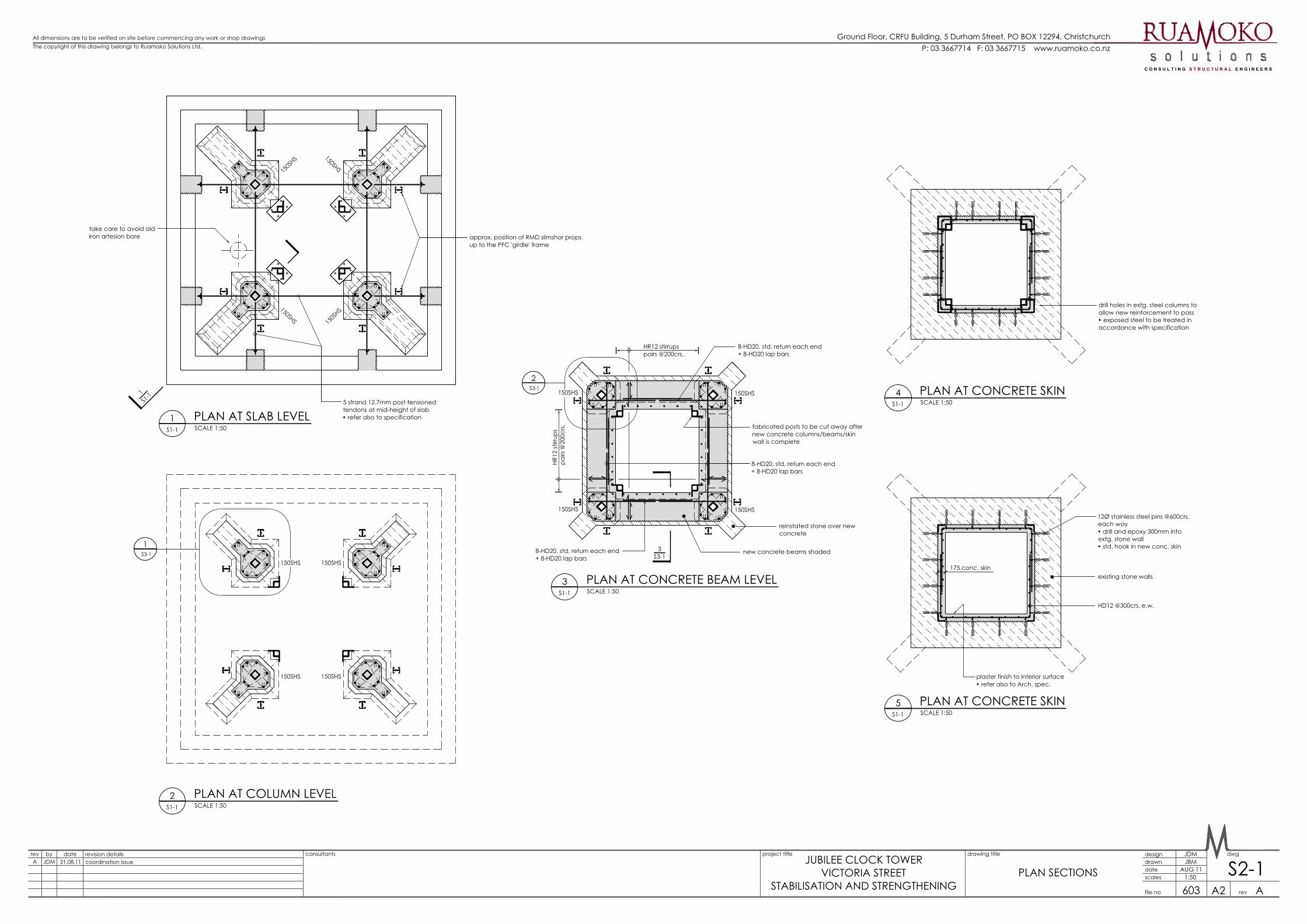
16.0 Design Feature Report
The seismic retrofit of the Jubilee Clock Tower involves sequential deconstruction of the lower stone
arches and buttress columns and reconstruction of those elements with a new internal reinforced
concrete structure. Refer to Appendix B for drawings of the proposed seismic strengthening work.
Before deconstruction commences a steel PFC beam is to be placed on the outside of the stone face
immediately above the level of deconstruction and connected through the stone walls with stainless
rods to an internal steel angle girdle which in turn is connected to the new concrete skin walls to be
cast on the inside surface of the stone tower.
The new reinforced concrete skin will connect to the existing stone with embedded stainless steel
pins. The new reinforced concrete skin wall in conjunction with the external steel PFC “girdle” will
provide support to the upper level of retained stone during sequential deconstruction of the buttress
columns and arches.

Ground Floor, CRFU Building, 5 Durham Street, PO Box 12294, Christchurch, New Zealand
P: 03 3667714 F: 03 3667715 E: [email protected] W: www.ruamoko.co.nz
PAGE 6
Each buttress column and adjacent arch is to be deconstructed sequentially. Immediately after
deconstruction of each column a steel SHS post is to be placed as an additional prop to the upper
level stone wall and is to be cast centrally within the new reinforced concrete column. One by one the
buttress columns are to be deconstructed and re-built with reinforced concrete.
When all buttress columns have been re-built, the arches are to be cast in reinforced concrete.
Starter bar reinforcing that is cast into the concrete skin walls above will be cast into the new arches.
The buttress columns are to connect to the existing foundation using a series of reinforcing bars
embedded into the existing foundation pad.
The existing foundation pad is to be strengthened with four post tensioned tendons placed at mid
depth of the existing foundation, with a tendon located under each column in both directions.
Once the new reinforced concrete structure has been constructed the existing internal structural
steel stabilisation frame and temporary stabilisation slab topping is to be removed so that the plaster
finish to the inside of the tower and placement of a cut stone veneer can be completed. The cut stone
veneer is to be made from the existing deconstructed stone and is to match the existing stone surface
and coursing patterns exactly.
16.1 New Load Paths
Once works are complete the new lateral load path will be through frame action in the new
reinforced concrete buttress columns and arch together with shear wall action in the new reinforced
concrete skin above the arch level. Post tensioned clamping across the existing stone foundation from
the four post tensioned tendons will provide the foundation pad with enhanced flexural and shear
strength.
Vertical load paths will be through the new reinforced concrete buttress columns and arches.
16.2 Load Levels and Coefficients
The seismic design of the tower has been based on the CCC Earthquake Prone Building Policy, 2010,
which requires this building to be strengthened to 67% new seismic code. Vertical load paths have
been designed for elastic response under ultimate limit state conditions.
The basic seismic design parameters are listed in the table below.
Z R Sp
1.25 0.3 1.0 0.7
Table 1: Elastic site spectra multipliers for structural strength

Ground Floor, CRFU Building, 5 Durham Street, PO Box 12294, Christchurch, New Zealand
P: 03 3667714 F: 03 3667715 E: [email protected] W: www.ruamoko.co.nz
PAGE 7
16.3 New Structural Elements
New structural elements include the SHS posts cast centrally within the new reinforced concrete
buttress columns, the new concrete skin walls within the tower walls, the new concrete arches and
the post tensioned tendons installed in core drilled holes through the existing foundation pad.
17.0 Recommended Timeframe for Strengthening
As this structure is already stabilised, retrofit does not need to be implemented as a matter of
urgency. However, the stone components of this clock tower can be expected to deteriorate further if
it is subjected to more large seismic events.
18.0 Retrofit Sketches or Drawings
Refer Appendix B for the detailed plans showing the seismic upgrading and repairs intended for this
tower.
19.0 Disclaimer and Limitation of Liability
Ruamoko Solutions Ltd conditions of contract are the standard ACENZ/IPENZ “Short Form Agreement for Consultant Engagement,” July 2011 version. These conditions can be downloaded from the ACENZ website www.acenz.org.nz. Ruamoko Solutions is liable to the building owner only to the extent of that agreement. That commercial engagement is not bound by the Consumer Guarantees Act. Report prepared by
Joe McGIrr BE (Hons) (Civil)
STRUCTURAL ENGINEER Written on 30 08 11
Report reviewed by
Grant Wilkinson BE (Hons) (Civil), FIPENZ (Structural, Civil), CPEng
MANAGING DIRECTOR

Ground Floor, CRFU Building, 5 Durham Street, PO Box 12294, Christchurch, New Zealand
P: +643 366 7714 F: +643 366 7715 E: [email protected] W: www.ruamoko.co.nz
APPENDIX A
VICTORIA JUBILEE CLOCK TOWER
CHRISTCHURCH
SELECTED PHOTOGRAPHS
OF DAMAGED STRUCTURE

Ground Floor, CRFU Building, 5 Durham Street, PO Box 12294, Christchurch, New Zealand
P: +643 366 7714 F: +643 366 7715 E: [email protected] W: www.ruamoko.co.nz
View of the south arch shortly after the February
earthquake showing the dislodged arch keystone and damaged columns
View from the east during stabilisation
Elevation of the entire tower from the south, finial
bent at top Internal view of the tower stone lower section
View of the dislocated southern arch keystone
View from the north after stabilisation showing
damage to the columns including the failed internal stainless rods

Ground Floor, CRFU Building, 5 Durham Street, PO Box 12294, Christchurch, New Zealand
P: +643 366 7714 F: +643 366 7715 E: [email protected] W: www.ruamoko.co.nz
APPENDIX B
VICTORIA JUBILEE CLOCK TOWER
CHRISTCHURCH
DRAWINGS OF THE PROPOSED
SEISMIC STRENGTHENING WORK

COORDINATION ISSUEAUGUST 2011
PROJECT NUMBER : 603DRAWING INDEX
JUBILEE CLOCK TOWERSTABILISATION AND STRENGTHENING
VICTORIA STREET, CHRISTCHURCH
S1-1 Cross sections
S2-1 Plan sections
S3-1 Details

6-HD20, std. return one end• + 6-HD20 lap bars
HR12
stirr
ups q
uad
s @20
0crs
.
8-HD25• std. return to top.
10-HD25 starters• drill and epoxy full depthof conc. slab/foundation• splay drilled holes awayfrom center by 15°
150SHS6 post cast-inconc. column
TYPICAL COLUMN ELEVATIONSCALE 1:50
approx. extent of extg. timber floor
approx. extent of extg. steel frame
existing stone walls
HD12@300crs.• std. return e.e.
HD12
@30
0crs
.
2-HD20, std. return one end+ 2-HD20 lap bars
HR12 stirrups pairs @200crs.+ HD12 starters drilled and epoxiedinto stone top and bott.
TYPICAL CONCRETE SKIN ELEVATIONSCALE 1:50
5S2-1
4S2-1
3S2-1
1S2-1
2S2-1
approx. outline of existing temporaryconc. slab to be removed after newconc. frame/skin wall is complete
2-HD25• std. return to top.
1S2-1
drill holes in extg. steel tie beams toallow new reinforcement to pass
HR12 stirrupstriples @150crs.
finial to be removed, andremaining socket/hole to beweather sealed
PROPOSED CONSTRUCTION METHODOLOGY:
• place PFC 'girdle' exterior frame and bolt inplace, including props to base slab
• post-tensioned cables to be placed to slabfoundation
• place reinforcement, wall starters and boxingfor concrete skin to the internal face of thestone walls. Cast internal concrete skin
• jacking as required to base of temporaryframe to be carried out, to ensure tower isplumb and to offset any settlement to theexisting columns during seismic movement
• deconstruct stone legs one at a time to levelindicated, place internal SHS prop, columnstarters, column reinforcement and boxing asrequired. Cast structural concrete column.Continue leg-by-leg until all four are complete
• place falsework to support reinstated archstones, starters, beam reinforcement andformwork to concrete beams. Cast beams.
• cut and remove temporary support frame,treating exposed steel as specified
• 'veneer' stones to be relaid around newconcrete columns and arches with veneer tiesas specified, finial reinstated with instructiongiven by engineer on site
DECONSTRUCTIONLEVEL OF
temporary braced framestabilisation structure (existing)
PFC 'girdle' frame to betemporarily installed andproped down to ground on 8total RMD slimshor soldiers
TYPICAL EXTERNAL ELEVATIONSCALE 1:100
P: 03 3667714 F: 03 3667715 www.ruamoko.co.nzAll dimensions are to be verified on site before commencing any work or shop drawingsThe copyright of this drawing belongs to Ruamoko Solutions Ltd.
rev by date revision details design dwg
rev
drawn
scales
file no
project title drawing title
date
603
JUBILEE CLOCK TOWERVICTORIA STREET
STABILISATION AND STRENGTHENING
consultantsA JDM 31.08.11 coordination issue
A
JDMJBM
AUG 11
A2
Ground Floor, CRFU Building, 5 Durham Street, PO BOX 12294, Christchurch
S1-1TYPICAL ELEVATIONNEW STRUCTURE ELEVATIONS
150SHS
5 strand 12.7mm post-tensionedtendons at mid-height of slab• refer also to specificationPLAN AT SLAB LEVEL
SCALE 1:501
S1-1
175 conc. skin
12Ø stainless steel pins @600crs.each way• drill and epoxy 300mm intoextg. stone wall• std. hook in new conc. skin
HD12 @300crs. e.w.
existing stone walls
HR12 stirrupspairs @200crs.
8-HD20, std. return each end+ 8-HD20 lap bars
reinstated stone over newconcrete
new concrete beams shaded
PLAN AT CONCRETE BEAM LEVELSCALE 1:50
3S1-1
PLAN AT CONCRETE SKINSCALE 1:50
5S1-1
PLAN AT CONCRETE SKINSCALE 1:50
4S1-1
PLAN AT COLUMN LEVELSCALE 1:50
2S1-1
HR12
stirr
ups
pairs
@20
0crs
.
150S
HS
150S
HS
150SHS
150SHS 150SHS
150SHS 150SHS
150SHS
150SHS
150SHS
150SHS
8-HD20, std. return each end+ 8-HD20 lap bars
8-HD20, std. return each end+ 8-HD20 lap bars
1S3-1
2S3-1
S3-13
S1-11
drill holes in extg. steel columns toallow new reinforcement to pass• exposed steel to be treated inaccordance with specification
approx. position of RMD slimshor propsup to the PFC 'girdle' frame
fabricated posts to be cut away afternew concrete columns/beams/skinwall is complete
take care to avoid oldiron artesion bore
plaster finish to interior surface• refer also to Arch. spec.
P: 03 3667714 F: 03 3667715 www.ruamoko.co.nzAll dimensions are to be verified on site before commencing any work or shop drawingsThe copyright of this drawing belongs to Ruamoko Solutions Ltd.
rev by date revision details design dwg
rev
drawn
scales
file no
project title drawing title
date
603
JUBILEE CLOCK TOWERVICTORIA STREET
STABILISATION AND STRENGTHENING
consultantsA JDM 31.08.11 coordination issue
A
JDMJBM
AUG 11
A2
Ground Floor, CRFU Building, 5 Durham Street, PO BOX 12294, Christchurch
1:50 S2-1 PLAN SECTIONS

COLUMN DETAILSCALE 1:10
1S2-1
HR12 stirrup quads @200crs.
2-HD25
1-HD25
1-HD25
1-HD25
1-HD25
2-HD25
stone re-laid around new concrete column• size and shape to match existing
150SHS6 post cast-in center of newconcrete column
nominal 100mm stone veneer
BEAM/COLUMN DETAILSCALE 1:10
2S2-1
CONCRETE BEAM DETAILSCALE 1:10
3S2-1
HR12 stirrup pairs @200crs.
existing 'Arch' stones repositionedon temporary support structureand cast-in concrete beam
2-HD20
4 x 10Ø SS pins to each Arch stone• drill and epoxy into stone• standard return in concrete beam
300
50V
ARI
ES
existing stone walls
HD12@300crs.
2- rows 12Ø SS pins @300crs.• drill and epoxy 300mm intoexisting stone• std. hook in conc. beam
layer of thin high strengthsoft protective rubber eachside of stone wall
250PFC square 'girdle'frame• 2- props to each cornerof frame during works
M24 stainless bolts @400crs.
Sika 212 grout
HR12 stirrup pairs @300crs.
stone re-laid around new concrete column• size and shape to match existing
175
2-HD20
HD20
3-HD20
HD12@300crs.• std. hook to base
proposed construction joint
beam starter from above may becast straight to enable beamreinforcement to be placed• heat and bend into beam afterbeam reinf. is placed
2-D10 'U-bars' to each beamstarter• 400mm long legs
proposed construction joints• to be roughened to a 5mm amplitede
HR12 stirrup triples @150crs. over joint
nominally 25mm
100
plaster over to Arch. spec.
100mm nominal
dep
th v
arie
s
'letter-box' slots to pour beams
12Ø stainless steel pins @600crs. each way• drill and epoxy 300mm into extg. stone wall• std. hook in new conc. skin
6Ø SS veneer ties to each quoin stone course
250x250x12 base and top plate• 2-14Ø holes top and bott. for M12Chemset bolts• nominal 20mm Drypack top and bott.
P: 03 3667714 F: 03 3667715 www.ruamoko.co.nzAll dimensions are to be verified on site before commencing any work or shop drawingsThe copyright of this drawing belongs to Ruamoko Solutions Ltd.
rev by date revision details design dwg
rev
drawn
scales
file no
project title drawing title
date
603
JUBILEE CLOCK TOWERVICTORIA STREET
STABILISATION AND STRENGTHENING
consultantsA JDM 31.08.11 coordination issue
A
JDMJBM
AUG 11
A2
Ground Floor, CRFU Building, 5 Durham Street, PO BOX 12294, Christchurch
1:10 S3-1DETAILS

Ground Floor, CRFU Building, 5 Durham Street, PO Box 12294, Christchurch, New Zealand
P: +643 366 7714 F: +643 366 7715 E: [email protected] W: www.ruamoko.co.nz
APPENDIX C
VICTORIA JUBILEE CLOCK TOWER
CHRISTCHURCH
PRELIMINARY GEOTECHNICAL
ASSESSMENT REPORT
BY: LAND DEVELOPMENT & EXPLORATION LTD
DATED: JULY 11TH 2011
Land Development & Exploration Ltd, P.O. Box 671, Gisborne, New Zealand Ph (06) 8673035, Fax (06) 8673037, www.lde.co.nz
Project Reference: 10048
11 July 2011
Christchurch City Council
C/o Insight Unlimited
P.O. Box 1219
GISBORNE
Attention: John Radburn
Dear John
JUBILEE CLOCK TOWER
PRELIMINARY GEOTECHNICAL ASSESSMENT REPORT
1 INTRODUCTION
Land Development & Exploration Ltd was engaged by Insight Unlimited on behalf of
Christchurch City Council to undertake a visual assessment of the buildings and land
forming the Jubilee Clock Tower which was damaged by the February earthquake event.
The purpose of the work was to provide a preliminary assessment as to what geotechnical
issues contributed to the damage to the property, and what geotechnical engineering work
may be required to reinstate it back to a satisfactory condition. Provision of possible
engineering solutions to minimise damage to the assets from future earthquake events
was also an objective.
2 ASSESSMENT
The visual assessment was undertaken by Georg Winkler; a senior Chartered Professional
Engineer with a background in engineering geology and geotechnical engineering, and the
director of a team responsible for the mapping and understanding of earthquake-induced
lateral spreading throughout Christchurch for the Earthquake Commission. Georg was
accompanied by John Radburn of Insight Unlimited (Project Manager).
3 S ITUATION
The Jubilee Clock Tower comprises a stone masonry tower located at the intersection of
Montreal and Victoria Streets.
The damage to the structure appears to be mostly a result of earthquake shaking.
However, it is noted that the adjacent building has subsided as a result of underlying
Christchurch City Council Jubilee Clock Tower Preliminary Geotechnical Assessment Report
Project Ref: 10048 - 2 -
liquefaction, indicating that liquefaction-induced settlement of the tower may have also
occurred. This inference is supported by the tilting of some of the paving towards the
tower.
The tower may be located within a zone of slight lateral movement towards Hagley Park,
although the surface damage to land associated with this appears to be largely negligible,
especially with respect to the subject site.
There is a reasonably significant volume of water emanating from the core of the tower.
We understand that it is may be an artesian well rather than a broken water main, which is
plausible given the slight settlement of the ground directly beneath the tower. We
understand that a chemical analysis of the water has been carried out to determine
whether it is artesian water or town supply water, although we do not know the outcome of
this.
Based on our visual assessment we consider that further settlement is possible with future
large earthquake events, although the risk of adverse settlement or differential settlement
is considered to be low.
4 RECOMMENDATIONS
We do not consider that further geotechnical work will be required, unless new foundations
for the structure are proposed.
5 OTHER CONSIDERATIONS
This report was prepared for Christchurch City Council with respect to the particular brief
given to us. Information contained in it can not be used for other purposes or by other
entities without our prior review and written consent.
It should be appreciated that the report is based on a visual assessment and observations
made in a regional context and that the nature and behaviour of the subsurface materials
may vary from that described following further investigation and analysis.
Christchurch City Council Jubilee Clock Tower Preliminary Geotechnical Assessment Report
Project Ref: 10048 - 3 -
Yours faithfully
LAND DEVELOPMENT & EXPLORATION LTD
Georg Winkler
MIPENZ, CPEng
Geological-geotechnical engineer
\\sbs\documents\LDE Projects\10000 to 10100\10048 Insight Chch Building Investigations\Jubilee Clock Tower\10048gew08072011 Jubilie Clock Tower
Preliminary Assessment Report R1.docx

Rūamoko Maori god of earthquakes and volcanoes. Youngest son of Rangi And Papa (Sky father and Earth mother). Alternate sp Rūaūmoko
ww
w.ru
am
ok
o.c
o.n
z