costing of steelwork from feasibility through to completion 1996 - australian institute of steel...
DESCRIPTION
COSTING OF STEELWORK FROM FEASIBILITY THROUGH TO COMPLETIONTRANSCRIPT

JOURNAL OF THEAUSTRALIAN
INSTITUTE OF STEELCONSTRUCTION
A.C.N. 000 973 839
STEELC O N S T R U C T I O N
COSTING OF STEELWORKFROM FEASIBILITY
THROUGH TO COMPLETION
VOLUME 30 NUMBER 2JUNE 1996ISSN 0049-2205
Print Post Approvedpp 255003/01614 $7.00

AISC MEMBERS…
THE BEST IN STEEL FABRICATION
AISC disseminates information on up-to-date steel design and fabrication technology, and thisinformation flows to its detailer and fabricator members.
When considering fabricated steelwork it makes sense to deal with those detailers andfabricators who share the institute’s resources. Their names, addresses and telephone numbers arelisted below.
While every effort has been made and all reasonable care taken to ensure the accuracy of the material contained herein
the Authors, Editors and Publishers of this Publication shall not be held to be liable or responsible in any way whatsoever
and expressly disclaim any liability or responsibility for any loss or damage costs or expenses howsoever incurred by
any person whether the purchaser of this work or otherwise including but without in any way limiting any loss or damage
costs or expenses incurred as a result of or in connection with the reliance whether whole or partial by any person as
aforesaid upon any part of the contents of this publication.
Should expert assistance be required, the services of a competent professional person should be sought.
© AUSTRALIAN INSTITUTE OF STEEL CONSTRUCTION
NEW SOUTH WALEST & S Bates Pty LtdPO Box 308, Engadine NSW 2233 . . . . . (02) 520 6096
QUEENSLANDBDS Technical Services80 Tribune Street, South Brisbane 4101 . (07) 3844 8093
G & D Drafting Pty LtdPO Box 928, Cleveland 4163 . . . . . . . . (07) 3252 5124
QEI Pty Ltd361-363 Montague Road, West End 4101 . . . . . . . . . . . . . . . . . . . (07) 3844 2772
Steelcad Drafting Pty Ltd4/27 Birubi Street, Coorparoo 4151 . . . (07) 3847 3799
Steeltech Steel Detailers Pty Ltd24 Curzon Street, Tennyson 4105 . . . . (07) 3848 6464
VICTORIABayside B W E Pty Ltd7 Bowen Crescent, Melbourne 3004 . . (03) 9867 6066
Bayside Drafting (Aust) Pty LtdCnr Skye Road & Farrell Street,Frankston 3199 . . . . . . . . . . . . . . . . . . . (03) 9781 4011
BDS Technical ServicesLevel 1, 240 Bay Street, Brighton 3186 . . . . . . . . . . . . . . . . . . . . (03) 9596 6500
WESTERN AUSTRALIAPerth Drafting Company (WA)48 Kishorn Road, Applecross 6153 . . . . (09) 364 8288
Steelplan Drafting Services15/885 Albany Highway, East Victoria Park 6101 . . . . . . . . . . . . . (09) 362 2599
For detailing of steelwork
For fabricated steelwork
See page 48

STEEL CONSTRUCTION VOLUME 30 NUMBER 2, JUNE 1996 1
AISC OFFICES
SYDNEY
Level 13, 99 Mount StreetNorth Sydney NSW 2060
(P.O. Box 6366, North Sydney NSW 2059) Telephone (02) 9929 6666 Facsimile (02) 9955 5406
BRISBANE
State Manager – Queensland Telephone (07) 3371 3633
MELBOURNE
State Manager – VictoriaTelephone (03) 9699 8138
PERTH
State Manager – Western AustraliaTelephone (09) 367 0617
STEEL CONSTRUCTION is published quarterly by the AustralianInstitute of Steel Construction – a national body whose purpose is topromote the use of fabricated steel through engineering, researchand the dissemination of knowledge.
Its services, which are available free of charge to corporate members,include technical information and advice and a library which containslocal and overseas publications.
For details regarding AISC services, readers may contact theInstitute’s offices:
AISC CONTACTS
ACT & SOUTHERN NSW
Mr Robert ThompsonTelephone (06) 281 1711
ILLAWARRA
Mr Ken WilymanTelephone (042) 28 4133
NEWCASTLE & NORTHERN NSW
Mr José ZaragozaTelephone (02) 9929 6666
SOUTH AUSTRALIA
Mr Les NashTelephone (08) 302 3330
TASMANIA
Mr Graham O’ByrneTelephone (003) 31 7044
CONTRIBUTIONSContributions of original papers on steel design, researchand allied technical matters are invited from readers of“Steel Construction’’, for publication in the journal. Theeditor also invites readers to submit letters, commentsand discussions on papers appearing in “SteelConstruction’’.
Editor: Arun Syam
EDITORIALIt has long been recognised that the costing of structuralsteelwork cannot be accurately determined by rates based on$/tonne, weight/square metre, etc – i.e. by weight conceptsalone. The costs associated with various connection types,materials procurement and the value adding processes ofdetailing, fabrication, coating, transportation and erection areessentially process dependent. Current design optimizationtechniques generally utilise the steel weight criterion whichdoes not necessarily produce minimum cost solutions.However, rational methods of costing have not been readilyavailable.
The paper contained in this issue of Steel Constructionentitled “Costing of Steelwork from Feasibility through toCompletion” considers a new method of costing steelwork.The method examines costs associated with each processand breaks it up into costs related to steel supply, fabrication,surface treatment and erection. The paper also illustrates themethodology by several case studies.
As the new costing method is published in the journal forfurther industry comment, the authors would welcome anyfeedback on its details and application. Additionally, readersshould note that the regular Steel Construction “Current CostIndicators” – which was generally based on a $/tonne method– has been withdrawn. This has been due to various reasons– the primary one being its inconsistency with the preferrednew costing method.
AISC MEMBERS…
THE BEST IN STEEL FABRICATION
AISC disseminates information on up-to-date steel design and fabrication technology, and thisinformation flows to its detailer and fabricator members.
When considering fabricated steelwork it makes sense to deal with those detailers andfabricators who share the institute’s resources. Their names, addresses and telephone numbers arelisted below.
While every effort has been made and all reasonable care taken to ensure the accuracy of the material contained herein
the Authors, Editors and Publishers of this Publication shall not be held to be liable or responsible in any way whatsoever
and expressly disclaim any liability or responsibility for any loss or damage costs or expenses howsoever incurred by
any person whether the purchaser of this work or otherwise including but without in any way limiting any loss or damage
costs or expenses incurred as a result of or in connection with the reliance whether whole or partial by any person as
aforesaid upon any part of the contents of this publication.
Should expert assistance be required, the services of a competent professional person should be sought.
© AUSTRALIAN INSTITUTE OF STEEL CONSTRUCTION
NEW SOUTH WALEST & S Bates Pty LtdPO Box 308, Engadine NSW 2233 . . . . . (02) 520 6096
QUEENSLANDBDS Technical Services80 Tribune Street, South Brisbane 4101 . (07) 3844 8093
G & D Drafting Pty LtdPO Box 928, Cleveland 4163 . . . . . . . . (07) 3252 5124
QEI Pty Ltd361-363 Montague Road, West End 4101 . . . . . . . . . . . . . . . . . . . (07) 3844 2772
Steelcad Drafting Pty Ltd4/27 Birubi Street, Coorparoo 4151 . . . (07) 3847 3799
Steeltech Steel Detailers Pty Ltd24 Curzon Street, Tennyson 4105 . . . . (07) 3848 6464
VICTORIABayside B W E Pty Ltd7 Bowen Crescent, Melbourne 3004 . . (03) 9867 6066
Bayside Drafting (Aust) Pty LtdCnr Skye Road & Farrell Street,Frankston 3199 . . . . . . . . . . . . . . . . . . . (03) 9781 4011
BDS Technical ServicesLevel 1, 240 Bay Street, Brighton 3186 . . . . . . . . . . . . . . . . . . . . (03) 9596 6500
WESTERN AUSTRALIAPerth Drafting Company (WA)48 Kishorn Road, Applecross 6153 . . . . (09) 364 8288
Steelplan Drafting Services15/885 Albany Highway, East Victoria Park 6101 . . . . . . . . . . . . . (09) 362 2599
For detailing of steelwork
For fabricated steelwork
See page 48

STEEL CONSTRUCTION VOLUME 30 NUMBER 2, JUNE 19962
1. INTRODUCTIONA considerable amount of effort is devoted during thedesign process to optimizing the design to achieve a min-imum cost solution. The measure traditionally used tojudge the economy of the design is the quantity of steel inthe structure expressed as a weight per square metre offloor area or per cubic metre of cubic content (Hart Henn& Sontag (1)). Therefore, the optimization of a design hasmeant the minimization of the quantity of material in a pro-ject. This has permeated all facets of design, constructionand research. For steel structures, the current method ofcosting steelwork on the basis of a rate per tonne has leadto this concentration on minimum mass solutions. YetGirardier (2) indicates that the material cost representsonly 40% of the total cost of the steel frame. The remain-ing 60% of the cost represents the value added in fabrica-tion and erection which has been very difficult toaccurately quantify. This latter component has often beenneglected in design. For example, the cost of stiffening apenetration can add considerably to the cost a beam, yetit is often not considered worthwhile to carry out a designto determine the level of stiffening required. By compari-son, a considerable time is typically spent minimizing thesize of the member.
Various proposals (Australian Institute of SteelConstruction (3), Hogan and Firkins (4)) have been madeto remedy this situation and some worthwhile generalprinciples have been developed. These have includedadvice such as: weld in the fabrication shop, bolt on site;adopt simply supported connections not continuous.Whilst these qualitative principles will generally apply,they do not allow the particular situation to be adequate-ly investigated. There has also been some industry skep-ticism on whether the benefits of adopting good designprinciples were being passed on to the client in the formof lower prices. In fact, it was frequently perceived thatgood design was costing more, as the design was oftenheavier and hence on a rate per tonne basis it would costmore. Firkins and Hemphill (5) advised on work hours pertonne for various types of work and whilst this was arefinement, it translated into a rate per tonne. It was anaverage rate and did not allow details to be costed withsufficient accuracy to allow comparisons to be undertak-en. This method has the additional disadvantage that it isvery dependent on the experience of the estimator in theparticular type of work.
To help give a better understanding of the total cost of
steelwork, Watson and Buchhorn (6) developed conceptsfor costing steelwork in which components of the cost weretaken into account. The concepts proposed were similar tothose practices adopted by the professional fabricators.The method was further developed (Watson, Dallas & Main(7); Main, Watson & Dallas (8) and Watson & Dallas (9))into a practical and rational method of costing steelwork.During this period extensive consultations were undertak-en with all sections of the Australian construction industrywhich lead to the method being refined and extended tocover most types of steel construction. The steel construc-tion industry has been very supportive of these develop-ments as the system reduces the contractual risks to thefabricator and also reduces the cost of tendering by pro-viding a format consistent with the fabricator’s method ofestimating.
Tizani, Davies, Nethercot and Smith (10) have been devel-oping knowledge based engineering systems to carry outcomparative costing on different space frame systems.Their approach is similar to that discussed in this paper.
This paper explains the method and uses case studies toillustrate the insight that can be achieved into factors influ-encing costs. Extensive tables of indicative unit rates aregiven so that most structures can be costed. The applica-tion of the method at various stages of the design and con-struction process is demonstrated with particular attentionbeing given to extending the method to cover early stagesof design. Indicative sizes and costing are given for portalframe industrial buildings, carpark, office and retail floorsto assist with costing at the early stages of design.The pro-posed method presented has not yet been fully extendedto cover all plate structures such as bins and silos.However the principles can readily be applied to suchstructures.
2. THE CURRENT METHODWhen pricing a job, fabricators determine the cost of thesupply of materials, the number of hours involved in fabri-cating steelwork, and the costs for surface treatment anderection.These costs are then summed and divided by thetotal number of tonnes to determine a rate per tonne to beincluded in the tender documents.Therefore the rates rep-resent an average across the total job and do not provevery useful in determining the cost of variations or refiningdesigns. The format of the breakup is guided by theAustralian Standard AS1181- 1982 (11) for civil engineer-
COSTING OF STEELWORK FROMFEASIBILITY THROUGH TO COMPLETION
K.B. Watson, S. Dallas and N. van der KreekBHP Structural Steel Development Group
T. MainTrevor Main & Associates

STEEL CONSTRUCTION VOLUME 30 NUMBER 2, JUNE 1996 3
ing projects and the Institute of Quantity Surveyors andMaster Builders’ – Construction and HousingAssociation’s (12) Standard Method of Measurement(SMM5) for building projects.
Table 1 shows that there is a great variation in cost ofsteelwork on a dollars per tonne basis. The variationreflects the complexity of the work to fabricate and erect.Toovercome this wide spread, rates have been developedand published (Cordell (13), Rawlinsons (14)) for varioustypes of work.
Poulos (15) investigated the costs of three different portalframe designs for a 2,000 square metre building with aspan of 30 metres. The results are summarised in Table 2and show a 36% variation in tonnage rates over the threedesigns. This illustrates that even for standard structuresthe current method cannot give accurate and reliable cost-ing of projects. Whilst the ‘conservative’ design increasedthe tonnage by 12% over that required for the ‘good’design, the total cost of the frames increased by only 6%.This was because only the steel supply component of thecost increased as there was no difference in the cost ofthe shop drawings, fabrication, transport and erection.However, for the skinny design a corresponding decreasein the mass of steel from the ‘good’ design increased thecost of the frame by 15%. This increase was caused bymore complicated knee connections, additional fly bracingand additional costs in erecting flimsy members.Therefore the current method, which leads to minimisingweight can result in more costly designs.
3. PROPOSED NEW METHOD OFCOSTING
As accurate costing is one of the essential features neces-sary to design and construct economical structures, it wasdecided to develop a rational costing method which willovercome these deficiencies.The goals of the new methodare to:
• give a more reliable and accurate method
• provide a continuity of approach from initial projectcosting through to fabricator’s detailed costing
• provide a clearer focus on the elements that will havea significant effect on the final cost
• allow reliable determination of cost of contract varia-tions
• provide a methodology which is simple to understand.
In order to achieve these goals, the costs are divided intofour components: steel supply, fabrication, surface treat-ment and erection. Costs represent rates received fromfabricators and as such, they do not include the builder’smargin. The indicative costs given in Appendix A areapplicable for projects where the steelwork cost (supply,fabrication and erection) is greater than $150,000.The cur-rent hourly labour rate adopted for the tables is $40.00.
3.1 Steel SupplySteel supply covers the supply of all materials including hotrolled, welded, cold formed and tubular sections, plate, aswell as items such as bolts and shear studs. (ReferAppendix A1 for tables.)
Sections are costed on a rate per metre basis. This bringsthe costing of hot rolled sections into line with cold formedsections, such as purlins and tubular sections, which havebeen traditionally been sold on a per metre basis. Anotheradvantage of this method is that it allows a very quick com-parison to be undertaken on different sections capable ofcarrying the same load.
Plate is costed on a rate per square metre basis.This givesa more realistic measure than dollars per tonne and allowsfor any changes in the cost of steel with thickness to behighlighted as shown in Figure 1.
Wastage has not been allowed for in the rates given as itcan be minimised in the design process. For instance,
Design Description Frame Mass Cost $ / tonne(tonnes) ($)
‘Good’ Design 20.2 45,646 2,260
‘Conservative’ Design 22.6 48,530 2,147
‘Skinny’ Design 18.0 52,679 2,927
Table 2. Comparison of costs for different designs for 2,000 square metre portal frame building (span 30m).
Item Cost ($) / tonne Variation(times lowest cost)
Steel supply 900 - 1,300 1.4
Shop detailing 50 - 500 10.0
Fabrication 200 - 2,000 10.0
Surface treatment 0 - 750 ∞Transport to site 50 - 200 4.0
Erection 150 - 700 4.7
TOTAL 1,350 - 5,450 4.0
Table 1.Typical range of tonnage rates.
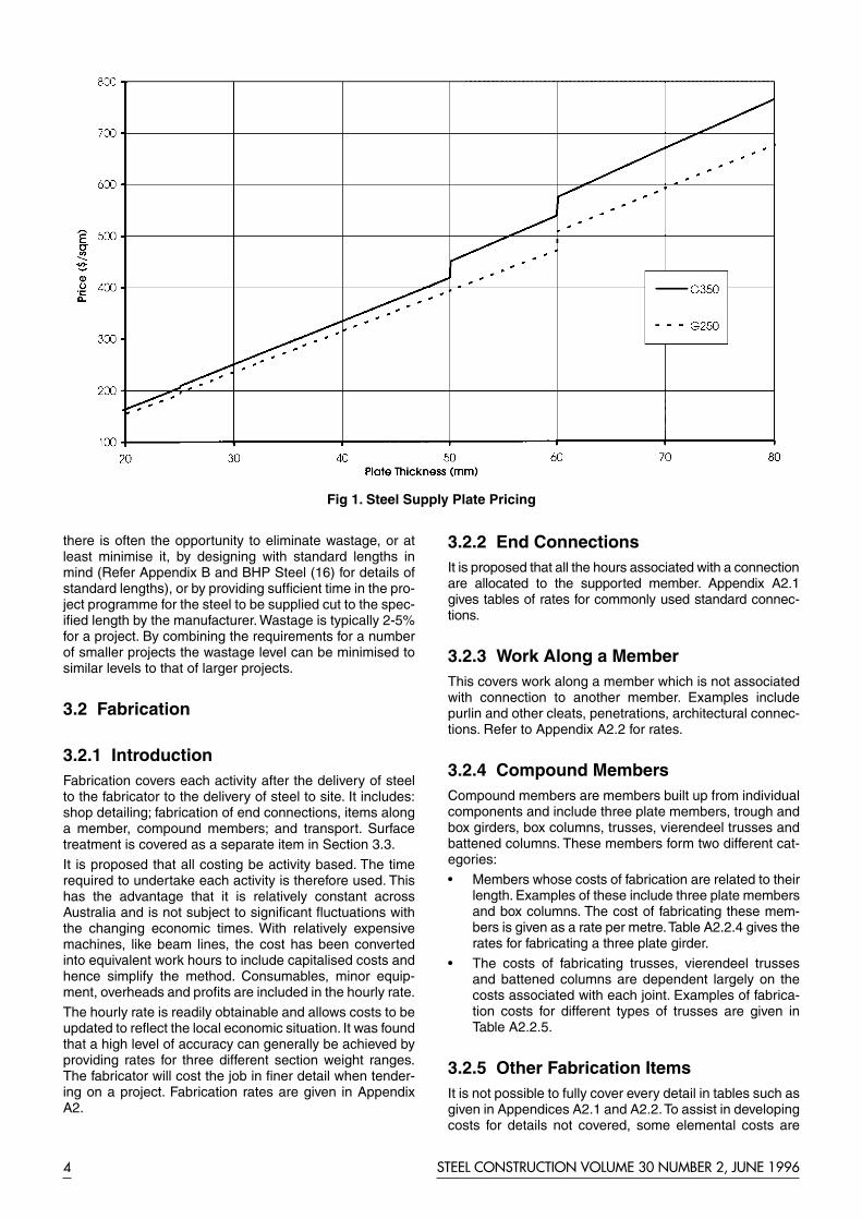
there is often the opportunity to eliminate wastage, or atleast minimise it, by designing with standard lengths inmind (Refer Appendix B and BHP Steel (16) for details ofstandard lengths), or by providing sufficient time in the pro-ject programme for the steel to be supplied cut to the spec-ified length by the manufacturer. Wastage is typically 2-5%for a project. By combining the requirements for a numberof smaller projects the wastage level can be minimised tosimilar levels to that of larger projects.
3.2 Fabrication
3.2.1 IntroductionFabrication covers each activity after the delivery of steelto the fabricator to the delivery of steel to site. It includes:shop detailing; fabrication of end connections, items alonga member, compound members; and transport. Surfacetreatment is covered as a separate item in Section 3.3.
It is proposed that all costing be activity based. The timerequired to undertake each activity is therefore used. Thishas the advantage that it is relatively constant acrossAustralia and is not subject to significant fluctuations withthe changing economic times. With relatively expensivemachines, like beam lines, the cost has been convertedinto equivalent work hours to include capitalised costs andhence simplify the method. Consumables, minor equip-ment, overheads and profits are included in the hourly rate.
The hourly rate is readily obtainable and allows costs to beupdated to reflect the local economic situation. It was foundthat a high level of accuracy can generally be achieved byproviding rates for three different section weight ranges.The fabricator will cost the job in finer detail when tender-ing on a project. Fabrication rates are given in AppendixA2.
3.2.2 End ConnectionsIt is proposed that all the hours associated with a connectionare allocated to the supported member. Appendix A2.1gives tables of rates for commonly used standard connec-tions.
3.2.3 Work Along a Member This covers work along a member which is not associatedwith connection to another member. Examples includepurlin and other cleats, penetrations, architectural connec-tions. Refer to Appendix A2.2 for rates.
3.2.4 Compound MembersCompound members are members built up from individualcomponents and include three plate members, trough andbox girders, box columns, trusses, vierendeel trusses andbattened columns. These members form two different cat-egories:
• Members whose costs of fabrication are related to theirlength. Examples of these include three plate membersand box columns. The cost of fabricating these mem-bers is given as a rate per metre.Table A2.2.4 gives therates for fabricating a three plate girder.
• The costs of fabricating trusses, vierendeel trussesand battened columns are dependent largely on thecosts associated with each joint. Examples of fabrica-tion costs for different types of trusses are given inTable A2.2.5.
3.2.5 Other Fabrication ItemsIt is not possible to fully cover every detail in tables such asgiven in Appendices A2.1 and A2.2.To assist in developingcosts for details not covered, some elemental costs are
STEEL CONSTRUCTION VOLUME 30 NUMBER 2, JUNE 19964
Fig 1. Steel Supply Plate Pricing

STEEL CONSTRUCTION VOLUME 30 NUMBER 2, JUNE 1996 5
included in Appendix A2.3. These costs may need to besupplemented with advice from fabricators. The costsgiven in Appendix A2.1 and A2.2 are complete costs for thefabrication of the item and hence already include the costsgiven in Appendix A2.3.
3.2.6 Shop DetailingWatson et. al. (7) referenced the cost of shop drawingsback to the number of hours of fabrication. The ratio variedfrom 1 hour of shop detailing for every 4 hours of fabrica-tion for portal frame work, to parity for complex work involv-ing significant variations.
Main et. al. (8) gave guidance on the number of hoursrequired to draw marking plans, individual members, com-ponents and carry out checking. The estimator is thenrequired to determine the number of drawings.
The time to prepare shop drawings is dependent on thequality of the contract drawings, the complexity of the pro-ject and the amount of repetition.There has been a declinein the quality of contract drawings as fee pressure hasintensified. This is usually a false economy, as the shopdetailer must fill in the gaps in information, and this resultsin significantly increasing the costs of shop detailing.
Where members are identical, the costs of detailing aresignificantly reduced as the member is only drawn once.Minor differences in details add to the cost, as they must benoted on drawings or the members redrawn. When sever-al people are working on a project, there should be com-mon detailing across the whole project, otherwisemembers will be required to be redrawn needlessly.
Due to difficulties in determining the number of identicaland similar members early in the design process, it is rec-ommended that a method of relating the cost of detailing tothe cost of fabrication be used at this stage (refer TableA2.4.1). As the design is finalised, the estimate can berefined if it is based on the number of shop drawings (referTable A2.4.2).
3.2.7 Transport The cost of transport is directly related to the number oftruck loads of steel, the size of the loads and time taken toload, transport and unload the steel. Hence the cost isrelated to both the weight and volume of steel and to alesser extent the distance from the site. Table A2.5.1 givesthe rate per member to transport beam and stick typesteelwork.
The total typical travel time for a city delivery is 9 hours perload which is composed of the following components: timefrom depot to fabrication shop (1.0 hour); time to load steel-work on truck ( 2.5 hours); fabrication shop to site (1.5hours); waiting time at site and the time to unload steelwork(3 hours); travel time back to depot (1 hour).This highlightsthe significant time and subsequent cost savings that couldbe made by palletising fabricated steelwork.
Transport costs for other types of work can be calculatedusing the above principles. When transporting bulky itemssuch as three dimensional trusses, the volume will deter-mine the number of items that can be carried on a truck.
If the steel is galvanised or painted at an external shop, thecost of transport is almost doubled as the steel is trans-ported twice, once to the galvanisers or paint shop andthen to site. It is recommended that this additional cost be
included in the surface treatment cost.
3.3 Surface TreatmentSurface treatment covers all forms of treatment to the steeland includes painting, galvanising, fire spray, intumescentpaint and fire rated board systems. A rate per square metreof applied treatment has been adopted as the appropriatemeasurement. Differences in handling, thickness of zinc ingalvanising and thickness of fire spray due to changingsurface to mass ratio have been allowed for by giving ratesfor three different mass per metre categories as shown inAppendix A3. For the fire rated board systems, the project-ed area will generally be applicable. Appendix C gives thesurface areas for standard sections which makes the pro-posed method very simple to apply.
3.4 ErectionThe key determinant in the cost of erecting steelwork is thenumber of lifts that are required. Once the crane size isdetermined based on the dual requirements of lifting radiusand mass of component, it costs virtually the same to lift avery light member as a heavy member. The cost of erect-ing bigger sections has been increased to allow for theextra time for the end connections and to plumb the steel-work. Appendix A4 gives typical costs per member for por-tal frames and multi-storey buildings.
For other types of projects it is recommended that thecosts be derived using the same methodology.This is illus-trated by the bridge example in section 3.5.2.
4. CASE STUDIES
4.1 Case Study No. 1 – Portal FrameThe costing of an internal bay of a 2000 square metrewarehouse with portal frames at 9 metre centres and 6metre eaves is given in Appendix D1. This shows thatapproximately 60% of the cost of the building is in thepurlins and sheeting. However, the time spent in optimisingdesigns of portal frames has generally been on minimisingthe tonnage in the frame which represents only 20% of thecost of the building. As was shown in section 3, this effortcan be counter productive and lead to more expensivedesigns.
An alkyd primer (red oxide zinc phosphate) paint systemwas chosen as providing adequate corrosion protection.This paint system is usually applied in the fabrication shop.However, if an inorganic zinc silicate system was adopted,the steel would normally have to be transported to a spe-cialist contractor to be grit blasted and painted. The totalcost of painting would have increased four fold with the useof inorganic zinc silicate.
It is normal practice for the fabricator to be responsible forthe supply of cranes on industrial projects and thereforethis has been allowed for in the costing.
This costing method allows the determination of the mosteconomical spacings of the portal frames and purlins.
4.2 Case Study No. 2 – Multi StoreyBuilding

A ten level office building with a floor plate of 1000 squaremetres net per floor was chosen to investigate the costingmethod (refer Figure 2). A conventional layout with beamsspanning from the perimeter to the core was prepared(refer Figure D2.1). A 120mm deep slab on 1.0mm BondekII spanned 2.8 metres between the steel beams. The floorstructure was required to accommodate a major air condi-tioning (A/C) duct around the reinforced concrete core. Asteel depth limit of 300mm was adopted in this area tomaintain a reasonable plenum height (the height fromunderside of ceiling to the top of slab above). Also, the A/Cduct layout and flexibility requirements indicated web pen-etrations at third points in the typical secondary beams B1and B7. Other internal beams were specified to have smallcircular penetrations at third points for services. The floorbeams were designed in accordance with the soon to bereleased composite beam standard AS2327.1-1996 (17).Beams were cambered for their self weight and the con-crete slab weight.
The initial design, referred to as Design A, had an overallsteel beam intensity of 31kg/sq.m. This scheme involvedstiffened web penetrations in B1 and B7 which were460UB67.1 beams. Alternatively, adopting 530UB82.0beams in these locations eliminated the need for stiffeningat the web penetrations. This scheme had a beam steelintensity of 35kg/sq.m and is referred to as Design B.
Appendix D2 gives a full costing of beams for Design A andthe varied beams in Design B, using the proposed method
of costing. The results are summarised in Table 3.
When costing according to the proposed method, the steelframe cost of Design B is slightly lower even though it isheavier than Design A. However traditional methods ofcosting based on a constant dollars per tonne rate wouldhave quickly ruled out Design B, as it was heavier.
For Design A, the stiffener supply and fabrication costs atthe penetrations totalled $190 per penetration comparedto $32 for Design B with its unstiffened penetrations.Whenthe extra beam supply and firespray costs associated witha 530UB82.0 were also included, a similar overall costresulted. Steel cost includes supply, shop detailing, fabri-cation, fire-spray, transport and erection of structuralsteelwork.
The fire spray cost for both schemes represented about20% of the total steel-frame cost. Bennetts and Thomas(18) showed that on the 40 storey, 140 William Street,office building in Melbourne that if a reliable fire sprinklersystem was installed and the passive fire protectionremoved, the building would be safer than a building meet-ing the building regulations. The fire spray on this buildingwas subsequently not reapplied during the refurbishment.
The shop detailing was costed by estimating the number ofdrawings. It was decided that each beam type would bekept identical throughout the 10 floors. Consequently, theshop detailing cost represented less than 1% of the totalsteelwork cost. However if changes were made such ashaving different end connection on some members, chang-ing penetration sizes throughout the floor and betweenfloors, the cost of shop details could increase to about 5%of the total steel cost.
The plenum height is influenced by a variety of factors suchas the depth and layout of the mechanical services, thedepth of the beam/slab at beam notches and the depth ofthe lights. Even though some beams were increased indepth in Design B, it would not generally require a greaterplenum height than Design A.Therefore facade costs werenot included in the cost comparison. Also, crane costs havenot been included since for this type of project the crane isnormally provided by the builder.
4.3 Case Study No 3. – 34.5 m spanBridge
The structures used in the previous examples havesignificant repetition and similarity between projects andhence industry rates could be developed. This commentparticularly applies to site activities. Accordingly for morecomplex projects, or for projects with less repetition, thepublished rates may need to be supplemented with ratesdeveloped from first principles. A simply supportedskewed bridge spanning 34.5 metres is used to demon-strate the application of the method.
STEEL CONSTRUCTION VOLUME 30 NUMBER 2, JUNE 19966
Item Design A Design B
Steel Frame Intensity 31 kg/sq m 35 kg/sq mSteel Floor Frame Cost * $86.60 /sq m $85.50 /sq m
* Costs exclude columns, steel decking and the reinforced concrete slab, which would be similar for the twolayouts.
Table 3. Cost Comparison of Designs.
Fig 2. Floor Layout

STEEL CONSTRUCTION VOLUME 30 NUMBER 2, JUNE 1996 7
4.3.1 Bridge DesignThe bridge is shown in Appendix D3 and is skewed at 15°to the road alignment. The bridge spans 34.5 metres witha width of 12.6 metres and consists of four composite plateI-beams, each weighing approximately 25 tonnes, at aspacing of 3.5 metres. Grade 350 steel has been adoptedfor the top flange and as the bridge is designed in accor-dance with Victorian conditions, Grade 350L15 has beenused for the bottom flange. The web is Grade 250. Theplate lengths were chosen to minimise the number ofsplices within the length of the beam. The concrete deck iscomposed of precast formwork acting compositely with theinsitu concrete.
The surface treatment specified for the project was Class2.5 blast together with 75µm of inorganic zinc silicate. Thishas been found to provide a very good life as well as beingan economical solution.
4.3.2 Costing Of The BridgeAppendix D3 shows the estimated costs of the supply, fab-rication, surface treatment and erection of the beams,intermediate and abutment cross frames.
(a) Steel SupplyThe areas of plate and the lengths of sections were calcu-lated and the appropriate rates applied. During this processthe various length, width and thickness combinations ofplates were investigated to minimise the number of weldedsplices and ensure the required combination was available(Refer Appendix B). For bridges, it is usually necessary toorder the required combination rather than rely on standardplates which have a maximum length of 12 metres and aremainly available in Grade 250. A smaller range of Grade350 standard plate is also stocked by distributors.
A 5% wastage factor was allowed for trimming the platesand for the waste involved in profiling the web to provide thespecified camber. This could have been refined by investi-gating in more detail the exact size of plates required.
(b) Fabrication The fabrication costs of the beams and cross frames werequickly and simply obtained from the relevant tables. Themass per metre of the beam was greater than given in thetable for the fabrication of gussets (or stiffeners). After con-sultation with some fabricators, it was agreed that the high-est rate in the table would be appropriate.
Bridge design drawings generally contain sufficient infor-mation so that shop drawings are not required.
The transport of the 35 metre long beams required specialconsideration as they were significantly over length andwould therefore require pilot vehicles and semi trailers withsteerable rear bogies. A specialist transport company wascontacted and it was determined that it would be feasibleand most economical to transport two beams and thecross bracing per truck. It was also determined that oneload would be scheduled per day. A budget price was thendeveloped and used as the basis of costing.
(c) Surface TreatmentThe surface areas were readily determined and the appro-priate rates for inorganic zinc silicate applied.
(d) ErectionA layout of the site was prepared and it was determinedthat it was necessary to lift 25 tonnes at a radius of 20metres. A number of crane hire companies were then con-tacted to determine suitable mobile cranes. A 150 tonnecrawler crane was required to enable a single crane lift. Forsuch large cranes the mobilisation and demobilisationcosts form a large component of the total cost of the erec-tion where there is a small number of members to be liftedinto place. It was determined that the crane would berequired to be on site for a total of a week. A rigging crewof 3 was allowed.
(e) Accuracy of estimateTo confirm the accuracy of the method and rates, a num-ber of fabricators were asked to price the bridge. Detailedpricing by the fabricators was found to be in close agree-ment with those given in Appendix D3.
4.3.3 Comparison With Traditional DesignThis method allows the designer to assess the impact ofdifferent structural arrangements to be determined withaccuracy. For example the beam spacing of 3.5 metres iscompared with the traditional spacing of steel beams of 1.8to 2.5 metres (Rapattoni (19)). The reduced spacingincreased the number of beams from 4 to 6.
Haywood (20) indicates the steel quantity would be slight-ly increased with the traditional beam spacing. AppendixD3 illustrates that the fabrication, surface treatment andtime related erection cost are proportional to the number ofbeams. Therefore the cost of these items would increaseby approximately 50%. This would increase overall cost ofthe steelwork for the bridge by about 20%.
5. APPLICATION OF METHOD ATDIFFERENT STAGES OF PROJECT
5.1 Stage 1 – Pre-design CostingAt this stage of a project the information is often verysketchy and the aim of the study is to determine whetherthe project is worth proceeding with. Therefore the inputsare the variables affecting the cost and revenue from theproject. For example on an office development the keyvariable is the amount of floor space. Hence it is impor-tant to have reliable costs per square metre of officespace.
These costs can be derived from previous projects usingthe methodology presented in Section 3. A database fromprevious similar projects would allow this information to bebuilt up. Perara and Bennett (21) reviewed methods ofmodeling data from previous projects to predict the cost ofthe project. The models can be categorised as threetypes: Parametric Cost Models, Regression Models, andProbabilistic Models.
There are also public sources of such information pub-lished on a regular basis such as Cordells(13) andRawlinsons(14).
A number of pre-design rates for industrial buildings, officeand retail floors are given in Appendix E.The order of accu-racy of estimate at this time would be ±20%.

5.2 Stage 2 – Indicative CostingOnce a layout is prepared, no matter how preliminary, themethod of costing proposed in Section 3 can be applied.Initial sizing can be based on experience, previous similardesigns, or design aids such as those given in Appendix E.The types of connections will be generally known at thisstage.This can be as general as whether the connection isrigid or pinned.
The accuracy of the estimate can be improved when thepreliminary sizing is undertaken by the structural engineer.This step is necessary when the team has limited experi-ence with a particular form of construction. Design aids toassist in the preparation of preliminary sizing include:
• Design Capacity Tables (22)(23) for steel members
• Steel Construction Journal December 1995 (24) forcomposite members
• Portal frame design guidance and charts (25) (26)
• Composite Steel Highway Bridge design guidance andcharts (20).
All non-standard connections should be reviewed toensure that practical connections can be developed.
The supply of bolts, cleats and wastage at this stage canbe allowed for by applying a percentage increase on themain steel members. It is suggested that 5% be allowed forsimply supported construction and 10% for continuousconstruction.
The order of accuracy at this stage is ±10%.
5.3 Stage 3 – Detailed CostingAt the end of the detailed engineering, all the information isavailable to accurately (±5%) determine the cost of thestructure using the method. This is illustrated in the casestudies (Section 4 and Appendix D). During all stages ofthe design, considerable benefit to the project can beobtained by having detailed discussions with the fabricatorand other specialists. The proposed costing methodassists in this by providing a common language for all pro-ject participants.
5.4 TenderThe new method will greatly assist the fabricator, in com-parison to the current method, during the tender processas it is presented in a form that assists preparation of thetender. The time taken for the preparation of the Bill ofQuantities is the same as that for the current method, asthe new method doesn’t significantly change the processof taking off the quantities, instead it changes the way theinformation is presented. For the full benefit to be obtainedfrom the new method, the Bill of Quantities must form partof the contract. This in the longer term will lead to signifi-cant savings for the client as it will substantially reduce thecost of tendering.
5.5 Cost Control Including VariationsAs the method is activity based, it lends itself to controllingcosts during a project. It allows the cost of variations to beeasily determined and has been used successfully on anumber of projects to help resolve disputes on variations.This saves a considerable amount of time and thereforecosts, in administering a contract.
6. STANDARD METHOD OFMEASUREMENTS
The Victorian Fabricators Sub-Committee of the AustralianInstitute of Steel Construction (27) have developed a draftrevision for amending the SMM5 (12) to incorporate thenew method. This has been trialed on a project and foundto be very workable. As it largely involved changing the pre-sentation of the document rather than fundamentallychanging how quantities are taken off, it took the sametime as preparing a conventional bill.This document is cur-rently being circulated for industry comment prior to mak-ing a formal submission on changing the standard.
The Australian Standard AS 1181 (11) was issued in 1982and gives only limited guidance for steel construction. It istime that consideration be given to updating this standard.
7. COMPUTERISATIONDuring the development of the costing method, spread-sheets have been used extensively to assist in quickly eval-uating different options. Spreadsheets have the advantagethat they can be simply modified to suit a particular pro-ject’s requirements.
Two different sets of proforma sheets have been used inAppendix D. These may be used as a template for spead-sheets or for manual calculations. The first set (AppendixD1 and D2) is suitable where there is a large number ofmembers in the structure and relatively little work permember. The second set (Appendix D3) is suitable wherethere are relatively few members, but with a significantamount of work on the members. The second proformasheets may also be used to develop costs for more com-plicated members and the results then fed into the first setof sheets.
At the more sophisticated level a number of database sys-tems (eg. Costcalc, WinEst Pro) are in use in the largercompanies. Discussions with the vendors indicate thatthese systems can be relatively easily changed to accom-modate the new method of costing.
One interesting development is the linking of design anddrafting systems into costing systems.There are a numberof instances where the Computer Aided Drafting Systemhas been linked to the costing system. This saves a con-siderable amount of time, but probably more importantlythe number of errors.
8. CONCLUSIONSA rational new approach has been presented which hasbeen shown to give improved reliability and accuracy incosting steelwork. It provides a common language that canbe used by all participants at every stage of the design andconstruction of the structure.
The new approach is based on dividing the costing exer-cise into four components:
• Steel supply - cost per metre for sections
- cost per square metre for plate
• Fabrication - cost per item of work
• Surface treatment - cost per square metre of treat-ment
• Erection - cost per lift.
STEEL CONSTRUCTION VOLUME 30 NUMBER 2, JUNE 19968
STEEL CONSTRUCTION VOLUME 30 NUMBER 2, JUNE 1996 9
The method has been shown to be simple to apply at allstages of a project from pre-design, design, tenderingthrough to contract administration. It has proven to providea valuable tool in the economical design and constructionof steel structures.
9. ACKNOWLEDGEMENTSThe Authors would like to thank those colleagues whohave commented on the previous work which has addedconsiderably to the development of the new method. In par-ticular, special thanks are given to fabricators who havecooperated in supplying rates given in the appendices.
10. REFERENCES1. HART, F.,W. HENN, H. SONTAG, “Multi-Storey
Buildings in Steel”. 2nd Edition Ed B. Godfrey,University Press, Cambridge. 1985.
2. GIRARDIER, E.V. “Design for stability…of theindustry”. Structural Stability and Design, Kitipornchai,Hancock & Bradford (eds) 1995 Balkema, Rotterdam.
3. Australian Institute of Steel Construction (1992).“Economical Structural Steelwork” (Third Edition).
4. HOGAN,T.J. AND A. FIRKINS. (1986). “EconomicalDesign and Construction of Medium Rise CommercialBuildings using Structural Steel”. Proceedings of thePacific Structural Steel Conference. New ZealandHeavy Engineering Reasearch Association. Vol 1. pp243-263.
5. FIRKINS, A. AND R. HEMPHILL (1990). “FabricationCost of Structural Steelwork”. Steel Construction Vol24 No. 2, Australian Institute of Steel Construction.
6. WATSON, K.B. AND D.P. BUCHHORN (1992). “A newapproach to costing structural steelwork”. Proceedingsof the Third Pacific Structural Steel Conference,Japanese Society of Steel Construction. pp 437-444.
7. WATSON, K.B., S. DALLAS AND T. MAIN (1994).“Costing of Structural Steelwork – The Need for a NewApproach”. Preprints Of Papers AustralasianStructural Engineering Conference 1994. TheInstitution of Engineers, Australia. Vol 2 pp 1039-1046.
8. MAIN. T., K.B. WATSON AND S. DALLAS (1995). “ARational Approach to Costing Steelwork”.Construction Economics – The EssentialManagement Tool. The Australian Institute of BuildingSurveyors
9. WATSON, K.B. AND S. DALLAS (1995). “New Methodof Costing Steelwork – The Way to EconomicalStructures”. Structural Steel: PSSC ’95, 4th PacificStructural Steel Conference. (N.E. Shanmugan & Y.S.Choo (eds)). Vol 1. pp 651-658.Pergamon.
10. TIZANI, W.M.K, G. DAVIES, D.A. NETHERCOT, ANDD.A. SMITH (1994). “Construction-led design of tubulartrusses using a cost model: Knowledge acquisition andrepresentation”. Tubular Structures VI ProceedingsSixth International Symposium on Tubular StructuresMelbourne Australia. (P. Grundy, P. A. Holgate &B.Wong (eds)). pp. 411-416. A.A Balkema, Rotterdam.
11. STANDARDS AUSTRALIA (1982). “AS 1181-1982.Method of measurement of civil engineering works andassociated building works”.
12. THE INSTITUTE OF QUANTITY SURVEYORS ANDMASTER BUILDERS’ – CONSTRUCTION ANDHOUSING ASSOCIATION. “Standard Method of
Measurement” (SMM5).13. CORDELL BUILDING INFORMATION SERVICES.
“Cordell Building Cost Guide, Commercial & Industrial”(1996) Vol 26 No. 1.
14. RAWLINSONS (1996). “Australian Construction Hand-book”. (The Rawlinson Group (ed))
15. POULOS, J.(1993). “Costing of Fabricated StructuralSteelwork De-Mystified”. Notes from AISC TechnicalEvening Melbourne.
16. BHP STEEL. (1994). “Hot Rolled and Structural SteelProducts”. BHP Steel.
17. STANDARDS AUSTRALIA (1996). “AS2327.1 Com-posite construction in structural steel and concrete –Simply supported beams”.
18. BENNETTS, I.D. AND I.R. THOMAS (1994). Develop-ments in the Design of Buildings for Fire Safety.Preprints Of Papers Australasian StructuralEngineering Conference 1994. The Institution ofEngineers, Australia. Vol 2 pp 640.
19. RAPATTONI, F. (1996). “Steel Road Bridges – NewDevelopments and Future Trends”. The NationalConference of the Institution of Engineers.
20. HAYWOOD, A.C.G. “Composite Steel HighwayBridges”. British Steel General Steels.
21. PERERA, M.K.M. and D.W. Bennett, “ProbablisticRegression Models for Construction Cost and Time”.Australian Civil Engineering Transactions, TheInstitution of Engineers, Australia, Vol. 35 No. 2 June1993, pp171-177.
22. AUSTRALIAN INSTITUTE OF STEELCONSTRUCTION (1994). “Design Capacity Tables forStructural Steel, Vol 1: Open Sections” (SecondEdition).
23. AUSTRALIAN INSTITUTE OF STEELCONSTRUCTION (1992). “Design Capacity Tables forStructural Steel Hollow Sections”.
24. PATRICK, M., P.H. DAYAWANSA, I. EADIE, K.B.WATSON AND N.VAN DER KREEK (1993).”AustralianComposite Structures Standard AS2327, Part 1:Simply – Supported Beams”. Steel Construction Vol 29No. 4, Australian Institute of Steel Construction.
25. WOOLCOCK, S.T., S. KITIPORNCHAI, M.A.BRADFORD (1993). “Limit State Design of PortalFrame Buildings.” 2nd Edition. Australian Institute ofSteel Construction.
26. KITIPORNCHAI, S., L.W. BLINCO, S.E. GRUMMIT(1991). “Portal Frame Design Charts.” First Edition.Australian Institute of Steel Construction.
27. AUSTRALIAN INSTITUTE OF STEEL CONSTRUC-TION VICTORIAN FABRICATOR SUB COM-MITTEE.(1996) Proposed Revision to SMM5.
28. AUSTRALIAN INSTITUTE OF STEEL CONSTRUC-TION (1985). Standardized Structural Connection(Third Edition).

APPENDIX A1: STEEL SUPPLY COST
General Notes:1) The rates given include distributor’s and fabricator’s margins but do not include an allowance for wastage. Typically,
wastage allowance varies between 2 - 5 %.
2) The base grade of hot rolled steel and welded sections is readily available ex-stock from distributors.Higher grade steel must be specifically ordered (typical lead time – 8 weeks) and is subject to minimum order quantities.For standard lengths and widths refer to Appendix B.Subject to minimum order quantities and lead times, steel may be ordered to a specific length.This can be useful when the wastage would otherwise be high.
3) Hollow Sections are readily available ex stock from distributors.Non standard lengths must be specifically ordered (typical lead time – 5 weeks).
For standard lengths and widths refer to Appendix B.
4) Purlins & Girts are readily available cut to specified length.Coating Class Z450 is subject to minimum order quantities.
STEEL CONSTRUCTION VOLUME 30 NUMBER 2, JUNE 199610
SECTION GRADE SECTION GRADE SECTION GRADE SECTION GRADE
300 350 300 350 300 400 300 400kg/m $/m $/m kg/m $/m $/m kg/m $/m $/m kg/m $/m $/m
150 UB 14.0 14 15 360 UB 44.7 51 54 700 WB 115 159 168 1000 WB 215 297 31418.0 19 20 50.7 58 62 130 179 190 258 356 377
180 UB 16.1 16 17 56.7 65 69 150 207 219 296 409 43218.1 18 20 410 UB 53.7 62 65 173 239 253 322 445 47022.2 23 24 59.7 68 72 800 WB 122 168 178 1200 WB 249 344 364
200 UB 18.2 19 20 460 UB 67.1 75 80 146 202 213 278 384 40622.3 23 25 74.6 84 89 168 232 245 317 438 46325.4 26 28 82.1 92 98 192 265 280 342 472 49929.8 31 33 530 UB 82.0 92 98 900 WB 175 242 256 392 541 573
250 UB 25.7 28 30 92.4 104 110 218 301 318 423 584 61831.4 35 37 610 UB 101 120 127 257 355 375 455 628 66537.3 41 44 113 134 142 282 389 412
310 UB 32.0 36 38 125 148 15740.4 46 4946.2 52 56
SECTION GRADE SECTION GRADE SECTION GRADE SECTION GRADE
300 350 300 350 300 400 300 400kg/m $/m $/m kg/m $/m $/m kg/m $/m $/m kg/m $/m $/m
100 UC 14.8 19 20 310 UC 96.8 118 125 350 WC 197 272 288 500 WC 228 315 333150 UC 23.4 27 29 118 144 152 230 318 336 267 369 390
30.0 35 37 137 168 176 258 356 377 290 400 42437.2 43 46 158 193 204 280 387 409 340 469 497
200 UC 46.2 54 57 400 WC 144 199 210 383 529 55952.2 61 65 181 250 264 414 572 60559.5 70 74 212 293 310 440 607 643
250 UC 72.9 86 91 270 373 39489.5 105 111 303 418 443
328 453 479361 498 527
TABLE A1.1 UNIVERSAL BEAMS & WELDED BEAMS
TABLE A1.2 UNIVERSAL COLUMNS AND WELDED COLUMNS

STEEL CONSTRUCTION VOLUME 30 NUMBER 2, JUNE 1996 11
SECTION GRADE SECTION GRADE SECTION GRADE SECTION GRADE
250 350 250 350 250 350 300 350$/m $/m $/m $/m $/m $/m $/m $/m
25x25x3 EA 1.1 1.1 50x50x3 EA 2.2 2.3 90x90x6 EA 7.9 8.3 125x125x8 EA 16.0 17.05 EA 1.6 1.7 5 EA 3.3 3.5 8 EA 10.2 10.7 10 EA 19.4 20.66 EA 2.0 2.1 6 EA 4.3 4.5 10 EA 12.2 12.9 12 EA 24.2 25.7
30x30x3 EA 1.3 1.4 8 EA 5.4 5.7 100x100x6 EA 8.8 9.3 16 EA 31.3 33.35 EA 1.9 2.0 55x55x5 EA 3.7 3.9 8 EA 11.3 11.9 150x150x10 EA 23.3 24.86 EA 2.5 2.6 6 EA 4.7 5.0 10 EA 13.6 14.4 12 EA 29.1 30.9
40x40x3 EA 1.8 1.9 65x65x5 EA 4.4 4.6 12 EA 17.0 17.9 16 EA 37.7 40.15 EA 2.6 2.8 6 EA 5.6 5.9 19 EA 44.8 47.76 EA 3.4 3.5 8 EA 7.2 7.6 200x200x13 EA 48.0 50.6
45x45x3 EA 2.0 2.1 10 EA 8.7 9.1 16 EA 58.4 61.65 EA 3.0 3.1 75x75x5 EA 5.1 5.3 18 EA 65.2 68.86 EA 3.8 4.0 6 EA 6.5 6.9 20 EA 72.1 76.0
8 EA 8.4 8.8 26 EA 92.1 97.210 EA 10.1 10.6
TABLE A1.5 EQUAL ANGLES
SECTION GRADE SECTION GRADE SECTION GRADE
250 350 250 350 300 350$/m $/m $/m $/m $/m $/m
65x50x5 UA 4.0 4.2 100x75x6 UA 7.9 8.4 150x90x8 UA 15.6 16.56 UA 5.1 5.4 8 UA 10.2 10.8 10 UA 18.8 20.08 UA 6.6 6.9 10 UA 12.3 13.0 12 UA 23.5 25.0
75x50x5 UA 4.4 4.6 125x75x6 UA 9.1 9.6 16 UA 30.4 32.26 UA 5.6 5.9 8 UA 11.7 12.3 150x100x10 UA 18.7 20.08 UA 7.2 7.6 10 UA 14.1 14.9 12 UA 23.4 25.0
12 UA 17.6 18.5
TABLE A1.6 UNEQUAL ANGLES
SECTION GRADE SECTION GRADE SECTION GRADE
250 350 300 350 300 350$/m $/m $/m $/m $/m $/m
75 TFC 7 7 150 PFC 18 19 250 PFC 39 41100 TFC 9 10 180 PFC 23 24 300 PFC 45 48125 TFC 13 14 200 PFC 25 27 380 PFC 62 66
230 PFC 28 29
TABLE A1.3 TAPER FLANGE CHANNELS & PARALLEL FLANGE CHANNELS
SECTION GRADE SECTION GRADE
250 350 250 350$/m $/m $/m $/m
100 TFB 8 8 125 TFB 14 14
TABLE A1.4 TAPER FLANGE BEAMS
APPENDIX A1: STEEL SUPPLY COST (CONT’D)

WIDTH x GRADE WIDTH x GRADE WIDTH x GRADE WIDTH x GRADETHICKNESS 250 350 THICKNESS 250 350 THICKNESS 250 350 THICKNESS 250 350
mm x mm $/m $/m mm x mm $/m $/m mm x mm $/m $/m mm x mm $/m $/m
50x3 1.3 1.4 75x5 3.1 3.2 110x5 4.8 5.0 180x5 7.4 7.85 2.1 2.2 6 3.7 3.9 6 5.8 6.0 6 8.9 9.46 2.5 2.6 8 4.7 4.9 8 7.7 8.0 10 14.0 14.88 3.3 3.5 10 5.9 6.2 10 9.6 10.0 12 16.9 17.8
10 3.9 4.1 12 7.0 7.4 12 11.6 12.1 20 31.5 32.912 4.7 4.9 16 9.4 9.9 130x5 5.4 5.6 200x6 9.9 10.416 6.2 6.6 20 11.7 12.3 6 6.4 6.8 8 13.3 13.920 7.8 8.2 25 14.6 15.4 8 8.6 9.0 10 15.6 16.425 9.8 10.3 40 26.2 27.4 10 10.1 10.7 12 18.7 19.7
65x3 1.8 1.9 90x5 3.9 4.1 12 12.1 12.8 16 25.0 26.35 2.7 2.8 6 4.5 4.7 16 16.2 17.1 20 31.2 32.96 3.2 3.4 8 5.6 5.9 20 20.3 21.3 25 39.1 41.18 4.3 4.5 10 7.0 7.4 25 28.3 29.6 250x5 10.3 10.8
10 5.1 5.3 12 8.4 8.9 150x5 6.2 6.5 6 12.4 13.012 6.1 6.4 100x5 4.4 4.6 6 7.4 7.8 8 16.5 17.316 8.1 8.5 6 5.0 5.2 8 9.4 9.9 10 20.6 21.620 10.1 10.7 8 6.2 6.6 10 11.7 12.3 12 24.9 26.1
10 7.8 8.2 12 14.0 14.8 300x5 12.4 13.012 9.4 9.9 16 18.7 19.7 6 14.8 15.616 12.5 13.2 20 23.5 24.7 8 19.8 20.820 15.6 16.4 25 29.2 30.8 10 24.9 26.125 19.5 20.5 50 65.5 68.4 12 29.8 31.250 43.7 45.6
TABLE A1.7 FLATS
Note: Extra for Prime Plate (Abrasive Clean 2 sides and Prime 2 sides) – $3.90/sqm
Note: Extra for Prime Plate (Abrasive Clean 2 sides and Prime 2 sides) – $3.90/sqm
STEEL CONSTRUCTION VOLUME 30 NUMBER 2, JUNE 199612
THICKNESS GRADE THICKNESS GRADE THICKNESS GRADE
250 350 250 350 250 350mm $/sqm $/sqm mm $/sqm $/sqm mm $/sqm $/sqm
5 42 43 25 191 204 55 434 4976 50 50 28 221 235 60 475 5438 63 64 32 254 270 70 596 674
10 77 82 36 284 302 80 681 77112 92 98 40 317 337 90 766 86916 123 131 45 355 378 100 851 96620 153 163 50 396 421
TABLE A1.8 PLATE
THICKNESS GRADE THICKNESS GRADE THICKNESS GRADE
250L15 350L15 250L15 350L15 250L15 350L15mm $/sqm $/sqm mm $/sqm $/sqm mm $/sqm $/sqm
25 194 210 55 479 51428 224 241 60 524 562
8 64 66 32 257 277 70 652 69610 78 84 36 288 336 80 745 79612 93 101 40 320 37416 125 135 45 392 42020 155 168 50 436 468
TABLE A1.9 GRADE L15 PLATE
APPENDIX A1: STEEL SUPPLY COST (CONT’D)

STEEL CONSTRUCTION VOLUME 30 NUMBER 2, JUNE 1996 13
THICKNESS GRADE THICKNESS GRADE
250 250mm $/sqm mm $/sqm
6 51 10 858 67 12 97
TABLE A1.10 FLOOR PLATE
APPENDIX A1: STEEL SUPPLY COST (CONT’D)
SECTION GRADE SECTION GRADE SECTION GRADE SECTION GRADE
C250L0 C250L0 C250L0 C250L0$/m $/m $/m $/m
13.5x2.3 CHS 3.6 33.7x3.2 CHS 3.1 76.1x3.6 CHS 8.5 139.7x5.0 CHS 22.52.9 CHS 4.9 4.0 CHS 4.3 4.5 CHS 11.5 5.4 CHS 28.3
17.2x2.3 CHS 4.0 4.5 CHS 8.0 5.9 CHS 17.4 165.1x5.0 CHS 26.52.9 CHS 5.3 42.4x3.2 CHS 3.8 88.9x4.0 CHS 11.0 5.4 CHS 33.2
21.3x2.6 CHS 2.3 4.0 CHS 5.5 5.0 CHS 14.1 508.0x6.4 CHS 1163.2 CHS 3.2 4.9 CHS 15.0 5.9 CHS 21.4 9.5 CHS 1713.6 CHS 4.7 48.3x3.2 CHS 4.4 101.6x4.0 CHS 15.0 12.7 CHS 226
26.9x2.6 CHS 2.3 4.0 CHS 5.7 5.0 CHS 19.7 610.0x6.4 CHS 1423.2 CHS 3.4 5.4 CHS 9.1 114.3x4.5 CHS 16.0 9.5 CHS 2104.0 CHS 6.0 60.3x3.6 CHS 6.4 5.4 CHS 22.8 12.7 CHS 278
4.5 CHS 8.55.4 CHS 10.8
TABLE A1.11 CIRCULAR HOLLOW SECTIONS
SECTION GRADE SECTION GRADE SECTION GRADE SECTION GRADE
C350L0 C350L0 C350L0 C350L0$/m $/m $/m $/m
21.3x2.0 CHS 2.2 76.1x3.2 CHS 9.1 273.1x4.8 CHS 39.4 406.4x6.4 CHS 66.126.9x2.0 CHS 2.3 88.9x3.2 CHS 11.3 6.4 CHS 48.0 9.5 CHS 109
2.3 CHS 2.6 5.5 CHS 12.8 9.3 CHS 68.3 12.7 CHS 14833.7x2.0 CHS 2.6 114.3x4.8 CHS 13.3 323.9x6.4 CHS 58.8 457.0x6.4 CHS 87.5
2.6 CHS 3.3 6.0 CHS 16.4 9.5 CHS 84.4 9.5 CHS 11742.4x2.0 CHS 3.4 168.3x4.8 CHS 22.9 12.7 CHS 114 12.7 CHS 125
2.6 CHS 4.4 6.4 CHS 28.4 355.6x6.4 CHS 64.848.3x2.3 CHS 4.1 7.1 CHS 31.3 9.5 CHS 92.3
2.9 CHS 5.1 219.1x4.8 CHS 30.6 12.7 CHS 12560.3x2.3 CHS 4.6 6.4 CHS 37.5
2.9 CHS 5.8 8.2 CHS 48.0
TABLE A1.12 CIRCULAR HOLLOW SECTIONS
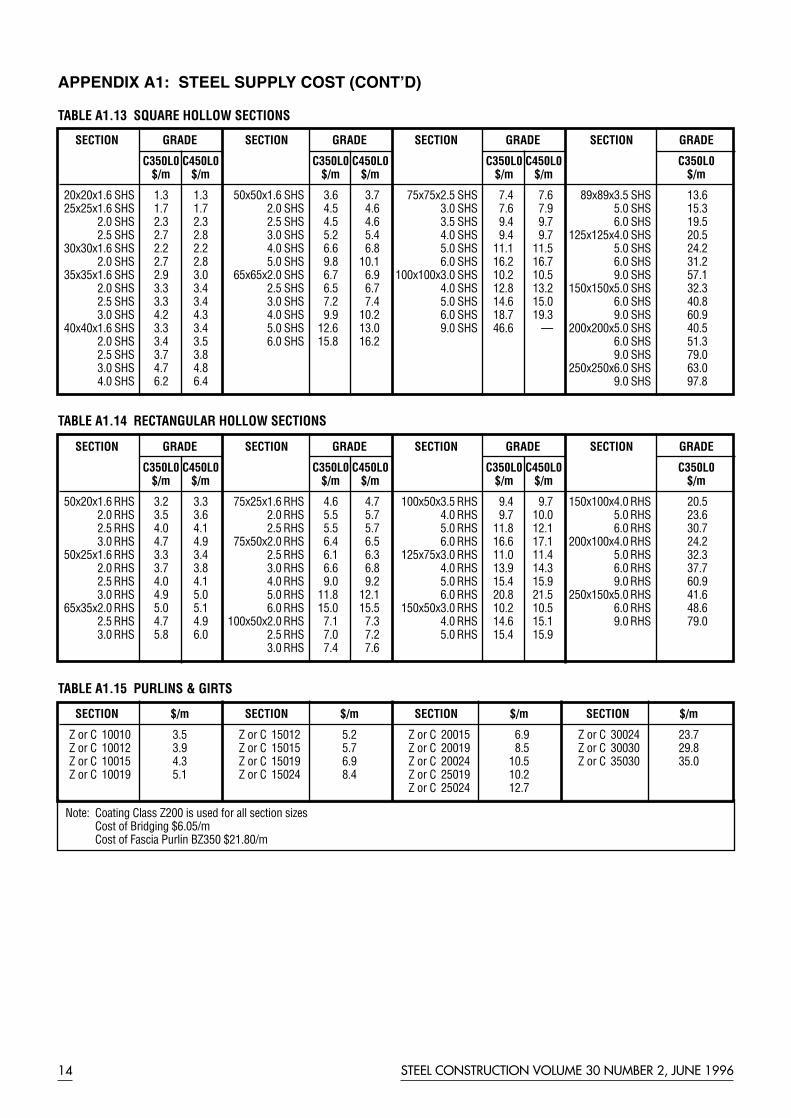
Note: Coating Class Z200 is used for all section sizesCost of Bridging $6.05/mCost of Fascia Purlin BZ350 $21.80/m
STEEL CONSTRUCTION VOLUME 30 NUMBER 2, JUNE 199614
APPENDIX A1: STEEL SUPPLY COST (CONT’D)
SECTION $/m SECTION $/m SECTION $/m SECTION $/m
Z or C 10010 3.5 Z or C 15012 5.2 Z or C 20015 6.9 Z or C 30024 23.7Z or C 10012 3.9 Z or C 15015 5.7 Z or C 20019 8.5 Z or C 30030 29.8Z or C 10015 4.3 Z or C 15019 6.9 Z or C 20024 10.5 Z or C 35030 35.0Z or C 10019 5.1 Z or C 15024 8.4 Z or C 25019 10.2
Z or C 25024 12.7
TABLE A1.15 PURLINS & GIRTS
SECTION GRADE SECTION GRADE SECTION GRADE SECTION GRADE
C350L0 C450L0 C350L0 C450L0 C350L0 C450L0 C350L0$/m $/m $/m $/m $/m $/m $/m
20x20x1.6 SHS 1.3 1.3 50x50x1.6 SHS 3.6 3.7 75x75x2.5 SHS 7.4 7.6 89x89x3.5 SHS 13.625x25x1.6 SHS 1.7 1.7 2.0 SHS 4.5 4.6 3.0 SHS 7.6 7.9 5.0 SHS 15.3
2.0 SHS 2.3 2.3 2.5 SHS 4.5 4.6 3.5 SHS 9.4 9.7 6.0 SHS 19.52.5 SHS 2.7 2.8 3.0 SHS 5.2 5.4 4.0 SHS 9.4 9.7 125x125x4.0 SHS 20.5
30x30x1.6 SHS 2.2 2.2 4.0 SHS 6.6 6.8 5.0 SHS 11.1 11.5 5.0 SHS 24.22.0 SHS 2.7 2.8 5.0 SHS 9.8 10.1 6.0 SHS 16.2 16.7 6.0 SHS 31.2
35x35x1.6 SHS 2.9 3.0 65x65x2.0 SHS 6.7 6.9 100x100x3.0 SHS 10.2 10.5 9.0 SHS 57.12.0 SHS 3.3 3.4 2.5 SHS 6.5 6.7 4.0 SHS 12.8 13.2 150x150x5.0 SHS 32.32.5 SHS 3.3 3.4 3.0 SHS 7.2 7.4 5.0 SHS 14.6 15.0 6.0 SHS 40.83.0 SHS 4.2 4.3 4.0 SHS 9.9 10.2 6.0 SHS 18.7 19.3 9.0 SHS 60.9
40x40x1.6 SHS 3.3 3.4 5.0 SHS 12.6 13.0 9.0 SHS 46.6 — 200x200x5.0 SHS 40.52.0 SHS 3.4 3.5 6.0 SHS 15.8 16.2 6.0 SHS 51.32.5 SHS 3.7 3.8 9.0 SHS 79.03.0 SHS 4.7 4.8 250x250x6.0 SHS 63.04.0 SHS 6.2 6.4 9.0 SHS 97.8
TABLE A1.13 SQUARE HOLLOW SECTIONS
SECTION GRADE SECTION GRADE SECTION GRADE SECTION GRADE
C350L0 C450L0 C350L0 C450L0 C350L0 C450L0 C350L0$/m $/m $/m $/m $/m $/m $/m
50x20x1.6 RHS 3.2 3.3 75x25x1.6 RHS 4.6 4.7 100x50x3.5 RHS 9.4 9.7 150x100x4.0 RHS 20.52.0 RHS 3.5 3.6 2.0 RHS 5.5 5.7 4.0 RHS 9.7 10.0 5.0 RHS 23.62.5 RHS 4.0 4.1 2.5 RHS 5.5 5.7 5.0 RHS 11.8 12.1 6.0 RHS 30.73.0 RHS 4.7 4.9 75x50x2.0 RHS 6.4 6.5 6.0 RHS 16.6 17.1 200x100x4.0 RHS 24.2
50x25x1.6 RHS 3.3 3.4 2.5 RHS 6.1 6.3 125x75x3.0 RHS 11.0 11.4 5.0 RHS 32.32.0 RHS 3.7 3.8 3.0 RHS 6.6 6.8 4.0 RHS 13.9 14.3 6.0 RHS 37.72.5 RHS 4.0 4.1 4.0 RHS 9.0 9.2 5.0 RHS 15.4 15.9 9.0 RHS 60.93.0 RHS 4.9 5.0 5.0 RHS 11.8 12.1 6.0 RHS 20.8 21.5 250x150x5.0 RHS 41.6
65x35x2.0 RHS 5.0 5.1 6.0 RHS 15.0 15.5 150x50x3.0 RHS 10.2 10.5 6.0 RHS 48.62.5 RHS 4.7 4.9 100x50x2.0 RHS 7.1 7.3 4.0 RHS 14.6 15.1 9.0 RHS 79.03.0 RHS 5.8 6.0 2.5 RHS 7.0 7.2 5.0 RHS 15.4 15.9
3.0 RHS 7.4 7.6
TABLE A1.14 RECTANGULAR HOLLOW SECTIONS

Note: Cost of Edgeform $5/m
APPENDIX A1: STEEL SUPPLY COST (CONT’D)
Diameter M12 M16 M20 M24 M30Length (mm) $/Assembly $/Assembly $/Assembly $/Assembly $/Assembly
30 0.35 0.5 - - -50 - 0.6 1.0 2.6 -100 - 1.0 1.8 3.3 8.0150 - 1.5 2.5 4.3 9.0300 - 2.0 4.5 6.4 11.7400 - 3.0 5.2 7.6 -500 - 3.5 6.5 9.0 -
TABLE A1.21 METRIC COMMERCIAL BOLT (Grade 4.6), NUT & WASHER ASSEMBLY – GALVANISED
Diameter M16 M20 M24 M30 M36Length (mm) $/Assembly $/Assembly $/Assembly $/Assembly $/Assembly
50 1.2 1.5 2.7 - -100 2.0 2.3 4.0 8.4 15.7150 - 3.5 6.2 11.0 17.3
TABLE A1.22 HIGH STRENGTH STRUCTURAL BOLT (Grade 8.8), NUT & WASHER ASSEMBLY – GALVANISED
Product Names Custon Orb Trimdek SpandekCorrugated Monoclad Longspan
Base Generic Profile NamesMetal
Thickness Sinusoidal Trapezoidal Continous Trapezoidalmm $/sqm $/sqm $/sqm
Colorbond 0.42 10.2 10.2 11.7Colorbond 0.48 12.4 12.4 12.9Zincalume 0.42 7.1 7.1 8.3Zincalume 0.48 8.9 8.9 9.7
TABLE A1.19 ROOFING & WALLING PROFILES
Base Metal Thickness (BMT)mm $/sqm
0.60 17.30.75 20.01.00 25.0
TABLE A1.16 STRUCTURAL STEEL DECKING
Supply includes sealants, etc.
Panel Thickness Costmm $/sqm
150 53
TABLE A1.18 COLORBONDSANDWICH PANELS
Diameter Grade 250mm $/m
12 0.916 1.620 2.424 3.530 4.536 5.5
TABLE A1.20 ROUNDS
Sizemm $/Stud
19dia. x 100 1.822dia. x 130 3.0
TABLE A1.17 SHEAR STUDS
STEEL CONSTRUCTION VOLUME 30 NUMBER 2, JUNE 1996 15

STEEL CONSTRUCTION VOLUME 30 NUMBER 2, JUNE 199616
*Note: For further details refer AISC (28)
APPENDIX A2.1: FABRICATION CONNECTION COSTS
General Notes:1) All costs given in Appendix A2.1 are based on an hourly rate of $40 which includes overheads, consumables and
fabricator’s margin for medium sized steel projects.(Greater than a $150,000 steel contract for supply, fab. & erect).
2) These costs do not include material supply costs. Refer to Appendix A1 for details.
3) CFW: Continuous Fillet WeldCPBW: Complete Penetration Butt Weld
Connections Web Side Plate Flexible End Plate Moment Haunch Moment Base Plate
Sectionmass (kg/m) Hours $ Hours $ Hours $ Hours $ Hours $
<60.5 0.8 32 1.0 40 6.2 248 1.6 64 1.5 6060.6 to 160 1.6 64 1.8 72 9.5 380 2.7 108 2.0 80160.1 to 455 3.0 120 3.3 132 11.4 456 5.4 216 3.0 120
Diagram
Comments Cut beam & WSP Cut beam & FEP Doubler plate (200x100x16mm) extra $20ea Cut, beam & platedrill/punch holes drill/punch holes Cut haunch, beam & end plate, drill/punch drill & weld CFW*CFW to WSP * CFW to FEP * holes & weld CPBW to Flange & CFW to Web*
TABLE A2.1.1 CONNECTIONS COSTS
Connections 50% Moment Capacity Splice 100% Moment Capacity Splice Web Splice Plate
Section Welded/Bolted Fully Bolted Welded/Bolted Fully Bolted
mass (kg/m) Hours $ Hours $ Hours $ Hours $ Hours $
<60.5 2.5 100 3.0 120 3.8 152 4.3 172 1.1 4460.6 to 160 6.3 252 8.3 332 9.0 360 11.0 440 2.4 96160.1 to 455 12.3 492 15.8 632 17.8 712 23.8 952 3.5 140
Diagram
Comments Cut plates & beams, drill/punch holes Cut plates & beams, drill/punch holes Cut plate & beamWeb Splice Plate each side. Web Splice Plate each side. drill/punch holes.CFW weld for welded/bolted Single web Splice Plate.
TABLE A2.1.2 SPLICE CONNECTIONS COSTS
Hourly Rate $40/hr

Section Notch End of Beam Cope
mass Un-Stiffened Stiffened(kg/m) Hours $ Hours $ Hours $
<60.5 0.8 32 2.5 100 0.3 1260.6 to 160 1.4 56 4.1 164 0.4 16160.1 to 455 2.3 92 7.9 316 0.7 28
Diagram
Comments Cut notch & beam Cut notch & beam, Cut cope onlystiffener slot & weld CFW
TABLE A2.1.3 NOTCH END OF BEAM AND COPE COSTS
STEEL CONSTRUCTION VOLUME 30 NUMBER 2, JUNE 1996 17
Section Flattened Welded “T” Slotted End Plate Capped as a Wedge Gusset Slotted mass and Slotted Through
kg/m Hours $ Hours $ Hours $ Hours $ Hours $
< 15 0.7 28 1.1 44 1.3 52 2.0 80 1.3 5215.1 to 30 1.0 40 1.5 60 2.2 88 3.8 152 2.4 9630.1 to 60.5 - - 1.8 72 3.4 136 5.5 220 3.7 14860.6 to 160 - - 2.0 80 4.5 180 7.3 292 5.1 204
Diagram
Comments Cut Section & Press Cut Section and Cut Section & Plate, Cut Section & Slot Cut Gusset & SlotCut & CFW weld “T” Slot & CFW weld & CFW weld & CFW weld
TABLE A2.1.4 HOLLOW SECTIONS END-CONNECTIONS COSTS
Connections Universal Columns Connections Equal Angles
Section Welded to Slotted Section Bolted to mass Gussets mass Gussets(kg/m) Hours $ (kg/m) Hours $
< 60.5 2.0 80 < 30 0.9 3660.6 to 160 5.1 204 30.1 to 60.5 1.3 52
60.6 to 120 1.8 72
Diagram Diagram
Comments Cut bracing member & Gusset Comments Cut bracing member CPBW web to gusset & CFW & Gusset flanges to gusset Drill/Punch holesCFW gusset to other members CFW gusset to other
members
TABLE 2.1.5 BRACING CONNECTION COSTS
APPENDIX A2.1: FABRICATION CONNECTION COSTS (CONT)

STEEL CONSTRUCTION VOLUME 30 NUMBER 2, JUNE 199618
APPENDIX A2.2: FABRICATION WORK ALONG A MEMBER COSTS
General Notes:1) All costs given in Appendix A2.2 are based on an hourly rate of $40 which includes overheads,
consumables and fabricator’s margin for medium sized steel projects.(Greater than a $150,000 steel contract for supply, fab. & erect).
2) These costs do not include material supply costs. Refer to Appendix A1 for details.
3) CFW: Continuous Fillet WeldCPBW: Complete Penetration Weld
Note: All rates given above are for non overlap except for “CHS Profiled” joints and may include stiffeners which are added to above costs.Extra for overlap joints 10%. Weld CFW except for the flanges of I-Sections are CPBW in the 60.1 - 120kg/m range only.
Section Hours per web member per joint for cutting, handling, assembly & welding.
mass Angles RHS/SHS CHS - Gusset Plate CHS Profiled I- Sectionskg/m Hours $ Hours $ Hours $ Hours $ Hours $
< 30 0.4 16 0.5 20 1.8 72 1.6 64 1.4 5630.1 to 60.5 0.7 28 1.0 40 3.0 120 2.9 116 2.8 11260.6 to 120 - - - - 4.2 168 3.3 132 4.0 160
Diagram
TABLE A2.2.1 TRUSS WEB MEMBER FABRICATION COSTS
*Note: CPBW costs are based on 10mm thick stiffener. For thicker stiffeners refer to Table A2.3.3 for additional weldingcosts. CFW are based on 6mm CFW.
Stiffeners Fitted Stiffener Fitted Stiffener Curtailed Stiffener Curtailed Stiffener
Section - Butt welded ends - Fillet welded - Both ends - Single end
mass (kg/m) Hours $ Hours $ Hours $ Hours $
<60.5 1.4 56 1.1 44 0.7 28 0.8 3260.6 to 160 2.7 108 1.6 64 1.1 44 1.2 48160.1 to 455 4.1 164 3.0 120 1.6 64 1.7 68
Diagram
Comments Cut & weld Cut & weld Cut & weld Cut & weldFlange CPBW* Flange / Web CFW Web CFW Flange / Web CFW/ Web CFW
TABLE A2.2.2 STIFFENERS FABRICATION COSTS
Hourly Rate $40/hr

Note: CFW all around stiffeners
STEEL CONSTRUCTION VOLUME 30 NUMBER 2, JUNE 1996 19
APPENDIX A2.2: FABRICATION WORK ALONG A MEMBER COSTS (CONT’D)
Note: Stripping, handling, assembly,CFW to web/flanges
Longitudinal butt welds if required, refer Table A2.3.2 & A2.3.3.
Section Costmass kg/m Hours/m $/m
315 to 455 2.5 100455.1 to 700 4.5 180
TABLE A2.2.4 THREE PLATE GIRDERFABRICATION COSTS
Item Hours $
Purlin cleat 0.25 10Fly bracing 0.25 10cleat
Comments Cut, drill & weld
TABLE A2.2.7 PURLIN CLEAT & FLYBRACING CLEAT COSTS
Sectionmass Weld Each Sidekg/m Hours/m $/m
<60.5 0.8 3260.6 to 160 1.0 40160.1 to 455 1.1 44
Diagram
Comments Weld CFW to eachside of cover plate
TABLE A2.2.8 COVER PLATE
Note: For lengths up to 12mCPBW used on plate preparation
For splice welding of lengths, refer toA2.3.3 for additional costs.
Dia x Plate Hours CostThickness
mm hours/m $/m
750x12 2.8 110900x16 4.5 1801200x20 7.5 3001200x25 9.3 370
TABLE A2.2.5 TUBULAR COLUMNFABRICATED COSTS
Note: Camber achieved by Heating orPressing.
For heaviour sections ie. >160.1kg/m, it is generally more economical toprofile cut the web.
Sectionmass Hours/kg/m beam $
<60.5 1.5 6060.6 to 160 2.0 80160.1 to 455 8.0 320
TABLE A2.2.6 CAMBER COSTS
Penetrations Unreinforced Reinforced
Section mass Circular Rectangular Rectangular Rectangular Rectangular
(kg/m) Hours $ Hours $ Hours $ Hours $ Hours $
<60.5 0.4 16 0.7 28 2.0 80 3.4 136 4.2 16860.6 to 160 0.5 20 0.8 32 2.4 96 4.1 164 5.7 228160.1 to 455 0.7 28 1.2 48 3.7 148 6.1 244 8.5 340
Diagram
TABLE A2.2.3 PENETRATIONS FABRICATION COSTS

Notes for Tables A2.3.1, A2.3.2 & A2.3.3Multiplying factors to above costs, depending on access:Site welding: 1.3Overhead welding: 1.5Vertically welding: 1.2IPBW depth of penetration is 0.5tGrinding welds flush = 0.4hrs/m = $16/mNote: Edge Preparation is included within the price.
See note below
See note below
See note below
Plate thick. Single V Double V
(t) Short Length Weld ≤250mm Long Length Weld >250mm Short Length Weld ≤250mm Long Length Weld >250mm
mm Hours/m $/m Hours/m $/m Hours/m $/m Hours/m $/m
12 1.7 68 1.3 52 1.9 76 1.6 6416 2.9 116 2.1 84 3.1 124 2.4 9620 3.5 140 2.5 100 4.0 160 3.0 12025 5.6 224 4.0 160 5.1 204 3.9 15628 7.1 284 5.0 200 6.0 240 4.5 18032 9.2 366 6.4 256 7.2 288 5.3 21240 13.4 536 9.2 368 9.6 384 6.9 27645 16.0 640 11.0 440 11.1 442 8.0 31850 19.9 796 13.6 544 13.7 548 9.8 392
TABLE A2.3.3 COMPLETE PENETRATION BUTT WELDS
LEGENDCFW: Continuous Fillet WeldCPBW: Complete Penetration Butt WeldIPBW: Incomplete Penetration Butt Weld (50% Penetration)GP: General PurposeSP: Structural Purpose
STEEL CONSTRUCTION VOLUME 30 NUMBER 2, JUNE 199620
APPENDIX A2.3: FABRICATION ELEMENT COST
General Notes:This Appendix has been provided to assist with costing connections or details not otherwise covered in Appendices A2.1and A2.2 (Connection Costs and Work Along a Member). Costs contained in those Appendices already include (whereappropriate) costs provided in this Appendix.
Visual inspection of welds is included however ultrasonic weld inspection is extra.
Leg size GP Weld SP Weld
tw Short Length Weld ≤250mm Long Length Weld >250mm Short Length Weld ≤250mm Long Length Weld >250mm
mm Hours/m $/m Hours/m $/m Hours/m $/m Hours/m $/m
6 0.3 12 0.2 8 0.3 12 0.25 108 0.6 24 0.4 16 0.7 28 0.50 2010 0.9 36 0.7 28 1.0 40 0.75 3012 1.2 48 0.9 36 1.3 52 1.00 4015 1.8 72 1.4 56 2.0 80 1.50 60
TABLE A2.3.1 CONTINUOUS FILLET WELDS
Plate thick. Single V Double V
(t) Short Length Weld ≤250mm Long Length Weld >250mm Short Length Weld ≤250mm Long Length Weld >250mm
mm Hours/m $/m Hours/m $/m Hours/m $/m Hours/m $/m
20 2.9 116 2.1 84 3.4 136 2.6 10425 3.5 140 2.5 100 4.2 168 3.3 13228 4.4 176 3.2 128 5.1 204 3.9 15632 5.0 198 3.5 140 5.4 216 4.1 16440 6.5 260 4.5 180 6.6 264 4.9 19645 7.6 304 5.4 216 7.5 300 5.5 22050 9.1 364 6.4 256 8.3 332 6.2 248
TABLE A2.3.2 INCOMPLETE PENETRATION BUTT WELDS
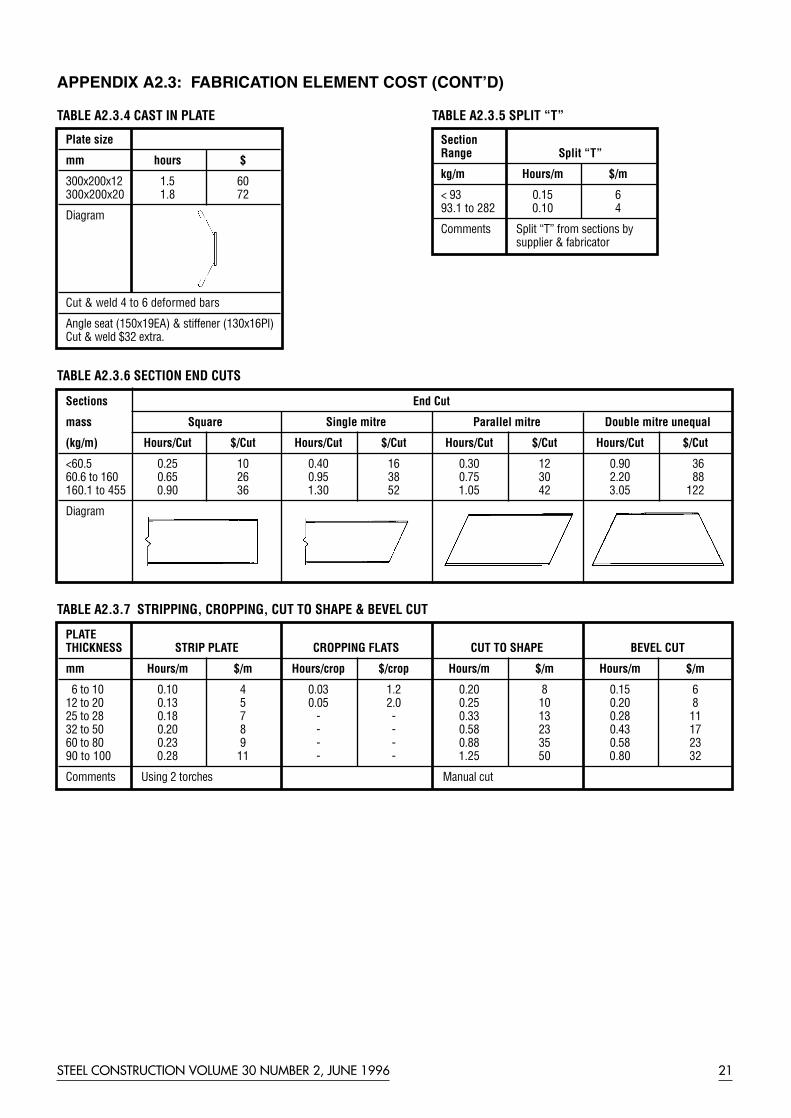
STEEL CONSTRUCTION VOLUME 30 NUMBER 2, JUNE 1996 21
Sections End Cut
mass Square Single mitre Parallel mitre Double mitre unequal
(kg/m) Hours/Cut $/Cut Hours/Cut $/Cut Hours/Cut $/Cut Hours/Cut $/Cut
<60.5 0.25 10 0.40 16 0.30 12 0.90 3660.6 to 160 0.65 26 0.95 38 0.75 30 2.20 88160.1 to 455 0.90 36 1.30 52 1.05 42 3.05 122
Diagram
TABLE A2.3.6 SECTION END CUTS
APPENDIX A2.3: FABRICATION ELEMENT COST (CONT’D)
Plate size
mm hours $
300x200x12 1.5 60300x200x20 1.8 72
Diagram
Cut & weld 4 to 6 deformed bars
Angle seat (150x19EA) & stiffener (130x16Pl)Cut & weld $32 extra.
TABLE A2.3.4 CAST IN PLATE
Section Range Split “T”
kg/m Hours/m $/m
< 93 0.15 693.1 to 282 0.10 4
Comments Split “T” from sections bysupplier & fabricator
TABLE A2.3.5 SPLIT “T”
PLATE THICKNESS STRIP PLATE CROPPING FLATS CUT TO SHAPE BEVEL CUT
mm Hours/m $/m Hours/crop $/crop Hours/m $/m Hours/m $/m
6 to 10 0.10 4 0.03 1.2 0.20 8 0.15 612 to 20 0.13 5 0.05 2.0 0.25 10 0.20 825 to 28 0.18 7 - - 0.33 13 0.28 1132 to 50 0.20 8 - - 0.58 23 0.43 1760 to 80 0.23 9 - - 0.88 35 0.58 2390 to 100 0.28 11 - - 1.25 50 0.80 32
Comments Using 2 torches Manual cut
TABLE A2.3.7 STRIPPING, CROPPING, CUT TO SHAPE & BEVEL CUT

STEEL CONSTRUCTION VOLUME 30 NUMBER 2, JUNE 199622
APPENDIX A2.3: FABRICATION ELEMENT COST (CONT’D)
Plate Thickness Punching Drilling
mm Hours/unit $/unit Hours/unit $/unit
<16.5 0.02 0.8 0.05 2.016.6 to 32 - - 0.10 4.032.5 to 50 - - 0.15 6.0
TABLE A2.3.8 DRILLING & PUNCHING HOLES
Plate Thickness Punching Drilling & Oxy Cutting
mm Hours/unit $/unit Hours/unit $/unit
<16.5 0.02 0.8 0.05 2.016.6 to 32 - - 0.30 12.032.5 to 50 - - 1.50 60.0
TABLE A2.3.9 DRILLING & PUNCHING SLOTTED HOLES
Weight/unit Cleats, Stiffeners,Gussets & Base plates
kg Hours/Unit $
< 5 0.13 55 to 15 0.25 1015.1 to 30 0.50 2030.1 to 80 0.75 30
TABLE A2.3.10 HANDLING & ASSEMBLY
TYPE Hours/Unit $
D-Bracket 0.3 12Turnbuckle 0.5 20
Comment D-Bracket (Slot hole)Turnbuckle ( weld rod to plate, cut & weld gusset plate, & drill 2 holes).
TABLE A2.3.11 BRACING WITH RODS

STEEL CONSTRUCTION VOLUME 30 NUMBER 2, JUNE 1996 23
Shop Drawings Fabrication Shop DrawingRatio of Fabrication Hours to Shop Drawing Hours Hours Hours
Low Rise or Light Portal Frame 4 1Portal with mezzanine 2.5 1Complicated work or with variations 1 3
TABLE A2.4.1 INITIAL STEEL DETAILING COST
Note: Above rates include checking of drawings* Drawings with minor changesMarking plans typically required:-Holding Down Bolts, Elevations, Roof & Floor Plans, Intersections & Purlin/Girts.ie. Portal Frame = 3 Drawings @ 15 Hours/Drg & Multi Storey Frame = (5 Drg + Floor Plans @ 15 Hours/Drg)Shop Drawings include connections
Portal Multi Storey TrussFrame Hours/Drw $/Drw Frame Hours/Drw $/Drw Hours/Drw $/Drw
Marking Plans: Marking Plans: Marking Plans:(see note) 20 800 Floor Plan 20 800 (see note)
Repeated Floor Plan* 3 120
Shop Drawings: Shop Drawings: Shop Drawings:Haunch Member 10 400 Beam Member 8 320 Profiled CHS 17 680Column Member 5.0 200 Column Member 5 200 Non-profiled 9 360Repeated Member* 1.5 60 Repeated Member* 1.5 60Bracing Member-(Angle) 1.5 60-(Rod with D-bracket) 0.4 16Flybracing 0.7 28Mullion door & door head 2.6 104
TABLE A2.4.2 DETAILED STEEL DETAILING COSTS
Hourly Rate $40/hr
APPENDIX A2.4: DRAWING COSTS
General Note:1) All costs given in Appendix A2 allow fabricator’s margin for medium sized steel projects
(greater than a $150,000 steel contract for supply, fabrication & erect).
APPENDIX A2.5:TRANSPORT COSTS
General Note:1) Allow for twice the cost of transportation if surface treatment is
applied at a premises other than the fabrication shop.Costs are based on a truck load of steel.
Transport Fab Shop To Paint Shop or Site
Sectionmass(kg/m) $/member
<60.5 1560.6 to 160 56160.1 to 455 225
TABLE A2.5.1 TRANSPORTATION COSTS

STEEL CONSTRUCTION VOLUME 30 NUMBER 2, JUNE 199624
Note: Alkyd Primer 50microns including hand or power clean, Class 1Inorganic Zinc Silicate (ZnSi) 75 microns including abrasive blast, Class 2.5 blast.Alkyd Gloss 40microns; MIO 100 microns.For Double Dip Galvanizing, add 30% to above rates (typically required for lengths greater than 12m; check with local galvanizers).
SectionPaint Types
Hot Dipmass Alkyd Primer Alkyd Gloss ZnSi MIO/High Acrylic Latex Galvanize
Built Epoxy
(kg/m) $/sqm $/sqm $/sqm $/sqm $/sqm $/sqm
<60.5 6 6 18 9 8 1760.6 to 160 5 5 16 8 7 23160.1 to 455 4 4 14 7 6 33
TABLE A3.1 SURFACE TREATMENT COSTS
Note: Rates include supply & paint/sprayIntumescent Paint inc. ZnSi Class 2.5 blast
SectionIntumescent Vermiculite
mass Fire Rating Level
1 Hr 2 Hrs 3 Hrs
(kg/m) $/sqm $/sqm $/sqm
<60.5 108 27 3760.6 to 160 106 23 35160.1 to 455 104 17 33
TABLE A3.4 PASSIVE FIRE PROTECTION COSTS
Item weight Hot Dip Gal.(kg) $/item
0-2.5 1.52.5-5 3.0
5-10 4.510-15 6.015-20 8.0
>20 10 plus
TABLE A3.2 LOOSE CLEATS
COMMENTS If >50mm useTable A3.1
TYPE Painting Galvanizing
Multiplication factor to Table A3.1
Section size
<50mm ALL
2 Dimensional 2.0 1.5
3 Dimensional 2.0 2.0
TABLE A3.3 FABRICATED FRAMES OR TRUSSES
APPENDIX A3: SURFACE TREATMENT COSTS
General Note:1) All costs given in Appendix A3 allow fabricator’s margin for medium sized steel projects.
(Greater than a $150,000 steel contract for supply, fab. & erect).

STEEL CONSTRUCTION VOLUME 30 NUMBER 2, JUNE 1996 25
Note: Pierced Fixed (includes screws)Concealeded Fixed ($1.1/clip extra)
Fixing includes Scaffolding, Crane, etc.
APPENDIX A4: ERECTION COSTS
General Note:1) All costs given in Appendix A4 allow fabricator’s / erector’s margin for medium sized steel projects
(greater than a $150,000 steel contract for supply, fab & erect)
Note: Crane rates allow for 1 hour travel per dayFull access of crane is assumedRates allow for three erectors at all timesTightening of bolts is allowed in the rates as appropriate
PLANT COST LABOUR
CRANE ACCESS EQUIPMENT COST
Unload & 2 x Mobile Erect Capacity Scaffolds 2 x Scissor Lifts 2 x Booms
23 t 16 t 6m 6m 12m 18m
$110/hr $85/hr $4/hr $14/hr $30/hr $50/hr $40/hr
Section mass Minutes/ $ per $ per $ per $ per $ per $ per $ per (kg/m) Member Member Member Member Member Member Member Member
<60.5 20 37 28 3 9 20 33 4060.6 to 160 20 37 28 3 9 20 33 40160.1 to 455 24 44 34 3 11 24 40 48Purlins 7 13 10 1 3 7 12 14Girts 3 6 4 0.4 1 3 5 6
TABLE A4.1 ERECTION COSTS. Rates are for typical portal frames and multi storey buildings.
Base Metal Thickness $/sqmmm
All 6
TABLE A4.2 FIXING STEEL DECK
Section depthmm $/m
100 to 150 7
TABLE A4.3 EDGEFORM
Size $/Stud
19mm dia. x 100mm 0.9022mm dia. x 130mm 1.00
TABLE A4.4 WELDING SHEAR STUDS
Profiles $/sqm
All 2.2
TABLE A4.5 FIXING ROOFING & WALLING PROFILES
Panel Thickness Costmm $/sqm
150 27
TABLE A4.6 COLORBOND SANDWICH PANELS

STEEL CONSTRUCTION VOLUME 30 NUMBER 2, JUNE 199626
APPENDIX B1: STANDARD SECTION LENGTHS
Note: Other lengths are available subject to lead times and minimum order quantities.
SECTIONSTANDARD LENGTHS (m)
6.0 6.5 7.5 8.0 9.0 10.5 12.0 13.5 15.0 16.5 18.0
Universal Sections - AS/NZS 3679.1-300150UB, 180UB, 100UC • • • • • •All other sections • • • • • • •
Welded Sections -AS/NZS 3679.2-300All sections • • • •
Parallel Flange Channels - AS/NZS 3679.1-300380PFC • • • • •300PFC • • • • • •250PFC • • • • • •All other sections • • • • •
Taper Flange Beams-AS/NZS 3679.1-250All sections • •
Taper Flange Channels - AS/NZS3679.1-250125TFC • •100TFC • •75TFC • •
Equal Angles - AS/NZS3679.1-300200x200EA • • • •150x150EA • • • •125x125EA • • • •
Equal Angles -AS/NZS3679.1-250100x100EA • •90x90EA • •75x75EA •All other equal angles • •
Unequal Angles-AS/NZS 3679.1-300150x100UA • • • •150x90UA • • • •
Unequal Angles- AS/NZS 3679.1-250125x75UA • •100x75UA • •75x50UA • •65x50UA • •
Flats, Squares, Rounds-AS/NZS 3679.1-250All sections •
Circular Hollow Sections -AS1163Grades 250L0 •Grade 350L0 •
RHS/SHS -AS1163 All sections •

NOTE: Standard Plates should be ordered for quantities less than 10 tonnes (in any one thickness).
STEEL CONSTRUCTION VOLUME 30 NUMBER 2, JUNE 1996 27
APPENDIX B2: STANDARD PLATE LENGTHS (metres)
Width Thickness (mm)(mm) 5 6 8 10 12 16 20 25 32 40 50 60 70 80 90 100
1800 6 6 6 6 6 6 6 6 6 6 6 6 6 5.6
2400 6 & 9 6 & 9 6 & 9 6 & 9 6 & 9 6 & 9 6 & 9 6 & 9 6 & 9 6 & 9 6 & 9 6 6 6 & 5.2 4
3000 9 9 9 9 9 9 9 9
3200 12 12 12 12 12 12
PLATE SIZE SCHEDULE - AS/NZS 3678 - GRADE 250
Width Thickness (mm)(mm) 5 6 8 10 12 16 20 25 32 40 50 60 70 80 90 100
2400 9.6 9.6 9.6 9.6 9.6 9.6 7.6
3100 9.6 9.6 9.6 9.6
PLATE SIZE SCHEDULE - AS/NZS 3678 - GRADE 350

4.0 Minimum Length 2.4 Minimum Length
STEEL CONSTRUCTION VOLUME 30 NUMBER 2, JUNE 199628
APPENDIX B3: NON STANDARD MAXIMUM PLATE LENGTHS (metres)
Width Preferred Thickness (mm)(mm) 5 6 8 10 12 16 20 25 28 32 36 40 45 50 55 60 70 80 90 100
1200 18.3 18.3 18.3 18.3 18.3 18.3 18.3 18.3 17.6 15.7 14.1 12.8 11.7 10 8.7 7.7 6.9
1300 18.3 18.3 18.3 18.3 18.3 18.3 18.3 17.8 16.0 14.2 12.8 11.6 10.6 9.0 7.8 6.8 6.1
1400 18.3 18.3 18.3 18.3 18.3 18.3 18.3 17.0 15.4 13.6 12.3 11.1 10.2 8.6 7.5 6.6 5.9
1500 18.3 18.3 18.3 18.3 18.3 18.3 18.3 17.4 15.6 13.8 12.5 11.3 10.3 8.8 7.6 6.7 6.0
1600 18.3 18.3 18.3 18.3 18.3 18.3 18.3 18.3 16.8 15.1 13.4 12.0 10.9 10.0 8.5 7.4 6.4 5.6
1700 18.3 18.3 18.3 18.3 18.3 18.3 18.3 18.3 17.6 15.8 14.2 12.7 11.5 10.5 9.0 7.8 6.8 6.1
1800 18.3 18.3 18.3 18.3 18.3 18.3 18.3 18.3 18.3 16.5 14.6 13.2 12.0 10.9 9.3 8.1 7.1 6.3
1900 18.3 18.3 18.3 18.3 18.3 18.3 18.3 18.3 18.3 18.3 17.4 15.6 13.9 12.5 11.3 10.4 8.8 7.7 6.7 6.0
2000 18.3 18.3 18.3 18.3 18.3 18.3 18.3 18.3 18.3 18.3 16.6 14.9 13.2 11.8 10.8 9.8 8.4 7.3 6.4 5.7
2100 18.3 18.3 18.3 18.3 18.3 18.3 18.3 18.3 18.3 17.7 15.8 14.2 12.6 11.2 10.2 9.5 8.0 6.9 6.0 5.5
2200 18.3 18.3 18.3 18.3 18.3 18.3 18.3 18.3 18.3 16.6 15.0 13.6 12.0 10.8 9.8 8.9 7.6 6.6 5.7 5.1
2300 18.3 18.3 18.3 18.3 18.3 18.3 18.3 18.3 18.2 15.8 14.4 13.0 11.4 10.3 9.3 8.5 7.2 6.3 5.5 4.9
2400 18.3 18.3 18.3 18.3 18.3 18.3 18.3 18.3 17.4 15.2 13.8 12.4 11.0 9.8 8.9 8.2 6.9 6.0 5.2 4.7
2500 18.3 18.3 18.3 18.3 18.3 18.3 18.3 18.3 16.8 14.7 13.3 11.9 10.5 9.4 8.6 7.8 6.6 5.8 5.0 4.5
2600 18.3 18.3 18.3 18.3 18.3 18.3 18.3 18.2 16.2 14.1 12.8 11.4 10.2 9.1 8.2 7.5 6.4 5.5 4.8 4.3
2700 18.3 18.3 18.3 18.3 18.3 18.3 18.3 17.4 15.6 13.6 12.2 11.0 9.7 8.8 7.9 7.2 6.1 5.3 4.6 4.1
2800 18.3 18.3 18.3 18.3 18.3 18.3 18.3 16.8 15.0 13.2 11.8 10.6 9.4 8.4 7.6 7.0 5.9 5.1 4.4 3.9
2900 18.3 18.3 18.3 18.3 18.3 18.3 18.3 16.3 14.6 12.6 11.4 10.2 9.1 8.1 7.4 6.7 5.7 4.9 4.3 3.8
3000 18.3 18.3 18.3 18.3 18.3 18.3 18.3 15.8 14.0 12.2 11.0 9.9 8.8 7.9 7.1 6.5 5.5 4.8 4.1 3.7
3100 18.3 18.3 18.3 18.3 18.3 18.3 18.3 15.2 13.6 11.9 10.6 9.6 8.5 7.6 6.9 6.3 5.3 4.6 4.0 3.5
3200 - 18.3 18.3 18.3 18.3 18.3 18.3 14.8 13.2 11.5 10.4 9.3 8.2 7.3 6.6 6.0 5.1 4.4 3.8 3.4
3300 - 18.3 18.3 18.3 18.3 18.3 18.0 14.2 12.8 11.1 10.0 9.0 7.9 7.1 6.5 5.9 5.0 4.3 3.7 3.3
PLATE SIZE SCHEDULE : AS 3678 - SEE AVAILABILITY BELOW
Grade Thickness (mm)
AS 1594 5-12
AS/NZS 3678-200 5-12
AS/NZS 3678-250 5-100AS/NZS 3678-250 L15 8-100
AS/NZS 3678-350 5-80AS/NZS 3678-350 L15 8-80
Availability:
NOTES:1. Plate thickness and width may be ordered to required dimensions as follows (extra charge may apply depending on quantity)
2. Minimum order for Non Standard Plate ( in any one thickness ) is 10 tonnes.
Thickness (mm) Increments(mm)
5 to 25 0.0525 to 60 160 to 100 5
Widths: Increments of 10 mm
Product supplied from Coil Platemin length 2.4max length 9.0

STEEL CONSTRUCTION VOLUME 30 NUMBER 2, JUNE 1996 29
Section 4-Sides 3-Sidessqm/m sqm/m
150 UB 14.0 0.576 0.50118.0 0.584 0.509
180 UB 16.1 0.682 0.59218.1 0.685 0.59522.2 0.691 0.601
200 UB 18.2 0.764 0.66522.3 0.910 0.77725.4 0.912 0.77929.8 0.922 0.788
250 UB 25.7 0.961 0.83731.4 1.06 0.91437.3 1.07 0.922
310 UB 32.0 1.16 1.0140.4 1.24 1.0746.2 1.25 1.08
360 UB 44.7 1.35 1.1850.7 1.36 1.1956.7 1.37 1.20
410 UB 53.7 1.48 1.3059.7 1.49 1.31
460 UB 67.1 1.63 1.4474.6 1.64 1.4582.1 1.65 1.45
530 UB 82.0 1.85 1.6492.4 1.86 1.65
610 UB 101 2.07 1.84113 2.08 1.85125 2.09 1.86
TABLE C.1 UNIVERSAL BEAMS
Section 4-Sides 3-Sidessqm/m sqm/m
700 WB 115 2.36 2.11130 2.38 2.13150 2.40 2.15173 2.51 2.24
800 WB 122 2.56 2.31146 2.68 2.40168 2.70 2.42192 2.81 2.51
900 WB 175 2.98 2.68218 3.20 2.85257 3.41 3.01282 3.42 3.02
1000 WB 215 3.17 2.87258 3.39 3.04296 3.60 3.20322 3.62 3.22
1200 WB 249 3.41 3.13278 3.71 3.36317 3.92 3.52342 3.94 3.54392 4.34 3.84423 4.35 3.85455 4.37 3.87
TABLE C.2 WELDED BEAMS
APPENDIX C: SURFACE AREA PER METRE FOR SECTIONS
General Note:1) Three sides excludes top face of flange.

STEEL CONSTRUCTION VOLUME 30 NUMBER 2, JUNE 199630
Section 4-Sides 3-Sidessqm/m sqm/m
100 UC 14.8 0.563 0.464
150 UC 23.4 0.885 0.73330.0 0.899 0.74637.2 0.908 0.754
200 UC 46.2 1.18 0.98252.2 1.19 0.98959.5 1.22 1.02
250 UC 72.9 1.48 1.2389.5 1.50 1.24
310 UC 96.8 1.79 1.48118 1.81 1.50137 1.82 1.51158 1.84 1.53
TABLE C.3 UNIVERSAL COLUMNS
Section 4-Sides 3-Sidessqm/m sqm/m
350 WC 197 2.02 1.67230 2.03 1.68258 2.04 1.69280 2.05 1.70
400 WC 144 2.33 1.93181 2.34 1.94212 2.36 1.96270 2.38 1.98303 2.39 1.99328 2.40 2.00361 2.38 1.98
500 WC 228 2.94 2.44267 2.96 2.46290 2.97 2.47340 2.98 2.48383 2.88 2.38414 2.90 2.40440 2.88 2.38
TABLE C.4 WELDED COLUMNS
Section sqm/m
150 PFC 0.579180 PFC 0.638200 PFC 0.678230 PFC 0.737250 PFC 0.834300 PFC 0.932380 PFC 1.13
TABLE C.5 PARALLEL FLANGE CHANNELS
Section sqm/m
75 TFC 0.286100 TFC 0.374125 TFC 0.48
TABLE C.6 TAPER FLANGE CHANNELS
Section sqm/m
25 x 25 EA 0.095330 x 30 EA 0.11540 x 40 EA 0.15545 x 45 EA 0.17550 x 50 EA 0.19555 x 55 EA 0.21565 x 65 EA 0.25575 x 75 EA 0.29290 x 90 EA 0.352
100 x 100 EA 0.392125 x 125 EA 0.491150 x 150 EA 0.590200 x 200 EA 0.788
TABLE C.7 EQUAL ANGLES
Section sqm/m
65 x 50 UA 0.22575 x 50 UA 0.244
100 x 75 UA 0.342125 x 75 UA 0.392150 x 90 UA 0.471150 x 100 UA 0.491
TABLE C.8 UNEQUAL ANGLES
APPENDIX C: SURFACE AREA PER METRE FOR SECTIONS (CONT’D)

STEEL CONSTRUCTION VOLUME 30 NUMBER 2, JUNE 1996 31
Section sqm/m
42.4 CHS 0.13348.3 CHS 0.15260.3 CHS 0.18976.1 CHS 0.23988.9 CHS 0.279
101.6 CHS 0.319114.3 CHS 0.359139.7 CHS 0.439165.1 CHS 0.519168.3 CHS 0.529219.1 CHS 0.688273.1 CHS 0.858323.9 CHS 1.02355.6 CHS 1.12406.4 CHS 1.28457.0 CHS 1.44508.0 CHS 1.60610.0 CHS 1.92
TABLE C.9 CIRCULAR HOLLOW SECTIONS
Section sqm/m
65 x 35 x 3.0 RHS 0.190
70 x 50 x 3.0 RHS 0.240x 4.0 RHS 0.233
100 x 50 x 3.0 RHS 0.290x 3.5 RHS 0.285x 4.0 RHS 0.283x 5.0 RHS 0.279x 6.0 RHS 0.274
125 x 75 x 3.0 RHS 0.390x 4.0 RHS 0.383x 5.0 RHS 0.379
150 x 50 x 3.0 RHS 0.390x 4.0 RHS 0.383x 5.0 RHS 0.379
150 x 100 x 4.0 RHS 0.483x 5.0 RHS 0.479x 6.0 RHS 0.474
200 x 100 x 4.0 RHS 0.583x 5.0 RHS 0.579x 6.0 RHS 0.574x 9.0 RHS 0.561
250 x 150 x 5.0 RHS 0.779x 6.0 RHS 0.774x 9.0 RHS 0.761
TABLE C.11 RECTANGULAR HOLLOW SECTIONS
Section sqm/m
50 x 50 x 3.0 SHS 0.190x 4.0 SHS 0.183
65 x 65 x 3.0 SHS 0.250
75 x 75 x 3.0 SHS 0.290x 3.3 SHS 0.286x 3.5 SHS 0.285x 4.0 SHS 0.283x 5.0 SHS 0.279x 6.0 SHS 0.274
89 x 89 x 3.5 SHS 0.341x 5.0 SHS 0.334x 6.0 SHS 0.330
100 x 100 x 3.0 SHS 0.390x 3.3 SHS 0.386x 3.8 SHS 0.384x 4.0 SHS 0.383x 5.0 SHS 0.379x 6.0 SHS 0.374x 9.0 SHS 0.361
125 x 125 x 4.0 SHS 0.483x 5.0 SHS 0.479x 6.0 SHS 0.474x 9.0 SHS 0.461
150 x 150 x 5.0 SHS 0.579x 6.0 SHS 0.574x 9.0 SHS 0.561
200 x 200 x 5.0 SHS 0.779x 6.0 SHS 0.774x 9.0 SHS 0.761
250 x 250 x 6.0 SHS 0.974x 9.0 SHS 0.961
TABLE C.10 SQUARE HOLLOW SECTIONS
APPENDIX C: SURFACE AREA PER METRE FOR SECTIONS (CONT’D)

STEEL CONSTRUCTION VOLUME 30 NUMBER 2, JUNE 199632
APPENDIX D1. PORTAL FRAME CASE STUDY
This appendix presents the costing associated with a typical portal frame bay of an industrial building.
The design criteria and frame configuration are similar to that in appendix E1 except the eaves height and span are 6m and25m respectively.
Steel sheeting and overall building bracing have not been included in this case study.
Waste lengths have been calculated assuming supply from standard lengths. Shop detailing costs were determined inaccordance with Table A2.4.1.
SUPPLY COSTS
Items per Member Total Member
Member Section Grade No. of Steel Member Supply Bolt Supply Plates, Flats Other Items per Mark
Mark Members Member Total
No. $/m Finished Waste Type $/ Bolt No. No. & Type Total No. & Type Total $ $Length m Length m $ $
Column 460UB67.1 300 2 75 6.00 M24 4.00 4 230x25 pl 21.24 487 9740.48 m Long
Rafter and 310UB40.4 300 2 46 12.24 1.26 M24 4.00 12 180x32 pl 37.84 180x32 pl 23.95 846 1,692Haunch and 2.5 0.83 m Long 0.52 m Long
Purlins Z20024 Lapped, G450 24 10.5 9.90 M12 0.35 6 100 x 8 FL 1.24 107 2,5682 rows bridging 0.2 m Long
Fly Braces 50 x 50 x 5 EA 250 11 3.3 0.68 M12 0.35 1 100 x 8 FL 0.62 3 330.1 m Long
SubTotal $5,267
Hourly Rate ($/Hr) 40Detailing Hours / Fabrication Hours 0.25Notes: 1. Hrs = Workhours.
2. Fabrication costs are associated with the supported member.
FABRICATION AND DETAILING COSTS
Work per Member Fabrication Detailing Member Member
Member Section No. of Camber Connections Plates, Flats, Notches, Total Total Total Mark
Mark Members Stiffeners, Other Penetrations, Other per Member per Member Total
No. Hrs Type - Hrs Type - Hrs No. & Type Total No. & Type Total Hrs $ Hrs $ $ $end 1 end 1 end 2 end 2 Hrs Hrs
Column 460UB67.1 2 Base Pl 2.00 2.0 80 0.5 20 100 200
Rafter and 310UB40.4 2 Bolted 6.20 BMEP 1.60 4 @ Web Stiff 7.6 15.4 616 3.9 156 772 1,544Haunch Haunch & Fl Doublers
Fly Braces 50 x 50 x 5 EA 11 cleat 0.25 0.25 10 0.1 2.5 13 138
SubTotal $1,882

STEEL CONSTRUCTION VOLUME 30 NUMBER 2, JUNE 1996 33
APPENDIX D1. PORTAL FRAME CASE STUDY (CONT’D)
Items per Member Total Member
Member Section Finished No. of Surface Treatment per Mark
Mark Length Members Member Total
m No. Treatment Faces Profile Profile Prep. & Additional $ $Type Covered Area Area First Coat Coats
m2/m m2 $/m2 $/m2
Column 460UB67.1 6.00 2 Alkyd Primer 4 1.63 9.8 5.00 49 98Rafter 310UB40.4 12.24 2 Alkyd Primer 4 1.24 18.3 6.00 110 220Fly Braces 50x50x5 EA 0.68 11 Alkyd Primer 4 0.20 0.1 6.00 1 11
SubTotal $329
SURFACE TREATMENT COSTS
Transport per Member Total Member
Member Section Finished No. of Transportation to: per Mark Mark Length Members Member Total
m No. Paint Shop Site $ $
Column 460UB67.1 6.00 2 56 56 112Rafter 310UB40.4 12.24 2 15 15 30
SubTotal $142
TRANSPORT COSTS
Items per Member Erection Member
Member Section Finished No. of Crane Access Labour Shear Studs Other per Mark
Mark Length Members Equipment Member Total
m No. $ $ $ No. $ $ $ $
Column 460UB67.1 6.00 2 37 9 40 86 172
Rafter 310UB40.4 12.24 2 37 9 40 86 172
Z20024 Purlins Lapped, 9.90 24 13 3 14 30 720
2 rows bridging
SubTotal $1,064
ERECTION COSTS
Items per Member Total Member
Member Section Grade No. of Supply Fabrication Detailing Surface Transport Erection per Mark
Mark Members Treatment Member Total
No. $ $ $ $ $ $ $ $
Column 460UB67.1 300 2 487 80 20 49 56 86 778 1,556
Rafter and 310UB40.4 300 2 846 616 156 110 15 86 1829 3,658Haunch
Purlins Z20024 Lapped, G450 24 107 30 137 3,2882 rows bridging
Fly Braces 50 x 50 x 5 EA 250 11 3 10 2.5 1 17 187
Total $8,689
SUMMARY OF COSTS

STEEL CONSTRUCTION VOLUME 30 NUMBER 2, JUNE 199634
SUPPLY COSTS – DESIGN A
Items per MemberTotal Member
Member Section Grade No. of Steel Member Supply Shear Studs Bolt Supply Plates, Flats Other Items per Mark Mark Members Member Total
No. $/m Finished Waste Type $/ No. Type $/ No. No. & Type Total No. & Type Total $ $Length m Length m Stud Bolt $ $
B1 460 UB 67.1 300 120 75.00 12.00 19 1.80 32 M20 1.50 10 90x10 FL 4.90 90x10 FL 50.40 1028 123,360diam 8.8/S (2 @ .35m long, (8 @ .9m long,
$7.00/m) $7.00/m)
B7 460 UB 67.1 300 100 75.00 12.00 19 1.80 32 M20 1.50 7 90x10 FL 2.45 90x10 FL 75.8 1046 104,600diam 8.8/S (.35m long, (8 @ .9m long,
$7.00/m) $7.00/m) and 180x12 FL (1.5m long, $16.90/m)
200x12 FL 11.61 150x19EA, 13.3 25 2,500(.3m long, (.25m long,
$18.70/m) and $44.80/m) and 6 @ 12mm 130x16 FL diam bars, (.13m long, $1.00 each $16.20/m)
SubTotal B1 and B7 $230,460
B2 530 UB 82.0 300 40 92.00 10.00 0.50 19 1.80 38 M20 1.50 14 180x10 FL 5.88 200x16 FL 37.5 1099 43,960diam 8.8/S (.42m long, (1.5m long,
$14.00/m) $25.00/m)
200x20 FL 15.36 150x19EA, 13.3 29 1,160(.3m long, (.25m long,
$31.20/m) and $44.80/m) and 6 @ 12mm 130x16 FL diam bars, (.13m long, $1.00 each $16.20/m)
B3 410 UB 59.7 300 40 68.00 12.00 19 1.80 30 M20 1.50 8 90x10 FL 3.92 886 35,440diam 8.8/S (2 @ .28m long,
$7.00/m)
B4 460 UB 67.1 300 80 75.00 8.40 0.60 19 1.80 32 M20 1.50 10 90x10 FL 4.90 753 60,240diam 8.8/S (2 @ .35m long,
$7.00/m)
B5 410 UB 53.7 300 20 62.00 8.40 0.60 19 1.80 26 M20 1.50 10 90x10 FL 4.90 625 12,500diam 8.8/S (2 @ .35m long,
$7.00/m)
B6 360 UB 44.7 300 40 51.00 10.00 0.50 19 1.80 28 M20 1.50 4 90x10 FL 1.96 180x10 FL 21.0 615 24,600diam 8.8/S (.28m long, (1.5m long,
$7.00/m) $14.00/m)
200x12 FL 11.61 150x19EA, 13.3 25 1,000(.3m long, (.25m long,
$18.70/m) and $44.80/m) and 6 @ 12mm 130x16 FL diam bars, (.13m long,
$1.00 each) $16.20/m)
SubTotal B2 to B6 $178,900
Supply Total Design A $409,360
APPENDIX D2. MULTI-STOREY BUILDING CASE STUDY
This appendix presents the costing asoociated with the office floor beams illustrated in figure D2.1.
Refer figure 2 for the overall floor plan and section 4.2 for a discussion of the design options A and B.
Waste lengths have been calculated assuming supply from standard lengths.

STEEL CONSTRUCTION VOLUME 30 NUMBER 2, JUNE 1996 35
APPENDIX D2. MULTI-STOREY BUILDING CASE STUDY (CONT’D)
Items per MemberTotal Member
Member Section Grade No. of Steel Member Supply Shear Studs Bolt Supply Plates, Flats Other Items per Mark Mark Members Member Total
No. $/m Finished Waste Type $/ No. Type $/ No. No. & Type Total No. & Type Total $ $Length m Length m Stud Bolt $ $
B1 530 UB 82.0 300 120 92.00 12.00 19 1.80 32 M20 1.50 10 90x10 FL 4.90 1182 141,840diam 8.8/S (2 @ .35m long,
$7.00/m)
B7 530 UB 82.0 300 100 92.00 12.00 19 1.80 32 M20 1.50 7 90x10 FL 2.45 180x12 FL 25.4 1200 120,000diam 8.8/S (.35m long, (1.5m long,
$7.00/m) $16.90/m)
200x12 FL 11.61 150x19EA, 13.3 25 2,500(.3m long, (.25m long,
$18.70/m) and $44.80/m) and 6 @ 12mm 130x16 FL diam bars, (.13m long, $1.00 each $16.20/m)
SubTotal B1 and B7 $264,340
SubTotal B2 to B6 As per Design A $178,900
Supply Total Design B $443,240
SUPPLY COSTS – DESIGN B
Figure D2.1

FABRICATION COSTS – DESIGN A
FABRICATION COSTS – DESIGN B
Work per Member Total per Member Member
Member Section No. of Camber Connections Coping Plates, Flats, Notches, Penetrations, FabricationMark
Mark Members Stiffeners, Other OtherTotal
No. Hrs Type - Hrs Type - Hrs Type - Hrs Type - Hrs No. & Type Total No. & Type Total Hrs $ $end 1 end 1 end 2 end 2 end 1 end 1 end 2 end 2 Hrs Hrs
B1 460 UB 67.1 120 2.0 WSP 1.60 WSP 1.60 Web 0.4 2x 0.8 2 @ Stiffened 8.2 14.6 584 70,080Web Rectang. Pens
B7 460 UB 67.1 100 2.0 WSP 1.60 Cast-in- 2.60 2x 0.8 2 slotted holes 0.12 1 Notch and 12.3 19.4 777 77,700Plate Web 2 @ Stiffened Rect
SubTotal B1 and B7 $147,780
B2 530 UB 82.0 40 2.0 WSP 1.60 Cast-in- 2.60 2 slotted holes 0.24 1 Notch and 5.1 11.5 462 18,480Plate 2 @ Unstiff,
Circular
B3 410 UB 59.7 40 1.5 WSP 0.80 WSP 0.80 3.1 124 4,960
B4 460 UB 67.1 80 WSP 1.60 WSP 1.60 3.2 128 10,240
B5 410 UB 53.7 20 1.5 WSP 0.80 WSP 0.80 3.1 124 2,480
B6 360 UB 44.7 40 1.5 WSP 0.80 Cast-in- 2.60 Web 0.3 2 slotted holes 0.12 1 Notch and 3.3 8.6 345 13,800Plate 2 @ Unstiff,
Circular
SubTotal B2 to B6 $49,960
Fabrication Total Design A $197,740
Work per Member Total per Member Member
Member Section No. of Camber Connections Coping Plates, Flats, Notches, Penetrations, FabricationMark
Mark Members Stiffeners, Other OtherTotal
No. Hrs Type - Hrs Type - Hrs Type - Hrs Type - Hrs No. & Type Total No. & Type Total Hrs $ $end 1 end 1 end 2 end 2 end 1 end 1 end 2 end 2 Hrs Hrs
B1 530 UB 82.0 120 2.0 WSP 1.60 WSP 1.60 Web 0.4 2x 0.8 2 @ Unstiff, 1.6 8.0 320 38,400Web Rectangular
B7 530 UB 82.0 100 2.0 WSP 1.60 Cast-in- 2.60 Web 0.4 2 slotted holes 0.12 1 Notch and 5.7 12 497 49,700Plate 2 @ Unstiff, Rect.
SubTotal B1 and B7 $88,100
SubTotal B2 to B6 As per Design A $49,960
Fabrication Total Design B $138,060
Hourly Rate ($/Hr) 40 Notes: 1. Hrs = Workhours.2. Fabrication costs are associated with the supported member.
STEEL CONSTRUCTION VOLUME 30 NUMBER 2, JUNE 199636
APPENDIX D2. MULTI-STOREY BUILDING CASE STUDY (CONT’D)

STEEL CONSTRUCTION VOLUME 30 NUMBER 2, JUNE 1996 37
APPENDIX D2. MULTI-STOREY BUILDING CASE STUDY (CONT’D)
Hourly Rate ($/Hr) 40
Items per Member Total Member
Member Section Finished No. of Surface Treatment per Mark
Mark Length Members Member Total
m No. Treatment Faces Profile Profile Prep. & Additional $ $Type Covered Area Area First Coat Coats
m2/m m2 $/m2 $/m2
B1 460 UB 67.1 12.00 120 2 Hr firespray 3 1.44 17.3 27.00 467 56,040
B7 460 UB 67.1 12.00 100 2 Hr firespray 3 1.44 17.3 27.00 467 46,700
SubTotal B1 and B7 $102,740
B2 530 UB 82.0 10.00 40 2 Hr firespray 3 1.64 16.4 23.00 377 15,080
B3 410 UB 59.7 12.00 40 2 Hr firespray 3 1.31 15.7 27.00 424 16,960
B4 460 UB 67.1 8.40 80 2 Hr firespray 3 1.44 12.1 23.00 278 22,240
B5 410 UB 53.7 8.40 20 2 Hr firespray 3 1.30 10.9 27.00 295 5,900
B6 360 UB 44.7 10.00 40 2 Hr firespray 3 1.18 11.8 27.00 319 12,760
SubTotal B2 to B6 $72,940
Surface Treatment Total Design A $175,680
Items per Member Total Member
Member Section Finished No. of Surface Treatment per Mark
Mark Length Members Member Total
m No. Treatment Faces Profile Profile Prep. & Additional $ $Type Covered Area Area First Coat Coats
m2/m m2 $/m2 $/m2
B1 530 UB 82.0 12.00 120 2 Hr firespray 3 1.64 19.7 27.00 531 63,720
B7 530 UB 82.0 12.00 100 2 Hr firespray 3 1.64 19.7 27.00 531 53,100
SubTotal B1 and B7 $116,820
SubTotal B2 to B6 As per Design A $72,940
Surface Treatment Total Design B $189,760
SURFACE TREATMENT COSTS – DESIGN A
SURFACE TREATMENT COSTS – DESIGN B
Drawing Type No. of Drawings Time per Total Time per Drawing Required Drawing Drawing Type Type Total
No. Hrs Hrs $
Marking Plans eg: elevations, plans, 6 15 90 3,600intersections, etc.
Repeated Marking Plans (similar to a 9 2 18 720previous drawing but with minor changes)
Shop Drawing - Beam Member 7 6 42 1,680
Detailing Total $6,000
DETAILING COSTS – DESIGN A & B

STEEL CONSTRUCTION VOLUME 30 NUMBER 2, JUNE 199638
Transport per Member Total Member
Member Section Finished No. of Transportation to: per Mark Mark Length Members Member Total
m No. Paint Shop Site $ $
B1 460 UB 67.1 12.00 120 56.00 56 6,720
B7 460 UB 67.1 12.00 100 56.00 56 5,600
B2 530 UB 82.0 10.00 40 56.00 56 2,240
B3 410 UB 59.7 12.00 40 15.00 15 600
B4 460 UB 67.1 8.40 80 56.00 56 4,480
B5 410 UB 53.7 8.40 20 15.00 15 300
B6 360 UB 44.7 10.00 40 15.00 15 600
Transport Total $20,540
TRANSPORT COSTS – DESIGN A & B
Items per Member Erection Member
Member Section Finished No. of Crane Access Labour Shear Studs Other per Mark
Mark Length Members Equipment Member Total
m No. $ $ $ $ $ $ $
B1 460 UB 67.1 12.00 120 20 40 32 @ $0.90 27 87 10,440
B7 460 UB 67.1 12.00 100 20 40 32 @ $0.90 27 87 8,700
Scissor lift and 100 45 60 105 10,500welding angle seat to cast-in-
plate
B2 530 UB 82.0 10.00 40 20 40 38 @ $0.90 34 94 3,760
Scissor lift and 40 45 60 105 4,200welding angle seat to cast-in-
plate
B3 410 UB 59.7 12 40 20 40 30 @ $0.90 27 87 3,480
B4 460 UB 67.1 8.40 80 20 40 32 @ $0.90 27 87 6,960
B5 410 UB 53.7 8.40 20 20 40 26 @ $0.90 23 83 1,660
B6 360 UB 44.7 10.00 40 20 40 22 @ $0.90 20 80 3,200
Scissor lift and 40 45 60 105 4,200welding angle seat to cast-in-
plate
Erection Total $57,100
ERECTION COSTS – DESIGN A & B
APPENDIX D2. MULTI-STOREY BUILDING CASE STUDY (CONT’D)

STEEL CONSTRUCTION VOLUME 30 NUMBER 2, JUNE 1996 39
Items per Member Total Member
Member Section Grade No. of Supply Fabrication Surface Transport Erection per Mark
Mark Members Treatment Member Total
No. $ $ $ $ $ $ $
B1 460 UB 67.1 300 120 1028 584 467 56 87 2,222 266,640
B7 460 UB 67.1 300 100 1071 777 467 56 192 2,563 256,300
SubTotal B1 and B7 $522,940
B2 530 UB 82.0 300 40 1128 462 377 56 199 2,222 88,880
B3 410 UB 59.7 300 40 886 124 424 15 87 1,536 61,440
B4 460 UB 67.1 300 80 753 128 278 56 87 1,302 104,160
B5 410 UB 53.7 300 20 625 124 295 15 83 1,142 22,840
B6 360 UB 44.7 300 40 640 345 319 15 185 1,504 60,160
SubTotal B2 to B6 $337,480Detailing $6,000
Total, Design A $866,420
Items per Member Total Member
Member Section Grade No. of Supply Fabrication Surface Transport Erection per Mark
Mark Members Treatment Member Total
No. $ $ $ $ $ $ $
B1 530 UB 82.0 300 120 1182 320 531 56 87 2,176 261,120
B7 530 UB 82.0 300 100 1225 497 531 56 192 2,501 250,100
SubTotal B1 and B7 $511,220
SubTotal B2 to B6 As per Design A $337,480Detailing $6,000
Total, Design B $854,700
SUMMARY OF COSTS – DESIGN A
SUMMARY OF COSTS – DESIGN B
APPENDIX D2. MULTI-STOREY BUILDING CASE STUDY (CONT’D)

STEEL CONSTRUCTION VOLUME 30 NUMBER 2, JUNE 199640
APPENDIX D3 - BRIDGE CASE STUDY
Figure D3.1 Bridge Design

STEEL CONSTRUCTION VOLUME 30 NUMBER 2, JUNE 1996 41
MATERIAL SUPPLY ITEM UNIT QUANTITY RATE COST
PlatesTop Flange: 450x25x35000 Grade350 sqm 15.8 204 3,223Bottom Flange: 650x45x12000 Grade350L15 (2off) sqm 15.6 420 6,552Bottom Flange: 650x55x11000 Grade350L15 sqm 7.2 514 3,701Web: 1415x20x17000 Grade250 sqm 24.1 153 3,687Web: 1415x20x18000 Grade250 sqm 25.5 153 3,902Intermediate Gusset Plate: 200x12mm Flat x1335mm long m 4.0 18.7 75
Grade 250 (3 off)Abutment Gusset Plate: 200x25mm Flat x 1415mm long m 5.7 39.1 223
Grade 250 (4 off)
Wastage @ 5% 1,068
Shear StudsSize: 22mm dia. x 130 long No. 280 3.0 840
$23,271
TABLE D3.1 - COSTING OF 35m LENGTH BEAM
TRANSPORTATION UNIT QUANTITY RATE COST
Fabrication Shop to Paint Shop, and Paint Shop to Site. No. 1 900 900
$900
SURFACE TREATMENT UNIT QUANTITY RATE COST
ZnSi 75microns , Class 2.5 blast (All-sides) sqm 182.5 14 2,555
$2,555
ERECTION (Cost of crane hire spread over 4 beams) UNIT QUANTITY RATE COST
CraneHire; 150T P&H 5170A crawler,pin jib ($5000/week, min.) No. 1 1250 1,250
Mobilisation $6000; Demobilisation $6000 3,000
Labour: 3 x Riggers @ 4hrs Hrs. 12 40 480
$4,730
FABRICATION ITEM UNIT QUANTITY RATE COST
Gusset Plates (Stiffeners)Intermediate Gusset Plates No 3 64 192Abutment Gusset Plate No 4 120 480
BeamsThree Plate Girder Fabrication Cost m 35 180 6,300
WeldsCPBW Splicing: Top Flange m 0.45 156 70CPBW Splicing: Bottom Flange m 1.30 318 413CPBW Splicing: Web m 1.42 100 142
Grinding of WeldsCPBW Splicing: Top Flange m 0.90 16 14CPBW Splicing: Bottom Flange m 2.60 16 42CPBW Splicing: Web m 1.42 16 23
Taper Bottom Flange Plates (x2) m 0.90 17 15Holes
Drilling No. 4 2 8
Shear Studs fix: 22mm dia. x 130mm No. 280 1 280
$7,979
APPENDIX D3 - BRIDGE CASE STUDY (CONT’D)
COST OF 35m BEAM $39,435

STEEL CONSTRUCTION VOLUME 30 NUMBER 2, JUNE 199642
MATERIAL SUPPLY ITEM UNIT QUANTITY RATE COST
ChordsTop chord: 300 PFC Grade300 m 3.5 45 158Bottom chord: 125x125x10 EA Grade300 m 3.5 19 67
Bracing (x2)Bracing: 100x100x12 EA Grade250 m 3.5 17 60
PlatePlate: 700 x350x12mm Grade250 sqm 0.245 92 23
Wastage @ 5% 15
BoltsBolts: M20, Grade 8.8 60mm No. 14 2 28Shear Studs: Supply No. 11 3 33
$384
TABLE D3.2 - COSTING OF ABUTMENT CROSSFRAME
FABRICATION ITEM UNIT QUANTITY RATE COST
Top chordCut No. 2 10 20Cope No. 2 12 24Drill No. 12 2 24
Bottom ChordCut No. 2 10 20Drill No. 8 2 16Weld: 6mm CFW m 1.7 12 20
PlateStrip m 1.1 5 6
Braces (x2)Drill No. 4 2 8Cut No. 2 10 20Weld: 6mm CFW m 0.7 12 8
Shear Studsfix: 22mm dia x 130 long No. 9 1 9
$175
ERECTION (Cost of crane hire included in main beams) UNIT QUANTITY RATE COST
Labour: 3 x Riggers @ 0.4hrs/bracing Hrs 1.2 40 48
$48
SURFACE TREATMENT UNIT QUANTITY RATE COST
ZnSi 75microns , Class 2.5 blast (All Sides) sqm 5.5 14 77
$77
TRANSPORTATION UNIT QUANTITY RATE COST
Included with girders 0
TOTAL COST/CROSSFRAME $684
APPENDIX D3 - BRIDGE CASE STUDY (CONT’D)

STEEL CONSTRUCTION VOLUME 30 NUMBER 2, JUNE 1996 43
MATERIAL SUPPLY ITEM UNIT QUANTITY RATE COST
ChordsTop chord: 90x90x8 EA Grade250 m 3.5 10.2 36Bottom chord: 90x90x8 EA Grade250 m 3.5 10.2 36
Bracing (x2)Bracing: 90x90x8 EA Grade250 m 3.5 10.2 36
PlatePlate: 700 x350x12mm Grade250 sqm 0.245 92 23
Wastage @ 5% 7Bolts: M20, Grade 8.8 50mm No. 12 1.5 18
$156
TABLE D3.3 - COSTING OF CROSS FRAME INTERMEDIATE
TABLE D3.4 - SUMMARY OF BRIDGE COST
FABRICATION ITEM UNIT QUANTITY RATE COST
Top chordCut No. 2 10 20Drill No. 8 2 16
Bottom chordCut No. 1 10 10Drill No. 8 2 16Weld: 6mm CFW m 1.58 12 19
PlateStrip m 1.05 5 5
Braces (x 2)Cut No. 2 10 20Drill No. 8 2 16Weld: 6mm CFW m 0.66 12 8
$130
TRANSPORTATION UNIT QUANTITY RATE COST
Included with girders 0
ERECTION (Cost of crane hire included in main beams) UNIT QUANTITY RATE COST
Labour: 3 x Riggers @ 0.4hrs/bracing Hrs. 1.2 40 48
$48
SURFACE TREATMENT UNIT QUANTITY RATE COST
ZnSi 75microns , Class 2.5 blast (All Sides) sqm 5.4 18 97
$97
APPENDIX D3 - BRIDGE CASE STUDY (CONT’D)
Member Cost/Member No. of Members Total Cost
35m Length Beam $39,435 4 $157,740
Abutment Crossframe $684 6 $4,104
Cross Frame Intermediate $431 6 $2,586
TOTAL COST/CROSSFRAME $431
TOTAL STEELWORK COST $164,430

STEEL CONSTRUCTION VOLUME 30 NUMBER 2, JUNE 199644
APPENDIX E1. INDICATIVE COSTING OF STEEL CLAD PORTAL FRAMES
Costs prepared for haunched portal frames at 9m spacing, 7m eaves height, 3 degrees rafter pitch, wind region A, terraincategory 3, Cpi=0.3.
Portal Frame Span (m)
20 25 30 35
Rafter Section Size 360UB44.7 360UB50.7 360UB50.7 410UB53.7Column Section Size 460UB67.1 460UB74.6 530UB82.0 530UB92.4Purlin Section Size Lapped Z20024, 2 rows of bridgingColorbond Sheeting Spandek/Longspan, 0.48mm Base Metal Thickness
TOTAL COST, PORTAL FRAME AND CLADDING
90 83 77 74
($/sq.m of floor plan area)
SupplyFrame 18% 20% 20% 21%Purlins 13% 13% 13% 13%Sheeting 39% 39% 39% 39%
Supply subtotal 70% 72% 72% 73%
FabricationFrame 17% 15% 14% 13%
Surface TreatmentFrame (Alkyd primer) 2% 2% 2% 2%
ErectionFrame 2% 2% 2% 2%Purlins 4% 4% 4% 4%Sheeting 5% 5% 6% 6%
Erection subtotal 11% 11% 12% 12%
Cost of Portal Frame and Cladding
20 m Span Portal Frame andCladding
Costs by Cost Category
20 m Span Portal Frame andCladding
Costs by Building Component

STEEL CONSTRUCTION VOLUME 30 NUMBER 2, JUNE 1996 45
APPENDIX E2. STEEL FLOOR BEAM COSTS AT INDICATIVE COSTING STAGE
This appendix presents the results of steel designs prepared for carpark, office and retail centre floors, using the typicalbeam arrangement as depicted in figure E2.1. The results are intended to provide a guide during the assessment ofpreliminary design options (such as framing system or column layout) and early cost estimation. The costs charted areassociated with the primary and secondary floor beams only and include steel supply, detailing, fabrication, surfacetreatment, transport, cranage, erection and shear studs. Costs of notches or penetrations which might be required toaccommodate services are not included. Table E2.2 is a guide to the additional costs per sqm for the steel decking andreinforced concrete slab. The costs allow for fabricator margins.
The beams were designed according to AS2327.1 (1996) (Composite structures – Simply-supported beams) and arestandard BHP universal or welded beams of Grade 300 steel. Beams were assumed to carry uniformly distributed loading,were connected using AISC web side plate or flexible end plate connections and propping was not used. A selected set ofbeam design results is reproduced in Table E2.3.
Chart No. Building Use or Surface Treatment to Floor Type Steel Beams
E2.1 Carpark Alkyd PrimerE2.2 Carpark Zinc Silicate PrimerE2.3 Office NoneE2.4 Office 2 Hour Fire ProtectionE2.5 Retail NoneE2.6 Retail 3 Hour Fire Protection
Building Cost for 1 mm Cost for 120mm Use or Steel Decking Reinforced Concrete Slab Floor (supply and install) (supply and install) Type ($/sqm) ($/sqm)
Carpark 31 35
Office 31 30
Retail 31 35
Table E2.1 Index to Indicative Costing Charts
Table E2.2 Additional Costs of Steel Decking and Reinforced Concrete Slab
Figure E2.1.Typical Grid Layout
Chart E2.1. Carpark with Alklyd Primer to Steelwork
Chart E2.2. Carpark with Inorganic Zinc Silicate to Steelwork

STEEL CONSTRUCTION VOLUME 30 NUMBER 2, JUNE 199646
APPENDIX E2. STEEL FLOOR BEAM COSTS AT INDICATIVE COSTING STAGE (CONT’D)
Chart E2.3. Office Building with No SurfaceTreament to Steelwork
Chart E2.4. Office Building with 2 Hour FireProtection to Steelwork
Chart E2.5. Retail Centre with No SurfaceTreatment to Steelwork
Chart E2.6. Retail Centre with 3 Hour FireProtection to Steelwork

STEEL CONSTRUCTION VOLUME 30 NUMBER 2, JUNE 1996 47
CARPARKS OFFICE BUILDINGS RETAIL CENTRES
Span Spacing Beam, Camber No. of Studs Beam, Camber No. of Studs Beam, Camber No. of Studs (m) (m) Grade 300 (mm) per beam Grade 300 (mm) per beam Grade 300 (mm) per beam
Secondary Beams
8 2.8 310UB40.4 25 20 310UB40.4 25 20 310UB40.4 30 389 2.8 310UB40.4 40 22 310UB40.4 45 22 360UB44.7 35 4210 2.8 360UB44.7 45 25 360UB44.7 50 25 410UB53.7 35 5211 2.8 410UB53.7 45 27 410UB53.7 45 27 410UB59.7 45 5412 2.8 410UB59.7 55 30 410UB59.7 55 30 460UB67.1 50 6013 2.8 460UB67.1 55 32 460UB67.1 60 32 530UB82.0 40 3614 2.8 530UB82.0 50 36 530UB82.0 50 36 530UB92.4 50 3615 2.8 530UB92.4 55 40 530UB92.4 55 37 610UB101 50 3716 2.8 610UB101 50 44 610UB101 55 40 610UB125 50 40
Primary Beams
8 360UB44.7 15 22 360UB44.7 15 22 410UB53.7 0 269 360UB44.7 20 22 360UB44.7 20 22 410UB59.7 0 2810 360UB50.7 15 22 360UB50.7 20 24 460UB67.1 0 3011 410UB53.7 15 26 410UB53.7 15 26 460UB74.6 0 34
6 12 410UB53.7 15 26 410UB53.7 15 26 460UB82.1 0 3813 410UB59.7 15 26 410UB59.7 15 28 530UB82.0 0 3614 460UB67.1 0 30 460UB67.1 0 30 530UB82.0 0 3615 460UB67.1 15 30 460UB67.1 0 30 530UB92.4 0 4216 460UB74.6 0 32 460UB67.1 15 30 610UB101 0 42
8 410UB53.7 20 26 410UB53.7 20 26 460UB67.1 15 309 410UB53.7 25 26 410UB53.7 25 26 460UB74.6 15 3410 460UB67.1 15 30 460UB67.1 15 30 530UB82.0 0 3611 460UB67.1 15 30 460UB67.1 20 30 530UB92.4 0 42
7 12 460UB74.6 15 32 460UB67.1 20 30 610UB101 0 4613 460UB74.6 20 32 460UB74.6 20 34 610UB101 0 4614 460UB82.1 20 36 460UB82.1 20 36 610UB101 0 4615 530UB82.0 15 36 530UB82.0 15 36 610UB125 0 4816 530UB92.4 15 40 530UB82.0 15 36 610UB125 0 48
8 460UB67.1 20 30 460UB67.1 20 30 530UB82.0 15 369 460UB67.1 25 30 460UB67.1 25 30 530UB92.4 15 4210 460UB74.6 25 32 460UB74.6 25 34 610UB101 0 4611 530UB82.0 20 36 530UB82.0 20 36 610UB101 0 46
8 12 530UB82.0 20 36 530UB82.0 20 36 610UB125 0 5213 530UB92.4 20 40 530UB92.4 20 42 700WB115 0 5214 530UB92.4 20 40 530UB92.4 20 42 700WB115 0 5215 610UB101 15 44 610UB101 15 46 800WB122 0 5416 610UB101 15 44 610UB101 20 46 800WB122 0 54
8 460UB74.6 30 32 460UB74.6 35 34 610UB101 15 469 530UB82.0 25 36 460UB82.1 35 36 610UB101 20 4610 530UB92.4 25 40 530UB82.0 30 36 700WB115 0 5211 530UB92.4 25 40 530UB92.4 25 42 700WB115 0 52
9 12 610UB101 20 44 610UB101 20 46 800WB122 0 5613 610UB101 25 44 610UB101 25 46 800WB122 0 5614 610UB113 20 46 610UB101 25 46 800WB146 0 6015 610UB125 20 50 610UB125 20 52 800WB146 0 6016 700WB115 20 50 610UB125 25 52 800WB168 0 60
8 530UB82.0 35 36 530UB82.0 35 36 700WB115 0 529 530UB92.4 35 40 530UB92.4 35 42 700WB115 20 5210 610UB101 25 44 610UB101 30 46 800WB122 0 5611 610UB101 30 44 610UB101 30 46 800WB146 0 60
10 12 610UB125 25 50 610UB113 30 46 800WB146 0 6013 700WB115 25 50 610UB125 30 52 800WB168 0 6014 700WB115 25 50 700WB115 25 52 900WB175 0 6015 800WB122 20 52 800WB122 20 54 900WB175 0 6016 800WB122 20 52 800WB122 20 54 900WB175 0 60
8 610UB101 30 44 610UB101 30 46 800WB122 0 569 610UB101 35 44 610UB101 35 46 800WB122 20 5610 610UB125 30 50 610UB113 35 46 800WB146 0 6011 700WB115 30 50 610UB125 35 52 800WB168 0 60
11 12 800WB122 25 52 700WB115 35 52 900WB175 0 6013 800WB122 25 52 800WB122 25 54 900WB175 0 6014 800WB146 20 62 800WB122 30 54 900WB218 0 6215 800WB146 25 62 800WB146 25 64 900WB218 0 6216 800WB146 25 62 800WB146 25 64 1000WB215 0 60
8 610UB113 40 46 610UB113 40 46 800WB146 0 609 610UB125 40 50 610UB125 40 52 800WB168 0 6010 700WB115 40 50 700WB115 40 52 900WB175 0 6011 800WB122 30 52 800WB122 30 54 900WB175 0 60
12 12 800WB146 25 62 800WB122 35 54 900WB218 0 6213 800WB146 30 62 800WB146 30 64 900WB218 0 6214 800WB146 30 62 800WB146 30 64 900WB257 0 6415 900WB175 20 74 800WB146 35 64 900WB257 0 6416 900WB175 25 74 800WB168 30 64 1200WB249 0 60
APPENDIX E2. STEEL FLOOR BEAM COSTS AT INDICATIVE COSTING STAGE (CONT’D)Table E2.3 Preliminary design solutions for floor beams. (Shear studs are 19mm dia.)

STEEL CONSTRUCTION VOLUME 30 NUMBER 2, JUNE 199648
NEW SOUTH WALES & ACTABB Engineering Construction Pty Ltd (Office)
GPO Box 1537, Sydney 2001 . . . . . . . . (02) 356 2433
ABB Engineering Construction Pty LtdTomago Road, Tomago 2322 . . . . . . . . . (049) 64 8282
Adua Engineering Pty Ltd25 Loftus Street, Riverstone 2765 . . . . . (02) 627 2933
Antax Steel Constructions Pty Ltd93 Bellambi Lane, Bellambi 2518 . . . . . . (042) 85 2644
Austfab Pty LtdFactory 3, 16 Ada Avenue, Brookvale 2100 . . . . . . . . . . . . . . . . . . . (02) 9905 7055
Baxter Engineering Pty Ltd177 Gladstone Street, Fyshwick 2609 . . (06) 280 5688
B & G Welding Pty Ltd12 Bessemer Street, Blacktown 2148 . . (02) 621 3189
Beltor Engineering Pty LtdThe Broadway, Killingworth 2301 . . . . . . (049) 53 2444
Bosmac Pty Ltd64-68 Station Street, Parkes 2870 . . . . . (068) 62 3699
Boweld Constructions Pty LtdLot 1 Bolong Road, Bomaderry 2541 . . . (044) 21 6781
Chapple Bros Engineers (Albury) Pty LtdLot 62 Conrad Place, Lavington 2641 . . (060) 25 6622
Charles Heath Industries18 Britton Street, Smithfield 2164 . . . . . . (02) 609 6000
Combell Constructions (NSW) Pty Ltd51 Jedda Road, Prestons 2170 . . . . . . . (02) 607 3822
Coolamon Steelworks81 Wade Street, Coolamon 2701 . . . . . . (069) 27 3296
Cullen Steel Fabrications Pty Ltd26 Williamson Road, Ingleburn 2565 . . . (02) 605 4888
Designed Building Systems144 Sackville Street, Fairfield 2165 . . . . (02) 727 0566
DTD General Engineering Pty Ltd12 Hoffman Road, Thurgoona 2640 . . . . (060) 43 1560
Edcon Steel Pty Ltd52 Orchard Road, Brookvale 2100 . . . . (02) 9905 6622
E M R Group14-16 Heald Road, Ingleburn 2565 . . . . (02) 829 3768
Flame-Cut Pty Ltd68 Elizabeth Street, Wetherill Park 2164 . (02) 609 3677
Gale Bros Engineering Pty LtdCnr Batt & Penrith Streets, Penrith 2750 . (047) 32 1133
Haniox GroupLot 51 Norfolk Avenue, South Nowra 2541 . . . . . . . . . . . . . . . . . (044) 21 2388
Hepvette Pty LtdB-14/B-15 Campbell Parade, Manly Vale 2093 . . . . . . . . . . . . . . . . . . (02) 9907 9866
Kermac Welding & EngineeringCemetery Street, Goulburn 2580 . . . . . . (048) 21 3877
Leewood Welding77 Corporation Place, Orange 2800 . . . . (063) 62 8797
Mannesmann Demag Pty Ltd92 Long Street, Smithfield 2164 . . . . . . . (02) 609 9500
Mecha Engineering Pty Ltd9A Lucca Road, North Wyong 2259 . . . . (043) 51 1877
Morson Engineering Pty LtdLot 3 Lucca Road, Wyong 2259 . . . . . . . (043) 52 2188
National Engineering Pty Ltd6 Boorowa Street, Young 2594 . . . . . . . . (063) 82 1499
National Engineering Pty Ltd72-74 Bayldon Road, Queanbeyan 2620 . (06) 299 1844
Nifty Welding Pty Ltd34 Eddy Crescent, Florey 2615 . . . . . . . (06) 258 9818
Niloc Engineering Pty LtdLot 2 Enterprise Drive, Berkeley Vale 2261 . . . . . . . . . . . . . . . . . (043) 89 2250
Piper & Harvey Steel FabricationsTasman Road, Wagga Wagga 2650 . . . . (069) 22 7527
Profab Industries8 Childs Road, Chipping Norton 2170 . . (02) 755 2600
Romac Engineering288 Manns Street, Armidale 2350 . . . . . (067) 72 3407
Silo Constructions Aust Pty Ltd36 Victoria Street, Smithfield 2164 . . . . . (02) 604 1865
Steeline Fabrications9 Mutu Street, Woy Woy 2256 . . . . . . . . (043) 41 9571
Transfield Construction Pty Ltd (Office)PO Box 470, North Sydney 2059 . . . . . (02) 9929 8600
Transfield Construction Pty Ltd (Works)15-25 Powers Road, Seven Hills 2147 . . (02) 624 4400
Tri-Fab Engineering Pty LtdLot 1 Ti-Tree Street, Wilberforce 2756 . . (045) 75 1056
Universal Steel Construction NSW Pty Ltd50 Newton Road, Wetherill Park 2164 . . (02) 756 2555
Walpett Engineering Pty Ltd52 Hincksman Street, Queanbeyan 2620 . . . . . . . . . . . . . . . . . (06) 297 1277
PJ & JD Wayte Structural Engineering23 Brickfield Avenue, Armidale 2350 . . . (067) 72 7464
Weldcraft Engineering Pty Ltd79 Thuralilly Street, Queanbeyan 2620 . (06) 297 1453
Wieland Engineering Pty Ltd1 Victoria Street, Riverstone 2765 . . . . . (02) 627 4400
NORTHERN TERRITORY`Transcon’Trans Australian Constructions Pty Ltd
1859 Pruen Road, Berrimah 0828 . . . . . (089) 84 4511
QUEENSLANDABB Engineering Construction Pty Ltd (Works)
19 Formation Street, Wacol 4076 . . . . . (07) 3271 1333
Allterrain Engineering & FabricationCnr Ann & James Street, Fortitude Valley 4006 . . . . . . . . . . . . . . (07) 3257 1101
Apex Fabrication & Construction164 – 168 Cobalt Street, Carole Park 4300 . . . . . . . . . . . . . . . . . (07) 3271 4467
Apple Fabrications Pty Ltd22-24 Jade Drive, Nerang 4211 . . . . . . (07) 5527 9999
Arcraft Industries Pty Ltd2 Queensbury Avenue, Currumbin 4223 . . . . . . . . . . . . . . . . . . (07) 5598 1225
Austin Engineering Pty Ltd173 Cobalt Street, Carole Park 4300 . . (07) 3271 2622
Barmax Steel Fabrication165A Lavarack Avenue, Eagle Farm 4007 . . . . . . . . . . . . . . . . . (07) 3216 4311
Beenleigh Steel Fabrications Pty Ltd41 Magnesium Drive, Crestmead 4132 . . . . . . . . . . . . . . . . . . (07) 3803 6033
Belconnen Steel Pty Ltd11 Malton Street, The Gap 4061 . . . . . (07) 3300 2444
Better Garages & Carports35 Centenary Place, Logan Village 4207 . . . . . . . . . . . . . . . (07) 5546 8654
Boral Structural97 Robinson Road, Geebung 4034 . . . (07) 3265 7922
Cairns Steel Fabricators Pty Ltd29 Redden Street, Portsmith 4870 . . . . . (070) 35 1506
Caloundra Engineering38P Grigor Street, Caloundra 4551 . . . . (074) 91 3198
DA Manufacturing Co Pty Ltd7 Hilldon Court, Nerang 4211 . . . . . . . . (07) 5596 2222
Darra Welding Works Pty Ltd53 Station Avenue, Darra 4076 . . . . . . (07) 3375 5841
Evans Deakin Industries Ltd (Office)451 Sherwood Road, Sherwood 4075 . (07) 3278 2555
Gay Constructions360 Lytton Road, Morningside 4170 . . . (07) 3370 6555
Jenark Engineering Pty Ltd10 Mica Street, Carole Park 4300 . . . . (07) 3271 2300
J K Morrow Sales7-9 William Street, Cairns 4870 . . . . . . . (070) 35 1599
Kawana Engineering Pty Ltd21 Enterprise Street, Caloundra 4551 . . (074) 917 733
M & S Steel Buildings Pty LtdCnr Meringandan & Kinsthorpe Roads, Goombungee 4354 . . . . . . . . . . . . . . . . . (076) 96 5255
Mining & Metal Pty Ltd36 Buchan Street, Portsmith 4870 . . . . . (070) 35 2310
for fabricated steelwork…
Consider those who share AISC’s resources
AUSTRALIAN INSTITUTE OF STEEL CONSTRUCTIONLevel 13, 99 Mount Street, North Sydney NSW 2060

Morton Engineering Co47 Barku Court, Hemmant 4174 . . . . . . (07) 3396 5322
Noosa Engineering & Crane Hire9 Leo Alley Road, Noosaville 4566 . . . . . (074) 49 7477
Podevin Engineering Co Pty Ltd298 Musgrave Road, Coopers Plains 4108 . . . . . . . . . . . . . . (07) 3277 1388
Schmider Steel Fabricators2 Neon Street, Sumner Park 4074 . . . . (07) 3279 0066
Stewart & Sons11 Production Street, Bundaberg 4670 . (071) 52 6311
Story SteelOlney Court, Southport 4215 . . . . . . . . (07) 5591 2400
Strathpine Welding Works Pty LtdLeitch’s Road, Strathpine 4500 . . . . . . . (07) 3205 6944
Sun Engineering Pty Ltd113 Cobalt Street, Carole Park 4300 . . (07) 3271 2988
Swift Engineering Pty LtdBoundary Road, Mackay 4740 . . . . . . . . (079) 52 1766
Thiess Contractors Pty Ltd146 Kerry Road, Archerfield 4108 . . . . (07) 3275 8627
Thomas Steel Fabrication19 Hartley Street, Garbutt 4814 . . . . . . . (077) 75 1266
Transfield Construction Pty Ltd (Office)GPO Box 2238, Brisbane 4001 . . . . . . (07) 3236 3131
Tropical Fabrications6 Caldwell Street, Garbutt 4814 . . . . . . . (077) 75 4688
W D T Engineering Pty Ltd124 Ingram Road, Acacia Ridge 4110 . (07) 3345 4000
W T M ProjectsPO Box 406, Salisbury 4107 . . . . . . . . (07) 3875 1745
SOUTH AUSTRALIAAdelaide Profile Services
8 Waddikee Road, Lonsdale 5160 . . . . . (08) 384 6449
Ahrens Engineering Pty LtdWilliam Street, Sheaoak Log 5371 . . . . . (085) 24 9045
R C & M L Johnson Pty Ltd671 Magill Road, Magill 5072 . . . . . . . . . (08) 333 0188
Samaras Structural Engineers61-67 Plymouth Road, Wingfield 5013 . . (08) 268 7988
Transfield Construction Pty LtdJacobs Street, Whyalla Norrie 5608 . . . . (086) 44 0099
TASMANIACrisp Bros Pty Ltd
160 Hobart Road, Kings Meadows 7249 . (003) 44 4144
Dowling Constructions Pty Ltd46 Formby Road, Devonport 7310 . . . . . (004) 23 1099
Haywards Steel Fabrication & Construction 1 Boral Road, Breadalbane 7258 . . . . . . (003) 918 508
Northern EngineeringLot 30 Thomson Avenue, George Town 7253 . . . . . . . . . . . . . . . . . (003) 822 099
Specialist Engineering & Construction Services Pty LtdMobile Road, Bell Bay 7253 . . . . . . . . . . (003) 82 1689
VICTORIAABB Engineering Construction Pty Ltd
195 Wellington Road, Clayton 3168 . . . (03) 9560 9944
AKZ Engineering Pty Ltd80 Latrobe Road, Morwell 3840 . . . . . . . (051) 34 3899
Alfasi Constructions Pty LtdLevel 5/434 St Kilda Road, Melbourne 3004 . . . . . . . . . . . . . . . . . . (03) 9243 5520
A.M.S. Fabrications Pty Ltd14 Park Drive, Dandenong 3175 . . . . . (03) 9706 5988
Associated Iron Industries25-35 Japaddy Street, Mordialloc 3195 . (03) 9580 0744
Bahcon Steel Pty Ltd549 Princes Highway, Morwell 3840 . . . . (051) 34 2877
Chapple Bros Engineers (Aust) Pty Ltd80 Albert Street, East Preston 3072 . . . (03) 9478 4244
Fairbairn Steel Pty Ltd8A Apsley Place, Seaford 3198 . . . . . . (03) 9786 2866
Freelance Engineering Pty Ltd40 Slough Road, Altona 3018 . . . . . . . . (03) 9398 1790
Geelong Fabrications Pty Ltd5-19 Madden Avenue, North Shore 3214 . (052) 75 7255
GFC Industries Pty Ltd42 Glenbarry Road, Campbellfield 3061 (03) 9357 9900
Grinter Manufacturing Pty Ltd75 Heales Road, Corio 3214 . . . . . . . . . (052) 75 2751
John Beever (Aust) Pty Ltd78 Berkshire Road, North Sunshine 3020 . . . . . . . . . . . . . . (03) 9312 4811
Metalform Structures Pty Ltd22 Fowler Road, Dandenong 3175 . . . . (03) 9706 7644
Monks Harper Fabrications Pty LtdLot 7 Tatterson Road, Dandenong 3175 . . . . . . . . . . . . . . . . . (03) 9794 0888
Page Steel Fabrications Pty Ltd9-11 Sutton Street, Spotswood 3015 . . (03) 9399 1600
P & G Genis Steel Construction10 Spences Street, Thomastown 3074 . (03) 9465 1287
Stanley Welding Industries Pty Ltd19 Sullivan Street, Moorabbin 3189 . . . (03) 9555 5611
Vale Engineering Co Pty Ltd170 Gaffney Street, Coburg 3058 . . . . . (03) 9350 5655
WESTERN AUSTRALIAABB Engineering Construction Pty Ltd
(Office)172 St Georges Terrace, Perth 6000 . . . (09) 322 5933
ABB Engineering Construction Pty Ltd (Works)441 Beach Street, Kwinana 6167 . . . . . . (09) 419 5000
Cay’s Engineering & ConstructionLot 21 Thornborough Road, Mandurah 6210 . . . . . . . . . . . . . . . . . . . (09) 581 6611
C Bellotti & CoLot 40 Spearwood Avenue, Spearwood 6163 . . . . . . . . . . . . . . . . . . (09) 434 1442
Fremantle Steel Fabrication CoLot 500 Cutler Road, Jandakot 6164 . . . (09) 417 9111
Highline Building Constructions9 Felspar Street, Welshpool 6106 . . . . . .(09) 451 5366
Kewdale Engineering & Construction13 Stott Street, Welshpool 6106 . . . . . . . (09) 458 4322
Mandurah Steel SuppliesLot 96, 16 Hampton Street, Mandurah 6210 . . . . . . . . . . . . . . . . . . . (09) 581 6030
Modular Metals (Aust) Pty Ltd7 Lumsden Road, Wanneroo 6065 . . . . . (09) 409 9044
Pacific Industrial Co (1979) 11 Hopevalley Road, Naval Base 6165 . (09) 410 2566
Park Engineers Pty Ltd42 Railway Parade, Welshpool 6106 . . . (09) 458 1437
Patten Welding Services262 Cox Street, Pinjarra 6208 . . . . . . . . (09) 531 2119
Phillips Engineering Pty Ltd5 Egmont Road, Henderson 6166 . . . . . (09) 410 2422
Picton Steel Pty Ltd25 Yookson Road, Picton 6229 . . . . . . . . (097) 25 4371
Scenna Constructions43 Spencer Street, Jandakot 6164 . . . . . (09) 417 4447
SDR Construction (Office)Level 29, 108 St George’s Terrace, Perth 6000 . . . . . . . . . . . . . . . . . . . . . . . (09) 481 3277
SDR Construction (Works)174 Thomas Road, Kwinana 6167 . . . . . (09) 419 4844
Transfield Construction Pty Ltd (Office)PO Box 125, West Perth 6005 . . . . . . . . (09) 322 6244
Transfield Construction Pty Ltd (Works)Beard Street, Naval Base 6165 . . . . . . . (09) 410 1066
United Construction Group Pty Ltd Lot 449 Mandurah Road, Kwinana 6167 . (09) 419 2255
Uniweld Structural Co Pty Ltd61A Coast Road, Beechboro 6063 . . . . . (09) 377 6666
Wenco Pty Ltd1 Ladner Street, O’Connor 6163 . . . . . . (09) 337 7600
A NATIONAL BODY TO PROMOTE THE USE OF STEEL IN CONSTRUCTION – SPONSOREDAND SUSTAINED BY AUSTRALIA’S FABRICATORS, STEELMAKERS AND ALLIED INDUSTRIES.

AUSTRALIAN INSTITUTE OF STEEL CONSTRUCTION
Level 13, 99 Mount StreetNorth Sydney NSW 2060
Telephone (02) 9929 6666