coupled horizontal and rocking vibration, and seismic ...persio/temp/labakibarroseabe_3971.pdf ·...
TRANSCRIPT

Coupled Horizontal and Rocking Vibration, and Seismic Shear-Wave Scatteringof a Piled Plate on a Transversely Isotropic Half-Space
Josué Labakia,∗, Pérsio L. A. Barrosb, Euclides Mesquitac
aSchool of Mechanical Engineering, University of Campinas, Brazil.FEM-UNICAMP
Rua Mendeleyev, 200, Cidade Universitária Zeferino VazCEP 13083-860, Campinas, SP.
bSchool of Civil Engineering, Architecture and Urbanism, University of Campinas, Brazil.FEC-UNICAMP
Rua Saturnino de Brito, 224, Cidade Universitária Zeferino VazCEP 13083-889, Campinas, SP.
cSchool of Mechanical Engineering, University of Campinas, Brazil.FEM-UNICAMP
andCCES – Center for Computational Engineering and Sciences
(http://www.escience.org.br),Campinas SP, Brazil
Abstract
A boundary element model of a piled raft foundation under horizontal and rocking excitations is presented. Excita-tions are time-harmonic and can be either horizontal loads and rocking moments applied to the raft, or a vertically-propagating seismic shear wave. The raft is modeled as a rigid circular plate bonded to the surface of the soil, and thepile is an elastic body embedded in the soil. The soil is a three-dimensional, transversely isotropic half-space. Contacttractions at the plate-soil and pile-soil interfaces are obtained by a numerical integration of the Green’s functions forthe aforementioned half-space at discrete points. The equation of motion for the discretized piled raft is obtained uponestablishing equilibrium and continuity conditions between foundation and soil throughout those interfaces. The paperinvestigates the effect of foundation and soil parameters in the response of the system to both external and seismicexcitations.
Keywords: Piled-raft foundation, Boundary elements, Soil-structure dynamic interaction, Elastodynamics,Anisotropy.
1. Introduction
Many geotechnical engineers start the design of foun-dations with considering whether a shallow foundation iscapable of satisfying the performance requirements of the
∗Corresponding authorEmail addresses: [email protected] (Josué Labaki),
[email protected] (Pérsio L. A. Barros),[email protected] (Euclides Mesquita)
structure. If this is insufficient, the inclusion of one ormore piles may help the project to achieve that goal. Theresulting piled raft can have anywhere from one pile, suchas in the case of many wind turbines [1], to thousands ofpiles, such as in the case of many particle accelerators [2].Many analysts disregard the presence of the raft connect-ing the structure to the buried piles in their analyses, butthis generally leads to oversized foundation designs.
Studies on piled rafts foundations, mainly experimen-
Preprint submitted to Engeneering Analysis with Boundary Elements April 23, 2019

tal, can be found as early as in 1957, such as [3], [4], [5]and many others [6]. Back then, only a few initiativessuch as those of [7] and [8] were invested in the numeri-cal analysis of the problem, albeit dedicated to the staticresponse of piled rafts.
It is only in the last decade that the dynamic responseof piled rafts began receiving significant attention. Mod-eling strategies include full finite element discretizations([9]; [10] and the references therein; [11] and the ref-erences therein), which require cumbersome schemes inorder to comply with Sommerfeld’s radiation conditionof the soil [12], and parameterization and reduced-ordermodels ([13]; [14]; [15]).
More recently, Barros et al. [16] proposed a compu-tationally efficient boundary element model of a piledraft under internal and external vertical excitations, whichaccurately represents the elastic body of the embeddedpile and the energy transfer between pile, plate, and soil,while satisfying Sommerfeld’s radiation condition. Inmany applications, however, the critical performance ofthe piled raft foundation is in the horizontal-rocking di-rection, rather than in the vertical direction. Wind tur-bines, for example, consist of a tall tower supportingheavy machinery, which are connected to the soil throughmonopiled raft foundations. The base of the tower is un-der remarkably high levels of eccentricity, which subjectsthe foundation to high flexural moments but low verticalforces [17].
This paper proposes a model of the horizontal and rock-ing time-harmonic vibratory response of a piled raft foun-dation. The rigid circular raft is rigidly connected to anelastic pile, embedded within a three-dimensional, vis-coelastic, transversely isotropic soil. Both external exci-tations, in the form of horizontal loads and rocking mo-ments, and internal excitations, in the form of vertically-propagating seismic shear (S) waves, are considered. Thecoupled horizontal-rocking responses of the piled raft iscarefully taken into account.
1.1. Problem statement
Consider a circular rigid plate of radius ab, which isperfectly bonded to the free surface of a transverselyisotropic, elastic, three-dimensional half-space of massdensity ρs and elastic constants ci j, the plane of isotropyof which is parallel to its free surface. The plate is rigidly
connected at its center to an elastic cylindrical pile of ra-dius ap, length lp, Young’s modulus Ep, and mass densityρp, which in turn is perfectly bonded with the half-spacethroughout its length (Fig. 1).
The system is under time-harmonic horizontal forcesof amplitude Qx, rocking moments of amplitude My aboutthe y-axis, and vertically-propagating seismic shear wavesof amplitude us.
The resulting horizontal displacement ub and rotationφb of the plate due to Qx and My are related through
{Qx
My/ap
}= apc44
[kXX kXMkMX kMM
]{ub
apφb
}=
[cXX cXMcMX cMM
]−1{ ubapφb
}(1)
in which ki j and ci j are respectively non-dimensionalimpedances and compliances. Note that, due to elasticreciprocity, kXM = kMX .
On the other hand, the displacement and rotation of theplate due to the incident S-wave can be presented relativeto the amplitude of the incident wave, respectively sXX =ub/us and φY X = apφb/us.
2. Influence functions
This boundary-element based formulation of embeddedfoundations requires the displacement and stress fieldswithin the half-space to be known. In the absence of bodyforces, the Navier-Cauchy equations describing the stress-displacement relation in the half-space are given in cylin-drical coordinates by
σrr = c11εrr + c12εθθ + c13εzzσθθ = c12εrr + c11εθθ + c13εzzσzz = c13εrr + c13εθθ + c33εzzσθz = 2c44εθzσrz = 2c44εrzσrθ = (c11− c12)εrθ
(2)
Anisotropy indices can provide a measure of the degreeby which the properties of the transversely isotropic half-space deviate from those of an isotropic half-space, c11 =c33 = λ + 2µ , c13 = c12 = λ , and c44 = µ, where λ andµ are Lamé’s constants. In this work, the indices
2

xxxxxxxxxxxxxxxxxxxxxxxxxxxxxxxxxxxxxxxxxxxxxxxxxxxxxxxxxxxxxxxxxxxxxxxxxxxxxxxxxxxxxxxxxxxxxxxxxxxxxxxxxxxxxxxxxxxxxxxx
r,x
z
xxxxxxxxxxxxxxxxxxxxxxxxxxxxxxxxxxxxxxxxxxxxxxxxxxxxxxxxxxxxxxxxxxxxxxxxxxxxxxxxxxxxxxxxxxxxxxxxxxxxxxxxxxxxxxxxxxxxxxxxxxxxxxxxxxxxxxxxxxxxxxxxxxxxxxxxxxxxxxxxxxxxxxxxxxxxxxxxxxxxxxxxxxxxxx
2ap
lp
QxeiωtMyeiωt
S-waves
ab
elastic half-space
flexiblepile
rigid circularplate
xxxxxxxxxxxxxxxxxxxxxxxxxxxxxxxxxxxxxxxxxxxxxxxxxxxxxxxxxxxxxxxxxxxxxxxxxxxxxxxxxxxxxxxxxxxxxxxxxxxxxxxxxxxxxxxxxxxxxxxxxxxxxxxxxxxxxxxxxxxxxxxxxxxxxxxxxxxxxxxxxxxxxxxxxxxxxxxxxxxxxxxxxxxxxxxxxxxxxxxxxxxxxxxxxxxxxxxxxxxxxxxxxxxxxxxxxxxxxxxxxxxxxxxxxxxxxxxxxxxxxxxxxxxxxxxxxxxxxxxxxxxxxxxxxxxxxxxxxxxxxxxxxxxxxxxxxxxxxxxxxxxxxxxxxxxxxxxxxxxxxxxxxxxxxxxxxxxxxxxxxxxxxxxxxxxxxxxxxxxxxxxxxxxxxxxxxxxxxxxxxxxxxxxxxxxxxxxxxxxxxxxxxxxxxxxxxxxxxxxxxxxxxxxxxxxxxxxxxxxxxxxxxxxxxxxxxxxxxxxxxxxxxxxxxxxxxxxxxxxxxxxxxxxxxxxxxxxxxxxxxxxxxxxxxxxxxxxxxxxxxxxxxxxxxxxxxxxxxxxxxxxxxxxxxxxxxxxxxxxxxxxxxxxxxxxxxxxxxxxxxxxxxxxxxxxxxxxxxxxxxxxxxxxxxxxxxxxxxxxxxxxxxxxxxxxxxxxxxxxxxxxxxxxxxx
xxxxxxxxxxxxxxxxxxxxxxxxxxxxxxxxxxxxxxxxxxxxxxxxxxxxxxxxxxxxxxxxxxxxxxxxxxxxxxxxxxxxxxxxxxxxxxxxxxxxxxxxxxxxxxxxxxxxxxxxxxxxxxxxxxxxxxxxxxxxxxxxxxxxxxxxxxxxxxxxxxxxxxxxxxxxxxxxxxxxxxxxxxxxxxxxxxxxxxxxxxxxxxxxxxxxxxxxxxxxxxxxxxxxxxxxxxxxxxxxxxxxxxxxxxxxxxxxxxxxxxxxxxxxxxxxxxxxxxxxxxxxxxxxxxxxxxxxxxxxxxxxxxxxxxxxxxxxxxxxxxxxxxxxxxxxxxxxxxxxxxxxxxxxxxxxxxxxxxxxxxxxxxxxxxxxxxxxxxxxxxxxxxxxxxxxxxxxxxxxxxxxxxxxxxxxxxxxxxxxxxxxxxxxxxxxxxxxxxxxxxxxxxxxxxxxxxxxxxxxxxxxxxxxxxxxxxxxxxxxxxxxxxxxxxxxxxxxxxxxxxxxxxxxxxxxxxxxxxxxxxxxxxxxxxxxxxxxxxxxxxxxxxxxxxxxxxxxxxxxxxxxxxxxxxxxxxxxxxxxxxxxxxxxxxxxxxxxxxxxxxxxxxxxxxxxxxxxxxxxxxxxxxxxxxxxxxxxxxxxxxxxxxxxxxxxxxxxxxxxxxxxxxxxxxxxxxxxxxxxxxxxxxxxxxxxxxxxxxxxxxxxxxxxxxxxxxxxxxxxxxxxxxxxxxxxxxxxxxxxxxxxxxxxxxxxxxxxxxxxxxxxxxxxxxxxxxxxxxxxxxxxxxxxxxxxxxxxxxxxxxxxxxxxxxxxxxxxxxxxxxxxxxxxxxxxxxxxxxxxxxxxxxxxxxxxxxxxxxxxxxxxxxxxxxxxxxxxxxxxxxxxxxxxxxxxxxxxxxxxxxxxxxxxxxxxxxxxxxxxxxxxxxxxxxxxxxxxxxxxxxxxxxxxxxxx
x
y
z
Figure 1: Rigid plate supported by an elastic pile within a homogeneous half-space.
n1 = c33/c11, (3)n2 = (c11− c12)/2c44 and (4)n3 = (c11−2c44)/c13 (5)
are used [18].
Solutions to Eq. 2 were derived with the aid of Hankeltransforms by Rajapakse and Wang [19]:
uikm(r,z) =
∞
0
uikm(ζ )pkm(ζ )dζ (6)
σi jkm(r,z) =
∞
0
σi jkm(ζ )pkm(ζ )dζ , i, j,k = r,θ ,z (7)
in which uikm and σi jkm are respectively the m-th compo-nent of Fourier expansions of the displacement and stressfields ui(r,θ ,z) and σi j(r,θ ,z) in the θ -direction due to aring load pk in the k-direction. The Fourier expansion of
the displacement terms is given by
ur(r,θ ,z) =∞
∑m=0
[urm(r,z)cosmθ +u∗rm(r,z)sinmθ ]
uθ (r,θ ,z) =∞
∑m=0
[uθm(r,z)sinmθ −u∗θm(r,z)cosmθ ]
uz(r,θ ,z) =∞
∑m=0
[uzm(r,z)cosmθ +u∗zm(r,z)sinmθ
](8)
in which uim and u∗im indicate respectively symmetric andantisymmetric components of ui in the expansion [20].Analogous expansion is used for the stress terms as wellas for the applied load terms, pkm.
Horizontal loads in the x-direction and rocking mo-ments about the y-axis can be obtained by superposingthese cylindrical-coordinate solutions with m = 1. A hor-izontal load px is such that px = pr1 = −pθ1. The hori-zontal displacement ux can be obtained from the displace-ments due to pr1 and pθ1 through
ux =ur1−uθ1
2(9)
Note that ur1 and uθ1 are not equal throughout all θ .
3

The difference between them results in a circular distor-tion ud ,
ud =ur1 +uθ1
2(10)
The issue of distortion is described in detail by Barros[21] and further discussion is outside the scope of this ar-ticle. In this work, it is imposed that no distortion occursalong the soil-foundation interface. This is obtained byincorporating a distorting load pd = pr1 = pθ1, to coun-teract the distortion ud .
Finally, vertical loads pz1 = pm result in a net momentabout the y-axis (Fig. 2). The resulting vertical displace-ment uz1 causes a rotation in the half space and is calledum in this work.
In the context of the boundary element formulationused in the present model (see Section 3), the applicationof these influence functions to model embedded founda-tions requires the subsequent integration of the displace-ment and stress components over an annular surface orover the length of a cylinder (Fig. 3). The resulting non-singular solutions are called influence functions, to dis-tinguish them from the original displacement and stressfields due to concentrated ring loads.
The numerical evaluation of influence functions is themost intricate and computationally expensive task in thepresent model. A more detailed description of the maindifficulties and strategies used in this work to deal withthem are shown in AppendixA.
3. Embedded foundation
This section describes the discretization strategy tosolve the equilibrium equations of the embedded founda-tion under external loads.
In this work, an Indirect Boundary Element Method (I-BEM) framework is used to model the embedded founda-tion. The I-BEM consists in connecting the stress anddisplacement fields at discrete points in the continuumthrough a set of fictitious loads.
Consider that the pile–half-space interface is dividedinto np cylindrical-shell elements of radius ap and lengthle along the length of the pile (0≤ z≤ lp,r = ap), and onedisc element or radius ap at the pile tip–half-space inter-face (z = lp,0 ≤ r ≤ ap). The plate–half-space interface
(z = 0,ap ≤ r ≤ ab) is discretized into nb concentric an-nular disc elements (see Fig. 4). Nodes are place at thecenter of each element. The resulting displacement andtraction at each node in the plate– and pile–half-space in-terfaces is given by
up = Uppqp +Upbqb
ub = Ubpqp +Ubbqb
tp = Tppqp +Tpbqb
tb = Tpbqp +Tbbqb (11)
in which
up ={
u(1)px ,u(1)pm,u
(1)pd ,u
(2)px , . . . ,u
(nn)pd
}T
ub ={
u(1)bx ,u(1)bm ,u
(1)bd ,u
(2)bx , . . . ,u
(nn)bd
}T (12)
are the displacements at the discrete points of the inter-faces,
tp ={
t(1)px , t(1)pm , t
(1)pd , t
(2)px , . . . , t
(nn)pd
}T
tb ={
t(1)bx , t(1)bm , t(1)bd , t(2)bx , . . . , t(nn)bd
}T (13)
are the corresponding tractions,
qp ={
q(1)px ,q(1)pm,q
(1)pd ,q
(2)px , . . . ,q
(nn)pd
}T
qb ={
q(1)bx ,q(1)bm ,q
(1)bd ,q
(2)bx , . . . ,q
(nn)bd
}T (14)
are fictitious loads, and nn = np+1 is the number of pointsin the pile–half-space interface. The value of these quan-tities at each element node is taken to represent their valuefor that element. Matrices Uαβ and Tαβ , α,β = p,b,contain respectively the displacement and traction at thecenter of element i due to a unit fictitious load uniformlydistributed over element j, i, j = 1,2, ...,nn+nb. For each(i, j) pair, submatrices U(i j)
αβand T(i j)
αβare used to assemble
Uαβ and Tαβ , in which
U(i j)αβ
=
U (i j)xx U (i j)
xm U (i j)xd
U (i j)mx U (i j)
mm U (i j)md
U (i j)dx U (i j)
dm U (i j)dd
αβ
(15)
and
T(i j)αβ
=
T (i j)xx T (i j)
xm T (i j)xd
T (i j)mx T (i j)
mm T (i j)md
T (i j)dx T (i j)
dm T (i j)dd
αβ
(16)
4

x
y
px,ux
r
θ
x
y
pd,ud
r
θ
x
z
y
pm,um
Figure 2: Horizontal, vertical, radial, and distorting loads
xxxxxxxxxxxxxxxxxxxxxxxxxxxxxxxxxxxxxxxxxxxxxxxxxxxxxxxxxxxxxxxxxxxxxxxxxxxxxxxxxxxxxxxxxxxxxxxxxxxxxxxxxxxxxxxxxxxxxxxxxxxxxxxxxxxxxxxxxxxxxxxxxxxxxxxxxxxxxxxxxxxxxxxxxxxxxxxxxxxxxxxxxxxxxxxxxxxxxxxxxxxxxxxxxxxxxxxxxxxxxxxxxxxxxxxxxxxxxxxxxxxxxxxxxxxxxxxxxxxxxxxxxxxxxxxxxxxxxxxxxxxxxxxxxxxxxxxxxxxxxxxxxxxxxxxxxxxxxxxxxxxxxxxxxxxxxxxxxxxxxxxxxxxxxxxxxxxxxxxxxxxxxxxxxxxxxxxxxxxxxxxxxxxxxxxxxxxxxxxxxxxxxxxxxxxxxxxxxxxxxxxxxxxxxxxxxxxxxxxxxxxx
xxxxxxxxxxxxxxxxxxxxxxxxxxxxxxxxxxxxxxxxxxxxxxxxxxxxxxxxxxxxxxxxxxxxxxxxxxxxxxxxxxxxxxxxxxxxxxxxxxxxxxxxxxxxxxxxxxxxxxxxxxxxxxxxxxxxxxxxxxxxxxxxxxxxxxxxxxxxxxxxxxxxxxxxxxxxxxxxxxxxxxxxxxxxxxxxxxxxxxxxxxxxxxxxxxxxxxxxxxxxxxxxxxxxxxxxxxxxxxxxxxxxxxxxxxxxxxxxxxxxxxxxxxxxxxxxxxxxxxxxxxxxxxxxxxxxxxxxxxxxxxxxxxxxxxxxxxxxxxxxxxxxxxxxxxxxxxxxxxxxxxxxxxxxxxxxxxxxxxxxxxxxxxxxxxxxxxxxxxxxxxxxxxxxxxxxxxxxxxxxxxxxxxxxxxxxxxxxxxxxxxxxxxxxxxxxxxxxxxxxxxxxxxxxxxxxxxxxxxxxxxxxxxxxxxxxxxxxxxxxxxxxxxxxxxxxxxxxxxxxxxxxxxxxxxxxxxxxxxxxxxxxxxxxxxxxxxxxxxxxxxxxxxxxxxxxxxxxxxxxxxxxxxxxxxxxxxxxxxxxxxxxxxxxxxxxxxxxxxxxxxxxxxxxxxxxxxxxxxxxxxxxxxxxxxxxxxxxxxxxxxxxxxxxxxxxxxxxxxxxxxxxxxxxxxxxxxxxxxxxxxxxxxxxxxxxxxxxxxxxxxxxxxxxxxxxxxxxxxxxxxxxxxxxxxxxxxxxxxxxxxxxxxxxxxxxxxxxxxxx
xxxxxxxxxxxxxxxxxxxxxxxxxxxxxxxxxxxxxxxxxxxxxxxxxxxxxxxxxxxxxxxxxxxxxxxxxxxxxxxxxxxxxxxxxxxxxxxxxxxxxxxxxxxxxxxxxxxxxxxxxxxxxxxxxxxxxxxxxxxxxxxxxxxxxxxxxxxxxxxxxxxxxxxxxxxxxxxxxxxxxxxxxxxxxxxxxxxxxxxxxxxxxxxxxxxxxxxxxxxxxxxxxxxxxxxxxxxxxxxxxxxxxxxxxxxxxxxxxxxxxxxxxxxxxxxxxxxxxxxxxxxxxxxxxxxxxxxxxxxxxxxxxxxxxxxxxxxxxxxxxxxxxxxxxxxxxxxxxxxxxxxxxxxxxxxxxxxxxxxxxxxxxxxxxxxxxxxxxxxxxxxxxxxxxxxxxxxxxxxxxxxxxxxxxxxxxxxxxxxxxxxxxxxxxxxxxxxxxxxxxxxxxxxxxxxxxxxxxxxxxxxxxxxxxxxxxxxxxxxxxxxxxxxxxxxxxxxxxxxxxxxxxxxxxxxxxxxxxxxxxxxxxxxxxxxxxxxxxxxxxxxxxxxxxxxxxxxxxxxxxxxxxxxxxxxxxxxxxxxxxxxxxxxxxxxxxxxxxxxxxxxxxxxxxxxxxxxxxxxxxxxxxxxxxxxxxxxxxxxxxxxxxxxxxxxxxxxxxxxxxxxxxxxxxxxxxxxxxxxxxxxxxxxxxxxxxxxxxxxxxxxxxxxxxxxxxxxxxxxxxxxxxxxxxxxxxxxxxxxxxxxxxxxxxxxxxxxxxxxxxxxxxxxxxxxxxxxxxxxxxxxxxxxxxxxxxxxxxxxxxxxxxxxxxxxxxxxxxxxxxxxxxxxxxxxx
rm
le
rm
hm
le
Figure 3: Annular and cylindrical load elements
r,x
z
tx,ux,td,ud
tm,umBEM
elements
BEM
nodes
Figure 4: Discretization of the plate– and pile–half-space interfaces
in which
Uxk =ur1−uθ1
2(17)
Udk =ur1 +uθ1
2(18)
Umk = uz1 (19)
and
Txk =−σrz1−σθz1
2(20)
Tdk =−σrz1 +σθz1
2(21)
Tmz =−σzz1 (22)
along the plate–half-space interface, and
Txk =−σrr1−σθr1
2(23)
Tdk =−σrr1 +σθr1
2(24)
Tmz =−σrz1 (25)
along the pile–half-space interface.The terms of matrices U(i j)
αβand T(i j)
αβare influence func-
tions of displacement and traction of the medium. Theycan be selected to represent any type of soil for whichsuch influence functions are available. For the presentcase of homogeneous, transversely isotropic soils, theseterms are defined in Section 2.
Note that, due to the plate being supported at the freesurface of the half-space, Tbp = 0 and Tbb = I, in whichI is the identity matrix. This results in tb = qb, that is,the fictitious loads correspond to physical tractions at theplate–half-space interface.
5
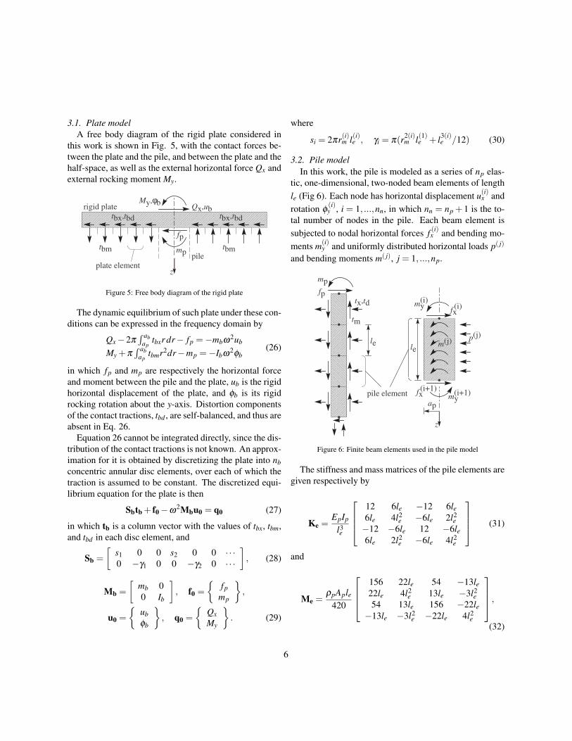
3.1. Plate modelA free body diagram of the rigid plate considered in
this work is shown in Fig. 5, with the contact forces be-tween the plate and the pile, and between the plate and thehalf-space, as well as the external horizontal force Qx andexternal rocking moment My.
xxxxxxxxxxxxxxxxxxxxxxxxxxxxxxxxxxxxxxxxxxxxxxxxxxxxxxxxxxxxxxxxxxxxxxxxxxxxxxxxxxxxxxxxxxxxxxxxxxxxxxxxxxxxxxxxxxxxxxxxxxxxxxxxxxxxxxxxxxxxxxxxxxxxxxxxxxxxxxxxxxxxxxxxxxxxxxxxxxxxxxxxxxxxxxxxxxxxxxxxxxxxxxxxxxxxxxxxxxxxxxxxxxxxxxxxxxxxxxxxxxxxxxxxxxxxxxxxxxxxxxxxxxxxxxxxxxxxxxxxxxxxxxxxxxxxxxxxxxxxxxxxxxxxxxxxxxxxxxxxxxxxxxxxxxxxxxxxxxxxxxxxxxxxxxxxxxxxxxxxxxxxxxxxxxxxxxxxxxxxxxxxxxxxxxxxxxxxxxxxxxxxxxxxxxxxxxxxxxxxxxxxxxxxxxxxxxxxxxxxxxxxxxxxxxxxxxxxxxxxxxxxxxxxxxxxxxxxxxxxxxxxxxxxxxxxxxxxxxxxxxxxxxxxxxxxxxxxxxxxxxxxxxxxxxxxxxxxxxxxxxxxxxxxxxxxxxxxxxxxxxxxxxxxxxxxxxxxxxxxxxxxxxxxxxxxxxxxxxxxxxxxxxxxxxxxxxxxxxxxxxxxxxxxxxxxxxxxxxxxxxxxxxxxxxxxxxxxxxxxxxxxxxxxxxxxxxxxxxxxxxxxxxxxxxxxxxxxxxxxxxxxxxxxxxxxxxxxxxxxxxxxxxxxxxxxxxxxxxxxxxxxxxxxxxxxxxxxxxxxxxxxxxxxxxxxxxxxxxxxxxxxxxxxxxxxxxxxxxxxxxxxxxxxxxxxxxxxxxxxxxxxxxxxxxxxxxxxxxxxxxxxxxxxxxxxxxxxxxxxxxxxxxxxxxxxxxxxxxxxxxxxxxxxxxxxxxxxxxxxxxxxxxxxxxxxxxxxxxxxxxxxxxxxxxxxxxxxxxxxxxxxxxxxxxxxxxxxxxxxxxxxxxxxxxxxxxxxxxxxxxxxxxxxxxxxxxxxxxxxxxxxxxxxxxxxxxxxxxxxxxxxxxxxxxxxxxxxxxxxxxxxxxxxxxxxxxxxxxxxxxxxxxxxxxxxxxxxxxxxxxxxxxxxxxxxxxxxxxxxxxxxxxxxxx
z
tbx,tbd
tbm
tbx,tbd
tbmpile
plate element
rigid plateMy,φb
Qx,ub
mp
fp
Figure 5: Free body diagram of the rigid plate
The dynamic equilibrium of such plate under these con-ditions can be expressed in the frequency domain by
Qx−2π´ ab
aptbxr dr− fp =−mbω2ub
My +π´ ab
aptbmr2dr−mp =−Ibω2φb
(26)
in which fp and mp are respectively the horizontal forceand moment between the pile and the plate, ub is the rigidhorizontal displacement of the plate, and φb is its rigidrocking rotation about the y-axis. Distortion componentsof the contact tractions, tbd , are self-balanced, and thus areabsent in Eq. 26.
Equation 26 cannot be integrated directly, since the dis-tribution of the contact tractions is not known. An approx-imation for it is obtained by discretizing the plate into nbconcentric annular disc elements, over each of which thetraction is assumed to be constant. The discretized equi-librium equation for the plate is then
Sbtb + f0−ω2Mbu0 = q0 (27)
in which tb is a column vector with the values of tbx, tbm,and tbd in each disc element, and
Sb =
[s1 0 0 s2 0 0 · · ·0 −γ1 0 0 −γ2 0 · · ·
], (28)
Mb =
[mb 00 Ib
], f0 =
{fp
mp
},
u0 =
{ubφb
}, q0 =
{QxMy
}. (29)
where
si = 2πr(i)m l(i)e , γi = π(r2(i)m l(1)e + l3(i)
e /12) (30)
3.2. Pile modelIn this work, the pile is modeled as a series of np elas-
tic, one-dimensional, two-noded beam elements of lengthle (Fig 6). Each node has horizontal displacement u(i)x androtation φ
(i)y , i = 1, ...,nn, in which nn = np + 1 is the to-
tal number of nodes in the pile. Each beam element issubjected to nodal horizontal forces f (i)x and bending mo-ments m(i)
y and uniformly distributed horizontal loads p( j)
and bending moments m( j), j = 1, ...,np.
tx,td
tm
pile element
mp
fp
xxxxxxxxxxxxxxxxxxxxxxxxxxxxxxxxxxxxxxxxxxxxxxxxxxxxxxxxxxxxxxxxxxxxxxxxxxxxxxxxxxxxxxxxxxxxxxxxxxxxxxxxxxxxxxxxxxxxxxxxxxxxxxxxxxxxxxxxxxxxxxxxxxxxxxxxxxxxxxxxxxxxxxxxxxxxxxxxxxxxxxxxxxxxxx
xxxxxxxxxxxxxxxxxxxxxxxxxxxxxxxxxxxxxxxxxxxxxxxxxxxxxxxxxxxxxxxxxxxxxxxxxxxxxxxxxxxxxxxxxxxxxxxxxxxxxxxxxxxxxxxxxxxxxxxxxxxxxxxxxxxxxxxxxxxxxxxxxxxxxxxxxxxxxxxxxxxxxxxxxxxxxxxxxxxxxxxxxxxxxx
xxxxxxxxxxxxxxxxxxxxxxxxxxxxxxxxxxxxxxxxxxxxxxxxxxxxxxxxxxxxxxxxxxxxxxxxxxxxxxxxxxxxxxxxxxxxxxxxxxxxxxxxxxxxxxxxxxxxxxxxxxxxxxxxxxxxxxxxxxxxxxxxxxxxxxxxxxxxxxxxxxxxxxxxxxxxxxxxxxxxxxxxxxxxxxxxxxxxxxxx
xxxxxxxxxxxxxxxxxxxxxxxxxxxxxxxxxxxxxxxxxxxxxxxxxxxxxxxxxxxxxxxxxxxxxxxxxxxxxxxxxxxxxxxxxxxxxxxxxxxxxxxxxxxxxxxxxxxxxxxxxxxxxxxxxxxxxxxxxxxxxxxxxxxxxxxxxxxxxxxxxxxxxxxxxxxxxxxxxxxxxxxxxxxxxx
xxxxx
xxxxx
xxxxxxxxxxxxxx
le
xxxxxxxxxxxxxxxxxxxxxxxxxxxxxxxxxxxxxxxxxxxxxxxxxxxxxxxxxxxxxxxxxxxxxxxxxxxxxxxxxxxxxxxxxxxxxxxxxxxxxxxxxxxxxxxxxxxxxxxxxxxxxxxxxxxxxxxxxxxxxxxxxxxxxxxxxxxxxxxxxxxxxxxxxxxxxxxxxxxxxxxxxxxxxxxxxxxxxxxxxxxxxxxxxxxxxxxxxxxxxxxxxxxxxxxxxxxxxxxxxxxxxxxxxxxxxxxxxxxxxxxxxxxxxxxxxxxxxxxxxxxxxxxxxxxxxxxxxxxxxxxxxxxxxxxxxxxxxxxxxxxxxxxxxxxxxxxxxxxxxxxxxxxxxxxxxxxxxxxxxxxxxxxxxxxxxxxxxxxxxxxxxxxxxxxxxxxxxxxxxxxxxxxxxxxxxxxxxxxxxxxxxxxxxxxxxxxxxxxxxxxxxxxxxxxxxxxxxxxxxxxxxxxxxxxxxxxxxxxxxxxxxxxxxxxxxxxxxxxxxxxxxxxxxxxxxxxxxxxxxxxxxxxxxxxxxxxxxxxxxxxxxxxxxxxxxxxxxxxxxxxxxxxxxxxxxxxxxxxxxxxxxxxxxxxxxxxxxxxxxxxxxxxxxxxxxxxxxxxxxxxxxxxxxxxxxxxxxxxxxxxxxxxxxxxxxxxxxxxxxxxxxxxxxxxxxxxxxxxxxxxxxxxxxxxxxxxxxxxxxxxxxxxxxxxxxxxxxxxxxx
xxxxxxxxxxxxxxxxxxxxxxxxxxxxxxxxxxxxxxxxxxxxxxxxxxxxxxxx
m(j) p(j)
xxxxx
xxxxx
le
xxxxxxxxxxxxxxxxxxxxxxxxxxxxxxxx
fxmy
(i)(i)
fx my(i+1)
(i+1)
xxxxxxxxxxxxxxxx
z
xxxx
xxxxxxx
ap
xxxxxxxxx
xxxxxxxxxxxxxxxxxxxxxxxxxxxxxxxxxxxxxxxx
xxxxxxxxxxxxxxxxxxxxxxxxxxxxxxxxxxxxxxxxxxxxxxxxxxxxxxxxxxxxxxxxxxxxxxxxxxxxxxxxxxxxxxxxxxxxxxxxxxxxxxxxxxxxxxxxxxxxxxxxxxxxxxxxxxxxxxxxxxxxxxxxxxxxxxxxxxxxxxxxxxxxxxxxxxxxxxxxxxxxxxxxxxxxxxxxxxxxxxxxxxxxxxxxxxxxxxxxxxxxxxxxxxxxxxxxxxxxxxxxxxxxxxxxxxxxxxxxxxxxxxxxxxxxxxxxxxxx
Figure 6: Finite beam elements used in the pile model
The stiffness and mass matrices of the pile elements aregiven respectively by
Ke =EpIp
l3e
12 6le −12 6le6le 4l2
e −6le 2l2e
−12 −6le 12 −6le6le 2l2
e −6le 4l2e
(31)
and
Me =ρpAple
420
156 22le 54 −13le22le 4l2
e 13le −3l2e
54 13le 156 −22le−13le −3l2
e −22le 4l2e
,(32)
6

in which Ip = πa4p/4 and Ap = πa2
p are respectively themoment of inertia and cross sectional area of each pileelement.
The global stiffness and mass matrices K and M of thebody of the pile are obtained from Ke and Me through theclassical finite element assembly scheme.
The equilibrium between the pile and its surroundinghalf-space is obtained by imposing that the distributedload p(i) and moment m(i) equal the horizontal and mo-ment resulting from tractions t(i)x and t(i)m , i = 1, ...,np +1,along the pile–half-space interface, recalling that np + 1is the total number of elements in that interface. Thesetractions are computed within the half-space in as manycylindrical-shell segments as pile elements, so that eachsegment of the half-space corresponds to a pile element.The equilibrium between the pile and the half-space is im-posed for each element, and results in
p(i) = 2πapt(i)x (33)
m(i) = πa2pt(i)m (34)
The dynamic equation of motion for the discretized pilecan be written as
(K−ω
2M)
uf = f− fs (35)
in which uf, f,and fs all have lengths 2nn and containrespectively the nodal displacements, applied externalforces, and forces resulting from the pile–half-space in-teraction, in which
fs = Atp (36)
where
A =πap
6
A1aA1b A2a
A2b A3aA3b · · ·
Anp+1
, (37)
with the submatrices
[AiaAib
]=
6l(i)e 6ap 0l(i)e li
e 0 06l(i)e −6ap 0−l(i)e l(i)e 0 0
, i≤ np (38)
Anp+1 =
[6ap 0 00 −2a2
p 0
], (39)
transforms the contact tractions tp into equivalent nodalforces.
The vector f can be written as f = I0f0, in which
I0 =
1 00 10 0...
...0 0
. (40)
Equation 35 is then
Kuf +Atp− I0f0 = 0 (41)
in which K = K−ω2M.Substituting the third line of Eq. 11 into Eq. 41 yields
Kuf +ATppqp +ATpbqb− I0f0 = 0 (42)
3.3. Continuity conditions
The kinematic compatibility between the displace-ments up and the nodal displacements and rotations of thepile, uf can be written as
up = Duf (43)
in which
D =
D1a D1b
D2a D2bD3a D3b
. . .Dnp+1
, (44)
7

where the submatrices
[Dia Dib
]=
12
l(i)e8
12 − l(i)e
8
− 3ap
2l(i)e− ap
43ap
2l(i)e− ap
4
0 0 0 0
, i≤ np
(45)
Dnp+1 =
1 0
0 ap2
0 0
, (46)
translates the displacements and rotations of the finite ele-ment nodes into displacement and rotations of the bound-ary element nodes through cubic shape functions.
The displacements ub of the rigid plate are given by
ub = I1u0 (47)
in which
I1 =
1 00 −r(1)m0 0...
...1 00 −r(nb)
m0 0
. (48)
Assuming that the pile is perfectly bonded to the plate,the kinematic compatibility between the plate and the pilehead is
u0 = I0T uf. (49)
Therefore,ub = I1I0
T uf. (50)
3.4. System of equationsSubstituting Eqs. 50 and 11 into Eq. 27 yields
−ω2MbI0
T uf +SbTbpqp +SbTbbqb + f0 = q0 (51)
Substituting Eqs. 43 and 50 into the first two equationsof Eq. 11 yields
−Duf +Uppqp +Upbqb = 0 (52)
−I1I0T uf +Ubpqp +Ubbqb = 0 (53)
Together with Eq. 42, these result in the equation ofmotion of the embedded foundation in matrix form,
K ATpp ATpb −I0−D Upp Upb 0−I1I0
T Ubp Ubb 0−ω2MbI0
T SbTbp SbTbb I
ufqpqbf0
=
000q0
(54)
The numerical solution of Eq. 54 yields the nodal dis-placements and rotations uf along the pile, the contactforce and moment fp and mp between the plate and thepile, and the fictitious loads qp and qb, from which dis-placements and stresses can be computed anywhere in thehalf-space. The rigid-body rotation and displacement ofthe plate can be obtained by substituting uf into Eq. 49.
4. Seismic excitation
This section shows a derivation of the response of theembedded foundation to seismic (internal) excitations.
Consider a time-harmonic shear wave (S-wave) propa-gating vertically from infinity towards the surface of thehalf-space at speed c2
s = c44/ρ and frequency ω . Thehorizontal displacement ux, rotation φy, and stresses σxzwithin the half-space due to this wave are given by
ux(z) = us cos ωzcs
φy(z) =−usω
cssin ωz
csσxz(z) =−ωus
√ρc44 sin ωz
cs
(55)
in which us is the horizontal displacement at the surfaceof the half-space, us = ux (0), due to the S-wave.
The presence of the pile causes the wave striking theportion of the half-space occupied by the pile to be par-tially scattered. The total displacement and traction in thatportion of the half-space is then
u = u(i)+u(s)
t = t(i)+ t(s)(56)
in which the upper indices i and s indicate the incident andscattered components of the displacements and tractions.
8

In view of Eq. 55,
uf(i) =
{us cos
(ω
csz(1)p
),−us
ω
cssin(
ω
csz(1)p
),
us cos(
ω
csz(2)p
), . . .
}T
(57)
in which zp (z(n)p = le(n−1), n = 1, ...,nn +1) is the verti-cal coordinate of the nodes in the pile discretization. Thecorresponding tractions are given by t(i)px = 0 along thelength of the pile, t(i)px = us
√ρc44 sinωlp/cs at the pile
tip, and t(i)pm = t(i)pd = 0 everywhere.On the other hand, Eq. 55 at the plate–half-space inter-
face is simply
ub(i) = {us,0,0,us,0,0, . . .}T (58)
tb(i) = 0 (59)
Based on the displacement and traction fields due to theS-wave (Eq. 56), Eq. 41 can be rewritten for the seismiccase as
K(
uf(s)+uf
(i))+A
(tp
(s)+ tp(i))− I0f0 = 0, (60)
or
Kuf(s)+ATppqp +ATpbqb− I0f0 =−Kuf
(i)−Atp(i).(61)
Analogously, Eq. 51 becomes
−ω2MbI0
T uf(s)+SbTbpqp +SbTbbqb + f0 = ω
2Mbus,(62)
in which us = {us,0}T .Since the incident terms u(i) and t(i) are known, Eq. 54
can be rewritten for the seismic case:K ATpp ATpb −I0−D Upp Upb 0−I1I0
T Ubp Ubb 0−ω2MbI0
T SbTbp SbTbb I
uf(s)
qpqbf0
=
−Kuf
(i)−Atp(i)
00
ω2Mbus
(63)
5. Numerical results
This section brings a comparison between results ob-tained with the present implementation and classical re-sults from the literature, as well as original numerical re-sults.
5.1. Validation
Figure 7 shows the normalized direct and cross compli-ances c′i = ci/ci(a0 = 0) (see Eq. 1), (i = XX ,XM,MM),of a single pile within an elastic half-space, in whicha0 = ωap
√ρs/c44 is the normalized frequency of exci-
tation. The response of a single pile can be obtained withthe present model of piled plate by making the radius ofthe plate very small. The results consider the case of anisotropic half-space with Poisson ratio νs = 0.25 contain-ing a pile of length lp = 50ap, mass density ρp = ρs, andYoung’s modulus Ep = 104Es. These results are comparedwith Rajapakse and Shah [22]. Additionally, Fig. 7 showsthe corresponding transversely isotropic case, in which apile of lp = 50ap, ρp = 1.7ρs, and Ep = 5 ·103Es is embed-ded within a half-space with c′11 = 7, c′12 = 3, c′13 = 2.5,and c′33 = 2.5, in which c′i j = ci j/c44. These results agreewith the corresponding case solved by Gharahi et al. [23].In all results in this section, a discretization of np = lp/apand nb = ab/ap has been used for the pile and the plate,respectively. This has been shown to be an adequate dis-cretizaton for this problem [16].
Figure 8 shows the direct and cross compliances of arigid plate on the surface of a homogeneous half-space.This problem can be analyzed with the present imple-mentation by making the length of the pile very small.An isotropic half-space with νs = 0.25 and a transverselyisotropic half-space with c′33 = 3, n1 = n3 = 1, and n2 = 2are presented, which agree with previous results fromthe literature, provided respectively by Triantafyllidis andPrange [24] and Barros [21].
Finally, the response of the pile to a vertically-propagating shear wave is presented in Fig. 9. The rel-ative seismic horizontal displacement sXX and relativeseismic rotation φY X (see Section 1.1) are shown for anisotropic half-space with Ep = 104Es and lp = 80ap (CaseA), and Ep = 103Es and lp = 40ap (Case B). Both casesconsider ρp = 1.43ρs and νs = 0.4. The results agree withFan et al. [25].
9

0 0.1 0.2 0.3 0.4 0.5
Frequency a0
0
0.2
0.4
0.6
0.8
1
1.2
c' X
X
real
imag
Rajapakse & Shah 1989
Gharahi et al. 2014
0 0.1 0.2 0.3 0.4 0.5
Frequency a0
0
0.2
0.4
0.6
0.8
1
1.2
c' X
M
real
imag
Rajapakse & Shah 1989
Gharahi et al. 2014
0 0.1 0.2 0.3 0.4 0.5
Frequency a0
0
0.2
0.4
0.6
0.8
1
1.2
c' M
M
real
imag
Rajapakse & Shah 1989
Gharahi et al. 2014
Figure 7: Response of a single pile.
0 0.5 1 1.5 2
Frequency a0
0
0.2
0.4
0.6
0.8
1
1.2
c' X
X
real
imag
Triantafyllidis & Prange 1988
Barros 2006
0 0.5 1 1.5 2
Frequency a0
-0.5
0
0.5
1
1.5
c' X
M
real
imag
Triantafyllidis & Prange 1988
Barros 2006
0 0.5 1 1.5 2
Frequency a0
0
0.2
0.4
0.6
0.8
1
1.2
c' M
M
real
imag
Triantafyllidis & Prange 1988
Barros 2006
Figure 8: Response of a single plate.
10

0 0.1 0.2 0.3 0.4 0.5
Frequency a0
0
0.5
1
1.5
|sX
X|
Case A
Case B
Fan et al. 1991
0 0.1 0.2 0.3 0.4 0.5
Frequency a0
0
0.1
0.2
0.3
0.4
0.5
|X
Y|
Case A
Case B
Fan et al. 1991
Figure 9: Seismic response of a single pile.
5.2. Influence of plate radiusThis section shows an analysis of the influence of the
radius of the plate in the response of the piled plate. Theresults are presented in terms of the real and imaginaryparts of the impedance components ki, for two differentrelative radii a′ = ab/ap, as well as the corresponding re-sponse of the single pile for comparison. In these anal-yses, an isotropic half-space with νs = 0.25 is consid-ered. The pile has properties lp = 20ap, ρp = 2ρs, andEp = 103Es.
Figure 10 shows that the impedance of the system gen-erally increases with the inclusion of a plate, relative tothe impedance of the pile alone. Larger radii correspondto larger impedances for both direct impedance terms kHHand kMM . This is not observed for the cross impedance
kHM . The smaller plate causes the system to have asmaller static cross impedance than that of the pile alone,while the larger plate increases the static cross impedanceof the system. This behavior is switched for higher fre-quencies of excitation. The system presents the largestimpedance in the rocking direction, regardless of the ra-dius of the plate.
5.3. Influence of pile length
Figure 11 shows the influence of the pile length in theresponse of the piled raft. For this analysis, ab = 6ap,νs = 0.25, ρp = 2ρs, and Ep = 103Es. The results includethe response of the plate without a pile for comparison.Five different relative pile lengths l′ = lp/ap are consid-ered.
Figure 11 shows that both direct and cross impedancesof the piled raft are significantly affected by the pilelength, for the parameters considered. A monotonic ten-dency towards the case of the longer pile is observed forthe static impedances. These results show that the inclu-sion of a pile is capable of increasing the static impedanceof the plate by about 16% for the horizontal case and66% for the rocking case, while the cross impedance canbe increased by more than threefold. For the dynamiccase, the a monotonic tendency towards the case of thelongest pile is only observed for the rocking impedancesfor all frequencies of excitation. The horizontal and crossimpedances cannot be inferred from the pile length andfrequency of excitation. For higher frequencies of exci-tation, for example, an increase in pile length is accom-panied by a decrease in horizontal impedance of the piledraft.
5.4. Seismic response
This section considers the response of the piled raftto a vertically-propagating shear wave. The response ispresented in terms of the relative horizontal displacementsXX and relative rocking rotation about the y-axis φY X ofthe plate. The results in this section consider lp = 20ap,ρp = 2ρs, νs = 0.25, and Ep = 103Es, and different plateradii. The response of the pile without a plate is includedfor comparison. The results are presented in the samescale so that the effect of the seismic excitation, whichis the same for both sXX and φY X , can be compared moreeasily.
11

0 0.1 0.2 0.3 0.4 0.5
Frequency a0
0
20
40
60
80
100
Re(k
XX
)
a'=4
a'=8
a'=12
a'=16
a'=20
pile only
0 0.1 0.2 0.3 0.4 0.5
Frequency a0
0
100
200
300
400
500
600
700
Im(k
XX
)
a'=4
a'=8
a'=12
a'=16
a'=20
pile only
0 0.1 0.2 0.3 0.4 0.5
Frequency a0
0
50
100
150
200
250
300
350
Re(k
XM
)
a'=4
a'=8
a'=12
a'=16
a'=20
pile only
0 0.1 0.2 0.3 0.4 0.5
Frequency a0
-150
-100
-50
0
50
100
150
200
250
Im(k
XM
)a'=4
a'=8
a'=12
a'=16
a'=20
pile only
0 0.1 0.2 0.3 0.4 0.5
Frequency a0
0
0.5
1
1.5
2
2.5
3
Re(k
MM
)
104
a'=4
a'=8
a'=12
a'=16
a'=20
pile only
0 0.1 0.2 0.3 0.4 0.5
Frequency a0
0
2
4
6
8
10
12
Im(k
MM
)
104
a'=4
a'=8
a'=12
a'=16
a'=20
pile only
Figure 10: Influence of plate radius.
12

0 0.1 0.2 0.3 0.4 0.5
Frequency a0
10
15
20
25
30
35
Re(k
XX
)
l'=4
l'=8
l'=12
l'=18
l'=24
plate only
0 0.1 0.2 0.3 0.4 0.5
Frequency a0
0
20
40
60
80
Im(k
XX
)
l'=4
l'=8
l'=12
l'=18
l'=24
plate only
0 0.1 0.2 0.3 0.4 0.5
Frequency a0
0
20
40
60
80
100
Re(k
XM
)
l'=4
l'=8
l'=12
l'=18
l'=24
plate only
0 0.1 0.2 0.3 0.4 0.5
Frequency a0
-20
0
20
40
60
80
Im(k
XM
)l'=4
l'=8
l'=12
l'=18
l'=24
plate only
0 0.1 0.2 0.3 0.4 0.5
Frequency a0
400
600
800
1000
1200
1400
Re(k
MM
)
l'=4
l'=8
l'=12
l'=18
l'=24
plate only
0 0.1 0.2 0.3 0.4 0.5
Frequency a0
0
200
400
600
800
1000
Im(k
MM
)
l'=4
l'=8
l'=12
l'=18
l'=24
plate only
Figure 11: Influence of pile length.
13

0 0.1 0.2 0.3 0.4 0.5
Frequency a0
0
0.2
0.4
0.6
0.8
1
1.2
1.4
Re(s
XX
)
a'=4
a'=8
a'=12
a'=16
a'=20
pile only
0 0.1 0.2 0.3 0.4 0.5
Frequency a0
-0.05
0
0.05
0.1
0.15
0.2
0.25
Im(s
XX
)
a'=4
a'=8
a'=12
a'=16
a'=20
pile only
0 0.1 0.2 0.3 0.4 0.5
Frequency a0
0
0.2
0.4
0.6
0.8
1
1.2
1.4
Re(
YX
)
a'=4
a'=8
a'=12
a'=16
a'=20
pile only
0 0.1 0.2 0.3 0.4 0.5
Frequency a0
-0.05
0
0.05
0.1
0.15
0.2
0.25
Im(
YX
)a'=4
a'=8
a'=12
a'=16
a'=20
pile only
Figure 12: Influence of plate radius in the seismic case.
As expected, the horizontal displacement of the systemdue to the seismic shear wave is much larger than the ro-tation of the system about the y-axis. The inclusion of aplate of any radius stiffens the system; smaller displace-ments and rotations are observed for larger plate radii, re-gardless of the frequency of excitation.
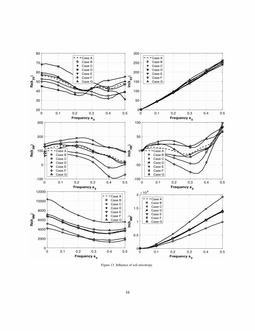
5.5. Influence of soil anisotropyIn order to analyze the influence of soil anisotropy in
the response of the system, a set of seven different ma-terial parameters is considered for the half-space (Table1), including an isotropic one for reference of compari-son. These are selected so that all relevant combinationsof anisotropy indices n1, n2, and n3 are accounted for, inwhich n1 = n2 = n3 = 1 is the isotropic case.
Case n1 n2 n3 c′11 c′12 c′13 c′33
A (isotropic) 1 1 1 3 1 1 3
B 0.5 1 1 3 1 1 1.5
C 2 1 1 3 1 1 6
D 1 0.5 1 3 2 1 3
E 1 2 1 3 −1 1 3
F 1 1 0.5 3 1 2 3
G 1 1 2 3 1 0.5 3
H 11/3 2 1 3 −1 1 11
Table 1: Transversely isotropic properties of the half-space consideredin this analysis.
14

The response of the piled raft embedded in each ofthese half-spaces is shown in Fig. 13. In this analysis,lp = 20ap, ρp = 2ρs, ab = 12ap, and Ep = 103Eiso, inwhich Eiso is the Young’s modulus of the half-space in theisotropic case.
Figure 13 shows that the parameters of the soil havesome influence in the direct impedances of the systemin most cases. One special case is that the rockingimpedance presents a significant increase with a reduc-tion in n1 (Case B) and a slight decrease with a reductionin n3 (Case F). The cross impedance is affected by theanisotropy of the half-space in various ways, for which ageneral pattern cannot be identified.
5.6. Half-space displacement fields
Figure 14a shows the displacement and strain profileswithin the isotropic half-space due to an external hori-zontal load. These results consider a0 = 0.5, νs = 0.25,Ep = 1000Es, ρp = 1.5ρs, lp = 25ap, and ab = 8ap. Thecorresponding case of rocking excitation is shown in Fig.14b. The light-gray line grid in these figures illustrates thedistortion of the half-space, that is, the resulting displace-ment field, and the grayscale background maps the cor-responding volumetric strain in the left-hand side of eachpicture, and the corresponding shear strain in the right-hand sides. The darker the shade of gray, the less strain.These are animated figures that can be played in the onlinePDF version of this article.
One straightforward observation from these figures isthat waves propagate from the excitation source withoutreflection, which illustrates the model’s compliance withSommerfeld’s radiation condition. Moreover, clear wave-fronts are observed in the darker-gray lines, which are inscale with the sizes of the plate and the pile in the figureand are approximately this half-space’s pressure and shearwavelengths apart from each other. It is physically con-sistent that the shear wavefronts on the right-hand side ofeach figure move more quickly than the pressure wave-fronts on the left-hand side. These results also showclearly the coupled nature of the phenomenon, in whichhorizontal excitations cause rotation of the plate as well,and vice-versa. These crossed terms have significantlysmaller amplitude than the direct terms, i.e., horizontaldisplacement due to horizontal load and rotation due tobending moment.
Figure 15 shows the corresponding displacement andstrain fields within a transversely isotropic half-space.These results consider material H from Table 1, whichhas the same horizontal Young’s modulus as the isotropicmaterial A. The foundation parameters and excitation fre-quency are the same as in the previous results. It canbe seen that in both cases, the largest flexural amplitudealong the body of the pile occurs where it connects to therigid plate. This is shown quantitatively in Section 5.7.Finally, it is noted that the rocking excitation of the plateperturbs the surface of the soil significantly more than thehorizontal excitation.
Figure 15 shows that the propagation of waves in thetransversely isotropic material considered occurs in lessclearly-defined wavefronts than in the previous isotropiccase. This is physically consistent, since the propagationof waves in different directions in anisotropic media de-pends on material properties in different directions. Table1 shows that the fundamental difference between the ma-terials in Figs. 14 (material A) and 15 (material H) isthat material H is stiffer than material A in the verticaldirection. This causes both pressure and shear waves topropagate more quickly in the vertical direction in mate-rial H than in material A. The resulting effect is that wavespropagate in a spheroidal shape from the origin of the co-ordinate system in material A, and in a vertically-alignedoblong shape in material H.
5.7. Bending moment along the pileThe bending moment along a pile is a quantity of pri-
mary interest in their design, because it is directly con-nected to the normal stress along the pile. Figure 16shows the bending moment along a pile for three dif-ferent frequencies of excitation: a0 = 0, a0 = 0.5, anda0 = 1. In these results, νs = 0.25, Ep = 100Es, ρp = 2ρs,lp = 25ap, and ab = 8ap. The results are presented interms of normalized bending moments m′Y X = mY X/Qxapand m′YY = mYY/Myap, in which mY X and mYY are bend-ing moments along the pile due respectively to horizontalloads and rocking moments applied at the plate.
Confirming what had been observed qualitatively inSection 5.6, the largest amplitudes of bending momentoccur at the pile head, where it is connected to the plate,regardless of the frequency of excitation, and for both hor-izontal load and rocking moment excitations. The distri-
15
0 0.1 0.2 0.3 0.4 0.5
Frequency a0
20
30
40
50
60
70
80
Re(k
XX
)
Case A
Case B
Case C
Case D
Case E
Case F
Case G
0 0.1 0.2 0.3 0.4 0.5
Frequency a0
0
50
100
150
200
250
300
Im(k
XX
)
Case A
Case B
Case C
Case D
Case E
Case F
Case G
0 0.1 0.2 0.3 0.4 0.5
Frequency a0
-100
0
100
200
300
Re(k
XM
)
Case A
Case B
Case C
Case D
Case E
Case F
Case G
0 0.1 0.2 0.3 0.4 0.5
Frequency a0
-100
-50
0
50
100
Im(k
XM
)
Case A
Case B
Case C
Case D
Case E
Case F
Case G
0 0.1 0.2 0.3 0.4 0.5
Frequency a0
0
2000
4000
6000
8000
10000
12000
Re(k
MM
)
Case A
Case B
Case C
Case D
Case E
Case F
Case G
0 0.1 0.2 0.3 0.4 0.5
Frequency a0
0
0.5
1
1.5
2
Im(k
MM
)
104
Case A
Case B
Case C
Case D
Case E
Case F
Case G
Figure 13: Influence of soil anisotropy.
16

(a) Response horizontal load (b) Response to rocking moment
Figure 14: Displacement and strain within an isotropic half-space due to external horizontal loads and rocking moments.
bution of bending moment varies along the pile in differ-ent ways, according to the frequency of excitation. Noticehow the present distribution of mY X differs from that dueto a horizontal load applied directly at the pile head [23],in which the bending moment is zero at the pile head andmaximum elsewhere.
6. Concluding remarks
This article proposed a model of the horizontal androcking responses of a piled raft under external and inter-nal excitations. The equation of motion for the embeddedfoundation was obtained upon establishing equilibriumand continuity conditions throughout the foundation-soilinterface. The unknown traction distribution at that in-terface was approximated by piece-wise constant values,which were obtained for the soil part by the numerical in-tegration of Green’s functions for transversely isotropichalf-spaces. Results showed good agreement with previ-ous results from the literature. Original numerical results
were presented for various foundation and soil parame-ters, for both external and internal excitations.
7. Acknowledgements
The research leading to this article has been fundedin part by the São Paulo Research Foundation - Fapesp,through grants 2013/08293-7 (CEPID), and 2017/01450-0. The support of Capes, CNPq, and Faepex-Unicamp isalso gratefully acknowledged.
[1] P. Wang, M. Zhao, X. Du, J. Liu, C. Xu, Wind,wave and earthquake responses of offshore wind tur-bine on monopile foundation in clay, Soil Dynam-ics and Earthquake Engineering 113 (2018) 47–57,10.1016/j.soildyn.2018.04.028.
[2] L. Liu, R. Basilio, J. Citadini, R. Farias, R. Marcon-des, X. Resende, A. Rodrigues, F. Rodrigues, F. Sá,P. Sanchez, et al., Status of sirius–a new brazilian
17

(a) Response to horizontal load (b) Response to rocking moment
Figure 15: Displacement and strain within an isotropic half-space due to external horizontal loads.
synchrotron light source, Proc. of IPAC 11 (2011)931–933.
[3] L. Zeevaert, Compensated friction-pile foundationto reduce the settlement of buildings on the highlycompressible volcanic clay of Mexico City, in: Proc.4th Int. Conf. on SMFE, vol. 1, 81–86, 1957.
[4] J. Hooper, Observations on the behavior of a pile-raft foundation on London clay., Proceedings of theinstitution of civil engineers 55 (4) (1973) 855–877,10.1680/iicep.1973.4144.
[5] H. Sommer, Piled raft foundation of a tall buildingin Frankfurt clay, in: Proc. 11th Int. Conf. on SMFE,vol. 4, 2253–2257, 1985.
[6] H. Poulos, Piled raft foundations: design and ap-plications, Geotechnique 51 (2) (2001) 95–113,10.1680/geot.2001.51.2.95.
[7] E. Davis, H. Poulos, The analysis of piled raft sys-tems, Australia Geotechnique Journal 2 (1) (1972)21–27.
[8] Y. El-Mossallamy, E. Franke, Piled rafts: numeri-cal modelling to simulate the behaviour of piled raftfoundations, ARCADIS, Trischler & Partner, 1997.
[9] S. Mali, B. Singh, Behavior of large piled-raft foun-dation on clay soil, Ocean Engineering 149 (2018)205–216, 10.1016/j.oceaneng.2017.12.029.
[10] A. Boominathan, R. Varghese, S. K. Nair, Soil–Structure Interaction Analysis of Pile FoundationsSubjected to Dynamic Loads, in: Geotechnics forNatural and Engineered Sustainable Technologies,Springer, 45–61, 2018.
[11] M. Saadatinezhad, A. Lakirouhani, S. Jabini Asli,Seismic response of non-connected piled raftfoundations, International Journal of Geotechnical
18

-0.4 -0.2 0 0.2 0.4
Re(m'YX
)
0
5
10
15
20
25
Co
ord
ina
te z
/ap
-0.04 0 0.04
Re(m'YY
)
a0=1
a0=0.5
a0=0
-0.4 -0.2 0 0.2 0.4
Im(m'YX
)
0
5
10
15
20
25
Co
ord
ina
te z
/ap
-0.04 0 0.04
Im(m'YY
)
a0=0.5
a0=1
a0=0
Figure 16: Bending momet along the body of the pile due to horizontalloads and bending moments.
Engineering (2019) 1–1510.1080/19386362.2019.1565392.
[12] A. Sommerfeld, Partial differential equations inphysics, vol. 1, Academic press, 1949.
[13] R. Chen, Y. Chen, J. Han, Z. Xu, A theoreticalsolution for pile-supported embankments on softsoils under one-dimensional compression, CanadianGeotechnical Journal 45 (5) (2008) 611–623, 10.1139/t08-003.
[14] G. Filz, J. Sloan, M. P. McGuire, J. Collin, M. Smith,Column-supported embankments: settlement andload transfer, in: Geotechnical Engineering State ofthe Art and Practice: Keynote Lectures from Geo-Congress 2012, 54–77, 2012.
[15] K. Deb, S. R. Mohapatra, Analysis of stonecolumn-supported geosynthetic-reinforced embank-ments, Applied Mathematical Modelling 37 (5)(2013) 2943–2960, 10.1016/j.apm.2012.07.002.
[16] P. L. A. Barros, J. Labaki, E. Mesquita, IBEM-FEM model of a piled plate within a transverselyisotropic half-space, Engineering Analysis withBoundary Elements 101 (2019) 281–296, 10.1016/j.enganabound.2018.12.013.
[17] H. V. Pham, D. Dias, T. Miranda, N. Cristelo,N. Araújo, 3D Numerical Modeling of FoundationSolutions for Wind Turbines, International Jour-nal of Geomechanics 18 (12) (2018) 04018164,10.1061/(asce)gm.1943-5622.0001318.
[18] D. L. Anderson, Elastic wave propagation inlayered anisotropic media, Journal of Geophysi-cal Research 66 (9) (1961) 2953–2963, 10.1029/JZ066i009p02953.
[19] R. K. N. D. Rajapakse, Y. Wang, Green’s Func-tions for Transversely Isotropic Elastic Half Space,Journal of Engineering Mechanics 119 (9) (1993)1724–1746, 10.1061/(ASCE)0733-9399(1993)119:9(1724).
[20] R. Muki, Asymmetric Problems of the Theory ofElasticity for a Semi Infinite Solid and a Thick Plate,Progress in solid mechanics (1960) 399–439.
[21] P. L. A. Barros, Impedances of rigid cylin-drical foundations embedded in transverselyisotropic soils, International Journal for Numer-ical and Analytical Methods in Geomechanics30 (7) (2006) 683–702, 10.1002/nag.496, URLhttps://onlinelibrary.wiley.com/doi/
abs/10.1002/nag.496.
[22] R. Rajapakse, A. Shah, Impedance curves foran elastic pile, Soil Dynamics and Earthquake
19

Engineering 8 (3) (1989) 145–152, 10.1016/s0267-7261(89)80009-0.
[23] A. Gharahi, M. Rahimian, M. Eskandari-Ghadi,R. Pak, Dynamic interaction of a pile with atransversely isotropic elastic half-space under trans-verse excitations, International Journal of Solids andStructures 51 (23-24) (2014) 4082–4093, 10.1016/j.ijsolstr.2014.08.001.
[24] T. Triantafyllidis, B. Prange, Rigid circular founda-tion: dynamic effects of coupling to the half-space,Soil Dynamics and Earthquake Engineering 7 (1)(1988) 40–52, 10.1016/s0267-7261(88)80014-9.
[25] K. Fan, G. Gazetas, A. Kaynia, E. Kausel, S. Ah-mad, Kinematic seismic response of single piles andpile groups, Journal of Geotechnical Engineering117 (12) (1991) 1860–1879.
[26] R. M. Christensen, Theory of Viscoelasticity: Sec-ond Edition (Dover Civil and Mechanical Engineer-ing), Dover Publications, ISBN 048642880X, 2010.
[27] R. Piessens, E. de Doncker-Kapenga, C. Überhuber,D. Kahaner, Quadpack: A Subroutine Package forAutomatic Integration, Springer Series in Computa-tional Mathematics, Springer-Verlag, 1983.
[28] P. Wynn, A Note on Salzer’s Method for Sum-ming Certain Slowly Convergent Series, Journal ofMathematics and Physics 35 (1-4) (1956) 318–320,10.1002/sapm1956351318.
[29] P. L. A. Barros, Accurate stress evaluation of influ-ence functions at the load application points, in: The2005 Joint ASCE/ASME/SES Conference on Me-chanics and Materials, 2005.
AppendixA. Numerical evaluation of influence func-tions
The numerical evaluation of influence functions for thesoil part, Eqs. 6 and 7, is the most difficult computationaltask in the present model. Figure A.17 shows a selectedexample of integrand of Eq. 6. This example considers ahalf-space with material properties of Case A from Table
1, under a horizontal surface load of frequency a0 = 1.5and amplitude p0 applied in the annular area s1/a = 0.5≤r ≤ s2/a = 1; z = 0.
0 2 4 6 8 1010
-6
10-4
10-2
100
Figure A.17: Typical integrand of Eqs. 6 and 7.
Figure A.17 illustrates the typical characteristics of theintegrands of Eqs. 6 and 7. The integration interval canbe divided into a Region I in which the most marking fea-ture of the integrand is the presence of singularities, anda Region II in which the integrand decays and oscillatestoward ζ →∞. Thanks to the normalization of the Hankelspace variable proposed by Rajapakse and Wang [19], onemay expect the singularities in the integrand to be con-fined within 0 < ζ < ζR for all constitutive parameters, inwhich ζR is Rayleigh’s normalized wavenumber.
In the present implementation, the singularities in Re-gion I are dealt with by incorporating a small dampingfactor in the elastic constants [26]. Figure A.18a shows asample of the integrand within Region I for various valuesof damping coefficients η . This sampled interval containsa singularity, and the figure shows that a one percent ma-terial damping is capable of completely smoothing it out.After this treatment of the singularities, Region I is accu-rately integrated via an adaptive quadrature scheme [27].
Figure A.18b shows a sample of the integrand withinRegion II. The difficulty in dealing with this region is thatthe integrand oscillates indefinitely, which causes the in-tegral to converge only at infinity. Truncation of the inte-gration interval may lead to inaccurate evaluation of theintegral for some combination of parameters. However,
20

0.5 0.52 0.54 0.56 0.58 0.6
100
elastic
=0.005
=0.01
=0.1
(a) Region I
2 4 6 8 10
-0.1
0
0.1
0.2
0.3
(b) Region II
Figure A.18: Details of Regions I and II.
the way in which this integrand decays while it oscillatesaround zero causes the integral between two of its con-secutive roots to change in signal and decrease in the waythe terms of an infinite converging series do. Wynn [28]proposed an extrapolation method of integration that ob-tains an approximation for the integral by extrapolatingthe series convergence from these oscillatory-decayingterms. An implementation of Wynn’s strategy is used inthe present implementation for Region II.
Finally, the evaluation of stress components along and
through loading paths presents the additional difficultythat these components are discontinuous at those loci. Inthis case, the computation of the stress components isreplaced by the superposition of three equivalent stressproblems. Firstly, note that due to the linearity of the dif-ferential equations describing these media, the responseof a half-space to a buried load may be obtained by linearsuperposition of the response of a full-space to such loadand the reflection of waves due to the free surface of thehalf-space. This equivalence is illustrated in Fig. A.19.
The effect of the free surface may be obtained withoutdifficulty for this problem. The response of the full-spaceto the buried load, on the other hand, can be replaced inyet to more steps. The first step is substituting the finiteburied load by an infinitely long cylindrical load minusthe loading area that stretches outside of the actual loadedarea (Fig. A.20). At this point, the discontinuity is con-fined within the infinite cylindrical load problem. Theresponse of a full-space to an infinitely long cylindricalload, however, can be obtained analytically.
Finally, the response of the full-space to infinitely longcylindrical load minus the discontinuous region is sim-ply the superposition of its response to two semi-infinitecylindrical loads (Fig. A.21), neither of which containsdiscontinuities.
This strategy of evaluating discontinuous stress com-ponents within the half-space holds for all stress compo-nents, and was first proposed by Barros [29].
21

xxxxxxxxxxxxxxxxxxxxxxxxxxxxxxxxxxxxxxxxxxxxxxxxxxxxxxxxxxxxxxxxxxxxxxxxxxxxxxxxxxxxxxxxxxxxxxxxxxxxxxxxxxxxxxxxxxxxxxx
xxxxxxxxxxxxxxxxxxxxxxxxxxxxxxxxxxxxxxxxxxxxxxxxxxxxxxxxxxxxxxxxxxxxxxxxxxxxxxxxxxxxxxxxxxxxxxxxxxxxxxxxxxxxxxxxxxxxxxxxxxxxxxxxxxxxxxxxxxxxxxxxxxxxxxxxxxxxxxxxxxxxxxxxxxxxxxxxxxxxxxxxxxxxxxxxxxxxxxxxxxxxxxxxxxxxxxxxxxxxxxxxxxxxxxxxxxxxxxxxxxxxxxxxxxxxxxxxxxxxxxxxxxxxxxxxxxxxxxxxxxxxxxxxxxxxxxxxxxxxxxxxxxxxxxxxxxxxxxxxxxxxxxxxxxxxxxxxxxxxxxxxxxxxxxxxxxxxxxxxxxxxxxxxxxxxxxxxxxxxxxxxxxxxxxxxxxxxxxxxxxxxxxx
xxxxxxxxxxxxxxxxxxxxxxxxxxxxxxxxxxxxxxxxxxxxxxxxxxxxxxxxxxxxxxxxxxxxxxxxxxxxxxxxxxxxxxxxxxxxxxxxxxxxxxxxxxxxxxxxxxxxxxxxxxxxxxxxxxxxxxxxxxxxxxxxxxxxxxxxxxxxxxxxxxxxxxxxxxxxxxxxxxxxxxxxxxxxxxxxxxxxxxxxxxxxxxxxxxxxxxxxxxxxxxxxxxxxxxxxxxxxxxxxxxxxxxxxxxxxxxxxxxxxxxxxxxxxxxxxxxxxxxxxxxxxxxxxxxxxxxxxxxxxxxxxxxxxxxxxxxxxxxxxxxxxxxxxxxxxxxxxxxxxxxxxxxxxxxxxxxxxxxxxxxxxxxxxxxxxxxxxxxxxxxxxxxxxxxxxxxxxxxxxxxxxxxxxxxxxxxxxxxxxxxxxxxxxxxxxxxxxxxxxxxxxxxxxxxxxxxxxxxxxxxxxxxxxxxxxxxxxxxxxxxxxxxxxxxxxxxxxxxxxxxxxxxxxxxxxxxxxxxxxxxxxxxxxxxxxxxxxxxxxxxxxxxxxxxxxxxxxxxxxxxxxxxxxxxxxxxxxxxxxxxxxxxxxxxxxxxxxxxxxxxxxxxxxxxxxxxxxxxxxxxxxxxxxxxxxxxxxxxxxxxxxxxxxxxxxxxxxxxxxxxxxxxxxxxxxxxxxxxxxxxxxxxxxxxxxxxxxxxxxxxx
free surface
half-space
buried load effect of free surface
xxxxxxxxxxxxxxxxxxxxxxxxxxxxxxxxxxxxxxxxxxxxxxxxxxxxxxxxxxxxxxxxxxxxxxxxxxxxxxxxxxxxxxxxxxxxxxxxxxxxxxxxxxxxxxxxxxxxxxxxxxxxxxxxxxxxxxxxxxxxxxxx
xxxxxxxxxxxxxxxxxxxxxxxxxxxxxxxxxxxxxxxxxxxxxxxxxxxxxxxxxxxxxxxxxxxxxxxxxxxxxxxxxxxxxxxxxxxxxxxxxxxxxxxxxxxxxxxxxxxxxxxxxxxxxxxxxxxxxxxxxxxxxxxxxxx
xxxxxxxxxxxxxxxxxxxxxxxxxxxxxxxxxxx
xxxxxxxxxxxxxxxxxxxxxxxxxxxxxxxxxxxxxxxxxxxxxxxxxxxxxxxx
xxxxxxx
xxxxxxxxxxxxxx
xxxxxx
xxxxxxxxxxxxxxxxxxxxxxxxxxxxxxxxxxxxxxxxxxxxxxxxxxxxxxxxxxxxxxxxxxxxxxxxxxxxxxxxxxxxxxxxxxxxxxxxxxxxxxxxxxxxxxxxxxxxxxxxxxxxxxxxxxxxxxxxxxxxxxxxxxxxxxxxxxxxxxxxxxxxxxxxxxxxxxxxxxxxxxxxxxxxxxxxxxxxxxxxxxxxxxxxxxxxxxxxxxxxxxxxxxxxxxxxxxxxxxxxxxxxxxxxxxxxxxxxxxxxxxxxxxxxxxxxxxxxxxxxxxxxxxxxxxxxxxxxxxxxxxxxxxxxxxxxxxxxxxxxxxxxxxxxxxxxxxxxxxxxxxxxxxxxxxxxxxxxxxxxxxxxxxxxxxxxxxxxxxxxxxxxxxxxxxxxxxxxxxxxxxxxxxx
xxxxxxxxxxxxxxxxxxxxxxxxxxxxxxxxxxxxxxxxxxxxxxxxxxxxxxxxxxxxxxxxxxxxxxxxxxxxxxxxxxxxxxxxxxxxxxxxxxxxxxxxxxxxxxxxxxxxxxxxxxxxxxxxxxxxxxxxxxxxxxxxxxxxxxxxxxxxxxxxxxxxxxxxxxxxxxxxxxxxxxxxxxxxxxxxxxxxxxxxxxxxxxxxxxxxxxxxxxxxxxxxxxxxxxxxxxxxxxxxxxxxxxxxxxxxxxxxxxxxxxxxxxxxxxxxxxxxxxxxxxxxxxxxxxxxxxxxxxxxxxxxxxxxxxxxxxxxxxxxxxxxxxxxxxxxxxxxxxxxxxxxxxxxxxxxxxxxxxxxxxxxxxxxxxxxxxxxxxxxxxxxxxxxxxxxxxxxxxxxxxxxxxxxxxxxxxxxxxxxxxxxxxxxxxxxxxxxxxxxxxxxxxxxxxxxxxxxxxxxxxxxxxxxxxxxxxxxxxxxxxxxxxxxxxxxxxxxxxxxxxxxxxxxxxxxxxxxxxxxxxxxxxxxxxxxxxxxxxxxxxxxxxxxxxxxxxxxxxxxxxxxxxxxxxxxxxxxxxxxxxxxxxxxxxxxxxxxxxxxxxxxxxxxxxxxxxxxxxxxxxxxxxxxxxxxxxxxxxxxxxxxxxxxxxxxxxxxxxxxxxxxxxxxxxxxxxxxxxxxxxxxxxxxxxxxxxxxxxxxxxxxxxxxxxxxxxxxxxxxxx
full-space
buried loadxxxxxxxxxxxxxxxxxxxxxxxxxxxxxxxxxxxxxxxxxxxxxxxxxxxxxxxxxxxxxxxxxxxxxxxxxxxxxxxxxxxxxxxxxxxxxxxxxxxxxxxxxxxxxxxxxxxxxxx
free surface
half-space
Figure A.19: Equivalence between buried loads within a half-space and within a full-space.
xxxxxxxxxxxxxxxxxxxxxxxxxxxxxxxxxxxxxxxxxxxxxxxxxxxxxxxxxxxxxxxxxxxxxxxxxxxxxxxxxxxxxxxxxxxxxxxxxxxxxxxxxxxxxxxxxxxxxxxxxxxxxxxxxxxxxxxxxxxxxxxxxxxxxxxxxxxxxxxxxxxxxxxxxxxxxxxxxxxxxxxxxxxxxxxxxxxxxxxxxxxxxxxxxxxxxxxxxxxxxxxxxxxxxxxxxxxxxxxxxxxxxxxxxxxxxxxxxxxxxxxxxxxxxxxxxxxxxxxxxxxxxxxxxxxxxxxxxxxxxxxxxxxxxxxxxxxxxxxxxxxxxxxxxxxxxxxxxxxxxxxxxxxxxxxxxxxxxxxxxxxxxxxxxxxxxxxxxxxxxxxxxxxxxxxxxxxxxxxxxxxxxxxxxxxxxxxxxxxxxxxxxxxxxxxxxxxxxxxxxxxx
xxxxxxxxxxxxxxxxxxxxxxxxxxxxxxxxxxxxxxxxxxxxxxxxxxxxxxxxxxxxxxxxxxxxxxxxxxxxxxxxxxxxxxxxxxxxxxxxxxxxxxxxxxxxxxxxxxxxxxxxxxxxxxxxxxxxxxxxxxxxxxxxxxxxxxxxxxxxxxxxxxxxxxxxxxxxxxxxxxxxxxxxxxxxxxxxxxxxxxxxxxxxxxxxxxxxxxxxxxxxxxxxxxxxxxxxxxxxxxxxxxxxxxxxxxxxxxxxxxxxxxxxxxxxxxxxxxxxxxxxxxxxxxxxxxxxxxxxxxxxxxxxxxxxxxxxxxxxxxxxxxxxxxxxxxxxxxxxxxxxxxxxxxxxxxxxxxxxxxxxxxxxxxxxxxxxxxxxxxxxxxxxxxxxxxxxxxxxxxxxxxxxxxxxxxxxxxxxxxxxxxxxxxxxxxxxxxxxxxxxxxxxxxxxxxxxxxxxxxxxxxxxxxxxxxxxxxxxxxxxxxxxxxxxxxxxxxxxxxxxxxxxxxxxxxxxxxxxxxxxxxxxxxxxxxxxxxxxxxxxxxxxxxxxxxxxxxxxxxxxxxxxxxxxxxxxxxxxxxxxxxxxxxxxxxxxxxxxxxxxxxxxxxxxxxxxxxxxxxxxxxxxxxxxxxxxxxxxxxxxxxxxxxxxxxxxxxxxxxxxxxxxxxxxxxxxxxxxxxxxxxxxxxxxxxxxxxxxxxxxxxxxxxxxxxxxxxxxxxxxxxxxxxxxxxxxxxxxxxxxxxxxxxxxxxxxxxxxxxxxxxxxxxxxxxxxxxxxxxxxxxxxxxxxxxxxxxxxxxxxxxxxxxxxxxxxxxxxxxxxxxxxxxxxxxxxxxxxxxxxxxxxxxxxxxxxxxxxxxxxxxxxxxxxxxxxxxxxxxxxxxxxxxxxxxxxxxxxxxxxxxxxxxxxxxxxxxxxxxxxxxxxxxxxxxxxxxxxxxxxxxxxxxxxxxxxxxxxxxxxxxxxxxxxxxxxxxxxxxxxxxxxxxxxxxxxxxxxxxxxxxxxxxxxxxxxxxxxxxxxxxxxxxxxxxxxxxxxxxxxxxxxxxxxxxxxxxxxxxxxxxxxxxxxxxxxxxxxxxxxxxxxxxxxxxxxxxxxxxxxxxxxxxxxxxxxxxxxxxxxxxxxxxxxxxxxxxxxxxxxxxxxxxxxxxxxxxxxxxxxxxxxxxxxxxxxxxxxxxxxxxxxxxxxxxxxxxxxxxxxxxxxxxxxxxxxxxxxxxxxxxxxxxxxxxxxxxxxxxxxxxxxxxxxxxxxxxxxxxxxxxxxxxxxxxxxxxxxxxxxxxxxxxxxxxxxxxxxxxxxxxxxxxxxxxxxxxxxxxxxxxxxxxxxxxxxxxxxxxxxxxxxxxxxxxxxxxxxxxxxxxxxxxxxxxxxxxxxxxxxxxxxxxxxxxxxxxxxxxxxxxxxxx
xxxxxxxxxxxxxxxxxxxxxxxxxxxxxxxxxxxxxxxxxxxxxxxxxxxxxxxxxxxxxxxxxxxxxxxxxxxxxxxxxxxxxxxxxxxxxxxxxxxxxxxxxxxxxxxxxxxxxxxxxxxxxxxxxxxxxxxxxxxxxxxxxxxxxxxxxxxxxxxxxxxxxxxxxxxxxxxxxxxxxxxxxxxxxxxxxxxxxxxxxxxxxxxxxxxxxxxxxxxxxxxxxxxxxxxxxxxxxxxxxxxxxxxxxxxxxxxxxxxxxxxxxxxxxxxxxxxxxxxxxxxxxxxxxxxxxxxxxxxxxxxxxxxxxxxxxxxxxxxxxxxxxxxxxxxxxxxxxxxxxxxxxxxxxxxxxxxxxxxxxxxxxxxxxxxxxxxxxxxxxxxxxxxxxxxxxxxxxxxxxxxxxxxxxxxxxxxxxxxxxxxxxxxxxxxxxxxxxxxxxxxx
xxxxxxxxxxxxxxxxxxxxxxxxxxxxxxxxxxxxxxxxxxxxxxxxxxxxxxxxxxxxxxxxxxxxxxxxxxxxxxxxxxxxxxxxxxxxxxxxxxxxxxxxxxxxxxxxxxxxxxxxxxxxxxxxxxxxxxxxxxxxxxxxxxxxxxxxxxxxxxxxxxxxxxxxxxxxxxxxxxxxxxxxxxxxxxxxxxxxxxxxxxxxxxxxxxxxxxxxxxxxxxxxxxxxxxxxxxxxxxxxxxxxxxxxxxxxxxxxxxxxxxxxxxxxxxxxxxxxxxxxxxxxxxxxxxxxxxxxxxxxxxxxxxxxxxxxxxxxxxxxxxxxxxxxxxxxxxxxxxxxxxxxxxxxxxxxxxxxxxxxxxxxxxxxxxxxxxxxxxxxxxxxxxxxxxxxxxxxxxxxxxxxxxxxxxxxxxxxxxxxxxxxxxxxxxxxxxxxxxxxxxxxxxxxxxxxxxxxxxxxxxxxxxxxxxxxxxxxxxxxxxxxxxxxxxxxxxxxxxxxxxxxxxxxxxxxxxxxxxxxxxxxxxxxxxxxxxxxxxxxxxxxxxxxxxxxxxxxxxxxxxxxxxxxxxxxxxxxxxxxxxxxxxxxxxxxxxxxxxxxxxxxxxxxxxxxxxxxxxxxxxxxxxxxxxxxxxxxxxxxxxxxxxxxxxxxxxxxxxxxxxxxxxxxxxxxxxxxxxxxxxxxxxxxxxxxxxxxxxxxxxxxxxxxxxxxxxxxxxxxxxxxxxxxxxxxxxxxxxxx
buried load
xxxxxxxxxxxx xxxxxx
xxxxxxxxxxxxxxxxxxxxxxxxxxxxxxxxxxxxxxxxxxxxxxxxxxxxxxxxxxxxxxxxxxxxxxxxxxxxxxxxxxxxxxxxxxxxxxxxxxxxxxxxxxxxxxxxxxxxxxxxxxxxxxxxxxxxxxxxxxxxxxxxxxxxxxxxxxxxxxxxxxxxxxxxxxxxxxxxxxxxxxxxxxxxxxxxxxxxxxxxxxxxxxxxxxxxxxxxxxxxxxxxxxxxxxxxxxxxxxxxxxxxxxxxxxxxxxxxxxxxxxxxxxxxxxxxxxxxxxxxxxxxxxxxxxxxxxxxxxxxxxxxxxxxxxxxxxxxxxxxxxxxxxxxxxxxxxxxxxxxxxxxxxxxxxxxxxxxxxxxxxxxxxxxxxxxxxxxxxxxxxxxxxxxxxxxxxxxxxxxxxxxxxxxxxxxxxxxxxxxxxxxxxxxxxxxxxxxxxxxxxxx
xxxxxxxxxxxxxxxxxxxxxxxxxxxxxxxxxxxxxxxxxxxxxxxxxxxxxxxxxxxxxxxxxxxxxxxxxxxxxxxxxxxxxxxxxxxxxxxxxxxxxxxxxxxxxxxxxxxxxxxxxxxxxxxxxxxxxxxxxxxxxxxxxxxxxxxxxxxxxxxxxxxxxxxxxxxxxxxxxxxxxxxxxxxxxxxxxxxxxxxxxxxxxxxxxxxxxxxxxxxxxxxxxxxxxxxxxxxxxxxxxxxxxxxxxxxxxxxxxxxxxxxxxxxxxxxxxxxxxxxxxxxxxxxxxxxxxxxxxxxxxxxxxxxxxxxxxxxxxxxxxxxxxxxxxxxxxxxxxxxxxxxxxxxxxxxxxxxxxxxxxxxxxxxxxxxxxxxxxxxxxxxxxxxxxxxxxxxxxxxxxxxxxxxxxxxxxxxxxxxxxxxxxxxxxxxxxxxxxxxxxxxxxxxxxxxxxxxxxxxxxxxxxxxxxxxxxxxxxxxxxxxxxxxxxxxxxxxxxxxxxxxxxxxxxxxxxxxxxxxxxxxxxxxxxxxxxxxxxxxxxxxxxxxxxxxxxxxxxxxxxxxxxxxxxxxxxxxxxxxxxxxxxxxxxxxxxxxxxxxxxxxxxxxxxxxxxxxxxxxxxxxxxxxxxxxxxxxxxxxxxxxxxxxxxxxxxxxxxxxxxxxxxxxxxxxxxxxxxxxxxxxxxxxxxxxxxxxxxxxxxxxxxxxxxxxxxxxxxxxxxxxxxxxxxxxxxxxxxxxxxxxxxxxxxxxxxxxxxxxxxxxxxxxxxxxxxxxxxxxxxxxxxxxxxxxxxxxxxxxxxxxxxxxxxxxxxxxxxxxxxxxxxxxxxxxxxxxxxxxxxxxxxxxxxxxxxxxxxxxxxxxxxxxxxxxxxxxxxxxxxxxxxxxxxxxxxxxxxxxxxxxxxxxxxxxxxxxxxxxxxxxxxxxxxxxxxxxxxxxxxxxxxxxxxxxxxxxxxxxxxxxxxxxxxxxxxxxxxxxxxxxxxxxxxxxxxxxxxxxxxxxxxxxxxxxxxxxxxxxxxxxxxxxxxxxxxxxxxxxxxxxxxxxxxxxxxxxxxxxxxxxxxxxxxxxxxxxxxxxxxxxxxxxxxxxxxxxxxxxxxxxxxxxxxxxxxxxxxxxxxxxxxxxxxxxxxxxxxxxxxxxxxxxxxxxxxxxxxxxxxxxxxxxxxxxxxxxxxxxxxxxxxxxxxxxxxxxxxxxxxxxxxxxxxxxxxxxxxxxxxxxxxxxxxxxxxxxxxxxxxxxxxxxxxxxxxxxxxxxxxxxxxxxxxxxxxxxxxxxxxxxxxxxxxxxxxxxxxxxxxxxxxxxxxxxxxxxxxxxxxxxxxxxxxxxxxxxxxxxxxxxxxxxxxxxxxxxxxxxxxxxxxxxxxxxxxxxxxxxxxxxxxxxxxxxxxxxxxxxxxxxxxxxxxxxxxxxxxxxxxxxxxxxxxxxxxxxxxxxxxxxxxxxxxxxxxxxxxxxxxxxxxxxxxxxxxxxxxxxxxxxxxxxxxxxxxxxxxxxxxxxxxxxxxxxxxxxxxxxxxxxxxxxxxxxxxxxxxxxxxxxxxxxxxxxxxxxxxxxxxxxxxxxxxxxxxxxxxxxxxxxxxxxxxxxxxxxxxxxxxxxxxxxxxxxxxxxxxxxxxxxxxxxxxxxxxxxxxxxxxxxxxxxxxxxxxxxxxxxxxxxxxxxxxxxxxxxxxxxxxxxxxxxxxxxxxxxxxxxxxxxxxxxxxxxxxxxxxxxxxxxxxxxxxxxxxxxxxxxxxxxxxxxxxxxxxxxxxxxxxxxxxxxxxxxxxxxxxxxxxxxxxxxxxxxxxxxxxxxxxxxxxxxxxxxxxxxxxxxxxxxxxxxxxxxxxxxxxxxxxxxxxxxxxxxxxxxxxxxxxxxxxxxxxxxxxxxxxxxxxxxxxxxxxxxxxxxxxxxxxxxxxxxxxxxxxxxxxxxxxxxxxxxxxxxxxxxxxxxxxxxxxxxxxxxxxxxxxxxxxxxxxxxxxxxxxxxxxxxxxxxxxxxxxxxxxxxxxxxxxxxxxxxxxxxxxxxxxxxxxxxxxxxxxxxxxxxxxxxxxxxxxxxxxxxxxxxxxxxxxxxxxxxxxxxxxxxxxxxxxxxxxxxxxxxxxxxxxxxxxxxxxxxxxxxxxxxxxxxxxxxxxxxxxxxxxxxxxxxxxxxxxxxxxxxxxxxxxxxxxxxxxxxxxxxxxxxxxxxxxxxxxxxxxxxxxxxxxxxxxxxxxxxxxxxxxxxxxxxxxxxxxxxxxxxxxxxxxxxxxxxxxxxxxxxxxxxxxxxxxxxxxxxxxxxxxxxxxxxxxxxxxxxxxxxxxxxxxxxxxxxxxxxxxxxxxxxxxxxxxxxxxxxxxxxxxxxxxxxxxxxxxxxxxxxxxxxxxxxxxxxxxxxxxxxxxxxxxxxxxxxxxxxxxxxxxxxxxxxxxxxxxxxxxxxxxxxxxxxxxxxxxxxxxxxxxxxxxxxxxxxxxxxxxxxxxxxxxxxxxxxxxxxxxxxxxxxxxxxxxxxxxxxxxxxxxxxxxxxxxxxxxxxxxxxxxxxxxxxxxxxxxxxxxxxxxxxxxxxxxxxxxxxxxxxxxxxxxxxxxxxxxxxxxxxxxxxxxxxxxxxxxxxxxxxxxxxxxxxxxxxxxxxxxxxxxxxxxxxxxxxxxxxxxxxxxxxxxxxxxxxxxxxxxxxxxxxxxxxxxxxxxxxxxxxxxxxxxxxxxxxxxxxxxxxxxxxxxxxxxxxxxxxxxxxxxxxxxxxxxxxxxxxxxxxxxxxxxxxxxxxxxxxxxxxxxxxxxxxxxxxxxxxxxxxxxxxxxxxxxxxxxxxxxxxxxxxxxxxxxxxxxxxxxxxxxxxxxxxxxxxxxxxxxxxxxxxxxxxxxxxxxxxxxxxxxxxxxxxxxxxxxxxxxxxxxxxxxxxxxxxxxxxxxxxxxxxxxxxxxxxxxxxxxxxxxxxxxxxxxxxxxxxxxxxxxxxxxxxxxxxxxxxxxxxxxxxxxxxxxxxxxxxxxxxxxxxxxxxxxxxxxxxxxxxxxxxxxxxxxxxxxxxxxxxxxxxxxxxxxxxxxxxxxxxxxxxxxxxxxxxxxxxxxxxxxxxxxxxxxxxxxxxxxxxxxxxxxxxxxxxxxxxxxxxxxxxxxxxxxxxxxxxxxxxxxxxxxxxxxxxxxxxxxxxxxxxxxxxxxxxxxxxxxxxxxxxxxxxxxxxxxxxxxxxxxxxxxxxxxxxxxxxxxxxxxxxxxxxxxxxxxxxxxxxxxxxxxxxxxxxxxxxxxxxxxxxxxxxxxxxxxxxxxxxxxxxxxxxxxxxxxxxxxxxxxxxxxxxxxxxxxxxxxxxxxxxxxxxxxxxxxxxxxxxxxxxxxxxxxxxxxxxxxxxxxxxxxxxxxxxxxxxxxxxxxxxxxxxxxxxxxxxxxxxxxxxxxxxxxxxxxxxxxxxxxxxxxxxxxxxxxxxxxxxxxxxxxxxxxxxxxxxxxxxxxxxxxxxxxxxxxxxxxxxxxxxxxxxxxxxxxxxxxxxxxxxxxxxxxxxxxxxxxxxxxxxx
infinite load
xxxxxxxxxxxxxxxxxxxxxxxxxxxxxxxxxxxxxxxxxxxxxxxxxxxxxxxxxxxxxxxxxxxxxxxxxxxxxxxxxxxxxxxxxxxxxxxxxxxxxxxxxxxxxxxxxxxxxxxxxxxxxxxxxxxxxxxxxxxxxxxxxxxxxxxxxxxxxxxxxxxxxxxxxxxxxxxxxxxxxxxxxxxxxxxxxxxxxxxxxxxxxxxxxxxxxxxxxxxxxxxxxxxxxxxxxxxxxxxxxxxxxxxxxxxxxxxxxxxxxxxxxxxxxxxxxxxxxxxxxxxxxxxxxxxxxxxxxxxxxxxxxxxxxxxxxxxxxxxxxxxxxxxxxxxxxxxxxxxxxxxxxxxxxxxxxxxxxxxxxxxxxxxxxxxxxxxxxxxxxxxxxxxxxxxxxxxxxxxxxxxxxxxxxxxxxxxxxxxxxxxxxxxxxxxxxxxxxxxxxxxx
xxxxxxxxxxxxxxxxxxxxxxxxxxxxxxxxxxxxxxxxxxxxxxxxxxxxxxxxxxxxxxxxxxxxxxxxxxxxxxxxxxxxxxxxxxxxxxxxxxxxxxxxxxxxxxxxxxxxxxxxxxxxxxxxxxxxxxxxxxxxxxxxxxxxxxxxxxxxxxxxxxxxxxxxxxxxxxxxxxxxxxxxxxxxxxxxxxxxxxxxxxxxxxxxxxxxxxxxxxxxxxxxxxxxxxxxxxxxxxxxxxxxxxxxxxxxxxxxxxxxxxxxxxxxxxxxxxxxxxxxxxxxxxxxxxxxxxxxxxxxxxxxxxxxxxxxxxxxxxxxxxxxxxxxxxxxxxxxxxxxxxxxxxxxxxxxxxxxxxxxxxxxxxxxxxxxxxxxxxxxxxxxxxxxxxxxxxxxxxxxxxxxxxxxxxxxxxxxxxxxxxxxxxxxxxxxxxxxxxxxxxxxxxxxxxxxxxxxxxxxxxxxxxxxxxxxxxxxxxxxxxxxxxxxxxxxxxxxxxxxxxxxxxxxxxxxxxxxxxxxxxxxxxxxxxxxxxxxxxxxxxxxxxxxxxxxxxxxxxxxxxxxxxxxxxxxxxxxxxxxxxxxxxxxxxxxxxxxxxxxxxxxxxxxxxxxxxxxxxxxxxxxxxxxxxxxxxxxxxxxxxxxxxxxxxxxxxxxxxxxxxxxxxxxxxxxxxxxxxxxxxxxxxxxxxxxxxxxxxxxxxxxxxxxxxxxxxxxxxxxxxxxxxxxxxxxxxxxxxxxxxxxxxxxxxxxxxxxxxxxxxxxxxxxxxxxxxxxxxxxxxxxxxxxxxxxxxxxxxxxxxxxxxxxxxxxxxxxxxxxxxxxxxxxxxxxxxxxxxxxxxxxxxxxxxxxxxxxxxxxxxxxxxxxxxxxxxxxxxxxxxxxxxxxxxxxxxxxxxxxxxxxxxxxxxxxxxxxxxxxxxxxxxxxxxxxxxxxxxxxxxxxxxxxxxxxxxxxxxxxxxxxxxxxxxxxxxxxxxxxxxxxxxxxxxxxxxxxxxxxxxxxxxxxxxxxxxxxxxxxxxxxxxxxxxxxxxxxxxxxxxxxxxxxxxxxxxxxxxxxxxxxxxxxxxxxxxxxxxxxxxxxxxxxxxxxxxxxxxxxxxxxxxxxxxxxxxxxxxxxxxxxxxxxxxxxxxxxxxxxxxxxxxxxxxxxxxxxxxxxxxxxxxxxxxxxxxxxxxxxxxxxxxxxxxxxxxxxxxxxxxxxxxxxxxxxxxxxxxxxxxxxxxxxxxxxxxxxxxxxxxxxxxxxxxxxxxxxxxxxxxxxxxxxxxxxxxxxxxxxxxxxxxxxxxxxxxxxxxxxxxxxxxxxxxxxxxxxxxxxxxxxxxxxxxxxxxxxxxxxxxxxxxxxxxxxxxxxxxxxxxxxxxxxxxxxxxxxxxxxxxxxxxxxxxxxxxxxxxxxxxxxxx
Figure A.20: Substitution of buried load by its equivalents.
xxxxxxxxxxxxxxxxxxxxxxxxxxxxxxxxxxxxxxxxxxxxxxxxxxxxxxxxxxxxxxxxxxxxxxxxxxxxxxxxxxxxxxxxxxxxxxxxxxxxxxxxxxxxxxxxxxxxxxxxxxxxxxxxxxxxxxxxxxxxxxxxxxxxxxxxxxxxxxxxxxxxxxxxxxxxxxxxxxxxxxxxxxxxxxxxxxxxxxxxxxxxxxxxxxxxxxxxxxxxxxxxxxxxxxxxxxxxxxxxxxxxxxxxxxxxxxxxxxxxxxxxxxxxxxxxxxxxxxxxxxxxxxxxxxxxxxxxxxxxxxxxxxxxxxxxxxxxxxxxxxxxxxxxxxxxxxxxxxxxxxxxxxxxxxxxxxxxxxxxxxxxxxxxxxxxxxxxxxxxxxxxxxxxxxxxxxxxxxxxxxxxxxxxxxxxxxxxxxxxxxxxxxxxxxxxxxxxxxxxxxxx
xxxxxxxxxxxxxxxxxxxxxxxxxxxxxxxxxxxxxxxxxxxxxxxxxxxxxxxxxxxxxxxxxxxxxxxxxxxxxxxxxxxxxxxxxxxxxxxxxxxxxxxxxxxxxxxxxxxxxxxxxxxxxxxxxxxxxxxxxxxxxxxxxxxxxxxxxxxxxxxxxxxxxxxxxxxxxxxxxxxxxxxxxxxxxxxxxxxxxxxxxxxxxxxxxxxxxxxxxxxxxxxxxxxxxxxxxxxxxxxxxxxxxxxxxxxxxxxxxxxxxxxxxxxxxxxxxxxxxxxxxxxxxxxxxxxxxxxxxxxxxxxxxxxxxxxxxxxxxxxxxxxxxxxxxxxxxxxxxxxxxxxxxxxxxxxxxxxxxxxxxxxxxxxxxxxxxxxxxxxxxxxxxxxxxxxxxxxxxxxxxxxxxxxxxxxxxxxxxxxxxxxxxxxxxxxxxxxxxxxxxxxxxxxxxxxxxxxxxxxxxxxxxxxxxxxxxxxxxxxxxxxxxxxxxxxxxxxxxxxxxxxxxxxxxxxxxxxxxxxxxxxxxxxxxxxxxxxxxxxxxxxxxxxxxxxxxxxxxxxxxxxxxxxxxxxxxxxxxxxxxxxxxxxxxxxxxxxxxxxxxxxxxxxxxxxxxxxxxxxxxxxxxxxxxxxxxxxxxxxxxxxxxxxxxxxxxxxxxxxxxxxxxxxxxxxxxxxxxxxxxxxxxxxxxxxxxxxxxxxxxxxxxxxxxxxxxxxxxxxxxxxxxxxxxxxxxxxxxxxxxxxxxxxxxxxxxxxxxxxxxxxxxxxxxxxxxxxxxxxxxxxxxxxxxxxxxxxxxxxxxxxxxxxxxxxxxxxxxxxxxxxxxxxxxxxxxxxxxxxxxxxxxxxxxxxxxxxxxxxxxxxxxxxxxxxxxxxxxxxxxxxxxxxxxxxxxxxxxxxxxxxxxxxxxxxxxxxxxxxxxxxxxxxxxxxxxxxxxxxxxxxxxxxxxxxxxxxxxxxxxxxxxxxxxxxxxxxxxxxxxxxxxxxxxxxxxxxxxxxxxxxxxxxxxxxxxxxxxxxxxxxxxxxxxxxxxxxxxxxxxxxxxxxxxxxxxxxxxxxxxxxxxxxxxxxxxxxxxxxxxxxxxxxxxxxxxxxxxxxxxxxxxxxxxxxxxxxxxxxxxxxxxxxxxxxxxxxxxxxxxxxxxxxxxxxxxxxxxxxxxxxxxxxxxxxxxxxxxxxxxxxxxxxxxxxxxxxxxxxxxxxxxxxxxxxxxxxxxxxxxxxxxxxxxxxxxxxxxxxxxxxxxxxxxxxxxxxxxxxxxxxxxxxxxxxxxxxxxxxxxxxxxxxxxxxxxxxxxxxxxxxxxxxxxxxxxxxxxxxxxxxxxxxxxxxxxxxxxxxxxxxxxxxxxxxxxxxxxxxxxxxxxxxxxxxxxxxxxxxxxxxxxxxxxxxxxxxxxxxxxxxxxx
xxxxxxxxxxxx xxxxxx
xxxxxx
xxxxxxxxxxxxxxxxxxxxxxxxxxxxxxxxxxxxxxxxxxxxxxxxxxxxxxxxxxxxxxxxxxxxxxxxxxxxxxxxxxxxxxxxxxxxxxxxxxxxxxxxxxxxxxxxxxxxxxxxxxxxxxxxxxxxxxxxxxxxxxxxxxxxxxxxxxxxxxxxxxxxxxxxxxxxxxxxxxxxxxxxxxxxxxxxxxxxxxxxxxxxxxxxxxxxxxxxxxxxxxxxxxxxxxxxxxxxxxxxxxxxxxxxxxxxxxxxxxxxxxxxxxxxxxxxxxxxxxxxxxxxxxxxxxxxxxxxxxxxxxxxxxxxxxxxxxxxxxxxxxxxxxxxxxxxxxxxxxxxxxxxxxxxxxxxxxxxxxxxxxxxxxxxxxxxxxxxxxxxxxxxxxxxxxxxxxxxxxxxxxxxxxxxxxxxxxxxxxxxxxxxxxxxxxxxxxxxxxxxxxxx
xxxxxxxxxxxxxxxxxxxxxxxxxxxxxxxxxxxxxxxxxxxxxxxxxxxxxxxxxxxxxxxxxxxxxxxxxxxxxxxxxxxxxxxxxxxxxxxxxxxxxxxxxxxxxxxxxxxxxxxxxxxxxxxxxxxxxxxxxxxxxxxxxxxxxxxxxxxxxxxxxxxxxxxxxxxxxxxxxxxxxxxxxxxxxxxxxxxxxxxxxxxxxxxxxxxxxxxxxxxxxxxxxxxxxxxxxxxxxxxxxxxxxxxxxxxxxxxxxxxxxxxxxxxxxxxxxxxxxxxxxxxxxxxxxxxxxxxxxxxxxxxxxxxxxxxxxxxxxxxxxxxxxxxxxxxxxxxxxxxxxxxxxxxxxxxxxxxxxxxxxxxxxxxxxxxxxxxxxxxxxxxxxxxxxxxxxxxxxxxxxxxxxxxxxxxxxxxxxxxxxxxxxxxxxxxxxxxxxxxxxxxxxxxxxxxxxxxxxxxxxxxxxxxxxxxxxxxxxxxxxxxxxxxxxxxxxxxxxxxxxxxxxxxxxxxxxxxxxxxxxxxxxxxxxxxxxxxxxxxxxxxxxxxxxxxxxxxxxxxxxxxxxxxxxxxxxxxxxxxxxxxxxxxxxxxxxxxxxxxxxxxxxxxxxxxxxxxxxxxxxxxxxxxxxxxxxxxxxxxxxxxxxxxxxxxxxxxxxxxxxxxxxxxxxxxxxxxxxxxxxxxxxxxxxxxxxxxxxxxxxxxxxxxxxxxxxxxxxxxxxxxxxxxxxxxxxxxxxxxxxxxxxxxxxxxxxxxxxxxxxxxxxxxxxxxxxxxxxxxxxxxxxxxxxxxxxxxxxxxxxxxxxxxxxxxxxxxxxxxxxxxxxxxxxxxxxxxxxxxxxxxxxxxxxxxxxxxxxxxxxxxxxxxxxxxxxxxxxxxxxxxxxxxxxxxxxxxxxxxxxxxxxxxxxxxxxxxxxxxxxxxxxxxxxxxxxxxxxxxxxxxxxxxxxxxxxxxxxxxxxxxxxxxxxxxxxxxxxxxxxxxxxxxxxxxxxxxxxxxxxxxxxxxxxxxxxxxxxxxxxxxxxxxxxxxxxxxxxxxxxxxxxxxxxxxxxxxxxxxxxxxxxxxxxxxxxxxxxxxxxxxxxxxxxxxxxxxxxxxxxxxxxxxxxxxxxxxxxxxxxxxxxxxxxxxxxxxxxxxxxxxxxxxxxxxxxxxxxxxxxxxxxxxxxxxxxxxxxxxxxxxxxxxxxxxxxxxxxxxxxxxxxxxxxxxxxxxxxxxxxxxxxxxxxxxxxxxxxxxxxxxxxxxxxxxxxxxxxxxxxxxxxxxxxxxxxxxxxxxxxxxxxxxxxxxxxxxxxxxxxxxxxxxxxxxxxxxxxxxxxxxxxxxxxxxxxxxxxxxxxxxxxxxxxxxxxxxxxxxxxxxxxxxxxxxxxxxxxxxxxxxxxxxxxxxxxxxxxxxxxxxxxxxxxxxxxxxxxxxxxxxxxxxxxxxxxxxxxxxxxxxxxxxxxxxxxxxxxxxxxxxxxxxxxxxxxxxxxxxxxxxxxxxxxxxxxxxxxxxxxxxxxxxxxxxxxxxxxxxxxxxxxxxxxxxxxxxxxxxxxxxxxxxxxxxxxxxxxxxxxxxxxxxxxxxxxxxxxxxxxxxxxxxxxxxxxxxxxxxxxxxxxxxxxxxxxxxxxxxxxxxxxxxxxxxxxxxxxxxxxxxxxxxxxxxxxxxxxxxxxxxxxxxxxxxxxxxxxxxxxxxxxxxxxxxxxxxxxxxxxxxxxxxxxxxxxxxxxxxxxxxxxxxxxxxxxxxxxxxxxxxxxxxxxxxxxxxxxxxxxxxxxxxxxxxxxxxxxxxxxxxxxxxxxxxxxxxxxxxxxxxxxxxxxxxxxxxxxxxxxxxxxxxxxxxxxxxxxxxxxxxxxxxxxxxxxxxxxxxxxxxxxxxxxxxxxxxxxxxxxxxxxxxxxxxxxxxxxxxxxxxxxxxxxxxxxxxxxxxxxxxxxxxxxxxxxxxxxxxxxxxxxxxxxxxxxxxxxxxxxxxxxxxxxxxxxxxxxxxxxxxxxxxxxxxxxxxxxxxxxxxxxxxxxxxxxxxxxxxxxxxxxxxxxxxxxxxxxxxxxxxxxxxxxxxxxxxxxxxxxxxxxxxxxxxxxxxxxxxxxxxxxxxxxxxxxxxxxxxxxxxxxxxxxxxxxxxxxxxxxxxxxxxxxxxxxxxxxxxxxxxxxxxxxxxxxxxxxxxxxxxxxxxxxxxxxxxxxxxxxxxxxxxxxxxxxxxxxxxxxxxxxxxxxxxxxxxxxxxxxxxxxxxxxxxxxxxxxxxxxxxxxxxxxxxxxxxxxxxxxxxxxxxxxxxxxxxxxxxxxxxxxxxxxxxxxxxxxxxxxxxxxxxxxxxxxxxxxxxxxxxxxxxxxxxxxxxxxxxxxxxxxxxxxxxxxxxxxxxxxxxxxxxxxxxxxxxxxxxxxxxxxxxxxxxxxxxxxxxxxxxxxxxxxxxxxxxxxxxxxxxxxxxxxxxxxxxxxxxxxxxxxxxxxxxxxxxxxxxxxxxxxxxxxxxxxxxxxxxxxxxxxxxxxxxxxxxxxxxxxxxxxxxxxxxxxxxxxxxxxxxxxxxxxxxxxxxxxxxxxxxxxxxxxxxxxxxxxxxxxxxxxxxxxxxxxxxxxxxxxxxxxxxxxxxxxxxxxxxxxxxxxxxxxxxxxxxxxxxxxxxxxxxxxxxxxxxxxxxxxxxxxxxxxxxxxxxxxxxxxxxxxxxxxxxxxxxxxxxxxxxxxxxxxxxxxxxxxxxxxxxxxxxxxxxxxxxxxxxxxxxxxxxxxxxxxxxxxxxxxxxxxxxxxxxxxxxxxxxxxxxxxxxxxxxxxxxxxxxxxxxxxxxxxxxxxxxxxxxxxxxxxxxxxxxxxxxxxxxxxxxxxxxxxxxxxxxxxxxxxxxxxxxxxxxxxxxxxxxxxxxxxxxxxxxxxxxxxxxxxxxxxxxxxxxxxxxxxxxxxxxxxxxxxxxxxxxxxxxxxxxxxxxxxxxxxxxxxxxxxxxxxxxxxxxxxxxxxxxxxxxxxxxxxxxxxxxxxxxxxxxxxxxxxxxxxxxxxxxxxxxxxxxxxxxxxxxxxxxxxxxxxxxxxxxxxxxxxxxxxxxxxxxxxxxxxxxxxxxxxxxxxxxxxxxxxxxxxxxxxxxxxxxxxxxxxxxxxxxxxxxxxxxxxxxxxxxxxxxxxxxxxxxxxxxxxxxxxxxxxxxxxxxxxxxxxxxxxxxxxxxxxxxxxxxxxxxxxxxxxxxxxxxxxxxxxxxxxxxxxxxxxxxxxxxxxxxxxxxxxxxxxxxxxxxxxxxxxxxxxxxxxxxxxxxxxxxxxxxxxxxxxxxxxxxxxxxxxxxxxxxxxxxxxxxxxxxxxxxxxxxxxxxxxxxxxxxxxxxxxxxxxxxxxxxxxxxxxxxxxxxxxxxxxxxxxxxxxxxxxxxxxxxxxxxxxxxxxxxxxxxxxxxxxxxxxxxxxxxxxxxx
infinite load
xxxxxxxxxxxxxxxxxxxxxxxxxxxxxxxxxxxxxxxxxxxxxxxxxxxxxxxxxxxxxxxxxxxxxxxxxxxxxxxxxxxxxxxxxxxxxxxxxxxxxxxxxxxxxxxxxxxxxxxxxxxxxxxxxxxxxxxxxxxxxxxxxxxxxxxxxxxxxxxxxxxxxxxxxxxxxxxxxxxxxxxxxxxxxxxxxxxxxxxxxxxxxxxxxxxxxxxxxxxxxxxxxxxxxxxxxxxxxxxxxxxxxxxxxxxxxxxxxxxxxxxxxxxxxxxxxxxxxxxxxxxxxxxxxxxxxxxxxxxxxxxxxxxxxxxxxxxxxxxxxxxxxxxxxxxxxxxxxxxxxxxxxxxxxxxxxxxxxxxxxxxxxxxxxxxxxxxxxxxxxxxxxxxxxxxxxxxxxxxxxxxxxxxxxxxxxxxxxxxxxxxxxxxxxxxxxxxxxxxxxxxx
xxxxxxxxxxxxxxxxxxxxxxxxxxxxxxxxxxxxxxxxxxxxxxxxxxxxxxxxxxxxxxxxxxxxxxxxxxxxxxxxxxxxxxxxxxxxxxxxxxxxxxxxxxxxxxxxxxxxxxxxxxxxxxxxxxxxxxxxxxxxxxxxxxxxxxxxxxxxxxxxxxxxxxxxxxxxxxxxxxxxxxxxxxxxxxxxxxxxxxxxxxxxxxxxxxxxxxxxxxxxxxxxxxxxxxxxxxxxxxxxxxxxxxxxxxxxxxxxxxxxxxxxxxxxxxxxxxxxxxxxxxxxxxxxxxxxxxxxxxxxxxxxxxxxxxxxxxxxxxxxxxxxxxxxxxxxxxxxxxxxxxxxxxxxxxxxxxxxxxxxxxxxxxxxxxxxxxxxxxxxxxxxxxxxxxxxxxxxxxxxxxxxxxxxxxxxxxxxxxxxxxxxxxxxxxxxxxxxxxxxxxxxxxxxxxxxxxxxxxxxxxxxxxxxxxxxxxxxxxxxxxxxxxxxxxxxxxxxxxxxxxxxxxxxxxxxxxxxxxxxxxxxxxxxxxxxxxxxxxxxxxxxxxxxxxxxxxxxxxxxxxxxxxxxxxxxxxxxxxxxxxxxxxxxxxxxxxxxxxxxxxxxxxxxxxxxxxxxxxxxxxxxxxxxxxxxxxxxxxxxxxxxxxxxxxxxxxxxxxxxxxxxxxxxxxxxxxxxxxxxxxxxxxxxxxxxxxxxxxxxxxxxxxxxxxxxxxxxxxxxxxxxxxxxxxxxxxxxxxxxxxxxxxxxxxxxxxxxxxxxxxxxxxxxxxxxxxxxxxxxxxxxxxxxxxxxxxxxxxxxxxxxxxxxxxxxxxxxxxxxxxxxxxxxxxxxxxxxxxxxxxxxxxxxxxxxxxxxxxxxxxxxxxxxxxxxxxxxxxxxxxxxxxxxxxxxxxxxxxxxxxxxxxxxxxxxxxxxxxxxxxxxxxxxxxxxxxxxxxxxxxxxxxxxxxxxxxxxxxxxxxxxxxxxxxxxxxxxxxxxxxxxxxxxxxxxxxxxxxxxxxxxxxxxxxxxxxxxxxxxxxxxxxxxxxxxxxxxxxxxxxxxxxxxxxxxxxxxxxxxxxxxxxxxxxxxxxxxxxxxxxxxxxxxxxxxxxxxxxxxxxxxxxxxxxxxxxxxxxxxxxxxxxxxxxxxxxxxxxxxxxxxxxxxxxxxxxxxxxxxxxxxxxxxxxxxxxxxxxxxxxxxxxxxxxxxxxxxxxxxxxxxxxxxxxxxxxxxxxxxxxxxxxxxxxxxxxxxxxxxxxxxxxxxxxxxxxxxxxxxxxxxxxxxxxxxxxxxxxxxxxxxxxxxxxxxxxxxxxxxxxxxxxxxxxxxxxxxxxxxxxxxxxxxxxxxxxxxxxxxxxxxxxxxxxxxxxxxxxxxxxxxxxxxxxxxxxxxxxxxxxxxxxxxxxxxxxxxxxxxxxxxxx
Figure A.21: Substitution of buried load by its equivalents.
22