cp racks & pinions cp racks & - mecapedia … · type (cp spur gear) material (s45c)...
TRANSCRIPT
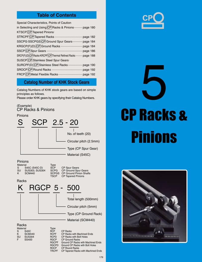
5Catalog Number of KHK Stock Gears
Catalog Numbers of KHK stock gears are based on simple principles as follows.Please order KHK gears by specifying their Catalog Numbers.
(Example)CP Racks & PinionsPinions
S SCP 2.5 - 20No. of teeth (20)
Circular pitch (2.5mm)
Type (CP Spur Gear)
Material (S45C)
MaterialS S45C (S45C-D)SU SUS303, SUS304K SCM440
TypeSCP CP Spur GearsSCPG CP Ground Spur GearsSCPGS CP Ground Pinion ShaftsTSCP CP Tapered Pinions
Pinions
K RGCP 5 - 500Racks
Total length (500mm)
Circular pitch (5mm)
Type (CP Ground Rack)
Material (SCM440)
MaterialS S45CK SCM440SU SUS304F SS400
TypeRCP CP RacksRCPF CP Racks with Machined EndsRCPD CP Racks with Bolt HolesRGCP CP Ground RacksRGCPF Ground CP Racks with Machined EndsRGCPD Ground CP Racks with Bolt HolesROCP CP Round RacksTRCPF CP Tapered Racks with Machined Ends
Racks
179
CP Racks & Pinions
Table of Contents
Special Characteristics, Points of Caution
in Selecting and Using CP Racks & Pinions .......... page 180
KTSCP CP Tapered Pinions.
STRCPF CP Tapered Racks ................................. page 182
SSCPG.SSCPGS CP Ground Spur Gears ............ page 184
KRGCP(F)(D) CP Ground Racks .......................... page 184
SSCP CP Spur Gears ........................................... page 186
SRCP(F)(D) CP Racks.KRCPF CP Thermal Refined Racks ........ page 188
SUSCP CP Stainless Steel Spur Gears.
SURCPF(D) CP Stainless Steel Racks ................. page 190
SROCP CP Round Racks ..................................... page 192
FRCP CP Metal Flexible Racks ............................. page 192

180
For Accurate Positioning in Linear Motion Applications.
KHK stock CP racks and pinions are suitable in applications where very accurate positioning in linear motion is required. For your convenience, we offer circular pitches of 2.5 to 20mm and in lengths of 100 to 2000mm. (FRCP is available to 4000mm)
The reference pitch of a metric module is computed by multiplying the number of module by p (3.14159). For example, the reference pitch of m3 rack is 9.425mm (3×p). When using a rack and a pinion in a linear motion application, the fact that the pitch is not an integral number presents a difficulty in accurate positioning. This problem is solved by CP racks and pinions where one rotation of a pinion moves it precisely 50, 100, 150, ... or 600mm. The difference in movement of one rotation of a 30 tooth CP10 vs. SS3 spur gear is illustrated on the right.
NOTE 1: The catalog numbers in the above table with (F) on the end have both ends machined so that they can be butted against each other to make any desired length. The items with (D) have mounting screw holes for easier assembly.
NOTE 2: The pinions with (S) are pinion shafts.
Movement of one cycle ofSSCP10-30 on CP10 rack vs. SS3-30 (m3) on m3 rack
One turn
1/2 turnCP10=300mm 3=282.74mm
CP10=150mm 3=141.37mm
Differencebetween CP10 and m 3
CP10=10mm 3=9.425mmPitch
m
m
m
< Racks >
Catalog No.
STRCPF
KRGCP(F)(D)
KRCPF
SRCP (F)(D)
SURCPF(D)
SROCP
FRCP
Straightened
& annealed
Thermal refining
Thermal refining
Straightened
& annealed
Solution
treatment
Straightened
& annealed
-
Hobbed
Ground
Hobbed
Hobbed
Hobbed
Hobbed
Hobbed
4
1
4
4
5
4
8
By pairing with KTSCP pinion, the backlash may be adjusted.
High strength and abrasion-resistant for precision linear motion.
Increased strength with SCM440 material which is thermal refined.
Widely applicable due to low cost and large selection of pitches and lengths.
Suitable for food machinery due to SUS304 material’s rust-resistant quality.
Convenient in applications where the rack has reciprocal motion.
Cut continuously. Long length and deformable to a contour.
S45C-D
SCM440
SCM440
S45C-D
SUS304
S45C-D
SS400
1000
100, 500,1000
1000
100, 1000,1500, 2000
1000
500
2000, 3000,4000
5, 10
5, 10
5, 10
2.5, 5, 10, 15, 20
5, 10
2.5, 5, 10
5
Pitch mm Length mm ( ) denotes no. of teeth
MaterialHeat
treatment
Tooth
surface
finish
PrecisionKHK R 001
( ) denotes JIS B 1702-1 grades
Main characteristics
KTSCP
SSCPG(S)
SSCP
SUSCP
Thermal refining
Induction hardened teeth (SSCPGS is thermal
rifined)
-
-
Hobbed
Ground
Hobbed
Hobbed
(N8)
(N7)
(N8)
(N8)
By paring with STRCP rack, the backlash may be adjusted.
Perform secondary operations to suit your requirement on these ground CP spur gears.
Widely applicable due to low cost and large selection of pitches and numbers of teeth.
Suitable for food machinery due to SUS303 material’s rust-resistant quality.
SCM440
S45C
S45C
SUS303
(20~40)
(10~40)
(20~40)
(20~30)
5, 10
5, 10
2.5, 5,
10, 15, 20
5, 10
<Pinions>
CP Racks & Pinions
Characteristics
■ About CP Racks & Pinions
■ Main Characteristics of CP Racks & Pinions
NOTE1
NOTE1
NOTE2

181
It is important to thoroughly understand the contents of the product tables as well as “CAUTION” notes before making the selection. In addition, read the section below as well as “1. Caution in Selecting the Mating Gears”, “3. Selecting Racks by Precison”, “4. Caution with Regard to the Special Characteristics”, and “5. Other Points to Consider in the Selection Process” in the KHK stock rack section starting on page 155, and “Selection Hints” of spur gears on pages 27 and 28.
The gear strength values shown in the product pages were computed by assuming a certain application environment. Therefore, they should be used as reference only. We recommend that each user computes his own values by applying the actual usage conditions. The table below contains the assumptions established for these products in order to compute gear strengths.
Item
Catalog No. KRGCP KRGCPF KRGCPD KRCPF
SRCPSRCPF SRCPFD SROCPSTRCPF
SURCPFSURCPFD FRCP
KTSCPSSCPG (SSCPGS) SSCP SUSCP
Formula of spur and helical gears on bending strength (JGMA401-01)
30 Same number teeth
Over 107 cycles
Uniform load
Uniform load
Bidirectional
1.2
Formula of spur and helical gears on surface durability (JGMA402-01)
100cSt (50℃ )
Support on one end Symmetric support by bearings
1.15
100min-1 100min-1600min-1
21.33kgf/mm2 13.33kgf/mm2 7kgf/mm2 19kgf/mm214 (16.67) kgf/mm2 12.67kgf/mm2 7kgf/mm2
79kgf/mm2 52.5kgf/mm2 41.3kgf/mm2 74.5kgf/mm290 (99) kgf/mm2 49kgf/mm2 41.3kgf/mm2
NOTE 1: The gear strength formula is based on JGMA (Japanese Gear Manufactures Association) specifications. The units of number of rotations (min-1) and the stress (kgf/mm2) are adjusted to the units needed in the formula.
NOTE 2: Since the load is bidirectional, the allowable bending stress at root σFlim is set to 2/3 of the value.
When using KHK stock CP racks and pinions, please carefully read the Application Hints of the rack section starting on page 155.● CP5 (m1.592) and CP10 (m3.183) are very close in size to m1.5 and
m3 respectively. The piece marking should be verified to make sure that the item is correct.
● Examples of fastening methods of FRCP metal flexible racks are shown below.
Example of KHK Gear Applications
Automatic material handling equipment (CP racks & pinions)
Fixed by flat head screw Fixed by spot welding
(top view)
<Racks> <Pinions>
KHK Technical Information
Selection Hints
Application Hints
■ Caution in Selecting Gears Based on Gear Strength
■ Calculation of Bending Strength
■ Calculation of Surface Durability (Except those in common with bending strength)
Formula NOTE 1
No. of teeth of mating gears
Rotation
Durability
Impact from motor
Impact from load
Direction of load
Allowable root bending stress σFlim NOTE 2
Safety factor SF
Formula NOTE 1
Kinematic viscosity of lubricant
Gear support
Allowable Hertz stress σHlim
Safety factor SH
182
z AH7 B C D D' E F GKTSCP5 -20KTSCP5 -25KTSCP5 -30KTSCP5 -40
CP5(1.5915)CP5(1.5915)CP5(1.5915)CP5(1.5915)
100125150200
20253040
8101012
25323845
31.8339.7947.7563.66
36.0644.0251.9867.89
33.9741.9249.8865.80
18181818
15151515
33333333
KTSCP10-20KTSCP10-25KTSCP10-30KTSCP10-40
CP10(3.1831)CP10(3.1831)CP10(3.1831)CP10(3.1831)
200250300400
20253040
15202020
50607580
063.66079.58095.49127.32
072.13088.04103.96135.79
067.93083.85099.76131.59
36363636
20202020
56565656
A B C C' D ESTRCPF 5-1000STRCPF10-1000
05(1.5915)10(3.1831)
200100
10001000
1530
19.534.5
18.4532.40
17.3830.27
07.515.0
NOTE 1: The amount denotes the distance in mm tapered pinion travels on the racks in one revolution.
Adjustable backlash:Moving the pinion axially by 1mm changes the backlash by 0.05mm
■ For example● SRCP5-1000 & SSCP5-30 Backlash value → 0.1~0.2● STRCPF5-1000 & KTSCP5-30 Backlash value → 0.05 or less.
* NOTE: The above backlash values are the theoretical values.
* NOTE: Tapered rack& pinion are not interchangeable with KHK stock CP racks and pinions.
* NOTE: Different modules, number of teeth, ground gear versions and custom-made items are available as special orders.
ST Shape
KTSCP Tapered Pinions.STRCPF Tapered Racks
■ KTSCP Tapered Pinion CP5
CP R
acks
&
Pin
ions
KTSCP.STRCPF
Catalog
No.
Bore Hub dia.Pitch mm (m)
Pitch dia.No. of teeth Outside dia. (major) Outside dia. (minor) Face width Hub width Total length Distance traveled in one turn Note 1
CircularPitches 5,10
Reference mating position
■ KTSCP Tapered Pinion CP10
■ STRCPF Tapered Rack
Catalog
No.
Face widthPitch mm (m)
Height (major)Total length Height (minor) Reference positionReference mating height
Tapered Pinion
Tapered RackMoving the pinion axially
by 1mm changes the backlash by 0.05mm
Effective No. of teeth
Tapered Racks & Pinions
183
KTSCP.STRCPF
H I JSTSTSTST
0.160.260.360.60
0 ~ 0.110 ~ 0.110 ~ 0.110 ~ 0.11
KTSCP5 -20KTSCP5 -25KTSCP5 -30KTSCP5 -40
15151515
3333
10.510.510.510.5
039.3054.1069.4100.8
03.5705.8908.7616.02
(04.01)(05.52)(07.07)(10.28)
(0.364)(0.600)(0.893)(1.634)
STSTSTST
1.161.742.604.28
0 ~ 0.120 ~ 0.120 ~ 0.120 ~ 0.12
KTSCP10-20KTSCP10-25KTSCP10-30KTSCP10-40
30303030
6666
21212121
315433555807
030.8050.6075.3138.6
(32.1)(44.1)(56.6)(82.3)
(03.14)(05.16)(07.68)(14.13)
22909150
46818700
(233)(933)
(046.7)(190.0)
RTRT
2.067.10
STRCPF 5-1000STRCPF10-1000
NOTE 2: The allowable torques shown in the table are the calculated values according to the assumed usage conditions. Please see page 181 for more details.NOTE 3: The backlash values shown in the table are the theoretical values when these gears and the STRCP Tapered Racks are in mesh.
NOTE4: The allowable forces shown in the table are the calculated values according to the assumed usage conditions. Please see page 181 for more details.
RT Shape
ShapeAllowable force (kgf) Weight
(kgf)Catalog
No.Allowable force (N) NOTE 4
CP R
acks
&
Pin
ions
Reference mating position
KTSCP Specifications
Precision grade
Gear teeth
Pressure angle
Material
Heat treatment
JIS N8 grade (JIS1 B1702-1: 1998) OLD JIS 4 grade (JIS B1702: 1976) Tooth hardness
Surface treatment
Tooth surface finish
Secondary Operations
Datum reference surface for gear cutting
225~260HB
Black oxide
Cut
Bore
Possible
Precision grade
Gear teeth
Pressure angle
Material
Heat treatment
STRCPF Specifications
Standard full depth
20°
S45C-D
Stress relief annealing
Tooth hardnessSurface treatment
Tooth surface finish
Secondary Operations
Datum reference surface for gear cutting
89~95HRB
Black oxide
Cut
Bottom surface
Possible
KHK R 001 grade 4
Reference face width Adjustable width Reference position Allowable torque (N.m) NOTE 2
Bending strength
Allowable torque (kgf.m) Backlash (mm) Note 3Surface durabilityBending strength Surface durability
ShapeWeight
(kgf)Catalog
No.
Bending strength Surface durability Bending strength Surface durability
Thermal refining only

184
A B C D
EA B C D F G
z x A B C D E F GSSCPGS5-15SSCPGS5-20SSCPGS5-25
CP5(1.5915)CP5(1.5915)CP5(1.5915)
152025
000
19.227.230.2
252525
23.8731.8339.79
27.0635.0142.97
151515
100100100
140140140
075100125
SSCPGS10-10SSCPGS10-15SSCPGS10-20
CP10(3.1831)CP10(3.1831)CP10(3.1831)
101520
+0.5+0.0+0.0
25.235.240.2
404040
31.8347.7563.66
41.0554.1170.03
303030
150150150
220220220
100150200
z AH7 B C D E F GSSCPG5-20SSCPG5-25SSCPG5-30SSCPG5-40
CP5(1.5915)CP5(1.5915)CP5(1.5915)CP5(1.5915)
20253040
8101012
25323850
31.8339.7947.7463.66
35.0142.9750.9366.84
15151515
15151515
30303030
100125150200
SSCPG10-20SSCPG10-25SSCPG10-30SSCPG10-40
CP10(3.1831)CP10(3.1831)CP10(3.1831)CP10(3.1831)
20253040
15202025
50607580
063.66079.57095.49127.32
070.03085.94101.86133.69
30303030
20202020
50505050
200250300400
KRGCPF 5-1000KRGCPF10-1000
KRGCP 5-100 NOTE 3
KRGCP10-100 NOTE 3
CP05(1.5915)CP10(3.1831)
098098
1530
2035
18.4131.82
020010
R1R1
0366014640
15576228
(0373.2)(1493.0)
(158.8)(635.1)
KRGCP 5-500KRGCP10-500
CP05(1.5915)CP10(3.1831)
505505
1530
2035
18.4131.82
101050
R1R1
0366014640
15576228
(0373.2)(1493.0)
(158.8)(635.1)
CP05(1.5915))CP10(3.1831)
10001000
1530
2035
18.4131.82
200100
R1R1
0366014640
15576228
(0373.2)(1493.0)
(158.8)(635.1)
KRGCPD 5-500KRGCPD10-500
CP05(1.5915)CP10(3.1831)
500500
1530
2035
18.4131.82
100050
0814
4040
140140
44
M05M10
NOTE 1: Please see the SSGS ground Spur gears section for the center distance table of profile shifted gears.
NOTE 2: The amount denotes the distance in mm the CP spur gear travels on the rack in one revolution.
NOTE 3: These racks may be used as the joining gauges for the ground racks with machined ends.
NOTE 4: The dimensions “E” and “F” have the general tolerance.
S1 Shape
S7 Shape
SSCPG(S) CP Ground Spur GearsKRGCP(F)(D) CP Ground Racks
■ CP5 Ground Pinion Shafts
CP R
acks
&
Pin
ions
SSCPG.SSCPGS.KRGCP.KRGCPF.KRGCPD
Catalog
No.
Coefficient of profile shift NOTE 1 Shaft dia.
Pitch mm (m)No. of teeth Shaft length (L) Pitch dia. Face width Shaft length (R) Total length Distance
traveled in one turn NOTE 2
Outside dia.
■ CP10 Ground Pinion Shafts
■ CP5 Ground Spur Gears
■ CP10 Ground Spur Gears
■ CP5~10 Ground Racks
■ CP5~10 Ground Racks Type F
■ CP5~10 Ground Racks Type D
Catalog
No.
Bore Hub dia.Pitch mm (m)
No. of teeth Pitch dia. Outside dia. Face width Hub width Total length Distance traveled in one turn NOTE 2
Catalog
No.
Face width Height Pitch mm (m)
Total length Height to pitch Line EffectiveNo. of teeth Shape
Allowable force (N) NOTE 5
Bending strength
Allowable force (kgf)
Surface durability Bending strength Surface durability
Catalog
No.
Face width Height Pitch mm (m)
Total length Height to pitch Line EffectiveNo. of teeth
Mounting hole dimension NOTE 4 Mounting screw size
No. of mounting holes
CircularPitches 5~10

R1 Shape
(Type D)
Ground Spur Gears, Ground Racks
KRGCP 5-500KRGCP10-500
185
KRGCPD 5-500KRGCPD10-500
H
0611
10.017.5
0611
0919
R1R1
0366014640
15576228
(0373.2)(1493.0)
(158.8)(635.1)
I J K
S7S7S7
18.4728.7232.95
05.99711.28015.230
0.04 ~ 0.130.04 ~ 0.130.04 ~ 0.13
(1.883)(2.929)(3.360)
(0.6115)(1.1500)(1.5530)
SSCPGS10-10SSCPGS10-15SSCPGS10-20
0.971.872.64
S7S7S7
090.57123.20191.50
27.6942.1379.72
0.05 ~ 0.150.05 ~ 0.150.06 ~ 0.16
(09.236)(12.560)(19.530)
(2.824)(4.296)(8.129)
0.160.220.40.58
S1S1S1S1
24.1327.6735.4851.58
09.32312.58018.40033.530
0.04 ~ 0.130.04 ~ 0.130.04 ~ 0.130.05 ~ 0.14
(2.461)(2.822)(3.618)(5.260)
(0.9507)(1.2830)(1.8760)(3.4190)
SSCPG10-20SSCPG10-25SSCPG10-30SSCPG10-40
1.101.702.503.59
S1S1S1S1
160.9221.3283.9380.9
065.89107.00156.80265.70
0.06 ~ 0.160.06 ~ 0.160.06 ~ 0.160.07 ~ 0.17
(16.41)(22.57)(28.95)(38.84)
(6.719)(10.91)(15.99)(27.09)
KRGCP 5-100KRGCP10-100
0.220.751.103.80
KRGCPF 5-1000KRGCPF10-1000
2.27.5
CP
NOTE 7: The allowable forces shown in the table are the calculated values according to the assumed usage conditions. Please see page 181 for more details.
NOTE 5: The allowable torque values shown in the table are the calculated values according to the assumed usage conditions. NOTE 6: The backlash values shown in the table are the theoretical values when these gears are meshed with KRGCP racks.
R1 Shape
R1Shape
(Type F)
*SW is saw blade finish.
0.340.660.85
1 3.6
SSCPG5-20SSCPG5-25SSCPG5-30SSCPG5-40
SSCPG5-20SSCPG5-25SSCPG5-30SSCPG5-40
ShapeBending strength Surface durability Bending strength Surface durability
Catalog
No.
Backlash (mm)
NOTE 6
Allowable torque (kgf.m)Allowable torque (N.m) NOTE 5 Weight
(kgf)
Weight
(kgf)
Catalog
No.
Counterbore and hole dimentions Allowable force (N) NOTE 7 Allowable force (kgf) Catalog
No.Bending strength Surface durability Bending strength Surface durabilityShape
CP R
acks
&
Pin
ions
Precision grade
Gear teeth
Pressure angle
Material
Specifications
SSCPGS
SCM440
SSCPG
Heat treatment
Tooth hardness
Surface treatment
Tooth surface finish
Induction hardened teeth
48~53HRC
Black oxide except ground surfaces
Ground
Bottom surface
S45C
Secondary Operations
Bore
JIS N7 grade (JIS B1702-1: 1998) OLD JIS 3 grade (JIS B1702: 1976)
Standard full depth
48~53HRC
Shaft (Ground portion)
Possible except tooth area
S45C
20°
Possible except tooth area
20° Standard full depth
JIS N7 grade (JIS B1702-1: 1998) OLD JIS 3 grade (JIS B1702: 1976)
Tooth induction hardened after thermal refining
Black oxide except ground surfaces
Ground
20°
Standard full depth
KHK R 001 grade 1
KRGCP(F)(D)
Thermal refining only
250~285HB
—
GroundDatum reference surface for gear grinding
Catalog No.
Possible
ShapeBending strength Surface durability Bending strength Surface durability
Catalog
No.
Backlash (mm)
NOTE 6
Allowable torque (kgf.m)Allowable torque (N.m) NOTE 5 Weight
(kgf)
Weight
(kgf)
SSCPG.SSCPGS.KRGCP.KRGCPF.KRGCPD

186
SSCP
z AH7 B C D E F GSSCP2.5-20SSCP2.5-25SSCP2.5-30SSCP2.5-40
CP2.5(0.7958)CP2.5(0.7958)CP2.5(0.7958)CP2.5(0.7958)
20253040
06080810
13172128
15.9219.8923.8731.83
17.5121.4925.4633.42
10101010
10101010
20202020
050.0062.5075.0100.0
S1S1S1S1
SSCP5 -20SSCP5 -25SSCP5 -30SSCP5 -40
CP5(1.5915)CP5(1.5915)CP5(1.5915)CP5(1.5915)
20253040
08101012
25323845
31.8339.7947.7463.66
35.0142.9750.9266.84
15151515
15151515
30303030
100125150200
S1S1S1S1
SSCP10 -20SSCP10 -25SSCP10 -30SSCP10 -40
CP10(3.1831)CP10(3.1831)CP10(3.1831)CP10(3.1831)
20253040
15202020
50607580
063.66079.57095.49127.32
070.03085.93101.86133.69
30303030
20202020
50505050
200250300400
S1S1S1S1
SSCP15 -20SSCP15 -25SSCP15 -30
CP15(4.7746)CP15(4.7746)CP15(4.7746)
202530
222525
075100110
095.49119.37143.24
105.04128.92152.79
505050
272727
777777
300375450
S1S1S1
SSCP20 -20SSCP20 -25SSCP20 -30
CP20(6.3662)CP20(6.3662)CP20(6.3662)
202530
253030
100130150
127.32159.16190.99
140.06171.89203.72
606060
303030
909090
400500600
S1S1S1
CAUTION: SSCP and SS spur gears are similar in appearance and dimensions. Please check the identifying marking before use.NOTE 1: The amount denotes the distance in mm that a pinion travels on the rack in one revolution.
S1 Shape
SSCP CP Spur Gears
■ CP2.5 (m 0.7958)
CP R
acks
&
Pin
ions
Catalog
No.
Bore Hub dia.Pitch mm (m)
No. of teeth Pitch dia Outside dia Hub width Total length Distancetraveled in one
turn NOTE1Shape
Face width
■ CP5 (m 1.5915)
■ CP10 (m 3.1831)
■ CP15 (m 4.7746)
■ CP20 (m 6.3662)
CircularPitches 2.5~20

Spur Gears
187
SSCP
SSCP2.5-20SSCP2.5-25SSCP2.5-30SSCP2.5-40
0.020.040.060.11
3.6375.0056.4199.326
0.19810.32360.48440.8934
(0.3709)(0.5104)(0.6546)(0.9510)
(0.0202)(0.0330)(0.0494)(0.0911)
0.06 ~ 0.200.08 ~ 0.220.08 ~ 0.220.08 ~ 0.22
SSCP5 -20SSCP5 -25SSCP5 -30SSCP5 -40
0.160.220.400.54
21.8330.0438.5256.01
1.3172.1493.1565.774
(2.226)(3.063)(3.928)(5.711)
(0.1343)(0.2191)(0.3218)(0.5888)
0.09 ~ 0.240.10 ~ 0.260.10 ~ 0.260.10 ~ 0.26
SSCP10 -20SSCP10 -25SSCP10 -30SSCP10 -40
1.11.72.53.7
174.7240.4308.2448.0
11.3518.4727.1349.95
(17.81)(24.51)(31.43)(45.68)
(1.157)(1.883)(2.767)(5.094)
0.14 ~ 0.340.16 ~ 0.370.16 ~ 0.370.16 ~ 0.37
SSCP15 -20SSCP15 -25SSCP15 -30
3.55.88.9
0655.00901.31156.0
043.87072.15107.10
(066.79)(091.91)(117.90)
(04.474)(07.357)(10.920)
0.19 ~ 0.460.21 ~ 0.490.21 ~ 0.49
SSCP20 -20SSCP20 -25SSCP20 -30
07.512.017.0
139719232465
098.16160.90237.10
(142.5)(196.1)(251.4)
(10.01)(16.41)(24.18)
0.21 ~ 0.520.23 ~ 0.560.23 ~ 0.56
NOTE 2: The allowable torques shown in the table are the calculated values according to the assumed usage conditions. Please see page 181 for more details.
NOTE 3: The backlash values shown in the table are the theoretical values when these gears are meshed with SRCP racks.
CP
Bending strength Surface durability Bending strength Surface durability
Catalog
No.Backlash (mm)
NOTE 3
Allowable torque (kgf.m)Allowable torque (N.m) NOTE 2 Weight
(kgf)
CP R
acks
&
Pin
ions
20°
S45C
—
Specifications
Precision grade
Gear teeth
Pressure angle
Material
Standard full depth
Tooth hardness
Surface treatment
Tooth surface finishDatum reference surface for gear cutting
Secondary Operations
Less than 194HB
Black oxide
Bore
Possible
Cut
Heat treatment
JIS N8 grade (JIS1 B1702-1: 1998) OLD JIS 4 grade (JIS B1702: 1976)
188
SRCP.SRCPF.SRCPFD.KRCPF
A B C DSRCP 5 -100 NOTE 1
SRCP10 -100 NOTE 1
SRCP15 -100 NOTE 1
SRCP20 -100 NOTE 1
CP05.0(1.5915)CP10.0(3.1831)CP15.0(4.7746)CP20.0(6.3662)
0098009801030098
15305060
20355060
18.4131.8245.2353.63
018008005003
R1R1R1R1
02288.009150.022880.036600.0
0467.51870.04528.07479.0
(0233.30)(0933.10)(2333.00)(3732.00)
(047.67)(190.70)(461.70)(762.70)
SRCP2.5-1000SRCP 5-1000SRCP 10-1000
CP02.5(0.7958)CP05.0(1.5915)CP10.0(3.1831)
101010101010
101530
122035
11.2018.4131.82
402200100
R1R1R1
0762.62288.09150.0
0142.50467.51870.0
(0077.76)(0233.30)(0933.10)
(014.53)(047.67)(190.70)
SRCPF 5-1000SRCPF10-1000SRCPF15-1000SRCPF20-1000
CP05(1.5915)CP10(3.1831)CP15(4.7746)CP20(6.3662)
1000100010051000
15305060
20355060
18.4131.8245.2353.63
200100067050
R1R1R1R1
02288091502288036600
0467.51870.04528.07479.0
(0233.3)(0933.1)(2333.0)(3732.0)
(047.67)(190.70)(461.70)(762.70)
SRCPF 5-1500SRCPF10-1500SRCPF15-1500SRCPF20-1500
CP05(1.5915)CP10(3.1831)CP15(4.7746)CP20(6.3662)
1500150015001500
15305060
20355060
18.4131.8245.2353.63
300150100075
R1R1R1R1
02288091502288036600
0467.51870.04528.07479.0
(0233.3)(0933.1)(2333.0)(3732.0)
(047.67)(190.70)(461.70)(762.70)
SRCPF 5-2000SRCPF10-2000SRCPF15-2000SRCPF20-2000
CP05(1.5915)CP10(3.1831)CP15(4.7746)CP20(6.3662)
2050205020402040
15305060
20355060
18.4131.8245.2353.63
410205136102
R1R1R1R1
02288091502288036600
0467.51870.04528.07479.0
(0233.3)(0933.1)(2333.0)(3732.0)
(047.67)(190.70)(461.70)(762.70)
EA B C D F GSRCPFD 5-1000SRCPFD10-1000SRCPFD15-1000SRCPFD20-1000
CP05(1.5915)CP10(3.1831)CP15(4.7746)CP20(6.3662)
1000100010051000
15305060
20355060
18.4131.8245.2353.63
200100067050
08142023
50.050.062.560.0
180180220220
06060505
M05M10M14M16
SRCPFD 5-1500SRCPFD10-1500SRCPFD15-1500SRCPFD20-1500
CP05(1.5915)CP10(3.1831)CP15(4.7746)CP20(6.3662)
1500150015001500
15305060
20355060
18.4131.8245.2353.63
300150100075
08142023
30.030.090.090.0
180180220220
09090707
M05M10M14M16
SRCPFD 5-2000SRCPFD10-2000SRCPFD15-2000SRCPFD20-2000
CP05(1.5915)CP10(3.1831)CP15(4.7746)CP20(6.3662)
2050205020402040
15305060
20355060
18.4131.8245.2353.63
410205136102
08142023
35.035.030.030.0
180180220220
12121010
M05M10M14M16
A B C DKRCPF 5-1000KRCPF10-1000
CP05(1.5915)CP10(3.1831)
10001000
1530
2035
18.4131.82
200100
R1R1
0366014640
10384479
(0373.2)(1493.0)
(105.8)(456.7)
NOTE 1: These racks may be used as the joining gauges for the ground racks with machined ends.
NOTE 2: The dimensions “E” and “F” have the general tolerance.
R1 Shape
R1 Shape (Type F)
*SW is saw blade finish.
SRCP(F)(D) CP RacksKRCPF CP Thermal Refined Racks
CP R
acks
&
Pin
ions
■ CP2.5~20
Catalog
No.
Face width Height Pitch mm (m)
Total length Height to pitch Line Effective
No. of teeth
Allowable force (N) NOTE 3
Surface durabilityBending strengthShape
Allowable force (kgf)
Surface durabilityBending strength
■ CP5~20 Type F
■ CP5~20 Type D
Catalog
No.
Face width Height Pitch mm (m)
Total length Height to pitch Line Effective
No. of teeth
Mounting hole dimensions NOTE 2 No. of mounting
holes
Mounting
screw size
■ CP5~10 Type F Thermal Refined
Catalog
No.
Face width Height Pitch mm (m)
Total length Height to pitch Line Effective
No. of teeth
Allowable force (N) NOTE 3
Surface durabilityBending strengthShape
Allowable force (kgf)
Surface durabilityBending strength
CircularPitches 2.5~20

Racks
SRCPFD 5-1500SRCPFD10-1500SRCPFD15-1500SRCPFD20-1500
SRCPF 5-1500SRCPF10-1500SRCPF15-1500SRCPF20-1500
189
CP R
acks
&
Pin
ions
SRCP.SRCPF.SRCPFD.KRCPF
H I J KR1R1R1R1
SRCPFD 5-1000SRCPFD10-1000SRCPFD15-1000SRCPFD20-1000
06111618
10.017.523.026.0
06111618
09193442
02288091502288036600
0467.51870.04528.07479.0
(0233.3)(0933.1)(2333.0)(3732.0)
(047.67)
(190.70)(461.70)(762.70)
02.107.417.224.2
R1R1R1R1
06111618
10.017.523.026.0
06111618
09193442
02288091502288036600
0467.51870.04528.07479.0
(0233.3)
(0933.1)(2333.0)(3732.0)
(047.67)(190.70)
(461.70)(762.70)
03.211.025.736.4
R1R1R1R1
SRCPFD 5-2000SRCPFD10-2000SRCPFD15-2000SRCPFD20-2000
06111618
10.017.523.026.0
06111618
09193442
02288091502288036600
0467.51870.04528.07479.0
(0233.3)
(0933.1)(2333.0)(3732.0)
(047.67)
(190.70)(461.70)(762.70)
04.415.134.849.4
KRCPF 5-1000KRCPF10-1000
2.27.5
SRCP 5 -100SRCP10 -100SRCP15 -100SRCP20 -100
0.220.751.902.50
SRCP2.5-1000SRCP 5-1000SRCP 10-1000
1.102.207.60
SRCPF 5-1000SRCPF10-1000SRCPF15-1000SRCPF20-1000
02.207.617.725.003.311.226.437.5
SRCPF 5-2000SRCPF10-2000SRCPF15-2000SRCPF20-2000
04.415.435.951.0
NOTE 3: The allowable forces shown in the table are the calculated values according to the assumed usage conditions. Please see page 181 for more details.
NOTE 4: Due to the decarburization layer of about 0.5mm thickness, the rectangular surfaces have less than HB187 hardness.
CP
R1 Shape (Type D)
20°
SCM440
Thermal refining only
KHK R 001 grade 4
Standard full depth
SRCP(F)(D) Specifications
KHK R 001 grade 4
Standard full depth
20°
S45C-D
Stress relief annealing
Tooth hardness
Surface treatment
Tooth surface finishDatum reference surface for gear cutting
Secondary Operations
Precision grade
Gear teeth
Pressure angle
Material
Heat treatment
Less than 95HRB
Black oxide
Cut
Bottom surface
Possible
Weight
(kgf)Catalog
No.
250~285HB NOTE 4
—
Cut
Bottom surface
Possible
KRCPF Specifications
Allowable force (N) NOTE 3
Surface durabilityBending strengthShape
Allowable force (kgf)
Surface durabilityBending strength
Weight
(kgf)
Catalog
No.
Weight
(kgf)
Catalog
No.
Counterbore and hole dimensions
Tooth hardness
Surface treatment
Tooth surface finishDatum reference surface for gear cutting
Secondary Operations
Precision grade
Gear teeth
Pressure angle
Material
Heat treatment

5050
SURCPFD 5-1000SURCPFD10-1000
190
CP R
acks
&
Pin
ions
SUSCP.SURCPF.SURCPFD
z AH7 B C D E F GSUSCP5-20SUSCP5-25SUSCP5-30
CP5(1.5915)CP5(1.5915)CP5(1.5915)
S1S1S1
202530
081010
253238
31.8339.7947.75
35.0142.9750.93
151515
151515
303030
100125150
SUSCP10-20SUSCP10-25SUSCP10-30
CP10(3.1831)CP10(3.1831)CP10(3.1831)
S1S1S1
202530
152020
506075
63.6679.5895.49
070.03085.94101.86
303030
202020
505050
200250300
SURCPF 5-1000SURCPF10-1000
CP05(1.5915)CP10(3.1831)
10001000
1530
2035
18.4131.82
200100
R1R1
CAUTION: SUSCP and SUS spur gears are similar in appearance and dimensions. Please check the identifying marking before use. NOTE 1: The amount denotes the distance in mm that a pinion travels on the rack in one revolution.
A B C D
S1 Shape
R1 Shape (Type F)
*The blue catalog numbers indicate the new products.
EA B C D F GCP05(1.5915)CP10(3.1831)
10001000
1530
2035
18.4131.82
200100
0814
180180
66
M05M10
■ CP5 (m 1.5915)
CircularPitches 5~10
Catalog
No.
Bore Hub dia.Pitch mm (m)
No. of teeth Pitch dia. Outside dia. Face width Shaft length (R) Total length Distancetraveled in one
turn NOTE 1
Shape
■ CP10 (m 3.1831)
CircularPitches 5~10
■ CP5~10
■ CP5~10
Catalog
No.
Face width Height Pitch mm (m)
Total length Height to pitch LineEffective No. of teeth Shape
Catalog
No.
Face width Height Pitch mm (m)
Total length Height to pitch Line Effective
No. of teeth
Mounting hole dimensions No. of mounting
holesMounting
screw size
SURCPF(D) CP Stainless Steel Racks
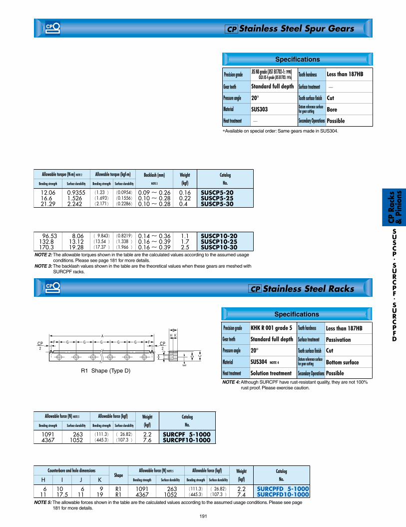
SUSCP CP Stainless Steel Spur Gears
CP R
acks
&
Pin
ions
20°
SUS303
—
Specifications
Standard full depth
Less than 187HB
—
Cut
Bore
Possible
Stainless Steel Racks
Stainless Steel Spur Gears
Passivation
191
SUSCP.SURCPF.SURCPFD
SUSCP5-20SUSCP5-25SUSCP5-30
0.160.220.40
12.0616.6021.29
0.93551.52602.2420
(1.230)(1.693)(2.171)
(0.0954)(0.1556)(0.2286)
0.09 ~ 0.260.10 ~ 0.280.10 ~ 0.28
SURCPF 5-1000SURCPF10-1000
2.27.6
10914367
02631052
(026.82)(107.30)
SUSCP10-20SUSCP10-25SUSCP10-30
1.11.72.5
096.53132.80170.30
08.0613.1219.28
(09.843)(13.540)(17.370)
(0.8219)(1.3380)(1.9660)
0.14 ~ 0.360.16 ~ 0.390.16 ~ 0.39
NOTE 2: The allowable torques shown in the table are the calculated values according to the assumed usage conditions. Please see page 181 for more details.
NOTE 3: The backlash values shown in the table are the theoretical values when these gears are meshed with SURCPF racks.
NOTE 4: Although SURCPF have rust-resistant quality, they are not 100% rust proof. Please exercise caution.
KHK R 001 grade 5 Less than 187HB
Cut
Bottom surface
Possible
Standard full depth
20°
SUS304 NOTE 4
Solution treatment
CP
CP
*Available on special order: Same gears made in SUS304.
(111.3)(445.3)
SURCPFD 5-1000SURCPFD10-1000
2.27.4
H
0611
10.017.5
0611
0919
R1R1
10914367
02631052
(111.3)(445.3)
(026.82)(107.30)
I J K
NOTE 5: The allowable forces shown in the table are the calculated values according to the assumed usage conditions. Please see page 181 for more details.
R1 Shape (Type D)
Tooth hardness
Surface treatment
Tooth surface finishDatum reference surface for gear cutting
Secondary Operations
Precision grade
Gear teeth
Pressure angle
Material
Heat treatment
Tooth hardness
Surface treatment
Tooth surface finishDatum reference surface for gear cutting
Secondary Operations
Precision grade
Gear teeth
Pressure angle
Material
Heat treatment
Specifications
JIS N8 grade (JIS1 B1702-1: 1998) OLD JIS 4 grade (JIS B1702: 1976)
Weight
(kgf)
Allowable torque (N.m) NOTE 2
Bending strength Surface durability Bending strength Surface durability
Allowable torque (kgf.m) Backlash (mm)
NOTE 3
Catalog
No.
Catalog
No.
Weight
(kgf)
Allowable force (N) NOTE 5
Bending strength Surface durability Bending strength Surface durability
Allowable force (kgf)
Catalog
No.
Counterbore and hole dimensionsShape
Weight
(kgf)
Allowable force (N) NOTE 5
Bending strength Surface durability Bending strength Surface durability
Allowable force (kgf)

CP R
acks
&
Pin
ions
2.5~10SROCP CP Round Racks Circular Pitches
■ CP 2.5~10
192
S R O C P.FRCP
E FA B C DFRCP5-2000FRCP5-3000FRCP5-4000
CP5(1.5915)CP5(1.5915)CP5(1.5915)
200030004000
101010
666
4.414.414.41
222
171717
397597797
R3R3R3
800.9800.9800.9
(81.65)(81.65)(81.65)
0.901.361.82
A dh9 DSROCP2.5- 500SROCP 5- 500SROCP 10-1000
CP2.5(0.7958)CP5.0(1.5915)CP10 (3.1831)
050505051010
101530
09.2013.4026.81
200099099
R2R2R2
0473.51652.06607.0
0091.830324.401297.00
(048.28)(168.50)(673.70)
(009.364)(033.080)(132.300)
0.580.653.60
NOTE 1: The allowable forces shown in the table are the calculated values according to the assumed usage conditions. Please see page 181 for more details.
5FRCP CP Metal Flexible Racks Circular Pitch
■ CP 5
CAUTION: When using the metal flexible rack with a 20 tooth pinion, allow a minimum radius of curvature of 150mm for the teeth on the exterior and 300mm for the teeth in the interior side.
CAUTION: These metal flexible racks are not suitable for applications where positioning accuracy is required.NOTE 1: The allowable forces shown in the table are the calculated values according to the assumed usage conditions. Please see page 181 for more details.NOTE 2: The tolerance of the height (C) is and the tolerance of the width of the base (F) is .
*SW is saw bale finish.
R3 Shape
R2 Shape
0-0.15
0-0.1
Catalog
No.Pitch mm (m)
Total length Height topitch line Effective
No. of teethShape
Allowable force (N) NOTE 1 Allowable force (kgf) Weight
(kgf)Bending strength Bending strengthSurface durability Surface durability
Specifications
KHK R 001 grade 4
Stress relief annealing
Standard full depth 20°
89~95HRB
Black oxide
Cut
—
Possible
Precision grade
Heat treatment
Pressure angle
Material
Tooth hardness
Surface treatment
Tooth surface finishDatum reference surface for gear cutting
Secondary Operations
Gear teeth
Specifications
KHK R 001 grade 8
—鈍
Standard full depth
20°
Less than 187HB
Black oxide
Cut
Bottom surface
Possible
SS400
Catalog
No.Pitch mm (m)
Total length Face width Height NOTE 2Height topitch line
Thickness ofbase
Width of flange NOTE2
Allowable force(N) NOTE 1
Allowable force(kgf) Weight
(kgf)Bending strength Bending strength
Effective No.
of teethShape
Outside dia.
Precision grade
Heat treatment
Pressure angle
Material
Tooth hardness
Surface treatment
Toth surface finishDatum reference surface for gear cutting
Secondary Operations
Gear teeth
S45C-D