cpdlc explained
TRANSCRIPT

8/9/2019 CPDLC Explained
http://slidepdf.com/reader/full/cpdlc-explained 1/421
GOLD (1) Second Edition — 26 April 2013
Global Operational
Data Link Document
(GOLD)
This edition has been issued by the GOLD ad hoc Working Group for the
Asia/Pacific Air Navigation Planning and Implementation Regional Group(APANPIRG), the North Atlantic Systems Planning Group (NAT SPG), theEuropean Air Navigation Planning Group (EANPG), the South AmericanRegion Implementation Group (SAM/IG) and the African-Indian OceanPlanning and Implementation Regional Group (APIRG).
Second Edition — 26 April 2013
International Civil Aviation Organization

8/9/2019 CPDLC Explained
http://slidepdf.com/reader/full/cpdlc-explained 2/421
This document is available by accessing any of the following ICAO regional websites.
Asia and Pacific (APAC) Office http://www.icao.int/apac
Eastern and Southern African (ESAF) Office www.icao.int/esaf
European and North Atlantic (EUR/NAT) Office http://www.paris.icao.int
Middle East (MID) Office www.icao.int/mid
North American, Central American and Caribbean (NACC) Office http://www.mexico.icao.int
South American (SAM) Office http://www.lima.icao.int
Western and Central African (WACAF) Office http://www.icao.int/wacaf
For more information, contact the ICAO regional office.
8/9/2019 CPDLC Explained
http://slidepdf.com/reader/full/cpdlc-explained 3/421
8/9/2019 CPDLC Explained
http://slidepdf.com/reader/full/cpdlc-explained 4/421
(ii) Global Operational Data Link Document (GOLD)
Second Edition — 26 April 2013 (ii) GOLD
AMENDMENTS
The issue of amendments is announced by the ICAO Regional Offices concerned, which holders of this publication should consult. The space below is provided to keep a record of such amendments.
RECORD OF AMENDMENTS AND CORRIGENDA
AMENDMENTS
No. Dateapplicable
Dateentered
Entered by
CORRIGENDA
No. Dateapplicable
Dateentered
Entered by
8/9/2019 CPDLC Explained
http://slidepdf.com/reader/full/cpdlc-explained 5/421
Global Operational Data Link Document (GOLD) (iii)
GOLD (iii) Second Edition — 26 April 2013
Table of Contents
Page
FOREWORD
. ......................................................................................................................................... xv
Chapter 1. Definitions ....................................................................................................................... 1-1
1.1
Terms and definitions .............................................................................................................. 1-1
1.2
Acronyms ............................................................................................................................... 1-13
Chapter 2. Overview of data link operations .................................................................................. 2-1
2.1
Data link operational capabilities ............................................................................................ 2-1
2.1.1 Data link benefits ........................................................................................................ 2-1
2.1.2
Data link systems – interoperability standards ........................................................... 2-2
2.1.3
Data link services – safety and performance specifications ....................................... 2-7
2.1.3.1
Oceanic SPR Standard (RTCA DO-306/EUROCAE ED-122) .................. 2-7
2.1.3.2 Continental SPR Standard (RTCA DO-290/EUROCAE ED-120) ............. 2-9
2.1.3.3
Performance-based communication and surveillance (PBCS).................... 2-9
2.1.4
Airspace types and their data link operational capabilities ....................................... 2-10
2.1.4.1
Airspace where procedural separation is being applied ............................ 2-10
2.1.4.2
Airspace where ATS surveillance services are provided .......................... 2-11
2.1.4.3 Global overview of data link operational capabilities ............................... 2-11
2.2
Data link systems and services .............................................................................................. 2-13
2.2.1
Network descriptions and message acknowledgements ........................................... 2-13
2.2.1.1
ACARS network and message acknowledgement .................................... 2-13
2.2.1.2
ATN network and message acknowledgement ......................................... 2-14
2.2.2
Data link messages ................................................................................................... 2-15
2.2.3
Data link initiation capability (DLIC) ...................................................................... 2-19
2.2.3.1
Purpose of the logon (flight plan correlation) ........................................... 2-19
2.2.3.2
Initial logon request .................................................................................. 2-21
2.2.3.3
Logon response ......................................................................................... 2-22
2.2.3.4 Logon request triggered by contact request .............................................. 2-22
2.2.4 CPDLC connection management ............................................................................. 2-24
2.2.4.1
Purpose of a CPDLC connection .............................................................. 2-24
2.2.4.2
Active and inactive CPDLC connections .................................................. 2-24
2.2.4.3
Establishing a CPDLC connection ............................................................ 2-24
2.2.4.4 Terminating a CPDLC connection (termination request message) ........... 2-26
2.2.4.5
Transferring CPDLC connections ............................................................. 2-27
2.2.4.6
The CPDLC connection sequence ............................................................ 2-29
2.2.4.7
Determining an active CPDLC connection ............................................... 2-33
2.2.4.8
Non-standard events associated with CPDLC transfers ............................ 2-34
2.2.5 Controller-pilot data link communications (CPDLC) .............................................. 2-39
2.2.5.1
CPDLC - general ....................................................................................... 2-39
2.2.5.2
CPDLC message set .................................................................................. 2-39
2.2.5.3
CPDLC messages ...................................................................................... 2-40
2.2.5.4
Responses to CPDLC messages ................................................................ 2-41
2.2.5.5
Open and closed CPDLC messages .......................................................... 2-42
8/9/2019 CPDLC Explained
http://slidepdf.com/reader/full/cpdlc-explained 6/421
(iv) Global Operational Data Link Document (GOLD)
Second Edition — 26 April 2013 (iv) GOLD
2.2.5.6
CPDLC dialogues ..................................................................................... 2-43
2.2.5.7
Message identification numbers (MIN) .................................................... 2-44
2.2.5.8
Message reference numbers (MRN) ......................................................... 2-44
2.2.6
Automatic dependent surveillance – contract (ADS-C) ........................................... 2-46
2.2.6.1 ADS-C – general ....................................................................................... 2-46
2.2.6.3
ADS contract ............................................................................................. 2-46
2.2.6.4
ADS-C report ............................................................................................ 2-55
2.2.6.5
Contents of ADS-C groups ....................................................................... 2-59
2.2.6.6
Using ADS-C reports ................................................................................ 2-59
2.2.7 FMC WPR data link system ..................................................................................... 2-64
2.2.7.1
FMC WPR - general ................................................................................. 2-64
2.2.7.2
Description ................................................................................................ 2-65
2.2.7.3
Position report - description ...................................................................... 2-65
Chapter 3.
Administrative provisions related to data link operations ......................................... 3-1
3.1
ANSP service provision ........................................................................................................... 3-1
3.1.1
ANSP system validation ............................................................................................. 3-1
3.1.2
ATC automated data link functions ............................................................................ 3-3
3.1.2.1
Logon request .............................................................................................. 3-3
3.1.2.2 Transfers between FANS 1/A and ATN B1 adjacent ATSUs .................... 3-3
3.1.2.3
CPDLC and ADS-C connection management ............................................ 3-6
3.1.2.4
Emergency message element handling ....................................................... 3-6
3.1.2.5
Automated responses .................................................................................. 3-6
3.1.2.6
Message latency monitor ............................................................................ 3-7
3.1.2.7 Abnormal cases with ADS-C ...................................................................... 3-8
3.1.2.8
Satcom channel numbers in CPDLC messages .......................................... 3-8
3.1.3
Contractual considerations for CSP ............................................................................ 3-8
3.1.4
Aeronautical information, notifications, and interfacility agreements ....................... 3-9
3.1.5
Monitoring and data recording ................................................................................. 3-11
3.2
Operator eligibility................................................................................................................. 3-11
3.2.1
Operational authorization to use data link ................................................................ 3-11
3.2.2
Regional/State monitoring agencies ......................................................................... 3-13
3.3
Flight planning ....................................................................................................................... 3-13
3.3.1 General...................................................................................................................... 3-13
3.3.2
CPDLC and ADS-C .................................................................................................. 3-14
3.3.3 FMC WPR ................................................................................................................ 3-15
3.4
FMC WPR – additional guidance .......................................................................................... 3-15
Chapter 4. Controller and radio operator procedures .................................................................. 4-1
4.1 Overview ................................................................................................................................. 4-1
4.1.1
General........................................................................................................................ 4-1
4.1.2
When to use voice and when to use CPDLC .............................................................. 4-1
4.2
CPDLC connection management and voice communication transfers .................................... 4-2
4.2.1
General........................................................................................................................ 4-2
4.2.2 Establish CPDLC connection ..................................................................................... 4-2
4.2.3
Transfer voice communications with CPDLC connection transfer ............................ 4-3
4.2.4
Termination of the CPDLC connection ...................................................................... 4-5
4.2.5
CPDLC connection with aircraft transiting small data link area ................................ 4-5
8/9/2019 CPDLC Explained
http://slidepdf.com/reader/full/cpdlc-explained 7/421
Global Operational Data Link Document (GOLD) (v)
GOLD (v) Second Edition — 26 April 2013
4.3
CPDLC – Uplink messages ..................................................................................................... 4-8
4.3.1
General........................................................................................................................ 4-8
4.3.2
Use of free text ........................................................................................................... 4-9
4.3.3
“EXPECT” uplink messages ...................................................................................... 4-9
4.3.4 Vertical clearances .................................................................................................... 4-11
4.3.5
Report/confirmation requests.................................................................................... 4-13
4.3.6
Creating multi-element uplink messages .................................................................. 4-14
4.3.7
Weather deviations ................................................................................................... 4-15
4.4
CPDLC – Downlinks ............................................................................................................. 4-16
4.4.1 General...................................................................................................................... 4-16
4.4.2
Clarifying a downlink message ................................................................................ 4-16
4.4.3
Responses/acknowledgements .................................................................................. 4-16
4.4.4
Responding to multi-element requests ...................................................................... 4-18
4.4.5
Offering alternative clearances to requests ............................................................... 4-19
4.5
ADS-C ................................................................................................................................... 4-20
4.5.1
General...................................................................................................................... 4-20
4.5.2
ADS contracts ........................................................................................................... 4-21
4.5.3
ADS-C connection management .............................................................................. 4-22 4.5.4
ADS contract - periodic ............................................................................................ 4-24
4.5.5
ADS contract - waypoint change event .................................................................... 4-25
4.5.6 ADS contract - vertical range change and lateral deviation events .......................... 4-25
4.6
Separation .............................................................................................................................. 4-25
4.6.1
General – ADS-C ...................................................................................................... 4-25
4.6.2
Vertical separation –ADS-C ..................................................................................... 4-26
4.6.3 Lateral separation – ADS-C...................................................................................... 4-26
4.6.4
Longitudinal separation – ADS-C ............................................................................ 4-27
4.6.5
Using FMC WPR for position reporting .................................................................. 4-28
4.7
Alerting service ...................................................................................................................... 4-28
4.8
Emergency procedures ........................................................................................................... 4-28
4.8.1
General...................................................................................................................... 4-28 4.8.2
CPDLC and ADS-C emergency ............................................................................... 4-28
4.8.3
ADS-C emergency report without a CPDLC emergency message .......................... 4-29
4.9
Non-routine procedures ......................................................................................................... 4-30
4.9.1
General...................................................................................................................... 4-30
4.9.2
Voice communications related to data link............................................................... 4-30
4.9.3 Data link initiation failure ......................................................................................... 4-32
4.9.4
Data link service failures .......................................................................................... 4-32
4.9.4.1
CPDLC connection failure ........................................................................ 4-32
4.9.4.2
Transferring the CPDLC connection – abnormal conditions .................... 4-33
4.9.4.3
Data link service failure ............................................................................ 4-33
4.9.4.4 Planned data link shutdown ...................................................................... 4-33
4.9.4.5
CPDLC or ADS-C service failure ............................................................. 4-34 4.9.4.6
Resuming data link operations .................................................................. 4-34
4.9.4.7
Inaccurate time estimates .......................................................................... 4-35
4.9.4.8
SATCOM failure ...................................................................................... 4-35
4.9.5 Using CPDLC to relay messages .............................................................................. 4-35
Chapter 5. Flight crew procedures .................................................................................................. 5-1
5.1
Overview ................................................................................................................................. 5-1
8/9/2019 CPDLC Explained
http://slidepdf.com/reader/full/cpdlc-explained 8/421
(vi) Global Operational Data Link Document (GOLD)
Second Edition — 26 April 2013 (vi) GOLD
5.1.1
General........................................................................................................................ 5-1
5.1.2
Operational differences between voice communications and CPDLC ....................... 5-1
5.1.3
When to use voice and when to use CPDLC .............................................................. 5-2
5.2
Logon ....................................................................................................................................... 5-3
5.2.1 General........................................................................................................................ 5-3
5.2.2
When to log on initially for data link services ............................................................ 5-7
5.2.3
Automatic transfer of CPDLC and ADS-C services between ATSUs ....................... 5-7
5.2.4
Transfer voice communications with the CPDLC connection transfer ...................... 5-7
5.2.5
Exiting CPDLC and ADS-C service areas ................................................................. 5-8
5.3 CPDLC – ATS uplink messages .............................................................................................. 5-8
5.3.1
General........................................................................................................................ 5-8
5.3.2
Flight crew response times for CPDLC uplink messages ......................................... 5-10
5.3.3
Conditional clearances .............................................................................................. 5-11
5.3.4
“EXPECT” uplink messages .................................................................................... 5-12
5.3.5
Uplinks containing FMS-loadable data .................................................................... 5-13
5.4
CPDLC – ATS downlink messages ....................................................................................... 5-14
5.4.1
General...................................................................................................................... 5-14
5.4.2
Free text .................................................................................................................... 5-15 5.4.3
Unsupported messages ............................................................................................. 5-15
5.4.4
CPDLC reports and confirmation requests ............................................................... 5-15
5.5 Automatic dependant surveillance – contract (ADS-C) ........................................................ 5-16
5.5.1
General...................................................................................................................... 5-16
5.6
Position reporting .................................................................................................................. 5-16
5.6.1
General...................................................................................................................... 5-16
5.6.2
Position reporting in a non-ADS-C environment ..................................................... 5-17
5.6.3 Position reporting in an ADS-C environment .......................................................... 5-17
5.6.4
Position reporting using FMC WPR ......................................................................... 5-18
5.7
Weather deviations and offsets .............................................................................................. 5-19
5.7.1
General...................................................................................................................... 5-19
5.7.2
Weather deviation requests and offsets .................................................................... 5-19 5.7.3
Deviations either side of route .................................................................................. 5-22
5.7.4
Reporting back on route............................................................................................ 5-23
5.8
Emergency procedures ........................................................................................................... 5-23
5.8.1
General...................................................................................................................... 5-23
5.8.2 CPDLC and ADS-C emergency ............................................................................... 5-23
5.9
Non-routine procedures ......................................................................................................... 5-24
5.9.1
General...................................................................................................................... 5-24
5.9.2
Voice communications related to data link............................................................... 5-24
5.9.3
Data link initiation failure ......................................................................................... 5-25
5.9.4
Data link system failures .......................................................................................... 5-26
5.9.5 Using CPDLC to relay messages .............................................................................. 5-27
Chapter 6. Advanced air traffic services supported by data link ................................................. 6-1
6.1
Re-route procedures ................................................................................................................. 6-1
6.1.1 General........................................................................................................................ 6-1
6.1.2
Re-route procedures – AOC initiated (DARP) ........................................................... 6-1
6.1.3
Re-route procedures – ATC initiated .......................................................................... 6-4
6.2
Tailored arrival (TA) ............................................................................................................. 6-11
6.2.1
General...................................................................................................................... 6-11
8/9/2019 CPDLC Explained
http://slidepdf.com/reader/full/cpdlc-explained 9/421
Global Operational Data Link Document (GOLD) (vii)
GOLD (vii) Second Edition — 26 April 2013
6.2.2
Provisions for the TA service ................................................................................... 6-12
6.2.3
Clearance delivery and execution ............................................................................. 6-12
6.3
Automatic dependent surveillance – broadcast in-trail procedure (ADS-B ITP) .................. 6-16
6.3.1
General...................................................................................................................... 6-16
6.3.2 Provisions for the ADS-B ITP service and operator eligibility ................................ 6-17
6.3.3
Clearance delivery and execution ............................................................................. 6-17
Chapter 7. State aircraft data link operations ................................................................................ 7-1
7.1 General ..................................................................................................................................... 7-1
7.2
Military assumes responsibility for separation of aircraft (MARSA) .................................... 7-1
7.3
Air-to-air refueling (AAR) ...................................................................................................... 7-2
7.4
Formation flight data link procedures ...................................................................................... 7-7
7.5
ADS-C reports ......................................................................................................................... 7-9
List of FiguresFigure 2-1. Overview of a data link system .......................................................................................... 2-2
Figure 2-2.
Different ATSU/aircraft interoperable connectivity ........................................................... 2-3
Figure 2-3.
Uplink and message assurance ......................................................................................... 2-13
Figure 2-4.
Downlink and network acknowledgement ....................................................................... 2-14
Figure 2-5.
Uplink and logical acknowledgement .............................................................................. 2-15
Figure 2-6.
Downlink and logical acknowledgement ......................................................................... 2-15
Figure 2-7. Initial logon exchanges ..................................................................................................... 2-22
Figure 2-8.
Air-ground address forwarding message sequence (Transfer between areas wheredata link is provided) ........................................................................................................ 2-23
Figure 2-9.
Ground-ground address forwarding using logon forwarding message ............................. 2-24
Figure 2-10. CPDLC connection sequence ........................................................................................... 2-25
Figure 2-11.
Successful attempt to establish a CPDLC connection (inactive) ...................................... 2-26
Figure 2-12.
Termination of the CPDLC connection ............................................................................ 2-27
Figure 2-13.
Next data authority notification ........................................................................................ 2-28
Figure 2-14.
Connection forwarding ..................................................................................................... 2-29
Figure 2-15. Life cycle of the CPDLC connection process .................................................................. 2-30
Figure 2-16.
Nominal sequence for initial CPDLC connection establishment and transfer ofCPDLC connection using air-ground address forwarding ............................................... 2-31
Figure 2-17.
Nominal sequence for initial CPDLC connection establishment and transfer ofCPDLC connection using ground-ground address forwarding (no use of NextAuthority Notified) ........................................................................................................... 2-32
Figure 2-18.
Nominal sequence for initial CPDLC connection establishment and transfer ofCPDLC connection using ground-ground address forwarding (use of Next
Authority Notified) ........................................................................................................... 2-33
Figure 2-19.
Rejection of CPDLC uplinks from the NDA .................................................................... 2-34
Figure 2-20.
Depiction of the change in route of an aircraft ................................................................. 2-35
Figure 2-21.
Sending a new NDA following a re-route ........................................................................ 2-36
Figure 2-22.
Non-receipt of the NDA message ..................................................................................... 2-37
Figure 2-23.
Connection request from an ATSU not designated as the NDA ...................................... 2-37
Figure 2-24.
Successful CPDLC connection following a re-send of the NDA message ...................... 2-38
Figure 2-25.
Disconnection of both active and inactive connections .................................................... 2-39
8/9/2019 CPDLC Explained
http://slidepdf.com/reader/full/cpdlc-explained 10/421
(viii) Global Operational Data Link Document (GOLD)
Second Edition — 26 April 2013 (viii) GOLD
Figure 2-26.
Message/dialogue status for CPDLC request and clearance exchange ............................ 2-43
Figure 2-27.
Message/dialogue status for CPDLC confirmation request and report exchange ............ 2-44
Figure 2-28.
ADS-C periodic contract sequence .................................................................................. 2-47
Figure 2-29.
ADS-C emergency and non-emergency report sequence ................................................. 2-49
Figure 2-30. ADS-C event contract sequence ....................................................................................... 2-50
Figure 2-31.
ADS-C waypoint change event ........................................................................................ 2-50
Figure 2-32.
ADS-C level range deviation event .................................................................................. 2-51
Figure 2-33.
ADS-C level range deviation event report ....................................................................... 2-51
Figure 2-34.
ADS-C lateral deviation event .......................................................................................... 2-52
Figure 2-35. ADS-C lateral deviation event report ............................................................................... 2-52
Figure 2-36.
Effect of offset on ADS-C lateral deviation event report ................................................. 2-53
Figure 2-37.
No lateral deviation event report if active route is different to route held by ATSU ....... 2-54
Figure 2-38.
ADS-C basic group........................................................................................................... 2-56
Figure 2-39.
ADS-C flight identification group .................................................................................... 2-56
Figure 2-40.
ADS-C Earth reference group .......................................................................................... 2-56
Figure 2-41. ADS-C air reference group ............................................................................................... 2-57
Figure 2-42.
ADS-C airframe identification group ............................................................................... 2-57
Figure 2-43.
ADS-C meteorological group ........................................................................................... 2-57 Figure 2-44.
ADS-C predicted route group ........................................................................................... 2-58
Figure 2-45.
ADS-C fixed projected intent group ................................................................................. 2-58
Figure 2-46. ADS-C intermediate projected intent group ..................................................................... 2-59
Figure 2-47.
Multiple ADS periodic contracts with different groups ................................................... 2-61
Figure 2-48.
Multiple ADS periodic contracts with different reporting intervals ................................. 2-61
Figure 2-49.
Multiple and different ADS event contracts ..................................................................... 2-62
Figure 2-50. Calculation of ADS-C periodic reporting interval ........................................................... 2-64
Figure 4-1.
CPDLC connection transfer - separate messages .............................................................. 4-4
Figure 4-2.
Transiting small data link area ........................................................................................... 4-7
Figure 4-3.
Priorities for ADS-C connections ..................................................................................... 4-23
Figure 4-4.
ADS-C connection not available due to congestion ......................................................... 4-24
Figure 5-1.
Depiction of logon addresses and CPDLC/ADS-C services on en route chart .................. 5-5 Figure 5-2.
Waypoint sequencing anomaly ......................................................................................... 5-17
Figure 5-3.
Offset and weather deviation ............................................................................................ 5-19
Figure 5-4.
Weather deviation clearance up to 20 NM left of route ................................................... 5-20
Figure 5-5.
Subsequent weather deviation clearance up to 50 NM left of route ................................. 5-21
Figure 5-6.
Subsequent weather deviation clearance up to 30 NM right of route ............................... 5-22
Figure 6-1. The DARP process ............................................................................................................. 6-4
Figure 6-2.
ATC initiated re-route – first waypoint in the new route is on the current route andthere is no route discontinuity ............................................................................................ 6-7
Figure 6-3.
ATC initiated re-route – first waypoint in the new route is on the current route andthere is route discontinuity ................................................................................................. 6-8
Figure 6-4. ATC initiated re-route – first waypoint in the new route is not on the current route
and there is no route discontinuity ...................................................................................... 6-9 Figure 6-5.
ATC initiated re-route – first waypoint in the new route is not on the current routeand there is route discontinuity ......................................................................................... 6-10
Figure 6-6. ATC initiated re-route – aircraft is cleared direct to a fix that is locateddownstream in the current route ....................................................................................... 6-11
Figure 7-1.
Air refueling pattern ........................................................................................................... 7-3
8/9/2019 CPDLC Explained
http://slidepdf.com/reader/full/cpdlc-explained 11/421
Global Operational Data Link Document (GOLD) (ix)
GOLD (ix) Second Edition — 26 April 2013
List of Tables
Table 2-1. Designators for aircraft and ATSU (ground) data link systems ......................................... 2-4
Table 2-2.
Designators for subnetworks .............................................................................................. 2-7
Table 2-3.
Examples of applying RCP specifications to intended uses ............................................... 2-8
Table 2-4.
Examples of applying RSP specifications to intended uses ............................................... 2-8
Table 2-5.
Types of data link systems and operations ....................................................................... 2-12
Table 2-6.
Air-ground data link messages for DLIC ......................................................................... 2-16
Table 2-7.
Ground-ground data link messages for DLIC .................................................................. 2-16
Table 2-8.
Data link messages for CPDLC connection ..................................................................... 2-17
Table 2-9.
Examples of responses to CPDLC uplink messages ........................................................ 2-40
Table 2-10. Precedence of responses ................................................................................................... 2-41
Table 2-11.
Examples of multi-element CPDLC uplink messages ..................................................... 2-42
Table 2-12.
Example of CPDLC dialogue ........................................................................................... 2-45
Table 2-13.
Figure of merit values ....................................................................................................... 2-63
Table 3-1.
Supporting technology for transfers between FANS 1/A and ATN B1 ............................. 3-3
Table 3-2 Descriptors for CPDLC/ADS-C equipment and capabilities in Item 10 .......................... 3-14
Table 4-1. CONTACT/MONITOR message elements ........................................................................ 4-4
Table 4-2.
“EXPECT” uplink message elements for flight crew requests .......................................... 4-9
Table 4-3.
Procedural “EXPECT” uplink message elements ............................................................ 4-10
Table 4-4.
Conditional vertical clearances applicable during flight maneuver.................................. 4-11
Table 4-5.
ADS-C out-of-conformance messages ............................................................................. 4-14
Table 4-6. Voice phraseology related to CPDLC .............................................................................. 4-31
Table 5-1.
Messages and indications regarding use of message latency monitor ................................ 5-6
Table 5-2.
Conditional clearance clarification of vertical clearances ................................................ 5-11
Table 5-3.
Voice phraseology related to CPDLC .............................................................................. 5-25
Table 6-1.
AOC initiated re-route procedures ..................................................................................... 6-2
Table 6-2.
ATC initiated re-route procedures ...................................................................................... 6-6
Table 6-3.
Tailored arrival clearance delivery and execution ............................................................ 6-13
Table 6-4.
ADS-B ITP clearance delivery and execution .................................................................. 6-18
Table 7-1.
MARSA initiation and termination procedures .................................................................. 7-2
Table 7-2. Air refueling data link procedures ...................................................................................... 7-3
Table 7-3.
Single aircraft or formation joining an ALTRV data link procedures ................................ 7-8
Table 7-4.
Formation break-up or departure from ALTRV data link procedures ............................... 7-8
Appendices
Appendix A
CPDLC message elements and standardized free text messages .................................. 1
A.1
General ........................................................................................................................................ 1
A.2
CPDLC message element response requirements key ................................................................ 3
A.3
CPDLC uplink message elements .............................................................................................. 4
A.4
CPDLC downlink message elements ........................................................................................ 32
A.5 CPDLC standardized free text messages .................................................................................. 46
A.5.1
CPDLC standardized free text uplink messages .......................................................... 46
A.5.2
CPDLC standardized free text downlink messages ..................................................... 52
8/9/2019 CPDLC Explained
http://slidepdf.com/reader/full/cpdlc-explained 12/421
(x) Global Operational Data Link Document (GOLD)
Second Edition — 26 April 2013 (x) GOLD
Appendix B
RCP specifications ............................................................................................................ 1
B.1 General ........................................................................................................................................ 1
B.2
Terms and acronyms ................................................................................................................... 1
B.3
RCP 240 specification ................................................................................................................ 6
B.3.1
RCP 240/D allocations .................................................................................................. 6
B.3.1.1
General ........................................................................................................... 6
B.3.1.2
Air navigation service provider (ANSP) ........................................................ 7
B.3.1.3
Communication service provider (CSP) ...................................................... 10
B.3.1.4
Aircraft system ............................................................................................. 12
B.3.1.5
Aircraft operator ........................................................................................... 15
B.4 RCP 400 specification .............................................................................................................. 17
B.4.1
RCP 400/D allocations ................................................................................................ 17
B.4.1.1
General ......................................................................................................... 17
B.4.1.2
Air navigation service provider (ANSP) ...................................................... 18
B.4.1.3
Communication service provider (CSP) ...................................................... 19
B.4.1.4 Aircraft system ............................................................................................. 20
B.4.1.5
Aircraft operator ........................................................................................... 22
B.5
RCP 150 specification .............................................................................................................. 24
B.5.1
RCP 150/D allocations ................................................................................................ 24
B.5.1.1
General ......................................................................................................... 24
B.5.1.2
Air navigation service provider (ANSP) ...................................................... 25
B.5.1.3 Communication service provider (CSP) ...................................................... 29
B.5.1.4
Aircraft system ............................................................................................. 31
B.5.1.5
Aircraft operator ........................................................................................... 34
Appendix C
RSP specifications ............................................................................................................. 1
C.1
General ........................................................................................................................................ 1
C.2
Terms and acronyms ................................................................................................................... 1
C.3
RSP 180 specification ................................................................................................................. 5 C.3.1
RSP 180/D allocations ................................................................................................... 6
C.3.1.1 General ........................................................................................................... 6
C.3.1.2
Air navigation service provider (ANSP) ........................................................ 6
C.3.1.3
Communication service provider (CSP) ........................................................ 8
C.3.1.4
Aircraft system ............................................................................................... 9
C.3.1.5
Aircraft operator ........................................................................................... 11
C.4
RSP 400 specification ............................................................................................................... 13
C.4.1
RSP 400/D allocations ................................................................................................. 14
C.4.1.1
General ......................................................................................................... 14
C.4.1.2
Air navigation service provider (ANSP) ...................................................... 14
C.4.1.3
Communication service provider (CSP) ...................................................... 14
C.4.1.4
Aircraft system ............................................................................................. 16 C.4.1.5 Aircraft operator ........................................................................................... 16
Appendix D Post-implementation monitoring and corrective action ................................................ 1
D.1
General ........................................................................................................................................ 1
D.2 ANSP data collection and analysis ............................................................................................. 2
D.2.1
General........................................................................................................................... 2
D.2.2
ANSP data collection for CPDLC application .............................................................. 3
8/9/2019 CPDLC Explained
http://slidepdf.com/reader/full/cpdlc-explained 13/421
Global Operational Data Link Document (GOLD) (xi)
GOLD (xi) Second Edition — 26 April 2013
D.2.2.1
General ........................................................................................................... 3
D.2.2.2
Measuring CPDLC communication performance .......................................... 3
D.2.2.3
Recording the data points for each CPDLC transaction ................................ 8
D.2.2.4
Data record for each CPDLC transaction..................................................... 12
D.2.3 ANSP data collection for ADS-C application ............................................................. 12
D.2.3.1
General ......................................................................................................... 12
D.2.3.2
Measuring actual surveillance performance (ASP) ...................................... 12
D.2.3.3
Recording the ADS-C data points for each ADS-C downlink ..................... 12
D.2.3.4
Data record for each ADS-C downlink ........................................................ 14
D.2.4 ANSP data analysis ..................................................................................................... 14
D.2.4.1
General ......................................................................................................... 14
D.2.4.2
Graphical analysis ........................................................................................ 15
D.2.4.3
Data filtering ................................................................................................ 16
D.2.4.4
CPDLC performance analysis ...................................................................... 17
D.2.4.5
ADS-C surveillance data transit time analysis ............................................. 23
D.2.4.6
Identifying poor performers ......................................................................... 28
D.2.4.7
Assessing periodic monitoring results ......................................................... 29
D.3
Problem reporting and resolution ............................................................................................. 32 D.3.1 General......................................................................................................................... 32
D.3.2
Problem report form .................................................................................................... 33
D.3.3 Problem assessment ..................................................................................................... 36
D.3.3.1
Data collection ............................................................................................. 36
D.3.3.2
Data analysis ................................................................................................ 36
D.3.4
Mitigating procedures – problem resolution ................................................................ 37
D.4
Regional performance monitoring ............................................................................................ 37
D.4.1 General......................................................................................................................... 37
D.4.2
Reporting on availability ............................................................................................. 37
D.4.3
Reporting on CPDLC actual communications performance ....................................... 39
D.4.4
Reporting on RSP data transit time ............................................................................. 40
D.4.5
Reporting data to enable graphical reports .................................................................. 42
Appendix E
Regional/State-specific information ................................................................................ 1
E.1
General ........................................................................................................................................ 1
E.2
Africa-Indian Ocean (AFI) Region ............................................................................................. 1
E.2.1 Administrative provisions related to data link operations ............................................. 1
E.2.2
Controller and radio operator procedures ...................................................................... 2
E.2.3
Flight crew procedures .................................................................................................. 2
E.2.4
Advanced data link operations ....................................................................................... 2
E.2.5 State aircraft data link operation .................................................................................... 2
E.3 Caribbean (CAR) Region ........................................................................................................... 2
E.3.1 Administrative provisions related to data link operations ............................................. 2
E.3.2
Controller and radio operator procedures ...................................................................... 3
E.3.3
Flight crew procedures .................................................................................................. 4
E.3.4
Advanced data link operations....................................................................................... 4
E.3.5 State aircraft data link operation .................................................................................... 4
E.4
European (EUR) Region ............................................................................................................. 4
E.4.1
Administrative provisions related to data link operations ............................................. 4
E.4.1.1
ANSP service provision ................................................................................. 4
E.4.1.2
EUR - NSAP address registry ........................................................................ 7

8/9/2019 CPDLC Explained
http://slidepdf.com/reader/full/cpdlc-explained 14/421
(xii) Global Operational Data Link Document (GOLD)
Second Edition — 26 April 2013 (xii) GOLD
E.4.1.3
Flight plan provisions .................................................................................... 8
E.4.1.4
Logon criteria ................................................................................................. 8
E.4.1.5
Lack Timer ..................................................................................................... 8
E.4.2
Controller procedures .................................................................................................... 8
E.4.2.1 Reverting from CPDLC to voice ................................................................... 8
E.4.2.2
Preconditions for the operational exchange of CPDLC messages ................. 9
E.4.2.3
Uplink messages ............................................................................................ 9
E.4.2.4
Operational timers used by ATSU ............................................................... 12
E.4.2.5
Transfer of data communications with open dialogues ................................ 12
E.4.2.6 Abnormal situations ..................................................................................... 13
E.4.2.7
Downlink error messages ............................................................................. 14
E.4.3
Flight crew procedures ................................................................................................ 16
E.4.3.1
General ......................................................................................................... 16
E.4.3.2
Latency time monitor (LTM) ....................................................................... 18
E.4.3.3
Operational use of LACK ............................................................................ 18
E.4.3.4
Operational timers used by the aircraft ........................................................ 19
E.4.3.5
Use of degrees in ACL messages ................................................................. 19
E.4.3.6
Transfer of data communications with open dialogues ................................ 20 E.4.3.7 Multiple open requests for a same type ....................................................... 20
E.4.3.8
Abnormal situations ..................................................................................... 20
E.4.3.9 Uplink error messages .................................................................................. 21
E.4.4
Advanced data link operations..................................................................................... 24
E.4.5
State aircraft data link operation .................................................................................. 24
E.5
Middle East/Asia (MID/ASIA) Region .................................................................................... 25
E.5.1
Administrative provisions related to data link operations ........................................... 25
E.5.2 Controller and radio operator procedures .................................................................... 25
E.5.3
Flight crew procedures ................................................................................................ 25
E.5.4
Advanced data link operations..................................................................................... 25
E.5.5
State aircraft data link operation .................................................................................. 25
E.6
North-America (NAM) Region ................................................................................................ 25 E.6.1
Administrative provisions related to data link operations ........................................... 25
E.6.2
Controller and radio operator procedures .................................................................... 27
E.6.3
Flight crew procedures ................................................................................................ 28
E.6.4
Advanced data link operations..................................................................................... 28
E.6.5 State aircraft data link operation .................................................................................. 28
E.7
North Atlantic (NAT) Region ................................................................................................... 28
E.7.1
Administrative provisions related to data link operations ........................................... 28
E.7.1.1
ANSP service provision ............................................................................... 28
E.7.1.2
Uplink message elements unsuited for NAT operations .............................. 31
E.7.1.3 Unsupported CPDLC downlink message elements – NAT ......................... 31
E.7.1.4
Reporting requirements in NAT airspace where ADS-C is available .......... 32
E.7.2
Controller and radio operator procedures .................................................................... 33 E.7.2.1
Voice communication procedures ................................................................ 33
E.7.3
Flight crew procedures ................................................................................................ 34
E.7.3.1
Voice communication procedures ................................................................ 34
E.7.4
Advanced data link operations..................................................................................... 36
E.7.5
State aircraft data link operation .................................................................................. 36
E.8
Pacific (PAC) Region ............................................................................................................... 36
E.8.1
Administrative provisions related to data link operations ........................................... 36
8/9/2019 CPDLC Explained
http://slidepdf.com/reader/full/cpdlc-explained 15/421
Global Operational Data Link Document (GOLD) (xiii)
GOLD (xiii) Second Edition — 26 April 2013
E.8.1.1
ANSP service provision ............................................................................... 36
E.8.1.2
Exchange of turbulence information in Fukuoka FIR .................................. 40
E.8.2
Controller and radio operator procedures .................................................................... 41
E.8.3
Flight crew procedures ................................................................................................ 41
E.8.4 Advanced data link operations ..................................................................................... 41
E.8.5
State aircraft data link operation .................................................................................. 42
E.9
South-America (SAM) Region ................................................................................................. 42
E.9.1
Administrative provisions related to data link operations ........................................... 42
E.9.2
Controller and radio operator procedures .................................................................... 42
E.9.3 Flight crew procedures ................................................................................................ 42
E.9.4
Advanced data link operations..................................................................................... 43
E.9.5
State aircraft data link operation .................................................................................. 43
Appendix F
Operator/aircraft specific information ........................................................................... 1
F.1
FANS 1/A and ATN B1 product availability ............................................................................. 1
F.2
Verifying aircraft registration ..................................................................................................... 2
F.3
CPDLC connection management ............................................................................................... 3
F.4
Flight crew display – response and acknowledgement ............................................................... 3
F.5 FMS processing of waypoints in position reports ...................................................................... 4
F.6
Multiple request messages .......................................................................................................... 4
F.7
Waypoint sequencing.................................................................................................................. 5
F.8
Open uplinks at time of transfer of communications .................................................................. 6
F.9
Variable constraints .................................................................................................................... 6
F.10
ADS-C emergency report interval default .................................................................................. 6
F.11 Message latency monitor ............................................................................................................ 6
F.12
Terminating ADS-C connections ............................................................................................... 7
F.13
SATCOM channel format........................................................................................................... 8
F.14
Transfer of ATSU ....................................................................................................................... 8
F.15
Number of ADS-C connections .................................................................................................. 8
F.16
Lateral deviation events on offsets ............................................................................................. 8
F.17
Assigned block altitude............................................................................................................... 9
F.18
FANS 1/A-ATN B1 aircraft behavior for automatic CPDLC transfers ..................................... 9
F.19
CM contact procedure............................................................................................................... 10
F.20 Duplicate CPDLC uplink message processing ......................................................................... 10
F.21
Response to end-service and error uplink messages ................................................................. 10
F.22
CPDLC connection after logon ................................................................................................ 11
F.23
ARINC 424 oceanic waypoints ................................................................................................ 11
F.24
STANDBY response to pilot-initiated downlink request ......................................................... 12

8/9/2019 CPDLC Explained
http://slidepdf.com/reader/full/cpdlc-explained 16/421

8/9/2019 CPDLC Explained
http://slidepdf.com/reader/full/cpdlc-explained 17/421
Global Operational Data Link Document (GOLD) (xv)
GOLD (xv) Second Edition — 26 April 2013
FOREWORD.
1. Historical background
1.1 The Global Operational Data Link Document (GOLD) is the result of the progressive evolutionof the ICAO Asia-Pacific (APAC) Initial Future Air Navigation System (FANS 1/A) Operations Manual,the North Atlantic (NAT) Guidance Material for ATS Data Link Services in North Atlantic Airspace andthe Eurocontrol LINK2000+ Guidance Material for the aeronautical telecommunication network baseline1 (ATN B1).
1.2 Each of these founding documents provided guidance on a regional basis. However, inrecognition of the need to provide globally harmonized guidance on data link operations, the GOLD, FirstEdition, merging initially the APAC and NAT guidance material, was adopted by the APAC and NATRegions in 2010. The Second Edition of the GOLD enabled integration of the LINK2000+ guidancematerial.
1.3 The GOLD addresses data link service provision, operator readiness, controller and flight crew procedures, performance-based specifications and post-implementation monitoring and analysis.
2. Scope and purpose
2.1 The GOLD provides guidance and information concerning data link operations and is intendedto facilitate the uniform application of Standards and Recommended Practices contained in Annex 2 — Rules of the Air , Annex 10 — Aeronautical Telecommunications and Annex 11 — Air Traffic Services,the provisions in the Procedures for Air Navigation Services — Air Traffic Management (PANS-ATM,Doc 4444) and, when necessary, the Regional Supplementary Procedures (Doc 7030).
2.2 This guidance material is intended to improve safety and maximize operational benefits by promoting seamless and interoperable data link operations throughout the world. This edition applies tothe FANS 1/A and ATN B1 data link operations using automatic dependent surveillance — contract(ADS-C), controller-pilot data link communications (CPDLC) and the flight management computerwaypoint position reporting (FMC WPR). Additional guidance is provided on the use of automaticdependent surveillance – broadcast (ADS-B) in-trail procedures (ITP). It also addresses the performanceof the data link applications taking into consideration the transmission media used by those applications.
2.3 The following personnel and organizations should be familiar with relevant aspects of itscontents: regulators, airspace planners, aircraft operators, dispatchers, air navigation service providers(ANSPs), aeronautical stations, communication service providers (CSPs), satellite service providers(SSPs) and radio operators, training organizations, regional/State monitoring agencies, automationspecialists at centers and radio facilities, and aircraft manufacturers and equipment suppliers.
2.4 The guidance will support the following activities:
a) The States’ roles and responsibilities in relation to the following:
1) Safety regulatory oversight of air navigation services;
2) Operational authorizations, flight crew training and qualification; and
3) Design approval of aircraft data link systems.

8/9/2019 CPDLC Explained
http://slidepdf.com/reader/full/cpdlc-explained 18/421
(xvi) Global Operational Data Link Document (GOLD)
Second Edition — 26 April 2013 (xvi) GOLD
b) The development of agreements and/or contractual arrangements between ANSPs and aircraftoperators and their respective communication service providers;
c) The development of operational procedures; and
d) Operational monitoring, analysis, and exchange of operational data among regions, States, and
communication service providers.
3. Status
This guidance is approved and maintained by the respective participating PIRGs and has a status ofan ICAO regional guidance material. It contains material that may eventually become Standards andRecommended Practices (SARPs) or PANS provisions when it has reached the maturity and stabilitynecessary for adoption or approval. It also comprises material prepared as an amplification of the basic principles in the corresponding SARPs, and designed particularly to assist the user in the application ofthe SARPs and PANS.
4. Implementation
With a view of facilitating implementation of the provisions herein by States, this guidance materialhas been prepared using language that permits direct use by all users.
5. References
6.1 The following references are cited in this document:
a) ICAO Annex 1 — Personnel Licensing
b) ICAO Annex 2 — Rules of the Air
c) ICAO Annex 4 — Aeronautical Charts
d) ICAO Annex 6 — Operation of Aircraft – Part I — International Commercial Air Transport —
Aeroplanes
e) ICAO Annex 10 — Aeronautical Telecommunications – Volume II — CommunicationProcedures including those with PANS status
f) ICAO Annex 10 — Aeronautical Telecommunications – Volume III — CommunicationSystems
g) ICAO Annex 11 — Air Traffic Services
h) ICAO Annex 15 — Aeronautical Information Services
i) Procedures for Air Navigation Services — Air Traffic Management (PANS-ATM, ICAO
Doc 4444)
j) Regional Supplementary Procedures (Regional SUPPs, ICAO Doc 7030)
k) Procedures for Air Navigation Services — ICAO Abbreviations and Codes (PANS-ABC, ICAODoc 8400)
l) Designators for Aircraft Operating Agencies, Aeronautical Authorities and Services (ICAODoc 8585)
8/9/2019 CPDLC Explained
http://slidepdf.com/reader/full/cpdlc-explained 19/421
Global Operational Data Link Document (GOLD) (xvii)
GOLD (xvii) Second Edition — 26 April 2013
m) Aircraft Type Designators (ICAO Doc 8643)
n) Manual on Airspace Planning Methodology for the Determination of Separation Minima (ICAO Doc 9689)
o) Performance-based Navigation Manual (PBN) (ICAO Doc 9613)
p) Manual on Required Communication Performance (RCP) (ICAO Doc 9869)
q) Manual on Airborne Surveillance Applications (Doc 9994)
r) In Trail Procedure (ITP) Using Automatic Dependant Surveillance - Broadcast (ADS-B)" (ICAO Circular 325)
s) Safety and Performance Standard for Air Traffic Data Link Services in Oceanic and Remote
Airspace (Oceanic SPR Standard, RTCA DO-306/EUROCAE ED-122)
t) Safety and Performance Standard for Air Traffic Data Link Services in Continental Airspace (Continental SPR Standard, RTCA DO-290/EUROCAE ED-120, Change 1 and Change 2)
u) Interoperability Requirements for ATS Applications Using ARINC 622 Data Communications
(FANS 1/A INTEROP Standard, RTCA DO-258A/EUROCAE ED-100A)v) Interoperability Requirements Standard for Aeronautical Telecommunication Network
Baseline 1 (ATN B1 INTEROP Standard, RTCA DO-280B/EUROCAE ED-110B)
w) Future Air Navigation System 1/A — Aeronautical Telecommunication Network Interoperability
Standard (FANS 1/A — ATN B1 INTEROP Standard, RTCA DO-305A/EUROCAE ED-154A)
x) Safety, Performance and Interoperability Requirements Document for In-Trail Procedure in
Oceanic Airspace (RTCA DO-312/EUROCAE ED-159) and Supplement
y) Navigation Systems Data Base (ARINC 424)
z) Advanced Flight Management Computer System (ARINC 702A)
6. Changes to the document
This document is maintained as a regional document in coordination with all ICAO planning andimplementation regional groups (PIRGs) providing data link services within their region. Each participating PIRG establishes a mechanism for submitting and administering change proposals.
Change proposals (CPs) can be submitted by any stakeholder participating in data link operations.The stakeholder should submit a Change Proposal to their ICAO regional office (see Appendix E). TheICAO regional office will coordinate the change proposal within its own region, other regions, and ICAOHQ, to determine the acceptability of the change proposal. Once the ICAO regional office has completedcoordination and the participating PIRGs accept the change proposal, the change is concluded by each ofthe PIRGs.
8/9/2019 CPDLC Explained
http://slidepdf.com/reader/full/cpdlc-explained 20/421
(xviii) Global Operational Data Link Document (GOLD)
Second Edition — 26 April 2013 (xviii) GOLD
Amendments to the GOLD
Amendment Source(s) Subject(s)ApprovedApplicable
1st Edition
(2010)
Asia/Pacific Air Navigation
Planning and ImplementationRegional Group(APANPIRG/20 – 2009)
North Atlantic SystemsPlanning Group(NAT SPG/46 – 2010)
Global Operational Data Link
Document (GOLD)
Applicable within
participating Regionson 1 July 2010.
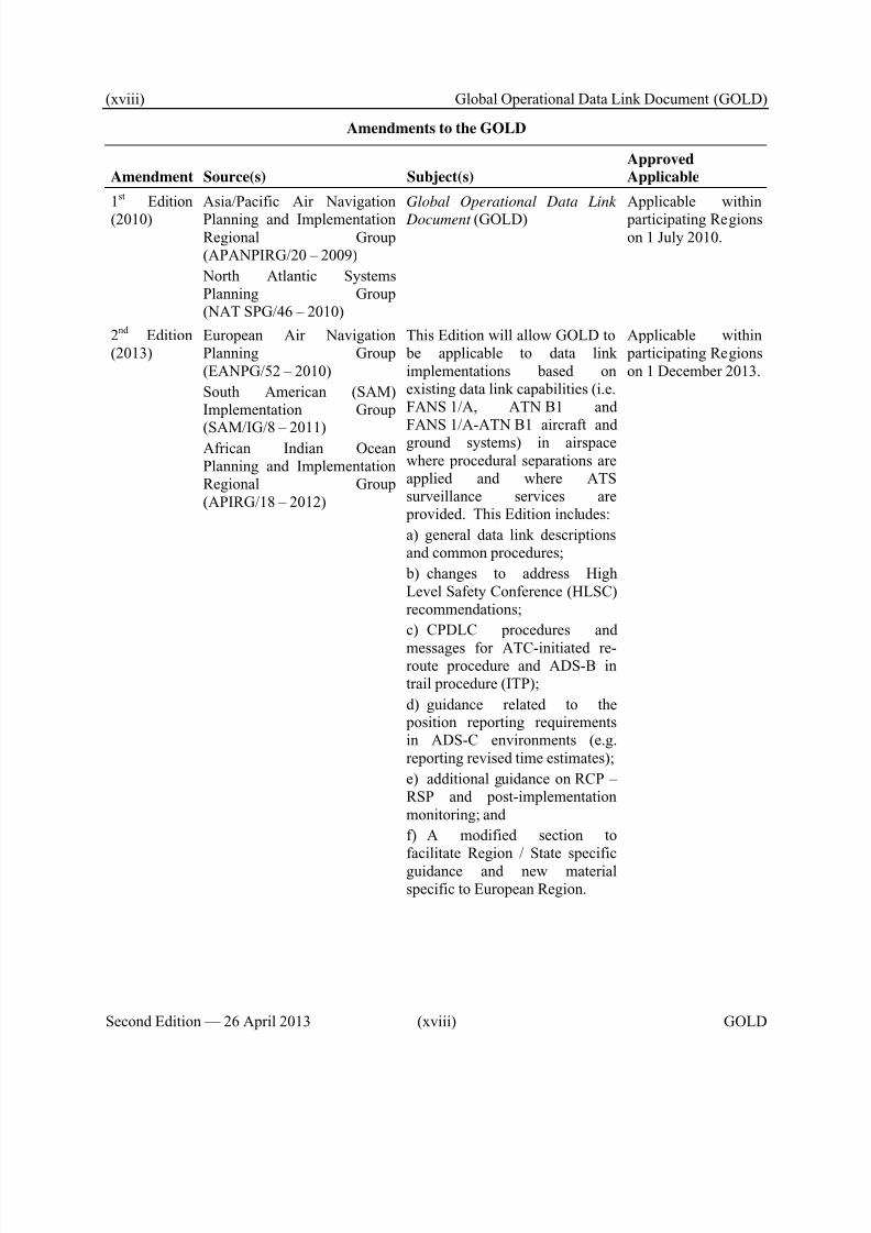
2nd Edition(2013)
European Air NavigationPlanning Group(EANPG/52 – 2010)
South American (SAM)Implementation Group
(SAM/IG/8 – 2011)African Indian OceanPlanning and ImplementationRegional Group(APIRG/18 – 2012)
This Edition will allow GOLD to be applicable to data linkimplementations based onexisting data link capabilities (i.e.FANS 1/A, ATN B1 and
FANS 1/A-ATN B1 aircraft andground systems) in airspacewhere procedural separations areapplied and where ATSsurveillance services are provided. This Edition includes:
a) general data link descriptionsand common procedures;
b) changes to address HighLevel Safety Conference (HLSC)recommendations;
c) CPDLC procedures and
messages for ATC-initiated re-route procedure and ADS-B intrail procedure (ITP);
d) guidance related to the position reporting requirementsin ADS-C environments (e.g.reporting revised time estimates);
e) additional guidance on RCP –RSP and post-implementationmonitoring; and
f) A modified section tofacilitate Region / State specificguidance and new materialspecific to European Region.
Applicable within participating Regionson 1 December 2013.
8/9/2019 CPDLC Explained
http://slidepdf.com/reader/full/cpdlc-explained 21/421
Global Operational Data Link Document (GOLD) 1-1
GOLD 1-1 Second Edition — 26 April 2013
Chapter 1. Definitions
1.1 Terms and definitions
When the following terms are used in this document they have the following meanings. Where the termhas “(ICAO)” annotated, the term has already been defined as such in SARPs and/or PANS.
Term
ADS-C service. A term used to indicate an ATS service that provides surveillance information bymeans of the ADS-C application.
Note.— ICAO Doc 4444 does not include ADS-C in its definition for ATS surveillance system.
Therefore, an ATS surveillance service does not consider those provided by means of the ADS-C
application, unless it can be shown by comparative assessment to have a level of safety and
performance equal to or better than monopulse SSR.
Aeronautical fixed telecommunication network (AFTN). A worldwide system of aeronautical fixedcircuits provided, as part of the aeronautical fixed service, for the exchange of messages and/ordigital data between aeronautical fixed stations having the same or compatible communicationscharacteristics. (ICAO)
Aeronautical Information Publication (AIP). A publication issued by or with the authority of a Stateand containing aeronautical information of a lasting character essential to air navigation. (ICAO)
Aeronautical operational control (AOC). Communication required for the exercise of authority overthe initiation, continuation, diversion or termination of flight for safety, regularity and efficiencyreasons. (ICAO)
Aeronautical telecommunication network (ATN). A global internetwork architecture that allowsground, air-ground and avionic data subnetworks to exchange digital data for the safety of airnavigation and for the regular, efficient and economic operation of air traffic services. (ICAO)
Air navigation services provider (ANSP). An organization responsible for the provision of air trafficservices.
Air traffic control (ATC) clearance. Authorization for an aircraft to proceed under conditionsspecified by an air traffic control unit.
Note 1.— For convenience, the term “air traffic control clearance” is frequently abbreviated to
“clearance” when used in appropriate contexts.
Note 2.— The abbreviated term “clearance” may be prefixed by the words “taxi”, “take-off”,“departure”, “en-route”, “approach” or “landing” to indicate the particular portion of flight to which
the air traffic control clearance relates.
(ICAO)
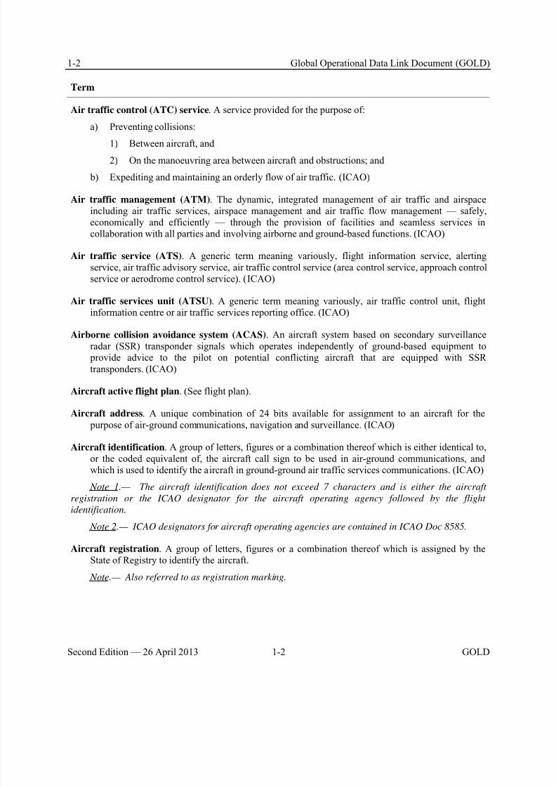
8/9/2019 CPDLC Explained
http://slidepdf.com/reader/full/cpdlc-explained 22/421
1-2 Global Operational Data Link Document (GOLD)
Second Edition — 26 April 2013 1-2 GOLD
Term
Air traffic control (ATC) service. A service provided for the purpose of:
a) Preventing collisions:
1) Between aircraft, and
2) On the manoeuvring area between aircraft and obstructions; and
b) Expediting and maintaining an orderly flow of air traffic. (ICAO)
Air traffic management (ATM). The dynamic, integrated management of air traffic and airspaceincluding air traffic services, airspace management and air traffic flow management — safely,economically and efficiently — through the provision of facilities and seamless services incollaboration with all parties and involving airborne and ground-based functions. (ICAO)
Air traffic service (ATS). A generic term meaning variously, flight information service, alertingservice, air traffic advisory service, air traffic control service (area control service, approach control
service or aerodrome control service). (ICAO)
Air traffic services unit (ATSU). A generic term meaning variously, air traffic control unit, flightinformation centre or air traffic services reporting office. (ICAO)
Airborne collision avoidance system (ACAS). An aircraft system based on secondary surveillanceradar (SSR) transponder signals which operates independently of ground-based equipment to provide advice to the pilot on potential conflicting aircraft that are equipped with SSRtransponders. (ICAO)
Aircraft active flight plan. (See flight plan).
Aircraft address. A unique combination of 24 bits available for assignment to an aircraft for the purpose of air-ground communications, navigation and surveillance. (ICAO)
Aircraft identification. A group of letters, figures or a combination thereof which is either identical to,or the coded equivalent of, the aircraft call sign to be used in air-ground communications, andwhich is used to identify the aircraft in ground-ground air traffic services communications. (ICAO)
Note 1.— The aircraft identification does not exceed 7 characters and is either the aircraft
registration or the ICAO designator for the aircraft operating agency followed by the flight
identification.
Note 2.— ICAO designators for aircraft operating agencies are contained in ICAO Doc 8585.
Aircraft registration. A group of letters, figures or a combination thereof which is assigned by theState of Registry to identify the aircraft.
Note.— Also referred to as registration marking.
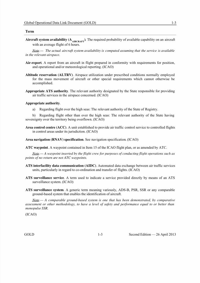
8/9/2019 CPDLC Explained
http://slidepdf.com/reader/full/cpdlc-explained 23/421
Global Operational Data Link Document (GOLD) 1-3
GOLD 1-3 Second Edition — 26 April 2013
Term
Aircraft system availability (AAIRCRAFT
) . The required probability of available capability on an aircraft
with an average flight of 6 hours.
Note.— The actual aircraft system availability is computed assuming that the service is availablein the relevant airspace.
Air-report. A report from an aircraft in flight prepared in conformity with requirements for position,and operational and/or meteorological reporting. (ICAO)
Altitude reservation (ALTRV). Airspace utilization under prescribed conditions normally employedfor the mass movement of aircraft or other special requirements which cannot otherwise beaccomplished.
Appropriate ATS authority. The relevant authority designated by the State responsible for providingair traffic services in the airspace concerned. (ICAO)
Appropriate authority.
a) Regarding flight over the high seas: The relevant authority of the State of Registry.
b) Regarding flight other than over the high seas: The relevant authority of the State havingsovereignty over the territory being overflown. (ICAO)
Area control centre (ACC). A unit established to provide air traffic control service to controlled flightsin control areas under its jurisdiction. (ICAO)
Area navigation (RNAV) specification. See navigation specification. (ICAO)
ATC waypoint. A waypoint contained in Item 15 of the ICAO flight plan, or as amended by ATC. Note.— A waypoint inserted by the flight crew for purposes of conducting flight operations such as
points of no return are not ATC waypoints.
ATS interfacility data communication (AIDC). Automated data exchange between air traffic servicesunits, particularly in regard to co-ordination and transfer of flights. (ICAO)
ATS surveillance service. A term used to indicate a service provided directly by means of an ATSsurveillance system. (ICAO)
ATS surveillance system. A generic term meaning variously, ADS-B, PSR, SSR or any comparableground-based system that enables the identification of aircraft.
Note.— A comparable ground-based system is one that has been demonstrated, by comparative
assessment or other methodology, to have a level of safety and performance equal to or better than
monopulse SSR.
(ICAO)

8/9/2019 CPDLC Explained
http://slidepdf.com/reader/full/cpdlc-explained 24/421
1-4 Global Operational Data Link Document (GOLD)
Second Edition — 26 April 2013 1-4 GOLD
Term
Automatic dependent surveillance — broadcast (ADS-B). A means by which aircraft, aerodromevehicles and other objects can automatically transmit and/or receive data such as identification,
position and additional data, as appropriate, in a broadcast mode via a data link. (ICAO)
Automatic dependent surveillance — contract (ADS-C). A means by which the terms of an ADS-Cagreement will be exchanged between the ground system and the aircraft, via a data link,specifying under what conditions ADS-C reports would be initiated, and what data would becontained in the reports. (ICAO)
Note.— The abbreviated term “ADS contract” is commonly used to refer to ADS event contract,
ADS demand contract, ADS periodic contract or an emergency mode.
C for RCTP. The proportion of intervention messages and responses that can be delivered within thespecified RCTP time for intervention.
C for RCTPAIR. The proportion of intervention messages and responses that can be delivered within thespecified RCTP
AIR time for intervention.
C for RCTPATSU
. The proportion of intervention messages and responses that can be delivered within
the specified RCTPATSU
time for intervention.
C for RCTPCSP
. The proportion of intervention messages and responses that can be delivered within
the specified RCTPCSP
time for intervention.
C for RSTPAIR
. The proportion of surveillance messages that can be delivered within the specified
RSTPAIR
time.
C for RSTPATSU
. The proportion of surveillance messages that can be delivered within the specified
RSTPATSU
time.
C for RSTPCSP
. The proportion of surveillance messages that can be delivered within the specified
RSTPCSP
time.
C for TRN. The proportion of intervention messages and responses that can be delivered within thespecified TRN time for intervention.
Call sign. The designator used in air-ground communications to identify the aircraft and is equivalent to
the encoded aircraft identification.
Closed message. A message that:
a) Contains no message elements that require a response; or
b) Has received a closure response.
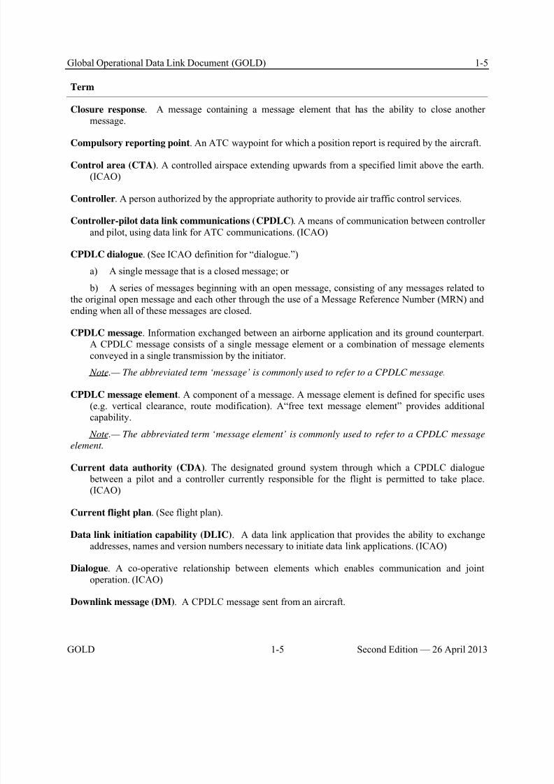
8/9/2019 CPDLC Explained
http://slidepdf.com/reader/full/cpdlc-explained 25/421
Global Operational Data Link Document (GOLD) 1-5
GOLD 1-5 Second Edition — 26 April 2013
Term
Closure response. A message containing a message element that has the ability to close anothermessage.
Compulsory reporting point. An ATC waypoint for which a position report is required by the aircraft.
Control area (CTA). A controlled airspace extending upwards from a specified limit above the earth.(ICAO)
Controller. A person authorized by the appropriate authority to provide air traffic control services.
Controller-pilot data link communications (CPDLC). A means of communication between controllerand pilot, using data link for ATC communications. (ICAO)
CPDLC dialogue. (See ICAO definition for “dialogue.”)
a) A single message that is a closed message; or b) A series of messages beginning with an open message, consisting of any messages related to
the original open message and each other through the use of a Message Reference Number (MRN) andending when all of these messages are closed.
CPDLC message. Information exchanged between an airborne application and its ground counterpart.A CPDLC message consists of a single message element or a combination of message elementsconveyed in a single transmission by the initiator.
Note.— The abbreviated term ‘message’ is commonly used to refer to a CPDLC message.
CPDLC message element. A component of a message. A message element is defined for specific uses(e.g. vertical clearance, route modification). A“free text message element” provides additionalcapability.
Note.— The abbreviated term ‘message element’ is commonly used to refer to a CPDLC message
element.
Current data authority (CDA). The designated ground system through which a CPDLC dialogue between a pilot and a controller currently responsible for the flight is permitted to take place.(ICAO)
Current flight plan. (See flight plan).
Data link initiation capability (DLIC). A data link application that provides the ability to exchange
addresses, names and version numbers necessary to initiate data link applications. (ICAO)
Dialogue. A co-operative relationship between elements which enables communication and jointoperation. (ICAO)
Downlink message (DM). A CPDLC message sent from an aircraft.
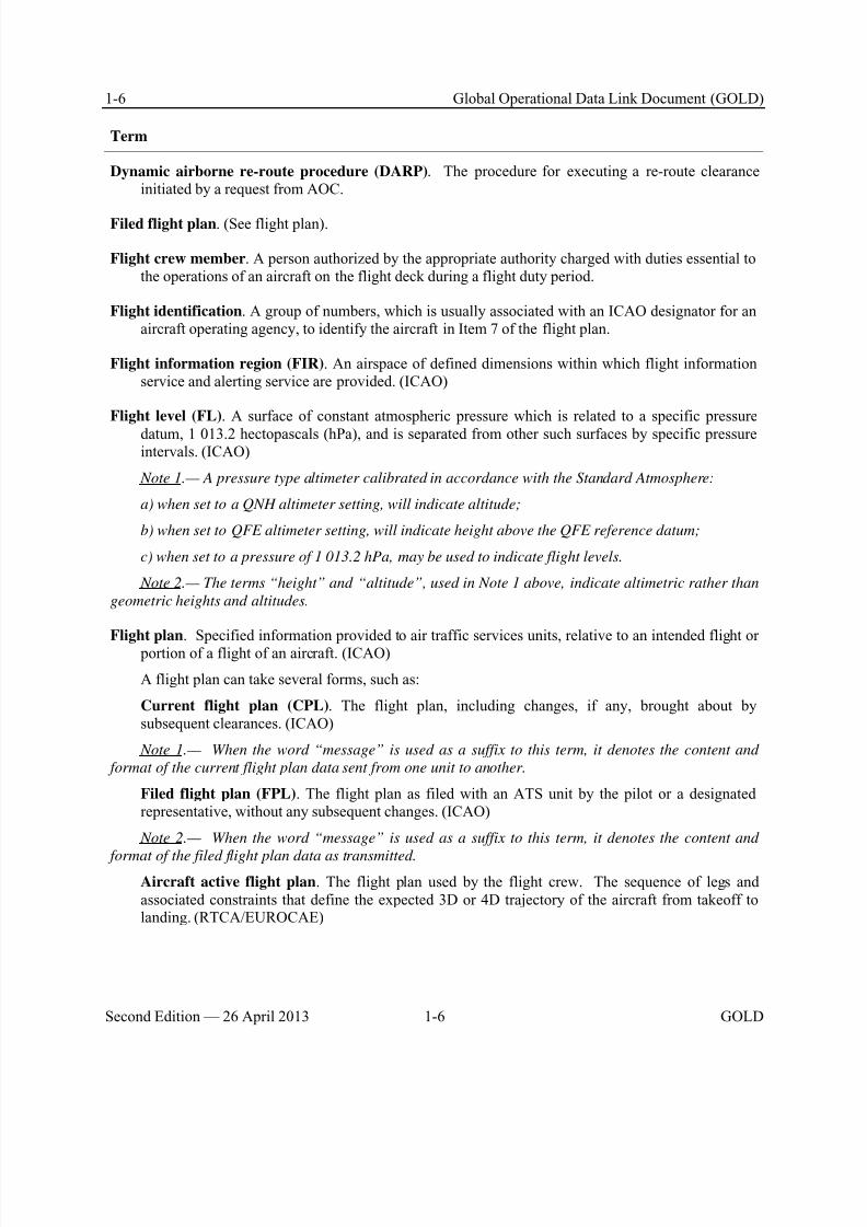
8/9/2019 CPDLC Explained
http://slidepdf.com/reader/full/cpdlc-explained 26/421
1-6 Global Operational Data Link Document (GOLD)
Second Edition — 26 April 2013 1-6 GOLD
Term
Dynamic airborne re-route procedure (DARP). The procedure for executing a re-route clearanceinitiated by a request from AOC.
Filed flight plan. (See flight plan).
Flight crew member. A person authorized by the appropriate authority charged with duties essential tothe operations of an aircraft on the flight deck during a flight duty period.
Flight identification. A group of numbers, which is usually associated with an ICAO designator for anaircraft operating agency, to identify the aircraft in Item 7 of the flight plan.
Flight information region (FIR). An airspace of defined dimensions within which flight informationservice and alerting service are provided. (ICAO)
Flight level (FL). A surface of constant atmospheric pressure which is related to a specific pressure
datum, 1 013.2 hectopascals (hPa), and is separated from other such surfaces by specific pressureintervals. (ICAO)
Note 1.— A pressure type altimeter calibrated in accordance with the Standard Atmosphere:
a) when set to a QNH altimeter setting, will indicate altitude;
b) when set to QFE altimeter setting, will indicate height above the QFE reference datum;
c) when set to a pressure of 1 013.2 hPa, may be used to indicate flight levels.
Note 2.— The terms “height” and “altitude”, used in Note 1 above, indicate altimetric rather than
geometric heights and altitudes.
Flight plan. Specified information provided to air traffic services units, relative to an intended flight or portion of a flight of an aircraft. (ICAO)
A flight plan can take several forms, such as:
Current flight plan (CPL). The flight plan, including changes, if any, brought about bysubsequent clearances. (ICAO)
Note 1.— When the word “message” is used as a suffix to this term, it denotes the content and
format of the current flight plan data sent from one unit to another.
Filed flight plan (FPL). The flight plan as filed with an ATS unit by the pilot or a designatedrepresentative, without any subsequent changes. (ICAO)
Note 2.— When the word “message” is used as a suffix to this term, it denotes the content and
format of the filed flight plan data as transmitted.Aircraft active flight plan. The flight plan used by the flight crew. The sequence of legs andassociated constraints that define the expected 3D or 4D trajectory of the aircraft from takeoff tolanding. (RTCA/EUROCAE)
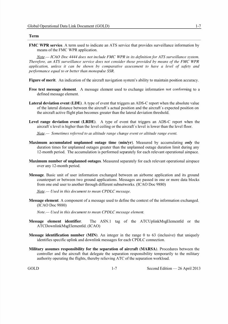
8/9/2019 CPDLC Explained
http://slidepdf.com/reader/full/cpdlc-explained 27/421
Global Operational Data Link Document (GOLD) 1-7
GOLD 1-7 Second Edition — 26 April 2013
Term
FMC WPR service. A term used to indicate an ATS service that provides surveillance information bymeans of the FMC WPR application.
Note.— ICAO Doc 4444 does not include FMC WPR in its definition for ATS surveillance system.Therefore, an ATS surveillance service does not consider those provided by means of the FMC WPR
application, unless it can be shown by comparative assessment to have a level of safety and
performance equal to or better than monopulse SSR.
Figure of merit. An indication of the aircraft navigation system’s ability to maintain position accuracy.
Free text message element. A message element used to exchange information not conforming to adefined message element.
Lateral deviation event (LDE). A type of event that triggers an ADS-C report when the absolute valueof the lateral distance between the aircraft`s actual position and the aircraft`s expected position on
the aircraft active flight plan becomes greater than the lateral deviation threshold.
Level range deviation event (LRDE). A type of event that triggers an ADS-C report when theaircraft`s level is higher than the level ceiling or the aircraft`s level is lower than the level floor.
Note.— Sometimes referred to as altitude range change event or altitude range event.
Maximum accumulated unplanned outage time (min/yr). Measured by accumulating only theduration times for unplanned outages greater than the unplanned outage duration limit during any12-month period. The accumulation is performed separately for each relevant operational airspace.
Maximum number of unplanned outages. Measured separately for each relevant operational airspaceover any 12-month period.
Message. Basic unit of user information exchanged between an airborne application and its groundcounterpart or between two ground applications. Messages are passed in one or more data blocksfrom one end user to another through different subnetworks. (ICAO Doc 9880)
Note.— Used in this document to mean CPDLC message.
Message element. A component of a message used to define the context of the information exchanged.(ICAO Doc 9880)
Note.— Used in this document to mean CPDLC message element.
Message element identifier. The ASN.1 tag of the ATCUplinkMsgElementId or the
ATCDownlinkMsgElementId. (ICAO)
Message identification number (MIN). An integer in the range 0 to 63 (inclusive) that uniquelyidentifies specific uplink and downlink messages for each CPDLC connection.
Military assumes responsibility for the separation of aircraft (MARSA). Procedures between thecontroller and the aircraft that delegate the separation responsibility temporarily to the militaryauthority operating the flights, thereby relieving ATC of the separation workload.
8/9/2019 CPDLC Explained
http://slidepdf.com/reader/full/cpdlc-explained 28/421
1-8 Global Operational Data Link Document (GOLD)
Second Edition — 26 April 2013 1-8 GOLD
Term
Minimum equipment list (MEL). A list which provides for the operation of aircraft, subject tospecified conditions, with particular equipment inoperative, prepared by an operator in conformity
with, or more restrictive than, the MMEL established for the aircraft type. (ICAO)
Monitored operational performance (TRN). The portion of the transaction time (used forintervention) that does not include the times for message composition or recognition of theoperational response.
Multi-element message. A CPDLC message consisting of more than one message element (clearance,instruction or information), handled by the controller of the flight crew as a single message.
Navigation specification. A set of aircraft and flight crew requirements needed to support performance- based navigation operations within a defined airspace. There are two kinds of navigationspecifications:
Required navigation performance (RNP) specification. A navigation specification based on areanavigation that includes the requirement for performance monitoring and alerting, designated by the prefix RNP (e.g. RNP 4, RNP APCH).
Area navigation (RNAV) specification. A navigation specification based on area navigation thatdoes not include the requirement for performance monitoring and alerting, designated by the prefix RNAV (e.g. RNAV 5, RNAV 1).
Note 1.— The Performance-based Navigation (PBN) Manual (Doc 9613), Volume II, contains
detailed guidance on navigation specifications.
Note 2.— The term RNP, previously defined as “a statement of the navigation performance
necessary for operation within a defined airspace”, has been removed from this Annex as the concept of
RNP has been overtaken by the concept of PBN. The term RNP is now solely used in the context of
navigation specifications that require performance monitoring and alerting (e.g. RNP 4 refers to theaircraft and operating requirements, including a 4 NM lateral performance with on-board performance
monitoring and alerting that are detailed in Doc 9613).
Next data authority. The ground system so designated by the current data authority through which anonward transfer of communications and control can take place. (ICAO)
NOTAM. A notice distributed by means of telecommunication containing information concerning theestablishment, condition or change in any aeronautical facility, service, procedure or hazard, thetimely knowledge of which is essential to personnel concerned with flight operations. (ICAO)
Open message. A message that contains at least one message element that requires a response. An
open message remains open until the required response is received.
Operational communication transaction. The process a human uses to initiate the transmission of aninstruction, clearance, flight information, and/or request, and is completed when that human isconfident that the transaction is complete.
8/9/2019 CPDLC Explained
http://slidepdf.com/reader/full/cpdlc-explained 29/421
Global Operational Data Link Document (GOLD) 1-9
GOLD 1-9 Second Edition — 26 April 2013
Term
Performance-based communication (PBC). ATS communication services and capability based on performance requirements for air traffic service provision, aircraft and flight operations along an
ATS route, on an instrument approach procedure or in a designated airspace. Note.— Communication performance requirements are allocated to system components in an RCP
specification in terms of communication transaction time, continuity, availability, integrity, safety and
functionality needed for the proposed operation in the context of a particular airspace concept.
Performance-based navigation (PBN). Area navigation based on performance requirements foraircraft operating along an ATS route, on an instrument approach procedure or in a designatedairspace.
Note.— Performance requirements are expressed in navigation specifications (RNAV specification,
RNP specification) in terms of accuracy, integrity, continuity, availability and functionality needed for
the proposed operation in the context of a particular airspace concept. (ICAO)
Performance-based surveillance (PBS). ATS surveillance services and capability based on performance requirements for air traffic service provision, aircraft and flight operations along anATS route, on an instrument approach procedure or in a designated airspace.
Note.— Surveillance performance requirements are allocated to system components in an RSP
specification in terms of surveillance data delivery time, continuity, availability, integrity, accuracy of
the surveillance data, safety and functionality needed for the proposed operation in the context of a
particular airspace concept.
Preformatted free text message. A free text message element that is stored within the aircraft systemor ground system for selection.
Procedural control. Term used to indicate that information derived from an ATS surveillance systemis not required for the provision of air traffic control service. (ICAO)
Procedural separation. The separation used when providing procedural control. (ICAO)
Radio operator. A person authorized by the appropriate authority to relay a radiotelephonycommunication between the ATSU and the flight crew.
RCP availability (A). The required probability that an operational communication transaction can beinitiated when needed.
RCP continuity (C). The required probability that an operational communication transaction can becompleted within the communication transaction time, either ET or TT 95%, given that the service
was available at the start of the transaction.
RCP expiration time (ET). The maximum time for the completion of the operational communicationtransaction after which the initiator is required to revert to an alternative procedure.
8/9/2019 CPDLC Explained
http://slidepdf.com/reader/full/cpdlc-explained 30/421
1-10 Global Operational Data Link Document (GOLD)
Second Edition — 26 April 2013 1-10 GOLD
Term
RCP integrity (I). The required probability that an operational communication transaction is completedwith no undetected errors.
Note.— Whilst RCP integrity is defined in terms of the “goodness” of the communicationcapability, it is specified in terms of the likelihood of occurrence of malfunction on a per flight hour
basis (e.g. 10-5
), consistent with RNAV/RNP specifications.
RCP nominal time (TT 95%). The maximum nominal time within which 95% of operationalcommunication transactions is required to be completed.
RCP type. A label (e.g. RCP 240) that represents the values assigned to RCP parameters forcommunication transaction time, continuity, availability and integrity. (ICAO)
Note.— This document uses the term RCP specification to align RCP with RNP and RNAV
specifications provided in the Performance Based Navigation Manual.
RCTPAIR
. The summed critical transit times for an ATC intervention message and a response message,
allocated to the aircraft system.
RCTPATSU
. The summed critical transit times for an ATC intervention message and a response
message, allocated to the ATSU system.
RCTPCSP
. The summed critical transit times for an ATC intervention message and a response message,
allocated to the CSP system.
Required communication performance (RCP) specification. A set of requirements for air trafficservice provision, aircraft capability, and operations needed to support performance-based
communication within a defined airspace.
Note 1.— See ICAO Doc 9869 and Appendix B of this document for RCP specifications.
Note 2.— The term RCP, currently defined by ICAO as “a statement of performance requirements
for operational communication in support of specific ATM functions”, is used in this document to align
the concept of PBC with the concept of PBN. The term RCP is now used in the context of a specification
that is applicable to the prescription of airspace requirements, qualification of ATS provision, aircraft
capability, and operational use, including post-implementation monitoring (e.g. RCP 240 refers to the
criteria for various components of the operational system to ensure an acceptable intervention
capability for the controller is maintained.
Required communication technical performance (RCTP). The portion of the (intervention)
transaction time that does not include the human times for message composition, operationalresponse, and recognition of the operational response.
Required surveillance technical performance (RSTP). The technical transit time for surveillance datadelivery from the time associated with the aircraft’s position to when the recipient (e.g. ATSU)receives the report, but does not include the generation or processing of the report.
Required navigation performance (RNP) specification. See navigation specification. (ICAO)

8/9/2019 CPDLC Explained
http://slidepdf.com/reader/full/cpdlc-explained 31/421
Global Operational Data Link Document (GOLD) 1-11
GOLD 1-11 Second Edition — 26 April 2013
Term
Required surveillance performance (RSP) specification. A set of requirements for air traffic service provision, aircraft capability, and operations needed to support performance-based surveillance
within a defined airspace. Note 1.— See ICAO Doc 9869 and Appendix C of this document for RSP specifications.
Note 2.— The term RSP is used in the context of a specification that is applicable to the
prescription of airspace requirements, qualification of ATS provision, aircraft capability, and
operational use, including post-implementation monitoring (e.g. RSP 180 refers to the criteria for
various components of the operational system to ensure an acceptable surveillance capability for the
controller is maintained).
Responder performance criteria. The operational portion of the transaction time to prepare theoperational response, and includes the recognition of the instruction, and message composition(e.g. flight crew/HMI) for intervention transactions.
RSTPAIR
. The overdue (OD) and nominal (DT) transit times for surveillance data from the aircraft
system to the antenna.
RSTPATSU
. The overdue (OD) and nominal (DT) transit times for surveillance data from the CSP
interface to the ATSU’s flight data processing system.
RSTPCSP
. The overdue (OD) and nominal (DT) transit times for surveillance data allocated to the CSP.
Service availability (ACSP
). The required probability that the communication service is available to all
users in a specific airspace when desired.
Standardized free text message. A message element that uses a defined free text message format,using specific words in a specific order which has been agreed by stakeholders. Standardized freetext message elements may be manually entered by the user or may be a preformatted free textmessage.
Standard message element. Any message element defined by ICAO Doc 4444 that does not containthe [free text] parameter.
RSP availability (A). The required probability that surveillance data can be provided when needed.
RSP continuity (C). The required probability that surveillance data can be delivered within thesurveillance delivery time parameter, either OT or DT 95%, given that the service was available at
the start of delivery.
Surveillance data. Data pertaining to the identification of aircraft and/or obstructions for routeconformance monitoring and safe and efficient conduct of flight.
Surveillance data delivery. The process for obtaining surveillance data.
RSP data transit time. The required time for surveillance data delivery.
8/9/2019 CPDLC Explained
http://slidepdf.com/reader/full/cpdlc-explained 32/421
1-12 Global Operational Data Link Document (GOLD)
Second Edition — 26 April 2013 1-12 GOLD
Term
RSP integrity (I). The required probability that the surveillance data is delivered with no undetectederror.
Note 1.— Surveillance integrity includes such factors as the accuracy of time, correlating the timeat aircraft position, reporting interval, data latency, extrapolation and/or estimation of the data.
Note 2.— Whilst surveillance integrity is defined in terms of the “goodness” of the surveillance
capability, it is specified in terms of the likelihood of occurrence of malfunction on a per flight hour
basis (e.g. 10-5
), consistent with RCP and RNAV/RNP specifications.
RSP nominal delivery time (DT 95%). The maximum nominal time within which 95% of surveillancedata is required to be delivered.
RSP overdue delivery time (OT). The maximum time for the successful delivery of surveillance dataafter which the initiator is required to revert to an alternative procedure.
RSP specification. A set of ATS provision, including communication services, aircraft and operatorrequirements (e.g. RSP 180) needed for surveillance supporting a performance-based operationwithin a defined airspace.
Required surveillance performance (RSP). A statement of the performance requirements foroperational surveillance in support of specific ATM functions.
Tailored arrival (TA). A 4-dimentional (4-D) arrival procedure, based on an optimized ATCclearance, including, as necessary, vertical and/or speed restrictions, from the aircraft's current position, normally just prior to top of descent, to the designated destination runway. The TAclearance is issued via CPDLC data link message(s) to the aircraft and automatically loaded intothe aircraft's 4-D trajectory guidance capability.
Time critical situation. A situation when a prompt controlling action is required in the provision of airtraffic services.
Note.— Time-criticality is mainly determined by the following factors: ATC traffic situation, end-
to-end performance (systems and flight crew/controller response time), recovery time and
controller/flight crew confidence and experience on the means of communication that are available.
Unplanned outage duration limit (minutes). Time after the unplanned outage begins at which there isan operational impact. Measured from when an unplanned outage begins to when the ATSUreceives notification that the service has been restored.
Unplanned outage notification delay (min). Notification to the ATSU of an unplanned outage.Measured from when the unplanned outage begins to when the ATSU receives notification.
Uplink message (UM). A CPDLC message sent from a ground system.
Vertical rate change event (VRE). A type of event that triggers an ADS-C report when the aircraft`srate of climb or descent is greater than the vertical rate threshold.
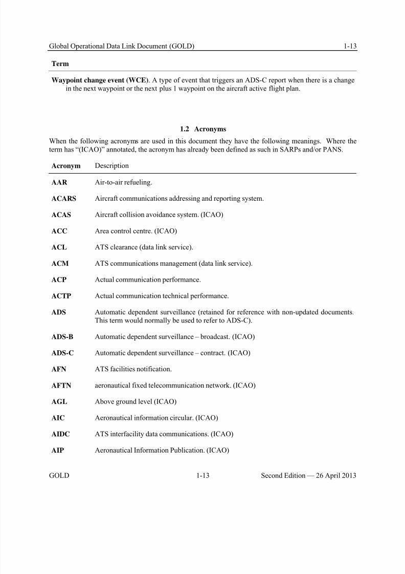
8/9/2019 CPDLC Explained
http://slidepdf.com/reader/full/cpdlc-explained 33/421
Global Operational Data Link Document (GOLD) 1-13
GOLD 1-13 Second Edition — 26 April 2013
Term
Waypoint change event (WCE). A type of event that triggers an ADS-C report when there is a changein the next waypoint or the next plus 1 waypoint on the aircraft active flight plan.
1.2 Acronyms
When the following acronyms are used in this document they have the following meanings. Where theterm has “(ICAO)” annotated, the acronym has already been defined as such in SARPs and/or PANS.
Acronym Description
AAR Air-to-air refueling.
ACARS Aircraft communications addressing and reporting system.
ACAS Aircraft collision avoidance system. (ICAO)
ACC Area control centre. (ICAO)
ACL ATS clearance (data link service).
ACM ATS communications management (data link service).
ACP Actual communication performance.
ACTP Actual communication technical performance.
ADS Automatic dependent surveillance (retained for reference with non-updated documents.This term would normally be used to refer to ADS-C).
ADS-B Automatic dependent surveillance – broadcast. (ICAO)
ADS-C Automatic dependent surveillance – contract. (ICAO)
AFN ATS facilities notification.
AFTN aeronautical fixed telecommunication network. (ICAO)
AGL Above ground level (ICAO)
AIC Aeronautical information circular. (ICAO)
AIDC ATS interfacility data communications. (ICAO)
AIP Aeronautical Information Publication. (ICAO)
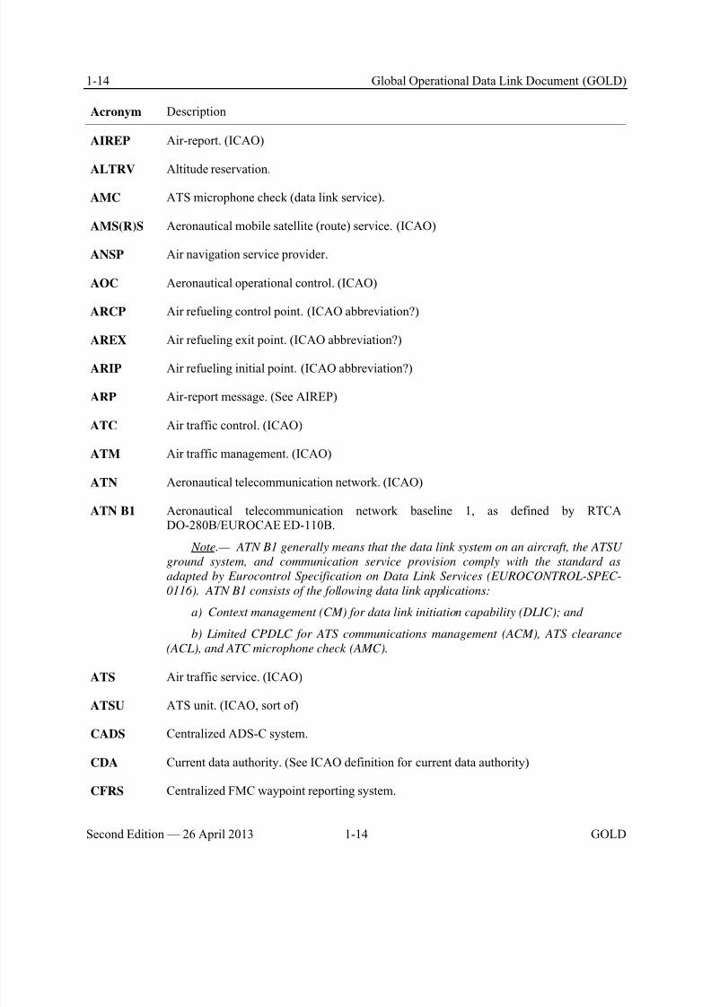
8/9/2019 CPDLC Explained
http://slidepdf.com/reader/full/cpdlc-explained 34/421
1-14 Global Operational Data Link Document (GOLD)
Second Edition — 26 April 2013 1-14 GOLD
Acronym Description
AIREP Air-report. (ICAO)
ALTRV Altitude reservation.
AMC ATS microphone check (data link service).
AMS(R)S Aeronautical mobile satellite (route) service. (ICAO)
ANSP Air navigation service provider.
AOC Aeronautical operational control. (ICAO)
ARCP Air refueling control point. (ICAO abbreviation?)
AREX Air refueling exit point. (ICAO abbreviation?)
ARIP Air refueling initial point. (ICAO abbreviation?)
ARP Air-report message. (See AIREP)
ATC Air traffic control. (ICAO)
ATM Air traffic management. (ICAO)
ATN Aeronautical telecommunication network. (ICAO)
ATN B1 Aeronautical telecommunication network baseline 1, as defined by RTCA
DO-280B/EUROCAE ED-110B. Note.— ATN B1 generally means that the data link system on an aircraft, the ATSU
ground system, and communication service provision comply with the standard as
adapted by Eurocontrol Specification on Data Link Services (EUROCONTROL-SPEC-
0116). ATN B1 consists of the following data link applications:
a) Context management (CM) for data link initiation capability (DLIC); and
b) Limited CPDLC for ATS communications management (ACM), ATS clearance
(ACL), and ATC microphone check (AMC).
ATS Air traffic service. (ICAO)
ATSU ATS unit. (ICAO, sort of)
CADS Centralized ADS-C system.
CDA Current data authority. (See ICAO definition for current data authority)
CFRS Centralized FMC waypoint reporting system.
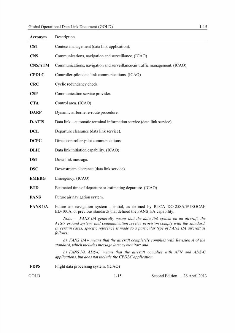
8/9/2019 CPDLC Explained
http://slidepdf.com/reader/full/cpdlc-explained 35/421

8/9/2019 CPDLC Explained
http://slidepdf.com/reader/full/cpdlc-explained 36/421
1-16 Global Operational Data Link Document (GOLD)
Second Edition — 26 April 2013 1-16 GOLD
Acronym Description
FIR Flight information region. (ICAO)
FL Flight level.
FLIPCY Flight plan consistency (data link service).
FMC Flight management computer.
FMC WPR Flight management computer waypoint position reporting.
FMS Flight management system.
GPS Global positioning system (USA).
HF High frequency (3-30 Mhz). (ICAO)
IATA International Air Transport Association.
ICAO International Civil Aviation Organization. (ICAO)
ICD Interface control document.
ITP In trail procedure
LDE Lateral deviation event.
LRDE Level range deviation event.
MARSA Military assumes responsibility for separation of aircraft.
MAS Message assurance.
MASPS Minimum aviation system performance standards.
MEL Minimum equipment list. (ICAO)
MET Meteorological or meteorology. (ICAO)
MIN Message identification number.
MRN Message reference number.
MTBF Mean time between failures.
MTTR Mean time to repair.
NDA Next data authority. (See ICAO definition for next data authority.)

8/9/2019 CPDLC Explained
http://slidepdf.com/reader/full/cpdlc-explained 37/421
Global Operational Data Link Document (GOLD) 1-17
GOLD 1-17 Second Edition — 26 April 2013
Acronym Description
ORT Operational requirements table.
PANS-ATM Procedures for Air Navigation Services — Air Traffic Management (ICAO Doc 4444).(ICAO)
PBC Performance-based communication
PBCS Performance-based communication and surveillance
PBN Performance-based navigation
PBS Performance-based surveillance
PORT Pilot operational response time.
POS Position report message.
RCP Required communication performance.
RCTP Required communication technical performance.
RGS Radio ground station.
RNAV Area navigation.
RNP Required navigation performance.
RSP Required surveillance performance
RSTP Required surveillance technical performance.
SARPs Standards and Recommended Practices. (ICAO)
SATCOM Satellite communication. (ICAO)
SELCAL Selective calling system. (ICAO)
TA Tailored arrival.
TRN Monitored operational performance.
UM Uplink message.
UPR User preferred route.
VDL M0/A VHF data link mode 0/A subnetwork.

8/9/2019 CPDLC Explained
http://slidepdf.com/reader/full/cpdlc-explained 38/421
1-18 Global Operational Data Link Document (GOLD)
Second Edition — 26 April 2013 1-18 GOLD
Acronym Description
VDL M2 VHF data link mode 2 subnetwork,
VHF Very high frequency (30-300 Mhz). (ICAO)
VRE Vertical rate change event.
WCE Waypoint change event.
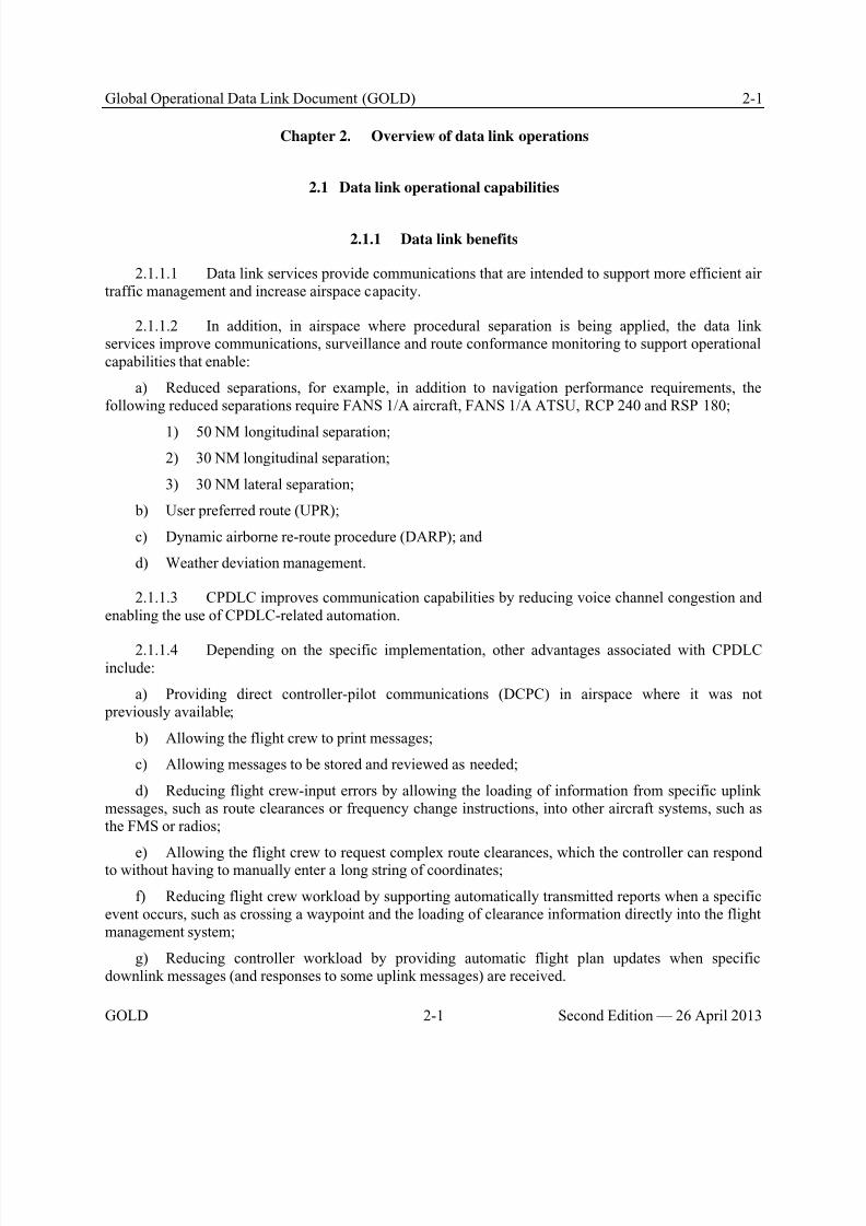
8/9/2019 CPDLC Explained
http://slidepdf.com/reader/full/cpdlc-explained 39/421
Global Operational Data Link Document (GOLD) 2-1
GOLD 2-1 Second Edition — 26 April 2013
Chapter 2. Overview of data link operations
2.1 Data link operational capabilities
2.1.1 Data link benefits
2.1.1.1 Data link services provide communications that are intended to support more efficient airtraffic management and increase airspace capacity.
2.1.1.2 In addition, in airspace where procedural separation is being applied, the data linkservices improve communications, surveillance and route conformance monitoring to support operationalcapabilities that enable:
a) Reduced separations, for example, in addition to navigation performance requirements, thefollowing reduced separations require FANS 1/A aircraft, FANS 1/A ATSU, RCP 240 and RSP 180;
1) 50 NM longitudinal separation;
2) 30 NM longitudinal separation;
3) 30 NM lateral separation;
b) User preferred route (UPR);
c) Dynamic airborne re-route procedure (DARP); and
d) Weather deviation management.
2.1.1.3 CPDLC improves communication capabilities by reducing voice channel congestion andenabling the use of CPDLC-related automation.
2.1.1.4 Depending on the specific implementation, other advantages associated with CPDLCinclude:
a) Providing direct controller-pilot communications (DCPC) in airspace where it was not previously available;
b) Allowing the flight crew to print messages;
c) Allowing messages to be stored and reviewed as needed;
d) Reducing flight crew-input errors by allowing the loading of information from specific uplinkmessages, such as route clearances or frequency change instructions, into other aircraft systems, such asthe FMS or radios;
e) Allowing the flight crew to request complex route clearances, which the controller can respondto without having to manually enter a long string of coordinates;
f) Reducing flight crew workload by supporting automatically transmitted reports when a specificevent occurs, such as crossing a waypoint and the loading of clearance information directly into the flightmanagement system;
g) Reducing controller workload by providing automatic flight plan updates when specificdownlink messages (and responses to some uplink messages) are received.
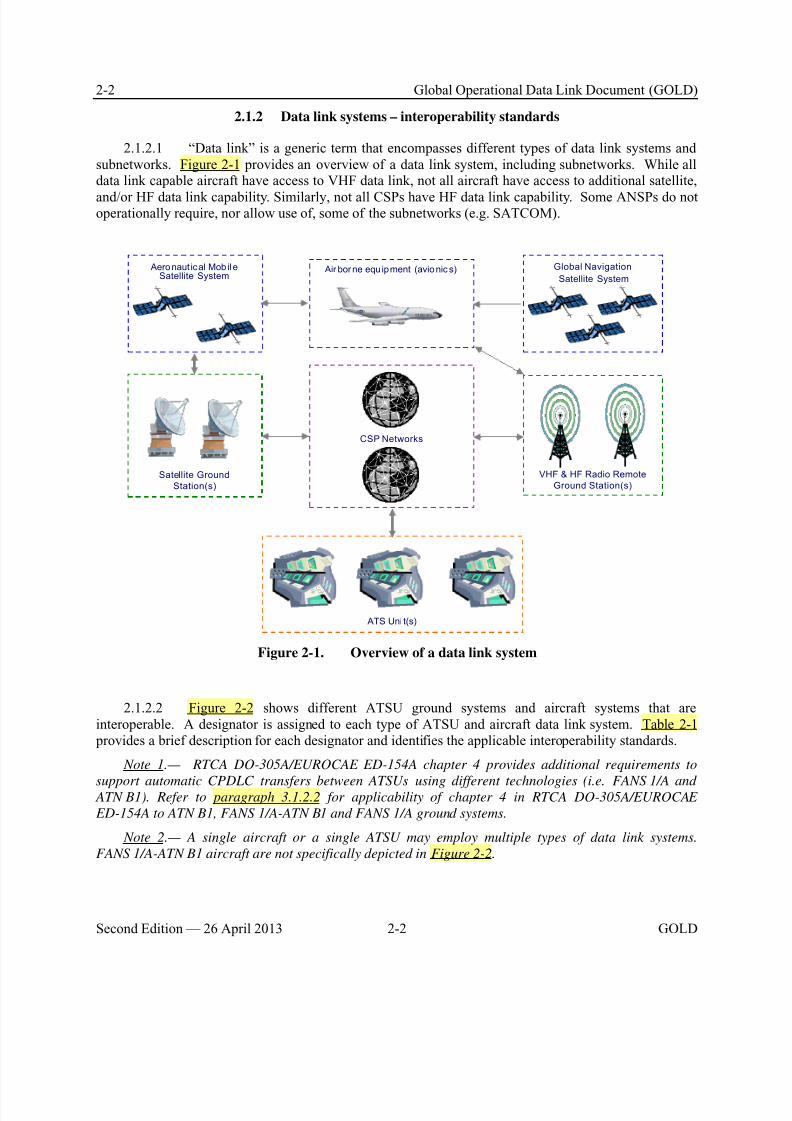
8/9/2019 CPDLC Explained
http://slidepdf.com/reader/full/cpdlc-explained 40/421
2-2 Global Operational Data Link Document (GOLD)
Second Edition — 26 April 2013 2-2 GOLD
2.1.2 Data link systems – interoperability standards
2.1.2.1 “Data link” is a generic term that encompasses different types of data link systems andsubnetworks. Figure 2-1 provides an overview of a data link system, including subnetworks. While alldata link capable aircraft have access to VHF data link, not all aircraft have access to additional satellite,
and/or HF data link capability. Similarly, not all CSPs have HF data link capability. Some ANSPs do notoperationally require, nor allow use of, some of the subnetworks (e.g. SATCOM).
Global Navigation
Satellite System
ATS Uni t(s)
Air borne equ ipment (avio nic s) Aero naut ical Mob ileSatellite System
CSP Networks
Satellite Ground
Station(s)
VHF & HF Radio Remote
Ground Station(s)
Figure 2-1. Overview of a data link system
2.1.2.2 Figure 2-2 shows different ATSU ground systems and aircraft systems that areinteroperable. A designator is assigned to each type of ATSU and aircraft data link system. Table 2-1 provides a brief description for each designator and identifies the applicable interoperability standards.
Note 1.— RTCA DO-305A/EUROCAE ED-154A chapter 4 provides additional requirements to
support automatic CPDLC transfers between ATSUs using different technologies (i.e. FANS 1/A and ATN B1). Refer to paragraph 3.1.2.2 for applicability of chapter 4 in RTCA DO-305A/EUROCAE
ED-154A to ATN B1, FANS 1/A-ATN B1 and FANS 1/A ground systems.
Note 2.— A single aircraft or a single ATSU may employ multiple types of data link systems.
FANS 1/A-ATN B1 aircraft are not specifically depicted in Figure 2-2.
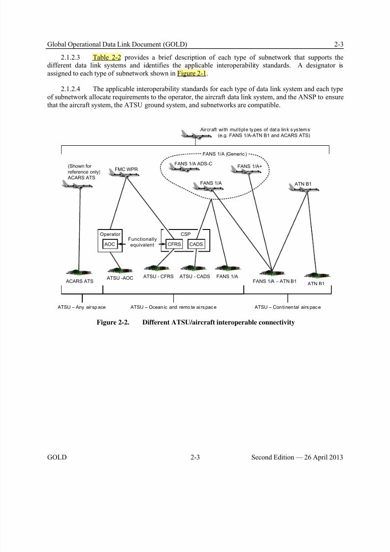
8/9/2019 CPDLC Explained
http://slidepdf.com/reader/full/cpdlc-explained 41/421
Global Operational Data Link Document (GOLD) 2-3
GOLD 2-3 Second Edition — 26 April 2013
2.1.2.3 Table 2-2 provides a brief description of each type of subnetwork that supports thedifferent data link systems and identifies the applicable interoperability standards. A designator isassigned to each type of subnetwork shown in Figure 2-1.
2.1.2.4 The applicable interoperability standards for each type of data link system and each type
of subnetwork allocate requirements to the operator, the aircraft data link system, and the ANSP to ensurethat the aircraft system, the ATSU ground system, and subnetworks are compatible.
CSPOperator
(Shown for
reference only)
ACARS ATS
FMC WPR
FANS 1/A
FANS 1/A+FANS 1/A ADS-C
ATN B1
ACARS ATS
CFRS AOC CADS
FANS 1/A
ATN B1FANS 1/A – ATN B1
ATSU -AOC ATSU - CFRS ATSU - CADS
ATSU – Ocean ic and remo te ai rspace
FANS 1/A (Generic )
Aircraft wi th mul tiple types of dat a link systems
(e.g. FANS 1/A-ATN B1 and ACARS ATS)
Functionally
equivalent
ATSU – Any airspace ATSU – Continental airs pace
Figure 2-2. Different ATSU/aircraft interoperable connectivity

8/9/2019 CPDLC Explained
http://slidepdf.com/reader/full/cpdlc-explained 42/421
2-4 Global Operational Data Link Document (GOLD)
Second Edition — 26 April 2013 2-4 GOLD
Table 2-1. Designators for aircraft and ATSU (ground) data link systems
Designator Description of designator Applicable interoperability
standard(s)
Applicable
system
ACARS
ATS
ATS applications, departure clearance
(DCL), oceanic clearance (OCL) and datalink – automatic terminal information service(D-ATIS), supported by aircraftcommunications addressing and reportingsystem (ACARS).
Note.— ACARS ATS is defined for reference
only. Guidance for these applications is not
provided in this document.
a) ED-85A (DCL)
b) ED-106A (OCL)
c) ED-89A (D-ATIS)
d) ARINC 623-3
ATSU and
Aircraft
FMC WPR Flight management computer waypoint position reporting (FMC WPR)
ATS application, generates and sends
waypoint position reports, supported byflight management system and ACARS.
ARINC 702A-3 Aircraft
ATSUCFRS
Communication service provider’s (CSP’s)centralized flight management computerwaypoint reporting system (CFRS) enablesATSU to receive waypoint position reports inICAO format from any FMC WPR aircraft.
a) ARINC 702A-3
b) CFRS CommonSpecification, Version 2.0,April 2004 (Available fromICAO Regional Office inParis)
ATSU
ATSU AOC Operator’s aeronautical operational control(AOC) facility enables ATSU to receivewaypoint position reports in ICAO format
from the operator’s FMC WPR aircraft.
a) ARINC 702A-3
b) Aeronautical fixedtelecommunication network
(AFTN) specifications
ATSU
ATSUCADS
CSP’s centralized ADS-C system (CADS)enables an ATSU without FANS 1/Acapability to receive ADS-C reports from anyFANS 1/A, FANS 1/A+ or FANS 1/AADS-C aircraft.
a) DO-258A/ED-100A, or previous versions.
b) CADS CommonSpecification, Version 2.0,April 2004 (Available fromICAO Regional Office inParis)
ATSU
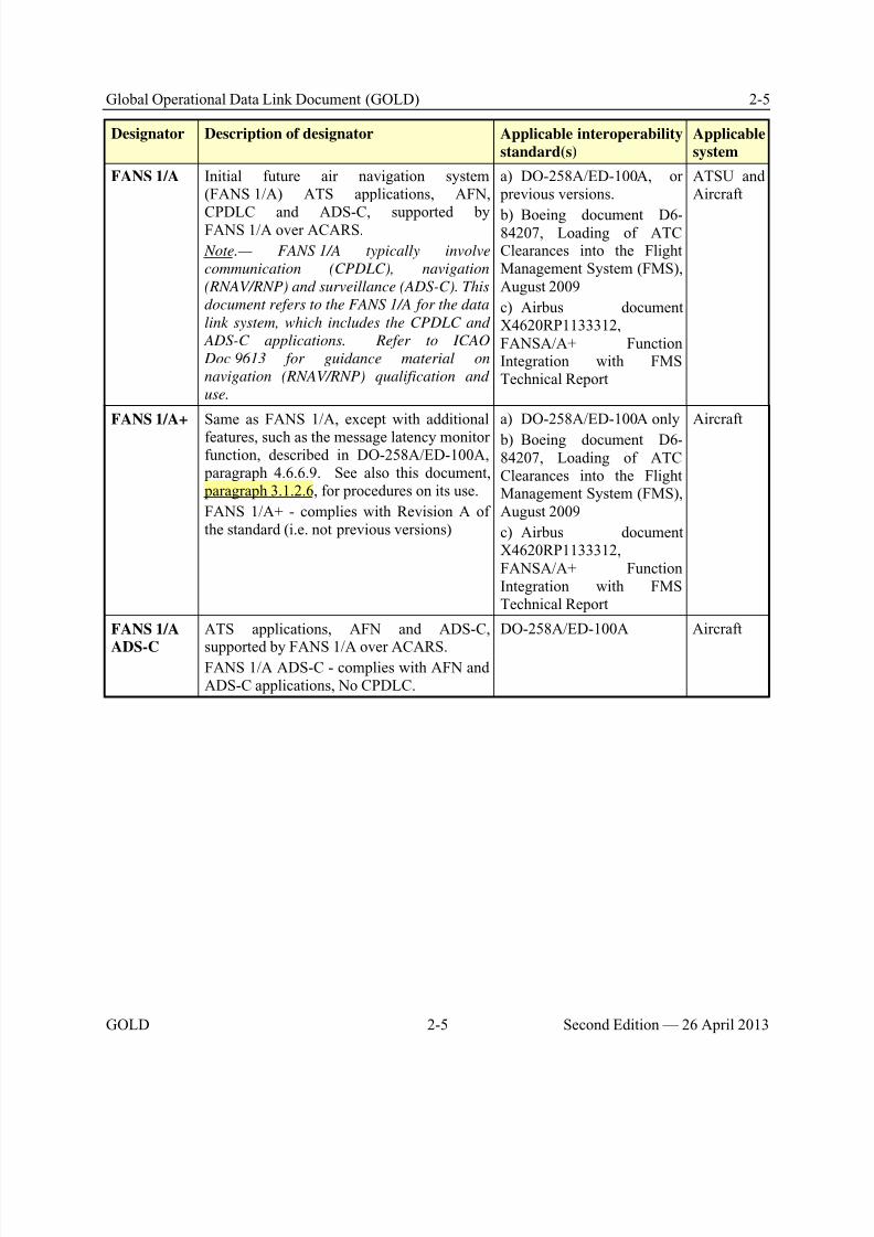
8/9/2019 CPDLC Explained
http://slidepdf.com/reader/full/cpdlc-explained 43/421
Global Operational Data Link Document (GOLD) 2-5
GOLD 2-5 Second Edition — 26 April 2013
Designator Description of designator Applicable interoperability
standard(s)
Applicable
system
FANS 1/A Initial future air navigation system(FANS 1/A) ATS applications, AFN,
CPDLC and ADS-C, supported byFANS 1/A over ACARS.
Note.— FANS 1/A typically involve
communication (CPDLC), navigation
(RNAV/RNP) and surveillance (ADS-C). This
document refers to the FANS 1/A for the data
link system, which includes the CPDLC and
ADS-C applications. Refer to ICAO
Doc 9613 for guidance material on
navigation (RNAV/RNP) qualification and
use.
a) DO-258A/ED-100A, or previous versions.
b) Boeing document D6-84207, Loading of ATCClearances into the FlightManagement System (FMS),August 2009
c) Airbus documentX4620RP1133312,FANSA/A+ FunctionIntegration with FMSTechnical Report
ATSU andAircraft
FANS 1/A+ Same as FANS 1/A, except with additional
features, such as the message latency monitorfunction, described in DO-258A/ED-100A, paragraph 4.6.6.9. See also this document, paragraph 3.1.2.6, for procedures on its use.
FANS 1/A+ - complies with Revision A ofthe standard (i.e. not previous versions)
a) DO-258A/ED-100A only
b) Boeing document D6-84207, Loading of ATCClearances into the FlightManagement System (FMS),August 2009
c) Airbus documentX4620RP1133312,FANSA/A+ FunctionIntegration with FMSTechnical Report
Aircraft
FANS 1/A
ADS-C
ATS applications, AFN and ADS-C,
supported by FANS 1/A over ACARS.FANS 1/A ADS-C - complies with AFN andADS-C applications, No CPDLC.
DO-258A/ED-100A Aircraft
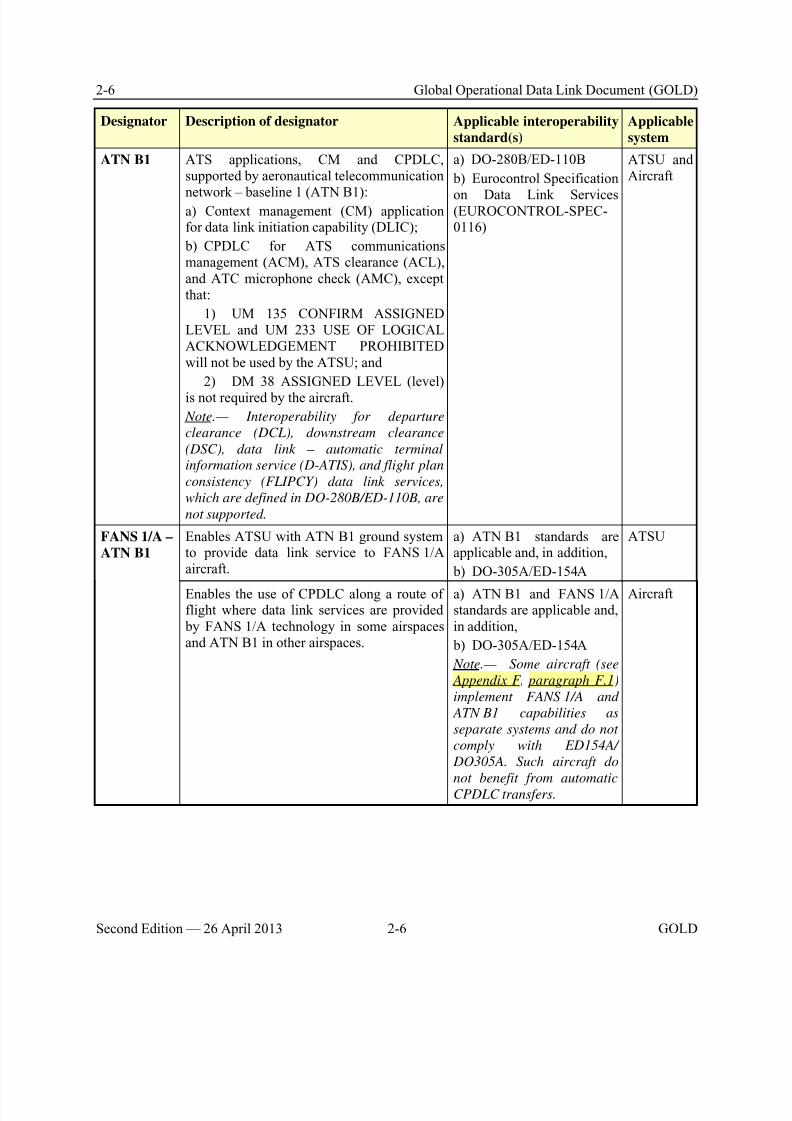
8/9/2019 CPDLC Explained
http://slidepdf.com/reader/full/cpdlc-explained 44/421
2-6 Global Operational Data Link Document (GOLD)
Second Edition — 26 April 2013 2-6 GOLD
Designator Description of designator Applicable interoperability
standard(s)
Applicable
system
ATN B1 ATS applications, CM and CPDLC,supported by aeronautical telecommunication
network – baseline 1 (ATN B1):a) Context management (CM) applicationfor data link initiation capability (DLIC);
b) CPDLC for ATS communicationsmanagement (ACM), ATS clearance (ACL),and ATC microphone check (AMC), exceptthat:
1) UM 135 CONFIRM ASSIGNEDLEVEL and UM 233 USE OF LOGICALACKNOWLEDGEMENT PROHIBITEDwill not be used by the ATSU; and
2) DM 38 ASSIGNED LEVEL (level)
is not required by the aircraft.
Note.— Interoperability for departure
clearance (DCL), downstream clearance
(DSC), data link – automatic terminal
information service (D-ATIS), and flight plan
consistency (FLIPCY) data link services,
which are defined in DO-280B/ED-110B, are
not supported.
a) DO-280B/ED-110B
b) Eurocontrol Specification
on Data Link Services(EUROCONTROL-SPEC-0116)
ATSU andAircraft
FANS 1/A –
ATN B1
Enables ATSU with ATN B1 ground systemto provide data link service to FANS 1/Aaircraft.
a) ATN B1 standards areapplicable and, in addition,
b) DO-305A/ED-154A
ATSU
Enables the use of CPDLC along a route offlight where data link services are provided by FANS 1/A technology in some airspacesand ATN B1 in other airspaces.
a) ATN B1 and FANS 1/Astandards are applicable and,in addition,
b) DO-305A/ED-154A
Note.— Some aircraft (see
Appendix F, paragraph F.1)
implement FANS 1/A and
ATN B1 capabilities as
separate systems and do not
comply with ED154A/
DO305A. Such aircraft do
not benefit from automatic
CPDLC transfers.
Aircraft
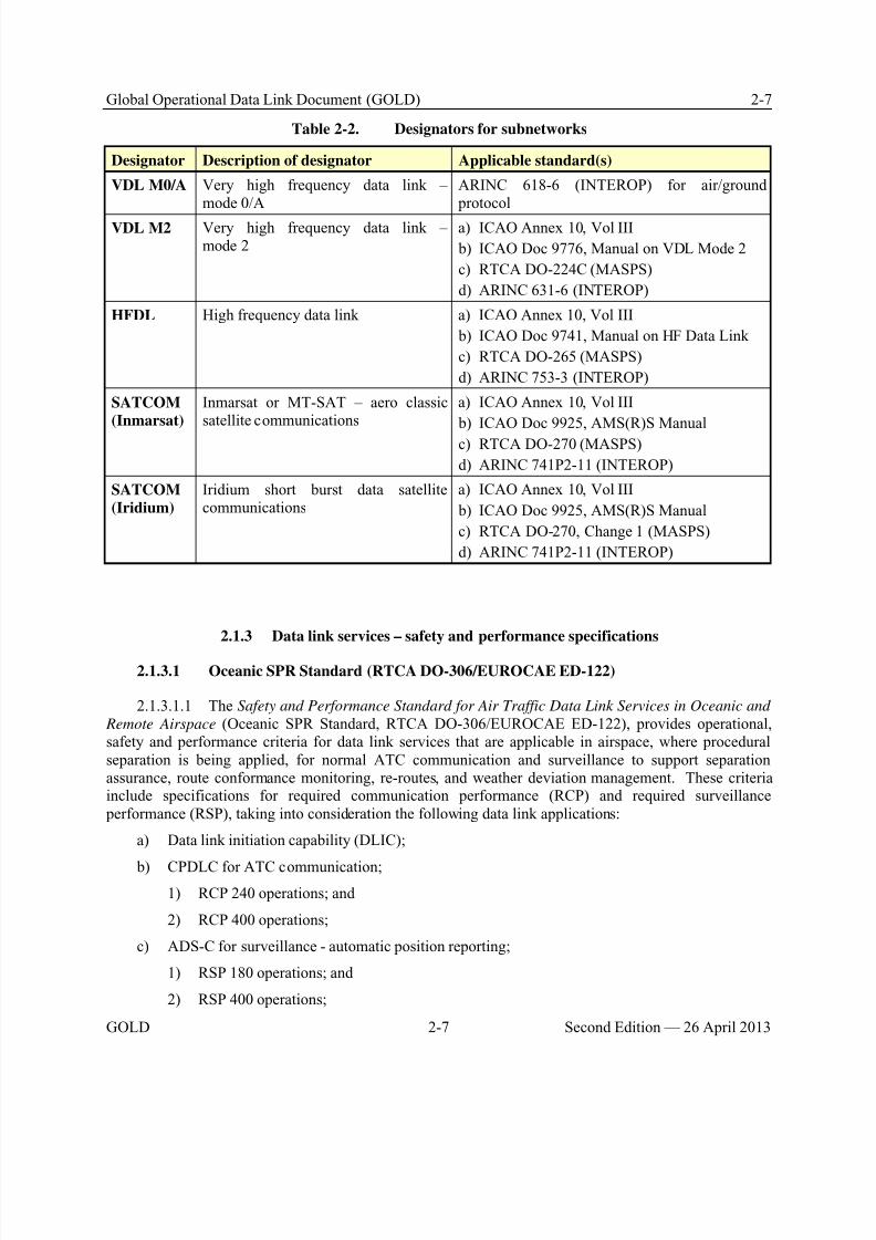
8/9/2019 CPDLC Explained
http://slidepdf.com/reader/full/cpdlc-explained 45/421
Global Operational Data Link Document (GOLD) 2-7
GOLD 2-7 Second Edition — 26 April 2013
Table 2-2. Designators for subnetworks
Designator Description of designator Applicable standard(s)
VDL M0/A Very high frequency data link –mode 0/A
ARINC 618-6 (INTEROP) for air/ground protocol
VDL M2 Very high frequency data link –mode 2
a) ICAO Annex 10, Vol III
b) ICAO Doc 9776, Manual on VDL Mode 2
c) RTCA DO-224C (MASPS)
d) ARINC 631-6 (INTEROP)
HFDL High frequency data link a) ICAO Annex 10, Vol III
b) ICAO Doc 9741, Manual on HF Data Link
c) RTCA DO-265 (MASPS)
d) ARINC 753-3 (INTEROP)
SATCOM
(Inmarsat)
Inmarsat or MT-SAT – aero classicsatellite communications
a) ICAO Annex 10, Vol III
b) ICAO Doc 9925, AMS(R)S Manual
c) RTCA DO-270 (MASPS)
d) ARINC 741P2-11 (INTEROP)
SATCOM
(Iridium)
Iridium short burst data satellitecommunications
a) ICAO Annex 10, Vol III
b) ICAO Doc 9925, AMS(R)S Manual
c) RTCA DO-270, Change 1 (MASPS)
d) ARINC 741P2-11 (INTEROP)
2.1.3 Data link services – safety and performance specifications
2.1.3.1 Oceanic SPR Standard (RTCA DO-306/EUROCAE ED-122)
2.1.3.1.1 The Safety and Performance Standard for Air Traffic Data Link Services in Oceanic and
Remote Airspace (Oceanic SPR Standard, RTCA DO-306/EUROCAE ED-122), provides operational,safety and performance criteria for data link services that are applicable in airspace, where proceduralseparation is being applied, for normal ATC communication and surveillance to support separationassurance, route conformance monitoring, re-routes, and weather deviation management. These criteriainclude specifications for required communication performance (RCP) and required surveillance performance (RSP), taking into consideration the following data link applications:
a) Data link initiation capability (DLIC);
b) CPDLC for ATC communication;1) RCP 240 operations; and
2) RCP 400 operations;
c) ADS-C for surveillance - automatic position reporting;
1) RSP 180 operations; and
2) RSP 400 operations;
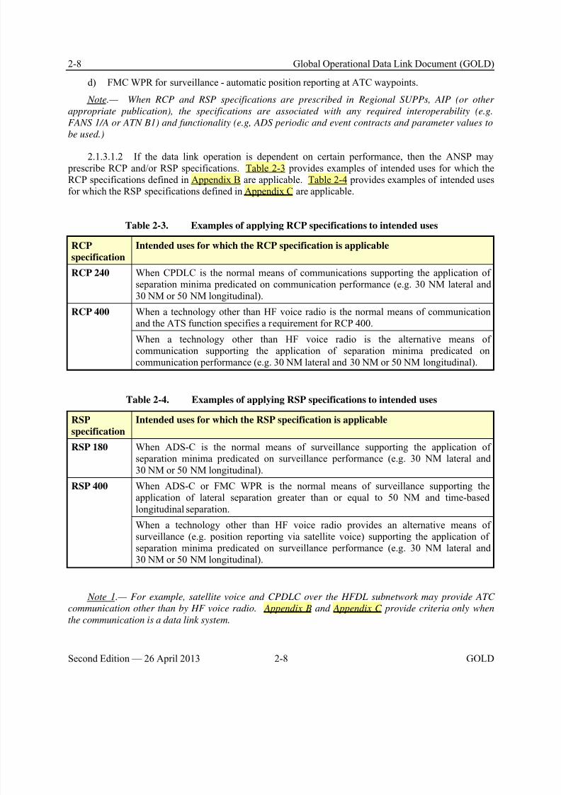
8/9/2019 CPDLC Explained
http://slidepdf.com/reader/full/cpdlc-explained 46/421
2-8 Global Operational Data Link Document (GOLD)
Second Edition — 26 April 2013 2-8 GOLD
d) FMC WPR for surveillance - automatic position reporting at ATC waypoints.
Note.— When RCP and RSP specifications are prescribed in Regional SUPPs, AIP (or other
appropriate publication), the specifications are associated with any required interoperability (e.g.
FANS 1/A or ATN B1) and functionality (e.g, ADS periodic and event contracts and parameter values to
be used.)
2.1.3.1.2 If the data link operation is dependent on certain performance, then the ANSP may prescribe RCP and/or RSP specifications. Table 2-3 provides examples of intended uses for which theRCP specifications defined in Appendix B are applicable. Table 2-4 provides examples of intended usesfor which the RSP specifications defined in Appendix C are applicable.
Table 2-3. Examples of applying RCP specifications to intended uses
RCP
specification
Intended uses for which the RCP specification is applicable
RCP 240 When CPDLC is the normal means of communications supporting the application ofseparation minima predicated on communication performance (e.g. 30 NM lateral and30 NM or 50 NM longitudinal).
RCP 400 When a technology other than HF voice radio is the normal means of communicationand the ATS function specifies a requirement for RCP 400.
When a technology other than HF voice radio is the alternative means ofcommunication supporting the application of separation minima predicated oncommunication performance (e.g. 30 NM lateral and 30 NM or 50 NM longitudinal).
Table 2-4. Examples of applying RSP specifications to intended uses
RSPspecification
Intended uses for which the RSP specification is applicable
RSP 180 When ADS-C is the normal means of surveillance supporting the application ofseparation minima predicated on surveillance performance (e.g. 30 NM lateral and30 NM or 50 NM longitudinal).
RSP 400 When ADS-C or FMC WPR is the normal means of surveillance supporting theapplication of lateral separation greater than or equal to 50 NM and time-basedlongitudinal separation.
When a technology other than HF voice radio provides an alternative means ofsurveillance (e.g. position reporting via satellite voice) supporting the application ofseparation minima predicated on surveillance performance (e.g. 30 NM lateral and
30 NM or 50 NM longitudinal).
Note 1.— For example, satellite voice and CPDLC over the HFDL subnetwork may provide ATC
communication other than by HF voice radio. Appendix B and Appendix C provide criteria only when
the communication is a data link system.
8/9/2019 CPDLC Explained
http://slidepdf.com/reader/full/cpdlc-explained 47/421
Global Operational Data Link Document (GOLD) 2-9
GOLD 2-9 Second Edition — 26 April 2013
2.1.3.1.3 Data link operations that use certain subnetworks (e.g. HFDL) or take place insubnetwork transition areas (e.g. VHF fringe coverage area) may not meet the criteria for some RCP orRSP specifications.
2.1.3.1.4 Aircraft capability that supports multiple RCP and/or RSP operations needs to include
appropriate indications and/or procedures to enable the flight crew to notify ATC when aircraft equipmentfailures result in the aircraft’s inability to meet its criteria for any of the RCP or RSP specifications. (SeeAppendix B and Appendix C.)
2.1.3.1.5 An ATSU that supports multiple RCP and/or RSP operations needs to include appropriateindications and/or procedures to enable the controller to notify all affected aircraft when infrastructurefailures result in the ground system’s inability to meet its criteria for any of the RCP or RSPspecifications.
2.1.3.1.6 If no RCP or RSP specification is prescribed for the data link operation, then anysubnetwork provided in Table 2-2 is acceptable, unless otherwise prescribed by airspace requirements.
2.1.3.2 Continental SPR Standard (RTCA DO-290/EUROCAE ED-120)
2.1.3.2.1 The Safety and Performance Standard for Air Traffic Data Link Services in Continental
Airspace (Continental SPR Standard, RTCA DO-290/EUROCAE ED-120, Change 1 and Change 2), provides operational, safety and performance criteria for data link services in airspace where ATSsurveillance services (e.g. radar services) are provided and where certain specific criteria for sectordensities and separation minima apply. Specific criteria for data link services to support ATS surveillanceunder circumstances where lower densities and/or higher minima apply would be locally assessed takinginto consideration the appropriate safety and performance standards.
2.1.3.2.2 Appendix B provides an RCP 150 specification based on the performance criteria provided in RTCA DO-290/EUROCAE ED-120 for CPDLC supporting ACM, AMC and ACL in
airspace where ATS surveillance services are provided.
2.1.3.2.3 An ATSU that prescribes RCP 150 for CPDLC in its airspace needs to includeappropriate indications and/or procedures to enable the controller to notify all affected aircraft wheninfrastructure failures result in the ground system’s inability to meet its RCP allocation.
2.1.3.2.4 Data link operations that use certain subnetworks (e.g. VDL M0/A), or take place insubnetwork transition areas (e.g. VHF fringe coverage area), may not meet the performance criteria.
2.1.3.3 Performance-based communication and surveillance (PBCS)
2.1.3.3.1 Where beneficial, performance-based communication and surveillance performance is aconcept that enables the management of communication and surveillance capabilities by prescription ofRCP and RSP specifications (See Appendix B and Appendix C). When an ATS operation is predicatedon communication and surveillance performance, RCP and RSP specifications provide operationalrequirements and allocations that apply to infrastructure as well as aircraft and operations. For example:
a) RCP 240 includes a four-minute time requirement for a controller capability to intervene withan aircraft; the requirement is specified from when the controller initiates the communication to when thecontroller receives the operational response from the flight crew; and
8/9/2019 CPDLC Explained
http://slidepdf.com/reader/full/cpdlc-explained 48/421
2-10 Global Operational Data Link Document (GOLD)
Second Edition — 26 April 2013 2-10 GOLD
b) RSP 180 includes an accuracy requirement on the “position at time” based on the prescribedRNP/RNAV specification and a +/- one-second accuracy on Coordinated Universal Time (UTC). It alsoincludes a time requirement from when the aircraft is at the compulsory reporting point to when the reportis received by the controlling ATS unit.
Note.— RCP 240 and RSP 180 also include requirements associated with continuity, serviceavailability, integrity and functionality.
2.1.3.3.2 Based on RCP and RSP, PBCS will enable:
a) ICAO to specify communication and surveillance requirements for specific ATS operations(e.g. application of separation minimum) by reference to RCP and RSP specifications;
b) Regions/States to prescribe RCP and RSP specifications in Regional Supplementary Proceduresand Aeronautical Information Publications (AIPs or equivalent publication);
c) Aircraft systems to be approved in accordance with prescribed RCP and RSP specifications;
d) Operators to be authorized by the State of Registry or State of the Operator, as appropriate, andto file the prescribed performance based designators (e.g. RCP 240, RSP 180) in their flight plans;
e) ANSPs to ensure infrastructure in accordance with prescribed RCP and RSP specifications andassess aircraft capability from flight plan information, to safely apply the appropriate ATS (e.g. reducedseparation) to eligible aircraft; and
f) ICAO Regions to conduct post-implementation monitoring of operational performance, inaccordance with Appendix D, against RCP and RSP specifications, and initiate corrective action to theappropriate party, as necessary, for continued operational safety. Operators will need to establish programs that support post-implementation monitoring activities.
2.1.4 Airspace types and their data link operational capabilities
Note 1.— Depending on airspace type, RTCA DO-306/EUROCAE ED-122 (see section 2.1.3.1) or RTCA DO-290/EUROCAE ED-120 (see section 2.1.3.2) can be considered for operational, safety and
performance requirements.
Note 2.— Operational, safety and performance requirements applicable in an airspace are specified
by the appropriate ATS authority.
2.1.4.1 Airspace where procedural separation is being applied
2.1.4.1.1 The data link system in airspace where procedural separation is being applied, as shownin Figure 2-2, comprises a variety of ground systems that may provide data link services to FANS 1/A(generic) aircraft, FMC WPR aircraft and ACARS ATS aircraft.
2.1.4.1.2 The data link services improve communications, surveillance and route conformancemonitoring to support operational capabilities that enable:
a) Reduced separations, for example, in addition to navigation performance requirements, thefollowing reduced separations require FANS 1/A aircraft, FANS 1/A ATSU, RCP 240 and RSP 180;
1) 50 NM longitudinal separation;
2) 30 NM longitudinal separation;
8/9/2019 CPDLC Explained
http://slidepdf.com/reader/full/cpdlc-explained 49/421
Global Operational Data Link Document (GOLD) 2-11
GOLD 2-11 Second Edition — 26 April 2013
3) 30 NM lateral separation;
b) User preferred route (UPR) may require data link in some airspace;
c) Re-route, may require data link in some airspace; dynamic airborne re-route procedure (DARP)requires FANS 1/A aircraft and FANS 1/A ATSU;
d) Weather deviation management may require data link in reduced separation environments;
e) More efficient air traffic management and increases in airspace capacity. For example, ADS-C provides automatic surveillance capability that an ANSP may use to replace CPDLC and/or voice positionreporting; and
f) Reduced flight crew workload through, for example, automatic position reporting and the abilityto load clearance information directly into the flight management system.
2.1.4.2 Airspace where ATS surveillance services are provided
2.1.4.2.1 As shown in Figure 2-2, the data link system in airspace where ATS surveillance servicesare provided comprises a variety of ground systems:
a) ATN B1 ground systems, that may provide data link services to ATN B1 aircraft andFANS 1/A-ATN B1 aircraft;
b) FANS 1/A-ATN ground systems, that may provide data link services to ATN B1 aircraft,FANS 1/A aircraft and FANS 1/A-ATN B1 aircraft;
c) FANS 1/A ground systems, that may provide data link services to FANS 1/A aircraft,FANS 1/A+ aircraft and FANS 1/A-ATN B1 aircraft; and
d) ACARS ATS ground systems, that may provide data link services to ACARS ATS aircraft.
Note.— FANS 1/A aircraft are technically interoperable with a FANS 1/A-ATN ATSU. However,
operationally, FANS-1/A+ may be required for data link operations in applicable airspace as specified in
Regional SUPPs and/or AIP (or other appropriate publication, such as AIC or NOTAM). (refer to Table2-1).
2.1.4.3 Global overview of data link operational capabilities
2.1.4.3.1 Table 2-5 provides an overview of the operational capabilities that are supported by eachof the different data link systems.
Note.— In Table 2-5, the term “surveillance” includes conformance monitoring and conflict
detection.
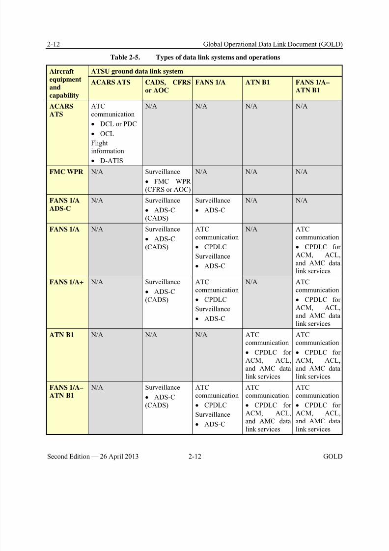
8/9/2019 CPDLC Explained
http://slidepdf.com/reader/full/cpdlc-explained 50/421
2-12 Global Operational Data Link Document (GOLD)
Second Edition — 26 April 2013 2-12 GOLD
Table 2-5. Types of data link systems and operations
Aircraft
equipment
and
capability
ATSU ground data link system
ACARS ATS CADS, CFRS
or AOC
FANS 1/A ATN B1 FANS 1/A–
ATN B1
ACARS
ATS
ATCcommunication
• DCL or PDC
• OCL
Flightinformation
• D-ATIS
N/A N/A N/A N/A
FMC WPR N/A Surveillance
• FMC WPR
(CFRS or AOC)
N/A N/A N/A
FANS 1/A
ADS-C
N/A Surveillance
• ADS-C(CADS)
Surveillance
• ADS-C
N/A N/A
FANS 1/A N/A Surveillance
• ADS-C(CADS)
ATCcommunication
• CPDLC
Surveillance
• ADS-C
N/A ATCcommunication
• CPDLC forACM, ACL,and AMC datalink services
FANS 1/A+ N/A Surveillance
• ADS-C(CADS)
ATC
communication• CPDLC
Surveillance
• ADS-C
N/A ATC
communication• CPDLC forACM, ACL,and AMC datalink services
ATN B1 N/A N/A N/A ATCcommunication
• CPDLC forACM, ACL,and AMC datalink services
ATCcommunication
• CPDLC forACM, ACL,and AMC datalink services
FANS 1/A–ATN B1
N/A Surveillance
• ADS-C(CADS)
ATCcommunication
• CPDLC
Surveillance
• ADS-C
ATCcommunication
• CPDLC forACM, ACL,and AMC datalink services
ATCcommunication
• CPDLC forACM, ACL,and AMC datalink services
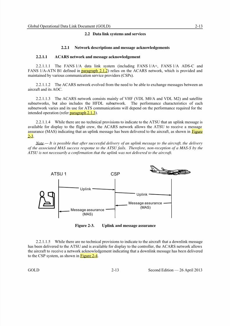
8/9/2019 CPDLC Explained
http://slidepdf.com/reader/full/cpdlc-explained 51/421
Global Operational Data Link Document (GOLD) 2-13
GOLD 2-13 Second Edition — 26 April 2013
2.2 Data link systems and services
2.2.1 Network descriptions and message acknowledgements
2.2.1.1 ACARS network and message acknowledgement
2.2.1.1.1 The FANS 1/A data link system (including FANS 1/A+, FANS 1/A ADS-C andFANS 1/A-ATN B1 defined in paragraph 2.1.2) relies on the ACARS network, which is provided andmaintained by various communication service providers (CSPs).
2.2.1.1.2 The ACARS network evolved from the need to be able to exchange messages between anaircraft and its AOC.
2.2.1.1.3 The ACARS network consists mainly of VHF (VDL M0/A and VDL M2) and satellitesubnetworks, but also includes the HFDL subnetwork. The performance characteristics of eachsubnetwork varies and its use for ATS communications will depend on the performance required for the
intended operation (refer paragraph 2.1.3).
2.2.1.1.4 While there are no technical provisions to indicate to the ATSU that an uplink message isavailable for display to the flight crew, the ACARS network allows the ATSU to receive a messageassurance (MAS) indicating that an uplink message has been delivered to the aircraft, as shown in Figure2-3.
Note.— It is possible that after successful delivery of an uplink message to the aircraft, the delivery
of the associated MAS success response to the ATSU fails. Therefore, non-reception of a MAS-S by the
ATSU is not necessarily a confirmation that the uplink was not delivered to the aircraft.
ATSU 1
Uplink
Message assurance
(MAS)
Uplink
Message assurance
(MAS)
CSP
Figure 2-3. Uplink and message assurance
2.2.1.1.5 While there are no technical provisions to indicate to the aircraft that a downlink messagehas been delivered to the ATSU and is available for display to the controller, the ACARS network allowsthe aircraft to receive a network acknowledgement indicating that a downlink message has been deliveredto the CSP system, as shown in Figure 2-4.
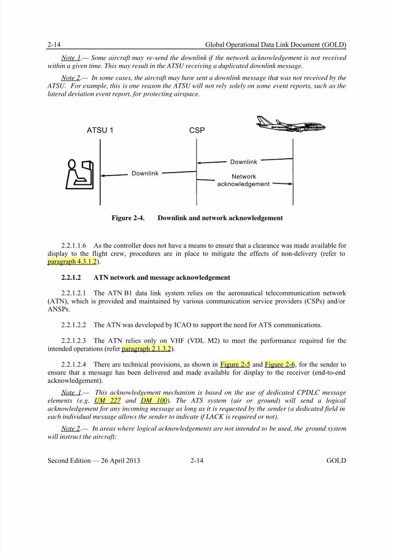
8/9/2019 CPDLC Explained
http://slidepdf.com/reader/full/cpdlc-explained 52/421
2-14 Global Operational Data Link Document (GOLD)
Second Edition — 26 April 2013 2-14 GOLD
Note 1.— Some aircraft may re-send the downlink if the network acknowledgement is not received
within a given time. This may result in the ATSU receiving a duplicated downlink message.
Note 2.— In some cases, the aircraft may have sent a downlink message that was not received by the
ATSU. For example, this is one reason the ATSU will not rely solely on some event reports, such as the
lateral deviation event report, for protecting airspace.
ATSU 1
Downlink
Downlink
Network
acknowledgement
CSP
Figure 2-4. Downlink and network acknowledgement
2.2.1.1.6 As the controller does not have a means to ensure that a clearance was made available fordisplay to the flight crew, procedures are in place to mitigate the effects of non-delivery (refer to paragraph 4.3.1.2).
2.2.1.2 ATN network and message acknowledgement
2.2.1.2.1 The ATN B1 data link system relies on the aeronautical telecommunication network(ATN), which is provided and maintained by various communication service providers (CSPs) and/orANSPs.
2.2.1.2.2 The ATN was developed by ICAO to support the need for ATS communications.
2.2.1.2.3 The ATN relies only on VHF (VDL M2) to meet the performance required for theintended operations (refer paragraph 2.1.3.2).
2.2.1.2.4 There are technical provisions, as shown in Figure 2-5 and Figure 2-6, for the sender toensure that a message has been delivered and made available for display to the receiver (end-to-endacknowledgement).
Note 1.— This acknowledgement mechanism is based on the use of dedicated CPDLC message
elements (e.g. UM 227 and DM 100). The ATS system (air or ground) will send a logical
acknowledgement for any incoming message as long as it is requested by the sender (a dedicated field in
each individual message allows the sender to indicate if LACK is required or not).
Note 2.— In areas where logical acknowledgements are not intended to be used, the ground system
will instruct the aircraft:
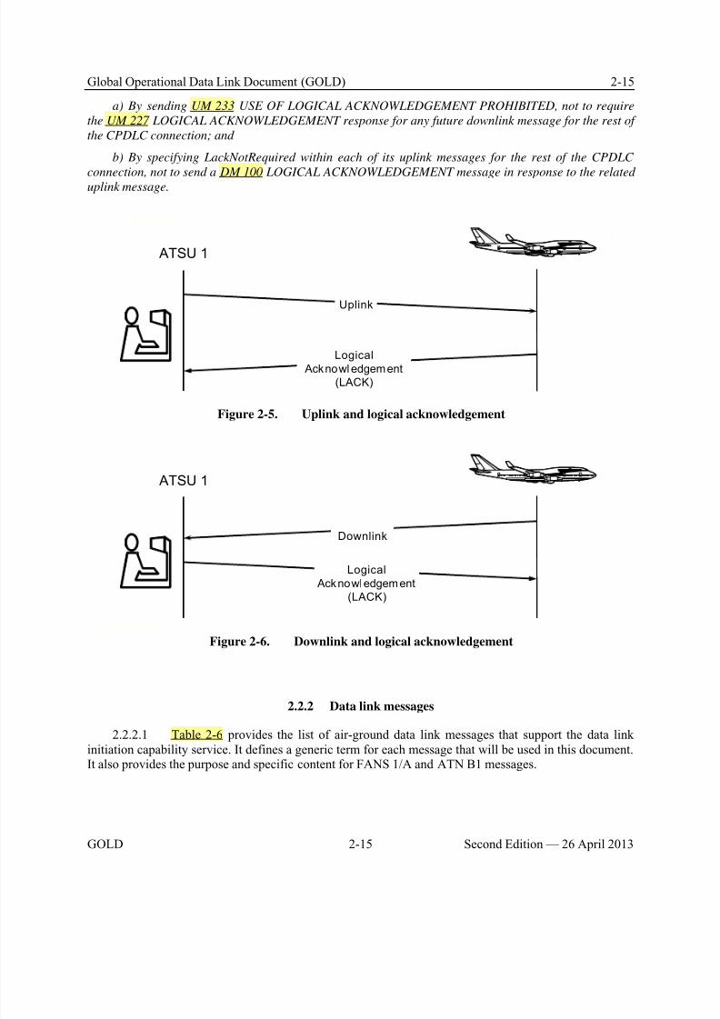
8/9/2019 CPDLC Explained
http://slidepdf.com/reader/full/cpdlc-explained 53/421
Global Operational Data Link Document (GOLD) 2-15
GOLD 2-15 Second Edition — 26 April 2013
a) By sending UM 233 USE OF LOGICAL ACKNOWLEDGEMENT PROHIBITED, not to require
the UM 227 LOGICAL ACKNOWLEDGEMENT response for any future downlink message for the rest of
the CPDLC connection; and
b) By specifying LackNotRequired within each of its uplink messages for the rest of the CPDLC
connection, not to send a DM 100 LOGICAL ACKNOWLEDGEMENT message in response to the relateduplink message.
ATSU 1
Uplink
Logical Acknowl edgement
(LACK)
Figure 2-5. Uplink and logical acknowledgement
ATSU 1
Downlink
Logical
Acknowledgement
(LACK)
Figure 2-6. Downlink and logical acknowledgement
2.2.2 Data link messages
2.2.2.1 Table 2-6 provides the list of air-ground data link messages that support the data linkinitiation capability service. It defines a generic term for each message that will be used in this document.It also provides the purpose and specific content for FANS 1/A and ATN B1 messages.

8/9/2019 CPDLC Explained
http://slidepdf.com/reader/full/cpdlc-explained 54/421
2-16 Global Operational Data Link Document (GOLD)
Second Edition — 26 April 2013 2-16 GOLD
Table 2-6. Air-ground data link messages for DLIC
Generic
Message
Name
Purpose FANS-1/A
Messages
ATN B1 Messages
Air-ground logon procedure
LogonRequest
To provide the ATSU with informationto confirm the identity of the aircraftand its data link capabilities, and tonotify the ATSU of the flight crew’sintention to use data link services.
FN_CON CM_LOGON_REQUEST
LogonResponse
To notify the aircraft of the status of itslogon request.
FN_AK CM_LOGON_RESPONSE
Air-ground address forwarding procedure
Contact
Request
To instruct the aircraft to send a logon
request to the specified ATSU.
FN_CAD CM_CONTACT
ContactResponse
To indicate to the initiating ATSU thatthe logon request will be sent to thespecified ATSU.
FN_RESP No ATN equivalent
ContactComplete
To provide to the initiating ATSU thestatus of the logon request to thespecified ATSU.
FN_COMP CM_CONTACT_RESPONSE
2.2.2.2 Table 2-7 provides the list of ground-ground data link messages that support the ground-ground coordination for address forwarding between initiating and receiving ATSUs.
Table 2-7. Ground-ground data link messages for DLIC
Generic
MessageName
Purpose AIDC OLDI (See note)
Ground-ground address forwarding procedure
LogonForwarding
To provide an ATSU with logoninformation from an aircraft.
AIDC FAN OLDI LOF
Next
Authority Notified
To provide the receiving ATSU with
the information that the aircraft has been notified about its next dataauthority.
Note.— This message is to prevent the
receiving ATSU from attempting to
establish a CPDLC connection prior to
the NDA message being uplinked to the
aircraft.
No equivalent OLDI NAN
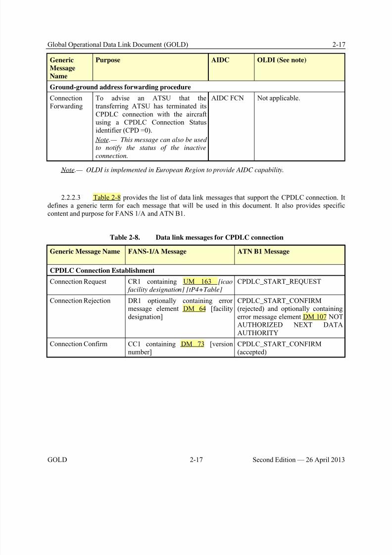
8/9/2019 CPDLC Explained
http://slidepdf.com/reader/full/cpdlc-explained 55/421
Global Operational Data Link Document (GOLD) 2-17
GOLD 2-17 Second Edition — 26 April 2013
Generic
Message
Name
Purpose AIDC OLDI (See note)
Ground-ground address forwarding procedure
ConnectionForwarding
To advise an ATSU that thetransferring ATSU has terminated itsCPDLC connection with the aircraftusing a CPDLC Connection Statusidentifier (CPD =0).
Note.— This message can also be used
to notify the status of the inactive
connection.
AIDC FCN Not applicable.
Note.— OLDI is implemented in European Region to provide AIDC capability.
2.2.2.3 Table 2-8 provides the list of data link messages that support the CPDLC connection. Itdefines a generic term for each message that will be used in this document. It also provides specificcontent and purpose for FANS 1/A and ATN B1.
Table 2-8. Data link messages for CPDLC connection
Generic Message Name FANS-1/A Message ATN B1 Message
CPDLC Connection Establishment
Connection Request CR1 containing UM 163 [icao
facility designation] [tP4+Table]
CPDLC_START_REQUEST
Connection Rejection DR1 optionally containing errormessage element DM 64 [facilitydesignation]
CPDLC_START_CONFIRM(rejected) and optionally containingerror message element DM 107 NOTAUTHORIZED NEXT DATAAUTHORITY
Connection Confirm CC1 containing DM 73 [versionnumber]
CPDLC_START_CONFIRM(accepted)
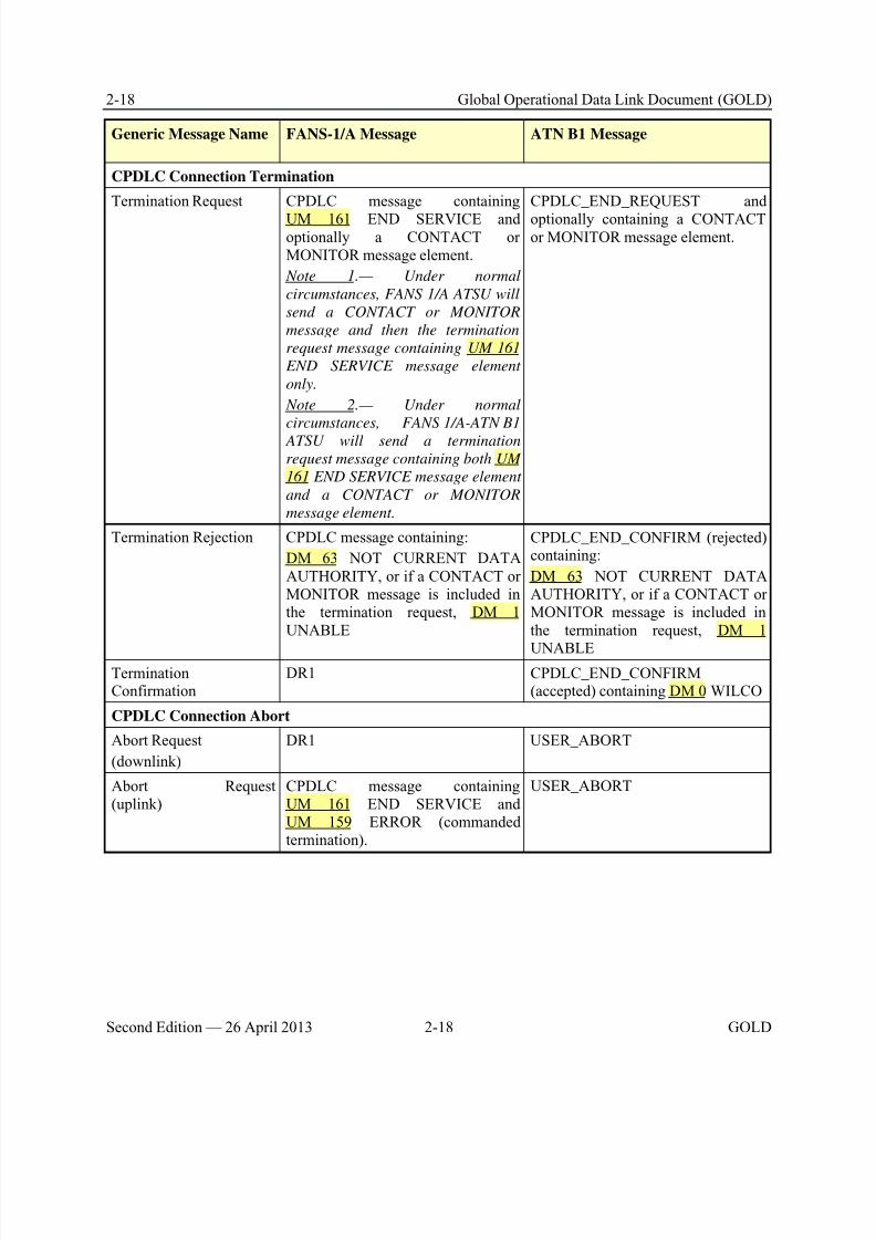
8/9/2019 CPDLC Explained
http://slidepdf.com/reader/full/cpdlc-explained 56/421
2-18 Global Operational Data Link Document (GOLD)
Second Edition — 26 April 2013 2-18 GOLD
Generic Message Name FANS-1/A Message ATN B1 Message
CPDLC Connection Termination
Termination Request CPDLC message containing
UM 161 END SERVICE andoptionally a CONTACT orMONITOR message element.
Note 1.— Under normal
circumstances, FANS 1/A ATSU will
send a CONTACT or MONITOR
message and then the termination
request message containing UM 161
END SERVICE message element
only.
Note 2.— Under normal
circumstances, FANS 1/A-ATN B1
ATSU will send a termination
request message containing both UM
161 END SERVICE message element
and a CONTACT or MONITOR
message element.
CPDLC_END_REQUEST and
optionally containing a CONTACTor MONITOR message element.
Termination Rejection CPDLC message containing:
DM 63 NOT CURRENT DATAAUTHORITY, or if a CONTACT orMONITOR message is included inthe termination request, DM 1UNABLE
CPDLC_END_CONFIRM (rejected)containing:
DM 63 NOT CURRENT DATAAUTHORITY, or if a CONTACT orMONITOR message is included inthe termination request, DM 1
UNABLETerminationConfirmation
DR1 CPDLC_END_CONFIRM(accepted) containing DM 0 WILCO
CPDLC Connection Abort
Abort Request
(downlink)
DR1 USER_ABORT
Abort Request(uplink)
CPDLC message containingUM 161 END SERVICE andUM 159 ERROR (commandedtermination).
USER_ABORT
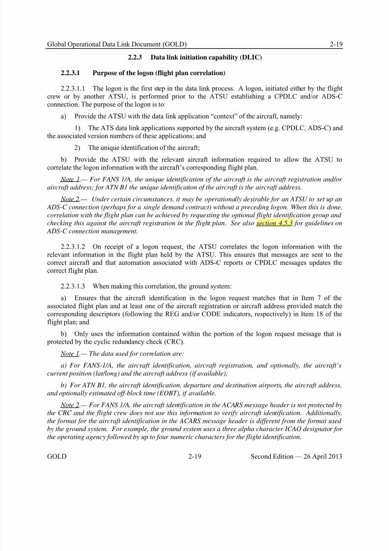
8/9/2019 CPDLC Explained
http://slidepdf.com/reader/full/cpdlc-explained 57/421
Global Operational Data Link Document (GOLD) 2-19
GOLD 2-19 Second Edition — 26 April 2013
2.2.3 Data link initiation capability (DLIC)
2.2.3.1 Purpose of the logon (flight plan correlation)
2.2.3.1.1 The logon is the first step in the data link process. A logon, initiated either by the flight
crew or by another ATSU, is performed prior to the ATSU establishing a CPDLC and/or ADS-Cconnection. The purpose of the logon is to:
a) Provide the ATSU with the data link application “context” of the aircraft, namely:
1) The ATS data link applications supported by the aircraft system (e.g. CPDLC, ADS-C) andthe associated version numbers of these applications; and
2) The unique identification of the aircraft;
b) Provide the ATSU with the relevant aircraft information required to allow the ATSU tocorrelate the logon information with the aircraft’s corresponding flight plan.
Note 1.— For FANS 1/A, the unique identification of the aircraft is the aircraft registration and/or
aircraft address; for ATN B1 the unique identification of the aircraft is the aircraft address.
Note 2.— Under certain circumstances, it may be operationally desirable for an ATSU to set up an
ADS-C connection (perhaps for a single demand contract) without a preceding logon. When this is done,
correlation with the flight plan can be achieved by requesting the optional flight identification group and
checking this against the aircraft registration in the flight plan. See also section 4.5.3 for guidelines on
ADS-C connection management.
2.2.3.1.2 On receipt of a logon request, the ATSU correlates the logon information with therelevant information in the flight plan held by the ATSU. This ensures that messages are sent to thecorrect aircraft and that automation associated with ADS-C reports or CPDLC messages updates thecorrect flight plan.
2.2.3.1.3 When making this correlation, the ground system:a) Ensures that the aircraft identification in the logon request matches that in Item 7 of the
associated flight plan and at least one of the aircraft registration or aircraft address provided match thecorresponding descriptors (following the REG and/or CODE indicators, respectively) in Item 18 of theflight plan; and
b) Only uses the information contained within the portion of the logon request message that is protected by the cyclic redundancy check (CRC).
Note 1.— The data used for correlation are:
a) For FANS-1/A, the aircraft identification, aircraft registration, and optionally, the aircraft’s
current position (lat/long) and the aircraft address (if available);
b) For ATN B1, the aircraft identification, departure and destination airports, the aircraft address,and optionally estimated off-block time (EOBT), if available.
Note 2.— For FANS 1/A, the aircraft identification in the ACARS message header is not protected by
the CRC and the flight crew does not use this information to verify aircraft identification. Additionally,
the format for the aircraft identification in the ACARS message header is different from the format used
by the ground system. For example, the ground system uses a three alpha character ICAO designator for
the operating agency followed by up to four numeric characters for the flight identification.

8/9/2019 CPDLC Explained
http://slidepdf.com/reader/full/cpdlc-explained 58/421
2-20 Global Operational Data Link Document (GOLD)
Second Edition — 26 April 2013 2-20 GOLD
FANS 1/A Example
The following example of an AFN logon indicates the appropriate information in theACARS message to correlate the AFN logon with a flight plan.
QU <ACARS “TO” address>
. <ACARS “FROM” address> 010000
AFD
FI AB0123/AN ST-XYZ
DT QXT POR1 010000 J59A
- AFN/FMH ABC123,.ST-XYZ,DEF456 ,000002/FPOS30000E160000,0/FCOADS,01/
FCOATC,01<CRC>
The ATSU only uses the information in the CRC-protected portion of the ACARSmessage. In the example above, the CRC portion is highlighted, and contains thefollowing information:
• aircraft identification is ABC123 (not the AB0123 contained in the ACARS header);
• aircraft registration is ST-XYZ (hyphen is removed by ATS automation per paragraph3.1.2.1.2); and
• aircraft address is DEF456.
Note.— Some ATSUs may operate a ground system that does not integrate data link
capability with a flight data processing system. Under these circumstances, the ATSU
will need to ensure that the logon information is available for the controller to manually
cross-check the information with the details in the flight plan.
ATN B1 Example
The following example of a CM logon indicates the appropriate information in the CMmessage to correlate the CM logon with a flight plan.
CMLogonRequest
aircraftFlightIdentification ABC123
cMLongTSAP ATN address of the aircraft CM application(string of 18 or 19 octets), including the
aircraft address DEF456 (3 octets).
groundInitiatedApplications 1 (CMA) and 22 (PM-CPDLC)
airOnlyInitiatedApplications 1 (CMA)
facilityDesignation None
airportDeparture LFBO
airportDestination ENGM
8/9/2019 CPDLC Explained
http://slidepdf.com/reader/full/cpdlc-explained 59/421
Global Operational Data Link Document (GOLD) 2-21
GOLD 2-21 Second Edition — 26 April 2013
dateTimeDepartureETD None
The ATSU only uses the information in the CRC-protected portion of the message:
• aircraft identification is ABC123;
• aircraft address is DEF456 and is included in the cMLongTSAP; and• departure airport is LFBO (Toulouse) and destination airport is ENGM (Oslo).
Note.— The facilityDesignation field would be used to require a logon to a facility
different from the one to which the logon request will be addressed. Such capability
(commonly referred to as DLIC server) is not implemented by ATN B1 systems.
2.2.3.2 Initial logon request
2.2.3.2.1 An initial logon request is needed when the aircraft does not already have an ADS-C orCPDLC connection, such as when:
a) The aircraft is preparing for departure; or
b) The aircraft will enter an area where data link services are available from an area where datalink services are not available; or
c) Instructed by ATC (e.g. following a failed data link transfer).
2.2.3.2.2 To perform an initial logon request, the flight crew enters the four character ICAOidentifier of the ATSU to which the logon request is to be sent and includes the following flight-specificinformation:
a) Aircraft identification (same as item 7 of the flight plan);
b) Aircraft registration and/or aircraft address (same as item 18, preceded by REG and/or CODE,
of the flight plan); and
c) Departure and destination aerodromes, when required (same as items 13 and 16 of the flight plan).
Note 1.— In accordance with ICAO Doc 4444, the aircraft identification entered into the aircraft
system is either the ICAO designator for the aircraft operating agency followed by the flight identification
or the aircraft registration.
Note 2.— The aircraft identification and registration may have been loaded prior to departure.
Note 3.— When the aircraft identification includes a numeric component, this component matches
exactly that included in the flight plan. In other words, “ABC3” does not match “ABC003.”
Note 4.— While the ATSU identifier is only 4-characters, ATN B1 is capable of supporting up to 8
characters.
2.2.3.2.3 To avoid an automatic rejection of the logon request, the flight crew ensures that theflight-specific information entered into the aircraft system is the same as the corresponding details filed inthe flight plan.
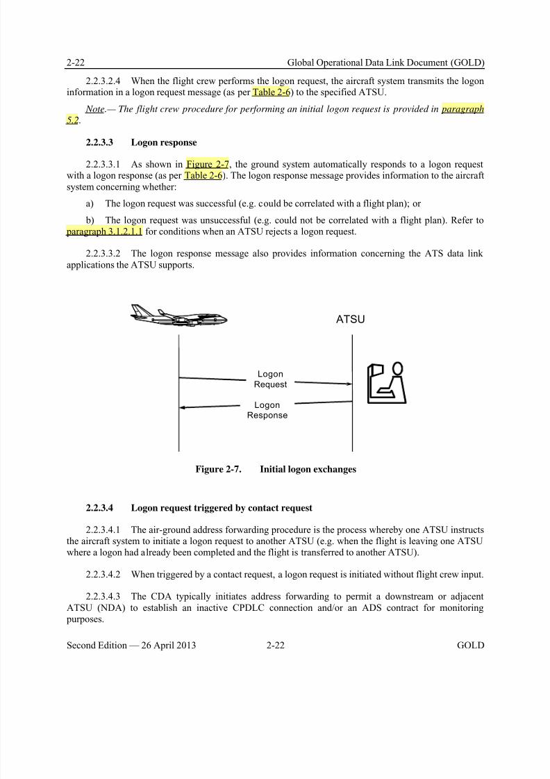
8/9/2019 CPDLC Explained
http://slidepdf.com/reader/full/cpdlc-explained 60/421
2-22 Global Operational Data Link Document (GOLD)
Second Edition — 26 April 2013 2-22 GOLD
2.2.3.2.4 When the flight crew performs the logon request, the aircraft system transmits the logoninformation in a logon request message (as per Table 2-6) to the specified ATSU.
Note.— The flight crew procedure for performing an initial logon request is provided in paragraph
5.2.
2.2.3.3 Logon response
2.2.3.3.1 As shown in Figure 2-7, the ground system automatically responds to a logon requestwith a logon response (as per Table 2-6). The logon response message provides information to the aircraftsystem concerning whether:
a) The logon request was successful (e.g. could be correlated with a flight plan); or
b) The logon request was unsuccessful (e.g. could not be correlated with a flight plan). Refer to paragraph 3.1.2.1.1 for conditions when an ATSU rejects a logon request.
2.2.3.3.2 The logon response message also provides information concerning the ATS data linkapplications the ATSU supports.
Logon
Request
LogonResponse
ATSU
Figure 2-7. Initial logon exchanges
2.2.3.4 Logon request triggered by contact request
2.2.3.4.1 The air-ground address forwarding procedure is the process whereby one ATSU instructs
the aircraft system to initiate a logon request to another ATSU (e.g. when the flight is leaving one ATSUwhere a logon had already been completed and the flight is transferred to another ATSU).
2.2.3.4.2 When triggered by a contact request, a logon request is initiated without flight crew input.
2.2.3.4.3 The CDA typically initiates address forwarding to permit a downstream or adjacentATSU (NDA) to establish an inactive CPDLC connection and/or an ADS contract for monitoring purposes.
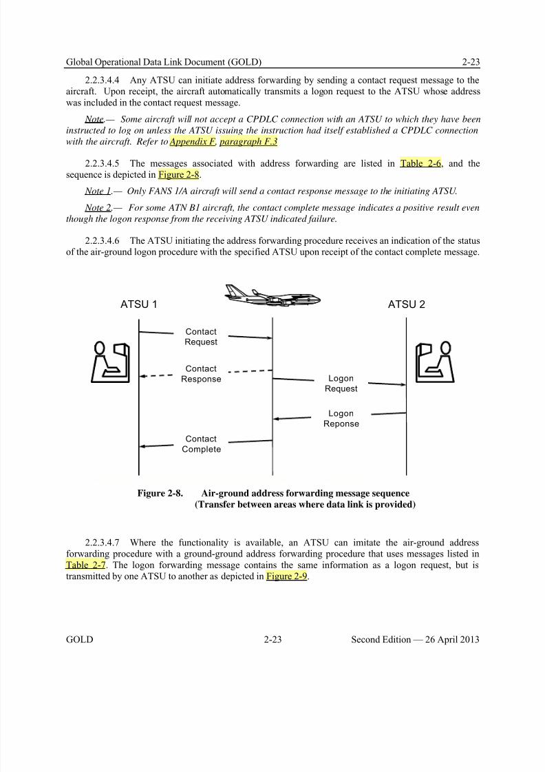
8/9/2019 CPDLC Explained
http://slidepdf.com/reader/full/cpdlc-explained 61/421
Global Operational Data Link Document (GOLD) 2-23
GOLD 2-23 Second Edition — 26 April 2013
2.2.3.4.4 Any ATSU can initiate address forwarding by sending a contact request message to theaircraft. Upon receipt, the aircraft automatically transmits a logon request to the ATSU whose addresswas included in the contact request message.
Note.— Some aircraft will not accept a CPDLC connection with an ATSU to which they have been
instructed to log on unless the ATSU issuing the instruction had itself established a CPDLC connectionwith the aircraft. Refer to Appendix F, paragraph F.3
2.2.3.4.5 The messages associated with address forwarding are listed in Table 2-6, and thesequence is depicted in Figure 2-8.
Note 1.— Only FANS 1/A aircraft will send a contact response message to the initiating ATSU.
Note 2.— For some ATN B1 aircraft, the contact complete message indicates a positive result even
though the logon response from the receiving ATSU indicated failure.
2.2.3.4.6 The ATSU initiating the address forwarding procedure receives an indication of the statusof the air-ground logon procedure with the specified ATSU upon receipt of the contact complete message.
ATSU 1 ATSU 2
Contact
Request
Contact
Response
Contact
Complete
Logon
Request
Logon
Reponse
Figure 2-8. Air-ground address forwarding message sequence
(Transfer between areas where data link is provided)
2.2.3.4.7 Where the functionality is available, an ATSU can imitate the air-ground addressforwarding procedure with a ground-ground address forwarding procedure that uses messages listed inTable 2-7. The logon forwarding message contains the same information as a logon request, but istransmitted by one ATSU to another as depicted in Figure 2-9.
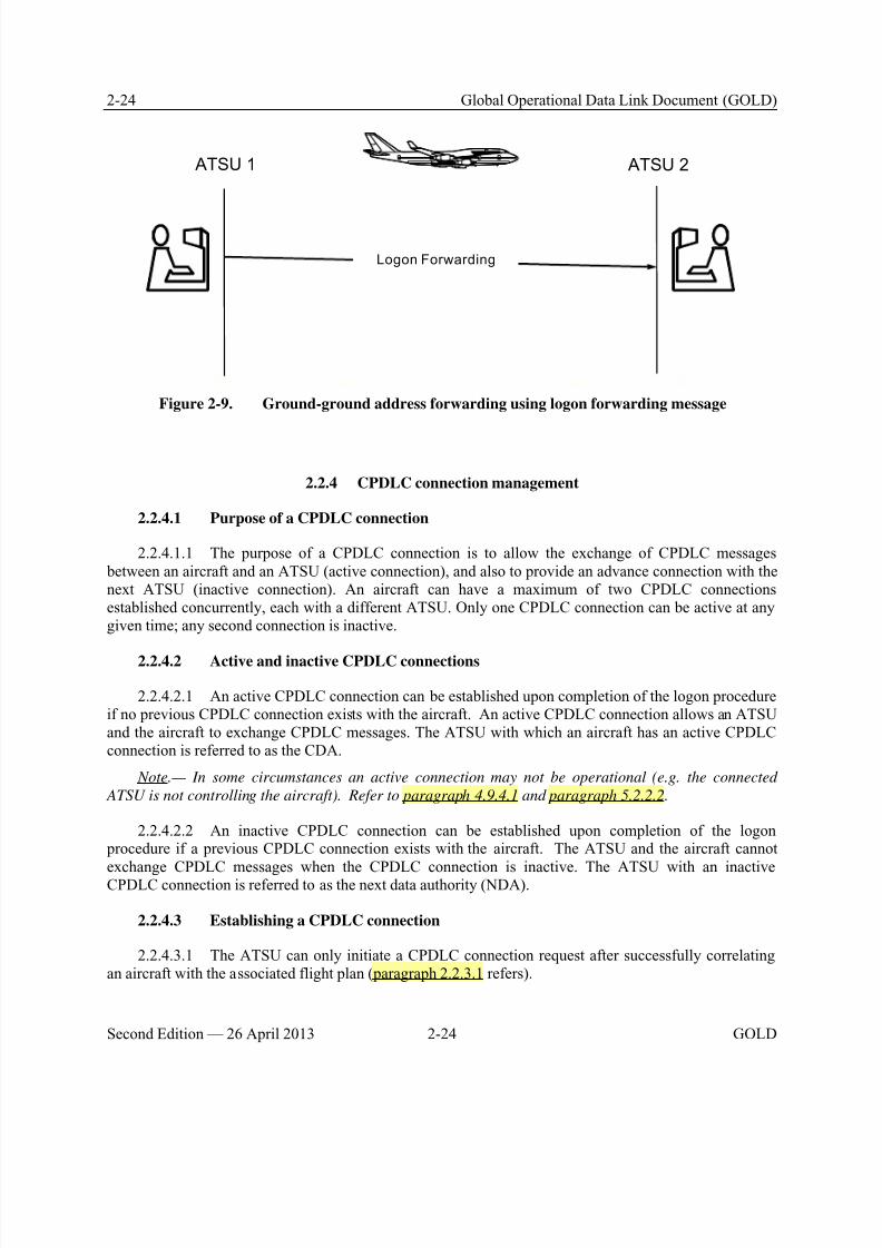
8/9/2019 CPDLC Explained
http://slidepdf.com/reader/full/cpdlc-explained 62/421
2-24 Global Operational Data Link Document (GOLD)
Second Edition — 26 April 2013 2-24 GOLD
ATSU 1 ATSU 2
Logon Forwarding
Figure 2-9. Ground-ground address forwarding using logon forwarding message
2.2.4 CPDLC connection management
2.2.4.1 Purpose of a CPDLC connection
2.2.4.1.1 The purpose of a CPDLC connection is to allow the exchange of CPDLC messages between an aircraft and an ATSU (active connection), and also to provide an advance connection with thenext ATSU (inactive connection). An aircraft can have a maximum of two CPDLC connectionsestablished concurrently, each with a different ATSU. Only one CPDLC connection can be active at anygiven time; any second connection is inactive.
2.2.4.2 Active and inactive CPDLC connections
2.2.4.2.1 An active CPDLC connection can be established upon completion of the logon procedureif no previous CPDLC connection exists with the aircraft. An active CPDLC connection allows an ATSUand the aircraft to exchange CPDLC messages. The ATSU with which an aircraft has an active CPDLCconnection is referred to as the CDA.
Note.— In some circumstances an active connection may not be operational (e.g. the connected
ATSU is not controlling the aircraft). Refer to paragraph 4.9.4.1 and paragraph 5.2.2.2.
2.2.4.2.2 An inactive CPDLC connection can be established upon completion of the logon procedure if a previous CPDLC connection exists with the aircraft. The ATSU and the aircraft cannot
exchange CPDLC messages when the CPDLC connection is inactive. The ATSU with an inactiveCPDLC connection is referred to as the next data authority (NDA).
2.2.4.3 Establishing a CPDLC connection
2.2.4.3.1 The ATSU can only initiate a CPDLC connection request after successfully correlatingan aircraft with the associated flight plan ( paragraph 2.2.3.1 refers).
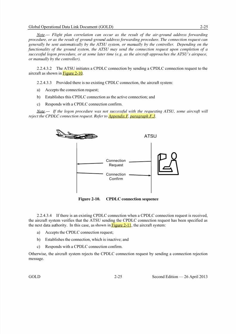
8/9/2019 CPDLC Explained
http://slidepdf.com/reader/full/cpdlc-explained 63/421
Global Operational Data Link Document (GOLD) 2-25
GOLD 2-25 Second Edition — 26 April 2013
Note.— Flight plan correlation can occur as the result of the air-ground address forwarding
procedure, or as the result of ground-ground address forwarding procedure. The connection request can
generally be sent automatically by the ATSU system, or manually by the controller. Depending on the
functionality of the ground system, the ATSU may send the connection request upon completion of a
successful logon procedure, or at some later time (e.g. as the aircraft approaches the ATSU’s airspace,
or manually by the controller).
2.2.4.3.2 The ATSU initiates a CPDLC connection by sending a CPDLC connection request to theaircraft as shown in Figure 2-10.
2.2.4.3.3 Provided there is no existing CPDLC connection, the aircraft system:
a) Accepts the connection request;
b) Establishes this CPDLC connection as the active connection; and
c) Responds with a CPDLC connection confirm.
Note.— If the logon procedure was not successful with the requesting ATSU, some aircraft will
reject the CPDLC connection request. Refer to Appendix F, paragraph F.3.
Connection
Request
ConnectionConfirm
ATSU
Figure 2-10. CPDLC connection sequence
2.2.4.3.4 If there is an existing CPDLC connection when a CPDLC connection request is received,the aircraft system verifies that the ATSU sending the CPDLC connection request has been specified asthe next data authority. In this case, as shown in Figure 2-11, the aircraft system:
a) Accepts the CPDLC connection request; b) Establishes the connection, which is inactive; and
c) Responds with a CPDLC connection confirm.
Otherwise, the aircraft system rejects the CPDLC connection request by sending a connection rejectionmessage.
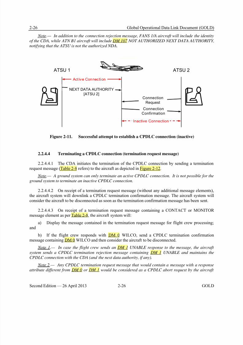
8/9/2019 CPDLC Explained
http://slidepdf.com/reader/full/cpdlc-explained 64/421
2-26 Global Operational Data Link Document (GOLD)
Second Edition — 26 April 2013 2-26 GOLD
Note.— In addition to the connection rejection message, FANS 1/A aircraft will include the identity
of the CDA, while ATN B1 aircraft will include DM 107 NOT AUTHORIZED NEXT DATA AUTHORITY,
notifying that the ATSU is not the authorized NDA.
ATSU 1 ATSU 2
Connection
Request
NEXT DATA AUTHORITY
[ATSU 2]
Connection
Confirmation
Act ive Connection
Inactive Connection
Figure 2-11. Successful attempt to establish a CPDLC connection (inactive)
2.2.4.4 Terminating a CPDLC connection (termination request message)
2.2.4.4.1 The CDA initiates the termination of the CPDLC connection by sending a terminationrequest message (Table 2-8 refers) to the aircraft as depicted in Figure 2-12.
Note.— A ground system can only terminate an active CPDLC connection. It is not possible for the
ground system to terminate an inactive CPDLC connection.
2.2.4.4.2 On receipt of a termination request message (without any additional message elements),the aircraft system will downlink a CPDLC termination confirmation message. The aircraft system willconsider the aircraft to be disconnected as soon as the termination confirmation message has been sent.
2.2.4.4.3 On receipt of a termination request message containing a CONTACT or MONITORmessage element as per Table 2-8, the aircraft system will:
a) Display the message contained in the termination request message for flight crew processing;and
b) If the flight crew responds with DM 0 WILCO, send a CPDLC termination confirmation
message containing DM 0 WILCO and then consider the aircraft to be disconnected. Note 1.— In case the flight crew sends an DM 1 UNABLE response to the message, the aircraft
system sends a CPDLC termination rejection message containing DM 1 UNABLE and maintains the
CPDLC connection with the CDA (and the next data authority, if any).
Note 2.— Any CPDLC termination request message that would contain a message with a response
attribute different from DM 0 or DM 1 would be considered as a CPDLC abort request by the aircraft
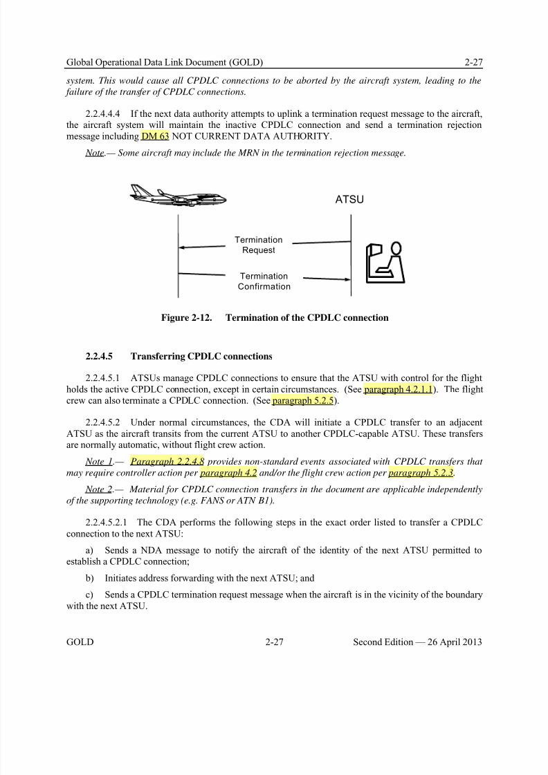
8/9/2019 CPDLC Explained
http://slidepdf.com/reader/full/cpdlc-explained 65/421
Global Operational Data Link Document (GOLD) 2-27
GOLD 2-27 Second Edition — 26 April 2013
system. This would cause all CPDLC connections to be aborted by the aircraft system, leading to the
failure of the transfer of CPDLC connections.
2.2.4.4.4 If the next data authority attempts to uplink a termination request message to the aircraft,the aircraft system will maintain the inactive CPDLC connection and send a termination rejection
message including DM 63 NOT CURRENT DATA AUTHORITY.
Note.— Some aircraft may include the MRN in the termination rejection message.
Termination
Request
Termination
Confirmation
ATSU
Figure 2-12. Termination of the CPDLC connection
2.2.4.5 Transferring CPDLC connections
2.2.4.5.1 ATSUs manage CPDLC connections to ensure that the ATSU with control for the flightholds the active CPDLC connection, except in certain circumstances. (See paragraph 4.2.1.1). The flightcrew can also terminate a CPDLC connection. (See paragraph 5.2.5).
2.2.4.5.2 Under normal circumstances, the CDA will initiate a CPDLC transfer to an adjacentATSU as the aircraft transits from the current ATSU to another CPDLC-capable ATSU. These transfersare normally automatic, without flight crew action.
Note 1.— Paragraph 2.2.4.8 provides non-standard events associated with CPDLC transfers that
may require controller action per paragraph 4.2 and/or the flight crew action per paragraph 5.2.3.
Note 2.— Material for CPDLC connection transfers in the document are applicable independently
of the supporting technology (e.g. FANS or ATN B1).
2.2.4.5.2.1 The CDA performs the following steps in the exact order listed to transfer a CPDLCconnection to the next ATSU:
a) Sends a NDA message to notify the aircraft of the identity of the next ATSU permitted toestablish a CPDLC connection;
b) Initiates address forwarding with the next ATSU; and
c) Sends a CPDLC termination request message when the aircraft is in the vicinity of the boundarywith the next ATSU.
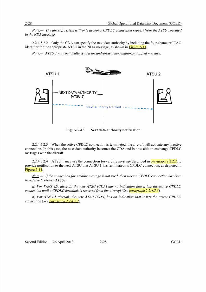
8/9/2019 CPDLC Explained
http://slidepdf.com/reader/full/cpdlc-explained 66/421
2-28 Global Operational Data Link Document (GOLD)
Second Edition — 26 April 2013 2-28 GOLD
Note.— The aircraft system will only accept a CPDLC connection request from the ATSU specified
in the NDA message.
2.2.4.5.2.2 Only the CDA can specify the next data authority by including the four-character ICAOidentifier for the appropriate ATSU in the NDA message, as shown in Figure 2-13.
Note.— ATSU 1 may optionally send a ground-ground next authority notified message.
ATSU 1 ATSU 2
NEXT DATA AUTHORITY
[ATSU 2]
Next Authority Notified
Figure 2-13. Next data authority notification
2.2.4.5.2.3 When the active CPDLC connection is terminated, the aircraft will activate any inactiveconnection. In this case, the next data authority becomes the CDA and is now able to exchange CPDLC
messages with the aircraft.
2.2.4.5.2.4 ATSU 1 may use the connection forwarding message described in paragraph 2.2.2.2, to provide notification to the next ATSU that ATSU 1 has terminated its CPDLC connection, as depicted inFigure 2-14.
Note.— If the connection forwarding message is not used, then when a CPDLC connection has been
transferred between ATSUs:
a) For FANS 1/A aircraft, the new ATSU (CDA) has no indication that it has the active CPDLC
connection until a CPDLC downlink is received from the aircraft (See paragraph 2.2.4.7.3).
b) For ATN B1 aircraft, the new ATSU (CDA) has an indication that it has the active CPDLC
connection (See paragraph 2.2.4.7.2).
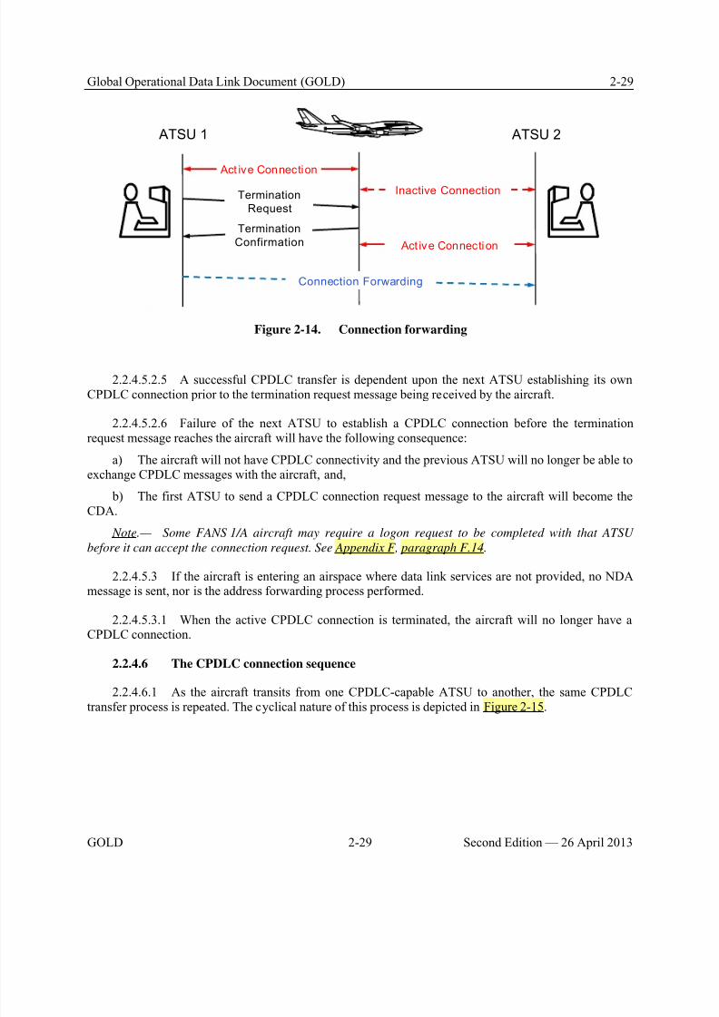
8/9/2019 CPDLC Explained
http://slidepdf.com/reader/full/cpdlc-explained 67/421
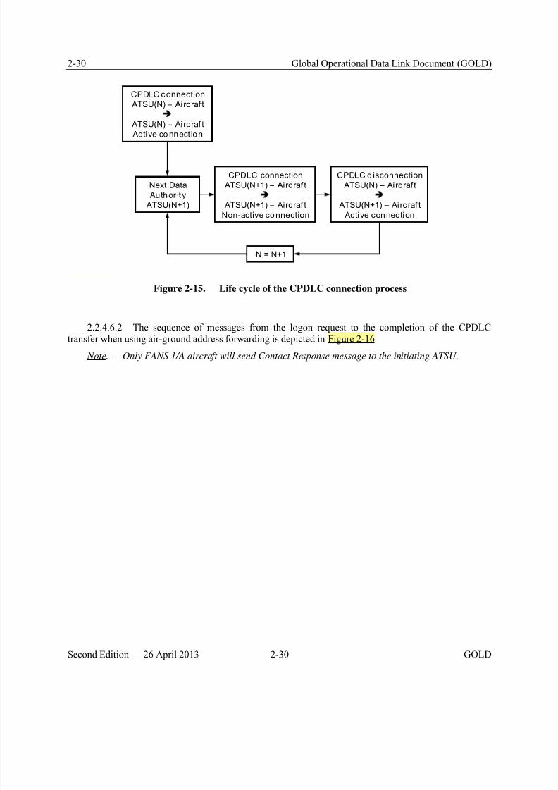
8/9/2019 CPDLC Explained
http://slidepdf.com/reader/full/cpdlc-explained 68/421
2-30 Global Operational Data Link Document (GOLD)
Second Edition — 26 April 2013 2-30 GOLD
CPDLC c onnection
ATSU(N) – Aircraf t
ATSU(N) – Aircraf t
Active co nnect ion
Next Data
Author ity
ATSU(N+1)
CPDLC connection
ATSU(N+1) – Airc raf t
ATSU(N+1) – Airc raf t
Non-active connection
CPDLC d isconnection
ATSU(N) – Airc raf t
ATSU(N+1) – Airc raf t
Active connection
N = N+1
Figure 2-15. Life cycle of the CPDLC connection process
2.2.4.6.2 The sequence of messages from the logon request to the completion of the CPDLCtransfer when using air-ground address forwarding is depicted in Figure 2-16.
Note.— Only FANS 1/A aircraft will send Contact Response message to the initiating ATSU.
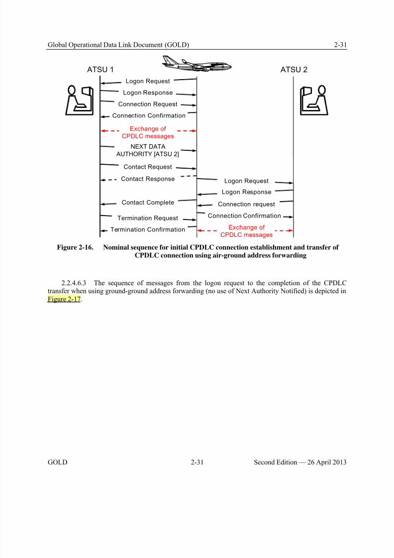
8/9/2019 CPDLC Explained
http://slidepdf.com/reader/full/cpdlc-explained 69/421
Global Operational Data Link Document (GOLD) 2-31
GOLD 2-31 Second Edition — 26 April 2013
ATSU 1 ATSU 2
Contact Request
Connection Request
Connection Confirmation
Exchange of
CPDLC messages
Exchange of
CPDLC messages
NEXT DATA
AUTHORITY [ATSU 2]
Termination Request
Connection request
Connection Confirmation
Logon Request
Logon Response
Contact Response
Contact Complete
Termination Confirmation
Logon Request
Logon Response
Figure 2-16. Nominal sequence for initial CPDLC connection establishment and transfer ofCPDLC connection using air-ground address forwarding
2.2.4.6.3 The sequence of messages from the logon request to the completion of the CPDLC
transfer when using ground-ground address forwarding (no use of Next Authority Notified) is depicted inFigure 2-17.
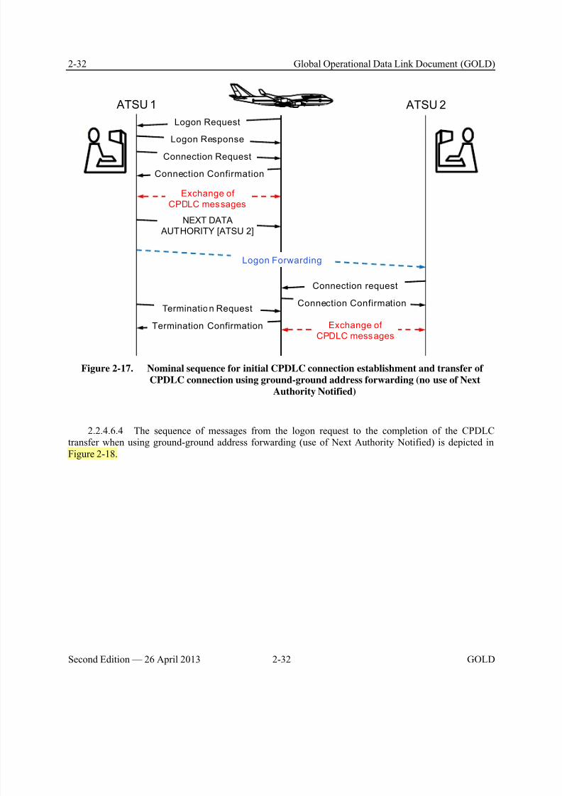
8/9/2019 CPDLC Explained
http://slidepdf.com/reader/full/cpdlc-explained 70/421
2-32 Global Operational Data Link Document (GOLD)
Second Edition — 26 April 2013 2-32 GOLD
ATSU 1 ATSU 2
Connection Request
Connection Confirmation
Exchange of
CPDLC messages
Exchange of
CPDLC messages
NEXT DATA
AUTHORITY [ATSU 2]
Termination Request
Connection request
Connection Confirmation
Termination Confirmation
Logon Request
Logon Response
Logon Forwarding
Figure 2-17. Nominal sequence for initial CPDLC connection establishment and transfer of
CPDLC connection using ground-ground address forwarding (no use of Next
Authority Notified)
2.2.4.6.4 The sequence of messages from the logon request to the completion of the CPDLCtransfer when using ground-ground address forwarding (use of Next Authority Notified) is depicted inFigure 2-18.
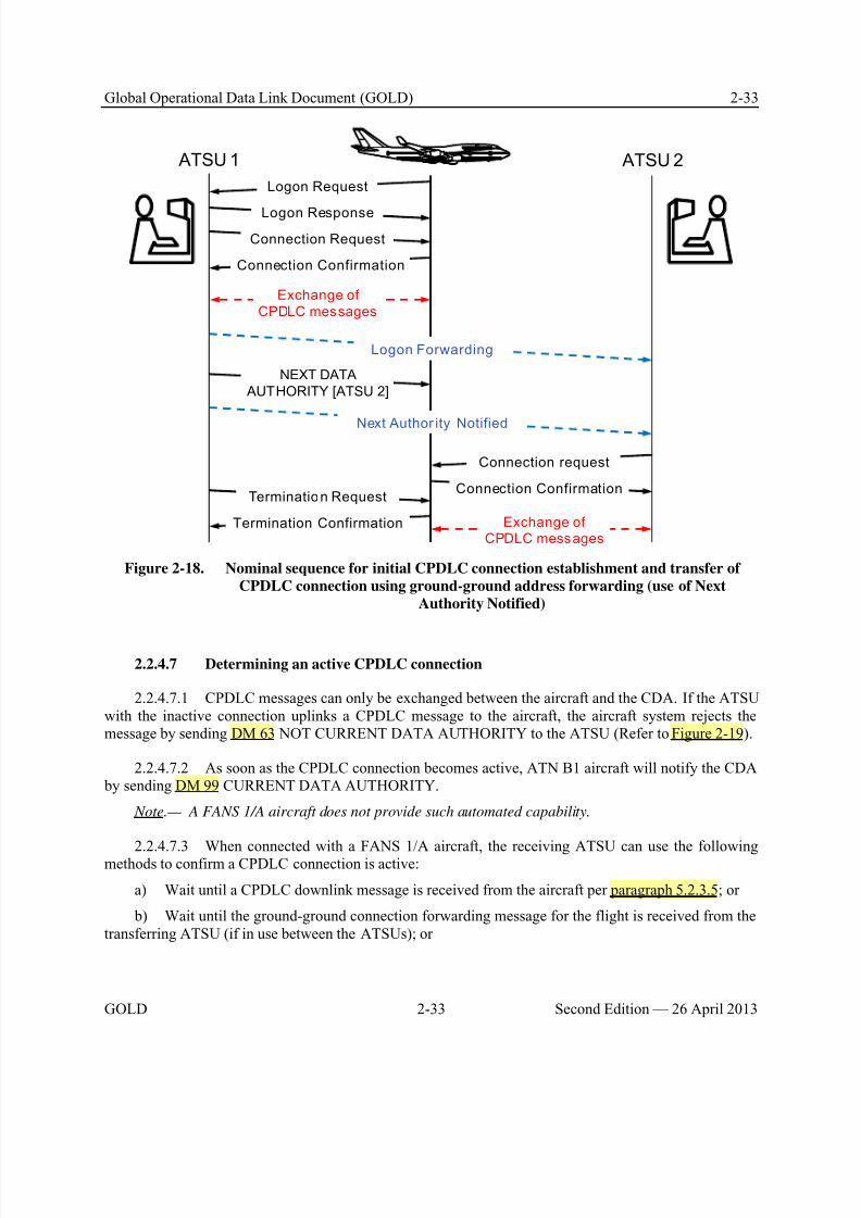
8/9/2019 CPDLC Explained
http://slidepdf.com/reader/full/cpdlc-explained 71/421
Global Operational Data Link Document (GOLD) 2-33
GOLD 2-33 Second Edition — 26 April 2013
ATSU 1 ATSU 2
Connection Request
Connection Confirmation
Exchange of
CPDLC messages
Exchange ofCPDLC messages
NEXT DATA
AUTHORITY [ATSU 2]
Termination Request
Connection request
Connection Confirmation
Termination Confirmation
Logon Request
Logon Response
Next Author ity Notified
Logon Forwarding
Figure 2-18. Nominal sequence for initial CPDLC connection establishment and transfer of
CPDLC connection using ground-ground address forwarding (use of Next
Authority Notified)
2.2.4.7 Determining an active CPDLC connection
2.2.4.7.1 CPDLC messages can only be exchanged between the aircraft and the CDA. If the ATSUwith the inactive connection uplinks a CPDLC message to the aircraft, the aircraft system rejects themessage by sending DM 63 NOT CURRENT DATA AUTHORITY to the ATSU (Refer to Figure 2-19).
2.2.4.7.2 As soon as the CPDLC connection becomes active, ATN B1 aircraft will notify the CDA by sending DM 99 CURRENT DATA AUTHORITY.
Note.— A FANS 1/A aircraft does not provide such automated capability.
2.2.4.7.3 When connected with a FANS 1/A aircraft, the receiving ATSU can use the followingmethods to confirm a CPDLC connection is active:
a) Wait until a CPDLC downlink message is received from the aircraft per paragraph 5.2.3.5; or
b) Wait until the ground-ground connection forwarding message for the flight is received from thetransferring ATSU (if in use between the ATSUs); or
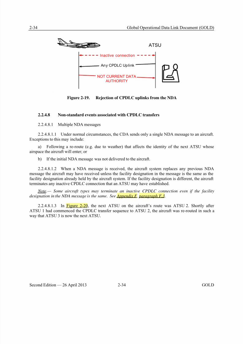
8/9/2019 CPDLC Explained
http://slidepdf.com/reader/full/cpdlc-explained 72/421
2-34 Global Operational Data Link Document (GOLD)
Second Edition — 26 April 2013 2-34 GOLD
Any CPDLC Uplink
NOT CURRENT DATA
AUTHORITY
ATSU
Inactive connection
Figure 2-19. Rejection of CPDLC uplinks from the NDA
2.2.4.8 Non-standard events associated with CPDLC transfers
2.2.4.8.1 Multiple NDA messages
2.2.4.8.1.1 Under normal circumstances, the CDA sends only a single NDA message to an aircraft.Exceptions to this may include:
a) Following a re-route (e.g. due to weather) that affects the identity of the next ATSU whoseairspace the aircraft will enter; or
b) If the initial NDA message was not delivered to the aircraft.
2.2.4.8.1.2 When a NDA message is received, the aircraft system replaces any previous NDAmessage the aircraft may have received unless the facility designation in the message is the same as the
facility designation already held by the aircraft system. If the facility designation is different, the aircraftterminates any inactive CPDLC connection that an ATSU may have established.
Note.— Some aircraft types may terminate an inactive CPDLC connection even if the facility
designation in the NDA message is the same. See Appendix F, paragraph F.3.
2.2.4.8.1.3 In Figure 2-20, the next ATSU on the aircraft’s route was ATSU 2. Shortly afterATSU 1 had commenced the CPDLC transfer sequence to ATSU 2, the aircraft was re-routed in such away that ATSU 3 is now the next ATSU.
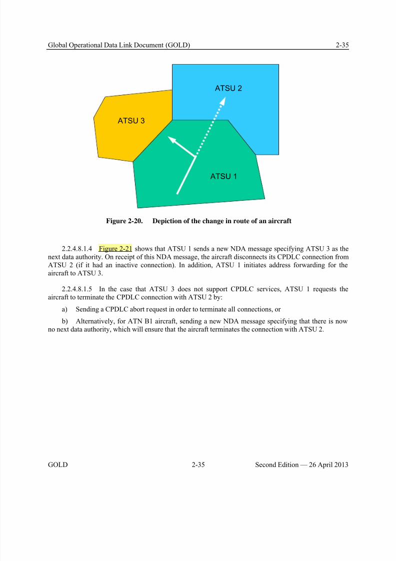
8/9/2019 CPDLC Explained
http://slidepdf.com/reader/full/cpdlc-explained 73/421
Global Operational Data Link Document (GOLD) 2-35
GOLD 2-35 Second Edition — 26 April 2013
ATSU 1
ATSU 2
ATSU 3
Figure 2-20. Depiction of the change in route of an aircraft
2.2.4.8.1.4 Figure 2-21 shows that ATSU 1 sends a new NDA message specifying ATSU 3 as thenext data authority. On receipt of this NDA message, the aircraft disconnects its CPDLC connection fromATSU 2 (if it had an inactive connection). In addition, ATSU 1 initiates address forwarding for theaircraft to ATSU 3.
2.2.4.8.1.5 In the case that ATSU 3 does not support CPDLC services, ATSU 1 requests the
aircraft to terminate the CPDLC connection with ATSU 2 by:
a) Sending a CPDLC abort request in order to terminate all connections, or
b) Alternatively, for ATN B1 aircraft, sending a new NDA message specifying that there is nowno next data authority, which will ensure that the aircraft terminates the connection with ATSU 2.
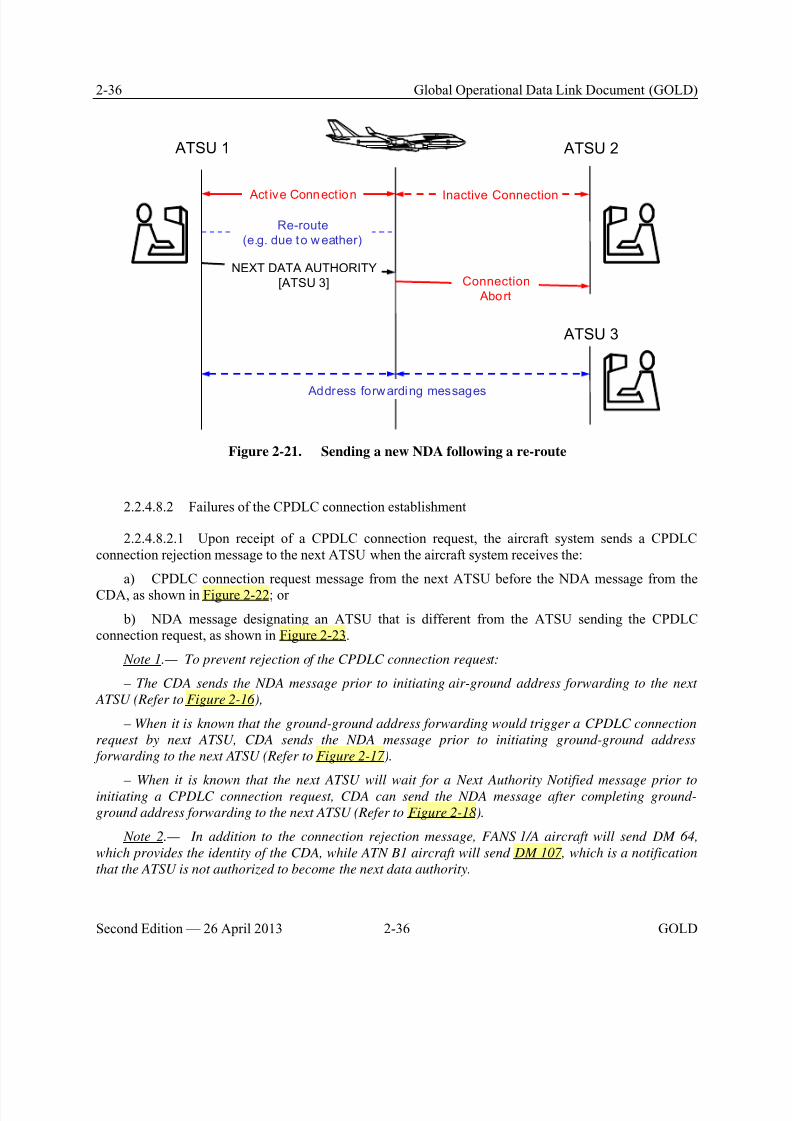
8/9/2019 CPDLC Explained
http://slidepdf.com/reader/full/cpdlc-explained 74/421
2-36 Global Operational Data Link Document (GOLD)
Second Edition — 26 April 2013 2-36 GOLD
Act ive Connection
ATSU 1 ATSU 2
ATSU 3
NEXT DATA AUTHORITY
[ATSU 3]
Re-route
(e.g. due to w eather)
Inactive Connection
Connection
Abort
Address forwarding messages
Figure 2-21. Sending a new NDA following a re-route
2.2.4.8.2 Failures of the CPDLC connection establishment
2.2.4.8.2.1 Upon receipt of a CPDLC connection request, the aircraft system sends a CPDLCconnection rejection message to the next ATSU when the aircraft system receives the:
a) CPDLC connection request message from the next ATSU before the NDA message from theCDA, as shown in Figure 2-22; or
b) NDA message designating an ATSU that is different from the ATSU sending the CPDLCconnection request, as shown in Figure 2-23.
Note 1.— To prevent rejection of the CPDLC connection request:
– The CDA sends the NDA message prior to initiating air-ground address forwarding to the next
ATSU (Refer to Figure 2-16) ,
– When it is known that the ground-ground address forwarding would trigger a CPDLC connection
request by next ATSU, CDA sends the NDA message prior to initiating ground-ground address
forwarding to the next ATSU (Refer to Figure 2-17).
– When it is known that the next ATSU will wait for a Next Authority Notified message prior toinitiating a CPDLC connection request, CDA can send the NDA message after completing ground-
ground address forwarding to the next ATSU (Refer to Figure 2-18).
Note 2.— In addition to the connection rejection message, FANS 1/A aircraft will send DM 64,
which provides the identity of the CDA, while ATN B1 aircraft will send DM 107, which is a notification
that the ATSU is not authorized to become the next data authority.
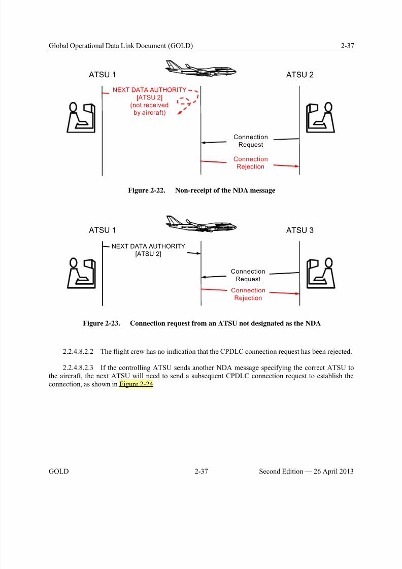
8/9/2019 CPDLC Explained
http://slidepdf.com/reader/full/cpdlc-explained 75/421
Global Operational Data Link Document (GOLD) 2-37
GOLD 2-37 Second Edition — 26 April 2013
ATSU 1 ATSU 2
Connection
Rejection
Connection
Request
NEXT DATA AUTHORITY
[ATSU 2](not received
by aircraft)
Figure 2-22. Non-receipt of the NDA message
NEXT DATA AUTHORITY
[ATSU 2]
ATSU 1 ATSU 3
Connection
Rejection
Connection
Request
Figure 2-23. Connection request from an ATSU not designated as the NDA
2.2.4.8.2.2 The flight crew has no indication that the CPDLC connection request has been rejected.
2.2.4.8.2.3 If the controlling ATSU sends another NDA message specifying the correct ATSU tothe aircraft, the next ATSU will need to send a subsequent CPDLC connection request to establish theconnection, as shown in Figure 2-24.
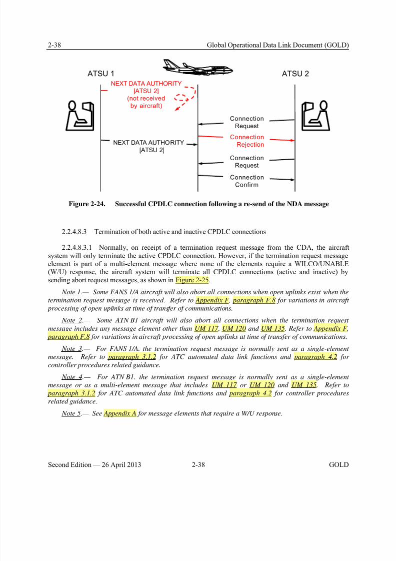
8/9/2019 CPDLC Explained
http://slidepdf.com/reader/full/cpdlc-explained 76/421
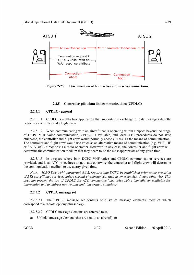
8/9/2019 CPDLC Explained
http://slidepdf.com/reader/full/cpdlc-explained 77/421
Global Operational Data Link Document (GOLD) 2-39
GOLD 2-39 Second Edition — 26 April 2013
Active Connection
ATSU 1 ATSU 2
Termination request +
CPDLC uplink with no
W/U response attribute
Connection
Abort
Inactive Connection
Connection
Abort
Figure 2-25. Disconnection of both active and inactive connections
2.2.5 Controller-pilot data link communications (CPDLC)
2.2.5.1 CPDLC - general
2.2.5.1.1 CPDLC is a data link application that supports the exchange of data messages directly between a controller and a flight crew.
2.2.5.1.2 When communicating with an aircraft that is operating within airspace beyond the rangeof DCPC VHF voice communication, CPDLC is available, and local ATC procedures do not stateotherwise, the controller and flight crew would normally chose CPDLC as the means of communication.
The controller and flight crew would use voice as an alternative means of communication (e.g. VHF, HFor SATVOICE direct or via a radio operator). However, in any case, the controller and flight crew willdetermine the communication medium that they deem to be the most appropriate at any given time.
2.2.5.1.3 In airspace where both DCPC VHF voice and CPDLC communication services are provided, and local ATC procedures do not state otherwise, the controller and flight crew will determinethe communication medium to use at any given time.
Note.— ICAO Doc 4444, paragraph 8.3.2, requires that DCPC be established prior to the provision
of ATS surveillance services, unless special circumstances, such as emergencies, dictate otherwise. This
does not prevent the use of CPDLC for ATC communications, voice being immediately available for
intervention and to address non-routine and time critical situations.
2.2.5.2 CPDLC message set
2.2.5.2.1 The CPDLC message set consists of a set of message elements, most of whichcorrespond to a radiotelephony phraseology.
2.2.5.2.2 CPDLC message elements are referred to as:
a) Uplinks (message elements that are sent to an aircraft); or

8/9/2019 CPDLC Explained
http://slidepdf.com/reader/full/cpdlc-explained 78/421
2-40 Global Operational Data Link Document (GOLD)
Second Edition — 26 April 2013 2-40 GOLD
b) Downlinks (message elements that are sent by the aircraft).
2.2.5.2.3 Each message element has a number of attributes associated to it, including:
a) A message number that uniquely identifies each type of message element. Uplink messageelements are prefixed UM and downlink message elements are prefixed with DM;
b) A response attribute that defines whether or not a response is required for a message element,and, in the case of an uplink message element, the type of response required.
Note.— Other attributes include the urgency and alert attributes to specify precedence in message
presentation and indication to the recipient. However, these attributes are currently not used.
2.2.5.2.4 The CPDLC message set, including the possible responses associated with each responseattribute, is included in Appendix A.
2.2.5.2.5 Table 2-9 provides examples of responses that may be required for a CPDLC uplinkmessage depending on its response attribute. See Appendix A, paragraph A.2 for a complete descriptionof the responses associated with each response attribute.
Table 2-9. Examples of responses to CPDLC uplink messages
Response attribute Description
W/U A DM 0 WILCO or DM 1 UNABLE is required in response to this CPDLCuplink message element.
A/N An DM 4 AFFIRM or DM 5 NEGATIVE is required in response to this CPDLCuplink message element.
R A DM 3 ROGER or DM 1 UNABLE is required in response to this CPDLCuplink message element.
Note 1.— FANS 1/A allows only DM 3 ROGER message as a response to uplinkmessage with a R response attribute.
Y A response is required to close the CPDLC uplink message element. AnyCPDLC downlink message satisfies the requirement.
Note 2.— FANS 1/A does not include any message element with Y response
attribute.
NE (for FANS 1/A)
N (for ATN B1)
A response is not required to close the CPDLC uplink message element eventhough a response may be required operationally.
2.2.5.3 CPDLC messages
2.2.5.3.1 A CPDLC message consists of either a single message element, or a combination of up tofive message elements. A CPDLC message that consists of more than one message element is a multi-element message.
Note.— As a general rule, the size of a CPDLC message needs to be kept to a minimum. Refer to
paragraphs 4.3.6, 4.4.4, 5.3.1.2 and 5.4.1.4 for guidelines on use of multi-element messages.
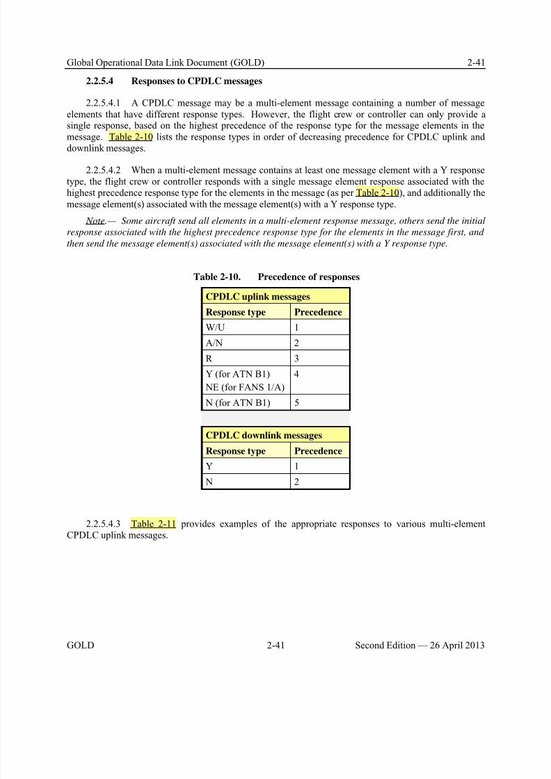
8/9/2019 CPDLC Explained
http://slidepdf.com/reader/full/cpdlc-explained 79/421
Global Operational Data Link Document (GOLD) 2-41
GOLD 2-41 Second Edition — 26 April 2013
2.2.5.4 Responses to CPDLC messages
2.2.5.4.1 A CPDLC message may be a multi-element message containing a number of messageelements that have different response types. However, the flight crew or controller can only provide asingle response, based on the highest precedence of the response type for the message elements in the
message. Table 2-10 lists the response types in order of decreasing precedence for CPDLC uplink anddownlink messages.
2.2.5.4.2 When a multi-element message contains at least one message element with a Y responsetype, the flight crew or controller responds with a single message element response associated with thehighest precedence response type for the elements in the message (as per Table 2-10), and additionally themessage element(s) associated with the message element(s) with a Y response type.
Note.— Some aircraft send all elements in a multi-element response message, others send the initial
response associated with the highest precedence response type for the elements in the message first, and
then send the message element(s) associated with the message element(s) with a Y response type.
Table 2-10. Precedence of responses
CPDLC uplink messages
Response type Precedence
W/U 1
A/N 2
R 3
Y (for ATN B1)
NE (for FANS 1/A)
4
N (for ATN B1) 5
CPDLC downlink messages
Response type Precedence
Y 1
N 2
2.2.5.4.3 Table 2-11 provides examples of the appropriate responses to various multi-elementCPDLC uplink messages.
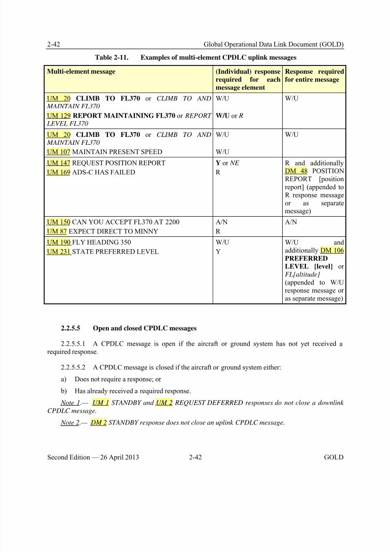
8/9/2019 CPDLC Explained
http://slidepdf.com/reader/full/cpdlc-explained 80/421
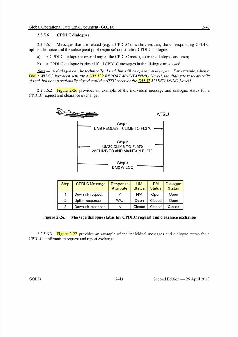
8/9/2019 CPDLC Explained
http://slidepdf.com/reader/full/cpdlc-explained 81/421

8/9/2019 CPDLC Explained
http://slidepdf.com/reader/full/cpdlc-explained 82/421
2-44 Global Operational Data Link Document (GOLD)
Second Edition — 26 April 2013 2-44 GOLD
Step 1
UM136 CONFIRM ASSIGNED SPEED
ATSU
Step 2
DM39 ASSIGNED SPEED 250KT
ClosedClosedClosedNDownlink response2
Open or
ClosedN/A
Open or
Closed
Y or
NEUplink request1
Dialogue
Status
DM
Status
UM
Status
Response
Att ribute
CPDLC MessageStep
Figure 2-27. Message/dialogue status for CPDLC confirmation request and report exchange
2.2.5.7 Message identification numbers (MIN)
2.2.5.7.1 For each CPDLC connection, the aircraft and ground systems assign every CPDLCuplink and downlink message an identifier, known as a message identification number (MIN). The MIN
is an integer in the range 0 to 63 (inclusive). The ground system assigns the MIN for uplink messages,and the aircraft system assigns the MIN for downlink messages.
Note.— Some aircraft and ground systems assign MINs sequentially through the allowed range,
while others re-assign MINs as soon as the dialogues using them have been closed. The numbers used as
MINs by the ground and aircraft systems are entirely independent.
2.2.5.8 Message reference numbers (MRN)
2.2.5.8.1 The aircraft and ground systems assign a message reference number (MRN) to a CPDLCmessage when it is a response to another CPDLC message. The MRN of the response message is thesame as the MIN of the corresponding CPDLC message in the dialogue.
2.2.5.8.2 The aircraft and ground systems associate corresponding CPDLC messages within adialogue by their message identification numbers and message reference numbers.
2.2.5.8.3 This functionality ensures that the aircraft and ground systems associate a CPDLCresponse message with the correct CPDLC message in the dialogue.
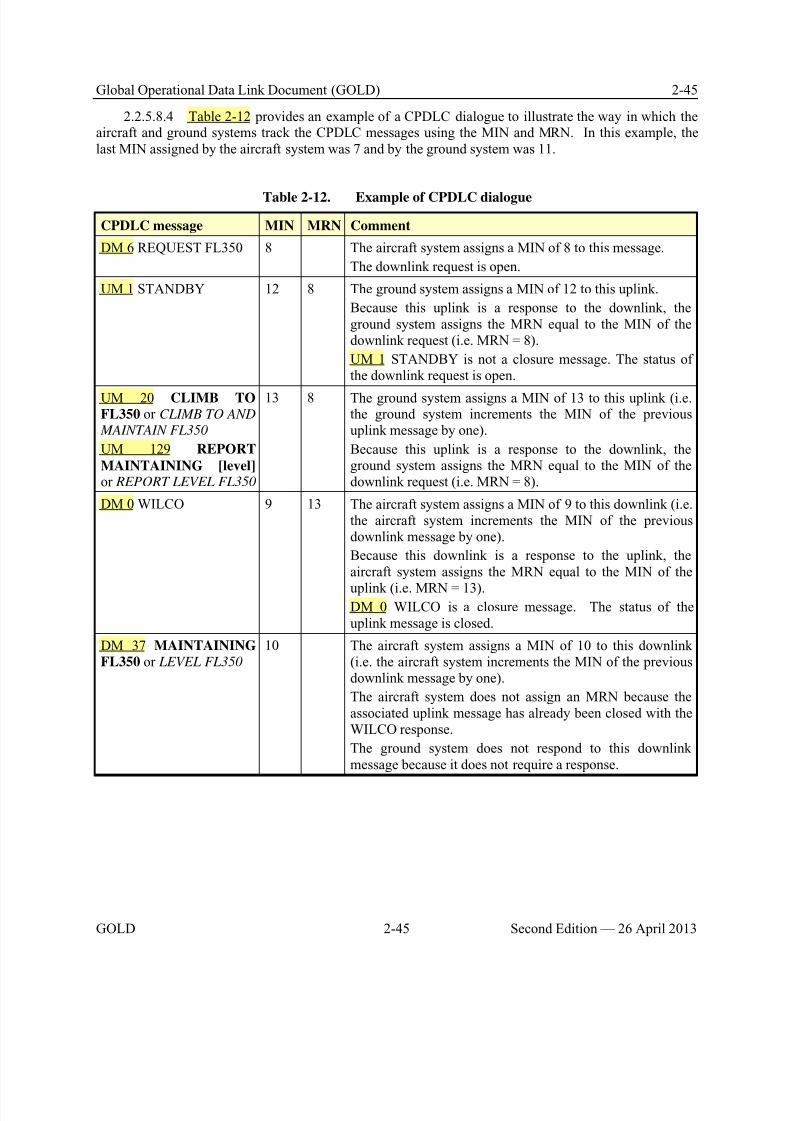
8/9/2019 CPDLC Explained
http://slidepdf.com/reader/full/cpdlc-explained 83/421
Global Operational Data Link Document (GOLD) 2-45
GOLD 2-45 Second Edition — 26 April 2013
2.2.5.8.4 Table 2-12 provides an example of a CPDLC dialogue to illustrate the way in which theaircraft and ground systems track the CPDLC messages using the MIN and MRN. In this example, thelast MIN assigned by the aircraft system was 7 and by the ground system was 11.
Table 2-12. Example of CPDLC dialogue
CPDLC message MIN MRN Comment
DM 6 REQUEST FL350 8 The aircraft system assigns a MIN of 8 to this message.
The downlink request is open.
UM 1 STANDBY 12 8 The ground system assigns a MIN of 12 to this uplink.
Because this uplink is a response to the downlink, theground system assigns the MRN equal to the MIN of thedownlink request (i.e. MRN = 8).
UM 1 STANDBY is not a closure message. The status ofthe downlink request is open.
UM 20 CLIMB TOFL350 or CLIMB TO AND
MAINTAIN FL350
UM 129 REPORT
MAINTAINING [level] or REPORT LEVEL FL350
13 8 The ground system assigns a MIN of 13 to this uplink (i.e.the ground system increments the MIN of the previousuplink message by one).
Because this uplink is a response to the downlink, theground system assigns the MRN equal to the MIN of thedownlink request (i.e. MRN = 8).
DM 0 WILCO 9 13 The aircraft system assigns a MIN of 9 to this downlink (i.e.the aircraft system increments the MIN of the previousdownlink message by one).
Because this downlink is a response to the uplink, theaircraft system assigns the MRN equal to the MIN of the
uplink (i.e. MRN = 13).DM 0 WILCO is a closure message. The status of theuplink message is closed.
DM 37 MAINTAINING
FL350 or LEVEL FL350 10 The aircraft system assigns a MIN of 10 to this downlink
(i.e. the aircraft system increments the MIN of the previousdownlink message by one).
The aircraft system does not assign an MRN because theassociated uplink message has already been closed with theWILCO response.
The ground system does not respond to this downlinkmessage because it does not require a response.
8/9/2019 CPDLC Explained
http://slidepdf.com/reader/full/cpdlc-explained 84/421
2-46 Global Operational Data Link Document (GOLD)
Second Edition — 26 April 2013 2-46 GOLD
2.2.6 Automatic dependent surveillance – contract (ADS-C)
2.2.6.1 ADS-C – general
2.2.6.2 ADS-C uses various systems on board the aircraft to automatically provide aircraft
position, altitude, speed, intent and meteorological data, which can be sent in a report to an ATSU orAOC facility ground system for surveillance and route conformance monitoring.
2.2.6.2.1 One or more reports are generated in response to an ADS contract, which is requested bythe ground system. An ADS contract identifies the types of information and the conditions under whichreports are to be sent by the aircraft. Some types of information are included in every report, while othertypes are provided only if specified in the ADS contract request. The aircraft can also send unsolicitedADS-C emergency reports to any ATSU that has an ADS contract with the aircraft.
2.2.6.2.2 An ATSU system may request multiple simultaneous ADS contracts to a single aircraft,including one periodic and one event contract, which may be supplemented by any number of demandcontracts. Up to five separate ground systems may request ADS contracts with a single aircraft.
Note.— Although the terms are similar, ADS-C and ADS-B are two different applications. Incomparison, ADS-B (PSR, SSR or any comparable ground-based system that enables the identification of
aircraft) is an ATS surveillance system. An ADS-B-capable aircraft supports ATS surveillance services
and broadcasts information at a relatively high rate, and any appropriate receiver on the ground or in
another aircraft within range can receive the information.
2.2.6.3 ADS contract
2.2.6.3.1 After receiving a logon request, the ATSU will need to establish ADS contract(s) withthe aircraft before it can receive any ADS-C reports. There are three types of ADS contracts:
a) Periodic contract;
b) Demand contract; and
c) Event contract.
2.2.6.3.2 The ground system can establish ADS contracts without flight crew action provided thatADS-C in the aircraft system is not selected off. The flight crew has the ability to cancel all contracts byselecting ADS-C off and some aircraft systems allow the flight crew to cancel an ADS contract with aspecific ATSU.
Note.— The ADS-C capability on the aircraft is normally not turned off per paragraph 5.5.1. ADS
contracts are managed by ATSUs based on their surveillance requirements (refer to paragraph 4.5.2).
2.2.6.3.3 Periodic contract
2.2.6.3.3.1 A periodic contract allows an ATSU to specify:
a) The time interval at which the aircraft system sends an ADS-C report; and
b) The optional ADS-C groups that are to be included in the periodic report. Each optional groupmay have a unique modulus which defines how often the optional group is included with the periodicreport (e.g. a modulus of five indicates that the optional group would be included with every fifth periodicreport sent).
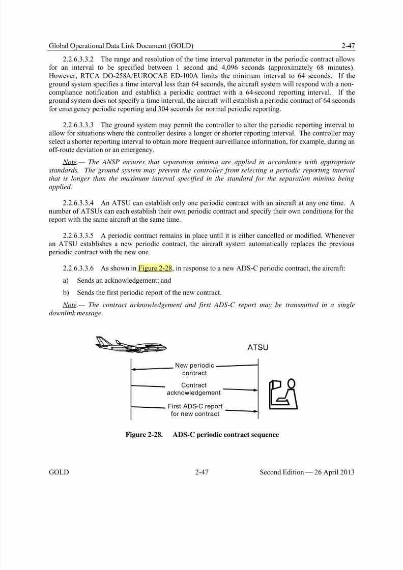
8/9/2019 CPDLC Explained
http://slidepdf.com/reader/full/cpdlc-explained 85/421
Global Operational Data Link Document (GOLD) 2-47
GOLD 2-47 Second Edition — 26 April 2013
2.2.6.3.3.2 The range and resolution of the time interval parameter in the periodic contract allowsfor an interval to be specified between 1 second and 4,096 seconds (approximately 68 minutes).However, RTCA DO-258A/EUROCAE ED-100A limits the minimum interval to 64 seconds. If theground system specifies a time interval less than 64 seconds, the aircraft system will respond with a non-compliance notification and establish a periodic contract with a 64-second reporting interval. If the
ground system does not specify a time interval, the aircraft will establish a periodic contract of 64 secondsfor emergency periodic reporting and 304 seconds for normal periodic reporting.
2.2.6.3.3.3 The ground system may permit the controller to alter the periodic reporting interval toallow for situations where the controller desires a longer or shorter reporting interval. The controller mayselect a shorter reporting interval to obtain more frequent surveillance information, for example, during anoff-route deviation or an emergency.
Note.— The ANSP ensures that separation minima are applied in accordance with appropriate
standards. The ground system may prevent the controller from selecting a periodic reporting interval
that is longer than the maximum interval specified in the standard for the separation minima being
applied.
2.2.6.3.3.4 An ATSU can establish only one periodic contract with an aircraft at any one time. Anumber of ATSUs can each establish their own periodic contract and specify their own conditions for thereport with the same aircraft at the same time.
2.2.6.3.3.5 A periodic contract remains in place until it is either cancelled or modified. Wheneveran ATSU establishes a new periodic contract, the aircraft system automatically replaces the previous periodic contract with the new one.
2.2.6.3.3.6 As shown in Figure 2-28, in response to a new ADS-C periodic contract, the aircraft:
a) Sends an acknowledgement; and
b) Sends the first periodic report of the new contract.
Note.— The contract acknowledgement and first ADS-C report may be transmitted in a single
downlink message.
New periodic
contract
Contract
acknowledgement
ATSU
First ADS-C report
for new contract
Figure 2-28. ADS-C periodic contract sequence
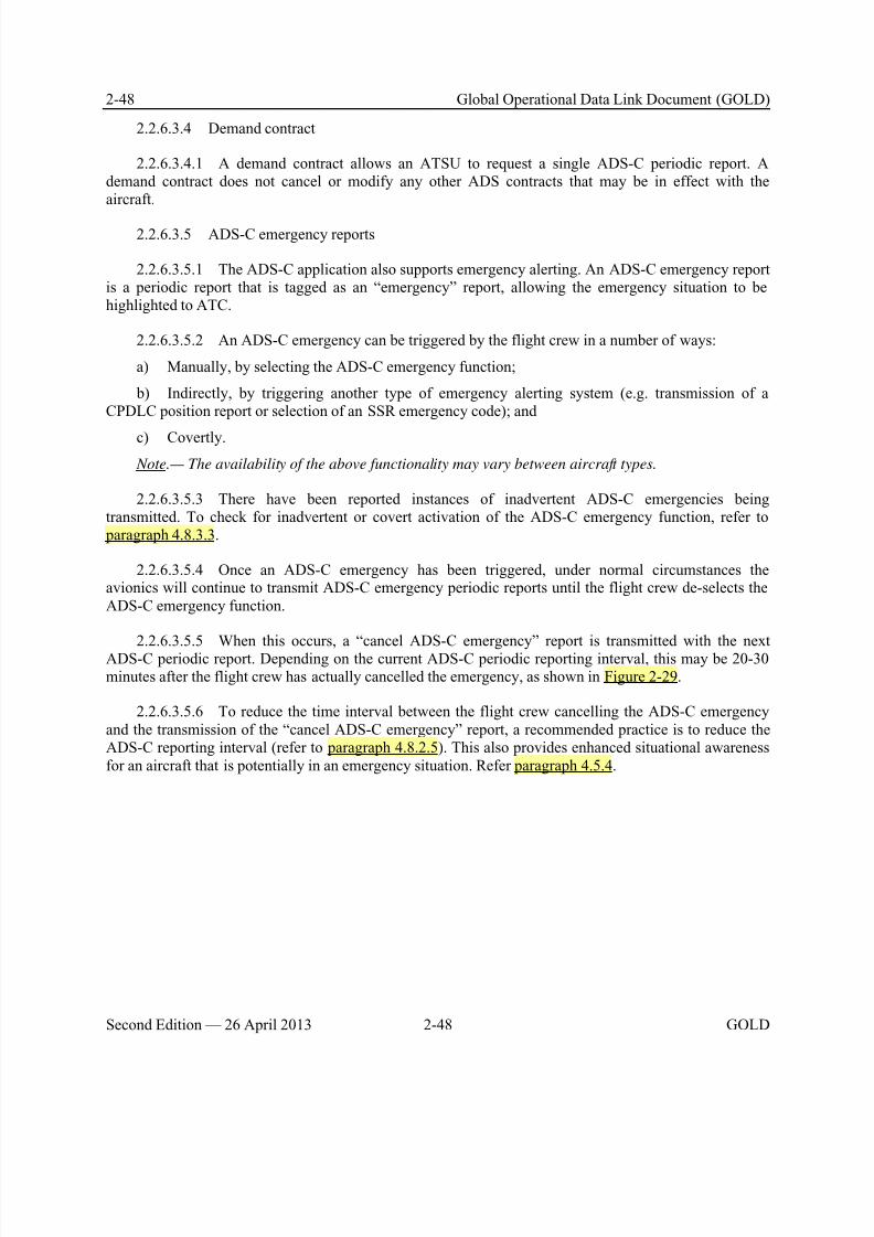
8/9/2019 CPDLC Explained
http://slidepdf.com/reader/full/cpdlc-explained 86/421
2-48 Global Operational Data Link Document (GOLD)
Second Edition — 26 April 2013 2-48 GOLD
2.2.6.3.4 Demand contract
2.2.6.3.4.1 A demand contract allows an ATSU to request a single ADS-C periodic report. Ademand contract does not cancel or modify any other ADS contracts that may be in effect with theaircraft.
2.2.6.3.5 ADS-C emergency reports
2.2.6.3.5.1 The ADS-C application also supports emergency alerting. An ADS-C emergency reportis a periodic report that is tagged as an “emergency” report, allowing the emergency situation to behighlighted to ATC.
2.2.6.3.5.2 An ADS-C emergency can be triggered by the flight crew in a number of ways:
a) Manually, by selecting the ADS-C emergency function;
b) Indirectly, by triggering another type of emergency alerting system (e.g. transmission of aCPDLC position report or selection of an SSR emergency code); and
c) Covertly.
Note.— The availability of the above functionality may vary between aircraft types.
2.2.6.3.5.3 There have been reported instances of inadvertent ADS-C emergencies beingtransmitted. To check for inadvertent or covert activation of the ADS-C emergency function, refer to paragraph 4.8.3.3.
2.2.6.3.5.4 Once an ADS-C emergency has been triggered, under normal circumstances theavionics will continue to transmit ADS-C emergency periodic reports until the flight crew de-selects theADS-C emergency function.
2.2.6.3.5.5 When this occurs, a “cancel ADS-C emergency” report is transmitted with the nextADS-C periodic report. Depending on the current ADS-C periodic reporting interval, this may be 20-30minutes after the flight crew has actually cancelled the emergency, as shown in Figure 2-29.
2.2.6.3.5.6 To reduce the time interval between the flight crew cancelling the ADS-C emergencyand the transmission of the “cancel ADS-C emergency” report, a recommended practice is to reduce theADS-C reporting interval (refer to paragraph 4.8.2.5). This also provides enhanced situational awarenessfor an aircraft that is potentially in an emergency situation. Refer paragraph 4.5.4.

8/9/2019 CPDLC Explained
http://slidepdf.com/reader/full/cpdlc-explained 87/421
Global Operational Data Link Document (GOLD) 2-49
GOLD 2-49 Second Edition — 26 April 2013
ATSU 1 ATSU 2
New ADS-C contract
(reduced reporting
interval)
ADS-C
emergency
report
ADS-C
emergency
report
ADS-C non-
emergency
report
ADS-C non-
emergency
reportIt may be some time before
ATSU2 receives a cancellation
of t he ADS-C emergency
Flight crew cancels the
ADS-C emergency
Figure 2-29. ADS-C emergency and non-emergency report sequence
2.2.6.3.6 Event contract
2.2.6.3.6.1 An event contract allows an ATSU to request an ADS-C report whenever a specificevent occurs. An ATSU can establish only one event contract with an aircraft at any one time. However,the event contract can contain multiple event types. These types of optional events include:
a) Waypoint change event (WCE);
b) Level range deviation event (LRDE);
c) Lateral deviation event (LDE); and
d) Vertical rate change event (VRE).
2.2.6.3.6.2 As shown in Figure 2-30, in response to a new ADS-C event contract, the aircraftseparately sends an acknowledgement and then an ADS-C report(s) is transmitted only after one of thespecified events occurs.
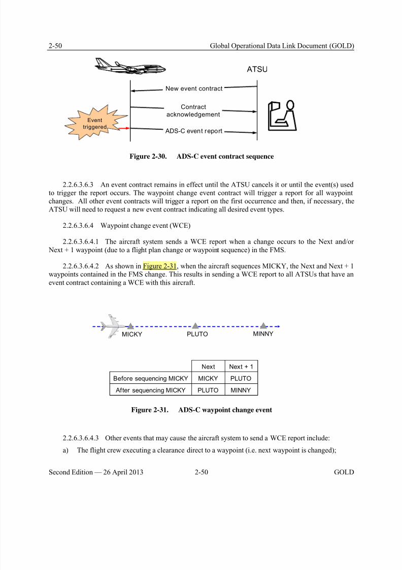
8/9/2019 CPDLC Explained
http://slidepdf.com/reader/full/cpdlc-explained 88/421
2-50 Global Operational Data Link Document (GOLD)
Second Edition — 26 April 2013 2-50 GOLD
New event contract
Contract
acknowledgement
ATSU
ADS-C event report
Event
triggered
Figure 2-30. ADS-C event contract sequence
2.2.6.3.6.3 An event contract remains in effect until the ATSU cancels it or until the event(s) usedto trigger the report occurs. The waypoint change event contract will trigger a report for all waypoint
changes. All other event contracts will trigger a report on the first occurrence and then, if necessary, theATSU will need to request a new event contract indicating all desired event types.
2.2.6.3.6.4 Waypoint change event (WCE)
2.2.6.3.6.4.1 The aircraft system sends a WCE report when a change occurs to the Next and/or Next + 1 waypoint (due to a flight plan change or waypoint sequence) in the FMS.
2.2.6.3.6.4.2 As shown in Figure 2-31, when the aircraft sequences MICKY, the Next and Next + 1waypoints contained in the FMS change. This results in sending a WCE report to all ATSUs that have anevent contract containing a WCE with this aircraft.
MICKY PLUTO MINNY
Before sequencing MICKY MICKY PLUTO
After sequencing MICKY PLUTO MINNY
Next Next + 1
Figure 2-31. ADS-C waypoint change event
2.2.6.3.6.4.3 Other events that may cause the aircraft system to send a WCE report include:
a) The flight crew executing a clearance direct to a waypoint (i.e. next waypoint is changed);

8/9/2019 CPDLC Explained
http://slidepdf.com/reader/full/cpdlc-explained 89/421
Global Operational Data Link Document (GOLD) 2-51
GOLD 2-51 Second Edition — 26 April 2013
b) The flight crew inserting a waypoint ahead of the aircraft (resulting in a change to the Next or Next + 1 waypoint); and
c) The flight crew executing a lateral offset (resulting in a change to the Next waypoint).
2.2.6.3.6.4.4 A waypoint change event report contains the following ADS-C groups:
a) Basic group; and
b) Predicted route group.
2.2.6.3.6.5 Level range deviation event (LRDE)
2.2.6.3.6.5.1 The ATSU specifies the LRDE by defining the lower and upper limits of the levelrange.
2.2.6.3.6.5.2 For example, in Figure 2-32, the LRDE has been defined with a lower limit of FL368and an upper limit of FL372.
370
368
372
Lower Limit
Upper Limi t
Figure 2-32. ADS-C level range deviation event
2.2.6.3.6.5.3 The aircraft system sends a LRDE report when the aircraft’s flight level is outside thelevel range tolerances defined in the ADS-C event contract (Figure 2-33).
370
368
372
LRDE report
Lower Limit
Upper Limi t
Figure 2-33. ADS-C level range deviation event report

8/9/2019 CPDLC Explained
http://slidepdf.com/reader/full/cpdlc-explained 90/421
2-52 Global Operational Data Link Document (GOLD)
Second Edition — 26 April 2013 2-52 GOLD
2.2.6.3.6.5.4 Once an aircraft sends an LRDE report, it will not send another LRDE report until theATSU establishes a new ADS-C LRDE contract.
2.2.6.3.6.5.5 An LRDE report contains the ADS-C basic group only.
2.2.6.3.6.6 Lateral deviation event
2.2.6.3.6.6.1 The ATSU specifies the lateral deviation event by defining a lateral deviationthreshold, which is a maximum off-route distance either side of the route as specified by the ATSU. It isnot possible to define different distances on each side of the route.
2.2.6.3.6.6.2 For example, in Figure 2-34, the lateral deviation event has been defined to betriggered for a lateral deviation threshold of greater than 5NM either side of the route.
DAFFY PLUTO
5NM
5NM
Figure 2-34. ADS-C lateral deviation event
2.2.6.3.6.6.3 The lateral deviation event is triggered when the lateral distance between the aircraft’sactual position and its expected position, as defined in the aircraft active flight plan, exceeds the lateral
deviation threshold defined in the ADS-C event contract (Figure 2-35).
DAFFY PLUTO
5NM
5NM
LDE report
Figure 2-35. ADS-C lateral deviation event report
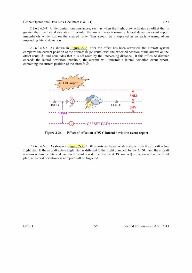
8/9/2019 CPDLC Explained
http://slidepdf.com/reader/full/cpdlc-explained 91/421
Global Operational Data Link Document (GOLD) 2-53
GOLD 2-53 Second Edition — 26 April 2013
2.2.6.3.6.6.4 Under certain circumstances, such as when the flight crew activates an offset that isgreater than the lateral deviation threshold, the aircraft may transmit a lateral deviation event reportimmediately while still on the cleared route. This should be interpreted as an early warning of animpending lateral deviation.
2.2.6.3.6.6.5 As shown in Figure 2-36, after the offset has been activated, the aircraft systemcompares the current position of the aircraft (on route) with the expected position of the aircraft on theoffset route , and concludes that it is off route by the intervening distance. If this off-route distanceexceeds the lateral deviation threshold, the aircraft will transmit a lateral deviation event report,containing the current position of the aircraft .
DAFFY PLUTO
5NM
5NM
10NM
1
2 OFFSET PATH
LDE report
Figure 2-36. Effect of offset on ADS-C lateral deviation event report
2.2.6.3.6.6.6 As shown in Figure 2-37, LDE reports are based on deviations from the aircraft activeflight plan. If the aircraft active flight plan is different to the flight plan held by the ATSU, and the aircraftremains within the lateral deviation threshold (as defined by the ADS contract) of the aircraft active flight plan, no lateral deviation event report will be triggered.
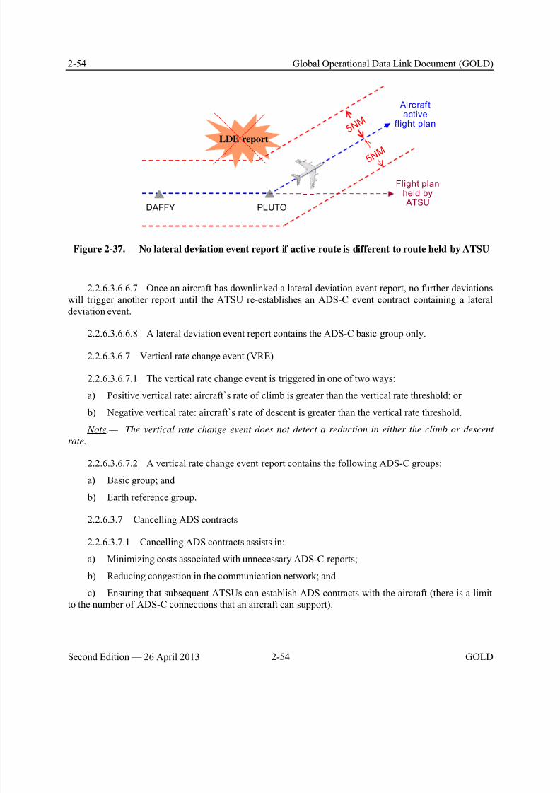
8/9/2019 CPDLC Explained
http://slidepdf.com/reader/full/cpdlc-explained 92/421
2-54 Global Operational Data Link Document (GOLD)
Second Edition — 26 April 2013 2-54 GOLD
DAFFY PLUTO
5 N M
LDE report
5 N M
Aircraf tactive
flight plan
Flight planheld by ATSU
Figure 2-37. No lateral deviation event report if active route is different to route held by ATSU
2.2.6.3.6.6.7 Once an aircraft has downlinked a lateral deviation event report, no further deviationswill trigger another report until the ATSU re-establishes an ADS-C event contract containing a lateraldeviation event.
2.2.6.3.6.6.8 A lateral deviation event report contains the ADS-C basic group only.
2.2.6.3.6.7 Vertical rate change event (VRE)
2.2.6.3.6.7.1 The vertical rate change event is triggered in one of two ways:
a) Positive vertical rate: aircraft`s rate of climb is greater than the vertical rate threshold; or
b) Negative vertical rate: aircraft`s rate of descent is greater than the vertical rate threshold. Note.— The vertical rate change event does not detect a reduction in either the climb or descent
rate.
2.2.6.3.6.7.2 A vertical rate change event report contains the following ADS-C groups:
a) Basic group; and
b) Earth reference group.
2.2.6.3.7 Cancelling ADS contracts
2.2.6.3.7.1 Cancelling ADS contracts assists in:
a) Minimizing costs associated with unnecessary ADS-C reports;
b) Reducing congestion in the communication network; and
c) Ensuring that subsequent ATSUs can establish ADS contracts with the aircraft (there is a limitto the number of ADS-C connections that an aircraft can support).
8/9/2019 CPDLC Explained
http://slidepdf.com/reader/full/cpdlc-explained 93/421
Global Operational Data Link Document (GOLD) 2-55
GOLD 2-55 Second Edition — 26 April 2013
2.2.6.3.7.2 The ATSU cancels an ADS contract and terminates the ADS-C connection when it nolonger needs ADS-C reports to avoid unnecessary loading of the data link system. The ground systemterminates the ADS-C connection when:
a) The aircraft has crossed the boundary and the transferring ATSU needs no further surveillance
information from the flight; b) The ATSU has cancelled or finished the flight plan for the aircraft; or
c) The controlling authority or an adjacent ATSU needs no further surveillance information fromthe flight.
2.2.6.3.7.3 The flight crew is able to terminate ADS-C connections, which in turn cancels ADScontracts. This capability is used in accordance with guidelines provided in paragraph 5.5.
2.2.6.4 ADS-C report
2.2.6.4.1 The aircraft system sends specific aircraft data in different groups of an ADS-C report.Each group contains different types of data. An ADS-C event report contains only some of the groups,
which are fixed. The ADS-C periodic report can contain any of the ADS-C groups, which the ATSUspecifies in the contract request.
2.2.6.4.2 ADS-C groups include:
a) Basic group (Figure 2-38);
b) Flight identification group (Figure 2-39);
c) Earth reference group (Figure 2-40);
d) Air reference group (Figure 2-41);
e) Airframe identification group (Figure 2-42);
f) Meteorological group (Figure 2-43);
g) Predicted route group (Figure 2-44);
h) Fixed projected intent group (Figure 2-45); and
i) Intermediate projected intent group (Figure 2-46).
2.2.6.4.3 At a minimum, all ADS-C reports contain the basic group.
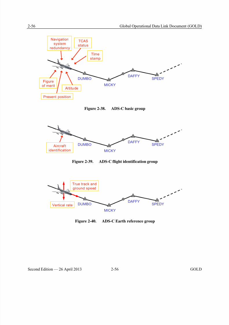
8/9/2019 CPDLC Explained
http://slidepdf.com/reader/full/cpdlc-explained 94/421
2-56 Global Operational Data Link Document (GOLD)
Second Edition — 26 April 2013 2-56 GOLD
DUMBO
MICKY
DAFFYSPEDY
Present position
Figure
of merit
Navigation
system
redundancy
TCAS
status
Time
stamp
Alti tude
Figure 2-38. ADS-C basic group
DUMBO
MICKY
DAFFYSPEDY Aircraf t
identification
Figure 2-39. ADS-C flight identification group
DUMBO
MICKY
DAFFYSPEDYVertical rate
True track and
ground speed
Figure 2-40. ADS-C Earth reference group
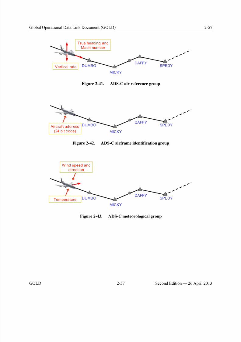
8/9/2019 CPDLC Explained
http://slidepdf.com/reader/full/cpdlc-explained 95/421
Global Operational Data Link Document (GOLD) 2-57
GOLD 2-57 Second Edition — 26 April 2013
DUMBO
MICKY
DAFFYSPEDYVertical rate
True heading and
Mach number
Figure 2-41. ADS-C air reference group
DUMBO
MICKY
DAFFYSPEDY Aircraf t address
(24 bit code)
Figure 2-42. ADS-C airframe identification group
DUMBO
MICKY
DAFFYSPEDYTemperature
Wind speed and
direction
Figure 2-43. ADS-C meteorological group
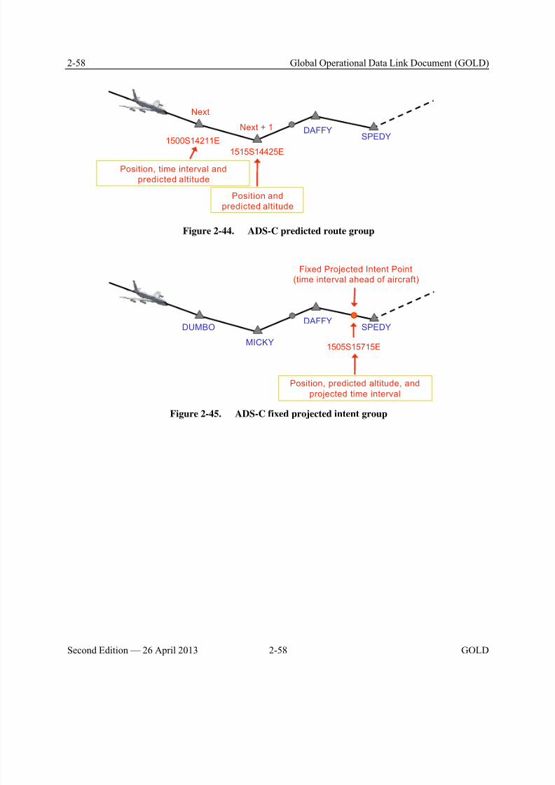
8/9/2019 CPDLC Explained
http://slidepdf.com/reader/full/cpdlc-explained 96/421
2-58 Global Operational Data Link Document (GOLD)
Second Edition — 26 April 2013 2-58 GOLD
1500S14211E
1515S14425E
DAFFY
SPEDY
Next
Position, time interval and
predicted altitude
Position and
predicted altitude
Next + 1
Figure 2-44. ADS-C predicted route group
DAFFYSPEDY
1505S15715E
DUMBO
MICKY
Position, predicted altitude, and
projected time interval
Fixed Projected Intent Point
(time interval ahead of aircraft)
Figure 2-45. ADS-C fixed projected intent group
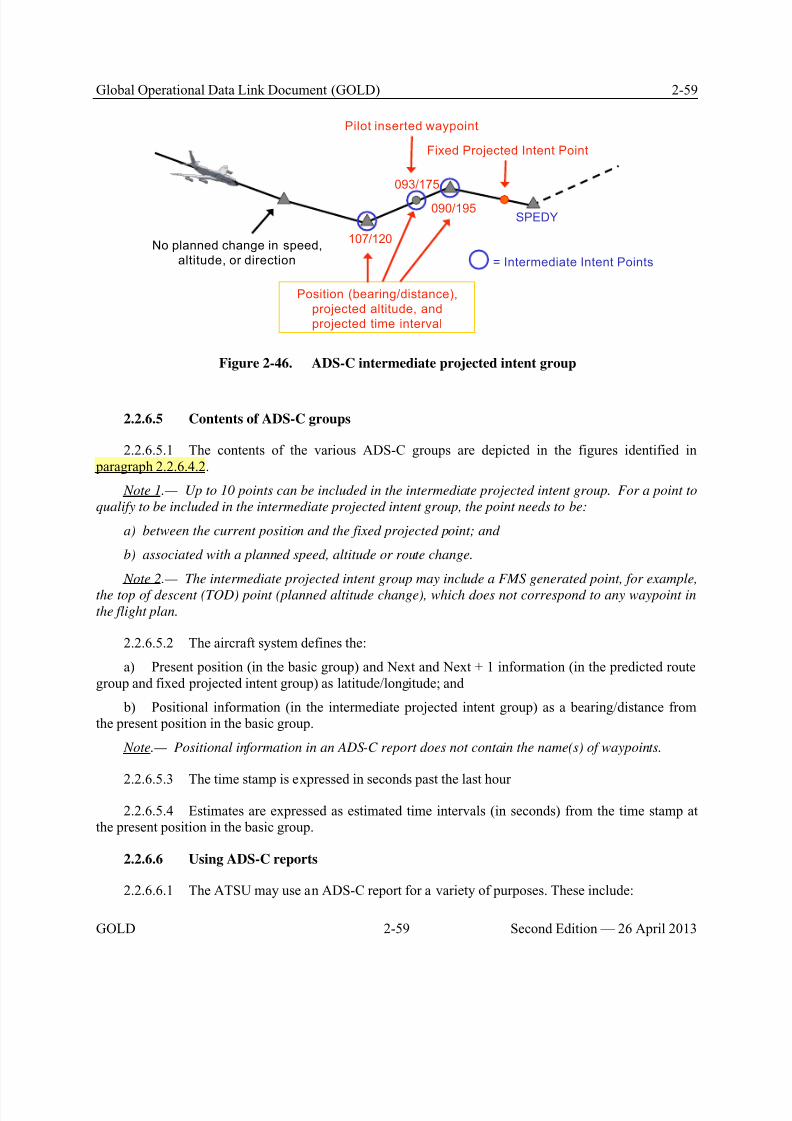
8/9/2019 CPDLC Explained
http://slidepdf.com/reader/full/cpdlc-explained 97/421
Global Operational Data Link Document (GOLD) 2-59
GOLD 2-59 Second Edition — 26 April 2013
SPEDY090/195
107/120
093/175
Fixed Projected Intent Point
Pilot inserted waypoint
Position (bearing/distance),
projected altitude, and
projected time interval
No planned change in speed,
altitude, or direction = Intermediate Intent Points
Figure 2-46. ADS-C intermediate projected intent group
2.2.6.5 Contents of ADS-C groups
2.2.6.5.1 The contents of the various ADS-C groups are depicted in the figures identified in paragraph 2.2.6.4.2.
Note 1.— Up to 10 points can be included in the intermediate projected intent group. For a point to
qualify to be included in the intermediate projected intent group, the point needs to be:
a) between the current position and the fixed projected point; and
b) associated with a planned speed, altitude or route change.
Note 2.— The intermediate projected intent group may include a FMS generated point, for example,
the top of descent (TOD) point (planned altitude change), which does not correspond to any waypoint in
the flight plan.
2.2.6.5.2 The aircraft system defines the:
a) Present position (in the basic group) and Next and Next + 1 information (in the predicted routegroup and fixed projected intent group) as latitude/longitude; and
b) Positional information (in the intermediate projected intent group) as a bearing/distance fromthe present position in the basic group.
Note.— Positional information in an ADS-C report does not contain the name(s) of waypoints.
2.2.6.5.3 The time stamp is expressed in seconds past the last hour
2.2.6.5.4 Estimates are expressed as estimated time intervals (in seconds) from the time stamp atthe present position in the basic group.
2.2.6.6 Using ADS-C reports
2.2.6.6.1 The ATSU may use an ADS-C report for a variety of purposes. These include:
8/9/2019 CPDLC Explained
http://slidepdf.com/reader/full/cpdlc-explained 98/421

8/9/2019 CPDLC Explained
http://slidepdf.com/reader/full/cpdlc-explained 99/421
Global Operational Data Link Document (GOLD) 2-61
GOLD 2-61 Second Edition — 26 April 2013
ATSU 2
ATSU 1
AOC
ATSU 3
ATSU 4
B a s i c g r o u p
F i x e d p
r o j e c t e d i n t
e n t
g r o u p
+ i n t e r m
e d i a t e
p r o j e c t
e d i n t e
n t g r o u
p
P re d ic te d r o u te
g r o u p + E a r t h
re fe re nce g r o u p
Al l g r o u p s
Figure 2-47. Multiple ADS periodic contracts with different groups
ATSU 2
ATSU 1
AOC
ATSU 3
ATSU 4
2 0 m i n r e p o r t s
2 4 m i n r
e p o r t s
15 m i n re p o r t s
1 4 m i n r e p o r t s
Figure 2-48. Multiple ADS periodic contracts with different reporting intervals
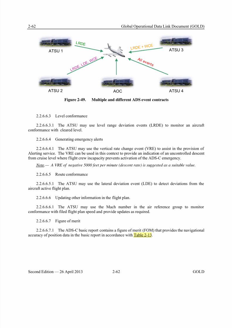
8/9/2019 CPDLC Explained
http://slidepdf.com/reader/full/cpdlc-explained 100/421
2-62 Global Operational Data Link Document (GOLD)
Second Edition — 26 April 2013 2-62 GOLD
ATSU 2
ATSU 1
AOC
ATSU 3
ATSU 4
LR D E
L R D E, L
D E, W C E
L R D E + W C E
Al l e v e n t s
Figure 2-49. Multiple and different ADS event contracts
2.2.6.6.3 Level conformance
2.2.6.6.3.1 The ATSU may use level range deviation events (LRDE) to monitor an aircraftconformance with cleared level.
2.2.6.6.4 Generating emergency alerts
2.2.6.6.4.1 The ATSU may use the vertical rate change event (VRE) to assist in the provision ofAlerting service. The VRE can be used in this context to provide an indication of an uncontrolled descentfrom cruise level where flight crew incapacity prevents activation of the ADS-C emergency.
Note.— A VRE of negative 5000 feet per minute (descent rate) is suggested as a suitable value.
2.2.6.6.5 Route conformance
2.2.6.6.5.1 The ATSU may use the lateral deviation event (LDE) to detect deviations from theaircraft active flight plan.
2.2.6.6.6 Updating other information in the flight plan.
2.2.6.6.6.1 The ATSU may use the Mach number in the air reference group to monitorconformance with filed flight plan speed and provide updates as required.
2.2.6.6.7 Figure of merit
2.2.6.6.7.1 The ADS-C basic report contains a figure of merit (FOM) that provides the navigationalaccuracy of position data in the basic report in accordance with Table 2-13.
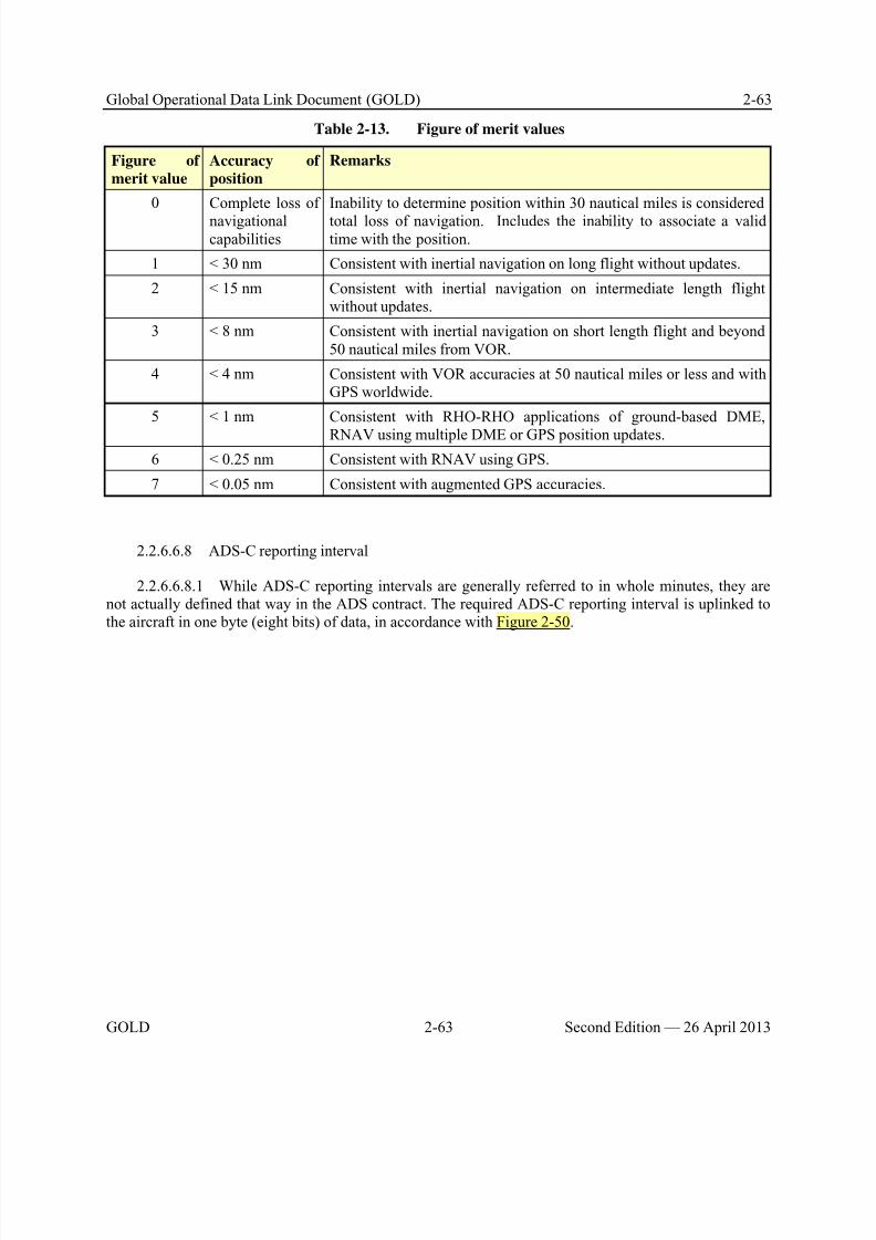
8/9/2019 CPDLC Explained
http://slidepdf.com/reader/full/cpdlc-explained 101/421
Global Operational Data Link Document (GOLD) 2-63
GOLD 2-63 Second Edition — 26 April 2013
Table 2-13. Figure of merit values
Figure of
merit value
Accuracy of
position
Remarks
0 Complete loss of
navigationalcapabilities
Inability to determine position within 30 nautical miles is considered
total loss of navigation. Includes the inability to associate a validtime with the position.
1 < 30 nm Consistent with inertial navigation on long flight without updates.
2 < 15 nm Consistent with inertial navigation on intermediate length flightwithout updates.
3 < 8 nm Consistent with inertial navigation on short length flight and beyond50 nautical miles from VOR.
4 < 4 nm Consistent with VOR accuracies at 50 nautical miles or less and withGPS worldwide.
5 < 1 nm Consistent with RHO-RHO applications of ground-based DME,
RNAV using multiple DME or GPS position updates.
6 < 0.25 nm Consistent with RNAV using GPS.
7 < 0.05 nm Consistent with augmented GPS accuracies.
2.2.6.6.8 ADS-C reporting interval
2.2.6.6.8.1 While ADS-C reporting intervals are generally referred to in whole minutes, they arenot actually defined that way in the ADS contract. The required ADS-C reporting interval is uplinked tothe aircraft in one byte (eight bits) of data, in accordance with Figure 2-50.
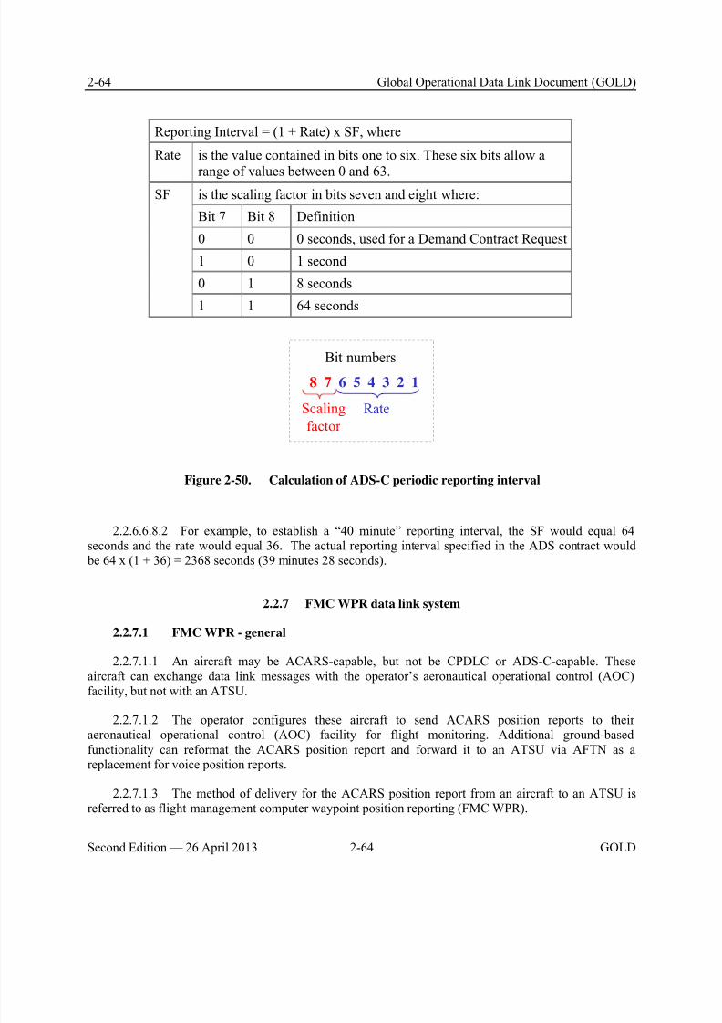
8/9/2019 CPDLC Explained
http://slidepdf.com/reader/full/cpdlc-explained 102/421
8/9/2019 CPDLC Explained
http://slidepdf.com/reader/full/cpdlc-explained 103/421
Global Operational Data Link Document (GOLD) 2-65
GOLD 2-65 Second Edition — 26 April 2013
2.2.7.1.4 FMC WPR provides the operator an alternative to FANS 1/A ADS-C position reporting,in cases where FANS 1/A equipage is impractical or cost prohibitive for the operator. FMC WPR is notintended to replace or delay FANS 1/A equipage.
2.2.7.2 Description
2.2.7.2.1 In some airspace, the aircraft sends the FMC waypoint position report to a central FMCwaypoint reporting system (CFRS) or to the operator’s AOC host computer. The CFRS or operator’sAOC host computer converts the position report to a suitable format and delivers it via AFTN toappropriate ATSUs. A CFRS may also convert the report to standard AFTN format and deliver it toappropriate meteorological facilities to support weather forecasting.
Note.— Because there is no format defined, formats may vary slightly between ATSUs. The CFRS or
AOC host computer should support different formats for different ATSUs.
2.2.7.2.2 Appendix E indicates which of the above two approaches each ATSU uses.
2.2.7.3 Position report - description
2.2.7.3.1 A logon request is not necessary to initiate FMC WPR.
2.2.7.3.2 An FMC WPR is a position report that:
a) Consists entirely of data entered automatically by the FMS;
b) Consists of data CRC protected by the FMS;
c) Consists of data formatted and populated in accordance with the ARINC 702A; and
d) Contains geographical coordinates in ICAO format (Refer to paragraph 5.6.1.2).
2.2.7.3.3 An FMC WPR can be initiated automatically or manually as prescribed by flight deck
procedures (Refer to paragraphs 3.2, 3.4, and 5.6.4).
2.2.7.3.4 An operator participating in FMC WPR ensures that the FMC WPR:
a) Is generated at each ATC waypoint of a cleared route; and
b) Contains data only for an ATC waypoint.

8/9/2019 CPDLC Explained
http://slidepdf.com/reader/full/cpdlc-explained 104/421
8/9/2019 CPDLC Explained
http://slidepdf.com/reader/full/cpdlc-explained 105/421
Global Operational Data Link Document (GOLD) 3-1
GOLD 3-1 Second Edition — 26 April 2013
Chapter 3. Administrative provisions related to data link operations
This chapter includes the prerequisites for data link operations, including service provision, operatoreligibility, and flight planning.
3.1 ANSP service provision
3.1.1 ANSP system validation
3.1.1.1 The ANSP should ensure a validation process that confirms the integrity of theirequipment and procedures meets system integrity requirements. This process should include:
a) A system safety assessment which demonstrates that the service provision meets the safetyobjectives. The ANSP should conduct a system safety assessment through a functional hazard analysis ora documented system safety case for initial implementation as well as for future enhancements. Theseassessments should include:
1) Identifying failure conditions;
2) Assigning levels of criticality;
3) Determining probabilities for occurrence; and
4) Identifying mitigating measures;
b) Integration test results confirming interoperability for operational use of the aircraft and groundsystems; and
c) Confirmation that the ATS operation manuals are compatible with those of adjacent providers.
3.1.1.2 Following the safety assessment, the ANSP should institute measures through automation
or procedures to mitigate the identified failure conditions. For example:a) If the ANSP uses integrated measurement tools for the purpose of determining separation, they
may need to publish limitations on the use of such tools for establishing and monitoring separationstandards;
b) If an ANSP receives both an ADS-C and a CPDLC position report containing ETA that differ by 3 minutes or more, the controller should request confirmation of the estimate for the waypoint inquestion; and
c) To fulfill the requirements of Annex 10, paragraph 8.2.8, the controller should be provided withautomation and/or procedures to ensure that the appropriate ATC unit has established an active CPDLCconnection with the aircraft. Refer to Appendix E for the mitigating measures used for confirming CDA.
3.1.1.3 The ANSP should ensure that it provides communication services that meet the performance specifications provided at Appendix B and Appendix C, and that the contracted CSP meetsits performance allocations. The risks represented by the requirements are regarded as being minimum forthe specified ATS function to maintain operational efficiency while meeting its required safety needs.
3.1.1.4 If the ANSP uses free text messages, it should include an evaluation of the effectsassociated with the use of free text messages in operational and system safety assessments. When theintent/use of the free text message impacts seamless operations, the ANSP should globally coordinate the
8/9/2019 CPDLC Explained
http://slidepdf.com/reader/full/cpdlc-explained 106/421
3-2 Global Operational Data Link Document (GOLD)
Second Edition — 26 April 2013 3-2 GOLD
free text message to define the operational contents, format, and use as a new standardized free textmessage. The standardized free text messages are provided in Appendix A, paragraph A.5.
a) The results of an operational assessment may conclude that a free text message needs to be pre-formatted and readily available for the flight crew or the controller because it is too workload intensive to
manually enter the message. Pre-formatted free text messages should only be selected from standardizedfree text messages, which are appropriate for the intended use.
b) When the ANSP establishes procedures that require the controller or flight crew to use a freetext message element to mimic ICAO Doc 4444 standard message elements, the ANSP should apply thefollowing criteria:
1) The ground system should apply any range, resolution, and units of measure restrictions prior to use of the message;
2) The ground system and aircraft system should provide a human interface for messagecomposition and recognition of free text messages consistent with operational, safety, and performancerequirements associated with use of the free text message;
3) The ATSU should not use free text to mimic an ICAO Doc 4444 message element with aW/U response attribute, unless the free text is combined with a standard message element with a W/Uresponse attribute as part of a multi-element message (see paragraph 4.3.6); and
4) When a free text message (with a R response attribute) is used to mimic a message elementwith a Y response attribute, the ATSU should provide procedures and/or automation to ensure theappropriate operational response is received.
Note.— The ground system will technically close the uplink message when it receives the R response
from the aircraft.
3.1.1.5 The ANSP should conduct trials with aircraft to ensure that the system meets therequirements for interoperability such as is defined for FANS 1/A in RTCA DO-258A/EUROCAEED-100A. Refer to paragraph 2.1 for applicable interoperability standards for the different data link
system.
3.1.1.6 The ANSP should develop appropriate procedures or other means to:
a) Respond to CPDLC downlink message elements defined in Appendix A (See paragraph 3.1.4.2for publication of unsupported downlink messages);
b) Ensure that data are correct and accurate, including any changes, and that security of such datais not compromised;
c) Notify adjacent ATSUs of system failures, software upgrades (or downgrades) or other changes,which may impact them. Such notification procedures will normally be detailed in letters of agreement between adjacent units; and
d) Ensure that the ATSU only establishes an ADS contract with aircraft for which that ATSU hasdirect control or monitoring responsibility.
Note.— An ATSU may need to establish ADS contracts with aircraft operating in their area of
responsibility for purposes other than direct control or monitoring (e.g. testing of ground system software
before operational release).
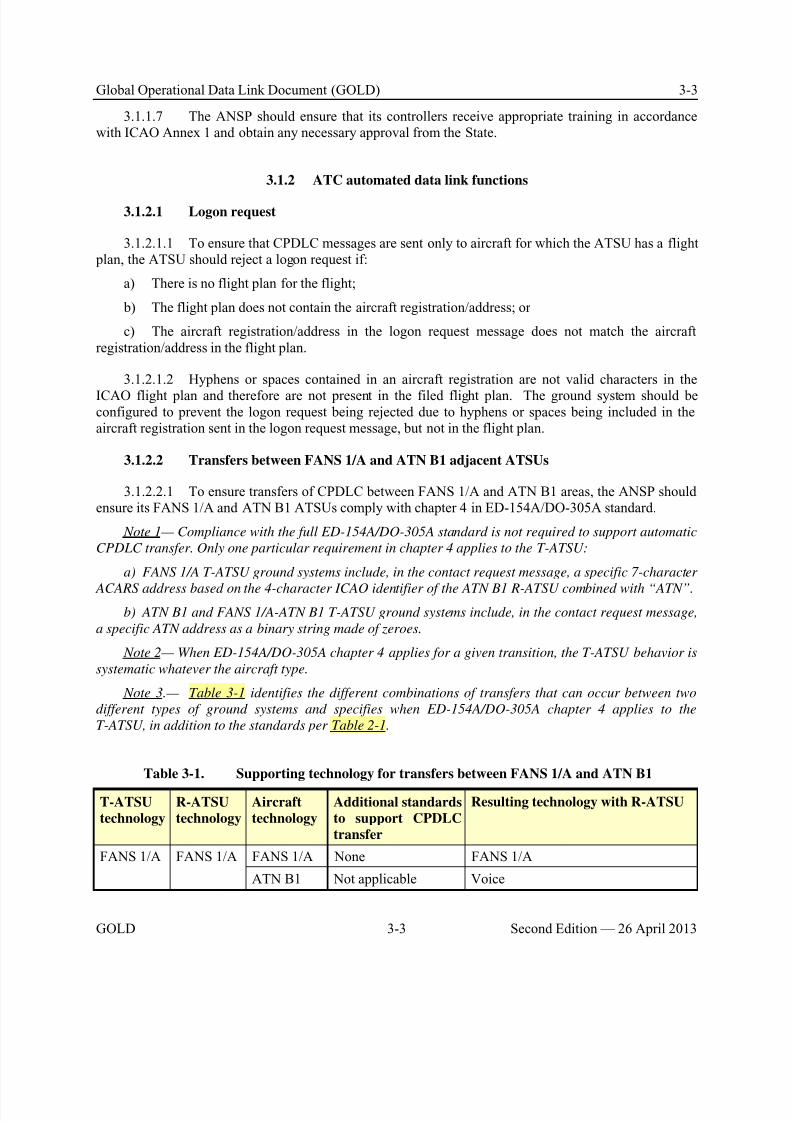
8/9/2019 CPDLC Explained
http://slidepdf.com/reader/full/cpdlc-explained 107/421
Global Operational Data Link Document (GOLD) 3-3
GOLD 3-3 Second Edition — 26 April 2013
3.1.1.7 The ANSP should ensure that its controllers receive appropriate training in accordancewith ICAO Annex 1 and obtain any necessary approval from the State.
3.1.2 ATC automated data link functions
3.1.2.1 Logon request
3.1.2.1.1 To ensure that CPDLC messages are sent only to aircraft for which the ATSU has a flight plan, the ATSU should reject a logon request if:
a) There is no flight plan for the flight;
b) The flight plan does not contain the aircraft registration/address; or
c) The aircraft registration/address in the logon request message does not match the aircraftregistration/address in the flight plan.
3.1.2.1.2 Hyphens or spaces contained in an aircraft registration are not valid characters in the
ICAO flight plan and therefore are not present in the filed flight plan. The ground system should beconfigured to prevent the logon request being rejected due to hyphens or spaces being included in theaircraft registration sent in the logon request message, but not in the flight plan.
3.1.2.2 Transfers between FANS 1/A and ATN B1 adjacent ATSUs
3.1.2.2.1 To ensure transfers of CPDLC between FANS 1/A and ATN B1 areas, the ANSP shouldensure its FANS 1/A and ATN B1 ATSUs comply with chapter 4 in ED-154A/DO-305A standard.
Note 1— Compliance with the full ED-154A/DO-305A standard is not required to support automatic
CPDLC transfer. Only one particular requirement in chapter 4 applies to the T-ATSU:
a) FANS 1/A T-ATSU ground systems include, in the contact request message, a specific 7-character
ACARS address based on the 4-character ICAO identifier of the ATN B1 R-ATSU combined with “ATN”.
b) ATN B1 and FANS 1/A-ATN B1 T-ATSU ground systems include, in the contact request message,
a specific ATN address as a binary string made of zeroes.
Note 2— When ED-154A/DO-305A chapter 4 applies for a given transition, the T-ATSU behavior is
systematic whatever the aircraft type.
Note 3.— Table 3-1 identifies the different combinations of transfers that can occur between two
different types of ground systems and specifies when ED-154A/DO-305A chapter 4 applies to the
T-ATSU, in addition to the standards per Table 2-1.
Table 3-1. Supporting technology for transfers between FANS 1/A and ATN B1
T-ATSU
technology
R-ATSU
technology
Aircraft
technology
Additional standards
to support CPDLC
transfer
Resulting technology with R-ATSU
FANS 1/A FANS 1/A FANS 1/A None FANS 1/A
ATN B1 Not applicable Voice
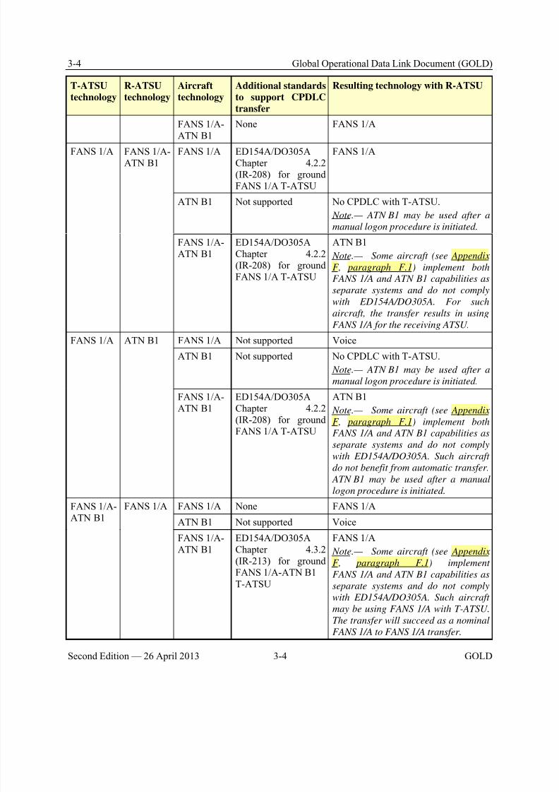
8/9/2019 CPDLC Explained
http://slidepdf.com/reader/full/cpdlc-explained 108/421
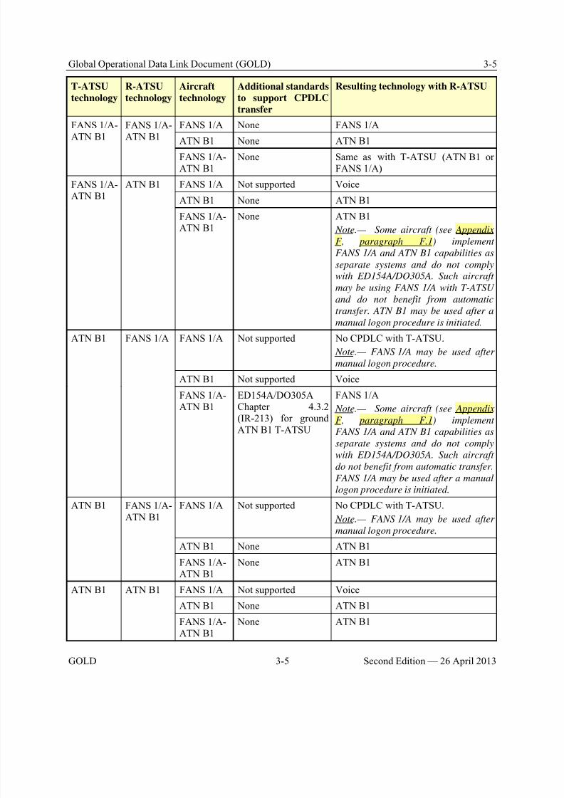
8/9/2019 CPDLC Explained
http://slidepdf.com/reader/full/cpdlc-explained 109/421
Global Operational Data Link Document (GOLD) 3-5
GOLD 3-5 Second Edition — 26 April 2013
T-ATSU
technology
R-ATSU
technology
Aircraft
technology
Additional standards
to support CPDLC
transfer
Resulting technology with R-ATSU
FANS 1/A-
ATN B1
FANS 1/A-
ATN B1
FANS 1/A None FANS 1/A
ATN B1 None ATN B1
FANS 1/A-ATN B1
None Same as with T-ATSU (ATN B1 orFANS 1/A)
FANS 1/A-ATN B1
ATN B1 FANS 1/A Not supported Voice
ATN B1 None ATN B1
FANS 1/A-ATN B1
None ATN B1
Note.— Some aircraft (see Appendix
F, paragraph F.1) implement
FANS 1/A and ATN B1 capabilities as
separate systems and do not comply
with ED154A/DO305A. Such aircraftmay be using FANS 1/A with T-ATSU
and do not benefit from automatic
transfer. ATN B1 may be used after a
manual logon procedure is initiated.
ATN B1 FANS 1/A FANS 1/A Not supported No CPDLC with T-ATSU.
Note.— FANS 1/A may be used after
manual logon procedure.
ATN B1 Not supported Voice
FANS 1/A-ATN B1
ED154A/DO305AChapter 4.3.2
(IR-213) for groundATN B1 T-ATSU
FANS 1/A
Note.— Some aircraft (see Appendix
F, paragraph F.1) implementFANS 1/A and ATN B1 capabilities as
separate systems and do not comply
with ED154A/DO305A. Such aircraft
do not benefit from automatic transfer.
FANS 1/A may be used after a manual
logon procedure is initiated.
ATN B1 FANS 1/A-ATN B1
FANS 1/A Not supported No CPDLC with T-ATSU.
Note.— FANS 1/A may be used after
manual logon procedure.
ATN B1 None ATN B1
FANS 1/A-ATN B1
None ATN B1
ATN B1 ATN B1 FANS 1/A Not supported Voice
ATN B1 None ATN B1
FANS 1/A-ATN B1
None ATN B1
8/9/2019 CPDLC Explained
http://slidepdf.com/reader/full/cpdlc-explained 110/421
3-6 Global Operational Data Link Document (GOLD)
Second Edition — 26 April 2013 3-6 GOLD
3.1.2.3 CPDLC and ADS-C connection management
3.1.2.3.1 To prevent the aircraft rejecting the CPDLC connection request message from the
receiving ATSU, the CDA should ensure completion of the NDA process prior to initiating addressforwarding to the next ATSU.
3.1.2.3.2 To avoid interruption of data link service, the ATSU should:
a) Initiate address forwarding at an agreed time prior to the estimated time at the boundary of adownstream unit; or
b) When short transit times preclude this, as soon as possible after becoming CDA. Confirmationof CDA status may be necessary to ensure that the NDA message, which needs to precede addressforwarding, is not rejected by the aircraft (see paragraph 4.2.4).
3.1.2.3.3 If the ground system does not receive the contact complete message within a specified
time (e.g. 15 minutes) from sending the contact request message, it should provide an indication to thecontroller. Refer to paragraph 4.2.2.3 for associated controller procedures.
3.1.2.3.4 If open uplink or downlink messages exist for the aircraft, the ground system should provide indication to the controller and confirm messages are closed prior to sending the CPDLCtermination request message.
3.1.2.3.5 When a CPDLC connection cannot be established by any ATSU, the ground systemshould indicate to the controller at that ATSU that no connection has been established.
3.1.2.4 Emergency message element handling
3.1.2.4.1 The ground system should provide a clear indication to the controller of downlinkedmessages that contain any of the message elements from the emergency message elements (see AppendixA, paragraph A.4, for the list of emergency message elements.)
3.1.2.4.2 When the ground system receives an emergency-mode ADS-C report, it should present itto the controller. If a periodic contract is active, the emergency report will be transmitted at the existing periodic interval. Otherwise, the interval will default to a value determined by the aircraft system (seeAppendix F, paragraph F.10). Only the flight crew can cancel the emergency mode (see paragraph 4.8.3for associated controller procedures).
3.1.2.5 Automated responses
3.1.2.5.1 With the exception of UM 1 STANDBY or UM 2 REQUEST DEFERRED, the ground
system should assign an MRN to only one uplink message in response to a particular downlink message.If the ground system sends two separate messages with the same MRN, and neither of the messages isUM 1 or UM 2, the aircraft system will discard the second message and not display it to the flight crew.
3.1.2.5.2 The ground system should only assign a MRN to an uplink message that is responding toa downlink message with the associated MIN and the downlink message requires a response. If theATSU sends an uplink message with a MRN and the downlink message with the associated MIN did notrequire a response, the aircraft system will discard the uplink message and not display it to the flight crew.
8/9/2019 CPDLC Explained
http://slidepdf.com/reader/full/cpdlc-explained 111/421
Global Operational Data Link Document (GOLD) 3-7
GOLD 3-7 Second Edition — 26 April 2013
Note.— If an uplink message is discarded for the reasons described in paragraph 3.1.2.5.1 or
paragraph 3.1.2.5.2, the aircraft system will send an error message to the ground system indicating that
the MRN was not recognized.
3.1.2.5.3 If a downlink message contains a message element that is not supported, then the ATSU
should:
a) For a FANS 1/A ATSU, send CPDLC free text UM 169u MESSAGE NOT SUPPORTED BYTHIS ATS UNIT rather than terminating the connection; or
b) For an ATN B1 ATSU, send UM 162 MESSAGE NOT SUPPORTED BY THIS ATS UNIT or SERVICE UNAVAILABLE .
Note.— For UM 162, some FANS 1/A aircraft may display SERVICE UNAVAILABLE, which may be
confusing to the flight crew. An ATN B1 aircraft will display MESSAGE NOT SUPPORTED BY THIS
ATS UNIT.
3.1.2.5.4 ATSUs may automate the sending of the CPDLC termination request message, basedupon the estimated time or location the aircraft is expected to cross the boundary. Refer to paragraph
2.2.4 and paragraph 4.2 for the proper sequence and timing for sending the CPDLC termination requestmessage and associated controller procedures. Refer to paragraph 3.1.4.8 for guidance on detailing the parameters for this operation in interfacility agreements.
3.1.2.6 Message latency monitor
3.1.2.6.1 An ATSU may implement automation to support use of a message latency monitor on theaircraft. The extent to which automation supports controller procedures that use the message latencymonitor is a local matter.
3.1.2.6.2 The use of the message latency monitor, available on all ATN B1 aircraft andFANS 1/A+ aircraft, can provide the ANSP a means to mitigate the effects of a delayed CPDLC message
that is delivered to the aircraft, and contributes to meeting the safety requirements for the ATSU and theaircraft. Refer to Appendix B for specific safety requirements associated with each RCP specification.
3.1.2.6.3 The ANSP should consider the effects of a delayed CPDLC message in accordance with paragraph 3.1.1.1 and identify mitigating measures.
Note 1.— A FANS 1/A ATSU or a FANS 1/A–ATN B1 ATSU, providing CPDLC services to
FANS 1/A aircraft, does not use the message latency monitor. To mitigate the effects of a delayed
CPDLC message, the ATSU may apply the following alternative mitigation measures:
a) Specify, in a contract or service agreement with the communication service provider, provisions
that would preclude the delivery of a delayed CPDLC message to an aircraft; or
b) Perform the procedure from paragraph 4.3.1.2 a); or
c) For FANS 1/A–ATN B1 ATSU, perform the procedure from paragraph 4.3.1.2 c).
Note 2.— An ATN B1 ATSU or a FANS 1/A-ATN B1 ATSU that provides CPDLC services to
ATN B1 aircraft may use the message latency monitor as mitigation against a delayed CPDLC message.
The procedures are applicable only in the European Region and are described in Appendix E, paragraph
E.4.3.2.
8/9/2019 CPDLC Explained
http://slidepdf.com/reader/full/cpdlc-explained 112/421
3-8 Global Operational Data Link Document (GOLD)
Second Edition — 26 April 2013 3-8 GOLD
3.1.2.7 Abnormal cases with ADS-C
3.1.2.7.1 When more than one ADS-C report for the same waypoint (or position) are received, theground system should update the flight data with the first report and provide an indication to thecontroller if there are significant discrepancies in subsequent reports.
3.1.2.7.2 When the time stamp in the basic group is determined to be invalid for the position in anADS-C report, the ground system should not use it to update any flight data.
Note 1.— When the time stamp is invalid, the figure of merit (FOM) will be set to 0 and any value
could be expected in the basic group.
Note 2.— The time stamp in a FANS 1/A ADS-C report is provided only as seconds past the last
hour. Therefore, when an ADS-C report is received with a time stamp greater than the current ground
system seconds past the hour, the time stamp in the report may be related to the previous hour (possibly
even the previous day/month/year). The ground system may need to determine the full time stamp (i.e.
including hours/day/month/year) for the ADS-C report when determining the validity of the time stamp
with the associated position in the ADS-C report.
3.1.2.7.3 If the aircraft is in heading select mode and the aircraft passes abeam an ATC waypoint by more than a defined distance, the FMS will not sequence this or subsequent waypoints. Consequently,the aircraft will not send an ADS-C waypoint change event report. However, if the aircraft sends anADS-C periodic report with a predicted route group, the NEXT waypoint data in the report will continueto indicate the waypoint that was passed. As a result, the ground system could use invalid data for displayof the aircraft position or extrapolating the correct route for the aircraft. Refer to paragraph 5.6.1.1 forflight crew procedures.
Note.— When the aircraft is in heading select mode, the intent and predicted route information
transmitted by the aircraft will contain the next waypoint in the aircraft active flight plan regardless of
the actual position and heading of the aircraft. Predicted information is based on the FMS intent, which
may not necessarily reflect the intentions of the flight crew.
3.1.2.8 Satcom channel numbers in CPDLC messages
3.1.2.8.1 The CPDLC standard provides a [Frequencysatchannel] variable that is intended forATSUs to send satellite voice telephone numbers in MONITOR and CONTACT messages (UM 117 toUM 122). However, the decoding of this variable varies by aircraft type. Therefore, the ATSU shouldnot use this variable in these messages unless the ground system can determine the appropriate decodingin use by the receiving aircraft and encode the uplink accordingly.
3.1.3 Contractual considerations for CSP
3.1.3.1 The CSP should meet the performance criteria for communication services, in accordancewith Appendix B and Appendix C.
3.1.3.2 If an aircraft generated downlink message passes all validation criteria, the CSP shouldsend an acknowledgement (ACK) to the aircraft and deliver the message to the address identified in thedownlink message.
Note.— If the message is not delivered to the address identified in the downlink message, the CSP
should not send an acknowledgement (ACK) to the aircraft.
8/9/2019 CPDLC Explained
http://slidepdf.com/reader/full/cpdlc-explained 113/421
Global Operational Data Link Document (GOLD) 3-9
GOLD 3-9 Second Edition — 26 April 2013
3.1.3.3 For those situations when a CSP cannot continue to provide data communications, itshould inform ANSPs and operators in accordance with established coordination procedures.
Note.— A CSP that holds a contract with an operator per paragraph 3.2.1.8 but not with the ANSP
should notify the ANSP when such situations occur and that operator is conducting data link operations
in the ANSP’s airspace.
3.1.3.4 In the event of a centralized ADS-C (CADS) failure, the CSP for the CADS serviceshould inform ATS.
3.1.3.5 In the event of a CFRS failure, the CSP for the CFRS service should inform ATS.
3.1.4 Aeronautical information, notifications, and interfacility agreements
3.1.4.1 The ANSP should notify operators of data link services using the AIP (or otherappropriate publication). Notification includes:
a) The ICAO 4-letter location indicator assigned to the ATSU serving the airspace; b) Logon address, The logon address should preferably match the 4-letter location indicator. The
ANSP should ensure that the logon address for the ATSU serving the airspace is provided on theappropriate aeronautical charts (ICAO Annex 4);
c) Applications, including for each application; application name, version interoperabilitycoverage, scheduled service, shutdowns, and information/alert bulletins;
d) Differences between national regulations and practices, and related ICAO SARPs and procedures;
e) Requirements for use, for example:
1) Procedures for initiation - When an ATSU is unable to accept a logon request sent between
15 and 25 minutes prior to either the ETD or the estimate for entering its airspace, the ANSP should publish in appropriate AIP (or other appropriate publication) the criteria for when a logon request will beaccepted. Refer to paragraph 2.2.3.1.2;
2) ADS-C and CPDLC position reporting requirements;
Note.— The AIP may specify that ADS-C reports may fulfill all normal position reporting
requirements. Refer to paragraph 5.6.3 for position reporting guidelines in an ADS-C environment.
3) Supporting reduced separations, re-routes, tailored arrival and associated RCP and/or RSPspecification(s); and
4) Any required functionality, such as the message latency monitor provided by FANS 1/A+aircraft (Refer to paragraph 3.1.2.6); and
f) Flight plan form and submission requirements.
3.1.4.2 The ANSP should support all downlink message elements as defined in Appendix A, unless the ANSP publishes the differences in the appropriate regional/State supplement along with procedures for handling unsupported message elements.
Note 1.— Emergency messages, as a minimum, are displayed to the controller per paragraph
3.1.2.4.
8/9/2019 CPDLC Explained
http://slidepdf.com/reader/full/cpdlc-explained 114/421
3-10 Global Operational Data Link Document (GOLD)
Second Edition — 26 April 2013 3-10 GOLD
Note 2.— When a reduced CPDLC message set is used across a group of adjoining ATSUs, the
ANSP(s) need to ensure that the reduced message set is common and adequate for the applicable
airspace.
3.1.4.3 An ANSP may suspend ADS-C, FMC WPR and/or CPDLC use (including trials) for the
control area under its jurisdiction. Notification to affected ATSUs should be carried out in accordancewith coordination requirements specified in applicable interfacility agreements.
3.1.4.4 The ANSP should issue a timely NOTAM for scheduled and/or extended outages of theADS-C or FMC WPR service and advise the operators to conduct position reporting via CPDLC or voicecommunications.
3.1.4.5 When an ANSP suspends CPDLC operations or when a planned system shutdown of thecommunications network or the ATS system occurs, the ANSP should publish a NOTAM to inform allaffected parties of the shutdown period and advise operators to use voice communications during thattime. The ANSP should ensure procedures are established for the ATSU to notify flight crews by voiceor CPDLC of any imminent loss of CPDLC service.
3.1.4.6 In the event of an unexpected outage of ADS-C service, the ANSP should establishinterfacility agreements with other ATSUs concerned and issue a NOTAM if required to inform affected parties.
3.1.4.7 In the event of an unexpected outage of CPDLC service, or if an ATSU suspends CPDLCoperations without prior notice, the ANSP should:
a) Inform aircraft currently in communication with the ATSU of the loss of CPDLC service;
b) Inform other ATSUs concerned;
c) Specifically advise whether the outage also affects ADS-C service; and
d) Issue a NOTAM, if required.
3.1.4.8 When one or more ANSPs provide CPDLC service with adjoining ATSUs, the ANSP(s)should establish interfacility agreements to allow the uninterrupted transfer of the CPDLC connection.The interfacility agreements should include:
a) The time or location at which address forwarding occurs taking into consideration anyautomation requirements;
b) The time at which CPDLC termination request message is sent (see paragraph 3.1.2.5.4regarding related ATC automation and paragraph 4.1.2 for associated ATC procedures) taking intoconsideration;
1) Sufficient time to allow the NDA (if established) to establish an active CPDLC connection
prior to the aircraft crossing the common boundary; and2) Sufficient time to prevent an inappropriate active CPDLC connection from continuing with
an aircraft while it is transiting airspace where CPDLC is not available.
3.1.4.9 When an ATSU will only have control of a CPDLC-capable aircraft for a relatively shortduration, the ANSP may establish procedures in appropriate interfacility agreements to coordinate thetransfer of communications for the aircraft among the controlling and the affected ATSUs. Refer to paragraph 4.2.4.
8/9/2019 CPDLC Explained
http://slidepdf.com/reader/full/cpdlc-explained 115/421
Global Operational Data Link Document (GOLD) 3-11
GOLD 3-11 Second Edition — 26 April 2013
3.1.4.10 The ANSP should establish interfacility agreements, as appropriate, to ensure thatadjacent FIRs can establish ADS contracts to monitor aircraft in the vicinity of the common boundary.
3.1.4.11 When CPDLC is used to assign frequencies, the ANSP should establish the frequenciesto be used by interfacility agreements.
3.1.4.12 If the message latency monitor described in paragraph 3.1.2.6 is used, the ANSP shouldestablish interfacility agreements, as necessary, to ensure that its use or non-use is consistent with datalink operations in airspace controlled by any of the adjacent ATSUs.
3.1.5 Monitoring and data recording
3.1.5.1 The CNS/ATM environment is an integrated system including physical systems(hardware, software, and communication network), human elements (the flight crew and the controller),and the related procedures.
3.1.5.2 The ANSP should establish end-to-end system monitoring in accordance with theguidelines provided in Appendix D. The guidelines aim to ensure end-to-end system integrity through post-implementation monitoring, identifying, reporting and tracking of problems, and corrective action.
Note.— The guidelines presented herein do not replace the ATS incident reporting standards and
guidelines, as specified in ICAO Doc 4444, Appendix 4; ICAO Air Traffic Services Planning Manual
(Doc 9426), Chapter 3; or applicable State regulations, affecting the parties directly involved in a
potential ATS incident.
3.1.5.3 The ANSP and its CSP(s) should retain records for at least 30 days to allow foraccident/incident investigation purposes. The ANSP and CSPs should make these records available forair safety investigative purposes on demand. These recordings should allow replaying of the situation andidentifying the messages that the ATSU sent or received.
3.2 Operator eligibility
3.2.1 Operational authorization to use data link
3.2.1.1 An operator intending to use CPDLC or ADS-C service should obtain an operationalauthorization with the State of registry or State of the operator, if required, in accordance with their rulesand means of compliance. This operational authorization should address flight crew training andqualification, maintenance, MEL, user modifiable software, service agreements with the CSP, and procedures for submitting problem reports and data to the regional/State monitoring agencies. The
operator should also ensure that aircraft equipment has been approved for the intended use perinteroperability standards (e.g. FANS 1/A or ATN B1), described in paragraph 2.1.2, performancespecifications (e.g. RCP 240 or RCP 400), described in paragraph 2.1.3, and in accordance withairworthiness requirements and related means of compliance.
3.2.1.2 The operator is not required to obtain an operational authorization to use FMC WPR.However, the operator should ensure that the aircraft equipment has been approved by the State of

8/9/2019 CPDLC Explained
http://slidepdf.com/reader/full/cpdlc-explained 116/421
3-12 Global Operational Data Link Document (GOLD)
Second Edition — 26 April 2013 3-12 GOLD
Registry or State of the Operator for FMC WPR (e.g. meets appropriate software assurance criteria). See paragraph 3.4 for additional guidance on operational use of FMC WPR.
3.2.1.3 The operator should establish policy and procedures for flight crews and operational staffinvolved in data link operations, and incorporate them in appropriate operations manuals. The operations
manuals should include:
a) Procedures for use of the data link system specific to the aircraft type in accordance withoperating manuals provided by the aircraft or system manufacturer;
Note.— See Appendix F, paragraph F.4, for aircraft-specific display of responses and
acknowledgements to CPDLC messages and any constraints on processing these responses and
acknowledgements.
b) Procedures for the data link operations taking into account the guidance provided in Chapter 5and Chapter 6, as necessary;
c) Minimum equipment lists (MEL) modifications (if required); and
d) Flight crew and operational staff procedures, including procedures for establishing and
maintaining voice communications (including any required SELCAL check(s)) with every ATSU alongthe route of flight.
3.2.1.4 The operator should ensure the flight crews and operational staff (e.g. dispatcher)receives appropriate training in accordance with Annex 1 and Annex 6 to the Convention on InternationalCivil Aviation.
3.2.1.5 If applicable, the operator should ensure the operational staff is trained in data linkoperations. This training should include:
a) Description of the data link system, including applications, network and subnetworks;
b) Flight planning requirements for data link flights;
c) Implications of flights departing under minimum equipment list (MEL) relief; and
d) Implications of planned and unplanned network outages on data link operations.
3.2.1.6 From time to time aircraft manufacturers release new software which will often rectify inservice issues and may add increased functionally. The operator should update their software as newreleases become available to ensure best possible performance.
3.2.1.7 The operator should initially coordinate with its CSP(s) to initiate ground systemconfiguration for its aircraft. In operations involving CFRS, to ensure FMC WPR downlinks are properlyrouted to the appropriate CFRS system(s), the operator should coordinate with their CSP(s) to configurefor routing their FMC WPRs to the appropriate CFRS system(s).
3.2.1.8 The operator should ensure that their CSP(s) meets the performance criteria forcommunication services, in accordance with Appendix B and Appendix C, and notifies them andappropriate ANSPs when data communication services as prescribed for the intended operations cannot be provided.
8/9/2019 CPDLC Explained
http://slidepdf.com/reader/full/cpdlc-explained 117/421
Global Operational Data Link Document (GOLD) 3-13
GOLD 3-13 Second Edition — 26 April 2013
3.2.1.9 The operator should ensure that flight operations, the flight crews and the appropriateANSPs are notified of failures with the aircraft equipment or the operator’s AOC system related to datalink operations (such as when used to provide FMC WPR service to ANSPs).
3.2.1.10 The operator should provide flight operations and the flight crew with procedures, as
appropriate, when the following occurs:
a) The operator is notified of data link system failures per paragraph 3.2.1.8; or
b) The AOC system or aircraft equipment fails such that the aircraft capability can no longer meetthe performance specifications (Appendix B and Appendix C) prescribed for the intended operation.
3.2.1.11 The operator may be required to make special arrangements with an ATSU for the purposes of undertaking trials using ATC data link equipment.
3.2.2 Regional/State monitoring agencies
Note.— Guidelines on problem reporting and corrective action can be found at Appendix D.
Contact information for the appropriate regional/State monitoring agency can be found at Appendix E.
3.2.2.1 The operator should indicate their intention to participate in data link operations bycontacting the appropriate regional/State monitoring agency and providing the following informationthirty days in advance:
a) Operator name;
b) Operator contact person; and
c) The appropriate 8-letter aeronautical fixed telecommunication network (AFTN) address(es) ifthe operator requires receipt of converted ADS-C waypoint change event reports or FMC waypoint position reports.
3.2.2.2 If any of the information provided in paragraph 3.2.2.1 changes, the operator shouldadvise the appropriate regional/State monitoring agency.
3.2.2.3 The operator should establish procedures to report to the appropriate regional/Statemonitoring agency, as soon as practicable, any problems its flight crews and dispatchers have with datalink operations.
Note.— Filing a report with regional/State monitoring agencies does not replace the ATS incident
reporting procedures and requirements, as specified in ICAO Doc 4444, Appendix 4; ICAO Doc 9426,
Chapter 3; or applicable State regulations affecting parties involved in a potential ATS incident.
3.3 Flight planning
3.3.1 General
3.3.1.1 When filing data link capability, the operator should ensure that the planned use of datalink for the flight will be in accordance with regulations, policies and procedures applicable in individual
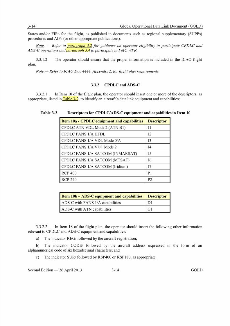
8/9/2019 CPDLC Explained
http://slidepdf.com/reader/full/cpdlc-explained 118/421
3-14 Global Operational Data Link Document (GOLD)
Second Edition — 26 April 2013 3-14 GOLD
States and/or FIRs for the flight, as published in documents such as regional supplementary (SUPPs) procedures and AIPs (or other appropriate publications).
Note.— Refer to paragraph 3.2 for guidance on operator eligibility to participate CPDLC and
ADS-C operations and paragraph 3.4 to participate in FMC WPR.
3.3.1.2 The operator should ensure that the proper information is included in the ICAO flight plan.
Note.— Refer to ICAO Doc 4444, Appendix 2, for flight plan requirements.
3.3.2 CPDLC and ADS-C
3.3.2.1 In Item 10 of the flight plan, the operator should insert one or more of the descriptors, asappropriate, listed in Table 3-2, to identify an aircraft’s data link equipment and capabilities:
Table 3-2 Descriptors for CPDLC/ADS-C equipment and capabilities in Item 10
Item 10a - CPDLC equipment and capabilities Descriptor
CPDLC ATN VDL Mode 2 (ATN B1) J1
CPDLC FANS 1/A HFDL J2
CPDLC FANS 1/A VDL Mode 0/A J3
CPDLC FANS 1/A VDL Mode 2 J4
CPDLC FANS 1/A SATCOM (INMARSAT) J5
CPDLC FANS 1/A SATCOM (MTSAT) J6
CPDLC FANS 1/A SATCOM (Iridium) J7
RCP 400 P1
RCP 240 P2
Item 10b – ADS-C equipment and capabilities Descriptor
ADS-C with FANS 1/A capabilities D1
ADS-C with ATN capabilities G1
3.3.2.2 In Item 18 of the flight plan, the operator should insert the following other informationrelevant to CPDLC and ADS-C equipment and capabilities:
a) The indicator REG/ followed by the aircraft registration;
b) The indicator CODE/ followed by the aircraft address expressed in the form of analphanumerical code of six hexadecimal characters; and
c) The indicator SUR/ followed by RSP400 or RSP180, as appropriate.
8/9/2019 CPDLC Explained
http://slidepdf.com/reader/full/cpdlc-explained 119/421

8/9/2019 CPDLC Explained
http://slidepdf.com/reader/full/cpdlc-explained 120/421
3-16 Global Operational Data Link Document (GOLD)
Second Edition — 26 April 2013 3-16 GOLD
Note.— Per ARINC 618, the flight identifier in the ACARS downlink message consists of a two
character airline identifier and a four character flight number field. Aircraft identifications such as
ABC124A (flight identification 124A) or ABC324W (flight identification 324W) cannot be encoded in the
ACARS message, therefore making FMC WPR for these flights unavailable.
3.4.1.5 Early versions of Airbus software are prone to large errors in position data. Operatorsshould ensure they have updated software before using FMC WPR.
8/9/2019 CPDLC Explained
http://slidepdf.com/reader/full/cpdlc-explained 121/421
Global Operational Data Link Document (GOLD) 4-1
GOLD 4-1 Second Edition — 26 April 2013
Chapter 4. Controller and radio operator procedures
4.1 Overview
4.1.1 General
4.1.1.1 This chapter provides guidance on procedures and recommended practices for thecontroller and the radio operator in airspace where data link services are available.
4.1.1.2 This information is intended to assist in the development of:
a) Local procedures and associated documentation; and
b) Appropriate training programs.
4.1.1.3 Controllers should be knowledgeable in the ATC automation. Refer to paragraph 3.1.2
for guidelines for implementation of ground systems supporting data link operations.
4.1.1.4 Controllers should be knowledgeable in data link operations. Refer to Chapter 2 for anoverview of data link operations.
4.1.1.5 Radio operator procedures specific to data link operations can be found in paragraphs 4.9and 4.9.3.
4.1.2 When to use voice and when to use CPDLC
4.1.2.1 When communicating with an aircraft that is operating within airspace beyond the range
of DCPC VHF voice communication, CPDLC is available and local ATC procedures do not stateotherwise, the controller should normally choose CPDLC as the means of communication. The controllerwould use voice as an alternative means of communication (e.g. VHF, HF or SATVOICE direct or via aradio operator). However, in any case, the controller will determine the appropriate communicationmedium to use at any given time.
4.1.2.2 In airspace where both DCPC VHF voice and CPDLC communication services are provided, and local ATC procedures do not state otherwise, the controller will determine the appropriatecommunication medium to use at any given time.
Note.— ICAO Doc 4444, paragraph 8.3.2, requires that DCPC be established prior to the provision
of ATS surveillance services, unless special circumstances, such as emergencies, dictate otherwise. This
does not prevent the use of CPDLC for ATC communications, voice being immediately available for
intervention and to address non-routine and time critical situations.
4.1.2.3 To minimize pilot head down time and potential distractions during critical phases offlight, the controller should use voice to communicate with aircraft operating below 10,000 ft AGL.
4.1.2.4 While the CPDLC message set, as defined in Appendix A, generally provides messageelements for common ATC communications, the controller may determine voice to be a more appropriatemeans depending on the circumstances (e.g. some types of non-routine communications).
8/9/2019 CPDLC Explained
http://slidepdf.com/reader/full/cpdlc-explained 122/421
4-2 Global Operational Data Link Document (GOLD)
Second Edition — 26 April 2013 4-2 GOLD
Note 1.— Refer to paragraph 4.8 and paragraph 4.9 for guidelines on use of voice and data
communications in emergency and non-routine situations, respectively.
Note 2.— During an emergency, the flight crew would normally revert to voice communications.
However, the flight crew may use CPDLC for emergency communications depending on the situation.
Refer to paragraph 5.8.1 for flight crew procedures on use of voice and data communications inemergency situations.
4.1.2.5 The controller should respond to a CPDLC message via CPDLC, and should respond to avoice message via voice.
4.1.2.6 If a conflicting CPDLC and voice communication is received, the controller shouldobtain clarification using voice.
4.2 CPDLC connection management and voice communication transfers
4.2.1 General
4.2.1.1 The ATSU should manage its CPDLC connections, including initiating, transferring andterminating the connection when no longer needed.
Note.— The controlling ATSU coordinates with the next ATSU, establishing clearly when or where
the address forwarding will have to occur.
4.2.1.2 An ATSU may have an active connection with an aircraft not in that ATSU’s airspace.Some examples are:
a) When the aircraft is within a non-CPDLC service area and the flight crew initiates a logon tothe next controlling ATSU which is a CPDLC service area;
b) During the CPDLC connection transfer process;
c) Where the active connection is retained by the transferring ATSU subject to prior coordination;or
d) In emergency circumstances.
4.2.1.3 Regardless of its connection status, an ATSU should never issue a clearance orinstruction to an aircraft outside its control area unless it has been coordinated with the ATSU in whoseairspace the aircraft is operating.
4.2.1.4 The ATSU should conduct any transfer of the CPDLC connection, or termination whenthe aircraft leaves CPDLC airspace, in conjunction with an instruction (CONTACT or MONITOR)
identifying the appropriate ATSU for further communication.
4.2.2 Establish CPDLC connection
Note.— See paragraph 2.2.4 for a description of CPDLC connection management.
8/9/2019 CPDLC Explained
http://slidepdf.com/reader/full/cpdlc-explained 123/421
Global Operational Data Link Document (GOLD) 4-3
GOLD 4-3 Second Edition — 26 April 2013
4.2.2.1 The first ATSU should establish a CPDLC connection if no previous CPDLC connectionexists with the aircraft.
4.2.2.2 The next ATSU should establish a CPDLC connection prior to the CDA terminating theactive CPDLC connection.
4.2.2.3 An ATSU should confirm that its CPDLC connection is active as soon as practicableafter the controller has assumed control of the aircraft, using one of the following methods:
a) For FANS 1/A, receipt of a DM 3 ROGER in response to UM 169 [free text];
b) For FANS 1/A, receipt of a DM 48 POSITION REPORT [position report], either initiated bythe flight crew or in response to UM 147 REQUEST POSITION REPORT; or
c) For ATN B1, receipt of a DM 99 CURRENT DATA AUTHORITY message; or
Note 1.— If the receiving ATSU has not confirmed its CPDLC connection as being active, the receipt
of any response to an uplink (other than DM 63 NOT CURRENT DATA AUTHORITY), or any unsolicited
downlink message, will confirm that the connection is active.
Note 2.— Refer Appendix E for regional/State differences.
4.2.3 Transfer voice communications with CPDLC connection transfer
4.2.3.1 When using CPDLC to effect voice communications transfers, the CDA should completethe voice frequency change process with the CPDLC connection transfer, as shown in Figure 4-1, usingthe CONTACT/MONITOR message elements (UM 117 through UM 122):
a) If the frequency change is to be made immediately, sending UM 117 CONTACT [unit name][frequency] or UM 120 MONITOR [unit name] [frequency] and then, as soon as possible after the receiptof the DM 0 WILCO response to the CONTACT or MONITOR message, terminate the CPDLCconnection; or
Note.— For ATN B1, the termination request message is sent as a multi-element message that
includes UM 117 or UM 120. ,while the termination confirmation is sent as a multi-element message that
includes the WILCO response. Refer to paragraph 2.2.4.8.3 for CPDLC termination.
b) If the frequency change is to be made at some time or position in the future, such as at the boundary, sending UM 118 or UM 119 AT [position/time] CONTACT [unit name] [frequency] or UM121 or UM 122 AT [position/time] MONITOR [unit name] [frequency] and then, after the receipt of theDM 0 WILCO response, terminate the CPDLC connection in accordance with interfacility agreements(See paragraph 3.1.4.8).
4.2.3.2 When using the (UM 117 through UM 122) CONTACT/MONITOR message elements,the CDA should use the facility name for the [unit name] parameter.
Note.— See Appendix F, paragraph F.9 for aircraft that do not support a <space> within the [unit
name] parameter.
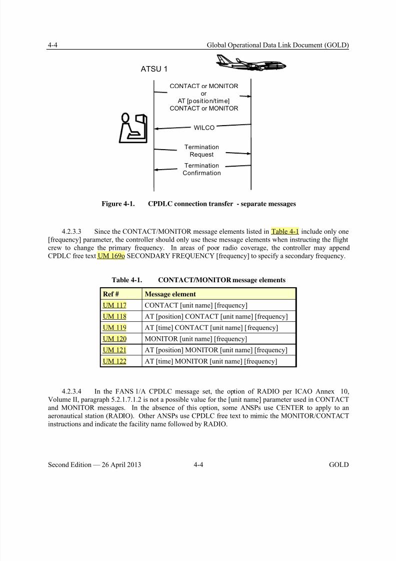
8/9/2019 CPDLC Explained
http://slidepdf.com/reader/full/cpdlc-explained 124/421
4-4 Global Operational Data Link Document (GOLD)
Second Edition — 26 April 2013 4-4 GOLD
ATSU 1
Termination
Request
Termination
Confirmation
CONTACT or MONITOR
or
AT [posit ion/t ime]
CONTACT or MONITOR
WILCO
Figure 4-1. CPDLC connection transfer - separate messages
4.2.3.3 Since the CONTACT/MONITOR message elements listed in Table 4-1 include only one[frequency] parameter, the controller should only use these message elements when instructing the flightcrew to change the primary frequency. In areas of poor radio coverage, the controller may appendCPDLC free text UM 169o SECONDARY FREQUENCY [frequency] to specify a secondary frequency.
Table 4-1. CONTACT/MONITOR message elements
Ref # Message elementUM 117 CONTACT [unit name] [frequency]
UM 118 AT [position] CONTACT [unit name] [frequency]
UM 119 AT [time] CONTACT [unit name] [frequency]
UM 120 MONITOR [unit name] [frequency]
UM 121 AT [position] MONITOR [unit name] [frequency]
UM 122 AT [time] MONITOR [unit name] [frequency]
4.2.3.4 In the FANS 1/A CPDLC message set, the option of RADIO per ICAO Annex 10,Volume II, paragraph 5.2.1.7.1.2 is not a possible value for the [unit name] parameter used in CONTACTand MONITOR messages. In the absence of this option, some ANSPs use CENTER to apply to anaeronautical station (RADIO). Other ANSPs use CPDLC free text to mimic the MONITOR/CONTACTinstructions and indicate the facility name followed by RADIO.
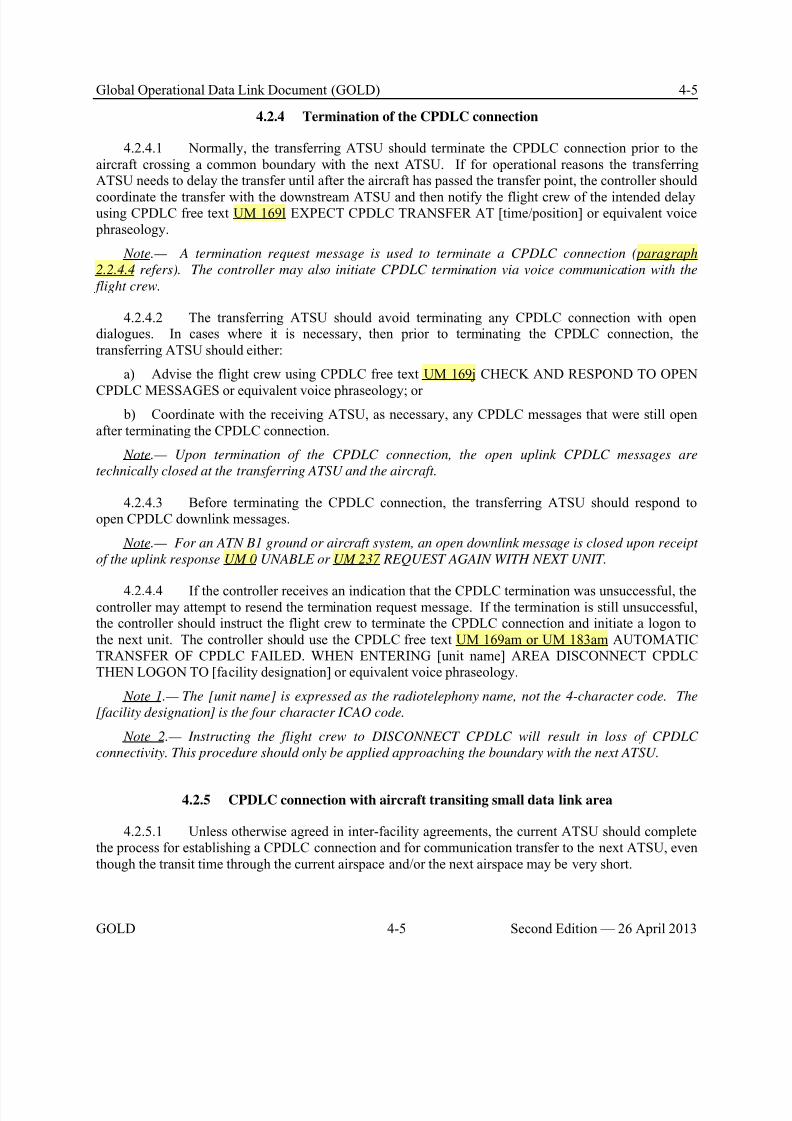
8/9/2019 CPDLC Explained
http://slidepdf.com/reader/full/cpdlc-explained 125/421
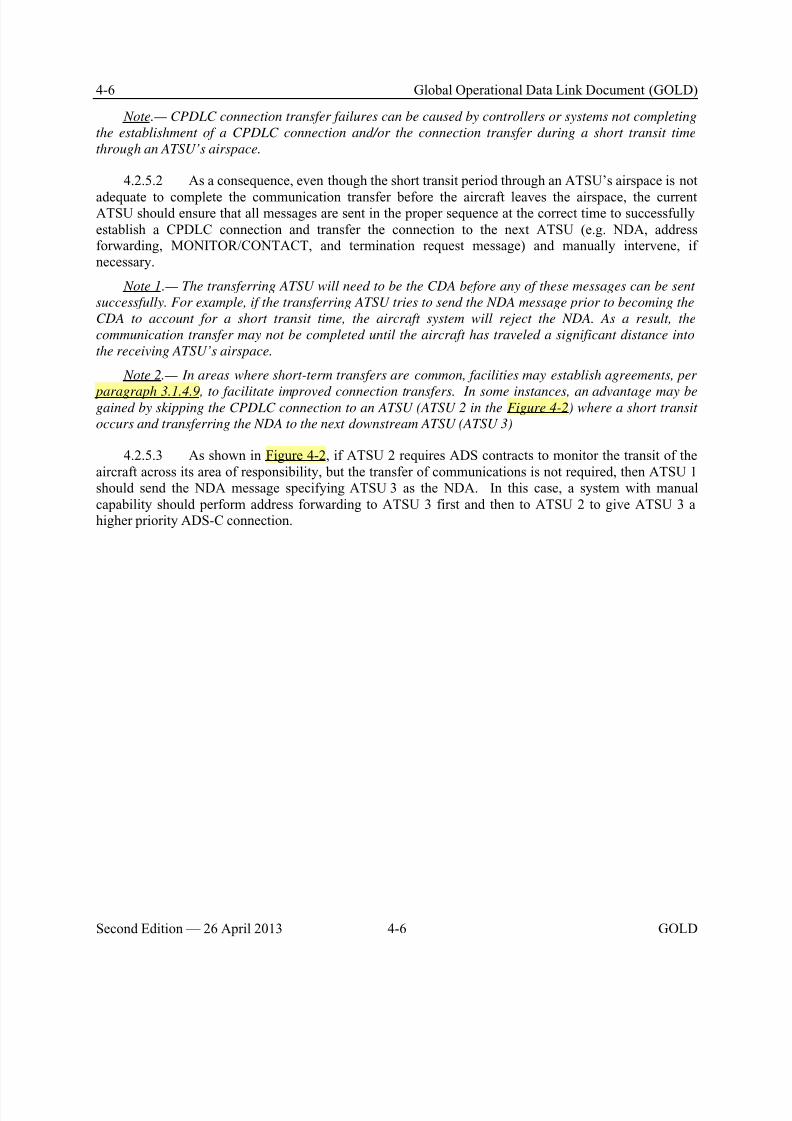
8/9/2019 CPDLC Explained
http://slidepdf.com/reader/full/cpdlc-explained 126/421
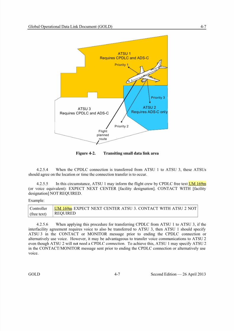
8/9/2019 CPDLC Explained
http://slidepdf.com/reader/full/cpdlc-explained 127/421
Global Operational Data Link Document (GOLD) 4-7
GOLD 4-7 Second Edition — 26 April 2013
ATSU 1
Requires CPDLC and ADS-C
ATSU 3
Requires CPDLC and ADS-C
Priority 2
ATSU 2
Requires ADS-C only
Priority 3
Flight
planned
route
Priority 1
Figure 4-2. Transiting small data link area
4.2.5.4 When the CPDLC connection is transferred from ATSU 1 to ATSU 3, these ATSUs
should agree on the location or time the connection transfer is to occur.
4.2.5.5 In this circumstance, ATSU 1 may inform the flight crew by CPDLC free text UM 169m(or voice equivalent): EXPECT NEXT CENTER [facility designation]. CONTACT WITH [facilitydesignation] NOT REQUIRED.
Example:
Controller
(free text)
UM 169m EXPECT NEXT CENTER ATSU 3. CONTACT WITH ATSU 2 NOTREQUIRED
4.2.5.6 When applying this procedure for transferring CPDLC from ATSU 1 to ATSU 3, if theinterfacility agreement requires voice to also be transferred to ATSU 3, then ATSU 1 should specifyATSU 3 in the CONTACT or MONITOR message prior to ending the CPDLC connection oralternatively use voice. However, it may be advantageous to transfer voice communications to ATSU 2even though ATSU 2 will not need a CPDLC connection. To achieve this, ATSU 1 may specify ATSU 2in the CONTACT/MONITOR message sent prior to ending the CPDLC connection or alternatively usevoice.
8/9/2019 CPDLC Explained
http://slidepdf.com/reader/full/cpdlc-explained 128/421
4-8 Global Operational Data Link Document (GOLD)
Second Edition — 26 April 2013 4-8 GOLD
4.2.5.7 If address forwarding can be manually initiated, then ATSU 1 (priority 1) should initiateaddress forwarding to ATSU 3 (priority 2) prior to initiating address forwarding to ATSU 2 (priority 3).A system that performs automatic address forwarding would normally perform the address forwarding insequence (i.e. ATSU 2 first and then ATSU 3).
Note.— The order in which the ATSU 1 performs address forwarding will ensure that the limitednumber of ADS-C connections available are used in the priority assigned to each ATSU.
4.3 CPDLC – Uplink messages
4.3.1 General
4.3.1.1 If an unexpected or inappropriate response to a CPDLC uplink message is received orthere is any misunderstanding or doubt about the intent of a CPDLC dialogue, the controller shouldinitiate voice contact to clarify the meaning or intent. (see Appendix A for intent and use of CPDLCuplink and downlink message elements).
4.3.1.2 When a closure response to an open CPDLC uplink message is not received within areasonable time period as determined by the ATSU, the controller should:
a) Continue to protect any airspace reserved by an outstanding clearance until an appropriateoperational response is received from the flight crew;
b) For a FANS 1/A ATSU, send CPDLC free text UM 169j CHECK AND RESPOND TO OPENCPDLC MESSAGES, rather than re-sending the original message. Alternatively, the controller may usevoice communication to clarify the status of the open CPDLC uplink message; or
c) For an ATN-B1 ATSU or a FANS 1/A-ATN B1 ATSU providing services to a FANS 1/Aaircraft, use voice communication to resolve the operational situation resulting from the timed outCPDLC uplink message.
Note 1.— A closure response is a response that operationally closes the dialogue. A DM 2
STANDBY response to an open CPDLC uplink message does not operationally close the dialogue.
Note 2.— The use of a CPDLC free text message by a FANS 1/A ATSU avoids multiple open
messages involving the same instruction.
Note 3.— An ATN B1 aircraft system and ground system close the uplink message after the aircraft
timer (ttr) expiration and receipt of an ERROR response. In normal circumstances, the aircraft-timer
(ttr) expires before the ground-timer (tts) expires.
Note 4.— Some FANS 1/A-ATN B1 ATSUs automatically initiate a Provider Abort (commanded
termination) message to the aircraft upon expiration of the ground timer (tts).
4.3.1.3 The controller should only use standard message elements when composing clearances orinstructions. However, circumstances may exist where the controller may use free text to supplement thestandard message elements (See paragraph 4.3.2).
Note.— The use of standard message elements will minimize the risk of input errors and
misunderstandings, and facilitate use by a non-native English speaking controllers and flight crews. The
use of standard message elements allows the aircraft and ground systems to automatically process the
information in the messages that are exchanged, which allows the flight crew to respond more quickly to
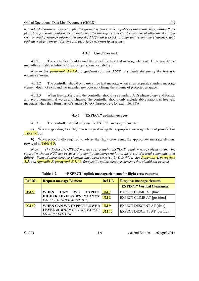
8/9/2019 CPDLC Explained
http://slidepdf.com/reader/full/cpdlc-explained 129/421
Global Operational Data Link Document (GOLD) 4-9
GOLD 4-9 Second Edition — 26 April 2013
a standard clearance. For example, the ground system can be capable of automatically updating flight
plan data for route conformance monitoring, the aircraft system can be capable of allowing the flight
crew to load clearance information into the FMS with a LOAD prompt and review the clearance, and
both aircraft and ground systems can associate responses to messages.
4.3.2 Use of free text
4.3.2.1 The controller should avoid the use of the free text message element. However, its usemay offer a viable solution to enhance operational capability.
Note.— See paragraph 3.1.1.4 for guidelines for the ANSP to validate the use of the free text
message element.
4.3.2.2 The controller should only use a free text message when an appropriate standard messageelement does not exist and the intended use does not change the volume of protected airspace.
4.3.2.3 When free text is used, the controller should use standard ATS phraseology and format
and avoid nonessential words and phrases. The controller should only include abbreviations in free textmessages when they form part of standard ICAO phraseology, for example, ETA.
4.3.3 “EXPECT” uplink messages
4.3.3.1 The controller should only use the EXPECT message elements:
a) When responding to a flight crew request using the appropriate message element provided inTable 4-2; or
b) When procedurally required to advise the flight crew using the appropriate message element provided in Table 4-3.
Note.— The FANS 1/A CPDLC message set contains EXPECT uplink message elements that the
controller should NOT use because of potential misinterpretation in the event of a total communication
failure. Some of these message elements have been reserved by Doc 4444. See Appendix A, paragraph
A.3, and Appendix E, paragraph E.7.1.3, for specific uplink message elements that should not be used.
Table 4-2. “EXPECT” uplink message elements for flight crew requests
Ref DL Request message Element Ref UL Response message element
“EXPECT” Vertical Clearances
DM 53 WHEN CAN WE EXPECT
HIGHER LEVEL or WHEN CAN WE EXPECT HIGHER ALTITUDE
UM 7 EXPECT CLIMB AT [time]
UM 8 EXPECT CLIMB AT [position]
DM 52 WHEN CAN WE EXPECT LOWERLEVEL or WHEN CAN WE EXPECT LOWER ALTITUDE
UM 9 EXPECT DESCENT AT [time]
UM 10 EXPECT DESCENT AT [position]
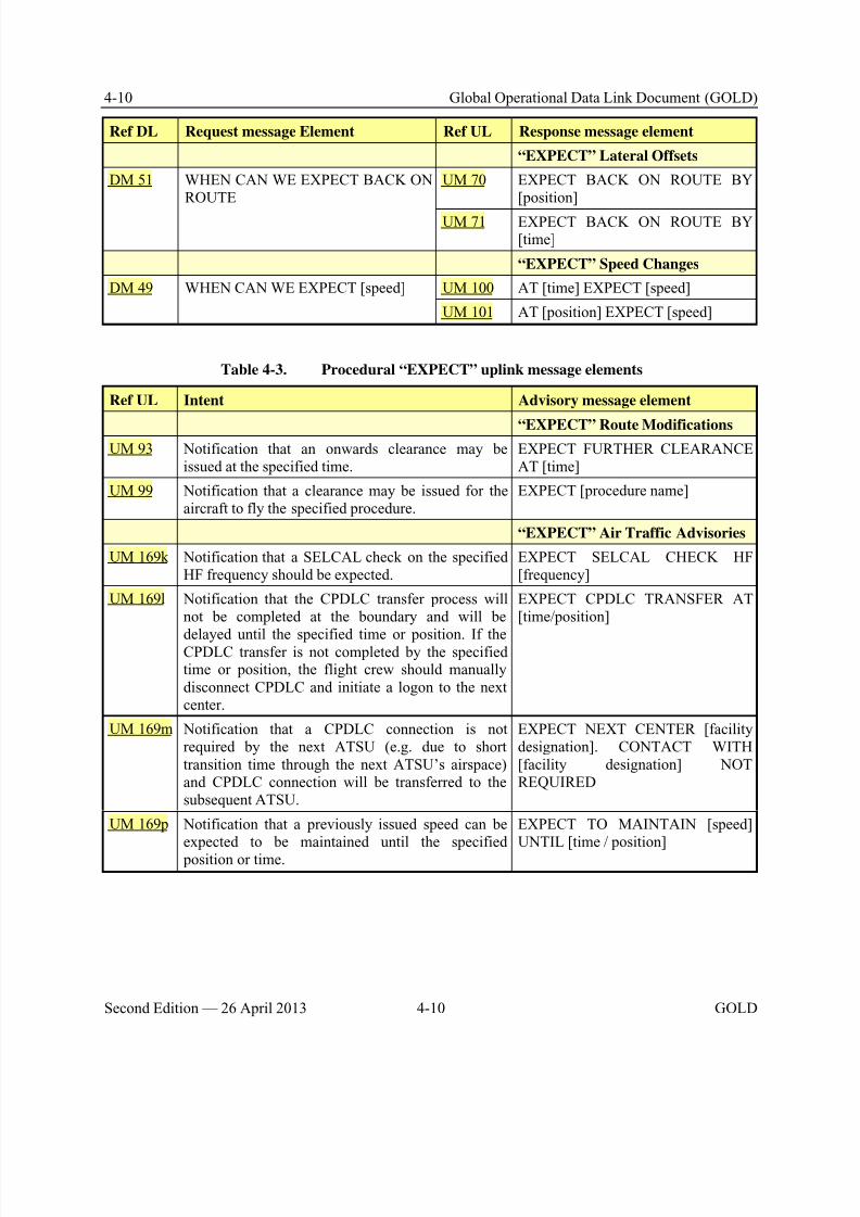
8/9/2019 CPDLC Explained
http://slidepdf.com/reader/full/cpdlc-explained 130/421
4-10 Global Operational Data Link Document (GOLD)
Second Edition — 26 April 2013 4-10 GOLD
Ref DL Request message Element Ref UL Response message element
“EXPECT” Lateral Offsets
DM 51 WHEN CAN WE EXPECT BACK ONROUTE
UM 70 EXPECT BACK ON ROUTE BY[position]
UM 71 EXPECT BACK ON ROUTE BY[time]
“EXPECT” Speed Changes
DM 49 WHEN CAN WE EXPECT [speed] UM 100 AT [time] EXPECT [speed]
UM 101 AT [position] EXPECT [speed]
Table 4-3. Procedural “EXPECT” uplink message elements
Ref UL Intent Advisory message element
“EXPECT” Route ModificationsUM 93 Notification that an onwards clearance may be
issued at the specified time.EXPECT FURTHER CLEARANCEAT [time]
UM 99 Notification that a clearance may be issued for theaircraft to fly the specified procedure.
EXPECT [procedure name]
“EXPECT” Air Traffic Advisories
UM 169k Notification that a SELCAL check on the specifiedHF frequency should be expected.
EXPECT SELCAL CHECK HF[frequency]
UM 169l Notification that the CPDLC transfer process willnot be completed at the boundary and will be
delayed until the specified time or position. If theCPDLC transfer is not completed by the specifiedtime or position, the flight crew should manuallydisconnect CPDLC and initiate a logon to the nextcenter.
EXPECT CPDLC TRANSFER AT[time/position]
UM 169m Notification that a CPDLC connection is notrequired by the next ATSU (e.g. due to shorttransition time through the next ATSU’s airspace)and CPDLC connection will be transferred to thesubsequent ATSU.
EXPECT NEXT CENTER [facilitydesignation]. CONTACT WITH[facility designation] NOTREQUIRED
UM 169p Notification that a previously issued speed can beexpected to be maintained until the specified position or time.
EXPECT TO MAINTAIN [speed]UNTIL [time / position]
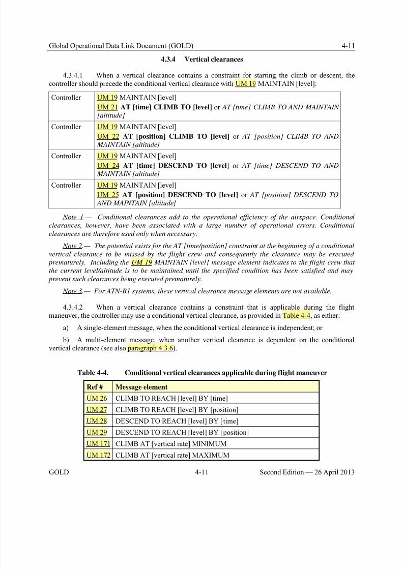
8/9/2019 CPDLC Explained
http://slidepdf.com/reader/full/cpdlc-explained 131/421
Global Operational Data Link Document (GOLD) 4-11
GOLD 4-11 Second Edition — 26 April 2013
4.3.4 Vertical clearances
4.3.4.1 When a vertical clearance contains a constraint for starting the climb or descent, thecontroller should precede the conditional vertical clearance with UM 19 MAINTAIN [level]:
Controller UM 19 MAINTAIN [level]UM 21 AT [time] CLIMB TO [level] or AT [time] CLIMB TO AND MAINTAIN
[altitude]
Controller UM 19 MAINTAIN [level]
UM 22 AT [position] CLIMB TO [level] or AT [position] CLIMB TO AND
MAINTAIN [altitude]
Controller UM 19 MAINTAIN [level]
UM 24 AT [time] DESCEND TO [level] or AT [time] DESCEND TO AND
MAINTAIN [altitude]
Controller UM 19 MAINTAIN [level]
UM 25 AT [position] DESCEND TO [level] or AT [position] DESCEND TO
AND MAINTAIN [altitude]
Note 1.— Conditional clearances add to the operational efficiency of the airspace. Conditional
clearances, however, have been associated with a large number of operational errors. Conditional
clearances are therefore used only when necessary.
Note 2.— The potential exists for the AT [time/position] constraint at the beginning of a conditional
vertical clearance to be missed by the flight crew and consequently the clearance may be executed
prematurely. Including the UM 19 MAINTAIN [level] message element indicates to the flight crew that
the current level/altitude is to be maintained until the specified condition has been satisfied and may
prevent such clearances being executed prematurely.
Note 3.— For ATN-B1 systems, these vertical clearance message elements are not available.
4.3.4.2 When a vertical clearance contains a constraint that is applicable during the flightmaneuver, the controller may use a conditional vertical clearance, as provided in Table 4-4, as either:
a) A single-element message, when the conditional vertical clearance is independent; or
b) A multi-element message, when another vertical clearance is dependent on the conditionalvertical clearance (see also paragraph 4.3.6).
Table 4-4. Conditional vertical clearances applicable during flight maneuver
Ref # Message element
UM 26 CLIMB TO REACH [level] BY [time]UM 27 CLIMB TO REACH [level] BY [position]
UM 28 DESCEND TO REACH [level] BY [time]
UM 29 DESCEND TO REACH [level] BY [position]
UM 171 CLIMB AT [vertical rate] MINIMUM
UM 172 CLIMB AT [vertical rate] MAXIMUM
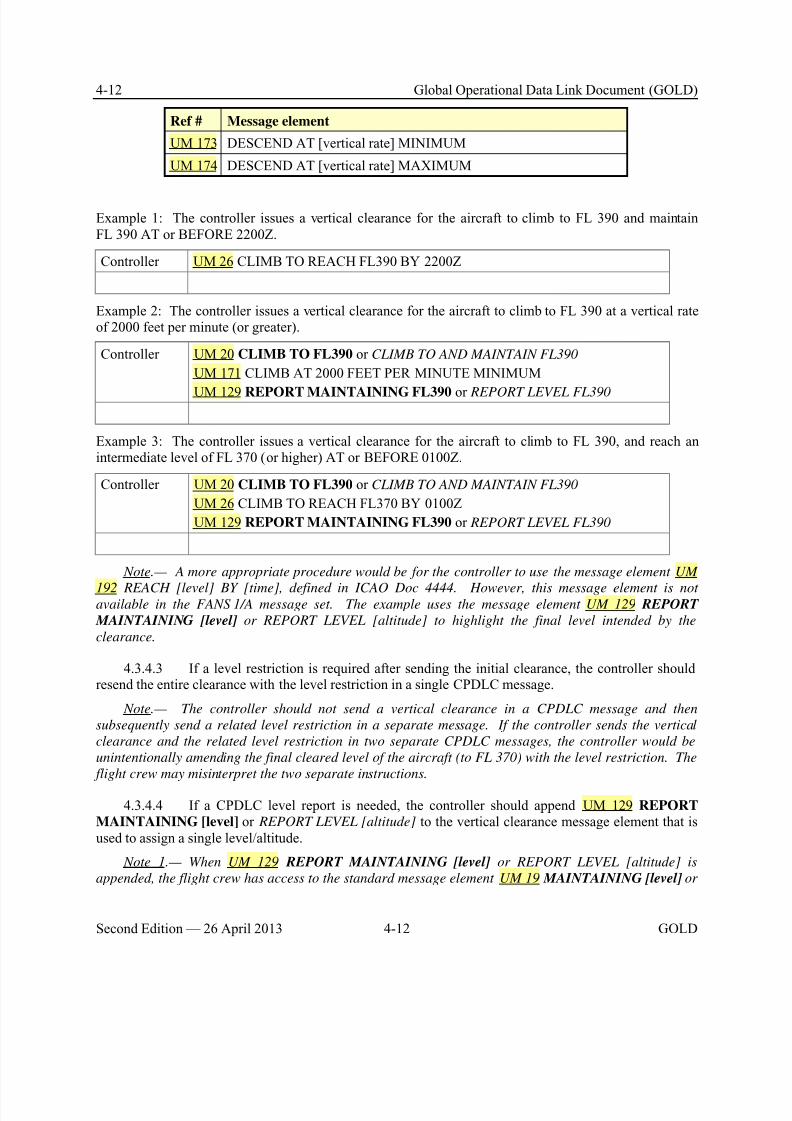
8/9/2019 CPDLC Explained
http://slidepdf.com/reader/full/cpdlc-explained 132/421
4-12 Global Operational Data Link Document (GOLD)
Second Edition — 26 April 2013 4-12 GOLD
Ref # Message element
UM 173 DESCEND AT [vertical rate] MINIMUM
UM 174 DESCEND AT [vertical rate] MAXIMUM
Example 1: The controller issues a vertical clearance for the aircraft to climb to FL 390 and maintainFL 390 AT or BEFORE 2200Z.
Controller UM 26 CLIMB TO REACH FL390 BY 2200Z
Example 2: The controller issues a vertical clearance for the aircraft to climb to FL 390 at a vertical rateof 2000 feet per minute (or greater).
Controller UM 20 CLIMB TO FL390 or CLIMB TO AND MAINTAIN FL390
UM 171 CLIMB AT 2000 FEET PER MINUTE MINIMUM
UM 129 REPORT MAINTAINING FL390 or REPORT LEVEL FL390
Example 3: The controller issues a vertical clearance for the aircraft to climb to FL 390, and reach anintermediate level of FL 370 (or higher) AT or BEFORE 0100Z.
Controller UM 20 CLIMB TO FL390 or CLIMB TO AND MAINTAIN FL390
UM 26 CLIMB TO REACH FL370 BY 0100Z
UM 129 REPORT MAINTAINING FL390 or REPORT LEVEL FL390
Note.— A more appropriate procedure would be for the controller to use the message element UM
192 REACH [level] BY [time], defined in ICAO Doc 4444. However, this message element is notavailable in the FANS 1/A message set. The example uses the message element UM 129 REPORT
MAINTAINING [level] or REPORT LEVEL [altitude] to highlight the final level intended by the
clearance.
4.3.4.3 If a level restriction is required after sending the initial clearance, the controller shouldresend the entire clearance with the level restriction in a single CPDLC message.
Note.— The controller should not send a vertical clearance in a CPDLC message and then
subsequently send a related level restriction in a separate message. If the controller sends the vertical
clearance and the related level restriction in two separate CPDLC messages, the controller would be
unintentionally amending the final cleared level of the aircraft (to FL 370) with the level restriction. The
flight crew may misinterpret the two separate instructions.
4.3.4.4 If a CPDLC level report is needed, the controller should append UM 129 REPORT
MAINTAINING [level] or REPORT LEVEL [altitude] to the vertical clearance message element that isused to assign a single level/altitude.
Note 1.— When UM 129 REPORT MAINTAINING [level] or REPORT LEVEL [altitude] is
appended, the flight crew has access to the standard message element UM 19 MAINTAINING [level] or
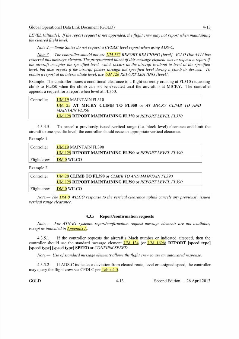
8/9/2019 CPDLC Explained
http://slidepdf.com/reader/full/cpdlc-explained 133/421
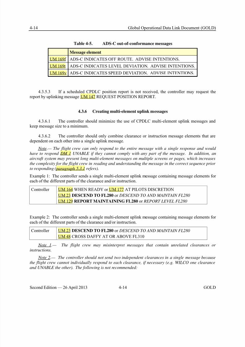
8/9/2019 CPDLC Explained
http://slidepdf.com/reader/full/cpdlc-explained 134/421
4-14 Global Operational Data Link Document (GOLD)
Second Edition — 26 April 2013 4-14 GOLD
Table 4-5. ADS-C out-of-conformance messages
Message element
UM 169f ADS-C INDICATES OFF ROUTE. ADVISE INTENTIONS.UM 169t ADS-C INDICATES LEVEL DEVIATION. ADVISE INTENTIONS.
UM 169v ADS-C INDICATES SPEED DEVIATION. ADVISE INTENTIONS.
4.3.5.3 If a scheduled CPDLC position report is not received, the controller may request thereport by uplinking message UM 147 REQUEST POSITION REPORT.
4.3.6 Creating multi-element uplink messages
4.3.6.1 The controller should minimize the use of CPDLC multi-element uplink messages andkeep message size to a minimum.
4.3.6.2 The controller should only combine clearance or instruction message elements that aredependent on each other into a single uplink message.
Note.— The flight crew can only respond to the entire message with a single response and would
have to respond DM 1 UNABLE if they cannot comply with any part of the message. In addition, an
aircraft system may present long multi-element messages on multiple screens or pages, which increases
the complexity for the flight crew in reading and understanding the message in the correct sequence prior
to responding (paragraph 5.3.1 refers).
Example 1: The controller sends a single multi-element uplink message containing message elements for
each of the different parts of the clearance and/or instruction.
Controller UM 164 WHEN READY or UM 177 AT PILOTS DISCRETION
UM 23 DESCEND TO FL280 or DESCEND TO AND MAINTAIN FL280
UM 129 REPORT MAINTAINING FL280 or REPORT LEVEL FL280
Example 2: The controller sends a single multi-element uplink message containing message elements foreach of the different parts of the clearance and/or instruction.
Controller UM 23 DESCEND TO FL280 or DESCEND TO AND MAINTAIN FL280
UM 48 CROSS DAFFY AT OR ABOVE FL310
Note 1.— The flight crew may misinterpret messages that contain unrelated clearances or
instructions.
Note 2.— The controller should not send two independent clearances in a single message because
the flight crew cannot individually respond to each clearance, if necessary (e.g. WILCO one clearance
and UNABLE the other). The following is not recommended:
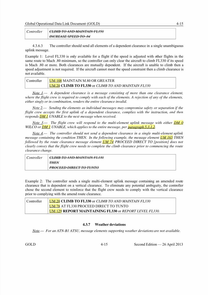
8/9/2019 CPDLC Explained
http://slidepdf.com/reader/full/cpdlc-explained 135/421
Global Operational Data Link Document (GOLD) 4-15
GOLD 4-15 Second Edition — 26 April 2013
Controller CLIMB TO AND MAINTAIN FL350
INCREASE SPEED TO .84
4.3.6.3 The controller should send all elements of a dependent clearance in a single unambiguous
uplink message.Example 1: Level FL330 is only available for a flight if the speed is adjusted with other flights in thesame route to Mach .80 minimum, so the controller can only clear the aircraft to climb FL330 if its speedis Mach .80 or more. Both clearances are mutually dependent. If the aircraft is unable to climb then aspeed adjustment is not required. If the aircraft cannot meet the speed constraint then a climb clearance isnot available.
Controller UM 108 MAINTAIN M.80 OR GREATER
UM 20 CLIMB TO FL330 or CLIMB TO AND MAINTAIN FL330
Note 1.— A dependent clearance is a message consisting of more than one clearance element,
where the flight crew is required to comply with each of the elements. A rejection of any of the elements,
either singly or in combination, renders the entire clearance invalid. Note 2.— Sending the elements as individual messages may compromise safety or separation if the
flight crew accepts the first uplink of a dependent clearance, complies with the instruction, and then
responds DM 1 UNABLE to the next message when received.
Note 3.— The flight crew will respond to the multi-element uplink message with either DM 0
WILCO or DM 1 UNABLE, which applies to the entire message, per paragraph 5.3.1.2.
Note 4.— The controller should not send a dependent clearance in a single multi-element uplink
message containing the condition THEN. In the following example, the message element UM 165 THEN
followed by the route clearance message element UM 74 PROCEED DIRECT TO [position] does not
clearly convey that the flight crew needs to complete the climb clearance prior to commencing the route
clearance change.
Controller CLIMB TO AND MAINTAIN FL330
THEN
PROCEED DIRECT TO TUNTO
Example 2: The controller sends a single multi-element uplink message containing an amended routeclearance that is dependent on a vertical clearance. To eliminate any potential ambiguity, the controllerchose the second element to reinforce that the flight crew needs to comply with the vertical clearance prior to complying with the amend route clearance.
Controller UM 20 CLIMB TO FL330 or CLIMB TO AND MAINTAIN FL330
UM 78 AT FL330 PROCEED DIRECT TO TUNTOUM 129 REPORT MAINTAINING FL330 or REPORT LEVEL FL330.
4.3.7 Weather deviations
Note.— For an ATN-B1 ATSU, message elements supporting weather deviations are not available.
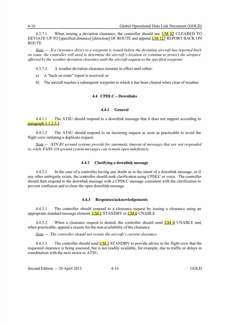
8/9/2019 CPDLC Explained
http://slidepdf.com/reader/full/cpdlc-explained 136/421
4-16 Global Operational Data Link Document (GOLD)
Second Edition — 26 April 2013 4-16 GOLD
4.3.7.1 When issuing a deviation clearance, the controller should use UM 82 CLEARED TODEVIATE UP TO [specified distance] [direction] OF ROUTE and append UM 127 REPORT BACK ONROUTE.
Note.— If a clearance direct to a waypoint is issued before the deviating aircraft has reported back
on route, the controller will need to determine the aircraft’s location or continue to protect the airspaceaffected by the weather deviation clearance until the aircraft sequences the specified waypoint.
4.3.7.2 A weather deviation clearance remains in effect until either:
a) A “back on route” report is received; or
b) The aircraft reaches a subsequent waypoint to which it has been cleared when clear of weather.
4.4 CPDLC – Downlinks
4.4.1 General
4.4.1.1 The ATSU should respond to a downlink message that it does not support according to paragraph 3.1.2.5.3.
4.4.1.2 The ATSU should respond to an incoming request as soon as practicable to avoid theflight crew initiating a duplicate request.
Note.— ATN B1 ground systems provide for automatic timeout of messages that are not responded
to, while FANS 1/A ground system messages can remain open indefinitely.
4.4.2 Clarifying a downlink message
4.4.2.1 In the case of a controller having any doubt as to the intent of a downlink message, or ifany other ambiguity exists, the controller should seek clarification using CPDLC or voice. The controllershould then respond to the downlink message with a CPDLC message consistent with the clarification to prevent confusion and to close the open downlink message.
4.4.3 Responses/acknowledgements
4.4.3.1 The controller should respond to a clearance request by issuing a clearance using anappropriate standard message element, UM 1 STANDBY or UM 0 UNABLE.
4.4.3.2 When a clearance request is denied, the controller should send UM 0 UNABLE and,
when practicable, append a reason for the non-availability of the clearance.
Note.— The controller should not restate the aircraft’s current clearance.
4.4.3.3 The controller should send UM 1 STANDBY to provide advice to the flight crew that therequested clearance is being assessed, but is not readily available, for example, due to traffic or delays incoordination with the next sector or ATSU.
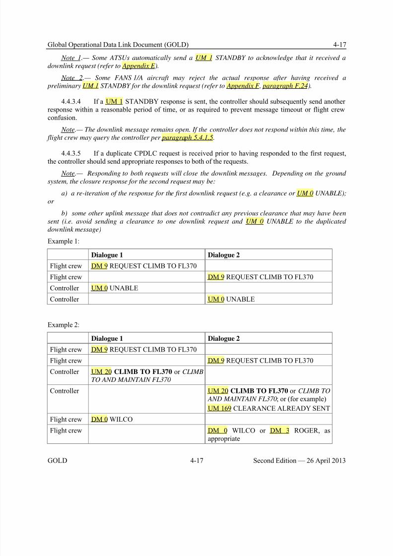
8/9/2019 CPDLC Explained
http://slidepdf.com/reader/full/cpdlc-explained 137/421
Global Operational Data Link Document (GOLD) 4-17
GOLD 4-17 Second Edition — 26 April 2013
Note 1.— Some ATSUs automatically send a UM 1 STANDBY to acknowledge that it received a
downlink request (refer to Appendix E).
Note 2.— Some FANS 1/A aircraft may reject the actual response after having received a
preliminary UM 1 STANDBY for the downlink request (refer to Appendix F, paragraph F.24).
4.4.3.4 If a UM 1 STANDBY response is sent, the controller should subsequently send anotherresponse within a reasonable period of time, or as required to prevent message timeout or flight crewconfusion.
Note.— The downlink message remains open. If the controller does not respond within this time, the
flight crew may query the controller per paragraph 5.4.1.5.
4.4.3.5 If a duplicate CPDLC request is received prior to having responded to the first request,the controller should send appropriate responses to both of the requests.
Note.— Responding to both requests will close the downlink messages. Depending on the ground
system, the closure response for the second request may be:
a) a re-iteration of the response for the first downlink request (e.g. a clearance or UM 0 UNABLE);or
b) some other uplink message that does not contradict any previous clearance that may have been
sent (i.e. avoid sending a clearance to one downlink request and UM 0 UNABLE to the duplicated
downlink message)
Example 1:
Dialogue 1 Dialogue 2
Flight crew DM 9 REQUEST CLIMB TO FL370
Flight crew DM 9 REQUEST CLIMB TO FL370
Controller UM 0 UNABLE
Controller UM 0 UNABLE
Example 2:
Dialogue 1 Dialogue 2
Flight crew DM 9 REQUEST CLIMB TO FL370
Flight crew DM 9 REQUEST CLIMB TO FL370
Controller UM 20 CLIMB TO FL370 or CLIMB
TO AND MAINTAIN FL370
Controller UM 20 CLIMB TO FL370 or CLIMB TO AND MAINTAIN FL370; or (for example)
UM 169 CLEARANCE ALREADY SENT
Flight crew DM 0 WILCO
Flight crew DM 0 WILCO or DM 3 ROGER, asappropriate
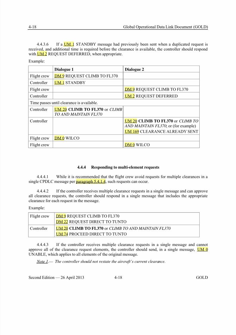
8/9/2019 CPDLC Explained
http://slidepdf.com/reader/full/cpdlc-explained 138/421
4-18 Global Operational Data Link Document (GOLD)
Second Edition — 26 April 2013 4-18 GOLD
4.4.3.6 If a UM 1 STANDBY message had previously been sent when a duplicated request isreceived, and additional time is required before the clearance is available, the controller should respondwith UM 2 REQUEST DEFERRED, when appropriate.
Example:
Dialogue 1 Dialogue 2
Flight crew DM 9 REQUEST CLIMB TO FL370
Controller UM 1 STANDBY
Flight crew DM 9 REQUEST CLIMB TO FL370
Controller UM 2 REQUEST DEFERRED
Time passes until clearance is available.
Controller UM 20 CLIMB TO FL370 or CLIMB
TO AND MAINTAIN FL370
Controller UM 20 CLIMB TO FL370 or CLIMB TO
AND MAINTAIN FL370; or (for example)
UM 169 CLEARANCE ALREADY SENT
Flight crew DM 0 WILCO
Flight crew DM 0 WILCO
4.4.4 Responding to multi-element requests
4.4.4.1 While it is recommended that the flight crew avoid requests for multiple clearances in asingle CPDLC message per paragraph 5.4.1.4, such requests can occur.
4.4.4.2 If the controller receives multiple clearance requests in a single message and can approveall clearance requests, the controller should respond in a single message that includes the appropriateclearance for each request in the message.
Example:
Flight crew DM 9 REQUEST CLIMB TO FL370
DM 22 REQUEST DIRECT TO TUNTO
Controller UM 20 CLIMB TO FL370 or CLIMB TO AND MAINTAIN FL370
UM 74 PROCEED DIRECT TO TUNTO
4.4.4.3 If the controller receives multiple clearance requests in a single message and cannotapprove all of the clearance request elements, the controller should send, in a single message, UM 0UNABLE, which applies to all elements of the original message.
Note 1.— The controller should not restate the aircraft’s current clearance.
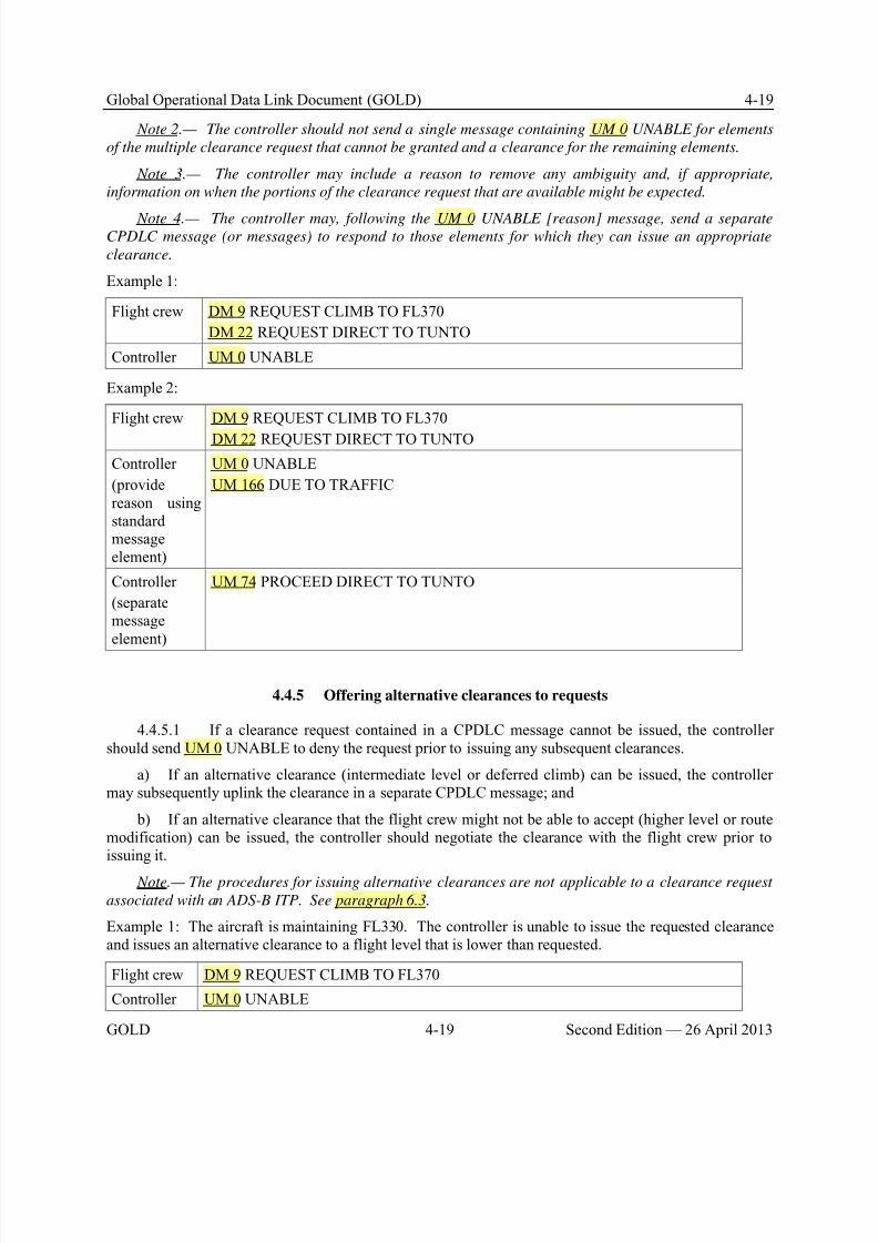
8/9/2019 CPDLC Explained
http://slidepdf.com/reader/full/cpdlc-explained 139/421
Global Operational Data Link Document (GOLD) 4-19
GOLD 4-19 Second Edition — 26 April 2013
Note 2.— The controller should not send a single message containing UM 0 UNABLE for elements
of the multiple clearance request that cannot be granted and a clearance for the remaining elements.
Note 3.— The controller may include a reason to remove any ambiguity and, if appropriate,
information on when the portions of the clearance request that are available might be expected.
Note 4.— The controller may, following the UM 0 UNABLE [reason] message, send a separateCPDLC message (or messages) to respond to those elements for which they can issue an appropriate
clearance.
Example 1:
Flight crew DM 9 REQUEST CLIMB TO FL370
DM 22 REQUEST DIRECT TO TUNTO
Controller UM 0 UNABLE
Example 2:
Flight crew DM 9 REQUEST CLIMB TO FL370
DM 22 REQUEST DIRECT TO TUNTO
Controller
(providereason usingstandardmessageelement)
UM 0 UNABLE
UM 166 DUE TO TRAFFIC
Controller
(separatemessageelement)
UM 74 PROCEED DIRECT TO TUNTO
4.4.5 Offering alternative clearances to requests
4.4.5.1 If a clearance request contained in a CPDLC message cannot be issued, the controllershould send UM 0 UNABLE to deny the request prior to issuing any subsequent clearances.
a) If an alternative clearance (intermediate level or deferred climb) can be issued, the controllermay subsequently uplink the clearance in a separate CPDLC message; and
b) If an alternative clearance that the flight crew might not be able to accept (higher level or routemodification) can be issued, the controller should negotiate the clearance with the flight crew prior toissuing it.
Note.— The procedures for issuing alternative clearances are not applicable to a clearance request
associated with an ADS-B ITP. See paragraph 6.3.
Example 1: The aircraft is maintaining FL330. The controller is unable to issue the requested clearanceand issues an alternative clearance to a flight level that is lower than requested.
Flight crew DM 9 REQUEST CLIMB TO FL370
Controller UM 0 UNABLE
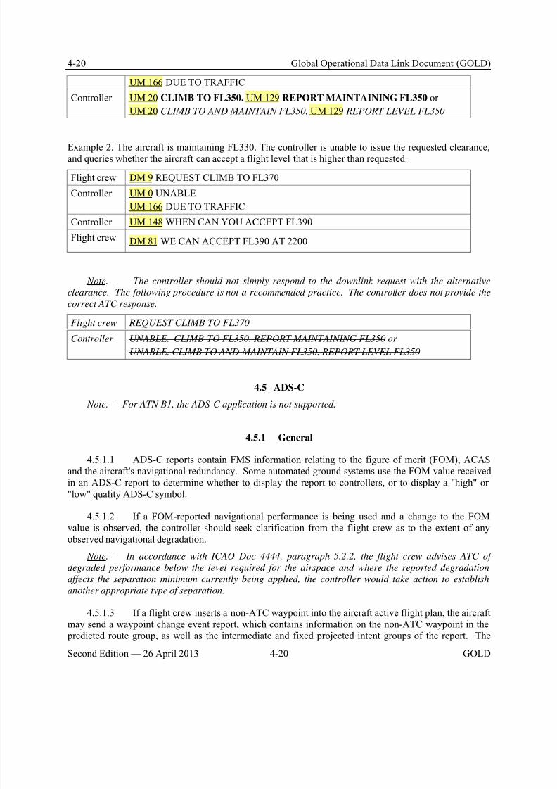
8/9/2019 CPDLC Explained
http://slidepdf.com/reader/full/cpdlc-explained 140/421
8/9/2019 CPDLC Explained
http://slidepdf.com/reader/full/cpdlc-explained 141/421
Global Operational Data Link Document (GOLD) 4-21
GOLD 4-21 Second Edition — 26 April 2013
ATSU may receive information on the next, or the next-plus-one waypoints from that report that do notcorrelate with the waypoint information provided in the current flight plan or flight data record held bythe ATSU. Refer to Appendix F, paragraph F.5 for FMS processing of waypoints on different aircrafttypes.
Note.— The flight crew normally would not insert non-ATC waypoints per paragraph 5.6.4.4.
4.5.1.4 Unless required for safety purposes, such as to monitor aircraft operating close to, but notentering its airspace, the ATSU should only establish ADS contracts for aircraft within its area ofresponsibility.
4.5.1.5 A controller who becomes aware of corrupt or incorrect data from an ADS-C reportshould establish voice contact with the aircraft concerned in order to correct the situation.
4.5.1.6 When an ATSU is using both ADS-C and CPDLC position reporting and detects adiscrepancy of 2 minutes or less between the reports, the controller should reconcile the time difference.Where the time difference is more than 2 minutes, the controller should request confirmation of theestimate for the waypoint in question.
Note.— CPDLC and ADS-C estimates received from the same aircraft for the same position may
differ as a result of the ADS-C application reporting time to the second and the time reported by CPDLC
application either being truncated or rounded to the nearest full minute (depending on aircraft type). The
flight crew also has the ability to modify the estimate for the next position in the CPDLC position report.
Any such modification will not be reflected in the ADS-C report.
4.5.1.7 Whenever an ADS-C report (either a periodic or waypoint change event report) is notreceived within a parameter of the expected time, the controller should ascertain the position of theaircraft by initiating a demand contract request, re-establish a new periodic contract with the aircraft, orrequest a CPDLC or voice position report.
4.5.1.8 When the application of specified separation minima is dependent on the reportinginterval of periodic position reports, the ATC unit should only establish a periodic contract with areporting interval less than the required reporting interval.
4.5.1.9 If the controller becomes aware of a data link communications failure, the controllershould advise affected aircraft to revert to voice position reporting in accordance with paragraph 4.9.3.
4.5.2 ADS contracts
4.5.2.1 In airspace where procedural separation is being applied, the ATSU should establish thefollowing:
a) ADS periodic contract at an interval appropriate to the airspace requirements; and b) ADS event contract for the following events:
1) Waypoint change event;
2) Lateral deviation event;
3) Level range deviation event; and
4) Vertical rate change event of negative 5000 feet per minute (descent rate).
8/9/2019 CPDLC Explained
http://slidepdf.com/reader/full/cpdlc-explained 142/421
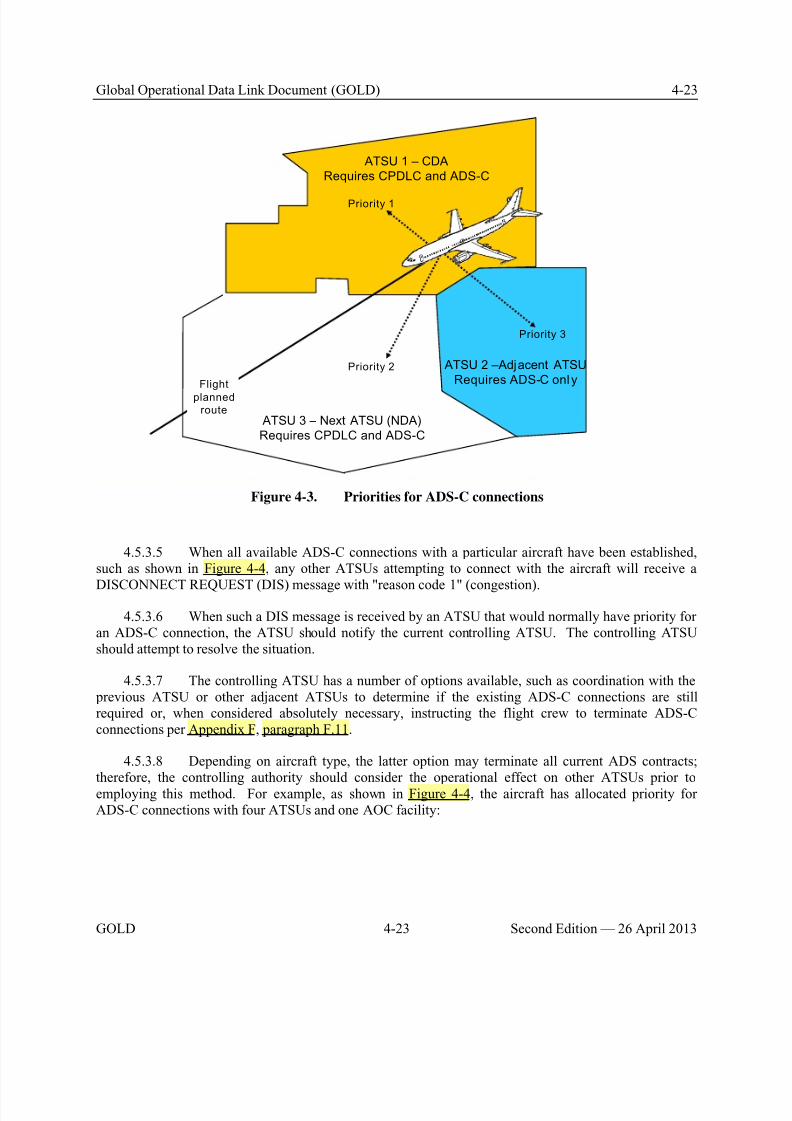
8/9/2019 CPDLC Explained
http://slidepdf.com/reader/full/cpdlc-explained 143/421
Global Operational Data Link Document (GOLD) 4-23
GOLD 4-23 Second Edition — 26 April 2013
ATSU 1 – CDA
Requires CPDLC and ADS-C
ATSU 3 – Next ATSU (NDA)
Requires CPDLC and ADS-C
Priority 1
ATSU 2 –Adjacent ATSU
Requires ADS-C onlyFlight
planned
route
Priority 2
Priority 3
Figure 4-3. Priorities for ADS-C connections
4.5.3.5 When all available ADS-C connections with a particular aircraft have been established,such as shown in Figure 4-4, any other ATSUs attempting to connect with the aircraft will receive a
DISCONNECT REQUEST (DIS) message with "reason code 1" (congestion).
4.5.3.6 When such a DIS message is received by an ATSU that would normally have priority foran ADS-C connection, the ATSU should notify the current controlling ATSU. The controlling ATSUshould attempt to resolve the situation.
4.5.3.7 The controlling ATSU has a number of options available, such as coordination with the previous ATSU or other adjacent ATSUs to determine if the existing ADS-C connections are stillrequired or, when considered absolutely necessary, instructing the flight crew to terminate ADS-Cconnections per Appendix F, paragraph F.11.
4.5.3.8 Depending on aircraft type, the latter option may terminate all current ADS contracts;therefore, the controlling authority should consider the operational effect on other ATSUs prior toemploying this method. For example, as shown in Figure 4-4, the aircraft has allocated priority forADS-C connections with four ATSUs and one AOC facility:
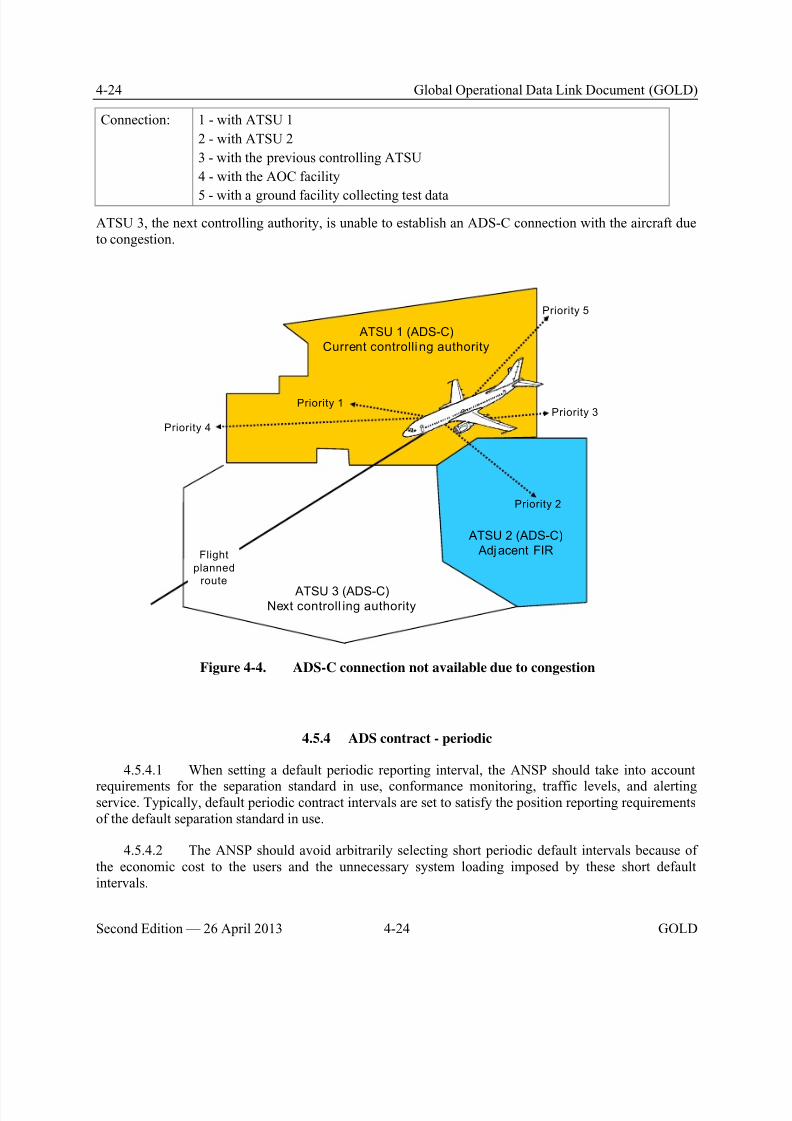
8/9/2019 CPDLC Explained
http://slidepdf.com/reader/full/cpdlc-explained 144/421
4-24 Global Operational Data Link Document (GOLD)
Second Edition — 26 April 2013 4-24 GOLD
Connection: 1 - with ATSU 1
2 - with ATSU 2
3 - with the previous controlling ATSU
4 - with the AOC facility
5 - with a ground facility collecting test data
ATSU 3, the next controlling authority, is unable to establish an ADS-C connection with the aircraft dueto congestion.
ATSU 1 (ADS-C)
Current controlli ng authority
ATSU 3 (ADS-C)Next controll ing authority
ATSU 2 (ADS-C)
Adjacent FIRFlight
planned
route
Priority 1
Priority 2
Priority 3
Priority 4
Priority 5
Figure 4-4. ADS-C connection not available due to congestion
4.5.4 ADS contract - periodic
4.5.4.1 When setting a default periodic reporting interval, the ANSP should take into account
requirements for the separation standard in use, conformance monitoring, traffic levels, and alertingservice. Typically, default periodic contract intervals are set to satisfy the position reporting requirementsof the default separation standard in use.
4.5.4.2 The ANSP should avoid arbitrarily selecting short periodic default intervals because ofthe economic cost to the users and the unnecessary system loading imposed by these short defaultintervals.
8/9/2019 CPDLC Explained
http://slidepdf.com/reader/full/cpdlc-explained 145/421
Global Operational Data Link Document (GOLD) 4-25
GOLD 4-25 Second Edition — 26 April 2013
4.5.4.3 There are a number of situations where a controller or ground automation may use areporting interval other than the default interval in the periodic contract. A change to the default intervalfor an aircraft may be warranted or useful when:
a) The aircraft is cleared to deviate from areas of known significant weather;
b) The application of a smaller separation standard requires a shorter periodic interval;
c) There are periods of turbulence;
d) An unauthorized deviation from the clearance is detected; or
e) The aircraft is approaching a crossing route on which there is other traffic.
4.5.4.4 The ANSP should ensure that the periodic reporting interval in use is in accordance withthe position reporting requirements of the separation standard being used. In some circumstances, such asan emergency situation, the ATSU may establish a shorter periodic reporting interval. When not requiredfor the application of separation, or other circumstances, the ANSP should return to a longer periodicreporting interval to reduce operators costs and unnecessary loading of the system.
Note.— Normally, the controlling ATSU should not establish ADS-C periodic reporting at aninterval shorter than five minutes. An adjacent non-controlling ATSU should not establish ADS-C
periodic reporting at an interval shorter than what is required for application of any reduced separation
in effect for the flight. In unusual circumstances, the ATSU may specify a periodic reporting interval for
a few aircraft as short as 64 seconds, per paragraph 2.2.6.3.3.2.
4.5.5 ADS contract - waypoint change event
4.5.5.1 A waypoint event report will be sent at any waypoint contained in the aircraft activeflight plan, which may include compulsory and non-compulsory reporting points. These waypoints arereflected in the predicted route group.
4.5.6 ADS contract - vertical range change and lateral deviation events
4.5.6.1 When the level range deviation event and lateral deviation event contracts areestablished, the controller will only be alerted to vertical or lateral variations that exceed the associatedtolerances.
Note.— If a regular periodic report is sent as the aircraft is deviating from cleared level or route
(but still within the level or lateral tolerances) the controller will still be alerted to the variation despite
no event report having been sent.
4.6 Separation
4.6.1 General – ADS-C
4.6.1.1 The ATSU may use ADS-C for the application of procedural separation within a mixedenvironment, such as airspace where position reports are provided by a mixture of aircraft reporting byADS-C and aircraft reporting by other means.
8/9/2019 CPDLC Explained
http://slidepdf.com/reader/full/cpdlc-explained 146/421
4-26 Global Operational Data Link Document (GOLD)
Second Edition — 26 April 2013 4-26 GOLD
4.6.1.2 For example, the ATSU may use a combination of ADS-C, voice reports, radar orADS-B information to determine separation between two or more aircraft.
4.6.1.3 When ADS-C is used for route conformance monitoring to support the separation, theATSU should establish appropriate ADS contracts that specify the periodic reporting interval and
tolerances on events in accordance with separation standards.
Note.— This will ensure that estimates being used for route conformance monitoring are acceptable
for the separation and the controller receives an indication when the aircraft is not in conformance with
its current flight plan.
4.6.1.4 The controller should advise the flight crew when the controller observes that the aircrafthas deviated significantly from its cleared flight profile. The controller should take action as appropriate ifthe deviation is likely to affect the air traffic service being provided.
4.6.2 Vertical separation –ADS-C
4.6.2.1 Where practical, the tolerances used to determine whether a specific level is occupied byan ADS-C reporting aircraft within the airspace of a specific ATSU should be consistent with othertolerances used throughout the airspace. For example, the vertical tolerances for ADS-C should beconsistent with vertical tolerances used for level adherence monitoring by other forms of surveillance,such as radar.
4.6.2.2 Where other vertical tolerances do not exist, the ATSU should apply a vertical toleranceof +/– 300 feet for ADS-C applications. However, an individual ATSU may specify in local instructionsand the AIP (or other appropriate publication) that it uses a tolerance of not less than +/– 200 feet to provide consistency with other vertical tolerances applied within its airspace.
4.6.2.3 If displayed ADS-C level information does not satisfy the required tolerance for an
individual ATSU, then the controller should advise the flight crew accordingly and request confirmationof the aircraft's level. If following confirmation of the level, the displayed ADS-C level information isstill beyond the required tolerance, the controller may need to apply another method of separation oranother method of determining level information.
4.6.2.4 When displayed ADS-C level information is within the specified tolerance of theexpected or cleared flight level, the ATSU may use the ADS-C level information to apply verticalseparation and to determine that an aircraft has reached or is maintaining a specified level.
4.6.2.5 The controller can consider that an aircraft has left a specified level when the displayedADS-C level information indicates that the aircraft has passed the level in the required direction by morethan the required tolerance.
4.6.3 Lateral separation – ADS-C
4.6.3.1 An ATSU can use ADS-C report information to automatically detect when an aircraft is beyond an area of lateral conflict and provide an indication when this occurs to the controller.
8/9/2019 CPDLC Explained
http://slidepdf.com/reader/full/cpdlc-explained 147/421
Global Operational Data Link Document (GOLD) 4-27
GOLD 4-27 Second Edition — 26 April 2013
4.6.3.2 When conflict detection tools are not available, the controller can determine lateralconflicts by observing the ADS-C report information and determining if the aircraft is within or outsidethe area of conflict.
Note.— The adequacy of the procedures used to detect lateral conflicts is a matter of the State.
4.6.4 Longitudinal separation – ADS-C
4.6.4.1 ATSUs that use approved or integrated measurement tools for the purpose of determiningscreen-based separation should publish in local documentation any limitations on the use of such tools forthe establishment and monitoring of separation standards.
4.6.4.2 The ATSU may use ADS-C reports to establish and monitor longitudinal time anddistance separation standards.
4.6.4.3 Some ground systems display an extrapolated or interpolated ADS-C symbol between thereceipt of ADS-C reports. Provided that the periodic reporting interval in use is in accordance with any
maximum reporting interval specified by the separation standard, the ATSU may determine separation between the extrapolated/interpolated symbols by the use of screen-based measurement tools, or by theuse of automated conflict detection tools.
4.6.4.4 When the ATSU uses extrapolated or interpolated ADS-C symbols to provide separationand any doubt exists as to the integrity or validity of the information being presented, the controllershould send a demand contract to update the relevant information. If doubt still exists, the controllershould consider using an alternative method of separation.
4.6.4.5 The ATSU may use ground system flight data records updated by ADS-C reports in theapplication of appropriate time-based separation standards. Methods of determination may includereference to:
a) Estimates at waypoints;
b) Calculated estimates for positions not contained in the flight plan;
c) Screen-based measurement tools; or
d) Automated conflict detection tools.
4.6.4.6 The ATSU may use ADS-C reports for the application of appropriate longitudinaldistance standards. Methods of determination may include:
a) The use of automated system tools to measure the displayed positions of two or more aircraftreporting by ADS-C;
b) Comparing the displayed position of an ADS-C aircraft with the position of another aircraftdetermined by an alternative form of surveillance; or
c) The use of automated conflict detection tools.
8/9/2019 CPDLC Explained
http://slidepdf.com/reader/full/cpdlc-explained 148/421
4-28 Global Operational Data Link Document (GOLD)
Second Edition — 26 April 2013 4-28 GOLD
4.6.5 Using FMC WPR for position reporting
4.6.5.1 Whenever an FMC waypoint position report is overdue by more than a specific interval,as determined by ATC, the controller should take action to advise the aircraft concerned and request avoice position report. If either the flight crew or the controller notices intermittent operation, either may
revert to voice reporting at any time. (The flight crew would be expected to report by voice for theremainder of the flight.)
4.6.5.2 A controller who becomes aware of corrupt or incorrect data in the FMC waypoint position report should establish voice contact with the aircraft concerned in order to correct the situation.
4.6.5.3 A controller who becomes aware of a FMC WPR service failure should advise affectedaircraft to revert to voice position reporting in accordance with paragraph 4.9.3.
4.7 Alerting service
4.7.1 For ADS-C aircraft, the ATSU should base the provision of the alerting service on anymissed scheduled report (i.e. provided by either the periodic contract or the waypoint event contract).
4.8 Emergency procedures
4.8.1 General
4.8.1.1 The flight crew will use whatever means are appropriate (i.e. CPDLC and/or voice) tocommunicate during an emergency.
Note.— For ATN B1 aircraft, emergency message elements are not supported. See Appendix A,
paragraph A.4, for a list of emergency message elements.
4.8.1.2 When emergency situations are communicated via CPDLC, the controller may respondvia CPDLC. However, the controller may also attempt to make voice contact with the aircraft.
4.8.1.3 The controller should follow normal emergency response procedures, as appropriate,depending on the nature of the emergency.
4.8.2 CPDLC and ADS-C emergency
4.8.2.1 If the ATSU receives an ADS-C emergency report without a corresponding CPDLCemergency message, then the controller should request confirmation of the emergency in accordance withthe guidelines provided in paragraph 4.8.3.
4.8.2.2 The controller should treat any CPDLC downlink message that contains an emergencymessage element (see Appendix A, paragraph A.4 for the list of emergency message elements) as anemergency message.

8/9/2019 CPDLC Explained
http://slidepdf.com/reader/full/cpdlc-explained 149/421
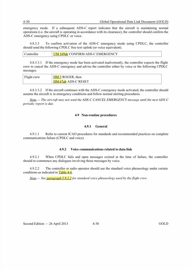
8/9/2019 CPDLC Explained
http://slidepdf.com/reader/full/cpdlc-explained 150/421
4-30 Global Operational Data Link Document (GOLD)
Second Edition — 26 April 2013 4-30 GOLD
emergency mode. If a subsequent ADS-C report indicates that the aircraft is maintaining normaloperations (i.e. the aircraft is operating in accordance with its clearance), the controller should confirm theADS-C emergency using CPDLC or voice.
4.8.3.3 To confirm activation of the ADS-C emergency mode using CPDLC, the controller
should send the following CPDLC free text uplink (or voice equivalent).
Controller UM 169ak CONFIRM ADS-C EMERGENCY
4.8.3.3.1 If the emergency mode has been activated inadvertently, the controller expects the flightcrew to cancel the ADS-C emergency and advise the controller either by voice or the following CPDLCmessages.
Flight crew DM 3 ROGER, then
DM 67ab ADS-C RESET
4.8.3.3.2 If the aircraft continues with the ADS-C emergency mode activated, the controller should
assume the aircraft is in emergency conditions and follow normal alerting procedures. Note.— The aircraft may not send the ADS-C CANCEL EMERGENCY message until the next ADS-C
periodic report is due.
4.9 Non-routine procedures
4.9.1 General
4.9.1.1 Refer to current ICAO procedures for standards and recommended practices on completecommunications failure (CPDLC and voice).
4.9.2 Voice communications related to data link
4.9.2.1 When CPDLC fails and open messages existed at the time of failure, the controllershould re-commence any dialogues involving those messages by voice.
4.9.2.2 The controller or radio operator should use the standard voice phraseology under certainconditions as indicated in Table 4-6.
Note.— See paragraph 5.9.2.2 for standard voice phraseology used by the flight crew.
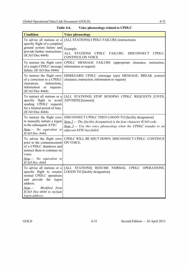
8/9/2019 CPDLC Explained
http://slidepdf.com/reader/full/cpdlc-explained 151/421
Global Operational Data Link Document (GOLD) 4-31
GOLD 4-31 Second Edition — 26 April 2013
Table 4-6. Voice phraseology related to CPDLC
Condition Voice phraseology
To advise all stations or aspecific flight of a complete
ground system failure and provide further instructions.(ICAO Doc 4444)
[ALL STATIONS] CPDLC FAILURE (instructions).
Example:
ALL STATIONS CPDLC FAILURE. DISCONNECT CPDLC.CONTINUE ON VOICE
To instruct the flight crewof a single CPDLC messagefailure. (ICAO Doc 4444)
CPDLC MESSAGE FAILURE (appropriate clearance, instruction,information or request)
To instruct the flight crewof a correction to a CPDLCclearances, instructions,information or requests.(ICAO Doc 4444)
DISREGARD CPDLC (message type) MESSAGE, BREAK (correctclearance, instruction, information or request)
To instruct all stations or aspecific flight to avoidsending CPDLC requestsfor a limited period of time.(ICAO Doc 4444)
[ALL STATIONS] STOP SENDING CPDLC REQUESTS [UNTILADVISED] [(reason)]
To instruct the flight crewto manually initiate a logonto the subsequent ATSU
Note.— No equivalent to
ICAO Doc 4444.
DISCONNECT CPDLC THEN LOGON TO [facility designation]
Note 1.— The [facility designation] is the four character ICAO code.
Note 2.— Use this voice phraseology when the CPDLC transfer to an
adjacent ATSU has failed.
To advise the flight crew prior to the commencementof a CPDLC shutdown andinstruct them to continue onvoice.
Note.— No equivalent to
ICAO Doc 4444.
CPDLC WILL BE SHUT DOWN. DISCONNECT CPDLC. CONTINUEON VOICE.
To advise all stations or aspecific flight to resumenormal CPDLC operationsand provide the logonaddress.
Note.— Modified from ICAO Doc-4444 to include
logon address.
[ALL STATIONS] RESUME NORMAL CPDLC OPERATIONS.LOGON TO [facility designation]
8/9/2019 CPDLC Explained
http://slidepdf.com/reader/full/cpdlc-explained 152/421
4-32 Global Operational Data Link Document (GOLD)
Second Edition — 26 April 2013 4-32 GOLD
4.9.3 Data link initiation failure
4.9.3.1 In the event of a log on failure by an aircraft in or approaching an ATSU’s airspace, andwhen a flight plan is available, the ATSU should check that the aircraft identification and aircraftregistration or address, as well as other details contained in the data link initiation request, correspond
with details in the flight plan.
Note.— In the case of FANS 1/A, the geographic position of the aircraft at the time of initiating the
logon is contained in the logon request message.
4.9.3.1.1 If initiation request details differ from the flight plan details, the controller should contactthe flight crew to resolve differences between the aircraft details and the flight plan and make theappropriate changes in either the flight plan or the aircraft; and then arrange a re-initiation of the logon process by the flight crew.
4.9.3.1.2 If initiation request details match the flight plan details but the flight is not eligible for logon at this time, the controller should contact the flight crew to arrange a re-initiation of the logon processat an appropriate time.
4.9.3.2 In the event of a log on failure by an aircraft in or approaching an ATSU’s airspace, and,when no flight plan is available, the controller should:
a) If possible, contact the flight crew to obtain sufficient flight plan data to enable a successful logon; and then
b) Arrange a re-initiation of the logon process.
4.9.3.3 The ANSP should ensure that procedures are in place to notify the appropriateState/regional monitoring agency via a problem report of the failure.(paragraph 3.2.2 refers)
Note.— When it can be determined that the log on is inappropriate, no action is required.
4.9.4 Data link service failures
4.9.4.1 CPDLC connection failure
4.9.4.1.1 If a CPDLC dialogue is interrupted by a data link service failure, the controller should re-commence the entire dialogue by voice communication.
4.9.4.1.2 When the controller recognizes a failure of the CPDLC connection, the controller shouldinstruct the flight crew to terminate the connection and then initiate another logon. The controller or radiooperator should use the following voice phraseology:
Controller(or radio operator)
CPDLC FAILURE.DISCONNECT CPDLC THEN LOGON TO [facility designation]
Flight crew ROGER
Note.— The [facility designation] is the 4 character ICAO code.
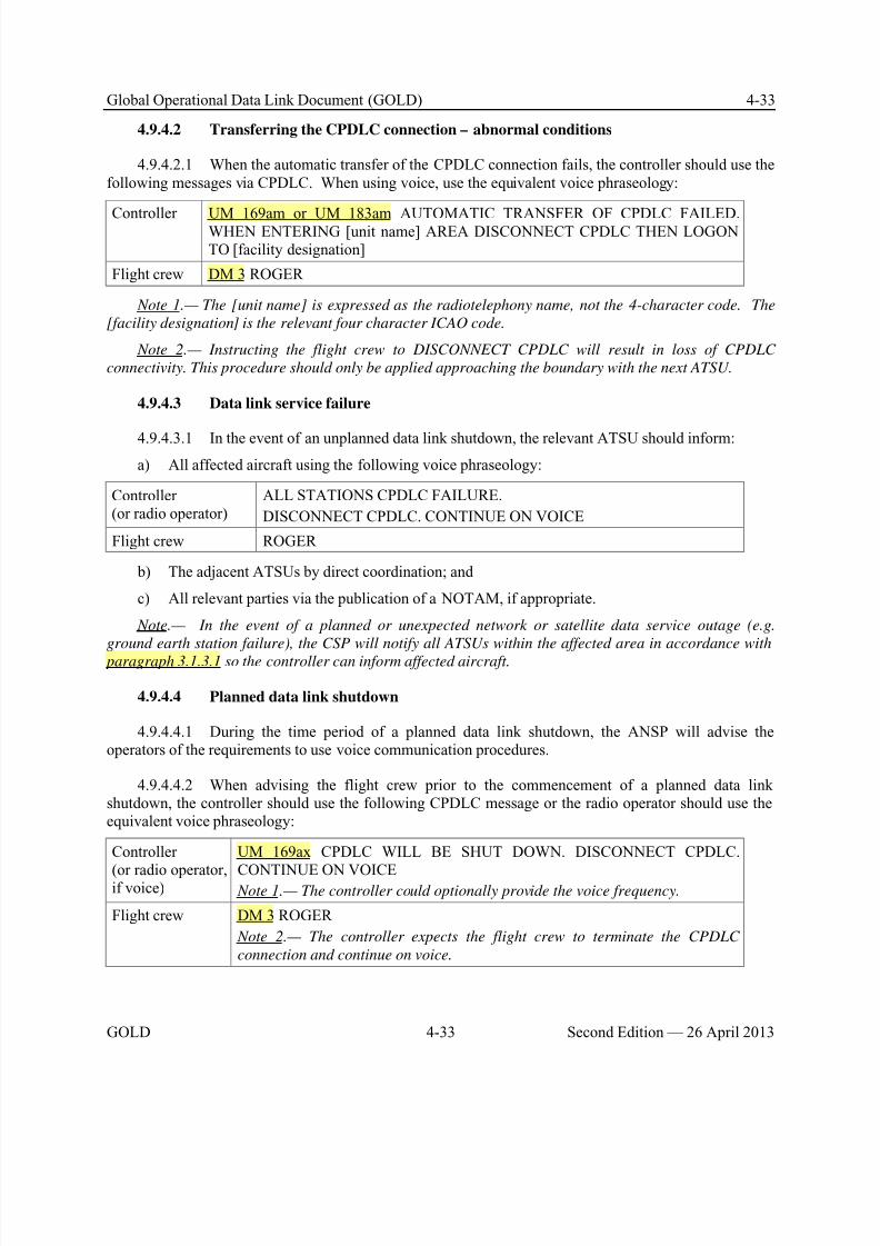
8/9/2019 CPDLC Explained
http://slidepdf.com/reader/full/cpdlc-explained 153/421
Global Operational Data Link Document (GOLD) 4-33
GOLD 4-33 Second Edition — 26 April 2013
4.9.4.2 Transferring the CPDLC connection – abnormal conditions
4.9.4.2.1 When the automatic transfer of the CPDLC connection fails, the controller should use thefollowing messages via CPDLC. When using voice, use the equivalent voice phraseology:
Controller UM 169am or UM 183am AUTOMATIC TRANSFER OF CPDLC FAILED.WHEN ENTERING [unit name] AREA DISCONNECT CPDLC THEN LOGONTO [facility designation]
Flight crew DM 3 ROGER
Note 1.— The [unit name] is expressed as the radiotelephony name, not the 4-character code. The
[facility designation] is the relevant four character ICAO code.
Note 2.— Instructing the flight crew to DISCONNECT CPDLC will result in loss of CPDLC
connectivity. This procedure should only be applied approaching the boundary with the next ATSU.
4.9.4.3 Data link service failure
4.9.4.3.1 In the event of an unplanned data link shutdown, the relevant ATSU should inform:
a) All affected aircraft using the following voice phraseology:
Controller(or radio operator)
ALL STATIONS CPDLC FAILURE.
DISCONNECT CPDLC. CONTINUE ON VOICE
Flight crew ROGER
b) The adjacent ATSUs by direct coordination; and
c) All relevant parties via the publication of a NOTAM, if appropriate.
Note.— In the event of a planned or unexpected network or satellite data service outage (e.g.
ground earth station failure), the CSP will notify all ATSUs within the affected area in accordance with
paragraph 3.1.3.1 so the controller can inform affected aircraft.
4.9.4.4 Planned data link shutdown
4.9.4.4.1 During the time period of a planned data link shutdown, the ANSP will advise theoperators of the requirements to use voice communication procedures.
4.9.4.4.2 When advising the flight crew prior to the commencement of a planned data linkshutdown, the controller should use the following CPDLC message or the radio operator should use theequivalent voice phraseology:
Controller
(or radio operator,if voice)
UM 169ax CPDLC WILL BE SHUT DOWN. DISCONNECT CPDLC.
CONTINUE ON VOICE Note 1.— The controller could optionally provide the voice frequency.
Flight crew DM 3 ROGER
Note 2.— The controller expects the flight crew to terminate the CPDLC
connection and continue on voice.
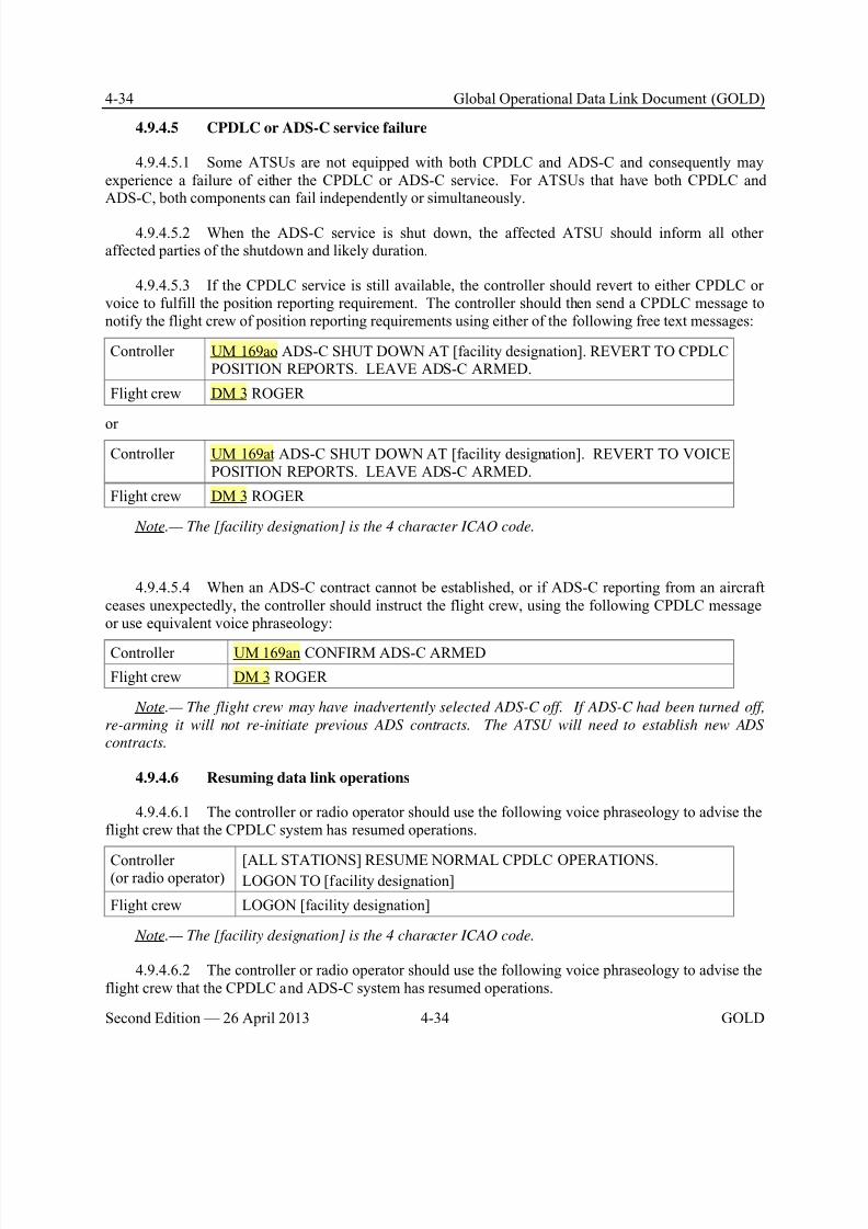
8/9/2019 CPDLC Explained
http://slidepdf.com/reader/full/cpdlc-explained 154/421
4-34 Global Operational Data Link Document (GOLD)
Second Edition — 26 April 2013 4-34 GOLD
4.9.4.5 CPDLC or ADS-C service failure
4.9.4.5.1 Some ATSUs are not equipped with both CPDLC and ADS-C and consequently mayexperience a failure of either the CPDLC or ADS-C service. For ATSUs that have both CPDLC andADS-C, both components can fail independently or simultaneously.
4.9.4.5.2 When the ADS-C service is shut down, the affected ATSU should inform all otheraffected parties of the shutdown and likely duration.
4.9.4.5.3 If the CPDLC service is still available, the controller should revert to either CPDLC orvoice to fulfill the position reporting requirement. The controller should then send a CPDLC message tonotify the flight crew of position reporting requirements using either of the following free text messages:
Controller UM 169ao ADS-C SHUT DOWN AT [facility designation]. REVERT TO CPDLCPOSITION REPORTS. LEAVE ADS-C ARMED.
Flight crew DM 3 ROGER
orController UM 169at ADS-C SHUT DOWN AT [facility designation]. REVERT TO VOICE
POSITION REPORTS. LEAVE ADS-C ARMED.
Flight crew DM 3 ROGER
Note.— The [facility designation] is the 4 character ICAO code.
4.9.4.5.4 When an ADS-C contract cannot be established, or if ADS-C reporting from an aircraftceases unexpectedly, the controller should instruct the flight crew, using the following CPDLC messageor use equivalent voice phraseology:
Controller UM 169an CONFIRM ADS-C ARMED
Flight crew DM 3 ROGER
Note.— The flight crew may have inadvertently selected ADS-C off. If ADS-C had been turned off,
re-arming it will not re-initiate previous ADS contracts. The ATSU will need to establish new ADS
contracts.
4.9.4.6 Resuming data link operations
4.9.4.6.1 The controller or radio operator should use the following voice phraseology to advise theflight crew that the CPDLC system has resumed operations.
Controller(or radio operator)
[ALL STATIONS] RESUME NORMAL CPDLC OPERATIONS.LOGON TO [facility designation]
Flight crew LOGON [facility designation]
Note.— The [facility designation] is the 4 character ICAO code.
4.9.4.6.2 The controller or radio operator should use the following voice phraseology to advise theflight crew that the CPDLC and ADS-C system has resumed operations.
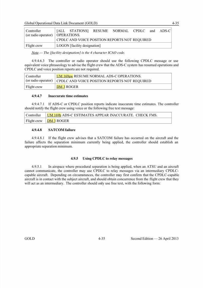
8/9/2019 CPDLC Explained
http://slidepdf.com/reader/full/cpdlc-explained 155/421
Global Operational Data Link Document (GOLD) 4-35
GOLD 4-35 Second Edition — 26 April 2013
Controller(or radio operator)
[ALL STATIONS] RESUME NORMAL CPDLC and ADS-COPERATIONS.
CPDLC AND VOICE POSITION REPORTS NOT REQUIRED
Flight crew LOGON [facility designation]
Note.— The [facility designation] is the 4 character ICAO code.
4.9.4.6.3 The controller or radio operator should use the following CPDLC message or useequivalent voice phraseology to advise the flight crew that the ADS-C system has resumed operations andCPDLC and voice position reports are not required.
Controller(or radio operator)
UM 169aw RESUME NORMAL ADS-C OPERATIONS.
CPDLC AND VOICE POSITION REPORTS NOT REQUIRED
Flight crew DM 3 ROGER
4.9.4.7 Inaccurate time estimates
4.9.4.7.1 If ADS-C or CPDLC position reports indicate inaccurate time estimates. The controllershould notify the flight crew using voice or the following free text message:
Controller UM 169h ADS-C ESTIMATES APPEAR INACCURATE. CHECK FMS.
Flight crew DM 3 ROGER
4.9.4.8 SATCOM failure
4.9.4.8.1 If the flight crew advises that a SATCOM failure has occurred on the aircraft and thefailure affects the separation minimum currently being applied, the controller should establish anappropriate separation minimum.
4.9.5 Using CPDLC to relay messages
4.9.5.1 In airspace where procedural separation is being applied, when an ATSU and an aircraftcannot communicate, the controller may use CPDLC to relay messages via an intermediary CPDLC-capable aircraft. Depending on circumstances, the controller may first confirm that the CPDLC-capableaircraft is in contact with the subject aircraft, and should obtain concurrence from the flight crew that theywill act as an intermediary. The controller should only use free text, with the following form:
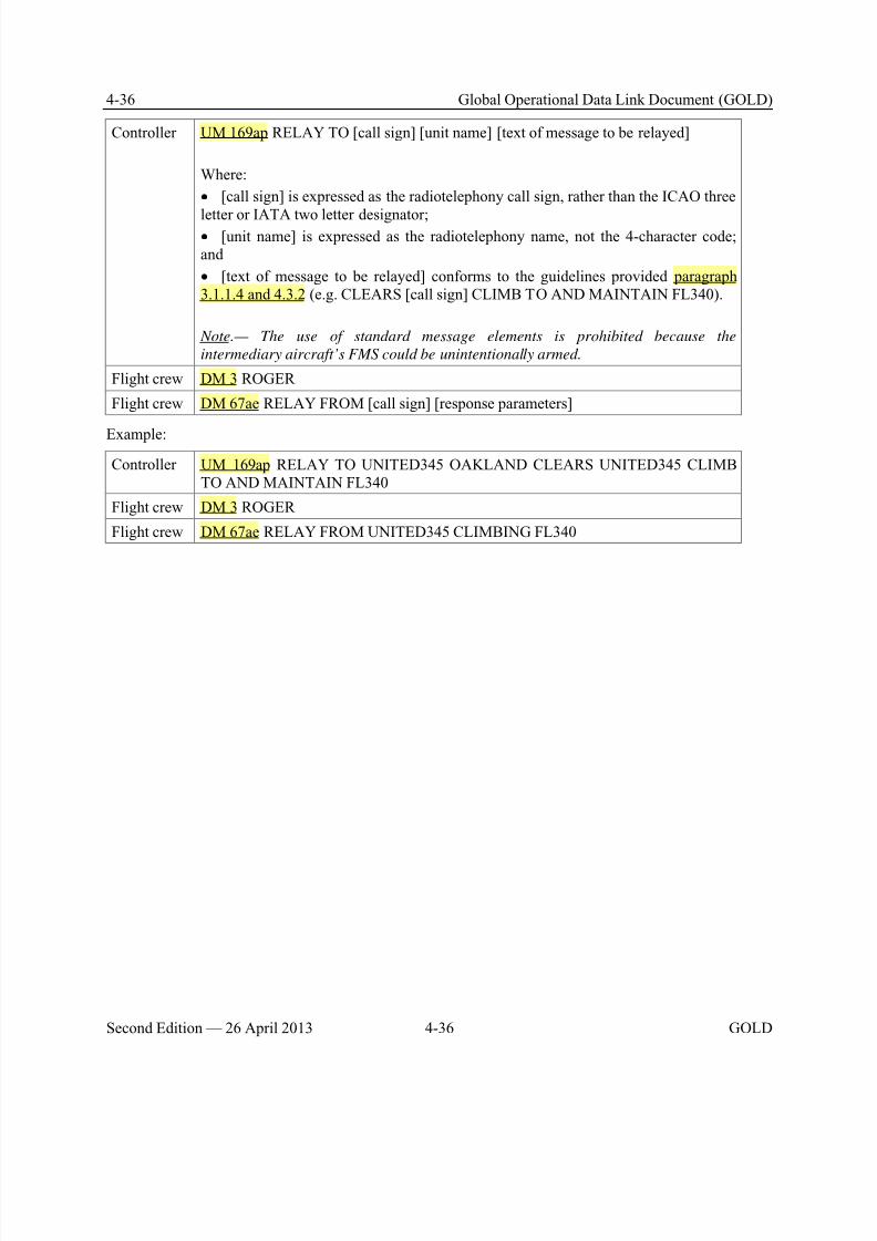
8/9/2019 CPDLC Explained
http://slidepdf.com/reader/full/cpdlc-explained 156/421
4-36 Global Operational Data Link Document (GOLD)
Second Edition — 26 April 2013 4-36 GOLD
Controller UM 169ap RELAY TO [call sign] [unit name] [text of message to be relayed]
Where:
• [call sign] is expressed as the radiotelephony call sign, rather than the ICAO three
letter or IATA two letter designator;• [unit name] is expressed as the radiotelephony name, not the 4-character code;and
• [text of message to be relayed] conforms to the guidelines provided paragraph3.1.1.4 and 4.3.2 (e.g. CLEARS [call sign] CLIMB TO AND MAINTAIN FL340).
Note.— The use of standard message elements is prohibited because the
intermediary aircraft’s FMS could be unintentionally armed.
Flight crew DM 3 ROGER
Flight crew DM 67ae RELAY FROM [call sign] [response parameters]
Example:
Controller UM 169ap RELAY TO UNITED345 OAKLAND CLEARS UNITED345 CLIMBTO AND MAINTAIN FL340
Flight crew DM 3 ROGER
Flight crew DM 67ae RELAY FROM UNITED345 CLIMBING FL340
8/9/2019 CPDLC Explained
http://slidepdf.com/reader/full/cpdlc-explained 157/421
Global Operational Data Link Document (GOLD) 5-1
GOLD 5-1 Second Edition — 26 April 2013
Chapter 5. Flight crew procedures
5.1 Overview
5.1.1 General
5.1.1.1 The operator may be required to obtain an operational authorization by the State of theOperator or State of Registry to use CPDLC and ADS-C services in accordance with paragraph 3.2. Thischapter provides guidance on procedures for the flight crew in airspace where data link services areavailable.
5.1.1.2 These procedures are intended to assist operators in the development of:
a) Operating procedures and associated documentation; and
b) Appropriate training programs.
5.1.1.3 Flight crews should be knowledgeable in operating manuals for use of the data linksystem specific to the aircraft type.
Note.— Refer to paragraph 3.2.1.3.
5.1.1.4 Flight crews should be knowledgeable in data link operations.
Note 1.— Refer to Chapter 2 for an overview of data link operations.
Note 2.— Where applicable, the communication procedures for the provision of CPDLC shall be in
line with ICAO Annex 10, Volume II and Volume III, Part I, Chapter 3. CPDLC message element intent
and text and associated procedures are, in general, consistent with ICAO Doc 4444 PANS-ATM Chapter
12 – Phraseologies and Chapter 14 – CPDLC.
5.1.2 Operational differences between voice communications and CPDLC
5.1.2.1 Development, testing, and operational experience have highlighted fundamentaldifferences between CPDLC and voice communications. These differences need to be considered whendeveloping or approving flight crew procedures involving the use of CPDLC.
5.1.2.2 For example, when using voice communications, each flight crew member hears anincoming or outgoing ATS transmission. With voice, the natural ability for each flight crew member tounderstand incoming and outgoing transmissions for their own aircraft has provided a certain level ofsituational awareness among the flight crew. With CPDLC, flight crew procedures need to ensure that the
flight crew has an equivalent level of situational awareness associated with understanding the content andintent of a message in the same way.
5.1.2.3 Each flight crew member (e.g. pilot flying and pilot monitoring) should individuallyreview each CPDLC uplink message prior to responding to and/or executing any clearance, andindividually review each CPDLC downlink message prior to transmission.
8/9/2019 CPDLC Explained
http://slidepdf.com/reader/full/cpdlc-explained 158/421
5-2 Global Operational Data Link Document (GOLD)
Second Edition — 26 April 2013 5-2 GOLD
5.1.2.4 If an operator uses augmented crews, the flight crew carrying out the ‘handover’ briefingshould thoroughly brief the ‘changeover’ flight crew or flight crew member on the status of ADS-C andCPDLC connections and messages, including a review of any pertinent uplink and downlink CPDLCmessages (e.g. conditional clearances).
5.1.2.5 Uplink messages require special attention to prevent the flight crew from responding to aclearance with DM 0 WILCO, but not complying with that clearance. To minimize errors, whenresponding to a clearance with DM 0 WILCO, each flight crew member should read the uplink messageindividually (silently) before initiating a discussion about whether and how to act on the message.Reading a message individually is a key element to ensuring that each flight crew member does not inferany preconceived intent different from what is intended or appropriate. Use of this method can provide aflight crew with an acceptable level of situational awareness for the intended operations.
5.1.2.6 In a similar manner, each flight crew member should individually review CPDLCdownlink messages before the message is sent. Having one flight crew member (e.g. the pilotmonitoring) input the message and having a different flight crew member (pilot flying) review themessage before it is sent provides an adequate level of situational awareness comparable to or better than
voice communication.
5.1.2.7 The flight crew should coordinate uplink and downlink messages using the appropriateflight deck displays. Unless otherwise authorized, the flight crew should not use printer-basedinformation to verify CPDLC messages as printers are not usually intended for this specific purpose.
Note.— For aircraft that have CPDLC message printing capabilities, there are constraints
associated with the use of the flight deck printer. Printers may not produce an exact copy of the
displayed clearance with the required reliability, and should not be used as the primary display for
CPDLC. However, in some cases, printed copies may assist the flight crew with clearances and other
information that are displayed on more than one page, conditional clearances and crew handover
briefings.
5.1.3 When to use voice and when to use CPDLC
5.1.3.1 When operating within airspace beyond the range of DCPC VHF voice communication,CPDLC is available and local ATC procedures do not state otherwise, the flight crew should normallychoose CPDLC as the means of communication. The flight crew would use voice as an alternative meansof communication (e.g. VHF, HF or SATVOICE direct or via a radio operator). However, in any case,the flight crew will determine the appropriate communication medium to use at any given time.
5.1.3.2 In airspace where both DCPC VHF voice and CPDLC communication services are provided, and local ATC procedures do not state otherwise, the flight crew will determine thecommunication medium to use at any given time.
Note.— ICAO Doc 4444, paragraph 8.3.2, requires that DCPC be established prior to the provision
of ATS surveillance services, unless special circumstances, such as emergencies, dictate otherwise. This
does not prevent the use of CPDLC for ATC communications, voice being immediately available for
intervention and to address non-routine and time critical situations.
5.1.3.3 To minimize pilot head down time and potential distractions during critical phases offlight, the flight crew should use voice for ATC communications when operating below 10,000 ft AGL.
8/9/2019 CPDLC Explained
http://slidepdf.com/reader/full/cpdlc-explained 159/421
Global Operational Data Link Document (GOLD) 5-3
GOLD 5-3 Second Edition — 26 April 2013
5.1.3.4 While the CPDLC message set, as defined in Appendix A, generally provides messageelements for common ATC communications, the flight crew may determine voice to be a moreappropriate means depending on the circumstances (e.g. some types of non-routine communications).
Note.— Refer to paragraph 5.8 for guidelines on use of voice and data communications in
emergency and non-routine situations.
5.1.3.5 During an emergency, the flight crew would normally revert to voice communications.However, the flight crew may use CPDLC for emergency communications if it is either more expedientor if voice contact cannot be established. Refer to paragraph 5.8.2 for guidelines on use.
Note.— For ATN B1 aircraft, emergency message elements are not supported. See Appendix A,
paragraph A.4, for a list of emergency message elements.
5.1.3.6 Except as provided in paragraph 5.8.1.2, the flight crew should respond to a CPDLCmessage via CPDLC, and should respond to a voice message via voice.
Note.— This will lessen the opportunity for messages to get lost, discarded or unanswered between
the ATSU and the flight crew and cause unintended consequences.
5.1.3.7 If the intent of an uplink message is uncertain, the flight crew should respond to theuplink message with DM 1 UNABLE and obtain clarification using voice.
Note.—For FANS 1/A aircraft, some uplink messages do not have a DM 1 UNABLE response. On
these aircraft, the flight crew should respond with DM 3 ROGER and then obtain clarification via voice.
5.1.3.8 Regardless of whether CPDLC is being used, the flight crew should continuously monitorVHF/HF/UHF guard frequency. In addition, the flight crew should continuously maintain a listening orSELCAL watch on the specified backup or secondary frequency (frequencies). On aircraft capable of twoSATCOM channels, one channel may be selected to the phone number for the radio facility assigned tothe current ATSU to enable timely voice communications. The second channel may be selected to the
company phone number to enable timely voice communications with company dispatch.
5.2 Logon
5.2.1 General
5.2.1.1 A CPDLC connection requires a successfully completed logon procedure before theATSU can establish a CPDLC connection with the aircraft.
Note.— Refer to paragraph 2.2.1.2 for an overview of the logon procedure.
5.2.1.2 Prior to initiating the logon, the flight crew should verify the following:a) The aircraft identification provided when initiating the logon exactly matches the aircraft
identification (Item 7) of the filed flight plan;
b) The flight plan contains the correct aircraft registration in Item 18 prefixed by REG/;
c) The flight plan contains the correct aircraft address in Item 18 prefixed by CODE/, whenrequired;
8/9/2019 CPDLC Explained
http://slidepdf.com/reader/full/cpdlc-explained 160/421
5-4 Global Operational Data Link Document (GOLD)
Second Edition — 26 April 2013 5-4 GOLD
d) The flight plan contains the correct departure and destination aerodromes in Items 13 and 16,when required; and
e) The aircraft registration provided when initiating the logon exactly matches the aircraft placard,when the flight crew manually enters the aircraft registration. Refer to Appendix F, paragraph F.1 for
aircraft types that require manual entry. Note.— If a logon request has been initiated with incorrect aircraft identification and aircraft
registration, the logon process will fail. The flight crew will need to correct the information and
reinitiate the logon request.
5.2.1.3 If any of the information described in paragraph 5.2.1.2 do not match, the flight crew willneed to contact AOC or ATC, as appropriate, to resolve the discrepancy.
Note 1: In accordance with ICAO Doc 4444, the aircraft identification is either the:
a) ICAO designator for the aircraft operating agency followed by the flight identification; or
b) aircraft registration.
Note 2.— The aircraft registration entered into the aircraft system can include a hyphen(-), eventhough the aircraft registration in the flight plan message cannot include a hyphen.
Note 3.- The ATSU correlates the data sent in a logon request message with flight plan data. If the
data does not match, the ATSU will reject the logon request.
5.2.1.4 The flight crew should then manually initiate a logon using the logon address, asindicated on aeronautical charts (See Figure 5-1 for example).
Note 1.— Often the logon address is the same as the 4-letter facility designator but in some airspace
a different logon address is used. Refer to Appendix E.
Note 2.— Some aircraft (see Appendix F, paragraph F.1) implement FANS 1/A and ATN B1
capabilities as separate systems and do not comply ith ED154A/DO305A. For these aircraft, the flight
crew will have to select the appropriate system (FANS 1/A or ATN B1) to initiate the logon.
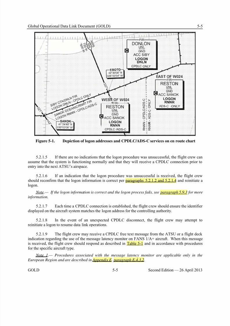
8/9/2019 CPDLC Explained
http://slidepdf.com/reader/full/cpdlc-explained 161/421
Global Operational Data Link Document (GOLD) 5-5
GOLD 5-5 Second Edition — 26 April 2013
Figure 5-1. Depiction of logon addresses and CPDLC/ADS-C services on en route chart
5.2.1.5 If there are no indications that the logon procedure was unsuccessful, the flight crew canassume that the system is functioning normally and that they will receive a CPDLC connection prior toentry into the next ATSU’s airspace.
5.2.1.6 If an indication that the logon procedure was unsuccessful is received, the flight crewshould reconfirm that the logon information is correct per paragraphs 5.2.1.2 and 5.2.1.4 and reinitiate alogon.
Note.— If the logon information is correct and the logon process fails, see paragraph 5.9.3 for more
information.
5.2.1.7 Each time a CPDLC connection is established, the flight crew should ensure the identifierdisplayed on the aircraft system matches the logon address for the controlling authority.
5.2.1.8 In the event of an unexpected CPDLC disconnect, the flight crew may attempt toreinitiate a logon to resume data link operations.
5.2.1.9 The flight crew may receive a CPDLC free text message from the ATSU or a flight deckindication regarding the use of the message latency monitor on FANS 1/A+ aircraft. When this messageis received, the flight crew should respond as described in Table 5-1 and in accordance with proceduresfor the specific aircraft type.
Note 1.— Procedures associated with the message latency monitor are applicable only in the
European Region and are described in Appendix E, paragraph E.4.3.2.
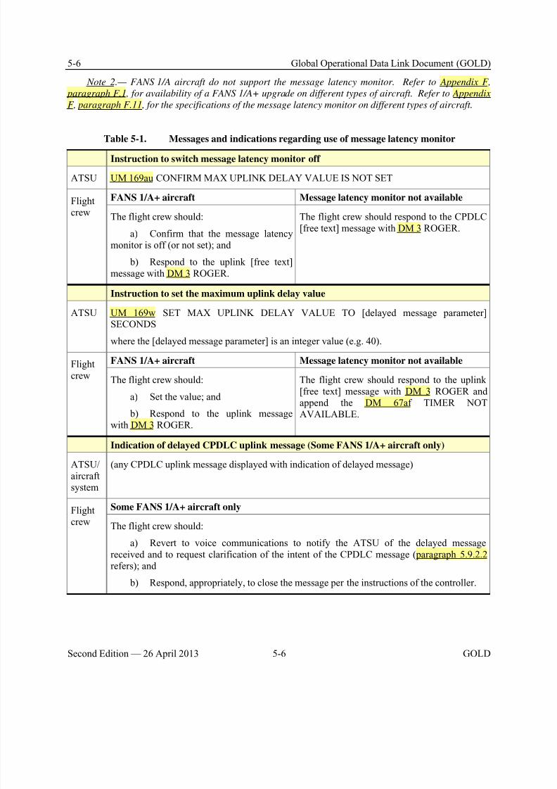
8/9/2019 CPDLC Explained
http://slidepdf.com/reader/full/cpdlc-explained 162/421
5-6 Global Operational Data Link Document (GOLD)
Second Edition — 26 April 2013 5-6 GOLD
Note 2.— FANS 1/A aircraft do not support the message latency monitor. Refer to Appendix F,
paragraph F.1, for availability of a FANS 1/A+ upgrade on different types of aircraft. Refer to Appendix
F, paragraph F.11, for the specifications of the message latency monitor on different types of aircraft.
Table 5-1. Messages and indications regarding use of message latency monitor
Instruction to switch message latency monitor off
ATSU UM 169au CONFIRM MAX UPLINK DELAY VALUE IS NOT SET
Flightcrew
FANS 1/A+ aircraft Message latency monitor not available
The flight crew should:
a) Confirm that the message latencymonitor is off (or not set); and
b) Respond to the uplink [free text]
message with DM 3 ROGER.
The flight crew should respond to the CPDLC[free text] message with DM 3 ROGER.
Instruction to set the maximum uplink delay value
ATSU UM 169w SET MAX UPLINK DELAY VALUE TO [delayed message parameter]SECONDS
where the [delayed message parameter] is an integer value (e.g. 40).
Flightcrew
FANS 1/A+ aircraft Message latency monitor not available
The flight crew should:
a) Set the value; and
b) Respond to the uplink messagewith DM 3 ROGER.
The flight crew should respond to the uplink[free text] message with DM 3 ROGER andappend the DM 67af TIMER NOT
AVAILABLE.
Indication of delayed CPDLC uplink message (Some FANS 1/A+ aircraft only)
ATSU/aircraftsystem
(any CPDLC uplink message displayed with indication of delayed message)
Flightcrew
Some FANS 1/A+ aircraft only
The flight crew should:
a) Revert to voice communications to notify the ATSU of the delayed message
received and to request clarification of the intent of the CPDLC message (paragraph 5.9.2.2refers); and
b) Respond, appropriately, to close the message per the instructions of the controller.
8/9/2019 CPDLC Explained
http://slidepdf.com/reader/full/cpdlc-explained 163/421
Global Operational Data Link Document (GOLD) 5-7
GOLD 5-7 Second Edition — 26 April 2013
5.2.2 When to log on initially for data link services
5.2.2.1 When operating outside data link airspace, the flight crew should initiate a logon 10 to 25minutes prior to entry into airspace where data link services are provided.
Note.— When departing an aerodrome close to or within such airspace, this may require the logon
to be initiated prior to departure.
5.2.2.2 Where a data link service is only provided in upper airspace and where local proceduresdo not dictate otherwise, the flight crew should log on to that ATSU in whose airspace a data link servicewill first be used.
5.2.2.3 When failure of a data link connection is detected, the flight crew should terminate theconnection and then initiate a new logon with the current ATSU.
5.2.3 Automatic transfer of CPDLC and ADS-C services between ATSUs
5.2.3.1 Under normal circumstances, the current and next ATSUs automatically transfer CPDLCand ADS-C services. The transfer is seamless to the flight crew.
Note.— The flight crew should not need to reinitiate a logon.
5.2.3.2 The flight crew should promptly respond to CPDLC uplinks to minimize the risk of anopen CPDLC uplink message when transferring to the next ATSU.
Note.— If a flight is transferred to a new ATSU with an open CPDLC message, the message status
will change to ABORTED. If the flight crew has not yet received a response from the controller, the
downlink request will also display the ABORTED status. Refer also to Appendix F, paragraph F.8.
5.2.3.3 Prior to the point at which the current ATSU will transfer CPDLC and/or ADS-C
services, the flight crew may receive an instruction to close any open CPDLC messages.
5.2.3.4 When entering the next ATSU’s airspace, the flight crew should confirm the successfultransfer from the current ATSU to the next ATSU by observing the change in the active center indication provided by the aircraft system.
5.2.3.5 When required by local procedures, the flight crew should send DM 48 POSITIONREPORT [position report]. Alternatively, the flight crew may be required to respond to a CPDLCmessage exchange initiated by the ATSU.
Note.— Since FANS 1/A aircraft do not report that the downstream ATSU has become the CDA, the
only way to confirm that it has taken place is for the ATSU to receive a CPDLC message from the aircraft
(refer to Appendix E).
5.2.4 Transfer voice communications with the CPDLC connection transfer
5.2.4.1 Prior to crossing the boundary, the active center may initiate transfer of voicecommunications with the CPDLC connection transfer using any of the message elements containingCONTACT or MONITOR. Refer to paragraph 4.2.3 for guidelines on the controller’s use of thesemessage elements.
8/9/2019 CPDLC Explained
http://slidepdf.com/reader/full/cpdlc-explained 164/421
5-8 Global Operational Data Link Document (GOLD)
Second Edition — 26 April 2013 5-8 GOLD
5.2.4.2 A CONTACT or MONITOR message instructs the flight crew to change to the specifiedfrequency and may include a position or time for when to change to the new frequency.
a) When a MONITOR message is received, the flight crew should change to the specifiedfrequency upon receipt of the instruction or at the specified time or position. The flight crew should not
establish voice contact on the frequency. b) When a CONTACT message is received, the flight crew should change to the specified
frequency upon receipt of the instruction or at the specified time or position, and establish voice contacton the frequency.
Note 1.— Some States do not require HF SELCAL checks. If, following a MONITOR instruction, a
SELCAL check is specifically required by operator procedures, this will usually be accommodated on the
allocated frequency.
Note 2.— If the next ATSU provides CPDLC services, the flight crew should not expect that CPDLC
will be terminated or suspended once voice contact is established per receipt of a CONTACT message,
unless otherwise advised per paragraph 4.2.4.4.
5.2.4.3 If the ATSU assigns a single HF frequency, the flight crew should select anotherfrequency from the same ‘family’ as a secondary frequency.
Note.— In areas of poor radio coverage, the controller may append UM 238 SECONDARY
FREQUENCY [frequency] to specify a secondary frequency.
5.2.5 Exiting CPDLC and ADS-C service areas
5.2.5.1 The flight crew should consult the current ATSU prior to the manual termination of anyADS contract with the aircraft, even if it is suspected to be unnecessary or that its termination has failed.
Note.— ADS contracts are managed (e.g. established and terminated) by ATSUs per paragraph
4.5.3.
5.2.5.2 Approximately 15 minutes after exiting CPDLC and/or ADS-C service areas, the flightcrew should ensure there are no active CPDLC or ADS-C connections. Ensuring that connections are notactive eliminates the possibility of inadvertent or inappropriate use of the connections, and reducesoperating costs and loading of the system.
Note.— Some ATSUs may maintain ADS contracts with an aircraft for a period of time (e.g. 15
minutes) after the aircraft has left the airspace.
5.3 CPDLC – ATS uplink messages
5.3.1 General
5.3.1.1 When a CPDLC uplink is received, each flight crew member (e.g. pilot flying and pilotmonitoring) should read the message from the flight deck displays individually to ensure situationalawareness is maintained. Once the message has been individually read, the flight crew should thendiscuss whether to respond to the message with DM 0 WILCO or DM 3 ROGER, as appropriate, or DM 1UNABLE.
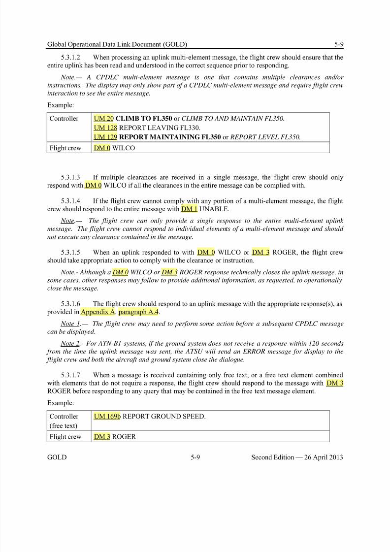
8/9/2019 CPDLC Explained
http://slidepdf.com/reader/full/cpdlc-explained 165/421
Global Operational Data Link Document (GOLD) 5-9
GOLD 5-9 Second Edition — 26 April 2013
5.3.1.2 When processing an uplink multi-element message, the flight crew should ensure that theentire uplink has been read and understood in the correct sequence prior to responding.
Note.— A CPDLC multi-element message is one that contains multiple clearances and/or
instructions. The display may only show part of a CPDLC multi-element message and require flight crew
interaction to see the entire message.Example:
Controller UM 20 CLIMB TO FL350 or CLIMB TO AND MAINTAIN FL350.
UM 128 REPORT LEAVING FL330.
UM 129 REPORT MAINTAINING FL350 or REPORT LEVEL FL350.
Flight crew DM 0 WILCO
5.3.1.3 If multiple clearances are received in a single message, the flight crew should onlyrespond with DM 0 WILCO if all the clearances in the entire message can be complied with.
5.3.1.4 If the flight crew cannot comply with any portion of a multi-element message, the flightcrew should respond to the entire message with DM 1 UNABLE.
Note.— The flight crew can only provide a single response to the entire multi-element uplink
message. The flight crew cannot respond to individual elements of a multi-element message and should
not execute any clearance contained in the message.
5.3.1.5 When an uplink responded to with DM 0 WILCO or DM 3 ROGER, the flight crewshould take appropriate action to comply with the clearance or instruction.
Note.- Although a DM 0 WILCO or DM 3 ROGER response technically closes the uplink message, in
some cases, other responses may follow to provide additional information, as requested, to operationally
close the message.
5.3.1.6 The flight crew should respond to an uplink message with the appropriate response(s), as provided in Appendix A, paragraph A.4.
Note 1.— The flight crew may need to perform some action before a subsequent CPDLC message
can be displayed.
Note 2.- For ATN-B1 systems, if the ground system does not receive a response within 120 seconds
from the time the uplink message was sent, the ATSU will send an ERROR message for display to the
flight crew and both the aircraft and ground system close the dialogue.
5.3.1.7 When a message is received containing only free text, or a free text element combinedwith elements that do not require a response, the flight crew should respond to the message with DM 3ROGER before responding to any query that may be contained in the free text message element.
Example:
Controller
(free text)
UM 169b REPORT GROUND SPEED.
Flight crew DM 3 ROGER
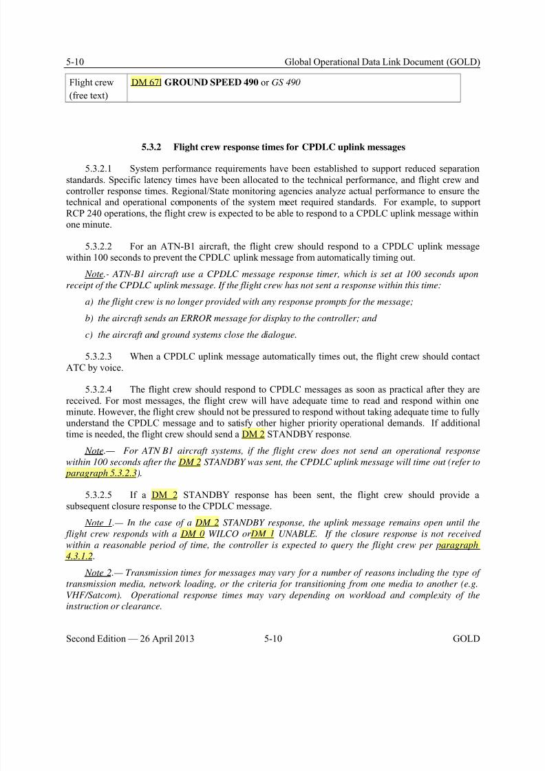
8/9/2019 CPDLC Explained
http://slidepdf.com/reader/full/cpdlc-explained 166/421
5-10 Global Operational Data Link Document (GOLD)
Second Edition — 26 April 2013 5-10 GOLD
Flight crew
(free text)
DM 67l GROUND SPEED 490 or GS 490
5.3.2 Flight crew response times for CPDLC uplink messages
5.3.2.1 System performance requirements have been established to support reduced separationstandards. Specific latency times have been allocated to the technical performance, and flight crew andcontroller response times. Regional/State monitoring agencies analyze actual performance to ensure thetechnical and operational components of the system meet required standards. For example, to supportRCP 240 operations, the flight crew is expected to be able to respond to a CPDLC uplink message withinone minute.
5.3.2.2 For an ATN-B1 aircraft, the flight crew should respond to a CPDLC uplink messagewithin 100 seconds to prevent the CPDLC uplink message from automatically timing out.
Note.- ATN-B1 aircraft use a CPDLC message response timer, which is set at 100 seconds upon
receipt of the CPDLC uplink message. If the flight crew has not sent a response within this time:
a) the flight crew is no longer provided with any response prompts for the message;
b) the aircraft sends an ERROR message for display to the controller; and
c) the aircraft and ground systems close the dialogue.
5.3.2.3 When a CPDLC uplink message automatically times out, the flight crew should contactATC by voice.
5.3.2.4 The flight crew should respond to CPDLC messages as soon as practical after they are
received. For most messages, the flight crew will have adequate time to read and respond within oneminute. However, the flight crew should not be pressured to respond without taking adequate time to fullyunderstand the CPDLC message and to satisfy other higher priority operational demands. If additionaltime is needed, the flight crew should send a DM 2 STANDBY response.
Note.— For ATN B1 aircraft systems, if the flight crew does not send an operational response
within 100 seconds after the DM 2 STANDBY was sent, the CPDLC uplink message will time out (refer to
paragraph 5.3.2.3).
5.3.2.5 If a DM 2 STANDBY response has been sent, the flight crew should provide asubsequent closure response to the CPDLC message.
Note 1.— In the case of a DM 2 STANDBY response, the uplink message remains open until the
flight crew responds with a DM 0 WILCO orDM 1 UNABLE. If the closure response is not received
within a reasonable period of time, the controller is expected to query the flight crew per paragraph
4.3.1.2.
Note 2.— Transmission times for messages may vary for a number of reasons including the type of
transmission media, network loading, or the criteria for transitioning from one media to another (e.g.
VHF/Satcom). Operational response times may vary depending on workload and complexity of the
instruction or clearance.
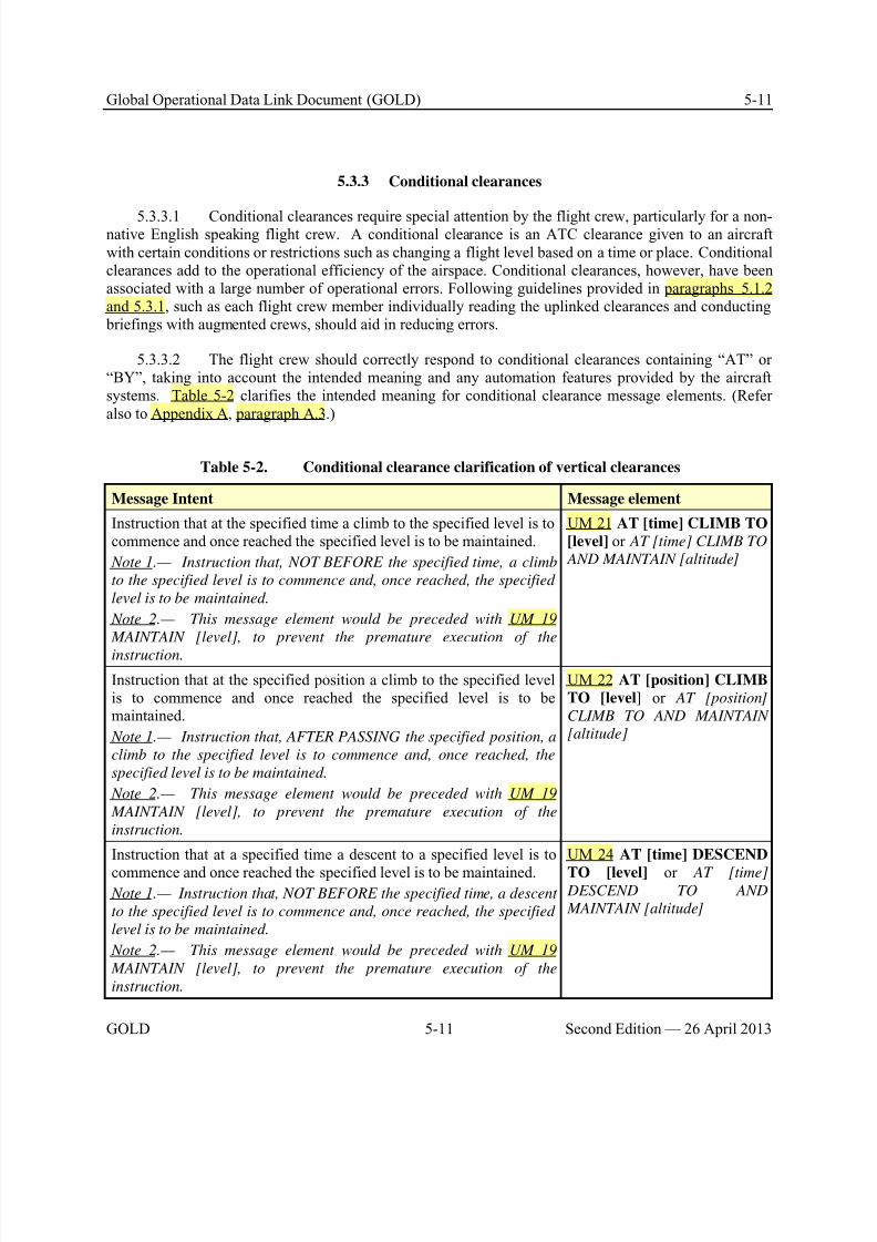
8/9/2019 CPDLC Explained
http://slidepdf.com/reader/full/cpdlc-explained 167/421
Global Operational Data Link Document (GOLD) 5-11
GOLD 5-11 Second Edition — 26 April 2013
5.3.3 Conditional clearances
5.3.3.1 Conditional clearances require special attention by the flight crew, particularly for a non-native English speaking flight crew. A conditional clearance is an ATC clearance given to an aircraftwith certain conditions or restrictions such as changing a flight level based on a time or place. Conditionalclearances add to the operational efficiency of the airspace. Conditional clearances, however, have beenassociated with a large number of operational errors. Following guidelines provided in paragraphs 5.1.2and 5.3.1, such as each flight crew member individually reading the uplinked clearances and conducting briefings with augmented crews, should aid in reducing errors.
5.3.3.2 The flight crew should correctly respond to conditional clearances containing “AT” or“BY”, taking into account the intended meaning and any automation features provided by the aircraftsystems. Table 5-2 clarifies the intended meaning for conditional clearance message elements. (Referalso to Appendix A, paragraph A.3.)
Table 5-2. Conditional clearance clarification of vertical clearances
Message Intent Message element
Instruction that at the specified time a climb to the specified level is tocommence and once reached the specified level is to be maintained.
Note 1.— Instruction that, NOT BEFORE the specified time, a climb
to the specified level is to commence and, once reached, the specified
level is to be maintained.
Note 2.— This message element would be preceded with UM 19
MAINTAIN [level], to prevent the premature execution of the
instruction.
UM 21 AT [time] CLIMB TO
[level] or AT [time] CLIMB TO
AND MAINTAIN [altitude]
Instruction that at the specified position a climb to the specified levelis to commence and once reached the specified level is to bemaintained.
Note 1.— Instruction that, AFTER PASSING the specified position, a
climb to the specified level is to commence and, once reached, the
specified level is to be maintained.
Note 2.— This message element would be preceded with UM 19
MAINTAIN [level], to prevent the premature execution of the
instruction.
UM 22 AT [position] CLIMB
TO [level] or AT [position]
CLIMB TO AND MAINTAIN
[altitude]
Instruction that at a specified time a descent to a specified level is to
commence and once reached the specified level is to be maintained. Note 1.— Instruction that, NOT BEFORE the specified time, a descent
to the specified level is to commence and, once reached, the specified
level is to be maintained.
Note 2.— This message element would be preceded with UM 19
MAINTAIN [level], to prevent the premature execution of the
instruction.
UM 24 AT [time] DESCEND
TO [level] or AT [time] DESCEND TO AND
MAINTAIN [altitude]
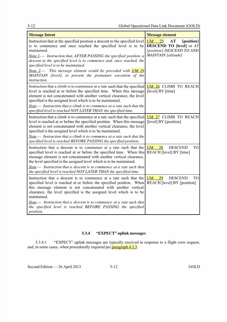
8/9/2019 CPDLC Explained
http://slidepdf.com/reader/full/cpdlc-explained 168/421
5-12 Global Operational Data Link Document (GOLD)
Second Edition — 26 April 2013 5-12 GOLD
Message Intent Message element
Instruction that at the specified position a descent to the specified levelis to commence and once reached the specified level is to bemaintained.
Note 1.— Instruction that, AFTER PASSING the specified position, adescent to the specified level is to commence and, once reached, the
specified level is to be maintained.
Note 2.— This message element would be preceded with UM 19
MAINTAIN [level], to prevent the premature execution of the
instruction.
UM 25 AT [position]
DESCEND TO [level] or AT
[position] DESCEND TO AND
MAINTAIN [altitude]
Instruction that a climb is to commence at a rate such that the specifiedlevel is reached at or before the specified time. When this messageelement is not concatenated with another vertical clearance, the levelspecified is the assigned level which is to be maintained.
Note.— Instruction that a climb is to commence at a rate such that the
specified level is reached NOT LATER THAN the specified time.
UM 26 CLIMB TO REACH[level] BY [time]
Instruction that a climb is to commence at a rate such that the specifiedlevel is reached at or before the specified position. When this messageelement is not concatenated with another vertical clearance, the levelspecified is the assigned level which is to be maintained.
Note.— Instruction that a climb is to commence at a rate such that the
specified level is reached BEFORE PASSING the specified position.
UM 27 CLIMB TO REACH[level] BY [position]
Instruction that a descent is to commence at a rate such that thespecified level is reached at or before the specified time. When thismessage element is not concatenated with another vertical clearance,the level specified is the assigned level which is to be maintained.
Note.— Instruction that a descent is to commence at a rate such that
the specified level is reached NOT LATER THAN the specified time.
UM 28 DESCEND TOREACH [level] BY [time]
Instruction that a descent is to commence at a rate such that thespecified level is reached at or before the specified position. Whenthis message element is not concatenated with another verticalclearance, the level specified is the assigned level which is to bemaintained.
Note.— Instruction that a descent is to commence at a rate such that
the specified level is reached BEFORE PASSING the specified
position.
UM 29 DESCEND TOREACH [level] BY [position]
5.3.4 “EXPECT” uplink messages
5.3.4.1 “EXPECT” uplink messages are typically received in response to a flight crew request,and, in some cases, when procedurally required per paragraph 4.3.3.
8/9/2019 CPDLC Explained
http://slidepdf.com/reader/full/cpdlc-explained 169/421
Global Operational Data Link Document (GOLD) 5-13
GOLD 5-13 Second Edition — 26 April 2013
5.3.4.2 When receiving an EXPECT uplink message, the flight crew should respond with DM 3ROGER, meaning that the message was received and understood.
Note 1.— The flight crew should NOT comply with an EXPECT message as if it was a clearance.
Note 2.— The FANS 1/A CPDLC message set contains EXPECT uplink message elements that the
controller should NOT use because of potential misinterpretation in the event of a total communication failure. Some of these message elements have been reserved by Doc 4444. As a consequence, some
“WHEN CAN WE EXPECT” downlink messages are not supported. See Appendix A, paragraph A.3, and
Appendix E, paragraph E.7.1.3, for specific message elements that are not supported.
5.3.5 Uplinks containing FMS-loadable data
5.3.5.1 CPDLC allows aircraft systems to be capable of loading route clearance information fromCPDLC messages directly into an FMS. The flight crew can use this capability to minimize the potentialfor data entry errors when executing clearances involving loadable data. It also enables advanced airtraffic services supported by data link, such as a re-route or a tailored arrival, as described in Chapter 6,
which otherwise may not be possible via voice. Note.— Not all aircraft have the capability to load information from CPDLC message directly into
the FMS.
5.3.5.2 If a clearance is received that can be automatically loaded into the FMS, the flight crewshould load the clearance into the FMS and review it before responding with DM 0 WILCO.
5.3.5.3 The flight crew should verify that the route modification in the FMS is consistent withthe CPDLC route clearance. A discontinuity in a CPDLC route clearance is not necessarily a reason torespond to the clearance with DM 1 UNABLE, as these can be appropriate in some circumstances.
5.3.5.4 The flight crew should respond to the clearance with DM 1 UNABLE when:
a) The FMS indicates that it cannot load the clearance (e.g. partial clearance loaded or unable toload); or
Note.— The FMS checks the clearance to ensure it is correctly formatted and compatible with the
FMS navigation database.
b) The FMS indicates any inconsistencies or discontinuities with the route modification that arenot addressed by AIP (or other appropriate publication) or cannot be resolved by the flight crew.
5.3.5.5 The flight crew should use CPDLC or voice to clarify any clearance that was respondedto with DM 1 UNABLE due to any loading failures, route discontinuities or inconsistencies.
5.3.5.6 If the clearance loads successfully and is acceptable, the flight crew may execute an FMS
route modification and respond to the clearance with DM 0 WILCO.
Note.— The flight crew will ensure the route in the FMC matches the ATC clearance.

8/9/2019 CPDLC Explained
http://slidepdf.com/reader/full/cpdlc-explained 170/421
5-14 Global Operational Data Link Document (GOLD)
Second Edition — 26 April 2013 5-14 GOLD
5.4 CPDLC – ATS downlink messages
5.4.1 General
5.4.1.1 Downlink messages can only be sent to the ATSU that holds the active CPDLCconnection. To provide situational awareness, procedures should ensure that each flight crew member hasread each downlink message before it is sent.
5.4.1.2 When the aircraft has an active CPDLC connection with an ATSU, the flight crew shoulddownlink a clearance request only if the flight is in that ATSU’s airspace.
5.4.1.3 The flight crew should use standard downlink message elements to compose and sendclearance requests, CPDLC position reports, and other requested reports. Additional qualifying standardmessage elements, such as DM 65 DUE TO WEATHER, should also be used as needed.
Note.— The use of standard message elements will minimize the risk of input errors,
misunderstandings, and confusion, and facilitate use by a non-native English speaking flight crew. The
use of standard message elements allows the aircraft and ground systems to automatically process theinformation in the messages that are exchanged. For example, the flight crew can automatically load
clearance information into the FMS and review the clearance, the ground system can automatically
update flight plan data for route conformance monitoring, and both aircraft and ground systems can
associate responses to messages.
5.4.1.4 To avoid potential ambiguity, the flight crew should avoid sending multiple clearancerequests in a single downlink message. For example, the flight crew should send separate downlinkmessages for DM 9 REQUEST CLIMB TO [level] and DM 22 REQUEST DIRECT TO [position] unlessthere is an operational need to combine them in a single message (i.e. the flight crew does not want toclimb unless they can re-route).
5.4.1.5 When a closure response to an open CPDLC downlink message is not received within areasonable time period, the flight crew should:
a) For a FANS 1/A aircraft, send a query using one of the Negotiation Requests messages or a DM67 [free text] message rather than resending the downlink message. Alternatively, the flight crew mayuse voice communication to clarify the status of the open CPDLC downlink message; or
b) For an ATN-B1 aircraft, the flight crew should use voice communication to resolve theoperational situation resulting from the timed out CPDLC downlink message.
Note 1.— A closure response is a response that operationally closes the dialogue. A UM 1
STANDBY response to an open CPDLC downlink message does not operationally close the dialogue.
Note 2.— The use of a CPDLC free text message by a FANS 1/A aircraft avoids multiple open
messages involving the same downlink message.
Note 3.- ATN-B1 ground systems will reject duplicate requests and return an ERROR message for
display to the flight crew TOO MANY (dialogue type) REQUESTS - EXPECT ONLY ONE REPLY.
Example:
Flight crew DM 9 REQUEST CLIMB TO FL350
Reasonable period of time has passed
8/9/2019 CPDLC Explained
http://slidepdf.com/reader/full/cpdlc-explained 171/421
Global Operational Data Link Document (GOLD) 5-15
GOLD 5-15 Second Edition — 26 April 2013
Flight crew DM 53 WHEN CAN WE EXPECT HIGHER LEVEL (or ALTITUDE )
or
DM 87 WHEN CAN WE EXPECT CLIMB TO FL350
5.4.1.6 If the flight crew receives an indication of non-delivery of a downlink message, they mayelect to re-send an identical message within a reasonable amount of time or as required. Alternatively,they may use voice communication to clarify the status of the downlink message.
5.4.2 Free text
5.4.2.1 The flight crew should avoid the use of the free text message element. However, its usemay offer a viable solution to enhance operational capability.
Note 1.— The use of standard message elements is intended to reduce the possibility of
misinterpretation and ambiguity.
Note 2.— A free text message (such as DM 67k REVISED ETA [position] [time]) does not require a
response from the ATSU.
5.4.2.2 Free text messages should be used only when an appropriate standard message elementdoes not exist.
5.4.2.3 When composing a free text message, the flight crew should use standard ATS phraseology and format and avoid nonessential words and phrases. Abbreviations should only be includedin free text messages when they form part of standard ICAO phraseology, for example, ETA.
5.4.3 Unsupported messages
5.4.3.1 While ATSUs should provide CPDLC service using the complete message set providedin Appendix A, some ATSUs provide a CPDLC service using a limited message set. The flight crewshould be are aware of any unsupported downlink message elements that are described in regional orState documentation.
5.4.3.2 If a downlink message, containing a message element that is not supported by the ATSU,is sent, the flight crew will typically receive the uplink message, UM 162 or UM 169u MESSAGE NOTSUPPORTED BY THIS ATS UNIT. If this message is received, the flight crew should respond to themessage with DM 3 ROGER and use voice for the communication transaction.
5.4.4 CPDLC reports and confirmation requests
5.4.4.1 The flight crew should respond to CPDLC reports and confirmation requests, whenappropriate.
Note 1.— ATSUs may send a CPDLC message that combines a REPORT instruction with a
clearance. The flight crew may use automation, procedures, and/or a combination to remind them when
to send the reports requested in the CPDLC message.
8/9/2019 CPDLC Explained
http://slidepdf.com/reader/full/cpdlc-explained 172/421
5-16 Global Operational Data Link Document (GOLD)
Second Edition — 26 April 2013 5-16 GOLD
Example:
Controller UM 20 CLIMB TO FL350 or CLIMB TO AND MAINTAIN FL350.
UM 128 REPORT LEAVING FL330.
UM 129 REPORT MAINTAINING [level] or REPORT LEVEL FL350.
Flight crew DM 0 WILCO
Note 2.— The controller may send a CPDLC message to request the flight crew to advise intentions
when ADS-C indicates the aircraft has deviated from its cleared route, level or assigned speed
(paragraph 4.3.5.2 refers).
5.5 Automatic dependant surveillance – contract (ADS-C)
5.5.1 General
5.5.1.1 ADS-C allows the ATSU to obtain position reports from the aircraft without flight crewaction to update the current flight plan, to check conformance and to provide emergency alerting.
Note.— In airspace where ADS-C services are available, the flight crew need not send position
reports via voice or CPDLC, except as described in paragraph 5.6.3 or when required by regional
supplementary procedures or AIP (or other appropriate publication).
5.5.1.2 When using ADS-C services, the flight crew should check to ensure ADS-C is armed prior to initiating a logon with an ATSU.
Note.— The flight crew can switch ADS-C off, which will cancel any ADS-C connections with the
aircraft. While ADS-C is disabled, the ground system will not be able to establish an ADS-C connection.
5.5.1.3 Normally, the flight crew should leave ADS-C armed for the entire flight. However, inairspace where ADS-C services are available, if the flight crew switches ADS-C off for any reason, orthey receive indication of avionics failure leading to loss of ADS-C service, the flight crew should adviseATC and follow alternative procedures for position reporting per paragraphs 5.6 and 5.9.4.4.
5.5.1.4 In airspace where ADS-C services are not available, the flight crew may switch ADS-Coff to cancel inadvertent ADS-C connections. In such cases, the flight crew should ensure that ADS-C isarmed when re-entering airspace where ADS-C services are again available.
5.5.1.5 If ADS-C is disabled in an ADS-C environment, the ATSU may send the flight crew aninquiry per paragraph 5.9.4.6.
5.6 Position reporting
5.6.1 General
5.6.1.1 The flight crew should ensure that waypoints are sequenced correctly. If an aircraft passes abeam a waypoint by more than the aircraft FMS waypoint sequencing parameter, the flight crewshould sequence the waypoints in the FMS, as appropriate.
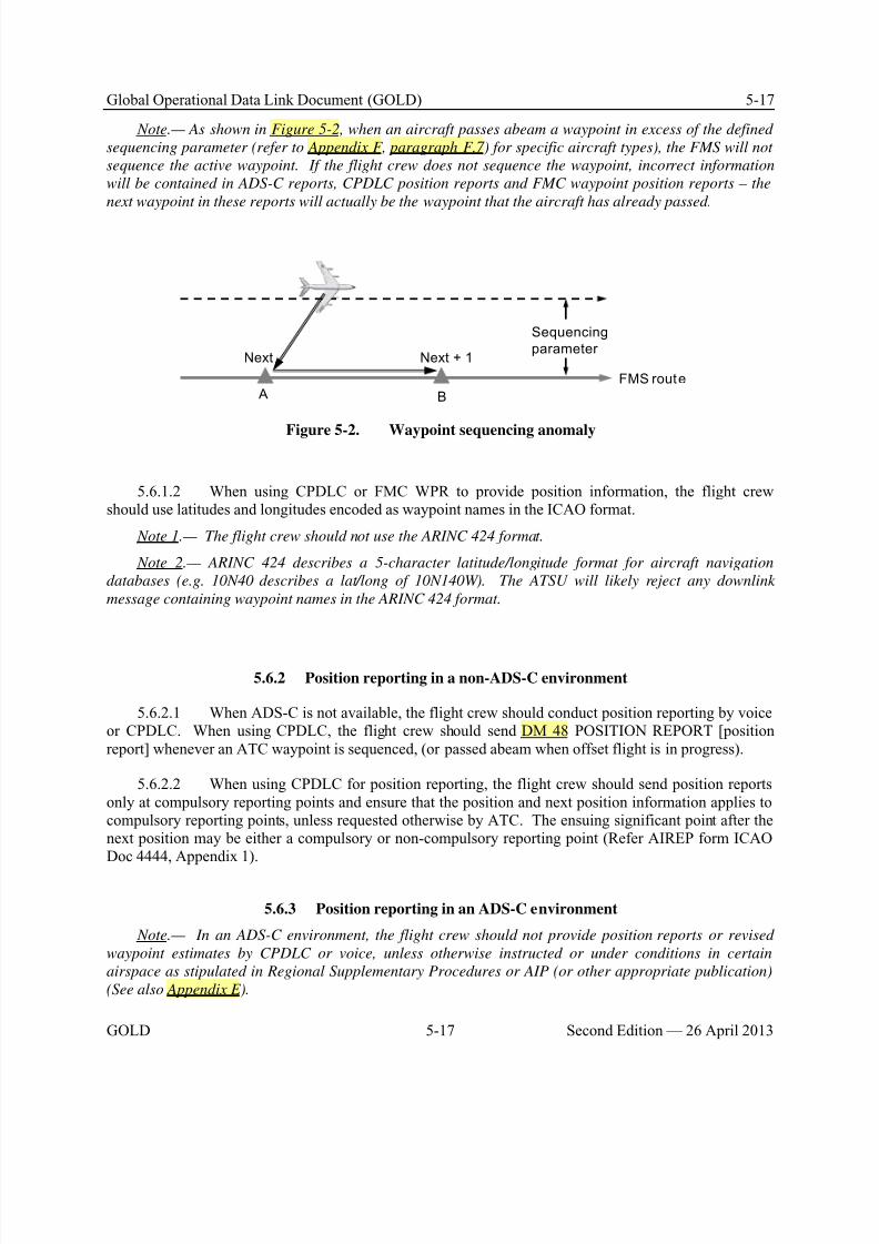
8/9/2019 CPDLC Explained
http://slidepdf.com/reader/full/cpdlc-explained 173/421
Global Operational Data Link Document (GOLD) 5-17
GOLD 5-17 Second Edition — 26 April 2013
Note.— As shown in Figure 5-2, when an aircraft passes abeam a waypoint in excess of the defined
sequencing parameter (refer to Appendix F, paragraph F.7) for specific aircraft types), the FMS will not
sequence the active waypoint. If the flight crew does not sequence the waypoint, incorrect information
will be contained in ADS-C reports, CPDLC position reports and FMC waypoint position reports – the
next waypoint in these reports will actually be the waypoint that the aircraft has already passed.
FMS route A B
Sequencing
parameter Next + 1Next
Figure 5-2. Waypoint sequencing anomaly
5.6.1.2 When using CPDLC or FMC WPR to provide position information, the flight crewshould use latitudes and longitudes encoded as waypoint names in the ICAO format.
Note 1.— The flight crew should not use the ARINC 424 format.
Note 2.— ARINC 424 describes a 5-character latitude/longitude format for aircraft navigation
databases (e.g. 10N40 describes a lat/long of 10N140W). The ATSU will likely reject any downlink
message containing waypoint names in the ARINC 424 format.
5.6.2 Position reporting in a non-ADS-C environment
5.6.2.1 When ADS-C is not available, the flight crew should conduct position reporting by voiceor CPDLC. When using CPDLC, the flight crew should send DM 48 POSITION REPORT [positionreport] whenever an ATC waypoint is sequenced, (or passed abeam when offset flight is in progress).
5.6.2.2 When using CPDLC for position reporting, the flight crew should send position reportsonly at compulsory reporting points and ensure that the position and next position information applies tocompulsory reporting points, unless requested otherwise by ATC. The ensuing significant point after thenext position may be either a compulsory or non-compulsory reporting point (Refer AIREP form ICAODoc 4444, Appendix 1).
5.6.3 Position reporting in an ADS-C environment
Note.— In an ADS-C environment, the flight crew should not provide position reports or revised
waypoint estimates by CPDLC or voice, unless otherwise instructed or under conditions in certain
airspace as stipulated in Regional Supplementary Procedures or AIP (or other appropriate publication)
(See also Appendix E).
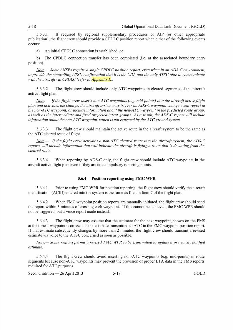
8/9/2019 CPDLC Explained
http://slidepdf.com/reader/full/cpdlc-explained 174/421
5-18 Global Operational Data Link Document (GOLD)
Second Edition — 26 April 2013 5-18 GOLD
5.6.3.1 If required by regional supplementary procedures or AIP (or other appropriate publication), the flight crew should provide a CPDLC position report when either of the following eventsoccurs:
a) An initial CPDLC connection is established; or
b) The CPDLC connection transfer has been completed (i.e. at the associated boundary entry position).
Note.— Some ANSPs require a single CPDLC position report, even when in an ADS-C environment,
to provide the controlling ATSU confirmation that it is the CDA and the only ATSU able to communicate
with the aircraft via CPDLC (refer to Appendix E).
5.6.3.2 The flight crew should include only ATC waypoints in cleared segments of the aircraftactive flight plan.
Note.— If the flight crew inserts non-ATC waypoints (e.g. mid-points) into the aircraft active flight
plan and activates the change, the aircraft system may trigger an ADS-C waypoint change event report at
the non-ATC waypoint, or include information about the non-ATC waypoint in the predicted route group,
as well as the intermediate and fixed projected intent groups. As a result, the ADS-C report will includeinformation about the non-ATC waypoint, which is not expected by the ATC ground system.
5.6.3.3 The flight crew should maintain the active route in the aircraft system to be the same asthe ATC cleared route of flight.
Note.— If the flight crew activates a non-ATC cleared route into the aircraft system, the ADS-C
reports will include information that will indicate the aircraft is flying a route that is deviating from the
cleared route.
5.6.3.4 When reporting by ADS-C only, the flight crew should include ATC waypoints in theaircraft active flight plan even if they are not compulsory reporting points.
5.6.4 Position reporting using FMC WPR
5.6.4.1 Prior to using FMC WPR for position reporting, the flight crew should verify the aircraftidentification (ACID) entered into the system is the same as filed in Item 7 of the flight plan.
5.6.4.2 When FMC waypoint position reports are manually initiated, the flight crew should sendthe report within 3 minutes of crossing each waypoint. If this cannot be achieved, the FMC WPR shouldnot be triggered, but a voice report made instead.
5.6.4.3 The flight crew may assume that the estimate for the next waypoint, shown on the FMSat the time a waypoint is crossed, is the estimate transmitted to ATC in the FMC waypoint position report.
If that estimate subsequently changes by more than 2 minutes, the flight crew should transmit a revisedestimate via voice to the ATSU concerned as soon as possible.
Note.— Some regions permit a revised FMC WPR to be transmitted to update a previously notified
estimate.
5.6.4.4 The flight crew should avoid inserting non-ATC waypoints (e.g. mid-points) in routesegments because non-ATC waypoints may prevent the provision of proper ETA data in the FMS reportsrequired for ATC purposes.
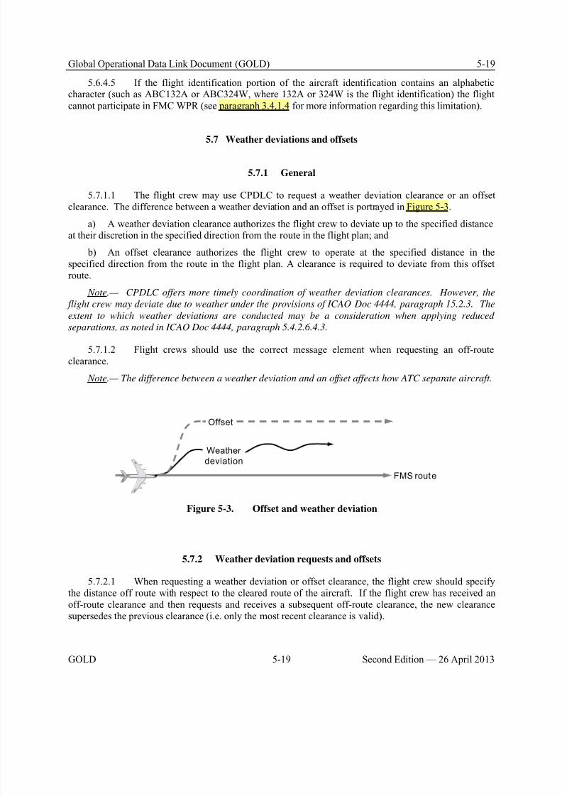
8/9/2019 CPDLC Explained
http://slidepdf.com/reader/full/cpdlc-explained 175/421
Global Operational Data Link Document (GOLD) 5-19
GOLD 5-19 Second Edition — 26 April 2013
5.6.4.5 If the flight identification portion of the aircraft identification contains an alphabeticcharacter (such as ABC132A or ABC324W, where 132A or 324W is the flight identification) the flightcannot participate in FMC WPR (see paragraph 3.4.1.4 for more information regarding this limitation).
5.7 Weather deviations and offsets
5.7.1 General
5.7.1.1 The flight crew may use CPDLC to request a weather deviation clearance or an offsetclearance. The difference between a weather deviation and an offset is portrayed in Figure 5-3.
a) A weather deviation clearance authorizes the flight crew to deviate up to the specified distanceat their discretion in the specified direction from the route in the flight plan; and
b) An offset clearance authorizes the flight crew to operate at the specified distance in thespecified direction from the route in the flight plan. A clearance is required to deviate from this offset
route. Note.— CPDLC offers more timely coordination of weather deviation clearances. However, the
flight crew may deviate due to weather under the provisions of ICAO Doc 4444, paragraph 15.2.3. The
extent to which weather deviations are conducted may be a consideration when applying reduced
separations, as noted in ICAO Doc 4444, paragraph 5.4.2.6.4.3.
5.7.1.2 Flight crews should use the correct message element when requesting an off-routeclearance.
Note.— The difference between a weather deviation and an offset affects how ATC separate aircraft.
FMS route
Offset
Weather
deviation
Figure 5-3. Offset and weather deviation
5.7.2 Weather deviation requests and offsets
5.7.2.1 When requesting a weather deviation or offset clearance, the flight crew should specifythe distance off route with respect to the cleared route of the aircraft. If the flight crew has received anoff-route clearance and then requests and receives a subsequent off-route clearance, the new clearancesupersedes the previous clearance (i.e. only the most recent clearance is valid).

8/9/2019 CPDLC Explained
http://slidepdf.com/reader/full/cpdlc-explained 176/421

8/9/2019 CPDLC Explained
http://slidepdf.com/reader/full/cpdlc-explained 177/421
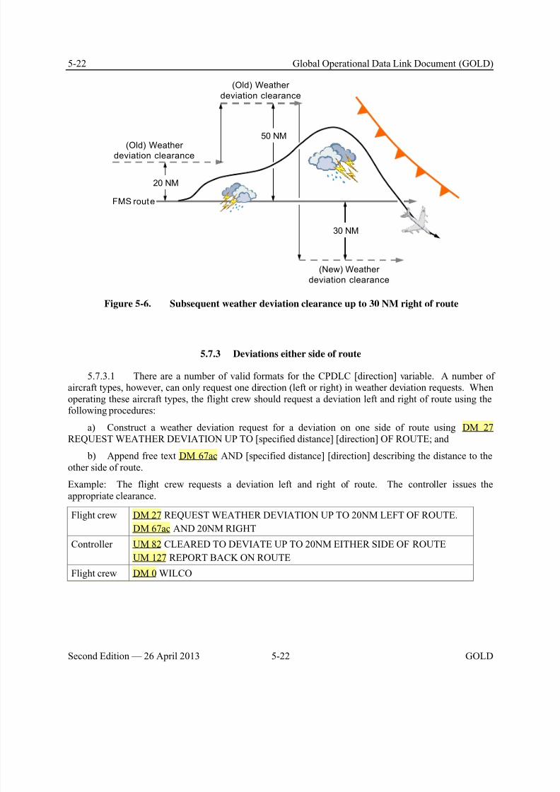
8/9/2019 CPDLC Explained
http://slidepdf.com/reader/full/cpdlc-explained 178/421
5-22 Global Operational Data Link Document (GOLD)
Second Edition — 26 April 2013 5-22 GOLD
FMS route
(Old) Weather
deviation clearance
50 NM
(Old) Weather
deviation clearance
20 NM
30 NM
(New) Weather
deviation clearance
Figure 5-6. Subsequent weather deviation clearance up to 30 NM right of route
5.7.3 Deviations either side of route
5.7.3.1 There are a number of valid formats for the CPDLC [direction] variable. A number ofaircraft types, however, can only request one direction (left or right) in weather deviation requests. Whenoperating these aircraft types, the flight crew should request a deviation left and right of route using thefollowing procedures:
a) Construct a weather deviation request for a deviation on one side of route using DM 27REQUEST WEATHER DEVIATION UP TO [specified distance] [direction] OF ROUTE; and
b) Append free text DM 67ac AND [specified distance] [direction] describing the distance to theother side of route.
Example: The flight crew requests a deviation left and right of route. The controller issues theappropriate clearance.
Flight crew DM 27 REQUEST WEATHER DEVIATION UP TO 20NM LEFT OF ROUTE.
DM 67ac AND 20NM RIGHT
Controller UM 82 CLEARED TO DEVIATE UP TO 20NM EITHER SIDE OF ROUTE
UM 127 REPORT BACK ON ROUTE
Flight crew DM 0 WILCO
8/9/2019 CPDLC Explained
http://slidepdf.com/reader/full/cpdlc-explained 179/421
Global Operational Data Link Document (GOLD) 5-23
GOLD 5-23 Second Edition — 26 April 2013
5.7.4 Reporting back on route
5.7.4.1 When the flight crew no longer needs the deviation clearance and is back on the clearedroute, the flight crew should send a DM 41 BACK ON ROUTE report.
a) If during the weather deviation, the flight crew receives a clearance to proceed direct to awaypoint – and the flight crew responds to the clearance with DM 0 WILCO – the aircraft is consideredto be on the cleared route. Therefore, the flight crew should send a DM 41 BACK ON ROUTE reportafter they execute the “direct to” clearance; and
b) If the aircraft is off route during a weather deviation clearance and proceeding direct to awaypoint on the cleared route, the flight crew should send a DM 41 BACK ON ROUTE report after theaircraft has sequenced the waypoint on the cleared route.
Note.— If a DM 41 BACK ON ROUTE report is received while the aircraft is still off route, the
incorrect information provided to ATC may affect the separation standards in use. Alternatively, the
flight crew may consider requesting a clearance direct to the waypoint – on receipt of the uplink
clearance, the procedure specified in item a) above applies.
5.8 Emergency procedures
5.8.1 General
5.8.1.1 In accordance with established emergency procedures, the ATSU within whose airspacethe aircraft is operating remains in control of the flight. If the flight crew takes action contrary to aclearance that the controller has already coordinated with another sector or ATSU and furthercoordination is not possible in the time available, then the flight crew performs this action under theiremergency command authority.
5.8.1.2 The flight crew will use whatever means are appropriate (i.e. CPDLC and/or voice) tocommunicate during an emergency.
5.8.1.3 During an emergency, the flight crew would normally revert to voice communications.However, the flight crew may use CPDLC for emergency communications if it is either more expedientor if voice contact cannot be established.
Note.— For ATN B1 aircraft, emergency message elements are not supported. See Appendix A,
paragraph A.4, for a list of emergency message elements.
5.8.2 CPDLC and ADS-C emergency
5.8.2.1 When using CPDLC to indicate an emergency situation or degraded operations to anATSU, the flight crew should use the CPDLC emergency downlink message, either DM 56 MAYDAYMAYDAY MAYDAY or DM 55 PAN PAN PAN.
Note 1.— The flight crew may enter PERSONS on BOARD during preflight preparation, prior to
initiating a logon, or prior to sending the emergency message.
Note 2.— The CPDLC emergency downlink message will automatically select the ADS-C function to
emergency mode. When a situation prohibits sending a CPDLC emergency message (e.g. in an ADS-C
8/9/2019 CPDLC Explained
http://slidepdf.com/reader/full/cpdlc-explained 180/421
5-24 Global Operational Data Link Document (GOLD)
Second Edition — 26 April 2013 5-24 GOLD
only environment), the flight crew may activate ADS-C emergency mode directly via ADS-C control
functions.
5.8.2.2 If a CPDLC emergency downlink message is inadvertently sent or the emergencysituation is resolved, the flight crew should send DM 58 CANCEL EMERGENCY as soon as possible to
advise the controller and automatically set the ADS-C emergency mode to off. After sending DM 58CANCEL EMERGENCY, the flight crew should confirm the status of the flight and their intentions viaeither voice or CPDLC.
5.8.2.3 To check for inadvertent activation of the ADS-C emergency mode using CPDLC, thecontroller may send the following CPDLC free text uplink or use equivalent voice phraseology:
Controller UM 169ak CONFIRM ADS-C EMERGENCY
The flight crew should then check the status of the aircraft’s ADS-C emergency mode and if theemergency mode has been activated inadvertently, the flight crew should select ADS-C emergency modeto off and advise the controller either by voice or by the following CPDLC messages.
Flight crew DM 3 ROGER, then (free text)DM 67ab ADS-C RESET
5.9 Non-routine procedures
5.9.1 General
5.9.1.1 Refer to current ICAO procedures for standards and recommended practices on completecommunications failure (CPDLC and voice).
5.9.2 Voice communications related to data link
5.9.2.1 When CPDLC fails and open messages existed at the time of failure, the flight crewshould re-commence any dialogues involving those messages by voice.
5.9.2.2 The flight crew should use the standard voice phraseology under certain conditions asindicated in Table 5-3.
Note.— See paragraph 4.9.2.2 for standard voice phraseology used by the controller or radio
operator.
5.9.2.3 Except as provided in Table 5-3 and paragraph 4.9.2.2, voice communication procedures
related to data link operations are not standardized among the regions. Refer to Appendix E for anyadditional voice communication procedures for a specific region.
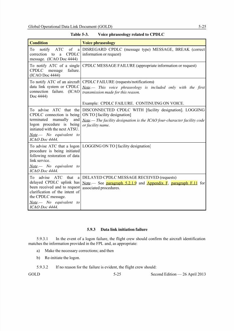
8/9/2019 CPDLC Explained
http://slidepdf.com/reader/full/cpdlc-explained 181/421
8/9/2019 CPDLC Explained
http://slidepdf.com/reader/full/cpdlc-explained 182/421
5-26 Global Operational Data Link Document (GOLD)
Second Edition — 26 April 2013 5-26 GOLD
a) Contact the ATSU by voice to advise of the failure; and
b) Contact AOC to advise of the failure.
Note.— The ATSU will attempt to resolve the problem.
5.9.3.3 The flight crew should report log-on failures to the appropriate State/regional monitoringagency in accordance with procedures established by the operator (paragraph 3.2.2 refers).
5.9.4 Data link system failures
5.9.4.1 When operating CPDLC and the aircraft data link system provides an indication ofdegraded performance resulting from a failure or loss of connectivity, the flight crew should notify theATSU of the failure as soon as practicable, including:
a) When operating outside of VHF coverage area and the SATCOM data link system fails; and
b) When operating in airspace where ATS surveillance services are provided and the VHF data
link system fails. Note.— Timely notification is appropriate to ensure that the ATSU has time to assess the situation
and apply a revised separation standard, if necessary.
5.9.4.2 If an automatic transfer of the CPDLC connection does not occur at the boundary, theflight crew should contact the transferring ATSU by sending DM 67j CPDLC TRANSFER FAILURE (orvoice equivalent), advising them that the transfer has not occurred.
5.9.4.3 In the event of an aircraft data link system failure, the flight crew should notify the ATSUof the situation using the following voice phraseology:
Flight crew CPDLC FAILURE. CONTINUING ON VOICE
Controller ROGER. CONTINUE ON VOICE
Note.— The flight crew continues to use voice until the functionality of the aircraft system can be re-
established.
5.9.4.4 When the ATSU provides notification that the CPDLC service has failed or will be shutdown, the flight crew should follow the instructions provided in the notification (e.g. disconnect CPDLCand continue on voice until informed by the ATSU that the data link system has resumed normal CPDLCoperations).
5.9.4.5 If only the ADS-C service is terminated, then during that time period, the flight crewshould conduct position reporting by other means (e.g. CPDLC, if available, or via voice).
5.9.4.6 If the ATSU cannot establish ADS contracts with an aircraft, or if ADS-C reporting froman aircraft ceases, the flight crew may have inadvertently switched ADS-C off. If CPDLC is stillavailable and the flight crew receives the CPDLC message UM 169an CONFIRM ADS-C ARMED (orvoice equivalent), they should check to ensure that ADS-C is not switched off and respond to thecontroller as follows:
Controller UM 169an CONFIRM ADS-C ARMED
8/9/2019 CPDLC Explained
http://slidepdf.com/reader/full/cpdlc-explained 183/421
Global Operational Data Link Document (GOLD) 5-27
GOLD 5-27 Second Edition — 26 April 2013
Flight crew DM 3 ROGER
5.9.4.7 If the aircraft is operating on a vertical profile that is different from the profile programmed in the FMS, the time estimates in the ADS-C report will be inaccurate. If the flight crewreceives the message UM 169h ADS-C ESTIMATES APPEAR INACCURATE. CHECK FMS, theflight crew should check the FMS, correct any the discrepancy and respond to the CPDLC message withDM 3 ROGER.
5.9.5 Using CPDLC to relay messages
5.9.5.1 When an ATSU and an aircraft cannot communicate, the controller may use CPDLC orvoice to relay messages. When it had been determined to use CPDLC, the controller may first confirmthat the CPDLC-capable aircraft is in contact with the subject aircraft. The flight crew should concur thatthey will act as an intermediary.
5.9.5.2 When using CPDLC to relay messages, the flight crew should:
a) Only respond with DM 3 ROGER to CPDLC messages consisting entirely of free text; and
b) Respond with DM 1 UNABLE to any CPDLC message containing standard message elementsto avoid confusion.
5.9.5.3 After sending DM 3 ROGER, the flight crew should only use free text to respond to thecontroller’s uplink free text message.
Example, using:
a) UM 169ap RELAY TO [call sign] [unit name] [text of message to be relayed]; and
b) DM 67ae RELAY FROM [call sign] [response parameters]; where.
1) [call sign] is expressed as the radiotelephony call sign, rather than the ICAO three letter orIATA two letter designator; and
2) [response parameters] conform to the guidelines provided paragraph 5.4.2.3.
Controller UM 169ap RELAY TO UNITED345 OAKLAND CLEARS UNITED345 CLIMBTO AND MAINTAIN FL340
Flight crew DM 3 ROGER
Flight crew DM 67ae RELAY FROM UNITED345 CLIMBING FL340

8/9/2019 CPDLC Explained
http://slidepdf.com/reader/full/cpdlc-explained 184/421
8/9/2019 CPDLC Explained
http://slidepdf.com/reader/full/cpdlc-explained 185/421
Global Operational Data Link Document (GOLD) 6-1
GOLD 6-1 Second Edition — 26 April 2013
Chapter 6. Advanced air traffic services supported by data link
6.1 Re-route procedures
6.1.1 General
6.1.1.1 When re-routing an aircraft, the flight crew, AOC and each ATSU should followstandardized procedures using appropriate CPDLC message elements. For flight crews performing re-routes, see paragraph 5.3.5.
6.1.1.2 The availability of new weather forecasts on long-haul routes may provide the potentialfor economic and/or safety benefits for operators by allowing them to propose revised routes for airborneaircraft.
6.1.1.3 The flight crew may initiate a re-route request. Each ATSU along the route may initiate
an amended route clearance.
6.1.1.4 For flights that cross the common boundary between two automated ATSUs, the ATSUscan coordinate revised route information, reducing the requirement for AOC to transmit modificationmessages to all the ATSUs along the route.
6.1.1.5 If a re-route clearance changes the NEXT or NEXT+1 waypoint, the flight crew shouldupdate the re-route clearance with most current available weather information for the newwaypoints/levels.
6.1.2 Re-route procedures – AOC initiated (DARP)
6.1.2.1 The purpose of the dynamic airborne re-route procedure (DARP) is to allow aeronauticaloperational control (AOC) to initiate the process for an airborne aircraft to be issued an amended routeclearance by the ATSU.
6.1.2.2 An operator should only initiate these procedures where the re-route will occur in FIRswhere DARP services are available (Refer to Appendix E).
Note.— DARP service requires Air Traffic Services Interfacility Data Communications (AIDC) to
permit the electronic exchange of revised route information.
6.1.2.3 To be eligible for DARP, the operator will need an aircraft with operational CPDLCcapability. Additionally, the flight crew should downlink the route request:
a) At least 60 minutes prior to crossing the next boundary to permit AIDC messaging to take place between the affected ATSUs. This time period may be reduced between ATSUs that support AIDC CDNmessaging to coordinate the modification of route information; and
b) At least 20 minutes prior to the divergence waypoint to allow processing time by the ATSU andthe flight crew.

8/9/2019 CPDLC Explained
http://slidepdf.com/reader/full/cpdlc-explained 186/421
6-2 Global Operational Data Link Document (GOLD)
Second Edition — 26 April 2013 6-2 GOLD
Note.— A downlink route request may be made to a new ATSU immediately after crossing the
boundary provided the above requirements are still met.
6.1.2.4 Table 6-1 provides the procedures for an AOC initiated re-route and Figure 6-1 providesan overview of the DARP process.
Table 6-1. AOC initiated re-route procedures
Who Procedures
AOC
(Step 1)
a) The AOC should generate the amended route in compliance with standard UPRflight planning requirements (e.g. common boundary waypoints).
b) The AOC ensures that the elements used to define the amended route complywith the requirements of ICAO Doc 4444. The elements that may be used to describe theamended route include:
1) Fix Names; Note 1.— ARINC 424 fix names should not be used to define latitude and longitude.
2) Airway Designators;
Note 2.— Where an airway designator is used it should be preceded and followed
by a fix name or navaid designator that is defined on the airway described.
3) Navaid Designators; and
4) Latitude and Longitude.
Note 3.— The ICAO requirement is that position should be defined in either whole
degrees of latitude and longitude (e.g. 35S164E), or degrees and minutes for both
latitude and longitude (e.g. 2513S15645E). A mixture of these formats should be avoided(e.g. 35S15725E).
c) The AOC uplinks the proposed route to the aircraft via ACARS.
Flight crew
(Step 2)
a) Where applicable, delete any waypoints on the proposed route that havealready been sequenced.
b) Providing that the proposed route is acceptable to the flight crew, downlink theroute request to the controlling ATSU using the CPDLC message element:
DM 24 REQUEST CLEARANCE [route clearance] or REQUEST [route clearance]
where the first fix in the route clearance is the next waypoint ahead of the aircraft. Note 4.— The route request may also contain additional information such as
departure airport, destination airport, etc.
Note 5.— Flight crew procedures should include guidance on downlinking CPDLC
route clearance requests.
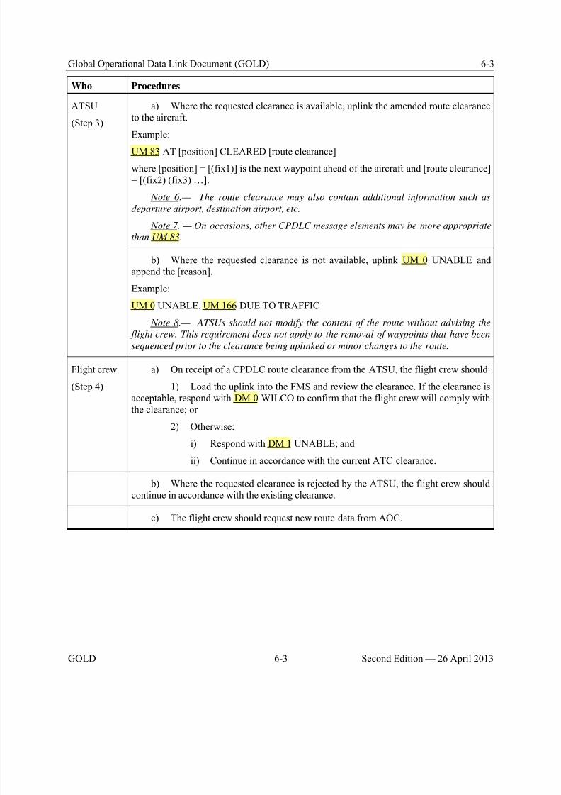
8/9/2019 CPDLC Explained
http://slidepdf.com/reader/full/cpdlc-explained 187/421
Global Operational Data Link Document (GOLD) 6-3
GOLD 6-3 Second Edition — 26 April 2013
Who Procedures
ATSU
(Step 3)
a) Where the requested clearance is available, uplink the amended route clearanceto the aircraft.
Example:UM 83 AT [position] CLEARED [route clearance]
where [position] = [(fix1)] is the next waypoint ahead of the aircraft and [route clearance]= [(fix2) (fix3) …].
Note 6.— The route clearance may also contain additional information such as
departure airport, destination airport, etc.
Note 7. — On occasions, other CPDLC message elements may be more appropriate
than UM 83.
b) Where the requested clearance is not available, uplink UM 0 UNABLE andappend the [reason].
Example:
UM 0 UNABLE. UM 166 DUE TO TRAFFIC
Note 8.— ATSUs should not modify the content of the route without advising the
flight crew. This requirement does not apply to the removal of waypoints that have been
sequenced prior to the clearance being uplinked or minor changes to the route.
Flight crew
(Step 4)
a) On receipt of a CPDLC route clearance from the ATSU, the flight crew should:
1) Load the uplink into the FMS and review the clearance. If the clearance isacceptable, respond with DM 0 WILCO to confirm that the flight crew will comply withthe clearance; or
2) Otherwise:
i) Respond with DM 1 UNABLE; and
ii) Continue in accordance with the current ATC clearance.
b) Where the requested clearance is rejected by the ATSU, the flight crew shouldcontinue in accordance with the existing clearance.
c) The flight crew should request new route data from AOC.
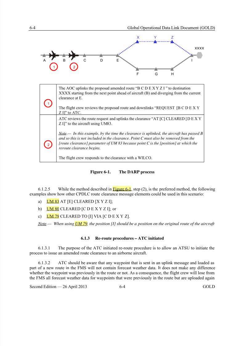
8/9/2019 CPDLC Explained
http://slidepdf.com/reader/full/cpdlc-explained 188/421
6-4 Global Operational Data Link Document (GOLD)
Second Edition — 26 April 2013 6-4 GOLD
XXXX
I
HGF
EDCB A
X Y Z
1 2
The AOC uplinks the proposed amended route “B C D E X Y Z I ” to destination
XXXX starting from the next point ahead of aircraft (B) and diverging from the current
clearance at E.
The flight crew reviews the proposed route and downlinks “REQUEST [B C D E X Y
Z I]” to ATC.
ATC reviews the route request and uplinks the clearance “AT [C] CLEARED [D E X Y
Z I]” to the aircraft using UM83.
Note.— In this example, by the time the clearance is uplinked, the aircraft has passed B
and so this is not included in the clearance. Point C must also be removed from the
[route clearance] parameter of UM 83 because point C is the [position] at which the
reroute clearance begins.
The flight crew responds to the clearance with a WILCO.
1
2
Figure 6-1. The DARP process
6.1.2.5 While the method described in Figure 6-1, step (2), is the preferred method, the followingexamples show how other CPDLC route clearance message elements could be used in this scenario:
a) UM 83 AT [E] CLEARED [X Y Z I];
b) UM 80 CLEARED [C D E X Y Z I]; or
c) UM 79 CLEARED TO [I] VIA [C D E X Y Z].
Note.— When using UM 79, the position [I] should be a position on the original route of the aircraft
6.1.3 Re-route procedures – ATC initiated
6.1.3.1 The purpose of the ATC initiated re-route procedure is to allow an ATSU to initiate the process to issue an amended route clearance to an airborne aircraft.
6.1.3.2 ATC should be aware that any waypoint that is sent in an uplink message and loaded as part of a new route in the FMS will not contain forecast weather data. It does not make any differencewhether the waypoint was previously in the route or not. As a consequence, the flight crew will lose fromthe FMS all forecast weather data for waypoints that were previously in the route but are uploaded again

8/9/2019 CPDLC Explained
http://slidepdf.com/reader/full/cpdlc-explained 189/421
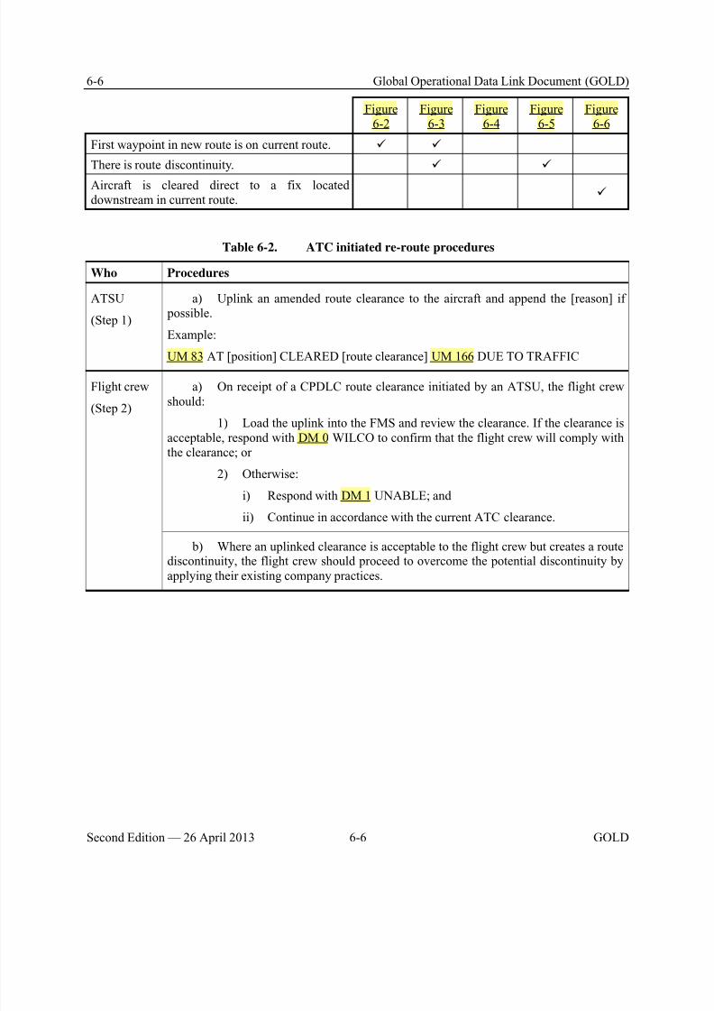
8/9/2019 CPDLC Explained
http://slidepdf.com/reader/full/cpdlc-explained 190/421
6-6 Global Operational Data Link Document (GOLD)
Second Edition — 26 April 2013 6-6 GOLD
Figure6-2
Figure6-3
Figure6-4
Figure6-5
Figure6-6
First waypoint in new route is on current route.
There is route discontinuity.
Aircraft is cleared direct to a fix locateddownstream in current route.
Table 6-2. ATC initiated re-route procedures
Who Procedures
ATSU
(Step 1)
a) Uplink an amended route clearance to the aircraft and append the [reason] if possible.
Example:
UM 83 AT [position] CLEARED [route clearance] UM 166 DUE TO TRAFFIC
Flight crew
(Step 2)
a) On receipt of a CPDLC route clearance initiated by an ATSU, the flight crewshould:
1) Load the uplink into the FMS and review the clearance. If the clearance isacceptable, respond with DM 0 WILCO to confirm that the flight crew will comply withthe clearance; or
2) Otherwise:
i) Respond with DM 1 UNABLE; and
ii) Continue in accordance with the current ATC clearance.
b) Where an uplinked clearance is acceptable to the flight crew but creates a routediscontinuity, the flight crew should proceed to overcome the potential discontinuity byapplying their existing company practices.
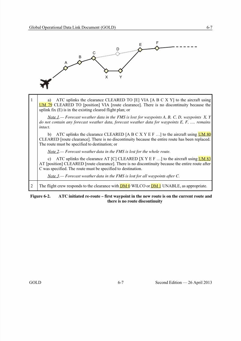
8/9/2019 CPDLC Explained
http://slidepdf.com/reader/full/cpdlc-explained 191/421
Global Operational Data Link Document (GOLD) 6-7
GOLD 6-7 Second Edition — 26 April 2013
A
BC
DE
F
YX
1 a) ATC uplinks the clearance CLEARED TO [E] VIA [A B C X Y] to the aircraft usingUM 79 CLEARED TO [position] VIA [route clearance]. There is no discontinuity because theuplink fix (E) is in the existing cleared flight plan; or
Note 1.— Forecast weather data in the FMS is lost for waypoints A, B, C, D, waypoints X, Y
do not contain any forecast weather data, forecast weather data for waypoints E, F, …. remains
intact.
b) ATC uplinks the clearance CLEARED [A B C X Y E F …] to the aircraft using UM 80CLEARED [route clearance]. There is no discontinuity because the entire route has been replaced.The route must be specified to destination; or
Note 2.— Forecast weather data in the FMS is lost for the whole route.
c) ATC uplinks the clearance AT [C] CLEARED [X Y E F …] to the aircraft using UM 83AT [position] CLEARED [route clearance]. There is no discontinuity because the entire route afterC was specified. The route must be specified to destination.
Note 3.— Forecast weather data in the FMS is lost for all waypoints after C.
2 The flight crew responds to the clearance with DM 0 WILCO or DM 1 UNABLE, as appropriate.
Figure 6-2. ATC initiated re-route – first waypoint in the new route is on the current route and
there is no route discontinuity

8/9/2019 CPDLC Explained
http://slidepdf.com/reader/full/cpdlc-explained 192/421
6-8 Global Operational Data Link Document (GOLD)
Second Edition — 26 April 2013 6-8 GOLD
A
BC
DE
F
YX
G H
Z
1 ATC uplinks the clearance CLEARED TO [Z] VIA [A B C X Y] to the aircraft using UM 79CLEARED TO [position] VIA [route clearance].
Note 1.— Forecast weather data in the FMS is lost for waypoints A, B, C waypoints. X, Y, Z
do not contain any forecast weather data. Forecast weather data for waypoints D, E F, G, H etc
remains intact.
Note 2.— In this case, ATC should not use CPDLC message elements UM 80 CLEARED
[route clearance] or UM 83 AT [position] CLEARED [route clearance].
2 a) The flight crew responds to the clearance with DM 0 WILCO or DM 1 UNABLE, asappropriate.
b) This clearance creates a route discontinuity at Z. The flight crew should obtain furtherroute clearance from ATC before the aircraft reaches Z (that clearance could, for example, be fromZ direct to G). In the meantime, the flight crew should overcome the discontinuity at Z byapplying their existing company practices under the assumption that a further route clearance will be received before reaching Z.
Figure 6-3. ATC initiated re-route – first waypoint in the new route is on the current route and
there is route discontinuity

8/9/2019 CPDLC Explained
http://slidepdf.com/reader/full/cpdlc-explained 193/421
Global Operational Data Link Document (GOLD) 6-9
GOLD 6-9 Second Edition — 26 April 2013
A
BC
DE
F
YX
1 a) ATC uplinks the clearance CLEARED TO [E] VIA [X Y] to the aircraft using UM 79CLEARED TO [position] VIA [route clearance]. There is no discontinuity at E because the uplinkfix (E) is in the existing cleared flight plan; or
Note 1.— Forecast weather data in the FMS is lost for waypoints A, B, C, D, waypoints X, Y
do not contain any forecast weather data, forecast weather data for waypoints E, F, etc, remains
intact).
b) ATC uplinks the clearance CLEARED [X, Y, E, F …] to the aircraft using UM 80CLEARED [route clearance]. The entire route is replaced and the route must be specified todestination.
Note 2.— Forecast weather data in the FMS is lost for the whole route.
Note 3.— The clearance in a) and b) above takes immediate effect and, since the first fix
specified (X) is not on the existing route of flight, the new route effectively starts with “present
position direct X,” although this is not explicitly stated in the uplink message.
Note 4.— In this case, ATC should not use CPDLC message element UM 83 AT [position]
CLEARED [route clearance].
2 The flight crew responds to the clearance with DM 0 WILCO or DM 1 UNABLE, as appropriate.
Figure 6-4. ATC initiated re-route – first waypoint in the new route is not on the current route
and there is no route discontinuity
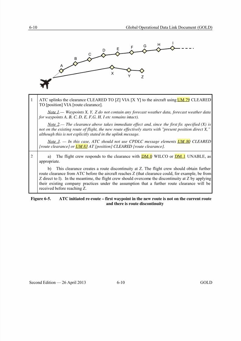
8/9/2019 CPDLC Explained
http://slidepdf.com/reader/full/cpdlc-explained 194/421
6-10 Global Operational Data Link Document (GOLD)
Second Edition — 26 April 2013 6-10 GOLD
A
B
CD E F
YX
G H
Z
I
1 ATC uplinks the clearance CLEARED TO [Z] VIA [X Y] to the aircraft using UM 79 CLEAREDTO [position] VIA [route clearance].
Note 1.— Waypoints X, Y, Z do not contain any forecast weather data, forecast weather data
for waypoints A, B, C, D, E, F,G, H, I etc remains intact).
Note 2.— The clearance above takes immediate effect and, since the first fix specified (X) is
not on the existing route of flight, the new route effectively starts with "present position direct X,”
although this is not explicitly stated in the uplink message.
Note 3. — In this case, ATC should not use CPDLC message elements UM 80 CLEARED
[route clearance] or UM 83 AT [position] CLEARED [route clearance].
2 a) The flight crew responds to the clearance with DM 0 WILCO or DM 1 UNABLE, asappropriate.
b) This clearance creates a route discontinuity at Z. The flight crew should obtain furtherroute clearance from ATC before the aircraft reaches Z (that clearance could, for example, be from
Z direct to I). In the meantime, the flight crew should overcome the discontinuity at Z by applyingtheir existing company practices under the assumption that a further route clearance will bereceived before reaching Z.
Figure 6-5. ATC initiated re-route – first waypoint in the new route is not on the current route
and there is route discontinuity
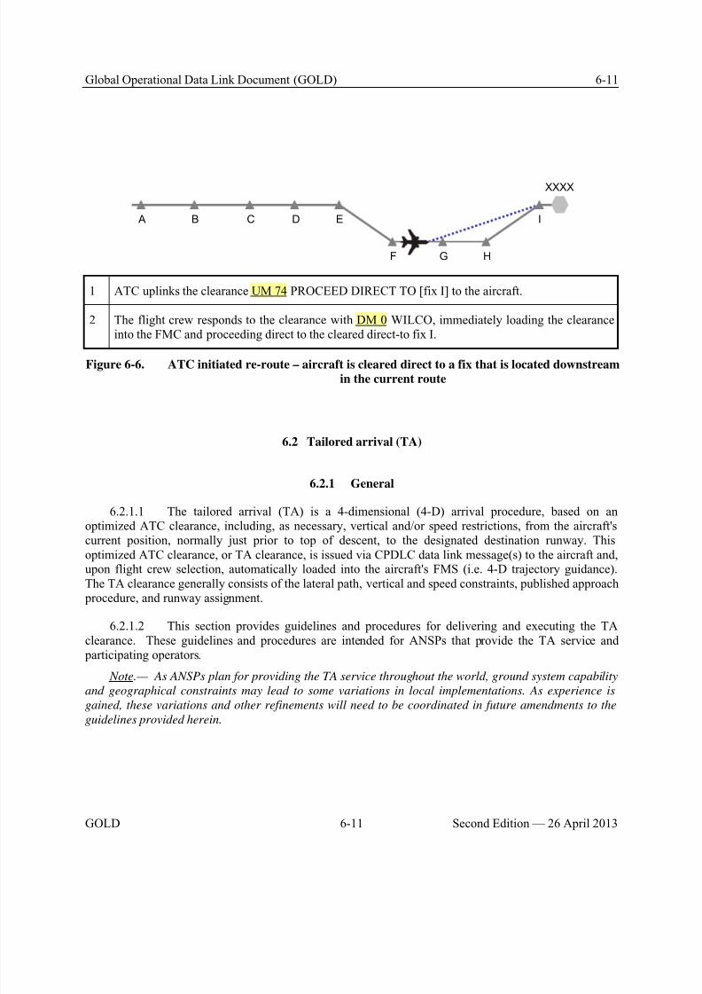
8/9/2019 CPDLC Explained
http://slidepdf.com/reader/full/cpdlc-explained 195/421
Global Operational Data Link Document (GOLD) 6-11
GOLD 6-11 Second Edition — 26 April 2013
XXXX
I
HGF
EDCB A
1 ATC uplinks the clearance UM 74 PROCEED DIRECT TO [fix I] to the aircraft.
2 The flight crew responds to the clearance with DM 0 WILCO, immediately loading the clearanceinto the FMC and proceeding direct to the cleared direct-to fix I.
Figure 6-6. ATC initiated re-route – aircraft is cleared direct to a fix that is located downstream
in the current route
6.2 Tailored arrival (TA)
6.2.1 General
6.2.1.1 The tailored arrival (TA) is a 4-dimensional (4-D) arrival procedure, based on an
optimized ATC clearance, including, as necessary, vertical and/or speed restrictions, from the aircraft'scurrent position, normally just prior to top of descent, to the designated destination runway. Thisoptimized ATC clearance, or TA clearance, is issued via CPDLC data link message(s) to the aircraft and,upon flight crew selection, automatically loaded into the aircraft's FMS (i.e. 4-D trajectory guidance).The TA clearance generally consists of the lateral path, vertical and speed constraints, published approach procedure, and runway assignment.
6.2.1.2 This section provides guidelines and procedures for delivering and executing the TAclearance. These guidelines and procedures are intended for ANSPs that provide the TA service and participating operators.
Note.— As ANSPs plan for providing the TA service throughout the world, ground system capability
and geographical constraints may lead to some variations in local implementations. As experience isgained, these variations and other refinements will need to be coordinated in future amendments to the
guidelines provided herein.
8/9/2019 CPDLC Explained
http://slidepdf.com/reader/full/cpdlc-explained 196/421
6-12 Global Operational Data Link Document (GOLD)
Second Edition — 26 April 2013 6-12 GOLD
6.2.2 Provisions for the TA service
6.2.2.1 The operator should establish operating and notification procedures for the flight crewand conduct training to be eligible to participate in tailored arrivals.
6.2.2.2 At each of the ATSUs where the TA service is available, the ANSP should provide procedures to the controllers and conduct training for constructing and issuing the TA clearance. If theflight crew from an eligible operator requests a TA clearance and the traffic situation permits, thecontroller should accommodate the request. All other standard operating procedures apply.
6.2.2.3 When the TA service is provided, the ANSP should:
a) Assign a TA designator to the TA clearance. The TA designator should:
1) Contain more than five letters so that it is not easily confused with a published or public procedure;
2) Relate to the geographical arrival area (e.g. PACIFIC 1 TA); and
3) Be easy to pronounce when communicating on voice. Note.— The flight crew and the controller use the TA designator throughout the procedure to
unambiguously convey the route and vertical and speed constraints associated with the TA.
b) Define and notify operators of the TA request point as a time in minutes from the estimated topof descent (TOD) or from the airspace boundary where CPDLC service is terminated.
Note.— For example, the TA request point for the PACIFIC 1 TA at San Francisco airport is 45
minutes before the aircraft enters U.S. domestic airspace.
6.2.3 Clearance delivery and execution
6.2.3.1 Table 6-3 provides the procedures for delivering and executing a tailored arrivalclearance.
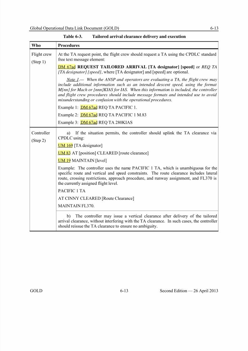
8/9/2019 CPDLC Explained
http://slidepdf.com/reader/full/cpdlc-explained 197/421
Global Operational Data Link Document (GOLD) 6-13
GOLD 6-13 Second Edition — 26 April 2013
Table 6-3. Tailored arrival clearance delivery and execution
Who Procedures
Flight crew
(Step 1)
At the TA request point, the flight crew should request a TA using the CPDLC standard
free text message element:DM 67ad REQUEST TAILORED ARRIVAL [TA designator] [speed] or REQ TA
[TA designator] [speed], where [TA designator] and [speed] are optional.
Note 1.— When the ANSP and operators are evaluating a TA, the flight crew may
include additional information such as an intended descent speed, using the format
M[nn] for Mach or [nnn]KIAS for IAS. When this information is included, the controller
and flight crew procedures should include message formats and intended use to avoid
misunderstanding or confusion with the operational procedures.
Example 1: DM 67ad REQ TA PACIFIC 1.
Example 2: DM 67ad REQ TA PACIFIC 1 M.83
Example 3: DM 67ad REQ TA 280KIAS
Controller
(Step 2)
a) If the situation permits, the controller should uplink the TA clearance viaCPDLC using:
UM 169 [TA designator]
UM 83 AT [position] CLEARED [route clearance]
UM 19 MAINTAIN [level]
Example: The controller uses the name PACIFIC 1 TA, which is unambiguous for thespecific route and vertical and speed constraints. The route clearance includes lateralroute, crossing restrictions, approach procedure, and runway assignment, and FL370 is
the currently assigned flight level.PACIFIC 1 TA
AT CINNY CLEARED [Route Clearance]
MAINTAIN FL370.
b) The controller may issue a vertical clearance after delivery of the tailoredarrival clearance, without interfering with the TA clearance. In such cases, the controllershould reissue the TA clearance to ensure no ambiguity.
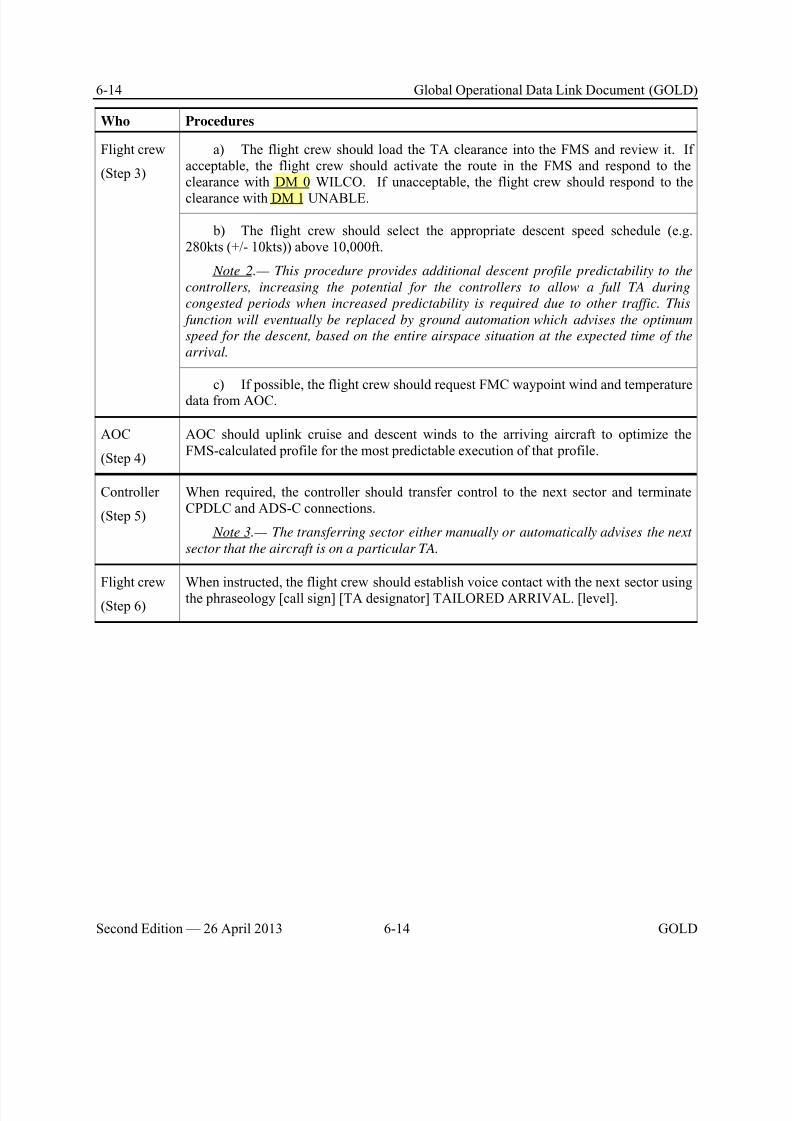
8/9/2019 CPDLC Explained
http://slidepdf.com/reader/full/cpdlc-explained 198/421
6-14 Global Operational Data Link Document (GOLD)
Second Edition — 26 April 2013 6-14 GOLD
Who Procedures
Flight crew
(Step 3)
a) The flight crew should load the TA clearance into the FMS and review it. Ifacceptable, the flight crew should activate the route in the FMS and respond to theclearance with DM 0 WILCO. If unacceptable, the flight crew should respond to the
clearance with DM 1 UNABLE.
b) The flight crew should select the appropriate descent speed schedule (e.g.280kts (+/- 10kts)) above 10,000ft.
Note 2.— This procedure provides additional descent profile predictability to the
controllers, increasing the potential for the controllers to allow a full TA during
congested periods when increased predictability is required due to other traffic. This
function will eventually be replaced by ground automation which advises the optimum
speed for the descent, based on the entire airspace situation at the expected time of the
arrival.
c) If possible, the flight crew should request FMC waypoint wind and temperaturedata from AOC.
AOC
(Step 4)
AOC should uplink cruise and descent winds to the arriving aircraft to optimize theFMS-calculated profile for the most predictable execution of that profile.
Controller
(Step 5)
When required, the controller should transfer control to the next sector and terminateCPDLC and ADS-C connections.
Note 3.— The transferring sector either manually or automatically advises the next
sector that the aircraft is on a particular TA.
Flight crew(Step 6)
When instructed, the flight crew should establish voice contact with the next sector usingthe phraseology [call sign] [TA designator] TAILORED ARRIVAL. [level].
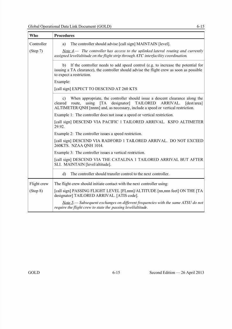
8/9/2019 CPDLC Explained
http://slidepdf.com/reader/full/cpdlc-explained 199/421
Global Operational Data Link Document (GOLD) 6-15
GOLD 6-15 Second Edition — 26 April 2013
Who Procedures
Controller
(Step 7)
a) The controller should advise [call sign] MAINTAIN [level].
Note 4.— The controller has access to the uplinked lateral routing and currently
assigned level/altitude on the flight strip through ATC interfacility coordination.
b) If the controller needs to add speed control (e.g. to increase the potential forissuing a TA clearance), the controller should advise the flight crew as soon as possibleto expect a restriction.
Example:
[call sign] EXPECT TO DESCEND AT 260 KTS
c) When appropriate, the controller should issue a descent clearance along thecleared route, using [TA designator] TAILORED ARRIVAL. [dest/area]ALTIMETER/QNH [nnnn] and, as necessary, include a speed or vertical restriction.
Example 1: The controller does not issue a speed or vertical restriction.
[call sign] DESCEND VIA PACIFIC 1 TAILORED ARRIVAL. KSFO ALTIMETER29.92.
Example 2: The controller issues a speed restriction.
[call sign] DESCEND VIA RADFORD 1 TAILORED ARRIVAL. DO NOT EXCEED260KTS. NZAA QNH 1014.
Example 3: The controller issues a vertical restriction.
[call sign] DESCEND VIA THE CATALINA 1 TAILORED ARRIVAL BUT AFTERSLI. MAINTAIN [level/altitude].
d) The controller should transfer control to the next controller.
Flight crew
(Step 8)
The flight crew should initiate contact with the next controller using:
[call sign] PASSING FLIGHT LEVEL [FLnnn]/ALTITUDE [nn,nnn feet] ON THE [TAdesignator] TAILORED ARRIVAL. [ATIS code].
Note 5.— Subsequent exchanges on different frequencies with the same ATSU do not
require the flight crew to state the passing level/altitude.
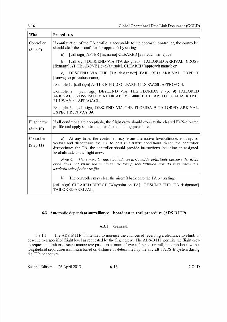
8/9/2019 CPDLC Explained
http://slidepdf.com/reader/full/cpdlc-explained 200/421
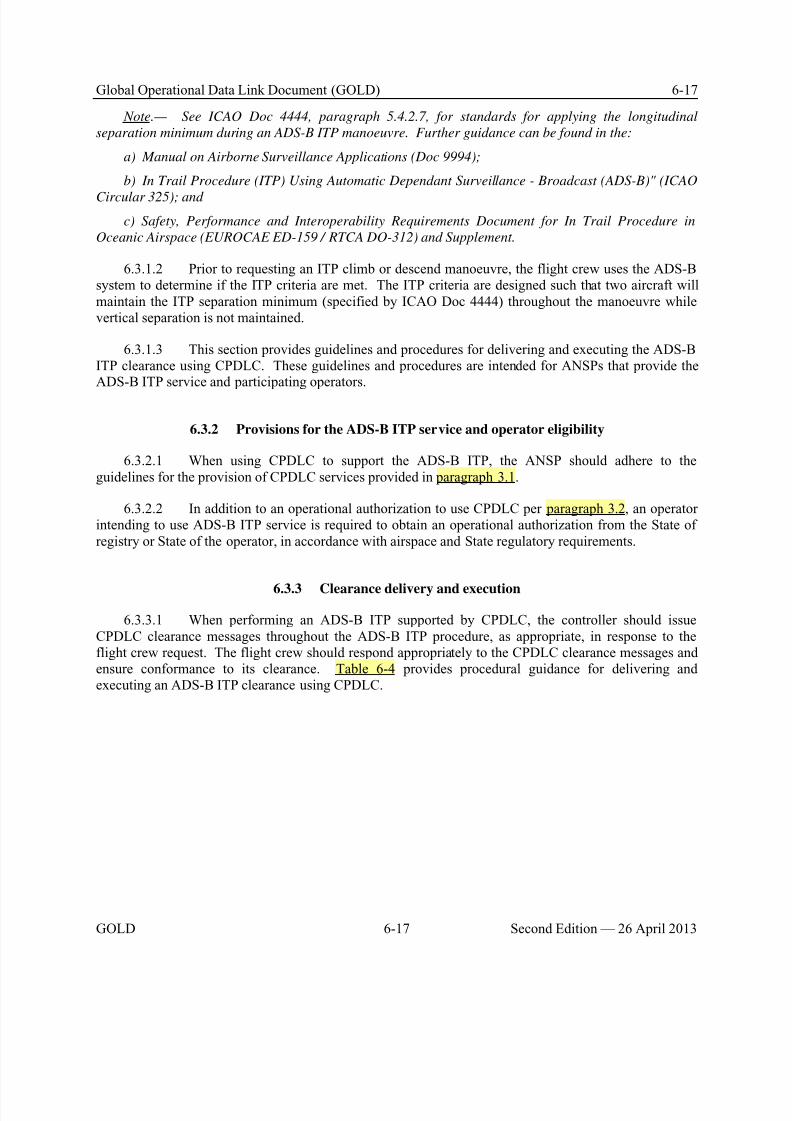
8/9/2019 CPDLC Explained
http://slidepdf.com/reader/full/cpdlc-explained 201/421
Global Operational Data Link Document (GOLD) 6-17
GOLD 6-17 Second Edition — 26 April 2013
Note.— See ICAO Doc 4444, paragraph 5.4.2.7, for standards for applying the longitudinal
separation minimum during an ADS-B ITP manoeuvre. Further guidance can be found in the:
a) Manual on Airborne Surveillance Applications (Doc 9994);
b) In Trail Procedure (ITP) Using Automatic Dependant Surveillance - Broadcast (ADS-B)" (ICAO
Circular 325); and
c) Safety, Performance and Interoperability Requirements Document for In Trail Procedure in
Oceanic Airspace (EUROCAE ED-159 / RTCA DO-312) and Supplement.
6.3.1.2 Prior to requesting an ITP climb or descend manoeuvre, the flight crew uses the ADS-Bsystem to determine if the ITP criteria are met. The ITP criteria are designed such that two aircraft willmaintain the ITP separation minimum (specified by ICAO Doc 4444) throughout the manoeuvre whilevertical separation is not maintained.
6.3.1.3 This section provides guidelines and procedures for delivering and executing the ADS-BITP clearance using CPDLC. These guidelines and procedures are intended for ANSPs that provide theADS-B ITP service and participating operators.
6.3.2 Provisions for the ADS-B ITP service and operator eligibility
6.3.2.1 When using CPDLC to support the ADS-B ITP, the ANSP should adhere to theguidelines for the provision of CPDLC services provided in paragraph 3.1.
6.3.2.2 In addition to an operational authorization to use CPDLC per paragraph 3.2, an operatorintending to use ADS-B ITP service is required to obtain an operational authorization from the State ofregistry or State of the operator, in accordance with airspace and State regulatory requirements.
6.3.3 Clearance delivery and execution
6.3.3.1 When performing an ADS-B ITP supported by CPDLC, the controller should issueCPDLC clearance messages throughout the ADS-B ITP procedure, as appropriate, in response to theflight crew request. The flight crew should respond appropriately to the CPDLC clearance messages andensure conformance to its clearance. Table 6-4 provides procedural guidance for delivering andexecuting an ADS-B ITP clearance using CPDLC.
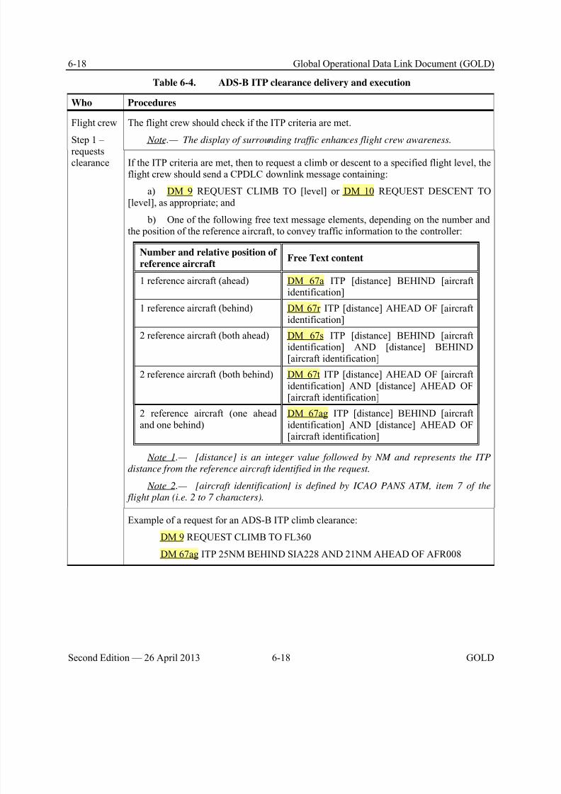
8/9/2019 CPDLC Explained
http://slidepdf.com/reader/full/cpdlc-explained 202/421
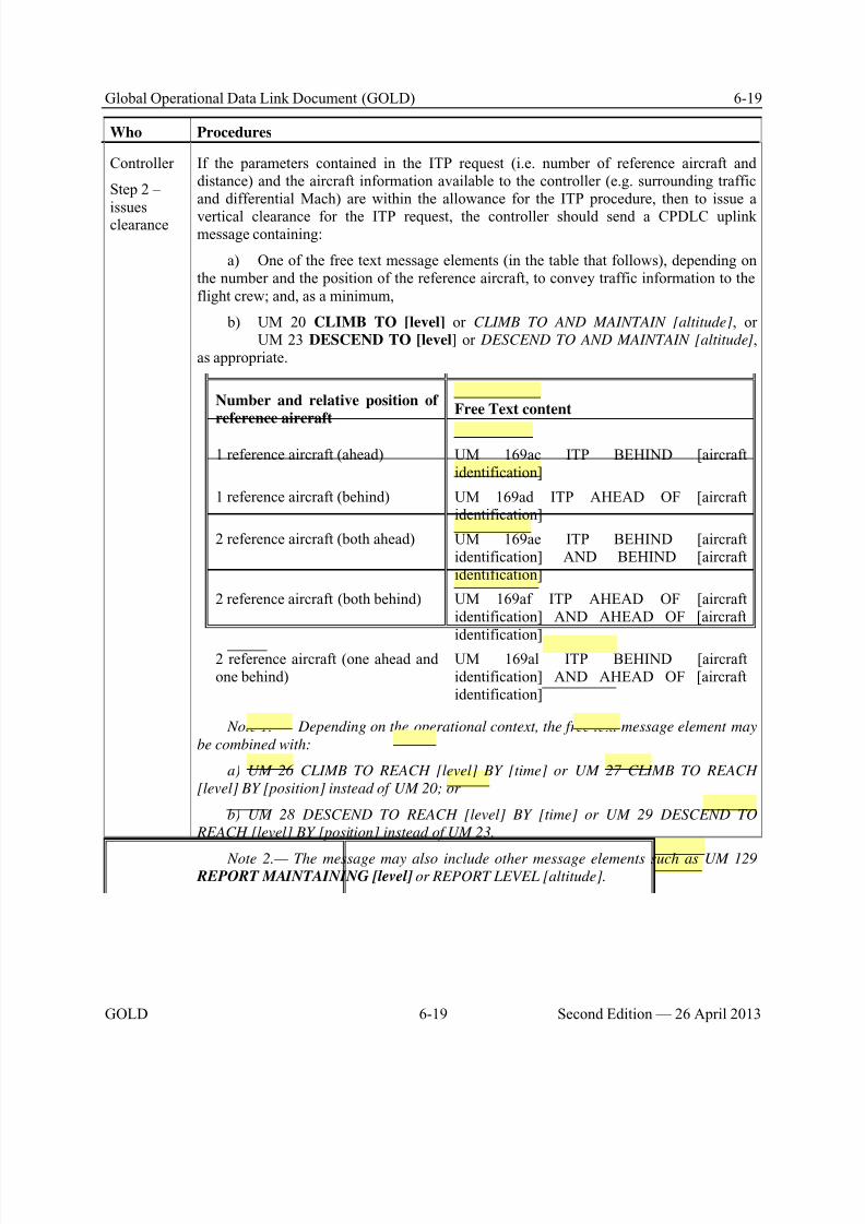
8/9/2019 CPDLC Explained
http://slidepdf.com/reader/full/cpdlc-explained 203/421
Global Operational Data Link Document (GOLD) 6-19
GOLD 6-19 Second Edition — 26 April 2013
Who Procedures
Controller
Step 2 –
issuesclearance
If the parameters contained in the ITP request (i.e. number of reference aircraft anddistance) and the aircraft information available to the controller (e.g. surrounding trafficand differential Mach) are within the allowance for the ITP procedure, then to issue a
vertical clearance for the ITP request, the controller should send a CPDLC uplinkmessage containing:
a) One of the free text message elements (in the table that follows), depending onthe number and the position of the reference aircraft, to convey traffic information to theflight crew; and, as a minimum,
b) UM 20 CLIMB TO [level] or CLIMB TO AND MAINTAIN [altitude], orUM 23 DESCEND TO [level] or DESCEND TO AND MAINTAIN [altitude],
as appropriate.
Number and relative position of
reference aircraftFree Text content
1 reference aircraft (ahead) UM 169ac ITP BEHIND [aircraftidentification]
1 reference aircraft (behind) UM 169ad ITP AHEAD OF [aircraftidentification]
2 reference aircraft (both ahead) UM 169ae ITP BEHIND [aircraftidentification] AND BEHIND [aircraftidentification]
2 reference aircraft (both behind) UM 169af ITP AHEAD OF [aircraftidentification] AND AHEAD OF [aircraftidentification]
2 reference aircraft (one ahead andone behind)
UM 169al ITP BEHIND [aircraftidentification] AND AHEAD OF [aircraftidentification]
Note 1.— Depending on the operational context, the free text message element may
be combined with:
a) UM 26 CLIMB TO REACH [level] BY [time] or UM 27 CLIMB TO REACH
[level] BY [position] instead of UM 20; or
b) UM 28 DESCEND TO REACH [level] BY [time] or UM 29 DESCEND TO
REACH [level] BY [position] instead of UM 23.
Note 2.— The message may also include other message elements such as UM 129 REPORT MAINTAINING [level] or REPORT LEVEL [altitude].
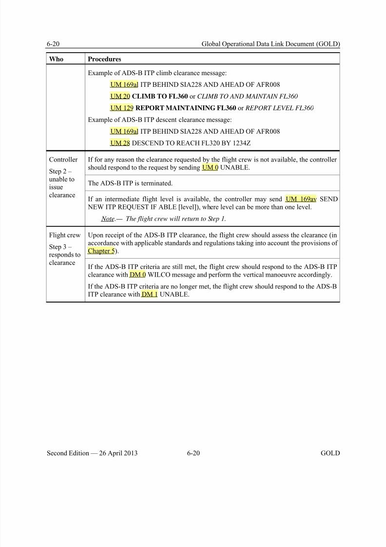
8/9/2019 CPDLC Explained
http://slidepdf.com/reader/full/cpdlc-explained 204/421
6-20 Global Operational Data Link Document (GOLD)
Second Edition — 26 April 2013 6-20 GOLD
Who Procedures
Example of ADS-B ITP climb clearance message:
UM 169al ITP BEHIND SIA228 AND AHEAD OF AFR008
UM 20 CLIMB TO FL360 or CLIMB TO AND MAINTAIN FL360
UM 129 REPORT MAINTAINING FL360 or REPORT LEVEL FL360
Example of ADS-B ITP descent clearance message:
UM 169al ITP BEHIND SIA228 AND AHEAD OF AFR008
UM 28 DESCEND TO REACH FL320 BY 1234Z
Controller
Step 2 –unable toissueclearance
If for any reason the clearance requested by the flight crew is not available, the controllershould respond to the request by sending UM 0 UNABLE.
The ADS-B ITP is terminated.
If an intermediate flight level is available, the controller may send UM 169av SEND NEW ITP REQUEST IF ABLE [level]), where level can be more than one level.
Note.— The flight crew will return to Step 1.
Flight crew
Step 3 –responds toclearance
Upon receipt of the ADS-B ITP clearance, the flight crew should assess the clearance (inaccordance with applicable standards and regulations taking into account the provisions ofChapter 5).
If the ADS-B ITP criteria are still met, the flight crew should respond to the ADS-B ITPclearance with DM 0 WILCO message and perform the vertical manoeuvre accordingly.
If the ADS-B ITP criteria are no longer met, the flight crew should respond to the ADS-BITP clearance with DM 1 UNABLE.
8/9/2019 CPDLC Explained
http://slidepdf.com/reader/full/cpdlc-explained 205/421
Global Operational Data Link Document (GOLD) 7-1
GOLD 7-1 Second Edition — 26 April 2013
Chapter 7. State aircraft data link operations
7.1 General
7.1.1 The data link and voice communication requirements for CNS/ATM are being defined byinternational, regional, and national civil aviation authorities and are based on use of commercialcommunication systems. In airspace where procedural separation is being applied, data link has seenincreased use and is normally used as the means of communication. The military has unique requirementsinsofar as using CPDLC. These requirements were never considered when the CPDLC message set was being developed.
7.1.2 Many air and maritime air forces have the capability to conduct air-to-air refueling(AAR) operations. Although detailed procedures are dependent on aircraft type, mode of employment andnational requirements, there is sufficient commonality for standard procedures to be developed to enhanceoperational interoperability. Many of these air and maritime air forces are making the transition toaeronautical data links and the use of controller pilot data link communications (CPDLC) and automatic
dependent surveillance - contract (ADS-C).
7.1.3 The procedures outlined below describe the communications to be utilized by militaryaircraft in the attempt to promote harmonization in CPDLC and ADS-C procedures. These procedureshave been developed utilizing a combination of existing CPDLC message elements and standardized freetext. Standardized free text messages have been created to support these military operations in theattempt to avoid the general use of free text messages and for overall standardization. To the maximumextent possible, data link capable aircraft should adhere to procedural guidelines provided in Chapter 5and Chapter 6.
7.1.4 The aim of this chapter is to provide a reference document covering military proceduresto be used in an aeronautical data link environment. This chapter will provide guidance for the flight
crew and the ANSP to promote harmonized military AAR operations in an aeronautical data linkenvironment and lead to a better understanding of AAR procedures and terminology.
7.2 Military assumes responsibility for separation of aircraft (MARSA)
7.2.1 Prior to commencing AAR or maneuvers with receiver aircraft, the tanker will notifyATC that the military assumes responsibility for separation of aircraft (MARSA). The tanker will use theterm, MARSA, to notify ATC that the tanker and receiver aircraft are accepting the responsibility for theiractions within the AAR route and the tanker is the lead of the formation. ATC controls all other traffic to preclude conflicts between civil and military traffic involved in the AAR while at the same time stillcontrolling the tanker and receiver. The actual refueling commences at the air refueling control point
(ARCP) and continues as the aircraft proceed down the refueling route. Normally, the refueling iscompleted prior to the aircraft reaching the air refueling exit point (AREX) point. At AREX, both aircraftneed to receive ATC clearances to continue on their filed routing.
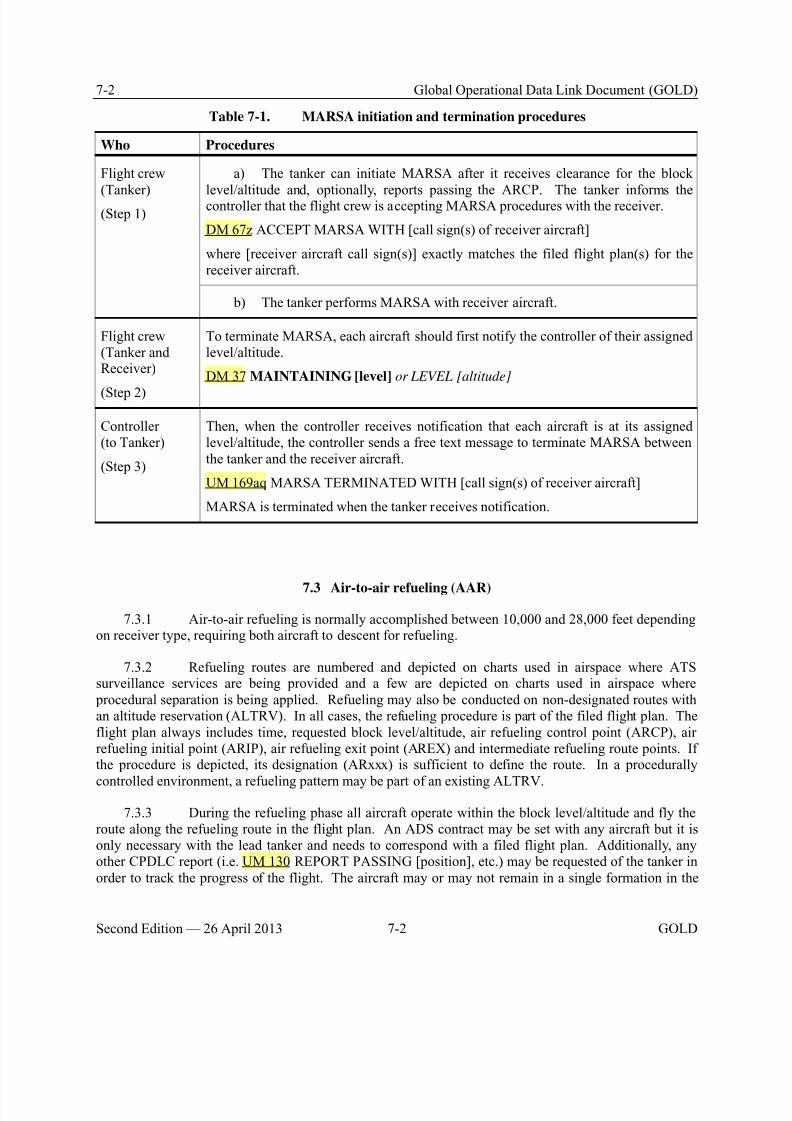
8/9/2019 CPDLC Explained
http://slidepdf.com/reader/full/cpdlc-explained 206/421
7-2 Global Operational Data Link Document (GOLD)
Second Edition — 26 April 2013 7-2 GOLD
Table 7-1. MARSA initiation and termination procedures
Who Procedures
Flight crew
(Tanker)(Step 1)
a) The tanker can initiate MARSA after it receives clearance for the block
level/altitude and, optionally, reports passing the ARCP. The tanker informs thecontroller that the flight crew is accepting MARSA procedures with the receiver.
DM 67z ACCEPT MARSA WITH [call sign(s) of receiver aircraft]
where [receiver aircraft call sign(s)] exactly matches the filed flight plan(s) for thereceiver aircraft.
b) The tanker performs MARSA with receiver aircraft.
Flight crew(Tanker andReceiver)
(Step 2)
To terminate MARSA, each aircraft should first notify the controller of their assignedlevel/altitude.
DM 37 MAINTAINING [level] or LEVEL [altitude]
Controller(to Tanker)
(Step 3)
Then, when the controller receives notification that each aircraft is at its assignedlevel/altitude, the controller sends a free text message to terminate MARSA betweenthe tanker and the receiver aircraft.
UM 169aq MARSA TERMINATED WITH [call sign(s) of receiver aircraft]
MARSA is terminated when the tanker receives notification.
7.3 Air-to-air refueling (AAR)
7.3.1 Air-to-air refueling is normally accomplished between 10,000 and 28,000 feet dependingon receiver type, requiring both aircraft to descent for refueling.
7.3.2 Refueling routes are numbered and depicted on charts used in airspace where ATSsurveillance services are being provided and a few are depicted on charts used in airspace where procedural separation is being applied. Refueling may also be conducted on non-designated routes withan altitude reservation (ALTRV). In all cases, the refueling procedure is part of the filed flight plan. Theflight plan always includes time, requested block level/altitude, air refueling control point (ARCP), airrefueling initial point (ARIP), air refueling exit point (AREX) and intermediate refueling route points. Ifthe procedure is depicted, its designation (ARxxx) is sufficient to define the route. In a procedurally
controlled environment, a refueling pattern may be part of an existing ALTRV.
7.3.3 During the refueling phase all aircraft operate within the block level/altitude and fly theroute along the refueling route in the flight plan. An ADS contract may be set with any aircraft but it isonly necessary with the lead tanker and needs to correspond with a filed flight plan. Additionally, anyother CPDLC report (i.e. UM 130 REPORT PASSING [position], etc.) may be requested of the tanker inorder to track the progress of the flight. The aircraft may or may not remain in a single formation in the

8/9/2019 CPDLC Explained
http://slidepdf.com/reader/full/cpdlc-explained 207/421
Global Operational Data Link Document (GOLD) 7-3
GOLD 7-3 Second Edition — 26 April 2013
block level/altitude for the remainder of the flight. There are no special CPDLC messages developedduring this phase.
7.3.4 A typical air-refueling pattern is illustrated in Figure 7-1. The light green routerepresents the tanker’s intended route to the ARCP. The light blue route is the receiver’s intended route.
Both aircraft file separate flight plans showing the specific aerial refueling locations. The dark blue routeis the tanker’s orbit and rendezvous flight paths with the dark green route depicting the AAR route. Threeor more points can define the AAR route. The ARIP is the point where the receiver enters the AAR route.The ARCP is the reference point for the holding pattern where the tanker awaits the receiver. The AARroute is between the ARCP and the AREX.
ARIP ARCP AREX
Tanker
Tanker Receiver
Receiver
Tanker
Figure 7-1. Air refueling pattern
Table 7-2. Air refueling data link procedures
Who Procedures
Flight crew(Tanker)
(Step 1)
At approximately 10 minutes from the ARCP, the tanker requests a clearance to delayat the ARCP until the rendezvous with the receiver and request a block level/altitudefor air refueling.
DM 25 REQUEST CLEARANCE
DM 67w TO DELAY FOR AIR REFUEL AT [position] UNTIL [time]
DM 7 REQUEST BLOCK [level] TO [level]
Where:
[position] is the ARCP as filed in the tanker’s flight plan.
[time] is the time the tanker expects to pass the ARCP and commence refueling alongthe refueling route. It is also the end of the delay time.
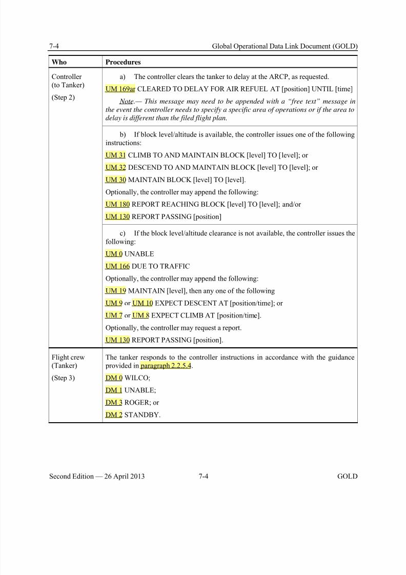
8/9/2019 CPDLC Explained
http://slidepdf.com/reader/full/cpdlc-explained 208/421
7-4 Global Operational Data Link Document (GOLD)
Second Edition — 26 April 2013 7-4 GOLD
Who Procedures
Controller(to Tanker)
(Step 2)
a) The controller clears the tanker to delay at the ARCP, as requested.
UM 169ar CLEARED TO DELAY FOR AIR REFUEL AT [position] UNTIL [time]
Note.— This message may need to be appended with a “free text” message inthe event the controller needs to specify a specific area of operations or if the area to
delay is different than the filed flight plan.
b) If block level/altitude is available, the controller issues one of the followinginstructions:
UM 31 CLIMB TO AND MAINTAIN BLOCK [level] TO [level]; or
UM 32 DESCEND TO AND MAINTAIN BLOCK [level] TO [level]; or
UM 30 MAINTAIN BLOCK [level] TO [level].
Optionally, the controller may append the following:
UM 180 REPORT REACHING BLOCK [level] TO [level]; and/or
UM 130 REPORT PASSING [position]
c) If the block level/altitude clearance is not available, the controller issues thefollowing:
UM 0 UNABLE
UM 166 DUE TO TRAFFIC
Optionally, the controller may append the following:
UM 19 MAINTAIN [level], then any one of the following
UM 9 or UM 10 EXPECT DESCENT AT [position/time]; or
UM 7 or UM 8 EXPECT CLIMB AT [position/time].
Optionally, the controller may request a report.
UM 130 REPORT PASSING [position].
Flight crew(Tanker)
(Step 3)
The tanker responds to the controller instructions in accordance with the guidance provided in paragraph 2.2.5.4.
DM 0 WILCO;
DM 1 UNABLE;
DM 3 ROGER; or
DM 2 STANDBY.
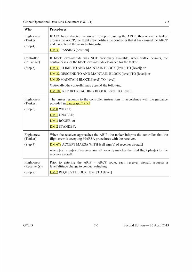
8/9/2019 CPDLC Explained
http://slidepdf.com/reader/full/cpdlc-explained 209/421
Global Operational Data Link Document (GOLD) 7-5
GOLD 7-5 Second Edition — 26 April 2013
Who Procedures
Flight crew(Tanker)
(Step 4)
If ATC has instructed the aircraft to report passing the ARCP, then when the tankercrosses the ARCP, the flight crew notifies the controller that it has crossed the ARCPand has entered the air-refueling orbit.
DM 31 PASSING [position]
Controller(to Tanker)
(Step 5)
If block level/altitude was NOT previously available, when traffic permits, thecontroller issues the block level/altitude clearance for the tanker.
UM 31 CLIMB TO AND MAINTAIN BLOCK [level] TO [level]; or
UM 32 DESCEND TO AND MAINTAIN BLOCK [level] TO [level]; or
UM 30 MAINTAIN BLOCK [level] TO [level].
Optionally, the controller may append the following:
UM 180 REPORT REACHING BLOCK [level] TO [level].
Flight crew(Tanker)
(Step 6)
The tanker responds to the controller instructions in accordance with the guidance provided in paragraph 2.2.5.4.
DM 0 WILCO;
DM 1 UNABLE;
DM 3 ROGER; or
DM 2 STANDBY.
Flight crew(Tanker)
(Step 7)
When the receiver approaches the ARIP, the tanker informs the controller that theflight crew is accepting MARSA procedures with the receiver.
DM 67z ACCEPT MARSA WITH [call sign(s) of receiver aircraft]
where [call sign(s) of receiver aircraft] exactly matches the filed flight plan(s) for thereceiver aircraft.
Flight crew(Receiver(s))
(Step 8)
Prior to entering the ARIP – ARCP route, each receiver aircraft requests alevel/altitude change to conduct refueling.
DM 7 REQUEST BLOCK [level] TO [level]
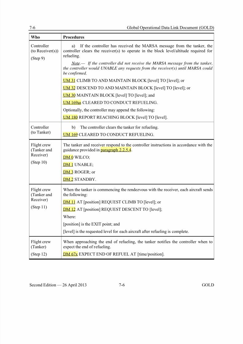
8/9/2019 CPDLC Explained
http://slidepdf.com/reader/full/cpdlc-explained 210/421
7-6 Global Operational Data Link Document (GOLD)
Second Edition — 26 April 2013 7-6 GOLD
Who Procedures
Controller(to Receiver(s))
(Step 9)
a) If the controller has received the MARSA message from the tanker, thecontroller clears the receiver(s) to operate in the block level/altitude required forrefueling.
Note.— If the controller did not receive the MARSA message from the tanker,
the controller would UNABLE any requests from the receiver(s) until MARSA could
be confirmed.
UM 31 CLIMB TO AND MAINTAIN BLOCK [level] TO [level]; or
UM 32 DESCEND TO AND MAINTAIN BLOCK [level] TO [level]; or
UM 30 MAINTAIN BLOCK [level] TO [level]; and
UM 169as CLEARED TO CONDUCT REFUELING.
Optionally, the controller may append the following:
UM 180 REPORT REACHING BLOCK [level] TO [level].
Controller(to Tanker)
b) The controller clears the tanker for refueling.
UM 169 CLEARED TO CONDUCT REFUELING.
Flight crew(Tanker andReceiver)
(Step 10)
The tanker and receiver respond to the controller instructions in accordance with theguidance provided in paragraph 2.2.5.4.
DM 0 WILCO;
DM 1 UNABLE;
DM 3 ROGER; or
DM 2 STANDBY.
Flight crew(Tanker andReceiver)
(Step 11)
When the tanker is commencing the rendezvous with the receiver, each aircraft sendsthe following:
DM 11 AT [position] REQUEST CLIMB TO [level]; or
DM 12 AT [position] REQUEST DESCENT TO [level];
Where:
[position] is the EXIT point; and
[level] is the requested level for each aircraft after refueling is complete.
Flight crew(Tanker)
(Step 12)
When approaching the end of refueling, the tanker notifies the controller when toexpect the end of refueling.
DM 67x EXPECT END OF REFUEL AT [time/position].

8/9/2019 CPDLC Explained
http://slidepdf.com/reader/full/cpdlc-explained 211/421
Global Operational Data Link Document (GOLD) 7-7
GOLD 7-7 Second Edition — 26 April 2013
Who Procedures
Controller(to Tanker andReceiver)
(Step 13)
The controller issues instructions to assign different flight levels/altitudes to each ofthe aircraft upon completion of refueling.
UM 164 WHEN READY; andUM 19 MAINTAIN [level]; and
UM 129 REPORT MAINTAINING [level] or REPORT LEVEL [altitude]
Note.— Climb or descent clearances may be issued as appropriate.
Flight crew(Tanker andReceiver)
(Step 14)
a) The tanker and receiver respond to the controller instructions in accordancewith the guidance provided in paragraph 2.2.5.4.
DM 0 WILCO;
DM 1 UNABLE;
DM 3 ROGER; or
DM 2 STANDBY.
b) When the aircraft is maintaining the assigned level, each aircraft notifies thecontroller.
DM 37 MAINTAINING [level] or LEVEL [altitude]
Controller(to Tanker)
(Step 15)
When the controller receives notification that each aircraft is at its assignedlevel/altitude, the controller sends a free text message to terminate MARSA betweenthe tanker and the receiver aircraft.
UM 169aq MARSA TERMINATED WITH [call sign(s) of receiver aircraft]
7.4 Formation flight data link procedures
7.4.1 Formation flying in a standard formation is usually one in which a proximity of no morethan 1 mile laterally or longitudinally and within 100 feet vertically from the flight leader is maintained by each aircraft. Non-standard formations are those operating under conditions other than standardformation dimensions that the flight leader has requested and air traffic control (ATC) has approved, orwhen operating within an authorized ALTRV.
7.4.2 For each flight plan, the lead aircraft will initiate a logon at the correct time (refer to paragraph 5.2.2). Once in formation, only the lead aircraft will make position reports in accordance paragraph 5.6. Use CPDLC standard messages for level/altitude requests, routing requests (if differentfrom what was filed), and speed or ETA requests with ATC to effect any en-route changes.
7.4.3 In the event a formation wants to break-up the formation or depart an ALTRV the aircraftdesiring to break off of the formation will coordinate their departure a minimum of ten (10) minutes prior
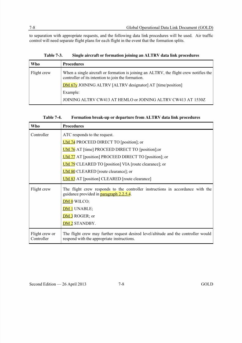
8/9/2019 CPDLC Explained
http://slidepdf.com/reader/full/cpdlc-explained 212/421
7-8 Global Operational Data Link Document (GOLD)
Second Edition — 26 April 2013 7-8 GOLD
to separation with appropriate requests, and the following data link procedures will be used. Air trafficcontrol will need separate flight plans for each flight in the event that the formation splits.
Table 7-3. Single aircraft or formation joining an ALTRV data link procedures
Who Procedures
Flight crew When a single aircraft or formation is joining an ALTRV, the flight crew notifies thecontroller of its intention to join the formation.
DM 67y JOINING ALTRV [ALTRV designator] AT [time/position]
Example:
JOINING ALTRV CW413 AT HEMLO or JOINING ALTRV CW413 AT 1530Z
Table 7-4. Formation break-up or departure from ALTRV data link procedures
Who Procedures
Controller ATC responds to the request.
UM 74 PROCEED DIRECT TO [position]; or
UM 76 AT [time] PROCEED DIRECT TO [position];or
UM 77 AT [position] PROCEED DIRECT TO [position]; or
UM 79 CLEARED TO [position] VIA [route clearance]; or
UM 80 CLEARED [route clearance]; or
UM 83 AT [position] CLEARED [route clearance]
Flight crew The flight crew responds to the controller instructions in accordance with theguidance provided in paragraph 2.2.5.4.
DM 0 WILCO;
DM 1 UNABLE;
DM 3 ROGER; or
DM 2 STANDBY.
Flight crew or
Controller
The flight crew may further request desired level/altitude and the controller would
respond with the appropriate instructions.
8/9/2019 CPDLC Explained
http://slidepdf.com/reader/full/cpdlc-explained 213/421

8/9/2019 CPDLC Explained
http://slidepdf.com/reader/full/cpdlc-explained 214/421
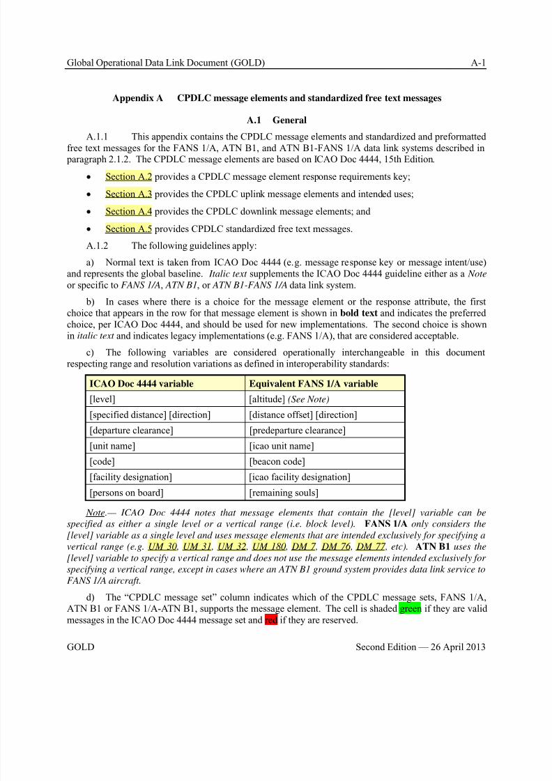
8/9/2019 CPDLC Explained
http://slidepdf.com/reader/full/cpdlc-explained 215/421
Global Operational Data Link Document (GOLD) A-1
GOLD Second Edition — 26 April 2013
Appendix A CPDLC message elements and standardized free text messages
A.1 General
A.1.1 This appendix contains the CPDLC message elements and standardized and preformattedfree text messages for the FANS 1/A, ATN B1, and ATN B1-FANS 1/A data link systems described in paragraph 2.1.2. The CPDLC message elements are based on ICAO Doc 4444, 15th Edition.
• Section A.2 provides a CPDLC message element response requirements key;
• Section A.3 provides the CPDLC uplink message elements and intended uses;
• Section A.4 provides the CPDLC downlink message elements; and
• Section A.5 provides CPDLC standardized free text messages.
A.1.2 The following guidelines apply:
a) Normal text is taken from ICAO Doc 4444 (e.g. message response key or message intent/use)
and represents the global baseline. Italic text supplements the ICAO Doc 4444 guideline either as a Note or specific to FANS 1/A, ATN B1, or ATN B1-FANS 1/A data link system.
b) In cases where there is a choice for the message element or the response attribute, the firstchoice that appears in the row for that message element is shown in bold text and indicates the preferredchoice, per ICAO Doc 4444, and should be used for new implementations. The second choice is shownin italic text and indicates legacy implementations (e.g. FANS 1/A), that are considered acceptable.
c) The following variables are considered operationally interchangeable in this documentrespecting range and resolution variations as defined in interoperability standards:
ICAO Doc 4444 variable Equivalent FANS 1/A variable
[level] [altitude] (See Note)
[specified distance] [direction] [distance offset] [direction]
[departure clearance] [predeparture clearance]
[unit name] [icao unit name]
[code] [beacon code]
[facility designation] [icao facility designation]
[persons on board] [remaining souls]
Note.— ICAO Doc 4444 notes that message elements that contain the [level] variable can be
specified as either a single level or a vertical range (i.e. block level). FANS 1/A only considers the
[level] variable as a single level and uses message elements that are intended exclusively for specifying a
vertical range (e.g. UM 30, UM 31, UM 32, UM 180, DM 7, DM 76, DM 77, etc). ATN B1 uses the[level] variable to specify a vertical range and does not use the message elements intended exclusively for
specifying a vertical range, except in cases where an ATN B1 ground system provides data link service to
FANS 1/A aircraft.
d) The “CPDLC message set” column indicates which of the CPDLC message sets, FANS 1/A,ATN B1 or FANS 1/A-ATN B1, supports the message element. The cell is shaded green if they are validmessages in the ICAO Doc 4444 message set and red if they are reserved.
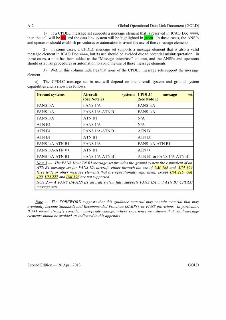
8/9/2019 CPDLC Explained
http://slidepdf.com/reader/full/cpdlc-explained 216/421
A-2 Global Operational Data Link Document (GOLD)
Second Edition — 26 April 2013 GOLD
1) If a CPDLC message set supports a message element that is reserved in ICAO Doc 4444,then the cell will be red and the data link system will be highlighted in green. In these cases, the ANSPsand operators should establish procedures or automation to avoid the use of these message elements.
2) In some cases, a CPDLC message set supports a message element that is also a valid
message element in ICAO Doc 4444, but its use should be avoided due to potential misinterpretation. Inthese cases, a note has been added to the “Message intent/use” column, and the ANSPs and operatorsshould establish procedures or automation to avoid the use of these message elements.
3) N/A in this column indicates that none of the CPDLC message sets support the messageelement.
e) The CPDLC message set in use will depend on the aircraft system and ground systemcapabilities and is shown as follows:
Ground systems Aircraft systems
(See Note 2)
CPDLC message set
(See Note 1)
FANS 1/A FANS 1/A FANS 1/A
FANS 1/A FANS 1/A-ATN B1 FANS 1/AFANS 1/A ATN B1 N/A
ATN B1 FANS 1/A N/A
ATN B1 FANS 1/A-ATN B1 ATN B1
ATN B1 ATN B1 ATN B1
FANS 1/A-ATN B1 FANS 1/A FANS 1/A-ATN B1
FANS 1/A-ATN B1 ATN B1 ATN B1
FANS 1/A-ATN B1 FANS 1/A-ATN B1 ATN B1 or FANS 1/A-ATN B1
Note 1.— The FANS 1/A-ATN B1 message set provides the ground system the equivalent of an
ATN B1 message set for FANS 1/A aircraft, either through the use of UM 183 and UM 169[free text] or other message elements that are operationally equivalent, except UM 215, UM
190, UM 227 and UM 196 are not supported.
Note 2.— A FANS 1/A-ATN B1 aircraft system fully supports FANS 1/A and ATN B1 CPDLC
message sets.
Note.— The FOREWORD suggests that this guidance material may contain material that may
eventually become Standards and Recommended Practices (SARPs), or PANS provisions. In particular,
ICAO should strongly consider appropriate changes where experience has shown that valid message
elements should be avoided, as indicated in this appendix.

8/9/2019 CPDLC Explained
http://slidepdf.com/reader/full/cpdlc-explained 217/421
Global Operational Data Link Document (GOLD) A-3
GOLD Second Edition — 26 April 2013
A.2 CPDLC message element response requirements key
Response
column
Description
For uplink message
W/U Response required. Yes
Valid responses. WILCO, UNABLE, STANDBY, NOT CURRENT DATA AUTHORITY, NOT AUTHORIZED NEXT DATA AUTHORITY, LOGICAL ACKNOWLEDGEMENT(only if required), ERROR
Note.— WILCO, UNABLE, NOT CURRENT DATA AUTHORITY, NOT AUTHORIZED
NEXT DATA AUTHORITY and ERROR will close the uplink message.
FANS 1/A.— WILCO, UNABLE, STANDBY, ERROR, NOT CURRENT DATA AUTHORITY.
A/N Response required. Yes
Valid responses. AFFIRM, NEGATIVE, STANDBY, NOT CURRENT DATA
AUTHORITY, NOT AUTHORIZED NEXT DATA AUTHORITY, LOGICALACKNOWLEDGEMENT (only if required), ERROR
Note.— AFFIRM, NEGATIVE, NOT CURRENT DATA AUTHORITY, NOT AUTHORIZED
NEXT DATA AUTHORITY and ERROR will close the uplink message.
FANS 1/A.— AFFIRM, NEGATIVE, STANDBY, ERROR, NOT CURRENT DATA
AUTHORITY.
R Response required. Yes
Valid responses. ROGER, UNABLE, STANDBY, NOT CURRENT DATA AUTHORITY, NOT AUTHORIZED NEXT DATA AUTHORITY, LOGICAL ACKNOWLEDGEMENT(only if required), ERROR
Note.— ROGER, NOT CURRENT DATA AUTHORITY, NOT AUTHORIZED NEXT DATA
AUTHORITY and ERROR will close the uplink message.FANS 1/A.— ROGER, STANDBY, ERROR, NOT CURRENT DATA AUTHORITY.
FANS 1/A aircraft do not have the capability to send UNABLE in response to an uplink
message containing message elements with an “R” response attribute. For these aircraft,
the flight crew may use alternative means to UNABLE the message. These alternative
means will need to be taken into consideration to ensure proper technical and operational
closure of the communication transaction.
Y Response required. Yes
Valid responses: Any CPDLC downlink message, LOGICAL ACKNOWLEDGEMENT(only if required)
N Response required. No, unless logical acknowledgement required.
Valid Responses (only if LOGICAL ACKNOWLEDGEMENT is required). LOGICALACKNOWLEDGEMENT, NOT CURRENT DATA AUTHORITY, NOT AUTHORIZED NEXT DATA AUTHORITY, ERROR
FANS 1/A.— Defined “Response not required,” but not used. Under some circumstances,
an ERROR message will also close an uplink message.

8/9/2019 CPDLC Explained
http://slidepdf.com/reader/full/cpdlc-explained 218/421
A-4 Global Operational Data Link Document (GOLD)
Second Edition — 26 April 2013 GOLD
Response
column
Description
NE [Not defined in ICAO Doc 4444]
FANS 1/A.— The WILCO, UNABLE, AFFIRM, NEGATIVE, ROGER, and STANDBY
responses are not enabled (NE) for flight crew selection. An uplink message with a responseattribute NE is considered to be closed even though a response may be required
operationally. Under some circumstances, a downlink error message may be linked to an
uplink message with a NE attribute.
For downlink messages
Y Response required. Yes
Valid responses. Any CPDLC uplink message, LOGICAL ACKNOWLEDGEMENT (onlyif required).
N Response required. No, unless logical acknowledgement required.
Valid responses (only if LOGICAL ACKNOWLEDGEMENT is required). LOGICALACKNOWLEDGEMENT, SERVICE UNAVAILABLE, FLIGHT PLAN NOT HELD,
ERROR
FANS 1/A.— Aircraft do not have the capability to receive technical responses to downlink
message elements with an “N” response attribute (other than LACK or ERROR for ATN B1
aircraft). In some cases, the response attribute is different between FANS 1/A aircraft and
ICAO Doc 4444. As an example, most emergency messages have an “N” response attribute
for FANS 1/A whereas ICAO Doc 4444 defines a “Y” response attribute for them. As a
consequence, for FANS 1/A aircraft, the ATC will need to use alternative means to
acknowledge to the flight crew that an emergency message has been received.
A.3 CPDLC uplink message elements
Ref
#
Message Intent/Use Message Element Resp. Data link
system(s)
Responses/Acknowledgements (uplink)
UM0
Indicates that ATC cannot comply withthe request.
UNABLE N
or
NE
FANS 1/A
ATN B1
FANS 1/A-ATN B1
UM
1
Indicates that ATC has received the
message and will respond. Note.— The flight crew is informed that
the request is being assessed and there
will be a short-term delay (e.g. as
appropriate, given the situation, but not to
exceed 10 minutes). The exchange is not
closed and the request will be responded
to when conditions allow.
STANDBY N
or NE
FANS 1/A
ATN B1FANS 1/A-ATN B1
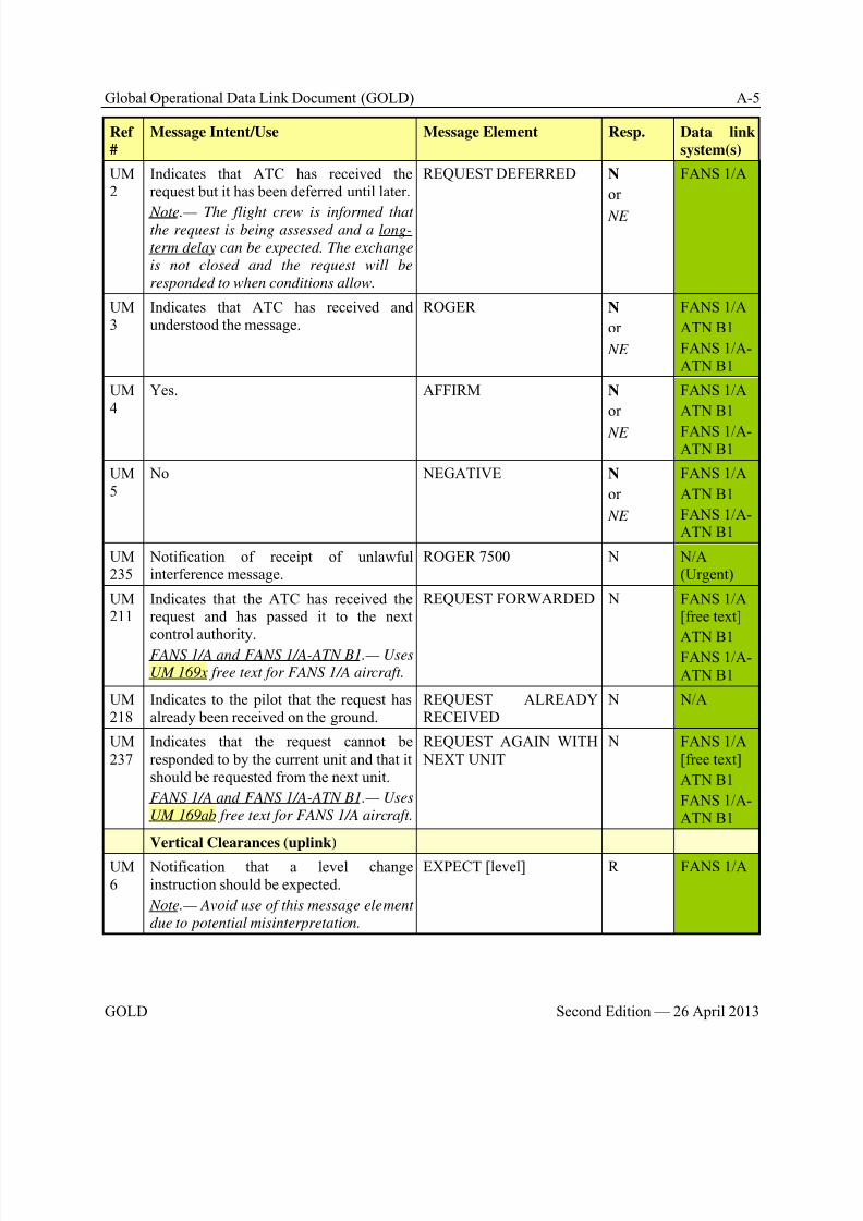
8/9/2019 CPDLC Explained
http://slidepdf.com/reader/full/cpdlc-explained 219/421
Global Operational Data Link Document (GOLD) A-5
GOLD Second Edition — 26 April 2013
Ref
#
Message Intent/Use Message Element Resp. Data link
system(s)
UM2
Indicates that ATC has received therequest but it has been deferred until later.
Note.— The flight crew is informed thatthe request is being assessed and a long-
term delay can be expected. The exchange
is not closed and the request will be
responded to when conditions allow.
REQUEST DEFERRED N
or
NE
FANS 1/A
UM3
Indicates that ATC has received andunderstood the message.
ROGER N
or
NE
FANS 1/A
ATN B1
FANS 1/A-ATN B1
UM4
Yes. AFFIRM N
or
NE
FANS 1/A
ATN B1
FANS 1/A-ATN B1
UM5
No NEGATIVE N
or
NE
FANS 1/A
ATN B1
FANS 1/A-ATN B1
UM235
Notification of receipt of unlawfulinterference message.
ROGER 7500 N N/A(Urgent)
UM211
Indicates that the ATC has received therequest and has passed it to the next
control authority.FANS 1/A and FANS 1/A-ATN B1.— Uses
UM 169x free text for FANS 1/A aircraft.
REQUEST FORWARDED N FANS 1/A[free text]
ATN B1FANS 1/A-ATN B1
UM218
Indicates to the pilot that the request hasalready been received on the ground.
REQUEST ALREADYRECEIVED
N N/A
UM237
Indicates that the request cannot beresponded to by the current unit and that itshould be requested from the next unit.
FANS 1/A and FANS 1/A-ATN B1.— Uses
UM 169ab free text for FANS 1/A aircraft.
REQUEST AGAIN WITH NEXT UNIT
N FANS 1/A[free text]
ATN B1
FANS 1/A-ATN B1
Vertical Clearances (uplink)
UM6
Notification that a level changeinstruction should be expected.
Note.— Avoid use of this message element
due to potential misinterpretation.
EXPECT [level] R FANS 1/A
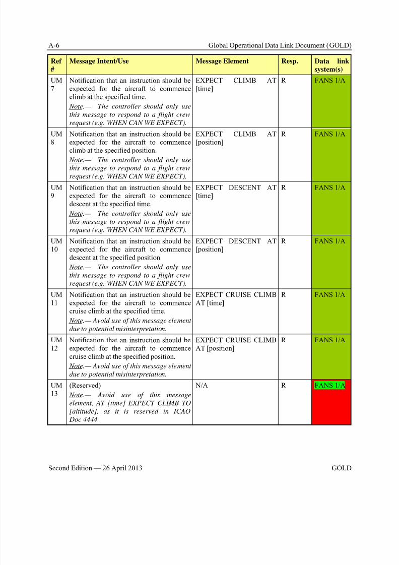
8/9/2019 CPDLC Explained
http://slidepdf.com/reader/full/cpdlc-explained 220/421
A-6 Global Operational Data Link Document (GOLD)
Second Edition — 26 April 2013 GOLD
Ref
#
Message Intent/Use Message Element Resp. Data link
system(s)
UM7
Notification that an instruction should beexpected for the aircraft to commence
climb at the specified time. Note.— The controller should only use
this message to respond to a flight crew
request (e.g. WHEN CAN WE EXPECT).
EXPECT CLIMB AT[time]
R FANS 1/A
UM8
Notification that an instruction should beexpected for the aircraft to commenceclimb at the specified position.
Note.— The controller should only use
this message to respond to a flight crew
request (e.g. WHEN CAN WE EXPECT).
EXPECT CLIMB AT[position]
R FANS 1/A
UM
9
Notification that an instruction should be
expected for the aircraft to commencedescent at the specified time.
Note.— The controller should only use
this message to respond to a flight crew
request (e.g. WHEN CAN WE EXPECT).
EXPECT DESCENT AT
[time]
R FANS 1/A
UM10
Notification that an instruction should beexpected for the aircraft to commencedescent at the specified position.
Note.— The controller should only use
this message to respond to a flight crew
request (e.g. WHEN CAN WE EXPECT).
EXPECT DESCENT AT[position]
R FANS 1/A
UM11 Notification that an instruction should beexpected for the aircraft to commencecruise climb at the specified time.
Note.— Avoid use of this message element
due to potential misinterpretation.
EXPECT CRUISE CLIMBAT [time] R FANS 1/A
UM12
Notification that an instruction should beexpected for the aircraft to commencecruise climb at the specified position.
Note.— Avoid use of this message element
due to potential misinterpretation.
EXPECT CRUISE CLIMBAT [position]
R FANS 1/A
UM
13
(Reserved)
Note.— Avoid use of this messageelement, AT [time] EXPECT CLIMB TO
[altitude], as it is reserved in ICAO
Doc 4444.
N/A R FANS 1/A
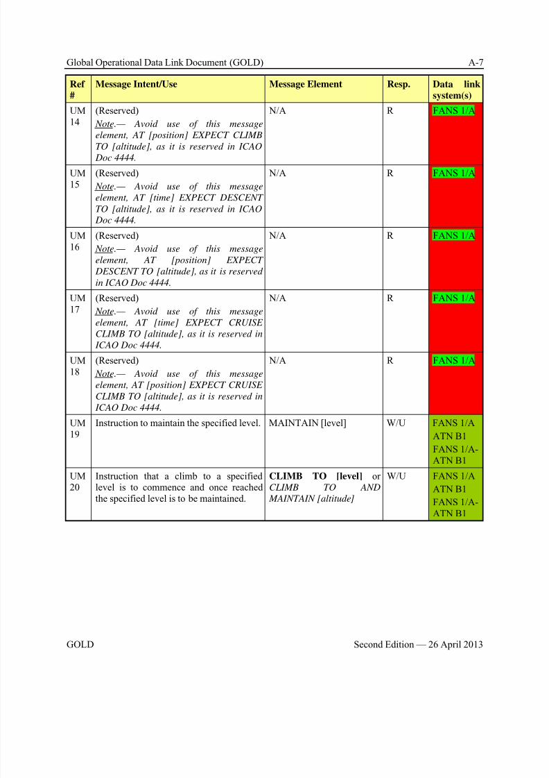
8/9/2019 CPDLC Explained
http://slidepdf.com/reader/full/cpdlc-explained 221/421
Global Operational Data Link Document (GOLD) A-7
GOLD Second Edition — 26 April 2013
Ref
#
Message Intent/Use Message Element Resp. Data link
system(s)
UM14
(Reserved)
Note.— Avoid use of this message
element, AT [position] EXPECT CLIMBTO [altitude], as it is reserved in ICAO
Doc 4444.
N/A R FANS 1/A
UM15
(Reserved)
Note.— Avoid use of this message
element, AT [time] EXPECT DESCENT
TO [altitude], as it is reserved in ICAO
Doc 4444.
N/A R FANS 1/A
UM16
(Reserved)
Note.— Avoid use of this message
element, AT [position] EXPECT
DESCENT TO [altitude], as it is reservedin ICAO Doc 4444.
N/A R FANS 1/A
UM17
(Reserved)
Note.— Avoid use of this message
element, AT [time] EXPECT CRUISE
CLIMB TO [altitude], as it is reserved in
ICAO Doc 4444.
N/A R FANS 1/A
UM18
(Reserved)
Note.— Avoid use of this message
element, AT [position] EXPECT CRUISE
CLIMB TO [altitude], as it is reserved in
ICAO Doc 4444.
N/A R FANS 1/A
UM19
Instruction to maintain the specified level. MAINTAIN [level] W/U FANS 1/A
ATN B1
FANS 1/A-ATN B1
UM20
Instruction that a climb to a specifiedlevel is to commence and once reachedthe specified level is to be maintained.
CLIMB TO [level] orCLIMB TO AND
MAINTAIN [altitude]
W/U FANS 1/A
ATN B1
FANS 1/A-ATN B1

8/9/2019 CPDLC Explained
http://slidepdf.com/reader/full/cpdlc-explained 222/421
A-8 Global Operational Data Link Document (GOLD)
Second Edition — 26 April 2013 GOLD
Ref
#
Message Intent/Use Message Element Resp. Data link
system(s)
UM21
Instruction that at the specified time aclimb to the specified level is to
commence and once reached the specifiedlevel is to be maintained.
Note 1.— Instruction that NOT BEFORE
the specified time, a climb to the specified
level is to commence and once reached
the specified level is to be maintained.
Note 2.— Precede this message element
with UM 19 MAINTAIN [level], to
prevent the premature execution of the
instruction.
AT [time] CLIMB TO[level] or AT [time] CLIMB
TO AND MAINTAIN[altitude]
W/U FANS 1/A
UM22
Instruction that at the specified position aclimb to the specified level is tocommence and once reached the specifiedlevel is to be maintained.
Note 1.— Instruction that AFTER
PASSING the specified position, a climb
to the specified level is to commence and
once reached the specified level is to be
maintained.
Note 2.— Precede this message element
with UM 19 MAINTAIN [level], to
prevent the premature execution of the
instruction.
AT [position] CLIMB TO[level] or AT [position]
CLIMB TO AND
MAINTAIN [altitude]
W/U FANS 1/A
UM185
(Reserved) N/A W/U N/A
UM23
Instruction that a descent to a specifiedlevel is to commence and once reachedthe specified level is to be maintained.
DESCEND TO [level] or DESCEND TO AND
MAINTAIN [altitude]
W/U FANS 1/A
ATN B1
FANS 1/A-ATN B1
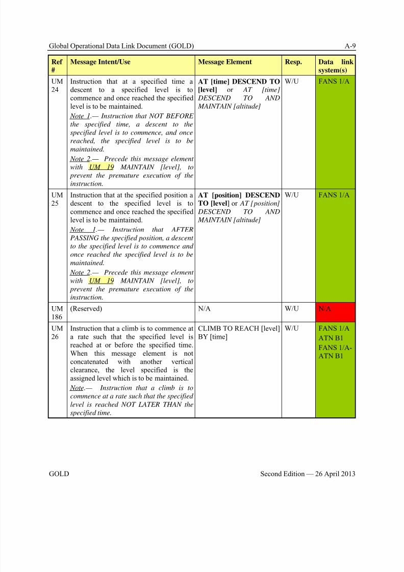
8/9/2019 CPDLC Explained
http://slidepdf.com/reader/full/cpdlc-explained 223/421
Global Operational Data Link Document (GOLD) A-9
GOLD Second Edition — 26 April 2013
Ref
#
Message Intent/Use Message Element Resp. Data link
system(s)
UM24
Instruction that at a specified time adescent to a specified level is to
commence and once reached the specifiedlevel is to be maintained.
Note 1.— Instruction that NOT BEFORE
the specified time, a descent to the
specified level is to commence, and once
reached, the specified level is to be
maintained.
Note 2.— Precede this message element
with UM 19 MAINTAIN [level], to
prevent the premature execution of the
instruction.
AT [time] DESCEND TO[level] or AT [time]
DESCEND TO AND MAINTAIN [altitude]
W/U FANS 1/A
UM25
Instruction that at the specified position adescent to the specified level is tocommence and once reached the specifiedlevel is to be maintained.
Note 1.— Instruction that AFTER
PASSING the specified position, a descent
to the specified level is to commence and
once reached the specified level is to be
maintained.
Note 2.— Precede this message element
with UM 19 MAINTAIN [level], to
prevent the premature execution of the
instruction.
AT [position] DESCENDTO [level] or AT [position]
DESCEND TO AND
MAINTAIN [altitude]
W/U FANS 1/A
UM186
(Reserved) N/A W/U N/A
UM26
Instruction that a climb is to commence ata rate such that the specified level isreached at or before the specified time.When this message element is notconcatenated with another verticalclearance, the level specified is theassigned level which is to be maintained.
Note.— Instruction that a climb is to
commence at a rate such that the specified
level is reached NOT LATER THAN the
specified time.
CLIMB TO REACH [level]BY [time]
W/U FANS 1/A
ATN B1
FANS 1/A-ATN B1

8/9/2019 CPDLC Explained
http://slidepdf.com/reader/full/cpdlc-explained 224/421
A-10 Global Operational Data Link Document (GOLD)
Second Edition — 26 April 2013 GOLD
Ref
#
Message Intent/Use Message Element Resp. Data link
system(s)
UM27
Instruction that a climb is to commence ata rate such that the specified level is
reached at or before the specified position.When this message element is notconcatenated with another verticalclearance, the level specified is theassigned level which is to be maintained.
Note.— Instruction that a climb is to
commence at a rate such that the specified
level is reached BEFORE PASSING the
specified position.
CLIMB TO REACH [level]BY [position]
W/U FANS 1/A
ATN B1
FANS 1/A-ATN B1
UM28
Instruction that a descent is to commenceat a rate such that the specified level isreached at or before the specified time.
When this message element is notconcatenated with another verticalclearance, the level specified is theassigned level which is to be maintained.
Note.— Instruction that a descent is to
commence at a rate such that the specified
level is reached NOT LATER THAN the
specified time.
DESCEND TO REACH[level] BY [time]
W/U FANS 1/A
ATN B1
FANS 1/A-ATN B1
UM29
Instruction that a descent is to commenceat a rate such that the specified level isreached at or before the specified position.
When this message element is notconcatenated with another verticalclearance, the level specified is theassigned level which is to be maintained.
Note.— Instruction that a descent is to
commence at a rate such that the specified
level is reached BEFORE PASSING the
specified position.
DESCEND TO REACH[level] BY [position]
W/U FANS 1/A
ATN B1
FANS 1/A-
ATN B1
UM192
Instruction that a change of level is tocontinue, but at a rate such that thespecified level is reached at or before thespecified time.
REACH [level] BY [time] W/U N/A
UM209
Instruction that a change of level is tocontinue, but at a rate such that thespecified level is reached at or before thespecified position.
REACH [level] BY[position]
W/U N/A
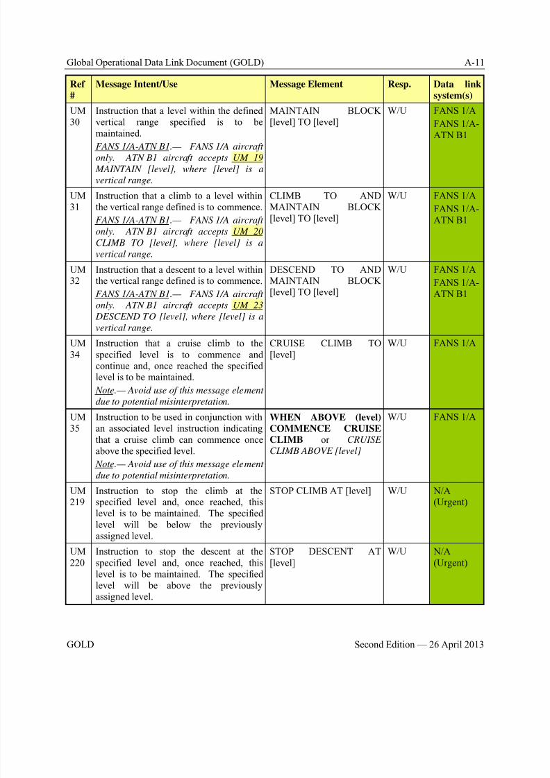
8/9/2019 CPDLC Explained
http://slidepdf.com/reader/full/cpdlc-explained 225/421
Global Operational Data Link Document (GOLD) A-11
GOLD Second Edition — 26 April 2013
Ref
#
Message Intent/Use Message Element Resp. Data link
system(s)
UM30
Instruction that a level within the definedvertical range specified is to be
maintained.FANS 1/A-ATN B1.— FANS 1/A aircraft
only. ATN B1 aircraft accepts UM 19
MAINTAIN [level], where [level] is a
vertical range.
MAINTAIN BLOCK[level] TO [level]
W/U FANS 1/A
FANS 1/A-
ATN B1
UM31
Instruction that a climb to a level withinthe vertical range defined is to commence.
FANS 1/A-ATN B1.— FANS 1/A aircraft
only. ATN B1 aircraft accepts UM 20
CLIMB TO [level], where [level] is a
vertical range.
CLIMB TO ANDMAINTAIN BLOCK[level] TO [level]
W/U FANS 1/A
FANS 1/A-ATN B1
UM32 Instruction that a descent to a level withinthe vertical range defined is to commence.
FANS 1/A-ATN B1.— FANS 1/A aircraft
only. ATN B1 aircraft accepts UM 23
DESCEND TO [level], where [level] is a
vertical range.
DESCEND TO ANDMAINTAIN BLOCK[level] TO [level]
W/U FANS 1/AFANS 1/A-ATN B1
UM34
Instruction that a cruise climb to thespecified level is to commence andcontinue and, once reached the specifiedlevel is to be maintained.
Note.— Avoid use of this message element
due to potential misinterpretation.
CRUISE CLIMB TO[level]
W/U FANS 1/A
UM35
Instruction to be used in conjunction withan associated level instruction indicatingthat a cruise climb can commence onceabove the specified level.
Note.— Avoid use of this message element
due to potential misinterpretation.
WHEN ABOVE (level)
COMMENCE CRUISECLIMB or CRUISE
CLIMB ABOVE [level]
W/U FANS 1/A
UM219
Instruction to stop the climb at thespecified level and, once reached, thislevel is to be maintained. The specifiedlevel will be below the previouslyassigned level.
STOP CLIMB AT [level] W/U N/A(Urgent)
UM220
Instruction to stop the descent at thespecified level and, once reached, thislevel is to be maintained. The specifiedlevel will be above the previouslyassigned level.
STOP DESCENT AT[level]
W/U N/A(Urgent)
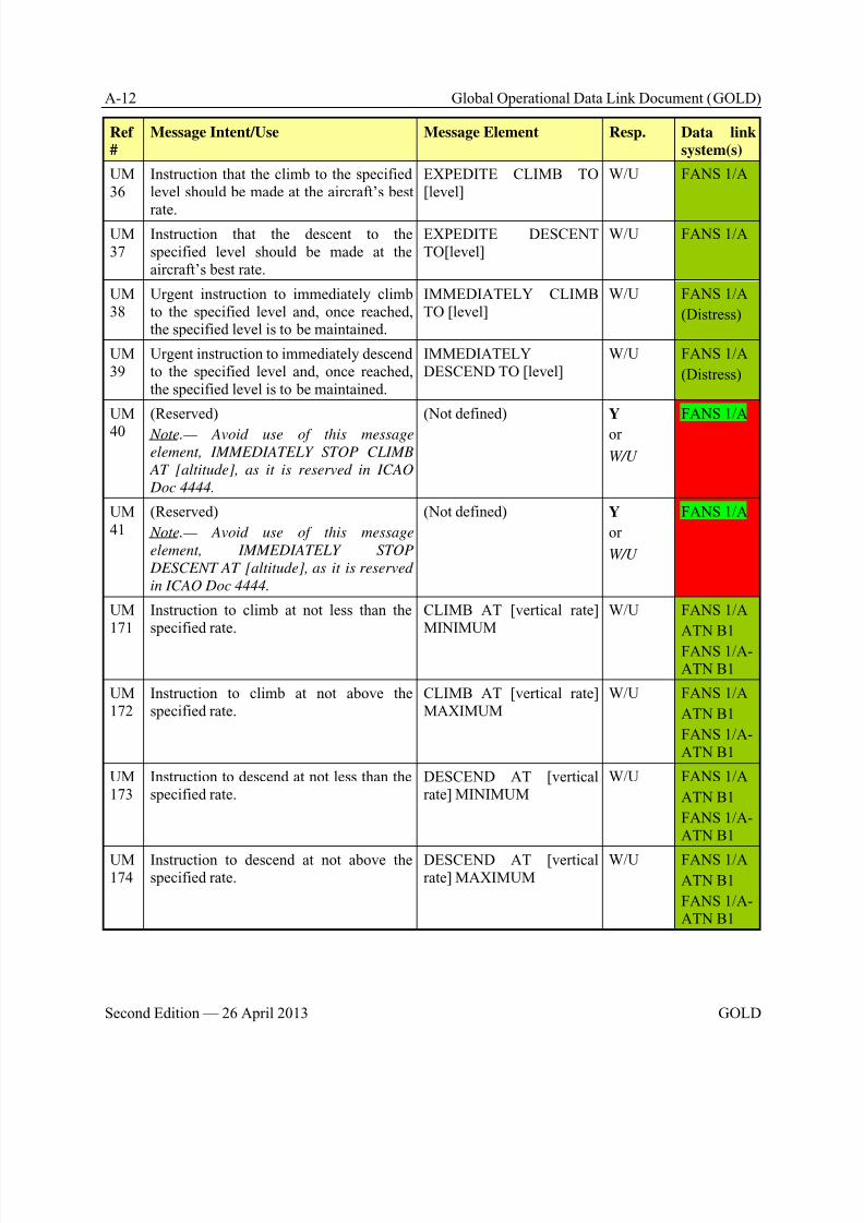
8/9/2019 CPDLC Explained
http://slidepdf.com/reader/full/cpdlc-explained 226/421
A-12 Global Operational Data Link Document (GOLD)
Second Edition — 26 April 2013 GOLD
Ref
#
Message Intent/Use Message Element Resp. Data link
system(s)
UM36
Instruction that the climb to the specifiedlevel should be made at the aircraft’s best
rate.
EXPEDITE CLIMB TO[level]
W/U FANS 1/A
UM37
Instruction that the descent to thespecified level should be made at theaircraft’s best rate.
EXPEDITE DESCENTTO[level]
W/U FANS 1/A
UM38
Urgent instruction to immediately climbto the specified level and, once reached,the specified level is to be maintained.
IMMEDIATELY CLIMBTO [level]
W/U FANS 1/A
(Distress)
UM39
Urgent instruction to immediately descendto the specified level and, once reached,the specified level is to be maintained.
IMMEDIATELYDESCEND TO [level]
W/U FANS 1/A
(Distress)
UM
40
(Reserved)
Note.— Avoid use of this message
element, IMMEDIATELY STOP CLIMB
AT [altitude], as it is reserved in ICAO
Doc 4444.
(Not defined) Y
or
W/U
FANS 1/A
UM41
(Reserved)
Note.— Avoid use of this message
element, IMMEDIATELY STOP
DESCENT AT [altitude], as it is reserved
in ICAO Doc 4444.
(Not defined) Y
or
W/U
FANS 1/A
UM171
Instruction to climb at not less than thespecified rate.
CLIMB AT [vertical rate]MINIMUM
W/U FANS 1/A
ATN B1
FANS 1/A-ATN B1
UM172
Instruction to climb at not above thespecified rate.
CLIMB AT [vertical rate]MAXIMUM
W/U FANS 1/A
ATN B1
FANS 1/A-ATN B1
UM173
Instruction to descend at not less than thespecified rate.
DESCEND AT [verticalrate] MINIMUM
W/U FANS 1/A
ATN B1
FANS 1/A-ATN B1
UM174
Instruction to descend at not above thespecified rate.
DESCEND AT [verticalrate] MAXIMUM
W/U FANS 1/AATN B1
FANS 1/A-ATN B1
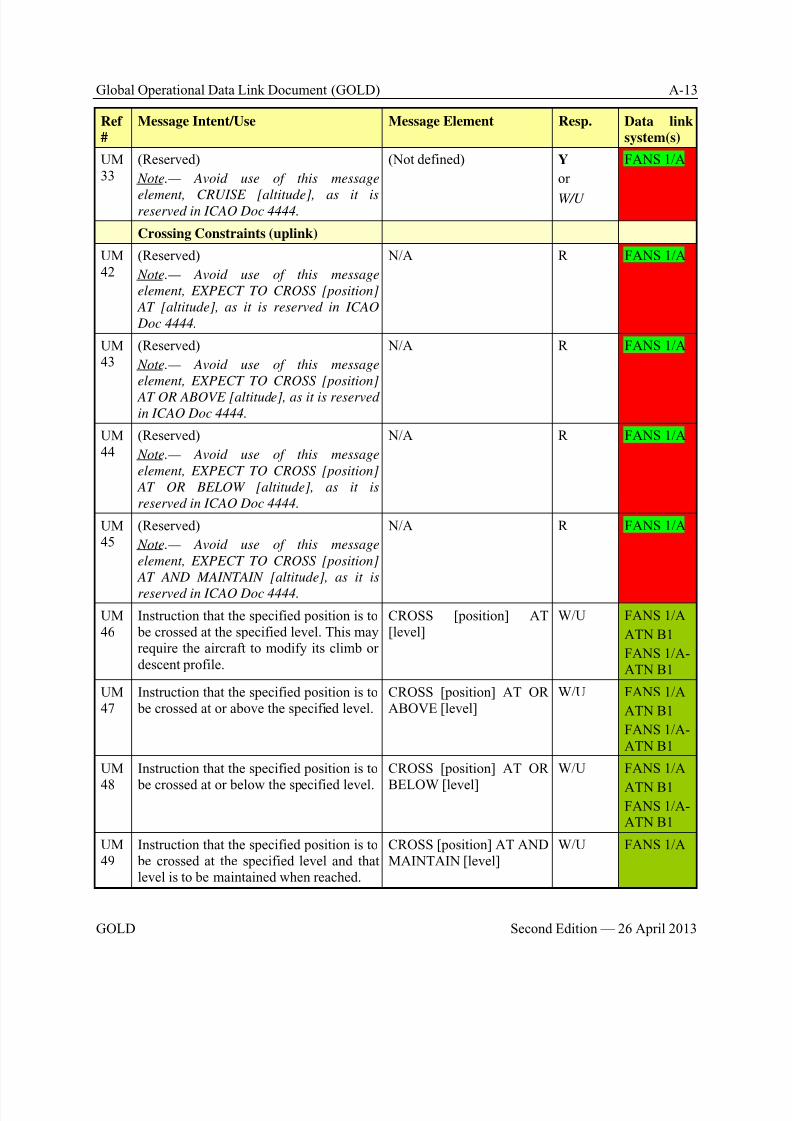
8/9/2019 CPDLC Explained
http://slidepdf.com/reader/full/cpdlc-explained 227/421
Global Operational Data Link Document (GOLD) A-13
GOLD Second Edition — 26 April 2013
Ref
#
Message Intent/Use Message Element Resp. Data link
system(s)
UM33
(Reserved)
Note.— Avoid use of this message
element, CRUISE [altitude], as it isreserved in ICAO Doc 4444.
(Not defined) Y
or
W/U
FANS 1/A
Crossing Constraints (uplink)
UM42
(Reserved)
Note.— Avoid use of this message
element, EXPECT TO CROSS [position]
AT [altitude], as it is reserved in ICAO
Doc 4444.
N/A R FANS 1/A
UM43
(Reserved)
Note.— Avoid use of this message
element, EXPECT TO CROSS [position]
AT OR ABOVE [altitude], as it is reservedin ICAO Doc 4444.
N/A R FANS 1/A
UM44
(Reserved)
Note.— Avoid use of this message
element, EXPECT TO CROSS [position]
AT OR BELOW [altitude], as it is
reserved in ICAO Doc 4444.
N/A R FANS 1/A
UM45
(Reserved)
Note.— Avoid use of this message
element, EXPECT TO CROSS [position]
AT AND MAINTAIN [altitude], as it is
reserved in ICAO Doc 4444.
N/A R FANS 1/A
UM46
Instruction that the specified position is to be crossed at the specified level. This mayrequire the aircraft to modify its climb ordescent profile.
CROSS [position] AT[level]
W/U FANS 1/A
ATN B1
FANS 1/A-ATN B1
UM47
Instruction that the specified position is to be crossed at or above the specified level.
CROSS [position] AT ORABOVE [level]
W/U FANS 1/A
ATN B1
FANS 1/A-ATN B1
UM
48
Instruction that the specified position is to
be crossed at or below the specified level.
CROSS [position] AT OR
BELOW [level]
W/U FANS 1/A
ATN B1FANS 1/A-ATN B1
UM49
Instruction that the specified position is to be crossed at the specified level and thatlevel is to be maintained when reached.
CROSS [position] AT ANDMAINTAIN [level]
W/U FANS 1/A

8/9/2019 CPDLC Explained
http://slidepdf.com/reader/full/cpdlc-explained 228/421
A-14 Global Operational Data Link Document (GOLD)
Second Edition — 26 April 2013 GOLD
Ref
#
Message Intent/Use Message Element Resp. Data link
system(s)
UM50
Instruction that the specified position is to be crossed at a level between the specified
levels.
CROSS [position]BETWEEN [level] AND
[level]
W/U FANS 1/A
UM51
Instruction that the specified position is to be crossed at the specified time.
CROSS [position] AT[time]
W/U FANS 1/A
ATN B1
FANS 1/A-ATN B1
UM52
Instruction that the specified position is to be crossed at or before the specified time.
CROSS [position] AT ORBEFORE [time]
W/U FANS 1/A
ATN B1
FANS 1/A-ATN B1
UM53
Instruction that the specified position is to be crossed at or after the specified time.
CROSS [position] AT ORAFTER [time]
W/U FANS 1/A
ATN B1FANS 1/A-ATN B1
UM54
Instruction that the specified position is to be crossed at a time between the specifiedtimes.
CROSS [position]BETWEEN [time] AND[time]
W/U FANS 1/A
ATN B1
FANS 1/A-ATN B1
UM55
Instruction that the specified position is to be crossed at the specified speed and thespecified speed is to be maintained untilfurther advised.
CROSS [position] AT[speed]
W/U FANS 1/A
ATN B1
FANS 1/A-ATN B1
UM56
Instruction that the specified position is to be crossed at a speed equal to or less thanthe specified speed and the specifiedspeed or less is to be maintained untilfurther advised.
CROSS [position] AT ORLESS THAN [speed]
W/U FANS 1/A
UM57
Instruction that the specified position is to be crossed at a speed equal to or greaterthan the specified speed and the specifiedspeed or greater is to be maintained untilfurther advised.
CROSS [position] AT ORGREATER THAN [speed]
W/U FANS 1/A
UM
58
Instruction that the specified position is to
be crossed at the specified time and thespecified level.
CROSS [position] AT
[time] AT [level]
W/U FANS 1/A
UM59
Instruction that the specified position is to be crossed at or before the specified timeand at the specified level.
CROSS [position] AT ORBEFORE [time] AT [level]
W/U FANS 1/A
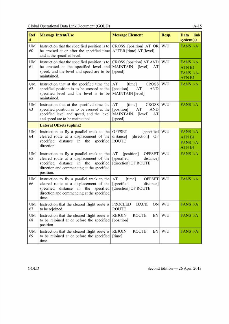
8/9/2019 CPDLC Explained
http://slidepdf.com/reader/full/cpdlc-explained 229/421
Global Operational Data Link Document (GOLD) A-15
GOLD Second Edition — 26 April 2013
Ref
#
Message Intent/Use Message Element Resp. Data link
system(s)
UM60
Instruction that the specified position is to be crossed at or after the specified time
and at the specified level.
CROSS [position] AT ORAFTER [time] AT [level]
W/U FANS 1/A
UM61
Instruction that the specified position is to be crossed at the specified level andspeed, and the level and speed are to bemaintained.
CROSS [position] AT ANDMAINTAIN [level] AT[speed]
W/U FANS 1/A
ATN B1
FANS 1/A-ATN B1
UM62
Instruction that at the specified time thespecified position is to be crossed at thespecified level and the level is to bemaintained.
AT [time] CROSS[position] AT ANDMAINTAIN [level]
W/U FANS 1/A
UM63
Instruction that at the specified time thespecified position is to be crossed at the
specified level and speed, and the leveland speed are to be maintained.
AT [time] CROSS[position] AT AND
MAINTAIN [level] AT[speed]
W/U FANS 1/A
Lateral Offsets (uplink)
UM64
Instruction to fly a parallel track to thecleared route at a displacement of thespecified distance in the specifieddirection.
OFFSET [specifieddistance] [direction] OFROUTE
W/U FANS 1/A
ATN B1
FANS 1/A-ATN B1
UM65
Instruction to fly a parallel track to thecleared route at a displacement of thespecified distance in the specifieddirection and commencing at the specified position.
AT [position] OFFSET[specified distance][direction] OF ROUTE
W/U FANS 1/A
UM66
Instruction to fly a parallel track to thecleared route at a displacement of thespecified distance in the specifieddirection and commencing at the specifiedtime.
AT [time] OFFSET[specified distance][direction] OF ROUTE
W/U FANS 1/A
UM67
Instruction that the cleared flight route isto be rejoined.
PROCEED BACK ONROUTE
W/U FANS 1/A
UM68
Instruction that the cleared flight route isto be rejoined at or before the specified position.
REJOIN ROUTE BY[position]
W/U FANS 1/A
UM69
Instruction that the cleared flight route isto be rejoined at or before the specifiedtime.
REJOIN ROUTE BY[time]
W/U FANS 1/A

8/9/2019 CPDLC Explained
http://slidepdf.com/reader/full/cpdlc-explained 230/421
A-16 Global Operational Data Link Document (GOLD)
Second Edition — 26 April 2013 GOLD
Ref
#
Message Intent/Use Message Element Resp. Data link
system(s)
UM70
Notification that a clearance may beissued to enable the aircraft to rejoin the
cleared route at or before the specified position.
EXPECT BACK ONROUTE BY [position]
R FANS 1/A
UM71
Notification that a clearance may beissued to enable the aircraft to rejoin thecleared route at or before the specifiedtime.
EXPECT BACK ONROUTE BY [time]
R FANS 1/A
UM72
Instruction to resume own navigationfollowing a period of tracking or headingclearances. May be used in conjunctionwith an instruction on how or where torejoin the cleared route.
RESUME OWN NAVIGATION
W/U FANS 1/A
ATN B1
FANS 1/A-ATN B1
Route Modifications (uplink)UM73
Instruction to be followed from departureuntil the specified clearance limit.
[departure clearance] W/U FANS 1/A
UM74
Instruction to proceed directly from its present position to the specified position.
PROCEED DIRECT TO[position]
W/U FANS 1/A
ATN B1
FANS 1/A-ATN B1
UM75
Instruction to proceed, when able, directlyto the specified position.
WHEN ABLE PROCEEDDIRECT TO [position]
W/U FANS 1/A
UM76
Instruction to proceed, at the specifiedtime, directly to the specified position.
AT [time] PROCEEDDIRECT TO [position]
W/U FANS 1/A
UM77
Instruction to proceed, at the specified position, directly to the next specified position.
AT [position] PROCEEDDIRECT TO [position]
W/U FANS 1/A
UM78
Instruction to proceed, upon reaching thespecified level, directly to the specified position.
AT [level] PROCEEDDIRECT TO [position]
W/U FANS 1/A
UM79
Instruction to proceed to the specified position via the specified route.
CLEARED TO [position]VIA [route clearance]
W/U FANS 1/A
ATN B1
FANS 1/A-ATN B1
UM80
Instruction to proceed via the specifiedroute.
CLEARED [routeclearance]
W/U FANS 1/A
ATN B1
FANS 1/A-ATN B1
UM81
Instruction to proceed in accordance withthe specified procedure.
CLEARED [procedurename]
W/U FANS 1/A
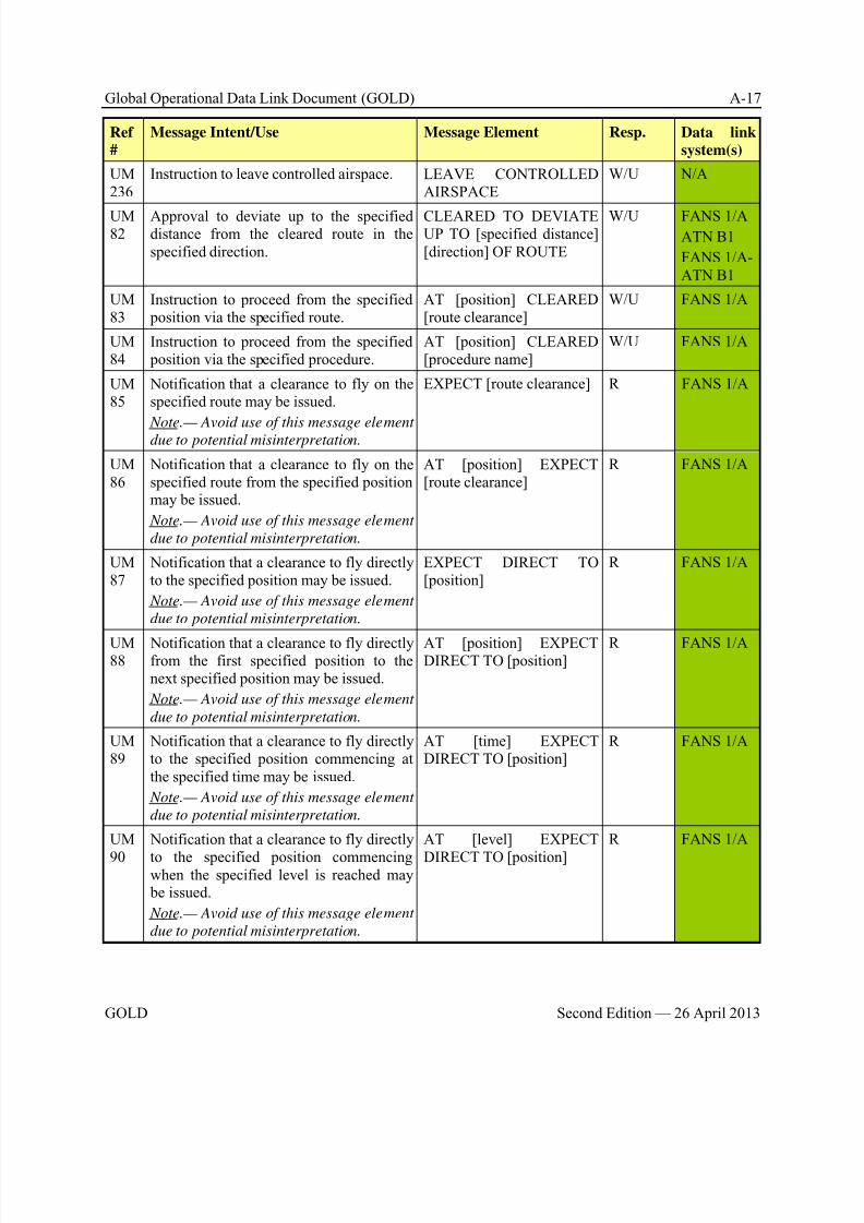
8/9/2019 CPDLC Explained
http://slidepdf.com/reader/full/cpdlc-explained 231/421
Global Operational Data Link Document (GOLD) A-17
GOLD Second Edition — 26 April 2013
Ref
#
Message Intent/Use Message Element Resp. Data link
system(s)
UM236
Instruction to leave controlled airspace. LEAVE CONTROLLEDAIRSPACE
W/U N/A
UM82
Approval to deviate up to the specifieddistance from the cleared route in thespecified direction.
CLEARED TO DEVIATEUP TO [specified distance][direction] OF ROUTE
W/U FANS 1/AATN B1
FANS 1/A-ATN B1
UM83
Instruction to proceed from the specified position via the specified route.
AT [position] CLEARED[route clearance]
W/U FANS 1/A
UM84
Instruction to proceed from the specified position via the specified procedure.
AT [position] CLEARED[procedure name]
W/U FANS 1/A
UM85
Notification that a clearance to fly on thespecified route may be issued.
Note.— Avoid use of this message elementdue to potential misinterpretation.
EXPECT [route clearance] R FANS 1/A
UM86
Notification that a clearance to fly on thespecified route from the specified positionmay be issued.
Note.— Avoid use of this message element
due to potential misinterpretation.
AT [position] EXPECT[route clearance]
R FANS 1/A
UM87
Notification that a clearance to fly directlyto the specified position may be issued.
Note.— Avoid use of this message element
due to potential misinterpretation.
EXPECT DIRECT TO[position]
R FANS 1/A
UM88
Notification that a clearance to fly directlyfrom the first specified position to thenext specified position may be issued.
Note.— Avoid use of this message element
due to potential misinterpretation.
AT [position] EXPECTDIRECT TO [position]
R FANS 1/A
UM89
Notification that a clearance to fly directlyto the specified position commencing atthe specified time may be issued.
Note.— Avoid use of this message element
due to potential misinterpretation.
AT [time] EXPECTDIRECT TO [position]
R FANS 1/A
UM
90
Notification that a clearance to fly directly
to the specified position commencingwhen the specified level is reached may be issued.
Note.— Avoid use of this message element
due to potential misinterpretation.
AT [level] EXPECT
DIRECT TO [position]
R FANS 1/A

8/9/2019 CPDLC Explained
http://slidepdf.com/reader/full/cpdlc-explained 232/421
A-18 Global Operational Data Link Document (GOLD)
Second Edition — 26 April 2013 GOLD
Ref
#
Message Intent/Use Message Element Resp. Data link
system(s)
UM91
Instruction to enter a holding pattern withthe specified characteristics at the
specified position and level.
HOLD AT [position]
MAINTAIN [level]
INBOUND TRACK[degrees] [direction]TURNS [leg type] or
HOLD AT [position]
MAINTAIN [altitude]
INBOUND TRACK
[degrees][direction] TURN
LEG TIME [leg type]
W/U FANS 1/A
UM92
Instruction to enter a holding pattern withthe published characteristics at thespecified position and level.
HOLD AT [position] ASPUBLISHED MAINTAIN[level]
W/U FANS 1/A
ATN B1
FANS 1/A-ATN B1
UM93
Notification that an onwards clearancemay be issued at the specified time.
EXPECT FURTHERCLEARANCE AT [time]
R FANS 1/A
UM94
Instruction to turn left or right as specifiedon to the specified heading.
TURN [direction]HEADING [degrees]
W/U FANS 1/A
ATN B1
FANS 1/A-ATN B1
UM95
Instruction to turn left or right as specifiedon to the specified track.
TURN [direction]GROUND TRACK[degrees]
W/U FANS 1/A
UM
215
Instruction to turn a specified number of
degrees left or right.
TURN [direction] [degrees]
DEGREES
W/U ATN B1
FANS 1/A-ATN B1
UM190
Instruction to fly on the specified heading. FLY HEADING [degrees] W/U ATN B1
FANS 1/A-ATN B1
UM96
Instruction to continue to fly on thecurrent heading.
CONTINUE PRESENTHEADING or FLY
PRESENT HEADING
W/U FANS 1/A
ATN B1
FANS 1/A-ATN B1
UM
97
Instruction to fly on the specified heading
from the specified position.
AT [position] FLY
HEADING [degrees]
W/U FANS 1/A
UM221
Instruction to stop turn at the specifiedheading prior to reaching the previouslyassigned heading.
STOP TURN HEADING[degrees]
W/U N/A(Urgent)
UM98
Instruction to turn immediately left orright as specified on to the specifiedheading.
IMMEDIATELY TURN[direction] HEADING[degrees]
W/U FANS 1/A
(Distress)
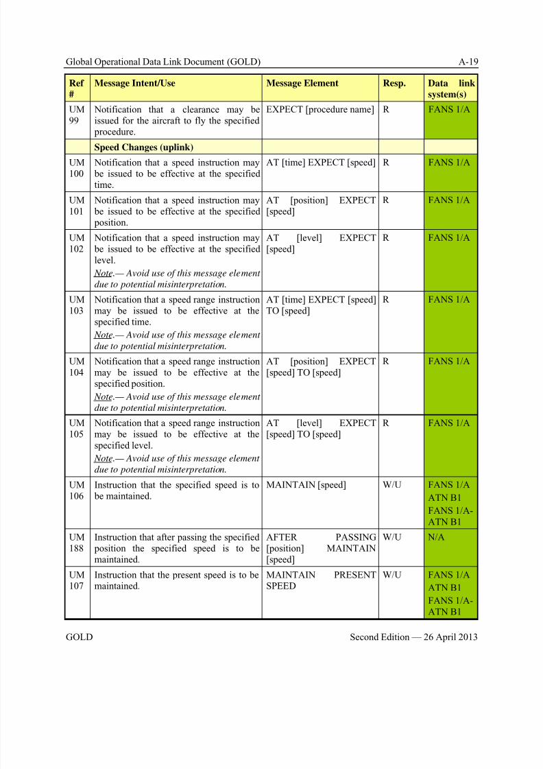
8/9/2019 CPDLC Explained
http://slidepdf.com/reader/full/cpdlc-explained 233/421
Global Operational Data Link Document (GOLD) A-19
GOLD Second Edition — 26 April 2013
Ref
#
Message Intent/Use Message Element Resp. Data link
system(s)
UM99
Notification that a clearance may beissued for the aircraft to fly the specified
procedure.
EXPECT [procedure name] R FANS 1/A
Speed Changes (uplink)
UM100
Notification that a speed instruction may be issued to be effective at the specifiedtime.
AT [time] EXPECT [speed] R FANS 1/A
UM101
Notification that a speed instruction may be issued to be effective at the specified position.
AT [position] EXPECT[speed]
R FANS 1/A
UM102
Notification that a speed instruction may be issued to be effective at the specifiedlevel.
Note.— Avoid use of this message element
due to potential misinterpretation.
AT [level] EXPECT[speed]
R FANS 1/A
UM103
Notification that a speed range instructionmay be issued to be effective at thespecified time.
Note.— Avoid use of this message element
due to potential misinterpretation.
AT [time] EXPECT [speed]TO [speed]
R FANS 1/A
UM104
Notification that a speed range instructionmay be issued to be effective at thespecified position.
Note.— Avoid use of this message element
due to potential misinterpretation.
AT [position] EXPECT[speed] TO [speed]
R FANS 1/A
UM105
Notification that a speed range instructionmay be issued to be effective at thespecified level.
Note.— Avoid use of this message element
due to potential misinterpretation.
AT [level] EXPECT[speed] TO [speed]
R FANS 1/A
UM106
Instruction that the specified speed is to be maintained.
MAINTAIN [speed] W/U FANS 1/A
ATN B1
FANS 1/A-ATN B1
UM188
Instruction that after passing the specified position the specified speed is to bemaintained.
AFTER PASSING[position] MAINTAIN[speed]
W/U N/A
UM107
Instruction that the present speed is to bemaintained.
MAINTAIN PRESENTSPEED
W/U FANS 1/A
ATN B1
FANS 1/A-ATN B1
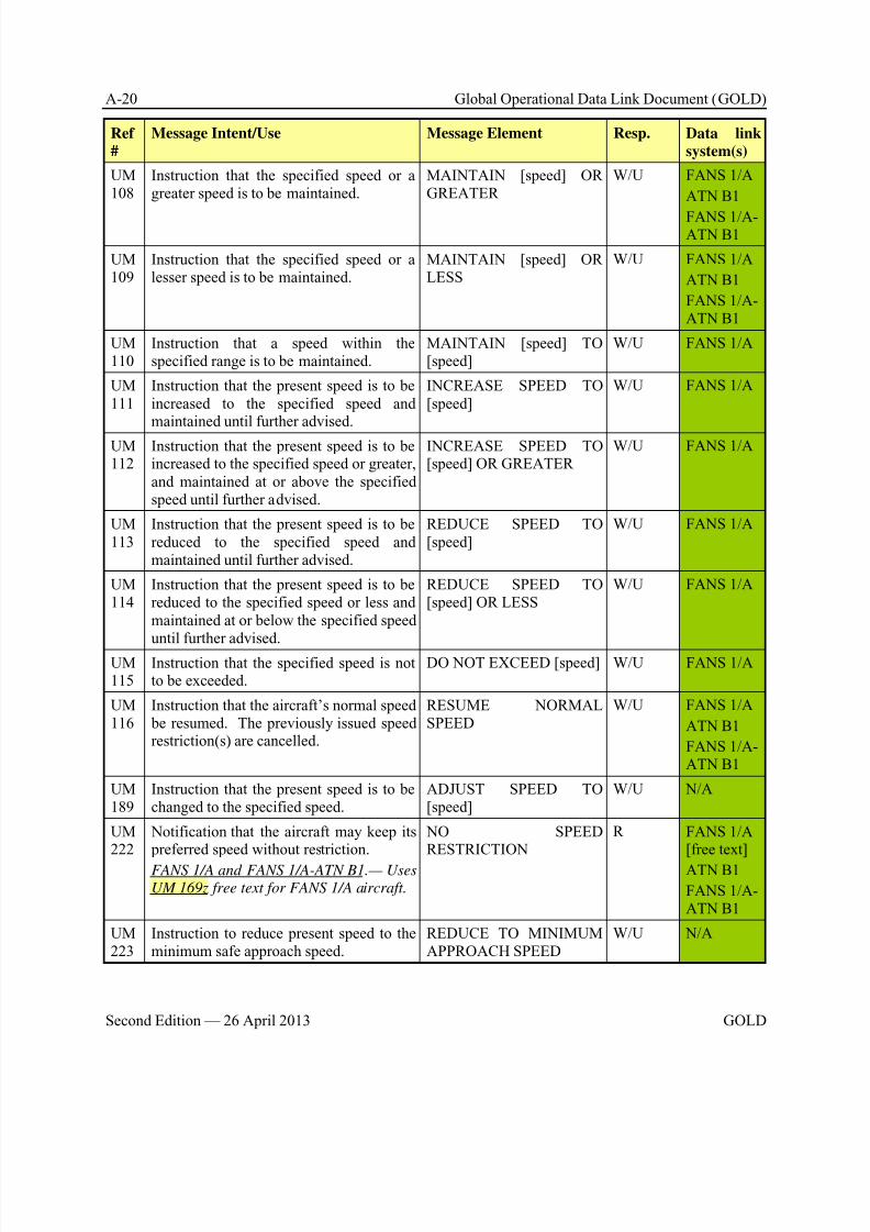
8/9/2019 CPDLC Explained
http://slidepdf.com/reader/full/cpdlc-explained 234/421
A-20 Global Operational Data Link Document (GOLD)
Second Edition — 26 April 2013 GOLD
Ref
#
Message Intent/Use Message Element Resp. Data link
system(s)
UM108
Instruction that the specified speed or agreater speed is to be maintained.
MAINTAIN [speed] ORGREATER
W/U FANS 1/A
ATN B1
FANS 1/A-ATN B1
UM109
Instruction that the specified speed or alesser speed is to be maintained.
MAINTAIN [speed] ORLESS
W/U FANS 1/A
ATN B1
FANS 1/A-ATN B1
UM110
Instruction that a speed within thespecified range is to be maintained.
MAINTAIN [speed] TO[speed]
W/U FANS 1/A
UM111
Instruction that the present speed is to beincreased to the specified speed andmaintained until further advised.
INCREASE SPEED TO[speed]
W/U FANS 1/A
UM112
Instruction that the present speed is to beincreased to the specified speed or greater,and maintained at or above the specifiedspeed until further advised.
INCREASE SPEED TO[speed] OR GREATER
W/U FANS 1/A
UM113
Instruction that the present speed is to bereduced to the specified speed andmaintained until further advised.
REDUCE SPEED TO[speed]
W/U FANS 1/A
UM114
Instruction that the present speed is to bereduced to the specified speed or less andmaintained at or below the specified speeduntil further advised.
REDUCE SPEED TO[speed] OR LESS
W/U FANS 1/A
UM115
Instruction that the specified speed is notto be exceeded.
DO NOT EXCEED [speed] W/U FANS 1/A
UM116
Instruction that the aircraft’s normal speed be resumed. The previously issued speedrestriction(s) are cancelled.
RESUME NORMALSPEED
W/U FANS 1/A
ATN B1
FANS 1/A-ATN B1
UM189
Instruction that the present speed is to bechanged to the specified speed.
ADJUST SPEED TO[speed]
W/U N/A
UM222
Notification that the aircraft may keep its preferred speed without restriction.
FANS 1/A and FANS 1/A-ATN B1.— Uses
UM 169z free text for FANS 1/A aircraft.
NO SPEEDRESTRICTION
R FANS 1/A[free text]
ATN B1
FANS 1/A-ATN B1
UM223
Instruction to reduce present speed to theminimum safe approach speed.
REDUCE TO MINIMUMAPPROACH SPEED
W/U N/A
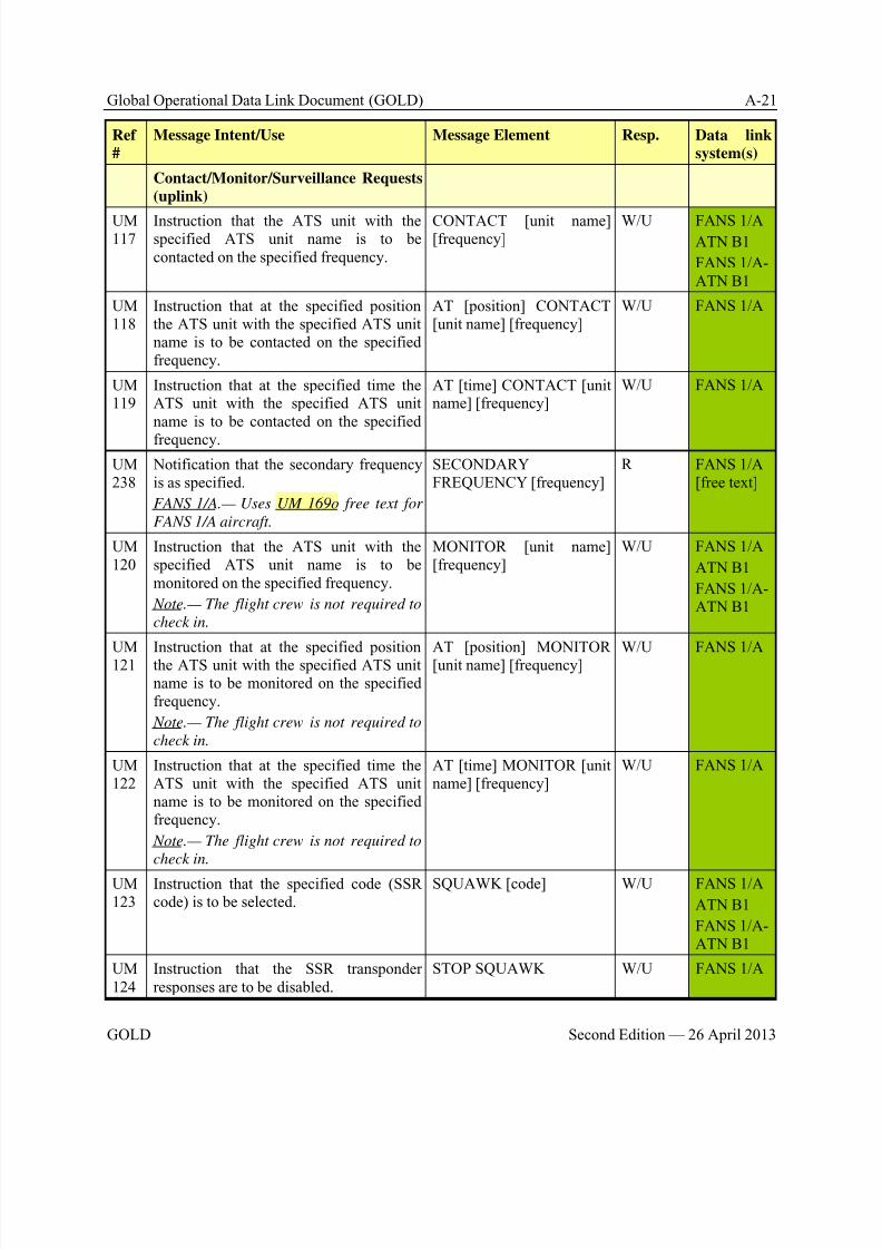
8/9/2019 CPDLC Explained
http://slidepdf.com/reader/full/cpdlc-explained 235/421
Global Operational Data Link Document (GOLD) A-21
GOLD Second Edition — 26 April 2013
Ref
#
Message Intent/Use Message Element Resp. Data link
system(s)
Contact/Monitor/Surveillance Requests
(uplink)
UM117
Instruction that the ATS unit with thespecified ATS unit name is to becontacted on the specified frequency.
CONTACT [unit name][frequency]
W/U FANS 1/AATN B1
FANS 1/A-ATN B1
UM118
Instruction that at the specified positionthe ATS unit with the specified ATS unitname is to be contacted on the specifiedfrequency.
AT [position] CONTACT[unit name] [frequency]
W/U FANS 1/A
UM119
Instruction that at the specified time theATS unit with the specified ATS unitname is to be contacted on the specified
frequency.
AT [time] CONTACT [unitname] [frequency]
W/U FANS 1/A
UM238
Notification that the secondary frequencyis as specified.
FANS 1/A.— Uses UM 169o free text for
FANS 1/A aircraft.
SECONDARYFREQUENCY [frequency]
R FANS 1/A[free text]
UM120
Instruction that the ATS unit with thespecified ATS unit name is to bemonitored on the specified frequency.
Note.— The flight crew is not required to
check in.
MONITOR [unit name][frequency]
W/U FANS 1/A
ATN B1
FANS 1/A-ATN B1
UM121
Instruction that at the specified positionthe ATS unit with the specified ATS unitname is to be monitored on the specifiedfrequency.
Note.— The flight crew is not required to
check in.
AT [position] MONITOR[unit name] [frequency]
W/U FANS 1/A
UM122
Instruction that at the specified time theATS unit with the specified ATS unitname is to be monitored on the specifiedfrequency.
Note.— The flight crew is not required to
check in.
AT [time] MONITOR [unitname] [frequency]
W/U FANS 1/A
UM123
Instruction that the specified code (SSRcode) is to be selected.
SQUAWK [code] W/U FANS 1/A
ATN B1
FANS 1/A-ATN B1
UM124
Instruction that the SSR transponderresponses are to be disabled.
STOP SQUAWK W/U FANS 1/A
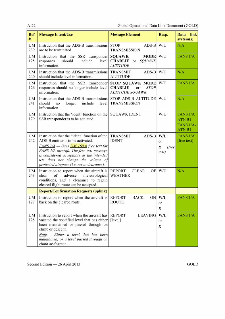
8/9/2019 CPDLC Explained
http://slidepdf.com/reader/full/cpdlc-explained 236/421
A-22 Global Operational Data Link Document (GOLD)
Second Edition — 26 April 2013 GOLD
Ref
#
Message Intent/Use Message Element Resp. Data link
system(s)
UM239
Instruction that the ADS-B transmissionsare to be terminated.
STOP ADS-BTRANSMISSION
W/U N/A
UM125
Instruction that the SSR transponderresponses should include levelinformation.
SQUAWK MODECHARLIE or SQUAWK
ALTITUDE
W/U FANS 1/A
UM240
Instruction that the ADS-B transmissionsshould include level information.
TRANSMIT ADS-BALTITUDE
W/U N/A
UM126
Instruction that the SSR transponderresponses should no longer include levelinformation.
STOP SQUAWK MODECHARLIE or STOP
ALTITUDE SQUAWK
W/U FANS 1/A
UM241
Instruction that the ADS-B transmissionsshould no longer include levelinformation.
STOP ADS-B ALTITUDETRANSMISSION
W/U N/A
UM179
Instruction that the ‘ident’ function on theSSR transponder is to be actuated.
SQUAWK IDENT W/U FANS 1/A
ATN B1
FANS 1/A-ATN B1
UM242
Instruction that the “ident” function of theADS-B emitter is to be activated.
FANS 1/A.— Uses UM 169ai free text for
FANS 1/A aircraft. The free text message
is considered acceptable as the intended
use does not change the volume of
protected airspace (i.e. not a clearance).
TRANSMIT ADS-BIDENT
W/U
or
R (free
text)
FANS 1/A[free text]
UM243
Instruction to report when the aircraft isclear of adverse meteorologicalconditions, and a clearance to regaincleared flight route can be accepted.
REPORT CLEAR OFWEATHER
W/U N/A
Report/Confirmation Requests (uplink)
UM127
Instruction to report when the aircraft is back on the cleared route.
REPORT BACK ONROUTE
W/U
or
R
FANS 1/A
UM128
Instruction to report when the aircraft hasvacated the specified level that has either
been maintained or passed through onclimb or descent.
Note.— Either a level that has been
maintained, or a level passed through on
climb or descent.
REPORT LEAVING[level]
W/U
or
R
FANS 1/A
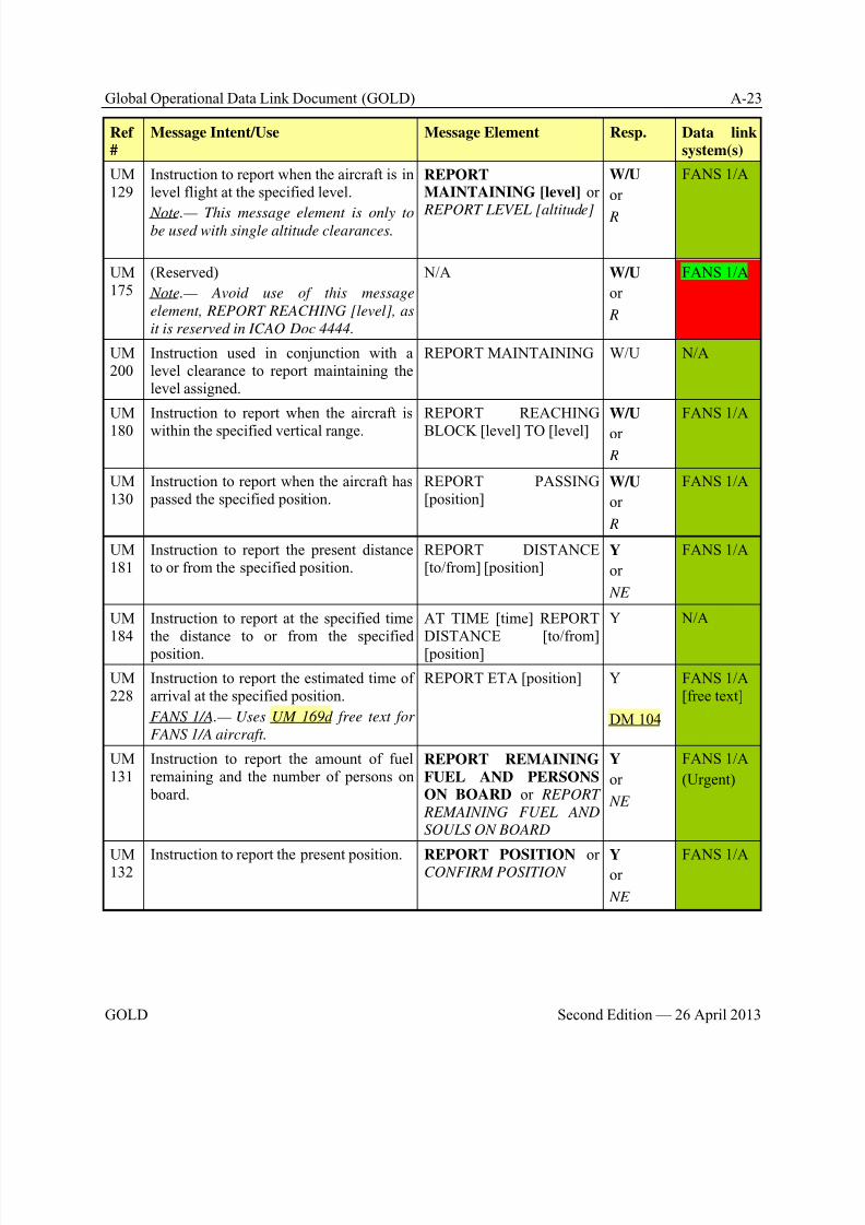
8/9/2019 CPDLC Explained
http://slidepdf.com/reader/full/cpdlc-explained 237/421
Global Operational Data Link Document (GOLD) A-23
GOLD Second Edition — 26 April 2013
Ref
#
Message Intent/Use Message Element Resp. Data link
system(s)
UM129
Instruction to report when the aircraft is inlevel flight at the specified level.
Note.— This message element is only tobe used with single altitude clearances.
REPORTMAINTAINING [level] or
REPORT LEVEL [altitude]
W/U
or
R
FANS 1/A
UM175
(Reserved)
Note.— Avoid use of this message
element, REPORT REACHING [level], as
it is reserved in ICAO Doc 4444.
N/A W/U
or
R
FANS 1/A
UM200
Instruction used in conjunction with alevel clearance to report maintaining thelevel assigned.
REPORT MAINTAINING W/U N/A
UM
180
Instruction to report when the aircraft is
within the specified vertical range.
REPORT REACHING
BLOCK [level] TO [level]
W/U
or
R
FANS 1/A
UM130
Instruction to report when the aircraft has passed the specified position.
REPORT PASSING[position]
W/U
or
R
FANS 1/A
UM181
Instruction to report the present distanceto or from the specified position.
REPORT DISTANCE[to/from] [position]
Y
or
NE
FANS 1/A
UM
184
Instruction to report at the specified time
the distance to or from the specified position.
AT TIME [time] REPORT
DISTANCE [to/from][position]
Y N/A
UM228
Instruction to report the estimated time ofarrival at the specified position.
FANS 1/A.— Uses UM 169d free text for
FANS 1/A aircraft.
REPORT ETA [position] Y
DM 104
FANS 1/A[free text]
UM131
Instruction to report the amount of fuelremaining and the number of persons on board.
REPORT REMAINING
FUEL AND PERSONSON BOARD or REPORT
REMAINING FUEL AND
SOULS ON BOARD
Y
or
NE
FANS 1/A
(Urgent)
UM132
Instruction to report the present position. REPORT POSITION orCONFIRM POSITION
Yor
NE
FANS 1/A
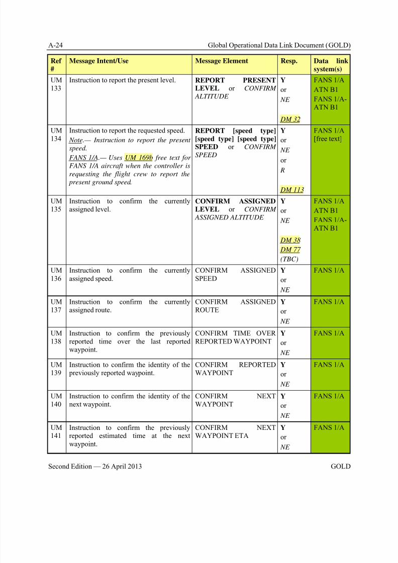
8/9/2019 CPDLC Explained
http://slidepdf.com/reader/full/cpdlc-explained 238/421
A-24 Global Operational Data Link Document (GOLD)
Second Edition — 26 April 2013 GOLD
Ref
#
Message Intent/Use Message Element Resp. Data link
system(s)
UM133
Instruction to report the present level. REPORT PRESENTLEVEL or CONFIRM
ALTITUDE
Y
or
NE
DM 32
FANS 1/A
ATN B1
FANS 1/A-ATN B1
UM134
Instruction to report the requested speed.
Note.— Instruction to report the present
speed.
FANS 1/A.— Uses UM 169b free text for
FANS 1/A aircraft when the controller is
requesting the flight crew to report the
present ground speed.
REPORT [speed type]
[speed type] [speed type]SPEED or CONFIRM
SPEED
Y
or
NE
or
R
DM 113
FANS 1/A[free text]
UM135
Instruction to confirm the currentlyassigned level.
CONFIRM ASSIGNEDLEVEL or CONFIRM
ASSIGNED ALTITUDE
Y
or
NE
DM 38
DM 77
(TBC)
FANS 1/A
ATN B1
FANS 1/A-ATN B1
UM136
Instruction to confirm the currentlyassigned speed.
CONFIRM ASSIGNEDSPEED
Y
or
NE
FANS 1/A
UM137
Instruction to confirm the currentlyassigned route.
CONFIRM ASSIGNEDROUTE
Y
or
NE
FANS 1/A
UM138
Instruction to confirm the previouslyreported time over the last reportedwaypoint.
CONFIRM TIME OVERREPORTED WAYPOINT
Y
or
NE
FANS 1/A
UM139
Instruction to confirm the identity of the previously reported waypoint.
CONFIRM REPORTEDWAYPOINT
Y
or
NE
FANS 1/A
UM140
Instruction to confirm the identity of thenext waypoint.
CONFIRM NEXTWAYPOINT
Y
or
NE
FANS 1/A
UM141
Instruction to confirm the previouslyreported estimated time at the nextwaypoint.
CONFIRM NEXTWAYPOINT ETA
Y
or
NE
FANS 1/A
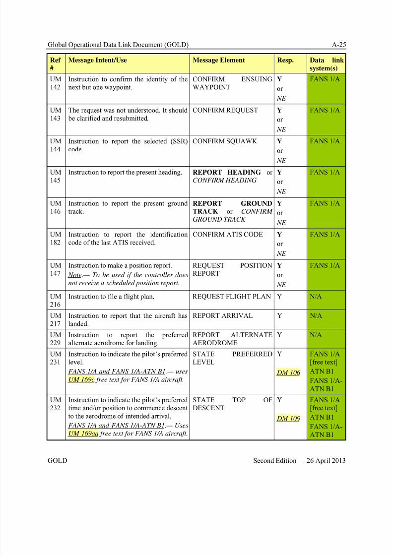
8/9/2019 CPDLC Explained
http://slidepdf.com/reader/full/cpdlc-explained 239/421
Global Operational Data Link Document (GOLD) A-25
GOLD Second Edition — 26 April 2013
Ref
#
Message Intent/Use Message Element Resp. Data link
system(s)
UM142
Instruction to confirm the identity of thenext but one waypoint.
CONFIRM ENSUINGWAYPOINT
Y
or
NE
FANS 1/A
UM143
The request was not understood. It should be clarified and resubmitted.
CONFIRM REQUEST Y
or
NE
FANS 1/A
UM144
Instruction to report the selected (SSR)code.
CONFIRM SQUAWK Y
or
NE
FANS 1/A
UM145
Instruction to report the present heading. REPORT HEADING orCONFIRM HEADING
Y
or
NE
FANS 1/A
UM146
Instruction to report the present groundtrack.
REPORT GROUNDTRACK or CONFIRM
GROUND TRACK
Y
or
NE
FANS 1/A
UM182
Instruction to report the identificationcode of the last ATIS received.
CONFIRM ATIS CODE Y
or
NE
FANS 1/A
UM147
Instruction to make a position report.
Note.— To be used if the controller does
not receive a scheduled position report.
REQUEST POSITIONREPORT
Y
or
NE
FANS 1/A
UM216
Instruction to file a flight plan. REQUEST FLIGHT PLAN Y N/A
UM217
Instruction to report that the aircraft haslanded.
REPORT ARRIVAL Y N/A
UM229
Instruction to report the preferredalternate aerodrome for landing.
REPORT ALTERNATEAERODROME
Y N/A
UM231
Instruction to indicate the pilot’s preferredlevel.
FANS 1/A and FANS 1/A-ATN B1.— uses
UM 169c free text for FANS 1/A aircraft.
STATE PREFERREDLEVEL
Y
DM 106
FANS 1/A[free text]
ATN B1
FANS 1/A-
ATN B1UM232
Instruction to indicate the pilot’s preferredtime and/or position to commence descentto the aerodrome of intended arrival.
FANS 1/A and FANS 1/A-ATN B1.— Uses
UM 169aa free text for FANS 1/A aircraft.
STATE TOP OFDESCENT
Y
DM 109
FANS 1/A[free text]
ATN B1
FANS 1/A-ATN B1

8/9/2019 CPDLC Explained
http://slidepdf.com/reader/full/cpdlc-explained 240/421
A-26 Global Operational Data Link Document (GOLD)
Second Edition — 26 April 2013 GOLD
Ref
#
Message Intent/Use Message Element Resp. Data link
system(s)
Negotiation Requests (uplink)
UM
148
Request for the earliest time or position at
which the specified level can be accepted.
WHEN CAN YOU
ACCEPT [level]
Y
or
NE
DM 81
DM 82
FANS 1/A
ATN B1
FANS 1/A-ATN B1
UM149
Instruction to report whether or not thespecified level can be accepted at thespecified position.
CAN YOU ACCEPT[level] AT [position]
A/N FANS 1/A
UM150
Instruction to report whether or not thespecified level can be accepted at the
specified time.
CAN YOU ACCEPT[level] AT [time]
A/N FANS 1/A
UM151
Instruction to report the earliest time or position when the specified speed can beaccepted.
WHEN CAN YOUACCEPT [speed]
Y
or
NE
DM 83
DM 84
FANS 1/A
UM152
Instruction to report the earliest time or position when the specified offset trackcan be accepted.
WHEN CAN YOUACCEPT [specifieddistance] [direction]OFFSET
Y
or
NE
DM 85
DM 86
FANS 1/A
Air Traffic Advisories (uplink)
UM153
ATS advisory that the altimeter settingshould be the specified setting.
ALTIMETER [altimeter] R FANS 1/A
UM213
ATS advisory that the specified altimetersetting relates to the specified facility.
FANS 1/A and FANS 1/A-ATN B1.— Uses
UM 169y free text for FANS 1/A aircraft.
[facility designation]ALTIMETER [altimeter]
R FANS 1/A[free text]
ATN B1
FANS 1/A-
ATN B1UM154
ATS advisory that the radar service isterminated.
RADAR SERVICETERMINATED or RADAR SERVICES
TERMINATED
R FANS 1/A
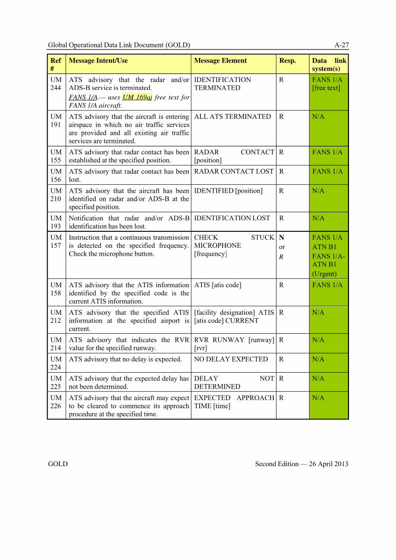
8/9/2019 CPDLC Explained
http://slidepdf.com/reader/full/cpdlc-explained 241/421
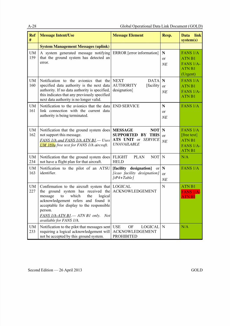
8/9/2019 CPDLC Explained
http://slidepdf.com/reader/full/cpdlc-explained 242/421
A-28 Global Operational Data Link Document (GOLD)
Second Edition — 26 April 2013 GOLD
Ref
#
Message Intent/Use Message Element Resp. Data link
system(s)
System Management Messages (uplink)
UM
159
A system generated message notifying
that the ground system has detected anerror.
ERROR [error information] N
or
NE
FANS 1/A
ATN B1
FANS 1/A-ATN B1
(Urgent)
UM160
Notification to the avionics that thespecified data authority is the next dataauthority. If no data authority is specified,this indicates that any previously specifiednext data authority is no longer valid.
NEXT DATAAUTHORITY [facilitydesignation]
N
or
NE
FANS 1/A
ATN B1
FANS 1/A-ATN B1
UM161
Notification to the avionics that the datalink connection with the current data
authority is being terminated.
END SERVICE N
or
NE
FANS 1/A
UM162
Notification that the ground system doesnot support this message.
FANS 1/A and FANS 1/A ATN B1.— Uses
UM 169u free text for FANS 1/A aircraft.
MESSAGE NOT
SUPPORTED BY THISATS UNIT or SERVICE
UNAVAILABLE
N
or
NE
FANS 1/A[free text]
ATN B1
FANS 1/A-ATN B1
UM234
Notification that the ground system doesnot have a flight plan for that aircraft.
FLIGHT PLAN NOTHELD
N N/A
UM163
Notification to the pilot of an ATSUidentifier.
[facility designation] or[icao facility designation]
[tP4+Table]
N
or
NE
FANS 1/A
UM227
Confirmation to the aircraft system thatthe ground system has received themessage to which the logicalacknowledgement refers and found itacceptable for display to the responsible person.
FANS 1/A-ATN B1.— ATN B1 only. Not
available for FANS 1/A.
LOGICALACKNOWLEDGEMENT
N ATN B1
FANS 1/A-ATN B1
UM233 Notification to the pilot that messages sentrequiring a logical acknowledgement willnot be accepted by this ground system.
USE OF LOGICALACKNOWLEDGEMENTPROHIBITED
N N/A
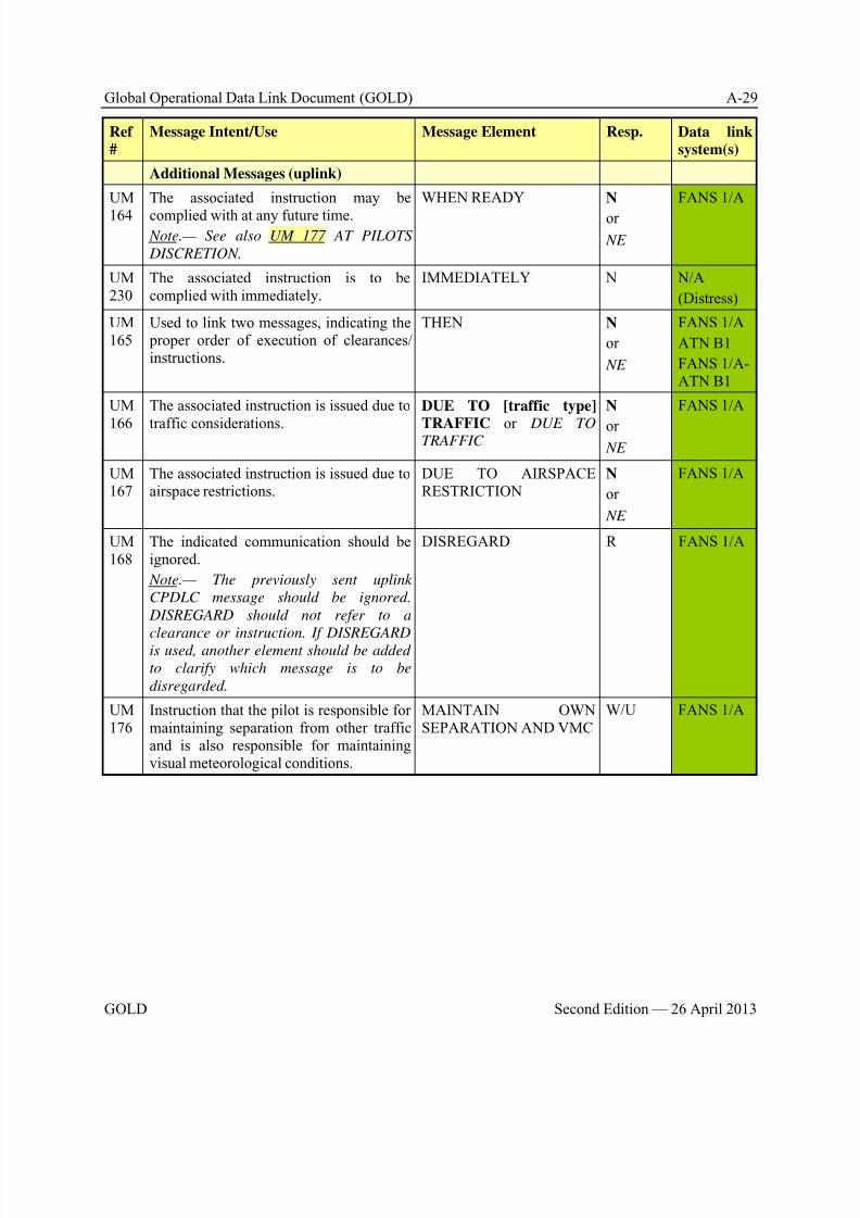
8/9/2019 CPDLC Explained
http://slidepdf.com/reader/full/cpdlc-explained 243/421
Global Operational Data Link Document (GOLD) A-29
GOLD Second Edition — 26 April 2013
Ref
#
Message Intent/Use Message Element Resp. Data link
system(s)
Additional Messages (uplink)
UM
164
The associated instruction may be
complied with at any future time. Note.— See also UM 177 AT PILOTS
DISCRETION.
WHEN READY N
or
NE
FANS 1/A
UM230
The associated instruction is to becomplied with immediately.
IMMEDIATELY N N/A
(Distress)
UM165
Used to link two messages, indicating the proper order of execution of clearances/instructions.
THEN N
or
NE
FANS 1/A
ATN B1
FANS 1/A-ATN B1
UM
166
The associated instruction is issued due to
traffic considerations.
DUE TO [traffic type]
TRAFFIC or DUE TOTRAFFIC
N
or NE
FANS 1/A
UM167
The associated instruction is issued due toairspace restrictions.
DUE TO AIRSPACERESTRICTION
N
or
NE
FANS 1/A
UM168
The indicated communication should beignored.
Note.— The previously sent uplink
CPDLC message should be ignored.
DISREGARD should not refer to a
clearance or instruction. If DISREGARDis used, another element should be added
to clarify which message is to be
disregarded.
DISREGARD R FANS 1/A
UM176
Instruction that the pilot is responsible formaintaining separation from other trafficand is also responsible for maintainingvisual meteorological conditions.
MAINTAIN OWNSEPARATION AND VMC
W/U FANS 1/A
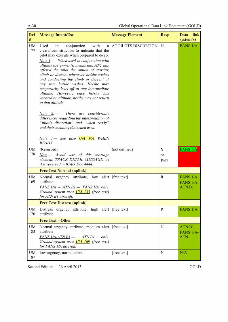
8/9/2019 CPDLC Explained
http://slidepdf.com/reader/full/cpdlc-explained 244/421
A-30 Global Operational Data Link Document (GOLD)
Second Edition — 26 April 2013 GOLD
Ref
#
Message Intent/Use Message Element Resp. Data link
system(s)
UM177
Used in conjunction with aclearance/instruction to indicate that the
pilot may execute when prepared to do so. Note 1.— When used in conjunction with
altitude assignments, means that ATC has
offered the pilot the option of starting
climb or descent whenever he/she wishes
and conducting the climb or descent at
any rate he/she wishes. He/she may
temporarily level off at any intermediate
altitude. However, once he/she has
vacated an altitude, he/she may not return
to that altitude.
Note 2.— There are considerabledifferences regarding the interpretation of
“pilot’s discretion” and “when ready”
and their meanings/intended uses.
Note 3.— See also UM 164 WHEN
READY.
AT PILOTS DISCRETION N FANS 1/A
UM178
(Reserved)
Note.— Avoid use of this message
element, TRACK DETAIL MESSAGE, as
it is reserved in ICAO Doc 4444.
(not defined) Y
or
W/U
FANS 1/A
Free Text Normal-(uplink)
UM169
Normal urgency attribute, low alertattribute
FANS 1/A – ATN B1.— FANS 1/A only.
Ground system uses UM 183 [free text]
for ATN B1 aircraft.
[free text] R FANS 1/A
FANS 1/A-ATN B1
Free Text Distress (uplink)
UM170
Distress urgency attribute, high alertattribute
[free text] R FANS 1/A
Free Text – Other
UM183
Normal urgency attribute, medium alertattribute
FANS 1/A-ATN B1.— ATN B1 only.
Ground system uses UM 169 [free text]
for FANS 1/A aircraft.
[free text] N ATN B1
FANS 1/A-ATN
UM187
low urgency, normal alert [free text] N N/A

8/9/2019 CPDLC Explained
http://slidepdf.com/reader/full/cpdlc-explained 245/421
Global Operational Data Link Document (GOLD) A-31
GOLD Second Edition — 26 April 2013
Ref
#
Message Intent/Use Message Element Resp. Data link
system(s)
UM194
normal urgency, low alert [free text] Y N/A
UM195
low urgency, low alert [free text] R N/A
UM196
normal urgency, medium alert [free text] W/U ATN B1
FANS 1/A-ATN B1
UM197
urgent urgency, medium alert [free text] W/U N/A
(Urgent)
UM198
distress urgency, high alert [free text] W/U N/A(Distress)
UM
199
normal urgency, low alert [free text] N N/A
UM201
Not used, low urgency, low alert [free text] N N/A
UM202
Not used, low urgency, low alert [free text] N N/A
UM203
normal urgency, medium alert [free text] R N/A
UM204
normal urgency, medium alert [free text] Y N/A
UM
205
normal urgency, medium alert [free text] A/N N/A
UM206
low urgency, normal alert [free text] Y N/A
UM207
low urgency, low alert [free text] Y N/A
UM208
low urgency, low alert [free text] N N/A
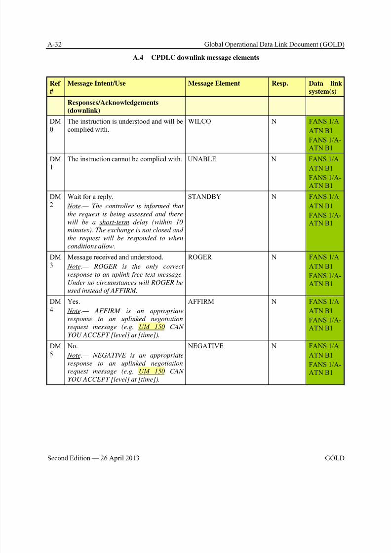
8/9/2019 CPDLC Explained
http://slidepdf.com/reader/full/cpdlc-explained 246/421
A-32 Global Operational Data Link Document (GOLD)
Second Edition — 26 April 2013 GOLD
A.4 CPDLC downlink message elements
Ref
#
Message Intent/Use Message Element Resp. Data link
system(s)
Responses/Acknowledgements
(downlink)
DM0
The instruction is understood and will becomplied with.
WILCO N FANS 1/A
ATN B1
FANS 1/A-ATN B1
DM1
The instruction cannot be complied with. UNABLE N FANS 1/A
ATN B1
FANS 1/A-ATN B1
DM2
Wait for a reply.
Note.— The controller is informed that
the request is being assessed and there
will be a short-term delay (within 10
minutes). The exchange is not closed and
the request will be responded to when
conditions allow.
STANDBY N FANS 1/A
ATN B1
FANS 1/A-ATN B1
DM3
Message received and understood.
Note.— ROGER is the only correct
response to an uplink free text message.
Under no circumstances will ROGER be
used instead of AFFIRM.
ROGER N FANS 1/A
ATN B1
FANS 1/A-ATN B1
DM4
Yes.
Note.— AFFIRM is an appropriate
response to an uplinked negotiation
request message (e.g. UM 150 CAN
YOU ACCEPT [level] at [time]).
AFFIRM N FANS 1/A
ATN B1
FANS 1/A-ATN B1
DM5
No.
Note.— NEGATIVE is an appropriate
response to an uplinked negotiation
request message (e.g. UM 150 CAN
YOU ACCEPT [level] at [time]).
NEGATIVE N FANS 1/A
ATN B1
FANS 1/A-ATN B1
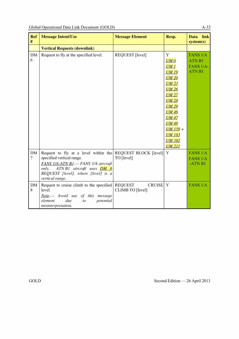
8/9/2019 CPDLC Explained
http://slidepdf.com/reader/full/cpdlc-explained 247/421
Global Operational Data Link Document (GOLD) A-33
GOLD Second Edition — 26 April 2013
Ref
#
Message Intent/Use Message Element Resp. Data link
system(s)
Vertical Requests (downlink)
DM
6
Request to fly at the specified level. REQUEST [level] Y
UM 0
UM 1
UM 19
UM 20
UM 23
UM 26
UM 27
UM 28
UM 29
UM 46
UM 47UM 48
UM 159 +
UM 183
UM 162
UM 211
FANS 1/A
ATN B1
FANS 1/A-ATN B1
DM7
Request to fly at a level within thespecified vertical range.
FANS 1/A-ATN B1.— FANS 1/A aircraft
only. ATN B1 aircraft uses DM 6
REQUEST [level], where [level] is a
vertical range.
REQUEST BLOCK [level]TO [level]
Y FANS 1/A
FANS 1/A –ATN B1
DM8
Request to cruise climb to the specifiedlevel.
Note.— Avoid use of this message
element due to potential
misinterpretation.
REQUEST CRUISECLIMB TO [level]
Y FANS 1/A
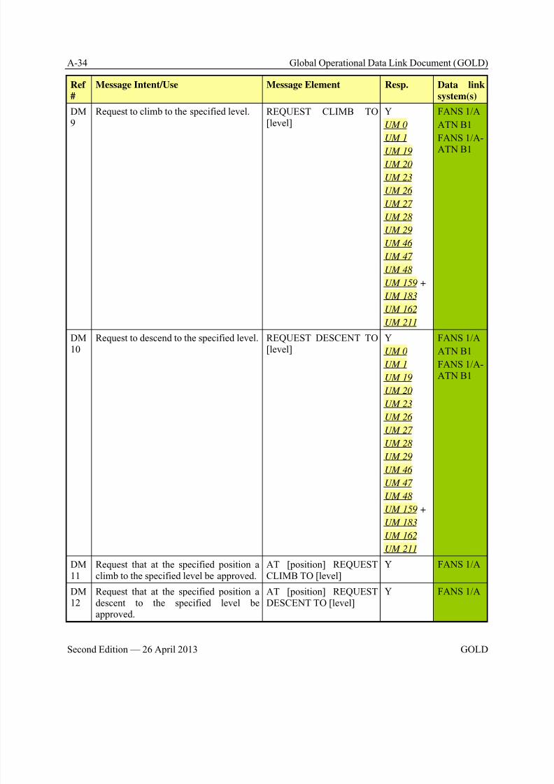
8/9/2019 CPDLC Explained
http://slidepdf.com/reader/full/cpdlc-explained 248/421
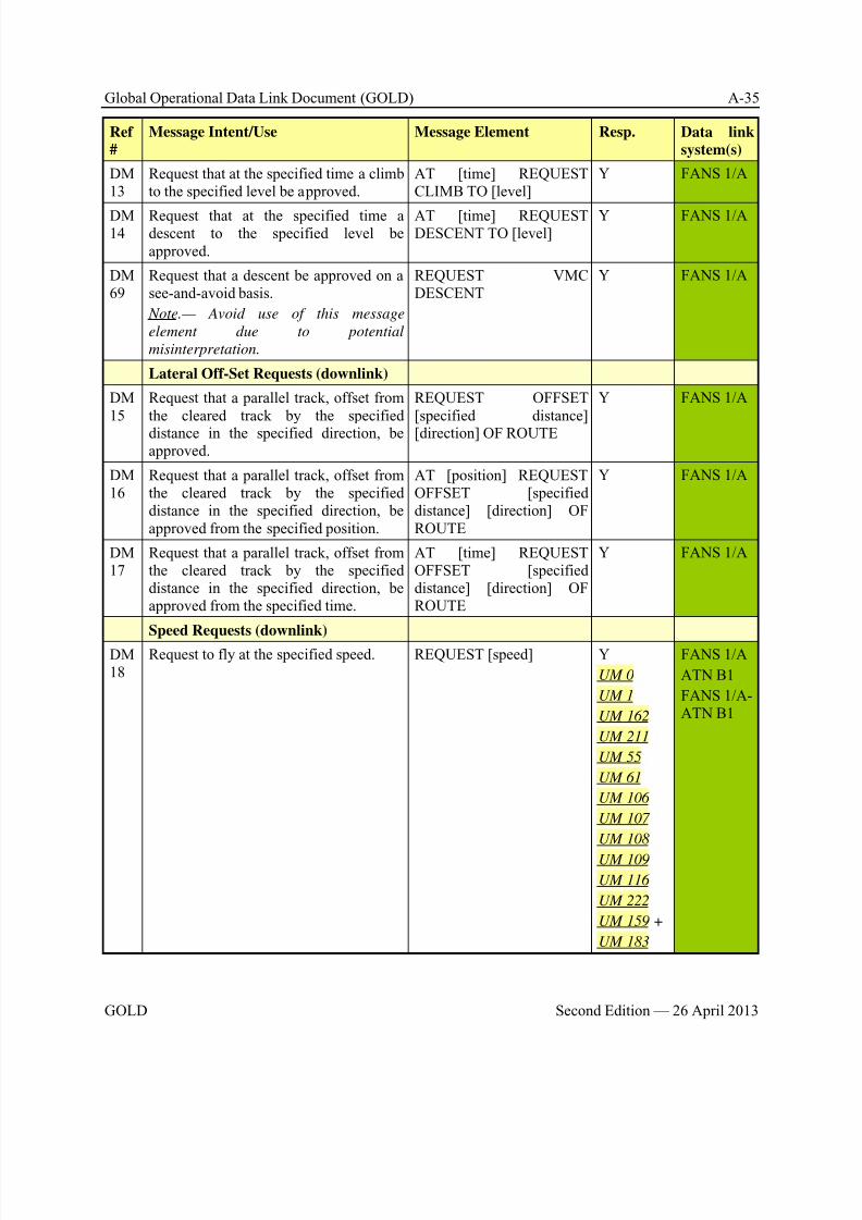
8/9/2019 CPDLC Explained
http://slidepdf.com/reader/full/cpdlc-explained 249/421
Global Operational Data Link Document (GOLD) A-35
GOLD Second Edition — 26 April 2013
Ref
#
Message Intent/Use Message Element Resp. Data link
system(s)
DM13
Request that at the specified time a climbto the specified level be approved.
AT [time] REQUESTCLIMB TO [level]
Y FANS 1/A
DM14
Request that at the specified time adescent to the specified level beapproved.
AT [time] REQUESTDESCENT TO [level]
Y FANS 1/A
DM69
Request that a descent be approved on asee-and-avoid basis.
Note.— Avoid use of this message
element due to potential
misinterpretation.
REQUEST VMCDESCENT
Y FANS 1/A
Lateral Off-Set Requests (downlink)
DM15
Request that a parallel track, offset fromthe cleared track by the specified
distance in the specified direction, beapproved.
REQUEST OFFSET[specified distance]
[direction] OF ROUTE
Y FANS 1/A
DM16
Request that a parallel track, offset fromthe cleared track by the specifieddistance in the specified direction, beapproved from the specified position.
AT [position] REQUESTOFFSET [specifieddistance] [direction] OFROUTE
Y FANS 1/A
DM17
Request that a parallel track, offset fromthe cleared track by the specifieddistance in the specified direction, beapproved from the specified time.
AT [time] REQUESTOFFSET [specifieddistance] [direction] OFROUTE
Y FANS 1/A
Speed Requests (downlink)
DM18
Request to fly at the specified speed. REQUEST [speed] Y
UM 0
UM 1
UM 162
UM 211
UM 55
UM 61
UM 106
UM 107
UM 108
UM 109
UM 116
UM 222
UM 159 +
UM 183
FANS 1/A
ATN B1
FANS 1/A-ATN B1
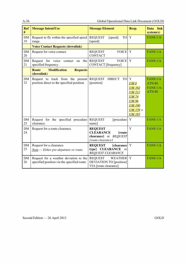
8/9/2019 CPDLC Explained
http://slidepdf.com/reader/full/cpdlc-explained 250/421
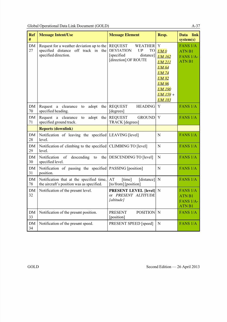
8/9/2019 CPDLC Explained
http://slidepdf.com/reader/full/cpdlc-explained 251/421
Global Operational Data Link Document (GOLD) A-37
GOLD Second Edition — 26 April 2013
Ref
#
Message Intent/Use Message Element Resp. Data link
system(s)
DM27
Request for a weather deviation up to thespecified distance off track in the
specified direction.
REQUEST WEATHERDEVIATION UP TO
[specified distance] [direction] OF ROUTE
Y
UM 0
UM 162UM 211
UM 64
UM 74
UM 82
UM 96
UM 190
UM 159 +
UM 183
FANS 1/A
ATN B1
FANS 1/A-ATN B1
DM
70
Request a clearance to adopt the
specified heading.
REQUEST HEADING
[degrees]
Y FANS 1/A
DM71
Request a clearance to adopt thespecified ground track.
REQUEST GROUNDTRACK [degrees]
Y FANS 1/A
Reports (downlink)
DM28
Notification of leaving the specifiedlevel.
LEAVING [level] N FANS 1/A
DM29
Notification of climbing to the specifiedlevel.
CLIMBING TO [level] N FANS 1/A
DM30
Notification of descending to thespecified level.
DESCENDING TO [level] N FANS 1/A
DM31
Notification of passing the specified position.
PASSING [position] N FANS 1/A
DM78
Notification that at the specified time,the aircraft’s position was as specified.
AT [time] [distance][to/from] [position]
N FANS 1/A
DM32
Notification of the present level. PRESENT LEVEL [level] or PRESENT ALTITUDE
[altitude]
N FANS 1/A
ATN B1
FANS 1/A-ATN B1
DM33
Notification of the present position. PRESENT POSITION[position]
N FANS 1/A
DM34
Notification of the present speed. PRESENT SPEED [speed] N FANS 1/A
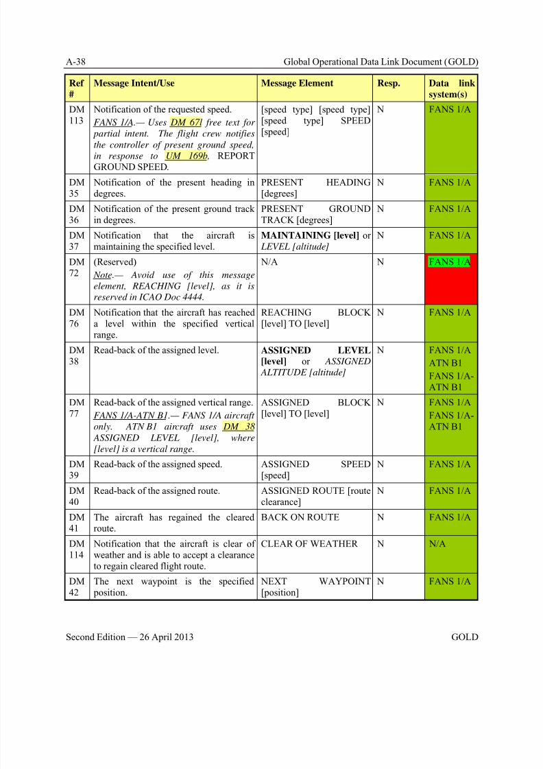
8/9/2019 CPDLC Explained
http://slidepdf.com/reader/full/cpdlc-explained 252/421
A-38 Global Operational Data Link Document (GOLD)
Second Edition — 26 April 2013 GOLD
Ref
#
Message Intent/Use Message Element Resp. Data link
system(s)
DM113
Notification of the requested speed.
FANS 1/A.— Uses DM 67l free text for
partial intent. The flight crew notifiesthe controller of present ground speed,
in response to UM 169b, REPORTGROUND SPEED.
[speed type] [speed type][speed type] SPEED
[speed]
N FANS 1/A
DM35
Notification of the present heading indegrees.
PRESENT HEADING[degrees]
N FANS 1/A
DM36
Notification of the present ground trackin degrees.
PRESENT GROUNDTRACK [degrees]
N FANS 1/A
DM37
Notification that the aircraft ismaintaining the specified level.
MAINTAINING [level] or LEVEL [altitude]
N FANS 1/A
DM
72
(Reserved)
Note.— Avoid use of this message
element, REACHING [level], as it is
reserved in ICAO Doc 4444.
N/A N FANS 1/A
DM76
Notification that the aircraft has reacheda level within the specified verticalrange.
REACHING BLOCK[level] TO [level]
N FANS 1/A
DM38
Read-back of the assigned level. ASSIGNED LEVEL[level] or ASSIGNED
ALTITUDE [altitude]
N FANS 1/A
ATN B1
FANS 1/A-ATN B1
DM77
Read-back of the assigned vertical range.FANS 1/A-ATN B1.— FANS 1/A aircraft
only. ATN B1 aircraft uses DM 38
ASSIGNED LEVEL [level], where
[level] is a vertical range.
ASSIGNED BLOCK[level] TO [level]
N FANS 1/AFANS 1/A-ATN B1
DM39
Read-back of the assigned speed. ASSIGNED SPEED[speed]
N FANS 1/A
DM40
Read-back of the assigned route. ASSIGNED ROUTE [routeclearance]
N FANS 1/A
DM41
The aircraft has regained the clearedroute.
BACK ON ROUTE N FANS 1/A
DM114
Notification that the aircraft is clear ofweather and is able to accept a clearanceto regain cleared flight route.
CLEAR OF WEATHER N N/A
DM42
The next waypoint is the specified position.
NEXT WAYPOINT[position]
N FANS 1/A
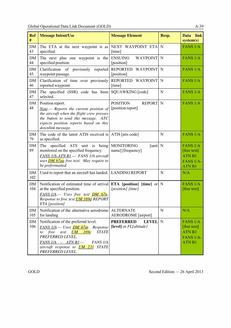
8/9/2019 CPDLC Explained
http://slidepdf.com/reader/full/cpdlc-explained 253/421
Global Operational Data Link Document (GOLD) A-39
GOLD Second Edition — 26 April 2013
Ref
#
Message Intent/Use Message Element Resp. Data link
system(s)
DM43
The ETA at the next waypoint is asspecified.
NEXT WAYPOINT ETA[time]
N FANS 1/A
DM44
The next plus one waypoint is thespecified position.
ENSUING WAYPOINT[position]
N FANS 1/A
DM45
Clarification of previously reportedwaypoint passage.
REPORTED WAYPOINT[position]
N FANS 1/A
DM46
Clarification of time over previouslyreported waypoint.
REPORTED WAYPOINT[time]
N FANS 1/A
DM47
The specified (SSR) code has beenselected.
SQUAWKING [code] N FANS 1/A
DM48
Position report.
Note.— Reports the current position of
the aircraft when the flight crew pressesthe button to send this message. ATC
expects position reports based on this
downlink message.
POSITION REPORT[position report]
N FANS 1/A
DM79
The code of the latest ATIS received isas specified.
ATIS [atis code] N FANS 1/A
DM89
The specified ATS unit is beingmonitored on the specified frequency.
FANS 1/A-ATN B1.— FANS 1/A aircraft
uses DM 67aa free text. May require to
be preformatted.
MONITORING [unitname] [frequency]
N FANS 1/A[free text]
ATN B1
FANS 1/A-ATN B1
DM102
Used to report that an aircraft has landed. LANDING REPORT N N/A
DM104
Notification of estimated time of arrivalat the specified position.
FANS 1/A.— Uses free text DM 67n.
Response to free text UM 169d REPORT
ETA [position]
ETA [position] [time] or[position] [time]
N FANS 1/A[free text]
DM105
Notification of the alternative aerodromefor landing.
ALTERNATEAERODROME [airport]
N N/A
DM106
Notification of the preferred level.
FANS 1/A.— Uses DM 67m. Response
to free text UM 169c STATE
PREFERRED LEVEL.
FANS 1/A – ATN B1.— FANS 1/A
aircraft response to UM 231 STATE
PREFERRED LEVEL.
PREFERRED LEVEL[level] or FL[altitude]
N FANS 1/A[free text]
ATN B1
FANS 1/A-ATN B1
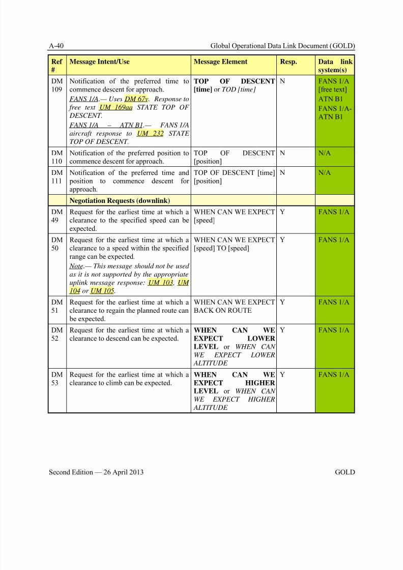
8/9/2019 CPDLC Explained
http://slidepdf.com/reader/full/cpdlc-explained 254/421
A-40 Global Operational Data Link Document (GOLD)
Second Edition — 26 April 2013 GOLD
Ref
#
Message Intent/Use Message Element Resp. Data link
system(s)
DM109
Notification of the preferred time tocommence descent for approach.
FANS 1/A.— Uses DM 67v. Response to free text UM 169aa STATE TOP OF
DESCENT.
FANS 1/A – ATN B1.— FANS 1/A
aircraft response to UM 232 STATE
TOP OF DESCENT.
TOP OF DESCENT[time] or TOD [time]
N FANS 1/A[free text]
ATN B1FANS 1/A-ATN B1
DM110
Notification of the preferred position tocommence descent for approach.
TOP OF DESCENT[position]
N N/A
DM111
Notification of the preferred time and position to commence descent forapproach.
TOP OF DESCENT [time][position]
N N/A
Negotiation Requests (downlink)
DM49
Request for the earliest time at which aclearance to the specified speed can beexpected.
WHEN CAN WE EXPECT[speed]
Y FANS 1/A
DM50
Request for the earliest time at which aclearance to a speed within the specifiedrange can be expected.
Note.— This message should not be used
as it is not supported by the appropriate
uplink message response: UM 103, UM
104 or UM 105.
WHEN CAN WE EXPECT[speed] TO [speed]
Y FANS 1/A
DM51
Request for the earliest time at which aclearance to regain the planned route can be expected.
WHEN CAN WE EXPECTBACK ON ROUTE
Y FANS 1/A
DM52
Request for the earliest time at which aclearance to descend can be expected.
WHEN CAN WE
EXPECT LOWERLEVEL or WHEN CAN
WE EXPECT LOWER
ALTITUDE
Y FANS 1/A
DM53
Request for the earliest time at which aclearance to climb can be expected.
WHEN CAN WE
EXPECT HIGHERLEVEL or WHEN CAN
WE EXPECT HIGHER ALTITUDE
Y FANS 1/A
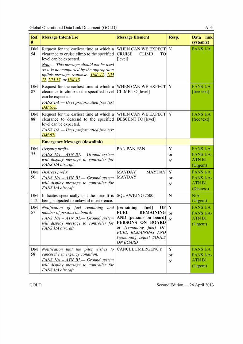
8/9/2019 CPDLC Explained
http://slidepdf.com/reader/full/cpdlc-explained 255/421
Global Operational Data Link Document (GOLD) A-41
GOLD Second Edition — 26 April 2013
Ref
#
Message Intent/Use Message Element Resp. Data link
system(s)
DM54
Request for the earliest time at which aclearance to cruise climb to the specified
level can be expected. Note.— This message should not be used
as it is not supported by the appropriate
uplink message response: UM 11, UM
12, UM 17, or UM 18.
WHEN CAN WE EXPECTCRUISE CLIMB TO
[level]
Y FANS 1/A
DM87
Request for the earliest time at which aclearance to climb to the specified levelcan be expected.
FANS 1/A.— Uses preformatted free text
DM 67h.
WHEN CAN WE EXPECTCLIMB TO [level]
Y FANS 1/A[free text]
DM
88
Request for the earliest time at which a
clearance to descend to the specifiedlevel can be expected.
FANS 1/A.— Uses preformatted free text
DM 67i.
WHEN CAN WE EXPECT
DESCENT TO [level]
Y FANS 1/A
[free text]
Emergency Messages (downlink)
DM55
Urgency prefix.
FANS 1/A – ATN B1.— Ground system
will display message to controller for
FANS 1/A aircraft.
PAN PAN PAN Y
or
N
FANS 1/A
FANS 1/A-ATN B1
(Urgent)
DM56
Distress prefix.
FANS 1/A – ATN B1.— Ground system
will display message to controller for
FANS 1/A aircraft.
MAYDAY MAYDAYMAYDAY
Y
or
N
FANS 1/A
FANS 1/A-ATN B1
(Distress)
DM112
Indicates specifically that the aircraft is being subjected to unlawful interference.
SQUAWKING 7500 N N/A(Urgent)
DM57
Notification of fuel remaining and
number of persons on board.
FANS 1/A – ATN B1.— Ground system
will display message to controller for
FANS 1/A aircraft.
[remaining fuel] OF
FUEL REMAINING
AND [persons on board]
PERSONS ON BOARD or [remaining fuel] OF
FUEL REMAINING AND
[remaining souls] SOULS
ON BOARD
Y
or
N
FANS 1/A
FANS 1/A-ATN B1
(Urgent)
DM58
Notification that the pilot wishes to
cancel the emergency condition.
FANS 1/A – ATN B1.— Ground system
will display message to controller for
FANS 1/A aircraft.
CANCEL EMERGENCY Y
or
N
FANS 1/A
FANS 1/A-ATN B1
(Urgent)
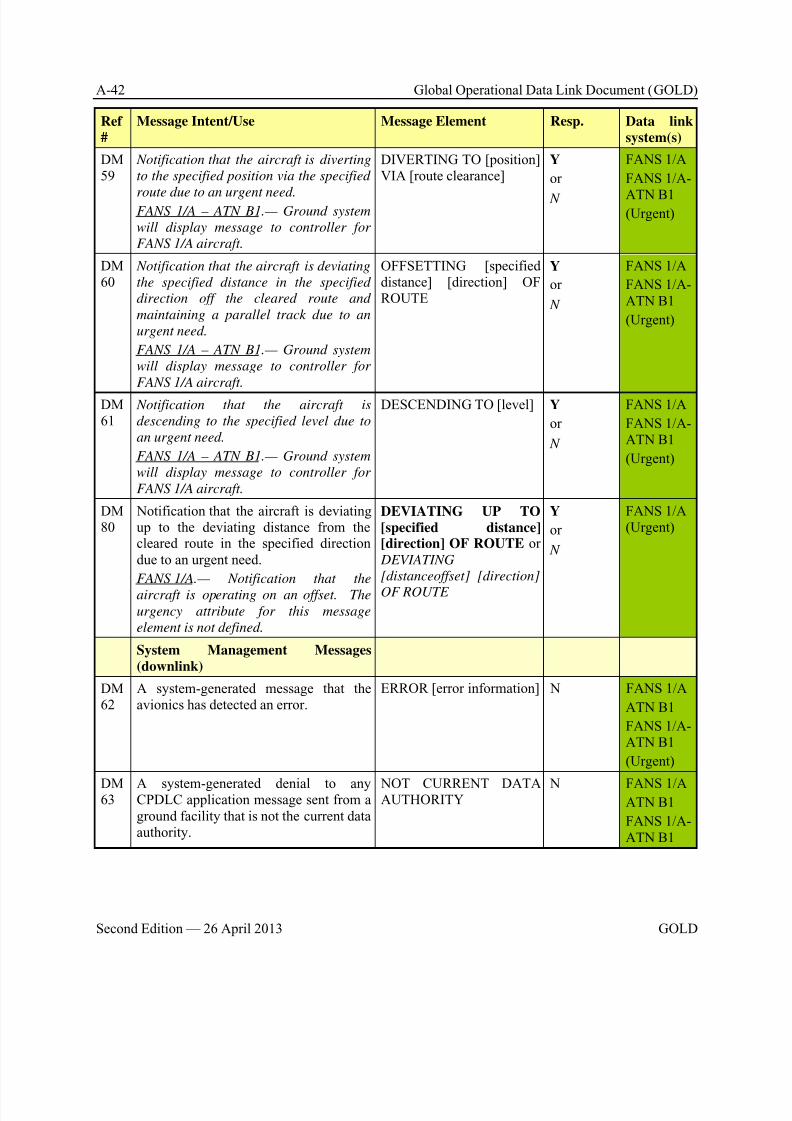
8/9/2019 CPDLC Explained
http://slidepdf.com/reader/full/cpdlc-explained 256/421
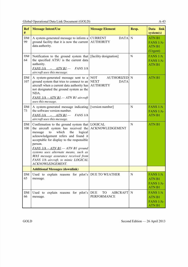
8/9/2019 CPDLC Explained
http://slidepdf.com/reader/full/cpdlc-explained 257/421
Global Operational Data Link Document (GOLD) A-43
GOLD Second Edition — 26 April 2013
Ref
#
Message Intent/Use Message Element Resp. Data link
system(s)
DM99
A system-generated message to inform aground facility that it is now the current
data authority.
CURRENT DATAAUTHORITY
N ATN B1
FANS 1/A-
ATN B1(Urgent)
DM64
Notification to the ground system thatthe specified ATSU is the current dataauthority.
FANS 1/A – ATN B1.— FANS 1/A
aircraft uses this message.
[facility designation] N FANS 1/A
FANS 1/A-ATN B1
DM107
A system-generated message sent to aground system that tries to connect to anaircraft when a current data authority hasnot designated the ground system as the
NDA.FANS 1/A – ATN B1.— ATN B1 aircraft
uses this message.
NOT AUTHORIZED NEXT DATAAUTHORITY
N ATN B1
DM73
A system-generated message indicatingthe software version number.
FANS 1/A – ATN B1.— FANS 1/A
aircraft uses this message.
[version number] N FANS 1/A
FANS 1/A-ATN B1
DM100
Confirmation to the ground system thatthe aircraft system has received themessage to which the logicalacknowledgement refers and found it
acceptable for display to the responsible person.
FANS 1/A – ATN B1.— ATN B1 ground
systems uses alternate means, such as
MAS message assurance received from
FANS 1/A aircraft, to mimic LOGICAL
ACKNOWLEDGEMENT.
LOGICALACKNOWLEDGEMENT
N ATN B1
Additional Messages (downlink)
DM65
Used to explain reasons for pilot’smessage.
DUE TO WEATHER N FANS 1/A
ATN B1
FANS 1/A-
ATN B1
DM66
Used to explain reasons for pilot’smessage.
DUE TO AIRCRAFTPERFORMANCE
N FANS 1/A
ATN B1
FANS 1/A-ATN B1
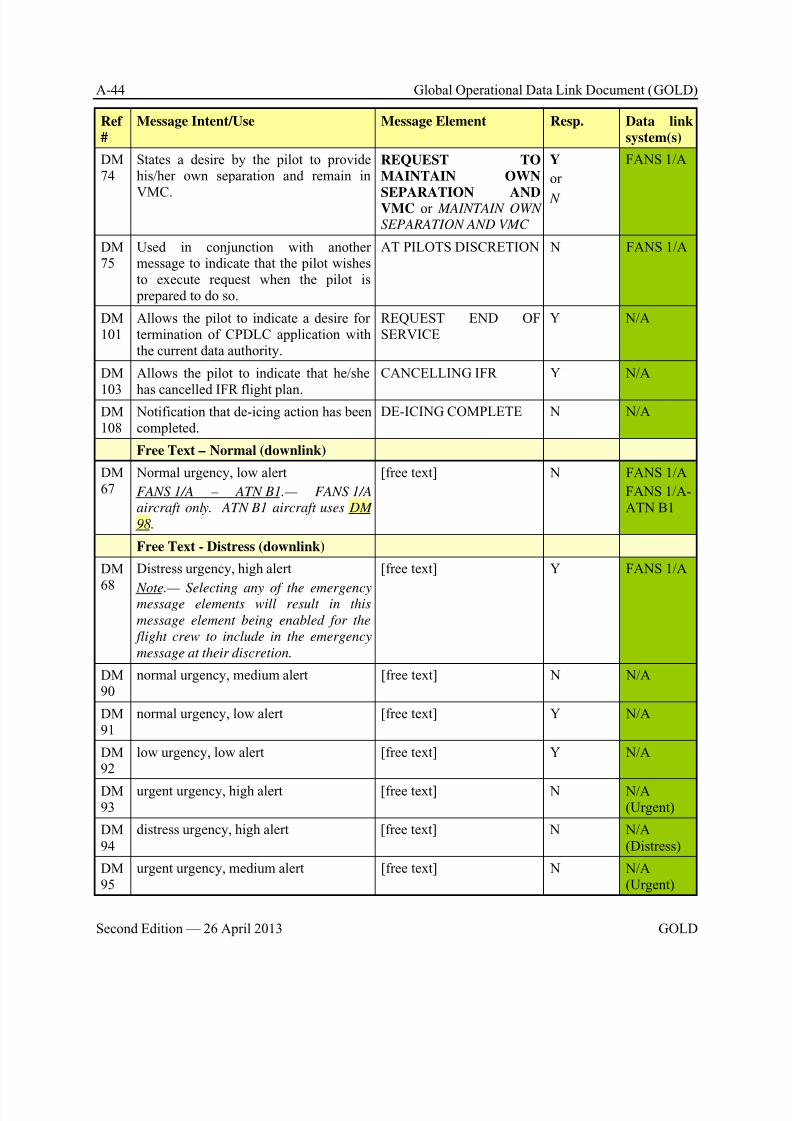
8/9/2019 CPDLC Explained
http://slidepdf.com/reader/full/cpdlc-explained 258/421
A-44 Global Operational Data Link Document (GOLD)
Second Edition — 26 April 2013 GOLD
Ref
#
Message Intent/Use Message Element Resp. Data link
system(s)
DM74
States a desire by the pilot to providehis/her own separation and remain in
VMC.
REQUEST TO
MAINTAIN OWN
SEPARATION ANDVMC or MAINTAIN OWN
SEPARATION AND VMC
Y
or
N
FANS 1/A
DM75
Used in conjunction with anothermessage to indicate that the pilot wishesto execute request when the pilot is prepared to do so.
AT PILOTS DISCRETION N FANS 1/A
DM101
Allows the pilot to indicate a desire fortermination of CPDLC application withthe current data authority.
REQUEST END OFSERVICE
Y N/A
DM
103
Allows the pilot to indicate that he/she
has cancelled IFR flight plan.
CANCELLING IFR Y N/A
DM108
Notification that de-icing action has beencompleted.
DE-ICING COMPLETE N N/A
Free Text – Normal (downlink)
DM67
Normal urgency, low alert
FANS 1/A – ATN B1.— FANS 1/A
aircraft only. ATN B1 aircraft uses DM
98.
[free text] N FANS 1/A
FANS 1/A-ATN B1
Free Text - Distress (downlink)
DM
68
Distress urgency, high alert
Note.— Selecting any of the emergencymessage elements will result in this
message element being enabled for the
flight crew to include in the emergency
message at their discretion.
[free text] Y FANS 1/A
DM90
normal urgency, medium alert [free text] N N/A
DM91
normal urgency, low alert [free text] Y N/A
DM92
low urgency, low alert [free text] Y N/A
DM93
urgent urgency, high alert [free text] N N/A(Urgent)
DM94
distress urgency, high alert [free text] N N/A(Distress)
DM95
urgent urgency, medium alert [free text] N N/A(Urgent)
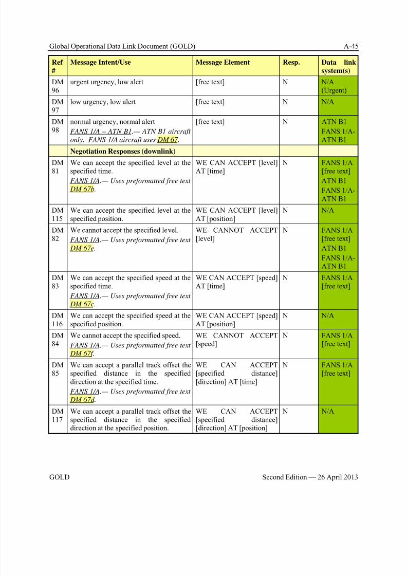
8/9/2019 CPDLC Explained
http://slidepdf.com/reader/full/cpdlc-explained 259/421
Global Operational Data Link Document (GOLD) A-45
GOLD Second Edition — 26 April 2013
Ref
#
Message Intent/Use Message Element Resp. Data link
system(s)
DM96
urgent urgency, low alert [free text] N N/A(Urgent)
DM97
low urgency, low alert [free text] N N/A
DM98
normal urgency, normal alert
FANS 1/A – ATN B1.— ATN B1 aircraft
only. FANS 1/A aircraft uses DM 67.
[free text] N ATN B1
FANS 1/A-ATN B1
Negotiation Responses (downlink)
DM81
We can accept the specified level at thespecified time.
FANS 1/A.— Uses preformatted free text
DM 67b.
WE CAN ACCEPT [level]AT [time]
N FANS 1/A[free text]
ATN B1
FANS 1/A-
ATN B1DM115
We can accept the specified level at thespecified position.
WE CAN ACCEPT [level]AT [position]
N N/A
DM82
We cannot accept the specified level.
FANS 1/A.— Uses preformatted free text
DM 67e.
WE CANNOT ACCEPT[level]
N FANS 1/A[free text]
ATN B1
FANS 1/A-ATN B1
DM83
We can accept the specified speed at thespecified time.
FANS 1/A.— Uses preformatted free text
DM 67c.
WE CAN ACCEPT [speed]AT [time]
N FANS 1/A[free text]
DM116
We can accept the specified speed at thespecified position.
WE CAN ACCEPT [speed]AT [position]
N N/A
DM84
We cannot accept the specified speed.
FANS 1/A.— Uses preformatted free text
DM 67f.
WE CANNOT ACCEPT[speed]
N FANS 1/A[free text]
DM85
We can accept a parallel track offset thespecified distance in the specifieddirection at the specified time.
FANS 1/A.— Uses preformatted free text
DM 67d.
WE CAN ACCEPT[specified distance][direction] AT [time]
N FANS 1/A[free text]
DM117
We can accept a parallel track offset thespecified distance in the specifieddirection at the specified position.
WE CAN ACCEPT[specified distance][direction] AT [position]
N N/A
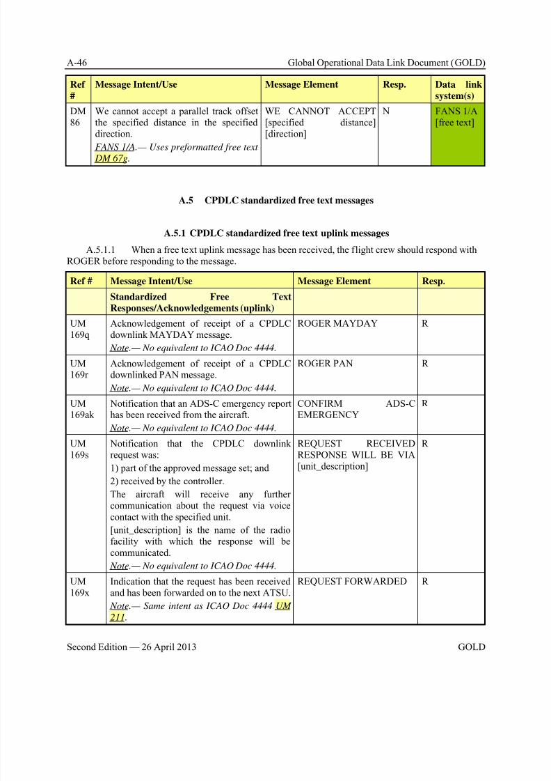
8/9/2019 CPDLC Explained
http://slidepdf.com/reader/full/cpdlc-explained 260/421
A-46 Global Operational Data Link Document (GOLD)
Second Edition — 26 April 2013 GOLD
Ref
#
Message Intent/Use Message Element Resp. Data link
system(s)
DM86
We cannot accept a parallel track offsetthe specified distance in the specified
direction.FANS 1/A.— Uses preformatted free text
DM 67g.
WE CANNOT ACCEPT[specified distance]
[direction]
N FANS 1/A[free text]
A.5 CPDLC standardized free text messages
A.5.1 CPDLC standardized free text uplink messages
A.5.1.1 When a free text uplink message has been received, the flight crew should respond withROGER before responding to the message.
Ref # Message Intent/Use Message Element Resp.
Standardized Free Text
Responses/Acknowledgements (uplink)
UM169q
Acknowledgement of receipt of a CPDLCdownlink MAYDAY message.
Note.— No equivalent to ICAO Doc 4444.
ROGER MAYDAY R
UM169r
Acknowledgement of receipt of a CPDLCdownlinked PAN message.
Note.— No equivalent to ICAO Doc 4444.
ROGER PAN R
UM169ak
Notification that an ADS-C emergency reporthas been received from the aircraft.
Note.— No equivalent to ICAO Doc 4444.
CONFIRM ADS-CEMERGENCY
R
UM169s
Notification that the CPDLC downlinkrequest was:
1) part of the approved message set; and
2) received by the controller.
The aircraft will receive any furthercommunication about the request via voicecontact with the specified unit.
[unit_description] is the name of the radiofacility with which the response will becommunicated.
Note.— No equivalent to ICAO Doc 4444.
REQUEST RECEIVEDRESPONSE WILL BE VIA[unit_description]
R
UM169x
Indication that the request has been receivedand has been forwarded on to the next ATSU.
Note.— Same intent as ICAO Doc 4444 UM
211.
REQUEST FORWARDED R
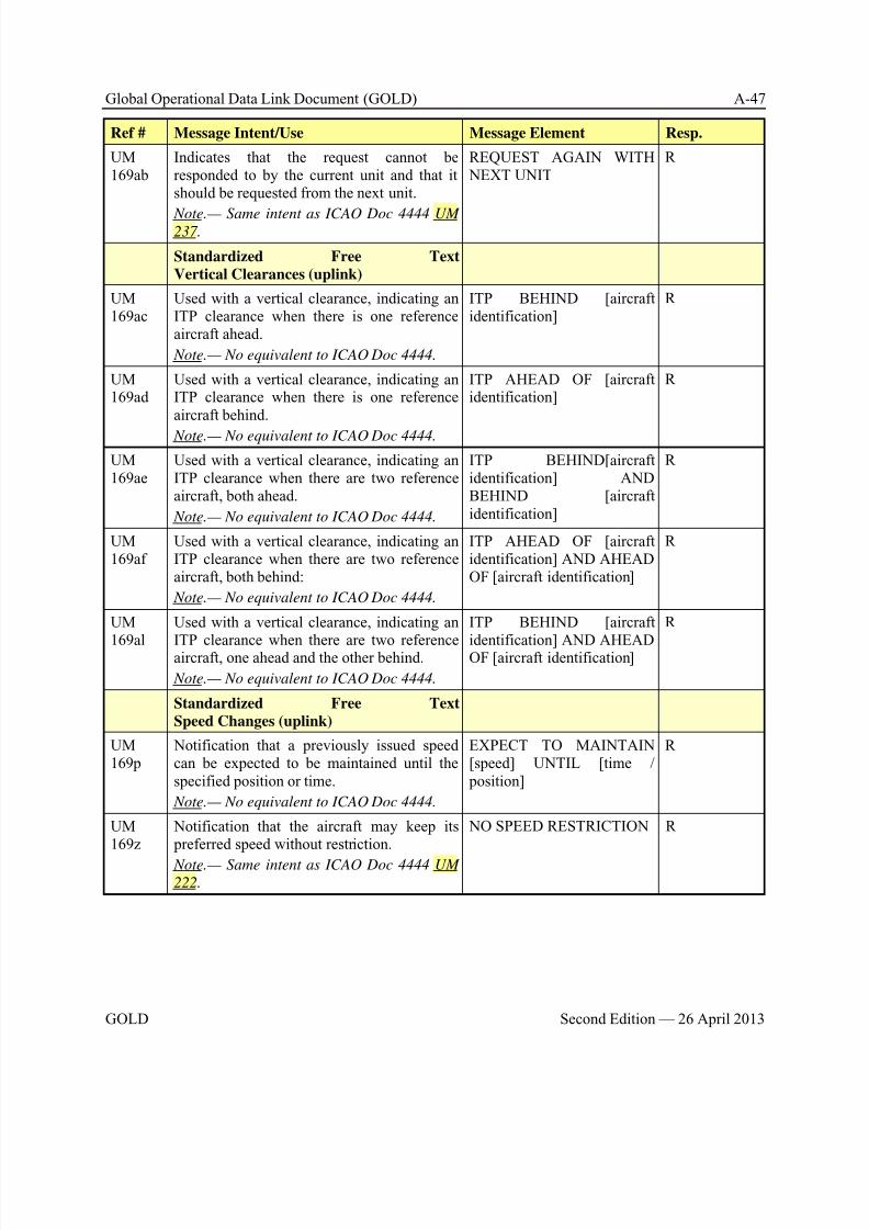
8/9/2019 CPDLC Explained
http://slidepdf.com/reader/full/cpdlc-explained 261/421
Global Operational Data Link Document (GOLD) A-47
GOLD Second Edition — 26 April 2013
Ref # Message Intent/Use Message Element Resp.
UM169ab
Indicates that the request cannot beresponded to by the current unit and that itshould be requested from the next unit.
Note.— Same intent as ICAO Doc 4444 UM237.
REQUEST AGAIN WITH NEXT UNIT
R
Standardized Free Text
Vertical Clearances (uplink)
UM169ac
Used with a vertical clearance, indicating anITP clearance when there is one referenceaircraft ahead.
Note.— No equivalent to ICAO Doc 4444.
ITP BEHIND [aircraftidentification]
R
UM169ad
Used with a vertical clearance, indicating anITP clearance when there is one referenceaircraft behind.
Note.— No equivalent to ICAO Doc 4444.
ITP AHEAD OF [aircraftidentification]
R
UM169ae
Used with a vertical clearance, indicating anITP clearance when there are two referenceaircraft, both ahead.
Note.— No equivalent to ICAO Doc 4444.
ITP BEHIND[aircraftidentification] ANDBEHIND [aircraftidentification]
R
UM169af
Used with a vertical clearance, indicating anITP clearance when there are two referenceaircraft, both behind:
Note.— No equivalent to ICAO Doc 4444.
ITP AHEAD OF [aircraftidentification] AND AHEADOF [aircraft identification]
R
UM
169al
Used with a vertical clearance, indicating an
ITP clearance when there are two referenceaircraft, one ahead and the other behind.
Note.— No equivalent to ICAO Doc 4444.
ITP BEHIND [aircraft
identification] AND AHEADOF [aircraft identification]
R
Standardized Free Text
Speed Changes (uplink)
UM169p
Notification that a previously issued speedcan be expected to be maintained until thespecified position or time.
Note.— No equivalent to ICAO Doc 4444.
EXPECT TO MAINTAIN[speed] UNTIL [time / position]
R
UM169z
Notification that the aircraft may keep its preferred speed without restriction.
Note.— Same intent as ICAO Doc 4444 UM222.
NO SPEED RESTRICTION R
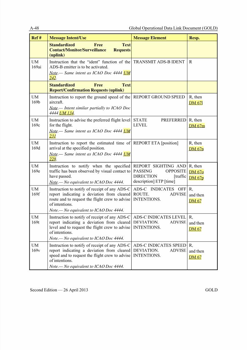
8/9/2019 CPDLC Explained
http://slidepdf.com/reader/full/cpdlc-explained 262/421
A-48 Global Operational Data Link Document (GOLD)
Second Edition — 26 April 2013 GOLD
Ref # Message Intent/Use Message Element Resp.
Standardized Free Text
Contact/Monitor/Surveillance Requests
(uplink)
UM169ai
Instruction that the “ident” function of theADS-B emitter is to be activated.
Note.— Same intent as ICAO Doc 4444 UM
242.
TRANSMIT ADS-B IDENT R
Standardized Free Text
Report/Confirmation Requests (uplink)
UM169b
Instruction to report the ground speed of theaircraft.
Note.— Intent similar partially to ICAO Doc
4444 UM 134.
REPORT GROUND SPEED R, then
DM 67l
UM169c
Instruction to advise the preferred flight levelfor the flight.
Note.— Same intent as ICAO Doc 4444 UM
231
STATE PREFERREDLEVEL
R, then
DM 67m
UM169d
Instruction to report the estimated time ofarrival at the specified position.
Note.— Same intent as ICAO Doc 4444 UM
228.
REPORT ETA [position] R, then
DM 67n
UM169e
Instruction to notify when the specifiedtraffic has been observed by visual contact tohave passed.
Note.— No equivalent to ICAO Doc 4444.
REPORT SIGHTING ANDPASSING OPPOSITE DIRECTION [traffic description] ETP [time]
R, then
DM 67o
DM 67p
UM169f
Instruction to notify of receipt of any ADS-Creport indicating a deviation from clearedroute and to request the flight crew to adviseof intentions.
Note.— No equivalent to ICAO Doc 4444.
ADS-C INDICATES OFFROUTE. ADVISEINTENTIONS.
R,
and then
DM 67
UM169t
Instruction to notify of receipt of any ADS-Creport indicating a deviation from clearedlevel and to request the flight crew to adviseof intentions.
Note.— No equivalent to ICAO Doc 4444.
ADS-C INDICATES LEVELDEVIATION. ADVISEINTENTIONS.
R,
and then
DM 67
UM169v
Instruction to notify of receipt of any ADS-Creport indicating a deviation from clearedspeed and to request the flight crew to adviseof intentions.
Note.— No equivalent to ICAO Doc 4444.
ADS-C INDICATES SPEEDDEVIATION. ADVISEINTENTIONS.
R,and then
DM 67
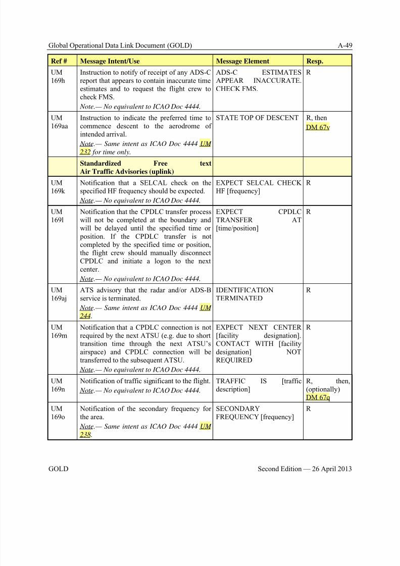
8/9/2019 CPDLC Explained
http://slidepdf.com/reader/full/cpdlc-explained 263/421
Global Operational Data Link Document (GOLD) A-49
GOLD Second Edition — 26 April 2013
Ref # Message Intent/Use Message Element Resp.
UM169h
Instruction to notify of receipt of any ADS-Creport that appears to contain inaccurate timeestimates and to request the flight crew to
check FMS. Note.— No equivalent to ICAO Doc 4444.
ADS-C ESTIMATESAPPEAR INACCURATE.CHECK FMS.
R
UM169aa
Instruction to indicate the preferred time tocommence descent to the aerodrome ofintended arrival.
Note.— Same intent as ICAO Doc 4444 UM
232 for time only.
STATE TOP OF DESCENT R, then
DM 67v
Standardized Free text
Air Traffic Advisories (uplink)
UM169k
Notification that a SELCAL check on thespecified HF frequency should be expected.
Note.— No equivalent to ICAO Doc 4444.
EXPECT SELCAL CHECKHF [frequency]
R
UM169l
Notification that the CPDLC transfer processwill not be completed at the boundary andwill be delayed until the specified time or position. If the CPDLC transfer is notcompleted by the specified time or position,the flight crew should manually disconnectCPDLC and initiate a logon to the nextcenter.
Note.— No equivalent to ICAO Doc 4444.
EXPECT CPDLCTRANSFER AT[time/position]
R
UM
169aj
ATS advisory that the radar and/or ADS-B
service is terminated. Note.— Same intent as ICAO Doc 4444 UM
244.
IDENTIFICATION
TERMINATED
R
UM169m
Notification that a CPDLC connection is notrequired by the next ATSU (e.g. due to shorttransition time through the next ATSU’sairspace) and CPDLC connection will betransferred to the subsequent ATSU.
Note.— No equivalent to ICAO Doc 4444.
EXPECT NEXT CENTER[facility designation].CONTACT WITH [facilitydesignation] NOTREQUIRED
R
UM169n
Notification of traffic significant to the flight.
Note.— No equivalent to ICAO Doc 4444.
TRAFFIC IS [trafficdescription]
R, then,(optionally)
DM 67q
UM169o
Notification of the secondary frequency forthe area.
Note.— Same intent as ICAO Doc 4444 UM
238.
SECONDARYFREQUENCY [frequency]
R
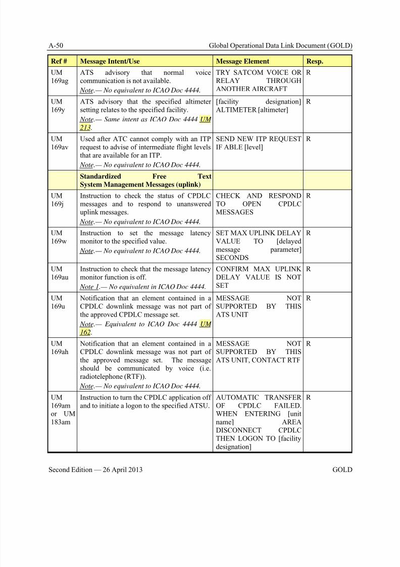
8/9/2019 CPDLC Explained
http://slidepdf.com/reader/full/cpdlc-explained 264/421
A-50 Global Operational Data Link Document (GOLD)
Second Edition — 26 April 2013 GOLD
Ref # Message Intent/Use Message Element Resp.
UM169ag
ATS advisory that normal voicecommunication is not available.
Note.— No equivalent to ICAO Doc 4444.
TRY SATCOM VOICE ORRELAY THROUGHANOTHER AIRCRAFT
R
UM169y
ATS advisory that the specified altimetersetting relates to the specified facility.
Note.— Same intent as ICAO Doc 4444 UM
213.
[facility designation]ALTIMETER [altimeter]
R
UM169av
Used after ATC cannot comply with an ITPrequest to advise of intermediate flight levelsthat are available for an ITP.
Note.— No equivalent to ICAO Doc 4444.
SEND NEW ITP REQUESTIF ABLE [level]
R
Standardized Free TextSystem Management Messages (uplink)
UM169j Instruction to check the status of CPDLCmessages and to respond to unanswereduplink messages.
Note.— No equivalent to ICAO Doc 4444.
CHECK AND RESPONDTO OPEN CPDLCMESSAGES
R
UM169w
Instruction to set the message latencymonitor to the specified value.
Note.— No equivalent to ICAO Doc 4444.
SET MAX UPLINK DELAYVALUE TO [delayedmessage parameter]SECONDS
R
UM169au
Instruction to check that the message latencymonitor function is off.
Note 1.— No equivalent in ICAO Doc 4444.
CONFIRM MAX UPLINKDELAY VALUE IS NOTSET
R
UM169u
Notification that an element contained in aCPDLC downlink message was not part ofthe approved CPDLC message set.
Note.— Equivalent to ICAO Doc 4444 UM
162.
MESSAGE NOTSUPPORTED BY THISATS UNIT
R
UM169ah
Notification that an element contained in aCPDLC downlink message was not part ofthe approved message set. The messageshould be communicated by voice (i.e.radiotelephone (RTF)).
Note.— No equivalent to ICAO Doc 4444.
MESSAGE NOTSUPPORTED BY THISATS UNIT, CONTACT RTF
R
UM169amor UM183am
Instruction to turn the CPDLC application offand to initiate a logon to the specified ATSU.
AUTOMATIC TRANSFEROF CPDLC FAILED.WHEN ENTERING [unitname] AREADISCONNECT CPDLCTHEN LOGON TO [facilitydesignation]
R
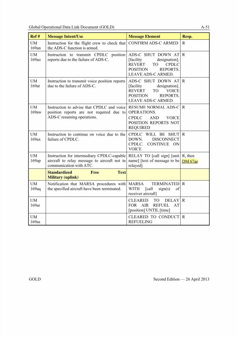
8/9/2019 CPDLC Explained
http://slidepdf.com/reader/full/cpdlc-explained 265/421
Global Operational Data Link Document (GOLD) A-51
GOLD Second Edition — 26 April 2013
Ref # Message Intent/Use Message Element Resp.
UM169an
Instruction for the flight crew to check thatthe ADS-C function is armed.
CONFIRM ADS-C ARMED R
UM
169ao
Instruction to transmit CPDLC position
reports due to the failure of ADS-C.
ADS-C SHUT DOWN AT
[facility designation].REVERT TO CPDLCPOSITION REPORTS.LEAVE ADS-C ARMED.
R
UM169at
Instruction to transmit voice position reportsdue to the failure of ADS-C.
ADS-C SHUT DOWN AT[facility designation].REVERT TO VOICEPOSITION REPORTS.LEAVE ADS-C ARMED.
R
UM169aw
Instruction to advise that CPDLC and voice position reports are not required due to
ADS-C resuming operations.
RESUME NORMAL ADS-COPERATIONS.
CPDLC AND VOICEPOSITION REPORTS NOTREQUIRED
R
UM169ax
Instruction to continue on voice due to thefailure of CPDLC.
CPDLC WILL BE SHUTDOWN. DISCONNECTCPDLC. CONTINUE ONVOICE
R
UM169ap
Instruction for intermediary CPDLC-capableaircraft to relay message to aircraft not incommunication with ATC.
RELAY TO [call sign] [unitname] [text of message to berelayed]
R, then
DM 67ae
Standardized Free Text
Military (uplink)
UM169aq
Notification that MARSA procedures withthe specified aircraft have been terminated.
MARSA TERMINATEDWITH [call sign(s) ofreceiver aircraft]
R
UM169ar
CLEARED TO DELAYFOR AIR REFUEL AT[position] UNTIL [time]
R
UM169as
CLEARED TO CONDUCTREFUELING
R
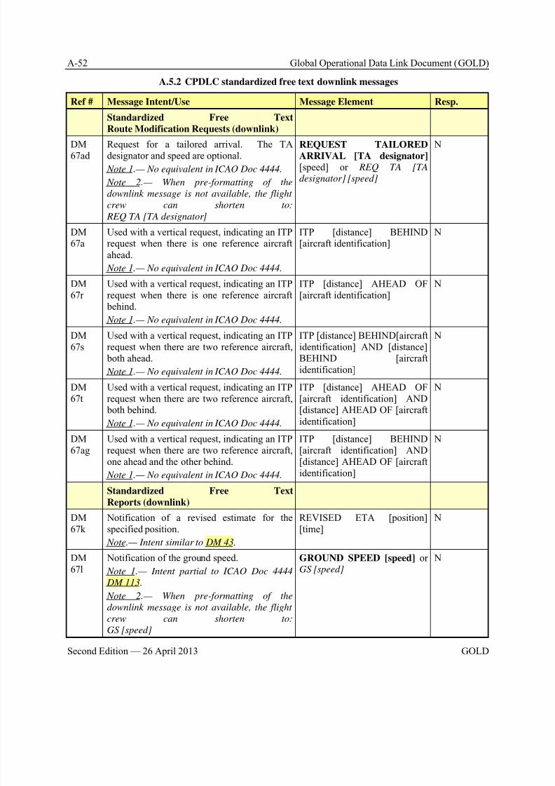
8/9/2019 CPDLC Explained
http://slidepdf.com/reader/full/cpdlc-explained 266/421
A-52 Global Operational Data Link Document (GOLD)
Second Edition — 26 April 2013 GOLD
A.5.2 CPDLC standardized free text downlink messages
Ref # Message Intent/Use Message Element Resp.
Standardized Free Text
Route Modification Requests (downlink)
DM67ad
Request for a tailored arrival. The TAdesignator and speed are optional.
Note 1.— No equivalent in ICAO Doc 4444.
Note 2.— When pre-formatting of the
downlink message is not available, the flight
crew can shorten to:
REQ TA [TA designator]
REQUEST TAILORED
ARRIVAL [TA designator] [speed] or REQ TA [TA
designator] [speed]
N
DM67a
Used with a vertical request, indicating an ITPrequest when there is one reference aircraftahead.
Note 1.— No equivalent in ICAO Doc 4444.
ITP [distance] BEHIND[aircraft identification]
N
DM67r
Used with a vertical request, indicating an ITPrequest when there is one reference aircraft behind.
Note 1.— No equivalent in ICAO Doc 4444.
ITP [distance] AHEAD OF[aircraft identification]
N
DM67s
Used with a vertical request, indicating an ITPrequest when there are two reference aircraft, both ahead.
Note 1.— No equivalent in ICAO Doc 4444.
ITP [distance] BEHIND[aircraftidentification] AND [distance]BEHIND [aircraftidentification]
N
DM67t
Used with a vertical request, indicating an ITPrequest when there are two reference aircraft,
both behind. Note 1.— No equivalent in ICAO Doc 4444.
ITP [distance] AHEAD OF[aircraft identification] AND
[distance] AHEAD OF [aircraftidentification]
N
DM67ag
Used with a vertical request, indicating an ITPrequest when there are two reference aircraft,one ahead and the other behind.
Note 1.— No equivalent in ICAO Doc 4444.
ITP [distance] BEHIND[aircraft identification] AND[distance] AHEAD OF [aircraftidentification]
N
Standardized Free Text
Reports (downlink)
DM67k
Notification of a revised estimate for thespecified position.
Note.— Intent similar to DM 43.
REVISED ETA [position][time]
N
DM67l
Notification of the ground speed.
Note 1.— Intent partial to ICAO Doc 4444
DM 113.
Note 2.— When pre-formatting of the
downlink message is not available, the flight
crew can shorten to:
GS [speed]
GROUND SPEED [speed] orGS [speed]
N
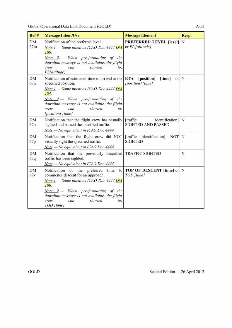
8/9/2019 CPDLC Explained
http://slidepdf.com/reader/full/cpdlc-explained 267/421
Global Operational Data Link Document (GOLD) A-53
GOLD Second Edition — 26 April 2013
Ref # Message Intent/Use Message Element Resp.
DM67m
Notification of the preferred level.
Note 1.— Same intent as ICAO Doc 4444 DM
106.
Note 2.— When pre-formatting of thedownlink message is not available, the flight
crew can shorten to:
FL[altitude]
PREFERRED LEVEL [level] or FL [altitude]
N
DM67n
Notification of estimated time of arrival at thespecified position.
Note 1.— Same intent as ICAO Doc 4444 DM
104.
Note 2.— When pre-formatting of the
downlink message is not available, the flight
crew can shorten to:
[position] [time]
ETA [position] [time] or[position] [time]
N
DM67o
Notification that the flight crew has visuallysighted and passed the specified traffic.
Note.— No equivalent in ICAO Doc 4444.
[traffic identification]SIGHTED AND PASSED
N
DM67p
Notification that the flight crew did NOTvisually sight the specified traffic.
Note.— No equivalent in ICAO Doc 4444.
[traffic identification] NOTSIGHTED
N
DM67q
Notification that the previously describedtraffic has been sighted.
Note.— No equivalent in ICAO Doc 4444.
TRAFFIC SIGHTED N
DM67v Notification of the preferred time tocommence descent for an approach.
Note 1.— Same intent as ICAO Doc 4444 DM
109.
Note 2.— When pre-formatting of the
downlink message is not available, the flight
crew can shorten to:
TOD [time]
TOP OF DESCENT [time] orTOD [time] N
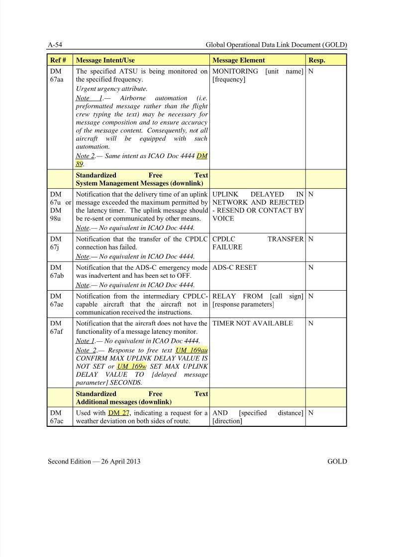
8/9/2019 CPDLC Explained
http://slidepdf.com/reader/full/cpdlc-explained 268/421
A-54 Global Operational Data Link Document (GOLD)
Second Edition — 26 April 2013 GOLD
Ref # Message Intent/Use Message Element Resp.
DM67aa
The specified ATSU is being monitored onthe specified frequency.
Urgent urgency attribute.
Note 1.— Airborne automation (i.e. preformatted message rather than the flight
crew typing the text) may be necessary for
message composition and to ensure accuracy
of the message content. Consequently, not all
aircraft will be equipped with such
automation.
Note 2.— Same intent as ICAO Doc 4444 DM
89.
MONITORING [unit name][frequency]
N
Standardized Free TextSystem Management Messages (downlink)
DM67u orDM98u
Notification that the delivery time of an uplinkmessage exceeded the maximum permitted bythe latency timer. The uplink message should be re-sent or communicated by other means.
Note.— No equivalent in ICAO Doc 4444.
UPLINK DELAYED IN NETWORK AND REJECTED- RESEND OR CONTACT BYVOICE
N
DM67j
Notification that the transfer of the CPDLCconnection has failed.
Note.— No equivalent in ICAO Doc 4444.
CPDLC TRANSFERFAILURE
N
DM67ab
Notification that the ADS-C emergency modewas inadvertent and has been set to OFF.
Note.— No equivalent in ICAO Doc 4444.
ADS-C RESET N
DM67ae
Notification from the intermediary CPDLC-capable aircraft that the aircraft not incommunication received the instructions.
RELAY FROM [call sign][response parameters]
N
DM67af
Notification that the aircraft does not have thefunctionality of a message latency monitor.
Note 1.— No equivalent in ICAO Doc 4444.
Note 2.— Response to free text UM 169au
CONFIRM MAX UPLINK DELAY VALUE IS
NOT SET or UM 169w SET MAX UPLINK
DELAY VALUE TO [delayed message
parameter] SECONDS.
TIMER NOT AVAILABLE N
Standardized Free Text
Additional messages (downlink)
DM67ac
Used with DM 27, indicating a request for aweather deviation on both sides of route.
AND [specified distance][direction]
N
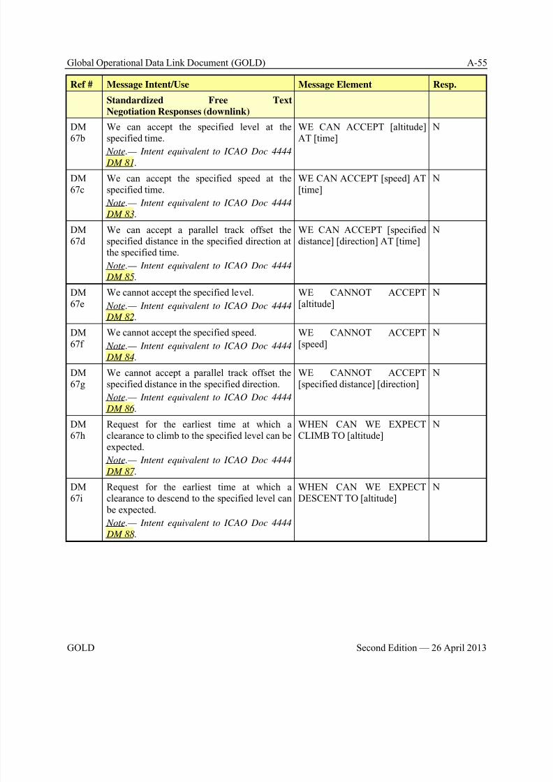
8/9/2019 CPDLC Explained
http://slidepdf.com/reader/full/cpdlc-explained 269/421
Global Operational Data Link Document (GOLD) A-55
GOLD Second Edition — 26 April 2013
Ref # Message Intent/Use Message Element Resp.
Standardized Free Text
Negotiation Responses (downlink)
DM
67b
We can accept the specified level at the
specified time. Note.— Intent equivalent to ICAO Doc 4444
DM 81.
WE CAN ACCEPT [altitude]
AT [time]
N
DM67c
We can accept the specified speed at thespecified time.
Note.— Intent equivalent to ICAO Doc 4444
DM 83.
WE CAN ACCEPT [speed] AT[time]
N
DM67d
We can accept a parallel track offset thespecified distance in the specified direction atthe specified time.
Note.— Intent equivalent to ICAO Doc 4444
DM 85.
WE CAN ACCEPT [specifieddistance] [direction] AT [time]
N
DM67e
We cannot accept the specified level.
Note.— Intent equivalent to ICAO Doc 4444
DM 82.
WE CANNOT ACCEPT[altitude]
N
DM67f
We cannot accept the specified speed.
Note.— Intent equivalent to ICAO Doc 4444
DM 84.
WE CANNOT ACCEPT[speed]
N
DM67g
We cannot accept a parallel track offset thespecified distance in the specified direction.
Note.— Intent equivalent to ICAO Doc 4444
DM 86.
WE CANNOT ACCEPT[specified distance] [direction]
N
DM67h
Request for the earliest time at which aclearance to climb to the specified level can beexpected.
Note.— Intent equivalent to ICAO Doc 4444
DM 87.
WHEN CAN WE EXPECTCLIMB TO [altitude]
N
DM67i
Request for the earliest time at which aclearance to descend to the specified level can be expected.
Note.— Intent equivalent to ICAO Doc 4444
DM 88.
WHEN CAN WE EXPECTDESCENT TO [altitude]
N
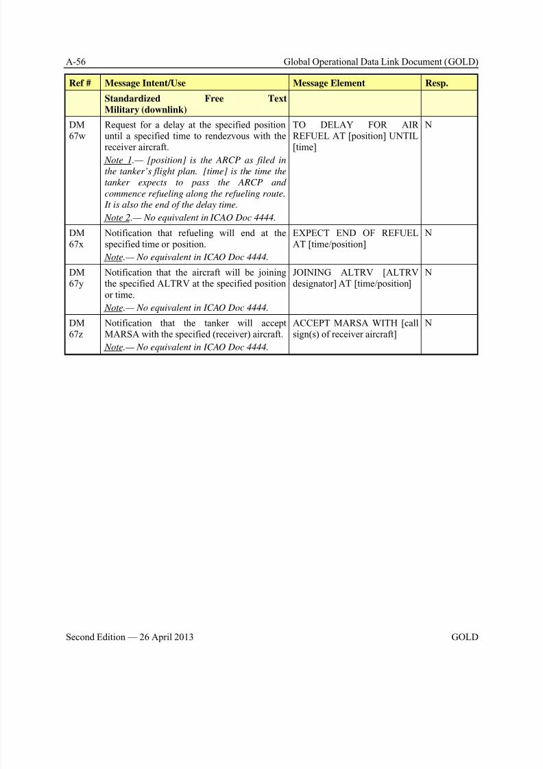
8/9/2019 CPDLC Explained
http://slidepdf.com/reader/full/cpdlc-explained 270/421
A-56 Global Operational Data Link Document (GOLD)
Second Edition — 26 April 2013 GOLD
Ref # Message Intent/Use Message Element Resp.
Standardized Free Text
Military (downlink)
DM
67w
Request for a delay at the specified position
until a specified time to rendezvous with thereceiver aircraft.
Note 1.— [position] is the ARCP as filed in
the tanker’s flight plan. [time] is the time the
tanker expects to pass the ARCP and
commence refueling along the refueling route.
It is also the end of the delay time.
Note 2.— No equivalent in ICAO Doc 4444.
TO DELAY FOR AIR
REFUEL AT [position] UNTIL[time]
N
DM67x
Notification that refueling will end at thespecified time or position.
Note.— No equivalent in ICAO Doc 4444.
EXPECT END OF REFUELAT [time/position]
N
DM67y
Notification that the aircraft will be joiningthe specified ALTRV at the specified positionor time.
Note.— No equivalent in ICAO Doc 4444.
JOINING ALTRV [ALTRVdesignator] AT [time/position]
N
DM67z
Notification that the tanker will acceptMARSA with the specified (receiver) aircraft.
Note.— No equivalent in ICAO Doc 4444.
ACCEPT MARSA WITH [callsign(s) of receiver aircraft]
N

8/9/2019 CPDLC Explained
http://slidepdf.com/reader/full/cpdlc-explained 271/421
Global Operational Data Link Document (GOLD) B-1
GOLD Second Edition — 26 April 2013
Appendix B RCP specifications
B.1 General
B.1.1 This appendix includes specifications for RCP 240 and RCP 400. These specificationssupport:
a) Safety oversight of air traffic service provisions and operations;
b) Agreements/contractual arrangements that ANSPs and aircraft operators make with theirrespective CSPs;
c) Operational authorizations, flight crew training and qualification;
d) Design approval of aircraft data link systems; and
e) Operational-monitoring, analysis, and exchange of operational data among regions and states.
B.1.2 The RCP specifications are derived mainly from a safety assessment. However, in cases
where it has been determined to be beneficial, the RCP specification may include criteria to supportoperational efficiency and orderly flow of air traffic. In these cases, the RCP specification indicates thedistinction between safety and efficiency.
B.1.3 The RCP specifications provide a means of compliance, in general. Additional guidancerelated to service provision, aircraft approval and operational authorizations can be found in Chapter 3. Guidance and requirements on post-implementation monitoring can be found at Appendix D.
B.1.4 The RCP specifications include allocations for data communications. The /D designatoris used to indicate the RCP allocations associated with the CPDLC application.
B.2 Terms and acronyms
Note.— The terms applied to the RCP specifications are taken from ICAO Doc 9869, First Edition,
Manual on Required Communication Performance, dated 2008. Additional terms are provided, as
appropriate, to clarify meaning and measurement points for the RCP allocations.
RCP specification
Term Description
Operational communicationtransaction
The process a human uses to initiate the transmission of an instruction,clearance, flight information, and/or request, and is completed when thathuman is confident that the transaction is complete.
RCP specification A set of ATS provision, including communication services, operator andflight crew requirements (e.g. RCP 240) needed for communicationssupporting a performance-based operation within a defined airspace.
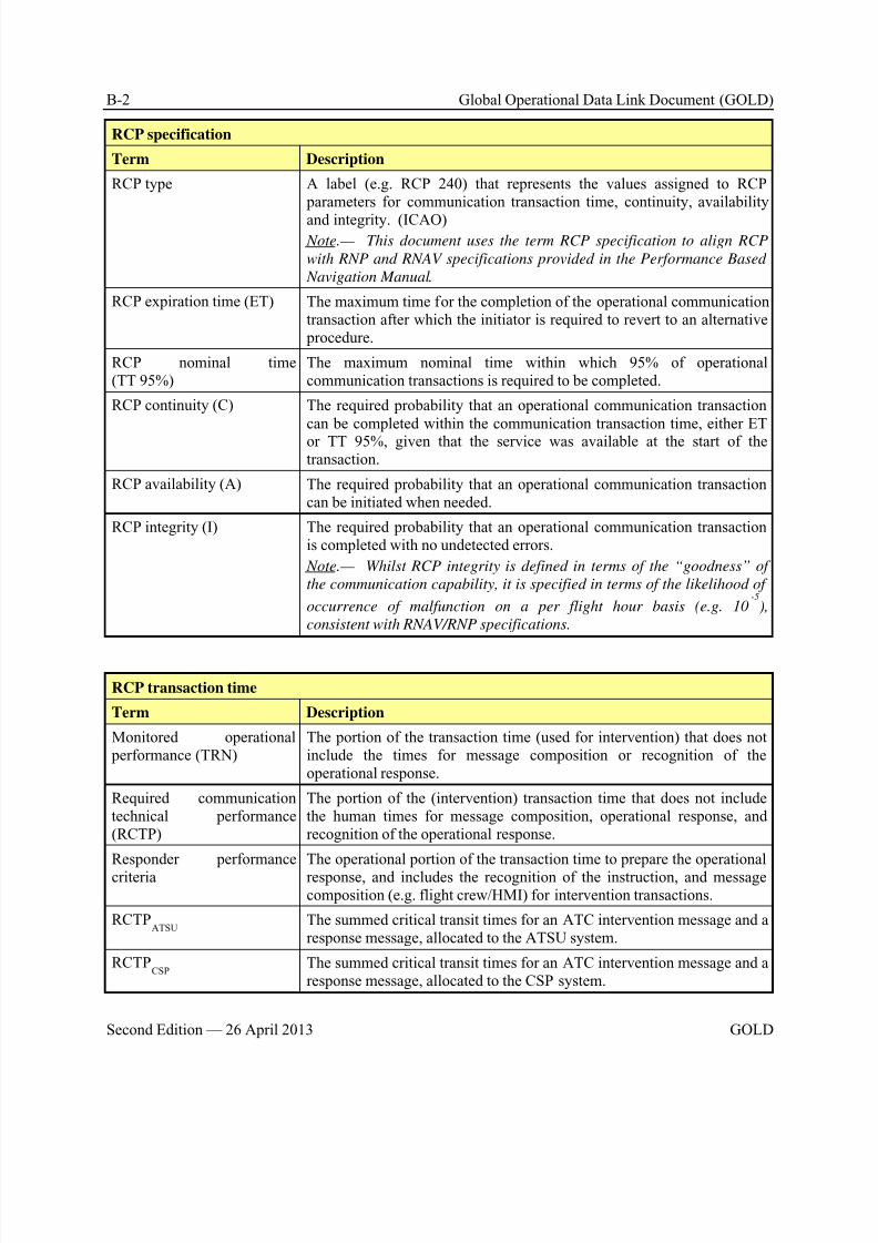
8/9/2019 CPDLC Explained
http://slidepdf.com/reader/full/cpdlc-explained 272/421
B-2 Global Operational Data Link Document (GOLD)
Second Edition — 26 April 2013 GOLD
RCP specification
Term Description
RCP type A label (e.g. RCP 240) that represents the values assigned to RCP parameters for communication transaction time, continuity, availability
and integrity. (ICAO) Note.— This document uses the term RCP specification to align RCP
with RNP and RNAV specifications provided in the Performance Based
Navigation Manual.
RCP expiration time (ET) The maximum time for the completion of the operational communicationtransaction after which the initiator is required to revert to an alternative procedure.
RCP nominal time(TT 95%)
The maximum nominal time within which 95% of operationalcommunication transactions is required to be completed.
RCP continuity (C) The required probability that an operational communication transactioncan be completed within the communication transaction time, either ET
or TT 95%, given that the service was available at the start of thetransaction.
RCP availability (A) The required probability that an operational communication transactioncan be initiated when needed.
RCP integrity (I) The required probability that an operational communication transactionis completed with no undetected errors.
Note.— Whilst RCP integrity is defined in terms of the “goodness” of
the communication capability, it is specified in terms of the likelihood of
occurrence of malfunction on a per flight hour basis (e.g. 10-5
),
consistent with RNAV/RNP specifications.
RCP transaction time
Term Description
Monitored operational performance (TRN)
The portion of the transaction time (used for intervention) that does notinclude the times for message composition or recognition of theoperational response.
Required communicationtechnical performance(RCTP)
The portion of the (intervention) transaction time that does not includethe human times for message composition, operational response, andrecognition of the operational response.
Responder performance
criteria
The operational portion of the transaction time to prepare the operational
response, and includes the recognition of the instruction, and messagecomposition (e.g. flight crew/HMI) for intervention transactions.
RCTPATSU
The summed critical transit times for an ATC intervention message and aresponse message, allocated to the ATSU system.
RCTPCSP
The summed critical transit times for an ATC intervention message and aresponse message, allocated to the CSP system.
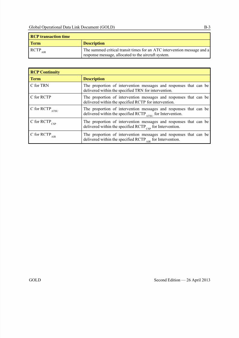
8/9/2019 CPDLC Explained
http://slidepdf.com/reader/full/cpdlc-explained 273/421
Global Operational Data Link Document (GOLD) B-3
GOLD Second Edition — 26 April 2013
RCP transaction time
Term Description
RCTPAIR
The summed critical transit times for an ATC intervention message and aresponse message, allocated to the aircraft system.
RCP Continuity
Term Description
C for TRN The proportion of intervention messages and responses that can bedelivered within the specified TRN for intervention.
C for RCTP The proportion of intervention messages and responses that can bedelivered within the specified RCTP for intervention.
C for RCTPATSU
The proportion of intervention messages and responses that can bedelivered within the specified RCTP
ATSU for Intervention.
C for RCTPCSP
The proportion of intervention messages and responses that can bedelivered within the specified RCTP
CSP for Intervention.
C for RCTPAIR
The proportion of intervention messages and responses that can bedelivered within the specified RCTP
AIR for Intervention.
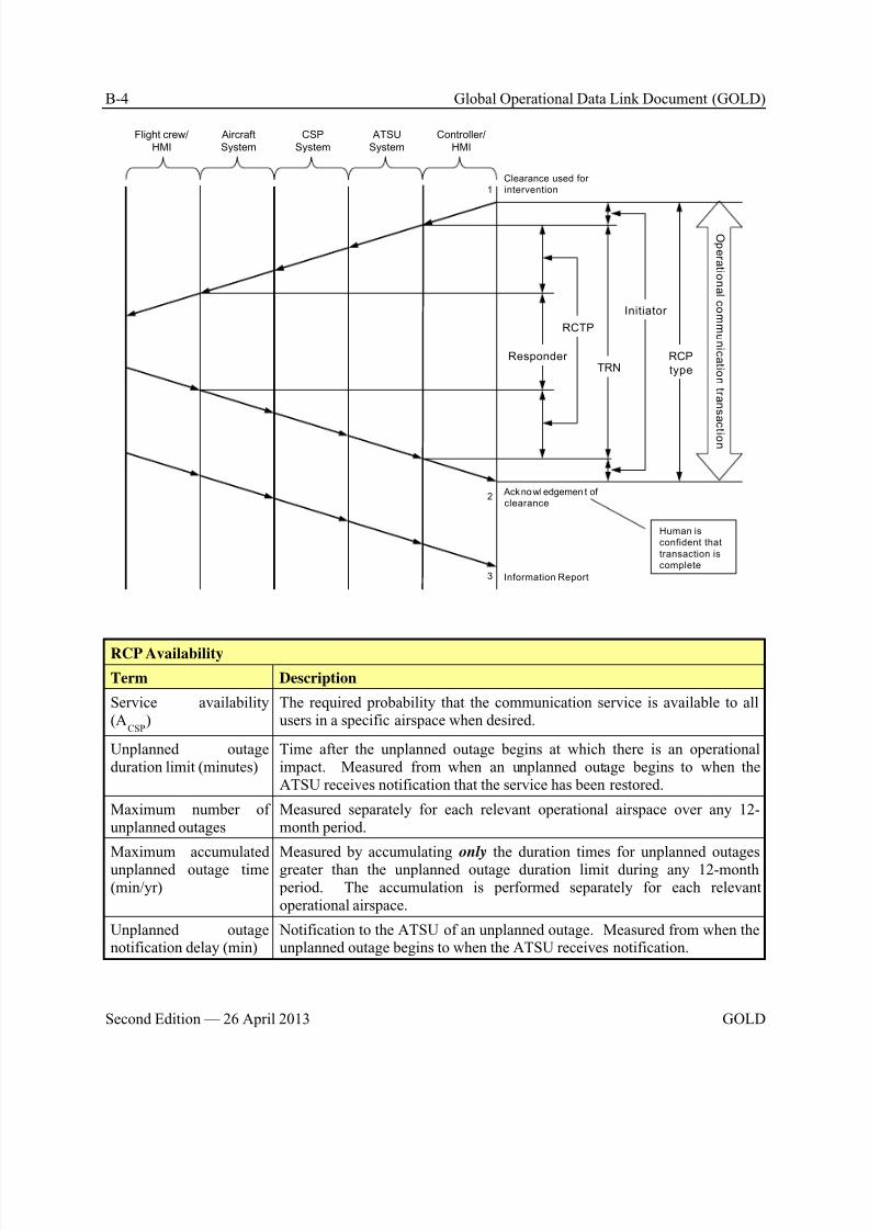
8/9/2019 CPDLC Explained
http://slidepdf.com/reader/full/cpdlc-explained 274/421
B-4 Global Operational Data Link Document (GOLD)
Second Edition — 26 April 2013 GOLD
Aircraft
System
Flight crew/
HMI
CSP
System
Controller/
HMI
ATSU
System
Clearance used for
intervention
Acknowledgemen t of
clearance
Information Report
1
3
2
Responder
Initiator
RCTP
TRNRCP
type
O p er a t i on al c omm uni c a t i on t r an s a c t i on
Human is
confident that
transaction is
complete
RCP Availability
Term Description
Service availability(A
CSP)
The required probability that the communication service is available to allusers in a specific airspace when desired.
Unplanned outageduration limit (minutes)
Time after the unplanned outage begins at which there is an operationalimpact. Measured from when an unplanned outage begins to when theATSU receives notification that the service has been restored.
Maximum number ofunplanned outages
Measured separately for each relevant operational airspace over any 12-month period.
Maximum accumulatedunplanned outage time(min/yr)
Measured by accumulating only the duration times for unplanned outagesgreater than the unplanned outage duration limit during any 12-month period. The accumulation is performed separately for each relevantoperational airspace.
Unplanned outagenotification delay (min)
Notification to the ATSU of an unplanned outage. Measured from when theunplanned outage begins to when the ATSU receives notification.
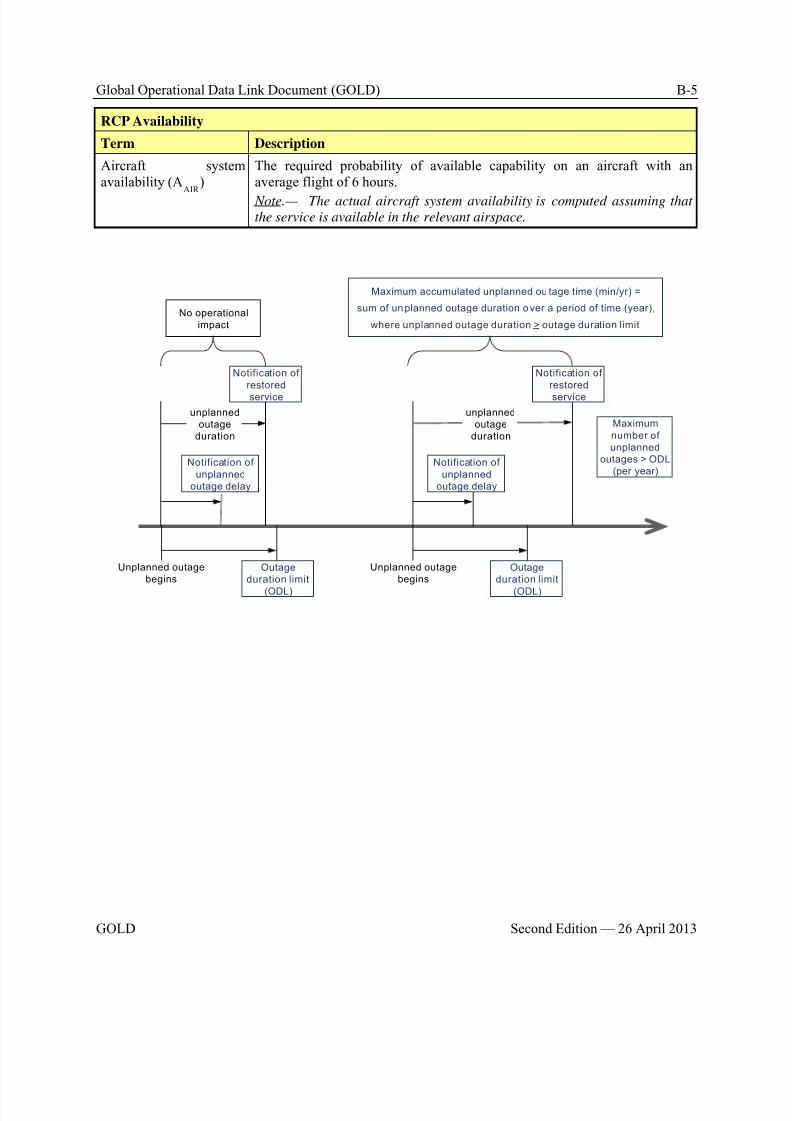
8/9/2019 CPDLC Explained
http://slidepdf.com/reader/full/cpdlc-explained 275/421
Global Operational Data Link Document (GOLD) B-5
GOLD Second Edition — 26 April 2013
RCP Availability
Term Description
Aircraft systemavailability (A
AIR )
The required probability of available capability on an aircraft with anaverage flight of 6 hours.
Note.— The actual aircraft system availability is computed assuming thatthe service is available in the relevant airspace.
Unplanned outage
begins
Notification of
restored
service
Outage
duration limit
(ODL)
Notification of
unplanned
outage delay
unplanned
outage
duration
Unplanned outage
beginsOutage
duration limit
(ODL)
Notification of
unplanned
outage delay
unplanned
outage
duration
Maximum accumulated unplanned ou tage time (min/yr) =
sum of un planned outage duration o ver a period of time (year),
where unplanned outage duration > outage duration limit
No operational
impact
Maximum
number of
unplanned
outages > ODL
(per year)
Notification of
restored
service
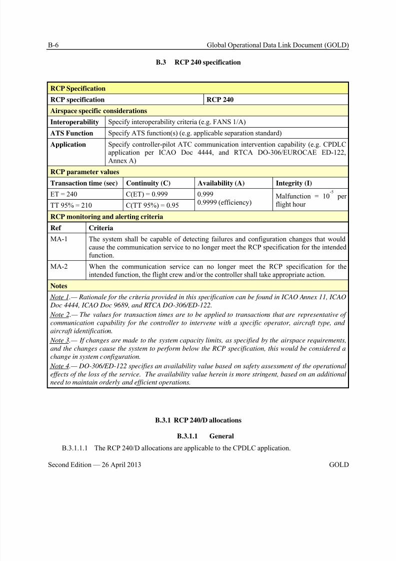
8/9/2019 CPDLC Explained
http://slidepdf.com/reader/full/cpdlc-explained 276/421
B-6 Global Operational Data Link Document (GOLD)
Second Edition — 26 April 2013 GOLD
B.3 RCP 240 specification
RCP Specification
RCP specification RCP 240
Airspace specific considerations
Interoperability Specify interoperability criteria (e.g. FANS 1/A)
ATS Function Specify ATS function(s) (e.g. applicable separation standard)
Application Specify controller-pilot ATC communication intervention capability (e.g. CPDLCapplication per ICAO Doc 4444, and RTCA DO-306/EUROCAE ED-122,Annex A)
RCP parameter values
Transaction time (sec) Continuity (C) Availability (A) Integrity (I)
ET = 240 C(ET) = 0.999 0.9990.9999 (efficiency) Malfunction = 10
-5
perflight hourTT 95% = 210 C(TT 95%) = 0.95
RCP monitoring and alerting criteria
Ref Criteria
MA-1 The system shall be capable of detecting failures and configuration changes that wouldcause the communication service to no longer meet the RCP specification for the intendedfunction.
MA-2 When the communication service can no longer meet the RCP specification for theintended function, the flight crew and/or the controller shall take appropriate action.
Notes
Note 1.— Rationale for the criteria provided in this specification can be found in ICAO Annex 11, ICAO Doc 4444, ICAO Doc 9689, and RTCA DO-306/ED-122.
Note 2.— The values for transaction times are to be applied to transactions that are representative of
communication capability for the controller to intervene with a specific operator, aircraft type, and
aircraft identification.
Note 3.— If changes are made to the system capacity limits, as specified by the airspace requirements,
and the changes cause the system to perform below the RCP specification, this would be considered a
change in system configuration.
Note 4.— DO-306/ED-122 specifies an availability value based on safety assessment of the operational
effects of the loss of the service. The availability value herein is more stringent, based on an additional
need to maintain orderly and efficient operations.
B.3.1 RCP 240/D allocations
B.3.1.1 General
B.3.1.1.1 The RCP 240/D allocations are applicable to the CPDLC application.
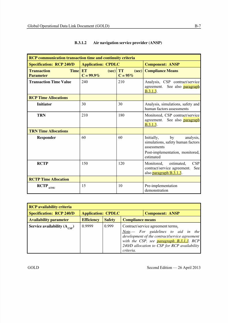
8/9/2019 CPDLC Explained
http://slidepdf.com/reader/full/cpdlc-explained 277/421
Global Operational Data Link Document (GOLD) B-7
GOLD Second Edition — 26 April 2013
B.3.1.2 Air navigation service provider (ANSP)
RCP communication transaction time and continuity criteria
Specification: RCP 240/D Application: CPDLC Component: ANSP
Transaction Time
Parameter
ET (sec)
C = 99.9%
TT (sec)
C = 95%
Compliance Means
Transaction Time Value 240 210 Analysis, CSP contract/serviceagreement. See also paragraphB.3.1.3.
RCP Time Allocations
Initiator 30 30 Analysis, simulations, safety andhuman factors assessments
TRN 210 180 Monitored, CSP contract/serviceagreement. See also paragraphB.3.1.3.
TRN Time Allocations
Responder 60 60 Initially, by analysis,simulations, safety human factorsassessments
Post-implementation, monitored,estimated
RCTP 150 120 Monitored, estimated, CSP
contract/service agreement. Seealso paragraph B.3.1.3.
RCTP Time Allocation
RCTPATSU
15 10 Pre-implementationdemonstration
RCP availability criteria
Specification: RCP 240/D Application: CPDLC Component: ANSP
Availability parameter Efficiency Safety Compliance means
Service availability (ACSP) 0.9999 0.999 Contract/service agreement terms. Note.— For guidelines to aid in the
development of the contract/service agreement
with the CSP, see paragraph B.3.1.3, RCP
240/D allocation to CSP for RCP availability
criteria.
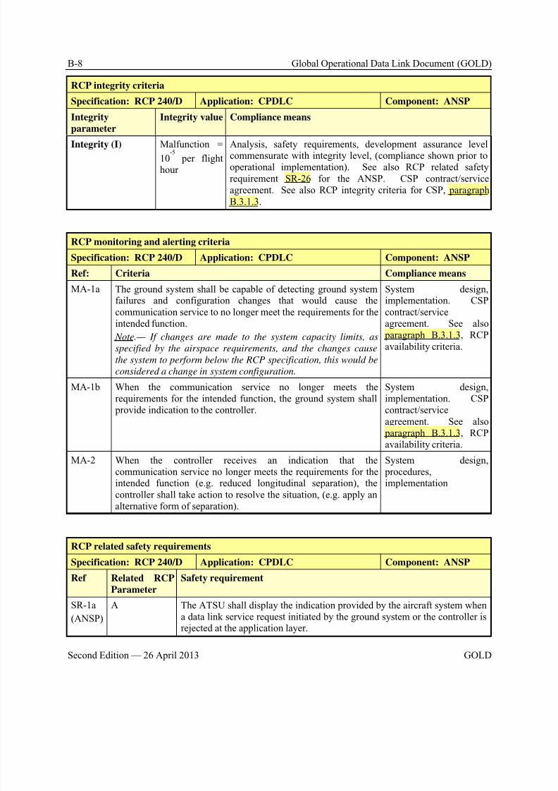
8/9/2019 CPDLC Explained
http://slidepdf.com/reader/full/cpdlc-explained 278/421
B-8 Global Operational Data Link Document (GOLD)
Second Edition — 26 April 2013 GOLD
RCP integrity criteria
Specification: RCP 240/D Application: CPDLC Component: ANSP
Integrity
parameter
Integrity value Compliance means
Integrity (I) Malfunction =
10-5
per flighthour
Analysis, safety requirements, development assurance levelcommensurate with integrity level, (compliance shown prior tooperational implementation). See also RCP related safetyrequirement SR-26 for the ANSP. CSP contract/serviceagreement. See also RCP integrity criteria for CSP, paragraphB.3.1.3.
RCP monitoring and alerting criteria
Specification: RCP 240/D Application: CPDLC Component: ANSP
Ref: Criteria Compliance meansMA-1a The ground system shall be capable of detecting ground system
failures and configuration changes that would cause thecommunication service to no longer meet the requirements for theintended function.
Note.— If changes are made to the system capacity limits, as
specified by the airspace requirements, and the changes cause
the system to perform below the RCP specification, this would be
considered a change in system configuration.
System design,implementation. CSPcontract/serviceagreement. See also paragraph B.3.1.3, RCPavailability criteria.
MA-1b When the communication service no longer meets therequirements for the intended function, the ground system shall provide indication to the controller.
System design,implementation. CSPcontract/serviceagreement. See also paragraph B.3.1.3, RCPavailability criteria.
MA-2 When the controller receives an indication that thecommunication service no longer meets the requirements for theintended function (e.g. reduced longitudinal separation), thecontroller shall take action to resolve the situation, (e.g. apply analternative form of separation).
System design, procedures,implementation
RCP related safety requirements
Specification: RCP 240/D Application: CPDLC Component: ANSP
Ref Related RCP
Parameter
Safety requirement
SR-1a
(ANSP)
A The ATSU shall display the indication provided by the aircraft system whena data link service request initiated by the ground system or the controller isrejected at the application layer.
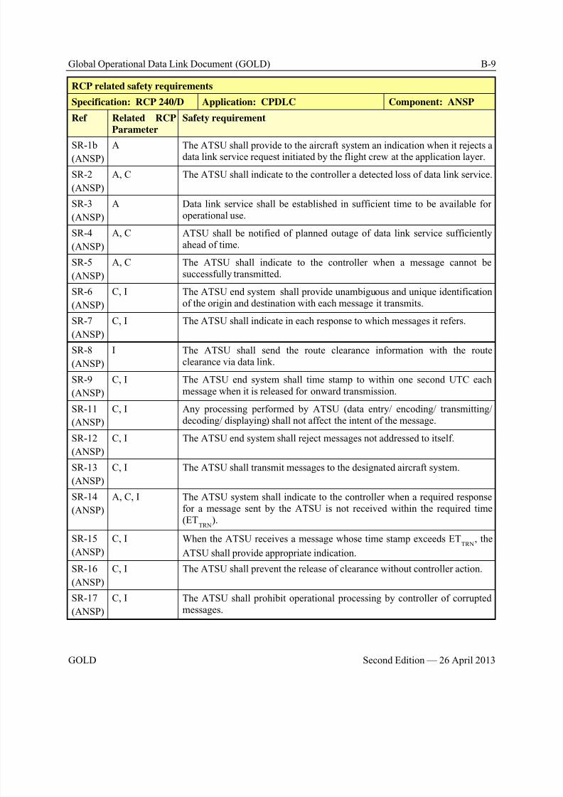
8/9/2019 CPDLC Explained
http://slidepdf.com/reader/full/cpdlc-explained 279/421
Global Operational Data Link Document (GOLD) B-9
GOLD Second Edition — 26 April 2013
RCP related safety requirements
Specification: RCP 240/D Application: CPDLC Component: ANSP
Ref Related RCP
Parameter
Safety requirement
SR-1b
(ANSP)
A The ATSU shall provide to the aircraft system an indication when it rejects adata link service request initiated by the flight crew at the application layer.
SR-2
(ANSP)
A, C The ATSU shall indicate to the controller a detected loss of data link service.
SR-3
(ANSP)
A Data link service shall be established in sufficient time to be available foroperational use.
SR-4
(ANSP)
A, C ATSU shall be notified of planned outage of data link service sufficientlyahead of time.
SR-5
(ANSP)
A, C The ATSU shall indicate to the controller when a message cannot be
successfully transmitted.SR-6
(ANSP)
C, I The ATSU end system shall provide unambiguous and unique identificationof the origin and destination with each message it transmits.
SR-7
(ANSP)
C, I The ATSU shall indicate in each response to which messages it refers.
SR-8
(ANSP)
I The ATSU shall send the route clearance information with the routeclearance via data link.
SR-9
(ANSP)
C, I The ATSU end system shall time stamp to within one second UTC eachmessage when it is released for onward transmission.
SR-11
(ANSP)
C, I Any processing performed by ATSU (data entry/ encoding/ transmitting/
decoding/ displaying) shall not affect the intent of the message.
SR-12
(ANSP)
C, I The ATSU end system shall reject messages not addressed to itself.
SR-13
(ANSP)
C, I The ATSU shall transmit messages to the designated aircraft system.
SR-14
(ANSP)
A, C, I The ATSU system shall indicate to the controller when a required responsefor a message sent by the ATSU is not received within the required time(ET
TRN).
SR-15
(ANSP)
C, I When the ATSU receives a message whose time stamp exceeds ETTRN
, the
ATSU shall provide appropriate indication.
SR-16
(ANSP)
C, I The ATSU shall prevent the release of clearance without controller action.
SR-17
(ANSP)
C, I The ATSU shall prohibit operational processing by controller of corruptedmessages.
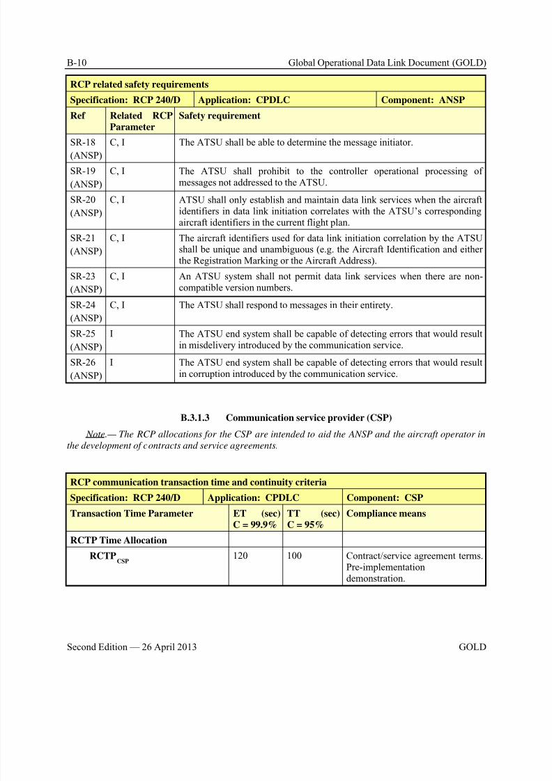
8/9/2019 CPDLC Explained
http://slidepdf.com/reader/full/cpdlc-explained 280/421
B-10 Global Operational Data Link Document (GOLD)
Second Edition — 26 April 2013 GOLD
RCP related safety requirements
Specification: RCP 240/D Application: CPDLC Component: ANSP
Ref Related RCP
Parameter
Safety requirement
SR-18
(ANSP)
C, I The ATSU shall be able to determine the message initiator.
SR-19
(ANSP)
C, I The ATSU shall prohibit to the controller operational processing ofmessages not addressed to the ATSU.
SR-20
(ANSP)
C, I ATSU shall only establish and maintain data link services when the aircraftidentifiers in data link initiation correlates with the ATSU’s correspondingaircraft identifiers in the current flight plan.
SR-21
(ANSP)
C, I The aircraft identifiers used for data link initiation correlation by the ATSUshall be unique and unambiguous (e.g. the Aircraft Identification and eitherthe Registration Marking or the Aircraft Address).
SR-23
(ANSP)
C, I An ATSU system shall not permit data link services when there are non-compatible version numbers.
SR-24
(ANSP)
C, I The ATSU shall respond to messages in their entirety.
SR-25
(ANSP)
I The ATSU end system shall be capable of detecting errors that would resultin misdelivery introduced by the communication service.
SR-26
(ANSP)
I The ATSU end system shall be capable of detecting errors that would resultin corruption introduced by the communication service.
B.3.1.3 Communication service provider (CSP)
Note.— The RCP allocations for the CSP are intended to aid the ANSP and the aircraft operator in
the development of contracts and service agreements.
RCP communication transaction time and continuity criteria
Specification: RCP 240/D Application: CPDLC Component: CSP
Transaction Time Parameter ET (sec)
C = 99.9%
TT (sec)
C = 95%
Compliance means
RCTP Time Allocation
RCTPCSP
120 100 Contract/service agreement terms.Pre-implementationdemonstration.
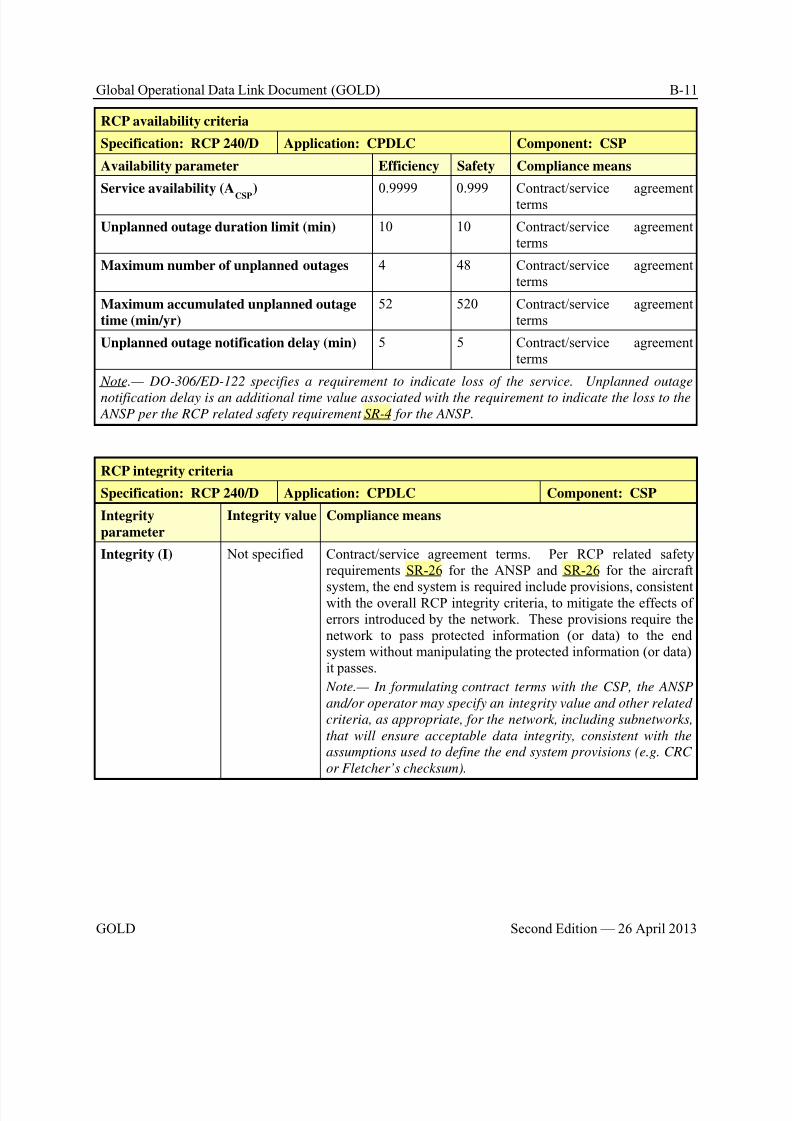
8/9/2019 CPDLC Explained
http://slidepdf.com/reader/full/cpdlc-explained 281/421
Global Operational Data Link Document (GOLD) B-11
GOLD Second Edition — 26 April 2013
RCP availability criteria
Specification: RCP 240/D Application: CPDLC Component: CSP
Availability parameter Efficiency Safety Compliance means
Service availability (ACSP
) 0.9999 0.999 Contract/service agreementterms
Unplanned outage duration limit (min) 10 10 Contract/service agreementterms
Maximum number of unplanned outages 4 48 Contract/service agreementterms
Maximum accumulated unplanned outage
time (min/yr)
52 520 Contract/service agreementterms
Unplanned outage notification delay (min) 5 5 Contract/service agreementterms
Note.— DO-306/ED-122 specifies a requirement to indicate loss of the service. Unplanned outage
notification delay is an additional time value associated with the requirement to indicate the loss to the ANSP per the RCP related safety requirement SR-4 for the ANSP.
RCP integrity criteria
Specification: RCP 240/D Application: CPDLC Component: CSP
Integrity
parameter
Integrity value Compliance means
Integrity (I) Not specified Contract/service agreement terms. Per RCP related safetyrequirements SR-26 for the ANSP and SR-26 for the aircraft
system, the end system is required include provisions, consistentwith the overall RCP integrity criteria, to mitigate the effects oferrors introduced by the network. These provisions require thenetwork to pass protected information (or data) to the endsystem without manipulating the protected information (or data)it passes.
Note.— In formulating contract terms with the CSP, the ANSP
and/or operator may specify an integrity value and other related
criteria, as appropriate, for the network, including subnetworks,
that will ensure acceptable data integrity, consistent with the
assumptions used to define the end system provisions (e.g. CRC
or Fletcher’s checksum).
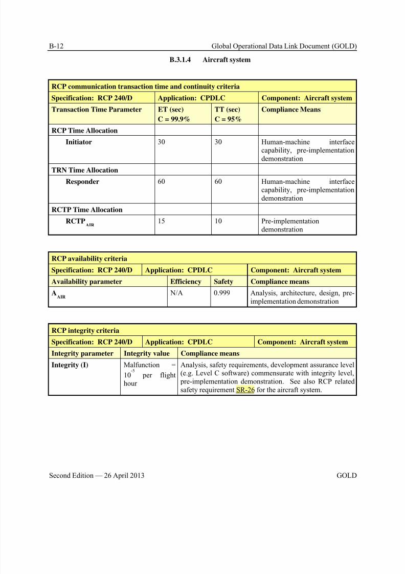
8/9/2019 CPDLC Explained
http://slidepdf.com/reader/full/cpdlc-explained 282/421
B-12 Global Operational Data Link Document (GOLD)
Second Edition — 26 April 2013 GOLD
B.3.1.4 Aircraft system
RCP communication transaction time and continuity criteria
Specification: RCP 240/D Application: CPDLC Component: Aircraft systemTransaction Time Parameter ET (sec)
C = 99.9%
TT (sec)
C = 95%
Compliance Means
RCP Time Allocation
Initiator 30 30 Human-machine interfacecapability, pre-implementationdemonstration
TRN Time Allocation
Responder 60 60 Human-machine interfacecapability, pre-implementation
demonstrationRCTP Time Allocation
RCTPAIR
15 10 Pre-implementationdemonstration
RCP availability criteria
Specification: RCP 240/D Application: CPDLC Component: Aircraft system
Availability parameter Efficiency Safety Compliance means
AAIR
N/A 0.999 Analysis, architecture, design, pre-
implementation demonstration
RCP integrity criteria
Specification: RCP 240/D Application: CPDLC Component: Aircraft system
Integrity parameter Integrity value Compliance means
Integrity (I) Malfunction =
10-5
per flighthour
Analysis, safety requirements, development assurance level(e.g. Level C software) commensurate with integrity level, pre-implementation demonstration. See also RCP relatedsafety requirement SR-26 for the aircraft system.
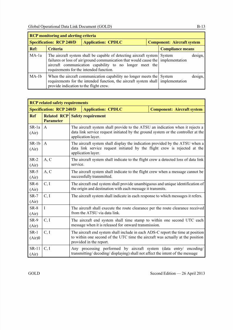
8/9/2019 CPDLC Explained
http://slidepdf.com/reader/full/cpdlc-explained 283/421
Global Operational Data Link Document (GOLD) B-13
GOLD Second Edition — 26 April 2013
RCP monitoring and alerting criteria
Specification: RCP 240/D Application: CPDLC Component: Aircraft system
Ref: Criteria Compliance means
MA-1a The aircraft system shall be capable of detecting aircraft systemfailures or loss of air/ground communication that would cause theaircraft communication capability to no longer meet therequirements for the intended function.
System design,implementation
MA-1b When the aircraft communication capability no longer meets therequirements for the intended function, the aircraft system shall provide indication to the flight crew.
System design,implementation
RCP related safety requirements
Specification: RCP 240/D Application: CPDLC Component: Aircraft system
Ref Related RCPParameter
Safety requirement
SR-1a
(Air)
A The aircraft system shall provide to the ATSU an indication when it rejects adata link service request initiated by the ground system or the controller at theapplication layer.
SR-1b
(Air)
A The aircraft system shall display the indication provided by the ATSU when adata link service request initiated by the flight crew is rejected at theapplication layer.
SR-2
(Air)
A, C The aircraft system shall indicate to the flight crew a detected loss of data linkservice.
SR-5(Air)
A, C The aircraft system shall indicate to the flight crew when a message cannot besuccessfully transmitted.
SR-6
(Air)
C, I The aircraft end system shall provide unambiguous and unique identification ofthe origin and destination with each message it transmits.
SR-7
(Air)
C, I The aircraft system shall indicate in each response to which messages it refers.
SR-8
(Air)
I The aircraft shall execute the route clearance per the route clearance receivedfrom the ATSU via data link.
SR-9
(Air)
C, I The aircraft end system shall time stamp to within one second UTC eachmessage when it is released for onward transmission.
SR-1
(Air)0
C, I The aircraft end system shall include in each ADS-C report the time at positionto within one second of the UTC time the aircraft was actually at the position provided in the report.
SR-11
(Air)
C, I Any processing performed by aircraft system (data entry/ encoding/transmitting/ decoding/ displaying) shall not affect the intent of the message

8/9/2019 CPDLC Explained
http://slidepdf.com/reader/full/cpdlc-explained 284/421
B-14 Global Operational Data Link Document (GOLD)
Second Edition — 26 April 2013 GOLD
RCP related safety requirements
Specification: RCP 240/D Application: CPDLC Component: Aircraft system
Ref Related RCP
Parameter
Safety requirement
SR-12
(Air)
C, I The aircraft end system shall reject messages not addressed to itself.
SR-13
(Air)
C, I The aircraft system shall transmit messages to the designated ATSU.
SR-15
(Air)
C, I When the aircraft system receives a message whose time stamp exceeds ETTRN
,
the aircraft system shall provide appropriate indication.
SR-16
(Air)
C, I The aircraft end system shall prevent the release of responses to clearanceswithout flight crew action.
SR-17
(Air)
C, I The aircraft system shall prohibit operational processing by flight crew of
corrupted messages.SR-18
(Air)
C, I The aircraft system shall be able to determine the message initiator.
SR-19
(Air)
C, I The aircraft system shall prohibit to the flight crew operational processing ofmessages not addressed to the aircraft.
SR-21
(Air)
C, I The aircraft identifiers sent by the aircraft system and used for data linkinitiation correlation shall be unique and unambiguous (e.g. the AircraftIdentification and either the Registration Marking or the Aircraft Address).
SR-24
(Air)
C, I The aircraft system shall respond to messages in their entirety or allow theflight crew to do it.
SR-25(Air)
I The aircraft end system shall be capable of detecting errors that would result inmisdelivery introduced by the communication service
SR-26
(Air)
I The aircraft end system shall be capable of detecting errors that would result incorruption introduced by the communication service.
SR-27
(Air)
C, I The aircraft and/or flight crew shall ensure the correct transfer into or out of theaircraft’s FMS of route data received/sent via data link that will be used todefine the aircraft active flight plan.
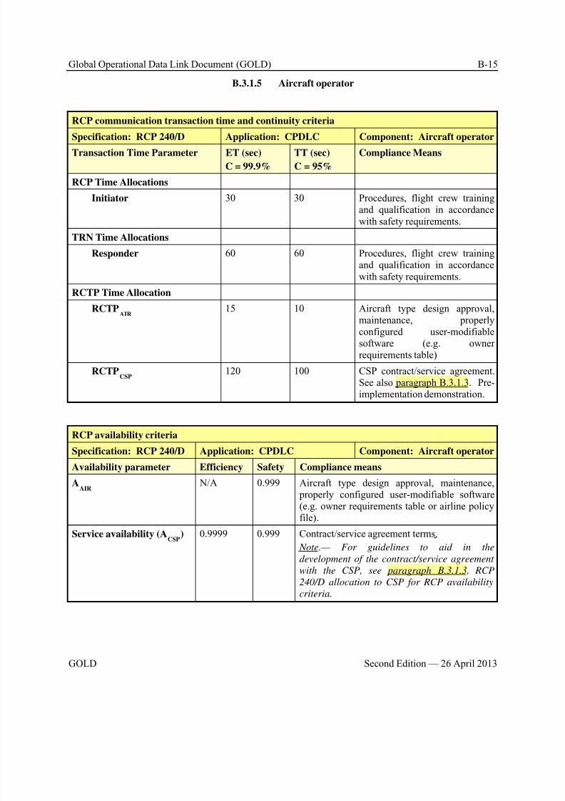
8/9/2019 CPDLC Explained
http://slidepdf.com/reader/full/cpdlc-explained 285/421
Global Operational Data Link Document (GOLD) B-15
GOLD Second Edition — 26 April 2013
B.3.1.5 Aircraft operator
RCP communication transaction time and continuity criteria
Specification: RCP 240/D Application: CPDLC Component: Aircraft operatorTransaction Time Parameter ET (sec)
C = 99.9%
TT (sec)
C = 95%
Compliance Means
RCP Time Allocations
Initiator 30 30 Procedures, flight crew trainingand qualification in accordancewith safety requirements.
TRN Time Allocations
Responder 60 60 Procedures, flight crew trainingand qualification in accordance
with safety requirements.RCTP Time Allocation
RCTPAIR
15 10 Aircraft type design approval,maintenance, properlyconfigured user-modifiablesoftware (e.g. ownerrequirements table)
RCTPCSP
120 100 CSP contract/service agreement.See also paragraph B.3.1.3. Pre-implementation demonstration.
RCP availability criteria
Specification: RCP 240/D Application: CPDLC Component: Aircraft operator
Availability parameter Efficiency Safety Compliance means
AAIR
N/A 0.999 Aircraft type design approval, maintenance, properly configured user-modifiable software(e.g. owner requirements table or airline policyfile).
Service availability (ACSP
) 0.9999 0.999 Contract/service agreement terms.
Note.— For guidelines to aid in the
development of the contract/service agreementwith the CSP, see paragraph B.3.1.3, RCP
240/D allocation to CSP for RCP availability
criteria.
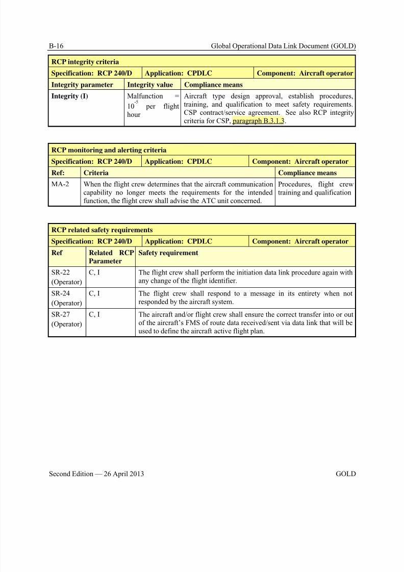
8/9/2019 CPDLC Explained
http://slidepdf.com/reader/full/cpdlc-explained 286/421
B-16 Global Operational Data Link Document (GOLD)
Second Edition — 26 April 2013 GOLD
RCP integrity criteria
Specification: RCP 240/D Application: CPDLC Component: Aircraft operator
Integrity parameter Integrity value Compliance means
Integrity (I) Malfunction =
10-5
per flighthour
Aircraft type design approval, establish procedures,training, and qualification to meet safety requirements.CSP contract/service agreement. See also RCP integritycriteria for CSP, paragraph B.3.1.3.
RCP monitoring and alerting criteria
Specification: RCP 240/D Application: CPDLC Component: Aircraft operator
Ref: Criteria Compliance means
MA-2 When the flight crew determines that the aircraft communicationcapability no longer meets the requirements for the intended
function, the flight crew shall advise the ATC unit concerned.
Procedures, flight crewtraining and qualification
RCP related safety requirements
Specification: RCP 240/D Application: CPDLC Component: Aircraft operator
Ref Related RCP
Parameter
Safety requirement
SR-22
(Operator)
C, I The flight crew shall perform the initiation data link procedure again withany change of the flight identifier.
SR-24
(Operator)
C, I The flight crew shall respond to a message in its entirety when not
responded by the aircraft system.
SR-27
(Operator)
C, I The aircraft and/or flight crew shall ensure the correct transfer into or outof the aircraft’s FMS of route data received/sent via data link that will beused to define the aircraft active flight plan.
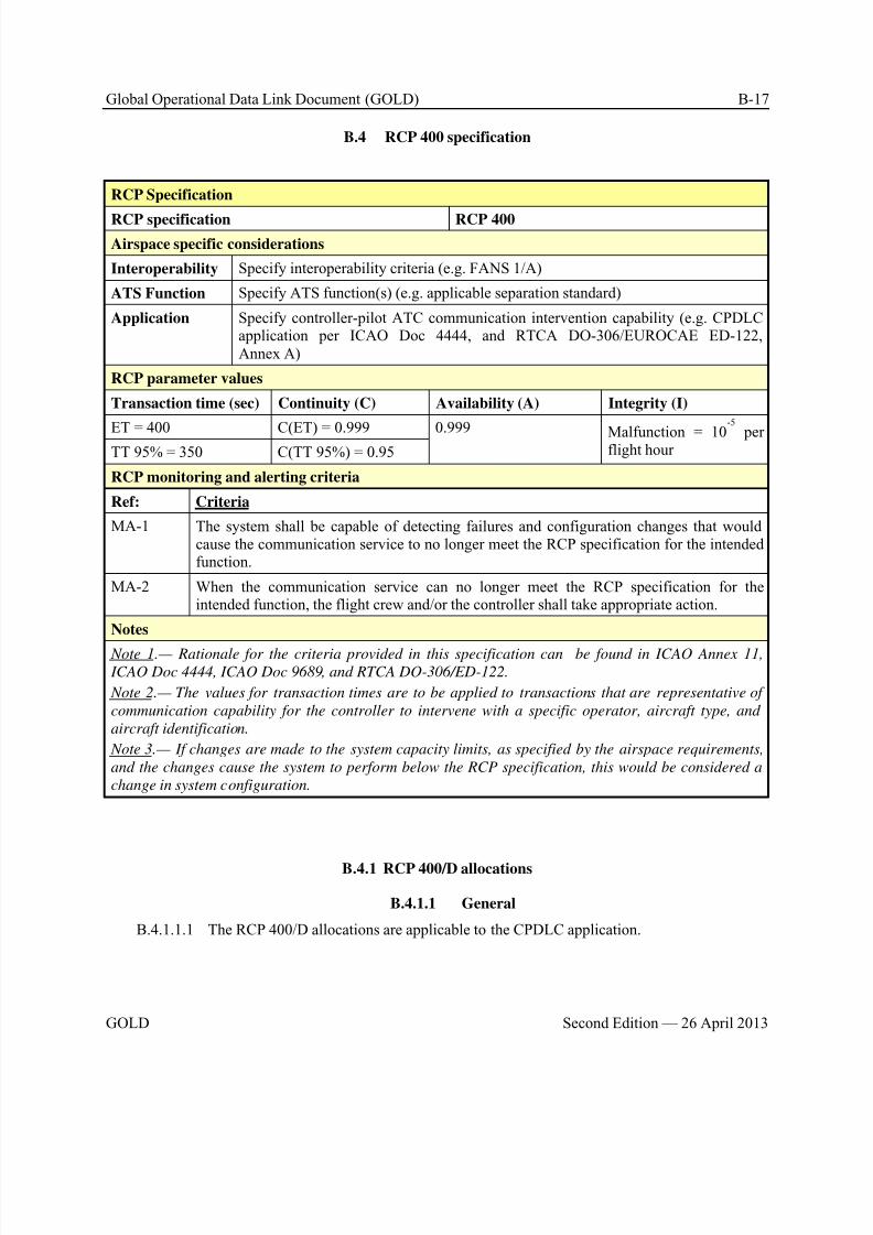
8/9/2019 CPDLC Explained
http://slidepdf.com/reader/full/cpdlc-explained 287/421
Global Operational Data Link Document (GOLD) B-17
GOLD Second Edition — 26 April 2013
B.4 RCP 400 specification
RCP Specification
RCP specification RCP 400
Airspace specific considerations
Interoperability Specify interoperability criteria (e.g. FANS 1/A)
ATS Function Specify ATS function(s) (e.g. applicable separation standard)
Application Specify controller-pilot ATC communication intervention capability (e.g. CPDLCapplication per ICAO Doc 4444, and RTCA DO-306/EUROCAE ED-122,Annex A)
RCP parameter values
Transaction time (sec) Continuity (C) Availability (A) Integrity (I)
ET = 400 C(ET) = 0.999 0.999 Malfunction = 10
-5
perflight hourTT 95% = 350 C(TT 95%) = 0.95
RCP monitoring and alerting criteria
Ref: Criteria
MA-1 The system shall be capable of detecting failures and configuration changes that wouldcause the communication service to no longer meet the RCP specification for the intendedfunction.
MA-2 When the communication service can no longer meet the RCP specification for theintended function, the flight crew and/or the controller shall take appropriate action.
Notes
Note 1.— Rationale for the criteria provided in this specification can be found in ICAO Annex 11, ICAO Doc 4444, ICAO Doc 9689, and RTCA DO-306/ED-122.
Note 2.— The values for transaction times are to be applied to transactions that are representative of
communication capability for the controller to intervene with a specific operator, aircraft type, and
aircraft identification.
Note 3.— If changes are made to the system capacity limits, as specified by the airspace requirements,
and the changes cause the system to perform below the RCP specification, this would be considered a
change in system configuration.
B.4.1 RCP 400/D allocations
B.4.1.1 General
B.4.1.1.1 The RCP 400/D allocations are applicable to the CPDLC application.

8/9/2019 CPDLC Explained
http://slidepdf.com/reader/full/cpdlc-explained 288/421
B-18 Global Operational Data Link Document (GOLD)
Second Edition — 26 April 2013 GOLD
B.4.1.2 Air navigation service provider (ANSP)
RCP communication transaction time and continuity criteria
Specification: RCP 400/D Application: CPDLC Component: ANSPTransaction Time Parameter ET (sec)
C = 99.9%
TT (sec)
C = 95%
Compliance Means
Transaction Time Value 400 350 Analysis, CSP contract/serviceagreement. See also paragraphB.4.1.3.
RCP Time Allocations
Initiator 30 30 Analysis, simulations, safety andhuman factors assessments
TRN 370 320 Monitored, CSP contract/service
agreement. See also paragraphB.4.1.3.
TRN Time Allocations
Responder 60 60 Initially, by analysis,simulations, safety humanfactors assessments
Post-implementation, monitored,estimated
RCTP 310 260 Monitored, estimated, CSPcontract/service agreement. Seealso paragraph B.4.1.3.
RCTP Time Allocation
RCTPATSU
15 10 Pre-implementationdemonstration
RCP availability criteria
Specification: RCP 400/D Application: CPDLC Component: ANSP
Availability parameter Efficiency Safety Compliance means
Service availability (ACSP
) N/A 0.999 Contract/service agreement terms.
Note.— For guidelines to aid in the
development of the contract/service agreement
with the CSP, see paragraph B.4.1.3, RCP
400/D allocation to CSP for RCP availability
criteria.
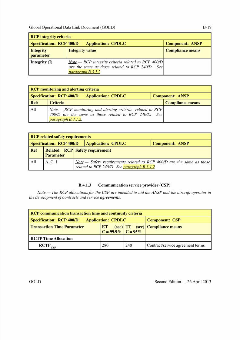
8/9/2019 CPDLC Explained
http://slidepdf.com/reader/full/cpdlc-explained 289/421
Global Operational Data Link Document (GOLD) B-19
GOLD Second Edition — 26 April 2013
RCP integrity criteria
Specification: RCP 400/D Application: CPDLC Component: ANSP
Integrity
parameter
Integrity value Compliance means
Integrity (I) Note.— RCP integrity criteria related to RCP 400/D
are the same as those related to RCP 240/D. See
paragraph B.3.1.2.
RCP monitoring and alerting criteria
Specification: RCP 400/D Application: CPDLC Component: ANSP
Ref: Criteria Compliance means
All Note.— RCP monitoring and alerting criteria related to RCP
400/D are the same as those related to RCP 240/D. See
paragraph B.3.1.2.
RCP related safety requirements
Specification: RCP 400/D Application: CPDLC Component: ANSP
Ref Related RCP
Parameter
Safety requirement
All A, C, I Note.— Safety requirements related to RCP 400/D are the same as those
related to RCP 240/D. See paragraph B.3.1.2.
B.4.1.3 Communication service provider (CSP)
Note.— The RCP allocations for the CSP are intended to aid the ANSP and the aircraft operator in
the development of contracts and service agreements.
RCP communication transaction time and continuity criteria
Specification: RCP 400/D Application: CPDLC Component: CSP
Transaction Time Parameter ET (sec)
C = 99.9%
TT (sec)
C = 95%
Compliance means
RCTP Time Allocation
RCTPCSP
280 240 Contract/service agreement terms
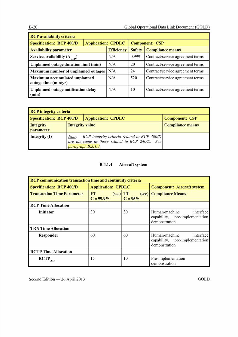
8/9/2019 CPDLC Explained
http://slidepdf.com/reader/full/cpdlc-explained 290/421
B-20 Global Operational Data Link Document (GOLD)
Second Edition — 26 April 2013 GOLD
RCP availability criteria
Specification: RCP 400/D Application: CPDLC Component: CSP
Availability parameter Efficiency Safety Compliance means
Service availability (ACSP
) N/A 0.999 Contract/service agreement terms
Unplanned outage duration limit (min) N/A 20 Contract/service agreement terms
Maximum number of unplanned outages N/A 24 Contract/service agreement terms
Maximum accumulated unplanned
outage time (min/yr)
N/A 520 Contract/service agreement terms
Unplanned outage notification delay
(min)
N/A 10 Contract/service agreement terms
RCP integrity criteria
Specification: RCP 400/D Application: CPDLC Component: CSP
Integrity
parameter
Integrity value Compliance means
Integrity (I) Note.— RCP integrity criteria related to RCP 400/D
are the same as those related to RCP 240/D. See
paragraph B.3.1.3.
B.4.1.4 Aircraft system
RCP communication transaction time and continuity criteria
Specification: RCP 400/D Application: CPDLC Component: Aircraft system
Transaction Time Parameter ET (sec)
C = 99.9%
TT (sec)
C = 95%
Compliance Means
RCP Time Allocation
Initiator 30 30 Human-machine interfacecapability, pre-implementationdemonstration
TRN Time Allocation
Responder 60 60 Human-machine interfacecapability, pre-implementationdemonstration
RCTP Time Allocation
RCTPAIR
15 10 Pre-implementationdemonstration
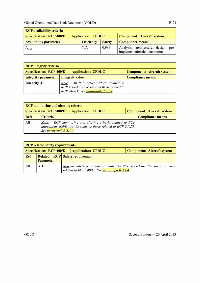
8/9/2019 CPDLC Explained
http://slidepdf.com/reader/full/cpdlc-explained 291/421
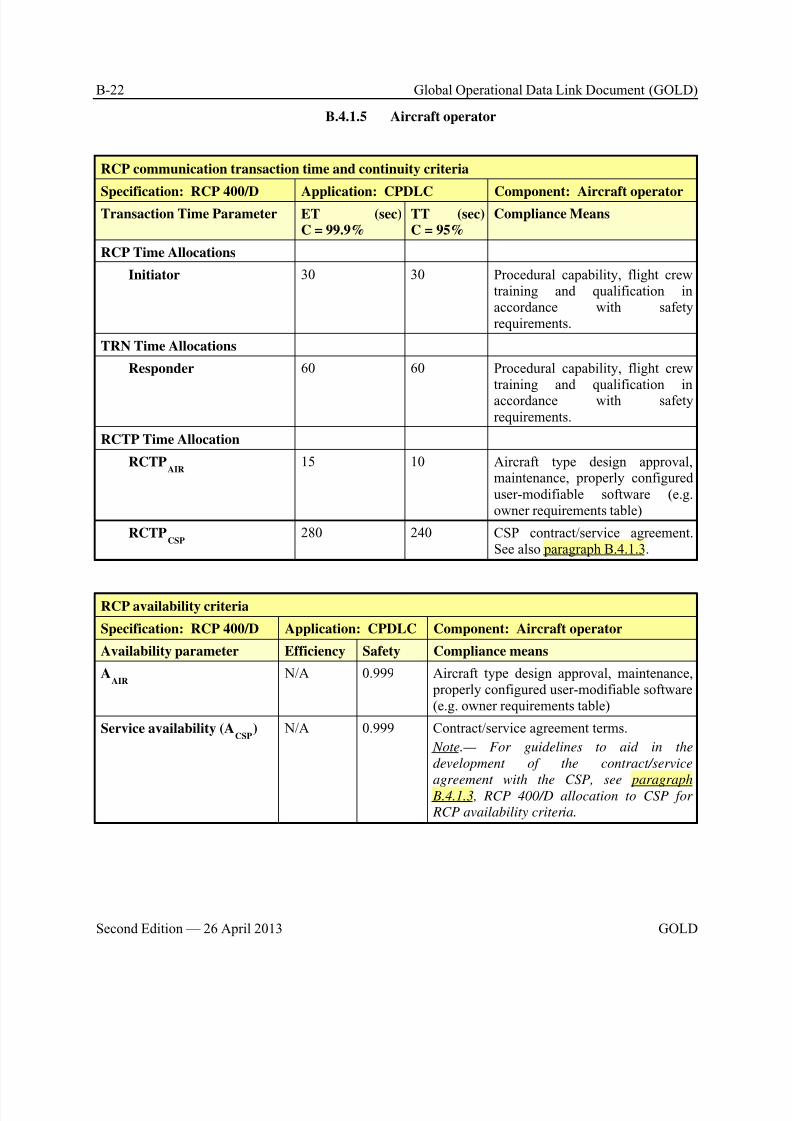
8/9/2019 CPDLC Explained
http://slidepdf.com/reader/full/cpdlc-explained 292/421
B-22 Global Operational Data Link Document (GOLD)
Second Edition — 26 April 2013 GOLD
B.4.1.5 Aircraft operator
RCP communication transaction time and continuity criteria
Specification: RCP 400/D Application: CPDLC Component: Aircraft operatorTransaction Time Parameter ET (sec)
C = 99.9%TT (sec)C = 95%
Compliance Means
RCP Time Allocations
Initiator 30 30 Procedural capability, flight crewtraining and qualification inaccordance with safetyrequirements.
TRN Time Allocations
Responder 60 60 Procedural capability, flight crewtraining and qualification inaccordance with safetyrequirements.
RCTP Time Allocation
RCTPAIR
15 10 Aircraft type design approval,maintenance, properly configureduser-modifiable software (e.g.owner requirements table)
RCTPCSP
280 240 CSP contract/service agreement.See also paragraph B.4.1.3.
RCP availability criteria
Specification: RCP 400/D Application: CPDLC Component: Aircraft operator
Availability parameter Efficiency Safety Compliance means
AAIR
N/A 0.999 Aircraft type design approval, maintenance, properly configured user-modifiable software(e.g. owner requirements table)
Service availability (ACSP
) N/A 0.999 Contract/service agreement terms.
Note.— For guidelines to aid in the
development of the contract/service
agreement with the CSP, see paragraph B.4.1.3, RCP 400/D allocation to CSP for
RCP availability criteria.
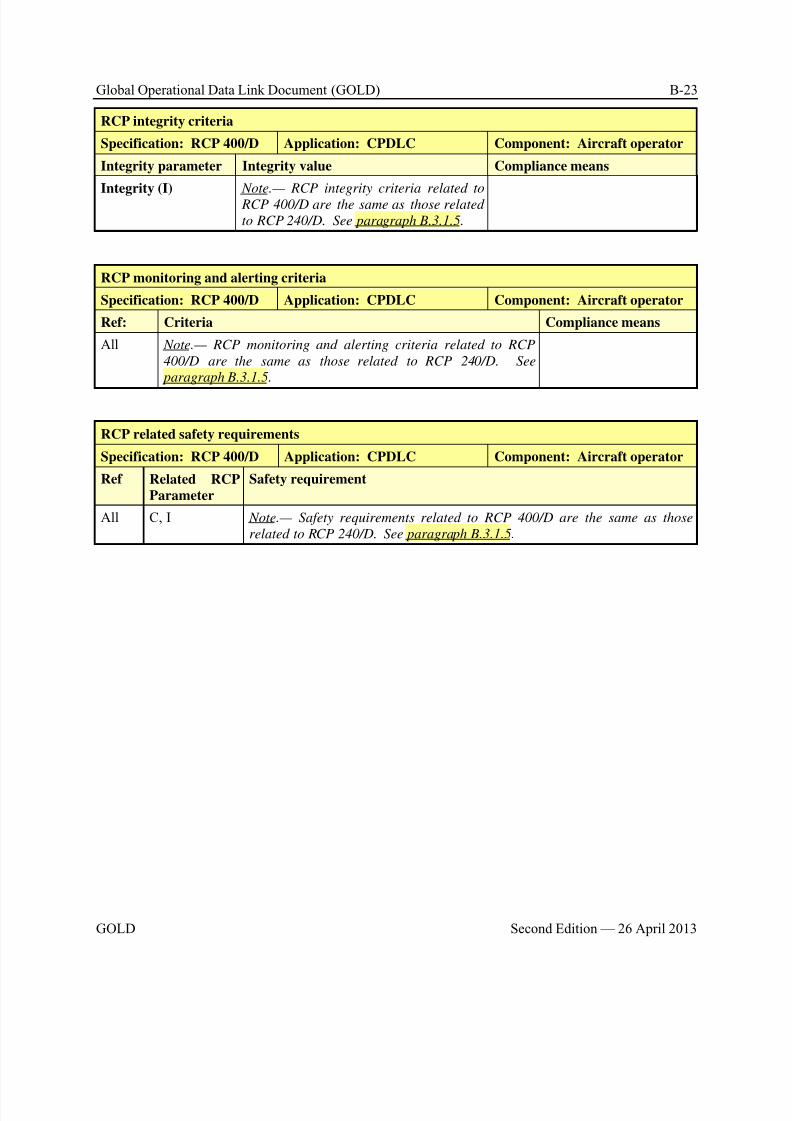
8/9/2019 CPDLC Explained
http://slidepdf.com/reader/full/cpdlc-explained 293/421
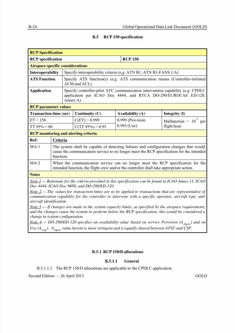
8/9/2019 CPDLC Explained
http://slidepdf.com/reader/full/cpdlc-explained 294/421
B-24 Global Operational Data Link Document (GOLD)
Second Edition — 26 April 2013 GOLD
B.5 RCP 150 specification
RCP Specification
RCP specification RCP 150
Airspace specific considerations
Interoperability Specify interoperability criteria (e.g. ATN B1, ATN B1-FANS 1/A)
ATS Function Specify ATS function(s) (e.g. ATS communication means (Controller-initiatedACM and ACL)
Application Specify controller-pilot ATC communication intervention capability (e.g. CPDLCapplication per ICAO Doc 4444, and RTCA DO-290/EUROCAE ED-120,Annex A)
RCP parameter values
Transaction time (sec) Continuity (C) Availability (A) Integrity (I)
ET = 150 C(ET) = 0.999 0.999 (Provision
0.993 (Use)Malfunction = 10
-5 per
flight hourTT 95% = 80 C(TT 95%) = 0.95
RCP monitoring and alerting criteria
Ref: Criteria
MA-1 The system shall be capable of detecting failures and configuration changes that wouldcause the communication service to no longer meet the RCP specification for the intendedfunction.
MA-2 When the communication service can no longer meet the RCP specification for theintended function, the flight crew and/or the controller shall take appropriate action.
Notes Note 1.— Rationale for the criteria provided in this specification can be found in ICAO Annex 11, ICAO
Doc 4444, ICAO Doc 9689, and DO-290/ED-120.
Note 2.— The values for transaction times are to be applied to transactions that are representative of
communication capability for the controller to intervene with a specific operator, aircraft type, and
aircraft identification.
Note 3.— If changes are made to the system capacity limits, as specified by the airspace requirements,
and the changes cause the system to perform below the RCP specification, this would be considered a
change in system configuration.
Note 4.— DO-290/ED-120 specifies an availability value based on service Provision (APROV
) and on
Use (AUSE
). APROV
value herein is more stringent and is equally shared between ATSU and CSP.
B.5.1 RCP 150/D allocations
B.5.1.1 General
B.5.1.1.1 The RCP 150/D allocations are applicable to the CPDLC application.
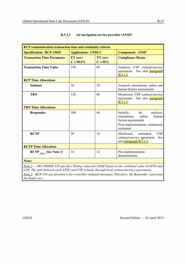
8/9/2019 CPDLC Explained
http://slidepdf.com/reader/full/cpdlc-explained 295/421
Global Operational Data Link Document (GOLD) B-25
GOLD Second Edition — 26 April 2013
B.5.1.2 Air navigation service provider (ANSP)
RCP communication transaction time and continuity criteria
Specification: RCP 150/D Application: CPDLC Component: ANSP
Transaction Time Parameter ET (sec)
C = 99.9%
TT (sec)
C = 95%
Compliance Means
Transaction Time Value 150 80 Analysis, CSP contract/serviceagreement. See also paragraphB.5.1.3.
RCP Time Allocations
Initiator 30 20 Analysis, simulations, safety andhuman factors assessments
TRN 120 60 Monitored, CSP contract/serviceagreement. See also paragraphB.5.1.3.
TRN Time Allocations
Responder 100 44 Initially, by analysis,simulations, safety humanfactors assessments
Post-implementation, monitored,estimated
RCTP 20 16 Monitored, estimated, CSP
contract/service agreement. Seealso paragraph B.5.1.3.
RCTP Time Allocation
RCTPATSU
(See Note 1) 14 12 Pre-implementationdemonstration
Notes
Note 1.— DO-290/ED-120 specifies Timing values for ANSP based on the combined value of ATSU and
CSP. The split between each ATSU and CSP is made through local contract/service agreements.
Note 2.- RCP 150 specification is for controller-initiated messages. Therefore, the Responder represents
the flight crew.
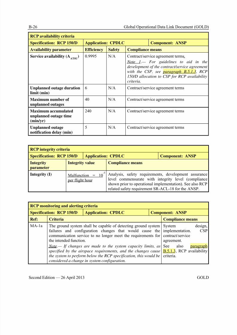
8/9/2019 CPDLC Explained
http://slidepdf.com/reader/full/cpdlc-explained 296/421
B-26 Global Operational Data Link Document (GOLD)
Second Edition — 26 April 2013 GOLD
RCP availability criteria
Specification: RCP 150/D Application: CPDLC Component: ANSP
Availability parameter Efficiency Safety Compliance means
Service availability (AATSU
) 0.9995 N/A Contract/service agreement terms.
Note 1.— For guidelines to aid in the
development of the contract/service agreement
with the CSP, see paragraph B.5.1.3, RCP
150/D allocation to CSP for RCP availability
criteria.
Unplanned outage duration
limit (min)
6 N/A Contract/service agreement terms
Maximum number of
unplanned outages
40 N/A Contract/service agreement terms
Maximum accumulated
unplanned outage time(min/yr)
240 N/A Contract/service agreement terms
Unplanned outage
notification delay (min)
5 N/A Contract/service agreement terms
RCP integrity criteria
Specification: RCP 150/D Application: CPDLC Component: ANSP
Integrityparameter
Integrity value Compliance means
Integrity (I) Malfunction = 10
-5
per flight hour
Analysis, safety requirements, development assurancelevel commensurate with integrity level (complianceshown prior to operational implementation). See also RCPrelated safety requirement SR-ACL-18 for the ANSP.
RCP monitoring and alerting criteria
Specification: RCP 150/D Application: CPDLC Component: ANSP
Ref: Criteria Compliance means
MA-1a The ground system shall be capable of detecting ground systemfailures and configuration changes that would cause the
communication service to no longer meet the requirements forthe intended function.
Note.— If changes are made to the system capacity limits, as
specified by the airspace requirements, and the changes cause
the system to perform below the RCP specification, this would be
considered a change in system configuration.
System design,implementation. CSP
contract/serviceagreement.
See also paragraphB.5.1.3, RCP availabilitycriteria.
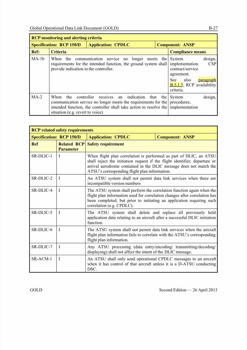
8/9/2019 CPDLC Explained
http://slidepdf.com/reader/full/cpdlc-explained 297/421
Global Operational Data Link Document (GOLD) B-27
GOLD Second Edition — 26 April 2013
RCP monitoring and alerting criteria
Specification: RCP 150/D Application: CPDLC Component: ANSP
Ref: Criteria Compliance means
MA-1b When the communication service no longer meets therequirements for the intended function, the ground system shall provide indication to the controller.
System design,implementation. CSPcontract/serviceagreement.
See also paragraphB.5.1.3, RCP availabilitycriteria.
MA-2 When the controller receives an indication that thecommunication service no longer meets the requirements for theintended function, the controller shall take action to resolve thesituation (e.g. revert to voice)
System design, procedures,implementation
RCP related safety requirements
Specification: RCP 150/D Application: CPDLC Component: ANSP
Ref Related RCP
Parameter
Safety requirement
SR-DLIC-1 I When flight plan correlation is performed as part of DLIC, an ATSUshall reject the initiation request if the flight identifier, departure orarrival aerodrome contained in the DLIC message does not match theATSU’s corresponding flight plan information.
SR-DLIC-2 I An ATSU system shall not permit data link services when there are
incompatible version numbersSR-DLIC-4 I The ATSU system shall perform the correlation function again when the
flight plan information used for correlation changes after correlation has been completed, but prior to initiating an application requiring suchcorrelation (e.g. CPDLC).
SR-DLIC-5 I The ATSU system shall delete and replace all previously heldapplication data relating to an aircraft after a successful DLIC initiationfunction.
SR-DLIC-6 I The ATSU system shall not permit data link services when the aircraftflight plan information fails to correlate with the ATSU’s correspondingflight plan information.
SR-DLIC-7 I Any ATSU processing (data entry/encoding/ transmitting/decoding/displaying) shall not affect the intent of the DLIC message.
SR-ACM-1 I An ATSU shall only send operational CPDLC messages to an aircraftwhen it has control of that aircraft unless it is a D-ATSU conductingDSC.
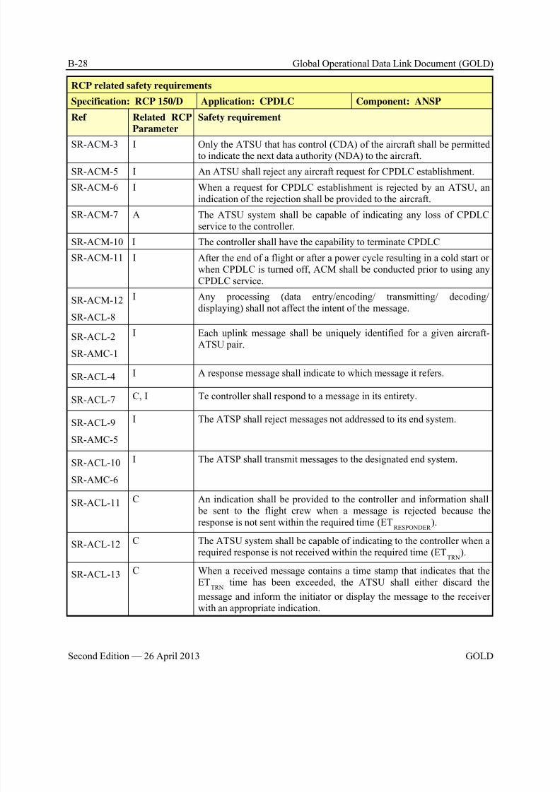
8/9/2019 CPDLC Explained
http://slidepdf.com/reader/full/cpdlc-explained 298/421
B-28 Global Operational Data Link Document (GOLD)
Second Edition — 26 April 2013 GOLD
RCP related safety requirements
Specification: RCP 150/D Application: CPDLC Component: ANSP
Ref Related RCP
Parameter
Safety requirement
SR-ACM-3 I Only the ATSU that has control (CDA) of the aircraft shall be permittedto indicate the next data authority (NDA) to the aircraft.
SR-ACM-5 I An ATSU shall reject any aircraft request for CPDLC establishment.
SR-ACM-6 I When a request for CPDLC establishment is rejected by an ATSU, anindication of the rejection shall be provided to the aircraft.
SR-ACM-7 A The ATSU system shall be capable of indicating any loss of CPDLCservice to the controller.
SR-ACM-10 I The controller shall have the capability to terminate CPDLC
SR-ACM-11 I After the end of a flight or after a power cycle resulting in a cold start orwhen CPDLC is turned off, ACM shall be conducted prior to using any
CPDLC service.
SR-ACM-12
SR-ACL-8
I Any processing (data entry/encoding/ transmitting/ decoding/displaying) shall not affect the intent of the message.
SR-ACL-2
SR-AMC-1
I Each uplink message shall be uniquely identified for a given aircraft-ATSU pair.
SR-ACL-4 I A response message shall indicate to which message it refers.
SR-ACL-7 C, I Te controller shall respond to a message in its entirety.
SR-ACL-9
SR-AMC-5
I The ATSP shall reject messages not addressed to its end system.
SR-ACL-10
SR-AMC-6
I The ATSP shall transmit messages to the designated end system.
SR-ACL-11 C An indication shall be provided to the controller and information shall be sent to the flight crew when a message is rejected because theresponse is not sent within the required time (ET
RESPONDER ).
SR-ACL-12 C The ATSU system shall be capable of indicating to the controller when a
required response is not received within the required time (ETTRN).
SR-ACL-13 C When a received message contains a time stamp that indicates that theET
TRN time has been exceeded, the ATSU shall either discard the
message and inform the initiator or display the message to the receiverwith an appropriate indication.
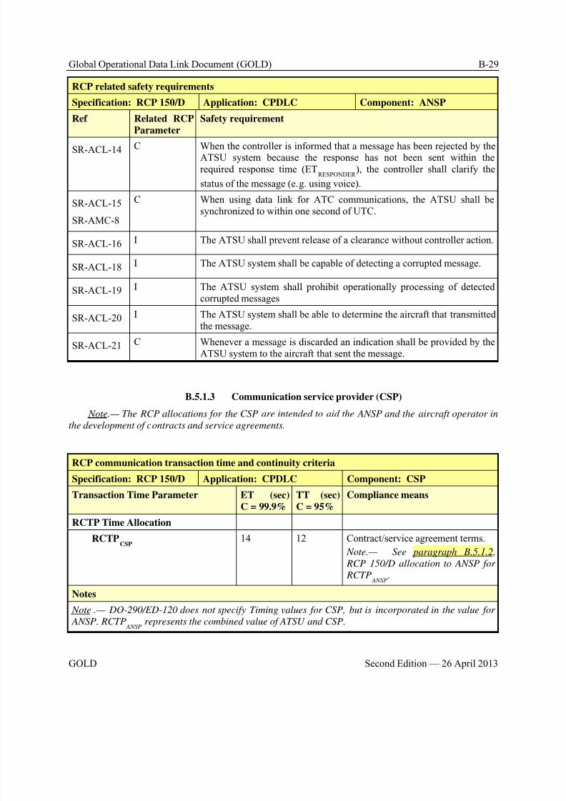
8/9/2019 CPDLC Explained
http://slidepdf.com/reader/full/cpdlc-explained 299/421
Global Operational Data Link Document (GOLD) B-29
GOLD Second Edition — 26 April 2013
RCP related safety requirements
Specification: RCP 150/D Application: CPDLC Component: ANSP
Ref Related RCP
Parameter
Safety requirement
SR-ACL-14 C When the controller is informed that a message has been rejected by theATSU system because the response has not been sent within therequired response time (ET
RESPONDER ), the controller shall clarify the
status of the message (e.g. using voice).
SR-ACL-15
SR-AMC-8
C When using data link for ATC communications, the ATSU shall besynchronized to within one second of UTC.
SR-ACL-16 I The ATSU shall prevent release of a clearance without controller action.
SR-ACL-18 I The ATSU system shall be capable of detecting a corrupted message.
SR-ACL-19 I The ATSU system shall prohibit operationally processing of detectedcorrupted messages
SR-ACL-20 I The ATSU system shall be able to determine the aircraft that transmittedthe message.
SR-ACL-21 C Whenever a message is discarded an indication shall be provided by theATSU system to the aircraft that sent the message.
B.5.1.3 Communication service provider (CSP)
Note.— The RCP allocations for the CSP are intended to aid the ANSP and the aircraft operator in
the development of contracts and service agreements.
RCP communication transaction time and continuity criteria
Specification: RCP 150/D Application: CPDLC Component: CSP
Transaction Time Parameter ET (sec)
C = 99.9%
TT (sec)
C = 95%
Compliance means
RCTP Time Allocation
RCTPCSP
14 12 Contract/service agreement terms.
Note.— See paragraph B.5.1.2,
RCP 150/D allocation to ANSP for RCTP
ANSP.
Notes
Note .— DO-290/ED-120 does not specify Timing values for CSP, but is incorporated in the value for
ANSP. RCTP ANSP
represents the combined value of ATSU and CSP.

8/9/2019 CPDLC Explained
http://slidepdf.com/reader/full/cpdlc-explained 300/421
B-30 Global Operational Data Link Document (GOLD)
Second Edition — 26 April 2013 GOLD
RCP availability criteria
Specification: RCP 150/D Application: CPDLC Component: CSP
Availability parameter Efficiency Safety Compliance means
Service availability (ACSP
) 0.995 N/A Contract/service agreement terms
Unplanned outage duration limit (min) 6 N/A Contract/service agreement terms
Maximum number of unplanned outages 40 N/A Contract/service agreement terms
Maximum accumulated unplanned
outage time (min/yr)
240 N/A Contract/service agreement terms
Unplanned outage notification delay
(min)
5 N/A Contract/service agreement terms
Notes
Note.— ACSP
is derived from APROV
and is equally shared between ATSU and CSP.
RCP integrity criteria
Specification: RCP 150/D Application: CPDLC Component: CSP
Integrity
parameter
Integrity value Compliance means
Integrity (I) Not specified Contract/service agreement terms. Per RCP related safetyrequirements SR-ACL-18 for the ANSP and SR-ACL-18 forthe aircraft system, the end system is required include provisions, consistent with the overall RCP integrity criteria, tomitigate the effects of errors introduced by the network. These
provisions require the network to pass protected information(or data) to the end system without manipulating the protectedinformation (or data) it passes.
Note.— In formulating contract terms with the CSP, the ANSP
and/or operator may specify an integrity value and other
related criteria, as appropriate, for the network, including
subnetworks, that will ensure acceptable data integrity,
consistent with the assumptions used to define the end system
provisions (e.g. CRC or Fletcher’s checksum).

8/9/2019 CPDLC Explained
http://slidepdf.com/reader/full/cpdlc-explained 301/421
Global Operational Data Link Document (GOLD) B-31
GOLD Second Edition — 26 April 2013
B.5.1.4 Aircraft system
RCP communication transaction time and continuity criteria
Specification: RCP 150/D Application: CPDLC Component: Aircraft systemTransaction Time Parameter ET (sec)
C = 99.9%TT (sec)C = 95%
Compliance Means
RCP Time Allocation
Initiator See note See note Human-machine interfacecapability, pre-implementationdemonstration
TRN Time Allocation
Responder 100 44 Human-machine interfacecapability, pre-implementationdemonstration
RCTP Time Allocation
RCTPAIR
6 4 Pre-implementationdemonstration
Notes
Note.— RCP 150 specification is for controller-initiated messages. Therefore, the INITIATOR time is
not provided.
RCP availability criteria
Specification: RCP 150/D Application: CPDLC Component: Aircraft systemAvailability parameter Efficiency Safety Compliance means
AAIR
0.994 N/A Analysis, architecture, design, pre-implementation demonstration
Notes
Note.— A AIR
,is derived from AUSE
and APROVISION
, where A AIR
equals AUSE
/ APROVISION
.
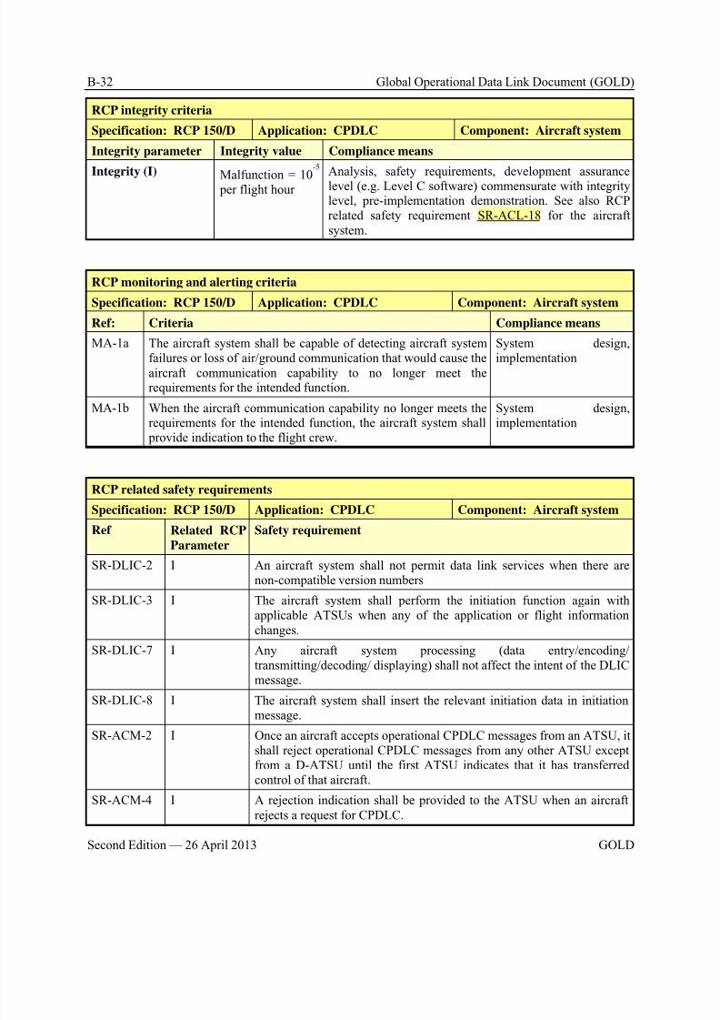
8/9/2019 CPDLC Explained
http://slidepdf.com/reader/full/cpdlc-explained 302/421
B-32 Global Operational Data Link Document (GOLD)
Second Edition — 26 April 2013 GOLD
RCP integrity criteria
Specification: RCP 150/D Application: CPDLC Component: Aircraft system
Integrity parameter Integrity value Compliance means
Integrity (I)Malfunction = 10
-5
per flight hour
Analysis, safety requirements, development assurancelevel (e.g. Level C software) commensurate with integritylevel, pre-implementation demonstration. See also RCPrelated safety requirement SR-ACL-18 for the aircraftsystem.
RCP monitoring and alerting criteria
Specification: RCP 150/D Application: CPDLC Component: Aircraft system
Ref: Criteria Compliance means
MA-1a The aircraft system shall be capable of detecting aircraft system
failures or loss of air/ground communication that would cause theaircraft communication capability to no longer meet therequirements for the intended function.
System design,
implementation
MA-1b When the aircraft communication capability no longer meets therequirements for the intended function, the aircraft system shall provide indication to the flight crew.
System design,implementation
RCP related safety requirements
Specification: RCP 150/D Application: CPDLC Component: Aircraft system
Ref Related RCPParameter Safety requirement
SR-DLIC-2 I An aircraft system shall not permit data link services when there arenon-compatible version numbers
SR-DLIC-3 I The aircraft system shall perform the initiation function again withapplicable ATSUs when any of the application or flight informationchanges.
SR-DLIC-7 I Any aircraft system processing (data entry/encoding/transmitting/decoding/ displaying) shall not affect the intent of the DLICmessage.
SR-DLIC-8 I The aircraft system shall insert the relevant initiation data in initiation
message.
SR-ACM-2 I Once an aircraft accepts operational CPDLC messages from an ATSU, itshall reject operational CPDLC messages from any other ATSU exceptfrom a D-ATSU until the first ATSU indicates that it has transferredcontrol of that aircraft.
SR-ACM-4 I A rejection indication shall be provided to the ATSU when an aircraftrejects a request for CPDLC.
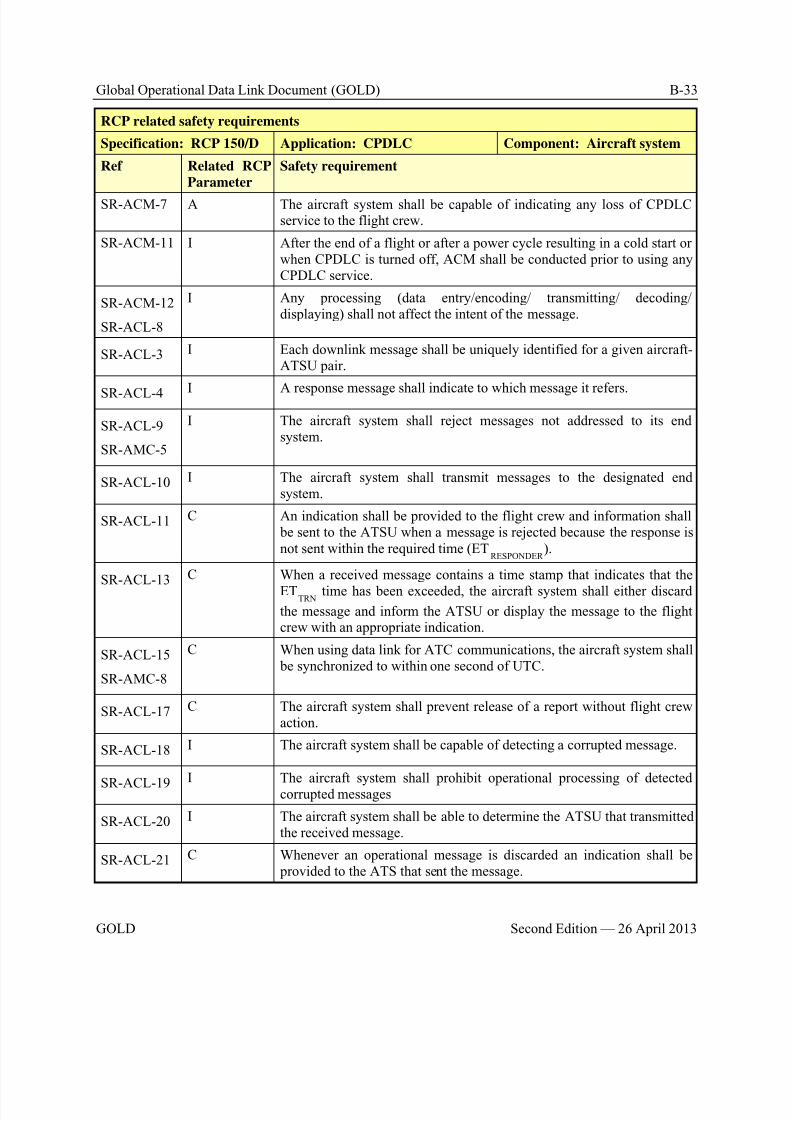
8/9/2019 CPDLC Explained
http://slidepdf.com/reader/full/cpdlc-explained 303/421
Global Operational Data Link Document (GOLD) B-33
GOLD Second Edition — 26 April 2013
RCP related safety requirements
Specification: RCP 150/D Application: CPDLC Component: Aircraft system
Ref Related RCP
Parameter
Safety requirement
SR-ACM-7 A The aircraft system shall be capable of indicating any loss of CPDLCservice to the flight crew.
SR-ACM-11 I After the end of a flight or after a power cycle resulting in a cold start orwhen CPDLC is turned off, ACM shall be conducted prior to using anyCPDLC service.
SR-ACM-12
SR-ACL-8
I Any processing (data entry/encoding/ transmitting/ decoding/displaying) shall not affect the intent of the message.
SR-ACL-3 I Each downlink message shall be uniquely identified for a given aircraft-ATSU pair.
SR-ACL-4 I A response message shall indicate to which message it refers.
SR-ACL-9
SR-AMC-5
I The aircraft system shall reject messages not addressed to its endsystem.
SR-ACL-10 I The aircraft system shall transmit messages to the designated endsystem.
SR-ACL-11 C An indication shall be provided to the flight crew and information shall be sent to the ATSU when a message is rejected because the response isnot sent within the required time (ET
RESPONDER ).
SR-ACL-13 C When a received message contains a time stamp that indicates that the
ETTRN time has been exceeded, the aircraft system shall either discardthe message and inform the ATSU or display the message to the flightcrew with an appropriate indication.
SR-ACL-15
SR-AMC-8
C When using data link for ATC communications, the aircraft system shall be synchronized to within one second of UTC.
SR-ACL-17 C The aircraft system shall prevent release of a report without flight crewaction.
SR-ACL-18 I The aircraft system shall be capable of detecting a corrupted message.
SR-ACL-19I The aircraft system shall prohibit operational processing of detected
corrupted messages
SR-ACL-20 I The aircraft system shall be able to determine the ATSU that transmittedthe received message.
SR-ACL-21 C Whenever an operational message is discarded an indication shall be provided to the ATS that sent the message.
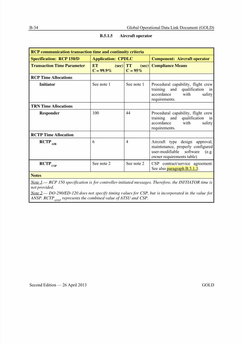
8/9/2019 CPDLC Explained
http://slidepdf.com/reader/full/cpdlc-explained 304/421
B-34 Global Operational Data Link Document (GOLD)
Second Edition — 26 April 2013 GOLD
B.5.1.5 Aircraft operator
RCP communication transaction time and continuity criteria
Specification: RCP 150/D Application: CPDLC Component: Aircraft operatorTransaction Time Parameter ET (sec)
C = 99.9%TT (sec)C = 95%
Compliance Means
RCP Time Allocations
Initiator See note 1 See note 1 Procedural capability, flight crewtraining and qualification inaccordance with safetyrequirements.
TRN Time Allocations
Responder 100 44 Procedural capability, flight crewtraining and qualification inaccordance with safetyrequirements.
RCTP Time Allocation
RCTPAIR
6 4 Aircraft type design approval,maintenance, properly configureduser-modifiable software (e.g.owner requirements table)
RCTPCSP
See note 2 See note 2 CSP contract/service agreement.See also paragraph B.5.1.3.
Notes
Note 1.— RCP 150 specification is for controller-initiated messages. Therefore, the INITIATOR time isnot provided.
Note 2.— DO-290/ED-120 does not specify timing values for CSP, but is incorporated in the value for
ANSP. RCTP ANSP
represents the combined value of ATSU and CSP.
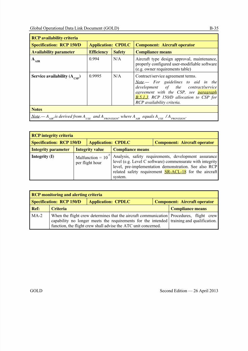
8/9/2019 CPDLC Explained
http://slidepdf.com/reader/full/cpdlc-explained 305/421
Global Operational Data Link Document (GOLD) B-35
GOLD Second Edition — 26 April 2013
RCP availability criteria
Specification: RCP 150/D Application: CPDLC Component: Aircraft operator
Availability parameter Efficiency Safety Compliance means
AAIR
0.994 N/A Aircraft type design approval, maintenance, properly configured user-modifiable software(e.g. owner requirements table)
Service availability (ACSP
) 0.9995 N/A Contract/service agreement terms.
Note.— For guidelines to aid in the
development of the contract/service
agreement with the CSP, see paragraph
B.5.1.3, RCP 150/D allocation to CSP for
RCP availability criteria.
Notes
Note.— A AIR
,is derived from AUSE
and APROVISION
, where A AIR
equals AUSE
/ APROVISION
.
RCP integrity criteria
Specification: RCP 150/D Application: CPDLC Component: Aircraft operator
Integrity parameter Integrity value Compliance means
Integrity (I) Malfunction = 10-5
per flight hour
Analysis, safety requirements, development assurancelevel (e.g. Level C software) commensurate with integritylevel, pre-implementation demonstration. See also RCPrelated safety requirement SR-ACL-18 for the aircraftsystem.
RCP monitoring and alerting criteria
Specification: RCP 150/D Application: CPDLC Component: Aircraft operator
Ref: Criteria Compliance means
MA-2 When the flight crew determines that the aircraft communicationcapability no longer meets the requirements for the intendedfunction, the flight crew shall advise the ATC unit concerned.
Procedures, flight crewtraining and qualification.
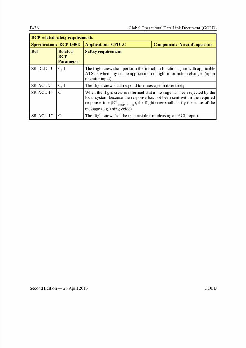
8/9/2019 CPDLC Explained
http://slidepdf.com/reader/full/cpdlc-explained 306/421
B-36 Global Operational Data Link Document (GOLD)
Second Edition — 26 April 2013 GOLD
RCP related safety requirements
Specification: RCP 150/D Application: CPDLC Component: Aircraft operator
Ref Related
RCP
Parameter
Safety requirement
SR-DLIC-3 C, I The flight crew shall perform the initiation function again with applicableATSUs when any of the application or flight information changes (uponoperator input).
SR-ACL-7 C, I The flight crew shall respond to a message in its entirety.
SR-ACL-14 C When the flight crew is informed that a message has been rejected by thelocal system because the response has not been sent within the requiredresponse time (ET
RESPONDER ), the flight crew shall clarify the status of the
message (e.g. using voice).
SR-ACL-17 C The flight crew shall be responsible for releasing an ACL report.
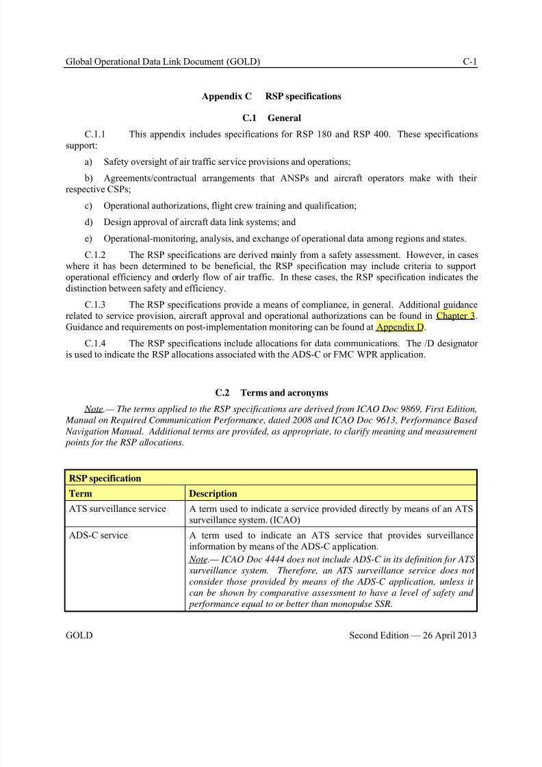
8/9/2019 CPDLC Explained
http://slidepdf.com/reader/full/cpdlc-explained 307/421
Global Operational Data Link Document (GOLD) C-1
GOLD Second Edition — 26 April 2013
Appendix C RSP specifications
C.1 General
C.1.1 This appendix includes specifications for RSP 180 and RSP 400. These specificationssupport:
a) Safety oversight of air traffic service provisions and operations;
b) Agreements/contractual arrangements that ANSPs and aircraft operators make with theirrespective CSPs;
c) Operational authorizations, flight crew training and qualification;
d) Design approval of aircraft data link systems; and
e) Operational-monitoring, analysis, and exchange of operational data among regions and states.
C.1.2 The RSP specifications are derived mainly from a safety assessment. However, in cases
where it has been determined to be beneficial, the RSP specification may include criteria to supportoperational efficiency and orderly flow of air traffic. In these cases, the RSP specification indicates thedistinction between safety and efficiency.
C.1.3 The RSP specifications provide a means of compliance, in general. Additional guidancerelated to service provision, aircraft approval and operational authorizations can be found in Chapter 3. Guidance and requirements on post-implementation monitoring can be found at Appendix D.
C.1.4 The RSP specifications include allocations for data communications. The /D designatoris used to indicate the RSP allocations associated with the ADS-C or FMC WPR application.
C.2 Terms and acronyms
Note.— The terms applied to the RSP specifications are derived from ICAO Doc 9869, First Edition,
Manual on Required Communication Performance, dated 2008 and ICAO Doc 9613, Performance Based
Navigation Manual. Additional terms are provided, as appropriate, to clarify meaning and measurement
points for the RSP allocations.
RSP specification
Term Description
ATS surveillance service A term used to indicate a service provided directly by means of an ATSsurveillance system. (ICAO)
ADS-C service A term used to indicate an ATS service that provides surveillanceinformation by means of the ADS-C application.
Note.— ICAO Doc 4444 does not include ADS-C in its definition for ATS
surveillance system. Therefore, an ATS surveillance service does not
consider those provided by means of the ADS-C application, unless it
can be shown by comparative assessment to have a level of safety and
performance equal to or better than monopulse SSR.
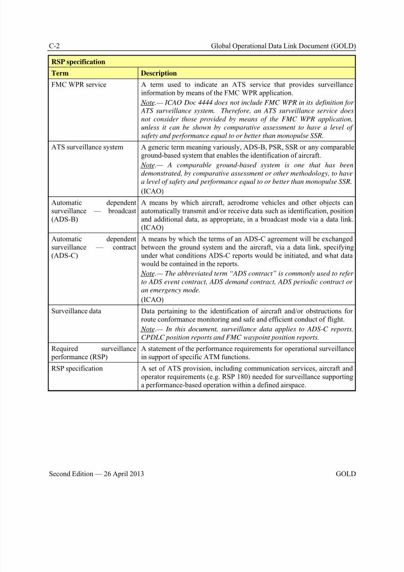
8/9/2019 CPDLC Explained
http://slidepdf.com/reader/full/cpdlc-explained 308/421
C-2 Global Operational Data Link Document (GOLD)
Second Edition — 26 April 2013 GOLD
RSP specification
Term Description
FMC WPR service A term used to indicate an ATS service that provides surveillanceinformation by means of the FMC WPR application.
Note.— ICAO Doc 4444 does not include FMC WPR in its definition for ATS surveillance system. Therefore, an ATS surveillance service does
not consider those provided by means of the FMC WPR application,
unless it can be shown by comparative assessment to have a level of
safety and performance equal to or better than monopulse SSR.
ATS surveillance system A generic term meaning variously, ADS-B, PSR, SSR or any comparableground-based system that enables the identification of aircraft.
Note.— A comparable ground-based system is one that has been
demonstrated, by comparative assessment or other methodology, to have
a level of safety and performance equal to or better than monopulse SSR.
(ICAO)
Automatic dependentsurveillance — broadcast(ADS-B)
A means by which aircraft, aerodrome vehicles and other objects canautomatically transmit and/or receive data such as identification, positionand additional data, as appropriate, in a broadcast mode via a data link.(ICAO)
Automatic dependentsurveillance — contract(ADS-C)
A means by which the terms of an ADS-C agreement will be exchanged between the ground system and the aircraft, via a data link, specifyingunder what conditions ADS-C reports would be initiated, and what datawould be contained in the reports.
Note.— The abbreviated term “ADS contract” is commonly used to refer
to ADS event contract, ADS demand contract, ADS periodic contract or
an emergency mode.
(ICAO)Surveillance data Data pertaining to the identification of aircraft and/or obstructions for
route conformance monitoring and safe and efficient conduct of flight.
Note.— In this document, surveillance data applies to ADS-C reports,
CPDLC position reports and FMC waypoint position reports.
Required surveillance performance (RSP)
A statement of the performance requirements for operational surveillancein support of specific ATM functions.
RSP specification A set of ATS provision, including communication services, aircraft andoperator requirements (e.g. RSP 180) needed for surveillance supportinga performance-based operation within a defined airspace.
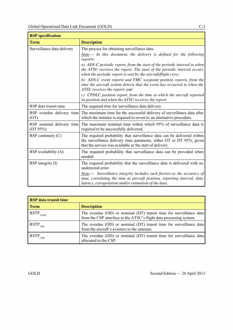
8/9/2019 CPDLC Explained
http://slidepdf.com/reader/full/cpdlc-explained 309/421
Global Operational Data Link Document (GOLD) C-3
GOLD Second Edition — 26 April 2013
RSP specification
Term Description
Surveillance data delivery The process for obtaining surveillance data.
Note.— In this document, the delivery is defined for the following
reports:
a) ADS-C periodic report, from the start of the periodic interval to when
the ATSU receives the report. The start of the periodic interval occurs
when the periodic report is sent by the aircraft/flight crew;
b) ADS-C event reports and FMC waypoint position reports, from the
time the aircraft system detects that the event has occurred to when the
ATSU receives the report; and
c) CPDLC position report, from the time at which the aircraft reported
its position and when the ATSU receives the report.
RSP data transit time The required time for surveillance data delivery.
RSP overdue delivery time(OT)
The maximum time for the successful delivery of surveillance data afterwhich the initiator is required to revert to an alternative procedure.
RSP nominal delivery time(DT 95%)
The maximum nominal time within which 95% of surveillance data isrequired to be successfully delivered.
RSP continuity (C) The required probability that surveillance data can be delivered withinthe surveillance delivery time parameter, either OT or DT 95%, giventhat the service was available at the start of delivery.
RSP availability (A) The required probability that surveillance data can be provided whenneeded.
RSP integrity (I) The required probability that the surveillance data is delivered with noundetected error.
Note.— Surveillance integrity includes such factors as the accuracy oftime, correlating the time at aircraft position, reporting interval, data
latency, extrapolation and/or estimation of the data.
RSP data transit time
Term Description
RSTPATSU
The overdue (OD) or nominal (DT) transit time for surveillance datafrom the CSP interface to the ATSU’s flight data processing system.
RSTPAIR
The overdue (OD) or nominal (DT) transit time for surveillance data
from the aircraft’s avionics to the antenna.RSTP
CSP The overdue (OD) or nominal (DT) transit time for surveillance data
allocated to the CSP.
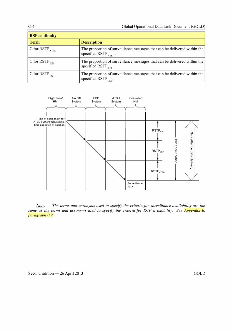
8/9/2019 CPDLC Explained
http://slidepdf.com/reader/full/cpdlc-explained 310/421
C-4 Global Operational Data Link Document (GOLD)
Second Edition — 26 April 2013 GOLD
RSP continuity
Term Description
C for RSTPATSU
The proportion of surveillance messages that can be delivered within thespecified RSTP
ATSU.
C for RSTPAIR
The proportion of surveillance messages that can be delivered within thespecified RSTP
AIR .
C for RSTPCSP
The proportion of surveillance messages that can be delivered within thespecified RSTP
CSP.
Aircraft
System
Flight crew/
HMI
CSP
System
Controller/
HMI
ATSU
System
Surveillance
data
S ur v ei l l an c e d a t a d el i v er y
R S P s p e c i f i c a t i on
RSTP AIR
Time at position or, for
ATSU syst em mon ito rin g,
time expected at position
RSTPCSP
RSTP ATSU
Note.— The terms and acronyms used to specify the criteria for surveillance availability are the
same as the terms and acronyms used to specify the criteria for RCP availability. See Appendix B,
paragraph B.2.

8/9/2019 CPDLC Explained
http://slidepdf.com/reader/full/cpdlc-explained 311/421
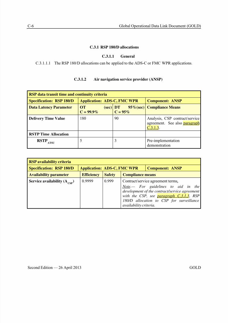
8/9/2019 CPDLC Explained
http://slidepdf.com/reader/full/cpdlc-explained 312/421
C-6 Global Operational Data Link Document (GOLD)
Second Edition — 26 April 2013 GOLD
C.3.1 RSP 180/D allocations
C.3.1.1 General
C.3.1.1.1 The RSP 180/D allocations can be applied to the ADS-C or FMC WPR applications.
C.3.1.2 Air navigation service provider (ANSP)
RSP data transit time and continuity criteria
Specification: RSP 180/D Application: ADS-C, FMC WPR Component: ANSP
Data Latency Parameter OT (sec)
C = 99.9%
DT 95%(sec)
C = 95%
Compliance Means
Delivery Time Value 180 90 Analysis, CSP contract/serviceagreement. See also paragraphC.3.1.3.
RSTP Time Allocation
RSTPATSU
5 3 Pre-implementationdemonstration
RSP availability criteria
Specification: RSP 180/D Application: ADS-C, FMC WPR Component: ANSPAvailability parameter Efficiency Safety Compliance means
Service availability (ACSP
) 0.9999 0.999 Contract/service agreement terms.
Note.— For guidelines to aid in the
development of the contract/service agreement
with the CSP, see paragraph C.3.1.3, RSP
180/D allocation to CSP for surveillance
availability criteria.
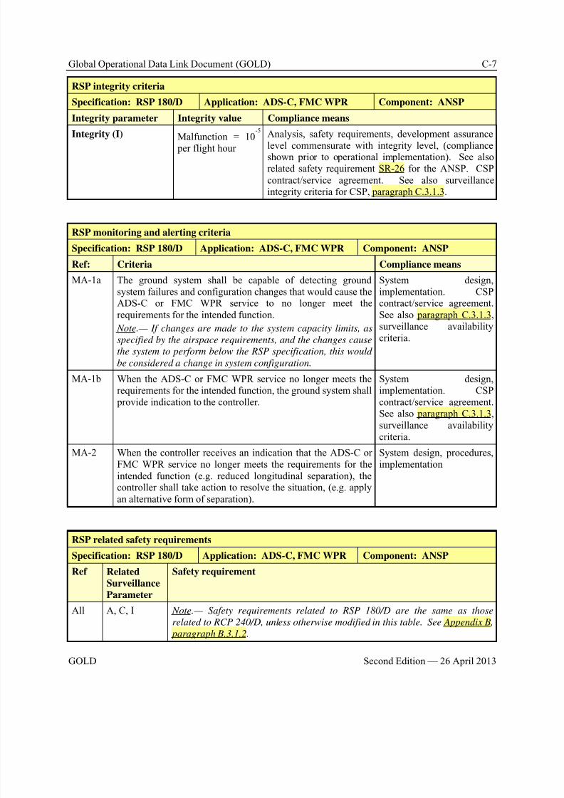
8/9/2019 CPDLC Explained
http://slidepdf.com/reader/full/cpdlc-explained 313/421
Global Operational Data Link Document (GOLD) C-7
GOLD Second Edition — 26 April 2013
RSP integrity criteria
Specification: RSP 180/D Application: ADS-C, FMC WPR Component: ANSP
Integrity parameter Integrity value Compliance means
Integrity (I)Malfunction = 10
-5
per flight hour
Analysis, safety requirements, development assurancelevel commensurate with integrity level, (complianceshown prior to operational implementation). See alsorelated safety requirement SR-26 for the ANSP. CSPcontract/service agreement. See also surveillanceintegrity criteria for CSP, paragraph C.3.1.3.
RSP monitoring and alerting criteria
Specification: RSP 180/D Application: ADS-C, FMC WPR Component: ANSP
Ref: Criteria Compliance means
MA-1a The ground system shall be capable of detecting groundsystem failures and configuration changes that would cause theADS-C or FMC WPR service to no longer meet therequirements for the intended function.
Note.— If changes are made to the system capacity limits, as
specified by the airspace requirements, and the changes cause
the system to perform below the RSP specification, this would
be considered a change in system configuration.
System design,implementation. CSPcontract/service agreement.See also paragraph C.3.1.3, surveillance availabilitycriteria.
MA-1b When the ADS-C or FMC WPR service no longer meets therequirements for the intended function, the ground system shall provide indication to the controller.
System design,implementation. CSPcontract/service agreement.See also paragraph C.3.1.3, surveillance availabilitycriteria.
MA-2 When the controller receives an indication that the ADS-C orFMC WPR service no longer meets the requirements for theintended function (e.g. reduced longitudinal separation), thecontroller shall take action to resolve the situation, (e.g. applyan alternative form of separation).
System design, procedures,implementation
RSP related safety requirements
Specification: RSP 180/D Application: ADS-C, FMC WPR Component: ANSPRef Related
Surveillance
Parameter
Safety requirement
All A, C, I Note.— Safety requirements related to RSP 180/D are the same as those
related to RCP 240/D, unless otherwise modified in this table. See Appendix B,
paragraph B.3.1.2.
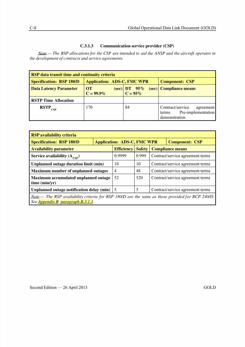
8/9/2019 CPDLC Explained
http://slidepdf.com/reader/full/cpdlc-explained 314/421
C-8 Global Operational Data Link Document (GOLD)
Second Edition — 26 April 2013 GOLD
C.3.1.3 Communication service provider (CSP)
Note.— The RSP allocations for the CSP are intended to aid the ANSP and the aircraft operator in
the development of contracts and service agreements.
RSP data transit time and continuity criteria
Specification: RSP 180/D Application: ADS-C, FMC WPR Component: CSP
Data Latency Parameter OT (sec)C = 99.9%
DT 95% (sec)C = 95%
Compliance means
RSTP Time Allocation
RSTPCSP
170 84 Contract/service agreementterms. Pre-implementationdemonstration
RSP availability criteria
Specification: RSP 180/D Application: ADS-C, FMC WPR Component: CSP
Availability parameter Efficiency Safety Compliance means
Service availability (ACSP
) 0.9999 0.999 Contract/service agreement terms
Unplanned outage duration limit (min) 10 10 Contract/service agreement terms
Maximum number of unplanned outages 4 48 Contract/service agreement terms
Maximum accumulated unplanned outage
time (min/yr)
52 520 Contract/service agreement terms
Unplanned outage notification delay (min) 5 5 Contract/service agreement terms
Note.— The RSP availability criteria for RSP 180/D are the same as those provided for RCP 240/D.
See Appendix B, paragraph B.3.1.3.
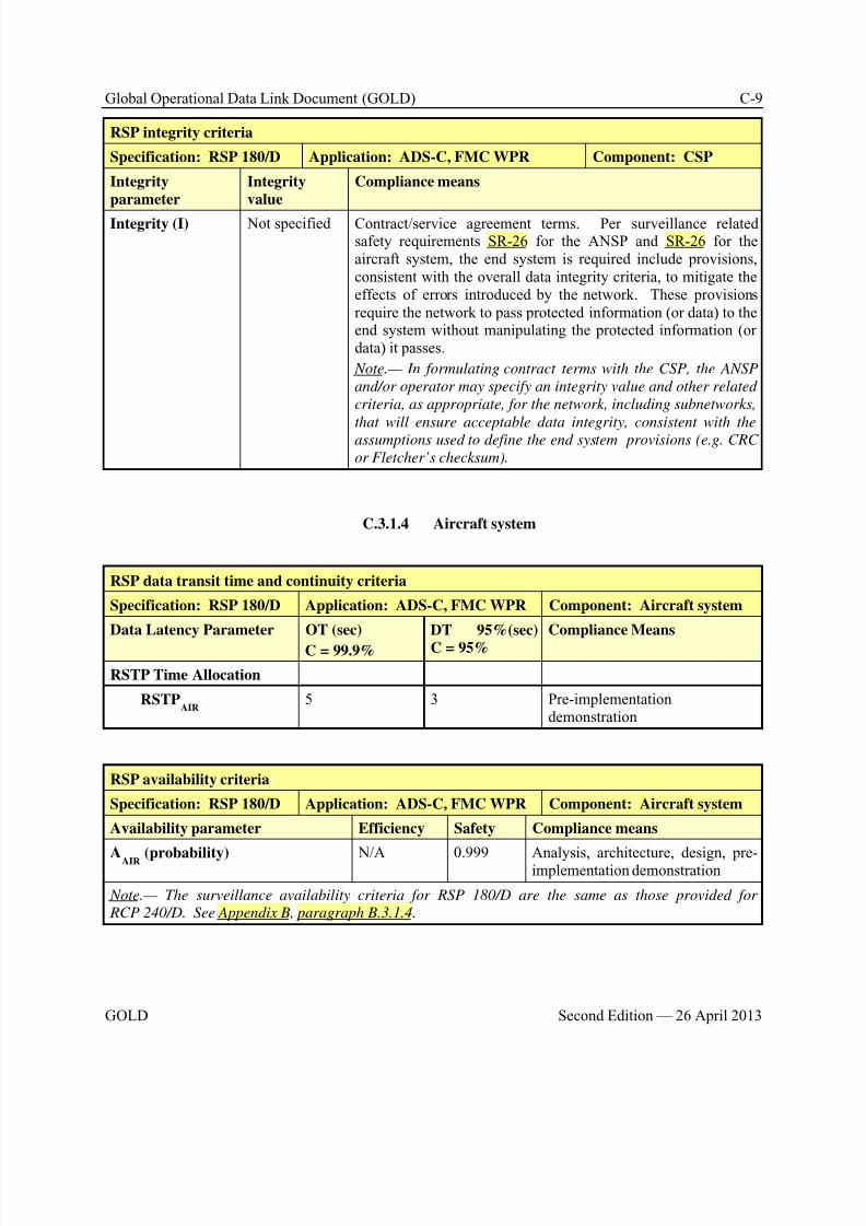
8/9/2019 CPDLC Explained
http://slidepdf.com/reader/full/cpdlc-explained 315/421
Global Operational Data Link Document (GOLD) C-9
GOLD Second Edition — 26 April 2013
RSP integrity criteria
Specification: RSP 180/D Application: ADS-C, FMC WPR Component: CSP
Integrity
parameter
Integrity
value
Compliance means
Integrity (I) Not specified Contract/service agreement terms. Per surveillance relatedsafety requirements SR-26 for the ANSP and SR-26 for theaircraft system, the end system is required include provisions,consistent with the overall data integrity criteria, to mitigate theeffects of errors introduced by the network. These provisionsrequire the network to pass protected information (or data) to theend system without manipulating the protected information (ordata) it passes.
Note.— In formulating contract terms with the CSP, the ANSP
and/or operator may specify an integrity value and other related
criteria, as appropriate, for the network, including subnetworks,
that will ensure acceptable data integrity, consistent with theassumptions used to define the end system provisions (e.g. CRC
or Fletcher’s checksum).
C.3.1.4 Aircraft system
RSP data transit time and continuity criteria
Specification: RSP 180/D Application: ADS-C, FMC WPR Component: Aircraft system
Data Latency Parameter OT (sec)
C = 99.9%
DT 95%(sec)
C = 95%
Compliance Means
RSTP Time Allocation
RSTPAIR
5 3 Pre-implementationdemonstration
RSP availability criteria
Specification: RSP 180/D Application: ADS-C, FMC WPR Component: Aircraft system
Availability parameter Efficiency Safety Compliance means
AAIR (probability) N/A 0.999 Analysis, architecture, design, pre-implementation demonstration
Note.— The surveillance availability criteria for RSP 180/D are the same as those provided for
RCP 240/D. See Appendix B, paragraph B.3.1.4.
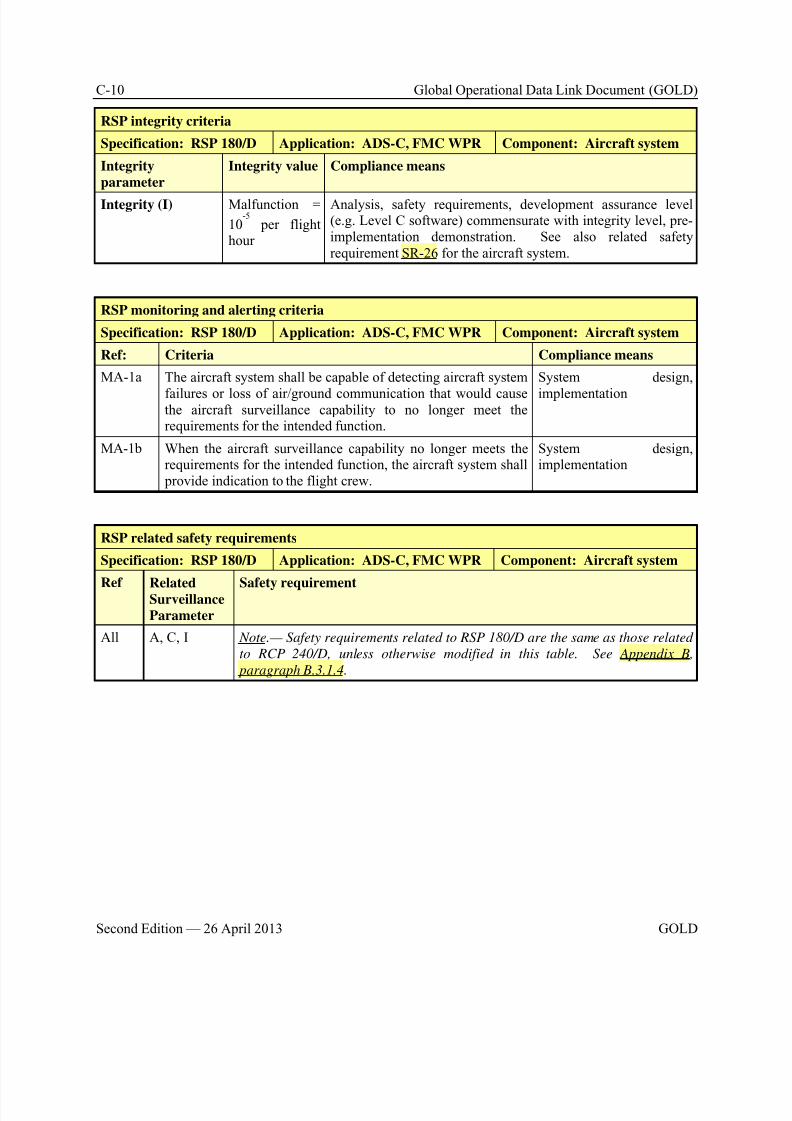
8/9/2019 CPDLC Explained
http://slidepdf.com/reader/full/cpdlc-explained 316/421
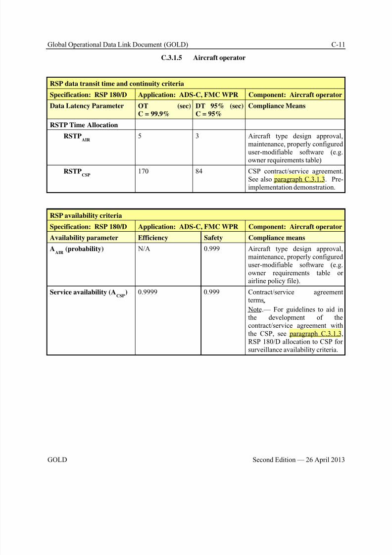
8/9/2019 CPDLC Explained
http://slidepdf.com/reader/full/cpdlc-explained 317/421
Global Operational Data Link Document (GOLD) C-11
GOLD Second Edition — 26 April 2013
C.3.1.5 Aircraft operator
RSP data transit time and continuity criteria
Specification: RSP 180/D Application: ADS-C, FMC WPR Component: Aircraft operatorData Latency Parameter OT (sec)
C = 99.9%DT 95% (sec)C = 95%
Compliance Means
RSTP Time Allocation
RSTPAIR
5 3 Aircraft type design approval,maintenance, properly configureduser-modifiable software (e.g.owner requirements table)
RSTPCSP
170 84 CSP contract/service agreement.See also paragraph C.3.1.3. Pre-implementation demonstration.
RSP availability criteria
Specification: RSP 180/D Application: ADS-C, FMC WPR Component: Aircraft operator
Availability parameter Efficiency Safety Compliance means
AAIR
(probability) N/A 0.999 Aircraft type design approval,maintenance, properly configureduser-modifiable software (e.g.owner requirements table orairline policy file).
Service availability (ACSP) 0.9999 0.999 Contract/service agreementterms.
Note.— For guidelines to aid inthe development of thecontract/service agreement withthe CSP, see paragraph C.3.1.3, RSP 180/D allocation to CSP forsurveillance availability criteria.
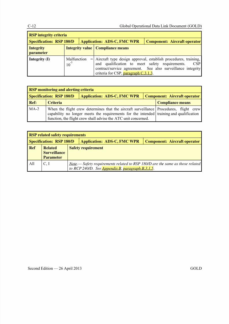
8/9/2019 CPDLC Explained
http://slidepdf.com/reader/full/cpdlc-explained 318/421

8/9/2019 CPDLC Explained
http://slidepdf.com/reader/full/cpdlc-explained 319/421
Global Operational Data Link Document (GOLD) C-13
GOLD Second Edition — 26 April 2013
C.4 RSP 400 specification
RSP specification
RSP specification RSP 400
Airspace specific considerations
Interoperability Specify interoperability criteria (e.g. FANS 1/A)
ATS Function Specify ATS function(s) (e.g. applicable separation standard)
Application Specify the required surveillance capability. FMC WPR or, for ADS-C, specifythe types of contracts required to support the ATS function (e.g. periodic contractat [nn] min, waypoint change event contract, lateral deviation event contract at [n] NM).
Surveillance parameter values
Transit time (sec) Continuity (C) Availability (A) Integrity (I)
OT = 400 C(OT) = 0.999 0.999 Navigation FOM See Note 3.
DT 95% = 300 C(DT 95%) = 0.95 Time at position
accuracy
+/- 1 sec(UTC)
Data integrity Malfunction
= 10-5
perflight hour
Surveillance monitoring and alerting criteria
Ref Criteria
MA-1 The system shall be capable of detecting failures and configuration changes that would
cause the ADS-C or FMC WPR service to no longer meet the surveillance parametervalues for the intended function.
MA-2 When the ADS-C or FMC WPR service can no longer meet the surveillance parametervalues for the intended function, the flight crew and/or the controller shall takeappropriate action.
Notes
Note 1.— Rationale for the criteria provided in this specification can be found in ICAO Annex 11, ICAO
Doc 4444, ICAO Doc 9689, and RTCA DO-306/ED-122.
Note 2.— If changes are made to the system capacity limits, as specified by the airspace requirements,
and the changes cause the system to perform below the surveillance parameter values, this would be
considered a change in system configuration.
Note 3.— The navigation figure of merit (FOM) is specified based on the navigation criteria associatedwith this spec. For example, if RNP 10 is prescribed, then for ADS-C surveillance service, the FOM
level would need to be 3 or higher. In all cases, when the navigation capability no longer meets the
criteria specified for the operation, the flight crew is responsible for reporting the non-compliance to
ATC in accordance with ICAO procedures.

8/9/2019 CPDLC Explained
http://slidepdf.com/reader/full/cpdlc-explained 320/421
C-14 Global Operational Data Link Document (GOLD)
Second Edition — 26 April 2013 GOLD
C.4.1 RSP 400/D allocations
C.4.1.1 General
C.4.1.1.1 The RSP 400/D allocations can be applied to the ADS-C or FMC WPR applications.
C.4.1.2 Air navigation service provider (ANSP)
RSP data transit time and continuity criteria
Specification: RSP 400/D Application: ADS-C, FMC WPR Component: ANSP
Data Latency Parameter OT (sec)
C = 99.9%
DT 95% (sec)
C = 95%
Compliance Means
Delivery Time Value 400 300 Analysis, CSP contract/serviceagreement. See also paragraphC.4.1.3.
RSTP Time Allocation
RSTPATSU
30 15 Pre-implementationdemonstration
RSP availability criteria
Specification: RSP 400/D Application: ADS-C, FMC WPR Component: ANSP
Availability parameter Efficiency Safety Compliance means
Service availability (ACSP
) N/A 0.999 Contract/service agreement terms.
Note.— For guidelines to aid in the
development of the contract/serviceagreement with the CSP, see paragraph
C.4.1.3, RSP 180/D allocation to CSP for
surveillance availability criteria.
Note.— The RSP integrity criteria, monitoring and alerting criteria, and related safety requirements
for RSP 400/D are the same as the criteria provided for RSP 180/D. See paragraph C.3.1.2.
C.4.1.3 Communication service provider (CSP)
Note.— The RSP allocations for the CSP are intended to aid the ANSP and the aircraft operator inthe development of contracts and service agreements.
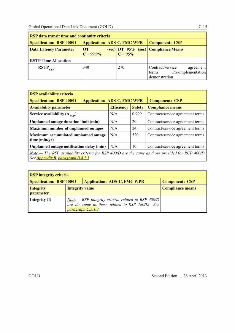
8/9/2019 CPDLC Explained
http://slidepdf.com/reader/full/cpdlc-explained 321/421
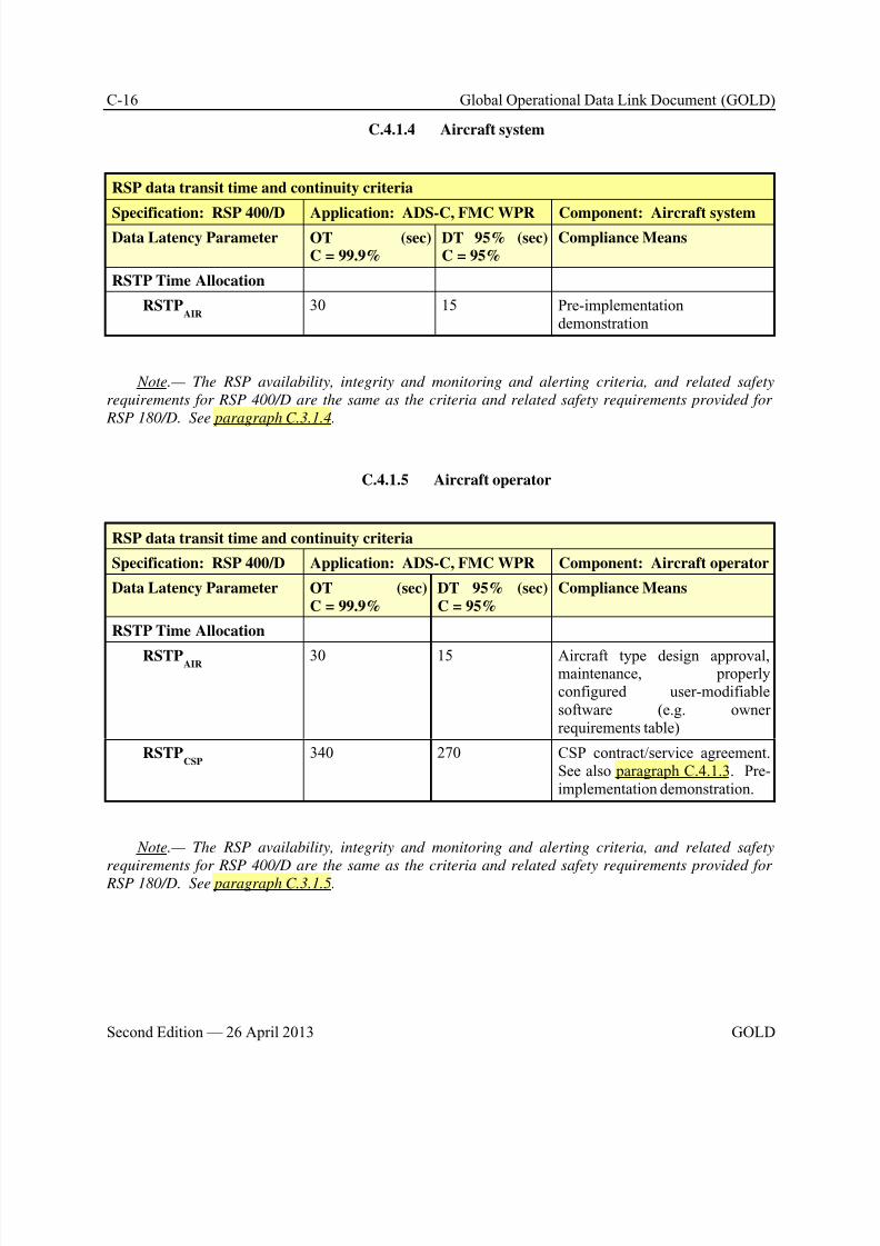
8/9/2019 CPDLC Explained
http://slidepdf.com/reader/full/cpdlc-explained 322/421
8/9/2019 CPDLC Explained
http://slidepdf.com/reader/full/cpdlc-explained 323/421
Global Operational Data Link Document (GOLD) D-1
GOLD Second Edition — 26 April 2013
Appendix D Post-implementation monitoring and corrective action
D.1 General
D.1.1 The ICAO Global Plan calls for the implementation of a performance based system andICAO Annex 11 requires that data link system performance is monitored to verify that an acceptable levelof safety continues to be met. Annex 11 at paragraph 2.2.7.5 states:
“Any significant safety-related change to the ATC system, including the implementation of areduced separation minimum or a new procedure, shall only be effected after a safetyassessment has demonstrated that an acceptable level of safety will be met and users have beenconsulted. When appropriate, the responsible authority shall ensure that adequate provision ismade for post-implementation monitoring to verify that the defined level of safety continues to bemet.”
D.1.2 For continental European airspace, EC Regulation 29/2009 (the DLS IR) stipulates:
“The quality of service of air-ground data link communications should be regularly monitored by
ATS Providers”.D.1.3 It also states:
“ATS providers shall monitor the quality of service of communication services and verify theirconformance with the level of performance required”.
D.1.4 The CPDLC system, data link system (ATN or FANS 1/A) and A/G radio links(SATCOM, VDL M2, etc) must operate successfully as a whole to ensure smooth CPDLC operations andto verify that an acceptable level of safety continues to be met. As such a central function performing theoverall monitoring of normal data link operations, service disruptions and restorations not only at thelevel of communication service provision but also at CPDLC, data link system and A/G radio link level,will be needed to:
• guarantee performance and inter-operability;
• investigate problems;
• share lessons learned.
D.1.5 Without such a central function this may prove difficult to achieve. This function willneed to continue once the data link service is in place to guarantee capacity, performance and inter-operability in the years following successful implementation.
D.1.6 Oversight of the compliance to the Annex 11 requirements is a matter for the States.However, States participate in planning and implementation regional groups (PIRGs), and most use aregional monitoring agency to facilitate monitoring activities within their respective region. Theindividual states/ANSPs will need to provide the data and information and analysis that will portrayregional performance measures. The ANSPs, operators, CSPs, airframe manufacturers, and equipment
suppliers all need to participate in reporting and resolving problems associated among the ANSPs andwith aircraft.
D.1.7 While individual ANSP will develop the data collection mechanisms, monitoring tools,and internal reporting requirements best suiting their own environment, all ANSP should collect andmaintain a database of performance data using the data formats specified in this appendix. Thesedatabases will provide the means to aggregate ADS-C surveillance transit time and CPDLC RCPtransaction time on a regional and global basis.
8/9/2019 CPDLC Explained
http://slidepdf.com/reader/full/cpdlc-explained 324/421
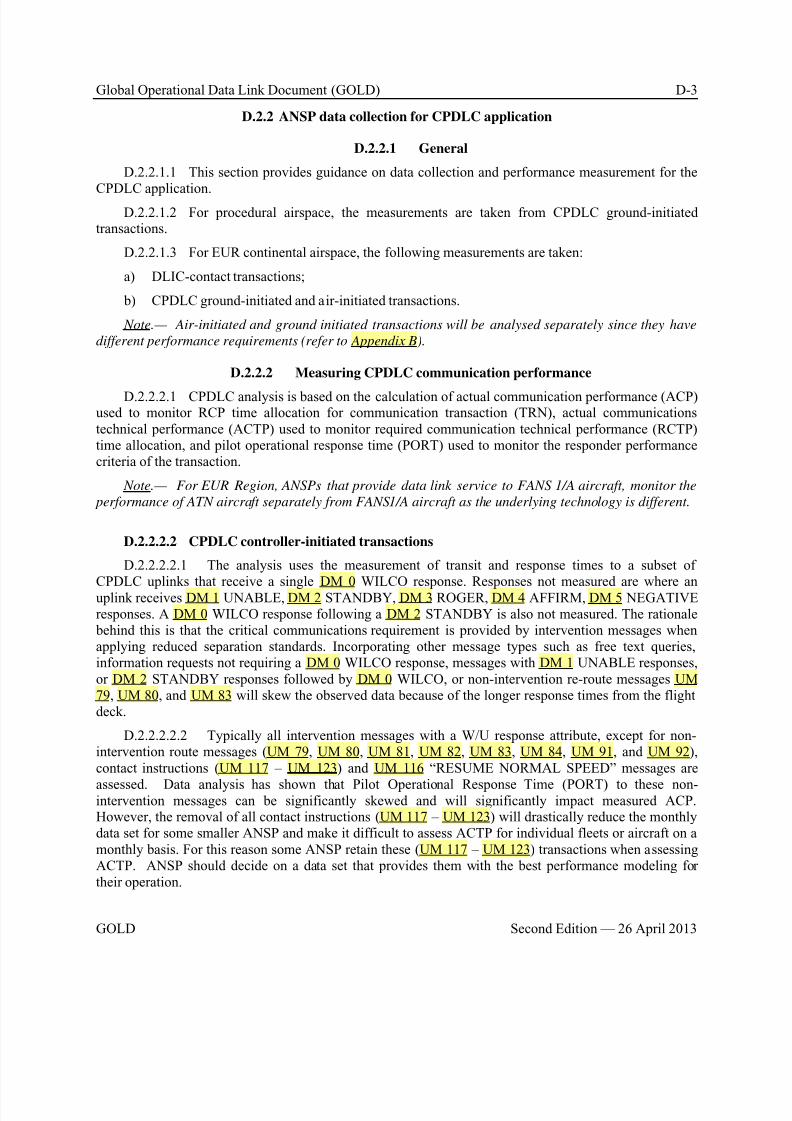
8/9/2019 CPDLC Explained
http://slidepdf.com/reader/full/cpdlc-explained 325/421
Global Operational Data Link Document (GOLD) D-3
GOLD Second Edition — 26 April 2013
D.2.2 ANSP data collection for CPDLC application
D.2.2.1 General
D.2.2.1.1 This section provides guidance on data collection and performance measurement for theCPDLC application.
D.2.2.1.2 For procedural airspace, the measurements are taken from CPDLC ground-initiatedtransactions.
D.2.2.1.3 For EUR continental airspace, the following measurements are taken:
a) DLIC-contact transactions;
b) CPDLC ground-initiated and air-initiated transactions.
Note.— Air-initiated and ground initiated transactions will be analysed separately since they have
different performance requirements (refer to Appendix B).
D.2.2.2 Measuring CPDLC communication performance
D.2.2.2.1 CPDLC analysis is based on the calculation of actual communication performance (ACP)used to monitor RCP time allocation for communication transaction (TRN), actual communicationstechnical performance (ACTP) used to monitor required communication technical performance (RCTP)time allocation, and pilot operational response time (PORT) used to monitor the responder performancecriteria of the transaction.
Note.— For EUR Region, ANSPs that provide data link service to FANS 1/A aircraft, monitor the
performance of ATN aircraft separately from FANS1/A aircraft as the underlying technology is different.
D.2.2.2.2 CPDLC controller-initiated transactions
D.2.2.2.2.1 The analysis uses the measurement of transit and response times to a subset ofCPDLC uplinks that receive a single DM 0 WILCO response. Responses not measured are where anuplink receives DM 1 UNABLE, DM 2 STANDBY, DM 3 ROGER, DM 4 AFFIRM, DM 5 NEGATIVEresponses. A DM 0 WILCO response following a DM 2 STANDBY is also not measured. The rationale behind this is that the critical communications requirement is provided by intervention messages whenapplying reduced separation standards. Incorporating other message types such as free text queries,information requests not requiring a DM 0 WILCO response, messages with DM 1 UNABLE responses,or DM 2 STANDBY responses followed by DM 0 WILCO, or non-intervention re-route messages UM79, UM 80, and UM 83 will skew the observed data because of the longer response times from the flightdeck.
D.2.2.2.2.2 Typically all intervention messages with a W/U response attribute, except for non-intervention route messages (UM 79, UM 80, UM 81, UM 82, UM 83, UM 84, UM 91, and UM 92),contact instructions (UM 117 – UM 123) and UM 116 “RESUME NORMAL SPEED” messages are
assessed. Data analysis has shown that Pilot Operational Response Time (PORT) to these non-intervention messages can be significantly skewed and will significantly impact measured ACP.However, the removal of all contact instructions (UM 117 – UM 123) will drastically reduce the monthlydata set for some smaller ANSP and make it difficult to assess ACTP for individual fleets or aircraft on amonthly basis. For this reason some ANSP retain these (UM 117 – UM 123) transactions when assessingACTP. ANSP should decide on a data set that provides them with the best performance modeling fortheir operation.
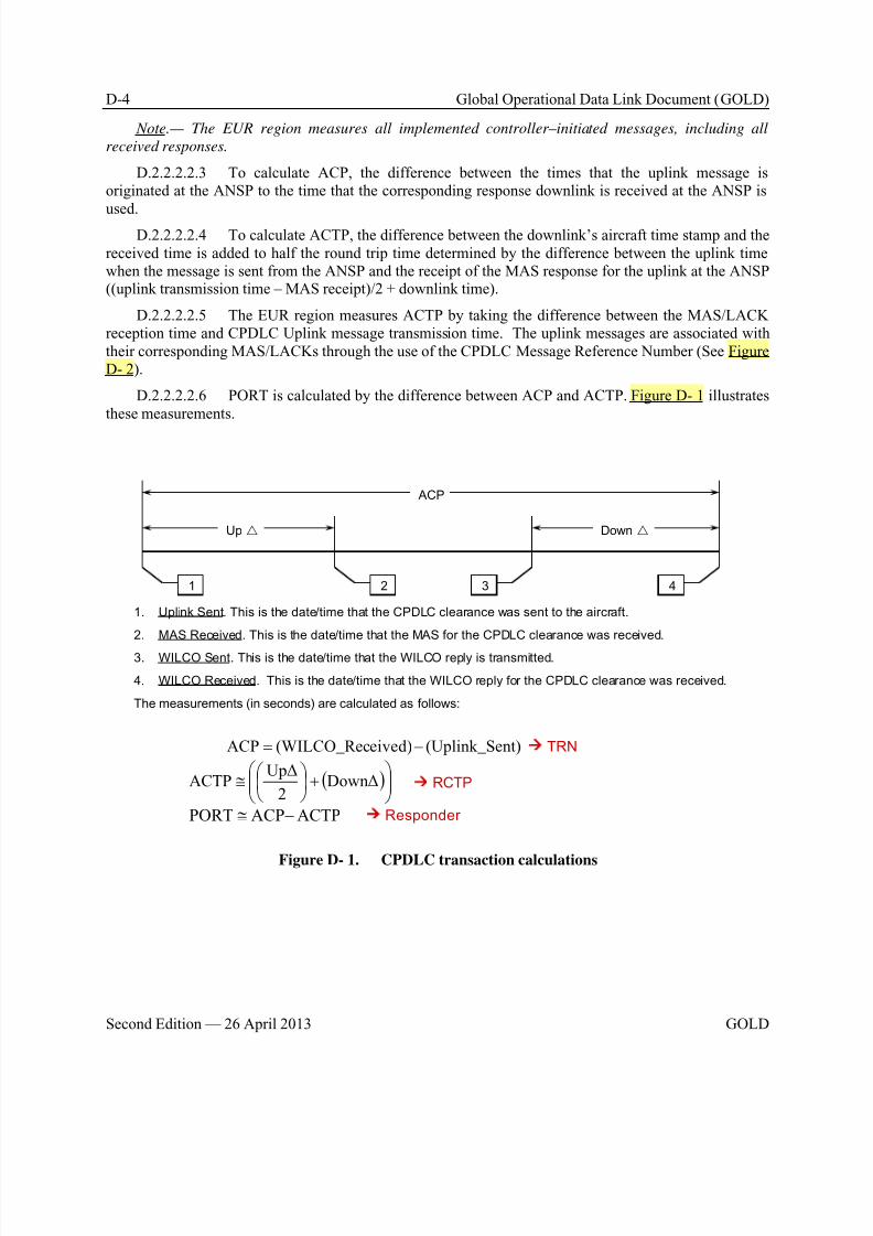
8/9/2019 CPDLC Explained
http://slidepdf.com/reader/full/cpdlc-explained 326/421
D-4 Global Operational Data Link Document (GOLD)
Second Edition — 26 April 2013 GOLD
Note.— The EUR region measures all implemented controller–initiated messages, including all
received responses.
D.2.2.2.2.3 To calculate ACP, the difference between the times that the uplink message isoriginated at the ANSP to the time that the corresponding response downlink is received at the ANSP is
used.D.2.2.2.2.4 To calculate ACTP, the difference between the downlink’s aircraft time stamp and the
received time is added to half the round trip time determined by the difference between the uplink timewhen the message is sent from the ANSP and the receipt of the MAS response for the uplink at the ANSP((uplink transmission time – MAS receipt)/2 + downlink time).
D.2.2.2.2.5 The EUR region measures ACTP by taking the difference between the MAS/LACKreception time and CPDLC Uplink message transmission time. The uplink messages are associated withtheir corresponding MAS/LACKs through the use of the CPDLC Message Reference Number (See FigureD- 2).
D.2.2.2.2.6 PORT is calculated by the difference between ACP and ACTP. Figure D- 1 illustratesthese measurements.
1 42 3
ACP
Up Down
nt)(Uplink_Seeived)(WILCO_RecACP −=
( )
+
≅ DownΔ
2
UpΔACTP
ACTPACPPORT −≅
1. Uplink Sent. This is the date/time that the CPDLC clearance was sent to the aircraft.
2. MAS Received. This is the date/time that the MAS for the CPDLC clearance was received.
3. WILCO Sent. This is the date/time that the WILCO reply is transmitted.
4. WILCO Received. This is the date/time that the WILCO reply for the CPDLC clearance was received.
The measurements (in seconds) are calculated as follows:
TRN
RCTP
Responder
Figure D- 1. CPDLC transaction calculations
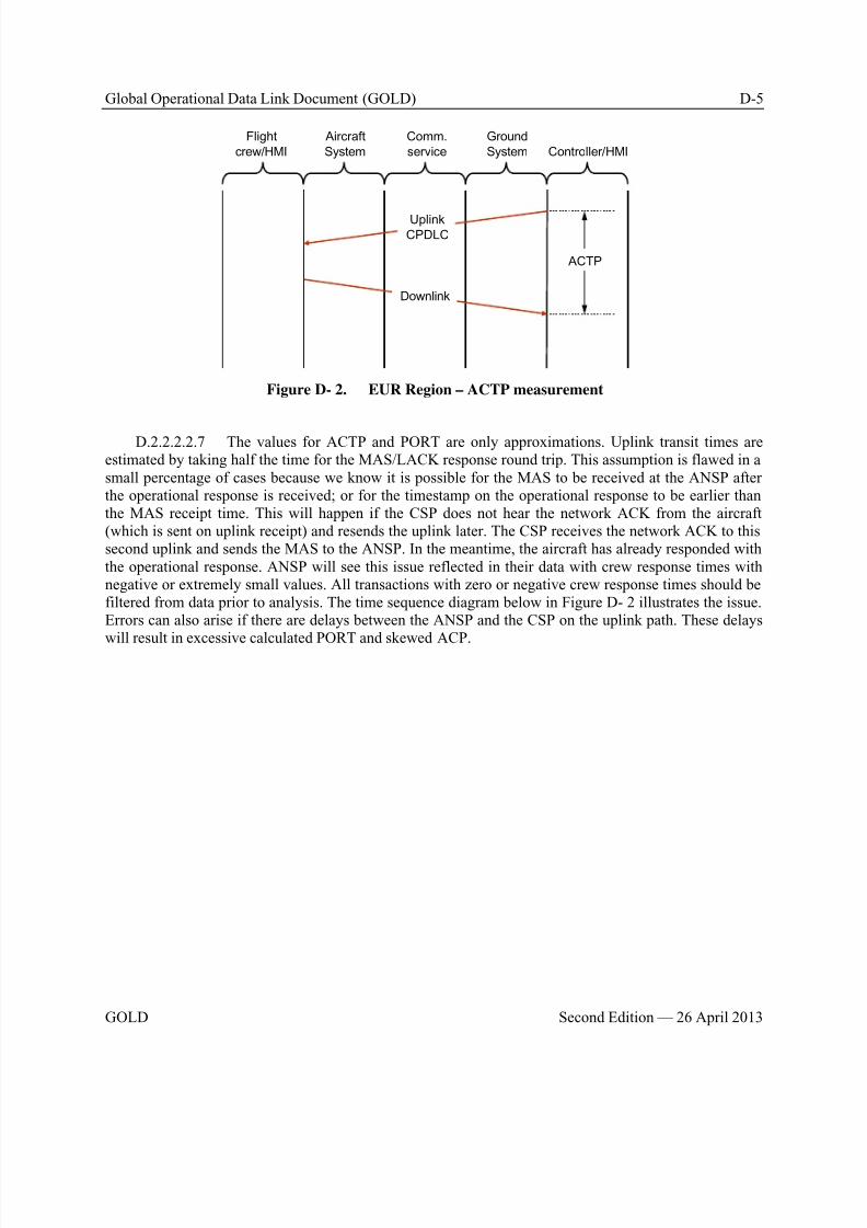
8/9/2019 CPDLC Explained
http://slidepdf.com/reader/full/cpdlc-explained 327/421
Global Operational Data Link Document (GOLD) D-5
GOLD Second Edition — 26 April 2013
Aircraft
System
Flight
crew/HMI
Comm.
service Controller/HMI
Ground
System
ACTP
UplinkCPDLC
Downlink
Figure D- 2. EUR Region – ACTP measurement
D.2.2.2.2.7 The values for ACTP and PORT are only approximations. Uplink transit times areestimated by taking half the time for the MAS/LACK response round trip. This assumption is flawed in asmall percentage of cases because we know it is possible for the MAS to be received at the ANSP afterthe operational response is received; or for the timestamp on the operational response to be earlier thanthe MAS receipt time. This will happen if the CSP does not hear the network ACK from the aircraft(which is sent on uplink receipt) and resends the uplink later. The CSP receives the network ACK to thissecond uplink and sends the MAS to the ANSP. In the meantime, the aircraft has already responded withthe operational response. ANSP will see this issue reflected in their data with crew response times withnegative or extremely small values. All transactions with zero or negative crew response times should befiltered from data prior to analysis. The time sequence diagram below in Figure D- 2 illustrates the issue.Errors can also arise if there are delays between the ANSP and the CSP on the uplink path. These delays
will result in excessive calculated PORT and skewed ACP.
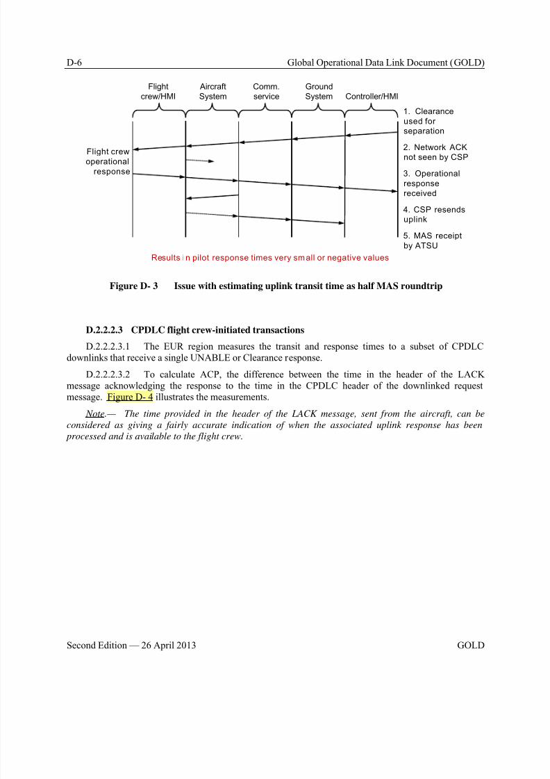
8/9/2019 CPDLC Explained
http://slidepdf.com/reader/full/cpdlc-explained 328/421
D-6 Global Operational Data Link Document (GOLD)
Second Edition — 26 April 2013 GOLD
Aircraft
System
Flight
crew/HMI
Comm.
service Controller/HMI
Ground
System
Flight crew
operational
response
1. Clearance
used for
separation
5. MAS receipt
by ATSU
2. Network ACK
not seen by CSP
3. Operational
response
received
4. CSP resends
uplink
Results i n pilot response times very small or negative values
Figure D- 3 Issue with estimating uplink transit time as half MAS roundtrip
D.2.2.2.3 CPDLC flight crew-initiated transactions
D.2.2.2.3.1 The EUR region measures the transit and response times to a subset of CPDLCdownlinks that receive a single UNABLE or Clearance response.
D.2.2.2.3.2 To calculate ACP, the difference between the time in the header of the LACKmessage acknowledging the response to the time in the CPDLC header of the downlinked requestmessage. Figure D- 4 illustrates the measurements.
Note.— The time provided in the header of the LACK message, sent from the aircraft, can be
considered as giving a fairly accurate indication of when the associated uplink response has been
processed and is available to the flight crew.
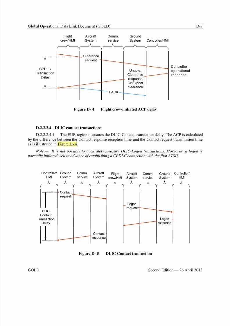
8/9/2019 CPDLC Explained
http://slidepdf.com/reader/full/cpdlc-explained 329/421
Global Operational Data Link Document (GOLD) D-7
GOLD Second Edition — 26 April 2013
Aircraft
System
Flight
crew/HMI
Comm.
service Controller/HMI
Ground
System
Clearancerequest
CPDLC
Transaction
Delay
LACK
Unable,
Clearance
response
Or Expect
clearance
Controller
operational
response
Figure D- 4 Flight crew-initiated ACP delay
D.2.2.2.4 DLIC contact transactions
D.2.2.2.4.1 The EUR region measures the DLIC-Contact transaction delay. The ACP is calculated by the difference between the Contact response reception time and the Contact request transmission timeas is illustrated in Figure D- 4.
Note.— It is not possible to accurately measure DLIC-Logon transactions. Moreover, a logon is
normally initiated well in advance of establishing a CPDLC connection with the first ATSU.
Aircraft
System
Flight
crew/HMI
Comm.
service
Controller/
HMIGround
System
Aircraft
System
Comm.
service
Ground
System
Controller/
HMI
Contact
request
Contact
response
Logon
request
Logon
response
DLIC
Contact
Transaction
Delay
Figure D- 5 DLIC Contact transaction

8/9/2019 CPDLC Explained
http://slidepdf.com/reader/full/cpdlc-explained 330/421
D-8 Global Operational Data Link Document (GOLD)
Second Edition — 26 April 2013 GOLD
D.2.2.3 Recording the data points for each CPDLC transaction
D.2.2.3.1 The following data points in Table D-1 are recommended as the minimum set that should be extracted from ANSP data link system recordings to enable RCP analysis and provide sufficientinformation for problem analysis. This does not preclude individual ANSP from extracting additional data
points for their own analysis requirements and some possibilities are listed below. To obtain these data points ANSP should note that they will require additional database information to enable the aircraft typeand operator to be obtained by correlation to the aircraft registration extracted from the data linkrecordings. All of the other data points are extracted from either the ACARS or ATN B1 header or theCPDLC application message.
Table D-1 CPDLC data collection points
Ref Label Description and/or remarks
1 ANSP The four letter ICAO designator of the facility (e.g. NZZO).
2 Aircraft
registration(FANS 1/A)
The aircraft registration in ICAO Doc 4444 Format (no hyphens, packing
dots, etc.) (e.g. N104UA). Note.— Extracted from ACARS header or application message.
2 Aircraft address(ATNB1)
The 24 bit address in ICAO Doc4444 Format (alphanumerical character, insix hexadecimals)
Note.— Extracted from CM application message.
3 Aircraft typedesignator
The ICAO aircraft type designator (e.g. B744).
Note.— Extracted from ANSP database using aircraft registration as key.
4 Operatordesignator
The ICAO designator for the aircraft operating agency (e.g. UAL).
Note.— Extracted from ANSP database using aircraft registration as key.
5 Date In YYYYMMDD format (e.g. 20081114).
Note.— Extracted from ANSP system data recording time stamp,synchronized to within 1 second of Universal Time Coordinated (UTC).
6 MAS RGS Designator of the RGS that MAS downlink was received from (e.g. POR1).
Note.— This is a 3 or 4 letter designator extracted from the ACARS header
DT line.
7 OPS RGS Designator of the RGS that the operational response was received from (e.g.AKL1).
Note.— This is a 3 or 4 letter designator extracted from the ACARS header
DT line.
8 Uplink time The timestamp on the uplink CPDLC message sent by the ANSP inHH:MM:SS format (e.g. 03:43:25).
Note.— Extracted from ANSP system data recording time stamp,
synchronized to within 1 second of UTC.
9 MAS/LACKreceipt time
The ANSP timestamp on receipt of the MAS/LACK in HH:MM:SS format(e.g. 03:43:35).
Note.— Extracted from ANSP system data recording time stamp,
synchronized to within 1 second of UTC.
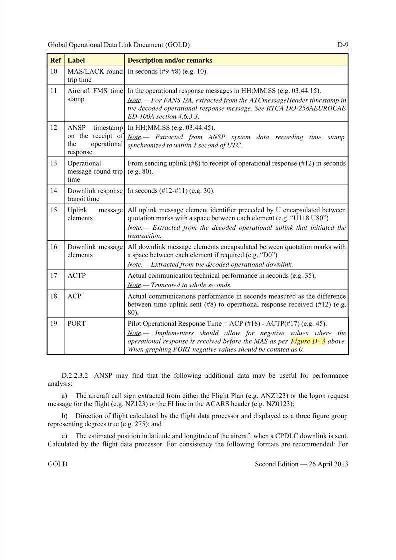
8/9/2019 CPDLC Explained
http://slidepdf.com/reader/full/cpdlc-explained 331/421
Global Operational Data Link Document (GOLD) D-9
GOLD Second Edition — 26 April 2013
Ref Label Description and/or remarks
10 MAS/LACK roundtrip time
In seconds (#9-#8) (e.g. 10).
11 Aircraft FMS time
stamp
In the operational response messages in HH:MM:SS (e.g. 03:44:15).
Note.— For FANS 1/A, extracted from the ATCmessageHeader timestamp inthe decoded operational response message. See RTCA DO-258AEUROCAE
ED-100A section 4.6.3.3.
12 ANSP timestampon the receipt ofthe operationalresponse
In HH:MM:SS (e.g. 03:44:45).
Note.— Extracted from ANSP system data recording time stamp,
synchronized to within 1 second of UTC.
13 Operationalmessage round triptime
From sending uplink (#8) to receipt of operational response (#12) in seconds(e.g. 80).
14 Downlink response
transit time
In seconds (#12-#11) (e.g. 30).
15 Uplink messageelements
All uplink message element identifier preceded by U encapsulated betweenquotation marks with a space between each element (e.g. “U118 U80”)
Note.— Extracted from the decoded operational uplink that initiated the
transaction.
16 Downlink messageelements
All downlink message elements encapsulated between quotation marks witha space between each element if required (e.g. “D0”)
Note.— Extracted from the decoded operational downlink.
17 ACTP Actual communication technical performance in seconds (e.g. 35).
Note.— Truncated to whole seconds.
18 ACP Actual communications performance in seconds measured as the difference between time uplink sent (#8) to operational response received (#12) (e.g.80).
19 PORT Pilot Operational Response Time = ACP (#18) - ACTP(#17) (e.g. 45).
Note.— Implementers should allow for negative values where the
operational response is received before the MAS as per Figure D- 3 above.
When graphing PORT negative values should be counted as 0.
D.2.2.3.2 ANSP may find that the following additional data may be useful for performanceanalysis:
a) The aircraft call sign extracted from either the Flight Plan (e.g. ANZ123) or the logon requestmessage for the flight (e.g. NZ123) or the FI line in the ACARS header (e.g. NZ0123);
b) Direction of flight calculated by the flight data processor and displayed as a three figure grouprepresenting degrees true (e.g. 275); and
c) The estimated position in latitude and longitude of the aircraft when a CPDLC downlink is sent.Calculated by the flight data processor. For consistency the following formats are recommended: For
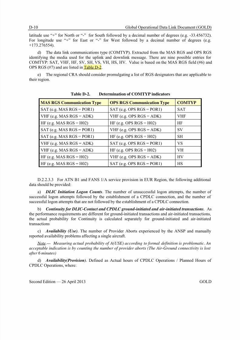
8/9/2019 CPDLC Explained
http://slidepdf.com/reader/full/cpdlc-explained 332/421
D-10 Global Operational Data Link Document (GOLD)
Second Edition — 26 April 2013 GOLD
latitude use “+” for North or “-” for South followed by a decimal number of degrees (e.g. -33.456732).For longitude use “+” for East or “-” for West followed by a decimal number of degrees (e.g.+173.276554).
d) The data link communications type (COMTYP). Extracted from the MAS RGS and OPS RGS
identifying the media used for the uplink and downlink message. There are nine possible entries forCOMTYP: SAT, VHF, HF, SV, SH, VS, VH, HS, HV. Value is based on the MAS RGS field (#6) andOPS RGS (#7) and are listed in Table D-2.
e) The regional CRA should consider promulgating a list of RGS designators that are applicable totheir region.
Table D-2. Determination of COMTYP indicators
MAS RGS Communication Type OPS RGS Communication Type COMTYP
SAT (e.g. MAS RGS = POR1) SAT (e.g. OPS RGS = POR1) SAT
VHF (e.g. MAS RGS = ADK) VHF (e.g. OPS RGS = ADK) VHF
HF (e.g. MAS RGS = H02) HF (e.g. OPS RGS = H02) HF
SAT (e.g. MAS RGS = POR1) VHF (e.g. OPS RGS = ADK) SV
SAT (e.g. MAS RGS = POR1) HF (e.g. OPS RGS = H02) SH
VHF (e.g. MAS RGS = ADK) SAT (e.g. OPS RGS = POR1) VS
VHF (e.g. MAS RGS = ADK) HF (e.g. OPS RGS = H02) VH
HF (e.g. MAS RGS = H02) VHF (e.g. OPS RGS = ADK) HV
HF (e.g. MAS RGS = H02) SAT (e.g. OPS RGS = POR1) HS
D.2.2.3.3 For ATN B1 and FANS 1/A service provision in EUR Region, the following additionaldata should be provided:
a) DLIC Initiation Logon Counts. The number of unsuccessful logon attempts, the number ofsuccessful logon attempts followed by the establishment of a CPDLC connection, and the number ofsuccessful logon attempts that are not followed by the establishment of a CPDLC connection.
b) Continuity for DLIC-Contact and CPDLC ground-initiated and air-initiated transactions. Asthe performance requirements are different for ground-initiated transactions and air-initiated transactions,the actual probability for Continuity is calculated separately for ground-initiated and air-initiatedtransactions
c) Availability (Use). The number of Provider Aborts experienced by the ANSP and manuallyreported availability problems affecting a single aircraft.
Note.— Measuring actual probability of A(USE) according to formal definition is problematic. An
acceptable indication is by counting the number of provider aborts (The Air-Ground connectivity is lost
after 6 minutes)
d) Availability(Provision). Defined as Actual hours of CPDLC Operations / Planned Hours ofCPDLC Operations, where:
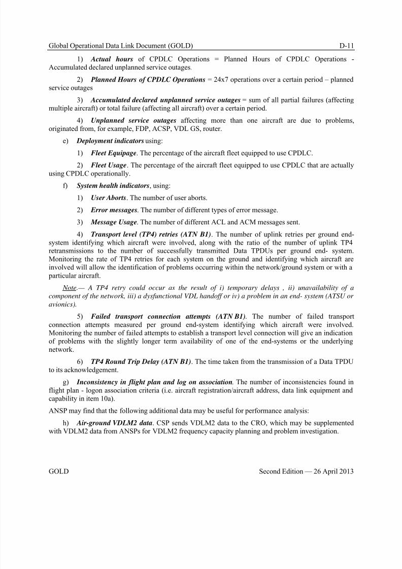
8/9/2019 CPDLC Explained
http://slidepdf.com/reader/full/cpdlc-explained 333/421
Global Operational Data Link Document (GOLD) D-11
GOLD Second Edition — 26 April 2013
1) Actual hours of CPDLC Operations = Planned Hours of CPDLC Operations -Accumulated declared unplanned service outages.
2) Planned Hours of CPDLC Operations = 24x7 operations over a certain period – plannedservice outages
3) Accumulated declared unplanned service outages = sum of all partial failures (affectingmultiple aircraft) or total failure (affecting all aircraft) over a certain period.
4) Unplanned service outages affecting more than one aircraft are due to problems,originated from, for example, FDP, ACSP, VDL GS, router.
e) Deployment indicators using:
1) Fleet Equipage. The percentage of the aircraft fleet equipped to use CPDLC.
2) Fleet Usage. The percentage of the aircraft fleet equipped to use CPDLC that are actuallyusing CPDLC operationally.
f) System health indicators, using:
1) User Aborts. The number of user aborts.2) Error messages. The number of different types of error message.
3) Message Usage. The number of different ACL and ACM messages sent.
4) Transport level (TP4) retries (ATN B1). The number of uplink retries per ground end-system identifying which aircraft were involved, along with the ratio of the number of uplink TP4retransmissions to the number of successfully transmitted Data TPDUs per ground end- system.Monitoring the rate of TP4 retries for each system on the ground and identifying which aircraft areinvolved will allow the identification of problems occurring within the network/ground system or with a particular aircraft.
Note.— A TP4 retry could occur as the result of i) temporary delays , ii) unavailability of a
component of the network, iii) a dysfunctional VDL handoff or iv) a problem in an end- system (ATSU oravionics).
5) Failed transport connection attempts (ATN B1). The number of failed transportconnection attempts measured per ground end-system identifying which aircraft were involved.Monitoring the number of failed attempts to establish a transport level connection will give an indicationof problems with the slightly longer term availability of one of the end-systems or the underlyingnetwork.
6) TP4 Round Trip Delay (ATN B1). The time taken from the transmission of a Data TPDUto its acknowledgement.
g) Inconsistency in flight plan and log on association. The number of inconsistencies found inflight plan - logon association criteria (i.e. aircraft registration/aircraft address, data link equipment and
capability in item 10a).
ANSP may find that the following additional data may be useful for performance analysis:
h) Air-ground VDLM2 data. CSP sends VDLM2 data to the CRO, which may be supplementedwith VDLM2 data from ANSPs for VDLM2 frequency capacity planning and problem investigation.
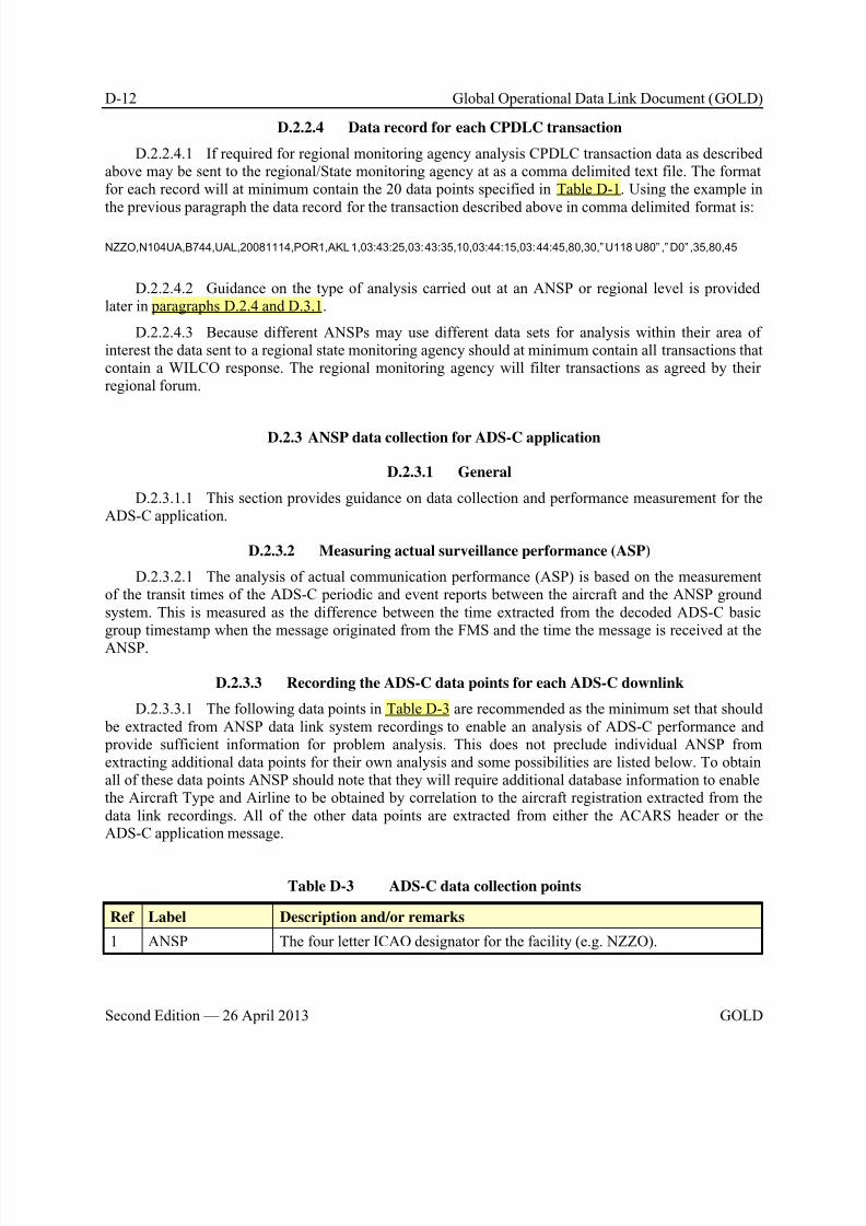
8/9/2019 CPDLC Explained
http://slidepdf.com/reader/full/cpdlc-explained 334/421
D-12 Global Operational Data Link Document (GOLD)
Second Edition — 26 April 2013 GOLD
D.2.2.4 Data record for each CPDLC transaction
D.2.2.4.1 If required for regional monitoring agency analysis CPDLC transaction data as describedabove may be sent to the regional/State monitoring agency at as a comma delimited text file. The formatfor each record will at minimum contain the 20 data points specified in Table D-1. Using the example in
the previous paragraph the data record for the transaction described above in comma delimited format is:
NZZO,N104UA,B744,UAL,20081114,POR1,AKL1,03:43:25,03:43:35,10,03:44:15,03:44:45,80,30,” U118 U80” ,” D0” ,35,80,45
D.2.2.4.2 Guidance on the type of analysis carried out at an ANSP or regional level is providedlater in paragraphs D.2.4 and D.3.1.
D.2.2.4.3 Because different ANSPs may use different data sets for analysis within their area ofinterest the data sent to a regional state monitoring agency should at minimum contain all transactions thatcontain a WILCO response. The regional monitoring agency will filter transactions as agreed by theirregional forum.
D.2.3 ANSP data collection for ADS-C application
D.2.3.1 General
D.2.3.1.1 This section provides guidance on data collection and performance measurement for theADS-C application.
D.2.3.2 Measuring actual surveillance performance (ASP)
D.2.3.2.1 The analysis of actual communication performance (ASP) is based on the measurementof the transit times of the ADS-C periodic and event reports between the aircraft and the ANSP groundsystem. This is measured as the difference between the time extracted from the decoded ADS-C basicgroup timestamp when the message originated from the FMS and the time the message is received at the
ANSP.
D.2.3.3 Recording the ADS-C data points for each ADS-C downlink
D.2.3.3.1 The following data points in Table D-3 are recommended as the minimum set that should be extracted from ANSP data link system recordings to enable an analysis of ADS-C performance and provide sufficient information for problem analysis. This does not preclude individual ANSP fromextracting additional data points for their own analysis and some possibilities are listed below. To obtainall of these data points ANSP should note that they will require additional database information to enablethe Aircraft Type and Airline to be obtained by correlation to the aircraft registration extracted from thedata link recordings. All of the other data points are extracted from either the ACARS header or theADS-C application message.
Table D-3 ADS-C data collection points
Ref Label Description and/or remarks
1 ANSP The four letter ICAO designator for the facility (e.g. NZZO).
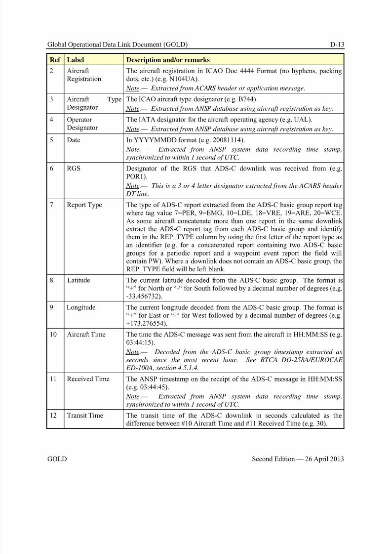
8/9/2019 CPDLC Explained
http://slidepdf.com/reader/full/cpdlc-explained 335/421
Global Operational Data Link Document (GOLD) D-13
GOLD Second Edition — 26 April 2013
Ref Label Description and/or remarks
2 AircraftRegistration
The aircraft registration in ICAO Doc 4444 Format (no hyphens, packingdots, etc.) (e.g. N104UA).
Note.— Extracted from ACARS header or application message.
3 Aircraft TypeDesignator
The ICAO aircraft type designator (e.g. B744).
Note.— Extracted from ANSP database using aircraft registration as key.
4 OperatorDesignator
The IATA designator for the aircraft operating agency (e.g. UAL).
Note.— Extracted from ANSP database using aircraft registration as key.
5 Date In YYYYMMDD format (e.g. 20081114).
Note.— Extracted from ANSP system data recording time stamp,
synchronized to within 1 second of UTC.
6 RGS Designator of the RGS that ADS-C downlink was received from (e.g.POR1).
Note.— This is a 3 or 4 letter designator extracted from the ACARS header
DT line.
7 Report Type The type of ADS-C report extracted from the ADS-C basic group report tagwhere tag value 7=PER, 9=EMG, 10=LDE, 18=VRE, 19=ARE, 20=WCE.As some aircraft concatenate more than one report in the same downlinkextract the ADS-C report tag from each ADS-C basic group and identifythem in the REP_TYPE column by using the first letter of the report type asan identifier (e.g. for a concatenated report containing two ADS-C basicgroups for a periodic report and a waypoint event report the field willcontain PW). Where a downlink does not contain an ADS-C basic group, theREP_TYPE field will be left blank.
8 Latitude The current latitude decoded from the ADS-C basic group. The format is
“+” for North or “-“ for South followed by a decimal number of degrees (e.g.-33.456732).
9 Longitude The current longitude decoded from the ADS-C basic group. The format is“+” for East or “-“ for West followed by a decimal number of degrees (e.g.+173.276554).
10 Aircraft Time The time the ADS-C message was sent from the aircraft in HH:MM:SS (e.g.03:44:15).
Note.— Decoded from the ADS-C basic group timestamp extracted as
seconds since the most recent hour. See RTCA DO-258A/EUROCAE
ED-100A, section 4.5.1.4.
11 Received Time The ANSP timestamp on the receipt of the ADS-C message in HH:MM:SS
(e.g. 03:44:45). Note.— Extracted from ANSP system data recording time stamp,
synchronized to within 1 second of UTC.
12 Transit Time The transit time of the ADS-C downlink in seconds calculated as thedifference between #10 Aircraft Time and #11 Received Time (e.g. 30).
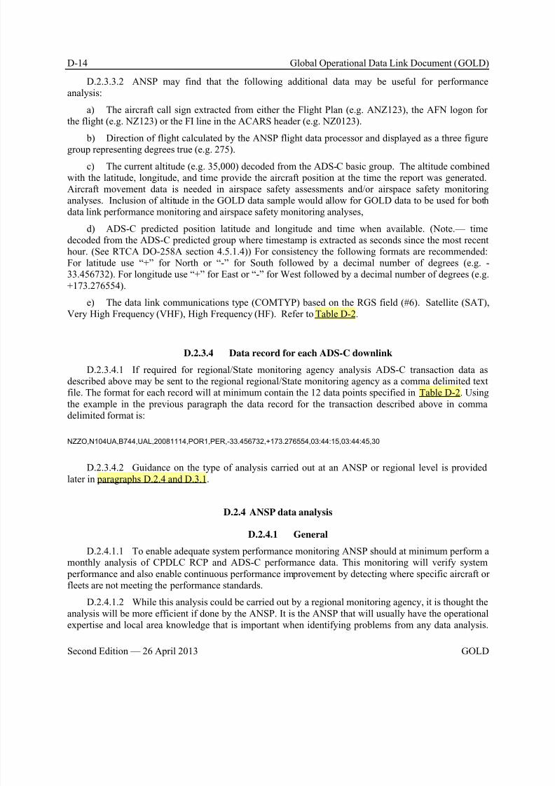
8/9/2019 CPDLC Explained
http://slidepdf.com/reader/full/cpdlc-explained 336/421
D-14 Global Operational Data Link Document (GOLD)
Second Edition — 26 April 2013 GOLD
D.2.3.3.2 ANSP may find that the following additional data may be useful for performanceanalysis:
a) The aircraft call sign extracted from either the Flight Plan (e.g. ANZ123), the AFN logon forthe flight (e.g. NZ123) or the FI line in the ACARS header (e.g. NZ0123).
b) Direction of flight calculated by the ANSP flight data processor and displayed as a three figuregroup representing degrees true (e.g. 275).
c) The current altitude (e.g. 35,000) decoded from the ADS-C basic group. The altitude combinedwith the latitude, longitude, and time provide the aircraft position at the time the report was generated.Aircraft movement data is needed in airspace safety assessments and/or airspace safety monitoringanalyses. Inclusion of altitude in the GOLD data sample would allow for GOLD data to be used for bothdata link performance monitoring and airspace safety monitoring analyses,
d) ADS-C predicted position latitude and longitude and time when available. (Note.— timedecoded from the ADS-C predicted group where timestamp is extracted as seconds since the most recenthour. (See RTCA DO-258A section 4.5.1.4)) For consistency the following formats are recommended:For latitude use “+” for North or “-” for South followed by a decimal number of degrees (e.g. -
33.456732). For longitude use “+” for East or “-” for West followed by a decimal number of degrees (e.g.+173.276554).
e) The data link communications type (COMTYP) based on the RGS field (#6). Satellite (SAT),Very High Frequency (VHF), High Frequency (HF). Refer to Table D-2.
D.2.3.4 Data record for each ADS-C downlink
D.2.3.4.1 If required for regional/State monitoring agency analysis ADS-C transaction data asdescribed above may be sent to the regional regional/State monitoring agency as a comma delimited textfile. The format for each record will at minimum contain the 12 data points specified in Table D-2. Usingthe example in the previous paragraph the data record for the transaction described above in comma
delimited format is:
NZZO,N104UA,B744,UAL,20081114,POR1,PER,-33.456732,+173.276554,03:44:15,03:44:45,30
D.2.3.4.2 Guidance on the type of analysis carried out at an ANSP or regional level is providedlater in paragraphs D.2.4 and D.3.1.
D.2.4 ANSP data analysis
D.2.4.1 General
D.2.4.1.1 To enable adequate system performance monitoring ANSP should at minimum perform amonthly analysis of CPDLC RCP and ADS-C performance data. This monitoring will verify system performance and also enable continuous performance improvement by detecting where specific aircraft orfleets are not meeting the performance standards.
D.2.4.1.2 While this analysis could be carried out by a regional monitoring agency, it is thought theanalysis will be more efficient if done by the ANSP. It is the ANSP that will usually have the operationalexpertise and local area knowledge that is important when identifying problems from any data analysis.
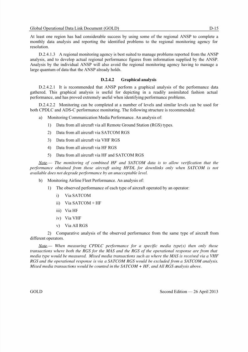
8/9/2019 CPDLC Explained
http://slidepdf.com/reader/full/cpdlc-explained 337/421
Global Operational Data Link Document (GOLD) D-15
GOLD Second Edition — 26 April 2013
At least one region has had considerable success by using some of the regional ANSP to complete amonthly data analysis and reporting the identified problems to the regional monitoring agency forresolution.
D.2.4.1.3 A regional monitoring agency is best suited to manage problems reported from the ANSP
analysis, and to develop actual regional performance figures from information supplied by the ANSP.Analysis by the individual ANSP will also avoid the regional monitoring agency having to manage alarge quantum of data that the ANSP already holds.
D.2.4.2 Graphical analysis
D.2.4.2.1 It is recommended that ANSP perform a graphical analysis of the performance datagathered. This graphical analysis is useful for depicting in a readily assimilated fashion actual performance, and has proved extremely useful when identifying performance problems.
D.2.4.2.2 Monitoring can be completed at a number of levels and similar levels can be used for both CPDLC and ADS-C performance monitoring. The following structure is recommended:
a) Monitoring Communication Media Performance. An analysis of:
1) Data from all aircraft via all Remote Ground Station (RGS) types.
2) Data from all aircraft via SATCOM RGS
3) Data from all aircraft via VHF RGS
4) Data from all aircraft via HF RGS
5) Data from all aircraft via HF and SATCOM RGS
Note.— The monitoring of combined HF and SATCOM data is to allow verification that the
performance obtained from those aircraft using HFDL for downlinks only when SATCOM is not
available does not degrade performance by an unacceptable level.
b) Monitoring Airline Fleet Performance. An analysis of:
1) The observed performance of each type of aircraft operated by an operator:
i) Via SATCOM
ii) Via SATCOM + HF
iii) Via HF
iv) Via VHF
v) Via All RGS
2) Comparative analysis of the observed performance from the same type of aircraft fromdifferent operators.
Note.— When measuring CPDLC performance for a specific media type(s) then only thosetransactions where both the RGS for the MAS and the RGS of the operational response are from that
media type would be measured. Mixed media transactions such as where the MAS is received via a VHF
RGS and the operational response is via a SATCOM RGS would be excluded from a SATCOM analysis.
Mixed media transactions would be counted in the SATCOM + HF, and All RGS analysis above.
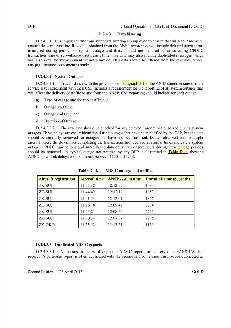
8/9/2019 CPDLC Explained
http://slidepdf.com/reader/full/cpdlc-explained 338/421
D-16 Global Operational Data Link Document (GOLD)
Second Edition — 26 April 2013 GOLD
D.2.4.3 Data filtering
D.2.4.3.1 It is important that consistent data filtering is employed to ensure that all ANSP measureagainst the same baseline. Raw data obtained from the ANSP recordings will include delayed transactionsmeasured during periods of system outage and these should not be used when assessing CPDLC
transaction time or surveillance data transit time. The data may also include duplicated messages whichwill also skew the measurements if not removed. This data should be filtered from the raw data beforeany performance assessment is made.
D.2.4.3.2 System Outages
D.2.4.3.2.1 In accordance with the provisions of paragraph 3.1.3, the ANSP should ensure that theservice level agreement with their CSP includes a requirement for the reporting of all system outages thatwill affect the delivery of traffic to and from the ANSP. CSP reporting should include for each outage:
a) Type of outage and the media affected;
b) Outage start time;
c) Outage end time; andd) Duration of Outage.
D.2.4.3.2.2 The raw data should be checked for any delayed transactions observed during systemoutages. These delays are easily identified during outages that have been notified by the CSP, but the datashould be carefully reviewed for outages that have not been notified. Delays observed from multipleaircraft where the downlinks completing the transactions are received at similar times indicate a systemoutage. CPDLC transactions and surveillance data delivery measurements during these outage periodsshould be removed. A typical outage not notified by any DSP is illustrated in Table D- 4 showingADS-C downlink delays from 3 aircraft between 1120 and 1213.
Table D- 4. ADS-C outages not notified
Aircraft registration Aircraft time ANSP system time Downlink time (Seconds)
ZK-SUI 11:55:38 12:12:52 1034
ZK-SUI 11:44:42 12:12:19 1657
ZK-SUJ 11:41:54 12:12:01 1807
ZK-SUJ 11:26:18 12:09:42 2604
ZK-SUI 11:23:21 12:08:32 2711
ZK-SUJ 11:20:34 12:07:39 2825
ZK-OKG 11:53:52 12:12:51 1139
D.2.4.3.3 Duplicated ADS-C reports
D.2.4.3.3.1 Numerous instances of duplicate ADS-C reports are observed in FANS-1/A datarecords. A particular report is often duplicated with the second and sometimes third record duplicated at

8/9/2019 CPDLC Explained
http://slidepdf.com/reader/full/cpdlc-explained 339/421
Global Operational Data Link Document (GOLD) D-17
GOLD Second Edition — 26 April 2013
some later time as illustrated in Table D- 5. These duplicate records will skew ADS-C surveillance datadelivery measurements and should be removed.
Table D- 5. ADS-C duplicate reports
LAT_LON Aircraft time ANSP system time Downlink time (Seconds)
350225S1694139E 22:29:45 22:31:04 79
350225S1694139E 22:29:45 22:34:56 311
350225S1694139E 22:29:45 22:40:05 620
D.2.4.4 CPDLC performance analysis
D.2.4.4.1 Monitoring of CPDLC performance involves an assessment of ACP, ACTP, and PORT by a graphical analysis of data using the structure outline in paragraph D.2.4.2.
D.2.4.4.2 Monitoring communications media performance
D.2.4.4.2.1 Graphs illustrating ACP and ACTP are used to assess CPDLC transaction performance through the various communications media. Since PORT is independent of media this wouldnormally only be assessed over one media. The graphs depict measured performance against the TRN andRCTP requirements at the 95% and 99.9% level and would be completed for the performancespecifications in use (e.g. RCP 240, RCP 400). An analysis is completed for:
a) Data from all aircraft via all remote ground station (RGS) types.
b) Data from all aircraft via SATCOM RGS
c) Data from all aircraft via VHF RGS
d) Data from all aircraft via HF RGS
e) Data from all aircraft via HF and SATCOM RGS
D.2.4.4.2.2 A typical graph illustrating SATCOM ACTP performance constructed using aspreadsheet application is illustrated in Figure D- 6. Similar graphs are used to assess ACTP and ACP forother communications media.
D.2.4.4.2.3 Figure D- 6 graphs ACTP against the 95% 120” and 99.9% 150” requirements of theRCP240 specification for the years 2009-2012 as observed in the NZZO FIR.
D.2.4.4.2.4 Figure D- 7 and Figure D- 8 illustrate other methods of reporting performance.
D.2.4.4.2.5 Data transactions used for the measurement of SATCOM, VHF, and HF ACTP and
ACP are where both the MAS and operational response are received via the media being assessed. Theexception to this is the assessment of combined HF and SATCOM performance where any transactioninvolving HF or SATCOM is used.
D.2.4.4.2.6 Similar graphs are used to assess ACTP and ACP for other communications media.
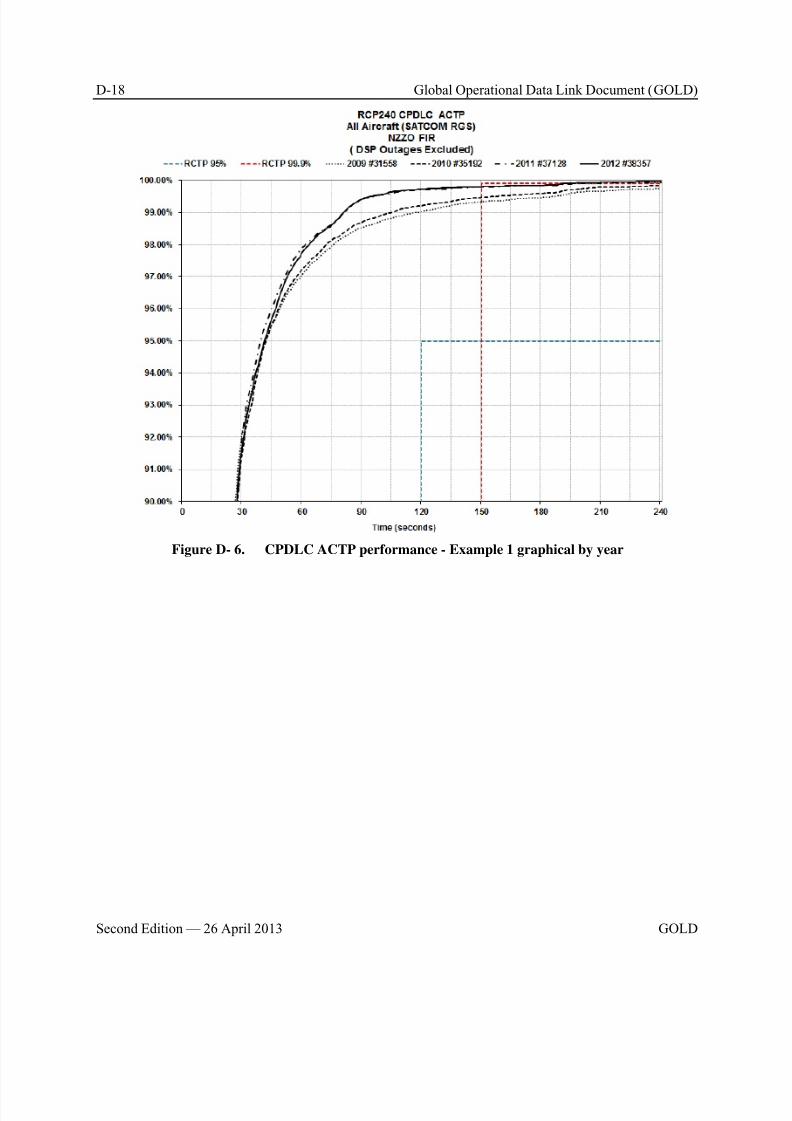
8/9/2019 CPDLC Explained
http://slidepdf.com/reader/full/cpdlc-explained 340/421

8/9/2019 CPDLC Explained
http://slidepdf.com/reader/full/cpdlc-explained 341/421
Global Operational Data Link Document (GOLD) D-19
GOLD Second Edition — 26 April 2013
Figure D- 7 CPDLC ACTP performance – Example 2 graphical Analysis by Month
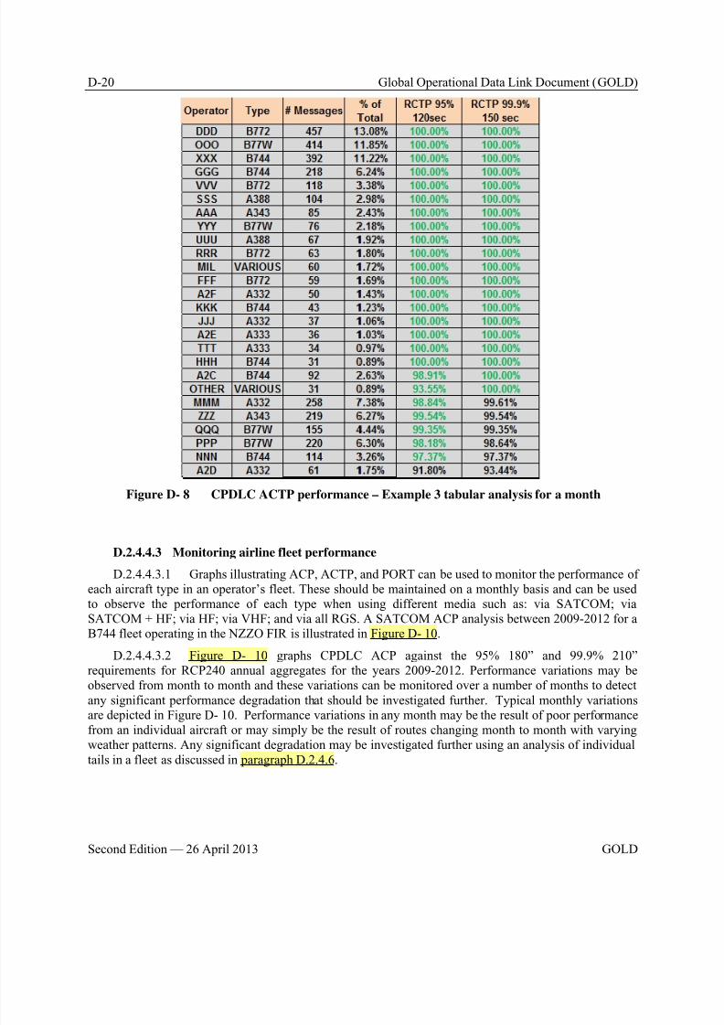
8/9/2019 CPDLC Explained
http://slidepdf.com/reader/full/cpdlc-explained 342/421
D-20 Global Operational Data Link Document (GOLD)
Second Edition — 26 April 2013 GOLD
Figure D- 8 CPDLC ACTP performance – Example 3 tabular analysis for a month
D.2.4.4.3 Monitoring airline fleet performance
D.2.4.4.3.1 Graphs illustrating ACP, ACTP, and PORT can be used to monitor the performance ofeach aircraft type in an operator’s fleet. These should be maintained on a monthly basis and can be usedto observe the performance of each type when using different media such as: via SATCOM; viaSATCOM + HF; via HF; via VHF; and via all RGS. A SATCOM ACP analysis between 2009-2012 for aB744 fleet operating in the NZZO FIR is illustrated in Figure D- 10.
D.2.4.4.3.2 Figure D- 10 graphs CPDLC ACP against the 95% 180” and 99.9% 210”requirements for RCP240 annual aggregates for the years 2009-2012. Performance variations may beobserved from month to month and these variations can be monitored over a number of months to detectany significant performance degradation that should be investigated further. Typical monthly variations
are depicted in Figure D- 10. Performance variations in any month may be the result of poor performancefrom an individual aircraft or may simply be the result of routes changing month to month with varyingweather patterns. Any significant degradation may be investigated further using an analysis of individualtails in a fleet as discussed in paragraph D.2.4.6.
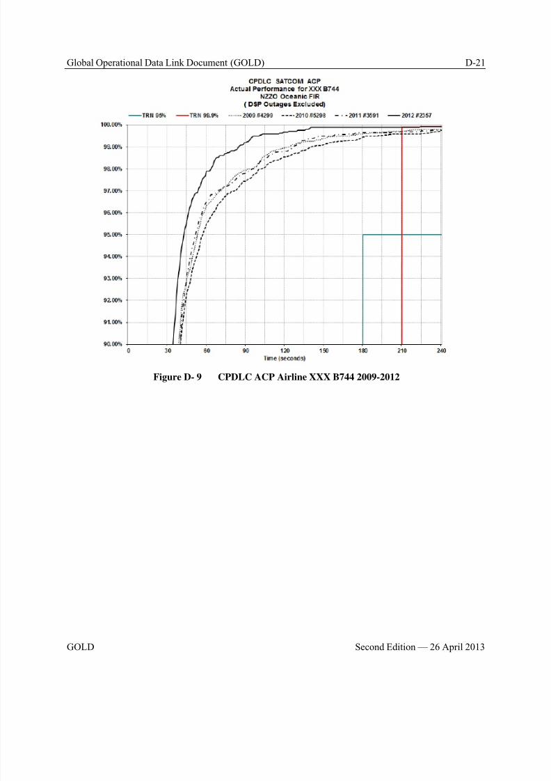
8/9/2019 CPDLC Explained
http://slidepdf.com/reader/full/cpdlc-explained 343/421
Global Operational Data Link Document (GOLD) D-21
GOLD Second Edition — 26 April 2013
Figure D- 9 CPDLC ACP Airline XXX B744 2009-2012
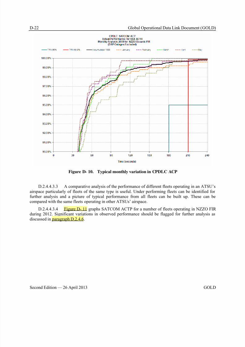
8/9/2019 CPDLC Explained
http://slidepdf.com/reader/full/cpdlc-explained 344/421
D-22 Global Operational Data Link Document (GOLD)
Second Edition — 26 April 2013 GOLD
Figure D- 10. Typical monthly variation in CPDLC ACP
D.2.4.4.3.3 A comparative analysis of the performance of different fleets operating in an ATSU’sairspace particularly of fleets of the same type is useful. Under performing fleets can be identified forfurther analysis and a picture of typical performance from all fleets can be built up. These can becompared with the same fleets operating in other ATSUs’ airspace.
D.2.4.4.3.4 Figure D- 11 graphs SATCOM ACTP for a number of fleets operating in NZZO FIRduring 2012. Significant variations in observed performance should be flagged for further analysis asdiscussed in paragraph D.2.4.6.
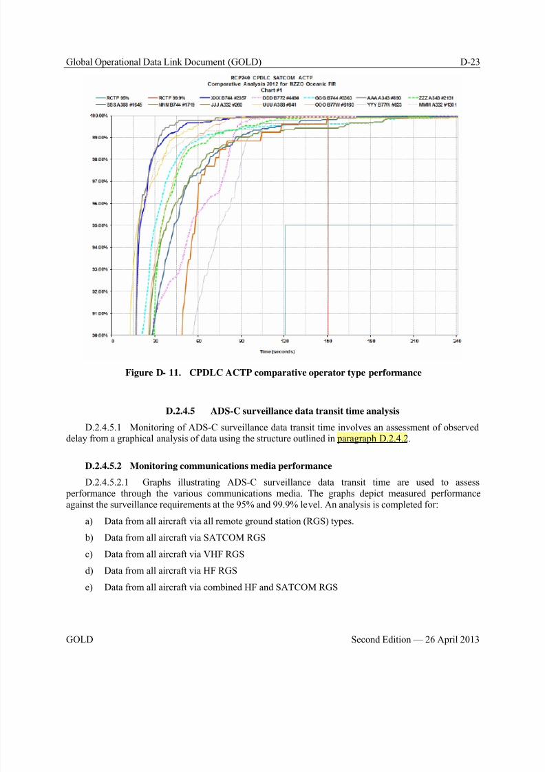
8/9/2019 CPDLC Explained
http://slidepdf.com/reader/full/cpdlc-explained 345/421
Global Operational Data Link Document (GOLD) D-23
GOLD Second Edition — 26 April 2013
Figure D- 11. CPDLC ACTP comparative operator type performance
D.2.4.5 ADS-C surveillance data transit time analysis
D.2.4.5.1 Monitoring of ADS-C surveillance data transit time involves an assessment of observeddelay from a graphical analysis of data using the structure outlined in paragraph D.2.4.2.
D.2.4.5.2 Monitoring communications media performance
D.2.4.5.2.1 Graphs illustrating ADS-C surveillance data transit time are used to assess performance through the various communications media. The graphs depict measured performanceagainst the surveillance requirements at the 95% and 99.9% level. An analysis is completed for:
a) Data from all aircraft via all remote ground station (RGS) types.
b) Data from all aircraft via SATCOM RGSc) Data from all aircraft via VHF RGS
d) Data from all aircraft via HF RGS
e) Data from all aircraft via combined HF and SATCOM RGS
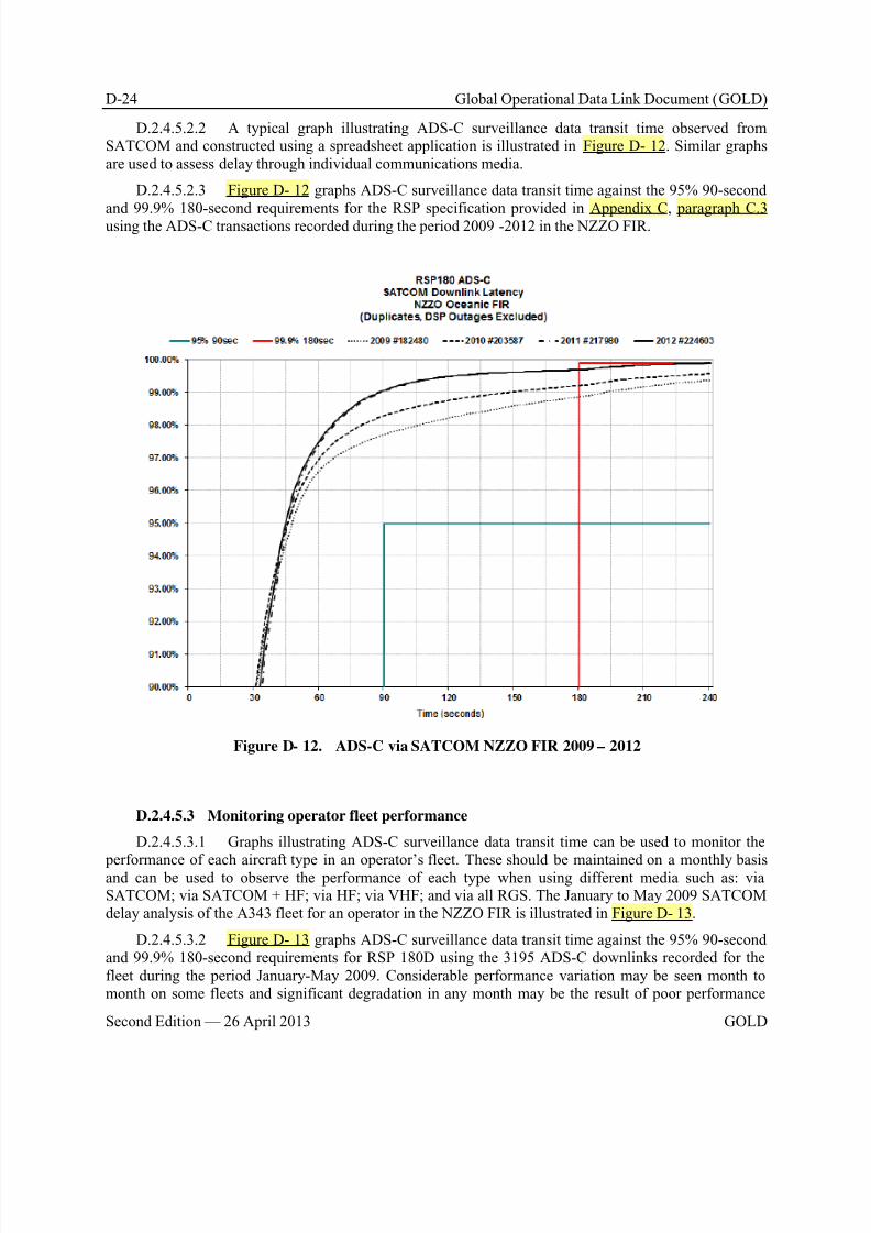
8/9/2019 CPDLC Explained
http://slidepdf.com/reader/full/cpdlc-explained 346/421
D-24 Global Operational Data Link Document (GOLD)
Second Edition — 26 April 2013 GOLD
D.2.4.5.2.2 A typical graph illustrating ADS-C surveillance data transit time observed fromSATCOM and constructed using a spreadsheet application is illustrated in Figure D- 12. Similar graphsare used to assess delay through individual communications media.
D.2.4.5.2.3 Figure D- 12 graphs ADS-C surveillance data transit time against the 95% 90-second
and 99.9% 180-second requirements for the RSP specification provided in Appendix C, paragraph C.3using the ADS-C transactions recorded during the period 2009 -2012 in the NZZO FIR.
Figure D- 12. ADS-C via SATCOM NZZO FIR 2009 – 2012
D.2.4.5.3 Monitoring operator fleet performance
D.2.4.5.3.1 Graphs illustrating ADS-C surveillance data transit time can be used to monitor the
performance of each aircraft type in an operator’s fleet. These should be maintained on a monthly basisand can be used to observe the performance of each type when using different media such as: viaSATCOM; via SATCOM + HF; via HF; via VHF; and via all RGS. The January to May 2009 SATCOMdelay analysis of the A343 fleet for an operator in the NZZO FIR is illustrated in Figure D- 13.
D.2.4.5.3.2 Figure D- 13 graphs ADS-C surveillance data transit time against the 95% 90-secondand 99.9% 180-second requirements for RSP 180D using the 3195 ADS-C downlinks recorded for thefleet during the period January-May 2009. Considerable performance variation may be seen month tomonth on some fleets and significant degradation in any month may be the result of poor performance
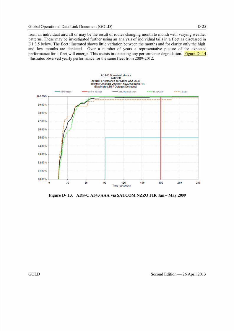
8/9/2019 CPDLC Explained
http://slidepdf.com/reader/full/cpdlc-explained 347/421
Global Operational Data Link Document (GOLD) D-25
GOLD Second Edition — 26 April 2013
from an individual aircraft or may be the result of routes changing month to month with varying weather patterns. These may be investigated further using an analysis of individual tails in a fleet as discussed inD1.3.5 below. The fleet illustrated shows little variation between the months and for clarity only the highand low months are depicted. Over a number of years a representative picture of the expected performance for a fleet will emerge. This assists in detecting any performance degradation. Figure D- 14
illustrates observed yearly performance for the same fleet from 2009-2012.
Figure D- 13. ADS-C A343 AAA via SATCOM NZZO FIR Jan – May 2009
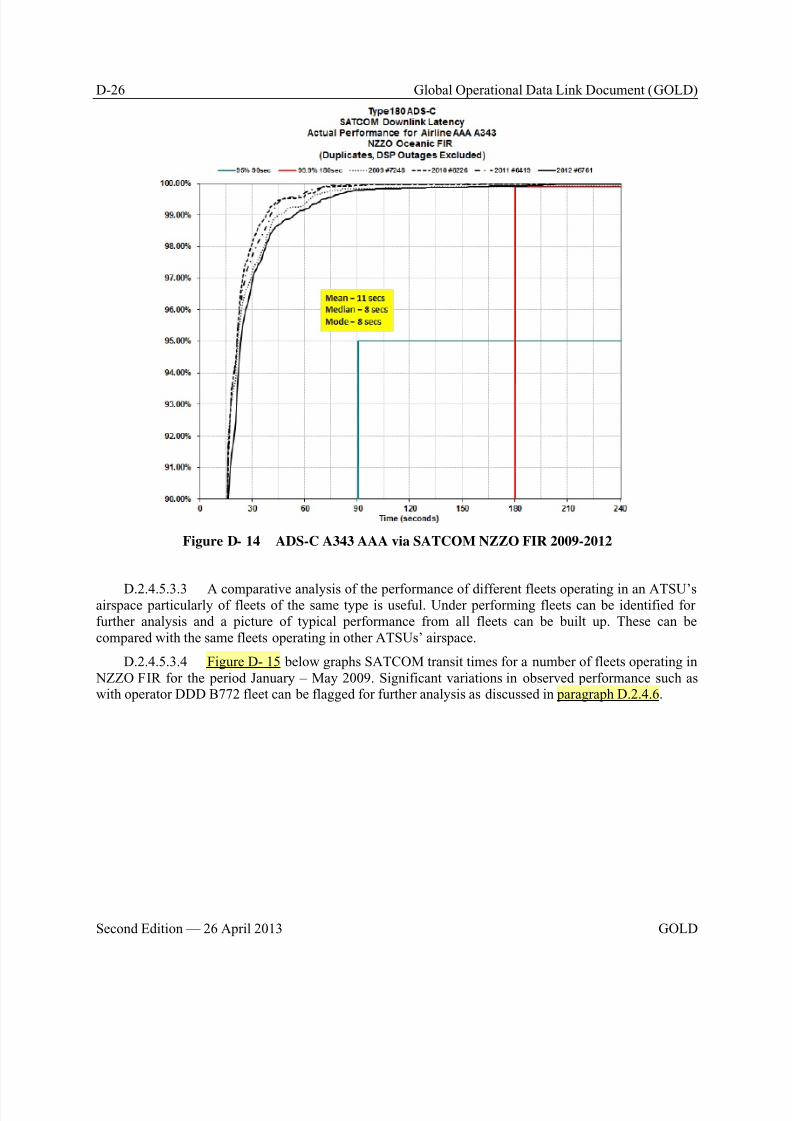
8/9/2019 CPDLC Explained
http://slidepdf.com/reader/full/cpdlc-explained 348/421
D-26 Global Operational Data Link Document (GOLD)
Second Edition — 26 April 2013 GOLD
Figure D- 14 ADS-C A343 AAA via SATCOM NZZO FIR 2009-2012
D.2.4.5.3.3 A comparative analysis of the performance of different fleets operating in an ATSU’sairspace particularly of fleets of the same type is useful. Under performing fleets can be identified forfurther analysis and a picture of typical performance from all fleets can be built up. These can becompared with the same fleets operating in other ATSUs’ airspace.
D.2.4.5.3.4 Figure D- 15 below graphs SATCOM transit times for a number of fleets operating in NZZO FIR for the period January – May 2009. Significant variations in observed performance such aswith operator DDD B772 fleet can be flagged for further analysis as discussed in paragraph D.2.4.6.
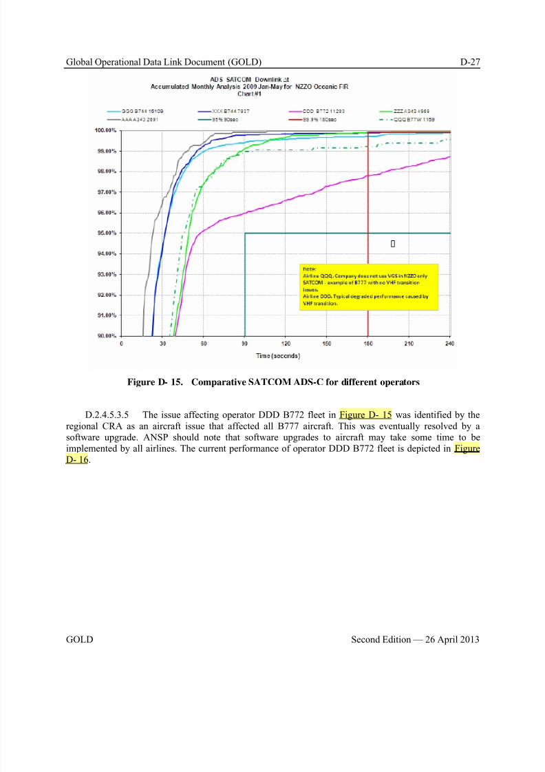
8/9/2019 CPDLC Explained
http://slidepdf.com/reader/full/cpdlc-explained 349/421
Global Operational Data Link Document (GOLD) D-27
GOLD Second Edition — 26 April 2013
Figure D- 15. Comparative SATCOM ADS-C for different operators
D.2.4.5.3.5 The issue affecting operator DDD B772 fleet in Figure D- 15 was identified by theregional CRA as an aircraft issue that affected all B777 aircraft. This was eventually resolved by asoftware upgrade. ANSP should note that software upgrades to aircraft may take some time to beimplemented by all airlines. The current performance of operator DDD B772 fleet is depicted in FigureD- 16.
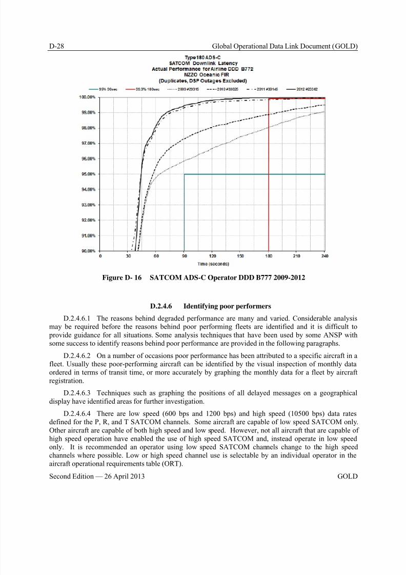
8/9/2019 CPDLC Explained
http://slidepdf.com/reader/full/cpdlc-explained 350/421
D-28 Global Operational Data Link Document (GOLD)
Second Edition — 26 April 2013 GOLD
Figure D- 16 SATCOM ADS-C Operator DDD B777 2009-2012
D.2.4.6 Identifying poor performers
D.2.4.6.1 The reasons behind degraded performance are many and varied. Considerable analysismay be required before the reasons behind poor performing fleets are identified and it is difficult to provide guidance for all situations. Some analysis techniques that have been used by some ANSP withsome success to identify reasons behind poor performance are provided in the following paragraphs.
D.2.4.6.2 On a number of occasions poor performance has been attributed to a specific aircraft in afleet. Usually these poor-performing aircraft can be identified by the visual inspection of monthly dataordered in terms of transit time, or more accurately by graphing the monthly data for a fleet by aircraftregistration.
D.2.4.6.3 Techniques such as graphing the positions of all delayed messages on a geographical
display have identified areas for further investigation.D.2.4.6.4 There are low speed (600 bps and 1200 bps) and high speed (10500 bps) data rates
defined for the P, R, and T SATCOM channels. Some aircraft are capable of low speed SATCOM only.Other aircraft are capable of both high speed and low speed. However, not all aircraft that are capable ofhigh speed operation have enabled the use of high speed SATCOM and, instead operate in low speedonly. It is recommended an operator using low speed SATCOM channels change to the high speedchannels where possible. Low or high speed channel use is selectable by an individual operator in theaircraft operational requirements table (ORT).
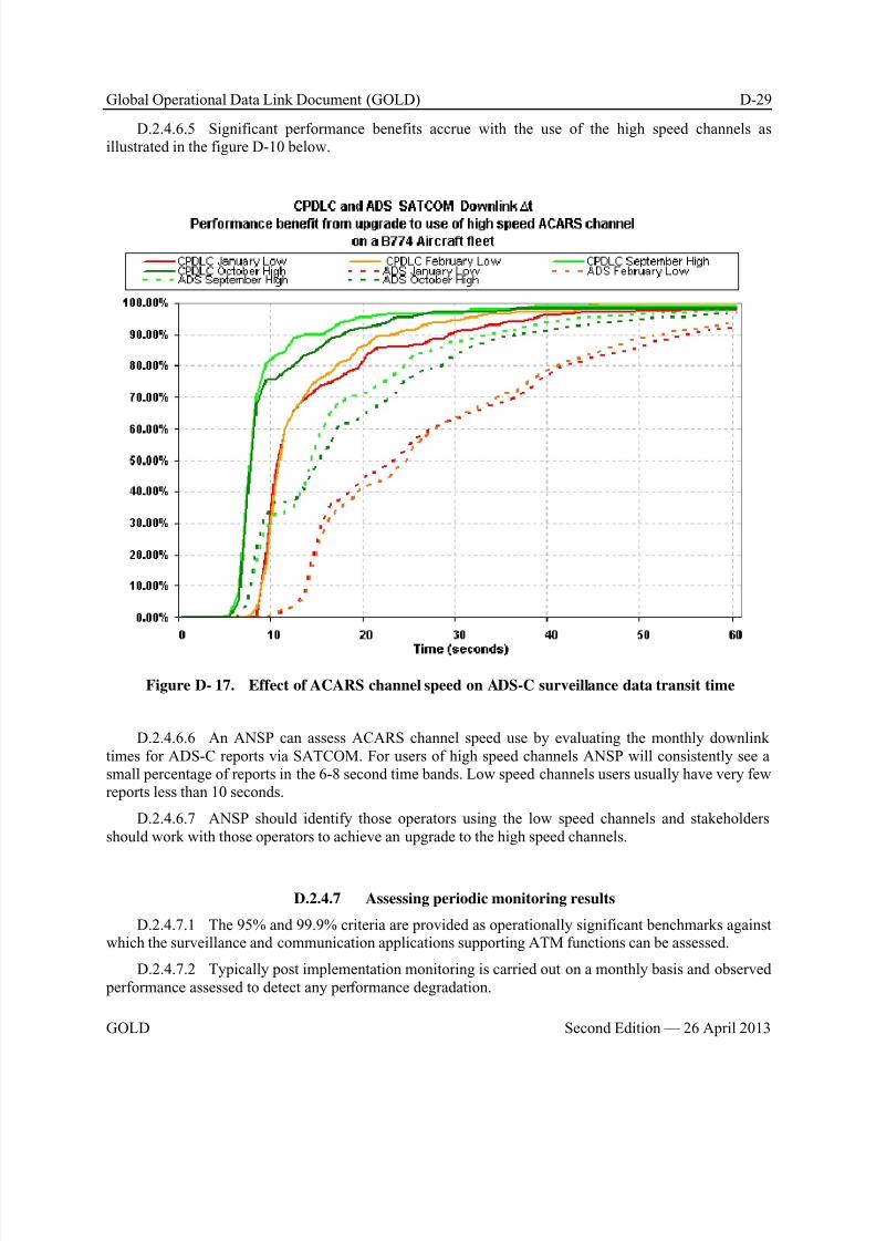
8/9/2019 CPDLC Explained
http://slidepdf.com/reader/full/cpdlc-explained 351/421
Global Operational Data Link Document (GOLD) D-29
GOLD Second Edition — 26 April 2013
D.2.4.6.5 Significant performance benefits accrue with the use of the high speed channels asillustrated in the figure D-10 below.
Figure D- 17. Effect of ACARS channel speed on ADS-C surveillance data transit time
D.2.4.6.6 An ANSP can assess ACARS channel speed use by evaluating the monthly downlinktimes for ADS-C reports via SATCOM. For users of high speed channels ANSP will consistently see asmall percentage of reports in the 6-8 second time bands. Low speed channels users usually have very fewreports less than 10 seconds.
D.2.4.6.7 ANSP should identify those operators using the low speed channels and stakeholdersshould work with those operators to achieve an upgrade to the high speed channels.
D.2.4.7 Assessing periodic monitoring results
D.2.4.7.1 The 95% and 99.9% criteria are provided as operationally significant benchmarks againstwhich the surveillance and communication applications supporting ATM functions can be assessed.
D.2.4.7.2 Typically post implementation monitoring is carried out on a monthly basis and observed performance assessed to detect any performance degradation.
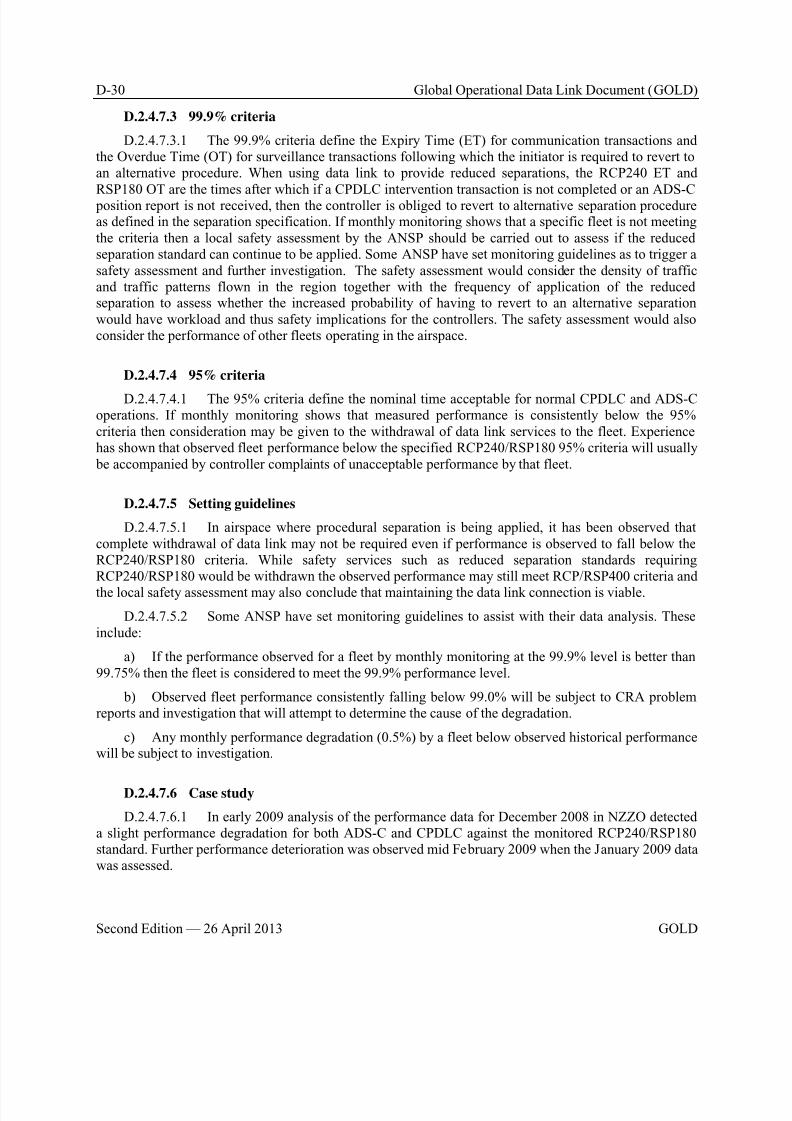
8/9/2019 CPDLC Explained
http://slidepdf.com/reader/full/cpdlc-explained 352/421
D-30 Global Operational Data Link Document (GOLD)
Second Edition — 26 April 2013 GOLD
D.2.4.7.3 99.9% criteria
D.2.4.7.3.1 The 99.9% criteria define the Expiry Time (ET) for communication transactions andthe Overdue Time (OT) for surveillance transactions following which the initiator is required to revert toan alternative procedure. When using data link to provide reduced separations, the RCP240 ET and
RSP180 OT are the times after which if a CPDLC intervention transaction is not completed or an ADS-C position report is not received, then the controller is obliged to revert to alternative separation procedureas defined in the separation specification. If monthly monitoring shows that a specific fleet is not meetingthe criteria then a local safety assessment by the ANSP should be carried out to assess if the reducedseparation standard can continue to be applied. Some ANSP have set monitoring guidelines as to trigger asafety assessment and further investigation. The safety assessment would consider the density of trafficand traffic patterns flown in the region together with the frequency of application of the reducedseparation to assess whether the increased probability of having to revert to an alternative separationwould have workload and thus safety implications for the controllers. The safety assessment would alsoconsider the performance of other fleets operating in the airspace.
D.2.4.7.4 95% criteria
D.2.4.7.4.1 The 95% criteria define the nominal time acceptable for normal CPDLC and ADS-Coperations. If monthly monitoring shows that measured performance is consistently below the 95%criteria then consideration may be given to the withdrawal of data link services to the fleet. Experiencehas shown that observed fleet performance below the specified RCP240/RSP180 95% criteria will usually be accompanied by controller complaints of unacceptable performance by that fleet.
D.2.4.7.5 Setting guidelines
D.2.4.7.5.1 In airspace where procedural separation is being applied, it has been observed thatcomplete withdrawal of data link may not be required even if performance is observed to fall below theRCP240/RSP180 criteria. While safety services such as reduced separation standards requiringRCP240/RSP180 would be withdrawn the observed performance may still meet RCP/RSP400 criteria and
the local safety assessment may also conclude that maintaining the data link connection is viable.
D.2.4.7.5.2 Some ANSP have set monitoring guidelines to assist with their data analysis. Theseinclude:
a) If the performance observed for a fleet by monthly monitoring at the 99.9% level is better than99.75% then the fleet is considered to meet the 99.9% performance level.
b) Observed fleet performance consistently falling below 99.0% will be subject to CRA problemreports and investigation that will attempt to determine the cause of the degradation.
c) Any monthly performance degradation (0.5%) by a fleet below observed historical performancewill be subject to investigation.
D.2.4.7.6 Case study
D.2.4.7.6.1 In early 2009 analysis of the performance data for December 2008 in NZZO detecteda slight performance degradation for both ADS-C and CPDLC against the monitored RCP240/RSP180standard. Further performance deterioration was observed mid February 2009 when the January 2009 datawas assessed.
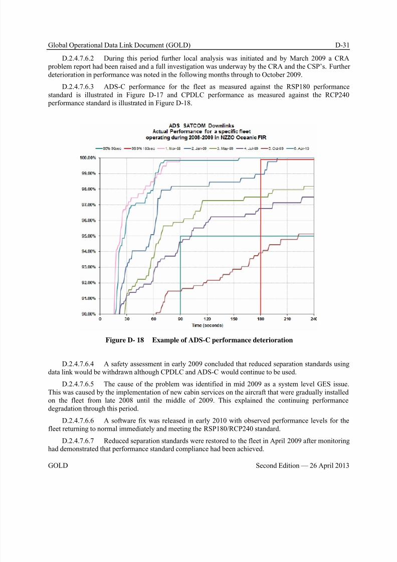
8/9/2019 CPDLC Explained
http://slidepdf.com/reader/full/cpdlc-explained 353/421
Global Operational Data Link Document (GOLD) D-31
GOLD Second Edition — 26 April 2013
D.2.4.7.6.2 During this period further local analysis was initiated and by March 2009 a CRA problem report had been raised and a full investigation was underway by the CRA and the CSP’s. Furtherdeterioration in performance was noted in the following months through to October 2009.
D.2.4.7.6.3 ADS-C performance for the fleet as measured against the RSP180 performance
standard is illustrated in Figure D-17 and CPDLC performance as measured against the RCP240 performance standard is illustrated in Figure D-18.
Figure D- 18 Example of ADS-C performance deterioration
D.2.4.7.6.4 A safety assessment in early 2009 concluded that reduced separation standards usingdata link would be withdrawn although CPDLC and ADS-C would continue to be used.
D.2.4.7.6.5 The cause of the problem was identified in mid 2009 as a system level GES issue.
This was caused by the implementation of new cabin services on the aircraft that were gradually installedon the fleet from late 2008 until the middle of 2009. This explained the continuing performancedegradation through this period.
D.2.4.7.6.6 A software fix was released in early 2010 with observed performance levels for thefleet returning to normal immediately and meeting the RSP180/RCP240 standard.
D.2.4.7.6.7 Reduced separation standards were restored to the fleet in April 2009 after monitoringhad demonstrated that performance standard compliance had been achieved.
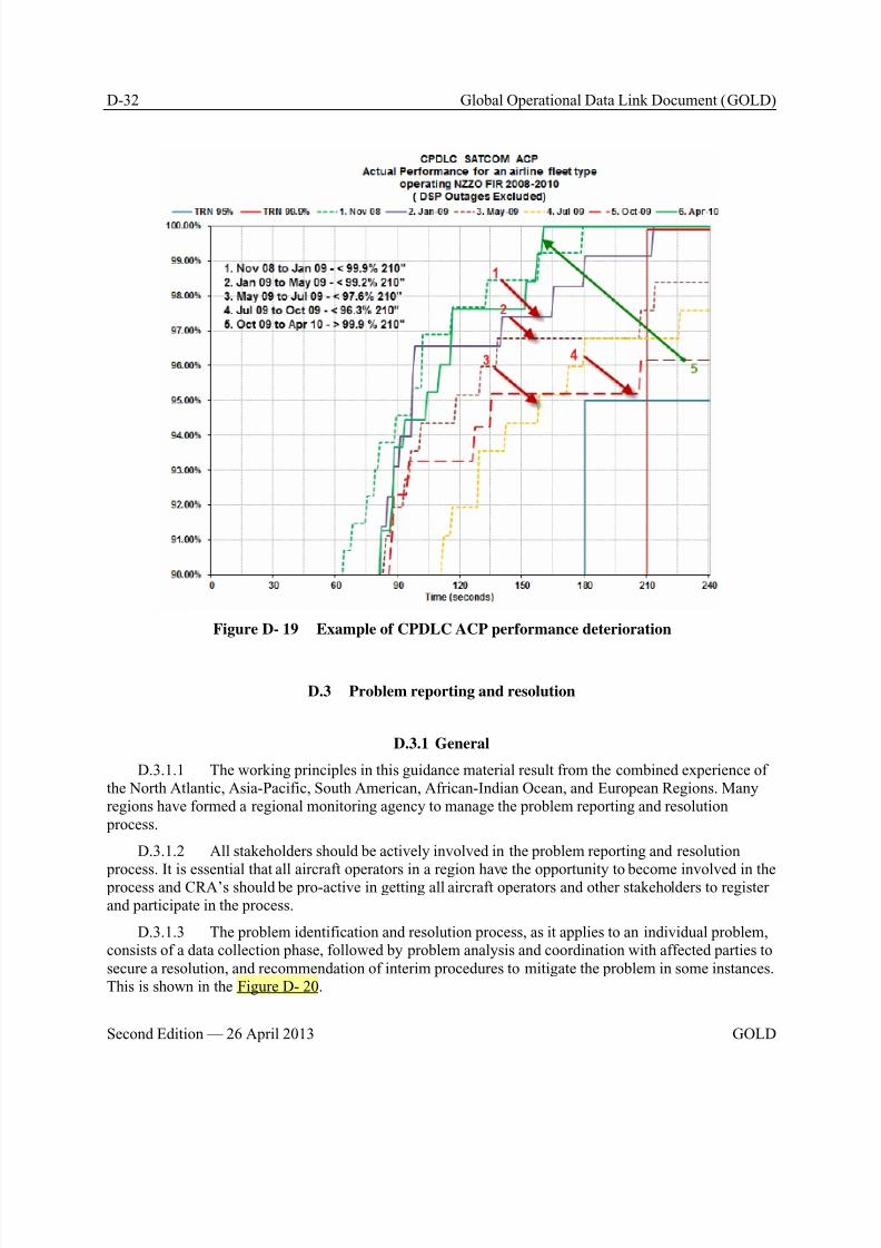
8/9/2019 CPDLC Explained
http://slidepdf.com/reader/full/cpdlc-explained 354/421
D-32 Global Operational Data Link Document (GOLD)
Second Edition — 26 April 2013 GOLD
Figure D- 19 Example of CPDLC ACP performance deterioration
D.3 Problem reporting and resolution
D.3.1 General
D.3.1.1 The working principles in this guidance material result from the combined experience ofthe North Atlantic, Asia-Pacific, South American, African-Indian Ocean, and European Regions. Manyregions have formed a regional monitoring agency to manage the problem reporting and resolution process.
D.3.1.2 All stakeholders should be actively involved in the problem reporting and resolution
process. It is essential that all aircraft operators in a region have the opportunity to become involved in the process and CRA’s should be pro-active in getting all aircraft operators and other stakeholders to registerand participate in the process.
D.3.1.3 The problem identification and resolution process, as it applies to an individual problem,consists of a data collection phase, followed by problem analysis and coordination with affected parties tosecure a resolution, and recommendation of interim procedures to mitigate the problem in some instances.This is shown in the Figure D- 20.
8/9/2019 CPDLC Explained
http://slidepdf.com/reader/full/cpdlc-explained 355/421
8/9/2019 CPDLC Explained
http://slidepdf.com/reader/full/cpdlc-explained 356/421
D-34 Global Operational Data Link Document (GOLD)
Second Edition — 26 April 2013 GOLD
b) Title: A short title which conveys the main issue of the reported problem (e.g. CPDLC transferfailure);
c) Date UTC: Date in YYYYMMDD format (e.g. 20090705);
d) Time UTC: Time in HHMM (e.g. 2345);
e) Aircraft registration: ICAO flight plan aircraft registration (e.g. ZKADR);
f) Aircraft identification: ICAO flight plan call sign if applicable (e.g. NZA456);
g) Flight Sector: If applicable the departure and destination airfield of the flight (e.g. NZAA-RJBB);
h) Organization: Name of the originators organization (e.g. Airways NZ);
i) Active Center: Controlling Centre at time of occurrence if applicable (e.g. NZZO);
j) Next Center: Next controlling centre at time of occurrence if applicable (e.g. NFFF);
k) Position: Position of occurrence (e.g. 3022S16345E);
l) Problem Description: Detailed description of problem;m) Attach File: Area of web page where originator and assigned stakeholders can attach data files
or other detailed information such as geographic overlays; and
n) Additional Data: Area set aside for feedback from stakeholders assigned by the regional/Statemonitoring agency. This will includes the results of the investigation and the agreed action plan.
Note.— A number of regional monitoring agencies are developing websites to manage the problem
reporting process. Website addresses and the regional monitoring agency to which they are applicable
are listed in Appendix E.
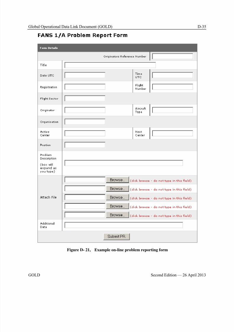
8/9/2019 CPDLC Explained
http://slidepdf.com/reader/full/cpdlc-explained 357/421
Global Operational Data Link Document (GOLD) D-35
GOLD Second Edition — 26 April 2013
Figure D- 21, Example on-line problem reporting form
8/9/2019 CPDLC Explained
http://slidepdf.com/reader/full/cpdlc-explained 358/421
8/9/2019 CPDLC Explained
http://slidepdf.com/reader/full/cpdlc-explained 359/421
Global Operational Data Link Document (GOLD) D-37
GOLD Second Edition — 26 April 2013
may also require lab testing using the airborne equipment (and sometimes the ground networks) toreliably assign the problem to a particular cause.
D.3.3.2.5 Once the problem has been identified, then the task of coordination with affected parties begins. The stakeholder who is assigned responsibility for fixing the problem must be contacted and a
corrective action plan agreed. The stakeholder who initiated the problem report shall be provided withregular updates on the progress and resolution of the problem
D.3.3.2.6 This information (the problem description, the results of the analysis and the plan forcorrective action) is then entered into a database covering data link problems, both in a complete form toallow continued analysis and monitoring of the corrective action and in a de-identified form for theinformation of other stakeholders. These de-identified summaries are reported at the appropriate regionalmanagement forum and made available to other regional central reporting/monitoring agencies onrequest.
D.3.4 Mitigating procedures – problem resolution
D.3.4.1 The regional monitoring agency’s responsibility does not end with determining the cause
of the problem and identifying a fix. As part of that activity, and because a considerable period mayelapse while software updates are applied to all aircraft in a fleet, procedural methods to mitigate the problem may have to be developed while the solution is being coordinated. The regional monitoringagency should identify the need for such procedures and develop recommendations for implementation bythe ANSPs, CSPs and operators involved.
D.4 Regional performance monitoring
D.4.1 General
D.4.1.1 This section provides guidance on periodic reporting by individual ANSP of observed
system performance in their airspace that will enable regional performance metrics to be developed forthe availability, CPDLC transaction time and ADS-C surveillance data transit time requirements specifiedin Appendix B and Appendix C.
D.4.1.2 These regional performance metrics should be made available to all interestedstakeholders. The use of regional websites to enhance the distribution of these metrics should beconsidered. An example of such a website can be viewed at http://www.ispacg-cra.com/.
D.4.1.3 It is recommended that regions implement monthly performance reporting to obtainsystem performance metrics. These reports will provide data on observed availability, CPDLC transactiontime and ADS-C surveillance data transit time as described herein.
D.4.2 Reporting on availability
D.4.2.1 ANSP should report on CSP notified system outages and on detected outages that havenot been notified as described in paragraph D.2.4.3.2. This is used to calculate the actual availability ofservice provision.
D.4.2.2 For each outage the following information should be reported:
a) Time of CSP outage notification: In YYYYMMDDHHMM format or “Not Notified” if no CSPnotification received.
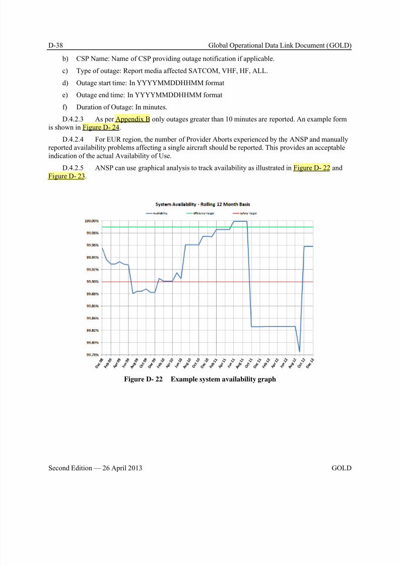
8/9/2019 CPDLC Explained
http://slidepdf.com/reader/full/cpdlc-explained 360/421
D-38 Global Operational Data Link Document (GOLD)
Second Edition — 26 April 2013 GOLD
b) CSP Name: Name of CSP providing outage notification if applicable.
c) Type of outage: Report media affected SATCOM, VHF, HF, ALL.
d) Outage start time: In YYYYMMDDHHMM format
e) Outage end time: In YYYYMMDDHHMM format
f) Duration of Outage: In minutes.
D.4.2.3 As per Appendix B only outages greater than 10 minutes are reported. An example formis shown in Figure D- 24.
D.4.2.4 For EUR region, the number of Provider Aborts experienced by the ANSP and manuallyreported availability problems affecting a single aircraft should be reported. This provides an acceptableindication of the actual Availability of Use.
D.4.2.5 ANSP can use graphical analysis to track availability as illustrated in Figure D- 22 andFigure D- 23.
Figure D- 22 Example system availability graph

8/9/2019 CPDLC Explained
http://slidepdf.com/reader/full/cpdlc-explained 361/421
Global Operational Data Link Document (GOLD) D-39
GOLD Second Edition — 26 April 2013
Figure D- 23 Example network outage graph
D.4.3 Reporting on CPDLC actual communications performance
D.4.3.1 ANSP should report observed ACP and ACTP for RCP240 and RCP400 for different
media paths using all transactions involving a WILCO response as described in paragraph D.2.4. Themedia paths to report are:
a) From all aircraft via all remote ground station (RGS) types.
b) From all aircraft where both uplink and downlink are via SATCOM RGS
c) From all aircraft where both uplink and downlink are via VHF RGS
d) From all aircraft where both uplink and downlink are via HF RGS
e) From all aircraft where either uplink and downlink are via HF or SATCOM RGS
D.4.3.2 A tabular reporting format can be used to capture the observed performance at the 95%and 99.9% RCP240/400 times.
D.4.3.3 As PORT is independent of media path, this need only be reported for all RGS types. Anexample form is shown in Figure D- 24.
D.4.3.4 ANSPs within the EUR region should record the observed ACP and ACTP for RCP 150and CPDLC-flight crew-initiated log files for different media paths using all transactions requiring aresponse. In addition, it should record the observed ACP and ACTP for DLIC-Contact/CPDLC log filesand ATN B1 transport level log files, deployment and system health log files in the standardised XML-format as described in paragraph D.1.1.2. All ANSPs send the log files to the CRO for importing intoPRISME (Pan-European Repository of Information Supporting the Management of EATM). PRISME is

8/9/2019 CPDLC Explained
http://slidepdf.com/reader/full/cpdlc-explained 362/421
D-40 Global Operational Data Link Document (GOLD)
Second Edition — 26 April 2013 GOLD
an integrated ATM data ware house for creation of various performance monitoring reports (e.g. EURnetwork, an ANSP, an Aircraft Operator, particular avionics configuration).
D.4.3.5 The EUR network performance monitoring reports are published on the CRO website.The reports at the other levels (per ANSP, per Aircraft Operator and per Avionics configuration) would
normally be restricted to just EUROCONTROL and the relevant stakeholder.
D.4.4 Reporting on RSP data transit time
D.4.4.1 ANSP should report observed RSP data transit time for RSP 180 and RSP 400 andDO290/ED120 based performance specifications for different media paths as described in paragraphD.2.4. The media paths to report are:
a) From all aircraft via all Remote Ground Station (RGS) types.
b) From all aircraft where both uplink and downlink are via SATCOM RGS
c) From all aircraft where both uplink and downlink are via VHF RGSd) From all aircraft where both uplink and downlink are via HF RGS
e) From all aircraft where either uplink and downlink are via HF or SATCOM RGS
D.4.4.2 A tabular reporting format can be used to capture the observed performance at the 95%and 99.9% RSP 180 and RSP 400 times. An example form is shown in Figure D- 24.
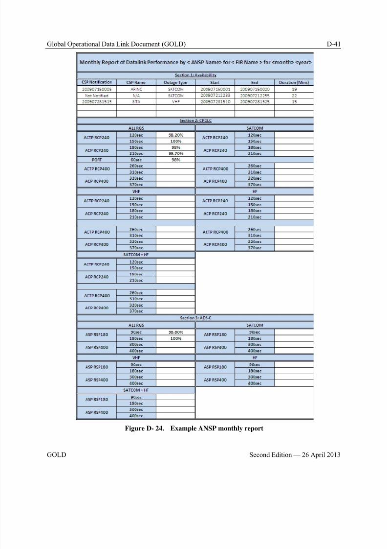
8/9/2019 CPDLC Explained
http://slidepdf.com/reader/full/cpdlc-explained 363/421
Global Operational Data Link Document (GOLD) D-41
GOLD Second Edition — 26 April 2013
Figure D- 24. Example ANSP monthly report
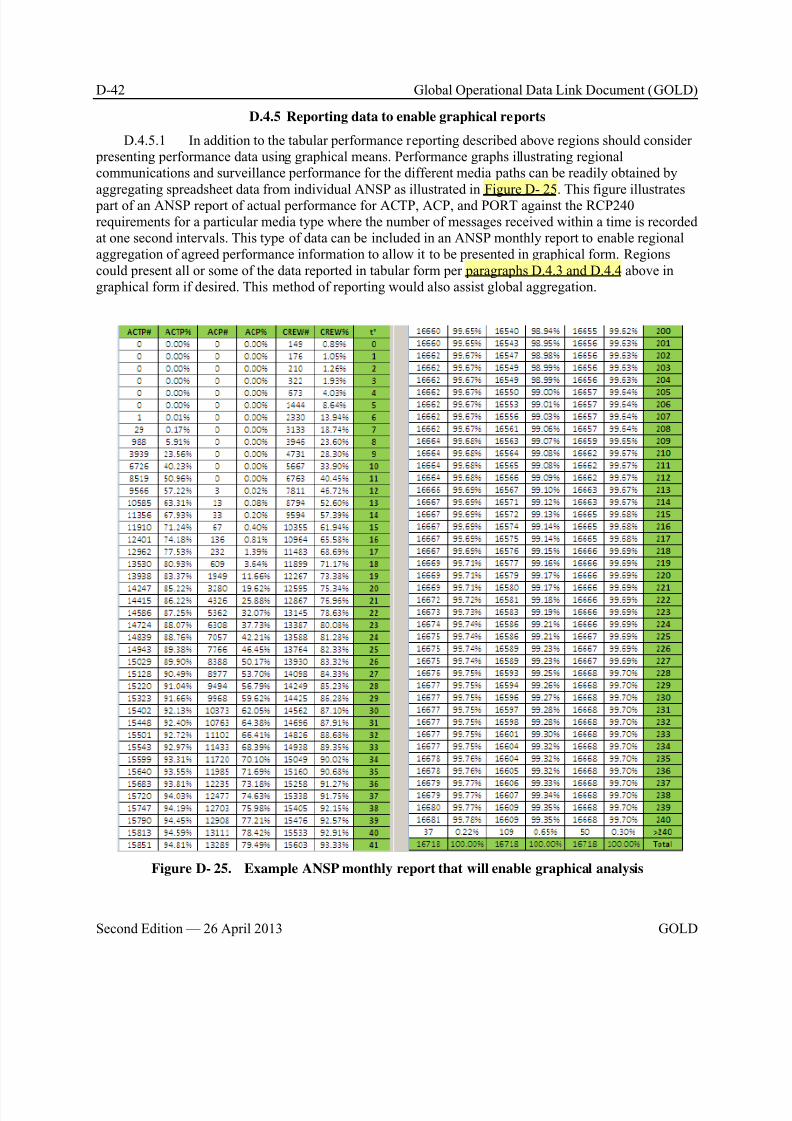
8/9/2019 CPDLC Explained
http://slidepdf.com/reader/full/cpdlc-explained 364/421
D-42 Global Operational Data Link Document (GOLD)
Second Edition — 26 April 2013 GOLD
D.4.5 Reporting data to enable graphical reports
D.4.5.1 In addition to the tabular performance reporting described above regions should consider presenting performance data using graphical means. Performance graphs illustrating regionalcommunications and surveillance performance for the different media paths can be readily obtained by
aggregating spreadsheet data from individual ANSP as illustrated in Figure D- 25. This figure illustrates part of an ANSP report of actual performance for ACTP, ACP, and PORT against the RCP240requirements for a particular media type where the number of messages received within a time is recordedat one second intervals. This type of data can be included in an ANSP monthly report to enable regionalaggregation of agreed performance information to allow it to be presented in graphical form. Regionscould present all or some of the data reported in tabular form per paragraphs D.4.3 and D.4.4 above ingraphical form if desired. This method of reporting would also assist global aggregation.
Figure D- 25. Example ANSP monthly report that will enable graphical analysis
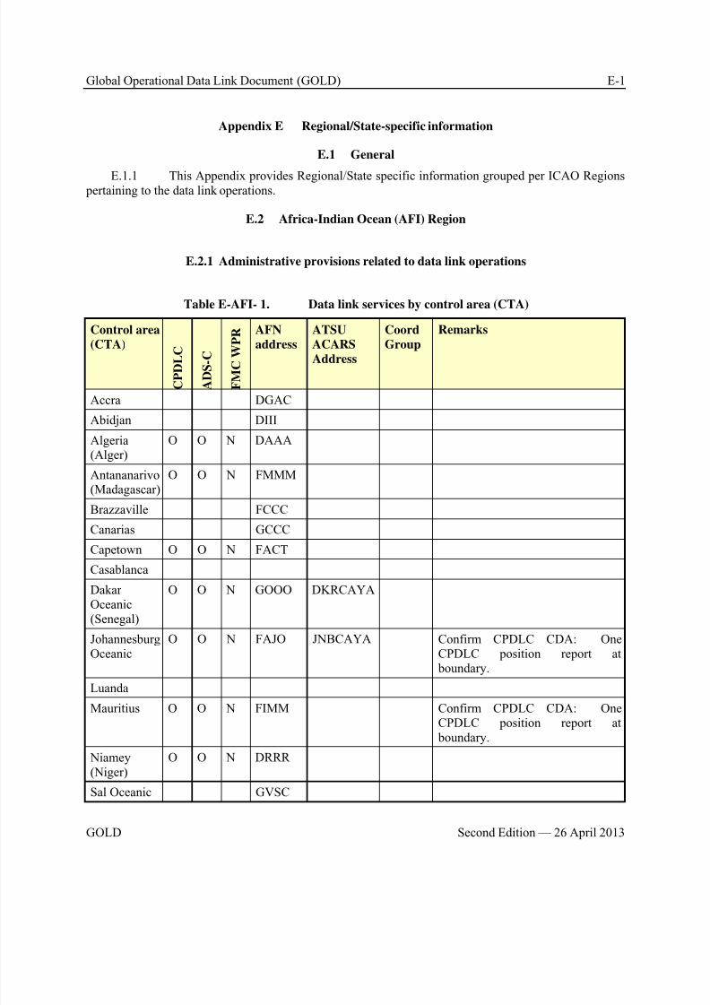
8/9/2019 CPDLC Explained
http://slidepdf.com/reader/full/cpdlc-explained 365/421
Global Operational Data Link Document (GOLD) E-1
GOLD Second Edition — 26 April 2013
Appendix E Regional/State-specific information
E.1 General
E.1.1 This Appendix provides Regional/State specific information grouped per ICAO Regions pertaining to the data link operations.
E.2 Africa-Indian Ocean (AFI) Region
E.2.1 Administrative provisions related to data link operations
Table E-AFI- 1. Data link services by control area (CTA)
Control area
(CTA)
C P D L C
A D S - C
F M C W
P R AFN
address
ATSU
ACARS
Address
Coord
Group
Remarks
Accra DGAC
Abidjan DIII
Algeria(Alger)
O O N DAAA
Antananarivo(Madagascar)
O O N FMMM
Brazzaville FCCC
Canarias GCCC
Capetown O O N FACT
Casablanca
DakarOceanic(Senegal)
O O N GOOO DKRCAYA
JohannesburgOceanic
O O N FAJO JNBCAYA Confirm CPDLC CDA: OneCPDLC position report at boundary.
Luanda
Mauritius O O N FIMM Confirm CPDLC CDA: OneCPDLC position report at boundary.
Niamey(Niger)
O O N DRRR
Sal Oceanic GVSC
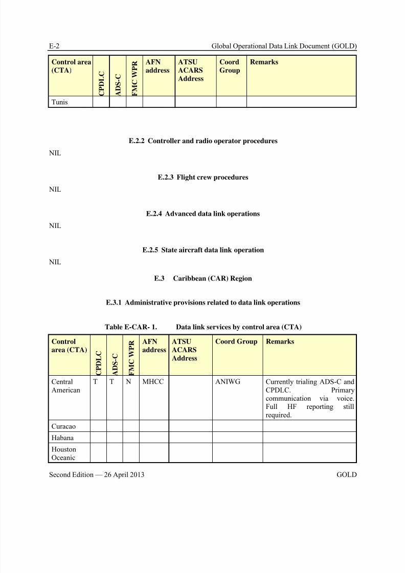
8/9/2019 CPDLC Explained
http://slidepdf.com/reader/full/cpdlc-explained 366/421
E-2 Global Operational Data Link Document (GOLD)
Second Edition — 26 April 2013 GOLD
Control area
(CTA)
C P D L C
A D S - C
F M C W P R AFN
address
ATSU
ACARS
Address
Coord
Group
Remarks
Tunis
E.2.2 Controller and radio operator procedures
NIL
E.2.3 Flight crew procedures
NIL
E.2.4 Advanced data link operations
NIL
E.2.5 State aircraft data link operation
NIL
E.3 Caribbean (CAR) Region
E.3.1 Administrative provisions related to data link operations
Table E-CAR- 1. Data link services by control area (CTA)
Control
area (CTA)
C P D L C
A D S - C
F M C W P R AFN
address
ATSU
ACARS
Address
Coord Group Remarks
CentralAmerican
T T N MHCC ANIWG Currently trialing ADS-C andCPDLC. Primary
communication via voice.Full HF reporting stillrequired.
Curacao
Habana
HoustonOceanic

8/9/2019 CPDLC Explained
http://slidepdf.com/reader/full/cpdlc-explained 367/421
Global Operational Data Link Document (GOLD) E-3
GOLD Second Edition — 26 April 2013
Control
area (CTA)
C P D L C
A D S - C
F M C W P R AFN
address
ATSU
ACARS
Address
Coord Group Remarks
Kingston
MazatlanOceanic
T T N MMMX ANIWG Currently trialing ADS-C andCPDLC. Primarycommunication via voice. FullHF reporting still required.
Mexico
MiamiOceanic
Nassau
New York
Oceanic(south of 27 N)
O O N KZWY NYCODYA NAT CNSG DO NOT use CPDLC for
position reporting. Use ADS-C or voice only.
SELCAL check via HF arerequired for all FANSconnected aircraft prior toentering the CTA/FIR.
DO NOT send a CPDLC position report to confirmCDA prior to, or uponcrossing the FIR.
Port-Au-
PrincePIARCO T T N TTZP ANIWG
(NAM/CARAir NavigationImplementationWorkingGroup)
Currently trialing ADS-C andCPDLC. Primarycommunication via voice.Full HF reporting stillrequired.
San Juan
SantoDomingo
E.3.2 Controller and radio operator procedures
NIL
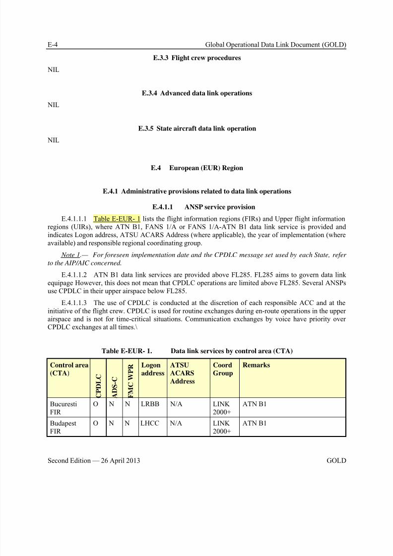
8/9/2019 CPDLC Explained
http://slidepdf.com/reader/full/cpdlc-explained 368/421
E-4 Global Operational Data Link Document (GOLD)
Second Edition — 26 April 2013 GOLD
E.3.3 Flight crew procedures
NIL
E.3.4 Advanced data link operations
NIL
E.3.5 State aircraft data link operation
NIL
E.4 European (EUR) Region
E.4.1 Administrative provisions related to data link operations
E.4.1.1 ANSP service provision
E.4.1.1.1 Table E-EUR- 1 lists the flight information regions (FIRs) and Upper flight informationregions (UIRs), where ATN B1, FANS 1/A or FANS 1/A-ATN B1 data link service is provided andindicates Logon address, ATSU ACARS Address (where applicable), the year of implementation (whereavailable) and responsible regional coordinating group.
Note 1.— For foreseen implementation date and the CPDLC message set used by each State, refer
to the AIP/AIC concerned.
E.4.1.1.2 ATN B1 data link services are provided above FL285. FL285 aims to govern data linkequipage However, this does not mean that CPDLC operations are limited above FL285. Several ANSPs
use CPDLC in their upper airspace below FL285.E.4.1.1.3 The use of CPDLC is conducted at the discretion of each responsible ACC and at the
initiative of the flight crew. CPDLC is used for routine exchanges during en-route operations in the upperairspace and is not for time-critical situations. Communication exchanges by voice have priority overCPDLC exchanges at all times.\
Table E-EUR- 1. Data link services by control area (CTA)
Control area
(CTA)
C P D L C
A D S - C
F M
C W P R Logon
address
ATSU
ACARS
Address
Coord
Group
Remarks
BucurestiFIR
O N N LRBB N/A LINK2000+
ATN B1
BudapestFIR
O N N LHCC N/A LINK2000+
ATN B1
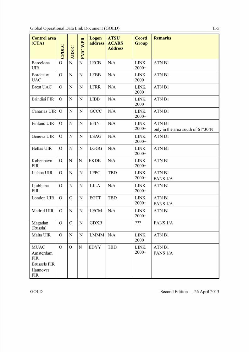
8/9/2019 CPDLC Explained
http://slidepdf.com/reader/full/cpdlc-explained 369/421
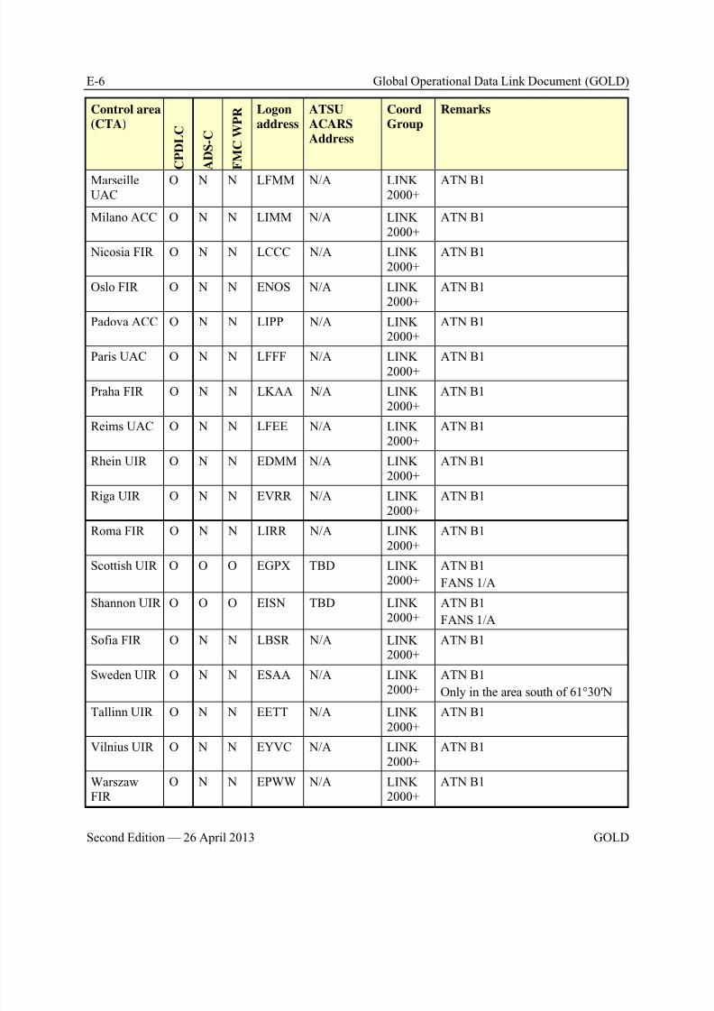
8/9/2019 CPDLC Explained
http://slidepdf.com/reader/full/cpdlc-explained 370/421

8/9/2019 CPDLC Explained
http://slidepdf.com/reader/full/cpdlc-explained 371/421
8/9/2019 CPDLC Explained
http://slidepdf.com/reader/full/cpdlc-explained 372/421
E-8 Global Operational Data Link Document (GOLD)
Second Edition — 26 April 2013 GOLD
E.4.1.3 Flight plan provisions
E.4.1.3.1 In the EUR airspace where ATN B1 CPDLC is available and aircraft are equipped andcapable ATN B1 CPDLC, J1 shall be included in Item 10a of the flight plan:
a) Operators of FANS 1/A – ATN B1 (independent or integrated) equipped aircraft shall insert one
or more of the appropriate indicators among J1 –J7 in Item 10a.
b) For flights conducted wholly or partly in the EUR airspace where ATN B1 CPDLC is available but not equipped with CPDLC capabilities but which have been granted an exemption, the letter Z shall be included in Item 10A and the indicator DAT/CPDLCX shall be included in Item18 of the flight plan.
E.4.1.3.2 For a flight operating based on a repetitive flight plan (RPL), during which the pilotintends to use CPDLC, a modification message (CHG) shall be submitted to indicate that the flight iscapable of, and authorized for CPDLC, in accordance with paragraph 3.3.
E.4.1.3.3 When there is a change to the CPDLC capability status for a flight planned to operate inthe area specified in Table E-EUR- 1, the operator should send a modification message (CHG) with theappropriate indications in the relevant items of the ICAO flight plan form, including any change to theaircraft address. A modification message for the day of operation should be sent not earlier than 20 hours before the estimated off-block time.
E.4.1.4 Logon criteria
E.4.1.4.1 In addition to the logon FPL correlation criteria, described in paragraph 3.3, the CPDLCaircraft equipment capabilities in Item 10a are also used as criterion for a successful logon. Absence ofitem J1 and/or one or more of the items J2 to J7 in Item 10a will lead to a logon rejection.
E.4.1.5 Lack Timer
E.4.1.5.1 Logical Acknowledgement (LACK) messages (downlink message element DM 100 anduplink message element UM 227) are used in ATN B1 based ACL and ACM message exchanges.
Note 1.— Ground systems do not request a LACK for the messages ERROR (UM 159) , ServiceUnavailable (UM 162) and LACK (UM 227).
Note 2.— When a LACK is received after expiry of the LACK timer, the LACK may be discarded.
E.4.2 Controller procedures
E.4.2.1 Reverting from CPDLC to voice
E.4.2.1.1 The following circumstances describe potential situations where the controller shouldrevert to voice to instruct the controller/pilot to ignore the CPDLC message:
a) When it is required to clarify the meaning or the intent of any unexpected, inappropriate or
ambiguous CPDLC message; b) Whenever it is deemed necessary to ensure the timely execution of a clearance or instruction
previously issued by CPDLC.
c) Whenever corrective actions are required with respect to unintended clearances, instructions orinformation that has been sent using CPDLC.
E.4.2.1.2 Controllers should be aware that once a message is sent via CPDLC, no means exist tocancel or to recall that message.

8/9/2019 CPDLC Explained
http://slidepdf.com/reader/full/cpdlc-explained 373/421
Global Operational Data Link Document (GOLD) E-9
GOLD Second Edition — 26 April 2013
Note.— In case of reversion to voice, controllers should be aware of the possibility that the CPDLC
message they want the addressee to ignore may not be yet displayed to the addressee.
E.4.2.1.3 In that respect, the following actions should be taken by the addressee:
a) If response to the referred CPDLC message was sent, cancel any action initiated on the basis of
the initial CPDLC message and comply with the voice message;
b) If the referred message is not responded to or not displayed, let the dialogue close on time-out.Since it may be possible to be asked to ignore a message that was not yet displayed, the controller/pilotshould take all measures to ensure that the message is no longer valid.
c) In case the controller/pilot has already received an operational response to the initial CPDLCmessage, he/she shall use appropriate voice phrases to stop/cancel the actions of the addressee.
d) Whenever a system generates a time-out or an error for a CPDLC message.
E.4.2.1.4 Use of Free Text. In support of the recommendation in ED-110B/DO-280B on ‘freetext’, some ANSPs don’t allow the controller to enter free text on the HMI.
E.4.2.2 Preconditions for the operational exchange of CPDLC messagesE.4.2.2.1 “When CPDLC is transferred, the transfer of voice communications and CPDLC shall
commence concurrently” (Annex 10 V2, 8.2.9.6.1; PANS-ATM, 14.3.3.1).
E.4.2.2.2 The active connection status, as described in paragraph 2.2.4.2, only allows for technicalair-ground CPDLC exchanges between the aircraft and the ground system of the CDA.
E.4.2.2.3 The minimum condition required for an operationally functional 2-way communicationconnection, is that the aircraft is under the responsibility of the CDA (i.e. the ATSU has assumed thecontrol of the flight after initial voice contact establishment and a CPDLC message, indicating the nameand function of the current ATC unit, is received by the flight crew).
Note.— Additional local conditions (boundary proximity, etc.), which will vary from ATSU to ATSU,
may apply.E.4.2.2.4 If an aircraft sends a request to an ATSU before the minimum conditions have been
fulfilled, the request is rejected by the ground system. An error message is displayed to the flight crewTRANSFER NOT COMPLETED REPEAT REQUEST.
E.4.2.3 Uplink messages
E.4.2.3.1 Operational use of LACK
E.4.2.3.1.1 Each time the controller uplinks an operational message, the ATN B1 aircraft systemreturns a DM 100 logical acknowledgement (LACK).
E.4.2.3.1.2 The LACK timer value should be set by the ground system at 40 seconds.
E.4.2.3.1.3 If the ground system does not receive a LACK within 40 seconds, the controller will be notified.
Note 1.— The ground system does not request a LACK for messages UM 159 (ERROR), UM 162
(SERVICE UNAVAILABLE), UM 227 (LACK).
Note2.— Local implementers may decide whether the controller is notified on the receipt of each
LACK (positive feedback) or is only notified upon a LACK time out (negative feedback).
8/9/2019 CPDLC Explained
http://slidepdf.com/reader/full/cpdlc-explained 374/421
E-10 Global Operational Data Link Document (GOLD)
Second Edition — 26 April 2013 GOLD
Note3.— When a LACK is received after expiry of the LACK timer, the LACK may be discarded.
E.4.2.3.2 UM 120 MONITOR [unitname] [frequency]
E.4.2.3.2.1 The UM 120 MONITOR message is not used for inter-ATSU and intra-ATSU flight
transfers. This is because controllers want to have the assurance that voice communication is establishedat "initial call" to the next sector or ATSU. Moreover, the “initial call” is used to communicate clearedlevel and passing level, to reconfirm clearance previously given and to verify the accuracy of Mode-C atthe first sector of the receiving ATSU.
E.4.2.3.2.2 In response to UM 120 MONITOR, sent by the transferring ATSU, DM 89MONITORING is sent to the receiving ATSU which provides a confirmation message to the controllerthat the flight crew has switched to the instructed VHF frequency. It appears that in many aircraft, theuplinked frequency is not automatically loaded in the RMP and that the frequency and the ATSU’sFacility designator in the ‘DM 89 Monitoring’ message are manually keyed in, making frequencyswitching more prone to errors.
E.4.2.3.2.3 As voice is the primary means of communications, controllers are not confident that
silent transfers can be used.
E.4.2.3.3 ATC Microphone Check service (AMC)
E.4.2.3.3.1 The AMC service is achieved by the use of either of the following 2 Uplink messages:
a) UM 157 CHECK STUCK MICROPHONE [frequency], or
b) Free text UM 183 CHECK STUCK MICROPHONE
Note 1.— No flight crew acknowledgement of the instruction is required.
Note 2.— LACK is not used for AMC.
E.4.2.3.4 Uplink messages from a FANS 1/A – ATN B1 ATSU
E.4.2.3.4.1 A FANS 1/A – ATN B1 ATSU also provides CPDLC services to FANS 1/A aircraft.The following two procedures exist as mitigation against mis-delivered- and excessively delayed uplinkmessage:
a) Misdelivery. For some of the FANS 1/A – ATN B1 ATSUs, the local safety assessmentrequires additional measures against the risk of misdelivery, when sending a CPDLC uplink message to aFANS 1/A aircraft. These ATSUs will automatically ‘prepend’ a free text message UM 169, containingthe Flight Identification (FID), to each uplink message for verification by the flight crew (refer toE.3.3.1.1).
Note.— The mitigation measure is an identical mimic, when transmitting the clearance or
instruction, using voice.
b) Delayed Uplink message, received by an aircraft. A FANS1/A –ATN B1 ATSU does notuplink message UM 169w SET MAX UPLINK DELAY VALUE TO [delayed message parameter]SECONDS to a FANS 1/A+ aircraft, instructing the flight crew to use the LTM function. Instead, thefollowing procedure is used for FANS 1/A and FANS 1/A+ aircraft, when such aircraft receive anexcessively delayed message. Upon expiry of ground-timer tts:
1) The ATSU should provide an indication to the controller, and,
8/9/2019 CPDLC Explained
http://slidepdf.com/reader/full/cpdlc-explained 375/421
Global Operational Data Link Document (GOLD) E-11
GOLD Second Edition — 26 April 2013
2) The controller should return to voice and clarify the situation, and
3) Optionally, the controller may instruct the flight crew to terminate the CPDLC connectionand logon to the next unit. The controller should use the following voice phraseology:
i) DISREGARD CPDLC [message type]. DISCONNECT CPDLC CONTINUE ON
VOICE THEN LOGON TO [facility designation]
Note.— Upon tts timeout, some FANS 1/A- ATN ATSUs may automatically initiate a Provider Abort
(commanded termination) message to the aircraft.
E.4.2.3.5 Concatenated uplink messages
E.4.2.3.5.1 ATSUs should only uplink a concatenated message containing maximum 2clearances, instructions or report/information requests.
E.4.2.3.5.2 The use of concatenations of a message element with the ‘W/U’, A/N, R or Yresponse attribute and a message element with the ‘Y’ response attribute should be avoided.
E.4.2.3.5.3 Based on these principles, the use of concatenated messages should be limited to the
following combinations:
a) Level instruction concatenated with Speed instruction,
b) Level instruction concatenated with Level Constraint,
1) UM 20 CLIMB TO [level] (resp. UM 23 DESCEND TO [level]) clearance beingincompatible with UM 173 DESCEND AT [verticalRate] MINIMUM or UM 174 DESCEND AT[verticalRate] MAXIMUM (resp. UM 171 CLIMB AT [verticalRate] MINIMUM or UM 172 CLIMB AT[verticalRate] MAXIMUM )
c) Level instruction concatenated with Route modification instruction,
d) Level instruction concatenated with Heading instruction,
e) Route modification instruction concatenated with Speed instruction,
f) Heading instruction concatenated with Speed instruction
Note.— most of these instructions added as suffixes of uplinked concatenated messages being
optional. ANSPs will publish in aeronautical information publication the set of messages actually
implemented.
E.4.2.3.6 Multiple open dialogues of CPDLC messages of the same type
E.4.2.3.6.1 In European Continental airspace, the controller should perform the exchange ofCPDLC messages with only one open dialogue of the same type with the same aircraft at any given time.
Note.— Appropriate consideration should be given to system support procedures, so as to not allow
the initiation of clearance dialogues with the same recipient, already involved in the same type ofclearance dialogue.
Example 1: If a level instruction has been sent to an aircraft via CPDLC, a subsequent level instruction tothe same aircraft can be initiated only if the CPDLC dialogue pertaining to the initial level instruction has been closed. If action is required before the dialogue is closed, the communications should be reverted tovoice
8/9/2019 CPDLC Explained
http://slidepdf.com/reader/full/cpdlc-explained 376/421
E-12 Global Operational Data Link Document (GOLD)
Second Edition — 26 April 2013 GOLD
Example 2: When the ground system receives a downlink request and there is an existing open uplink,containing the same type, the downlink request is discarded.
E.4.2.4 Operational timers used by ATSU
E.4.2.4.1 Controller initiated dialogue
E.4.2.4.1.1 When the controller uplinks a CPDLC message, requiring an operational response, theground system starts the ground-timer (tts) which value is set at 120 seconds.
a) When this timer expires (i.e. non receipt of operational closure response within tts) thecontroller is notified and reverts to voice to resolve the situation (refer to paragraph E.4.2.1 – Revertingfrom CPDLC to voice).
Note 1.— ATN B1 aircraft systems also have implemented an aircraft-timer (ttr), which is set at
100s. In normal circumstances, the aircraft-timer (ttr) expires before the ground-timer (tts) expires and
consequently follows the procedure in paragraph E.4.2.4.1.
Note 2.— FANS 1/A aircraft do not have ttr timer.
b) The dialogue is closed locally by the ground system, ensuring that the dialogue doesn’t remainopen at the ground side.
E.4.2.4.1.2 If the flight crew responds to a clearance with a STANDBY, the aircraft and groundtimers are re-started.
E.4.2.4.2 Flight crew initiated dialogue
E.4.2.4.2.1 When the ground system receives a request, then it starts the expiration timer-responder (ttr), which value is set at 250 seconds.
a) The timer-responder (ttr) expires, if the controller fails to respond within 250 seconds. Thecontroller is notified and reverts to voice to complete the dialogue (Refer to paragraph E.4.2.1 – Revertingfrom CPDLC to voice).
b) The ground system closes the dialogue and uplinks an error response ‘ATC TIME OUT –REPEAT REQUEST’. The error response ensures that the dialogue will also be closed at the aircraft side.
Note.— Some ATN B1 aircraft systems also have implemented an aircraft-timer (tts), which is set at
270s. In normal circumstances, the ground-timer (ttr) expires before the aircraft-timer (tts) expires.
E.4.2.4.2.2 If the controller responds to a request with a STANDBY, the aircraft- and groundtimer are re-started.
E.4.2.5 Transfer of data communications with open dialogues
E.4.2.5.1 Open ground-initiated dialogues
E.4.2.5.1.1 When a transfer of CPDLC results in a change of data authority and the transferinstruction has been initiated, but not yet sent, the controller transferring the CPDLC is informed of theopen ground-initiated dialogues. The controller:
a) Waits for the responses to the open ground-initiated dialogues and then continues with thetransfer instruction, or
8/9/2019 CPDLC Explained
http://slidepdf.com/reader/full/cpdlc-explained 377/421
Global Operational Data Link Document (GOLD) E-13
GOLD Second Edition — 26 April 2013
b) Resolves the open ground initiated dialogues (via voice instructions) and then continues withthe transfer instructions, or
c) Ignores the open ground initiated dialogues and continues with the transfer instruction.
Note.— When open-ground initiated dialogues are ignored, the ground system closes all outstanding
dialogues.
E.4.2.5.1.2 When there are open ground-initiated dialogues, and the flight crew responds to thetransfer instruction with a WILCO, the airborne system cancels all open ground initiated dialogues. Whenresponding with UNABLE or STANDBY, the aircraft system maintains the open dialogues.
E.4.2.5.1.3 When a transfer of CPDLC does not result in a change of data authority and assumingthat the T-sector is not the same as the R-sector, local procedures will define system behaviour, allowingground systems to cancel or maintain all open ground-initiated dialogues. The airborne system maintainsopen ground-initiated dialogues.
E.4.2.6 Abnormal situations
E.4.2.6.1 Use of CPDLC in the event of voice radio communication failure
E.4.2.6.1.1 The existence of a CPDLC connection between the ATS unit and the aircraft shouldnot pre-empt the pilot and ATC from applying all the ICAO provisions in the event of radiocommunication failure.
E.4.2.6.1.2 When the pilot cannot comply with the requirement above, he/she will have to applythe provisions stipulated for the event of radio communication failure.
E.4.2.6.2 Failure of logon forwarding procedure
E.4.2.6.2.1 The ground-ground forwarding (OLDI) procedure is used as default procedure forinter-ATSU flight transfers. In case of failure of the ground-ground forwarding (OLDI) procedure, or
when this is temporarily not available, the transferring ATSU should automatically initiate a DLIC-contact request.
Note.— No OLDI exchanges exist between ATSUs at the NAT boundary. DLIC-contact is used in this
case.
E.4.2.6.3 Controller commanded CPDLC termination
E.4.2.6.3.1 When the controller initiates termination, the ground system uplinks a free textmessage element (UM 183), containing the text “CONTROLLER TERMINATED CPDLC”, followed bya CPDLC-User–abort request.
E.4.2.6.3.2 To reinstate CPDLC after a controller initiated commanded termination, the controller
initiates CPDLC on the HMI, triggering the ground system for a CPDLC-start request to the aircraft.
E.4.2.6.4 Suspension of CPDLC operations within a sector
E.4.2.6.4.1 Ground systems capable to provide CPDLC may allow the controller CPDLC to beturned “ON” and “OFF” on a sector basis as an additional protection to suspend CPDLC. When this isdone on a sector basis, the CPDLC connection is maintained.
Note.— Setting CPDLC “OFF/ON” is a local implementation issue.
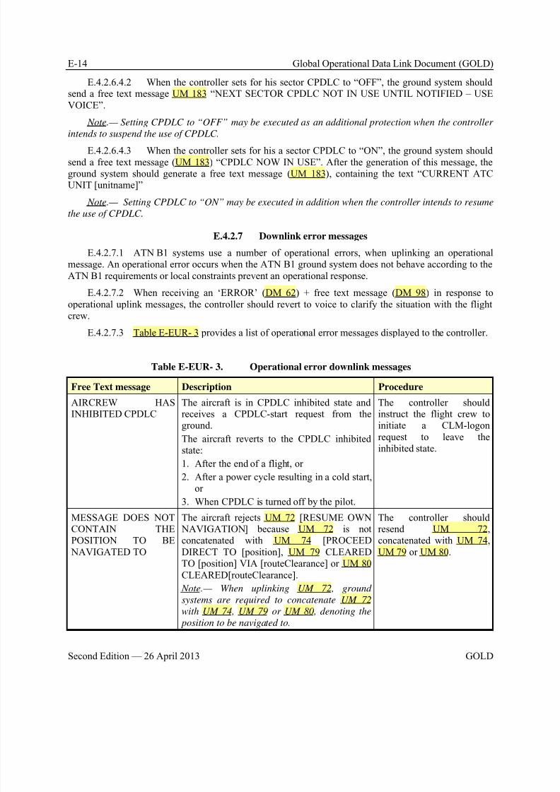
8/9/2019 CPDLC Explained
http://slidepdf.com/reader/full/cpdlc-explained 378/421
E-14 Global Operational Data Link Document (GOLD)
Second Edition — 26 April 2013 GOLD
E.4.2.6.4.2 When the controller sets for his sector CPDLC to “OFF”, the ground system shouldsend a free text message UM 183 “NEXT SECTOR CPDLC NOT IN USE UNTIL NOTIFIED – USEVOICE”.
Note.— Setting CPDLC to “OFF” may be executed as an additional protection when the controller
intends to suspend the use of CPDLC.E.4.2.6.4.3 When the controller sets for his a sector CPDLC to “ON”, the ground system should
send a free text message (UM 183) “CPDLC NOW IN USE”. After the generation of this message, theground system should generate a free text message (UM 183), containing the text “CURRENT ATCUNIT [unitname]”
Note.— Setting CPDLC to “ON” may be executed in addition when the controller intends to resume
the use of CPDLC.
E.4.2.7 Downlink error messages
E.4.2.7.1 ATN B1 systems use a number of operational errors, when uplinking an operationalmessage. An operational error occurs when the ATN B1 ground system does not behave according to the
ATN B1 requirements or local constraints prevent an operational response.E.4.2.7.2 When receiving an ‘ERROR’ (DM 62) + free text message (DM 98) in response to
operational uplink messages, the controller should revert to voice to clarify the situation with the flightcrew.
E.4.2.7.3 Table E-EUR- 3 provides a list of operational error messages displayed to the controller.
Table E-EUR- 3. Operational error downlink messages
Free Text message Description Procedure
AIRCREW HAS
INHIBITED CPDLC
The aircraft is in CPDLC inhibited state and
receives a CPDLC-start request from theground.
The aircraft reverts to the CPDLC inhibitedstate:
1. After the end of a flight, or
2. After a power cycle resulting in a cold start,or
3. When CPDLC is turned off by the pilot.
The controller should
instruct the flight crew toinitiate a CLM-logonrequest to leave theinhibited state.
MESSAGE DOES NOTCONTAIN THEPOSITION TO BE
NAVIGATED TO
The aircraft rejects UM 72 [RESUME OWN NAVIGATION] because UM 72 is notconcatenated with UM 74 [PROCEED
DIRECT TO [position], UM 79 CLEAREDTO [position] VIA [routeClearance] or UM 80CLEARED[routeClearance].
Note.— When uplinking UM 72, ground
systems are required to concatenate UM 72
with UM 74, UM 79 or UM 80, denoting the
position to be navigated to.
The controller shouldresend UM 72, concatenated with UM 74,
UM 79 or UM 80.
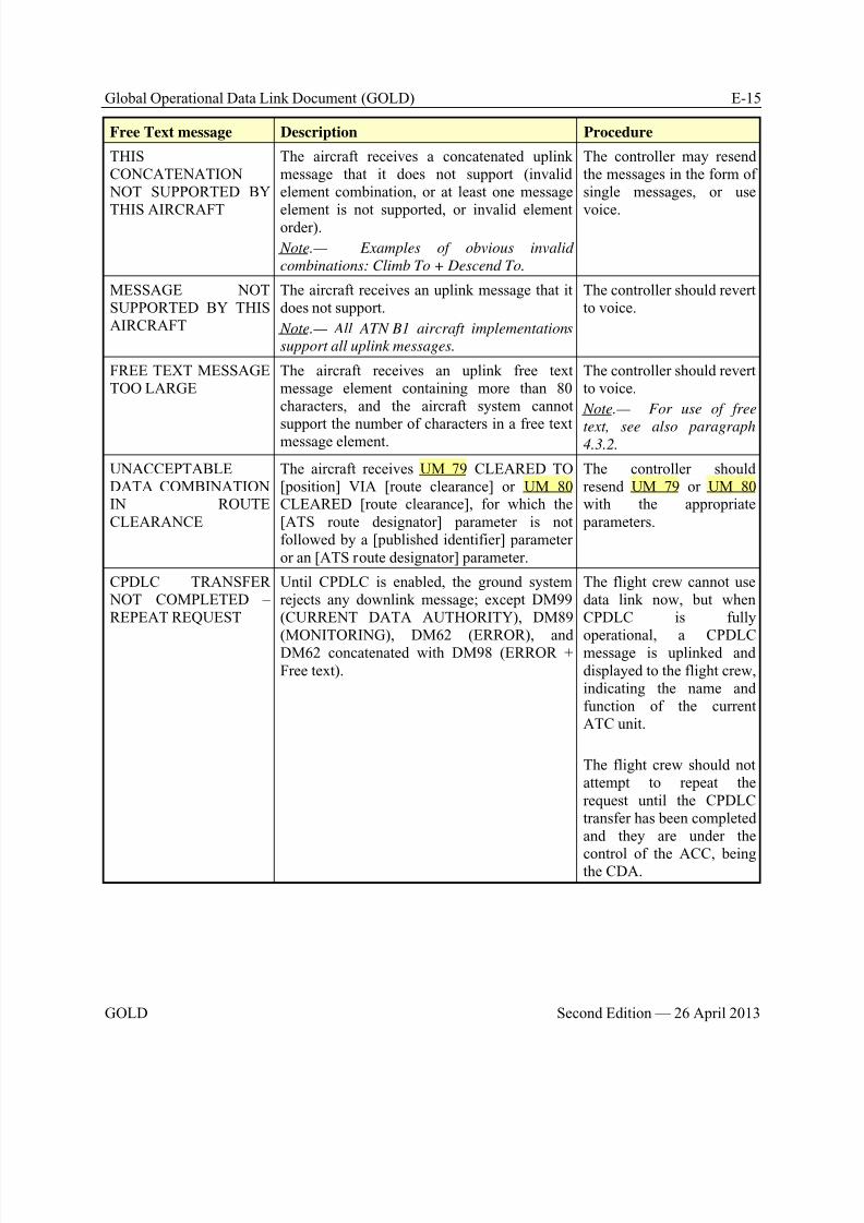
8/9/2019 CPDLC Explained
http://slidepdf.com/reader/full/cpdlc-explained 379/421
Global Operational Data Link Document (GOLD) E-15
GOLD Second Edition — 26 April 2013
Free Text message Description Procedure
THISCONCATENATION NOT SUPPORTED BY
THIS AIRCRAFT
The aircraft receives a concatenated uplinkmessage that it does not support (invalidelement combination, or at least one message
element is not supported, or invalid elementorder).
Note.— Examples of obvious invalid
combinations: Climb To + Descend To.
The controller may resendthe messages in the form ofsingle messages, or use
voice.
MESSAGE NOTSUPPORTED BY THISAIRCRAFT
The aircraft receives an uplink message that itdoes not support.
Note.— All ATN B1 aircraft implementations
support all uplink messages.
The controller should revertto voice.
FREE TEXT MESSAGETOO LARGE
The aircraft receives an uplink free textmessage element containing more than 80characters, and the aircraft system cannot
support the number of characters in a free textmessage element.
The controller should revertto voice.
Note.— For use of free
text, see also paragraph4.3.2.
UNACCEPTABLEDATA COMBINATIONIN ROUTECLEARANCE
The aircraft receives UM 79 CLEARED TO[position] VIA [route clearance] or UM 80CLEARED [route clearance], for which the[ATS route designator] parameter is notfollowed by a [published identifier] parameteror an [ATS route designator] parameter.
The controller shouldresend UM 79 or UM 80with the appropriate parameters.
CPDLC TRANSFER NOT COMPLETED –REPEAT REQUEST
Until CPDLC is enabled, the ground systemrejects any downlink message; except DM99(CURRENT DATA AUTHORITY), DM89
(MONITORING), DM62 (ERROR), andDM62 concatenated with DM98 (ERROR +Free text).
The flight crew cannot usedata link now, but whenCPDLC is fully
operational, a CPDLCmessage is uplinked anddisplayed to the flight crew,indicating the name andfunction of the currentATC unit.
The flight crew should notattempt to repeat therequest until the CPDLCtransfer has been completedand they are under the
control of the ACC, beingthe CDA.
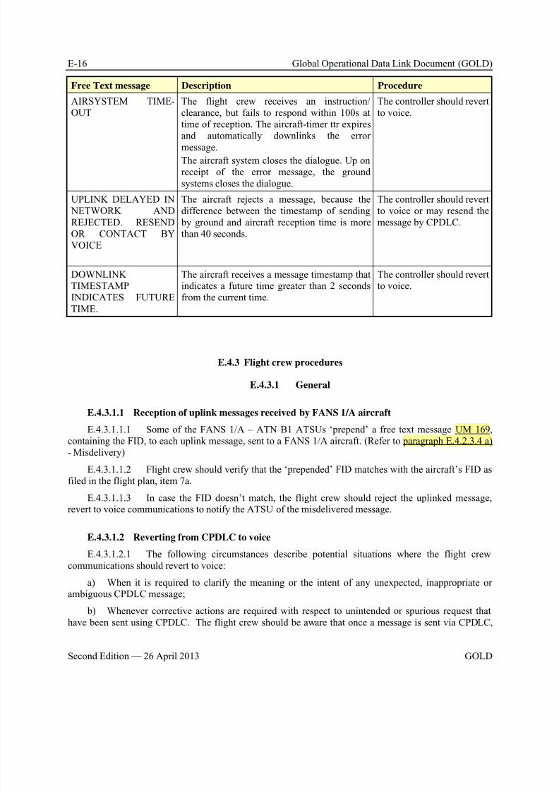
8/9/2019 CPDLC Explained
http://slidepdf.com/reader/full/cpdlc-explained 380/421
E-16 Global Operational Data Link Document (GOLD)
Second Edition — 26 April 2013 GOLD
Free Text message Description Procedure
AIRSYSTEM TIME-OUT
The flight crew receives an instruction/clearance, but fails to respond within 100s attime of reception. The aircraft-timer ttr expires
and automatically downlinks the errormessage.
The aircraft system closes the dialogue. Up onreceipt of the error message, the groundsystems closes the dialogue.
The controller should revertto voice.
UPLINK DELAYED IN NETWORK ANDREJECTED. RESENDOR CONTACT BYVOICE
The aircraft rejects a message, because thedifference between the timestamp of sending by ground and aircraft reception time is morethan 40 seconds.
The controller should revertto voice or may resend themessage by CPDLC.
DOWNLINKTIMESTAMPINDICATES FUTURETIME.
The aircraft receives a message timestamp thatindicates a future time greater than 2 secondsfrom the current time.
The controller should revertto voice.
E.4.3 Flight crew procedures
E.4.3.1 General
E.4.3.1.1 Reception of uplink messages received by FANS 1/A aircraftE.4.3.1.1.1 Some of the FANS 1/A – ATN B1 ATSUs ‘prepend’ a free text message UM 169,
containing the FID, to each uplink message, sent to a FANS 1/A aircraft. (Refer to paragraph E.4.2.3.4 a)- Misdelivery)
E.4.3.1.1.2 Flight crew should verify that the ‘prepended’ FID matches with the aircraft’s FID asfiled in the flight plan, item 7a.
E.4.3.1.1.3 In case the FID doesn’t match, the flight crew should reject the uplinked message,revert to voice communications to notify the ATSU of the misdelivered message.
E.4.3.1.2 Reverting from CPDLC to voice
E.4.3.1.2.1 The following circumstances describe potential situations where the flight crewcommunications should revert to voice:
a) When it is required to clarify the meaning or the intent of any unexpected, inappropriate orambiguous CPDLC message;
b) Whenever corrective actions are required with respect to unintended or spurious request thathave been sent using CPDLC. The flight crew should be aware that once a message is sent via CPDLC,
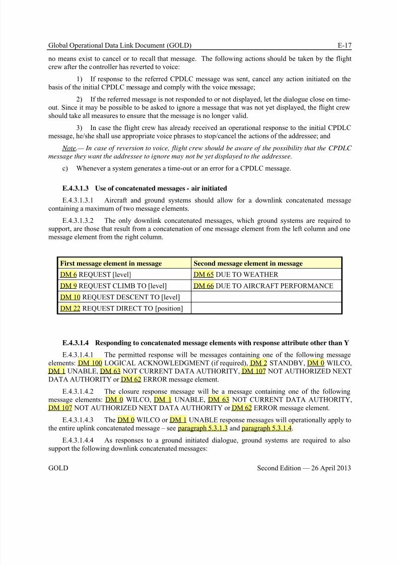
8/9/2019 CPDLC Explained
http://slidepdf.com/reader/full/cpdlc-explained 381/421
Global Operational Data Link Document (GOLD) E-17
GOLD Second Edition — 26 April 2013
no means exist to cancel or to recall that message. The following actions should be taken by the flightcrew after the controller has reverted to voice:
1) If response to the referred CPDLC message was sent, cancel any action initiated on the basis of the initial CPDLC message and comply with the voice message;
2) If the referred message is not responded to or not displayed, let the dialogue close on time-out. Since it may be possible to be asked to ignore a message that was not yet displayed, the flight crewshould take all measures to ensure that the message is no longer valid.
3) In case the flight crew has already received an operational response to the initial CPDLCmessage, he/she shall use appropriate voice phrases to stop/cancel the actions of the addressee; and
Note.— In case of reversion to voice, flight crew should be aware of the possibility that the CPDLC
message they want the addressee to ignore may not be yet displayed to the addressee.
c) Whenever a system generates a time-out or an error for a CPDLC message.
E.4.3.1.3 Use of concatenated messages - air initiated
E.4.3.1.3.1 Aircraft and ground systems should allow for a downlink concatenated messagecontaining a maximum of two message elements.
E.4.3.1.3.2 The only downlink concatenated messages, which ground systems are required tosupport, are those that result from a concatenation of one message element from the left column and onemessage element from the right column.
First message element in message Second message element in message
DM 6 REQUEST [level] DM 65 DUE TO WEATHER
DM 9 REQUEST CLIMB TO [level] DM 66 DUE TO AIRCRAFT PERFORMANCE
DM 10 REQUEST DESCENT TO [level]
DM 22 REQUEST DIRECT TO [position]
E.4.3.1.4 Responding to concatenated message elements with response attribute other than Y
E.4.3.1.4.1 The permitted response will be messages containing one of the following messageelements: DM 100 LOGICAL ACKNOWLEDGMENT (if required), DM 2 STANDBY, DM 0 WILCO,DM 1 UNABLE, DM 63 NOT CURRENT DATA AUTHORITY, DM 107 NOT AUTHORIZED NEXTDATA AUTHORITY or DM 62 ERROR message element.
E.4.3.1.4.2 The closure response message will be a message containing one of the followingmessage elements: DM 0 WILCO, DM 1 UNABLE, DM 63 NOT CURRENT DATA AUTHORITY,DM 107 NOT AUTHORIZED NEXT DATA AUTHORITY or DM 62 ERROR message element.
E.4.3.1.4.3 The DM 0 WILCO or DM 1 UNABLE response messages will operationally apply tothe entire uplink concatenated message – see paragraph 5.3.1.3 and paragraph 5.3.1.4.
E.4.3.1.4.4 As responses to a ground initiated dialogue, ground systems are required to alsosupport the following downlink concatenated messages:
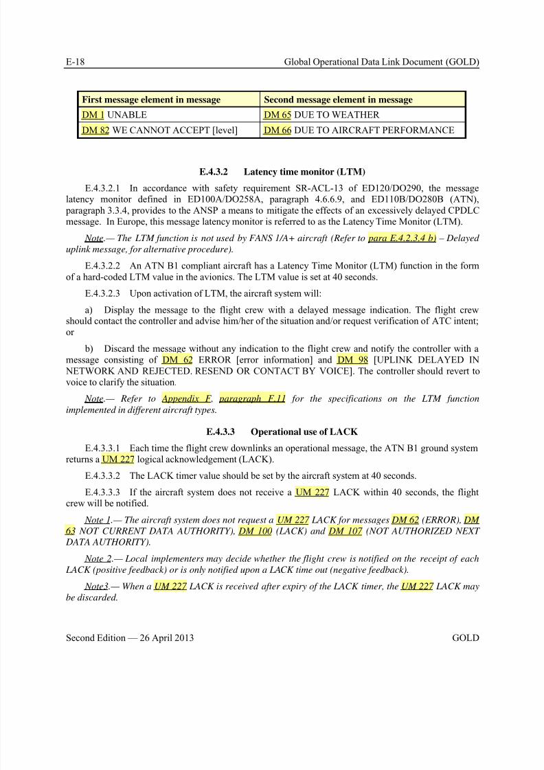
8/9/2019 CPDLC Explained
http://slidepdf.com/reader/full/cpdlc-explained 382/421
E-18 Global Operational Data Link Document (GOLD)
Second Edition — 26 April 2013 GOLD
First message element in message Second message element in message
DM 1 UNABLE DM 65 DUE TO WEATHER
DM 82 WE CANNOT ACCEPT [level] DM 66 DUE TO AIRCRAFT PERFORMANCE
E.4.3.2 Latency time monitor (LTM)
E.4.3.2.1 In accordance with safety requirement SR-ACL-13 of ED120/DO290, the messagelatency monitor defined in ED100A/DO258A, paragraph 4.6.6.9, and ED110B/DO280B (ATN), paragraph 3.3.4, provides to the ANSP a means to mitigate the effects of an excessively delayed CPDLCmessage. In Europe, this message latency monitor is referred to as the Latency Time Monitor (LTM).
Note.— The LTM function is not used by FANS 1/A+ aircraft (Refer to para E.4.2.3.4 b) – Delayed
uplink message, for alternative procedure).
E.4.3.2.2 An ATN B1 compliant aircraft has a Latency Time Monitor (LTM) function in the formof a hard-coded LTM value in the avionics. The LTM value is set at 40 seconds.
E.4.3.2.3 Upon activation of LTM, the aircraft system will:
a) Display the message to the flight crew with a delayed message indication. The flight crewshould contact the controller and advise him/her of the situation and/or request verification of ATC intent;or
b) Discard the message without any indication to the flight crew and notify the controller with amessage consisting of DM 62 ERROR [error information] and DM 98 [UPLINK DELAYED IN NETWORK AND REJECTED. RESEND OR CONTACT BY VOICE]. The controller should revert tovoice to clarify the situation.
Note.— Refer to Appendix F, paragraph F.11 for the specifications on the LTM function
implemented in different aircraft types.
E.4.3.3 Operational use of LACK
E.4.3.3.1 Each time the flight crew downlinks an operational message, the ATN B1 ground systemreturns a UM 227 logical acknowledgement (LACK).
E.4.3.3.2 The LACK timer value should be set by the aircraft system at 40 seconds.
E.4.3.3.3 If the aircraft system does not receive a UM 227 LACK within 40 seconds, the flightcrew will be notified.
Note 1.— The aircraft system does not request a UM 227 LACK for messages DM 62 (ERROR), DM
63 NOT CURRENT DATA AUTHORITY), DM 100 (LACK) and DM 107 (NOT AUTHORIZED NEXT
DATA AUTHORITY).
Note 2.— Local implementers may decide whether the flight crew is notified on the receipt of each
LACK (positive feedback) or is only notified upon a LACK time out (negative feedback).
Note3.— When a UM 227 LACK is received after expiry of the LACK timer, the UM 227 LACK may
be discarded.

8/9/2019 CPDLC Explained
http://slidepdf.com/reader/full/cpdlc-explained 383/421
Global Operational Data Link Document (GOLD) E-19
GOLD Second Edition — 26 April 2013
E.4.3.4 Operational timers used by the aircraft
E.4.3.4.1 Controller initiated dialogue
E.4.3.4.1.1 When an ATN B1 aircraft system receives an uplink message, requiring a response, it
starts the expiration timer-responder (ttr), which value for the response to be sent is set at 100 seconds.
a) The timer-responder (ttr) expires if the flight crew fails to respond within 100 seconds. Theflight crew is notified and reverts to voice to complete the dialogue;
Note.— FANS 1/A aircraft do not have a ttr timer.
b) The ATN B1 aircraft system closes the dialogue and downlinks an error response‘AIRSYSTEM TIME-OUT’. The error response ensures that the dialogue will also be closed within theATSU.
Note.— In normal circumstances, the aircraft-timer (ttr) expires before the ground-timer (tts)
expires.
E.4.3.4.1.2 If the flight crew responds to a clearance with a DM 2 STANDBY, the aircraft- and
ground timers are re-started.
E.4.3.4.2 Flight crew initiated dialogue
E.4.3.4.2.1 When the flight crew downlinks a request, requiring an operational response, andwhen implemented, the ATN B1 aircraft system starts the expiration timer-initiator (tts). If used, the timervalue for the operational response to be received is set at 270 seconds.
a) The timer-initiator (tts) expires, if no operational response has been received by the aircraftsystem within 270 seconds. The flight crew is notified and reverts to voice to resolve the situation.
b) The dialogue is closed locally by the aircraft system, ensuring that the dialogue doesn’t remainopen at the aircraft side.
Note.— ATN B1 ground systems have implemented ground-timer. In normal circumstances, the
ground-timer (ttr) expires before the aircraft-timer (tts) expires. Refer to paragraph E.4.2.4.2.
E.4.3.4.2.2 If the controller responds to a request with a UM 1 STANDBY, the aircraft andground timers are re-started.
E.4.3.5 Use of degrees in ACL messages
E.4.3.5.1 The Display of [degrees] parameter is used in the following three CPDLC messages:
a) UM 94 TURN (direction) HEADING (degrees)
b) UM 190 FLY HEADING (degrees)
c) UM 215 TURN (direction) (degrees) DEGREESE.4.3.5.2 UM 94 and UM 190 represent an absolute change towards the instructed HEADING,
while UM 215 is a relative change with reference to the current HEADING.
E.4.3.5.3 ICAO requires that the HEADING in UM 94 and UM 190 is expressed in 3 digits (e.g.‘015°) and should be displayed accordingly.
E.4.3.5.4 Flight crews should be aware that Airframe and avionics manufacturers are adding aleading ‘0’ for degrees less than 100° for UM 94 and UM 190.
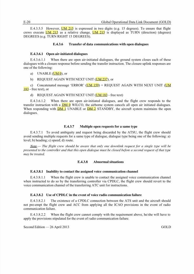
8/9/2019 CPDLC Explained
http://slidepdf.com/reader/full/cpdlc-explained 384/421
E-20 Global Operational Data Link Document (GOLD)
Second Edition — 26 April 2013 GOLD
E.4.3.5.5 However, UM 215 is expressed in two digits (e.g. 15 degrees). To ensure that flightcrews execute UM 215 as a relative change, UM 215 is displayed as TURN (direction) (degrees)DEGREES (e.g. TURN RIGHT 15 DEGREES).
E.4.3.6 Transfer of data communications with open dialogues
E.4.3.6.1 Open air-initiated dialogues
E.4.3.6.1.1 When there are open air-initiated dialogues, the ground system closes each of thesedialogues with a closure response before sending the transfer instruction. The closure uplink responses areone of the following:
a) UNABLE (UM 0), or
b) REQUEST AGAIN WITH NEXT UNIT (UM 237), or
c) Concatenated message ‘ERROR’ (UM 159) + REQUEST AGAIN WITH NEXT UNIT (UM183 - free text), or
d) REQUEST AGAIN WITH NEXT UNIT (UM 183 - free text)E.4.3.6.1.2 When there are open air-initiated dialogues, and the flight crew responds to the
transfer instruction with a DM 0 WILCO, the airborne system cancels all open air initiated dialogues.When responding with DM 1 UNABLE or DM 2 STANDBY, the aircraft system maintains the opendialogues.
E.4.3.7 Multiple open requests for a same type
E.4.3.7.1 To avoid ambiguity and request being discarded by the ATSU, the flight crew shouldavoid sending multiple requests for a same type of dialogue, dialogue type being one of the following: a)level; b) heading; c) speed; d) route.
Note.— The flight crew should be aware that only one downlink request for a single type will be
presented to the controller and that this open dialogue must be closed before a second request of that type
may be treated.
E.4.3.8 Abnormal situations
E.4.3.8.1 Inability to contact the assigned voice communication channel
E.4.3.8.1.1 When the flight crew is unable to contact the assigned voice communication channelwhen instructed to do so by the transferring controller via CPDLC, the flight crew should revert to thevoice communication channel of the transferring ATC unit for instructions.
E.4.3.8.2 Use of CPDLC in the event of voice radio communication failure
E.4.3.8.2.1 The existence of a CPDLC connection between the ATS unit and the aircraft shouldnot pre-empt the flight crew and ACC from applying all the ICAO provisions in the event of radiocommunication failure.
E.4.3.8.2.2 When the flight crew cannot comply with the requirement above, he/she will have toapply the provisions stipulated for the event of radio communication failure.
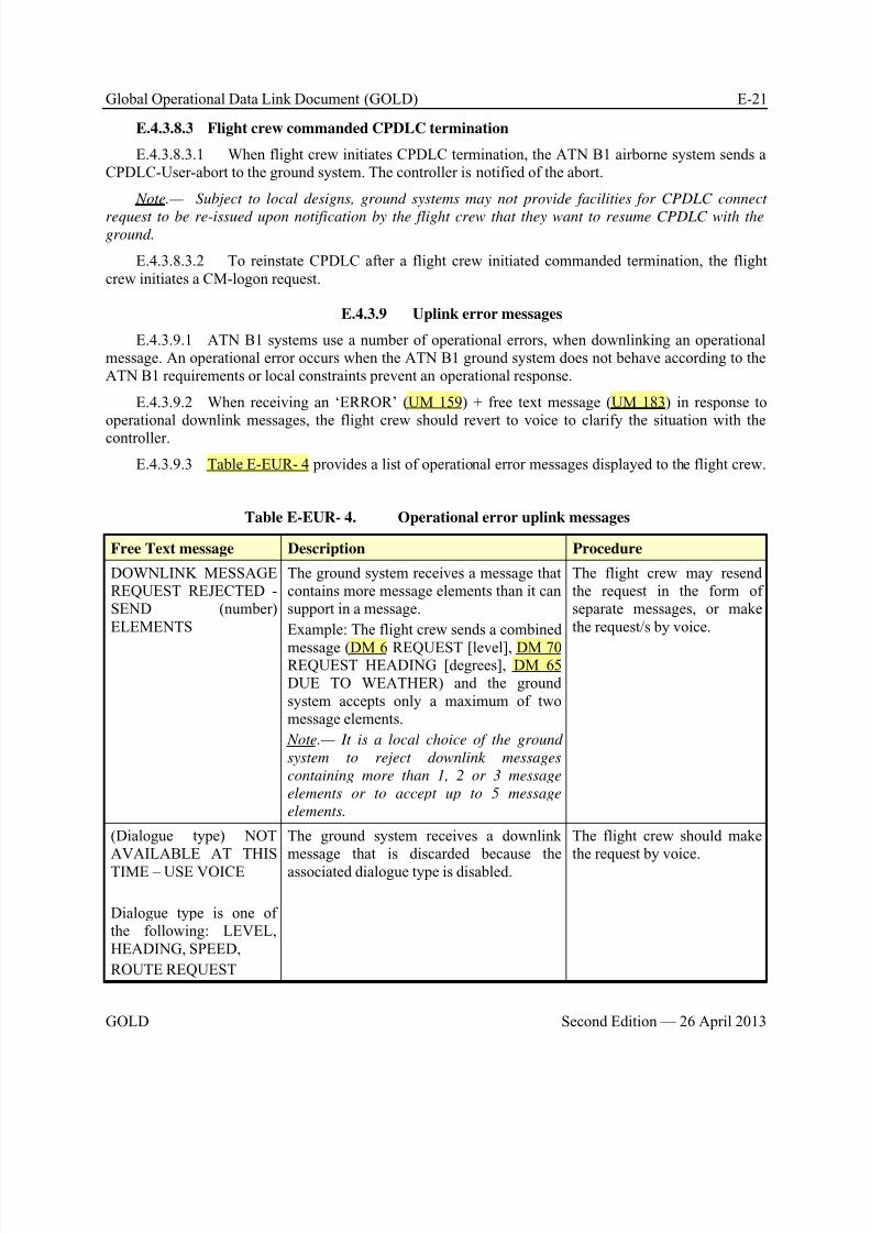
8/9/2019 CPDLC Explained
http://slidepdf.com/reader/full/cpdlc-explained 385/421
Global Operational Data Link Document (GOLD) E-21
GOLD Second Edition — 26 April 2013
E.4.3.8.3 Flight crew commanded CPDLC termination
E.4.3.8.3.1 When flight crew initiates CPDLC termination, the ATN B1 airborne system sends aCPDLC-User-abort to the ground system. The controller is notified of the abort.
Note.— Subject to local designs, ground systems may not provide facilities for CPDLC connect
request to be re-issued upon notification by the flight crew that they want to resume CPDLC with theground.
E.4.3.8.3.2 To reinstate CPDLC after a flight crew initiated commanded termination, the flightcrew initiates a CM-logon request.
E.4.3.9 Uplink error messages
E.4.3.9.1 ATN B1 systems use a number of operational errors, when downlinking an operationalmessage. An operational error occurs when the ATN B1 ground system does not behave according to theATN B1 requirements or local constraints prevent an operational response.
E.4.3.9.2 When receiving an ‘ERROR’ (UM 159) + free text message (UM 183) in response tooperational downlink messages, the flight crew should revert to voice to clarify the situation with the
controller.
E.4.3.9.3 Table E-EUR- 4 provides a list of operational error messages displayed to the flight crew.
Table E-EUR- 4. Operational error uplink messages
Free Text message Description Procedure
DOWNLINK MESSAGEREQUEST REJECTED -SEND (number)ELEMENTS
The ground system receives a message thatcontains more message elements than it cansupport in a message.
Example: The flight crew sends a combined
message (DM 6 REQUEST [level], DM 70REQUEST HEADING [degrees], DM 65DUE TO WEATHER) and the groundsystem accepts only a maximum of twomessage elements.
Note.— It is a local choice of the ground
system to reject downlink messages
containing more than 1, 2 or 3 message
elements or to accept up to 5 message
elements.
The flight crew may resendthe request in the form ofseparate messages, or makethe request/s by voice.
(Dialogue type) NOTAVAILABLE AT THISTIME – USE VOICE
Dialogue type is one ofthe following: LEVEL,HEADING, SPEED,
ROUTE REQUEST
The ground system receives a downlinkmessage that is discarded because theassociated dialogue type is disabled.
The flight crew should makethe request by voice.
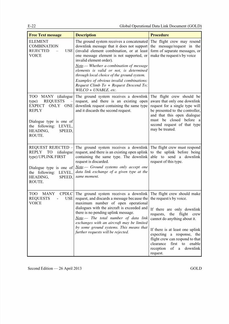
8/9/2019 CPDLC Explained
http://slidepdf.com/reader/full/cpdlc-explained 386/421
E-22 Global Operational Data Link Document (GOLD)
Second Edition — 26 April 2013 GOLD
Free Text message Description Procedure
ELEMENTCOMBINATIONREJECTED – USE
VOICE
The ground system receives a concatenateddownlink message that it does not support(invalid element combination, or at least
one message element is not supported, orinvalid element order).
Note.— Whether a combination of message
elements is valid or not, is determined
through local choice of the ground system.
Examples of obvious invalid combinations:
Request Climb To + Request Descend To;
WILCO + UNABLE, etc.
The flight crew may resendthe message/request in theform of separate messages, or
make the request/s by voice
TOO MANY (dialoguetype) REQUESTS –EXPECT ONLY ONEREPLY
Dialogue type is one ofthe following: LEVEL,HEADING, SPEED,ROUTE.
The ground system receives a downlinkrequest, and there is an existing opendownlink request containing the same typeand it discards the second request.
The flight crew should beaware that only one downlinkrequest for a single type will be presented to the controller,and that this open dialoguemust be closed before asecond request of that typemay be treated.
REQUEST REJECTED –REPLY TO (dialoguetype) UPLINK FIRST
Dialogue type is one ofthe following: LEVEL,HEADING, SPEED,ROUTE.
The ground system receives a downlinkrequest, and there is an existing open uplinkcontaining the same type. The downlinkrequest is discarded.
Note.— Ground systems only accept one
data link exchange of a given type at thesame moment.
The flight crew must respondto the uplink before beingable to send a downlinkrequest of this type.
TOO MANY CPDLCREQUESTS - USEVOICE
The ground system receives a downlinkrequest, and discards a message because themaximum number of open operationaldialogues with the aircraft is exceeded andthere is no pending uplink message.
Note.— The total number of data link
exchanges with an aircraft may be limited
by some ground systems. This means that further requests will be rejected.
The flight crew should makethe request/s by voice.
If there are only downlinkrequests, the flight crewcannot do anything about it.
If there is at least one uplinkexpecting a response, theflight crew can respond to thatclearance first to enablereception of a downlinkrequest.
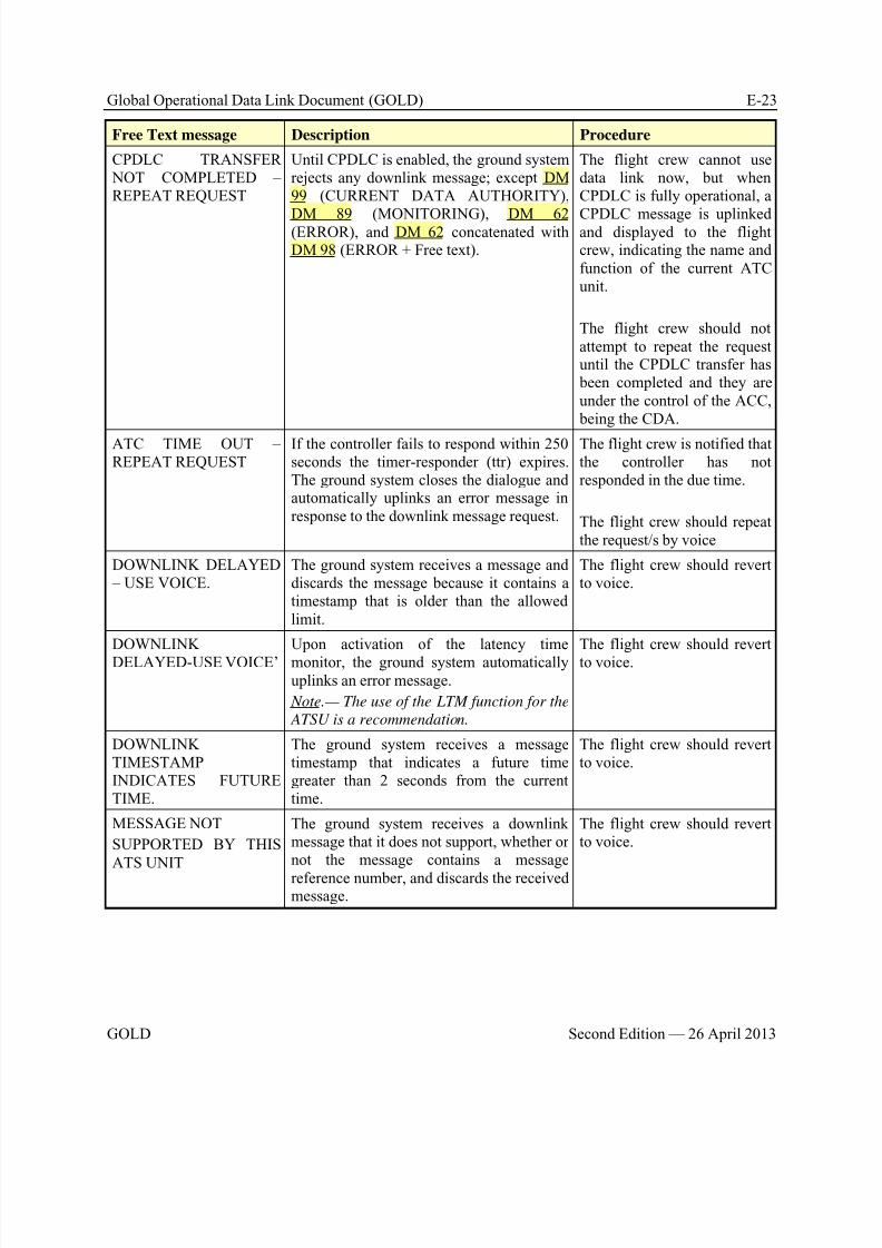
8/9/2019 CPDLC Explained
http://slidepdf.com/reader/full/cpdlc-explained 387/421
Global Operational Data Link Document (GOLD) E-23
GOLD Second Edition — 26 April 2013
Free Text message Description Procedure
CPDLC TRANSFER NOT COMPLETED –REPEAT REQUEST
Until CPDLC is enabled, the ground systemrejects any downlink message; except DM99 (CURRENT DATA AUTHORITY),
DM 89 (MONITORING), DM 62(ERROR), and DM 62 concatenated withDM 98 (ERROR + Free text).
The flight crew cannot usedata link now, but whenCPDLC is fully operational, a
CPDLC message is uplinkedand displayed to the flightcrew, indicating the name andfunction of the current ATCunit.
The flight crew should notattempt to repeat the requestuntil the CPDLC transfer has been completed and they areunder the control of the ACC, being the CDA.
ATC TIME OUT –REPEAT REQUEST
If the controller fails to respond within 250seconds the timer-responder (ttr) expires.The ground system closes the dialogue andautomatically uplinks an error message inresponse to the downlink message request.
The flight crew is notified thatthe controller has notresponded in the due time.
The flight crew should repeatthe request/s by voice
DOWNLINK DELAYED – USE VOICE.
The ground system receives a message anddiscards the message because it contains atimestamp that is older than the allowedlimit.
The flight crew should revertto voice.
DOWNLINKDELAYED-USE VOICE’
Upon activation of the latency timemonitor, the ground system automaticallyuplinks an error message.
Note.— The use of the LTM function for the
ATSU is a recommendation.
The flight crew should revertto voice.
DOWNLINKTIMESTAMPINDICATES FUTURETIME.
The ground system receives a messagetimestamp that indicates a future timegreater than 2 seconds from the currenttime.
The flight crew should revertto voice.
MESSAGE NOT
SUPPORTED BY THISATS UNIT
The ground system receives a downlinkmessage that it does not support, whether ornot the message contains a message
reference number, and discards the receivedmessage.
The flight crew should revertto voice.
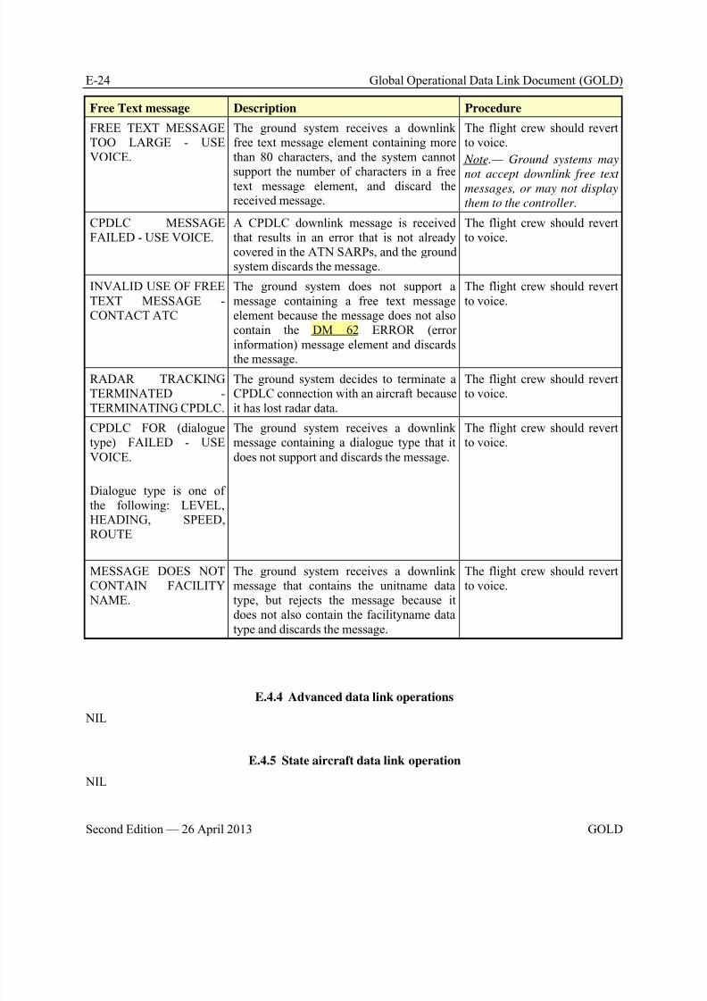
8/9/2019 CPDLC Explained
http://slidepdf.com/reader/full/cpdlc-explained 388/421
E-24 Global Operational Data Link Document (GOLD)
Second Edition — 26 April 2013 GOLD
Free Text message Description Procedure
FREE TEXT MESSAGETOO LARGE - USEVOICE.
The ground system receives a downlinkfree text message element containing morethan 80 characters, and the system cannot
support the number of characters in a freetext message element, and discard thereceived message.
The flight crew should revertto voice.
Note.— Ground systems may
not accept downlink free textmessages, or may not display
them to the controller.
CPDLC MESSAGEFAILED - USE VOICE.
A CPDLC downlink message is receivedthat results in an error that is not alreadycovered in the ATN SARPs, and the groundsystem discards the message.
The flight crew should revertto voice.
INVALID USE OF FREETEXT MESSAGE -CONTACT ATC
The ground system does not support amessage containing a free text messageelement because the message does not alsocontain the DM 62 ERROR (error
information) message element and discardsthe message.
The flight crew should revertto voice.
RADAR TRACKINGTERMINATED -TERMINATING CPDLC.
The ground system decides to terminate aCPDLC connection with an aircraft becauseit has lost radar data.
The flight crew should revertto voice.
CPDLC FOR (dialoguetype) FAILED - USEVOICE.
Dialogue type is one ofthe following: LEVEL,
HEADING, SPEED,ROUTE
The ground system receives a downlinkmessage containing a dialogue type that itdoes not support and discards the message.
The flight crew should revertto voice.
MESSAGE DOES NOTCONTAIN FACILITY NAME.
The ground system receives a downlinkmessage that contains the unitname datatype, but rejects the message because itdoes not also contain the facilityname datatype and discards the message.
The flight crew should revertto voice.
E.4.4 Advanced data link operations NIL
E.4.5 State aircraft data link operation
NIL
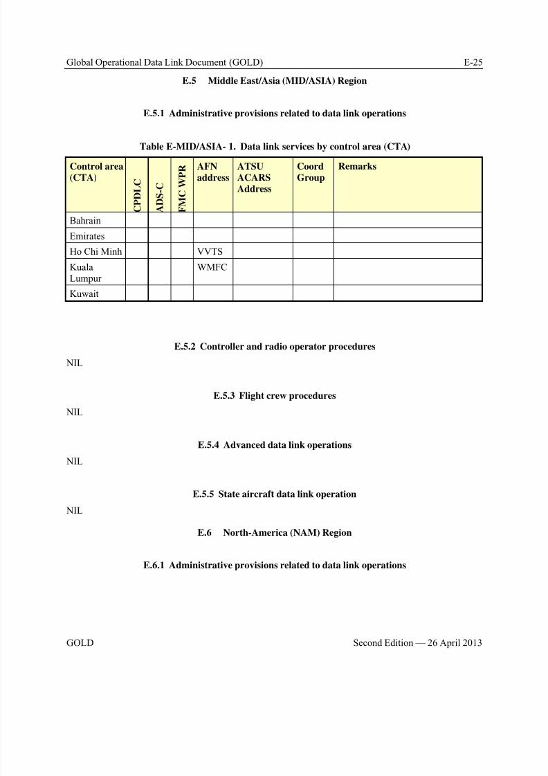
8/9/2019 CPDLC Explained
http://slidepdf.com/reader/full/cpdlc-explained 389/421
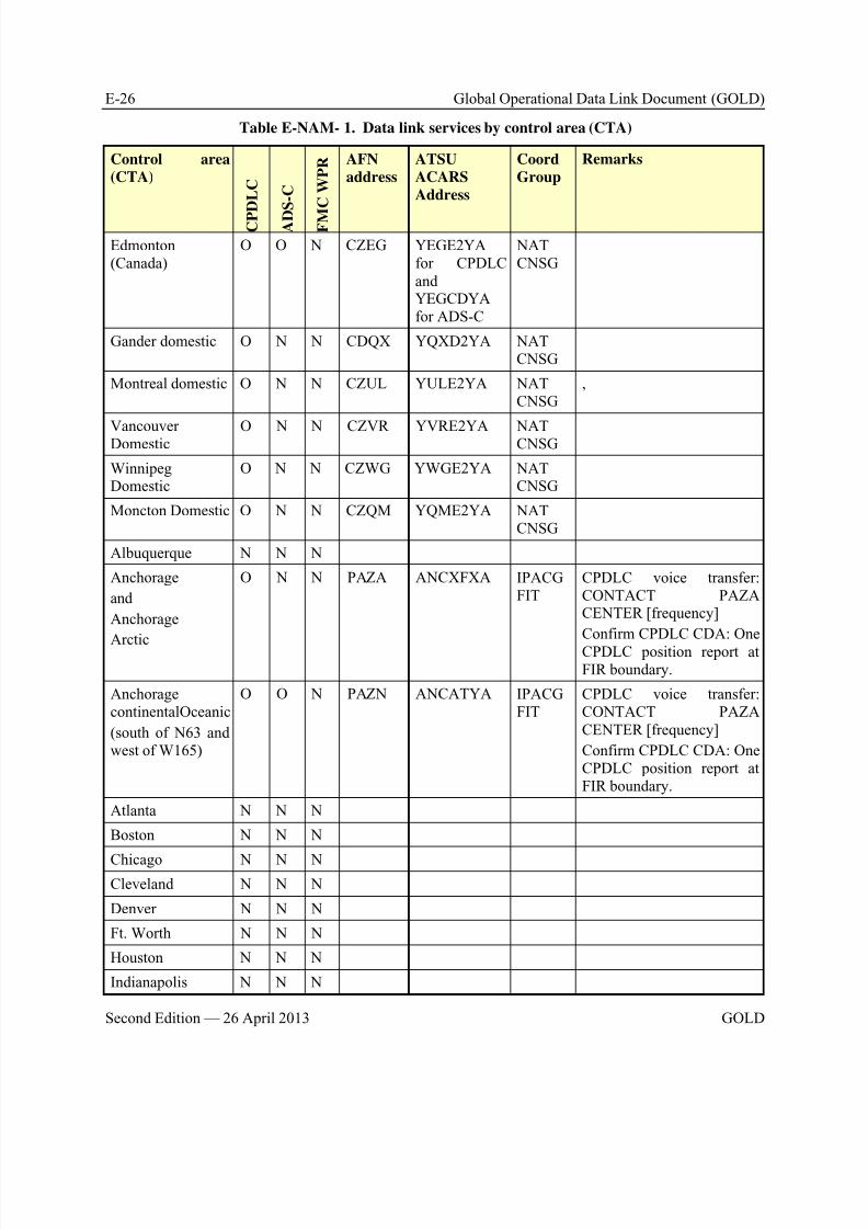
8/9/2019 CPDLC Explained
http://slidepdf.com/reader/full/cpdlc-explained 390/421
E-26 Global Operational Data Link Document (GOLD)
Second Edition — 26 April 2013 GOLD
Table E-NAM- 1. Data link services by control area (CTA)
Control area
(CTA)
C P D L C
A D
S - C
F M
C W P R AFN
address
ATSU
ACARS
Address
Coord
Group
Remarks
Edmonton(Canada)
O O N CZEG YEGE2YAfor CPDLCandYEGCDYAfor ADS-C
NATCNSG
Gander domestic O N N CDQX YQXD2YA NATCNSG
Montreal domestic O N N CZUL YULE2YA NATCNSG
,
VancouverDomestic O N N CZVR YVRE2YA NATCNSG
WinnipegDomestic
O N N CZWG YWGE2YA NATCNSG
Moncton Domestic O N N CZQM YQME2YA NATCNSG
Albuquerque N N N
Anchorage
and
Anchorage
Arctic
O N N PAZA ANCXFXA IPACGFIT
CPDLC voice transfer:CONTACT PAZACENTER [frequency]
Confirm CPDLC CDA: One
CPDLC position report atFIR boundary.
AnchoragecontinentalOceanic
(south of N63 andwest of W165)
O O N PAZN ANCATYA IPACGFIT
CPDLC voice transfer:CONTACT PAZACENTER [frequency]
Confirm CPDLC CDA: OneCPDLC position report atFIR boundary.
Atlanta N N N
Boston N N N
Chicago N N NCleveland N N N
Denver N N N
Ft. Worth N N N
Houston N N N
Indianapolis N N N
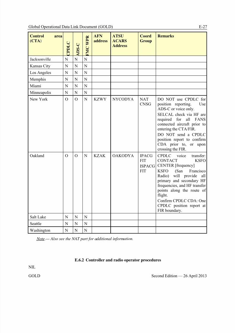
8/9/2019 CPDLC Explained
http://slidepdf.com/reader/full/cpdlc-explained 391/421
Global Operational Data Link Document (GOLD) E-27
GOLD Second Edition — 26 April 2013
Control area
(CTA)
C P D L C
A D S - C
F M C W P R AFN
address
ATSU
ACARS
Address
Coord
Group
Remarks
Jacksonville N N N
Kansas City N N N
Los Angeles N N N
Memphis N N N
Miami N N N
Minneapolis N N N
New York O O N KZWY NYCODYA NATCNSG
DO NOT use CPDLC for position reporting. UseADS-C or voice only.
SELCAL check via HF arerequired for all FANSconnected aircraft prior toentering the CTA/FIR.
DO NOT send a CPDLC position report to confirmCDA prior to, or uponcrossing the FIR.
Oakland O O N KZAK OAKODYA IPACGFIT
ISPACGFIT
CPDLC voice transfer:CONTACT KSFOCENTER [frequency]
KSFO (San Francisco
Radio) will provide all primary and secondary HFfrequencies, and HF transfer points along the route offlight.
Confirm CPDLC CDA: OneCPDLC position report atFIR boundary.
Salt Lake N N N
Seattle N N N
Washington N N N
Note.— Also see the NAT part for additional information.
E.6.2 Controller and radio operator procedures
NIL

8/9/2019 CPDLC Explained
http://slidepdf.com/reader/full/cpdlc-explained 392/421
E-28 Global Operational Data Link Document (GOLD)
Second Edition — 26 April 2013 GOLD
E.6.3 Flight crew procedures
NIL
E.6.4 Advanced data link operations
NIL
E.6.5 State aircraft data link operation
NIL
E.7 North Atlantic (NAT) Region
E.7.1 Administrative provisions related to data link operations
E.7.1.1 ANSP service provision
E.7.1.1.1 Table E-NAT- 1 lists the flight information regions (FIRs) and Upper flight informationregions (UIRs), where data link service is provided and indicates Logon address, ATSU ACARS Address,coordinating group, CPDLC Contact or Monitor message requirements and position reportingrequirements. For CPDLC, ADS-C and FMC WPR columns, O=operational, T=trial, and N=notavailable.
E.7.1.1.2 Table E-NAT- 2 lists the contact information of the NAT CSNG and Table E-NAT- 3 provides the website URL of the CRA.
Table E-NAT- 1. Data link services by control area (CTA).
Control area
(CTA)
C P D L C
A D S - C
F M C W P R AFN
address
ATSU
ACARS
Address
Coord
Group
Remarks
Bodø N O O ENOB NATCNSG
Edmonton(Canada)
O O N CZEG YEGE2YAfor CPDLCandYEGCDYA
for ADS-C
NATCNSG
GanderOceanic
O O O CZQX YQXE2YA NATCNSG
Report revised ETA: Nextwaypoint ETA error 3 minutes ormore, use free text DM 67kREVISED ETA [position] [time].See paragraph E.7.1.4.
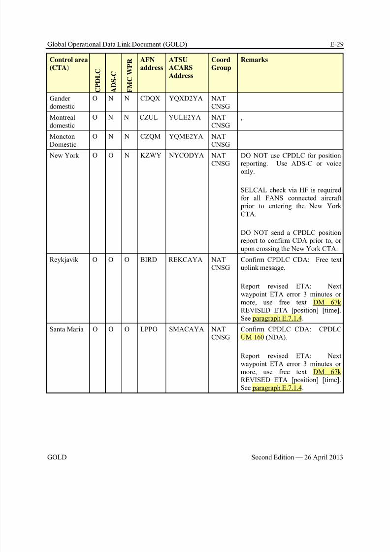
8/9/2019 CPDLC Explained
http://slidepdf.com/reader/full/cpdlc-explained 393/421
Global Operational Data Link Document (GOLD) E-29
GOLD Second Edition — 26 April 2013
Control area
(CTA)
C P D L C
A D S - C
F M C W P R AFN
address
ATSU
ACARS
Address
Coord
Group
Remarks
Ganderdomestic
O N N CDQX YQXD2YA NATCNSG
Montrealdomestic
O N N CZUL YULE2YA NATCNSG
,
MonctonDomestic
O N N CZQM YQME2YA NATCNSG
New York O O N KZWY NYCODYA NATCNSG
DO NOT use CPDLC for positionreporting. Use ADS-C or voiceonly.
SELCAL check via HF is requiredfor all FANS connected aircraft prior to entering the New YorkCTA.
DO NOT send a CPDLC positionreport to confirm CDA prior to, orupon crossing the New York CTA.
Reykjavik O O O BIRD REKCAYA NATCNSG
Confirm CPDLC CDA: Free textuplink message.
Report revised ETA: Nextwaypoint ETA error 3 minutes ormore, use free text DM 67kREVISED ETA [position] [time].See paragraph E.7.1.4.
Santa Maria O O O LPPO SMACAYA NATCNSG
Confirm CPDLC CDA: CPDLCUM 160 (NDA).
Report revised ETA: Nextwaypoint ETA error 3 minutes ormore, use free text DM 67kREVISED ETA [position] [time].
See paragraph E.7.1.4.
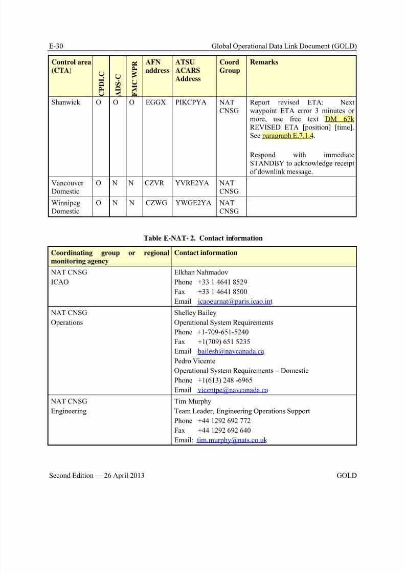
8/9/2019 CPDLC Explained
http://slidepdf.com/reader/full/cpdlc-explained 394/421
E-30 Global Operational Data Link Document (GOLD)
Second Edition — 26 April 2013 GOLD
Control area
(CTA)
C P D L C
A D S - C
F M C W P R AFN
address
ATSU
ACARS
Address
Coord
Group
Remarks
Shanwick O O O EGGX PIKCPYA NATCNSG
Report revised ETA: Nextwaypoint ETA error 3 minutes ormore, use free text DM 67kREVISED ETA [position] [time].See paragraph E.7.1.4.
Respond with immediateSTANDBY to acknowledge receiptof downlink message.
VancouverDomestic
O N N CZVR YVRE2YA NATCNSG
WinnipegDomestic
O N N CZWG YWGE2YA NATCNSG
Table E-NAT- 2. Contact information
Coordinating group or regional
monitoring agency
Contact information
NAT CNSG
ICAO
Elkhan Nahmadov
Phone +33 1 4641 8529
Fax +33 1 4641 8500
Email [email protected] NAT CNSG
Operations
Shelley Bailey
Operational System Requirements
Phone +1-709-651-5240
Fax +1(709) 651 5235
Email [email protected]
Pedro Vicente
Operational System Requirements – Domestic
Phone +1(613) 248 -6965
Email [email protected]
NAT CNSGEngineering
Tim MurphyTeam Leader, Engineering Operations Support
Phone +44 1292 692 772
Fax +44 1292 692 640
Email: [email protected]
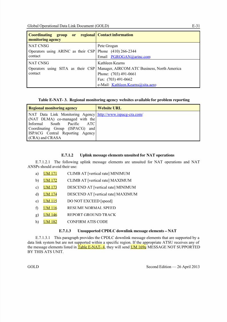
8/9/2019 CPDLC Explained
http://slidepdf.com/reader/full/cpdlc-explained 395/421
Global Operational Data Link Document (GOLD) E-31
GOLD Second Edition — 26 April 2013
Coordinating group or regional
monitoring agency
Contact information
NAT CNSG
Operators using ARINC as their CSP
contact
Pete Grogan
Phone (410) 266-2344
Email [email protected]
NAT CNSG
Operators using SITA as their CSPcontact
Kathleen Kearns
Manager, AIRCOM ATC Business, North America
Phone: (703) 491-0661
Fax: (703) 491-0662
e-Mail: [email protected]
Table E-NAT- 3. Regional monitoring agency websites available for problem reporting
Regional monitoring agency Website URL
NAT Data Link Monitoring Agency(NAT DLMA) co-managed with theInformal South Pacific ATCCoordinating Group (ISPACG) andISPACG Central Reporting Agency(CRA) and CRASA
http://www.ispacg-cra.com/
E.7.1.2 Uplink message elements unsuited for NAT operations
E.7.1.2.1 The following uplink message elements are unsuited for NAT operations and NATANSPs should avoid their use:
a) UM 171 CLIMB AT [vertical rate] MINIMUM
b) UM 172 CLIMB AT [vertical rate] MAXIMUM
c) UM 173 DESCEND AT [vertical rate] MINIMUM
d) UM 174 DESCEND AT [vertical rate] MAXIMUM
e) UM 115 DO NOT EXCEED [speed]
f) UM 116 RESUME NORMAL SPEED
g) UM 146 REPORT GROUND TRACK
h) UM 182 CONFIRM ATIS CODE
E.7.1.3 Unsupported CPDLC downlink message elements – NAT
E.7.1.3.1 This paragraph provides the CPDLC downlink message elements that are supported by adata link system but are not supported within a specific region. If the appropriate ATSU receives any ofthe message elements listed in Table E-NAT- 4, they will send UM 169u MESSAGE NOT SUPPORTEDBY THIS ATS UNIT.
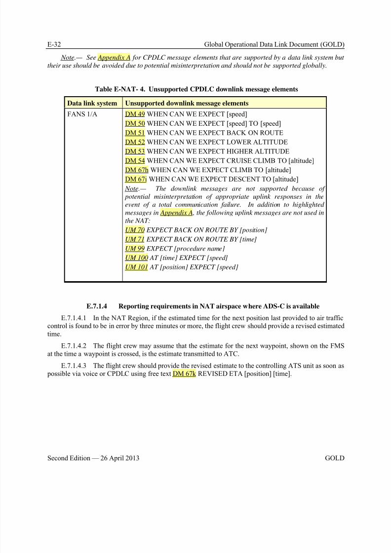
8/9/2019 CPDLC Explained
http://slidepdf.com/reader/full/cpdlc-explained 396/421
E-32 Global Operational Data Link Document (GOLD)
Second Edition — 26 April 2013 GOLD
Note.— See Appendix A for CPDLC message elements that are supported by a data link system but
their use should be avoided due to potential misinterpretation and should not be supported globally.
Table E-NAT- 4. Unsupported CPDLC downlink message elements
Data link system Unsupported downlink message elements
FANS 1/A DM 49 WHEN CAN WE EXPECT [speed]
DM 50 WHEN CAN WE EXPECT [speed] TO [speed]
DM 51 WHEN CAN WE EXPECT BACK ON ROUTE
DM 52 WHEN CAN WE EXPECT LOWER ALTITUDE
DM 53 WHEN CAN WE EXPECT HIGHER ALTITUDE
DM 54 WHEN CAN WE EXPECT CRUISE CLIMB TO [altitude]
DM 67h WHEN CAN WE EXPECT CLIMB TO [altitude]
DM 67i WHEN CAN WE EXPECT DESCENT TO [altitude]
Note.— The downlink messages are not supported because of
potential misinterpretation of appropriate uplink responses in the
event of a total communication failure. In addition to highlighted
messages in Appendix A, the following uplink messages are not used in
the NAT:
UM 70 EXPECT BACK ON ROUTE BY [position]
UM 71 EXPECT BACK ON ROUTE BY [time]
UM 99 EXPECT [procedure name]
UM 100 AT [time] EXPECT [speed]
UM 101 AT [position] EXPECT [speed]
E.7.1.4 Reporting requirements in NAT airspace where ADS-C is available
E.7.1.4.1 In the NAT Region, if the estimated time for the next position last provided to air trafficcontrol is found to be in error by three minutes or more, the flight crew should provide a revised estimatedtime.
E.7.1.4.2 The flight crew may assume that the estimate for the next waypoint, shown on the FMSat the time a waypoint is crossed, is the estimate transmitted to ATC.
E.7.1.4.3 The flight crew should provide the revised estimate to the controlling ATS unit as soon as possible via voice or CPDLC using free text DM 67k REVISED ETA [position] [time].

8/9/2019 CPDLC Explained
http://slidepdf.com/reader/full/cpdlc-explained 397/421
Global Operational Data Link Document (GOLD) E-33
GOLD Second Edition — 26 April 2013
E.7.2 Controller and radio operator procedures
E.7.2.1 Voice communication procedures
E.7.2.1.1 Aeradio - response to initial contact
E.7.2.1.1.1 Aeradio operators should:
a) Respond to an aircraft that identifies itself by including a data link term after the aircraft callsign by restating the data link term after the aircraft call sign (see paragraph E.7.3.1.1.3 for the list of datalink terms); and
b) Complete the SELCAL check (see paragraph E.7.3.1.1.4 and paragraph E.7.3.1.1.5 forexamples of the initial contact procedures to be used by the flight crew).
E.7.2.1.1.2 If a flight uses the term “A-D-S” after the aircraft call sign, the aeradio operatorshould issue:
a) Communication instruction for the next CTA/FIR; or
b) Communications instructions and the frequency to contact the appropriate ATSU approaching,or over, the exit point; or
c) Instructions for the flight to contact the aeradio station serving the next CTA/FIR at a time orlocation prior to the next CTA/FIR boundary or exit point.
E.7.2.1.1.3 When the CTA/FIR does not offer FMC WPR services, if a flight uses the term“F-M-C” after the aircraft call sign, the aeradio operator should advise the flight crew to make positionreports by HF voice.
E.7.2.1.1.4 When the CTA/FIR offers FMC WPR services, if a flight uses the term “F-M-C” afterthe aircraft call sign, the aeradio operator should issue:
a) Communication instruction for the next CTA/FIR; or
b) Communications instructions and the frequency to contact the appropriate ATSU approaching,or over, the exit point; or
c) Instructions for the flight to contact the aeradio station serving the next CTA/FIR at a time orlocation prior to the next CTA/FIR boundary or exit point.
E.7.2.1.1.5 When the CTA/FIR does not offer CPDLC services, if a flight uses the term“C-P-D-L-C” after the aircraft call sign, the aeradio operator should:
a) Advise the flight that ““CPDLC SERVICE NOT AVAILABLE IN (name) CTA/FIR”; and
b) Issue:
1) Communication instruction for the next CTA/FIR; or
2) Communications instructions and the frequency to contact the appropriate ATSUapproaching, or over, the exit point; or
3) Instructions for the flight to contact the aeradio station serving the next CTA/FIR at a timeor location prior the next CTA/FIR boundary or exit point.
E.7.2.1.1.6 During CPDLC operations, if a flight uses the term “C-P-D-L-C” after the aircraft callsign, the aeradio operator should:
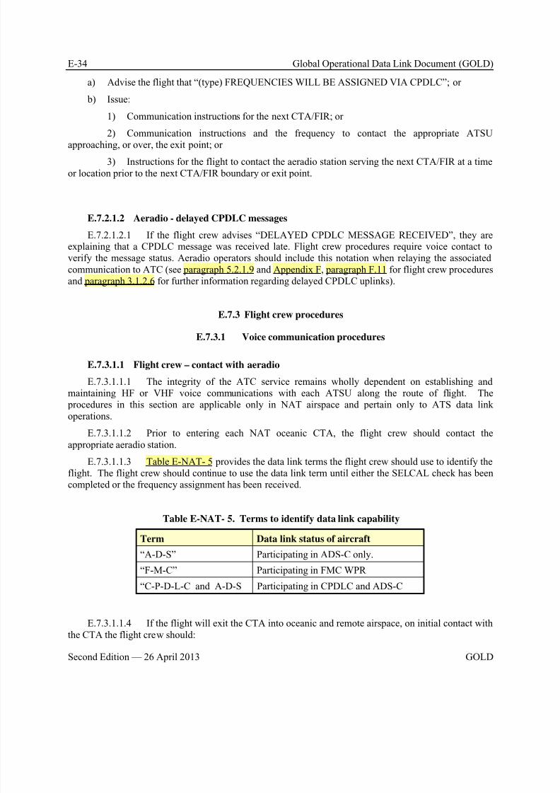
8/9/2019 CPDLC Explained
http://slidepdf.com/reader/full/cpdlc-explained 398/421
E-34 Global Operational Data Link Document (GOLD)
Second Edition — 26 April 2013 GOLD
a) Advise the flight that “(type) FREQUENCIES WILL BE ASSIGNED VIA CPDLC”; or
b) Issue:
1) Communication instructions for the next CTA/FIR; or
2) Communication instructions and the frequency to contact the appropriate ATSUapproaching, or over, the exit point; or
3) Instructions for the flight to contact the aeradio station serving the next CTA/FIR at a timeor location prior to the next CTA/FIR boundary or exit point.
E.7.2.1.2 Aeradio - delayed CPDLC messages
E.7.2.1.2.1 If the flight crew advises “DELAYED CPDLC MESSAGE RECEIVED”, they areexplaining that a CPDLC message was received late. Flight crew procedures require voice contact toverify the message status. Aeradio operators should include this notation when relaying the associatedcommunication to ATC (see paragraph 5.2.1.9 and Appendix F, paragraph F.11 for flight crew procedures
and paragraph 3.1.2.6 for further information regarding delayed CPDLC uplinks).
E.7.3 Flight crew procedures
E.7.3.1 Voice communication procedures
E.7.3.1.1 Flight crew – contact with aeradio
E.7.3.1.1.1 The integrity of the ATC service remains wholly dependent on establishing andmaintaining HF or VHF voice communications with each ATSU along the route of flight. The procedures in this section are applicable only in NAT airspace and pertain only to ATS data link
operations.
E.7.3.1.1.2 Prior to entering each NAT oceanic CTA, the flight crew should contact theappropriate aeradio station.
E.7.3.1.1.3 Table E-NAT- 5 provides the data link terms the flight crew should use to identify theflight. The flight crew should continue to use the data link term until either the SELCAL check has beencompleted or the frequency assignment has been received.
Table E-NAT- 5. Terms to identify data link capability
Term Data link status of aircraft
“A-D-S” Participating in ADS-C only.“F-M-C” Participating in FMC WPR
“C-P-D-L-C and A-D-S Participating in CPDLC and ADS-C
E.7.3.1.1.4 If the flight will exit the CTA into oceanic and remote airspace, on initial contact withthe CTA the flight crew should:
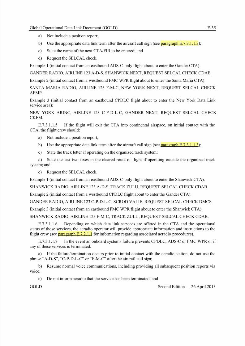
8/9/2019 CPDLC Explained
http://slidepdf.com/reader/full/cpdlc-explained 399/421
Global Operational Data Link Document (GOLD) E-35
GOLD Second Edition — 26 April 2013
a) Not include a position report;
b) Use the appropriate data link term after the aircraft call sign (see paragraph E.7.3.1.1.3);
c) State the name of the next CTA/FIR to be entered; and
d) Request the SELCAL check.
Example 1 (initial contact from an eastbound ADS-C-only flight about to enter the Gander CTA):
GANDER RADIO, AIRLINE 123 A-D-S, SHANWICK NEXT, REQUEST SELCAL CHECK CDAB.
Example 2 (initial contact from a westbound FMC WPR flight about to enter the Santa Maria CTA):
SANTA MARIA RADIO, AIRLINE 123 F-M-C, NEW YORK NEXT, REQUEST SELCAL CHECKAFMP.
Example 3 (initial contact from an eastbound CPDLC flight about to enter the New York Data Linkservice area):
NEW YORK ARINC, AIRLINE 123 C-P-D-L-C, GANDER NEXT, REQUEST SELCAL CHECKCKFM.
E.7.3.1.1.5 If the flight will exit the CTA into continental airspace, on initial contact with theCTA, the flight crew should:
a) Not include a position report;
b) Use the appropriate data link term after the aircraft call sign (see paragraph E.7.3.1.1.3);
c) State the track letter if operating on the organized track system;
d) State the last two fixes in the cleared route of flight if operating outside the organized tracksystem; and
e) Request the SELCAL check.
Example 1 (initial contact from an eastbound ADS-C-only flight about to enter the Shanwick CTA):
SHANWICK RADIO, AIRLINE 123 A-D-S, TRACK ZULU, REQUEST SELCAL CHECK CDAB.
Example 2 (initial contact from a westbound CPDLC flight about to enter the Gander CTA):
GANDER RADIO, AIRLINE 123 C-P-D-L-C, SCROD VALIE, REQUEST SELCAL CHECK DMCS.
Example 3 (initial contact from an eastbound FMC WPR flight about to enter the Shanwick CTA):
SHANWICK RADIO, AIRLINE 123 F-M-C, TRACK ZULU, REQUEST SELCAL CHECK CDAB.
E.7.3.1.1.6 Depending on which data link services are offered in the CTA and the operationalstatus of those services, the aeradio operator will provide appropriate information and instructions to theflight crew (see paragraph E.7.2.1.1 for information regarding associated aeradio procedures).
E.7.3.1.1.7 In the event an onboard systems failure prevents CPDLC, ADS-C or FMC WPR or ifany of these services is terminated:
a) If the failure/termination occurs prior to initial contact with the aeradio station, do not use the phrase “A-D-S”, “C-P-D-L-C” or “F-M-C” after the aircraft call sign;
b) Resume normal voice communications, including providing all subsequent position reports viavoice;
c) Do not inform aeradio that the service has been terminated; and
8/9/2019 CPDLC Explained
http://slidepdf.com/reader/full/cpdlc-explained 400/421
E-36 Global Operational Data Link Document (GOLD)
Second Edition — 26 April 2013 GOLD
d) Inform Company Operations Department in accordance with established problem reporting procedures.
E.7.3.1.1.8 For ADS-C & FMC WPR flights, the flight crew should not submit position reportsvia voice to reduce frequency congestion, unless otherwise advised by aeradio operator.
E.7.3.1.1.9 ADS-C flights are exempt from all routine voice meteorological reporting, howeverthe flight crew should use voice to report unusual meteorological conditions such as severe turbulence tothe aeradio station.
E.7.3.1.1.10 The flight crew should not ask aeradio questions regarding the status of the ADS-Cconnections or whether an ADS-C or an FMC WPR has been received. Should the ATSU fail to receivean expected position report, the controller will follow guidelines in paragraph 4.5.1.7 for late or missingADS-C reports or request a voice report for a late or missing FMC waypoint position report.
E.7.3.1.1.11 When leaving CPDLC, ADS-C-only, or FMC WPR environment, the flight crewshould comply with all communication requirements applicable to the airspace being entered.
E.7.3.1.1.12 If the flight crew does not receive its domestic frequency assignment by 10 minutes prior to the flight’s entry into continental airspace, the flight crew should contact aeradio and request thefrequency, stating the oceanic exit fix.
E.7.4 Advanced data link operations
NIL
E.7.5 State aircraft data link operation
NIL
E.8 Pacific (PAC) Region
E.8.1 Administrative provisions related to data link operations
E.8.1.1 ANSP service provision
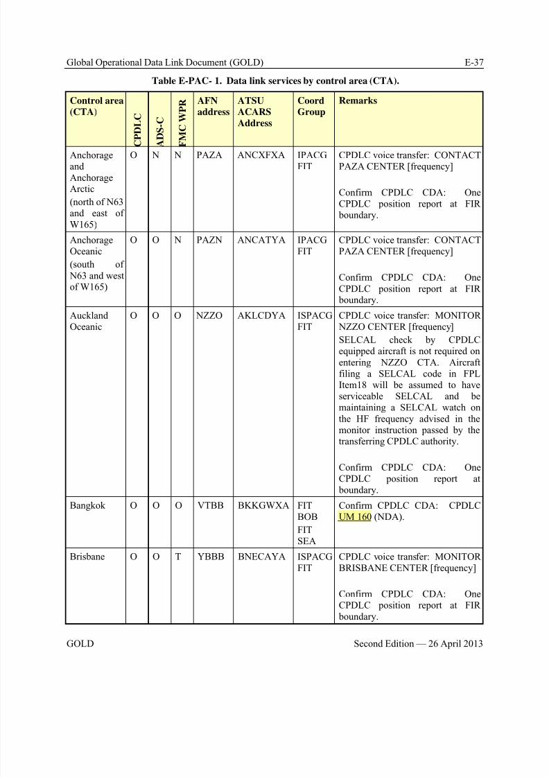
8/9/2019 CPDLC Explained
http://slidepdf.com/reader/full/cpdlc-explained 401/421
Global Operational Data Link Document (GOLD) E-37
GOLD Second Edition — 26 April 2013
Table E-PAC- 1. Data link services by control area (CTA).
Control area
(CTA)
C P D L C
A D
S - C
F M
C W P R AFN
address
ATSU
ACARS
Address
Coord
Group
Remarks
AnchorageandAnchorageArctic
(north of N63and east ofW165)
O N N PAZA ANCXFXA IPACGFIT
CPDLC voice transfer: CONTACTPAZA CENTER [frequency]
Confirm CPDLC CDA: OneCPDLC position report at FIR boundary.
AnchorageOceanic
(south of
N63 and westof W165)
O O N PAZN ANCATYA IPACGFIT
CPDLC voice transfer: CONTACTPAZA CENTER [frequency]
Confirm CPDLC CDA: OneCPDLC position report at FIR boundary.
AucklandOceanic
O O O NZZO AKLCDYA ISPACGFIT
CPDLC voice transfer: MONITOR NZZO CENTER [frequency]
SELCAL check by CPDLCequipped aircraft is not required onentering NZZO CTA. Aircraftfiling a SELCAL code in FPLItem18 will be assumed to haveserviceable SELCAL and be
maintaining a SELCAL watch onthe HF frequency advised in themonitor instruction passed by thetransferring CPDLC authority.
Confirm CPDLC CDA: OneCPDLC position report at boundary.
Bangkok O O O VTBB BKKGWXA FITBOB
FIT
SEA
Confirm CPDLC CDA: CPDLCUM 160 (NDA).
Brisbane O O T YBBB BNECAYA ISPACGFIT
CPDLC voice transfer: MONITORBRISBANE CENTER [frequency]
Confirm CPDLC CDA: OneCPDLC position report at FIR boundary.
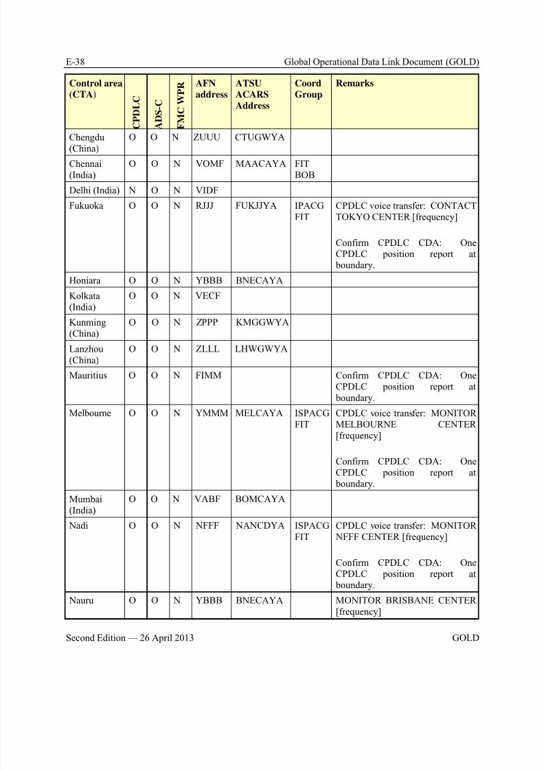
8/9/2019 CPDLC Explained
http://slidepdf.com/reader/full/cpdlc-explained 402/421
E-38 Global Operational Data Link Document (GOLD)
Second Edition — 26 April 2013 GOLD
Control area
(CTA)
C P D L C
A D S - C
F M C W P R AFN
address
ATSU
ACARS
Address
Coord
Group
Remarks
Chengdu(China)
O O N ZUUU CTUGWYA
Chennai(India)
O O N VOMF MAACAYA FITBOB
Delhi (India) N O N VIDF
Fukuoka O O N RJJJ FUKJJYA IPACGFIT
CPDLC voice transfer: CONTACTTOKYO CENTER [frequency]
Confirm CPDLC CDA: OneCPDLC position report at
boundary.Honiara O O N YBBB BNECAYA
Kolkata(India)
O O N VECF
Kunming(China)
O O N ZPPP KMGGWYA
Lanzhou(China)
O O N ZLLL LHWGWYA
Mauritius O O N FIMM Confirm CPDLC CDA: OneCPDLC position report at boundary.
Melbourne O O N YMMM MELCAYA ISPACGFIT
CPDLC voice transfer: MONITORMELBOURNE CENTER[frequency]
Confirm CPDLC CDA: OneCPDLC position report at boundary.
Mumbai(India)
O O N VABF BOMCAYA
Nadi O O N NFFF NANCDYA ISPACG
FIT
CPDLC voice transfer: MONITOR
NFFF CENTER [frequency]
Confirm CPDLC CDA: OneCPDLC position report at boundary.
Nauru O O N YBBB BNECAYA MONITOR BRISBANE CENTER[frequency]
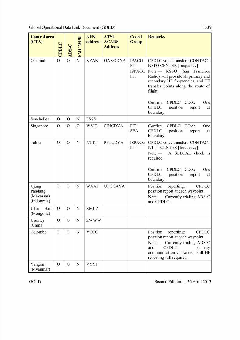
8/9/2019 CPDLC Explained
http://slidepdf.com/reader/full/cpdlc-explained 403/421
Global Operational Data Link Document (GOLD) E-39
GOLD Second Edition — 26 April 2013
Control area
(CTA)
C P D L C
A D S - C
F M C W P R AFN
address
ATSU
ACARS
Address
Coord
Group
Remarks
Oakland O O N KZAK OAKODYA IPACGFIT
ISPACGFIT
CPDLC voice transfer: CONTACTKSFO CENTER [frequency]
Note.— KSFO (San FranciscoRadio) will provide all primary andsecondary HF frequencies, and HFtransfer points along the route offlight.
Confirm CPDLC CDA: OneCPDLC position report at boundary.
Seychelles O O N FSSSSingapore O O O WSJC SINCDYA FIT
SEAConfirm CPDLC CDA: OneCPDLC position report at boundary.
Tahiti O O N NTTT PPTCDYA ISPACGFIT
CPDLC voice transfer: CONTACT NTTT CENTER [frequency]
Note.— A SELCAL check isrequired.
Confirm CPDLC CDA: OneCPDLC position report at
boundary.
UjungPandang(Makassar)(Indonesia)
T T N WAAF UPGCAYA Position reporting: CPDLC position report at each waypoint.
Note.— Currently trialing ADS-Cand CPDLC.
Ulan Bator(Mongolia)
O O N ZMUA
Urumqi(China)
O O N ZWWW
Colombo T T N VCCC Position reporting: CPDLC
position report at each waypoint. Note.— Currently trialing ADS-Cand CPDLC. Primarycommunication via voice. Full HFreporting still required.
Yangon(Myanmar)
O O N VYYF
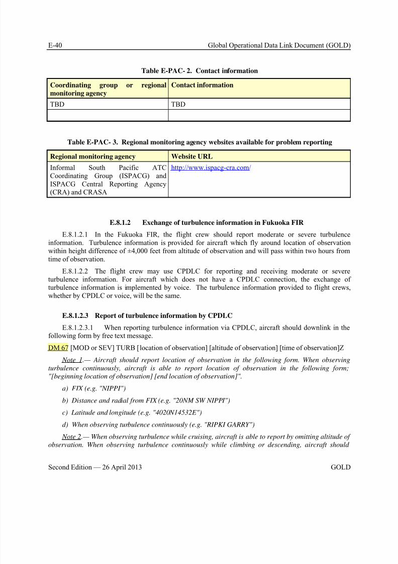
8/9/2019 CPDLC Explained
http://slidepdf.com/reader/full/cpdlc-explained 404/421
E-40 Global Operational Data Link Document (GOLD)
Second Edition — 26 April 2013 GOLD
Table E-PAC- 2. Contact information
Coordinating group or regional
monitoring agency
Contact information
TBD TBD
Table E-PAC- 3. Regional monitoring agency websites available for problem reporting
Regional monitoring agency Website URL
Informal South Pacific ATC Coordinating Group (ISPACG) andISPACG Central Reporting Agency(CRA) and CRASA
http://www.ispacg-cra.com/
E.8.1.2 Exchange of turbulence information in Fukuoka FIR
E.8.1.2.1 In the Fukuoka FIR, the flight crew should report moderate or severe turbulenceinformation. Turbulence information is provided for aircraft which fly around location of observationwithin height difference of ±4,000 feet from altitude of observation and will pass within two hours fromtime of observation.
E.8.1.2.2 The flight crew may use CPDLC for reporting and receiving moderate or severeturbulence information. For aircraft which does not have a CPDLC connection, the exchange ofturbulence information is implemented by voice. The turbulence information provided to flight crews,
whether by CPDLC or voice, will be the same.
E.8.1.2.3 Report of turbulence information by CPDLC
E.8.1.2.3.1 When reporting turbulence information via CPDLC, aircraft should downlink in thefollowing form by free text message.
DM 67 [MOD or SEV] TURB [location of observation] [altitude of observation] [time of observation]Z
Note 1.— Aircraft should report location of observation in the following form. When observing
turbulence continuously, aircraft is able to report location of observation in the following form;
"[beginning location of observation] [end location of observation]".
a) FIX (e.g. "NIPPI")
b) Distance and radial from FIX (e.g. "20NM SW NIPPI")
c) Latitude and longitude (e.g. "4020N14532E")
d) When observing turbulence continuously (e.g. "RIPKI GARRY")
Note 2.— When observing turbulence while cruising, aircraft is able to report by omitting altitude of
observation. When observing turbulence continuously while climbing or descending, aircraft should

8/9/2019 CPDLC Explained
http://slidepdf.com/reader/full/cpdlc-explained 405/421
Global Operational Data Link Document (GOLD) E-41
GOLD Second Edition — 26 April 2013
report altitude of observation in the following form; "[lower limit altitude of observation] [upper limit
altitude of observation]" (e.g. "FL330 FL350").
Note 3.— When reporting turbulence information within 5 minutes after observing, aircraft is able to
report by omitting time of observation.
Examples of downlink messages:
"SEV TURB 35N160E FL330 0924Z"
"MOD TURB 20NM N ASEDA 35NM S ASEDA FL350 1152Z"
"MOD TURB NIPPI 2114Z"
"SEV TURB 3530N15451E FL370 FL390 0304Z"
"SEV TURB POXED FL320"
"MOD TURB CELIN"
E.8.1.2.4 Provision of turbulence information by CPDLC
E.8.1.2.4.1 When providing via CPDLC, turbulence information is uplinked in the following form by free text message:
UM 169 [MOD or SEV] TURB [location of observation] [altitude of observation] [time of observation]Z[type of aircraft]
E.8.1.2.4.2 The downlink response DM 3 ROGER should be used to acknowledge receipt ofturbulence information issued.
Examples of uplink messages:
"MOD TURB NIPPI F360 0130Z B772"
"SEV TURB FM 37N160E TO 37N158E F320 0418Z A332"
"MOD TURB 20NM N ASEDA F330F350 1152Z B744"
E.8.2 Controller and radio operator procedures
NIL
E.8.3 Flight crew procedures
NIL
E.8.4 Advanced data link operations
NIL
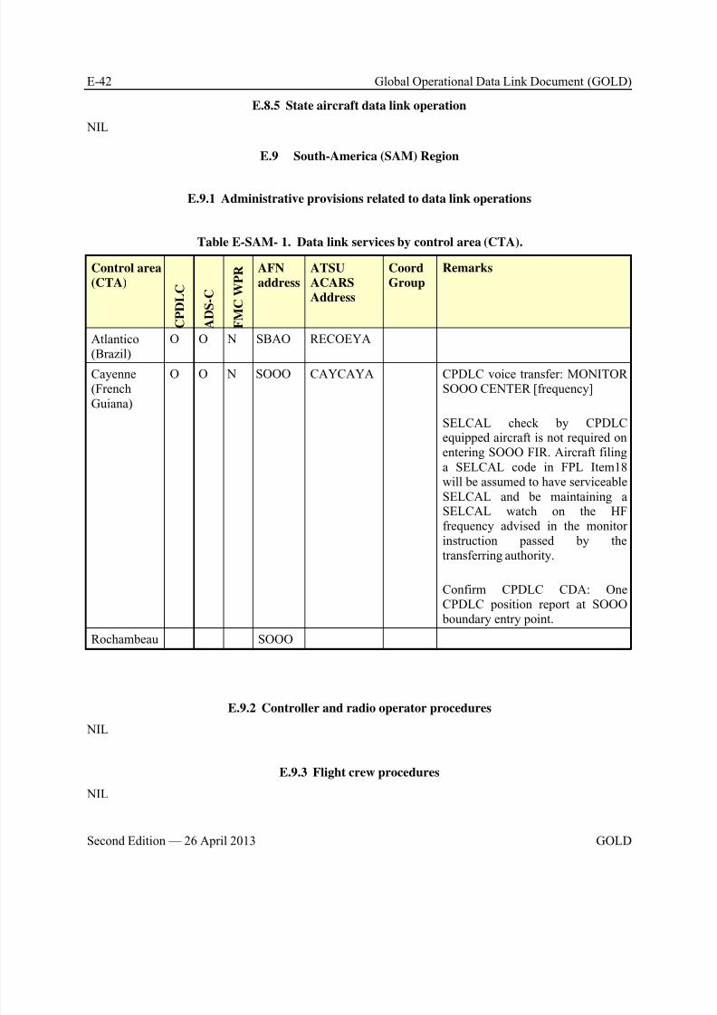
8/9/2019 CPDLC Explained
http://slidepdf.com/reader/full/cpdlc-explained 406/421
E-42 Global Operational Data Link Document (GOLD)
Second Edition — 26 April 2013 GOLD
E.8.5 State aircraft data link operation
NIL
E.9 South-America (SAM) Region
E.9.1 Administrative provisions related to data link operations
Table E-SAM- 1. Data link services by control area (CTA).
Control area
(CTA)
C P D L C
A D S - C
F M C W P R AFN
address
ATSU
ACARS
Address
Coord
Group
Remarks
Atlantico
(Brazil)
O O N SBAO RECOEYA
Cayenne(FrenchGuiana)
O O N SOOO CAYCAYA CPDLC voice transfer: MONITORSOOO CENTER [frequency]
SELCAL check by CPDLCequipped aircraft is not required onentering SOOO FIR. Aircraft filinga SELCAL code in FPL Item18will be assumed to have serviceableSELCAL and be maintaining aSELCAL watch on the HFfrequency advised in the monitorinstruction passed by thetransferring authority.
Confirm CPDLC CDA: OneCPDLC position report at SOOO boundary entry point.
Rochambeau SOOO
E.9.2 Controller and radio operator procedures NIL
E.9.3 Flight crew procedures
NIL

8/9/2019 CPDLC Explained
http://slidepdf.com/reader/full/cpdlc-explained 407/421
Global Operational Data Link Document (GOLD) E-43
GOLD Second Edition — 26 April 2013
E.9.4 Advanced data link operations
NIL
E.9.5 State aircraft data link operation
NIL

8/9/2019 CPDLC Explained
http://slidepdf.com/reader/full/cpdlc-explained 408/421
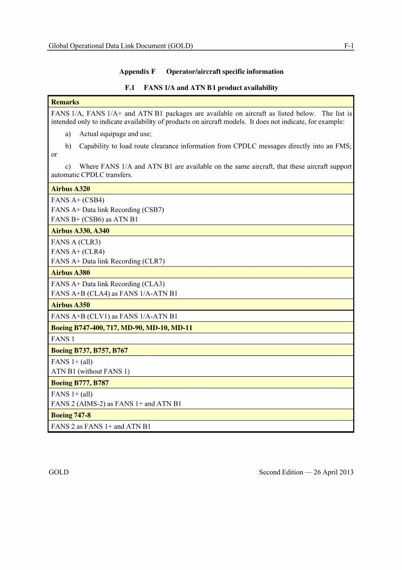
8/9/2019 CPDLC Explained
http://slidepdf.com/reader/full/cpdlc-explained 409/421
Global Operational Data Link Document (GOLD) F-1
GOLD Second Edition — 26 April 2013
Appendix F Operator/aircraft specific information
F.1 FANS 1/A and ATN B1 product availability
Remarks
FANS 1/A, FANS 1/A+ and ATN B1 packages are available on aircraft as listed below. The list isintended only to indicate availability of products on aircraft models. It does not indicate, for example:
a) Actual equipage and use;
b) Capability to load route clearance information from CPDLC messages directly into an FMS;or
c) Where FANS 1/A and ATN B1 are available on the same aircraft, that these aircraft supportautomatic CPDLC transfers.
Airbus A320
FANS A+ (CSB4)FANS A+ Data link Recording (CSB7)
FANS B+ (CSB6) as ATN B1
Airbus A330, A340
FANS A (CLR3)
FANS A+ (CLR4)
FANS A+ Data link Recording (CLR7)
Airbus A380
FANS A+ Data link Recording (CLA3)
FANS A+B (CLA4) as FANS 1/A-ATN B1
Airbus A350
FANS A+B (CLV1) as FANS 1/A-ATN B1
Boeing B747-400, 717, MD-90, MD-10, MD-11
FANS 1
Boeing B737, B757, B767
FANS 1+ (all)
ATN B1 (without FANS 1)
Boeing B777, B787
FANS 1+ (all)
FANS 2 (AIMS-2) as FANS 1+ and ATN B1
Boeing 747-8
FANS 2 as FANS 1+ and ATN B1
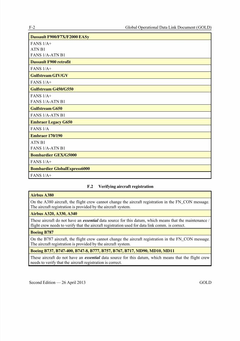
8/9/2019 CPDLC Explained
http://slidepdf.com/reader/full/cpdlc-explained 410/421
F-2 Global Operational Data Link Document (GOLD)
Second Edition — 26 April 2013 GOLD
Dassault F900/F7X/F2000 EASy
FANS 1/A+
ATN B1
FANS 1/A-ATN B1
Dassault F900 retrofit
FANS 1/A+
Gulfstream GIV/GV
FANS 1/A+
Gulfstream G450/G550
FANS 1/A+
FANS 1/A-ATN B1
Gulfstream G650
FANS 1/A-ATN B1
Embraer Legacy G650
FANS 1/A
Embraer 170/190
ATN B1
FANS 1/A-ATN B1
Bombardier GEX/G5000
FANS 1/A+
Bombardier GlobalExpress6000
FANS 1/A+
F.2 Verifying aircraft registration
Airbus A380
On the A380 aircraft, the flight crew cannot change the aircraft registration in the FN_CON message.The aircraft registration is provided by the aircraft system.
Airbus A320, A330, A340
These aircraft do not have an essential data source for this datum, which means that the maintenance /flight crew needs to verify that the aircraft registration used for data link comm. is correct.
Boeing B787
On the B787 aircraft, the flight crew cannot change the aircraft registration in the FN_CON message.The aircraft registration is provided by the aircraft system.
Boeing B737, B747-400, B747-8, B777, B757, B767, B717, MD90, MD10, MD11
These aircraft do not have an essential data source for this datum, which means that the flight crewneeds to verify that the aircraft registration is correct.
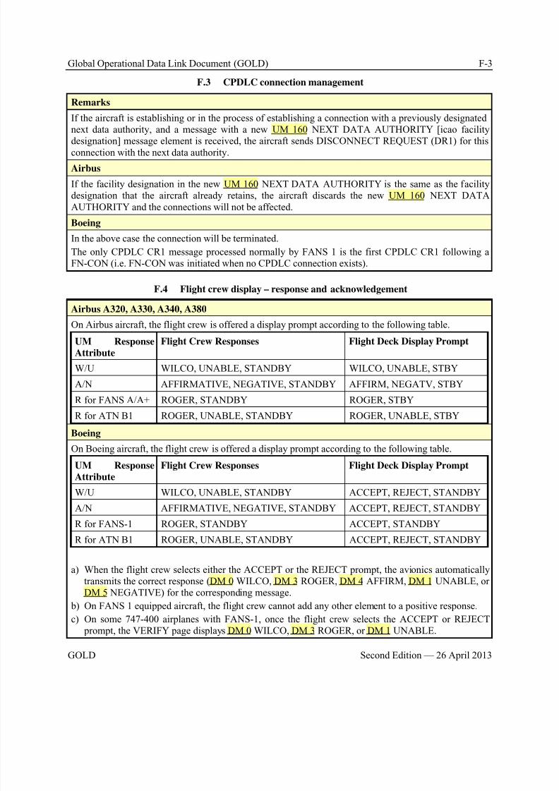
8/9/2019 CPDLC Explained
http://slidepdf.com/reader/full/cpdlc-explained 411/421
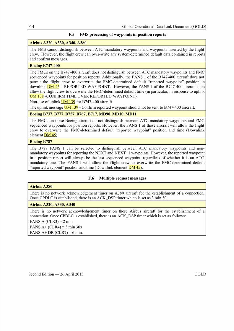
8/9/2019 CPDLC Explained
http://slidepdf.com/reader/full/cpdlc-explained 412/421
F-4 Global Operational Data Link Document (GOLD)
Second Edition — 26 April 2013 GOLD
F.5 FMS processing of waypoints in position reports
Airbus A320, A330, A340, A380
The FMS cannot distinguish between ATC mandatory waypoints and waypoints inserted by the flightcrew. However, the flight crew can over-write any system-determined default data contained in reports
and confirm messages.
Boeing B747-400
The FMCs on the B747-400 aircraft does not distinguish between ATC mandatory waypoints and FMCsequenced waypoints for position reports. Additionally, the FANS 1 of the B747-400 aircraft does not permit the flight crew to overwrite the FMC-determined default “reported waypoint” position indownlink DM 45 - REPORTED WAYPOINT. However, the FANS 1 of the B747-400 aircraft doesallow the flight crew to overwrite the FMC-determined default time (in particular, in response to uplinkUM 138 -CONFIRM TIME OVER REPORTED WAYPOINT).
Non-use of uplink UM 139 for B747-400 aircraft
The uplink message UM 139 - Confirm reported waypoint should not be sent to B747-400 aircraft.
Boeing B737, B777, B757, B767, B717, MD90, MD10, MD11The FMCs on these Boeing aircraft do not distinguish between ATC mandatory waypoints and FMCsequenced waypoints for position reports. However, the FANS 1 of these aircraft will allow the flightcrew to overwrite the FMC-determined default “reported waypoint” position and time (Downlinkelement DM 45).
Boeing B787
The B787 FANS 1 can be selected to distinguish between ATC mandatory waypoints and non-mandatory waypoints for reporting the NEXT and NEXT+1 waypoints. However, the reported waypointin a position report will always be the last sequenced waypoint, regardless of whether it is an ATCmandatory one. The FANS 1 will allow the flight crew to overwrite the FMC-determined default“reported waypoint” position and time (Downlink element DM 45).
F.6 Multiple request messages
Airbus A380
There is no network acknowledgement timer on A380 aircraft for the establishment of a connection.Once CPDLC is established, there is an ACK_DSP timer which is set as 3 min 30.
Airbus A320, A330, A340
There is no network acknowledgement timer on these Airbus aircraft for the establishment of aconnection. Once CPDLC is established, there is an ACK_DSP timer which is set as follows:
FANS A (CLR3) = 2 min
FANS A+ (CLR4) = 3 min 30s
FANS A+ DR (CLR7) = 6 min.
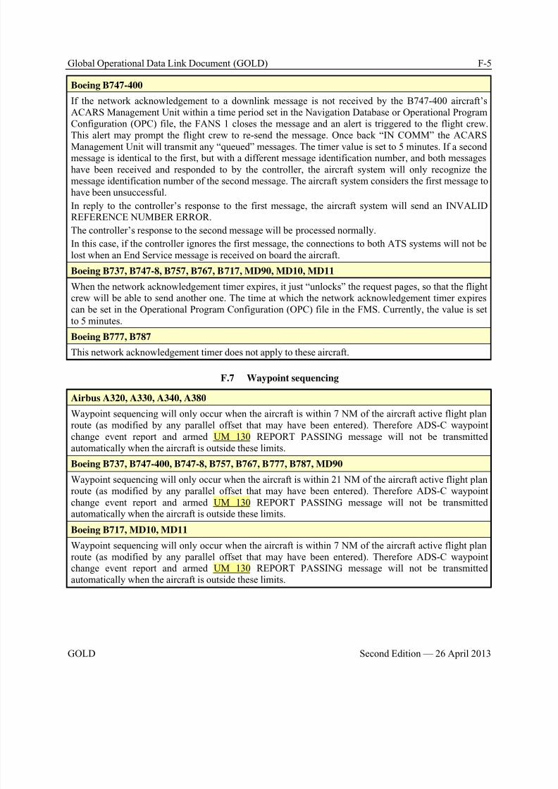
8/9/2019 CPDLC Explained
http://slidepdf.com/reader/full/cpdlc-explained 413/421
Global Operational Data Link Document (GOLD) F-5
GOLD Second Edition — 26 April 2013
Boeing B747-400
If the network acknowledgement to a downlink message is not received by the B747-400 aircraft’sACARS Management Unit within a time period set in the Navigation Database or Operational ProgramConfiguration (OPC) file, the FANS 1 closes the message and an alert is triggered to the flight crew.
This alert may prompt the flight crew to re-send the message. Once back “IN COMM” the ACARSManagement Unit will transmit any “queued” messages. The timer value is set to 5 minutes. If a secondmessage is identical to the first, but with a different message identification number, and both messageshave been received and responded to by the controller, the aircraft system will only recognize themessage identification number of the second message. The aircraft system considers the first message tohave been unsuccessful.
In reply to the controller’s response to the first message, the aircraft system will send an INVALIDREFERENCE NUMBER ERROR.
The controller’s response to the second message will be processed normally.
In this case, if the controller ignores the first message, the connections to both ATS systems will not belost when an End Service message is received on board the aircraft.
Boeing B737, B747-8, B757, B767, B717, MD90, MD10, MD11
When the network acknowledgement timer expires, it just “unlocks” the request pages, so that the flightcrew will be able to send another one. The time at which the network acknowledgement timer expirescan be set in the Operational Program Configuration (OPC) file in the FMS. Currently, the value is setto 5 minutes.
Boeing B777, B787
This network acknowledgement timer does not apply to these aircraft.
F.7 Waypoint sequencing
Airbus A320, A330, A340, A380
Waypoint sequencing will only occur when the aircraft is within 7 NM of the aircraft active flight planroute (as modified by any parallel offset that may have been entered). Therefore ADS-C waypointchange event report and armed UM 130 REPORT PASSING message will not be transmittedautomatically when the aircraft is outside these limits.
Boeing B737, B747-400, B747-8, B757, B767, B777, B787, MD90
Waypoint sequencing will only occur when the aircraft is within 21 NM of the aircraft active flight planroute (as modified by any parallel offset that may have been entered). Therefore ADS-C waypointchange event report and armed UM 130 REPORT PASSING message will not be transmittedautomatically when the aircraft is outside these limits.
Boeing B717, MD10, MD11
Waypoint sequencing will only occur when the aircraft is within 7 NM of the aircraft active flight planroute (as modified by any parallel offset that may have been entered). Therefore ADS-C waypointchange event report and armed UM 130 REPORT PASSING message will not be transmittedautomatically when the aircraft is outside these limits.
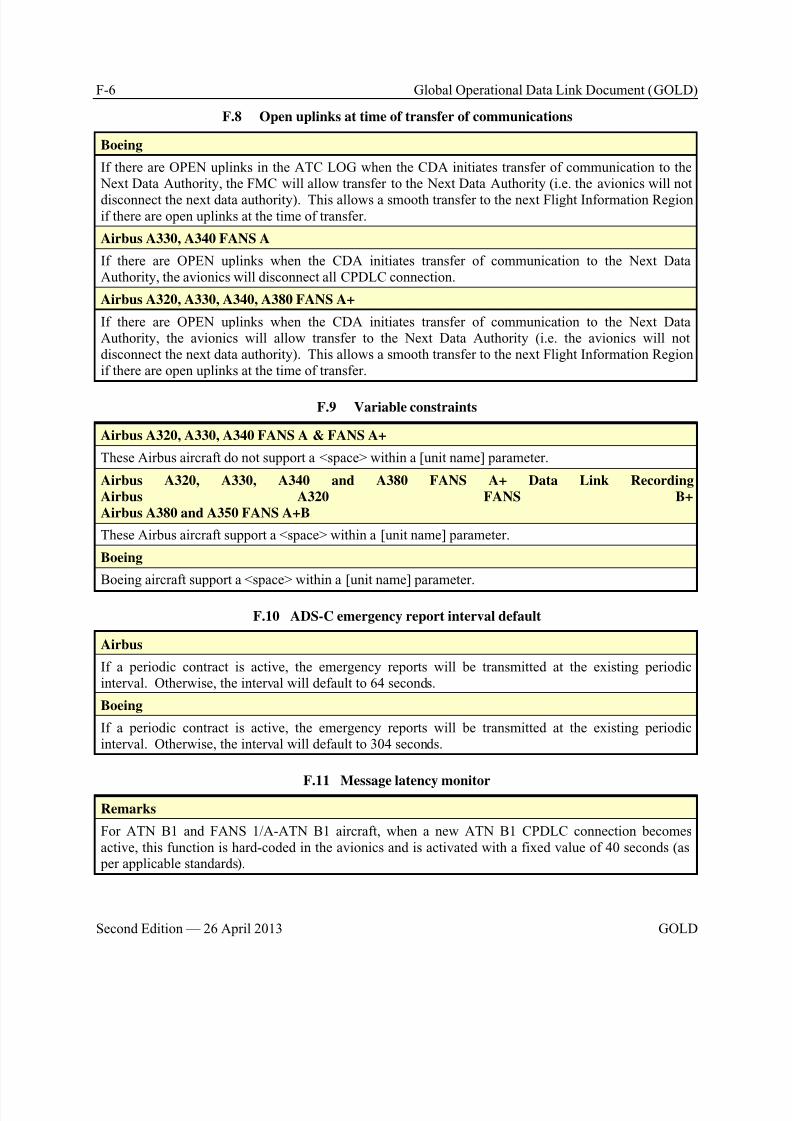
8/9/2019 CPDLC Explained
http://slidepdf.com/reader/full/cpdlc-explained 414/421
F-6 Global Operational Data Link Document (GOLD)
Second Edition — 26 April 2013 GOLD
F.8 Open uplinks at time of transfer of communications
Boeing
If there are OPEN uplinks in the ATC LOG when the CDA initiates transfer of communication to the Next Data Authority, the FMC will allow transfer to the Next Data Authority (i.e. the avionics will not
disconnect the next data authority). This allows a smooth transfer to the next Flight Information Regionif there are open uplinks at the time of transfer.
Airbus A330, A340 FANS A
If there are OPEN uplinks when the CDA initiates transfer of communication to the Next DataAuthority, the avionics will disconnect all CPDLC connection.
Airbus A320, A330, A340, A380 FANS A+
If there are OPEN uplinks when the CDA initiates transfer of communication to the Next DataAuthority, the avionics will allow transfer to the Next Data Authority (i.e. the avionics will notdisconnect the next data authority). This allows a smooth transfer to the next Flight Information Regionif there are open uplinks at the time of transfer.
F.9 Variable constraints
Airbus A320, A330, A340 FANS A & FANS A+
These Airbus aircraft do not support a <space> within a [unit name] parameter.
Airbus A320, A330, A340 and A380 FANS A+ Data Link Recording
Airbus A320 FANS B+
Airbus A380 and A350 FANS A+B
These Airbus aircraft support a <space> within a [unit name] parameter.
Boeing
Boeing aircraft support a <space> within a [unit name] parameter.
F.10 ADS-C emergency report interval default
Airbus
If a periodic contract is active, the emergency reports will be transmitted at the existing periodicinterval. Otherwise, the interval will default to 64 seconds.
Boeing
If a periodic contract is active, the emergency reports will be transmitted at the existing periodicinterval. Otherwise, the interval will default to 304 seconds.
F.11 Message latency monitor
Remarks
For ATN B1 and FANS 1/A-ATN B1 aircraft, when a new ATN B1 CPDLC connection becomesactive, this function is hard-coded in the avionics and is activated with a fixed value of 40 seconds (as per applicable standards).
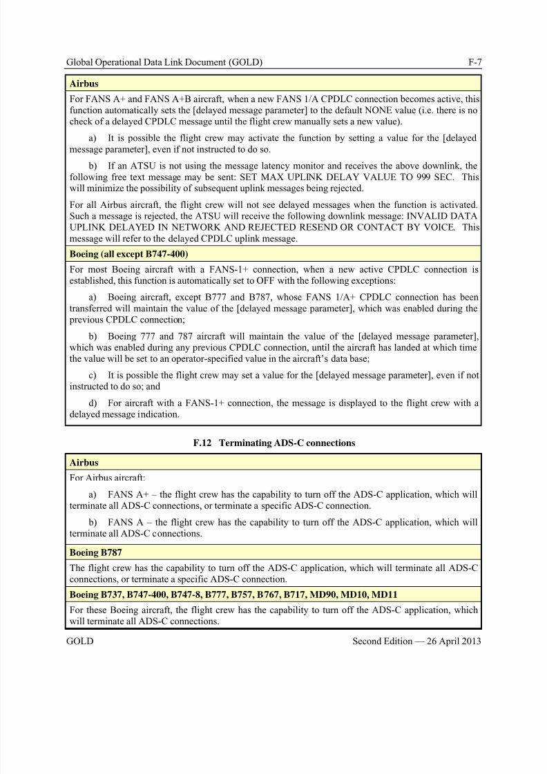
8/9/2019 CPDLC Explained
http://slidepdf.com/reader/full/cpdlc-explained 415/421
Global Operational Data Link Document (GOLD) F-7
GOLD Second Edition — 26 April 2013
Airbus
For FANS A+ and FANS A+B aircraft, when a new FANS 1/A CPDLC connection becomes active, thisfunction automatically sets the [delayed message parameter] to the default NONE value (i.e. there is nocheck of a delayed CPDLC message until the flight crew manually sets a new value).
a) It is possible the flight crew may activate the function by setting a value for the [delayedmessage parameter], even if not instructed to do so.
b) If an ATSU is not using the message latency monitor and receives the above downlink, thefollowing free text message may be sent: SET MAX UPLINK DELAY VALUE TO 999 SEC. Thiswill minimize the possibility of subsequent uplink messages being rejected.
For all Airbus aircraft, the flight crew will not see delayed messages when the function is activated.Such a message is rejected, the ATSU will receive the following downlink message: INVALID DATAUPLINK DELAYED IN NETWORK AND REJECTED RESEND OR CONTACT BY VOICE. Thismessage will refer to the delayed CPDLC uplink message.
Boeing (all except B747-400)
For most Boeing aircraft with a FANS-1+ connection, when a new active CPDLC connection isestablished, this function is automatically set to OFF with the following exceptions:
a) Boeing aircraft, except B777 and B787, whose FANS 1/A+ CPDLC connection has beentransferred will maintain the value of the [delayed message parameter], which was enabled during the previous CPDLC connection;
b) Boeing 777 and 787 aircraft will maintain the value of the [delayed message parameter],which was enabled during any previous CPDLC connection, until the aircraft has landed at which timethe value will be set to an operator-specified value in the aircraft’s data base;
c) It is possible the flight crew may set a value for the [delayed message parameter], even if notinstructed to do so; and
d) For aircraft with a FANS-1+ connection, the message is displayed to the flight crew with adelayed message indication.
F.12 Terminating ADS-C connections
Airbus
For Airbus aircraft:
a) FANS A+ – the flight crew has the capability to turn off the ADS-C application, which willterminate all ADS-C connections, or terminate a specific ADS-C connection.
b) FANS A – the flight crew has the capability to turn off the ADS-C application, which willterminate all ADS-C connections.
Boeing B787
The flight crew has the capability to turn off the ADS-C application, which will terminate all ADS-Cconnections, or terminate a specific ADS-C connection.
Boeing B737, B747-400, B747-8, B777, B757, B767, B717, MD90, MD10, MD11
For these Boeing aircraft, the flight crew has the capability to turn off the ADS-C application, whichwill terminate all ADS-C connections.
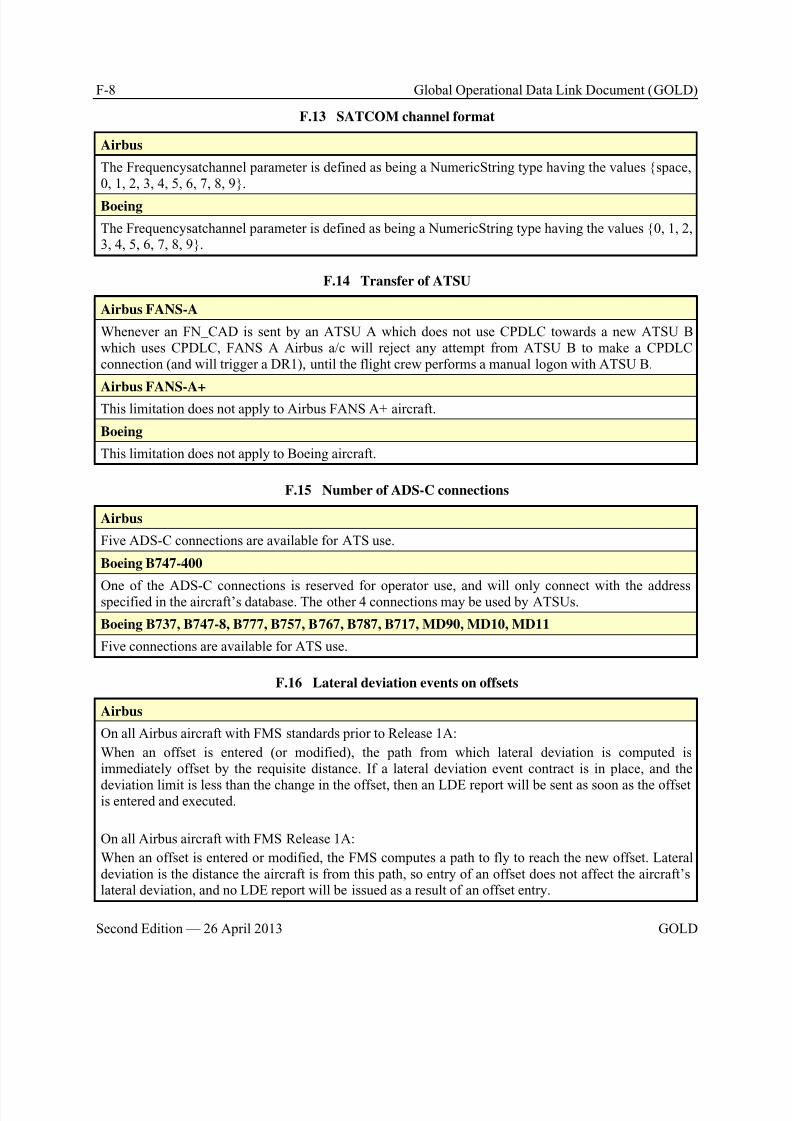
8/9/2019 CPDLC Explained
http://slidepdf.com/reader/full/cpdlc-explained 416/421
F-8 Global Operational Data Link Document (GOLD)
Second Edition — 26 April 2013 GOLD
F.13 SATCOM channel format
Airbus
The Frequencysatchannel parameter is defined as being a NumericString type having the values {space,0, 1, 2, 3, 4, 5, 6, 7, 8, 9}.
Boeing
The Frequencysatchannel parameter is defined as being a NumericString type having the values {0, 1, 2,3, 4, 5, 6, 7, 8, 9}.
F.14 Transfer of ATSU
Airbus FANS-A
Whenever an FN_CAD is sent by an ATSU A which does not use CPDLC towards a new ATSU Bwhich uses CPDLC, FANS A Airbus a/c will reject any attempt from ATSU B to make a CPDLCconnection (and will trigger a DR1), until the flight crew performs a manual logon with ATSU B.
Airbus FANS-A+This limitation does not apply to Airbus FANS A+ aircraft.
Boeing
This limitation does not apply to Boeing aircraft.
F.15 Number of ADS-C connections
Airbus
Five ADS-C connections are available for ATS use.
Boeing B747-400
One of the ADS-C connections is reserved for operator use, and will only connect with the addressspecified in the aircraft’s database. The other 4 connections may be used by ATSUs.
Boeing B737, B747-8, B777, B757, B767, B787, B717, MD90, MD10, MD11
Five connections are available for ATS use.
F.16 Lateral deviation events on offsets
Airbus
On all Airbus aircraft with FMS standards prior to Release 1A:
When an offset is entered (or modified), the path from which lateral deviation is computed isimmediately offset by the requisite distance. If a lateral deviation event contract is in place, and the
deviation limit is less than the change in the offset, then an LDE report will be sent as soon as the offsetis entered and executed.
On all Airbus aircraft with FMS Release 1A:
When an offset is entered or modified, the FMS computes a path to fly to reach the new offset. Lateraldeviation is the distance the aircraft is from this path, so entry of an offset does not affect the aircraft’slateral deviation, and no LDE report will be issued as a result of an offset entry.
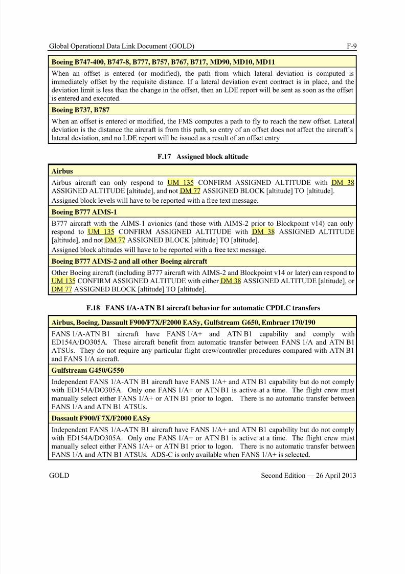
8/9/2019 CPDLC Explained
http://slidepdf.com/reader/full/cpdlc-explained 417/421
Global Operational Data Link Document (GOLD) F-9
GOLD Second Edition — 26 April 2013
Boeing B747-400, B747-8, B777, B757, B767, B717, MD90, MD10, MD11
When an offset is entered (or modified), the path from which lateral deviation is computed isimmediately offset by the requisite distance. If a lateral deviation event contract is in place, and thedeviation limit is less than the change in the offset, then an LDE report will be sent as soon as the offset
is entered and executed.Boeing B737, B787
When an offset is entered or modified, the FMS computes a path to fly to reach the new offset. Lateraldeviation is the distance the aircraft is from this path, so entry of an offset does not affect the aircraft’slateral deviation, and no LDE report will be issued as a result of an offset entry
F.17 Assigned block altitude
Airbus
Airbus aircraft can only respond to UM 135 CONFIRM ASSIGNED ALTITUDE with DM 38ASSIGNED ALTITUDE [altitude], and not DM 77 ASSIGNED BLOCK [altitude] TO [altitude].
Assigned block levels will have to be reported with a free text message.Boeing B777 AIMS-1
B777 aircraft with the AIMS-1 avionics (and those with AIMS-2 prior to Blockpoint v14) can onlyrespond to UM 135 CONFIRM ASSIGNED ALTITUDE with DM 38 ASSIGNED ALTITUDE[altitude], and not DM 77 ASSIGNED BLOCK [altitude] TO [altitude].
Assigned block altitudes will have to be reported with a free text message.
Boeing B777 AIMS-2 and all other Boeing aircraft
Other Boeing aircraft (including B777 aircraft with AIMS-2 and Blockpoint v14 or later) can respond toUM 135 CONFIRM ASSIGNED ALTITUDE with either DM 38 ASSIGNED ALTITUDE [altitude], orDM 77 ASSIGNED BLOCK [altitude] TO [altitude].
F.18 FANS 1/A-ATN B1 aircraft behavior for automatic CPDLC transfers
Airbus, Boeing, Dassault F900/F7X/F2000 EASy, Gulfstream G650, Embraer 170/190
FANS 1/A-ATN B1 aircraft have FANS 1/A+ and ATN B1 capability and comply withED154A/DO305A. These aircraft benefit from automatic transfer between FANS 1/A and ATN B1ATSUs. They do not require any particular flight crew/controller procedures compared with ATN B1and FANS 1/A aircraft.
Gulfstream G450/G550
Independent FANS 1/A-ATN B1 aircraft have FANS 1/A+ and ATN B1 capability but do not complywith ED154A/DO305A. Only one FANS 1/A+ or ATN B1 is active at a time. The flight crew mustmanually select either FANS 1/A+ or ATN B1 prior to logon. There is no automatic transfer betweenFANS 1/A and ATN B1 ATSUs.
Dassault F900/F7X/F2000 EASy
Independent FANS 1/A-ATN B1 aircraft have FANS 1/A+ and ATN B1 capability but do not complywith ED154A/DO305A. Only one FANS 1/A+ or ATN B1 is active at a time. The flight crew mustmanually select either FANS 1/A+ or ATN B1 prior to logon. There is no automatic transfer betweenFANS 1/A and ATN B1 ATSUs. ADS-C is only available when FANS 1/A+ is selected.

8/9/2019 CPDLC Explained
http://slidepdf.com/reader/full/cpdlc-explained 418/421
F-10 Global Operational Data Link Document (GOLD)
Second Edition — 26 April 2013 GOLD
F.19 CM contact procedure
Remarks
ED110B/DO280B requires ATN B1 aircraft to send a successful CM Contact Response to a T-ATSU assoon as a Logon response was received from the R-ATSU, whatever the result (successful or not).
Airbus
FANS B+ and FANS A+B aircraft deviate from this requirement.
FANS B+ and FANS A+B aircraft will send a successful CM Contact Response to the T-ATSU only ifthe Logon procedure with the R-ATSU succeeds.
FANS B+ and FANS A+B aircraft will send a unsuccessful CM Contact Response to the T-ATSU :
if the sending of the Logon Request to the R-ATSU fails, or
if the no Logon Response is received in due time, or
if the Logon response from the R-ATSU indicated failure.
F.20 Duplicate CPDLC uplink message processing
Airbus FANS A (CLR3), FANS A+ (CSB4/CLR4 & CLA3)
If a message is received that contains strictly identical coded data to any other pending (open) message,then it will be discarded as a duplicate, with no response to the ground, and no indication to the flightcrew.
Airbus FANS A+ Data Link Recording (CSB7/CLR7), FANS A+B (CLA4 & CLV1)
If a message is received that contains strictly identical coded data to any other message, then it will bediscarded as a duplicate, with no response to the ground, and no indication to the flight crew.
Boeing B747-400 (before Load 15), B757/B767 (before Peg03), B777 (before BP01), B737 (before
U10.5), MD-90, B717, MD-10
If a duplicate message is received (e.g. the same message is received on both VHF and SATCOM), itwill be treated like any other new message. If the existing message with the same MIN is still open (hasnot been responded/dispositioned by the flight crew) it will be rejected as a “duplicate MIN”.
Boeing B757/B767 (from Peg03), B777 (from BP01), B737 (from U10.5), B747-8, B787, MD-11
If a message is received that has the identical MIN and CRC to any other message in the log, then it will be discarded as a duplicate, with no response to the ground, and no indication to the flight crew.
Boeing B747-400 (from Load 15)
If a message is received that has the identical MIN and CRC to any other pending (open) message, thenit will be discarded as a duplicate, with no response to the ground, and no indication to the flight crew.
F.21 Response to end-service and error uplink messages
Airbus

8/9/2019 CPDLC Explained
http://slidepdf.com/reader/full/cpdlc-explained 419/421
Global Operational Data Link Document (GOLD) F-11
GOLD Second Edition — 26 April 2013
Boeing
When a FANS uplink containing a concatenated end-service (um161) and ERROR (um159), the flightcrew will be presented with a display indicating a DOWNLINK ERROR.
While this construct is recommended in DO-258/ED-100, Section 4.6.2.2.2, it was not included in DO-
219, which is the basis of FANS designs. ATC should therefore avoid using this type of concatenatedmessage.
F.22 CPDLC connection after logon
Airbus
Boeing B747-400, B757, B767, B717, MD90, MD10, MD11 and B777 or B787 without FANS-2
Once an AFN logon has been performed, the airplane will accept a CPDLC connection request (CR1)from any ATC Center. It is not required to be the center with which the AFN logon was performed.
Boeing B747-8, B777 and B787 with FANS-2
Once a CM or AFN logon has been performed, the airplane will accept a CPDLC connection request orCPDLC start from any center.
F.23 ARINC 424 oceanic waypoints
Remarks
The Flight Management System on most airplanes will contain oceanic waypoints at whole degrees oflatitude and longitude (and potentially at half degrees) with names assigned using the namingconvention for such waypoints contained in ARINC 424.
Airbus
Boeing B747-400, B747-8, B777, B757, B767, B717, MD90, MD10, MD11
If the route constructed by the flight crew or data linked from the airline contains such waypoints, thendownlinked routes, position reports and requests for clearances (such as climbs or offsets) to start at awaypoint on the route will contain the ARINC 424 waypoint names.
Boeing B787
Whole-degree waypoints of this type in the route will be converted to the equivalent latitude/longitudefor ATC downlinks.
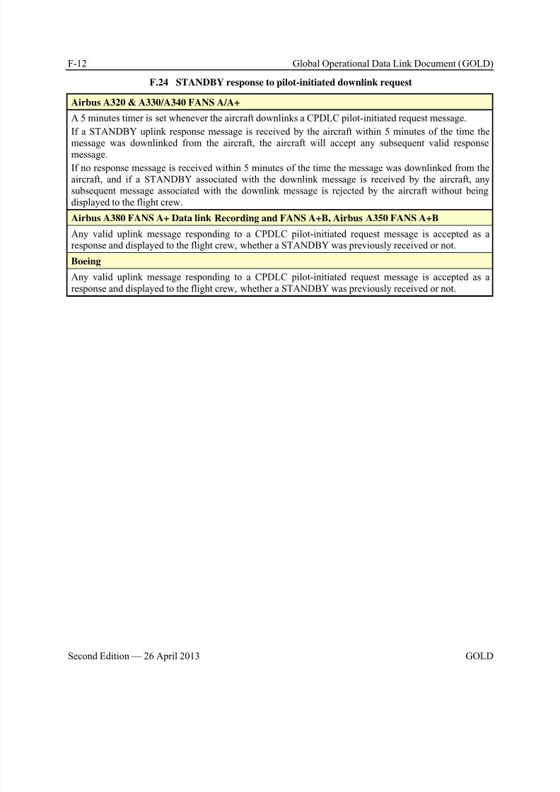
8/9/2019 CPDLC Explained
http://slidepdf.com/reader/full/cpdlc-explained 420/421
F-12 Global Operational Data Link Document (GOLD)
Second Edition — 26 April 2013 GOLD
F.24 STANDBY response to pilot-initiated downlink request
Airbus A320 & A330/A340 FANS A/A+
A 5 minutes timer is set whenever the aircraft downlinks a CPDLC pilot-initiated request message.
If a STANDBY uplink response message is received by the aircraft within 5 minutes of the time themessage was downlinked from the aircraft, the aircraft will accept any subsequent valid responsemessage.
If no response message is received within 5 minutes of the time the message was downlinked from theaircraft, and if a STANDBY associated with the downlink message is received by the aircraft, anysubsequent message associated with the downlink message is rejected by the aircraft without beingdisplayed to the flight crew.
Airbus A380 FANS A+ Data link Recording and FANS A+B, Airbus A350 FANS A+B
Any valid uplink message responding to a CPDLC pilot-initiated request message is accepted as aresponse and displayed to the flight crew, whether a STANDBY was previously received or not.
Boeing
Any valid uplink message responding to a CPDLC pilot-initiated request message is accepted as aresponse and displayed to the flight crew, whether a STANDBY was previously received or not.

8/9/2019 CPDLC Explained
http://slidepdf.com/reader/full/cpdlc-explained 421/421