cr-39 detector and experimental techniques of cosmic supermassive particles search
TRANSCRIPT

Nuclear Instruments and Methods in Physics Research A286 (1990) 327-333North-Holland
CR-39 DETECTOR AND EXPERIMENTAL TECHNIQUESSUPERMASSIVE PARTICLES SEARCH
H. ICHINOSE, T. DOKE, H. TAWARA and K. KUWAHARAScience and Engineering Research Laboratory, Waseda University, Kikuicho 17, Sinjuku-ku, Tokyo 162, Japan
S. NAKAMURA and S. ORITODepartment of Physics, University of Tokyo, Hongo 7-3-1, Bunkyo-ku, Tokyo 113, Japan
K. OGURACollege of Industrial Technology, Nihon University, Izumicho 1-2-1, Narashino-shi, Chiba 275, Japan
Received 7 April 1989 and in revised form 21 July 1989
The characteristics of CR-39 plastic for cosmic supermassive particles search are described. The long-term effects of temperature,oxygen, and water vapor on the sensitivity of CR-39 and the pre-soaking effect were investigated . For processing the large number ofCR-39 plates, a way of mass etching was also investigated and a large etching system was developed. In addition, the procedure of theexperiment searching for cosmic supermassive particles is presented .
1 . Introduction
Recent theories have predicted the existence of su-permassive particles such as magnetic monopoles [1],fractional charged particles [2], and strange matter [3] .Astrophysical arguments indicate that these are ex-tremely rare [4]. We are performing a search for theseparticles with a large area of CR-39 [5]. CR-39 is themost sensitive plastic track detector and is less expen-sive than other types of detectors such as proportionalor scintillation counters. As pointed out by Price [6],monopoles with velocities of about 10 -4c can be de-tected due to an atomic repulsion process .
For this experiment, a heavy etching method [7] wasdeveloped and the characteristics of CR-39 were studied[8]. Recently, we developed a CR-39 detector with highsensitivity and long-term stability [9,10]. A large etchingsystem [11-13] and an optical scanning system [14] havebeen developed for processing the large number ofCR-39 detectors. In this paper, further studies of CR-39are described : 1) the effects of temperature, oxygen andwater vapor, 2) the pre-soaking effect on the sensitivityof CR-39, and 3) the method of mass etching. A1- o theprocedure for supermassive particle search is reported .
2 . Description off the experiment
The experiment has been carried out in three differ-ent sites . First, the 160 m2 array was set in the Kamioka
0168-9002/90/$03.50 n Elsevier Science Publishers B.V .(North-Holland)
F C SMIC
327
metal mine (depth: 1 .8 x 10 5 g/cm2 ), which is locatedabout 300 km west of Tokyo. Second, the 200 m2 arraywas exposed near the top of the Mt. Norikura (depth :730 g/cm2 ) to detect lighter supermassive particles. Theexposure and analysis of these arrays had already beencompleted . The third experiment is being carried out atOhya underground stone pits (depth : _ 104 g/cm2)located about 100 km north of Tokyo, where the 3800m2 array has been exposed (fig. 1) . The backgroundfrom the heavy ion component of primary cosmic raysis negligible at the three sites. The number of recoilnuclei, due to fast neutrons produced by cosmic rays,are also negligible at Kamiokz: and Ohya . The annualtemperature at the sites is between 18° C an3 20 ° C atKamioka, 0 ° C at Norikura, and between 0 ° C and10 ° C at Ohya . The detector array at Ohya consists of12 800 stacks, each of which is comprised of 4 layers ofCR-39 plates . The dimensions of the plate are 540mm x 560 mm x 1 .6 mm. The proportion of effectivedetecting area is about 80% . The total detecting area ofall the CR-39 stacks is about 3000 m'-- .
After a few years of exposure, two adjacent layers ofthe stacks are soaked in hot water and then deeplyetched to about 400 Rm thickness . Holes are producedalong the path by each penetrating particle with asufficiently high REL (restricted energy loss). Then theetched CR-39 plates are dyed black and scanned by anautomatic optical scanning system in order to detectpenetrating holes . The position and size of all penetrat-

328
Fig . 1 . CR-39 track detector arrays placed underground atOhya. Each stack consists of four layers of CR-39 plates with
the size of 540 mm x 560 mmx 1.6 mm.
ing holes are determined . If there are coincident holeswithin 15 mm in the two adjacent layers, the remainingtwo layers in the same stack are also etched and ex-amined by an optical microscope . If there are corre-sponding etch pits in the third and fourth layer of thesame stack, REL of the particles is obtained from theshape of the etch pit . This requirement of "coincidence"eliminates background holes due to other particles orimperfections in the CR-39 material.
After finishing the analysis of all CR-39 plates, aflux of the order of 10-16 CM-2 sr -1 s-1 will bedetectable for magnetic monopoles with the velocitiesgreater than 10-2c .
3. Preparation of the stacks
In the experiment at Norikura and Ohya, CR-39plates doped with 0.01% Naugard 445 (N-0.01 CR-39)were used . The characteristics of the N-0.01 CR-39plates have previously been studied [9,10]. Because of ahumidity of 1009 at the underground sites, all stackswere prepared in a job tent, which was insulated by
CR-39
H. Ichinose et al. / CR-39 detector and experimental techniques
Fig. 2 . Outline for the construction of CR-39 stacks .
vinyl sheets. The humidity within the job tent wasmaintained at about 60% by air conditioners. EachCR-39 plate of the same stack was brought separatelyinto the underground site.
As is shown in fig. 2, the four plates of each stackwere firmly attached to each other by small pieces ofdouble-sided adhesive tape . This procedure alsoguarantees a thin layer of air between the CR-39 plates.The stack's serial numbers were marked in a small sealfixed on each plate. A specially designed drilling ma-chine drilled twelve holes at a time through each stack.Each hole had a diameter of 2 mm. Five holes wereprovided as a reference of the coordinates among thedetector layers, and the other holes were used to sus-pend the CR-39 plates from the frame 'in the etchingbath .
Each stack was inserted in an air- and light-tight bagwith cross sectional dimensions of 600 mm x 720 mm.The bags were made of laminated sheets of polyestel,aluminum, nylon, and polyethylene . In order not todamage the bags, the sharp comers of the stacks werewrapped with cloth tape. Finally, the bags were sealedby a heat-sealing machine.
4. Environmental conditions
Because of the CR-39 stacks being exposed for a fewyears, the effects of the environment on the sensitivityof CR-39 were studied prior to the final installation .The effects studied were: 1) the fading effect with orwithout oxygen, and 2) "aging and irradiation" and"irradiation and fading". Two kinds of CR-39 wereused : CR-39 doped with no antioxidants (pine CR-39)and N-0.01 CR-39.
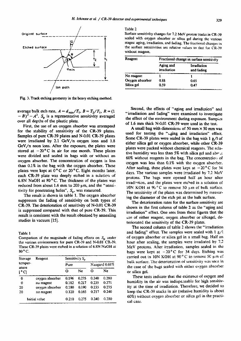
Since the tract. response of CR-39 shows a depthdependent variation, a considerable difference is ob-served bevveen the sensitivity on the surface and thatfor making penetrating holes [8,9]. The former is moresensitive than the latter [9] . At this time, it is impossibleto distinguish whether the observed depth dependenceof the sensitivity is mainly caused by the characteristicsof the materials themselves or by the fading of thelatent track during the long etching at high temper-atures . In order to evaluate the properties of CR-39 forfills experiment, it is practical to use an effective sensi-tivity, Sp "sensitivity for penetrating holes", for makingholes instead of the surface sensitivity [9] . Sp is ob-tained from geometrical considerations of the penetrat-ing holes after the heavy etching (see fig. 3), and definedby the following equation :
1 -B- R cos Q+A 1 -R cos2QSP = Vi/Vt - 1=~ R cos Q
,
where V, is the average track etch rate and Vb is the
Original surface
j
H. Ichinose et al. / CR-39 detector and experimental techniques
Fig. 3. Track etching geometry in the heavy etching method .
average bulk etch rate, A = d� , ;�/Tt, B= T2/TI, R = (1- B)2 - A2. Sp is a representative sensitivity averagedover all depths of the plastic plate.
First, the use of an oxygen absorber was attemptedfor the stability of sensitivity of the CR-39 plates.Samples of pure CR-39 plates and N-0.01 CR-39 plateswere irradiated by 2.1 GeV/n oxygen ions and 1 .8GeV/n neon ions. After the exposure, the plates werestored at -20 ° C in air for one month. These plateswere divided and sealed in bags with or without anoxygen absorber. The concentration of oxygen is lessthan 0.1% in the bag with the oxygen absorber. Theseplates were kept at O ° C or 20°C.Eight months later,each CR-39 plate was deeply etched in a solution of6.8N NaOH at 80°C.The thickness of the plates wasreduced from about 1 .6 mm to 200 Rm, and the "sensi-tivity for penetrating holes", Sp, was measured .
The result is shown in table 1 . The oxygen absorbersuppresses the fading of sensitivity on both types ofCR-39. Thedeterioration of sensitivity of N-0.01 CR-39is suppressed compared with that of pure CR-39. Thisresult is consistent with the result obtained by annealingstudies in vacuum [15] .
Table 1Comparison of the magnitude of fading effects on SP underthe various environments for pure CR-39 and N-0.01 CR-39.These CR-39 plates were etched in a solution of 6.8N NaOH at80 ° C.
Table 2Surface sensitivity changes for 7.2 MeV proton tracks in CR-39sealed with oxygen absorber or silica gel during the variousstages : aging, irradiation, and fading. The fractional changes inthe surface sensitivities are relative values to that for CR-39without reagent.
Reagent
Fractional change in surface sensitivityAging and
Irradiationirradiation
andfadingNo reagent
1
1Oxygen absorber
0.88
0.65Silica gel
0.59
0.47
329
Second, the effects of "aging and irradiation" and"irradiation and fading" were examined to investigatethe effect of the environment during exposure. Samp,,:sof 1.6 mm thick N-0.01 CR-39 were used in the test .A small bag with dimension; of 50 mm x 50 mm was
used for testing the "t.ging and irradiation" effect .Some CR-39 plates were sealed in the bag with 1 g/l ofeither silica gel or oxygen absorber, while other CR-39plates were packed without chemical reagents . The rela-tive humidity was less than 5% with silica gel and abr,,.t60% without reagents in the bag. The concentratio-i ofoxygen was less than 0.1% with the oxygen absorber.After sealing, these plates were kept at -20"C for 34days. The various samples were irradiated by 7.2 hleVprotons. The bags were opened half an hour afterirrad-ition, and the plates were etched in a solution ofION KOH at 9V C to remove 50 [tm of bulk surface.The sensitivity of the plates was determined by measur-ing the diameter of the etch pit at the balk surface.
The deterioration rates for the surface sensitivity areshown in the first column of table 2 as the "aging andirradiation" effect. One sees from these figures that theuse of either reagent, oxygen absorber or silicagel, de-teriorated the sensitivity of the CR-39 plates .
The second column of table 2 shows the "irradiationand fading" effect . The samples were sealed with 1 g/lof oxygen absorber or silica gel in a small bag. Half anhour after sealing, the samples were irradiated by 7.2MeV protons. After irradiation, samples sealed in thebags were kept at -20 °C for 34 days. Etching wascarried out in ION KOH at 90 °C to remove 50 ~Lm ofbulk surface. ihe deterioration of sensitivity was seen inthe case of the bags sealed with either oxygen absorberor silica gel.
These tests indicate that the existence of oxygen andhumidity in the air was indispe.zsable for high sensitiv-ity at the time of irradiation . Therefore, we decided tokeep the CR-39 stacks in air (relative humidity is about60%) without oxygen absorber or silica gel in the practi-cal case .
Storage Reagent Sensitivity Sptemper- Pure Naugard 0.0l%atureo CJ O Ne O Ne
0 oxygen absorber 0.196 0.235 0.240 0.2800 no reagent 0.182 0.217 0.235 0.27120 oxygen absorber 0.180 0.190 0.235 0.27520 no reagent 0.120 0.165 0.217 0.240
Initial value 0.210 0.275 0.240 0.280

330
5 . Etching facility
As is illustrated in fig . 4, the etching system iscomprised of two etching baths, a reservoir tank, awaste etchant tank, two dyeing baths and a water bath .The facility was set up at the Kamioka Mining &Smelting Co . [11-13]. Pipelines connect the etchingbaths, the reservoir, and the buffer tank . Pumps transferthe etchant through the pipelines . The etching bath ismade of stainless steel, and the inner dimensions of thebath are 1 .8 m x 2.4 m x 2.2 m, and the volume isabout 9 m3 . The speed of flow of the etchant is main-tained at a few cm/s or less in order not to destroy thethin CR-39 sheets .
Temperature uniformity in the bath is maintained at80 f 0.01°C throughout the effective etching volume ofthe tank . It is relatively easy to maintain uniformitybecause of the efficient thermal insulation, and themoderate flow rate and large heat capacity of theetchant . The volumes of the reservoir tank and the
,tip rite etchant tank are about 9 m3 . The volumes of thedyeing bath and the water bath are about 1 .3 m3 .Further details of the etching systems are described inanother paper [13].
6. Pre-soaking
Pre-soaking is a process during which a track detec-tor is soaked in hot water for a few hours just beforeetching . The process was suggested to increase the sensi-tivity of the tract. etch detector [16] . The effect ofpre-soaking was studied on 1 .6 mm thick N-0.01 CR-39plates . The plates were irradiated by 2.1 GeV/n neon.ions. The plates were then stored at - 20 ° C in air forabout a month, and then were soaked in hot water at70 ° C for the various times shown in fig. 5 . Subse-quently, all the plates were deeply etched to about 200~Lm in thickness in a solution of ION KOH at 90'C.
In fig . 5, SP is plotted as a function of soaking time.In case of short time period, the pre-soaking processincreases the sensitivity, SP . The beneficial effects of the
Fib. 4. Arrangement of baths, reservoir and the waste etchanttank in the large-scale etching and dyeing system .
H. :chinose et al. / CR-39 detector and experimental techniques
a
7. Mass etching
J
3 6 9 12 15Pre-soaking Time(hours)
Fig . 5 . Sensitivity for penetrating holes, SP , as a function ofpre-soaking time in hot water at 70 ° C . The horizontal dashed
line represents the sensitivity for no-soakig CR-39.
pre-soaking are decreased by fading . We shall discussthis effect in other paper [17] .
Because of the large quantities of CR-39 plates to beprocessed (mass etching), the chemical by-products inthe etching process might contaminate the etchant . Weinvestigated the properties of mass etching : 1) the pre-soaking effect on the sensitivity of CR-39 in the case ofmass etching, and 2) the effective way of mass etchingin a fixed quantity of etchant .
First, the pre-soaking effect was examined in thecase of mass etching. Samples of 1.6 mm thick N-0.01CR-39 were irradiated by 1 .6 GeV/n oxygen ions.Before the etching, one group of samples was pre-soakedin hot water at 70 ° C for 3 hours and another groupwas not soaked . Samples from each group were cut intothree sub-groups so that the amounts of dissolved CR-39after etching were 8, 16, and 24 g/l, respectively . In thepractical case, the amounts of CR-39 correspond to 160,320, and 480 _plates of CR-39 etçhed at a time in theetchant with a volume of 9 m3 . Samf les were separatelyetched in neH etchant of ION NaOH at 90'C. Fromfig . 6, it is seen that pre-soaking is a very effectiveprocedure for making the sensitivity, St,, increase . Inaddition, the pre-soaking process suppressed the de-terioration rates of sensitivity even in the case of etchinga large am tt of CR-39 plates . In the practical case,we decid-o to apply a two-step developing process,pre-soaking ano etching, in order to use the etchanteffectively .
0.50
0.40 0
Initial value0 .3
Naugard 0.01%Ne 2 .1 GeV I n
0.2 Etching 10N KOH at 90 °C
0 .1

0.4
0.3
`n 0.2
0.4
0 .3
n .0 . 2
Naugard 0.01%0 1.6GeVlnEtching 10NNew NOOH at 90*C
0 0 0
o Pre-soaking 3hby water at 70*C
No-soaking
Final amount of CR-39 dissolvedin etchant (gll)
Fig. 6. Deterioration of the sensitivity for penetrating holes,SP , for CR-39 with and without pre-soaking as a function of
the final amount of CR-39 dissolved in 1 1 of etchant.
Naugard 0.01%0 1 .6GeVlnPre-soaking 3hby water at 70 °CEtching 10N Na0H at 90 °C
0 New etchant0-8 gll0-16 gll0-24 gll
0 Used etchant8-16 91116-24 gll
0 1
1
1
I
i0 8 16 24 32
Final amount of CR-39 dissolvedi n etchant
(g I l )
Fig. 7. Deterioration of the sensitivity, S., as a function o !hefinal amount of CR-39 dissolved in etchant . CR-39 plates wereetched in new etchant (open circle), or in used etchant (closedcircle). In the former, experiments started with new etchantand en%'ed with 8, 16, and 24 g/1 of the final amount of CR-39dissolved in etchant . The latter started with used etchant thatcontained 8 or 16 g/1 of dissolved CR-39 and ended with 16 or
24 g/I, respectively .
H. Ichinose et al. / CR-39 detector and experimental techniques 331
Second, an effective way of mass etching was ex-amined in a fixed quantity of etchant. In this case, forexample, there are two ways of etching. One way was toetch all the plates at the same time in new etchant asshown in fig . 7. The otherway was to etch half of all theplates in new etchant. Subsequently, the remaining halfof the plates was etched in the etchant which was usedfor the first half . To examine the way for keeping theaverage sensitivity of all the plates high, etching wascarried out at the different stages of mass etching.Samples of 1 .6 mm thick N-0,01 CR-39 were irradiatedby 1 .6 GeV/n oxygen ions. The etching solution wasION NaOH at 90 °C. As a result, the way of etching allthe plates at the same time in new etchant gave arelatively high sensitivity when compared with the otherway as shown in fig . 7.
Based on this study, we decided to etch 320 plates ofCR-39 at a time in new NaOH solution in the practicalcase. The number of plates is the maximum that can beprocessed in the etching bath at a time .
8. Procedure for etching and dyeing
For the etching procedure, each plate is mounted ona small frame (fig. 8a). Twenty of these small frames aremounted into a rack of medium size (fig. 8b). Eight ofthe medium size racks are then mounted into a largerack (fig. 8c), and two of the large racks are insertedinto the etching bath by a hoist which is set in theworking house. 320 plates of CR-39 are processed at atime . This number corresponds to a total area of about80 m-'.
After the top of the bath is closed, hot water that spreviously stored in the second tank is pumped into thetank that contains the plates . Pre-soaking begins at70 °C. After 3 hours, the pre-soaking is finished . Thehot water is returned to the second tank, and a solutionof ION NaOH at 90'C is pumped in from the etchantstorage tank .
In order to monitor the sensitivity and thickness ofCR-39 plates, test plates are cut from CR-39 plateswhich have been exposed. Some of the plates are irradi-ated by relativistic ions from Bevalac to monitor thesensitivity of CR-39. Other plates for monitoring the
,
.vthickness ar° not irradiated . These are inserted into the
etching bath along with the racks. The duration of theetching process is determined by a direct measurementof the thickness of these additional plates . Typically,etching requires about 35 hours.
After etching, the waste etchant is pumped into thewaste etchant buffer tank and disposed of safely by theKamioka Mining & Smelting Co . Hot water is pumpedinto the etching tank to clean the plates. The plates
remain in the hot water at 70 ° C for about one day.

332
Fig. 8 . Photographs of the three different sizes of stainless steel frames in which the CSR-?o nlitPC . ar- fixed . (a) Each one of the CR-39plates is fixed in a small size frame by twelve pieces of stainless-steel wires. (b) 4 medium-size racks. (c) A large rack hung by a hoist
in a working house at Kamioka. Behind it, an etching bath can be seen.
Aft,2r this process, the plates are moved to the dyeingbaths.
The facility contains two dyeing baths, each of whichis made of stainless steel . The inner dimensions of thebaths are 1.6 m x 0.8 m x 1 m. Each of the baths canaccommodate 80 CR-39 plates when mounted on 4 ofthe medium size racks . Each bath contains a pipe-typeelectric heater of 15 kW in order to maintain thetemperature of the dye solution at 94° C .
The dye used in our facility is SPR Black #200supplied by the Mitsui Toatsu Dyes, Ltd . For its initialuse, the solution contains dye with a concentration of'.0 g/l, and the duration of the initial dyeing peg 1 is 6i.,. . . .. .. ...,. . �,- c .1a r .a . .,. J . . s t-_r_~_ ,_a .ours . n11 nothee 2. . ., g/ 1 of dye is iitloilul:eu Uefule etLCI,
additional use of the dyeing solution, and the durationof the dyeing period is increased by an hour . After sixor seven uses, the dyeing solution is transferred toKamioka Mining & Smelting Co . and disposed of safely.After being dyed deep black, the CR-39 plates aretransferred to a water bath containing warm water inorder to remove the residual dyes. A mixture of thecolloidal solution of dyes and the surfactant work to-gether to permeate the dyes into the interior of the
H. Ichinose et al. / CR-39 detector and experimental techniques
9. Conclusion
CR-39 plates . By microscopic inspection, it was con-firmed that the dyeing does not cause a loss of pin holesas small as 1 Rm [14] . Moreover, it was observed thatthe edge of the pin holes is kept free from the remnantof dyeing .
After scanning, if an inspection of the etch pits by amicroscope is required for a candidate track, the dyesthat are diffused into the CR-39 sheet can easily bedissolved by soaking the sheet in hot water for a fewdays, resulting in a semi-transparent sheet .
One complete cycle of etching and dyeing requiresabout three days, and about 80 cycles are scheduled totreat the CR-39 stacks creating an effective area of 3000Iil
For cosmic supermassive particle search, the char-acteristics of CR-39 plastic were investigated : 1) thefading of the sensitivity of CR-39 is suppressed at lowtemperature ( - 0 ° C), 2) CR-39 plates should be keptin air with a relative humidity o¬ several tens of percents

during exposure, 3) the pre-soaking process is effectivefor mass etching, and 4) in the case of etching the largequantities of CR-39 plates in the fixed amount ofetchant, all CR-39 plates should be etched at the sametime .A large etching system was developed, and an opti-
mum procedure was established for handling a largenumber of CR-39 plates .
Acknowledgements
We are greatly indebted to the staff of LBL, Berke-ley for kindly helping with the exposure by relativisticions from Bevalac. We are also grateful to KamiokaMining & Smelting Co . The authors would like toexpress their thanks to Professor P.N. Kirk, LouisianaState University, for his critical reading of themanuscript .
This work is supported by the Yamada ScienceFoundation and a Grant-in-Aid for Scientific Researchfrom the Ministry of Education, Science and Culture.
References
[1] G. 't Hooft, Nucl . Phys. B 79 (1974) 276;A.M . Polyakov, JETP Lett. 20 (1974) 194.
[2] H. Terazawa, Phys . Rev. D22 (1980) 184.[3] E. Farhi and R.L . Jaffe, Phys . Rev. D30 (1984) 2379 ;
A. De Rujura and S.L. Glashow, Nature 312 (1984) 734.[41 M.S. Turner, E.N . Parker and T.J . Bogdan, Phys . Rev.
D26 (1982) 1296,H.M . Hodges, E.W . Kolb and M.S . Turner, Phys . Rev.D35 (1987) 2024 .
H. Ichinose et al. / CR-39 detector and experimental techniques 333
[51 S. Nakamura, K. Kawagoe, K. Yamamoto, S. Orito, H.Ichinose, T. Doke, T. Hayashi, H . Tawara and K. Ogura,Phys . Lett . B183 (1987) 395.
[61 P.B . Price, Phys . Lett . B140 (1954) 112.[71 T. Doke, T. Hayashi, 1 . Matsurni, M . Matsushita, I-1 .
Tawara, K . Kawagoe, K. Nagano, :. Nozaki, S. Oritoand K. Ogura, Nucl . Tracks and Radiation Measurements8 (1984), 112.
[81 K. Ogura, H. Tawara, T. Hayashi, H. Ichinose, T. Doke,S. Nakamura and S. Orito, Nucl . Instr. and Meth. B30(1988) 540.
[91 T. Doke, H. Tawara, K. Hayashi, H. Ichinose, K.Kuwahara, S. Nakamura, S. Orito and K. Ogura, Nucl.Instr. and Meth. B34 (1988) 81 .
[101 K. Ogura, T. Doke, H. Ichinose, K. Kuwahara, H. Tawara,S. Nakamura and S. Orito, Nucl . Tracks and RadiationMeasurements 15 (1988) 315.
[11] S. Nakamura, S. Orito, H. Ichinose, K. Kuwahara, T.Doke and K. Ogura, Nucl. Tracks and Radiation Mea-surements 15 (1988) 91 .
112] S. Nakamura, University of Tokyo Report No. UT-ICEPP-88-4 (Mar. 1988).
[131 S. Nakamura, T. Doke, H. Ichinose, K. Kuwahara, K.Ogura and S. Orito, Nucl . Instr. and Meth. A, in press .
[141 M. Imori, K. Kawagoe, S. Nakamura, T. Tsukamoto, K.Yamamoto and S. Orito, Nucl . Instr. and Meth. B18(1987) 307.
[151 A.F. Frank, K. Ogura and E.V . Benton . Nucl . Tracks andRadiation Measurements 12 (1986) 83 .
[161 I . Milanowski,W. Enge, G. Sermund, R. Beaujean and G.Siegmon, Proc . 11th Int. Conf. on SSNTD, Bristol (Per-gamon, 1981) p. 311 ;T. Kobayashi, Ionizing Radiation 12 (1985) 134, inJapanese .
[171 K. Ogura et al ., to be submitted to Nucl . instr . and Meth .B.