cross saturation inductance analysis of a permanent magnet
TRANSCRIPT
BALKAN JOURNAL OF ELECTRICAL & COMPUTER ENGINEERING, Vol. 6, No. 3, July 2018
Copyright © BAJECE ISSN: 2147-284X http://www.bajece.com
Abstract— This paper presents the cross saturation effect on a
specially designed spoke type permanent magnet synchronous
motor (PMSM) for the sensorless vector control. The cross
saturation effect becomes very important where the sensorless
control algorithm is used. Accurate flux linkage modeling is
required to obtain a satisfactory position estimation and
eventually minimum induced torque error. The magnetic
saturation is the most impacting parameters affecting the
position error. Since the Ld and Lq inductance difference is
generally less than 5% in the spoke type PMSM, the accurate
estimation of the cross saturation is critical for the sensorless
vector control. In this paper, the designed PMSM has the Ld and
Lq difference in 15% level even for the overload capacity. So it is
even possible to operate the motor in the transient modes with
the overload capacity by estimating right cross saturation effect
with certain time limits. The mapping of the inductances and
efficiency are obtained by using Finite element method and
presented in the paper. Some experimental results are also given
such as efficiency and power-speed variation at the constant
torque.
Index Terms—Permanent magnet synchronous motor, finite
element method, cross saturation effect, d-q inductances,
sensorless vector control.
I. INTRODUCTION
HE rapid developments in magnetic materials used in the
production of electric motors has led to the development
of special electric motors such as brushless DC, permanent
magnet synchronous motors with the electronic commutation.
Reaching high speeds in the electronic components used in
motor drive systems and the cost reduction in the
manufacturing are also supporting this development. It is very
critical to find the most suitable motor and drive system in
terms of the design and control algorithm for the application.
Permanent magnet synchronous motors (PMSM) can be used
widely in the systems from low to medium power because of
their high efficiency, high torque/inertia ratio, high reliability
and high dynamic performance features. The efficient motor
design was the main focus on the early literature [1]. How
ever the control algorithms become more important in the
recent publication. Generally, ac variable-speed drive of a
permanent magnet synchronous motor needs a position sensor
for the commutation and also current control. L. T. ERGENE, is with Department of Electrical Engineering of Istanbul Technical University, Istanbul, Turkey, (e-mail: [email protected]). M. IMERYÜZ, is with Department of Electrical Engineering of Istanbul Technical University, Istanbul, Turkey, (e-mail: [email protected]). C. EKIN, is with PROMOTE AS, Çorlu, Tekirdag, Turkey, (e-mail: [email protected] Manuscript received May 23, 2018; accepted June 10, 2018.
DOI: 10.17694/bajece.426284
Position sensor brings some disadvantages such as increased
drive cost, reduced mechanical robustness of the overall
system, etc. [2]. Sensorless control solutions have been studied
since the beginning of 80s to cope with these drawbacks [3-6].
There are two methodologies in the literature: one is based on
the back-EMF and the other is based on the position
dependency of the winding. In low speed applications extra
high frequency signal should be injected to estimate the rotor
flux position. The significant saliency between Ld and Lq
becomes critical. Interior PM synchronous motors are
naturally suitable for the sensorless control because of their
saliency. Rahideh et.al. succeeded the high performance direct
torque control of PMSM by using fuzzy logic and genetic
algorithms in 2007 [7]. Novak et al. used the field oriented
control with the flux weakening in 2008 [8]. PMSM with
sensorless control requires to take into account the cross
saturation carefully. The cross saturation was studied by
different researchers. Fuchs et al. pointed the constraints of the
model d, q in the case of turbo alternators in 1973 [9]. The
similar study was performed on the salient pole synchronous
motor and the limitation of classical linear uncoupled model
compared to experimental results was shown [10]. Especially
the experimental validation of the saturation and cross
coupling are studied in some literature [11–14]. This paper
presents the analysis of a spoke type PMSM motor with its
cross saturation inductances and performance calculations. It
is also shown that the motor can be operated with the accurate
positioning at under and overload conditions by using the
sensorless control without any problem.
II. CROSS SATURATION OF PMSM
PMSM motor control systems generally have two-axis
model, direct-axis (d-axis) and quadrature-axis (q- axis).
Moreover these two-axis inductances, Ld and Lq directly
affects the performance of the motor, such as output torque.
Therefore, the analysis of these inductances is very critical for
the dynamic characteristics of the motor. These d- and q-axes
inductances are not constant. They are changing under
different operating conditions non-linearly because of the
varying current phase and magnitude and changing reluctance
due to the saturation of the magnetic material [14]. This issue
becomes more important especially for the dynamics model
of the highly saturated PMSMs [12]-[14]. The cross
saturation is taken in to account in the flux models where the
models are linear or non-linear. The nonlinear flux linkage
equations for a saturated interior type PMSM are given as
Cross Saturation Inductance Analysis of a
Permanent Magnet Synchronous Motor
L.T. Ergene, Member IEEE, M. Imeryüz and C. Ekin
T
153

BALKAN JOURNAL OF ELECTRICAL & COMPUTER ENGINEERING, Vol. 6, No. 3, July 2018
Copyright © BAJECE ISSN: 2147-284X http://www.bajece.com
follows [15]:
(1)
where d and q are the total flux linkages in d and q axes
respecitvely. d, PM and q, PM are the permanent magnet
flux linkages in d and q axes. The electromagnetic torque
equations in synchronous machines is defined as in Eq(2)
(2)
After substituting the non-linear flux linkage equqtions into
Eq(1), the torque equation becomes:
(3)
There are five terms in Eq.3. First and second terms
represent the permanent magnet components. Third
term is the reluctance torque term. Fourt and fifth terms
are the cross saturation terms. The stator voltages of the
PMSM can be given in dq-reference frame as follows:
(4)
Steady state voltage equations at speed, E back
electromotive force (EMF) with the assumption of
negligibly small q, PM are given in Eq(5)
(5)
The cross saturation terms can be approximated by
using numerical equations as follows
(6)
III. MODELLING OF PMSM
A. Specifications of the PMSM
The test PMSM motor is a special designed and optimized
motor which has an efficiency class IE5. The motor has 1.1
kilowatts, 10 Poles, 12 stators slots, ferrite permanent
magnets, 3.5 Nm, 3000 min-1 rated values (500-4000 min-1
without flux weakening and 6000 min-1 with the flux
weakening). The needle winding is used for the stator. The
motor layout is given in Fig.1. in two and three dimensions.
Fig.1. 1.1 kW PMSM motor view.
B. Numerical Modeling of PMSM
A commercial software (EMAG FEM) which based on
Finite Element Method is used for the numerical
simulations. The motor half geometry with the equi flux
lines are given in Fig.2.
Fig.2. PMSM FEM Model (half of the motor).
The motor is simulated at very low speed to see the
reluctance effect as known as the cogging torque. The
cogging torque is shown for the half of the motor in Fig.3.
Fig.3. Cogging torque of the PMSM
154

BALKAN JOURNAL OF ELECTRICAL & COMPUTER ENGINEERING, Vol. 6, No. 3, July 2018
Copyright © BAJECE ISSN: 2147-284X http://www.bajece.com
The peak to peak value of the cogging torque is 14 mNm.
Saliency of the motor is about 1.2 for this sensorless vector
control algorithm. The motor has the cogging torque less
than 1% of the rated torque. The simulated output torque
profile is given in Fig. 4. Torque ripple is less than 10% of
the rated torque.
0.93
0.94
0.95
0.96
0.97
0.98
0.99
1
0 40 80 120 160 200 240 280 320 360
No
rma
lize
d t
o M
ax
Rotor position []
Torque waveform
Fig.4. Output torque of the PMSM
The first model would be the no-load operation to calculation
of d-axis flux linkage. Later different loading conditions will
be applied to obtain d and q axes flux linkages. The flux
density distributions for the different loadings are given in Fig.
5.
(a) (b)
(c) (d)
Fig.5. The flux density distribution (a) No-load at 3000 min-1 (b) q-axis align, Iq = 2.5A, Id = 0A, 3000 min-1 (c) d-axis align, Iq = 0A, Id = 2.5A,
3000 min-1 (d) d-axis align, Iq = 1.8A, Id = 1.8A, 6000 min-1
Fig.6a gives the d-axis inductance (Ld) variation due to the
Id/IN and Iq/IN while Fig.6b shows the d-axis flux linkage
variation respect to the Id/IN and Iq/IN for peak IN= 3.5 A. The
differential inductance method is used to define the inductance
values especially in the saturation region. Fig.7a and 7b
present the similar variations for the q-axis inductance and
flux linkage respectively for peak IN= 3.5 A. Fig.8a shows Ldq
cross saturation inductance which is calculated by using
Equation 5. Ldq is calculated by taking the differential d axis
flux change ( d) respect to q axis current (Iq) while keeping the
d-axis current (Id) constant.
(a)
(b)
Fig.6.(a) Ld “d” axis inductance vs Id and Iq currents (b) Flux linkage of “d”axis vs Id and Iq currents
(a)
(b)
Fig.7.(a) Lq “q” axis inductance vs Id and Iq currents (b) Flux linkage of
“q”axis vs Id and Iq currents
155
BALKAN JOURNAL OF ELECTRICAL & COMPUTER ENGINEERING, Vol. 6, No. 3, July 2018
Copyright © BAJECE ISSN: 2147-284X http://www.bajece.com
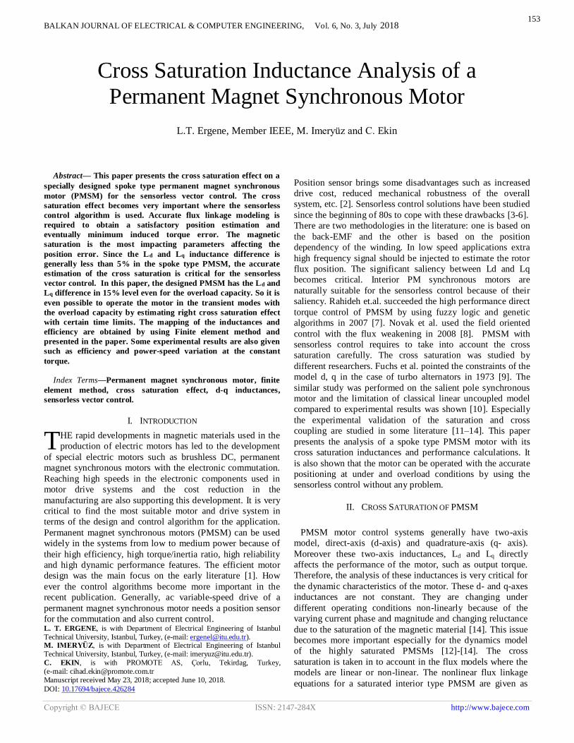
Similarly, Lqd cross saturation inductance is also calculated
by using Eq.6 and drawn as given in Fig.8b. Lqd is calculated
by taking the differential q axis flux change ( q) respect to d
axis current (Id) while keeping the q-axis current (Iq) constant.
(a)
(b) Fig.8.(a) Ldq cross saturation inductance (b) Lqd cross saturation inductance
(a)
(b)
Fig.9.(a) Lq “q” axis inductance vs Id current and rotor position (Iq=IN, peak=3.5 A) (b) Ld “d” axis inductance vs Iq current and rotor position
(Id=IN, peak=3.5 A)
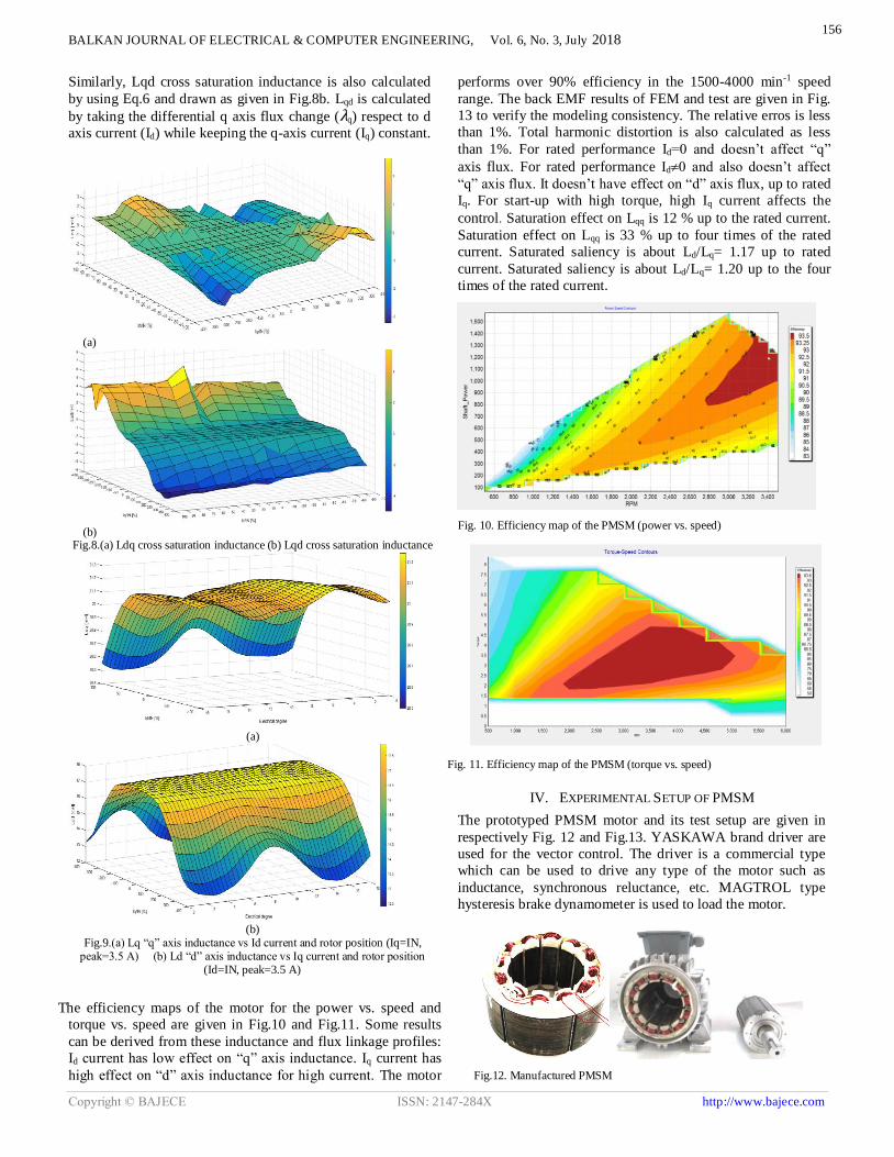
The efficiency maps of the motor for the power vs. speed and
torque vs. speed are given in Fig.10 and Fig.11. Some results
can be derived from these inductance and flux linkage profiles:
Id current has low effect on “q” axis inductance. Iq current has
high effect on “d” axis inductance for high current. The motor
performs over 90% efficiency in the 1500-4000 min-1 speed
range. The back EMF results of FEM and test are given in Fig.
13 to verify the modeling consistency. The relative erros is less
than 1%. Total harmonic distortion is also calculated as less
than 1%. For rated performance Id=0 and doesn’t affect “q”
axis flux. For rated performance Id0 and also doesn’t affect
“q” axis flux. It doesn’t have effect on “d” axis flux, up to rated
Iq. For start-up with high torque, high Iq current affects the
control. Saturation effect on Lqq is 12 % up to the rated current.
Saturation effect on Lqq is 33 % up to four times of the rated
current. Saturated saliency is about Ld/Lq= 1.17 up to rated
current. Saturated saliency is about Ld/Lq= 1.20 up to the four
times of the rated current.
Fig. 10. Efficiency map of the PMSM (power vs. speed)
Fig. 11. Efficiency map of the PMSM (torque vs. speed)
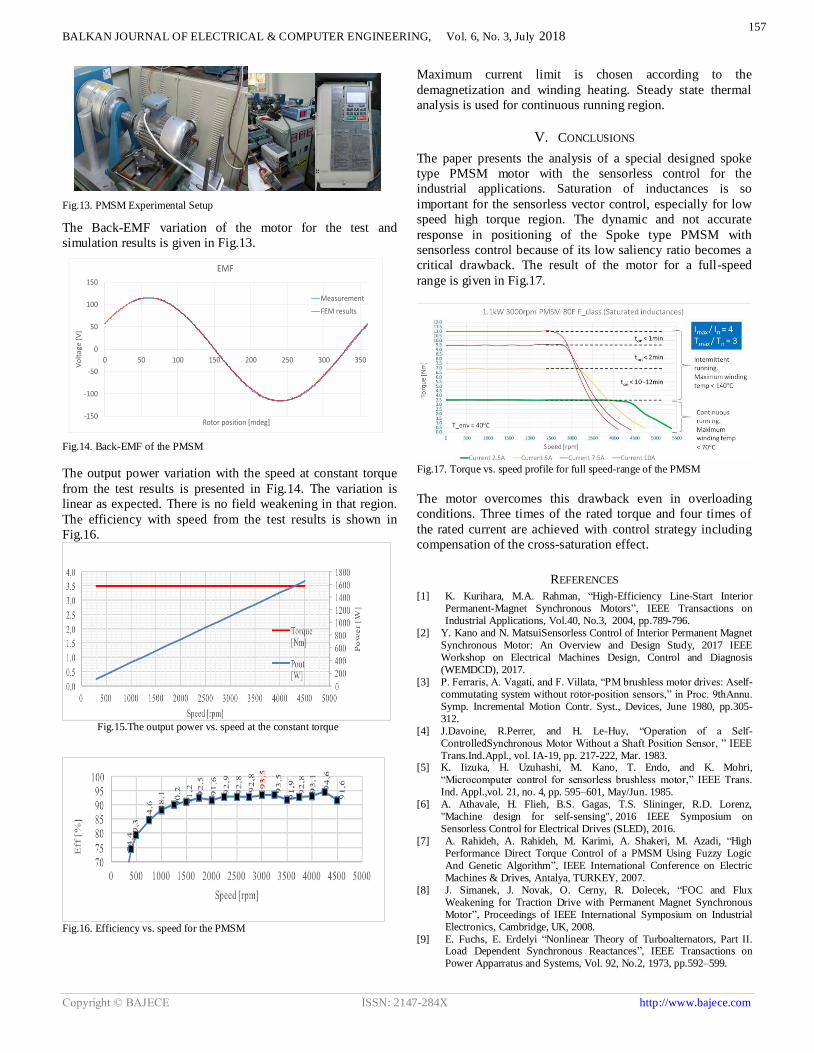
IV. EXPERIMENTAL SETUP OF PMSM
The prototyped PMSM motor and its test setup are given in
respectively Fig. 12 and Fig.13. YASKAWA brand driver are
used for the vector control. The driver is a commercial type
which can be used to drive any type of the motor such as
inductance, synchronous reluctance, etc. MAGTROL type
hysteresis brake dynamometer is used to load the motor.
Fig.12. Manufactured PMSM
156
BALKAN JOURNAL OF ELECTRICAL & COMPUTER ENGINEERING, Vol. 6, No. 3, July 2018
Copyright © BAJECE ISSN: 2147-284X http://www.bajece.com
Fig.13. PMSM Experimental Setup
The Back-EMF variation of the motor for the test and
simulation results is given in Fig.13.
-150
-100
-50
0
50
100
150
0 50 100 150 200 250 300 350
Vo
lta
ge
[V
]
Rotor position [mdeg]
EMF
Measurement
FEM results
Fig.14. Back-EMF of the PMSM
The output power variation with the speed at constant torque
from the test results is presented in Fig.14. The variation is
linear as expected. There is no field weakening in that region.
The efficiency with speed from the test results is shown in
Fig.16.
Fig.15.The output power vs. speed at the constant torque
Fig.16. Efficiency vs. speed for the PMSM
Maximum current limit is chosen according to the
demagnetization and winding heating. Steady state thermal
analysis is used for continuous running region.
V. CONCLUSIONS
The paper presents the analysis of a special designed spoke
type PMSM motor with the sensorless control for the
industrial applications. Saturation of inductances is so
important for the sensorless vector control, especially for low
speed high torque region. The dynamic and not accurate
response in positioning of the Spoke type PMSM with
sensorless control because of its low saliency ratio becomes a
critical drawback. The result of the motor for a full-speed
range is given in Fig.17.
Fig.17. Torque vs. speed profile for full speed-range of the PMSM
The motor overcomes this drawback even in overloading
conditions. Three times of the rated torque and four times of
the rated current are achieved with control strategy including
compensation of the cross-saturation effect.
REFERENCES
[1] K. Kurihara, M.A. Rahman, “High-Efficiency Line-Start Interior Permanent-Magnet Synchronous Motors”, IEEE Transactions on Industrial Applications, Vol.40, No.3, 2004, pp.789-796.
[2] Y. Kano and N. MatsuiSensorless Control of Interior Permanent Magnet Synchronous Motor: An Overview and Design Study, 2017 IEEE Workshop on Electrical Machines Design, Control and Diagnosis (WEMDCD), 2017.
[3] P. Ferraris, A. Vagati, and F. Villata, “PM brushless motor drives: Aself-commutating system without rotor-position sensors,” in Proc. 9thAnnu. Symp. Incremental Motion Contr. Syst., Devices, June 1980, pp.305-312.
[4] J.Davoine, R.Perrer, and H. Le-Huy, “Operation of a Self-ControlledSynchronous Motor Without a Shaft Position Sensor, ” IEEE Trans.Ind.Appl., vol. IA-19, pp. 217-222, Mar. 1983.
[5] K. Iizuka, H. Uzuhashi, M. Kano, T. Endo, and K. Mohri, “Microcomputer control for sensorless brushless motor,” IEEE Trans. Ind. Appl.,vol. 21, no. 4, pp. 595–601, May/Jun. 1985.
[6] A. Athavale, H. Flieh, B.S. Gagas, T.S. Slininger, R.D. Lorenz, "Machine design for self-sensing", 2016 IEEE Symposium on Sensorless Control for Electrical Drives (SLED), 2016.
[7] A. Rahideh, A. Rahideh, M. Karimi, A. Shakeri, M. Azadi, “High Performance Direct Torque Control of a PMSM Using Fuzzy Logic And Genetic Algorithm”, IEEE International Conference on Electric Machines & Drives, Antalya, TURKEY, 2007.
[8] J. Simanek, J. Novak, O. Cerny, R. Dolecek, “FOC and Flux Weakening for Traction Drive with Permanent Magnet Synchronous Motor”, Proceedings of IEEE International Symposium on Industrial Electronics, Cambridge, UK, 2008.
[9] E. Fuchs, E. Erdelyi “Nonlinear Theory of Turboalternators, Part II. Load Dependent Synchronous Reactances”, IEEE Transactions on Power Apparratus and Systems, Vol. 92, No.2, 1973, pp.592–599.
157

BALKAN JOURNAL OF ELECTRICAL & COMPUTER ENGINEERING, Vol. 6, No. 3, July 2018
Copyright © BAJECE ISSN: 2147-284X http://www.bajece.com
[10] M. Kamoun, M. Poloujadoff, “Experimental Study of The Effect of
Saturation on The Steady State Operation of a Salient Pole Microalternator”, Electrical Machines and Power Systems, Vol.10, 1985, pp.325–334.
[11] K. Saleh, M. Sumner, “Sensorless Speed Control of Five-Phase PMSM Drives with Low Current Distortion”, Electrical Engineering, 2017, pp.1-18.
[12] B. Stumberger, G. Stumberger, D. Dolinar, A. Hamler, M. Trlep, “Evaluation of Saturation and Cross-Magnetization Effects in Interior Permanent-Magnet Synchronous Motor”, IEEE Transactions on Industrial Applications, Vol.39, No.5, 2003, pp.1264–1271.
[13] A.M. El-Serafi, A.S. Abdallah, M.K. El-Sherbiny, E. Badawy, “Experimental Study of The Saturation and the Cross-Magnetizing Phenomenon in Saturated Synchronous Machines”, IEEE Transactions on Energy Conversion, Vol.2, No.4, 1988, pp.815–823.
[14] E. Levi, V.A. Levi, “Impact of Dynamic Cross-Saturation on Accuracy of Saturated Synchronous Machine Models”, IEEE Transactions on Energy Conversion, Vol.15, No.2, 2000, pp.224–230.
[15] E. Oksuztepe, Z.Omac, H. Kurum, “Sensorless Vector Control Of PMSM With Non-Sinusoidal Flux Using Observer Based On FEM”, Electrical Engineering, Vol.96, No.3, September 2014, pp. 227-238.
BIOGRAPHIES
Lale T. Ergene received her BS and
M.Sc. degrees in Electrical Engineering
at Istanbul Technical University (ITU)
in 1992 and 1995 respectively and Ph.D.
degree in Electrical Power Engineering
at Rensselaer Polytechnic Institute
(RPI), NY, USA in 2003. She worked
as consultant engineer at MAGSOFT Corporation during
1999-2004. She was also an adjunct assistant professor at RPI
in 2004. From 2004 to 2009, she was an assistant professor at
the Informatics Institute, ITU. She joined to the faculty of
Electrical Engineering, Istanbul Technical University in 2009.
She is currently an associate professor at the same department.
Her current research interests include design, analysis, control
of electrical machines and alternative energy technologies.
Murat İmeryüz was born in Ankara in
1967. He graduated from Suadiye High
School and started undergraduate
education in 1984 at the Istanbul
Technical University, Faculty of Electric
& Electronics, Department of Electrical
Engineering. He completed his
undergraduate education in 1989 and
M.Sc. degree in 1994 in Electrical Engineering major. He is
working at the same department since 1990. His current
research interests are fault diagnosis in asynchronous
machines, electrical drive systems, analytical calculation of
electrical machines and solar energy systems.
Cihad Ekin received his BS degree in
Electrical Engineering at Istanbul
Technical University (ITU) in 1997. He
worked as design team leader at
ARCELİK AS between 1997-2013. He
is currently the Vice Director of
PROMOTE AS. He has several patents
on electrical motors. His research
interests include design, analysis, control of PM motors.
158