cryowiz™ liquid nitrogen cryogenic switchover - … 5770e.pdf1 cryowiz™ liquid nitrogen...
TRANSCRIPT
1
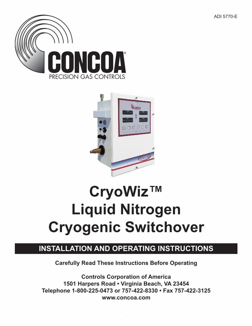
CryoWiz™Liquid Nitrogen
Cryogenic SwitchoverINSTALLATION AND OPERATING INSTRUCTIONS
Carefully Read These Instructions Before Operating
Controls Corporation of America1501 Harpers Road • Virginia Beach, VA 23454
Telephone 1-800-225-0473 or 757-422-8330 • Fax 757-422-3125www.concoa.com
ADI 5770-E

2
This page intentionally left blank.

3
Table of Contents
Safety .........................................................................................................................4User Responsibility .................................................................................................. 6Description of Product ............................................................................................. 6Features..................................................................................................................... 6Modes of Operation ................................................................................................. 8Installing the CryoWiz™ ......................................................................................... 10Connecting Power ................................................................................................... 15Operating the CryoWiz™ ........................................................................................ 17Mounting Detail ........................................................................................................25Power Requirements ...............................................................................................25Service ......................................................................................................................25Warranty ...................................................................................................................27
4
SAFETYHandling Liquid Nitrogen
Nitrogen is a colorless, odorless, tasteless gas. Liquid nitrogen (LN2) is a potential asphyxiate and may cause severe frostbite. Please observe all proper safety precautions to ensure proper handling of LN2. Consult your local LN2 Dealer for detailed handling instructions.
Cryogenic containers (Dewars) must be operated in accordance with the manufacturer instructions. Cryogenic Dewars must be kept in a well-ventilated place where they are protected from the weather and away from any sources of heat.
Nitrogen is a potential asphyxiate and can cause rapid suffocation without warning. Store and use in area with adequate ventilation. DO NOT vent container or system in confined spaces. DO NOT enter confined spaces where gas may be present unless area has been well ventilated. If inhaled, remove to fresh air. If not breathing, give artificial respiration. If breathing is difficult, supplemental Oxygen may be required. SEEK MEDICAL ATTENTION IMMEDIATELY.
Liquid Nitrogen can cause severe frostbite to the eyes or skin. DO NOT touch frosted pipes, hose assemblies or valves. In case of frostbite, consult a physician at once. If a physician is not readily available, warm the affected areas with water that is near body temperature.
Never place LN2 in a sealed container without a pressure relief device. The expansion of LN2 to N2 gas is approximately 1 to 700. When handling LN2 the most important safety aspects to consider are adequate ventilation and eye and skin protection. Although Nitrogen gas is non-toxic, it is dangerous in that the gas will displace the Oxygen in ambient air. Therefore, it is imperative that cryogenic supply and storage Dewars be stored and operated in open and well-ventilated areas. Oxygen Deficiency Monitoring Equipment should be used in areas where use of LN2 poses the risk of creating an Oxygen deficient atmosphere. Never enter a space where Oxygen deficiency is detected.
Persons transferring LN2 should make every effort to protect the eyes and skin from accidental contact with liquid or cold gas. Protect the eyes with a full-face shield. Safety glasses are not adequate. Always wear cryogenic gloves or equivalent when handling anything that is or may have been, in contact with the liquid, cold gas, cold pipes, or equipment. Long sleeve shirts and trousers, without cuffs, that are of sufficient length to prevent liquid from entering the shoes are recommended.
Notice
The CryoWiz™ is intended for low pressure 22 to 35 psig Cryogenic Liquid Nitrogen Applications

5
Basic safety precautions must be followed to reduce the risk of fire, electrical shock or injury.
• Connect the CryoWiz™ to the correct line voltage. A label on the product identifies what voltage it is wired for. CONNECTION TO AN INCORRECT VOLTAGE CAN CAUSE SERIOUS DAMAGE TO THE PRODUCT AND WILL VOID ANY WARRANTY.
• Install the CryoWiz™ where the ambient temperature range is between 0° F and 140° F.• Do not connect to Cryogenic Liquid Sources higher than 22 to 35 psig.• Do not install this product in a hazardous environment.• If product appears damaged in any way, do not use and request service from CONCOA.• Connect System purge and relief valve outlets to appropriately sized piping to an exterior unobstructed
vent. • Consult your local LN2 Dealer for detailed handling instructions. Always open valves slowly when being
used.• Use appropriate protective equipment.• Always be sure that a cylinder contains the correct gas before connecting it to any manifold.• Always leak-test any manifold or distribution pipeline before using.• Always close all cylinder valves before disconnecting cylinders from a manifold.• Always remove all empty cylinders from a manifold before connecting full cylinders.• Always check cylinders to be sure the cylinders are full before connecting to a manifold.• All gas distribution piping systems must meet the appropriate industrial standards for the intended service
and must be thoroughly cleaned before using. For the United States, some applicable safety rules and precautions are listed below:
1. American Society of Mechanical Engineers ASME B31.3 Process Piping; ASME Three Park Avenue2. New York, NY 10016-59903. Local Ordinances4. O.S.H.A. Standard 29 CFR5. C.G.A. Pamphlet C-4, American National Standard Method of Marking Portable Compressed Gas
Containers to Identify the Material Contained.6. C.G.A. Pamphlet G-4.1, Equipment Cleaned for oxygen service.7. C.G.A. Pamphlet P-12, Safe Handling of Cryogenic Liquids.8. C.G.A. Safety Bulletin SB-2, Oxygen Deficient Atmospheres.
C.G.A. Pamphlets can be obtained from the Compressed Gas Association, 1235 Jefferson Davis Highway, Arlington, VA 22202-3239, and (703) 979-0900. Publications: (703) 979-4341. Fax: (703) 979-0134
6
USER RESPONSIBILITYService and Installation of this product should only be performed by CONCOA or an authorized CONCOA factory trained technician having extensive knowledge of cryogenic liquid Nitrogen installations and systems. Requests for service may be made using the following methods of contact:
CUSTOMER SERVICE: 1-800-225-0473 CONCOA’s FAX: 1-757-422-3125 CONCOA’s E-MAIL: [email protected]
CONCOA accepts no responsibility for damage or injury if this product is modified in any way. CONCOA assumes/accepts no liability or responsibility for damage to individuals or equipment that may occur when using this product.
DESCRIPTION OF PRODUCTThe CryoWiz™ is a device used to monitor, control and switch the flow of cryogenic liquid nitrogen from two independent sources while maintaining an uninterrupted supply.
It consists of four electronically controlled pneumatic valves. Two inlet valves control the flow of cryogenic liquid nitrogen to the outlet of the device. The other two purge valves redirect hot gas from the inlet to ensure that the optimal supply of cryogenic liquid is available and delivered to the outlet.
The CryoWiz™ monitors the supply and demand using a proprietary computer algorithm to deliver an uninterrupted supply of LN2 to the outlet of the device.
The status of the CryoWiz™ may be monitored remotely via an optional Ethernet port. A series of indicator lights show the status of the system at any given time. In addition, the CryoWiz™ can interface with a CONCOA Remote Alarm.
The failsafe positions of all valves are normally closed during a power outage, cessation of the pneumatic dry nitrogen supply, or when an oxygen deficiency alert is relayed to the CryoWiz™.
FEATURESOperation from Cryogenic Liquid Nitrogen SourcesLiquid Dewars of Nitrogen provide the CryoWiz™ with an operating pressure of 22 to 35 PSI. Cryogenic Liquid Sources above 35 psig are not recommended. This is due to the increase in flash loss and the relief valve settings of the components connected. The Liquid Sources can be an individual or a multiple of cylinders connected, via an appropriate pipeline or manifold.
High Flow Cryogenic ValvesThe CryoWiz™ uses high flow cryogenic valves. The cryogenic valves deliver an optimal supply of liquid Nitrogen to the outlet, with minimal disturbance in flow and virtually no heat transfer.
Compact Enclosure with Condensate DrainThe entire system is enclosed in a single compact enclosure, with a condensate drain to reduce moisture and space problems.
Insulated Switching MechanismThe Insulated Switching Mechanism minimizes heat transfer, reduces condensation and ensures optimal delivery of liquid nitrogen.
7
Switchover With the depletion of the primary supply, The CryoWiz™ automatically switches to reserve supply using the proprietary algorithm and accurate sensors that detects the presence of the reserve supply of liquid nitrogen.
Oxygen Deficiency AlarmThe CryoWiz™ comes with a terminal strip to connect the output contact from an Oxygen Deficiency Monitor to the unit. When the Oxygen alarm relay contact is broken, the system will illuminate the LED and automatically shut down the system until the alarm condition is clear. The unit is designed to have an area deficiency alarm permanently connected. It is recommended that an auxiliary output, from any Oxygen deficiency, be connected to the CryoWiz™ so that the installation is safe and correct.
(See the section for connecting the Oxygen Alarm input).
Manual Bank SwitchingIt is possible to manually change the side that cryogenic liquid is being drawn from by pressing the SOURCE button. Switching will occur if there is sufficient supply on the reverse side.
PurgingThe CryoWiz™ will automatically purge as needed to detect liquid, depending on the mode of operation currently set. Manual purging is possible by pushing and holding the purge button on the display. The system will purge as long as the button is held.
Units of MeasureThe units of measure for the CryoWiz™ are Celsius and psig and they are not changeable. The display of the units is available thru the Ethernet Web Server.
Security LockoutThe CryoWiz™ has the ability to electronically lockout the front panel buttons to discourage tampering. The factory default setting is OFF or disabled. Refer to section on Keypad Security Lockout for details.
Alarm NotificationThe CryoWiz™ has a local audible and visual alarm. It is also designed to interface with CONCOA Remote Alarms, and comes with the necessary mating connector for their use. The normally closed dry contact output from the CryoWiz™ can be configured as five multiple alarms, or a single alarm contact. Refer to the section on connecting a remote alarm for more information.
Ethernet Port – Web ServerThe CryoWiz™ can be equipped with an integral Web Server enabling remote monitoring of functions, e-mail and remote configuration. For more information on the Web Server feature refer to the Web Server manual included with this product.
USB PortThe USB port should only be used by factory trained and authorized CONCOA installation technicians, during factory warranty installations and system configuration.
Relief Valve Overpressure ProtectionThe CryoWiz™ is equipped with three 35 psig or 50 psig Cryogenic Relief valves in the inlet and outlet. The Relief Valves will protect the system from pressure increases that may occur due to vaporization or trapping of cryogenic liquid during operation. Appropriate relief devices should be installed to protect against rapid pressure rise anywhere liquid may be trapped elsewhere in the system. (Note: Downstream relief valves must have a higher pressure settings than the ones supplied with the CryoWiz™).
8
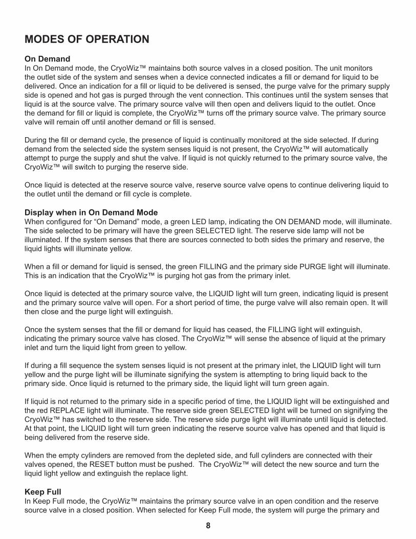
MODES OF OPERATIONOn DemandIn On Demand mode, the CryoWiz™ maintains both source valves in a closed position. The unit monitors the outlet side of the system and senses when a device connected indicates a fill or demand for liquid to be delivered. Once an indication for a fill or liquid to be delivered is sensed, the purge valve for the primary supply side is opened and hot gas is purged through the vent connection. This continues until the system senses that liquid is at the source valve. The primary source valve will then open and delivers liquid to the outlet. Once the demand for fill or liquid is complete, the CryoWiz™ turns off the primary source valve. The primary source valve will remain off until another demand or fill is sensed.
During the fill or demand cycle, the presence of liquid is continually monitored at the side selected. If during demand from the selected side the system senses liquid is not present, the CryoWiz™ will automatically attempt to purge the supply and shut the valve. If liquid is not quickly returned to the primary source valve, the CryoWiz™ will switch to purging the reserve side.
Once liquid is detected at the reserve source valve, reserve source valve opens to continue delivering liquid to the outlet until the demand or fill cycle is complete.
Display when in On Demand ModeWhen configured for “On Demand” mode, a green LED lamp, indicating the ON DEMAND mode, will illuminate. The side selected to be primary will have the green SELECTED light. The reserve side lamp will not be illuminated. If the system senses that there are sources connected to both sides the primary and reserve, the liquid lights will illuminate yellow.
When a fill or demand for liquid is sensed, the green FILLING and the primary side PURGE light will illuminate. This is an indication that the CryoWiz™ is purging hot gas from the primary inlet.
Once liquid is detected at the primary source valve, the LIQUID light will turn green, indicating liquid is present and the primary source valve will open. For a short period of time, the purge valve will also remain open. It will then close and the purge light will extinguish.
Once the system senses that the fill or demand for liquid has ceased, the FILLING light will extinguish, indicating the primary source valve has closed. The CryoWiz™ will sense the absence of liquid at the primary inlet and turn the liquid light from green to yellow.
If during a fill sequence the system senses liquid is not present at the primary inlet, the LIQUID light will turn yellow and the purge light will be illuminate signifying the system is attempting to bring liquid back to the primary side. Once liquid is returned to the primary side, the liquid light will turn green again.
If liquid is not returned to the primary side in a specific period of time, the LIQUID light will be extinguished and the red REPLACE light will illuminate. The reserve side green SELECTED light will be turned on signifying the CryoWiz™ has switched to the reserve side. The reserve side purge light will illuminate until liquid is detected. At that point, the LIQUID light will turn green indicating the reserve source valve has opened and that liquid is being delivered from the reserve side.
When the empty cylinders are removed from the depleted side, and full cylinders are connected with their valves opened, the RESET button must be pushed. The CryoWiz™ will detect the new source and turn the liquid light yellow and extinguish the replace light. Keep Full In Keep Full mode, the CryoWiz™ maintains the primary source valve in an open condition and the reserve source valve in a closed position. When selected for Keep Full mode, the system will purge the primary and
9
reserve inlets to maintain liquid at both source valves. This ensures that liquid is instantaneously available from either side should there be a DEMAND or Fill required. When CryoWiz™ senses liquid is no longer present, at the primary inlet, the system will automatically switch supply to the reserve and continue delivering liquid to the outlet. In a high demand or continual use application, the amount of liquid nitrogen consumed doing purging will be minimal relative to that used to supply the demand. Keep Full mode is not recommended for installations where demand is sporadic, as purging may lead to excessive product loss.
Display when in Keep Full ModeWhen configured for Keep Full mode, the green light for KEEP FULL and the green light for FILLING will illuminate. The side selected as the primary will have the green SELECTED light illuminated. The reserve side SELECTED light will remain off.
If the CryoWiz™ senses sources connected to both sides, the primary and reserve LIQUID lights will be illuminate yellow. The Liquid light will not illuminate green until the system has purged one or both sides and determined that there is liquid present.
For short periods of time, the purge LEDs will illuminate indicating the purge valves opening to maintain continuous liquid supply. The LIQUID lights will also switch from green to yellow as the system senses actual liquid presence at the inlets.
When liquid is not present or sensed, at the primary inlet, the LIQUID light and the PURGE light will illuminate yellow signifying the system is attempting to bring liquid back to the primary side.
Once liquid is returned to the primary side, the lamp will illuminate green again. If liquid is not returned to the primary side within a specified period of time, the LIQUID light will extinguish and the red REPLACE light will illuminate. The CryoWiz™ will now switch to the reserve side and the green SELECTED light will illuminate. The reserve side purge light will remain on until liquid is detected. At that point, the LIQUID light will turn green signifying the reserve source valve has opened and that liquid is being delivered from the reserve side.
10
15.062in382.6mm
19
.846in
504.1
mm
.494in12.5mm
.839in
21.3m
m
.47
1in12
mm
INLETINLET
OUTL
ET
1/2" NPTFemale
1/2" NPTFemale
1/2" NPTFemale
17
.669in
448.8
mm
1.3
41in
34.1m
m
.83
6in21
.2mm
10.383in263.7mm
6.469in164.3mm
2.969in75.4mm
1.469in37.3mm
.435in11mm
1.3
07in
33.2m
m
1.0
45in
26.5m
m
.137in3.5mm
4.387in111.4mm
OUTL
ET
DRAIN
1/8" NPTFemale
ø1/2" PVC DrainPipe Connection
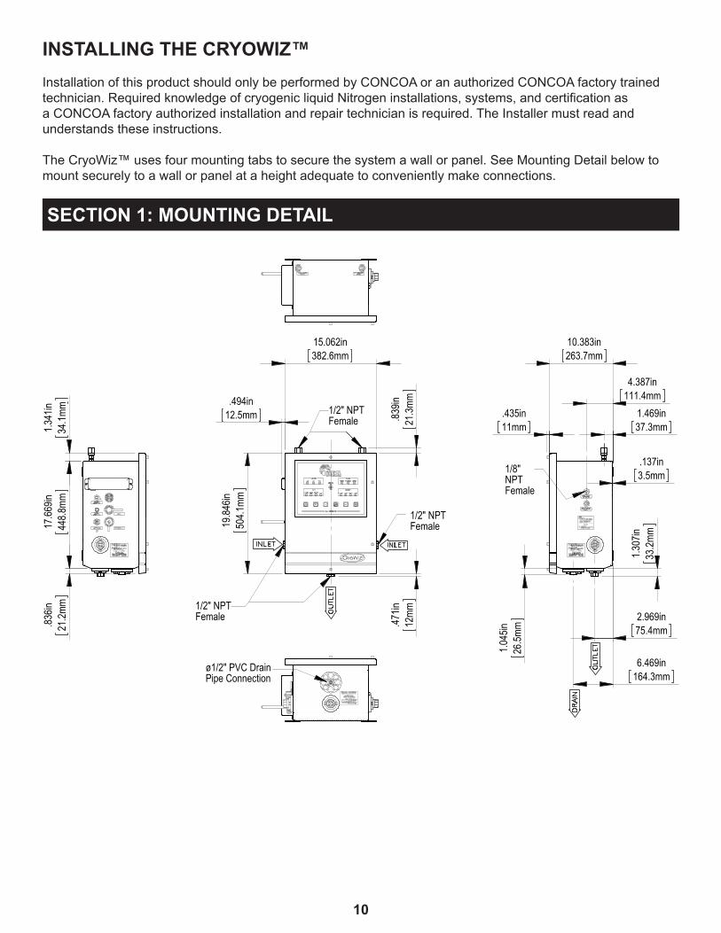
SECTION 1: MOUNTING DETAIL
INSTALLING THE CRYOWIZ™Installation of this product should only be performed by CONCOA or an authorized CONCOA factory trained technician. Required knowledge of cryogenic liquid Nitrogen installations, systems, and certification as a CONCOA factory authorized installation and repair technician is required. The Installer must read and understands these instructions.
The CryoWiz™ uses four mounting tabs to secure the system a wall or panel. See Mounting Detail below to mount securely to a wall or panel at a height adequate to conveniently make connections.

11
Drain Flange for 1/2”PVC Drain Pipe.
Cover Over TermnialBlock for Accessories
Audible Alarm
USB Connection
Ethernet Connection
Terminal BlockAccess Hole
Remote AlarmConnection
Power Cord(plug not shown)
Fuse
ALARM
FUSE
### VAC ETHERNET
USB
OUTPUT
3AG 1A/250V
Left Side Detail
12
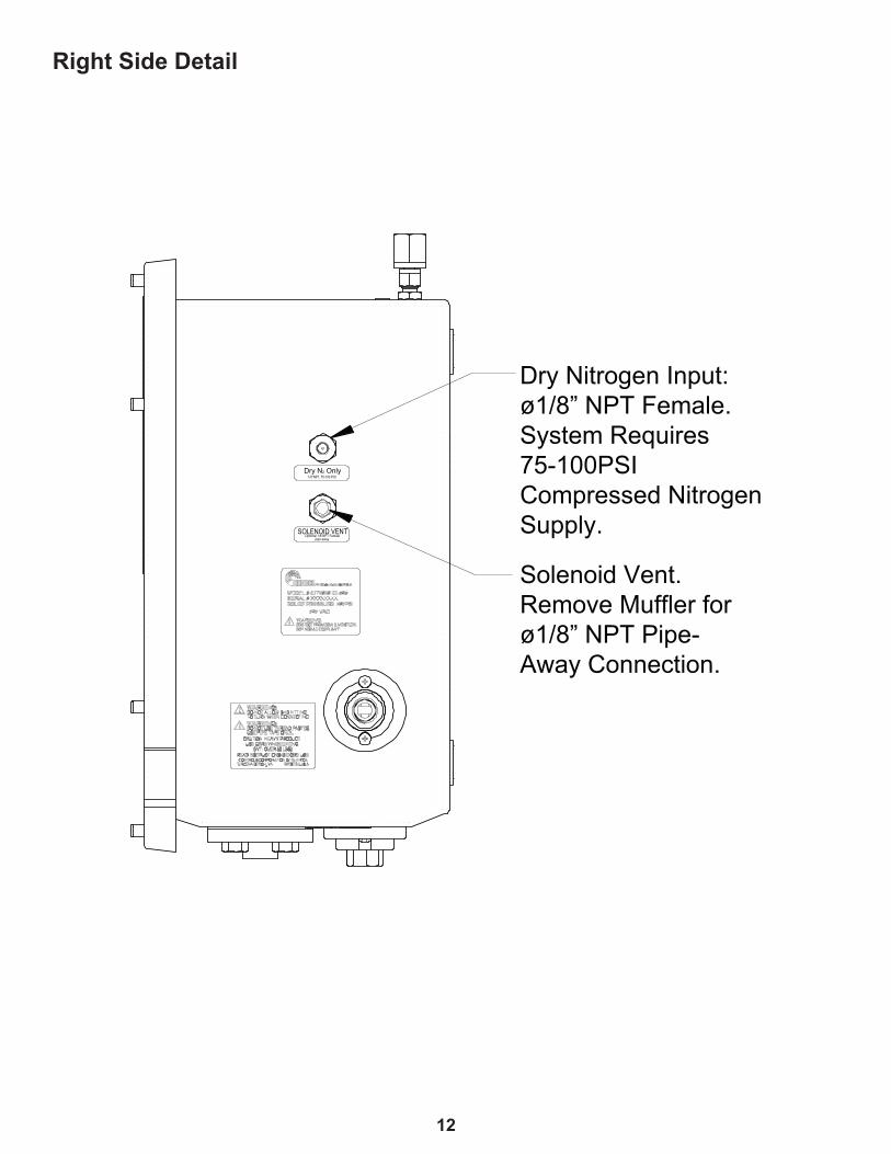
Solenoid Vent.Remove Muffler forø1/8” NPT Pipe-Away Connection.
Dry Nitrogen Input:ø1/8” NPT Female.System Requires75-100PSI Compressed NitrogenSupply.SOLENOID VENT
Optional 1/8”NPT Femalepipe away.
Dry N2 Only1/8”NPT, 75-100 PSI
Right Side Detail

13
Back Side Detail
14
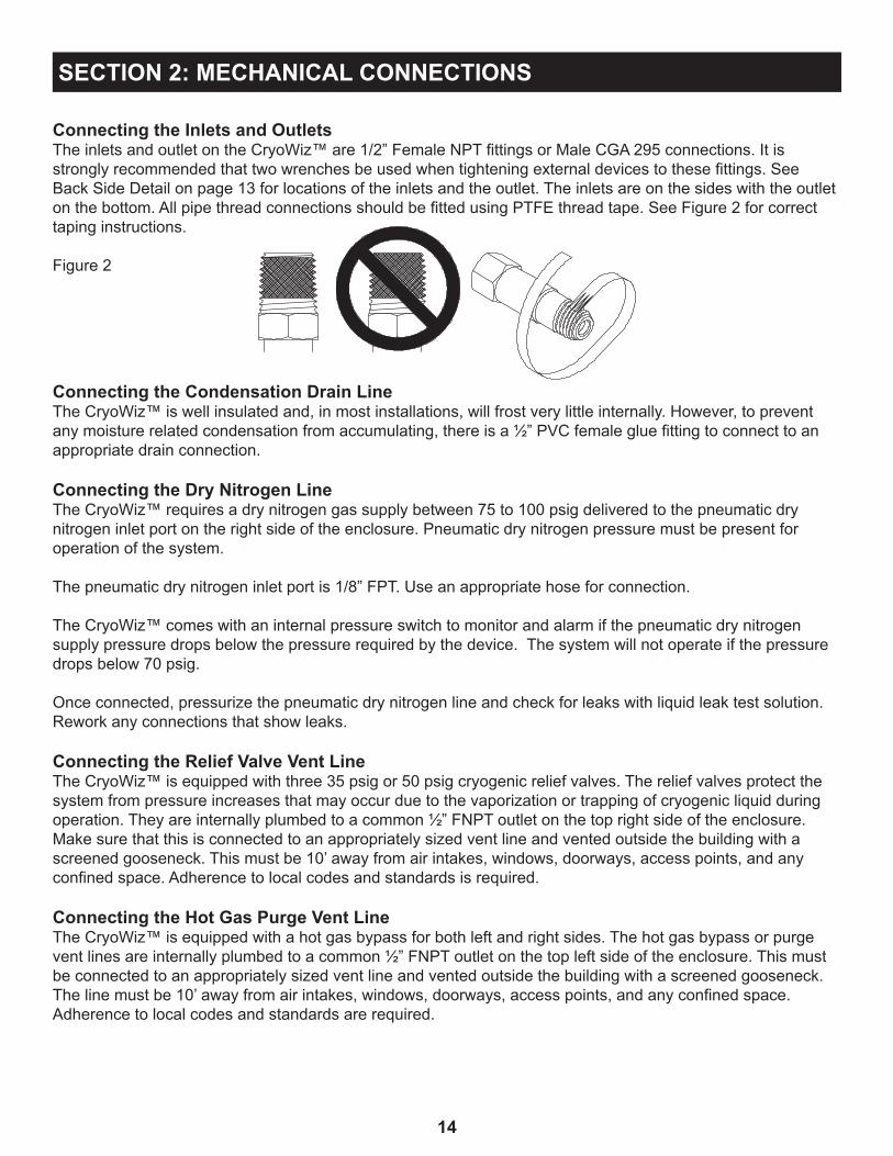
Connecting the Inlets and OutletsThe inlets and outlet on the CryoWiz™ are 1/2” Female NPT fittings or Male CGA 295 connections. It is strongly recommended that two wrenches be used when tightening external devices to these fittings. See Back Side Detail on page 13 for locations of the inlets and the outlet. The inlets are on the sides with the outlet on the bottom. All pipe thread connections should be fitted using PTFE thread tape. See Figure 2 for correct taping instructions.
Figure 2
SECTION 2: MECHANICAL CONNECTIONS
Connecting the Condensation Drain LineThe CryoWiz™ is well insulated and, in most installations, will frost very little internally. However, to prevent any moisture related condensation from accumulating, there is a ½” PVC female glue fitting to connect to an appropriate drain connection.
Connecting the Dry Nitrogen LineThe CryoWiz™ requires a dry nitrogen gas supply between 75 to 100 psig delivered to the pneumatic dry nitrogen inlet port on the right side of the enclosure. Pneumatic dry nitrogen pressure must be present for operation of the system.
The pneumatic dry nitrogen inlet port is 1/8” FPT. Use an appropriate hose for connection.
The CryoWiz™ comes with an internal pressure switch to monitor and alarm if the pneumatic dry nitrogen supply pressure drops below the pressure required by the device. The system will not operate if the pressure drops below 70 psig.
Once connected, pressurize the pneumatic dry nitrogen line and check for leaks with liquid leak test solution. Rework any connections that show leaks.
Connecting the Relief Valve Vent LineThe CryoWiz™ is equipped with three 35 psig or 50 psig cryogenic relief valves. The relief valves protect the system from pressure increases that may occur due to the vaporization or trapping of cryogenic liquid during operation. They are internally plumbed to a common ½” FNPT outlet on the top right side of the enclosure. Make sure that this is connected to an appropriately sized vent line and vented outside the building with a screened gooseneck. This must be 10’ away from air intakes, windows, doorways, access points, and any confined space. Adherence to local codes and standards is required.
Connecting the Hot Gas Purge Vent Line The CryoWiz™ is equipped with a hot gas bypass for both left and right sides. The hot gas bypass or purge vent lines are internally plumbed to a common ½” FNPT outlet on the top left side of the enclosure. This must be connected to an appropriately sized vent line and vented outside the building with a screened gooseneck. The line must be 10’ away from air intakes, windows, doorways, access points, and any confined space. Adherence to local codes and standards are required.
15
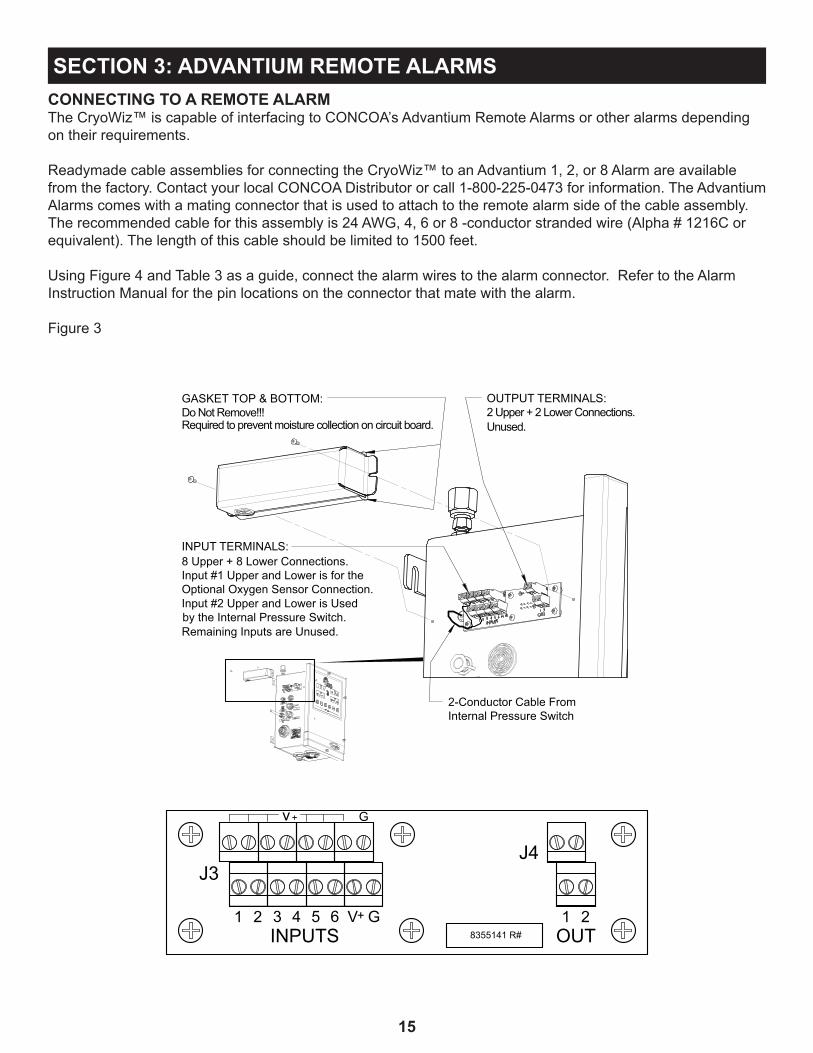
2-Conductor Cable From Internal Pressure Switch
INPUT TERMINALS:8 Upper + 8 Lower Connections.Input #1 Upper and Lower is for theOptional Oxygen Sensor Connection.Input #2 Upper and Lower is Used by the Internal Pressure Switch.Remaining Inputs are Unused.
OUTPUT TERMINALS:2 Upper + 2 Lower Connections.Unused.
GASKET TOP & BOTTOM:Do Not Remove!!! Required to prevent moisture collection on circuit board.
CONNECTING TO A REMOTE ALARMThe CryoWiz™ is capable of interfacing to CONCOA’s Advantium Remote Alarms or other alarms depending on their requirements.
Readymade cable assemblies for connecting the CryoWiz™ to an Advantium 1, 2, or 8 Alarm are available from the factory. Contact your local CONCOA Distributor or call 1-800-225-0473 for information. The Advantium Alarms comes with a mating connector that is used to attach to the remote alarm side of the cable assembly. The recommended cable for this assembly is 24 AWG, 4, 6 or 8 -conductor stranded wire (Alpha # 1216C or equivalent). The length of this cable should be limited to 1500 feet.
Using Figure 4 and Table 3 as a guide, connect the alarm wires to the alarm connector. Refer to the Alarm Instruction Manual for the pin locations on the connector that mate with the alarm.
Figure 3
SECTION 3: ADVANTIUM REMOTE ALARMS
v +
J3
INPUTS OUT
J4
V+ G
G
4 5 6321 218355141 R#

16
Pin diagram on wire connector
Terminal Number Terminal Number Description1 V+ Oxygen Sensor2 V+ Dry Nitrogen Pressure Switch 3 V+ Reserved4 V+ Reserved5 V+ Reserved6 V+ Reserved
Table 1
Table 2
Terminal Number Terminal Number Description1 1B Reserved2 2B Reserved
1
2
3
45
6
78
Table 3Figure 4
ALARMS CONNECTORPin # Function
1 LF Alarm 2 RT Alarm out3 +V in4 Oxygen Alarm 5 Air Alarm6 Gnd7 Freeze Alarm8 Unused
Connecting the Oxygen Alarm Input
The CryoWiz™ is equipped with a terminal strip to connect the normally closed dry contact input from an oxygen deficiency monitor. The terminal strip is located on the left side of the enclosure under a metal cover. Remove the cover and connect wires from the oxygen deficiency monitor to terminal 1 of the CryoWiz™ as shown in Figure 3 and Table 1.
17
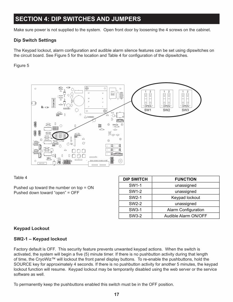
Make sure power is not supplied to the system. Open front door by loosening the 4 screws on the cabinet.
Dip Switch Settings
The Keypad lockout, alarm configuration and audible alarm silence features can be set using dipswitches on the circuit board. See Figure 5 for the location and Table 4 for configuration of the dipswitches.
Figure 5
SECTION 4: DIP SWITCHES AND JUMPERS
++
+ +
2
4 3
1
2
4 3
1
C24
U11
U16
U15
U18
J35
J33
Q1
J34
1
TEMP1
J4
Q2
J34
TEMP2
R23
SW2OPEN
J42
1
SW1
121
1
OPEN
R6
U1
J12
J9
R41
1
R21
R18
BUZ
J37
R22
C11
C17
D10
C5
C8
SW3OPEN
1 2
R15
2
1 J17
C10
C9
C3
INPUT1J43
1
1
R27
R25
C19
D6
D8
R26
1
C23
R24
C27
C25C22
C26
C20C211
J18
J39
1
C7
C18
1J24
J27
C14
R20 1
1
U22
U23
U17
U19
R11
1
J21
R19
J16
J15
R8
12
10
9
D7
7
6
3
4
1
C2
C1
1 J22
ALARM
J40
SOLENOID
S
J38J41
J32
J3
SW4
115VRV1
J44
+
+
R16
C4
+
C15
+
+
1
8355133 R3
1
R1
D1D9
R31
R321
C38
C39C41 C40
L8
C42
C43
J46
1
1
12
34
56
78
R41
J48
R40
11
1
1
J50 J51
J49
1
SERIAL
J10
LS1
LS2
LS4
LS3
LS5
J52
1
2
3
D3
F1
J36
1C45
R42
SW1 SW2 SW3
1
OPEN OPEN OPEN
2 1 2 1 2
Table 4
Pushed up toward the number on top = ONPushed down toward “open” = OFF
DIP SWITCH FUNCTIONSW1-1 unassignedSW1-2 unassignedSW2-1 Keypad lockoutSW2-2 unassignedSW3-1 Alarm ConfigurationSW3-2 Audible Alarm ON/OFF
Keypad Lockout
SW2-1 – Keypad lockout
Factory default is OFF. This security feature prevents unwanted keypad actions. When the switch is activated, the system will begin a five (5) minute timer. If there is no pushbutton activity during that length of time, the CryoWiz™ will lockout the front panel display buttons. To re-enable the pushbuttons, hold the SOURCE key for approximately 4 seconds. If there is no pushbutton activity for another 5 minutes, the keypad lockout function will resume. Keypad lockout may be temporarily disabled using the web server or the service software as well.
To permanently keep the pushbuttons enabled this switch must be in the OFF position.
18
Alarm Configuration
SW3-1 – Alarm Configuration
Factory default is OFF (all relays operate independently). The CryoWiz has five (5) dry contact alarm relays. Each one is defined in the Table 4. There may be applications that require a single relay contact closure, regardless of the alarm event, to be routed to the facility’s management. Closing SW3-1 directs the CryoWiz to activate the L-replace relay when any alarm event occurs.
SW3-2 – Audible Alarm ON/OFF
Factory default is ON. To disable the audible alarm turn SW3-2 OFF.
NOTE: With the exception of SW3-2, the CryoWiz will need to be power cycled for a DIP Switch change to be recognized.
SETTING REMOTE ALARM OUTPUTSThe CryoWiz™ is designed to interface with an external alarm system. Relay contacts are brought out through a connector on the left side of the cabinet. The pin connections on this connector are set to connect directly to a CONCOA alarm. CONCOA alarms are designed such that the contacts are Normally Closed (N.C.). In an alarm condition these contacts will open. This is the factory default. It is possible to change these contacts to Normal Open (N.O.). Figure 9 shows the location of the jumpers on the lower right side of the Control Board. There are five jumpers; one for each alarm or relay as shown on Table 5. To change a contact from N.C. to N.O., follow the steps below and see table 5:
1. Turn AC power OFF to the system.2. Open front door by loosening the 4 screws on the cabinet.3. Locate the jumpers on the Control Board.4. Change the jumpers to cover the center and the bottom pins of each relay.5. Close door and re-secure it to the cabinet.6. Make the necessary connections to the alarm and plug the alarm cable into the alarm connector on the
side of the cabinet.7. Turn AC power ON.
Table 5
Relay JUMPER FUNCTIONLS1 J51 Left alarmLS2 J50 Right AlarmLS3 J49 Oxygen AlarmLS4 J40 Air AlarmLS5 J41 Freeze Alarm

19
Figure 6
31
22
1
32
1
3
12
3
11
11
1
Jumper is shown inthe normally OPENpostion.
Jumper is shown inthe normally CLOSEDpostion(factory default).
ALARM
SO
LEN
OID
S
LS4
LS2
LS3
LS5
LS1
J50
J40
J51
J49
J41
J32
84
73
62
5
1
J38

20
Date and Time Clock Backup The CryoWiz™ is supplied with an onboard event log with a real time date and clock stamp. After installing the unit on the wall with all inlet and outlet connection configured and prior to putting any power to the unit, open the front door, insert the three AA batteries enclosed with the unit located below the circuit board on the inside of the door. These are the battery backup to continue calculating the date and time clock. They will typically provide a minimum of 7 days battery backup to the date and time clock in the event of power failure. This ensures that the event log retains an accurate time and date stamp. It is suggested that the installer write the date the batteries were installed on the label covering the battery pack. The batteries should be replaced annually.
Using Figure 7, install the three AA batteries properly in the battery pack. Make sure AC power is disconnected prior to battery installation.
Figure 7
SECTION 5: INSTALLING THE BATTERIES
Once complete, close door and re-secure the screws on the front of the cabinet.
21
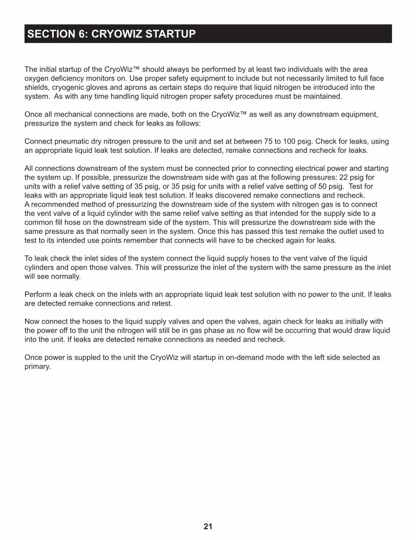
The initial startup of the CryoWiz™ should always be performed by at least two individuals with the area oxygen deficiency monitors on. Use proper safety equipment to include but not necessarily limited to full face shields, cryogenic gloves and aprons as certain steps do require that liquid nitrogen be introduced into the system. As with any time handling liquid nitrogen proper safety procedures must be maintained. Once all mechanical connections are made, both on the CryoWiz™ as well as any downstream equipment, pressurize the system and check for leaks as follows:
Connect pneumatic dry nitrogen pressure to the unit and set at between 75 to 100 psig. Check for leaks, using an appropriate liquid leak test solution. If leaks are detected, remake connections and recheck for leaks.
All connections downstream of the system must be connected prior to connecting electrical power and starting the system up. If possible, pressurize the downstream side with gas at the following pressures: 22 psig for units with a relief valve setting of 35 psig, or 35 psig for units with a relief valve setting of 50 psig. Test for leaks with an appropriate liquid leak test solution. If leaks discovered remake connections and recheck. A recommended method of pressurizing the downstream side of the system with nitrogen gas is to connect the vent valve of a liquid cylinder with the same relief valve setting as that intended for the supply side to a common fill hose on the downstream side of the system. This will pressurize the downstream side with the same pressure as that normally seen in the system. Once this has passed this test remake the outlet used to test to its intended use points remember that connects will have to be checked again for leaks.
To leak check the inlet sides of the system connect the liquid supply hoses to the vent valve of the liquid cylinders and open those valves. This will pressurize the inlet of the system with the same pressure as the inlet will see normally.
Perform a leak check on the inlets with an appropriate liquid leak test solution with no power to the unit. If leaks are detected remake connections and retest.
Now connect the hoses to the liquid supply valves and open the valves, again check for leaks as initially with the power off to the unit the nitrogen will still be in gas phase as no flow will be occurring that would draw liquid into the unit. If leaks are detected remake connections as needed and recheck.
Once power is suppled to the unit the CryoWiz will startup in on-demand mode with the left side selected as primary.
SECTION 6: CRYOWIZ STARTUP

22
Finally connect AC power to the CryoWiz™. The system is factory set to operate at either 115VAC 60hz or 230 VAC 60hz. Check the product label for the product voltage. It is strongly recommeded that a battery backup such as a UPS be used to ensure the continuous function of the device.
SECTION 7: CONNECTION POWER
Connection of the CryoWiz™ to an incorrect input voltage will damage the product and void any warranty.
The unit is supplied with the appropriate plug.
The CryoWiz™ will start up in the ON DEMAND mode with the left side selected as primary. The unit will purge the left inlet until the system senses liquid. During this time check the liquid valve connections and the hot gas bypass line for leaks to ensure that the vent gas is directed outside the building only.
Switch the unit to the right side and allow that side to purge and check that there are no leaks on the liquid valve connections.
Once liquid is sensed the right side valve the downstream valve will open and will continue to fill the downstream outlet with gas only until a stable outlet pressure has been established. Any liquid will sent downstream will flash to gas on the downstream side rather quickly generating this pressure. if the system continues to fill for more than 20 seconds this may indicate that there is a leak downstream that was not detected. Turn off power and recheck downstream connections.
Check for leaks downstream with an appropriate liquid leak test solution. If the system continues to fill with no real demand for liquid downstream, this is an indication of a leak. Turn power off to the unit and check all connections.
If the unit cannot establish any pressure downstream the unit fairly quickly register that as an empty supply side and switch to the other side if this occurs that is also an indication that there is an open connection downstream or a large leak.
Turn power off to the unit and check all connections.
If necessary, use the SOURCE select pushbutton to choose the side you would like to be considered the primary bank. The CryoWiz™ will default to the left inlet side as the primary.
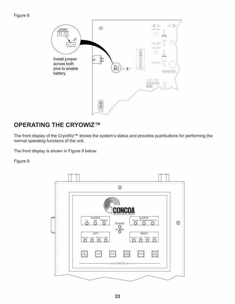
Once the CryoWiz™ is powered & operating, locate jumper J1 on the control circuit board. Connect jumper as shown in Figure 8. Using the installer’s service software utility, set the date and time.
Normal operation of the CryoWiz™ can now begin.
All switching is automatic.
23
Figure 8
www.CONCOA.com
ALERTSAIRO2 FREEZE
ALERTSON DEMANDFILLING KEEP FULL
LEFT
POWER
ALARM
LIQUIDSELECTED REPLACE PURGE
RIGHTLIQUIDSELECTED REPLACE PURGE
MODELEFTPURGE
ALARMSILENCE
RIGHTPURGERESET SOURCE
OPERATING THE CRYOWIZ™The front display of the CryoWiz™ shows the system’s status and provides pushbuttons for performing the normal operating functions of the unit.
The front display is shown in Figure 9 below:
Figure 9
J1
J1
Jumper
Install jumperacross both pins to enablebattery.
24
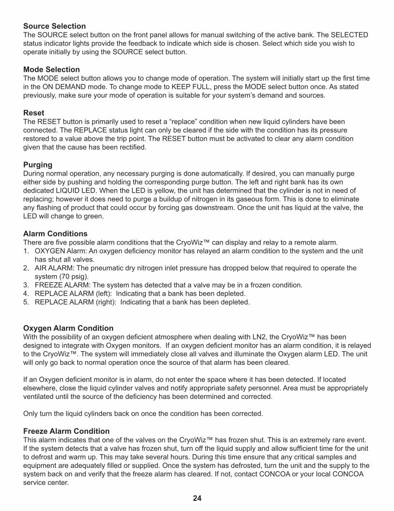
Source SelectionThe SOURCE select button on the front panel allows for manual switching of the active bank. The SELECTED status indicator lights provide the feedback to indicate which side is chosen. Select which side you wish to operate initially by using the SOURCE select button.
Mode SelectionThe MODE select button allows you to change mode of operation. The system will initially start up the first time in the ON DEMAND mode. To change mode to KEEP FULL, press the MODE select button once. As stated previously, make sure your mode of operation is suitable for your system’s demand and sources.
ResetThe RESET button is primarily used to reset a “replace” condition when new liquid cylinders have been connected. The REPLACE status light can only be cleared if the side with the condition has its pressure restored to a value above the trip point. The RESET button must be activated to clear any alarm condition given that the cause has been rectified.
Purging During normal operation, any necessary purging is done automatically. If desired, you can manually purge either side by pushing and holding the corresponding purge button. The left and right bank has its own dedicated LIQUID LED. When the LED is yellow, the unit has determined that the cylinder is not in need of replacing; however it does need to purge a buildup of nitrogen in its gaseous form. This is done to eliminate any flashing of product that could occur by forcing gas downstream. Once the unit has liquid at the valve, the LED will change to green.
Alarm ConditionsThere are five possible alarm conditions that the CryoWiz™ can display and relay to a remote alarm.1. OXYGEN Alarm: An oxygen deficiency monitor has relayed an alarm condition to the system and the unit
has shut all valves.2. AIR ALARM: The pneumatic dry nitrogen inlet pressure has dropped below that required to operate the
system (70 psig). 3. FREEZE ALARM: The system has detected that a valve may be in a frozen condition.4. REPLACE ALARM (left): Indicating that a bank has been depleted. 5. REPLACE ALARM (right): Indicating that a bank has been depleted.
Oxygen Alarm ConditionWith the possibility of an oxygen deficient atmosphere when dealing with LN2, the CryoWiz™ has been designed to integrate with Oxygen monitors. If an oxygen deficient monitor has an alarm condition, it is relayed to the CryoWiz™. The system will immediately close all valves and illuminate the Oxygen alarm LED. The unit will only go back to normal operation once the source of that alarm has been cleared.
If an Oxygen deficient monitor is in alarm, do not enter the space where it has been detected. If located elsewhere, close the liquid cylinder valves and notify appropriate safety personnel. Area must be appropriately ventilated until the source of the deficiency has been determined and corrected.
Only turn the liquid cylinders back on once the condition has been corrected.
Freeze Alarm ConditionThis alarm indicates that one of the valves on the CryoWiz™ has frozen shut. This is an extremely rare event. If the system detects that a valve has frozen shut, turn off the liquid supply and allow sufficient time for the unit to defrost and warm up. This may take several hours. During this time ensure that any critical samples and equipment are adequately filled or supplied. Once the system has defrosted, turn the unit and the supply to the system back on and verify that the freeze alarm has cleared. If not, contact CONCOA or your local CONCOA service center.

25
Air Alarm ConditionThe air alarm indicates that the pneumatic dry nitrogen gas supply has dropped below the alarm set point (70 psig) and may not be able to keep the system running properly. Check to make sure that the pneumatic dry nitrogen is between 75 to 100 psig.
Replace Alarm ConditionThe system has determined that a bank is now empty and will illuminate its corresponding “REPLACE” LED. Once the empty side is replenished with full cylinders supplying the CryoWiz™ with sufficient pressure, press the RESET button to extinguish the alarm.
Alarm Silence The alarm silence button will silence the local audible alarm. The alarm indication will still be lit until the alarm condition has been cleared.
COMMUNICATION MODEThe CryoWiz™ has the built in capability to communicate externally via the Ethernet (Web Server) or USB port. The USB port is only used when Factory Authorized Technicians customize the setup of the CryoWiz™.The Ethernet (Web Server) is used for all end user remote communication. This includes email notification, system status viewing and event logging.
CONNECTING THE WEB SERVERThe CryoWiz™ can be ordered with an integral Web Server device. Connection to the Web Server is through an RJ45 connector located on the left side of the CryoWiz™. Unscrew the protective cap that covers the connector jack to insert the cable. Use any CAT 5 or CAT 6 cable to make this connection to the local area network. Refer to the Web Server ADI that was included with the CryoWiz™ for instructions on interfacing it to the local area network.
POWER REQUIREMENTSInput Voltage: 115 VAC ± 10% 50-60hz or 230 VAC ± 10% 50-60hzPower Consumption: 20 wattsFuses: 1 amp, type 3AG normal blow. Connection to UPS power supply for the system and its components is highly recommended.Date and time event clock: 3 AA batteries.
SERVICEFor Service to the CryoWiz™ contact your local Distributor or CONCOA Customer Service at 1-800-225-0473.
FACTORY DEFAULT SETTINGSCommunication: USB, Ethernet (Web Server)
Units of Measure: °C, psig
Key Lock Security: Disabled

26
This page intentionally left blank.
27
WARRANTY INFORMATION This equipment is sold by CONTROLS CORPORATION OF AMERICA under the warranties set forth in the following paragraphs. Such warranties are extended only with respect to the purchase of this equipment directly from CONTROLS CORPORATION OF AMERICA or its Authorized Distributors as new merchandise and are extended to the first Buyer thereof other than for the purpose of resale.
For a period of one (1) year from the date of original delivery (90 days in corrosive service) to Buyer or to Buyer’s order, this equipment is warrantied to be free from functional defects in materials and workmanship and to conform to the description of this equipment contained in this manual and any accompanying labels and/or inserts, provided that the same is properly operated under conditions of normal use and that regular periodic maintenance and service is performed or replacements made in accordance with the instructions provided. The foregoing warranties shall not apply if the equipment has been repaired: other than by CONTROLS CORPORATION OF AMERICA or a designated service facility in accordance with written instructions provided by CONTROLS CORPORATION OF AMERICA; or altered by anyone other than CONTROLS CORPORATION OF AMERICA; or if the equipment has been operated under improper conditions or outside published specifications; or if the equipment has been damaged or does not function due to improper installation, improper supply of required utilities, accident, abuse, misuse, natural disaster, insufficient or excessive electrical supply, abnormal mechanical or environmental conditions, or debris or particles in the gas or liquid source of supply.
CONTROLS CORPORATION OF AMERICA’s sole and exclusive obligation and Buyer’s sole and exclusive remedy under the above warranties is limited to repairing using new or reconditioned parts or replacing, free of charge except for labor if permanently installed for the continuous supply of gas by other than a technician certified by CONTROLS CORPORATION OF AMERICA specifically to do so, at CONTROLS CORPORATION OF AMERICA’s option, the equipment or part, which is either (1) reported to its Authorized Distributor from whom purchased, and which if so advised, is returned with a statement of the observed deficiency, and proof of purchase of equipment or part not later than seven (7) days after the expiration date of the applicable warranty, to the nearest designated service facility during normal business hours, transportation charges prepaid, and which upon examination, is found not to comply with the above warranties with return trip transportation charges for the equipment or part paid by Buyer or (2) in the case of designated equipment permanently installed for the continuous supply of gas, reported to an Authorized Service Center with proof of initial installation no later than seven (7) days after the expiration date of the applicable warranty, and which is evaluated for compliance with the above warranties by technician certified by CONTROLS CORPORATION OF AMERICA, and which is determined by CONTROLS CORPORATION OF AMERICA based on said evaluation to be non-compliant.
CONTROLS CORPORATION OF AMERICA SHALL NOT BE OTHERWISE LIABLE FOR ANY DAMAGES INCLUDING BUT NOT LIMITED TO: INCIDENTAL DAMAGES, CONSEQUENTIAL DAMAGES, OR SPECIAL DAMAGES, WHETHER SUCH DAMAGES RESULT FROM NEGLIGENCE, BREACH OF WARRANTY OR OTHERWISE.
THERE ARE NO EXPRESS OR IMPLIED WARRANTIES WHICH EXTEND BEYOND THE WARRANTIES HEREINABOVE SET FORTH. CONTROLS CORPORATION OF AMERICA MAKES NO WARRANTY OF MERCHANTABILITY OR FITNESS FOR A PARTICULAR PURPOSE WITH RESPECT TO THE EQUIPMENT OR PARTS THEREOF.
28
INSTALLATION AND OPERATING INSTRUCTIONS
Certified ISO 9001:2008
Controls Corporation of America1501 Harpers Road • Virginia Beach, VA 23454
Telephone 1-800-225-0473 or 757-422-8330 • Fax 757-422-3125www.concoa.com
ADI 5770-ERevised Date: October 2013