crystalfontz america, incorporated · pdf filecrystalfontz america, incorporated serial lcd...
TRANSCRIPT

Crystalfontz America, Incorporated
SERIAL LCD MODULE SPECIFICATIONS
Crystalfontz America, Incorporated12412 East Saltese Avenue
Spokane Valley, WA 99216-0357
Phone: (888) 206-9720Fax: (509) 892-1203Email: [email protected]: www.crystalfontz.com
Crystalfontz Model Number CFA635-TFE-KS
Hardware Version Part 1: CFA-635 LCD ModuleRevision 1.0, August 2005
Part 2: CFA-RS232-01 Serial ConverterRevision 1.0, June 2005
Firmware Version Revision s1.3, June 2005
Data Sheet Version Revision 1.0, May 2007
Product Pages http://www.crystalfontz.com/products/635/index.html
Customer Name

Crystalfontz America, Inc. CFA635-TFE-KS Serial LCD Module Data Sheetwww.crystalfontz.com Hardware v1.0 / Firmware s1.3 / Data Sheet v1.0May 2007 Page 2
REVISION HISTORY
The information in this publication is deemed accurate but is not guaranteed.
Company and product names mentioned in this publication are trademarks or registered trademarks of their respective owners.
© 2007 Crystalfontz America, Inc., 12412 East Saltese Avenue, Spokane Valley, WA 99212-0357 U.S.A.
HARDWAREPART 1: CFA-635 LCD MODULE
(CFA635-TFE-KS identical to USB version CFA635-TFE-KU)
2005/08/01 Start Public Version Tracking.Current Hardware Revision: v1.0
HARDWAREPART 2: CFA-RS232-01 SERIAL CONVERTER
(mounted on CFA-635 LCD module)
2006/01/01 Current Hardware Revision: v1.0New hardware.
FIRMWARE
2005/06/01
Current Firmware Revision: s1.3New firmware. (CFA-635 v1.3 USB module firmware was modified for this serial module.) Command 1: Get Hardware & Firmware Version returns: “CFA635:h1.0,s1.3”
DATA SHEET
2007/05/15 Current Data Sheet Revision: v1.0New Data Sheet.

Crystalfontz America, Inc. CFA635-TFE-KS Serial LCD Module Data Sheetwww.crystalfontz.com Hardware v1.0 / Firmware s1.3 / Data Sheet v1.0May 2007 Page 3
INTRODUCTION - - - - - - - - - - - - - - - - - - - - - - - - - - - - - - - - - - - - - - - - - - - - - - - - - - - - - - - - - - - - - - - - - 6MAIN FEATURES - - - - - - - - - - - - - - - - - - - - - - - - - - - - - - - - - - - - - - - - - - - - - - - - - - - - - - - - - - - - - - - - 6
Module Classification Information - - - - - - - - - - - - - - - - - - - - - - - - - - - - - - - - - - - - - - - - - - - - - - - - - - - 7Ordering Information - - - - - - - - - - - - - - - - - - - - - - - - - - - - - - - - - - - - - - - - - - - - - - - - - - - - - - - - - - - - 7
MECHANICAL SPECIFICATIONS - - - - - - - - - - - - - - - - - - - - - - - - - - - - - - - - - - - - - - - - - - - - - - - - - - - - 8Physical Characteristics - - - - - - - - - - - - - - - - - - - - - - - - - - - - - - - - - - - - - - - - - - - - - - - - - - - - - - - - - - 8Two Parts: CFA-635 Serial LCD Module and CFA-RS232-01 Serial Converter - - - - - - - - - - - - - - - - - - - 9Connector Descriptions - - - - - - - - - - - - - - - - - - - - - - - - - - - - - - - - - - - - - - - - - - - - - - - - - - - - - - - - - - 9
CFA-RS232-01 Serial Converter Connectors - - - - - - - - - - - - - - - - - - - - - - - - - - - - - - - - - - - - - - - 10CFA-635 Serial LCD Module Connectors - - - - - - - - - - - - - - - - - - - - - - - - - - - - - - - - - - - - - - - - - 11
Module Outline Drawing - - - - - - - - - - - - - - - - - - - - - - - - - - - - - - - - - - - - - - - - - - - - - - - - - - - - - - - - 12Jumper Locations and Functions - - - - - - - - - - - - - - - - - - - - - - - - - - - - - - - - - - - - - - - - - - - - - - - - - - 13Keypad Outline Drawing - - - - - - - - - - - - - - - - - - - - - - - - - - - - - - - - - - - - - - - - - - - - - - - - - - - - - - - - 14
ELECTRICAL SPECIFICATIONS - - - - - - - - - - - - - - - - - - - - - - - - - - - - - - - - - - - - - - - - - - - - - - - - - - - - 15System Block Diagram - - - - - - - - - - - - - - - - - - - - - - - - - - - - - - - - - - - - - - - - - - - - - - - - - - - - - - - - - 15Viewing Direction - - - - - - - - - - - - - - - - - - - - - - - - - - - - - - - - - - - - - - - - - - - - - - - - - - - - - - - - - - - - - 16Driving Method - - - - - - - - - - - - - - - - - - - - - - - - - - - - - - - - - - - - - - - - - - - - - - - - - - - - - - - - - - - - - - - 16Absolute Maximum Ratings - - - - - - - - - - - - - - - - - - - - - - - - - - - - - - - - - - - - - - - - - - - - - - - - - - - - - - 16DC Characteristics - - - - - - - - - - - - - - - - - - - - - - - - - - - - - - - - - - - - - - - - - - - - - - - - - - - - - - - - - - - - 16Typical Current Consumption - - - - - - - - - - - - - - - - - - - - - - - - - - - - - - - - - - - - - - - - - - - - - - - - - - - - - 17ESD (Electro-Static Discharge) Specifications - - - - - - - - - - - - - - - - - - - - - - - - - - - - - - - - - - - - - - - - - 17Additional Criteria - - - - - - - - - - - - - - - - - - - - - - - - - - - - - - - - - - - - - - - - - - - - - - - - - - - - - - - - - - - - - 18Pin Assignments (Default and Alternate) on CFA-RS232-01 “J1” Connector - - - - - - - - - - - - - - - - - - - - 18Pin Assignments on CFA-RS232-01 "J2" Connector (Including GPIO Connections) - - - - - - - - - - - - - - 19Pin Assignments on CFA-635 Serial LCD Module “H1”Connector (Including GPIO Connections) - - - - - - - - - - - - - - - - - - - - - - - - - - - - - - - - - - - - - - - - - - - - 21Pin Assignments on CFA-635 Serial LCD Module “H2”Connector (Including GPO Connections) - - - - - - - - - - - - - - - - - - - - - - - - - - - - - - - - - - - - - - - - - - - - - 22Power Connection to Host and Optional SCAB - - - - - - - - - - - - - - - - - - - - - - - - - - - - - - - - - - - - - - - - 22Connection of Optional SCAB - - - - - - - - - - - - - - - - - - - - - - - - - - - - - - - - - - - - - - - - - - - - - - - - - - - - 24
PRODUCT RELIABILITY- - - - - - - - - - - - - - - - - - - - - - - - - - - - - - - - - - - - - - - - - - - - - - - - - - - - - - - - - - 25HOST COMMUNICATIONS - - - - - - - - - - - - - - - - - - - - - - - - - - - - - - - - - - - - - - - - - - - - - - - - - - - - - - - - 25
Packet Structure - - - - - - - - - - - - - - - - - - - - - - - - - - - - - - - - - - - - - - - - - - - - - - - - - - - - - - - - - - - - - - 25About Handshaking - - - - - - - - - - - - - - - - - - - - - - - - - - - - - - - - - - - - - - - - - - - - - - - - - - - - - - - - - - - - 26Report Codes - - - - - - - - - - - - - - - - - - - - - - - - - - - - - - - - - - - - - - - - - - - - - - - - - - - - - - - - - - - - - - - - 26
0x80: Key Activity - - - - - - - - - - - - - - - - - - - - - - - - - - - - - - - - - - - - - - - - - - - - - - - - - - - - - - - - - - 270x81: Fan Speed Report (SCAB required) - - - - - - - - - - - - - - - - - - - - - - - - - - - - - - - - - - - - - - - - - 270x82: Temperature Sensor Report (SCAB required) - - - - - - - - - - - - - - - - - - - - - - - - - - - - - - - - - - 28
Command Codes - - - - - - - - - - - - - - - - - - - - - - - - - - - - - - - - - - - - - - - - - - - - - - - - - - - - - - - - - - - - - 290 (0x00): Ping Command - - - - - - - - - - - - - - - - - - - - - - - - - - - - - - - - - - - - - - - - - - - - - - - - - - - - - 291 (0x01): Get Hardware & Firmware Version - - - - - - - - - - - - - - - - - - - - - - - - - - - - - - - - - - - - - - - 292 (0x02): Write User Flash Area - - - - - - - - - - - - - - - - - - - - - - - - - - - - - - - - - - - - - - - - - - - - - - - - 293 (0x03): Read User Flash Area - - - - - - - - - - - - - - - - - - - - - - - - - - - - - - - - - - - - - - - - - - - - - - - - 304 (0x04): Store Current State As Boot State - - - - - - - - - - - - - - - - - - - - - - - - - - - - - - - - - - - - - - - 305 (0x05): Reboot CFA-635, Reset Host (SCAB required), or Power Off Host (SCAB required) - - - - 31
CONTENTS
Crystalfontz America, Inc. CFA635-TFE-KS Serial LCD Module Data Sheetwww.crystalfontz.com Hardware v1.0 / Firmware s1.3 / Data Sheet v1.0May 2007 Page 4
6 (0x06): Clear LCD Screen - - - - - - - - - - - - - - - - - - - - - - - - - - - - - - - - - - - - - - - - - - - - - - - - - - - 319 (0x09): Set LCD Special Character Data - - - - - - - - - - - - - - - - - - - - - - - - - - - - - - - - - - - - - - - - 3210 (0x0A): Read 8 Bytes of LCD Memory - - - - - - - - - - - - - - - - - - - - - - - - - - - - - - - - - - - - - - - - - 3211 (0x0B): Set LCD Cursor Position - - - - - - - - - - - - - - - - - - - - - - - - - - - - - - - - - - - - - - - - - - - - - 3312 (0x0C): Set LCD Cursor Style - - - - - - - - - - - - - - - - - - - - - - - - - - - - - - - - - - - - - - - - - - - - - - - 3313 (0x0D): Set LCD Contrast - - - - - - - - - - - - - - - - - - - - - - - - - - - - - - - - - - - - - - - - - - - - - - - - - - 3314 (0x0E): Set LCD & Keypad Backlight - - - - - - - - - - - - - - - - - - - - - - - - - - - - - - - - - - - - - - - - - - 3316 (0x10): Set Up Fan Reporting (SCAB required) - - - - - - - - - - - - - - - - - - - - - - - - - - - - - - - - - - - 3417 (0x11): Set Fan Power (SCAB required) - - - - - - - - - - - - - - - - - - - - - - - - - - - - - - - - - - - - - - - - 3418 (0x12): Read DOW Device Information (SCAB required) - - - - - - - - - - - - - - - - - - - - - - - - - - - - 3519 (0x13): Set Up Temperature Reporting (SCAB required) - - - - - - - - - - - - - - - - - - - - - - - - - - - - 3520 (0x14): Arbitrary DOW Transaction (SCAB required) - - - - - - - - - - - - - - - - - - - - - - - - - - - - - - - 3722 (0x16): Send Command Directly to the LCD Controller - - - - - - - - - - - - - - - - - - - - - - - - - - - - - - 3723 (0x17): Configure Key Reporting - - - - - - - - - - - - - - - - - - - - - - - - - - - - - - - - - - - - - - - - - - - - - 3824 (0x18): Read Keypad, Polled Mode - - - - - - - - - - - - - - - - - - - - - - - - - - - - - - - - - - - - - - - - - - - 3825 (0x19): Set Fan Power Fail-Safe (SCAB required) - - - - - - - - - - - - - - - - - - - - - - - - - - - - - - - - - 3926 (0x1A): Set Fan Tachometer Glitch Filter (SCAB required) - - - - - - - - - - - - - - - - - - - - - - - - - - - 3927 (0x1B): Query Fan Power & Fail-Safe Mask (SCAB required) - - - - - - - - - - - - - - - - - - - - - - - - - 4028 (0x1C): Set ATX Power Switch Functionality (SCAB required) - - - - - - - - - - - - - - - - - - - - - - - - 4129 (0x1D): Enable/Disable and Reset the Watchdog (SCAB required) - - - - - - - - - - - - - - - - - - - - - 4230 (0x1E): Read Reporting & Status - - - - - - - - - - - - - - - - - - - - - - - - - - - - - - - - - - - - - - - - - - - - - 4331 (0x1F): Send Data to LCD - - - - - - - - - - - - - - - - - - - - - - - - - - - - - - - - - - - - - - - - - - - - - - - - - - 4433 (0x21): Set Baud Rate - - - - - - - - - - - - - - - - - - - - - - - - - - - - - - - - - - - - - - - - - - - - - - - - - - - - 4434 (0x22): Set or Set and Configure GPIO Pin - - - - - - - - - - - - - - - - - - - - - - - - - - - - - - - - - - - - - - 4435 (0x23): Read GPIO Pin Levels and Configuration State - - - - - - - - - - - - - - - - - - - - - - - - - - - - - 46
CHARACTER GENERATOR ROM (CGROM) - - - - - - - - - - - - - - - - - - - - - - - - - - - - - - - - - - - - - - - - - - - 48CARE AND HANDLING PRECAUTIONS - - - - - - - - - - - - - - - - - - - - - - - - - - - - - - - - - - - - - - - - - - - - - - 49APPENDIX A: CONNECTING A DS2450 1-WIRE QUAD A/D CONVERTER (SCAB REQUIRED)- - - - - - 51APPENDIX B: CONNECTING A DS1963S SHA IBUTTON (SCAB REQUIRED) - - - - - - - - - - - - - - - - - - 53APPENDIX C: CALCULATING THE CRC - - - - - - - - - - - - - - - - - - - - - - - - - - - - - - - - - - - - - - - - - - - - - - 56
Algorithm 1: “C” Table Implementation - - - - - - - - - - - - - - - - - - - - - - - - - - - - - - - - - - - - - - - - - - - - - - 56Algorithm 2: “C” Bit Shift Implementation - - - - - - - - - - - - - - - - - - - - - - - - - - - - - - - - - - - - - - - - - - - - - 57Algorithm 3: “PIC Assembly” Bit Shift Implementation - - - - - - - - - - - - - - - - - - - - - - - - - - - - - - - - - - - - 58Algorithm 4: “Visual Basic” Table Implementation - - - - - - - - - - - - - - - - - - - - - - - - - - - - - - - - - - - - - - - 60Algorithm 5: “Java” Table Implementation - - - - - - - - - - - - - - - - - - - - - - - - - - - - - - - - - - - - - - - - - - - - 61Algorithm 6: “Perl” Table Implementation - - - - - - - - - - - - - - - - - - - - - - - - - - - - - - - - - - - - - - - - - - - - - 62
APPENDIX D: QUALITY ASSURANCE STANDARDS- - - - - - - - - - - - - - - - - - - - - - - - - - - - - - - - - - - - - 64
CONTENTS, CONTINUED

Crystalfontz America, Inc. CFA635-TFE-KS Serial LCD Module Data Sheetwww.crystalfontz.com Hardware v1.0 / Firmware s1.3 / Data Sheet v1.0May 2007 Page 5
LIST OF FIGURESFigure 1. Photo of CFA-RS232-01 Serial Converter Mounted on CFA-635 Serial LCD Module - - - - - - - - - 9Figure 2. CFA-RS232-01 Serial Converter (Side View) - - - - - - - - - - - - - - - - - - - - - - - - - - - - - - - - - - - - 10Figure 3. CFA-RS232-01 Serial Converter Connectors "J1", "J2", and "J3" - - - - - - - - - - - - - - - - - - - - - - 10Figure 4. CFA-635 Serial LCD Module Connectors "H1" and “"H2" - - - - - - - - - - - - - - - - - - - - - - - - - - - - - 11Figure 5. Module Outline Drawing - - - - - - - - - - - - - - - - - - - - - - - - - - - - - - - - - - - - - - - - - - - - - - - - - - - 12Figure 6. Jumper Locations and Functions - - - - - - - - - - - - - - - - - - - - - - - - - - - - - - - - - - - - - - - - - - - - - 13Figure 7. Keypad Outline Drawing (identical to keypad for CFA-633 v1.0) - - - - - - - - - - - - - - - - - - - - - - - 14Figure 8. System Block Diagram - - - - - - - - - - - - - - - - - - - - - - - - - - - - - - - - - - - - - - - - - - - - - - - - - - - - 15Figure 9. CFA-RS232-01 "J1" Connector Default RS-232 Pin Assignments - - - - - - - - - - - - - - - - - - - - - - 18Figure 10. CFA-RS232-01 "J1" Connector Alternate RS-232 Pin Assignments - - - - - - - - - - - - - - - - - - - - 19Figure 11. CFA-RS232-01 "J2" Connector Pin Assignments - - - - - - - - - - - - - - - - - - - - - - - - - - - - - - - - - 20Figure 12. Pin Assignments on CFA-635 Serial LCD Module "H1" Connector (Includes GPIOs) - - - - - - - - 21Figure 13. Pin Assignments on CFA-635 Serial LCD Module "H2" Connector (Includes GPOs)- - - - - - - - - 22Figure 14. CFA-635 Serial LCD Module Power Connection to Host and Optional SCAB- - - - - - - - - - - - - - 23Figure 15. Photo of CFA635-TFE-KS Connected to Optional CFA-SCAB, Bracket and WREXTY19 Cable- 24Figure 16. Character Generator ROM (CGROM) - - - - - - - - - - - - - - - - - - - - - - - - - - - - - - - - - - - - - - - - - 48
Appendix A Figure 1. CFA-635 Test Circuit Schematic - - - - - - - - - - - - - - - - - - - - - - - - - - - - - - - - - - - - - - 51Appendix B Figure 1. Connect CFA-635 to Maxim/Dallas DS19632 SHA iButton using
DS9094 iButton Clip - - - - - - - - - - - - - - - - - - - - - - - - - - - - - - - - - - - - - - - - - - - - - - 53

Crystalfontz America, Inc. CFA635-TFE-KS Serial LCD Module Data Sheetwww.crystalfontz.com Hardware v1.0 / Firmware s1.3 / Data Sheet v1.0May 2007 Page 6
INTRODUCTIONThe CFA-635 was originally conceived as an integrated easy-to-use front panel for 1U internet appliances. Since USB is the standard low-speed interface for these appliances, the CFA-635 design was USB. Shortly after its introduction, we received requests for a serial version of CFA-635. Many embedded designs could use the integrated LCD, keypad, LEDs, and compact form factor of the CFA-635, but these embedded applications rarely had the resources to implement the USB host interface.
The CFA635-TFE-KL and CFA635-TFE-KS address this need by providing serial variants of the CFA-635. Both serial variants of the serial CFA-635 use a special version of firmware that brings the two UART pins (Tx & Rx) of the CFA-635's microcontroller to one of the CFA-635's existing expansion connectors.
The CFA635-TFE-KL simply exposes these UART Tx & Rx (inverted, logic level, 0v to 5v nominal) signals on pin 1 and pin 2 of the CFA-635's expansion header H1. If your embedded processor is in close physical proximity to the CFA-635, you can cable its UART Rx and Tx pins directly to the CFA635-TFE-KL's Tx and Rx pins. No RS-232 level translators are required on either end.
The CFA635-TFE-KS is a CFA635-TFE-KL with an RS-232 level translator board (CFA-RS232-01) attached. The CFA635-TFE-KS is the correct choice if your embedded controller or host system has a "real" RS-232 serial port.
MAIN FEATURES20 characters x 4 lines LCD has a large display area in a compact size: fits in a 1U rack mount case (37 mm overall height).5.25" half-height drive-bay CFA-635 LCD Mounting Bracket available (optional).Bidirectional 115200 baud ESD-protected RS-232 serial interface is provided by the included CFA-RS232-01 v1.0 serial conversion board (named CFA-RS232-01 Serial Converter) when connected with the appropriate cables. (See Two Parts: CFA-635 Serial LCD Module and CFA-RS232-01 Serial Converter (Pg. 9).White edge LED backlit with FSTN positive mode LCD (displays dark characters on light background).Integrated white LED backlit translucent silicone keypad.Direct sunlight readable.Four bicolor (red + green) LED Indicators. The LEDs' brightness can be set by the host software, which allows smoothly mixing the LEDs to produce other colors (for example, yellow and orange).ATX power supply control functionality allows the keypad buttons on the CFA635-TFE-KS to replace the "power" and "reset" switches on your system, simplifying front panel design. Optional 16-pin WRPWRY25 ATX power switch cable may be used for direct connection to the host’s PC power supply.LCD characters are contiguous in both X and Y directions to allow the host software to display “gapless” bar graphs in horizontal or vertical directions.Fully decoded keypad: any key combination is valid and unique.Robust packet-based communications protocol with 16-bit CRC.Nonvolatile memory capability (EEPROM):
Customize the “power-on” display settings.16-byte “scratch” register for storing IP address, netmask, system serial number . . .

Crystalfontz America, Inc. CFA635-TFE-KS Serial LCD Module Data Sheetwww.crystalfontz.com Hardware v1.0 / Firmware s1.3 / Data Sheet v1.0May 2007 Page 7
Firmware support for the optional Crystalfontz expansion module System Cooling Accessory Board (SCAB). For more information, see Power Connection to Host and Optional SCAB (Pg. 22) and the CFA-SCAB Expansion Mod-ule Data Sheet on our website. The combination of the CFA635-TFE-KS with the optional SCAB (written as “CFA635-TFE-KS+SCAB” in this Data Sheet) allows:
Three functional fan connectors with RPM monitoring and variable PWM (Pulse Width Modulation) fan power control. A USB version CFA-635 combined with a SCAB allows control of four fans. In this serial version, the connections for a fourth fan are remapped and used as the serial Rx and Tx connections. (Commonly available PC cooling fans may be used.)Fail-safe fan power settings allows host to safely control three fans based on temperature.Using optional Crystalfontz WRDOWY17 cable with Dallas 1-Wire sensor, you can monitor temperatures up to 32 channels at up to 0.5°C absolute accuracy.Hardware watchdog can reset host on host software failure.RS-232 to Dallas Semiconductor 1-Wire bridge functionality allows control of other 1-Wire compatible devices (ADC, voltage monitoring, current monitoring, RTC, GPIO, counters, identification/encryption).
RoHS compliant.
MODULE CLASSIFICATION INFORMATION
ORDERING INFORMATION
CFA 635 - T F E - KS
Brand Crystalfontz America, Inc.
Model Identifier 635
Backlight Type & Color T – LED, white
Fluid Type, Image (positive or negative), & LCD Glass Color F – FSTN, positive
Polarizer Film Type, Normal (NT) Temperature Range, & View Angle (O ‘Clock)
E – Transflective, NT, 12:00
Special Codes K – Manufacturer's codeS – Serial with RS232
PART NUMBER FLUIDLCD GLASS
COLOR IMAGEPOLARIZER
FILM BACKLIGHTS
CFA635-TFE-KS FSTN positive transflective LCD: white edge LEDsKeypad: white LEDs
Additional variants available (same form factor, different LCD mode or backlight):
CFA635-YYE-KS STN yellow-green positive transflective LCD: yellow-green edge LEDsKeypad: yellow-green LEDs
CFA635-TMF-KS STN blue negative transmissive LCD: white edge LEDsKeypad: blue LEDs

Crystalfontz America, Inc. CFA635-TFE-KS Serial LCD Module Data Sheetwww.crystalfontz.com Hardware v1.0 / Firmware s1.3 / Data Sheet v1.0May 2007 Page 8
MECHANICAL SPECIFICATIONS
PHYSICAL CHARACTERISTICS
ITEM SIZE
Module Width and Height 142.0 (W) x 37.0 (H) mm
Depth: (includes mounted CFA-RS232-01 located under keypad) Without Keypad With Keypad
28.9 + 0.3 mm32.79 + 0.3 mm
Viewing Area 82.95 (W) x 27.5 (H) mm
Active Area 77.95 (W) x 22.35 (H) mm
Character Size 3.2 (W) x 4.85 (H) mm
Character Pitch 3.9 (W) X 5.6 (H) mm
Dot Size 0.60 (W) x 0.65 (H) mm
Dot Pitch 0.65 (W) x 0.70 (H) mm
Keystroke Travel (approximate) 2.4 mm
Weight (includes mounted CFA-RS232-01) 71 grams (typical)
Crystalfontz America, Inc. CFA635-TFE-KS Serial LCD Module Data Sheetwww.crystalfontz.com Hardware v1.0 / Firmware s1.3 / Data Sheet v1.0May 2007 Page 9
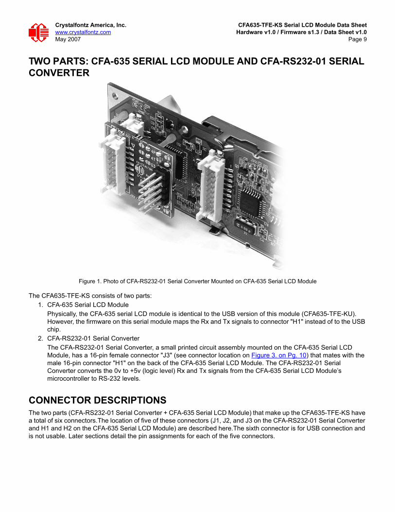
TWO PARTS: CFA-635 SERIAL LCD MODULE AND CFA-RS232-01 SERIAL CONVERTER
Figure 1. Photo of CFA-RS232-01 Serial Converter Mounted on CFA-635 Serial LCD Module
The CFA635-TFE-KS consists of two parts:1. CFA-635 Serial LCD Module
Physically, the CFA-635 serial LCD module is identical to the USB version of this module (CFA635-TFE-KU). However, the firmware on this serial module maps the Rx and Tx signals to connector "H1" instead of to the USB chip.
2. CFA-RS232-01 Serial ConverterThe CFA-RS232-01 Serial Converter, a small printed circuit assembly mounted on the CFA-635 Serial LCD Module, has a 16-pin female connector "J3" (see connector location on Figure 3. on Pg. 10) that mates with the male 16-pin connector "H1" on the back of the CFA-635 Serial LCD Module. The CFA-RS232-01 Serial Converter converts the 0v to +5v (logic level) Rx and Tx signals from the CFA-635 Serial LCD Module’s microcontroller to RS-232 levels.
CONNECTOR DESCRIPTIONSThe two parts (CFA-RS232-01 Serial Converter + CFA-635 Serial LCD Module) that make up the CFA635-TFE-KS have a total of six connectors.The location of five of these connectors (J1, J2, and J3 on the CFA-RS232-01 Serial Converter and H1 and H2 on the CFA-635 Serial LCD Module) are described here.The sixth connector is for USB connection and is not usable. Later sections detail the pin assignments for each of the five connectors.

Crystalfontz America, Inc. CFA635-TFE-KS Serial LCD Module Data Sheetwww.crystalfontz.com Hardware v1.0 / Firmware s1.3 / Data Sheet v1.0May 2007 Page 10
CFA-RS232-01 Serial Converter ConnectorsThe front side of the CFA-RS232-01 Serial Converter has the Crystalfontz logo silk-screened onto it and has two connectors. The back side of the CFA-RS232-01 Serial Converter does not have the Crystalfontz logo and has one connector.
Figure 2. CFA-RS232-01 Serial Converter (Side View)
The "J1" and "J2" connectors are on the front side of the CFA-RS232-01 Serial Converter, facing away from the module when the CFA-RS232-01 is mounted on the CFA-635 Serial LCD Module. The "J3" connector is on the back side of the CFA-RS232-01 Serial Converter, facing towards the module when it is mounted on the CFA635-TFE-KS.
Figure 3. CFA-RS232-01 Serial Converter Connectors "J1", "J2", and "J3"
1. "J1" is the male 10-pin (0.1” center) RS-232 host communications connector on the front side. For pin assignments, see Pin Assignments (Default and Alternate) on CFA-RS232-01 “J1” Connector (Pg. 18).
2. "J2" is the male 16-pin 2 mm “pass through” connector on the front side, passing through to the "J3" female16-pin 2 mm connector on the back side of the board. For pin assignments, see Pin Assignments on CFA-RS232-01 "J2" Connector (Including GPIO Connections) (Pg. 19). An optional SCAB may be connected to the male 16-pin “pass through” connector "J2".
3. "J3" is the female 16-pin 2 mm connector on the back side that mates with "H1" male 16-pin 2 mm connector on the CFA-635 Serial LCD Module.
J3
C5
C3
C1
C2
C4
C6h t t p : / / w w w . c r y s t a l f o n t z . c o m
JP
JPM A D E I N U S A
C FA - R S 2 3 2 - 0 1
Rev: 1.0
1 10
5 6G1
G0
G4
10
4P
4T
G3
0 1
13 JP 20
5 JP 6
2 1
JP 3 4
©2
00
5 C
rys
talf
on
tz A
me
ric
a
JP
JP
JP
C RY S TA L F O N T Z
J1J2
FRONT BACK

Crystalfontz America, Inc. CFA635-TFE-KS Serial LCD Module Data Sheetwww.crystalfontz.com Hardware v1.0 / Firmware s1.3 / Data Sheet v1.0May 2007 Page 11
CFA-635 Serial LCD Module ConnectorsThe CFA-635 Serial LCD Module has two connectors on its back side, "H1" and "H2".
Figure 4. CFA-635 Serial LCD Module Connectors "H1" and “"H2"
1. The "H1" male 16-pin 2 mm connector mates with the "J3" female 16-pin 2 mm connector on the CFA-RS232-01 Serial Converter.For pin assignments, see Pin Assignments on CFA-635 Serial LCD Module “H1” Connector (Including GPIO Connections) (Pg. 21).
2. The "H2" male 18-pin 2 mm connector provides GPO connections, including those that drive the front panel LEDs. For pin assignments, see Pin Assignments on CFA-635 Serial LCD Module “H1” Connector (Including GPIO Connections) (Pg. 21).
2
2
18
1
1
1516
H2
H2
H1
H1

Crystalfontz America, Inc. CFA635-TFE-KS Serial LCD Module Data Sheetwww.crystalfontz.com Hardware v1.0 / Firmware s1.3 / Data Sheet v1.0May 2007 Page 12
MODULE OUTLINE DRAWING
Figure 5. Module Outline Drawing
Cry
sta
lfo
ntz
Am
eri
ca
, In
co
rpo
rate
dC
FA
-635-X
XX
-KS
Series
DR
AW
N B
Y:
SC
AL
E:
UN
ITS
:
Ale
xis
DR
AW
ING
NU
MB
ER
:
DA
TE
:
CFA
-635K
SP
02
2007/0
4/0
4
RE
VIS
ION
:
1.0
SH
EE
T:
1 o
f 1
http://w
ww
.cry
sta
lfontz
.com
/pro
ducts
/635/index.h
tml
Copyright ©
2007
No
t to
sca
le
Mill
ime
ters
Dot D
imensio
ns
(Nom
inal P
ixel D
eta
il)

Crystalfontz America, Inc. CFA635-TFE-KS Serial LCD Module Data Sheetwww.crystalfontz.com Hardware v1.0 / Firmware s1.3 / Data Sheet v1.0May 2007 Page 13
JUMPER LOCATIONS AND FUNCTIONSThe CFA-635 Serial LCD module has eight jumpers. Only JPF may be changed. This jumper is normally open. The jumper may be closed by melting a ball of solder across the gap. To re-open the jumper, remove the solder. Solder wick works well for this.
Figure 6. Jumper Locations and Functions
Cry
sta
lfo
ntz
Am
eri
ca, In
co
rpo
rate
dC
FA
-635-X
XX
-KS
Series
DR
AW
N B
Y:
SC
AL
E:
UN
ITS
:
Ale
xis
DR
AW
ING
NU
MB
ER
:
DA
TE
:
CF
A-6
35
KS
P0
3
2007/0
4/0
4
RE
VIS
ION
:
1.0
SH
EE
T:
1 o
f 1
http://w
ww
.cry
sta
lfontz
.com
/pro
ducts
/1602b/index.h
tml
Copyright ©
2007
No
t to
sca
le
Mill
ime
ters
21
18
17
LED
0G
R
LED
2G
R
LED
1G
R+-
+
+-
+
LED
3G
R+-
+
+-
+
JP
B2
JP
A2
JP
B1
JP
2
AB
CJP
3
JP
A1
JP
C
JP
F
CFA
-635-X
XX
-KS
Series J
um
per
Locations a
nd F
unctions
JP
Fo
pen
Fra
me g
round is isola
ted fro
m logic
/US
B g
round.
clo
sed
Fra
me g
round is c
onnecte
d to logic
/US
B g
round.
All
oth
er
jum
pers
(JP
2, JP
3, JP
A1, JP
A2, JP
B1, JP
B2, JP
C)
are
facto
ry b
uild
options. D
o n
ot
change.

Crystalfontz America, Inc. CFA635-TFE-KS Serial LCD Module Data Sheetwww.crystalfontz.com Hardware v1.0 / Firmware s1.3 / Data Sheet v1.0May 2007 Page 14
KEYPAD OUTLINE DRAWING
Figure 7. Keypad Outline Drawing (identical to keypad for CFA-633 v1.0)

Crystalfontz America, Inc. CFA635-TFE-KS Serial LCD Module Data Sheetwww.crystalfontz.com Hardware v1.0 / Firmware s1.3 / Data Sheet v1.0May 2007 Page 15
ELECTRICAL SPECIFICATIONS
SYSTEM BLOCK DIAGRAM
Figure 8. System Block Diagram
LCD
Contrast Control
Backlight
Brightness Control
LCD Panel
Segment Driver
Display Backlight
Keypad Backlight
32
COM
60 SEG
RS-232
to Host
CFA-635 "H1"
(occupied by
CFA-RS232-01)
Microcontroller
LCD
Controller 60 SEG
"H2" Expansion
& LEDs (18-pin)
Keypad
4 bicolor
LEDs
optional
SCAB
(F4T and F4P
disabled)
CFA-RS232-01
Serial Converter
"J1" "J2"
"J3"

Crystalfontz America, Inc. CFA635-TFE-KS Serial LCD Module Data Sheetwww.crystalfontz.com Hardware v1.0 / Firmware s1.3 / Data Sheet v1.0May 2007 Page 16
VIEWING DIRECTION
DRIVING METHOD
ABSOLUTE MAXIMUM RATINGS
DC CHARACTERISTICS
Viewing Direction 12 o’clock
DRIVING METHOD SPECIFICATION
Duty 1/32
Bias 6.7
ABSOLUTE MAXIMUM RATINGS SYM
BO
L
MIN
IMU
M
MA
XIM
UM
Operating Temperature TOP -0°C +50°C
Storage Temperature* TST -10°C +60°C
Supply Voltage for Logic VDD 0 5.25v
RS-232 Input Pin VRX -25v +25v
RS-232 Output Pin VTX -13v +13v
*Note: Prolonged exposure at temperatures outside of this range may cause permanent damage to the module.
DC CHARACTERISTICS SYM
BO
L
MIN
IMU
M
TYPI
CA
L
MA
XIM
UM
Supply voltage for driving the serial LCD module, typically supplied through cable WRPWRY24. (See Module Outline Drawing (Pg. 12).)
VDD - VO +4.75v +5.0v +5.25v
RS-232 Input Voltage Range -25v +25v
RS-232 Input High Voltage +1.8v +2.4v
RS-232 Input Low Voltage +0.8v +1.5v
RS-232 Output Voltage Swing +5.0v +5.4v

Crystalfontz America, Inc. CFA635-TFE-KS Serial LCD Module Data Sheetwww.crystalfontz.com Hardware v1.0 / Firmware s1.3 / Data Sheet v1.0May 2007 Page 17
TYPICAL CURRENT CONSUMPTION
ESD (ELECTRO-STATIC DISCHARGE) SPECIFICATIONSTx and Rx pins of connector "RS-232" only:
+15 kV Human Body Model +15 kV IEC1000-4-2 Air Discharge +8 kV IEC1000-4-2 Contact Discharge
The remainder of the circuitry is industry standard CMOS logic and is susceptible to ESD damage. Please use industry standard antistatic precautions as you would for any other PCB such as expansion cards or motherboards. For more information, read CARE AND HANDLING PRECAUTIONS (Pg. 49).
ITEMS ENABLEDTYPICAL CURRENT
CONSUMPTION
LogicLCD and Keypad
BacklightsAll Indicator LEDs(4 Red + 4 Green) VDD=4.75V VDD=5.25V
X - - 35 mA 42 mA
X X - 129 mA 161 mA
X - X 147 mA 175 mA
X X X 239 mA 290 mA
GPIO CURRENT LIMITS SPECIFICATION
Sink 25 mA
Source 10 mA
Crystalfontz America, Inc. CFA635-TFE-KS Serial LCD Module Data Sheetwww.crystalfontz.com Hardware v1.0 / Firmware s1.3 / Data Sheet v1.0May 2007 Page 18
ADDITIONAL CRITERIA
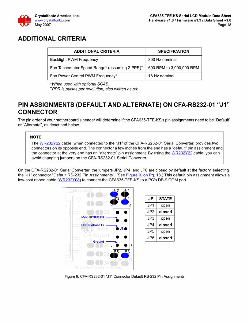
PIN ASSIGNMENTS (DEFAULT AND ALTERNATE) ON CFA-RS232-01 “J1” CONNECTORThe pin order of your motherboard's header will determine if the CFA635-TFE-KS's pin assignments need to be “Default” or “Alternate”, as described below.
On the CFA-RS232-01 Serial Converter, the jumpers JP2, JP4, and JP6 are closed by default at the factory, selecting the "J1" connector “Default RS-232 Pin Assignments”. (See Figure 9. on Pg. 18.) This default pin assignment allows a low-cost ribbon cable (WR232Y08) to connect the CFA635-TFE-KS to a PC's DB-9 COM port.
Figure 9. CFA-RS232-01 "J1" Connector Default RS-232 Pin Assignments
ADDITIONAL CRITERIA SPECIFICATION
Backlight PWM Frequency 300 Hz nominal
Fan Tachometer Speed Range* (assuming 2 PPR)+ 600 RPM to 3,000,000 RPM
Fan Power Control PWM Frequency* 18 Hz nominal
*When used with optional SCAB.+PPR is pulses per revolution, also written as p/r.
NOTEThe WR232Y22 cable, when connected to the "J1" of the CFA-RS232-01 Serial Converter, provides two connectors on its opposite end. The connector a few inches from the end has a “default” pin assignment and the connector at the very end has an “alternate” pin assignment. By using the WR232Y22 cable, you can avoid changing jumpers on the CFA-RS232-01 Serial Converter.
h t t p : / / w w w . c r y s t a l f o n t z . c o m
JP
JPM A D E I N U S A
C FA - R S 2 3 2 - 0 1
Rev: 1.0
G1
G0
G4
10
4P
4T
G3
0 1
13 JP 20
5 JP 6
2 1
JP 3 4
JP
JP
JP
JP
5 JP 6
2 1
JP 3 4
JP
JP
JP
C RY S TA L F O N T Z
1 10
5 6
LCD Tx/Host Rx
LCD Rx/Host Tx
Ground
J1
JP STATEJP1 openJP2 closedJP3 openJP4 closedJP5 openJP6 closed

Crystalfontz America, Inc. CFA635-TFE-KS Serial LCD Module Data Sheetwww.crystalfontz.com Hardware v1.0 / Firmware s1.3 / Data Sheet v1.0May 2007 Page 19
By opening jumpers JP2, JP4, and JP6 and closing JP1, JP3, and JP5, you can select the “Alternate RS-232 Pin Assignments”.
Figure 10. CFA-RS232-01 "J1" Connector Alternate RS-232 Pin Assignments
If there is a matching 0.1" center, 10-pin RS-232 connector on your system's motherboard, then in most cases a simple straight-through ribbon cable such as Crystalfontz WR232Y22 or CW Industries’ C3AAG-1018G-ND cable (available from Digi-Key) can be used to connect from the CFA635-TFE-KS to a motherboard's 10-pin header.
PIN ASSIGNMENTS ON CFA-RS232-01 "J2" CONNECTOR (INCLUDING GPIO CONNECTIONS)The CFA-635 module has five pins that can be used for “General Purpose Input or Output (GPIO)s. The pass-through header “J2” on the CFA-RS232-01 Serial Converter. (See the GPIOS labeled in Figure 9. on Pg. 18.) These GPIOs can be accessed directly through "J2" or through the optional SCAB connected to “J2”. The SCAB can be easily connected to the CFA635-TFE-KS by using either the WREXTY15 or WREXTY19 cables. For more information on the SCAB, see Power Connection to Host and Optional SCAB (Pg. 22) and the CFA-SCAB Data Sheet on our website.
h t t p : / / w w w . c r y s t a l f o n t z . c o m
JP
JPM A D E I N U S A
C FA - R S 2 3 2 - 0 1
Rev: 1.0
G1
G0
G4
10
4P
4T
G3
0 1
13 JP 20
5 JP 6
2 1
JP 3 4
JP
JP
JP
JP
5 JP 6
2 1
JP 3 4
JP
JP
JP
C RY S TA L F O N T Z
JP
JP
5 JP 6
2 1
JP 3 4
JP
JP
1 2
9 10
LCD Tx/Host Rx
LCD Rx/Host Tx
Ground
J1
JP STATEJP1 closedJP2 openJP3 closedJP4 openJP5 closedJP6 open

Crystalfontz America, Inc. CFA635-TFE-KS Serial LCD Module Data Sheetwww.crystalfontz.com Hardware v1.0 / Firmware s1.3 / Data Sheet v1.0May 2007 Page 20
Please note that FAN4 (F4P & F4T) is disabled in the CFA-635 RS-232 version.
Figure 11. CFA-RS232-01 "J2" Connector Pin Assignments
The following parts may be used to make a mating cable for "J2":16-position housing: Hirose DF11-16DS-2C / Digi-Key H2025-ND.Terminal (tape & reel): Hirose DF11-2428SCF / Digi-Key H1504TR-ND.Terminal (loose): Hirose DF11-2428SC / Digi-Key H1504-ND.Pre-terminated interconnect wire: Hirose / Digi-Key H3BBT-10112-B4-ND (typical).
h t t p : / / w w w . c r y s t a l f o n t z . c o m
JPM A D E I N U S A
C FA - R S 2 3 2 - 0 1
Rev: 1.0
G1
G0
G4
10
4P
4T
G3
0 1
13 20
5 JP 6
2 1
JP 3 4
©2
00
5 C
rys
talf
on
tz A
me
ric
a
JP
JP
C RY S TA L F O N T Z
2 1
16 15
Reserved, Make No Connection
Reserved, Make No Connection
F3P
F2P
F1P
GPIO[3] (ATX Host Reset Control)
GPIO[1] (ATX Host Power Sense)
+5v Ground
Reserved, Make No Connection
F3T
F2T
F1T
GPIO[2] (ATX Host Power Control)
GPIO[0] (ATX Host Power Sense)
GPIO[4] (DOW I/O)
J2

Crystalfontz America, Inc. CFA635-TFE-KS Serial LCD Module Data Sheetwww.crystalfontz.com Hardware v1.0 / Firmware s1.3 / Data Sheet v1.0May 2007 Page 21
PIN ASSIGNMENTS ON CFA-635 SERIAL LCD MODULE “H1”CONNECTOR (INCLUDING GPIO CONNECTIONS)
Figure 12. Pin Assignments on CFA-635 Serial LCD Module "H1" Connector (Includes GPIOs)
The following parts may be used to make a mating cable for "H1":16-position housing: Hirose DF11-16DS-2C / Digi-Key H2025-ND.Terminal (tape & reel): Hirose DF11-2428SCF / Digi-Key H1504TR-ND.Terminal (loose): Hirose DF11-2428SC / Digi-Key H1504-ND.Pre-terminated interconnect wire: Hirose / Digi-Key H3BBT-10112-B4-ND is typical.
LCD Tx / Host Rx
F3P
F2P
F1P
GPIO3 (ATX Host Reset Control)
GPIO1 (ATX Host Power Sense)
Reserved, Make No Connection
+5v
LCD Rx / Host Tx
F3T
F2T
F1T
GPIO2 (ATX Host Power Control)
GPIO0
GPIO4 (DOW I/O)
Ground
H1
16
2 1
15
Crystalfontz America, Inc. CFA635-TFE-KS Serial LCD Module Data Sheetwww.crystalfontz.com Hardware v1.0 / Firmware s1.3 / Data Sheet v1.0May 2007 Page 22
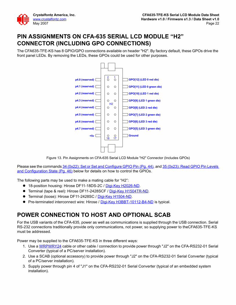
PIN ASSIGNMENTS ON CFA-635 SERIAL LCD MODULE “H2”CONNECTOR (INCLUDING GPO CONNECTIONS)The CFA635-TFE-KS has 8 GPIO/GPO connections available on header "H2". By factory default, these GPOs drive the front panel LEDs. By removing the LEDs, these GPOs could be used for other purposes.
Figure 13. Pin Assignments on CFA-635 Serial LCD Module "H2" Connector (Includes GPOs)
Please see the commands 34 (0x22): Set or Set and Configure GPIO Pin (Pg. 44), and 35 (0x23): Read GPIO Pin Levels and Configuration State (Pg. 46) below for details on how to control the GPIOs.
The following parts may be used to make a mating cable for “H2”:18-position housing: Hirose DF11-18DS-2C / Digi-Key H2026-ND.Terminal (tape & reel): Hirose DF11-2428SCF / Digi-Key H1504TR-ND.Terminal (loose): Hirose DF11-2428SC / Digi-Key H1504-ND.Pre-terminated interconnect wire: Hirose / Digi-Key H3BBT-10112-B4-ND is typical.
POWER CONNECTION TO HOST AND OPTIONAL SCABFor the USB variants of the CFA-635, power as well as communications is supplied through the USB connection. Serial RS-232 connections traditionally provide only communications, not power, so supplying power to theCFA635-TFE-KS must be addressed.
Power may be supplied to the CFA635-TFE-KS in three different ways:1. Use a WRPWRY24 cable or other cable / connection to provide power through "J2" on the CFA-RS232-01 Serial
Converter (typical of a PC/server installation).2. Use a SCAB (optional accessory) to provide power through "J2" on the CFA-RS232-01 Serial Converter (typical
of a PC/server installation). 3. Supply power through pin 4 of "J1" on the CFA-RS232-01 Serial Converter (typical of an embedded system
installation).
p4.0 (reserved)
p4.1 (reserved)
p4.2 (reserved)
p4.3 (reserved)
p4.4 (reserved)
p4.5 (reserved)
p4.6 (reserved)
p4.7 (reserved)
+5v Ground
GPO[12] (LED 0 red die)
GPO[11] (LED 0 green die)
GPO[10] (LED 1 red die)
GPO[9] (LED 1 green die)
GPO[8] (LED 2 red die)
GPO[7] (LED 2 green die)
GPO[6] (LED 3 red die)
GPO[5] (LED 3 green die)
H2
18
2 1
17
Crystalfontz America, Inc. CFA635-TFE-KS Serial LCD Module Data Sheetwww.crystalfontz.com Hardware v1.0 / Firmware s1.3 / Data Sheet v1.0May 2007 Page 23
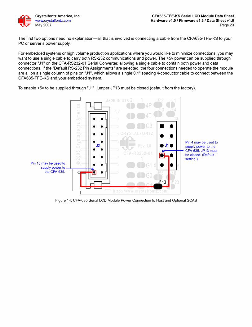
The first two options need no explanation—all that is involved is connecting a cable from the CFA635-TFE-KS to your PC or server’s power supply.
For embedded systems or high volume production applications where you would like to minimize connections, you may want to use a single cable to carry both RS-232 communications and power. The +5v power can be supplied through connector "J1" on the CFA-RS232-01 Serial Converter, allowing a single cable to contain both power and data connections. If the "Default RS-232 Pin Assignments" are selected, the four connections needed to operate the module are all on a single column of pins on "J1", which allows a single 0.1" spacing 4-conductor cable to connect between the CFA635-TFE-KS and your embedded system.
To enable +5v to be supplied through "J1", jumper JP13 must be closed (default from the factory).
Figure 14. CFA-635 Serial LCD Module Power Connection to Host and Optional SCAB
h t t p : / / w w w . c r y s t a l f o n t z . c o m
JP
JPM A D E I N U S A
C FA - R S 2 3 2 - 0 1
Rev: 1.0
1 10
5 6G1
G0
G4
1
4P
4T
G3
0 1
13 JP 20
5 JP 6
2 1
JP 3 4
©2
00
5 C
rys
talf
on
tz A
me
ric
a
J1
JP
JP
JP
J2
C RY S TA L F O N T Z
Pin 16 may be used to
supply power to
the CFA-635.
Pin 4 may be used to
supply power to the
CFA-635. JP13 must
be closed. (Default
setting.)
13JP

Crystalfontz America, Inc. CFA635-TFE-KS Serial LCD Module Data Sheetwww.crystalfontz.com Hardware v1.0 / Firmware s1.3 / Data Sheet v1.0May 2007 Page 24
CONNECTION OF OPTIONAL SCABThe optional CFA-SCAB is designed to connect to the CFA635-TFE-KS "J2" header. The SCAB will receive the correct signals to operate from the CFA635-TFE-KS.
Figure 15. Photo of CFA635-TFE-KS Connected to Optional CFA-SCAB, Bracket and WREXTY19 Cable
Two Crystalfontz cables are available to make the connection between the optional SCAB and the CFA635-TFE-KS:1. WREXTY15 SCAB Cable, 16-inch
This 16-pin cable allows the SCAB to be mounted some distance away from the CFA-635. For instance, the SCAB could be mounted in a central location within the PC's case. The WREXTY15 could connect the SCAB from this central location to the CFA635-TFE-KS mounted in a drive bay. The connections to the fans and temperature sensors only need to be run to the SCAB, not all the way to the front panel where the LCD module is mounted.
2. WREXTY19 SCAB Cable, 3.5-inchThis shorter 16-pin cable can be used when the SCAB is mounted in close proximity to the CFA-635, as is the case when the SCAB is fastened directly to the LCD module's mounting bracket. (See the figure above.)
For more information about the optional SCAB, see Connection of Optional SCAB (Pg. 24) in this Data Sheet and the CFA-SCAB Data Sheet on our website.
NOTES1. Fan 4 (F4P and F4T) will not be available through the SCAB when it is used with the CFA635-TFE-KS. 2. Because the serial CFA635-TFE-KS has unique firmware, it will not work if you attempt to use it as a
USB LCD module.

Crystalfontz America, Inc. CFA635-TFE-KS Serial LCD Module Data Sheetwww.crystalfontz.com Hardware v1.0 / Firmware s1.3 / Data Sheet v1.0May 2007 Page 25
PRODUCT RELIABILITY
HOST COMMUNICATIONS
The CFA-635 communicates with its host using the RS-232 interface. The host’s RS-232 communications port should be opened at 115200 baud, 8 data bits, no parity, 1 stop bit.
PACKET STRUCTUREAll communication between the CFA-635 and the host takes place in the form of a simple and robust CRC checked packet. The packet format allows for very reliable communications between the CFA-635 and the host without the traditional problems that occur in a stream-based serial communication (such as having to send data in inefficient ASCII format, to “escape” certain “control characters”, or losing sync if a character is corrupted, missing, or inserted).
All packets have the following structure:<type><data_length><data><CRC>
type is one byte, and identifies the type and function of the packet:
TTcc cccc|||| ||||--Command, response, error or report code 0-63||---------Type: 00 = normal command from host to CFA-635 01 = normal response from CFA-635 to host 10 = normal report from CFA-635 to host (not in direct response to a command from the host) 11 = error response from CFA-635 to host (a packet with valid structure but illegal content was received by the CFA-635)
ITEM SPECIFICATION
LCD portion (excluding Keypad, Indicator LEDs, and Backlights)
50,000 to 100,000 hours (typical)
Keypad 1,000,000 keystrokes
Bicolor LED Indicators 50,000 to 100,000 hours (typical)
White LED Display and White LED Keypad Backlights
Note: We recommend that the backlight of white LED backlit modules be dimmed or turned off during periods of inactivity to conserve the white LED backlight lifetime.
Power-On Hours % of Initial Brightness (New Module)
<10,000 hours >90%
<50,000 hours >50%
NOTEBecause there is no difference in communications and commands for serial and USB variants of the CFA-635, the remaining sections in this Data Sheet use the shorter term “CFA-635” instead of “CFA635-TFE-KS”.

Crystalfontz America, Inc. CFA635-TFE-KS Serial LCD Module Data Sheetwww.crystalfontz.com Hardware v1.0 / Firmware s1.3 / Data Sheet v1.0May 2007 Page 26
data_length specifies the number of bytes that will follow in the data field. The valid range of data_length is 0 to 22.
data is the payload of the packet. Each type of packet will have a specified data_length and format for data as well as algorithms for decoding data detailed below.
CRC is a standard 16-bit CRC of all the bytes in the packet except the CRC itself. The CRC is sent LSB first. At the port, the CRC immediately follows the last used element of data []. See APPENDIX C: CALCULATING THE CRC (Pg. 56) for details.
The following C definition may be useful for understanding the packet structure.typedef struct { unsigned char command; unsigned char data_length; unsigned char data[MAX_DATA_LENGTH]; unsigned short CRC; }COMMAND_PACKET;
On our website, Crystalfontz supplies a demonstration and test program, 635_WinTest along with its C source code. Included in the 635_WinTest source is a CRC algorithm and an algorithm that detects packets. The algorithm will automatically re-synchronize to the next valid packet in the event of any communications errors. Please follow the algorithm in the sample code closely in order to realize the benefits of using the packet communications.
ABOUT HANDSHAKINGThe nature of CFA-635’s packets makes it unnecessary to implement traditional hardware or software handshaking.
The host should wait for a corresponding acknowledge packet from the CFA-635 before sending the next command packet. The CFA-635 will respond to all packets within 250 mS. The host software should stop waiting and retry the packet if the CFA-635 fails to respond within 250 mS. The host software should report an error if a packet is not acknowledged after several retries. This situation indicates a hardware problem—for example, a disconnected cable. Please note that some operating systems may introduce delays between when the data arrives at the physical port from the CFA-635 until it is available to the user program. In this case, the host program may have to increase its timeout window to account for the additional overhead of the operating system.
The CFA-635 can be configured to send several types of report packets along with regular acknowledge packets. The host should be able to buffer several incoming packets and must guarantee that it can process and remove packets from its input buffer faster than the packets can arrive given the 115200 equivalent baud rate of the VCP and the reporting configuration of the CFA-635. For any modern PC or microcontroller using reasonably efficient software, this requirement will not pose a challenge.
The report packets are sent asynchronously with respect to the command packets received from the host. The host should not assume that the first packet received after it sends a command is the acknowledge packet for that command. The host should inspect the type field of incoming packets and process them accordingly.
REPORT CODESThe CFA-635 can be configured to report three items. The CFA-635 sends reports automatically when the data becomes available. Reports are not sent in response to a particular packet received from the host. The three report types are:

Crystalfontz America, Inc. CFA635-TFE-KS Serial LCD Module Data Sheetwww.crystalfontz.com Hardware v1.0 / Firmware s1.3 / Data Sheet v1.0May 2007 Page 27
0x80: Key ActivityIf a key is pressed or released, the CFA-635 sends a Key Activity report packet to the host. Key event reporting may be individually enabled or disabled by command 23 (0x17): Configure Key Reporting (Pg. 38).
type = 0x80data_length = 1data[0] is the type of keyboard activity: KEY_UP_PRESS 1 KEY_DOWN_PRESS 2 KEY_LEFT_PRESS 3 KEY_RIGHT_PRESS 4 KEY_ENTER_PRESS 5 KEY_EXIT_PRESS 6 KEY_UP_RELEASE 7 KEY_DOWN_RELEASE 8 KEY_LEFT_RELEASE 9 KEY_RIGHT_RELEASE 10 KEY_ENTER_RELEASE 11 KEY_EXIT_RELEASE 12
These codes are identical to the codes returned by the CFA-633. Please note that the CFA-631 will return codes 13 through 20. (See the CFA-631 Data Sheet on our website for more details.)
0x81: Fan Speed Report (SCAB required)If any of up to the fans connected to CFA-635+SCAB is configured to report its speed information to the host, the CFA-635 will send Fan Speed Reports for each selected fan every 1/2 second. See command 16 (0x10): Set Up Fan Reporting (SCAB required) (Pg. 34) below.
type = 0x81data_length = 4data[0] is the index of the fan being reported: 0 = FAN 1 1 = FAN 2 2 = FAN 3 3 = FAN 4data[1] is number_of_fan_tach_cyclesdata[2] is the MSB of Fan_Timer_Ticksdata[3] is the LSB of Fan_Timer_Ticks

Crystalfontz America, Inc. CFA635-TFE-KS Serial LCD Module Data Sheetwww.crystalfontz.com Hardware v1.0 / Firmware s1.3 / Data Sheet v1.0May 2007 Page 28
The following C function will decode the fan speed from a Fan Speed Report packet into RPM:int OnReceivedFanReport(COMMAND_PACKET *packet, char * output) { int return_value; return_value=0;
int number_of_fan_tach_cycles; number_of_fan_tach_cycles=packet->data[1];
if(number_of_fan_tach_cycles<3) sprintf(output," STOP"); else if(number_of_fan_tach_cycles<4) sprintf(output," SLOW"); else if(0xFF==number_of_fan_tach_cycles) sprintf(output," ----"); else { //Specific to each fan, most commonly 2 int pulses_per_revolution; pulses_per_revolution=2;
int Fan_Timer_Ticks; Fan_Timer_Ticks=(*(unsigned short *)(&(packet->data[2])));
return_value=((27692308L/pulses_per_revolution)* (unsigned long)(number_of_fan_tach_cycles-3))/ (Fan_Timer_Ticks); sprintf(output,"%5d",return_value); } return(return_value); }
0x82: Temperature Sensor Report (SCAB required)If any of the up to 32 temperature sensors is configured to report to the host, the CFA-635+SCAB will send Temperature Sensor Reports for each selected sensor every second. See the command 19 (0x13): Set Up Temperature Reporting (SCAB required) (Pg. 35) below.
type = 0x82data_length = 4data[0] is the index of the temperature sensor being reported: 0 = temperature sensor 1 1 = temperature sensor 2 . . . 31 = temperature sensor 32data[1] is the LSB of Temperature_Sensor_Countsdata[2] is the MSB of Temperature_Sensor_Countsdata[3] is DOW_crc_status
Crystalfontz America, Inc. CFA635-TFE-KS Serial LCD Module Data Sheetwww.crystalfontz.com Hardware v1.0 / Firmware s1.3 / Data Sheet v1.0May 2007 Page 29
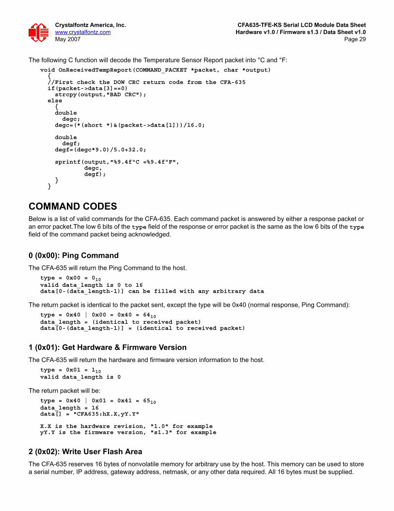
The following C function will decode the Temperature Sensor Report packet into °C and °F:void OnReceivedTempReport(COMMAND_PACKET *packet, char *output) { //First check the DOW CRC return code from the CFA-635 if(packet->data[3]==0) strcpy(output,"BAD CRC"); else { double degc; degc=(*(short *)&(packet->data[1]))/16.0;
double degf; degf=(degc*9.0)/5.0+32.0;
sprintf(output,"%9.4f°C =%9.4f°F", degc, degf); } }
COMMAND CODESBelow is a list of valid commands for the CFA-635. Each command packet is answered by either a response packet or an error packet.The low 6 bits of the type field of the response or error packet is the same as the low 6 bits of the type field of the command packet being acknowledged.
0 (0x00): Ping CommandThe CFA-635 will return the Ping Command to the host.
type = 0x00 = 010valid data_length is 0 to 16data[0-(data_length-1)] can be filled with any arbitrary data
The return packet is identical to the packet sent, except the type will be 0x40 (normal response, Ping Command):type = 0x40 | 0x00 = 0x40 = 6410data_length = (identical to received packet)data[0-(data_length-1)] = (identical to received packet)
1 (0x01): Get Hardware & Firmware VersionThe CFA-635 will return the hardware and firmware version information to the host.
type = 0x01 = 110valid data_length is 0
The return packet will be:type = 0x40 | 0x01 = 0x41 = 6510data_length = 16data[] = "CFA635:hX.X,yY.Y"
X.X is the hardware revision, "1.0" for exampleyY.Y is the firmware version, "s1.3" for example
2 (0x02): Write User Flash AreaThe CFA-635 reserves 16 bytes of nonvolatile memory for arbitrary use by the host. This memory can be used to store a serial number, IP address, gateway address, netmask, or any other data required. All 16 bytes must be supplied.

Crystalfontz America, Inc. CFA635-TFE-KS Serial LCD Module Data Sheetwww.crystalfontz.com Hardware v1.0 / Firmware s1.3 / Data Sheet v1.0May 2007 Page 30
type = 0x02 = 210valid data_length is 16data[] = 16 bytes of arbitrary user data to be stored in the CFA-635's non-volatile memory
The return packet will be:type = 0x40 | 0x02 = 0x42 = 6610data_length = 0
3 (0x03): Read User Flash AreaThis command will read the User Flash Area and return the data to the host.
type = 0x03 = 310valid data_length is 0
The return packet will be:type = 0x40 | 0x03 = 0x43 = 6710data_length = 16data[] = 16 bytes user data recalled from the CFA-635's non-volatile memory
4 (0x04): Store Current State As Boot StateThe CFA-635 loads its power-up configuration from nonvolatile memory when power is applied. The CFA-635 is configured at the factory to display a “welcome screen” when power is applied. This command can be used to customize the welcome screen, as well as the following items:
Characters shown on LCD, which are affected by:Command 6 (0x06): Clear LCD Screen (Pg. 31).Command 7. Deprecated (Pg. 32). See command 31 (0x1F): Send Data to LCD (Pg. 44).Command 8. Deprecated (Pg. 32). See command 31 (0x1F): Send Data to LCD (Pg. 44).Command 31 (0x1F): Send Data to LCD (Pg. 44).
Special character font definitions (command 9 (0x09): Set LCD Special Character Data (Pg. 32)). Cursor position (command 11 (0x0B): Set LCD Cursor Position (Pg. 33)).Cursor style (command 12 (0x0C): Set LCD Cursor Style (Pg. 33)).Contrast setting (command 13 (0x0D): Set LCD Contrast (Pg. 33)).Backlight setting (command 14 (0x0E): Set LCD & Keypad Backlight (Pg. 33)).Fan power settings (command 17 (0x11): Set Fan Power (SCAB required) (Pg. 34)).Key press and release masks (command 23 (0x17): Configure Key Reporting (Pg. 38)).Fan glitch delay settings (command 26 (0x1A): Set Fan Tachometer Glitch Filter (SCAB required) (Pg. 39)).ATX function enable and pulse length settings (command 28 (0x1C): Set ATX Power Switch Functionality (SCAB required) (Pg. 41)).Key legends (command 32 (0x20): Reserved for CFA-631 Key Legends (Pg. 44)).Baud rate (command 33 (0x21): Set Baud Rate (Pg. 44)).GPIO settings (command 34 (0x22): Set or Set and Configure GPIO Pin (Pg. 44)).The front panel LED/GPO settings (34 (0x22): Set or Set and Configure GPIO Pin (Pg. 44)).
You cannot store the fan or temperature reporting, or the fan fail-safe or host watchdog. The host software should enable these items once the system is initialized and it is ready to receive the data.
type = 0x04 = 410valid data_length is 0

Crystalfontz America, Inc. CFA635-TFE-KS Serial LCD Module Data Sheetwww.crystalfontz.com Hardware v1.0 / Firmware s1.3 / Data Sheet v1.0May 2007 Page 31
The return packet will be:type = 0x40 | 0x04 = 0x44 = 6810data_length = 0
5 (0x05): Reboot CFA-635, Reset Host (SCAB required), or Power Off Host (SCAB required)This command instructs the CFA-635+SCAB to simulate a power-on restart of itself, reset the host, or turn the host's power off. The ability to reset the host may be useful to allow certain host operating system configuration changes to complete. The ability to turn the host's power off under software control may be useful in systems that do not have ACPI compatible BIOS.
Rebooting the CFA-635 may be useful when testing the boot configuration. It may also be useful to re-enumerate the devices on the 1-Wire bus (SCAB required). To reboot the CFA-635, send the following packet:
type = 0x05 = 510valid data_length is 3data[0] = 8data[1] = 18data[2] = 99
To reset the host (SCAB required), assuming the host's reset line is connected to GPIO[3] as described in command 28 (0x1C): Set ATX Power Switch Functionality (SCAB required) (Pg. 41), send the following packet:
type = 0x05 = 510valid data_length is 3data[0] = 12data[1] = 28data[2] = 97
To turn the host's power off (SCAB required), assuming the host's power control line is connected to GPIO[2] as described in command 28 (0x1C): Set ATX Power Switch Functionality (SCAB required) (Pg. 41), send the following packet:
type = 0x05 = 510valid data_length is 3data[0] = 3data[1] = 11data[2] = 95
In any of the above cases, the return packet will be:type = 0x40 | 0x05 = 0x45 = 6910data_length = 0
6 (0x06): Clear LCD ScreenSets the contents of the LCD screen DDRAM to ' ' = 0x20 = 32 and moves the cursor to the left-most column of the top line.
type = 0x06 = 610valid data_length is 0
NOTEThe GPIO pins used for ATX control must not be configured as user GPIO, and must be configured to their default drive mode in order for the ATX functions to work correctly. These settings are factory default, but may be changed by the user. Please see command 34 (0x22): Set or Set and Configure GPIO Pin (Pg. 44).

Crystalfontz America, Inc. CFA635-TFE-KS Serial LCD Module Data Sheetwww.crystalfontz.com Hardware v1.0 / Firmware s1.3 / Data Sheet v1.0May 2007 Page 32
The return packet will be:type = 0x40 | 0x06 = 0x46 = 7010data_length = 0
Clear LCD Screen is one of the items stored by the command 4 (0x04): Store Current State As Boot State (Pg. 30).
7 (0x07): Deprecated (See command 31 (0x1F): Send Data to LCD (Pg. 44))
8 (0x08): Deprecated (See command 31 (0x1F): Send Data to LCD (Pg. 44))
9 (0x09): Set LCD Special Character DataSets the font definition for one of the special characters (CGRAM).
type = 0x09 = 910valid data_length is 9data[0] = index of special character that you would like to modify, 0-7 are validdata[1-8] = bitmap of the new font for this character
data[1-8] are the bitmap information for this character. Any value is valid between 0 and 63, the msb is at the left of the character cell of the row, and the lsb is at the right of the character cell. data[1] is at the top of the cell, data[8] is at the bottom of the cell.
Additionally, if you set bit 7 of any of the data bytes, the entire line will blink.
The return packet will be:type = 0x40 | 0x09 = 0x49 = 7310data_length = 0
Set LCD Special Character Data is one of the items stored by the command 4 (0x04): Store Current State As Boot State (Pg. 30).
10 (0x0A): Read 8 Bytes of LCD MemoryThis command will return the contents of the LCD’s DDRAM or CGRAM. This command is intended for debugging.
type = 0x0A = 1010valid data_length is 1data[0] = address code of desired data
data[0] is the address code native to the LCD controller: 0x40 ( 64) to 0x7F (127) for CGRAM 0x80 (128) to 0x93 (147) for DDRAM, line 0 0xA0 (160) to 0xB3 (179) for DDRAM, line 1 0xC0 (192) to 0xD3 (211) for DDRAM, line 2 0xE0 (224) to 0xF3 (243) for DDRAM, line 3
The return packet will be:type = 0x40 | 0x0A = 0x4A = 7410data_length = 9
data[0] of the return packet will be the address code.data[1-8] of the return packet will be the data read from the LCD controller's memory.
Crystalfontz America, Inc. CFA635-TFE-KS Serial LCD Module Data Sheetwww.crystalfontz.com Hardware v1.0 / Firmware s1.3 / Data Sheet v1.0May 2007 Page 33
11 (0x0B): Set LCD Cursor PositionThis command allows the cursor to be placed at the desired location on the CFA-635’s LCD screen. If you want the cursor to be visible, you may also need to send a command 12 (0x0C): Set LCD Cursor Style (Pg. 33).
type = 0x0B = 1110valid data_length is 2data[0] = column (0-19 valid)data[1] = row (0-3 valid)
The return packet will be:type = 0x40 | 0x0B = 0x4B = 7510data_length = 0
Set LCD Cursor Position is one of the items stored by the command 4 (0x04): Store Current State As Boot State (Pg. 30).
12 (0x0C): Set LCD Cursor StyleThis command allows you to select among four hardware generated cursor options.
type = 0x0C = 1210valid data_length is 1data[0] = cursor style (0-4 valid) 0 = no cursor 1 = blinking block cursor 2 = underscore cursor 3 = blinking block plus underscore 4 = inverting, blinking block
The return packet will be:type = 0x40 | 0x0C = 0x4C = 7610data_length = 0
Set LCD Cursor Style is one of the items stored by the command 4 (0x04): Store Current State As Boot State (Pg. 30).
13 (0x0D): Set LCD ContrastThis command sets the contrast or vertical viewing angle of the display.
type = 0x0D = 1310valid data_length is 1data[0] = contrast setting (0-255 valid) 0-65 = very light 66 = light 95 = about right 125 = dark 126-255 = very dark
The return packet will be:type = 0x40 | 0x0D = 0x4D = 7710data_length = 0
Set LCD Contrast is one of the items stored by the command 4 (0x04): Store Current State As Boot State (Pg. 30).
14 (0x0E): Set LCD & Keypad BacklightThis command sets the brightness of the LCD and keypad backlights.

Crystalfontz America, Inc. CFA635-TFE-KS Serial LCD Module Data Sheetwww.crystalfontz.com Hardware v1.0 / Firmware s1.3 / Data Sheet v1.0May 2007 Page 34
type = 0x0E = 1410valid data_length is 1data[0] = backlight power setting (0-100 valid) 0 = off 1-99 = variable brightness 100 = on
The return packet will be:type = 0x40 | 0x0E = 0x4E = 7810data_length = 0
Set LCD & Keypad Backlight is one of the items stored by the command 4 (0x04): Store Current State As Boot State (Pg. 30).
15 (0x0F): (Deprecated)
16 (0x10): Set Up Fan Reporting (SCAB required)Note: Fan 4 is disabled and unused in the CFA635-TFE-KS+SCAB.
This command will configure the CFA-635+SCAB to report the fan speed information to the host every 500 mS.type = 0x10 = 1610valid data_length is 1data[0] = bitmask indicating which fans are enabled to report (0-15 valid)---- 8421 Enable Reporting of this Fan’s Tach Input|||| ||||-- Fan 1: 1 = enable, 0 = disable|||| |||--- Fan 2: 1 = enable, 0 = disable|||| ||---- Fan 3: 1 = enable, 0 = disable|||| |----- Fan 4: 1 = enable, 0 = disable
The return packet will be:type = 0x40 | 0x10 = 0x50 = 8010data_length = 0
If data[0] is not 0, then the CFA-635+SCAB will start sending 0x81: Fan Speed Report packets for each enabled fan every 500 mS. (See 0x81: Fan Speed Report (SCAB required) (Pg. 27).) Each of the report packets is staggered by 1/8 of a second.
Reporting a fan will override the fan power setting to 100% for up to 1/8 of a second every 1/2 second. Please see Fan Connections in CFA-SCAB Data Sheet for a detailed description.
17 (0x11): Set Fan Power (SCAB required)Note: Fan 4 is disabled and unused in the CFA635-TFE-KS+SCAB.
This command will configure the power for the fan connectors. The fan power setting is one of the items stored by the command 4 (0x04): Store Current State As Boot State (Pg. 30).
type = 0x11 = 1710valid data_length is 4data[0] = power level for FAN 1 (0-100 valid)data[1] = power level for FAN 2 (0-100 valid)data[2] = power level for FAN 3 (0-100 valid)data[3] = power level for FAN 4 (0-100 valid)
Crystalfontz America, Inc. CFA635-TFE-KS Serial LCD Module Data Sheetwww.crystalfontz.com Hardware v1.0 / Firmware s1.3 / Data Sheet v1.0May 2007 Page 35
The return packet will be:type = 0x40 | 0x11 = 0x51 =8110data_length = 0
Set Fan Power is one of the items stored by the command 4 (0x04): Store Current State As Boot State (Pg. 30).
18 (0x12): Read DOW Device Information (SCAB required)When power is applied to the CFA-635+SCAB, it detects any devices connected to the Dallas Semiconductor 1-Wire (DOW) bus and stores the device’s information. This command will allow the host to read the device’s information.The first byte returned is the Family Code of the Dallas 1-Wire / iButton device. There is a list of the possible Dallas 1-Wire / iButton device family codes available in App Note 155: 1-Wire Software Resource Guide on the Maxim/Dallas website.
type = 0x12 = 1810valid data_length is 1data[0] = device index (0-31 valid)
The return packet will be:type = 0x40 | 0x12 = 0x52 = 8210data_length = 9data[0] = device index (0-31 valid)data[1-8] = ROM ID of the device
If data[1] is 0x22 (DS1822 Econo 1-Wire Digital Thermometer temperature sensor) or 0x28 (DS18B20 High Precision 1-Wire Digital Thermometer temperature sensor), then that device can be set up to automatically convert and report the temperature every second. See the command 19 (0x13): Set Up Temperature Reporting (SCAB required) (Pg. 35).
19 (0x13): Set Up Temperature Reporting (SCAB required)This command will configure the CFA-635 to report the temperature information to the host every second.
NOTE ON COMMAND 18: READ DOW DEVICE INFORMATIONThe GPIO pin used for DOW must not be configured as user GPIO. It must be configured to its default drive mode in order for the DOW functions to work correctly.
These settings are factory default but may be changed by the user. Please see command 34 (0x22): Set or Set and Configure GPIO Pin (Pg. 44).
In order for the DOW subsystem to be enabled and operate correctly, user GPIO[4] must be configured as:DDD = "111: 1=Hi-Z, 0=Slow, Strong Drive Down".F = "0: Port unused for user GPIO."
This state is the factory default, but it can be changed and saved by the user. To ensure that GPIO[4] is set correctly and the DOW operation is enabled, send the following command:
command = 34length = 3data[0] = 4data[1] = 100data[2] = 7
This setting must be saved as the boot state, so when the CFA-635+SCAB reboots it will detect the DOW devices.

Crystalfontz America, Inc. CFA635-TFE-KS Serial LCD Module Data Sheetwww.crystalfontz.com Hardware v1.0 / Firmware s1.3 / Data Sheet v1.0May 2007 Page 36
type = 0x13 = 1910valid data_length is 4data[0-3] = 32-bit bitmask indicating which temperature sensors fans are enabled to report (0-255 valid in each location)
data[0] 08 07 06 05 04 03 02 01 Enable Reporting of sensor with| | | | | | | | device index of:| | | | | | | |-- 0: 1 = enable, 0 = disable| | | | | | |----- 1: 1 = enable, 0 = disable| | | | | |--------- 2: 1 = enable, 0 = disable| | | | |------------ 3: 1 = enable, 0 = disable| | | |----------------- 4: 1 = enable, 0 = disable| | |-------------------- 5: 1 = enable, 0 = disable| |----------------------- 6: 1 = enable, 0 = disable|-------------------------- 7: 1 = enable, 0 = disable
data[1] 16 15 14 13 12 11 10 09 Enable Reporting of sensor with| | | | | | | | device index of:| | | | | | | |-- 8: 1 = enable, 0 = disable| | | | | | |----- 9: 1 = enable, 0 = disable| | | | | |--------- 10: 1 = enable, 0 = disable| | | | |------------ 11: 1 = enable, 0 = disable| | | |----------------- 12: 1 = enable, 0 = disable| | |-------------------- 13: 1 = enable, 0 = disable| |----------------------- 14: 1 = enable, 0 = disable|-------------------------- 15: 1 = enable, 0 = disable
data[2] 24 23 22 21 20 19 18 17 Enable Reporting of sensor with| | | | | | | | device index of:| | | | | | | |-- 16: 1 = enable, 0 = disable| | | | | | |----- 17: 1 = enable, 0 = disable| | | | | |--------- 18: 1 = enable, 0 = disable| | | | |------------ 19: 1 = enable, 0 = disable| | | |----------------- 20: 1 = enable, 0 = disable| | |-------------------- 21: 1 = enable, 0 = disable| |----------------------- 22: 1 = enable, 0 = disable|-------------------------- 23: 1 = enable, 0 = disable
data[3] 32 31 30 29 28 27 26 25 Enable Reporting of sensor with| | | | | | | | device index of:| | | | | | | |-- 24: 1 = enable, 0 = disable| | | | | | |----- 25: 1 = enable, 0 = disable| | | | | |--------- 26: 1 = enable, 0 = disable| | | | |------------ 27: 1 = enable, 0 = disable| | | |----------------- 28: 1 = enable, 0 = disable| | |-------------------- 29: 1 = enable, 0 = disables| |----------------------- 30: 1 = enable, 0 = disable|-------------------------- 31: 1 = enable, 0 = disable
Any sensor enabled must have been detected as a 0x22 (DS1822 temperature sensor) or 0x28 (DS18B20 temperature sensor) during DOW enumeration. This can be verified by using the command 18 (0x12): Read DOW Device Information (SCAB required) (Pg. 35).
The return packet will be:type = 0x40 | 0x13 = 0x53 = 8310data_length = 0

Crystalfontz America, Inc. CFA635-TFE-KS Serial LCD Module Data Sheetwww.crystalfontz.com Hardware v1.0 / Firmware s1.3 / Data Sheet v1.0May 2007 Page 37
20 (0x14): Arbitrary DOW Transaction (SCAB required)The CFA-635+SCAB can function as a RS-232 to Dallas 1-Wire bridge. The CFA-635+SCAB can send up to 15 bytes and receive up to 14 bytes. This will be sufficient for many devices, but some devices require larger transactions and cannot be fully used with the CFA-635+SCAB. This command allows you to specify arbitrary transactions on the 1-Wire bus. 1-Wire commands follow this basic layout:
<bus reset //Required<address_phase> //Must be "Match ROM" or "Skip ROM"<write_phase> //optional, but at least one of write_phase or read_phase must be sent<read_phase> //optional, but at least one of write_phase or read_phase must be sent
Please see APPENDIX A: CONNECTING A DS2450 1-WIRE QUAD A/D CONVERTER (SCAB REQUIRED) (Pg. 51) for an example of using this command.
type = 0x14 = 2010valid data_length is 2 to 16data[0] = device_index (0-32 valid)data[1] = number_of_bytes_to_read (0-14 valid) data[2-15] = data_to_be_written[data_length-2]
If device_index is 32, then no address phase will be executed. If device_index is in the range of 0 to 31, and a 1-Wire device was detected for that device_index at power on, then the write cycle will be prefixed with a "Match ROM” command and the address information for that device.
If data_length is two, then no specific write phase will be executed (although address information may be written independently of data_length depending on the value of device_index).
If data_length is greater than two, then data_length-2 bytes of data_to_be_written will be written to the 1-Wire bus immediately after the address phase.
If number_of_bytes_to_read is zero, then no read phase will be executed. If number_of_bytes_to_read is not zero then number_of_bytes_to_read will be read from the bus and loaded into the response packet.
The return packet will be:type = 0x40 | 0x14 = 0x54 = 8410data_length = 2 to 16data[0] = device index (0-31 valid)data[data_length-2] = Data read from the 1-Wire bus. This is the same as number_of_bytes_to_read from the command.data[data_length-1] = 1-Wire CRC
21 (0x15): Deprecated
22 (0x16): Send Command Directly to the LCD ControllerThe LCD controller on the CFA-635 is S6A0073 compatible. Generally you won’t need low-level access to the LCD controller but some arcane functions of the S6A0073 are not exposed by the CFA-635’s command set. This command allows you to access the CFA-635’s LCD controller directly. Note: It is possible to corrupt the CFA-635 display using this command.
type = 0x16 = 2210data_length = 2data[0]: location code 0 = "Data" register 1 = "Control" register, RE=0 2 = "Control" register, RE=1data[1]: data to write to the selected register

Crystalfontz America, Inc. CFA635-TFE-KS Serial LCD Module Data Sheetwww.crystalfontz.com Hardware v1.0 / Firmware s1.3 / Data Sheet v1.0May 2007 Page 38
The return packet will be:type = 0x40 | 0x16 = 0x56 = 8610data_length = 0
23 (0x17): Configure Key ReportingBy default, the CFA-635 reports any key event to the host. This command allows the key events to be enabled or disabled on an individual basis. The key events set to report are one of the items stored by the command 4 (0x04): Store Current State As Boot State (Pg. 30).
#define KP_UP 0x01#define KP_ENTER 0x02#define KP_CANCEL 0x04#define KP_LEFT 0x08#define KP_RIGHT 0x10#define KP_DOWN 0x20
type = 0x17 = 2310data_length = 2data[0]: press maskdata[1]: release mask
The return packet will be:type = 0x40 | 0x17 = 0x57 = 8710data_length = 0
Configure Key Reporting is one of the items stored by the command 4 (0x04): Store Current State As Boot State (Pg. 30).
24 (0x18): Read Keypad, Polled ModeIn some situations, it may be convenient for the host to poll the CFA-635 for key activity. This command allows the host to detect which keys are currently pressed, which keys have been pressed since the last poll, and which keys have been released since the last poll.
This command is independent of the key reporting masks set by command 23 (0x17): Configure Key Reporting (Pg. 38). All keys are always visible to this command. Typically both masks of command 23 would be set to "0" if the host is reading the keypad in polled mode.
#define KP_UP 0x01#define KP_ENTER 0x02#define KP_CANCEL 0x04#define KP_LEFT 0x08#define KP_RIGHT 0x10#define KP_DOWN 0x20
type = 0x18 = 2410data_length = 0
The return packet will be:type = 0x40 | 0x18 = 0x58 = 8810data_length = 3data[0] = bit mask showing the keys currently presseddata[1] = bit mask showing the keys that have been pressed since the last polldata[2] = bit mask showing the keys that have been released since the last poll

Crystalfontz America, Inc. CFA635-TFE-KS Serial LCD Module Data Sheetwww.crystalfontz.com Hardware v1.0 / Firmware s1.3 / Data Sheet v1.0May 2007 Page 39
25 (0x19): Set Fan Power Fail-Safe (SCAB required)Note: Fan 4 is disabled and unused in the CFA635-TFE-KS+SCAB.
The combination of the CFA-635+SCAB can be used as part of an active cooling system. For instance, the fans in a system can be slowed down to reduce noise when a system is idle or when the ambient temperature is low, and sped up when the system is under heavy load or the ambient temperature is high.
Since there are a very large number of ways to control the speed of the fans (thresholds, thermostat, proportional, PID, multiple temperature sensors “contributing” to the speed of several fans . . .) there was no way to foresee the particular requirements of your system and include an algorithm in the CFA-635’s firmware that would be an optimal fit for your application.
Varying fan speeds under host software control gives the ultimate flexibility in system design but would typically have a fatal flaw: a host software or hardware failure could cause the cooling system to fail. If the fans were set at a slow speed when the host software failed, system components may be damaged due to inadequate cooling.
The fan power fail-safe command allows host control of the fans without compromising safety. When the fan control software activates, it should set the fans that are under its control to fail-safe mode with an appropriate timeout value. If for any reason the host fails to update the power of the fans before the timeout expires, the fans previously set to fail-safe mode will be forced to 100% power.
#define FAN_1 0x01#define FAN_2 0x02#define FAN_3 0x04#define FAN_4 0x08
type = 0x19 = 2510data_length = 2data[0] = bit mask of fans set to fail-safedata[1] = timeout value in 1/8 second ticks: 1 = 1/8 second 2 = 1/4 second 255 = 31 7/8 seconds
The return packet will be:type = 0x40 | 0x19 = 0x59 = 8910data_length = 0
26 (0x1A): Set Fan Tachometer Glitch Filter (SCAB required)Note: Fan 4 is disabled and unused in the CFA635-TFE-KS+SCAB.
The combination of the CFA-635+SCAB controls fan speed by using PWM. Using PWM turns the power to a fan on and off quickly to change the average power delivered to the fan. The CFA-635 uses approximately 18 Hz for the PWM repetition rate. The fan’s tachometer output is only valid if power is applied to the fan. Most fans produce a valid tachometer output very quickly after the fan has been turned back on but some fans take time after being turned on before their tachometer output is valid.
This command allows you to set a variable-length delay after the fan has been turned on before the CFA-635 will recognize transitions on the tachometer line. The delay is specified in counts, each count being nominally 552.5 µS long (1/100 of one period of the 18 Hz PWM repetition rate).
In practice, most fans will not need the delay to be changed from the default length of 1 count. If a fan’s tachometer output is not stable when its PWM setting is other than 100%, simply increase the delay until the reading is stable. Typically you would (1) start at a delay count of 50 or 100, (2) reduce it until the problem reappears, and then (3) slightly increase the delay count to give it some margin.

Crystalfontz America, Inc. CFA635-TFE-KS Serial LCD Module Data Sheetwww.crystalfontz.com Hardware v1.0 / Firmware s1.3 / Data Sheet v1.0May 2007 Page 40
Setting the glitch delay to higher values will make the RPM monitoring slightly more intrusive at low power settings. Also, the higher values will increase the lowest speed that a fan with RPM reporting enabled will “seek” at "0%" power setting.
The Fan Glitch Delay is one of the items stored by the command 4 (0x04): Store Current State As Boot State (Pg. 30).type = 0x1A = 2610data_length = 4data[0] = delay count of fan 1data[1] = delay count of fan 2data[2] = delay count of fan 3data[3] = delay count of fan 4
The return packet will be:type = 0x40 | 0x1A = 0x5A = 9010data_length = 0
27 (0x1B): Query Fan Power & Fail-Safe Mask (SCAB required)Note: Fan 4 is disabled and unused in the CFA635-TFE-KS+SCAB.
This command can be used to verify the current fan power and verify which fans are set to fail-safe mode.#define FAN_1 0x01#define FAN_2 0x02#define FAN_3 0x04#define FAN_4 0x08
type = 0x1B = 2710data_length = 0
The return packet will be:type = 0x40 | 0x1B = 0x5B = 9110data_length = 5data[0] = fan 1 powerdata[1] = fan 2 powerdata[2] = fan 3 powerdata[3] = fan 4 powerdata[4] = bit mask of fans with fail-safe set

Crystalfontz America, Inc. CFA635-TFE-KS Serial LCD Module Data Sheetwww.crystalfontz.com Hardware v1.0 / Firmware s1.3 / Data Sheet v1.0May 2007 Page 41
28 (0x1C): Set ATX Power Switch Functionality (SCAB required)The combination of the CFA-635+SCAB with the optional WRPWRY14 cable can be used to replace the function of the power and reset switches in a standard ATX-compatible system. The ATX Power Switch Functionality is one of the items stored by the command 4 (0x04): Store Current State As Boot State (Pg. 30).
The RESET (GPIO[3]) and POWER CONTROL (GPIO[2]) lines on the CFA-635+SCAB are normally high-impedance. Electrically, they appear to be disconnected or floating. When the CFA-635+SCAB asserts the RESET or POWER_CONTROL lines, they are momentarily driven high or low (as determined by the RESET_INVERT and POWER_INVERT bits, detailed below). To end the power or reset pulse, the CFA-635+SCAB changes the lines back to high-impedance.
NOTE ON COMMAND 28: SET ATX POWER SWITCH FUNCTIONALITYThe GPIO pins used for ATX control must not be configured as user GPIO. The pins must be configured to their default drive mode in order for the ATX functions to work correctly.
These settings are factory default but may be changed by the user. Please see command 34 (0x22): Set or Set and Configure GPIO Pin (Pg. 44). These settings must be saved as the boot state.
To ensure that GPIO[1] will operate correctly as ATX SENSE, user GPIO[1] must be configured as:DDD = "011: 1=Resistive Pull Up, 0=Fast, Strong Drive Down".F = "0: Port unused for user GPIO."
This configuration can be assured by sending the following command:command = 34length = 3data[0] = 1data[1] = 0data[2] = 3
To ensure that GPIO[2] will operate correctly as ATX POWER, user GPIO[2] must be configured as:DDD = "010: Hi-Z, use for input".F = "0: Port unused for user GPIO."
This configuration can be assured by sending the following command:command = 34length = 3data[0] = 2data[1] = 0data[2] = 2
To ensure that GPIO[3] will operate correctly as ATX RESET, user GPIO[3] must be configured as:DDD = "010: Hi-Z, use for input".F = "0: Port unused for user GPIO."
This configuration can be assured by sending the following command: command = 34 length = 3 data[0] = 3 data[1] = 0 data[2] = 2
These settings must be saved as the boot state.

Crystalfontz America, Inc. CFA635-TFE-KS Serial LCD Module Data Sheetwww.crystalfontz.com Hardware v1.0 / Firmware s1.3 / Data Sheet v1.0May 2007 Page 42
FOUR FUNCTIONS ENABLED BY COMMAND 28
Function 1: KEYPAD_RESETIf POWER-ON SENSE (GPIO[1]) is high, holding the green check key for 4 seconds will pulse RESET (GPIO[3]) pin for 1 second. During the 1-second pulse, the CFA-635 will show "RESET", and then the CFA-635 will reset itself, showing its boot state as if it had just powered on. Once the pulse has finished, the CFA-635 will not respond to any commands until after it has reset the host and itself.
Function 2: KEYPAD_POWER_ONIf POWER-ON SENSE (GPIO[1]) is low, pressing the green check key for 0.25 seconds will pulse POWER CONTROL (GPIO[2]) for the duration specified by in data[1] or the default of 1 second. During this time the CFA-635 will show "POWER ON", then the CFA-635 will reset itself.
Function 3: KEYPAD_POWER_OFFIf POWER-ON SENSE (GPIO[1]) is high, holding the red “X” key for 4 seconds will pulse POWER CONTROL (GPIO[2]) for the duration specified by in data[1] or the default of 1 second. If the user continues to hold the power key down, then the CFA-635 will continue to drive the line for a maximum of 5 additional seconds. During this time the CFA-635 will show "POWER OFF".
Function 4: LCD_OFF_IF_HOST_IS_OFF If LCD_OFF_IF_HOST_IS_OFF is set, the CFA-635 will blank its screen and turn off its backlight to simulate its power being off any time POWER-ON SENSE (GPIO[1]) is low. The CFA-635 will still be active (since it is powered by VSB), monitoring the keypad for a power-on keystroke. If +12v remains active (which would not be expected, since the host is “off”), the fans will remain on at their previous settings. Once POWER-ON SENSE (GPIO[1]) goes high, the CFA-635 will reboot as if power had just been applied to it.
#define RESET_INVERT 0x02 //Reset pin drives high instead of low#define POWER_INVERT 0x04 //Power pin drives high instead of low#define LCD_OFF_IF_HOST_IS_OFF 0x10#define KEYPAD_RESET 0x20#define KEYPAD_POWER_ON 0x40#define KEYPAD_POWER_OFF 0x80
type = 0x1C = 2810data_length = 1 or 2data[0]: bit mask of enabled functionsdata[1]: (optional) length of power on & off pulses in 1/32 second 1 = 1/32 sec 2 = 1/16 sec 16 = 1/2 sec 255 = 8 sec
The return packet will be:type = 0x40 | 0x1C = 0x5C = 9210data_length = 0
29 (0x1D): Enable/Disable and Reset the Watchdog (SCAB required)Some high-availability systems use hardware watchdog timers to ensure that a software or hardware failure does not result in an extended system outage. Once the host system has booted, a system monitor program is started. The

Crystalfontz America, Inc. CFA635-TFE-KS Serial LCD Module Data Sheetwww.crystalfontz.com Hardware v1.0 / Firmware s1.3 / Data Sheet v1.0May 2007 Page 43
system monitor program would enable the watchdog timer on the CFA-635+SCAB. If the system monitor program fails to reset the CFA-635+SCAB’s watchdog timer, the CFA-635+SCAB will reset the host system.
type = 0x1D = 2910data_length = 1data[0] = enable/timeout
If timeout is 0, the watchdog is disabled.
If timeout is 1-255, then this command must be issued again within timeout seconds to avoid a watchdog reset.
To turn the watchdog off once it has been enabled, simply set timeout to 0.
If the command is not re-issued within timeout seconds, then the CFA-635+SCAB will reset the host (see command 28 for details). Since the watchdog is off by default when the CFA-635+SCAB powers up, the CFA-635+SCAB will not issue another host reset until the host has once again enabled the watchdog.
The return packet will be:type = 0x40 | 0x1D = 0x5D = 9310data_length = 0
30 (0x1E): Read Reporting & StatusNote: Fan 4 is disabled in the CFA635-TFE-KS+SCAB.
This command can be used to verify the current items configured to report to the host, as well as some other miscellaneous status information.
type = 0x1E = 3010data_length = 0
The return packet will be:type = 0x40 | 0x1E = 0x5E = 9410data_length = 15data[0] = fan 1-4 reporting status (as set by command 16)data[1] = temperatures 1-8 reporting status (as set by command 19)data[2] = temperatures 9-15 reporting status (as set by command 19)data[3] = temperatures 16-23 reporting status (as set by command 19)data[4] = temperatures 24-32 reporting status (as set by command 19)data[5] = key presses (as set by command 23)data[6] = key releases (as set by command 23)data[7] = ATX Power Switch Functionality (as set by command 28), and bit 0x08 will be set if the watchdog is activedata[8] = current watchdog counter (as set by command 29)data[9] = fan RPM glitch delay[0] (as set by command 26)data[10] = fan RPM glitch delay[1] (as set by command 26)data[11] = fan RPM glitch delay[2] (as set by command 26)data[12] = fan RPM glitch delay[3] (as set by command 26)data[13] = contrast setting (as set by command 13)data[14] = backlight setting (as set by command 14)
NOTEThe GPIO pins used for ATX control must not be configured as user GPIO. They must be configured to their default drive mode in order for the ATX functions to work correctly. These settings are factory default, but may be changed by the user. Please see the note under command 28 (0x1C): Set ATX Power Switch Functionality (SCAB required) (Pg. 41) or command 34 (0x22): Set or Set and Configure GPIO Pin (Pg. 44).

Crystalfontz America, Inc. CFA635-TFE-KS Serial LCD Module Data Sheetwww.crystalfontz.com Hardware v1.0 / Firmware s1.3 / Data Sheet v1.0May 2007 Page 44
Please Note: Previous and future firmware versions may return fewer or additional bytes.
31 (0x1F): Send Data to LCDThis command allows data to be placed at any position on the LCD.
type = 0x1F = 3110data_length = 3 to 22data[0]: col = x = 0 to 19data[1]: row = y = 0 to 3data[2-21]: text to place on the LCD, variable from 1 to 20 characters
The return packet will be:type = 0x40 | 0x1F = 0x5F = 9510data_length = 0
Send Data to LCD is one of the items stored by the command 4 (0x04): Store Current State As Boot State (Pg. 30).
32 (0x20): Reserved for CFA-631 Key Legends
33 (0x21): Set Baud RateThis command will change the CFA-635’s baud rate. The CFA-635 will send the acknowledge packet for this command and change its baud rate to the new value. The host should send the baud rate command, wait for a positive acknowledge from the CFA-635 at the old baud rate, and then switch itself to the new baud rate. The baud rate must be saved by the command 4 (0x04): Store Current State As Boot State (Pg. 30) if you want the CFA-635 to power up at the new baud rate.
The factory default baud rate is 115200.type = 0x21 = 3310data_length = 1data[0]: 0 = 19200 baud 1 = 115200 baud
The return packet will be:type = 0x40 | 0x21 = 0x61 = 9710data_length = 0
34 (0x22): Set or Set and Configure GPIO PinThe CFA-635 has five pins for user-definable general purpose input / output (GPIO). These pins are shared with the DOW and ATX functions. Be careful when you configure the GPIO if you want to use the ATX or DOW at the same time.
The architecture of the CFA-635 allows great flexibility in the configuration of the GPIO pins. They can be set as input or output. They can output constant high or low signals or a variable duty cycle 100 Hz PWM signal.
In output mode using the PWM (and a suitable current limiting resistor), an LED may be turned on or off and even dimmed under host software control. With suitable external circuitry, the GPIOs can also be used to drive external logic or power transistors.
The CFA-635 continuously polls the GPIOs as inputs at 32 Hz. The present level can be queried by the host software at a lower rate. The CFA-635 also keeps track of whether there were rising or falling edges since the last host query (subject to the resolution of the 32 Hz sampling). This means that the host is not forced to poll quickly in order to detect short events. The algorithm used by the CFA-635 to read the inputs is inherently “bounce-free”.

Crystalfontz America, Inc. CFA635-TFE-KS Serial LCD Module Data Sheetwww.crystalfontz.com Hardware v1.0 / Firmware s1.3 / Data Sheet v1.0May 2007 Page 45
The GPIOs also have “pull-up” and “pull-down” modes. These modes can be useful when using the GPIO as an input connected to a switch since no external pull-up or pull-down resistor is needed. For instance, the GPIO can be set to pull up. Then when a switch connected between the GPIO and ground is open, reading the GPIO will return a "1". When the switch is closed, the input will return a "0".
Pull-up/pull-down resistance values are approximately 5kΩ. Do not exceed current of 25 mA per GPIO.
The GPIO configuration is one of the items stored by the command 4 (0x04): Store Current State As Boot State (Pg. 30).type: 0x22 = 3410data_length: 2 bytes to change value only 3 bytes to change value and configure function and drive mode
data[0]: index of GPIO/GPO to modify 0 = GPIO[0] = (reserved, additional hardware required) 1 = GPIO[1] = (reserved, additional hardware required) 2 = GPIO[2] = (reserved, additional hardware required) 3 = GPIO[3] = (reserved, additional hardware required) 4 = GPIO[4] = (reserved, additional hardware required) 5 = GPO[5] = LED 3 (bottom) green die 6 = GPO[6] = LED 3 (bottom) red die 7 = GPO[7] = LED 2 green die 8 = GPO[8] = LED 2 red die 9 = GPO[9] = LED 1 green die 10 = GPO[10] = LED 1 red die 11 = GPO[11] = LED 0 (top) green die 12 = GPO[12] = LED 0 (top) red die
13-255: reserved
Please note: Future versions of this command on future hardware models may accept additional values for data[0], which would control the state of future additional GPIO pins data[1] = Pin output state (actual behavior depends on drive mode): 0 = Output set to low 1-99: Output duty cycle percentage (100 Hz nominal) 100 = Output set to high 101-255: invalid
(Continues on the next page.)
NOTE ON SETTING AND CONFIGURING GPIO PINSThe GPIO pins may also be used for ATX control through the SCAB’s header J8 and temperature sensing through the SCAB’s DOW header. By factory default, the GPIO output setting, function, and drive mode are set correctly to enable operation of the ATX and DOW functions. The GPIO output setting, function, and drive mode must be set to the correct values in order for the ATX and DOW functions to work. Improper use of this command can disable the ATX and DOW functions.The 635_WinTest may be used to easily check and reset the GPIO configuration to the default state so the ATX and DOW functions will work.

Crystalfontz America, Inc. CFA635-TFE-KS Serial LCD Module Data Sheetwww.crystalfontz.com Hardware v1.0 / Firmware s1.3 / Data Sheet v1.0May 2007 Page 46
data[2] = Pin function select and drive mode (optional) ---- FDDD |||| ||||-- DDD = Drive Mode (based on output state of 1 or 0) |||| | ======================================================= |||| | 000: 1=Fast, Strong Drive Up, 0=Resistive Pull Down |||| | 001: 1=Fast, Strong Drive Up, 0=Fast, Strong Drive Down |||| | 010: Hi-Z, use for input |||| | 011: 1=Resistive Pull Up, 0=Fast, Strong Drive Down |||| | 100: 1=Slow, Strong Drive Up, 0=Hi-Z |||| | 101: 1=Slow, Strong Drive Up, 0=Slow, Strong Drive Down |||| | 110: reserved, do not use |||| | 111: 1=Hi-Z, 0=Slow, Strong Drive Down |||| | |||| |----- F = Function |||| ======================================================= |||| 0: Port unused for GPIO. It will take on the default |||| function such as ATX, DOW or unused. The user is |||| responsible for setting the drive to the correct |||| value in order for the default function to work |||| correctly. |||| 1: Port used for GPIO under user control. The user is |||| responsible for setting the drive to the correct |||| value in order for the desired GPIO mode to work |||| correctly. ||||------- reserved, must be 0
The return packet will be:type = 0x40 | 0x22 = 0x62 = 9810data_length = 0
35 (0x23): Read GPIO Pin Levels and Configuration StatePlease see command 34 (0x22): Set or Set and Configure GPIO Pin (Pg. 44) for details on the GPIO architecture.
type: 0x23 = 3510data_length: 4
data[0]: index of GPIO to query 0 = GPIO[0] = J8, Pin 7 1 = GPIO[1] = J8, Pin 6 (default is ATX Host Power Sense) 2 = GPIO[2] = J8, Pin 5 (default is ATX Host Power Control) 3 = GPIO[3] = J8, Pin 4 (default is ATX Host Reset Control) 4 = GPIO[4] = J9, Pin 2 (default is DOW I/O--always has 1 KΩ hardware pull-up) 5-255: reserved
Please note: Future versions of this command on future hardware models may accept additional values for data[0], which would return the status of future additional GPIO pins
The return packet will be:type = 0x40 | 0x23 = 0x63 = 9910data_length = 4

Crystalfontz America, Inc. CFA635-TFE-KS Serial LCD Module Data Sheetwww.crystalfontz.com Hardware v1.0 / Firmware s1.3 / Data Sheet v1.0May 2007 Page 47
data[0] = index of GPIO to read data[1] = Pin state & changes since last poll ---- -RFS Enable Reporting of this Fan’s Tach Input |||| ||||-- S = state at the last reading |||| |||--- F = at least one falling edge has |||| || been detected since the last poll |||| ||---- R = at least one rising edge has |||| | been detected since the last poll |||| |----- reserved (This reading is the actual pin state, which may or may not agree with the pin setting, depending on drive mode and the load presented by external circuitry. The pins are polled at approximately 32 Hz asynchronously with respect to this command. Transients that happen between polls will not be detected.) data[2] = Requested Pin level/PWM level 0-100: Output duty cycle percentage (This value is the requested PWM duty cycle. The actual pin may or may not be toggling in agreement with this value, depending on the drive mode and the load presented by external circuitry) data[3] = Pin function select and drive mode ---- FDDD |||| ||||-- DDD = Drive Mode |||| | ======================================================= |||| | 000: 1=Fast, Strong Drive Up, 0=Resistive Pull Down |||| | 001: 1=Fast, Strong Drive Up, 0=Fast, Strong Drive Down |||| | 010: Hi-Z, use for input |||| | 011: 1=Resistive Pull Up, 0=Fast, Strong Drive Down |||| | 100: 1=Slow, Strong Drive Up, 0=Hi-Z |||| | 101: 1=Slow, Strong Drive Up, 0=Slow, Strong Drive Down |||| | 110: reserved |||| | 111: 1=Hi-Z, 0=Slow, Strong Drive Down |||| | |||| |----- F = Function |||| ======================================================= |||| 0: Port unused for GPIO. It will take on the default |||| function such as ATX, DOW or unused. The user is |||| responsible for setting the drive to the correct |||| value in order for the default function to work |||| correctly. |||| 1: Port used for GPIO under user control. The user is |||| responsible for setting the drive to the correct |||| value in order for the desired GPIO mode to work |||| correctly. ||||------- reserved, will return 0

Crystalfontz America, Inc. CFA635-TFE-KS Serial LCD Module Data Sheetwww.crystalfontz.com Hardware v1.0 / Firmware s1.3 / Data Sheet v1.0May 2007 Page 48
CHARACTER GENERATOR ROM (CGROM)To find the code for a given character, add the two numbers that are shown in bold for its row and column. For example, the superscript "9" is in the column labeled "128d" and in the row labeled "9d". So you would add 128 + 9 to get 137. When you send a byte with the value of 137 to the display, then a superscript "9" will be shown.
Figure 16. Character Generator ROM (CGROM)

Crystalfontz America, Inc. CFA635-TFE-KS Serial LCD Module Data Sheetwww.crystalfontz.com Hardware v1.0 / Firmware s1.3 / Data Sheet v1.0May 2007 Page 49
CARE AND HANDLING PRECAUTIONSFor optimum operation of the CFA635-TFE-KS and to prolong its life, please follow the precautions described below.
ESD (ELECTRO-STATIC DISCHARGE) The circuitry is industry standard CMOS logic and susceptible to ESD damage. Please use industry standard antistatic precautions as you would for any other PCB such as expansion cards or motherboards. Ground your body, work surfaces, and equipment.
DESIGN AND MOUNTINGThe exposed surface of the LCD “glass” is actually a polarizer laminated on top of the glass. To protect the polarizer from damage, the CFA635-TFE-KS ships with a protective film over the polarizer. Please peel off the protective film slowly. Peeling off the protective film abruptly may generate static electricity.The polarizer is made out of soft plastic and is easily scratched or damaged. When handling the module, avoid touching the polarizer. Finger oils are difficult to remove.To protect the soft plastic polarizer from damage, place a transparent plate (for example, acrylic, polycarbonate, or glass) in front of the CFA635-TFE-KS, leaving a small gap between the plate and the display surface. We recommend GE HP-92 Lexan, which is readily available and works well.Do not disassemble or modify the module.Do not modify the tab of the metal holder or make connections to it.Do not reverse polarity to the power supply connections. Reversing polarity will immediately ruin the module.
AVOID SHOCK, IMPACT, TORQUE, AND TENSIONDo not expose the module to strong mechanical shock, impact, torque, and tension.Do not drop, toss, bend, or twist the module.Do not place weight or pressure on the module.
IF LCD PANEL BREAKSIf the LCD panel breaks, be careful to not get the liquid crystal fluid in your mouth or eyes.If the liquid crystal fluid touches your skin, clothes, or work surface, wash it off immediately using soap and plenty of water. Do not eat the LCD panel.
CLEANINGThe polarizer (laminated to the glass) is soft plastic. The soft plastic is easily scratched or damaged. Damage will be especially obvious on a "negative" module (a module that appear dark when power is “off”). Be very careful when you clean the polarizer.
Do not clean the polarizer with liquids. Do not wipe the polarizer with any type of cloth or swab (for example, Q-tips). Use the removable protective film to remove smudges (for example, fingerprints) and any foreign matter. If you no longer have the protective film, use standard transparent office tape (for example, Scotch® brand “Crystal Clear Tape”). If the polarizer is dusty, you may carefully blow it off with clean, dry, oil-free compressed air.

Crystalfontz America, Inc. CFA635-TFE-KS Serial LCD Module Data Sheetwww.crystalfontz.com Hardware v1.0 / Firmware s1.3 / Data Sheet v1.0May 2007 Page 50
OPERATIONYour circuit should be designed to protect the module from ESD and power supply transients.Observe the operating temperature limitations: a minimum of 0°C to a maximum of 50°C noncondensing with minimal fluctuation. Operation outside of these limits may shorten life and/or harm display.
At lower temperatures of this range, response time is delayed.At higher temperatures of this range, display becomes dark. (You may need to adjust the contrast.)
Operate away from dust, moisture, and direct sunlight.Adjust backlight brightness so the display is readable but not too bright. Dim or turn off the backlight during periods of inactivity to conserve the white LED backlight lifetime.
STORAGEStore in an ESD-approved container away from dust, moisture, and direct sunlight.Observe the storage temperature limitations: a minimum of -10°C minimum to +60°C non-condensing maximum with minimal fluctuations. Rapid temperature changes can cause moisture to form, resulting in permanent damage.Do not allow weight to be placed on the modules while they are in storage.

Crystalfontz America, Inc. CFA635-TFE-KS Serial LCD Module Data Sheetwww.crystalfontz.com Hardware v1.0 / Firmware s1.3 / Data Sheet v1.0May 2007 Page 51
APPENDIX A: CONNECTING A DS2450 1-WIRE QUAD A/D CONVERTER (SCAB REQUIRED)This appendix describes a simple test circuit that demonstrates how to connect a Dallas Semiconductor DS2450 4-channel ADC to the SCAB’s “DOW” (Dallas One Wire) connector. It also gives a sample command sequence to initialize and read the ADC.
Up to 32 DOW devices can be connected to the CFA-635+SCAB. In this example the DS2450 appears at device index 0. Your software should query the connected devices using command 18 (0x12): Read DOW Device Information (SCAB required) (Pg. 35) to verify the locations and types of DOW devices connected in your application.
Please refer to the DS2450 Data Sheet and the description for command 20 (0x14): Arbitrary DOW Transaction (SCAB required) (Pg. 37) more information.
Appendix A Figure 1. CFA-635 Test Circuit Schematic
Start 635_WinTest and open the Packet Debugger dialog.
Select Command 20 = Arbitrary DOW Transaction, then paste each string below into the data field and send the packet.The response should be similar to what is shown.
Crystalfontz America, Inc. CFA635-TFE-KS Serial LCD Module Data Sheetwww.crystalfontz.com Hardware v1.0 / Firmware s1.3 / Data Sheet v1.0May 2007 Page 52
//Write 0x40 (=64) to address 0x1C (=28) to leave analog circuitry on//(see page 6 of the data sheet)<command 20> \000\002\085\028\000\064<response> C=84(d=0):2E,05,22 //16 bit "i-button" CRC + 8-bit "DOW" CRC //Consult "i-button" docs to check 16-bit CRC //DOW CRC is probably useless for this device.
//Write all 8 channels of control/status (16 bits, 5.10v range)<command 20> \000\002\085\008\000\000 // address = 8, channel A low<response> C=84(d=0):6F,F1,68 // 16-bits, output off
<command 20> \000\002\085\009\000\001 // address = 9, channel A high<response> C=84(d=0):FF,F1,AB // no alarms, 5.1v
<command 20> \000\002\085\010\000\000 // address = 10, channel B low<response> C=84(d=0):CE,31,88 // 16-bits, output off
<command 20> \000\002\085\011\000\001 // address = 11, channel B high<response> C=84(d=0):5E,31,4B // no alarms, 5.1v
<command 20> \000\002\085\012\000\000 // address = 12, channel C low<response> C=84(d=0):2E,30,A3 // 16-bits, output off
<command 20> \000\002\085\013\000\001 // address = 13, channel C high<response> C=84(d=0):BE,30,60 // no alarms, 5.1v
<command 20> \000\002\085\014\000\000 // address = 14, channel D low<response> C=84(d=0):8F,F0,43 // 16-bits, output off
<command 20> \000\002\085\015\000\001 // address = 15, channel D high<response> C=84(d=0):1F,F0,80 // no alarms, 5.1v
//Read all 4 channels of control/status (check only)<command 20> \000\010\170\008\000<response> C=84(d=0):00,01,00,01,00,01,00,01,E0,CF,01
//Repeat next two commands for each conversion (two cycles shown)
//Start conversion on all channels<command 20> \000\002\060\015\000<response> C=84(d=0):3A,03,28
//Read all 8 channels<command 20> \000\010\170\000\000<response> C=84(d=0):00,33,DF,64,84,96,6A,C8,5A,6B,BE
//Decoded response:0x3300 = 130561.016015625 volts (channel A)0x64DF = 258232.009541321 volts (channel B)0x9684 = 385322.998553467 volts (channel C)0xC86A = 513063.992623901 volts (channel D)
//Start conversion on all channels<command 20> \000\002\060\015\000<response> C=84(d=0):3A,03,28
//Read all 8 channels<command 20> \000\010\170\000\000<response> C=84(d=0):6B,33,B2,64,97,96,42,C8,0F,C9,0A
//Decoded response:0x336B = 131631.024342346 volts (channel A)0x64B2 = 257782.006039429 volts (channel B)0x9697 = 385513.000032043 volts (channel C)0xC842 = 512663.989511108 volts (channel D)

Crystalfontz America, Inc. CFA635-TFE-KS Serial LCD Module Data Sheetwww.crystalfontz.com Hardware v1.0 / Firmware s1.3 / Data Sheet v1.0May 2007 Page 53
APPENDIX B: CONNECTING A DS1963S SHA IBUTTON (SCAB REQUIRED)This appendix describes connecting a Dallas Semiconductor DS1963S Monetary iButton with SHA-1 Challenge Response Algorithm and 4KB of nonvolatile RAM to the CFA-635+SCAB’s DOW (Dallas One Wire) connector. It also gives a sample command sequence to read and write the DS1963S’s scratch memory.
The DS1963S can be used as a secure dongle to protect your system’s application software from being copied. Even if the communication channel is compromised or the host is not authentic, the SHA algorithm ensures that the data is still secure. Please see the following Maxim/Dallas white papers and application notes for more information:
White Paper 1: SHA Devices Used in Small Cash SystemsWhite Paper 2: Using the 1-Wire Public-Domain KitWhite Paper 3: Why are 1-Wire SHA-1 Devices Secure?White Paper 4: Glossary of 1-Wire SHA-1 TermsWhite Paper 8: 1-Wire SHA-1 OverviewApp Note 150: Small Message Encryption using SHA DevicesApp Note 152: SHA iButton Secrets and ChallengesApp Note 154: Passwords in SHA AuthenticationApp Note 156: DS1963S SHA 1-Wire API Users GuideApp Note 157: SHA iButton API OverviewApp Note 190: Challenge and Response with 1-Wire SHA devices
Up to 32 DOW devices can be connected to the CFA-635+SCAB. In this example the DS1963S appears at device index 0. Your software should query the connected devices using command 18 (0x12): Read DOW Device Information (SCAB required) (Pg. 35) to verify the locations and types of DOW devices connected in your application.
Please refer to the DS1963S Data Sheet and the description for command 20 (0x14): Arbitrary DOW Transaction (SCAB required) (Pg. 37) for more information.
To connect the DS1963S to the CFA-635+SCAB, simply make one connection between the DS1963S’s "GND" terminal and the CFA-635+SCAB DOW connector’s GND pin, and a second connection between the DS1963S’s "IO" pin and the CFA-635+SCAB DOW connector’s I/O pin. By using a DS9094 iButton Clip, the connection is easy.
Appendix B Figure 1. Connect CFA-635 to Maxim/Dallas DS19632 SHA iButton using DS9094 iButton Clip

Crystalfontz America, Inc. CFA635-TFE-KS Serial LCD Module Data Sheetwww.crystalfontz.com Hardware v1.0 / Firmware s1.3 / Data Sheet v1.0May 2007 Page 54
To demonstrate reading and writing the scratch memory on DS1963S, open the 635_WinTest Packet Debugger dialog and use it to experiment with the following commands: Erase Scratchpad, Read Scratchpad, and Write Scratchpad.
To use the full power of the DS1963S, a program based on the Dallas/Maxim application notes listed above is needed. The challenge/response sequence would be unwieldy to demonstrate using the 635_WinTest Packet Debugger dialog.
First read the address of the DS1963S as detected by the CFA-635 at boot. Since only one device is connected, you only need to query index 0. In a production situation, query all 32 indices to get a complete picture of the devices available on the DOW bus.
Command: 18 = Read DOW Device InformationData sent: \000Data received: C=82(d=0):18,CC,D2,19;00,00,00,9E
The first byte returned is the Family Code of the Dallas One Wire / iButton device. 0x18 indicates that this device is a DS1963. A list of the possible Dallas One Wire / iButton device family codes is available in App Note 155: 1-Wire Software Resource Guide on the Maxim/Dallas website.
Erase Scratchpad Command (quote from the Maxim/Dallas DS1963S Data Sheet):Erase Scratchpad [C3h]The purpose of this command is to clear the HIDE flag and to wipe out data that might have been left in the scratchpad from a previous operation. After having issued the command code the bus master transmits a target address, as with the write scratchpad command, but no data. Next the whole scratchpad will be automatically filled with FFh bytes, regardless of the target address. This process takes approximately 32 µs during which the master reads 1’s. After this the master reads a pattern of alternating 0’s and 1’s indicating that the command has completed. The master must read at least 8 bits of this alternating pattern. Otherwise the device might not properly respond to a subsequent Reset Pulse.Command: 20 = Arbitrary DOW transactionData sent: \000\014\xC3\000\000Data received: C=84(d=0):FF,AA,AA,AA,AA,AA,AA,AA,AA,AA,AA,AA,AA,AA,9F
The “AA” bytes read are the pattern of alternating 0’s and 1’s indicating that the command has completed.
Read Scratchpad Command (quote from the Maxim/Dallas DS1963S Data Sheet)Read Scratchpad Command [AAh]HIDE = 0:The Read Scratchpad command allows verifying the target address, ending offset and the integrity of the scratchpad data. After issuing the command code the master begins reading. The first 2 bytes will be the target address. The next byte will be the ending offset/data status byte (E/S) followed by the scratchpad data beginning at the byte offset (T4: T0). The master may read data until the end of the scratchpad after which it will receive the inverted CRC generated by the DS1963S. If the master continues reading after the CRC all data will be logic 1’s.Command:
20 = Arbitrary DOW transactionData sent: \000\014\xAAData received: C=84(d=0):00,00,1F,FF,FF,FF,FF,FF,FF,FF,FF,FF,FF,FF,07
Since you did an "Erase Scratchpad” as the previous command, the "Read Scratchpad” returns 0xFF bytes as expected.
Crystalfontz America, Inc. CFA635-TFE-KS Serial LCD Module Data Sheetwww.crystalfontz.com Hardware v1.0 / Firmware s1.3 / Data Sheet v1.0May 2007 Page 55
Write Scratchpad Command (quote from the Maxim/Dallas DS1963S Data Sheet)Write Scratchpad Command [0Fh]HIDE = 0, Target Address range 0000h to 01FFh onlyAfter issuing the write scratchpad command, the master must first provide the 2–byte target address, followed by the data to be written to the scratchpad. The data will be written to the scratchpad starting at the byte offset (T4:T0). The ending offset (E4: E0) will be the byte offset at which the master stops writing data. Only full data bytes are accepted. If the last data byte is incomplete its content will be ignored and the partial byte flag PF will be set.
When executing the Write Scratchpad command the CRC generator inside the DS1963S (see Figure 12) calculates a CRC of the entire data stream, starting at the command code and ending at the last data byte sent by the master. This CRC is generated using the CRC16 polynomial by first clearing the CRC generator and then shifting in the command code (0FH) of the Write Scratchpad command, the Target Addresses TA1 and TA2 as supplied by the master and all the data bytes. The master may end the Write Scratchpad command at any time. However, if the ending offset is 11111b, the master may send 16 read time slots and will receive the CRC generated by the DS1963S.
Write 10 bytes of identifiable test data {0x11, 0x22, 0x33, 0x44, 0x55, 0x66, 0x77, 0x88, 0x99, 0xAA} to the scratch pad in location 0:0
Command: 20 = Arbitrary DOW transactionData sent: \000\000\x0F\x00\x00\x11\x22\x33\x44\x55\x66\x77\x88\x99\xAAData received: C=84(d=0):00
Use the Read Scratchpad Command [AAh] to read back the data.Command: 20 = Arbitrary DOW transactionData sent: \000\013\xAAData received: C=84(d=0):00,00,09,11,22,33,44,55,66,77,88,99,AA,1E
Now write 10 bytes of identifiable test data {0x12, 0x23, 0x34, 0x45, 0x56, 0x67, 0x78, 0x89, 0x9A, 0xAB} to the scratch pad in location 0:0x0A
Command: 20 = Arbitrary DOW transactionData sent: \000\000\x0F\x0A\x00\x12\x23\x34\x45\x56\x67\x78\x89\x9A\xABData received: C=84(d=0):00
Use the Read Scratchpad Command [AAh] to read back the data.Command: 20 = Arbitrary DOW transactionData sent: \000\013\xAAData received: C=84(d=0):00,02,09,12,23,34,45,56,67,78,89,9A,AB,62
Reading and writing to the scratch pad is the first step required to communicate with the DS1863S. In order to fully use the DS1963S for a dongle application that securely protects your software from copying, become familiar with the SHA algorithm as it applies to the SHA iButton by studying the Maxim/Dallas white papers and application notes listed above. Then create a software application that implements the secure challenge/response protocol as outlined in the application notes.

Crystalfontz America, Inc. CFA635-TFE-KS Serial LCD Module Data Sheetwww.crystalfontz.com Hardware v1.0 / Firmware s1.3 / Data Sheet v1.0May 2007 Page 56
APPENDIX C: CALCULATING THE CRCBelow are five sample algorithms that will calculate the CRC of a CFA-635 packet. Some of the algorithms were contributed by forum members and originally written for the CFA-631 or CFA-633. The CRC used in the CFA-635 is the same one that is used in IrDA, which came from PPP, which to at least some extent seems to be related to a CCITT (ref: Network Working Group Request for Comments: 1171) standard. At that point, the trail was getting a bit cold and diverged into several referenced articles and papers, dating back to 1983.
The polynomial used is X16 + X12 + X5 + X0 (0x8408)The result is bit-wise inverted before being returned.
ALGORITHM 1: “C” TABLE IMPLEMENTATIONThis algorithm is typically used on the host computer, where code space is not an issue.
//This code is from the IRDA LAP documentation, which appears to //have been copied from PPP://// http://irda.affiniscape.com/associations/2494/files/Specifications/IrLAP11_Plus_Errata.zip////I doubt that there are any worries about the legality of this code,//searching for the first line of the table below, it appears that//the code is already included in the linux 2.6 kernel "Driver for//ST5481 USB ISDN modem". This is an "industry standard" algorithm//and I do not think there are ANY issues with it at all.word get_crc(ubyte *bufptr,word len) { //CRC lookup table to avoid bit-shifting loops. static const word crcLookupTable[256] = {0x00000,0x01189,0x02312,0x0329B,0x04624,0x057AD,0x06536,0x074BF, 0x08C48,0x09DC1,0x0AF5A,0x0BED3,0x0CA6C,0x0DBE5,0x0E97E,0x0F8F7, 0x01081,0x00108,0x03393,0x0221A,0x056A5,0x0472C,0x075B7,0x0643E, 0x09CC9,0x08D40,0x0BFDB,0x0AE52,0x0DAED,0x0CB64,0x0F9FF,0x0E876, 0x02102,0x0308B,0x00210,0x01399,0x06726,0x076AF,0x04434,0x055BD, 0x0AD4A,0x0BCC3,0x08E58,0x09FD1,0x0EB6E,0x0FAE7,0x0C87C,0x0D9F5, 0x03183,0x0200A,0x01291,0x00318,0x077A7,0x0662E,0x054B5,0x0453C, 0x0BDCB,0x0AC42,0x09ED9,0x08F50,0x0FBEF,0x0EA66,0x0D8FD,0x0C974, 0x04204,0x0538D,0x06116,0x0709F,0x00420,0x015A9,0x02732,0x036BB, 0x0CE4C,0x0DFC5,0x0ED5E,0x0FCD7,0x08868,0x099E1,0x0AB7A,0x0BAF3, 0x05285,0x0430C,0x07197,0x0601E,0x014A1,0x00528,0x037B3,0x0263A, 0x0DECD,0x0CF44,0x0FDDF,0x0EC56,0x098E9,0x08960,0x0BBFB,0x0AA72, 0x06306,0x0728F,0x04014,0x0519D,0x02522,0x034AB,0x00630,0x017B9, 0x0EF4E,0x0FEC7,0x0CC5C,0x0DDD5,0x0A96A,0x0B8E3,0x08A78,0x09BF1, 0x07387,0x0620E,0x05095,0x0411C,0x035A3,0x0242A,0x016B1,0x00738, 0x0FFCF,0x0EE46,0x0DCDD,0x0CD54,0x0B9EB,0x0A862,0x09AF9,0x08B70, 0x08408,0x09581,0x0A71A,0x0B693,0x0C22C,0x0D3A5,0x0E13E,0x0F0B7, 0x00840,0x019C9,0x02B52,0x03ADB,0x04E64,0x05FED,0x06D76,0x07CFF, 0x09489,0x08500,0x0B79B,0x0A612,0x0D2AD,0x0C324,0x0F1BF,0x0E036, 0x018C1,0x00948,0x03BD3,0x02A5A,0x05EE5,0x04F6C,0x07DF7,0x06C7E, 0x0A50A,0x0B483,0x08618,0x09791,0x0E32E,0x0F2A7,0x0C03C,0x0D1B5, 0x02942,0x038CB,0x00A50,0x01BD9,0x06F66,0x07EEF,0x04C74,0x05DFD, 0x0B58B,0x0A402,0x09699,0x08710,0x0F3AF,0x0E226,0x0D0BD,0x0C134, 0x039C3,0x0284A,0x01AD1,0x00B58,0x07FE7,0x06E6E,0x05CF5,0x04D7C, 0x0C60C,0x0D785,0x0E51E,0x0F497,0x08028,0x091A1,0x0A33A,0x0B2B3, 0x04A44,0x05BCD,0x06956,0x078DF,0x00C60,0x01DE9,0x02F72,0x03EFB, 0x0D68D,0x0C704,0x0F59F,0x0E416,0x090A9,0x08120,0x0B3BB,0x0A232, 0x05AC5,0x04B4C,0x079D7,0x0685E,0x01CE1,0x00D68,0x03FF3,0x02E7A, 0x0E70E,0x0F687,0x0C41C,0x0D595,0x0A12A,0x0B0A3,0x08238,0x093B1, 0x06B46,0x07ACF,0x04854,0x059DD,0x02D62,0x03CEB,0x00E70,0x01FF9, 0x0F78F,0x0E606,0x0D49D,0x0C514,0x0B1AB,0x0A022,0x092B9,0x08330, 0x07BC7,0x06A4E,0x058D5,0x0495C,0x03DE3,0x02C6A,0x01EF1,0x00F78};
Crystalfontz America, Inc. CFA635-TFE-KS Serial LCD Module Data Sheetwww.crystalfontz.com Hardware v1.0 / Firmware s1.3 / Data Sheet v1.0May 2007 Page 57
register word newCrc; newCrc=0xFFFF; //This algorithm is based on the IrDA LAP example. while(len--) newCrc = (newCrc >> 8) ^ crcLookupTable[(newCrc ^ *bufptr++) & 0xff];
//Make this crc match the one’s complement that is sent in the packet. return(~newCrc); }
ALGORITHM 2: “C” BIT SHIFT IMPLEMENTATIONThis algorithm was mainly written to avoid any possible legal issues about the source of the routine (at the request of the LCDproc group). This routine was “clean” coded from the definition of the CRC. It is ostensibly smaller than the table driven approach but will take longer to execute. This routine is offered under the GPL.
word get_crc(ubyte *bufptr,word len) { register unsigned int newCRC; //Put the current byte in here. ubyte data; int bit_count; //This seed makes the output of this shift based algorithm match //the table based algorithm. The center 16 bits of the 32-bit //"newCRC" are used for the CRC. The MSB of the lower byte is used //to see what bit was shifted out of the center 16 bit CRC //accumulator ("carry flag analog"); newCRC=0x00F32100; while(len--) { //Get the next byte in the stream. data=*bufptr++; //Push this byte’s bits through a software //implementation of a hardware shift & xor. for(bit_count=0;bit_count<=7;bit_count++) { //Shift the CRC accumulator newCRC>>=1;
//The new MSB of the CRC accumulator comes //from the LSB of the current data byte. if(data&0x01) newCRC|=0x00800000;
//If the low bit of the current CRC accumulator was set //before the shift, then we need to XOR the accumulator //with the polynomial (center 16 bits of 0x00840800) if(newCRC&0x00000080) newCRC^=0x00840800; //Shift the data byte to put the next bit of the stream //into position 0. data>>=1; } }
//All the data has been done. Do 16 more bits of 0 data. for(bit_count=0;bit_count<=15;bit_count++) { //Shift the CRC accumulator newCRC>>=1;
//If the low bit of the current CRC accumulator was set

Crystalfontz America, Inc. CFA635-TFE-KS Serial LCD Module Data Sheetwww.crystalfontz.com Hardware v1.0 / Firmware s1.3 / Data Sheet v1.0May 2007 Page 58
//before the shift we need to XOR the accumulator with //0x00840800. if(newCRC&0x00000080) newCRC^=0x00840800; } //Return the center 16 bits, making this CRC match the one’s //complement that is sent in the packet. return((~newCRC)>>8); }
ALGORITHM 3: “PIC ASSEMBLY” BIT SHIFT IMPLEMENTATIONThis routine was graciously donated by one of our customers.
;====================================================================; Crystalfontz CFA-635 PIC CRC Calculation Example;; This example calculates the CRC for the hard coded example provided; in the documentation. ;; It uses "This is a test. " as input and calculates the proper CRC; of 0x93FA.;====================================================================#include "p16f877.inc";====================================================================; CRC16 equates and storage;--------------------------------------------------------------------accuml equ 40h ; BYTE - CRC result register high byteaccumh equ 41h ; BYTE - CRC result register high low bytedatareg equ 42h ; BYTE - data register for shiftj equ 43h ; BYTE - bit counter for CRC 16 routineZero equ 44h ; BYTE - storage for string memory readindex equ 45h ; BYTE - index for string memory readsavchr equ 46h ; BYTE - temp storage for CRC routine;seedlo equ 021h ; initial seed for CRC reg lo byteseedhi equ 0F3h ; initial seed for CRC reg hi byte;polyL equ 008h ; polynomial low bytepolyH equ 084h ; polynomial high byte;====================================================================; CRC Test Program;-------------------------------------------------------------------- org 0 ; reset vector = 0000H; clrf PCLATH ; ensure upper bits of PC are cleared clrf STATUS ; ensure page bits are cleared goto main ; jump to start of program;; ISR Vector; org 4 ; start of ISR goto $ ; jump to ISR when coded; org 20 ; start of main programmain movlw seedhi ; setup intial CRC seed value. movwf accumh ; This must be done prior to movlw seedlo ; sending string to CRC routine. movwf accuml ; clrf index ; clear string read variables;main1 movlw HIGH InputStr ; point to LCD test string movwf PCLATH ; latch into PCL movfw index ; get index call InputStr ; get character

Crystalfontz America, Inc. CFA635-TFE-KS Serial LCD Module Data Sheetwww.crystalfontz.com Hardware v1.0 / Firmware s1.3 / Data Sheet v1.0May 2007 Page 59
movwf Zero ; setup for terminator test movf Zero,f ; see if terminator btfsc STATUS,Z ; skip if not terminator goto main2 ; else terminator reached, jump out of loop call CRC16 ; calculate new crc call SENDUART ; send data to LCD incf index,f ; bump index goto main1 ; loop;main2 movlw 00h ; shift accumulator 16 more bits. call CRC16 ; This must be done after sending movlw 00h ; string to CRC routine. call CRC16 ; ; comf accumh,f ; invert result comf accuml,f ;; movfw accuml ; get CRC low byte call SENDUART ; send to LCD movfw accumh ; get CRC hi byte call SENDUART ; send to LCD;stop goto stop ; word result of 0x93FA is in accumh/accuml;====================================================================; calculate CRC of input byte;--------------------------------------------------------------------CRC16 movwf savchr ; save the input character movwf datareg ; load data register movlw .8 ; setup number of bits to test movwf j ; save to incrementor _loop clrc ; clear carry for CRC register shift rrf datareg,f ; perform shift of data into CRC register rrf accumh,f ; rrf accuml,f ; btfss STATUS,C ; skip jump if if carry goto _notset ; otherwise goto next bit movlw polyL ; XOR poly mask with CRC register xorwf accuml,F ; movlw polyH ; xorwf accumh,F ;_notset decfsz j,F ; decrement bit counter goto _loop ; loop if not complete movfw savchr ; restore the input character return ; return to calling routine;====================================================================; USER SUPPLIED Serial port transmit routine;--------------------------------------------------------------------SENDUART return ; put serial xmit routine here;====================================================================; test string storage;-------------------------------------------------------------------- org 0100h; InputStr addwf PCL,f dt 7h,10h,"This is a test. ",0;;==================================================================== end

Crystalfontz America, Inc. CFA635-TFE-KS Serial LCD Module Data Sheetwww.crystalfontz.com Hardware v1.0 / Firmware s1.3 / Data Sheet v1.0May 2007 Page 60
ALGORITHM 4: “VISUAL BASIC” TABLE IMPLEMENTATIONVisual BASIC has its own challenges as a language (such as initializing static arrays), and it is also challenging to use Visual BASIC to work with “binary” (arbitrary length character data possibly containing nulls—such as the “data” portion of the CFA-635 packet) data. This routine was adapted from the C table implementation. The complete project can be found in our forums.
'This program is brutally blunt. Just like VB. No apologies.'Written by Crystalfontz America, Inc. 2004 http://www.crystalfontz.com'Free code, not copyright copyleft or anything else.'Some visual basic concepts taken from:'http://www.planet-source-code.com/vb/scripts/ShowCode.asp?txtCodeId=21434&lngWId=1'most of the algorithm is from functions in 635_WinTest:'http://www.crystalfontz.com/products/635/635_WinTest.zip'Full zip of the project is available in our forum:'http://www.crystalfontz.com/forum/showthread.php?postid=9921#post9921
Private Type WORD Lo As Byte Hi As ByteEnd Type
Private Type PACKET_STRUCT command As Byte data_length As Byte data(22) As Byte crc As WORDEnd Type
Dim crcLookupTable(256) As WORD
Private Sub MSComm_OnComm()'Leave this hereEnd Sub
'My understanding of visual basic is very limited--however it appears that there is no way 'to initialize an array of structures. Nice language. Fast processors, lots of memory, big 'disks,and we fill them up with this . . this . . this . . STUFF.Sub Initialize_CRC_Lookup_Table() crcLookupTable(0).Lo = &H0 crcLookupTable(0).Hi = &H0 . . . 'For purposes of brevity in this data sheet, I have removed 251 entries of this table, the'full source is available in our forum:'http://www.crystalfontz.com/forum/showthread.php?postid=9921#post9921 . . . crcLookupTable(255).Lo = &H78 crcLookupTable(255).Hi = &HFEnd Sub
'This function returns the CRC of the array at data for length positionsPrivate Function Get_Crc(ByRef data() As Byte, ByVal length As Integer) As WORD Dim Index As Integer Dim Table_Index As Integer Dim newCrc As WORD newCrc.Lo = &HFF newCrc.Hi = &HFF For Index = 0 To length - 1 'exclusive-or the input byte with the low-order byte of the CRC register 'to get an index into crcLookupTable Table_Index = newCrc.Lo Xor data(Index) 'shift the CRC register eight bits to the right newCrc.Lo = newCrc.Hi newCrc.Hi = 0 ' exclusive-or the CRC register with the contents of Table at Table_Index newCrc.Lo = newCrc.Lo Xor crcLookupTable(Table_Index).Lo newCrc.Hi = newCrc.Hi Xor crcLookupTable(Table_Index).Hi

Crystalfontz America, Inc. CFA635-TFE-KS Serial LCD Module Data Sheetwww.crystalfontz.com Hardware v1.0 / Firmware s1.3 / Data Sheet v1.0May 2007 Page 61
Next Index 'Invert & return newCrc Get_Crc.Lo = newCrc.Lo Xor &HFF Get_Crc.Hi = newCrc.Hi Xor &HFFEnd Function
Private Sub Send_Packet(ByRef packet As PACKET_STRUCT) Dim Index As Integer 'Need to put the whole packet into a linear array 'since you can’t do type overrides. VB, gotta love it. Dim linear_array(26) As Byte linear_array(0) = packet.command linear_array(1) = packet.data_length For Index = 0 To packet.data_length - 1 linear_array(Index + 2) = packet.data(Index) Next Index packet.crc = Get_Crc(linear_array, packet.data_length + 2) 'Might as well move the CRC into the linear array too linear_array(packet.data_length + 2) = packet.crc.Lo linear_array(packet.data_length + 3) = packet.crc.Hi 'Now a simple loop can dump it out the port. For Index = 0 To packet.data_length + 3 MSComm.Output = Chr(linear_array(Index)) Next IndexEnd Sub
ALGORITHM 5: “JAVA” TABLE IMPLEMENTATIONThis code was posted in our forum by user “norm” as a working example of a Java CRC calculation.
public class CRC16 extends Object { public static void main(String[] args) { byte[] data = new byte[2]; // hw - fw data[0] = 0x01; data[1] = 0x00; System.out.println("hw -fw req"); System.out.println(Integer.toHexString(compute(data)));
// ping data[0] = 0x00; data[1] = 0x00; System.out.println("ping"); System.out.println(Integer.toHexString(compute(data)));
// reboot data[0] = 0x05; data[1] = 0x00; System.out.println("reboot"); System.out.println(Integer.toHexString(compute(data)));
// clear lcd data[0] = 0x06; data[1] = 0x00; System.out.println("clear lcd"); System.out.println(Integer.toHexString(compute(data)));
// set line 1 data = new byte[18]; data[0] = 0x07; data[1] = 0x10; String text = "Test Test Test "; byte[] textByte = text.getBytes(); for (int i=0; i < text.length(); i++) data[i+2] = textByte[i]; System.out.println("text 1");

Crystalfontz America, Inc. CFA635-TFE-KS Serial LCD Module Data Sheetwww.crystalfontz.com Hardware v1.0 / Firmware s1.3 / Data Sheet v1.0May 2007 Page 62
System.out.println(Integer.toHexString(compute(data))); } private CRC16() { } private static final int[] crcLookupTable = { 0x00000,0x01189,0x02312,0x0329B,0x04624,0x057AD,0x06536,0x074BF, 0x08C48,0x09DC1,0x0AF5A,0x0BED3,0x0CA6C,0x0DBE5,0x0E97E,0x0F8F7, 0x01081,0x00108,0x03393,0x0221A,0x056A5,0x0472C,0x075B7,0x0643E, 0x09CC9,0x08D40,0x0BFDB,0x0AE52,0x0DAED,0x0CB64,0x0F9FF,0x0E876, 0x02102,0x0308B,0x00210,0x01399,0x06726,0x076AF,0x04434,0x055BD, 0x0AD4A,0x0BCC3,0x08E58,0x09FD1,0x0EB6E,0x0FAE7,0x0C87C,0x0D9F5, 0x03183,0x0200A,0x01291,0x00318,0x077A7,0x0662E,0x054B5,0x0453C, 0x0BDCB,0x0AC42,0x09ED9,0x08F50,0x0FBEF,0x0EA66,0x0D8FD,0x0C974, 0x04204,0x0538D,0x06116,0x0709F,0x00420,0x015A9,0x02732,0x036BB, 0x0CE4C,0x0DFC5,0x0ED5E,0x0FCD7,0x08868,0x099E1,0x0AB7A,0x0BAF3, 0x05285,0x0430C,0x07197,0x0601E,0x014A1,0x00528,0x037B3,0x0263A, 0x0DECD,0x0CF44,0x0FDDF,0x0EC56,0x098E9,0x08960,0x0BBFB,0x0AA72, 0x06306,0x0728F,0x04014,0x0519D,0x02522,0x034AB,0x00630,0x017B9, 0x0EF4E,0x0FEC7,0x0CC5C,0x0DDD5,0x0A96A,0x0B8E3,0x08A78,0x09BF1, 0x07387,0x0620E,0x05095,0x0411C,0x035A3,0x0242A,0x016B1,0x00738, 0x0FFCF,0x0EE46,0x0DCDD,0x0CD54,0x0B9EB,0x0A862,0x09AF9,0x08B70, 0x08408,0x09581,0x0A71A,0x0B693,0x0C22C,0x0D3A5,0x0E13E,0x0F0B7, 0x00840,0x019C9,0x02B52,0x03ADB,0x04E64,0x05FED,0x06D76,0x07CFF, 0x09489,0x08500,0x0B79B,0x0A612,0x0D2AD,0x0C324,0x0F1BF,0x0E036, 0x018C1,0x00948,0x03BD3,0x02A5A,0x05EE5,0x04F6C,0x07DF7,0x06C7E, 0x0A50A,0x0B483,0x08618,0x09791,0x0E32E,0x0F2A7,0x0C03C,0x0D1B5, 0x02942,0x038CB,0x00A50,0x01BD9,0x06F66,0x07EEF,0x04C74,0x05DFD, 0x0B58B,0x0A402,0x09699,0x08710,0x0F3AF,0x0E226,0x0D0BD,0x0C134, 0x039C3,0x0284A,0x01AD1,0x00B58,0x07FE7,0x06E6E,0x05CF5,0x04D7C, 0x0C60C,0x0D785,0x0E51E,0x0F497,0x08028,0x091A1,0x0A33A,0x0B2B3, 0x04A44,0x05BCD,0x06956,0x078DF,0x00C60,0x01DE9,0x02F72,0x03EFB, 0x0D68D,0x0C704,0x0F59F,0x0E416,0x090A9,0x08120,0x0B3BB,0x0A232, 0x05AC5,0x04B4C,0x079D7,0x0685E,0x01CE1,0x00D68,0x03FF3,0x02E7A, 0x0E70E,0x0F687,0x0C41C,0x0D595,0x0A12A,0x0B0A3,0x08238,0x093B1, 0x06B46,0x07ACF,0x04854,0x059DD,0x02D62,0x03CEB,0x00E70,0x01FF9, 0x0F78F,0x0E606,0x0D49D,0x0C514,0x0B1AB,0x0A022,0x092B9,0x08330, 0x07BC7,0x06A4E,0x058D5,0x0495C,0x03DE3,0x02C6A,0x01EF1,0x00F78 }; public static int compute(byte[] data) { int newCrc = 0x0FFFF; for (int i = 0; i < data.length; i++ ) { int lookup = crcLookupTable[(newCrc ^ data[i]) & 0xFF]; newCrc = (newCrc >> 8) ^ lookup; } return(~newCrc); } }
ALGORITHM 6: “PERL” TABLE IMPLEMENTATIONThis code was translated from the C version by one of our customers.
#!/usr/bin/perl
use strict;
my @CRC_LOOKUP = (0x00000,0x01189,0x02312,0x0329B,0x04624,0x057AD,0x06536,0x074BF, 0x08C48,0x09DC1,0x0AF5A,0x0BED3,0x0CA6C,0x0DBE5,0x0E97E,0x0F8F7, 0x01081,0x00108,0x03393,0x0221A,0x056A5,0x0472C,0x075B7,0x0643E, 0x09CC9,0x08D40,0x0BFDB,0x0AE52,0x0DAED,0x0CB64,0x0F9FF,0x0E876, 0x02102,0x0308B,0x00210,0x01399,0x06726,0x076AF,0x04434,0x055BD, 0x0AD4A,0x0BCC3,0x08E58,0x09FD1,0x0EB6E,0x0FAE7,0x0C87C,0x0D9F5,
Crystalfontz America, Inc. CFA635-TFE-KS Serial LCD Module Data Sheetwww.crystalfontz.com Hardware v1.0 / Firmware s1.3 / Data Sheet v1.0May 2007 Page 63
0x03183,0x0200A,0x01291,0x00318,0x077A7,0x0662E,0x054B5,0x0453C, 0x0BDCB,0x0AC42,0x09ED9,0x08F50,0x0FBEF,0x0EA66,0x0D8FD,0x0C974, 0x04204,0x0538D,0x06116,0x0709F,0x00420,0x015A9,0x02732,0x036BB, 0x0CE4C,0x0DFC5,0x0ED5E,0x0FCD7,0x08868,0x099E1,0x0AB7A,0x0BAF3, 0x05285,0x0430C,0x07197,0x0601E,0x014A1,0x00528,0x037B3,0x0263A, 0x0DECD,0x0CF44,0x0FDDF,0x0EC56,0x098E9,0x08960,0x0BBFB,0x0AA72, 0x06306,0x0728F,0x04014,0x0519D,0x02522,0x034AB,0x00630,0x017B9, 0x0EF4E,0x0FEC7,0x0CC5C,0x0DDD5,0x0A96A,0x0B8E3,0x08A78,0x09BF1, 0x07387,0x0620E,0x05095,0x0411C,0x035A3,0x0242A,0x016B1,0x00738, 0x0FFCF,0x0EE46,0x0DCDD,0x0CD54,0x0B9EB,0x0A862,0x09AF9,0x08B70, 0x08408,0x09581,0x0A71A,0x0B693,0x0C22C,0x0D3A5,0x0E13E,0x0F0B7, 0x00840,0x019C9,0x02B52,0x03ADB,0x04E64,0x05FED,0x06D76,0x07CFF, 0x09489,0x08500,0x0B79B,0x0A612,0x0D2AD,0x0C324,0x0F1BF,0x0E036, 0x018C1,0x00948,0x03BD3,0x02A5A,0x05EE5,0x04F6C,0x07DF7,0x06C7E, 0x0A50A,0x0B483,0x08618,0x09791,0x0E32E,0x0F2A7,0x0C03C,0x0D1B5, 0x02942,0x038CB,0x00A50,0x01BD9,0x06F66,0x07EEF,0x04C74,0x05DFD, 0x0B58B,0x0A402,0x09699,0x08710,0x0F3AF,0x0E226,0x0D0BD,0x0C134, 0x039C3,0x0284A,0x01AD1,0x00B58,0x07FE7,0x06E6E,0x05CF5,0x04D7C, 0x0C60C,0x0D785,0x0E51E,0x0F497,0x08028,0x091A1,0x0A33A,0x0B2B3, 0x04A44,0x05BCD,0x06956,0x078DF,0x00C60,0x01DE9,0x02F72,0x03EFB, 0x0D68D,0x0C704,0x0F59F,0x0E416,0x090A9,0x08120,0x0B3BB,0x0A232, 0x05AC5,0x04B4C,0x079D7,0x0685E,0x01CE1,0x00D68,0x03FF3,0x02E7A, 0x0E70E,0x0F687,0x0C41C,0x0D595,0x0A12A,0x0B0A3,0x08238,0x093B1, 0x06B46,0x07ACF,0x04854,0x059DD,0x02D62,0x03CEB,0x00E70,0x01FF9, 0x0F78F,0x0E606,0x0D49D,0x0C514,0x0B1AB,0x0A022,0x092B9,0x08330, 0x07BC7,0x06A4E,0x058D5,0x0495C,0x03DE3,0x02C6A,0x01EF1,0x00F78);
# our test packet read from an enter key press over the serial line:# type = 80 (key press)# data_length = 1 (1 byte of data)# data = 5
my $type = '80';my $length = '01';my $data = '05';
my $packet = $type . $length . $data ;
my $valid_crc = '5584' ;
print "A CRC of Packet ($packet) Should Equal ($valid_crc)\n";
my $crc = 0xFFFF ;
printf("%x\n", $crc);
foreach my $char (split //, $packet) { # newCrc = (newCrc >> 8) ^ crcLookupTable[(newCrc ^ *bufptr++) & 0xff]; # & is bitwise AND # ^ is bitwise XOR # >> bitwise shift right $crc = ($crc >> 8) ^ $CRC_LOOKUP[($crc ^ ord($char) ) & 0xFF] ; # print out the running crc at each byte printf("%x\n", $crc); }
# get the complement$crc = ~$crc ;$crc = ($crc & 0xFFFF) ;
# print out the crc in hexprintf("%x\n", $crc);

Crystalfontz America, Inc. CFA635-TFE-KS Serial LCD Module Data Sheetwww.crystalfontz.com Hardware v1.0 / Firmware s1.3 / Data Sheet v1.0May 2007 Page 64
APPENDIX D: QUALITY ASSURANCE STANDARDS
INSPECTION CONDITIONSEnvironment
Temperature: 25±5°CHumidity: 30~85% RH
For visual inspection of active display areaSource lighting: two 20 watt or one 40 watt fluorescent lightDisplay adjusted for best contrastViewing distance: 30±5 cm (about 12 inches)Viewing angle: inspect at 45° angle of normal line right and left, top and bottom
DEFINITION OF ACTIVE AREA AND VIEWING AREA
ACCEPTANCE SAMPLING
DEFECTS CLASSIFICATIONDefects are defined as:
A major defect is a defect that substantially reduces usability of unit for its intended purpose.A minor defect: is a defect that is unlikely to reduce usability for its intended purpose.
DEFECT TYPE AQL*
Major <.65%
Minor <1.0%
* Acceptable Quality Level: maximum allowable error rate or variation from standard
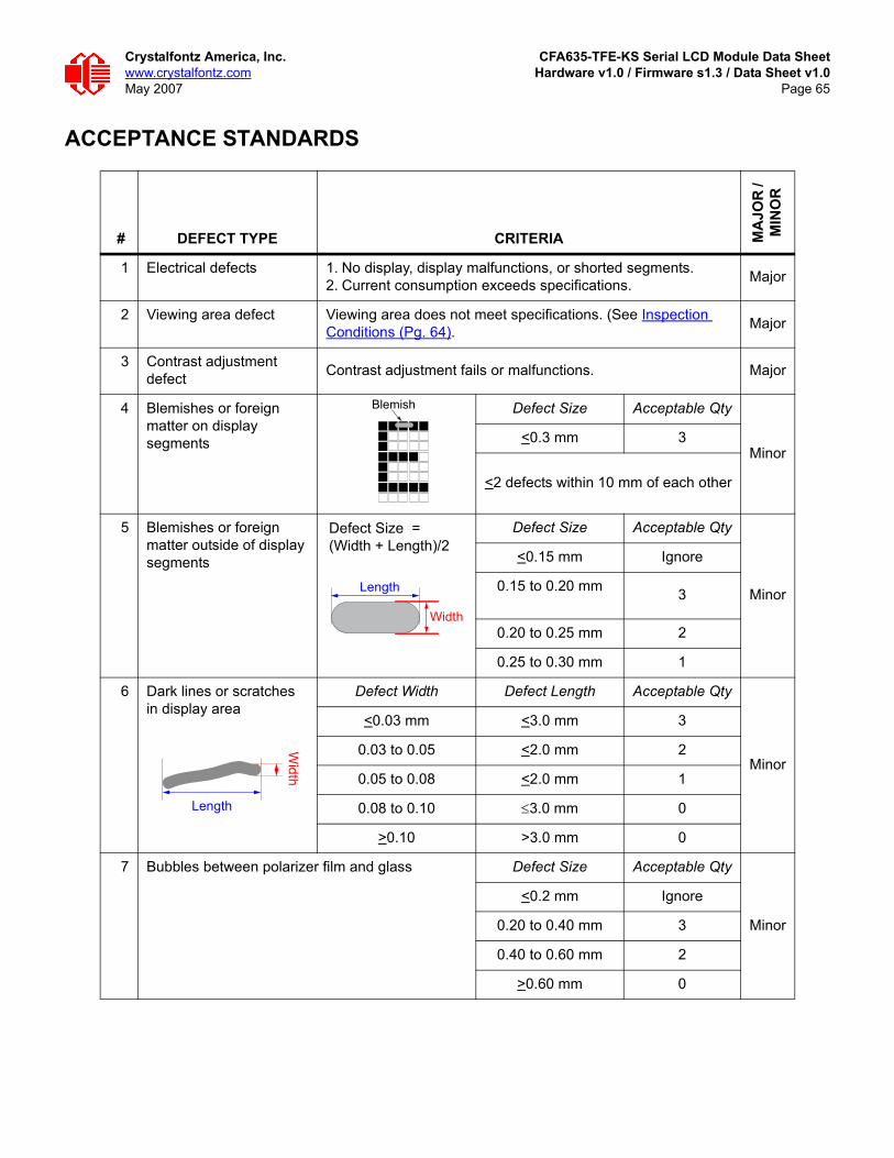
Crystalfontz America, Inc. CFA635-TFE-KS Serial LCD Module Data Sheetwww.crystalfontz.com Hardware v1.0 / Firmware s1.3 / Data Sheet v1.0May 2007 Page 65
ACCEPTANCE STANDARDS
# DEFECT TYPE CRITERIA MA
JOR
/ M
INO
R
1 Electrical defects 1. No display, display malfunctions, or shorted segments.2. Current consumption exceeds specifications. Major
2 Viewing area defect Viewing area does not meet specifications. (See Inspection Conditions (Pg. 64). Major
3 Contrast adjustment defect Contrast adjustment fails or malfunctions. Major
4 Blemishes or foreign matter on displaysegments
Defect Size Acceptable Qty
Minor<0.3 mm 3
<2 defects within 10 mm of each other
5 Blemishes or foreign matter outside of display segments
Defect Size Acceptable Qty
Minor
<0.15 mm Ignore
0.15 to 0.20 mm 3
0.20 to 0.25 mm 2
0.25 to 0.30 mm 1
6 Dark lines or scratches in display area
Defect Width Defect Length Acceptable Qty
Minor
<0.03 mm <3.0 mm 3
0.03 to 0.05 <2.0 mm 2
0.05 to 0.08 <2.0 mm 1
0.08 to 0.10 ≤3.0 mm 0
>0.10 >3.0 mm 0
7 Bubbles between polarizer film and glass Defect Size Acceptable Qty
Minor
<0.2 mm Ignore
0.20 to 0.40 mm 3
0.40 to 0.60 mm 2
>0.60 mm 0
Blemish
Defect Size = (Width + Length)/2
Width
LengthW
idth
Length

Crystalfontz America, Inc. CFA635-TFE-KS Serial LCD Module Data Sheetwww.crystalfontz.com Hardware v1.0 / Firmware s1.3 / Data Sheet v1.0May 2007 Page 66
8 Display pattern defect
Minor
9 Backlight defects 1. Light fails or flickers. (Major)2. Color and luminance do not correspond to specifications.
(Major)3. Exceeds standards for display’s blemishes or foreign matter
(see test 5, page 65), and dark lines or scratches (see test 6, page 65). (Minor)
See list←
10 PCB defects 1. Oxidation or contamination on connectors.*2. Wrong parts, missing parts, or parts not in specification.*3. Jumpers set incorrectly. (Minor)4. Solder (if any) on bezel, LED pad, zebra pad, or screw hole
pad is not smooth. (Minor) *Minor if display functions correctly. Major if the display fails.
See list←
11 Soldering defects 1. Unmelted solder paste.2. Cold solder joints, missing solder connections, or oxidation.*3. Solder bridges causing short circuits.*4. Residue or solder balls.5. Solder flux is black or brown. *Minor if display functions correctly. Major if the display fails.
Minor
# DEFECT TYPE CRITERIA MA
JOR
/ M
INO
R
Dot Size Acceptable Qty
((A+B)/2)<0.2 mm
<3 total defects <2 pinholes per digit
C>0 mm
((D+E)/2)<0.25 mm
((F+G)/2)<0.25 mm
D
A
B C
EF
G
a<1/4W