crystallization in organic semiconductor thin films: a...
TRANSCRIPT

PHYSICAL REVIEW E 89, 022407 (2014)
Crystallization in organic semiconductor thin films: A diffuse-interface approach
Alta Fang*
Department of Mechanical and Aerospace Engineering, Princeton University, Princeton, New Jersey 08544, USA
Mikko Haataja†
Department of Mechanical and Aerospace Engineering, Princeton Institute for the Science and Technology of Materials, and Program inApplied and Computational Mathematics, Princeton University, Princeton, New Jersey 08544, USA
(Received 21 November 2013; published 18 February 2014)
The crystallization of organic semiconductor thin films from an amorphous phase often results in a broadrange of microstructures and molecular arrangements that in turn critically impact the electronic properties of thefilm. Here we present a diffuse-interface model of thin film crystallization that accounts for out-of-plane tiltingof the kinetically favored crystalline orientation as well as the simultaneous appearance of multiple polymorphs.By adjusting the relative thermodynamic stability of grains oriented with the fast-growing axis either parallel orperpendicular to the substrate, crystallization can be made to occur in the form of either commonly observedspherulites or more complex morphologies such as sectors and centers. Furthermore, tuning the relative kineticcoefficients and free energies of multiple polymorphs can result in a spherulite of one crystal structure embeddedwithin a spherulite of another crystal structure. A parametric study of the effects of anisotropy, densification,time-varying treatments, and substrate patterning reveals a wide variety of morphologies that are possible in thesethin films, driven by a combination of kinetic and thermodynamics effects.
DOI: 10.1103/PhysRevE.89.022407 PACS number(s): 81.15.Aa, 68.55.−a
I. INTRODUCTION
Organic semiconductor thin films are employed in manyapplications such as flexible displays [1], sensors [2], andsolar cells [3]. In solution-processed films, starting from anamorphous structure, nucleation processes facilitate the forma-tion of crystalline domains [4] that significantly improve theconductivity of the films [5]. Often, kinetic frustration duringthe crystallization process traps organic semiconductor filmsinto highly nonequilibrium polycrystalline states, leading tothe formation of many interesting morphological features suchas spherulites [6], elongated platelets [7], and feathery textures[8]. A highly complex relationship exists between the process-ing methods used to fabricate the film and its final morphologysince intermolecular and intramolecular interactions with thesubstrate and solvent play a role in determining the structuralorganization of the film [9,10]. Molecular orientation stronglyinfluences the electrical mobility of organic semiconductorfilms [11,12] and can also affect optical absorption [13],while grain boundaries and film morphology can have astrong impact on charge transport processes [14–16]. A betterunderstanding of the physical mechanisms that lead organicsemiconductor thin films to crystallize in different molecularorientations and microstructures as well as greater knowledgeof the relationship between these two characteristics are thuscrucial for improved control of material and device properties.
Existing models of crystallization and microstructureformation in thin films have been able to simulate awide range of morphologies [17,18], but in these modelsthe molecular stacking directions have been confined tothe two-dimensional (2D) plane of the film. It has beenshown experimentally, however, that postdeposition process-
*[email protected]†[email protected]
ing can induce amorphously deposited films of organicmolecules [such as contorted hexabenzocoronene (HBC)]to crystallize preferentially in distinct out-of-plane orien-tations, including configurations where the molecular π -stacking direction is nearly perpendicular to the plane of thefilm [8].
In this work we introduce a diffuse-interface model to studycrystal growth in thin films of anisotropic molecules whosefast-crystallizing axis is allowed to take on any orientation,including those tilted out of the plane of the film. We usea continuum model to focus on the structure of the film onlength scales of tens to hundreds of microns. Since severalorganic semiconductors exhibit a preference for crystallizingwith π planes stacking either parallel or perpendicular to thesubstrate [8,19–21], we introduce a free energy that can betuned to adjust whether either or both of these configurationsare thermodynamically favored. In addition, given that thefilm thicknesses in experiments are typically on the orderof ∼100 nm [6,8,12], growth will be constrained to twodimensions. Thus, rather than explore the morphologies offully 3D spherulites as has been done previously [22,23],herein we study the physics of phase transitions on a 3D freeenergy landscape with only a 2D space in which growth ispermitted. Furthermore, experimental evidence suggests thatby annealing films of contorted HBC with certain solventvapors, multiple polymorphs can appear simultaneously inthe same film [24] and polymorphism is in fact displayed bymany other organic semiconductors as well [25]. Therefore,the model allows the free energies and mobilities of eachpolymorph to be independently tuned since an interplaybetween both thermodynamic and kinetic effects is importantfor the formation of concomitant polymorphs [26].
Our parametric simulation study reveals that complexmorphologies (such as sectors and centers) emerge whencertain regions of the film crystallize in one of the thermo-dynamically favored out-of-plane orientations while others
1539-3755/2014/89(2)/022407(9) 022407-1 ©2014 American Physical Society

ALTA FANG AND MIKKO HAATAJA PHYSICAL REVIEW E 89, 022407 (2014)
crystallize in the other orientation as a result of either(i) nucleating growth with differently oriented initial seeds,(ii) applying time-varying treatments, or (iii) patterning thesubstrate. Further diversity of microstructure was achieved bychanging the degree of densification, which leads to branchedstructures, and introducing multiple polymorphs, which canlead to embedded spherulites. In broader terms, the modelingapproach and results reported herein form the basis for amore quantitative study of nucleation and growth processesin organic semiconductor thin film systems.
The rest of the paper is organized as follows. In Sec. IIwe outline the diffuse-interface framework employed in thiswork. Then, results from our simulation studies and theirimplications are discussed in Sec. III. Finally, a brief summaryand concluding remarks are presented in Sec. IV.
II. MODEL
Our model builds on previous vector-valued diffuse-interface models for polycrystalline solidification [27–31].More specifically, we use a 3D vector order parameter�φi for each polymorph, indexed by i. The magnitude of�φi represents the degree of crystallinity such that | �φi | = 1(0) corresponds to the crystalline (amorphous) phase. Thedirection of �φi in turn represents the axis of fast crystalgrowth, which, in the case of molecules with aromatic ringssuch as contorted HBC, corresponds to the direction of π
stacking [see Fig. 1(a)]. Although a complete descriptionof a 3D orientation requires an additional variable to trackrotations in the plane perpendicular to �φ, here we assume thevalue of this rotational angle to be constant throughout thefilm, which makes the model significantly simpler than a fulltreatment of 3D polycrystallinity using quaternions [22,23]or orthogonal matrices [32]. Further discussion of advantagesand disadvantages of these different modeling frameworks ispresented in Sec. IV.
In addition, branched morphologies in some experimentallyobserved thin films suggest that crystal growth can be diffusionlimited. In particular, since branching can occur even insingle-component films, it may be a result of densification(rather than redistribution of impurities in multicomponentsystems), which can lead to the depletion of availablemolecules ahead of the growth front and the subsequentformation of dendritic morphologies. To account for sucheffects phenomenologically, we introduce a conserved scalarorder parameter u(�r,t) that is analogous to the dimensionlessundercooling in solidification processes [31] and can bedirectly related to the effective densification factor, as willbe discussed in further detail following Eq. (9).
The free energy functional includes both interfacial energyterms and a bulk free energy term for each of the Np
polymorphs, as well as a coupling term that penalizes thepresence of multiple polymorphs at the same location:
F =Np∑i=1
∫d�r
(ε2i
2[( �∇ · �φi)
2 + | �∇ × �φi |2] + fi( �φi,u)
+ a
Np∑j=i+1
| �φi |2| �φj |2)
, (1)
where
fi( �φ,u) = 1 + b1 cos(nθ ) sin2 ϕ
4(1 + b1)
1 + b2 cos(4ϕ)
1 + b2| �φ|4
+ mi(u) − 32 − λi cos2 ϕ
3| �φ|3
− mi(u) − 12 − λi cos2 ϕ
2| �φ|2, (2)
mi(u) = αi
πtan−1(−γ u), (3)
and
λi = λi + 3b1
2(1 + b1), (4)
with the following constraints on parameter values:
0 < αi < 1, − 1
2+ 3b1
1 + b1+ |λi | < mi <
1
2− |λi |,
−1 < b2 < 0. (5)
We have defined ϕ as the angle between �φ and the z axis, so ϕ =90◦ represents the edge-on orientation with the edges of theπ planes pointing into the substrate, while ϕ = 0◦ representsthe face-on orientation with the faces of the π planes parallelto the substrate. (Note that we have dropped the i subscriptssince this discussion applies to all polymorphs.) Furthermore,θ denotes the angle between the x axis and the projection of�φ onto the x-y plane. The constraints in Eq. (5) ensure that| �φ| = 0 and 1 as well as ϕ = 0◦ and 90◦ are always localminima of f .
The bulk free energy f is constructed to have a double-well shape in both | �φ| and ϕ, with m and λ dictating therelative depths of the local minima. This form of the bulk freeenergy reflects the existence of a first-order phase transitionbetween the amorphous and crystalline phases, while we use asimilarly shaped potential in the tilt angle ϕ [see Figs. 1(b) and1(c)], as the edge-on and face-on configurations are commonlyobserved experimentally and represent the limiting cases forpossible out-of-plane orientations. Physically, we envision thatm and λ can be varied, for example, by altering the substrate,exposing the surface of the film to different substances, orheating the film. The parameter b2 dictates the height of thefree energy barrier between the ϕ = 0◦ and 90◦ orientations,while Eq. (4) ensures that the values of f at these minimaare equal when λ = 0. Finally, grain boundaries are stabilizedby introducing a θ dependence in f such that certain in-planeorientations are preferred, allowing fixed misorientations toexist [see Fig. 1(d)]. The parameter b1 dictates the depth ofthese equispaced local free energy minima, while n controlsthe number of such minima.
Given the free energy in Eq. (1), the time evolution of �φi
and u is computed in Cartesian coordinates as follows:
∂φix
∂t= −Mi
δF
δφix
+ ηix, (6)
∂φiy
∂t= −Mi
δF
δφiy
+ ηiy, (7)
022407-2

CRYSTALLIZATION IN ORGANIC SEMICONDUCTOR THIN . . . PHYSICAL REVIEW E 89, 022407 (2014)
030
6090
00.2
0.40.6
0.81 � (degrees)
|Φ|
f
(c)
-1-0.5
00.5
1-1
-0.50
0.51
ΦyΦx
f
(d)
0 30 60 90
� (degrees)
Λ = 0.05Λ = 0
Λ = −0.05
f
(b)
substrate
������������
�
(a)
FIG. 1. (Color online) (a) Schematic adapted from Ref. [8] showing that �φ is oriented along the molecular π -stacking direction and tilted atan angle ϕ with respect to the z axis. (b) Parameter λ can be tuned to vary the relative free energies of the two preferred out-of-plane orientations.(c) The free energy has local minima in both | �φ| and ϕ, shown here for θ = 0◦, m = 0.42, and λ = 0. Note the presence of a rather shallowwell at | �φ| = 0 and a much deeper one at | �φ| = 1. (d) To incorporate multiple crystalline orientations, n equispaced values of the in-planeorientation θ are singled out by f , as demonstrated for ϕ = 90◦, m = 0.42, λ = 0, and b1 = −0.005.
∂φiz
∂t= −Mi
δF
δφiz
+ ηiz, (8)
∂u
∂t= ∇2u +
Np∑i=1
1
i
∂| �φi |∂t
. (9)
Here is a tunable parameter that is related to the degreeof densification during crystallization and thus controls howdiffusion limited the crystal growth is. In particular, � 1( → 0) corresponds to low (high) degree of densification.More specifically, given the boundary conditions employedin the simulations, for < 1, a fraction of the systemwill crystallize before the effective supercooling is depleted.Thus, the magnitude of is physically determined by =ρamorph/ρcryst, where ρamorph/ρcryst is the densification factorand ρi denotes the effective areal density of the ith phase.The field m is in turn coupled to the conserved field u viaEq. (3) such that as the conserved quantity is depleted, thedriving force for crystallization disappears. Furthermore, thefollowing form for the mobility is used:
M = M{1 + δθ (1 + cos[2(ψ − θ )]) sin2 ϕ}[1 + δβ(1
+ cos(kψ)) cos2 ϕ], (10)
where
M = Mmaxg(| �φ|)1 + 2δθ
,
g(| �φ|) = 1
2
[1 + tanh
(−| �φ| − c
c
)],
ψ = tan−1
(∂| �φ|∂y
/∂| �φ|∂x
),
and δθ > δβ > 0. Here ψ denotes the local orientation of thegrowth front. Because no coarsening is observed experimen-tally, the mobility is modulated such that its value is ordersof magnitude smaller in crystalline regions than in amorphousregions, effectively freezing the film in a kinetically trappedstate [see Fig. 2(a)]. In particular, c is the threshold value of| �φ| above which the mobility approaches zero, while c dictatesthe range of | �φ| values over which this transition in mobilityoccurs. Furthermore, the mobility used here has a twofold-symmetric anisotropy δθ in the fast-growing crystallographicaxis because it has been found that in many organic small-molecule systems with planar geometries, the direction ofthe crystal growth is aligned with the one associated with π
stacking [6]. Thus, when the molecules are oriented edge-on,the mobility is at a maximum (M = Mmax) if the projection of
022407-3

ALTA FANG AND MIKKO HAATAJA PHYSICAL REVIEW E 89, 022407 (2014)
0
0.2
0.4
0.6
0.8
1
0 0.2 0.4 0.6 0.8 1
g(�Φ�)
�Φ�
(a)
0
0.2
0.4
0.6
0.8
1
0 30 60 90 120 150 180
MMmax
Ψ − θ (degrees)
Δθ 01Δθ 05
δθ 4
(b)
-1-0.5
00.5
1-1
-0.50
0.51 �Φ� sinΨ
�Φ� cosΨ
M
(c)
FIG. 2. (Color online) (a) The mobility M effectively vanishesas | �φ| → 1, thereby freezing the order parameter �φ in the crys-talline phase. (b) Edge-on orientations, corresponding to ϕ = 90◦,experience an anisotropic mobility that is at a maximum when thegrowth direction ψ is aligned with the in-plane orientation θ and ata minimum when they are perpendicular. (c) Face-on orientations,for which ϕ = 0◦, can also be made to have an anisotropic mobility,as demonstrated here for k = 4 and δβ = 2. The mobility attains amaximum for four growth directions ψ and decreases sharply for allvalues of ψ as | �φ| → 1.
�φ onto the x-y plane is parallel to the crystal growth directionand at a minimum if they are perpendicular [see Fig. 2(b)]. Inthe face-on case, anisotropy in the crystallographic directionsperpendicular to �φ can be controlled by adjusting δβ , whichcontrols the magnitude of the k-fold anisotropy, as illustratedin Fig. 2(c). The factors of sin2 ϕ and cos2 ϕ in Eq. (10) ensurethat when a region of the film has an edge-on orientation,the anisotropy is dictated by δθ , while face-on regions insteadhave a k-fold symmetric anisotropy δβ in the plane of the thinfilm.
Finally, stochastic fluctuations are introduced through η,which obey
〈η(�r,t)〉 = 0, 〈η(�r,t)η(�r ′,t ′)〉 = η 2R(�r,�r ′; l)δ(t − t ′), (11)
where
R(�r,�r ′; l) = 1
2πl2exp
(−|�r − �r ′|22l2
)(12)
and
η = 4| �φ|(1 − | �φ|)√
2kBT Mmaxg(| �φ|). (13)
The presence of time-varying fluctuations at the interfaceis essential to accurately simulating spherulites since theirpolycrystallinity arises from growth front nucleation [17].Here we do not use the usual uncorrelated Gaussian noisebut instead use fluctuations that are spatially correlated overa length scale l. Physically, this reflects the fact that theinitial supposedly amorphous films are often not completelydisordered but have small regions with distinct orientations [6].Furthermore, the noise is modulated to allow fluctuations tooccur only at the interface and not in either the fully amorphousor crystalline phases. This prevents nucleation from happeningin the amorphous phase so that the morphologies of thecrystalline domains can be more clearly discerned.
To study the morphologies that arise from this model usingnumerical simulations, initially a small seed with out-of-planeorientation ϕ0 is placed in the center of a square simulationgrid with periodic boundary conditions and the time evolutionof the system is computed with explicit finite-differencemethods. A nine-point stencil for the Laplacian is used toreduce grid anisotropy artifacts and Fourier transforms areused to generate the spatially correlated noise [33]. Represen-tative nondimensionalized parameter values used are Nx =Ny = 1024, t = 2.4 × 10⁻⁵, Mmax = 5
3 × 10⁴, x = 0.01,ε2 = 10−5, n = 24, l2 = 10−5, b1 = −0.0025, b2 = −0.01,α = 0.9, γ = 10, kBT = 1.2 × 10⁻⁸, c = 0.95, c = 0.01, anda = 0.5. Numerical implementation of this model faces thechallenge that numerical artifacts may arise if interfacesare resolved by too few grid points, but physical interfacialwidths are extremely small and fine grids are computationallyexpensive. Therefore, in these simulations we use an interfacewidth that is larger than what is physical, while carefullychoosing parameter values that lead to physically reasonableresults.
III. RESULTS
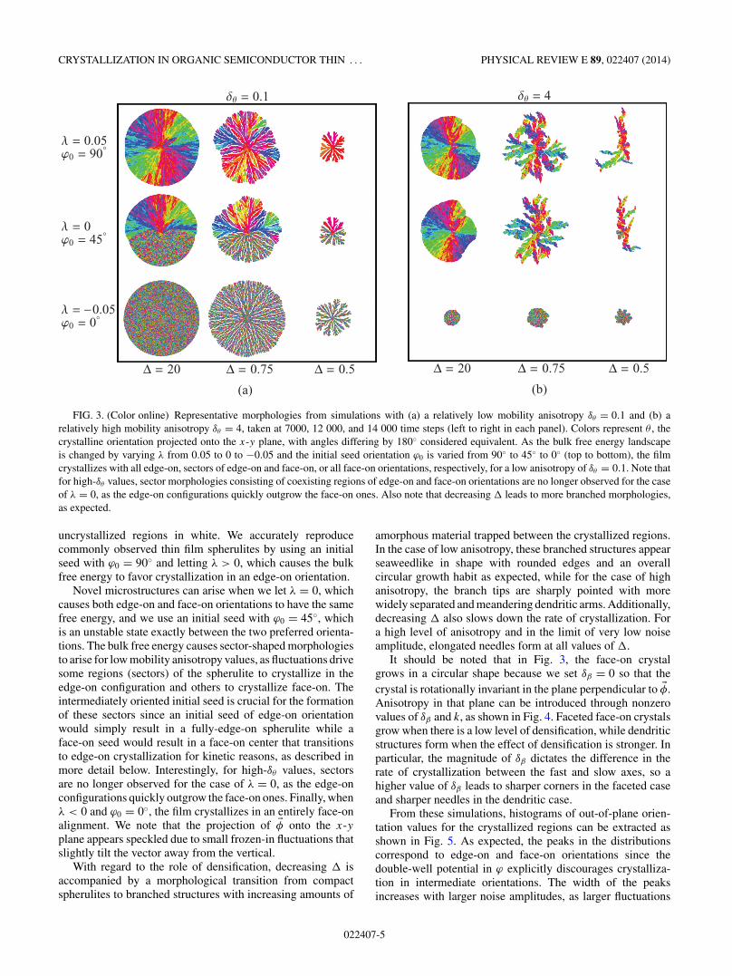
We begin our exploration of the model by considering theeffects of the parameters λ and , which account for thethermodynamic preference of edge-on vs face-on configu-rations and densification effects, respectively, on crystallinemorphologies. In all simulations reported below, unless other-wise stated, we only consider one polymorph and set Np = 1.To this end, Fig. 3 illustrates some of the crystallizationpatterns that can form for various values of λ and inthe cases of both low- and high-mobility anisotropy. Sinceexperimentally spherulites are often visualized using polarizedoptical micrographs where color indicates the local orientation,here we use a cyclic color map to visualize θ and show
022407-4
CRYSTALLIZATION IN ORGANIC SEMICONDUCTOR THIN . . . PHYSICAL REVIEW E 89, 022407 (2014)
Δ 20 Δ 075 Δ 05
ΔΘ 4
(b)
Λ 005�0 90°
Λ 0�0 45°
Λ −005�0 0°
Δ 20 Δ 075 Δ 05
ΔΘ 01
(a)
FIG. 3. (Color online) Representative morphologies from simulations with (a) a relatively low mobility anisotropy δθ = 0.1 and (b) arelatively high mobility anisotropy δθ = 4, taken at 7000, 12 000, and 14 000 time steps (left to right in each panel). Colors represent θ , thecrystalline orientation projected onto the x-y plane, with angles differing by 180◦ considered equivalent. As the bulk free energy landscapeis changed by varying λ from 0.05 to 0 to −0.05 and the initial seed orientation ϕ0 is varied from 90◦ to 45◦ to 0◦ (top to bottom), the filmcrystallizes with all edge-on, sectors of edge-on and face-on, or all face-on orientations, respectively, for a low anisotropy of δθ = 0.1. Note thatfor high-δθ values, sector morphologies consisting of coexisting regions of edge-on and face-on orientations are no longer observed for the caseof λ = 0, as the edge-on configurations quickly outgrow the face-on ones. Also note that decreasing leads to more branched morphologies,as expected.
uncrystallized regions in white. We accurately reproducecommonly observed thin film spherulites by using an initialseed with ϕ0 = 90◦ and letting λ > 0, which causes the bulkfree energy to favor crystallization in an edge-on orientation.
Novel microstructures can arise when we let λ = 0, whichcauses both edge-on and face-on orientations to have the samefree energy, and we use an initial seed with ϕ0 = 45◦, whichis an unstable state exactly between the two preferred orienta-tions. The bulk free energy causes sector-shaped morphologiesto arise for low mobility anisotropy values, as fluctuations drivesome regions (sectors) of the spherulite to crystallize in theedge-on configuration and others to crystallize face-on. Theintermediately oriented initial seed is crucial for the formationof these sectors since an initial seed of edge-on orientationwould simply result in a fully-edge-on spherulite while aface-on seed would result in a face-on center that transitionsto edge-on crystallization for kinetic reasons, as described inmore detail below. Interestingly, for high-δθ values, sectorsare no longer observed for the case of λ = 0, as the edge-onconfigurations quickly outgrow the face-on ones. Finally, whenλ < 0 and ϕ0 = 0◦, the film crystallizes in an entirely face-onalignment. We note that the projection of �φ onto the x-yplane appears speckled due to small frozen-in fluctuations thatslightly tilt the vector away from the vertical.
With regard to the role of densification, decreasing isaccompanied by a morphological transition from compactspherulites to branched structures with increasing amounts of
amorphous material trapped between the crystallized regions.In the case of low anisotropy, these branched structures appearseaweedlike in shape with rounded edges and an overallcircular growth habit as expected, while for the case of highanisotropy, the branch tips are sharply pointed with morewidely separated and meandering dendritic arms. Additionally,decreasing also slows down the rate of crystallization. Fora high level of anisotropy and in the limit of very low noiseamplitude, elongated needles form at all values of .
It should be noted that in Fig. 3, the face-on crystalgrows in a circular shape because we set δβ = 0 so that thecrystal is rotationally invariant in the plane perpendicular to �φ.Anisotropy in that plane can be introduced through nonzerovalues of δβ and k, as shown in Fig. 4. Faceted face-on crystalsgrow when there is a low level of densification, while dendriticstructures form when the effect of densification is stronger. Inparticular, the magnitude of δβ dictates the difference in therate of crystallization between the fast and slow axes, so ahigher value of δβ leads to sharper corners in the faceted caseand sharper needles in the dendritic case.
From these simulations, histograms of out-of-plane orien-tation values for the crystallized regions can be extracted asshown in Fig. 5. As expected, the peaks in the distributionscorrespond to edge-on and face-on orientations since thedouble-well potential in ϕ explicitly discourages crystalliza-tion in intermediate orientations. The width of the peaksincreases with larger noise amplitudes, as larger fluctuations
022407-5

ALTA FANG AND MIKKO HAATAJA PHYSICAL REVIEW E 89, 022407 (2014)
Δ = 20 Δ = 0.5
FIG. 4. (Color online) When anisotropy is introduced in the planeperpendicular to �φ by setting k = 4 and δβ = 2, a fourfold symmetricface-on crystal forms for λ = −0.05 and ϕ0 = 0◦. When = 20 theshape is faceted, while when = 0.5 the shape is dendritic.
in ϕ become subsumed into the crystal growth front. Thedrop in normalized frequency near ϕ = 0◦ that results in theface-on maxima being shifted slightly away from ϕ = 0◦ isdue to the fact that a histogram of ϕ values is a measureof the polar probability distribution rather than a probabilitydensity function. That is, even though a probability densityfunction p(ϕ) may have a maximum at ϕ = 0◦ [and in factdoes, as per fi in Eq. (2)], the probability of finding anout-of-plane orientation in the interval from ϕ to ϕ + ϕ isgiven by Pr(ϕ,ϕ + ϕ) ∝ p(ϕ) sin ϕ ϕ, so the factor of sin ϕ
will always cause the polar probability distribution to approach0 as ϕ → 0◦ for finite p(ϕ).
We note that these orientation distributions can be comparedwith intensity profiles of particular crystalline plane reflectionsin experimental grazing-incidence x-ray-diffraction (GIXD)
data. Care must be exercised with direct comparisons, however,as kinetic effects may suppress or enhance the frequency ofoccurrence of certain orientations. For example, in the caseof high mobility anisotropy values, edge-on configurationsquickly outgrow the face-on ones and effectively elimi-nate them from the orientation distribution, even thoughboth configurations are equally stable thermodynamically forλ = 0. Nevertheless, in conjunction with kinetic data, theGIXD data can be employed to constrain the number ofthermodynamically favored orientations.
Additional intriguing microstructures arise when the bulkfree energy is suddenly changed during the crystallizationprocess, which physically corresponds to applying time-varying treatments to the film. Figure 6 shows that centerswith a different out-of-plane orientation than their neighboringouter ring form when crystallization is first begun with λ > 0,which favors edge-on orientations, and then after some timethe bulk free energy is switched to favor face-on orientationsby setting λ < 0 or vice versa. The jagged interface at thetransition between the two regions in such center morphologiesin Fig. 6 reflects the fact that the change in orientations is drivenby fluctuations that cause different parts of the interface toovercome the energy barrier and transition from the metastableto the stable state at different times. Indeed, the transitionbetween a center of one orientation and its surrounding crystalof a different orientation can take on different geometriesdepending on the energetics and kinetics of the film, as wewill discuss next.
Now, the top row of Fig. 7 shows the morphology thatarises when both the edge-on and face-on orientations have thesame free energy, but edge-on crystals grow twice as fast asface-on crystals and the initial seed is face-on. Faster-growingedge-on grains nucleate at various points along the interfaceand eventually pinch off the face-on growth front, resulting
0
0.2
0.4
0.6
0.8
1
0 10 20 30 40 50 60 70 80 90
� (degrees)
(b) Δθ 4
norm
aliz
edhi
stog
ram
Λ 005Λ 0
Λ −005
0
0.2
0.4
0.6
0.8
1
0 10 20 30 40 50 60 70 80 90
� (degrees)
(a) Δθ 01
norm
aliz
edhi
stog
ram
Λ 005Λ 0
Λ −005
FIG. 5. (Color online) Histograms of out-of-plane orientations for crystallized regions of the structures with (a) a low and (b) a high valueof the mobility anisotropy δθ , for = 20. The film crystallizes in primarily edge-on, primarily face-on, or a combination of both orientations asdictated by the value of λ. Note that for high δθ and λ = 0, edge-on configurations quickly outgrow the face-on ones and effectively eliminatethem from the orientation distribution, even though both configurations are equally stable thermodynamically.
022407-6

CRYSTALLIZATION IN ORGANIC SEMICONDUCTOR THIN . . . PHYSICAL REVIEW E 89, 022407 (2014)
FIG. 6. (Color online) Simulated configurations shown every 1200 time steps during crystallization. The parameter λ was changed from−0.05 to 0.05 (top row) or 0.05 to −0.05 (bottom row) after 3600 time steps. This change causes the film that began crystallizing face-on tosubsequently switch to crystallizing edge-on, or vice versa. Here a low value for the mobility anisotropy (δθ = 0.1) was used.
in a flower-petal shape. Such patterns have been observedexperimentally in polyhydroxybutyrate [34]. In the bottomrow of Fig. 7, a time-varying treatment identical to that in thebottom row of Fig. 6 was applied to a system with a higheranisotropy of δθ = 0.5. Note the presence of narrow strandsof edge-on crystals at the interface, which arise because edge-on crystallization proceeds faster than face-on crystallization,resulting in the rapid growth of the edge-on crystals radially
�Θ0° 180° 0° 90°
�0 0°
Λ 0
�0 90°
t ≤ tmax
2 :Λ 005t � tmax
2 :Λ −005
FIG. 7. (Color online) When edge-on crystallization is fasterthan face-on crystallization and a face-on initial seed is used, aflower-petal-shaped center arises as the faster-growing orientationpinches off the slower-growing orientation (top row). In contrast,when a time-varying treatment energetically favors a transition fromthe edge-on to the face-on orientation, strands of the faster-growingedge-on orientation persist for some time before switching to thelower-energy state (bottom row). An intermediate value for themobility anisotropy (δθ = 0.5) was used for both simulations.
outward from the seed crystal until the transition to the lower-energy face-on orientation takes place.
If the substrate is patterned so that certain regions favorcrystallization in the edge-on orientation while others favor theface-on orientation, arbitrarily shaped regions of different ori-entation can be created. An example is shown in Fig. 8, whereλ = −0.05 within a square ring while λ = 0.05 everywhereelse. The initial edge-on crystal seed grows radially outward,switches to the face-on orientation in the region inside thesquare ring, and then switches back to the edge-on orientationagain. Inequalities in the mobilities of the two orientationsand the need to overcome the energy barrier to the favoredorientation through fluctuations introduces roughness to theinterface and a lag in transitioning between orientations. Theresolution of the features achievable from substrate patterningthus can be limited by these considerations.
�Θ0° 180° 0° 90°
FIG. 8. (Color online) When the substrate is patterned such thatλ = −0.05 inside a square ring (indicated by dashed white lines)while λ = 0.05 everywhere else, crystallization proceeds in thelocally energetically favored orientation, with jagged edges wheretransitions between preferred molecular orientations have occurred.Here δθ = 0.1.
022407-7

ALTA FANG AND MIKKO HAATAJA PHYSICAL REVIEW E 89, 022407 (2014)
FIG. 9. (Color online) Snapshots at t = 1400, 2800, 4200, 5600, and 7000 (left to right) time steps show a spherulite of one polymorphbecoming embedded within a spherulite of another, faster growing polymorph. Shades of red (dark) represent θ for the lower-mobility polymorphand shades of orange (light) represent θ for the higher-mobility polymorph.
Finally, when multiple polymorphs crystallize in the samethin film, an even greater variety of microstructures is possible.Arbitrarily many polymorphs can be simulated with our modelby using an additional vector order parameter field �φi totrack the evolution of each polymorph. To demonstrate this,we simulate two polymorphs with the same free energy butdifferent crystallization rates. When an initial seed of eachpolymorph is placed in the film with α1 = α2 = 0.9 so thatboth equally favor a transition to the crystalline state andM1,max = 2M2,max so that one polymorph crystallizes at twicethe rate of the other, embedded spherulites emerge as shownin Fig. 9. This type of microstructure has been experimentallyobserved in isotactic polypropylene [35].
IV. CONCLUSION
In this paper we have employed a diffuse-interface mod-eling approach to investigate crystallization phenomena andmorphological evolution in amorphously deposited organicthin films. In particular, we have demonstrated that a widevariety of microstructures can arise during the crystallizationprocess when the fast-growing crystallographic axis is allowedto vary in three dimensions and a thermodynamic free energyis introduced to favor certain out-of-plane orientations duringan effectively 2D crystal growth process. Tuning the relativethermodynamic stability of different out-of-plane orientationsresults in complex morphologies such as sectors and centers,while altering parameters such as the anisotropy, degree ofdensification, and kinetics of multiple polymorphs leads tofurther variations in the microstructure of the film. Transitionsfrom an edge-on to a face-on orientation or vice versa can bedriven by either kinetic or thermodynamic reasons, resultingin intriguing microstructures such as petal-shaped interfacesor radiating thin strands. Substrate patterning can producearbitrarily shaped edge-on and face-on regions; however,feature resolution may be limited by the relative crystallizationrates of different orientations as well as the amplitude offluctuations. We have also demonstrated that interestingmorphologies emerge when the thermodynamic preferenceof edge-on vs face-on orientations is modified during thecrystallization process.
Although the development of our model has been inspiredby small-molecule organic semiconductors, our findings are
in principle applicable to films composed of any material witha preferred axis of crystal growth. For example, polymers areknown to exhibit diverse morphologies [34,35] that closelyresemble those presented in this paper. While the lamellarstructure of semicrystalline polymers is not identical to theplanar stacking geometry assumed in this model [36], thequalitative concepts presented here regarding the interplaybetween kinetics and thermodynamics as well as the manifes-tation of polymorphism are nevertheless relevant to polymersas well as other spherulite-forming systems. Furthermore, theextension of our model to account for additional physicalphenomena may help explain certain experimentally observedmorphologies and relative crystallization rates of differentlyoriented grains that cannot yet be reproduced by the currentmodel. For example, here it has been assumed that films tendtoward either face-on or edge-on crystallization, but filmswith intermediate orientations have also been experimentallyobserved [8,13].
It is important to note that the framework used in ourmodel possesses both advantages and disadvantages comparedto other 3D orientational diffuse-interface models in theliterature, which employ quaternions [22,23] or orthogonalmatrices [32] to fully describe local orientations. In thesemodels the mobilities of the crystallinity order parameter andthe orientational fields can be varied independently, allowingfor a wider range of resultant morphologies by simply tuningthe relative mobility values [17]. Our model lacks this degreeof freedom due to its use of Cartesian coordinates for timeevolution, but it instead benefits from simple nonsingular timeevolution equations as well as the ability to maintain numericalstability with larger time steps. Another consequence of usinga single mobility is that enforcing it to have a very low value inthe crystalline phase freezes not only the orientation but alsothe degree of crystallinity, thereby preventing the crystallinephase from transforming to any other phase or even undergoinggrain growth processes, which is clearly unphysical overextended time scales. However, in this paper we have onlyinvestigated the process of crystallization and hence this modelremains valid for the applications considered. Finally, since wefocus on the direction of one fast-crystallizing axis, we avoidincluding unnecessary additional parameters in our model byassuming that the local orientation in the plane perpendicularto �φ is constant throughout the film. However, in situationswith different crystalline symmetries it may be necessary to
022407-8

CRYSTALLIZATION IN ORGANIC SEMICONDUCTOR THIN . . . PHYSICAL REVIEW E 89, 022407 (2014)
use quaternions to provide a more complete description of3D orientations. In closing, we hope that the approach andfindings presented in this paper provide inspiration for newexperiments as well as theoretical work toward the ultimategoal of guiding experiments through the large phase space ofpossible thin film microstructures by better understanding thephysical mechanisms controlling both nucleation and growthprocesses.
ACKNOWLEDGMENTS
This work was partly supported by an NSF-DMR GrantNo. 0819860 (Princeton Center for Complex Materials, aMaterials Research Center) and by the National ScienceFoundation Graduate Research Fellowship under Grant No.DGE 1148900. Useful discussions with A. Hiszpanski andY.-L. Loo are gratefully acknowledged.
[1] G. H. Gelinck, H. E. A. Huitema, E. van Veenendaal,E. Cantatore, L. Schrijnemakers, J. B. van der Putten, T. C.Geuns, M. Beenhakkers, J. B. Giesbers, B.-H. Huisman et al.,Nat. Mater. 3, 106 (2004).
[2] J. Mabeck and G. Malliaras, Anal. Bioanal. Chem. 384, 343(2006).
[3] Y. Lin, Y. Li, and X. Zhan, Chem. Soc. Rev. 41, 4245(2012).
[4] S. S. Lee, S. Muralidharan, A. R. Woll, M. A. Loth, Z. Li,J. E. Anthony, M. Haataja, and Y.-L. Loo, Chem. Mater. 24,2920 (2012).
[5] K. C. Dickey, J. E. Anthony, and Y.-L. Loo, Adv. Mater. 18,1721 (2006).
[6] S. S. Lee, S. B. Tang, D.-M. Smilgies, A. R. Woll, M. A. Loth,J. M. Mativetsky, J. E. Anthony, and Y.-L. Loo, Adv. Mater. 24,2692 (2012).
[7] R. J. Kline, S. D. Hudson, X. Zhang, D. J. Gundlach, A. J. Moad,O. D. Jurchescu, T. N. Jackson, S. Subramanian, J. E. Anthony,M. F. Toney, and L. J. Richter, Chem. Mater. 23, 1194 (2011).
[8] A. M. Hiszpanski, S. S. Lee, H. Wang, A. R. Woll, C. Nuckolls,and Y.-L. Loo, ACS Nano 7, 294 (2013).
[9] S. S. Lee and Y.-L. Loo, Annu. Rev. Chem. Biomol. Eng. 1, 59(2010).
[10] Z. B. Henson, K. Mullen, and G. C. Bazan, Nat. Chem. 4, 699(2012).
[11] J. Y. Lee, S. Roth, and Y. W. Park, Appl. Phys. Lett. 88, 252106(2006).
[12] S. K. Park, D. A. Mourey, S. Subramanian, J. E. Anthony, andT. N. Jackson, Appl. Phys. Lett. 93, 043301 (2008).
[13] C. Schunemann, D. Wynands, K.-J. Eichhorn, M. Stamm,K. Leo, and M. Riede, J. Phys. Chem. C 117, 11600 (2013).
[14] S. S. Lee, J. M. Mativetsky, M. A. Loth, J. E. Anthony, and Y.-L.Loo, ACS Nano 6, 9879 (2012).
[15] S. S. Lee, M. A. Loth, J. E. Anthony, and Y.-L. Loo, J. Am.Chem. Soc. 134, 5436 (2012).
[16] G. Horowitz and M. E. Hajlaoui, Adv. Mater. 12, 1046 (2000).[17] L. Granasy, T. Pusztai, G. Tegze, J. A. Warren, and J. F. Douglas,
Phys. Rev. E 72, 011605 (2005).
[18] L. Granasy, L. Ratkai, A. Szallas, B. Korbuly, G. I. Toth,L. Krnyei, and T. Pusztai, Metall. Mater. Trans. A (to bepublished).
[19] A. Durr, B. Nickel, V. Sharma, U. Taffner, and H. Dosch, ThinSolid Films 503, 127 (2006).
[20] T. Djuric, T. Ules, H.-G. Flesch, H. Plank, Q. Shen, C. Teichert,R. Resel, and M. G. Ramsey, Cryst. Growth Design 11, 1015(2011).
[21] H. Sirringhaus, P. Brown, R. Friend, M. Nielsen, K. Bechgaard,B. Langeveld-Voss, A. Spiering, R. A. Janssen, E. Meijer,P. Herwig, and D. M. de Leeuw, Nature (London) 401, 685(1999).
[22] T. Pusztai, G. Bortel, and L. Granasy, Europhys. Lett. 71, 131(2005).
[23] T. Pusztai, G. Tegze, G. I. Toth, L. Kornyei, G. Bansel, Z. Fan,and L. Granasy, J. Phys.: Condens. Matter 20, 404205 (2008).
[24] A. Hiszpanski and Y.-L. Loo (private communication).[25] A. M. Hiszpanski and Y.-L. Loo, Energy Environ. Sci. 7, 592
(2014).[26] J. Bernstein, R. J. Davey, and J.-O. Henck, Angew. Chem. Int.
Ed. Engl. 38, 3440 (1999).[27] R. Kobayashi, Physica D 63, 410 (1993).[28] B. Morin, K. R. Elder, M. Sutton, and M. Grant, Phys. Rev. Lett.
75, 2156 (1995).[29] R. Kobayashi, J. Warren, and W. Carter, Physica D 119, 415
(1998).[30] S. Muralidharan, Ph.D. thesis, Princeton University, 2012.[31] K. Aguenaou, Ph.D. thesis, McGill University, 1997.[32] R. Kobayashi and J. A. Warren, Physica A 356, 127
(2005).[33] H. A. Makse, S. Havlin, M. Schwartz, and H. E. Stanley, Phys.
Rev. E 53, 5445 (1996).[34] O. Farrance, R. Jones, and J. Hobbs, Polymer 50, 3730
(2009).[35] G. Schulze and H.-P. Wilbert, Colloid Polym. Sci. 267, 108
(1989).[36] Y.-X. Liu and E.-Q. Chen, Coord. Chem. Rev. 254, 1011
(2010).
022407-9