cs 223 digital systems fall 2010 chapter 4. outline analysis of combinational circuits signed...
TRANSCRIPT

CS 223 Digital Systems
Fall 2010
Chapter 4
Outline
Analysis of Combinational Circuits Signed Number Arithmetic Binary Adder-Subtractor Binary Multiplier Magnitude Comparator Decoders Encoders Multiplexers Three-state Gates

Analysis of Combinational Circuits
Given a combinational circuit diagram determine the function of the circuit.
Label all gate outputs with arbitrary symbols. Determine the functions for each gate output.
Repeat the process until the function for the outputs are obtained.
Substitute the functions for arbitrary symbols until out functions are expressed in terms of input variables.
Chapter 4 3
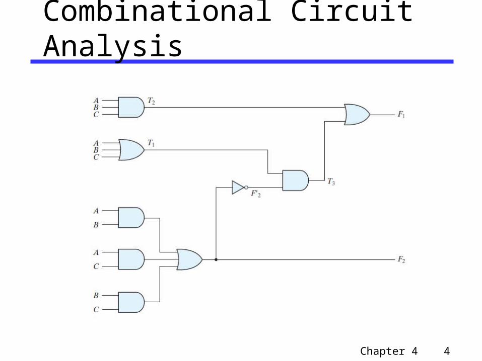
Combinational Circuit Analysis
Chapter 4 4

Combinational Circuit Analysis
Chapter 4 5

Combinational Circuit Design
Given a specification for the circuit: Determine the number of inputs and outputs Derive the truth table for the output
functions Obtain simplified Boolean functions for
each output Draw the logic diagram using gates and
verify the design (simulation, manually)
Chapter 4 6

Combinational Circuit Design Example 1
Problem: Number-of-1s Counter Design a circuit that counts the number of
1s present on three inputs a,b,c and outputs that number in binary using two outputs, y and z.
abc=001 yz=01 abc=011 yz=10
Chapter 4 7

Combinational Circuit Design Example 1
Chapter 4 8

Combinational Circuit Design Example 1
y=ac+bc+ab
z is an odd-function
Chapter 4 9

Combinational Circuit Design Example 2 Implement a circuit that can detect
(output=1) whether a pattern of at least three adjacent 1’s occur anywhere in a an 8-bit input.• if input abcdefgh=00011100 output=1.• if input abcdefgh=01010110 output=0.• if input abcdefgh=00111110 output=1.
Chapter 4 10

Combinational Circuit Design Example 2 Truth Table for Pattern Detector There are 8 input variables. The truth table
will have 2^8=256 rows. In this case try the to find equation that lists
the possible occurrences of three 1s in a row.
Output z=abc+bcd+cde+def+efg+fgh
Chapter 4 11

Combinational Circuit Design Example 2
Chapter 4 12

Combinational Circuit Design Example 3 Problem: Convert BCD code to Excess-3
Chapter 4 13

Combinational Circuit Design Example 3
Chapter 4 14

Combinational Circuit Design Example 3
Chapter 4 15

Combinational Circuit Design Example 3
Chapter 4 16

Half Adder
X + Y = C S
Chapter 4 17

Half Adder Verilog
Chapter 4 18

Half Adder Verilog
Using XOR
Verilog 2001,2005 Syntax
Chapter 4 19

Binary Adder - Subtractor
Chapter 4 20

Binary Adder - Subtractor
Chapter 4 21

Binary Adder - Subtractor
2-level AND-OR implementation
Chapter 4 22
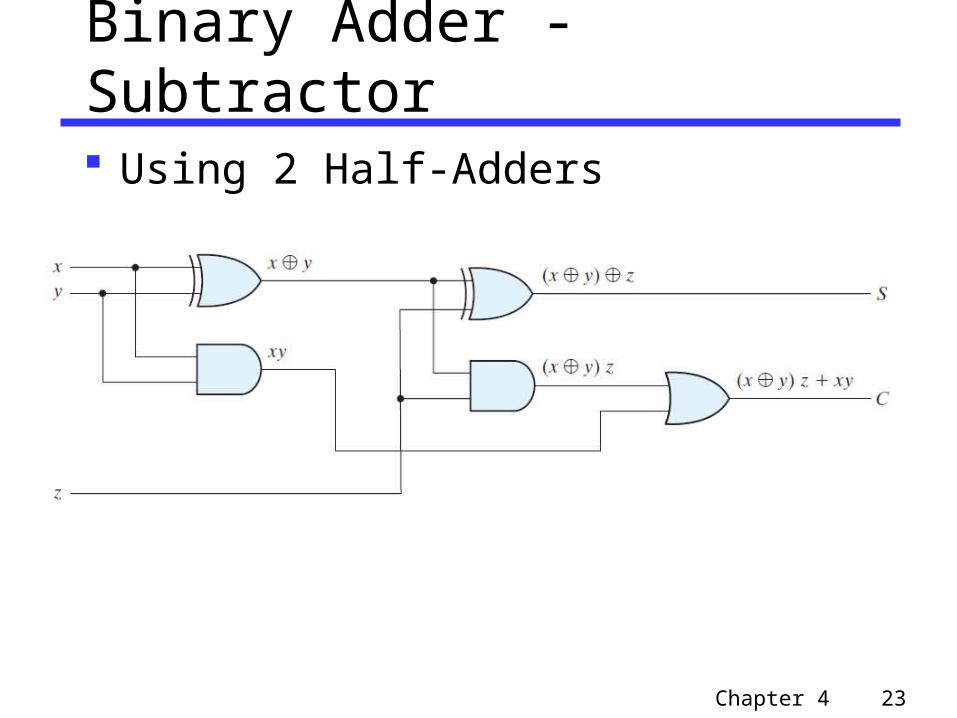
Binary Adder - Subtractor
Using 2 Half-Adders
Chapter 4 23

Binary Adder - Subtractor
Verilog Description
Chapter 4 24

Verilog Dataflow Modeling
Dataflow modeling uses assign statements for continuous assignment
The data type net is used to represent physical connection between circuit elements.
A net is declared by wire or by declaring an identifier to be an output port.
A continuous assignment assigns a value to a net.
assign Y=A & B specifies that output of an AND gate is connected to wire Y.
Chapter 4 25

Verilog Operators
Chapter 4 26

Binary Adder - Subtractor
Chapter 4 27

4-bit Binary Adder
Chapter 4 28

Binary Adder Carry Propagation
Each gate generates a delay d called propagation delay.
Propagation delay in a circuit is delay of a gate times the number of gate levels.
In a full adder the input carry cin propagates to output carry cout through an AND gate followed by an OR gate.
One stage of a full adder generates 3d delay. For four stages of a 4-bit full adder total delay
is 4*3d=12d.
Chapter 4 29

Carry Lookahead
Chapter 4 30

Carry Lookahead Adder
Chapter 4 31

Carry Lookahead
For a 4 bit adder
Chapter 4 32

Carry Lookahead Generator
Chapter 4 33

Carry Lookahead Adder
Chapter 4 34

Signed Numbers
Signed number representation: Use most significant bit as sign bit .
If sign bit=0 number is positive sign bit=1 number is negative
Three types of signed number representation. For 8-bit number +9=00001001
Sign Magnitude:• +9=00001001 -9=10001001
Signed 1-s complement: • +9=00001001-9=11110110
Signed 2-s complement: • +9=00001001 -9=11110111
Chapter 4 35

Signed Addition and Subtraction
Add the numbers including the sign bits, discarding a carry out of the sign bits (2’s Complement)
The sign of the result is computed in step 1. For subtraction in x – y use y, get –y
Chapter 4 36

Overflow
If the numbers are unsigned overflow is the carry from most significant position.
If the numbers are signed• Result is different from what it is supposed to
be Then there is overflow
When carry into sign bit position and carry out are not equal
Chapter 4 37

Binary Adder-Subtractor
Binary subtraction can be done by using complements. In the figure when M=0 S=A+B when M=1 S=A+(2^4-B)+1
Chapter 4 38

Decoders
A decoder is a combinational circuit that converts binary information from n-input lines to a maximum of 2^n unique output lines.
Decoders are called n-to-m line decoders where m <= 2^n
Chapter 4 39

Decoders
Chapter 4 40

4-to-16 Decoder using two 3-to-8 Decoders
Chapter 4 41

Boolean Function Implementation using Decoders Using a n-to-2n decoder and OR gates any
functions of n variables can be implemented.
Example: • S(x,y,z)= Σ(1,2,4,7) • C(x,y,z)=Σ(3,5,6,7)
Functions S and C can be implemented using a 3-to-8 decoder and two 4-input OR gates
Chapter 4 42

Implementation of S and C
Chapter 4 43

Encoders
An Encoder performs the inverse operation of a decoder.
Has 2^n or less input lines and n outputs.
Chapter 4 44

Encoders
Octal to binary encoder outputs x,y,z are:• x=D4 + D5 + D6 + D7• y=D2 + D3 + D6 + D7• z=D1 + D3 + D5 + D7
If more than one input is 1 there will be an ambiguity.
Usually a priority between inputs are set so that the code for the highest priority input is generated.
Chapter 4 45

Priority Encoder
A priority encoder will assign priorities to its inputs. It will also have an output V =1 for valid inputs and V=0 for all inputs are 0.
Chapter 4 46

Multiplexer
A multiplexer is a combinational circuit that selects information from one of many input lines and directs it to a single line.
Chapter 4 47

4x1 Multiplexer
Chapter 4 48

Implement Boolean function using Multiplexer Using a 4x1 multiplexer
Chapter 4 49

Example
Using 8x1 multiplexer implement
Chapter 4 50

Three State Gates
The tri-state gate acts as a switch opened or closed by the control input C.
Chapter 4 51

Multiplexer with tri-state buffers
Chapter 4 52

Chapter 4 - Summary
Analysis of Combinational Circuits Signed Number Arithmetic Binary Adder-Subtractor Binary Multiplier Magnitude Comparator Decoders Encoders Multiplexers Three-state Gates