cs 3410, spring 2014 computer science cornell university see p&h chapter: 4.1-4.4, 1.4, appendix...
TRANSCRIPT
Processor
CS 3410, Spring 2014Computer ScienceCornell University
See P&H Chapter: 4.1-4.4, 1.4, Appendix A
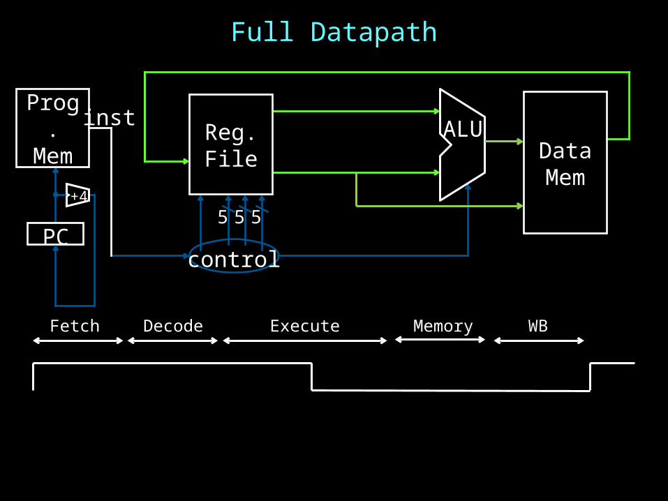
Full Datapath
5
ALU
5 5
control
Reg.File
PC
Prog.Mem
inst
+4
DataMem
Fetch Decode Execute Memory WB

IclickerHow many stages of a datapath are there in our single cycle MIPS design?
A) 1B) 2C) 3D) 4E) 5

Stages of datapath (1/5)
5
ALU
5 5
control
Reg.File
PC
Prog.Mem
inst
+4
DataMem
Fetch Decode Execute Memory WB
A Single cycle processor

Stages of datapath (2/5)
5
ALU
5 5
control
Reg.File
PC
Prog.Mem
inst
+4
DataMem
Fetch Decode Execute Memory WB
A Single cycle processor
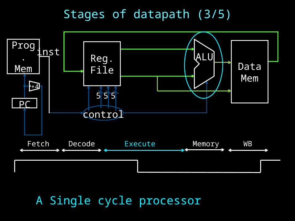
Stages of datapath (3/5)
5
ALU
5 5
control
Reg.File
PC
Prog.Mem
inst
+4
DataMem
Fetch Decode Execute Memory WB
A Single cycle processor

Stages of datapath (4/5)
5
ALU
5 5
control
Reg.File
PC
Prog.Mem
inst
+4
DataMem
Fetch Decode Execute Memory WB
A Single cycle processor

Stages of datapath (5/5)
5
ALU
5 5
control
Reg.File
PC
Prog.Mem
inst
+4
DataMem
Fetch Decode Execute Memory WB

Takeaway
The datapath for a MIPS processor has five stages:1. Instruction Fetch2. Instruction Decode3. Execution (ALU)4. Memory Access5. Register Writeback
This five stage datapath is used to execute all MIPS instructions

IclickerThere are how many types of instructions in the MIPS ISA?
A) 1B) 3C) 5D) 200E) 1000s

MIPS instructions
All MIPS instructions are 32 bits long, has 3 formats
R-type
I-type
J-type
op rs rt rd shamt
func
6 bits 5 bits 5 bits 5 bits 5 bits 6 bits
op rs rt immediate6 bits 5 bits 5 bits 16 bits
op immediate (target address)
6 bits 26 bits

MIPS Instruction Functions
Arithmetic/Logical• R-type: result and two source registers, shift amount• I-type: 16-bit immediate with sign/zero extension
Memory Access• load/store between registers and memory• word, half-word and byte operations
Control flow• conditional branches: pc-relative addresses• jumps: fixed offsets, register absolute

Arithmetic Instructions: Shift
op - rt rd shamt
func
6 bits 5 bits 5 bits 5 bits 5 bits 6 bits
op func mnemonic description0x0 0x0 SLL rd, rt, shamt R[rd] = R[rt] << shamt0x0 0x2 SRL rd, rt, shamt R[rd] = R[rt] >>> shamt (zero ext.)0x0 0x3 SRA rd, rt, shamt R[rd] = R[rt] >> shamt (sign ext.)
00000000000001000100000110000000
ex: r8 = r4 * 64 # SLL r8, r4, 6 r8 = r4 << 6
R-Type

Shift
5
ALU
5 5
Reg.File
PC
Prog.Mem
inst
+4
shamtcontrol
r4
shamt = 6
r8
sllsll

mnemonic description0x9 ADDIU rd, rs, imm R[rd] = R[rs] + sign_extend(imm)0xc ANDI rd, rs, imm R[rd] = R[rs] & zero_extend(imm)0xd ORI rd, rs, imm R[rd] = R[rs] | zero_extend(imm)
op mnemonic description0x8 ADDI rd, rs, imm R[rd] = R[rs] + imm0xc ANDI rd, rs, imm R[rd] = R[rs] & imm0xd ORI rd, rs, imm R[rd] = R[rs] | imm
Arithmetic Instructions: Immediates
op rs rd immediate6 bits 5 bits 5 bits 16 bits
00100000101001010000000000000101
I-Type
ex: r5 += -1
ex: r5 = r5 + 5 # ADDI r5, r5, 5 r5 += 5What if immediate is negative?

Immediates
5
imm
5 5
extend
+4
shamt
Reg.File
PC
Prog.Mem ALUinst
control
r5
r5
addiaddi

Immediates
5
imm
5 5
extend
+4
shamt
Reg.File
PC
Prog.Mem ALUinst
control
r5
r5
addiaddi

Arithmetic Instructions: Immediates
op mnemonic description0xF LUI rd, imm R[rd] = imm << 16
op - rd immediate6 bits 5 bits 5 bits 16 bits
00111100000001010000000000000101
I-Type
ex: LUI r5, 0xdead ORI r5, r5 0xbeef
What does r5 = ?r5 = 0xdeadbeef
ex: r5 = 0x50000 # LUI r5, 5

Immediates
5
imm
5 5
extend
+4
shamt
Reg.File
PC
Prog.Mem ALUinst
16control
r5
lui
lui
5

Goals for today
MIPS Datapath• Memory layout• Control Instructions
Performance• How fast can we make it?• CPI (Cycles Per Instruction) • MIPS (Instructions Per Cycle)• Clock Frequency
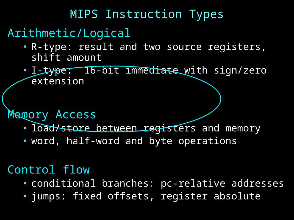
MIPS Instruction Types
Arithmetic/Logical• R-type: result and two source registers, shift amount• I-type: 16-bit immediate with sign/zero extension
Memory Access• load/store between registers and memory• word, half-word and byte operations
Control flow• conditional branches: pc-relative addresses• jumps: fixed offsets, register absolute
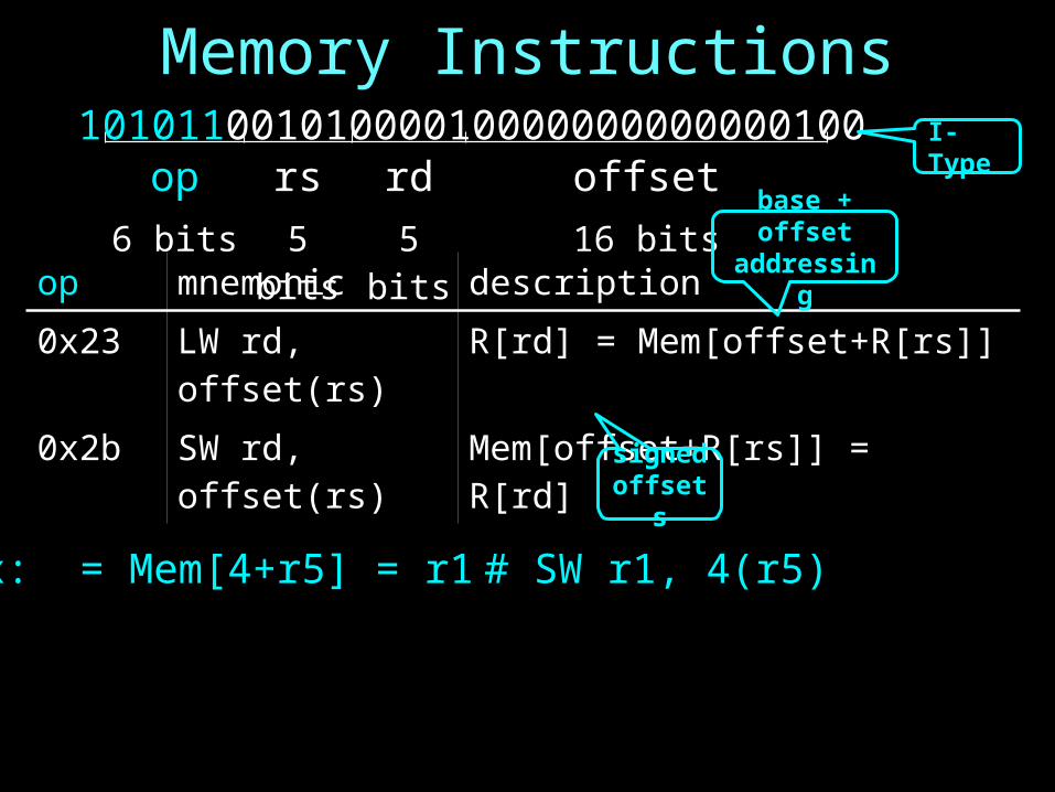
Memory Instructions
op mnemonic description0x23 LW rd, offset(rs) R[rd] = Mem[offset+R[rs]]0x2b SW rd, offset(rs) Mem[offset+R[rs]] = R[rd]
op rs rd offset6 bits 5 bits 5 bits 16 bits
10101100101000010000000000000100
base + offset addressing
I-Type
signedoffsets
ex: = Mem[4+r5] = r1 # SW r1, 4(r5)

Memory Operations
Data Mem
addr
ext
+4
5
imm
5 5
control
Reg.File
PC
Prog.Mem ALUinst
sw
r5+4
4
Write Enable
r5
r1
ex: = Mem[4+r5] = r1 # SW r1, 4(r5)

Memory Instructions
op mnemonic description0x20 LB rd, offset(rs) R[rd] = sign_ext(Mem[offset+R[rs]])0x24 LBU rd, offset(rs) R[rd] = zero_ext(Mem[offset+R[rs]])0x21 LH rd, offset(rs) R[rd] = sign_ext(Mem[offset+R[rs]])0x25 LHU rd, offset(rs) R[rd] = zero_ext(Mem[offset+R[rs]])0x23 LW rd, offset(rs) R[rd] = Mem[offset+R[rs]]0x28 SB rd, offset(rs) Mem[offset+R[rs]] = R[rd]0x29 SH rd, offset(rs) Mem[offset+R[rs]] = R[rd]0x2b SW rd, offset(rs) Mem[offset+R[rs]] = R[rd]
op rs rd offset6 bits 5 bits 5 bits 16 bits
10101100101000010000000000000100

EndiannessEndianness: Ordering of bytes within a memory word
1000 1001 1002 1003
0x12345678
Big Endian = most significant part first (MIPS, networks)
Little Endian = least significant part first (MIPS, x86)
as 4 bytes
as 2 halfwordsas 1 word
1000 1001 1002 1003
0x12345678
as 4 bytes
as 2 halfwordsas 1 word
0x78 0x56 0x34 0x120x5678 0x1234
0x12 0x34 0x56 0x780x1234 0x5678

Memory LayoutExamples (big/little endian):# r5 contains 5 (0x00000005)
SB r5, 2(r0)LB r6, 2(r0)# R[r6] = 0x05
SW r5, 8(r0)LB r7, 8(r0)LB r8, 11(r0)# R[r7] = 0x00# R[r8] = 0x05
0x00000000
0x00000001
0x00000002
0x00000003
0x00000004
0x00000005
0x00000006
0x00000007
0x00000008
0x00000009
0x0000000a
0x0000000b
...
0xffffffff
0x05
0x000x000x000x05

MIPS Instruction Types
Arithmetic/Logical• R-type: result and two source registers, shift amount• I-type: 16-bit immediate with sign/zero extension
Memory Access• load/store between registers and memory• word, half-word and byte operations
Control flow• conditional branches: pc-relative addresses• jumps: fixed offsets, register absolute

Control Flow: Absolute Jump
op immediate6 bits 26 bits
00001010100001001000011000000011
J-Type
ex: j 0x1000000 PC = ((PC+4) & 0xf0000000) | 0x04000000
op Mnemonic Description0x2 J target PC = (PC+4)31..28 target 00
(PC+4)31..28 target 004 bits 26 bits 2 bits
(PC+4)31..28 01000000000000000000000000 00

Absolute addressing for jumps• Jump from 0x30000000 to 0x20000000? NO Reverse? NO
– But: Jumps from 0x2FFFFFFF to 0x3xxxxxxx are possible, but not reverse• Trade-off: out-of-region jumps vs. 32-bit instruction encoding
MIPS Quirk:• jump targets computed using already incremented PC
Control Flow: Absolute Jump
op immediate6 bits 26 bits
00001010100001001000011000000011
J-Type
(PC+4)31..28 will be the same
op Mnemonic Description0x2 J target PC = (PC+4)31..28 target 00

Absolute Jump
tgt
+4
Data Mem
addr
ext
5 5 5
Reg.File
PC
Prog.Mem ALUinst
control
immJ
op Mnemonic Description0x2 J target PC = (PC+4)31..28 target 00

Control Flow: Jump Register
op rs - - - func6 bits 5 bits 5 bits 5 bits 5 bits 6 bits
00000000011000000000000000001000
op func mnemonic description0x0 0x08 JR rs PC = R[rs]
R-Type
ex: JR r3

Jump Register
+4
tgt
Data Mem
addr
ext
5 5 5
Reg.File
PC
Prog.Mem ALUinst
control
imm
op func mnemonic description0x0 0x08 JR rs PC = R[rs]
R[r3]
JR

Examples
E.g. Use Jump or Jump Register instruction tojump to 0xabcd1234
But, what about a jump based on a condition?# assume 0 <= r3 <= 1if (r3 == 0) jump to 0xdecafe00else jump to 0xabcd1234

Control Flow: Branches
op mnemonic description0x4 BEQ rs, rd, offset if R[rs] == R[rd] then PC = PC+4 + (offset<<2)0x5 BNE rs, rd, offset if R[rs] != R[rd] then PC = PC+4 + (offset<<2)
op rs rd offset6 bits 5 bits 5 bits 16 bits
00010000101000010000000000000011
signed offsets
I-Type
ex: BEQ r5, r1, 3If(R[r5]==R[r1]) then PC = PC+4 + 12 (i.e. 12 == 3<<2)

Control Flow: Branches
tgt
+4
Data Mem
addr
ext
5 5 5
Reg.File
PC
Prog.Mem ALUinst
control
imm
offset
+
Could have used ALU for branch add
=?
Could have used ALU for branch cmp
op mnemonic description0x4 BEQ rs, rd, offset if R[rs] == R[rd] then PC = PC+4 + (offset<<2)0x5 BNE rs, rd, offset if R[rs] != R[rd] then PC = PC+4 + (offset<<2)
R[r5]
BEQ
R[r1]

Control Flow: More Branches
op rs subop
offset
6 bits 5 bits 5 bits 16 bits
00000100101000010000000000000010
signed offsets
almost I-Type
op subop
mnemonic description
0x1 0x0 BLTZ rs, offset if R[rs] < 0 then PC = PC+4+ (offset<<2)0x1 0x1 BGEZ rs, offset if R[rs] ≥ 0 then PC = PC+4+ (offset<<2)0x6 0x0 BLEZ rs, offset if R[rs] ≤ 0 then PC = PC+4+ (offset<<2)0x7 0x0 BGTZ rs, offset if R[rs] > 0 then PC = PC+4+ (offset<<2)
Conditional Jumps (cont.)
ex: BGEZ r5, 2If(R[r5] ≥ 0) then PC = PC+4 + 8 (i.e. 8 == 2<<2)

op subop mnemonic description
0x1 0x0 BLTZ rs, offset if R[rs] < 0 then PC = PC+4+ (offset<<2)
0x1 0x1 BGEZ rs, offset if R[rs] ≥ 0 then PC = PC+4+ (offset<<2)
0x6 0x0 BLEZ rs, offset if R[rs] ≤ 0 then PC = PC+4+ (offset<<2)
0x7 0x0 BGTZ rs, offset if R[rs] > 0 then PC = PC+4+ (offset<<2)
Control Flow: More Branches
tgt
+4
Data Mem
addr
ext
5 5 5
Reg.File
PC
Prog.Mem ALUinst
control
imm
offset
+
Could have used ALU for branch cmp
=?
cmp
R[r5]
BEQZ

Control Flow: Jump and Link
op mnemonic description0x3 JAL target r31 = PC+8 (+8 due to branch delay slot)
PC = (PC+4)31..28 target 00
op immediate6 bits 26 bits
00001100000001001000011000000010
J-Type
Why? Function/procedure calls
op mnemonic description0x2 J target PC = (PC+4)31..28 target 00
Discuss later
ex: JAL 0x1000000 r31 = PC+8
PC = (PC+4)31..28 0x4000000

Jump and Link
tgt
+4
Data Mem
addr
ext
5 5 5
Reg.File
PC
Prog.Mem ALUinst
control
imm
offset
+
=?
cmp
Could have used ALU for
link add
+4
op mnemonic description0x3 JAL target r31 = PC+8 (+8 due to branch delay slot)
PC = (PC+4)31..28 || (target << 2)
R[r31]PC+8

Goals for today
MIPS Datapath• Memory layout• Control Instructions
Performance• How to get it?• CPI (Cycles Per Instruction) • MIPS (Instructions Per Cycle)• Clock Frequency
Pipelining• Latency vs throughput

Questions
How do we measure performance?What is the performance of a single cycle CPU?
How do I get performance?
See: P&H 1.4

What instruction has the longest path
A) LWB) SWC) ADD/SUB/AND/OR/etcD) BEQE) J

Memory Operations
Data Mem
addr
ext
+4
5
imm
5 5
control
Reg.File
PC
Prog.Mem ALUinst
lw
r5+4
4
Write Enable
r5
ex: = r1 = Mem[4+r5] # LW r1, 4(r5)
Mem[4+r5]
Mem[4+r5]
r1

PerformanceHow do I get it?
ParallelismPipeliningBoth!

Performance: Aside
Speed of a circuit is affected by the number of gates in series (on the critical path or the deepest level of logic)
combinatorialLogic
tcombinatorial
inpu
tsar
rive
outp
uts
expe
cted

4-bit Ripple Carry AdderA3 B3
S3
C4
A1 B1
S1
A2 B2
S2
A0 B0
C0
S0
C1C2C3
• First full adder, 2 gate delay• Second full adder, 2 gate delay• …
Carry ripples from lsb to msb

AddingMain ALU, slows us downDoes it need to be this slow?
Observations• Have to wait for Cin• Can we compute in parallel in some way?• CLA carry look-ahead adder

Carry Look Ahead Logic
Can we reason independent of Cin?• Just based on (A,B) only
When is Cout == 1, irrespective of Cin
If Cin == 1, when is Cout also == 1

1-bit Adder with CarryA B
S
CinCout
A B Cin Cout S
0 0 0 0 0
0 1 0 0 1
1 0 0 0 1
1 1 0 1 0
0 0 1 0 1
0 1 1 1 0
1 0 1 1 0
1 1 1 1 1
Full Adder• Adds three 1-bit numbers• Computes 1-bit result and
1-bit carry• Can be cascaded
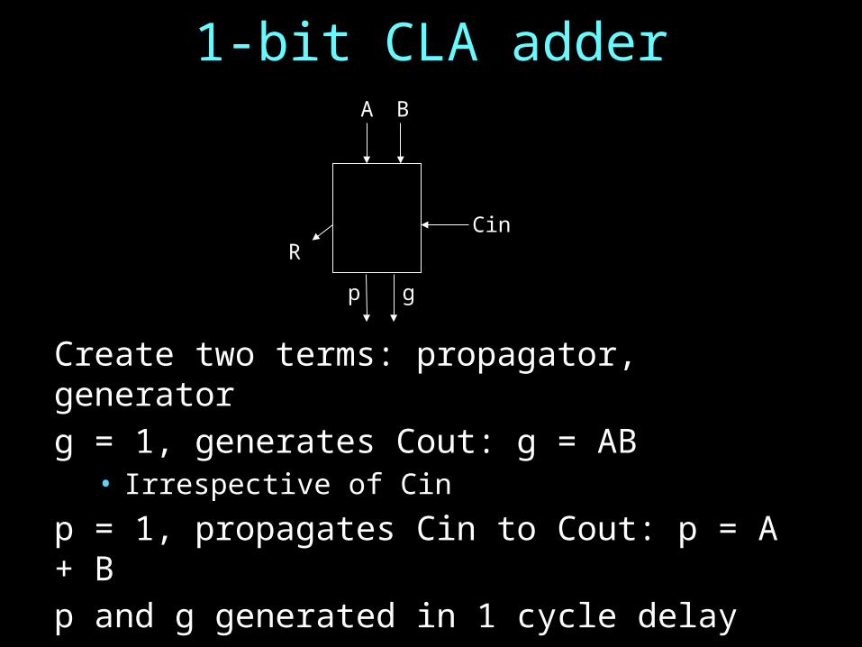
1-bit CLA adderA B
CinR
p g
Create two terms: propagator, generatorg = 1, generates Cout: g = AB
• Irrespective of Cin
p = 1, propagates Cin to Cout: p = A + Bp and g generated in 1 cycle delayR is 2 cycle delay after we get Cin

1-bit Adder with CarryA B
S
CinCout
A B Cin Cout S
0 0 0 0 0
0 1 0 0 1
1 0 0 0 1
1 1 0 1 0
0 0 1 0 1
0 1 1 1 0
1 0 1 1 0
1 1 1 1 1
Full Adder• Adds three 1-bit numbers• Computes 1-bit result and
1-bit carry• Can be cascaded

4-bit CLAA B
C0
p g
A B
p g
A B
p g
A B
p g
CLA (carry look-ahead logic)
• CLA takes p,g from all 4 bits, C0 and generates all Cs: 2 gate delay
C1C2C3
C4
S
Ci = Function (C0, p and g values)

4-bit CLA
A0 B0
C0
A1 B1A2 B2A3 B3
CLA (carry look-ahead logic)
p0 g0p1 g1p2 g2p3 g3
• Given A,B’s, all p,g’s are generated in 1 gate delay in parallel
C1C2C3
• Given all p,g’s, all C’s are generated in 2 gate delay in parallel
S3 S2 S1 S0
• Given all C’s, all S’s are generated in 2 gate delay in parallel
Sequential operation is made into parallel operation!!

PerformanceRipple carry adder vs carry lookahead adder for 8 bits
• 2 x 8 vs. 5

PerformanceHow do I get it?
ParallelismPipeliningBoth!