cs3235 - semester ii, 2016-2017 computer securityhugh/cs3235/previous...android apk binary can be...
TRANSCRIPT

NATIONAL UNIVERSITY OF SINGAPORE
SCHOOL OF COMPUTING
CS3235 - Semester II,2016-2017
Computer Security
The Projects for CS3235(Computer Security)Singapore, April 2017.

ii

Table of Contents
Attacking Blink Home Security Camera System.. . . . . . . . . . . . . . . . . . . . . . . . . . . . .1Andhieka Putra, Lai Hoang Dung,Le Ba Hieu Giang and Tan Yi Yan (Gp 1)
Exploitation of MIFARE Classic. . . . . . . . . . . . . . . . . . . . . . . . . . . . . . . . . . . . . . . . . . . . . 7Chung Wee Jing, Apoorva Ullas,Pay Hao Jie and Gan Yang Chuen Samson (Gp 2)
Protocol Downgrade Attacks on HTTPS.. . . . . . . . . . . . . . . . . . . . . . . . . . . . . . . . . . .17Ng Aik Sheng, Chan Jian Hui, Eldric Lim and Derek Kok (Gp 4)
Fingerprint Authentication and its vulnerabilities. . . . . . . . . . . . . . . . . . . . . . . . . . . 23Cao Shuai Benjamin, Shirlene Quah Jiamin,Sharon Mariam Mathew and Vani Gupta (Gp 5)
Exploiting the Security Lapses in the NUS Matriculation Card.. . . . . . . . . . . . .29Cheong Jack Kuan, Anna He, Lim Zeming and Lim Zeming (Gp 6)
A Brief Introduction To The Mathematics Of ECC. . . . . . . . . . . . . . . . . . . . . . . . . 37Cao Wei, Moon Byunghun and Ang Yoong Zhen (Gp 7)
Keystroke Dynamics Analysis. . . . . . . . . . . . . . . . . . . . . . . . . . . . . . . . . . . . . . . . . . . . . . 43Goh Jing Loon, Bernard Yi,Ng Qing Hua and Yee Jian Feng Eric (Gp 8)
Protection and Authentication for Web Application. . . . . . . . . . . . . . . . . . . . . . . . .45Ng Wei Kiang, Huang Baoyi and Lim Shu Na (Gp 9)
Analysis of Bluetooth Low Energy Sniffing Technologies. . . . . . . . . . . . . . . . . . . . 51Ang Ray Yan, Chan Lup Seng,Lee Han Cheng and Yuan Yu Chuan (Gp 10)
MIFARE 1K attacks and prevention. . . . . . . . . . . . . . . . . . . . . . . . . . . . . . . . . . . . . . . . 55Chew Zhi Jiang, Simon Lindblad,Yang Boxin and Fiona Chang Wenxin (Gp 11)
iii

ATTACKING BLINK HOME SECURITY CAMERA SYSTEM
Andhieka Putra National University of Singapore
Lai Hoang Dung National University of Singapore
Tan Yi Yan
National University of Singapore [email protected]
Le Ba Hieu Giang National University of Singapore
ABSTRACT Blink Home Security Camera System is a modular home surveillance system that uses motion sensing to capture videos and photos automatically. The most basic setup includes a Camera Module and a Sync Module. Users can download the Blink Mobile App to configure the Sync Module, which then is able to “arm” and issues commands to the Camera Module. Videos and photos captured can then be accessed from the cloud. The greatest selling point of the Blink system is that it can be kept running for two years without replacing the batteries. For our project, we are investigating whether it is possible to gain unauthorized access into the Blink system, collect information about the user, and possibly gain access to the saved videos and photos.
Categories and Subject Descriptors K.6.5 [Security and Protection ]: Unauthorized access – hacking and vulnerabilities.
General Terms Experimentation, Security.
Keywords Internet of Things, Vulnerabilities, Reverse Engineering.
1. INTRODUCTION Blink is a wireless video home security camera system. The primary use case of the system is to capture videos and photos automatically when it senses motion or upon receiving commands from the owner.
In order to use the system, the user must have a Blink account, a Blink Sync Module, at least one Blink Camera Module and the Blink Application installed on his mobile phone. The setup of the home security system is fairly simple. Firstly, the user needs to link up the Sync Module to his Blink account via the Blink mobile application. Secondly, the Sync Module has to be given Internet access. The user can configure settings to allow the Sync Module to have access to his home’s wifi. Lastly, the user can connect up to ten motion-activated Camera Modules to the Sync Module.
Once the setup is completed, the Blink Camera System is “armed”. When the Camera Module detects motion, it will automatically record a short video clip for up to 60 seconds [4]. The recorded video will then be uploaded to Blink Cloud Server. The user will then receive a push notification alert with a link to the video attached and can view the recorded video on the Blink Application.
In addition, the user can also perform the following actions when logged in to the Blink Application:
1. Access Blink cloud to view and delete all the past photos and videos.
2. Issue commands to arm or disarm the Blink system so that the Camera Modules start or stop capturing photos and videos respectively.
3. Schedule timings to arm or disarm the Blink system
In this project, we will be evaluating the security of the Blink system. Specifically, we will be investigating the possibility of gaining unauthorized access to the Blink system, collecting user information, and obtaining the videos and photos stored on the Blink cloud.
2. METHODOLOGY 2.1 Black-box Investigation 2.1.1 Inspecting network packets with WireShark & BurpSuite
Since Blink is an IoT system where different components interact with each other through the cloud, we believed that there would be some traces left behind by the network communication. We used Wireshark to monitor the network traffic when the camera system is active, as well as used BurpSuite to inspect possible network requests that were called when commands are sent to the Sync Module, or when photos/videos are uploaded to the cloud.
Through inspecting the network traffic with WireShark and BurpSuite, we were able to gain some interesting insight into the Blink system, in particular its communication model (further elaborated in section 3.1) and a list of APIs used to communicate with Blink cloud service (further elaborated in section 3.3).
2.1.2 Monitoring the radio signals
Since the Camera Module & the Sync Module communicate with each other through radio signals [6], we used Gqrx together with a RTL-SDR dongle (RTL2832U) to monitor the radio traffic.
2.2 White-box Investigation 2.2.1 Camera Module
One of our early hypothesis about the Camera Module is that it is using Si4455 radios to communicate with the Sync Module. To validate this hypothesis, we decided to take apart the Camera Module to determine what are the individual chips / components used in the camera. The findings of our investigation are documented in section 3.2 of this paper.
1
1

2.2.2 Blink Android Application
The Blink Application is a critical link in the Blink system as user uses it to send commands to the Sync Module, as well as to retrieve videos/photos from the cloud. We decided to decompile the Android version of the Blink Application, since a copy of the Android apk binary can be easily obtained from online apk library. There are a lot of free options available to decompile an apk file. In our cases, we used Android Apk Decompiler [2] to do it. The decompiled Android project provided us with a lot of information about the APIs used by the Blink system (further elaborated in section 3.3).
2.2.3 Sync Module
The Sync Module is accessible through a Telnet port. We also telnet into it to investigate the data held inside.
3. RESULTS & FINDINGS 3.1 Communication Model
Figure 1. Interactions between components in Blink Security System.
A typical sequence of communication would start off with the Blink Application sending commands to the cloud server via a HTTPS API endpoint. We ran Burpsuite on a Linux computer on the same network as the smartphone, and set the phone to proxy through the Linux computer. We also performed SSL Stripping by installing BurpSuite’s CA certificate on the phone’s OS. This behavior was confirmed once again when we decompiled the Android Application and studied the source code. The authentication used is token-based. Since the token can be obtained from the Sync Module, we could craft and send a valid request to Blink cloud server via Postman.
Next, the cloud would send commands to the Sync Module to perform the recording. Between the Sync Module and the cloud server, a TLS encrypted communication channel is established.
After receiving the command, the Sync Module would send a radio signal (with frequency between 915-922 MHz) to the Camera Modules to initiate the recording. The frequency was gathered by using RTL-SDR dongle and Gqrx software. The camera will start recording after receiving this signal.
Contrary to our original hypothesis, there is direct communication between the Camera Module and the cloud server. The camera sends encrypted TLS packets to the Cloud (via wifi) whenever it is uploading photo or video. Camera immediately disconnects after upload is finished.
For live streaming, the camera sends streaming data directly to the cloud server, using RTSPS protocol (RTSP is a common streaming protocol [3]. RTSPS simply means that the RTSP stream is protected with SSL encryption).
There is also a periodic heartbeat signal (via radio) between the Sync Module and the cameras.
3.2 Components in Camera Module In order to better understand the internal structure of the Camera Module, we took it apart to examine its components. The camera consists of two boards linked by pins. The following figures and tables documents our findings:
Figure 2. Top board of camera module Table 1. Components of top board of camera module
Label Chip Marking Type/Function
A ISI-108A 163739
Video Processor (Video encoder)
B MSP430 G2533 TI 668A A3XV 64
Processor
C 455A BH20 630
Si4455 Radio
D GH12E J1GJH5
Regulator
E WINBOND 25Q809_NIG 1642
Flash memory
Figure 3. Bottom board of camera module
2
2
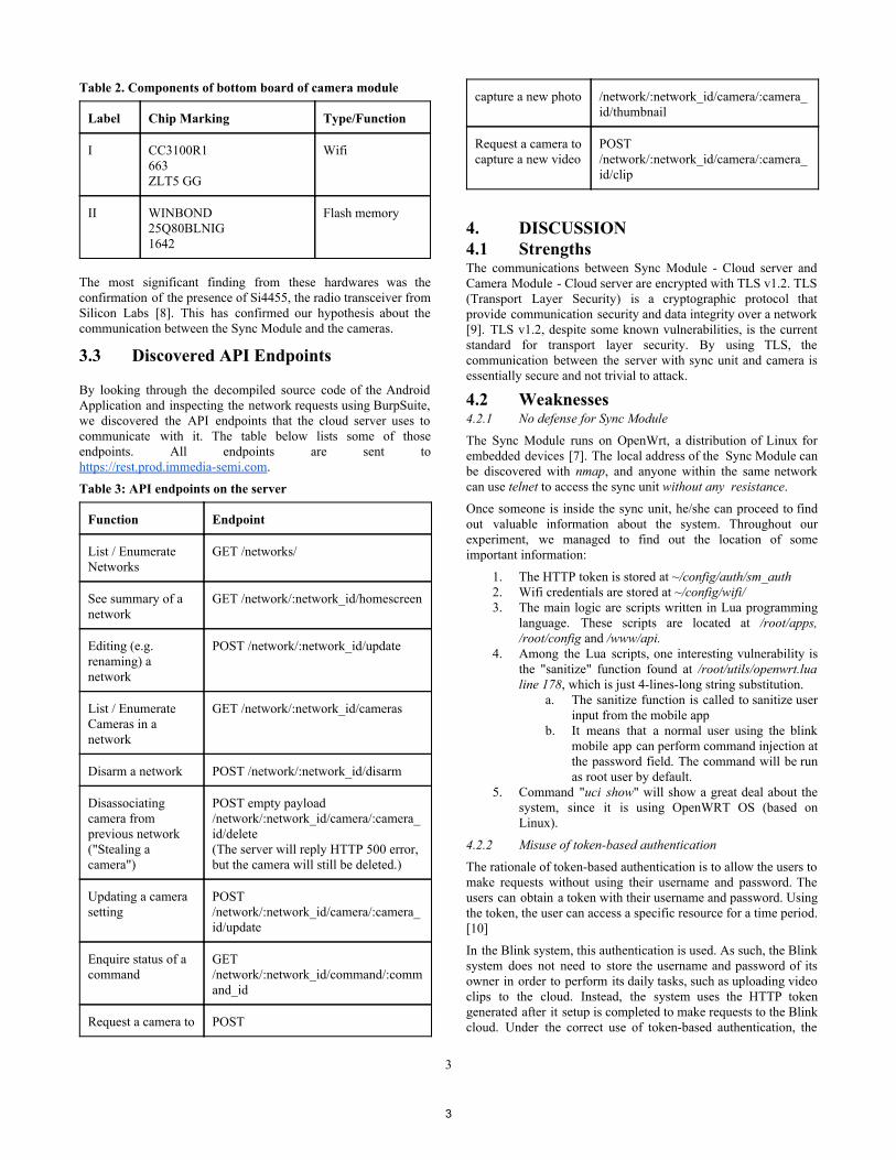
Table 2. Components of bottom board of camera module
Label Chip Marking Type/Function
I CC3100R1 663 ZLT5 GG
Wifi
II WINBOND 25Q80BLNIG 1642
Flash memory
The most significant finding from these hardwares was the confirmation of the presence of Si4455, the radio transceiver from Silicon Labs [8]. This has confirmed our hypothesis about the communication between the Sync Module and the cameras.
3.3 Discovered API Endpoints By looking through the decompiled source code of the Android Application and inspecting the network requests using BurpSuite, we discovered the API endpoints that the cloud server uses to communicate with it. The table below lists some of those endpoints. All endpoints are sent to https://rest.prod.immedia-semi.com .
Table 3: API endpoints on the server
Function Endpoint
List / Enumerate Networks
GET /networks/
See summary of a network
GET /network/:network_id/homescreen
Editing (e.g. renaming) a network
POST /network/:network_id/update
List / Enumerate Cameras in a network
GET /network/:network_id/cameras
Disarm a network POST /network/:network_id/disarm
Disassociating camera from previous network ("Stealing a camera")
POST empty payload /network/:network_id/camera/:camera_id/delete (The server will reply HTTP 500 error, but the camera will still be deleted.)
Updating a camera setting
POST /network/:network_id/camera/:camera_id/update
Enquire status of a command
GET /network/:network_id/command/:command_id
Request a camera to POST
capture a new photo /network/:network_id/camera/:camera_id/thumbnail
Request a camera to capture a new video
POST /network/:network_id/camera/:camera_id/clip
4. DISCUSSION 4.1 Strengths The communications between Sync Module - Cloud server and Camera Module - Cloud server are encrypted with TLS v1.2. TLS (Transport Layer Security) is a cryptographic protocol that provide communication security and data integrity over a network [9]. TLS v1.2, despite some known vulnerabilities, is the current standard for transport layer security. By using TLS, the communication between the server with sync unit and camera is essentially secure and not trivial to attack.
4.2 Weaknesses 4.2.1 No defense for Sync Module
The Sync Module runs on OpenWrt, a distribution of Linux for embedded devices [7]. The local address of the Sync Module can be discovered with nmap, and anyone within the same network can use telnet to access the sync unit without any resistance. Once someone is inside the sync unit, he/she can proceed to find out valuable information about the system. Throughout our experiment, we managed to find out the location of some important information:
1. The HTTP token is stored at ~/config/auth/sm_auth 2. Wifi credentials are stored at ~/config/wifi/ 3. The main logic are scripts written in Lua programming
language. These scripts are located at /root/apps, /root/config and /www/api.
4. Among the Lua scripts, one interesting vulnerability is the "sanitize" function found at /root/utils/openwrt.lua line 178 , which is just 4-lines-long string substitution.
a. The sanitize function is called to sanitize user input from the mobile app
b. It means that a normal user using the blink mobile app can perform command injection at the password field. The command will be run as root user by default.
5. Command "uci show " will show a great deal about the system, since it is using OpenWRT OS (based on Linux).
4.2.2 Misuse of token-based authentication
The rationale of token-based authentication is to allow the users to make requests without using their username and password. The users can obtain a token with their username and password. Using the token, the user can access a specific resource for a time period. [10]
In the Blink system, this authentication is used. As such, the Blink system does not need to store the username and password of its owner in order to perform its daily tasks, such as uploading video clips to the cloud. Instead, the system uses the HTTP token generated after it setup is completed to make requests to the Blink cloud. Under the correct use of token-based authentication, the
3
3

system might have been more secure. Since with this authentication method, an attacker will not be find the username and password of the user directly from the system.
However, the developers of Blink seems to have misused the token-based authentication. Under normal circumstances, an access token should have a time-to-live so that an attacker can perform malicious actions using a stolen token for only a limited period of time [3]. However, in the Blink system, the HTTP token that can be used to access the Blink API Endpoints does not seem expire. Based on our experiments, the time-to-live for the token is at least three months. The token that we used since the start of the project has not expired. As a result, an attacker is able to abuse a stolen token indefinitely.
4.2.3 No Code Obfuscation for Android Application
Something we found out about the Android Application was that the codes are still very readable after decompilation of its apk. All the class names and variable names are still attached. An example of a decompiled Java class file is provided below
Figure 4. Decompiled codes for AddCameraRequest
Just by glancing at the class name, you are able to tell it represents a request to Blink cloud server to add a new camera. In fact, by simply searching for the keyword “Request” in the decompiled code base, we are able to obtain all the supported APIs.
What is so surprising about this is that the developer of the Blink app could have easily obfuscated the code base by simply turning on ProGuard during the app compilation. ProGuard ships with most Android development environment by default, and is the tool of choice to obfuscate Android project codes [2].
5. PROOF OF CONCEPT FOR ATTACKING BLINK Using the gained insight, we built a proof-of-concept web application, named Blink Hack Auto, to demonstrate how we can perform an attack on the Blink system.
A requirement for Blink Hack Auto to work is that it should be
placed inside the same wifi network as the Sync Module..
Blink Hack Auto can perform the following capabilities:
● Arm/Disarm a Blink camera ● Request Blink to capture a new photo and view it ● Request Blink to capture a new video and view it ● View all previous videos/photos saved on the cloud
How Blink Hack Auto works is that it will run a script to telnet into the Sync unit to obtain the saved token. Subsequently the web application can use the token with the various APIs discussed in section 3.3 to perform the capabilities.
6. PROPOSED DEFENCE MEASURES Based on the weaknesses in the security of the Blink system, we have devised some measures to mitigate the weaknesses discussed in section 5.
Firstly, remote access to the Sync Module should be limited. The developers of Blink could have disabled the telnet service. As such, we would not have been able to conduct white-box investigation of the Sync Module and obtain the HTTP token used by the Blink system to access resources on the Blink cloud. Similarly, the other services that allow remote access should be closed.
Secondly, the HTTP Token used by the Blink system should have have a time-to-live so that in the case when a token is stolen by an attacker, he can only perform malicious actions up to the time when the token expires.
Lastly, the developers of Blink could have obfuscated the code of their Android Application so that it cannot be reverse engineered (or at least takes a lot more time to be reverse engineered) and the Blink API Endpoints would not have been so easily discovered. Some tools that can used for code obfuscation includes ProGuard and DexGuard.
7. FUTURE WORK Although we managed to confirm the existence and the nature of the communication via radio signal between the Sync Module and the cameras, we could not reverse engineer these signals due to time and resource constraints. However, this particular area can be further explored in the future with more focused attention and hardware.
8. CONCLUSION This paper has examined the different security aspects of the Blink Camera System, and found that security of the Sync Module is insufficient. The security of the entire system is only as strong as its weakest link. In this case, the fact that the telnet port of the Sync Module is so poorly protected allows a potential attacker to obtain an authorization token to open the door to all different kinds of capabilities provided by the Blink APIs. Although the attack may seem trivial, the consequence is significant because the attacker can effectively gain possession of the Blink cameras, arm/disarm it to his liking and use the owner’s camera to spy on the owner himself. The final parts of the paper discussed some defence measures that can be implemented to improve the overall security of the Blink system, as well as other exploratory work that can be done in the future to investigate further into the radio protocol used by the Blink camera.
4
4
9. ACKNOWLEDGMENTS Our thanks to Associate Professor Hugh Anderson for providing us the hardware and for his timely guidance.
10. REFERENCES [1] A. Rao, H. Schulzrinne & R. Lanphier (1998, April). Real
Time Streaming Protocol (RTSP). Retrieved from https://www.ietf.org/rfc/rfc2326.txt .
[2] Android Apk Decompiler. Retrieved from www.javadecompilers.com/apk.
[3] E. Hammer (2012, August). Stack Overflow. Retrieved from http://stackoverflow.com/questions/7030694/why-do-access-tokens-expire .
[4] Immedia, Inc. Blink FAQ. Retrieved from https://blinkforhome.com/pages/faq .
[5] M.Serafin (2016, February). Reverse Engineering Android. Retrieved from http://blog.scalac.io/2016/02/11/android-reverse-engineering.html .
[6] M.Wollerton (2016, January). Immedia Blink review: Too few features stymie this security camera. Retrieved from https://www.cnet.com/products/immedia-blink-wire-free-hd-home-monitoring-alert-system/
[7] OpenWrt. Retrieved from https://openwrt.org/.
[8] Silicon Laboratories Inc (2013, October). Easy-to-use, low-current OOK/(G)FSK sub-GHz transceiver.
[9] T. Dierks & E. Rescorla (2008, August). The Transport Layer Security (TLS) Protocol, Version 1.2.
[10] W3C (2001). Token Based Authentication -- Implementation Demonstration. Retrieved from https://www.w3.org/2001/sw/Europe/events/foaf-galway/papers/fp/token_based_authentication.
[11] Z. Durumeric et. al (2017, February). The Security Impact of HTTPS Interception.
5
5

6
Exploitation of MIFARE Classic
Chung Wee Jing School of Computing,
NUS A0125492E
Apoorva Ullas School of Computing,
NUS A0141138N
Gan Yang Chuen Samson
School of Computing, NUS
A0112643R [email protected]
Pay Hao Jie School of Computing,
NUS A0125552L
ABSTRACT Near Field Communication (NFC) is growing in popularity over
the years. NFC-equipped smart devices are capable of exchanging
information with each other simply with a tap or a wave. It is
currently used for making contactless payments, opening car
doors and its potential is unlimited. As we explore the possible
applications of NFC, it is important to consider how secure
transactions using NFC really are. In this paper, we explore the
possibility of sniffing and modifying data stored in a MIFARE
Classic 1K exploit card using a NFC reader.
Keywords
Near Field Communication (NFC), MIFARE Classic
1. INTRODUCTION
1.1 NFC and RFID Radio Frequency Identification (RFID) refers to the unique
identification of objects using radio waves. RFID is an
improvement of bar codes as it allows manufacturers to identify
large quantities of inventory simultaneously, and store more
information about the product. RFID systems comprise of 2 parts,
a reader and a tag. The RFID reader is a network connected
device with an antenna, which transmits data, power and
commands to the tags. The reader can be fixed or mobile. The
reader antenna converts the information in the form of electrical
current into electromagnetic waves, which is received by the tag
antenna and converted back to electrical current, storing the
information digitally in a format which can be processed by computers. There are three different types of RFID Systems based
on the frequency band within which they can operate, with
different advantages and disadvantages associated with each
frequency band.
1. Low Frequency (LF) RFID: 30 KHz to 300 KHz. Lower
frequencies have a shorter read range of about 10 cm and
slower data read rate but are less sensitive to radio wave
interference. Applications include tracking livestock and
farm animals.
2. High Frequency (HF) RFID: 3 to 30 MHz. Applications
include data transfer, contactless payments and ticketing.
3. Ultra-High Frequency (UHF) RFID: 300 MHz to 3 GHz.
Higher frequencies have a larger read range of up to 12m and
faster data transfer rate but are very sensitive to interference.
However, many UHF product manufacturers have designed their
UHF products in ways to maintain high performance standards
even in environments with a lot of interference. Applications
include retail inventory management, pharmaceutical anti-
counterfeiting and wireless device configurations.
RFID Systems can also be broadly categorised into two types: (1)
Passive and (2) Active. In active RFID systems, tags have their
own power source which is used to broadcast signals to transmit
information stored in their microchips. Active RFID systems offer
a large coverage range of up to 100m, and is used in assets which
require tracking over long distances such as trucks. However, in
passive RFID systems, tags do not require a power source as they
use the signal transmitted by the reader to power on and reflect
energy back to the reader. Passive RFID systems offer a read
range for close contacts for up to 25m, and is used to monitor
asset movement within warehouses and distribution centers. Thus,
active RFID systems operate in the UHF band while passive RFID
systems operate in the LF, HF and UHF bands.
NFC is a specialized branch of the HF RFID. NFC is based on
RFID protocols, particularly protocols for the use of RFID in
proximity cards. NFC devices operate at the same frequency as
the HF RFID system, at 13.56MHz. Hence, they can only operate
at a short range of up to 10 cm. NFC devices use electromagnetic
induction between 2 loop antennas to exchange information.
There are 3 different modes NFC-enabled devices supports:
1. Card emulation: allows NFC-enabled devices to act like a
smart card to perform any card-related tasks such as
ticketing, access control, identification and loyalty cards.
2. Reader/Writer: allows NFC-enabled devices to interact with
NFC tags embedded in smart posters and labels. Devices can
read or write information to these smart information sources
with NFC tags embedded in them.
3. Peer-to-peer communication (P2P): Creates a connectivity
between 2 NFC devices for exchange of information.
Similar to RFID, NFC offers contactless transfer of information
using radio signals and features a read or write operation mode.
7

However, while RFID only offers one-directional communication
between its reader and tag, NFC goes beyond RFID as it offers
peer-to-peer (P2P) two-way communication between NFC-
enabled devices. NFC’s P2P mode allows NFC devices to act as
both a reader and a tag, allowing NFC devices in close physical
proximity to exchange information and files simply with a touch.
NFC increases the convenience and frequency of information
transfer, which explains its pervasiveness and rapid growth in
many industries. It is used in the healthcare industry in the form of
a contactless NFC tag to store all the patient’s information in one
place such as the patient’s identification, insurance coverage, and
payment information, in the shipment of temperature-sensitive
shipping of specialized equipment and to track symptoms
associated with sleeping disorder to provide suggestions on better
sleep habits the next day. However, the largest market of NFC is
in the contactless payment market. With popular apps such as
Google Wallet, Samsung Pay and Apple Pay on the rise, the
global value of contactless payment market is estimated to
approach $100 billion by 2018, according to the research entitled
Contactless Payment: NFC Handsets, Wearables & Payment
Cards 2016 - 2020 by Juniper Research.
1.2 Motivations Due to the increasing use of NFC to exchange sensitive
information, it is pertinent to ensure NFC is secure. After
researching on the topic, we found several security issues on
NFC:
1. Eavesdropping: Although the range for NFC is a few
centimetres, an attacker can still retrieve usable signals up to
a few meters away. The attacker only needs to intercept a
certain percentage of the conversation and can use large and
sophisticated antennas to catch stronger signals.
2. Data corruption: The attacker may disturb the
communication between 2 NFC devices by sending valid
data or blocking the channel to corrupt the legitimate data
being exchanged. This is a form of Denial of Service (DoS)
attack.
3. Data modification: The attacker manipulates the data being
received by the reader device by changing pulses between
signals into signals.
4. Man-in-the-middle: The attacker acts as a relay, receiving the
data and modifying it without the 2 NFC devices detecting
the presence of the interceptor. However, as NFC devices are
able to detect collisions, a man-in-the-middle attack is not
possible at the collision layer.
5. Card cloning and skimming: The skimmer is an electronic
device hidden from view. When it comes into contact with the card, it intercepts the card data, attempting to collect its
information.
6. Ghost and leech attack: Two attackers are co-ordinated to
carry out this attack. The ghost places their attack equipment
near the victim’s reader, and the leech places their attack
equipment near the victim’s card. By relaying all
communications between the reader and victim’s card, the
ghost can gain access while impersonating the victim.
Given the vast number of possible attacks, we explore a possible
attack vector on an NFC card, namely the MIFARE Classic 1K
exploit card.
2. MIFARE CLASSIC 1K
2.1 Overview MIFARE Classic 1K is a contactless smart card developed by
NXP for the use in applications like public transportation and
cashless payment. An anti-collision function allows multiple cards
to operate in the same field simultaneously. Its memory access
conditions allow administrators to freely program MIFARE
Classic 1K to suit the business needs of their organizations. In
addition, the compatibility of card and reader across all
generations has reduced the infrastructure costs needed to
implement it.
2.2 MIFARE Classic 1K Chip Design
Figure 1. Block diagram of Chip Design [1]
MIFARE Classic 1K uses an MF1S70yyX/V1 chip that consists
of a 1K EEPROM, RF interface and Digital Control Unit. Energy
and data are transferred via an antenna consisting of a coil with a
small number of turns which is directly connected to the chip. The
followings are the description of the functionality of the major
components in the chip:
RF Interface: Consists of Modulator / Demodulator,
Clock Input Filter, Reset Regenerator, Power-On-Reset
and Voltage Regulator.
Logic Unit: Stores value in a special redundant format
and can be incremented and decremented.
CRYPTO-1: Used for authentication and encryption of
data exchange.
EEPROM: Memory Organisation
2.3 Communication Principle
2.3.1 Communication flow between reader and card
8

Figure 2. Communication flow diagram [1]
Step 1: Commands are initiated by the reader and controlled by
its Digital Control Unit.
Step 2: After Power-On-Reset (POR), the card answers to a
request.
Step 3: In the anti-collision loop, the unique identifier of a card is
read in order to distinguish between multiple cards. It allows the
reader to operate more than one card in the field simultaneously.
Step 4: With the select card command, the reader selects one
individual card for authentication and memory related operations.
The card return the Select Acknowledge (SAK) code, which
determines the type of the selected card.
Step 5: After selecting a card, the reader specifies the location of
memory it wants to access and uses a corresponding key for three
pass authentication procedure.
Step 6: The response of the card will depend on the state and the
access conditions for the corresponding sector that the reader is
trying to access. All commands and responses are encrypted after
a successful authentication.
2.3.2 Three-Pass Authentication
Figure 3. Communication between reader & card [2]
Step 1: A card sends it Unique Identifier (UID) to the reader for
authentication.
Step 2: The reader specifies the sector to be accessed and chooses
key A or B for subsequent encryption of messages.
Step 3: The card reads the secret key and the access conditions
from the selected sector. The card will send a number nT as the
challenge to the reader when the secret key and access conditions
have met its requirement.
Step 4: The reader calculates the response ks1 using the secret
key and additional input.
ks1 = cipher(key, UID, nT)
The reader will randomly generate a challenge nR and transmit a
reply rReader to the card together with the response.
ks2 = cipher(nR)
rReader = nR ⊕ ks1, suc(nT) ⊕ ks2
Step 5: The card verifies the response of the reader by comparing
it with its own challenge.
(nR ⊕ ks1) ⊕ ks1 = nR
(suc(nT) ⊕ ks2) ⊕ (cipher(nR)) = suc(nT)*
*suc() denotes the successor function associated with the 16-bit
LFSR used for generating nT, which maps 32 successive LFSR
sequence bits into the next non-overlapping 32 successive LFSR
sequence bits.
9

When the response of the reader is authenticated, the card will
calculate a response rCard to the challenge sent by the reader and
transmits it.
ks3 = cipher(nR)
rCard = suc(nT) ⊕ ks3
Step 6: The reader verifies the response of the card by comparing
it to its own challenge.
(suc(nT) ⊕ ks3) ⊕ suc(nT) = ks3
decrypt(ks3) = nR
After verifying that the response of the card is equivalent to its
own challenge nR, the communication between card and reader is
encrypted.
2.3.3 Memory Operations After the three-pass authentication procedure, any of the
following operations may be performed:
Table 1. The different memory operations
2.4 Memory Organisation The MIFARE Classic 1K card is a memory storage device that is
divided into segments and blocks with access control as security
mechanisms. They are ASIC-based and have limited
computational power.
Figure 4. Memory Organization of MIFARE Classic 1K [1]
In the figure above, it shows the MIFARE Classic 1K memory
layout. It offers 1024 bytes of data storage that is split into 16
sectors. Each sector is protected by 2 different keys, called A and
B, which allow operations such as reading, writing and increasing
the value of a block. The manufacturer data and unique identifier
of a card usually reside in the first sector of the memory.
2.4.1 Manufacturer Block
Figure 5. Layout of Manufacturer Block [1]
In the figure above, Block 0 of sector 0 is known as the
Manufacturer Block that stores the manufacturer’s data and the
Unique Identifier (UID) of the card. This block is written to and
locked by the manufacturer in order to prevent the contents from
getting tampered. The byte size of the UID and manufacturer data
may vary according to each model of MIFARE Classic 1K.
2.4.2 Sector Trailer Each sector contains 4 blocks (block 0 to 3). Block 3 of each
sector is called sector trailer.
Figure 6. Layout of Sector Trailer [1]
In the figure above, the access bits is stored in the sector trailer as
it handles the sector access, as well as the secret keys A
(mandatory) and B (optional). The reader will have to perform an
authentication with key A or key B to either read or write the
sector depending on the setting of the access bits.
Operation Description Valid for
Block Type
Read
Block
Access the content of a block Read/write,
value and
sector trailer
Write
Block
Modify the content of a block Read/write,
value and
sector trailer
Decrement Decrements the contents of a
block and stores the result to
Transfer
Value
Increment Increments the contents of a
block and stores the result to
Transfer
Value
Restore Moves the contents of a block to
Transfer
Value and
read/write
Transfer Temporary buffer to store
contents from Decrement,
Increment and Restore blocks
before writing the contents of to
a block
Value
Halt Terminate current
communication with the reader.
-
10
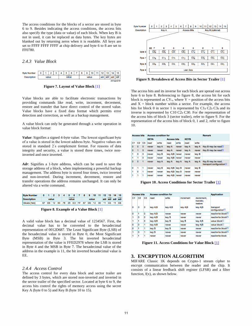
The access conditions for the blocks of a sector are stored in byte
6 to 9. Besides indicating the access conditions, the access bits
also specify the type (data or value) of each block. When key B is
not in used, it can be replaced as data bytes. The key bytes are
blanked out by returning zeros when it is readable. All keys are
set to FFFF FFFF FFFF at chip delivery and byte 6 to 8 are set to
FF0780.
2.4.3 Value Block
Figure 7. Layout of Value Block [1]
Value blocks are able to facilitate electronic transactions by
providing commands like read, write, increment, decrement,
restore and transfer that have direct control of the stored value.
Value blocks have a fixed data format which permits error
detection and correction, as well as a backup management.
A value block can only be generated through a write operation in
value block format: Value: Signifies a signed 4-byte value. The lowest significant byte
of a value is stored in the lowest address byte. Negative values are
stored in standard 2 s complement format. For reasons of data
integrity and security, a value is stored three times, twice non-
inverted and once inverted.
Adr: Signifies a 1-byte address, which can be used to save the
storage address of a block, when implementing a powerful backup
management. The address byte is stored four times, twice inverted
and non-inverted. During increment, decrement, restore and
transfer operations the address remains unchanged. It can only be
altered via a write command.
Figure 8. Example of a Value Block [1]
A valid value block has a decimal value of 1234567. First, the
decimal value has to be converted to the hexadecimal
representation of 0012D687. The Least Significant Byte (LSB) of
the hexadecimal value is stored in Byte 0, the Most Significant
Byte (MSB) in Byte 3. The bit inverted hexadecimal
representation of the value is FFED2978 where the LSB is stored
in Byte 4 and the MSB in Byte 7. The hexadecimal value of the
address in the example is 11, the bit inverted hexadecimal value is
EE.
2.4.4 Access Control The access control for every data block and sector trailer are
defined by 3 bytes, which are stored non-inverted and inverted in
the sector trailer of the specified sector. Located at byte 6 to 9, the
access bits control the rights of memory access using the secret
Key A (byte 0 to 5) and Key B (byte 10 to 15).
Figure 9. Breakdown of Access Bits in Sector Trailer [1]
The access bits and its inverse for each block are spread out across
byte 6 to byte 8. Referencing to figure 8, the access bit for each
block is represented as CYx, where Y = position of the access bits
and X = block number within a sector. For example, the access
bits for block 0 in sector 1 is represented by C10 C20 C30 and its
inverse is represented by C10 C20 C30. For the representation of
the access bits of block 3 (sector trailer), refer to figure 9. For the
representation of the access bits of block 0, 1 and 2, refer to figure
10.
Figure 10. Access Conditions for Sector Trailer [1]
Figure 11. Access Conditions for Value Block [1]
3. ENCRPYTION ALGORITHM MIFARE Classic 1K depends on Crypto-1 stream cipher to
encrypt communication between the reader and the chip. It
consists of a linear feedback shift register (LFSR) and a filter
function, f(x), as shown below.
11

Figure 12. Crypto-1 stream cipher and initialization value [1]
Based on the research paper by Karsten Nohl [3], the Crypto-1
cipher loads a 48-bit secret key into the shift register. The
Pseudorandom Number Generator (PRNG) initializes a 32-bit
random number and XOR with the UID of the card. The random
number is also used for the three-way authentication protocol
between the reader and card. During each clock cycle, the
function f(x) will compute one bit of the key stream from 20
LFSR bits. The function is composed from 6 instantiations of 3
smaller functions. The generated keystream by Crypto-1 will be
the encrypted message intended for the reader.
4. EXPERIMENTATION PROCESS
4.1 Understanding the System Before exploiting our target card, we need to understand how the
entire information system of the company works. With such
knowledge, we hope to identify the potential loopholes in the
system and help us narrow down our research field. After several
experiments, we conclude that the company only uses self-service
kiosks and POS Terminals to conduct computational before
updating the users’ cards. No backend server is used to store any
cards’ information. This information is particularly useful for us
to implement double spending attack.
Figure 13. Simplified interaction between a card and a POS
terminal
4.2 Setup Before we begin to exploit the card, we must first download and
install the necessary software. By looking at the card reader, we
can immediately determine the type of device driver required to
be installed. We would also require the use of MIFARE offline
cracker (MFOC) to assist us in the process of getting the keys out
the card.
4.3 Card Cracking
4.3.1 Layout of Target Card After analyzing multiple dump files from various target cards, we
are able to identify the different types of information stored on
each data block. In addition, the target card only uses 4 out of 16
sectors for memory allocation. We are able to identify the
different types of information easily as they are stored in clear
plaintext. However, the card has various checksum values stored
on it for defense purpose.
Figure 14. Memory Layout of the target card
4.3.2 Access control of target card The access bits for our target card is FF 07 80 69 in all sector
trailers. The access bits for each block in a sector are spread
across byte 7 [bit 4 to 7] and byte 8, while the inverse access bits
are stored in byte 6 and byte 7 [bit 0 to 3]. The following table
will illustrate how the access bits for each data block and sector
trailer are positioned.
Table 2. Breakdown of Target’s access bits
* X [Y], where X is the bit and Y is the position of the bit.
** The inverse representation of each data block can be referred
to figure 9.
Based on the documentation of the card manufacturer, we are able
to decode the meaning of the access bits. This information is
useful for us so that we can manipulate the access control before
executing our attack. The following table is the analysis of the
access bits of our target card:
Bit 7 6 5 4 3 2 1 0
Byte 6
[FF]
Byte 7
[07]
0
[0]
0
[0]
0
[0]
0 [0] 0 1 1 1
Byte 8
[80]
1
[2]
0
[2]
0
[2]
0 [2] 0
[1] 0 [1]
0 [1]
0 [1]
Byte 9
[69]
User data
12

Table 3. Access bits representation of Target’s sector
4.4 Attacks
4.4.1 Double Spending The dump file consists important information which is extracted
out from the card. By using this extracted information, one can
proceed to perform a simple double spending attack. The idea of
this attack would be to revert the card back to its original state
after making a transaction. The procedures to conduct this attack
is relatively simple.
1. Dump out the contents of the card and save it to an mfd
file named cardBasic.mfd.
2. Perform a transaction with the card.
3. Dump out the contents of the card again and save it to
an mfd file named spend.mfd
4. Restore the card back to its original state by using both
files.
In the figure above, the command to restore the card back to its
original state is shown.
4.4.2 Writing value to the card Another attack will be an attempt to write data into the card.
Since one is able to extract the plain-text data out, the next
attempt would be to write an arbitrary huge amount to the value
field or modify the expiry date of the card. To attempt this attack,
one must first explore and understand how the checksum is being
generated. The image below depicts the state of the card at its
original state.
Figure 16. Contents of basic.mfd
In the figure shown above, the contents of the card is extracted
and stored to a file name basic.mfd. The attack is first begin by
performing some reconnaissance on the card to identify what are
the values that results a change to the checksum. It is likely that a
change in value would result in a change to the checksum. From
there, one can verify this by changing the current value of one hex
digit and proceed to verify the card against a POS machine. Upon
presenting the card, an authentication failure message is
prompted. This has proved that a change in the current value
would affect the checksum value. One can also verify the other
values by repeating the aforementioned method above.
After several tries, factors such as the current value, total amount
spent, latest top-up date and card expiry date is likely the cause of
a change to the checksum value.
After identifying the above, it is time to perform some frequency
analysis to determine how the checksum is formed. One can
perform this by heading to a POS machine to reload the value of
$2 into the card.
Figure 17. Contents of addTwo.mfd
In the figure above, it is observed that there is a substantial change
in value as compared to figure 16. The updated hex values are
reflected in red. It is verified that a change in current value as well
as the latest top-up date does indeed cause a change in the
checksum. However, there is a need for a few other transactions to
determine the change in its checksum because 2 variables are
needed. One can conduct a frequency analysis by restricting one
of the variable from changing. In this situation, the current value
variable is chosen to not change. By doing so, one would have to
revert the card back to the basic.mfd file and return on the
following day to perform another transaction by topping up $2.
Block Access
Bits
Valid Commands Description
0 000 Read, write, decrement,
increment, transfer, restore
with both keys
Data Block
1 000 Read, write, decrement,
increment, transfer, restore
with both keys
Data Block
2 000 Read, write, decrement,
increment, transfer, restore
with both keys
Data Block
3 001 Read & write access bits and
Key B with Key A. Able to
overwrite Key A.
Sector
Trailer
Figure 15. Command to restore to its original state
13

Figure 18. Contents of addTwoAgain.mfd
In the figure above, the final result would be the current value
being the same as addTwo.mfd whereas the latest top-up date
would be different. To conduct a thorough frequency analysis,
one would need more dump files generated since the difference
between both checksum was huge. However, this is rather time-
intensive as one would have to wait for the following day to verify
the changes. Furthermore, it will not be useful as the attack would
most likely result in one figuring out the change made to the
checksum based on changes made to the latest top-up date.
Ultimately, the goal of this attack is to discover changes made to
checksum based on changes made to the current value.
To solve this problem, one can make use of the current value and
total spend value variables to decipher the checksum. To perform
this frequency analysis attack, one must first determine the
amount of monetary difference between each of the dump file
current and total spend values. In this attack, we will explore a
difference value of 9 cents. (To be continued)
5. DEFENSES
5.1 Security implementations As demonstrated through our experimentation, MIFARE Classic
is not secure. However, there are some defences which can be
implemented to improve the security of MIFARE Classic. 1. Ensure that there are no default keys left on any of the sectors
of the tag. Any new keys generated should be completely random
and different for each sector. The random generator used should
produce keys which do not have any hidden patterns that can be
used for predicting the keys. If all this is correctly implemented,
key retrieval becomes harder. 2. Ensure that the system makes proper use of the encryption
capabilities of the MIFARE Classic tags. This means that any
authentication information should only be stored on the encrypted
data sectors, and it should be used in the decision of the reader to
give or decline access to the restricted area. Hence,
implementations should not solely make use of the UID of the tag.
6. SOLUTION
6.1 Setting up Centralized Servers With a several number of outlets island-wide, having a centralized
server to store a latest copy of each card will prevent potential
fraudsters from conducting double spending attacks. This is
because the kiosks and POS terminals will use the information
retrieved from the card to verify with the server. Any
inconsistency will see the transactions being voided. This will
either invalid the modified card or forces the attacker to revert the
card back to its original state. However, the cost of setting up a
server can be costly as it requires software updates for all existing
kiosks and POS terminals, as well as the installation of Internet
connection.
Figure 19. Improvised System
6.2 Phase out MIFARE Classic The use of 48-bit key and a weak Pseudorandom Number
Generator have exposed MIFARE Classic to numerous
vulnerabilities. Tools exploiting the vulnerabilities of MIFARE
Classic are widely available and the cost of executing such attack
is relatively low. Even though there is a limit to how much credit
a card can hold, multiple attacks at simultaneous time will be
detrimental to the financial of the company. The best and low cost
solution is to cease the issue of MIFARE Classic card and deploy
cards with stronger encryption scheme.
7. CONCLUSION With technology on the rise, it is clear that MIFARE classic cards
are considered to be obsolete and vulnerable to attacks. The usage
of a 48-bit key is too weak and it can easily be cracked in today’s
technology. Given a 128-bit key, the cracking speed even with the
use of a GPU would be significantly longer.
8. ACKNOWLEDGMENTS The authors of this paper will like to extend their gratification to
A/Prof Hugh Anderson for his continuous guidance and support
throughout this project. He has been very helpful in loaning the
required equipment’s such as the card reader and Chinese magic
cards.
9. REFERENCES [1] MIFARE Classic Datasheet. (2014, Sep 8). Retrieved from
http://cache.nxp.com/documents/data_sheet/MF1S70YYX_V
1.pdf?pspll=1
[2] Kuo-Tsang Huang, and Jung-Hui Chiu 2012. Secured RFID
Mutual Authentication Scheme for MIFARE Systems.
Research Report. Chang Gung University, Tao-Yuan,
Taiwan
[3] Karsten Nohl, Cryptanalysis of Crypto-1, Retrieved from
https://www.cs.virginia.edu/~kn5f/pdf/Mifare.Cryptanalysis.
pdf. University of Virginia.
[4] NFC Type MIFARE Classic Tag Operation. (2012, Oct 2).
Retrieved from
http://www.nxp.com/documents/application_note/AN1304.p
df
14

[5] Ed Dawson, Topics in Cryptology - CT- RSA 2013, (San
Francisco: Springer, 2015), 242.
[6] About RFID, Retrieved from
http://www.impinj.com/resources/about-rfid/
[7] Sam Smith, Mobile & Wearable Contactless Payments To
Approach $100BN By 2018, Retrieved from Juniper
Research https://www.juniperresearch.com/press/press-
releases/mobile-wearable-contactless-payments-to-approach-
$
[8] Ian Poole, NFC Security, Retrieved from Radio-Electronics
http://www.radio-electronics.com/info/wireless/nfc/nfc-near-
field-communications-security.php
[9] Jan Scholtyssek, Practical Cryptoanalysis, Retrieved from
http://www.janscholtyssek.dk/jan/wp-
content/uploads/2013/12/CRYPTO1-presentation.pdf
[10] Chen-Mou Cheng, MIFARE Classic: Completely Broken.
Retrieved from
http://hitcon.org/download/2010/11_MIFARE%20Classic%2
0IS%20Completely%20Broken.pdf
[11] Mathias Morbitzer, The MIFARE Hack, Retrieved from
http://proxmark.nl/files/Documents/13.56%20MHz%20-
%20MIFARE%20Classic/The_MIFARE_Hack.pdf
15

16

Protocol Downgrade Attacks on HTTPS
Ng Aik ShengNational University of
Singapore13 Computing DriveSingapore 117417
Chan Jian HuiNational University of
Singapore13 Computing DriveSingapore 117417
Eldric LimNational University of
Singapore13 Computing DriveSingapore 117417
Derek KokNational University of
Singapore13 Computing DriveSingapore 117417
ABSTRACTSince its introduction, HTTPS has seen widespread adop-tion and deployment. As of March 2017, 53.8% of popularsites have a secure implementation of HTTPS. [2] HTTPS,or HTTP over TLS, provides not only integrity and con-fidentiality of the data exchanged, but also authenticationof the website with which one is communicating with. [7]However, throughout the years, there have been multiplemajor attacks on TLS. This includes protocol downgradeattacks such as ssltripping[9], cipher-based attacks such asBEAST and compression-based attacks such as CRIME andBREACH. [8]
In this paper, we are interested in looking at protocol down-grade attacks against HTTPS and more specifically - sslstrip-ping. We will look at the various techniques and methodsused to achieve a HTTPS protocol downgrade to HTTP andevaluate their successes and failures. Finally, we present ademonstration of HTTPS Stripping through the use of aRaspberryPi as a rogue access point(AP).
Categories and Subject DescriptorsC.2.0 [Computer-Communication Networks]: General- Data Communications, Security and Protection
General Termssslstrip, HTTP Strict Transport Security, Network TimeProtocol, Network Security, Domain Name Server
KeywordsHTTPS, SSL, man-in-the-middle, HSTS, NTP, DNS
1. INTRODUCTIONDue to the lack of security in low-level protocols such as Ad-dress Resolution Protocol (ARP), Man-In-The-Middle (MITM)attacks have always been an avenue through which attackerscan obtain privileged information from victims. In the con-text of HTTPS connections, the use of certain techniquescan allow an attacker to downgrade HTTPS to HTTP andobtain plaintext information during an MITM session.
During BlackHat DC 2009, a security researcher under thepseudonym of Moxie Marlinspike published his findings, ”MoreTricks For Defeating SSL In Practice”. In his presentation,he introduced an attack called sslstrip, which is a proto-col downgrade attack that strips all HTTPS connections toHTTP connections in order to obtain otherwise encryptedinformation.
However, this led to the introduction of the HTTP StrictTransport Security (HSTS) Specification[6] in 2010, whichrendered most sslstripping attempts useless. Despite HSTS,security researchers have found workarounds to bypass HSTSto achieve an sslstrip and we will look at how HSTS can bebypassed in the following sections.
2. MOTIVATIONWhere web browsing is concerned, users seldom establishHTTPS connections directly or intentionally.
As a result, it is either encountered as a result of mainly twofactors: [9]
1. 302 RedirectIf a site requires a connection over HTTPS, a 302 redi-rect will be triggered to direct HTTP to HTTPS
2. HTTPS LinksThe link that a user visits or clicks explicitly statesHTTPS
Therefore, it is possible to exploit this lapse by forcinga user to strictly use HTTP through means of a proxy.
17

3. SSLSTRIPAt its core, sslstrip is a form of MITM as it relies on routingtraffic from a victim’s machine via a proxy that an attackerhas control of. Therefore, it is assumed that an attacker isable to intercept all traffic transmitted to and from the vic-tim’s machine either through techniques like ARP poisoningor by masquerading as a rogue AP on a network. Figure 1shows a typical MITM setup.
Figure 1: MITM Setup
3.1 Attack FlowThe attacker would listen and observe as HTTP traffic istransmitted to and fro the victim and the web server. If itis just HTTP traffic, nothing will be done as the attackercan just extract information from the plaintext data.
In the event that HTTPS traffic is detected, the attackerperforms the following[9]:
1. ”Strip” HTTPS LinksChange <a href=”https://...”> links to<a href=”http://...”>, while maintaining a map-ping of the things changed (CSS, javascript links).
2. Change location headerChange Location: https:// to Location: http://in HTTP header and keep a mapping of the thingschanged as well.
3. Proxy HTTPS requestsAttacker’s proxy will send and proxy HTTPS requeststo and fro the victim’s intended web server and the vic-tim. The attacker’s machine impersonates the client.
4. Log HTTP trafficTraffic going from the victim to the attacker would bein plaintext while traffic going from the attacker tothe web server would be encrypted. However, all thesensitive information from the victim is in plaintext asHTTPS is bypassed completely.
A map of all relative CSS, Javascript links have to bemaintained for the browsing session to remain undis-rupted.
Figure 2 shows the sslstrip attack flow, with a victim brows-ing to facebook.com. Where the web server is concerned, it
would not notice that it is communicating with the attackeras the attacker is masquerading as the victim. The only visi-ble difference is that the browsing session will not be flaggedas HTTPS in the browser and a user who is more cognizantmay notice that.
Even so, this attack was an ingenious way to bypass an oth-erwise fairly secure protocol. Since then, HSTS was intro-duced and it imposed severe limitations on the effectivenessof this attack.
Figure 2: sslstrip Attack Flow
4. HSTSProposed in 2009, HTTP Strict Transport Security (HSTS)was motivated by Moxie’s demonstration of how connectionscould be downgraded and insecure redirects could be ex-ploited in a hostile network. [1] As such, it was rapidlyadopted by major web browsers and formalized as RFC6797in 2012. [6]
4.1 MechanismHSTS is not a protocol per se, but rather, a policy that canbe enforced by domains that visitors connect to. The goal ofHSTS is ensure that a visitor’s browser always connects toa website over HTTPS. When a visitor visits a domain thathas enabled HSTS, the browser would perform two actions:
1. Always use HTTPSAll connections would default to HTTPS, even whenclicking on HTTP links or typing a domain into theURL bar without explicit specification of a protocol.
2. Prevent users from clicking through warningsHSTS ensures that users are not able to ignore andclick through warnings about invalid certificates whenthey browse to a HSTS-enabled domain.
4.2 HSTS HeaderTo inform a browser to enable HSTS for a domain, thedomain web server sends a HTTP response header over aHTTPS connection when the visitor first establishes con-nection with the domain.
There are three directives associated with the HSTS header:
1. max-ageThe max-age directive instructs the browser to keepthe HSTS entry for that particular domain for as longas the time is declared in max-age (in seconds).
2. includeSubDomainsThe includeSubDomains directive, if present, would in-dicate that the HSTS Policy applies to this HSTS do-main, as well as any subdomains of the host’s domain
18

name. For example, given that the domain, foo.exampl-e.com is HSTS-enabled, includeSubDomains would meanthat the HSTS policy applies to *.foo.example.com aswell.
3. preloadAs HSTS headers are only sent when a visitor firstvisits a domain, there exists an opportunity for an at-tacker to intercept the initial connection and strip anddiscard all HSTS headers, which allows for an sslstripattack. To combat this problem, browsers like Chromeand Firefox introduced preloaded HSTS lists that arebuilt into the browser itself.
After enabling the preload directive in the header, thedomain administrator can submit the domain’s URL tothe HSTS preload site. For example, Chrome’s HSTSpreload site is: https://hstspreload.org/.
Frequently visited websites such as Google, Twitter,Paypal are already members of the preloaded HSTSlist and most major browsers also have HSTS preloadlists based on the Chrome list.
In its strongest and most recommended form, the HSTSpolicy should include all three directives:
S t r i c t −Transport−Secur i ty : max−age =31536000;includeSubDomains ; pre load
While highly recommended, many websites do not adoptthe strictest enforcement as it is expensive and inconvenientto do so. Specifying the includeSubDomains and preloaddirectives means that all subdomains associated with theparent domain must support HTTPS. Hence, as of April2017, only 2.9% of websites use HSTS. [3] Without strict andproper implementations of HSTS, researchers have managedto find ways to bypass HSTS.
5. BYPASSING HSTSAs mentioned earlier, without using HSTS in its most rec-ommended form comes with its repercussions. A visitor canstill be subject to protocol-downgrade attacks like sslstrip ifa domain is not in the preloaded HSTS list of a browser. Theinitial connection with the domain would be over HTTP andan attacker can intercept traffic and strip any HSTS headerthat is transmitted. After which, the attacker can just goabout performing the regular sslstrip attack as mentioned.Hence, the attacks listed here are techniques to bypass HSTSfor means of achieving an sslstrip attack.
5.1 Exploiting DNS Server ChangesDuring Blackhat Asia 2014, Leonardo Nve Egea presentedsslstrip+, an improvement over Moxie’s sslstrip attack. Thistool aimed to bypass HSTS through exploiting DNS serverchanges. [4]
5.1.1 HSTS SubdomainsAs HSTS entries are applied on a per-hostname basis, theomission of the includeSubDomains directive leaves domainsvulnerable to this form of attack. Without includeSubDo-mains, the HSTS rule only applies to that specific domainand this presents an opportunity to exploit the lack of HSTSprotection for the subdomains of that domain.
5.1.2 DNS HijackDomain Name System (DNS) is a protocol that resolveshostnames to ip addresses. [11] In his presentation, Leonardoproposed a way to bypass HSTS through the hijacking ofDNS queries. Similar to sslstrip, the tool acts as a proxyand is able to observe and intercept traffic between the vic-tim and the web server. Instead of just stripping HTTPSlinks to HTTP, this attack involves modifying the HTTPlink to another domain name that is slightly different fromthe original HTTPS request. To resolve the non-existentdomain that the modified link points to, the attacker inter-cepts the DNS query and responds with a malformed DNSpacket with the same hostname. /citeleonard:exploitdns
5.1.3 Attack FlowThe following is an example of the attack flow when a victimvisits a website that is HSTS-enabled for that exact domainonly.
1. Victim visits ”www.facebook.com”Since the browser knows that the domain uses HSTS, itwould attempt to use HTTPS. sslstrip+ will interceptthe traffic from the server to the client and modifythe link to change from ”https://www.facebook.com”to ”wwww.facebook.com”.
2. Victim’s DNS queries ”wwww.facebook.com”sslstrip+ would intercept the request and make a realDNS query to the original hostname ”www.facebook.com”and returns a DNS reponse with the fake domain namebut real IP (IP address of www.facebook.com)
3. Browser receives DNS reply and check if do-main HSTS-enabledWhen the victim’s browser receives the DNS reply, itwill verify if that domain has a HSTS entry. Since thedomain is fake, there will be no HSTS entry for thatdomain and the browser would establish a HTTP con-nection to the address return in the reply, which is theIP addresss of the real domain (www.facebook.com)
4. HTTPS links are stripped to HTTPSince the HTTPS link is now HTTP, sslstrip+ can nowperform logging operations just like sslstrip.
5.1.4 MitigationsAs mentioned earlier, the includeSubDomains directive shouldbe specified in the HSTS header when a visitor first visitsa domain. This would prevent the attacker from utilizingany fake domains to circumvent HSTS detection. Togetherwith the preload directive, it would be impossible to bypassHSTS in this manner. Also, DNSSec could be used to pre-vent malicious DNS servers from intercepting and replyingqueries.
5.2 Time Synchronization AttacksIn the event that a domain is preloaded and has HSTS ap-plied to its subdomains, there is still an avenue throughwhich attackers can hope to achieve a protocol downgrade.HSTS entries expire when the time specified in the max-agedirective for an entry is up. Therefore, time synchronizationattacks can be used to alter the time of a system such thatthe time specified for max-age elapses. [13]
19
5.2.1 NTPNetwork Time Protocol (NTP) is a protocol used to syn-chronize the clocks between computer systems. Most clocksin computer systems are inherently inaccurate as they areset initially and rarely checked after that. This results inclock drifting, where the system time deviates from a refer-ence time. Using NTP, desktop operating systems such asLinux or Windows are able to synchronize their time withNTP servers hosted on the Internet.
By default, the servers that they poll from are usually ownedby the operating system provider, such as ”ntp.ubuntu.com”for Ubuntu distributions. Different operating systems usedifferent versions (v3 or v4) [10][5] to synchronize their time.
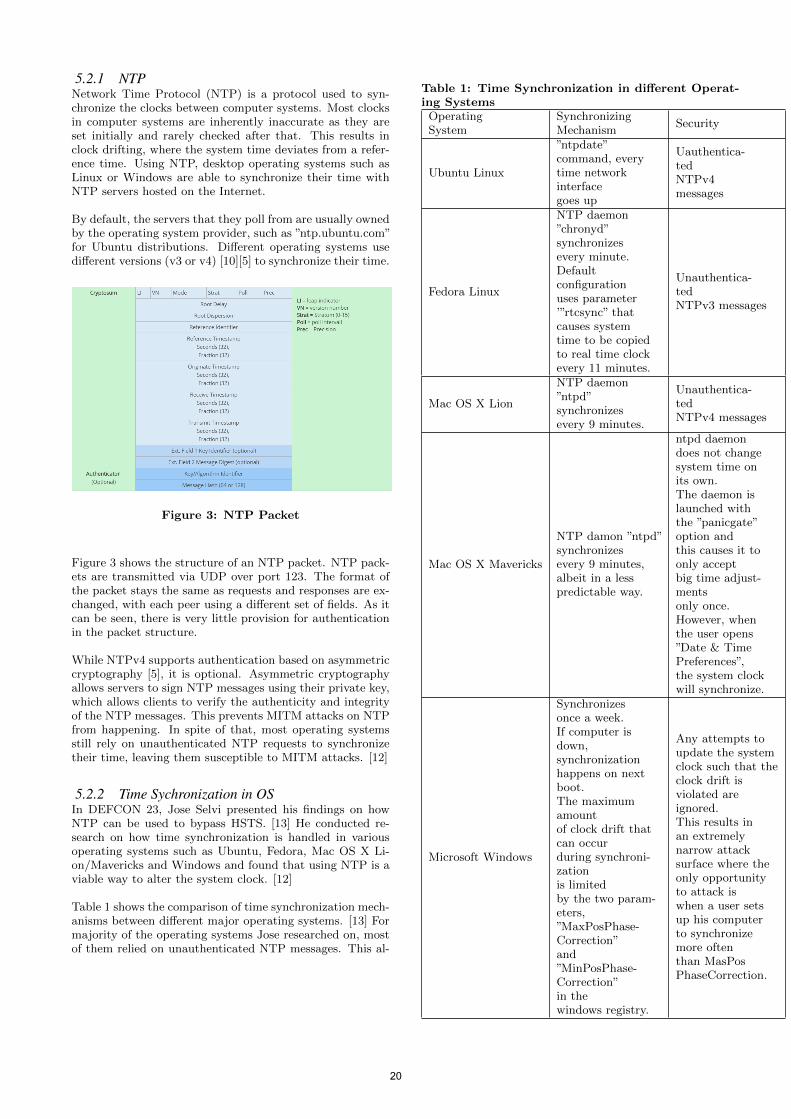
Figure 3: NTP Packet
Figure 3 shows the structure of an NTP packet. NTP pack-ets are transmitted via UDP over port 123. The format ofthe packet stays the same as requests and responses are ex-changed, with each peer using a different set of fields. As itcan be seen, there is very little provision for authenticationin the packet structure.
While NTPv4 supports authentication based on asymmetriccryptography [5], it is optional. Asymmetric cryptographyallows servers to sign NTP messages using their private key,which allows clients to verify the authenticity and integrityof the NTP messages. This prevents MITM attacks on NTPfrom happening. In spite of that, most operating systemsstill rely on unauthenticated NTP requests to synchronizetheir time, leaving them susceptible to MITM attacks. [12]
5.2.2 Time Sychronization in OSIn DEFCON 23, Jose Selvi presented his findings on howNTP can be used to bypass HSTS. [13] He conducted re-search on how time synchronization is handled in variousoperating systems such as Ubuntu, Fedora, Mac OS X Li-on/Mavericks and Windows and found that using NTP is aviable way to alter the system clock. [12]
Table 1 shows the comparison of time synchronization mech-anisms between different major operating systems. [13] Formajority of the operating systems Jose researched on, mostof them relied on unauthenticated NTP messages. This al-
Table 1: Time Synchronization in different Operat-ing Systems
OperatingSystem
SynchronizingMechanism
Security
Ubuntu Linux
”ntpdate”command, everytime networkinterfacegoes up
Uauthentica-tedNTPv4messages
Fedora Linux
NTP daemon”chronyd”synchronizesevery minute.Defaultconfigurationuses parameter’”rtcsync” thatcauses systemtime to be copiedto real time clockevery 11 minutes.
Unauthentica-tedNTPv3 messages
Mac OS X Lion
NTP daemon”ntpd”synchronizesevery 9 minutes.
Unauthentica-tedNTPv4 messages
Mac OS X Mavericks
NTP damon ”ntpd”synchronizesevery 9 minutes,albeit in a lesspredictable way.
ntpd daemondoes not changesystem time onits own.The daemon islaunched withthe ”panicgate”option andthis causes it toonly acceptbig time adjust-mentsonly once.However, whenthe user opens”Date & TimePreferences”,the system clockwill synchronize.
Microsoft Windows
Synchronizesonce a week.If computer isdown,synchronizationhappens on nextboot.The maximumamountof clock drift thatcan occurduring synchroni-zationis limitedby the two param-eters,”MaxPosPhase-Correction”and”MinPosPhase-Correction”in thewindows registry.
Any attempts toupdate the systemclock such that theclock drift isviolated areignored.This results inan extremelynarrow attacksurface where theonly opportunityto attack iswhen a user setsup his computerto synchronizemore oftenthan MasPosPhaseCorrection.
20

lows MITM attacks to be launched when an operating sys-tem attempts to synchronize its clock.
5.2.3 Delorean - NTP MITMDelorean[14] was developed to act as a fake NTP server thatresponds to NTP requests with time indicated by the at-tacker.
Figure 4: Delorean
By default, it replies to NTP queries with a date 1000 daysgreater than the current time, while maintaining the samemonth, day and time. This far exceeds the max-age thatmost HSTS entries specify, which is usually 31557600 sec-onds(1 year). Maintaining the same month, day and timealso helps to prevent the user from noticing that somethingis amiss. However, an attacker can also specify the date toreply to queries with the -d flag.
6. REFERENCES[1] HTTP Strict Transport Security. Retrieved March 28,
2017 from https://https.cio.gov/hsts/.
[2] Survey of the SSL Implementation of the MostPopular Web Sites, 2017. Retrieved March 28, 2017from https://www.trustworthyinternet.org/ssl-pulse/.
[3] Usage of HTTP Strict Transport Security for websites,2017. Retrieved April 1, 2017 fromhttps://w3techs.com/technologies/details/ce-hsts/all/all.
[4] L. N. Egea. Exploiting changes on DNS serverconfiguration, 2014. Retrieved March 28, 2017 fromhttps://www.blackhat.com/docs/asia-14/materials/Nve/Asia-14-Nve-Offensive-Exploiting-DNS-Servers-Changes.pdf.
[5] D. L. M. et al. Network Time Protocol Version 4:Protocol and Algorithms Specification. RFC 1305,June 2010.
[6] J. H. et al. HTTP Strict Transport Security (HSTS).RFC 6796, November 2012.
[7] T. D. et al. The Transport Layer Security (TLS)Protocol Version 1.2. RFC 5246, August 2008.
[8] Y. S. et al. Summarizing Known Attacks on TransportLayer Security (TLS) and Datagram TLS (DTLS).RFC 7457, February 2015.
[9] M. Marlinspike. More Tricks For Defeating SSL InPractice, 2009. Retrieved March 28, 2017 fromhttps://www.blackhat.com/presentations/bh-usa-09/MARLINSPIKE/BHUSA09-Marlinspike-DefeatSSL-SLIDES.pdf.
[10] D. L. Mills. Network Time Protocol (Version 3)Specification, Implementation and Analysis. RFC1305, March 1992.
[11] P. Mockapetris. DOMAIN NAMES -IMPLEMENTATION AND SPECIFICATION. RFC1035, November 1987.
[12] J. Selvi. Bypassing http strict transport security.Blackhat Europe 2014, pages 1–4, 2014.
[13] J. Selvi. Breaking SSL using time synchronizationattacks, 2015. Retrieved March 28, 2017 fromhttps://media.defcon.org/DEF
[14] J. Selvi. NTP MitM attack using a Delorean, 2015.Retrieved March 28, 2017 fromhttp://www.en.pentester.es/2015/10/delorean.html.
21

22

Fingerprint Authentication and its vulnerabilities
Cao Shuai Benjamin A0124933H
School of Computing National University of Singapore
13 Computing Drive
Sharon Mariam Mathew A0113000N
School of Computing National University of Singapore
13 Computing Drive
Shirlene Quah Jiamin A0130909H
School of Computing National University of Singapore
13 Computing Drive
Vani Gupta A0118899E
School of Computing National University of Singapore
13 Computing Drive
ABSTRACT In this paper, we explore the vulnerabilities of the biometric
authentication on security systems. We show the many ways we
may spoof the fingerprint scanner to scan fingerprints extracted
from a photograph and a DIY fingerprint mould. From these
attempts, we will conclude which is the most suitable resolution at
which the fingerprints can be identified to access a device that is
protected by the fingerprint authentication, thereby raising the
vulnerabilities of a supposed secure scheme of protecting our
information.
Categories and Subject Descriptors K.6.5 [Security and Protection]: Authentication, Unauthorized
Access - Spoofing
D.2.0 [General]: Protection Mechanisms
General Terms Experimentation, Security, Verification, Authentication
Keywords Biometric, fingerprint, scanner, spoofing.
1. INTRODUCTION In this digital day and age where our phones have become
computers in itself and everything we need to find is just a ‘click’
away, the security of our data and information have been
undermined. As of 2015, there were 177,866,236 personal records
exposed in 780 breaches and there has been a 38% increase in the
instances of phishing scams and other cyber security incidents. This
figure will only become higher as the years go by and as systems
and data become more transparent. As technology advances each
day and innovation becomes an everyday part of life, we have
opened our horizons to many forms of authentication schemes. The
old-school method of protecting authentication with passwords
have now evolved to the fingerprint (biometric) scanning to the
“one-time password (OTP)” scheme. Each day as cyber-attacks
plague our virtual world, professionals are gearing up to secure our
systems and prevent vulnerabilities from occurring.
2. BIOMETRIC AUTHENTICATION Biometric authentication has increasingly been used in the field of
computer science and access control. Biometric identities are
related to an individual's physiological characteristics. There are
many different forms of biometric authentication. Some of the most
common forms include [1]: Fingerprint, Palm veins, Palm print,
DNA, Face Recognition, Hand geometry, Iris recognition, Retina
Scan.
Figure 1 : Biometric Authentication Preference
23

Figure 2 : Biometric Authentications Examples
3. FINGERPRINT SCANNER
3.1 Introduction The most commonly used form of biometric authentication
nowadays is fingerprint scanning. Increasingly being used by the
smartphone industry, the popularity has increased over the years.
The first phone with fingerprint scanner was introduced to the
world in 2007 by Toshiba [2], which did not gain much popularity.
It was only when Apple Inc launched Touch ID in 2013 [3] when
fingerprint scanning became the news of the world. World’s
leading smartphone companies like Samsung followed the concept
of integrating fingerprint authentication with smartphones.
Figure 3 : First phone with fingerprint scanner - Toshiba
Prior to the introduction of Touch ID, biometric authentication was
the form of authentication on certain security systems, like the
entrance of a secure facility, or for the identification used in travel
documents. The use of fingerprint scanning by the smartphone
industry was a big breakthrough for the biometric authentication
systems.
Figure 4 : Apple Touch ID
However, as the popularity increased, more people wanted to break
into it. According to a leading editorial, “Your phone’s biggest
vulnerability is your fingerprint”. There were numerous ways in
which it could be hacked. This research paper tries to describe some
ways in which this could be achieved, and how it has caused a
breach in the security systems.
3.2 Types of biometric authentication All fingerprint scanners make use of the unique features and
patterns present in the fingerprints. For example, the ridges and
valleys. There are 5 different patterns that cover most of the
fingerprints. [5][6]
1. Arch - Tented or Plain
2. Left Loop
3. Right Loop
4. Whorl
5. Accidental Whorl
All the five patterns are displayed in Figure 5.
Figure 5 : Fingerprint patterns
The main minutia in the fingerprints are the ridge ending - where
the ridges end, ridge bifurcation - where the ridge splits into two,
and short ridge - where the ridge is equivalent to a dot. There are
mainly two types of fingerprint recognizing algorithms, Minutiae
matching (pre-processing algorithm) and Pattern matching (image
matching algorithm). The minutiae are a collective term used for
24
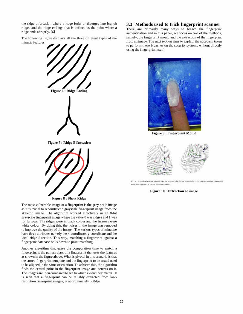
the ridge bifurcation where a ridge forks or diverges into branch
ridges and the ridge endings that is defined as the point where a
ridge ends abruptly. [6]
The following figure displays all the three different types of the
minutia features.
Figure 6 : Ridge Ending
Figure 7 : Ridge Bifurcation
Figure 8 : Short Ridge
The most vulnerable image of a fingerprint is the grey-scale image
as it is trivial to reconstruct a grayscale fingerprint image from the
skeleton image. The algorithm worked effectively in an 8-bit
grayscale fingerprint image where the value 0 was ridges and 1 was
for furrows. The ridges were in black colour and the furrows were
white colour. By doing this, the noises in the image was removed
to improve the quality of the image. The various types of minutiae
have three attributes namely the x-coordinate, y-coordinate and the
local ridge direction. This way, matching a fingerprint against a
fingerprint database boils down to point matching.
Another algorithm that eases the computation time to match a
fingerprint is the pattern class of a fingerprint that uses the features
as shown in the figure above. What is pivotal in this scenario is that
the stored fingerprint template and the fingerprint to be tested need
to be aligned in the same orientation. To achieve this, the algorithm
finds the central point in the fingerprint image and centres on it.
The images are then compared to see to which extent they match. It
is seen that a fingerprint can be reliably extracted from low-
resolution fingerprint images, at approximately 500dpi.
3.3 Methods used to trick fingerprint scanner There are primarily many ways to breach the fingerprint
authentication and in this paper, we focus on two of the methods,
namely, the fingerprint mould and the extraction of the fingerprint
from an image. The next section aims to explain the approach taken
to perform these breaches on the security systems without directly
using the fingerprint itself.
Figure 9 : Fingerprint Mould
Figure 10 : Extraction of image
25

3.4 Experiment and Results Before any extraction of fingerprint was done, hardware was set
up. For this paper, the fingerprint scanner used was SecuGen
Hamster III. The hardware setup includes linking up the
fingerprint scanner, SecuGen Hamster(III) with the computer and
using the SDK and the sample code given by SecuGen to generate
the .exe file.
Figure 11 : SecuGen Hamster III
The code had been edited in certain areas that included removing
certain features such as registration and limiting the template
format to SG400. Figure 12 shows the UI of the .exe file that was
created for this research.
Figure 12 : UI of program
3.4.1 Extracting fingerprint from photo The main objective of the experiment, being able to extract the
fingerprint from the photo involved the consecutive steps that
were taken. We captured a photo of the fingerprint and also used a
photo editing software to improve clarity.
Figure 13 : Fingerprint image
Next, we converted the image to black and white format and
processed the image by adjusting the shadow and highlight levels
to best expose the clarity of the ridges. Then, we adjust the curves
of the image lighting and the threshold level to further maximise
clarity of the ridges. Next, we adjust the curves of the image
lighting as well as the threshold level in order to further maximize
the clarity of the ridges. Also, we invert the image either by using
the photo editing software or by printing the fingerprint out and
inversing by scanning it into a scanner. The ratio of the fingerprint
has to be within 3x3cm to best replicate the size of the finger.
Figure 14 shows the black and white format that we obtained from
an image of the fingerprint. In this case, Figure 14 was smudged
to prevent the image from being used.
Figure 14 : Processed Image of fingerprint (smudge)
We printed the image on glossy photo paper and were able to
spoof the fingerprint scanner.
26
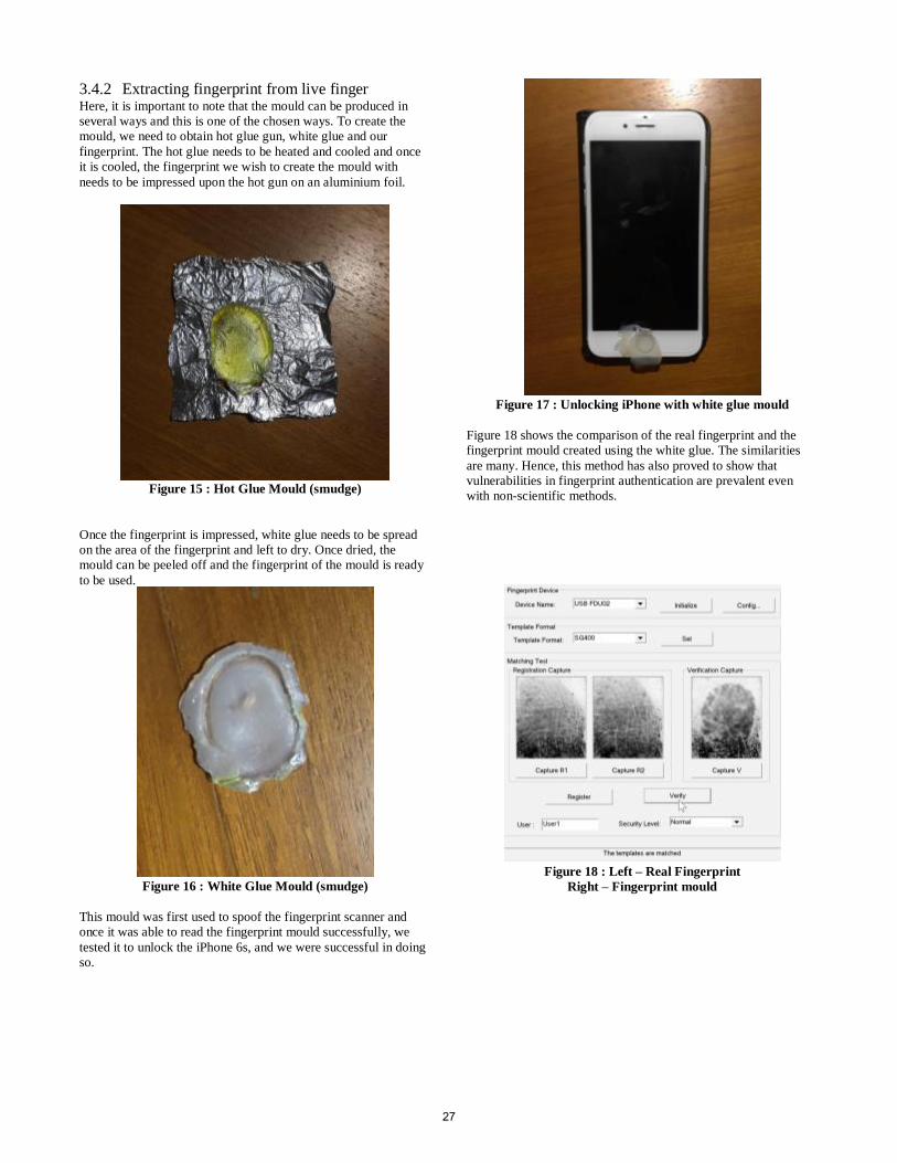
3.4.2 Extracting fingerprint from live finger Here, it is important to note that the mould can be produced in
several ways and this is one of the chosen ways. To create the
mould, we need to obtain hot glue gun, white glue and our
fingerprint. The hot glue needs to be heated and cooled and once
it is cooled, the fingerprint we wish to create the mould with
needs to be impressed upon the hot gun on an aluminium foil.
Figure 15 : Hot Glue Mould (smudge)
Once the fingerprint is impressed, white glue needs to be spread
on the area of the fingerprint and left to dry. Once dried, the
mould can be peeled off and the fingerprint of the mould is ready
to be used.
Figure 16 : White Glue Mould (smudge)
This mould was first used to spoof the fingerprint scanner and
once it was able to read the fingerprint mould successfully, we
tested it to unlock the iPhone 6s, and we were successful in doing
so.
Figure 17 : Unlocking iPhone with white glue mould
Figure 18 shows the comparison of the real fingerprint and the
fingerprint mould created using the white glue. The similarities
are many. Hence, this method has also proved to show that
vulnerabilities in fingerprint authentication are prevalent even
with non-scientific methods.
Figure 18 : Left – Real Fingerprint
Right – Fingerprint mould
27

4. CONCLUSION In conclusion, we have come to appreciate the biometric
authentication on security systems. It has surely been a
breakthrough in the area of cyber security. It is becoming a popular
approach to keep security systems secure due to the ease and the
uniqueness of the nature of the authentication. It has also been said
to be the future of digital security and industries are positive that
many more biometric methods such as behaviour ID can be used
on transactions and this is only the beginning of many more
technological breakthroughs. As fingerprint authentication is one
of the more preferred forms of biometric security in systems, we
have to increase the complications of fingerprint extraction and
strengthen the security of fingerprint authentication.
5. ACKNOWLEDGEMENT We would like to thank Prof Hugh Anderson of National University
of Singapore for giving us an opportunity to write the paper and
providing guidance for the project. We would also like to thank
secugen hamster III for allowing us to access the SDK and make
changes to their template and sample code. We would like to thank
our sponsors GovTech and Garena for the publishing of our posters
for the STEPS project exhibition.
6. REFERENCES [1] Angle, S., Bhagtani, R.,Chheda, H. (n.d). Biometrics: A
further Echelon of Security. Retrieved from
https://pdfs.semanticscholar.org/68d5/e5d733729de294eb6a0
f0b20092f2feedac9.pdf
[2] Apple. (2013, September 10). Apple Announces iPhone 5s –
The most forward-thinking Smartphone in the world.
Retrieved from
http://www.apple.com/pr/library/2013/09/10Apple-
Announces-iPhone-5s-The-Most-Forward-Thinking-
Smartphone-in-the-World.html
[3] Chakrabarty, J. (2016, April 17). Fingerprint Scanner on
Phones: History & Evolution, but do we Really Need that?
Retrieved from https://www.igadgetsworld.com/fingerprint-
scanner-history-evolution-but-do-we-really-need-that/
[4] Chen, L. (2013, October 10). In China: Fake Fingerprints in
Five Minutes Flat. Retrieved from
http://www.theepochtimes.com/n3/313493-in-china-fake-
fingerprints-in-five-minutes-
flat/?expvar=004&utm_expid=.5zxdwnfjSHaLe_IPrO6c5w.1
&utm_referrer=
[5] Le, C. (2011, November 28). A survey of Biometric Security
Systems. Retried from
http://www.cse.wustl.edu/~jain/cse571-11/ftp/biomet/
[6] Real Time North America. (2008). Fingerprint Identification.
Retrieved from
http://www.realtimenorthamerica.com/download/Fingerprint
_Identification.pdf
[7] Wikipedia. (2017, April 2). Fingerprint recognition.
Retrieved from
https://en.wikipedia.org/wiki/Fingerprint_recognition#Patter
n-based_.28or_image-based.29_algorithms
[8] Zaeri, M. (2011, June 20). Minutiae-based Fingerprint
Extraction and Recognition. Retrieved from
https://www.intechopen.com/books/biometrics/minutiae-
based-fingerprint-extraction-and-recognition
28

Exploiting the Security Lapses in the NUS MatriculationCard
Cheong Jack KuanNUS, School of Computing
Anna HeNUS, School of Computing
Lim ZemingNUS, Department of
EngineeringA0116214W
Tan Yan HanNUS, Department of
EngineeringA0110583N
ABSTRACTThis paper provides an overview of the MIFARE card tech-nology developed by NXP Semi-conductors and how its en-cryption key can be attacked. The prevalent use of MI-FARE cards gave attackers a huge motivation for attackingit and the choice of NXP to achieve security through obscu-rity proved to be detrimental to the technology. The authorsalso discuss some of their findings in attacking the NUS ma-triculation card which is a MIFARE Classic 1k card.
Categories and Subject DescriptorsK.6.5 [Security and Protection]: Unauthorized access—hacking ; D.2.0 [General]: Protection mechanisms
General TermsSecurity, Theory
KeywordsMIFARE Classic, Hacking, NUS Matriculation Cards
1. INTRODUCTIONAt the turn of the century, pocket sized smart cards withembedded integrated circuits have become part of everyone’slife. The convenience brought about by such cards from theuse in identification, payment, ticketing, and a host of otherapplications, comes with a trade-off; security. When morepeople use a system, the motivation for exploiting the systemgrows and this is precisely the issue that NXP faced with itsMIFARE cards.
The MIFARE Classic cards were introduced in 1994 as alow-cost smart card with encrypted data transmission. Theproduct was well-received by markets worldwide and was
widely adopted by many companies for various purposes.In 2009, tools to attack MIFARE Classic cards to obtainthe encryption key was published and various systems werecompromised. Many of these users have upgraded to newerversion of MIFARE cards that offer better security. How-ever, the matriculation card used by the National Universityof Singapore is still a MIFARE Classic card. The matricu-lation card is used for various authentication activities suchas in granting area access, borrowing books from the libraryand for authorising meals at canteens in the halls.
This report will focus on MIFARE Classic cards, its dataorganisation, how it can be attacked and our findings withregards to attacking NUS matriculation cards.
2. VARIANTS OF MIFARE CARDSMIFARE refers to a trademark owned by NXP semiconduc-tors for a series of chips most commonly found in contactlesscards. The MIFARE name covers proprietary technologiesbased on various levels of the ISO/IEC 14443 Type A 13.56MHz contactless smartcard standard. Over the years, NXPhas developed a variants of cards based on MIFARE tech-nology with slight differences and improvements along theway. The most common being the MIFARE Classic, MI-FARE Ultralight and MIFARE DESFire.
2.1 MIFARE UltralightThe MIFARE Ultralight is a low-cost variant which onlyhas 512 bits of memory and possesses no encryption ca-pabilities. It provides basic security features such as one-time programmable bits and a write-lock feature to preventre-writing of memory but does not include cryptographypresent in other MIFARE variants. As a result, these cardsare cheaply available and often used in one time applicationssuch as football match tickets and single journey tickets.
2.2 MIFARE DESfireThe MIFARE DESfire has more hardware and software se-curity feature than the MIFARE Classic. It comes pre-programmed with the general purpose MIFARE DESfire op-erating system which offers simple directory structures andfiles. The ”DES” in the name refers to the use of the Data
29

Encryption Standard for securing the transmission of dataduring communication.
2.3 MIFARE ClassicThe MIFARE Classic is fundamentally a memory-storagedevice with memory divided into blocks and a security mech-anism in each block for access control. Due to its low costand reliability, these devices have been widely used as elec-tronic wallet, transport cards (London’s Oyster Card andHong Kong’s Octopus Card) and corporate ID cards. MI-FARE Classic cards come in 1K, 4K and mini variants whichdiffers in the amount of memory available on the card. TheMIFARE classic makes use of a rather frowned upon ap-proach to secure the data transmission between the card andreader; security by obscurity. In December of 2007, two ger-man reserchers, Karsten Nohl and Henryk Plotz released thepartial reverse engineering of the secret CRYPTO-1 cipherinitialization process through hardware analysis. The nextfew years proved detrimental to the security features of MI-FARE classic with more hackers releasing papers document-ing the communication between the card and the reader. In2009, two attacking tools (MFOC and MFCUK) were re-leased and together, are able to completely crack a card anyMIFARE classic card. This report will be focused on ex-ploiting the weakness of the NUS Matriculation card whichis a MIFARE Classic 1K card.
3. OBTAINING THE KEYS FOR MIFARECLASSIC
The NUS matriculation card, similar to most student cards(including NTU, SMU, etc ) is a MIFARE Classic 1K card.The MIFARE Classic 1K has 1024 bytes of EEPROM mem-ory which is further divided into 16 sectors of 4 blocks each.Thus each block has 16 bytes of information.
3.1 Sector TrailerEach sector inside the MIFARE Classic can be configuredwith different read/ write access conditions that are separatefrom other sectors. The data within the sector is protectedby 2 keys, namely Key A and Key B that is stored in thelast block of each sector (Block 3). This block is calledthe sector trailer, and it also contains the access conditions(read/ write permissions) for this sector.
3.2 Sector 0Sector 0 is special as it contains the manufacturer block,which comprises a 4-byte UID of the card (unique identi-fier), a check byte as well as manufacturer data. This blockis normally locked by the manufacturer and cannot be writ-ten[5]. An overall view of the MIFARE Classic 1k structurecan be seen in Figure 1.
3.3 Authentication ProtocolMIFARE Classic makes use of a mutual three pass authenti-cation protocol that is based on ISO 9798-2 shown in Figure2. The protocol starts with Step (1) Auth: After this mu-tual authentication both card and reader will know that theyshare the same key. The authentication procedure starts af-ter a successful anticollision procedure when the card is inan active state. The reader sends a request for sector au-thentication and the card will respond with a 32-bit nonce
Figure 1: Data Organisation in MIFARE Classic 1K
Figure 2: Three pass authentication protocol usedin MIFARE Classic
NC in step (2). Then in Step (3) the reader sends back anencryption of the nonce NC of the card together with itsown nonce NR and some additional input in an 8-byte re-sponse[8]. This answer is the first encrypted message afterthe start of the authentication procedure. From this pointon no messages are send in the clear anymore. The carddecrypts the response in the previous step and checks if itcontains its own nonce NC and therefore knows whether ornot the reader possesses the same key. To show the readerthat the card also knows the key, an encryption of NR issend back in step (4). The reader decrypts this responseand checks for its own nonce NC[9].
3.4 Issues with MIFARE Authentication Pro-tocol
In the Chaos Computing Conference, researchers partiallyrecovered the algorithm that is used to encrypt the commu-nication between card and reader. Furthermore, they dis-covered that the pseudo random generator used to generatenonces for the authentication protocol is not strong. Theweakness in the nonce generation can be seen by requestingmany nonces from the card continuously. Since this pseudorandom generator utilises Linear Feedback Shift Register togenerate the nonce, by calculating the shift times of this reg-ister, a random nonce could be made to reappear if the cardis queried at the right time[3].
30

As previously, MIFARE Classic uses 48-bit symmetric keysfor authentication that are stored in the sector trailers ofeach sector. Since most MIFARE card issuers or distribu-tors do not need the space afforded by all the sectors in thecards, any of the MIFARE Classic cards in circulation haveunwritten sectors. These sectors are thus encrypted withone of 8 default keys[7]:
0xffffffffffff
0xa0a1a2a3a4a5
0xb0b1b2b3b4b5
0xaabbccddeeff
0x4d3a99c351dd
0x1a982c7e459a
0x000000000000
0xd3f7d3f7d3f7
3.5 MFOC AttackThe issues highlighted above gives rise to an attack knownas MFOC (MIFARE Classic Offline Cracker), that allows foran attacker to obtain keys from the MIFARE Classic card,using the 8 default keys. After finding a sector that usesa default key authentication can be done with a nonce N0.Thereafter, a nested attack can be conducted by reauthenti-cating to the sector with the encrypted nonce N0’ (originallygenerated by the Linear Feedback Shift Register). The tim-ing distance is then calculated from the number of LFSRshifts and the nonce of the target sector is estimated. Whenattempting to authenticate to the target sector, the cardwill send NT XOR kT where NT is the nonce and kT is thekeystream generated by the key of the new sector. Hence,by correctly estimating the nonce, a partial keystream canbe found. From the invertibility of the filter function, eachcorrectly estimated nonce will generate a set of possible can-didate keys[6]. By comparing the possible candidate keysand analysing the similarities, the key of the target sectorcan then be found.
4. ANDROID ATTACK ON MIFARE CARDSIn the previous section, we explained how to crack MIFAREcards using computers. The next phase of our project in-volves looking into the possibility of using mobile phones tocrack MIFARE cards instead. Specifically we will be focus-ing on Android operating system because it is open sourcewhich makes it easier for hacking purposes. The motiva-tion behind this is that carrying out the attack over mobilephones would be more preferable than using computers forportability and stealth reasons. Imagine sneaking aroundwith a laptop versus a mobile phone. The latter definitelyseems more covert and possible in real life.
We started by conceiving up different attack techniques withAndroid phones - cloning, sniffing and emulating the MI-FARE cards. We then proceeded to evaluate the possibilityof each technique. Here are our findings:
4.1 Cloning MIFARE Cards with AndroidCloning the MIFARE card involves 3 stages: (1) crackingthe access keys in the MIFARE card, (2) reading the cardcontent, (3) writing the card content into a new blank card.Stage 1 is the most critical. Each block in the MIFARE cardis read-protected and write-protected by the access keys.
Without the access keys, there is no way to clone the card.Typical attacks to retrieve access keys include nested attack,dark-side attack or replay attack with custom hardware likeProxmark3.
Unfortunately, the NFC chip in NFC enabled phone is notmade to perform these attacks, because it does not supportlow level access to the NFC hardware. Unlike the Prox-mark3, the Android phone is not built to detect the com-munication between the MIFARE card and the reader. Dueto hardware limitations, cloning a MIFARE card using justan Android phone is deemed to be impossible now.
However if devices like Proxmark3 can be plugged into theAndroid phone to provide for hardware support, it seemspossible to clone MIFARE card on mobile. We know thatsome developer communities are already looking into build-ing this feature[2]. Cloning on the phone would certainlybe more convenient than computers, but the cracking pro-cess would take longer too as the processing power on phoneis not as good as a computer. Whether cloning on mobilewould be better than cloning on computers remains to beseen, but at least this is something new to look forward inMIFARE hacking.
Conclusion: Cloning is not possible on Android because ofhardware limitations
4.2 Sniffing MIFARE Cards with AndroidSniffing the MIFARE card means reading the dump contentfrom a MIFARE card. It is similar to cloning - up to thereading stage - and it involves cracking of access keys asa prerequisite too. For the same reason as above, mobilephones do not have the hardware to support key cracking,so it is not possible to sniff MIFARE card using just anAndroid phone.
Conclusion: Sniffing is not possible on Android because ofhardware limitations
4.3 Emulating MIFARE card with AndroidSince cracking of keys is not possible on the phone, can wecrack the keys on computer first then dump the data to thephone? In other words, we are investigating now whether itis possible to emulate a phone as a MIFARE card?
Many Android devices with NFC functionality already sup-port NFC card emulation. The card is emulated by a sep-arate chip called a secure element in the phone (see Figure3(a)). When the phone is placed over a NFC reader, theNFC controller routes all data from the reader to the secureelement. As such, the secure element effectively prevents anyAndroid application from being involved in the transactionat all.
Android 4.4 introduces an additional method of card emula-tion that does not involve a secure element, called host-basedcard emulation (HCE). This allows any Android App to em-ulate a card and communicate directly to the NFC reader(see Figure 3(b)).
With Android 4.4, it seems possible to write an App thatemulates a physical MIFARE card now. Our project focus is
31
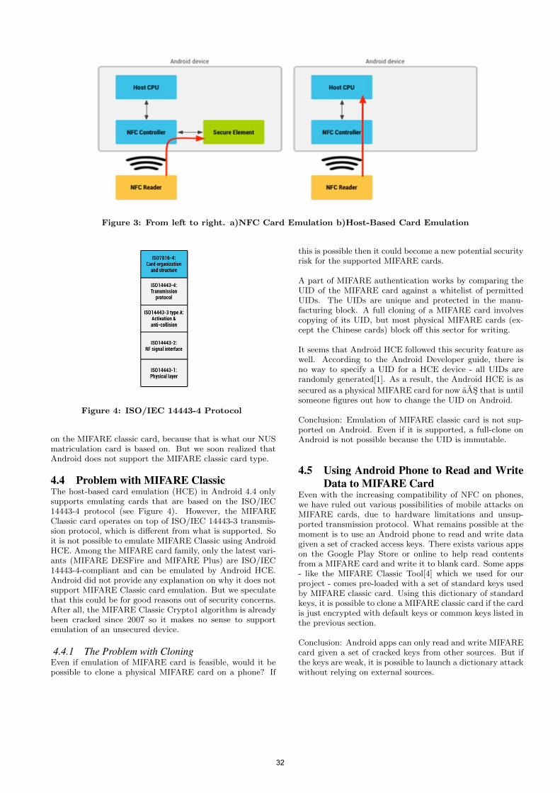
Figure 3: From left to right. a)NFC Card Emulation b)Host-Based Card Emulation
Figure 4: ISO/IEC 14443-4 Protocol
on the MIFARE classic card, because that is what our NUSmatriculation card is based on. But we soon realized thatAndroid does not support the MIFARE classic card type.
4.4 Problem with MIFARE ClassicThe host-based card emulation (HCE) in Android 4.4 onlysupports emulating cards that are based on the ISO/IEC14443-4 protocol (see Figure 4). However, the MIFAREClassic card operates on top of ISO/IEC 14443-3 transmis-sion protocol, which is different from what is supported. Soit is not possible to emulate MIFARE Classic using AndroidHCE. Among the MIFARE card family, only the latest vari-ants (MIFARE DESFire and MIFARE Plus) are ISO/IEC14443-4-compliant and can be emulated by Android HCE.Android did not provide any explanation on why it does notsupport MIFARE Classic card emulation. But we speculatethat this could be for good reasons out of security concerns.After all, the MIFARE Classic Crypto1 algorithm is alreadybeen cracked since 2007 so it makes no sense to supportemulation of an unsecured device.
4.4.1 The Problem with CloningEven if emulation of MIFARE card is feasible, would it bepossible to clone a physical MIFARE card on a phone? If
this is possible then it could become a new potential securityrisk for the supported MIFARE cards.
A part of MIFARE authentication works by comparing theUID of the MIFARE card against a whitelist of permittedUIDs. The UIDs are unique and protected in the manu-facturing block. A full cloning of a MIFARE card involvescopying of its UID, but most physical MIFARE cards (ex-cept the Chinese cards) block off this sector for writing.
It seems that Android HCE followed this security feature aswell. According to the Android Developer guide, there isno way to specify a UID for a HCE device - all UIDs arerandomly generated[1]. As a result, the Android HCE is as
secured as a physical MIFARE card for now aAS that is untilsomeone figures out how to change the UID on Android.
Conclusion: Emulation of MIFARE classic card is not sup-ported on Android. Even if it is supported, a full-clone onAndroid is not possible because the UID is immutable.
4.5 Using Android Phone to Read and WriteData to MIFARE Card
Even with the increasing compatibility of NFC on phones,we have ruled out various possibilities of mobile attacks onMIFARE cards, due to hardware limitations and unsup-ported transmission protocol. What remains possible at themoment is to use an Android phone to read and write datagiven a set of cracked access keys. There exists various appson the Google Play Store or online to help read contentsfrom a MIFARE card and write it to blank card. Some apps- like the MIFARE Classic Tool[4] which we used for ourproject - comes pre-loaded with a set of standard keys usedby MIFARE classic card. Using this dictionary of standardkeys, it is possible to clone a MIFARE classic card if the cardis just encrypted with default keys or common keys listed inthe previous section.
Conclusion: Android apps can only read and write MIFAREcard given a set of cracked keys from other sources. But ifthe keys are weak, it is possible to launch a dictionary attackwithout relying on external sources.
32

5. OUR EXPERIMENTSBelow are the various experiments we have tested in attemptto find a working solution to clone the identity and functionof the NUS matriculation card into a new MIFARE classic1K card or NFC enabled smartphone.
We can break our experiments to four parts:
• reading the metric card with an NFC reader to a com-puter
• cracking the NUS student Metric Card access key Aand key B
• Cloning to a card or an NFC enabled device
• Further experiments
5.1 Reading the Matric Card with a NFC Readerto a Computer
In the early stage of the project, we were blocked by notbeing able to claim the USB port on our development ma-chines, which is needed to connect to the NFC reader.
• Since Ubuntu is a more developer friendly platform, weresorted to a Virtual Machine to run Ubuntu. Since itis a virtual machine, this method failed as it is unableto claim the native USB port.
• We moved on to the Mac OS and windows platformbecause we believe that failure from using a virtualmachine was because the operating system was notnative. It was running Ubuntu in a windows envi-ronment. After testing out Mac OS and windows, wealso had problems claiming the USB port because ofincompatible driver issues.
• In an attempt to resolve this issue, we tried to dualboot Kali on a machine, and after installing the nec-essary dependencies for the NFC reader, we were ableto successfully claim the USB port and read from theNFC reader.
5.2 Cracking Matriculation Card Key A andKey B
Since a MFOC attack has already been implemented to crackkeys for MIFARE classic 1K cards, there is no point to rein-vent the wheel. We installed this program onto our devel-opment machine, and feed it the data read from the NFCreader to crack key A and key B for the metric card.
5.3 Emulating Matriculation Card using NFC-Enabled Phone
The original aim of the project was to be able to clonethe MIFARE matriculation card to an NFC enabled smart-phone. However, after some research, it seems that cloningMIFARE cards are possible to NFC enabled devices, just notthe MIFARE classic 1K cards, which is the type of cards thatthe NUS matriculation cards use. The MIFARE classic 1Kcards operates on top of ISO/IEC 14443-3 which is not sup-ported by Android host card based emulation. This makesit impossible to emulate the matriculation card on phone.
5.4 Cloning Matriculation Card to Chinese CardSimilar to the libnfc library used on computer, there is al-ready an android application that reads MIFARE cards andcan clone to a blank card. We used MIFARE Classic Toolto accomplish this (See Figure 5).
5.4.1 Changing UID of Cloned CardEvery MIFARE classic 1K card has a UID that is manufac-ture set. This value cannot be altered by anyone else sincethe purpose of this UID is to distinguish MIFARE cardsfrom each other. However, on Chinese cards, the value ofUID can be altered. We tested this by using MIFARE Clas-sic Tool, where we read the NUS matriculation card, enteredthe key A and key B that we cracked using MFOC, changedthe value of UID in sector 0 and wrote it to a blank Chinesecard.
5.5 Further Experiments5.5.1 Exploiting Access to NUS Central Library
We gave an attempt to exploit the school library system.The school’s library system takes a studentaAZs matricula-tion card and matches the UID and the matriculation num-ber, if successful, a student can checkout a book. To producea secondary matriculation card that matches this criteria, wecan clone a student’s matriculation card to a blank MIFAREcard. Since UID is only alterable on Chinese cards, we mustmake sure that the MIFARE card is a Chinese card. We canthen change the UID on sector 0.
Even though we have successfully cloned the matriculationcard of interest and altering the UID such that it is thesame, this method failed because the library has made theirbook checkout flow more robust. The library has imple-mented a two factor authentication system for a studentto successfully checkout a book. Specifically, this means af-ter authenticating the student’s matriculation card and UIDupon scanning, a second factor is needed to complete au-thentication. The student will have to provide a 6 digit pinfrom the secure NUS online services portal to complete theborrowing. Since we are unable to guess a random student’spin number, it is unlikely for this attack to succeed.
5.5.2 Exploiting Meal Credits in Colleges and HallsFor students living in colleges and halls on campus, theyare given a meal plan. In the colleges, students are givenan amount of credit that they can use over the semesterwhereas students living in halls have a set range of time formeals, and they have a binary choice of either eating or noteating. Unlike colleges, student in halls are not given creditsto use over the semester, so if they fail to show up, their mealexpires.
Upon investigating the information scanned from the stu-dent matriculation cards, we noticed that students living inHalls have different values in certain sectors due to their Halldining hall credits that can be used to redeem meals. Halland college meal credits can be exploited by investigatingand deducing the appropriate sectors on the matriculationcard. After some questioning and interviewing of studentswho live in halls and colleges, we took note that the mealscanners records the student matriculation number. Basedon this, we can attempt to exploit this area just from having
33

Figure 5: MIFARE Classic tool app
a student’s matriculation number. This is especially entic-ing, since a student’s matriculation number could easily beobtained anywhere, such as the student email on MicrosoftOutlook. Once we find out that a student belongs to a hallor college, we can write their matriculation number to ablank Chinese MIFARE classic 1K card, and use up theirmeal credits.
We can deduce the appropriate sectors that contain the stu-dent’s meal credit by reading a student’s matriculation card,and reading the said matriculation card once again right af-ter a student redeems a meal with their matriculation card.We can safely say that the varying sector among the twohex dumps is the sector that we are looking for. We canthen write a dining value to this sector. Now that we havethe dining value and the student matriculation number onthe card, it is sufficient to go to a hall or college to redeemmeals.
5.5.3 Exploiting Room Access in HallsStudents living in halls and colleges are also granted accessto rooms and resources when presented their matriculationcards. We can further exploit this by reading two matric-ulation cards that currently have access to two neighboringrooms. Similar to how we exploit the meal credits, we canread both matriculation cards and compare their hex dumpto deduce the appropriate sector on the card. Then, we canproceed to make changes to the corresponding sector andhave access to the rooms even we are not privileged users.
Since our attack requires matriculation cards from studentsthat live in the colleges or halls on campus, and due to thenecessity of manipulating their meal credits, we were unableto find participants who consented to such manipulation totheir information. Especially since if accidental event hap-pens, the student whose matriculation number is on the cardis responsible regardless of whether it was the original ma-triculation card or a duplicated card.
5.5.4 Exploiting facility access in schoolWe also investigated how our matriculation card gives accessto the various facilities in school - such as laboratories andtutorial rooms. For this, we do not need to find consenting
participants and can just use our own matriculation card toconduct the experiment. Using MFOC, we cracked the con-tents of our matriculation card and investigated the valueson each sector. For each sector, we toggle values to null andtested access to protected facilities. After some trial and er-ror, we found out that access to facilities is based on valuesin Sector 1 and the UID in Sector 0. This values could bedownloaded from a server daily, or updated by maintenanceinto the card reader outside a facility or room. The valuesin Sector 1 used for access control can be seen below:
Site Code: A8
Faculty Code: 01BB
Expiry date: 0B41
The card reader will check that the card has the correctsite code, faculty code and ensure that the card has yet toexpire. Then it will check against the UID value in Sector0. By default, users are denied entry to a protected facilityunless his UID in the matriculation card is whitelisted bythe reader. This secondary UID check allows the systemadministrator to conveniently update access control everysemester without reprogramming the values in the studentcard.
However, a security flaw also exists because the UID in Sec-tor 0 is not protected by any keys and can be easily read byany program. Using the MIFARE Classic Tool app, we suc-cessfully sniffed the UID value without cracking the accesskeys. The sniffing is convenient because it is quick (no needto crack the keys which takes time), mobile (can be doneover mobile phone), and long-distance (we managed to sniffthe UID just by placing the phone over the wallet withouttaking the card out of the wallet). This means that we caneasily impersonate as another student to gain access to a lab.Once we sniffed the UID value from a card, we can simplyclone our matriculation card to a Chinese card and changethe UID value to the victim’s one to gain access to the facil-ity. The premise is of course that we have a valid Sector 1value written to the Chinese card in the first place. So thisattack is only likely to work for current students in NUSwho can first clone their cards but not outsiders without amatriculation card.
34

6. CONCLUSIONIn conclusion, the MIFARE Classic 1k should not be consid-ered secured. In particular, if the MIFARE Classic card isused to store personal information (like name, date of birth,or travel information), this constitutes a direct privacy risk.This is particularly worrying in applications where the cardis used to store a certain value, like loyalty points or, evenworse, some form of digital currency. The value stored inthe electronic purse could easily be increased (or decreased).NUS libraries has circumvented this issue by adding an ad-ditional layer of security, but other universities still rely onthe matriculation card for numerous services. Furthermore,it is not safe to store any secret information in Sector 0, asit is not protected by any keys. Any information in sector 0can be sniffed with a smartphone app in less than 1 secondof contact.
Due to the widespread use of the MIFARE classic 1k, itwould be difficult to replace the card and readers to some-thing else in the short term. However, security can be in-creased by simply writing away the default keys for newlyissued cards. This would make MFOC attacks impossiblewithout somehow obtaining a sector key, thereby increasingsecurity significantly.
In the long term this countermeasure will not be sufficient.The MIFARE Classic card has a closed design which isagainst basic security design principles. Security by obscu-rity has shown many times that at some point the details ofthe system will be revealed compromising security. There-fore it is best to migrate to more advanced cards with anopen design architecture in the future.
7. REFERENCES[1] Host-based card emulation.
[2] J. Brashars. Proxmark 3, now with more android, dec2012.
[3] J.-H. H. Gerhard de Koning Gans and F. D. Garcia. Apractical attack on the mifare classic. Technical report,Institute for Computing and Information SciencesRadboud University Nijmegen, 2010.
[4] ikarus23. Mifare classic tool (mct).
[5] lady ada, apr 2015.
[6] P. LuptA ↪ak. Vulnerabilities in slovak mifare classiccards. In Mifare Classic analysis, 2010.
[7] MI1. Cooking with mifare classic. In Cooking withMifare Classic. Packet Storm, 2011.
[8] N. Semiconductors. AN10927 MIFARE and handling ofUIDs. NXP Semiconductors, 190740 edition, feb 2017.
[9] N. Tools. Libnfc:nfc-mfclassic.
35

36

A Brief Introduction To The Mathematics Of ECC Cao Wei
National University of Singapore Computing 1
13 Computing Drive, Singapore (+65)91566998
Moon Byunghun National University of Singapore
27 Prince George's Park Block 29, Level 8, Singapore 118424
(+65)83604316
Ang Yoong Zhen National University of Singapore
Computing 1 13 Computing Drive, Singapore
117417 (+65) 9666 3124
ABSTRACTElliptic curve cryptography(ECC) is a relatively new public key
cryptography. However, it is showing great potential in terms of
cryptographic strength with a small key size. This project will
introduce the mathematical foundation of elliptic curve
cryptography, briefly describe its implementation, compare its
strength and weaknesses with some other encryption schemes, and
analyze possible attacks on ECC and corresponding
countermeasures. We will also demonstrate an interactive
application to show the fundamental mathematics behind ECC.
Categories and Subject DescriptorsD.3.3 [Cryptography]: General – Mathematics and implication
General Terms1. Algorithms, Security.
KeywordsElliptic curve, elliptic curve cryptography, point arithmetic, filed
arithmetic, attack.
1. INTRODUCTIONElliptic Curve Cryptography (ECC) is a public key cryptography,
otherwise known as asymmetric cryptography, uses a pair of
private and public key which the private key is only known to the
owner while the public key can be distributed out with any
constraint. In the first half of the paper, we will walk you through
the basic mathematics of the ECC, and how it is used as a
cryptography scheme. In the latter half of the paper, we will mainly
focus on the ECC over a prime field. We will discuss the
advantages and disadvantages of ECC, compared with RSA. Also,
we will introduce several popular attacks on the ECC, and discuss
their efficiency. There are applications developed by Mathematica
used in paper, to facilitate the illustration of mathematics we are
using. To access these apps, go to
https://github.com/LoneGunman001/ECC-Tools and download
the .cdf files. To play these files, you will need to download a CDF player through the link https://www.wolfram.com/cdf-player/.
2. ECC's Mathematical OperationsThe mathematical operations of ECC are revolved around an
elliptic curve. Thus, in order to generate the public key Kpub , a
random number which is the private key Kpriv is multiplied with a
point P on the curve through point multiplication leading to the
following formula:
Kpub = P x Kpriv
In ECC, these mathematical operations tend to be used over finite
field which mainly consists of prime field and binary field as the
operations over real numbers tend to be much slower and
inaccurate. However, in this section, the mathematical
operations over real
numbers will be covered as well. Before any mathematical
operations should be done it is important to determine the necessary
domain parameters as well which will define ECC.
2.1 Real Numbers In real numbers, the elliptic curve will take the equation of y2 = x3
+ ax + b whereby 4a3 + 27b2 != 0 and the domain parameters of
this curve include a, b and P.
2.1.1 Point Multiplication Point multiplication consists of 2 other functions which are point
addition and point doubling. The simplest method of implementing
point multiplication is through the use of double-and-add method
which can be implemented in a recursive function. The following
pseudo code shows the implementation of the recursive function of
double-and-add method for point multiplication:
point_multiplication(P, n) {
if (n == 0)
return 0;
else if (n == 1)
return P;
else if (n % 2 == 1)
return point_addition(P, point_multiplication(P, n - 1));
else
return point_multiplication(point_doubling(P), n / 2);
}
where P is the point of the curve that is used to multiple with the
private key Kpri while n is the number of bits of the private key.
2.1.2 Point Addition Point addition is defined as the operation of adding 2 different
points, J and K , together in order to obtain another point L such
that J = (xJ, yJ), K = (xK, yK) and L = (xL, yL). Hence, L can be
obtained using the following formulas:
xL = s2 - xJ - xK
yL = -yJ + s (xJ - xL)
where s = (yJ - yK) / (xJ - xK).
2.1.3 Point Doubling Point doubling is defined as the operation of adding a point J to
itself in order to obtain another point L such that J = (xJ, yJ) and L
= (xL, yL). Hence, L can be obtained using the following formulas:
xL = s2 – s xJ
yL = -yJ + s (xJ - xL)
37

where s = (3xJ2 + a) / 2yJ in which a is the chosen domain
parameters for ECC in real numbers.
2.2 Prime Field In prime field, the elliptic curve will take the equation of y2 mod p
= x3 + ax + b mod p whereby 4a3 + 27b2 mod p != 0 and the domain
parameters of this curve include a, b, P and p which defines the
prime number to be used in the prime field. In addition, in prime
field, point multiplication operation still remains the same as real
numbers'. Hence, only point addition and point doubling is covered
in this section.
2.2.1 Point Addition Point addition is defined as the operation of adding 2 different
points, J and K , together in order to obtain another point L such
that J = (xJ, yJ), K = (xK, yK) and L = (xL, yL). Hence, L can be
obtained using the following formulas:
xL = s2 - xJ – xK mod p
yL = -yJ + s (xJ - xL) mod p
where s = (yJ - yK) / (xJ - xK) mod p in which p is the chosen domain
parameters for ECC in prime field.
2.2.2 Point Doubling Point doubling is defined as the operation of adding a point J to
itself in order to obtain another point L such that J = (xJ, yJ) and L
= (xL, yL). Hence, L can be obtained using the following formulas:
xL = s2 – s xJ mod p
yL = -yJ + s (xJ - xL) mod p
where s = (3xJ2 + a) / 2yJ mod p in which a and p is the chosen
domain parameters for ECC in prime field.
2.3 Binary Field In binary field, the elliptic curve will take the equation of y2 + xy =
x3 + ax2 + b whereby b != 0 and the domain parameters of this
curve include a, b and P. Likewise, point multiplication operation
used in binary field remains the same.
2.3.1 Point Addition Point addition is defined as the operation of adding 2 different
points, J and K , together in order to obtain another point L such
that J = (xJ, yJ), K = (xK, yK) and L = (xL, yL). Hence, L can be
obtained using the following formulas:
xL = s2 + s + xJ + xK + a
yL = s (xJ + xL) + xL + yJ
where s = (yJ + yK) / (xJ + xK) in which a is the chosen domain
parameters for ECC in binary field.
2.3.2 Point Doubling Point doubling is defined as the operation of adding a point J to
itself in order to obtain another point L such that J = (xJ, yJ) and L
= (xL, yL). Hence, L can be obtained using the following formulas:
xL = s2 + s + a
yL = xJ2 + (s + 1) * xL
where s = xJ + yJ xJ in which a is the chosen domain parameters
for ECC in binary field.
3. ECC VS RSARivest Shamir Adelman(RSA) is one of the most widely used
public key cryptography. Also, it is one of the oldest cryptography
algorithm which are commonly used nowadays.
Since RSA and RCC are both public key cryptography algorithm,
they are often compared in terms of usefulness. In this report, we
have included three different types of performance test to compare
RSA and ECDSA (Elliptic Curve Digital Signature Algorithm).
ECC has ability to offer same level of security with much smaller
key size than RSA. Thus, the below table shows the comparable
key sizes of ECC and RSA to test the performance of these two
cryptography.
Table 1. Comparable key sizes (in bits) of symmetric, ECC
and RSA
Symmetric ECC RSA
80 163 1024
112 233 2240
128 283 3072
192 409 7680
256 571 15360
The performance comparison test was done for key generation,
signature generation and signature verification. These three
functionalities were chosen since they determine the overall
performance of the public key cryptography algorithm.
Test were done by Nicholas Jansma and Brandon Arrendondo. The
testing was performed on an Intel P4 2.0 GHz machine with 512 of
RAM and size of the message used for signing is 100Kb txt file.
3.1 Key Generation Table 2. Key generation time of ECC and RSA for different
key length
Key Length Time (s)
ECC RSA ECC RSA
163 1024 0.08 0.16
233 2240 0.18 7.47
283 3072 0.27 9.80
409 7680 0.64 133.90
571 15360 1.44 679.06
From the data above, we can clearly see that key generation speed
of ECC is much faster than key generation speed of RSA. This is
because ECC does not have to spend its resources for generating
prime numbers.
Also, ECC key generation time grows linearly whereas RSA key
generation time grows exponentially. Thus, ECC can generate
much faster than RSA as key length grows.
3.2 Signature Generation Table 3. Signature generation time of ECC and RSA for
different key lengths
Key Length Time (s)
ECC RSA ECC RSA
163 1024 0.15 0.01
38

233 2240 0.34 0.15
283 3072 0.59 0.21
409 7680 1.18 1.53
571 15360 3.07 9.20
RSA seems to run much faster than ECC when key size is small.
But when key size increases, ECC seems to be much faster than
RSA.
3.3 Signature Verification Table 4. Signature verification time of ECC and RSA for
different key lengths
Key Length Time (s)
ECC RSA ECC RSA
163 1024 0.23 0.01
233 2240 0.51 0.01
283 3072 0.86 0.01
409 7680 1.80 0.01
571 15360 4.53 0.03
For signature verification performance, RSA outperforms ECC for
all key sizes. The key size factor seems to be negligible in signature
verification in RSA whereas the verification time seems to have
linear growth in ECC for increasing key sizes.
The test result clearly shows that RSA outperforms ECC. However,
the difference is minor compared to the difference in key generation
time and signature generation time.
Therefore, signature verification is the only part that RSA
outperforms ECC but the overall performance of ECC is much
faster than RSA.
Thus, we can conclude that ECC is much faster than RSA
cryptography algorithm.
3.4 Why ECC Is Not Widely Used? ECC can achieve same level of security with much smaller key size
compared to RSA and from the performance tests above, we can
clearly see that the overall performance of ECC is much faster than
RSA. However, there are some factors that hinder the wide
acceptance of ECC.
3.4.1 Understandability Firstly, ECC involves much complicated mathematics and it makes
it harder to understand, whereas other cryptography like RSA has
much simpler mathematics than ECC. Thus, RSA is much easier to
understand than ECC.
3.4.2 Lack of research Furthermore, it is known that there is a lot of support from US
government and political push for using ECC. However, RSA is
more widely deployed and has better industry support with much
more research compared to ECC.
3.4.3 Patent issue In addition, ECC has some patent problems, especially for binary
curves. Thus, there are some potential legal risks related to patents.
3.4.4 Other technical limitations
Though it seems that ECC is much better than RSA in performance
wise, ECC still has some technical limitations. Here are some
possible limitations of ECC.
Most of ECDSA implementation needs a secure random generator.
By doing this, ECDSA can ensure difficulty of revealing the private
key but if this random generator reuses same random value for
different plaintext, the private key will be revealed easily.
On the other hand, ECC is much more efficient than RSA, ECC is
still much slower than symmetric algorithms.
Also, ECC is a public-key cryptography. Thus, disadvantages of
using public-key applies to ECC as well.
Furthermore, ECC has some interoperability issue over using two
or three specific curves. Implementation of ECC can be done over
curves of distinct type and we can choose one of the known curves
to optimize when actual code is written.
NIST has defined 15 standard curves, but most the implementations
support only two of them. There are no security threats by using
same curve but there are some potential interoperability issues
when most of implementation supports only supports few curves
3.5 Possible Improvements for ECC There are some possible improvements for ECC such that ECC can
be widely accepted by people. In terms of key size and performance,
ECC outperforms RSA. Thus, when ECC can overcome some of
its limitations, ECC can also be widely used as RSA.
3.5.1 Improvements in understandability and
research contents One of the disadvantage of ECC compared to RSA is its
understandability. However, only programmers who implements
ECC will need to understand this cryptography and the others will
only need to know its functionality. Thus, the understandability
issue can be overcome by having more researches such that the
programmers can refer to these researches and understand better.
3.5.2 Time solution for patents problems On the other hand, the patent problem is also one of the main
disadvantage of ECC. When things are related to possible legal
risks, it is hard to be accepted widely.
Patents for RSA was expired on 21 September 2000 but there is
some patent left for ECC. However, most of its patents will be
expiring soon. For example, US patents held by Hewlett-Packard
and Certicom will be expiring in 2018 and 2019 respectively. And
the last patent related to ECC will be expiring in 2020.
Therefore, the time will solve its patent problem and will further
improve the acceptance of ECC.
4. Possible attacks on ECC In order to break the ECC, we need to solve the elliptic curve
discrete logarithm problem. Up to now, our focus is on the attack
on the ECC with a prime field, which means the ECDLP is about
given 2 points P and Q on Ep(a, b), we want to find the integer k
such that 𝐐 = k ∗ 𝐏. In this chapter, I will introduce simple-power
analysis as an efficient side-channel attack, along with baby-step,
giant-step algorithm and Pollard’s Rho method as two commonly
used brute force attacks. Last but not least, I will introduce Pohlig-
Hellman attack as an attack on some special curves.
39

4.1 Simple Power analysis – a side-channel
attack Side channels of ECC cryptosystem leak crucial information.
Simple power analysis (SPA) can find out the number and sequence
of point additions and point doubling due to differences in power
traces between the two operations. In fact, the attacker can derive
the value of k, if the attacker knows the sequence of point addition
and point doubling when calculating k ∗ 𝐏, as the process gives
away binary bits of k. In the application we can show that such
attack is possible.
Figure 1: A screenshot of an application implementing simple
power analysis
4.2 Baby-step, Giant-step Algorithm – a
brute-force attack Normally when we perform brute-force attack to find a value, we
start from 1 and step up, until we find a hit. Baby-step, Giant-step
algorithm uses a meet-in-the-middle attack to reduce the time
complexity. It rewrites k as k = a ∗ x + b, where x = ⌈√𝑝⌉ and p is
the order of the ECC. a and b are the quotient and the remainder of
k divided by x. According to the quotient remainder theorem, 0 ≤b < x. Meanwhile, since k ≤ p, we can see that 0 ≤ a ≤ x. The
ECDLP now transforms into solving 𝐐 − a ∗ x ∗ 𝐏 = b ∗ 𝐏. If we
calculate b ∗ 𝐏 for every b and store the values in a hash table, we
will find a correspondence by calculating some 𝐐 − a ∗ x ∗ 𝐏, and
the corresponding values of a and b can give us the value of k.
Overall, this algorithm has a time complexity of O(√𝑝).
However, it is not feasible to apply this algorithm on a 192-bit key.
Note the space complexity of this algorithm is also O(√𝑝) due to
the hash table. For a key with 192 bits, √𝑝 can be several octillions
(1027 ). Assuming each entry in the hash table takes 1 byte (in
reality the value is much larger than this), the size of the hash table
will exceed the total storage power in the world.
Figure 2: A screenshot of an application implementing Baby-
step, Giant-step Algorithm
4.3 Pollard's Rho Method – a brute-force
attack Pollard's Rho Method is another brute-force method with much less
space complexity compared to the Baby-step, Giant-step algorithm.
It also involves in rewriting 𝐐 = k ∗ 𝐏 . In fact, Pollard's Rho
method transforms the ECDLP into finding a set of integers
a, b, A and B such that a ∗ 𝐏 + b ∗ 𝐐 = A ∗ 𝐏 + B ∗ 𝐐 . By
substituting Q with k*P, we can see k =𝑎−𝐴
𝑏−𝐵.
The foundation of this method is that since P and Q are both in the
same finite field, a ∗ 𝐏 + b ∗ 𝐐 would be in the same finite field as
well. By the pigeonhole principle, we have p2 pigeons (pairs of
(a, b)) here and p pigeon holes (possible values of a ∗ 𝐏 + b ∗ 𝐐),
by substituting different pairs of (a, b), we eventually will find two
pairs of integers which give the same result.
To make the attack efficient, Pollard's Rho method uses Floyd's
cycle-finding algorithm. First, we generate a pseudorandom
sequence of (a, b) pairs, then calculate the corresponding a ∗ 𝐏 +b ∗ 𝐐 . Starting from 2 different positions in the sequence, we
simultaneously progress in the sequence with different speed.
Sooner or later, the two different positions will hold the same value,
but the corresponding pairs of (a, b) are different. These two pairs
will give us the set of integers a, b, A and B.
The average performance of this method is still O(√𝑝). Here I will
not establish a probability model and prove its correctness.
Meanwhile, the average space complexity for this method is
O(log 𝑝), if we need to generate the pseudorandom integer pair
sequence every time. If there is a given sequence, the space
complexity of this method is actually O(1).
40
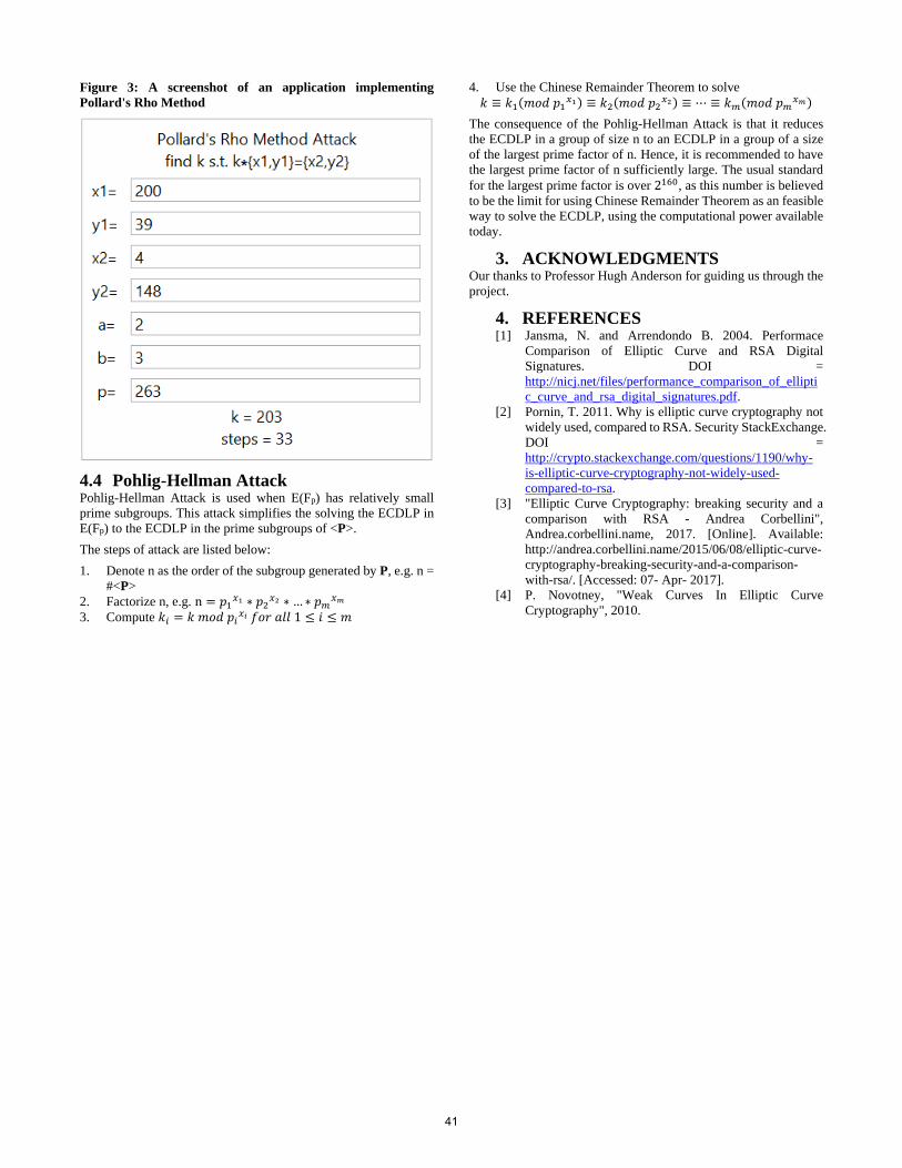
Figure 3: A screenshot of an application implementing
Pollard's Rho Method
4.4 Pohlig-Hellman Attack Pohlig-Hellman Attack is used when E(Fp) has relatively small
prime subgroups. This attack simplifies the solving the ECDLP in
E(Fp) to the ECDLP in the prime subgroups of <P>.
The steps of attack are listed below:
1. Denote n as the order of the subgroup generated by P, e.g. n =
#<P>
2. Factorize n, e.g. n = 𝑝1𝑥1 ∗ 𝑝2
𝑥2 ∗ … ∗ 𝑝𝑚𝑥𝑚
3. Compute 𝑘𝑖 = 𝑘 𝑚𝑜𝑑 𝑝𝑖𝑥𝑖 𝑓𝑜𝑟 𝑎𝑙𝑙 1 ≤ 𝑖 ≤ 𝑚
4. Use the Chinese Remainder Theorem to solve
𝑘 ≡ 𝑘1(𝑚𝑜𝑑 𝑝1𝑥1) ≡ 𝑘2(𝑚𝑜𝑑 𝑝2
𝑥2) ≡ ⋯ ≡ 𝑘𝑚(𝑚𝑜𝑑 𝑝𝑚𝑥𝑚)
The consequence of the Pohlig-Hellman Attack is that it reduces
the ECDLP in a group of size n to an ECDLP in a group of a size
of the largest prime factor of n. Hence, it is recommended to have
the largest prime factor of n sufficiently large. The usual standard
for the largest prime factor is over 2160, as this number is believed
to be the limit for using Chinese Remainder Theorem as an feasible
way to solve the ECDLP, using the computational power available
today.
3. ACKNOWLEDGMENTS Our thanks to Professor Hugh Anderson for guiding us through the
project.
4. REFERENCES [1] Jansma, N. and Arrendondo B. 2004. Performace
Comparison of Elliptic Curve and RSA Digital
Signatures. DOI =
http://nicj.net/files/performance_comparison_of_ellipti
c_curve_and_rsa_digital_signatures.pdf.
[2] Pornin, T. 2011. Why is elliptic curve cryptography not
widely used, compared to RSA. Security StackExchange.
DOI =
http://crypto.stackexchange.com/questions/1190/why-
is-elliptic-curve-cryptography-not-widely-used-
compared-to-rsa.
[3] "Elliptic Curve Cryptography: breaking security and a
comparison with RSA - Andrea Corbellini",
Andrea.corbellini.name, 2017. [Online]. Available:
http://andrea.corbellini.name/2015/06/08/elliptic-curve-
cryptography-breaking-security-and-a-comparison-
with-rsa/. [Accessed: 07- Apr- 2017].
[4] P. Novotney, "Weak Curves In Elliptic Curve
Cryptography", 2010.
41

42

Keystroke Dynamics Analysis (Preliminary Paper / Work-in-progress)
Goh Jing Loon
A0147827U [email protected]
Bernard Yip
A0140042A [email protected]
Ng Qing Hua
A0139915W [email protected]
Yee Jian Feng Eric
A0140016B [email protected]
ABSTRACT Keystroke dynamics refers to the automated method of confirming or identifying the identity of an individual based on the manner and the rhythm of typing on a keyboard. Keystroke dynamics is a behavioral biometric which means that the biometric factor is something one performs. In this paper, we explore into analyzing the keystrokes patterns of individuals and replicating a unique person's keystroke dynamics to bypass current existing keystroke profiling authenticators in the market.
Categories and Subject Descriptors D.3.3 [Programming Languages]: Language Contructs and Features – abstract data types, polymorphism, control structures. This is just an example, please use the correct category and subject descriptors for your submission. The ACM Computing Classification Scheme: http://www.acm.org/class/1998/
General Terms Experimentation, Security, Human Factors, Verification.
Keywords Keystroke, Keystroke Dynamics, Profiling
1. INTRODUCTION The roots of keystroke dynamics go back to the early days of the telegraph, when individuals developed distinctive patterns that identified them. During World War II, a methodology known as the "fist of the sender" helped to identify the source of Morse code and confirm that a particular message was, in fact, from a valid source (Rouse, 2008). In the modern technology era, individuals interact with the keyboard almost on a daily basis. Each individual has his own unique patterns in typing out the intended words. This leads to the possibility of obtaining a distinguishable variable for a person’s identity. Research in this domain area has been quite in-depth and it is now possible to successfully identify a unique individual by analysing his typing patterns. However, results from relevant studies and findings are mostly proprietary and hard to obtain. Different products analyse and develop their confidence values in their unique way. As such, we decided to experiment on our own and come up with our own keystroke profile analyser. We then test its capabilities by attempting to replicate a unique person's keystroke dynamics to bypass current existing keystroke profiling authenticators in the market.
2. KEYSTROKE AS BIOMETRIC DATA Keystroke dynamic information, if properly analysed, can be converted into an accurate representation of a person’s biometric property. This is often possible because some characteristics of keystroke production are as unique as an individual’s handwriting or a signature. The techniques used to do this vary widely in power and sophistication, and range from statistical techniques to AI approaches like neural networks.
2.1 KEYSTROKE DYNAMICS VARIABLES Keystroke dynamics include: overall speed. variations of speed moving between specific keys, common errors and the length of time that keys are depressed.
3. EXPERIMENT 3.1 Objective Our aim is to successfully replicate a person’s keystroke dynamics onto an authenticator in the existing market. We start with collecting raw keyboard input data. The data is then processed and analyzed for recognizable patterns. Results from the data will be fed into our profile builder. The profile is then loaded into the profile-based typing robot. Lastly, we run the robot on existing authenticators and compare the confidence levels with the person’s actual human input.
3.2 Data Collection We enrolled 7 volunteers to provide their unique keystroke patterns for the project. Subjects were given specific paragraphs to type. The keypresses are collected with a low-level keylogger built in C.
Figure 1 - Collecting the keystrokes of a user
3.3 Data Analysis The recorded data is broken down into identifiable patterns (see 2.1 Keystroke Dynamics Variables). The results are logged under a profile data file encoded in JSON.
3.4 Profile Generation
43

3.5 Mimicking Human Input with a Keystroke Profile 3.5.1 Profile-Based Typing Robot We built a profile-based typing robot which takes in the individual’s profile. We can then feed in the required text for the robot to replicate based on the user’s keystroke dynamics.
Figure 2 - Loading a keystroke profile into the typing robot
3.5.2 Tests on Market-ready Authenticators We run the robot on various market-ready keystroke authenticators, such as TypingDNA and KeyTrac. The robot is run on the provided demos in their websites.
4. FINDINGS Out of the 7 profiles, the average level of confidence the robot managed to aquire was _%. The results are summarized in the table below.
Individual
TypingDNA KeyTrac Difference
Individual
Robot
Individual
Robot
1
To be updated
2
3
4
5
6
7
5. CONCLUSION To be updated after project testing phase.
6. FUTURE STUDY To be updated after conclusion of project.
7. REFERENCES [1] Rouse, M. 2008. Definition: Keystroke Dynamics.
SearchSecurity, TechTarget. DOI= http://searchsecurity.techtarget.com/definition/keystroke-dynamics
44

Protection and Authentication for Web Application
Ng Wei Kiang
School of Computing National University of Singapore
Huang Baoyi School of Computing
National University of Singapore
Lim Shu Na School of Computing
National University of Singapore
ABSTRACT In this paper, our group will work on a Web application where we will explore the strengths and weaknesses of techniques used for protecting web-based applications.
Our objectives for this project are to demonstrate various forms of attacks, such as the SQL Injection, Cross-Site-Scripting (XSS) and Cross-Site Request Forgery (CSRF) attacks. On top of that, our group will look at enhanced security feature by performing Password Hash Salting implementation before storing it to the database. We will also be demonstrating the ways to protect and authenticate in 2 separate websites.
Therefore, with the help of our application, it allows users to understand the common vulnerabilities that might happen when they are using a web application, and to provide guidance on how to avoid these vulnerabilities.
1. INTRODUCTION Moving along with latest technology advancement, many of the corporate enterprises have made use of the digital world to facilitate financial transactions. Businesses provide online platform for potential users to interact with the content by having a web authentication framework. With such an authentication process in place, users are potentially exposed to several web vulnerabilities which can be observed by the rising trend of cyber-attacks. According to PwC’s 2016 Global Economic Crime Survey – Singapore, “Cybercrimes jumped from 15% in 2014 to 43% in 2016; now the second most prevalent economic crime in Singapore”. In responding to such threats, the Singapore government is beefing up its capabilities to fight cybercrime by developing a masterplan for the national Cyber Security Agency (CSA) as well as enhancing the Cyber Watch Centre (CWC) and Threat Analysis Centre (TAC). Hence, the motivations in heightening cyber security by exploring the fundamental preventive measures against cybercrimes.
2. WEB APPLICATION In facilitating the various attacks based on the security components, a Web page was designed and implemented using PHP, together with web development features such as Bootstrap, CSS and JavaScript. The Index Page is as shown in Figure 1.
Figure 1. Index Page
3. DATABASE DESIGN In order to have a clearer explanation, our group has created a database which simulates the realistic scenarios, such as registration, log-in authentication, fund transfer, as well as showing if the attacks were able to be performed. For example, when user is registering for a new account, the username and password will be stored into the username, password, password_hash and password_salt fields. More elaboration on the Password Hash Salting Algorithm will be discussed in Section 3.3. The acct_transfer, mirror_value and csrf_value fields are used to show if we were able to perform the XSS Persistent, XSS Mirror and CSRF attacks respectively.
45

4. IMPLEMENTATION
4.1 Password Hash Salting Workflow The Workflow in Figure 2 illustrates how the password was added to the database with “enhanced” security using the Password Hash Salting implementation.
Figure 2. Password Hash Salting Workflow
4.2 SQL Injection It is a type of security exploit in which the attacker adds SQL code to the input box of the web form to gain access to resources or to make changes to the data. Figure 3 illustrates the execution flow of the SQL Injection attack.
Figure 3. SQL Injection Attack Workflow
4.2.1. How it works? With reference to Figure 4, SQL Injection works when malicious SQL query is run against the database server. An attacker will have to first find the input fields from the web application that is vulnerable to any text form, without the Validation and Sanitization checks at the front end, and the SQL Prepared Statement implemented at the back end. Pretending that we are the attacker, we do not have an account in this system, all we have to do is to key in ' or ''=' in the username and password input fields at the login page and we can enter to the transfer fund page successfully.
After attacker has successfully entered into the transfer fund page, attacker finds the input fields of the page vulnerable to any text form, and use the same technique to perform SQL injection on this page. All the attacker needs to do is to key in ' or ''=' in the your account number input field, enter the payee’s account number, which in this case is the attacker’s account number, follow by entering any amount to be transferred, and the money will be transferred seamlessly over.
Figure 4. SQL Injection Attack Sign-in page without Validation and Sanitization checks
4.2.2. How to prevent? As shown in Figure 5, in order to prevent SQL Injection from happening in the web application, we have performed a Validation and Sanitization checks over at the front end where the input fields are checked before further processing. Other than performing the checks at the front end, we have also performed checking at the back end, where we have made use of SQL Prepared Statements to prevent any potential attempt of SQL Injection.
Figure 5. SQL Injection Protection Workflow
46

4.3 Cross-Site-Scripting (XSS) Persistent It is a type of attack to execute malicious JavaScript in the victim’s browser, where the malicious string originates from the website’s database. Figure 6 illustrates the execution flow of the XSS Persistent attack.
Figure 6. XSS Persistent Attack Workflow
4.3.1. How it works? With reference to Figure 7, XSS Persistent, which is also known as XSS Stored attack is a type of attack to execute malicious JavaScript in the victim’s browser, where the malicious string originates from the website’s database. To successfully execute a XSS Persistent attack, the attacker will first have to find an input field from the web application that is vulnerable to any text form, without the Validation and Sanitization checks at the front end, and the SQL Prepared Statements implemented at the back end.
Pretending that we are the attacker and we do not have an account of this system, all we have to do is to key in ' or ''=' in the username and password input fields at the login page and we can enter to the transfer fund page successfully, which acts like a SQL Injection attack. After the attacker has successfully entered into the transfer fund page, attacker finds the input fields of the page vulnerable to any text form, key in ' or ''=' in your account number and payee’s account number input fields. Now, in order to perform the XSS Persistent attack, the attacker will have to key in a malicious script in the amount input field, where this malicious script will redirect users who visits this page to the malicious page created by the attacker. The malicious script could be the following example
Fail to make transaction <script>window.location='http://localhost/CS3235/transfer_fund_malicious.php'</script>
Where transfer_fund_malicious.php is the malicious page created by the attacker. By doing this, the malicious script has been stored into the database. Therefore, without knowing what has happened, users who visit this page afterwards will be redirected to the malicious page which looks exactly like the original page.
Figure 7. XSS Persistent Attack Sign-in page without Validation and Sanitization checks
4.3.2. How to prevent? As shown in Figure 8, in order to prevent XSS Persistent attack from happening in the web application, we have performed Validation and Sanitization checks over at the front end where the input fields are checked before further processing. Other than performing the checks at the front end, we have also performed checking at the back end, where we have made use of SQL Prepared Statements to prevent any potential attempt of XSS Persistent attack.
Figure 8. XSS Persistent Protection Workflow
47

4.4 Cross-Site-Scripting (XSS) Mirror It is a type of attack to execute malicious JavaScript in the victim’s browser, where the malicious string originates from the victim’s request. Figure 9 illustrates the execution flow of the XSS Mirror attack.
Figure 9. XSS Mirror Attack Workflow
4.4.1. How it works? With reference to Figure 10, XSS Mirror, which is also known as XSS Reflected attack is a type of attack to execute malicious JavaScript in the victim’s browser, where the malicious string originates from the victim’s request. To successfully execute a XSS Mirror attack, the attacker will have first to find an input field from the web application that is vulnerable to any text form, without the Validation and Sanitization checks at the front end, and the SQL Prepared Statements implemented at the back end.
Pretending that we are the attacker and we do not have an account in this system, all we have to do is to key in ' or ''=' in the username and password input fields at the login page and we can enter to the transfer fund page successfully, which acts like a SQL Injection attack. After the attacker has successfully entered into the transfer fund page, attacker finds the input fields of the page vulnerable to any text form, key in ' or ''=' in your account number and payee’s account number input fields. Now, in order to perform the XSS Mirror attack, the attacker will have to key in a malicious script in the amount input field, where this malicious script will redirect users who visits this page to the malicious page created by the attacker. The malicious script could be the following example
<script>alert(document.cookie)</script>
By doing this, the malicious script has been stored into the database. Therefore, without knowing what has happened, users who visit this page afterwards will be able to see a pop out alert that shows their web browser’s cookie. Being able to attack this vulnerability, it allows attacker to obtain cookie from the users who have visited this page.
Figure 10. XSS Mirror Attack Sign-in page without Validation and Sanitization checks
4.4.2. How to prevent? As shown in Figure 11, in order to prevent XSS Mirror attack from happening in the web application, we have performed Validation and Sanitization checks over at the front end where the input fields are checked before further processing. Other than performing the checks at the front end, we have also performed checking at the back end, where we have made use of SQL Prepared Statements to prevent any potential attempt of XSS Mirror attack.
Figure 11. XSS Mirror Protection Workflow
48
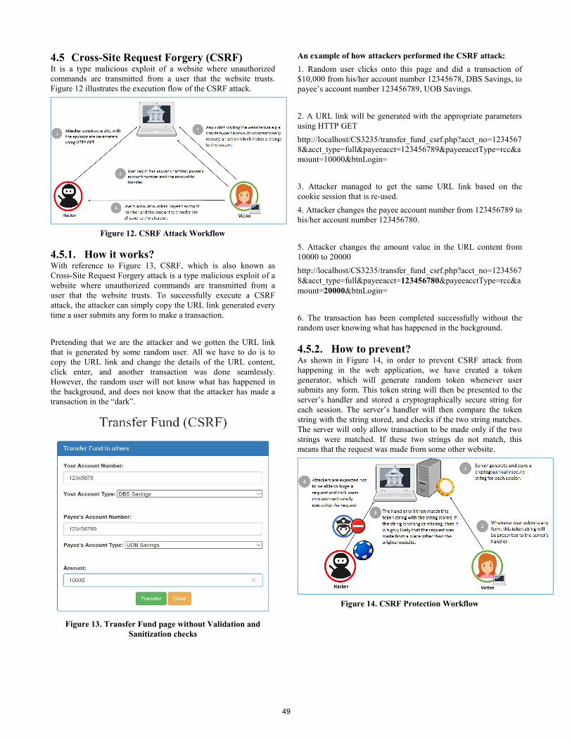
4.5 Cross-Site Request Forgery (CSRF) It is a type malicious exploit of a website where unauthorized commands are transmitted from a user that the website trusts. Figure 12 illustrates the execution flow of the CSRF attack.
Figure 12. CSRF Attack Workflow
4.5.1. How it works? With reference to Figure 13, CSRF, which is also known as Cross-Site Request Forgery attack is a type malicious exploit of a website where unauthorized commands are transmitted from a user that the website trusts. To successfully execute a CSRF attack, the attacker can simply copy the URL link generated every time a user submits any form to make a transaction.
Pretending that we are the attacker and we gotten the URL link that is generated by some random user. All we have to do is to copy the URL link and change the details of the URL content, click enter, and another transaction was done seamlessly. However, the random user will not know what has happened in the background, and does not know that the attacker has made a transaction in the “dark”.
Figure 13. Transfer Fund page without Validation and Sanitization checks
An example of how attackers performed the CSRF attack:
1. Random user clicks onto this page and did a transaction of $10,000 from his/her account number 12345678, DBS Savings, to payee’s account number 123456789, UOB Savings.
2. A URL link will be generated with the appropriate parameters using HTTP GET
http://localhost/CS3235/transfer_fund_csrf.php?acct_no=12345678&acct_type=full&payeeacct=123456789&payeeacctType=rcc&amount=10000&btnLogin=
3. Attacker managed to get the same URL link based on the cookie session that is re-used.
4. Attacker changes the payee account number from 123456789 to his/her account number 123456780.
5. Attacker changes the amount value in the URL content from 10000 to 20000
http://localhost/CS3235/transfer_fund_csrf.php?acct_no=12345678&acct_type=full&payeeacct=123456780&payeeacctType=rcc&amount=20000&btnLogin=
6. The transaction has been completed successfully without the random user knowing what has happened in the background.
4.5.2. How to prevent? As shown in Figure 14, in order to prevent CSRF attack from happening in the web application, we have created a token generator, which will generate random token whenever user submits any form. This token string will then be presented to the server’s handler and stored a cryptographically secure string for each session. The server’s handler will then compare the token string with the string stored, and checks if the two string matches. The server will only allow transaction to be made only if the two strings were matched. If these two strings do not match, this means that the request was made from some other website.
Figure 14. CSRF Protection Workflow
49

5. LEARNING EXPERIENCE In almost every projects, teamwork is vital to ensure the success of the project implementation. Our group constantly shares ideas and update one another through knowledge-sharing sessions. Although substantial amount of time was invested in the debugging process, our group managed to appreciate the content much better with the hands-on experience.
6. CONCLUSION In conclusion, we can’t deny the fact that cybercrimes are on a rise. Recently, the Ministry of Defence (MINDEF) detected a breach in its I-net system. Another incident happened where fake Immigration & Checkpoints Authority (ICA) website has surfaced with the intent to phish visitors’ personal particulars. Although the agencies might have strong network security systems in place, that does not deter the attackers from penetrating to their systems. Hence, it is inevitable that the threats of cybercrimes are presence, but the ultimate objective is to reduce the occurrences by providing security awareness and proper guidance in using IT systems.
[9] Economic crime remains an obstinate threat in Singapore Retrieved March 14, 2017, from https://www.pwc.com/sg/en/consulting/assets/economic-crime-survey/economic_crime_survey_2016_singapore.pdf
7. ACKNOWLEDGEMENTS Most importantly, our group would like to express our gratitude and appreciation to our Lecturer, Assoc Professor Hugh Anderson, who will always provide his valuable feedback for any potential area of improvements. Thank you, Sir.
8. REFERENCES [1] What is Cross-site Scripting and How Can You Fix it? (n.d.). Retrieved March 02, 2017, from http://www.acunetix.com/websitesecurity/cross-site-scripting/ [2] Defending against CSRF Attacks, XSRF or Sea-Surf. (n.d.). Retrieved March 03, 2017, from http://www.acunetix.com/websitesecurity/csrf-attacks/ [3] Fekete, G. (2013, October 28). Cross-Site Scripting Attacks (XSS). Retrieved March 10, 2017, from https://www.sitepoint.com/php-security-cross-site-scripting-attacks-xss/ [4] Hacking, E. (n.d.). Cross Site Scripting(XSS) Complete Tutorial for Beginners~ Web Application Vulnerability. Retrieved March 11, 2017, from https://breakthesecurity.cysecurity.org/2011/10/cross-site-scriptingxss- complete-tutorial-for-beginners-web-application-vulnerability.html [5] (n.d.). Retrieved March 15, 2017, from h ttps://www.incapsula.com/web-application-security/cross-site- scripting-xss-attacks.html [6] Learn SQL Injection with practical example. (n.d.). Retrieved March 15, 2017, from http://www.guru99.com/learn-sql-injection-with-practical-example.html [7] Injection, L. B., & Learn & share more on Hacking and Security. (n.d.). Security Idiots. Retrieved March 15, 2017, from http://securityidiots.com/Web-Pentest/SQL-Injection/bypass-login- using-sql-injection.html [8] P. (2013, November 18). PHP CSRF (Cross Site Request Forgery) Protection (Part 1/2). Retrieved March 08, 2017, from https://www.youtube.com/watch?v=CWje5DWniDQ&t=274s
50

Analysis of Bluetooth Low Energy
Sniffing Technologies
Ang Ray Yan A0139797E
+65 6516 2727 e0003682@ u.nus.edu
Chan Lup Seng A0140063X
+65 6516 2727 e0003948@ u.nus.edu
Lee Han Cheng A0135730M
+65 6516 2727 e0011792@ u.nus.edu
Yuan Yu Chuan A0092390E
+65 6516 2727 yuchuan@ u.nus.edu
ABSTRACT In this paper, we will be illustrating our methodology in using BLE Sniffers to obtain BLE packets for subsequent analysis in Wireshark. We do so with the intention of attempting to reverse an existing communication protocol and spoof as a BLE device and send forged packets to other device(s). Categories and Subject Descriptors B.4.1 [Input/output and Data Communications]: Data Communication Devices, C.2.2 [Computer System Organization]: Network Protocols, C.2.3 [Computer System Organization]: Network Operations – Applications (Bluetooth), Network Monitoring General Terms Experimentation, Security Keywords Bluetooth, BLE, Ubertooth One, Bluefruit 1. INTRODUCTION Bluetooth devices use radio waves to connect with another Bluetooth device, through a process known as pairing. Communication happens via piconets, a short-range, ad-hoc network established by connected Bluetooth devices. One device becomes the master (central device), and the other the slave (peripheral device). Pairing occurs when using the Bluetooth device for the first time. It requires some user interaction to confirm the identity of the devices. When pairing is successful, user does not need to repeat the process subsequently. 2. BLUETOOTH LOW ENERGY Bluetooth low energy (BLE) is a subset of Bluetooth version 4.0, characterized by its lower power consumption and cost, whilst maintaining similar communication range. BLE is targeted for lower-capability, limited-power devices such as fitness trackers and home appliances. BLE operates on a 2.4GHz band, as per Classic Bluetooth. Both uses Gaussian Frequency Shift Key (GFSK) Modulation at a bitrate of 1Mbits/s, but BLE uses a lower modulation index. Also, BLE uses 40 channels, spaced at 2MHz compared to Classic Bluetooth, which uses 79 channels, spaced at 1MHz [1] [2]. These differences mean that BLE cannot communicate with Classic Bluetooth. 2.1 BLE Communication The advertising and connecting mechanism is framed by Generic Access Profile (GAP), which defines how devices communicate. A sequence diagram showing a typical connection between BLE peripheral and a another device (e.g. iPhone) is shown.
Figure 1: Sequence diagram between 2 BLE devices
The broadcaster (peripheral device) advertises (broadcasts) by sending advertising packets unilaterally within the communication range. Advertising (ADV_IND) packets are sent at 3 advertising channels (Channels 37, 38, 39) periodically at a fixed interval and random delay, to reduce collisions. BLE uses frequency hopping between the 3 advertising channels are spread across the 2.4GHz band to minimize interference. The observer (central device) periodically scans for advertising signals in the advertising channel and consequently sends a connection request (CONNECT_REQ) packet to the peripheral device to initiate connection. When the peripheral device acknowledges (usually via user interactions), the connection is established, with a randomly-generated Access Address as its identifier [3]. Once the connection is established, the central and peripheral device send and receive signals at one of the 37 data channels. Channel hopping still applies during connection, until either the central or peripheral device disconnects. In the connection phase, data is transferred over the Attribute Protocol (ATT), atop which the Generic Attribute Profile (GATT) is built, which defines the format in which data is transmitted. GATT is a master-slave protocol, requiring the master device (typically the computer or smartphone) to send a request with Services and Characteristics data to the GATT slave (usually a bluetooth peripheral), which then replies with a response based on user data stored in the GATT slave to the GATT master. Service is a collection of related Characteristics and Characteristic is an encapsulation of data, which contains the property, value and description [4].
51

2.2 BLE Encryption Before communication is encrypted, the two BLE devices first need to set up by pairing. This involves a Temporary Key (TK) which is used to create the Short Term Key (STK) which is then used to create the Long Term Key (LTK). The LTK is then used to encrypt future communication and is not changed. Therefore, the TK is key to the encryption process. How the TK is determined is based on the pairing mode used. 2.3 Pairing modes The pairing modes available for BLE 4.0 and 4.1 are Just Works, Pass Key, and Out of Band (OOB). In Just Works, the TK is always 0. This is obviously an insecure method but is probably used for convenience. This method is also vulnerable to MITM attacks due to its inability to authenticate the devices participating in the pairing. In Passkey, a 6 digit number between 0 - 999,999 is used as the TK. The number is padded to 128 bit. Typically, a device would generate a random number, displaying it to the user. The user subsequently enters the saame number other device. Although this method seems secure a 6 digit number is easy to brute force and thus break the encryption. In fact, software such as Crackle has been development to quickly deduce the TK in both Just Works and Passkey. In OOB, the TK is not exchanged using bluetooth (hence out of band). For example, it could be exchanged using NFC. Additionally, a 128 bit number is used as the TK, making it non-trivial to brute force the value of TK. The level of security this method then relies upon the security of the OOB channel itself [5]. The capabilities of both the central and peripheral devices are considered before choosing the pairing scheme. For a device with no input or output or a single yes/no button, Just Works can be used. For devices with only input capabilities, such as keyboard or buttons etc, the passkey method can be used instead. The other device to be paired with it must display the 6-digit passkey. Lastly, devices with NFC interface could take advantage of OOB as well. 2.4 Security Issues In order to minimize power consumption, BLE uses a lower channel hopping rate than Classic Bluetooth, and the data whitening (scrambling) process is simplified. These simplifications ease the process of calculating the hop sequence and unwhitened data, thus providing a way for passive eavesdropping. Although BLE is encrypted by 128-bit AES, which is considered very secure, the key exchange protocol (also known as LE Legacy Pairing) of older BLE 4.0 and 4.1 devices introduces security vulnerabilities which can be compromised to eventually decrypt any encrypted Bluetooth communication [5]. In addition, man in the middle (MITM) attacks may be carried out by compromising the pairing process. The malicious device could impersonate the other two legitimate devices and fool both of them into connecting to it. Both the central and peripheral devices will remain unaware that they are connected to the malicious device and transmit BLE packets as per normal. The malicious device can intercept these packets and decide to either modify or remove these BLE packets.
3. BLE SNIFFING HARDWARE Before sniffing any BLE packets, specialized hardware is required. Fortunately, some of these devices are relatively affordable and can be easily purchased. 3.1 Ubertooth One The Ubertooth One is an open source platform designed for Bluetooth experimentation. It comes in a form of a USB dongle and an antenna for RF capturing. At the time of writing, it costs about $100. It is capable of sniffing BLE traffic and partial sniffing of Bluetooth Classic traffic. Sniffing of BLE packets is easier since it is a simpler protocol than classic Bluetooth. Ubertooth One uses a CC2400 radio chip to monitor a specific BLE channel. CC2400 is a 2.4 GHz RF transceiver that can convert RF into a bitstream which is then processed by the LPC microcontroller that is also present in the Ubertooth One [6]. The Ubertooth One has many capabilities, including the detection Bluetooth devices, its UAP, and whether they are in discoverable mode or not. It can also follow a target device as it is hopping across the channels to reliably capture all BLE packets sent [7]. For BLE communications, the Ubertooth One utilizes the CONNECT_REQ packet to follow a device. Information such as the Access Address, CRC Info, Hop Interval, Hop Increment decided between both devices can be found in it. If the CONNECT_REQ packet is successfully captured, the necessary information to follow future communications is thus obtained as we reliably know the channel used at each moment (across the other 37 non-advertising data channels). It would be difficult to follow a connection without the CONNECT_REQ packet as we would not know which channel to monitor. Indeed, Ubertooth comes with the Promiscuous and Following mode. In Promiscuous mode, the Ubertooth One listens to all channels, looking for communications that are already paired. Although it is difficult to determine the necessary information without sniffing the CONNECT_REQ packet, Ubertooth One utilizes some clever methods to try and determine these values. Although there might be false positives, it remains highly reliable and should the correct values be obtained, the connection can be followed as well. In Following mode, the Ubertooth One will listen on the three advertising channels and look for the CONNECT_REQ packet. Once it obtains this packet, it follows the communication and sniffs the packets sent between the two corresponding devices, only stopping when either device closes the connection [8]. 3.2 Adafruit Bluefruit LE Sniffer Adafruit Bluefruit LE Sniffer is built based on Adafruit Bluefruit LE Friend. Bluefruit LE Friend has a full BLE peripheral stack and interface software such that a user can communicate with BLE devices via a USB port on any platform. Adafruit Bluefruit LE Sniffer adds on with a special firmware image provided by Nordic Semiconductors, which allows it to sniff communication between two BLE devices and capturing the data onto Wireshark. At the time of writing, an Adafruit Bluefruit LE Sniffer costs about $25 USD.
52

There are three ways to use Bluefruit LE Sniffer. For Windows users, it is preferable to use the official Nordic’s nRF Sniffer Utility application. For Mac users, there is an OS X client (ble-sniffer-osx) which interfaces with the sniffer. Additionally, a Python API exists to communicate with nRFSniffer firmware [9]. 4 EXPERIMENTS In order to explore the possibilities of BLE Sniffing, we have decided to conduct our own experiments as well. 4.1 Target Device For the experiment, we used Actxa Stride as our target BLE device to sniff. Actxa Stride is a steps tracker provided by the Health Promotion Board (HPB) for National Steps Challenge Season 2. We chose the Actxa Stride over other BLE devices such as the MiBand II, as it did not encrypt the data during transmission, and presumably would be easier to exploit. Successfully spoofing the device’s transmissions would also allow us to falsify data used for the National Steps Challenge, enabling a higher-level attack on the Challenge scoreboard. 4.2 Setup The relevant hardware/software used are as follows: 1. 1x Actxa Stride 2. 1x Healthy 365 App (loaded on Android device) 3. 1x Adafruit Bluefruit LE Sniffer (w/ ble-sniffer-osx) 4. 1x Ubertooth One (w/ Ubertooth 2017-03-R2 Release) 5. Wireshark v2.2.5 4.3 Packets Obtained We aimed to capture a single series of communication between the Android phone and the Actxa Stride, initiated with the “Sync with Tracker” button in the app, that would send a request for the Stride to send steps and other information to the phone. The packets can be obtained using both Ubertooth One and the Bluefruit. For the Ubertooth One, we run the following command to begin BLE sniffing:
mkfifo /tmp/pipe ubertooth-btle -f -q /tmp/pipe
This command creates a FIFO file at /tmp/pipe where ubertooth-btle can write capture data to. This information can be retrieved using Wireshark with a protocol setting for DLT_USER=147 as btle. Similarly, for the Bluefruit, we use the ble-sniffer-osx tool in order to begin BLE sniffing. The GUI interface allows us to capture packets obtained to a .pcap file, to be subsequently analyzed by Wireshark in a similar fashion. The information can be retrieved with a protocol setting for DLT_USER=157 as nordic-btle. A sample wireshark snapshot of such a capture file demonstrating the results of the above is as follows:
Figure 2: Wireshark Capturing BLE packets
In particular, we observe that when attempting to obtain characteristic data from the Actxa Stride with Handle 0x0015, we obtain values being sent from the slave device to the master device.
4.4 Reversing Protocol In an attempt to reverse-engineer the protocol of the Actxa Stride, we capture multiple sync operations at different times, with different step counts, active minutes, dates, and times. Each sync process is recorded in WireShark .pcap files. Initially, knowing nothing about the packets, our best guess of information that has to be contained in the packets was the step count, and so we first made a search in the packets for the hex value of the displayed step count. This was found to be present, unencrypted, in the last packet, leading us to believe that the rest of the packet might also be sent in plaintext. By doing similar comparisons with other parameters, such as the date, active minutes, and distance, we have determined that the format of a single packet is likely to be as follows:
Table 1: Bytes for Actxa Stride and corresponding data Byte Numbers Expected Data 0 Header, always 0x92 1 Packet Sequence number, indicating data is
for 7 - x days ago, where x is value of byte 2 - 4 Date in hex YY MM DD format 5 - 8 Step Count 9 - 10 Active minutes Count 11 - 14 Distance Count (in km)
We also note that each sync sends 8 packets at a time, with data ranging from 7 days ago to the most recent data. Additionally, bytes 11 - 14 have an associated weight to each byte, and the distance is obtained through their summation, i.e.: distance (km) = byte[11] + byte[12] / 10 +
byte[13] / 100 + byte [14]/1000 We also suspect that there is a constant factor of approximately 1249 for step-distance conversion. The 1st byte has a constant value of 0x92 for pairings between different peripheral and central devices. Thus, we speculate it is used as a header representation for the packet itself.
53

5 BLE SNIFFING PREVENTION In order to make BLE support low energy output and low cost, BLE made compromises in its security aspects. Certain security measures that were present in Bluetooth Classic are not in BLE. One of the most critical measure that is missing is a secure key exchange protocol. The pairing process occurs over an insecure channel, the lack of a secure key exchange protocol allows for passive attackers to completely sniff communication traffic. 5.1 Bluetooth 4.2 Bluetooth 4.2 adds an essential mechanism, the Elliptic Curve Diffie-Hellman (ECDH) key exchange protocol. ECDH allows two devices to set up a secure secret key while communicating over an insecure channel. The new security measures are called LE Secure Connections while the Secure Simple Pairing model used in 4.0 and 4.1 are named as LE Legacy after the release of 4.2. When ECDH key exchange is used, both devices will generate private and public key for themselves. They will exchange their public key with one another and based on the received key, they will calculate the Diffie-Hellman key. A pairing method is first used for authentication before a long term key is subsequently computed to encrypt the connection. Other that the three pairing methods used in LE Legacy, 4.2 also adds the numeric comparison method for pairing. This method functions similarly to the Just Works method except for an extra step at the end. After verifying that the confirm value matches, each device will use both nonces to compute a 6 digit value as a final confirmation. The user then needs to check the displayed 6 digit value matches on both device. If they match, the connection is considered successful. This method is meant as an extra protection against MITM attacks [10]. 6 CONCLUSION This project shows that with the appropriate BLE sniffer and software, it is possible to sniff BLE communications at a low cost. We have explained BLE communication in detail and how it can be compromised. We have also demonstrated a passive eavesdropping attack. With more devices such as medical equipment, door locks or IoT devices using BLE, we hope that our project is able to raise security concerns regarding BLE such that it remains a secure and viable protocol in future.
7 ACKNOWLEDGEMENTS This project would not have been possible without the kind support from Prof. Hugh Anderson. We would like to extend our sincere thanks to him for overseeing our project and providing us with the equipment for BLE Sniffing. We would also like to acknowledge the developers for their contributions to UberTooth and BlueFruit, providing us with an extensive interface for BLE Sniffing. 8 REFERENCES 1] Ryan, M. (n.d.). Bluetooth: With Low Energy comes Low Security. Retrieved 7 April 2017, from https://lacklustre.net/ bluetooth/Ryan_Bluetooth_Low_Energy_USENIX_WOOT.pdf [2] Argenox Technologies LLC. (n.d.). A BLE Advertising Primer. Retrieved 7 April 2017, from http://www.argenox.com/a-ble-advertising-primer/ [3] Jeong, K. (n.d.). Bluetooth Low Energy(BLE) 파헤치기. Retrieved April 07, 2017, from https://zoyi.co/tech-blog/2015/11/03/Bluetoot-Low-Energy-BLE-%ED%8C%8C%ED%97%A4%EC%B9%98%EA%B8%B0/ [4] Townsend, K. (n.d.). Introduction to Bluetooth Low Energy: GATT. Retrieved 7 April 2017, from https://learn.adafruit.com/ introduction-to-bluetooth-low-energy/gatt [5] Bon, M. (n.d.). A Basic Introduction to BLE Security - Wireless. Retrieved April 07, 2017, from https://eewiki.net/display/Wireless/ A Basic Introduction to BLE Security [6] CC2400 (NRND). (n.d.). Retrieved April 07, 2017, from http://www.ti.com/product/CC2400 [7] Chai, E., Deardorff, B., & Wu, C. (n.d.). 6.858: Hacking Bluetooth. Retrieved April 07, 2017, from https://css.csail.mit.edu/ 6.858/2012/projects/echai-bendorff-cathywu.pdf [8] Ryan, M. (2014, January 27). BLE Fun With Ubertooth: Sniffing Bluetooth Smart and Cracking Its Crypto. Retrieved April 07, 2017, from http://blog.ice9.us/2014/01/ble-fun-with-ubertooth-sniffing.html [9] Townsend, K. (n.d.). Introducing the Adafruit Bluefruit LE Sniffer. Retrieved April 07, 2017, from http://www.alliedelec.com/ m/d/77f864c943b2cce5737fad95d6a160a6.pdf [10] Bluetooth SIG, Inc. (n.d.). Bluetooth Low Energy Security. Retrieved April 07, 2017, from https://www.bluetooth.com/ ~/media/files/specification/bluetooth-low-energy-security.ashx?la=en
54
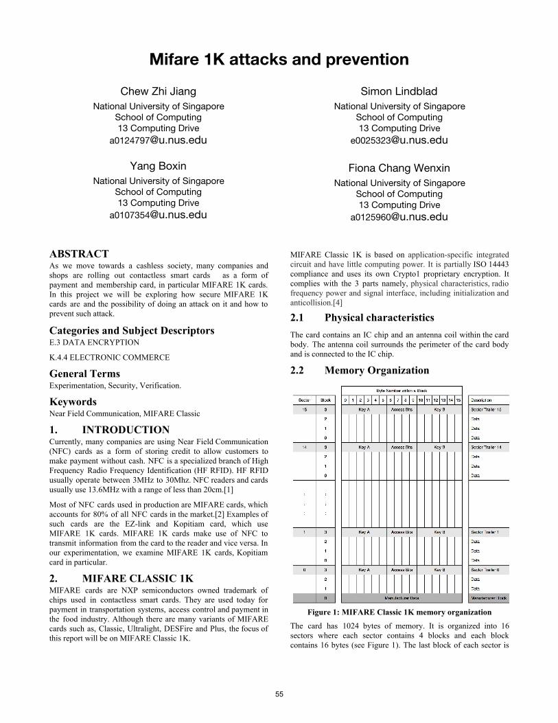
Mifare 1K attacks and prevention
Chew Zhi Jiang National University of Singapore
School of Computing 13 Computing Drive
Yang Boxin National University of Singapore
School of Computing 13 Computing Drive
[email protected] ABSTRACT As we move towards a cashless society, many companies and shops are rolling out contactless smart cards as a form of payment and membership card, in particular MIFARE 1K cards. In this project we will be exploring how secure MIFARE 1K cards are and the possibility of doing an attack on it and how to prevent such attack.
Categories and Subject Descriptors E.3 DATA ENCRYPTION
K.4.4 ELECTRONIC COMMERCE
General Terms Experimentation, Security, Verification.
Keywords Near Field Communication, MIFARE Classic
1. INTRODUCTION Currently, many companies are using Near Field Communication (NFC) cards as a form of storing credit to allow customers to make payment without cash. NFC is a specialized branch of High Frequency Radio Frequency Identification (HF RFID). HF RFID usually operate between 3MHz to 30Mhz. NFC readers and cards usually use 13.6MHz with a range of less than 20cm.[1]
Most of NFC cards used in production are MIFARE cards, which accounts for 80% of all NFC cards in the market.[2] Examples of such cards are the EZ-link and Kopitiam card, which use MIFARE 1K cards. MIFARE 1K cards make use of NFC to transmit information from the card to the reader and vice versa. In our experimentation, we examine MIFARE 1K cards, Kopitiam card in particular.
2. MIFARE CLASSIC 1K MIFARE cards are NXP semiconductors owned trademark of chips used in contactless smart cards. They are used today for payment in transportation systems, access control and payment in the food industry. Although there are many variants of MIFARE cards such as, Classic, Ultralight, DESFire and Plus, the focus of this report will be on MIFARE Classic 1K.
Simon Lindblad National University of Singapore
School of Computing 13 Computing Drive
Fiona Chang Wenxin National University of Singapore
School of Computing 13 Computing Drive
MIFARE Classic 1K is based on application-specific integrated circuit and have little computing power. It is partially ISO 14443 compliance and uses its own Crypto1 proprietary encryption. It complies with the 3 parts namely, physical characteristics, radio frequency power and signal interface, including initialization and anticollision.[4]
2.1 Physical characteristics The card contains an IC chip and an antenna coil within the card body. The antenna coil surrounds the perimeter of the card body and is connected to the IC chip.
2.2 Memory Organization
Figure 1: MIFARE Classic 1K memory organization
The card has 1024 bytes of memory. It is organized into 16 sectors where each sector contains 4 blocks and each block contains 16 bytes (see Figure 1). The last block of each sector is
55

the sector trailer. It contains key A, key B and the access bits. The access bits determine the access conditions, which key can be used for the different operations, for the data blocks and the sector trailer. The operations for the data blocks includes read and write, and additional value operations such as increment, decrement, transfer and restore. The operations for the sector trailer includes read and write access to key A, key B and the access bits.
2.3 UID and Chinese Magic Cards Block 0 of sector 0 of a MIFARE 1K card is reserved for hardware information of the card, including Unique Identification Number (UID) and manufacturer information. This block is designed to be only readable to prevent total copy of a MIFARE 1K card.
However, the Chinese Magic Card is a type of special MIFARE 1K cards. The Chinese Magic Card has writable block 0 of sector 0, which allows modification of UID and manufacturer information. The Chinese Magic Card is used in our experiment to duplicate a Kopitiam card.
2.4 Card Readers To read and write to MIFARE 1K card, we used two different card readers Proxmark3 and ACR122U. Both readers have embedded system built with character user interface (CUI) and are capable of reading and writing to MIFARE 1K card. The CUI of both readers also provides common cryptographic attack methods such as Dictionary Attack and Random Number Generator Attack, which are later used in our experiment.
3. EXPERIMENT We conducted our experiment on Kopitiam card by Kopitiam Investment Pte Ltd, which is a MIFARE 1k card. Our experiment aims to clone the card, restore the card value and change the card value.
3.1 Setup For our experiment, we use Proxmark3 and ACR122U readers that is connected to our laptops via the USB to read the card.
3.1.1 Proxmark3 To start Proxmark3, we first find the usb device that the Proxmark3 reader is connected to using the command
ls /dev/cu.usbmodem*
Then, we start Proxmark3 with the device file as the command argument. The command format is
./proxmark3 /dev/cu.usbmodem#
where # is a number indicating the device identifier.
Before we issue other commands, we have to check whether the reader is able to detect the card using the following command:
hf search
If Proxmark3 is able to detect the card, card tag information such as the UID and card type will be displayed.
3.1.2 ACR122U ARC122U has its own open source library nfc-mfclassic and it offers command line user interface. The library implements card clone method which will be further explained in section 3.4 .
Besides, we used another open source library mfoc for nested attack to decrypt the Kopitiam card.
3.2 Card Decryption To decrypt the card, we make use of the libraries of the individual readers. Decrypting the card allows us to gain access to its content.
3.2.1 Proxmark3 We can try to do a dictionary attack using the manufacturer’s default key using the following command:
hf mf chk *1 ? t
This command will display the list of sectors and the corresponding keys. If there are sectors with unknown keys and at least one sector with a known key, we can use the nested attack on other sectors to get their respective keys and the content using the following command:
hf mf nested 1 1 A ffffffffffff d
Here, the nested attack uses key A ffffffffffff of block 1 of sector 11 to decrypt other sectors. It will then generate a binary dump file (card.dump by default) which can be converted to hexadecimal by using the following command:
xxd card.dump 3.2.2 ACR122U We used mfoc, an open source implementation of offline nested attack by Nethemba. The command used is :
mfoc -P 500 -O cardData.dmp
This command decrypts all the authentication keys used by the card, reads the content of the card using the decrypted keys and stores all the data, including the keys, into the file cardData.dmp. 3.3 Card Content After cracking the card, we look at the values in each blocks and compare it with the values of the card obtained from Kopitiam’s card reader machine and receipts to decipher what each of the block represent.
Like all MIFARE classic 1K cards, the Kopitiam card’s memory consists of 64 blocks. Most of these blocks contains null bytes. Notable blocks used in the Kopitiam card are block 0 of sector 0 which contains the card’s UID as described in section 2.3, block 2 of sector 0, block 0 and block 1 of sector 1, block 0 of sector 2 and block 0 of sector 3.
The first 6 bytes of block 2 of sector 0 contains the hexadecimal number 002001010100 . This number appears to remain constant regardless of what transaction occurs. The following 4 bytes contains the Binary-coded Decimal (BCD) representation of the accumulated transaction amount since the last time the card was topped up.
In block 0 of sector 1, the first 4 bytes are used to describe the value stored on the card. So for example, if you have $10.13 stored, its BCD representation 00001013 would be stored there. This number is also repeated in bytes 6 to 9. However, it is stored in the format 00101300 . Bytes 10 to 13 contains data that changes for each card transaction and its value is not explicit. We suspect this value is a checksum, the purpose of which is to ensure that no one can overwrite data with an arbitrary value.
In block 1 of sector 1, we find the card’s last top-up date in the first 3 bytes. It’s written in the format: YYMMDD. For example,
56

17 February 2017 is represented as the hexadecimal number 170224. Bytes 4 to 6 contains the expiration date for the card in the same format. Byte 7 indicates whether the card is valid, 0x01 for valid and 0x02 for invalid.
3.4 Card Cloning We first tried cloning the Kopitiam card without cloning the uid of the card but the Kopitiam’s reader does not recognise the card. Next, we try to clone into the Chinese Magic Cards as explained in section 2.3. The Chinese Magic Card allows us to clone its uid and now the Kopitiam’s reader is able to read the card. Here are the steps to recreate the cloning of card. 3.4.1 Proxmark3 The Proxmark3 library has library built to copy card data to Chinese Magic Card. The command is:
hf mf cload data
where data is the data to be loaded onto the Chinese Magic Card. However, following the instruction, the copying is not successful. This might be due to a software issue in Proxmark library and we used ACR122U to clone the card.
3.4.2 ACR122U
In order to overwrite the Chinese Magic Card with Kopitiam card data in cardData.dmp, we need to decrypt the blank Chinese Card to get its keys. This is done by
mfoc -P 500 -O blankCardData.dmp
To clone the content of Kopitiam card to Chinese Magic Card, we use nfc-mfclassic library with following command:
nfc-mfclassic W b cardData.dmp blankCardData.dmp
Here the W option overwrites the blank Chinese Magic Card including the UID of block 0, sector 0 .
3.5 Card Modification Even without knowing the checksum, we can still do some modifications to the card after gaining read and write access to the data.
The goal is to write a new value to the card. However, just writing this would require a change in checksum as well, so this option is not viable if we don’t know how to compute the checksum. What we can do instead is to use the data from an old instance of the card. That is, we can restore the card to a previous value. First we need information from an old version of the card. Storing the data from is done as described in section 3.2. We can do this using the proxmark3 or the ACR122U.
3.5.1 Proxmark3 For a single card, the only three blocks to ever change is block 2 in sector 0 as well as block 0 and 1 in sector 2. With the proxmark we use an instruction to write a block at a time. So for each block we use the following command: hf mf wrbl 0 a ffffffffffff 0000000000000000000000000000000
The first 0 specifies which block it is. The “a” specifies the key
type, when writing to these blocks we use key A. The following 32 integers specifies the data to be written. This sequence should therefore contain the data for the corresponding section in the old data.
3.5.2 ACR122U The approach taken with the ACR122U is a bit different. If we have the old card data we don’t need to write it block by block, but can instead just using the cloning procedure described in 3.4 to clone the old data into the card. 4. PREVENTION Since MIFARE classic are vulnerable to attacks, one way to prevent such attack is to change to better encrypted cards such as MIFARE DESFire. However, MIFARE DESFire card might incur higher cost and it is therefore less practical in a commercial company like Kopitiam.
Besides upgrading cards, there are things we can do to improve the security of Kopitiam card. Firstly, Kopitiam should not use the manufacturer’s default key in any of the sectors. This prevents the dictionary attack. Also, the use of nested attack requires known key to at least one sector. When dictionary attack is not successful, attackers are deterred as they have to do a brute force attack to find one of the sector key..
Another alternative but more costly prevention is to store the card’s data on a cloud server and is only able to update the data from one of your own top up machines. Thus, when someone tries to tamper the card you will notice the difference when you compare it with the cloud’s data.
5. CONCLUSION In our experiment, we successfully demonstrated that with proper equipment, it is easy to decrypt MIFARE 1k card with dictionary attack and nested attack. With decrypted keys, we can effectively decrypt, clone and modify the content of Kopitiam card. Therefore we can always reset the value of the card to a higher initial value and exploit the system. Even if keys used are not default keys, brute force is still possible. Therefore, without connection to the cloud, such attacks are hard to prevent.
6. REFERENCES [1] CNRFID. RFID frequency ranges. Retrived from
http://www.centrenational-rfid.com/rfid-frequency-ranges-article-16-gb-ruid-202.html
[2] Anon. About MIFARE. Retrieved April 7, 2017 from https://www.mifare.net/en/about-mifare/
[3] NXP Semiconductors. (2014, March 3). MF1S50yyX/V1 Product Data Sheet. Retrieved from http://www.nxp.com/documents/data_sheet/MF1S50YYX_V1.pdf
[4] NXP Semiconductors. Identification and Security. Retrived from http://www.nxp.com/products/identification-and-security/mifare-ics/mifare-classic:MC_41863
57