Čsn en 12814-4 oprava 1
TRANSCRIPT

ICS 25.160.40 ČSN EN 12814-4 OPRAVA 1 05 6820
Leden 2019
ČESKÁ TECHNICKÁ NORMA
Zkoušení svarových spojů polotovarů z termoplastů – Část 4: Odlupovací zkouška
© Úřad pro technickou normalizaci, metrologii a státní zkušebnictví, 2019 Podle zákona č. 22/1997 Sb. smějí být české technické normy rozmnožovány
a rozšiřovány jen se souhlasem Úřadu pro technickou normalizaci, metrologii a státní zkušebnictví.

ČSN EN 12814-4/Opr. 1
EUROPEAN STANDARD
NORME EUROPÉENNE
EUROPÄISCHE NORM
EN 12814-4
April 2018
ICS 25.160.40 Supersedes EN 12814-4:2001
English Version
Testing of welded joints of thermoplastics semi-finished products - Part 4: Peel test
Essai des assemblages soudés sur produits semi-finis en thermoplastiques - Partie 4 : Essai de pelage
Prüfen von Schweißverbindungen aus thermoplastischen Kunststoffen - Teil 4: Schälversuch
This European Standard was approved by CEN on 10 December 2017. CEN members are bound to comply with the CEN/CENELEC Internal Regulations which stipulate the conditions for giving this European Standard the status of a national standard without any alteration. Up-to-date lists and bibliographical references concerning such national standards may be obtained on application to the CEN-CENELEC Management Centre or to any CEN member. This European Standard exists in three official versions (English, French, German). A version in any other language made by translation under the responsibility of a CEN member into its own language and notified to the CEN-CENELEC Management Centre has the same status as the official versions. CEN members are the national standards bodies of Austria, Belgium, Bulgaria, Croatia, Cyprus, Czech Republic, Denmark, Estonia, Finland, Former Yugoslav Republic of Macedonia, France, Germany, Greece, Hungary, Iceland, Ireland, Italy, Latvia, Lithuania, Luxembourg, Malta, Netherlands, Norway, Poland, Portugal, Romania, Serbia, Slovakia, Slovenia, Spain, Sweden, Switzerland, Turkey and United Kingdom. This document consolidates EN 12814-4:2018 and the corrigendum EN 12814-4:2018/AC:2018.
EUROPEAN COMMITTEE FOR STANDARDIZATION C O M I T É E U R O P É E N D E N O R M A L I S A T I O N E U R O P Ä I S C H E S K O M I T E E F Ü R N O R M U N G
CEN-CENELEC Management Centre: Rue de la Science 23, B-1040 Brussels
© 2018 CEN All rights of exploitation in any form and by any means reserved worldwide for CEN national Members.
Ref. No. EN 12814-4:2018 E
ČSN EN 12814-4/Opr. 1

EN 12814-4:2018+AC:2018 (E)
2
Contents Page
European foreword .......................................................................................................................................................................... 3 1 Scope............................................................................................................................................................................................. 4 2 Normative references ............................................................................................................................................................ 4 3 Terms and definitions ............................................................................................................................................................ 4 4 Symbols and designations .................................................................................................................................................... 4 5 T-peel test ................................................................................................................................................................................... 5 6 Decohesion test ........................................................................................................................................................................ 8 7 Crush test .................................................................................................................................................................................. 12 8 Test report ............................................................................................................................................................................... 14 Bibliography ...................................................................................................................................................................................... 16
ČSN EN 12814-4/Opr. 1
EN 12814-4:2018+AC:2018 (E)
3
European foreword
This document (EN 12814-4:2018) has been prepared by Technical Committee CEN/TC 249 “Plastics”, the secretariat of which is held by NBN.
This European Standard shall be given the status of a national standard, either by publication of an identical text or by endorsement, at the latest by October 2018, and conflicting national standards shall be withdrawn at the latest by October 2018.
Attention is drawn to the possibility that some of the elements of this document may be the subject of patent rights. CEN [and/or CENELEC] shall not be held responsible for identifying any or all such patent rights.
This document supersedes EN 12814-4:2001.
This document includes the corrigendum EN 12814-4:2018/AC:2018 which corrects the symbol for the peel resistance in 5.5, 2nd paragraph, 1st line.
In comparison with the previous edition, the following technical modifications have been made:
— the procedures in the Clauses “T-peel test”, “Decohesion test”, “Crush test” have been detailed with specifications and consequently with the reference figures.
EN 12814, Testing of welded joints of thermoplastics semi-finished products, is composed with the following parts:
— Part 1: Bend test;
— Part 2: Tensile test;
— Part 3: Tensile creep test;
— Part 4: Peel test;
— Part 5: Macroscopic examination;
— Part 6: Low temperature tensile test;
— Part 7: Tensile test with waisted test specimens;
— Part 8: Requirements.
According to the CEN-CENELEC Internal Regulations, the national standards organisations of the following countries are bound to implement this European Standard: Austria, Belgium, Bulgaria, Croatia, Cyprus, Czech Republic, Denmark, Estonia, Finland, Former Yugoslav Republic of Macedonia, France, Germany, Greece, Hungary, Iceland, Ireland, Italy, Latvia, Lithuania, Luxembourg, Malta, Netherlands, Norway, Poland, Portugal, Romania, Serbia, Slovakia, Slovenia, Spain, Sweden, Switzerland, Turkey and the United Kingdom.
ČSN EN 12814-4/Opr. 1
EN 12814-4:2018+AC:2018 (E)
4
1 Scope
This document specifies the dimensions, the method of sampling and the preparation of the test specimens, and also the conditions for performing the peel test perpendicular to the weld in order to determine the peel resistance and the failure behaviour.
A peel test can be used in conjunction with other tests (e.g. tensile creep, macroscopic examination...) to assess the performance of welded assemblies, made from thermoplastics materials.
Peel tests are applicable to overlap welded assemblies made from thermoplastics materials.
The T-peel test as defined in Clause 5 will be used only for assessing welded sheet assemblies. This test is not applicable to welded test pieces containing sheets of different nominal thickness.
The decohesion test as defined in Clause 6 will be used only for assessing electrofusion joints with nominal thickness of pipe/fitting greater than 10 mm.
For socket fusion and for electrofusion socket joints with nominal outside diameter less than or equal to 90 mm, a crush test will be used, as defined in Clause 7.
The crush test can also be used for electrofusion joints with outside diameters greater than 90 mm.
The crush test for electrofusion saddle joints will be performed in accordance with ISO 13955 [1]. NOTE A decohesion test is also defined in ISO 13954 [2].
The tests defined in this standard are not intended to be used for assessment and/or qualification of thermoplastic fittings that already have their own requirements, e.g. polyethylene fittings according to EN 1555-3 [3] and EN 12201-3 [4].
2 Normative references
The following documents are referred to in the text in such a way that some or all of their content constitutes requirements of this document. For dated references, only the edition cited applies. For undated references, the latest edition of the referenced document (including any amendments) applies.
ISO 5893, Rubber and plastics test equipment — Tensile, flexural and compression types (constant rate of traverse) — Specification
3 Terms and definitions
For the purposes of this document, the following term and definition apply.
ISO and IEC maintain terminological databases for use in standardization at the following addresses:
— IEC Electropedia: available at http://www.electropedia.org/
— ISO Online browsing platform: available at http://www.iso.org/obp
3.1 peel resistance Pl arithmetic mean of the force values divided by the width of the test specimen (only relevant for T-peel test)
4 Symbols and designations
For the purposes of this document, the symbols and designations given in Table 1 apply.
ČSN EN 12814-4/Opr. 1
EN 12814-4:2018+AC:2018 (E)
5
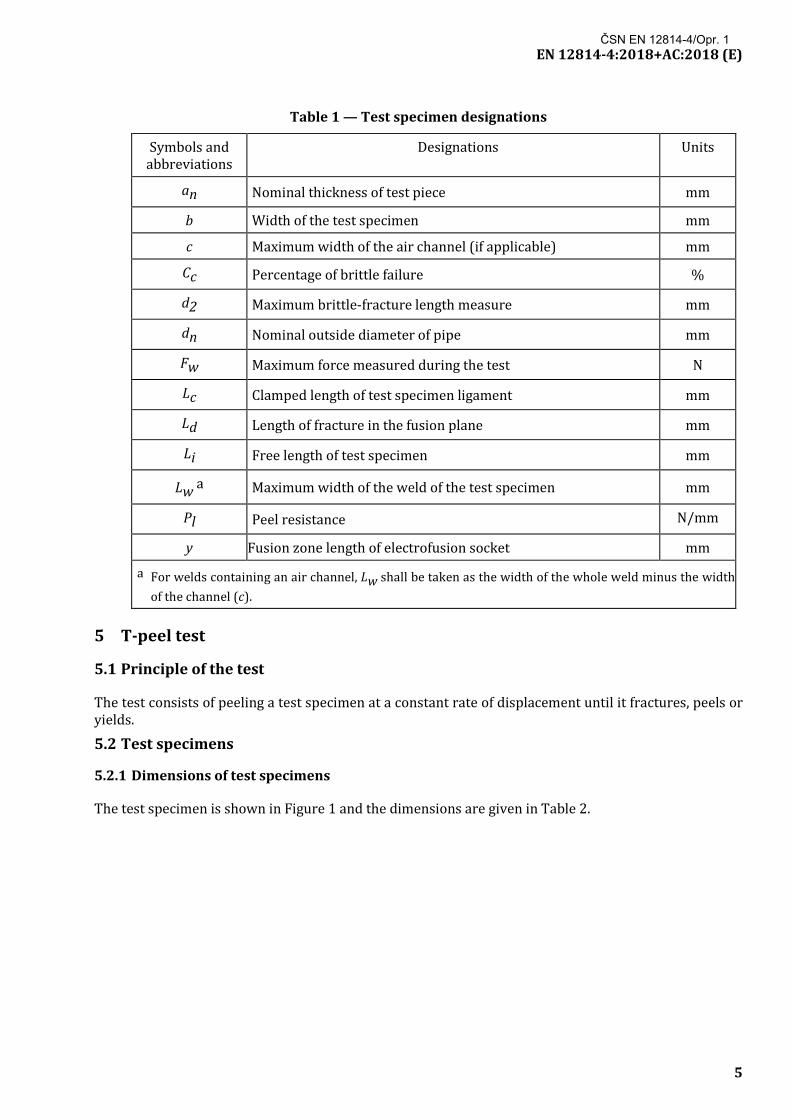
Table 1 — Test specimen designations
Symbols and abbreviations
Designations Units
an Nominal thickness of test piece mm
b Width of the test specimen mm
c Maximum width of the air channel (if applicable) mm
Cc Percentage of brittle failure %
d2 Maximum brittle-fracture length measure mm
dn Nominal outside diameter of pipe mm
Fw Maximum force measured during the test N
Lc Clamped length of test specimen ligament mm
Ld Length of fracture in the fusion plane mm
Li Free length of test specimen mm
Lw a Maximum width of the weld of the test specimen mm
Pl Peel resistance N/mm
y Fusion zone length of electrofusion socket mm
a For welds containing an air channel, Lw shall be taken as the width of the whole weld minus the width of the channel (c).
5 T-peel test
5.1 Principle of the test
The test consists of peeling a test specimen at a constant rate of displacement until it fractures, peels or yields.
5.2 Test specimens
5.2.1 Dimensions of test specimens
The test specimen is shown in Figure 1 and the dimensions are given in Table 2.
ČSN EN 12814-4/Opr. 1

EN 12814-4:2018+AC:2018 (E)
6
Figure 1 — T-peel test specimen
The value of Lc shall be greater than, or equal to, b.
Table 2 — Dimensions of test specimen Dimensions in millimetres
an b a Li
an ≤ 1,5 15 ≥ 15
1,5 < an ≤ 3 15 ≥ 10 x an
3 < an ≤ 5 25 ≥ 10 x an
an > 5 5 x an ≥ 10 x an
a For reinforced materials, b shall be 50 mm.
The tolerance for b shall be ± 0,5 mm. 5.2.2 Preparation of test specimens
The time between the end of the welding operations and the start of machining operations, shall be at least 8 h.
The welded test specimens shall be cut perpendicular to the welded joint.
The test specimens shall be cut with parallel sides as shown in Figure 1.
During cutting, heating of the test specimen should be avoided.
Cutting of the test specimen shall not produce notches.
After cutting, a visual examination of the weld should be carried out and any imperfections, as defined in EN 14728 [5], recorded.
Each test specimen shall be marked so that its original position in the test piece can be identified. 5.2.3 Number of test specimens
At least 5 specimens shall be tested for each welded test piece unless otherwise specified in the relevant application standard.
ČSN EN 12814-4/Opr. 1

EN 12814-4:2018+AC:2018 (E)
7
5.2.4 Conditioning of test specimens
No heat treatment or mechanical straightening operations shall be carried out on the test specimen. After machining, the test specimens shall be conditioned at least 2 h at the testing temperature.
5.3 Apparatus
The test equipment shall conform to the requirements given in ISO 5893.
The crosshead displacement shall be continuous, uniform and in accordance with Table 3.
After setting, the rate shall not vary during the course of any test or series of tests by more than ± 5 % of the mean rate and shall remain within the limits imposed in Table 3.
The force shall be measured and recorded with an accuracy of ± 2 %.
The test equipment shall be provided with a suitable self-aligning grip to hold the specimen.
5.4 Test procedure
The two unwelded ends of the test specimen shall be bent in opposite directions until each end is perpendicular to the weld, to form a T-shaped specimen (see Figure 2) for clamping in the jaws of the test equipment. Inserting the test specimen into the test equipment shall not cause cracking at the weld. If it does, the test is invalid.
Unless otherwise specified, the test shall be carried out at a room temperature of (23 ± 2) °C.
The test speeds for some relevant thermoplastic materials are listed in Table 3.
Table 3 — T-peel test speeds for some thermoplastics
Material Speed mm/min
PVC 10 ± 2
PVDF, PP-H, PP-B 20 ± 2,5
PE, PP-R 50 ± 5
For other materials, the test speed shall be agreed between the contracting parties.
ČSN EN 12814-4/Opr. 1

EN 12814-4:2018+AC:2018 (E)
8
Key 1,2 jaw
Figure 2 — Peel test arrangement
In order to provide additional information, a graph of force versus crosshead displacement may be recorded for each specimen. 5.5 Calculation of the peel resistance
At least five test specimens shall be used in the evaluation of the peel resistance. No test specimen shall be disregarded unless failure occurs in the clamps.
The peel resistance, ˜Pl,™ is calculated using the following formula:
= w l
FP b
where
Fw
is the arithmetic mean of the maximum force values
b is the width of the test specimens
6 Decohesion test
6.1 Principle of the test
A fused socket joint is sectioned at four equidistant positions around the circumference of the fitting and subjected to a longitudinal peel test, such that the resultant peel should be along the length of the fusion interface. Separation of the joint components is taken to completion and the parted surfaces shall be inspected for evidence of ductile and/or brittle failure along the joint interface.
ČSN EN 12814-4/Opr. 1

EN 12814-4:2018+AC:2018 (E)
9
6.2 Test specimens
6.2.1 Dimensions of test specimens
The dimensions of the test specimens are given in Figures 3, 4 and 5. 6.2.2 Preparation of test specimens
6.2.2.1 General
The test specimens shall be cut with parallel sides as shown in Figures 3, 4 and 5.
During cutting, heating of the test specimen should be avoided.
Cutting of the test specimen shall not produce notches. After cutting, a visual examination of the weld should be carried out and any imperfections, as defined in EN 14728 [5], recorded. Initially, standard test specimens shall be used for the decohesion test. If the joint cannot be broken, using this test specimen, a side grooved test specimen shall be used (see 6.2.2.3).
Each test specimen shall be cut from an assembly between a socket and a spigot end of a fitting or a pipe. 6.2.2.2 Cutting of test specimens
The conditioned welded assembly shall be cut into parallel-sided sections (see Figure 3).
Key b = 20 (90 < dn ≤ 180)
b = 30 (dn > 180)
Figure 3 — Cutting test specimens
Test specimens shall be spaced at equidistant intervals around the joint circumference. The specimen length shall include the fusion zone and both cold zones of the electrofusion joint.
Test specimen shall not include terminals.
For electrofusion joints with nominal outside diameter greater than 90 mm and up to and including
180 mm, the width b of the test specimen shall be 20 mm.
For pipes of nominal outside diameter greater than 180 mm, the width b of the test specimen shall be 30 mm.
ČSN EN 12814-4/Opr. 1
EN 12814-4:2018+AC:2018 (E)
10
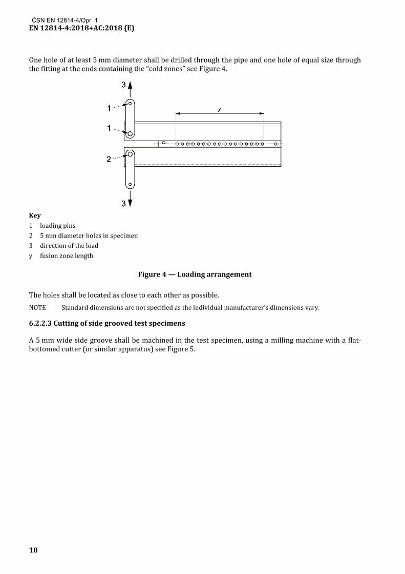
One hole of at least 5 mm diameter shall be drilled through the pipe and one hole of equal size through the fitting at the ends containing the “cold zones” see Figure 4.
Key 1 loading pins 2 5 mm diameter holes in specimen 3 direction of the load y fusion zone length
Figure 4 — Loading arrangement
The holes shall be located as close to each other as possible. NOTE Standard dimensions are not specified as the individual manufacturer's dimensions vary.
6.2.2.3 Cutting of side grooved test specimens
A 5 mm wide side groove shall be machined in the test specimen, using a milling machine with a flat-bottomed cutter (or similar apparatus) see Figure 5.
ČSN EN 12814-4/Opr. 1

EN 12814-4:2018+AC:2018 (E)
11
Figure 5 — Side grooved test specimen
Grooves shall be machined into both faces of the test specimen, penetrating to a quarter of the specimen width. The joint interface shall lie within the groove. 6.2.3 Number of test specimens
The number of test specimens tested shall be as specified in the relevant application standard. 6.2.4 Conditioning of test specimens
Between the welding and machining operations, the test piece shall be conditioned for at least 8 h at an ambient temperature of (23 ± 2) °C. After machining, the test specimen shall be continuously conditioned at the test temperature.
6.3 Apparatus
All tests shall be conducted on a tensile testing machine conforming to the requirements given in ISO 5893.
After setting the cross head speed, the rate shall not vary during the course of any test or series of tests by more than ± 5 % of the mean rate and shall remain within the limits imposed in 6.4
The tensile testing machine shall incorporate a means of providing a permanent record of the force/displacement history during the test.
6.4 Test procedure
The test temperature shall be (23 ± 2) °C.
Push fit metal pins shall be placed in the holes drilled in the test specimen and drilled side plates attached which allow free movement during alignment see Figure 4.
ČSN EN 12814-4/Opr. 1

EN 12814-4:2018+AC:2018 (E)
12
For polyethylene joints, the tensile force shall be applied using a cross-head rate of displacement of (25 ± 2,5) mm/min.
For other thermoplastic materials the cross-head rate of displacement shall be agreed between the contracting parties.
The test shall be continued until there is complete separation of the test specimen.
A force/displacement graph shall be obtained for each test.
The mode of failure shall be recorded by noting the location and length of either brittle crack growth (with no signs of macro-ductility) or ductile yielding as marked by intense white colouring and/or extensive cold-flow of the plastic material.
6.5 Calculation of the percentage of the brittle fracture
The percentage of the brittle failure Cc shall be calculated using the following formula:
Cc = (d2/y) × 100
7 Crush test
7.1 Principle of the test
A welded socket joint is sectioned in the axial direction in two equal parts.
The pipe is squeezed in order to assess the weld properties of the assembly.
7.2 Test specimens
7.2.1 Dimensions of test specimens
The dimensions of the test specimens are given in Figure 6.
Key L = 5 dn
Figure 6 — Crush test specimen
ČSN EN 12814-4/Opr. 1

EN 12814-4:2018+AC:2018 (E)
13
7.2.2 Preparation of test specimens
Each test specimen shall be cut from an assembly between a socket and a spigot end of a fitting or a pipe.
The test specimens shall be cut as shown in Figure 6.
During cutting, heating of the test specimen should be avoided.
Cutting of the test specimen shall not produce notches.
After cutting, a visual examination of the weld should be carried out and any imperfections, as defined in EN 14728 [5], recorded. 7.2.3 Number of test specimens
Two test specimens shall be cut from each welded assembly. The number of test specimens tested shall be as specified in the relevant application standard. 7.2.4 Conditioning of test specimens
Between the fusion and machining operations, the test piece shall be conditioned for at least 8 h at an ambient temperature of (23 ± 2) °C.
After machining, the test specimen shall be continuously conditioned at the test temperature.
7.3 Apparatus
All tests shall be carried out on compression equipment, capable of applying the necessary compressive force.
7.4 Test procedure
The pipe of each test specimen shall be squeezed 5 mm ± 2 mm from the mouth of the socket (see Figure 7) until the internal pipe surfaces touch, i.e. the distance between the jaws of the squeezing equipment becomes equal to twice the pipe wall thickness. The time to squeeze the pipe shall be recorded.
The assembly shall be held in this position for ten minutes, at the end of which, the fused interface shall be inspected and the length of fracture in the fusion plane, parallel to the axis of the pipe, Ld, shall be measured.
ČSN EN 12814-4/Opr. 1

EN 12814-4:2018+AC:2018 (E)
14
Key 1 apparatus (e.g. manual vice) L > 5 dn
h = (5 ± 2) mm g < 10 mm
Figure 7 — Crush test arrangement
For each test specimen, tests shall be performed on both ends of the socket.
Caution should be taken since the specimen may spring out of the clamps during the test.
8 Test report
The test report shall include the following general information:
a) reference to this standard and to the relevant application standard;
b) description and identification of the test piece and test specimen;
c) weld type;
d) the welding conditions for test pieces (if known, reference should be made to CEN/TS 16892 [6]);
e) dimensions of the test specimen;
f) test temperature;
ČSN EN 12814-4/Opr. 1

EN 12814-4:2018+AC:2018 (E)
15
g) the number of test specimens used;
h) the time for conditioning the test pieces and test specimens before testing;
i) appearance of all surfaces of the test specimens before the test (e.g. flaws, scratches, visual imperfections);
j) description of failure behaviour (e.g. photos, ...);
k) identification of the laboratory;
l) the date of the test and the name and the signature of the operator; completed by the following specific information:
1) for the T-peel test:
i) distance between the clamping jaws;
ii) individual values of measured maximum force (Fw);
iii) maximum width of the weld of the test specimen (Lw);
iv) peel resistance (Pl);
v) test speed;
vi) the failure position;
vii) the maximum width of the air channel (if applicable);
2) for the decohesion test:
i) the nominal size of the fitting;
ii) the dimensions of the pipes, including the mean outside diameter and thickness;
iii) the fusion conditions for the test pieces;
iv) the location of the holes for the loading pins (i.e. internal or external cold zone);
v) the calculated values of the percentage of brittle failure, Cc for each test specimen;
3) for the crush test:
i) the nominal size of the fitting ;
ii) the dimensions of the pipes, including the mean outside diameter and thickness;
iii) the free length of pipes;
iv) the length of fracture in the fusion plane (Ld) for each test specimen;
v) the time to squeeze the pipe.
ČSN EN 12814-4/Opr. 1
EN 12814-4:2018+AC:2018 (E)
16
Bibliography
[1] ISO 13955, Plastics pipes and fittings — Crushing decohesion test for polyethylene (PE) electrofusion assemblies
[2] ISO 13954, Plastics pipes and fittings — Peel decohesion test for polyethylene (PE) electrofusion assemblies of nominal outside diameter greater than or equal to 90 mm
[3] EN 1555-3, Plastics piping systems for the supply of gaseous fuels — Polyethylene (PE) — Part 3: Fittings
[4] EN 12201-3, Plastics piping systems for water supply, and for drainage and sewerage under pressure — Polyethylene (PE) — Part 3: Fittings
[5] EN 14728, Imperfections in thermoplastic welds — Classification
[6] CEN/TS 16892, Plastics — Welding of thermoplastics — Specification of welding procedures
ČSN EN 12814-4/Opr. 1


U p o z o r n ě n í : Oznámení o změnách, opravách a nově vydaných normách jsou uveřejňována ve Věstníku Úřadu pro technickou normalizaci, metrologii a státní zkušebnictví.
Vaše názory, podněty a připomínky týkající se technických norem a zájmu o možnou účast v procesech technické normalizace lze zaslat na e-mailovou adresu [email protected].
ČSN EN 12814-4 OPRAVA 1 +!5J6BD5-afjjdf!
505993
Vydala Česká agentura pro standardizaci na základě ustanovení § 5 odst. 2 zákona č. 22/1997 Sb. Rok vydání 2019, 20 stran Cenová skupina 998