csnl elements
DESCRIPTION
CSNL ELEMENTSTRANSCRIPT

7/17/2019 Csnl Elements
http://slidepdf.com/reader/full/csnl-elements 1/17
Section 6: Cross Sectional Elements
Overview
This section includes information on the following cross sectional design elements:
• Pavement Cross Slope
• Median Design
• Lane Widths
• Shoulder Widths
• Sidewalks and Pedestrian Elements
• Cur and Cur and !utters
• "oadside Design
• Slopes and Ditches
• Lateral #ffset to #structions
• Clear $one
Pavement design is covered in T%D#T&s Pavement Design Guide'
Pavement Cross Slope
The operating characteristics of vehicles on crowned pavements are such that on crossslopes up to ( percent) the effect on steering is arel* perceptile' + reasonal* steep lateral
slope is desirale to minimi,e water ponding on flat sections of uncured pavements due to
imperfections or une-ual settlement' With cured pavements) a steep cross slope is desirale
to contain the flow of water ad.acent to the cur' The recommended pavement cross slope for
usual conditions is ( percent' /n areas of high rainfall) steeper cross slopes ma* e used 0see
++S1T#&s A Policy on Geometric Design of Highways and Streets2'
#n multilane divided highwa*s) pavements with three or more lanes inclined in the same
direction desiral* should have greater slope across the outside lane0s2 than across the two
interior lanes' The increase in slope in the outer lane0s2 should e at least 3'4 percent greater
than the inside lanes 0i'e') slope of ('4 percent2' /n these cases) the inside lanes ma* e
sloped flatter than normal) t*picall* at 5'4 percent ut not less than 5'3 percent'
6or tangent sections on divided highwa*s) each pavement should have a uniform cross slope
with the high point at the edge nearest the median' +lthough a uniform cross slope is
preferale) on rural sections with a wide median) the high point of the crown is sometimes
placed at the centerline of the pavement with cross slopes from 5'4 to ( percent' +t
7/17/2019 Csnl Elements
http://slidepdf.com/reader/full/csnl-elements 2/17
intersections) interchange ramps or in unusual situations) the high point of the crown position
ma* var* depending upon drainage or other controls'
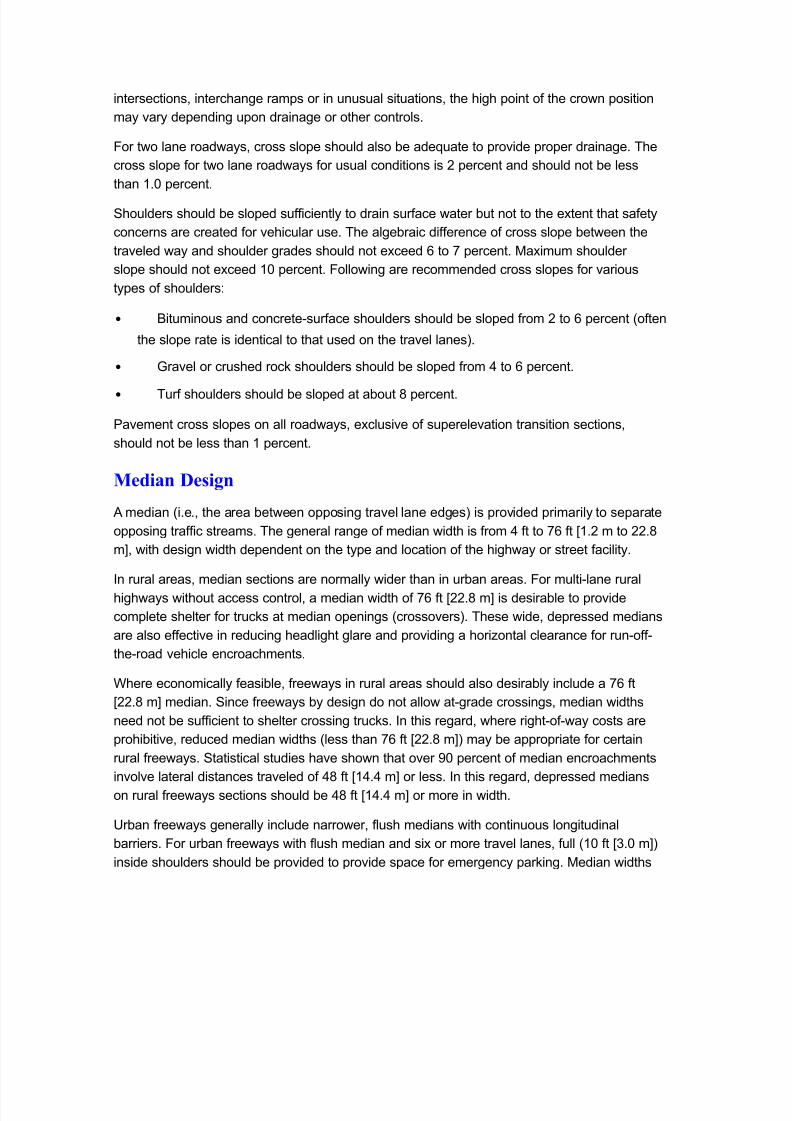
6or two lane roadwa*s) cross slope should also e ade-uate to provide proper drainage' The
cross slope for two lane roadwa*s for usual conditions is ( percent and should not e less
than 5'3 percent'
Shoulders should e sloped sufficientl* to drain surface water ut not to the e%tent that safet*
concerns are created for vehicular use' The algeraic difference of cross slope etween the
traveled wa* and shoulder grades should not e%ceed 7 to 8 percent' Ma%imum shoulder
slope should not e%ceed 53 percent' 6ollowing are recommended cross slopes for various
t*pes of shoulders:
• 9ituminous and concretesurface shoulders should e sloped from ( to 7 percent 0often
the slope rate is identical to that used on the travel lanes2'
•
!ravel or crushed rock shoulders should e sloped from ; to 7 percent'
• Turf shoulders should e sloped at aout < percent'
Pavement cross slopes on all roadwa*s) e%clusive of superelevation transition sections)
should not e less than 5 percent'
Median Design
+ median 0i'e') the area etween opposing travel lane edges2 is provided primaril* to separate
opposing traffic streams' The general range of median width is from ; ft to 87 ft =5'( m to (('<
m>) with design width dependent on the t*pe and location of the highwa* or street facilit*'
/n rural areas) median sections are normall* wider than in uran areas' 6or multilane rural
highwa*s without access control) a median width of 87 ft =(('< m> is desirale to provide
complete shelter for trucks at median openings 0crossovers2' These wide) depressed medians
are also effective in reducing headlight glare and providing a hori,ontal clearance for runoff
theroad vehicle encroachments'
Where economicall* feasile) freewa*s in rural areas should also desiral* include a 87 ft
=(('< m> median' Since freewa*s * design do not allow atgrade crossings) median widths
need not e sufficient to shelter crossing trucks' /n this regard) where rightofwa* costs are
prohiitive) reduced median widths 0less than 87 ft =(('< m>2 ma* e appropriate for certainrural freewa*s' Statistical studies have shown that over ?3 percent of median encroachments
involve lateral distances traveled of ;< ft =5;'; m> or less' /n this regard) depressed medians
on rural freewa*s sections should e ;< ft =5;'; m> or more in width'
@ran freewa*s generall* include narrower) flush medians with continuous longitudinal
arriers' 6or uran freewa*s with flush median and si% or more travel lanes) full 053 ft =A'3 m>2
inside shoulders should e provided to provide space for emergenc* parking' Median widths

7/17/2019 Csnl Elements
http://slidepdf.com/reader/full/csnl-elements 3/17
var* up to A3 ft =?'3 m>) with (; ft =8'( m> commonl* used' 6or pro.ects involving the
rehailitation and e%pansion of e%isting uran freewa*s) the provision of wide inside
shoulders ma* not e feasile'
6or lowspeed uran arterial streets) flush or cured medians are used' + width of 57 ft =;'<
m> will effectivel* accommodate leftturning traffic for either raised or flush medians' Wherethe need for dual left turns are anticipated at cross streets) the median width should e (< ft
=<'; m>' The twowa* 0continuous2 leftturn lane design is appropriate where there e%ists 0or is
e%pected to e%ist2 a high fre-uenc* of midlock left turns' Median t*pes for uran arterials
without access control are further discussed in Chapter A) Section () B@ran Streets'
When flush median designs are selected) it should e e%pected that some crossing and
turning movements can occur in and around these medians' 6ull pavement structure designs
will usuall* e carried across flush medians to allow for traffic movements'
Lane Widths6or highspeed facilities such as all freewa*s and most rural arterials) lane widths should e
5( ft =A'7 m> minimum' 6or lowspeed uran streets) 55 ft or 5( ft =A'A m or A'7 m> lanes are
generall* used' Suse-uent sections of this manual identif* appropriate lane widths for the
various classes of highwa* and street facilities'
9ic*cle accomodations should e considered when a pro.ect is scoped' 9ic*cle consideration
is re-uired on uran facilities' To accommodate ic*cles) the outside cur lane should e 5; ft
=;'(m> from the lane stripe to the gutter .oint or gutter lip on a monolithic cur' 6or a striped
ic*cle lane) the clear width is 4 ft =5'4m> minimum' 6or additional guidance) refer to the
++S1T# Guide for the Development of Bicycle Facilities'
Shoulder Widths
Wide) surfaced shoulders provide a suitale) allweather area for stopped vehicles to e clear
of the travel lanes' Shoulders are of considerale value on highspeed facilities such as
freewa*s and rural highwa*s' Shoulders) in addition to serving as emergenc* parking areas)
lend lateral support to travel lane pavement structure) provide a maneuvering area) increase
sight distance of hori,ontal curves) and give drivers a sense of safe) open roadwa*' Design
shoulder widths for the various classes of highwa*s are shown in the appropriate suse-uent
portions of this manual'
Shoulder widths should accomodate ic*cle facilities and provide a 5 ft offset to arriers
across ridges eing replaced or rehailitated'
#n uran collector and local streets) parking lanes ma* e provided instead of shoulders' #n
arterial streets) parking lanes decrease capacit* and generall* are discouraged'
7/17/2019 Csnl Elements
http://slidepdf.com/reader/full/csnl-elements 4/17
Sidewalks and Pedestrian Elements
Walking is an important transportation mode that needs to e incorporated in transportation
pro.ects' Planning for pedestrian facilities should occur earl* and continuousl* throughout
pro.ect development' Sidewalks provide distinct separation of pedestrians and vehicles)
serving to increase pedestrian safet* as well as to enhance vehicular capacit*' When an* ofthe following factors are present) sidewalks should e included on a pro.ect located in an
uran setting where:
• Construction is within e%isting rightofwa*) and the scope of work involves pavement
widening
• 6ull reconstruction or new construction that re-uires new rightofwa*'
/n t*pical suuran development) there are initiall* few pedestrian trips ecause there are few
closel* located pedestrian destinations' 1owever) when pedestrian demand increases with
additional development) it ma* e more difficult and more costl* to go ack and installpedestrian facilities if the* were not considered in the initial design' Earl* consideration of
pedestrian facilit* design during the pro.ect development process ma* also greatl* simplif*
compliance with accessiilit* re-uirements estalished * the Americans with Disabilities Act
Public Accessibility Guidelines for Pedestrian Facilities in the Public Right of ay
!PR"AG# and the $e%as Accessibility Standards 0T+S2'
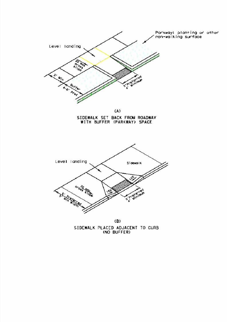
Sidewalk Location. 6or pedestrian comfort) especiall* ad.acent to high speed traffic) it is
desirale to provide a uffer space etween the traveled wa* and the sidewalk as shown in
6igure (80+2' 6or cur and gutter sections) a uffer space of ; ft to 7 ft =5'(m to 5'<m>
etween the ack of the cur and the sidewalk is desirale' "oadwa*s in uran and suuranareas without cur and gutter re-uire sidewalks ) which should e placed etween the ditch
and the right of wa* line if practical' ote that pedestrian street crossings must e +D+
compliant' 6or roadwa*s functionall* classified as rural) the shoulder ma* e used to
accommodate pedestrian and ic*cle traffic' Where a shoulder serves as part of the
pedestrian access route) it must meet +D+FT+S re-uirements'
Sidewalk Width' Sidewalks should e wide enough to accommodate the volume and t*pe of
pedestrian traffic e%pected in the area' The minimum clear sidewalk width is 4 ft =54(4 mm>'
Where a sidewalk is placed immediatel* ad.acent to the cur as shown in 6igure (8092) a
sidewalk width of 7 ft =5<A3 mm> is recommended to allow additional space for street and
highwa* hardware and allow for the pro%imit* of moving traffic' Sidewalk widths of < ft =(;;3
mm> or more ma* e appropriate in commercial areas) along school routes) and other areas
with concentrated pedestrian traffic'
Where necessar* to cross a drivewa* while maintaining the ma%imum ( percent cross slope)
the sidewalk width ma* e reduced to ; ft =5((3 mm> 06igure (<2' +lso)if insufficient space is
availale to locate street fi%tures 0elements such as sign supports) signal poles) fire h*drants)
7/17/2019 Csnl Elements
http://slidepdf.com/reader/full/csnl-elements 5/17
manhole covers) and controller cainets that are not intended for pulic use2 outside the 4 ft
=54(4 mm> minimum clear width) the sidewalk width ma* e reduced to ; ft =5((3 mm> for
short distances'
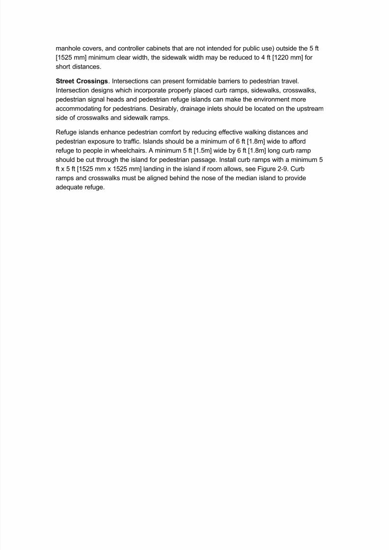
Street Crossings' /ntersections can present formidale arriers to pedestrian travel'
/ntersection designs which incorporate properl* placed cur ramps) sidewalks) crosswalks)pedestrian signal heads and pedestrian refuge islands can make the environment more
accommodating for pedestrians' Desiral*) drainage inlets should e located on the upstream
side of crosswalks and sidewalk ramps'
"efuge islands enhance pedestrian comfort * reducing effective walking distances and
pedestrian e%posure to traffic' /slands should e a minimum of 7 ft =5'<m> wide to afford
refuge to people in wheelchairs' + minimum 4 ft =5'4m> wide * 7 ft =5'<m> long cur ramp
should e cut through the island for pedestrian passage' /nstall cur ramps with a minimum 4
ft % 4 ft =54(4 mm % 54(4 mm> landing in the island if room allows) see 6igure (?' Cur
ramps and crosswalks must e aligned ehind the nose of the median island to provideade-uate refuge'
7/17/2019 Csnl Elements
http://slidepdf.com/reader/full/csnl-elements 6/17

7/17/2019 Csnl Elements
http://slidepdf.com/reader/full/csnl-elements 7/17
Figure &'() *urb Ramps and +andings

7/17/2019 Csnl Elements
http://slidepdf.com/reader/full/csnl-elements 8/17

7/17/2019 Csnl Elements
http://slidepdf.com/reader/full/csnl-elements 9/17
Figure &',) Sidewal-s at Driveway Aprons)
7/17/2019 Csnl Elements
http://slidepdf.com/reader/full/csnl-elements 10/17
7/17/2019 Csnl Elements
http://slidepdf.com/reader/full/csnl-elements 11/17
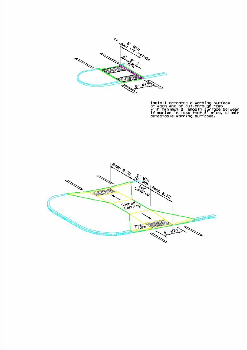
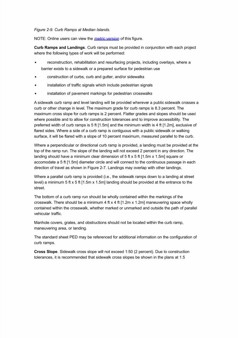
Figure &'.) *urb Ramps at /edian 0slands)
#TE: #nline users can view the metric version of this figure'
Curb Ramps and Landings' Cur ramps must e provided in con.unction with each pro.ect
where the following t*pes of work will e performed:
• reconstruction) rehailitation and resurfacing pro.ects) including overla*s) where a
arrier e%ists to a sidewalk or a prepared surface for pedestrian use
• construction of curs) cur and gutter) andFor sidewalks
• installation of traffic signals which include pedestrian signals
• installation of pavement markings for pedestrian crosswalks
+ sidewalk cur ramp and level landing will e provided wherever a pulic sidewalk crosses a
cur or other change in level' The ma%imum grade for cur ramps is <'A percent' The
ma%imum cross slope for cur ramps is ( percent' 6latter grades and slopes should e used
where possile and to allow for construction tolerances and to improve accessiilit*' The
preferred width of cur ramps is 4 ft =5'4m> and the minimum width is ; ft =5'(m>) e%clusive of
flared sides' Where a side of a cur ramp is contiguous with a pulic sidewalk or walking
surface) it will e flared with a slope of 53 percent ma%imum) measured parallel to the cur'
Where a perpendicular or directional cur ramp is provided) a landing must e provided at the
top of the ramp run' The slope of the landing will not e%ceed ( percent in an* direction' The
landing should have a minimum clear dimension of 4 ft % 4 ft =5'4m % 5'4m> s-uare or
accomodate a 4 ft =5'4m> diameter circle and will connect to the continuous passage in each
direction of travel as shown in 6igure (8' Landings ma* overlap with other landings'
Where a parallel cur ramp is provided 0i'e') the sidewalk ramps down to a landing at street
level2 a minimum 4 ft % 4 ft =5'4m % 5'4m> landing should e provided at the entrance to the
street'
The ottom of a cur ramp run should e wholl* contained within the markings of the
crosswalk' There should e a minimum ; ft % ; ft =5'(m % 5'(m> maneuvering space wholl*
contained within the crosswalk) whether marked or unmarked and outside the path of parallel
vehicular traffic'
Manhole covers) grates) and ostructions should not e located within the cur ramp)maneuvering area) or landing'
The standard sheet PED ma* e referenced for additional information on the configuration of
cur ramps'
Cross Slope' Sidewalk cross slope will not e%ceed 5:43 0( percent2' Due to construction
tolerances) it is recommended that sidewalk cross slopes e shown in the plans at 5'4

7/17/2019 Csnl Elements
http://slidepdf.com/reader/full/csnl-elements 12/17
percent to avoid e%ceeding the ( percent limit when complete' Cross slope re-uirements also
appl* to the continuation of the pedestrian route through the cross walk' Sidewalks
immediatel* ad.acent to the cur or roadwa* ma* e offset to avoid a nonconforming cross
slope at drivewa* aprons * diverting the sidewalk around the apron as shown in 6igure (<'
Where the ramp sidewalk must e sloped to cross a drivewa*) the designer is encouraged to
use a running slope of 4 percent or less on the sloping portions of the sidewalk to avoid the
need for handrails'
Street Furniture' Special consideration should e given to the location of street furniture
0items intended for use * the pulic such as enches) pulic telephones) ike racks) and
parking meters2' + clear ground space at least ('4 ft % ; ft =873 mm % 5'(m> with a ma%imum
slope of ( percent must e provided and positioned to allow for either forward or parallel
approach to the element in compliance with P"#W+!FT+S' The clear ground space must
have an accessile connection to the sidewalk and must not encroach into the 4 ft =5'4m>
minimum sidewalk width * more than ( ft =753 mm>' Pedestrian push uttons must also e
within specified reach ranges of a ground space'
PROWAG!AS. Specific design re-uirements to accommodate the needs of persons with
disailities are estalished * the P"#W+!FT+S and related rulemaking' + re-uest for a
design variance for an* deviations from T+S re-uirements must e sumitted to the Te%as
Department of Licensing and "egulation 0TDL"2 for approval'
Cur and Cur and !utters
Cur designs are classified as vertical or sloping' Gertical curs are defined as those having a
vertical or nearl* vertical traffic face 7 inches =543 mm> or higher' Gertical curs are intended
to discourage motorists from delieratel* leaving the roadwa*' Sloping curs are defined as
those having a sloping traffic face 7 inches =543 mm> or less in height' Sloping curs can e
readil* traversed * a motorist when necessar*' + preferale height for sloping curs at some
locations ma* e ; inches =533 mm> or less ecause higher curs ma* drag the underside of
some vehicles'
Curs are used primaril* on frontage roads) crossroads) and lowspeed streets in uran
areas' The* should not e used in connection with the through) highspeed traffic lanes or
ramp areas e%cept at the outer edge of the shoulder where needed for drainage) in which
case the* should e of the sloping t*pe'
"oadside Design
#f particular concern to the design engineer is the numer of singlevehicle) runofftheroad
accidents which occur even on the safest facilities' +out onethird of all highwa* fatalities are
associated with accidents of this nature' The configuration and condition of the roadside
greatl* affect the e%tent of damages and in.uries for these accidents'

7/17/2019 Csnl Elements
http://slidepdf.com/reader/full/csnl-elements 13/17
/ncreased safet* ma* e reali,ed through application of the following principles) particularl*
on highspeed facilities:
• + Bforgiving roadside should e provided) free of un*ielding ostacles including
landscaping) drainage facilities that create ostacles) steep slopes) utilit* poles) etc' 6or
ade-uate safet*) it is desirale to provide an unencumered roadside recover* area that is
as wide as practicale for the specific highwa* and traffic conditions'
• 6or e%isting highwa*s) treatment of ostacles should e considered in the following
order:
o Eliminate the ostacle'
o "edesign the ostacle so that it can * safel* traversed'
o "elocate the ostacle to a point where it is less likel* to e struck'
o Make the ostacle reakawa*'
o +ppl* a costeffective device to provide for redirection 0longitudinal arrier2 or
severit* reduction 0impact attenuators2' 9arrier should onl* e used if the arrier is
less of an ostacle than the ostacle it would protect) or if the cost of otherwise safet*
treating the ostacle is prohiitive'
o Delineate the ostacle'
• @se of higher than minimum design standards result in a driver environment which is
fundamentall* safer ecause it is more likel* to compensate for driver errors' 6re-uentl*) a
design) including sight distances greater than minimum) flattened slopes) etc') costs littlemore over the life of a pro.ect and increases safet* and usefulness sustantiall*'
• 6or improved safet* performance) highwa* geometr* and traffic control devices should
merel* confirm driversH e%pectations' @ne%pected situations) such as left side ramps on
freewa*s) sharp hori,ontal curvature introduced within a series of flat curves) etc') have
demonstrated adverse effects on traffic operations'
These principles have een incorporated as appropriate into the design guidelines included
herein' These principles should e e%amined for their applicailit* at an individual site ased
on its particular circumstances) including the aspects of social impact) environmental impact)
econom*) and safet*'
Slopes and Ditches
Sideslopes' Sideslopes refer to the slopes of areas ad.acent to the shoulder and located
etween the shoulder and the rightofwa* line' 6or safet* reasons) it is desirale to design

7/17/2019 Csnl Elements
http://slidepdf.com/reader/full/csnl-elements 14/17
relativel* flat areas ad.acent to the travelwa* so that outofcontrol vehicles are less likel* to
turn over) vault) or impact the side of a drainage channel'
Slope Rates. The path that an outofcontrol vehicle follows after it leaves the traveled
portion of the roadwa* is related to a numer of factors such as driver capailities) slope
rates) and vehicular speed' +ccident data indicates that appro%imatel* 84 percent of reportedencroachments do not e%ceed a lateral distance of A3 ft =? m> from the travel lane edge where
roadside slopes are 5G:71 or flatter slope rates that afford drivers significant opportunit* for
recover*' Crash test data further indicates that steeper slopes 0up to 5G:A12 are negotiale *
drivers however) recover* of vehicular control on these steeper slopes is less likel*'
"ecommended clear ,one width associated with these slopes are further discussed in Clear
$one'
"esign #alues' Particularl* difficult terrain or restricted rightofwa* width ma* re-uire
deviation from these general guide values' Where conditions are favorale) it is desirale to
use flatter slopes to enhance roadside safet*'
• Front Slope. The slope ad.acent to the shoulder is called the front slope' /deall*) the
front slope should e 5G:71 or flatter) although steeper slopes are acceptale in some
locations' "ates of 5G:;1 0or flatter2 facilitate efficient operation of construction and
maintenance e-uipment' Slope rates of 5G:A1 ma* e used in constrained conditions'
Slope rates of 5G:(1 are normall* onl* used on ridge header anks or ditch side slopes)
oth of which would likel* re-uire riprap'
When the front slope is steeper than 5G:A1) a longitudinal arrier ma* e considered to
keep vehicles from traversing the slope' + longitudinal arrier should not e used solel*
for slope protection for rates of 5G:A1 or flatter since the arrier ma* e more of an
ostacle than the slope' +lso) since recover* is less likel* on 5G:A1 and 5G:;1 slopes)
fi%ed o.ects should not e present in the vicinit* of the toe of these slopes' Particular
care should e taken in the treatment of manmade appurtenances such as culvert ends'
• $ack Slope. The ack slope is t*picall* at a slope of 5G:;1 or flatter for mowing
purposes' !enerall*) if steep front slopes are provided) the ack slopes are relativel* flat'
Conversel*) if flat front slopes are provided) the ack slopes ma* e steeper' The slope
ratio of the ack slope ma* var* depending upon the geologic formation encountered' 6or
e%ample) where the roadwa* alignment traverses through a rock formation area) ack
slopes are t*picall* much steeper and ma* e close to vertical' Steep ack slope designs
should e e%amined for slope stailit*'
"esign' The intersections of slope planes in the highwa* cross section should e well
rounded for added safet*) increased stailit*) and improved aesthetics' 6ront slopes) ack
slopes) and ditches should e sodded andFor seeded where feasile to promote stailit* and
7/17/2019 Csnl Elements
http://slidepdf.com/reader/full/csnl-elements 15/17
reduce erosion' /n arid regions) concrete or rock retards ma* e necessar* to prevent ditch
erosion'
Where guardrail is placed on side slopes) the area etween the roadwa* and arrier should
e sloped at 5G:531 or flatter'
"oadside drainage ditches should e of sufficient width and depth to handle the design run
off and should e at least 7 inches =543 mm> elow the sugrade crown to insure stailit* of
the ase course' 6or additional information) see Drainage 6acilit* Placement'
Lateral O##set to Ostructions
/t is generall* desirale that there e uniform clearance etween traffic and roadside features
such as ridge railings) parapets) retaining walls) and roadside arriers' /n an uran
environment) right of wa* is often limited and is characteri,ed * sidewalks) enclosed
drainage) numerous fi%ed o.ects 0e'g') signs) utilit* poles) luminaire supports) fire h*drants)
sidewalk furniture) etc'2) and traffic making fre-uent stops' @niform alignment enhances
highwa* safet* * providing the driver with a certain level of e%pectation) thus reducing driver
concern for and reaction to those o.ects' The distance from the edge of the traveled wa*)
e*ond which a roadside o.ect will not e perceived as an ostacle and result in a motorist&s
reducing speed or changing vehicle position on the roadwa*) is called the lateral offset' This
lateral offset to ostructions helps to:
• +void impacts on vehicle lane position and encroachments into opposing or ad.acent
lanes
•
/mprove drivewa* and hori,ontal sight distances• "educe the travel lane encroachments from occasional parked and disaled vehicles
• /mprove travel lane capacit*
• Minimi,e contact from vehicle mounted intrusions 0e'g') large mirrors) car doors) and the
overhang of turning trucks'
+s a minimum) as long as the ostruction is located e*ond the recommended paved
shoulder of a roadwa*) it will have minimum impact on driver speed or lane position and meet
the lateral offset re-uirement' Where a cur is present) the lateral offset is measured from the
face of cur and shall e a minimum of 5'4 ft =3'4 m>' + minimum of 5 ft =3'A m> lateral offsetshould e provided from the toe of arrier to the edge of traveled wa*'
Clear $one
+ clear recover* area) or clear ,one) should e provided along highspeed rural highwa*s' +
clear ,one is the unostructed) traversale area provided e*ond the edge of the through
traveled wa* for the recover* of errant vehicles' The clear ,one includes shoulders) ike
7/17/2019 Csnl Elements
http://slidepdf.com/reader/full/csnl-elements 16/17
lanes) and au%iliar* lanes) e%cept those au%iliar* lanes that function like through lanes' Such
a recover* area should e clear of un*ielding o.ects where practical or shielded * crash
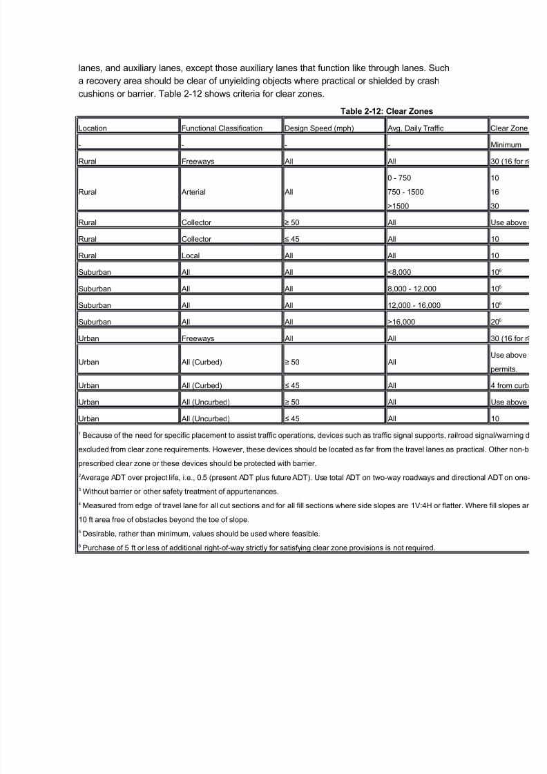
cushions or arrier' Tale (5( shows criteria for clear ,ones'
!able %&'%( Clear )ones
Location 6unctional Classification Design Speed 0mph2 +vg' Dail* Traffic Cl
M
"ural 6reewa*s +ll +ll A3
"ural +rterial +ll
3 843
843 5433
I5433
53
57
A3
"ural Collector J 43 +ll @s
"ural Collector K ;4 +ll 53
"ural Local +ll +ll 53
Suuran +ll +ll <)333 53
Suuran +ll +ll <)333 5()333 53
Suuran +ll +ll 5()333 57)333 53
Suuran +ll +ll I57)333 (3
@ran 6reewa*s +ll +ll A3
@ran +ll 0Cured2 J 43 +ll@s
pe
@ran +ll 0Cured2 K ;4 +ll ; f
@ran +ll 0@ncured2 J 43 +ll @s
@ran +ll 0@ncured2 K ;4 +ll 53
5 9ecause of the need for specific placement to assist traffic operations) devices such as traffic signal supports) railroad signalF
e%cluded from clear ,one re-uirements' 1owever) these devices should e located as far from the travel lanes as practical' #t
prescried clear ,one or these devices should e protected with arrier'
( +verage +DT over pro.ect life) i'e') 3'4 0present +DT plus future +DT2' @se total +DT on twowa* roadwa*s and directional +D
A Without arrier or other safet* treatment of appurtenances'
; Measured from edge of travel lane for all cut sections and for all fill sections where side slopes are 5G:;1 or flatter' Where fill
53 ft area free of ostacles e*ond the toe of slope'
4 Desirale) rather than minimum) values should e used where feasile'
7 Purchase of 4 ft or less of additional rightofwa* strictl* for satisf*ing clear ,one provisions is not re-uired'

7/17/2019 Csnl Elements
http://slidepdf.com/reader/full/csnl-elements 17/17
#TE: #nline users can view the metric version of this tale in PD6 format'
The clear ,one values shown in Tale (5( are measured from the edge of travel lane' These
are appropriate design values for all cut sections 0see Drainage 6acilit* Placement2) for cross
sectional design of ditches within the clear ,one area2 and for all fill sections with side slopes
5G:;1 or flatter' /t should e noted that) while a 5G:;1 slope is acceptale) that a 5G:71 orflatter slope is preferred for oth errant vehicle performance and slope maintainailit*' 6or fill
slopes steeper than 5G:;1) errant vehicles have a reduced chance of recover* and the lateral
e%tent of each roadside encroachment increases' /t is therefore preferale to provide an
ostaclefree area of 53 ft=A'3m> e*ond the toe of steep side slopes even when this area is
outside the clear ,one'