csu bre we r y de s i gn and aut omati...
TRANSCRIPT

CSU Brewery Design and Automation Mid-project Report Fall Semester 2016
- Full Report -
By:
Keaton Sloan Briana Chamberlain
Andy Ross Julia Tucker Dustin Tauxe Nick Wells
Department of Electrical and Computer Engineering Colorado State University
Fort Collins, Colorado 80523
Project advisor: Dr. Tony Maciejewski
Approved by: ____Dan Malyszko______

Mid-Project Report Page 1/42
ABSTRACT
The CSU Brewery Design and Automation senior design team has been tasked to design and implement the Fermentation Science and Technology Department’s state of the art, training brewery. Located within the Gifford building, the team has the distinct challenge of designing a real world system within a predefined and pre-existing workspace. The system must meet not only the immediate needs of the FST program, but also serve as a platform for future modifications. This brewing system and laboratory will serve as the cornerstone of the department’s experiential learning opportunities and departmental growth.
In the initial planning stages, it was assumed the team would be be actively automating a brewing system. Soon after the senior design team began work on the project, the customer realized that the LSC did not align well with the academic timeline, and that the team would gain more experience through the design of a full brewing system, as well as see through the final fabrication, implementation, and commissioning of the Gifford system.
Starting with the piping and instrumentation diagram as the foundation, the team has gone through arduous revisions to meet customer specifications as well as industry standards. Concurrently, with the help of industry experts, the senior design team has revised the design of several of the brewing vessels including but not limited to: Mash Tun, Lauter Tun, Fermentation Vessels, etc. Initial electrical and power compliance groundwork has been completed to ensure that installation and construction can begin as soon as possible. Aside from the physical design, an equal amount of resources has been allocated to creating an IT system topology design, which includes virtual machines and process simulation environments. Some of the specific design challenges include ensuring proper compliance with existing National Electric Code statutes and working with existing HVAC, conduit, and brine heating and cooling lines. Besides constraint specifications, considerable engineering problem solving is being applied towards making the system efficient and safe.
Future work on the project includes installing, commissioning, and automating the Gifford brewery. During this phase, the team will implement the automation platform and extensively troubleshoot the system. Additionally, components researched for the physical power side of the system will be seamlessly integrated into the Rockwell Automation software. Programming architecture of the Batch program provided by Malisko Engineering will allow the team and future users to fully simulate the brewing process from inception to consumption. The team will soon begin work involving the Lory Student Center Brewery automation system, as well as various systems adjustments, to ensure functionality and longevity of the systems.

Mid-Project Report Page 2/42
TABLE OF CONTENTS ABSTRACT 1
TABLE OF CONTENTS 2
Chapter 1 – Introduction 3
Chapter 2 – Summary of Previous Work 5 2.1 LSC Brewery 5 2.2 Gifford Brewery 5
Chapter 3 – Purpose, Objectives and Constraints 5 3.1 Purpose 6 3.2 Objectives 6 3.3 Constraints 6
Chapter 4 – System Design and Development 7 4.1 Process Development 7 4.2 Infrastructure 9
4.2.1 System Design 9 4.2.2 Piping and Instrumentation 9
4.2.3 Vessels 10 4.2.4 Power and Electrical 13
4.3 Automation 14 4.3.1 Integration 14
Chapter 5 – Future Work 15 5.1 Infrastructure 15
5.1.1 Piping and Instrumentation and Vessels 15 5.1.2 Power and Electrical 16
5.2 Automation 16 5.2.1 Integration 17
Chapter 6 – Ethics and Marketability 17
Chapter 7 – Conclusion 18
APPENDIX A - Abbreviations 19
APPENDIX B - Budget 20
APPENDIX C - Project Plan Evolution 22
APPENDIX D - Design Revisions 28 Vessels 28 Piping and Instrumentation Diagrams 37
ACKNOWLEDGEMENTS 42

Mid-Project Report Page 3/42
Chapter 1 – Introduction
Colorado State University is a college located in Northern Colorado that provides a broad variety of majors to over thirty thousand enrolled students. The university offers various majors, but prides itself in academic excellence of the sciences. CSU has a strong culture of experiential learning and providing the hands on experience that will aid in graduates’ success. One such department is the Food Science and Human Nutrition Department which houses a program called Fermentation Science and Technology. The program, hereafter referred to as “FST”, specializes in the science and art form of fermenting beverages and food. Common examples of fermented food and beverages are beer, cheese, meat, and wine. Fermentation of food is truly a combination of both art and biochemical sciences. The program is only one of 22 in the country that teach such a unique set of highly sought after skills in an industry that is an integral part of an operating society. FST is relatively new in the context of the university timeline, however, is already a leader among collegiate programs across the nation who offer such a unique major.
The FST program stands out nation-wide because of the hands on learning space that it provides to its students. This comes in the form of multiple sensory and food science labs, with a curriculum structured to best teach students how to practice food science safely and successfully. An area of focus in this program is the fermentation of beer and the brewing process. The curriculum currently focuses on the biochemistry involved, the brewing processes in small and large scale breweries, and the engineering required in large scale food processing plants. All of the aforementioned facets are crucial to educating a well rounded graduate of the program. To compliment all three of these areas of education, as well as those not mentioned, the program focuses on providing as much hands on and practical experience as possible to students.
Currently, the program teaches students the process of brewing through a lab based class that brews on a small scale, modular brewing system. This system functions well, however, it is not representative of what actually exists in the brewing industry. Due to its size and overall design, the program is not able to sufficiently represent these aspects such as general automation, automatic process monitoring, fluid movement, and complex flow system cleaning.
To overcome these insufficiencies, the program has decided to build two functional breweries on campus. The purpose of these two breweries is to aid student learning and development, and to support continual growth and research in the local brewing community. For this reason, the two breweries will have different end users. One is a research and development based system located in the Gifford Building, while the other is more of a practice and outside industry focused pub style brewery, located in the Lory Student Center. The research and development brewery will be more robust and capable compared to the pub style brewery, including an addition of a second cooking vessel and the ability to control the process to a greater degree. Both brewing systems have received the stamp of approval from the university, and their design has been in progress for approximately the last year.
In order to get the breweries approved, one requirement the FST Program has to fulfill is including other colleges and majors in this innovative and incredible opportunity. With this in mind, the College of Engineering was offered an involvement opportunity to help develop these two breweries. The decision was made to open up the design and automation of the breweries to the College of Engineering as a means of providing engineering students with the chance to gain experience on a real world project. More specifically, the project was offered to the graduating class of 2017, and for years to come, as a senior design project for a team of interdisciplinary

Mid-Project Report Page 4/42
students. Typical senior design projects consist of engineering need based projects, from industry or the university, that a team of single major engineers complete over the course of two semesters. Within these projects, the team of engineering students operate as a consulting firm, with an industry professional as the customer. With the Brewery Design and Automation project, Jeff Callaway, the Director of Fermentation Science, is the associated customer.
This project is meant for a multi-disciplinary team of engineers because of the wide scope defined by the customer. In order to complete the project and have two working breweries, there is quite an extensive list of engineering to be completed. A few of these tasks are the system design, vessel specification, flow control equipment specification, IT infrastructure, automation, and automation integration. All of the listed aspects are being considered and executed by the senior design team that is comprised of a total of six students, studying electrical, computer, chemical/biological, and mechanical engineering.
With such a broad project scope, the Gifford brewery has been assigned as top priority by the customer, and the design process of this brewery was approached as the first step. After design, the team aims to oversee the installation of the brewing vessels, flow equipment, instrumentation, electrical/power, and automation equipment. Upon process installation, the team will integrate the automation simulation platform that was developed with the help of industry associates. This will make the Gifford Brewery an automated, scaled down version of an innovative and industry standard brewing system.
The purpose of this report is to highlight the student engineering team’s current status in regards to the project, and also to describe the future plans and next steps of the project that will be completed in the Spring 2017 semester. The document is broken down into numbered chapters that provide the skeleton of the report; Chapter 1 is the overall project introduction; Chapter 2 contains information pertaining to previous project work and historical work of brewing; Chapter 3 explains the purpose, objectives, and constraints of the project; Chapter 4 contains the in-depth system design progress with details of each area of the design; Chapter 5 covers the future work needing to be done and conclusions from the Fall 2016 semester; Chapter 6 focuses on the ethics and marketability of the project as a whole, and chapter 7 is the document’s conclusion. Following the numbered chapters, there will be multiple Appendix sections that include important details of the project such as the project evolution, budget, abbreviation glossary, and design revisions.

Mid-Project Report Page 5/42
Chapter 2 – Summary of Previous Work
The concept inception for this project was approximately three years prior to the current project's timeline. In that 3 year period, the dream grew and developed and reached a point where the project design could begin. Considering the two-fold nature of this senior design project, it is best to describe previous work in a fashion which conforms to this duplicitousness; specifically, elucidating prior work for the Lory Student Center (LSC) Brewery and Gifford Building Brewery separately. 2.1 LSC Brewery
Prior to the senior design team’s involvement in this project, a significant amount of infrastructural work had already been accomplished with regards to the LSC Brewery: vessels had been finalized and manufactured, piping and instrumentation diagrams (P&ID’s) had been approved, and contractors were lined up to perform construction on the utilities systems of the LSC. On the automation front, preliminary work had begun: human-machine interface (HMI) template screens were in development and programmable logic controller (PLC) structures were laid out for the augmentation of process-specific code.
This work, largely performed by Malisko Engineering, was primarily destined for use in the LSC Brewery and as such, it was designed specifically with the Ramskeller-adjacent location in mind. Unfortunately, this means that such extensive work could not simply be carbon-copied for use in the Gifford location, as each required distinctly unique modifications and specifications be made to their idiosyncrasies. It is because of this fact that the previous work on the LSC Brewery cannot also be considered prior work for the Gifford Brewery. 2.2 Gifford Brewery
The Gifford Brewery was far less complete in design at project inauguration than its LSC counterpart. Only rough vessel designs existed, there were no P&ID’s, and vessels had not begun to be manufactured. The only notable progress which existed at the time was that the construction site had been roughly prepared for the implementation of a system: overhead piping support was welded into place; floor berms were erected around the prospective hot liquor, cold liquor, and clean-in-place (CIP) tank locations; and both the brine chiller and glycol compressor were installed.
This work adequately prepared the design location for construction, come the time when the senior design team deems it appropriate to proceed. No prior design work had occurred, however, on neither the physical brewery plant nor the virtual automation environment.
Chapter 3 – Purpose, Objectives and Constraints Before beginning design on any system, it is important to clearly define the purpose,
objectives and constraints. The purpose describes the goals of a project, and leads into more specific outcomes through objectives and constraints. Objectives are an integral part of solving engineering problems, as they turn the scope of work into measureable outcomes. The

Mid-Project Report Page 6/42
tangibility of objectives helps to translate ideas into plans, which can be carefully analyzed and used for progress. Another important step before attempting to solve an engineering problem is to identify the project’s constraints. These constraints delve deeper into specific objectives and define the bounds within which a design or project needs to operate. All three parts of the design process will be discussed below. 3.1 Purpose
At Colorado State University, a multidisciplinary senior design team from the College of Engineering will work hand in hand with the Fermentation Science and Technology department to build two functional breweries on campus. The focus of the senior design team assigned to this task is to design, construct, and automate the Gifford Brewery, as well as assist with the automation of the LSC Ramskeller Brewery as needed. The purpose of these breweries is to incorporate experiential learning into the FST program, and to lead universities across the nation in growth and research in the brewing industry.
The customer (FST) has assigned the Gifford brewery as the primary focus of the senior design team. The senior design team’s work on the Gifford Brewery will include, but is not limited to, the system design, vessel specification, flow control equipment specification, IT infrastructure, automation, and system integration. After the design, the team aims to oversee the installation of the brewing vessels, flow equipment, instrumentation, and electrical/power equipment. Upon installation, the team will integrate the automation simulation platform that they developed with the help of industry associates to make the process an automated, scaled down version of an industry brewing system. 3.2 Objectives Of the 22 FST programs in the nation, CSU will be the only one to have a brewery of this caliber and complexity designed by students. As this experiential learning opportunity for FST students will greatly enhance the department, a key objective of the CSU Brewery Design and Automation project is to incorporate both education and industry standards into the final brewery. Many learning tools are therefore incorporated into this design, including but not limited to sight glasses, hand valves, and manual system control. New Belgium Brewery and many other industry collaborators are helping to provide knowledge on industry standards. Using this guidance, the senior design team is creating a system that reflects a large brewery, simply on a smaller scale.
Due to the nature of the CSU Brewery Design and Automation project, the scope is incredibly complex and expansive. The senior design project must be continued for future years in order to build out and optimize this year’s team design and automation processes of the Gifford Brewery. All execution processes must therefore be fully documented to allow for a transition phase between senior design teams. 3.3 Constraints Like many real world projects, the CSU Brewery and Automation project has many constraints to work within. One large constraint is the Gifford building itself. The lab space has

Mid-Project Report Page 7/42
already been designed and constructed, therefore, the mechanical and electrical designs must be organized within the existing space. Another constraint defined by the building is designing and using the existing electrical, water, and steam systems. An unusual constraint for a senior design project is departmental logistics. This project operates under the jurisdiction of the Electrical Engineering department, however, the customer and sponsor is the Fermentation Science and Technology department. Academics must be considered during this project, however, the senior design team must deliver the desired design only to the customer. Another sponsor, Malisko Engineering, as well as many industry collaborators including New Belgium Brewing, Northand Process and Piping, and CSU facilities also contribute and hold influence on this project.
Another integral consideration to this system design is safety. The entire system is designed for safety with flow control components, such as valves, places specifically for process design and safety measures. Vessel instrumentation is also designed for safety. The system design includes level switches protect against boil over and proximity sensors prevent the system from running while a hatchway is open. Steam and glycol systems are also used, therefore must follow industry protocol. Clean-in-Place, or CIP will be a system used to clean after each brew, and will use high molarity, FDA standard, chemicals. All of these items will be part of the system’s operational protocol. Additional industry-wide safety protocol will be implemented for Lock Out Tag Out as well as Confined Space Entry.
The final constraint is budget. Primarily donations, the budget has to operate within the bounds of both engineering work/time and monetary donations. Please refer to Appendix B for more information.
Chapter 4 – System Design and Development
4.1 Process Development
In any project, documentation is one of the most important elements. With this project in particular, standardized documentation is crucial as the project will be continued on by other senior design teams in the following years. The first documentation created was the process descriptions, hereafter referred to as “PDs”. PDs are a step-by-step explanation of the flow of the process which includes every vessel with its subsystem, and how a particular vessel and subsystem are involved with each other. In industry, the Process Descriptions would normally be created after the P&IDs are complete. However, the team worked on the Process Descriptions simultaneously with P&ID development to allow every student to be involved at all stages.
The team followed Figure 1 from the ISA88 standards, which represents the procedural control model for a batch system, to develop the PDs. For this project, the “Procedure” at the top of this model represents the whole brewhouse as a system. The Procedure is comprised of “Unit Procedures” which are the vessels individually. For example, one unit procedure is the Mash Tun. The “Operation” goes into even more detail of what makes up the units, thus multiple operations and systems make up one unit procedure or vessel. Lastly, the “Phase” is the basic building block that makes up the individual operations. The phase details are what will be specifically programmed into the PLC. In summary, multiple phases make up one operation, multiple operations make up one Unit Procedure, and ultimately, multiple unit procedures make up the desired Procedure, which again, is the brewhouse system as a whole.

Mid-Project Report Page 8/42
Figure 1: Procedural control model from ISA-88 standards.
Using the model above as a guideline to develop the Process Descriptions, the team
utilized a variety of resources to gather more knowledge on the brewing process and brewing equipment. Online research was conducted and multiple meetings were held with folks in the brewing industry here in the Northern Colorado area. The industry meetings were especially helpful. In those meetings, the team was able to gain insight into more of the details in regards to the system itself, rather than just the broad concepts of brewing. Specifically, the team met with New Belgium and Funkwerks breweries and learned more about particular process parameters, in addition to how to conduct flow path analyses. Once Process Descriptions and P&IDs are completed, Functional Design Specifications are the next step. FDSs are essentially the most detailed version possible of the Process Descriptions. These will be the most vital documents in regards to the system integration from the raw process side, to the technological automation side. As this is a batch process, the FDSs include every phase that will make up the operations for the unit procedures such as the Mash Tun, Lauter Tun, etc. In each step, every valve, motor, and piece of instrumentation that will be
Mid-Project Report Page 9/42
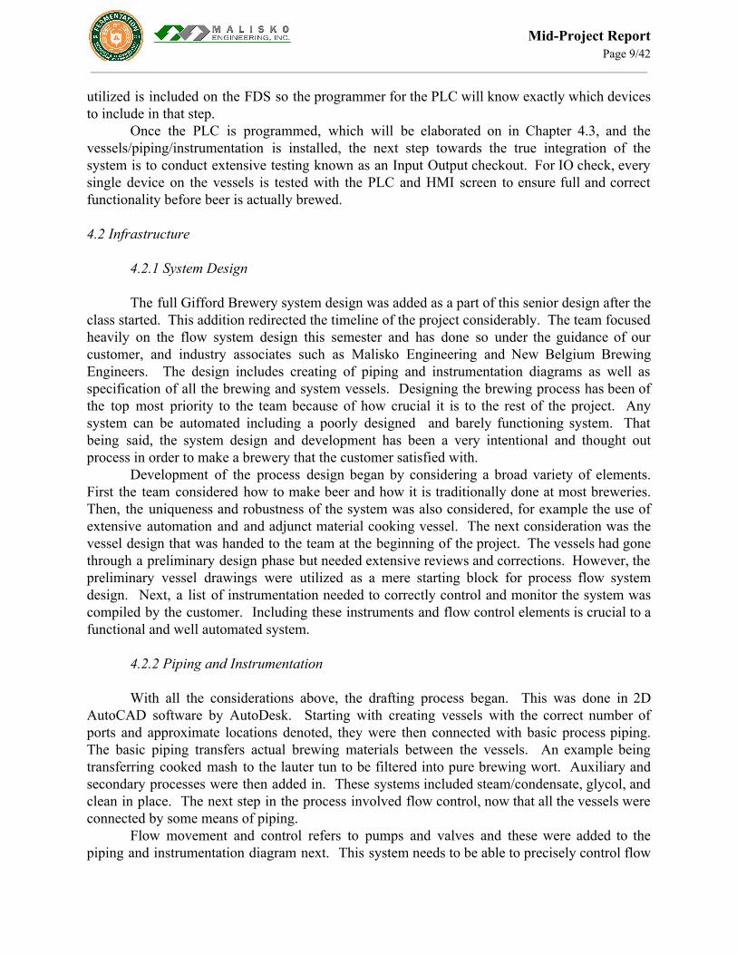
utilized is included on the FDS so the programmer for the PLC will know exactly which devices to include in that step.
Once the PLC is programmed, which will be elaborated on in Chapter 4.3, and the vessels/piping/instrumentation is installed, the next step towards the true integration of the system is to conduct extensive testing known as an Input Output checkout. For IO check, every single device on the vessels is tested with the PLC and HMI screen to ensure full and correct functionality before beer is actually brewed. 4.2 Infrastructure
4.2.1 System Design
The full Gifford Brewery system design was added as a part of this senior design after the class started. This addition redirected the timeline of the project considerably. The team focused heavily on the flow system design this semester and has done so under the guidance of our customer, and industry associates such as Malisko Engineering and New Belgium Brewing Engineers. The design includes creating of piping and instrumentation diagrams as well as specification of all the brewing and system vessels. Designing the brewing process has been of the top most priority to the team because of how crucial it is to the rest of the project. Any system can be automated including a poorly designed and barely functioning system. That being said, the system design and development has been a very intentional and thought out process in order to make a brewery that the customer satisfied with.
Development of the process design began by considering a broad variety of elements. First the team considered how to make beer and how it is traditionally done at most breweries. Then, the uniqueness and robustness of the system was also considered, for example the use of extensive automation and and adjunct material cooking vessel. The next consideration was the vessel design that was handed to the team at the beginning of the project. The vessels had gone through a preliminary design phase but needed extensive reviews and corrections. However, the preliminary vessel drawings were utilized as a mere starting block for process flow system design. Next, a list of instrumentation needed to correctly control and monitor the system was compiled by the customer. Including these instruments and flow control elements is crucial to a functional and well automated system.
4.2.2 Piping and Instrumentation
With all the considerations above, the drafting process began. This was done in 2D
AutoCAD software by AutoDesk. Starting with creating vessels with the correct number of ports and approximate locations denoted, they were then connected with basic process piping. The basic piping transfers actual brewing materials between the vessels. An example being transferring cooked mash to the lauter tun to be filtered into pure brewing wort. Auxiliary and secondary processes were then added in. These systems included steam/condensate, glycol, and clean in place. The next step in the process involved flow control, now that all the vessels were connected by some means of piping.
Flow movement and control refers to pumps and valves and these were added to the piping and instrumentation diagram next. This system needs to be able to precisely control flow

Mid-Project Report Page 10/42
movement and paths. Manipulation is physically done by opening and closing valves along piping and vessels and by increasing and decreasing pump speed until the desired flow velocity is reached. Movement in this system has the ability to go in the logical forward direction from cooking vessels, to separation and boil vessels as well as the other direction. This reverse feature is useful for some specific recipes as well as cleaning. The brewing process is only one of the processes that has had these flow control and movement equipment added to them, other systems such as steam, glycol, and CIP have pumps and valves as well.
Figure 2: Segmented version of the piping and instrumentation diagram.
With all of the previous work being completed, and having a working piping and
instrumentation diagram, one of the last steps towards completion is flow path analysis. The purpose of this current analysis state is to complete a major component fail safe check against our design. It approaches the system batch by batch and walks through the process descriptions. In doing this, the team can denote which exact pumps will run, and which valves will need to be open and closed for each flow movement step. In completing the analysis thus far, minor adjustments to the P&ID have been made, mainly with the addition and subtraction of pneumatics control valves. Again this analysis is about 50% complete with an expected completion during the week after finals.
4.2.3 Vessels
The vessels are an important part of this system. They are connected and without them, this process and it end goal of producing beer, would not be possible. To create a state of the art system, the Gifford Brewery will consist of a Mash Tun, Cereal Cooker, Lauter Tun, Wort
Mid-Project Report Page 11/42
Holding Tank, Kettle, Whirlpool, and Trub Tank on the hot side, and six fermenters on the cold side.
In order to function, the vessels will constantly rely on smaller subsystems. Examples of these are steam, glycol, hot and cold water, and instrumentation. Brewing is a standardized and controlled process which creates the desired results within incredibly finite boundaries. Instrumentation provides this through data acquisition, and allows for system wide process control. Vessel instrumentation includes but is not limited to the following; Temperature transmitters, pressure transmitters, level transmitters and level switches. Two instruments used specifically for safety, are level switches and inductive proximity sensors for hatchway safety.
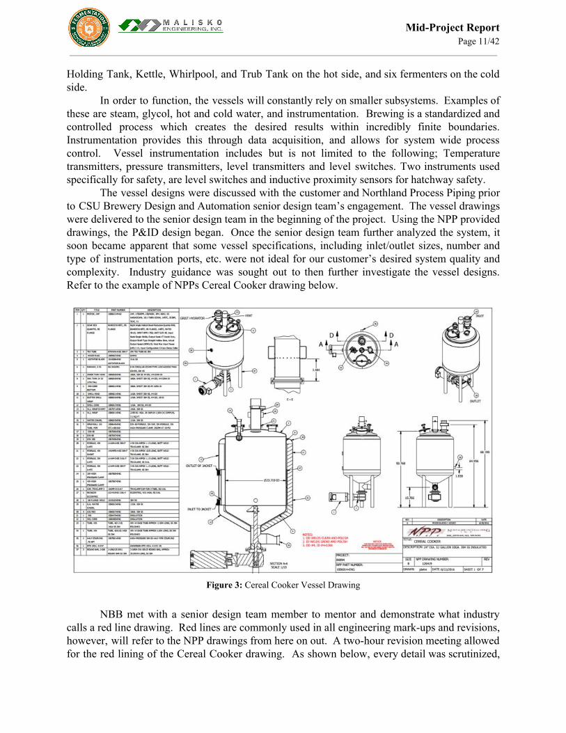
The vessel designs were discussed with the customer and Northland Process Piping prior to CSU Brewery Design and Automation senior design team’s engagement. The vessel drawings were delivered to the senior design team in the beginning of the project. Using the NPP provided drawings, the P&ID design began. Once the senior design team further analyzed the system, it soon became apparent that some vessel specifications, including inlet/outlet sizes, number and type of instrumentation ports, etc. were not ideal for our customer’s desired system quality and complexity. Industry guidance was sought out to then further investigate the vessel designs. Refer to the example of NPPs Cereal Cooker drawing below.
Figure 3: Cereal Cooker Vessel Drawing
NBB met with a senior design team member to mentor and demonstrate what industry
calls a red line drawing. Red lines are commonly used in all engineering mark-ups and revisions, however, will refer to the NPP drawings from here on out. A two-hour revision meeting allowed for the red lining of the Cereal Cooker drawing. As shown below, every detail was scrutinized,

Mid-Project Report Page 12/42
in order to ensure that all items aligned with our instrumentation and overall system. This allowed the P&ID to be designed in accordance with 100% of our customer’s desires. Refer to the Cereal Cooker red line below.
Figure 4: Cereal Cooker Vessel Drawing after red line revision
4.2.4 Power and Electrical
Preliminary electrical work began with the verification of the VFLA architects
schematics for the mandatory power monitoring period required in any instance when an industrial load is to be supplied to a pre-existing structure with an existing powered load. Incoming three phase commercial power into the Gifford building is rated at 14.4 kVA. In cooperation with CSU facilities the team was able to determine that the power monitoring period had been accomplished in accordance with National Electric Code statutes section 220.87 which dictates: If the maximum demand data for a 1-year period is not available, the calculated load shall be permitted to be based
on the maximum demand (measure of average power demand over a 15-minute period) continuously recorded over a minimum 30-day period using a recording ammeter or power meter connected to the highest loaded phase of the
feeder or service, based on the initial loading at the start of the recording. The recording shall reflect the maximum demand of the feeder or service by being taken when the building or space is occupied and shall include by
measurement or calculation the larger of the heating or cooling equipment load, and other loads that may be periodic in nature due to seasonal or similar conditions.
(2) The maximum demand at 125 percent plus the new load does not exceed the ampacity of the feeder or rating of
the service.

Mid-Project Report Page 13/42
(3) The feeder has overcurrent protection in accordance with 240.4, and the service has overload protection in accordance with 230.90.
The anticipated rated load of the brewery system after the monitoring period was set to be
185 kVA 480V three phase power on existing 1200 amp service. Once this was accomplished the team was asked to determine fault current to the laboratory work space. Coming off commercial power in series with the buildings Delta-Wye step down transformer the 200Amp J-series fuse rated the workspace at 50kVA, which powers panels F and FA. This design ensures system stability and longevity, protecting sensitive components and instrumentation.
4.3 Automation
In order to teach future fermentation science students, the Gifford brewery should be able
to run both manually and automatically. This is accomplished by creating automation software that can run predefined “recipes” while at the same time accepting manual overrides from the on-site HMI screen(s). Students will be able to gain hands-on experience with a real system by manually controlling the brewing process with the manual functionality. This will allow them to become more intimately familiar with the brewing process.
However, a main focus on this system is the automation of as much of the process as possible when desired. This will allow students to write programs that will be executed autonomously. These programs will allow the students to specify different parameters in order to easily see how they can affect the brew. Modern breweries are moving towards more and more automation, so this will be valuable experience in the industry.
So far, the team has been working towards automation as much as possible without a designed system. System topology has been designed and virtual machines were also created. The rockwell software was then installed on the virtual machines and building of the simulation environment has commenced. All this is done alongside and under the guidance of Malisko Engineering.
4.3.1 Integration The automatic and manual control is implemented using Malisko Engineering custom
BatchBrew software, which itself is built off of Rockwell Automation’s PlantPAx system. The software provides the environment in which the system will be programmed.
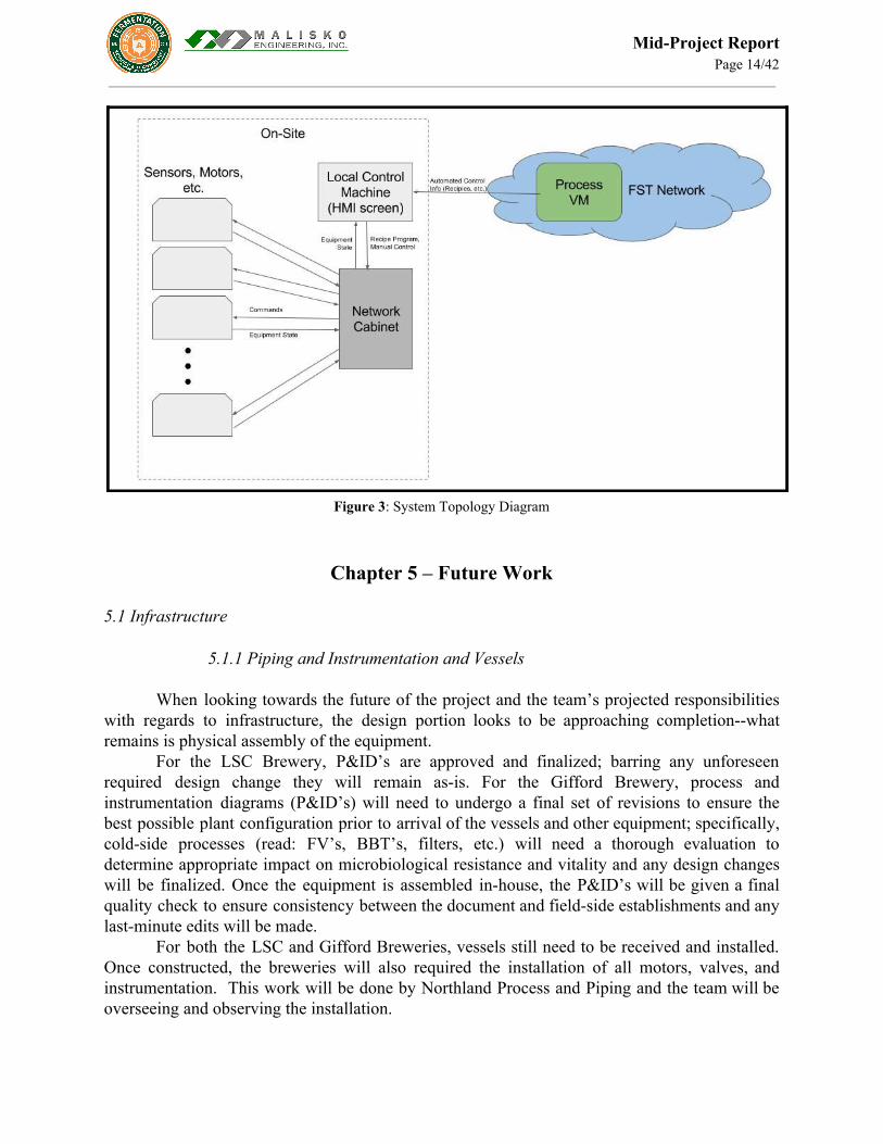
The system topology is shown in Fig 4.3 . Users will be able to remotely access a process VM where they can create the recipes that will be processed automatically. These recipes can then be uploaded to an on-site machine with an HMI screen that will allow users to select recipe program to run and will allow for manual control. The recipes or manual control signals will be sent to a PLC which will in turn control all of the brewing hardware.
The virtual machines used to host this software are set up and ready for use with the software installed and operational. The system has not yet been customized to reflect the final design, in part because that design itself is not finished.
Mid-Project Report Page 14/42
Figure 3: System Topology Diagram
Chapter 5 – Future Work 5.1 Infrastructure
5.1.1 Piping and Instrumentation and Vessels
When looking towards the future of the project and the team’s projected responsibilities with regards to infrastructure, the design portion looks to be approaching completion--what remains is physical assembly of the equipment.
For the LSC Brewery, P&ID’s are approved and finalized; barring any unforeseen required design change they will remain as-is. For the Gifford Brewery, process and instrumentation diagrams (P&ID’s) will need to undergo a final set of revisions to ensure the best possible plant configuration prior to arrival of the vessels and other equipment; specifically, cold-side processes (read: FV’s, BBT’s, filters, etc.) will need a thorough evaluation to determine appropriate impact on microbiological resistance and vitality and any design changes will be finalized. Once the equipment is assembled in-house, the P&ID’s will be given a final quality check to ensure consistency between the document and field-side establishments and any last-minute edits will be made.
For both the LSC and Gifford Breweries, vessels still need to be received and installed. Once constructed, the breweries will also required the installation of all motors, valves, and instrumentation. This work will be done by Northland Process and Piping and the team will be overseeing and observing the installation.

Mid-Project Report Page 15/42
5.1.2 Power and Electrical
Future electrical work will largely focus on troubleshooting and systems integration with the Batch automation software. Panel design moving forward will involve working closely with an Encore Electric engineer to design both the control and power systems. The control panels will be 24VDC input/output panels designed to integrate the instrumentation with the physical control side automation equipment. Connected to the PLC the control side will receive signals from the user interface to automate every process of the brewery and will be used for troubleshooting procedures during the commissioning process. Expected instrumentation controlled by the panels will be temperature transmitters, motor VFDs, automated processes valves, and user side I/O checkouts.
The power panel design will contain three phase commercial power used to control pump motors for transporting liquids from the brewing process. As such, housed within will be fuses rated for equipment protection, power distribution, motor cutouts and wiring to various equipment items. Most of these will be limited life components designed to be replaced when power spikes and other electrical faults occur, protecting the more sensitive and expensive equipment items they power.
Additionally component research will be needed in cooperation with the mechanical engineers to ensure motors and pumps are powerful enough to operate the brewery without exceeding system specifications. Other areas of power that could be of concern will be future modifications to the system requiring additional loads; panel design will have to take these future modifications into consideration when being drafted. The last step will involve drawing up wiring and power schematics for the entire system. Both the power schematics and wiring schematics will show the entirety of the system and its interconnectivity in detail. Parts lists will need to written with parts numbers and ordering information to ensure ease of replacement as parts wear out and break. 5.2 Automation
Automation controls and hardware will be installed as part of the installation process of the rest of the infrastructure and machinery. There will be an extensive checkout process to ensure all the sensors, motors, and valves function properly with the HMI screen and PLC. Each valve will be checked after it is installed and connected to the panel, this is to verify functionality. Motors will be tested with water and piping to drain to ensure that they are fully operational. Additionally, the HMI screens which are needed to operate the system will be developed.
The next step in the automation process is actually the programming of the PLC. Given the fact that the PLC is the link between all instrumentation and automation hardware, programming it correctly will be of the utmost importance to the team. The programmer will be using the FDSs discussed earlier to develop the PLC. Once the PLC is programmed, the team will conduct factory acceptance testing within the simulation environment. The goal of this testing is to run through every single possible scenario to ensure system safety and functionality of the system.
When FAT is complete, the PLC and the HMI screens will be transferred into and connected with the production environment, rather than the simulation environment. Once the

Mid-Project Report Page 16/42
production environment is all set up and IO Check out is complete, a water brew can begin with the fully installed and functioning system.
5.2.1 Integration
Currently, the software on the virtual machines needs to be programmed to match what will be the real setup of the Gifford brewery hardware. The framework for this has already been laid out by Malisko Engineering and the construction of the P&ID will begin at the start of the semester. With this full system built in simulation, brewing simulations can begin on the virtual machines and brewing parameters and recipes can be developed. Multiple members of the team will be responsible for this programming and switchover from the simulation environment to the production environment.
Chapter 6 – Ethics and Marketability
The Fermentation Science Program in itself focuses heavily on marketability. This focus is because the program is in its infancy relative to the age of the university. The program is also incredibly unique because it is one of few schools in the nation to offer a full degree in fermentation science that is recognized as credible to industry partners and by major industry players. This uniqueness provides the program with an opportunity to really sell their program as one of a kind and top notch.
That being said, the Gifford Brewery plays an integral role in this marketing because it can be considered a major selling point of the degree program to incoming students and also to companies looking to hire students with some kind of hands on experience. The project customer Jeff Callaway has been working on a university affiliated branding of the Fermentation Science Program and as a team who works for him, this senior design team is very much a part of this branding. The system we are designing is important to future students coming to the university for the program and also for the quality and excellence of the degree they earn when they attend CSU for a major in fermentation science.
Marketability has also come in the form of collaboration. The most direct example of this is working with other departments, specifically the engineering department for this project. Other examples of outside collaboration that directly tie into the marketing of the brewery is working with the business school by presenting in marketing class lectures and practicing management class team dynamic studies. The team has learned that through participation similar to the exercises that we have already completed, people want to be a part of this project because it involves making beer and because it involves leaving a lasting impact on the university which most students are not able to do in their short 4 years here.
The marketability does not directly tie into the ethics of the project. Ethics have been considered in the project so far by ensuring that student learning and safety have remained at the center of what we do. After all is said and done, it is students who will be operating this system primarily. As a team we are responsible for designing a well thought out system that truly exemplifies and safety as an overall relevant industry concern.
Since students tend to not have as much if any experience as a seasoned professional, safety will be covered by a lab manager and will be a necessary part of our system. I say necessary because like any brewing system, we are designing in safety based process methods
Mid-Project Report Page 17/42
that will need to be explained to operate the system effectively. What this means is that unless certain safety measures are not taken, the system will not operate. Examples of these are inductive proximity sensors for entry prevention and also level sensors on vessels to prevent the system from boilovers. The safety of the future users is of the utmost concern to the team and the safety is being considered as a design requirement, which in turn is creating a safer more effective and integrated brewing system.
Other ethical issues that the team must consider when working with a project as this one are donor relations and industry involvement. These were mentioned because in industry, there are many precautions taken when dealing with donations and supplies as well as free help from any sort of business. In no way is this mean to limit or ignore certain businesses, but fairness in competition is being considered for quotes and bids on work. Donor and supplier relations are easy to leave in a grey area of misunderstanding however, the team is confident that the customer is also considering these ethical donation and supplier relational issues similar to how we are.
Chapter 7 – Conclusion
The progress made this semester heavily involved the setup and design of the brewery. The groundwork was laid for all parts. Some of these mentioned parts include IT system topology, electrical compliance, automation process based descriptions, and flow system design. All of these elements were deemed critical to having a system that goes above and beyond what the customer desires. Anything, including a poorly designed system, can be automated. Thanks to all of the collaboration the team did with experienced professionals, this will not be the case.
The team is very grateful to be working on such an impactful project that really does make a difference in future students learning experience. Being able to leave a legacy that boosts the image of the university and its students is something that the team is very proud of. As a result of this project and its continuation in the years to come, the caliber of students, fermentation and engineering will increase. This project is as “real world” as they come because if it was not the senior design team completing it, it would be a team of engineers from design and integration firms across the front range. The senior design team has been able to learn an incredible amount from working with such a variety of industry professionals and outside vendors, an opportunity which most won’t experience till they are graduated.

Mid-Project Report Page 18/42
APPENDIX A - Abbreviations AB Anheuser Busch BBT Bright Beer Tank CC Cereal Cooker CIP Clean In Place CLT Cold Liquor Tank CSU Colorado State University ECE Electrical and Computer Engineering FAT Factory Acceptance Testing FDS Functional Design Specifications FST Fermentation Science and Technology FV Fermentation Vessel HLT Hot Liquor Tank HMI Human-Machine Interface KT Kettle LSC Lory Student Center LT Lauter Tun MT Mash Tun NBB New Belgium Brewery NPP Northland Process Piping P&ID Process and Implementation Diagram PD Process Description PLC Programmable Logic Controller SCADA Supervisory Control And Data Acquisition TT Trub Tank VFD Variable Frequency Drive VM Virtual Machine WC Wort Cooler WHT Wort Holding Tank WP Whirlpool
Mid-Project Report Page 19/42
APPENDIX B - Budget For this section of the report, the budget is to be discussed. All values are estimates that
came from conversations with the customer, Jeff Callaway in the Fermentation Science Program. The project budget is very unique especially to this senior design team. The reason being because it is all based off pre-approved spending from the FST program combined with an incredibly large and diverse donation base. Not only that, the project has an unusually large budget for a senior design project. The senior design team is not directly involved in financial approvals or decisions. The involvement of the team is to act as a pro bono engineering team who works for free and is based at the university. Any equipment that the team designs into the system must be specified and then sent to the customer with costs for approval. When it comes to smaller equipment purchase, most distributors and manufacturers are selling their products at a discount to the project for the marketing benefits. The engineering team’s approach is to not spend more than necessary by paying full price or by purchasing overpriced equipment. The approach is to design the system to work with state of the art vessels and functional equipment while remaining within the customer’s cost boundaries.
Donations have come in the form of cash to spend and also through specific brewery components and equipment. For example New Belgium Brewery and Odell’s Brewery have each given cash donations of over $100,000 each. Another example is of Atlas Copco has donated an oil free scroll air compressor to drive the pneumatic valve system and they are also looking into donating other equipment. Companies such as Malisko Engineering have donated hundreds of hours of time in creating automation platforms as well as working with Rockwell Automation to have them donate a software package worth ~$85,000. The donor list is incredibly long and can be seen in the acknowledgements section.
The majority of the labor costs will be incurred in vessel manufacturing, vessel installation, and electrical contract design and installation work. All of these are done by contractors working closely with the senior design team. The design and fabrication of the vessels will cost approximately ~$200,000. Included in this amount is the packaging and shipping of the vessels from the Minnesota and California based fabrication shops. Installation of these vessels as well as the piping materials will cost FST another $85,000. This work will be done by the piping fitting team Northland Process and Piping who is based in the Denver and Northern Colorado Leprino food plants. There work is being done at a cost based yet discounted rate. It is estimated that installation will take approximately 120 hours for a crew of 3-4 contractors. Electrical contract work is estimated around total around $20,000.
The total estimated cost for the project hovers around 0.8 million dollars and this is subject to change according to the customer. The electrical engineering department also included $200 for student based need, however, the team has not found a use for this money at this time. Included in the table are costs covered by the customer and large donations that the team should be aware in order to get a realistic sense of the total project cost. All costs listed below are for the Gifford Brewery. The LSC brewery was not discussed in the budgetary talks.

Mid-Project Report Page 20/42
Figure B.1: Total Project Budget Estimate

Mid-Project Report Page 21/42
APPENDIX C - Project Plan Evolution
The scope of the CSU Brewery Design and Automation team has changed over the course of the fall 2016 semester. As discussed earlier and as seen below in Figures C1-C2, it became apparent that it was unlikely for the senior design team to complete the original scope of one brewery per semester (LSC in the fall and Gifford in the Spring). Due to further complications with the LSC, the scope of the project was shifted from the automation of the LSC Brewery, towards the complete design and automation of the Gifford Brewery. This also led to a team name change in late November from “CSU Brewery Automation” to “CSU Brewery Design and Automation.”
Team updates were completed each week during Monday night team meetings and verbally expressed to sponsors during bi-weekly meetings. Design completion was pushed back due to the necessity for a further investigation into NPP’s vessel designs, and revisions of the P&ID with NBB. Full project plan revisions, however, were circulated approximately once a month, resulting in a total of four revisions for the fall-2016 semester, as can be seen below in C1-C4.

Mid-Project Report Page 22/42
Figure C.1: Project Plan 9/16/16 (Page 1/2)

Mid-Project Report Page 23/42
Figure C.2: Project Plan 9/16/16 (Page 2/2)

Mid-Project Report Page 24/42
Figure C.3: Project Plan 9/30/16

Mid-Project Report Page 25/42
Figure C.4: Project Plan 10/26/16
Mid-Project Report Page 26/42
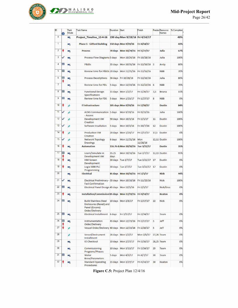
Figure C.5: Project Plan 12/4/16

Mid-Project Report Page 27/42
APPENDIX D - Design Revisions Vessels
Figure D.1: Cold Liquor Vessel

Mid-Project Report Page 28/42
Figure D.2: Hot Liquor Vessel

Mid-Project Report Page 29/42
Figure D.3: Fermentation Vessel

Mid-Project Report Page 30/42
Figure D.4: Wort Kettle Vessel

Mid-Project Report Page 31/42
Figure D.5: Lauter Tun Vessel

Mid-Project Report Page 32/42
Figure D.6: Lauter Tun Vessel

Mid-Project Report Page 33/42
Figure D.7: Whirlpool Separation Vessel

Mid-Project Report Page 34/42
Figure D7: Wort Holding Vessel

Mid-Project Report Page 35/42
Figure D8: Wort Holding Vessel

Mid-Project Report Page 36/42
Piping and Instrumentation Diagrams Given that these diagrams are AutoCAD files, images of the full files will be attached. Details about the differences in revisions will follow each revision image. Revision 1 started on a large sticky note with post it notes connecting the “vessels”. Revision 2 was the first time the process was represented in AutoCAD.
Figure D8: Revision 2
Revision 2 included putting the mental image on into AutoCad. Basic lines were connected and basic subsystems were added and connected to the appropriate vessels.
Figure D9: Revision 3
Revision 3 included additions of more extensive cleaning systems and also a distribution swing link panel to the fermentors. The structure of the chiller was also adjusted and so was the piping from the hot liquor tank.
Mid-Project Report Page 37/42
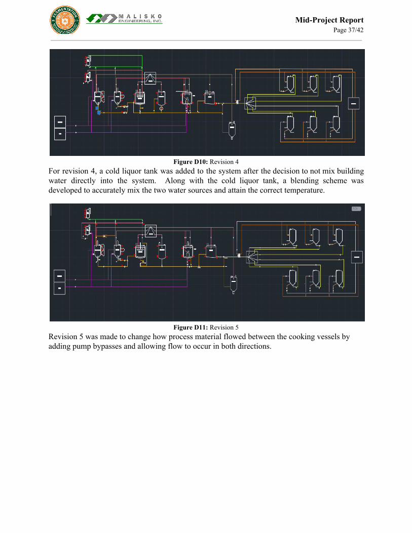
Figure D10: Revision 4
For revision 4, a cold liquor tank was added to the system after the decision to not mix building water directly into the system. Along with the cold liquor tank, a blending scheme was developed to accurately mix the two water sources and attain the correct temperature.
Figure D11: Revision 5
Revision 5 was made to change how process material flowed between the cooking vessels by adding pump bypasses and allowing flow to occur in both directions.

Mid-Project Report Page 38/42
Figure D12: Revision 6
Revision 6 consisted of adding flow control elements to the system, with a main focus on the outlet of different vessels. The glycol system was also redone to better match a continuously flowing system.
Figure D13: Revision 7
Revision 7 focused on the restructure and development of the cold side and it’s distribution to the individual fermentors. Drains combined with block and bleed protection were added as well as the cold liquor system blending stations were added to the outlet of the whirlpool separator.

Mid-Project Report Page 39/42
Figure D14: Revision 8 and 9
For revisions 8 and 9, the clean in place system was the main focus and at this time, the team thought that a palletized portable system would be utilized so the original swing link panel was removed.
Figure D15: Revision 10 and 11
For these revisions, they were close enough together that they were combined. The glycol system was once again overhauled. The clean in place decision came through and the customer decided that they wanted a panel for the hot side and the cold side. The trub tank was also connected as a temporary holding vessel

Mid-Project Report Page 40/42
Figure D16: Revision 12
Revision 12 is where the team has left off and will pick back up on revision 13. The design and flow elements are being analyzed for correct flow. There was also a strong focus again on the clean in place system, specifically the return system for the chemicals.
Mid-Project Report Page 41/42
ACKNOWLEDGEMENTS Dr. Tony Maciejewski- Project Advisor Olivera Notaros- Senior Design Professor Jeff Callaway- Fermentation Science and Technology Dan Malyszko- Malisko Engineering Chris Mccombs, Jeff Biegert, Chris Keogan- New Belgium Brewing Toby Eppard- Fermentation Science Faculty, MillerCoors Rich Rende- Funkwerks Brewing Northland Process and Piping Endress and Hauser Instrumentation