cti consultants pty ltd - home - roads and maritime services · nace certified coating inspector...
TRANSCRIPT

Sydney Newcastle Melbourne Moama
CTI Consultants Pty Ltd Head Office: 4 Rothwell Avenue, Concord West NSW 2138
ABN 56 003 824 815 PO Box 153, North Strathfield NSW 2137
www.cticonsultants.com.au P: (02) 9736 3911 F: (02) 9736 3287
Graphitisation Investigation
Windsor Bridge
Prepared for: Roads & Traffic Authority NSW 110 George St Parramatta NSW 2150
Contact: Peter Ton Phone: (02) 8837 0843 Mob: (0407 295 624
Date: July 13th, 2011 Job Number: 2739 Report Number: C11231 Rev: 0riginal

Graphitisation Investigation Project: Windsor Bridge
Prepared for Roads & Traffic Authority NSW
2739R11231 Page i of ii. 13th July, 2011
Report No. C11231
Issued by
__________________________________________
Fred Salome, B.Sc. (Hons.) ACA Corrosion Technologist
NACE Certified Coating Inspector
Director CTI Consultants Pty Ltd
(ABN 56 003 824 815)
4 Rothwell Avenue, Concord West NSW 2138 Australia PO Box 153, Nth Strathfield NSW 2137 Australia
Telephone (02) 9736 3911 Facsimile (02) 9736 3287
e-mail: [email protected]
Revision Date Reason for Revision Approved By 0 13/07/2011 Original issue F. Salome
Disclaimer
This report has been produced for the information of the client and their advisers only, and is limited to the matters presented in the scope.
Any recommendations herein should not be regarded as a specification, and this report should not be used for the purpose of tendering for works unless used in conjunction with a separate specification detailing the full extent and precise nature of the works.
The report must be read in its entirety and must not be copied, distributed or referred to in part only.
The report must not be reproduced without the written approval of CTI Consultants Pty Ltd.

Graphitisation Investigation Project: Windsor Bridge
Prepared for Roads & Traffic Authority NSW
2739R11231 Page ii of ii. 13th July, 2011
TABLE OF CONTENTS
1 INTRODUCTION ..............................................................................................................................1
2 METHODOLOGY .............................................................................................................................2
2.1 Details of Survey .....................................................................................................................2 2.2 Site Nomenclature ..................................................................................................................2 2.3 Inspection Procedures ............................................................................................................3
2.3.1 Pre-Inspection ............................................................................................................3 2.3.2 Cleaning .....................................................................................................................3 2.3.3 Depth of Graphitisation ..............................................................................................3 2.3.4 Wall Thickness...........................................................................................................3
2.4 Analysis of Water....................................................................................................................3 2.5 Metallurgical Examination .......................................................................................................4
2.5.1 Sample Preparation ...................................................................................................4 2.5.2 Hardness Testing .......................................................................................................4 2.5.3 Chemical Composition ...............................................................................................4
3 RESULTS .........................................................................................................................................5
3.1 Description ..............................................................................................................................5 3.2 Design of Castings .................................................................................................................6 3.3 Wall Thickness .......................................................................................................................7
3.3.1 Original Thickness .....................................................................................................7 3.3.2 Remaining Thickness ................................................................................................8
3.4 Cracking in Columns ............................................................................................................11 3.5 Water Quality ........................................................................................................................14 3.6 Metallurgical..........................................................................................................................15
3.6.1 Sample Details. ........................................................................................................15 3.6.2 Microstructure and Hardness...................................................................................15 3.6.3 Chemical Composition .............................................................................................17 3.6.4 Discussion ...............................................................................................................17
4 DISCUSSION & CONCLUSIONS ..................................................................................................18
4.1 Original Wall Thickness ........................................................................................................18 4.2 Graphitisation .......................................................................................................................18 4.3 Residual Wall Thickness ......................................................................................................18 4.4 Cracking ...............................................................................................................................19
5 ADDITIONAL OBSERVATION ......................................................................................................20

Graphitisation Investigation Project: Windsor Bridge
Prepared for Roads & Traffic Authority NSW
2739R11231 Page 1 of 20. 13th July, 2011
1 INTRODUCTION
As part of its ongoing asset management program, the Roads and Traffic Authority of NSW (RTA) has been gathering data on the condition of its bridge structures.
Many older bridges have cast iron piers1
CTI Consultants have been providing assistance to the RTA in the assessment of graphitisation of cast-iron bridge piers since 1999, and have previously carried out graphitisation surveys on cast iron bridge columns of a number of bridges including the Unwins Bridge and Undercliff Bridge over the Cooks River at Tempe, the Pacific Highway Bridge over Wyong Creek, the old truss bridge over the Shoalhaven River (Nowra Bridge) at Nowra and the Bridge over the Patterson River at Hinton.
footed in rivers or estuaries and over recent years, concerns have been raised about the condition of many of these structures. One of the main concerns is the possibility of graphitisation of the cast iron piers, especially in the splash and tidal zones in coastal environments.
The results of the previous surveys showed that, in general, the extent of graphitisation was surprisingly low in the tidal and splash zone, but that graphitisation in the immersed sections of piers was considerably more advanced, with depths of graphitisation up to 25 mm being reported even in brackish and fresh water conditions.
CTI conducted a previous study on the columns of the Windsor Bridge on the Hawkesbury River in 2005, the findings of which were reported in CTI Report C10174, dated 30/04/2005. Based on a limited, random core sampling program, this investigation revealed high rates of graphitisation, with residual wall thickness being as low as 12 mm in places. This investigation also raised uncertainty about the original design thickness of the column castings, thought to be 30 mm from available drawings, but with site observations suggesting a 25 mm wall thickness.
In order to gain a more thorough understanding of the dimensions and wall thickness of the cast-iron column segments at Windsor (and other bridges), CTI proposed an additional program of core sampling, involving eight cores to be taken from the same segment, four cores at the cardinal points at both the upper and lower quarter circumferences. The divers would first be asked to identify the seams between the individual castings by cleaning a strip approximately 200 mm wide down the side of the selected column. This would allow the length of the segments to be established.
This report contains the details and findings of the latest investigation into the condition of the cast-iron piers of the bridge at Windsor. Although a stand-alone report, the reader is referred to the previous CTI Reports (C9666, C9880 and C10174) which contain background information on the composition, strength and corrosion of cast iron bridge piers as well as the above-water and under-water findings for the other bridges mentioned above.
1 The cast iron columns of these piers are usually filled with concrete or rubble, but the iron casing provides the
principal load bearing function.

Graphitisation Investigation Project: Windsor Bridge
Prepared for Roads & Traffic Authority NSW
2739R11231 Page 2 of 20. 13th July, 2011
2 METHODOLOGY
2.1 Details of Survey
The survey was conducted over the period from Monday, May 9th, 2011 to Saturday, May 21st, 2011.
All underwater work and inspections were provided by Commercial Diving Solutions Pty Ltd of Sapphire, NSW, (Manager Martin Woschitzka) under the on-site direction of Mr John Selway of the RTA Hunter Region. The inspection work was to coincide with the installation of other instrumentation on the bridge, directed by Mr Peter Ton of the RTA Bridge Section.
Fred Salome of CTI attended site at regular intervals to brief the divers on the requirements of the cleaning and core sampling program, and to receive updated results and samples as these became available.
2.2 Site Nomenclature
The bridge is oriented in an essentially NS direction. The piers are numbered from the south. Columns are denoted as D – Downstream or U - Upstream
The divers adopted a convention of referring to the upstream (West) direction as 12 o’clock, and working in a clockwise direction from there so that North is 3 o’clock and so on.
All reported heights on the piers were measured from a reference level corresponding to the lower of the two flanges on the columns.
The water level varied between approximately 2 and 3 m below the reference height, and the river bed was at approximately 8 m below the reference height (ie 5 to 6 m deep) for most of the river’s width.
View of above water part of bridge pier showing lower flange used as reference level for recording height on piers

Graphitisation Investigation Project: Windsor Bridge
Prepared for Roads & Traffic Authority NSW
2739R11231 Page 3 of 20. 13th July, 2011
2.3 Inspection Procedures
2.3.1 Pre-Inspection
Before carrying out any cleaning tasks, the divers inspected the columns for visual signs of corrosion, noting the prevalence of marine growth, instances of loose rust tubercules and the relative incidence of hard nodules.
2.3.2 Cleaning
Vertical strips of approximately 150 mm width were cleared (using scraping and high pressure water) on target columns. The main purpose of this was to identify the seams between the individual castings comprising the columns, but this also allowed the columns to be checked for horizontal (circumferential) cracks.
Where cracks were encountered on any column, the entire circumference was cleaned.
2.3.3 Depth of Graphitisation
Cleaned areas were explored for depth of graphitisation by focussed application of the high pressure water nozzle or by probing with a chisel. The pins of a profile gauge were pushed into the excavated graphite layer to indicate its thickness, and photographed. This allowed the range of metal loss (= depth of graphitisation) to be determined.
2.3.4 Wall Thickness
Small diameter (20 mm) core samples were taken through the wall of the columns at selected locations, to allow the residual wall thickness to be measured directly. Where the graphite layer remained on the core undisturbed, the original total wall thickness could also be deduced (assuming no loss of graphite had occurred under service conditions, see discussion below).
2.4 Analysis of Water
Water samples were taken by the divers from near the surface, at mid-depth and close to the sea-bed.
CTI forwarded these samples to Envirolab Services of Chatswood, NSW, for analysis of a range of water quality parameters as further described in the results section below.

Graphitisation Investigation Project: Windsor Bridge
Prepared for Roads & Traffic Authority NSW
2739R11231 Page 4 of 20. 13th July, 2011
2.5 Metallurgical Examination
One sample taken from the lowest segment of Pier 5 visible above the sea-floor was examined metallurgically, for comparison with samples analysed as part of the 2005 survey.
2.5.1 Sample Preparation
The core samples was mounted and polished, and the microstructure viewed under a metallurgical microscope both in the un-etched and etched condition.
The un-etched condition was viewed at 120X magnification to identify the type of cast iron and to indicate the size, shape and distribution of the graphite phases.
To obtain an indication of the composition of the iron matrix, the samples were etched in 3% Nital and viewed at 250X magnification.
2.5.2 Hardness Testing
A Vickers Hardness test, using a 20 kg load, was performed on the cast iron sample to obtain an indication of the tensile and compressive properties of the material.
In cast irons, the strength is determined by the size and distribution of the graphite flakes and the composition of the matrix. The lower grades of cast iron tend to have a fully ferritic softer matrix compared to a fully pearlitic harder matrix for the higher strength grades.
2.5.3 Chemical Composition
Part of the sample was sent to Spectrometer Services for elemental composition analysis by electric arc spectroscopy.

Graphitisation Investigation Project: Windsor Bridge
Prepared for Roads & Traffic Authority NSW
2739R11231 Page 5 of 20. 13th July, 2011
3 RESULTS
3.1 Description
The piers are footed in the river-bed which is approximately 5m deep.
There is diagonal bracing in the atmospheric zone with a tie-beam located at approximately the low water mark, as indicated in Figure 1. The tidal range is of the order of 1 metre.
Note that the cross bracing at present is fixed to the columns by means of cleats at the top, with the cleats having been riveted onto the cast iron columns. However at the base, the bracing is secured by means of collars clamped around the columns, at the bottom of the tidal range (see arrows in Figure 1).
Figure 1 Sketch Showing General Arrangement of Piers

Graphitisation Investigation Project: Windsor Bridge
Prepared for Roads & Traffic Authority NSW
2739R11231 Page 6 of 20. 13th July, 2011
3.2 Design of Castings
After performing the strip cleaning of each pier, the individual castings were found to be 1.84 m in height (ie. 6 feet).
Core sampling into one of the seams (Pier 5 Downstream, mid-water level) revealed there to be an internal flange, with a bolt hole intersected by the core as indicated by the concave shape at its end. This confirms the castings are joined by internally bolted flanges.
Core from seam between sections as retrieved by divers - length > 50mm, with cast-in rebate for gasket (two halves taped together)
Inner ends of the two halves of the core were a concave shape, indicating the core intersected a bolt hole

Graphitisation Investigation Project: Windsor Bridge
Prepared for Roads & Traffic Authority NSW
2739R11231 Page 7 of 20. 13th July, 2011
3.3 Wall Thickness
3.3.1 Original Thickness
Core sampling of one casting (on pier 5) was conducted on two circumferences, at the upper and lower quarters, with samples taken at four equidistant points on each circumference (NW, NE, etc). The graphite layer on the core samples was largely undisturbed during the coring so that the total original wall thickness could be measured.
The results are presented in Table 1, which also includes the results from the 2005 survey. Together these indicate that the castings were made with a wall thickness ranging from 22 to 38 mm, but with most samples falling between 22mm and 29mm.
The results are considerably lower than found for the above water extension castings in 2005 and are lower than the indications on drawing which suggested a 30 mm wall thickness.
However, a core was taken from the base of column 5D, as the divers reported the surface condition before cleaning to be significantly different, with fewer and smaller tubercules or lumps in the marine growth layer. The length of this core was only 22mm, but it had only minimal graphitisation, less than 1 mm.
Metallurgical assessment of this core (refer section 3.6 below) confirmed it to be of the same type and composition as the remainder of the castings, as determined as part of the 2005 survey.
As it is considered highly unlikely that a lower wall thickness would have been used at the base of the columns, it is concluded that the original thickness was indeed greater than 22 mm, and that the graphitised layer has been worn away.
Scouring or sediment (essentially sand) loading at the base of a column during periods of high flow might be assumed to be significant and can provide a possible mechanism for the gradual erosion of the graphitised layer.
Another possible cause of loss of the marine growth or graphitised layers is prior cleaning and assessment. A thorough search of available records may provide further information on the likelihood of this having occurred.
Core from base of 5D, total length 22mm Surface of core showing minimal (< 1 mm) graphitisation

Graphitisation Investigation Project: Windsor Bridge
Prepared for Roads & Traffic Authority NSW
2739R11231 Page 8 of 20. 13th July, 2011
3.3.2 Remaining Thickness
The remaining effective wall thickness (ie. exclusive of graphitised material) as measured during May 2011 ranges widely, from a maximum of 27 mm to a low of 2 mm.
There was no distinct or discernible pattern to the distribution of the residual wall thickness.
It should be noted that in addition to the core samples taken, the divers also measured the depth of graphitisation by excavating through the graphitised layer. This frequently showed depths of graphitisation in excess of 20mm, so that the residual cast iron thickness will be less than 10 mm and perhaps, in some instances, negligible.
Measuring depth of graphitisation – diver pushing pins of profile gauge into excavation through graphite layer
Profile gauge withdrawn from excavation allows depth of graphitisation to be measured
Profile gauge withdrawn from excavation allows depth of graphitisation to be measured
Profile gauge withdrawn from excavation allows depth of graphitisation to be measured

Graphitisation Investigation Project: Windsor Bridge
Prepared for Roads & Traffic Authority NSW
2739R11231 Page 9 of 20. 13th July, 2011
Table 1 Summary of Core Samples (2005 and 2011)
Date Cored Pier Column Aspect Height Casting Length
Residual Cast Iron Comment
Above Water
10/03/2005 1 D
Above water, above flange 35 35 Column extension
10/03/2005 1 D
300mm below flange 26 26 Upper limit of immersed
column sections
May 2011 5 D
Ref less 2m 26 26 Above MHWS
May 2011 5 D
Ref less 2m 23 23 Above MHWS
May 2011 5 D
Ref less 2m 25 25 Above MHWS
May 2011 5 D
Ref less 2m 26 23 Above MHWS
Below Water
10/03/2005 1 D
1600mm below flange 25 25
11/03/2005 5 D
Underwater 31 > 20 At internal thickening
11/03/2005 5 D
Underwater ~30 20 1.6m from bed
11/03/2005 7 D
Underwater ~ 38 18 1.6m from bed
11/03/2005 9 U
Underwater ~38 27 1.6m from bed
May 2011 5 U NW Ref less 4m 22 6-10 ~ 0.7m below water
May 2011 5 U NE Ref less 4m 24 14-15 ~ 0.7m below water
May 2011 5 U SE Ref less 4m 24 10-11 ~ 0.7m below water
May 2011 5 U SW Ref less 4m 22-23 8-13 ~ 0.7m below water
May 2011 5 U SW Ref less 4m 22-23 2-9 ~ 0.7m below water
May 2011 5 U NW Ref less 5m 22 14-17 ~ 1.7m below water
May 2011 5 U NE Ref less 5m 29 21-27 ~ 1.7m below water
May 2011 5 U SE Ref less 5m ~28 18-20 ~ 1.7m below water
May 2011 5 U SW Ref less 5m 27 16-21 ~ 1.7m below water
May 2011 5 D
Ref less 3.6 m 23 11 50mm core through crack
May 2011 5 U
Ref less 3.35 m 27 15-17 50mm core through crack
May 2011 5 D Ref less 8m 22 21 Sea-Bed core

Graphitisation Investigation Project: Windsor Bridge
Prepared for Roads & Traffic Authority NSW
2739R11231 Page 10 of 20. 13th July, 2011
Typical appearance of cores is illustrated in the following photographs.
5D NE aspect, above water; no graphitisation 5U NE aspect, upper quarter of immersed casting, showing 9-10mm of graphitisation and 14-15mm remaining cast iron
5U SW aspect, upper quarter of immersed casting, showing up to 18 mm of graphitisation and as little as 2mm remaining cast iron
5U SW aspect, lower quarter of immersed casting, showing up to 11 mm of graphitisation and as little as 16mm remaining cast iron

Graphitisation Investigation Project: Windsor Bridge
Prepared for Roads & Traffic Authority NSW
2739R11231 Page 11 of 20. 13th July, 2011
3.4 Cracking in Columns
During the inspection, three horizontal (circumferential) cracks were detected in columns.
The Upstream Column of Pier 5 (5U) had a full circumferential crack, approximately 200mm above the seam at the top of first fully immersed section. This placed the crack just below the collar for the bracing, and it probably coincides with the beginning of the internal thickening of the casting to create the flange. The crack was at its widest on the downstream (6 o’clock) side of the pier, where it was estimated to be in excess of 1 mm.
There was also a vertical crack on the column, starting at the same seam (at 6 o’clock, east or downstream) and extending approximately 100 mm upwards. Its width was measured to be up to 2 mm wide at its base, tapering upwards.
Circumferential crack on column 5U Circumferential crack on column 5U
Vertical cack on column 5U on downstream side, estimated to be > 2 mm wide at its base
Cleaning and excavating graphite layer shows crack to extend beyond the outer graphite layer

Graphitisation Investigation Project: Windsor Bridge
Prepared for Roads & Traffic Authority NSW
2739R11231 Page 12 of 20. 13th July, 2011
The Downstream column of Pier 5 (5D) also had a full circumferential crack but in this case, the crack was approximately 200mm below the seam at the top of the first fully immersed casting. The crack was cored using a 50mm diameter bit, and confirmed the crack to be full depth. Graphitisation had followed the line of the crack for some distance, indicating the crack to be of some age.
5D crack, at its widest on East, downstream side (6 o’clock)
5D crack, narrow on West, upstream side (12 o’clock)
Core (50mm diameter) through crack on 5D showing it to extend full depth through the casting
Graphitisation follows line of crack indicating crack to be of reasonable age
Graphitisation Investigation Project: Windsor Bridge
Prepared for Roads & Traffic Authority NSW
2739R11231 Page 13 of 20. 13th July, 2011
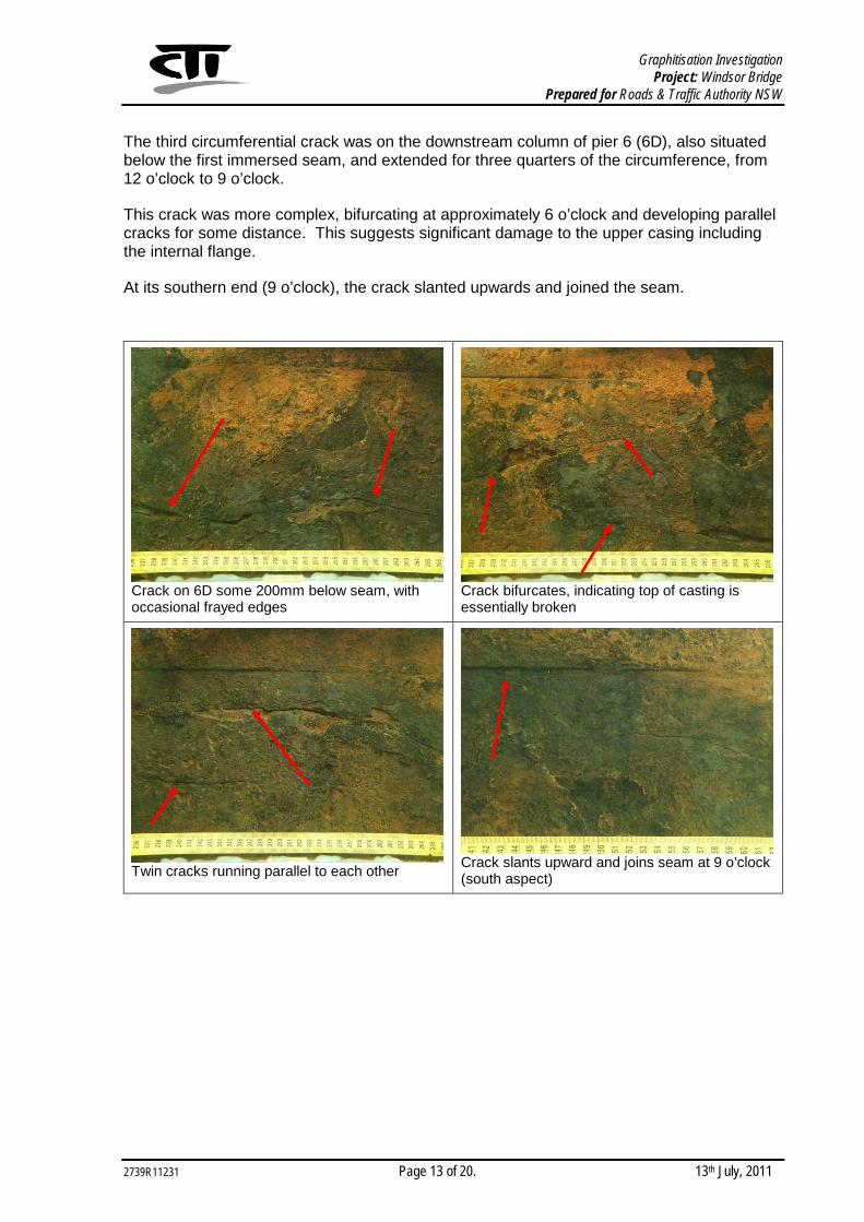
The third circumferential crack was on the downstream column of pier 6 (6D), also situated below the first immersed seam, and extended for three quarters of the circumference, from 12 o’clock to 9 o’clock.
This crack was more complex, bifurcating at approximately 6 o’clock and developing parallel cracks for some distance. This suggests significant damage to the upper casing including the internal flange.
At its southern end (9 o’clock), the crack slanted upwards and joined the seam.
Crack on 6D some 200mm below seam, with occasional frayed edges
Crack bifurcates, indicating top of casting is essentially broken
Twin cracks running parallel to each other Crack slants upward and joins seam at 9 o’clock (south aspect)

Graphitisation Investigation Project: Windsor Bridge
Prepared for Roads & Traffic Authority NSW
2739R11231 Page 14 of 20. 13th July, 2011
3.5 Water Quality
The results of the river water analyses are presented in Table 2.
Table 2 River Water Analysis Results
Test CTI 38629 (Surface)
CTI 38630 (Mid depth, 2.5 m)
CTI 38631 (Bottom, 5 m)
Chloride (mg/L) 29 29 29
Sulphate (mg/L) 7 7 7
Electrical Conductivity (µS/cm) 170 170 170
Total Dissolved Solids (grav, mg/L) 86 100 96
pH 6.6 6.7 6.7
Hardness (mgCaCO3/L) 24 25 23
Calcium (mg/L) 3.8 4.1 3.8
Iron (mg/L) 0.3 0.4 0.7
Potassium (mg/L) 2.0 2.2 2.0
Sodium (mg/L) 15 16 15
These results indicate that there has been no significant layering of the water, with no significant differences in any of the parameters tested. The water is essentially fresh water with a low hardness (soft).
The level of chloride and sodium present, at 29 ppm and 15 ppm respectively, are in fact well below potable water standards which have permissible chloride levels at 250 ppm and sodium at 180 ppm.
Therefore the waters sampled at Windsor Bridge during the survey indicate essentially fresh water with no marine influence. Although subject to tidal height water variations, this simply results in fresh water moving backwards and forwards by the pushing action of incoming tides, without sea water actually being present.

Graphitisation Investigation Project: Windsor Bridge
Prepared for Roads & Traffic Authority NSW
2739R11231 Page 15 of 20. 13th July, 2011
3.6 Metallurgical
3.6.1 Sample Details.
The cast iron core sample (CTI 38888) was taken by the divers at sea-bed level from the downstream Column of Pier 5 (5D) on 20/5/2011.
3.6.2 Microstructure and Hardness
The results of the metallurgical assessment are given in Table 3, which also reproduces the results for the earlier 2005 samples.
Table 3 Results of Metallurgical Tests and Estimates of Tensile Strength
Sample No.
Hardness (Hv 20)
Microstructure Estimated UTS*
CTI 25791 180 - 200 No evidence of graphitisation. Coarse flake graphite in fully pearlitic matrix plus relatively high levels of phosphide eutectoid (Figures 1 & 2 in 2005 Report)
220 to 240 MPa
CTI 25792 160 - 175
No evidence of graphitisation. Coarse flake graphite and fine rosette graphite in a ferritic/pearlitic matrix. relatively high levels of phosphide eutectoid (Figures 3 & 4 in 2005 Report)
180 to 200 MPa
CTI 25793 160 - 180 Graphitisation on outer surface. Coarse flake graphite in ferritic/pearlitic matrix plus relatively high levels of phosphide eutectoid (Figures 5 & 6 in 2005 Report)
180 to 200 MPa
CTI 25794 160 - 175
Graphitisation on outer surface. Coarse flake graphite and some rosettes of medium to fine graphite in a ferritic/pearlitic matrix plus medium levels of phosphide eutectoid (Figures 7 & 8 in 2005 Report)
180 to 200 MPa
CTI 25795 145 - 155
Graphitisation on outer surface. Coarse flake graphite and some rosettes of medium to fine graphite in a nearly fully ferritic matrix plus medium levels of phosphide eutectoid (Figures 9 & 10 in 2005 Report)
140 to 160 MPa
CTI 38888 160 - 175
Slight graphitization on outer surface. Coarse flake graphite and some rosettes of medium to fine graphite in a ferritic/pearlitic matrix plus relatively high levels of phosphide eutectoid (refer Figures 2 & 3)
180 to 200 MPa
* Based on shape and size of graphite flake, type of matrix and hardness.
Graphitisation Investigation Project: Windsor Bridge
Prepared for Roads & Traffic Authority NSW
2739R11231 Page 16 of 20. 13th July, 2011
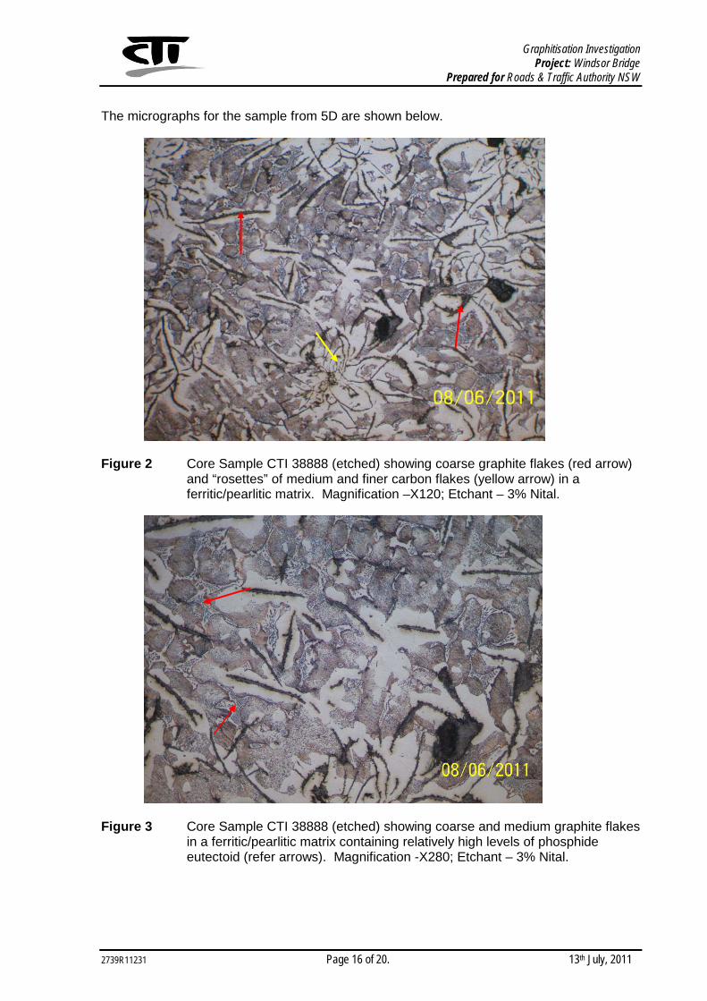
The micrographs for the sample from 5D are shown below.
Figure 2 Core Sample CTI 38888 (etched) showing coarse graphite flakes (red arrow) and “rosettes” of medium and finer carbon flakes (yellow arrow) in a ferritic/pearlitic matrix. Magnification –X120; Etchant – 3% Nital.
Figure 3 Core Sample CTI 38888 (etched) showing coarse and medium graphite flakes in a ferritic/pearlitic matrix containing relatively high levels of phosphide eutectoid (refer arrows). Magnification -X280; Etchant – 3% Nital.

Graphitisation Investigation Project: Windsor Bridge
Prepared for Roads & Traffic Authority NSW
2739R11231 Page 17 of 20. 13th July, 2011
3.6.3 Chemical Composition
The results of the chemical analysis are given in Table 4, which also reproduces the results for the earlier 2005 samples.
Table 4 Compositional Analysis
Sample C (%) Mn (%) Si (%) S (%) P (%) Ni (%) Cr (%) Cu (%)
CTI 25791 3.54 1.6 2.1 0.021 0.95 <0.01 <0.01 0.02
CTI 25792 3.16 0.66 2.6 0.048 1.2 <0.01 <0.01 0.01
CTI 25793 3.40 0.91 2.2 0.040 1.2 <0.01 <0.01 0.01
CTI 25794 3.15 0.76 2.4 0.075 1.4 <0.01 <0.01 <0.01
CTI 25795 3.16 0.69 2.70 0.060 1.1 <0.01 <0.01 0.01
CTI 38888 3.2 0.82 2.5 0.05 1.15 0.02 0.02 0.01
3.6.4 Discussion
The core sample from column 5D at sea-bed level was of grey cast iron as indicated by the presence of flake graphite. The size of the graphite flakes and the high level of phosphide eutectoid in the sample indicate the cast iron pier was relatively old and the tensile strength would be relatively low compared to modern day grey or SG iron.
There was no significant difference in chemical composition for the major elements although the nickel and chromium contents are very slightly higher in the sample from column 5D. The microstructure and hardness of the cast iron samples collected in 2005 and the sample from column 5D are similar.

Graphitisation Investigation Project: Windsor Bridge
Prepared for Roads & Traffic Authority NSW
2739R11231 Page 18 of 20. 13th July, 2011
4 DISCUSSION & CONCLUSIONS
4.1 Original Wall Thickness
The evidence from the two surveys to date indicates that the wall thickness of the immersed castings was of the order of 22 to 29 mm, say 25 mm on average.
This is based on the premise that no significant amount of the graphitised layer has been lost, so that the outer surface of the graphite represents the outer surface of the column at time of construction.
However there is now some reason to doubt this, with the core from the bottom of Column 5D having very little graphitisation and a total indicated wall thickness of only 22mm. As this is considered improbable, the above premise must be questioned.
It is now thought probable that erosion (at times of high river flow) has resulted in the marine growth layer and some of the graphitised layer being worn away, so that the original outline of the outer surface of the castings has, at least in some places, been irrecoverably lost.
4.2 Graphitisation
The condition of the columns as detected during the present survey reveals that graphitisation has advanced to significant proportions. Indications are that in places there is more than 20mm of graphitised material present.
There is no clear pattern to the extent of graphitisation, other than an apparent tendency for higher depth of graphitisation to occur on the upstream (West) side of the columns. This may be linked to debris disturbing the otherwise protective layer of marine growth, allowing more ready diffusion of oxygen to the corrosion front.
The high degree of graphitisation has occurred despite the river water at the bridge being essentially fresh, with no significant salt loading. It should be noted that evidence is emerging from other RTA bridges where cast-iron graphitisation in freshwater settings appears to be generally greater than for salt or brackish waters.
This phenomenon is being explored in a parallel report on graphitisation in other bridges in the Hunter and Northern regions.
4.3 Residual Wall Thickness
Residual cast iron (ie. effective wall thickness) varies but in places is very low, almost negligible. Bearing in mind the limited extent of the core survey, it is possible that full depth graphitisation may have occurred in places.
The average residual wall thickness from the underwater cores taken to date is approximately 15 mm, but the limited nature of the sampling suggests that a more conservative thickness should be used in any structural analysis.

Graphitisation Investigation Project: Windsor Bridge
Prepared for Roads & Traffic Authority NSW
2739R11231 Page 19 of 20. 13th July, 2011
4.4 Cracking
Horizontal cracking is present in three of the columns, including both columns in pier 5. They occur at quite shallow depths, and may be related to the location of the bracing collars just above where they occur.
There is also a short vertical crack on the upstream column of pier 5.
It appears that the cracks are not new and have been present for quite some time, at least a few decades and possibly longer.
Nevertheless such cracks would be expected to have a serious impact on the overall serviceability of the bridge, and a detailed structural analysis should be carried out to determine their probable impact on the bridge’s capacity.

Graphitisation Investigation Project: Windsor Bridge
Prepared for Roads & Traffic Authority NSW
2739R11231 Page 20 of 20. 13th July, 2011
5 ADDITIONAL OBSERVATION
Although the scope of the investigation was limited to the underwater sections of the piers, it was noticed that on Pier 4, there are vertical cracks in the brackets securing the upper end of the diagonal bracing to the piles. Cracks are present in this bracket on both upstream and downstream columns.
The photograph below illustrates one of these cracks, on the downstream column of Pier 4. Note also that there is one bolt missing from this detail.