ctog-250 - comtech ef data comtech traffic optimization gateway with cdm-800 gateway router...
TRANSCRIPT

Part Number MN-CTOG250 / CD-MNCTOG250 Revision 3
CTOG-250 Advanced VSAT Series Comtech Traffic Optimization
Gateway (with CDM-800 Gateway Router) Installation and Operation Manual
For Firmware Version 1.6.2.X or Higher
IMPORTANT NOTE: The information contained in this document supersedes all previously published information regarding this product. Product specifications are subject to change without prior notice.


Copyright © 2016 Comtech EF Data. All rights reserved. Printed in the USA. Comtech EF Data, 2114 West 7th Street, Tempe, Arizona 85281 USA, 480.333.2200, FAX: 480.333.2161
CTOG-250 Advanced VSAT Series Comtech Traffic Optimization
Gateway (with CDM-800 Gateway Router) Installation and Operation Manual
For Firmware Version 1.6.2.X or Higher
Part Number MN-CTOG250/CD-MNCTOG250 Revision 3

BLANK PAGE

iii
TABLE OF CONTENTS TABLE OF CONTENTS ............................................................................................................III
TABLES ................................................................................................................................. XIII
FIGURES ................................................................................................................................ XIII
PREFACE .............................................................................................................................. XVII
About this Manual ......................................................................................................................... xvii Related Documents ................................................................................................................................ xvii
Conventions and References .......................................................................................................... xvii Patents and Trademarks ........................................................................................................................ xvii Software License Acknowledgement ..................................................................................................... xvii Warnings, Cautions, and Notes ............................................................................................................. xviii Examples of Multi-Hazard Notices ........................................................................................................ xviii Recommended Standard Designations ................................................................................................. xviii
Safety and Compliance .................................................................................................................. xviii Electrical Safety and Compliance .......................................................................................................... xviii Class I Pluggable Equipment Type A-Protective Earthing ....................................................................... xix Galvanic Isolator Use .............................................................................................................................. xix Restricted Access Location ...................................................................................................................... xix Battery Warning ...................................................................................................................................... xix Electrical Installation ............................................................................................................................... xix Operating Environment .......................................................................................................................... xix European Union Radio Equipment and Telecommunications Terminal Equipment (R&TTE) Directive (1999/5/EC) and EN 301 489-1 .............................................................................................. xx
European Union Electromagnetic Compatibility (EMC) Directive (2004/108/EC) ......................... xx European Union Low Voltage Directive (LVD) (2006/95/EC) .............................................................. xxi European Union RoHS Directive (2002/95/EC) ................................................................................... xxi European Union Telecommunications Terminal Equipment Directive (91/263/EEC) ........................ xxi CE Mark ............................................................................................................................................... xxi
Product Support ............................................................................................................................. xxii
Comtech EF Data Headquarters ...................................................................................................... xxii
Warranty Policy ............................................................................................................................ xxiii Limitations of Warranty ........................................................................................................................ xxiii Exclusive Remedies ............................................................................................................................... xxiii

CTOG-250 Comtech Traffic Optimization Gateway with CDM-800 Gateway Router MN-CTOG250/CD-MNCTOG250 Table of Contents Revision 3
iv
CHAPTER 1. INTRODUCTION ............................................................................................ 1–1
1.1 Overview ............................................................................................................................ 1–1
1.2 CTOG-250 Functional Description ........................................................................................ 1–3 1.2.1 CTOG-250 / CDM-800 Integrated Operation ............................................................................ 1–3 1.2.2 DVB-S2 Transmitter .................................................................................................................. 1–4 1.2.3 Outbound Adaptive Coding & Modulation (ACM) ................................................................... 1–4
1.3 CTOG-250 Product Features ................................................................................................ 1–5 1.3.1 Physical Descriptions ................................................................................................................ 1–5
1.3.1.1 CTOG-250 Unit .................................................................................................................. 1–5 1.3.1.1.1 CTOG-250 System Standard Assemblies ..................................................................... 1–5
1.3.1.1.1.1 CTOG-250 System Optional Assemblies .............................................................. 1–5 1.3.1.2 CDM-800 Unit ................................................................................................................... 1–5
1.3.2 Dimensional Envelopes ............................................................................................................. 1–6 1.3.2.1 CTOG-250 Unit Dimensional Envelope ............................................................................. 1–6 1.3.2.2 CDM-800 Unit Dimensional Envelope ............................................................................... 1–7
1.3.3 Physical Features ...................................................................................................................... 1–8 1.3.3.1 CTOG-250 Unit .................................................................................................................. 1–8
1.3.3.1.1 CTOG-250 Front Panel ................................................................................................ 1–8 1.3.3.1.1.1 Install or Remove the Locking Front Bezel ........................................................... 1–9 1.3.3.1.1.2 Install or Remove the Hard Drive ....................................................................... 1–10 1.3.3.1.1.3 Front Panel Operation Indicators and Controls ................................................. 1–11
1.3.3.1.2 CTOG-250 Back Panel................................................................................................ 1–12 1.3.3.1.2.1 CTOG-250 Back Panel Standard Operation Features ......................................... 1–13 1.3.3.1.2.2 CTOG-250 Back Panel Auxiliary or Optional Features ....................................... 1–14
1.3.3.2 CDM-800 Unit ................................................................................................................. 1–15 1.3.3.2.1 CDM-800 Front Panel ................................................................................................ 1–15 1.3.3.2.2 CDM-800 Rear Panel ................................................................................................. 1–16
1.3.3.2.2.1 CDM-800 Rear Panel Standard Features ........................................................... 1–16 1.3.3.2.2.2 CDM-800 Rear Panel Optional Features ............................................................ 1–17
1.4 Product Specifications ....................................................................................................... 1–18 1.4.1 CTOG-250 Specifications ........................................................................................................ 1–18
1.4.1.1 CTOG-250 Unit Physical and Environmental Specifications ............................................ 1–18 1.4.1.2 CTOG-250 System Operational Specifications ................................................................ 1–19 1.4.1.3 CTOG-250 System Regulatory Compliance ..................................................................... 1–19
1.4.2 CDM-800 Unit Physical and Environmental Specifications .................................................... 1–20
CHAPTER 2. INSTALLATION ............................................................................................. 2–1
2.1 Unpack and Inspect the Shipments ...................................................................................... 2–1
2.2 Install the Units Into a Rack Enclosure ................................................................................. 2–2 2.2.1 Install the CTOG-250 Standard Slide Rails Kit ........................................................................... 2–4 2.2.2 Install the CDM-800 Optional Rear-Mounting Support Brackets Kit ........................................ 2–6

CTOG-250 Comtech Traffic Optimization Gateway with CDM-800 Gateway Router MN-CTOG250/CD-MNCTOG250 Table of Contents Revision 3
v
2.3 Connect External Cables ...................................................................................................... 2–7
2.4 Configure the CTOG-250 ...................................................................................................... 2–7
CHAPTER 3. CTOG-250 SYSTEM CONNECTORS ............................................................ 3–1
3.1 Overview – Cabling Connector Types ................................................................................... 3–1 3.1.1 Coaxial Cable Connections ........................................................................................................ 3–1
3.1.1.1 Type ‘BNC’ ......................................................................................................................... 3–2 3.1.1.2 Type ‘TNC’ ......................................................................................................................... 3–2 3.1.1.3 Type ‘N’ ............................................................................................................................. 3–2 3.1.1.4 Type ‘F’ .............................................................................................................................. 3–2 3.1.1.5 Type ‘SMA’ (Subminiature Version ‘A’) ............................................................................. 3–3
3.1.2 D-Subminiature Cable Connections .......................................................................................... 3–3 3.1.3 RJ-45, RJ-48 Cable Connections ................................................................................................ 3–4 3.1.4 USB Cable Connections ............................................................................................................. 3–4
3.2 CTOG-250 Unit Connectors .................................................................................................. 3–5 3.2.1 Back Panel Overview ................................................................................................................ 3–5 3.2.2 CTOG-250 Back Panel – Operational Connections ................................................................... 3–6
3.2.2.1 Ethernet Traffic Connector Group .................................................................................... 3–8 3.2.2.1.1 ‘WAN’ Port .................................................................................................................. 3–8 3.2.2.1.2 ‘LAN-1’ and ‘LAN-2’ Ports............................................................................................ 3–8 3.2.2.1.3 ‘EXPNET-1’ (Expansion Network) Port ........................................................................ 3–9 3.2.2.1.4 ‘EXPNET-2’ (Expansion Network) Port (FUTURE) ........................................................ 3–9
3.2.2.2 Utility Connector Group .................................................................................................... 3–9 3.2.2.2.1 ‘MGMT-2’ Connector (RJ-45) (FUTURE) ...................................................................... 3–9 3.2.2.2.2 Unit Identification Switch and LED (FUTURE) ............................................................. 3–9 3.2.2.2.3 ‘MGMT-1’ Connector (RJ-45) .................................................................................... 3–10 3.2.2.2.4 ‘SERIAL’ Connector (DB-9M) ..................................................................................... 3–10
3.2.3 CTOG-250 Back Panel – Power and Ground Connections ...................................................... 3–11 3.2.3.1 CTOG-250 Typical AC Power Interface (Standard) .......................................................... 3–11
3.2.3.1.1 Apply AC Power to the CTOG-250 ............................................................................ 3–12 3.2.3.2 CTOG-250 Typical DC Power and Grounding Interface (Optional) ................................. 3–13
3.2.3.2.1 CTOG-250 DC Power and Grounding Connections ................................................... 3–14 3.2.3.3 Replace the CTOG-250 Power Module (Typical) ............................................................. 3–15
3.3 CDM-800 Gateway Router Unit Connectors ....................................................................... 3–16 3.3.1 Functional Overview ............................................................................................................... 3–16 3.3.2 Operational Connections Interface ........................................................................................ 3–17
3.3.2.1 IF Connectors Group ....................................................................................................... 3–17 3.3.2.1.1 ‘L-BAND Tx’ Connector .............................................................................................. 3–17 3.3.2.1.2 ‘70/140 Tx’ IF Connector ........................................................................................... 3–17
3.3.2.2 Terrestrial Data Connector Group .................................................................................. 3–18 3.3.2.2.1 ‘GE1’ and ‘GE2’ (Gigabit Ethernet) Connectors ........................................................ 3–18 3.3.2.2.2 ‘CLOCK EXTENSION IN’ Connector ............................................................................ 3–18
3.3.2.3 Utility Connectors Group ................................................................................................ 3–18

CTOG-250 Comtech Traffic Optimization Gateway with CDM-800 Gateway Router MN-CTOG250/CD-MNCTOG250 Table of Contents Revision 3
vi
3.3.2.3.1 ‘(EXTERNAL) REFERENCE IN/OUT’ Connector ........................................................... 3–18 3.3.3 CDM-800 Ground and Power Connections ............................................................................ 3–19
3.3.3.1 CDM-800 Chassis Ground Interface ................................................................................ 3–19 3.3.3.2 CDM-800 115V/230V Alternating Current (AC) Power Interface (Standard) ................. 3–20
3.3.3.2.1 CDM-800 AC Operation – Apply Power .................................................................... 3–20 3.3.3.2.2 CDM-800 AC Operation – Replace the Fuses ............................................................ 3–21
3.3.3.3 48V Direct Current (DC) Power Interface (Optional) ...................................................... 3–22 3.3.3.3.1 DC Operation – Apply Power ................................................................................... 3–22 3.3.3.3.2 CDM-800 DC Operation – Replace the Fuses ........................................................... 3–23
3.4 CTOG-250 / CDM-800 System – Basic Interconnection and Configuration Reference ........... 3–24
CHAPTER 4. CDM-800 FIRMWARE UPDATE .................................................................... 4–1
4.1 CDM-800 Firmware Update Overview ................................................................................. 4–1
4.2 Getting Started: Prepare for the Firmware Download .......................................................... 4–2
4.3 Download and Extract the Firmware Update ....................................................................... 4–6
4.4 Perform the Ethernet FTP Upload Procedure ....................................................................... 4–7
CHAPTER 5. CDM-800 FAST ACTIVATION PROCEDURE ............................................... 5–1
5.1 Introduction ....................................................................................................................... 5–1
5.2 CDM-800 FAST Activation via the HTTP Interface ................................................................. 5–2 5.2.1 CDM-800 FAST Configuration ................................................................................................... 5–3
CHAPTER 6. QUICK START GUIDE................................................................................... 6–1
6.1 Overview ............................................................................................................................ 6–1
6.2 Getting Started ................................................................................................................... 6–2 6.2.1 Using This Quick Start Guide .................................................................................................... 6–2 6.2.2 Equipment List for Standalone Operation ................................................................................ 6–2
6.3 Baseline CTOG-250 Deployment .......................................................................................... 6–3 6.3.1 Connect the CTOG-250 System Components ........................................................................... 6–3 6.3.2 Automatic CDM-800 Configuration .......................................................................................... 6–5 6.3.3 Configuration via the CTOG-250 Serial Interface ..................................................................... 6–5 6.3.4 Configuration via the CTOG-250 HTTP Interface ...................................................................... 6–6
6.4 Adding a CTOG-250 to an Existing (Previously Deployed) CDM-800....................................... 6–7
6.5 Configure Traffic for the Advanced VSAT Network ............................................................... 6–8 6.5.1 Configuring Traffic in Router Mode: CTOG-250 CDM-840 .................................................... 6–9 6.5.2 Configuring Traffic in BPM (Bridge Point-to-Multipoint) Mode: CTOG-250 CDM-840 ....... 6–14

CTOG-250 Comtech Traffic Optimization Gateway with CDM-800 Gateway Router MN-CTOG250/CD-MNCTOG250 Table of Contents Revision 3
vii
6.6 Using the CTOG-250 in Redundancy Operations ................................................................. 6–17 6.6.1 CTOG-250 N:M Redundant Operation in a Vipersat Management System (VMS) ................ 6–17
6.6.1.1 VMS-enabled CTOG-250 1:1 Redundancy – Assembly and Connection Instructions ..... 6–18 6.6.1.2 Configure the CTOG-250 for VMS-enabled N:M Redundancy ........................................ 6–20
6.7 For Help With CTOG-250 Configuration .............................................................................. 6–20
CHAPTER 7. ETHERNET INTERFACE OPERATION ......................................................... 7–1
7.1 Overview ............................................................................................................................ 7–1
7.2 Ethernet Management Interface Protocols .......................................................................... 7–2 7.2.1 Ethernet Management Interface Access .................................................................................. 7–2 7.2.2 SNMP Interface ......................................................................................................................... 7–3
7.2.2.1 Management Information Base (MIB) Files ...................................................................... 7–3 7.2.2.2 SNMP Community Strings ................................................................................................. 7–4
7.2.3 HTTP (Web Server) Interface .................................................................................................... 7–5 7.2.3.1 User Login ......................................................................................................................... 7–5 7.2.3.2 HTTP Interface – Operational Features............................................................................. 7–6
7.2.3.2.1 Virtual Front Panel ...................................................................................................... 7–6 7.2.3.2.2 Navigation ................................................................................................................... 7–8 7.2.3.2.3 Page Sections .............................................................................................................. 7–8 7.2.3.2.4 Action Buttons ............................................................................................................ 7–8 7.2.3.2.5 Drop-down Lists .......................................................................................................... 7–8 7.2.3.2.6 Text or Data Entry ....................................................................................................... 7–9
7.2.3.3 HTTP Interface Menu Tree ................................................................................................ 7–9
7.3 HTTP Interface Page Descriptions ...................................................................................... 7–11 7.3.1 Home Pages ............................................................................................................................ 7–11
7.3.1.1 Home | Home ................................................................................................................. 7–11 7.3.1.2 Home | Contact ............................................................................................................... 7–12
7.3.2 Admin (Administration) Pages ................................................................................................ 7–13 7.3.2.1 Admin | Access................................................................................................................ 7–13 7.3.2.2 Admin | SNMP ................................................................................................................ 7–14 7.3.2.3 Admin | FAST .................................................................................................................. 7–15 7.3.2.4 Admin | Firmware ........................................................................................................... 7–16 7.3.2.5 Admin | Auto Logout ...................................................................................................... 7–17 7.3.2.6 Admin | VMS ................................................................................................................... 7–18
7.3.3 Configuration Pages ................................................................................................................ 7–20 7.3.3.1 Configuration | Interface Pages ...................................................................................... 7–20
7.3.3.1.1 Configuration | Interface | MGMT ........................................................................... 7–20 7.3.3.1.2 Configuration | Interface | LAN-1 or LAN-2 ............................................................. 7–21 7.3.3.1.3 Configuration | Interface | WAN .............................................................................. 7–22 7.3.3.1.4 Configuration | Interface | EXP-NET 1 ...................................................................... 7–23
7.3.3.2 Configuration | WAN Pages ............................................................................................ 7–24 7.3.3.2.1 Configuration | WAN | Mod (Modulator) Pages ...................................................... 7–24
7.3.3.2.1.1 Configuration | WAN | Mod | Mod Configuration ............................................ 7–24

CTOG-250 Comtech Traffic Optimization Gateway with CDM-800 Gateway Router MN-CTOG250/CD-MNCTOG250 Table of Contents Revision 3
viii
7.3.3.2.1.2 Configuration | WAN | Mod | Hub Attenuation ............................................... 7–29 7.3.3.2.2 Configuration | WAN | QoS (Quality of Service) Pages ............................................ 7–30
7.3.3.2.2.1 Configuration | WAN | QoS | Capacity Group .................................................. 7–30 7.3.3.2.2.2 Configuration | WAN | QoS | QoS Group.......................................................... 7–33
7.3.3.2.2.2.1 Page Functionality Common for all QoS Control Modes ............................ 7–33 7.3.3.2.2.2.2 Page Functionality Specific to Active QoS Control Mode ........................... 7–38
7.3.3.2.3 Configuration | WAN | Compression ....................................................................... 7–42 7.3.3.2.4 Configuration | WAN | Remote Sites Pages ............................................................. 7–43
7.3.3.2.4.1 Configuration | WAN | Remote Sites | Configuration ...................................... 7–43 7.3.3.2.4.2 Configuration | WAN | Remote Sites | Remote Site Event Log ........................ 7–45
7.3.3.2.5 Configuration | WAN | BUC (Block Up Converter) ................................................... 7–46 7.3.3.3 Configuration | Network pages ...................................................................................... 7–47
7.3.3.3.1 Configuration | Network | Routing .......................................................................... 7–47 7.3.3.3.2 Configuration | Network | ARP (Address Resolution Protocol) ............................... 7–52 7.3.3.3.3 Configuration | Network | Working Mode ............................................................... 7–53
7.3.4 Status Pages ............................................................................................................................ 7–54 7.3.4.1 Status | Statistics Pages .................................................................................................. 7–54
7.3.4.1.1 Status | Statistics | Traffic ........................................................................................ 7–54 7.3.4.1.2 Status | Statistics | Network Pages .......................................................................... 7–56
7.3.4.1.2.1 Status | Statistics | Network | Router ............................................................... 7–56 7.3.4.1.2.2 Status | Statistics | Network | Assoc. 880s ....................................................... 7–57
7.3.4.1.3 Status | Statistics | Compression.............................................................................. 7–58 7.3.4.1.4 Status | Statistics | QoS Pages .................................................................................. 7–59
7.3.4.1.4.1 Status | Statistics | QoS | Capacity Group......................................................... 7–59 7.3.4.1.4.2 Status | Statistics | QoS | QoS Group ................................................................ 7–60
7.3.4.1.4.2.1 Page Functionality Common for all QoS Control Modes ............................ 7–61 7.3.4.1.4.2.2 Page Functionality Specific to Active QoS Control Mode ........................... 7–62
7.3.4.1.5 Status | Statistics | Outbound .................................................................................. 7–63 7.3.4.1.6 Status | Statistics | Remote Sites ............................................................................. 7–65
7.3.4.2 Status | Monitor Pages ................................................................................................... 7–66 7.3.4.2.1 Status | Monitor | Events ......................................................................................... 7–66 7.3.4.2.2 Status | Monitor | Alarms ........................................................................................ 7–67
7.3.5 Utility Pages ............................................................................................................................ 7–69 7.3.5.1 Utility | System ............................................................................................................... 7–69 7.3.5.2 Utility | CTOG-250 Unit ................................................................................................... 7–72 7.3.5.3 Utility | Reboot ............................................................................................................... 7–74
CHAPTER 8. SERIAL INTERFACE OPERATION ............................................................... 8–1
8.1 Overview ............................................................................................................................ 8–1
8.2 Remote Commands and Queries Overview .......................................................................... 8–3 8.2.1 Basic Protocol ........................................................................................................................... 8–3 8.2.2 Packet Structure ....................................................................................................................... 8–3
8.2.2.1 Start of Packet ................................................................................................................... 8–4 8.2.2.2 Target Address .................................................................................................................. 8–5 8.2.2.3 Address Delimiter .............................................................................................................. 8–5

CTOG-250 Comtech Traffic Optimization Gateway with CDM-800 Gateway Router MN-CTOG250/CD-MNCTOG250 Table of Contents Revision 3
ix
8.2.2.4 Instruction Code ................................................................................................................ 8–5 8.2.2.5 Instruction Code Qualifier ................................................................................................. 8–5
8.2.2.5.1 Controller-to-Target Instruction Code Qualifiers ....................................................... 8–5 8.2.2.5.2 Target-to-Controller Instruction Code Qualifiers ....................................................... 8–6
8.2.2.6 Optional Message Arguments ........................................................................................... 8–7 8.2.2.7 End of Packet .................................................................................................................... 8–7
8.3 Remote Commands and Queries ......................................................................................... 8–8
APPENDIX A. REFERENCE DOCUMENTATION .............................................................. A–1
A.1 Overview ........................................................................................................................... A–1
A.2 FEC (Forward Error Correction) Options .............................................................................. A–2
A.3 ACM/VCM (Adaptive Coding and Modulation / Variable Coding and Modulation) Operation ..... .......................................................................................................................................... A–3
A.4 BPM (Bridge Point-to-Multipoint) Operation ...................................................................... A–4
A.5 ECM (Entry Channel Mode) Operation ................................................................................ A–5
A.6 dMesh (VMS Dynamic Mesh) Connectivity .......................................................................... A–6
A.7 DPC (VMS Dynamic Power Control) Operation .................................................................... A–7
APPENDIX B. FEC (FORWARD ERROR CORRECTION) OPTIONS ................................ B–1
B.1 FEC Overview ...................................................................................................................... B–1
B.2 DVB-S2: LDPC and BCH ........................................................................................................ B–1 B.2.1 Range of Data Rates.................................................................................................................. B–2 B.2.2 BER, QEF, Eb/No, Es/No Spectral Efficiency, and Occupied Bandwidth .......................................... B–2
B.3 CDM-800 Error Performance Characteristics ........................................................................ B–2
APPENDIX C. BPM (BRIDGE POINT-TO-MULTIPOINT) OPERATION ............................. C–1
C.1 Overview ............................................................................................................................ C–1 C.1.1 BPM Terminology ..................................................................................................................... C–2
C.2 Supported Network Configurations ..................................................................................... C–3 C.2.1 Flat Network ............................................................................................................................. C–3 C.2.2 Flat Network with Routers ........................................................................................................ C–3 C.2.3 VLAN Trunking .......................................................................................................................... C–4
C.3 Packet Processing ............................................................................................................... C–4 C.3.1 Traffic Network / Ethernet Switch Behavior ............................................................................. C–4

CTOG-250 Comtech Traffic Optimization Gateway with CDM-800 Gateway Router MN-CTOG250/CD-MNCTOG250 Table of Contents Revision 3
x
C.3.2 Management Network ............................................................................................................. C–5
C.4 IEEE 802.1Q Support ........................................................................................................... C–6 C.4.1 VLAN Trunking .......................................................................................................................... C–6 C.4.2 Access Mode Support ............................................................................................................... C–6 C.4.3 Multiple VLAN Tagging Support................................................................................................ C–7
C.5 Multicast BPM Behavior ...................................................................................................... C–7 C.5.1 Multicast Management/Routed Behavior (no change) ............................................................ C–8
C.6 BPM and Group QoS with Outbound ACM/VCM .................................................................. C–8
C.7 Hub Network Configuration ................................................................................................ C–9
C.8 Compatible Features and Detailed Specifications ............................................................... C–13
C.9 Summary .......................................................................................................................... C–14
APPENDIX D. HEADER AND PAYLOAD COMPRESSION ............................................... D–1
D.1 Header and Payload Compression Overview ....................................................................... D–1
D.2 Traffic Optimization ........................................................................................................... D–2
D.3 Compression Performance ................................................................................................. D–3
D.4 Configure, Operate, and Monitor Header and Payload Compression ................................... D–4 D.4.1 Enable or Disable Header and Payload Compression Operation .............................................D–5 D.4.2 Configure Header and Payload Compression Refresh Rates ....................................................D–6 D.4.3 View Header and Payload Compression Statistics ...................................................................D–8 D.4.4 Update the AHA Compression Card Software ..........................................................................D–9
APPENDIX E. OUTBOUND ACM (ADAPTIVE CODING AND MODULATION).................. E–1
E.1 Overview ............................................................................................................................ E–1 E.1.1 Background ............................................................................................................................... E–2
E.2 Advanced VSAT Outbound ACM Scheme ............................................................................. E–3 E.2.1 Target Es/No Margin ................................................................................................................. E–3 E.2.2 Es/No Reporting Mechanization and Timing ............................................................................ E–3 E.2.3 Monotonic Operation ............................................................................................................... E–5 E.2.4 ModCod Selection .................................................................................................................... E–6
E.3 Configure, Operate, and Monitor Outbound ACM ................................................................ E–9 E.3.1 Prerequisites for CDM-800 Outbound ACM Operation via the CTOG-250 ............................ E–10 E.3.2 Enable Outbound ACM Operation .......................................................................................... E–11 E.3.3 Monitor Outbound ACM Operational Events ......................................................................... E–12 E.3.4 View Outbound ACM MODCOD Statistics .............................................................................. E–13

CTOG-250 Comtech Traffic Optimization Gateway with CDM-800 Gateway Router MN-CTOG250/CD-MNCTOG250 Table of Contents Revision 3
xi
APPENDIX F. GROUP QOS (QUALITY OF SERVICE) ...................................................... F–1
F.1 Group QoS Overview........................................................................................................... F–1 F.1.1 QoS Terminology ...................................................................................................................... F–1 F.1.2 QoS List of Supported RFCs (Requests for Comment) .............................................................. F–3 F.1.3 Outbound 3-Level Group QoS .................................................................................................. F–3 F.1.4 Group QoS Operation via the CTOG-250 HTTP Interface ......................................................... F–7
F.2 Capacity Groups .................................................................................................................. F–9 F.2.1 Capacity Group Operation via the CTOG-250 HTTP Interface .................................................. F–9 F.2.2 Capacity Group CIR (kbps) Notes .............................................................................................. F–9 F.2.3 Capacity Group MIR (kbps) Notes .......................................................................................... F–10
F.3 QoS Groups ...................................................................................................................... F–10 F.3.1 QoS Group Matching .............................................................................................................. F–10 F.3.2 QoS Group Control Modes ..................................................................................................... F–11
F.3.2.1 QoS Group Max/Pri Control Mode.................................................................................. F–12 F.3.2.2 QoS Group Min/Max Control Mode ............................................................................... F–13 F.3.2.3 QoS Group Pri-Weighted Control Mode ......................................................................... F–15
F.3.2.3.1 Weight ....................................................................................................................... F–15 F.3.2.3.2 Weighted Scheduling ................................................................................................ F–15
F.3.2.4 QoS Group DiffServ Control Mode .................................................................................. F–20 F.3.2.4.1 DiffServ Operation via the CTOG-250 HTTP Interface .............................................. F–20 F.3.2.4.2 DiffServ Operational Examples ................................................................................. F–21
F.4 QoS Congestion Avoidance ................................................................................................ F–24
F.5 QoS with ACM/VCM (Adaptive/Variable Coding and Modulation) ...................................... F–25 F.5.1 MIR Clipping ............................................................................................................................ F–25 F.5.2 Honoring CIR ........................................................................................................................... F–25 F.5.3 Highly Degraded Remote ........................................................................................................ F–27
APPENDIX G. DMESH (VMS DYNAMIC MESH) SOLUTIONS .......................................... G–1
G.1 Overview ........................................................................................................................... G–1
G.2 Operational Features ......................................................................................................... G–2 G.2.1 VMS (Vipersat Management System) ...................................................................................... G–2 G.2.2 Return Path VersaFEC® ACM (Adaptive Coding and Modulation) ........................................... G–4
G.2.2.1 VersaFEC® ........................................................................................................................ G–4 G.2.2.2 ACM (Adaptive Coding and Modulation) ......................................................................... G–4
G.2.2.2.1 ACM and Dynamic Mesh ........................................................................................... G–5 G.2.2.2.2 ACM and Dynamic Power Control (DPC) ................................................................... G–5
G.3 Operational Example ......................................................................................................... G–6 G.3.1 Requirements for Bandwidth-on-Demand and Dynamic Mesh with Single Hop on Demand (SHOD) ................................................................................................................................................. G–6 G.3.2 Dynamic Mesh Operation ........................................................................................................ G–6

CTOG-250 Comtech Traffic Optimization Gateway with CDM-800 Gateway Router MN-CTOG250/CD-MNCTOG250 Table of Contents Revision 3
xii
G.3.2.1 Create a Distribution List.................................................................................................. G–7
G.4 Compatibility ................................................................................................................... G–11
G.5 Summary ......................................................................................................................... G–11
APPENDIX H. DPC (VMS DYNAMIC POWER CONTROL) ................................................ H–1
H.1 Overview ........................................................................................................................... H–1 H.1.1 Background ...............................................................................................................................H–2
H.2 Theory of Operation ........................................................................................................... H–2 H.2.1 About DPC .................................................................................................................................H–2 H.2.2 DPC Functionality ......................................................................................................................H–3
H.2.2.1 Entrance Link Cabling ........................................................................................................H–3 H.2.2.2 Operational Essentials .......................................................................................................H–4
H.2.2.2.1 Power Reference ........................................................................................................H–4 H.2.2.2.2 Reference Calibration .................................................................................................H–5 H.2.2.2.3 Rated Maximum Power ..............................................................................................H–5 H.2.2.2.4 Terminal Maximum Power .........................................................................................H–5 H.2.2.2.5 Target Power ..............................................................................................................H–5
H.2.3 DPC Operational Considerations ..............................................................................................H–7 H.2.3.1 Adaptive Control Loop (ACL) Components .......................................................................H–8
H.2.3.1.1 Closed Loop Mechanism.............................................................................................H–9 H.2.3.1.2 ACL Timers ............................................................................................................... H–10
H.2.3.2 LQRM Failure and Recovery Steps ................................................................................. H–11 H.2.3.3 DPC with ACM ................................................................................................................ H–12 H.2.3.4 Terminal Maximum Power ............................................................................................. H–13 H.2.3.5 DPC with ACM and Hub Backoff .................................................................................... H–14 H.2.3.6 Hub Fade Control ........................................................................................................... H–15
H.2.4 Roaming with DPC ................................................................................................................. H–16
H.3 DPC Operation ..................................................................................................................H–17 H.3.1 DPC Operation Using the HTTP Interfaces............................................................................. H–18
H.3.1.1 Configure DPC ................................................................................................................ H–19 H.3.1.2 Power Reference in DPC Operation ............................................................................... H–20
H.3.1.2.1 Set Power Reference ............................................................................................... H–20 H.3.1.3 DPC – Status Reporting .................................................................................................. H–24 H.3.1.4 DPC – Operational Changes ........................................................................................... H–24
H.4 Firmware Update ..............................................................................................................H–25
H.5 Final Considerations ..........................................................................................................H–25

CTOG-250 Comtech Traffic Optimization Gateway with CDM-800 Gateway Router MN-CTOG250/CD-MNCTOG250 Table of Contents Revision 3
xiii
TABLES Table 3-1. CTOG-250 Unit Connector Groups ........................................................................................... 3–7 Table 3-2. SERIAL Connector Pinout ...................................................................................................... 3–10 Table 3-3. CDM-800 Connector Groups .................................................................................................. 3–17 Table 6-1. Figure 6-4 1:1 Redundant Configuration Features ................................................................ 6–19 Table D-1. Comtech AHA GZip Performance Comparisons ......................................................................D–3 Table D-2. Comtech AHA GZip Performance Specifications Support .......................................................D–3 Table D-3. Compression Performance ......................................................................................................D–6 Table E-1. Spectral Efficiency and Ideal Es/No by ModCod ...................................................................... E–5 Table G-1. Comtech EF Data Product Compatibility Reference ............................................................. G–11
FIGURES Figure 1-1. CTOG-250 with Integrated CDM-800 Gateway Router .......................................................... 1–1 Figure 1-2. Advanced VSAT Series Network Topology Example ............................................................... 1–2 Figure 1-3. CTOG-250 Unit – Dimensional Envelope ................................................................................ 1–6 Figure 1-4. CDM-800 Unit – Dimensional Envelope ................................................................................. 1–7 Figure 1-5. CTOG-250 Unit Chassis – Front View ...................................................................................... 1–8 Figure 1-6. CTOG-250 Bay Assignment Diagram ....................................................................................... 1–8 Figure 1-7. CTOG-250 Unit Chassis – Front Bezel ..................................................................................... 1–9 Figure 1-8. Servicing the CTOG-250 Unit Hard Drive .............................................................................. 1–10 Figure 1-9. CTOG-250 – Front Panel Operational Indicators and Controls ............................................. 1–11 Figure 1-10. CTOG-250 – Chassis Back Panel View ................................................................................. 1–12 Figure 1-11. CTOG-250 Unit Back Panel Connectors Labels ................................................................... 1–12 Figure 1-12. CTOG-250 Unit Back Panel Traffic and Management Connectors ..................................... 1–13 Figure 1-13. CDM-800 – Front Panel View .............................................................................................. 1–15 Figure 1-14. CDM-800 – Rear Panel View ............................................................................................... 1–16 Figure 2-1. Unpacking and Inspecting the Shipments .............................................................................. 2–1 Figure 2-2. Install into a Rack Enclosure ................................................................................................... 2–3 Figure 2-3. Install the CTOG-250 Slide Rails Kit ......................................................................................... 2–4 Figure 2-4. Installing the CDM-800 Optional Rear-Mounting Support Brackets Kit ................................ 2–6 Figure 3-1. Coaxial Connector Examples ................................................................................................... 3–1 Figure 3-2. D-Subminiature Connector Examples ..................................................................................... 3–3 Figure 3-3. USB Connector Examples ........................................................................................................ 3–4 Figure 3-4. CTOG-250 – Chassis Back View ............................................................................................... 3–5 Figure 3-5. CTOG-250 –Chassis Common Back View ................................................................................ 3–6 Figure 3-6. CTOG-250 Back Panel Connectors Diagrams – Enlarged Detail .............................................. 3–6 Figure 3-7. Standard CTOG-250 AC Power Interface .............................................................................. 3–11 Figure 3-8. Apply AC Power to the CTOG-250 ........................................................................................ 3–12 Figure 3-9. Optional CTOG-250 DC Power and Ground Interface .......................................................... 3–13 Figure 3-10. Optional CTOG-250 DC Power and Ground Connections ................................................... 3–14 Figure 3-11. Remove or Install the Power Module ................................................................................. 3–15

CTOG-250 Comtech Traffic Optimization Gateway with CDM-800 Gateway Router MN-CTOG250/CD-MNCTOG250 Table of Contents Revision 3
xiv
Figure 3-12. CDM-800 Gateway Router – Rear Panel Features .............................................................. 3–16 Figure 3-13. CDM-800 Chassis Ground Interface .................................................................................... 3–19 Figure 3-14. CDM-800 AC Power Interface ............................................................................................. 3–20 Figure 3-15. Apply AC Power to the CDM-800 ........................................................................................ 3–20 Figure 3-16. Replace the CDM-800 AC Fuses .......................................................................................... 3–21 Figure 3-17. CDM-800 DC Power Interface ............................................................................................. 3–22 Figure 3-18. Apply DC Power to the CDM-800 ....................................................................................... 3–22 Figure 3-19. Replace the CDM-800 DC Fuses .......................................................................................... 3–23 Figure 3-20. CTOG-250 Basic Systems Interconnection Diagram ........................................................... 3–25 Figure 5-1. CTOG-250 HTTP Interface Admin | FAST page ....................................................................... 5–2 Figure 6-1. CTOG-250 Routed Implementation in an Advanced VSAT Network ...................................... 6–3 Figure 6-2. CTOG-250 Basic Systems Interconnection Diagram ............................................................... 6–4 Figure 6-3. Traffic Routing in a Basic Routed Advanced VSAT Network ................................................... 6–8 Figure 6-4. VMS-enabled CTOG-250 1:1 Redundant System Interconnection Diagram ........................ 6–18 Figure 7-1. CTOG-250 HTTP Interface – Menu Tree (FW Ver. 1.6.2.X) ................................................... 7–10 Figure 7-2. Home | Home Page .............................................................................................................. 7–11 Figure 7-3. Home | Contact Page ............................................................................................................ 7–12 Figure 7-4. Admin | Access Page............................................................................................................. 7–13 Figure 7-5. Admin | SNMP Page ............................................................................................................. 7–14 Figure 7-6. Admin | FAST Page ............................................................................................................... 7–15 Figure 7-7. Admin | Firmware Page Example ......................................................................................... 7–16 Figure 7-8. Admin | Auto Logout Page ................................................................................................... 7–17 Figure 7-9. Admin | VMS Page ................................................................................................................ 7–18 Figure 7-10. Configuration | Interface | MGMT Page ............................................................................ 7–20 Figure 7-11. Configuration | Interface | LAN-1 or LAN-2 Page ............................................................... 7–21 Figure 7-12. Configuration | Interface | WAN Page ............................................................................... 7–22 Figure 7-13. Configuration | Interface | Expansion-1 Page .................................................................... 7–23 Figure 7-14. Configuration | WAN | Mod | Mod Configuration Page .................................................... 7–24 Figure 7-15. Configuration | WAN | Mod | Hub Attenuation Page ....................................................... 7–29 Figure 7-16. Configuration | WAN | QoS | Capacity Group Page........................................................... 7–30 Figure 7-17. Configuration | WAN | QoS | QoS Group Page (QoS Control Mode = Off) ....................... 7–33 Figure 7-18. Configuration | WAN | Compression Page......................................................................... 7–42 Figure 7-19. Configuration | WAN | Remote Sites | Configuration Page ............................................... 7–43 Figure 7-20. Configuration | WAN | Remote Sites | Remote Site Event Log page ................................ 7–45 Figure 7-21. Configuration | WAN | BUC Page ....................................................................................... 7–46 Figure 7-22. Configuration | Routing | Routes Page .............................................................................. 7–47 Figure 7-23. Configuration | Network | ARP Page ................................................................................. 7–52 Figure 7-24. Configuration | Network | Working Mode Page ................................................................ 7–53 Figure 7-25. Status | Statistics | Traffic Page .......................................................................................... 7–54 Figure 7-26. Status | Statistics | Network | Router Page ....................................................................... 7–56 Figure 7-27. Status | Statistics | Network | Assoc. 880s Page ............................................................... 7–57 Figure 7-28. Status | Statistics | Compression Page ............................................................................... 7–58 Figure 7-29. Status | Statistics | QoS | Capacity Group Page ................................................................. 7–59 Figure 7-30. Status | Statistics | QoS | QoS Group Page ........................................................................ 7–60 Figure 7-31. Status | Statistics | Outbound Page ................................................................................... 7–63 Figure 7-32. Status | Statistics | Remote Sites Page ............................................................................... 7–65 Figure 7-33. Status | Monitor | Events Page .......................................................................................... 7–66

CTOG-250 Comtech Traffic Optimization Gateway with CDM-800 Gateway Router MN-CTOG250/CD-MNCTOG250 Table of Contents Revision 3
xv
Figure 7-34. Status | Monitor | Alarms Page .......................................................................................... 7–67 Figure 7-35. Utility | Utility Page ............................................................................................................ 7–69 Figure 7-36. Utility | CTOG-250 Unit Page .............................................................................................. 7–72 Figure 7-37. Utility | Reboot Page .......................................................................................................... 7–74 Figure 8-1. CTOG-250 Serial Interface Example ........................................................................................ 8–2 Figure A-1. Advanced VSAT Series Hub and Remote Site Products .......................................................... A–1 Figure B-1. DVB-S2 QPSK Packet Error Rate versus Es/No ........................................................................ B–3 Figure B-2. DVB-S2 8PSK Packet Error Rate versus Es/No ........................................................................ B–4 Figure B-3. DVB-S2 16APSK Packet Error Rate versus Es/No .................................................................... B–5 Figure B-4. DVB-S2 32APSK Packet Error Rate versus Es/No .................................................................... B–6 Figure C-1. Advanced VSAT BPM “Sky Ethernet Switch” .......................................................................... C–1 Figure C-2. Flat Network ........................................................................................................................... C–3 Figure C-3. Flat Network with Routers ...................................................................................................... C–3 Figure C-4. BPM with VLANs ..................................................................................................................... C–4 Figure C-5. Management Network in BPM Mode..................................................................................... C–5 Figure C-6. Multicast Behavior in BPM Mode ........................................................................................... C–7 Figure C-7. Configuring VLAN to QoS Group Mapping.............................................................................. C–8 Figure C-8. Hub Configuration – Standalone CTOG-250, No Redundancy ............................................. C–10 Figure C-9. Hub Network Configuration ................................................................................................. C–11 Figure C-10. Multiple CTOG-250 Outbounds in Redundant Mode ......................................................... C–12 Figure D-1. CTOG-250 HTTP Interface ......................................................................................................D–4 Figure D-2. Configuration | Network | Routing Page ...............................................................................D–5 Figure D-3. Configuration | WAN | Compression Page ............................................................................D–6 Figure D-4. Compression with Outbound ACM ........................................................................................D–7 Figure D-5. Status | Statistics | Compression Page ..................................................................................D–8 Figure D-6. Utility | CTOG-250 Unit Page .................................................................................................D–9 Figure E-1. Packet-to-ModCod Mapping in Router Mode ........................................................................ E–6 Figure E-2. Spectral Efficiency vs. Advanced VSAT Es/No @ QEF ............................................................. E–7 Figure E-3. Outbound ACM ModCod Transitions vs. Es/No Customer Margin @ 0 dB ............................ E–8 Figure E-4. Configuration | Network | Routing Page ................................................................................ E–9 Figure E-5. Configuration | Network | Routing Page .............................................................................. E–10 Figure E-6. Configuration | WAN | Mod | Mod Configuration Page ...................................................... E–11 Figure E-7. Configuration | WAN | Remote Sites | Remote Site Event Log Page................................... E–12 Figure E-8. Status | Statistics | Outbound Page ..................................................................................... E–13 Figure F-1. Group QoS Multi-User / Multi-Tier Outbound QoS ................................................................ F–3 Figure F-2. Group QoS 3-Level Outbound QoS Configuration .................................................................. F–4 Figure F-3. Service Differentiation by Application Type ........................................................................... F–6 Figure F-4. CTOG-250 HTTP Interface and Menu Tree – QoS Operation (FW Ver. 1.6.2.X) ..................... F–8 Figure F-5. Configuration | WAN | QoS | Capacity Group Page ............................................................... F–9 Figure F-6. Configuration | WAN | QoS | QoS Group Page (QoS Control Mode = Off) .......................... F–11 Figure F-7. Configuration | WAN | QoS | QoS Group Page (Control Mode = DiffServ) ......................... F–20 Figure F-8. DiffServ Operations ............................................................................................................... F–21 Figure F-10. Highly Degraded Remote Function – CDM-840 and CTOG-250 HTTP Interfaces ............... F–27 Figure F-9. CTOG-250 HTTP Interface – Statistics Page Examples .......................................................... F–28 Figure G-1. VMS Graphical User Interface (GUI) ...................................................................................... G–2 Figure G-2. VMS-configured Advanced VSAT Network ............................................................................ G–3 Figure G-3. CDD-880 HTTP Interface ‘Configuration | Network | Routing’ Page .................................... G–9

CTOG-250 Comtech Traffic Optimization Gateway with CDM-800 Gateway Router MN-CTOG250/CD-MNCTOG250 Table of Contents Revision 3
xvi
Figure H-1. DPC Power Scale .....................................................................................................................H–4 Figure H-2. ACM – ModCod Switch-Point .................................................................................................H–6 Figure H-3. Closed Loop Mechanism ........................................................................................................H–9 Figure H-4. LQRM / Power Management Flow Diagram ....................................................................... H–11 Figure H-5. DPC with ACM at Rate Max Power ...................................................................................... H–12 Figure H-6. Hub Rain Fade ..................................................................................................................... H–13 Figure H-7. DPC w/ACM with Hub Backoff ............................................................................................ H–14 Figure H-8. Roaming DPC ....................................................................................................................... H–16 Figure M-9. HTTP Interfaces – Splash Pages and DPC Operation Menu Trees (FW Ver. 1.6.2.X) ......... H–18

xvii
PREFACE
About this Manual
This manual provides installation and operation information for the Comtech EF Data Advanced VSAT System CTOG-250 Comtech Traffic Optimization Gateway with integrated CDM-800 Gateway Router. This manual also provides reference information for the CDM-800 Gateway Router, which is an integrated component of the CTOG-250. This is an informational document intended for the persons responsible for the operation and maintenance of the CTOG-250.
Related Documents
• Comtech EF Data CDM-840 Remote Router Installation and Operation Manual (CEFD P/N MN-CDM840)
• Comtech EF Data ODM-840 Remote Router/ODMR-840 Reduced Form Factor Remote Router / ODMR-840B Remote Router Board Set Installation and Operation Manual (CEFD P/N MN-ODM840)
• Comtech EF Data CDD-880 Multi Receiver Router Installation and Operation Manual (CEFD P/N MN-CDM880)
Conventions and References
Patents and Trademarks
See all of Comtech EF Data's Patents and Patents Pending at http://patents.comtechefdata.com.
Comtech EF Data acknowledges that all trademarks are the property of the trademark owners.
Software License Acknowledgement
The CTOG-250 makes use of the GNU DmiDecode software components, in part, in its operational software. These elements are licensed under the terms of the Free Software Foundation, Inc. GNU GENERAL PUBLIC LICENSE Version 2 (GPLv2 June 1991) and, as such, are therefore licensed as a whole, at no charge, under the terms of the GPLv2 License to all third parties purchasing the Comtech EF Data CTOG-250 Comtech Traffic Optimization Gateway. These modified software components are available from Comtech EF Data upon request per section 3b of the GPLv2 licensing agreement.

CTOG-250 Comtech Traffic Optimization Gateway with CDM-800 Gateway Router MN-CTOG250 Preface Revision 3
xviii
Warnings, Cautions, and Notes
A WARNING
GIVES INFORMATION ABOUT A POSSIBLE HAZARD THAT MAY CAUSE DEATH OR SERIOUS INJURY.
A CAUTION
gives information about a possible hazard that MAY CAUSE INJURY or PROPERTY DAMAGE.
A NOTE
gives important information about a task or the equipment.
A REFERENCE
Examples of Multi-Hazard Notices
directs you additional information about a task or the equipment.
Recommended Standard Designations
Electronic Industries Association (EIA) designations supersede Recommended Standard (RS) designations. Reference to the old RS designations (e.g., RS-232) may appear where it might concern actual text displayed on the unit’s rear panel, Serial Interface, or Web Server Interface pages. All other references in the manual use the EIA designations.
CAUTION – YOU SHOULD CAREFULLY REVIEW THE FOLLOWING INFORMATION:
Safety and Compliance
Electrical Safety and Compliance
The unit complies with the EN 60950 Safety of Information Technology Equipment (Including Electrical Business Machines) safety standard.

CTOG-250 Comtech Traffic Optimization Gateway with CDM-800 Gateway Router MN-CTOG250 Preface Revision 3
xix
Class I Pluggable Equipment Type A-Protective Earthing
The cable distribution system/telecommunication network of this product relies on protective earthing and the integrity of the protective earthing must be insured
In Finland: "Laite on liitettävä suojakoskettimilla varustettuun pistorasiaan"
In Norway: “Apparatet må tilkoples jordet stikkontakt”
In Sweden: “Apparaten skall anslutas till jordat uttag”
In Denmark: “Apparatets stikprop skal tilsluttes en stikkontakt med jord, som giver forbindelse til stikproppens jord”
Galvanic Isolator Use
Utrustning som är kopplad till skyddsjord via jordat vägguttag och/eller via annan utrustning och samtidigt är kopplad till kabel-TV nät kan i visa fall medfőra risk főr brand. Főr att undvika detta skall vid anslutning av utrustningen till kabel-TV nät galvanisk isolator finnas mellan utrustningen och kabel-TV nätet
Restricted Access Location
In Nordic Countries, equipotential bonding should be applied using the permanently connected ground stud by a qualified service person.
Battery Warning
CAUTION – RISK OF EXPLOSION IF BATTERY IS REPLACED BY AN INCORRECT TYPE. DISPOSE OF USED BATTERIES ACCORDING TO THE INSTRUCTIONS.
Electrical Installation
CAUTION – CONNECT THE UNIT TO A POWER SYSTEM THAT HAS SEPARATE GROUND, LINE AND NEUTRAL CONDUCTORS. DO NOT CONNECT THE UNIT WITHOUT A DIRECT CONNECTION TO GROUND.
Operating Environment
CAUTION – DO NOT OPERATE THE UNIT IN ANY OF THESE EXTREME OPERATING CONDITIONS:
• AMBIENT TEMPERATURES LESS THAN 0° C (32° F) OR MORE THAN 50° C (122° F).
• PRECIPITATION, CONDENSATION, OR HUMID ATMOSPHERES OF MORE THAN 95% RELATIVE HUMIDITY.

CTOG-250 Comtech Traffic Optimization Gateway with CDM-800 Gateway Router MN-CTOG250 Preface Revision 3
xx
• UNPRESSURIZED ALTITUDES OF MORE THAN 2000 METRES (6561.7 FEET).
• EXCESSIVE DUST.
• FLAMMABLE GASES.
• CORROSIVE OR EXPLOSIVE ATMOSPHERES.
European Union Radio Equipment and Telecommunications Terminal Equipment (R&TTE) Directive (1999/5/EC) and EN 301 489-1
Independent testing verifies that the unit complies with the European Union R&TTE Directive, its reference to EN 301 489-1 (Electromagnetic compatibility and Radio spectrum Matters [ERM]; ElectroMagnetic Compatibility [EMC] standard for radio equipment and services, Part 1: Common technical requirements), and the Declarations of Conformity for the applicable directives, standards, and practices that follow:
European Union Electromagnetic Compatibility (EMC) Directive (2004/108/EC)
• Emissions: EN 55022 Class B – Limits and Methods of Measurement of Radio Interference Characteristics of Information Technology Equipment.
• Immunity: EN 55024 – Information Technology Equipment: Immunity Characteristics, Limits, and Methods of Measurement.
• EN 61000-3-2 – Harmonic Currents Emission
• EN 61000-3-3 – Voltage Fluctuations and Flicker.
• Federal Communications Commission Federal Code of Regulation FCC Part 15, Subpart B.
CAUTION – TO ENSURE THAT THE UNIT COMPLIES WITH THESE STANDARDS, OBEY THESE INSTRUCTIONS:
• Use coaxial cable that is of good quality for connections to the L-Band Type ‘N’ Rx (receive) female connector.
• Use Type 'D' connectors that have back-shells with continuous metallic shielding. Type ‘D’ cabling must have a continuous outer shield (either foil or braid, or both). The shield must be bonded to the back-shell.
• Operate the unit with its cover on at all times.

CTOG-250 Comtech Traffic Optimization Gateway with CDM-800 Gateway Router MN-CTOG250 Preface Revision 3
xxi
European Union Low Voltage Directive (LVD) (2006/95/EC)
Symbol Description
<HAR> Type of power cord required for use in the European Community.
CAUTION: Double-pole/Neutral Fusing ACHTUNG: Zweipolige bzw. Neutralleiter-Sicherung
International Symbols
Symbol Definition Symbol Definition
Alternating Current Protective Earth
Fuse Chassis Ground
European Union RoHS Directive (2002/95/EC)
This unit satisfies (with exemptions) the requirements specified in the European Union Directive on the Restriction of Hazardous Substances in Electrical and Electronic Equipment (EU RoHS, Directive 2002/95/EC).
European Union Telecommunications Terminal Equipment Directive (91/263/EEC)
In accordance with the European Union Telecommunications Terminal Equipment Directive 91/263/EEC, the unit should not be directly connected to the Public Telecommunications Network.
CE Mark
Comtech EF Data declares that the unit meets the necessary requirements for the CE Mark.
!

CTOG-250 Comtech Traffic Optimization Gateway with CDM-800 Gateway Router MN-CTOG250 Preface Revision 3
xxii
Product Support
For all product support, please call: +1.240.243.1880
+1.866.472.3963 (toll free USA)
Comtech EF Data Headquarters
http://www.comtechefdata.com
Comtech EF Data Corp.
2114 West 7th Street
Tempe, Arizona USA 85281
+1.480.333.2200

CTOG-250 Comtech Traffic Optimization Gateway with CDM-800 Gateway Router MN-CTOG250 Preface Revision 3
xxiii
Warranty Policy
Comtech EF Data products are warranted against defects in material and workmanship for a specific period from the date of shipment, and this period varies by product. In most cases, the warranty period is two years. During the warranty period, Comtech EF Data will, at its option, repair or replace products that prove to be defective. Repairs are warranted for the remainder of the original warranty or a 90 day extended warranty, whichever is longer. Contact Comtech EF Data for the warranty period specific to the product purchased.
For equipment under warranty, the owner is responsible for freight to Comtech EF Data and all related customs, taxes, tariffs, insurance, etc. Comtech EF Data is responsible for the freight charges only for return of the equipment from the factory to the owner. Comtech EF Data will return the equipment by the same method (i.e., Air, Express, Surface) as the equipment was sent to Comtech EF Data.
All equipment returned for warranty repair must have a valid RMA number issued prior to return and be marked clearly on the return packaging. Comtech EF Data strongly recommends all equipment be returned in its original packaging.
Comtech EF Data Corporation’s obligations under this warranty are limited to repair or replacement of failed parts, and the return shipment to the buyer of the repaired or replaced parts.
Limitations of Warranty
The warranty does not apply to any part of a product that has been installed, altered, repaired, or misused in any way that, in the opinion of Comtech EF Data Corporation, would affect the reliability or detracts from the performance of any part of the product, or is damaged as the result of use in a way or with equipment that had not been previously approved by Comtech EF Data Corporation.
The warranty does not apply to any product or parts thereof where the serial number or the serial number of any of its parts has been altered, defaced, or removed.
The warranty does not cover damage or loss incurred in transportation of the product. The warranty does not cover replacement or repair necessitated by loss or damage from any cause beyond the control of Comtech EF Data Corporation, such as lightning or other natural and weather related events or wartime environments.
The warranty does not cover any labor involved in the removal and or reinstallation of warranted equipment or parts on site, or any labor required to diagnose the necessity for repair or replacement.
The warranty excludes any responsibility by Comtech EF Data Corporation for incidental or consequential damages arising from the use of the equipment or products, or for any inability to use them either separate from or in combination with any other equipment or products.
A fixed charge established for each product will be imposed for all equipment returned for warranty repair where Comtech EF Data Corporation cannot identify the cause of the reported failure.
Exclusive Remedies
Comtech EF Data Corporation’s warranty, as stated is in lieu of all other warranties, expressed, implied, or statutory, including those of merchantability and fitness for a particular purpose. The buyer shall pass on to any purchaser, lessee, or other user of Comtech EF Data Corporation’s products, the aforementioned warranty, and shall indemnify and hold harmless Comtech EF Data Corporation from any claims or liability of such purchaser, lessee, or user based upon allegations that the buyer, its agents, or employees have made additional warranties or representations as to product preference or use.
The remedies provided herein are the buyer’s sole and exclusive remedies. Comtech EF Data shall not be liable for any direct, indirect, special, incidental, or consequential damages, whether based on contract, tort, or any other legal theory.

CTOG-250 Comtech Traffic Optimization Gateway with CDM-800 Gateway Router MN-CTOG250 Preface Revision 3
xxiv
Notes:

1–1
Chapter 1. INTRODUCTION
1.1 Overview
Figure 1-1. CTOG-250 with Integrated CDM-800 Gateway Router The CTOG-250 Comtech Traffic Optimization Gateway (Figure 1-1) is designed to support large networks requiring high throughput. The CTOG-250 integrates the Comtech EF Data point-to-multipoint CDM-800 Gateway Router and serves as an enhanced “hub” or local site equipment component of Comtech EF Data’s Advanced VSAT Series group of products. This manual refers to the CTOG-250 with integrated CDM-800 collectively as the CTOG-250.
Comtech’s Advanced VSAT Series group of products (Figure 1-2) are designed to support latency-sensitive applications such as cellular backhaul over satellite, Universal Service Obligation (USO) networks, corporate networks, Internet Service Providers, and other similar hub-and-spoke network environments that require high-performance, high-quality E1 and IP transport with “always-on” availability.
• Sect. 1.3 Product Features • Sect. 1.4 Product Specifications • Sect. 3.X.X CTOG-250 / CDM-800 Basic Connection and Configuration Reference • Chapter 6. QUICK START GUIDE

CTOG-250 Comtech Traffic Optimization Gateway with CDM-800 Gateway Router MN-CTOG250 Introduction Revision 3
1–2
Feature Description
A Hub Site B Typical Remote Site Cluster
Figure 1-2. Advanced VSAT Series Network Topology Example Operational features include: • Outbound ACM/VCM (Adaptive Coding and Modulation/Variable Coding and Modulation)
Controller.
• Router or Bridge Point-to-Multipoint (BPM) Operation.
• Comtech Dynamic Routing Protocol (CDRP).
• Group Quality of Service (QoS).
• Header Compression.
• Lossless Payload Compression.
• Low Overhead Encapsulation.
• Up to 160 Mbps / 62 Msps.
• Management using the Vipersat Management System (VMS).
• 1:1 Redundant Operation Capability.
• Jumbo Frame support (2000 Byte Ethernet Payload).
• AES Encryption (requires EN version).

CTOG-250 Comtech Traffic Optimization Gateway with CDM-800 Gateway Router MN-CTOG250 Introduction Revision 3
1–3
1.2 CTOG-250 Functional Description
Based on a carrier-grade platform with dual multi-core processors, the CTOG-250 provides packet processing and traffic optimization for the high speed DVB-S2 outbound. It offloads the incoming IP datagrams from the CDM-800 and packages them into DVB-S2 baseband frames for transmission to the CDM-800 via its Gigabit Ethernet interface.
• Sect. 1.4.1 CTOG-250 Unit Specifications • Sect. 1.4.2 CDM-800 Unit Specifications • Appendix A. REFERENCE DOCUMENTATION
The CTOG-250 is managed through multiple interfaces providing options for both in-band and out-of-band monitor and control:
• Sect. 7.3 (ETHERNET-BASED PRODUCT MANAGEMENT) SNMP (MIB II and Private MIB)
• Sect. 7.4 (ETHERNET-BASED PRODUCT MANAGEMENT) Web Server (HTTP) Interface
• Chapter 8. SERIAL-BASED REMOTE PRODUCT MANAGEMENT
Field update of the operating system firmware is possible through file upload via satellite or the Ethernet port.
Chapter 4. CDM-800 FIRMWARE UPDATE
Field activation of software-based options is possible through Comtech’s FAST (Fully Accessible System Topology) Feature upgrade process.
• Chapter 5. FAST ACTIVATION PROCEDURE • Sect. 7.4.4.2.3 (CTOG-250 Web Server Interface) Admin | FAST Page
1.2.1 CTOG-250 / CDM-800 Integrated Operation
The CTOG-250 with integrated CDM-800 Gateway Router: • Is compatible with Comtech EF Data’s CDM-840 Remote Router for Variable Coding and
Modulation (VCM) operation.
• Supports reception and transmission of IP data over satellite links via two fundamentally different types of interface – IF and data:
o The IF interface provides uplink connectivity with the satellite.
o The data interface is a bidirectional path that connects the customer’s equipment
(assumed to be the Data Terminal Equipment, or DTE) to the unit (assumed to be the Data Communications Equipment, or DCE). All terrestrial data is connected using the available 10/100/1000 Gigabit Ethernet interface.

CTOG-250 Comtech Traffic Optimization Gateway with CDM-800 Gateway Router MN-CTOG250 Introduction Revision 3
1–4
Additionally, the CDM-800: • Features a high performance processor and a real-time operating system (RTOS) combined
with multiple Field Programmable Gate Arrays (FPGAs).
• Runs on an embedded operating system in non-volatile Flash memory. It does not have moving parts for media storage.
1.2.2 DVB-S2 Transmitter
Appendix B. FEC (FORWARD ERROR CORRECTION) OPTIONS
The CTOG-250, via the CDM-800’s modulator, supports enhanced GSE encapsulation and label filtering insertion for up to 2,047 unique labels. It supports DVB-S2 QPSK, 8-PSK, 16-APSK and 32-APSK modulation up to 62 Msps with transmit data rates up to 160 Mbps depending on the modulation type and code rate. In DVB-S2 operation, the CDM-800’s transmitter operates in the ACM/VCM mode. The receive modem automatically detects for spectral inversion pilots ON/OFF, spectral rolloff of 20%, 25% or 35%, frame size NORMAL/SHORT, and automatically detects the modulation and code rate (MODCOD).
1.2.3 Outbound Adaptive Coding & Modulation (ACM)
Appendix E. OUTBOUND ACM (ADAPTIVE CODING AND MODULATION)
ACM allows each remote in a shared outbound to achieve maximum efficiency and throughput by operating at the best MODCOD, subject to current conditions. Each remote reports the current receive conditions to the ACM controller at the Hub, which adjusts the MODCOD for traffic destined to that remote. The ACM controller selects the MODCOD on a frame by frame basis to optimize efficiency and availability. Without ACM the shared outbound would have to be dimensioned for the most disadvantaged remote leading to significantly inefficient operation. ACM maximizes network efficiency and throughput under all conditions – be it location disadvantage, rain fade, inclined orbit operation, interference or other impairments. Comtech EF Data’s ACM controller also includes dynamic remote route discovery, which simplifies hub configuration by automatically discovering remote routes and adding them to the ACM controller.

CTOG-250 Comtech Traffic Optimization Gateway with CDM-800 Gateway Router MN-CTOG250 Introduction Revision 3
1–5
1.3 CTOG-250 Product Features
1.3.1 Physical Descriptions
1.3.1.1 CTOG-250 Unit
The CTOG-250 is constructed as a 2RU-high rack-mounting chassis. Handles at the front allow easy removal from and placement into a user-supplied mounting rack. The CTOG-250 is shipped with side-mounting rack slides. The CTOG-250/CDM-800 set can be free-standing if desired.
1.3.1.1.1 CTOG-250 System Standard Assemblies
CEFD Item No. Description Where Installed
CTOG-250 PP-0020527 CTOG-250 Base AC Unit --- PP-0020533 CTOG-250 Power Bay Dummy Panel Back of CTOG-250 chassis
CDM-800 PL-0000820 CDM-800 Base Chassis Assembly (AC) --- PL-0000809 CDM-800 PCB Assembly CDM-800 chassis PL-0000851 CDM-800 Modulator Board Assembly CDM-800 chassis
1.3.1.1.1.1 CTOG-250 System Optional Assemblies
CEFD Item No. Description Where Installed
CTOG-250 PP-0020543 CTOG-250 -48 VDC Power Supply Module Back of CTOG-250 chassis
PP-0020544 Grounding Bracket Back of CTOG-250 DC Power Supply Module
CDM-800 PL-0000900 CDM-800 Base Chassis Assembly (48V DC) --- KT/6228-2 Rear-Mounting Support Bracket (4”) Sides of CDM-800 chassis / rear
of user-supplied mounting rack KT/6228-3 Rear-Mounting Support Bracket (10”)
1.3.1.2 CDM-800 Unit
Starting with Firmware Ver. 1.5.1.X, the CDM-800 is no longer supported in standalone mode. The CDM-800 must be paired with a CTOG-250.
The CDM-800 Gateway Router is constructed as a 1RU-high rack-mounting chassis. Handles at the front allow easy removal from and placement into a user-supplied mounting rack. Rear-mounting support brackets are also available for the CDM-800, for installation into a user-supplied mounting rack.

CTOG-250 Comtech Traffic Optimization Gateway with CDM-800 Gateway Router MN-CTOG250 Introduction Revision 3
1–6
1.3.2 Dimensional Envelopes
Unless otherwise indicated, all dimensions are in inches. Dimensions in parentheses are metric units (millimeters).
1.3.2.1 CTOG-250 Unit Dimensional Envelope
Figure 1-3. CTOG-250 Unit – Dimensional Envelope

CTOG-250 Comtech Traffic Optimization Gateway with CDM-800 Gateway Router MN-CTOG250 Introduction Revision 3
1–7
1.3.2.2 CDM-800 Unit Dimensional Envelope
Figure 1-4. CDM-800 Unit – Dimensional Envelope

CTOG-250 Comtech Traffic Optimization Gateway with CDM-800 Gateway Router MN-CTOG250 Introduction Revision 3
1–8
1.3.3 Physical Features
1.3.3.1 CTOG-250 Unit
1.3.3.1.1 CTOG-250 Front Panel
Figure 1-5. CTOG-250 Unit Chassis – Front View Access the SSD hard drive from the CTOG-250 chassis front panel (Figure 1-5). The removable, locking Front Bezel is provided for security and environmental protection purposes. Use the diagram affixed to the top panel of the chassis (Figure 1-6) to quickly reference the bay assignments without removing the Front Bezel.
Figure 1-6. CTOG-250 Bay Assignment Diagram
(TOP) Chassis with Front Bezel removed (BOTTOM) Chassis with Front Bezel installed

CTOG-250 Comtech Traffic Optimization Gateway with CDM-800 Gateway Router MN-CTOG250 Introduction Revision 3
1–9
1.3.3.1.1.1 Install or Remove the Locking Front Bezel
Figure 1-7. CTOG-250 Unit Chassis – Front Bezel Do these steps to install the Front Panel Bezel:
Step Task
1 Tilt the bezel at a slight angle and insert the black anchor posts (Item 1) into the left handle retention holes.
2 Depress the latch (Item 3) to retract the red latch posts (Item 2)
3 A) Swing the panel into closed position. B) Make sure the retractable latch posts are centered to the right handle retention holes. C) Release the latch to secure the bezel to the chassis front panel.
4 Use the provided key to lock the front panel as needed.
5 System operations may be monitored with the Operation Indicators Panel. (See the next section for details on using this interface.)
Item Description
1 Anchor Posts
2 Retracting Latch Posts
3 Latch
4 Lock
5 Operation Indicators Panel

CTOG-250 Comtech Traffic Optimization Gateway with CDM-800 Gateway Router MN-CTOG250 Introduction Revision 3
1–10
1.3.3.1.1.2 Install or Remove the Hard Drive
CAUTION – CTOG-250 operation requires continual read/write access to the SSD hard drive. The CTOG-250 is not intended to function for extended periods with the SSD hard drive removed from operation. Note that only SSD hard drives provided by Comtech EF Data are recommended for use in the CTOG-250.
The CTOG-250 features a hot-swappable SATA hard drive mounted into a removable drive carrier (Figure 1-8). Up to eight hard drives may be installed in the CTOG-250 chassis. Depending on the configured jumper settings, each drive carrier features two operational LEDS – green indicating normal operational conditions (read/write access), and red to indicate drive failure.
Figure 1-8. Servicing the CTOG-250 Unit Hard Drive Do these steps to install or remove the hard drive(s):
Step Task
1 Remove the Front Bezel from the CTOG-250 chassis (Figure 1-7).
2 Use the Bay Assignment Diagram (Figure 1-6) to locate the hard drive carrier requiring service.
3 Press the red carrier release button to release the carrier handle.
4 Swing out the carrier handle.
5 • To remove: Use the handle to pull the drive carrier straight out from the chassis bay. • To install: Push the carrier straight into the chassis bay until the handle is engaged for lockdown.
6 Swing the carrier handle into its stored position until the carrier release button locks into place.
(LEFT) Hard Drive Installed and Operational (RIGHT) Installing or Removing the Hard Drive

CTOG-250 Comtech Traffic Optimization Gateway with CDM-800 Gateway Router MN-CTOG250 Introduction Revision 3
1–11
1.3.3.1.1.3 Front Panel Operation Indicators and Controls
The CTOG-250 Front Bezel and chassis front panel feature six operational indicators. Control buttons are also provided on the chassis front panel. Figure 1-9 identifies these features.
Feature Description Color Function
A Indicator Panel – Front Bezel N/A ---
B Chassis Front Panel Controls with Light-Emitting Diode (LED) Indicators
N/A ---
1 Power Indicator Green
Indicates CTOG-250 power is ON when lit.
This LED should be continuously lit during normal operation.
2 Hard Drive Access Indicator Amber Indicates read/write activity on the installed hard drive(s) or DVD-ROM drive (if installed) when flashing.
3 Network 1 (right) & Network 2 (left) Activity Indicators Green Indicates network traffic activity for the Expansion
Traffic 1 or 2 interfaces when flashing.
4 Operating Temperature Indicator White
• When flashing – Indicates a fan failure. • When continuously lit – Indicates conditions
exist for overheating. This may be due to: o High ambient room temperature o Operation without the top covers installed o An obstruction to the chassis internal airflow o Heat sink installation issues
This LED will remain flashing/lit until the issue is resolved.
5 Power Failure Indicator Red Indicates a power supply failure when flashing.
6 Power Button N/A Use this button to power up/power down the chassis.
7 Reset Button N/A Use this button to perform a soft reboot of the operating system.
Figure 1-9. CTOG-250 – Front Panel Operational Indicators and Controls

CTOG-250 Comtech Traffic Optimization Gateway with CDM-800 Gateway Router MN-CTOG250 Introduction Revision 3
1–12
1.3.3.1.2 CTOG-250 Back Panel
Sect. 3.X.X CTOG-250 Unit Cabling Connections
External cables for the CDM-800 Gateway Router and user network are attached to connectors located on the chassis back panel (Figure 1-10). Connector assignments may be quickly referenced using the labels affixed to the top panel of the chassis (Figure 1-11).
Figure 1-10. CTOG-250 – Chassis Back Panel View
Figure 1-11. CTOG-250 Unit Back Panel Connectors Labels
(Top) Standard AC Chassis Label (Bottom) Optional DC Chassis Label
(TOP) Standard AC Chassis (BOTTOM) Optional DC Chassis

CTOG-250 Comtech Traffic Optimization Gateway with CDM-800 Gateway Router MN-CTOG250 Introduction Revision 3
1–13
1.3.3.1.2.1 CTOG-250 Back Panel Standard Operation Features
Figure 1-12. CTOG-250 Unit Back Panel Traffic and Management Connectors The CTOG-250 provides the following interfaces for use in standard operations: Traffic Interfaces: • (5X) IEEE 802.3ab 10/100/1000 Gigabit Ethernet (GigE) RJ-45 Data Traffic Interfaces:
o (1X) for WAN traffic.
o (2X) for LAN traffic.
o (1X) (EXPO-NET1) to pass traffic coming back from the remote sites when in BPM (Bridge
Point-to-Multipoint) mode.
o (RESERVED FOR FUTURE USE) (1X) (EXP-NET2) for Expansion traffic. Management Interfaces: • (1X) IEEE 802.3ab 10/100/1000 Gigabit Ethernet (GigE) RJ-45 Interface, labeled MGMT-1,
intended for CTOG-250 HTTP and SNMP management and control purposes (Web and SNMP).
• (RESERVED FOR FUTURE USE) (1X) IEEE 802.3ab 10/100/1000 Gigabit Ethernet (GigE) RJ-45 Interface, labeled MGMT-2, intended for future IPMI (Intelligent Platform Management Interface) LAN operations.
• (1X) DB-9M EIA-232 connector, intended for operation of the CTOG-250 Serial Interface.
Power Interface
• 100/240 VAC Primary Input Power Supply Module.

CTOG-250 Comtech Traffic Optimization Gateway with CDM-800 Gateway Router MN-CTOG250 Introduction Revision 3
1–14
1.3.3.1.2.2 CTOG-250 Back Panel Auxiliary or Optional Features
The unit provides the following interfaces for the CTOG-250’s future use as a server unit: • (1X) PS/2 keyboard connector.
• (1X) PS/2 mouse connector.
• (1X) DE-15F VGA monitor connector.
• (4X) USB Type ‘A’ connectors. The following Power Interface Option is available from Comtech EF Data:
• -48 VDC Primary Input Power Supply Module.
The following installation kits are available from Comtech EF Data for rack-mounting the CDM-800 Gateway Router: • KT/6228-2 4” Rear-Mounting Support Brackets Kit.
• KT/6228-3 10” Rear-Mounting Support Brackets Kit.
Chapter 2. INSTALLATION

CTOG-250 Comtech Traffic Optimization Gateway with CDM-800 Gateway Router MN-CTOG250 Introduction Revision 3
1–15
1.3.3.2 CDM-800 Unit
1.3.3.2.1 CDM-800 Front Panel
Figure 1-13. CDM-800 – Front Panel View
The CDM-800 front panel (Figure 1-5) provides these features: 1 LED Indicators
The front panel features eight (8) Light-Emitting Diode (LED) indicators. These LEDs convey operational states as follows:
LED Condition
UNIT STATUS
Green No Unit Faults or Alarms.
Amber No Unit Faults, but an Alarm exists.
Red A Unit Fault exists (Example: PSU fault).
STORED EVENT Amber There is a Stored Event in the log, which can be viewed from the Web
Server Interface or retrieved via the SNMP interface. Off There are no Stored Events.
ONLINE Green The Unit is On Line, and carrying traffic.
Off The Unit is Off Line (standby – forced by externally connected 1:1 or 1:N Redundancy System).
TEST MODE Amber A Test Mode is selected (Example: CW).
Off There is no Test Mode currently selected.
TRANSMITTER ON
Green The Transmitter Carrier is On.
Off The Transmitter Carrier is Off.
Tx TRAFFIC
Green (solid) No Tx Traffic Faults, no packets. Green (blinking)
No Tx Traffic Faults, blinks when a packet is being transmitted to the satellite link from this unit.
Off A Tx Traffic Fault exists.
GE1 or GE2 LINK/ACTIVITY
Green (solid) Traffic Ethernet is connected, but no traffic exists. Green (blinking) Ethernet activity detected.
Off Traffic Ethernet is not connected. 2 Rack Handles
In a rack enclosure, these handles help you install and remove the unit.

CTOG-250 Comtech Traffic Optimization Gateway with CDM-800 Gateway Router MN-CTOG250 Introduction Revision 3
1–16
1.3.3.2.2 CDM-800 Rear Panel
CAUTION – PROPER GROUNDING PROTECTION IS REQUIRED. You must connect the equipment to the protective earth connection at all times. It is therefore imperative that you properly ground the unit, using the ground stud provided on the unit rear panel, during installation, configuration, and operation.
• Sect. 3.X.X CDM-800 Cabling Connections • Sect. 3.X.X CDM-800 Grounding and Power Connections
External cables are attached to connectors provided on the rear panel of the unit (Figure 1-10).
Figure 1-14. CDM-800 – Rear Panel View
1.3.3.2.2.1 CDM-800 Rear Panel Standard Features
The unit provides the following standard interfaces: Data Interfaces:
The 10/100 BaseT Fast Ethernet RJ-45 Interface ‘FE’ port and the DB-9F EIA-232 serial ‘CONSOLE’ port are no longer used.
• (2X) 10/100/1000 BaseT Gigabit Ethernet RJ-45 Interfaces (‘GE1’ and ‘GE2’ ports) for Ethernet connectivity to the CTOG-250.
• You must connect the CDM-800 ‘GE1’ port directly to the CTOG-250 ‘WAN’ port. If you use any external networking device(s) to connect the CDM-800 to the CTOG-250 ‘WAN’ port, this constitutes an unsupported configuration and will result in degraded system performance.
• ‘GE2’ is not used at present.
Tx (Transmit) IF Interfaces: • (1X) Type ‘N’ female connector for 50Ω L-Band (950 to 2150 MHz).
• (1X) Type ‘BNC’ female connector for 62Ω 70/140 MHz
(TOP) Standard AC Unit (BOTTOM) Optional 48V DC Unit

CTOG-250 Comtech Traffic Optimization Gateway with CDM-800 Gateway Router MN-CTOG250 Introduction Revision 3
1–17
Power Interface:
• 115/230 VAC Primary Input Power Supply with Press-fit Fuse Holder.
1.3.3.2.2.2 CDM-800 Rear Panel Optional Features
The DB-9M EIA-232 ‘REDUNDANCY’ connector is no longer used. M:N device redundancy support is available with the separately purchased Vipersat Management System (VMS).
The following Power Interface Option is available from Comtech EF Data:
• 48 VDC Primary Input Power Supply with Screw-in Fuse Holders.
The following installation kits are available from Comtech EF Data: • KT/6228-2 4” Rear-Mounting Support Brackets Kit.
• KT/6228-3 10” Rear-Mounting Support Brackets Kit.
Sect. 2.2.1 Installing the Optional Rear-Mounting Support Brackets Kit

CTOG-250 Comtech Traffic Optimization Gateway with CDM-800 Gateway Router MN-CTOG250 Introduction Revision 3
1–18
1.4 Product Specifications
1.4.1 CTOG-250 Specifications
1.4.1.1 CTOG-250 Unit Physical and Environmental Specifications
Specification Description Chassis Dimensions (all dimensions approximate)
3.5” (2RU) H x 17.2” W x 25.5” D (89mm x 437mm x 648mm)
Weight (approximate)
AC Input Unit (Standard) 52 lbs (23.6 kg)
DC Input Unit (Optional) 50 lbs (22.7 kg)
Chassis Power
AC Input (Standard) 100 to 240 VAC, 50 to 60 Hz
DC Input (Optional)
–48 VDC (Nominal) –36 VDC (24A) to –75 VDC (11A)
Power Supply
AC Input (Standard) (2X) 740W high-efficiency power supply modules
DC Input (Optional) (2X) 710W high-efficiency power supply modules
Temperature Range Operating 50° to 95°F (10° to 35°C)
Storage –40° to 158°F (–40° to 70°C)
Humidity (Non-condensing)
Operating 8 to 90% Storage 5 to 95%
Cooling System (3X) 80x38mm PWM fans
Connectors
Ethernet
(7X) 10/100/1000 BaseT Gigabit Ethernet Interface (IEEE 802.3ab) RJ-45 Connectors: • (2X) LAN Traffic • (1X) WAN Traffic • (1X) Expansion-1 traffic (Required when operating in BPM Mode) • (1X) Management (MGMT-1)
RESERVED FOR FUTURE USE: • (1X) Expansion-2 traffic • (1X) IPMI (Intelligent Platform Management Interface) LAN (MGMT-2)
Serial (1X) DB-9M (D-Subminiature)
Auxiliary
RESERVED FOR FUTURE USE: • (1X) PS/2 keyboard connector • (1X) PS/2 mouse connector • (1X) DE-15F VGA monitor connector • (4X) USB ‘A’ connectors

CTOG-250 Comtech Traffic Optimization Gateway with CDM-800 Gateway Router MN-CTOG250 Introduction Revision 3
1–19
1.4.1.2 CTOG-250 System Operational Specifications
Specification Description
Supported Protocols
• RFC 768 – UDP • RFC 791 – IP • RFC 792 – ICMP • RFC 793 – TCP • RFC 826 – ARP • RFC 856 – Telnet • RFC 862 – Ping • RFC 894 – IP • RFC 959 – FTP • RFC 1112 – IP Multicast • RFC 1213 – SNMP MIB II
• RFC 1812 – IPv4 Routers • RFC 2045 – MIME • RFC 2474 – DiffServ • RFC 2475 – DiffServ • RFC 2578 – SMI • RFC 2597 – AF PHB • RFC 2598 – Expedite Forwarding • RFC 2616 – HTTP • RFC 3412 – SNMP • RFC 3416 – SNMPv2 • RFC 3418 – SNMP MIB
Packet Processing
Header Compression IP, IP/UDP, IP/UDP/RTP, TCP/IP
Payload Compression Lossless Payload Compression (GZIP)
Encapsulation Low Overhead Enhanced GSE
Statistics Detailed packet and throughput stats ACM/VCM Controller with Group QoS:
Number of Capacity Groups 20 (1 Default plus 19 User-configured Capacity Groups)
Number of QoS Groups per Capacity Group 257 (1 Default plus 256 User-configured QoS Groups per Capacity Group)
Number of Rules 32 rules per QoS Group
Number of VLANs 128 VLANs per QoS Group
Number of Remotes 200 per QoS Group
Number of Subnets 128 subnets per QoS Group Supported MODCODS • QPSK 1/4
• QPSK 1/3 • QPSK 2/5 • QPSK 1/2 • QPSK 3/5 • QPSK 2/3 • QPSK 3/4 • QPSK 4/5 • QPSK 5/6 • 8PSK 3/5
• 8PSK 2/3 • 8PSK 3/4 • 16APSK 2/3 • 16APSK 3/4 • 16APSK 5/6 • 16APSK 9/10 • 32APSK 3/4 • 32APSK 4/5 • 32APSK 5/6 • 32APSK 9/10
1.4.1.3 CTOG-250 System Regulatory Compliance
Entity Description
“CE” as follows:
• EN 30489-1 • EN 55022 Class B (Emissions) • EN 55024 (Immunity) • EN 60950 (Safety)
FCC FCC Part 15 Subpart B
RoHS Compliance Yes

CTOG-250 Comtech Traffic Optimization Gateway with CDM-800 Gateway Router MN-CTOG250 Introduction Revision 3
1–20
1.4.2 CDM-800 Unit Physical and Environmental Specifications
Specification Description
Front Panel
8 Light-emitting Diodes (LEDs): • UNIT STATUS (Green/Orange/Red) • STORED EVENT (Amber) • ONLINE (Green) • TEST MODE (Amber)
• TRANSMITTER ON (Green) • Tx TRAFFIC (Green) • GE1 LINK/ACTIVITY (Green) • GE2 Link Activity (Green)
Data Interfaces
• (2X) 10/100/1000 BaseT Gigabit Ethernet (traffic): Use GE1 for direct connection only to the CTOG-250 ‘WAN’ port GE2 is not used at present.
THESE INTERFACES/CONNECTORS ARE NO LONGER USED/SUPPORTED: • (1X) 10/100 BaseT Fast Ethernet (FE) • (1X) DB-9M EIA-232 (CONSOLE) • EIA-232 interface for router serial remote control (CONSOLE)
Dimensional Envelope 19.0 W x 18.15 D x 1 RU (1.7) H inches (483 W x 461 D x 44 H mm)
Temperature Operating 32° to 122°F (0° to 50°C)
Storage -4° to 158°F (–20° to 70°C)
Humidity 95% maximum, non-condensing
Tx Operating Frequency • 950 – 2150 MHz • 50 – 180 MHz
Tx Connectors & Impedance • Type-N Female, 50Ω • BNC Female, 62Ω
Power Supply
AC 100-240 VAC, 47 Hz-63 Hz
DC (HW option) 48V (36V to 60V) DC
Transmit Power • -5 to -40 dBm (950 – 2150 MHz) • -5 to -25 dBm (50 – 180 MHz)

2–1
Chapter 2. INSTALLATION
2.1 Unpack and Inspect the Shipments
Figure 2-1. Unpacking and Inspecting the Shipments
The CTOG-250 Comtech Traffic Optimization Gateway is packaged and shipped, along with its power cords, Slide Rails Kit, and optional Installation and Operation Manual (otherwise available online at http://www.comtechefdata.com), in a reusable cardboard carton containing protective foam spacing (Figure 2-1). The CDM-800 Gateway Router and its power cord are similarly packaged and shipped.

CTOG-250 Comtech Traffic Optimization Gateway with CDM-800 Gateway Router MN-CTOG250 Installation Revision 3
2–2
CAUTION – THIS EQUIPMENT CONTAINS PARTS AND ASSEMBLIES SENSITIVE TO DAMAGE BY ELECTROSTATIC DISCHARGE (ESD). USE ESD PRECAUTIONARY PROCEDURES WHEN HANDLING THE EQUIPMENT.
Once opened, inspect each shipment:
Step Task
1 Keep all shipping materials.
2 Check the packing lists to make sure the shipments are complete.
3 Inspect the equipment damage. If damage exists, immediately contact the carrier and Comtech EF Data to submit a damage report.
4 Read the manual.
2.2 Install the Units Into a Rack Enclosure
You may mount the CTOG-250 and the CDM-800 into their assigned positions in a rack enclosure (Error! Reference source not found.). Use, as required: • A standard rack-mounted shelf;
• User-supplied screws to secure the unit front panels to the rack enclosure threaded front
mounting rails; • The CTOG-250 standard Slide Rails Kit (Figure 2-3). • Comtech EF Data’s optional KT/6228 (4”) or KT/6228 (10”) Rear-Mounting Support Brackets
Kit (for the CDM-800) (Figure 2-4).
CAUTION – When you mount the CTOG-250 and CDM-800 into a rack enclosure:
• PROPER GROUNDING PROTECTION IS REQUIRED. The equipment must be connected to the protective earth connection at all times. It is therefore imperative that the setup is properly grounded – e.g., use the ground stud provided on the CDM-800 rear panel, and the grounding bracket on the CTOG-250 optional DC Input Power Module – during installation, configuration, and operation.
• PROPER AIR VENTILATION IS REQUIRED. In a rack system where there is high heat discharge, provide forced-air cooling with top- or bottom-mounted fans or blowers.
o Make sure there is adequate clearance inside the enclosure, especially at
the sides for air ventilation.
o Air temperature inside the rack enclosure should never exceed 35°C (95°F).

CTOG-250 Comtech Traffic Optimization Gateway with CDM-800 Gateway Router MN-CTOG250 Installation Revision 3
2–3
For information about custom rack enclosures, contact Comtech EF Data Product Support or visit Comtech EF Data’s Web site (www.comtechefdata.com).
• Because the CDM-800 Gateway Router chassis sides feature cooling vents and
exhaust fans, it CANNOT have slide rails mounted to its sides – you must make sure not to impede airflow. Comtech EF Data therefore recommends that an alternate method of support is provided within the rack, such as standard rack shelves or the optional Rear-Mounting Support Brackets Kits. If there is any doubt, contact Comtech EF Data Product Support.
Feature Description 1 Custom Rack Enclosure
2 CTOG-250 Comtech Traffic Optimization Gateway
3 CDM-800 Gateway Router 4 Standard Rack Shelving
5 Rack Enclosure Threaded Front Mounting Rail (typical)
6 Unit Front Panel 7 User-supplied Screws
Figure 2-2. Install into a Rack Enclosure

CTOG-250 Comtech Traffic Optimization Gateway with CDM-800 Gateway Router MN-CTOG250 Installation Revision 3
2–4
2.2.1 Install the CTOG-250 Standard Slide Rails Kit
The CTOG-250 is shipped with a Slide Rails Kit (Figure 2-3). The instructions as presented here are intended as an overview of the kit installation procedure. Carefully read the instruction sheet that is packaged with the Slide Rails Kit.
Item Description
1 Inner Chassis Rail
2 Middle Slide (Extension) Rail
3 Outer Rack Rail
Figure 2-3. Install the CTOG-250 Slide Rails Kit Tools needed to install the CTOG-250 Slide Rails Kit (Figure 2-3): • A medium Phillips screwdriver Do these steps to install the slide components onto the sides of the CTOG-250 and into the rack enclosure:
Step Task
1 Separate the Inner Chassis Rail (Item 1) from each slide rail assembly.

CTOG-250 Comtech Traffic Optimization Gateway with CDM-800 Gateway Router MN-CTOG250 Installation Revision 3
2–5
Step Task
2
Install the Inner Chassis Rails onto the CTOG-250 chassis using the hooks that are on each side of the chassis. Use the supplied mounting screws to secure each rail to the chassis.
The left and right Inner Chassis Rails differ and are clearly labeled as (L) and (R). Be sure to install the rails in their correct operating locations.
3 Install the Outer Rack Rails (Item 3) into each side of the rack enclosure. Use the supplied mounting screws to secure the mounting flanges to the rack enclosure’s front and back mounting rails.
4 Extend both Middle Slide Rails (Item 2) out from the rack enclosure.
5
Mount the CTOG-250 chassis into the front of the rack enclosure. Make sure that the Inner Chassis Rails properly engage the enclosure-mounted Middle Slide Rails, and then slide the chassis into the rack enclosure.
1) At least two persons are required to safely install the CTOG-250 chassis into the rack enclosure.
2) Make sure to read all warning labels affixed to the rail components
when installing and operating the slide rails.
6 If needed, secure the front panel to the rack enclosure threaded front mounting rails with user-supplied screws as shown in Figure 2-2.

CTOG-250 Comtech Traffic Optimization Gateway with CDM-800 Gateway Router MN-CTOG250 Installation Revision 3
2–6
2.2.2 Install the CDM-800 Optional Rear-Mounting Support Brackets Kit
Item Kit / Quantity
CEFD Part Number Description KT/6228-2 KT/6228-3
1 2 2 HW/10-32SHLDR Shoulder Screw, #10
2 4 4 HW/10-32FLT Flat Washer, #10
3 2 2 HW/10-32SPLIT Lock Washer, #10
4 2 2 HW/10-32HEXNUT Hex Nut, #10
5 4 4 HW/10-32x1/2RK Bolt, #10, Rear Support Bracket
6 2 – FP/6138-2 Bracket, Rear Support – 4”
– 2 FP/6138-3 Bracket, Rear Support – 10”
Figure 2-4. Installing the CDM-800 Optional Rear-Mounting Support Brackets Kit Tools needed to install the KT/6228-2 (4”) or KT/6228-3 (10”) Bracket Kit (Figure 2-4): • A medium Phillips screwdriver
• A 5/32-inch SAE Allen Wrench
• An adjustable Crescent wrench
Feature Description
1 Back of CDM-800
2 Rack Enclosure Threaded Rear Mounting Rail (typical)

CTOG-250 Comtech Traffic Optimization Gateway with CDM-800 Gateway Router MN-CTOG250 Installation Revision 3
2–7
Do these steps to install the support brackets kit:
Step Task
1 Use the #10 flat washers, split washers, and hex nuts (Items 2, 3, and 4) to secure the shoulder screws (Item 1) to the CDM-800 chassis through the rear right and left side mounting slots.
2 Use the #10 rear support bracket bolts (Item 5) to install the rear support brackets (Item 6) onto the rack enclosure threaded rear mounting rails.
3 Mount the CDM-800 into the rack enclosure: First ensure that the shoulders of the #10 shoulder screws properly engage into the rear support bracket slots. Then, slide the unit into its stored position.
4 If needed, secure the front panel to the rack enclosure threaded front mounting rails with user-supplied screws as shown in Figure 2-2.
2.3 Connect External Cables
Connect the cables to the proper locations on the rear panels of the CTOG-250 and CDM-800. See Chapter 3. CTOG-250 SYSTEM CONNECTORS for detailed information regarding the available connectors on both products.
2.4 Configure the CTOG-250
• Before you turn on the power switches, you should be familiar with the features of the system as shown in Chapter 1. INTRODUCTION and Chapter 3. CTOG-250 SYSTEM CONNECTORS.
• Turn on the power switches on the CTOG-250 front panel and the CDM-800 rear panel.
The auto-sensing AC power supplies do not require adjustment. Simply plug in the supplied line cords, and turn the power on to both units.
• Check for the proper modulator (Tx) output signal levels and MODCODS.
• All configurations are implemented locally via the unit’s loaded firmware. See Chapter 7.
ETHERNET INTERFACE OPERATION for details on how to use the CTOG-250 HTTP (Web Server) Interface, or Chapter 8. SERIAL INTERFACE OPERATION for details on using the CTOG-250 Serial Interface to fully configure the CTOG-250 for the desired operating parameters.
• If there is any problem with installation or initial operation, see Chapter 6. QUICK START GUIDE for possible solutions.

CTOG-250 Comtech Traffic Optimization Gateway with CDM-800 Gateway Router MN-CTOG250 Installation Revision 3
2–8
Notes:

3–1
Chapter 3. CTOG-250 SYSTEM CONNECTORS
3.1 Overview – Cabling Connector Types
Comtech EF Data’s Advanced VSAT Series group of products, including the CTOG-250 Comtech Traffic Optimization Gateway and its CDM-800 Gateway Router, use a number of different cables. Each cable type is typically dedicated to a specific mode of operation.
1) Not all of these operational interface types may be available.
2) The European EMC Directive (EN55022, EN50082-1) requires using properly shielded cables for DATA I/O. These cables must be double-shielded from end-to-end, ensuring a continuous ground shield.
3.1.1 Coaxial Cable Connections
Coupling Type Connector Type
Plug Jack
Bayonet (Type ‘BNC’ shown)
Threaded (Type ‘N’ shown)
Figure 3-1. Coaxial Connector Examples The types of coaxial cables used by Comtech EF Data are ‘BNC’, ‘TNC’, ‘N’, ‘F’, and ‘SMA’. Coaxial cables (plugs) and their mating connectors (jacks/sockets) are available in two coupling styles – Bayonet or Threaded:

CTOG-250 Comtech Traffic Optimization Gateway with CDM-800 Gateway Router MN-CTOG250 CTOG-250 System Connectors Revision 3
3–2
• Bayonet Coupling Style: The jack has a pair of guideposts that accommodate the plug’s lockdown slots. This lockdown design provides secure assembly without over-tightening the connection.
• Threaded Coupling Style: The jack features external threads. The plug shell features internal threads, and has either a knurled outer surface to permit hand-tightening of the connection, or hex flats to accommodate torqued installation.
Connection Instructions: • Bayonet Coupling Connections: Use the plug slots to guide, and then slide the plug onto the
jack posts. Then, turn the plug clockwise until the jack posts are fully seated within the plug slot.
• Threaded Coupling Connections: Engage the plug onto the jack threads, and then turn the plug clockwise until it is fully threaded onto the jack. Do not over-tighten the connection.
3.1.1.1 Type ‘BNC’
BNC plugs and jacks feature a Bayonet Coupling design.
3.1.1.2 Type ‘TNC’
TNC plugs and jacks feature a Threaded Coupling design similar to Type ‘N’, Type ‘F,’ and Type ‘SMA’ connectors.
3.1.1.3 Type ‘N’
Type ‘N’ connectors feature a Threaded Coupling design similar to Type ‘TNC’, Type ‘F’, and Type ‘SMA’ connectors.
3.1.1.4 Type ‘F’
Type ‘F’ connectors feature a Threaded Coupling design similar to Type ‘TNC’, Type ‘N’, and Type ‘SMA’ connectors.

CTOG-250 Comtech Traffic Optimization Gateway with CDM-800 Gateway Router MN-CTOG250 CTOG-250 System Connectors Revision 3
3–3
3.1.1.5 Type ‘SMA’ (Subminiature Version ‘A’)
Type ‘SMA’ connectors feature a Threaded Coupling design similar to Type ‘TNC’, Type ‘N’, and Type ‘F’ connectors.
3.1.2 D-Subminiature Cable Connections
Type ‘D’ Connector Type Example
Chassis Receptacles: Female (TOP)
Male (BOTTOM)
Type ‘D’ Cable with Jack Screws (female shown)
Figure 3-2. D-Subminiature Connector Examples D-Subminiature connectors are also called Type ‘D’ or ‘D-Sub’ connectors. The connector pair features multiple rows of pins (male side) coupled to mating sockets (female side). The cable plug and chassis receptacle each feature a D-shaped profile that interlock to ensure proper pin orientation and connector seating. Either chassis receptacle gender features two jack nuts for secure assembly of the cable plug to the chassis receptacle. Whether its gender is male or female, the cable plug features two jackscrews for secure connection to the jack nuts provided on the mating chassis receptacle. The jackscrews may be hand tightened or tightened with a standard flat-blade screwdriver. Connection Instructions: Orient the plug to the receptacle in the proper position. Press firmly into place. Use the jackscrews to secure the plug to the receptacle jack nuts. Do not over-tighten. About connector pinout tables: Figure 3-2 identifies the Pin 1 location for either gender connector. Unless noted otherwise, the connector pinout tables provided in this manual arrange/order information (i.e., the Pin # column/row) based on this orientation.

CTOG-250 Comtech Traffic Optimization Gateway with CDM-800 Gateway Router MN-CTOG250 CTOG-250 System Connectors Revision 3
3–4
3.1.3 RJ-45, RJ-48 Cable Connections
The plug for an RJ-45 or RJ-48 cable features a flexible tab. The RJ-45 or RJ-48 jack features a mating slot. This design configuration assures proper installation and pin orientation. Connection Instructions: Press down the tab on the cable plug, and then insert the plug into the RJ-4x jack. The connection is complete when the tab ‘clicks’ into position inside the jack.
3.1.4 USB Cable Connections
USB Connector Type Example
Type ‘A’ Connections: (LEFT) Plug
(RIGHT) Receptacle
Type ‘B’ Connections: (LEFT) Plug
(RIGHT) Receptacle
Figure 3-3. USB Connector Examples Universal Serial Bus connectors are also called USB connectors. A USB connection is used as a bus-type communications or power interface between peripheral devices. The connector pair (Figure 3-3) features a plug (male side) coupled to its mating receptacle (female side). Connection Instructions: • Type ‘A’ Connections: Use the plastic tabs to guide, and then slide the plug into the
receptacle.
• Type ‘B’ Connections: The Type ‘B’ cable plug and chassis receptacle each feature a D-shaped profile that interlock to ensure proper pin orientation and connector seating. By design, it is impossible to incorrectly insert the plug into the receptacle. Orient the plug to the receptacle and push in firmly.

CTOG-250 Comtech Traffic Optimization Gateway with CDM-800 Gateway Router MN-CTOG250 CTOG-250 System Connectors Revision 3
3–5
3.2 CTOG-250 Unit Connectors
3.2.1 Back Panel Overview
Feature Description See Chapter Sect.
A Common Operational Connections Interface 3.2.1
B AC Power or DC Power and Ground Interface 3.2.2
Figure 3-4. CTOG-250 – Chassis Back View The chapter sections that follows summarize the connectors provided here, grouped according to service function. Additionally: • See Sect. 3.3 for a quick reference to the CDM-800 Gateway Router rear panel features.
• See Sect. 3.4 for a CTOG-250 / CDM-800 basic cabling interconnect diagram.
(TOP) Standard AC Chassis (BOTTOM) Optional DC Chassis

CTOG-250 Comtech Traffic Optimization Gateway with CDM-800 Gateway Router MN-CTOG250 CTOG-250 System Connectors Revision 3
3–6
3.2.2 CTOG-250 Back Panel – Operational Connections
Figure 3-5. CTOG-250 –Chassis Common Back View
The CTOG-250 back panel connectors (Figure 3-5) provide all necessary external connections between the CTOG-250 and other equipment. Connector assignments may be quickly referenced using the diagram affixed to the top panel of the chassis (Figure 3-6). Table 3-1 summarizes the connectors provided here, grouped according to service function.
Figure 3-6. CTOG-250 Back Panel Connectors Diagrams – Enlarged Detail

CTOG-250 Comtech Traffic Optimization Gateway with CDM-800 Gateway Router MN-CTOG250 CTOG-250 System Connectors Revision 3
3–7
Table 3-1. CTOG-250 Unit Connector Groups
Connector Group (Sect.)
Connector Label Connector Type Connector Function
Ethernet Traffic
(3.2.1.1.1) WAN
RJ-45 female for 10/100/1000 BaseT Gigabit Ethernet
Traffic Interface between the CTOG-250 and the CDM-800. YOU MUST CONNECT THIS PORT DIRECTLY TO THE CDM-800 ‘GE1’ PORT!
LAN TRAFFIC (1) Data Traffic Interface
LAN TRAFFIC (2)
EXPANSION TRAFFIC (1) Traffic interface used to pass traffic coming back from remote sites when in BPM (Bridge Point-to-Multipoint) mode
EXPANSION TRAFFIC (2) RESERVED FOR FUTURE USE Utility
(3.2.1.1.2) MGMT-1 RJ-45 female10/100/1000 BaseT Gigabit Ethernet
For management and control purposes
SERIAL 9-pin Type ‘D’ male (DB-9M)
Serial Remote Interface (EIA-232) for connection of the CTOG-250 to the user PC or VT (video terminal) device for monitor and control purposes.
RESET N/A Press to perform a soft reboot of the CTOG-250 hard drive.
Auxiliary (NOTE 1) MGMT-2 RJ-45 female10/100/1000
BaseT Gigabit Ethernet IPMI (Intelligent Platform Management Interface) LAN operations interface
MOUSE PS/2 Server Serial mouse connection KEYBOARD PS/2 Server Keyboard connection USB (4X) USB Type ‘A’ Server USB Peripherals connections
VGA 15-pin Type ‘D’ Female (DE-15F) Server VGA Monitor connection
1) These back chassis connections are RESERVED FOR FUTURE USE and are not used at this time.
2) See Sect. 3.1 Overview – Cabling Connections Types for information about each Connector Type and its connection instructions.

CTOG-250 Comtech Traffic Optimization Gateway with CDM-800 Gateway Router MN-CTOG250 CTOG-250 System Connectors Revision 3
3–8
3.2.2.1 Ethernet Traffic Connector Group
3.2.2.1.1 ‘WAN’ Port
The ‘WAN’ port is used exclusively to send traffic to the CTOG-250 WAN segment. This is done specifically by connecting this port to the ‘GE1’ port on the rear panel of the CDM-800. Once the components are connected and power is applied to the CTOG-250, the units self-connect, configure, and synchronize without any user intervention required.
1) You must connect the CDM-800 ‘GE1’ port directly to the CTOG-250 ‘WAN’ port. This link carries traffic out of the CTOG-250 directly into the CDM-800. There must never be any router or switch installed on this link between the CTOG-250 and the CDM-800. If you use any external networking device(s) to connect the CDM-800 to the CTOG-250 ‘WAN’ port, this constitutes an unsupported configuration and will result in degraded system performance.
2) If there is an existing CDM-800 deployed in the customer’s network, the design
of the CTOG-250 is such that its installation into the existing setup will cause the CTOG-250 unit to automatically take over from the active CDM-800.
The CDM-800’s configuration can be pulled into the CTOG-250 by using the CTOG-250 Web Server Interface ‘Utility | CTOG-250 Unit’ page “Sync Configuration From CDM-800” feature.
3.2.2.1.2 ‘LAN-1’ and ‘LAN-2’ Ports
The LAN-1 and LAN-2 ports connect the CTOG-250 to the LAN side segment. This segment typically includes a switch that allows for incoming and outgoing traffic from and to the user’s LAN segment. See Figure 7-1 in Chapter 6. QUICK START GUIDE. The IP addresses of these ports can be set from either the CTOG-250 Serial Interface or the CTOG-250 Web Server Interface.
Both ports are always active in this firmware release.
• Chapter 7. ETHERNET INTERFACE OPERATION • Chapter 8. SERIAL INTERFACE OPERATION

CTOG-250 Comtech Traffic Optimization Gateway with CDM-800 Gateway Router MN-CTOG250 CTOG-250 System Connectors Revision 3
3–9
3.2.2.1.3 ‘EXPNET-1’ (Expansion Network) Port
The EXPNET-1 port is used to pass traffic coming back from remote sites when in BPM (Bridge Point-to-Multipoint) mode.
3.2.2.1.4 ‘EXPNET-2’ (Expansion Network) Port (FUTURE)
This 10/100/1000 Gigabit Ethernet port is reserved for future use.
3.2.2.2 Utility Connector Group
3.2.2.2.1 ‘MGMT-2’ Connector (RJ-45) (FUTURE)
This 10/100/1000 Gigabit Ethernet port is reserved for future use and is non-functional in this release. Do not remove the protective cap from this port.
3.2.2.2.2 Unit Identification Switch and LED (FUTURE)
Although the blue LED lights if the RESET button is pressed, this interface is reserved for future use and is non-functional in this release.
• Chapter 7. ETHERNET INTERFACE OPERATION • Chapter 8. SERIAL INTERFACE OPERATION • Appendix C. BPM (BRIDGE POINT-TO-MULTIPOINT) OPERATION

CTOG-250 Comtech Traffic Optimization Gateway with CDM-800 Gateway Router MN-CTOG250 CTOG-250 System Connectors Revision 3
3–10
3.2.2.2.3 ‘MGMT-1’ Connector (RJ-45)
This 10/100/1000 Gigabit Ethernet interface is used for M&C communications between the CTOG-250 and a user PC via the CTOG-250 Web Server Interface.
Chapter 7. ETHERNET INTERFACE OPERATION
3.2.2.2.4 ‘SERIAL’ Connector (DB-9M)
This EIA-232 interface is used for M&C communications between the CTOG-250 and a user PC or VT (Video Terminal) device via the CTOG-250 Serial Interface.
Chapter 8. SERIAL-BASED REMOTE PRODUCT MANAGEMENT
Table 3-2. SERIAL Connector Pinout
Pin # Description Direction
1 GROUND –
6 RESERVED - DO NOT CONNECT TO THIS PIN –
2 EIA-232 RECEIVE DATA IN
7 RESERVED - DO NOT CONNECT TO THIS PIN –
3 EIA-232 TRANSMIT DATA OUT
8 RESERVED - DO NOT CONNECT TO THIS PIN –
4 RESERVED - DO NOT CONNECT TO THIS PIN –
9 RESERVED - DO NOT CONNECT TO THIS PIN –
5 GROUND –

CTOG-250 Comtech Traffic Optimization Gateway with CDM-800 Gateway Router MN-CTOG250 CTOG-250 System Connectors Revision 3
3–11
3.2.3 CTOG-250 Back Panel – Power and Ground Connections
3.2.3.1 CTOG-250 Typical AC Power Interface (Standard)
Feature Description
1 Module Release Button
2 Module Handle
3 IEC Three-prong Connector
4 Power LED Indicator: • Green = Power On • Amber = Power Standby
AC Power Specifications
Input Power ~1000 W
Input Voltage 100-240V AC
Connector Type IEC-60320 Type C13/C14 Three-prong Connector
Figure 3-7. Standard CTOG-250 AC Power Interface

CTOG-250 Comtech Traffic Optimization Gateway with CDM-800 Gateway Router MN-CTOG250 CTOG-250 System Connectors Revision 3
3–12
3.2.3.1.1 Apply AC Power to the CTOG-250
A CTOG-250 Standalone (Single Thread) setup uses three individual AC power cords (two for the CTOG-250 chassis, and one for the CDM-800 unit). A CTOG-250 N:M Redundant setup uses a 1:3 AC Power Splitter Cord (CEFD P/N PP-0020563 for North American use, or CEFD P/N PP-0020564 for other regions) for each configuration in use. Contact Comtech EF Data Product Support for further information.
Sect. 8.6.1 CTOG-250 N:M Redundant Operation in a Vipersat Management System (VMS)
(LEFT) N:M Redundant AC Power application (RIGHT) Standalone AC Power application
Figure 3-8. Apply AC Power to the CTOG-250 Apply AC power to a CTOG-250 Standalone (Single Thread) setup. Do these steps:
Step Task
1 Plug the female end of each provided AC power cord into its respective AC Power Supply Module receptacle.
2 Plug the male end of each provided AC power cord into a user-supplied AC power outlet. Each module LED will light amber to indicate the unit is in standby mode.
3 Switch the CTOG-250 ON from the chassis front panel. Each module LED will light green to indicate power to the unit is ON. The front panel LEDs will also light.
4 (Not shown) Connect the AC power source to the CDM-800 as was done for the CTOG-250, and then switch the CDM-800 ON at the unit rear panel.
Apply AC power to a CTOG-250 N:M Redundant setup. Do these steps (typical for Unit ‘A’ and Unit ‘B’ configurations):
Step Task
1 Plug a female end of the AC 1:3 power cord into its respective AC Power Supply Module receptacle and into the CDM-800 AC receptacle.
2 Plug the male end of the AC 1:3 power cord into an outlet in the user-supplied VMS Network Controller AC Power Bus. Each CTOG-250 AC Power Module LED will light amber to indicate the unit is in standby mode.

CTOG-250 Comtech Traffic Optimization Gateway with CDM-800 Gateway Router MN-CTOG250 CTOG-250 System Connectors Revision 3
3–13
Step Task
3
Switch the redundant setup ON: • Switch the CTOG-250 ON at the chassis front panel. Each module LED will light green to indicate
power to the unit is ON. The front panel LEDs will also light. • Switch the CDM-800 ON at the unit rear panel.
3.2.3.2 CTOG-250 Typical DC Power and Grounding Interface (Optional)
Feature Description 1 Module Release Button 2 Module Handle 3 Power Terminal Block 4 Power LED Indicator: Green = Power applied 5 Grounding Bracket
DC Power Specifications Input Power ~825W Input Voltage -35V to -75V DC Connector Type Terminal Block
Figure 3-9. Optional CTOG-250 DC Power and Ground Interface

CTOG-250 Comtech Traffic Optimization Gateway with CDM-800 Gateway Router MN-CTOG250 CTOG-250 System Connectors Revision 3
3–14
3.2.3.2.1 CTOG-250 DC Power and Grounding Connections
CAUTION – PROPER GROUNDING PROTECTION IS REQUIRED. You must connect the equipment to the protective earth connection at all times. It is therefore imperative that you properly ground the unit, using the ground stud provided on the unit rear panel, during installation, configuration, and operation.
This procedure is typical for both DC Power Supply Modules
Figure 3-10. Optional CTOG-250 DC Power and Ground Connections Apply DC grounding and power to the CTOG-250. Do these steps:
Step Task
1 Use a medium Phillips screwdriver to secure the ground wire to the module grounding bracket. A Number 18 AWG minimum wire is recommended.al.
2 Connect the user-supplied DC power leads to their respective terminals (-48V) and (RTN). Number 18 AWG minimum wires are recommended. Use a small flat-bladed screwdriver to secure each lead within its terminal block.
3 Connect the user-supplied DC power leads to the power source.
4 Switch the unit ON from the chassis front panel. The module LED will light green to indicate power to the unit is ON. The front panel LEDs will also light.

CTOG-250 Comtech Traffic Optimization Gateway with CDM-800 Gateway Router MN-CTOG250 CTOG-250 System Connectors Revision 3
3–15
3.2.3.3 Replace the CTOG-250 Power Module (Typical)
WARNING! DISCONNECT THE POWER SUPPLY BEFORE PROCEEDING!
This procedure is typical for both the standard AC and optional DC units.
Figure 3-11. Remove or Install the Power Module
Remove or install either power module. Do these steps:
Step Task
1 Press the red module release button to free the module for removal.
2 Swing out the module handle.
3 • To remove: Use the handle to pull the power module straight out from the module bay. • To install: Push the module straight into the module bay until the carrier release button locks into
place.

CTOG-250 Comtech Traffic Optimization Gateway with CDM-800 Gateway Router MN-CTOG250 CTOG-250 System Connectors Revision 3
3–16
3.3 CDM-800 Gateway Router Unit Connectors
• Sect. 3.4 CTOG-250 / CDM-800 Basic Connection and Configuration Reference • Chapter 6. QUICK START GUIDE
3.3.1 Functional Overview
Starting with Firmware Ver. 1.5.1.X, the CDM-800 is no longer supported in standalone mode. The CDM-800 must be paired with a CTOG-250.
The CDM-800 unit acts as the modulator for the CTOG-250 unit. This means that, when the CTOG-250/CDM-800 are paired as they are with this configuration, the CDM-800 unit places itself into a bypass mode and the CTOG-250 performs the tasks of traffic shaping, optimization and prioritization. The CDM-800 serves in tandem as the Forward Error Correction (FEC) module, and modulates the traffic stream from the CTOG-250 by passing that stream directly to the CDM-800 modulator. When in CTOG-250 bypass mode, all packets destined to the remote as received directly by the CDM-800 will be dropped. User traffic must be directed through the CTOG-250 LAN ports. The CDM-800 Gateway Router rear panel connectors (Figure 3-12) provide all necessary external connections between the CTOG-250 as well as other equipment. Table 3-3 summarizes the connectors provided here, grouped according to service function.
(TOP) Standard AC Unit (BOTTOM) Optional 48V DC Unit
Feature Description See Chapter Sect.
A Common Operational Connections Interface 3.3.2 B AC or DC Power and Ground Interface 3.3.3
Figure 3-12. CDM-800 Gateway Router – Rear Panel Features

CTOG-250 Comtech Traffic Optimization Gateway with CDM-800 Gateway Router MN-CTOG250 CTOG-250 System Connectors Revision 3
3–17
Table 3-3. CDM-800 Connector Groups
Connectors Group (Section) Connector Name Connector Type Connector Function
3.3.2.1 IF L-BAND Tx Type ’N’ female (L-Band) IF Tx Output
70/140 Tx BNC female (70/140 MHz)
3.3.2.2 Terrestrial Data
GE1 RJ-45 female 10/100/1000 BaseT Gigabit Ethernet
Traffic Interface GE2 (NOT USED)
CLOCK EXTENSION IN BNC female G.703 Clock Extension Input
3.3.2.3 Utility REFERENCE IN/OUT BNC female Use for phase-locking the internal 10 MHz reference oscillator
TERM RJ-12 Female
The TERM, FE, Redundancy, and Console ports are NOT USED.
FE (Fast Ethernet) RJ-45 female
REDUNDANCY 9-pin Type ‘D’ female
CONSOLE 9-pin Type ‘D’ male
See Sect. 3.1 Cabling Connections Types for information about each Connector Type and its connection instructions.
3.3.2 Operational Connections Interface
3.3.2.1 IF Connectors Group
3.3.2.1.1 ‘L-BAND Tx’ Connector
THERE MAY BE DC VOLTAGES PRESENT ON THE TYPE ‘N’ TX IF CONNECTOR, UP TO A MAXIMUM OF 48 VOLTS.
3.3.2.1.2 ‘70/140 Tx’ IF Connector
Connector Type Name Description Direction Type ‘N’ 50Ω Female L-BAND Tx Tx IF Signal, L-Band Out
Connector Type Name Description Direction
Type ‘BNC’ 62Ω Female 70/140 Tx Tx IF signal, 70/140 MHz Out

CTOG-250 Comtech Traffic Optimization Gateway with CDM-800 Gateway Router MN-CTOG250 CTOG-250 System Connectors Revision 3
3–18
3.3.2.2 Terrestrial Data Connector Group
3.3.2.2.1 ‘GE1’ and ‘GE2’ (Gigabit Ethernet) Connectors
1) These interfaces operate at 10/100/1000 Mbps @ full duplex (10/100 Mbps @ half duplex), auto-negotiating.
2) You must connect ‘GE1’ directly to the CTOG-250 ‘WAN’ port. You must connect the CDM-800 ‘GE1’ port directly to the CTOG-250 ‘WAN’ port. If you use any external networking device(s) to connect the CDM-800 to the CTOG-250 ‘WAN’ port, this constitutes an unsupported configuration and will result in degraded system performance.
3) ‘GE2’ is not used at present.
3.3.2.2.2 ‘CLOCK EXTENSION IN’ Connector
3.3.2.3 Utility Connectors Group
The ‘TERM’, ‘FE’, ‘REDUNDANCY’, and ‘CONSOLE’ ports are NOT USED. No further information is provided in this chapter.
3.3.2.3.1 ‘(EXTERNAL) REFERENCE IN/OUT’ Connector
This interface is used for phase-locking the internal 10MHz reference oscillator. It allows selectable input of 1, 2, 5 or 10 MHz or an output of 10 MHz. The impedance is matched for 50Ω, and requires a level in the range of 0 dBm to +10 dBm ±3 dB.
Connector Type Name Direction
RJ-45 female modular jacks GE1, GE2 In/Out
Connector Type Name Direction BNC Clock Extension In In
Connector Type Name Direction
BNC Reference In/Out In/Out

CTOG-250 Comtech Traffic Optimization Gateway with CDM-800 Gateway Router MN-CTOG250 CTOG-250 System Connectors Revision 3
3–19
3.3.3 CDM-800 Ground and Power Connections
3.3.3.1 CDM-800 Chassis Ground Interface
CAUTION – PROPER GROUNDING PROTECTION IS REQUIRED. You must connect the equipment to the protective earth connection at all times. It is therefore imperative that you properly ground the unit, using the ground stud provided on the unit rear panel, during installation, configuration, and operation.
The AC power interface provides the safety ground.
(TOP) Standard AC Unit
(BOTTOM) Optional 48V DC Unit
Figure 3-13. CDM-800 Chassis Ground Interface Use the #10-32 stud, located adjacent to the power interface (Figure 3-13), for connecting a common chassis ground among equipment.
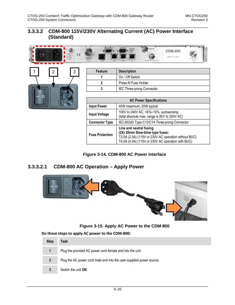
CTOG-250 Comtech Traffic Optimization Gateway with CDM-800 Gateway Router MN-CTOG250 CTOG-250 System Connectors Revision 3
3–20
3.3.3.2 CDM-800 115V/230V Alternating Current (AC) Power Interface (Standard)
Figure 3-14. CDM-800 AC Power Interface
3.3.3.2.1 CDM-800 AC Operation – Apply Power
Figure 3-15. Apply AC Power to the CDM-800
Do these steps to apply AC power to the CDM-800:
Step Task
1 Plug the provided AC power cord female end into the unit.
2 Plug the AC power cord male end into the user-supplied power source.
3 Switch the unit ON.
Feature Description 1 On / Off Switch 2 Press-fit Fuse Holder 3 IEC Three-prong Connector
AC Power Specifications
Input Power 40W maximum, 20W typical
Input Voltage 100V to 240V AC, +6%/-10%, autosensing (total absolute max. range is 90V to 254V AC)
Connector Type IEC-60320 Type C13/C14 Three-prong Connector
Fuse Protection Line and neutral fusing (2X) 20mm Slow-blow type fuses: T2.0A (2.0A) (115V or 230V AC operation without BUC) T4.0A (4.0A) (115V or 230V AC operation with BUC)

CTOG-250 Comtech Traffic Optimization Gateway with CDM-800 Gateway Router MN-CTOG250 CTOG-250 System Connectors Revision 3
3–21
3.3.3.2.2 CDM-800 AC Operation – Replace the Fuses
WARNING! DISCONNECT THE POWER SUPPLY BEFORE PROCEEDING!
Figure 3-16. Replace the CDM-800 AC Fuses
The fuses are contained within a fuse holder that is press-fit into the body of the IEC power module. The CDM-800 uses two 20mm Slow-blow fuses – one each for line and neutral connections. The fuses are located in the rear panel at the power supply (Figure 3-16).
CAUTION – FOR CONTINUED OPERATOR SAFETY, ALWAYS REPLACE THE FUSES WITH THE CORRECT TYPE AND RATING.
Do these steps to replace the AC fuses:
Step Task
1 Unseat the fuse holder from the IEC power module. • Use the slot to pry the holder outward from the IEC power module. • Pull the holder straight out, and then swing the holder away from the module.
2 Remove and replace the fuses as needed. • Use T2.0A (2.0 Amp) fuses for standard operation. • Use T4.0A (4.0 Amp) fuses when a Block Up Converter (BUC) is installed.
3 Re-seat the fuse holder in the IEC power module.

CTOG-250 Comtech Traffic Optimization Gateway with CDM-800 Gateway Router MN-CTOG250 CTOG-250 System Connectors Revision 3
3–22
3.3.3.3 48V Direct Current (DC) Power Interface (Optional)
Figure 3-17. CDM-800 DC Power Interface
3.3.3.3.1 DC Operation – Apply Power
Figure 3-18. Apply DC Power to the CDM-800
Do these steps to apply DC power to the CDM-800: Step Task
1 Connect the user-supplied (+) and (–) DC power leads to their respective terminals. Number 18 AWG minimum wires are recommended.
2 Connect the user-supplied DC power leads to the power source.
3 Switch the unit ON
Feature Description 1 On / Off Switch 2 Screw-in Fuse Holders / Receptacles 3 Power Terminal Block
DC Power Specifications
Input Power 25W (typical) 245W (maximum with BUC)
Input Voltage 48V DC, nominal (36V to 60V)
Connector Type Terminal Block
Fuse Protection (2X) 20mm Slow-blow type fuses: T3A (3.0A) Main T5A (5.0A) (BUC)

CTOG-250 Comtech Traffic Optimization Gateway with CDM-800 Gateway Router MN-CTOG250 CTOG-250 System Connectors Revision 3
3–23
3.3.3.3.2 CDM-800 DC Operation – Replace the Fuses
WARNING! DISCONNECT THE POWER SUPPLY BEFORE PROCEEDING!
Figure 3-19. Replace the CDM-800 DC Fuses
The fuses are contained within individual screw-in receptacles located below the terminal blocks (Figure 3-19). Do these steps to replace the DC fuses:
Step Task
1 Unscrew either fuse holder from its receptacle, and then remove and replace the fuse: • Use T3A (3 Amp) fuses for standard operation. • Use T5A (5 Amp) fuses when a Block Up Converter (BUC) is installed.
2 Screw either fuse holder back into its receptacle.

CTOG-250 Comtech Traffic Optimization Gateway with CDM-800 Gateway Router MN-CTOG250 CTOG-250 System Connectors Revision 3
3–24
3.4 CTOG-250 / CDM-800 System – Basic Interconnection and Configuration Reference
A typical CTOG-250 system, as purchased from Comtech EF Data, is shipped with both the CTOG-250 and CDM-800 units and the CAT5 Ethernet cable needed for interconnecting the pair. The coupled configuration is then incorporated for operation in an Advanced VSAT Network topology. The CTOG-250 chassis may also be purchased standalone from Comtech EF Data, and then paired with an existing CDM-800 Gateway Router that has previously been deployed in an Advanced VSAT Network topology.
Starting with Firmware Ver. 1.5.1.X, the CDM-800 is no longer supported as a standalone unit. The CDM-800 must be paired with a CTOG-250.
Typical for either installation scenario, Figure 3-20 illustrates the basic interconnection of the ‘parent’ CTOG-250 chassis to its ‘child’ CDM-800 Gateway Router. As illustrated, the CDM-800 ‘GE1’ port is connected to the CTOG-250 ‘WAN’ port. A user PC may be connected for Serial- and Ethernet-based Remote Product Management of the CTOG-250.
You must use an Ethernet hub, switch, or direct cable connection to connect the CTOG-250 ‘MGMT-1’ port to the user PC.
After power is applied to the CTOG-250 and CDM-800, the paired units then self-discover each other and the CDM-800 assumes bypass mode. Once this basic interconnection is achieved, the IP addresses of the CTOG-250 ‘WAN’ port and CDM-800 ‘GE1’ are auto-configured and no longer editable by the user, as this is now used as a dedicated link between the two units.
Do not make a connection to, or otherwise use, the CDM-800 ‘FE’ Management Port. Once you connect the CDM-800 to the CTOG-250, all management functions for the CDM-800 are seamlessly handled through the CTOG-250’s management interfaces.
The CTOG-250 is now ready for further connection to, and interoperation, with the remaining Hub and Remote Site-located Advanced VSAT Network topology components.
Chapter 6. QUICK START GUIDE

CTOG-250 Comtech Traffic Optimization Gateway with CDM-800 Gateway Router MN-CTOG250 CTOG-250 System Connectors Revision 3
3–25
Figure 3-20. CTOG-250 Basic Systems Interconnection Diagram
Feature Description A By User: Microsoft Windows-based PC that includes:
• Available Serial and Ethernet ports • A compatible Web browser (e.g., Internet Explorer 8.0) • A terminal emulator program (e.g., Tera Term or HyperTerminal).
B CTOG-250 Comtech Traffic Optimization Gateway
C CDM-800 Gateway Router
Connection Description Purpose
1 Serial connection from User PC to CTOG-250 Serial Port Serial-based remote product management
2 Ethernet connection from User PC to CTOG-250 MGMT-1 port – connect either directly or via user-provided Layer 2 Ethernet Switch
Ethernet-based remote product management
3 Ethernet connection from CTOG-250 WAN port to CDM-800 GE-1 Ethernet port Operational bridge between CTOG-250 and CDM-800

CTOG-250 Comtech Traffic Optimization Gateway with CDM-800 Gateway Router MN-CTOG250 CTOG-250 System Connectors Revision 3
3–26
Notes:

4–1
Chapter 4. CDM-800 FIRMWARE UPDATE
4.1 CDM-800 Firmware Update Overview
MAKE SURE TO OPERATE THE CTOG-250 AND CDM-800 WITH THEIR LATEST AVAILABLE FIRMWARE.
The CTOG-250 Comtech Traffic Optimization Gateway and its CDM-800 Gateway Router are factory-shipped with the latest version of operating firmware. If you require a firmware update, you must contact Comtech EF Data Product Support. CDM-800 firmware updates may be applied to an in-service CTOG-250 system without having to remove the covers of either product chassis. Use the CTOG-250 to update the firmware: • Obtain the firmware update archive file from Comtech EF Data Product Support.
• Establish the proper communications link for acquiring the firmware update archive files by
connecting the CTOG-250 back panel ‘MGMT-1’ 10/100/1000 Gigabit Ethernet port to the Ethernet port of a user-supplied PC.
• Transfer the extracted firmware update via File Transfer Protocol (FTP) from the user PC to the CTOG-250 by directing the FTP client (using the CTOG-250 Management IP Address) to connect to an FTP server. The CTOG-250 automatically updates any attached CDM-800 to the latest compatible CDM-800 firmware. The CDM-800 then automatically updates, changes the designated boot slot, and reboots to finalize the update process.
• Once the CDM-800 reboots, the CTOG-250 and CDM-800 automatically re-establish communication over the WAN link. The new firmware version for the now-updated CDM-800 will display on the CTOG-250 ‘Admin | Firmware’ page.

CTOG-250 Comtech Traffic Optimization Gateway with CDM-800 Gateway Router MN-CTOG250 CDM-800 Firmware Update Revision 3
4–2
4.2 Getting Started: Prepare for the Firmware Download
Do these steps: 1. First, identify the CTOG-250 assigned Management IP Address, and the firmware number/
revision letter/version number.
User-supplied items needed:
• A Microsoft Windows-based PC, equipped with available serial and Ethernet ports; a compatible Web browser (e.g., Internet Explorer); and a terminal emulator program (e.g., Tera Term or HyperTerminal).
• A 9-pin serial cable to connect the PC to the CTOG-250.
a) Use the 9-pin serial cable to connect the CTOG-250 ‘SERIAL’ port to a serial port on the user PC:
b) On the PC – Open the terminal emulator program.
Refer to your terminal emulator program HELP feature or user guide for operating and configuration instructions.
Configure the utility program serial port communication and terminal display operation:
• 38400 bps (Baud Rate) • 8 Data Bits • 1 Stop Bit
• Parity = NO • Port Flow Control = NONE • Display New line Rx/Tx: CR • Local Echo = ON
c) On the CTOG-250 – Turn on the power from the
chassis front panel:
d) On the PC – Make note of the information displayed on the CTOG-250 Serial Interface:
• Management IP Address (e.g., default is 192.168.1.2/24)
• Firmware Number and Revision Letter (e.g., FW-0020601T)
• Firmware Release Version (e.g., 1.6.2.4)

CTOG-250 Comtech Traffic Optimization Gateway with CDM-800 Gateway Router MN-CTOG250 CDM-800 Firmware Update Revision 3
4–3
The serial and HTTP interface figures as featured throughout this chapter are intended for user reference only and are subject to change. The firmware information (i.e., revision letters, version numbers, etc.) as displayed may differ from your setup.
See Chapter 8. SERIAL INTERFACE OPERATION for information and instructions on using the CTOG-250 Serial Interface.
e) Alternately, use the CTOG-250 HTTP Interface to obtain the firmware information.
• Use an Ethernet hub, switch, or direct cable connection to connect the CTOG-250 ‘MGMT-1’ port to the PC:
• On the PC – Use a Web browser (e.g., Internet Explorer) to log in to the CTOG-250 HTTP Interface and access the ‘Admin | Firmware’ page. Then, make note of the Slot #1 and Slot #2 firmware loads (e.g., 1.6.2.4):
2. Next, create a temporary folder (subdirectory) on the user PC for the firmware archive
download.
See Chapter 7. ETHERNET INTERFACE OPERATION for information and instructions on using the CTOG-250 HTTP Interface.

CTOG-250 Comtech Traffic Optimization Gateway with CDM-800 Gateway Router MN-CTOG250 CDM-800 Firmware Update Revision 3
4–4
• Drive letter “c:” is used in these examples. Any valid, writable drive letter can be used.
• Typical for all tasks: Type the command without quotes, and then press Enter to execute.
There are several ways the user may use create a temporary folder on a Windows-based PC:
a) Use the Windows Desktop to create and rename the temporary folder.
• Right-click anywhere on the desktop to open the popup submenu, and then select
New > Folder to create the temporary folder. The new folder will be created on the desktop.
• Right-click on the new folder and then select Rename from the popup submenu. Rename this folder to "temp" or some other convenient, unused name.
b) Use Windows Explorer to create and rename the temporary folder.
• Select File > New > Folder to create the temporary folder. The new folder will be
created in the active folder. • Right-click the “New Folder” folder name, and then rename this folder to "temp" or
some other convenient, unused name.
c) Use the ‘Run’ and ‘Browse’ windows to create and rename the temporary folder.
• Select [Start] on the Windows taskbar and then click the Run... icon. The ‘Run’
window will open.
• Click [Browse] in the ‘Run’ window. The ‘Browse’ window will open. • Click the ‘Create New Folder’ icon in the ‘Browse’ window. The new folder will be
created.

CTOG-250 Comtech Traffic Optimization Gateway with CDM-800 Gateway Router MN-CTOG250 CDM-800 Firmware Update Revision 3
4–5
• Right-click the “New Folder” folder name and then rename this folder to “temp” or some other convenient, unused name.
d) Use Windows Command-line to create the temporary folder.
• First, click [Start] on the Windows taskbar, and then click the Run... icon (or, depending on Windows OS versions prior to Windows 95, click the MS-DOS Prompt icon from the Main Menu).
• Next, open a Command-line window…
o For Windows 95 or Windows 98 – Type “command”. o For any Windows OS versions later than Windows 98 – Type “cmd” or
“command”.
o Alternately, from [Start], select All Programs > Accessories > Command
Prompt.
o Finally, from the Command-line ‘c:\>’ prompt, type “mkdir temp” or “md temp” (mkdir and md stand for make directory), and then click [OK].
There should now be a "temp" folder created and available for placement of the firmware file download.

CTOG-250 Comtech Traffic Optimization Gateway with CDM-800 Gateway Router MN-CTOG250 CDM-800 Firmware Update Revision 3
4–6
4.3 Download and Extract the Firmware Update
Do these steps: 1. Acquire the firmware update archive file from Comtech EF Data Product Support.
• About Firmware Numbers, File Versions, and Formats: Comtech EF Data provides its firmware update files by product type (e.g., router, modem, etc.), the specific model, and optional hardware configurations.
• About File Archive Formats: Comtech EF Data provides its firmware update files in two compressed archive formats: *.exe (self-extracting) and *.zip (compressed). The *.exe file does not require a file archiver and compression utility program such as PKZIP for Windows, WinZip, ZipCentral, etc. (PKZIP for DOS is not supported due to file naming conventions). Comtech EF Data does not provide this utility program. Some firewalls do not allow the download of *.exe files. Download the *.zip file instead, and extract the firmware files from the archive download with a user-supplied utility program. For detailed information on handling archived files, refer to the utility program Help documentation.
2. Transfer the archive file to the temporary folder.
• Once you select the EXE or ZIP hyperlink the ‘File Download’ window opens and prompts selection of [Open] or [Save]:
o Click [Open] to turn over file extraction to the user-supplied utility program. Be sure
to extract the firmware files to the “temp” folder created earlier.
o Click [Save] to open the ‘Save As’ window. Be sure to select and [Save] the archive *.exe or *.zip file to the “temp” folder created earlier.
o Otherwise, click [Cancel] to quit and exit the file download process.
3. Extract the firmware files from the archive file.
• (If not already done with File Download > [Open]) Extract the firmware files from the downloaded *.exe or *.zip archive file with the user-supplied utility program:

CTOG-250 Comtech Traffic Optimization Gateway with CDM-800 Gateway Router MN-CTOG250 CDM-800 Firmware Update Revision 3
4–7
o Double-click on the archive file name, and then follow the prompts provided by the
user-supplied utility program. Extract, at a minimum, two files: FW0020601x_ctog250.bin – the Firmware Bulk image file (where ‘x’ denotes the
revision letter), and
CTOG-250ReleaseNotes_v#-#-#.pdf – the Firmware Release Notes PDF file (where ‘#-#-#’ denotes the firmware version number).
4. Confirm availability of the firmware files in the temporary folder.
There are several ways the user may view the contents of the temporary folder on a Windows-based PC:
a) From the Windows Desktop:
• Double-left-click the “temp” folder saved to the Windows Desktop.
• Use Windows Explorer to locate, and then double-left-click the “temp” folder.
• Use the ‘Browse’ window ([Start] > ...Run > [Browse]) to locate, and then double-
click the “c:\temp” folder.
b) Use Command-line:
• Type “cd c:\temp” at the Command-line prompt to change to the temporary directory created earlier using Command-line.
• Type “dir” to list the files extracted to the temporary directory from the downloaded archive file.
The firmware files have been successfully downloaded and are now available for transfer to the CTOG-250.
4.4 Perform the Ethernet FTP Upload Procedure
You may proceed with the firmware update procedure, assuming that: • The CTOG-250 is connected to a user-supplied, Windows-based PC, and:
o The PC serial port is connected to the CTOG-250 ‘CONSOLE’ port.
o The PC Ethernet port is connected to the CTOG-250 ‘MGMT-1’ Ethernet port
with a user-supplied hub, switch, or direct Ethernet cable connection.
o The PC is running a terminal emulation program (for operation of the CTOG-250 Serial Interface) and a compatible Web browser (for operation of

CTOG-250 Comtech Traffic Optimization Gateway with CDM-800 Gateway Router MN-CTOG250 CDM-800 Firmware Update Revision 3
4–8
the CTOG-250 HTTP Interface).
• The CTOG-250 Management IP Address has been noted using the CTOG-250 Serial Interface, and the firmware has been identified using either the serial interface or the CTOG-250 HTTP Interface ‘Admin | Firmware’ page.
• You have downloaded, or otherwise received from Comtech EF Data, the latest firmware update and the extracted files are available on the User PC in an accessible temporary folder.
Do these steps:
1. Use Command-line to send a “PING” command to confirm proper connection and communication between the user PC and the CTOG-250:
• If the Management IP Address of the unit is still not known, type “info” at the serial
interface CTOG-250> command prompt and record the displayed information. Alternately, use Serial Remote Control or the HTTP Interface:
o Serial Remote Control – Type the “<0/IPA?” remote query (without quotes) at the
serial interface CTOG-250> command prompt. The unit returns the configured Management IP Address:
>0000/IPA=192.168.1.10/24 (default)
o HTTP Interface – View the IP Address/CIDR Mask entry on the ‘Configuration | Interface | Mgt’ page:
• Once the Management IP address is known – use Command-line to PING: Type “ping xxx.xxx.xxx.xxx” at the Command-line prompt (where ‘xxx.xxx.xxx.xxx’ is the unit Management IP Address). The response should confirm whether the unit is properly connected and communicating.
2. Use Command-line to transfer (FTP) the files from the user PC to the CTOG-250:
• Type "ftp xxx.xxx.xxx.xxx" (where ‘xxx.xxx.xxx.xxx’ denotes the Management IP
address of the unit being updated.
• Enter the username and password assigned to the unit. The default username and password is “comtech”.
• Type “bin” to set the binary transfer mode.

CTOG-250 Comtech Traffic Optimization Gateway with CDM-800 Gateway Router MN-CTOG250 CDM-800 Firmware Update Revision 3
4–9
• Type "put FW0020601x_ctog250.bin" (where ‘x’ denotes the revision letter) at the Command-line prompt, without quotes, to begin the file transfer. The process sequences through several blocks – this may take several minutes for the transfer to occur. Once the update file is received, the image is written to Flash memory and the unit transmits the message “UPLOAD COMPLETE.”
In the event you receive the “Connection closed by remote host.” message, wait another minute before continuing. The CDM-800 update sometimes takes longer than the FTP client allows.
• Type "bye" to terminate the FTP session, and then close the Command-line window. 3. Use the serial interface or the HTTP Interface ‘Admin | Firmware’ page to verify that the
PC-to-Unit FTP file transfer was successful.
4. Use the CTOG-250 HTTP Interface to select the firmware and reboot the unit:
a) Select the desired Boot Slot (Image):
• Go to the HTTP Interface ‘Admin | Firmware’ page.
• Use the ‘Boot From:’ drop-down menu to select Latest, Slot 1, or Slot 2 (in the Firmware Configuration section). By default, the unit will boot from the Slot that stores the firmware version having the latest date (Boot From: Latest). ‘Boot From:’ may also be set to force the unit to boot up using either firmware image loaded in Slot 1 or Slot 2.
• Click [Submit] to save the setting.
b) Reboot the CTOG-250:
• Go to either the HTTP Interface ‘Admin | Firmware’ page or the ‘Utility | Reboot’ page.
• Click [Reboot] in the System Reboot section of the ‘Admin | Firmware’ page or the
‘Utility | Reboot’ page and [OK] when prompted, and then wait while the CTOG-250 reboots.
The CTOG-250 and its CDM-800 are now operating with the latest firmware. The firmware update process is now complete.

CTOG-250 Comtech Traffic Optimization Gateway with CDM-800 Gateway Router MN-CTOG250 CDM-800 Firmware Update Revision 3
4–10
Notes:

5–1
Chapter 5. CDM-800 FAST ACTIVATION PROCEDURE
5.1 Introduction
The CDM-800 Gateway Router, as operated under the umbrella of CTOG-250 remote product management, incorporates a number of optional features. In order to permit a lower initial cost, you may purchase the unit with only the desired features enabled. If you wish to upgrade the functionality of a unit at a later date, Comtech EF Data provides Fully Accessible System Topology (FAST), which permits the purchase and activation of options through special authorization codes. You may contact Comtech EF Data Product Support to purchase these unique, register-specific Fast Access Codes, and then load these codes into the unit using the CTOG-250 HTTP Interface (accessible via the CTOG-250 back panel ‘MGMT-1’ GigE port). FAST System Theory: FAST allows on-site upgrade of the operating feature set without removing a unit from the setup. FAST technology allows you to order a unit precisely tailored for the initial application. When your service requirements change, you can upgrade the topology of the unit to meet these requirements within minutes. This accelerated upgrade is possible because of FAST’s extensive use of the programmable logic devices incorporated into Comtech EF Data products. FAST Implementation: Comtech EF Data implements the FAST system in the modem at the factory. All FAST options are available through the basic platform unit at the time of order – FAST allows immediate activation of available options, after confirmation by Comtech EF Data, through the CTOG-250 HTTP Interface. FAST Accessible Options: You may order hardware options for installation either at the factory, or you can install and activate them on-site. The FAST Access Code that you purchase from Comtech EF Data enables configuration of the available hardware.

CTOG-250 Comtech Traffic Optimization Gateway with CDM-800 Gateway Router MN-CTOG250 CDM-800 FAST Activation Procedure Revision 3
5–2
5.2 CDM-800 FAST Activation via the HTTP Interface
SECT. 7.4.4.2.3 Admin | FAST (Chapter 7. ETHERNET INTERFACE OPERATION)
Use the CTOG-250 HTTP Interface ‘Admin | FAST’ page to manage CDM-800 FAST Features. This page provides scrollable list boxes that display the availability and activation status for all FAST options. FAST code entry/option activation control is also provided.
Figure 5-1. CTOG-250 HTTP Interface Admin | FAST page

CTOG-250 Comtech Traffic Optimization Gateway with CDM-800 Gateway Router MN-CTOG250 CDM-800 FAST Activation Procedure Revision 3
5–3
5.2.1 CDM-800 FAST Configuration
The read-only table in this section displays the available CDM-800 FAST Features and the operational status for each option:
Column Description Option This column lists each available FAST Feature.
Status This column identifies each FAST Feature operational parameter(s). If an option is not enabled, the column displays this information.
The roster of FAST Accessible Options includes:
Option Compression Hardware Payload/Header Compression Card (CEFD KIT P/N KT-0000249) Tx Symbol Rate Up to maximum Mbps Tx Header Compression Enabled/Disabled Tx Payload Compression Enabled/Disabled QoS (Quality of Service) Group QoS G.703 Clock Extension Enabled/Disabled Tx Frequency IF (50-180 MHz) and L-Band (950-2150 MHz) PTP (Precision Time Protocol) NOT AVAILABLE IN THIS FIRMWARE RELEASE.
1) Tx Header and Payload Compression are standard (non-FAST) operational features for Comtech EF Data’s Advanced VSAT Series group of products. If these features are listed in the FAST Configuration table, they are always indicated as Enabled.
2) PTP is not available in this firmware release. Once operable, this protocol will be used to synchronize clocks throughout a computer network. When the hardware required for this option is not installed in the CDM-800, the web page will display the message “PTP not supported with installed hardware”.

CTOG-250 Comtech Traffic Optimization Gateway with CDM-800 Gateway Router MN-CTOG250 CDM-800 FAST Activation Procedure Revision 3
5–4
5.2.2 CDM-800 FAST Upgrade
Do these steps:
Step Task
1 Use the FAST Configuration table to view the currently installed features. Any options that appear as Disabled in the table’s Status column may be purchased as a FAST upgrade.
2 The serial number of the CDM-800 is required by Comtech EF Data when ordering FAST option upgrades. Take note of this number, provided here in the FAST Upgrade section, before contacting Comtech EF Data: Serial Number: __________________________
3 Contact Comtech EF Data Product Support: • Provide the CDM-800 Serial Number to the representative.
• Identify and purchase the desired FAST option(s).
• Obtain the invoice, the 20-digit FAST Access Code, and the FAST option
activation instructions.
4 Carefully enter the FAST Access Code into the FAST Code register text box.
5 Click [Submit] to execute the FAST Upgrade.
6 The unit either accepts or rejects the code, and the FAST Configuration table refreshes to reflect any upgrades in operation. If the unit rejects the code entry, repeat the FAST Access Code entry procedure. Should the code entry error persist, contact Comtech EF Data Product Support for further assistance.

6–1
Chapter 6. QUICK START GUIDE
6.1 Overview
By following this Quick Start Guide, beginning with the factory default settings you may be able to pass traffic over the CTOG-250 within a short period of time.
1) This chapter refers to the CTOG-250 system – the ‘parent’ CTOG-250 Comtech Optimization Gateway chassis and its ‘child’ CDM-800 Gateway Router – collectively as the “CTOG-250”.
2) This chapter assumes that you are familiar with the configuration and the operation of both the CTOG-250 Comtech Traffic Optimization Gateway and the various hub site and remote site components that comprise an Advanced VSAT System (e.g., the CDD-880 Multi Receiver Router, CDM-840 Remote Router, etc.)
3) Unless otherwise noted, this chapter refers to use of the CTOG-250 HTTP (Web Server) Interface via the User PC located at the network hub site. Where access to other Advanced VSAT Network product HTTP Interfaces is indicated – i.e., the hub site CDD-880 Multi Receiver Router, the remote site CDM-840 Remote Router, etc. – this assumes that interface access has been established by typing the applicable product Management IP Address into the hub site User PC’s web browser.
Chapter 7.ETHERNET INTERFACE OPERATION
4) The serial and HTTP interface figures as featured throughout this chapter are intended for user reference only and are subject to change. The firmware information (i.e., revision letters, version numbers, etc.) as displayed may differ from your setup.

CTOG-250 Comtech Traffic Optimization Gateway with CDM-800 Gateway Router MN-CTOG250 Quick Start Guide Revision 3
6–2
6.2 Getting Started
6.2.1 Using This Quick Start Guide
To learn how to... See
Chapter Section...
...set up the basic (baseline) CTOG-250 as a new Advanced VSAT network component 6.3
...integrate a previously-deployed CDM-800 with a new CTOG-250 Comtech Optimization Gateway chassis 6.4
...configure LAN-CTOG CDM-840 traffic 6.5.1
...set up the CTOG-250 in a Vipersat Management System (VMS)-enabled CTOG-250 N:M Redundancy system 6.6.1
...contact Comtech EF Data for troubleshooting or product support 6.7
6.2.2 Equipment List for Standalone Operation
Item Description Qty Comments
1 CTOG-250 chassis 1 Depending upon the end use system, you may need to connect additional equipment such as BUCs to convert 70 MHz IF to L-Band 2 CDM-800 Gateway Router 1
3 PC equipped with network interface card and terminal emulation program (e.g., HyperTerminal, Tera Term, etc.)
1 Provided by user.
4 10/100/1000 BaseT Ethernet Switch 1 Provided by user. (An RJ-45 Ethernet crossover cable can be substituted to connect the User PC directly to CTOG-250 without the use of a switch.)
5 CAT5 Ethernet cable(s) 1-4 Provided by user.
6 CTOG-250 Serial Console cable (DB-9 to RJ-11) 1
Supplied by Comtech EF Data. Note that the CTOG-250 cable is different from the CDM-800 cable and cannot be interchanged.
7 CDM-800 Serial Console cable (DB-9 to RJ-11) 1
Supplied by Comtech EF Data. Note that the CDM-800 cable is different from the CTOG-250 cable and cannot be interchanged.
8 IF cable 1 Provided by user: • Type BNC for 70/140 MHz operation • Type ‘N’ for L-Band operation

CTOG-250 Comtech Traffic Optimization Gateway with CDM-800 Gateway Router MN-CTOG250 Quick Start Guide Revision 3
6–3
6.3 Baseline CTOG-250 Deployment
Figure 6-1. CTOG-250 Routed Implementation in an Advanced VSAT Network
6.3.1 Connect the CTOG-250 System Components
Step Task
1 Connect the GigE ‘MGMT-1’ Management Port on the CTOG-250 chassis back panel to the User PC via a 10/100/1000 BaseT Ethernet Switch using CAT5 Ethernet cables. (An RJ-45 Ethernet crossover cable can be substituted to connect the CTOG-250 directly to the User PC without the use of a switch.)
2 Connect the CTOG-250 Console Serial Cable from the ‘SERIAL’ port on the CTOG-250 chassis back panel and a serial COM port on the User PC.
3 Connect a CAT5 Ethernet cable from the ‘WAN’ port on the CTOG-250 chassis back panel to the ‘GE1’ port on the CDM-800 rear panel.
4 Connect the CTOG-250 and the CDM-800 to a suitable power supply and turn the units ON.

CTOG-250 Comtech Traffic Optimization Gateway with CDM-800 Gateway Router MN-CTOG250 Quick Start Guide Revision 3
6–4
Figure 6-2. CTOG-250 Basic Systems Interconnection Diagram
Feature Description A By User: Microsoft Windows-based PC that includes:
• Available Serial and Ethernet ports • A compatible Web browser (e.g., Internet Explorer 8.0) • A terminal emulator program (e.g., Tera Term or HyperTerminal).
B CTOG-250 Comtech Traffic Optimization Gateway
C CDM-800 Gateway Router
Connection Description Purpose
1 Serial connection from User PC to CTOG-250 ‘SERIAL’ Port Serial-based remote product management
2 Ethernet connection from User PC to CTOG-250 ‘MGMT-1’ port – connect either directly or via a user-provided Layer 2 Ethernet Switch OR Ethernet crossover cable for direct connection to User PC
Ethernet-based remote product management
3 Ethernet connection from CTOG-250 ‘WAN’ port to CDM-800 ‘GE-1’ Ethernet port Operational bridge between CTOG-250 and CDM-800

CTOG-250 Comtech Traffic Optimization Gateway with CDM-800 Gateway Router MN-CTOG250 Quick Start Guide Revision 3
6–5
6.3.2 Automatic CDM-800 Configuration
Once you power up and boot the CTOG-250 system, the CTOG-250 checks the firmware version of the CDM-800. If the version is not correct, the CTOG-250 upgrades the CDM-800’s firmware, and then performs a reboot of the CDM-800 to load the new firmware.
You may review the results of the upgrade process with the CTOG-250 HTTP Interface STATUS | MONITOR page.
Chapter 7.ETHERNET INTERFACE OPERATION Chapter 8. SERIAL INTERFACE OPERATION
6.3.3 Configuration via the CTOG-250 Serial Interface
Do these steps:
Step Task
1 From the Windows-based User PC: Launch a terminal emulation program (e.g., HyperTerminal, Tera Term, etc.)
2 Select the appropriate COM port (i.e., the port to which the DB-9 end of the cable are connected) and configure it for: 38,400 bps 8 data bits No parity 1 stop bit No hardware flow control
3 Type “info” and press ENTER to display the CTOG-250 Serial Interface, as per the example shown here:
If the terminal is not set to “Echo”, any input to the terminal will not be displayed when typing, but will be received by the CTOG-250.

CTOG-250 Comtech Traffic Optimization Gateway with CDM-800 Gateway Router MN-CTOG250 Quick Start Guide Revision 3
6–6
6.3.4 Configuration via the CTOG-250 HTTP Interface
Step Task
1 From the Windows-based User PC: Launch a web browser (e.g., Internet Explorer 8.0).
2 Type the CTOG-250 Management IP Address (shown here as http://xxx.xxx.xxx.xxx) into the Address area of the User PC Web browser:
3 The login page, similar to the example shown here, opens. Enter the assigned User Name and Password – the default for both is comtech. Click [Log On].
4 If the User Name and Password are accepted: The CTOG-250 HTTP Interface Home page displays,
similar to the example shown here:

CTOG-250 Comtech Traffic Optimization Gateway with CDM-800 Gateway Router MN-CTOG250 Quick Start Guide Revision 3
6–7
6.4 Adding a CTOG-250 to an Existing (Previously Deployed) CDM-800
Do these steps:
Step Task
1 Remove all Ethernet cables from the existing CDM-800. Move the traffic Ethernet cables from the CDM-800 to the ‘LAN TRAFFIC (1)’ and (if necessary) ‘LAN Traffic (2)’ ports on the CTOG-250.
2 Assign a Management IP Address to the CTOG-250 that is on the existing CDM-800’s management network.
3 Verify that the CTOG-250 is on the same network and cabled correctly by issuing a ping from the User PC to the CTOG-250.
4 Connect a CAT5 Ethernet cable from the ‘WAN’ port on the CTOG-250 chassis back panel to the ‘GE1’ port on the CDM-800 rear panel.
5 Once you power up and boot the CTOG-250 system, the CTOG-250 checks the firmware version of the CDM-800. If the version is not correct, the CTOG-250 upgrades the CDM-800’s firmware, and then performs a reboot of the CDM-800 to load the new firmware.
6 Upload the existing CDM-800’s configuration to the CTOG-250 via the [Sync Configuration From CDM-800] button on the CTOG-250 HTTP Interface Utility | CTOG-250 Unit page.
Chapter 7.ETHERNET INTERFACE OPERATION
7 Ping the CDM840’s traffic IP. If the ping is unsucessful, check all cables and routing information and try again.

CTOG-250 Comtech Traffic Optimization Gateway with CDM-800 Gateway Router MN-CTOG250 Quick Start Guide Revision 3
6–8
6.5 Configure Traffic for the Advanced VSAT Network
Figure 6-3. Traffic Routing in a Basic Routed Advanced VSAT Network
Figure 6-3 shows the routing for both product management (i.e., remote M&C) and G.703/E1 and Gigabit Ethernet traffic data within the baseline Advanced VSAT Network. Configuration of traffic within the network follows this specific sequence of tasks:
Task Description
1 Configure the CTOG-250 and the CDM-840(s) located at the Remote Sites to the same frequency and symbol rate.
2 Add a route on the CTOG-250 to the CDM-840’s traffic network (make sure to use the correct WAN label). 3 Add a route on the CDM-840 to the CTOG-250’s management network.
If the CDD-880 isn’t on the same management network as the CTOG-250, then a route from the CDD-880 to the CTOG-250 is required.
4 Ping the CDM-840’s traffic IP. If the ping is unsucessful, check all cables and routing information and try again.

CTOG-250 Comtech Traffic Optimization Gateway with CDM-800 Gateway Router MN-CTOG250 Quick Start Guide Revision 3
6–9
6.5.1 Configuring Traffic in Router Mode: CTOG-250 CDM-840
You must follow this configuration procedure for Management traffic, and when the unit is in Router Mode.
Step Task
1 Use the CTOG-250 Configuration | Interface | LAN-1 page to configure the LAN IP(s) to an IP Address on their respective networks. In this example, the CTOG-250 is using the ‘LAN TRAFFIC (1)’ port and the traffic network is 11.0.0.0/8:
2 Connect the traffic network to the CTOG-250. Refresh the CTOG-250 Configuration | Interface |
LAN-1 page to verify negotiated link and speed:
3 Use the CTOG-250 Status | Statistics | Traffic page to verify Ethernet (network) activity on LAN-1
and/or LAN-2 (assuming that there is network traffic being routed to the CTOG-250):

CTOG-250 Comtech Traffic Optimization Gateway with CDM-800 Gateway Router MN-CTOG250 Quick Start Guide Revision 3
6–10
Step Task 4 Use the CTOG-250 Configuration | WAN | Mod (Modulator) page and the remote CDM-840
Configuration | WAN | Demod | Config (Demodulator) page to configure an identical RF frequency and symbol rate:

CTOG-250 Comtech Traffic Optimization Gateway with CDM-800 Gateway Router MN-CTOG250 Quick Start Guide Revision 3
6–11
Step Task 5 Use the CTOG-250 Configuration | Network | Routing page to add a route to the CTOG-250 for the
routing of IP traffic from the CTOG-250 LAN network to the CDM-840 traffic LAN. Be sure to use a WAN label that corresponds to that of the desired CDM-840. In this example, the CDM-840 network IP Address is 172.20.2.0/24 and the network WAN label is 200:
6 Use the Modulator Statistics table on the CTOG-250’s Status | Statistics | Traffic page to verify that
the entered route is correctly routing traffic to the modulator. The Current Tx Rate (Kbps) values in the table should be greater than zero.

CTOG-250 Comtech Traffic Optimization Gateway with CDM-800 Gateway Router MN-CTOG250 Quick Start Guide Revision 3
6–12
Step Task 7 Once the CDM-840 demodulator locks to the CTOG-250 RF signal, the CDM-840 Status | Statistics |
Traffic page Demod Statistics table shows traffic being received:
8 Traffic is routed when the CDM-840 ‘TRAFFIC | GE’ port is on the destination network. However, if the
destination network is beyond the CDM-840 traffic network, then a route is required to continue to the Next Hop. In this example, the Route Table (Edit) on the CDM-840 Configuration | Network | Routing | Routes page shows that the destination network is beyond the CDM-840’s traffic network and the Next Hop IP is 172.20.2.133:
When the destination network is on the CDM-840 traffic network, the CDM-840 dynamically adds an ARP (Address Resolution Protocol) entry for each host on the network. In this example, the destination IP, as listed in the ARP Table (Edit) table on the CDM-840 Configuration | Network | ARP page, is 172.20.2.100:

CTOG-250 Comtech Traffic Optimization Gateway with CDM-800 Gateway Router MN-CTOG250 Quick Start Guide Revision 3
6–13
Step Task 9 Traffic should now be evident at either the Next Hop IP or the end host. Use the Interface Counters and
Router Counters tables on the CDM-840 Status | Statistics | Router page to verify that the CDM-840 is routing received WAN traffic to the LAN:

CTOG-250 Comtech Traffic Optimization Gateway with CDM-800 Gateway Router MN-CTOG250 Quick Start Guide Revision 3
6–14
6.5.2 Configuring Traffic in BPM (Bridge Point-to-Multipoint) Mode: CTOG-250 CDM-840
You must follow this configuration procedure for the traffic path when the platform is running in BPM (Bridge Point-to-Multipoint) Mode. See Sect. 6.5.1 when you need to configure the platform for management traffic.
Step Task
1 Use the CTOG-250 Configuration | Network | Working Mode page to configure the CTOG-250 to run in BPM Mode:
2 Connect the traffic network to the CTOG-250. Refresh the CTOG-250 Configuration | Interface |
LAN-1 page to verify negotiated link and speed:
3 Use the CTOG-250 Status | Statistics | Traffic page to verify Ethernet (network) activity on LAN-1
and/or LAN-2 (assuming that there is network traffic being routed to the CTOG-250):

CTOG-250 Comtech Traffic Optimization Gateway with CDM-800 Gateway Router MN-CTOG250 Quick Start Guide Revision 3
6–15
Step Task 4 Use the CTOG-250 Configuration | WAN | Mod (Modulator) page and the remote CDM-840
Configuration | WAN | Demod | Config (Demodulator) page to configure an identical RF frequency and symbol rate:

CTOG-250 Comtech Traffic Optimization Gateway with CDM-800 Gateway Router MN-CTOG250 Quick Start Guide Revision 3
6–16
Step Task 5 Use the CTOG-250 Configuration | Interface | EXP-NET 1 page to confirm that the associated
CDD-880s have been connected to the CTOG-250 Expansion port:
6 Use the CTOG-250 Status | Statistics | Network | Assoc 880s page to confirm that the associated CDD-880s have been discovered by the CTOG-250:
7 Use the Modulator Statistics table on the CTOG-250 Status | Statistics | Traffic page to verify that
the entered route is correctly routing traffic to the modulator. The Current Tx Rate (Kbps) values in the table should be greater than zero:
8 Once the CDM-840 demodulator locks to the CTOG-250 RF signal, the CDM-840 Status | Statistics |
Traffic page Demod Statistics table shows traffic being received:

CTOG-250 Comtech Traffic Optimization Gateway with CDM-800 Gateway Router MN-CTOG250 Quick Start Guide Revision 3
6–17
6.6 Using the CTOG-250 in Redundancy Operations
6.6.1 CTOG-250 N:M Redundant Operation in a Vipersat Management System (VMS)
• Sect. 2.2 Install the Units Into a Rack Enclosure (Chapter 2. INSTALLATION) • MN/22156 Vipersat VMS v3.x.x Vipersat Management System User Guide
The installation of VMS-enabled CTOG-250 N:M redundancy in an Advanced VSAT Network involves the physical installation, interconnection, and grouping of the Unit A and Unit B CTOG-250s, and the logical grouping of managed units using the VMS Redundancy Manager. You must meet these requirements to operate a VMS-enabled CTOG-250 N:M redundancy system: 1) N:M Redundancy is only applicable to Hub devices that are not expansion units.
2) All VMS-controlled modems must have identical firmware version installed. 3) A Server Technology horizontal Sentry™ PowerTower XL IP Remote AC Power Control Bus is
required. 4) All modems must share the same RF infrastructure, such as Combiners and Splitters. Sect. 6.6.1.1 provides a reference diagram (Figure 6-4) and table (Table 6-1) that identifies the key features of a basic rack-mounted VMS-enabled CTOG-250 N:M redundant setup. Further assembly and configuration instructions follow in Sect. 6.6.1.2.

CTOG-250 Comtech Traffic Optimization Gateway with CDM-800 Gateway Router MN-CTOG250 Quick Start Guide Revision 3
6–18
6.6.1.1 VMS-enabled CTOG-250 1:1 Redundancy – Assembly and Connection Instructions
Figure 6-4. VMS-enabled CTOG-250 1:1 Redundant System Interconnection Diagram

CTOG-250 Comtech Traffic Optimization Gateway with CDM-800 Gateway Router MN-CTOG250 Quick Start Guide Revision 3
6–19
Figure 6-4 summarizes the connections required for a basic VMS-enabled 1:1 redundant configuration. Key features of this configuration are identified in Table 6-1:
Table 6-1. Figure 6-4 1:1 Redundant Configuration Features
Figure 6-4 NOTES
1) This figure depicts use of a North American AC Power Splitter Cord (CEFD P/N PP-0020563). For other regions, use CEFD P/N PP-0020564 or contact your local sales representative. (Image source: Quail Electronics, Inc.)
2) See MN/22156 Vipersat VMS v3.x.x Vipersat Management System User Guide for information on N:M configurations.
Feature Description A1 Unit A – CTOG-250 Comtech Traffic Optimization Gateway A2 Unit A – CDM-800 Gateway Router B1 Unit B – CTOG-250 Comtech Traffic Optimization Gateway B2 Unit B – CDM-800 Gateway Router
C CDD-880 Multi Receiver Router (purchased separately, shown for reference only, power connection not shown for clarity)
D Network Controller AC Power Bus E User Advanced VSAT Network Management Setup, including VMS Server
Connection Description Comments
1 AC Power Splitter Cord connection: CTOG-250 / CDM-800 Network Controller AC Power Bus outlets
CEFD P/N PP-0020563 See Note 1
2 Unit A CTOG-250 to CDM-800 Ethernet connection: CTOG-250 ‘WAN’ port CDM-800 ‘GE-1’ port Operational bridge between
CTOG-250 and CDM-800. See Figure 6-2 in Sect. 6.3.1. 3 Unit B CTOG-250 to CDM-800 Ethernet connection:
CTOG-250 ‘WAN’ port CDM-800 ‘GE-1’ port
4 Unit A CTOG-250 ‘MGMT-1’ port User PC via management network Remote Product Management (M&C) Ethernet connections – all CAT5 Ethernet cables are user-provided.
5 Unit B CTOG-250 ‘MGMT-1’ port User PC via management network
6 CDD-880 management Ethernet connection: ‘ETHERNET | TRAFFIC/MANAGEMENT | GE’ port User PC via management network
7 Network Controller AC Power Bus management Ethernet connection: ‘Ethernet’ port VMS Server via management network
Server Technology horizontal Sentry™ PowerTower XL IP Remote AC Power Control Bus

CTOG-250 Comtech Traffic Optimization Gateway with CDM-800 Gateway Router MN-CTOG250 Quick Start Guide Revision 3
6–20
6.6.1.2 Configure the CTOG-250 for VMS-enabled N:M Redundancy
Consult adjunct Comtech EF Data publication MN/22156 Vipersat VMS v3.x.x Vipersat Management System User Guide when using this section of the Quick Start Guide chapter.
1) Once you install your devices in the Advanced VSAT Network as shown in Figure 6-4, read
MN/22156 Appendix C – Redundancy subsection “N:M Hub Modem Redundancy |Installing N:M Redundancy”.
All units in both the primary and secondary group must be identical, with exactly the same hardware configuration and accessories, and have identical firmware revision levels.
2) To complete configuration, read and follow the procedures in MN/22156 Appendix C –
Redundancy subsection “N:M Hub Modem Redundancy | Setting Up N:M Redundancy”.
6.7 For Help With CTOG-250 Configuration
For all product support, please call:
+1.240.243.1880 +1.866.472.3963 (toll free USA)

7–1
Chapter 7. ETHERNET INTERFACE OPERATION
7.1 Overview
Ethernet-based remote product management of the ‘parent/host’ CTOG-250 Comtech Traffic Optimization Gateway chassis and its ‘child’ CDM-800 Gateway Router (referred to hereafter as the simply as the CTOG-250) is available using the CTOG-250’s chassis back panel ‘MGMT-1’ RJ-45 10/100/1000 BaseT Gigabit Ethernet M&C port.
1) YOU MAY PROCEED WITH ETHERNET-BASED REMOTE PRODUCT MANAGEMENT (SNMP OR HTTP), ASSUMING THAT:
• The CTOG-250 and its CDM-800 Gateway Router are interconnected and are
operating with the latest version firmware files.
• The CTOG-250 is connected to a user-supplied, Windows-based PC as follows: o The PC serial port connects to the CTOG-250 back panel ‘SERIAL’ port
with a user-supplied serial cable.
o The PC Ethernet port connects to the CTOG-250 back panel ‘MGMT-1’ 10/100/1000 BaseT Gigabit Ethernet port with a user-supplied hub, switch, or direct Ethernet cable connection.
o The PC is running a terminal emulation program (for use of the CTOG-250
Serial Interface) and a compatible Web browser (for use of the CTOG-250 HTTP Interface).
• The CTOG-250 Management IP Address is noted using the CTOG-250 Serial
Interface (CLI).
2) USE OF THE SNMP INTERFACE IS RECOMMENDED ONLY FOR ADVANCED USERS. ALL OTHER USERS ARE STRONGLY ENCOURAGED TO USE THE CTOG-250 HTTP INTERFACE FOR REMOTE MONITOR AND CONTROL (M&C).
3) THE SERIAL AND HTTP INTERFACE FIGURES FEATURED THROUGHOUT THIS CHAPTER ARE INTENDED FOR USER REFERENCE ONLY AND ARE SUBJECT TO CHANGE. THE FIRMWARE INFORMATION (I.E., REVISION LETTERS, VERSION

CTOG-250 Comtech Traffic Optimization Gateway with CDM-800 Gateway Router MN-CTOG250 Ethernet Interface Operation Revision 3
7–2
NUMBERS, ETC.) AS DISPLAYED MAY DIFFER FROM YOUR SETUP.
7.2 Ethernet Management Interface Protocols
The User PC affords access to Ethernet-based remote monitor and control (M&C) of the CTOG-250 through two separately operated protocols: • Simple Network Management Protocol (SNMP). This non-secure interface requires a user-
supplied Network Management System (NMS) and a user-supplied Management Information Base (MIB) File Browser.
• The CTOG-250 HTTP (Web Server) Interface. This non-secure interface requires a compatible user-supplied Web browser such as Internet Explorer.
7.2.1 Ethernet Management Interface Access
See Chapter 8. SERIAL INTERFACE OPERATION for details on setting up and using the CTOG-250 Serial Interface.
Access to the CTOG-250 Ethernet Management Interface requires that you specify the unit Management IP Address. Via use of a terminal emulator connected to the back panel 9-pin serial ‘SERIAL’ port, this address may be obtained from the CTOG-250 Serial Interface upon power-up of the unit. As shown, a number of operational parameters (including the factory-default IP addresses) are displayed. The factory-assigned default IP addresses are provided in the table that follows (if otherwise assigned, you may use the last column to write down the IP Addresses for future reference):
Description Default Address User-assigned Address Management 192.1.1.9 Traffic-1 (Router Mode only) 10.10.1.9

CTOG-250 Comtech Traffic Optimization Gateway with CDM-800 Gateway Router MN-CTOG250 Ethernet Interface Operation Revision 3
7–3
Description Default Address User-assigned Address Traffic-2 (Router Mode only) 10.10.2.9 WAN Egress (Router Mode only) 169.254.1.1 ExpTraffic-1 (Router Mode only) 10.10.3.9
7.2.2 SNMP Interface
The Simple Network Management Protocol (SNMP) is an Internet-standard protocol for managing devices on IP networks. An SNMP-managed network consists of three key components: • The managed device. This includes the CDM-800 Gateway Router (via the CTOG-250).
• The SNMP Agent. The software that runs on the CDM-800. The CDM-800 SNMP Agent
supports both SNMPv1 and SNMPv2c.
• The user-supplied Network Management System (NMS). The software that runs on the manager.
7.2.2.1 Management Information Base (MIB) Files
MIB files are used for SNMP remote management of a unique device. A MIB file consists of a tree of nodes called Object Identifiers (OIDs). Each OID provides remote management of a particular function. These MIB files should be compiled in a user-supplied MIB Browser or SNMP Network Monitoring System server. The following MIB files are associated with operation of the CTOG-250:
MIB File/Name (where ‘x’ is revision letter) Description
ComtechEFData.mib ComtechEFData Root MIB file
ComtechEFData MIB file gives the root tree for ALL Comtech EF Data products and consists of only the following OID: Name: comtechEFData Type: MODULE-IDENTITY OID: 1.3.6.1.4.1.6247 Full path: iso(1).org(3).dod(6).internet(1).private(4).enterprises(1).comtechEFData(6247) Module: ComtechEFData
FW-0000431x_CDM800.mib CDM-800 MIB file
MIB file consists of all of the OIDs for M&C.
SNMP should only be directed to the CTOG-250. The CDM-800 no longer supports standalone operation.

CTOG-250 Comtech Traffic Optimization Gateway with CDM-800 Gateway Router MN-CTOG250 Ethernet Interface Operation Revision 3
7–4
7.2.2.2 SNMP Community Strings
In SNMP v1/v2c, the SNMP Community String is sent unencrypted in the SNMP packets. Caution must be taken by the network administrator to ensure that SNMP packets travel only over a secure and private network if security is a concern.
The CDM-800 uses Community Strings as a password scheme that provides authentication before gaining access to the CDM-800 Agent MIBs via the CTOG-250. They are used to authenticate users and determine access privileges to the SNMP agent. Type the SNMP Community String into the user-supplied MIB Browser or Network Node Management software. Two Community Strings are defined for SNMP access:
• Read Community default = public
• Write Community default = private
For proper SNMP operation, the MIB files must be used with the associated version of the CDM-800 M&C. Refer to the CTOG-250 FW Release Notes for information on the required FW/SW compatibility.

CTOG-250 Comtech Traffic Optimization Gateway with CDM-800 Gateway Router MN-CTOG250 Ethernet Interface Operation Revision 3
7–5
7.2.3 HTTP (Web Server) Interface
A user-supplied Web browser allows the full monitoring and control (M&C) of the CTOG-250 from its HTTP Interface. This non-secure embedded Web application is designed for, and works best with, Microsoft Internet Explorer Version 7.0 or higher.
7.2.3.1 User Login
Type the CTOG-250 Management IP Address (shown here as http://xxx.xxx.xxx.xxx) into the Address area of the User PC Web browser: The login page, similar to this example, opens: Enter the assigned User Name and Password – the default for both is comtech. Click [Log On]. If the User Name and Password are accepted: The CTOG-250 HTTP Interface Home page, similar to this example, appears:

CTOG-250 Comtech Traffic Optimization Gateway with CDM-800 Gateway Router MN-CTOG250 Ethernet Interface Operation Revision 3
7–6
7.2.3.2 HTTP Interface – Operational Features
7.2.3.2.1 Virtual Front Panel
The top of every page in the CTOG-250 HTTP Interface features a read-only ‘Virtual Front Panel’ (VFP). Here, CTOG-250 functionality is combined with CDM-800 front panel real-time LED operation: • The VFP displays the CTOG-250’s currently running Firmware Version; the current Working
Mode (Router or BPM); and the operational state of the CTOG-250 – “Active” as shown above, or “Inactive” to indicate whether or not the unit is actively updating (e.g., a reboot is in process):
• The virtual LEDs provide ‘heads-up’ operational status indicators that react to any changes
made to unit operation, and convey operational states. To ensure that your web browser correctly displays the LED feature, Comtech EF Data recommends that you follow these configuration steps (this example uses Microsoft Internet Explorer):
Step Task
1 On the Tools menu, click Internet Options.
2 On the General tabbed page: Under Browsing history, click [Settings].
3 On the Temporary Internet Files and History Settings page: Under Check for Newer Versions of Stored Pages: Click Every Time I visit the webpage.
4 Click [OK] to save the selection and close the Temporary Internet Files and History Settings page.
5 Click [OK] to close the Internet Options page. 6 Restart your browser.

CTOG-250 Comtech Traffic Optimization Gateway with CDM-800 Gateway Router MN-CTOG250 Ethernet Interface Operation Revision 3
7–7
The VFP reflects the active operating state of the CTOG-250, and the CDM-800’s physical front panel LEDs as follows:
LED Condition Function
UNIT STATUS Green No Unit Faults or Alarms. Amber No Unit Faults, but an Alarm exists. Red A Unit Fault exists (Example: PSU fault).
STORED EVENT Amber There is a Stored Event in the log, which can be viewed from the HTTP
Interface or retrieved via the SNMP interface. Off There are no Stored Events.
ONLINE Green The Unit is On Line, and carrying traffic.
Off The Unit is Off Line (standby – forced by externally connected 1:1 or 1:N Redundancy System).
TEST MODE Amber A Test Mode is selected (Example: CW). Off There is no Test Mode currently selected.
TRANSMITTER ON Green The Transmitter Carrier is On. Off The Transmitter Carrier is Off.
Tx TRAFFIC
Green (solid) No Tx Traffic Faults, no packets.
Green (blinking) No Tx Traffic Faults, blinks when a packet is being transmitted to the satellite link from this unit.
Off A Tx Traffic Fault exists.
LAN-1 and LAN-2 LINK/ACTIVITY
Green (solid) LAN Traffic Ethernet is connected, but no traffic exists. Green (blinking) LAN Ethernet activity detected. Off LAN Traffic Ethernet is not connected.
CDM-800 COMM’S Green (solid) CDM-800 connectivity detected. Off CDM-800 is not connected.
WAN LINK/ACTIVITY Green (solid) WAN Traffic Ethernet is connected, but no traffic exists. Green (blinking) WAN Ethernet activity detected. Off WAN Traffic Ethernet is not connected.
EXPNET-1 LINK/ACTIVITY
Green (solid) Expansion Traffic Ethernet is connected, but no traffic exists. Green (blinking) Expansion Traffic Ethernet activity detected. Off Expansion Traffic Ethernet is not connected.
EXPNET-2 LINK/ACTIVITY NOTE: EXPNET-2 IS NOT OPERATIONAL

CTOG-250 Comtech Traffic Optimization Gateway with CDM-800 Gateway Router MN-CTOG250 Ethernet Interface Operation Revision 3
7–8
7.2.3.2.2 Navigation
The HTTP Interface features navigation tabs, located just below the Virtual Front Panel, at the top of each page. Once you click a navigation tab, you may click an available primary page tab. In turn, any nested tabs appear for further selection. This manual uses a naming format for all Web pages to indicate the depth of navigation needed to view the subject page: “Top Level Tab | Primary Page Tab | Nested Tab”. For example: Interpret “Status | Statistics | Traffic” to mean “first click the top-level Status navigation tab; then, click the Statistics primary page tab; finally, click the nested Traffic tab.”
7.2.3.2.3 Page Sections
Each page features one or more sections. The title at the upper-left corner of each page or page section indicates its functional purpose. Each section can feature editable fields, action buttons, and read-only displays that are specific to that section’s function. This manual explains the purpose and operation for each Web page on a per-page, per-section basis.
7.2.3.2.4 Action Buttons
Action buttons are important in the HTTP Interface. Click an action button to do one of these tasks: • Refresh the page with current data.
• Reset changed parameters to remove unsaved changes.
• Submit (permanently save) changes.
If you edit a field, make sure to click the action button before you leave the page. If you go to another page without first clicking the action button, your changes are not saved.
7.2.3.2.5 Drop-down Lists
A drop-down list lets you choose from a list of selections. Left-click the drop-down button to open the list. Then, left-click on an item to select that choice.

CTOG-250 Comtech Traffic Optimization Gateway with CDM-800 Gateway Router MN-CTOG250 Ethernet Interface Operation Revision 3
7–9
7.2.3.2.6 Text or Data Entry
Text boxes let you type data into a field. An action button may be associated with a single text box, or a QoS Group of text boxes. Click the related action button to save the data.
If you edit a field, make sure to click the action button before you leave the page. If you go to another page without first clicking the action button, your changes are not saved.
7.2.3.3 HTTP Interface Menu Tree
The tree diagram blocks that are marked with (*) denote pages that are accessible only when that particular FAST feature has been purchased and activated for the CDM-800. The block marked with (**) denotes the page that is accessible only when a Block Up Converter or Block Down Converter has been installed and is recognized as operational.
Figure 7-1 Illustrates the menu hierarchy for the CTOG-250 HTTP Interface. It features five navigation tabs (shown in blue) located below the VFD at the top of each page. Primary page tabs (green) and nested page tabs (yellow or grey) grant access to individual Web pages.

CTOG-250 Comtech Traffic Optimization Gateway with CDM-800 Gateway Router MN-CTOG250 Ethernet Interface Operation Revision 3
7–10
Figure 7-1. CTOG-250 HTTP Interface – Menu Tree (FW Ver. 1.6.2.X)

CTOG-250 Comtech Traffic Optimization Gateway with CDM-800 Gateway Router MN-CTOG250 Ethernet Interface Operation Revision 3
7–11
7.3 HTTP Interface Page Descriptions
1) Access to and availability of certain CTOG-250 HTTP Interface pages depends upon the FAST options purchased for operation, and/or the detected presence of auxiliary products (e.g., VIPERSAT Management System, Redundancy Switches, etc.) installed and configured for use with the CTOG-250. Such operational restrictions are noted in the subsections that follow through the end of this chapter.
2) The HTTP Interface pages as depicted in the figures featured throughout this chapter do not show the page banner and VFP (Virtual Front Panel). These figures depict operational examples that will vary from your actual implemented network. These figures are provided for reference purposes only.
7.3.1 Home Pages
Click the Home or Contact tab to continue.
7.3.1.1 Home | Home
Use this page to identify the product and its current operating firmware version. Click the Home navigation tab and/or the nested page tab to return to this page from anywhere in the HTTP Interface.
Figure 7-2. Home | Home Page

CTOG-250 Comtech Traffic Optimization Gateway with CDM-800 Gateway Router MN-CTOG250 Ethernet Interface Operation Revision 3
7–12
7.3.1.2 Home | Contact
For all product support, please call:
+1.240.243.1880
+1.866.472.3963 (toll free USA)
Figure 7-3. Home | Contact Page

CTOG-250 Comtech Traffic Optimization Gateway with CDM-800 Gateway Router MN-CTOG250 Ethernet Interface Operation Revision 3
7–13
7.3.2 Admin (Administration) Pages
Use these pages to set up user access, manage the firmware load preferences, and activate CDM-800 FAST features.
The ‘Admin’ pages are available only to users who have logged in using the Administrator Name and Password.
Click the Access, SNMP, FAST, Firmware, Auto Logout, or VMS tab to continue.
7.3.2.1 Admin | Access
The Administrator must use this page to manage the CDM-800 HTTP Interface user access settings.
Figure 7-4. Admin | Access Page
User Access
• Enter a User Name. The User Name can be any alphanumeric combination with a maximum length of 15 characters. The factory default is comtech.
• Enter a Password. The Password can be any alphanumeric combination with a maximum length of 15 characters. The factory default is comtech.
• Re-enter the new Password in the Confirm Password text box. Click [Submit] to save.

CTOG-250 Comtech Traffic Optimization Gateway with CDM-800 Gateway Router MN-CTOG250 Ethernet Interface Operation Revision 3
7–14
7.3.2.2 Admin | SNMP
Sect. 7.2.2 SNMP Interface
The Administrator must use this page to manage the CTOG-250 SNMP (Simple Network Management Protocol) settings.
Figure 7-5. Admin | SNMP Page
SNMP Configuration
• Enter an SNMP Trap Destination IP Address in the form XXX.XXX.XXX.XXX. Click [Submit] to save. • Enter an SNMP Read Community string. This string can be any combination of characters
and a length of 4 to 15 characters. The factory default string is public.
Click [Submit] to save. • Enter an SNMP Write Community string. This string can be any combination of characters
and a length of 4 to 15 characters. The factory default string is private. Click [Submit] to save.

CTOG-250 Comtech Traffic Optimization Gateway with CDM-800 Gateway Router MN-CTOG250 Ethernet Interface Operation Revision 3
7–15
7.3.2.3 Admin | FAST
The CDM-800 Gateway Router has a number of optional features that you may activate after you purchase their unique authorization codes from Comtech EF Data Product Support. Use this page to enter these Fully Accessible System Topology (FAST) Access Codes.
See Chapter 5. FAST ACTIVATION PROCEDURE for the complete information on activating CDM-800 FAST Features via the CTOG-250 HTTP Interface.
1) Tx Header and Payload Compression are standard (non-FAST) operational features for Comtech EF Data’s Advanced VSAT Series QoS Group of products. If these features are listed in the FAST Configuration table, they are always indicated as Enabled.
2) Precision Time Protocol (PTP) is not available in this firmware release. Once operable, this protocol is used to synchronize clocks throughout a computer network. When the hardware required for this option is not installed in the CDM-800, the web page will display the message “PTP not supported with installed hardware”.
Figure 7-6. Admin | FAST Page

CTOG-250 Comtech Traffic Optimization Gateway with CDM-800 Gateway Router MN-CTOG250 Ethernet Interface Operation Revision 3
7–16
7.3.2.4 Admin | Firmware
Chapter 4. UPDATING FIRMWARE
The Administrator must use this page to select which image (boot Slot #) is to be designated as the CTOG-250’s active running firmware image – i.e., the version loaded for operation upon power-up or soft reboot.
Figure 7-7. Admin | Firmware Page Example
Slot Information
This read-only status section displays information about and the operating status for the CTOG-250 current FW-0020601 firmware (e.g., Revision ‘T’ / FW Ver. 1.6.2.4), as loaded into CTOG-250 Slots #1 and #2.
THE FIRMWARE UPGRADE PROCESS ALWAYS USES THE “NON-RUNNING” SLOT TO UPLOAD NEW IMAGES. THIS ENSURES THAT THERE IS ALWAYS A FUNCTIONAL FIRMWARE IMAGE.
Firmware Information
This read-only status section displays the operating status for the CDM-800 FW-0000430 firmware version loaded into the CDM-800’s active boot slot. This section also displays the running version of the Comtech AHA Corp. GZIP Compression Card, and provides a hyperlink that, when selected, connects you to the ‘Utility | CTOG-250 Unit’ page (Sect. 7.3.5.2) to allow you to update the GZIP Compression Card operating software.

CTOG-250 Comtech Traffic Optimization Gateway with CDM-800 Gateway Router MN-CTOG250 Ethernet Interface Operation Revision 3
7–17
Firmware Configuration
Use the Boot From: drop-down list to select Latest, Slot 1, or Slot 2. The default selection is Latest, in which the CTOG-250 will automatically select the image that contains the most current firmware. Click [Submit] when done. Note that the Slot Information section, which in Figure 7-7 displays Slot #1 as the designated active running firmware image, will not update until after the system is rebooted.
System Reboot
Click [Reboot] to reboot the CTOG-250. Once the unit reboots, you must log in once again to resume use of the HTTP Interface. See the ‘Utility | Reboot’ page (Sect.7.3.5.3) for full details about the reboot process.
7.3.2.5 Admin | Auto Logout
Use this page to execute the Auto Logout security measure. When you configure Auto Logout, the active session terminates if the unit remains idle (i.e., when no user activity occurs) beyond your designated Logout Time. You must then log in with a valid user name and password to resume use of the CTOG-250 HTTP Interface.
Figure 7-8. Admin | Auto Logout Page
Auto Logout Configuration
Set an automatic logout time to safeguard access to an already logged-in unit: • Enter a time value from 1 to 15 minutes into the Logout Time box to configure this feature.
• Enter a value of 0 to disable this feature. Click [Submit] to save.

CTOG-250 Comtech Traffic Optimization Gateway with CDM-800 Gateway Router MN-CTOG250 Ethernet Interface Operation Revision 3
7–18
7.3.2.6 Admin | VMS
VMS v3.x.x VIPERSAT Management System User Guide (CEFD P/N MN/22156)
Starting with FW Ver. 1.6.2.X, the CTOG-250 automatically distributes and automatically update the Network ID and Management Multicast IP address throughout the Advanced VSAT equipment (i.e., the associated CDD-880s and CDM-840s) that are associated with a given CTOG-250. This is achieved through internal messaging protocols that function to keep these parameters synchronized for so long as there is a functional packet path for the Management Network.
Figure 7-9. Admin | VMS Page
Vipersat Management System Configuration
The acceptable/valid operating ranges for items in this section are provided in parentheses. • Network ID (1-255) –The Network ID designation defines to which network the Gateway
Router belongs. All devices in a common network will have the same network ID. VMS uses the Network ID to identify Vipersat units within a network, and allows the VMS to manage multiple networks, each with its own unique network ID number.
Starting with FW Ver. 1.6.2.X, the CTOG-250 automatically distributes and updates the Network ID and the Management Multicast IP Address to all Advanced VSAT components (i.e., CDD-880s and CDM-840s) that are associated with a given CTOG-250. This is achieved through internal messaging protocols that function to keep these parameters synchronized for so long as there is a functional packet path for the Management Network.
• Management Base Port – The Management Base Port sets the starting IP port addressing for all VMS, ACM, and CDRP messages.
CAUTION – MAKE NOTE OF THE FOLLOWING: • Use this setting ONLY if network port addressing is in contention. You
should otherwise leave this setting at default (hex) C000 (dec) 49152 to

CTOG-250 Comtech Traffic Optimization Gateway with CDM-800 Gateway Router MN-CTOG250 Ethernet Interface Operation Revision 3
7–19
avoid unnecessary configuration changes.
• If you change this port number, it will affect internal management operations across the entire network. You must make configuration changes to all modems.
• While this page is operational only when the optional VIPERSAT MANAGEMENT SYSTEM (VMS) is installed and operational, the Management Base Port number is essential to proper operations with or without the VMS feature.
• Management Multicast IP – The Multicast Address is the NMS Multicast IP address assigned to all Gateway Routers in the Vipersat network that are managed by the VMS. This address must match the VMS Transmit Multicast Address.
Typical for each item, click [Submit] to save the setting change.
Vipersat Management System Status
This read-only section provides available information on the VMS IP Address, Registration Status, and Version.

CTOG-250 Comtech Traffic Optimization Gateway with CDM-800 Gateway Router MN-CTOG250 Ethernet Interface Operation Revision 3
7–20
7.3.3 Configuration Pages
Use these nested pages to configure all operating parameters for both the ‘parent’ CTOG-250 and the ‘child’ CDM-800. Click the Interface, WAN, or Network tab to continue.
7.3.3.1 Configuration | Interface Pages
The CTOG-250 back panel Expansion Traffic (2) Port is not used and is typically left disconnected. The EXP-NET2 tab, while selectable, is therefore NOT OPERATIONAL in this firmware release.
Click the MGMT, LAN-1, LAN-2, WAN, or EXP-NET1 tab to continue.
7.3.3.1.1 Configuration | Interface | MGMT
Use this page to configure the back panel ‘MGMT-1’ 10/100/1000 BaseT Gigabit Ethernet M&C port. Note that this port serves as the dedicated Ethernet-based monitor and control interface between the ‘parent’ CTOG-250 / ‘child’ CDM-800 Gateway Router and the User PC.
Figure 7-10. Configuration | Interface | MGMT Page
FE – Management Interface
The acceptable/valid operating ranges for items in this section are provided in parentheses. • MAC Address (read-only) – The Ethernet MAC Addresses are configured at the factory and
cannot be changed. This address is unique for each port.
• IP Address / CIDR Mask (8-30) – Use this box to enter the IP Address and CIDR (Classless Inter-Domain Routing) Subnet Mask.
When in Router mode, the configured subnets must be unique. Overlapping the subnets is not allowed and the requested configuration is rejected.

CTOG-250 Comtech Traffic Optimization Gateway with CDM-800 Gateway Router MN-CTOG250 Ethernet Interface Operation Revision 3
7–21
• Link Configuration – Use the drop-down list to select the line speed and duplex setting for the CTOG-250 FE interface. The available selections are:
o Auto* o 100 BaseT / Full Duplex o 10 BaseT / Full Duplex o 100 BaseT / Half Duplex o 10 BaseT / Half Duplex
* Auto is the recommended configuration selection.
• Negotiated Link Mode (read-only) – The actual negotiated line speed and duplex setting for
the FE Interface is displayed here. The viewable settings are:
o 100 BaseT / Full Duplex o 10 BaseT / Full Duplex o 100 BaseT / Half Duplex o 10 BaseT / Half Duplex
Click [Submit] to save.
7.3.3.1.2 Configuration | Interface | LAN-1 or LAN-2
Use these pages to configure the back panel ‘LAN TRAFFIC (1)’ or ‘LAN TRAFFIC (2)’ 10/100/1000 BaseT Gigabit Ethernet ports. These ports should be connected to your LAN network. Either or both ports can be used for customer Ethernet traffic.
Figure 7-11. Configuration | Interface | LAN-1 or LAN-2 Page
LAN-1 Interface or LAN-2 Interface
The information and configuration options provided on these pages are identical to those featured on the ‘Configuration | Interface | MGMT’ page. See Sect. 7.3.3.1.1 for information about using these features.

CTOG-250 Comtech Traffic Optimization Gateway with CDM-800 Gateway Router MN-CTOG250 Ethernet Interface Operation Revision 3
7–22
7.3.3.1.3 Configuration | Interface | WAN
You must connect the CDM-800 ‘GE1’ port directly to the CTOG-250 ‘WAN’ port. This link carries traffic out of the CTOG-250 directly into the CDM-800. There must never be any router or switch installed on this link between the CTOG-250 and the CDM-800. If you use any external networking device(s) to connect the CDM-800 to the CTOG-250 ‘WAN’ port, this constitutes an unsupported configuration and will result in degraded system performance.
Use this read-only page to review information about the back panel ‘WAN’ 10/100/1000 BaseT Gigabit Ethernet port. Note that this port serves as the ‘umbilical’ between the ‘parent/host’ CTOG-250 and the ‘child’ CDM-800 Gateway Router. This interface is preset and is not configurable.
Figure 7-12. Configuration | Interface | WAN Page
WAN Interface
See the ‘Configuration | Interface | MGMT’ page (Sect. 7.3.3.1.1) for information about these read-only features.

CTOG-250 Comtech Traffic Optimization Gateway with CDM-800 Gateway Router MN-CTOG250 Ethernet Interface Operation Revision 3
7–23
7.3.3.1.4 Configuration | Interface | EXP-NET 1
You need to configure the EX-NET1 IP Address only when you are in Router mode.
Use this page to configure the back panel ‘Expansion Traffic (1)’ (EXP-NET 1) 10/100/1000 BaseT Gigabit Ethernet port. This port is required to pass packets coming back from the remote sites in BPM mode.
Figure 7-13. Configuration | Interface | Expansion-1 Page
Expansion-1 Interface
The information and configuration options provided on this page is identical to those featured on the ‘Configuration | Interface | MGMT’ page. See Sect. 7.3.3.1.1 for information about using these features.

CTOG-250 Comtech Traffic Optimization Gateway with CDM-800 Gateway Router MN-CTOG250 Ethernet Interface Operation Revision 3
7–24
7.3.3.2 Configuration | WAN Pages
MEO (Medium Earth Orbit) is not available in this firmware release. The ‘MEO’ tab and its nested page, while available and selectable on this interface, are therefore NOT OPERATIONAL.
Click the Mod, QoS, Compression, Remote Sites, or BUC tab to continue.
7.3.3.2.1 Configuration | WAN | Mod (Modulator) Pages
Click the Mod Configuration or Hub Attenuation tab to continue.
7.3.3.2.1.1 Configuration | WAN | Mod | Mod Configuration
The upper range of Symbol Rate selection requires activation of the CDM-800’s ‘TRANSMIT SYMBOL RATE’ FAST option.
Use this page to configure CDM-800 Tx modulator operations.
Figure 7-14. Configuration | WAN | Mod | Mod Configuration Page

CTOG-250 Comtech Traffic Optimization Gateway with CDM-800 Gateway Router MN-CTOG250 Ethernet Interface Operation Revision 3
7–25
Modulator
The acceptable/valid operating range for each item in this section is provided in parentheses. • Default MODCOD (read-only) – This section displays the default MODCOD based as
configured by the “VCM Only MODCOD” on the Default QoS Group. This MODCOD will be used when a packet maps to the Default QoS Group and Outbound ACM is disabled. Click the (Change the “Default Group” MODCOD) hyperlink to access the Configuration | WAN | QoS Group page (Sect. 7.3.3.2.2.2) if setting changes are needed.
• Total Capacity (read-only) – Reports the Total Capacity in Kbps of the Outbound Carrier at the current MODCOD distribution. This the same value as reported on the Status | Statistics | Outbound page.
• Outbound ACM – Use the drop-down list to Enable or Disable Outbound ACM. Click
[Submit] to save.
Appendix E. OUTBOUND ACM (ADAPTIVE CODING AND MODULATION)
Outbound ACM (Adaptive Coding and Modulation) allows you to configure the CTOG-250 to dynamically adjust the DVB-S2 MODCODs that are sent to each CDM-840 Remote Router based upon the conditions at that remote. These conditions include antenna size, look angle and satellite band, as well as the current environmental conditions. Each remote will automatically and periodically send its Rx Es/No to the associated CTOG-250.
Requirements for Outbound ACM operation are as follows:
1) Comtech Dynamic Routing Protocol (CDRP) must be enabled because the ACM
Controller uses the remote to route mapping provided by CDRP to properly determine the required MODCOD upon which to transport the packets destined to each remote. (To enable CDRP, see Sect. 7.3.3.3.1 Configuration | Network | Routing.)
2) Outbound ACM must be enabled.

CTOG-250 Comtech Traffic Optimization Gateway with CDM-800 Gateway Router MN-CTOG250 Ethernet Interface Operation Revision 3
7–26
3) When Outbound ACM is disabled, all packets will revert to the “VCM Only MODCOD” which is configured in each QoS Group.
4) Each CDM-840 must be locked to the Shared Outbound carrier from the CDM-800.
If a CDM-840 Remote Router reports that its demod is unlocked, the ACM Controller will assign the lowest MODCOD (QPSK ¼) to that remote in an effort to “recover” the remote. Once the remote locks again, the ACM algorithm adapts to the correct MODCOD for the reported Rx Es/No.
5) A packet path is required from the CDM-840 to the CDM-800 Management Interface.
• Symbol Rate – Enter the Tx Symbol Rate in ksps, and then click [Submit] to save. Once the Symbol Rate is selected, then range of valid MODCODs is as follows:
o 1000 to 62000 for MODCODs QPSK 1/4 through 8PSK 9/10.
o 1000 to 47000 for MODCODs QPSK 1/4 through 16APSK 9/10.
o 1000 to 38000 for MODCODs QPSK 1/4 through 32APSK 9/10.
When you are operating in ACM/VCM mode on the Outbound Carrier, the per-remote MODCOD assignment follows these rate restrictions. Specifically, if the Tx Symbol Rate is above 38 Msps, the ACM Controller will not assign any of the 16APSK or 32APSK MODCODs to a Remote Site. Likewise, if the symbol rate is above 47 Msps, none of the 32APSK MODCODs are assigned to a Remote Site. If you are not operating in ACM Mode on the Outbound Carrier, the range of acceptable MODCODs allowed for the “VCM Only” field for each Group QoS are limited as detailed previously. See Sect. 7.3.4.1.4.2 for further details.
• FEC Type – DVB-S2 is the sole available FEC type.
• Frame – Use the drop-down list to select the Frame type as Normal or Short. This field is forced to Normal if any MODCOD enabled in Group QoS (see Sect. 7.3.4.1.4.2) has a code rate of 9/10. Short Frame operation is recommended for latency- and jitter-sensitive applications when the Outbound Symbol rate is below 5Msps. Otherwise, Normal Frame operation is recommended. The CDM-840 automatically detects the framing, so no additional configuration is required.
• Pilots (read-only) – This feature is always ON. • Gold Code (000000 to 262141) – The Gold-n Index indicates the Physical Layer spreading
sequence number. The default setting is all 0s.

CTOG-250 Comtech Traffic Optimization Gateway with CDM-800 Gateway Router MN-CTOG250 Ethernet Interface Operation Revision 3
7–27
If a non-zero Gold Code is configured, you must be sure that the receiving CDM-840s are also configured with the same Gold Code. If they are not, then traffic will not pass.
• Roll Off – The Tx Alpha Rolloff (α) dictates how fast the spectral edges of the carrier are
attenuated beyond the 3 dB bandwidth. With 20% rolloff, the edge falls off more quickly than with 25% and 35%. Use the drop-down list to set the expected filter Tx Alpha Rolloff (α) of the carrier as 20%, 25%, or 35%. The default selection is 20%.
The CDM-840 automatically detects the roll-off, so no additional configuration is required.
• Spectrum Invert – Use the drop-down list to select the Tx Spectrum Invert as Normal or Tx Spectrum Inverted. The CDM-840 automatically detects the CDM-800 Spectrum Inversion; no additional configuration is required.
• Power Level (-40 to -5 dBm for L-Band, -25 to -5.0 for 70/140 MHz) – Enter the Tx power level, in dBm.
• Carrier State – Use the drop-down list to select the Tx Carrier State as either Off or On. Select or enter the desired Tx Frequency, Tx Symbol Rate, Frame, Gold Code, Roll Off, Spectrum Invert, and Carrier State settings. Click [Submit] to save.
Modulator Frequency
This Modulator Frequency Calculator conveniently allows you to eliminate the guesswork associated with the modulator’s L-Band Frequency and the terminal’s RF frequency. If the BUC LO Mix and BUC LO Frequency and either of the desired frequencies are known, then the other can be calculated. Use this calculator to start from either the Tx RF Frequency or Tx L-Band Frequency and calculate the “other” frequency.
The valid operating range for each item in this section is noted in parentheses. • Tx RF Frequency (0 to 67150 MHz) – This is the frequency at which the terminal transmits to
the satellite. Once you configure this to a non-zero value and enter a BUC LO Mix and BUC LO Frequency, the modulator automatically configures the L-Band or IF frequency.

CTOG-250 Comtech Traffic Optimization Gateway with CDM-800 Gateway Router MN-CTOG250 Ethernet Interface Operation Revision 3
7–28
Enter the Tx RF Frequency in MHz. Click [Submit]. Once you submit the Tx Rx Frequency and you enter a BUC LO Frequency, the modulator displays the resulting Tx RF Frequency. If you leave the BUC LO Frequency at the default setting of zero, then the modulator does not calculate the Tx RF Frequency.
The BUC LO Mix and BUC LO Frequency entries are provided for calculation purposes only. BUC configuration is not updated as a result of configuring these parameters.
• BUC LO Mix – Use this drop-down list to select the BUC LO (Low Oscillator) Mix as Upconv (SUM): RF=LO+LBand or DownConv (Diff): RF=LO-LBand.
Consult your BUC adjunct product datasheet or its Installation and Operation Manual for the type of BUC (Upconverter [Sum] or Downconverter [Diff]) being used.
• BUC LO Frequency – Enter the known BUC Tx LO (Low Oscillator) Frequency in MHz.
Consult your BUC adjunct product datasheet or its Installation and Operation Manual for the LO Frequency.
• Tx L-Band Frequency (950 to 2150 MHz for L-Band, 50 to 180 MHz for IF) – Enter the L-Band or IF-Band frequency in MHz. Click [Submit].

CTOG-250 Comtech Traffic Optimization Gateway with CDM-800 Gateway Router MN-CTOG250 Ethernet Interface Operation Revision 3
7–29
7.3.3.2.1.2 Configuration | WAN | Mod | Hub Attenuation
Hub downlinks with satellite beacon signals provide the most reliable and accurate reference for sensing if the carriers from the satellite to the hub are being attenuated. A beacon receiver can measure the satellite signal and provide C/N ratio; by reading this level, the system can set a reference of clear-sky. With this reference point, any signal reduction is distributed to all receiving remotes in the service area network. This reduction is then used to automatically reduce the amount of additional power increase available to Dynamic Power Control (DPC). This is important to keep a hub-side fade from causing a network-wide increase in power that could result in saturation of the satellite transponder. To accomplish this control, use this page to configure the CTOG-250 to SNMP poll to the beacon receiver that is measuring the satellite’s downlink carrier for C/N.
Figure 7-15. Configuration | WAN | Mod | Hub Attenuation Page
Beacon Configuration
• Beacon IP Address – Assign an IP Address, in the form XXX.XXX.XXX.XXX, for the beacon receiver
• Beacon Monitor SNMP OID – Specify the Object Identifier (OID) to query to get C/N measurement of beacon
Click [Submit] to save.
Beacon Status
• Hub Attenuation – This is periodically sent to all remotes. This is the difference between the defined clear-sky reading and the current beacon reading.
• “Clear Sky” Reading – This is the C/N value that is user-defined as being “clear day.” • Current Beacon Reading – This is current C/N value as read from the beacon receiver. Click [Set current reading as clear sky value] to store the current C/N value as the “clear sky” reference.

CTOG-250 Comtech Traffic Optimization Gateway with CDM-800 Gateway Router MN-CTOG250 Ethernet Interface Operation Revision 3
7–30
7.3.3.2.2 Configuration | WAN | QoS (Quality of Service) Pages
Appendix F. GROUP QOS (QUALITY OF SERVICE)
The CTOG-250 supports three aspects of Level 3 QoS: • Use Capacity Group to divide the available outbound total bandwidth;
• Use QoS Group to subdivide the available bandwidth within each Capacity Group;
• Use QoS Rules to define priorities/bandwidth for specific traffic streams within each QoS
Group. Click the Capacity Group or QoS Group tab to continue.
7.3.3.2.2.1 Configuration | WAN | QoS | Capacity Group
Use this page to manage your QoS Capacity Groups. You may click the (to Capacity Statistic page) hyperlink, located at the top of the page, to access the Status | Statistics | QoS | Capacity Group page (Sect. 7.3.4.1.4.1).
Figure 7-16. Configuration | WAN | QoS | Capacity Group Page
Add/Change/Delete Capacity Group

CTOG-250 Comtech Traffic Optimization Gateway with CDM-800 Gateway Router MN-CTOG250 Ethernet Interface Operation Revision 3
7–31
Use the top row text boxes, drop-down lists, and action button to create a Capacity Group. The middle row allows you to edit the currently selected Capacity Group. The bottom row allows you to delete any available Capacity Group other than the Default Capacity Group. • Add a Capacity Group – Use the top row text boxes to enter a Capacity Group name, the
CIR, and the MIR. Click [Add] to create the Capacity Group. From left to right (where applicable):
Column Description Index This is the internal index number for the Capacity Group. This number increments or
decrements automatically as you add or delete Capacity Groups. Name This is the name assigned to the Capacity Group. The name you create must be 20
characters or less, and it must be unique across all Capacity Groups. CIR (kbps) This is the Committed Information Rate for the Capacity Group. The QoS Manager
will try to guarantee this LAN data rate for all traffic that matches this Capacity Group. MIR (kbps) This is the Maximum Information Rate for the Capacity Group. The QoS Manager will
not allow traffic that matches this Capacity Group to send more than this LAN data rate.
Mode
Capacity Groups supports Min/Max Bandwidth Mode only.
Min/Max mode provides a Committed Information Rate (CIR) to each user-defined class of traffic with the ability to allow a higher burstable rate depending on availability.
• Change (modify) an existing Capacity Group – Use the middle row text boxes to make
changes to the active Index (Capacity Group). Click [Change] to save. The Capacity Group Table entries will update accordingly.
• Delete an existing Capacity Group – Use the bottom row text box to enter an Index (Capacity Group) number. Click [Delete]. Upon deletion, the Capacity Group Table index automatically decrements to the next available number.
About the Default Capacity Group – The Default Capacity Group will always exist and cannot be removed. The Default Capacity Group has the following characteristics: • The Default Capacity Group is always serviced after the CIR and MIR for user-defined
Capacity Groups have been serviced (i.e., what is left over). The Default Capacity Group should not be used to reserve bandwidth.
• The CIR for the Default Capacity Group is forced to 0 kbps. • The MIR for the Default Capacity Group is forced to the Maximum.
• If a packet does not match one of the user-defined subnets associated with a Capacity
Group, the packet is put into the Default Capacity Group.

CTOG-250 Comtech Traffic Optimization Gateway with CDM-800 Gateway Router MN-CTOG250 Ethernet Interface Operation Revision 3
7–32
• The Default Capacity Group contains all of the discovered Remote Sites. This means that if a matching Subnet is not found for a User-defined Capacity Group, the Default (QoS) Group is used and Outbound ACM will function as expected.
Capacity Group Table
This table displays the active Capacity Groups. When more than one Capacity Group is available, click Select to set that Capacity Group as the active operational configuration. The page refreshes automatically. If only a single Capacity Group exists, the page contents default to that Capacity Group.

CTOG-250 Comtech Traffic Optimization Gateway with CDM-800 Gateway Router MN-CTOG250 Ethernet Interface Operation Revision 3
7–33
7.3.3.2.2.2 Configuration | WAN | QoS | QoS Group
Appendix F. GROUP QoS (QUALITY OF SERVICE)
Figure 7-17 shows the appearance of this page when QoS is disabled (i.e., you use QoS Control Mode drop-down list to select Off, and then click [Submit]). The top half of the QoS Group page provides common functionality for all QoS modes. The bottom half of this page changes depending on the active QoS Control Mode. All commonalities/differences in page appearance between QoS Control Modes are noted accordingly.
When QoS Control Mode = Off there is no traffic shaping or filtering. All data coming into the modem is sent to the WAN as it is received, in the order it was received, for so long as the WAN can support the packet/frame and data rate of the incoming traffic. If there is not enough WAN capacity to support the incoming traffic, packets or frames are tail-dropped as they overflow the internal buffer.
Figure 7-17. Configuration | WAN | QoS | QoS Group Page (QoS Control Mode = Off)
7.3.3.2.2.2.1 Page Functionality Common for all QoS Control Modes
The page content that follows is available in all QoS Control Modes.
You may click the (to QoS Statistic page) hyperlink, located at the top of the page, to view QoS Group operational statistics on the Status | Statistics | QoS | QoS Group page (Sect. 7.3.4.1.4.2).
Default Capacity Group Tab
Click this tab to select your active Default Capacity Group page. As you add other Capacity Groups, you have the ability

CTOG-250 Comtech Traffic Optimization Gateway with CDM-800 Gateway Router MN-CTOG250 Ethernet Interface Operation Revision 3
7–34
select their Capacity Groups configuration pages.
Add/Change/Delete (QoS) Group
Use the top row text boxes, drop-down lists, and action button to create a QoS Group. The middle row allows you to edit the currently selected QoS Group. The bottom row allows you to delete any available QoS Group other than the Default Group.
• Add a QoS Group – Use the top row text boxes to create and add a QoS Group. Click [Add]
to create the rule. From left to right (where applicable):
Column Description Index This is the internal index number for the QoS Group. This number increments or
decrements automatically as you add or delete QoS Groups. Name This is the name assigned to the QoS Group. The name you create must be 20
characters or less, and it must be unique across all QoS Groups. CIR (kbps) This is the Committed Information Rate for the QoS Group. The QoS Manager will
try to guarantee this data rate for all LAN traffic that matches this QoS Group. MIR (kbps) This is the Maximum Information Rate for the QoS Group. The QoS Manager will
not allow traffic that matches this QoS Group to send more than this LAN data rate. VCM only MODCOD This is the modulation code assigned to the QoS Group that is used when
Outbound ACM is disabled. Note the following: • Packets matching a manually added route will go on this MODCOD. • Multicast packets passed through the QoS Group will go on this MODCOD. • In addition, if Outbound ACM is enabled and CDRP is unable to populate the
routes associated with a given remote, the VCM only MODCOD is used. • If the VCM Only MODCOD is used, at the least, all traffic that matches this
QoS Group is sent on this MODCOD. At best, the QoS Scheduler opportunistically puts these packets into a lower MODCOD in order to optimize utilization of the WAN bandwidth.
Mode When adding a new QoS Group or modifying an existing QoS Group, use the drop-down list to select a QoS Control Mode of operation: • Off – This mode disables QoS. With QoS Control Mode = Off, the “Per Group”
add/deleted/edit tables sections of this page are replaced with the message “QoS Control Mode is Off.”
• DiffServ – This mode allows the CDM-800 to operate in Differentiated Services Mode to make it fully compliant to the Differentiated Services QoS RFC (Request For Comments) standards.
• Max/Pri – This mode provides multi-level traffic prioritization with the ability to limit maximum traffic per priority class.
• Min/Max – This mode provides a Committed Information Rate (CIR) to each user-defined class of traffic with the ability to allow a higher burstable rate depending on availability.
• Pri-Weighted – Weighting is used to drain traffic having the same Priority Level.

CTOG-250 Comtech Traffic Optimization Gateway with CDM-800 Gateway Router MN-CTOG250 Ethernet Interface Operation Revision 3
7–35
• Change (modify) an existing QoS Group – Use the middle row text boxes to make changes to the active Index (QoS Group). Click [Change] to save. The Group Table will update accordingly.
• Delete an existing QoS Group – Use the bottom row text box to enter an Index (QoS Group)
number. Click [Delete]. Upon deletion, the table index automatically decrements to the next available number.
About the Default Group – This QoS Group will always exist and cannot be removed. The Default Group has the following characteristics: • The Default Group is always serviced after the CIR and MIR for user-defined QoS Groups
have been serviced (i.e., what is left over). You should not use the Default Group to reserve bandwidth.
• The CIR is forced to 0 kbps.
• The MIR is forced to the Maximum.
• If a packet does not match one of the user-defined subnets associated with a QoS Group, the packet is put into the Default Group.
• The Default Group contains all of the discovered Remote Sites. This means that if a matching Subnet is not found for a User-defined QoS Group, then the Default (QoS) Group will be used and Outbound ACM will function as expected.
Group Table
This table displays the active QoS Groups. See the table under “Add/Change/Delete Group” for detailed descriptions for each column. When more than one QoS Group is available, click Select to set that QoS Group as the active operational configuration. The page refreshes automatically. If only a single QoS Group exists, the page appearance defaults to display that QoS Group in all tables.
Add/Delete Per Group (Matching) Attribute

CTOG-250 Comtech Traffic Optimization Gateway with CDM-800 Gateway Router MN-CTOG250 Ethernet Interface Operation Revision 3
7–36
When you create more than one QoS Group, use the controls in this section to select and configure a matching attribute:
• Click VLAN to assign a VLAN ID to the QoS Group. All traffic with the configured VLAN ID is
then directed to this QoS Group. If more than one QoS Group has the same VLAN ID, then the subnet is used to match the packet to the correct QoS Group.
1) The system Working Mode must be in BPM Mode in order to use the VLAN ID to match packets to a QoS Group.
2) VERY IMPORTANT – When defining an attribute that has a VLAN and a Subnet, you must first define the VLAN before you can define the Subnet.
• Click Subnet to configure a subnet assigned to the QoS Group. All traffic within the
configured subnet is then directed to this QoS Group. If the QoS Group subnets should overlap, then the first QoS Group is used for traffic.
• Click Remote to directly assign a Remote to a QoS Group. All traffic destined to the remote with the configured Management IP Address is then directed to this QoS Group. The list of Remote Sites match a QoS Group that is listed as part of the QoS Group page.
1) VERY IMPORTANT – Starting with FW Ver. 1.5.1.X, once traffic for a given Remote Site matches to a QoS Group, the Remote Site list is automatically populated for that QoS Group. The Remote Site must show up in the QoS Group Remote Site list in order for the ACM/VCM Controller to use the correct MODCOD for that Remote Site.
2) A manually-added Remote takes higher precedence over a system-added Remote attribute.
To manage matching attributes: • Add a matching attribute – Use the top row text boxes to enter the attribute (i.e., the VLAN
ID, Subnet IP/Mask, or Remote Site IP/Mask). Click [Add] to create the attribute.
Adding a Subnet may result in removal of the Remote Site from the QoS Group.
• Delete an existing attribute – Enter an Index (attribute) number in the text box. Click [Delete] to execute removal of that attribute. The Attributes table will update accordingly.
Deleting a VLAN or subnet may result in removal of the Remote Site from the QoS Group.

CTOG-250 Comtech Traffic Optimization Gateway with CDM-800 Gateway Router MN-CTOG250 Ethernet Interface Operation Revision 3
7–37
Note the following: VLAN Attributes Table (from left to right):
Column Description Index This is the internal index number for the attribute. This number increments or
decrements automatically as you add or delete attributes. Type VLAN is the only available attribute. Value This is the assigned VLAN ID. Valid values are from 2 to 4095.
Subnet Attributes Table (from left to right):
Column Description Index This is the internal index number for the attribute. This number increments or
decrements automatically as you add or delete attributes. Type Subnet is the only available attribute. Value This is the assigned subnet, in xxx.xxx.xxx.xxx/yy format.
Remote Sites Table (from left to right):
Column Description Index This is the internal index number for the attribute. This number increments or
decrements automatically as you add or delete attributes. Remote Site IP This column identifies the IP Address for the specified remote site.
The Attributes table entries are displayed based on which traffic has matched to this QoS Group. The user-defined subnets entered into the QoS page need to be either equal to or a superset of any of the routes from the remotes – i.e., there must be no overlaps. The user-defined VLAN ID must be an exact match.
The examples that follow illustrate how the locally attached subnets associated with each Ethernet will be reported as routes, unless the Management IP address has not been changed; in which case, it will ignore that value.
Example #1 QoS Subnet 10.1.1.0/24 Remote Management IP Address 192.168.1.1 Remote’s Reported Routes 10.1.1.0/27 Result Remote 192.168.1.1 will be added when traffic to that remote is sent
through the CTOG-250 Example #2 QoS Subnet 10.1.0.0/16 Remote 1 Management IP Address 192.168.1.1 Remote 1 Reported Routes 10.1.1.0/27 Remote 2 Management IP Address 192.168.1.1 Remote 2 Reported Routes 10.1.2.0/24 Result Remote 192.168.1.1 and 192.168.2.1 will be added

CTOG-250 Comtech Traffic Optimization Gateway with CDM-800 Gateway Router MN-CTOG250 Ethernet Interface Operation Revision 3
7–38
Example #3 QoS Subnet 10.1.2.0/24 Remote 1 Management IP Address 192.168.1.1 Remote 1 Reported Routes 10.1.2.0/23 Result Remote 192.168.1.1 will NOT be added because the 192.168.1.0/23
route is not completely "covered" by the QoS Subnet.
Example #4 QoS VLAN ID 1000 Packet Format Packet #1 VLAN ID = 1000
Packet #2 No VLAN Packet #3 VLAN ID = 1001
Result Packet #1 will go through the QoS Group and cause the Remote ID for that Remote to be added to the Remote Sites list. Packet #2 and Packet #3 do not match and will either go to another QoS Group or fall to the Default Group.
7.3.3.2.2.2.2 Page Functionality Specific to Active QoS Control Mode
The DiffServ Rules Table is accessible only when QoS Control Mode = DiffServ.
DiffServ (Differentiated Services) Rules Table
When QoS Control Mode = DiffServ, you have the option of configuring attributes for each QoS Group (the acceptable ranges are shown in brackets). Note the following (from left to right):
Column Description Index The automatically assigned specific rule internal index number is identified here. Priority IP traffic is prioritized based upon the DSCP (DiffServ Code Points) Class Selector
Precedence. Per-Hop Behavior (PHB) This is the traffic class that determines how packets are forwarded. Codepoint (DSCP) This is the Codepoint value in the Type of Service (ToS) byte of the IP header. Service Rate (kbps) The minimum bandwidth is served first among the Assured Forwarding (ASFD) classes
in case of bandwidth availability, once Class Selector 7 through Class Selector 1 have been serviced.

CTOG-250 Comtech Traffic Optimization Gateway with CDM-800 Gateway Router MN-CTOG250 Ethernet Interface Operation Revision 3
7–39
Column Description Drop Precedences ASFD Class 4 through 1 Code Points (b100xx0, b011xx0, b010xx0, and b001xx0)
carry the drop precedence value (xx). In case of network congestion, a Weighted Random Early Detection (WRED) congestion avoidance algorithm is imposed on these queues to drop the packets randomly rather than ‘tail drop.’
The ASFD classes all take Priority 8 instead of their corresponding class priorities (i.e., 1 through 4) to provide “Service Rate (kbps)” among all ASFD classes.
• Low Drop Precedence (100% full) – In case of congestion, the WRED is applied after the queue depth exceeds the configured percentage value assigned for the Drop Precedence value b001.
• Med. Drop Precedence (% full) [20-90] – In case of congestion, the WRED is applied after the queue depth exceeds the configured percentage value assigned for the Drop Precedence value b010.
• High Drop Precedence (% full)) [10-80] – In case of congestion, the WRED is applied after the queue depth exceeds the configured percentage value assigned for the Drop Precedence value b011.
Make sure that: High Drop Precedence value < Med. Drop value < Low Drop value.
Click [Submit] to save.
The Add/Delete Per Group QoS Rule table is accessible only when the QoS Control Mode = Max/Pri, Min/.Max, or Pri-Weighted.
Add/Delete Per Group QoS Rule
When QoS Control Mode = Max/Pri:
When QoS Control Mode = Min/Max:
When QoS Control Mode = Pri-Weighted:
• To add a rule – Enter your desired parameters as needed, and click [Add Rule] to add the
rule to the Per Group QoS Rule table. Upon entry, the table index automatically increments to the next available number. Note the following (from left to right):

CTOG-250 Comtech Traffic Optimization Gateway with CDM-800 Gateway Router MN-CTOG250 Ethernet Interface Operation Revision 3
7–40
Column Description Name This is the name assigned to the QoS Group rule. The name you create must be 20
characters or less, and it must be unique across all QoS Groups. VLAN Min Enter a single VLAN ID at the minimum filter value. . VLAN Max Enter a single VLAN ID at the maximum filter value. TOS Type Of Service bits include a six-bit Differentiated Services Code Point (DSCP) and a two-
bit Explicit Congestion Notification (ECN) field: • Enter an explicit Code Point match. • Enter the wildcard entry of 255 so that all values trigger true.
Application Use the drop-down list to select the application as UDP, TCP, ICMP, RTP, RTP-VOICE, RTP-VIDEO, RTPS, FTP, HTTP, TELNET, SMTP, SNMP, or All-IP.
Src IP/Msk Enter a Source IP Address/Mask in the form XXX.XXX.XXX.XXX/YY. Dst IP/Msk Enter a Destination IP Address/Mask in the form XXX.XXX.XXX.XXX/YY. Min Src Port You should specify the Min / Max Source / Destination Ports only if you are aware of
the port usage of the desired protocol or application. There are well-known ports for various protocols, but often only the ‘command’ messaging is transacted on these ports and the ‘data’ is transferred through a negotiated port.
Max Src Prt Min Dst Port Max Dst Port Priority (Max/Pri and Pri-Weighted modes only) Use the drop-down list to assign a Priority Level
from 1 to 8 for each flow: • The IP Module classifies each packet that is to be forwarded over the satellite; the
packet then has a Priority assigned according to the defined QoS Rules; • Any latency critical traffic such as VoIP/RTP should always be assigned Priority 1; • Priority 1 packets are forwarded immediately; Priority 2 packets are forwarded as soon
as there are no Priority 1 packets in the Queue; and so on; • Any packet that does not meet a QoS Rule is assigned to the Default Rule and is
assigned a Priority of 9. Weight (Pri-Weighted mode only) Enter a weight from 1 to 9. Weighting is used to drain traffic
having the same Priority Level (Max/Pri mode) after the minimum bandwidth is met (Min/Max mode).
Min BW (Min/Max and Pri-Weighted modes only) Assign a committed information rate for this rule; otherwise, you may select the default of no bandwidth reservation.
Max BW Assign a value to limit the flow to this maximum utilized bandwidth; otherwise, you may select the default of no bandwidth restriction.
WRED Use the drop-down list to Disable or Enable Weighted Random Early Detection. Filter All QoS allows flows to be ‘filtered’ on a per-rule basis so that traffic that you do not want to
forward over a satellite link is discarded. Use the drop-down list to Disable or Enable filtering.
• To delete a QoS Group – Enter Rule Index to Delete in the text box, and then click [Delete
Rule]. Upon deletion, the table index automatically decrements to the next available number.
QoS Rules Per Group Table (Edit)
This table displays all existing QoS Rules. As each rule is added or deleted, the QoS Rules Table Index Number (#) automatically increments or decrements to the next available number.

CTOG-250 Comtech Traffic Optimization Gateway with CDM-800 Gateway Router MN-CTOG250 Ethernet Interface Operation Revision 3
7–41
You may use the text fields and drop-down lists to edit your existing created rules. Once you make your desired changes, click [Change] to execute your updates. The appearance of this table will vary depending on your active QoS Control Mode. Examples are as follows: When QoS Control Mode = Max/Pri:
When QoS Control Mode = Min/Max:
When QoS Control Mode = Pri-Weighted:
See “Add/Delete Per Group QoS Rule” for detailed descriptions for each column.

CTOG-250 Comtech Traffic Optimization Gateway with CDM-800 Gateway Router MN-CTOG250 Ethernet Interface Operation Revision 3
7–42
7.3.3.2.3 Configuration | WAN | Compression
When in Router mode, you must first enable Header and Payload Compression to use this page. Click the Configuration∷Routing hyperlink (located at the top of the Refresh Rates section of this page) to open the Configuration | Network | Routing page (Sect. 7.3.3.3.1).
Appendix C. HEADER AND PAYLOAD COMPRESSION
Figure 7-18. Configuration | WAN | Compression Page
Click the (Link to Compression Statistic Page) hyperlink to monitor compression performance with the Status | Statistics | Compression page (Sect. 7.3.4.1.3).
Refresh Rates
The refresh rate defines how often the system should refresh the compression/decompression history. When operating in networks with higher amounts of packet drops, the refresh rate should be lower to allow the compression algorithm to recover the decompression synchronization. Note the following:
Feature Description Header Compression for UDP User Datagram Protocol refresh rate Header Compression for RTP Real Time Protocol refresh rate Header Compression Default Default protocol refresh rate Payload Compression Payload Compression refresh rate
Enter each refresh rate, from 1 to 600 packets or 1 second (whichever comes first per traffic flow). Click [Submit] to save.
Bridge Point-to-Multipoint (BPM) Mode Configuration
Payload / Header Compression – Use the drop-down list to Enable or Disable each compression type under BPM Mode for the entire outbound. This control applies to the entire outbound. Click [Submit] to save.

CTOG-250 Comtech Traffic Optimization Gateway with CDM-800 Gateway Router MN-CTOG250 Ethernet Interface Operation Revision 3
7–43
7.3.3.2.4 Configuration | WAN | Remote Sites Pages
Click the Configuration or Event Log tab to continue.
7.3.3.2.4.1 Configuration | WAN | Remote Sites | Configuration
Figure 7-19. Configuration | WAN | Remote Sites | Configuration Page
Click the (Link to Remote Statistic Page) hyperlink to open the Status | Statistics | Remote Sites page (Sect. 7.3.4.1.6).
Configuration
• Clear Site Table Information – Click [Clear] to reset the “Time Last Report” and “Max Time Last Report” statistic for all of the remotes.
• Site Removal Timeout (10-1440 min) – Enter the timeout value, from 10 to 1440 minutes, and then click [Submit] to save.
If the CTOG-250 has not heard from the Remote Site in the configured amount of time, the CTOG-250 will automatically remove the Remote Site from all of the associated tables and QoS Groups.
Remote Site List
The Remote Site List is automatically populated. From left to right:
Column Description Site Name The name of the Remote Site is listed here. At present, the IP Address of the remote site
CDM-840’s ‘ETHERNET | MANAGEMENT |FE’ IP Management Port is used. Site IP This is the IP Address of the designated remote site. Current Assigned MODCOD
This is automatically calculated by the ACM Controller using the last reported Es/No and Rx Target Margin to achieve QEF (Quasi Error Free, 10-8 BER) for traffic destined to that remote.
Last Es/No (dB) Displays the most recent EsNo value received.

CTOG-250 Comtech Traffic Optimization Gateway with CDM-800 Gateway Router MN-CTOG250 Ethernet Interface Operation Revision 3
7–44
Column Description Max Rx MODCOD Displays the currently configured maximum Rx MODCOD. This value is configured in
the CDM-840 Remote Router. Use the drop-down list to select an operational override to the ACM Controller calculated and assigned MODCOD. The available selections are: • QPSK 1/4 • QPSK 1/3 • QPSK 2/5 • QPSK 1/2 • QPSK 3/5 • QPSK 2/3 • QPSK 3/4 • QPSK 4/5 • QPSK 5/6 • 8PSK 3/5 • 8PSK 2/3 • 8PSK 3/4 • 16APSK 2/3 • 16APSK 3/4 • 16APSK 5/6 • 16APSK 9/10 • 32APSK 3/4 • 32APSK 4/5 • 32APSK 5/6 • 32APSK 9/10
CIR MODCOD This is the MODCOD from which a degraded remote is no longer allowed to receive its full CIR. This directs the degraded remote to avoid using a disproportionate number of symbols at the expense of the entire Outbound Carrier's throughput.
Force MODCOD Set this to force the traffic destined to a remote to be transmitted on the "forced" MODCOD. This has the effect of disabling ACM, as the ACM/VCM Controller will no longer change the MODCOD based upon the reported Es/No from the Remote.
Force Header Comp or Force Payload Comp
Use the drop-down list to select an operational override to the default assigned Header or Payload Compression setting as Auto, Disable, or Enable. Note that selecting Auto allows the Global Configuration, as defined on the Route Table, to be used.
1) Beginning with FW Ver. 1.6.2.X, this feature applies only to routed traffic.
2) Selecting Auto allows the Global Configuration, as defined on the Route Table, to be used.
3) Once you Enable the Force MODCOD, Force Header Comp, and Force Payload Comp options on a Remote Site, that site can no longer be automatically deleted from the Remote Site List. Manual deletion of that site is required. Otherwise, when an option is set to Auto and that Remote Site is not heard from within the configured timeout period, that site and its associated routes are automatically deleted.
Rx Target Es/No Margin (dB)
Rx Target Es/No Margin is configured in each CDM-840 Remote Router and is then automatically reported to the CDM-800.
The Rx Target Margin allows the operator to configure an additional amount of margin above Quasi Error Free (QEF) Decoder Threshold to run the traffic to a given remote. It affords a “bandwidth versus reliability” tradeoff, where a low Target margin allows the operator to send more data most of the time, but if the remote experiences a fast fade, there could be periods of time where there is not enough margin to allow the ACM Controller to adapt the MODCOD before packets are lost. On the other hand, a large Tx Target Margin allows the ACM Controller to adapt before packet are dropped, but when the link is not fading quickly a lower amount of data (resulting in a lower MODCOD) is available for that remote.
The indicated number is the measured Es/No with 0.5 db Margin added to it. A value of at least 1db is recommended for Ku-Band.
Time Last Report (sec)
Amount of time, in seconds, since the Link Quality (Es/No) was last reported by the CDM-840.

CTOG-250 Comtech Traffic Optimization Gateway with CDM-800 Gateway Router MN-CTOG250 Ethernet Interface Operation Revision 3
7–45
Column Description Max Time, Last Report (sec)
Maximum time period, in seconds, that has expired in any cycle since the Link Quality (Es/No) was last reported by the CDM-840.
Click [Submit] to save any changes made in this section. Click [Delete] to delete this specific site entry. The prompt “Do you want to delete this site?” appears. Click [OK] to continue, or click the [X] to cancel this action.
1) Deleting a site also causes deletion of the CDRP associated routes. The Site is also removed from all of the QoS Groups.
2) If a remote does not report to the CTOG-250 within the “Site Removal Timeout” parameter, it is automatically removed from the Remote list.
3) If the remote still exists and continues to communicate with the CTOG-250 Management Interface, the remote is automatically re-added.
7.3.3.2.4.2 Configuration | WAN | Remote Sites | Remote Site Event Log
Figure 7-20. Configuration | WAN | Remote Sites | Remote Site Event Log page
ACM Event Status
• Event(s) Occurred Since Last Clear of Flag – Displays the total number of unread events that have compiled in Events buffer since the last time it was cleared.
• Clear Event Table – Click [Clear] to clear all events from the Events buffer.
Events (read-only)
This section displays the Date, Time, and a Description for each logged ACM event. The Number of Events logged into the buffer is listed at the bottom of the page.

CTOG-250 Comtech Traffic Optimization Gateway with CDM-800 Gateway Router MN-CTOG250 Ethernet Interface Operation Revision 3
7–46
7.3.3.2.5 Configuration | WAN | BUC (Block Up Converter)
Use this page to configure Block Up Converter parameters, and display the BUC status for L-Band operation.
Figure 7-21. Configuration | WAN | BUC Page
BUC Control
• BUC Power Supply and BUC 10 MHz Ref Enable – Use the drop down menus to turn these functions ON or OFF.
• BUC Low and High Current Limit – Assign a value for each (in mA) ranging from 0 to 4000. Click [Submit BUC Controls] once the desired configuration settings have been made in this section.
BUC Status
This section refreshes automatically every ten seconds. These status parameters are read-only and cannot be changed. Click [Refresh] to update this section with current information.

CTOG-250 Comtech Traffic Optimization Gateway with CDM-800 Gateway Router MN-CTOG250 Ethernet Interface Operation Revision 3
7–47
7.3.3.3 Configuration | Network pages
PTP (Precision Time Protocol) is not available in this firmware release. The PTP tab and its nested page, while available and selectable on this interface, are therefore NOT OPERATIONAL.
7.3.3.3.1 Configuration | Network | Routing
Use this page to configure routing for IP traffic over the satellite or to another device on the LAN.
Figure 7-22. Configuration | Routing | Routes Page
The CTOG-250 supports two types of routing: Dynamic and Manual.
When operating a network in Bridge Point-to-Multipoint (BPM) mode, user traffic will pass through the various traffic ports; however, the management of the network is required to be through the routed Management Network.
Comtech Dynamic Routing Protocol (CDRP) greatly reduces the complexity of the deployment of Comtech EF Data’s Advanced VSAT solution in an IP-routed network. When enabled, CDRP automatically synchronizes the CTOG-250’s Route Table with all of the LAN attached routes for every CDM-840 Remote Router that shares the CTOG-250’s Outbound Carrier. The CDM-840 LAN attached routes are: • One route for the Traffic Ethernet Interface (same as the configured IP/Mask);
• One route for the Traffic Ethernet Interface (same as the configured IP/Mask);

CTOG-250 Comtech Traffic Optimization Gateway with CDM-800 Gateway Router MN-CTOG250 Ethernet Interface Operation Revision 3
7–48
• Any route in the CDM-840 that is configured “toLAN”. Once you enable CDRP, any user changes in the CDM-840 Route Table for LAN routes are automatically synchronized with the CTOG-250. CDRP routes are created in the CTOG-250 with the WAN Label configured in WAN Label Entry #1 on a per-CDM-840 basis. In addition, if you change the value of WAN Label Entry #1 on the CDM-840, this change is automatically reflected at the CTOG-250 for all associated routes so as to avoid any possibility of accidental user omission. Note that if you enable CDRP, the WAN labels for the dynamic routes come from the WAN Label Entry #1 on each CDM-840 – however, they do not default to ‘1’ (unless you configure ‘1’ in the remote CDM-840). These WAN labels must be unique across all of the CDM-840s. Entries 2, 3, or 4 will work, but are ignored as far as CDRP and BPM are concerned. Proper CDRP operation requires that: • You must lock the CDM-840 Demodulator onto the CTOG-250/CDM-800 Carrier.
• You must configure each CDM-840 with a unique Entry #1 WAN label.
o If these values are not unique, then the potential exists for packets to be sent to multiple remotes and processed. This can result in duplicate packets as well as reduced processing capacity for each CDM-840.
• You must configure each CDM-840 with at least one of the following:
o A unique Traffic IP Address.
If the Management IP address is not re-configured from the factory default, the protocol will detect this condition and use the Traffic IP address.
o A unique Traffic and Management IP address (preferred).
If the IP Addresses are not unique, then CDRP is unable to uniquely differentiate these routes. As a result, not all routes can be created. Furthermore, this is a requirement for a routed network to function.
• You must configure a route back to the Hub Management LAN for each CDM-840.
o If it makes sense for your network configuration, a default route (0.0.0.0/0 “toWAN”) in
the CDM-840 is the simplest and recommended configuration.
o The Management IP address of the CTOG-250 is the IP address that is used for all of the signaling messages that allows CDRP, ACM and automatic remote statistics updates to occur.

CTOG-250 Comtech Traffic Optimization Gateway with CDM-800 Gateway Router MN-CTOG250 Ethernet Interface Operation Revision 3
7–49
o You are required, for CDRP operation, to connect the management network of the CTOG-250 and CDD-880s at the hub.
• CDRP does not manage multicast addresses. You must manually create a multicast routes
with a “/32” subnet mask. CDRP Operational Notes: • CDRP routes are dynamic and are not stored in a configuration file on the CTOG-250. As
such, CDRP will resynchronize the Route Table every time the unit reboots or a redundancy switchover occurs.
• Enabling CDRP is required for the proper and expected behavior of Outbound ACM. See Sect. 7.3.3.2.1 for more information.
• Default routes to the LAN on the CDM-840 are ignored in CDRP.
o If a default “toLAN” route is required at the CDM-840 for your network and you would like Outbound ACM to operate for that remote, contact CEFD Customer Service to discuss possible configuration options.
• Existing manual routes that exactly match a CDRP route are turned into CDRP routes.
This will not affect normal behavior; however, once you upgrade to FW Ver. 1.4.x, enable CDRP, but then downgrade to FW Ver. 1.3.x, the manual routes will no longer exist.
At this point, you must re-enter the routes, as CDRP is not supported in that version of software. This behavior is a result of the requirement for CDRP to be enabled for Outbound ACM to operate as expected.
The remainder of this section explains how to use this page for the creation of Dynamic or Manual Routes.
Comtech Dynamic Routing Protocol (CDRP)
Use the drop-down lists to set each feature as Enabled or Disabled. Click [Submit] to execute. Note the following: • Routing Information Protocol (RIP) (Announcement only) – When you select Enabled, the
RIPv1/2 Announcement messages containing the list of Routes in the CTOG-250 are sent.

CTOG-250 Comtech Traffic Optimization Gateway with CDM-800 Gateway Router MN-CTOG250 Ethernet Interface Operation Revision 3
7–50
1) You must enable RIP when operating a CDM-840 in Roaming mode.
2) CDRP must be enabled for RIPv1 to work as expected as only routes added by CDRP are included in the RIP announcements.
3) With RIP enabled in Router Mode, RIPv1/2 update messages will be sent
on the MGMT and LAN traffic Ethernet interfaces as broadcast messages. With RIP enabled in BPM Mode, RIPv1/2 routing update message will be sent on the MGMT interface only.
4) RIPv1/2 messages are broadcast every 30 seconds.
• Comtech Dynamic Routing Protocol (CDRP) – When Enabled, CDRP synchronizes the
CTOG-250’s Route Table with all of the LAN routes for all of the CDM-840 sharing the outbound carrier.
When Disabled, any existing manual or dynamic routes are used for processing traffic.
When Disabled, only manually added routes will exist in the Route Table if the unit reboots for any reason.
• Dynamic routes Header Compression – Enable or Disable Header Compression for all dynamically created routes unless the per-remote “Force” option has been configured using the Configuration |WAN | Remote Sites page (see Sect. 7.3.3.2.4.1 for more information). When you Enable Header Compression for a route, all packets matching that route are header-compressed.
• Dynamic routes Payload Compression – Enable or Disable Payload Compression for all dynamically created routes unless the per-remote “Force” option has been configured using the Configuration |WAN | Remote Sites page (see Sect. 7.3.3.2.4.1 for more information). When you Enable Payload Compression for a route, all packets matching that route are payload-compressed.
1) Dynamic Routes Header and Payload Compression do not affect BPM traffic. See Sect. 7.3.3.2.4.1 for more information.
2) You must individually configure Header and Payload Compression for routes that are manually added.
Add New Manual Route
Use this section to directly add a Manual Route. From left to right:

CTOG-250 Comtech Traffic Optimization Gateway with CDM-800 Gateway Router MN-CTOG250 Ethernet Interface Operation Revision 3
7–51
Column Description Route Name Enter a label string in this text box. This label helps to maintain the network. The
assigned name must be unique and cannot contain any whitespace. Dest. IP/Mask Enter a Destination IP Address/Mask in the form XXX.XXX.XXX.XXX/YY.
1) Multicast addresses must have a subnet of 32. 2) Once the manual route has been added, the Destination IP/Mask
for the route cannot be changed. If these values Dest. IP/Mask (cont.) need to be changed, you should delete the entry and add
another entry. Interf. Use the drop-down list to select the Interface as toWAN or toLAN. Next Hop IP Enter the desired Next Hop IP Address for toLAN routes. Note that no Next Hop
entry is needed for toWAN routes. WAN Label This label allows traffic to a defined remote designation to be passed. The valid label
range is from 1 to 2047.
1) If the WAN Label does not match any of the WAN Labels defined in the CDM-840 Remote Router, then the packets are dropped by the CDM-840.
2) The label is forced to “0” for Multicast addresses. A unique WAN Label for each remote CDM-840 is required for correct network operation. If the remote units have the same WAN Label, then multiple CDM-840s will receive the same packet This can cause duplicate packets in the network as well as unnecessary packet processing, which can reduce the available processing resources for packets actually destined to a given remote CDM-840.
Header Comp. or Payload Comp.
Use the drop-down list to Disable or Enable operations for packets that match on this route.
ACM does not function with manually added routes. Packets matching a manually added route are sent on the “VCM only MODCOD” (see Sect. 7.3.4.1.4.2) for the matching QoS Group.
Enter the desired information. Click [Add Entry] when done.
Route Table (Edit)
Use the text boxes and drop-down lists to edit the available manually added Route Table entries, as described previously for the Add New Route section. Click [Change] to save these settings. Alternately, click [Delete] to delete the specified route entry from the Route Table.
You may delete manually added routes only. If you wish to delete a dynamically created route, then the associated Remote Site must be deleted.

CTOG-250 Comtech Traffic Optimization Gateway with CDM-800 Gateway Router MN-CTOG250 Ethernet Interface Operation Revision 3
7–52
7.3.3.3.2 Configuration | Network | ARP (Address Resolution Protocol)
Use this page to configure the ARP (Address Resolution Protocol) parameters.
Figure 7-23. Configuration | Network | ARP Page
Add Static ARP
Enter the desired IP and MAC addresses. Click [Add Entry] when done. The Index column automatically increments to the next available number when the specified static ARP entry is added to the ARP Table.
Adding Static ARP entries is not recommended. Dynamic ARPs should function as expected under normal operation. Static ARP entries should only be used when it has been demonstrated that a connected networking device does not respond to ARP as expected.
Delete Static ARP
Enter the Entry Index to Delete – Click [Delete Entry] when done. This deletes the specified entry index from the ARP Table.
Flush Dynamic ARP
Click [Flush Dynamic ARP] to delete all dynamically learned ARP entries.
ARP Table (Edit)
This section displays all current Static and Dynamic ARP entries, and allows to user to directly edit the current Static ARP entries. From left to right:
Column Description Index The automatically assigned specific internal index number is identified here. IP This is the Entry IP Address, in xxx.xxx.xxx.xxx format.

CTOG-250 Comtech Traffic Optimization Gateway with CDM-800 Gateway Router MN-CTOG250 Ethernet Interface Operation Revision 3
7–53
Column Description MAC This is the Entry MAC Address, in YY:YY:YY:YY:YY format. Type The entry Type is identifiable as Static or Dynamic and cannot be edited.
Make the desired IP and MAC Address edits. Click [Submit Changes] to save.
7.3.3.3.3 Configuration | Network | Working Mode
See Appendix B. BPM (BRIDGE POINT-TO-MULTIPOINT) OPERATION for more information on operating a network in BPM Mode.
Figure 7-24. Configuration | Network | Working Mode Page
Working Mode
Select the desired working mode: • In BPM Mode, all L2/L3/L4 protocols such as VLAN, MPLS, IPv6, OSPF, and BGP will flow
through the network as they would through an off-the-shelf Ethernet Switch. The Advanced VSAT BPM feature makes the Advanced VSAT equipment appear as a “Sky Ethernet Switch”. This will allow for a greatly simplified network deployment.
• In Router Mode, the traffic ports of the CTOG-250, CDD-880, and CDM-840 are configured to function as a Router.
Click [Submit] to save.

CTOG-250 Comtech Traffic Optimization Gateway with CDM-800 Gateway Router MN-CTOG250 Ethernet Interface Operation Revision 3
7–54
7.3.4 Status Pages
The Status pages provide status, event logging, and operational statistics windows. Click the Statistics or Monitor tab to continue.
7.3.4.1 Status | Statistics Pages
Click the Traffic, Network, Compression, QoS, Outbound, or Remote Sites tab to continue.
7.3.4.1.1 Status | Statistics | Traffic
Use this page to view read-only, abridged status windows pertaining to the basic operational statistics for the Ethernet and Modulator traffic.
Figure 7-25. Status | Statistics | Traffic Page
Clear Statistics
Click [Clear Mod Stats] to clear only the modulator statistics from the buffer. Click [Clear Eth Stats] to clear only the Ethernet statistics from the buffer. Click [Clear All Stats] to clear all statistics from the buffer.

CTOG-250 Comtech Traffic Optimization Gateway with CDM-800 Gateway Router MN-CTOG250 Ethernet Interface Operation Revision 3
7–55
Ethernet Statistics
On a per-interface/per row basis, from left to right:
Column Description Total Packets Transmitted Total number of packets transmitted. Total Packets Received Total number of packets received. UC Packets Transmitted Unicast packets transmitted. UC Packets Received Unicast packets received. MC Packets Transmitted Multicast packets transmitted. MC Packets Received Multicast packets received. Current Tx Rate (kbps) Most recent transmitted data rate, in kilobits per second. Current Rx Rate (kbps) Most recently received data rate, in kilobits per second. Maximum Tx Rate (kbps) Peak transmitted data rate, in kilobits per second. Maximum Rx Rate (kbps) Peak received data rate, in kilobits per second.
Modulator Statistics
From left to right:
Column Description Total Packets Transmitted Packets transmitted. UC Packets Transmitted Unicast packets transmitted. MC Packets Transmitted Multicast packets transmitted. Packets Dropped Packets dropped in the QoS system. Current Tx Rate (pps) Most recent data rate, in packets per second. Current Tx Rate (kbps) Most recent data rate, in kilobits per second. Maximum Tx Rate (kbps) Peak data rate, in kilobits per second. Total Bytes Transmitted Total number of bytes transmitted.

CTOG-250 Comtech Traffic Optimization Gateway with CDM-800 Gateway Router MN-CTOG250 Ethernet Interface Operation Revision 3
7–56
7.3.4.1.2 Status | Statistics | Network Pages
Precision Time Protocol is not available in this firmware release. The PTP tab, while available and selectable on this interface, is therefore NOT OPERATIONAL.
Click the Router or Assoc. 800s tab to continue.
7.3.4.1.2.1 Status | Statistics | Network | Router
Use this page to view cumulative traffic information.
Figure 7-26. Status | Statistics | Network | Router Page
Clear Statistics
Click [Clear] to clear all operational statistics from the buffer.
Interface / Router / Management Counters
The Description column in each table identifies the specific packet traffic statistics compiled since the last time the buffer was cleared.

CTOG-250 Comtech Traffic Optimization Gateway with CDM-800 Gateway Router MN-CTOG250 Ethernet Interface Operation Revision 3
7–57
7.3.4.1.2.2 Status | Statistics | Network | Assoc. 880s
Use this page to review the list of CDD-880s that have been automatically discovered by the CTOG-250 through the Hub Ethernet network. This list is particularly important to reference when operating in BPM Mode. If packets are not passing as expected in BPM, it may be because the CDD-880 may not be correctly connected to the CTOG-250. Once you resolve any Hub Ethernet connectivity issues, the CDD-880 will be added to the Associated Demod(s) Table. It should be expected that, once a CDD-880 is associated with a CTOG-250, the ECM Multicast IP Address as configured in the CDD-880 will be automatically added to the CTOG-250. Further, the Network ID and Management Multicast IP Address, as configured in the CTOG-250, will be automatically distributed to the CDD-880.
Figure 7-27. Status | Statistics | Network | Assoc. 880s Page
Associated Demod(s) Table
From left to right:
Column Description
Index This is the internal index number for the CDD-880. This number increments or decrements automatically as the CTOG-250 adds or deletes CDD-880s to the table.
Management IP This is the CDD-880s ECM Multicast IP Address.

CTOG-250 Comtech Traffic Optimization Gateway with CDM-800 Gateway Router MN-CTOG250 Ethernet Interface Operation Revision 3
7–58
7.3.4.1.3 Status | Statistics | Compression
This page is accessible only when Tx Header and/or Payload Compression are enabled. To enable or disable Compression operation, click the (Link to Compression Configuration page) hyperlink located at the top of this page to open the Configuration | WAN | Compression page (Sect. 7.3.3.2.3).
Appendix D. HEADER AND PAYLOAD COMPRESSION
Use this page to view read-only cumulative WAN, Payload Compression, and Header Compression statistics.
Figure 7-28. Status | Statistics | Compression Page
Clear Compression Counters
Click [Clear] to clear all compression statistics from the buffer.
WAN / Payload Compression / Detailed Compression Statistics
Refer to each table for the specific compression statistics compiled since the last time the buffer was cleared. Click [Refresh] to update each table with the latest available statistics.

CTOG-250 Comtech Traffic Optimization Gateway with CDM-800 Gateway Router MN-CTOG250 Ethernet Interface Operation Revision 3
7–59
7.3.4.1.4 Status | Statistics | QoS Pages
Appendix F. GROUP QoS (QUALITY OF SERVICE)
Click the Capacity Group or QoS Group tab to continue.
7.3.4.1.4.1 Status | Statistics | QoS | Capacity Group
Figure 7-29. Status | Statistics | QoS | Capacity Group Page
You may click the (to Capacity Config page) hyperlink located at the top of this page to open the Configuration | WAN | QoS | Capacity Group page (Sect. 7.3.3.2.2.1). You may also refer to this page for the definition of the terms displayed in the Total for All Groups and Capacity Group Table sections.

CTOG-250 Comtech Traffic Optimization Gateway with CDM-800 Gateway Router MN-CTOG250 Ethernet Interface Operation Revision 3
7–60
7.3.4.1.4.2 Status | Statistics | QoS | QoS Group
The appearance of this page changes depending on the selected QoS Control Mode. If you need to change the QoS Control Mode, you may click the (to QoS Configuration page) hyperlink, located at the top of the page, to open the Configuration | WAN | QoS | QoS Group page (Sect. 7.3.3.2.2.2).
(TOP) Page with QoS Control Mode = OFF, Max/Pri, Min/Max, or Pri-Weighted (BOTTOM) QoS Statistics section with QoS Control Mode = DiffServ
Figure 7-30. Status | Statistics | QoS | QoS Group Page
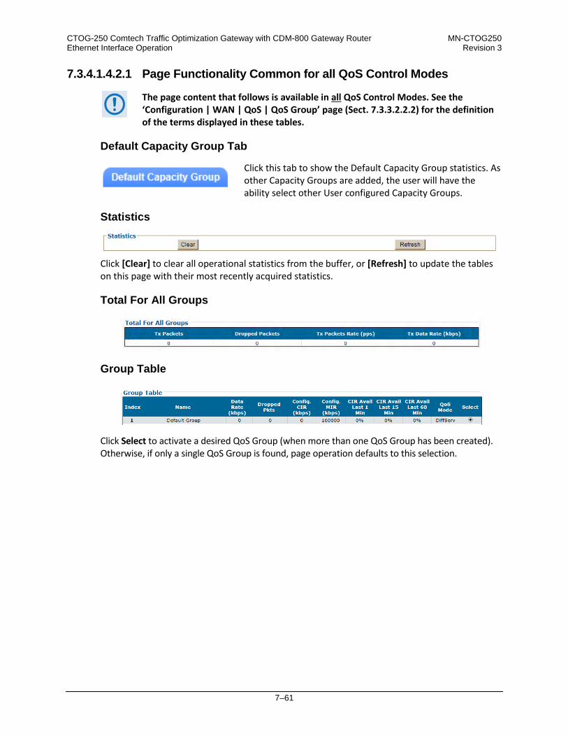
CTOG-250 Comtech Traffic Optimization Gateway with CDM-800 Gateway Router MN-CTOG250 Ethernet Interface Operation Revision 3
7–61
7.3.4.1.4.2.1 Page Functionality Common for all QoS Control Modes
The page content that follows is available in all QoS Control Modes. See the ‘Configuration | WAN | QoS | QoS Group’ page (Sect. 7.3.3.2.2.2) for the definition of the terms displayed in these tables.
Default Capacity Group Tab
Click this tab to show the Default Capacity Group statistics. As other Capacity Groups are added, the user will have the ability select other User configured Capacity Groups.
Statistics
Click [Clear] to clear all operational statistics from the buffer, or [Refresh] to update the tables on this page with their most recently acquired statistics.
Total For All Groups
Group Table
Click Select to activate a desired QoS Group (when more than one QoS Group has been created). Otherwise, if only a single QoS Group is found, page operation defaults to this selection.

CTOG-250 Comtech Traffic Optimization Gateway with CDM-800 Gateway Router MN-CTOG250 Ethernet Interface Operation Revision 3
7–62
7.3.4.1.4.2.2 Page Functionality Specific to Active QoS Control Mode
QoS Statistics
QoS Control Mode = Off, Max/Pri, Min/Max, or Pri-Weighted:
When QoS Control Mode = DiffServ:

CTOG-250 Comtech Traffic Optimization Gateway with CDM-800 Gateway Router MN-CTOG250 Ethernet Interface Operation Revision 3
7–63
7.3.4.1.5 Status | Statistics | Outbound
Appendix E. OUTBOUND ACM (ADAPTIVE CODING AND MODULATION)
ACM/VCM allows different MODCODs for different users and applications sharing a common outbound. The MODCODs are statically assigned based on link budget. Use this read-only page to view cumulative Outbound statistics.
Figure 7-31. Status | Statistics | Outbound Page
Entire Outbound
The statistics in this section represent information associated with the entire Outbound Carrier. From left to right:
Column Description
Current Throughput (from LAN in Kbps) This is Current Throughput of the Outbound Carrier as measured from the LAN port. This number represents the size of the packets before any Compression (Header or Payload).
Unused Capacity (for LAN in Kbps) This is the amount of Unused Kbps and measured by the number of unused Symbols at the current Average bits/symbol.
Total Capacity (for LAN in Kbps) Current Throughput plus Unused Capacity.

CTOG-250 Comtech Traffic Optimization Gateway with CDM-800 Gateway Router MN-CTOG250 Ethernet Interface Operation Revision 3
7–64
Column Description
Symbols/Second Utilization (%) Percentage of the configured symbols that are being used per second. Due to the nature of ACM/VCM and MODCOD assignment, this value is the most accurate representation of how full the Outbound Carrier is.
Average bits/symbol per second The average number of bits (as measured in LAN Kbps) that are being sent per symbol used. This number represents the spectral efficiency of the selected MODCOD combined with any Header or Payload compression benefits.
MODCOD Statistics
Outbound ACM – The Outbound operating status displays here as Enabled or Disabled. If you need to change the Outbound ACM Control, you may click the (Link to Outbound ACM control) hyperlink to open the ‘Configuration | Mod | Mod Configuration’ page (Sect. 7.3.3.2.1.1). From left to right:
Column Description MODCOD This column Identifies the MODCOD
Frames Sent (frames) Number of DVB-S2 base band frames transmitted for this MODCOD.
Percentage of Total (%) Percentage of the total number of DVB-S2 base band frames transmitted.
Current Throughput (from LAN Kbps) Current throughput as measured in LAN Kbps of the traffic being sent on this MODCOD.
Current Throughput (to WAN Kbps) Current throughput as measured in WAN Kbps of the traffic being sent on this MODCOD (after Compression)
Max Throughput (kbps) Maximum amount of data, in kilobits per second, transmitted through this MODCOD.
Average DVB-S2 Frame Utilization (%)
Average utilization of DVB-S2 MODCOD . This measures how full each MODCOD is of packet data. For example, 16-APSK 3/4 = 50% means that on average each 16-APSK 3/4 frame is only 50% full of packet data.
Click [Clear all counters] to clear all Outbound statistics from the buffer.

CTOG-250 Comtech Traffic Optimization Gateway with CDM-800 Gateway Router MN-CTOG250 Ethernet Interface Operation Revision 3
7–65
7.3.4.1.6 Status | Statistics | Remote Sites
Use this read-only page to view the cumulative statistics as reported by the actual CDM-840 Remote Units.
Figure 7-32. Status | Statistics | Remote Sites Page
Click the (Link to Remote Configuration Page) hyperlink to open the ‘Configuration | WAN | Remote Sites | Configuration’ page (Sect. 7.3.3.2.4.1).
Statistic Control
Click [Clear Statistics] to clear all CDM-840 Remote Site Statistics from the buffer. Click [Refresh Statistics] to display the latest available CDM-840 Remote Site Statistics.
CDM840 Remote Site Statistics
Enter a time in the text box, from 5 to 300 seconds, that defines the Remote Site Statistics Update Interval. This table will update automatically per the specified value. Click [Submit] to save. From left to right:
Column Description IP Address Assigned IP Address for the remote site. Site Name Assigned name for the remote site. Tx Current Rate (kbps) Most recent rate of data, in kilobits per second, transmitted by the remote site. Tx Max Rate (kbps) Maximum rate of data, in kilobits per second, transmitted by the remote site. Tx Current Packet Rate (kbps) Most recent packet rate, in kilobits per second, transmitted by the remote site. Tx Total Packets Transmitted Total number of packets transmitted by the remote site. Rx Current Rate (kbps) Most recent rate of data, in kilobits per second, received by the remote site. Rx Max Rate (kbps) Maximum rate of data, in kilobits per second, received by the remote site. Rx Current Packet Rate (kbps) Most recent packet rate, in kilobits per second, received by the remote site. Rx Total Packets Received Total number of packets received by the remote site.

CTOG-250 Comtech Traffic Optimization Gateway with CDM-800 Gateway Router MN-CTOG250 Ethernet Interface Operation Revision 3
7–66
7.3.4.2 Status | Monitor Pages
Click the Events or Alarms tab to continue.
7.3.4.2.1 Status | Monitor | Events
Use this page to view the alarms summary and a scrollable read-only window that displays any events and alarms as logged by the unit during normal operation.
Figure 7-33. Status | Monitor | Events Page
Alarms
This section provides an overall tally of the Unit, Tx, Traffic Ethernet and, when installed, the BUC alarms compiled since the logging buffer was last cleared.
PTP (Precision Time Protocol) is a future offering.
Events
Each logged event or alarm is Date- and Time-stamped, and a Description is provided. The page keeps a running tally of events (Number of Events). • Click [Refresh Events] to update the Events table with the most recently recorded events.
• Click [Clear Event Table] to delete all existing entries from the Events log. The Number of
Events tally resets to 1, and a single entry displays in the Events log: “INFO – Event Log Cleared”.
• Click the Remote Sites Event Log hyperlink to open the Configuration | WAN | Remote
Sites | Remote Sites Event Log page (Sect. 7.3.3.2.4.2).

CTOG-250 Comtech Traffic Optimization Gateway with CDM-800 Gateway Router MN-CTOG250 Ethernet Interface Operation Revision 3
7–67
7.3.4.2.2 Status | Monitor | Alarms
This page indicates whether or not an event or alarm has been logged for a specific item since the logging buffer was last cleared. Use this page to view the current unit operating status, and to control how the alarm masking parameters are processed by the unit.
Figure 7-34. Status | Monitor | Alarms Page
Legend
Operational status is color-coded for quick reference:
State Means Description Green “No Alarm” This indicates that no event or alarm has been logged since the logging
buffer was last cleared – status is OK.. Yellow “Previously Alarmed” This indicates that this alarm was once active, but has since been cleared. Red “Currently Alarmed” This indicates that an event or alarm has been logged since the logging
buffer was last cleared – status is FAULTED.

CTOG-250 Comtech Traffic Optimization Gateway with CDM-800 Gateway Router MN-CTOG250 Ethernet Interface Operation Revision 3
7–68
Clear Alarms
Click [Clear Previously Alarmed] to update this page with the latest available logged event or alarm information.
CDM-800 Unit Alarms / CDM-800 Modulator Alarms / CTOG Unit Alarms
Typical for these remaining page sections:
Section Column Description Name This is the name of the specific function. Status The event/alarm status for each item is displayed here – see the Legend page section. Mask Click to select alarm masking for a specific function.
• Click [Clear Masks] to deselect the Mask option for all listed functions.
• Click [Mask All] to select the Mask option for all listed functions.
• Click [Submit] to save.

CTOG-250 Comtech Traffic Optimization Gateway with CDM-800 Gateway Router MN-CTOG250 Ethernet Interface Operation Revision 3
7–69
7.3.5 Utility Pages
Click the System, CTOG-250 Unit, or Reboot tab to continue.
7.3.5.1 Utility | System
Use this page to configure a variety of top-level system operation controls, stored unit configurations, and test utilities.
Figure 7-35. Utility | Utility Page
Modem
• Unit Name – Enter your product label (e.g., CTOG-250) here.
• System Contact / System Location – Enter the e-mail and telephone contact information for Comtech EF Data Customer Support here.
Click [Submit] to save.
• Set Time (hh:mm:ss) – Use the HH:MM:SS time format to set the time, where: HH=hour [00
to 23]; MM=minutes [00 to 59]; and SS=seconds [00 to 59].
• Set Date (dd/mm/yy) – Use the DD/MM/YY European time format to set the date, where: DD=day [01 to 31]; MM=month [01 to 12]; and YY=year [00 to 99].
Click [Submit] to save

CTOG-250 Comtech Traffic Optimization Gateway with CDM-800 Gateway Router MN-CTOG250 Ethernet Interface Operation Revision 3
7–70
• Click Sync Remotes with CTOG Date and Time to automatically set the onboard clocks of all associated CDM-840s to the date and time of this CTOG-250.
When you enable this feature, the CTOG-250’s current date time is periodically broadcast to all CDM-840 remotes at an accuracy of 1 second. This feature is intended to synchronize the event log times across multiple units.
Click [Submit] to save
• Circuit ID – Enter a Circuit ID string consisting of 4 to 24 characters.
• Warm-Up Delay – Use the drop-down list to select Disable or Enable.
Click [Submit] to save.
• G.703 Clock Extended Mode – Use the drop-down list to select this operating mode as Off or
TxLock. Click [Submit] to save. • 10 MHz Internal Adjustment – Enter a value from (-)999 to (+)999 to set the adjustment for
the Internal 10 MHz High Stability Reference. • External Reference Frequency – Use the drop-down list to select this operating mode as
Internal, External 1/2/5/10 MHz, or Internal 10 MHz plus External. Click [Submit] to save. • Test Mode – Use the drop-down list to select an operating mode:
o Normal Mode – This mode clears any test modes or loopbacks, and returns the unit to its operational state.
o Tx CW – This test mode forces the modulator to transmit a pure carrier (unmodulated).
o Tx Alt 1/0 – This test mode forces the modulator to transmit a carrier modulated with an alternating 1,0,1,0 pattern, at the currently selected symbol rate. This causes two discrete spectral lines to appear, spaced at +/- half the symbol rate, about the carrier frequency. Use this mode to check the carrier suppression of the modulator.
Click [Submit] to save.
Save/Load Configuration
You may save or load (recall) up to 10 configuration sets: • To save a configuration set:

CTOG-250 Comtech Traffic Optimization Gateway with CDM-800 Gateway Router MN-CTOG250 Ethernet Interface Operation Revision 3
7–71
o First, adjust all operational configuration parameters to suit.
o Then, use the top (Save) Select Location drop-down to select 1 through 10.
o Finally, click [Save Configuration] to store the configuration settings.
• To load (recall) a configuration set: o First, use the bottom (Load) Select Location drop-down to select 1 through 10.
o Then, click [Load Configuration] to recall the selected configuration settings.
BERT Config
(Where BERT is the acronym for Bit Error Rate Test) Use the drop-down lists to: • Configure the Tx BERT State as On or Off. • Configure the Tx or Rx BERT Pattern as 2^23-1 (223-1) or 2047. • Set Error Insert(ion) as either Off or 10E-3. Click [Submit] to save the BERT settings and execute the test.
Once the Tx BERT is executed, the entire outbound carrier transmits a BERT pattern. All IP traffic and communications are halted during this test. Note also that the Rx BERT State for the CDM-840 Remote Router must be enabled to properly receive and monitor the BERT pattern.

CTOG-250 Comtech Traffic Optimization Gateway with CDM-800 Gateway Router MN-CTOG250 Ethernet Interface Operation Revision 3
7–72
7.3.5.2 Utility | CTOG-250 Unit
Use this page to synchronize CDM-800 operations to the CTOG-250, and to upgrade the operating software for the AHA GZip Compression Card.
Figure 7-36. Utility | CTOG-250 Unit Page
Utility
The product (e.g., CTOG-250) and its serial number are identified here.
AHA Compression Card
This section displays the running version of the Comtech AHA Corp. GZIP Compression card
• Current Version – The currently running software version and its release date are identified here.
• Available Version – The latest available software version and its release date are identified
here.
• Upgrade to Available Version – Click [Submit] To execute the upgrade process.
A dialogue box appears to prompt continuation or cancellation of the reboot process:
Click [OK] to continue the reboot process, or [Cancel] to abort the process and resume use of the ‘Utility | CTOG-250 Unit’ page.
Once the reboot process resumes, the ‘Utility | Reboot’ page is replaced with the dynamic message “Please wait... AHA Upgrading is in process. Login will be required in XXXX seconds” –

CTOG-250 Comtech Traffic Optimization Gateway with CDM-800 Gateway Router MN-CTOG250 Ethernet Interface Operation Revision 3
7–73
the time count decrements to 0 before the unit reboots. After the reboot, you must log in once more to resume use of the HTTP Interface.
Sync Configuration from CDM-800
Use this feature when adding a previously-standalone CDM-800 Gateway Router to a CTOG-250. Once the CDM-800 is connected to the CTOG-250, click [Submit] to update all CTOG-250 HTTP Interface pages with the configured parameters of the newly added CDM-800. Click [Submit] to initiate synchronization of the CDM-800 to the CTOG-250. A dialogue box displays the result of the process on a pass/fail basis:
Pass
Fail
Click [OK] to resume use of the Utility | CTOG-250 Unit page.

CTOG-250 Comtech Traffic Optimization Gateway with CDM-800 Gateway Router MN-CTOG250 Ethernet Interface Operation Revision 3
7–74
7.3.5.3 Utility | Reboot
Use this page to perform a soft reboot of the CTOG-250 or the CDM-800. Note that the function of the CTOG-250 Only Reboot section of this page is identical to the System Reboot section of the Admin | Firmware page described earlier.
Figure 7-37. Utility | Reboot Page
CTOG-250 Only Reboot
Click [Reboot]. A dialogue box appears to prompt continuation or cancellation of the reboot process: Click [OK] to continue the reboot process. Click [Cancel] to abort the process and resume use of the Utility | Reboot page. Once the reboot process resumes, the Utility | Reboot page is replaced with the dynamic message “Please wait... CTOG-250 is rebooting. Login will be required in XX seconds” – the time count decrements to 0 before the unit reboots. After reboot, you must log in once more to resume use of the HTTP Interface.
CDM-800 Only Reboot
Click [Reboot]. A dialogue box appears to prompt continuation or cancellation of the reboot process: Click [OK] to transparently continue the reboot process. Click [Cancel] to abort the process and resume use of the ‘Utility | Reboot’ page. As the message states, the reboot is complete once the Virtual Front Panel CDM-800 COMM’S LED changes from red to green.

8–1
Chapter 8. SERIAL INTERFACE OPERATION
8.1 Overview
Serial-based Remote Product Management of the CTOG-250 Comtech Traffic Optimization Gateway is available using the CTOG-250 back panel ‘SERIAL’ port.
1) YOU MAY PROCEED WITH SERIAL-BASED REMOTE PRODUCT MANAGEMENT, ASSUMING THAT:
• The CTOG-250 and its CDM-800 Gateway Router are interconnected and are operating with the latest version firmware files.
• The CTOG-250 is connected to a user-supplied, Windows-based PC as follows: o The PC serial port is connected to the CTOG-250 back panel ‘SERIAL’ port with a user-supplied serial cable.
o The PC Ethernet port is connected to the CTOG-250 back panel ‘MGMT-1’ 10/100/1000 BaseT Gigabit Ethernet
port with a user-supplied hub, switch, or direct Ethernet cable connection. o The PC is running a terminal emulation program (for use of the CTOG-250 Serial Interface) and a compatible
web browser (for use of the CTOG-250 HTTP Interface).
• The CTOG-250 Management IP Address has been noted using the CTOG-250 Serial Interface.

CTOG-250 Comtech Traffic Optimization Gateway with CDM-800 Gateway Router MN-CTOG250 Serial Interface Operation Revision 3
8–2
2) USE OF THE SNMP INTERFACE IS RECOMMENDED ONLY FOR ADVANCED USERS. ALL OTHER USERS ARE STRONGLY
ENCOURAGED TO USE THE CTOG-250 HTTP INTERFACE FOR REMOTE MONITOR AND CONTROL (M&C). SEE CHAPTER 7. ETHERNET INTERFACE OPERATION.
Figure 8-1. CTOG-250 Serial Interface Example
CTOG-250 Serial Remote Product Management is available through the EIA-232 operational interface, where the ‘Controller’ device (the user PC or an ASCII dumb terminal) is connected directly to the ‘Target’ device (the CTOG-250, via its DB-9M ‘SERIAL’ port). This connection makes possible serial remote monitor and control (M&C) of the system through its CTOG-250 Serial Interface. Through this EIA-232 connection (for the control of a single device), data is transmitted in asynchronous serial form, using ASCII characters. Control and status information is transmitted in packets of variable length in accordance with the structure and protocol defined later in this chapter. Access to the interface is accomplished with a user-supplied terminal emulator program such as Tera Term or HyperTerminal. Use this utility program to first configure serial port communication and terminal display operation: • 38400 bps (Baud Rate) • 8 Data Bits • 1 Stop Bit • Local Echo = ON
• Parity = NO • Port Flow Control = NONE • Display New line Rx/Tx: CR
When the user-supplied terminal emulator program is configured correctly, upon power-up of the system, the COMTECH EF DATA CTOG-250 SERIAL INTERFACE Info Screen appears, followed by the command prompt CTOG-250>. From here, type “help[cr]” or “?[cr]” (without the quotes) to display the available “set” commands and “get” queries, and to review instructions for using the interface.

CTOG-250 Comtech Traffic Optimization Gateway with CDM-800 Gateway Router MN-CTOG250 Serial Interface Operation Revision 3
8–3
8.2 Remote Commands and Queries Overview
8.2.1 Basic Protocol
In an EIA-232 configuration, the Controller device is connected directly to the Target device via a two wire-plus-ground connection. All data is transmitted in framed packets as asynchronous serial characters, suitable for transmission and reception to the Controller using a universal asynchronous receiver/transmitter (UART). Controller-to-Target data is carried via EIA-232 electrical levels on one conductor, and Target-to-Controller data is carried in the other direction on the other conductor: • Controller-to-Target: The Controller device (e.g., the user PC/Serial Interface) is used to “set”, or transmit, instructions (commands)
to – or to “get”, or request, information from (queries) – the Target device (i.e., the CDM-800).
• Target-to-Controller: The Target, in return, only transmits response information to the Controller when specifically directed by the Controller.
For Serial Remote Control, all issued commands (Controller-to-Target) require a response (Target-to-Controller). This response is either to return data that has been queried by the Controller, or to confirm the Target’s receipt of a command to change the Target’s configuration.
8.2.2 Packet Structure
The exchange of information is transmitted, Controller-to-Target and Target-to-Controller, in packets. Each packet contains a finite number of bytes consisting of printable ASCII characters, excluding ASCII code 127 (DELETE). In this context, the Carriage Return and Line Feed characters are considered printable. With one exception, all messages from Controller-to-Target require a response – this will be either to return data that has been requested by the Controller, or to acknowledge reception of an instruction to change the configuration of the Target.
Controller-to-Target (Issued Command or Query)
Start of Packet Target Address Address Delimiter Instruction Code Code Qualifier Optional Arguments End of Packet

CTOG-250 Comtech Traffic Optimization Gateway with CDM-800 Gateway Router MN-CTOG250 Serial Interface Operation Revision 3
8–4
< ASCII Code 60
(1 character)
0000 (default)
(4 characters)
/ ASCII Code 47
(1 character)
(3 characters)
= or ? ASCII Codes 61 or 63
(1 character)
(n characters)
Carriage Return ASCII Code 13
(1 character)
Packet “issued command” example: <0000/TFQ=1234.5678[cr] Packet “issued query” example: <0000/TFQ?[cr]
Target-to-Controller (Response to Command or Query)
Start of Packet Target Address Address Delimiter Instruction Code Code Qualifier Optional Arguments End of Packet
> ASCII Code 62
(1 character)
0000 (default)
(4 characters)
/ ASCII Code 47
(1 character)
(3 characters)
= , ?, !, *, # (ASCII Codes 61, 63,
33, 42, or 35)
(1 character)
(n characters)
Carriage Return ASCII Code 13
(1 character) Packet example – response received for issued query: >0000/TFQ=1234.5678[cr][lf] Detailed description of the packet components follow.
8.2.2.1 Start of Packet
• Controller-to-Target: This is the character ‘<’ (ASCII code 60).
• Target-to-Controller: This is the character ‘>’ (ASCII code 62). The ‘<’ and ‘>’ characters indicate the start of packet. They may not appear anywhere else within the body of the message.

CTOG-250 Comtech Traffic Optimization Gateway with CDM-800 Gateway Router MN-CTOG250 Serial Interface Operation Revision 3
8–5
8.2.2.2 Target Address
In EIA-232 applications, this value is set to 0000.
The Target Address designates the packet destination. The Controller does not have its own address. After the Controller sends a packet with the designated Target Address, the Target responds to the Controller, using this same address, to indicate the source of the packet.
8.2.2.3 Address Delimiter
This is the “forward slash” character '/ ' (ASCII code 47).
8.2.2.4 Instruction Code
This is a three-character alphanumeric sequence that identifies the message subject. Uppercase alphabetic characters (‘A’ to ‘Z’, ASCII Codes 65 to 90) and the numbers ‘0’ to ‘9’ *ASCII Codes 48 to 57) may be used. Wherever possible, each instruction code is named to serve as a mnemonic for its intended operation. This helps you interpret the code function, should it be shown in its raw ASCII form. For example: MLC for Management Link Configuration, IPA for Management IP Address, etc.
8.2.2.5 Instruction Code Qualifier
This is a single character that further qualifies the preceding instruction code.
8.2.2.5.1 Controller-to-Target Instruction Code Qualifiers
The only permitted characters are ‘ = ’ and ‘?’.
= (ASCII Code 61)
This character is used as the Assignment Operator (AO). It establishes that the Instruction Code that precedes it is issued as a command to assign or configure operation. The instruction set that follows serves to assign the Target’s new parameter setting or operational value.

CTOG-250 Comtech Traffic Optimization Gateway with CDM-800 Gateway Router MN-CTOG250 Serial Interface Operation Revision 3
8–6
For example: From Controller-to-Target, <0/IG1=aaa.bbb.ccc.ddd/yy means “set the GE LAN-1 Port IP address to aaa.bbb.ccc.ddd/yy”
? (ASCII Code 63)
This character is used as the Query Operator (QO). It establishes that the Instruction Code that precedes it is issued as a query that returns the Target’s current configured parameter setting or operational value. For example: From Controller-to-Target, <0/IG1? means “what’s the current GE LAN-1 Port IP address?”
8.2.2.5.2 Target-to-Controller Instruction Code Qualifiers
The permitted characters are ‘ = ’, ‘?’, ‘*’ , ‘!’, ‘*’, and ‘#.
= (ASCII Code 61)
This character is used in two ways: 1. If the Controller sends a query to the Target.
For example: <0/TFQ? (meaning “what is the current value of the transmit frequency?”) – the Target responds with >0000/TFQ=xxxx.xxxx, the value for that queried parameter.
2. If the Controller sends an instruction to set a parameter to a particular value, and the value sent is valid, the Target acknowledges the message and responds with, for example, >0000/TFQ = (with no message arguments).
? (ASCII Code 63)
If the Controller issues a command to set a parameter to a particular value, and the value sent is not valid, the Target then acknowledges the message and responds with ‘?’. This indicates that there was an error in the message sent by the Controller. For example: >0000/TFQ? (with no message arguments).

CTOG-250 Comtech Traffic Optimization Gateway with CDM-800 Gateway Router MN-CTOG250 Serial Interface Operation Revision 3
8–7
! (ASCII Code 33)
If the Controller issues a command that the Target does not recognize, the Target responds by echoing the invalid instruction code, followed by ‘!’. For example: >0000/ABC!
* (ASCII Code 42)
If the Controller issues a command to set a parameter to a particular value, and the value sent is valid BUT the modem will not permit that particular parameter to be changed at present, the Target responds by echoing the valid instruction code, followed by ‘*’. For example: >0000/TFQ* (with message arguments)
# (ASCII Code 35)
If the Controller sends a correctly formatted command, BUT the Target is not in Remote Mode, the unit does not allow reconfiguration and responds by echoing the valid instruction code, followed by ‘#’. For example: >0000/TFQ#
8.2.2.6 Optional Message Arguments
Arguments are not required for all messages. Comma ‘,’ (ASCII Code 44), period ‘.’ (ASCII Code 46), the numbers ‘0’ to ‘9’ (ASCII Codes 48 to 57), and the uppercase alphabetic characters ‘A’ to ‘Z’ (ASCII Codes 65 to 90) may be used.
8.2.2.7 End of Packet
• Controller-to-Target: This is the ‘Carriage Return’ ([CR]) character (ASCII code 13).
• Target-to-Controller: This is the two-character sequence ‘Carriage Return’, ‘Line Feed’ ([cr][lf]) (ASCII codes 13 and 10). Both indicate the valid termination of a packet.

CTOG-250 Comtech Traffic Optimization Gateway with CDM-800 Gateway Router MN-CTOG250 Serial Interface Operation Revision 3
8–8
8.3 Remote Commands and Queries
NOTES: 1) Index Columns – Where Column ‘C’ = Command, and Column ‘Q’ = Query, columns marked ‘X’ designate the instruction code as
Command only, Query only, or Command or Query.
2) In the Sect. 8.5.2 thru 8.5.X tables, these codes are used in the ‘Response to Command’ column (per Sect. 8.2.2.5.2):
= Message ok # Message ok, but unit is not in Remote mode. ? Received ok, but invalid arguments were found. ! Invalid instruction. ^ Message ok, but unit is in Ethernet mode.
INSTRUCTION
CODE USED TO... C Q Page
DPW Set default passwords X 8-9 IG1 Set or query the IP Address and network prefix for the 10/100/1000 Gigabit Ethernet Port #1 “LAN-1” X X 8-9 IG2 Set or query the IP Address and network prefix for the 10/100/1000 Gigabit Ethernet Port #2 “LAN-2” X X 8-9 IG3 Set or query the IP Address and network prefix for the 10/100/1000 Gigabit Ethernet Port #3 “EXPNET-1” X X 8-10 IG4 Set or query the IP Address and network prefix for the 10/100/1000 Gigabit Ethernet Port #4 “EXPNET-2” X X 8-10 IPA Set or query the IP Address and network prefix for the 10/100/1000 Gigabit Ethernet Management Port “MGMT-1” X X 8-10 LC1 Set or query the 10/100/1000 Gigabit Ethernet Port #1 “LAN-1” Interface Mode X X 8-11 LC2 Set or query the 10/100/1000 Gigabit Ethernet Port #2 “LAN-2” Interface Mode X X 8-11 LC3 Set or query the 10/100/1000 Gigabit Ethernet Port #3 “EXPNET-1” Interface Mode X X 8-11 LC4 Set or query the 10/100/1000 Gigabit Ethernet Port #4 “EXPNET-2” Interface Mode X X 8-11 MAC Query the unique MAC Address of the “MGMT-1” port. X 8-11 MG1 Query the unique MAC Address of the 10/100/1000 Gigabit Ethernet Port #1 “LAN-1” X 8-11 MG2 Query the unique MAC Address of the 10/100/1000 Gigabit Ethernet Port #2 “LAN-2” X 8-12 MG3 Query the unique MAC Address of the 10/100/1000 Gigabit Ethernet Port #3 “EXPNET-1” X 8-12 MG4 Query the unique MAC Address of the 10/100/1000 Gigabit Ethernet Port #4 “EXPNET-2” X 8-12 MLC Set or query the link configuration for the 10/100/1000 Gigabit Ethernet Management Port “MGMT-1” X X 8-12 NPS Query the negotiated port speeds for the “LAN-1”, “LAN-2”, and “MGMT-1” ports X 8-12 SRC Set or query the SNMP Read Community String X X 8-12 SWC Set or Query the SNMP Write Community String X X 8-13

CTOG-250 Comtech Traffic Optimization Gateway with CDM-800 Gateway Router MN-CTOG250 Serial Interface Operation Revision 3
8–9
Parameter Type
Command (Instruction & Qualifier)
Number of Arguments Description of Arguments Response to
Command Query
(Instruction & Qualifier)
Response to Query
Default Passwords
DPW= N/A Command Only. Resets the admin username/password to: Username = “comtech” Password = “comtech”
DPW= DPW? DPW* DPW#
N/A N/A
GE1 Address (TRAFFIC 1)
IG1= 18 bytes numerical Command or Query. Sets or returns the IP Address and network prefix for the 10/100/1000 BaseT LAN TRAFFIC (1) Ethernet port in the form aaa.bbb.ccc.ddd/yy when in Router Mode, where: (Permitted ranges – cannot all be zero)
aaa = 0-223 bbb = 0-255 ccc = 0-255 ddd = 0-255 yy = network prefix (range: 8 to 31)
Other restrictions: If aaa>191, prefix may not be less than 24. If aaa>127, prefix may not be less than 16. EXAMPLE: <0/IG1=010.006.030.001/24
IG1= IG1? IG1* IG1#
IG1? IG1=xxx.xxx.xxx.xxx/yy (see Description of Arguments)
GE2 Address (TRAFFIC 2)
IG2= 18 bytes numerical Command or Query. Sets or returns the IP Address and network prefix for the 10/100/1000 BaseT LAN TRAFFIC (2) Ethernet port in the form aaa.bbb.ccc.ddd/yy when in Router Mode, where: (Permitted ranges – cannot all be zero)
aaa = 0-223 bbb = 0-255 ccc = 0-255 ddd = 0-255 yy = network prefix (range: 8 to 31)
Other restrictions: If aaa>191, prefix may not be less than 24. If aaa>127, prefix may not be less than 16. EXAMPLE: <0/IG2=010.006.030.002/24
IG2= IG2? IG2* IG2#
IG2? IG2=xxx.xxx.xxx.xxx/yy (see Description of Arguments)

CTOG-250 Comtech Traffic Optimization Gateway with CDM-800 Gateway Router MN-CTOG250 Serial Interface Operation Revision 3
8–10
Parameter Type
Command (Instruction & Qualifier)
Number of Arguments Description of Arguments Response to
Command Query
(Instruction & Qualifier)
Response to Query
GE3 Address (EXP TRAFFIC 1)
IG3= 18 bytes numerical Command or Query. Sets or returns the IP Address and network prefix for the 10/100/1000 BaseT EXPANSION TRAFFIC (1) Ethernet port in the form aaa.bbb.ccc.ddd/yy when in Router mode, where: (Permitted ranges – cannot all be zero)
aaa = 0-223 bbb = 0-255 ccc = 0-255 ddd = 0-255 yy = network prefix (range: 8 to 31)
Other restrictions: If aaa>191, prefix may not be less than 24. If aaa>127, prefix may not be less than 16. EXAMPLE: <0/IG3=010.006.030.003/24
IG3= IG3? IG3* IG3#
IG3? IG3=xxx.xxx.xxx.xxx/yy (see Description of Arguments)
GE4 Address (EXP TRAFFIC 2)
IG4= 18 bytes numerical Command or Query (NOT USED) Sets or returns the IP Address and network prefix for the 10/100/1000 BaseT EXPANSION TRAFFIC (2) Ethernet port in the form aaa.bbb.ccc.ddd/yy, where: (Permitted ranges – cannot all be zero)
aaa = 0-223 bbb = 0-255 ccc = 0-255 ddd = 0-255 yy = network prefix (range: 8 to 31)
Other restrictions: If aaa>191, prefix may not be less than 24. If aaa>127, prefix may not be less than 16. EXAMPLE: <0/IG2=010.006.030.004/24
IG4= IG4? IG4* IG4#
IG4? IG4=xxx.xxx.xxx.xxx/yy (see Description of Arguments)
Management IP Address
IPA= 18 bytes numerical Command or Query. Sets or returns the IP Address and network prefix for the 10/100/1000 MGMT-1 Management Ethernet port in the form aaa.bbb.ccc.ddd/yy, where: (Permitted ranges – cannot all be zero)
aaa = 0-223 bbb = 0-255 ccc = 0-255 ddd = 0-255 yy = network prefix (range: 8 to 31)
EXAMPLE: <0/IPA=010.006.030.001/24
IPA= IPA? IPA* IPA#
IPA? IPA=xxx.xxx.xxx.xxx/yy (see Description of Arguments)

CTOG-250 Comtech Traffic Optimization Gateway with CDM-800 Gateway Router MN-CTOG250 Serial Interface Operation Revision 3
8–11
Parameter Type
Command (Instruction & Qualifier)
Number of Arguments Description of Arguments Response to
Command Query
(Instruction & Qualifier)
Response to Query
GE1 Link Configuration (TRAFFIC 1)
LC1= 1 byte, value 0 thru 5
Command or Query. Sets or returns the LAN TRAFFIC (1) Interface mode in the form x, where: 0 = Auto Negotiate 1 = 1000Mbps -Full Duplex 2 = 100Mbps – Full Duplex 3 = 100Mbps – Half Duplex 4 = 10Mbps – Full Duplex 5 = 10Mbps – Half Duplex
LC1= LC1? LC1* LC1#
LC1? LC1=x (see Description of Arguments)
GE2 Link Configuration (TRAFFIC 2)
LC2= 1 byte, value 0 thru 5
Command or Query. Sets or returns the LAN TRAFFIC (2) Interface mode in the form x, where: 0 = Auto Negotiate 1 = 1000Mbps -Full Duplex 2 = 100Mbps – Full Duplex 3 = 100Mbps – Half Duplex 4 = 10Mbps – Full Duplex 5 = 10Mbps – Half Duplex
LC2= LC2? LC2* LC2#
LC2? LC2=x (see Description of Arguments)
GE3 Link Configuration (EXP TRAFFIC 1)
LC3= 1 byte, value 0 thru 5
Command or Query. Sets or returns the EXPANSION TRAFFIC (1) Interface mode in the form x, where: 0 = Auto Negotiate 1 = 1000Mbps -Full Duplex 2 = 100Mbps – Full Duplex 3 = 100Mbps – Half Duplex 4 = 10Mbps – Full Duplex 5 = 10Mbps – Half Duplex
LC3= LC3? LC3* LC3#
LC3? LC3=x (see Description of Arguments)
GE4 Link Configuration (EXP TRAFFIC 2)
LC4= 1 byte, value 0 thru 5
Command or Query. Sets or returns the EXPANSION TRAFFIC (2) Interface mode in the form x, where: 0 = Auto Negotiate 1 = 1000Mbps -Full Duplex 2 = 100Mbps – Full Duplex 3 = 100Mbps – Half Duplex 4 = 10Mbps – Full Duplex 5 = 10Mbps – Half Duplex
LC4= LC4? LC4* LC4#
LC4? LC4=x (see Description of Arguments)
Management MAC Address
N/A 12 bytes, alpha- numerical
Query only. Returns the unique MAC Address for the modem. EXAMPLE: <0/MAC? >0000/MAC=00:06:B0:00:01:C2
N/A MAC? MAC=aabbccddeeff (see Description of Arguments)
GE1 MAC Address (TRAFFIC 1)
N/A 12 bytes, alpha- numerical
Query only. Returns the unique LAN TRAFFIC (1) MAC Address. EXAMPLE: <0/MG1? >0000/MG1=00:06:B0:00:01:C2
N/A MG1? MG1=aabbccddeeff (see Description of Arguments)

CTOG-250 Comtech Traffic Optimization Gateway with CDM-800 Gateway Router MN-CTOG250 Serial Interface Operation Revision 3
8–12
Parameter Type
Command (Instruction & Qualifier)
Number of Arguments Description of Arguments Response to
Command Query
(Instruction & Qualifier)
Response to Query
GE2 MAC Address (TRAFFIC 2)
N/A 12 bytes, alpha- numerical
Query only. Returns the unique LAN TRAFFIC (2) MAC Address. EXAMPLE: <0/MG2? >0000/MG2=00:06:B0:00:01:C2
N/A MG2? MG2=aabbccddeeff (see Description of Arguments)
GE3 MAC Address (EXP TRAFFIC 1)
N/A 12 bytes, alpha- numerical
Query only. Returns the unique EXPANSION TRAFFIC (1) MAC Address. EXAMPLE: <0/MG3? >0000/MG3=00:06:B0:00:01:C2
N/A MG3? MG3=aabbccddeeff (see Description of Arguments)
GE4 MAC Address (EXP TRAFFIC 2)
N/A 12 bytes, alpha- numerical
Query only. Returns the unique EXPANSION TRAFFIC (2) MAC Address. EXAMPLE: <0/MG4? >0000/MG4=00:06:B0:00:01:C2
N/A MG4? MG4=aabbccddeeff (see Description of Arguments)
Management Link Configuration
MLC= 1 byte, value 0 thru 5
Command or Query. Sets or returns the MGMT-1 Management Interface mode in the form x, where:
0 = Auto Negotiate 1 = reserved 2 = 100Mbps – Full Duplex 3 = 100Mbps – Half Duplex 4 = 10Mbps – Full Duplex 5 = 10Mbps – Half Duplex
MLC = MLC? MLC * MLC #
MLC? MLC =x (see Description of Arguments)
Actual Negotiated Port Speed
N/A None Query only. Returns the actual negotiated port speed in the form abcd, where:
a = LAN TRAFFIC (1) negotiated port speed. b = LAN TRAFFIC (2) negotiated port speed. c = MGMT-1 management port negotiated port speed. d = EXPANSION TRAFFIC (1) negotiated port speed. e = EXPANSION FRAFFIC (2) negotiated port speed.
a, b, and c have the following values: 0 = Link down 1 = 100 Full 2 = 100 Half 3 = 10 Full 4 = 10 Half 5 = 1000 Full
N/A NPS? NPS=abcde (see Description of Arguments)
SNMP Read Community
SRC= 16 bytes, characters, no spaces
Command or Query. Sets or returns the SNMP read community string. Note: Empty string is not allowed EXAMPLE: <0/SRC? >0000/SRC=public
SRC = SRC!
SRC?
SRC =x (see Description of Arguments)

CTOG-250 Comtech Traffic Optimization Gateway with CDM-800 Gateway Router MN-CTOG250 Serial Interface Operation Revision 3
8–13
Parameter Type
Command (Instruction & Qualifier)
Number of Arguments Description of Arguments Response to
Command Query
(Instruction & Qualifier)
Response to Query
SNMP Write Community
SWC=
16 bytes, characters, no spaces
Command or Query. Sets or returns the SNMP write community string. Note: Empty string is not allowed EXAMPLE: <0/SWC? >0000/SWC=public
SWC = SWC!
SWC? SWC =x (see Description of Arguments)

CTOG-250 Comtech Traffic Optimization Gateway with CDM-800 Gateway Router MN-CTOG250 Serial Interface Operation Revision 3
8–14
Notes:

A–1
Appendix A. REFERENCE DOCUMENTATION
A.1 Overview
1) UNLESS OTHERWISE NOTED – This appendix collectively refers to the Comtech EF Data Advanced VSAT Series ODM-840 Remote Router, ODMR-840 Reduced Form Factor Remote Router, and ODMR-840B Remote Router Board Set as the ODM-840.
2) This appendix describes features that may be monitored or controlled by the user, or otherwise processed by the CTOG-250 Comtech Traffic Optimization Gateway with integrated CDM-800 Gateway Router. For detailed reading about the operational features of the Advanced VSAT Series group of products, consult the adjunct documentation that is specified in this appendix and is available for download from Comtech EF Data’s web site (www.comtechefdata.com).
Figure A-1. Advanced VSAT Series Hub and Remote Site Products

CTOG-250 Comtech Traffic Optimization Gateway with CDM-800 Gateway Router MN-CTOG250 Appendix A Revision 3
A–2
A.2 FEC (Forward Error Correction) Options
The method of FEC used among Comtech EF Data’s Advanced VSAT series of products differs according to Advanced VSAT Series product. This includes VersaFEC®, a family of short‐block Low Density Parity Check (LDPC) codes with very low latency. VersaFEC® is a patent pending technology wholly owned and developed by Comtech EF Data and Comtech AHA Enterprise Products Group (the VersaFEC name is a trademark registered to Comtech AHA). For the CDM-800 Gateway Router via the CTOG-250 Comtech Traffic Optimization Gateway: The FEC method used by the hub site CDM‐800 is based upon the DVB‐S2 standard for QPSK, 8‐PSK, 16‐APSK and 32‐APSK with concatenated LDPC and Bose‐Chaudhuri‐Hocquenghem (BCH).
Appendix B. FEC (FORWARD ERROR CORRECTION) OPTIONS in this manual
For the CDM-840 and ODM-840 Remote Routers: The FEC method used by the remote site CDM‐840 and ODM‐840 Remote Routers depends on the direction of signal processing in use:
• The Rx (receive) side of the 840 operates with error correction based upon the DVB‐S2
standard for QPSK, 8‐PSK, 16‐APSK and 32‐APSK with concatenated LDPC and BCH.
• The Tx (transmit) side of the 840 uses the VersaFEC family of short‐block LDPC codes.
• Appendix B. FEC (FORWARD ERROR CORRECTION) OPTIONS in the Comtech EF Data CDM-840 Remote Router Installation and Operation Manual (CEFD P/N MN-CDM840).
• Appendix B. FEC (FORWARD ERROR CORRECTION) OPTIONS in the Comtech EF Data ODM-840 Remote Router / ODMR-840 Reduced Form Factor Remote Router / ODMR-840B Remote Router Board Set Installation and Operation Manual (CEFD P/N MN-ODM840)
For the CDD-880 Multi Receiver Router: The hub site CDD‐880 Multi Receiver Router uses the VersaFEC family of short‐block LDPC codes.
Appendix B. FEC (FORWARD ERROR CORRECTION) OPTIONS in the Comtech EF Data CDD-880 Multi Receiver Router Installation and Operation Manual (CEFD P/N MN-CDD880)
CTOG-250 Comtech Traffic Optimization Gateway with CDM-800 Gateway Router MN-CTOG250 Appendix A Revision 3
A–3
A.3 ACM/VCM (Adaptive Coding and Modulation / Variable Coding and Modulation) Operation
The VersaFEC® ACM (Adaptive Coding and Modulation) feature is a patents‐pending technology owned and developed by Comtech EF Data and Comtech AHA Enterprise Products Group. ACM allows modulation and code rate (ModCod) to change on a frame‐by‐frame basis subject to current link conditions. As ACM converts available link margin into increased capacity, average capacity gain of 100% or more is possible. This maximizes each remote’s throughput under all conditions which, in turn, maximizes network efficiency and availability. ACM maximizes throughput regardless of link conditions (noise or other impairments, clear sky, rain fade, etc). Outbound ACM operation is available in the CDM‐800 Gateway Router via the CTOG‐250 Comtech Traffic Optimization Gateway. Return Link ACM operation is available in the CDM‐840 and ODM‐840 Remote Routers and in the CDD‐880 Multi Receiver Routers.
• Appendix E. OUTBOUND ACM (ADAPTIVE CODING AND MODULATION) in this manual
• Appendix D. VERSAFEC RETURN LINK ACM (ADAPTIVE CODING AND MODULATION) in the Comtech EF Data CDM-840 Remote Router Installation and Operation Manual (CEFD P/N MN-CDM840)
• Appendix D. VERSAFEC RETURN LINK ACM (ADAPTIVE CODING AND MODULATION) in the Comtech EF Data ODM-840 Remote Router / ODMR-840 Reduced Form Factor Remote Router / ODMR-840B Remote Router Board Set Installation and Operation Manual (CEFD P/N MN-ODM840)
• Appendix H. VERSAFEC RETURN LINK ACM (ADAPTIVE CODING AND MODULATION)
in the Comtech EF Data CDD-880 Multi Receiver Router Installation and Operation Manual (CEFD P/N MN-CDD880)

CTOG-250 Comtech Traffic Optimization Gateway with CDM-800 Gateway Router MN-CTOG250 Appendix A Revision 3
A–4
A.4 BPM (Bridge Point-to-Multipoint) Operation
The Advanced VSAT BPM feature functions as a Learning Ethernet Switch when the “Working Mode” is set to BPM. This makes the Advanced VSAT equipment appear as a “Sky Ethernet Switch” and allows for a greatly simplified network deployment. In BPM Mode, all L2/L3/L4 protocols such as VLAN, MPLS, IPv6, OSPF, and BGP will flow through the network as they would through an off‐the‐shelf Ethernet Switch. The Advanced VSAT System, running in BPM Mode, supports Flat Networks, Flat Networks with Routers, and VLAN Trunking network topologies.
• Appendix C. BPM (BRIDGE POINT-TO-MULTIPOINT) OPERATION in this manual
• Appendix E. BPM (BRIDGE POINT-TO-MULTIPOINT) OPERATION in the Comtech EF Data CDM-840 Remote Router Installation and Operation Manual (CEFD P/N MN-CDM840)
• Appendix C. BPM (BRIDGE POINT-TO-MULTIPOINT) OPERATION in the Comtech
EF Data CDD-880 Multi Receiver Router Installation and Operation Manual (CEFD P/N MN-CDD880)

CTOG-250 Comtech Traffic Optimization Gateway with CDM-800 Gateway Router MN-CTOG250 Appendix A Revision 3
A–5
A.5 ECM (Entry Channel Mode) Operation
ECM (Entry Channel Mode) operation is available in the CDM‐840 and ODM‐840 Remote Routers, and in the CDD‐880 Multi Receiver Router. ECM is a feature based on slotted Aloha with random retransmission backoff. It supports multiple carriers through frequency assignments, which provide simplified deployment and scalability. While a Remote Router is in Entry Channel Mode, it allows the passing of management traffic only – it will not transmit user data traffic. An ECM‐enabled Remote Router may remain in the entry channel for an extended period if “online” communications are not required, or if dSCPC (dynamic Single Carrier Per Channel) resources are unavailable. While idle or waiting in the entry channel, the Remote Router sends periodic health status messages to the CTOG‐250 and Vipersat Management System (VMS) while it continues to service VMS recovery logic timers.
• Appendix G. ECM (ENTRY CHANNEL MODE) in the Comtech EF Data CDM-840 Remote Router Installation and Operation Manual (CEFD P/N MN-CDM840)
• Appendix F. ECM (ENTRY CHANNEL MODE) in the Comtech EF Data ODM-840 Remote Router / ODMR-840 Reduced Form Factor Remote Router / ODMR-840B Remote Router Board Set Installation and Operation Manual (CEFD P/N MN-ODM840)
• Appendix D. ECM (ENTRY CHANNEL MODE) in the Comtech EF Data CDD-880 Multi Receiver Router Installation and Operation Manual (CEFD P/N MN-CDD880)

CTOG-250 Comtech Traffic Optimization Gateway with CDM-800 Gateway Router MN-CTOG250 Appendix A Revision 3
A–6
A.6 dMesh (VMS Dynamic Mesh) Connectivity
dMesh (Dynamic Mesh) operation is available in the CDM‐840 and ODM‐840 Remote Routers, and in the CDD‐880 Multi Receiver Router. Mesh connectivity minimizes the requirement for communications that are routed through a hub and re‐routed back to the remote segments of an Advanced VSAT Network. Comtech EF Data leverages the concept of Bandwidth‐on‐Demand (BoD) by taking advantage of Dynamic Single Channel per Carrier (dSCPC) in a mesh environment and adapting it to Comtech EF Data’s Advanced VSAT Network platform. This adds dynamic point‐to‐multipoint SCPC mesh circuits to the network’s existing hub and remote link, and DVB‐S2 outbound and VersaFEC dSCPC to the return link. Comtech EF Data manages these elements, and provides BoD in a mesh environment through its Vipersat Management System (VMS), the software switching engine behind our Vipersat technology.
• Appendix G. dMESH (VMS DYNAMIC MESH) SOLUTIONS in this manual
• Appendix L. dMESH (VMS DYNAMIC MESH) SOLUTIONS in the Comtech EF Data CDM-840 Remote Router Installation and Operation Manual (CEFD P/N MN-CDM840)
• Appendix K. dMESH (VMS DYNAMIC MESH) SOLUTIONS in the Comtech EF Data ODM-840 Remote Router / ODMR-840 Reduced Form Factor Remote Router / ODMR-840B Remote Router Board Set Installation and Operation Manual (CEFD P/N MN-ODM840)
• Appendix F. dMESH (VMS DYNAMIC MESH) SOLUTIONS in the Comtech EF Data CDD-880 Multi Receiver Router Installation and Operation Manual (CEFD P/N MN-CDD880)

CTOG-250 Comtech Traffic Optimization Gateway with CDM-800 Gateway Router MN-CTOG250 Appendix A Revision 3
A–7
A.7 DPC (VMS Dynamic Power Control) Operation
The DPC (Dynamic Power Control) feature in Comtech EF Data’s CDM‐840 and ODM‐840 Remote Routers provides a mechanism whereby remote satellite uplinks have their transmit power levels adjusted in order to optimize the receive signal quality as measured by the corresponding demodulator ES/N0 (the ratio of energy per symbol to noise density). This optimization process acts to either increase or decrease transmitted signal levels in order to: • Achieve a minimum level of received ES/N0 consistent with providing an error free link or set
margin. • Reduce transmit power where sufficient link margin exists in order to optimize group station
uplink saturation and/or satellite transponder power usage reducing costs. • Increase link availability when margins apply (typically Ku‐Band or Ka‐Band). • Maintain proper power backoff to eliminate high power amplifier saturation and carrier
distortion.
• Appendix H. DPC (VMS DYNAMIC POWER CONTROL) in this manual
• Appendix M. DPC (VMS DYNAMIC POWER CONTROL) in the Comtech EF Data CDM-840 Remote Router Installation and Operation Manual (CEFD P/N MN-CDM840)
• Appendix L. DPC (VMS DYNAMIC POWER CONTROL) in the Comtech EF Data ODM-840 Remote Router / ODMR-840 Reduced Form Factor Remote Router / ODMR-840B Remote Router Board Set Installation and Operation Manual (CEFD P/N MN-ODM840)
• Appendix G. DPC (VMS DYNAMIC POWER CONTROL) in the Comtech EF Data CDD-880 Multi Receiver Router Installation and Operation Manual (CEFD P/N MN-CDD880)

CTOG-250 Comtech Traffic Optimization Gateway with CDM-800 Gateway Router MN-CTOG250 Appendix A Revision 3
A–8
Notes:

B–1
Appendix B. FEC (FORWARD ERROR CORRECTION) OPTIONS
B.1 FEC Overview
The method of FEC (Forward Error Correction) used by the CTOG-250/CDM-800 Gateway Router is based upon the DVB-S2 standard for QPSK, 8PSK, 16APSK and 32APSK with concatenated Low Density Parity Code (LDPC) and Bose-Chaudhuri-Hocquenghem (BCH).
B.2 DVB-S2: LDPC and BCH
The DVB-S2 specification defines a generation of performance that boosts throughput by about 30% over DVB-S while using the same amount of bandwidth. The result is coding and modulation that surpasses the capability of concatenated Viterbi and Reed Solomon coding. LDPC and BCH is also a concatenated error correction technique; the LDPC coding scheme features significant, Near-Shannon Bound Performance. In some cases, LDPC error correction starts flaring toward an error floor as the carrier-to-noise ratio increases. To compensate, BCH error correction follows LDPC and eliminates the flare for any practical range of error rates. LDPC also functions differently than Viterbi decoding by using iterative decoding. In this process, the data initially corrected by the LDPC decoder is re-encoded and run through the decoder again to correct additional errors. Through soft decision output from the LDPC decoder and a high-speed processor operating at a rate much higher than the data rate, the iterative process is run as many times as possible before corrected data is finally output to make way for a new block of data entering the decoder. LDPC also uses interleaving to spread the errors. In contrast, Viterbi error correction operates by passing data through the convolutional error correction process using a single error correction pass. The error correcting capability of LDPC is enhanced by use of large block sizes. Although large block sizes can increase latency in low bitrate applications (typically less than 2Mbps), this is not a drawback in one-way broadcast applications. Links with LDPC normally operate at multi-megabit data rates where latency effects are minimal. The standard block size for LDPC is 64,800

CTOG-250 Comtech Traffic Optimization Gateway with CDM-800 Gateway Router MN-CTOG250 Appendix B Revision 3
B–2
bits and, for lower data rate applications, a short frame block at 16,800 bits suffers only a small error correcting loss (0.2 to 0.5 dB) compared to the standard block.
B.2.1 Range of Data Rates
See Sect. 1.4 CTOG-250 SPECIFICATIONS for the range of available data rates
B.2.2 BER, QEF, Eb/No, Es/No Spectral Efficiency, and Occupied Bandwidth
Depending upon the operating mode, the DVB standard uses different modes of specifying performance with a unit in IF Loop and Additive White Gaussian Noise (AWGN): • DVB-S2 standard: "Quasi Error Free" (QEF) is defined as "less than one uncorrected error-
event per transmission hour at the level of a 5 Mbits/s single TV service decoder", approximately corresponding to a Transport Stream Packet Error Ratio equal to a PER<10-7 before demultiplexer. A packet is defined as block of 188 byte MPEG frame size data.
• Es/No vs. Eb/No: The DVB-S2 standard commonly refers to the use of Es/No instead of Eb/No. When links operate at a constant symbol rate this is a good method for comparing the performance of different modulation types and code rates.
The relation between the two quantities is given by:
Eb/No = Es/No – 10log(Spectral Efficiency)
• Occupied Bandwidth: Occupied bandwidth is defined as the bandwidth between -10 dB
points of the power spectral density, which are approximately: Occupied Bandwidth = 1.19 x Symbol Rate, for 35% Rolloff = 1.15 x Symbol Rate, for 25% Rolloff = 1.12 x Symbol Rate, for 20% Rolloff
* Taken at the -10 dB points on the plot of power spectral density, the occupied bandwidth is 1.19 x Symbol Rate for 35%, and 1.15 x Symbol Rate for 25%.
B.3 CDM-800 Error Performance Characteristics
On the pages that follow, Figure B-1 through Figure B-4 illustrate the guaranteed error performance characteristics of the CDM-800 for DVB-S2 operation while receiving with Normal frames (64,800 bits), Pilots ON.

CTOG-250 Comtech Traffic Optimization Gateway with CDM-800 Gateway Router MN-CTOG250 Appendix B Revision 3
B–3
Figure B-1. DVB-S2 QPSK Packet Error Rate versus Es/No

CTOG-250 Comtech Traffic Optimization Gateway with CDM-800 Gateway Router MN-CTOG250 Appendix B Revision 3
B–4
Figure B-2. DVB-S2 8PSK Packet Error Rate versus Es/No

CTOG-250 Comtech Traffic Optimization Gateway with CDM-800 Gateway Router MN-CTOG250 Appendix B Revision 3
B–5
Figure B-3. DVB-S2 16APSK Packet Error Rate versus Es/No

CTOG-250 Comtech Traffic Optimization Gateway with CDM-800 Gateway Router MN-CTOG250 Appendix B Revision 3
B–6
Figure B-4. DVB-S2 32APSK Packet Error Rate versus Es/No

C–1
Appendix C. BPM (BRIDGE POINT-TO-MULTIPOINT)
OPERATION
C.1 Overview
The overall intent of the Advanced VSAT BPM (Bridge Point-to-Multipoint) feature is to make the Advanced VSAT equipment appear as a “Sky Ethernet Switch”.
This allows for a greatly simplified network deployment.
In BPM Mode, all L2/L3/L4 protocols, such as VLAN, MPLS, IPv6, OSPF, and BGP, flow through the network as they would through an off-the-shelf Ethernet Switch.
Figure C-1. Advanced VSAT BPM “Sky Ethernet Switch”

CTOG-250 Comtech Traffic Optimization Gateway with CDM-800 Gateway Router MN-CTOG250 Appendix C Revision 3
C–2
C.1.1 BPM Terminology
Term Definition ACM/VCM Adaptive Coding and Modulation / Variable Coding and
Modulation Bridge Mode This Advanced VSAT Network Working Mode configures the Traffic
ports of the CTOG-250 and CDM-840 to function as a Bridge. BPM Mode Bridge Point-to-Multipoint Mode Comtech Dynamic Routing Protocol (CDRP)
CEFD Proprietary protocol that automatically synchronizes the CTOG-250’s Route table with the CDM-840’s LAN connected routes – i.e., the routes that are directed to the LAN ports of the CDM-840.
CTOG-250 Comtech Traffic Optimization Gateway 250. Entry Channel Mode (ECM)
Shared Aloha channel used in Vipersat dSCPC Mode that allows a remote terminal to gain access to the Network.
Flat Network A network in which all devices are directly connected to each other and all devices are on the same IP subnet.
IGMP Internet Group Management Protocol Router Mode This Advanced VSAT Network Working Mode configures the Traffic
ports of the CTOG-250, CDD-880, and CDM-840 to function as a Router.
Single Hop on Demand (SHOD)
This CEFD technology allows for dynamic creation of Single Hop Mesh connections from one CDM-840 to another CDM-840. SHOD requires the Vipersat Management System (VMS).
VLAN Access Mode This mode, only available in the CDM-840, forces the Traffic Interface to carry traffic for only one user-configured VLAN.
VLAN Trunking Mode This is the default mode for BPM, where all packets (with and without VLAN tags) arriving at the CTOG-250 and CDM-840 pass through the system without modification. A trunked port can pass two or more VLANs on the interface.

CTOG-250 Comtech Traffic Optimization Gateway with CDM-800 Gateway Router MN-CTOG250 Appendix C Revision 3
C–3
C.2 Supported Network Configurations
When running in BPM Mode, the Advanced VSAT System supports Flat Networks, Flat Networks with Routers, and VLAN Trunking network topologies.
C.2.1 Flat Network
In a Flat Network (Figure C-2), all devices are on the same IP subnet. This is a very easy-to-use topology for simple and/or small networks.
Figure C-2. Flat Network
C.2.2 Flat Network with Routers
This variation of the Flat Network includes Routers at each site. With this topology (Figure C-3), the Routers can be placed on the same subnet as if they were connected to the same Ethernet Switch, and all core routing protocols such as OSPF, RIPv2, BGP, VRRP, etc. work as expected.
Figure C-3. Flat Network with Routers

CTOG-250 Comtech Traffic Optimization Gateway with CDM-800 Gateway Router MN-CTOG250 Appendix C Revision 3
C–4
C.2.3 VLAN Trunking
In a VLAN Trunking topology (Figure C-4), the Hub side equipment functions as a VLAN trunking interface. You can map Outbound packets (Hub to Remote) to the desired QoS Group (see Sect. C.6). By default, the CDM-840 equipment functions as a VLAN trunk and passes all traffic received on the WAN and Traffic LAN ports. In this mode, you should have a VLAN-enabled Ethernet Switch at each remote to properly break out the VLAN into the desired network topology. In addition, you can optionally configure the CDM-840 in Access Mode with a user assigned VLAN ID (see Sect. C.4).
Figure C-4. BPM with VLANs
C.3 Packet Processing
C.3.1 Traffic Network / Ethernet Switch Behavior
The Advanced VSAT BPM feature functions as a Learning Ethernet Switch when you set the “Working Mode” to BPM. BPM has the following basic functionality: • MAC addresses associated with each segment/port are learned by inspecting the source
MAC for packets arriving at each Ethernet port.
• Once the port association for a MAC address is learned, an Ethernet Switch will not transmit Ethernet packets with that MAC address to other segments/ports.
• Broadcast packets are sent out all interfaces.

CTOG-250 Comtech Traffic Optimization Gateway with CDM-800 Gateway Router MN-CTOG250 Appendix C Revision 3
C–5
For Advanced VSAT BPM Mode, it is important to note that the CTOG-250 and CDM-840s learn MAC addresses and avoid any unnecessary transmission. In BPM Mode, the CDD-880 functions as a receive-only pass-through to the CTOG-250.
C.3.2 Management Network
Note that, while the Advanced VSAT BPM feature supports Bridged Traffic ports, the Management ports for all units in the Advanced VSAT System must operate in Router Mode. When in BPM Mode, the Traffic ports on the Advanced VSAT units do not have IP Addresses
(as you would expect from an Ethernet Switch). Therefore, the units cannot be managed (SNMP, Web, Telnet) or pinged from this interface.
Figure C-5. Management Network in BPM Mode When configuring the CTOG-250 for “BPM” Working Mode, Comtech Dynamic Routing Protocol (CDRP) continues to work as expected to populate the CTOG-250 with the routes required to manage the remote CDM-840s via their Management IP Addresses. Handle the Return Link Routed Management Traffic by entering a default route (0.0.0.0/0 “toWAN”) in the CDM-840’s routing table. As with “Router” Working Mode, you must enable CDRP in order for ACM/VCM on the DVB-S2 Outbound Carrier to work for Management Traffic destined to each remote. User traffic on the Traffic ports does not require CDRP, as BPM automatically and seamlessly handles ACM/VCM for this traffic.

CTOG-250 Comtech Traffic Optimization Gateway with CDM-800 Gateway Router MN-CTOG250 Appendix C Revision 3
C–6
When operating the network with the Comtech NetVue or Vipersat Management System (VMS), the Advanced VSAT units (CTOG-250, CDM-800, CDM-840, and CDD-880) are managed through the Management Network using the Management Ethernet port and Management IP Addresses.
C.4 IEEE 802.1Q Support
Advanced VSAT support for IEEE 802.1Q includes VLAN Trunking, Access Mode and Multiple VLAN Tagging support.
C.4.1 VLAN Trunking
The Advanced VSAT Hub equipment always functions in VLAN Trunking Mode. Trunking Mode means that Ethernet packets received by the CTOG-250 LAN-1 interface are passed, unchanged and unfiltered, to the appropriate remote modem. Likewise, when the CDM-840 is in Trunking Mode, the VLAN tags are passed, unchanged and unfiltered, through the modem. The CDD-880 is a receive-only pass-through in BPM Mode. As such, it receives the packets from the remotes and passes them to the CTOG-250 for processing and forwarding.
C.4.2 Access Mode Support
As part of 802.1Q support, the CDM-840 supports Traffic port configuration in either Trunk or Access Mode. Access Mode allows the CDM-840 to function as a VLAN edge switch to add and remove VLAN tags to connect a distant end network with other networks. • All packets received at the Traffic Ethernet port are tagged with the assigned Access Port
VLAN ID.
• All packets having the matching VLAN ID that are then received from the WAN have the VLAN tag removed, and the packets are passed out the Traffic LAN port.
• In Access Mode, the CDM-840 drops all packets that already have VLAN tags that it receives at its Traffic LAN port.
• In Access Port Mode, packets that do not have a matching VLAN ID that are received from the WAN are dropped. (Note that this is not normal behavior as, once the MAC addresses have been learned at a given remote, all other remotes will then perform a hardware-level filter on the packets.)

CTOG-250 Comtech Traffic Optimization Gateway with CDM-800 Gateway Router MN-CTOG250 Appendix C Revision 3
C–7
C.4.3 Multiple VLAN Tagging Support
The Advanced VSAT platform supports processing Ethernet packets with multiple stacked VLAN tags, with the following limitations: • At the CTOG-250, only the outermost VLAN ID is used for mapping to the appropriate QoS
Groups.
• In Trunking Mode, L2 Header Compression only compresses packets with one or two VLAN Headers. Packets with more than two VLAN Headers are allowed to pass, but only the first two VLAN headers will not be compressed.
C.5 Multicast BPM Behavior
In BPM Mode, Multicast packets are forwarded in two directions: • Outbound Path
(CTOG-250 CDM-840): Multicast packets arriving at the CTOG-250 are passed out the WAN to all CDM-840s using the “VCM Only MODCOD” option for the matching QoS Group (based upon VLAN or Subnet).
• Return Link Path
(CDM-840 CDD-880 CTOG-250): Multicast packets arriving into the CDM-840 Traffic port are automatically passed out the CTOG-250’s Traffic port only. Internet Control messages (such as OSPF, RIP, and BGP) that fall into the 224.0.0.0 - 224.0.1.255 address range are automatically passed out both the CTOG-250’s LAN and WAN ports.
Figure C-6. Multicast Behavior in BPM Mode

CTOG-250 Comtech Traffic Optimization Gateway with CDM-800 Gateway Router MN-CTOG250 Appendix C Revision 3
C–8
If required, you can create QoS rules with “Filter All” enabled to filter undesired Multicast from traversing the satellite network for both the CTOG-250 and the CDM-840.
C.5.1 Multicast Management/Routed Behavior (no change)
In both BPM and Router Modes, Multicast packets arriving at the Management (routed) port of the CTOG-250 and CDM-840 must be configured to be transmitted to the WAN by adding a Multicast-specific route table entry with a “/32” subnet. Packets arriving at the CDM-840 downlink pass out the CDM-840 Ethernet port based upon the following criteria (configurable via NetVue or the HTTP Interface page for each CDM-840): • Downlink (outbound from the Hub Segment) Multicast All – All downlink outbound
Multicast packets pass to the Traffic LAN interface of the CDM-840 unit.
• Use IGMP (Internet Group Management Protocol) – Only remotes that have IGMP clients enabled with the Multicast address pass the Multicast packet to the CDM-840’s LAN port.
C.6 BPM and Group QoS with Outbound ACM/VCM
Figure C-7. Configuring VLAN to QoS Group Mapping
ACM/VCM on the Outbound carrier works with BPM by seamlessly matching packets to the correct remote site. While no configuration is required, you have the ability to first use a VLAN ID, and then use a Subnet/Mask, to associate a packet to a QoS Group. This functionality allows you to partition the Outbound Carrier capacity.

CTOG-250 Comtech Traffic Optimization Gateway with CDM-800 Gateway Router MN-CTOG250 Appendix C Revision 3
C–9
In BPM Mode, you must define a simple VLAN mapping algorithm to map traffic for a given remote to a single QoS Group and a single VLAN ID. However, in cases where it is desired to the support the same VLAN ID across multiple remotes but continue to map the traffic for a remote to a single QoS Group, you have the ability to assign the same VLAN with different subnet/masks. Once you add a QoS Group, you can add up to 32 VLAN tags and/or 32 Subnet/Masks per QoS Group. Packet-to-QoS Group mapping employs a strict hierarchical matching algorithm:
Incoming Packet Matching criteria No VLAN header Uses the Destination IP Address of the packet to match the packet
to the QoS Group with the user configured Subnet/Mask. The desired QoS Group must not have any VLAN tags.
1 VLAN Tag First match on the QoS Group with the configured VLAN tag. If more than one QoS Group has the packet’s VLAN ID, then the QoS Group with the matching Subnet/Mask will be used. QoS Groups with a different VLAN ID or no VLAN IDs will not be matched.
2 VLAN Tags Same as the 1 VLAN Tag case, but the outermost VLAN tag will be used for matching purposes.
If the packet fails to match on any of the User Configured QoS Groups, the packet is placed into the Default QoS Group for processing.
C.7 Hub Network Configuration
In order for the BPM feature to operate as expected, you must configure the Hub Network as defined here. A standard off-the-shelf Ethernet switch that supports port isolation and MAC learning is required. All ports connected to the CEFD equipment should have MAC learning enabled. There are three basic deployment approaches: 1. A standalone CTOG-250; 2. Multiple independent CTOG-250s; 3. CTOG-250 redundancy. For the standalone CTOG-250 approach, there are no restrictions on the Hub network beyond requiring that you connect the traffic ports for all of the CDD-880s and the CTOG-250 to the same Ethernet Switch.

CTOG-250 Comtech Traffic Optimization Gateway with CDM-800 Gateway Router MN-CTOG250 Appendix C Revision 3
C–10
Figure C-8. Hub Configuration – Standalone CTOG-250, No Redundancy
While the Figure C-8 diagram suggests inclusion of the management network portion, it is not strictly required. However, what is strictly required is that the following holds true for all Advanced VSAT deployments: • The Management IP Addresses for all units have IP connectivity to the NetVue and VMS
server’s IP Address.
• CDM-880 management ports must have a packet path to the Management IP Address of the CDM-840s.
• CDM-840s have a packet path to the Management IP Address of the CTOG-250. If you have multiple Advanced VSAT outbound carriers at a single Hub, Comtech EF Data recommends the deployment architecture shown in Figure C-9.

CTOG-250 Comtech Traffic Optimization Gateway with CDM-800 Gateway Router MN-CTOG250 Appendix C Revision 3
C–11
Figure C-9. Hub Network Configuration
If you have multiple Advanced VSAT outbound carriers at a single Hub, Comtech EF Data recommends the deployment architecture shown in Figure C-10. In this case, there is no need for port isolation for each of the respective outbound networks; however, you MUST configure the “Static CTOG-250 IP” that is found on the CDD-880 HTTP Interface ‘Configuration | Network |Working Mode’ page. Once you set this value, then the CDD-880 is automatically associated with the desired CTOG-250. The CDD-880 and CTOG-250 exchange a proprietary handshake mechanism that allows the packets coming from the CDD-880s to be associated with the correct CTOG-250, as long as you enable MAC learning on the attached Ethernet Switch.

CTOG-250 Comtech Traffic Optimization Gateway with CDM-800 Gateway Router MN-CTOG250 Appendix C Revision 3
C–12
Figure C-10. Multiple CTOG-250 Outbounds in Redundant Mode

CTOG-250 Comtech Traffic Optimization Gateway with CDM-800 Gateway Router MN-CTOG250 Appendix C Revision 3
C–13
C.8 Compatible Features and Detailed Specifications
Advanced VSAT BPM Mode is compatible with the following features:
Feature Comments Header Compression Includes the following L2 Protocols:
• Ethernet 2.0 • Ethernet 2.0 + VLAN-tag • Ethernet 2.0 + VLAN-tag + VLAN-
tag • Ethernet 2.0 + MPLS
• 802.3-raw • 802.3-raw + VLAN-tag • 802.3-raw + VLAN-tag + VLAN-tag • 802.3 +802.2 • 802.3 +802.2 +VLAN-tag • 802.3 +802.2 +VLAN-tag +VLAN-tag • 802.3 +802.2 + SNAP • 802.3 +802.2 + SNAP + VLAN-tag • 802.3 +802.2 + SNAP + VLAN-tag
+ VLAN-tag • 802.3 +802.2 + SNAP + MPLS
Includes the following L3/L4 Protocols: • IP, UDP, TCP, RTP
The following features are not
supported when in BPM Mode:
• The standalone CDM-800* does not support BPM due to packet per second limitations.
• Single Hop on Demand (SHOD) Mesh.
• CDD-880 Port Diversity.
*Starting with Firmware Ver. 1.5.1.X, the CDM-800 no longer supports standalone operation. The CDM-800 must be paired with a CTOG-250.
The Advanced VSAT BPM Working Mode has the following detailed specifications:
Attribute Value Comments Maximum Ethernet Frame Size 2034 (2048 total) Bytes Includes FCS but not the preamble Working Mode Routing or BPM All units in the network MUST be configured the
same. All units in the network must be configured to “BPM” for BPM to function as expected.
Traffic port Bridge in BPM Mode Routed in Router Mode
Manage Port Always in Router Mode (not configurable)
Applies to CTOG-250, CDM-840, CDD-880
VLAN Access Mode Support CDM-840 will support VLAN Access Mode for a single VLAN ID.
Access Port VLAN ID = 1..4095
WAN Labels 1-2047 Must be unique across all CDM-840s that shared a CTOG-250 Outbound Carrier. WAN Labels seamlessly provide hardware level filtering to improve network performance.

CTOG-250 Comtech Traffic Optimization Gateway with CDM-800 Gateway Router MN-CTOG250 Appendix C Revision 3
C–14
C.9 Summary
The Advanced VSAT Bridge Point-to-Multipoint feature and functionality enables the support of network architectures requiring IEEE 802.1Q Standards in a number of simple yet powerful network deployments. This is made possible beginning with Advanced VSAT Firmware Version 1.5.X.X, while taking advantage of all of the features and benefits of the Advanced VSAT Solutions platform.

D–1
Appendix D. HEADER AND PAYLOAD COMPRESSION
D.1 Header and Payload Compression Overview
Header and Payload Compression are standard features provided in Comtech EF Data’s Advanced VSAT Series group of products, including the CTOG-250 Comtech Traffic Optimization Gateway. The CTOG-250 implements Payload Compression via the presence of Comtech AHA Corp.’s AHA363 GZIP Compression Card. This PCI-e dedicated compression card provides the outbound compression capabilities for maximum throughput and efficiency. With Header Compression, the compression library that is incorporated into the CTOG-250 for all IP traffic can reduce 40-byte IP/UDP/RTP headers to as little as one (1) byte, or as little as three (3) bytes for TCP/IP. For Voice-over-IP (VoIP), Header Compression provides bandwidth savings greater than 64%. For example, using an 8kbps G.729E voice codec requires 24 kbps of IP bandwidth once encapsulated into an IP/UDP/RTP datagram. With Comtech EF Data’s Header Compression enabled, the same voice call requires only an approximate 8.5 kbps – a savings of almost 65%. Additionally, bandwidth requirements for typical Web/HTTP traffic can be reduced by 10% or more with TCP/IP Header Compression operation enabled. With Payload Compression, the required satellite bandwidth can be reduced by as much as 40 to 50% based on Calgary Corpus files. The compression algorithm can be applied to all data, SLE and DVB-S2 header excluded. Compression statistics are fed back to the Quality of Service (QoS) system in order to maximize WAN utilization while maintaining priority, latency, and jitter.

CTOG-250 Comtech Traffic Optimization Gateway with CDM-800 Gateway Router MN-CTOG250 Appendix D Revision 3
D–2
D.2 Traffic Optimization
Traffic optimization through payload compression is provided on the CTOG-250 using Comtech AHA Corp. compression technology and its installed compression card. The CTOG-250 ostensibly supports a hardware-accelerated compression algorithm based on GZIP, a file format standard where the underlying compression algorithm is called Deflate. Deflate is a compression algorithm that is widely available as an open-source software tool; it does not require the use of a software license. Deflate-compressed blocks are wrapped with a header and footer to become GZIP files. Typically, when a classical, single, general purpose CPU performs GZIP compression, either the compression performance is scaled back to maximize data throughput speeds, or the CPU runs slow. To negate either deficiency, an efficient solution is to offload the compression task to a hardware-based GZIP function, as is accomplished with the CTOG-250. Hardware-based GZIP compression offloads lossless data compression and frees up the system’s main CPUs. This allows the compression functions to operate not only independently, but also at much higher data rates if needed. The card takes in uncompressed input data, compresses it, and outputs the data in compressed form. The compression hardware does many tasks in parallel, only offloaded from the central CPUs of the CTOG-250. This effectively eliminates the multi-pass and iterative nature typical of a classical, single, general purpose CPU that is over tasked with executing the Deflate algorithm.

CTOG-250 Comtech Traffic Optimization Gateway with CDM-800 Gateway Router MN-CTOG250 Appendix D Revision 3
D–3
D.3 Compression Performance
Compression performance is classically measured by two metrics – size reduction and data throughput: • Size reduction is usually reported as a ratio of the uncompressed original size divided by the
compressed size.
• Data throughput is measured in bytes per second (bps) as measured on the uncompressed side of the compression card.
Data complexity has no effect on data throughput. Easy-to-compress data files that compress with a high ratio pass through the co-processor at the same high data rate as very complex data, which achieves lower compression ratios.
Table D-1 provides Comtech AHA GZIP compression ratio results as compared with the Calgary Corpus and Canterbury Corpus industry standard file sets and algorithms. The HTML file set is from a collection of Internet dynamic content; LZS (Lempel-Ziv-Stac) compression results are based on publicly available descriptions of the LZS algorithm. Table D-2 outlines the comparison the effects of the CTOG specification for current operation, based on a session-based compression for which the current performance specifications are given.
Table D-1. Comtech AHA GZip Performance Comparisons
File Sets Comtech AHA363-PCIe LZS ALDC
Calgary Corpus 2.7:1 2.2:1 2.1:1
Canterbury Corpus 3.6:1 2.7:1 2.7:1
HTML 4.4:1 3.4:1 2.65:1
Table D-2. Comtech AHA GZip Performance Specifications Support
Description Specification
Number of TX compression sessions supported 1,048,576
Session history size supported 2048
Granularity of control • Per route basis when in Router Mode • The entire outbound when in BPM Mode
Refresh rate 1 to 600 packets or 1 second whichever comes first
Compatibility Packets compressed by the CTOG-250 transmitter will be decompressed without error by the CDM-840 receiver

CTOG-250 Comtech Traffic Optimization Gateway with CDM-800 Gateway Router MN-CTOG250 Appendix D Revision 3
D–4
D.4 Configure, Operate, and Monitor Header and Payload Compression
See Chapter 7. ETHERNET INTERFACE OPERATION for detailed information on using the CTOG-250 HTTP Interface.
Figure D-1. CTOG-250 HTTP Interface
Use these CTOG-250 HTTP Interface pages to configure, operate, and monitor Header and Payload Compression: • Configuration | Network | Routing • Configuration | WAN | Mod | Mod Configuration • Configuration | WAN | Compression • Configuration | WAN | Remote Sites | Configuration • Status | Statistics | Compression • Utility | CTOG-250 Unit

CTOG-250 Comtech Traffic Optimization Gateway with CDM-800 Gateway Router MN-CTOG250 Appendix D Revision 3
D–5
D.4.1 Enable or Disable Header and Payload Compression Operation
Header and Payload Compression is independent from QoS. The enabling or disabling of this feature is only on the sending Comtech EF Data VSAT products (CDM-840 or CTOG-250). The need to Header and Payload Decompress incoming packets on the CDM-840 or CDD-880 is automatic and transparent to the user.
Sect. 7.4.4.3.3.1 Configuration | Network | Routing
Figure D-2. Configuration | Network | Routing Page
Use the ‘Configuration | Network | Routing’ page (Figure D-2) to enable or disable Header and Payload Compression operation. When enabled, Header Compression-supported packets are automatically identified for compression; the only configurable settings are the Header and Payload Compression Refresh Rates.
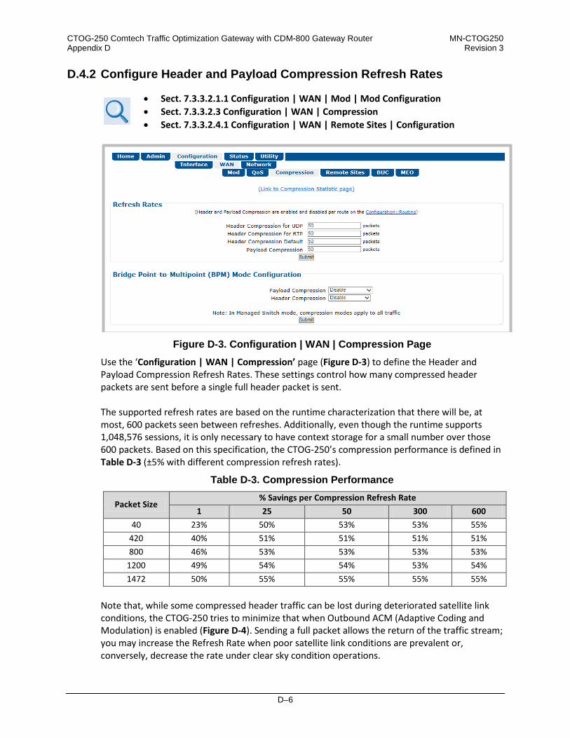
CTOG-250 Comtech Traffic Optimization Gateway with CDM-800 Gateway Router MN-CTOG250 Appendix D Revision 3
D–6
D.4.2 Configure Header and Payload Compression Refresh Rates
• Sect. 7.3.3.2.1.1 Configuration | WAN | Mod | Mod Configuration • Sect. 7.3.3.2.3 Configuration | WAN | Compression • Sect. 7.3.3.2.4.1 Configuration | WAN | Remote Sites | Configuration
Figure D-3. Configuration | WAN | Compression Page
Use the ‘Configuration | WAN | Compression’ page (Figure D-3) to define the Header and Payload Compression Refresh Rates. These settings control how many compressed header packets are sent before a single full header packet is sent. The supported refresh rates are based on the runtime characterization that there will be, at most, 600 packets seen between refreshes. Additionally, even though the runtime supports 1,048,576 sessions, it is only necessary to have context storage for a small number over those 600 packets. Based on this specification, the CTOG-250’s compression performance is defined in Table D-3 (±5% with different compression refresh rates).
Table D-3. Compression Performance
Packet Size % Savings per Compression Refresh Rate
1 25 50 300 600 40 23% 50% 53% 53% 55%
420 40% 51% 51% 51% 51% 800 46% 53% 53% 53% 53%
1200 49% 54% 54% 53% 54% 1472 50% 55% 55% 55% 55%
Note that, while some compressed header traffic can be lost during deteriorated satellite link conditions, the CTOG-250 tries to minimize that when Outbound ACM (Adaptive Coding and Modulation) is enabled (Figure D-4). Sending a full packet allows the return of the traffic stream; you may increase the Refresh Rate when poor satellite link conditions are prevalent or, conversely, decrease the rate under clear sky condition operations.

CTOG-250 Comtech Traffic Optimization Gateway with CDM-800 Gateway Router MN-CTOG250 Appendix D Revision 3
D–7
(TOP) Configuration | Mod | Mod Configuration Page (BOTTOM) Configuration | WAN | Remote Sites | Configuration Page
Figure D-4. Compression with Outbound ACM

CTOG-250 Comtech Traffic Optimization Gateway with CDM-800 Gateway Router MN-CTOG250 Appendix D Revision 3
D–8
D.4.3 View Header and Payload Compression Statistics
Sect. 7.4.4.4.1.3 Status | Statistics | Compression
Use the ‘Status | Statistics | Compression’ page (Figure D-5) to review Header and Payload Compression statistics – the total bytes of the pre-compressed and post-compressed traffic and effective compression ratio. The CTOG-250 supports header compression for Ethernet, and Layer 3, 4, and 5 headers.
When you operate the CTOG-250 in Router Mode, no Layer 2 headers are transmitted over the satellite link. However, when you operate the CTOG-250 in BPM mode, there is an option to enable/disable Header Compression for Layer 2 headers.
Figure D-5. Status | Statistics | Compression Page
Supported Ethernet Headers • Ethernet 2.0 • Ethernet 2.0 + VLAN tag • Ethernet 2.0 + MPLS • 802.3-raw • 802.3-raw _ VLAN tag • 803.3+802.2 • 803.3+802.2 + VLAN tag • 803.3+802.2 + SNAP • 803.3+802.2 + SNAP + VLAN tag • 803.3+ SNAP + MPLS
Supported Layer 3 and Layer 4 Headers
• IP • TCP • UDP • RTP (Codec Independent)

CTOG-250 Comtech Traffic Optimization Gateway with CDM-800 Gateway Router MN-CTOG250 Appendix D Revision 3
D–9
D.4.4 Update the AHA Compression Card Software
Sect. 7.4.4.5.2 Utility | CTOG-250 Unit
Figure D-6. Utility | CTOG-250 Unit Page
Use the AHA Compression Card section of the ‘Utility | CTOG-250 Unit’ page (Figure D-6) to update the operating software for the AHA Compression Card.

CTOG-250 Comtech Traffic Optimization Gateway with CDM-800 Gateway Router MN-CTOG250 Appendix D Revision 3
D–10
Notes:

E–1
Appendix E. OUTBOUND ACM (ADAPTIVE CODING A ND
MODULATION)
E.1 Overview
This appendix describes the physical layer implementation/mechanization of Advanced VSAT Outbound Adaptive Coding and Modulation (referred to hereafter as Outbound ACM). Outbound ACM is a technique that allows for automatic change in modulation and FEC Code Rate in response to changing link conditions for individual remotes sites in a ‘shared TDM (Time-division multiplexing) Carrier’. The primary objective of Outbound ACM is to capture historically unused satellite system link margin and convert this margin into additional data throughput for each remote site. An equally critical objective is to maintain optimum data transmission efficiency for all remotes sharing the TDM, independent of individual remote site link conditions (i.e., disadvantaged or weather-impaired remotes should have minimal impact on non-disadvantaged and clear-sky remote sites). In a simple Point-to-Point (non-TDM) ACM system, the physical layer symbol rate is constant (and occupied bandwidth is therefore constant), and power is also held constant. However, the utilized waveform varies with an assortment of modulation and coding combinations called ModCods. The ModCods are selected to span a range of Es/No (Energy per Symbol-to-Noise density ratio) so that, if a system detects a change in link margin (e.g., fading), it can use a different ModCod to preserve the link, albeit at a different user throughput rate. Therefore, as Es/No increases or decreases in an ACM system, so does the user data rate. Similarly, in a Point-to-Multipoint (shared TDM) ACM system, the physical layer symbol rate is constant; therefore, occupied bandwidth is constant and power is also held constant. However, the nature of the shared-TDM can make use of statistical multiplexing across a small or large number of remotes in which the ‘individual bandwidth requirements’ are, generally, simultaneously not at peak demand. Accordingly, not all remotes are equal in Point-to-Multipoint architectures – this holds true from both the physical configuration (Antenna, beam coverage contour, etc.) and Service Lease Agreement (SLA) perspectives. Because of this, a good Point-to-Multipoint ACM configuration must be a combination of a) optimal physical layer

CTOG-250 Comtech Traffic Optimization Gateway with CDM-800 Gateway Router MN-CTOG250 Appendix E Revision 3
E–2
transport efficiency and b) a strong, packet-based Quality of Service (QoS) engine. Advanced VSAT provides a very strong and tightly coupled solution for both. Advanced VSAT Outbound ACM offers significant operational enhancements: • ACM turns fade margin into increased link capacity – gains of 100% or more are possible
when compared to traditional Constant Coding and Modulation (CCM). This is accomplished by automatically adapting the modulation type and FEC code rate to give highest possible throughput.
• ACM maximizes throughput regardless of link conditions (noise, clear sky, rain fade, inclined orbit, antenna pointing error, or other impairments). Initial setup is easy and requires no further user intervention.
• With Point-to-Multipoint CCM systems, the network wide transmission efficiency (bits/Hz) must be set to support the most disadvantaged terminals. This results in tremendous inefficiencies and either higher than necessary OpEx (satellite operating expense/lease cost) or ‘advantageous terminal starving’ (i.e., terminals that could be receiving much great data (bits/Hz) are constrained to the CCM efficiency.
• With a CCM system, severe rain fading can cause total loss of the link – the result being zero throughput. ACM can keep the link active, with lower throughput during heavy fades, and can yield much higher system availability.
E.1.1 Background
The Advanced VSAT Outbound carrier is based on DVB-S2 standards. The DVB-S2 standardized a suite of 28 ModCods that work over an Es/No range of -2.3 dB to 16.0 dB (ideal). They have also defined much of the system for both ACM and a related feature called Variable Coding and Modulation (VCM). Because DVB-S2 did not specify the means of passing necessary information between system components, the ACM schemes adopted by different manufacturers are generally not interoperable. During ACM operation, control parameters between modems are transferred over the satellite link along with user traffic in what is usually referred to as Inband Signaling. DVB-S2 also describes an ACM method using “out-of-band” ACM controllers (per EN 302 307 Annex D.1) that is not supported with Advanced VSAT. In ACM mode, the symbol rate remains constant and the ModCod changes to preserve the data integrity. Most links are designed with enough Es/No margin to provide error-free performance under faded conditions when there is higher attenuation in the uplink path to or the downlink path from the satellite.

CTOG-250 Comtech Traffic Optimization Gateway with CDM-800 Gateway Router MN-CTOG250 Appendix E Revision 3
E–3
E.2 Advanced VSAT Outbound ACM Scheme
The description of Outbound ACM operation serves as the prelude to configuring Advanced VSAT for ACM operation. These key discussion points are: • Target Es/No Margin;
• Es/No Reporting Mechanization and Timing;
• Monotonic Operation;
• ModCod Selection.
E.2.1 Target Es/No Margin
Links normally include margin to meet performance criteria for SLA adherence. The Target Es/No Margin is added to the published guaranteed Es/No specification per ModCod for ACM operation. When ACM is enabled, in order for each remote site to switch to the next ModCod in a way that maintains a level of performance – generally near the QEF (Quasi Error Free) PER (Packet Error Rate) point of 10-7 – Target Es/No Margin serves to add margin to the guaranteed Es/No specification. The value of Target Es/No ranges from 0 to 4.5 dB For example, an Es/No Margin of 1.0 dB would mean that the minimum Es/No required to run at ModCod (5) QPSK 3/5 would be the guaranteed Es/No (2.7 dB) plus the Target Margin (1.0 dB) = 3.7 dB. The Target Es/No Margin can and should also be used as a way to dial in a maximum fade slope (rate of change). ACM messages sent from the remote demodulators to the Hub side ACM Controller contain the Es/No estimate that the demodulator was seeing at that particular time. If it takes ~260 ms to get the Es/No message to the CTOG-250 and another ~260 ms for the new ModCod to be received at the remote, the additional Target Margin above the QEF threshold will allow the system ~520 ms of fading before packets are dropped.
E.2.2 Es/No Reporting Mechanization and Timing
The Advanced VSAT Outbound ACM mechanization is formed on proprietary IP packets generated at each remote CDM-840 transmitted in band back to the ACM Controller (CTOG-250 or CDM-800) via the established link with the corresponding CDD-880 Multi Receiver Router demodulator device. These proprietary messages are transmitted on the Hub-side Management LAN to the ACM controller to ensure proper prioritization
To ensure proper operation, care must be taken to review and adhere to the LAN cabling requirements defined in the CTOG-250 Comtech Traffic Optimization Gateway Installation and Operation Manual.

CTOG-250 Comtech Traffic Optimization Gateway with CDM-800 Gateway Router MN-CTOG250 Appendix E Revision 3
E–4
Each CDM-840 Remote Router will send a proprietary Es/No reporting message during Steady State operation at a minimum rate of once every 60 seconds. Steady State operation is defined as times when the measured Es/No of the receive carrier does not exceed 0.3 dB variation from the last reported Es/No. During Non-steady State events, the CDM-840 will continue to send Es/No reporting messages at a rate of approximately two per second until Steady State conditions are again achieved. It is important to note that, in fade conditions of less than 0.6 dB/sec, this means that consecutive two-per-second updates will not be required. This mechanization, along with the proper prioritization of the Es/No reporting messages, provides a very ‘low messaging overhead’ during steady state conditions and a very reactive response during transient conditions.

CTOG-250 Comtech Traffic Optimization Gateway with CDM-800 Gateway Router MN-CTOG250 Appendix E Revision 3
E–5
E.2.3 Monotonic Operation
Table E-1. Spectral Efficiency and Ideal Es/No by ModCod
ModCod # ModCod Spectral Efficiency Normal FECFrame
Pilots ON
Advanced VSAT Es/No (dB) @ QEF
Normal Frame
Advanced VSAT Es/No (dB) @ QEF
Short Frame 1 QPSK 1/4 0.478577 -2.3 -2.3 2 QPSK 1/3 0.640827 -1.1 -0.7 3 QPSK 2/5 0.770627 -0.2 0.0 4 QPSK 1/2 0.965327 1.2 Not Supported 5 QPSK 3/5 1.160026 2.5 3.1 6 QPSK 2/3 1.290788 3.3 3.6 7 QPSK 3/4 1.452076 4.4 4.5 8 QPSK 4/5 1.549426 5.0 5.1 9 QPSK 5/6 1.615288 5.4 5.5
10 QPSK 8/9 1.724416 6.5 6.7 11 QPSK 9/10 1.746049 6.8 Not Supported 12 8PSK 3/5 1.739569 6.1 6.5 13 8PSK 2/3 1.935658 7.0 7.1 14 8PSK 3/4 2.177525 8.3 8.5 15 8PSK 5/6 2.422276 9.7 9.9 16 8PSK 8/9 2.585924 10.9 11.2 17 8PSK 9/10 2.618365 11.2 Not Supported 18 16APSK 2/3 2.574613 9.6 9.8 19 16APSK 3/4 2.896320 11.1 10.9 20 16APSK 4/5 3.090495 11.5 11.5 21 16APSK 5/6 3.221863 12.1 12.3 22 16APSK 8/9 3.439530 13.4 13.6 23 16APSK 9/10 3.482680 13.7 Not Supported 24 32APSK 3/4 3.623332 14.0 14.8 25 32APSK 4/5 3.866247 15.2 16.3 26 32APSK 5/6 4.030589 16.1 17.1 27 32APSK 8/9 4.302894 18.1 19.0 28 32APSK 9/10 4.356875 18.6 Not Supported
Table E-1 shows the Advanced VSAT Es/No at QEF, along with Spectral Efficiency, for each ModCod number. The QEF point corresponds to a PER = 10-7, based on 188 byte packets. Eight entries in this table (ModCods 10, 11, 15-17, 20, 22, and 27) are highlighted to indicate where the Spectral Efficiency does not change monotonically or provide less spectral efficiency than another ModCod of higher order. For Advanced VSAT in Outbound ACM mode, the table is re-sorted by Spectral Efficiency to assure monotonic behavior and system stability.

CTOG-250 Comtech Traffic Optimization Gateway with CDM-800 Gateway Router MN-CTOG250 Appendix E Revision 3
E–6
E.2.4 ModCod Selection
Figure E-1. Packet-to-ModCod Mapping in Router Mode

CTOG-250 Comtech Traffic Optimization Gateway with CDM-800 Gateway Router MN-CTOG250 Appendix E Revision 3
E–7
On the previous page, Figure E-1 provides the logic diagram for packet handling and processing by the CTOG-250.
Figure E-2. Spectral Efficiency vs. Advanced VSAT Es/No @ QEF
Figure E-2 depicts considerable overlap of ModCod combinations. This overlap implies omission of some of the ModCods; therefore, without dropping some of the ModCods, there is a non-monotonic change of Bits/Hz with changing Es/No. As this would result in an unstable system, re-sorting the DVB-S2 table resolves this. Also, a practical system needs some hysteresis to provide orderly transition to adjacent ModCods and avoid dithering. The minimum distance between adjacent ModCods must be at least the amount of hysteresis – the figure used for hysteresis is fixed in the Advanced VSAT at 0.5 dB. The actual Es/No values used are based on the guaranteed Es/No values + Target Es/No Margin + modulation type impairment, not the DVB-S2 ideal Es/No figures. Taking into account the ModCod spacing, hysteresis, Target Es/No Margin, modulation type impairment and monotonic behavior suggests a practical way to select the Es/No thresholds for switching ModCods, and a way to prune ModCods from the list. During parameter configuration, the modem selects the usable ModCods.

CTOG-250 Comtech Traffic Optimization Gateway with CDM-800 Gateway Router MN-CTOG250 Appendix E Revision 3
E–8
Figure E-3. Outbound ACM ModCod Transitions vs. Es/No Customer Margin @ 0 dB
Figure E-3 presents a practical set of ModCods based on ModCod selection. The pruned (inactive) ModCods are shown along the baseline of the plot. The transition to the next higher ModCod is:
The Es/No (spec) + Es/No Target Margin (user selected) + hysteresis (0.5 dB) + modulation impairment (user selected)

CTOG-250 Comtech Traffic Optimization Gateway with CDM-800 Gateway Router MN-CTOG250 Appendix E Revision 3
E–9
While a step down is:
The Es/No (spec) + Es/No Target Margin + modulation impairment. In this example, the Target Es/No Margin and Modulation Impairment are zero.
E.3 Configure, Operate, and Monitor Outbound ACM
See Chapter 7. ETHERNET INTERFACE OPERATION for detailed information on using the CTOG-250 Web Server Interface.
Figure E-4. Configuration | Network | Routing Page
Use these CTOG-250 HTTP Interface pages to configure, operate, and monitor Outbound ACM: • Configuration | Network | Routing • Configuration | WAN | Mod | Mod Configuration • Configuration | WAN | Remote Sites | Remote Sites Event Log • Status | Statistics | Outbound

CTOG-250 Comtech Traffic Optimization Gateway with CDM-800 Gateway Router MN-CTOG250 Appendix E Revision 3
E–10
E.3.1 Prerequisites for CDM-800 Outbound ACM Operation via the CTOG-250
Sect. 7.3.3.3.1 Configuration | Network | Routing
Figure E-5. Configuration | Network | Routing Page
You must use the ‘Configuration | Network | Routing’ page to enable Comtech Dynamic Routing Protocol (CDRP). CDRP is required because the ACM Controller uses the Remote-to-Route mapping provided by this feature to properly determine which MODCOD is required to transport the packets destined to each remote.

CTOG-250 Comtech Traffic Optimization Gateway with CDM-800 Gateway Router MN-CTOG250 Appendix E Revision 3
E–11
E.3.2 Enable Outbound ACM Operation
Sect. 7.3.3.2.1.1 Configuration | WAN | Mod | Mod Configuration
Use the ‘Configuration | WAN | Mod | Mod Configuration’ page to configure Outbound ACM operations. Use the Outbound ACM drop-down list, located in the Modulator section of the page, to Enable Outbound ACM operation. Click [Submit] to execute this selection.
When Outbound ACM is disabled, all packets will revert to the “VCM Only MODCOD” which is configured in each QoS Group.
Figure E-6. Configuration | WAN | Mod | Mod Configuration Page

CTOG-250 Comtech Traffic Optimization Gateway with CDM-800 Gateway Router MN-CTOG250 Appendix E Revision 3
E–12
E.3.3 Monitor Outbound ACM Operational Events
Sect. 7.3.3.2.4.2 Configuration | WAN | Remote Sites | Remote Site Event Log
Use the ‘Configuration | WAN | Remote Sites | Remote Site Event Log’ page to view events that have compiled in the ACM Events Log since it was last cleared.
Figure E-7. Configuration | WAN | Remote Sites | Remote Site Event Log Page

CTOG-250 Comtech Traffic Optimization Gateway with CDM-800 Gateway Router MN-CTOG250 Appendix E Revision 3
E–13
E.3.4 View Outbound ACM MODCOD Statistics
Sect. 7.3.4.1.5 Status | Statistics | Outbound
Use the Status | Statistics | Outbound page to view read-only cumulative Outbound ACM statistics.
Figure E-8. Status | Statistics | Outbound Page

CTOG-250 Comtech Traffic Optimization Gateway with CDM-800 Gateway Router MN-CTOG250 Appendix E Revision 3
E–14
Notes:

F–1
Appendix F. GROUP QoS (QUALITY OF SERVICE)
F.1 Group QoS Overview
Today’s networks must support a wide range of applications having diverse requirements. Comtech EF Data’s Advanced VSAT incorporates Group QoS, a multi-tier Quality of Service (QoS) concept that ensures the highest service quality with minimal jitter and latency for real-time traffic and priority treatment of mission critical applications while maximizing bandwidth utilization. Group QoS enables a network to use WAN bandwidth more efficiently by managing delay, jitter (delay variation), throughput, and packet loss. The CTOG-250 Comtech Traffic Optimization Gateway (with CDM-800 Gateway Router) provides Outbound 3-Level QoS while classifying packets up to Layer 4 (the Transport Layer) of the Open Systems Interconnection (OSI) Model.
F.1.1 QoS Terminology
• CIR – CIR (Committed Information Rate) is used to reserve capacity through the QoS system. CIR is entered in kbps but is enforced in 1k Bytes per second increments. The CIR will be honored unless there is not enough bandwidth/symbols on the transmitter.
• CIR Availability – The reported CIRs Availability statistics is the percentage of time over the
last 1, 15 or 60 minutes for which the CIR was demanded of the QoS system and the system was able to honor the packet throughput demand. The CIR Availability is intended to provide a metric for operators to trend over time to determine if there is enough satellite bandwidth allocated to meet customer demands. This metric allows operators the ability to “safely” oversubscribe the satellite bandwidth purchased.
• Clipping – The process of the QoS Scheduler’s discard of packets, when the traffic level for a queue exceeds the Max BW (Maximum Bandwidth) or MIR (Maximum Information Rate).
• Jitter – The amount of variation that is measured, in milliseconds, between two consequent frames at the receiving end.

CTOG-250 Comtech Traffic Optimization Gateway with CDM-800 Gateway Router MN-CTOG250 Appendix F Revision 3
F–2
• Latency – The time it takes for a packet to be transmitted, as measured from one point to another. For the purposes of Advanced VSAT, latency is the amount of delay that is measured, in milliseconds, from the Ethernet interface of the near-end modem to the Ethernet interface of the far-end modem.
• Maximum Clipping Rate – In Max/Pri (Maximum/Priority), Min/Max (Minimum/Maximum), and Pri-Weighted (Priority/Weighted) QoS Control Modes, you can define the maximum amount of data rate to be allocated to a queue. Maximum Clipping Rate can also be referred to as Max BW or MIR.
• Priority – In Max/Pri and Pri-Weighted QoS Control Modes, you may define a Priority level
of 1 through 8 for a flow. For example, a Priority 1 queue schedules and drains before a Priority 2 queue; similarly, Priority 2 packets will schedule and drain before Priority 3 packets, etc.
• QoS Queue Size – The QoS queue size varies and is equal to 1 second’s worth of TX data at
the current data rate. • Round-robin – The simplest scheduling process, where all packets are equal in priority and
are processed in the order they arrive. • Tail Drop – The process of discarding packets when a queue is full. Tail Drop is the most
basic queue management process where all packets are treated identically and newly arriving packets are dropped while the queue is at capacity.
• Traffic Shaping – Also known as 'packet shaping,' this is the practice of regulating network
data transfer to assure a certain level of QoS for some applications or users or to increase available bandwidth for some other purpose.
• Weight – This is the user-configurable parameter when using Pri-Weighted QoS Control
Mode. The valid Weight ranges are 1 through 9 – the greater the Weight, the higher the precedence will be given to that queue when draining packets.
For example, given the same Priority Level, more bytes would be drained from those with Weight = 9 than those with Weight = 8, and so on.
• Weighted Scheduling – Used in Pri-Weighted Mode. The QoS Scheduler calculates each quantum based on available bandwidth, total weights, and per queue value as follows:
Per queue quantum = available bandwidth *(per queue weight/total weights)
• WRED – Weighted Random Early Detection is a congestion avoidance algorithm that is
better at avoiding network congestion than using Tail Drop, particularly for TCP traffic.

CTOG-250 Comtech Traffic Optimization Gateway with CDM-800 Gateway Router MN-CTOG250 Appendix F Revision 3
F–3
F.1.2 QoS List of Supported RFCs (Requests for Comment)
RFC No. Description
2474 “Definition of the Differentiated Services Field (DS Field) in the IPv4 and IPv6 Headers” Nichols, K., Blake, S., Baker, F. and D. Black, December 1998
2475 “An Architecture for Differentiated Services” Blake, S., Black, D., Carlson, M., Davies, E., Wang, Z. and Weiss, W., December 1998
2597 “Assured Forwarding PHB” Heinanen, J., Baker, F., Weiss, W. and J. Wrocklawski, June 1999
2598 “An Expedited Forwarding PHB” Jacobson, V., Nichols, K. and K. Poduri, June 1999
F.1.3 Outbound 3-Level Group QoS
Figure F-1. Group QoS Multi-User / Multi-Tier Outbound QoS
As shown in Figure F-1, Group QoS Outbound 3-level QoS allows efficient bandwidth sharing and prioritization among users, sites and applications: • Level 1 allows different customers to share and prioritize bandwidth allocation among them.
• Level 2 allows bandwidth to be prioritized and shared among different sites belonging to a
customer.
• Level 3 allows different applications and traffic types to be prioritized within a site.

CTOG-250 Comtech Traffic Optimization Gateway with CDM-800 Gateway Router MN-CTOG250 Appendix F Revision 3
F–4
• Traffic shaping is supported with multi-tier QoS.
Figure F-2. Group QoS 3-Level Outbound QoS Configuration

CTOG-250 Comtech Traffic Optimization Gateway with CDM-800 Gateway Router MN-CTOG250 Appendix F Revision 3
F–5
As shown in Figure F-2, with Group QoS, the Outbound is divided into Capacity Groups; each Capacity Group is assigned a Committed Information Rate (CIR) and Minimum Information rate (MIR). Each Capacity Group is further divided into QoS Groups: • 100 QoS Groups per Capacity Group;
• Defined by VLAN(s), Remote IP(s), and IP Subnet(s);
• 32 VLANs per QoS Group;
• Configure CIR, MIR, and QoS Control Mode for each QoS Group;
• Each QoS Group supports these QoS Control Modes:
o Max/Pri (Maximum/Priority) – Provides multi-level traffic prioritization with the ability
to limit maximum traffic per priority class. See Sect. F.3.2.1 for details. o Min/Max (Minimum/Maximum) – Provides a Committed Information Rate (CIR) to
each user defined class of traffic with the ability to allow a higher rate (MIR) depending on bandwidth availability. See Sect. F.3.2.2 for details.
o Pri-Weighted (Priority/Weighted) – Allows for a combination of priorities and weights
with CIR. See Sect. F.3.2.3 for details.
o DiffServ (Differentiated Services) – Industry-standard method that enables seamless co-existence in networks that implement DiffServ. See Sect. F.3.2.4 for details.
• Associates remotes to Groups for ACM/VCM. An incoming packet is mapped to a QoS Group based on: • Matching Subnet;
• Matching VLAN;
• Matching Remote Site.
Remote site IPs are added automatically for traffic that matches a Subnet and/or a VLAN. A user-created Remote Site attribute has a higher precedence than a system-created Remote Site when determining the best QoS Group match.
You may assign up to 32 QoS Rules per Group. A “rule” is a powerful classifier, whereby packets are sorted (“classified”) based on VLAN IDs; ToS (Type of Service); Protocol (Application); Source and Destination IP Addresses/Subnets; and Source and Destination Ports/Ranges.

CTOG-250 Comtech Traffic Optimization Gateway with CDM-800 Gateway Router MN-CTOG250 Appendix F Revision 3
F–6
Figure F-3. Service Differentiation by Application Type

CTOG-250 Comtech Traffic Optimization Gateway with CDM-800 Gateway Router MN-CTOG250 Appendix F Revision 3
F–7
F.1.4 Group QoS Operation via the CTOG-250 HTTP Interface
Group QoS operation requires that you first enable the correct QoS Control Mode, and then configure your Capacity Group(s) and QoS Group(s). You must use the CTOG-250 HTTP Interface as the means for configuring QoS operation via Remote Product Control with a user-supplied PC.
Chapter 7. ETHERNET INTERFACE OPERATION
YOU MAY PROCEED WITH ETHERNET-BASED REMOTE PRODUCT MANAGEMENT (HTTP OR SNMP), ASSUMING THAT: • YOUR SETUP IS OPERATING WITH THE LATEST VERSION FIRMWARE FILES.
• YOUR SETUP IS CONNECTED TO A USER-SUPPLIED, WINDOWS-BASED PC AS
FOLLOWS:
O THE PC SERIAL PORT IS CONNECTED TO THE CTOG-250 BACK PANEL ‘SERIAL’ PORT WITH A USER-SUPPLIED SERIAL CABLE.
O THE PC ETHERNET PORT IS CONNECTED TO THE CTOG-250 BACK PANEL ‘MGMT-1’ ETHERNET PORT WITH A USER-SUPPLIED DIRECT ETHERNET CABLE CONNECTION.
O THE PC IS RUNNING A TERMINAL EMULATION PROGRAM (FOR OPERATION OF THE CTOG-250 SERIAL INTERFACE) AND A COMPATIBLE WEB BROWSER (FOR OPERATION OF THE CTOG-250 HTTP INTERFACE).
• YOU HAVE NOTED THE CTOG-250 MANAGEMENT IP ADDRESS USING THE
CTOG-250 SERIAL INTERFACE.
• COMTECH EF DATA RECOMMENDS USE OF THE SERIAL-BASED REMOTE CONTROL INTERFACE AND THE ETHERNET-BASED SNMP INTERFACE ONLY FOR ADVANCED USERS. COMTECH EF DATA STRONGLY ENCOURAGES USE OF THE CTOG-250 HTTP INTERFACE FOR MONITOR AND CONTROL (M&C) OF THE CTOG-250.
Figure F-4 shows the CTOG-250 HTTP Interface “splash” page, and the menu tree diagram for accessing QoS Capacity Group and QoS Group configuration, operation, and monitoring. Page functionality that is not specific to Group QoS operations appears dimmed.

CTOG-250 Comtech Traffic Optimization Gateway with CDM-800 Gateway Router MN-CTOG250 Appendix F Revision 3
F–8
Figure F-4. CTOG-250 HTTP Interface and Menu Tree – QoS Operation (FW
Ver. 1.6.2.X)

CTOG-250 Comtech Traffic Optimization Gateway with CDM-800 Gateway Router MN-CTOG250 Appendix F Revision 3
F–9
F.2 Capacity Groups
Capacity Groups are at the highest level of the Group QoS hierarchy. A configured Capacity Group allows the user to reserve bandwidth (CIR) and limit bandwidth (MIR).
Capacity Groups support Min/Max QoS Control Mode only.
F.2.1 Capacity Group Operation via the CTOG-250 HTTP Interface
Chapter 7.3.3.2.2.1 Configuration | WAN | QoS | Capacity Group in Chapter 7. ETHERNET INTERFACE OPERATION
Use the CTOG-250 HTTP Interface ‘Configuration | WAN | QoS | Capacity Group’ page (Figure F-5) to manage Capacity Groups: • Make changes to the Default Capacity Group.
• Add, change, or delete user-created Capacity Groups. • Use the Capacity Group Table to manage the active Capacity Group.
Figure F-5. Configuration | WAN | QoS | Capacity Group Page
F.2.2 Capacity Group CIR (kbps) Notes
The Capacity Group CIR reserves the configured amount of LAN bandwidth (pre-compression) which is shared across all QoS Groups in that Capacity Group. The QoS Group CIR will be honored first and then any remaining Capacity Group CIR will be honored with QoS Group MIR.

CTOG-250 Comtech Traffic Optimization Gateway with CDM-800 Gateway Router MN-CTOG250 Appendix F Revision 3
F–10
The sum of all QoS Group CIRs for a Capacity Group can configured to exceed the Capacity Group CIR (oversubscribed), but only the Capacity Group CIR is guaranteed assuming there are enough symbols available. The CIR Availability % statistic can be used to monitor/trend if the QoS Group CIR is being met.
F.2.3 Capacity Group MIR (kbps) Notes
The Capacity Group MIR limits the amount of LAN bandwidth (pre-compression) that is allowed across all QoS Groups in that Capacity Group. Although you can configure the sum of all QoS Group MIRs for a Capacity Group to exceed the Capacity Group MIR (oversubscribed), the aggregate traffic for all QoS Groups will be hard limited to the Capacity Group MIR. This configuration allows any one QoS Group to burst to a higher datarate while still enforcing a Capacity Group wide cap.
F.3 QoS Groups
Excluding the default queue, each QoS Group has up to 32 QoS Rules with eight configurable priorities. The Group QoS system: • Creates a separate queue for each rule to store the incoming stream of packets. (In this
appendix, ‘QoS rules’ and ‘QoS queues’ are interchangeable.)
• Uses a strict priority QoS scheduling algorithm. For QoS Group priority numbering, the lower the priority number, the higher the priority. For example, a Priority 1 queue schedules and drains before a Priority 2 queue; similarly, Priority 2 packets will schedule and drain before Priority 3 packets, etc. Each QoS queue is implemented to support at least one (1)-second burst at the maximum data rate of the Tx Carrier of the modem.
• Incorporates WRED (Weighted Random Early Detection) based congestion avoidance algorithm in addition to tail drop. WRED is designed to avoid congestion by progressively increasing the chance of an incoming packet being dropped once the QoS queue has reached 50% of capacity. After the queue is 50% full, then the random chance of dropping a packet increasing up to 100% when the queue is full.
F.3.1 QoS Group Matching
QoS Group Matching allows you to match an incoming packet to the desired QoS Group. Once a packet has been matched to a QoS Group, then the configured QoS Rule Matching criteria are used to determine where the packet is inserted into the QoS queue. Note that matching criteria occurs at the QoS Group level, not at the Capacity Group level. Therefore, the QoS Group Matching is global across all Capacity Groups. You must make sure that the QoS Groups across all of the Capacity Groups in the system do not share the same matching criteria.

CTOG-250 Comtech Traffic Optimization Gateway with CDM-800 Gateway Router MN-CTOG250 Appendix F Revision 3
F–11
The FW Ver. 1.6.2.X Packet-to-QoS Group Matching criteria is as follows (by order of preference): 1. Matching Subnet + VLAN
2. Matching Subnet
3. Matching VLAN + Remote
4. Matching VLAN
5. Matching Remote
6. Default QoS Group Matching is absolute, not partial. If a QoS Group has a Subnet and VLAN attribute, then the traffic must match BOTH attributes to be classified to use the group. Classification starts with the most stringent matching criteria (Subnet and VLAN) and continues down the hierarchy until a match is found. If there is more than one QoS Group with the same attributes (which should be avoided), the last matching QoS Group will be used.
F.3.2 QoS Group Control Modes
Chapter 7.3.3.2.2.2 Configuration | WAN | QoS | QoS Group in Chapter 7. ETHERNET INTERFACE OPERATION
Figure F-6. Configuration | WAN | QoS | QoS Group Page (QoS Control Mode = Off) Use the CTOG-250 HTTP Interface ‘Configuration | WAN | QoS |QoS Group’ page (Figure F-6) to manage QoS Groups. In the Add/Change/Delete Group section of the page, use the drop-down list to select the desired QoS Control Mode: Max/Pri, Min/Max, Pri-Weighted, or DiffServ. Click [Change] to proceed.

CTOG-250 Comtech Traffic Optimization Gateway with CDM-800 Gateway Router MN-CTOG250 Appendix F Revision 3
F–12
F.3.2.1 QoS Group Max/Pri Control Mode
In Max/Pri Control Mode, you may configure up to 32 QoS rules using VLAN Range, TOS Attributes, Protocol (Application), Source and Destination IP Subnets, and Source and Destination Port Ranges in order to match packets to the desired QoS rule. For each created rule, you can also set the QoS treatments such as Priority, limiting the Maximum Bandwidth, enable or disable WRED, and enable or disable the FILTER ALL rule. When you enable WRED for a specific queue, QoS randomly drops packets after reaching 50% of the QoS queue capacity. When you enable the FILTER ALL option for a rule, QoS provides the ability to filter the packet completely. In other words, all packets matching the QoS Rule with the FILTER ALL option enabled will be dropped. For example – using the CTOG-250 HTTP Interface Configuration | WAN | QoS | QoS Group page: 1. Select Max/Pri QoS Group Control Mode. 2. Set the Modem Tx bandwidth to 2048 kbps. 3. Configure the Max/Pri QoS rules as follows:
Index VLAN Range TOS Protocol Src IP/
mask Dest IP/
mask
Min Src Port
Max Src Port
Min Dst Port
Max Dst Port
Max BW
(kbps) Priority WRED Filter
All
1 0-4094 255 UDP ***/* ***/* 0 65535 0 65535 644 1 N N 2 0-4094 255 TCP ***/* ***/* 0 65535 0 65535 99999 2 N N 3 0-4094 255 HTTP ***/* ***/* 0 65535 0 65535 99999 3 N N 4 0-4094 255 Def ****/* ***/* 0 65535 0 65535 99999 9 N N
QoS Rules match from left to right, with VLANs being the highest match, and the Destination Port range being the lowest match. Matches can be made using multiple attributes
4. The input data streams are as follows:
Stream VLAN Range TOS Protocol Src IP Dest IP Src Port Dest Port Stream Data
Rate (kbps) 1 0-4094 255 UDP ***/* ***/* *** *** 1024 2 0-4094 255 TCP ***/* ***/* *** *** 1024 3 0-4094 255 HTTP ***/* ***/* *** *** 1024 4 0-4094 255 IP ***/* ***/* *** *** 64
QUESTION: What are the total output data rates and the individual stream data rates? ANSWER: The individual stream data rates are as follows:

CTOG-250 Comtech Traffic Optimization Gateway with CDM-800 Gateway Router MN-CTOG250 Appendix F Revision 3
F–13
QoS Rule
QoS Group Priority
Input Data Rate (kbps)
QoS Output Data Rate (kbps)
Remain Data Rate (kbps) (After Serving the Priority Queue)
1 1 1024 644 due to max clipping 1404 2 2 1024 1024 380 3 3 1024 380 0 4 9 64 0 0
Total 3136 2048 0
F.3.2.2 QoS Group Min/Max Control Mode
In Min/Max Control Mode, you may configure up to 32 QoS rules using VLAN Range, TOS, Protocol (Application), Source and Destination IP Addresses/Subnets, and Source and Destination Ports Ranges in order to match packets to the desired QoS rule. For each created rule, you can also set the QoS treatment, such as guaranteed minimum bandwidth (Committed Information Rate, or CIR), maximum clipping bandwidth (MIR), enable or disable WRED, and enable or disable the FILTER ALL rule. When you enable WRED for a specific queue, QoS randomly drops packets after reaching 50% of the QoS queue. When you enable the FILTER ALL option for a rule, QoS provides the ability to filter the packet completely. In other words, all packets matching the QoS Rule with the FILTER ALL option enabled will be dropped. For example – using the CTOG-250 HTTP Interface Configuration | WAN | QoS | QoS Group page: 1. Select Min/Max QoS Group Control Mode.
2. Set the Modem Tx bandwidth to 20000 kbps. 3. Configure the Min/Max QoS rules as follows:
Index VLAN Range TOS Protocol
Src IP/
mask
Dest IP/
mask
Min Src Port
Max Src Port
Min Dst Port
Max Dst Port
Min BW
(kbps)
Max BW
(kbps) Priority WRED Filter
All
1 0-4094 255 UDP ***/* ***/* 0 65535 0 65535 2500 4000 8 N N 2 0-4094 255 TCP ***/* ***/* 0 65535 0 65535 2500 99999 8 N N 3 0-4094 255 HTTP ***/* ***/* 0 65535 0 65535 0 99999 8 N N 4 0-4094 255 Def ****/* ***/* 0 65535 0 65535 0 99999 9 N N
When using the Add/Delete Per Group QoS Rule table, note that QoS Rules match from left to right, with VLANs being the highest match, and the Destination Port range being the lowest match. Matches can be made using multiple attributes.
4. The input data streams are as follows:

CTOG-250 Comtech Traffic Optimization Gateway with CDM-800 Gateway Router MN-CTOG250 Appendix F Revision 3
F–14
Stream VLAN Range TOS Protocol Src IP Dest IP Src Port Dest Port Stream Data
Rate (kbps) 1 0-4094 255 UDP ***/* ***/* *** *** 10000 2 0-4094 255 TCP ***/* ***/* *** *** 5000 3 0-4094 255 HTTP ***/* ***/* *** *** 7000 4 0-4094 255 DEF ***/* ***/* *** *** 10000
QUESTION: What are the total output data rates and the individual stream data rates? ANSWER: • In Min/Max QoS Control Mode, other than the default rule (which is configured as Priority
9), all QoS rules are configured at the same priority (Priority 8).
• In this mode, the minimum bandwidth (CIR) for all rules – excluding the default rule – will be served first in Round-robin fashion.
In this example, the total minimum bandwidth for Rules 1 and 2 is 5000 kbps. Since the total bandwidth is 20000 kbps, it has enough bandwidth to serve. • After serving the minimum bandwidth, the leftover bandwidth is 15000 kbps (20000 kbps −
5000 kbps).
• Leftover bandwidth will be served among all rules in Round-robin fashion until it hits maximum bandwidth limitations.
• Each rule’s bandwidth is 15000 / 3 = 5000 kbps.
• Since Rule 1 maximum clipping was set to 4000 kbps, and minimum bandwidth has already taken 2500 bytes, it will use 1500 kbps more before reaching the maximum clipping. The leftover 3500 kbps (5000 – 1500 = 3500) is again given to the main pool.
• Rule 2 does not have enough traffic coming in, so it will use only 2500 kbps (5000 – 2500 = 2500); the remaining bandwidth (5000 – 2500 = 2500) is again given to the main pool.
• Rule 3’s input stream is 7000 kbps; it will take its share of the 5000 kbps allocation. Still, it needs 7000 – 5000 = 2000.
• After serving the fair share, the total leftover bandwidth is 6000 kbps (3500 + 2500 = 6000).
• Since Rule 3 needs the bandwidth, the leftover bandwidth is applied to that rule.
• After serving Rule 3, the leftover bandwidth 4000 kbps will be applied to the default queue.
• The default rule will see the data rate of 4000 kbps. The individual rule’s data rates are as follows:

CTOG-250 Comtech Traffic Optimization Gateway with CDM-800 Gateway Router MN-CTOG250 Appendix F Revision 3
F–15
QoS Rule QoS Group Priority Input Data Rate (kbps) QoS Output Data Rate (kbps) 1 1 10000 4000 2 2 5000 5000 3 3 7000 7000 4 9 10000 4000
Total 32000 20000
F.3.2.3 QoS Group Pri-Weighted Control Mode
In Pri-Weighted Control Mode, you may enter the weight while configuring queues, similar to configuring other parameters such as minimum or maximum bandwidth, priority, etc. In this QoS Control Mode, the weight is considered only if multiple queues are configured with the same priority, and at least one of the weights is different from others and the minimum bandwidth has already been achieved. When valid weights are configured in this QoS Control Mode, the weighted scheduling algorithm is applied. In all other cases, Strict Priority and Round-robin scheduling will be applied.
F.3.2.3.1 Weight
Weight is a user-configurable parameter. The greater the weight, the higher the precedence will be given to that queue when draining the packets. Weight values range from 1 to 9 and 0 is an invalid value. The Scheduler will drain more bytes from weight 9 queues than weight 8 queues under the same priority, and so on.
F.3.2.3.2 Weighted Scheduling
In weighted scheduling mode, the QoS Scheduler calculates each quantum based on available bandwidth, total weights, and per-queue weights as follows: Per queue quantum=available bandwidth*per queue weight/total weights)
There are some exceptions when assigning per-queue quantum to each queue, as represented by three cases: • Case 1 – The per-queue quantum is greater than the configured maximum bandwidth.
When the LAN ingress data rate is greater than the maximum bandwidth, the Scheduler drains packets only up to the maximum bandwidth, and then drops the remaining packets. With Case 1, maximum bandwidth is the limiting factor, and weight is not applied.
• Case 2 – The per-queue quantum is less than the configured maximum bandwidth but more than the configured minimum bandwidth. In this scenario, when the available bandwidth is greater than the total minimum bandwidth but less than total maximum bandwidth, the QoS Scheduler first satisfies the minimum bandwidth for all queues with the same priority, and then divides the remaining bandwidth amongst the queues based on their weight value.

CTOG-250 Comtech Traffic Optimization Gateway with CDM-800 Gateway Router MN-CTOG250 Appendix F Revision 3
F–16
Case 2 example – The Pri-Weighted QoS rules are configured as follows:
Queue Min BW (kbps) Max BW (kbps) Delta Max Bytes (Max-Min kbps) Weight Allowed BW
(kbps) 1 16 32 16 9 – 2 32 64 32 8 – 3 48 128 64 7 – 4 64 64 0 6 –
Total 160 288 112 30 240 The total allowed bandwidth is 240 kbps. The total minimum bandwidth is 160 kbps. The minimum bandwidth is therefore less than the available bandwidth. The QoS Scheduler Calculation Solutions table for the Case 2 example is as follows:
Queue Round 1 Round 2 Round ‘N’ Final
(kbps) Weight Given (kbps)
Leftover (kbps) Weight Given
(kbps) Leftover (kbps) Weight Given
(kbps) Leftover (kbps)
1 9 30 14 – – – – – – 16 2 8 26.672 – 8 7.472 2.144 – – – 32 3 7 23.328 – 7 6.528 – 7 2.144 – 32 4 – – – – – – – – – –
Total 24 80 14 15 14 2.144 7 2.144 0 80 This table shows the result of the steps taken to calculate the individual allocated bandwidths: 1. After the minimum bandwidth is satisfied, there is 80 kbps of bandwidth remaining. This
leftover bandwidth is distributed to all queues whose maximum bandwidth hasn’t been reached. In this example, only Queues 1, 2, and 3 still have an unmet maximum bandwidth.
Since Queue 4’s minimum and maximum bandwidths are the same, Queue 4 will be taken out of the algorithm for distributing the remaining quantum.
The remaining total weight is (9 + 8 + 7) = 24.
2. Each bandwidth share is then calculated based on the remaining total weight (24) and
bandwidth availability (10000 bytes) after the minimum bandwidth is served (20000 bytes): o Queue 1 = 10000 * (9 / 24) = 3750 bytes (30 kbps)
o Queue 2 = 10000 * (8 / 24) = 3334 bytes (26.6 kbps)
o Queue 3 = 10000 * (7 / 24) = 2916 bytes (23.328 kbps)
3. After Round 1 of quantum distribution, Queue 1 requires only 16 kbps (2000 bytes) to
reach its maximum bandwidth, hence the remaining 14 kbps (3750 − 2000 = 1750

CTOG-250 Comtech Traffic Optimization Gateway with CDM-800 Gateway Router MN-CTOG250 Appendix F Revision 3
F–17
bytes). Queues 2 and 3 will consume all of the bytes because they have yet to reach their maximum bandwidth.
4. Calculate each bandwidth share based on the total remaining weight (15) and remaining bandwidth of 14 kbps (1750 bytes): o Queue 2 = 1750 * (8 / 15) = 934 bytes (7.472 kbps)
o Queue 3 = 1750 * (7 / 15) = 816 bytes (6.528 kbps)
5. After Round 2, Queue 2 can be assigned a maximum of 32 kbps (4000 bytes), hence the
remaining 2.144 kbps ((3334 − 934) − 4000 = 268 bytes) goes back into pool the pool once more. Queue 3 will consume all of the bytes because it has yet to reach its maximum bandwidth.
6. Calculate each bandwidth share based on the total remaining weight (7) and remaining bandwidth (268 bytes):
o Queue 3 = 268 * (7 / 7) = 268 bytes (2.144 kbps)
7. In the next round (Round ‘N’), only Queue 3 has a maximum bandwidth that is not yet.
This queue will take the remaining quantum 2.144 kbps (268 bytes). Since there is no more leftover bandwidth, the calculation loop stops here.
Case 2 Example Summary – After all rounds, each queue’s share is as follows: Q1 = 16 kbps ((2000 additional bytes (4000 bytes total))
Q2 = 32 kbps ((4000 additional bytes (8000 bytes total))
Q3 = 32 kbps ((4000 additional bytes (10000 bytes total))
Q4 = 0 kbps (( 0 additional bytes (8000 bytes total))
• Case 3 – The per-queue quantum is less than the configured maximum bandwidth.
Case 3 / Example 1 – The Pri-Weighted QoS rules are configured as follows:
Queue Min BW kbps (Bps) Weight Allowed BW kbps (Bps) 1 16 (2000) 9 – 2 32 (4000) 8 – 3 48 (6000) 7 – 4 64 (8000) 6 –
Total 160 (20000) 30 40 (5000) Each queue is configured with minimum bandwidth and weight as specified in this table. The total allowed bandwidth is 40 kbps (5000 Bps).

CTOG-250 Comtech Traffic Optimization Gateway with CDM-800 Gateway Router MN-CTOG250 Appendix F Revision 3
F–18
The QoS Scheduler Calculation Solutions table for Case 3 / Example 1 is as follows:
Queue Round 1 Round 2 Round ‘N’
Final kbps Weight Given (kbps)
Leftover (kbps) Weight Given
(kbps) Leftover (kbps) Weight Given
(kbps) Leftover (kbps)
1 9 12 – – – – – – – 12 2 8 10.672 – – – – – – – 10.672 3 7 9.328 – – – – – – – 9.328 4 6 8 – – – – – – – 8
Total 30 40 0 0 0 0 0 0 0 40 This table shows the result of the steps taken to calculate the individual allocated bandwidths: Calculate the bandwidth for each queue based on the total weight (30) and the available bandwidth of 40 kbps (5000 bytes).
o Queue 1 = 5000 * (9 / 30) = 1500 bytes (12 kbps)
o Queue 2 = 5000 * (8 / 30) = 1334 bytes (10.672 kbps)
o Queue 3 = 5000 * (7 / 30) = 1166 bytes (9.328 kbps)
o Queue 4 = 5000 * (6 / 30) = 1000 bytes (8 kbps)
After Round 1, all bandwidth is consumed and the calculation loop stops.
Case 3 Example 1 Summary – Each queue’s share is as follows:
Queue 1 = 1500 bytes (12 kbps)
Queue 2 = 1334 bytes (10.762 kbps)
Queue 3 = 1166 bytes (9.328 kbps)
Queue 4 = 1000 bytes (8 kbps) Case 3 / Example 2 – The Pri-Weighted QoS rules are configured as follows:
Queue Min BW kbps (Bps) Weight Allowed BW kbps (Bps) 1 8 (1000) 9 – 2 16 (2000) 8 – 3 24 (3000) 7 – 4 32 (4000) 6 –
Total 80 (10000) 30 64 (8000)

CTOG-250 Comtech Traffic Optimization Gateway with CDM-800 Gateway Router MN-CTOG250 Appendix F Revision 3
F–19
Some of the weighted share is more than the minimum configured value. Each queue is configured with minimum bandwidth and the weight as shown in the Case 3 / Example 2 rules table. The total allowed bandwidth is 8000 bytes per second. The QoS Scheduler Calculation Solutions table for Case 3 / Example 2 is as follows:
Queue Round 1 Round 2 Round ‘N’
Final kbps Weight Given (kbps)
Leftover (kbps) Weight Given
(kbps) Leftover (kbps) Weight Given
(kbps) Leftover (kbps)
1 9 12 – – – – – – – 12 2 8 10.762 – – – – – – – 10.762 3 7 9.328 – – – – – – – 9.328 4 6 8 – – – – – – – 8
Total 30 40 0 0 0 0 0 0 0 40 This table shows the result of the steps taken to calculate the individual allocated bandwidths: 1. Calculate the bandwidth for each queue based on the total weight (30) and the available
bandwidth of 64 kbps (8000 bytes). o Queue 1 = 8000 * (9 / 30) = 2400 bytes (19.2 kbps)
o Queue 2 = 8000 * (8 / 30) = 2133 bytes (17.064 kbps)
o Queue 3 = 8000 * (7 / 30) = 1866 bytes (14.928 kbps)
o Queue 4 = 8000 * (6 / 30) = 1600 bytes (12.8 kbps)
2. After Round 1, only Queues 3 and 4 have yet to reach their minimum bandwidth.
Calculate the bandwidth for each queue based on the total weight (13) and the available bandwidth (1534 bytes): o Queue 3 = 1534 * (7 / 13) = 826 bytes (6.608 kbps)
o Queue 4 = 8000 * (6 / 30) = 708 bytes (5.664 kbps)
After Round 2, all bandwidth is consumed and the calculation loop stops.
Case 3 Example 2 Summary – Each queue’s share is as follows:
Queue 1 = 1000 bytes (8 kbps)
Queue 2 = 2000 bytes (16 kpbs)
Queue 3 = 2692 bytes (21.536 kbps)
Queue 4 = 2308 bytes (18.464 kbps)

CTOG-250 Comtech Traffic Optimization Gateway with CDM-800 Gateway Router MN-CTOG250 Appendix F Revision 3
F–20
F.3.2.4 QoS Group DiffServ Control Mode
QoS Group DiffServ is fully compliant to RFC standards. In DiffServ Control Mode, the system automatically configures the rules with DSCP code points, priority values, and WRED. You can only configure the service rate and drop precedence levels for Assured Forwarding (ASFD) classes.
F.3.2.4.1 DiffServ Operation via the CTOG-250 HTTP Interface
Sect. 7.4.4.3.2.2.2 Configuration | WAN | QoS | QoS Group in Chapter 7. ETHERNET INTERFACE OPERATION
Use the CTOG-250 HTTP Interface Configuration | WAN | QoS | QoS Group page for complete management of the DiffServ features. Figure F-7 shows the page appearance with DiffServ as the selected mode; Figure F-8 shows the page sections that afford user control over the DiffServ feature.
Figure F-7. Configuration | WAN | QoS | QoS Group Page (Control Mode = DiffServ)

CTOG-250 Comtech Traffic Optimization Gateway with CDM-800 Gateway Router MN-CTOG250 Appendix F Revision 3
F–21
(TOP) Select QoS Group Control Mode = DiffServ
(BOTTOM) Page Section for DiffServ Operations and Settings
Figure F-8. DiffServ Operations
F.3.2.4.2 DiffServ Operational Examples
Figure F-8 shows the DiffServ QoS Rule table. During congestion, the QoS engine first services the prioritized Class Selector 1 through 7 queues (see the “Priority” and “Per-Hop Behavior (PHB)” columns); any remaining capacity is then "shared" among the Assured Forwarding Classes 1 through 4 (AF 1-4) and the Default class. The Service Rate is the minimum rate, in kbps, that the QoS engine attempts to provide the AF class if the capacity exists during congestion. It is similar to a CIR but it is not absolute and it is NOT guaranteed over the Priority 1 through 7 classes. If there is no congestion, there is no maximum limit on the AF class. However, during congestion, an AF class with Service Rate of “0” may experience near 100% discard or very high levels of discard as compared with other AF Classes with greater Service Rates. The QoS engine will not attempt to maintain a minimum rate for that class; however, Assured Forwarding algorithms may not cut that class off completely. AF dropping is NOT controlled by data rate, but by the status of the system buffer. Any time there is "buffering" of the data, there is risk of AF traffic dropping. The maximum data rate without dropping is always the size of the capacity of the link (minus the demand of Classes 1 through 7).

CTOG-250 Comtech Traffic Optimization Gateway with CDM-800 Gateway Router MN-CTOG250 Appendix F Revision 3
F–22
There is NO maximum data rate for the AF Class except for the total capacity rate, regardless of the configured "service rate" or buffer settings. These values are significant ONLY when there is enough WAN congestion to force the system to start buffering data. For example: If the Service Rate for Assured Forwarding Class 3 is 500 kbps, what is the maximum data rate permitted – without dropping – for Low, Medium and High Drop Precedence if the Service Rate we have is 100 kpbs, 90 kbps, or 80 kbps? First, consider this common configuration: • AF4 Service Rate 500 kbps Drop Precedence: Low=100% Med=75% High=50%
• AF3 Service Rate 500 kbps Drop Precedence: Low=100% Med=75% High=50%
• WAN Capacity = 7000 kbps
• AF4 traffic = 3000 kbps demanded 3000 kbps passed
• AF3 traffic = 3000 kbps demanded 3000 kbps passed
Here, because the total traffic is less than the WAN capacity, there is no dropping regardless of the Service Rate or Drop Precedence percentage. The low Service Rates have no impact at all on the data rate that is passed. Next, consider the following: • WAN Capacity = 7000 kbps
• Class 6 traffic = 5000 kbps demanded 5000 kbps passed
• AF4 traffic = 2000 kbps demanded 1000 kbps passed 50% of packets dropped
• AF3 traffic = 2000 kbps demanded 1000 kbps passed 50% of packets dropped Now, congestion exists because the total traffic demanded is 9 Mbps while the defined capacity is only 7000 kbps (7 Mbps). At this point, the system starts buffering data. Once the buffer reaches 50% full, it starts Weighted Random Early Detection (WRED) drops of the AF classes. Because both AF classes have Service rates of 500k and have the same priority, the system tries to give each class a minimum of 500k of data and distributes the extra capacity evenly between the two AF classes. Thus, in this example, each AF class gets 1000 kbps. Here, you can see how AF3 Service rate is respected, similar to the behavior of a CIR. AF3's traffic has some level of "Assured Forwarding" – in this way, AF4 cannot fully starve AF3.

CTOG-250 Comtech Traffic Optimization Gateway with CDM-800 Gateway Router MN-CTOG250 Appendix F Revision 3
F–23
QUESTION: What is the traffic value that can cause dropping for your current settings? ANSWER:
• Only WAN congestion determines IF AF dropping occurs – i.e., when WAN capacity is exceeded long enough to fill the system buffer by 50% (or as configured in the High Drop Precedence (% Full) setting).
• Service Rate does NOT determine if drops occur. It affects the "weighting" of discards
among the AF classes. If traffic for only one AF class exists, then service rate effectively does nothing at all.
• The Drop Precedence (% Full) settings do NOT impact the occurrence of drops:
o Decreasing the Drop Precedence (% Full) values cause drops to occur faster only after
congestion occurs.
o Increasing the Drop Precedence (% Full) values delay drops – dropping waits until the buffer is fuller.
o The Drop Precedence (% Full) parameters have two effects:
1. The Drop Precedence (% Full) parameters impact the weighting of drops within a given class. If all AF traffic arrives with the same Drop Precedence values, then these values have no impact. However, if AF class traffic comes in with different Drop Precedence values, then the High Drop Precedence (% Full) traffic is more likely to be discarded.
2. Lower values will attempt to distribute drops more evenly as the excess data comes in. For very lightly congested links, this may help preserve continuity and minimize the impact of the drops. For barely congested links, higher setting values may reduce the total numbers of drops but increase buffering delays; these higher values also cause drops that are more dramatic when they do occur.
Which parameter effect is better for your particular traffic? Sudden severe drops are resultant with High Drop Precedence (% Full) values, while more gradual distributed drops result with Low Drop Precedence (% Full) values. Experience indicates that congestion rarely exists in just the right "sweet spot" for this to become a significant question. Under heavy congestion, the impact of changing these settings is minimal. Under severe/sustained congestion, you will get the large discards regardless. The Service Rates can help to "weight" the priority between AF classes under these congestion states.

CTOG-250 Comtech Traffic Optimization Gateway with CDM-800 Gateway Router MN-CTOG250 Appendix F Revision 3
F–24
F.4 QoS Congestion Avoidance
The QoS system supports Weighted Random Early Detection (WRED) based congestion avoidance. WRED can be enabled or disabled on any queue. When WRED is disabled, upon overdriving the queue the packets will be tail-dropped. For example: 1. Select the DiffServ QoS Group Control Mode.
2. Set the modem Tx bandwidth to 10000 kbps. 3. The data rate of the modem drops down from 10000 kbps to 8700 kbps due to Es/No and
ACM MODCOD adjustment. 4. The input data streams to the modem are the same as those used in the Min/Max QoS
example provided in Sect. F.3.2.2.
QUESTION: What is the total output data rate and what are the individual port output data rates? ANSWER: • The QoS system first drains Priority 1 traffic. Since the management data stream is only 200
kbps, after serving Priority 1 traffic, QoS still has 9800 kbps (10000 – 200 = 9800).
• QoS next drains Priority 2’s 800 kbps traffic. After the end of the Priority 2 traffic, QoS still has 9000 kbps traffic available (9800 – 800 = 9000).
• Similarly, QoS walks through all priorities until it hits the ASFD classes:
o The beginning of ASFD Classes QoS leftover bandwidth is 2000 kbps.
o All ASFD classes have the same Priority of 7, with different service rates.
o ASFD service rate is a Committed Information Rate (CIR), except serviced if bandwidth available after serving all high priority queues. In this case, 2000 kbps bandwidth is available, serving all service rates first. The total of all ASFD service rates are 1600 kbps, which is less than the 2 Mbps leftover bandwidth.
o After serving the service rates, the leftover bandwidth is 400 kbps. This 400 kbps will be distributed to all ASFD classes equally in Round-robin fashion until either there is no more bandwidth, or the input streams have no data.
o The resulting individual data rates are as follows:

CTOG-250 Comtech Traffic Optimization Gateway with CDM-800 Gateway Router MN-CTOG250 Appendix F Revision 3
F–25
Stream Priority PHB / DSCP Code Service Rate Drop Precedence Data Rate
Management 1 CS7 / b111000 200 kbps 9800 kbps 200 kbps Networking
Control 2 CS6 / b110000 800 kbps 9000 kbps 800 kbps
Voice 3 EXFD / b101110 1000 kbps 8000 kbps 1000 kbps
Video 3 CS5 / b101000 4000 kbps 4000 kbps 4000 kbps
Data-1 4 CS4 / b100000 550 kbps 3450 kbps 550 kbps
Data-2 5 CS3 / b011000 1450 kbps 2000 kbps 1450 kbps
Data-3 7 ASFD4 / b100010 1000 kbps N/A 100 + 100 kbps
Data-4 7 ASFD3 / b011010 1000 kbps N/A 400 + 100 kbps
Data-5 7 ASFD2 / b010010 1000 kbps N/A 500 + 100 kbps
Data-6 7 ASFD1 / b001010 1000 kbps N/A 800 + 100 kbps
Data-7 8 BE / bXXXXXX 2000 kbps N/A 0 kbps
Total 14000 kbps 0 kbps 10000 kbps
F.5 QoS with ACM/VCM (Adaptive/Variable Coding and Modulation)
When ACM is enabled, the modem is configured with symbol rate, while QoS operates on data rate. Although the symbol rate will be constant in ACM/VCM mode, the data rate will not be constant. As a result, the modem’s data rate can vary "on-the-fly” based on the Es/No. The data rate can be more or less than when QoS was first configured, or when the modems first boots.
F.5.1 MIR Clipping
Due to ACM/VCM, when the data rate’s available bandwidth exceeds the MIR clipping rate, the QoS system limits the output rate of that Capacity Group, QoS Group or QoS Rule to configured MIR clipping rate. When the available data rate/symbols are less than the MIR clipping rate, the QoS system has nothing to clip, since it has not exceeded the defined MIR.
F.5.2 Honoring CIR
Due to ACM/VCM, when the data rate’s available bandwidth exceeds the CIR (per Capacity Group, QoS Group or QoS Rule), the QoS system operates as normal; since the CIR has been met, the available bandwidth is shared among all the QoS resources. When the available data rate/symbols are less than the CIR data rate, then the QoS system shares equally among all the Capacity Group, QoS Groups and QoS Rules in a Round-robin fashion until either CIR bandwidth is met, or no more data is available to drain. For example: 1. Select DiffServ QoS Group Control Mode.

CTOG-250 Comtech Traffic Optimization Gateway with CDM-800 Gateway Router MN-CTOG250 Appendix F Revision 3
F–26
2. Enable ACM. 3. The data rate of the modem drops down from 10000 kbps to 8700 kbps due to Es/No. 4. Input data streams are the same as with the QoS Group Min/Max Mode example (see Sect.
F.3.2.2). QUESTION: What will be the total data rate and what will be the individual data rates? ANSWER: • After serving all high priority queues, only 500 kbps is left for ASFD classes.
• This leftover bandwidth is less than the total minimum bandwidth; it must therefore share
the residual 500 kbps among all four ASFD classes equally – i.e., 500 / 4 = 175 kbps per class.
• Since ASFD 4 has the service rate 100 kbps, the excess 75 kbps will be given the other
queues where the service rate not met. • In this case, the 75 kbps again will share equally among ASFD3, ASFD2, and ASFD1 since
these service rates were not met. • The resulting individual data rate is as follows:
Stream Priority PHB / DSCP Code Input Data Date (kbps)
Leftover BW After Serving the Queue
(kbps) QoS Output Data
Rate (kbps)
Management 1 CS7 / b111000 200 9800 200 Networking
Control 2 CS6 / b110000 800 9000 800
Voice 3 EXFD / b101110 1000 8000 1000 Video 3 CS5 / b101000 4000 4000 4000 Data-1 4 CS4 / b100000 550 3450 550 Data-2 5 CS3 / b011000 1450 2000 1450 Data-3 7 ASFD4 / b100010 1000 N/A 100 Data-4 7 ASFD3 / b011010 1000 N/A 175 + 25 Data-5 7 ASFD2 / b010010 1000 N/A 175 + 25 Data-6 7 ASFD1 / b001010 1000 N/A 175 + 25 Data-7 8 BE / bXXXXXX 2000 N/A 0
Total 14000 0 8700
CTOG-250 Comtech Traffic Optimization Gateway with CDM-800 Gateway Router MN-CTOG250 Appendix F Revision 3
F–27
F.5.3 Highly Degraded Remote
In the ACM/VCM Outbound channel, when a remote either highly degrades or loses communication, prior to FW Ver. 1.6.2.X the ACM/VCM controller in the CTOG-250 would assign a low MODCOD for traffic destined to a given remote, and attempt to honor any configured CIR. As a result, the number of symbols used to meet CIR for that degraded remote was disproportionate and resulted in a network-wide reduction in throughput. The Highly Degraded Remote feature allows you to specify a “CIR Threshold MODCOD” on each CDM-840 that is automatically communicated to the CTOG-250. If the remote fades below this MODCOD and the Outbound link is fully utilized, the CTOG-250 will no longer try to maintain the CIR for traffic destined to that remote. Rather, the ACM/VCM QoS system will attempt to maintain a “fair share” of symbols for a highly degraded remote based upon the nominal number of symbols assigned to each QoS Group and its configured CIR. The data rate at which a remote is clamped will scale as the remote degrades below the “CIR Threshold MODCOD” – i.e., the more it fades, the more the data rate is clamped. You may configure the “CIR Threshold MODCOD” on the CDM-840 HTTP Interface Configuration | WAN | Demod | ACM page. You may view the currently configured value on the CTOG-250 HTTP Interface Configuration | WAN | Remotes Sites | Configuration page.
Figure F-9. Highly Degraded Remote Function – CDM-840 and CTOG-250 HTTP Interfaces

CTOG-250 Comtech Traffic Optimization Gateway with CDM-800 Gateway Router MN-CTOG250 Appendix F Revision 3
F–28
F.6 QoS Statistics Reporting
(TOP) Capacity Group Page
(CENTER) QoS Group Page (QoS Control Mode = OFF, Max/Pri, Min/Max, or Pri-Weighted) (BOTTOM) QoS Group Page (QoS Statistics Section with QoS Control Mode = DiffServ)
Figure F-10. CTOG-250 HTTP Interface – Statistics Page Examples
CTOG-250 Comtech Traffic Optimization Gateway with CDM-800 Gateway Router MN-CTOG250 Appendix F Revision 3
F–29
The system collects extensive statistics that you can use to monitor performance in real time, or store for historical analysis. Use the CDM-840 HTTP Interface ‘Status | Statistics | QoS | Capacity Group’ and ‘Status | Statistics | QoS | QoS Group’ pages (Figure F-10). These pages display the following information for the Capacity Groups and the QoS Groups:
• Outbound Statistics (updated every second with live data):
o Current Throughput (kbps) o Unused Capacity (kbps) o Total Capacity (kbps) o Symbols per second Utilization (%) o Average bits/symbols per second
• QoS Group Statistics (updated every second):
o Totals for all QoS Groups sharing the return
o Current aggregate data rate for each QoS Group
o CIR Availability (%): Last 1 minute, 15 minutes, 60 minutes % of time for the last 1 minute, 15 minutes, 60 minutes that CIR was available
when requested.
• Per Rule Statistic s (updated every second): o Rule Name o Tx Packet Rate (packets/second)
o Tx Packets per Rule o Tx Data Rate (kbps)
o Dropped Packets per Rule o Totals for all Rules per Group

CTOG-250 Comtech Traffic Optimization Gateway with CDM-800 Gateway Router MN-CTOG250 Appendix F Revision 3
F–30
Notes:

G–1
Appendix G. dMESH (VMS DYNAMIC MESH) SOLUTIONS
G.1 Overview
VMS v3.x.x VIPERSAT Management System User Guide (CEFD P/N MN/22156)
Mesh connectivity minimizes the requirement for communications that are routed through a hub and re-routed back to the remote segments of an Advanced VSAT Network. The benefit of a mesh circuit is that it reduces the time it takes to establish and maintain communications between remote sites. This eliminates double hop scenarios, provides less latency, and improves Quality of Service (QoS) between remote AVSAT locations; geostationary satellite single hop link latency is thereby maintained for real-time applications such as VoIP and videoconferencing. This is not a new concept – it has been implemented for many years in terrestrial microwave applications. Although there are many satellite modem manufacturers producing new generations of products, few provide the means to address point-to-point or point-to-multipoint mesh connectivity or offer premium commercial-grade services between AVSAT locations. Mesh offerings are typically limited to TDM/TDMA and DAMA solutions, or “best-effort” service for circuit-switched voice as well as limited VoIP and data throughput. Comtech EF Data leverages the concept of Bandwidth-on-Demand (BoD) by taking advantage of Dynamic Single Channel per Carrier (dSCPC) in a mesh environment and adapting it to Comtech EF Data’s Advanced VSAT Network platform. This adds dynamic point-to-multipoint SCPC mesh circuits to the network’s existing hub and remote link, and DVB-S2 outbound and VersaFEC dSCPC to the return link. Comtech EF Data manages these elements, and provides BoD in a mesh environment through its Vipersat Management System (VMS), the software switching engine behind our Vipersat technology.

CTOG-250 Comtech Traffic Optimization Gateway w/CDM-800 Gateway Router MN-CTOG250 Appendix G Revision 3
G–2
G.2 Operational Features
G.2.1 VMS (Vipersat Management System)
Figure G-1. VMS Graphical User Interface (GUI)
Figure G-1 shows a typical VMS graphical user interface (GUI). The VMS GUI displays a graphical representation of the deployed modems and demodulators, remote subnets, RF carriers, and switching events. Figure G-2 shows typical deployment of a Comtech EF Data Advanced VSAT Network. The Advanced VSAT IP Network operates at Layer 3 in a routed mode of operation that supports dynamic mesh. A major advantage of the Vipersat technology is that its design encompasses the use of Comtech EF Data’s Advanced VSAT offerings (CTOG-250 Comtech Traffic Optimization Gateway w/CDM-800 Gateway Router and CDD-880 Multi Receiver Router at the hub site, and CDM-840 Remote Routers with CDD-880 Multi Receiver Routers at the remote sites). For example, the Vipersat technology accommodates a mesh environment as follows: • Similarly-equipped CDD-880s are used at the Vipersat-enabled hub and at the remote sites.
The only differences between the network hub and remote site CDD-880s are the software interfaces and VMS configuration of the units. This intuitive design and configuration allows

CTOG-250 Comtech Traffic Optimization Gateway w/CDM-800 Gateway Router MN-CTOG250 Appendix G Revision 3
G–3
for rapid deployment of units at the remote site and their addition to the VMS database at the hub site.
• The network provides a true single hop solution for point-to-point or point-to-multipoint connectivity between remote sites. VMS automatically sets up the circuits either by Type of Service (ToS) detection through the remote site CDM-840, or a Distribution List configured in the VMS server with the respective remote site policies.
Figure G-2. VMS-configured Advanced VSAT Network
Startup of an application such as VoIP or videoconferencing initiates a switch request using ToS Detection. Upon ToS protocol detection, the CDM-840 forwards a switch request defined by network operator switching policy to VMS for the required bandwidth. VMS in turn, upon verification of available space segment and CDD-880 Expansion Demodulators, sends switching commands to the appropriate remote CDM-840 subnets, thus changing the CDM-840’s Tx frequency/power level/data rate and ModCod, where applicable. An available remote site CDD-880 is also tuned to receive the corresponding remote transmission, and a mesh circuit is created. As with Remote Sites ‘A’ and ‘B’, Remote Site ‘N’ is communicating with the Hub site via the CDD-880 Expansion Unit on another internal demodulator port. Since the CDD-880 Expansion Units at Remote Sites ‘A’ and ‘B’ also have a demodulator port tuned to their respective carrier, it is necessary to filter the traffic between them at the Hub site to avoid duplicate packets and unnecessary hub loading. This requires the entry of filter routes only at the hub’s CDD-880 Expansion Unit. VMS automatically manages these routes – entering them when needed, and removing them when not. From the VMS server interface, the Distribution List feature allows the operator to pre-define mesh circuits based on an Entry Channel Mode (ECM) switch, multicast transmission from remotes to a group of remotes, or the setup of monitor remotes. When the remote terminals

CTOG-250 Comtech Traffic Optimization Gateway w/CDM-800 Gateway Router MN-CTOG250 Appendix G Revision 3
G–4
are powered on, their presence in the dSCPC distribution mesh is constant unless taken out by operator intervention.
G.2.2 Return Path VersaFEC® ACM (Adaptive Coding and Modulation)
G.2.2.1 VersaFEC®
The transmit (Tx) side of the CDM-840 uses a family of short-block LDPC codes called VersaFEC®. VersaFEC is a patent pending technology wholly owned and developed by Comtech EF Data and Comtech AHA Enterprise Products Group (the VersaFEC name is a trademark registered to Comtech AHA). VersaFEC is ideal for lower data rates that demand the shortest possible latency. The VersaFEC codes are equally well-suited to Constant Coding and Modulation (CCM) applications.
G.2.2.2 ACM (Adaptive Coding and Modulation)
Adaptive Coding and Modulation (ACM) in the CDM-840 is used in conjunction with VersaFEC and is currently for IP traffic only. ACM is a technique that allows for automatic change in modulation and FEC Code Rate in response to changing link conditions. ACM may be used in packet-based satellite links to boost system throughput. The basic goal of ACM is to capture historically unused satellite system link margin and convert this margin into additional data throughput. An ACM system is set up using a constant physical layer symbol rate – and therefore occupied bandwidth – and power, but with a varying assortment of modulation and coding combinations called ModCods. The ModCods are selected to span a range of Es/No (Energy per Symbol to Noise density ratio) so that if a system detects a change in link margin – e.g., fading – it can use a different ModCod to preserve the link, albeit at a different user throughput rate. Therefore, in an ACM system, as Es/No increases or decreases, so does the user data rate. With ACM enabled, the CDM-840 offers significant operational enhancements: • ACM maximizes throughput regardless of link conditions (noise, clear sky, rain fade, inclined
orbit, antenna pointing error, or other impairments). Initial setup is easy and requires no further user intervention.
• ACM turns fade margin into increased link capacity – gains of 100% or more are possible, compared to traditional CCM. This is accomplished by automatically adapting the modulation type and FEC code rate to give highest possible throughput. With a CCM system, severe rain fading can cause the total loss of the link – the result being zero throughput. ACM can keep the link active during heavy fades with lower throughput, and can yield much higher system availability.

CTOG-250 Comtech Traffic Optimization Gateway w/CDM-800 Gateway Router MN-CTOG250 Appendix G Revision 3
G–5
The requirements for an ACM system that approaches the minimum possible latency are:
• The shortest possible LDPC codes that give performance at or very close to DVB-S2, in order to minimize latency, and which do not use interleaving.
• Design of the encoder to further reduce latency to the minimum possible.
• A constant number of symbols per block, to reduce the demodulator and decoder complexity, and significantly also reduces latency in the ACM case.
• The elimination of the need for pilot symbols for carrier tracking at low SNR by substitution of other modulation techniques. This further reduces the complexity of the demodulator.
• A reduction in the number of ModCods to further reduce complexity.
• The inclusion, at the physical layer, of an overhead channel to permit the reporting of SNR metrics back to the originating end. Note that this does not have to be enabled or disabled – it is part of the fundamental frame structure of VersaFEC ACM, and has been take into account in the code rate.
G.2.2.2.1 ACM and Dynamic Mesh
Although ACM and mesh are independent of one another, ACM is supported in a mesh environment. Return link ACM for the remote CDM-840 to the hub CDD-880 link is modeled after the Comtech EF Data CDM-625 Advanced Satellite Modem’s ACM approach and framing, while adapting control techniques to operate in a dynamic point-to-multipoint network that includes a mesh environment.
G.2.2.2.2 ACM and Dynamic Power Control (DPC)
Appendix H. VMS DPC (DYNAMIC POWER CONTROL)
The Dynamic Power Control (DPC) feature provided in Comtech EF Data’s Advanced VSAT products provides a mechanism whereby remote satellite uplinks have their transmit power levels adjusted in order to optimize the receive signal quality as measured by the corresponding demodulator ES/N0 (the ratio of energy per symbol to noise density). DPC and ACM function independent of one another, whereby power is modified first or second in combination with ACM. Depending on conditions, DPC and ACM can be operated exclusively or in combination, sharing the same resources for checks and balances. When DPC and ACM are operating in combination, the CDM-840/CDM-850 receives the LQRM comparing value to current settings and depending on conditions adjusts power or modifies ModCod.

CTOG-250 Comtech Traffic Optimization Gateway w/CDM-800 Gateway Router MN-CTOG250 Appendix G Revision 3
G–6
G.3 Operational Example
G.3.1 Requirements for Bandwidth-on-Demand and Dynamic Mesh with Single Hop on Demand (SHOD)
For any dynamic switch to occur, you need to adhere to some minimum requirements: • Your active network is an Advanced VSAT Network platform Version 1.5.2.1 or greater
running a Vipersat Management System (e.g., VMS Version 3.12.x).
• Space segment in the shared dSCPC bandwidth pool must be available.
• CDD-880 Expansion Units must be available at the hub site and each AVSAT remote site. o The hub site and remote site must be equipped identically. You may populate each
CDD-880 1RU chassis with up to 12 demodulators – two demodulators per card, up to six cards per unit. This provides a maximum of 12 point-to-multipoint dynamic mesh circuits between remote sites (assuming each remote site is equipped with a fully populated CDD-880).
o If more circuits are needed, you simply add more CDD-880s at the AVSAT remote sites
and at the hub location. (Again, the units at either side of the network must be populated equally with the appropriate number of demodulator cards.)
Such configurations allow transmission of a single carrier from an originating remote CDM-840, a benefit that results in requiring operation of a lower-wattage BUC and/or use of a smaller antenna, when compared with what would be required with multiple carriers transmitted from a remote site.
Care should be taken to insure that differential in receive gain between the hub antenna and remote mesh antennas does not exceed TBD.
G.3.2 Dynamic Mesh Operation
Meshed links can be set up based on specific applications that are sent from one remote site to another remote site or group of remotes sites. The easiest way to demonstrate the meshing capability of a Vipersat-managed Advanced VSAT Network is by using Distribution Lists. Distribution Lists allow you to set up a list of sites to be included in a switch under defined circumstances, such as meshing based on an ECM switch, multicast transmission from a remote to a group of remotes, or the setup of monitor remotes. This feature can be used to tune expansion demodulators at a list of sites for upstream switched services, to provide for point-to-multipoint distribution on an InBand service connection.

CTOG-250 Comtech Traffic Optimization Gateway w/CDM-800 Gateway Router MN-CTOG250 Appendix G Revision 3
G–7
G.3.2.1 Create a Distribution List
Chapter 3. VMS Configuration “Define Distribution Lists” in VMS v3.x.x VIPERSAT Management System User Guide (CEFD P/N MN/22156)
Do these steps, using the VMS, to set up a Distribution List: 1. From the VMS GUI, right click on a remote site icon to open the Properties page:
a) Highlight the Distribution Lists tag.
b) Right-click in the white space below the InBand Distribution Lists label. Click the [Insert] button that appears. The Distribute List dialogue window appears.
2. If the distribution is intended for multiple remotes, you may use the Distribute List dialogue
window to enter them:

CTOG-250 Comtech Traffic Optimization Gateway w/CDM-800 Gateway Router MN-CTOG250 Appendix G Revision 3
G–8
a) The target box shows all zeros, which means that any packet destined to the subnets shown here causes the VMS to set up a mesh connection.
b) Enter a Label that is easy to remember, such as the name of the target remote (e.g., Remote 2).
c) Enter the network Address for the remote subnet.
d) Enter the subnet Mask.
e) Click [Add]. The network Address and subnet Mask appear in the Destinations window.
3. Add CDD-880 Expansion Units to Antenna View. To set up a mesh, the VMS must have
available CDD-880 Expansion Units at the target remote site. Remote site mesh units must be dropped on the antenna and made available as shown here:
Note that this is the antenna view for R2 (Remote 2) and Demodulator #1 of this remote site’s CDD-880 Expansion Unit is already involved in a mesh with R1 (Remote 1).
4. Define your filtering rules. The VMS dynamically enters filters at the Hub demodulator(s)
when it sets up a mesh. It does this to prevent loops and duplicate packets on the network. Filters are also a function of the mesh location at the remote site. The CDD-880 HTTP Interface ‘Configuration | Network | Routing’ page (Figure G-3) defaults the Mesh Location to Hub.
To ensure proper operation and to prevent network loops, you MUST make sure that each remote site CDD-880 Expansion Unit has its Mesh Location set to Remote. The inset in Figure G-3 shows such a Mesh Location setting.

CTOG-250 Comtech Traffic Optimization Gateway w/CDM-800 Gateway Router MN-CTOG250 Appendix G Revision 3
G–9
Figure G-3. CDD-880 HTTP Interface ‘Configuration | Network | Routing’ Page
For each individual mesh connection, the VMS enters a SHOD (Single Hop On Demand) at the Hub site CDD-880 demodulator as shown in Figure G-3. The Filter Table lists the Destination Network IP/Mask and a Filter Map. This Filter Map corresponds to the Hub site CDD-880 demodulator that is tuned to the remote site originating the mesh.
The intent of this filter rule is to block any packets originating from R1 that are destined to R2. This prevents traffic to the meshed remote site from going on to the Hub LAN and being retransmitted by the TDM (CTOG-250) outbound. 5. Single Hop On Demand (SHOD): The VMS adds an additional SHOD filter to the Hub
CDD-880 for this subnet. If the traffic subnet is part of a subnet that can be described in one route statement (e.g., a subset of the same Class C that is the management subnet), this is

CTOG-250 Comtech Traffic Optimization Gateway w/CDM-800 Gateway Router MN-CTOG250 Appendix G Revision 3
G–10
not necessary. However, any subnets that are past a router at the target remote must be entered as external subnets.
6. Mesh Setup Based on ToS Detection: The detection by a CDM-840 Remote Router of a ToS
stamped packet can provide the means for setting up a SHOD mesh connection from that remote to another remote within the network.
For these SHOD connections, it is assumed that each remote site that is part of the SHOD connection has, at minimum, one CDD-880 Expansion Unit.
When a Remote site CDM-840 detects a packet that has been stamped with a ToS value that matches the user defined value, the CDM-840 then sends a switch request to the VMS, requesting the user defined bandwidth. The switch request also contains the address that the ToS stamped packet was destined for. The VMS processes the switch request and compares the destination address to the list of known subnets to determine if the destination belongs to another remote within the network. If the address does belong to another remote, the VMS will look for available hardware and bandwidth, and then issue tuning commands to set up the connection. Each direction of the mesh is set up independently; i.e., the detection that occurs at Remote 1 establishes a connection from Remote 1 to the other remote involved. However, the other remote must perform detection for set up in the opposite direction, thus creating a full duplex mesh connection.

CTOG-250 Comtech Traffic Optimization Gateway w/CDM-800 Gateway Router MN-CTOG250 Appendix G Revision 3
G–11
G.4 Compatibility
All Comtech EF Data products are designed to ensure seamless cohesion when interfacing its CDM-840s or demodulators to a single VMS Server. Table G-1 lists the available Comtech EF Data products that are supported by Vipersat technology.
Table G-1. Comtech EF Data Product Compatibility Reference
Product Max Data
Rate (Mbps)
In-Band
Out-of-
Band Mesh
dSCPC Switching Methods
Sche
duled
Manu
al
ToS
Load
QoS
VESP
Hitle
ss
Adva
nced
CDM-570/CDM-570L 9.98 X X X X X X X X X X X CDM-600/CDM-600L 20 X X X X X
CDM-625 25 X X X X X CDM-750 169 X X X X X
CDM-800 (p/o CTOG-250) X X X X X X X X X X X CDM-840/ODM-840 15.35 X X X X X X X X X X X
SLM-5650A 155 X X X X X X X X X CDD-562L 9.98 X X X X X X X X X X X
CDD-564/CDD-564L 9.98 X X X X X X X X X X X CDD-880 15.35 X X X X X X X X X X X
G.5 Summary
Vipersat provides a dynamic mesh for remote-to-remote communication through its use of a unique equipment topology and switching engine. It requires only a single transmitted SCPC carrier from each remote, as opposed to having multiple carriers at each site. Corresponding remote sites need available CDD-880 Multi-Receiver Router Expansion Units to receive the mesh transmission; this establishes a true dynamic SCPC circuit between remotes. Hardware costs are also significantly lower due to the ability to deploy the CDD-880s at both the hub location and the remote sites. ACM maintains link connectivity by “down revving” the ModCods while maintaining a constant symbol rate and power level.

CTOG-250 Comtech Traffic Optimization Gateway w/CDM-800 Gateway Router MN-CTOG250 Appendix G Revision 3
G–12
Notes:

H–1
Appendix H. DPC (VMS DYNAMIC POWER CONTROL)
H.1 Overview
VMS v3.x.x VIPERSAT Management System User Guide (CEFD P/N MN/22156)
This appendix provides information on Dynamic Power Control in reference to the return path only – CDM-840 Remote Router to CDD-880 Multi Receiver Router control.
The DPC (Dynamic Power Control) feature provided in Comtech EF Data’s Advanced VSAT products provides a mechanism whereby remote satellite uplinks have their transmit power levels adjusted in order to optimize the receive signal quality as measured by the corresponding demodulator ES/N0 (the ratio of energy per symbol to noise density). This optimization process acts to either increase or decrease transmitted signal levels in order to: • Achieve a minimum level of received ES/N0 consistent with providing an error free link or set
margin. • Reduce transmit power where sufficient link margin exists in order to optimize group station
uplink saturation and/or satellite transponder power usage reducing costs. • Increase link availability when margins apply (typically Ku-Band or Ka-Band). • Maintain proper power backoff to eliminate high power amplifier saturation and carrier
distortion. DPC is a selectable software feature operating independently on CDM-840s exchanging a UDP message between the receiving unit (where the signal quality is being measured) and the transmitting unit (where the power level is to be adjusted). This message contains link quality status, which is directed to the transmit site on timed intervals, updating the link state. This appendix explains the design details, mechanisms, and functional operation of Dynamic Power Control.

CTOG-250 Comtech Traffic Optimization Gateway w/CDM-800 Gateway Router MN-CTOG250 Appendix H Revision 3
H–2
H.1.1 Background
Satellite networks are subject to uplink/downlink degradations due to rain fade or other environmental factors. To ensure target link availability, network designers must take into account the rain region on both sides of a link, and design the terminals and operating point to include the appropriate link margins.
Satellite network operators typically lease Power Equivalent Bandwidth (PEB) from satellite owners. In clear sky operation, the terminals on both sides of the link transmit with RF power on the ground as a means to employ the PEB of the satellite that is assigned to that link. The presence of rain or other environmental attenuation lowers the RF power received at the satellite relative to clear sky conditions. In principle, terminals with sufficient RF power could increase their transmit power during rain loss conditions, to compensate for the loss and maintain the PEB on the satellite. However, rain fade may occur at the uplink or downlink location, which presents an ambiguity for each transmitting modem. If power is controlled solely on receiving quality and not power-limited at the transmitter, the satellite PEB may be exceeded – oversubscribing service level agreements or, worse, resulting in adjacent carrier interference. Such oversubscription is common in traditional uplink power control technology. Modems, in general, can automatically compensate for rain attenuation, but with power constraints and set limits not to exceed site margins. Running uplink power at margin, however, tends to flat-line power availability. If the modems are fed sufficient information to determine which side of the link is being impacted by rain fade, the power may exceed margin limits without compromising PEB, whereby the terminal knows the contribution of attenuation on the downlink and the remainder of uplink attenuation is between the transmitting terminal and the satellite. The additional information is obtained by monitoring the hub’s outbound transmission and taking the clear sky quality reading as a zero reference, then disseminating the offset to all listening remotes.
H.2 Theory of Operation
H.2.1 About DPC
DPC is divided into two segments: return path remote to hub/forward path hub to remote. On the return path, power adjustments can interoperate with Adaptive Coding and Modulation (ACM) by combining modulator output power adjustments with ACM step points. This exchange allows the transmit power level to try and compensate for fade before it is necessary to decrease data link capacity. The fade reporting adjustment is maintained by Adaptive Control Loop (ACL), which reports receiving ES/N0 using messages over the LAN/WAN data transmission segments. The ACL continuously updates the link conditions for each active receiving demodulator.

CTOG-250 Comtech Traffic Optimization Gateway w/CDM-800 Gateway Router MN-CTOG250 Appendix H Revision 3
H–3
The CDM-840 takes receipt of these messages via the outbound channel in order to take the appropriate actions. Thus, depending on the link estimation compared to internal power curves, the link is adaptive through configuration limits that maintain power budgets on the satellite.
H.2.2 DPC Functionality
DPC can be applied to any or all of the CDM-840s with the exception of the Entry Channel Mode (ECM) control CDD-880s in Dynamic Single Carrier Per Channel (dSCPC) networks. Since the ECM burst CDD-880s are dSCPC fast acquisition receivers, they cannot provide accurate signal quality ES/N0 measurements, which is critical in closing and maintaining a stable power control loop mechanism. The “Power Hunt” function is used in place of the closed loop control, and is described later in this appendix. The CDM-840 receives each message and compares it to tables, automatically adjusting the uplink modulator transmit power to maintain a target signal-to-noise ratio (SNR) as measured by the downlink signal quality at the corresponding receive demodulator(s). This exchange provides a mechanism to compensate for varying signal levels during transmit uplink/downlink fade conditions. The power control algorithm is a closed loop servomechanism linked to the received ES/N0 value as the input function; the modulators transmit power attenuator as the output function. Only modulator transmit power is controlled by the algorithm, assuming that the transmit up-conversion chain (BUC) is a fixed gain block.
H.2.2.1 Entrance Link Cabling
DPC relies on basic fundamental settings before it can operate properly. These parameters build the foundation on which the control can reference all power variations. One significant but often overlooked parameter is the transmit cable attenuation between the CDM-840 and the BUC. The entrance link cable run can be problematic when trying to balance the modulator’s output signal level to the output gain power of the BUC. If the mismatch of balance is not calculated during site commissioning, this can result in: • Too much cable attenuation and not enough power from the modulator to drive the BUC
output to achieve required uplink power, or
• Not enough cable attenuation and the minimum output power of the modulator is still overdriving the BUC, or worse, PEB on the satellite.
To help manage this problem, DPC Power Reference calibration takes into consideration budgeted parameters, maximum data rate, and power margin to determine rated and/or terminal maximum power. The Power Reference function uses the budgeted values, calculating from current power determining the amount of power required to achieve maximum. If the calculated power exceeds the modulator’s maximum output power range, the cable run has too

CTOG-250 Comtech Traffic Optimization Gateway w/CDM-800 Gateway Router MN-CTOG250 Appendix H Revision 3
H–4
much attenuation. This can possibly limit the terminal from reaching budgeted margin and/or terminal maximum power. Power Reference calibration returns an error if the modulator output level is >0 dBm. If this happens, you are notified to reevaluate budget values or cable attenuation before Power Reference power is complete. Although modulator minimum power (-40 dBm) is still important, it is not as critical to overall performance. The best balance for nominal operation is somewhere in the middle of the range, leaving headroom on the top and bottom. This range balance is extremely important when operating the network in dSCPC, as the system varies symbol rate and power.
For more information on CDM-840 commissioning and cabling considerations, see Comtech EF Data Quick Reference Document QR-CDM840.
H.2.2.2 Operational Essentials
Three basic criteria apply to power control function: Power Reference, Rated Maximum Power, and Terminal Maximum Power. Each plays an important role in constraining and maintaining power adjustments on the fly, with range check parameters, Tx Power Margin, and Maximum Data Rate providing power constraints.
H.2.2.2.1 Power Reference
Reference Calibration uses the listed operational essentials to take a unique approach in determining a power reference. This approach allows setting the reference at any point during dSCPC operation. However, to avoid the risk of improper entrance link balance, the operator MUST calibrate at the time of antenna commissioning.
Figure H-1. DPC Power Scale

CTOG-250 Comtech Traffic Optimization Gateway w/CDM-800 Gateway Router MN-CTOG250 Appendix H Revision 3
H–5
The DPC Power Scale (Figure H-1) represents the different calibration levels and limits depending on link-budgeted power parameters. When using the DPC Reference Calibration, the requirements that follow must be taken into consideration to determine link quality and the achievable maximum power.
H.2.2.2.2 Reference Calibration
Per Figure H-1: Line 1 (the green line) represents the calibration point which can be called anytime during dSCPC operation. Reference calibration uses current symbol rate and ModCod to target error-free link quality. Reference recalibration, during normal operation, forces re-evaluation, which could represent a different point on the scale, but not modifying maximum power set points.
H.2.2.2.3 Rated Maximum Power
Per Figure H-1: Line 2 (the blue line) indicates the breakpoint of rated maximum power given by the link budget parameters of maximum data rate, ModCod, and margin. This is the power adjustment between clear-sky and fade conditions and how much additional power is applied without exceeding assigned terminal PEB. This assumes hub downlink fade or backoff condition is not set/unknown.
H.2.2.2.4 Terminal Maximum Power
Per Figure H-1: Line 3 (the red line) shows terminal maximum power if the hub downlink fade condition is given and the remote’s BUC gain compression point is known. Without these two variables, the terminal is not allowed to increase power beyond the rated maximum; with these two pieces of information, the hub backoff control allows the power to adjust greater than budgeted margin.
H.2.2.2.5 Target Power
The target power for DPC is based on ModCod switch-points (Figure H-2), which correspond to SNR requirement for BER = 5 x 10⁻⁸. The calculated target power for a given ES/N0 is increased by one switch-point in this table; this is done to prevent unnecessary ACM switching if the terminal power is marginal, and also to give full range for set ModCod. This targeted power increase is independent of ACM operation.

CTOG-250 Comtech Traffic Optimization Gateway w/CDM-800 Gateway Router MN-CTOG250 Appendix H Revision 3
H–6
Figure H-2. ACM – ModCod Switch-Point

CTOG-250 Comtech Traffic Optimization Gateway w/CDM-800 Gateway Router MN-CTOG250 Appendix H Revision 3
H–7
H.2.3 DPC Operational Considerations
Dynamic Power Control operates independently from any upper Network Management System (NMS), relying solely on a peer-to-peer exchange between the transmitting and receiving terminals. This means that the logic control is embedded into each unit and requires no interaction from any external process. At a very basic level, the receiving demodulator is configured and assigned the Management IP Address of the corresponding remote modulator; the demodulator then starts sending an IP Packet (Link Quality Report Message, or LQRM) on varying timed intervals, depending on measured signal quality. The modulator receiving the LQRM compares the signal quality to target quality value, and adjusts its output power level accordingly. DPC requires a power reference value in order to operate properly. While this value should be determined during clear-sky operation, the Adaptive Control Loop (ACL) will work either way. The power reference value should equal the sum of the symbol rate, ModCod, and target ES/N0. This value becomes the mathematical pivot point from which all other power is calculated. For example, if the power reference measurement was taken during a 6 dB rain fade with terminal margin of 5 dB, the power control algorithm would re-adjust as the fade clears (leaving a –6 dB power delta) but the overall terminal margin is not affected, still providing fade increase of up to –1 dB. The only notable problem with calibrating during a fade is that the DPC delta reading is always at some offset from 0 dB, which represents clear-sky. Power Reference also provides the point from which all dSCPC switch commands are calculated for new power adjustments. Without DPC, the VMS switching engine uses home state values to determine the power value to send to the modulator during a symbol rate/ModCod change. When using DPC, the power reference value is used to determine the modulator power, instead. In this case, VMS power is ignored and internal power calculation uses the following:
Calculate Power: • Power Reference Base = Tx Power, ModCod, and Symbol Rate
• Target
• DPC Delta
• Switched Symbol Rate, and ModCod+Switch-Point
• Beam Offset (if roaming)
Reference Error Check (not to exceed maximum power): • Equal or less than Tx Margin
• Equal or less than Rate Maximum Power

CTOG-250 Comtech Traffic Optimization Gateway w/CDM-800 Gateway Router MN-CTOG250 Appendix H Revision 3
H–8
• Equal or less than Terminal Maximum Power (if known)
When DPC is enabled, the CDM-840 waits for first or next LQRM before performing any power adjustment. Upon receipt, the CDM-840 internal Link Adaptation Manager acts in response to incoming messages, storing the data from the last LQRM. If this message contains an ES/N0 value greater than or less than target, power is adjusted accordingly. When DPC is disabled, the current modulator power is modified, adding the margin at the current rate that remains as part of all other bandwidth changes. This means that the terminal is running at fixed power margin. The corresponding demodulator is notified of the state change, stopping the DPC’s fast LQRM reporting on power greater than the target power. This prevents the CDD-880 from sending messages at the fast rate for power above target window. ACM, if enabled, operates normally.
H.2.3.1 Adaptive Control Loop (ACL) Components
The ACL operates using separate components at both ends of the link. Each component plays a specific role in maintaining link quality during fade conditions: • CDD-880 Multi Receiver Router: The CDD-880 incorporates a mechanism to maintain or
adjust ACM during degraded conditions. This control uses the LQRM that is generated for each individual demodulator available within the unit, sending signal quality ES/N0 value to its corresponding CDM-840. Messages are sent on timed intervals: 60 seconds normally, or 0.5 second if measured BER falls below defined thresholds or ModCod is below maximum ACM ModCod. The DPC function reuses this messaging to adjust power in conjunction with ACM control.
• CDM-840 Remote Router: The CDM-840 power control has two methods to automatically
modify its transmit power:
1. ECM “Power Hunt” adjusts power depending on burst success or failure, whereby power is modified from base reference or default setting (–40 dBm) in 3 dB steps, up to a maximum 9 dB of additional power. ECM uses an open loop mechanism because burst CDD-880s cannot provide an accurate ES/N0 per burst. This control is useful, during commissioning to find the initial power setting to switch to dSCPC, or during normal operation to compensate for conditions that may exceed the set power.
2. In dSCPC, where the LQRM is used to adjust power during fade conditions and also to determine power reference during the calibration period.

CTOG-250 Comtech Traffic Optimization Gateway w/CDM-800 Gateway Router MN-CTOG250 Appendix H Revision 3
H–9
H.2.3.1.1 Closed Loop Mechanism
DPC is defined as a closed loop mechanism using an outer and inner feedback exchange between CDD-880 lock quality and CDM-840 Tx power.
Figure H-3. Closed Loop Mechanism
As shown in the Figure H-3 diagram, the outer loop requires that each CDD-880 send an LQRM (IP Packet) to a corresponding CDM-840 over the Management IP Network via the CTOG-250 Comtech Traffic Optimization Gateway w/CDM-800 Gateway Router WAN forwarding channel. The LQRM contains the demodulator’s lock quality; unlocked/locked with current ES/N0 value and sanity check1
conditions; threshold; Max ModCod; DPC enable/disable state; and current symbol rate.
The inner loop is Tx power adjustment based on last reported LQRM with configured conditions. The control loop is a constant handshake requiring certain conditions to be met before modifying power. The CDD-880 is assigned the Management IP Address of the corresponding CDM-840. Once assigned, the demodulator sends LQRM packets at either fast (500 ms) or slow (60 sec) rate; this rate depends on target window, ModCod, and lock condition. The decision to send the LQRM fast or slow is contingent on internal checks of ES/N0 value and current ModCod. These checks modify the timer to accelerate or slow down the send rate. The main check is: If ES/N0 is outside of the target window (± .5 dB), and/or the ModCod is not at maximum; then the fast timer is invoked. If ModCod is not at maximum, the timer will remain at fast rate.
1 The sanity check allows the CDM-840 to compare against configured parameters, sending adjustments to the CDD-880 if mismatched. This exchange synchronizes modulator settings to demodulator checks.

CTOG-250 Comtech Traffic Optimization Gateway w/CDM-800 Gateway Router MN-CTOG250 Appendix H Revision 3
H–10
When you disabler DPC, the CDM-840 notifies the CDD-880 and modifies the timer check logic, changing the target window to ES/N0 below .5 dB and/or ModCod is not at maximum. The reason for this change is, with DPC disabled the power level is set to Current Power+Margin Moving Power > Target Power; if not changed, the timer would be at fast rate indefinitely. This change also allows ACM to operate normally without DPC.
H.2.3.1.2 ACL Timers
Timers on both sides on the link are required to maintain quality and reduce hysteresis, with each end having a specific and separate function: • CDD-880 Messaging Timers – CDD-880 timers are state-driven on when to send the next
LQRM: o Every 500 ms, send ES/N0 data
Unlocked, ES/N0 outside target window or max ModCod mismatch.
o Every 60 seconds, send ES/N0 data, keep-alive Locked, ES/N0 = Target (target window ±.5 dB)
• CDM-840 Power Adjustment Timers – CDM-840 timers are dependent on receipt or loss of
LQRM: o Targeting Power adjustment (ratcheted steps)
.3 dB every 100 ms steps >1 dB
.1 dB targeting steps <1 dB
o Timeout on 60-second intervals
Two consecutive missed messages, 120 seconds
Drop to BPSK, go to rated max power
Four consecutive missed messages, 240 seconds Recovery Mode, loss of LQRM, remove demod from active control list Stay at BPSK until next LQRM

CTOG-250 Comtech Traffic Optimization Gateway w/CDM-800 Gateway Router MN-CTOG250 Appendix H Revision 3
H–11
H.2.3.2 LQRM Failure and Recovery Steps
Figure H-4 provides a flow chart of the LQRM and Power Management Send and Adjust Logic.
Figure H-4. LQRM / Power Management Flow Diagram
1. If the LQRM indicates a loss of lock, the new power value is immediately set to the rated or maximum power as an attempt to regain communication.
2. Once the power value changes, a timer prevents further power value or ModCod changes for a duration of 800 ms; this helps prevent the CDM-840 from modifying the power value on the basis of stale data.
3. If a CDM-840 hasn't received an LQRM from the CDD-880 in 120 seconds (two consecutive slow rate missed messages), it drops into recovery mode, adjusting the power value to rated or maximum adjusting ModCod to BPSK.
4. Once in recovery mode, a timer is set for an additional 120 seconds. If that timer expires
with no message from the CDD-880, the CDM-840 removes that CDD-880 from its internal control list and waits for the next LQRM. At that point, the CDM-840 is done with that particular unit and may either continue ACM and DPC to any other CDD-880 that is reporting in, or just maintain the Tx at BPSK and at the increased power level until it again hears from any CDD-880.

CTOG-250 Comtech Traffic Optimization Gateway w/CDM-800 Gateway Router MN-CTOG250 Appendix H Revision 3
H–12
H.2.3.3 DPC with ACM
DPC and ACM function independent of one another, whereby power is modified first or second in combination with ACM. Depending on conditions, DPC and ACM can be operated exclusively or in combination, sharing the same resources for checks and balances. When DPC and ACM are operating in combination, the CDM-840 receives the LQRM comparing value to current settings and depending on conditions adjusts power or modifies ModCod.
Figure H-5. DPC with ACM at Rate Max Power
Figure H-5 depicts Dynamic Power Control operating with ACM: • As Carrier-to-Noise Ratio (C/N) is decreased, output power is increased until rated maximum
power margin is achieved, clamping power change.
• As C/N continues to decrease, the ACM function commences to reduce ModCod.
• Further, as C/N increases, ModCod is adjusted, first leaving power at maximum until quality indicates reduction in power. Such reduction represents the terminal power control operating without hub backoff information, preventing power from increasing beyond margin.

CTOG-250 Comtech Traffic Optimization Gateway w/CDM-800 Gateway Router MN-CTOG250 Appendix H Revision 3
H–13
H.2.3.4 Terminal Maximum Power
Terminal Maximum Power is achievable only if the remote terminal has information on the hub end environmental conditions, and the remote end’s gain compression point (P1dB) is determined. If the hub can relay downlink information for clear-sky or degraded signal quality, the remote terminals are allowed to increase their power beyond the Rate Maximum Power setting. Terminal Maximum Power Control operates using a hub-generated outbound Universal Announcement (UA) message, which is broadcast to all listening remotes on timed intervals. The UA message that is generated and sent by the CTOG-250 contains an attenuation value and other network routing information. This attenuation value is a number is from 0 to 799, with the CDM-805 indicating invalid/”no attenuation” information. Each remote operating in DPC mode cannot increase power greater than Rate Maximum Power unless the hub’s attenuation message represents a value less than or equal to the Terminal Maximum Power setting.
Figure H-6. Hub Rain Fade
For example, see Figure H-6. If the remote Rate Maximum Power is –15 dBm with a Terminal Maximum Power setting of -5 dBm and the hub attenuation is 0 dB, then the remote may increase its power up to +10 dB without violating its PEB or link budget Service Level Agreement (SLA). This is possible because, if the hub is indicating clear-sky (UA=0 dB), the only contribution of reported low Es/N0 is Attenuation ‘A’ (between the remote transmit uplink and the satellite). If the UA were to indicate a value other than 0 dB, then for Attenuation ‘B’ at the downlink, the terminal would add this value to the GCP backoff, reducing the terminal maximum power. Note that terminal maximum power is with ModCod backoff applied.

CTOG-250 Comtech Traffic Optimization Gateway w/CDM-800 Gateway Router MN-CTOG250 Appendix H Revision 3
H–14
H.2.3.5 DPC with ACM and Hub Backoff
If hub fade is known, the transmit power is allowed to increase beyond rated maximum power and up to backoff power, possibly preventing degraded performance by not modifying ModCod under ACM control.
Figure H-7. DPC w/ACM with Hub Backoff
The Figure H-7 graph depicts DPC with hub backoff: • As C/N decreases, output power increases until terminal maximum power or backoff limit is
achieved, clamping power change.
• Depending on the amount of fade, the ModCod may not change.
CTOG-250 Comtech Traffic Optimization Gateway w/CDM-800 Gateway Router MN-CTOG250 Appendix H Revision 3
H–15
H.2.3.6 Hub Fade Control
The hub attenuation information fully optimizes power control, allowing the remote terminal to use all of available amplifier power to sustain data throughput without jeopardizing SLA. However, it can be difficult to determine if the hub downlink is in a fade condition. The problem involves measuring link quality variations from clear-sky to degraded performance, if the hub cannot receive its own uplink carrier or if the servicing satellite does not provide a beacon signal. Hub downlinks with satellite beacon signals provide the most reliable and accurate reference for realizing if the carriers from the satellite to the hub are being attenuated. A beacon receiver can measure the satellite signal and provide C/N; by reading this level, the system can set a reference of clear-sky. With a reference point established, any reduction of that signal is distributed to all receiving remotes in the service area network. To accomplish this control, the CTOG-250 sets up SNMP polling to the beacon receiver that is measuring the satellite’s downlink carrier for C/N. The periodic polled value is first stored in the CTOG-250’s reference snapshot of clear-sky condition, which sets the minimum attenuation in the UA messaging. From that “zero point” reference, any variation is updated and broadcast to all receiving remotes, providing an additional backoff value from terminal maximum. An alternate method is a collaborative approach, whereby outbound ACM remote LQRMs are collected at the corresponding CTOG-250 and stored in a table that is periodically updated. The link quality values formulate a variation in power using a statistical averaging algorithm, which the system uses to determine hub downlink fade.

CTOG-250 Comtech Traffic Optimization Gateway w/CDM-800 Gateway Router MN-CTOG250 Appendix H Revision 3
H–16
H.2.4 Roaming with DPC
The Roaming Oceanic Satellite Server (ROSS) is an integrated location server that works in conjunction with Comtech EF Data’s Vipersat Management System (VMS) to facilitate on-the-move satellite communications for oceanic vessels. With the support of ROSS, the modem power margin is modified depending on the Effective Isotropic Radiated Power (EIRP) value. ROSS stores multiple contours per service area, with each beam contour assigned a number (0 to 255) in order of power, high to lower gain. Roaming DPC provides additional control within a service area with multiple beam contours. As the vessel roams between beam contours, the power difference from beam-to-beam is applied to the CDM-840 DPC beam offset control, adjusting the terminal’s power margin by adding or subtracting the beam power differences. The net effect on power is that the maximum power scale is increased or decreased, depending on the vessel’s location within that satellite service area. The beam offset plays a very important role in maintaining power during beam contour transitioning. If the power control is operated without this additional adjustment, the uplink power may exceed budget, or the vessel could drop communication all together because of insufficient margins.
For more information about ROSS, please see adjunct Comtech EF Data publication MN/13070 ROSS Roaming Oceanic Satellite Server Installation and Users Guide.
Figure H-8. Roaming DPC

CTOG-250 Comtech Traffic Optimization Gateway w/CDM-800 Gateway Router MN-CTOG250 Appendix H Revision 3
H–17
H.3 DPC Operation
Dynamic Power Control and ACM work independent of one another. This gives you the option to run DPC with or without ACM. This section assumes all other operational parameters have been previously configured.
For detailed information, see: • Chapter 6. ETHERNET-BASED REMOTE PRODUCT MANAGEMENT and Chapter 7.
SERIAL-BASED REMOTE PRODUCT MANAGEMENT in the CDM-840 Remote Router Installation and Operation Manual (CEFD P/N MN-CDM840).
• Chapter 6. ETHERNET-BASED REMOTE PRODUCT MANAGEMENT and Chapter 7. SERIAL-BASED REMOTE PRODUCT MANAGEMENT in the CDD-880 Multi Receiver Router Installation and Operation Manual (CEFD P/N MN-CDD880).
• VMS v3.x.x VIPERSAT Management System User Guide (CEFD P/N MN/22156)
The CDD-880 and CDM-840 provide several means for configuring Dynamic Power Control operation via Remote Product Control with a user-supplied PC: • CDD-880 and CDM-840 HTTP (Web Server) Interfaces using a compatible Web browser.
• Ethernet-based Simple Network Management Protocol (SNMP) using a Network
Management System (NMS) and Management Information Base (MIB) File Browser. • Serial-based Remote Control Interface using a terminal emulation program or Windows
Command-line.
COMTECH EF DATA STRONGLY ENCOURAGES USE OF THE CDD-880 AND CDM-840 HTTP INTERFACES FOR MONITOR AND CONTROL (M&C) OF THE CDD-880 AND THE CDM-840. COMTECH EF DATA RECOMMENDS USE OF THE SERIAL-BASED REMOTE CONTROL INTERFACE AND THE ETHERNET-BASED SNMP INTERFACE ONLY FOR ADVANCED USERS. THE HTTP INTERFACE FIGURES AS FEATURED THROUGHOUT THIS APPENDIX ARE INTENDED FOR USER REFERENCE ONLY AND ARE SUBJECT TO CHANGE. THE FIRMWARE INFORMATION (I.E., REVISION LETTERS, VERSION NUMBERS, ETC.) AS DISPLAYED MAY DIFFER FROM YOUR SETUP.

CTOG-250 Comtech Traffic Optimization Gateway w/CDM-800 Gateway Router MN-CTOG250 Appendix H Revision 3
H–18
H.3.1 DPC Operation Using the HTTP Interfaces
Figure H-9 shows the CDM-840 and CDD-880 HTTP Interface “splash” pages, and the menu tree diagrams for accessing the operation specified in this appendix for DPC operation. Page functionality not specific to DPC operation appears dimmed in these diagrams.
(TOP) CDM-840 HTTP Interface (BOTTOM) CDD-880 HTTP Interface
Figure H-9. HTTP Interfaces – Splash Pages and DPC Operation Menu Trees (FW Ver. 1.6.2.X)

CTOG-250 Comtech Traffic Optimization Gateway w/CDM-800 Gateway Router MN-CTOG250 Appendix H Revision 3
H–19
H.3.1.1 Configure DPC
Do these steps: 1. In the ACM Demodulator Settings section of the CDD-880 HTTP Interface ‘Configuration |
WAN | ACM’ page, set the corresponding CDM-840 Management IP Address. If the system is running dSCPC, this address is set automatically. Once you set this address and click [Submit], the CDD-880 begins to send LQRMs.
2. In the Tx Dynamic Power Control (DPC) Configuration section of the CDM-840 HTTP Interface ‘Configuration | WAN | Mod | DPC’ page, use your network’s link budget information to enter the terminal’s Maximum Data Rate and the Tx Power Margin. Click [Submit] when done.
3. If operating with ACM: Use the drop-down list in the Tx ACM Configuration section of the CDM-840 HTTP Interface ‘Configuration | WAN | Mod | ACM’ page to select the desired Max MODCOD. Click [Submit] when done.

CTOG-250 Comtech Traffic Optimization Gateway w/CDM-800 Gateway Router MN-CTOG250 Appendix H Revision 3
H–20
• It is not important to enable ACM at this time. • Leave the Target Es/No Margin at 0.0. • Dynamic Power Control provides additional power margin for all of the
MODCOD switch-points. Adding any ACM margin will deduct from the DPC power margin, which is a one-for-one subtraction.
• When operating in dSCPC, the Max MODCOD is set automatically from the Site Default MODCOD setting. The Max MODCOD drop-down list is therefore dimmed, allowing no selection.
4. Use the drop-down list in the Tx Dynamic Power Control Configuration section of the CDM-840 HTTP Interface ‘Configuration | WAN | Mod | DPC’ page to enable DPC. Click [Submit] when done.
• ACM is not required for DPC operation. • Terminal Maximum Power is left at “Not Set” at this time and will not be
applied until hub fade detection is available.
H.3.1.2 Power Reference in DPC Operation
Once DPC is configured, the power reference setting is vital to the overall operation of DPC. The reference setting is an automatic feature that requires a dSCPC transmission link between a CDM-840 and its corresponding CDD-880 at the hub; outbound communication is assumed. The link can be statically or dynamically established, and at any data rate at or below budget maximum. When calibrating the reference, the system uses the ACL to adjust power until it reaches the optimal target value. This is accomplished through an exchange of messaging between units at a fast rate – taking the set values, adjusting power, and comparing against limits before allowing the reference set to complete.
H.3.1.2.1 Set Power Reference
To set the reference, the remote must be operating with an established link in dSCPC. The link data rate can be anywhere between remote site minimum or maximum, and MODCOD is at (default) maximum.

CTOG-250 Comtech Traffic Optimization Gateway w/CDM-800 Gateway Router MN-CTOG250 Appendix H Revision 3
H–21
1. If the link is established statically, use the CDM-840 HTTP Interface to do these steps:
a) Use the ‘Configuration | WAN | Mod | Config’ page to establish the communications link, set the Modulator Frequency, and select the MODCOD, Symbol Rate and Data Rate.
b) Manually adjust the modulator power until the return path demod locks with good data (pings).
c) Use the drop-down list in the Tx Dynamic Power Control Configuration section of the
‘Configuration | WAN | Mod | DPC’ page to enable DPC. Click [Submit], then allow power to target (ACM operation is not required).

CTOG-250 Comtech Traffic Optimization Gateway w/CDM-800 Gateway Router MN-CTOG250 Appendix H Revision 3
H–22
d) In the Power Reference section of the ‘Configuration | WAN | Mod | DPC’ page, click [Set Reference]:
e) If [Set Reference] fails, note the failure, correct the condition, and click [Set Reference] once more.
2. If the link is established dynamically, use the CDM-840 HTTP Interface to do these steps:
a) Use the ‘Configure | ECM’ page to enable ECM with correct TAP parameters:
b) Either manually set ECM Power or enable Power Hunt to adjust power until the return
path ECM demod locks with good data (VMS registration completes).

CTOG-250 Comtech Traffic Optimization Gateway w/CDM-800 Gateway Router MN-CTOG250 Appendix H Revision 3
H–23
c) Use the ‘Configuration | dSCPC’ page to switch to dSCPC manually (using the Load Switching Configuration section) or automatically (using the ToS Switching Configuration section).
d) Use the drop-down list in the Tx Dynamic Power Control (DPC) Configuration section of the ‘Configuration | WAN | Mod | DPC’ page to enable DPC. Click [Submit], and allow power to target (ACM operation is not required).
e) In the Power Reference section of the ‘Configuration | WAN | Mod | DPC’ page, click [Set Reference].
f) If [Set Reference] fails, note the failure, correct the condition, and click [Set Reference]
once more.

CTOG-250 Comtech Traffic Optimization Gateway w/CDM-800 Gateway Router MN-CTOG250 Appendix H Revision 3
H–24
H.3.1.3 DPC – Status Reporting
Once reference calibration is complete, the Tx Dynamic Power Control (DPC) Status section of the ‘Configuration | WAN | Mod | DPC’ page provides information on the ongoing DPC state. Each received LQRM updates this status section; any changes to power are noted between Target Es/No and Current DPC Delta. After the targeting of reference calibration, the DPC Delta is zeroed, and any +/- offset from this point indicates power changes due to link quality variations.
Depending on symbol rate, small rates will have variations up to ±.5 dB, even during clear-sky conditions.
Item Description Current Beam offset Current Beam offset is modified in a roam configuration, and any +/- offset
from zero either adds or subtracts from the margin or terminal maximum power backoff during a beam contour variation.
Target Es/No Target Es/No is calculated from maximum MODCOD and will remain constant unless changed.
Last Es/No Received This most recent reported value may change depending on link conditions. Current DPC Delta This represents the Adaptive Control Loop (ACL) change in power compared
to the set reference, which can increase to margin or terminal maximum power. Any decrease has the full remaining range down to -40 dBm of modulator’s output.
Time since last LQRM This is the time, in seconds, from the last power report received. Under normal conditions, the status updates every 60 seconds.
H.3.1.4 DPC – Operational Changes
DPC operation modifies the behavior between VMS site policy home state parameters and power reference control. Normally, the operator updates the home state parameter in the VMS to match the current settings in the CDM-840. This synchronizes the power settings between the two, providing correct power adjustments when the VMS sends a switch command to modify transmission rates. When DPC is enabled, power is now modified by the CDM-840, ignoring any power setting in the switch command; this changes the behavior of the home state settings. The home state settings remain very important for frequency domain check, but power is used only to limit the site’s symbol rate. During each rate change, the VMS calculates a new power value, comparing this

CTOG-250 Comtech Traffic Optimization Gateway w/CDM-800 Gateway Router MN-CTOG250 Appendix H Revision 3
H–25
value against the Up-converter’s power limit value; if the calculated power is less than or equal to this value, the requested rate is set. However, if the calculated power is greater than this value, the requested rate will be limited to the set limit.
H.4 Firmware Update
Firmware update notes apply to systems running Firmware Versions 1.5.2.1 or lower that require the DPC feature. The DPC feature is designed not to affect any current operational settings during an upgrade of firmware. The parameter setting for power will remain the same until reference calibration in the CDM-840 is applied, meaning that system will operate normally. The order of upgrade is important – Comtech EF Data recommendation that you first upgrade the CDD-880, and then upgrade the CDM-840.
H.5 Final Considerations
DPC is not an accurate system or absolute solution. As fading varies with time, it is not possible to keep up with changes as they occur quickly. This is particularly the case when scintillation is occurring. Scintillation – when due either to low elevation troposphere effects or to the ionosphere in tropical regions – sometimes involves changes of several dB per second. When DPC is operated in combination with ACM, the system may reduce throughput during such quick changes, but regains as the loop control catches up to resume normal operation.

CTOG-250 Comtech Traffic Optimization Gateway w/CDM-800 Gateway Router MN-CTOG250 Appendix H Revision 3
H–26
Notes:


2114 WEST 7TH STREET TEMPE ARIZONA 85281 USA 480 • 333 • 2200 PHONE
480 • 333 • 2161 FAX