curb ramp designers resource ramp designers resource...curb ramps are intended to provide...
TRANSCRIPT

Curb Ramp Designers ResourceVersion 1.2 – January 10th 2019

Curb Ramp DesignTable of Contents
- - 2 - -
Basic Curb Ramp Components 3Basic Curb Ramp Types 4Slope and Width Requirements 5Diagonal Curb Ramps (On the Apex) 7Perpendicular Grade Break Requirement 8Curb and Gutter 10Detectable Warning Surfaces 13Perpendicular Curb Ramps 17Directional Curb Ramp Warning 20Perpendicular Curb Ramp Examples 22Parallel Curb Ramps 30Parallel Curb Ramp Examples 32Blended Transitions/Depressed Corners 41Depressed Corner Ramp Examples 45
Disclaimer:The information contained in this document does not constitute a CDOT standard and shall be for reference only. This document is to be used in conjunction with existing CDOT design and construction standards.

Curb Ramp DesignBasic Curb Ramp Components
- - 3 - -
Curb ramps are intended to provide pedestrians access between the sidewalk and street when a curb face or vertical change in elevation is present. Most curb ramps contain a combination of the following elements: approach/pedestrian access route (PAR), ramp run, flares, vertical curb faces (return curbs), landings or turning spaces, transition between the ramp run and gutter, and detectable warning surfaces. These common elements can be combined and configured in several ways to create a variety of curb ramp designs. The document which offers guidance on whether or non a curb ramp is “accessible” to the general public is the “Public Right-of-Way Accessibility Guidelines” or PROWAG.
https://www.access-board.gov/guidelines-and-standards/streets-sidewalks/public-rights-of-way/proposed-rights-of-way-guidelines

Curb Ramp DesignBasic Curb Ramp Types
- - 4 - -
Perpendicular Curb Ramps
Parallel Curb Ramps
Blended Transitions
There are 3 basic curb ramp types, perpendicular, parallel, and blended transitions. Each of these ramp types can be configured in different ways to meet varying site constraints. Generally speaking perpendicular ramps are preferred, however, all ramp types are acceptable and meet accessibility requirements. Perpendicular ramps should not be used if compromising their technical requirements is necessary to construct them, in that scenario a different ramp type should be selected.

Curb Ramp DesignSlope and Width Requirements
- - 5 - -
Perpendicular Curb Ramps:
Parallel Curb Ramps:
Perpendicular curb ramps at a mid-block crossing, or crossing a
leg of an intersection without stop control (yield sign, or stop
sign), may have a ramp and turning space that equal the
highway grade.
Parallel curb ramps at a mid-block crossing, or crossing a leg of
an intersection without stop control (yield sign, or stop sign),
can have a turning space cross slope which may equal the
highway grade.
*
*

Curb Ramp DesignSlope and Width Requirements
- - 6 - -
Landings/Turning Space – A minimum 4 ft. by 4 ft. landing/turning space must be provided at the top of perpendicular ramps, at the bottom of parallel ramps, or whenever a ramp changes directions. If a turning space is constrained at the back of the sidewalk then the length of the turning space shall be increase to 5 ft. This area is intended to provide a wheelchair user a relatively flat area which can be used to maintain stability while turning or changing directions. This area must have a cross slope 2% or less in all directions.
Ramp Slopes – Ramp running slope is the grade measured along the direction of travel down the ramp. Curb ramp running slopes need to be less than 1 in. vertical for ever 1 ft. of horizontal run, an equivalent slope of 8.3%. Best practice is to design ramps with a running slope of 7.5% to allow some tolerance to compensate for error during construction. Ramps which have a running slope of less than 5% are technically considered a blended transition. Blended transitions can be beneficial because they do not require a landing/turning space at the top of the ramp.
Cross slope is the grade measured perpendicular to the direction of travel. The cross slope of curb ramps must be 2% or less. Best practice is to design ramps with a cross slope of 1.5% to allow some tolerance to compensate for error during construction.
Ramp Width – The clear width of ramp runs, turning spaces, and the pedestrian access route shall be 4 ft. minimum, 5 ft. is preferred on CDOT projects. Ramp width should match the width of the facility it serves. If a sidewalk is 6 ft. in width then the ramps servicing that sidewalk should be 6 ft. in width. Ramp width (excluding flares) servicing shared use paths shall match the width of the shared use path.
Flared Sides – Flares on the sides of curb ramps are required when the ramp abuts a walkable area or surface. The maximum slope for ramp flares is 10% (or 1:10). When a ramp is adjacent to a non-walkable surface such as turf, landscaping, or other areas that won’t be traversed by pedestrians, the flare slope can exceed 10% or even be a vertical curb. Best practice is to design ramp flares to have slopes between 8% and 10%.
Ramp Length/Tie in – Sometimes surrounding site conditions will necessitate that a curb ramp “chase grade” up a hill to tie into an existing sidewalk. A curb ramp run should not be longer than 15 ft. without a landing area. In a situation where a ramp is chasing grade, providing multiple ramp runs with landing spaces every 15 ft. may be an option to tie into the existing sidewalk elevation. However, PROWAG does not require that ramps chase grade more than 15 ft.. A designer may “chase grade” 15 ft. and tie into the existing sidewalk regardless of the resulting ramp slope. In this scenario, everything feasible should be done to minimize ramps slopes.

Curb Ramp DesignDiagonal Curb Ramps (On the Apex)
- - 7 - -
Historically, many curb ramps have been placed on the apex of a corner (diagonal curb ramp). This location is not desirable because it directs pedestrians into the middle of the intersection rather than into the street crossing (crosswalk). Furthermore, one ramp servicing two crossing directions makes it difficult for motorists to determine which direction a pedestrian is preparing to cross. Curb ramps on a corner apex should be avoided whenever possible, but are sometimes acceptable in retrofit situations with the engineers approval. The decision to orient one ramp diagonally will receive scrutiny and should be documented appropriately.
It is preferable to orient curb ramps in line with the preferred path of travel, usually a straight line between the approach curb ramp and the receiving curb ramp. These are often referred to as “directional ramps”. Directional ramps can present challenges when placed on large radius corners and should be designed and constructed carefully (see pages 8,9,20,21 for specific concerns regarding directional ramps).
It is often thought that perpendicular curb ramps on a radius are not acceptable because they do not orient pedestrians in perfect alignment with the crossing. This is a misconception, perpendicular ramps on a radius are acceptable as long as the ramp is contained within the crosswalk it serves, and it provide a clear space at the bottom of the ramp. Perpendicular ramps do not pose the construction challenges that directional ramps do and may often be preferred (see pages 8,9,20,21).
Undesirable Ramp Location
Desirable Ramp Locations(Directional Ramps)
Desirable Ramp Locations(Perpendicular Ramps)

Curb Ramp DesignPerpendicular Grade Break Requirement
- - 8 - -
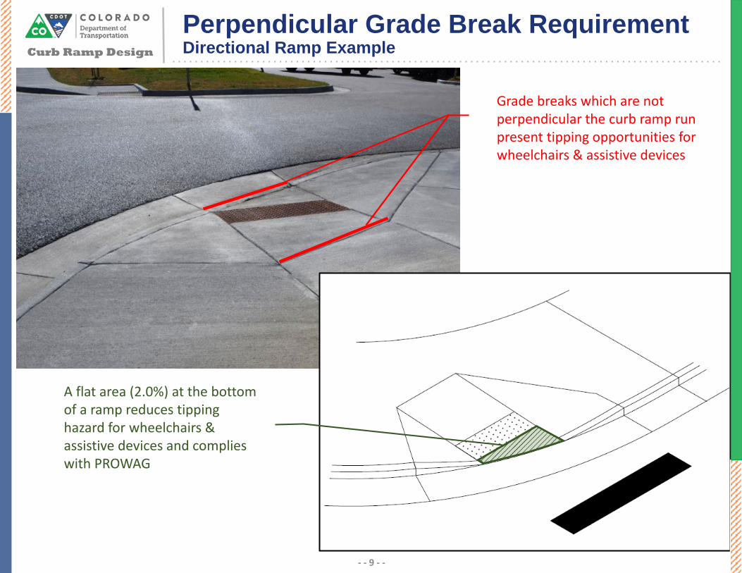
Aligning ramps with the crosswalk they serve provides good directionality, however, since ramps can’t always be located on a tangent section the “grade break” concept applies. PROWAG (R304.5.2) requires that grade breaks at the top and bottom of curb ramps be perpendicular to the direction of the ramp run. Directional ramps on large corners are often left with a triangular area at the bottom of the ramp which should slope towards the flowline at 2%. Creating perpendicular grade breaks at the bottom of directional ramps can be difficult and is often overlooked. The difficulty in achieving a level area at the bottom of a directional ramp is one reason directional ramps do not work well in many cases. It may be better to place a curb ramp perpendicular to the back of curb/flowline to avoid this issue. Designers should consider this carefully when constructing “directional” ramps.
Skewed grade breaks are unstable when they cause one wheel strike before the others.
Curb Ramp Design
Perpendicular Grade Break RequirementDirectional Ramp Example
- - 9 - -
A flat area (2.0%) at the bottom of a ramp reduces tipping hazard for wheelchairs & assistive devices and complies with PROWAG
Grade breaks which are not perpendicular the curb ramp run present tipping opportunities for wheelchairs & assistive devices

Source: FHWA - Designing Sidewalks and Trails for Access
Curb Ramp DesignCurb and Gutter
- - 10 - -
A rapid change in grade, such as between the base of a curb ramp and the street gutter, may be difficult to negotiate when in a wheelchair.
If the change is too severe wheelchair footrests or anti-tip wheels may not clear the transition. If footrests catch on the ground when coming down a curb ramp a user it at risk of falling forward, or causing the chair to tip forward. If a user moves quickly through an abrupt uphill change in grade the momentum of the wheelchair may cause it to rotate backwards as the user travels up a ramp. Any vertical discontinuities through the transition, such as lips, may compound this problem.
PROWAG allows a maximum change in grade of 13.3% between the bottom of a curb ramp and the gutter pan. This is determined by allowing a 8.33% ramp slope and a 5% gutter counter slope. If the standard CDOT curb and gutter template is used at curb ramps, the requirement for a 5% maximum counter slope at the bottom of the curb ramp will not be met. The slope of the gutter must be transitioned from the standard 1:12 slope to a 1:20 slope. There will be minimal grade adjustments necessary where the flatter gutter pan matches the existing street surface (approx. ¾” when adjusting from 1:12 to 1:20 gutter slope). This grade adjustment can beaccounted for in the patching that is required when replacing old curb and gutter sections. On concrete roadways where there will not be any bituminous pavement to patch into, adjusting the flowline is the only way to tie into the curb and gutter with a flatter pan. On alterations, this should be attempted to the maximum extent feasible within the scope of the project. Whenever gutter flowlines or pan slopes are adjusted it should be verified that positive drainage is maintained.

Curb Ramp DesignCurb and Gutter
- - 11 - -
Flush Surfaces – Transitions from curb ramps to the gutter, street, or landing areas must be flush and free of vertical discontinuities. Historically a small lip has often been constructed at the bottom of many curb ramps to assist with maintaining drainage. This lip cannot be provided, even a small vertical discontinuity can create difficulties for pedestrians using assistive mobility devices such as wheelchairs. When overlays are performed the transition from the street edge to the gutter pan must also be flush.
Vertical discontinuities which may seem insignificant to able body pedestrians may pose challenges to those using assistive mobility devices and should not be present at the transition from the curb ramp to the street crossing.
PROWAG R304.5.2 – “Grade breaks shall not be permitted on the surface of ramp runs and turning spaces. Surface slopes that meet at grade breaks shall be flush”

Curb Ramp DesignCurb and Gutter
- - 12 - -
Maximum allowable by PROWAG
Best Practice
1 IN. / 20 IN.
NOTES:1. THE CURB SLOPE SHOULD MATCH THE SLOPE OF THE CURB
RAMP BEHIND THE CURB (2% - 8.3%).
2. THERE SHALL BE NO VERTICAL DISCONTINUITIES GRATER THAN ¼ INCH.
1 22
1 IN. / FT.
CDOT CURB AND GUTTER TYPE 2 (SECTION IIB)
CURB AND GUTTER REQUIREMENTS AT CURB RAMP BASE

Curb Ramp DesignDetectable Warning Surfaces
- - 13 - -
Background Information
To accommodate pedestrians of all abilities, it is important to communicate information that can be understood using more than one sense. Placing detectable warning surfaces at the bottom of curb ramps helps pedestrians with vision impairments identify the transition between the sidewalk and the street.
Detectable Warning Surfaces (DWS) are a requirement in PROWAG to aid in detecting the boundary between the street and sidewalk. DWS are required when constructing or altering curb ramps. Truncated domes are the only detectable warning surface allowed by the U.S. Access Board. Information on the technical requirements of the truncated dome surface can be found in the PROWAG, section R305.
People obtain information about their surrounding environment in a variety of ways, and it is best practice to provide information in more than one format. For example, detectable warnings are generally perceived by texture, however, DWS can also be detected visuallythrough color contrast with the surrounding area. Accessibility Guidelines specify that DWS should contrast visually with adjoining surfaces; either dark on light, or light on dark.
Truncated domes should be aligned in square grid pattern in the predominate direction of travel. This is to allow pedestrians using wheeled devices to track between the domes. Detectable warning surfaces are not intended to provide wayfinding for pedestrians that have vision impairments. It is a common misperception that DWS must be aligned in the direction of travel to “guide” pedestrians in the correct alignment. “On pedestrian access routes, DWS indicate the boundary between a pedestrian route and a vehicular route where there is a flush rather than curbed connection for pedestrians who are blind or have low vision. Detectable warning surfaces are not intended to provide wayfinding for pedestrians who are blind or have low vision” – PROWAG Preamble regarding section R208
Care should be taken when choosing what type of DWS to install. Truncated domes that are uneven or too high may cause some pedestrians or people using wheeled devices to become unstable. Some models of truncated domes cannot withstand snow plowing equipment and the effects of snow and ice. The durability of DWS should be a consideration when selecting a model of truncated domes to install. Consideration should be given before installing truncated dome pavers as they often become uneven over time and require additional maintenance.
Grooves cannot be reliably detected by people with vision impairments and should not be used as a substitute for DWS. Additionally, grooves are more likely to fill with debris which reduces their effectiveness. Grooves can also cause discomfort for pedestrians with spinal cord injuries who must travel over them. Grooves along any portion of the curb ramp or throughout the PAR should be avoided.

Curb Ramp DesignDetectable Warning Surfaces
- - 14 - -
Recommended DWS Locations
• Around the edge of depressed corners;
• At the border of raised crosswalks and raised intersections to denote the transition from the sidewalk to the traveled way;
• At the base of curb ramps;
• At the border of median refuges (>6ft. in width) and islands; and
• At the edge of transit platforms
• Where sidewalks or shared use paths cross railroad tracks
DWS Placement
Perpendicular Ramps – Where both ends of the grade break at the bottom of a ramp are 5 ft. or less from the back of the curb, the DWS shall be located at the bottom of the ramp behind the grade break. If the space between the grade break at the bottom of the ramp and the back of curb is greater than 5 ft., on either side of the ramp, the DWS shall be placed at the back of curb.
The DWS should span the width of the curb ramp. The edge of the DWS should not be more than 2 in. from the edge of the flare or return curb. When no flare or curb face is present the DWS should not be more than 2 in. from the edge of concrete. These dimensions require careful planning on the part of the contractor to ensure the DWS can be placed while forms are present, or after they are removed while the concrete is still plastic.
Parallel Ramps – The DWS shall be located on the landing at the bottom of the ramp, parallel to the back of the curb. The DWS should be within 2” of the back of curb.
Blended Transitions/Depressed Corners – The DWS shall be located around the radius at the back of curb.
Special Considerations
Preference should be given to DWS surfaces which are durable, such as cast iron. Cutting pre-fabricated DWS to achieve a proper fit is discouraged, and should have approval of the construction engineer. Cutting cast iron DWS can remove the ribs/frame under the DWS which may cause the panel to warp and create long term maintenance issues. Radial detectable warnings can be procured in most 5 ft. radius increments, however, additional lead time is likely needed. If an irregular corner radius is needed, manufacturers can typically “mix and match” various sizes in a “best fit” shop drawing type process.

Curb Ramp DesignDetectable Warning Surfaces - Placement
- - 15 - -

Curb Ramp DesignDetectable Warning Surfaces - Placement
- - 16 - -

Curb Ramp DesignPerpendicular Curb Ramps
- - 17 - -
Flush Transition
5% Max Counter Slope

Curb Ramp DesignPerpendicular Curb Ramps
- - 18 - -
All perpendicular curb ramps must be installed with level landings/turning spaces at the top of the ramp. Landings allow pedestrians to move off the ramp surface before turning to proceed along the sidewalk. Perpendicular ramps without landings can create barriersbecause they may force pedestrians to travel over ramp flares. The path across the flares is not accessible due to excessive slope and skewed grade breaks.
If it is not possible to provide a level landing/turning space at the top of the ramp then perpendicular ramps should not be used.
A level landing/turning space at the bottom of a directional ramp is not required because the user is already oriented in the direction of travel. When a perpendicular curb ramp is on a corner radius and not directional, then a clear space must be provided at the bottom of the ramp. That clear space must be located outside of the parallel vehicle travel lane. If this cannot be accomplished then a different ramp type should be used.
Advantages of perpendicular ramps
• Pedestrians are aligned perpendicular to traffic and oriented in the direction of the crossing
• Can provide a straight path of travel for pedestrians when directional ramps are used on corners with small radii
• Make it easier for motorists to determine if, and in what direction, a pedestrian intends to cross the street
Disadvantages of perpendicular ramps
• Ramps and landings require more space than parallel ramp types. This can be an issue when R.O.W. is limited or there are physical constraints behind the sidewalk.
• Ramps located perpendicular to the curb line do not provide a straight path of travel on large radius corners.
• Directional ramps can be difficult to construct properly due to the requirement to make grade breaks perpendicular to the ramp run at the bottom of the ramp.

Curb Ramp DesignPerpendicular Ramp Length
- - 19 - -
Perpendicular Ramp Length
Ramp length for perpendicular curb ramps is dependent on the ramps slope, height of the curb, and adjacent sidewalk cross-slope. The following formula can be used to calculate the ramp length needed for a perpendicular ramp.
L= 𝐶𝐶𝐶𝐶(𝑅𝑅𝑅𝑅−𝐴𝐴𝐶𝐶𝑅𝑅)
Where: CH = Curb HeightRS = Ramp SlopeACS = Adjacent Sidewalk Cross Slope
Example: CH = 6 in., RS = 7.5%, ACS = 1.5%
𝐿𝐿 = 0.5 𝑓𝑓𝑓𝑓.(0.075−0.015)
= 8.3 𝑓𝑓𝑓𝑓.Change in Elevation (in.)
Length @ 7.5% Ramp Slope (ft.)
Length @ 8.3% Ramp Slope (ft.)
8 11.1 9.87 9.7 8.66 8.3 7.45 6.9 6.14 5.6 4.93 4.2 3.7
* This table assumes the adjacent sidewalk has a 1.5% cross-slope
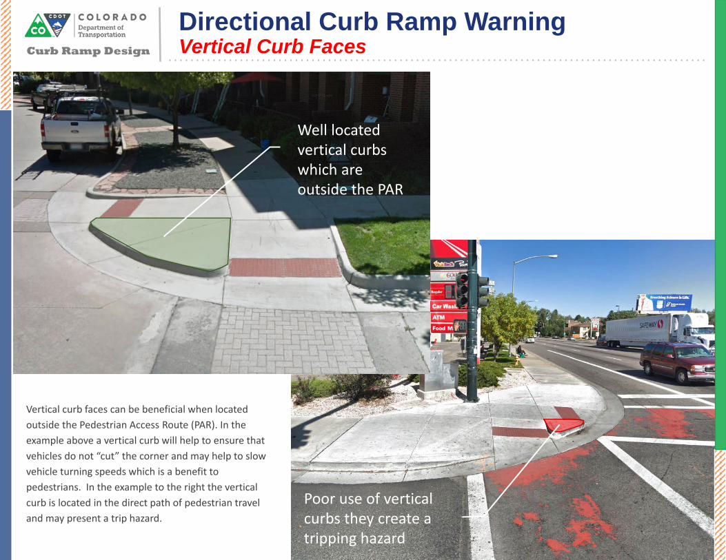
Poor use of vertical curbs they create a tripping hazard
Well located vertical curbs which are outside the PAR
Vertical curb faces can be beneficial when located outside the Pedestrian Access Route (PAR). In the example above a vertical curb will help to ensure that vehicles do not “cut” the corner and may help to slow vehicle turning speeds which is a benefit to pedestrians. In the example to the right the vertical curb is located in the direct path of pedestrian travel and may present a trip hazard.
Curb Ramp Design
Directional Curb Ramp WarningVertical Curb Faces
- - 20 - -

Curb Ramp Design
Directional Curb Ramp WarningDWS Gaps
- - 21 - -
On large radius corners where narrow directional curb ramps are use a gap can form between the DWS and the back of curb. These ramps as configured may be challenging for persons with visual impairments to navigate because they can enter into the street without passing over or detecting the truncated domes.
This situation, in addition to the challenges associates with placing a perpendicular grade break at the bottom of the ramp run, should be considered when selecting directional curb ramps. In situations as the one shown on the left a different ramp configuration should be used.

Curb Ramp Design
Perpendicular Curb Ramp Example 1:Paired Ramps on Tangent
- - 22 - -
Applications include intersections with small radii and wide sidewalks, commonly found in urban areas. This configuration directs pedestrians into the crossing which is beneficial. Flared sides must be provided when pedestrian can travel across the side of a ramp. A level landing/turning space must be provided at the top of each ramp.
Use standard plan M-608-1, Type 1B

Curb Ramp Design
Perpendicular Curb Ramp Example 2:Paired Ramps on Tangent – 3” Curb
- - 23 - -
Applications include intersections with small corner radii and wide sidewalks, commonly found in urban areas. Ramps are located close together where it would be beneficial to keep the crossing close to the intersection. This configuration directs pedestrians into the crossing which is beneficial. Flared sides must be provided when pedestrian can travel across the side of a ramp. A level landing/turning space must be provided at the top of each ramp. Where a full curb height cannot be obtained around the radius, the curb may be reduced to a minimum of 3”. Two ramps may share one landing area.
Use standard plan M-608-1, Type 1B
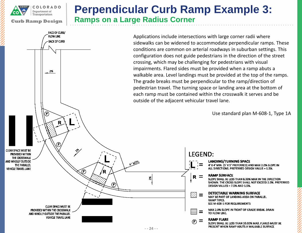
Applications include intersections with large corner radii where sidewalks can be widened to accommodate perpendicular ramps. These conditions are common on arterial roadways in suburban settings. This configuration does not guide pedestrians in the direction of the street crossing, which may be challenging for pedestrians with visual impairments. Flared sides must be provided when a ramp abuts a walkable area. Level landings must be provided at the top of the ramps. The grade breaks must be perpendicular to the ramp/direction of pedestrian travel. The turning space or landing area at the bottom of each ramp must be contained within the crosswalk it serves and be outside of the adjacent vehicular travel lane.
Use standard plan M-608-1, Type 1A
Curb Ramp Design
Perpendicular Curb Ramp Example 3:Ramps on a Large Radius Corner
- - 24 - -

Applications include intersections with large corner radii and wide sidewalks. These conditions are common on arterial roadways in suburban settings. This configuration guides pedestrians in the direction of the street crossing, which is beneficial when it can be constructed properly. Flared sides must be provided when a ramp abuts a walkable area. Level landings must be provided at the top of the ramps. The area below the bottom of the ramps should be sloped at no more than 2% towards the flowline, which is often a challenge. The grade breaks must be perpendicular to the ramp/direction of pedestrian travel. See page 8,9,20,21 for concerns regarding directional ramps.
Use standard plan M-608-1, Type 1B Modified
Curb Ramp Design
Perpendicular Curb Ramp Example 4:Directional Ramps on a Large Radius Corner
- - 25 - -

Applications include intersections with large corner radii and wide sidewalks where it is beneficial to keep the ramps close to the intersection. These conditions are common on arterial roadways in suburban settings. This configuration guides pedestrians in the direction of the street crossing, which is beneficial. Flared sides must be provided when a ramp abuts a walkable area. Level landings must be provided at the top of the ramps. Two ramps may share one landing area. The area below the bottom of the ramps should be sloped at no more than 2% towards the flowline, which is often a challenge with this ramp type. The grade breaks must be perpendicular to the ramp/direction of pedestrian travel. If the ramps are too close together to allow a full curb, then the curb height of the flares may be reduced to 3”. For concerns regarding directional ramps see pages 8,9,20,21.
Use standard plan M-608-1, Type 1B Modified
Curb Ramp Design
Perpendicular Curb Ramp Example 5:Directional Ramps With 3” Curb
- - 26 - -

Curb Ramp Design
Perpendicular Curb Ramp Example 6:Combination Ramps
- - 27 - -
Applications include intersections where a constraint exists behind the sidewalk, or where vertical changes in grade make it difficult to tie into the sidewalk with one ramp run. In this application two ramps are provided in each direction, these ramps may share a common level landing area. When needed, a curb or small retaining wall can be used to contain material behind the sidewalk. This orientation directs pedestrians into the street crossing which is beneficial. If the upper ramps are sloped at less than 5% they do not require a landing space at the top.
Use standard plan M-608-1, Types 3B or 3B Modified

Curb Ramp Design
Perpendicular Curb Ramp Example 7:Combination Ramps – Alternate Configuration
- - 28 - -
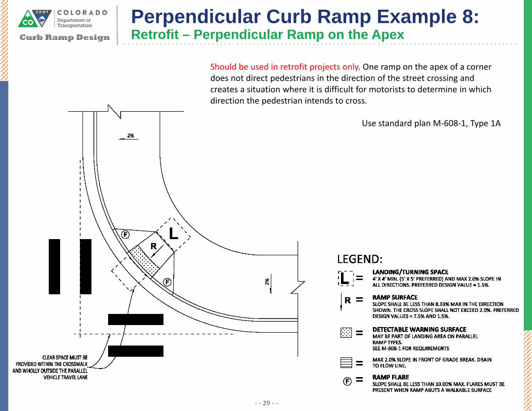
Should be used in retrofit projects only. One ramp on the apex of a corner does not direct pedestrians in the direction of the street crossing and creates a situation where it is difficult for motorists to determine in which direction the pedestrian intends to cross.
Use standard plan M-608-1, Type 1A
Curb Ramp Design
Perpendicular Curb Ramp Example 8:Retrofit – Perpendicular Ramp on the Apex
- - 29 - -

Curb Ramp DesignParallel Curb Ramps
- - 30 - -
5% Max Counter Slope
Flush Transition

Curb Ramp DesignParallel Curb Ramps
- - 31 - -
Parallel ramps consist of two ramp surfaces which lead down to a turning space/landing. A parallel ramp is one in which the path of travel of the pedestrian is located parallel to the vehicular path of travel on the parallel street. Parallel ramps can more easily be installed on narrow sidewalks. Parallel curb ramps can also be effective in steep terrain because ramps can be more easily lengthened to “chase grade”. Detectable warning surfaces on parallel curb ramps are located in the landing/turning space and should be placed at the back of curb. Detectable warnings are not placed at the bottom of each ramp.
Parallel curb ramps require pedestrians to traverse multiple ramp runs to remain on the sidewalk, for this reason parallel ramps should not be used in locations where it is possible to construct two well designed perpendicular curb ramps.
Advantages of perpendicular ramps
• Require minimal R.O.W, and can be more easily placed in constrained conditions.
• The boundary between the street and the sidewalk can be more easily detected than some perpendicular ramps.
• Can be easier to extend the ramp when needed to “chase grade”.
Disadvantages of perpendicular ramps
• Requires pedestrians to traverse multiple ramp runs when using the sidewalk.
• Can more easily accumulate debris and/or water if careful attention is not given drainage during design and construction.
• Requires attention when designing the curb flowline profile. The landing/turning space slope will equal the flowline grade.

Curb Ramp Design
Parallel Curb Ramp Example 1:Paired Parallel Ramps on a Small Radius Corner
- - 32 - -
Applications include intersections with small radii and narrow sidewalks, or where there may be a constraint behind the back of sidewalk which does not allow for perpendicular ramps (ex R.O.W.). Detectable warning surfaces may be included as part of the landing/turning space. Care should be taken to ensure sedimentation does not occur in front of landing if this configuration is used. Pedestrians must turn to orient themselves at the bottom of the ramp if they intend to cross the street. Additionally, pedestrians must cross multiple ramp runs in this configuration, for these reasons this configuration is less preferred than perpendicular ramps.
Use standard plan M-608-1, Type 2B

Applications include intersections with large corner radii and narrow sidewalks, or where there may be constraints behind the sidewalk and perpendicular ramps cannot be provided. Grade breaks for ramps should be perpendicular to pedestrian travel/back of curb. The detectable warning surface may be included in the turning space/landing. Care should be taken to ensure sedimentation/ponding does not occur in front of the landing area. Pedestrians must turn to orient themselves in the direction of the crossing. Pedestrians must traverse multiple ramp runs. For these reasons, this configuration is less preferred than perpendicular/directional ramps.
Use standard plan M-608-1, Type 2B
Curb Ramp Design
Parallel Curb Ramp Example 2:Parallel Ramps on a Large Radius Corner
- - 33 - -

Applications include intersections with large corner radii and narrow sidewalks, or locations where there may be constraints behind the sidewalk and perpendicular ramps cannot be provided. Grade breaks for ramps should be perpendicular to pedestrian travel/back of curb. The detectable warning surface may be included in the turning space/landing. Care should be taken to ensure sedimentation/ponding does not occur in front of the landing area. Pedestrians must turn to orient themselves in the direction of the crossing. Pedestrians must traverse multiple ramp runs. For these reasons, this configuration is less preferred than perpendicular/directional ramps.
Use standard plan M-608-1, Type 2B
Curb Ramp Design
Parallel Curb Ramp Example 3:Parallel Ramps on a Large Radius Corner – Minimal Separation
- - 34 - -

Curb Ramp Design
Parallel Curb Ramp Example 4:Directional Ramp along Arterial Roadway
- - 35 - -
Common applications include arterial roadways where there is a pedestrian crossing of an intersecting minor street but not the major street. All grade breaks must be perpendicular to the path of pedestrian travel. Sidewalk should naturally transition from wide to narrow as it travels around the corner radius. When the grade break for the ramp along the major street is greater than 5’ from the back of curb then the detectable warning surface is placed at the back of curb instead of at the bottom of the ramp.
Use standard plan M-608-1, Type 4B
Curb Ramp Design
Parallel Curb Ramp Example 5:Directional Ramp on a Small Radius Corner
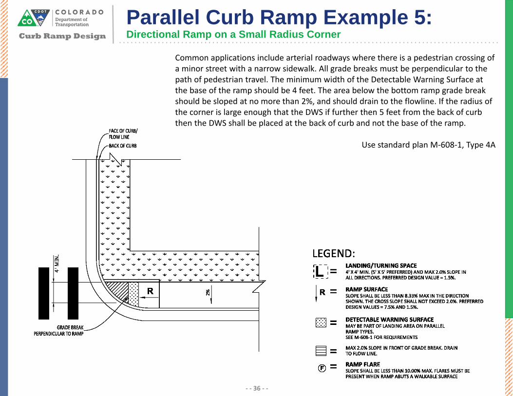
Common applications include arterial roadways where there is a pedestrian crossing of a minor street with a narrow sidewalk. All grade breaks must be perpendicular to the path of pedestrian travel. The minimum width of the Detectable Warning Surface at the base of the ramp should be 4 feet. The area below the bottom ramp grade break should be sloped at no more than 2%, and should drain to the flowline. If the radius of the corner is large enough that the DWS if further then 5 feet from the back of curb then the DWS shall be placed at the back of curb and not the base of the ramp.
Use standard plan M-608-1, Type 4A
- - 36 - -
Curb Ramp Design
- - 37 - -
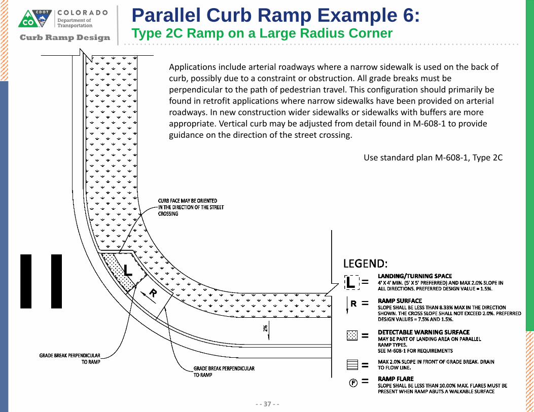
Applications include arterial roadways where a narrow sidewalk is used on the back of curb, possibly due to a constraint or obstruction. All grade breaks must be perpendicular to the path of pedestrian travel. This configuration should primarily be found in retrofit applications where narrow sidewalks have been provided on arterial roadways. In new construction wider sidewalks or sidewalks with buffers are more appropriate. Vertical curb may be adjusted from detail found in M-608-1 to provide guidance on the direction of the street crossing.
Use standard plan M-608-1, Type 2C
Parallel Curb Ramp Example 6:Type 2C Ramp on a Large Radius Corner

Curb Ramp Design
- - 38 - -
Common applications include arterial roadways with a wide sidewalk, or shared use path, where there is a pedestrian crossing of an intersecting minor. All grade breaks must be perpendicular to the path of pedestrian travel. When the grade break for the ramp along the major street is greater than 5’ from the back of curb then the detectable warning surface is placed at the back of curb instead of at the bottom of the ramp.
Use standard plan M-608-1, Type 4A
Parallel Curb Ramp Example 7:Directional Ramp for Shared Use Path

Common applications include arterial roadways where there is a pedestrian crossing of an intersecting minor. All grade breaks must be perpendicular to the path of pedestrian travel/back of curb. This orientation does not direct pedestrians in the direction of the street crossing and is less preferred. The sidewalk should naturally transition from wide to narrow as it travels around the corner.
Use standard plan M-608-1, Type 2A
Curb Ramp Design
Parallel Curb Ramp Example 8:Single Ramp on the Apex
- - 39 - -
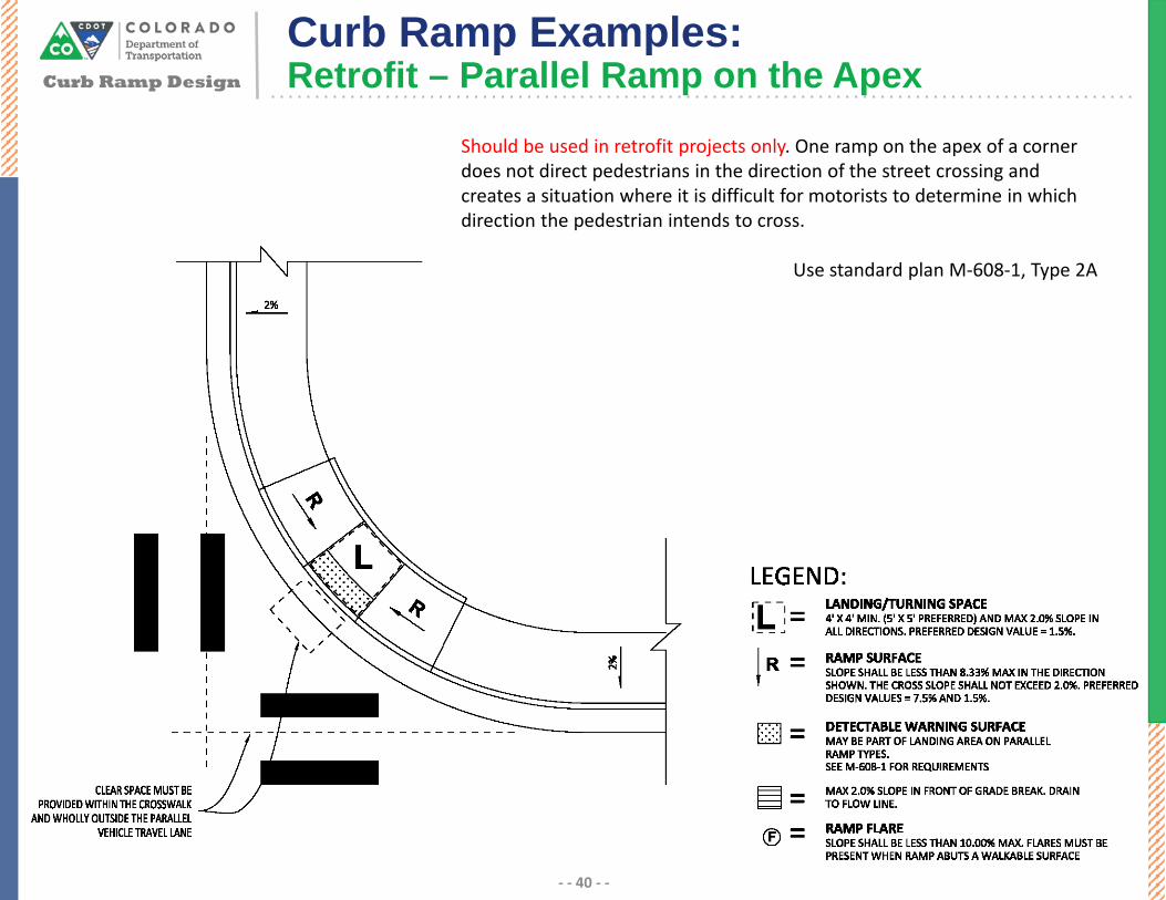
Should be used in retrofit projects only. One ramp on the apex of a corner does not direct pedestrians in the direction of the street crossing and creates a situation where it is difficult for motorists to determine in which direction the pedestrian intends to cross.
Use standard plan M-608-1, Type 2A
Curb Ramp Design
Curb Ramp Examples:Retrofit – Parallel Ramp on the Apex
- - 40 - -

Curb Ramp DesignBlended Transitions/Depressed Corners
- - 41 - -
1:10 Flare
5% Max Counter Slope
Flush Transition
Flush Transition
≤ 2.0%
Curb Ramp DesignBlended Transitions/Depressed Corners
- - 42 - -

Curb Ramp DesignBlended Transitions/Depressed Corners
- - 43 - -
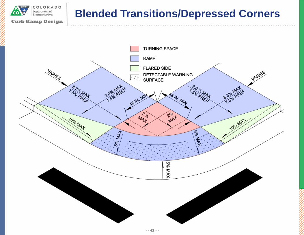
Depressed corners lower the level of the sidewalk to the grade of the street. Depressed corners could be considered an enhanced diagonal curb ramp that extends around the entire corner of an intersection. Blended transitions are a type of depressed corner in which there is a ramp with a slope of less than 5% which lowers the P.A.R to a landing, and then a second ramp which provides access to the street. Blended transitions can be better than depressed corners at alleviating drainage concerns because the whole corner is not depressed to street level.
Although depressed corners eliminate the need for ramps and landing spaces there are several drawbacks with this approach. Attempts to install actual curb ramps should be made before depressed corner options are examined. Depressed corners create difficulties for pedestrians by providing a large area where the corner and street are at the same elevation, this makes it much more difficult to detect the boundary between the sidewalk and the street for persons with vision impairments. Additionally, depressed corner may encourage motorists to encroach on the sidewalk, or turn at higher speeds, since there is no vertical separation between the sidewalk and street at the corner. Similar to diagonal curb ramps, depressed corners can make it more difficult for motorists to determine in which direction a pedestrian intends to cross the street.
Safety considerations need to be evaluated when considering depressed corners or blended transitions. Users should not be in danger of being struck by vehicle traffic when standing on a corner. As small an opening as possible should be used to discourage vehicles from tracking onto the sidewalk.
Source: FHWA - Designing Sidewalks and Trails for Access

Curb Ramp DesignBlended Transitions/Depressed Corners
- - 44 - -
Depressed corners may be used at locations where there is not enough space to construct two separate parallel or perpendicular curb ramps. Depressed corners may also be used at locations where there is a constraint behind the sidewalk such as a building.
Depressed corners should come off the gutter flowline at a grade between 1.5% and 2.0% to the interior corner of the landing. The depressed corner area should be kept to a minimum, a minimum slope of 1.5% throughout the landing is recommended to reduce ponding. If the flowline profile around the corner exceeds 2%, it should be flattened so the slope of the landing area does not exceed the 2% maximum allowable slope for a landing/turning space.
Radial detectable warning surfaces should be use with depressed corners.
Example before and after of a blended transition rampSource: MNDOT ADA Design Case Studies 2018

Curb Ramp DesignDepressed Corner Ramp Example:
- - 45 - -
Applications include intersections with small radii and narrow sidewalks, where there is a constraint behind the back of sidewalk, or where two parallel ramps cannot be provided, or are not appropriate. This configuration is often found in constrained urban conditions. This configuration is not ideal because it can be difficult for motorists to interpret which direction a pedestrian is trying to cross. This is due to the fact that both crossing directions use one shared landing space. Additionally, drainage can be an issue at the depressed corner. This configuration should only be used when parallel or perpendicular ramps are not an option. The Detectable Warning Surface may be included as part of the landing/turning space.
Use standard plan M-608-1, Type 5A

Curb Ramp DesignBlended Transition Ramp Example
- - 46 - -
Common applications include intersections in urban areas where two independent ramps cannot be constructed. Blended transitions are often found in urban cores. This configuration is not ideal because it can be difficult for motorists to interpret in which direction a pedestrian is trying to cross. This is due to the fact that both crossing directions use one shared landing space. Drainage issues can be lessened when this configuration is chosen over a depressed corner.
Use standard plan M-608-1, Type 5A