current hydro power plant projects of verbund in …current hydro power plant projects of verbund in...
TRANSCRIPT

Current Hydro Power Plant Projects of Verbund in Austria and the use of High Strength Steel – an Operators View
J. Mayrhuber and P. Stering VERBUND Austrian Hydro Power AG, Am Hof 6a, A-1010 Wien, Austria
Abstract
Steel lined pressure shafts made from high strength steels are key elements for high head storage and pumped storage power plants. High strength steels plates from thermomechanical rolling with yield strength up to 500 MPa and from quenching and tempering with yield strength up to 950 MPa are commercial available. Whereas several projects apply such steels and can benefit from the high yield and tensile strength, in other projects these steels are have not been applied so far. The paper gives an overview of penstock design and construction principles applied for projects in Austria, where other factors besides yield strength affect the design of penstocks and the selection of steel grades and limit the application of steel grades above 690 MPa. With current and future high head power plant projects it is necessary to evaluate the design principles in combination with high strength steel grades to reach an technical and economic optimum for new projects.
Introduction
In Europe there is an increasing need for hydro power plants due to several reasons. The European commission has issued an ambitious program for EU-27 for increasing the production and use of energy from renewable sources to 20% of the total primary energy use by 2020 and aims for a share of 21% of electricity by 2010. Besides other renewable sources, this will lead to an increase of wind energy for electricity production. The projected growth of wind power of EU-27 is from 50 GW in 2006 to about 180 GW until 2020. The additional capacity of hydro power was assumed with + 20 GW by 2020 reaching a capacity of 120 GW [1]. The increase in wind power in the European electricity market requires compensation by control power. The control power or secondary control (ore minute reserve power) can be provided by pumped storage hydro power plants, which are able to compensate fluctuation wind power production and provide stable grid frequency either by additional production (to increase the grid frequency) or by negative control power for pumping purpose to increase power consumption and lower the grid frequency. Secondary control or reserve power has become an
important topic for European power grid operators and has become a valuable product on the energy markets. One important source of control power can be pumped storage power plants (=psp), therefore most power plant operators are developing new projects. This paper focuses on projects for storage power plants and pumped storage power plants which use power conduits with steel lined pressure shafts, applying steel lining made from high strength steels fabricated by welding.
Content
Recent projects in Austria, especially for VERBUND, for steel lined pressure shafts use moderate design parameters, compared to recent international projects. This can be explained by several factors e.g. project specific topography, accepted design rules and acceptance by authorities, long term experience with approved construction technologies and long term operating performance and most important safety considerations. The aim of this paper is to outline the current situation for design and manufacturing of steel lined pressure shafts, the materials applied and the parameters, that affect the selection of the steel grades for pressure shaft linings. As an example a project under construction is presented and discussed. Potentials and limitations for application of higher strength steel grades are discussed and topics, that require more investigation for future projects are addressed.
Current projects
The country of Austria produces 2/3 of its electrical energy from hydro power with a peak capacity of 11,6 GW and an annual production of 66 TWh/year. Verbund owns and operates about 60% of this capacity. To increase the peak capacity and to provide the market with peak energy, potentials for high head power plants and for pumped storage power plants were investigated. The most economic projects use existing storage power plant reservoirs which can be connected with new power conduits to include new pumped storage capacity within the existing reservoir system. Two examples of this type are presented in Table 2 and 3 and Figures 1 and 2.
Conference on High Strength Steels for Hydropower Plants - Takasaki
4 - 1
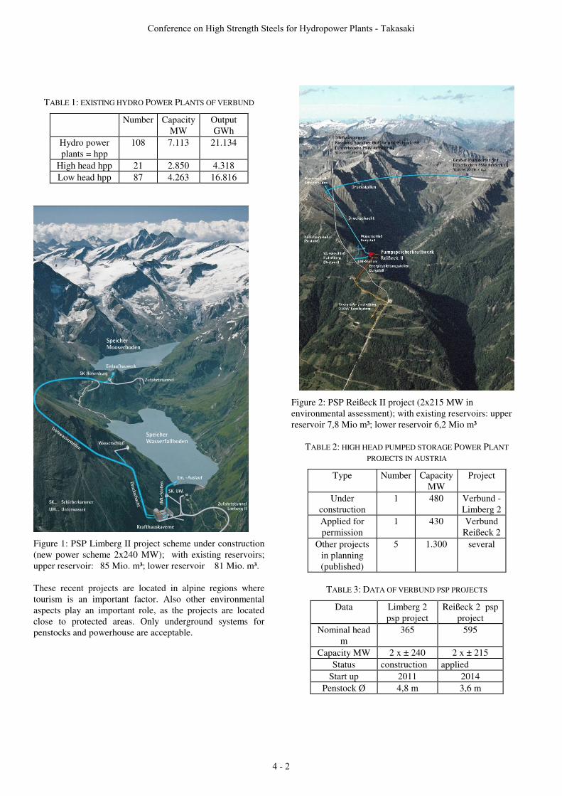
TABLE 1: EXISTING HYDRO POWER PLANTS OF VERBUND
Number Capacity MW
Output GWh
Hydro power plants = hpp
108 7.113 21.134
High head hpp 21 2.850 4.318 Low head hpp 87 4.263 16.816
Figure 1: PSP Limberg II project scheme under construction (new power scheme 2x240 MW); with existing reservoirs; upper reservoir: 85 Mio. m³; lower reservoir 81 Mio. m³. These recent projects are located in alpine regions where tourism is an important factor. Also other environmental aspects play an important role, as the projects are located close to protected areas. Only underground systems for penstocks and powerhouse are acceptable.
Figure 2: PSP Reißeck II project (2x215 MW in environmental assessment); with existing reservoirs: upper reservoir 7,8 Mio m³; lower reservoir 6,2 Mio m³
TABLE 2: HIGH HEAD PUMPED STORAGE POWER PLANT PROJECTS IN AUSTRIA
Type Number Capacity MW
Project
Under construction
1 480 Verbund -Limberg 2
Applied for permission
1 430 Verbund Reißeck 2
Other projects in planning (published)
5 1.300 several
TABLE 3: DATA OF VERBUND PSP PROJECTS
Data Limberg 2 psp project
Reißeck 2 psp project
Nominal head m
365 595
Capacity MW 2 x ± 240 2 x ± 215 Status construction applied
Start up 2011 2014 Penstock Ø 4,8 m 3,6 m
Conference on High Strength Steels for Hydropower Plants - Takasaki
4 - 2

Figure 3: Limberg II – schematic overview
Figure 4: Hydraulic scheme Limberg II
Steel lined pressure shaft design
The relevant parts of pressure shafts or penstocks can be the pressure tunnel with steel lining or open penstocks for high head power plants. For the current projects in mountainous regions it is preferred to build a pressure tunnel to avoid open penstocks, which can cause problems from an environmental point of view (public acceptance) and which have the risk of damage from external impacts. Underground evaluation by extensive drilling is done to gain information on geology and ground water to optimize the location of the power shaft. In addition the performance of tunnel boring machines (TBM) offer a high standard of construction progress, quality, accuracy and is an economic option for the time consuming tunnelling process. Open penstocks are used for bifurcations, manifolds and penstocks within power house and caverns. Design for internal pressure For steel lined pressure tunnels the experience of geotechnical engineering methods for rail or road tunnels is applied, which uses the surrounding rock for partial load
bearing, a method which is widely applied in tunnelling in Europe. This method proposed by Seeber [3] has become a standard in Austria for the design of steel lined pressure shafts. It includes several elements e.g. use of the surrounding rock mass as load bearing component, which has to be maintained with additional measures (pressure injection or local support elements) to achieve a bearing ring structure; measurements of mechanical properties of rock at different positions. This leads to a local design, where the load by internal penstock hydrostatic pressure is transferred via elastic deformation /(expansion) partially to the steel membrane expansion and partially to compression of the surrounding rock. Depending on the local parameters as rock working curve (pressure vs. deformation;) local gap between steel and rock and deformation of steel lining an equilibrium is reached between expansion due to internal hydrostatic pressure and membrane stress in the steel lining and compressive stress in the surrounding rock. By this method it is possible to transfer a significant part of the internal pressure load to the surrounding rock, which can bear up to 50% of the total load or even more at optimum conditions. Design even without steel lining is possible under certain conditions. Design for external pressure Two factors lead to external pressure load on the steel lining: The design method requires concrete injection to avoid gaps and to activate the rock load bearing, so the external injection pressure is relevant. Whereas during construction the tunnel is dewatered by a drainage pipe, this pipe is also injected with concrete after completion, so that an external ground water level and pressure builds up. This can lead to high external pressures as high as the rock and soil covering above the penstock. The design must consider stability against external pressure, which can lead to buckling problems of the lining. For stability like resistance against buckling the geometry (wall thickness of lining and roundness of the lining) and elasticity-modulus of the steel are essential, the higher yield strength has an minor effect with increasing values [4]. High strength steels lose some of their advantage under these conditions. For improvements of buckling resistance the wall thickness can be increased or external circular stiffener rings can be applied. Project planning for the location (depth, geological structure, ground water level) of the power shaft requires an optimization between high rock cover (allows high load transfer to the surrounding rock – reducing steel lining thickness) and ground water levels (resulting in external pressure – requiring increased steel lining or external stiffeners). For an optimum penstock location only the internal pressure should be design relevant. The design relevant situation for Limberg 2 project
Conference on High Strength Steels for Hydropower Plants - Takasaki
4 - 3

concerning the rock cover situation, the internal and external pressure is shown in Figure 5.
Figure 5: schematic load situation - pressure shaft Limberg II As mentioned above both loads – internal and external pressure - must be considered for design and depending on the relevant load case, the adequate material for the steel lining can be chosen. For the Limberg example the design regime switches: internal pressure in the upper penstock section – an intermediate section where external pressure by ground water and buckling stability is relevant - and the lower section, where again the internal pressure becomes dominant. Design for fatigue The main design load is the static load by internal hydrostatic pressure. During filling of the penstock and operation additional dynamic pressure fluctuations occur, which result from plant start and stop, from load changes or from reversing the flow from turbine to pumping mode. The hydrostatic pressure fluctuations can reach considerable levels compared to the nominal design stress (Figure 5). For the Limberg 2 project penstock the additional dynamic pressure fluctuations can reach 37% for the lining close to the surge chamber and 17 % for the manifold. For fatigue life calculation a lifetime of 75 years with expected operation profile is assumed. An examination for the steel lining – especially for the welds (longitudinal and circumferential welds) was done and gives sufficient fatigue life. For local construction elements (e.g. grouting sockets) the fatigue situation is more complex and the calculated fatigue life is determined by local design and weld details. Here the reserve in fatigue life is much lower and the situation is aggravated with higher design stress levels. For such elements the application of high strength steel loses some advantage. With the present design using materials up to S 690 the fatigue limitations became visible but could be solved.
Figure 6: Circumferential load situation and pressure fluctuations (fatigue load)
For higher yield strength steels using the present compound design the local fatigue situation at the grouting sockets should be investigated more closely and optimized for a high fatigue life of all welded details .
Figure 7: Penstock material for Limberg II: • S 460 ML (TM-steel) e.g. upper surge chamber • S 500 ML, S 550 ML (TM-steel) intermediate
pressure • S 690 QL for high pressure parts
Steel grades used for lining The steel grades applied for the Limberg 2 project are shown in Figure 7. The internal diameter of the penstock lining is 4,8 m. The shaft diameter produced by the TBM is about 5,8 m. The steel lining is designed for both internal and external pressure and depending on the local situation the steel grade is chosen. The actual situation is listed in Table 4. The amount of steel lining for the pressure shaft (length of about 585 m) is about 2.700 tons, the length of weldments (longitudinal and circumferential) was calculated with 4.600 m with a total weld deposit of about 8.000 kg. Also other parts of the pressure water conduit are steel lined with similar or even lower steel grades and an additional amount of 2.800 tons. So the total amount for steel lining for the project adds to about 5.500 tons of steel plates. The total amount of steel can serve as a basis for evaluation of the potential weight reduction by applying higher strength steel
Conference on High Strength Steels for Hydropower Plants - Takasaki
4 - 4
grades.
TABLE 4: STEEL GRADES FOR LIMBERG 2 PENSTOCK
Section Steel grade Plate thickness
Section 1 S 550 ML 30 mm Section 2 S 460 ML 32 – 34 mm Section 3 S 500 ML 34 mm Section 4 S 550 ML 34 mm Section 5 S 690 QL 33 - 34 mm
Higher strength steel linings, gives lower wall thickness, reduces welding volume and time and also reduce the necessity for post weld heat treatment (=pwht). A stress relief heat treatment is sometimes required for wall thickness > 30 mm or for applying ASME-Standards > 36 mm. So application of hss will reduce the necessity of pwht and gives an advantage for construction time and costs.
Penstock construction
Pipe fabrication For penstock construction the steel lining is prefabricated on the construction site in the upper valve chamber where pipes are rolled and welded submerged arc welding (=sma) from plates: two semishells are connected by longitudinal welds to 3 m pieces. Three pieces are then connected by circumferential welds to 9 m pipes which are then tested and inspected. After welding of the grouting holes and sockets the 9 m pipes are transferred to the tunnel. An extensive quality assurance program for materials and the welding process and non destructive testing (=ndt) program was developed with renowned experts and is applied to avoid any risk of welding defects.
Figure 8: Fabrication process of penstock steel lining Pipe welding For the circumferential welds in the tunnel a steel backing plate is used and the welding is done by automated tungsten hot wire method from the inside by simultaneous weldling
with 4 automated welding heads. One operator per head monitors and optimizes the welding conditions. The final ndt testing (manual) is carried out after 48 h to avoid undetected cold cracks. The method was successfully applied in earlier projects [5].
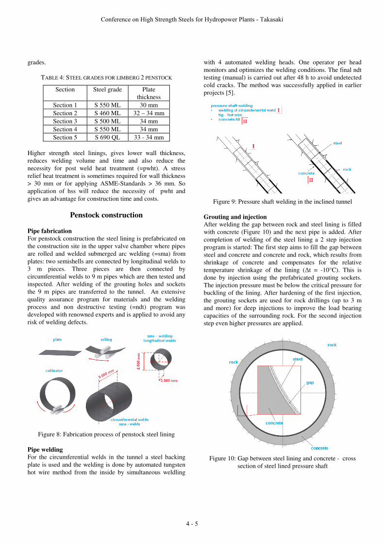
Figure 9: Pressure shaft welding in the inclined tunnel Grouting and injection After welding the gap between rock and steel lining is filled with concrete (Figure 10) and the next pipe is added. After completion of welding of the steel lining a 2 step injection program is started: The first step aims to fill the gap between steel and concrete and concrete and rock, which results from shrinkage of concrete and compensates for the relative temperature shrinkage of the lining (�t = -10°C). This is done by injection using the prefabricated grouting sockets. The injection pressure must be below the critical pressure for buckling of the lining. After hardening of the first injection, the grouting sockets are used for rock drillings (up to 3 m and more) for deep injections to improve the load bearing capacities of the surrounding rock. For the second injection step even higher pressures are applied.
Figure 10: Gap between steel lining and concrete - cross section of steel lined pressure shaft
Conference on High Strength Steels for Hydropower Plants - Takasaki
4 - 5

Both injection steps are carried out after completion of the welding process and require the use of drilling and injection equipment (Figure 11). Drainage systems which are used during first grouting are also filled and injected. These steps consume extra construction time but are essential to “activate” the load bearing of the surrounding rock and complete the compound system. The compound system has a long tradition in Austria and is described in detail [5].
Figure 11: Steel lined pressure shaft – grouting and injection system – with cross section of grouting socket
Penstock safety considerations The application of a compound-system steel lining / pre-stressed concrete gives an high inherent safety, resulting from safety factors from both components. For the steel lining usually 60% of yield strength is applied for design value for normal design load (and 90% of yield strength for extreme load) conditions. In addition the design stress for rock load is limited to proven (and tested) levels and the load bearing of rock is assured by the 2-step cement injection process. Even in case of failure of one of the two components, the load bearing capacity of the other should prevent a catastrophic failure of the penstock.
Conclusion
Steel lined pressure shafts are major elements of new storage and pumped storage power plants. More than 10 projects are under construction in Europe, which will use steel linings for pressure shaft. For the design of steel lined penstocks different design rules can be applied, depending on accepted rules by the local authorities and on planners and operators experience. For the projects of Verbund, steel lined penstocks are designed with partial load transfer to the surrounding rock and are constructed with injection to close the gap between
lining and rock under external pressure. This design leads to reduced membrane stress in the steel lining so that the required wall thickness or yield strength can be reduced. The design rules involving activated rock to reduce membrane stresses have their limits in cases where the penstock is exposed to stability problems by external pressure. As shown for the Limberg 2 project the dimensions of the steel lining can locally be determined by external pressure, leading to increase in plate thickness with reduced yield strength for stability reasons. Intermittent operation, frequent starts/stops and load changes lead to dynamic pressure fluctuation and oscillations in the penstocks resulting in pulsation load and fatigue stress in the steel lining. The level of pulsation can reach significant levels (locally up to % of static load) and if the plant lifetime is considered, the damage accumulation must be analyzed and considered for design. Here again the specific design, which requires injection flanges welded into the membrane, can lead to local notches, to residual stresses and peak stresses which can affect the fatigue life. The advantage of high strength steel grades is reduced by such structural imperfections thus again. High strength steels grades of yield strength 690 MPa and higher could be an economic alternative to the presently applied steel grades, however the accepted design rules for the projects described, present some limitations: The accepted design rules – compound concept - with its well proven inherent safety would have to be modified. In the specific construction process with potential stability load cases by external pressure, the high strength grades lose their advantage. Fatigue stresses at welded parts (e.g. grouting sockets) can also limit the advantage of hss grades. In addition the availability of hss materials and the quality assurance of the fabrication and welding process has to be proven. However there are several arguments for higher grades that include: Economic aspects: reduced material costs and welding time, less need for pwht, therefore reduced construction time and ecological benefits due to reduced materials and energy consumption and reduced transport and manipulation.
References
[1] The EREC Renewable Energy Technology Roadmap 20% by 2020; 14 November 2008: at: www.erec.org/
[2] M. J. Barnes: Hydropower in Europe: Current Status, Future Opportunities, HRW-Jurnal, July 2009 p. 24
[3] Seeber, G.: Neue Entwicklungen für Druckstollen und Druckschächte. In: Österreichische Ingenieur-Zeitschrift 18 (1975), Heft 5, S. 37-48
[4] Jacobsen, S., Buckling of circular rings and cylindrical tubes under external pressure, Water Power, December 1974
[5] P. Stering, E. Wagner, P. Widauer, "Reconstruction of the Power Conduit for Kaprun Main Scheme" Paper presented at the Conference “High Strength Steel for Hydropower Plants, Graz 07 2005
Conference on High Strength Steels for Hydropower Plants - Takasaki
4 - 6