current sensing in metering applications using a pulse ... · overview of the rogowski coil...
TRANSCRIPT

November 2010 Doc ID 18182 Rev 1 1/21
AN3306Application note
Current sensing in metering applications using aPulse current sensor and ST metering devices
IntroductionThis application note describes the benefits of a current sensing system for metering applications using STPMxx metering devices and a current sensor developed by Pulse Engineering Inc. (hereafter referred to as “Pulse current sensor”), based on the Rogowski coil principle. Following an overview of the Rogowski coil principle, the Pulse current sensor is introduced along with a comparison to other current measuring devices. This is followed by a presentation of the characteristics of the STPMxx family of metering devices, and the results of accuracy testing conducted using a demonstration board with the STPM01 and the Pulse current sensor.
The results obtained from the accuracy testing conducted with the STPM01 can be considered valid for all devices in the STPMxx family that share the same architecture(a).
In Figure 1 below the measuring system block diagram is provided.
Figure 1. Block diagram of a Rogowski coil-based application with the STPM01
a. Excludes only the STPM10
AM00178v1
www.st.com

Contents AN3306
2/21 Doc ID 18182 Rev 1
Contents
1 Overview of the Rogowski coil principle . . . . . . . . . . . . . . . . . . . . . . . . 4
2 The Pulse current sensor . . . . . . . . . . . . . . . . . . . . . . . . . . . . . . . . . . . . . 5
3 Comparison of current measuring devices . . . . . . . . . . . . . . . . . . . . . . 6
4 Overview of the STPMxx metering device family . . . . . . . . . . . . . . . . . . 8
5 Benefits of using STPMxx with Rogowski coil-based sensors . . . . . 10
5.1 Power calculation algorithm . . . . . . . . . . . . . . . . . . . . . . . . . . . . . . . . . . . 10
5.2 Mutual current compensation . . . . . . . . . . . . . . . . . . . . . . . . . . . . . . . . . . 12
6 Operation of the Pulse current sensor with the STPM01 . . . . . . . . . . 14
7 Accuracy results . . . . . . . . . . . . . . . . . . . . . . . . . . . . . . . . . . . . . . . . . . . 16
8 Recommendations . . . . . . . . . . . . . . . . . . . . . . . . . . . . . . . . . . . . . . . . . 18
9 Revision history . . . . . . . . . . . . . . . . . . . . . . . . . . . . . . . . . . . . . . . . . . . 20

AN3306 List of figures
Doc ID 18182 Rev 1 3/21
List of figures
Figure 1. Block diagram of a Rogowski coil-based application with the STPM01 . . . . . . . . . . . . . . . . 1Figure 2. Rogowski coil principle . . . . . . . . . . . . . . . . . . . . . . . . . . . . . . . . . . . . . . . . . . . . . . . . . . . . . 4Figure 3. The PA2999.006NL current sensor . . . . . . . . . . . . . . . . . . . . . . . . . . . . . . . . . . . . . . . . . . . 5Figure 4. Pulse current sensor adapted for a flat buss bar . . . . . . . . . . . . . . . . . . . . . . . . . . . . . . . . . 6Figure 5. Traditional power calculation approach . . . . . . . . . . . . . . . . . . . . . . . . . . . . . . . . . . . . . . . 10Figure 6. STPMxx power calculation approach . . . . . . . . . . . . . . . . . . . . . . . . . . . . . . . . . . . . . . . . . 11Figure 7. Test board schematic . . . . . . . . . . . . . . . . . . . . . . . . . . . . . . . . . . . . . . . . . . . . . . . . . . . . . 14Figure 8. Test configuration . . . . . . . . . . . . . . . . . . . . . . . . . . . . . . . . . . . . . . . . . . . . . . . . . . . . . . . . 16Figure 9. Accuracy results vs. current and accuracy limit standards . . . . . . . . . . . . . . . . . . . . . . . . . 17Figure 10. Cable in a diagonal position . . . . . . . . . . . . . . . . . . . . . . . . . . . . . . . . . . . . . . . . . . . . . . . . 18Figure 11. Accuracy results vs. current comparison between axial and diagonal position . . . . . . . . . 19

Overview of the Rogowski coil principle AN3306
4/21 Doc ID 18182 Rev 1
1 Overview of the Rogowski coil principle
As illustrated in Figure 2, the Rogowski coil principle states that a conductor carrying an AC current i(t) and passing through a helical coil, induces a voltage across the coil that is proportional to the rate of change of the current (di/dt) in the inductor.
Figure 2. Rogowski coil principle
The voltage v(t) is a function of winding factor (Kr) and the frequency (Fr) of the sinusoidal waveform i(t).
Equation 1
Kr is determined by the winding characteristics such as cross-sectional area (s), the number of turns per unit length (n) and the symmetry of the coil. An integration of v(t) gives a measure, proportional to Kr, of the instantaneous RMS current in the conductor.

AN3306 The Pulse current sensor
Doc ID 18182 Rev 1 5/21
2 The Pulse current sensor
While the Rogowski coil principle is well-known and has been widely implemented in various current sensing devices, the engineering challenge has been to control the winding characteristics to achieve the accurate current measurements required for metering applications. Pulse Engineering Inc. has developed a precision winding technique that controls the parameters which directly influence the output voltage. A patent-pending segmented winding approach allows for a high number of winding turns per unit length to provide a sufficiently large output voltage for detection and integration.
The Pulse current sensor is an air coil winding which has a highly linear output voltage over a very wide dynamic current range, meeting the Class 0.2 S accuracy limits defined by the IEC 62053-22 meter standard for currents from 0.1 A to 200 A. A specially designed winding configuration meets Class 1 requirements for immunity to external magnetic fields. An additional Faraday shield over the winding prevents electrostatic voltage coupling from the AC voltage of the conductor. This also acts as an effective barrier against external electrical fields associated with nearby current-carrying conductors and automatic meter-reading radio signals.
Pulse has implemented this winding technique in a highly automatable, low-cost standard product, the PA2999.006NL, shown in Figure 3. It is lightweight and, due to the Rogowski coil as a voltage source, is a zero power-consumption device with a stable voltage over a wide temperature range. Further information on this product is available at www.pulseeng.com
Figure 3. The PA2999.006NL current sensor

Comparison of current measuring devices AN3306
6/21 Doc ID 18182 Rev 1
3 Comparison of current measuring devices
The PA2999.006NL was developed as an alternative to the current transformer (CT) typically used in metering applications. The CT is wound on an amorphous metal core and therefore the operating principle is different. Here, the AC primary current passing through the center of the CT is closely coupled with the core and induces a current in the transformer winding. This current is used to drop a voltage across a terminating resistor which is a direct measure of the primary current. The PA2999.006NL can be used as an alternative to the CT when used with a metering IC which supports di/dt current sensors, such as a device from the STPMxx family.
The absence of an amorphous core in the Pulse current sensor offers several advantages. Lighter in weight and lower in cost, it has exceptional linearity over a wide current range. The upper current is limited only by the self-heating effects of the primary conductor. In comparison, the core of the CT needs to be sized to avoid saturation at the maximum current. For high current, this can be large and expensive. The amorphous material does not provide the same linearity (with current, frequency and temperature) and can have a remnant magnetic field that produces a DC offset. The core limits the frequency response of a CT to less than 8 harmonics, while the current sensor can accurately detect up to 100 harmonics for detailed load fingerprinting. Without all the limitations of a CT, a Pulse current sensor can simplify meter calibration.
In addition, the core determines the geometry of the CT. The Pulse current sensor presented here is toroidal only for the benefit of a fit, form and function comparison to the CT. The shape of the Pulse current sensor can be adapted to suit the typically flat conductor buss bar used in a meter, as illustrated in Figure 4. It is also possible to make it open-ended so it can be clamped directly to the buss bar rather than passing the buss bar through it.
Figure 4. Pulse current sensor adapted for a flat buss bar
Another current measurement device is the low resistance current shunt, typically the solution of choice for low current measurement. Its main advantage is cost. However, when isolation from the current-carrying conductor is required, it should be noted that the addition of an isolation transformer raises the cost of this solution to a level comparable to the Pulse current sensor option. Limitations of the shunt include its continual power consumption, temperature rise, and current limitation, as well as output variation over temperature.
Some metering applications favor the use of a Hall effect sensor as a low-cost integrated solution. However, the time and cost to develop this can be extensive. As a discrete solution, the Hall effect sensor is rather expensive.
AN3306 Comparison of current measuring devices
Doc ID 18182 Rev 1 7/21
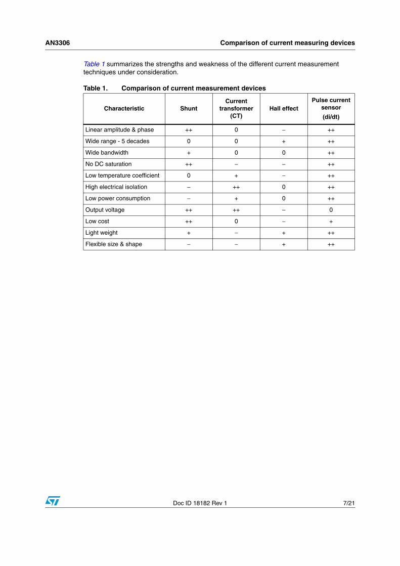
Table 1 summarizes the strengths and weakness of the different current measurement techniques under consideration.
Table 1. Comparison of current measurement devices
Characteristic ShuntCurrent
transformer (CT)
Hall effectPulse current
sensor
(di/dt)
Linear amplitude & phase ++ 0 − ++
Wide range - 5 decades 0 0 + ++
Wide bandwidth + 0 0 ++
No DC saturation ++ − − ++
Low temperature coefficient 0 + − ++
High electrical isolation − ++ 0 ++
Low power consumption − + 0 ++
Output voltage ++ ++ − 0
Low cost ++ 0 − +
Light weight + − + ++
Flexible size & shape − − + ++

Overview of the STPMxx metering device family AN3306
8/21 Doc ID 18182 Rev 1
4 Overview of the STPMxx metering device family
The STPMxx is a family of energy metering ASSPs (application specific standard products) designed to address a wide range of electricity metering requirements, thanks to built-in features including signal conditioning, signal processing, data conversion, input/output signals and voltage reference.
These devices are designed for effective measurement of active, reactive and apparent energy in a single- or poly-phase system using Rogowski coil-based sensors, current transformers or shunt sensors, and can be implemented as a single-chip energy meter or as a peripheral measurement system in a microcontroller-based energy meter.
The STPMxx devices consist, essentially, of an analog part and a digital part. The analog part is composed of preamplifier and 1st order Σ/Δ A/D converter blocks, band gap voltage reference, and low drop voltage regulator. The digital part is made up of system control, oscillator, hard-wired DSP and SPI interface.
A hard-wired DSP unit computes the amount of consummated active, reactive and apparent energy, RMS, and instantaneous values of voltage and current. The results of the computation are available as pulse frequency and states on the digital outputs of the device or as data bits in a data stream, which can be read by means of the SPI interface.
It is also possible to generate an output signal with pulse frequency proportional to energy, allowing for simpler calibration.
The STPMxx devices have been developed to address all the features and cost requirements of any metering application. Their features are summarized in Table 2 below.
Table 2. STPMxx device features
FeaturesDevice
STPMC1 STPM01 STPM11 STPM12 STPM13 STPM14
Current measuring devices
(C: current transformer, S: shunt, R: Rogowski coil-based)
C,S,R C,S,R C,S,R C,S,R C,S,R C,S,R
Pulsed output
SPI output X X X X
OTP memory
Current channel gain Set by
STPMSx modulators
8-16-24-32 8-16-24-32 8-16-24-32 8-16-24-32 8-16-24-32
Mutual current compensation N/A N/A N/A N/A N/A
Serial port Used only to program and calibrate the device
Active energyTotal and per-phase
Fundamental active energyTotal and per-phase
Reactive energyTotal and per-phase
X X X X

AN3306 Overview of the STPMxx metering device family
Doc ID 18182 Rev 1 9/21
Apparent energy X X X X X
VRMS, IRMS X X X X
Frequency pulse selection
Digital calibration
Pulses/kWh selection
RC oscillator X X X
Quartz oscillator X X
Tamper detection X X
Negative power, no load
Phase delay calculation N/A N/A N/A N/A N/A
Table 2. STPMxx device features (continued)
FeaturesDevice
STPMC1 STPM01 STPM11 STPM12 STPM13 STPM14
Benefits of using STPMxx with Rogowski coil-based sensors AN3306
10/21 Doc ID 18182 Rev 1
5 Benefits of using STPMxx with Rogowski coil-based sensors
Using a Rogowski coil-based sensor like the Pulse current sensor together with the STPMxx presents multiple benefits when compared to competitors’ approaches. These benefits are a result of:
● a proprietary power calculation and digital signal processing algorithm developed specifically for Rogowski coil-based sensors
● the capability of mutual current compensation when multiple sensors are used
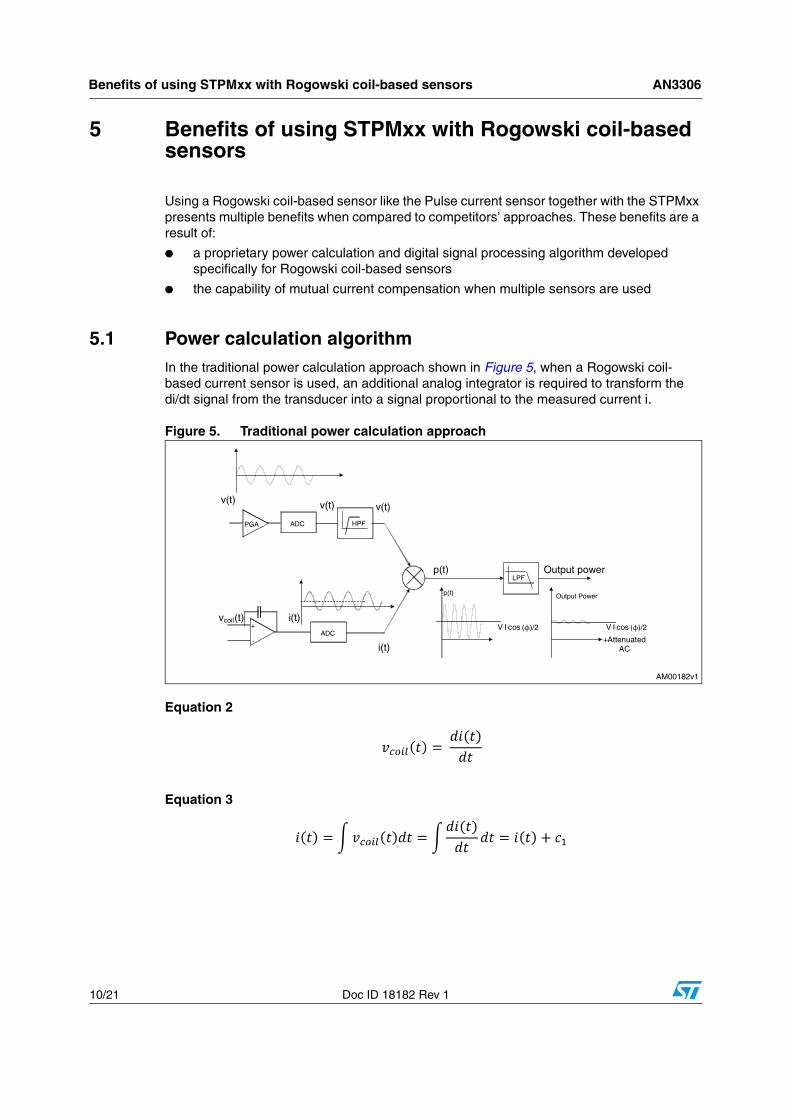
5.1 Power calculation algorithmIn the traditional power calculation approach shown in Figure 5, when a Rogowski coil-based current sensor is used, an additional analog integrator is required to transform the di/dt signal from the transducer into a signal proportional to the measured current i.
Figure 5. Traditional power calculation approach
Equation 2
Equation 3
ϕ ϕ

AN3306 Benefits of using STPMxx with Rogowski coil-based sensors
Doc ID 18182 Rev 1 11/21
Equation 4
This leads to an offset error in power measurement and to a residual sinusoidal ripple at twice the line frequency after the LP filtering. Real power should be averaged within a line period.
The STPMxx family implements a new proprietary algorithm for power calculation that removes this ripple and the offset by digital cancellation, providing an accurate and flat power calculation without the need for an additional integrator in the analog section.
Figure 6. STPMxx power calculation approach
Referring to Figure 6, the device calculates, then subtracts, and then divides by two the following powers:
Equation 5
PGA
Signal conditioning
ADC
v(t) v dt
p2(t)
p(t)
v(t)
di/dt
V.I.cos
ADC
Signal conditioning
i(t)di/dtSubtractor &:2 divider
p1(t)
v(t)
11-bit 16-bit
16-bit
Real power
AM00183v1
�
�
�ϕ�/�
�

Benefits of using STPMxx with Rogowski coil-based sensors AN3306
12/21 Doc ID 18182 Rev 1
Equation 6
The final result is:
Equation 7
This makes the use of STPMxx devices with Rogowski coil-based current sensors, such as the Pulse current sensor, advantageous. When a Rogowski coil-based sensor is used, a very high degree of accuracy is obtained by design due to the following:
● DC offset cancellation and the power calculation algorithm produces a DC component, proportional to the active power, without any offset or AC ripple.
● Ripple-free power calculation, so integration of power over the line period is avoided, and thus energy accumulation is not affected by fluctuation of the line frequency.
● The architecture makes the STPMxx devices ready for Rogowski coil-based sensors without the need for an additional integration block, which would increase system complexity and overall application cost.
5.2 Mutual current compensationFor poly-phase systems, where galvanic isolation between phases is a must, and immunity to DC magnetic fields is becoming a requirement in international standards, a Rogowski coil-based sensor offers an interesting and inexpensive solution.
The drawback of this approach is cross influence between current channels.
The STPMC1, a dedicated device for poly-phase measurement, features embedded functionality which allows error compensation from mutual currents.
For single-phase systems, two correction factors, α (alpha) and β (beta), produce a ±3.1% correction factor in 512 steps. Asymmetrical compensation is implemented by multiplying the phase current with α and neutral current with β, and these values are then subtracted from neutral and phase currents, respectively, as shown in Table 3 and Equation 8 and Equation 9.
Equation 8
Table 3. Mutual current compensation matrix for single-phase systems
Phase S T
S − β
T α −

AN3306 Benefits of using STPMxx with Rogowski coil-based sensors
Doc ID 18182 Rev 1 13/21
Equation 9
For poly-phase systems, three correction factors, a 7-bit •, 6-bit • and 4-bit • (gamma) respectively introduce a ±0.78%, ±0.39% and ±0.09% correction factor.
From these factors, a 4 x 4 matrix, shown in Table 4, implements symmetrical compensation multiplying each phase and neutral current with its row, adding the products together and subtracting them from the currents (Equation 10, Equation 11, Equation 12, and Equation 13).
Equation 10
Equation 11
Equation 12
Equation 13
Table 4. Mutual current compensation matrix for three-phase systems
Phase R S T N
R − α β γ
S α − α β
T β α − α
N γ β α −

Operation of the Pulse current sensor with the STPM01 AN3306
14/21 Doc ID 18182 Rev 1
6 Operation of the Pulse current sensor with the STPM01
Accuracy testing was conducted with the PA2999.006NL sensor using an STPM01 demonstration board. Its schematic diagram is shown in Figure 7 below.
Figure 7. Test board schematic

AN3306 Operation of the Pulse current sensor with the STPM01
Doc ID 18182 Rev 1 15/21
The sensor outputs are connected through a crosstalk network, which reduces the influence of the voltage channel on the current channel, to input pins IIP1 and IIN1.
In order to operate with a Rogowski coil sensor and obtain x32 amplification on the current channel, the following configuration bits in the STPM01 must be set:
– Bit 5 • PST = 1 (Rogowski coil sensor)
– Bit 52 • ADDG = 1 (additional gain)
The board was calibrated at IN = 5 A.

Accuracy results AN3306
16/21 Doc ID 18182 Rev 1
7 Accuracy results
Three different sensors were tested in the configuration shown in Figure 8. The nominal current IN is 10 A, and the accuracy was tested down to 1% IN at PF=1.
Figure 8. Test configuration
The results of the accuracy tests are shown in Table 5 below.
In Figure 9, the results of accuracy testing at the different currents are shown graphically for the three sensors, together with the accuracy limits for Class 1 and 0.5 meters (in accordance with international standards IEC 62053-21 and IEC 62053-22).
Table 5. Accuracy results vs. current
I [A] % IN S1 error % S2 error % S3 error %
10 100% 0.0000% 0.000% 0.0000%
1 10% -0.0640% 0.046% -0.0100%
0.5 5% -0.0040% -0.034% 0.1568%
0.1 1% -0.8436% -0.951% 0.2211%

AN3306 Accuracy results
Doc ID 18182 Rev 1 17/21
Figure 9. Accuracy results vs. current and accuracy limit standards
As can be noted from the results in the graph, there is a very high degree of accuracy for all sensors, fulfilling class 0.5 specifications even at very low currents.

Recommendations AN3306
18/21 Doc ID 18182 Rev 1
8 Recommendations
Because the current sensor is wound on a dielectric support, the positioning of the spires with respect to the cable has a relevant impact on performance in terms accuracy. Placing the spires of the sensor in an axial position with the cable in the middle, as shown in Figure 8, produces a higher sensitivity. Additional tests were conducted for current sensor 1, placing it in a diagonal position with respect to the current cable.
Figure 10. Cable in a diagonal position
The results are shown in column 4 of Table 6, and are compared to the accuracy error of the same sensor with the cable in an axial position (column 3).
Table 6. Accuracy results vs. current comparison between axial and diagonal position
I [A] % IN Error % - axial Error % - diagonal
10 100% 0.0000% 0.0000%
1 10% -0.0640% -0.0409%
0.5 5% -0.0040% -0.0214%
0.1 1% -0.8436% -1.0730%

AN3306 Recommendations
Doc ID 18182 Rev 1 19/21
Figure 11. Accuracy results vs. current comparison between axial and diagonal position
As illustrated in the graph above, changing the cable orientation from an axial to a non-axial position increases the transfer sensitivity, especially when the cable contacts the sensor body.
Moving the cable within the center-passing hole does not result in an appreciable lack of performance.
Attention should also be given to proper shielding, which can prevent errors on the measured current resulting from the high potential of the cable coupling with the sensor. It must be connected to ground.
Connecting the shield wire of the sensor (the white wire, if using the PA2999.006NL sensor) to the active signal input (hot), rather than a GND-referred input increases the error at low currents, and could cause external noise, further affecting accuracy.
The accuracy tests were also conducted with the shield connected to hot. However, even with this erroneous positioning, the lack of accuracy was very small and the error still far below Class 1 requirements.
-2,0%
-1,0%
0,0%
1,0%
2,0%
1% 10% 100%% of In
Axial position
Diagonal position
Class 1 limitsClass 0.5 limits

Revision history AN3306
20/21 Doc ID 18182 Rev 1
9 Revision history
Table 7. Document revision history
Date Revision Changes
05-Nov-2010 1 Initial release.

AN3306
Doc ID 18182 Rev 1 21/21
Please Read Carefully:
Information in this document is provided solely in connection with ST products. STMicroelectronics NV and its subsidiaries (“ST”) reserve theright to make changes, corrections, modifications or improvements, to this document, and the products and services described herein at anytime, without notice.
All ST products are sold pursuant to ST’s terms and conditions of sale.
Purchasers are solely responsible for the choice, selection and use of the ST products and services described herein, and ST assumes noliability whatsoever relating to the choice, selection or use of the ST products and services described herein.
No license, express or implied, by estoppel or otherwise, to any intellectual property rights is granted under this document. If any part of thisdocument refers to any third party products or services it shall not be deemed a license grant by ST for the use of such third party productsor services, or any intellectual property contained therein or considered as a warranty covering the use in any manner whatsoever of suchthird party products or services or any intellectual property contained therein.
UNLESS OTHERWISE SET FORTH IN ST’S TERMS AND CONDITIONS OF SALE ST DISCLAIMS ANY EXPRESS OR IMPLIEDWARRANTY WITH RESPECT TO THE USE AND/OR SALE OF ST PRODUCTS INCLUDING WITHOUT LIMITATION IMPLIEDWARRANTIES OF MERCHANTABILITY, FITNESS FOR A PARTICULAR PURPOSE (AND THEIR EQUIVALENTS UNDER THE LAWSOF ANY JURISDICTION), OR INFRINGEMENT OF ANY PATENT, COPYRIGHT OR OTHER INTELLECTUAL PROPERTY RIGHT.
UNLESS EXPRESSLY APPROVED IN WRITING BY AN AUTHORIZED ST REPRESENTATIVE, ST PRODUCTS ARE NOTRECOMMENDED, AUTHORIZED OR WARRANTED FOR USE IN MILITARY, AIR CRAFT, SPACE, LIFE SAVING, OR LIFE SUSTAININGAPPLICATIONS, NOR IN PRODUCTS OR SYSTEMS WHERE FAILURE OR MALFUNCTION MAY RESULT IN PERSONAL INJURY,DEATH, OR SEVERE PROPERTY OR ENVIRONMENTAL DAMAGE. ST PRODUCTS WHICH ARE NOT SPECIFIED AS "AUTOMOTIVEGRADE" MAY ONLY BE USED IN AUTOMOTIVE APPLICATIONS AT USER’S OWN RISK.
Resale of ST products with provisions different from the statements and/or technical features set forth in this document shall immediately voidany warranty granted by ST for the ST product or service described herein and shall not create or extend in any manner whatsoever, anyliability of ST.
ST and the ST logo are trademarks or registered trademarks of ST in various countries.
Information in this document supersedes and replaces all information previously supplied.
The ST logo is a registered trademark of STMicroelectronics. All other names are the property of their respective owners.
© 2010 STMicroelectronics - All rights reserved
STMicroelectronics group of companies
Australia - Belgium - Brazil - Canada - China - Czech Republic - Finland - France - Germany - Hong Kong - India - Israel - Italy - Japan - Malaysia - Malta - Morocco - Philippines - Singapore - Spain - Sweden - Switzerland - United Kingdom - United States of America
www.st.com