current status and future plan of htgr development · pdf filecurrent status and future plan...
TRANSCRIPT

Current Status and Future Plan of
HTGR Development
Japan Atomic Energy Agency
Training Course on
High Temperature Gas-cooled Reactor Technology
October 19-23, Serpong, Indonesia

p.2
Recent Topics in Japan (1/2)
Following VIPs visited the HTTR.
The Former Minister of the MEXT, Hakubun Shimomura, on July 4, 2014.
The Parliamentary Vice-Minister of the MEXT, Tsutomu Tomioka, on August 6, 2014.
The Former Minister Environment, Nobuteru Ishihara and five members of the House of Representatives, Takeshi Noda et.al., on April 7, 2014.
They are all supportive of deployment and development of HTGR.
Technical development of HTGR is stated in the following policies.
“Strategic Energy Plan” approved by the Cabinet on April 11, 2014.
“Basic Policies for the Economic and Fiscal Management and Reform 2014” and “Japan revitalization strategy, revised 2014” approved by the Cabinet on June 24, 2014.
“Strategic Roadmap of Hydrogen and Fuel Cells” issued by the committee in the METI on June 23, 2014.
HTGR development supporting group consisting of more than 40 LDP members was made on July 19, 2014. The second meeting was held on March 10, 2015, and the following resolution was adopted.
Early restart of HTTR and reinforcement of HTGR related research Reinforcement of system discussing basic policy for commercialization of HTGR Reinforcement of international collaboration and human education
p.3
Recent Topics in Japan (2/2)
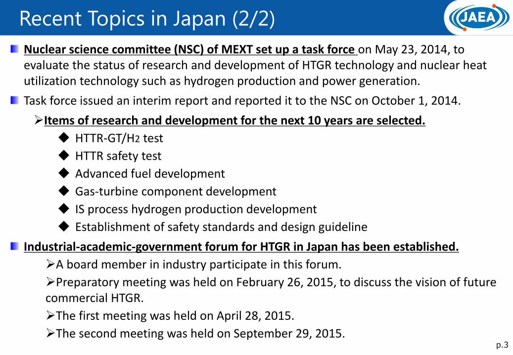
Nuclear science committee (NSC) of MEXT set up a task force on May 23, 2014, to evaluate the status of research and development of HTGR technology and nuclear heat utilization technology such as hydrogen production and power generation.
Task force issued an interim report and reported it to the NSC on October 1, 2014.
Items of research and development for the next 10 years are selected.
HTTR-GT/H2 test
HTTR safety test
Advanced fuel development
Gas-turbine component development
IS process hydrogen production development
Establishment of safety standards and design guideline
Industrial-academic-government forum for HTGR in Japan has been established.
A board member in industry participate in this forum.
Preparatory meeting was held on February 26, 2015, to discuss the vision of future commercial HTGR.
The first meeting was held on April 28, 2015.
The second meeting was held on September 29, 2015.

HTTR Project History
Reactor physics
Very High Temperature Reactor Critical Assembly (VHTRC)
Thermo-hydraulics Start Construction
Work
Installation of
Reactor Pressure
Vessel
Conceptual design
System integrity design
Basic design
Detail design
Application and
permission of construction
Construct ion
F i rs t cr i t i ca l i t y
Reactor thermal power(30MW)
Reactor outlet coolant
temperature 850℃
Reactor outlet coolant
temperature 950℃
850℃/30 days operation
950℃/50 days operation
Safety demonstration test
1973
1969 ~
1980
1974
~
1984
1981 ~
1985 ~
1988
1989
1990
1991 ~
1997
1998
2001
2002
2004
2007
2010
Research development and design
~
Construction of Reactor
Establishment of fundamental technology
Start of loss of forced
cooling test
Research and development
Fuel / material
In-pile Gas Loop(OGL-1)
Outside and inside of the HTTR
HTTR is the first HTGR in Japan. Reactor thermal power : 30MW Reactor inlet/outlet coolant temperature:
395/850,950C Primary coolant pressure: 4MPa Reactor core height/diameter: 2.9m/2.3m Average power density: 2.5W/cc Uranium enrichment: 3~10%(average6%)
H T T R
Long term high temperature operation
Construction
2013 New regulation standard issued
Confirmation of conformity of
the standard toward restart
p.4
Achievement in Fuel Technology Development
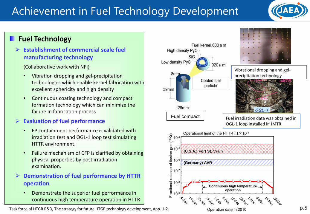
Fuel Technology
Establishment of commercial scale fuel manufacturing technology
(Collaborative work with NFI)
• Vibration dropping and gel-precipitation technologies which enable kernel fabrication with excellent sphericity and high density
• Continuous coating technology and compact formation technology which can minimize the failure in fabrication process
Evaluation of fuel performance
• FP containment performance is validated with irradiation test and OGL-1 loop test simulating HTTR environment.
• Failure mechanism of CFP is clarified by obtaining physical properties by post irradiation examination.
Demonstration of fuel performance by HTTR operation
• Demonstrate the superior fuel performance in continuous high temperature operation in HTTR
Vibrational dropping and gel-precipitation technology
Fuel irradiation data was obtained in OGL-1 loop installed in JMTR
p.5
Fuel compact
Fra
ctio
na
l re
lease
of
fissio
n g
as (
88K
r)
Operation date in 2010
10-9
10-8
10-7
10-6
10-5
10-4
(U.S.A.) Fort St. Vrain
(Germany) AVR
Continuous high temperature operation
Operational limit of the HTTR : 1×10⁻⁴
Task force of HTGR R&D, The strategy for future HTGR technology development, App. 1-2.
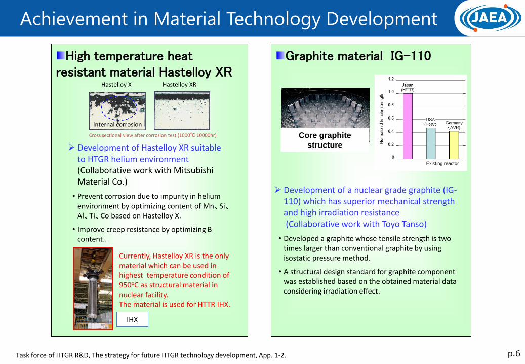
Graphite material IG-110
Achievement in Material Technology Development
p.6
Core graphite
structure
Development of a nuclear grade graphite (IG-110) which has superior mechanical strength and high irradiation resistance (Collaborative work with Toyo Tanso)
• Developed a graphite whose tensile strength is two times larger than conventional graphite by using isostatic pressure method.
• A structural design standard for graphite component was established based on the obtained material data considering irradiation effect.
High temperature heat resistant material Hastelloy XR
Currently, Hastelloy XR is the only material which can be used in highest temperature condition of 950oC as structural material in nuclear facility. The material is used for HTTR IHX.
IHX
Cross sectional view after corrosion test (1000℃ 10000hr)
Hastelloy X Hastelloy XR
Internal corrosion
Development of Hastelloy XR suitable to HTGR helium environment (Collaborative work with Mitsubishi Material Co.)
• Prevent corrosion due to impurity in helium environment by optimizing content of Mn、Si、Al、Ti、Co based on Hastelloy X.
• Improve creep resistance by optimizing B content..
Task force of HTGR R&D, The strategy for future HTGR technology development, App. 1-2.
Achievement in Core Physics Method Development
p.7 Task force of HTGR R&D, The strategy for future HTGR technology development, App. 1-2.
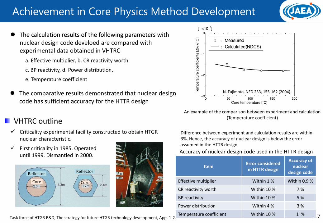
VHTRC outline Criticality experimental facility constructed to obtain HTGR
nuclear characteristic.
The calculation results of the following parameters with nuclear design code develoed are compared with experimental data obtained in VHTRC
a. Effective multiplier, b. CR reactivity worth
c. BP reactivity, d. Power distribution,
e. Temperature coefficient
Item Error considered in HTTR design
Accuracy of nuclear
design code
Effective multiplier Within 1 % Within 0.9 %
CR reactivity worth Within 10 % 7 %
BP reactivity Within 10 % 5 %
Power distribution Within 4 % 3 %
Temperature coefficient Within 10 % 1 %
Accuracy of nuclear design code used in the HTTR design
An example of the comparison between experiment and calculation (Temperature coefficient)
Difference between experiment and calculation results are within 3%. Hence, the accuracy of nuclear design is below the error assumed in the HTTR design.
First criticality in 1985. Operated until 1999. Dismantled in 2000.
Reflector Reflector
Core Core
The comparative results demonstrated that nuclear design code has sufficient accuracy for the HTTR design
N. Fujimoto, NED 233, 155-162 (2004).
Achievement in Thermal Fluids Method Development
p.8 Task force of HTGR R&D, The strategy for future HTGR technology development, App. 1-2.
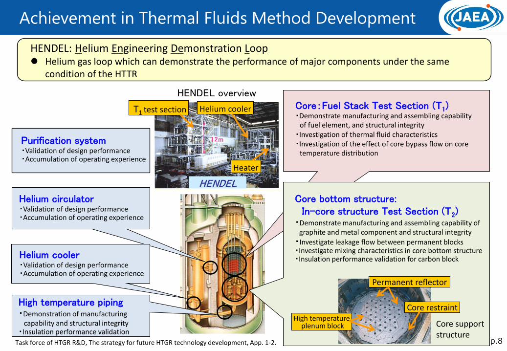
Core:Fuel Stack Test Section (T1) ・Demonstrate manufacturing and assembling capability
of fuel element, and structural integrity ・Investigation of thermal fluid characteristics ・Investigation of the effect of core bypass flow on core
temperature distribution
Core bottom structure: In-core structure Test Section (T2) ・Demonstrate manufacturing and assembling capability of
graphite and metal component and structural integrity
・Investigate leakage flow between permanent blocks ・Investigate mixing characteristics in core bottom structure ・Insulation performance validation for carbon block
High temperature piping ・Demonstration of manufacturing capability and structural integrity ・Insulation performance validation
Helium circulator ・Validation of design performance ・Accumulation of operating experience
HENDEL: Helium Engineering Demonstration Loop Helium gas loop which can demonstrate the performance of major components under the same
condition of the HTTR
Purification system ・Validation of design performance ・Accumulation of operating experience
T1 test section Helium cooler
Heater
Permanent reflector
Core restraint High temperature
plenum block
HENDEL overview
Core support structure
Helium cooler ・Validation of design performance ・Accumulation of operating experience
Achievement in HTTR Operation
p.9
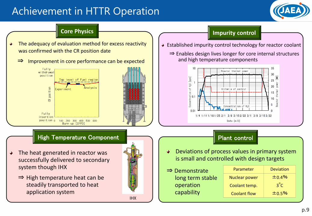
Core Physics
The adequacy of evaluation method for excess reactivity
was confirmed with the CR position date
⇒ Improvement in core performance can be expected
IHX
Impurity control
Established impurity control technology for reactor coolant
⇒ Enables design lives longer for core internal structures and high temperature components
Parameter Deviation
Nuclear power ±0.4%
Coolant temp. 3oC
Coolant flow ±0.5%
Plant control
Deviations of process values in primary system is small and controlled with design targets
⇒ Demonstrate long term stable operation capability
The heat generated in reactor was successfully delivered to secondary system though IHX
⇒ High temperature heat can be steadily transported to heat application system
High Temperature Component

HTGR R&D Items
p.10
HTGR technology Heat Application Technology
Commercial HTGR design
GTHTR300
Commercial HTGR design
Clean Burn HTGR for surplus plutonium burning
Establishment of safety standards and
international standardization
HTTR
Advanced Fuel Development
HTTR Safety Demonstration Test
He compressor
H2 facility
Basic technology development for H2 production and GT power generation are completed
Continuous H2 production test
Turbine blade alloy development
HTTR-GT/H2 test
Complete the system technology for construction of commercial lead plant
30 MWt and 950oC prismatic core
advanced test reactor (Operation start in 1998)
Advanced Fuel Development (1/2)
p.11
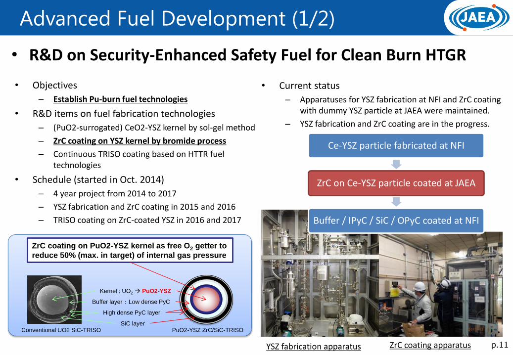
• R&D on Security-Enhanced Safety Fuel for Clean Burn HTGR
• Objectives
– Establish Pu-burn fuel technologies
• R&D items on fuel fabrication technologies
– (PuO2-surrogated) CeO2-YSZ kernel by sol-gel method
– ZrC coating on YSZ kernel by bromide process
– Continuous TRISO coating based on HTTR fuel technologies
• Schedule (started in Oct. 2014)
– 4 year project from 2014 to 2017
– YSZ fabrication and ZrC coating in 2015 and 2016
– TRISO coating on ZrC-coated YSZ in 2016 and 2017
PuO2-YSZ ZrC/SiC-TRISO
Kernel : UO2 PuO2-YSZ
ZrC coating on PuO2-YSZ kernel as free O2 getter to
reduce 50% (max. in target) of internal gas pressure
Buffer layer : Low dense PyC
High dense PyC layer
SiC layer Conventional UO2 SiC-TRISO
• Current status
– Apparatuses for YSZ fabrication at NFI and ZrC coating with dummy YSZ particle at JAEA were maintained.
– YSZ fabrication and ZrC coating are in the progress.
YSZ fabrication apparatus ZrC coating apparatus
Ce-YSZ particle fabricated at NFI
ZrC on Ce-YSZ particle coated at JAEA
Buffer / IPyC / SiC / OPyC coated at NFI

Advanced Fuel Development (2/2)
p.12
• R&D on Sleeveless Oxidation-Resistant Fuel • Objectives
– Develop the advanced HTGR fuel performing higher heat removal than that of the HTTR to decrease the maximum fuel temperature during the normal operation
• R&D items – Fabrication technologies by hot press with Si & C
powders
– New inspection methods based on HTTR fuel technologies
• Schedule( started in Sep. 2014) – 3 year project from 2014 to 2016
– Start fabrication of SiC-matrix dummy compact in 2015
– Optimize fabrication and inspection conditions in 2016
・・・・・
Higher heat removal Graphite sleeve → Sleeveless
Upgrading oxidation resistance
Graphite matrix → SiC
Sleeveless oxidation-resistant fuel element
Conventional HTTR fuel rod
Center rod
SiC-matrix fuel compact
• Current status
– Overcoating device was prepared.
– Fabrication conditions for SiC-matrix dummy compact (pressure, temperature, time, …) were analyzed by design of experiments, etc.
– Oxidation testing furnace (~ 1,600C in O2 atmosphere) was constructed.
– Fabrication and oxidation tests for SiC-matrix dummy compact is in the progress.
Oxidation testing furnace Overcoating device
Establishment of Safety Standards
p.13
Safe
ty s
tan
dar
ds
for
com
me
rcia
l HTG
Rs
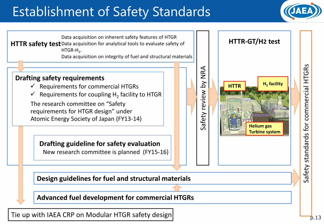
HTTR safety test HTTR-GT/H2 test
Safe
ty r
evie
w b
y N
RA
Drafting safety requirements Requirements for commercial HTGRs Requirements for coupling H2 facility to HTGR
Tie up with IAEA CRP on Modular HTGR safety design
The research committee on “Safety requirements for HTGR design” under Atomic Energy Society of Japan (FY13-14)
Drafting guideline for safety evaluation New research committee is planned (FY15-16)
HTTR H2 facility
Helium gas Turbine system
Design guidelines for fuel and structural materials
Advanced fuel development for commercial HTGRs
Data acquisition on inherent safety features of HTGR Data acquisition for analytical tools to evaluate safety of HTGR-H2. Data acquisition on integrity of fuel and structural materials

H2 Production Technology Development Strategy
p.14
2000
Lab-scale test
HTTR-GT/H2 test
Commercial use
Bench-scale test
Production of HI and H2SO4
H2SO4 decomp.
HI decomp.
Demonstration of one-week continuous
hydrogen production by glass apparatus
(0.03 m3/h-H2)
Elemental technologies
H2 production test facility
Integrity of key components in the IS
process environment (corrosion resistance , heat resistance)
Industrial material component test
HTTR
Helium gas turbine
H2 facility
Verification of integrity of total components and stability of hydrogen production
Development of strength evaluation methodology for ceramic components
Bunsen reactor
H2SO4 reactor
HI reactor Uncovering an closed-
cycle continuous
operation condition
(0.001 m3/h-H2)
Present
Technology transfer to private company

Continuous H2 Production Test
p.15
2013 FY2014 FY2015〜
Process ・H2 production: 100 L/h scale
・Electric heating
Component materials
Liquid phase
• Fluoroplastic lining
• Glass lining
• Silicon carbide (SiC)
ceramic
• Graphite (impervious)
Gaseous phase
•Hastelloy C-276
•JIS SUS316
Decomposer
Decom-
poser
Distillation
column
Reactor
Separator
EED
Bunsen reaction section
H2SO4 decomposition section
Hydrogen iodine (HI) Decomposition section
S (sulfur) I (iodine)
H2O H2 O2
H2 Production Test Facility
Continuous hydrogen production test -Verification of integrity of total components and stability of hydrogen production
Test schedule
Construction
Preparation for operation
Integrated operation
Operation for each section
• Confirmation check of components and devices • Pump flowrate calibration •Airtightness test • Flow tests of gas and water •Heating and cooling test
Status Confirmation of basic function

GT Technology Development Strategy
p.16
GTHTR300 basic design and component development
(2001- ) Collaborative work with MHI
World’s first successful operation of axial He compressor, He compressor design method validated
Full-size turbine hot-function test
850oC
Plant uprate
Present
Conceptual design for GTHTR300 power generation system
(1998-2001)
Technology transfer to private company
HTTR-GT/H2 construction
and operation (2015-2024)
GTHTR300 Commercial lead plant
(2025)
•850oC reactor outlet •Full size reactor build to allow uprate to 300 MWe without design modification
•Turbine disc/casing clearance confirmation
Single turbine disc
•Basic design, safety design, and cost estimation •Developed high-efficiency He compressor, compact heat exchanger, etc. •Turbine blade alloy development
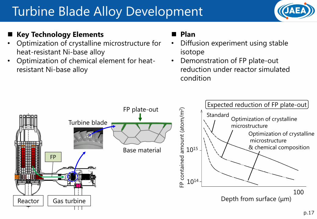
Plan
• Diffusion experiment using stable
isotope
• Demonstration of FP plate-out
reduction under reactor simulated
condition
Key Technology Elements
• Optimization of crystalline microstructure for
heat-resistant Ni-base alloy
• Optimization of chemical element for heat-
resistant Ni-base alloy
Expected reduction of FP plate-out
FP
FP plate-out
Base material
Turbine blade
Depth from surface (μm) 100
1015
1014
Standard Optimization of crystalline
microstructure
Optimization of crystalline
microstructure
& chemical composition
Gas turbine Reactor
FP
co
nta
ined
am
ou
nt
(ato
m/m
2)
Turbine Blade Alloy Development
p.17
p.18
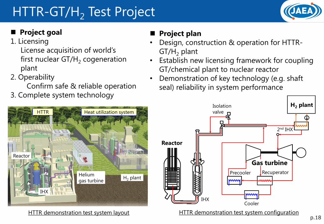
HTTR-GT/H2 Test Project
Project goal
1. Licensing
License acquisition of world’s
first nuclear GT/H2 cogeneration
plant
2. Operability
Confirm safe & reliable operation
3. Complete system technology
HTTR demonstration test system layout
Reactor
IHX
Helium
gas turbine H2 plant
HTTR Heat utilization system
HTTR demonstration test system configuration
Project plan
• Design, construction & operation for HTTR-
GT/H2 plant
• Establish new licensing framework for coupling
GT/chemical plant to nuclear reactor
• Demonstration of key technology (e.g. shaft
seal) reliability in system performance
IHX
Gas turbine
Recuperator Precooler
Reactor
H2 plant
Cooler
Isolation
valve
2nd IHX
-0.1
0
0.1
0.2
0
20
40
60
80
100
120
0 5
p.19
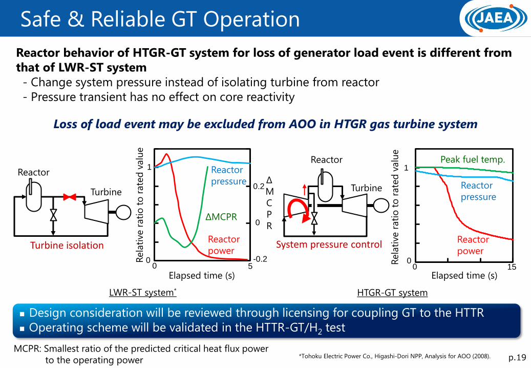
Safe & Reliable GT Operation
HTGR-GT system LWR-ST system*
Reactor
Turbine
0 5
1
0
0
0.2 Δ
M
C
P
R ΔMCPR
0
20
40
60
80
100
120
0 5 10 15Elapsed time (s) 0 15
Reactor
pressure
1
0
Peak fuel temp.
Reactor
power
Reactor behavior of HTGR-GT system for loss of generator load event is different from
that of LWR-ST system
- Change system pressure instead of isolating turbine from reactor
- Pressure transient has no effect on core reactivity
Design consideration will be reviewed through licensing for coupling GT to the HTTR
Operating scheme will be validated in the HTTR-GT/H2 test
Rela
tive r
ati
o t
o r
ate
d v
alu
e
Loss of load event may be excluded from AOO in HTGR gas turbine system
Reactor
System pressure control
Turbine
Turbine isolation
Elapsed time (s)
Rela
tive r
ati
o t
o r
ate
d v
alu
e
Reactor
pressure
Reactor
power
*Tohoku Electric Power Co., Higashi-Dori NPP, Analysis for AOO (2008). MCPR: Smallest ratio of the predicted critical heat flux power
to the operating power
-0.2
p.20
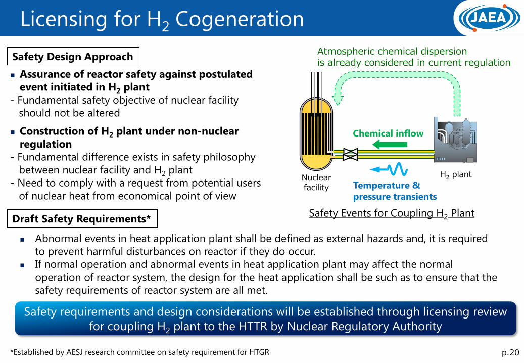
Licensing for H2 Cogeneration
H2 plant Nuclear facility
Atmospheric chemical dispersion is already considered in current regulation
Assurance of reactor safety against postulated
event initiated in H2 plant
- Fundamental safety objective of nuclear facility
should not be altered Construction of H2 plant under non-nuclear
regulation
- Fundamental difference exists in safety philosophy
between nuclear facility and H2 plant
- Need to comply with a request from potential users
of nuclear heat from economical point of view
Safety Design Approach
Safety Events for Coupling H2 Plant
Chemical inflow
Temperature &
pressure transients
Draft Safety Requirements*
*Established by AESJ research committee on safety requirement for HTGR
Abnormal events in heat application plant shall be defined as external hazards and, it is required
to prevent harmful disturbances on reactor if they do occur.
If normal operation and abnormal events in heat application plant may affect the normal
operation of reactor system, the design for the heat application shall be such as to ensure that the
safety requirements of reactor system are all met.
Safety requirements and design considerations will be established through licensing review
for coupling H2 plant to the HTTR by Nuclear Regulatory Authority
GTHTR300 HTTR-GT/H2 plant
H2 plant
Cooling
tower 冷却器
10MW
850oC
950oC
395oC
950oC
594oC
Reactor 600MW
360oC
150oC
850oC 〜650oC
170MW 0.7MW 650oC
850oC
p.21
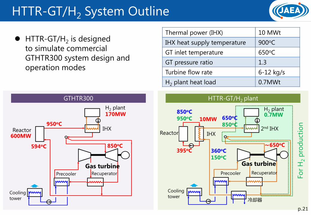
HTTR-GT/H2 System Outline
HTTR-GT/H2 is designed
to simulate commercial
GTHTR300 system design and
operation modes
H2 plant
Fo
r H
2 p
rod
uct
ion
2nd IHX
Gas turbine
Recuperator Precooler Recuperator Precooler
Gas turbine
Reactor
Cooling
tower
IHX IHX
Thermal power (IHX) 10 MWt
IHX heat supply temperature 900oC
GT inlet temperature 650oC
GT pressure ratio 1.3
Turbine flow rate 6-12 kg/s
H2 plant heat load 0.7MWt

To cooling tower
R&D
BUILDING
RB
CTB
SFSB
Exhaust
stack
MB0 50
scale (m)Nuclear facility
SFHB
H2 plant area
Trench
CTB: Cooling tower building
MB: Machinery building
RB: Reactor building
SFHB: Spent fuel handling building
SFSB: Spent fuel storage building
TB: Turbine building
N
TB
p.22
HTTR-GT/H2 Plant Layout
2nd IHX
Recuperator
Turbine
Compressor
Generator
Precooler
HTTR-GT/H2 plant layout
GT component layout

0
50
100
150
0 4 8 12p.23
HTTR-GT/H2 Planned Test Startup and shutdown operation
Load-following operation
Loss of load test
H2 plant upset simulating test
60
70
80
90
100
110
-2 0 2 4 6 8 10
Fuel temperature
Reactor pressure
Reactor power
Elapsed time [s]
No
rmalize
d v
alu
e [
%]
Elapsed time [h]
Po
wer-
to-H
2 r
ati
o [
%]
70
80
90
100
110
-50 0 50 100 150 200
Elapsed time [s]
Power generation rate
Fuel temperature
Reactor power N
orm
alize
d v
alu
e [
%] Power generation rate
H2 plant
heat supply
No
rmalize
d v
alu
e [
%]
100
0
Elapsed time 0
Turbine speed
Reactor power
Power
generation
rate

p.24
2014 2015 2016 2017 2018 2019 2020 2021 2022 2023 2024 2025
C&R
CONSTRUCTION
PLANT DESIGN
COMMISSIONING, OPERATION
LICENSING & REGULATORY
Conceptualdeign
Design
HTTR-GT
Site preparation
HTTR modification
Componentinstallation
Commissioning Operation
Commissioning Operation
Site preparation
Site construction
Pre-licensingdiscussion
Reactorinstallationlicensing
Licensing
Approval ofoperational safety program
Detailed deign
Componentfabrication
Pre-serviceinspection
Approval of construction plan
Component fabrication
HTTR-GT/H2
HTTR-GT/H2 Test Draft Schedule