cutter 1 model cd613h18 - multiquip inc
TRANSCRIPT

OPERATION AND PARTS MANUAL
P/N 25498
THIS MANUAL MUST ACCOMPANY THE EQUIPMENT AT ALL TIMES.
To find the latest revision of thispublication, visit our website at:
www.stowmfg.com
CUTTER 1MODEL CD613H18
Revision #6 (06/06/08)
(HONDA GX390 GASOLINE ENGINE)
MODEL CD605E16(5 HP ELECTRIC MOTOR)
CONCRETE/ASPHALT SAW

PAGE 2 — STOW CUTTER 1 SAW — OPERATION & PARTS MANUAL — REV. #6 (06/06/08)
Engine exhaust and some ofits constituents, and some dust created
of California to cause cancer, birthdefects and other reproductive harm.
by power sanding, sawing, grinding,drillingandotherconstructionactivitiescontains chemicals known to the State
Some examples of these chemicals are:
Leadfromlead-basedpaints.Crystallinesilicafrombricks.Cementandothermasonryproducts.Arsenicandchromiumfromchemicallytreatedlumber.
Your risk from these exposures varies,dependingonhowoftenyoudothistypeof work. To reduce your exposure tothese chemicals: work in aALWAYSwell ventilated area, and work withapproved safety equipment, such asdust masks that are specially designedto filter out microscopic particles.
STOW CUTTER 1 SAW — PROPOSITION 65 WARNING

STOW CUTTER 1 SAW — OPERATION & PARTS MANUAL — REV. #6 (06/06/08) — PAGE 3
NOTES
PAGE 4 — STOW CUTTER 1 SAW — OPERATION & PARTS MANUAL — REV. #6 (06/06/08)
STOW CUTTER 1 SAW — TABLE OF CONTENTSProposition 65 Warning ............................................. 2Table Of Contents ..................................................... 4Parts Ordering Procedures ....................................... 5Safety Message Alert Symbols .............................. 6-7Rules For Safe Operation .................................... 8-10Specifications (Saw) ................................................ 11Specifications (Engine) ........................................... 12
STOW — CUTTER 1 SAWControls & Components .......................................... 13Basic Engine ........................................................... 14Preparation/Pre-Inspection ................................ 15-17Blades ..................................................................... 18Blade Placement ..................................................... 19Initial Start-Up .................................................... 20-21Operation ................................................................ 21Maintenance ...................................................... 22-23Troubleshooting (Saw) ............................................ 24Troubleshooting (Engine) ................................... 25-26Explanation of Codes in Remarks Column ............. 28Suggested Spare Parts ........................................... 29Nameplate and Decals....................................... 30-31Engine, Belts And Pulleys Assembly .................. 32-33Electric Motor Assembly..................................... 34-35Undercarriage Assembly ................................... 36-37Blade Assembly & Water System Assembly....... 38-39Pointer Assembly ............................................... 40-41
NOTE
Specifications and
part numbers are
subject to change
without notice.
HONDA GX390K1QWT2/GX390U1QWT2 ENGINESAir Cleaner Assembly ......................................... 42-43Camshaft Assembly ........................................... 44-45Carburetor Assembly ......................................... 46-47Control Assembly ............................................... 48-49Crankcase Cover Assembly ............................... 50-51Crankshaft Assembly ......................................... 52-53Cylinder Barrel Assembly ................................... 54-55Cylinder Head Assembly .................................... 56-57Fan Cover Assembly .......................................... 58-59Flywheel Assembly ............................................ 60-61Fuel Tank Assembly ........................................... 62-63Ignition Coil Assembly ........................................ 64-65Muffler Assembly ............................................... 66-67Piston Assembly ................................................. 68-69Recoil Starter Assembly..................................... 70-71Labels ................................................................ 72-73
Terms and Conditions of Sale — Parts ................... 74

STOW CUTTER 1 SAW — OPERATION & PARTS MANUAL — REV. #6 (06/06/08) — PAGE 5
STOW CUTTER 1 SAW — PARTS ORDERING PROCEDURES
When ordering parts,please supply the following information:❒❒❒❒❒ Dealer account number❒❒❒❒❒ Dealer name and address❒❒❒❒❒ Shipping address (if different than billing address)❒❒❒❒❒ Return fax number❒❒❒❒❒ Applicable model number❒❒❒❒❒ Quantity, part number and description of each part❒❒❒❒❒ Specify preferred method of shipment:
✓ FedEx or UPS Ground✓ FedEx or UPS Second Day or Third Day✓ FedEx or UPS Next Day✓ Federal Express Priority One✓ DHL✓ Truck
Note: Unless otherwise indicated by customer, allorders are treated as “Standard Orders”, and willship within 24 hours. We will make every effort toship “Air Shipments” the same day that the orderis received, if prior to 2PM west coast time. “StockOrders” must be so noted on fax or web forms.
STOW CONSTRUCTION EQUIPMENTSTOW CONSTRUCTION EQUIPMENTSTOW CONSTRUCTION EQUIPMENTSTOW CONSTRUCTION EQUIPMENTSTOW CONSTRUCTION EQUIPMENTA DIVISION OF MULTIQUIP INC.
POST OFFICE BOX 6254 CARSON, CA 90749888-252-STOW [888-252-7869] 310-537-3700FAX: 310-537-1986 FAX: 800-556-1986E-MAIL: [email protected] INTERNET: www.stowmfg.com
Here’s how to get help...Please have the model and serial numberon hand when calling.
STOW MAIN OFFICE18910 Wilmington Ave. 800-421-1244Carson, CA 90746 FAX: 310-537-3927Email: [email protected]: www.stowmfg.comSALES DEPARTMENT310-661-4242 Fax: 310-604-9237877-289-7869 (877-BUY-STOW)PARTS DEPARTMENT800-427-1244 FAX: 800-672-7877310-537-3700 FAX: 310-637-3284SERVICE DEPARTMENT800-478-1244 FAX: 310-537-4259310-537-3700TECHNICAL ASSISTANCE800-478-1244 FAX: 310-631-5032WARRANTY DEPARTMENT800-421-1244, EXT. 279 FAX: 310-537-1173310-537-3700, EXT. 279
Extra Discounts!All parts orders which include complete part numbers andare received by our automated web parts order system, orby fax qualify for the following extra discounts:
Ordered Standard Stock ordersvia orders ($750 list and above)
Fax 3% 10%
Web 5% 10%
Special freight allowanceswhen you order 10 or moreline items via Web or Fax!**FedEx Ground Service at no charge for freightNo other allowances on freight shipped by any othercarrier.**Common nuts, bolts and washers (all items under $1.00list price) do not count towards the 10+ line items.
Place Your Parts Order Via Web or FaxFor Even More Savings!
(Domestic USA Dealers Only)
NOTE: DISCOUNTS ARE SUBJECT TO CHANGE
Direct TOLL-FREE accessto our Parts Department:
Toll-free nationwide — 800-427-1244
Toll-free FAX — 800-6-PARTS-7 (800/672-7877)

PAGE 6 — STOW CUTTER 1 SAW — OPERATION & PARTS MANUAL — REV. #6 (06/06/08)
STOW CUTTER 1 SAW — SAFETY MESSAGE ALERT SYMBOLS
Safety precautions should be followed at all times when operatingthis equipment. Failure to read and understand the SafetyMessages and Operating Instructions could result in injury toyourself and others.
FOR YOUR SAFETY AND THE SAFETY OF OTHERS!
This Owner's Manual has been developed to providecomplete instructions for the safe and efficient operationof the STOW CUTTER 1 SAW . For engine maintenanceinformation, please refer to the engine manufacturersinstructions for data relative to its safe operation.Before using this CONCRETE/ASPHALT SAW,ensure that the operating individual has read andunderstands all instructions in this manual.
NOTE
SAFETY MESSAGE ALERT SYMBOLS
The three (3) Safety Messages shown below will inform youabout potential hazards that could injure you or others. TheSafety Messages specifically address the level of exposure tothe operator, and are preceded by one of three words: DANGER,WARNING, or CAUTION.
DANGER: You WILL be KILLED orSERIOUSLY injured if you DO NOT followdirections.
WARNING: You CAN be KILLED orSERIOUSLY injured if you DO NOT followdirections.
CAUTION: You CAN be injured if youDO NOT follow directions.
HAZARD SYMBOLS
Engine exhaust gases contain poisonouscarbon monoxide. This gas is colorless andodorless, and can cause death if inhaled.NEVER operate this equipment in a confinedarea or enclosed structure that does notprovide ample free flow air.
Potential hazards associated with STOW CUTTER 1 SAWoperation will be referenced with "Hazard Symbols" whichappear throughout this manual, and will be referenced inconjunction with Safety "Message Alert Symbols".
Gasoline is extremely flammable, and itsvapors can cause an explosion if ignited. DONOT start the engine near spilled fuel orcombustible fluids. DO NOT fill the fuel tankwhile the engine is running or hot. DO NOToverfill tank, since spilled fuel could ignite if itcomes into contact with hot engine parts orsparks from the ignition system. Store fuel inapproved containers, in well-ventilated areasand away from sparks and flames. NEVERuse fuel as a cleaning agent.
Burn Hazards
Engine components can generate extreme heat.To prevent burns, DO NOT touch these areaswhile the engine is running or immediately afteroperations. NEVER operate the engine withheat shields or heat guards removed.
Rotating Parts
NEVER operate equipment with covers, orguards removed. Keep fingers, hands, hairand clothing away from all moving parts toprevent injury.
Explosive Fuel
Lethal Exhaust Gases

STOW CUTTER 1 SAW — OPERATION & PARTS MANUAL — REV. #6 (06/06/08) — PAGE 7
Accidental Starting
ALWAYS place the engine ON/OFFswitch in the OFF position, when the sawis not in use.
Over Speed Conditions
NEVER tamper with the factory settings of theengine governor or settings. Personal injuryand damage to the engine or equipment canresult if operating in speed ranges abovemaximum allowable.
Respiratory Hazard
ALWAYS wear approved respiratory protection.
ALWAYS wear approved eye and hearingprotection.
Sight and Hearing hazard
Equipment Damage Messages
Other important messages are provided throughout this manualto help prevent damage to your concrete saw, other property, orthe surrounding environment.
STOW CUTTER 1 SAW — SAFETY MESSAGE ALERT SYMBOLS
Guards and Covers In Place
NEVER operate the saw without blade guardsand covers in place. Adhere to safetyguidelines ANSI, OSHA, or other applicablelocal regulations.
This concrete/asphalt saw, otherproper ty, or the surroundingenvironment could be damaged ifyou do not follow instructions.
Rotating Blade
Rotating blade can cut and crush. Keephands and feet clear.
NOTE

PAGE 8 — STOW CUTTER 1 SAW — OPERATION & PARTS MANUAL — REV. #6 (06/06/08)
CAUTION:Failure to follow instructions in this manual maylead to serious injury or even death! Thisequipment is to be operated by trained andqualified personnel only! This equipment isfor industrial use only.
The following safety guidelines should always be used whenoperating the STOW CUTTER 1 SAW . Unless otherwise noted,these guidelines refer to saws with gasoline powered engines.
SAFETY
■ DO NOT operate or service this equipmentbefore reading this entire manual.
■ This equipment should not be operated by persons under 18years of age.
■ NEVER operate the saw without proper protectiveclothing, shatterproof glasses, steel-toed bootsand other protective devices required by the job.
■ NEVER operate this equipment when notfeeling well due to fatigue, illness or takingmedicine.
■ NEVER operate the saw under theinfluence or drugs or alcohol.
■ NEVER use accessories or attachments, which are notrecommended by STOW or Multiquip for this equipment.Damage to the equipment and/or injury to user may result.
■ Manufacturer does not assume responsibility for any accidentdue to equipment modifications. Unauthorized equipmentmodification will void all warranties.
■ Whenever necessary, replace nameplate, operation andsafety decals when they become difficult read.
■ ALWAYS check the saw for loosened hardware such as nutsand bolts before starting.
■ ALWAYS use extreme caution whenworking with flammable liquids. Whenrefueling, STOP the engine and allowit to cool.
■ NEVER smoke around or near themachine. Fire or explosion could result fromfuel vapors, or if fuel is spilled on a hot!engine.
■ NEVER operate the saw in an explosive atmosphere wherefumes are present or near combustible materials. An explosionor fire could result causing severe bodily harm or evendeath.
■ Topping-off to filler port is dangerous, as it tends to spill fuel.
■ NEVER use fuel as a cleaning agent.
■ NEVER touch the hot exhaustmanifold, muffler or cylinder. Allowthese parts to cool before servicingthe saw.
■ The engine of this saw requires an adequate free flow ofcooling air. NEVER operate the saw in any enclosed or narrow
area where free flow of theair is restricted. If the air flowis restricted it will causeserious damage to the saw'sengine and may cause injuryto people. Remember thesaw's engine gives offDEADLY carbon monoxidegas.
■ High Temperatures – Allow the engine to cool before addingfuel or performing service and maintenance functions. Contactwith hot! components can cause serious burns.
■ ALWAYS refuel in a well-ventilated area, away from sparksand open flames.
STOW CUTTER 1 SAW — RULES FOR SAFE OPERATIONRULES FOR SAFE OPERATION

STOW CUTTER 1 SAW — OPERATION & PARTS MANUAL — REV. #6 (06/06/08) — PAGE 9
STOW CUTTER 1 SAW — RULES FOR SAFE OPERATION
Diamond Blade Safety
■ Use appropriate steel centered diamond bladesmanufactured for use on concrete saws.
■ ALWAYS inspect diamond bladesbefore each use. The blade shouldexhibit no cracks, dings, or flaws inthe steel centered core and/or rim.Center (arbor) hole must beundamaged and true.
■ Examine blade flanges for damage, excessive wear andcleanliness before mounting blade. Blade should fit snuglyon the shaft and against the inside/outside blade flanges.
■ Ensure the blade is marked with an operating speed greaterthan the blade shaft speed of the saw.
■ Only cut the material that is specified by the diamond blade.Read the specifications of the diamond blade to ensure theproper tool has been matched to the material being cut.
■ ALWAYS keep blade guards in place. Exposure of thediamond blade must not exceed 180 degrees.
■ Ensure that the diamond blade does not come into contactwith the ground or surface during transportation. DO NOTdrop the diamond blade on ground or surface.
■ The engine governor is designed to permit maximum enginespeed in a no-load condition. Speeds that exceed this limitmay cause the diamond blade to exceed the maximum safeallowable speed.
■ Ensure that the blade is mounted for proper operatingdirection.
General Safety
■ ALWAYS read, understand, and follow procedures inOperator's Manual before attempting to operate equipment.
■ ALWAYS be sure the operator is familiar with proper safetyprecautions and operating techniques before using the saw.
■ NEVER leave the machine unattended while running.
■ Block the unit when leaving or when using on a slope.
■ ALWAYS check to make sure that the operating area is clearbefore starting the engine.
■ Maintain this equipment in a safe operating condition at alltimes.
■ ALWAYS stop the engine before servicing, adding fuel andoil.
■ NEVER run the engine without the air filter. Severe enginedamage could occur.
■ ALWAYS service air cleaner frequently to prevent carburetormalfunction.
■ AVOID wearing jewelry or loose fitting clothing that may snagon the controls or moving parts, this can cause a seriousinjury.
■ ALWAYS keep clear of rotating or moving parts while thesaw is in operation.
■ ALWAYS store equipment properly when it is not being used.Equipment should be stored in a clean, dry location out ofthe reach of children.
■ NEVER use accessories or attachments which are notrecommended by the manufacturer for this equipment.Damage to the equipment and/or injury to user may result.
WARNING
■ ALWAYS check to make sure that theoperating area is clear before starting theengine.
■ Keep all inexperienced and unauthorized people away fromthe equipment at all times.
WARNING
Electric Saws
■ ALWAYS connect electric motor of the saw to a power sourcein compliance with all local and state electrical codes. Thismust be performed by a qualified electrician. After thisconnection is made, it will be necessary to check the rotationof the motor shaft. The shaft rotation should be counter-clockwise when viewing the motor from the shaft extensionend. If the rotation of the shaft is incorrect make necessarychanges for the correct shaft rotation.
■ MAKE CERTAIN the power cord/extension cord is free fromdamage and that the grounding circuit is operational.
■ MAKE CERTAIN the extension cord that you are using isintended to be used in the environment you are using it in. Ifan extension is used, NEVER submerge the connection inwater. To reduce the risk of electric shock, always make water-tight connections.
■ MAKE CERTAIN the "ON/OFF" switch is in the "OFF" positionbefore plugging in the power cord/extension cord to avoidaccidental starting.
■ Use only the gauge wire and length of cord recommended forthe motor size. Refer to Table 3 in this manual.
■ When cutting, ALWAYS be aware of the location of the cord.
■ NEVER use a worn, frayed or damaged extension cord.
PAGE 10 — STOW CUTTER 1 SAW — OPERATION & PARTS MANUAL — REV. #6 (06/06/08)
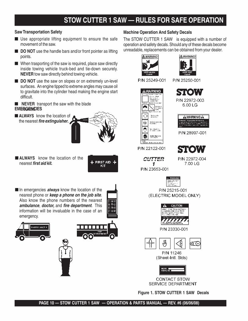
Figure 1. STOW CUTTER 1 SAW Decals
STOW CUTTER 1 SAW — RULES FOR SAFE OPERATION
EMERGENCIES
■ ALWAYS know the location ofthe nearest fire extinguisher.
■ ALWAYS know the location of thenearest first aid kit.
■ In emergencies always know the location of thenearest phone or keep a phone on the job site.Also know the phone numbers of the nearestambulance, doctor, and fire department. Thisinformation will be invaluable in the case of anemergency.
Saw Transportation Safety
■ Use appropriate lifting equipment to ensure the safemovement of the saw.
■ DO NOT use the handle bars and/or front pointer as liftingpoints.
■ When trasporting of the saw is required, place saw directlyinside towing vehicle truck-bed and tie-down securely.NEVER tow saw directly behind towing vehicle.
■ DO NOT use the saw on slopes or on extremely un-levelsurfaces. An engine tipped to extreme angles may cause oilto gravitate into the cylinder head making the engine startdifficult.
■ NEVER transport the saw with the blademounted.
Machine Operation And Safety Decals
The STOW CUTTER 1 SAW is equipped with a number ofoperation and safety decals. Should any of these decals becomeunreadable, replacements can be obtained from your dealer.
STOW CUTTER 1 SAW — OPERATION & PARTS MANUAL — REV. #6 (06/06/08) — PAGE 11
STOW CUTTER 1 SAW — SPECIFICATIONS (SAW)
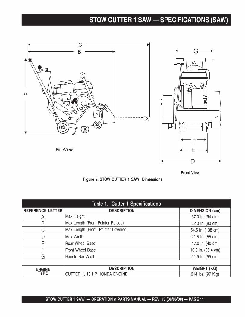
Figure 2. STOW CUTTER 1 SAW Dimensions
Side View
Front View
A
C
B
F
G
D
E
snoitacificepS1rettuC.1elbaTRETTELECNEREFER NOITPIRCSED )mc(NOISNEMID
A thgieHxaM )mc49(.nI0.73
B )desiaRretnioPtnorF(htgneLxaM )mc08(.nI0.23
C )derewoLretnioPtnorF(htgneLxaM )mc831(.nI5.45
D htdiWxaM )mc55(.nI5.12
E esaBleehWraeR )mc04(.nI0.71
F esaBleehWtnorF )mc4.52(.nI0.01
G htdiWraBeldnaH )mc55(.nI5.12
ENIGNEEPYT
NOITPIRCSED )GK(THGIEWENIGNEADNOHPH31,1RETTUC )g.K79(.sbl412

PAGE 12 — STOW CUTTER 1 SAW — OPERATION & PARTS MANUAL — REV. #6 (06/06/08)
STOW CUTTER 1 SAW — SPECIFICATIONS (ENGINE)
)enignE(snoitacificepS.2elbaT
enignE
ledoMADNOH
2TWQ1U093XG/2TWQ1K093XG
epyTelgniS,ekorts4delooc-riA
enignEenilosaG,VHO,rednilyC
ekortSXeroB.ni5.2X.ni5.3)mm46xmm88(
tnemecalpsiD )cc983(.ni-uc7.32
tuptuOxaM .M.P.R0063/.P.H0.31
yticapaCknaTleuFsnollaG.S.U27.1.xorppA
)sretiL5.6(
leuFenilosaGelibomotuAdedaelnU
rehgihroenatcO68
yticapaCliOebuL )retil1.1(tqSU61.1
lortnoCdeepSdohteM
epyTthgiew-ylFlagufirtneC
dohteMgnitratS tratSlioceR
noisnemiD)HxWxL(
.ni4.71X7.71x0.51)mm344X054X083(
yrDthgieWteN
).gK13(sbl4.86

STOW CUTTER 1 SAW — OPERATION & PARTS MANUAL — REV. #6 (06/06/08) — PAGE 13
STOW CUTTER 1 SAW — CONTROLS & COMPONENTS
Figure 3 shows the location of the basic controls or componentsfor the STOW CUTTER 1 SAW. Listed below is a briefexplanation of each control or component. (Gasoline-poweredunit shown)
1. Hand Grips/Handlebar – When operating the saw, placeboth hands on each grip to maneuver the saw. Replacehand grips when they become worn or damaged.
2. Handle Lock – Lock blade depth to desired position.
3. Garden Hose Connecter – Connect to water source toprovide blade cooling while cutting concrete or asphalt.
4. Air Filter – Prevents dirt and debris from entering the engineair intake. Check filter periodically and keep cleaned orreplace when necessary.
5. Recoil Starter Handle – Pull to engage and start theengine.
6. Recoil Starter Assembly – Engages the engine whenthe handle is pulled and rewinds the starter rope when thehandle is released.
7. Wheels/Carriage Assembly – Heavy-duty polyurethanewheels with permanently sealed ball bearings.
CONTROLS & COMPONENTS
Figure 3. Cutter 1
8. Cutting Blade – Use appropriate type blades for cuttingconcrete or asphalt.
9. Blade Guard – Covers saw blade and flips up to allowblade to be changed.
10. Belt Tension Adjuster – Adjusts belt tension.
11. Front Pointer – Front pointer wheel assists in straighttracking.
12. Front Pointer Arm – Stows up for storage and pivots downfor use.
13. Cutting Depth Adjuster – turn operating crank clockwiseor counter-clockwise to adjust the cutting depth up or down.
14. Fuel Tank – Use unleaded gasoline. Do not overfill.
15. Blade Coolant System – Provides cooling water to bladeduring cutting operations.
16. V-Belt Cover – Remove this cover to gain access to the V-belt. NEVER operate the saw with this cover removed.
17. Arbor Shaft Grease Zerks – Conveniently located forlubrication.
18. On/Off Switch – Turn to the "ON" position to allow engineto be started and turn to the "OFF" position to shut theengine off.

PAGE 14 — STOW CUTTER 1 SAW — OPERATION & PARTS MANUAL — REV. #6 (06/06/08)
Figure 4. Engine Controls and Components
Initial Servicing
The engine (Figure 4) must be checked for proper lubrication andfilled with fuel prior to operation. Refer to the manufacturers enginemanual for instructions & details of operation and servicing.
1. Fuel Filler Cap – Remove this cap to add unleadedgasoline to the fuel tank. Make sure cap is tightenedsecurely. DO NOT over fill.
6. Choke Lever – Used in the starting of a cold engine, or incold weather conditions. The choke enriches the fuelmixture.
7. Air Cleaner – Prevents dirt and other debris from enteringthe fuel system. Remove wing-nut on top of air filtercannister to gain access to filter element.
Operating the engine without an airfilter, with a damaged air filter, or afilter in need of replacement willallow dirt to enter the engine, causingrapid engine wear.
8. Spark Plug – Provides spark to the ignition system. Setspark plug gap to 0.6 - 0.7 mm (0.028 - 0.031 inch) Cleanspark plug once a month.
9. Muffler – Used to reduce noise and emissions.
Engine components can generate extreme heat.To prevent burns, DO NOT touch these areaswhile the engine is running or immediately after
operating. NEVER operate the engine with the muffler removed.
10. Fuel Tank – Holds unleaded gasoline. For additionalinformation refer to engine owner's manual.
DANGER
WARNING
STOW CUTTER 1 SAW — BASIC ENGINE
Adding fuel to the tank should be done only whenthe engine is stopped and has had an opportunity
to cool down. In the event of a fuel spill, DO NOT attempt to start theengine until the fuel residue has been completely wiped up, and thearea surrounding the engine is dry.
2. Throttle Lever – Used to adjust engine RPM speed (leveradvanced forward SLOW, lever back toward operatorFAST).
3. Engine ON/OFF Switch – ON position permits enginestarting, OFF position stops engine operations.
4. Recoil Starter (pull rope) – Manual-starting method. Pullthe starter grip until resistance is felt, then pull briskly andsmoothly.
5. Fuel Valve Lever – OPEN to let fuel flow, CLOSE to stopthe flow of fuel.
NOTE
BASIC ENGINE
STOW CUTTER 1 SAW — OPERATION & PARTS MANUAL — REV. #6 (06/06/08) — PAGE 15
STOW CUTTER 1 SAW — PREPARATION/PRE-INSPECTION
PREPARATION / PRE-INSPECTION1. Read and fully understand this manual,
the safety instructions in particular, andthe engine manufacturer's manualsupplied with the saw.
2. Select the correct blade for each application. If abrasiveblades are used, MAKE CERTAIN they are designed foruse on a concrete floor saw. They must be reinforced andhave a hole for the driving pin. When wet cutting with anabrasive blade, MAKE CERTAIN the blade is intended forwet cutting. Water will destroy a dry cut abrasive blade.Some diamond blades require water cooling and failure todo so will destroy them almost immediately. Other diamondblades can be used with or without water. Refer to the Bladesand Blade Placement sections on pages 18 and 19 for furtherinformation.
3. Handle all blades with care and NEVER use a damagedblade. NEVER use an abrasive blade that has beendropped.
Electric Powered Saws (50 or 60 HZ)
1. The electric motor of this saw requires 230 VAC inputvoltage (50/60 Hz, single-phase). Always make certain thatthe rated operating line voltage of the motor is correct whencutting. Electric motors can burn out when the line voltagefalls 10% below the voltage rating of the motor.
2. After the correct input voltage has been applied to the saw,turn the saw on, and check the rotation of the motor shaft.The shaft rotation MUST be counter-clockwise whenviewing the motor from the shaft extension end. If the rotationof the shaft is incorrect make the necessary changes forthe correct shaft rotation.
3. MAKE CERTAIN the correct size extension cord is used.Undersize extension cords can burn out an electric motor.Use Table 3 to determine the correct extension cord size.
4. NEVER! use a worn or frayed extension cord.
5. Record the model and serial number of the saw on thefront of the Operating and Parts Manual for future reference.
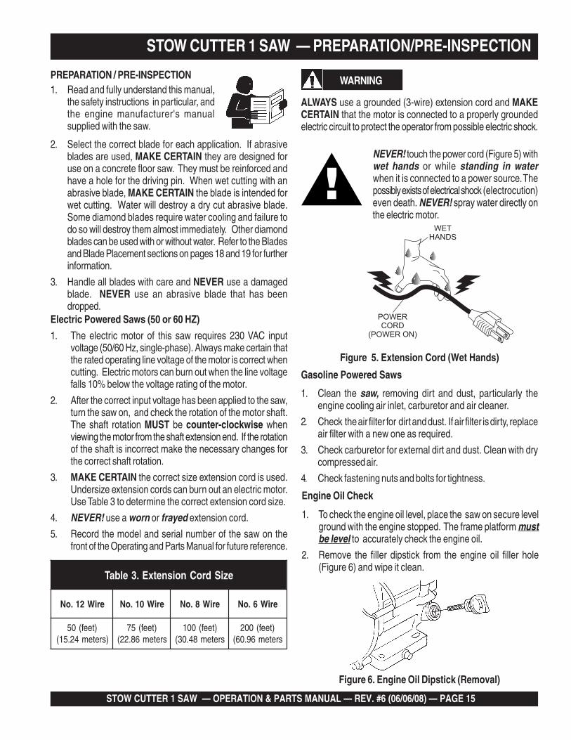
WARNING
ALWAYS use a grounded (3-wire) extension cord and MAKECERTAIN that the motor is connected to a properly groundedelectric circuit to protect the operator from possible electric shock.
Figure 6. Engine Oil Dipstick (Removal)
Gasoline Powered Saws
1. Clean the saw, removing dirt and dust, particularly theengine cooling air inlet, carburetor and air cleaner.
2. Check the air filter for dirt and dust. If air filter is dirty, replaceair filter with a new one as required.
3. Check carburetor for external dirt and dust. Clean with drycompressed air.
4. Check fastening nuts and bolts for tightness.
Engine Oil Check
1. To check the engine oil level, place the saw on secure levelground with the engine stopped. The frame platform mustbe level to accurately check the engine oil.
2. Remove the filler dipstick from the engine oil filler hole(Figure 6) and wipe it clean.
eziSdroCnoisnetxE.3elbaT
eriW21.oN eriW01.oN eriW8.oN eriW6.oN
)teef(05)sretem42.51(
)teef(57sretem68.22(
)teef(001sretem84.03(
)teef(002sretem69.06(
NEVER! touch the power cord (Figure 5) withwet hands or while standing in waterwhen it is connected to a power source. Thepossibly exists of electrical shock (electrocution)even death. NEVER! spray water directly onthe electric motor.
POWERCORD
(POWER ON)
WETHANDS
Figure 5. Extension Cord (Wet Hands)

PAGE 16 — STOW CUTTER 1 SAW — OPERATION & PARTS MANUAL — REV. #6 (06/06/08)
Figure 6. Engine Oil Dipstick (Oil Level)
Fuel Check
Motor fuels are highly flammable and can bedangerous if mishandled. DO NOT smokewhile refueling. DO NOT attempt to refuel thetrowel if the engine is hot! or running.
Explosive Fuel
1. Remove the gasoline cap located on top of fuel tank.
2. Visually inspect to see if fuel level is low. If fuel is low, replenishwith unleaded fuel.
3. When refueling, be sure to use a strainer for filtration. DONOT top-off fuel. Wipe up any spilled fuel.
NOTEReference manufacturer enginemanual for specific servicinginstructions.
epyTliO.4elbaT
nosaeS erutarepmeT epyTliO
remmuS rehgiHroC°52 03-W01EAS
llaF/gnirpS C°01~C°52 02/03-W01EAS
retniW rewoLroC°0 01-W01EAS
NEVER operate the saw without blade guardsand covers in place. DO NOT operate withthe front of the blade guard raised. The bladeexposure cannot exceed 180 degrees duringoperation. Adhere to the safety guidelines ofthe American National Standards Institute(ANSI) B7.1 and B7.5.
WARNING
Figure 7. Blade Guard
CHECK the following on the blade guard (Figure 8):
■ Ensure the capacity of the blade guard matches the diameterof your diamond blade.
■ Check that the guard is bolted firmly upon the saw frame.
■ Check that the spring tensioned front cover of the guard isfirmly seated with the rear section of the guard and there areno gaps. NEVER lift the blade guard while cutting.
CAUTIONCAUTIONCAUTIONCAUTIONCAUTIONNEVER attempt to checkthe V-belt with the enginerunning. Severe injury canoccur. Keep fingers, hands,hair, and clothing awayfrom all moving parts.
V-Belt Check
A worn or damaged V-belt can adversely affect the performanceof the saw. If a V-belt is defective or worn, replace ALL the V-belts. V-belts should always be replaced in sets.
Guards And Covers
ENSURE the V-belt Cover is in place and securely fastenedduring operation of the saw (Figure 8).
STOW CUTTER 1 SAW — PREPARATION/PRE-INSPECTION
3. Insert and remove the dipstick without screwing it into the fillerneck. Check the oil level shown on the dipstick.
4. If the oil level is low (Figure 7), fill to the edge of the oil fillerhole with the recommended oil type (Table 4).

STOW CUTTER 1 SAW — OPERATION & PARTS MANUAL — REV. #6 (06/06/08) — PAGE 17
Figure 10. Pulley Alignment
3. Check V-belt tension by using a tension meter (3.0 lbs.)against the inside belt at a mid point between the two pulleys,or by deflecting the center belt at a mid point 3/16" (5 mm).
4. DO NOT over or under tighten the V-belt. Severe damagecan occur to the saw and engine crankshaft if the belt isover-tensioned. A decrease of power to the blade and poorperformance will result if the belt is under-tensioned (looseon pulleys).
STOW CUTTER 1 SAW — PREPARATION/PRE-INSPECTION
Figure 9. V-Belt Cover
V-belt Alignment and Tensioning
This saw is equipped with a premium V-belt that has been alignedand tensioned by factory personnel. The V-belt must be alignedand tensioned for proper operation of the saw.
Use the following procedure to check the alignment of V-belt:
1. Remove the bolts that secure the V-belt cover (Figure 9) tothe saw frame.
2. Check uniform parallelism (Figure 10) of V-belt and pulley(sheaves). Use a straight-edge or machinist's square againstboth pulleys and adjust both pulleys until equally aligned.
NOTEV-belt alignment must berechecked after adjusting belttension.
PAGE 18 — STOW CUTTER 1 SAW — OPERATION & PARTS MANUAL — REV. #6 (06/06/08)
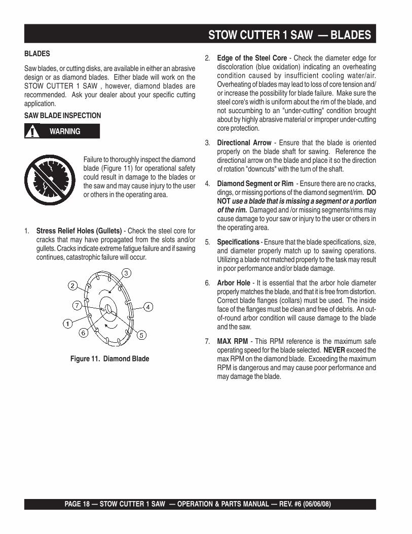
WARNING
Failure to thoroughly inspect the diamondblade (Figure 11) for operational safetycould result in damage to the blades orthe saw and may cause injury to the useror others in the operating area.
Figure 11. Diamond Blade
BLADES
Saw blades, or cutting disks, are available in either an abrasivedesign or as diamond blades. Either blade will work on theSTOW CUTTER 1 SAW , however, diamond blades arerecommended. Ask your dealer about your specific cuttingapplication.
SAW BLADE INSPECTION
1. Stress Relief Holes (Gullets) - Check the steel core forcracks that may have propagated from the slots and/orgullets. Cracks indicate extreme fatigue failure and if sawingcontinues, catastrophic failure will occur.
STOW CUTTER 1 SAW — BLADES
2. Edge of the Steel Core - Check the diameter edge fordiscoloration (blue oxidation) indicating an overheatingcondition caused by insufficient cooling water/air.Overheating of blades may lead to loss of core tension and/or increase the possibility for blade failure. Make sure thesteel core's width is uniform about the rim of the blade, andnot succumbing to an "under-cutting" condition broughtabout by highly abrasive material or improper under-cuttingcore protection.
3. Directional Arrow - Ensure that the blade is orientedproperly on the blade shaft for sawing. Reference thedirectional arrow on the blade and place it so the directionof rotation "downcuts" with the turn of the shaft.
4. Diamond Segment or Rim - Ensure there are no cracks,dings, or missing portions of the diamond segment/rim. DONOT use a blade that is missing a segment or a portionof the rim. Damaged and /or missing segments/rims maycause damage to your saw or injury to the user or others inthe operating area.
5. Specifications - Ensure that the blade specifications, size,and diameter properly match up to sawing operations.Utilizing a blade not matched properly to the task may resultin poor performance and/or blade damage.
6. Arbor Hole - It is essential that the arbor hole diameterproperly matches the blade, and that it is free from distortion.Correct blade flanges (collars) must be used. The insideface of the flanges must be clean and free of debris. An out-of-round arbor condition will cause damage to the bladeand the saw.
7. MAX RPM - This RPM reference is the maximum safeoperating speed for the blade selected. NEVER exceed themax RPM on the diamond blade. Exceeding the maximumRPM is dangerous and may cause poor performance andmay damage the blade.

STOW CUTTER 1 SAW — OPERATION & PARTS MANUAL — REV. #6 (06/06/08) — PAGE 19
Cutting Depth Adjustment
The saw is equipped with a Raise/Lower Assembly that issupported by the following components.■ Raise/Lower Acme Screw
■ Jack Arm
■ Blade Guard
■ Adjusting Handle Crank
STOW CUTTER 1 SAW — BLADE PLACEMENT
WARNING
Failure to thoroughly inspect the diamondblade for operational safety could result indamage to the blades or the saw and maycause injury to the user or others in theoperating area.1. Blade Guard - Pivot the blade guardfront cover all the way back. The guard
tension spring will keep the front cover in position.
2. Blade Hex Nut - Unscrew the blade shaft nut (right sideloosens clockwise and tightens counter-clockwise while theleft side loosens counter-clockwise and tightens clockwise.DO NOT overtighten the nut (approximately 45-50 ft. lb/61-68 N/m) when finalizing the assembly.
3. Outside Blade Flange (Collar) - Ensure that the outsideblade flange is placed flush against the diamond blade.The inside surface of the flange must be free of debris andpermit a tight closure on the surface of the blade core.
5. Inner Flange (Collar) - This flange is fixed upon the bladeshaft. The inside surface of the flange must be free of debrisand permit a tight closure on the surface of the blade.
The following steps should beaccomplished before using the sawon any cutting surface.
NOTE
4. Diamond Blade - Ensure that the proper diamond bladehas been selected for the job. Pay close attention to thedirectional arrows on the blade. The blade's operatingdirectional arrows must point in a "down-cutting" directionto perform correctly. When placing the blade onto the bladeshaft, ensure the arbor hole of the blade matches thediameter of the shaft.
WARNING
Dropping or forcing theblade onto the cuttingsurface can severely
damage the diamond blade and maycause serious damage to the saw andbodily harm.
Blade Removal and Replacement
1. Set the engine ON/OFF switch to the"OFF" position. (Unplug electricmodels.)
2. Place the saw on a stable level workingsurface.
3. Ensure the blade is raised and the raise/lower crank is lockedinto position.
When removing or installing adiamond blade, please note that theblade retaining nuts are left and right-hand threaded.
NOTE
BLADE PLACEMENT
5. Lift up the blade guard cover to gain access to the blade.
6. Use the provided blade nut and blade shaft lockingwrenches to remove and install the blade.
■ While holding the blade shaft with the locking wrench,remove the blade hex nut (clockwise direction) and outerblade flange.
■ Remove the old blade and install a new blade in thesame rotational direction as marked on the old blade.
■ Reinstall the outer blade flange and hex nut. Tightenthe nut firmly (counter-clockwise direction). DO NOTOVER TIGHTEN.
Blade Speed
A diamond blade’s performance is directly connected to specificperipheral (rim) speeds.
The following shaft rotational speeds have been factory set toensure optimum blade performance.
CUTTER 1- 18-inch (457.2 mm) Capacity - 2,836 RPM.
PAGE 20 — STOW CUTTER 1 SAW — OPERATION & PARTS MANUAL — REV. #6 (06/06/08)
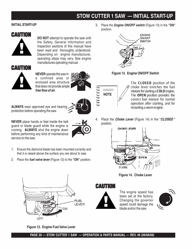
4. Place the Choke Lever (Figure 14) in the "CLOSED "position.
STOW CUTTER 1 SAW — INITIAL START-UP
DO NOT attempt to operate the saw untilthe Safety, General Information andInspection sections of this manual havebeen read and thoroughly understood.Depending on engine manufacturer,operating steps may vary. See enginemanufactures operating manual.
Figure 12. Engine Fuel Valve Lever
Figure 13. Engine ON/OFF Switch
CAUTIONCAUTIONCAUTIONCAUTIONCAUTION
CAUTIONCAUTIONCAUTIONCAUTIONCAUTION
1. Ensure the diamond blade has been mounted correctly andthat it is raised above the surface you are about to saw.
2. Place the fuel valve lever (Figure 12) to the "ON" position.
3. Place the Engine ON/OFF switch (Figure 13) in the "ON"position.
The CLOSED position of thechoke lever enriches the fuelmixture for starting a COLD engine.The OPEN position provides thecorrect fuel mixture for normaloperation after starting, and forrestarting a warm engine.
The engine speed hasbeen set at the factory.Changing the governorspeed could damage theblade and/or the saw.
Figure 14. Choke Lever
NOTE
CAUTIONCAUTIONCAUTIONCAUTIONCAUTIONNEVER operate the saw ina confined area orenclosed area structurethat does not provide amplefree flow of air.
ALWAYS wear approved eye and hearingprotection before operating the saw.
NEVER place hands or feet inside the beltguard or blade guard while the engine isrunning. ALWAYS shut the engine downbefore performing any kind of maintenanceservice on the saw.
INITIAL START-UP

STOW CUTTER 1 SAW — OPERATION & PARTS MANUAL — REV. #6 (06/06/08) — PAGE 21
6. Grasp the starter grip (Figure 16) and slowly pull it out. Theresistance becomes the hardest at a certain position, corre-sponding to the compression point. Pull the starter grip brisklyand smoothly for starting.
Figure 16. Starter Grip
8. Before the saw is placed into operation, run the engine forseveral minutes. Check for fuel leaks, and noises that wouldassociate with a loose guards and/or covers.
STOW CUTTER 1 SAW — INITIAL START-UP/OPERATION
CAUTIONCAUTIONCAUTIONCAUTIONCAUTIONDO NOT pull the starter rope all the way tothe end. DO NOT release the starter ropeafter pulling. Allow it to rewind as soon aspossible.
ALWAYS keep clear of rotating or moving parts while operatingthis equipment.
WARNING
3. When blade has reached full cutting depth, slowly walkbehind the saw at a rate that will allow the engine to operatewithout losing optimum RPM.
CAUTIONCAUTIONCAUTIONCAUTIONCAUTION
4. When the end of the cut has been reached, raise the bladeout of the cut by pulling back on the handlebars (using adownward pressure) until the raise/lower rod drops into itsslot with the blade in the raised position.
5. If cutting is complete, turn the engine off and wait for the bladeto stop rotating.
DO NOT try to cut faster than the blade willallow. Cutting too fast will cause the blade torise up out of the cut. Improper cutting ratecan decrease the life of the engine andblades.
5. Rotate the throttle lever (Figure 15) halfway between fastand slow for starting. All sawing is done at full throttle. Theengine governor speed is factory set to ensure optimumblade operating speeds.
Figure 15. Throttle Lever
ALWAYS cut with the saw at FULL THROTTLE. Attempting tocut with the saw at less than full throttle could cause the blade tobind or stop abruptly in the slab resulting in serious injury to theoperator or others in the area.
WARNING
2. To begin sawing, lower the rotating blade allowing it to cut tothe preset depth.
7. If the engine has started, slowly return the choke lever(Figure 14) to the "OPEN" position. If the engine has notstarted repeat steps 1 through 6.
OPERATION1. Start the engine. Rotate the throttle lever (Figure 14) toward
full throttle.
NOTE Mark the cutting line clearly and alwayssaw in a STRAIGHT LINE ONLY.
PAGE 22 — STOW CUTTER 1 SAW — OPERATION & PARTS MANUAL — REV. #6 (06/06/08)
Engine
Follow the maintenance procedures outlined in the engineowner's manual.
Engine Oil Change
Drain the used oil while the engine is warm by the following:
Refer to Figure 17.
1. Place an oil pan or suitable container below the engine drainplug to catch the used oil.
2. Remove the filler cap/dipstick and the drain plug.
3. Drain the oil completely and reinstall the drain plug. Ensurethe drain plug is tightened securely.
Drive Belt
Refer to pages 16 and 17 of this manual for Drive Belt adjustmentprocedures and Removal and Replacement procedures.
CAUTION!CAUTION!CAUTION!CAUTION!CAUTION!
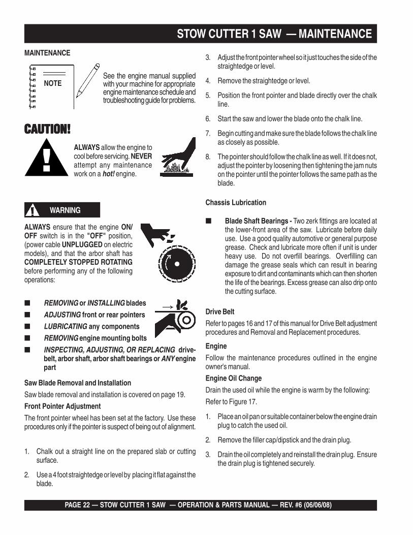
See the engine manual suppliedwith your machine for appropriateengine maintenance schedule andtroubleshooting guide for problems.
STOW CUTTER 1 SAW — MAINTENANCE
ALWAYS allow the engine tocool before servicing. NEVERattempt any maintenancework on a hot! engine.
WARNING
■ REMOVING or INSTALLING blades
■ ADJUSTING front or rear pointers
■ LUBRICATING any components
■ REMOVING engine mounting bolts
■ INSPECTING, ADJUSTING, OR REPLACING drive-belt, arbor shaft, arbor shaft bearings or ANY enginepart
ALWAYS ensure that the engine ON/OFF switch is in the "OFF" position,(power cable UNPLUGGED on electricmodels), and that the arbor shaft hasCOMPLETELY STOPPED ROTATINGbefore performing any of the followingoperations:
Saw Blade Removal and Installation
Saw blade removal and installation is covered on page 19.
Front Pointer Adjustment
The front pointer wheel has been set at the factory. Use theseprocedures only if the pointer is suspect of being out of alignment.
3. Adjust the front pointer wheel so it just touches the side of thestraightedge or level.
4. Remove the straightedge or level.
5. Position the front pointer and blade directly over the chalkline.
6. Start the saw and lower the blade onto the chalk line.
7. Begin cutting and make sure the blade follows the chalk lineas closely as possible.
8. The pointer should follow the chalk line as well. If it does not,adjust the pointer by loosening then tightening the jam nutson the pointer until the pointer follows the same path as theblade.
Chassis Lubrication
■ Blade Shaft Bearings - Two zerk fittings are located atthe lower-front area of the saw. Lubricate before dailyuse. Use a good quality automotive or general purposegrease. Check and lubricate more often if unit is underheavy use. Do not overfill bearings. Overfilling candamage the grease seals which can result in bearingexposure to dirt and contaminants which can then shortenthe life of the bearings. Excess grease can also drip ontothe cutting surface.
NOTE
1. Chalk out a straight line on the prepared slab or cuttingsurface.
2. Use a 4 foot straightedge or level by placing it flat against theblade.
MAINTENANCE

STOW CUTTER 1 SAW — OPERATION & PARTS MANUAL — REV. #6 (06/06/08) — PAGE 23
STOW CUTTER 1 SAW — MAINTENANCE
Figure 17. Engine Oil Change
Dispose of used oil properly. DONOT pour used oil on the ground,down a drain, or throw in the trash.Used oil can generally be taken toyour local recycling center orservice station for reclamation.
NOTE
4. Make sure the engine is in a level position and fill to the outeredge of the oil filler hole with the recommended oil. (SeeTable 4.) Engine oil capacity is 1.16 US quart (1.1 liter).
CAUTIONCAUTIONCAUTIONCAUTIONCAUTION
Running the engine with a low oil level cancause engine damage.
5. Screw in the filler cap/dipstick securely.

PAGE 24 — STOW CUTTER 1 SAW — OPERATION & PARTS MANUAL — REV. #6 (06/06/08)
STOW CUTTER 1 SAW — TROUBLESHOOTING (SAW)
GNITOOHSELBUORTEDALB.5ELBAT
MOTPMYS MELBORPELBISSOP NOITULOS
.gnittucspotsroswolsedalB
gnieblairetamehtrofdrahootedalB?tuc
gnittucyrT.edalbtcerrocrofpiuqitluMrorelaeDtlusnoCot)kcolbrednic,kcirbacilis,enotsdnas(lairetamtfosyrev
.edalbeht"sserdeR"
foesuacebdehsinimideuqrotenignE?tleb-Vesool .stleB-Vecalperro/dnanethgiT
?rewopenignetneiciffusnI .rewopesrohenignEkcehC.gnitteselttorhtkcehC
?noitatorfonoitceridreporpmI lanoitatordnadetneiroylreporpsiedalbehttahtkcehC.noitcerid"gnittuC-nwoD"anistniopworra
?tfahsedalbehtnognippilssiedalB nodellatsniylreporperanipegnalf&edalbehttahtkcehC.tfahsedalbeht
thgiartstuctonseodedalB.eurtro/dna
?wasdengilasimnodesugniebedalB .ytirgetnitnemngiladnasgniraebtfahsedalbkcehC
ehtrofdrahylevissecxesiedalB?tucgnieblairetam
gnieblairetamehthtiwedalbehtfonoitacificepskcehC.noitamrofnirofpiuqitluMrorelaeDtlusnoC.tuc
?MPRreporpmitadesugniebedalB si)MPFS(deepsetunimrepteefecafrusedalberusnE.000,6yletamixorppa
robranodetnuomylreporpmiedalB?segnalfdnasredluohs .tfahsedalbehtnodexiffaylreporpsiedalberusnE
elihwedalbotdeilppaecrofevissecxE?gnittuc
TONOD dnawolsaylppA.tucehtniedalbehtecrof.gniwasnehwecapydaets
gnilkcarc,gnirolocsidedalB.ylevissecxegniraewro/dna
gnieblairetamehtrofdrahootsedalB?tuc
gnittucyrT.edalbtcerrocrofpiuqitluMrorelaeDtlusnoCot)kcolbrednic,kcirbacilis,enotsdnas(lairetamtfosyrev
.edalbeht"sserdeR"
robranodetnuomylreporpmiedalB?segnalfdnasredluohs .tfahsedalbehtnodexiffaylreporpsiedalberusnE
gniloochguonegniviecertonedalB?riaroretaw
tewrofdedivorpsiretawfoemulov&wolfreporperusnEdetalucricsiriagnilooctneiciffuserusnE.sedalbgnittuc
.edalbgnittucyrdatuoba
?dnuorfotuoelohrobrA .tfahsedalbehtnodexiffaylreporpsiedalberusnE
lairetamrofnesohcedalbtcerrocnI?tucgnieb
gnieblairetamehthtiwedalbehtfonoitacificepskcehC.noitamrofnirofpiuqitluMrorelaeDtlusnoC.tuc
elihwedalbotdeilppaecrofevissecxE?gnittuc
TONOD dnawolsaylppA.tucehtniedalbehtecrof.gniwasnehwecapydaets

STOW CUTTER 1 SAW — OPERATION & PARTS MANUAL — REV. #6 (06/06/08) — PAGE 25
STOW CUTTER 1 SAW — TROUBLESHOOTING (ENGINE)
)ENIGNE(GNITOOHSELBUORT.6ELBAT
MOTPMYS ESUACELBISSOP NOITULOS
ontub,elbaliavasileuf",tratsottluciffiD."gulpkrapstaKRAPS
?gnigdirbgulpkrapS ronoitalusni,pagkcehC.gulpkrapsecalper
?gulpkrapsnotisopednobraC .gulpkrapsecalperronaelC
gulpkrapstneicifedoteudtiucrictrohS?noitalusni
,noitalusnigulpkrapskcehC.nrowfiecalper
?paggulpkrapsreporpmI .pagreporpotteS
?evitcefedliocnoitingI .liocnoitingiecalpeR
dna,elbaliavasileuf",tratsottluciffiD."gulpkrapsehttatneserpsiKRAPS
?detrohssihctiwsFFO/NO ecalper,gniriwhctiwskcehC.hctiws
?ytridstniop,pagkrapsreporpmI dnapagkrapstcerrocteS.stniopnaelc
trohsronrownoitalusniresnednoC?gnitiucric .resnednocecalpeR
?gnitiucrictrohsronekorberiwgulpkrapS gulpkrapsevitcefedecalpeR.gniriw
kraps,elbaliavasileuf",tratsottluciffiD."lamronsinoisserpmocdnatneserpsi
?epytleufgnorW ecalperdna,metsysleufhsulF.leuffoepyttcerrochtiw
?metsysleufnitsudroretaW .metsysleufhsulF
?ytridrenaelcriA .renaelcriaecalperronaelC
?nepOekohC .ekohCesolC
kraps,elbaliavasileuf",tratsottluciffiD."wolsinoisserpmocdnatneserpsi
?dedurtorprokcutsevlavtsuahxe/noitcuS .sevlavtaes-eR
?nrowrednilycro/dnagnirnotsiP ro/dnasgnirnotsipecalpeR.notsip
tongulpkrapsro/dnadaehrednilyC?ylreporpdenethgit
dnastlobdaehrednilyceuqroT.gulpkraps
teksaggulpkrapsro/dnateksagdaeH?degamad
gulpkrapsro/dnadaehecalpeR.steksag
.roterubracehttatneserpleufoN
?)ypmeknat(knatleufnielbaliavatonleuF .leuffoepyttcerrochtiwlliF
?deggolcretlifleuF .retlifleufecalpeR
?deggolcelohrehtaerbpacknatleuF .packnatleufecalperronaelC
?enilleufniriA .enilleufdeelB

PAGE 26 — STOW CUTTER 1 SAW — OPERATION & PARTS MANUAL — REV. #6 (06/06/08)
STOW CUTTER 1 SAW — TROUBLESHOOTING (ENGINE)
)DEUNITNOC,ENIGNE(GNITOOHSELBUORT.6ELBAT
MOTPMYS ESUACELBISSOP NOITULOS
reporpsinoisserpmoc"rewopnikaeW".erifsimtonseoddna
?naelctonrenaelcriA .renaelcriaecalperronaelC
?roterubracnilevelleufreporpmI.tnemtsujdataolfkcehC
.roterubracdliubeR
?gulpkrapsevitcefeD .gulpkrapsecalperronaelC
?paggulpkrapsreporpmI .pagreporpotteS
reporpsinoisserpmoc"rewopnikaeW".serifsimtub
?metsysleufniretaW ecalperdnametsysleufhsulF.leufepyttcerrochtiw
?evitcefedliocnoitingI .liocnoitingiecalpeR
?gulpkrapsytriD .gulpkrapsecalperronaelC
.staehrevoenignE
?epytleufgnorW ecalperdna,metsysleufhsulF.leuffoepyttcerrochtiw
?reporpmieulavtaehgulpkrapS foepyttcerrochtiwecalpeR.gulpkraps
?ytridsnifgnilooC .snifgniloocnaelC
.setautculfdeepslanoitatoR
?yltcerrocdetsujdaronrevoG .ronrevogtsujdA
?gnissimroevitcefedgnirpsronrevoG .gnirpsronrevogecalpeR
?detcirtserwolfleuF rofmetsysleuferitnekcehC.sgolcroskael
.noitcnuflamretratslioceR
dnatsudhtiwdeggolcmsinahcemlioceR?trid
paoshtiwylbmessaliocernaelC.retawdna
?esoolgnirpslaripS .gnirpslaripsecalpeR

STOW CUTTER 1 SAW — OPERATION & PARTS MANUAL — REV. #6 (06/06/08) — PAGE 27
NOTES

PAGE 28 — STOW CUTTER 1 SAW — OPERATION & PARTS MANUAL — REV. #6 (06/06/08)
EXPLANATION OF CODE IN REMARKS COLUMN
The contents and part numbers listed in the parts section aresubject to change without notice. Multiquip does notguarantee the availibility of the parts listed.
When ordering a part that has more than oneitem number listed, check the remarks columnfor help in determining the proper part to order.
The following section explains the different symbols andremarks used in the Parts section of this manual. Use the helpnumbers found on the back page of the manual if there are anyquestions.
NO. Column
Unique Symbols - All items with same unique symbol(*, #, +, %, or >) in the number column belong to the sameassembly or kit, which is indicated by a note in the “Remarks”column.
Duplicate Item Numbers - Duplicate numbers indicatemultiple part numbers are in effect for the same generalitem, such as different size saw blade guards in use or apart that has been updated on newer versions of the samemachine.
Sample Parts List:NO. PART NO. PART NAME QTY. REMARKS1 12345 BOLT ...................... 1 ...... INCLUDES ITEMS W/*2* WASHER, 1/4 IN. .............NOT SOLD SEPARATELY2* 12347 WASHER, 3/8 IN. ... 1 ......MQ-45T ONLY3 12348 HOSE ................... A/R ....MAKE LOCALLY4 12349 BEARING ............... 1 ......S/N 2345B AND ABOVE
PART NO. Column
Numbers Used - Part numbers can be indicated by anumber, a blank entry, or TBD.
TBD (To Be Determined) is generally used to show a partthat has not been assigned a formal part number at time ofpublication.
A blank entry generally indicates that the item is not soldseparately or is not sold by Multiquip. Other entries will beclarified in the “Remarks” Column.
QTY. Column
Numbers Used - Item quantity can be indicated by anumber, a blank entry, or A/R.
A/R (As Required) is generally used for hoses or other partsthat are sold in bulk and cut to length.
A blank entry generally indicates that the item is not soldseparately. Other entries will be clarified in the “Remarks”Column.
REMARKS Column
Some of the most common notes found in the “Remarks”Column are listed below. Other additional notes needed todescribe the item can also be shown.
Assembly/Kit - All items on the parts list with the sameunique symbol will be included when this item is purchased.
Indicated by:“INCLUDES ITEMS W/(unique symbol)”
Serial Number Break - Used to list an effective serialnumber range where a particular part is used.
Indicated by:“S/N XXXXX AND BELOW”“S/N XXXX AND ABOVE”“S/N XXXX TO S/N XXX”
Specific Model Number Use - Indicates that the part isused only with the specific model number or model numbervariant listed. It can also be used to show a part is NOTused on a specific model or model number variant.
Indicated by:“XXXXX ONLY”“NOT USED ON XXXX”
“Make/Obtain Locally” - Indicates that the part can bepurchased at any hardware shop or made out of availableitems. Examples include battery cables, shims, and certainwashers and nuts.
“Not Sold Separately” - Indicates that an item cannot bepurchased as a separate item and is either part of anassembly/kit that can be purchased, or is not available forsale through Multiquip.

STOW CUTTER 1 SAW — OPERATION & PARTS MANUAL — REV. #6 (06/06/08) — PAGE 29
STOW CUTTER 1 SAW CONCRETE/ASPHALT SAW
1 TO 3 UNITS WITH HONDA 13 HP GX390K1QWT2/GX390U1QWT2 ENGINESAND 5HP ELECTRIC MOTOR.
1 to 3 UnitsQty. ......P/N ........................... Description3 20478 ................... HAND GRIP4 2621 ..................... GREASE ZERK, SPINDLE BEARING4 1162 A .................. CAP, GREASE ZERK3 13249 ................... BELT (3VX315) 13HP HONDA3 16779-006 ............ BELT (3VX300) 5HP ELECTRIC MOTOR3 9807956846 ......... SPARK PLUG, BPR6ES, NKG
1 17620ZH7023 ...... TANK CAP, BLACK, (S/N 3605677 AND BELOW)1 17620Z0T305 ...... TANK CAP, CHROME PLATED, (S/N 3605678 AND ABOVE)1 ◊◊◊◊◊ 17620Z0T305 ...... TANK CAP, CHROME PLATED2 17210ZE3010 ...... AIR CLEANER ELEMENT
1 28462ZV7003 ...... ROPE, RECOIL STARTER1 ◊◊◊◊◊ 28462ZE3W01 .... ROPE, RECOIL STARTER2 28086001 ............. 8" REAR WHEEL ( GAS MODEL)2 23668001 ............. 6" REAR WHEEL ( ELECTRIC MODEL)2 26221001 ............. 4" FRONT WHEEL1 29013001 ............. 1-1/2" BOX WRENCH
STOW CUTTER 1 SAW — SUGGESTED SPARE PARTS
SUGGESTED SPARE PARTS
NOTE The contents of this parts catalogare subject to change withoutnotice.
NOTE GX390K1QWT2: Model S/N DECEMBER 2005 AND BELOW◊◊◊◊◊ GX390U1QWT2: Model S/N JANUARY 2006 AND ABOVE

PAGE 30 — STOW CUTTER 1 SAW — OPERATION & PARTS MANUAL — REV. #6 (06/06/08)
STOW CUTTER 1 SAW — NAMEPLATE AND DECALSDECALS
STOW CUTTER 1 SAW — OPERATION & PARTS MANUAL — REV. #6 (06/06/08) — PAGE 31
NAMEPLATE AND DECALSNO. PART NO. PART NAME QTY. REMARKS1 25215-001 DECAL, WARNING.......................... 1 .......... ELECTRIC MODEL ONLY2 28997-001 DECAL, PROP 65 WARNING 13 13118 DECAL, POWDER COATED 14 22972-003 DECAL, STOW 6.00 15 23653-001 DECAL, STOW CUTTER 1 SAW 16 SERIAL NUMBER PLATE ............... 1 .......... CONTACT PARTS DEPT.7 22122-001 DECAL, WARNING 18 25250-001 DECAL, WARNING FEET 19 22972-004 DECAL, STOW 7.00 110 23330-001 DECAL, CAUTION BLADE GUARD 111 25491 DECAL, ROTATION 112 25249-001 DECAL, WARNING HANDS 113 11246 DECAL SHEET, INTL STDS. 1
STOW CUTTER 1 SAW — NAMEPLATE AND DECALS

PAGE 32 — STOW CUTTER 1 SAW — OPERATION & PARTS MANUAL — REV. #6 (06/06/08)
STOW CUTTER 1 SAW — ENGINE, BELTS AND PULLEYS ASSY.ENGINE, BELTS AND PULLEYS ASSY.

STOW CUTTER 1 SAW — OPERATION & PARTS MANUAL — REV. #6 (06/06/08) — PAGE 33
STOW CUTTER 1 SAW — ENGINE, BELTS AND PULLEYS ASSY.ENGINE, BELTS AND PULLEYS ASSY.
NO. PART NO. PART NAME QTY. REMARKS2 15103 ENGINE 13 HP HONDA CYCLONE 13 0669 A SCREW. HHCS 5/16-18 x 2-1/4" 44 0300 B FLAT WASHER 5/16" 105 5283 NUT, 5/16 - 18 LOCK 46 23811-352 BELT TENSIONER 27 6059 B SQUARE KEY, 1/4 X 2 18 23665-001 PULLEY, ENGINE 19 25354 SCREW, SHS 1/4 - 20 X 1/2 ALLOY410 13249 BELT, 3VX315 311 23665-009 PULLEY, SPINDLE 112 27044-001 SPACER 213 26105-351 BELT GUARD, 13HP 114 0202 SCREW, 5/16 - 12 X 1 215 161 C WASHER, LOCK 5/16 216 26112-354 FRAME 117 9152 KEY, 1/4 X 1-3/4 118 10779-011 CAP 219 10133 NUT, 3/8 - 16 220 10136 WASHER, FLAT 3/8 2

PAGE 34 — STOW CUTTER 1 SAW — OPERATION & PARTS MANUAL — REV. #6 (06/06/08)
STOW CUTTER 1 SAW — ELECTRIC MOTOR ASSY.
ELECTRIC MOTOR ASSY.
2
7
5
10
11
12
4
8
9
6
3
1
11
13
STOW CUTTER 1 SAW — OPERATION & PARTS MANUAL — REV. #6 (06/06/08) — PAGE 35
STOW CUTTER 1 SAW — ELECTRIC MOTOR ASSY.
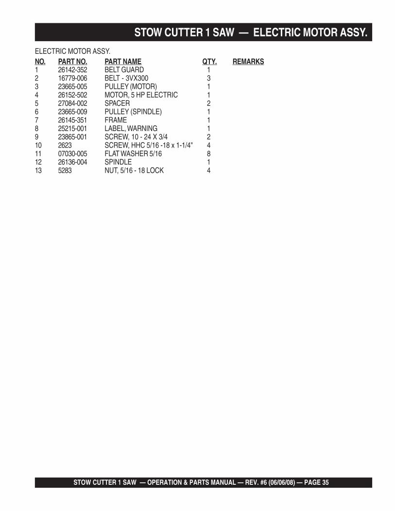
ELECTRIC MOTOR ASSY.NO. PART NO. PART NAME QTY. REMARKS1 26142-352 BELT GUARD 12 16779-006 BELT - 3VX300 33 23665-005 PULLEY (MOTOR) 14 26152-502 MOTOR, 5 HP ELECTRIC 15 27084-002 SPACER 26 23665-009 PULLEY (SPINDLE) 17 26145-351 FRAME 18 25215-001 LABEL, WARNING 19 23865-001 SCREW, 10 - 24 X 3/4 210 2623 SCREW, HHC 5/16 -18 x 1-1/4" 411 07030-005 FLAT WASHER 5/16 812 26136-004 SPINDLE 113 5283 NUT, 5/16 - 18 LOCK 4

PAGE 36 — STOW CUTTER 1 SAW — OPERATION & PARTS MANUAL — REV. #6 (06/06/08)
UNDERCARRIAGE ASSY
STOW CUTTER 1 SAW — UNDERCARRIAGE ASSY.
STOW CUTTER 1 SAW — OPERATION & PARTS MANUAL — REV. #6 (06/06/08) — PAGE 37
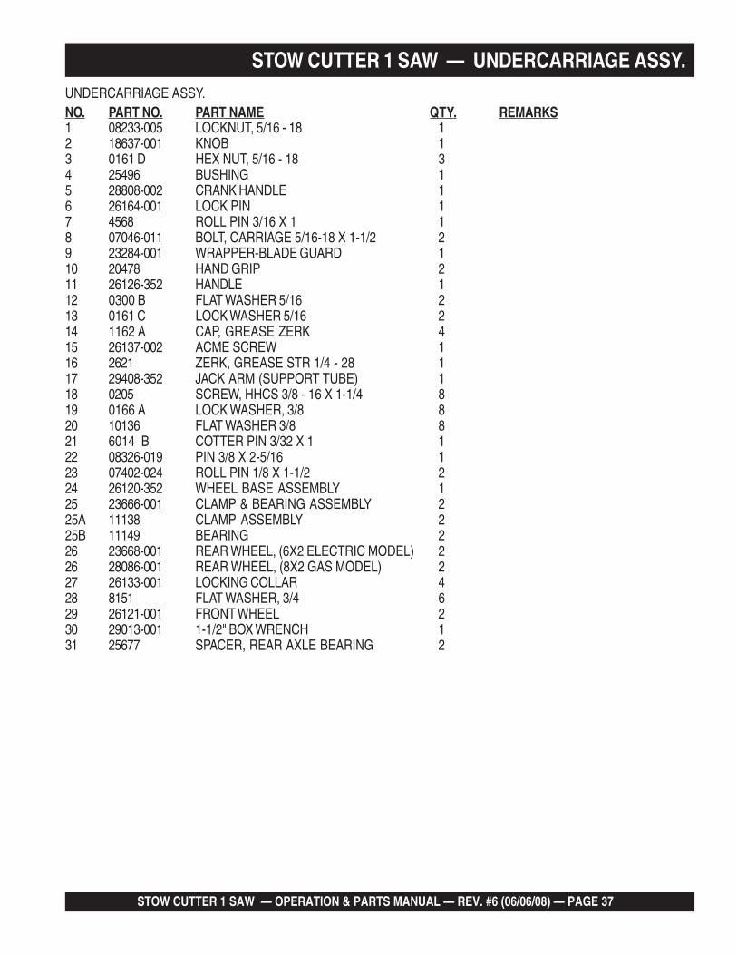
UNDERCARRIAGE ASSY.NO. PART NO. PART NAME QTY. REMARKS1 08233-005 LOCKNUT, 5/16 - 18 12 18637-001 KNOB 13 0161 D HEX NUT, 5/16 - 18 34 25496 BUSHING 15 28808-002 CRANK HANDLE 16 26164-001 LOCK PIN 17 4568 ROLL PIN 3/16 X 1 18 07046-011 BOLT, CARRIAGE 5/16-18 X 1-1/2 29 23284-001 WRAPPER-BLADE GUARD 110 20478 HAND GRIP 211 26126-352 HANDLE 112 0300 B FLAT WASHER 5/16 213 0161 C LOCK WASHER 5/16 214 1162 A CAP, GREASE ZERK 415 26137-002 ACME SCREW 116 2621 ZERK, GREASE STR 1/4 - 28 117 29408-352 JACK ARM (SUPPORT TUBE) 118 0205 SCREW, HHCS 3/8 - 16 X 1-1/4 819 0166 A LOCK WASHER, 3/8 820 10136 FLAT WASHER 3/8 821 6014 B COTTER PIN 3/32 X 1 122 08326-019 PIN 3/8 X 2-5/16 123 07402-024 ROLL PIN 1/8 X 1-1/2 224 26120-352 WHEEL BASE ASSEMBLY 125 23666-001 CLAMP & BEARING ASSEMBLY 225A 11138 CLAMP ASSEMBLY 225B 11149 BEARING 226 23668-001 REAR WHEEL, (6X2 ELECTRIC MODEL) 226 28086-001 REAR WHEEL, (8X2 GAS MODEL) 227 26133-001 LOCKING COLLAR 428 8151 FLAT WASHER, 3/4 629 26121-001 FRONT WHEEL 230 29013-001 1-1/2" BOX WRENCH 131 25677 SPACER, REAR AXLE BEARING 2
STOW CUTTER 1 SAW — UNDERCARRIAGE ASSY.

PAGE 38 — STOW CUTTER 1 SAW — OPERATION & PARTS MANUAL — REV. #6 (06/06/08)
WATER SYSTEM AND BLADE ASSY.
1PULLEY ASSEMBLY.SEE PAGE 30.
1
33
34
40
3741
36
12
2
3
3
4
4
5
7
6
8
1113 14
22
24
25
2
21
27 16
16
181920 17
26
28
2625
30
3231
26
35
35
30
38
29
39
910
12 15
23
4037
STOW CUTTER 1 SAW — WATER SYSTEM AND BLADE ASSY.

STOW CUTTER 1 SAW — OPERATION & PARTS MANUAL — REV. #6 (06/06/08) — PAGE 39
STOW CUTTER 1 SAW — WATER SYSTEM AND BLADE ASSY.WATER SYSTEM AND BLADE ASSY.NO. PART NO. PART NAME QTY. REMARKS1 22129-001 CLAMP 22 0948 FLAT WASHER, 1/4 53 0181 B LOCK WASHER 1/4 54 0949 HEX NUT 1/4 - 20 55 0424 SCREW, HHCS 1/4 - 20 X 1 46 29406-352 BLADE GUARD 17 18626-001 SPRING 28 23255-011 HOSE 26" 19 23566-001 BARBED FITTING 90 DEG. 110 35122-402 VALVE 111 11708 NIPPLE 1/2 112 16378-005 U-BOLT 1/4 113 23252-002 ELBOW 1/2 114 15544 CONNECTOR, GARDEN HOSE 115 13336-001 WASHER, RUBBER 116 12694-006 HOSE CLAMP 217 24778-001 SWIVEL CONNECTOR 118 24642-001 Y-FITTING 119 12694-004 HOSE CLAMP 220 60021 .............. HOSE, 1.0 FT. ................................. 2 .......... SOLD PER FOOT21 0131 A SCREW, HHCS 1/4 - 20 X 3/4 222 28729-005 CHIP GUARD 123 10930 FENDER WASHER 1/4 224 10024 LOCKNUT, 1/4 - 20 225 10136 FLAT WASHER 3/8 626 0166 A LOCK WASHER 3/8 227 06501-032 SCREW, HHCS 3/8 - 16 X 4 128 0205 SCREW, HHCS 3/8 - 16 X 1 129 06922-003 NUT L.H. 1 - 1/4 130 15046 DOWEL PIN 3/8 X 1-1/4 231 26928-004 FLANGE, OUTER 132 28811-001 FLANGE, INNER 133 4001 FLAT WASHER 434 1284 SCREW, HHCS 3/8 - 16 X 1-1/2 435 3200 BEARING 236 0125 WOODRUFF KEY 1/4 X 1 137 1162 A CAP, GREASE ZERK 238 26135-002 SPINDLE 139 9152 KEY 1/4 X 1-3/4 140 2621 GREASE ZERK 241 9SWG BLADE, DIAMOND BACK 1

PAGE 40 — STOW CUTTER 1 SAW — OPERATION & PARTS MANUAL — REV. #6 (06/06/08)
STOW CUTTER 1 SAW — POINTER ASSY.
POINTER ASSY.
STOW CUTTER 1 SAW — OPERATION & PARTS MANUAL — REV. #6 (06/06/08) — PAGE 41
STOW CUTTER 1 SAW — POINTER ASSY.
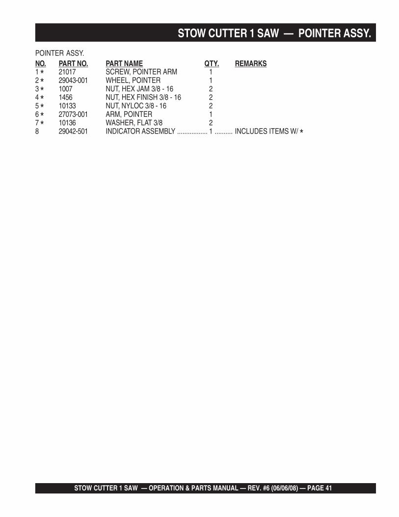
POINTER ASSY.NO. PART NO. PART NAME QTY. REMARKS1 * 21017 SCREW, POINTER ARM 12 * 29043-001 WHEEL, POINTER 13 * 1007 NUT, HEX JAM 3/8 - 16 24 * 1456 NUT, HEX FINISH 3/8 - 16 25 * 10133 NUT, NYLOC 3/8 - 16 26 * 27073-001 ARM, POINTER 17 * 10136 WASHER, FLAT 3/8 28 29042-501 INDICATOR ASSEMBLY ................. 1 .......... INCLUDES ITEMS W/ *

PAGE 42 — STOW CUTTER 1 SAW — OPERATION & PARTS MANUAL — REV. #6 (06/06/08)
AIR CLEANER ASSY.
HONDA GX390K1QWT2/GX390U1QWT2 ENG. — AIR CLEANER ASSY.
STOW CUTTER 1 SAW — OPERATION & PARTS MANUAL — REV. #6 (06/06/08) — PAGE 43
AIR CLEANER ASSY.
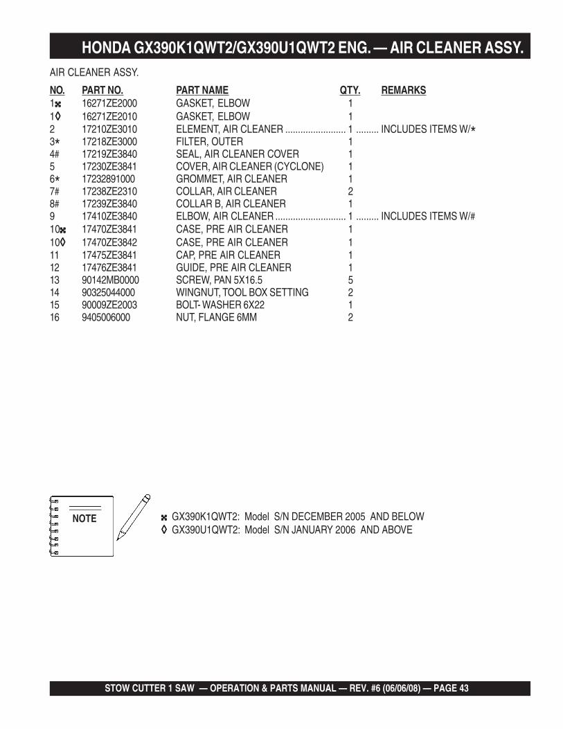
NO. PART NO. PART NAME QTY. REMARKS1 16271ZE2000 GASKET, ELBOW 11◊◊◊◊◊ 16271ZE2010 GASKET, ELBOW 12 17210ZE3010 ELEMENT, AIR CLEANER ........................ 1 ......... INCLUDES ITEMS W/*3* 17218ZE3000 FILTER, OUTER 14# 17219ZE3840 SEAL, AIR CLEANER COVER 15 17230ZE3841 COVER, AIR CLEANER (CYCLONE) 16* 17232891000 GROMMET, AIR CLEANER 17# 17238ZE2310 COLLAR, AIR CLEANER 28# 17239ZE3840 COLLAR B, AIR CLEANER 19 17410ZE3840 ELBOW, AIR CLEANER ............................ 1 ......... INCLUDES ITEMS W/#10 17470ZE3841 CASE, PRE AIR CLEANER 110◊◊◊◊◊ 17470ZE3842 CASE, PRE AIR CLEANER 111 17475ZE3841 CAP, PRE AIR CLEANER 112 17476ZE3841 GUIDE, PRE AIR CLEANER 113 90142MB0000 SCREW, PAN 5X16.5 514 90325044000 WINGNUT, TOOL BOX SETTING 215 90009ZE2003 BOLT- WASHER 6X22 116 9405006000 NUT, FLANGE 6MM 2
HONDA GX390K1QWT2/GX390U1QWT2 ENG. — AIR CLEANER ASSY.
NOTE GX390K1QWT2: Model S/N DECEMBER 2005 AND BELOW◊◊◊◊◊ GX390U1QWT2: Model S/N JANUARY 2006 AND ABOVE

PAGE 44 — STOW CUTTER 1 SAW — OPERATION & PARTS MANUAL — REV. #6 (06/06/08)
CAMSHAFT ASSY.
HONDA GX390K1QWT2/GX390U1QWT2 ENG. — CAMSHAFT ASSY.

STOW CUTTER 1 SAW — OPERATION & PARTS MANUAL — REV. #6 (06/06/08) — PAGE 45
CAMSHAFT ASSY.
NO. PART NO. PART NAME QTY. REMARKS1 14100ZF6W01 CAMSHAFT ASSEMBLY .......................... 1 ......... INCLUDES ITEM W/*2 14410ZE3013 ROD, PUSH 23 14431ZE2010 ARM, VALVE ROCKER 24 14441ZE2000 LIFTER, VALVE 25 14451ZE1013 PIVOT, ROCKER ARM 26* 14568ZE1000 SPRING, WEIGHT RETURN 17 14711ZE3000 VALVE, INTAKE 18 14721ZE3000 VALVE, EXHAUST 19 14751ZE2003 SPRING, VALVE 210 14771ZE2000 RETAINER,INTAKE VALVE SPRING 111 14773ZE2000 RETAINER, EXHAUST VALVE SPRING 112 14775ZE2010 SEAT, VALVE SPRING 113 14781ZE2000 ROTATOR, VALVE 114 14791ZE2010 PLATE, PUSH ROD GUIDE 115 90012ZE0010 BOLT, PIVOT 8MM 216 90206ZE1000 NUT, PIVOT ADJ. 217 12209ZE8003 SEAL, VALVE STEM 1
HONDA GX390K1QWT2/GX390U1QWT2 ENG. — CAMSHAFT ASSY.
PAGE 46 — STOW CUTTER 1 SAW — OPERATION & PARTS MANUAL — REV. #6 (06/06/08)
CARBURETOR ASSY.
HONDA GX390K1QWT2/GX390U1QWT2 ENG. — CARBURETOR ASSY.

STOW CUTTER 1 SAW — OPERATION & PARTS MANUAL — REV. #6 (06/06/08) — PAGE 47
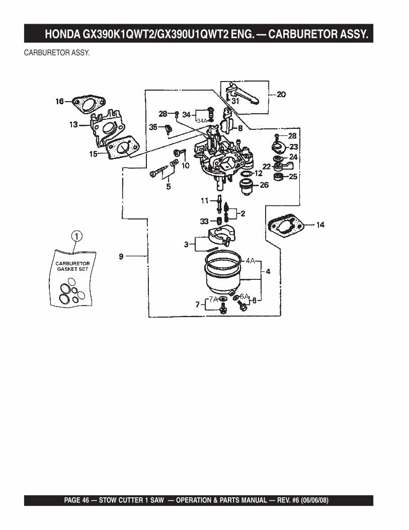
CARBURETOR ASSY.
NO. PART NO. PART NAME QTY. REMARKS1 16010ZE2812 CARBURETOR, GASKET SET 1 INCLUDES ITEMS W/+2$ 16011ZA0931 VALVE SET, FLOAT 13$ 16013ZA0931 FLOAT SET 14$ 16015ZE8005 CHAMBER SET, FLOAT ...................... 1 ............. INCLUDES ITEM 4A
............................................................................. INCLUDES ITEM W/>4A+ GASKET, CHAMBER SET FLOAT ...................... NOT SOLD SEPARATELY5$ 16016ZH7W01 SCREW SET, PILOT 16$> 16024ZE1811 SCREW SET, DRAIN, .......................... 1 ............. INCLUDES ITEM 6A6A+ GASKET, SCREW SET DRAIN ........................... NOT SOLD SEPARATELY7$ 16028ZE0005 SCREW SET ....................................... 1 ............. INCLUDES ITEM 7A7A+ GASKET, SCREW SET ....................................... NOT SOLD SEPARATELY8$ 16044ZE3W20 CHOKE SET 19$ 16100ZF6V21 CARBURETOR ASSY. (BE85C B) ....... 1 ............. INCLUDES ITEMS W/$10$ 16124ZE0005 SCREW, THROTTLE STOP 111$ 16166ZF6W10 NOZZLE, MAIN 112$+ 16173001004 GASKET, FUEL STRAINER CUP 113 16211ZF6000 INSULATOR, CARBURETOR 114 16220ZA0702 SPACER, CARBURETOR 115 16221ZF6800 GASKET, CARBURETOR 116 16223ZE3W00 GASKET, INSULATOR 120 16610ZE1000 LEVER, CHOKE (STD) ........................1 ............. INCLUDES ITEM W/*22$ 16953ZE1812 LEVER, VALVE 123$ 16954ZE1812 PLATE, LEVER SETTING 124$ 16956ZE1811 SPRING, VALVE LEVER 125$+ 16957ZE1812 GASKET, VALVE 126$ 16967ZE0811 CUP, FUEL STRAINER 128$ 93500030061H SCREW, PAN (3X6) 231* 9430520122 PIN, SPRING (2X12) 133$ 99101ZH80950 JET, MAIN (#95) (OPTIONAL) 133$ 99101ZH80980 JET, MAIN (#98) (OPTIONAL) 133$ 99101ZH81000 JET, MAIN (#100) 134$ 99204ZA00450 JET SET, PILOT (#45) ......................... 1 ............. INCLUDES ITEM 34A34A+ GASKET, JET SET PILOT (#45) ......................... NOT SOLD SEPARATELY35$ 16172ZE3W10 COLLAR, SET 1
HONDA GX390K1QWT2/GX390U1QWT2 ENG. — CARBURETOR ASSY.

PAGE 48 — STOW CUTTER 1 SAW — OPERATION & PARTS MANUAL — REV. #6 (06/06/08)
CONTROL ASSY.
HONDA GX390K1QWT2/GX390U1QWT2 ENG. — CONTROL ASSY.

STOW CUTTER 1 SAW — OPERATION & PARTS MANUAL — REV. #6 (06/06/08) — PAGE 49
CONTROL ASSY.
NO. PART NO. PART NAME QTY. REMARKS2 16551ZE3000 ARM, GOVERNOR 13 16555ZE3000 ROD, GOVERNOR 14 16561ZE3000 SPRING, GOVERNOR 15 16562ZE3000 SPRING, THROTTLE RETURN 16 16570ZE3W20 CONTROL ASSY. (REMOTE) .................... 1 ......... INCLUDES ITEMS W/*10* 16571ZE3W00 LEVER, CONTROL 111* 16574ZE1000 SPRING, LEVER 112* 16575ZE2W00 WASHER, CONTROL LEVER 113* 16576891000 HOLDER, CABLE 114* 16578ZE1000 SPACER, CONTROL LEVER 115* 16581ZE3W00 BASE, CONTROL 117* 16584883300 SPRING, CONTROL ADJUSTING 118* 16592883310 SPRING, CABLE RETURN 121 90013883000 BOLT, FLANGE (6X12) (CT200) 222 90015ZE5010 BOLT, GOVERNOR ARM 124* 90114SA0000 NUT, SELF-LOCK (6MM) 127* 93500050320A SCREW, PAN (5X32) 128* 93500050160A SCREW, PAN (5X16) 129 9405006000 NUT, FLANGE (6MM) 1
HONDA GX390K1QWT2/GX390U1QWT2 ENG. — CONTROL ASSY.

PAGE 50 — STOW CUTTER 1 SAW — OPERATION & PARTS MANUAL — REV. #6 (06/06/08)
CRANKCASE COVER ASSY.
HONDA GX390K1QWT2/GX390U1QWT2 ENG. — CRANKCASE ASSY.

STOW CUTTER 1 SAW — OPERATION & PARTS MANUAL — REV. #6 (06/06/08) — PAGE 51
CRANKCASE COVER ASSY.
NO. PART NO. PART NAME QTY. REMARKS2 11300ZE3602 COVER ASSY., CRANKCASE .........................1 ................ S/N 3287256 AND BELOW
............................................................................................ INCLUDES ITEMS W/>2 11300ZE3604 COVER ASSY., CRANKCASE .........................1 ................ S/N 3287257 AND ABOVE
............................................................................................ INCLUDES ITEMS W/%2◊◊◊◊◊ 11300ZE3604 COVER ASSY., CRANKCASE .........................1 ................ INCLUDES ITEMS W/$3 11381ZE3801 GASKET, CASE COVER 14 15600ZG4003 CAP ASSY., OIL FILLER .................................1 ................ INCLUDES ITEM W/#5 15600735003 CAP ASSY., OIL FILLER .................................1 ................ INCLUDES ITEM W/*8#* 15625ZE1003 GASKET, OIL FILLER CAP 29 16510ZE3000 GOVERNOR ASSY. ..........................................1 ................ INCLUDES ITEMS W/+10>%$+ 16511ZE8000 WEIGHT, GOVERNOR 311>%$+ 16512ZE3000 HOLDER, GOVERNOR WEIGHT 112>%$+ 16513ZE2000 PIN, GOVERNOR WEIGHT 313 >$% 16531ZE2000 SLIDER, GOVERNOR ......................................1 ................ S/N 3287256 AND BELOW13 >%$ 16531Z0A000 SLIDER, GOVERNOR ......................................1 ................ S/N 3287257 AND ABOVE13◊◊◊◊◊>%$ 16531Z0A000 SLIDER, GOVERNOR 115>%$ 90602ZE1000 CLIP, GOVERNOR HOLDER 116 90701HC4000 PIN, DOWEL (8X12) 217>%$ 91201ZE3004 OIL SEAL (35X52X8) 118>%$ 9410106800 WASHER, PLAIN (6MM) 119 957010804000 BOLT, FLANGE (8X40) 720>%$ 961006202000 BEARING, RADIAL BALL (6202) 121>%$ 961006207000 BEARING, RADIAL BALL (6207) 1
HONDA GX390K1QWT2/GX390U1QWT2 ENG. — CRANKCASE ASSY.
NOTE GX390K1QWT2: Model S/N DECEMBER 2005 AND BELOW◊◊◊◊◊ GX390U1QWT2: Model S/N JANUARY 2006 AND ABOVE

PAGE 52 — STOW CUTTER 1 SAW — OPERATION & PARTS MANUAL — REV. #6 (06/06/08)
CRANKSHAFT ASSY.
HONDA GX390K1QWT2/GX390U1QWT2 ENG. — CRANKSHAFT ASSY.

STOW CUTTER 1 SAW — OPERATION & PARTS MANUAL — REV. #6 (06/06/08) — PAGE 53
CRANKSHAFT ASSY.
NO. PART NO. PART NAME QTY. REMARKS2 13310ZF6W10 CRANKSHAFT .......................................... 1 ......... INCLUDES ITEM W/*2◊◊◊◊◊ 13310ZF6W11 CRANKSHAFT .......................................... 1 ......... INCLUDES ITEM W/#
............................................................................... S/N 1113739 AND BELOW2◊◊◊◊◊ 13310ZF6W12 CRANKSHAFT .......................................... 1 ......... INCLUDES ITEM W/+
.......................................................................... S/N 1113740 AND ABOVE8 13351ZE3010 WEIGHT, BALANCER 111 90745ZE2600 KEY(6.3X6.3X43) 112 * 91001ZF6003 BEARING, RADIAL BALL (6207S) 112◊◊◊◊◊# 91001ZF6003 BEARING, RADIAL BALL (6207S) ............ 1 ......... S/N 1113739 AND BELOW12◊◊◊◊◊+ 91001ZF6013 BEARING, RADIAL BALL (6207SH) ......... 1 ......... S/N 1113740 AND ABOVE
HONDA GX390K1QWT2/GX390U1QWT2 ENG. — CRANKSHAFT ASSY.
NOTE GX390K1QWT2: Model S/N DECEMBER 2005 AND BELOW◊◊◊◊◊ GX390U1QWT2: Model S/N JANUARY 2006 AND ABOVE
PAGE 54 — STOW CUTTER 1 SAW — OPERATION & PARTS MANUAL — REV. #6 (06/06/08)
CYLINDER BARREL ASSY.
HONDA GX390K1QWT2/GX390U1QWT2 ENG. — CYLINDER BARREL ASSY.
STOW CUTTER 1 SAW — OPERATION & PARTS MANUAL — REV. #6 (06/06/08) — PAGE 55
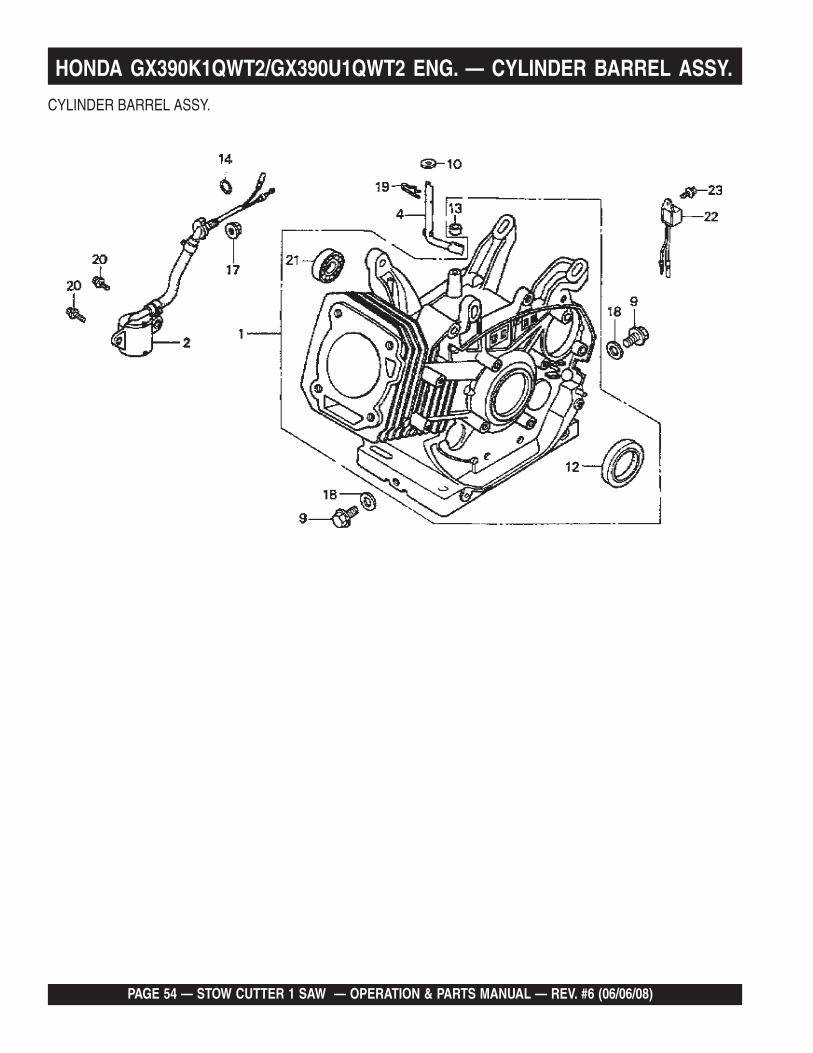
CYLINDER BARREL ASSY.
NO. PART NO. PART NAME QTY. REMARKS1 12000ZF6W13 CYLINDER ASSY. (ALERT) .................... 1 .............. INCLUDES ITEMS W/%1◊◊◊◊◊ 12000ZF6417 CYLINDER ASSY. ................................... 1 .............. INCLUDES ITEMS W/#2 15510ZE2043 SWITCH ASSY., OIL LEVEL 12◊◊◊◊◊ 15510ZE2043 SWITCH ASSY., OIL LEVEL .................. 1 .............. S/N 1412956 AND BELOW2◊◊◊◊◊ 15510ZE2053 SWITCH ASSY., OIL LEVEL .................. 1 .............. S/N 1412957 AND ABOVE4 16541ZE3010 SHAFT, GOVERNOR ARM 19 90131883000 BOLT, DRAIN PLUG 12X15 210 90446KE1000 WASHER (8.2X17X0.8) 112 %# 91201ZE3004 OIL SEAL (35X52X8) 113 91203952771 OIL SEAL (8X14X5) 114 91353671004 O-RING (14MM) (NOK) 117 9405010000 NUT, FLANGE (10MM) 118 9410912000 WASHER, DRAIN PLUG (12MM) 219 9425110000 PIN, LOCK (10MM) 120 957010601200 BOLT, FLANGE (6X12) 221%# 961006202000 BEARING, RADIAL BALL (6202) 122 34150ZH7003 ALERT UNIT, OIL 122◊◊◊◊◊ 34150ZH7003 ALERT UNIT, OIL .................................... 1 .............. S/N 1419413 AND BELOW22◊◊◊◊◊ 34150ZH7013 ALERT UNIT, OIL .................................... 1 .............. S/N 1419414 AND ABOVE23 90013883000 BOLT, FLANGE (6X12) (CT200) 1
HONDA GX390K1QWT2/GX390U1QWT2 ENG. — CYLINDER BARREL ASSY.
NOTE GX390K1QWT2: Model S/N DECEMBER 2005 AND BELOW◊◊◊◊◊ GX390U1QWT2: Model S/N JANUARY 2006 AND ABOVE

PAGE 56 — STOW CUTTER 1 SAW — OPERATION & PARTS MANUAL — REV. #6 (06/06/08)
CYLINDER HEAD ASSY.
HONDA GX390K1QWT2/GX390U1QWT2 ENG. — CYLINDER HEAD ASSY.
STOW CUTTER 1 SAW — OPERATION & PARTS MANUAL — REV. #6 (06/06/08) — PAGE 57
CYLINDER HEAD ASSY.
NO. PART NO. PART NAME QTY. REMARKS1 12200ZF6W01 CYLINDER HEAD.............................................1 ................ INCLUDES ITEMS W/*1◊◊◊◊◊ 12200ZF6406 CYLINDER HEAD.............................................1 ................ INCLUDES ITEMS W/%2*% 12204ZE2306 GUIDE, VALVE (OS) (OPTIONAL) 13*% 12205ZE2305 GUIDE, EX. VALVE (OS) (OPTIONAL) 14*% 12216ZE2300 CLIP, VALVE GUIDE 15 12251ZF6W00 GASKET, CYLINDER HEAD 16 12310ZE3791 COVER, HEAD 17 12315ZE3840 TUBE, BREATHER 18 12391ZE2020 GASKET, CYLINDER HEAD COVER 110 17316611000 CLIP, BREATHER TUBE 211 90014ZE2000 BOLT, HEAD COVER 112 90042ZE8000 BOLT, STUD (8X131.5) 213 92900080320E BOLT 2, STUD (8X32) 214 90441ZE2010 WASHER, HEAD COVER 116 9430112200 PIN A, DOWEL (12X20) 217 957251008000 BOLT, FLANGE (10X80) 417◊◊◊◊◊ 957251008000 BOLT, FLANGE (10X80) ...................................4 ................ S/N 1411816 AND BELOW17◊◊◊◊◊ 957011008000 BOLT, FLANGE (10X80) ...................................4 ................ S/N 1411817 AND ABOVE18 9807955846 SPARK PLUG (BPR5ES) (NGK) (OPT.) 118 9807955855 SPARK PLUG (W16EPR-U) (DENSO) 118 9807956846 SPARK PLUG (BPR6ES) (NGK) 118 9807956855 SPARK PLUG (W20EPR-U) (DENSO) 1
HONDA GX390K1QWT2/GX390U1QWT2 ENG. — CYLINDER HEAD ASSY.
NOTE GX390K1QWT2: Model S/N DECEMBER 2005 AND BELOW◊◊◊◊◊ GX390U1QWT2: Model S/N JANUARY 2006 AND ABOVE

PAGE 58 — STOW CUTTER 1 SAW — OPERATION & PARTS MANUAL — REV. #6 (06/06/08)
FAN COVER ASSY.
HONDA GX390K1QWT2/GX390U1QWT2 ENG. — FAN COVER ASSY.

STOW CUTTER 1 SAW — OPERATION & PARTS MANUAL — REV. #6 (06/06/08) — PAGE 59
FAN COVER ASSY.
NO. PART NO. PART NAME QTY. REMARKS4 16731ZE2003 CLIP, TUBE 17 19610ZE3010ZB COVER, FAN *NH1* (BLACK) 110 19631ZE3W00 SHROUD 113 36100ZH7003 SWITCH ASSY., ENGINE STOP 113◊◊◊◊◊ 36100ZF6P81 SWITCH ASSY., ENGINE STOP ................. 1 ..............S/N 1412956 AND BELOW13◊◊◊◊◊ 36100ZF6P82 SWITCH ASSY., ENGINE STOP ................. 1 ..............S/N 1412957 AND ABOVE15 90013883000 BOLT, FLANGE (6X12) (CT200) 6
HONDA GX390K1QWT2/GX390U1QWT2 ENG. — FAN COVER ASSY.
NOTE GX390K1QWT2: Model S/N DECEMBER 2005 AND BELOW◊◊◊◊◊ GX390U1QWT2: Model S/N JANUARY 2006 AND ABOVE

PAGE 60 — STOW CUTTER 1 SAW — OPERATION & PARTS MANUAL — REV. #6 (06/06/08)
FLYWHEEL ASSY.
HONDA GX390K1QWT2/GX390U1QWT2 ENG. — FLYWHEEL ASSY.

STOW CUTTER 1 SAW — OPERATION & PARTS MANUAL — REV. #6 (06/06/08) — PAGE 61
FLYWHEEL ASSY.
NO. PART NO. PART NAME QTY. REMARKS1 19511ZE3000 FAN, COOLING 13 28450ZE3W11 PULLEY, STARTER (SCREEN GRID) 17 31100ZE3701 FLYWHEEL 110 90201ZE3V00 NUT, SPECIAL (16MM) (1) 110◊◊◊◊◊ 90201ZE3V00 NUT, SPECIAL (16MM) (1) ........................... 1 ..............S/N 1317976 AND BELOW10◊◊◊◊◊ 90201ZE3790 NUT, SPECIAL (16MM) (1) ........................... 1 ..............S/N 1317977 AND ABOVE11 90741ZE2000 KEY, SPECIAL WOODRUFF (25X18) 1
HONDA GX390K1QWT2/GX390U1QWT2 ENG. — FLYWHEEL ASSY.
NOTE GX390K1QWT2: Model S/N DECEMBER 2005 AND BELOW◊◊◊◊◊ GX390U1QWT2: Model S/N JANUARY 2006 AND ABOVE

PAGE 62 — STOW CUTTER 1 SAW — OPERATION & PARTS MANUAL — REV. #6 (06/06/08)
FUEL TANK ASSY.
HONDA GX390K1QWT2/GX390U1QWT2 ENG. — FUEL TANK ASSY.

STOW CUTTER 1 SAW — OPERATION & PARTS MANUAL — REV. #6 (06/06/08) — PAGE 63
FUEL TANK ASSY.
NO. PART NO. PART NAME QTY. REMARKS1 16854ZH8000 RUBBER, SUPPORTER (107MM) 13 16955ZE1000 JOINT, FUEL TANK 16 17510ZE3010ZB TANK, FUEL *NH1* 16◊◊◊◊◊ 17510ZE3020ZB TANK, FUEL *NH1* ........................................... 1.......... S/N 1213085 AND BELOW6◊◊◊◊◊ 17510ZE3800ZA TANK, FUEL *NH1* ........................................... 1.......... S/N 1213086 THRU 13837996◊◊◊◊◊ 17510ZE3801ZA TANK, FUEL *NH1* ........................................... 1.......... S/N 1383800 AND ABOVE8 17620ZH7023 CAP, FUEL FILLER (BLACK) ............................ 1.......... INCLUDES ITEM W/*8◊◊◊◊◊ 17620Z0T305 CAP, FUEL FILLER (CHROME PLATED) .......... 1.......... INCLUDES ITEM W/#9* 17631ZH7003 GASKET, FUEL FILLER CAP 19# 17631Z0T812 GASKET, FUEL FILLER CAP 39X62X3 115 91353671004 O-RING (14MM) (NOK) 117 9405008000 NUT, FLANGE (8MM) 218 950014523540 BULK HOSE, FUEL (4.5X235) .......................... 1.......... REPLACES 950014500160M18◊◊◊◊◊ 950014523540 BULK HOSE, FUEL (4.5X235) .......................... 1.......... REPLACES 950014500160M
....................................................................................... S/N 1105013 AND BELOW18◊◊◊◊◊ 91424Z5L801 BULK HOSE, FUEL (4.5X235) (FKM) ............... 1.......... S/N 1105014 AND ABOVE20 9500202080 CLIP, TUBE (B8) 220◊◊◊◊◊ 9500202080 CLIP, TUBE (B8) ................................................ 2.......... S/N 1105013 AND BELOW20◊◊◊◊◊ 950024080008 CLAMP, TUBE (D8) ........................................... 2.......... S/N 1105014 AND ABOVE22 957010802500 BOLT, FLANGE (8X25) 2
HONDA GX390K1QWT2/GX390U1QWT2 ENG. — FUEL TANK ASSY.
NOTE GX390K1QWT2: Model S/N DECEMBER 2005 AND BELOW◊◊◊◊◊ GX390U1QWT2: Model S/N JANUARY 2006 AND ABOVE

PAGE 64 — STOW CUTTER 1 SAW — OPERATION & PARTS MANUAL — REV. #6 (06/06/08)
IGNITION COIL ASSY.
HONDA GX390K1QWT2/GX390U1QWT2 ENG. — IGNITION COIL ASSY.

STOW CUTTER 1 SAW — OPERATION & PARTS MANUAL — REV. #6 (06/06/08) — PAGE 65
IGNITION COIL ASSY.
NO. PART NO. PART NAME QTY. REMARKS1 30500ZF6W02 COIL ASSY., IGNITION 11◊◊◊◊◊ 30500ZF6W02 COIL ASSY., IGNITION..................................... 1.......... S/N 1411816 AND BELOW1◊◊◊◊◊ 30500ZF6W03 COIL ASSY., IGNITION..................................... 1.......... S/N 1411817 AND ABOVE2 30700ZE1013 CAP ASSY., NOISE SUPPRESSOR 18 31512ZE2000 GROMMET, WIRE 112 36101ZE2701 WIRE, STOP SWITCH (430MM) 117 90015883000 BOLT, FLANGE (6X28) 218 90684ZA0601 CLIP, WIRE HARNESS 1
HONDA GX390K1QWT2/GX390U1QWT2 ENG. — IGNITION COIL ASSY.
NOTE GX390K1QWT2: Model S/N DECEMBER 2005 AND BELOW◊◊◊◊◊ GX390U1QWT2: Model S/N JANUARY 2006 AND ABOVE
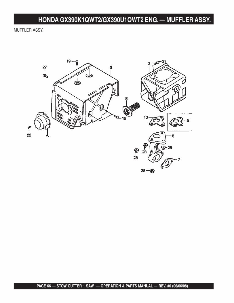
PAGE 66 — STOW CUTTER 1 SAW — OPERATION & PARTS MANUAL — REV. #6 (06/06/08)
MUFFLER ASSY.
HONDA GX390K1QWT2/GX390U1QWT2 ENG. — MUFFLER ASSY.

STOW CUTTER 1 SAW — OPERATION & PARTS MANUAL — REV. #6 (06/06/08) — PAGE 67
MUFFLER ASSY.
NO. PART NO. PART NAME QTY. REMARKS2 18310ZE2W61 MUFFLER 13 18320ZE2W61 PROTECTOR, MUFFLER 15 18330ZE2W00 PIPE, EX. 16 18331ZE3810 CAP, MUFFLER 16◊◊◊◊◊ 18331ZE3810 CAP, MUFFLER...................................................... 1 ......... S/N 1166160 AND BELOW6◊◊◊◊◊ 18331ZE3811 CAP, MUFFLER...................................................... 1 ......... S/N 1166161 AND ABOVE7 18333ZF6W01 GASKET, EX. PIPE 18 18355ZE2W00 ARRESTER, SPARK (OPTIONAL) 19 18381ZE2W10 GASKET, MUFFLER (ARRESTER) (OPTIONAL) 110 18381ZE2800 GASKET, MUFFLER 119 90050ZE1000 SCREW, TAPPING (5X8) 422 90055ZE1000 SCREW, TAPPING (4X6) 327 90006ZE2000 SCREW, TAPPING (6X10) 128 9405008000 NUT, FLANGE (8MM) 531 90055ZE1000 SCREW, TAPPING (4X6) 1
HONDA GX390K1QWT2/GX390U1QWT2 ENG. — MUFFLER ASSY.
NOTE GX390K1QWT2: Model S/N DECEMBER 2005 AND BELOW◊◊◊◊◊ GX390U1QWT2: Model S/N JANUARY 2006 AND ABOVE
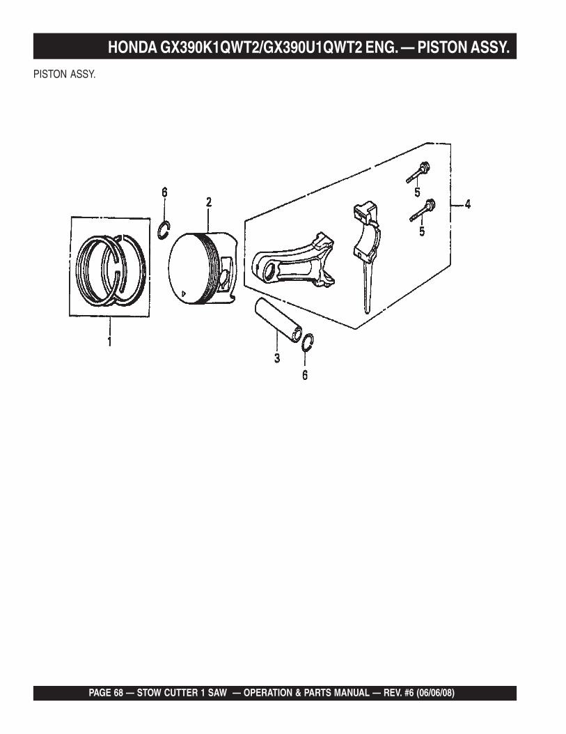
PAGE 68 — STOW CUTTER 1 SAW — OPERATION & PARTS MANUAL — REV. #6 (06/06/08)
PISTON ASSY.
HONDA GX390K1QWT2/GX390U1QWT2 ENG. — PISTON ASSY.

STOW CUTTER 1 SAW — OPERATION & PARTS MANUAL — REV. #6 (06/06/08) — PAGE 69
PISTON ASSY.
NO. PART NO. PART NAME QTY. REMARKS1 13010ZF6005 RING SET, PISTON (STD) 11 13011ZF6005 RING SET, PISTON (0.25) 11 13012ZF6005 RING SET, PISTON (0.50) 11 13013ZF6005 RING SET, PISTON (0.75) 12 13101ZF6W00 PISTON (STD) 12 13102ZF6W00 PISTON (0.25) 12 13103ZF6W00 PISTON (0.50) 12 13104ZF6W00 PISTON (0.75) 13 13111ZF6W00 PIN, PISTON 14 13200ZE3020 ROD ASSY., CONNECTING (STD) ........................ 1 ......... INCLUDES ITEM W/*4 13200ZE3315 ROD ASSY., CONNECTING (0.25 UNDERSIZE) 15* 90001ZE8000 BOLT, CONNECTING ROD 26 90601ZE3000 CLIP, PISTON PIN (20MM) 2
HONDA GX390K1QWT2/GX390U1QWT2 ENG. — PISTON ASSY.
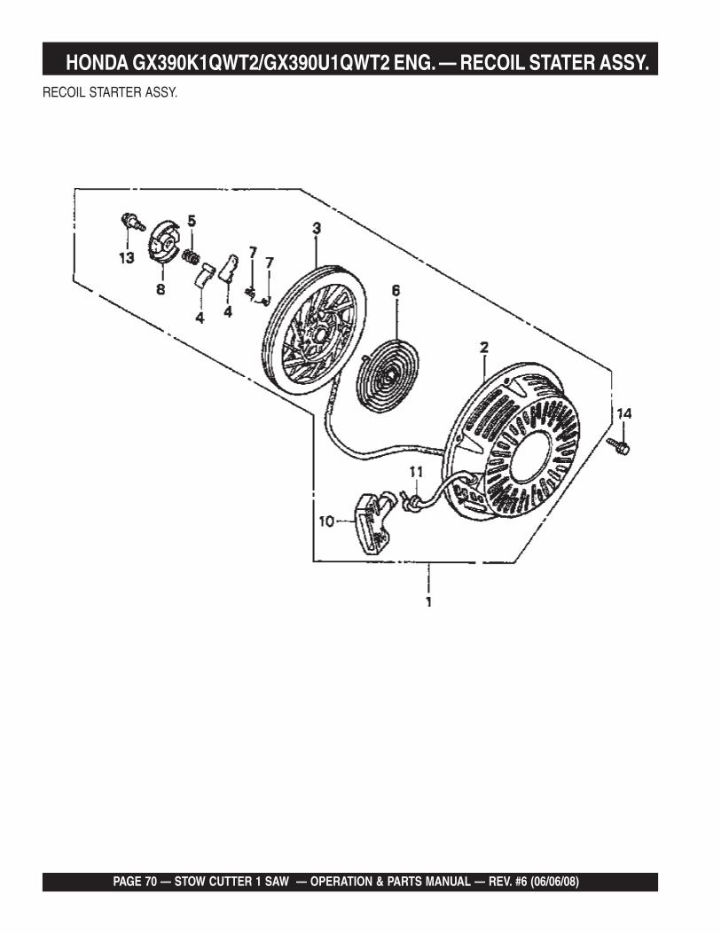
PAGE 70 — STOW CUTTER 1 SAW — OPERATION & PARTS MANUAL — REV. #6 (06/06/08)
RECOIL STARTER ASSY.
HONDA GX390K1QWT2/GX390U1QWT2 ENG. — RECOIL STATER ASSY.

STOW CUTTER 1 SAW — OPERATION & PARTS MANUAL — REV. #6 (06/06/08) — PAGE 71
RECOIL STARTER ASSY.
NO. PART NO. PART NAME QTY. REMARKS1 28400ZE3W01ZB STARTER ASSY., RECOIL *NH1* (BLACK) .............. 1 ...... INCLUDES ITEMS W/*2* 28410ZE3W01ZB CASE, RECOIL STARTER *NH1* (BLACK) 13* 28421ZE3W01 PULLEY, RECOIL STARTER 14* 28422ZE2W01 RATCHET, STARTER 25* 28441ZE2W01 SPRING, FRICTION 16* 28442ZE2W01 SPRING, STARTER RETURN 17* 28443ZE2W01 SPRING, RATCHET 28* 28444ZE2W01 RETAINER, SPRING 110* 28461ZE2W02 GRIP, STARTER 111 * 28462ZV7003 ROPE, RECOIL STARTER 111◊◊◊◊◊* 28462ZE3W01 ROPE, RECOIL STARTER 113* 90004ZE2W01 SCREW, CENTER 114 90008ZE2003 BOLT, FLANGE (6X10) 3
HONDA GX390K1QWT2/GX390U1QWT2 ENG. — RECOIL STATER ASSY.
NOTE GX390K1QWT2: Model S/N DECEMBER 2005 AND BELOW◊◊◊◊◊ GX390U1QWT2: Model S/N JANUARY 2006 AND ABOVE

PAGE 72 — STOW CUTTER 1 SAW — OPERATION & PARTS MANUAL — REV. #6 (06/06/08)
LABELS ASSY.
HONDA GX390K1QWT2/GX390U1QWT2 ENG. — LABELS ASSY.
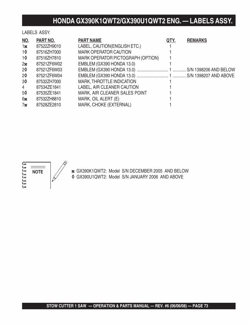
STOW CUTTER 1 SAW — OPERATION & PARTS MANUAL — REV. #6 (06/06/08) — PAGE 73
LABELS ASSY.
NO. PART NO. PART NAME QTY. REMARKS1 87522ZH9010 LABEL, CAUTION(ENGLISH ETC.) 11◊◊◊◊◊ 87516ZH7000 MARK OPERATOR CAUTION 11◊◊◊◊◊ 87516ZH7810 MARK OPERATOR PICTOGRAPH (OPTION) 12 87521ZF6W02 EMBLEM (GX390 HONDA 13.0) 12◊◊◊◊◊ 87521ZF6W03 EMBLEM (GX390 HONDA 13.0) ............................ 1 ............ S/N 1398206 AND BELOW2◊◊◊◊◊ 87521ZF6W04 EMBLEM (GX390 HONDA 13.0) ............................ 1 ............ S/N 1398207 AND ABOVE3◊◊◊◊◊ 87532ZH7000 MARK, THROTTLE INDICATION 14 87534ZE1841 LABEL, AIR CLEANER CAUTION 15◊◊◊◊◊ 87535ZE1841 MARK, AIR CLEANER SALES POINT 16 87532ZH8810 MARK, OIL ALERT (E) 17 87528ZE2810 MARK, CHOKE (EXTERNAL) 1
HONDA GX390K1QWT2/GX390U1QWT2 ENG. — LABELS ASSY.
NOTE GX390K1QWT2: Model S/N DECEMBER 2005 AND BELOW◊◊◊◊◊ GX390U1QWT2: Model S/N JANUARY 2006 AND ABOVE

PAGE 74 — STOW CUTTER 1 SAW — OPERATION & PARTS MANUAL — REV. #6 (06/06/08)
TERMS AND CONDITIONS OF SALE — PARTS
Terms and Conditions of SaleSTOW Construction Equipment
STOW CONSTRUCTION EQUIPMENTPOST OFFICE BOX 6254CARSON, CALIFORNIA 90749310-661-4242 • 877-BUY-STOWFAX: 310-604-9237E-MAIL: [email protected]
Atlanta • Boise • Newark • Quebec, CanadaManchester, UK • Rio de Janeiro, BR • Puebla, MX
PAYMENT TERMSTerms of payment for unit sales are 2% 15 daysnet 30 days from date of invoice unlessotherwise specifically stated on our invoice.Parts invoices have terms of net 10 days.Minimum parts billing is $15.00 net.Applicable discounts will be computed onmerchandise value only. Late charges will beassessed at prevailing rates. Cash discountscannot be taken on current billings if anypreviously billed amounts are past due.
FREIGHT POLICYFreight policy is established to offer customersevery advantage possible. Due to bulk freightratings on some equipment and other shippingconsiderations, freight policies differ byequipment type. Actual back freight may becharged for shipments originating from otherthan specified FOB warehouses. See FreightPolicy for details.All STOW domestic sales are FOB nearestavailable designated MQ/STOW warehouse.Export orders are ex-works factory located inCarson, CA or Boise, ID.Additions to orders already shipped cannot beaccepted for freight minimums.Should STOW elect to make partial shipmentsof an order originally complying with the “freightallowed” requirements, transportation chargeswill be absorbed by STOW on any subsequentshipment applying to that order.All other orders will be shipped collect orprepaid with charges added to the invoice.STOW’s responsibility ceases when a signedmanifest has been obtained from the carrier,and any claim for shortage or damage mustbe settled between the consignee and thecarrier.Parts: FOB Carson, California or Boise,Idaho. See Freight Policy for details andadditional discounts.
DROP SHIPMENTSSTOW reserves the right to refuse DropShipments outside the normal service area ofthe purchasing dealer.
FIELD WAREHOUSESField Warehouses are currently located inCalifornia, Georgia, Idaho, Iowa, and NewJersey
SPECIAL EXPEDITING SERVICEThe higher of a $35.00 surcharge or actualcosts will be added to the invoice for specialhandling, including bus shipments, or in caseswhere STOW personnel must personallydeliver the equipment or parts to the carrier.
RETURNED GOODS POLICYReturn shipments may be accepted and creditallowed, subject to the following provisions.1. A Returned Material Authorization (RMA)
must be approved by STOW prior toshipment. Approvals for returned goodsmust be with just cause and are at thesole discretion of STOW. A copy of theAuthorization must accompany the ship-ment to the designated Warehouse.
2. Parts being returned must be listed ascurrently supplied on the current parts list.
3. Parts must be in new and resalable conditionin the original package, with part numbersclearly marked.
4. Units and accessories must be currentmodels in the latest price list and in newand resalable condition.
5. Special order items are not returnable forcredit.
6. Credit on returned parts and units will beissued at actual dealer net price at time ofpurchase less 15% restocking charge.
7. All returned shipments are to be made tothe STOW designated receiving point,freight prepaid at the sender’s expense.
The sender will be notified of any materialreceived that does not meet the aboveprovisions. Such material will be held for 30 daysfrom notification pending instructions. If a replyis not received within 30 days, the material willbe returned to the sender at his expense withno credit issued.
PRICING, REBATES ANDSPECIFICATIONSEvery effort will be made to provide adequatenotice of changes; however, prices andequipment specifications are subject to changewithout notice.Price changes are effective on a specific dateand all orders received on or after that date willbe billed at the revised price.Rebates for price reductions and added chargesfor price increases will not be made for stock indealer inventory at the time of a price change.STOW reserves the right to quote and sell directto Government agencies and to OriginalEquipment Manufacturer accounts who use ourproducts as integral parts of their own products.
LIMITATION OF SELLER’S LIABILITYSTOW shall not be liable hereunder for damagesin excess of the purchase price of the item withrespect to which damages are claimed and inno event shall STOW be liable for loss of profitor good will or for any other special, consequentialor incidental damages.
LIMITATION OF WARRANTIESThere are no warranties, express or implied,made by STOW. hereunder on Productsmanufactured or distributed by it except thewarranty against defects in material andworkmanship on new Products to the originalpurchaser, as set forth in the STOW New ProductLimited Warranty.
Effective: July 15, 2003

STOW CUTTER 1 SAW — OPERATION & PARTS MANUAL — REV. #6 (06/06/08) — PAGE 75
NOTES

OPERATION AND PARTS MANUAL
Your Local Dealer is:
© COPYRIGHT 2008, MULTIQUIP INC.
Multiquip Inc, and the STOW logo are registered trademarks of Multiquip Inc. and may not be used, reproduced, or altered without written permission. All othertrademarks are the property of their respective owners and used with permission.
This manual MUST accompany the equipment at all times. This manual is considered a permanent part of the equipment and should remain with the unit if resold.
The information and specifications included in this publication were in effect at the time of approval for printing. Illustrations, descriptions, references and technicaldata contained in this manual are for guidance only and may not be considered as binding. Multiquip Inc. reserves the right to discontinue or change specifications,design or the information published in this publication at any time without notice and without incurring any obligations.
HERE’S HOW TO GET HELPPLEASE HAVE THE MODEL AND SERIAL
NUMBER ON-HAND WHEN CALLINGPARTS DEPARTMENT800-427-1244 FAX: 800-672-7877310-537-3700 FAX: 310-637-3284SERVICE DEPARTMENT800-478-1244 FAX: 310-537-4259310-537-3700TECHNICAL ASSISTANCE800-478-1244 FAX: 310-631-5032WARRANTY DEPARTMENT800-421-1244, EXT. 279 FAX: 310-537-1173310-537-3700, EXT. 279SALES DEPARTMENT310-661-4242 FAX: 310-604-9237877-289-7869 (877-BUY-STOW)
MQ STOW CONSTRUCTION EQUIPMENTA DIVISION OF MULTIQUIP INC.POST OFFICE BOX 6254CARSON, CA 90749310-537-3700 • 888-252-MQ STOW [888-252-7869]FAX: 310-537-1986 • FAX: 800-556-1986E-MAIL: MQ [email protected] • WWW:stowmfg.com
Atlanta • Boise • Newark • Quebec, CanadaManchester, UK • Rio de Janeiro, BR • Puebla, MX