cybercat 2015 full printout
TRANSCRIPT

7/23/2019 CyberCat 2015 FULL Printout
http://slidepdf.com/reader/full/cybercat-2015-full-printout 1/429

7/23/2019 CyberCat 2015 FULL Printout
http://slidepdf.com/reader/full/cybercat-2015-full-printout 2/429
2
Product Training&
Technical Certification
2015

7/23/2019 CyberCat 2015 FULL Printout
http://slidepdf.com/reader/full/cybercat-2015-full-printout 3/429

7/23/2019 CyberCat 2015 FULL Printout
http://slidepdf.com/reader/full/cybercat-2015-full-printout 4/429
4
Fike Training & Certification• Purpose
– Increase knowledge of the CyberCat Fire Alarm System
– Provide product certification to distributors• Certification
– Ongoing re-certification process
– Certification valid for two (2) years
– Re-certify on-line• Fike Forums = http://forums.fike.com
• Certification if for attending employee AS AN EMPLOYEE of
company sponsoring attendance. Certification does nottransfer to new company if employee leaves that company.

7/23/2019 CyberCat 2015 FULL Printout
http://slidepdf.com/reader/full/cybercat-2015-full-printout 5/429
5
Training Agenda• Equipment
– Specifications
– Wiring
• Design
• Operation
• Installation
– Panel Hookup
– Startup Procedure
• Programming/Configuration
• Service/Troubleshooting• Smoke Control
• Exam

7/23/2019 CyberCat 2015 FULL Printout
http://slidepdf.com/reader/full/cybercat-2015-full-printout 6/429
6
Generic Fire Alarm System
Smoke & Thermal
Detectors
Waterflow &
Supervisory
Manual Fire Alarm
Audible & Visual Alarm
Signals
Notification Appliances
Sprinkler Pre-Action
Clean Agent Release,
CO2, or Watermist
Peripheral Annunciation
LED Graphic
FIREALARM
Manual 06-326 Page 2-1
7/23/2019 CyberCat 2015 FULL Printout
http://slidepdf.com/reader/full/cybercat-2015-full-printout 7/429
7
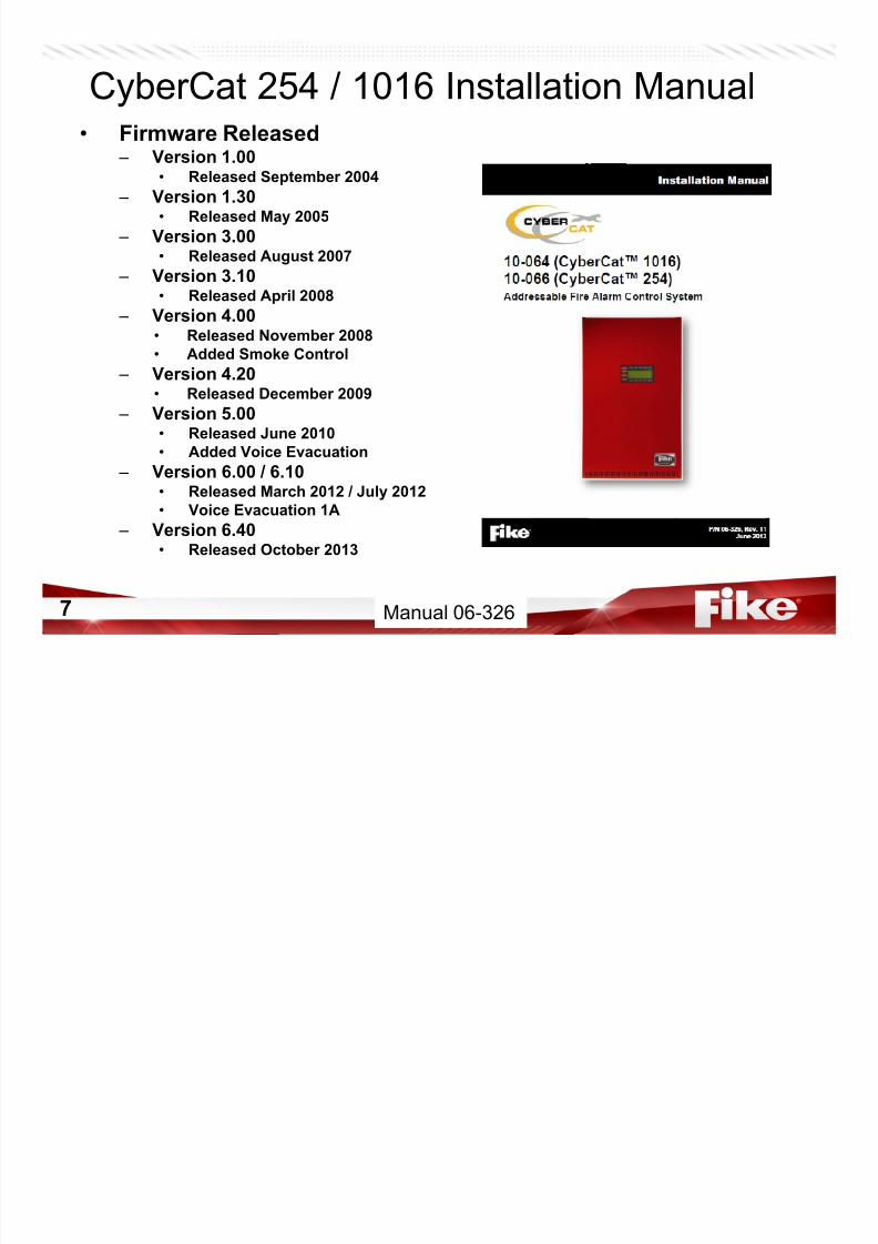
CyberCat 254 / 1016 Installation Manual• Firmware Released
– Version 1.00• Released September 2004
– Version 1.30• Released May 2005
– Version 3.00• Released August 2007
– Version 3.10• Released April 2008
– Version 4.00• Released November 2008
• Added Smoke Control – Version 4.20
• Released December 2009
– Version 5.00• Released June 2010
• Added Voice Evacuation
– Version 6.00 / 6.10• Released March 2012 / July 2012
• Voice Evacuation 1A
– Version 6.40• Released October 2013
Manual 06-326
7/23/2019 CyberCat 2015 FULL Printout
http://slidepdf.com/reader/full/cybercat-2015-full-printout 8/429
8
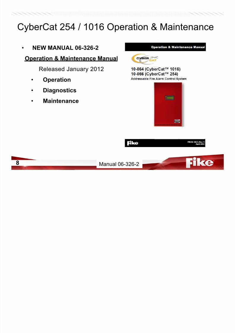
CyberCat 254 / 1016 Operation & Maintenance
• NEW MANUAL 06-326-2
Operation & Maintenance Manual
Released January 2012
• Operation
• Diagnostics
• Maintenance
Manual 06-326-2
7/23/2019 CyberCat 2015 FULL Printout
http://slidepdf.com/reader/full/cybercat-2015-full-printout 9/429
9
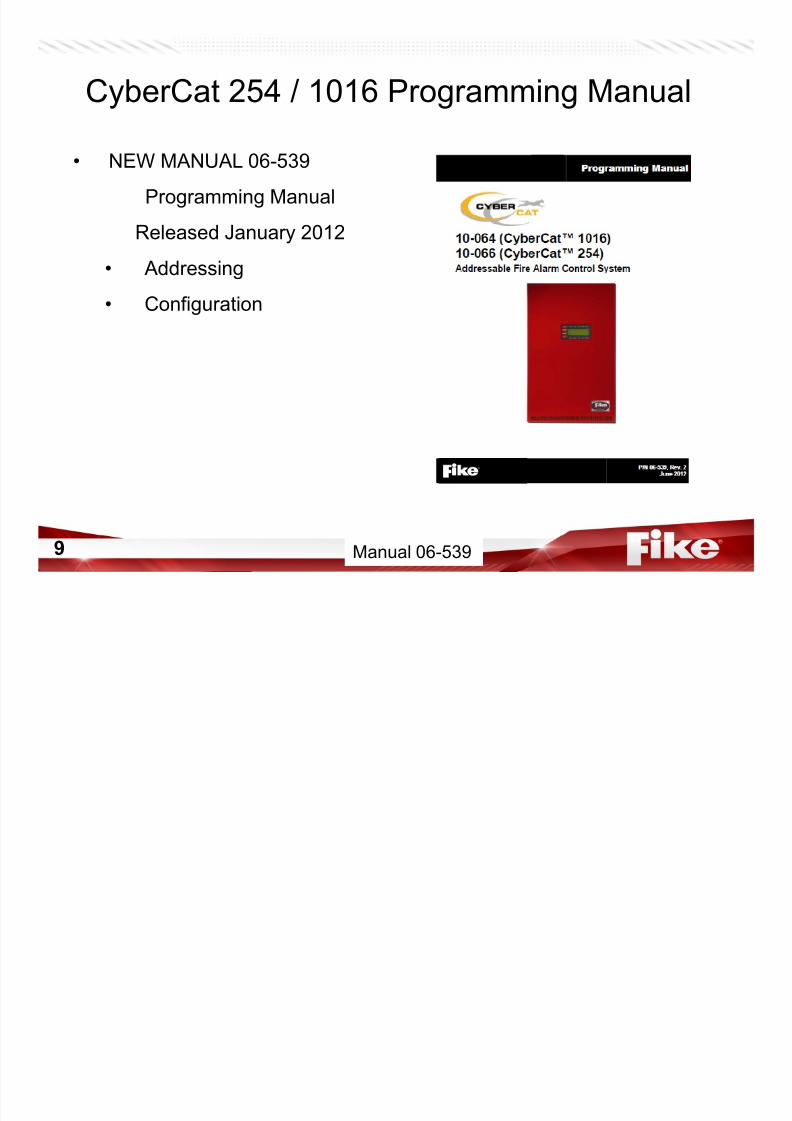
CyberCat 254 / 1016 Programming Manual
Manual 06-539
• NEW MANUAL 06-539
Programming Manual
Released January 2012
• Addressing
• Configuration
7/23/2019 CyberCat 2015 FULL Printout
http://slidepdf.com/reader/full/cybercat-2015-full-printout 10/429
10
• Underwriters Laboratories (UL) – File Number: S2203 – Type: Local, Remote Station, Central Station PPU – Service Type: A-Automatic Fire Alarm, M-Manual Fire Alarm, Releasing
Device Service, WF-Water-flow alarm, SS-Sprinkler Supervisory Service,DACT
• Factory Mutual (FM) – File Number: 3020297
• City of New York (MEA) – File Number: 490-04-E
• California State Fire Marshall (CSFM) – File Number: 7165-0900:137
• California State Fire Marshall (CSFM) (For High Rise Applications) – File Number: 7170-0900:148
• City of Denver, CO
• City of Chicago (Version 4.20) (CyberCat 1016 & 254)
• Version 6.0 Added Boston, New York and Chicago Voice Specs.
CyberCat Listings/Approvals
Manual 06-326 Page 2-3

7/23/2019 CyberCat 2015 FULL Printout
http://slidepdf.com/reader/full/cybercat-2015-full-printout 11/429
11
• Manual # 06-368 – Version 3.00
• Released March 2007
– Version 3.10
• Released April 2008 – Version 4.00
• Released November 2008
• Added Smoke Control
– Version 4.20 (Firmware Only)
• Released December 2009• Canada and Chicago
– Version 5.00 (Firmware Only)• Released June 2010
• Added Voice Evacuation
– Version 6.01 / 6.10 – Released March 2012 / July 2012
• Voice Evacuation 1A
– Version 6.40• Released October 2013
CyberCat 50 Installation Manual 06-368
Forums & Jump Drive Manual 06-368

7/23/2019 CyberCat 2015 FULL Printout
http://slidepdf.com/reader/full/cybercat-2015-full-printout 12/429
12
CyberCat 50 Operation & Maintenance
• NEW MANUAL 06-368-2
Operation & Maintenance Manual
Released July 2012
• Operation
• Diagnostics
• Maintenance
Jump Drive, Manual 06-368-2

7/23/2019 CyberCat 2015 FULL Printout
http://slidepdf.com/reader/full/cybercat-2015-full-printout 13/429
13
CyberCat 50 Programming Manual
Jump Drive, Manual 06-656
• NEW MANUAL 06-656
Programming Manual
Released July 2012
• Addressing
• Configuration

7/23/2019 CyberCat 2015 FULL Printout
http://slidepdf.com/reader/full/cybercat-2015-full-printout 14/429
14
CyberCat 50 Listings/Approvals
• Underwriters Laboratories (UL) – File Number: S2203
– Type: Local, Remote Station, Central Station PPU
– Service Type: A-Automatic Fire Alarm, M-Manual Fire Alarm, ReleasingDevice Service, WF-Water-flow alarm, SS-Sprinkler SupervisoryService, DACT
• Factory Mutual (FM) – File Number: 3020297
• City of New York (MEA)
– File Number: 490-04-E• California State Fire Marshall (CSFM)
– File Number: 7165-0900:137
• California State Fire Marshall (CSFM) (For High Rise Applications) – File Number: 7170-0900:148
• City of Denver, CO
• OSHPD (Seismic Certification)
Jump Drive – Manual 06-368, Page 1-2

7/23/2019 CyberCat 2015 FULL Printout
http://slidepdf.com/reader/full/cybercat-2015-full-printout 15/429
15
CyberCat Features
• System
– 254 Software Zones/Hazards
– 3200 Event history with dedicated alarm
– Serial Dialer, point ID
– 6 Amps of Power expandable to 12 Amps (1016 Only)
– 75 AH Battery Charging exp. to 150 AH (1016 Only)
Manual 06-326 Page 2-2
7/23/2019 CyberCat 2015 FULL Printout
http://slidepdf.com/reader/full/cybercat-2015-full-printout 16/429
16
CyberCat Features
• Signaling Line Circuit (SLC)
– True Peer-to-Peer intelligent Signaling Line Circuit devices(Eclipse)
– 254 Addressable Devices per loop (Except CyberCat 50)
• 2 loops standard (508 devices) (1016 Only)
• Expandable to 4 total loops (1016 devices total on 1016 Only)
• ** 50 Addressable Devices per Loop (1) on CyberCat 50
– Infrared (IR) Tool for addressing and testing devices
– Multicolor device LED for instant status
Manual 06-326 Page 2-2
7/23/2019 CyberCat 2015 FULL Printout
http://slidepdf.com/reader/full/cybercat-2015-full-printout 17/429
17
CyberCat System Operation
• Device LED Operation
– Normal = LED blinks green “heartbeat” every 5 seconds
– Pre-Alarm1 = LED blinks red, slowly – Pre-Alarm2 = LED blinks red, fast
– Active/Alarm = LED on red, continuous
– Trouble, Open = LED blinks amber (yellow), slowly
– Trouble, Short = LED blinks amber (yellow), fast – Trouble, General = LED on amber (yellow), continuous
– Test Alarm = LED blinks green/red
• Green/Red also possible on RM showing normal status of input
and activation status of Relay (or vice-versa)
• Green fast indicates device is ‘selected’ with IR or possible wiring
issue

7/23/2019 CyberCat 2015 FULL Printout
http://slidepdf.com/reader/full/cybercat-2015-full-printout 18/429
18
CyberCat Features
• Enclosure – Compact Steel Enclosure
– Available in Red or Black
– Available with or without Lexan cover
– Dead Front option
– Surface mount or use ½” lip to facilitate flush mounting
Manual 06-326 Page 2-2

7/23/2019 CyberCat 2015 FULL Printout
http://slidepdf.com/reader/full/cybercat-2015-full-printout 19/429
19
Specifications

7/23/2019 CyberCat 2015 FULL Printout
http://slidepdf.com/reader/full/cybercat-2015-full-printout 20/429
20
CyberCat 1016 Specifications
• 10-064-c-p-L CyberCat 1016 Control System – c, Enclosure color
• R = Red
• B=Black – p, Transformer
• 1 = 120VAC
• 2 = 240VAC
– L, Lexan• w/ L, Lexan installed
• w/o L, Lexan not installed
Manual 06-326 Page 3-1
7/23/2019 CyberCat 2015 FULL Printout
http://slidepdf.com/reader/full/cybercat-2015-full-printout 21/429
21
CyberCat 254 Specifications
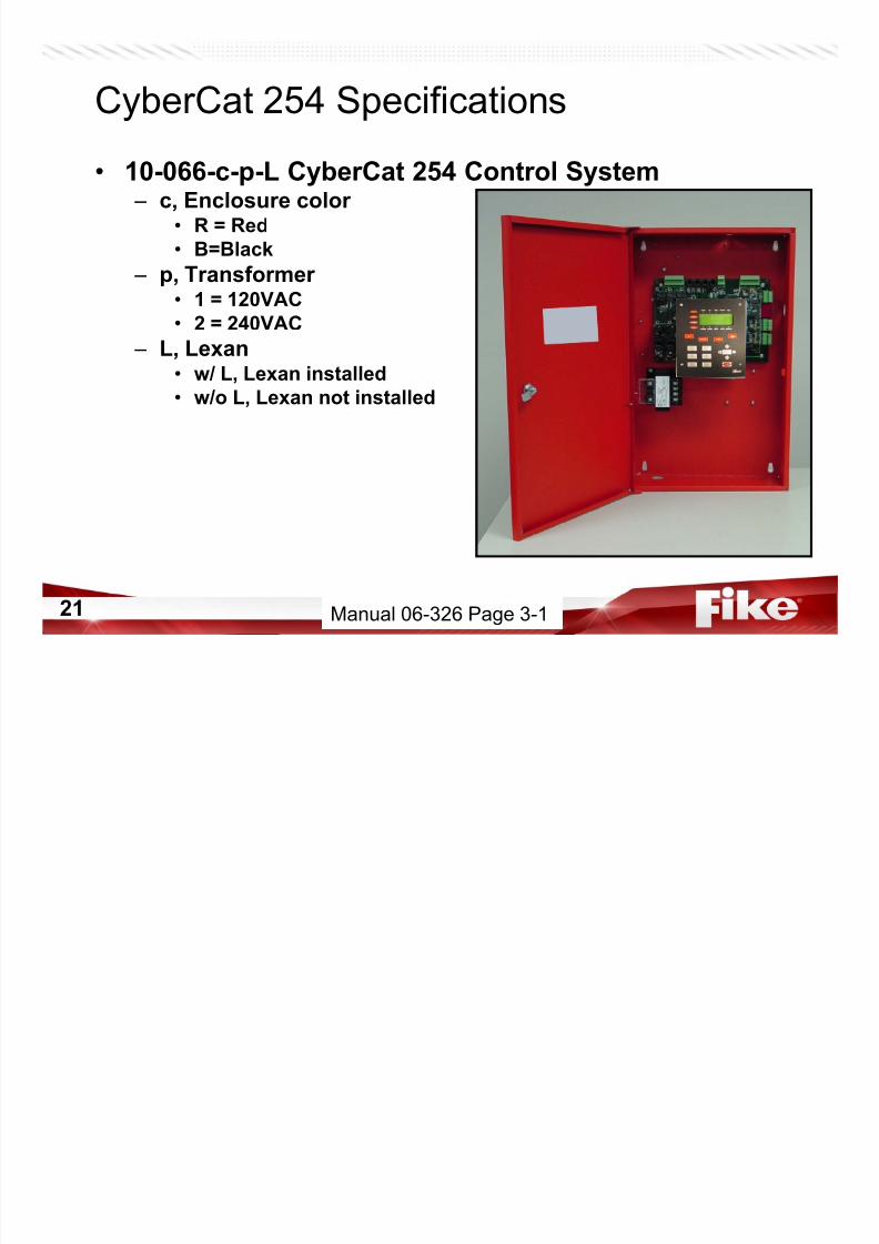
• 10-066-c-p-L CyberCat 254 Control System – c, Enclosure color
• R = Red
• B=Black
– p, Transformer• 1 = 120VAC
• 2 = 240VAC
– L, Lexan• w/ L, Lexan installed
• w/o L, Lexan not installed
Manual 06-326 Page 3-1
7/23/2019 CyberCat 2015 FULL Printout
http://slidepdf.com/reader/full/cybercat-2015-full-printout 22/429
22
CyberCat 254 Specifications
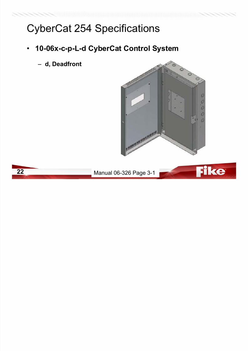
• 10-06x-c-p-L-d CyberCat Control System
– d, Deadfront
Manual 06-326 Page 3-1

7/23/2019 CyberCat 2015 FULL Printout
http://slidepdf.com/reader/full/cybercat-2015-full-printout 23/429
23
CyberCat 254 Specifications
• 10-06x-c-p-L-3-d CyberCat Control System
– 3, 3 Card Deadfront
Manual 06-326 Page 3-10
7/23/2019 CyberCat 2015 FULL Printout
http://slidepdf.com/reader/full/cybercat-2015-full-printout 24/429
24
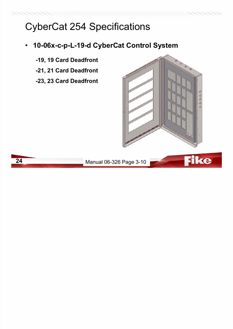
CyberCat 254 Specifications
• 10-06x-c-p-L-19-d CyberCat Control System
-19, 19 Card Deadfront
-21, 21 Card Deadfront
-23, 23 Card Deadfront
Manual 06-326 Page 3-10

7/23/2019 CyberCat 2015 FULL Printout
http://slidepdf.com/reader/full/cybercat-2015-full-printout 25/429
25
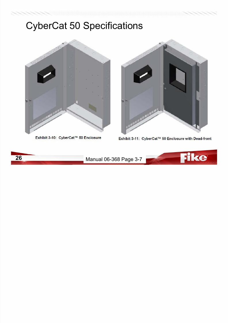
CyberCat 50 Specifications
• 10-070-c-p(-d) CyberCat 50 Control System – c, Enclosure color
• R = Red
• B=Black
– p, Transformer• 1 = 120VAC
• 2 = 240VAC
– d, Deadfront• w/ d, deadfront included
• w/o d, no deadfront included
Manual 06-368 Page 3-1
7/23/2019 CyberCat 2015 FULL Printout
http://slidepdf.com/reader/full/cybercat-2015-full-printout 26/429
26
CyberCat 50 Specifications
Manual 06-368 Page 3-7
7/23/2019 CyberCat 2015 FULL Printout
http://slidepdf.com/reader/full/cybercat-2015-full-printout 27/429
27
CyberCat Specifications
• Environmental – 32° – 120°F (0 ° – 49 °C)
– 93% Relative Humidity• Primary AC Power
– 120V Transformer (02-10881)
• 60 Hertz
• 2.22 Amps
• 225 VA
– 240V Transformer (02-10882)
• 50/60 Hertz
• 1.45 Amps
• 348 VA
Manual 06-326 Page 3-2

7/23/2019 CyberCat 2015 FULL Printout
http://slidepdf.com/reader/full/cybercat-2015-full-printout 28/429
28
CyberCat 254 / 1016 Specifications
• Main Controller – 10-2472 (1016)
– 10-2525 (254)
– Central Processors• Main
• Loop
– LCD Display
– Keypad – Status LEDs
– Buzzer
– AUX Power Circuits
– Signaling Line Circuits
– Peripheral/DACT Circuits
– Notification Appliance Circuits
Manual 06-326 Page 3-1

7/23/2019 CyberCat 2015 FULL Printout
http://slidepdf.com/reader/full/cybercat-2015-full-printout 29/429
29
CyberCat 50 Controller
• Main Controller – 10-2620
– Central Processors• Main
• Loop
– LCD Display
– Keypad
– Status LEDs – Buzzer
– AUX Power Circuits
– Signaling Line Circuits
– Peripheral/DACT Circuits
– Notification Appliance Circuits
Jump Drive - Manual 06-368 Page 3-1

7/23/2019 CyberCat 2015 FULL Printout
http://slidepdf.com/reader/full/cybercat-2015-full-printout 30/429
CyberCat Display
Manual 06-326-2 Page 2-3
7/23/2019 CyberCat 2015 FULL Printout
http://slidepdf.com/reader/full/cybercat-2015-full-printout 31/429
31
CyberCat 254 / 1016 Specifications
• Controller Power – 2 Amps Normal Standby
• Expandable to 4 Amps with SPS (1016 Only)
– 6 Amps Alarm
• Expandable to 12 Amps with SPS (1016 Only)
– Board itself pulls 0.275 A @ 24VDC
Manual 06-326 Page 3-3

7/23/2019 CyberCat 2015 FULL Printout
http://slidepdf.com/reader/full/cybercat-2015-full-printout 32/429
32
• System – 2 Amps Standby……5.25 Amps of Alarm Power Maximum – 2 Continuous AUX Power Circuits, 1.75 Amps Each – No pluggable modules (i.e. CRM4, Network)
– Non removable terminal blocks – Direct USB Configuration
• Signaling Line Circuit (SLC) – 50 Addressable Devices on 1 Loop
• Enclosure – Backbox is shallower – Door is deeper – Door has a rectangle hole with bezel
• REQUIRES USB cable
• REQUIRES USB Driver – Download from Fike Forums or Fike website – Now find on computer – Downloaded with C-Linx later versions – ANY USB/A to USB/B 2.0 Male to Male Cable (Buy Locally?)
CyberCat 50 Features vs. 254 &1016
Jump Drive - Manual 06-368 Page 1-4

7/23/2019 CyberCat 2015 FULL Printout
http://slidepdf.com/reader/full/cybercat-2015-full-printout 33/429
33
CyberCat Specifications
• NFPA 70 requirements
• Non Power-Limited – AC and Battery
• Power-Limited – Peripheral – Auxiliary Power – SLCs – NACs – P20 (Network)
• Undefined – P2, P12, P13
Non Power-Limited
Undefined Power-Limited

7/23/2019 CyberCat 2015 FULL Printout
http://slidepdf.com/reader/full/cybercat-2015-full-printout 34/429
34
CyberCat 254 / 1016 Specifications
• P1 – Power Supply Input
– AC XFMR
• Supervised
• Non Power-Limited
• Terminals 1 & 2 – 16 AWG – 12 AWG
• 24 VAC
• F1 – 15 Amp (P/N 02-4174)
Terminal 1
CAUTION: AC Voltage must be plugged into the LEFT side of P1 (Terminals 1 & 2).
Damage will occur if AC voltage is applied to the right side of P1 (Terminals 3 & 4).
Manual 06-326 Page 3-4

7/23/2019 CyberCat 2015 FULL Printout
http://slidepdf.com/reader/full/cybercat-2015-full-printout 35/429
35
CyberCat System Installation
• Transformer(s)
WARNING: Reversal of Transformer Primary and Secondary WILL DAMAGE CONTROLLER!
– H1/H2 = Primary (Transformer Input)• Think H for High Voltage
– X1/X2 = Secondary (Transformer Output)
Manual 06-326 Page 4-13

7/23/2019 CyberCat 2015 FULL Printout
http://slidepdf.com/reader/full/cybercat-2015-full-printout 36/429
36
CyberCat 254 / 1016 Specifications
• P1 – Power Supply Input
– BATTERY
• Supervised• Non Power-Limited
• Terminals 3 & 4 – 14 AWG – 12 AWG
– 10’ maximum
• 27.6 VDC
• F2 – 15 Amp (P/N 02-4174)
CAUTION: AC Voltage must be plugged into the LEFT side of P1 (Terminals 1 & 2).
Damage will occur if AC voltage is applied to the right side of P1 (Terminals 3 & 4).
CAUTION: Observe proper battery
polarity (+ = terminal 3; - = terminal 4).
Fuse F2 will open if reversed. Terminal 1
Manual 06-326 Page 3-4

7/23/2019 CyberCat 2015 FULL Printout
http://slidepdf.com/reader/full/cybercat-2015-full-printout 37/429
37
CyberCat 254 / 1016 Specifications
• Batteries
Manual 06-326 Page 4-14
7/23/2019 CyberCat 2015 FULL Printout
http://slidepdf.com/reader/full/cybercat-2015-full-printout 38/429
38
CyberCat 254 / 1016 Specifications
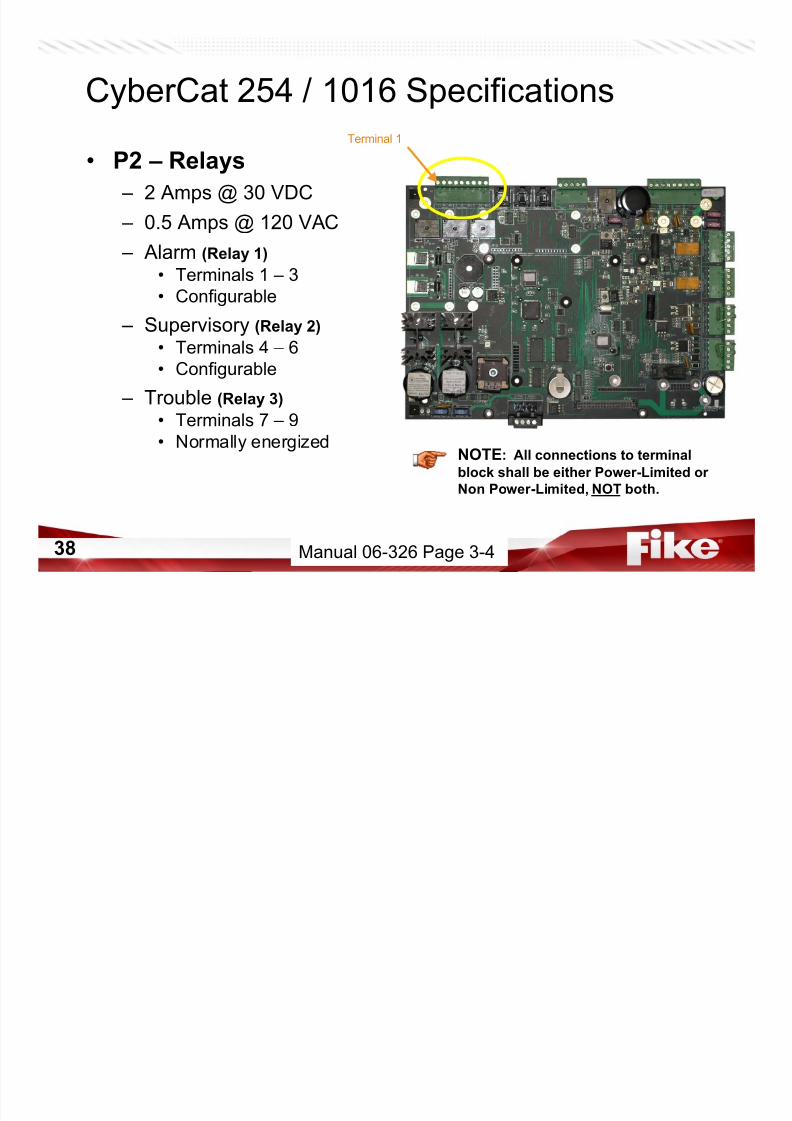
• P2 – Relays
– 2 Amps @ 30 VDC
– 0.5 Amps @ 120 VAC – Alarm (Relay 1)
• Terminals 1 – 3
• Configurable
– Supervisory (Relay 2)• Terminals 4 – 6
• Configurable
– Trouble (Relay 3)
• Terminals 7 – 9
• Normally energized
Terminal 1
NOTE: All connections to terminal
block shall be either Power-Limited or
Non Power-Limited, NOT both.
Manual 06-326 Page 3-4

7/23/2019 CyberCat 2015 FULL Printout
http://slidepdf.com/reader/full/cybercat-2015-full-printout 39/429
39
CyberCat System Installation
• P2 – Relays
– Form C, SPDT
– Contact Rating• 06-356, Page 14
• 2A@30VDC
• 0.5A@120VAC
– Alarm Relay
• Configurable – Supervisory Relay
• Configurable
– Trouble Relay
• Normally Energized – NON Configurable
C NC NO C NC NO C NC NO
P2
Alarm Supervisory Trouble
Manual 06-326 Page 4-17

7/23/2019 CyberCat 2015 FULL Printout
http://slidepdf.com/reader/full/cybercat-2015-full-printout 40/429
40
CyberCat 254 / 1016 Specifications
• P3 – COMPUTER
– Power-Limited
– RS-232
– C-Linx Port• System Configuration
• System Diagnostics
– 10-1874A or B• 50’ maximum
• 14’ provided
NOTE: This port is for configuration
and diagnostic purposes only and not
intended for continuous connection.
CAUTION: If a Ground Fault is presenton the system, do not connect the PC
until there is confidence that there is
not a high voltage present on the
ground.
Manual 06-326 Page 3-4
7/23/2019 CyberCat 2015 FULL Printout
http://slidepdf.com/reader/full/cybercat-2015-full-printout 41/429
41
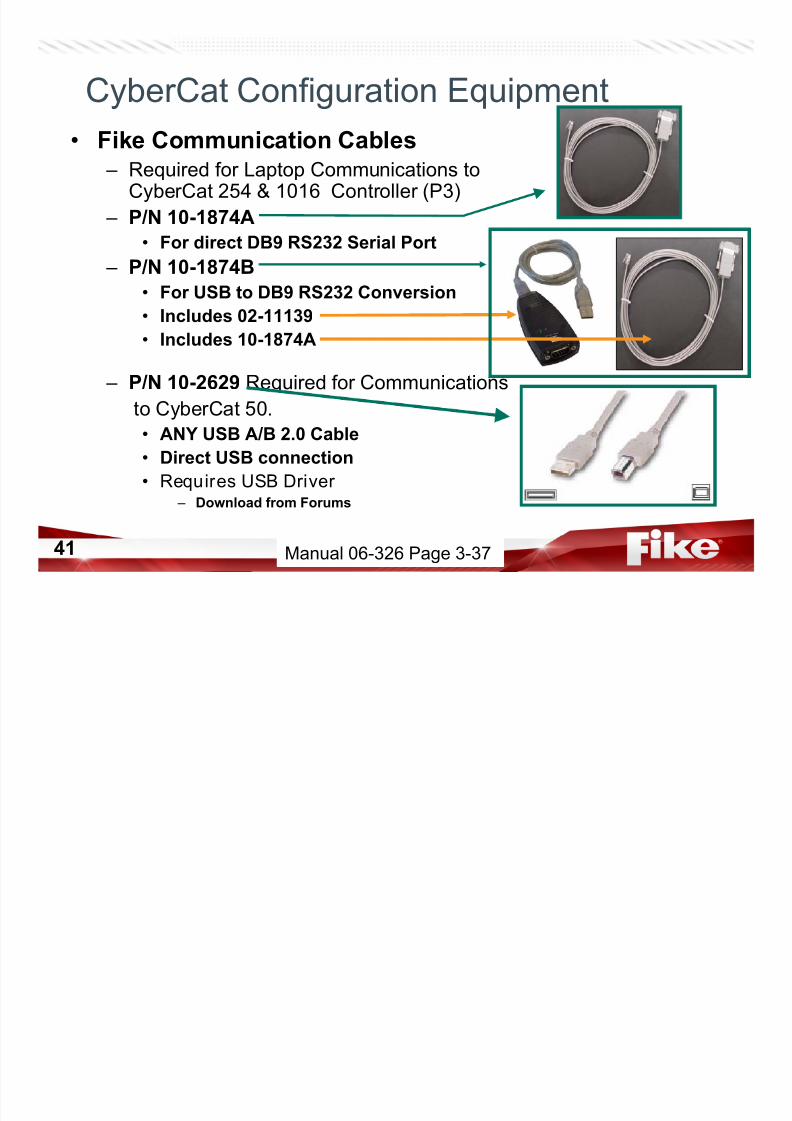
• Fike Communication Cables
– Required for Laptop Communications toCyberCat 254 & 1016 Controller (P3)
– P/N 10-1874A• For direct DB9 RS232 Serial Port
– P/N 10-1874B
• For USB to DB9 RS232 Conversion
• Includes 02-11139
• Includes 10-1874A
– P/N 10-2629 Required for Communications
to CyberCat 50.
• ANY USB A/B 2.0 Cable• Direct USB connection
• Requires USB Driver – Download from Forums
CyberCat Configuration Equipment
Manual 06-326 Page 3-37
7/23/2019 CyberCat 2015 FULL Printout
http://slidepdf.com/reader/full/cybercat-2015-full-printout 42/429
42
CyberCat 254 / 1016 Specifications
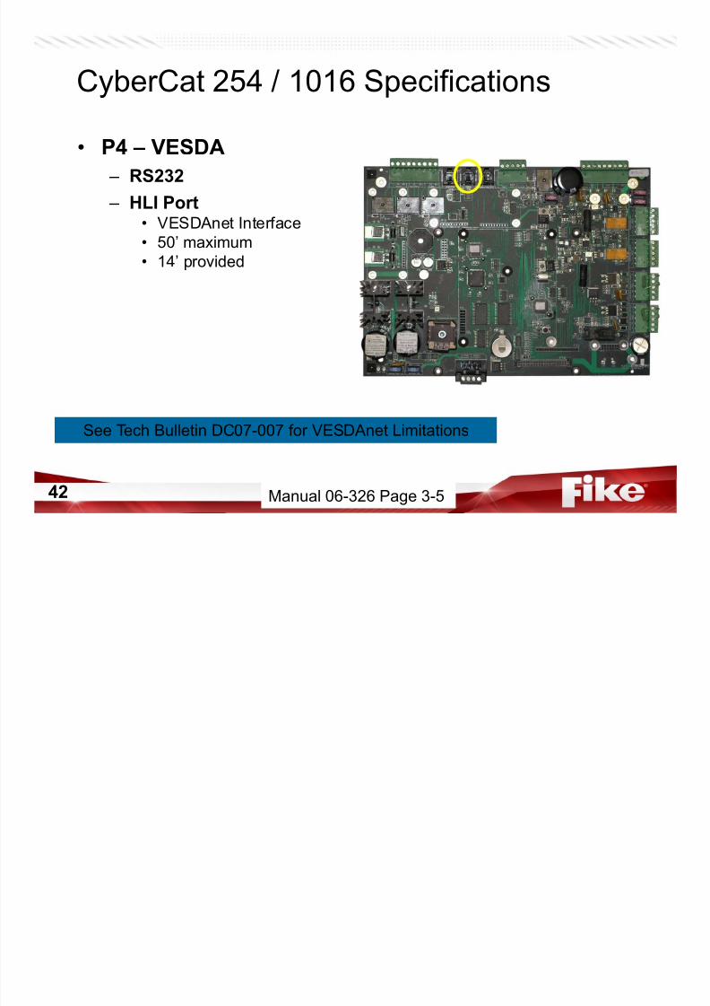
• P4 – VESDA
– RS232
– HLI Port• VESDAnet Interface
• 50’ maximum
• 14’ provided
Manual 06-326 Page 3-5
See Tech Bulletin DC07-007 for VESDAnet Limitations
7/23/2019 CyberCat 2015 FULL Printout
http://slidepdf.com/reader/full/cybercat-2015-full-printout 43/429
43
CyberCat 254 / 1016 Specifications
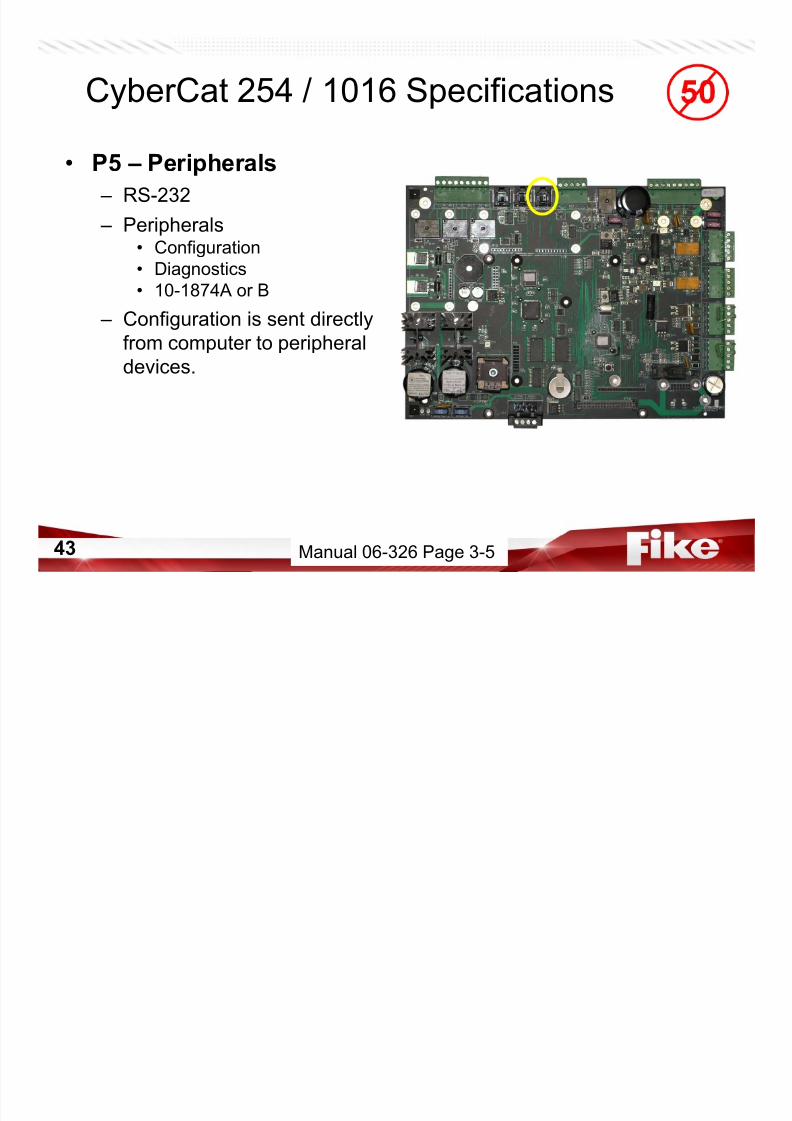
• P5 – Peripherals
– RS-232
– Peripherals• Configuration
• Diagnostics
• 10-1874A or B
– Configuration is sent directly
from computer to peripheral
devices.
Manual 06-326 Page 3-5
7/23/2019 CyberCat 2015 FULL Printout
http://slidepdf.com/reader/full/cybercat-2015-full-printout 44/429
44
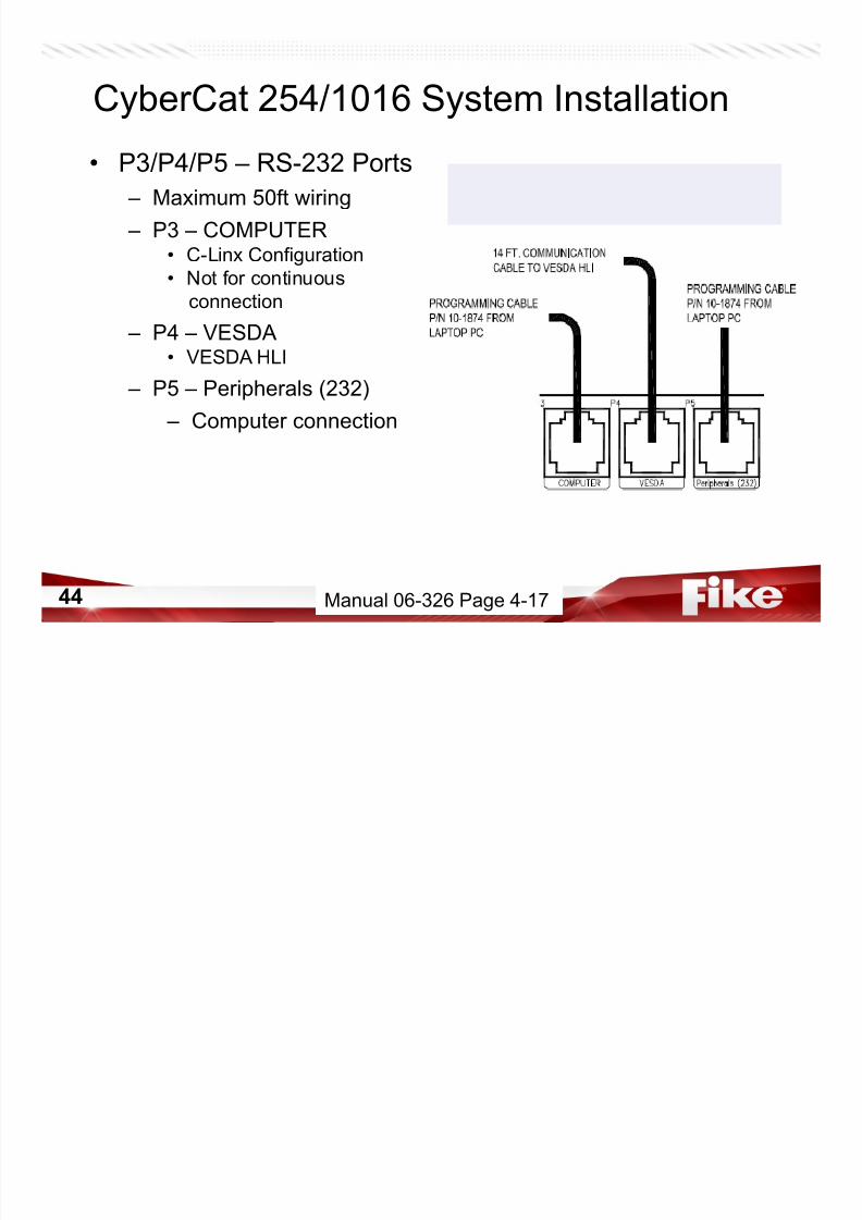
CyberCat 254/1016 System Installation
• P3/P4/P5 – RS-232 Ports
– Maximum 50ft wiring
– P3 – COMPUTER• C-Linx Configuration
• Not for continuous
connection
– P4 – VESDA
• VESDA HLI – P5 – Peripherals (232)
– Computer connection
Manual 06-326 Page 4-17

7/23/2019 CyberCat 2015 FULL Printout
http://slidepdf.com/reader/full/cybercat-2015-full-printout 45/429
45
CyberCat 254 / 1016 Specifications
Terminal 1
* Fike recommends Belden 9841, but any
cable with equivalent specifications can
be used.
Manual 06-326 Page 3-5
• P6 – RS485 – 31 Devices maximum
– 4,000’ maximum
• Low Capacitance Cable*• No t-tapping
– Terminals 1 & 2• Serial DACT
– Terminal 3• Drain Wire
– Terminals 4 & 5• Fike Peripherals
– RDUs, LED Graphic,
– Zone Annunciator, – Multi-Interface, Ethernet,
– Precise Graphics, Relay Controller,
– Class A Peripheral Card
– Voice Evacuation
7/23/2019 CyberCat 2015 FULL Printout
http://slidepdf.com/reader/full/cybercat-2015-full-printout 46/429
46
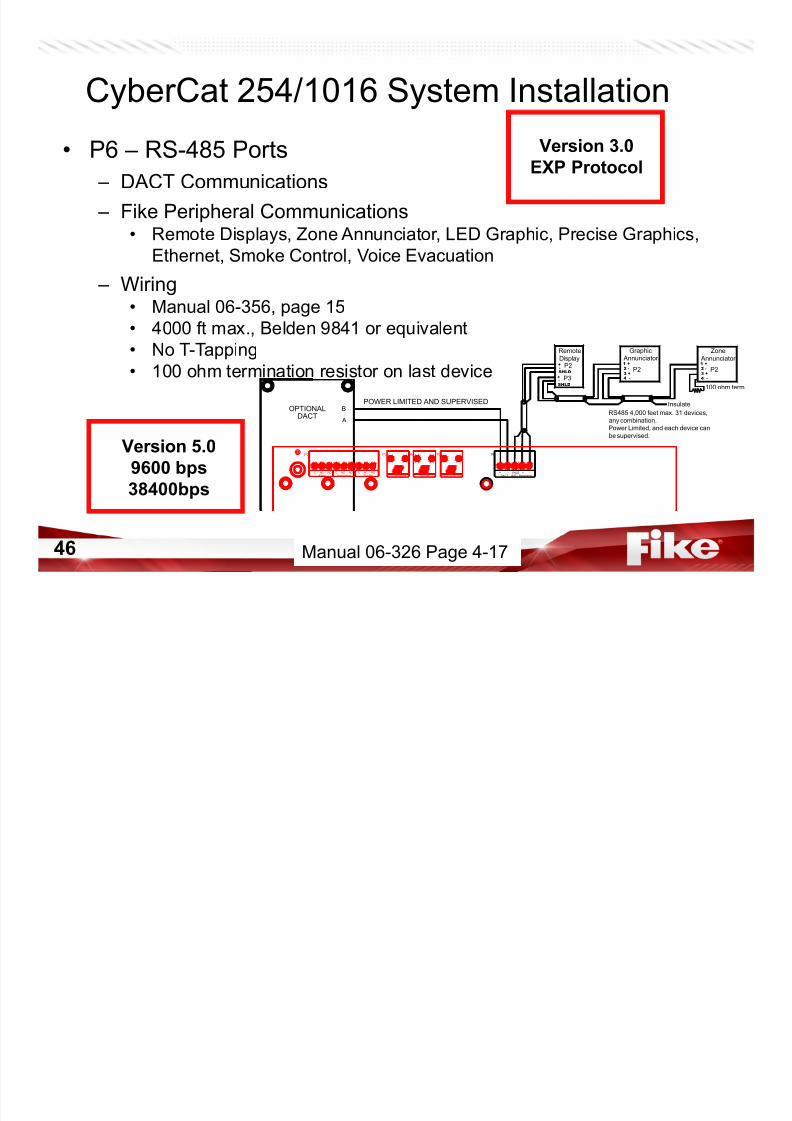
CyberCat 254/1016 System Installation
• P6 – RS-485 Ports
– DACT Communications
– Fike Peripheral Communications• Remote Displays, Zone Annunciator, LED Graphic, Precise Graphics,
Ethernet, Smoke Control, Voice Evacuation
– Wiring• Manual 06-356, page 15
• 4000 ft max., Belden 9841 or equivalent• No T-Tapping
• 100 ohm termination resistor on last device P21 +
2 -
4 -
3 +
POWER LIMITED AND SUPERVISEDB
A
Insulate
100 ohm term.
3 +
4 -
2 -
1 +
P2
P3+-
SHLD
SHLD
-+ P2
Graphic Annunciator
Zone
Annunciator
Remote
Display
RS485 4,000 feet max. 31 devices,
any combination.Power Limited, and each device can
be supervised.
DACT (485 ) Peripherals + - SHLD + -
P2 P3 P4 P5
COMPUTER VESDA
P6
Peripherals (232)
C NC NO C NC NO C NC NO Alarm Supervisory Trouble
DACTOPTIONAL
Version 5.0
9600 bps
38400bps
Manual 06-326 Page 4-17
Version 3.0
EXP Protocol

7/23/2019 CyberCat 2015 FULL Printout
http://slidepdf.com/reader/full/cybercat-2015-full-printout 47/429
47
CyberCat 50 System Installation
• P6 – RS-485 Ports – DACT Communications
– Fike Peripheral Communications
• Remote Displays, Zone Annunciator, LED Graphic, Multi-Interface,Ethernet
– Wiring• 4000 ft max.,
Belden 9841 or equivalent
• No T-Tapping• 100 ohm termination
resistor on last device
Version 5.0
9,600 bps Speed38,400 bps Speed
Jump Drive - Manual 06-368 Page 4-12
Version 3.0
EXP Protocol

7/23/2019 CyberCat 2015 FULL Printout
http://slidepdf.com/reader/full/cybercat-2015-full-printout 48/429
48
CyberCat 254 / 1016 Specifications
• P7 – Auxiliary Power
– Supervised
– 24VDC (Regulated 28V max.) – 2 Amps Maximum per circuit
– Resettable 24 VDC• Terminals 1 – 3
• Fused by F3
– Continuous 24 VDC• Terminals 4 – 9
• Fused by F4 / F5
Terminal 1
NOTE: Each of the circuits are short
circuit protected by a 4 Amp, field
replaceable, fuse (P/N 02-11412).
F3
F4
F5
NOTE: Shielded wiring is not required
for this circuit, but if used, connect drain
to panel at terminal provided.
Manual 06-326 Page 3-5
7/23/2019 CyberCat 2015 FULL Printout
http://slidepdf.com/reader/full/cybercat-2015-full-printout 49/429
49
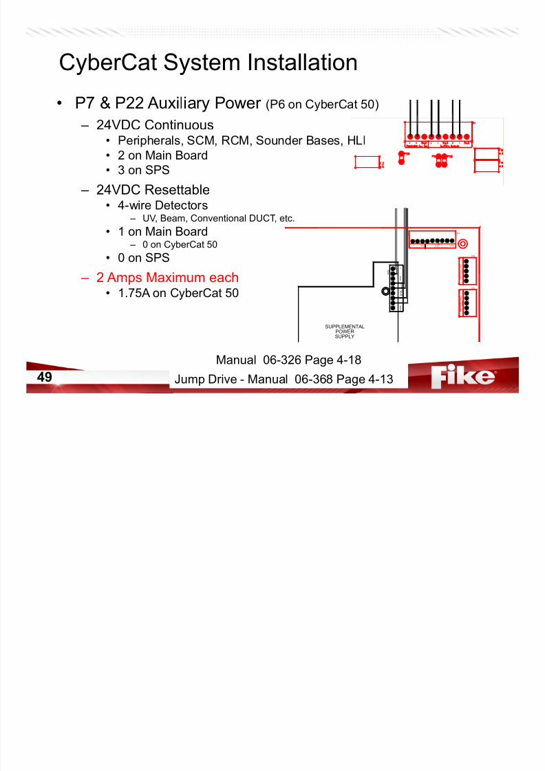
CyberCat System Installation
• P7 & P22 Auxiliary Power (P6 on CyberCat 50)
– 24VDC Continuous• Peripherals, SCM, RCM, Sounder Bases, HLI
• 2 on Main Board• 3 on SPS
– 24VDC Resettable• 4-wire Detectors
– UV, Beam, Conventional DUCT, etc.
• 1 on Main Board – 0 on CyberCat 50
• 0 on SPS
– 2 Amps Maximum each• 1.75A on CyberCat 50
A d d r e s s a b l e
L o o p 2
- -
+ +
S H L D
-
+
P8
A d d r e s s a b l e L o o p 1
- -
+ +
S H L D
-
+
- -
+ +
S H L D
-
+
A d d r e s s a b l e
L o o p 1
P9
+
-
S HL D
+
-
S HL D
+
-
S HL D
A ux i l i ar y O u t p u t s
P 2 2
SUPPLEMENTALPOWERSUPPLY
Resettable Aux Out Auxliliary Outputs + - SHLD + - SHLD + - SHLD
P7
Jump Drive - Manual 06-368 Page 4-13
Manual 06-326 Page 4-18

7/23/2019 CyberCat 2015 FULL Printout
http://slidepdf.com/reader/full/cybercat-2015-full-printout 50/429
50
CyberCat 254 / 1016 Specifications
• P8/P9 – Signaling Line Circuit (SLC) (No P9 on 254)
– Supervised
– Class B (Style-4)
– Class A (Style-6 or 7*)
– 100 mA maximum
– 28 VDC maximum
– 70 ohms maximum – 0.60 μF maximum
– 24 AWG – 12 AWG• 12,000 feet max. (14 AWG)
– 254 devices each
Terminal 1
*NOTE: When installing SLC using
Style-7, the first and last isolator device
shall be mounted in conduit, in the same
room, and within 20 feet of enclosure.
NOTE: Shielded wiring is not required
but recommended for electrically noisy
environment.
Manual 06-326 Page 3-6
C b C t S ifi ti

7/23/2019 CyberCat 2015 FULL Printout
http://slidepdf.com/reader/full/cybercat-2015-full-printout 51/429
51
CyberCat Specifications
Manual 06-326 Page 3-6
CyberCat Specifications
7/23/2019 CyberCat 2015 FULL Printout
http://slidepdf.com/reader/full/cybercat-2015-full-printout 52/429
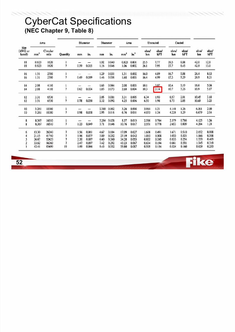
52
CyberCat Specifications(NEC Chapter 9, Table 8)
C b C S I ll i

7/23/2019 CyberCat 2015 FULL Printout
http://slidepdf.com/reader/full/cybercat-2015-full-printout 53/429
53
CyberCat System Installation
• P8/P9 Signaling Line Circuits (P7 on CyberCat 50)
– Eclipse Series Addressable Devices
– Class B (Style-4)
• T-Tapping Allowed – Class A (Style-6)
• NO T-Tapping
– Class A (Style-7)
• NO T-Tapping• Requires Isolator Devices
– Specifications• Manual 06-356, page 16
• 12,000ft. max. (14 AWG)
• 70 ohms max. loop
+L E D
-
OPTIONAL REMOTE ANNUNCIATOR(+)(-)
(+)
(-)
+L E
D - L E
D +
EOL39K
-
+-+
EOL39K
1 4
1 3
7
8
9
1 0
1 1
1 2
1 2 3
4
5
6
TOP
ADDRESSLOOP
- -
+ +
S H L D
-
+
A d d r e s s a b l e L o o p 1
A d d r e s s a b l e L o o p 1
P8
- -
+ +
S H L D
-
+
-
CONNECT DRAIN WIRE THROUGH AT JUNCTION BOXES
INSULATE. LEAVE DRAIN OPEN (NO CONNECTION) AT LAST DEVICE.
DET #1 DET #2
DET #3
02-11259
- -
+ +
S H L D
-
+
(--)
P8
A d d r e s s a b l e L o o p 1
A d d r e s s a b l e L o o p 1
- -
+ +
S H L D
-
+
LOOP ADDRESS
TOP
6
5
4 3 2 11
2
1 1
1 0
9
8
7
1 3
1 4
39KEOL
+-+-
39KEOL
+L E D
- - L E D
+
(-)
(+)(-) (+)
OPTIONAL REMOTE ANNUNCIATOR
(++)
02-11259
Manual 06-326 Page 4-19
Manual 06-326 Page 4-20
C b C t S t I t ll ti

7/23/2019 CyberCat 2015 FULL Printout
http://slidepdf.com/reader/full/cybercat-2015-full-printout 54/429
54
CyberCat System Installation
• Class B (Style-4) Wiring
– T-Tapping Allowed
– Loss of communications to devices after wiring break
+L E D
-
OPTIONAL REMOTE ANNUNCIATOR(+)(-)
(+)
(-)
+L E D
- L E D +
EOL
39K
-
+-+
EOL
39K
1 4
1 3
7
8
9
1 0
1 1
1 2
1 2 3
4
5
6
TOP
ADDRESSLOOP
- -
+ +
S H L D
-
+
A d d r e s s a b l e L o
o p 1
A d d r e s s a b l e L o o p 1
P8
- -
+ +
S H L D
-
+
-
CONNECT DRAIN WIRE THROUGH AT JUNCTION BOXES
INSULATE. LEAVE DRAIN OPEN (NO CONNECTION) AT LAST DEVICE.
DET #1 DET #2
DET #3
02-11259
Manual 06-326 Page 4-19
C b C t S t I t ll ti
7/23/2019 CyberCat 2015 FULL Printout
http://slidepdf.com/reader/full/cybercat-2015-full-printout 55/429
55
CyberCat System Installation
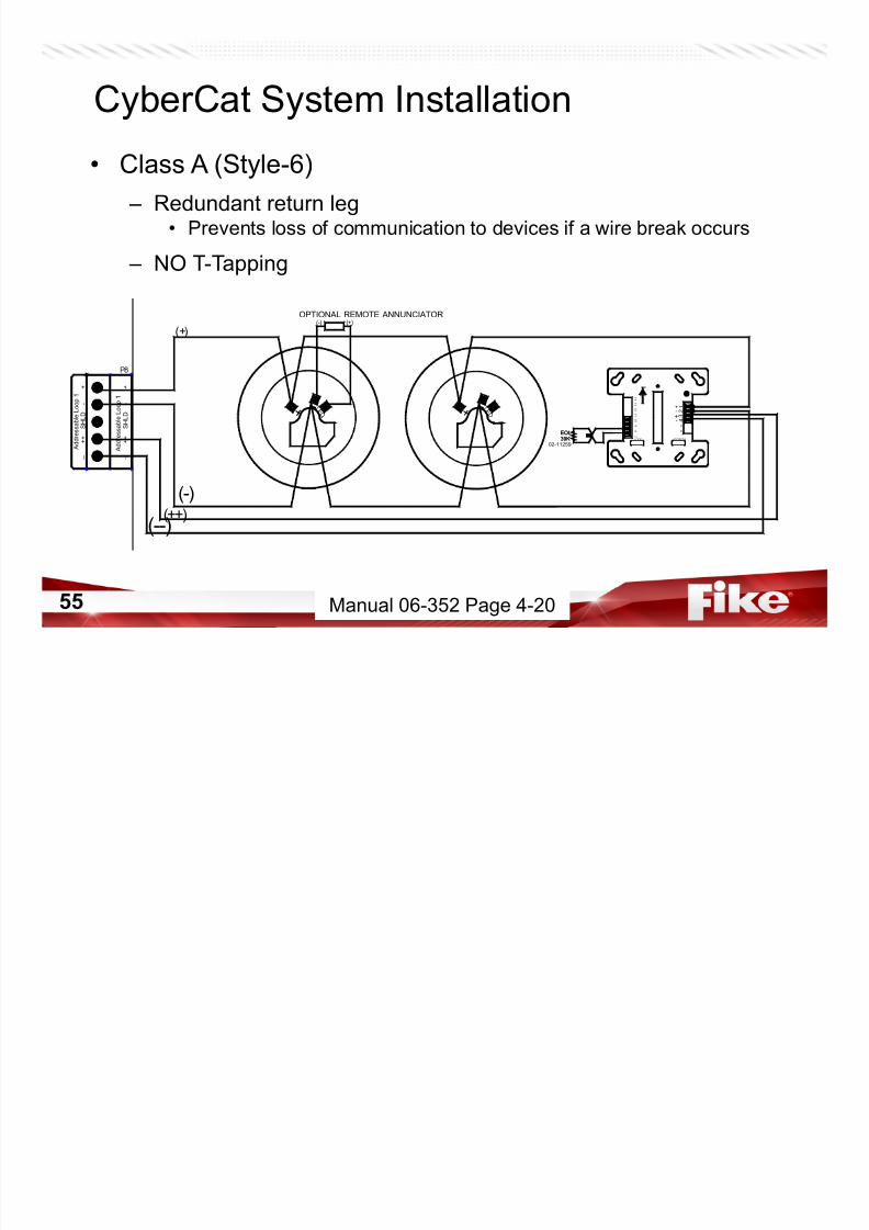
• Class A (Style-6)
– Redundant return leg• Prevents loss of communication to devices if a wire break occurs
– NO T-Tapping
- -
+ +
S H L D
-
+
(--)
P8
A d d r e s s a b l e L o o p 1
A d d r e s s a b l e L o o p 1
- -
+ +
S H L D
-
+
LOOP ADDRESS
TOP
6
5
4 3 2 11
2
1 1
1 0
9
8
7
1 3
1 4
39KEOL
+-+-
39KEOL
+L E
D - - L E
D +
(-)
(+)(-) (+)
OPTIONAL REMOTE ANNUNCIATOR
(++)
02-11259
Manual 06-352 Page 4-20
C b C t S t I t ll ti
7/23/2019 CyberCat 2015 FULL Printout
http://slidepdf.com/reader/full/cybercat-2015-full-printout 56/429
56
CyberCat System Installation
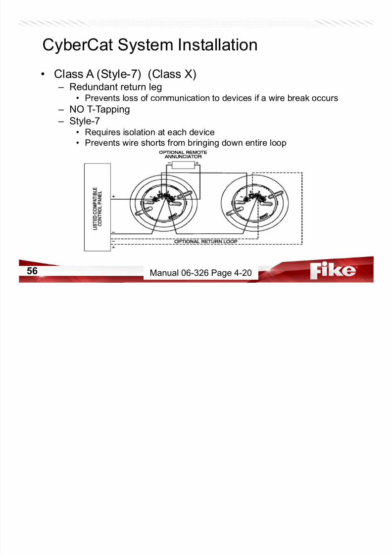
• Class A (Style-7) (Class X) – Redundant return leg
• Prevents loss of communication to devices if a wire break occurs
– NO T-Tapping – Style-7• Requires isolation at each device
• Prevents wire shorts from bringing down entire loop
Manual 06-326 Page 4-20
CyberCat 254 / 1016 Specifications

7/23/2019 CyberCat 2015 FULL Printout
http://slidepdf.com/reader/full/cybercat-2015-full-printout 57/429
57
CyberCat 254 / 1016 Specifications
• P10/P11 – Notification Appliance Circuit (NAC) – Supervised
– Wiring• Class B (Style-Y)
– 1.2K Ω EOL (p/n 10-2570)
• Class A (Style-Z)
• Max. Resistance – Refer to manual, page 17
– 2.00 Amps maximum
– Regulated (16 – 33 VDC)*
– Strobe Synchronization*• Gentex, System Sensor
Terminal 1
* See 06-186 Compatibility Document for
tested appliances and compatibility with
Wheelock notification appliances.
Manual 06-326 Page 3-6
CyberCat System Installation

7/23/2019 CyberCat 2015 FULL Printout
http://slidepdf.com/reader/full/cybercat-2015-full-printout 58/429
58
CyberCat System Installation
• P10/P11 – Notification Appliance Circuits
(P8 & P9 on CyberCat 50)
– Specifications
• Manual 06-356, page 17• 2 Amps Each on CyberCat 254 or 1016
– 1.75A Each CyberCat 50
• Class B w/ 1.2K ohm EOL
• Class A
Manual 06-326 Page 4-21
CyberCat Specifications

7/23/2019 CyberCat 2015 FULL Printout
http://slidepdf.com/reader/full/cybercat-2015-full-printout 59/429
59
CyberCat Specifications
• P12 – Optional Module
– CRM4 Relay
• 10-2204• 4 Configurable Relays
– RPM Reverse Polarity• 10-2254
• 2 Pre-Configured Options
• Not on 50 point panel
• Gives Fan Restart Delay Option
NOTE: If internal DACT (10-2528) option is used, P12 is unavailable (Covered Up).
P12
Manual 06-326 Page 3-6
CyberCat Modules

7/23/2019 CyberCat 2015 FULL Printout
http://slidepdf.com/reader/full/cybercat-2015-full-printout 60/429
60
CyberCat Modules
• Relay Module (CRM4)
– P/N 10-2204
– Includes 4 individually configurable Form-C Relays
– Fully Configurable for any Zone/State – Connects Through P12 and/or P13
– Not on 50 point panel
NOTE: Not recommended for critical function. (CAN toggle status on Power up)
Manual 06-326 Page 3-17
CyberCat System Installation

7/23/2019 CyberCat 2015 FULL Printout
http://slidepdf.com/reader/full/cybercat-2015-full-printout 61/429
61
CyberCat System Installation
• P12/P13 – Option Modules – CRM4
• 4 Independent Form C Relays
– CRPM
• Reverse Polarity Module
NOP42 C NC
RELAY 1
POWER
RELAY4RELAY3
P41
NC
RELAY 2
C NO C NC NO C NC LIMITEDNO
NON
Jump Drive - Manual 06-345
Jump Drive - Manual 06-156
CyberCat Modules
7/23/2019 CyberCat 2015 FULL Printout
http://slidepdf.com/reader/full/cybercat-2015-full-printout 62/429
62
CyberCat Modules
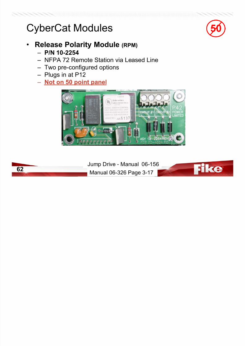
• Release Polarity Module (RPM)
– P/N 10-2254
– NFPA 72 Remote Station via Leased Line
– Two pre-configured options
– Plugs in at P12
– Not on 50 point panel
Jump Drive - Manual 06-156
Manual 06-326 Page 3-17
CyberCat Specifications
7/23/2019 CyberCat 2015 FULL Printout
http://slidepdf.com/reader/full/cybercat-2015-full-printout 63/429
63
CyberCat Specifications
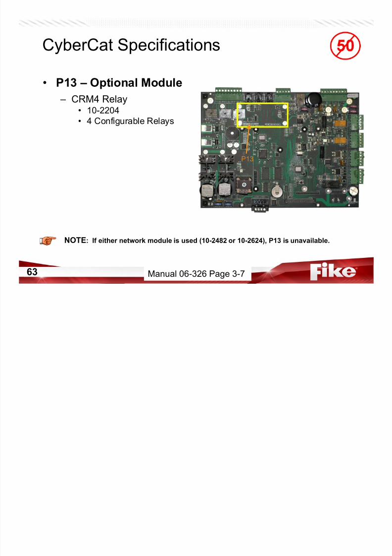
• P13 – Optional Module
– CRM4 Relay
• 10-2204• 4 Configurable Relays
NOTE: If either network module is used (10-2482 or 10-2624), P13 is unavailable.
P13
Manual 06-326 Page 3-7
CyberCat Specifications

7/23/2019 CyberCat 2015 FULL Printout
http://slidepdf.com/reader/full/cybercat-2015-full-printout 64/429
64
CyberCat Specifications
• P15 – Supplemental Loop Module (SLM)
– 10-2473
– Adds 2 SLCs• 508 Addressable Devices
• Not on CyberCat 254
• Not on CyberCat 50
P15
Manual 06-326 Page 3-7
CyberCat Modules

7/23/2019 CyberCat 2015 FULL Printout
http://slidepdf.com/reader/full/cybercat-2015-full-printout 65/429
65
CyberCat Modules
• Supplemental Loop Module (SLM)
– P/N 10-2473
– Doubles Device Capacity
• 4 Total Loops• 1016 Total Addressable Devices
– Plugs in at P15
– Firmware Version must match board PIC• **Locate sticker on processor
• Use Diagnostics menus
– MUST Enable through controller menu prior to
software download• F1-CONFIG, F3-SLC
• Not on CyberCat 254
• Not on CyberCat 50
4.1
Manual 06-326 Page 3-17
Jump Drive - Manual 06-339
CyberCat Specifications

7/23/2019 CyberCat 2015 FULL Printout
http://slidepdf.com/reader/full/cybercat-2015-full-printout 66/429
66
CyberCat Specifications
• P16 – Supplemental Power Supply (SPS)
– 10-2474-p
– Mounts behind display
– Doubles power • Standby Current – 4A
• Alarm Current – 12A
– Adds 3 AUX Circuits
– Increases Battery Size• 150 AH
• Not on CyberCat 254
• Not on CyberCat 50P16
Manual 06-326 Page 3-7
CyberCat Modules

7/23/2019 CyberCat 2015 FULL Printout
http://slidepdf.com/reader/full/cybercat-2015-full-printout 67/429
67
CyberCat Modules
• Supplemental Power Supply (SPS)
– P/N 10-2474-p• p, transformer
– 1 = 120V
– 2 = 240V
– Doubles Power Capacity• 4 Amps Standby Total
• 12 Amps Alarm Total
• 150 AH Max. Battery Capacity
– 3 Continuous AUX Outputs• Regulated, 24 VDC
• 2 Amps per circuit – Circuit Shorts: 4 Amp fuses (P/N 02-11412)
– Supervised Cooling Fan• Not on CyberCat 50 or 254
*** No firmware – Just Power Supply
Jump Drive - Manual 06-340
Manual 06-326 Page 3-16
CyberCat System Installation

7/23/2019 CyberCat 2015 FULL Printout
http://slidepdf.com/reader/full/cybercat-2015-full-printout 68/429
68
• Transformers
WARNING: Reversal of Transformer Primary and Secondary WILL DAMAGE CONTROLLER! – H1/H2 = Primary (Transformer Input)
• Think H for High Voltage
– X1/X2 = Secondary (Transformer Output)
Manual 06-326 Page 4-13
CyberCat Specifications

7/23/2019 CyberCat 2015 FULL Printout
http://slidepdf.com/reader/full/cybercat-2015-full-printout 69/429
69
y p
• P20 – Network Module
– RS-485 Network• 10-2482
– Fiber-Optic Network• 10-2624
NOTE: If either two CRM4 (10-2204) modules or a CRM4 and RPM module is required, P20
will be unavailable.
P20
Manual 06-326 Page 3-7
CyberCat Modules

7/23/2019 CyberCat 2015 FULL Printout
http://slidepdf.com/reader/full/cybercat-2015-full-printout 70/429
70
y
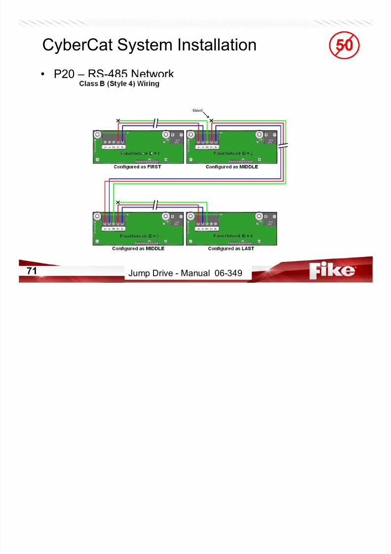
• RS-485 Network Module
– P/N 10-2482
– Network up to 128 panels• Cheetah Xi or CyberCat
– Excludes 50 points
– RS-485 wiring• 4000 feet between each module (Fike recommends Belden 9841)
• Style-4 or 7 (no t-tapping) – Configure Zones of participation
– Control other panels• Reset, Silence, Acknowledge, Drill
– Plugs in at P20
Manual 06-326 Page 3-17
CyberCat System Installation
7/23/2019 CyberCat 2015 FULL Printout
http://slidepdf.com/reader/full/cybercat-2015-full-printout 71/429
71
y y
• P20 – RS-485 Network
Jump Drive - Manual 06-349
CyberCat System Installation

7/23/2019 CyberCat 2015 FULL Printout
http://slidepdf.com/reader/full/cybercat-2015-full-printout 72/429
72
y y
• P20 – RS-485 Network
Jump Drive - Manual 06-349
CyberCat Modules
7/23/2019 CyberCat 2015 FULL Printout
http://slidepdf.com/reader/full/cybercat-2015-full-printout 73/429
73
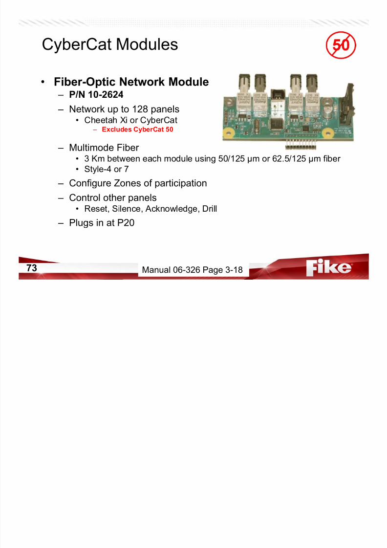
y
• Fiber-Optic Network Module – P/N 10-2624
– Network up to 128 panels• Cheetah Xi or CyberCat – Excludes CyberCat 50
– Multimode Fiber • 3 Km between each module using 50/125 µm or 62.5/125 µm fiber
• Style-4 or 7
– Configure Zones of participation
– Control other panels• Reset, Silence, Acknowledge, Drill
– Plugs in at P20
Manual 06-326 Page 3-18
CyberCat System Installation

7/23/2019 CyberCat 2015 FULL Printout
http://slidepdf.com/reader/full/cybercat-2015-full-printout 74/429
74
• P20 – Fiber Optic Network
Jump Drive - Manual 06-387
CyberCat System Installation
7/23/2019 CyberCat 2015 FULL Printout
http://slidepdf.com/reader/full/cybercat-2015-full-printout 75/429
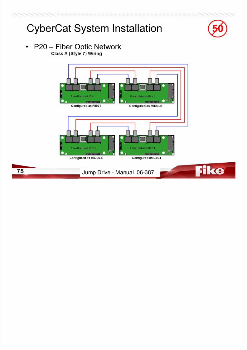
75
• P20 – Fiber Optic Network
Jump Drive - Manual 06-387

7/23/2019 CyberCat 2015 FULL Printout
http://slidepdf.com/reader/full/cybercat-2015-full-printout 76/429
76
RS-485 Peripherals
CyberCat Peripherals

7/23/2019 CyberCat 2015 FULL Printout
http://slidepdf.com/reader/full/cybercat-2015-full-printout 77/429
77
• Class A Peripheral Bus Card
– P/N 10-2792
– Firmware 6.0 & Newer Only
– Wires to P6 RS485 – Belden 9841
• 4000 ft Max
– Addressable Device
– Mounts in Enclosure on
extra transformer standoffs
– Communication LED
– 15-30VDC
• 57mA in Standby
• 57mA in Alarm
Manual 06-326 Page 3-25
CyberCat Peripherals
7/23/2019 CyberCat 2015 FULL Printout
http://slidepdf.com/reader/full/cybercat-2015-full-printout 78/429
78
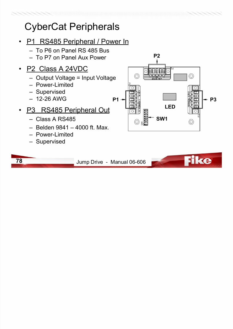
• P1 RS485 Peripheral / Power In
– To P6 on Panel RS 485 Bus
– To P7 on Panel Aux Power
• P2 Class A 24VDC – Output Voltage = Input Voltage
– Power-Limited
– Supervised
– 12-26 AWG
• P3 RS485 Peripheral Out
– Class A RS485
– Belden 9841 – 4000 ft. Max.
– Power-Limited
– Supervised
Jump Drive - Manual 06-606
P2
P3P1
SW1
LED
CyberCat Peripherals
7/23/2019 CyberCat 2015 FULL Printout
http://slidepdf.com/reader/full/cybercat-2015-full-printout 79/429
79 Jump Drive - Manual 06-606
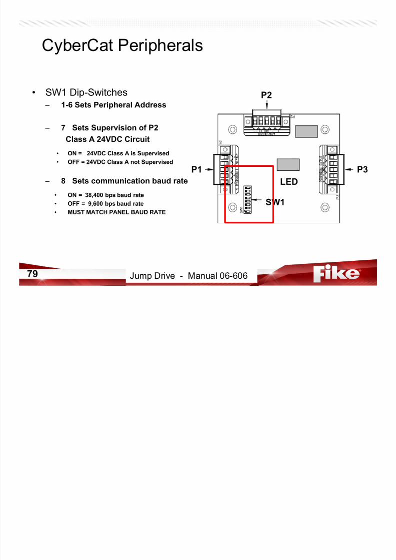
• SW1 Dip-Switches
– 1-6 Sets Peripheral Address
– 7 Sets Supervision of P2
Class A 24VDC Circuit
• ON = 24VDC Class A is Supervised
• OFF = 24VDC Class A not Supervised
– 8 Sets communication baud rate
• ON = 38,400 bps baud rate
• OFF = 9,600 bps baud rate
• MUST MATCH PANEL BAUD RATE
P2
P3P1
SW1
LED
CyberCat Peripherals
7/23/2019 CyberCat 2015 FULL Printout
http://slidepdf.com/reader/full/cybercat-2015-full-printout 80/429
80
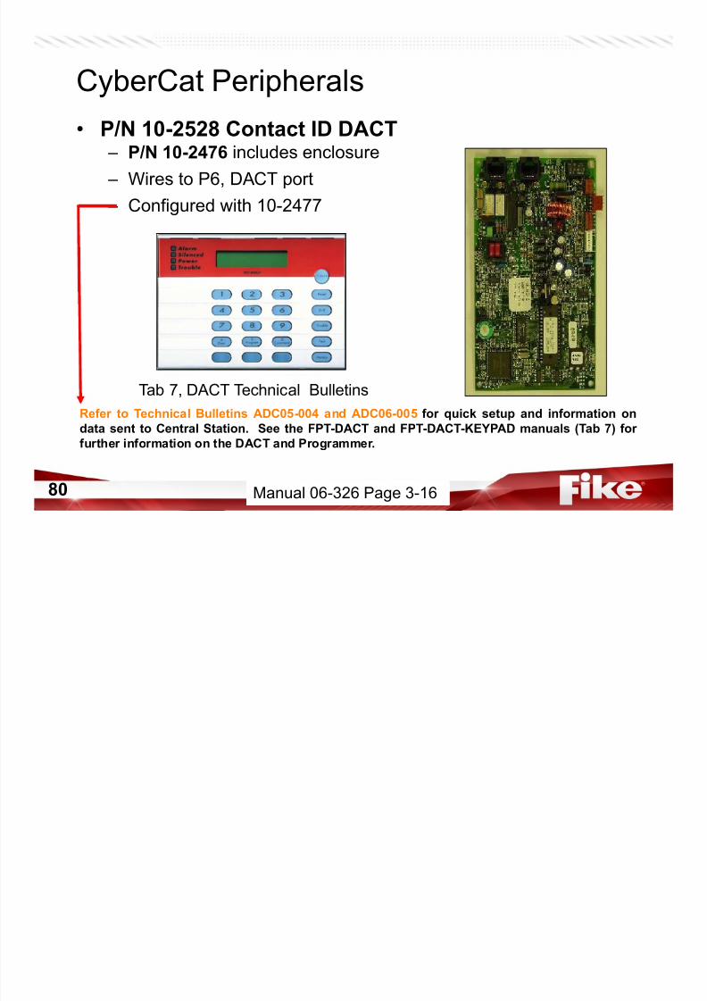
• P/N 10-2528 Contact ID DACT – P/N 10-2476 includes enclosure
– Wires to P6, DACT port
– Configured with 10-2477
Refer to Technical Bulletins ADC05-004 and ADC06-005 for quick setup and information on
data sent to Central Station. See the FPT-DACT and FPT-DACT-KEYPAD manuals (Tab 7) for
further information on the DACT and Programmer.
Tab 7, DACT Technical Bulletins
Manual 06-326 Page 3-16
CyberCat System Installation

7/23/2019 CyberCat 2015 FULL Printout
http://slidepdf.com/reader/full/cybercat-2015-full-printout 81/429
81
• Connect wiring for
DACT (when ready for
DACT operation)
A ux i l i ar y O u t p u t s
Battery+ Input -Secondary
AC XFMR
OPTIONAL
P 2 2
+
-
S HL D
+
-
S HL D
+
-
S HL D
- -
+ +
S H L D
-
+
A d d r e s s a b l e L o o p 4
A d d r e s s a b l e L o o p 4
- -
+ +
S H L D
-
+
- -
+ +
S H L D
-
+
A d d r e s s a b l e L o o p 3
A d d r e s s a b l e L o o p 3
- -
+ +
S H L D
-
+
P1
+ Input - Battery
Secondary AC XFMR
DACT (485) Peripherals + - SHLD + -
P19
P17
P 1 2
P20P13
LOOPMODULE
P16
DISPLAY
P7P2 P3 P4 P5
P9
A d d r e s s a b l e L o o p 1
- -
+ +
S H L D
-
+
- -
+ +
S H L D
-
+
A d d r e s s a b l e L o o p 1
P8
CRM4 OR CRP
OPTIONALRELAY
NETWORKCRM4 OR
CARD
SUPPLY
SUPPLEMENTALPOWER
P15
P11
- -
+ +
S H L D
-
+
Battery Fuse 10A ACFuse 10A
F1F2
+ - SHLD + - SHLD + - SHLD Resettable Aux Out AuxliliaryOutputsCOMPUTER VESDA
P6
P10
N o t i f i c a t i o n A p p l i a n c e C i r c u i t 1
- -
+ +
S H L D
-
+
N o t i f i c a t i o n A p p l i a n c e C i r c u i t 2
- -
+ +
S H L D
-
+
A d d r e s s a b l e L o o p 2
Peripherals(232)C NC NO C NC NO C NC NO Alarm Supervisory Trouble
DACTOPTIONAL
P21
P22
P18
B
A
-+
Manual 06-326 Page 4-18
CyberCat 50 System Installation

7/23/2019 CyberCat 2015 FULL Printout
http://slidepdf.com/reader/full/cybercat-2015-full-printout 82/429
82
B
A
+-
Jump Drive - Manual 06-368 Page 4-14
CyberCat Peripherals

7/23/2019 CyberCat 2015 FULL Printout
http://slidepdf.com/reader/full/cybercat-2015-full-printout 83/429
83
• 2-Button Expanded Protocol RDU
– P/N 10-2630
– Remote System Status• Custom Messages
– Buttons allow user to scroll events
– Wires to P6, Peripheral, up to 4000’ from panel – Compatible with panel firmware 3.0 and newer
– Mounts to standard 3-gang box (minimum 2” depth)
NOTE: Internal Piezo will sound until silenced by panel.
Jump Drive - Manual 06-610
Manual 06-326 Page 3-20
CyberCat Peripherals

7/23/2019 CyberCat 2015 FULL Printout
http://slidepdf.com/reader/full/cybercat-2015-full-printout 84/429
84
• 10-Button Expanded Protocol RDU
– P/N 10-2631
– Remote System Status• Custom Messages
– 4 Pre-Configured Buttons
– Remote Control of Panel
• Reset, Silence, Acknowledge, Drill
– Wires to P6, Peripheral, up to 4000’ from panel
– Compatible with panel firmware 3.0 and newer
– Mounts to standard 4-gang box (minimum 2” depth)
Jump Drive - Manual 06-610
Manual 06-326 Page 3-19
CyberCat Peripherals

7/23/2019 CyberCat 2015 FULL Printout
http://slidepdf.com/reader/full/cybercat-2015-full-printout 85/429
85
• 14-Button Expanded Protocol RDU
– P/N 10-2646
– Remote System Status• Custom Messages
– 8 Configurable Buttons
• Label pockets
– Remote Control of Panel
• Reset, Silence, etc.
– Wires to P6, Peripheral, up to 4000’ from panel
– Compatible with panel firmware 3.0 and newer
– Mounts to standard 5-gang box (minimum 2” depth)
Jump Drive - Manual 06-610
Manual 06-326 Page 3-19
CyberCat Peripherals

7/23/2019 CyberCat 2015 FULL Printout
http://slidepdf.com/reader/full/cybercat-2015-full-printout 86/429
86
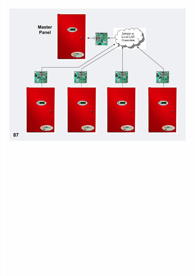
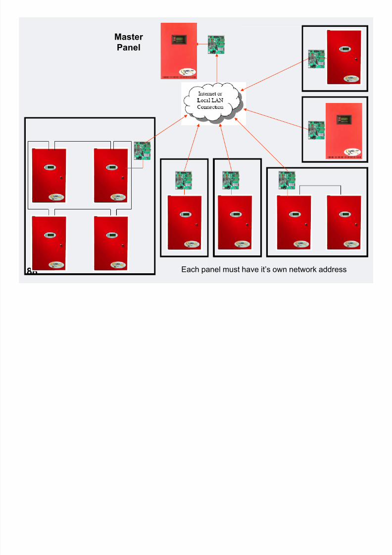
• Ethernet Module
• P/N 10-2627• P/N 10-074 includes enclosure
– Network up to 128 panels• Including 50 points
– Address set by DIP switches
– Wires to P6, Peripheral, up to 4,000’ from panel
– Mounts to spare transformer location or in separate enclosure.
– Allows connection of Fike panels both on and off premises.
– Not intended for contiguous building (timing)
NOTE: Ethernet modules provide the ability to send history events to
one destination....and ONLY one destination panel per UL.
P/N 10-2627P/N 10-074
Jump Drive - Manual 06-388 & 06-388-1
Manual 06-326 Page 3-20
Master
P l
7/23/2019 CyberCat 2015 FULL Printout
http://slidepdf.com/reader/full/cybercat-2015-full-printout 87/429
87
Panel
Master
Panel
7/23/2019 CyberCat 2015 FULL Printout
http://slidepdf.com/reader/full/cybercat-2015-full-printout 88/429
88Each panel must have it’s own network address
CyberCat Peripherals
7/23/2019 CyberCat 2015 FULL Printout
http://slidepdf.com/reader/full/cybercat-2015-full-printout 89/429
89
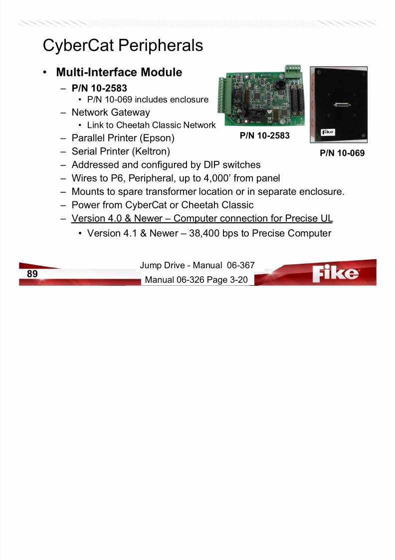
• Multi-Interface Module
– P/N 10-2583• P/N 10-069 includes enclosure
– Network Gateway
• Link to Cheetah Classic Network
– Parallel Printer (Epson)
– Serial Printer (Keltron)
– Addressed and configured by DIP switches
– Wires to P6, Peripheral, up to 4,000’ from panel
– Mounts to spare transformer location or in separate enclosure.
– Power from CyberCat or Cheetah Classic
– Version 4.0 & Newer – Computer connection for Precise UL
• Version 4.1 & Newer – 38,400 bps to Precise Computer
P/N 10-2583
P/N 10-069
Jump Drive - Manual 06-367
Manual 06-326 Page 3-20
CyberCat Peripherals
G

7/23/2019 CyberCat 2015 FULL Printout
http://slidepdf.com/reader/full/cybercat-2015-full-printout 90/429
90
• LED Graphic Panel
– P/N 10-2411, GDB256• LED Graphic Processor Card
• Supports up to 256 LEDs – 10-1858/59 LED Interface Card
– LED Indication on Custom Graphic
– Wires to P6, Peripheral, up to 4000’
from panel
– Configured with C-Linx
Jump Drive - Manual 06-231
Manual 06-326 Page 3-21
Intelligent Graphics WiringRS485 COMMUNICATION CIRCUIT FROM
PANEL OR PREVIOUS DEVICE. P2
24VDC POWER OUTPUT TO NEXT
DEVICE. P1 TERMINAL 3 (+) AND 4 (-).

7/23/2019 CyberCat 2015 FULL Printout
http://slidepdf.com/reader/full/cybercat-2015-full-printout 91/429
91
SW2
P6
P3
P7
SW1
P2P1
P4
P5
D3
D2
10B
10A9B
9A8B8A
7B
7A
BAT1
TERMINAL 1 (+) AND 2 (-).24VDC POWER INPUT FROM CONTROL PANEL,
PREVIOUS DEVICE, OR BATTERY BACKED,
REGULATED, POWER-LIMITED, POWER
SUPPLY LISTED FOR FIRE PROTECTIVE
SIGNLAING USE. P1 TERMINAL 1 (+) AND 2 (-).
( ) ( )
RS485 COMMUNICATION CIRCUIT TO
NEXT DEVICE OR 100 OHM EOL IF LAST
DEVICE ON CIRCUIT. P2 TERMINAL 3
(+) AND 4 (-).
NOT USED
SWITCH INPUTS:
7A/7B = RESET8A/8B = SILENCE
9A/9B = ACKNOWLEDGE
10A/10B = LAMP TEST
RS485 COMMUNICATIONS LED
O.K. = STEADY
FAILED = FLASHING
POWER LED (GREEN)
LITHIUM BATTERY (P/N 02-4040)
FOR CONFIGURATION BACKUP
RESET SWITCH
FIKE USE ONLY
RS232 PROGRAMMING PORT
(RJ11 STYLE CONNECTOR).
CONNECTS TO PC VIA
PROGRAMMING CABLE
(10-1874A).
MODULE
ADDRESS
SWITCHES
(2-32)
34-PIN RIBBON CABLE
CONNECTION TO LED
INTERFACE BOARD #1
(10-1858)
6-PIN RIBBON CABLE
CONNECTION TO SWITCH
CARD (10-2086)
Jump Drive - Manual 06-231
Cheetah Xi Peripherals (Fike Forums)
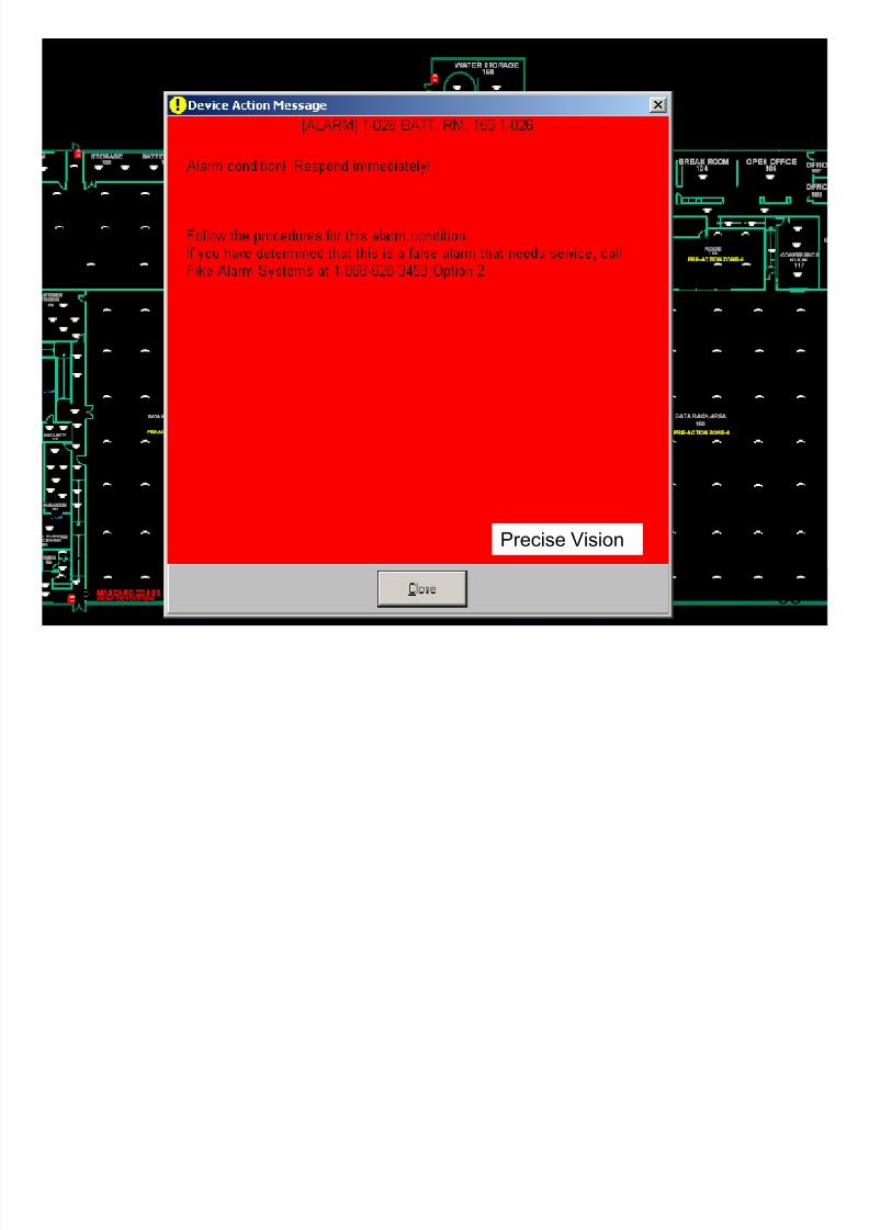
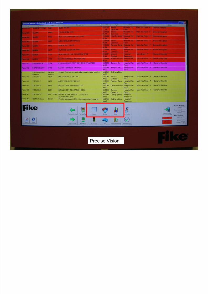
• Precise Vision

7/23/2019 CyberCat 2015 FULL Printout
http://slidepdf.com/reader/full/cybercat-2015-full-printout 92/429
92
• Precise Vision
• 06-461 Fike Precise Vision Management Software Package F Max of 130,047 Points(Monitoring Capability Only. No Command & Control Functionality)

7/23/2019 CyberCat 2015 FULL Printout
http://slidepdf.com/reader/full/cybercat-2015-full-printout 93/429
93Precise Vision

7/23/2019 CyberCat 2015 FULL Printout
http://slidepdf.com/reader/full/cybercat-2015-full-printout 94/429
94Precise Vision
7/23/2019 CyberCat 2015 FULL Printout
http://slidepdf.com/reader/full/cybercat-2015-full-printout 95/429
95
Precise Vision
7/23/2019 CyberCat 2015 FULL Printout
http://slidepdf.com/reader/full/cybercat-2015-full-printout 96/429
96Precise Vision

7/23/2019 CyberCat 2015 FULL Printout
http://slidepdf.com/reader/full/cybercat-2015-full-printout 97/429
97

7/23/2019 CyberCat 2015 FULL Printout
http://slidepdf.com/reader/full/cybercat-2015-full-printout 98/429
98
20
CyberCat Peripherals
7/23/2019 CyberCat 2015 FULL Printout
http://slidepdf.com/reader/full/cybercat-2015-full-printout 99/429
99
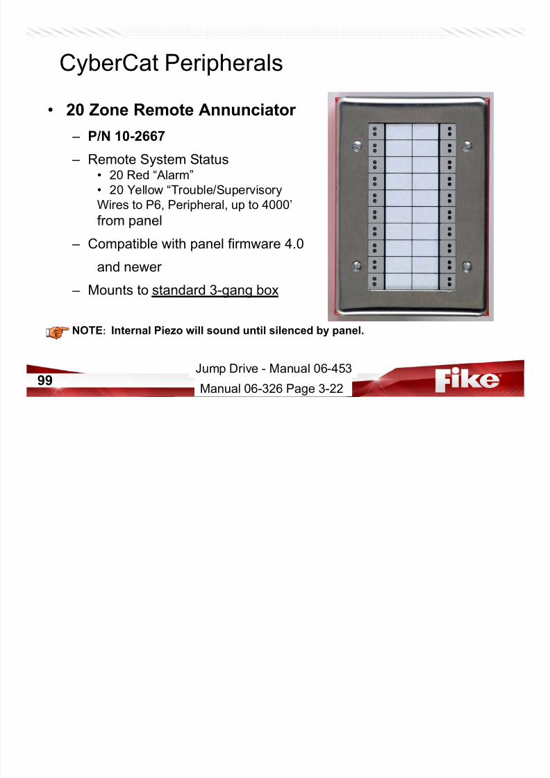
• 20 Zone Remote Annunciator
– P/N 10-2667
– Remote System Status• 20 Red “Alarm”
• 20 Yellow “Trouble/Supervisory
Wires to P6, Peripheral, up to 4000’
from panel
– Compatible with panel firmware 4.0
and newer
– Mounts to standard 3-gang box
NOTE: Internal Piezo will sound until silenced by panel.
Jump Drive - Manual 06-453
Manual 06-326 Page 3-22
CyberCat Peripherals

7/23/2019 CyberCat 2015 FULL Printout
http://slidepdf.com/reader/full/cybercat-2015-full-printout 100/429
100
• 20 Zone Annunciator Module
– P/N 10-2660
– Remote System Status• 20 Red “Alarm”
• 20 Yellow “Trouble/Supervisory
– Wires to P6, Peripheral, up to 4000’
from panel – Compatible with panel firmware 4.0
and newer
– Mounts in CyberCat Enclosure **
Jump Drive - Manual 06-445
Manual 06-326 Page 3-23
• Input/Output Control Module
CyberCat Peripherals
7/23/2019 CyberCat 2015 FULL Printout
http://slidepdf.com/reader/full/cybercat-2015-full-printout 101/429
101
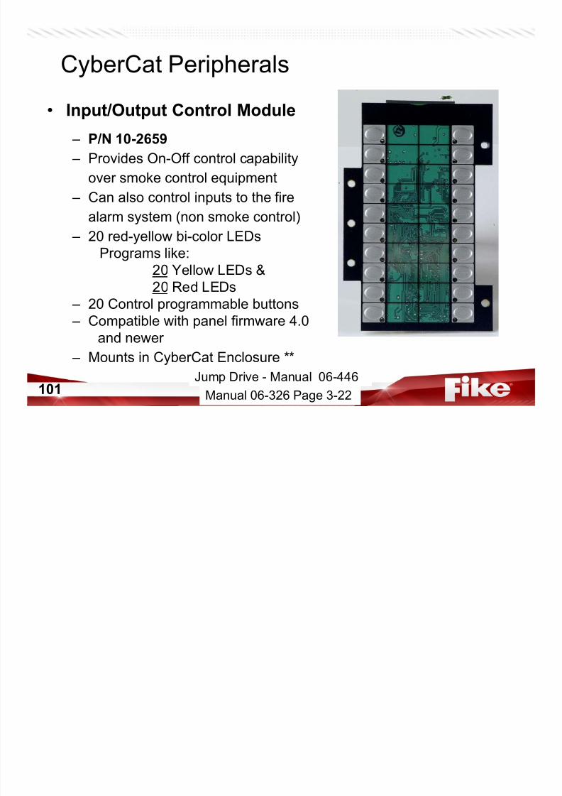
• Input/Output Control Module
– P/N 10-2659
– Provides On-Off control capability
over smoke control equipment
– Can also control inputs to the fire
alarm system (non smoke control)
– 20 red-yellow bi-color LEDs
Programs like:
20 Yellow LEDs &
20 Red LEDs
– 20 Control programmable buttons
– Compatible with panel firmware 4.0and newer
– Mounts in CyberCat Enclosure **
Manual 06-326 Page 3-22
Jump Drive - Manual 06-446
1
2
20
19LED 3=Red
LED 4=Yellow
LED 1=Red
LED 2=Yellow
LED 38=Red
LED 37=Yellow
LED 40=Red
LED 39=Yellow
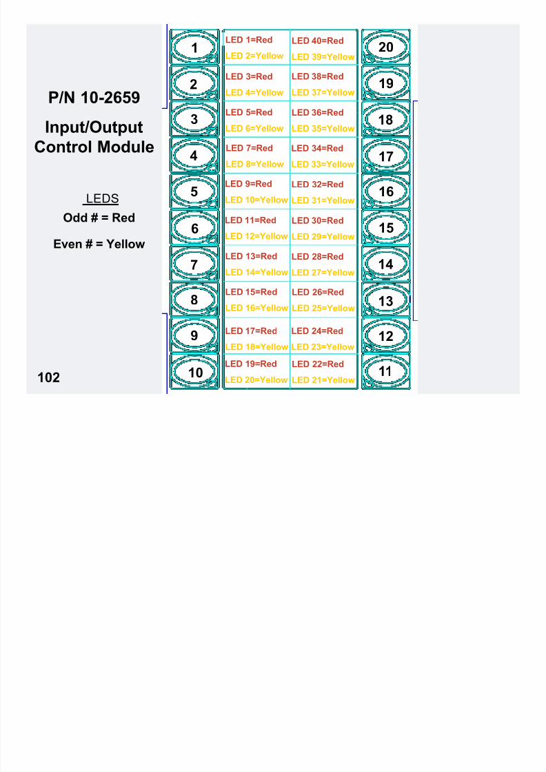
P/N 10-2659
7/23/2019 CyberCat 2015 FULL Printout
http://slidepdf.com/reader/full/cybercat-2015-full-printout 102/429
102
LEDS
Odd # = Red
Even # = Yellow
5
3
4
7
8
9
10
6
17
16
15
14
13
12
11
18LED 5=Red
LED 6=Yellow
LED 7=Red
LED 8=Yellow
LED 9=Red
LED 10=Yellow
LED 13=Red
LED 14=Yellow
LED 11=Red
LED 12=Yellow
LED 15=Red
LED 16=Yellow
LED 17=Red
LED 18=Yellow
LED 19=Red
LED 20=Yellow
LED 22=Red
LED 21=Yellow
LED 24=Red
LED 23=Yellow
LED 26=Red
LED 25=Yellow
LED 28=Red
LED 27=Yellow
LED 30=Red
LED 29=Yellow
LED 32=Red
LED 31=Yellow
LED 34=Red
LED 33=Yellow
LED 36=Red
LED 35=YellowInput/Output
Control Module
• 6 Zone Smoke Control Module
CyberCat Peripherals

7/23/2019 CyberCat 2015 FULL Printout
http://slidepdf.com/reader/full/cybercat-2015-full-printout 103/429
103
6 Zone Smoke Control Module
– P/N 10-2658
– Provides On-Off-Auto control capability
over smoke control equipment – Can also control inputs to the fire
alarm system (non smoke control)
– 24 LEDs (4 per zone)
(Green, Red, Yellow, White) – 18 Control programmable buttons
(3 per zone)
– Compatible with panel firmware 4.0
and newer – Mounts in CyberCat Enclosure **
Jump Drive - Manual 06-444
Manual 06-326 Page 3-22
• Fire-Fighter’s Smoke Control
CyberCat Peripherals

7/23/2019 CyberCat 2015 FULL Printout
http://slidepdf.com/reader/full/cybercat-2015-full-printout 104/429
104
g
Graphic Panel
– P/N 10-2xxx
– Provides On-Off-Auto control capabilityover smoke control equipment
– Can also control inputs to the fire
alarm system (non smoke control)
– LEDs to indicate operational status
or smoke control equipment – Manual Override switches to control
smoke system equipment
– Access key switch for lock-out of
smoke control switches – Compatible with panel firmware 4.0
and newer
Manual 06-326 Page 3-21
Jump Drive - Manual 06-447
• Relay Control Assembly
CyberCat Peripherals
• Adds up to 24 Relays
Datasheet P.1.149.01
7/23/2019 CyberCat 2015 FULL Printout
http://slidepdf.com/reader/full/cybercat-2015-full-printout 105/429
105
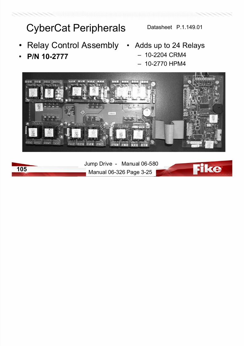
y y
• P/N 10-2777
p y
– 10-2204 CRM4
– 10-2770 HPM4
Jump Drive - Manual 06-580
Manual 06-326 Page 3-25
HPM4 Relay Card
CyberCat Peripherals
CRM4 Relay Card
Datasheet P.1.149.01

7/23/2019 CyberCat 2015 FULL Printout
http://slidepdf.com/reader/full/cybercat-2015-full-printout 106/429
106
• P/N 10-2770
– 5A @ 30VDC
– 5A @ 120VAC – 0 mA Standby
– 87 mA Alarm
• (All relays active)
• P/N 10-2204
– 2A @ 30VDC
– 0.5A @ 120VAC – 11 mA Standby
– 40 mA Alarm
• (All relays active)
Jump Drive - Manual 06-580
Datasheet P.1.150.01 Datasheet D.1.14.01
CyberCat Peripherals Datasheet P.1.149.01

7/23/2019 CyberCat 2015 FULL Printout
http://slidepdf.com/reader/full/cybercat-2015-full-printout 107/429
107 Jump Drive - Manual 06-580
CyberCat Peripherals Datasheet P.1.149.01

7/23/2019 CyberCat 2015 FULL Printout
http://slidepdf.com/reader/full/cybercat-2015-full-printout 108/429
108Jump Drive - Manual 06-580
• Relay Card (RC12)
CyberCat Peripherals Datasheet P.1.148.01

7/23/2019 CyberCat 2015 FULL Printout
http://slidepdf.com/reader/full/cybercat-2015-full-printout 109/429
109
– P/N 10-2785 - 12 Relays
• 2.5 A @ 30VDC
• 5 A @ 120VAC
• 32 mA Standby
• 256 mA Alarm (All relays active)
Jump Drive - Manual 06-586
CyberCat Peripherals
7/23/2019 CyberCat 2015 FULL Printout
http://slidepdf.com/reader/full/cybercat-2015-full-printout 110/429
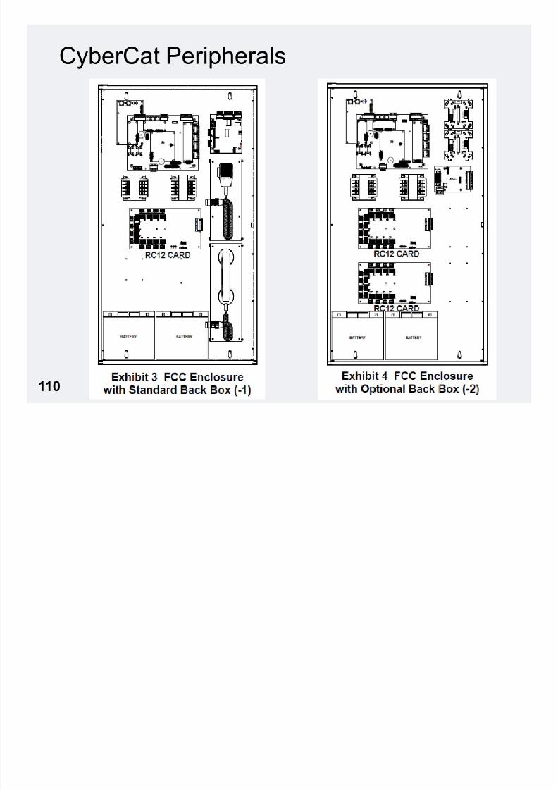
110
CyberCat Enclosures

7/23/2019 CyberCat 2015 FULL Printout
http://slidepdf.com/reader/full/cybercat-2015-full-printout 111/429
111 Datasheet D.1.26.01
CyberCat
Enclosures

7/23/2019 CyberCat 2015 FULL Printout
http://slidepdf.com/reader/full/cybercat-2015-full-printout 112/429
112 Datasheet D.1.26.01
CyberCat Peripherals
• FieldServer Protocol Converter*Links Xi to other popular protocols

7/23/2019 CyberCat 2015 FULL Printout
http://slidepdf.com/reader/full/cybercat-2015-full-printout 113/429
113 Jump Drive - Fieldserver
– Links Xi to other popular protocols• BACnet
• ControlNet
• Modbus• Profibus
• SNMP
• TCP
• Many more…
– Wires from P6 to Multi-Interface Module, up to 4000’ from panel
– Special quote required (no standard part number)
• Type of physical connection to customer equipment
• Customer Protocol needed
• Number of points to monitor
*Not UL Listed

7/23/2019 CyberCat 2015 FULL Printout
http://slidepdf.com/reader/full/cybercat-2015-full-printout 114/429
114
CyberCat Peripherals
• VESDA High Level Interface (HLI)
– 68-023

7/23/2019 CyberCat 2015 FULL Printout
http://slidepdf.com/reader/full/cybercat-2015-full-printout 115/429
115Jump Drive - Manual 06-158
Manual 06-326 Page 3-36
68 023
– Intelligently link to up to 40 VESDA detectors• VESDA Zones 1 - 255
– Powered from Cheetah Xi Continuous AUX Circuit – Wires to P4, VESDA, up to 50’ from panel (14’ provided)
– Refer to Tech Bulletin DC07-007 for limitations of network
Cheetah Xi Operation
VESDA Cheetah Xi
Alert Pre-Alarm 1
Action Pre-Alarm 2
Fire 1 Alarm/Pre-Discharge
Fire 2**
Alarm/Pre-DischargeFire 1 & Fire 2 can be
programmed for Supervisory

7/23/2019 CyberCat 2015 FULL Printout
http://slidepdf.com/reader/full/cybercat-2015-full-printout 116/429
116
SLC Devices & Accessories
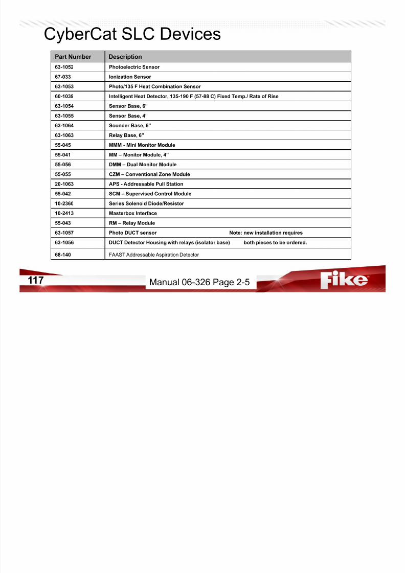
CyberCat SLC DevicesPart Number Description
63-1052 Photoelectric Sensor
67-033 Ionization Sensor
63-1053 Photo/135 F Heat Combination Sensor
7/23/2019 CyberCat 2015 FULL Printout
http://slidepdf.com/reader/full/cybercat-2015-full-printout 117/429
117
60-1039 Intelligent Heat Detector, 135-190 F (57-88 C) Fixed Temp./ Rate of Rise
63-1054 Sensor Base, 6”
63-1055 Sensor Base, 4”
63-1064 Sounder Base, 6”
63-1063 Relay Base, 6”
55-045 MMM - Mini Monitor Module
55-041 MM – Monitor Module, 4”
55-056 DMM – Dual Monitor Module
55-055 CZM – Conventional Zone Module
20-1063 APS - Addressable Pull Station
55-042 SCM – Supervised Control Module
10-2360 Series Solenoid Diode/Resistor
10-2413 Masterbox Interface
55-043 RM – Relay Module
63-1057 Photo DUCT sensor Note: new installation requires
63-1056
68-140
DUCT Detector Housing with relays (isolator base) both pieces to be ordered.
FAAST Addressable Aspiration Detector
Manual 06-326 Page 2-5
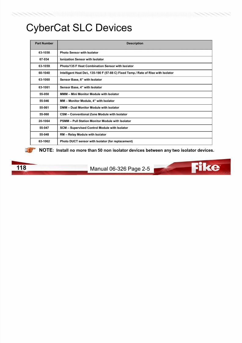
CyberCat SLC Devices
Part Number Description
63-1058 Photo Sensor with Isolator
7/23/2019 CyberCat 2015 FULL Printout
http://slidepdf.com/reader/full/cybercat-2015-full-printout 118/429
118
NOTE: Install no more than 50 non isolator devices between any two isolator devices.
67-034 Ionization Sensor with Isolator
63-1059 Photo/135 F Heat Combination Sensor with Isolator
60-1040 Intelligent Heat Det., 135-190 F (57-88 C) Fixed Temp./ Rate of Rise with Isolator
63-1060 Sensor Base, 6” with Isolator
63-1061 Sensor Base, 4” with Isolator
55-050 MMM – Mini Monitor Module with Isolator
55-046 MM – Monitor Module, 4” with Isolator
55-061 DMM – Dual Monitor Module with Isolator
55-060 CSM – Conventional Zone Module with Isolator
20-1064 PSMM – Pull Station Monitor Module with Isolator
55-047 SCM – Supervised Control Module with Isolator
55-048 RM – Relay Module with Isolator
63-1062 Photo DUCT sensor with Isolator (for replacement)
Manual 06-326 Page 2-5
CyberCat Addressable Sensors
• 63-1052 – Photoelectric Sensor

7/23/2019 CyberCat 2015 FULL Printout
http://slidepdf.com/reader/full/cybercat-2015-full-printout 119/429
119
– 63-1058 = Isolation version
– Features
• Acclimate• Alarm Verification
• Device Summing
• Day/Night Sensitivities
– 2 PreAlarm Levels (optional)
• 0.5 – 4.0%/ft. Obscuration
– Alarm Level
• 1.3 – 3.6%/ft. Obscuration
– 4000 FPM Maximum Airflow
Device Installation Instructions
Manual 06-326 Page 3-27
CyberCat Addressable Sensors
• 67-033 – Ionization Sensor

7/23/2019 CyberCat 2015 FULL Printout
http://slidepdf.com/reader/full/cybercat-2015-full-printout 120/429
120
– 67-034 = Isolation version
– Features
• Acclimate
• Alarm Verification
• Device Summing
• Day/Night Sensitivities
– 2 PreAlarm Levels (optional)
• 100 – 40 MIC (μA)
– Alarm Level
• 80 – 50 MIC (μA)
– 1200 FPM Maximum Airflow
Manual 06-326 Page 3-27
Device Installation Instructions
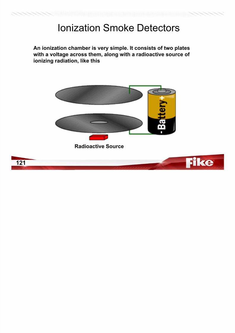
Ionization Smoke Detectors
An ionization chamber is very simple. It consists of two plates
with a voltage across them along with a radioactive source of
7/23/2019 CyberCat 2015 FULL Printout
http://slidepdf.com/reader/full/cybercat-2015-full-printout 121/429
121
with a voltage across them, along with a radioactive source of
ionizing radiation, like this
Radioactive Source
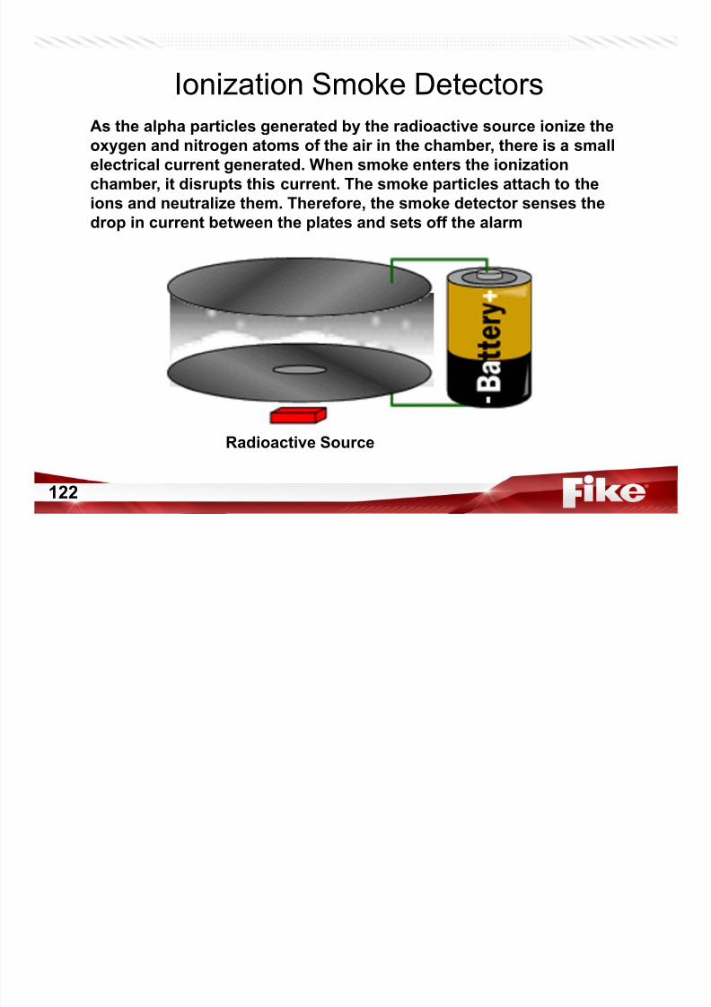
Ionization Smoke Detectors
As the alpha particles generated by the radioactive source ionize theoxygen and nitrogen atoms of the air in the chamber, there is a small
electrical current generated When smoke enters the ionization
7/23/2019 CyberCat 2015 FULL Printout
http://slidepdf.com/reader/full/cybercat-2015-full-printout 122/429
122
electrical current generated. When smoke enters the ionization
chamber, it disrupts this current. The smoke particles attach to the
ions and neutralize them. Therefore, the smoke detector senses the
drop in current between the plates and sets off the alarm
Radioactive Source
CyberCat Addressable Sensors
• 63-1053 – Photo/Heat Sensor

7/23/2019 CyberCat 2015 FULL Printout
http://slidepdf.com/reader/full/cybercat-2015-full-printout 123/429
123
– 63-1059 = Isolation version
– Photo Specs PLUS
• 135°F Fixed-Temp
• Multi-State Configuration
– Photo = Alarm* or Supervisory
– Heat = Alarm*
• Flame Enhancement – Smoke and Heat equals faster
response time
Manual 06-326 Page 3-28
Device Installation Instructions
CyberCat Addressable Sensors
• 60-1039 – Heat Sensor – 60-1040 = Isolation version

7/23/2019 CyberCat 2015 FULL Printout
http://slidepdf.com/reader/full/cybercat-2015-full-printout 124/429
124
60 1040 Isolation version
– Rate-of-Rise Detection• 135° – 174°F
• 15°F per minute – Fixed Temp Detection
• 135° - 190°F
– 2 Prealarms (70 °F)
Spacing Requirements
Temperature UL FM
135° - 155°F 50 feet 30 feet
156° - 174°F 15 feet 30 feet
175° - 190°F 50 feet 30 feet
Manual 06-326 Page 3-28
Device Installation Instructions
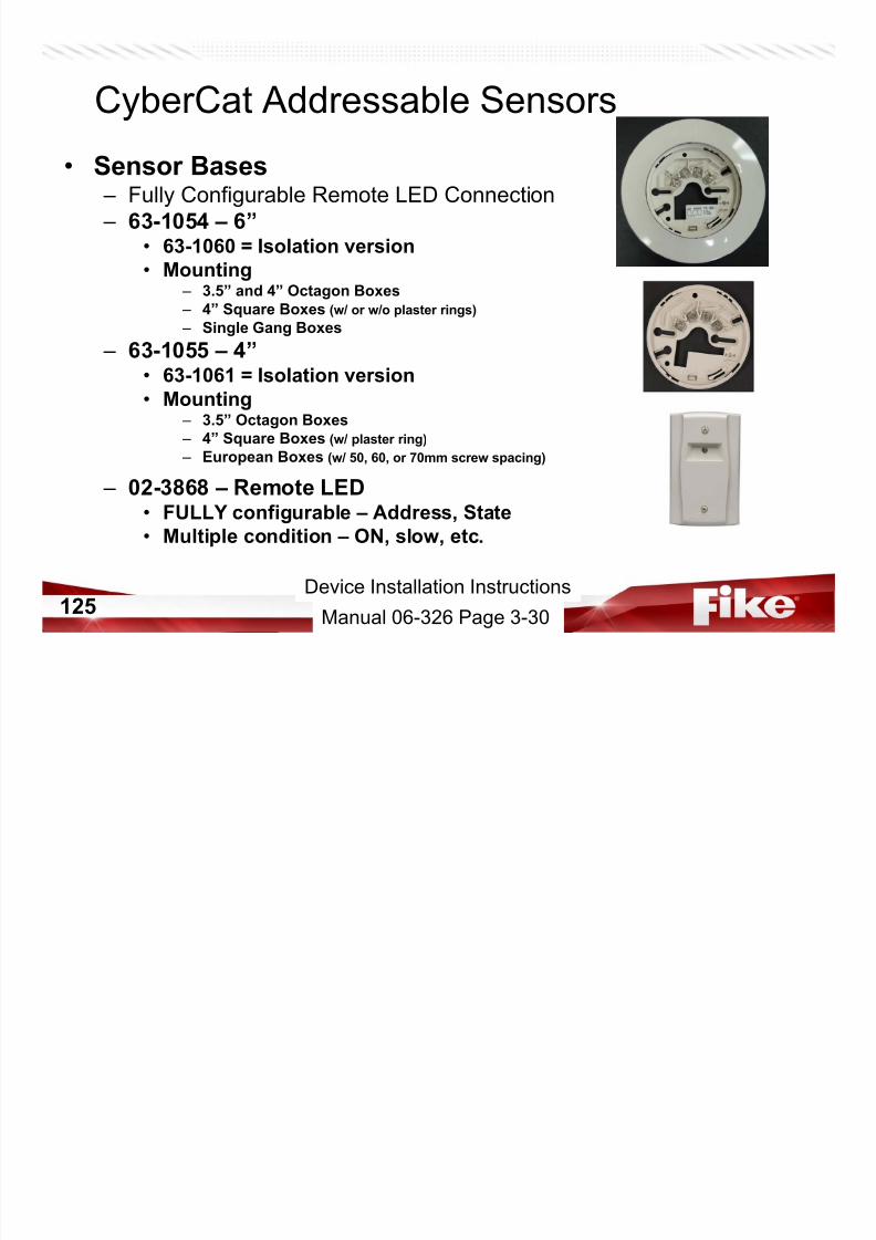
CyberCat Addressable Sensors
• Sensor Bases – Fully Configurable Remote LED Connection
7/23/2019 CyberCat 2015 FULL Printout
http://slidepdf.com/reader/full/cybercat-2015-full-printout 125/429
125
– 63-1054 – 6”• 63-1060 = Isolation version
• Mounting – 3.5” and 4” Octagon Boxes
– 4” Square Boxes (w/ or w/o plaster rings)
– Single Gang Boxes
– 63-1055 – 4”• 63-1061 = Isolation version
• Mounting – 3.5” Octagon Boxes
– 4” Square Boxes (w/ plaster ring)
– European Boxes (w/ 50, 60, or 70mm screw spacing)
– 02-3868 – Remote LED
• FULLY configurable – Address, State• Multiple condition – ON, slow, etc.
Manual 06-326 Page 3-30
Device Installation Instructions
CyberCat Addressable Sensors
• 63-1064 – Sounder Base – 6” Base

7/23/2019 CyberCat 2015 FULL Printout
http://slidepdf.com/reader/full/cybercat-2015-full-printout 126/429
126
– 85 dB Sounder
– Fully Configurable
– Requires 24 VDC – 24Vdc is NOT Supervised
• 63-1063 – Relay Base
– 6” Base – 1, Form C Contact
• Resistive – 2A @ 30VDC, 0.5A @ 125VAC
• Inductive
– 1A @ 30VDC, 0.25A @125VAC – Fully Configurable
– 24 VDC NOT required
Manual 06-326 Page 3-31
Device Installation Instructions
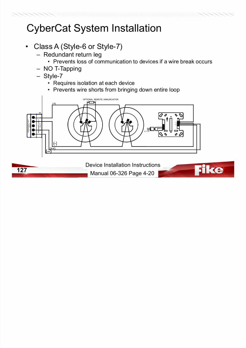
CyberCat System Installation
• Class A (Style-6 or Style-7) – Redundant return leg
P t l f i ti t d i if i b k
7/23/2019 CyberCat 2015 FULL Printout
http://slidepdf.com/reader/full/cybercat-2015-full-printout 127/429
127
• Prevents loss of communication to devices if a wire break occurs
– NO T-Tapping
– Style-7• Requires isolation at each device
• Prevents wire shorts from bringing down entire loop
- -
+ +
S H L D
-
+
(--)
P8
A d d r e s s a b l e L o o p 1
A d d r e s s a b l e L o o p 1
- -
+ +
S H L D
-
+
LOOP ADDRESS
TOP
6
5
4 3 2 11
2
1 1
1 0
9
8
7
1 3
1 4
39KEOL
+-+-
39KEOL
+L E
D - - L E D +
(-)
(+)(-) (+)
OPTIONAL REMOTE ANNUNCIATOR
(++)
02-11259
Manual 06-326 Page 4-20
Device Installation Instructions
CyberCat System Installation
• Sensor Base Wiring (Non-Isolator) – Fully configurable Remote LED Annunciator
Wi t th LED t i l f b

7/23/2019 CyberCat 2015 FULL Printout
http://slidepdf.com/reader/full/cybercat-2015-full-printout 128/429
128
• Wires to the LED terminal of sensor bases
OPTIONAL REMOTE ANNUNCIATOR
FACP
(+)
(-)
STRIP GAGE
SHIELD
+L E D
-
OTHER ADDRESSABLE DEVICES
TO FACPOR OPTIONAL CLASS A RETURN
OR OPTIONAL CLASS A RETURNTO FACP
OTHER ADDRESSABLE DEVICES
LED terminal is used for
LED ONLY, do not
split – loop wiring on
this terminal
Manual 06-326 Page 4-20
CyberCat System Installation
• Sensor Base Wiring (Isolator)
Redundant return leg – supervision even during single break and

7/23/2019 CyberCat 2015 FULL Printout
http://slidepdf.com/reader/full/cybercat-2015-full-printout 129/429
129
short will not bring down the loop.
Device Installation Instructions
Manual 06-326 Page 4-20
CyberCat Addressable Sensors
Tab 1, Datasheet P.1.166.01• 68-140 – FAAST Detector
– Aspirator Detector

7/23/2019 CyberCat 2015 FULL Printout
http://slidepdf.com/reader/full/cybercat-2015-full-printout 130/429
130
– Eclipse Protocol
– Connects on CyberCat SLC – Operates on 24Vdc..650 mA Full Load
– 6 Internal Programmable Relays
• 8 Relays on conventional unit P/N 68-126
– 5 Alarm Levels – IP Addressable
– Can send E-Mail Notifications
– Programmable with C-Linx
– Obscuration .00046% - 6.25% **
Manual 06-326 Page 3-30
Device Installation Instructions

7/23/2019 CyberCat 2015 FULL Printout
http://slidepdf.com/reader/full/cybercat-2015-full-printout 131/429
131
Comprehensive and Intuitive
FAAST Onboard Display, Controls, and Settings

7/23/2019 CyberCat 2015 FULL Printout
http://slidepdf.com/reader/full/cybercat-2015-full-printout 132/429
132
• Quick read monitoring at the device
of particulate levels, alarm levels, fault
conditions, air flow, etc.
Configurable Alarm Levels
FAAST Onboard Display, Controls, and Settings

7/23/2019 CyberCat 2015 FULL Printout
http://slidepdf.com/reader/full/cybercat-2015-full-printout 133/429
133
• 5 red pre-set alarm levels
• Alarm levels can be customized
• 6* form C relay outputs can be
programmed for either latching or
non-latching operation
• Relays have a programmable delayfrom 0 to 60 seconds
• Upon alarm level operation, the
associated LED illuminates and the
relay activates
• * 8 relays on conventional unit
CyberCat Addressable Modules
• Monitor Modules – Dry Contact Monitor
• Tamper, Manual Pull, Waterflow, etc

7/23/2019 CyberCat 2015 FULL Printout
http://slidepdf.com/reader/full/cybercat-2015-full-printout 134/429
134
Tamper, Manual Pull, Waterflow, etc.
• 2000’ of Linear Heat (UL & FM)
– 39K End-Of-Line Resistor
– Short Circuit Protection
– 100 Ω max. wire resistance
– Class B (Style-4) Wiring
– 55-041 – 4” Monitor Module (MM)
• 55-046 = Isolation version
• Class A (Style-6) Wiring for Contacts
– 55-045 – Mini Monitor Module (mmm)• 55-050 = Isolation version
• Class B wiring only for contacts
Manual 06-326 Page 3-33
Device Installation Instructions
CyberCat System Installation
• Mini Monitor Module – Wiring Style
• Class B Only(-)
(+)
(-)
(+)
K
TO NEXTDEVICE
SLC
PREVIOUS DEVICEFROM PANEL OR
SLC

7/23/2019 CyberCat 2015 FULL Printout
http://slidepdf.com/reader/full/cybercat-2015-full-printout 135/429
135
C O y – 39K ohm EOL
– Wire Resistance• 100 ohms max. wire resistance
– Short Circuit Detection• 14K ohm
• 2 part….program and install
(-) (+) (+)
B L A C
R E D
R E D
39K
V I O L E T
Y E L L O W
EOL
Device Installation Instructions
CyberCat System Installation
• Monitor Module – Wiring Style

7/23/2019 CyberCat 2015 FULL Printout
http://slidepdf.com/reader/full/cybercat-2015-full-printout 136/429
136
• Class B – 39K ohm EOL
• Class A – Wire Resistance
• 100 ohms max.
– Short Circuit Detection• 14K ohm
• 2 part P & I
Device Installation Instructions
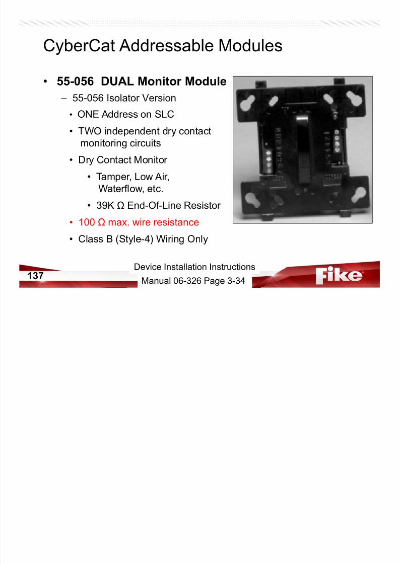
• 55-056 DUAL Monitor Module
– 55-056 Isolator Version
CyberCat Addressable Modules
7/23/2019 CyberCat 2015 FULL Printout
http://slidepdf.com/reader/full/cybercat-2015-full-printout 137/429
137
• ONE Address on SLC
• TWO independent dry contact
monitoring circuits
• Dry Contact Monitor
• Tamper, Low Air,Waterflow, etc.
• 39K End-Of-Line Resistor
• 100 max. wire resistance
• Class B (Style-4) Wiring Only
Manual 06-326 Page 3-34
Device Installation Instructions
• Dual Monitor Module – Wiring Style
• Class B
CyberCat System Installation

7/23/2019 CyberCat 2015 FULL Printout
http://slidepdf.com/reader/full/cybercat-2015-full-printout 138/429
138
– 39K ohm EOL
• NO Class A
– Wire Resistance• 100 ohms max.
– Short Circuit Detection• 14K ohm
LOOP ADDRESS
TOP
6
5
4
3
2
11 2
1 1
1 0
9
8
7
1 3
1 4
+
-
+
-
14K
39KEOL39KEOL
14K(p/n 02-11259)
39KEOL39KEOL
14K(p/n 02-11259)
Device Installation Instructions
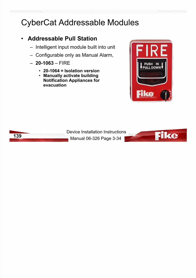
CyberCat Addressable Modules
• Addressable Pull Station
– Intelligent input module built into unit
7/23/2019 CyberCat 2015 FULL Printout
http://slidepdf.com/reader/full/cybercat-2015-full-printout 139/429
139
– Configurable only as Manual Alarm,
– 20-1063 – FIRE
• 20-1064 = Isolation version• Manually activate building
Notification Appliances forevacuation
Manual 06-326 Page 3-34
Device Installation Instructions
ADDRESSABLE LOOP
FROM PREVIOUS
DEVICE
+
-
ADDRESSABLE LOOP
TO NEXT
+
- DEVICE
CyberCat System Installation
• Pull Station

7/23/2019 CyberCat 2015 FULL Printout
http://slidepdf.com/reader/full/cybercat-2015-full-printout 140/429
140
1 2 3 4
-+- +
Terminal 1 is negative (-)
Wiring wrong WILL cause
LOOP SHORT Event on
Conrol Panel.
Device Installation Instructions
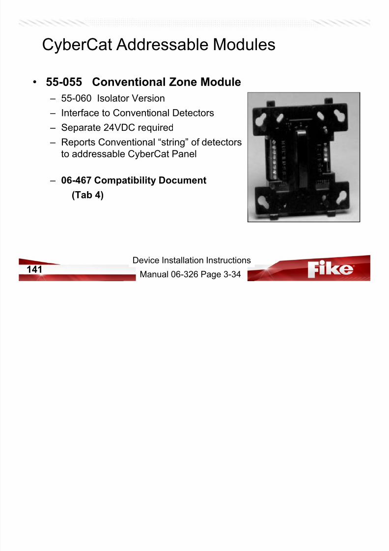
• 55-055 Conventional Zone Module
– 55-060 Isolator Version
CyberCat Addressable Modules
7/23/2019 CyberCat 2015 FULL Printout
http://slidepdf.com/reader/full/cybercat-2015-full-printout 141/429
141
– Interface to Conventional Detectors
– Separate 24VDC required
– Reports Conventional “string” of detectors
to addressable CyberCat Panel
– 06-467 Compatibility Document
(Tab 4)
Manual 06-326 Page 3-34
Device Installation Instructions
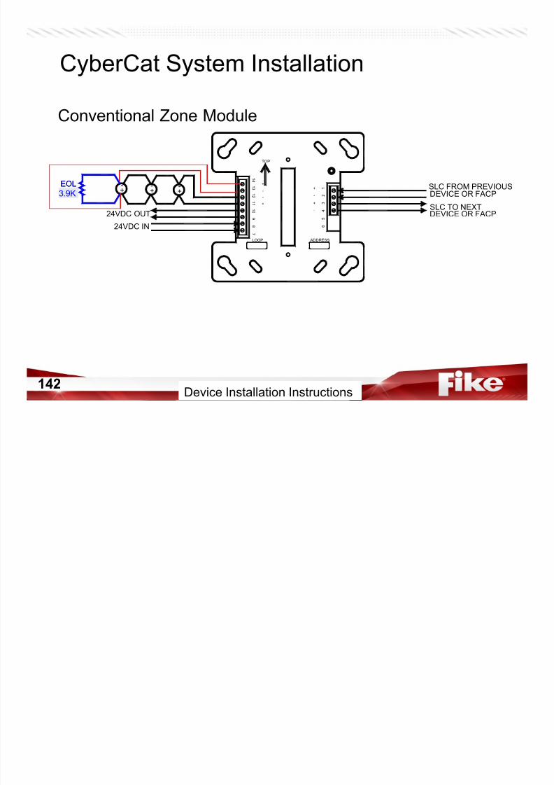
CyberCat System Installation
Conventional Zone Module
7/23/2019 CyberCat 2015 FULL Printout
http://slidepdf.com/reader/full/cybercat-2015-full-printout 142/429
142
-
+
-
+
1 4
1 3
7
8
9
1 0
1 1
1 2
1
2
3
4
5
6
TOP
ADDRESSLOOP
-
+
SLC TO NEXT
DEVICE OR FACP
-
+
-
+ SLC FROM PREVIOUS
DEVICE OR FACP
24VDC IN
24VDC OUT
-
+
-
+39KEOL39KEOL
3.9K
Device Installation Instructions
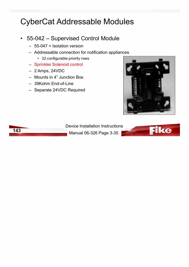
CyberCat Addressable Modules
• 55-042 – Supervised Control Module
– 55-047 = Isolation version
Addressable connection for notification appliances
7/23/2019 CyberCat 2015 FULL Printout
http://slidepdf.com/reader/full/cybercat-2015-full-printout 143/429
143
– Addressable connection for notification appliances
• 32 configurable priority rows – Sprinkler Solenoid control
– 2 Amps, 24VDC
– Mounts in 4” Junction Box
– 39Kohm End-of-Line – Separate 24VDC Required
Manual 06-326 Page 3-35
Device Installation Instructions
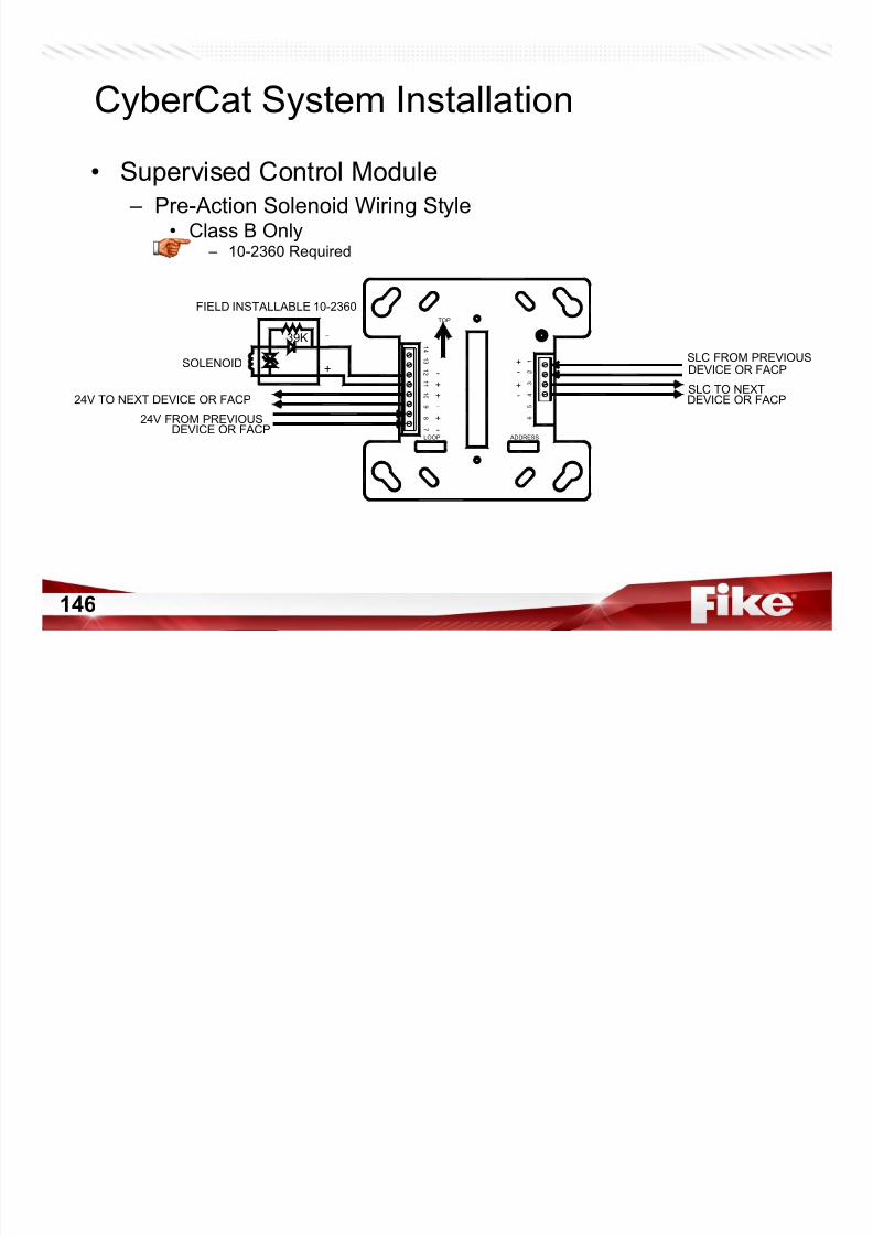
CyberCat System Installation
• Supervised Control Module – NAC Wiring Style
• Class BTOP
(P/N 02-11259)

7/23/2019 CyberCat 2015 FULL Printout
http://slidepdf.com/reader/full/cybercat-2015-full-printout 144/429
144
• Class B – 39K ohm EOL
• Class A
-
+
-
+
-
+
+
-
+
-
DEVICE OR FACP
SLC TO NEXT
39KEOL39KEOL -
+ +
-
24V TO NEXT DEVICE OR FACP
24V FROM PREVIOUS
LOOP ADDRESS
6
5
4
3
2
11 2
1 1
1 0
9
8
7
1 3
1 4
SLC FROM PREVIOUS
DEVICE OR FACP
DEVICE OR FACP
(P/N 02-11259)
-
+
-
+
1 4
1 3
7
8
9
1 0
1 1
1 2
1
2
3
4
5
6
TOP
ADDRESSLOOP
-
+ + -
-
+
-
+
DEVICE OR FACP
SLC TO NEXTDEVICE OR FACP
SLC FROM PREVIOUS
24VDC IN
24VDC OUT
Device Installation Instructions
• 10-2360 Solenoid Series Impedance
CyberCat Module Accessories

7/23/2019 CyberCat 2015 FULL Printout
http://slidepdf.com/reader/full/cybercat-2015-full-printout 145/429
145
– Required when connecting a solenoid to the 55-042(047) SCM
– Provides appropriate supervision
– Provides protection to panel and SCM when solenoid is de-
energized – See 06-186 for compatible solenoids
Manual 06-326 Page 3-35
7/23/2019 CyberCat 2015 FULL Printout
http://slidepdf.com/reader/full/cybercat-2015-full-printout 146/429
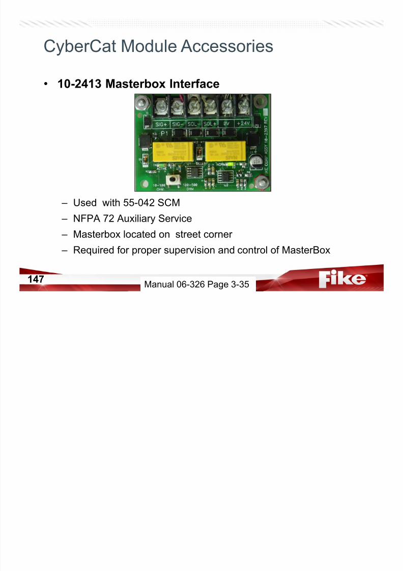
• 10-2413 Masterbox Interface
CyberCat Module Accessories
7/23/2019 CyberCat 2015 FULL Printout
http://slidepdf.com/reader/full/cybercat-2015-full-printout 147/429
147
– Used with 55-042 SCM
– NFPA 72 Auxiliary Service
– Masterbox located on street corner – Required for proper supervision and control of MasterBox
Manual 06-326 Page 3-35
CyberCat System Installation
• Supervised Control Module – Auxiliary Masterbox Wiring Style
• Class B Only– 10-2413 Required

7/23/2019 CyberCat 2015 FULL Printout
http://slidepdf.com/reader/full/cybercat-2015-full-printout 148/429
148
10 2413 Required
+-
-+
-
+
-
+
1 4
1 3
7
8
9
1 0
1 1
1 2
1
2
3
4
5
6
TOP
ADDRESSLOOP
+
-
Jump Drive - Manual 06-229
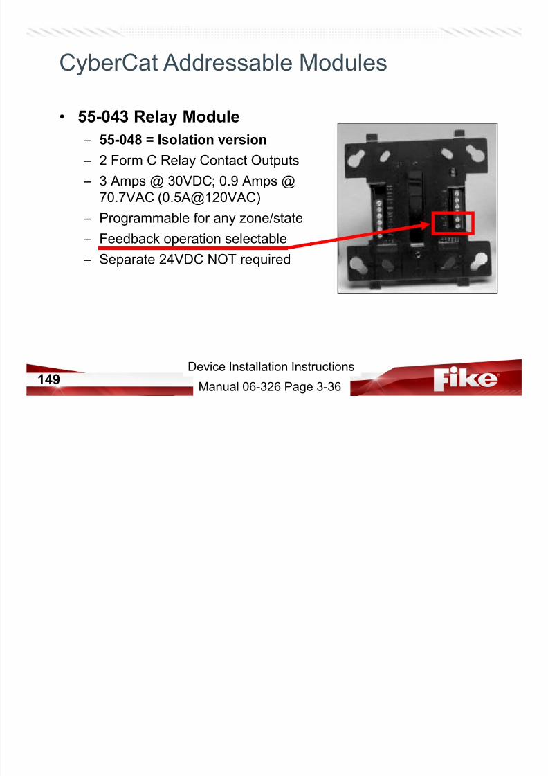
• 55-043 Relay Module
– 55-048 = Isolation version
2 F C R l C t t O t t
CyberCat Addressable Modules
7/23/2019 CyberCat 2015 FULL Printout
http://slidepdf.com/reader/full/cybercat-2015-full-printout 149/429
149
– 2 Form C Relay Contact Outputs
– 3 Amps @ 30VDC; 0.9 Amps @
70.7VAC (0.5A@120VAC)
– Programmable for any zone/state
– Feedback operation selectable
– Separate 24VDC NOT required
Device Installation Instructions
Manual 06-326 Page 3-36
CyberCat System Installation
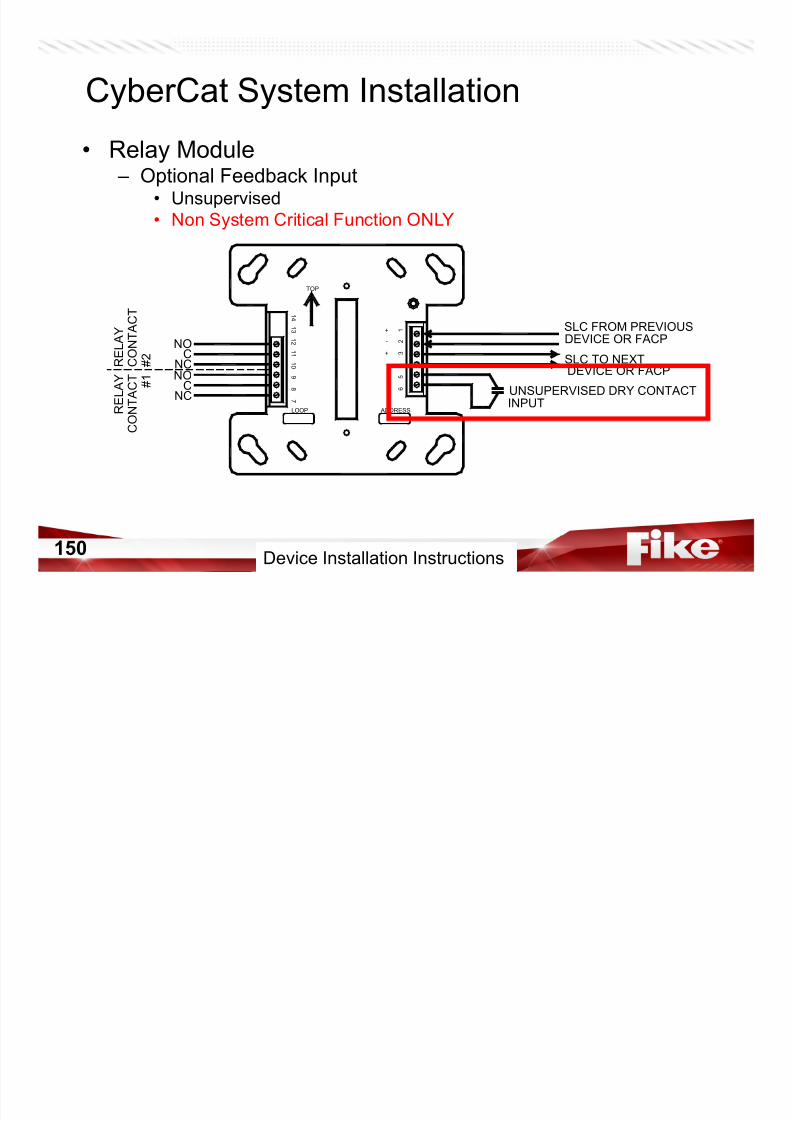
• Relay Module – Optional Feedback Input
• Unsupervised
• Non System Critical Function ONLY
7/23/2019 CyberCat 2015 FULL Printout
http://slidepdf.com/reader/full/cybercat-2015-full-printout 150/429
150
y
-
+
-
+
UNSUPERVISED DRY CONTACT
R E L A Y
C O N T A C T
# 1 # 2 C
O N T A C T
R E L A Y
NO
CNCNO
CNC
TOP
1 4
1 3
7
8
9
1 0
1 1
1 2
1
2
3
4
5
6
ADDRESSLOOPINPUT
SLC FROM PREVIOUSDEVICE OR FACP
SLC TO NEXTDEVICE OR FACP
Device Installation Instructions
CyberCat Addressable Sensors
• DUCT Detector – 63-1158 Housing – 63-1057 Duct Sensor
• Air DUCT smoke sensor • Programmable as Supervisory

7/23/2019 CyberCat 2015 FULL Printout
http://slidepdf.com/reader/full/cybercat-2015-full-printout 151/429
151Manual 06-326 Page 3-29 & 3-32
• Programmable as Supervisory
– Sampling tubes available – Remote LED follows sensor head – No Relays
– 02-3869 (RTS151) LED follows sensor • Magnet creates TEST ALRM state• Photo DUCT must be configured for Walktest with IR
– 02-4998 (RTS151-KEY) LED follows sensor • Key creates TEST ALRM state
• Photo DUCT must be configured for Walktest with IR
Device Installation Instructions
CyberCat Addressable Sensors
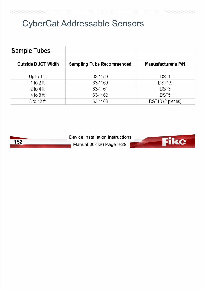
7/23/2019 CyberCat 2015 FULL Printout
http://slidepdf.com/reader/full/cybercat-2015-full-printout 152/429
152Manual 06-326 Page 3-29
Device Installation Instructions

7/23/2019 CyberCat 2015 FULL Printout
http://slidepdf.com/reader/full/cybercat-2015-full-printout 153/429
153
Configuration Tools
CyberCat Configuration Equipment
Part Number Description
55-051 Infrared (IR) Remote Addressing/Testing Tool (non-listed)
Configuration Tools

7/23/2019 CyberCat 2015 FULL Printout
http://slidepdf.com/reader/full/cybercat-2015-full-printout 154/429
154
55 051 Infrared (IR) Remote Addressing/Testing Tool (non listed)
10-2648 Hand held Configuration/Addressing/Training Tool (non-listed)
06-327 C-Linx Configuration/Diagnostic Software
10-1874A RS-232 Configuration Cable (DB9 to RJ11)
10-1874B RS-232 Configuration Cable (DB9 to RJ11) with USB to DB9 Adapter
10-2629 USB A Male to USB B Male Configuration Cable
10-2477 Contact ID DACT Programmer
• 55-051 IR Remote Tool
– Set Device Address
– Can communicate with other devices
CyberCat Configuration Equipment

7/23/2019 CyberCat 2015 FULL Printout
http://slidepdf.com/reader/full/cybercat-2015-full-printout 155/429
155
Can communicate with other devices
through one point
– Read Sensitivity ( & % dirty)
– Service Date (from panel date)
– Smokeless Walktest
– MUST ENABLE at CyberCat panel
(one loop at a time)
Manual 06-326 Page 3-36
Device Installation Instructions
• 10-2648 Hand Held Programmer
– Addresses new Eclipse devices
– Same operating code as the CyberCat V3.1
P l
CyberCat Configuration Equipment
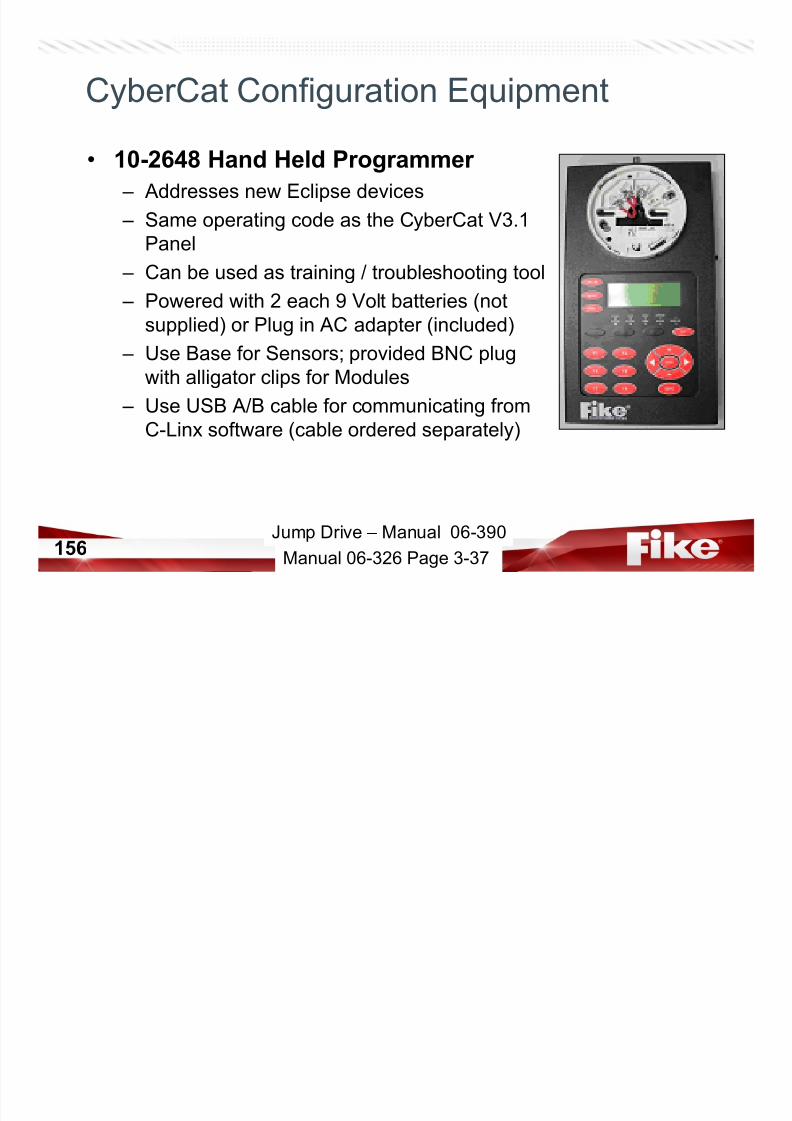
7/23/2019 CyberCat 2015 FULL Printout
http://slidepdf.com/reader/full/cybercat-2015-full-printout 156/429
156
Panel
– Can be used as training / troubleshooting tool
– Powered with 2 each 9 Volt batteries (not
supplied) or Plug in AC adapter (included)
– Use Base for Sensors; provided BNC plugwith alligator clips for Modules
– Use USB A/B cable for communicating from
C-Linx software (cable ordered separately)
Jump Drive – Manual 06-390
Manual 06-326 Page 3-37

7/23/2019 CyberCat 2015 FULL Printout
http://slidepdf.com/reader/full/cybercat-2015-full-printout 157/429
157
Batteries & Spare Parts
• Batteries – 10-2190-1
• 2x 7.2AH w/ wire assembly
– 10-2626• 2x 12AH
Batteries and Battery Enclosures
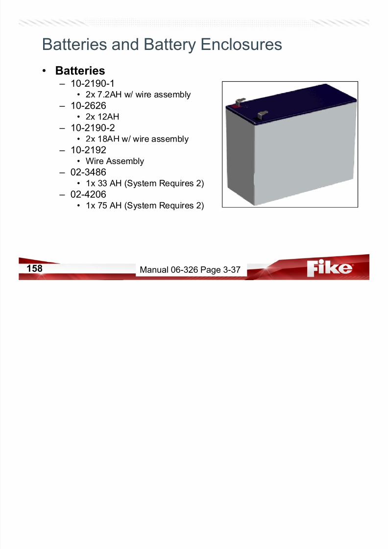
7/23/2019 CyberCat 2015 FULL Printout
http://slidepdf.com/reader/full/cybercat-2015-full-printout 158/429
158
• 2x 12AH
– 10-2190-2• 2x 18AH w/ wire assembly
– 10-2192• Wire Assembly
– 02-3486• 1x 33 AH (System Requires 2)
– 02-4206• 1x 75 AH (System Requires 2)
Manual 06-326 Page 3-37
Batteries and Battery Enclosures
• Battery Enclosures
– 10-2154-c 33AH – 10-2236-c 75AH

7/23/2019 CyberCat 2015 FULL Printout
http://slidepdf.com/reader/full/cybercat-2015-full-printout 159/429
159 Manual 06-326 Page 3-37
Part Number Description02-4035 Hardware Kit, #6 lock washers and hex nuts (30 each)
02-10788 Standoff kit, 5/8” M/F, 5 each required (10 each supplied)
02-4009 Standoff, 2” M/F, for 10-2528 DACT, 4 each required (1 each supplied)
02-11258 Deadfront mounting kit, 4 self-tap screws, #10-32
02-11127 Terminal Block, 4 position for P1 Power or P21 SPS Power
02 10996 Terminal Block 9 position for P2 Rela s OR P8 A Po er
CyberCat Spare Parts
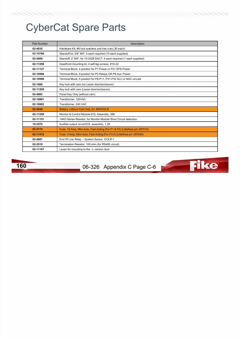
7/23/2019 CyberCat 2015 FULL Printout
http://slidepdf.com/reader/full/cybercat-2015-full-printout 160/429
160
02-10996 Terminal Block, 9 position for P2 Relays OR P8 Aux Power
02-10998 Terminal Block, 5 position for P8-P11, P31-P32 SLC or NAC circuits
02-1606 Key lock with cam (no Lexan door/enclosure)
02-11205 Key lock with cam (Lexan door/enclosure)
02-4983 Panel Key Only (without cam)
02-10881 Transformer, 120VAC
02-10882 Transformer, 240 VAC
02-4040 Battery, Lithium Coin Cell, 3V, BR2032-B
02-11259 Monitor & Control Module EOL Assembly, 39K
02-11151 14KΩ Series Resistor, for Monitor Module Short Circuit detection
10-2570 Audible output circuit EOL assembly, 1.2K
02-4174 Fuse, 15 Amp, Mini Auto, Fast Acting (For F1 & F2) (Littelfuse p/n 297015)
02-11412 Fuse, 4 Amp, Mini-Auto, Fast Acting (For F3-5) (Littelfuse p/n 297004)
02-4981 End Of Line Relay – System Sensor EOLR-1
02-2519 Termination Resistor, 100 ohm (for RS485 circuit)
02-11167 Lexan for mounting to the –L version door
06-326 Appendix C Page C-6

7/23/2019 CyberCat 2015 FULL Printout
http://slidepdf.com/reader/full/cybercat-2015-full-printout 161/429
SigniFireTM
Video Detection
• What does it detect? – Flame
– Smoke Plume

7/23/2019 CyberCat 2015 FULL Printout
http://slidepdf.com/reader/full/cybercat-2015-full-printout 162/429
162
– Ambient Smoke
– Reflected Fire
– Intrusion / Motion
System Architecture
With FACP
• Panel provides power todetectors
• Monitor Modules provideAlarm and Trouble status
28-01428-015

7/23/2019 CyberCat 2015 FULL Printout
http://slidepdf.com/reader/full/cybercat-2015-full-printout 163/429
Alarm and Trouble statusto the FACP
• Ethernet connections areused for communication tothe NVR, SpyderGuardand SpyderPanel
Manual 06-523 Page 15
28-014
28-014
Power supply is capable of
powering up to three (3)
28-014 Ethernet switches.
28-014 Ethernet switch
supports up to four (4)
SigniFire Detectors
SigniFire camera must be
powered from the FACP or an
external power supply UL
listed for fire alarm service.
Limit 32 SigniFire detectors
per Network Video Recorder
4.
3.
2.
1.
NOTES:

7/23/2019 CyberCat 2015 FULL Printout
http://slidepdf.com/reader/full/cybercat-2015-full-printout 164/429
164
Operation
CyberCat Operation
• LCD Display – 4 x 20 LCD for textual status
– 3 Main Displays:
• System Status

7/23/2019 CyberCat 2015 FULL Printout
http://slidepdf.com/reader/full/cybercat-2015-full-printout 165/429
165
y
• System Event
• Top Level Menu
• Press ESCAPE to cycle
displays
Manual 06-326-2 Page 2-1
CyberCat 50 Operation
• LCD Display – 4 x 20 LCD for textual status
– 3 Main Displays:
• System Status

7/23/2019 CyberCat 2015 FULL Printout
http://slidepdf.com/reader/full/cybercat-2015-full-printout 166/429
166
• System Event
• Top Level Menu
• Press ESCAPE to cycle
displays
Jump Drive – Manual 06-368 Page 2-1
• STATUS LEDs
– AC POWER
– ALARM
CyberCat Operation
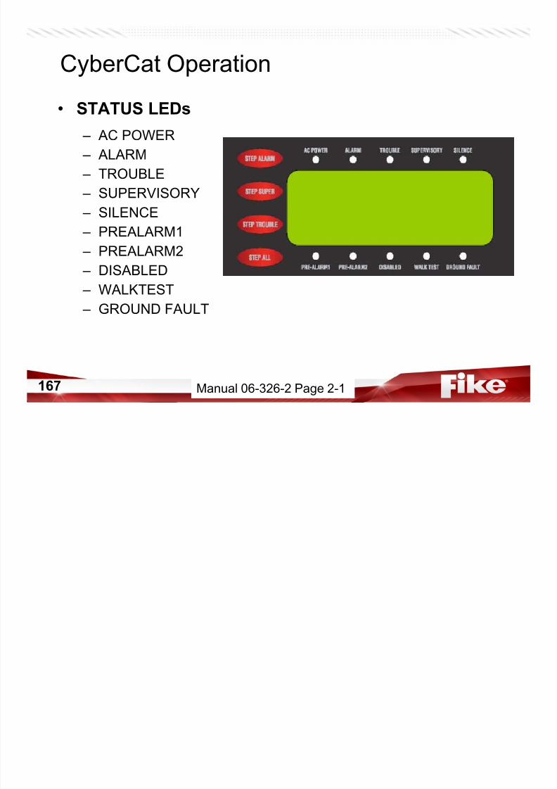
7/23/2019 CyberCat 2015 FULL Printout
http://slidepdf.com/reader/full/cybercat-2015-full-printout 167/429
167
– TROUBLE – SUPERVISORY
– SILENCE
– PREALARM1
– PREALARM2 – DISABLED
– WALKTEST
– GROUND FAULT
Manual 06-326-2 Page 2-1
• 3,200 Event Buffer – v3.0 and up• Records up to 3200 events and then FIFO (rotating)
• If an Alarm occurs, then records next 999 events and stops – Prevents overwriting first alarm condition
CyberCat Operation

7/23/2019 CyberCat 2015 FULL Printout
http://slidepdf.com/reader/full/cybercat-2015-full-printout 168/429
168
Steps through ALL current events
Steps thru current ALARM events only
Steps thru current SUPERvisory events only
Steps through current TROUBLE events
Manual 06-326-2 Page 2-3
• Activates “DRILL” function
• Silences local piezo, creates
CyberCat Operation

7/23/2019 CyberCat 2015 FULL Printout
http://slidepdf.com/reader/full/cybercat-2015-full-printout 169/429
169
ACKNOWLEDGE event
• Silences local piezo and any NAC
programmed as silenceable
• Clears latching events by resetting system
Manual 06-326-2 Page 2-3
• Exits current menu and returns
to previous menu
CyberCat Operation
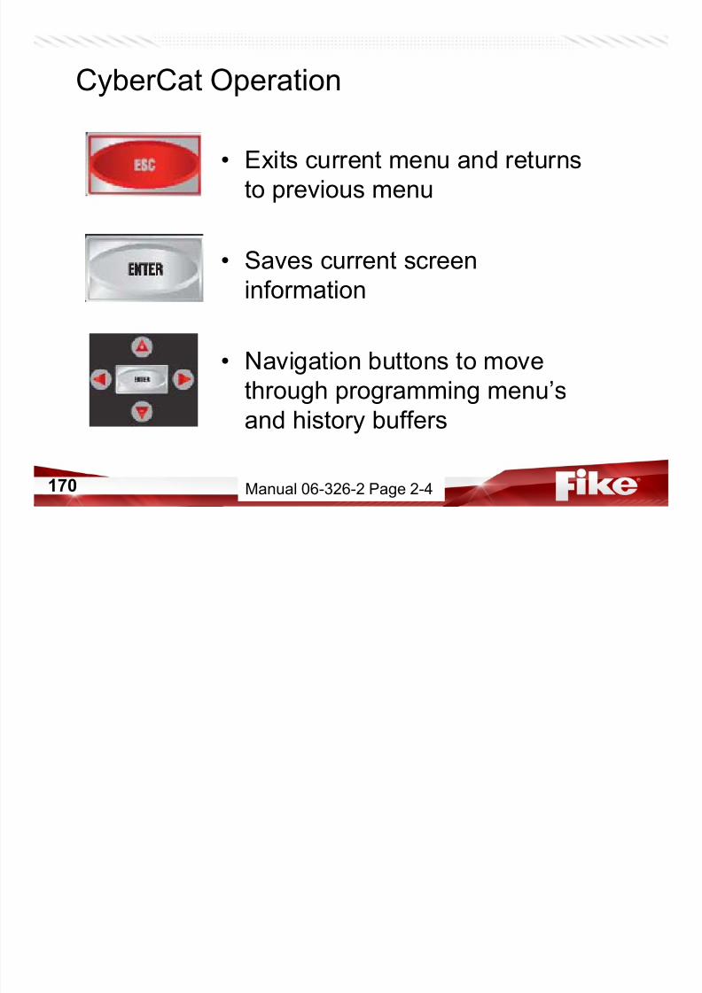
7/23/2019 CyberCat 2015 FULL Printout
http://slidepdf.com/reader/full/cybercat-2015-full-printout 170/429
170
• Saves current screen
information
• Navigation buttons to move
through programming menu’s
and history buffers
Manual 06-326-2 Page 2-4
F4 = PASSWORDF1 = CONFIG
CyberCat Operation
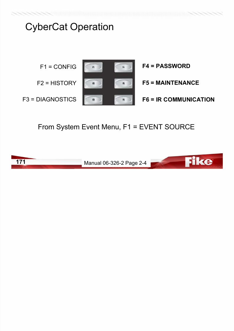
7/23/2019 CyberCat 2015 FULL Printout
http://slidepdf.com/reader/full/cybercat-2015-full-printout 171/429
171
F5 = MAINTENANCE
F6 = IR COMMUNICATION
F2 = HISTORY
F3 = DIAGNOSTICS
From System Event Menu, F1 = EVENT SOURCE
Manual 06-326-2 Page 2-4
CyberCat System Operation
• System Reset and Power Up (v3.1 & Newer ) – RESET
Reset devices (clears any latched conditions). All
devices are commanded to send ‘NEW DEVICE’
message to panel but it is not recorded in history.

7/23/2019 CyberCat 2015 FULL Printout
http://slidepdf.com/reader/full/cybercat-2015-full-printout 172/429
172
Reset devices (clears any latched conditions). Alldevices are commanded to send ‘NEW DEVICE’
message to panel where they are recorded in
history.
– RESET + ACKNOWLEDGE
Manual 06-326-2 Page 3-5
CyberCat System Operation
• NORMAL State
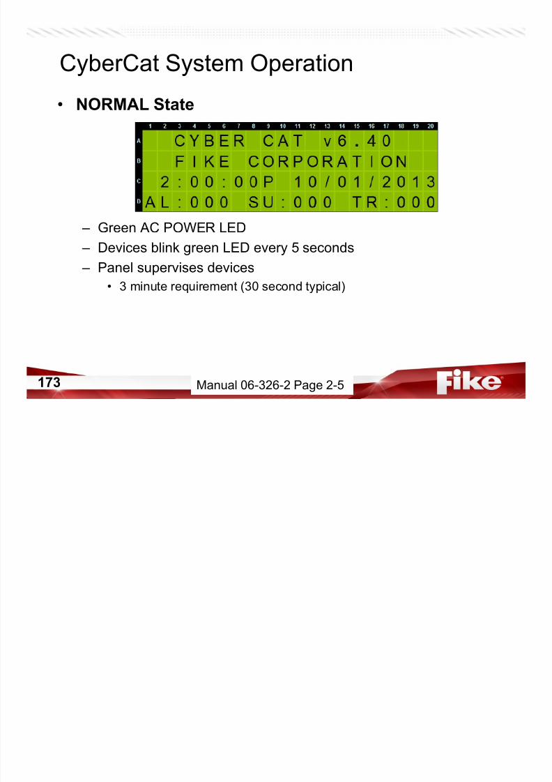
7/23/2019 CyberCat 2015 FULL Printout
http://slidepdf.com/reader/full/cybercat-2015-full-printout 173/429
173
– Green AC POWER LED
– Devices blink green LED every 5 seconds
– Panel supervises devices
• 3 minute requirement (30 second typical)
Manual 06-326-2 Page 2-5

7/23/2019 CyberCat 2015 FULL Printout
http://slidepdf.com/reader/full/cybercat-2015-full-printout 174/429
174
System Design
• Layout Zones• Determine type and location of devices required
• Configure System
• Power Calculations
Installation requirement review
CyberCat System Design
7/23/2019 CyberCat 2015 FULL Printout
http://slidepdf.com/reader/full/cybercat-2015-full-printout 175/429
175
• Installation requirement review
• Installation Drawings
Example:
1. Note zone layouts.
2. Device types.
3. C-Linx Software – typically used to
config or learn and modify.
Manual 06-326-2 Page 3-1
CyberCat Power CalculationsJump Drive - Battery Calculations – Excel Spreadsheet
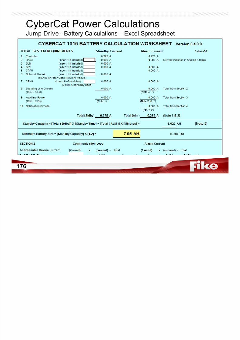
7/23/2019 CyberCat 2015 FULL Printout
http://slidepdf.com/reader/full/cybercat-2015-full-printout 176/429
176
Fike Remote Power Supply
• 10-2829 Remote Power Supply
– 10 Amps of Useable Power
– 4 Configurable Output Circuits
• NAC Circuits
• Door Holder Circuit
D di t d A P Ci it

7/23/2019 CyberCat 2015 FULL Printout
http://slidepdf.com/reader/full/cybercat-2015-full-printout 177/429
177177
Datasheet P.1.157.01
– Dedicated Aux Power Circuit
– Synchronization
• Gentex
• System Sensor
• Generator Mode• Follower Mode
– Internal Battery Charger
– Diagnostic LEDs
– Onboard Trouble Relay – Room for Modules & 12 AH Batteries
10-2829 Remote Power Supply

7/23/2019 CyberCat 2015 FULL Printout
http://slidepdf.com/reader/full/cybercat-2015-full-printout 178/429
178 Manual 06-583 - Page 7
1. AC Input - 100-240VAC
2. Battery Input – 24VDC
10-2829 Remote Power Supply
Page 15
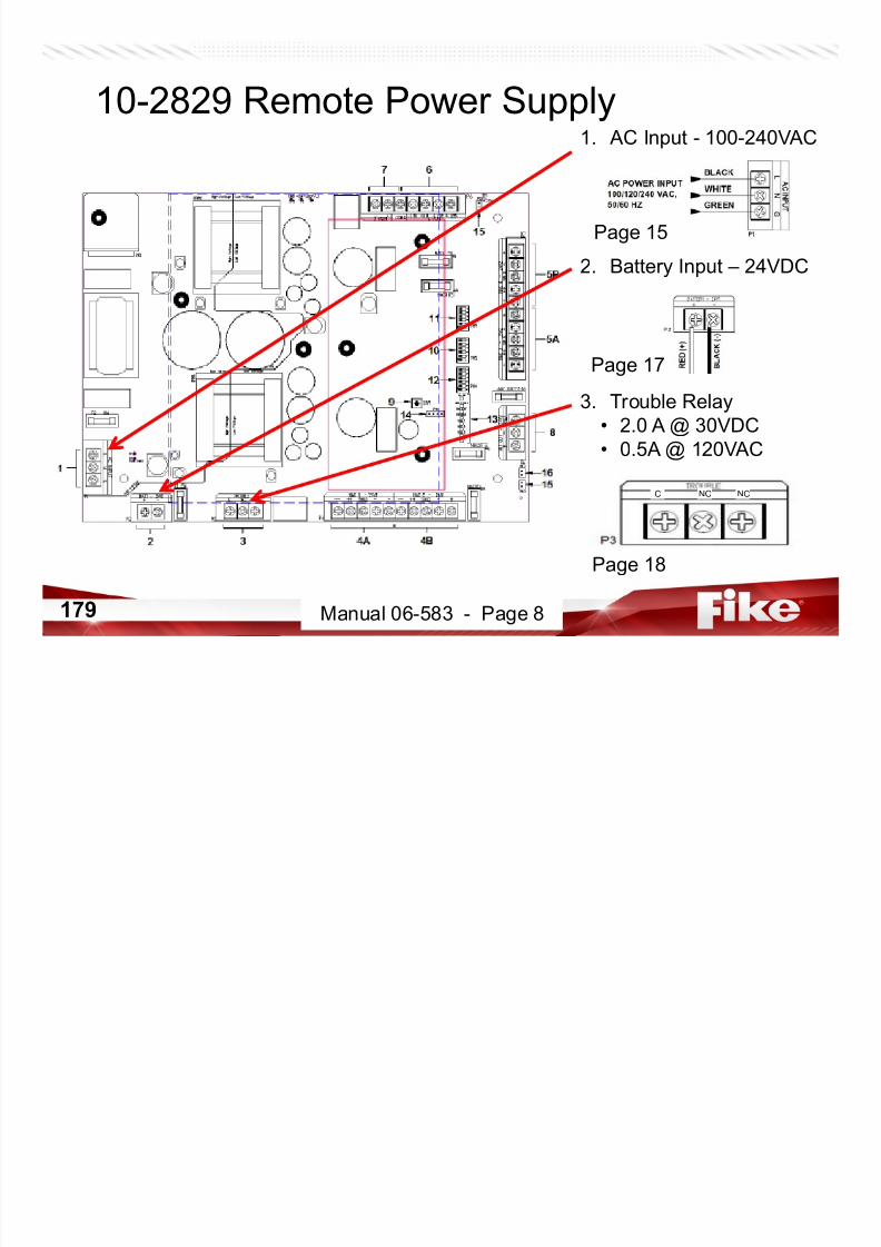
7/23/2019 CyberCat 2015 FULL Printout
http://slidepdf.com/reader/full/cybercat-2015-full-printout 179/429
179
3. Trouble Relay• 2.0 A @ 30VDC
• 0.5A @ 120VAC
C NO NC
Manual 06-583 - Page 8
Page 17
Page 18
10-2829 Remote Power Supply
4A. NAC 1• NAC Circuit
• Aux Power or
• Door Holder
• 3 A Max per circuit
• 1.0K EOLR

7/23/2019 CyberCat 2015 FULL Printout
http://slidepdf.com/reader/full/cybercat-2015-full-printout 180/429
180
1.0K EOLR• Supervised
• Power-Limited
4B. NAC 2
• NAC Circuit• Aux Power or
• Door Holder
• 3 A Max per circuit
• 1.0K EOLR
• Supervised• Power-Limited
Manual 06-583 - Page 9
10-2829 Remote Power Supply
5B. NAC 4• NAC Circuit
• Aux Power or
• Door Holder
• 3 A Max per circuit
• 1.0K EOLR

7/23/2019 CyberCat 2015 FULL Printout
http://slidepdf.com/reader/full/cybercat-2015-full-printout 181/429
181
• Supervised
• Power-Limited
5A. NAC 3
• NAC Circuit• Aux Power or
• Door Holder
• 3 A Max per circuit
• 1.0K EOLR
• Supervised• Power-Limited
Manual 06-583 - Page 9
10-2829 Remote Power Supply

7/23/2019 CyberCat 2015 FULL Printout
http://slidepdf.com/reader/full/cybercat-2015-full-printout 182/429
182
1.0K EOLR
Manual 06-583 - Page 19
10-2829 Remote Power Supply
6. Input 1• Control Input
• Electrically Isolated
• 12-30 VDC
• Input Current 2 mA
• Configurable for

7/23/2019 CyberCat 2015 FULL Printout
http://slidepdf.com/reader/full/cybercat-2015-full-printout 183/429
183
gSelective Silence
7. Input 2
• Control Input
• Electrically Isolated• 12-30 VDC
• Input Current 2 mA
• Configurable for
Selective Silence
Manual 06-583 - Page 9
10-2829 Remote Power Supply
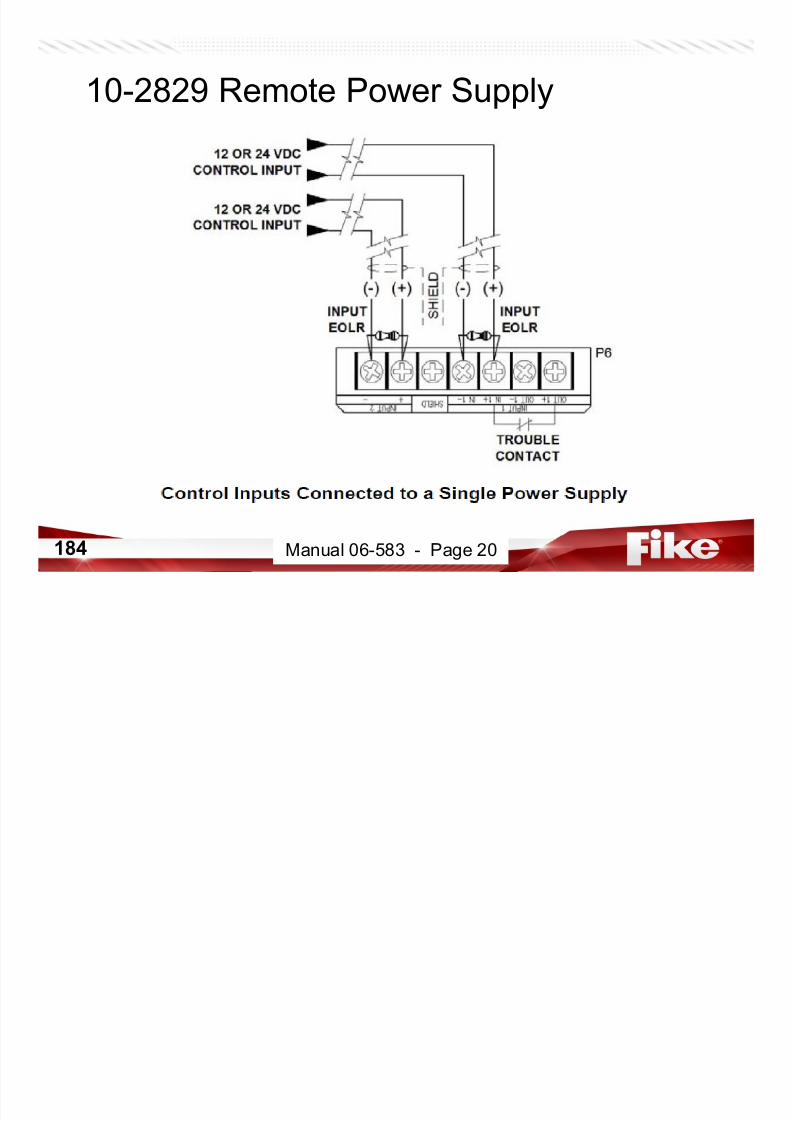
7/23/2019 CyberCat 2015 FULL Printout
http://slidepdf.com/reader/full/cybercat-2015-full-printout 184/429
184 Manual 06-583 - Page 20
10-2829 Remote Power Supply
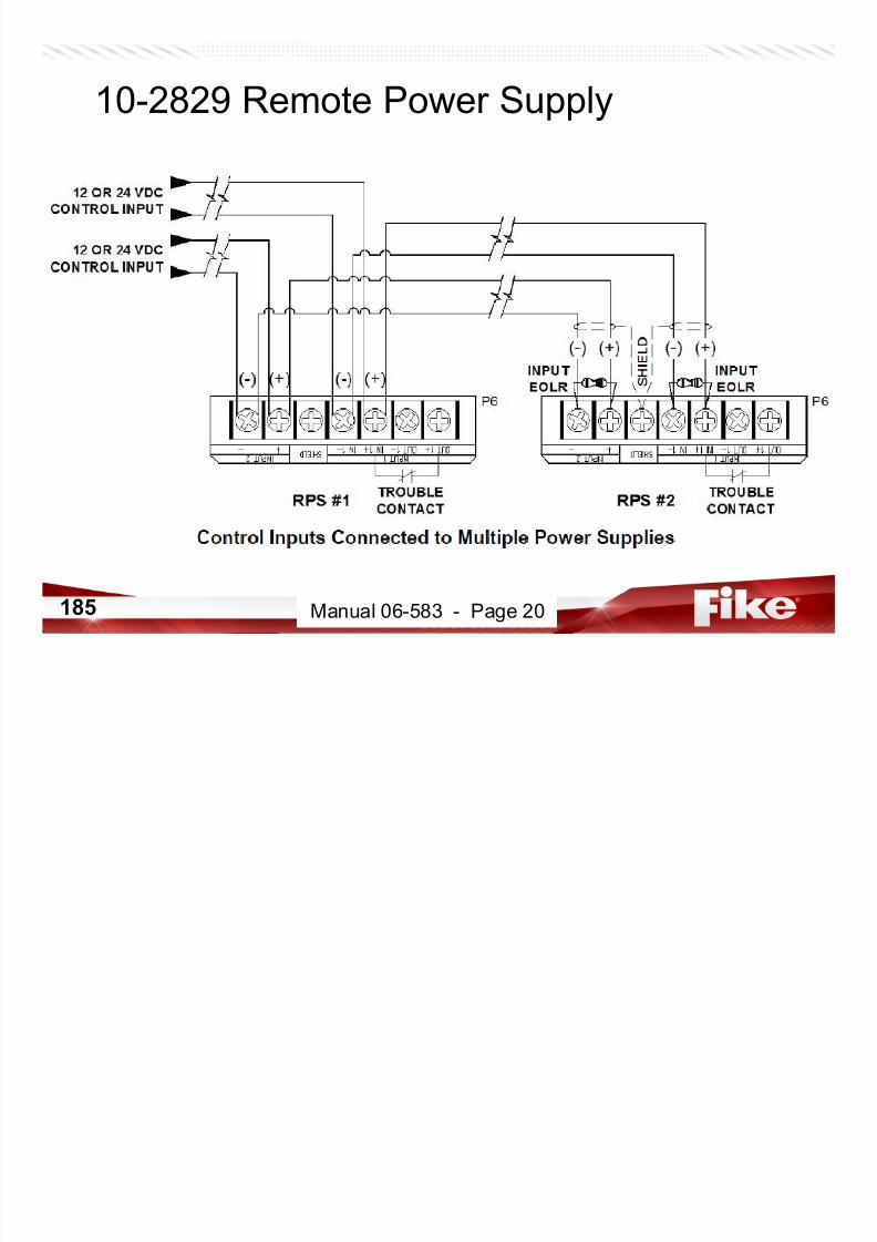
7/23/2019 CyberCat 2015 FULL Printout
http://slidepdf.com/reader/full/cybercat-2015-full-printout 185/429
185 Manual 06-583 - Page 20
10-2829 Remote Power Supply

7/23/2019 CyberCat 2015 FULL Printout
http://slidepdf.com/reader/full/cybercat-2015-full-printout 186/429
186 Manual 06-583 - Page 21
10-2829 Remote Power Supply
Aux Power Out
• 18.6 – 28.5 VDC
• 1 Amp Max Load
• Power-Limited
• Non-Supervised• No EOLR
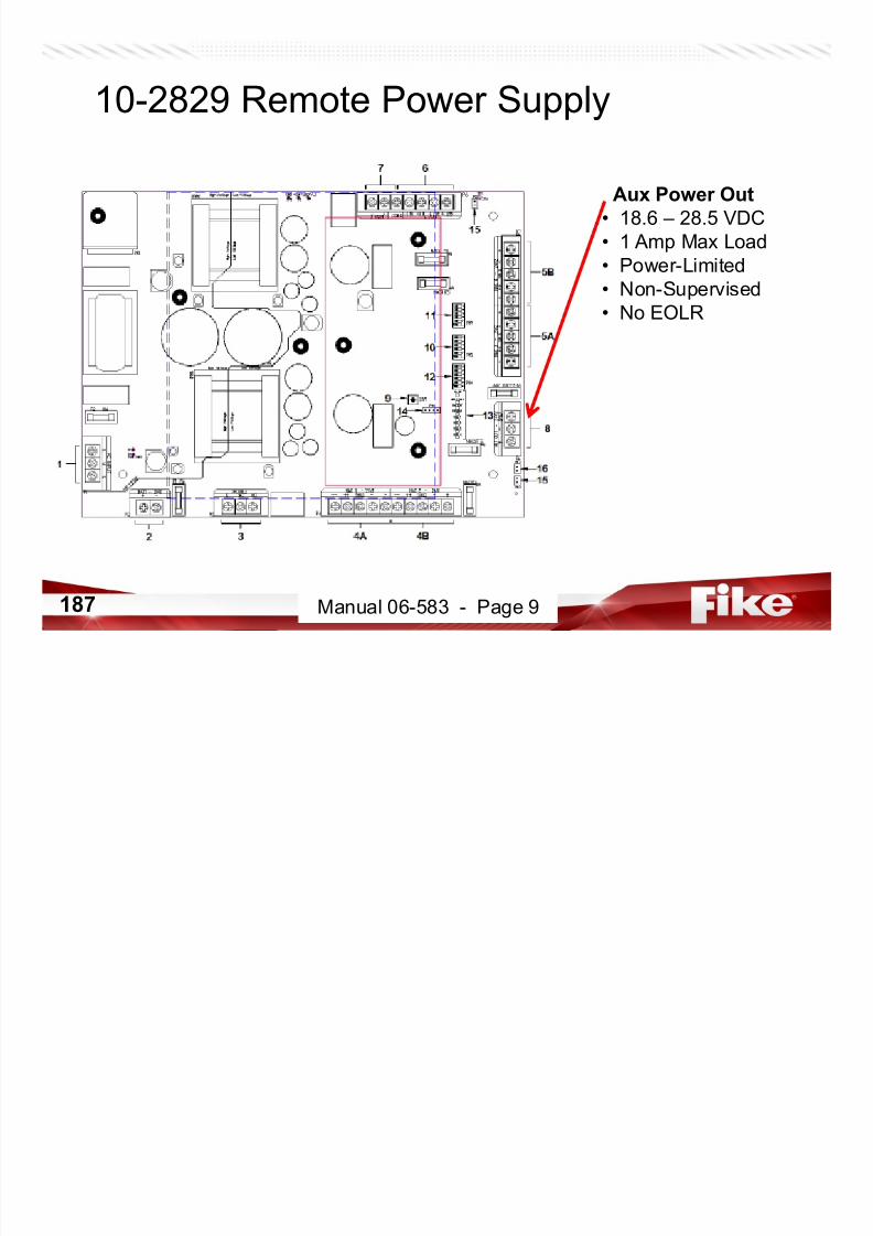
7/23/2019 CyberCat 2015 FULL Printout
http://slidepdf.com/reader/full/cybercat-2015-full-printout 187/429
187
• No EOLR
Manual 06-583 - Page 9
10-2829 Remote Power Supply
4A & 4B. NAC 1• 3 A Max per circuit
• 5 A Max per Combo
5A & 5B NAC 2 AUX
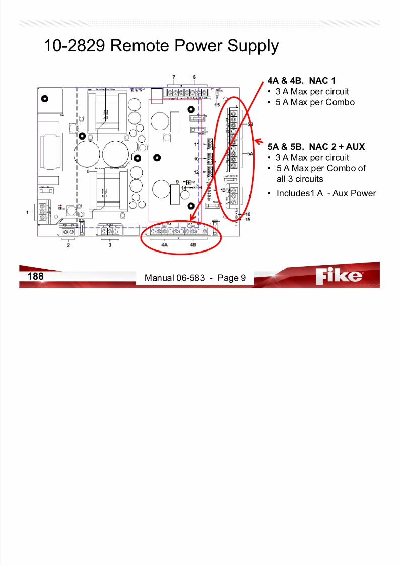
7/23/2019 CyberCat 2015 FULL Printout
http://slidepdf.com/reader/full/cybercat-2015-full-printout 188/429
188 Manual 06-583 - Page 9
5A & 5B. NAC 2 + AUX
• 3 A Max per circuit
• 5 A Max per Combo of
all 3 circuits
• Includes1 A - Aux Power
10-2829 Remote Power SupplyConfiguration Switches

7/23/2019 CyberCat 2015 FULL Printout
http://slidepdf.com/reader/full/cybercat-2015-full-printout 189/429
189 Manual 06-583 - Page 9
10-2829 Remote Power Supply

7/23/2019 CyberCat 2015 FULL Printout
http://slidepdf.com/reader/full/cybercat-2015-full-printout 190/429
190 Manual 06-583 - Pages 22-23
10-2829 Remote Power Supply

7/23/2019 CyberCat 2015 FULL Printout
http://slidepdf.com/reader/full/cybercat-2015-full-printout 191/429
191 Manual 06-583 - Page 23
10-2829 Remote Power Supply
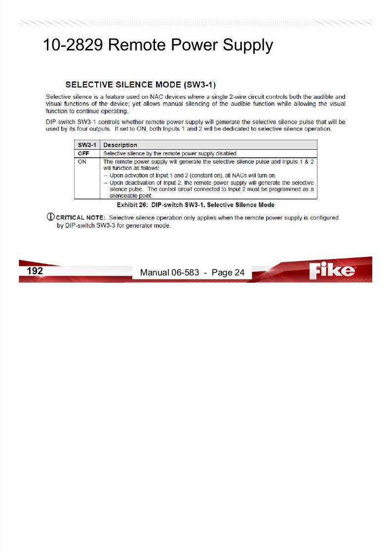
7/23/2019 CyberCat 2015 FULL Printout
http://slidepdf.com/reader/full/cybercat-2015-full-printout 192/429
192 Manual 06-583 - Page 24
10-2829 Remote Power Supply

7/23/2019 CyberCat 2015 FULL Printout
http://slidepdf.com/reader/full/cybercat-2015-full-printout 193/429
193 Manual 06-583 - Page 24
10-2829 Remote Power Supply

7/23/2019 CyberCat 2015 FULL Printout
http://slidepdf.com/reader/full/cybercat-2015-full-printout 194/429
194
Reset
Manual 06-583 - Page 9
10-2829 Remote Power Supply
Ground Fault Jumpers

7/23/2019 CyberCat 2015 FULL Printout
http://slidepdf.com/reader/full/cybercat-2015-full-printout 195/429
195 Manual 06-583 - Page 27
10-2829 Remote Power Supply

7/23/2019 CyberCat 2015 FULL Printout
http://slidepdf.com/reader/full/cybercat-2015-full-printout 196/429
196 Manual 06-583 - Page 27
10-2829 Remote Power Supply
Internal Piezo
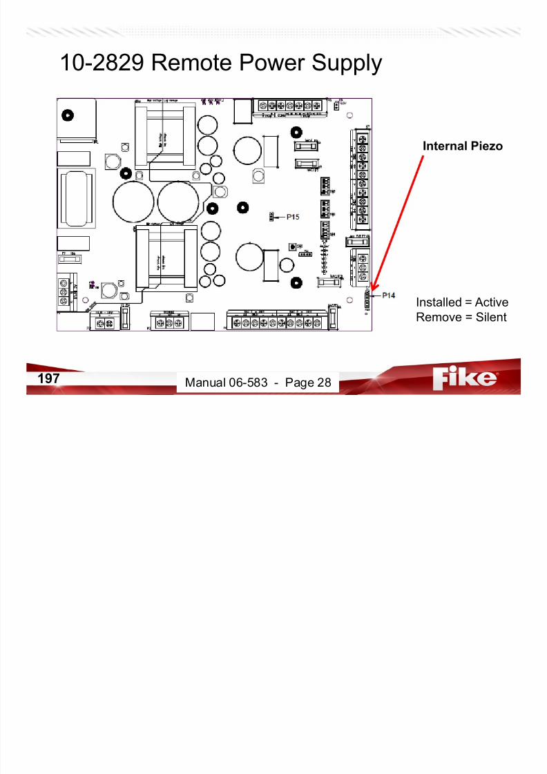
7/23/2019 CyberCat 2015 FULL Printout
http://slidepdf.com/reader/full/cybercat-2015-full-printout 197/429
197 Manual 06-583 - Page 28
Installed = Active
Remove = Silent
10-2829 Remote Power Supply
AC Power Input
Jumper

7/23/2019 CyberCat 2015 FULL Printout
http://slidepdf.com/reader/full/cybercat-2015-full-printout 198/429
198 Manual 06-583 - Page 28
Installed = 120/240VAC
Remove = 100VAC
This sets threshold for power supply to monitor AC input voltage
10-2829 Remote Power Supply
Diagnostic LEDs
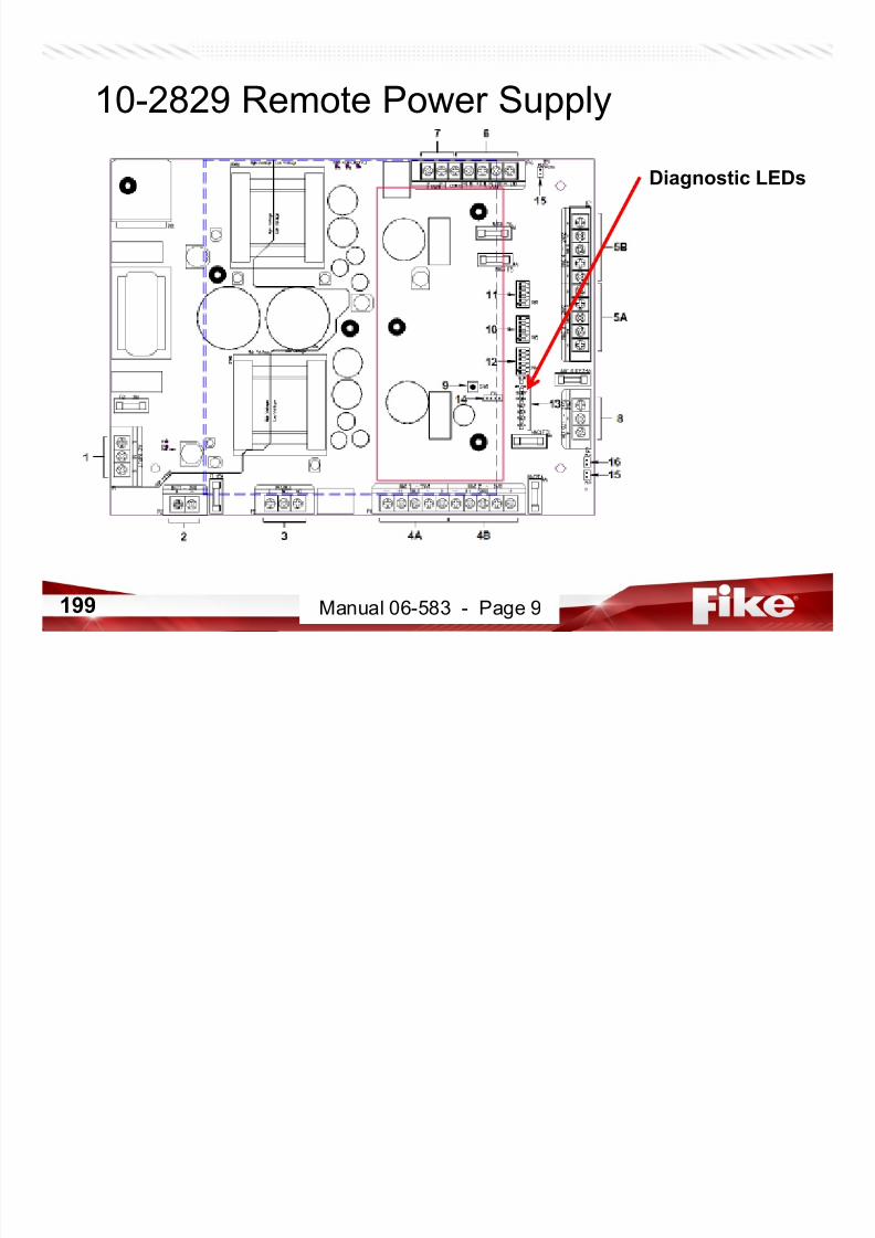
7/23/2019 CyberCat 2015 FULL Printout
http://slidepdf.com/reader/full/cybercat-2015-full-printout 199/429
199 Manual 06-583 - Page 9
10-2829 Remote Power Supply

7/23/2019 CyberCat 2015 FULL Printout
http://slidepdf.com/reader/full/cybercat-2015-full-printout 200/429
200 Manual 06-583 - Page 10
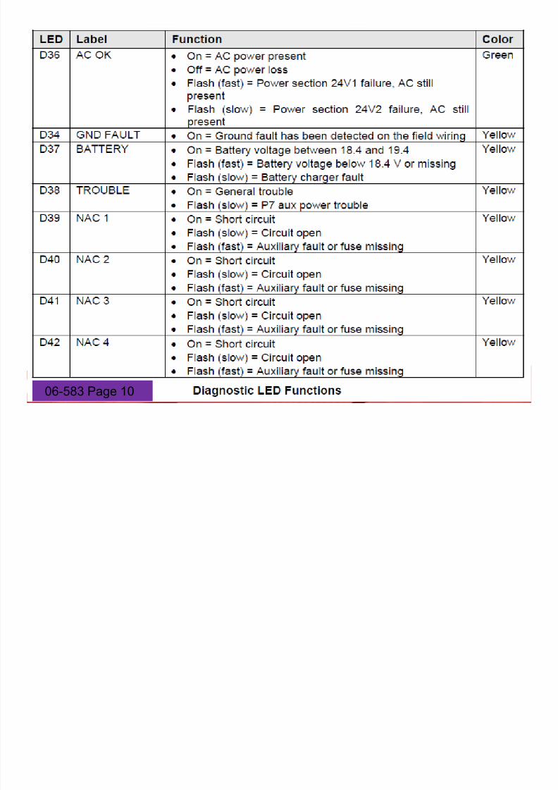
7/23/2019 CyberCat 2015 FULL Printout
http://slidepdf.com/reader/full/cybercat-2015-full-printout 201/429
20106-583 Page 10
Remote Power Supply

7/23/2019 CyberCat 2015 FULL Printout
http://slidepdf.com/reader/full/cybercat-2015-full-printout 202/429
202 Manual 06-583 - Page 14
Remote Power Supply - CAUTION

7/23/2019 CyberCat 2015 FULL Printout
http://slidepdf.com/reader/full/cybercat-2015-full-printout 203/429
203 Manual 06-583 - Page 29
Remote Power Supply - FUSES
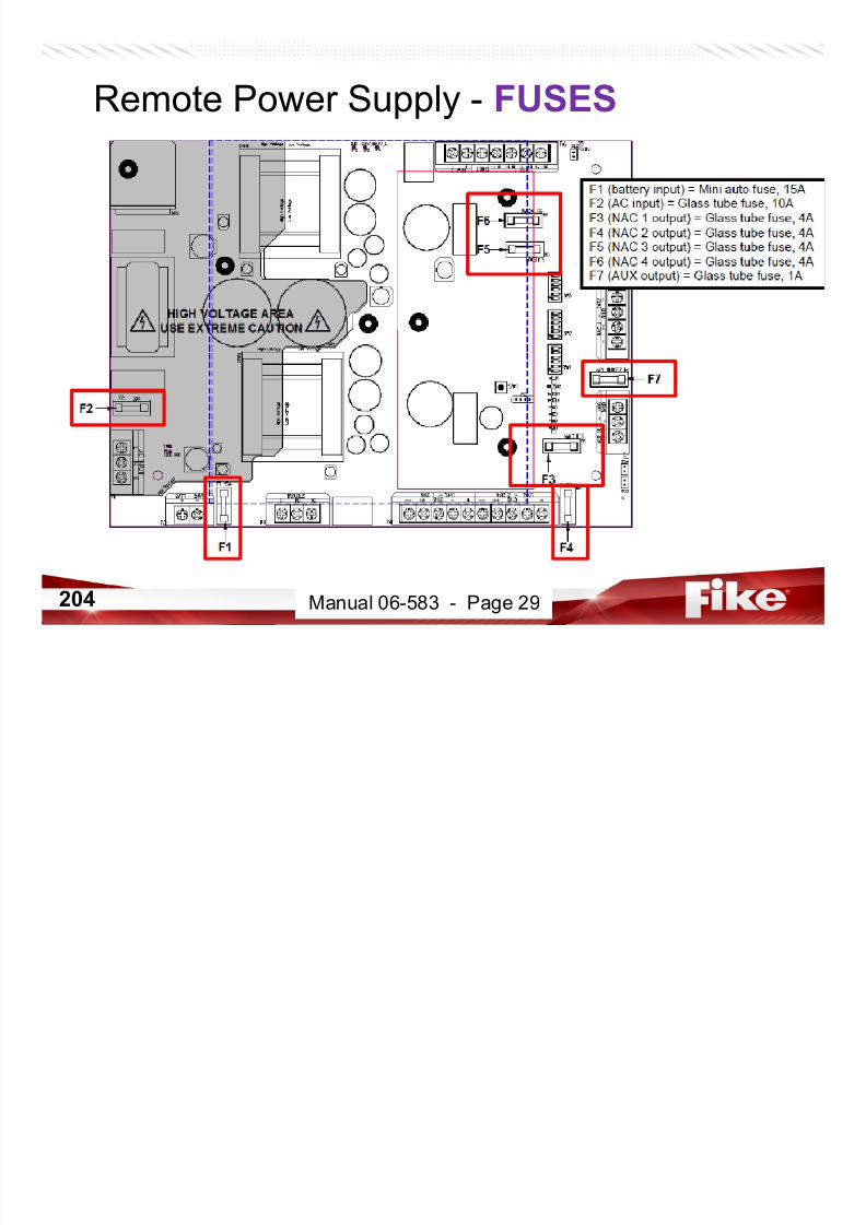
7/23/2019 CyberCat 2015 FULL Printout
http://slidepdf.com/reader/full/cybercat-2015-full-printout 204/429
204 Manual 06-583 - Page 29

7/23/2019 CyberCat 2015 FULL Printout
http://slidepdf.com/reader/full/cybercat-2015-full-printout 205/429
205
Installation
CyberCat System Installation
• Install Enclosure – Surface or Flush Mount
– Dry and Controlled
Environment
2.25 TYP.
4.75
.50 TYP.
4 SIDES
CABINET LIP
15.25
14.25
12.58
3.253.252.25 3.38
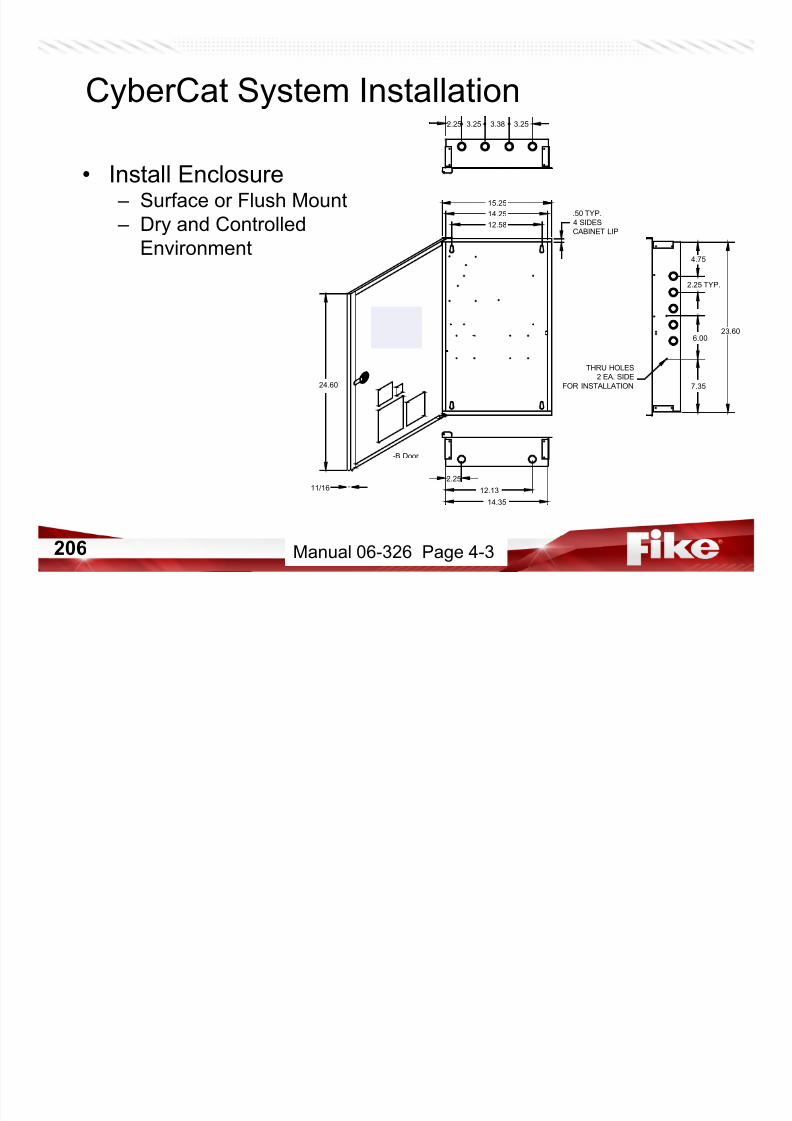
7/23/2019 CyberCat 2015 FULL Printout
http://slidepdf.com/reader/full/cybercat-2015-full-printout 206/429
206
6.00
7.35
23.60
THRU HOLES
2 EA. SIDEFOR INSTALLATION
12.132.25
14.35
24.60
11/16
-B Door
Manual 06-326 Page 4-3
CyberCat System Installation
• Power-Up panel – Connect AC power
– Validate the controller and optional devices power-up normally• Verify only BATTERY MISSING Trouble
• Power-Down panelG
AC XFMRSecondary
Battery+ I n p u t -
P1
AC XFMRS e co n da r y + I n p ut -
Battery
GROUNDEARTH
- -
+ +
S H L D
-
N o t i f i c a t i o n A p p l i a n c e C i
F2 F1
ACFuse 10ABattery Fuse 10A
P19
P15
DISPLAY
1
A u x i l i a r y O u t p u t s
P8
OPTIONAL
+ B A TT -
(SEPERATE ENCLOSURE)

7/23/2019 CyberCat 2015 FULL Printout
http://slidepdf.com/reader/full/cybercat-2015-full-printout 207/429
207
N
H
BATTERY #2
12 VDC
7AH TO 18AH
(33AH TO 75AH SEPERATE ENCLOSURE REQUIRED)
+ --+
(33AH TO 75AH SEPERATE ENCLOSURE REQUIRED)
7AH TO 18AH
12 VDC
BATTERY #1
T R A N S F O R M E R
2ND TRANSFORMERIF SPS IS USED
Manual 06-326 Page 4-7
CyberCat System Installation
• Connect optionalboards to main
controller – All except DACT
• Mount with screw thru
back of controller and
A ux i l i ar y O u t p u t s
OPTIONAL
P 2 2
+
-
S HL D
+
-
S HL D
+
-
S HL D
+
S H L D
-
+
d r e s s a b l e L o o p 4
d r e s s a b l e L o o p 4
+
S H L D
-
+
- -
+ +
S
H L D
-
+
A d d r e s s a
b l e L o o p 3
A d d r e s s a
b l e L o o p 3
- -
+ +
S
H L D
-
+
DACT (485) Peripherals + - SHLD + -
P17
P20P13
P7P2 P3 P4 P5
P9
A d d r e s s a b l e L o o p 1
- -
+ +
S H L D
-
+
- -
+ +
S H L D
-
+
A d d r e s s a b l e L o o p 1
P8
CRM4 OR CRP
OPTIONALRELAY
NETWORKCRM4 OR
CARD
- -
+ +
S H L D
-
+
+ - SHLD + - SHLD + - SHLD Resettable Aux Out AuxliliaryOutputsCOMPUTER VESDA
P6
A d d r e s s a b l e L o o p 2
Peripherals(232)
C NC NO C NC NO C NC NO Alarm Supervisory Trouble
DACTOPTIONAL
P21
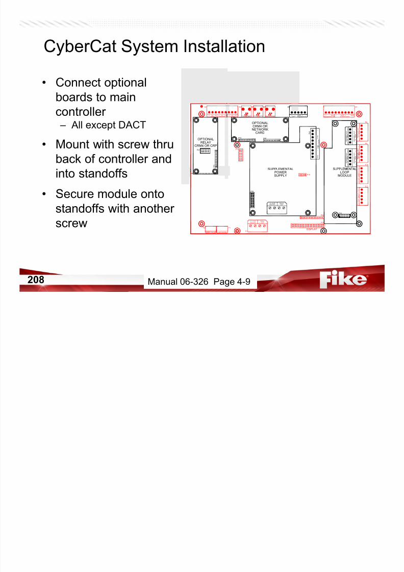
7/23/2019 CyberCat 2015 FULL Printout
http://slidepdf.com/reader/full/cybercat-2015-full-printout 208/429
208
back of controller and
into standoffs
• Secure module ontostandoffs with another
screw
Battery+ Input -Secondary
AC XFMR
- -
+
A d d
A d d
- -
+
P1
+ Input - Battery
Secondary AC XFMR
P19
P 1 2
LOOPMODULE
P16
DISPLAY
SUPPLY
SUPPLEMENTALPOWER
P15
P11
Battery Fuse 10A ACFuse 10A
F1F2
P10
N o t i f i c a t i o n A p p l i a n c e C i r c u i t 1
- -
+ +
S H L D
-
+
N o t i f i c a t i o n A p p l i a n c e C i r c u i t 2
- -
+ +
S H L D
-
+
P22
P18
Manual 06-326 Page 4-9
CyberCat System Installation
• Power-Up panel – Connect AC power
– Validate the controller and optional devices power-up normally• Verify only BATTERY MISSING Trouble
• If ok.......Power-Down panel
H
G
AC XFMRSecondary
Battery+ I n p u t -
P1
AC XFMRS e co n da r y + I n p ut -
Battery
GROUNDEARTH
- -
+ +
S H L D
-
N o t i f i c a t i o n A p p l i a n c e C i
F2 F1
ACFuse 10ABattery Fuse 10A
P19
P15
DISPLAY
1
A u x i l i a r y O u t p u t s
P8
OPTIONAL
+ B A TT -
(SEPERATE ENCLOSURE)
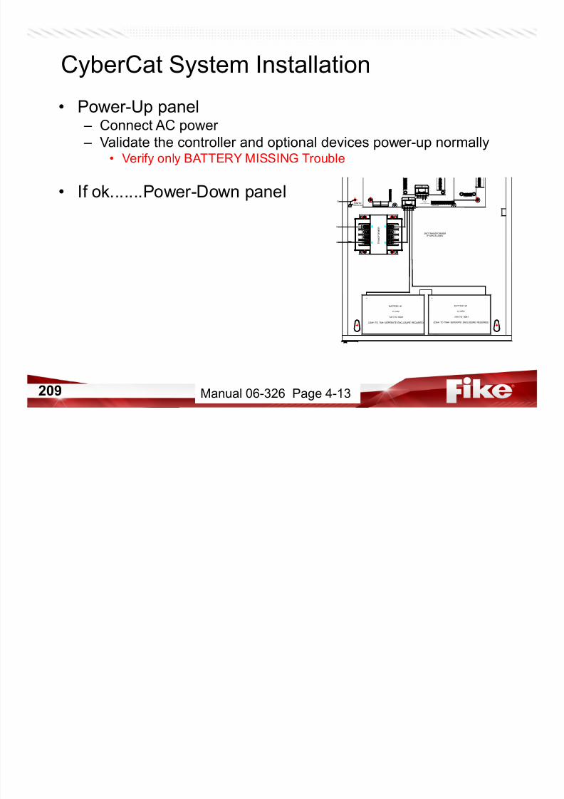
7/23/2019 CyberCat 2015 FULL Printout
http://slidepdf.com/reader/full/cybercat-2015-full-printout 209/429
209
N
H
BATTERY #2
12 VDC
7AH TO 18AH
(33AH TO 75AH SEPERATE ENCLOSURE REQUIRED)
+ --+
(33AH TO 75AH SEPERATE ENCLOSURE REQUIRED)
7AH TO 18AH
12 VDC
BATTERY #1
T R A N S F O R M E R
2ND TRANSFORMERIF SPS IS USED
Manual 06-326 Page 4-13
CyberCat System Installation
• Field Wiring – Segregate Power
Limited and Non Power
Limited
– Select wire and install – No Ground Faults or
stray voltagesEARTH
GROUND
P8
P179
POWERSUPPLEMENTAL
SUPPLY
P 2 2
A u x i l i a r y O u t p u t s
R e s e t t a b l e A u x O u t
P16
4
DISPLAY
P8P3 P4 P5
P10
A d d r e s s a b l e L o o p 1
- -
+ +
S H
L D
-
+
- -
+ +
S H L D
-
+
A d d r e s s a b l e L o o p 1
P9
NETWORKCRM4OR
CARD
MODULE
SUPPLEMENTALLOOP
P15
P12
P19
- -
+ +
S H
L D
-
+
BatteryFuse10A ACFuse10A
F1F2
+ - SHLD + - SHLD + - SHLD Resettable Aux Out AuxliliaryOutputsC OM PU TE R V E
SDA
P11
N o t i f i c a t i o n A p p l i a n c e C i r c u i t 1
- -
+ +
S H L D
-
+
N o t i f i c a t i o n A p p l i a n c e C i r c u i t 2
- -
+ +
S H L D
-
+
A d d r e s s a b l e L o o p 2
Battery+ Input -Secondary
AC XFMR
P1
+ Input - Battery
Secondary AC XFMR
Peripherals (232)
P6
+ -
SHLD + - DACT (485)Peripherals

7/23/2019 CyberCat 2015 FULL Printout
http://slidepdf.com/reader/full/cybercat-2015-full-printout 210/429
210
stray voltages
– Measure total wire
resistance
GROUND
T R A N S F O R M E R
T R A N S F O R M E R
DISPLAYBattery Fuse10A ACFuse10A
Manual 06-326 Page 4-16
CyberCat System Installation
• Terminate all Field Wiring
Peripherals(232)
OPTIONAL
- -
+ +
S H L D
-
+
A d d r e s s a b l e L o o p 3
A d d r e s s a b l e L o o p 3
- -
+ +
S H L D
-
+
DACT (485) Peripherals + - S HL D + -
+ +
- -
+ +
P7P2 P3 P4 P5
P9
+
+ + + +
- -
+ + -
+ -
+
(CLASS "A" WIRING)
- -
+ +
S H L D
-
+
A d d r e s s a b l e L o o p 1
P8
CRM4 OR NETWORK
+
+ - SHLD + - SHLD + - SHLD ResettableAuxOut AuxliliaryOutputsCOMPUTER VESDA
C N C N O C N C N O C N C N O Alarm Supervisory Trouble
OUTPUTS24VDC AUXILIARY
RELAYOPTIONAL
CRM4 OR CRP
OPTIONALDACT
POWER LIMITED
ALL 4 CIRCUITS BELOW ARE SUPERVISED AND POWER LIMITED
P6
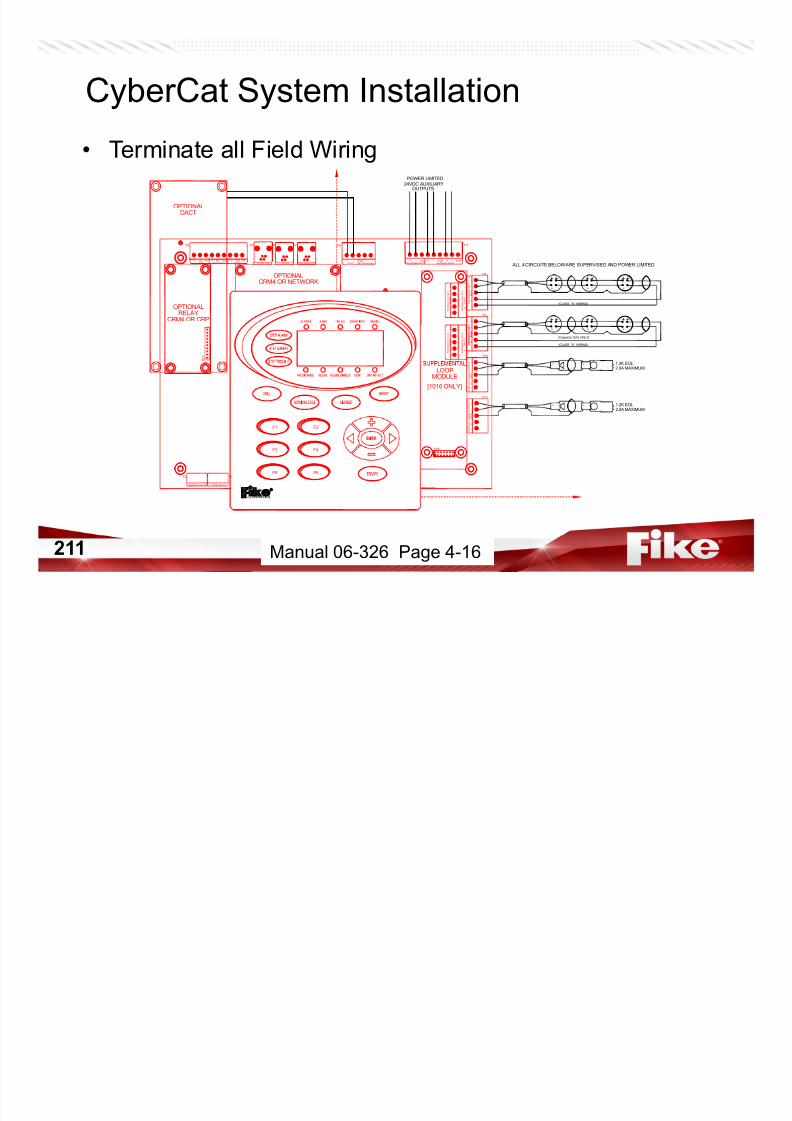
7/23/2019 CyberCat 2015 FULL Printout
http://slidepdf.com/reader/full/cybercat-2015-full-printout 211/429
211
F1
F1
F3
F5 F6
F4
F2
- -
+ +
S H L D
-
+
A d d r e s s a b l e L o o p 4
A d d r e s s a b l e L o o p 4
- -
+ +
S H L D
-
+
P 1 2
2.0A MAXIMUM1.2K EOL
1.2K EOL2.0A MAXIMUM
- -
LOOP
MODULE
+
- -
++
--
+
A d d r e s s a b l e L o o p 1
- -
+ +
S H L D
-
+
+
- -
+ +
--
+
(CLASS "A" WIRING)
- - - -
P15
P11
- -
+ +
S H L D
-
+
BatteryFuse10A ACFuse10A
F2
P10
N o t i f i c a t i o n A p
p l i a n c e C i r c u i t 1
- -
+ +
S H
L D
-
+
N o t i f i c a t i o n A p p l i a n c e C i r c u i t 2
- -
+ +
S H L D
-
+
A d d r e s s a b l e L o o p 2
C O C
[CyberCat 1016 ONLY]
[1016 ONLY]
Manual 06-326 Page 4-16
CyberCat System Installation
• Power-Up With Devices
– Apply AC power
– Verify panel comes up properly• Expect BATTERY TROUBLE
• Expect INVALID ADDRESS troubles for each addressable device *** – If problem exists…
• Immediately power-down system
7/23/2019 CyberCat 2015 FULL Printout
http://slidepdf.com/reader/full/cybercat-2015-full-printout 212/429
212
Immediately power down system
• Correct wiring and/or device issue
– If system okay…• Apply Battery power (if applicable)
• Proceed with building your configuration
Manual 06-326 Page 4-15

7/23/2019 CyberCat 2015 FULL Printout
http://slidepdf.com/reader/full/cybercat-2015-full-printout 213/429
213
Configuration
CyberCat LCD Display
• Top Level Menu – Press ESCAPE until Top Level Menu screen appears
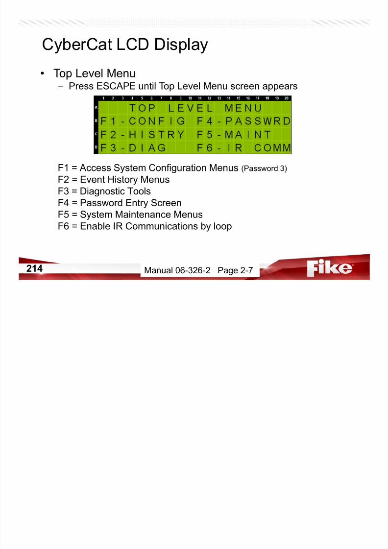
7/23/2019 CyberCat 2015 FULL Printout
http://slidepdf.com/reader/full/cybercat-2015-full-printout 214/429
214
F1 = Access System Configuration Menus (Password 3)
F2 = Event History MenusF3 = Diagnostic Tools
F4 = Password Entry Screen
F5 = System Maintenance Menus
F6 = Enable IR Communications by loop
Manual 06-326-2 Page 2-7
CyberCat System Operation
• PASSWORD
Level Type Created Function
1 CUSTOMER Keylock Button access
2 MAINTENANCE C-Linx
Set Date/time
View Configuration
R n Diagnostics

7/23/2019 CyberCat 2015 FULL Printout
http://slidepdf.com/reader/full/cybercat-2015-full-printout 215/429
215
Run Diagnostics
3 DISTRIBUTOR CyberCat Change ConfigurationChange level 3 PW
4 FACTORY CyberCat
Factory Initialize
Ground Fault Adjustment
Create level 3
Manual 06-326-2 Page 2-8
CyberCat System Operation
• F4 – PASSWORD from Top Level Menu
– Level 1, Keylock

7/23/2019 CyberCat 2015 FULL Printout
http://slidepdf.com/reader/full/cybercat-2015-full-printout 216/429
216
• Access to all buttons (i.e. Reset, Acknowledge, etc.)
– Level 2, Maintenance (NONE set by Default)
• Passwords defined ONLY in C-Linx – Level 3, Distributor
• Default password assigned by Fike, can be modified ONLY from
panel keypad
– Level 4, Factory
Manual 06-326-2 Page 2-9
CyberCat System Configuration
• Auto Configuration – NON - Engineered Configuration
– No prints or drawings of system to match
– Automatically assigns “Next Available Address” to any INVALID
ADDRESS devices – Will NOT affect any devices that already have a VALID address set
in them.

7/23/2019 CyberCat 2015 FULL Printout
http://slidepdf.com/reader/full/cybercat-2015-full-printout 217/429
217
– Factory default come as Loop 0, Address 000
– No choice of what device gets which address
– Addresses assigned as each Invalid Address device reports in after
loop restarts or device is added to loop.
NOTE: Refer to ADC06-002 for Multiple Methods of Addressing Devices
Manual 06-539 Page 3-4
CyberCat System ConfigurationNo Longer in Manual
• Auto Configure
– Automatically assigns loop & address to addressable devices
D i f ti i l fi d

7/23/2019 CyberCat 2015 FULL Printout
http://slidepdf.com/reader/full/cybercat-2015-full-printout 218/429
218
– Devices function as previously configured
• If new, out of box, devices function for Alarm in Zone 001 – Input devices CAUSE Alarm in Zone 001
– Output devices pre-configured to activate for Alarm in Zone 001
– See next set of slides for default configurations
– Use C-Linx to modify device configurations if desired• Using “Create Configuration Template” in C-Linx.
• Should NOT pull config from new panel and new device, modify andsend back to panel !!!!
Manual 06-539 Page 3-5
CyberCat System Configuration
• Engineered Configuration – Based on Engineered drawings/prints
– Manually assign loop & address to devices• IR Tool
• Handheld Programmer
• Assign Device Address• Device Addressing Wizard
– Use C-Linx to configure system/device functionality
B ild fi ti f t h t t h d i
7/23/2019 CyberCat 2015 FULL Printout
http://slidepdf.com/reader/full/cybercat-2015-full-printout 219/429
219
• Build configuration from scratch to match drawings
OR
• Create Configuration Template and modify
• Do NOT Pull configuration from panel and modify with Factory New
Devices
NOTE: Refer to ADC06-002 for Multiple Methods of Addressing Devices
Manual 06-539 Page 3-4
CyberCat Device Addressing
• IR Communications – Press F6 – IR COMM
Li B U / ENAbl L 1 2’ IR C i i

7/23/2019 CyberCat 2015 FULL Printout
http://slidepdf.com/reader/full/cybercat-2015-full-printout 220/429
220
Line B = Use +/- to ENAble Loop 1 or 2’s IR Communication
Line C = Use +/- to ENAble Loop 3 or 4’s IR Communication
NOTE: Only one loop can be enabled at a time. IR communications is
disabled on ALL loops upon panel Reset.
Manual 06-539 Page 3-8
CyberCat Device Addressing
• Address Device with IR Tool – Turn ON IR Communications
• F6-IR COMM
– Press PWR button on IR Tool
– Aim at device and press SELECT
• Device LED will flash green/red – ‘1. WRITE Loop/Adr’ – press ENTER
– Use up/dn arrow buttons to select Loop/Address
Use # buttons to enter Loop/Address
OWER BUTTON
ENTER KEY
SCROLL DOWN KEY
DESELECT KEY
ESCAPE KEY
SCROLL UP KEY
SELECT KEY
PWR
0987
654
2 31
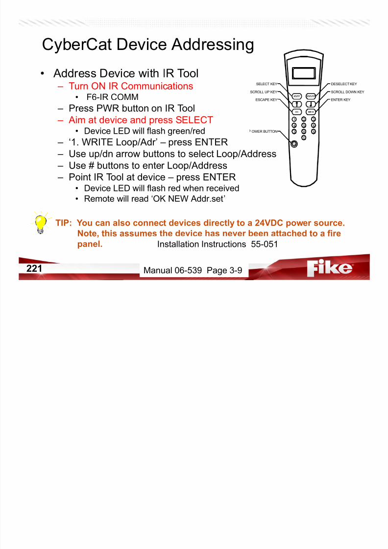
7/23/2019 CyberCat 2015 FULL Printout
http://slidepdf.com/reader/full/cybercat-2015-full-printout 221/429
221
– Use # buttons to enter Loop/Address
– Point IR Tool at device – press ENTER
• Device LED will flash red when received• Remote will read ‘OK NEW Addr.set’
TIP: You can also connect devices directly to a 24VDC power source.
Note, this assumes the device has never been attached to a firepanel. Installation Instructions 55-051
Manual 06-539 Page 3-9

7/23/2019 CyberCat 2015 FULL Printout
http://slidepdf.com/reader/full/cybercat-2015-full-printout 222/429
222 Class Handout
Device Addressing – Cheat Sheet
• Pull Station 1-001
• MM (Waterflow) 1-004
• MM (Tamper) 1-005
• MM (Zone Disable) 1-006
• Photo 1-014
• Ion 1-015
• Relay (HVAC) 1-020
• mmm (Low Press) 1-026
• Control (Solenoid) 1-054
• Control (Horn) 1-040
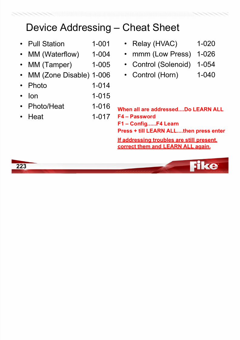
7/23/2019 CyberCat 2015 FULL Printout
http://slidepdf.com/reader/full/cybercat-2015-full-printout 223/429
223
• Photo/Heat 1-016
• Heat 1-017
When all are addressed....Do LEARN ALL
F4 – PasswordF1 – Config......F4 Learn
Press + till LEARN ALL....then press enter
If addressing troubles are still present,
correct them and LEARN ALL again.
• Top Level Menu – Press ESCAPE until Top Level Menu screen appears
F1 = Access System Configuration Menus (Password 3 4)
CyberCat LCD Display

7/23/2019 CyberCat 2015 FULL Printout
http://slidepdf.com/reader/full/cybercat-2015-full-printout 224/429
224
F1 = Access System Configuration Menus (Password 3 – 4)
F2 = Event History Menus
F3 = Diagnostic Tools
F4 = Password Entry Screen
F5 = System Maintenance Menus
F6 = Enable IR Communications by loop
• Maintenance Menu 1 (M1) – Press F5-MAINT
F1 = Read device loop/address
CyberCat LCD Display

7/23/2019 CyberCat 2015 FULL Printout
http://slidepdf.com/reader/full/cybercat-2015-full-printout 225/429
225
F1 = Read device loop/address
F2 = Assign loop/address to device
F3 = Perform device replacement sequence on sensors
F4 = Select Walktest Mode
F5 = Temporarily Disable onboard Buzzer
F6 = Maintenance Menu 2
Manual 06-326-2 Page 6-3
• Read Device Loop/Address Assignment (M1.1) – Press F1-DEV RD
Line C = Loop & Address of last ‘NEW DEVICE’ record received
CyberCat LCD Display

7/23/2019 CyberCat 2015 FULL Printout
http://slidepdf.com/reader/full/cybercat-2015-full-printout 226/429
226
Line C = Loop & Address of last NEW DEVICE record received
Line D = Device Type at Loop & Address
Manual 06-326-2 Page 6-4
• Assign Loop/Address to Device (M1.2) – Press ESCAPE, then Press F2-DEV ADR
– Step 1• Set Loop and Address
• Press ENTER to store
– Step 2• Attach device to programmer
– Step 3
CyberCat LCD Display

7/23/2019 CyberCat 2015 FULL Printout
http://slidepdf.com/reader/full/cybercat-2015-full-printout 227/429
227
Step 3• Display will indicate New Device
• Press ENTER to set loop/address
– Step 4• Display will indicate process completion
and increment to next address
Manual 06-326-2 Page 6-4
CyberCat Device Addressing
• Handheld Programmer – Power-Up and follow on-screen prompts
– Step 1• Set Loop and Address
• Press ENTER to store
– Step 2• Attach device to programmer
– Step 3
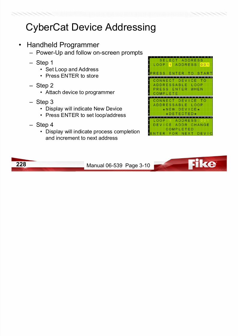
7/23/2019 CyberCat 2015 FULL Printout
http://slidepdf.com/reader/full/cybercat-2015-full-printout 228/429
228
p• Display will indicate New Device
• Press ENTER to set loop/address
– Step 4• Display will indicate process completion
and increment to next address
Manual 06-539 Page 3-10
1) Install C-Linx2) If prompted, install Microsoft .NET v2.0
3) License Software• Help – License Software…
• Enter the following Temporary License Code… Click Here
• Restart C-Linx to load License Code
CyberCat Software Configuration

7/23/2019 CyberCat 2015 FULL Printout
http://slidepdf.com/reader/full/cybercat-2015-full-printout 229/429
229
• Restart C-Linx to load License Code
Jump Drive or HELP Manual 06-448
CyberCat Device Addressing
• Assign Device Address – C-Linx Feature
– Open Panel Explorer
– Select Diagnostics
– Select Assign Device Address – Panel will Reset
– List will populate

7/23/2019 CyberCat 2015 FULL Printout
http://slidepdf.com/reader/full/cybercat-2015-full-printout 230/429
230
– Select Device
– Change Loop and/or Address
– Click Assign New Address
Jump Drive Manual 06-448 Page 188
NEVER PULL THE CONFIGURATION FROM BRAND NEW DEVICES AS THEY
WILL NOT CONTAIN ALL OPTIONS AND MAY NOT OPERATE CORRECTLY!!!
CyberCat System Configuration(Fike Recommended Configuration Procedure)
1) Address devices based on design drawings/prints2) Use C-Linx Assign Device Address to verify addressing
• Fix addressing errors accordingly
3) Perform a LEARN ALL from panel
• F1-CONFIG, F4-LEARN, +/- for LEARN ALL DEVICES• Review any troubles that occur, if addressing related, correct
• i.e. Multiple Device, Invalid Address, Device Not in Config
4) Create/Open C-Linx configuration
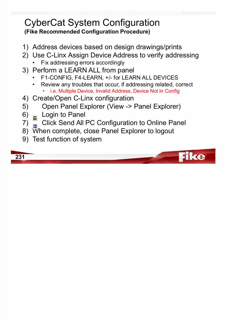
7/23/2019 CyberCat 2015 FULL Printout
http://slidepdf.com/reader/full/cybercat-2015-full-printout 231/429
231
) p g
5) Open Panel Explorer (View -> Panel Explorer)6) Login to Panel
7) Click Send All PC Configuration to Online Panel
8) When complete, close Panel Explorer to logout
9) Test function of system
CyberCat System Operation
• Zone – State Configuration – 254 Software Zones
• Z1 – Z253 = Hazard Zones
• Z254 = Panel (Disable-able)
– States/Functions = Normal, Alarm, Supervisory, Trouble, Pre- Alarm, Walk-test, Process, Drill, Zone Disable
– Inputs are programmed for zone and function

7/23/2019 CyberCat 2015 FULL Printout
http://slidepdf.com/reader/full/cybercat-2015-full-printout 232/429
232
– Outputs are programmed for zone and state
– When an input activates, it communicates the zone/state
activation to its peers and the panel – ¼ second SPEED
(older Polling, Group Polling, Interrupt methods)
CyberCat System Operation
• Fan Restart
– Applies to CRM4 modules
– Relay becomes Normally Energized
– Relay maintains current state thru Reset
R t ft fi d d l
- Appears immediately after
Reset
- Relay disappears when
delay expires
- If Manual, screen will
prompt to start sequence
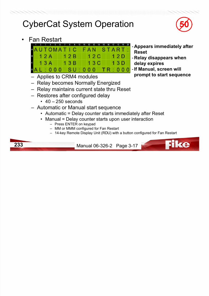
7/23/2019 CyberCat 2015 FULL Printout
http://slidepdf.com/reader/full/cybercat-2015-full-printout 233/429
233
– Restores after configured delay
• 40 – 250 seconds – Automatic or Manual start sequence
• Automatic = Delay counter starts immediately after Reset
• Manual = Delay counter starts upon user interaction – Press ENTER on keypad
– MM or MMM configured for Fan Restart – 14-key Remote Display Unit (RDU) with a button configured for Fan Restart
Manual 06-326-2 Page 3-17
CyberCat System Operation
• Flame Enhance – Photo/Heat Sensors – Improves response when both smoke and heat are detected
• History Buffer
– v3.0 and up• Records up to 3200 events and then FIFO (rotating)
• If an Alarm occurs, then records next 999 events and stops – Prevents overwriting first alarm condition

7/23/2019 CyberCat 2015 FULL Printout
http://slidepdf.com/reader/full/cybercat-2015-full-printout 234/429
234 Manual 06-326-2 Page 3-19
CyberCat System Operation
• Viewing History – STEP ALARM, STEP SUPER, STEP ALL
• Use +/- buttons to cycle thru events
• Press F5 while viewing events to toggle between CURRENT
history and ALL history – CURRENT History = Events received after Reset
– ALL History = Events received prior to and after Reset
– v3.0 firmware added F2-HISTRY menu

7/23/2019 CyberCat 2015 FULL Printout
http://slidepdf.com/reader/full/cybercat-2015-full-printout 235/429
235
• F1 – ALARM = STEP ALARM
• F2 – SUPERV = STEP SUPER
• F4 – EVENTS = STEP ALL
Manual 06-326-2 Page 4-1
CyberCat System Operation
• Network Operations – Connect up to 128 panels
• Cheetah Xi 1016, CyberCat 1016, or CyberCat 254
– RS485 or Fiber • 10-2482 = RS485
• 10-2624 = Fiber Optics – Wire Style-4 or Style-7
– Every event is received and recorded in history by every panel• Configure each panel to act upon event based on zone

7/23/2019 CyberCat 2015 FULL Printout
http://slidepdf.com/reader/full/cybercat-2015-full-printout 236/429
236
Configure each panel to act upon event based on zone
– Supervise all, none, or a select few panels
– Reset, Silence, Acknowledge, Drill broadcast to every panel• Configure each panel to accept switch commands from all, none, or a
select few panels
Manual 06-326-2 Page 3-2
CyberCat System Operation
• Positive Alarm Sequence (PAS)
– Enabled/Disabled for ALL sensors
– If a sensor alarms…• User has 15 seconds to press ACKNOWLEDGE
– If not pressed, system alarms normally
• After ACKNOWLEDGE, system starts 180 second verification period – During this period only panel buzzer and event display activate
– Outputs NOT configured for PAS will immediately activate
– User must press RESET within this period to prevent system alarm
• Second sensor or manual alarm is activated, system alarms normally

7/23/2019 CyberCat 2015 FULL Printout
http://slidepdf.com/reader/full/cybercat-2015-full-printout 237/429
237
– PAS Inhibit• Allows system to operate without delay
• MM or MMM configured for PAS Inhibit – When active, a trouble condition is generated at panel
Manual 06-326-2 Page 3-3
CyberCat System Operation
• Relay Base – Single, Form C contact – Operated by attached sensor
– Configurable for multiple zones and/or states
– Default follows red LED of attached sensor
– Does NOT require 24Vdc Aux power to operate
• Sounder Base – 85dB Sounder
– Operated by attached sensor
7/23/2019 CyberCat 2015 FULL Printout
http://slidepdf.com/reader/full/cybercat-2015-full-printout 238/429
238
– Operated by attached sensor
– Configurable for multiple zones and/or states – Default follows red LED of attached sensor
– Requires separate 24VDC
– 24VDC Aux Power is NOT Supervised• EOLR – Monitor Module
Manual 06-326 Page 3-31
CyberCat System Operation
• Silence Inhibit – If ENABLED, panel will not silence for 60 seconds following first
Alarm event
– Canadian Requirement
• Silence Reminder – If ENABLED, panel buzzer will chirp every 14 seconds after
outputs have been silenced
C di R i t
Manual 06-326-2 Page 3-1

7/23/2019 CyberCat 2015 FULL Printout
http://slidepdf.com/reader/full/cybercat-2015-full-printout 239/429
239
– Canadian RequirementManual 06-326-2 Page 3-2
CyberCat System Operation
• Summing – Non listed – Allows a summer to “sum” the smoke levels of up to 8 summee’s
– Summer • Sensor that totals the smoke levels of up to 8 sensors
• Configurable total smoke level threshold – Photoelectric Sensors ~ 1.0%OBS/FT – 10.0%OBS/FT
• Configurable “summing” activation state – Alarm – Supervisory Non Latching
– Summing Alarm – Pre-Alarm 1

7/23/2019 CyberCat 2015 FULL Printout
http://slidepdf.com/reader/full/cybercat-2015-full-printout 240/429
240
g
– Supervisory Latching – Pre-Alarm 2 – Summee (participant)
• Sensor configured to broadcast its smoke levels – 8 configurable broadcast smoke thresholds
– Broadcast occurs when threshold is reached regardless of rise or fall
NOTE: Summing is performed for devices on the same addressable loop.
Manual 06-326-2 Page 3-20
CyberCat System Operation
• Summing Example – Summer
• 1-001
– Summees (up to 8)• 1-001
• 1-002
• 1-003
• 1-019
• 1-020
• 1-022
1 023

7/23/2019 CyberCat 2015 FULL Printout
http://slidepdf.com/reader/full/cybercat-2015-full-printout 241/429
241
• 1-023
• 1-024
Manual 06-326-2 Page 3-20
CyberCat System Operation
• ALARM State
– Activated by Sensor or Input Modules specified
• Photo Sensor • Pull Station
• Photo/Heat Sensor • Monitor Module
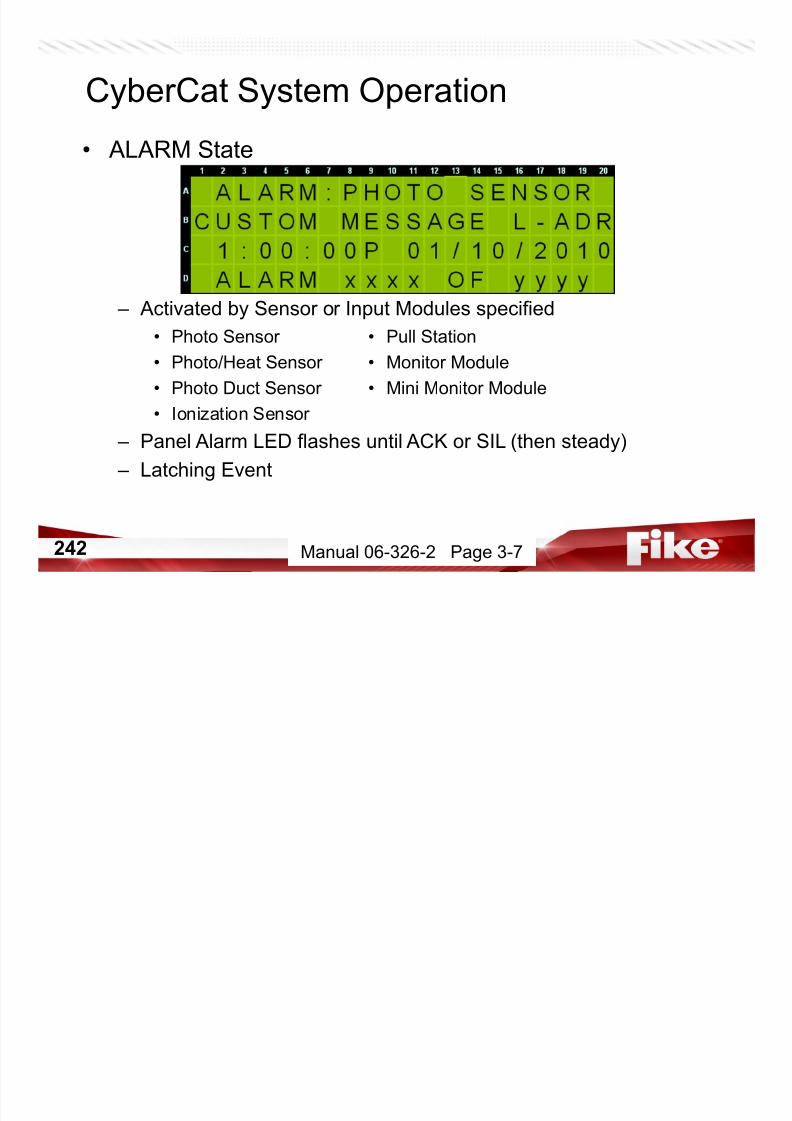
7/23/2019 CyberCat 2015 FULL Printout
http://slidepdf.com/reader/full/cybercat-2015-full-printout 242/429
242
• Photo Duct Sensor • Mini Monitor Module
• Ionization Sensor
– Panel Alarm LED flashes until ACK or SIL (then steady)
– Latching Event
Manual 06-326-2 Page 3-7
• WATERFLOW ALARM State
– Panel Alarm LED flashes until ACK or SIL (then steady)
– Latching Event
CyberCat System Operation

7/23/2019 CyberCat 2015 FULL Printout
http://slidepdf.com/reader/full/cybercat-2015-full-printout 243/429
243 Manual 06-326-2 Page 3-3
CyberCat System Operation
• ALARM VERIFICATION State
– Activated by Smoke Sensors
– Active during configured verification delay (0-60 seconds)
• Clears when delay expires and sensor alarms

7/23/2019 CyberCat 2015 FULL Printout
http://slidepdf.com/reader/full/cybercat-2015-full-printout 244/429
244
– No buzzer or LED annunciation, no outputs during verification delay – Provides extra time for smoke sensor to validate alarm threshold
– If alarm threshold is reached, Alarm Verification state begins. After
verification delay expires, if smoke level still exceeds alarm
threshold, sensor enters Alarm state
Manual 06-326-2 Page 3-8
CyberCat System Operation
• SUMMING ALARM State
– Activated when the Sensor specified* has summed smoke
levels from other sensors to a preconfigured value
• Photo Sensor • Photo Duct Sensor

7/23/2019 CyberCat 2015 FULL Printout
http://slidepdf.com/reader/full/cybercat-2015-full-printout 245/429
245
• Photo/Heat Sensor – Panel Alarm LED flashes until ACK or SIL (then steady)
– Latching Event
*Requires specified Sensor to be configured as a summer
Manual 06-326-2 Page 3-9
CyberCat System Operation
• TROUBLE State
– Panel Trouble LED flashes until SIL, ACK, or event clear
– Steady Buzzer

7/23/2019 CyberCat 2015 FULL Printout
http://slidepdf.com/reader/full/cybercat-2015-full-printout 246/429
246
– Most Troubles are non latching• Exceptions
– Loop Class A Open
– Loop Short
Manual 06-326-2 Page 3-10
Refer to, Manual 06-639 for Event List
CyberCat System Operation
• SUPERVISORY State
– Panel Supervisory LED flashes until SIL, ACK, or event clear
– Buzzer Warbles (rapid on/off pattern)
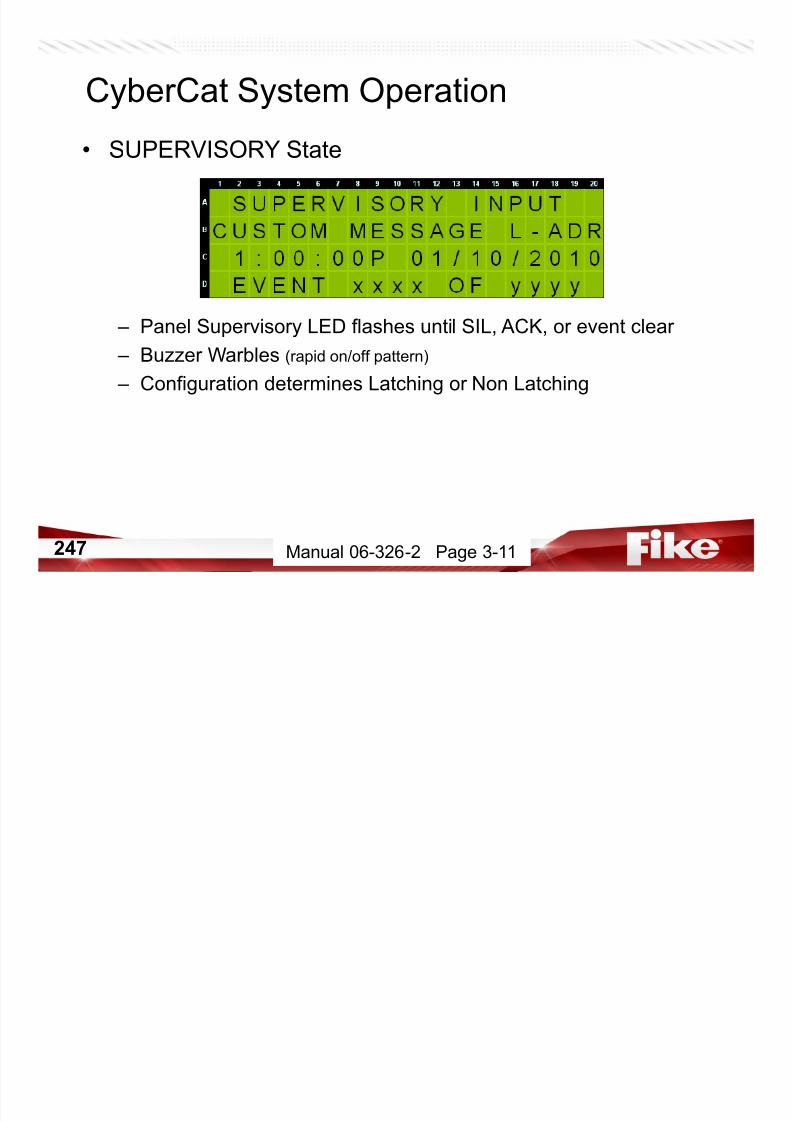
7/23/2019 CyberCat 2015 FULL Printout
http://slidepdf.com/reader/full/cybercat-2015-full-printout 247/429
247
– Configuration determines Latching or Non Latching
Manual 06-326-2 Page 3-11
CyberCat System Operation
• ZONE DISABLE State
– Trouble and Supervisory states activated
– Inputs from disabled zone still report to panel
– Panel modifies zone/state broadcast to a Zone 0
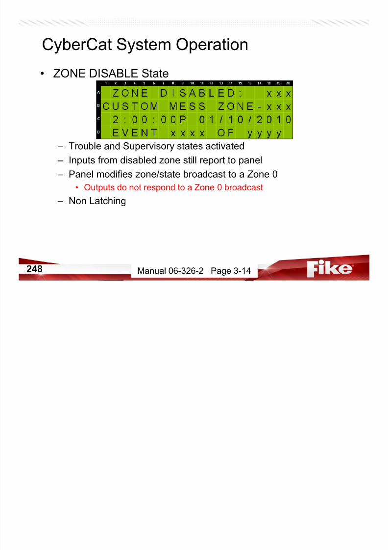
7/23/2019 CyberCat 2015 FULL Printout
http://slidepdf.com/reader/full/cybercat-2015-full-printout 248/429
248
• Outputs do not respond to a Zone 0 broadcast – Non Latching
Manual 06-326-2 Page 3-14
CyberCat System Operation
• PRE-ALARM State
– Two Pre-Alarm Levels (#1 and #2)
– Trouble LED lights, but not a trouble condition SO……
• Outputs configured for Trouble do not activate

7/23/2019 CyberCat 2015 FULL Printout
http://slidepdf.com/reader/full/cybercat-2015-full-printout 249/429
249
– Buzzer on steady until SIL, ACK, or event clear – No event sent to DACT
– Non Latching
Manual 06-326-2 Page 3-12
CyberCat System Operation
• PROCESS State
– No panel LED or Buzzer activation
– Event is recorded in History
– Non Latching
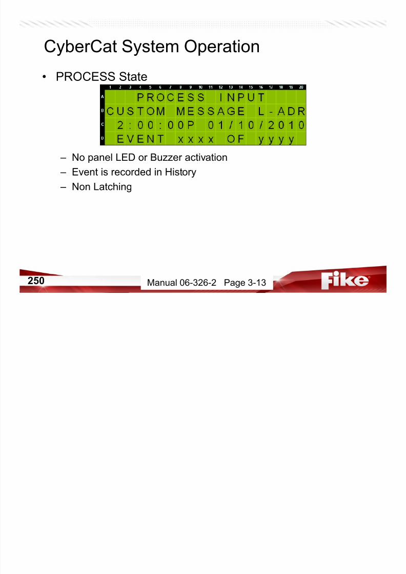
7/23/2019 CyberCat 2015 FULL Printout
http://slidepdf.com/reader/full/cybercat-2015-full-printout 250/429
250 Manual 06-326-2 Page 3-13
CyberCat System Operation
• WALKTEST State
– Activates outputs for 4 seconds
• When outputs are configured to activate for Walktest
– Trouble state entered

7/23/2019 CyberCat 2015 FULL Printout
http://slidepdf.com/reader/full/cybercat-2015-full-printout 251/429
251
– For addressable sensors and input modules
– Walktest is entered on the F5 – MAINTenance menu
Manual 06-326-2 Page 3-16
CyberCat System Operation
• DRILL State
– Activated by panel keypad, MM, or RDU
– Event is recorded, piezo warbles
– Outputs configured for the Drill state will remain ON until

7/23/2019 CyberCat 2015 FULL Printout
http://slidepdf.com/reader/full/cybercat-2015-full-printout 252/429
252
silenced (if configured to be silenceable)
– Latching
Manual 06-326-2 Page 3-15
CyberCat Main Board Defaults

7/23/2019 CyberCat 2015 FULL Printout
http://slidepdf.com/reader/full/cybercat-2015-full-printout 253/429
253 Manual 06-326-2 Page 1-4
Main Board Relay 1 P12 Relay 1 - 4
Activation State Alarm P12 Module CRM4 Module Installed
Enabled Yes Activation State Alarm
Silenceable No Enabled Yes
Drill Enabled No Silenceable No
Zone Assignments Any Drill Enabled No
Fan Restart Delay Disabled
Main Board Relay 2 Zone Assignments None
Activation State Supervisory
Enabled Yes P13 Relay 1 - 4
Silenceable No P13 Module CRM4 Module Installed
Drill Enabled No Activation State Alarm
Zone Assignments Any Enabled Yes
Silenceable No
Main Board Relay 3 Drill Enabled No
Activation State Trouble Fan Restart Delay Disabled
CyberCat Main Board Defaults

7/23/2019 CyberCat 2015 FULL Printout
http://slidepdf.com/reader/full/cybercat-2015-full-printout 254/429
254
Enabled Yes Zone Assignments NoneSilenceable No
Drill Enabled No
Zone Assignments Any
Manual 06-326-2 Page 1-5 & 1-6
CyberCat Device Configuration Defaults
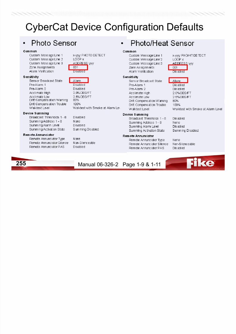
7/23/2019 CyberCat 2015 FULL Printout
http://slidepdf.com/reader/full/cybercat-2015-full-printout 255/429
255 Manual 06-326-2 Page 1-9 & 1-11
CyberCat Device Configuration Defaults
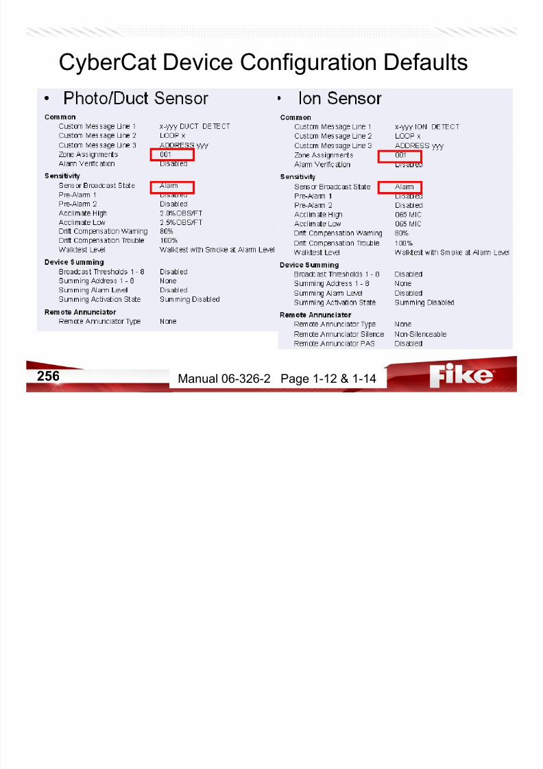
7/23/2019 CyberCat 2015 FULL Printout
http://slidepdf.com/reader/full/cybercat-2015-full-printout 256/429
256 Manual 06-326-2 Page 1-12 & 1-14
CyberCat Device Configuration Defaults
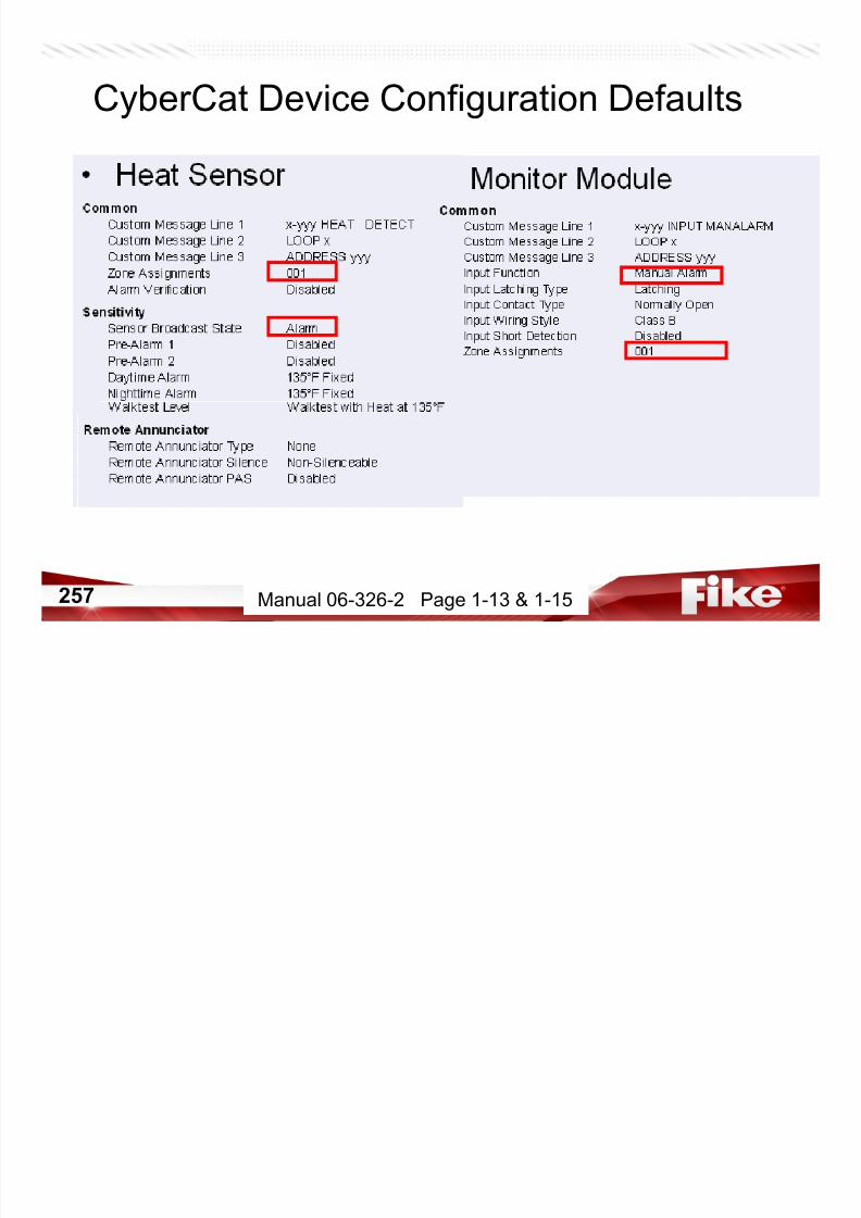
7/23/2019 CyberCat 2015 FULL Printout
http://slidepdf.com/reader/full/cybercat-2015-full-printout 257/429
257 Manual 06-326-2 Page 1-13 & 1-15
CommonCustom Message Line 1 x-yyy MINI MANALARM
Custom Message Line 2 LOOP x
Custom Message Line 3 ADDRESS yyy
Input Function Manual Alarm
Input Latching Type Latching
Input Contact Type Normally Open
Input Short Detection Disabled
Zone Assignments 001
• Mini Monitor Module • Pull Station ModuleCommon
Custom Message Line 1 x-yyy PULL STATION
Custom Message Line 2 LOOP x
Custom Message Line 3 ADDRESS yyy
Input Function Manual Alarm
Zone Assignments 001
CyberCat Device Configuration Defaults
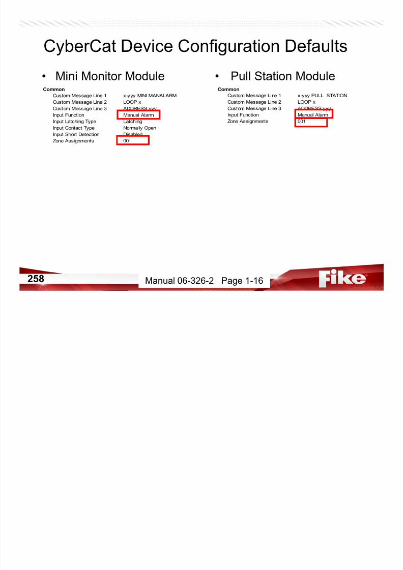
7/23/2019 CyberCat 2015 FULL Printout
http://slidepdf.com/reader/full/cybercat-2015-full-printout 258/429
258 Manual 06-326-2 Page 1-16
• Control Module • Relay ModuleCommon
Custom Message Line 1 x-yyy OUTPUT MODULE
Custom Message Line 2 LOOP x
Custom Message Line 3 ADDRESS yyy
Zone Assignments 001
Drill Output Pattern On Continuous
Silenceable Yes
Posit ive Alarm Sequence Disabled
Output ControlPriority State Action Pattern
01 Alarm Zone 001 On Continuous
32 Test Alarm Zone 001 Walktest
CommonCustom Message Line 1 x-yyy RELAY MODULE
Custom Message Line 2 LOOP x
Custom Message Line 3 ADDRESS yyy
Zone Assignments 001
Drill Output Pattern Disabled
Silenceable No
Positive Alarm Sequence Disabled
Relay Monitoring Disabled
Dry Contact Input Not Used
Output Control
Priority State Action Pattern
01 Alarm Zone 001 On Continuous
CyberCat Device Configuration Defaults

7/23/2019 CyberCat 2015 FULL Printout
http://slidepdf.com/reader/full/cybercat-2015-full-printout 259/429
259 Manual 06-326-2 Page 1-17 & 1-18
Build Configuration

7/23/2019 CyberCat 2015 FULL Printout
http://slidepdf.com/reader/full/cybercat-2015-full-printout 260/429
260

7/23/2019 CyberCat 2015 FULL Printout
http://slidepdf.com/reader/full/cybercat-2015-full-printout 261/429
REVIEW

7/23/2019 CyberCat 2015 FULL Printout
http://slidepdf.com/reader/full/cybercat-2015-full-printout 262/429
262
CyberCat System Configuration(Fike Recommended Configuration Procedure)
1) Address devices based on design drawings/prints2) Use C-Linx Assign Device Address to verify addressing• Fix addressing errors accordingly
3) Perform a LEARN ALL from panel• F1-CONFIG, F4-LEARN, +/- for LEARN ALL DEVICES
• Review any troubles that occur, if addressing related, correct• i.e. Multiple Device, Invalid Address, Device Not in Config
4) Create/Open C-Linx configuration
5) Open Panel Explorer (View -> Panel Explorer)
6) Login to Panel

7/23/2019 CyberCat 2015 FULL Printout
http://slidepdf.com/reader/full/cybercat-2015-full-printout 263/429
263
6) Login to Panel
7) Click Send All PC Configuration to Online Panel
8) When complete, close Panel Explorer to logout
9) Test function of system
LCD Display Menus

7/23/2019 CyberCat 2015 FULL Printout
http://slidepdf.com/reader/full/cybercat-2015-full-printout 264/429
264
CyberCat LCD Display
• System Status
– Press ESCAPE until System Status screen appears
Line A = Firmware Version
Line B = 20 character custom logo
Line C = Current system time and date

7/23/2019 CyberCat 2015 FULL Printout
http://slidepdf.com/reader/full/cybercat-2015-full-printout 265/429
265
Line C Current system time and dateLine D = Current # of Alarm, Supervisory, and Trouble Events
NOTE: Panel returns to this screen after 100 seconds of no activity.
CyberCat LCD Display
• Top Level Menu
– Press ESCAPE until Top Level Menu screen appears
F1 = Access System Configuration Menus (Level 3 Password)
F2 = Event History Menus
F3 = Diagnostic Tools
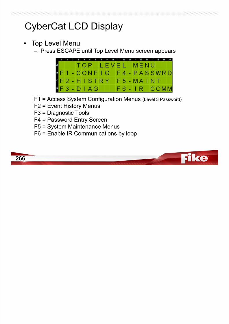
7/23/2019 CyberCat 2015 FULL Printout
http://slidepdf.com/reader/full/cybercat-2015-full-printout 266/429
266
gF4 = Password Entry Screen
F5 = System Maintenance Menus
F6 = Enable IR Communications by loop
CyberCat LCD Display
• Password
– Press F4-PASSWRD
Line B = Use left/right arrows and +/- buttons to enter 4 digit password
NOTE: Sys Admin or higher allows Sys Admin password to be edited
Line C = Status of Password entryLi D 4 di it d f bt i i f t d

7/23/2019 CyberCat 2015 FULL Printout
http://slidepdf.com/reader/full/cybercat-2015-full-printout 267/429
267
yLine D = 4 digit access code for obtaining factory password
NOTE: Password times out if no keys are pressed for a period of about 1/2 hour
Manual 06-539 Page 3-3
CyberCat LCD Display
• Configuration Menu 1 (C1)
– Press ESCAPE for Top Level Menu, then Press F1-CONFIG
F1 = Addressable Devices Configuration Menu
F2 = Onboard Notification Appliance Circuits Configuration Menu
F3 = Signaling Line Circuits Configuration MenuF4 L S

7/23/2019 CyberCat 2015 FULL Printout
http://slidepdf.com/reader/full/cybercat-2015-full-printout 268/429
268
g g gF4 = Learn Screen
F5 = Voice Operation Screen
F6 = Go to Configuration Menu 2
Manual 06-539 Page 4-1
CyberCat LCD Display
• Device Configuration (C1.1)
– Press F1-DEVICE
F1 = Configure device function, message, zone, pattern
F3 = Perform a manual configuration check
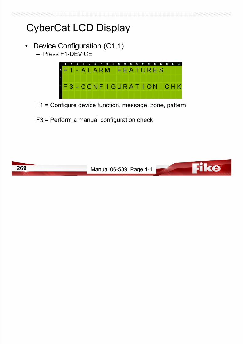
7/23/2019 CyberCat 2015 FULL Printout
http://slidepdf.com/reader/full/cybercat-2015-full-printout 269/429
269
g
Manual 06-539 Page 4-1
CyberCat LCD Display
• Device Alarm Features (C1.1.1)
– Press F1-ALARM FEATURES
Line A = Select Loop/Address to configure
Line B = Set device function of L-ADR and contact closure (if applicable)
NOTE: ‘d’ for disabled; ‘*’ reading/writing
Line C = Custom message that appears on Line B when an event fordevice L ADR occurs
Sensors & Input Modules Control & Relay Modules
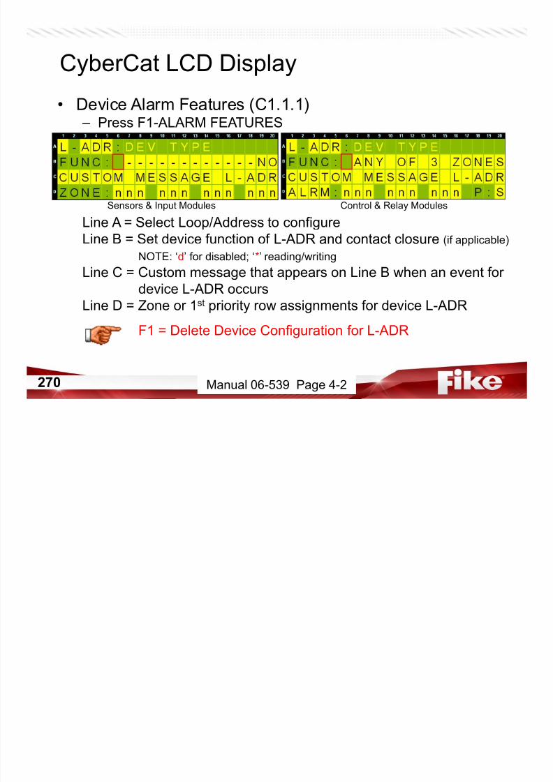
7/23/2019 CyberCat 2015 FULL Printout
http://slidepdf.com/reader/full/cybercat-2015-full-printout 270/429
270
device L-ADR occurs
Line D = Zone or 1st priority row assignments for device L-ADR
F1 = Delete Device Configuration for L-ADR
Manual 06-539 Page 4-2
CyberCat LCD Display
• Delete Device Configuration (C1.1.1.1)
– Press F1
Line A = Device to Delete – DEV TYPE clears after deleted
Line B = Instruction to press ENTER
Line C = Function to execute

7/23/2019 CyberCat 2015 FULL Printout
http://slidepdf.com/reader/full/cybercat-2015-full-printout 271/429
271 Manual 06-539 Page 4-8
CyberCat LCD Display
• Device Alarm Features (C1.1.1)
– Press F1-ALARM FEATURES
Line A = Select Loop/Address to configure
Line B = Set device function of L-ADR and contact closure (if applicable)
NOTE: ‘d’ for disabled; ‘*’ reading/writing
Line C = Custom message that appears on Line B when an event fordevice L-ADR occurs
Sensors & Input Modules Control & Relay Modules

7/23/2019 CyberCat 2015 FULL Printout
http://slidepdf.com/reader/full/cybercat-2015-full-printout 272/429
272
device L-ADR occurs
Line D = Zone or 1st priority row assignments for device L-ADR
F2 = Read/Write/Disable/Enable Device L-ADR
Manual 06-539 Page 4-2
CyberCat LCD Display
• Read/Write/Enable/Disable Device (C1.1.1.2) – Press ESCAPE, then Press F2
Line A = Device to Read/Write/Disable/Enable
Line B = Instruction to press ENTER at desired function
Line C = Desired function
Line D = Displays execution and completion of desire function

7/23/2019 CyberCat 2015 FULL Printout
http://slidepdf.com/reader/full/cybercat-2015-full-printout 273/429
273
CAUTION: Do NOT escape from this screen while performing any one of the
functions described.
Manual 06-539 Page 4-9
CAUTION: DO NOT DO A DEVICE READ OR LEARN ALL WITH
DEVICES DISABLED.
If device at address selected is a FAASTDetector…this is all you would see
CyberCat LCD Display

7/23/2019 CyberCat 2015 FULL Printout
http://slidepdf.com/reader/full/cybercat-2015-full-printout 274/429
274
• Device Alarm Features (C1.1.1)
– Press Escape….If this is a Relay Module
Line A = Select Loop/Address to configure
Line B = Set device function of L-ADR and contact closure (if applicable)
NOTE: ‘d’ for disabled; ‘*’ reading/writing
Line C = Custom message that appears on Line B when an event fordevice L ADR occurs
Relay Modules
CyberCat LCD Display
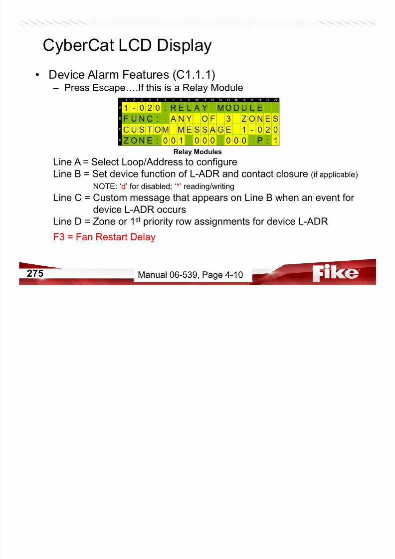
7/23/2019 CyberCat 2015 FULL Printout
http://slidepdf.com/reader/full/cybercat-2015-full-printout 275/429
275
device L-ADR occurs
Line D = Zone or 1st priority row assignments for device L-ADR
F3 = Fan Restart Delay
Manual 06-539, Page 4-10
• Device Alarm Features (C1.1.1.3)
– By Pressing F3
Line A =
Line B = This lets you set the fan re-start delay (0-255 seconds)
Line C =
Line D =
CyberCat LCD Display

7/23/2019 CyberCat 2015 FULL Printout
http://slidepdf.com/reader/full/cybercat-2015-full-printout 276/429
276 Manual 06-539, Page 4-10
CyberCat LCD Display
• Device Configuration (C1.1.3)
– Press ESCAPE, then Press F3-CONFIGURATION CHK
Firmware v2.0 and higher
Line A = Shows Loop/Address of existing devices being checked
Line B = Panel and Device checksum values for device L-ADR.
Updated by pressing ENTER.Line C = Instruction to press ENTER

7/23/2019 CyberCat 2015 FULL Printout
http://slidepdf.com/reader/full/cybercat-2015-full-printout 277/429
277
p
Line D = Indicates progress of configuration check
NOTE: This will check ALL devices, NOT just the address shown, AND
it keeps checking even if you ESCAPE this screen. (ALL Loops)
Manual 06-539 Page 4-10
• Device Configuration (C1.1)
– Press Escape back to Device Configuration Screen.
F1 = Configure device function, message, zone, pattern
F2 = Configure Pre-Discharge Type
F3 = Perform a manual configuration checkF4 = Requires Factory Level Password to see this option
CyberCat LCD Display

7/23/2019 CyberCat 2015 FULL Printout
http://slidepdf.com/reader/full/cybercat-2015-full-printout 278/429
278
q y p
Manual 06-539, Page 4-1
• Device Error (C1.1.4)
– Factory Level Password…then Press F4
Line A =
Line B = Device Error Trouble Indication (Enabled/Disabled)
Line C =Line D = Auto Correction for Device Error (Enabled/Disabled)
CyberCat LCD Display
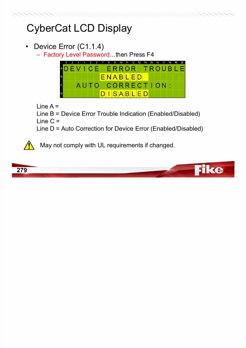
7/23/2019 CyberCat 2015 FULL Printout
http://slidepdf.com/reader/full/cybercat-2015-full-printout 279/429
279
May not comply with UL requirements if changed.
CyberCat LCD Display
• Configuration Menu 1 (C1)
– Press ESCAPE for Top Level Menu, then Press F1-CONFIG
F1 = Addressable Devices Configuration Menu
F2 = Onboard Notification Appliance Circuits Configuration Menu
F3 = Signaling Line Circuits Configuration MenuF4 = Learn Screen

7/23/2019 CyberCat 2015 FULL Printout
http://slidepdf.com/reader/full/cybercat-2015-full-printout 280/429
280
F5 = Voice Operation Screen
F6 = Go to Configuration Menu 2
Manual 06-539 Page 4-1
CyberCat LCD Display
• NAC Configuration (C1.2)
– Then Press F2-NAC
F1 = Set configuration for NAC #1 and #2
F2 = Assign NAC #1 and #2 to zones
F3 = Select Strobe Synchronization Protocol
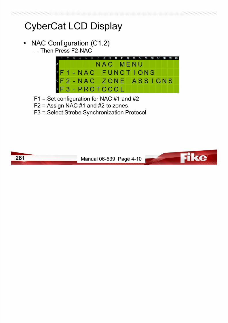
7/23/2019 CyberCat 2015 FULL Printout
http://slidepdf.com/reader/full/cybercat-2015-full-printout 281/429
281 Manual 06-539 Page 4-10
CyberCat LCD Display
• NAC Functions (C1.2.1)
– Press F1-NAC FUNCTIONS
Line A = Select NAC #1 or #2 – Enable/Disable NAC #1 or #2
Line B = Select activation state for NAC selected on Line A
Line C = Select CONSTANT output or Sync Protocol
(See Menu C1.2.3 for NAC Sync Protocol)
Line D = Can NAC be silenced? (Y/N)

7/23/2019 CyberCat 2015 FULL Printout
http://slidepdf.com/reader/full/cybercat-2015-full-printout 282/429
282
Line D Can NAC be silenced? (Y/N)
Does NAC activate in DRILL mode? (Y/N)
Does NAC activate on Walktest events? (Y/N)
Is it silenceable during Waterflow? (Y/N)
Manual 06-539 Page 4-11
CyberCat LCD Display
• NAC Zone Assignments (C1.2.2)
– Press ESCAPE, then Press F2-NAC ZONE ASSIGNS
Line A = Select NAC #1 or #2 – Any Zone/Multi-Zone
Line B = Range of 20 zones to display
Line C = Placeholders for Line DLine D = Only applies if Multi-Zone is selected – ‘Y’ means zone is
l t d

7/23/2019 CyberCat 2015 FULL Printout
http://slidepdf.com/reader/full/cybercat-2015-full-printout 283/429
283
selected
Manual 06-539 Page 4-12
CyberCat LCD Display
• NAC Synchronization Protocol (C1.2.3)
– Press ESCAPE, then Press F3-PROTOCOL
– Use +/- buttons to cycle thru and select desired sync protocol
– Selected sync protocol applies to both NAC #1 and #2
– Refer to Menu C1.2.1 to enable sync protocol on NAC circuits
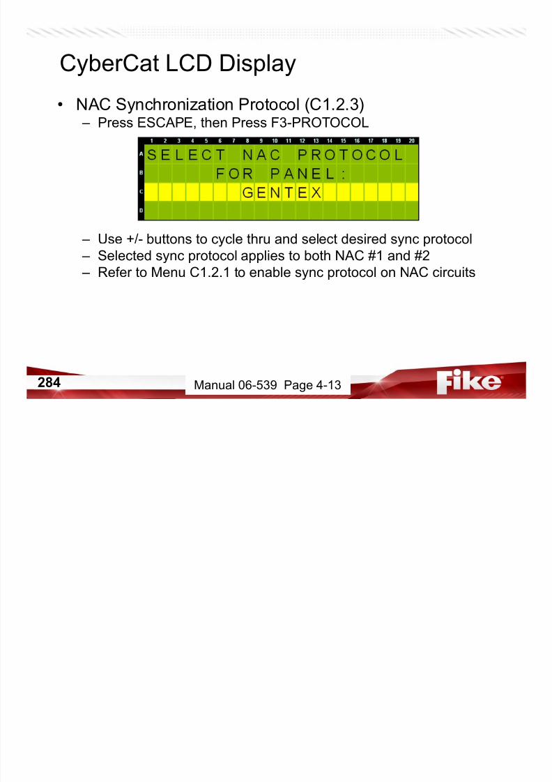
7/23/2019 CyberCat 2015 FULL Printout
http://slidepdf.com/reader/full/cybercat-2015-full-printout 284/429
284 Manual 06-539 Page 4-13
• SLC Configuration (C1.3)
– Press ESCAPE twice, then Press F3-SLC
Line B = Is a Supplemental Loop Module installed?
NOTE: Set this parameter prior to connecting with C-Linx
Line C = Are sensors configured for Positive Alarm Sequencing?If so, how much time to press Acknowledge (15 - 30 seconds)
If so what message do you want to play during that time?
CyberCat LCD Display
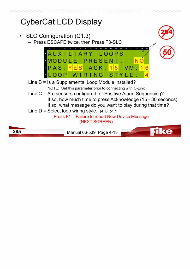
7/23/2019 CyberCat 2015 FULL Printout
http://slidepdf.com/reader/full/cybercat-2015-full-printout 285/429
285
If so, what message do you want to play during that time?
Line D = Select loop wiring style. (4, 6, or 7)
Press F1 = Failure to report New Device Message
(NEXT SCREEN)
Manual 06-539 Page 4-13
CyberCat LCD Display
• SLC Configuration
– By pressing F1 on previous screen, you get here.
– When panel is reset, each device should create a NEW DEVICE
record. If an OUTPUT DEVICE does not report a NEW DEVICE
record, it will register a new fault: DEVICE NOT READY if Line B isset to YES.
To clear reset panel until it clears

7/23/2019 CyberCat 2015 FULL Printout
http://slidepdf.com/reader/full/cybercat-2015-full-printout 286/429
286
– To clear, reset panel until it clears.
– If events show several DEVICE NOT READY events, set Line D to
YES. Panel will then send a message to devices at midnight.
Manual 06-539 Page 4-14
CyberCat LCD Display
• Learn (C1.4)
– Press ESCAPE twice, then Press F4-LEARN
– Use +/- to select either ‘LEARN NEW DEVICES’ or ‘LEARN ALL
DEVICES’• Learn New only learns loop/address not currently set in the panel
• Learn All erases all loop/address assignments and starts over
– Press ENTER to reset panel and execute the learn process.• Keypad is locked while Learn Mode Is Active
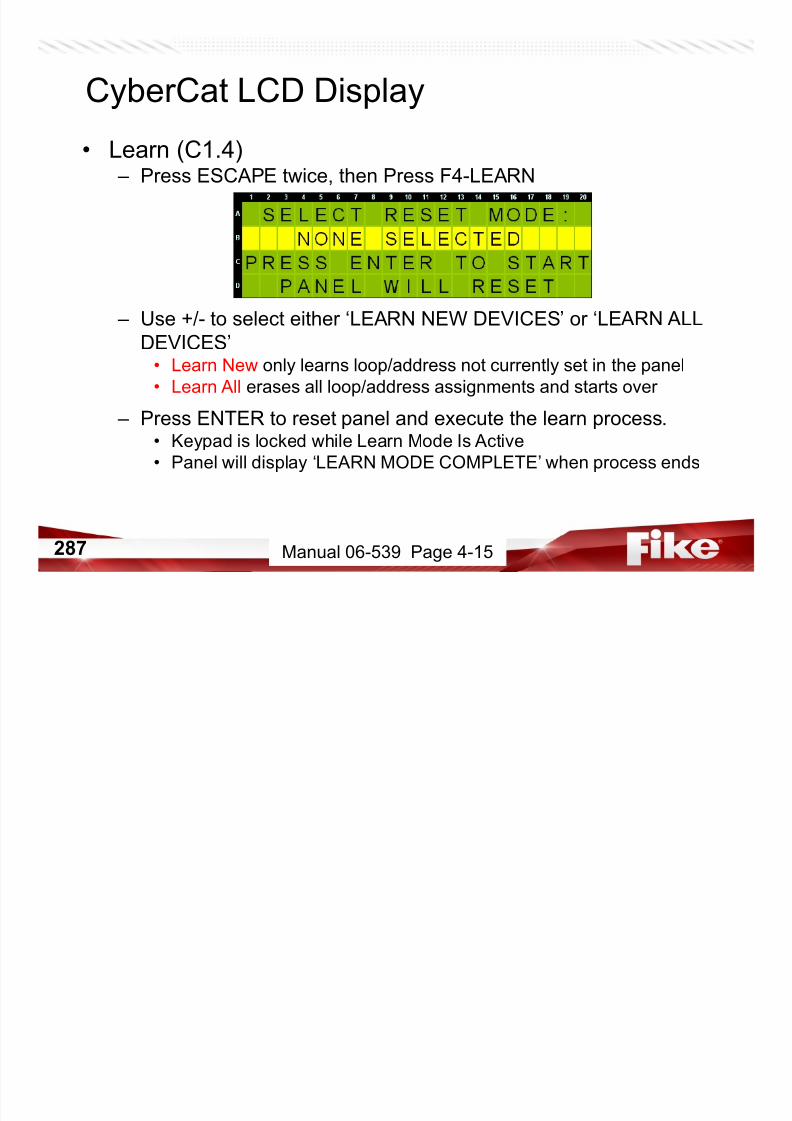
7/23/2019 CyberCat 2015 FULL Printout
http://slidepdf.com/reader/full/cybercat-2015-full-printout 287/429
287
• Keypad is locked while Learn Mode Is Active
• Panel will display ‘LEARN MODE COMPLETE’ when process ends
Manual 06-539 Page 4-15
CyberCat LCD Display
• Learn (C1.4)
– Press ESCAPE twice, then Press F4-LEARN
– Use +/- to select either ‘LEARN NEW DEVICES’ or ‘LEARN ALL
DEVICES’• Learn New only learns loop/address not currently set in the panel
• Learn All erases all loop/address assignments and starts over
– Press ENTER to reset panel and execute the learn process.• Keypad is locked while Learn Mode Is Active

7/23/2019 CyberCat 2015 FULL Printout
http://slidepdf.com/reader/full/cybercat-2015-full-printout 288/429
288
• Keypad is locked while Learn Mode Is Active
• Panel will display ‘LEARN MODE COMPLETE’ when process ends
Manual 06-539 Page 4-15
CyberCat LCD Display
• Voice (C1.5)
– Press ESCAPE, then Press F5-VOICE
Line A = Voice Operation Mode (Single/Dual Channel)
Line B = City Sequence Code
(Standard,Boston. Chicago, New York, Special)Line C = Messages to activate Eclipse Devices for voice operation
(On / Off)
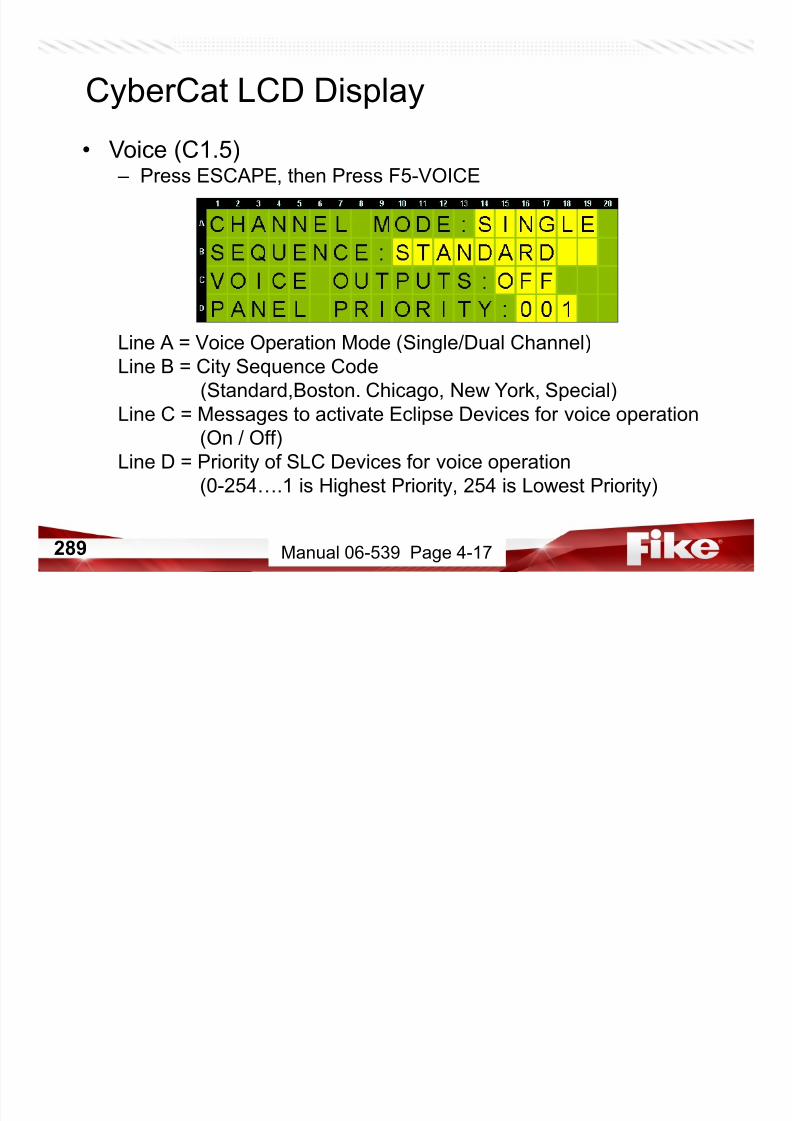
7/23/2019 CyberCat 2015 FULL Printout
http://slidepdf.com/reader/full/cybercat-2015-full-printout 289/429
289
(On / Off )
Line D = Priority of SLC Devices for voice operation
(0-254….1 is Highest Priority, 254 is Lowest Priority)
Manual 06-539 Page 4-17
CyberCat LCD Display
• Configuration Menu 2 (C2)
– Press ESCAPE, then Press F6-MENU 2
F1 = Adjust system time, date, day, and daylight savings
F2 = Set unsilence timeout and Canadian parameters
F3 = Auxiliary power circuits and system power optionsF4 = Day/Night Sensitivity Settings
F5 = Zone Configuration

7/23/2019 CyberCat 2015 FULL Printout
http://slidepdf.com/reader/full/cybercat-2015-full-printout 290/429
290
F5 Zone Configuration
F6 = Go to Configuration Menu 3
Manual 06-539 Page 4-19
CyberCat LCD Display
• System Time/Date (C2.1)
– Press F1-TIME
Line A = Adjust System Time
Line B = Adjust System Date
Line C = Adjust Current Day of WeekLine D = Participate in daylight savings?
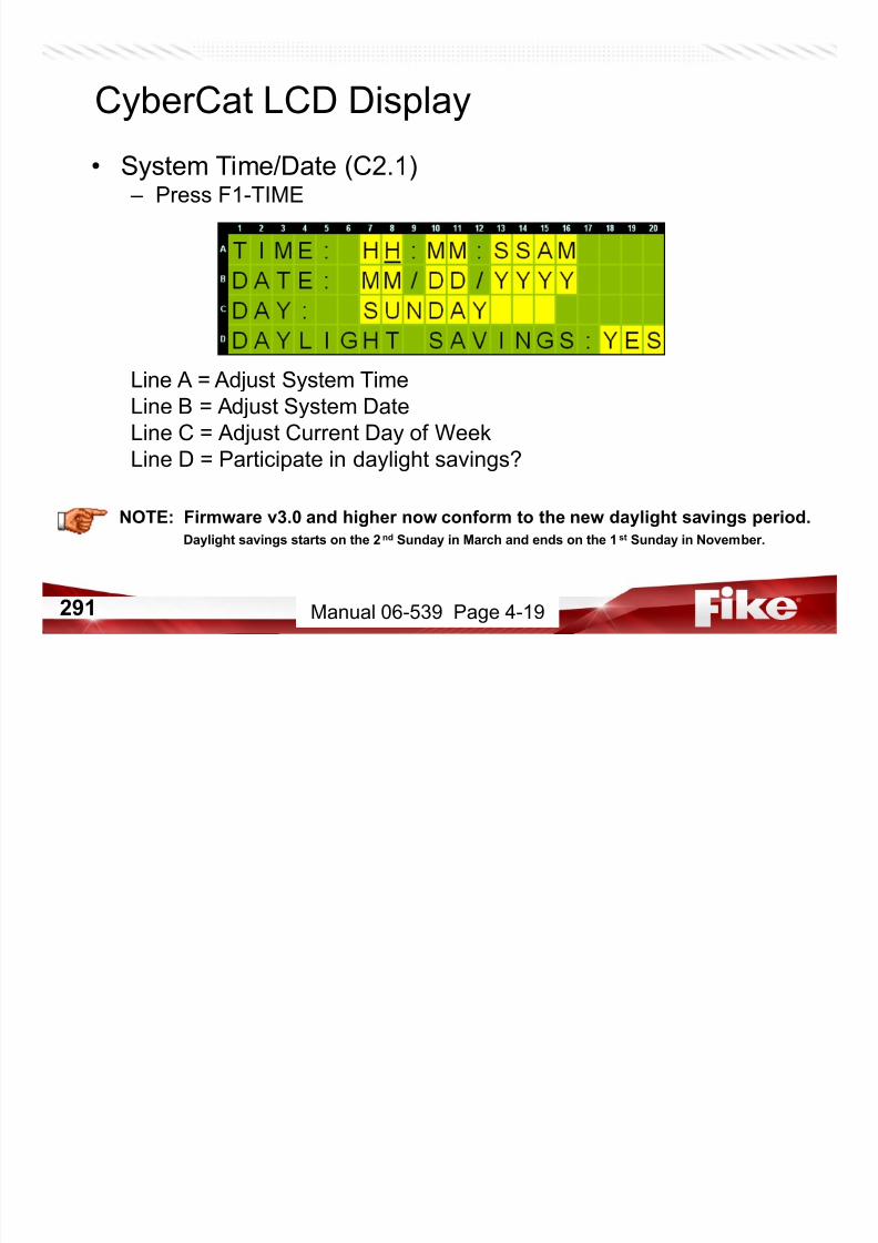
7/23/2019 CyberCat 2015 FULL Printout
http://slidepdf.com/reader/full/cybercat-2015-full-printout 291/429
291
NOTE: Firmware v3.0 and higher now conform to the new daylight savings period.
Daylight savings starts on the 2nd Sunday in March and ends on the 1st Sunday in November.
Manual 06-539 Page 4-19
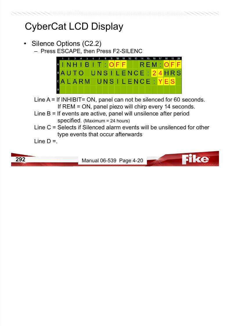
7/23/2019 CyberCat 2015 FULL Printout
http://slidepdf.com/reader/full/cybercat-2015-full-printout 292/429
CyberCat LCD Display
• Power Options (C2.3)
– Press ESCAPE, then Press F3-POWER
CyberCat 50 & 254 CyberCat 1016
Line A = Are batteries attached to the
main board? (Yes/No)
Line B = Is a 120V or 240V transformer
installed? (120VAC/240VAC)
Line A = Is a Supplemental Power
Supply (SPS) installed? (Yes/No)
Line B = Is a 120V or 240V transformer
installed? (120VAC/240VAC)
Line C = Is the main and/or aux battery
i t ll d? ( / )

7/23/2019 CyberCat 2015 FULL Printout
http://slidepdf.com/reader/full/cybercat-2015-full-printout 293/429
293
installed? (Y/N)
Line D = Supervise auxiliary power
circuits? (Y/N)
Manual 06-539 Page 4-21 & 22
CyberCat LCD Display
• Day/Night/Holiday Sensitivity (C2.4)
– Press ESCAPE, then Press F4-DAY SEN
F1 = Set Day/Night Sensitivity Start/Stop Times
F2 = Set dates considered to be a holiday

7/23/2019 CyberCat 2015 FULL Printout
http://slidepdf.com/reader/full/cybercat-2015-full-printout 294/429
294 Manual 06-539 Page 4-23
CyberCat LCD Display
• Day/Night Sensitivity (C2.4.1)
– Press F1-DAYTIME SEN RANGE
Line A =
Line B = Daytime Sensitivity Start Time
Line C = Daytime Sensitivity Stop Time (Night Start Time)Line D = Select days of the week that participate in Daytime
Sensitivity. Day participates if visible.

7/23/2019 CyberCat 2015 FULL Printout
http://slidepdf.com/reader/full/cybercat-2015-full-printout 295/429
295 Manual 06-539 Page 4-23
CyberCat LCD Display
• Holiday Settings (C2.4.2)
– Press ESCAPE, then Press F2-SELECT HOLIDAYS
Line A = 20 Holidays selectable among all 4 lines. Move the cursor to
the far right of line 4 and press right arrow once more to
advance to screen 2. Each holiday for the current year isdisplayed in Month-Date format.
Line B = Dates of holidays that will remain in night sensitivity

7/23/2019 CyberCat 2015 FULL Printout
http://slidepdf.com/reader/full/cybercat-2015-full-printout 296/429
296
Line C = Dates of holidays that will remain in night sensitivity
Line D = Dates of holidays that will remain in night sensitivity
Manual 06-539 Page 4-24
CyberCat LCD Display
• Zone Configuration (C2.5)
– Press ESCAPE twice, then Press F5-ZONE
Line A = Enable/Disable outputs in selected zone
Line B = Set 20 character custom message for selected zone
NOTE – See Tech Bulletin DC11-004
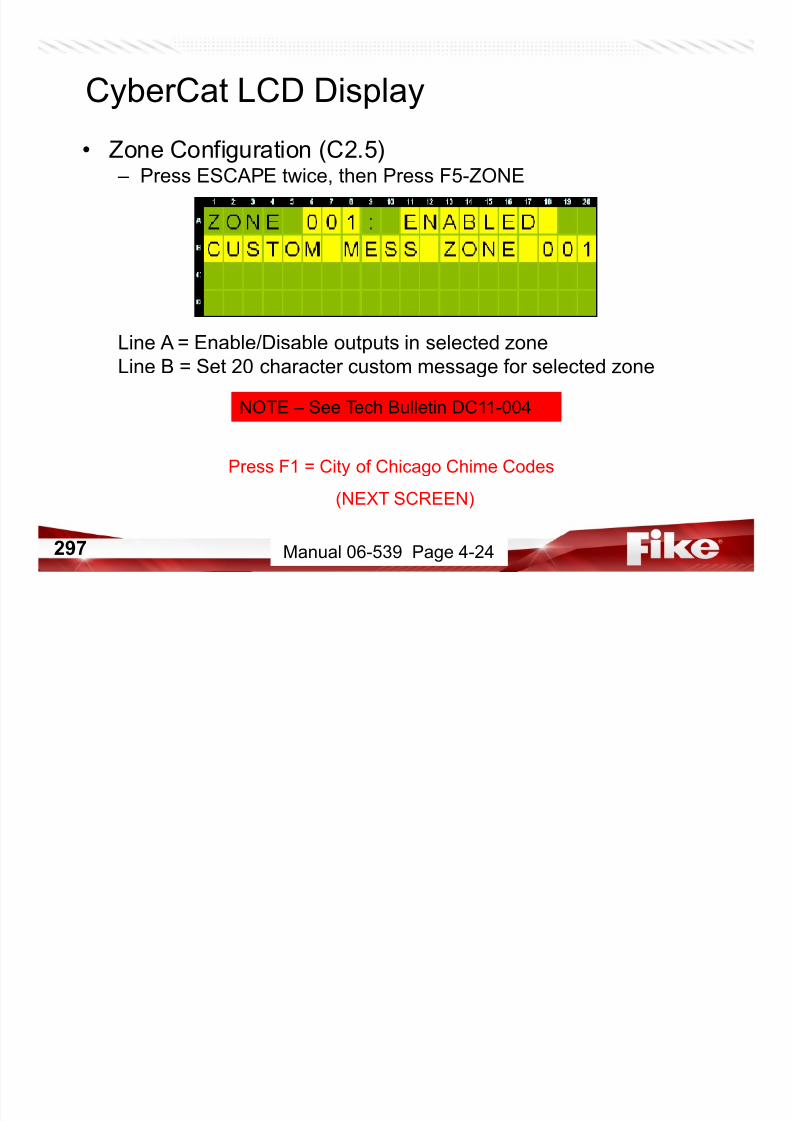
7/23/2019 CyberCat 2015 FULL Printout
http://slidepdf.com/reader/full/cybercat-2015-full-printout 297/429
297
Press F1 = City of Chicago Chime Codes
(NEXT SCREEN)
Manual 06-539 Page 4-24
CyberCat LCD Display
• Zone Configuration (C2.5.1) Chicago Only
Line B = Zone selected to set Chicago Chime Code for
Line C = Each zone can be programmed for up to a series of 4 chime
codes (0-9 chimes each). The codes are designed to chime at 1
second intervals. The time between digits is roughly 2 seconds.
NOTE: Chimes are produced on NAC #1 ONLY If codes are assigned
NOTE – See Tech Bulletin DC11-004
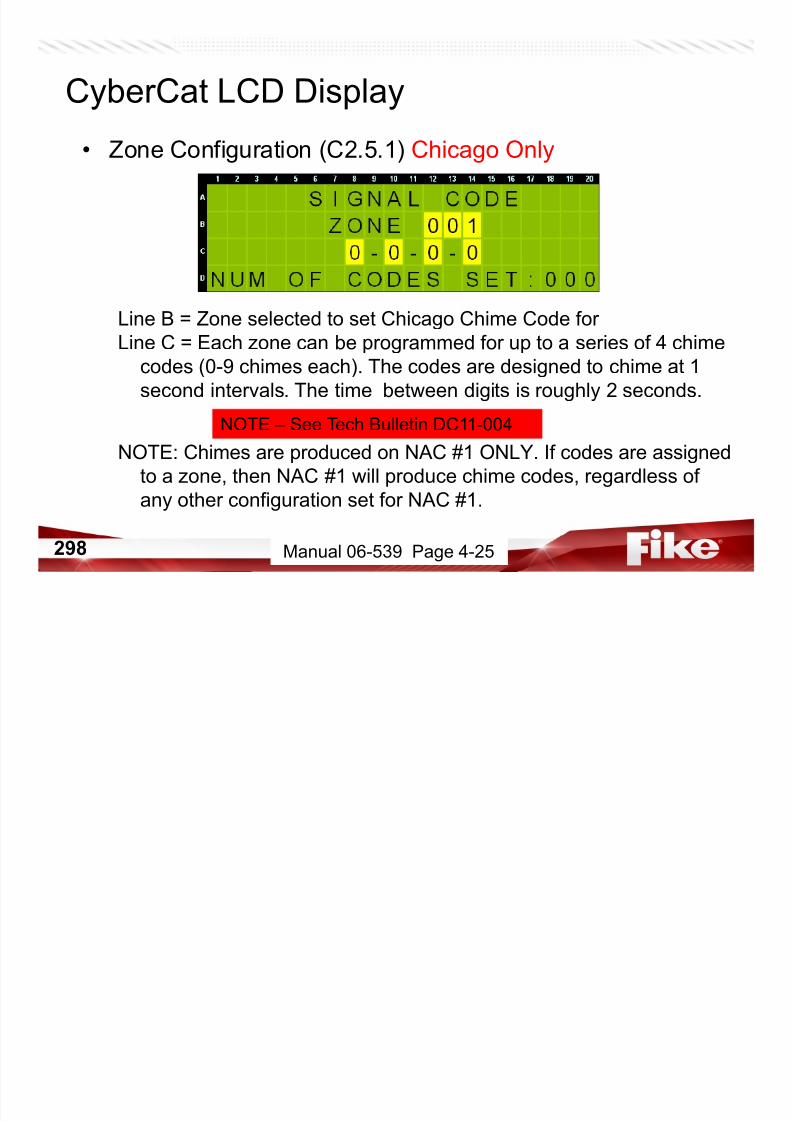
7/23/2019 CyberCat 2015 FULL Printout
http://slidepdf.com/reader/full/cybercat-2015-full-printout 298/429
298
NOTE: Chimes are produced on NAC #1 ONLY. If codes are assigned
to a zone, then NAC #1 will produce chime codes, regardless of
any other configuration set for NAC #1.
Manual 06-539 Page 4-25
CyberCat LCD Display
• Zone Configuration (C2.5.1) Chicago Only
• Chime Codes will only work on NAC #1 and only if Protocol for
NAC # 1 is set to CHIME CODE
• Neither Drill nor Walktest is allowed for NAC #1 when Chime
Codes are assigned..

7/23/2019 CyberCat 2015 FULL Printout
http://slidepdf.com/reader/full/cybercat-2015-full-printout 299/429
299 Manual 06-539 Page 4-25
CyberCat LCD Display
• Configuration Menu 3 (C3) – Press ESCAPE twice, then Press F6-MENU 3
F1 = Configure peripheral devices and circuit options
F2 = Allow/disallow access to walktest from Maintenance Menu
F3 = Set Ground Fault optionsF4 = Set panel Abort type
F5 = Enable/disable Day/Night Sensitivity
F6 Go to Configuration Menu 4

7/23/2019 CyberCat 2015 FULL Printout
http://slidepdf.com/reader/full/cybercat-2015-full-printout 300/429
300
F6 = Go to Configuration Menu 4
Manual 06-539 Page 4-27
CyberCat LCD Display
• Peripheral Configuration (C3.1) – Press F1-PERIPH
F1 = Configure peripheral devices
F2 = Peripheral communications source
F3 = Peripheral bus communications speedF4 = Configure peripheral command set
F5 =
F6 =
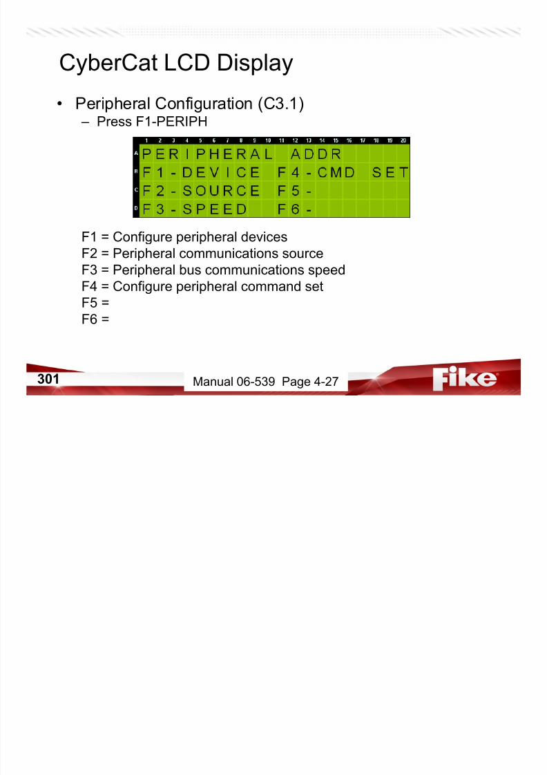
7/23/2019 CyberCat 2015 FULL Printout
http://slidepdf.com/reader/full/cybercat-2015-full-printout 301/429
301
F6 =
Manual 06-539 Page 4-27
CyberCat LCD Display
• Peripheral Device Configuration (C3.1.1) – Press F1-DEVICE
Line A = Select peripheral address to configure
Line B = What type of device is at address specified in Line A?
Line C = Do you want to supervise this device?Line D = 20 character custom message that will appear for any events
caused by this device.
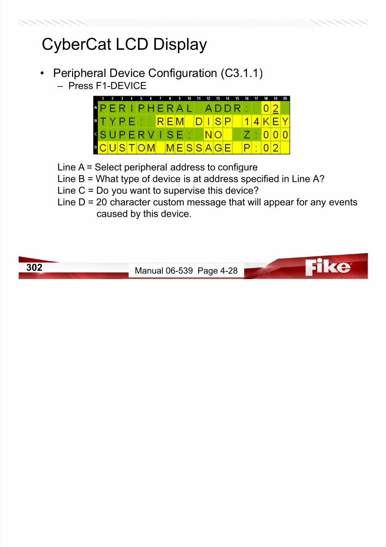
7/23/2019 CyberCat 2015 FULL Printout
http://slidepdf.com/reader/full/cybercat-2015-full-printout 302/429
302 Manual 06-539 Page 4-28
CyberCat LCD Display
• Peripheral Communications Source (C3.1.2) – Press ESCAPE twice, then Press F2-SOURCE
– PANEL• Default selection upon Reset and option necessary during normal
system operation. Allows communications between main board
processor and peripherals.
– USB CONNECTOR• Choose this option when uploading/downloading a configuration

7/23/2019 CyberCat 2015 FULL Printout
http://slidepdf.com/reader/full/cybercat-2015-full-printout 303/429
303
Choose this option when uploading/downloading a configuration
to/from a peripheral device and C-Linx.
Manual 06-539 Page 4-34
• Peripheral Communications Speed (C3.1.3) – Press ESCAPE, then Press F3-SPEED (Version 5.0 & Newer)
– PANEL• Starting with Version 6.1, default is 38,400bps
• HIT + (Next Slide)
CyberCat LCD Display
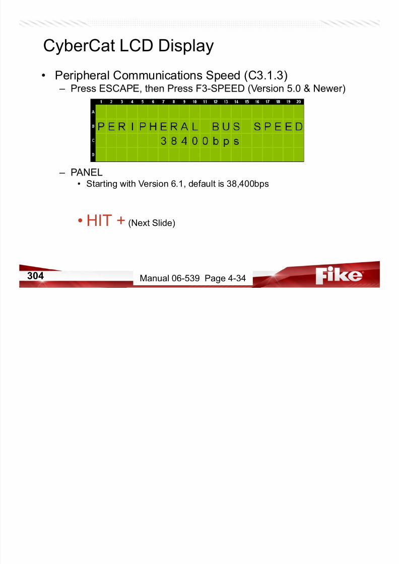
7/23/2019 CyberCat 2015 FULL Printout
http://slidepdf.com/reader/full/cybercat-2015-full-printout 304/429
304 Manual 06-539 Page 4-34
• Peripheral Communications Speed (C3.1.3)
– PANEL• Can change to 9,600 bps
– Correct Revision Firmware – MUST make sure that peripherals being used are capable of
38,400 baud rate. Panel bpd must match settings on Peripherals.
CyberCat LCD Display
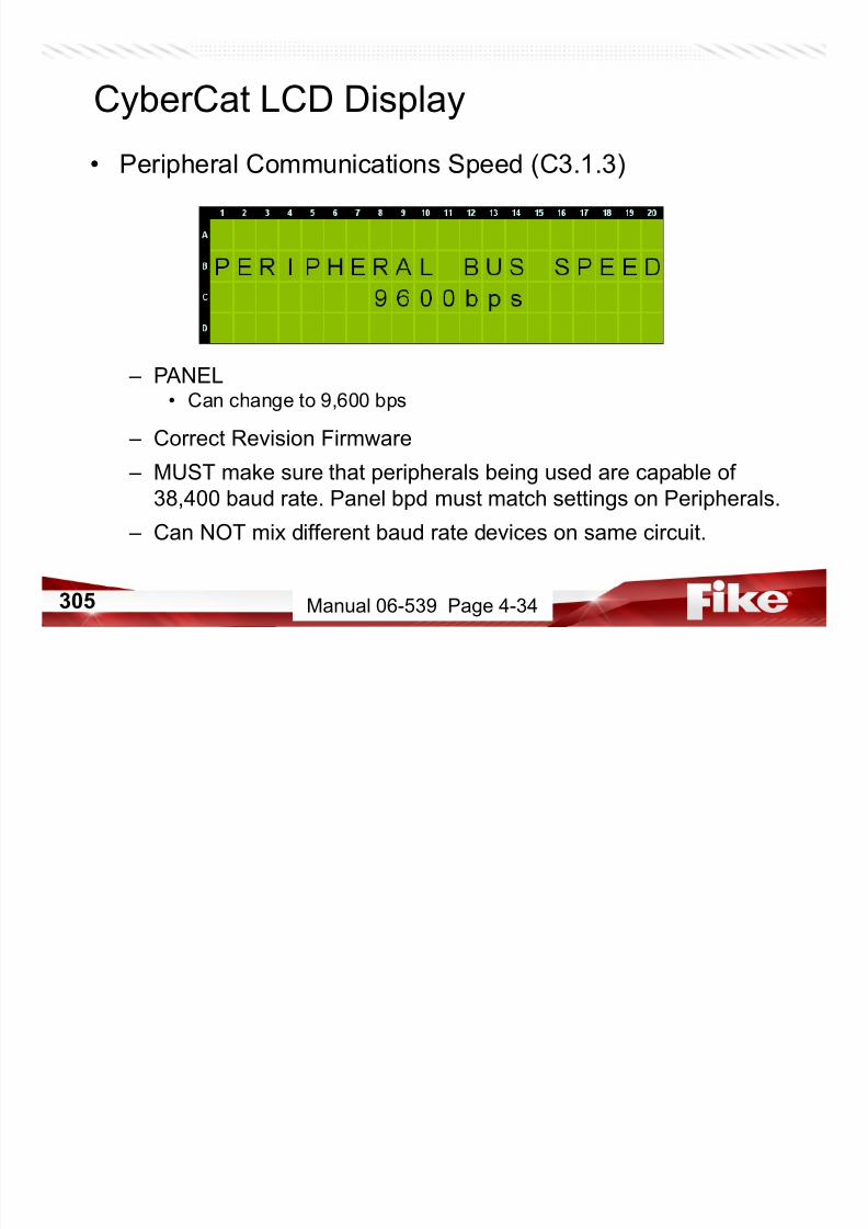
7/23/2019 CyberCat 2015 FULL Printout
http://slidepdf.com/reader/full/cybercat-2015-full-printout 305/429
305
– Can NOT mix different baud rate devices on same circuit.
Manual 06-539 Page 4-34
CyberCat LCD Display
• Peripheral Command Set (C3.1.4) – Press ESCAPE, then Press F4-CMD SET
EVAC – Set to NONE for no voice system
Set to EVAX if a FikeGuard/EVAX connected to the P5 jack.
Set to FIKE if using integrated Voice Evac
STATUS
HISTORY
XMIT
HISTORY
PACKING
HISTORY
MESSAGE
All peripherals v3.0 and newer: EXP Either ON EXP

7/23/2019 CyberCat 2015 FULL Printout
http://slidepdf.com/reader/full/cybercat-2015-full-printout 306/429
306
Any one peripheral below v3.0: STD Either OFF STD
Manual 06-539 Page 4-35
CyberCat LCD Display
• Walktest Enable/Disable (C3.2) – Press ESCAPE twice, then Press F2-WALK
Line A = ENABLED = Walktest mode can be activated from the
Maintenance Menu. (requires SYS ADMIN access)
DISABLED = Walktest mode can not be activated from the
Maintenance Menu.
NOTE: Activating a Test Alarm with the IR Tool will enter the panel into Walktest

7/23/2019 CyberCat 2015 FULL Printout
http://slidepdf.com/reader/full/cybercat-2015-full-printout 307/429
307
NOTE: Activating a Test Alarm with the IR Tool will enter the panel into Walktest
mode regardless of how this screen is configured.
Manual 06-539 Page 4-36
CyberCat LCD Display
• Ground Fault Enable/Disable & Offset (C3.3) – Press ESCAPE, then Press F3-GROUND
Line B = Supervise for level 1 ground fault? (ENABLED/DISABLED)
Line C = Supervise for level 2 ground fault? (ENABLED/DISABLED)
Line D = Set offset for ground fault sense. (+/- 25)
NOTE: Level 4 (FACTORY) password is required.

7/23/2019 CyberCat 2015 FULL Printout
http://slidepdf.com/reader/full/cybercat-2015-full-printout 308/429
308
NOTE: Level 4 (FACTORY) password is required.
Manual 06-539 Page 4-36
CyberCat LCD Display
• Sensitivity Changes (C3.5) – Press ESCAPE, then Press F5-SEN CHG
Line B = Use +/- to ENABLE/DISABLE day/night sensitivity changes.
Line D = Indicates current sensitivity being used.

7/23/2019 CyberCat 2015 FULL Printout
http://slidepdf.com/reader/full/cybercat-2015-full-printout 309/429
309 Manual 06-539 Page 4-37
CyberCat LCD Display
• Configuration Menu 4 (C4) – Press ESCAPE, then Press F6-MENU 4
F1 = AC Trouble Delay
F2 = VESDA Configuration
F3 = Auxiliary NAC Configuration
F4 = Power Cutoff Relay
F5 = On-board Relay and P12/P13 configuration (excludes CyberCat 50)
F6 = Go to Configuration Menu 5
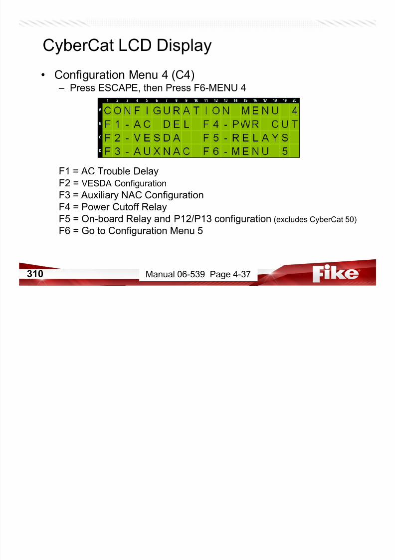
7/23/2019 CyberCat 2015 FULL Printout
http://slidepdf.com/reader/full/cybercat-2015-full-printout 310/429
310 Manual 06-539 Page 4-37
CyberCat LCD Display
• AC Trouble Delay (C4.1) – Press F1-AC DEL
Line C = If the panel should lose AC power, how many hours do you
want the panel to wait until the onboard trouble relay and
DACT are activated? (Default = 2 hours)
NOTE: Panel will still record AC POWER LOW event and activate any devices

7/23/2019 CyberCat 2015 FULL Printout
http://slidepdf.com/reader/full/cybercat-2015-full-printout 311/429
311
configured for trouble in zone 254 or 255.
Manual 06-539 Page 4-38
CyberCat LCD Display
• VESDA Configuration (C4.2) – Press ESCAPE, then Press F2-VESDA
F1 = VESDAnet device configuration
F2 = VESDA LaserSCANNER sector configuration
F3 = Point ID configuration for EVAX, DACT, LED Graphic, and
Graphic Monitoring applications.
F4 = Configure VESDA unit release features
F5 = VESDA HLI Setting

7/23/2019 CyberCat 2015 FULL Printout
http://slidepdf.com/reader/full/cybercat-2015-full-printout 312/429
312 Manual 06-539 Page 4-38
CyberCat LCD Display
• VESDA Alarm Features (C4.2.1) – Press F1-ALARM FEATURES
Line A = VESDAnet zone (device) number to configure
Line B = Select VESDA type, Fire-1 state, Enable/Disable
Line C = 20 character custom message for VESDA events
Line D = CyberCat zones that respond to events from selected
VESDA unit
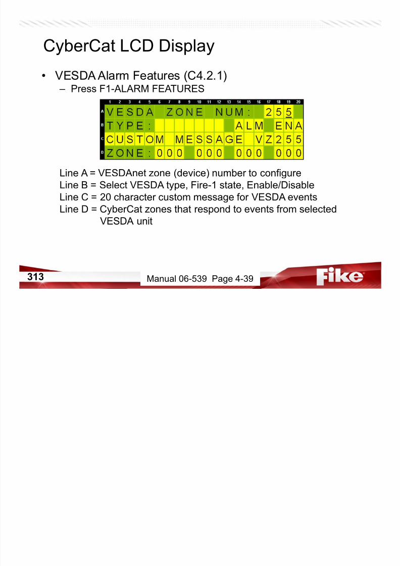
7/23/2019 CyberCat 2015 FULL Printout
http://slidepdf.com/reader/full/cybercat-2015-full-printout 313/429
313 Manual 06-539 Page 4-39
CyberCat LCD Display
• VESDA Alarm Features (C4.2.2) – Press ESCAPE, then Press F2-SECTOR ZONES
Line A = VESDAnet zone (device) number to configure
Line B = Configure the states for sectors 1 and 2, and which CyberCat
zones respond to sectors 1 and 2
Line C = Configure the states for sectors 3 and 4, and which CyberCat
zones respond to sectors 3 and 4
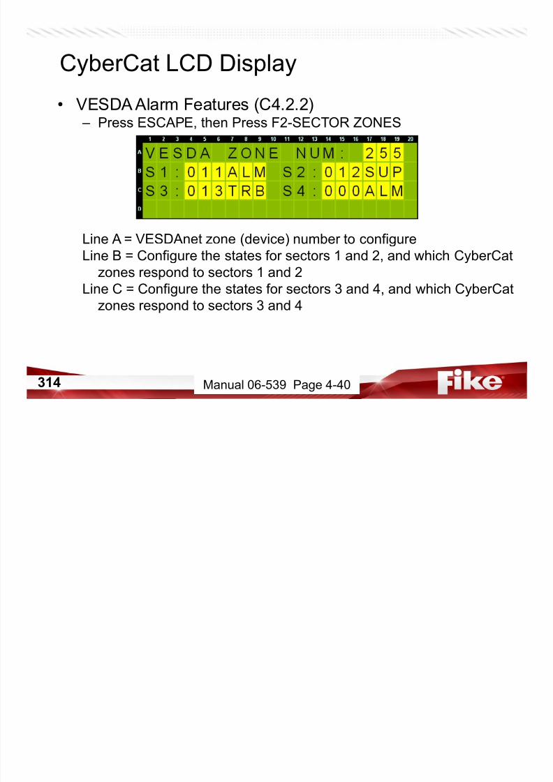
7/23/2019 CyberCat 2015 FULL Printout
http://slidepdf.com/reader/full/cybercat-2015-full-printout 314/429
314 Manual 06-539 Page 4-40
CyberCat LCD Display
• VESDA Point Configuration (C4.2.3) – Press ESCAPE, then Press F3-EVAX
Line A = VESDAnet zone (device) number to configure
Line B = Loop that selected VESDA unit is assigned
Line C = Address that selected VESDA unit is assigned
NOTE: Loop and Address are “virtual” assignments – only need to be configured
if VESDA needs to be monitored by a point ID system (i.e. EVAX, DACT,
LED Graphic, Computer Graphic, etc.).

7/23/2019 CyberCat 2015 FULL Printout
http://slidepdf.com/reader/full/cybercat-2015-full-printout 315/429
315
p , p p , )
Manual 06-539 Page 4-40
CyberCat LCD Display
• VESDA Point Configuration (C4.2.5) – Press ESCAPE, then Press F5-COMMAND
Line D = Shows HLI Firmware version (Retrieved from HLI itself)
NOTE: Panel will now query the HLI to determine which version is connected for
proper supervision upon reset. Press ENTER here to cause panel to send querycommand that retrieves HLI firmware version. The panel will also queries the HLI
during reset.
(OLDER) – Peer-to-Peer communicates with 40 VESDAs but only 10 for 10 second response

7/23/2019 CyberCat 2015 FULL Printout
http://slidepdf.com/reader/full/cybercat-2015-full-printout 316/429
316
(OLDER) Peer to Peer communicates with 40 VESDAs but only 10 for 10 second response
(NEWER) (HLI V3.08.00 or higher) communicates with 40 VESDAs for 10 second response
Manual 06-539 Page 4-41
CyberCat LCD Display
• Auxiliary NAC Configuration (C4.3) – Press ESCAPE twice, then Press F3-AUX NAC
F1 = Configure auxiliary NAC functions
F2 = Configure auxiliary NAC zone assignments
Manual 06-539 Page 4-41
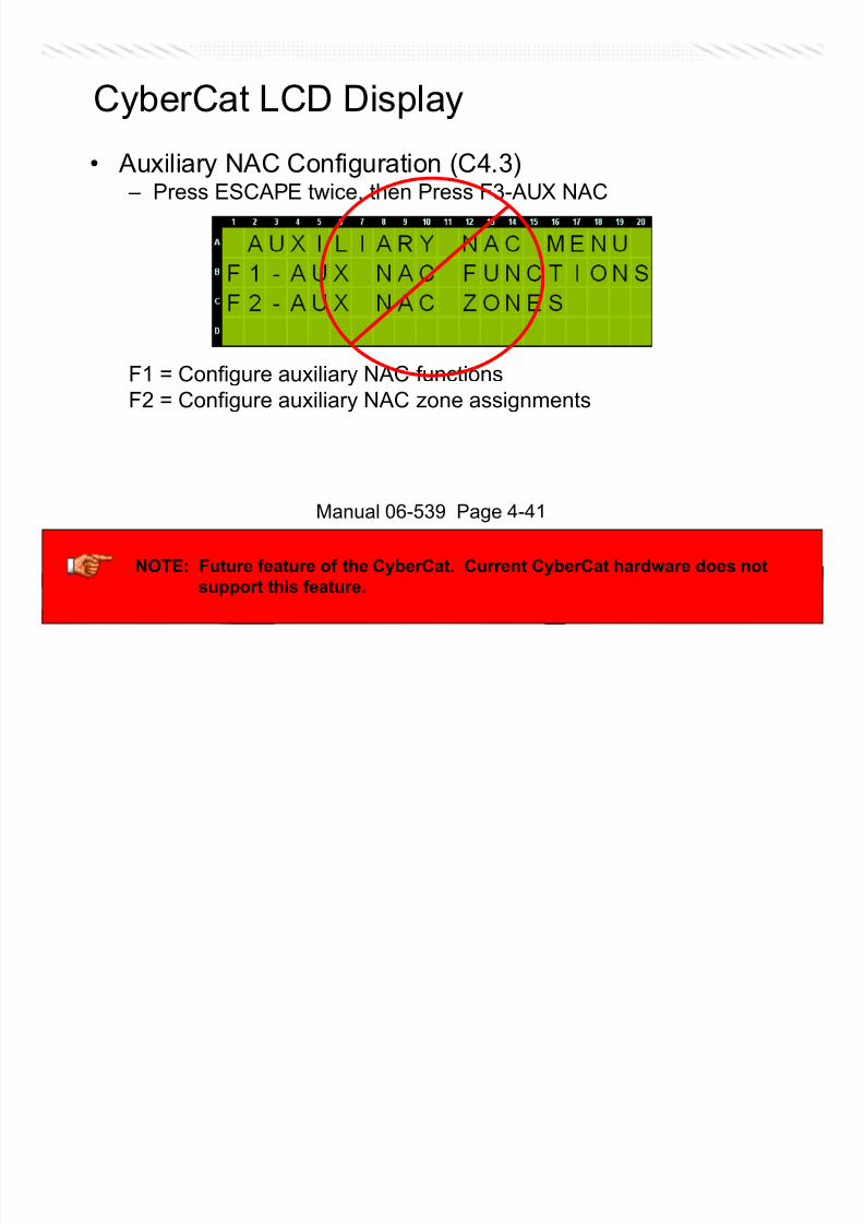
7/23/2019 CyberCat 2015 FULL Printout
http://slidepdf.com/reader/full/cybercat-2015-full-printout 317/429
317317
NOTE: Future feature of the CyberCat. Current CyberCat hardware does not
support this feature.
CyberCat LCD Display
• Auxiliary NAC Function (C4.3.1) – Press F1-AUX NAC FUNCTIONS
Line A = Select AUX NAC circuit to configure. Enable/Disable NAC
Line B = Select state of activation (if applicable)
Line C = Select function of output circuit.
(AUX CONST, AUX RESET, CLASS B NAC, TRACK NAC #1, TRACK NAC #2)
Line D = Select if silenceable, operate on Drill, operate on Walktest
(where applicable)
Manual 06-539 Page 4-42

7/23/2019 CyberCat 2015 FULL Printout
http://slidepdf.com/reader/full/cybercat-2015-full-printout 318/429
318318
NOTE: Future feature of the CyberCat. Current CyberCat hardware does not
support this feature.
CyberCat LCD Display
• Auxiliary NAC Zone Assignments (C4.3.2) – Press ESCAPE, then Press F2-AUX NAC ZONES
Line A = Select AUX NAC circuit to configure. Select active on ANY
ZONE or set to MULTI-ZONE to specify zone(s).
Line B = Select zones to view in groups of 20.
Line C = Place holders for zone numbers.
Line D = Place a ‘Y’ under each place holder for zone you wish this
NAC circuit to act upon.
Manual 06-539 Page 4-43
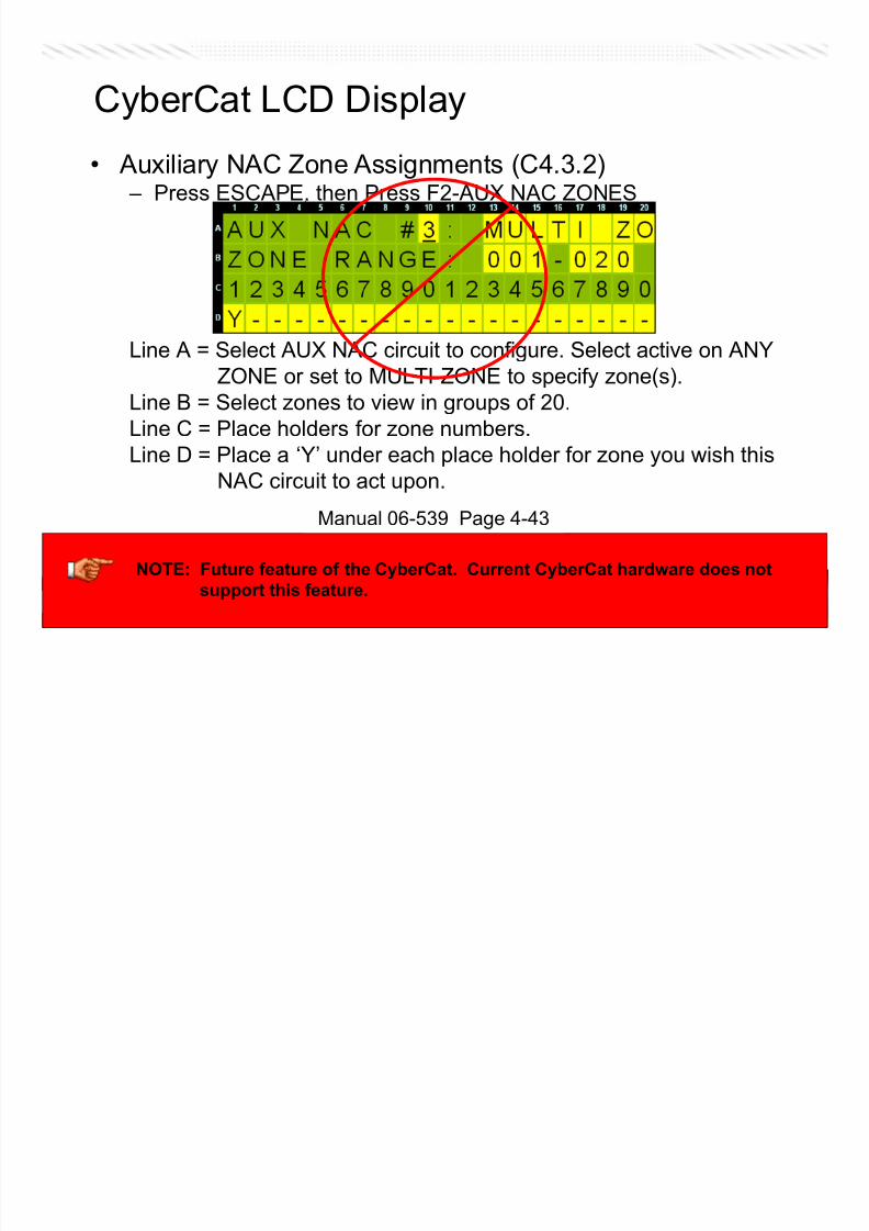
7/23/2019 CyberCat 2015 FULL Printout
http://slidepdf.com/reader/full/cybercat-2015-full-printout 319/429
319319
NOTE: Future feature of the CyberCat. Current CyberCat hardware does not
support this feature.
• Configuration Menu 4 (C4.4) – Press ESCAPE twice, then Press F4-PWR CUT
CyberCat LCD Display
Line C = What is the address of the Power Cutoff Relay?
(Configuration in that relay module should be BLANK.)
ULC requires low power cutoff when power dips below 19 volts DC.When power drops below that level, it will activate this relay. This in
turn activated a multi-voltage relay large enough to carry battery
current to panel, and opens that circuit.
(N t lid f i i )

7/23/2019 CyberCat 2015 FULL Printout
http://slidepdf.com/reader/full/cybercat-2015-full-printout 320/429
320
(Next slide for wiring)
Manual 06-539 Page 4-44
• Power Cutoff
Relay
CyberCat LCD Display

7/23/2019 CyberCat 2015 FULL Printout
http://slidepdf.com/reader/full/cybercat-2015-full-printout 321/429
321 Manual 06-326 Appendix D
CyberCat LCD Display
• Relay & P12/P13 Configuration (C4.5) – Press ESCAPE, then Press F5-RELAYS
F1 = Select module(s) installed at P12 and/or P13
F2 = Configure CRM4 Relay Functions (if installed)
F3 = Configure CRM4 Relay Zone Assignments (if installed)
F4 = Configure Fan Restart for Automatic or Manual operation

7/23/2019 CyberCat 2015 FULL Printout
http://slidepdf.com/reader/full/cybercat-2015-full-printout 322/429
322 Manual 06-539 Page 4-44
CyberCat LCD Display
• Configure P12/P13 (C4.5.1) – Press F1-SELECT MODULE
Line B = What module is installed at location P12?
(No Module, CRM4, RPM#1, RPM#2, Bosch DACT)
Line C = What module is installed at location P13?(No Module, CRM4, RPM#1, RPM#2)

7/23/2019 CyberCat 2015 FULL Printout
http://slidepdf.com/reader/full/cybercat-2015-full-printout 323/429
323 Manual 06-539 Page 4-45
• Relay Functions (C4.5.2) – Press ESCAPE, then Press F2-RELAY FUNCTIONS
Line A = Select relay to configure (NUM1-3 = P2 Relays 1-3, P12A-P13D)
Line B = What state do you want relay to activate on?
Line C = Should this relay silence when panel is silenced?
Should this relay activate while in DRILL mode?Line D = Fan Restart delay. Sets the number of seconds, after reset,
selected relay should delay its return to normal.
CyberCat LCD Display

7/23/2019 CyberCat 2015 FULL Printout
http://slidepdf.com/reader/full/cybercat-2015-full-printout 324/429
324 Manual 06-539 Page 4-46
• Relay Functions (C4.5.3) – Press ESCAPE, then Press F3-RELAY ZONE ASSIGN
Line A = Select port and relay to configure. Should this relay activate
for Any Zone, or specific zone (Multi Zone)?
Line B = If Multi Zone, which zone range do you wish to configure?
Line C = Place holder for zone range selected in Line B.Line D = If Multi Zone, which zone(s) do you wish to assign this relay?
CyberCat LCD Display
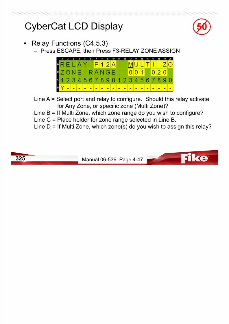
7/23/2019 CyberCat 2015 FULL Printout
http://slidepdf.com/reader/full/cybercat-2015-full-printout 325/429
325 Manual 06-539 Page 4-47
• CRM4 Relay Fan Restart Function (C4.5.4) – Press ESCAPE, then Press F4-FAN RESTART MODE
Line B = Do you want relays configured with a Fan Restart delay to
begin their counter automatically upon reset or require a manual
input activation following reset?
NOTE: Manual Fan Restart input options include the ENTER button on the main
controller, a Monitor Module configured for Fan Restart, or a Remote
Display with a button configured for Fan Restart.
CyberCat LCD Display
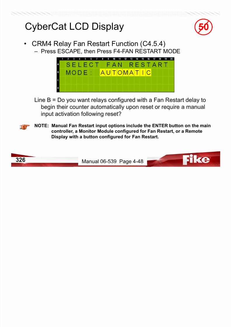
7/23/2019 CyberCat 2015 FULL Printout
http://slidepdf.com/reader/full/cybercat-2015-full-printout 326/429
326 Manual 06-539 Page 4-48
• Configuration Menu 5 (C5) – Press ESCAPE twice, then Press F6-MENU 5
F1 = Edit logo that appears on Line B of System Status Screen
F2 = Configure Auto Addressing feature
F3 = Factory Training Panel Option ONLY....will not see in field
F4 = Configure Dialer auto test featureF5 = CyberCat network configuration
F6 = Go to Configuration Menu 6
CyberCat LCD Display

7/23/2019 CyberCat 2015 FULL Printout
http://slidepdf.com/reader/full/cybercat-2015-full-printout 327/429
327 Manual 06-539 Page 4-48
• Corporate Logo (C5.1) – Press F1-LOGO
Line C = 20 character custom logo that will appear on Line B of the
System Status Screen.
NOTE: This is NOT the message that identifies the panel on the network or with
panel generated events. Refer to the Network Module menu C5.5.2 to
configure the panel custom message.
CyberCat LCD Display

7/23/2019 CyberCat 2015 FULL Printout
http://slidepdf.com/reader/full/cybercat-2015-full-printout 328/429
328 Manual 06-539 Page 4-49
CyberCat LCD Display
• Auto Addressing Feature (C5.2) – Press ESCAPE, then Press F2-AUTO A
Firmware v2.0 and higher
Line A = Turn auto addressing on/off
Line B = Visible loop numbers have auto addressing on
Line C = Desired start and end address rangeLine D = Stores auto addressing configuration changes

7/23/2019 CyberCat 2015 FULL Printout
http://slidepdf.com/reader/full/cybercat-2015-full-printout 329/429
329 Manual 06-539 Page 4-49
• Configuration Menu 5 (C5.3) – Press ESCAPE
F1 = Edit logo that appears on Line B of System Status Screen
F2 = Configure Auto Addressing feature
F3 = Factory Training Panel Option ONLY....will not see in field
F4 = Configure Dialer auto test featureF5 = CyberCat network configuration
F6 = Go to Configuration Menu 6
CyberCat LCD Display

7/23/2019 CyberCat 2015 FULL Printout
http://slidepdf.com/reader/full/cybercat-2015-full-printout 330/429
330
• Dialer Auto Test Configuration (C5.4) – Press F4-DIALER
Line B = Set how often the CyberCat should initiate a test to the
dialer. (never, 6 hours, 12 hours, 24 hours)
Line C = Set time first test should be initiated for give day.
NOTE: If the attached dialer performs its own auto test, unless instructed to do
so by the LAHJ, it is recommended to disable this feature.
CyberCat LCD Display
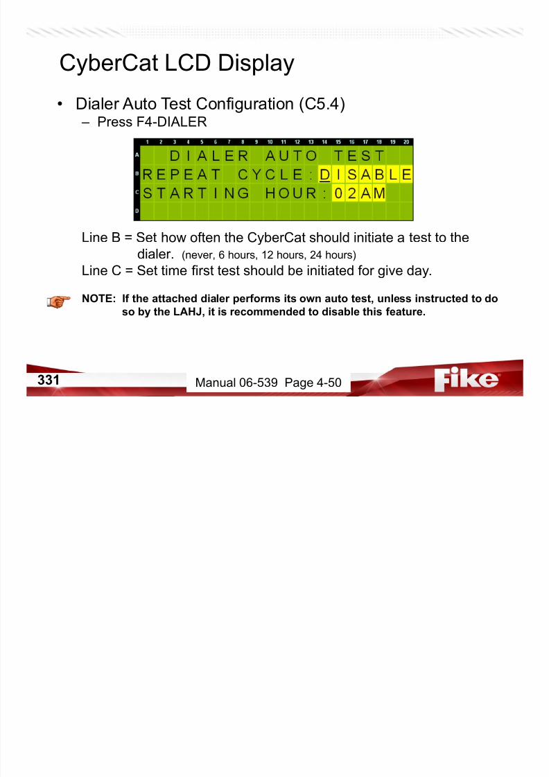
7/23/2019 CyberCat 2015 FULL Printout
http://slidepdf.com/reader/full/cybercat-2015-full-printout 331/429
331 Manual 06-539 Page 4-50
• Network Configuration Menu (C5.5) – Press ESCAPE, then Press F5-NETWORK
F1 = Configure panel’s network ID and network supervision
F2 = Set module type, wiring style, and switch functions
F3 = Select zones this panel should participate in
F4 = Set history message transmit redundancyF5 = Configure how panel responds to switches
F6 =
CyberCat LCD Display

7/23/2019 CyberCat 2015 FULL Printout
http://slidepdf.com/reader/full/cybercat-2015-full-printout 332/429
332 Manual 06-539 Page 4-50
• Network ID and Supervision (C5.5.1) – Press F1-ID’S
Line A = What is this panel’s network ID?
Line B = Cycle thru the 128 network IDs in groups of 20
Line C =Group placeholder #s
Line D = Place a ‘Y’ under each network ID this panel shouldsupervise
(Press F1 to give network panels Custom Message)
CyberCat LCD Display

7/23/2019 CyberCat 2015 FULL Printout
http://slidepdf.com/reader/full/cybercat-2015-full-printout 333/429
333 Manual 06-539 Page 4-51
• Network ID and Supervision (C5.5.1)
CyberCat LCD Display
By Pressing F1 from previous screen, you can change the network
custom messages that will be received by network panels.

7/23/2019 CyberCat 2015 FULL Printout
http://slidepdf.com/reader/full/cybercat-2015-full-printout 334/429
334 Manual 06-539 Page 4-51
• Network Module Type (C5.5.2) – Press ESCAPE twice, then Press F2-MODULE
Line A = Where is this module located in the network? (First, Middle, Last)
Line B = What wiring style is the network using?
(Class B – Style 4, Class A – Style 7)
Line C = Should this panel accept switch commands from ALL otherpanels on the network or only specific panels?
(ALL = GLOBAL, Specific = LOCAL)
Line D = Custom Message that is added to any events generated by
this panel.
CyberCat LCD Display

7/23/2019 CyberCat 2015 FULL Printout
http://slidepdf.com/reader/full/cybercat-2015-full-printout 335/429
335 Manual 06-539 Page 4-52
• Network Zone Configuration (C5.5.3) – Press ESCAPE, then Press F3-ZONES
Line B = Cycle thru the 254 zones in groups of 20
Line C = Zone placeholder #s
Line D = Place a ‘Y’ under each zone number that you want this panel
to participate.
NOTE: All events received from the network are recorded in history.
The panel will only act upon the event if it originated in one
of the zones specified by this menu.
CyberCat LCD Display
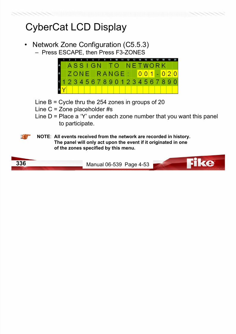
7/23/2019 CyberCat 2015 FULL Printout
http://slidepdf.com/reader/full/cybercat-2015-full-printout 336/429
336 Manual 06-539 Page 4-53
• Network Switch Assignments (C5.5.4) – Press ESCAPE, then Press F4-HIST TR
Line C = How many times to transmit each event onto the network
CyberCat LCD Display
Our endurance testing for LARGE panel networks has produced a very
small failure rate of the transmit/receipt of some history records acrossthe network. Therefore, we have provided the capability to transmit the
history twice for each event.
Default value is 0, but can be changed to 1 with SYS ADMIN password

7/23/2019 CyberCat 2015 FULL Printout
http://slidepdf.com/reader/full/cybercat-2015-full-printout 337/429
337 Manual 06-539 Page 4-54
• Network Switch Assignments (C5.5.5) – Press ESCAPE, then Press F5-SWITCH
Line B = Cycle thru the 128 panel IDs in groups of 20
Line C = Panel ID placeholder #s
Line D = Place a ‘Y’ under each panel ID that you want this panel
to accept switch commands from.
NOTE: Switch Function (C5.5.2) must be set to LOCAL before information entered
in this screen will apply.
CyberCat LCD Display

7/23/2019 CyberCat 2015 FULL Printout
http://slidepdf.com/reader/full/cybercat-2015-full-printout 338/429
338 Manual 06-539 Page 4-54
• Configuration Menu 6 (C6) – Press ESCAPE twice, then Press F6-MENU 6
F1 = Configure Internet Protocol (IP) addresses
F2 = Select which panels to supervise via Ethernet
F3 = Configure Ethernet supervision timeout period
F4 = Select keypad operationF5 = Select keypad LED operation
F6 = Go to Configuration Menu 7 (New in 6.4 Firmware)
CyberCat LCD Display

7/23/2019 CyberCat 2015 FULL Printout
http://slidepdf.com/reader/full/cybercat-2015-full-printout 339/429
339 Manual 06-539 Page 4-55
• Ethernet IP Addresses (C6.1) – Press F1-IP ADR
Line B = What is the IP address for this panel?
Line C = What is the IP address of the panel that should receive this
panel’s history messages?
Line D = What is the IP address of the panel that is supervising thispanel?
NOTE: SRC IP Address must be unique across entire local Ethernet network.
CyberCat LCD Display
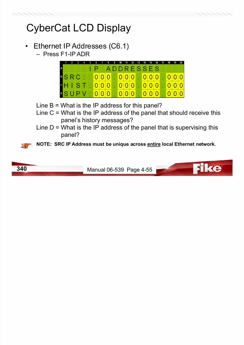
7/23/2019 CyberCat 2015 FULL Printout
http://slidepdf.com/reader/full/cybercat-2015-full-printout 340/429
340 Manual 06-539 Page 4-55
• Ethernet IP Supervision (C6.2) – Press ESCAPE, then Press F2-IP SUP
Line B = Which panel(s) do you wish to supervise?
Line C =
Line D = What is the IP address of the panel entered on Line B?
NOTE: Enter an IP address of all zeros for each panel you do NOT want to supervise.
CyberCat LCD Display

7/23/2019 CyberCat 2015 FULL Printout
http://slidepdf.com/reader/full/cybercat-2015-full-printout 341/429
341 Manual 06-539 Page 4-56
• Ethernet IP Timeout, History, & Date/Time (C6.3) – Press ESCAPE, then Press F3-IP TIM
Line B = How much time can elapse without a response from
supervised panels before a trouble is annunciated?5 – 55 seconds in increments of 5
1 – 59 minutes in increments of 1
1 – 18 hours in increments of 1
Line C = How many history messages are sent for each give event?
(Fike recommendation is 2)
Line D = Configure whether to update panel date/time from Ethernet
Events (DISABLED, ACCEPT, SEND)
CyberCat LCD Display

7/23/2019 CyberCat 2015 FULL Printout
http://slidepdf.com/reader/full/cybercat-2015-full-printout 342/429
342 Manual 06-539 Page 4-57
• Panel Switch Operation (C6.4) – Press ESCAPE, then Press F4-SW OPER
Line C = NORMAL allows DRILL and SILENCE buttons to function.
DISABLED renders these buttons inoperable.
REQUIRES LEVEL 4 FACTORY PASSWORD TO CHANGE
CyberCat LCD Display

7/23/2019 CyberCat 2015 FULL Printout
http://slidepdf.com/reader/full/cybercat-2015-full-printout 343/429
343 Manual 06-539 Page 4-58
• Panel Switch Operation (C6.5) – Press ESCAPE, then Press F5-LED OPR
Line C = Select how keypad status LEDs operate.• Pre-Alarm1/Pre-Alarm2/Zone Disabled/Walktest
OR
• Pre-Discharge/Release/Release Disabled/Abort
CyberCat LCD Display

7/23/2019 CyberCat 2015 FULL Printout
http://slidepdf.com/reader/full/cybercat-2015-full-printout 344/429
344 Manual 06-539 Page 4-58
• Configuration Menu 7 (C7) – Press ESCAPE, then Press F6-MENU 7
F1 = Configure AHU Fire Key Requirements
F2 =
F3 =
F4 =F5 =
F6 = Go to Configuration Menu 1
CyberCat LCD Display
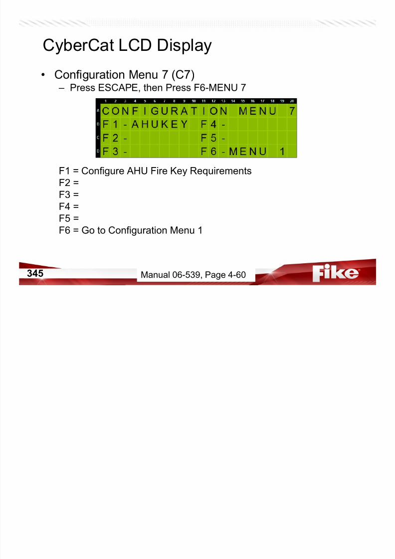
7/23/2019 CyberCat 2015 FULL Printout
http://slidepdf.com/reader/full/cybercat-2015-full-printout 345/429
345 Manual 06-539, Page 4-60
• Configuration Menu 7 (C7.1) – Press F1-AHUKEY
Line A = Use the +/- keys to toggle the field from ‘No’ to ‘Yes.’
‘Yes’ will require an AHU fire key switch to be active before
fan restart sequence is allowed.
CyberCat LCD Display
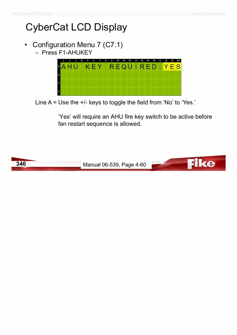
7/23/2019 CyberCat 2015 FULL Printout
http://slidepdf.com/reader/full/cybercat-2015-full-printout 346/429
346 Manual 06-539, Page 4-60
• Panel Switch Operation (C6.5) – Press ESCAPE, then Press F6-MENU 1
F1 = Configure Addressable Devices
F2 = Configure onboard Notification Appliance Circuits
F3 = Configure Signaling Line Circuits
F4 = Reset with Learn New or Learn AllF5 =
F6 = Go to Configuration Menu 2
CyberCat LCD Display

7/23/2019 CyberCat 2015 FULL Printout
http://slidepdf.com/reader/full/cybercat-2015-full-printout 347/429
347
• Top Level Menu – Press ESCAPE until Top Level Menu screen appears
F1 = Access System Configuration Menus (Level 3 Password)
F2 = Event History Menus
F3 = Diagnostic Tools
F4 = Password Entry ScreenF5 = System Maintenance Menus
F6 = Enable IR Communications by loop
CyberCat LCD Display
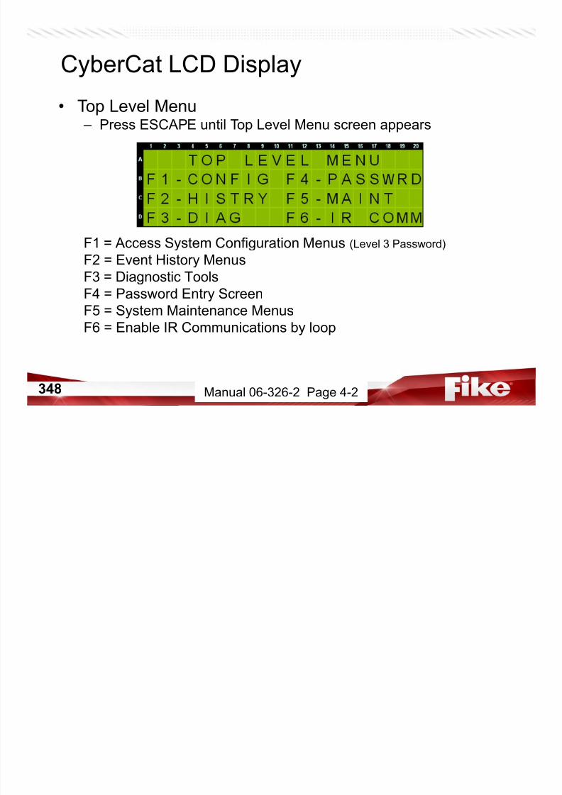
7/23/2019 CyberCat 2015 FULL Printout
http://slidepdf.com/reader/full/cybercat-2015-full-printout 348/429
348 Manual 06-326-2 Page 4-2
• History Menu (H1) – Press ESCAPE for Top Level Menu, then Press F2-HISTRY
F1 = Step thru current Alarm events (Alarm must be active)
F2 = Step thru current Supervisory events (Supervisory must be active)
F3 = Step thru current Trouble events (Trouble must be active)
F4 = Step thru All current eventsF5 = Step thru current Zone events (Zone related events must be active)
F6 = Erase history (Level 3 Password Required)
CyberCat LCD Display
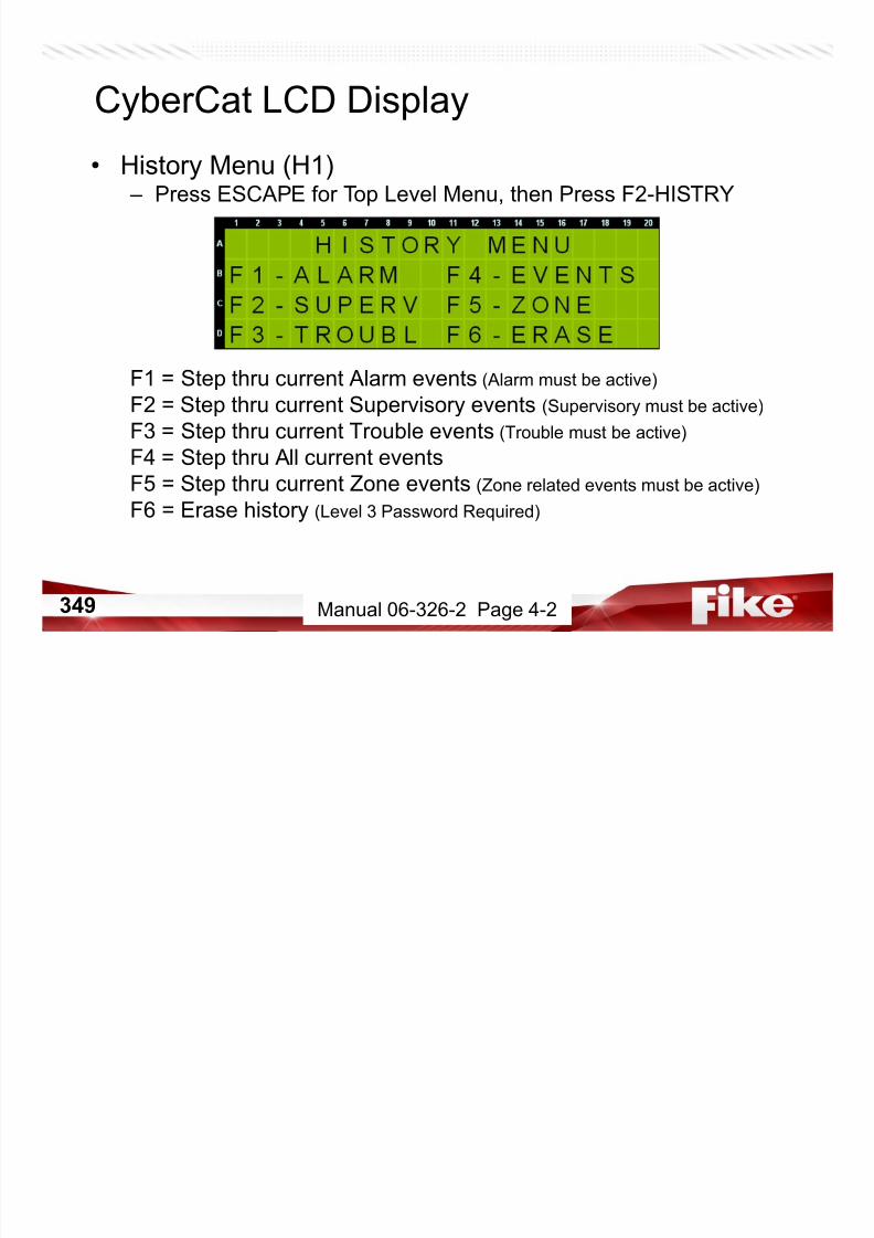
7/23/2019 CyberCat 2015 FULL Printout
http://slidepdf.com/reader/full/cybercat-2015-full-printout 349/429
349 Manual 06-326-2 Page 4-2
• Gather additional event information – Press F1 to toggle display of Panel, Loop, & Address
– Press F2 to toggle display of all 3 lines of custom message
CyberCat LCD Display
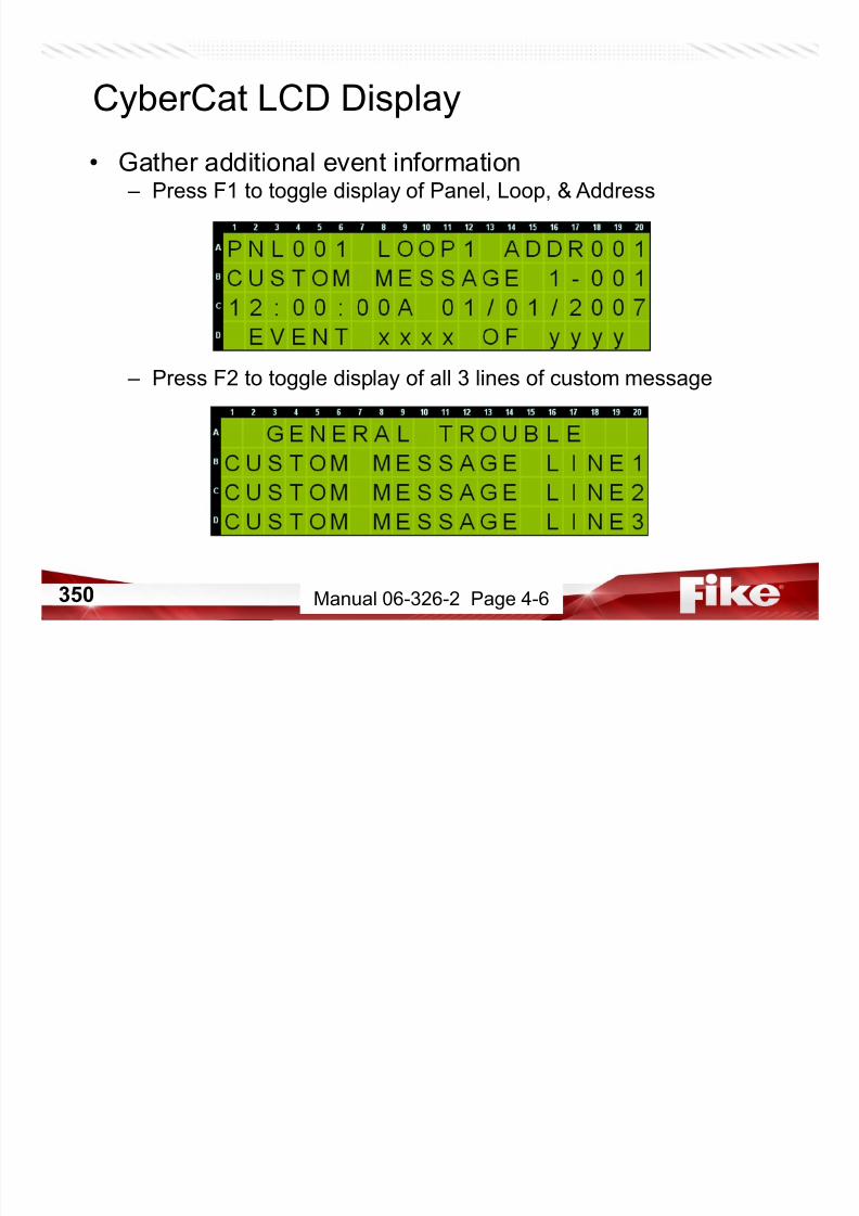
7/23/2019 CyberCat 2015 FULL Printout
http://slidepdf.com/reader/full/cybercat-2015-full-printout 350/429
350 Manual 06-326-2 Page 4-6
• Zone History (H1.5) – Press F5-ZONE
– No Password Required
– Zone related event must active on system
– Use +/- buttons to cycle thru events
CyberCat LCD Display

7/23/2019 CyberCat 2015 FULL Printout
http://slidepdf.com/reader/full/cybercat-2015-full-printout 351/429
351 Manual 06-326-2 Page 4-5
• Erase Panel History (H1.6) – Press F6-ERASE
– Level 3 – 4 Password Required
– Marks erased events as “ERASED EVENT”
– Records “HISTORY ERASED”
CyberCat LCD Display
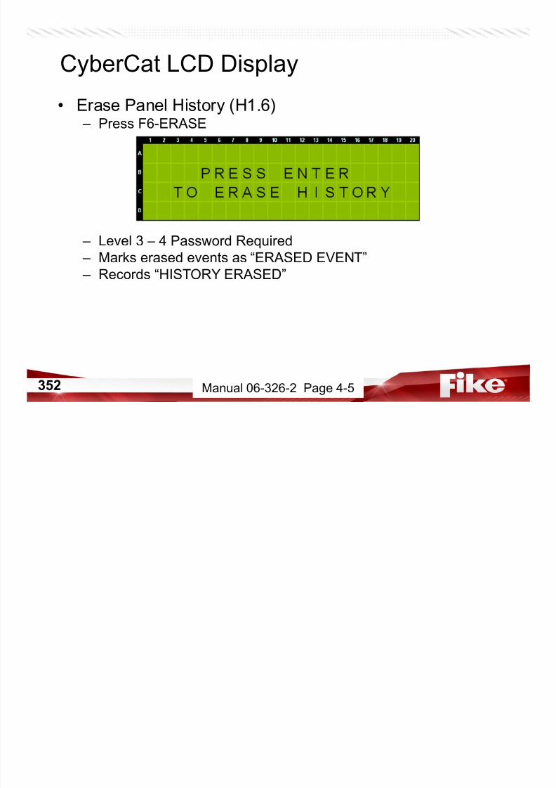
7/23/2019 CyberCat 2015 FULL Printout
http://slidepdf.com/reader/full/cybercat-2015-full-printout 352/429
352 Manual 06-326-2 Page 4-5
• Erase Panel History (H1.6) – Press ENTER
– History will be erased. Then history will be filled with events
showing as”
CyberCat LCD Display

7/23/2019 CyberCat 2015 FULL Printout
http://slidepdf.com/reader/full/cybercat-2015-full-printout 353/429
353 Manual 06-326-2 Page 4-5
354
• Top Level Menu – Press ESCAPE twice until Top Level Menu screen appears
F1 = Access System Configuration Menus (Password 3 – 4)
F2 = Event History Menus
F3 = Diagnostic Tools
F4 = Password Entry ScreenF5 = System Maintenance Menus
F6 = Enable IR Communications by loop
CyberCat LCD Display
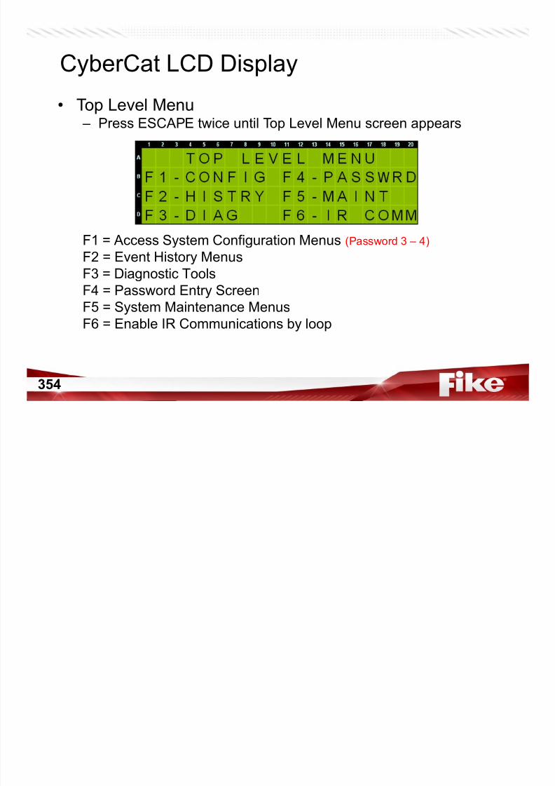
7/23/2019 CyberCat 2015 FULL Printout
http://slidepdf.com/reader/full/cybercat-2015-full-printout 354/429
354
355
• Maintenance Menu (M1) – Press F5-MAINT
F1 = Read device loop/address
F2 = Assign loop/address to device
F3 = Perform device replacement sequence on sensors
F4 = Select Walktest ModeF5 = Temporarily Disable onboard Buzzer
F6 = Maintenance Menu 2
CyberCat LCD Display

7/23/2019 CyberCat 2015 FULL Printout
http://slidepdf.com/reader/full/cybercat-2015-full-printout 355/429
355 Manual 06-326-2 Page 6-3
356
• Automated Sensor Replacement (M1.3) – Press ESCAPE, then Press F3-DEV RPL
– Step 1• Enter Level 2 – 4 Password
• Enter Loop/Address for the Sensor
• Press ENTER
– Step 2• Panel will retrieve Sensor’s config
NOTE: Do not press any buttons while this
screen is displayed.
– Step 3• Remove Sensor and install new one
• Press ENTER
– Continued…
CyberCat LCD Display

7/23/2019 CyberCat 2015 FULL Printout
http://slidepdf.com/reader/full/cybercat-2015-full-printout 356/429
356 Manual 06-326-2 Page 6-5 & 6-6
357
• Automated Sensor Replacement (M1.3)
– Step 4• Panel sends config to Sensor
NOTE: Do not press any buttons while screen
is displayed.
– Step 5
• Panel displays COMPLETED• Press ENTER to repeat sequence
NOTE: Panel will record DEVICE REPLACE OK in the event history upon a
successful sensor replacement. Panel will record DEVICE REPLACE FAILin the event history upon any failure of the sensor replacement process.
CyberCat LCD Display
M l 06 326 2 P 6 6

7/23/2019 CyberCat 2015 FULL Printout
http://slidepdf.com/reader/full/cybercat-2015-full-printout 357/429
357 Manual 06-326-2 Page 6-6
358
• Walktest Modes (M1.4) – Press ESCAPE, then Press F4-WALKTS
Line B = Press ENTER to toggle to desired walktest mode
Line C =
Line D = How many hours should pass with no events before walktest
mode times out?
NOTE: Walktest must be Enabled thru configuration (C3.2) before walktest mode
can be selected. Reset cancels walktest mode.
CyberCat LCD Display
M l 06 326 2 P 6 7

7/23/2019 CyberCat 2015 FULL Printout
http://slidepdf.com/reader/full/cybercat-2015-full-printout 358/429
358 Manual 06-326-2 Page 6-7
359
• Panel Buzzer Disable (M1.5) – Press ESCAPE, then Press F5-BUZZER
Line C = Select NORMAL or DISABLED. Disabled will keep local
piezo/buzzer OFF until Reset or Password Timeout.
NOTE: Level 3 Password Required.
CyberCat LCD Display
Manual 06 326 2 Page 6 9
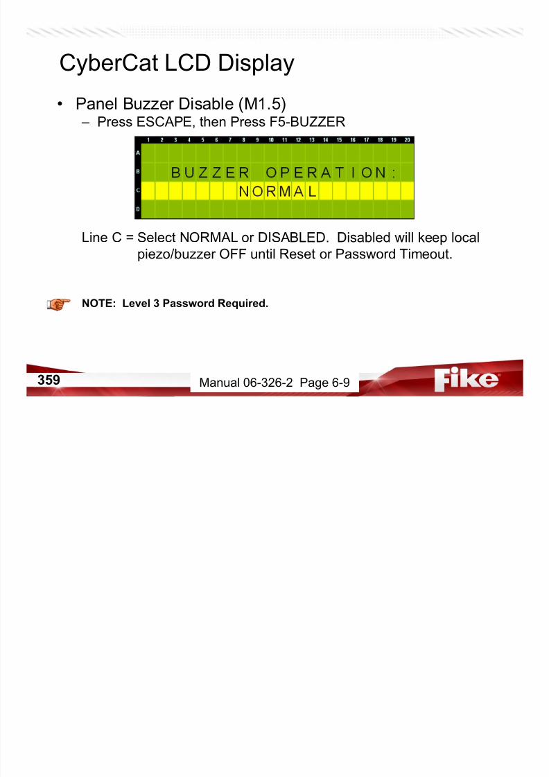
7/23/2019 CyberCat 2015 FULL Printout
http://slidepdf.com/reader/full/cybercat-2015-full-printout 359/429
359 Manual 06-326-2 Page 6-9
360
• Maintenance Menu (M2.3) – Press Escape back to MAINT
F1 = Read device loop/address
F2 = Assign loop/address to device
F3 = Perform device replacement sequence on sensors
F4 = Select Walktest ModeF5 = Temporarily Disable onboard Buzzer
F6 = Maintenance Menu 2
CyberCat LCD Display
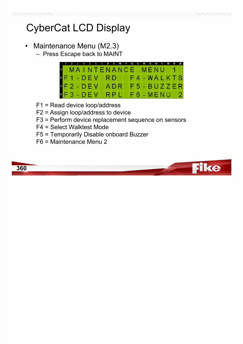
7/23/2019 CyberCat 2015 FULL Printout
http://slidepdf.com/reader/full/cybercat-2015-full-printout 360/429
360
361
• Maintenance Menu (M1) – Press F6 MENU 2
F1 = Mass Notification System Reset
F2 = Mass Notification System Silence
F3 = Switch Timeout (Chicago Mode Boards Only)
F4 = Read Config from Devices into PanelF5 = FAAST Maintenance Options
F6 = AHU ON
CyberCat LCD Display
Manual 06 326 2 Page 6 10
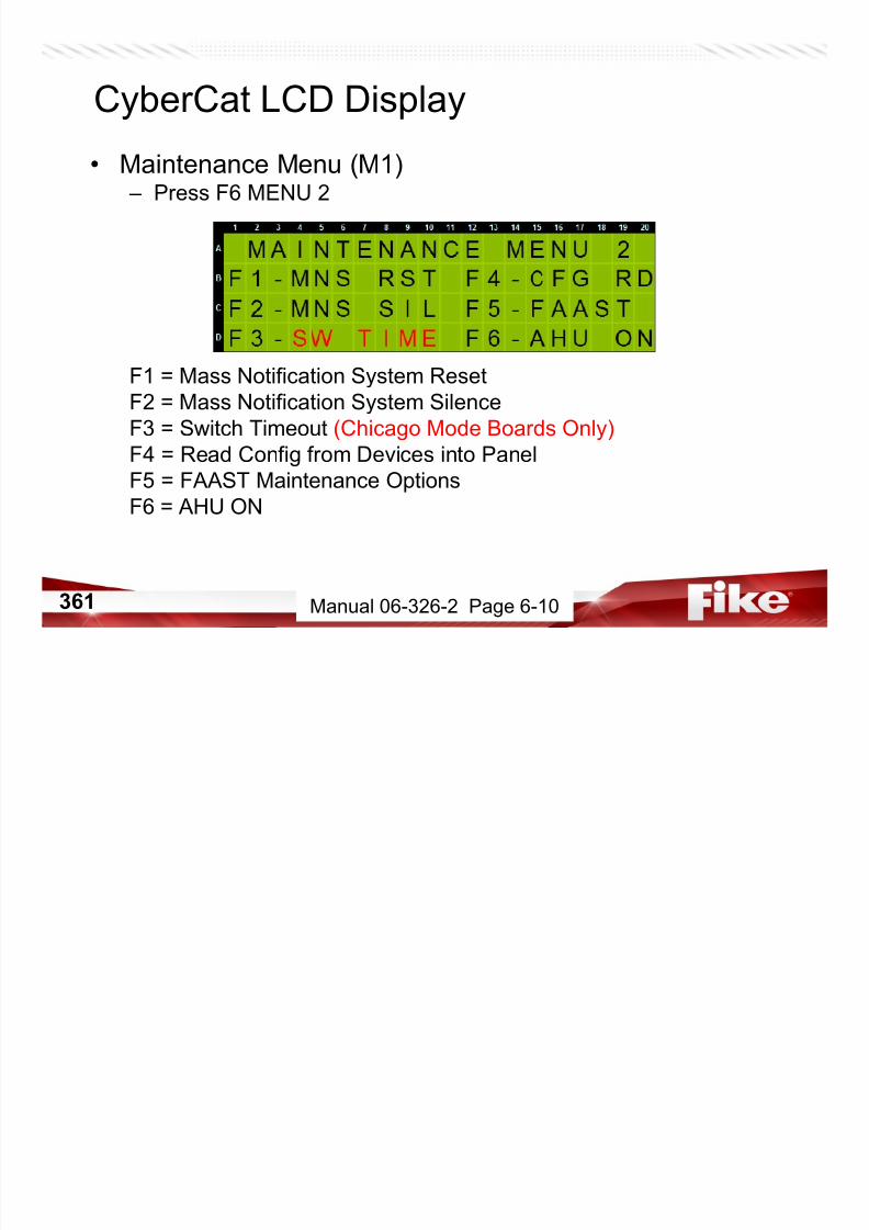
7/23/2019 CyberCat 2015 FULL Printout
http://slidepdf.com/reader/full/cybercat-2015-full-printout 361/429
361 Manual 06-326-2 Page 6-10
362
CyberCat LCD Display• Enable Drill/Silence/Acknowledge (M2.4)
– Press F4-CFG RD
Line A =
Line B = Select which loops the READ function will be performed on
Line C =
Line D= How many devices on system will be read
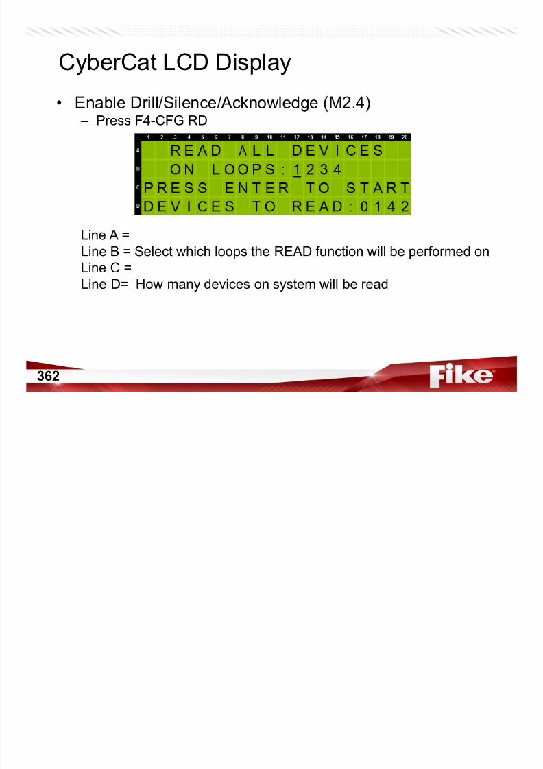
7/23/2019 CyberCat 2015 FULL Printout
http://slidepdf.com/reader/full/cybercat-2015-full-printout 362/429
362
363
CyberCat LCD Display• READ CONFIG (M2.4)
– Press ENTER will READ those devices configuration into panel
While Reading, main display will show this screen until completed.
You will also be locked out from performing other functions while
this is in progress.

7/23/2019 CyberCat 2015 FULL Printout
http://slidepdf.com/reader/full/cybercat-2015-full-printout 363/429
364
CyberCat LCD Display• READ CONFIG (M2.4)
– Press ENTER will READ and create event in History
While Reading, main display will show this screen until completed.
You will also be locked out from performing other functions while
this is in progress.

7/23/2019 CyberCat 2015 FULL Printout
http://slidepdf.com/reader/full/cybercat-2015-full-printout 364/429
365
CyberCat LCD Display• FAAST Read/Disable/Enable (M2.5)
– Escape, then Press F5-FAAST
Line A = Select the Loop and address range of device addresses
Line B = Place Holders to help find address desired for range set on
Line A
Line C = Addresses that are a FAAST Detector only will be displayed
Line D = Move cursor under FAAST shown on Line C and press:
F1 to Read the FAAST Detector
F2 to Isolate/Unisolate that FAAST
F3 to Disable/Enable that FAAST
Manual 06-326-2 Page 6-10

7/23/2019 CyberCat 2015 FULL Printout
http://slidepdf.com/reader/full/cybercat-2015-full-printout 365/429
g
366
CyberCat LCD Display• FAAST Read/Disable/Enable (M2.5)
– Press F1 to READ
Manual 06-326-2 Page 6-10

7/23/2019 CyberCat 2015 FULL Printout
http://slidepdf.com/reader/full/cybercat-2015-full-printout 366/429
g
367
CyberCat LCD Display• FAAST Read/Disable/Enable (M2.5)
– Press F2 to ISOLATE
Manual 06-326-2 Page 6-10

7/23/2019 CyberCat 2015 FULL Printout
http://slidepdf.com/reader/full/cybercat-2015-full-printout 367/429
g
368
CyberCat LCD Display• FAAST Read/Disable/Enable (M2.5)
–
When a FAAST Device is Isolated….
you will see the letter I under that address
Manual 06-326-2 Page 6-10

7/23/2019 CyberCat 2015 FULL Printout
http://slidepdf.com/reader/full/cybercat-2015-full-printout 368/429
369
CyberCat LCD Display• FAAST Read/Disable/Enable (M2.5)
–
And when Isolated, you create a TROUBLE event on your panel
Manual 06-326-2 Page 6-10
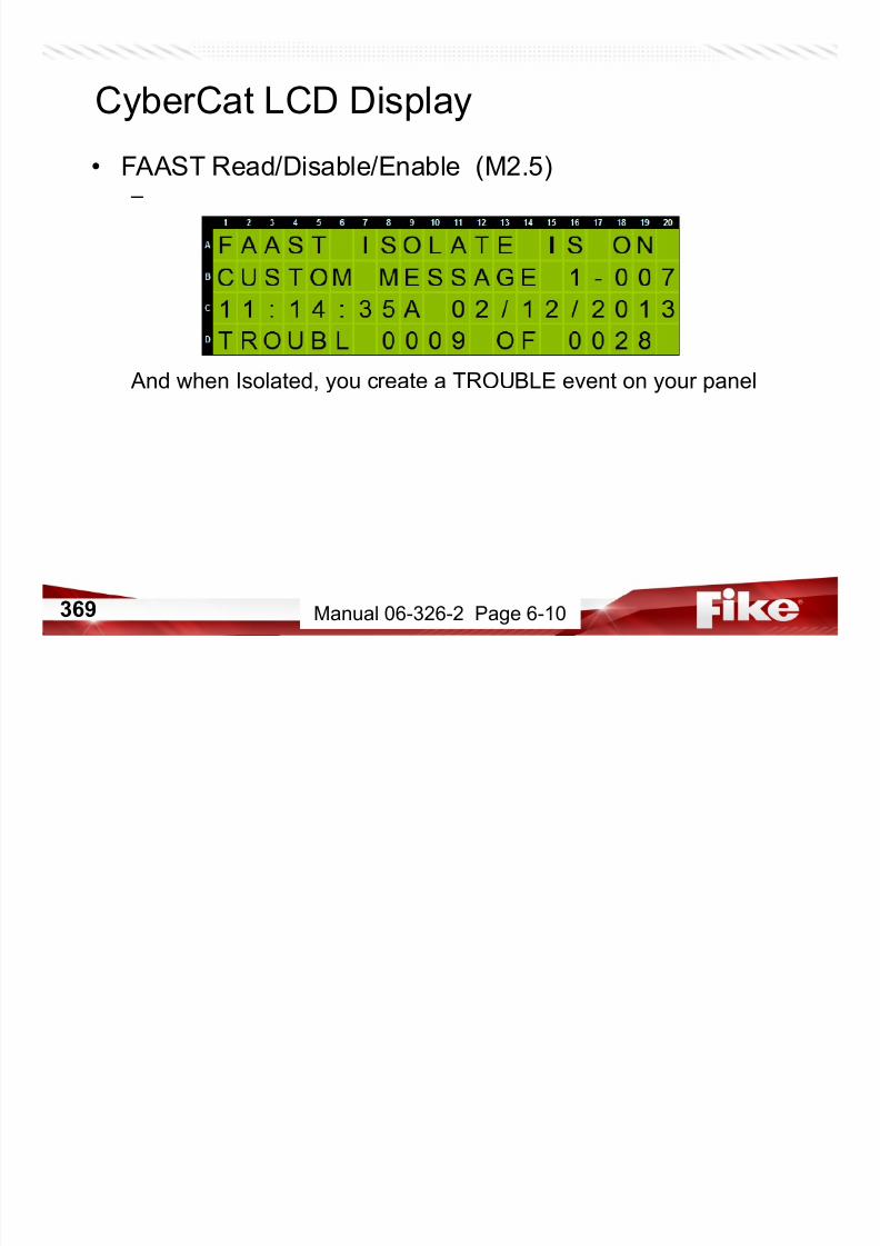
7/23/2019 CyberCat 2015 FULL Printout
http://slidepdf.com/reader/full/cybercat-2015-full-printout 369/429
370
CyberCat LCD Display• FAAST Read/Disable/Enable (M2.5)
– Press F3 to DISABLE
Manual 06-326-2 Page 6-10
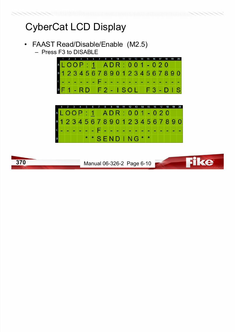
7/23/2019 CyberCat 2015 FULL Printout
http://slidepdf.com/reader/full/cybercat-2015-full-printout 370/429
371
CyberCat LCD Display• FAAST Read/Disable/Enable (M2.5)
–
When a FAAST Device is Disabled….
you will see the letter D under that address
Manual 06-326-2 Page 6-10
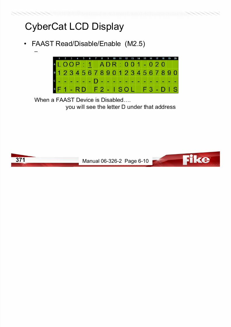
7/23/2019 CyberCat 2015 FULL Printout
http://slidepdf.com/reader/full/cybercat-2015-full-printout 371/429
372
CyberCat LCD Display• FAAST Read/Disable/Enable (M2.5)
–
When a FAAST Device is DISABLED….you create a TROUBLE AND
a SUPERVISORY event on your panel…
And the fan shuts down on the FAAST Unit.
Manual 06-326-2 Page 6-10
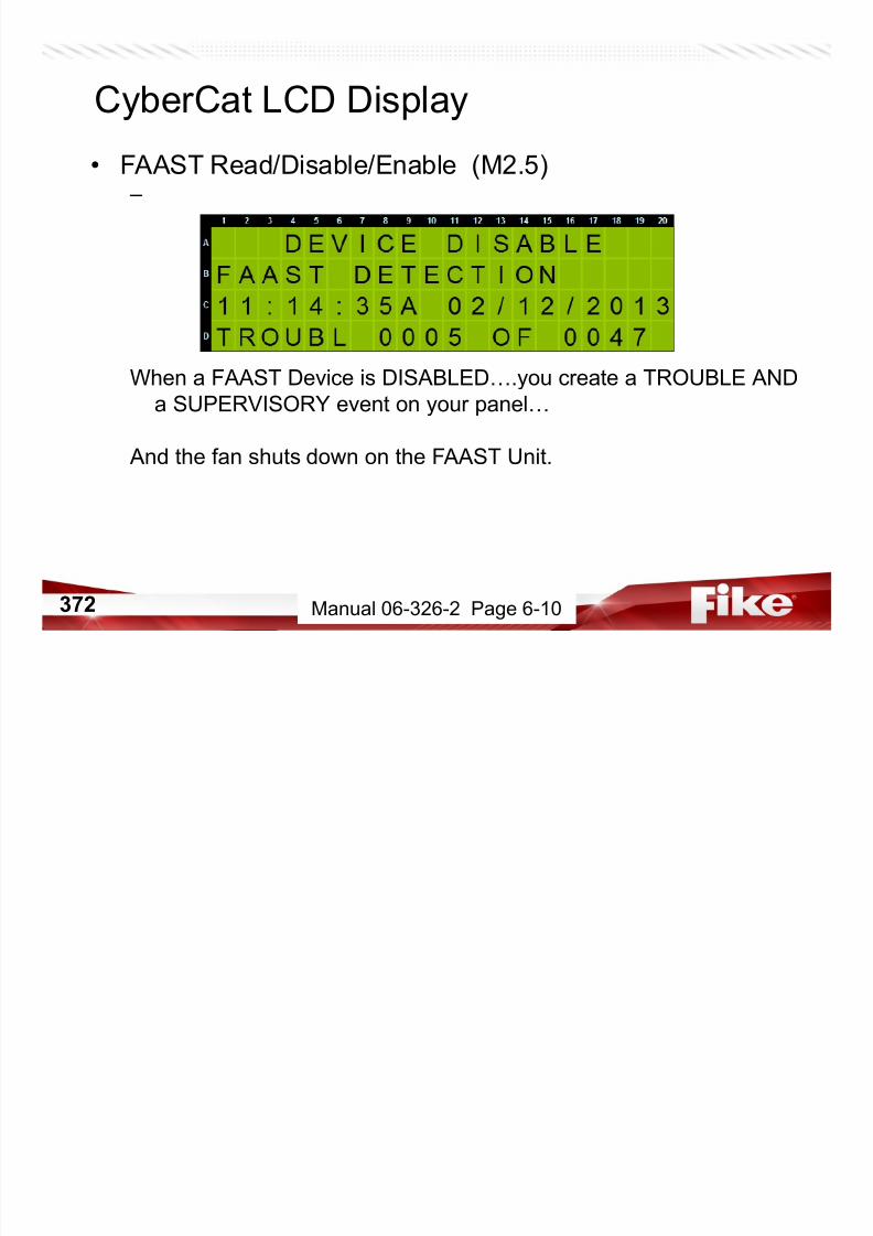
7/23/2019 CyberCat 2015 FULL Printout
http://slidepdf.com/reader/full/cybercat-2015-full-printout 372/429
373
CyberCat LCD Display• FAAST Read/Disable/Enable (M2.5)
– Move your cursor under the D and Press F3 again to Enable
It will again show **SENDING** on the bottom line until the D changes
back to F on the third line when RE-Enabled.
Manual 06-326-2 Page 6-10
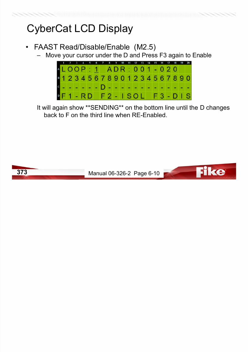
7/23/2019 CyberCat 2015 FULL Printout
http://slidepdf.com/reader/full/cybercat-2015-full-printout 373/429
374
CyberCat LCD Display• FAAST Read/Disable/Enable (M2.5)
–
And when RE-Enabled….you get an event to clear the trouble.
Give it a few seconds and the fan will restart on the FAAST.
You may have a GENERAL TROUBLE for a short time until the fangets up to speed on the unit.
Manual 06-326-2 Page 6-10
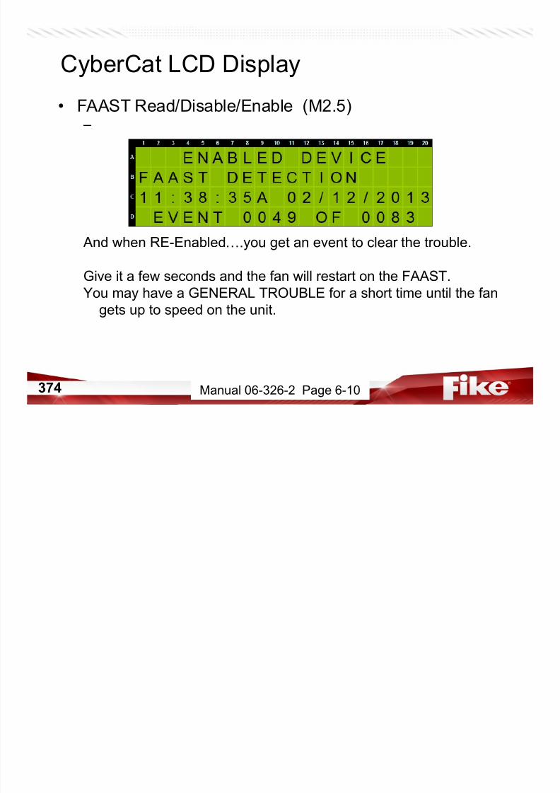
7/23/2019 CyberCat 2015 FULL Printout
http://slidepdf.com/reader/full/cybercat-2015-full-printout 374/429
375
Service & Troubleshooting

7/23/2019 CyberCat 2015 FULL Printout
http://slidepdf.com/reader/full/cybercat-2015-full-printout 375/429
376
CyberCat Service & Troubleshooting• Checkout per NFPA 72
• Maintenance
– Batteries• Sealed Lead Acid
– Replace every 3 years according to date of manufacture
– Sooner if required by customer or LAHJ
• Lithium Coin Cell – On CyberCat Controllers, LED Graphic Controller, Zone Annunciator, and RDUs
– Replace AT LEAST every 5 years – Fike P/N 02-4040
• Troubleshooting – System Events
• Refer to Manual 06-639 for event description and resolution
– Diagnostic Menus
7/23/2019 CyberCat 2015 FULL Printout
http://slidepdf.com/reader/full/cybercat-2015-full-printout 376/429
377
TP1 & 2GND +24V
AC & BATT FUSES BATTERY SW1 - HARD RESET
CHASSISGND
PTC’S (THERMAL FUSES-’PS’)Resettable AUX Power Fuse AUX Power Fuses
CHASSISGND

7/23/2019 CyberCat 2015 FULL Printout
http://slidepdf.com/reader/full/cybercat-2015-full-printout 377/429
378
AC & BATT FUSES
ChassisGround
Aux Power Fuses
TP 1
(Gnd)
TP 2 (24Vdc)

7/23/2019 CyberCat 2015 FULL Printout
http://slidepdf.com/reader/full/cybercat-2015-full-printout 378/429
379
Chassis
GroundLithium Battery
TP 1
(Gnd)
TP 2 (24Vdc)PTC’S (THERMAL FUSES-’PS’)

7/23/2019 CyberCat 2015 FULL Printout
http://slidepdf.com/reader/full/cybercat-2015-full-printout 379/429
380
Battery Charging Trouble
Manual 06-620 & DC10-001
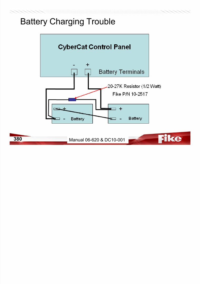
7/23/2019 CyberCat 2015 FULL Printout
http://slidepdf.com/reader/full/cybercat-2015-full-printout 380/429
Battery Charging Trouble
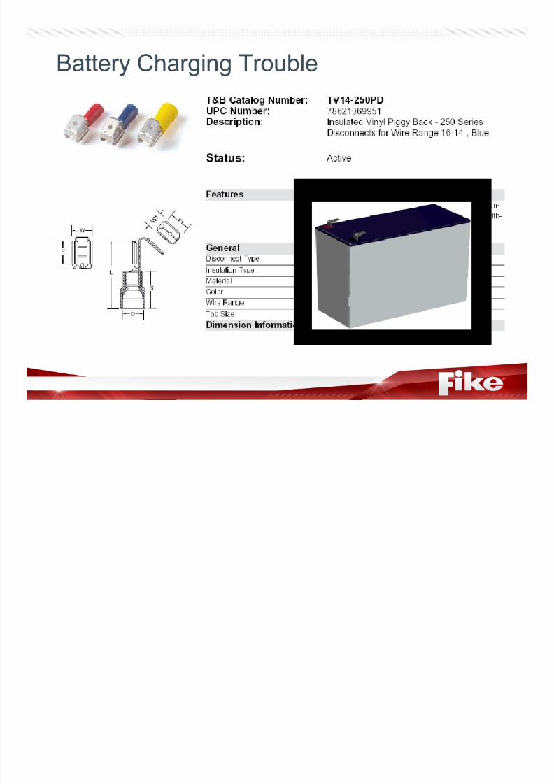
7/23/2019 CyberCat 2015 FULL Printout
http://slidepdf.com/reader/full/cybercat-2015-full-printout 381/429
382
• Diagnostic Menu 1 (D1) – Press ESCAPE for Top Level Menu, then Press F3-DIAG
F1 = Perform diagnostics on addressable devices
F2 = Panel diagnostics – Ground Fault
F3 = Panel diagnostics
F4 = Test front panel LEDs and LCD DisplayF5 = Firmware CRC value
F6 = Got to Diagnostics Menu 2
CyberCat Service & Troubleshooting
Manual 06-326-2 Page 5-3
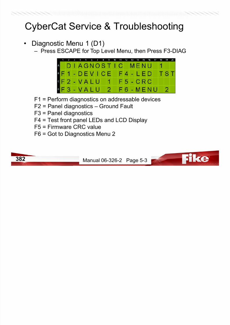
7/23/2019 CyberCat 2015 FULL Printout
http://slidepdf.com/reader/full/cybercat-2015-full-printout 382/429
383
• Addressable Device Diagnostic Menu (D1.1) – Press F1-DEVICE
F1 = View addressable devices by loop and light LEDs
F2 = Compare Device Serial Numbers to Configs
CyberCat Service & Troubleshooting
Manual 06-326-2 Page 5-3
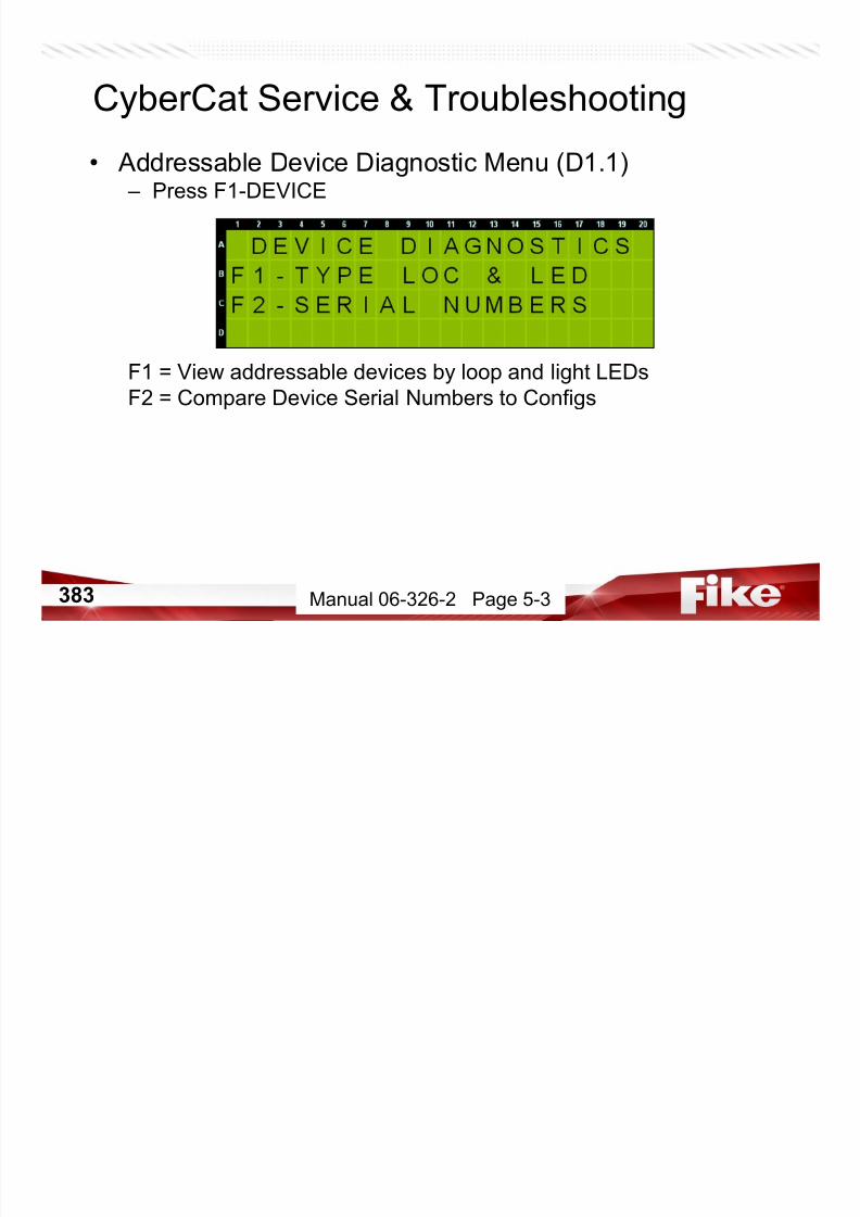
7/23/2019 CyberCat 2015 FULL Printout
http://slidepdf.com/reader/full/cybercat-2015-full-printout 383/429
384
• Addressable Device Type and Locate (D1.1.1) – Press F1-TYPE LOC & LED
Line A = Loop # (1-4), Addresses in groups of 20;
Last Position: D=Device type is displayed on line 4
Line B = Address placeholders for groups of 20 devices
Line C = Displays the type of device CONFIGURED at the specific address:P=Photo U=Photo/Heat H=Heat - =unknown 2=Dual Monitor Module
D=Duct T=Pull Station M=Monitor, 4” m=Mini Monitor Z=Zone Module
I=Ion Y=Relay C=Control
Line D = Displays the type of device PRESENT/FOUND on the SLC or the
devices LED status
CyberCat Service & Troubleshooting
Manual 06-326-2 Page 5-4

7/23/2019 CyberCat 2015 FULL Printout
http://slidepdf.com/reader/full/cybercat-2015-full-printout 384/429
385
• Addressable Device Type and Locate (D1.1.1) – Press F1-TYPE LOC & LED
Line A = Loop # (1-4), Addresses in groups of 20;
Last Position: L=Light LED; use +/- while cursor is under address
Line B = Address placeholders for groups of 20 devices
Line C =
Line D = Indicates which LED is currently forced on
CyberCat Service & Troubleshooting
Manual 06-326-2 Page 5-4

7/23/2019 CyberCat 2015 FULL Printout
http://slidepdf.com/reader/full/cybercat-2015-full-printout 385/429
386
• Addressable Device Type and Locate (D1.1.1) – Press F1-TYPE LOC & LED
Line A = Loop # (1-4), Addresses in groups of 20;
Last Position: D=Device type is displayed on line 4
L=Light LED; use +/- while cursor is under address
Line B = Address placeholders for groups of 20 devices
Line C = Displays the type of device CONFIGURED at the specific address:P=Photo U=Photo/Heat H=Heat _=unknown
D=Duct T=Pull Station M=Monitor, 4” m=Mini Monitor
I=Ion Y=Relay C=Control R=Release
Line D = Displays if the device has been READ….meaning copy of that
device config is stored in the panel.
CyberCat LCD Display
Manual 06-356-2, Page 5-4

7/23/2019 CyberCat 2015 FULL Printout
http://slidepdf.com/reader/full/cybercat-2015-full-printout 386/429
387
• Addressable Device Type and Locate (D1.1.1) – Press F1-TYPE LOC & LED
Line A = Loop # (1-4), Addresses in groups of 20;
Last Position: D=Device type is displayed on line 4
L=Light LED; use +/- while cursor is under address
Line B = Address placeholders for groups of 20 devices
Line C = Displays the type of device CONFIGURED at the specific address:P=Photo U=Photo/Heat H=Heat _=unknown
D=Duct T=Pull Station M=Monitor, 4” m=Mini Monitor
I=Ion Y=Relay C=Control R=Release
Line D = Displays all devices that are DISABLED
CyberCat LCD Display
Manual 06-356-2, Page 5-4

7/23/2019 CyberCat 2015 FULL Printout
http://slidepdf.com/reader/full/cybercat-2015-full-printout 387/429
388
• Addressable Device Serial Numbers (D1.1.2) – Press ESCAPE, then Press F2-SERIAL NUMBERS
Line A = Select Loop and Address of Device S/N to Compare
Line B = Displays the Device Type of Line A Loop and Address
Line C = S/N Stored in Panel for Line A Loop and Address
Line D = Actual S/N of Device at Line A Loop and Address
CyberCat Service & Troubleshooting
Manual 06-326-2 Page 5-5

7/23/2019 CyberCat 2015 FULL Printout
http://slidepdf.com/reader/full/cybercat-2015-full-printout 388/429
389
• Diagnostic Menu 1 (D1) – Press ESCAPE twice for DIAG Menu 1
F1 = Perform diagnostics on addressable devices
F2 = Panel diagnostics – Ground Fault
F3 = Panel diagnostics
F4 = Turn on all panel LEDs for 4 seconds. Also turns all LCDcharacters solid during this time. (Trouble LED flashes)
F5 = Firmware CRC value
F6 = Go to Diagnostics Menu 2
CyberCat Service & Troubleshooting
Manual 06-326-2 Page 5-3

7/23/2019 CyberCat 2015 FULL Printout
http://slidepdf.com/reader/full/cybercat-2015-full-printout 389/429
390
• Panel Diagnostics – Ground Fault (D1.2) – Press then Press F2-VALU 1
Line A = (GF) Ground Fault; < = Level 1 GF, - = GF Level is transitioning, > = Level 2 GF
Low = 60K ohm or less between power ground and chassis ground
High = 1M ohm or less between Main power (27.6VDC) and chassis
(Level 1 <) Low = 0 – 84; Normal = 85 – 120; High = 121 – 255
(Level 2 >) Low = 0 – 189; Normal = 190 – 255 (NOT USED ON CYBERCAT)
(A1) Voltage Regulator on main AC power for 120VAC = 200 – 255; (L1) Loop 1 short circuit detect
Line B = (24) Main panel 24VDC; (A2) Voltage Regulator on main AC power for 120VAC; (L2) Loop 2 short circuit
detect
Line C = (B1) Battery circuit on main controller; (A3) Voltage Regulator on SPS AC power for 120VAC; (N1)
Notification output # 1
Line D = (B2) SPS Battery circuit; (A4) Voltage Regulator on SPS AC power for 120VAC; (N2) Notification output # 2
Press Enter to
HOLD at one
GF level.
CyberCat Service & Troubleshooting
Manual 06-326-2 Page 5-6

7/23/2019 CyberCat 2015 FULL Printout
http://slidepdf.com/reader/full/cybercat-2015-full-printout 390/429
391
• Panel Diagnostics (D1.3) – Press ESCAPE, then Press F3-VALU 2
Line A = (C1+) Loop 1 ++ supervision; trouble if < 100(C1-) Loop 1 -- supervision; trouble if > 100
(L3) Loop 3 short circuit detect; normal = 10 – 255
Line B = (C2+) Loop 2 ++ supervision; trouble if < 100
(C2-) Loop 2 -- supervision; trouble if > 100
(L4) Loop 4 short circuit detect; normal = 10 – 255
Line C = (C3+) Loop 3 ++ supervision; trouble if < 100
(C3-) Loop 3 -- supervision; trouble if > 100
Line D = (C4+) Loop 4 ++ supervision; trouble if < 100
(C4-) Loop 4 -- supervision; trouble if > 100
Bottom Right= Fan Supervision
Value can increment to 1000Over 500 is trouble.
(New in Version 4.0)
CyberCat Service & Troubleshooting
Manual 06-326-2 Page 5-7

7/23/2019 CyberCat 2015 FULL Printout
http://slidepdf.com/reader/full/cybercat-2015-full-printout 391/429
392
• Panel Diagnostics (D1.4) – Press ESCAPE, then Press F4-LED TST
CyberCat Service & Troubleshooting
Turns on all panel LEDs for 4 seconds.
Also turns all LCD characters solid during this time.
(Trouble LED flashes)
Manual 06-326-2 Page 5-8

7/23/2019 CyberCat 2015 FULL Printout
http://slidepdf.com/reader/full/cybercat-2015-full-printout 392/429
393
• Diagnostic Menu 1 (D1) – When LED Test is complete you return to DIAG Menu 1
F1 = Perform diagnostics on addressable devices
F2 = Panel diagnostics – Ground Fault
F3 = Panel diagnostics
F4 = Turn on all panel LEDs for 4 seconds. Also turns all LCD
characters solid during this time. (Trouble LED flashes)
F5 = Firmware CRC value
F6 = Go to Diagnostics Menu 2
CyberCat Service & Troubleshooting
Manual 06-326-2 Page 5-3
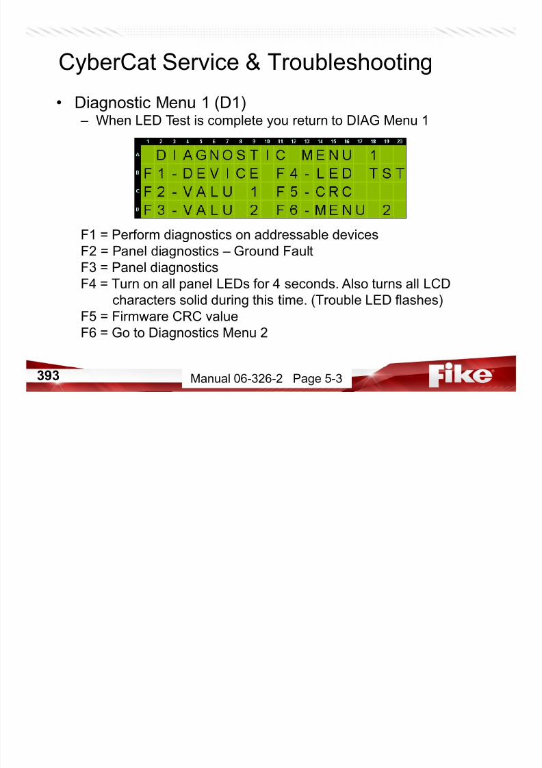
7/23/2019 CyberCat 2015 FULL Printout
http://slidepdf.com/reader/full/cybercat-2015-full-printout 393/429
394
• Cyclic Redundancy Check (CRC) (D1.5) – Press ESCAPE, then Press F5-CRC
Line A = Main System Processor CRC
CRC for v1.5 = 19D1 CRC for v4.0 = 01BD
CRC for v2.0 = 118B CRC for v5.0 = AA36
CRC for v3.0 = A790 CRC for v6.01 = AA82
CRC for v3.1 = E688 CRC for V6.20 = 0B42
CRC for V6.40 = 99C9
Line B = Main Loop (SLC 1 & 2) Processor Firmware Version
Line C = Auxiliary Loop (SLC 3 & 4) Processor Firmware Version
NOTE: If SLM is installed, Main and AuxL version must match.
CyberCat LCD Display
Manual 06-326-2, Page 5-8
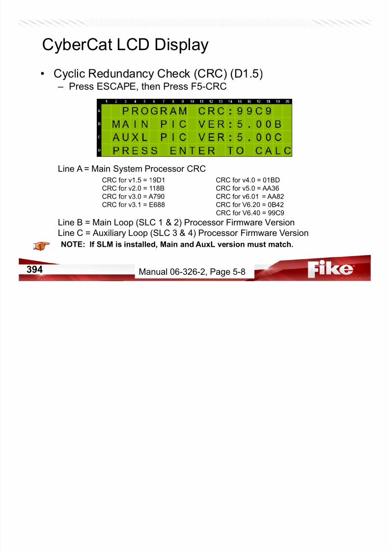
7/23/2019 CyberCat 2015 FULL Printout
http://slidepdf.com/reader/full/cybercat-2015-full-printout 394/429
395
• Diagnostic Menu 2 (D2) – Press ESCAPE, then Press F6-MENU 2
F1 = Perform diagnostics on panel keypad
F2 = VESDA diagnostics
F3 = VESDA diagnostics
F4 = Peripheral diagnostics
F5 = VESDAnet Polling Rate (v3.1 and newer)
F6 = Go to Diagnostic Menu 3 (v4.0 and newer)
CyberCat Service & Troubleshooting
Manual 06-326-2 Page 5-8

7/23/2019 CyberCat 2015 FULL Printout
http://slidepdf.com/reader/full/cybercat-2015-full-printout 395/429
396
• Keypad & LED Diagnostics (D2.1) – Press F1-KEYPAD
Displays key currently pressed and how many times it has been pressed.
Press the ‘>’ button to incrementally illuminate each of the panel’s state LEDs
Press ESCAPE 3 times to exit Keypad Diagnostics
CyberCat Service & Troubleshooting
Manual 06-326-2 Page 5-9
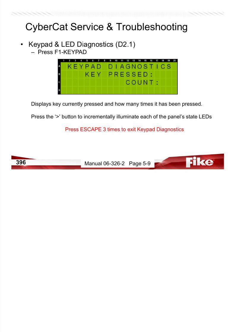
7/23/2019 CyberCat 2015 FULL Printout
http://slidepdf.com/reader/full/cybercat-2015-full-printout 396/429
397
• VESDA Diagnostics Menu 1 (D2.2) – Press ESCAPE, then Press F2-VESDA 1
Line A = Selected VESDA zone; (<>) indicates communications
< > toggle back and forth if communicating.
Line B = Current obscuration reading from selected VESDA unit
(press ENTER to update)
Line C = AL: Alert Level set point AC: Action Level set point
Line D = F1: Fire-1 Level set point
F2: Fire-2 Level set point (if applicable)
CyberCat Service & Troubleshooting
Manual 06-326-2 Page 5-9
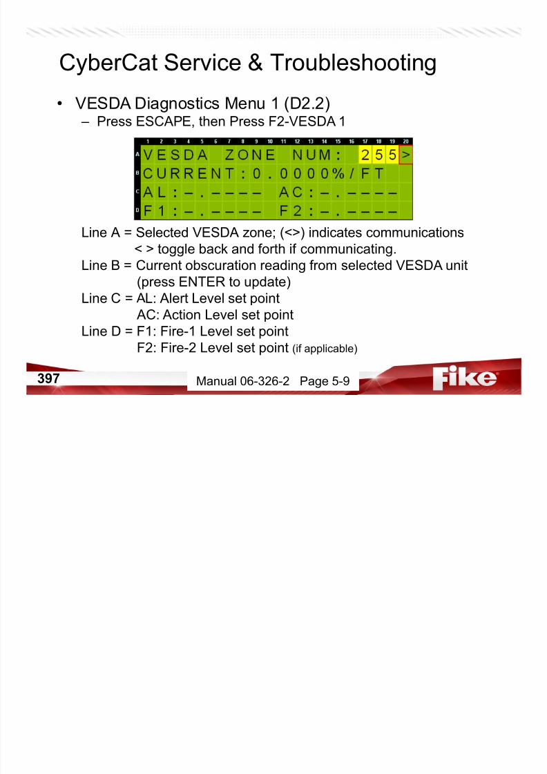
7/23/2019 CyberCat 2015 FULL Printout
http://slidepdf.com/reader/full/cybercat-2015-full-printout 397/429
398
• VESDA Diagnostics Menu 2 (D2.3) – Press ESCAPE, then Press F3-VESDA 2
Line A = Selected VESDA zone; (<>) indicates communications
Line B = Press ENTER to list up to 4 fault numbers
Line C = Displays the active faults
Line D = Displays the active faults
CyberCat Service & Troubleshooting
Manual 06-326-2 Page 5-10

7/23/2019 CyberCat 2015 FULL Printout
http://slidepdf.com/reader/full/cybercat-2015-full-printout 398/429
399
• Peripheral Diagnostics (D2.4) – Press ESCAPE, then Press F4-PERIPH
Line A = ADR = Peripheral address being diagnosed.
SUP = Number of supervision broadcasts without response.
Number resets to zero (0) with each response of peripheral. Missing
Peripheral trouble occurs if number exceeds 11.
MAX = Indicates maximum number of supervision broadcasts sent
without a response. Resets to zero on panel reset.
Line B = Peripheral type of address in Line A.
Line C = Number of supervision commands sent to peripheral.
Line D = Number of supervision commands received from peripheral.
CyberCat Service & Troubleshooting
Manual 06-326-2 Page 5-10

7/23/2019 CyberCat 2015 FULL Printout
http://slidepdf.com/reader/full/cybercat-2015-full-printout 399/429
400
CyberCat LCD Display• VESDAnet Polling Rate (D2.5) – Press ESCAPE twice, then Press F5-VE COM
Row A = Allow you to select the VESDA zone to displayRow B (Poll TX) = Number of polling transmissions to VESDA zone
Row B (Poll RX) = Number of polling receptions from VESDA zone
Row C (Netw TX) = Number of network alarm requests sent TO panel
Row C (Netw RX) = Number of network alarms sent FROM the HLIRow D = Allows you to adjust comm speed to HLI (250mS – 2000mS)
Level 4 (Factory) Password is Required.
Pressing ENTER will clear the TX and RX counters
Manual 06-326-2 Page 5-12
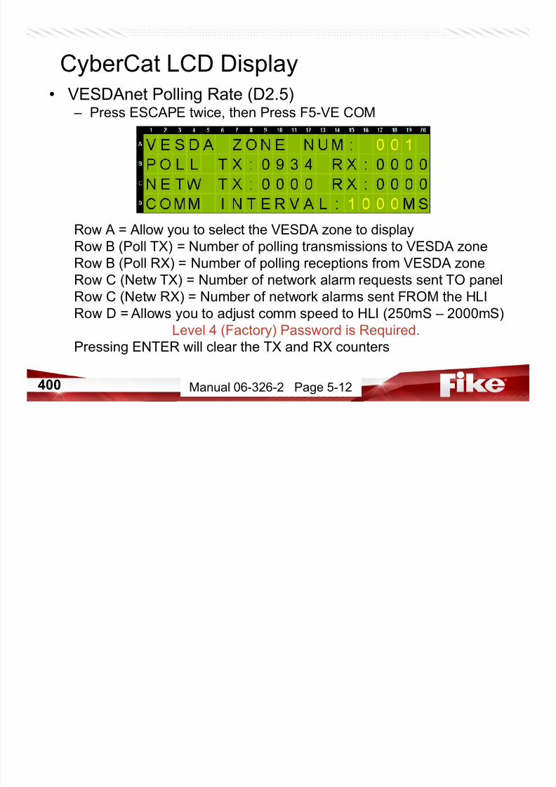
7/23/2019 CyberCat 2015 FULL Printout
http://slidepdf.com/reader/full/cybercat-2015-full-printout 400/429
401
CyberCat LCD Display• Diagnostic Menu 3 (D3)
– Press ESCAPE, then Press F6-MENU 3 (New in Version 4.0)
F1 = Monitor supervision activity on the network
F2 = Perform diagnostics between panel and network module PIC
F3 = Adjust Baud Rate and Transmit intervals between panels
F4 = Transmits messages onto peripheral buss for test purposes only
F5 = Main board processor communication
F6 = Goes to Diagnostic Menu 4 (New in Version 5.0)
Manual 06-326-2 Page 5-13

7/23/2019 CyberCat 2015 FULL Printout
http://slidepdf.com/reader/full/cybercat-2015-full-printout 401/429
402
CyberCat LCD Display• Network Diagnostics (D3.1)
– Press ESCAPE, then F1 – NETW 1
Line A= Panel id for this panel and the module type
Line B = Range of panel id’s from which this panel might be receiving data
The TXn increments each time this panel transmits to the network
Line C = Placeholders to align panel id numbers with panel below on line D
Line D = Number of receptions from the panel id directly above.
If no receptions from that panel, a blank is shown.
When data is received from that panel, this number increments
(New in Version 4.0)
Manual 06-326-2 Page 5-13
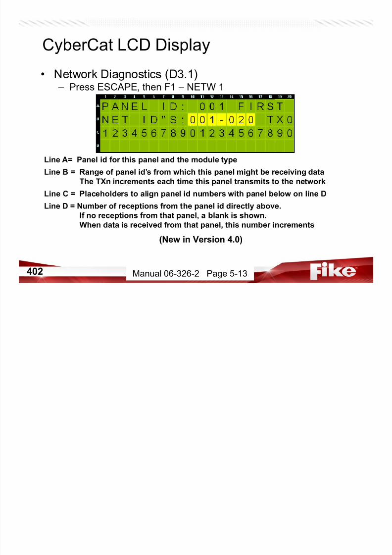
7/23/2019 CyberCat 2015 FULL Printout
http://slidepdf.com/reader/full/cybercat-2015-full-printout 402/429
403
CyberCat LCD Display• Network Diagnostics (D3.2)
– Press ESCAPE, then F2 – NETW 2 (New if Version 4.0 Firmware)
Manual 06-326-2 Page 5-14
Line A= Number of trouble events recorded when the installed network modulefails to respond to commands from panel. Number on left increments
each time a command is sent and is cleared when module responds.
Number on right is configurable threshold
Line B = Number of events when panel changed it’s network type.
Line C = Number of times module reports Class A wire trouble
Line D = Displays current network module position
ISOLA for isolated, FIRST, MIDDLE or LAST. RDY indicates if module is
ready for network command (Y=Ready, N= Not Ready)

7/23/2019 CyberCat 2015 FULL Printout
http://slidepdf.com/reader/full/cybercat-2015-full-printout 403/429
404
CyberCat LCD Display• Network Diagnostics (D3.3)
– Press ESCAPE, then F3 – NETW 3 (New if Version 4.0 Firmware)
Manual 06-326-2 Page 5-15
Line A= Allows you to adjust the communication interval between the panel and
network module in 1ms increments
Line B = Number of consecutive “panel missing” responses from Network PIC that
must be reached before a trouble condition is annunciated. Default is 3.
Line C =Line D = Allows you to adjust number of normal network super commands
containing history data that must be sent to Network PIC before the next
panel missing command can be verified. Default is 10
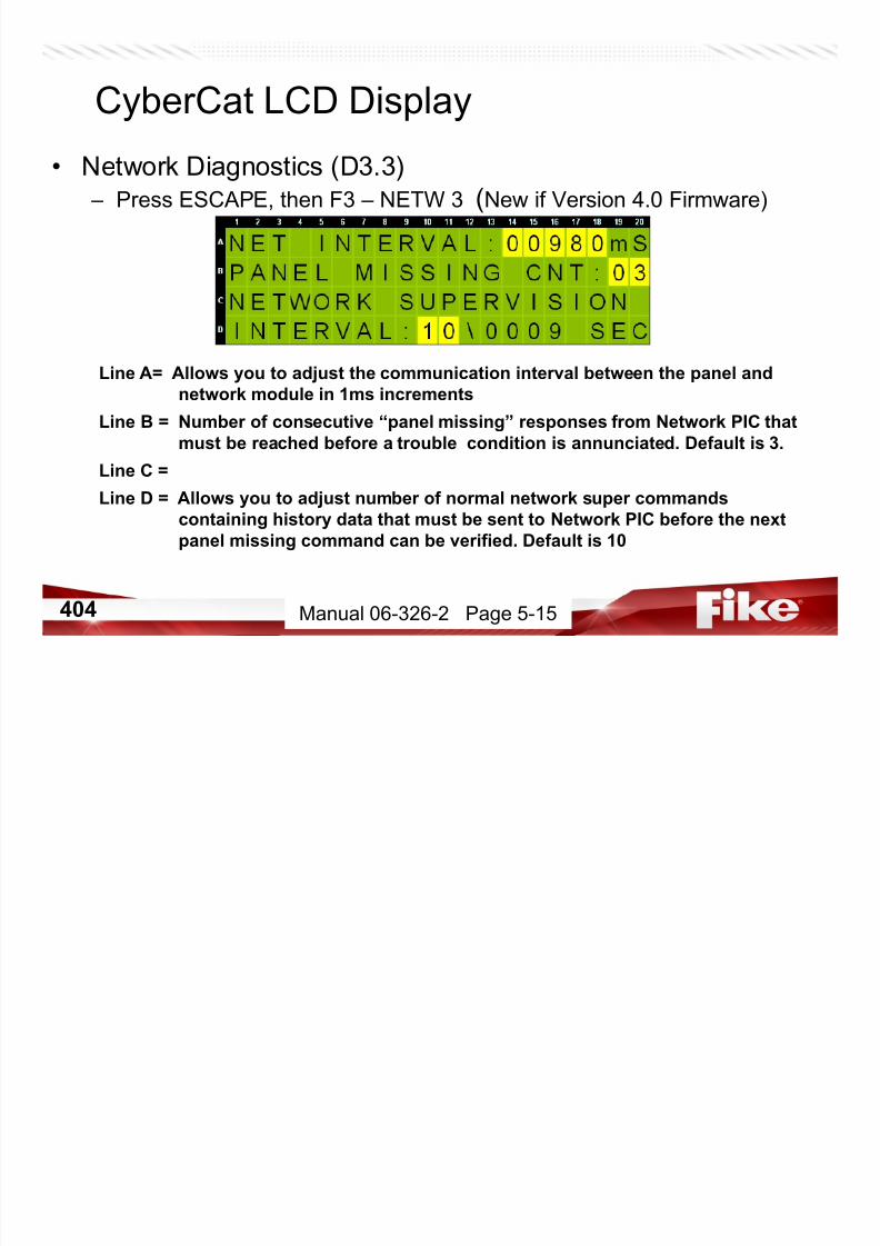
7/23/2019 CyberCat 2015 FULL Printout
http://slidepdf.com/reader/full/cybercat-2015-full-printout 404/429
405
CyberCat LCD Display• History Diagnostics (D3.4)
– Press Escape then F4 - HISTORY
Line A= This screen allows for automatic transmission of pre-set messages
Line B = When “ON” the panel will transmit an event every 10 seconds onto the
peripheral bus. The event number will increment after each transmission.
Line C = Allows selection of a specific event number. If the auto test is set to
“OFF” pressing ENTER will transmit this event onto peripheral bus.The message “**SENDING**” will show briefly to confirm transmission.
Line D = Selection of the history transmission variables when ENTER is
pressed. Leftmost is loop and address in hex. Others are “dat” variables.
Manual 06-326-2 Page 5-15
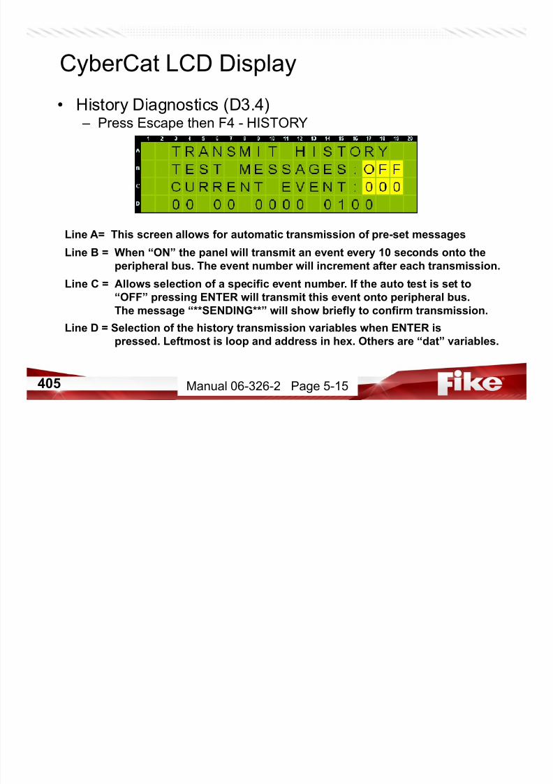
7/23/2019 CyberCat 2015 FULL Printout
http://slidepdf.com/reader/full/cybercat-2015-full-printout 405/429
406
• Main Board Processor Communications (D3.5) – Press ESCAPE, then Press F5-BRD COM
Firmware v3.1 and newer
Left Half = Main Loop Processor (SLC 1 & 2)
Right Half = AUX Loop Processor (SLC 3 & 4)
RXD: total data received by system processor from the MAIN or AUX processor
ERR: # of checksum errors noted by system processor from the MAIN or AUXprocessor
TXD: Total number of commands received by system processor from both MAIN and
AUX processors since last reset (will rollover)
ERR: Out of the TXD value, total # checksum errors
CyberCat LCD Display
Manual 06-326-2 Page 5-16

7/23/2019 CyberCat 2015 FULL Printout
http://slidepdf.com/reader/full/cybercat-2015-full-printout 406/429
407
CyberCat LCD Display• Diagnostic Menu 4 (D4)
– Press ESCAPE, then Press F6-MENU 4 (New in Version 5.0)
F1 = Status of Voice Amplifiers
F2 = Peripheral Supervision Data
F3 = Status of Voice Zone Information
F4 = Peripheral Firmware Version
F5 =
F6 = Diagnostics Menu 5
Manual 06-326-2 Page 5-16

7/23/2019 CyberCat 2015 FULL Printout
http://slidepdf.com/reader/full/cybercat-2015-full-printout 407/429
408
CyberCat LCD Display
• Peripheral PER FVPress F4 – PER FV (New in Version 5.0)
Line A = Select Peripheral Address
Line B = Type of peripheral device configured at address
Line C =
Line D = Displays current firmware version of device
Manual 06-326-2 Page 5-22
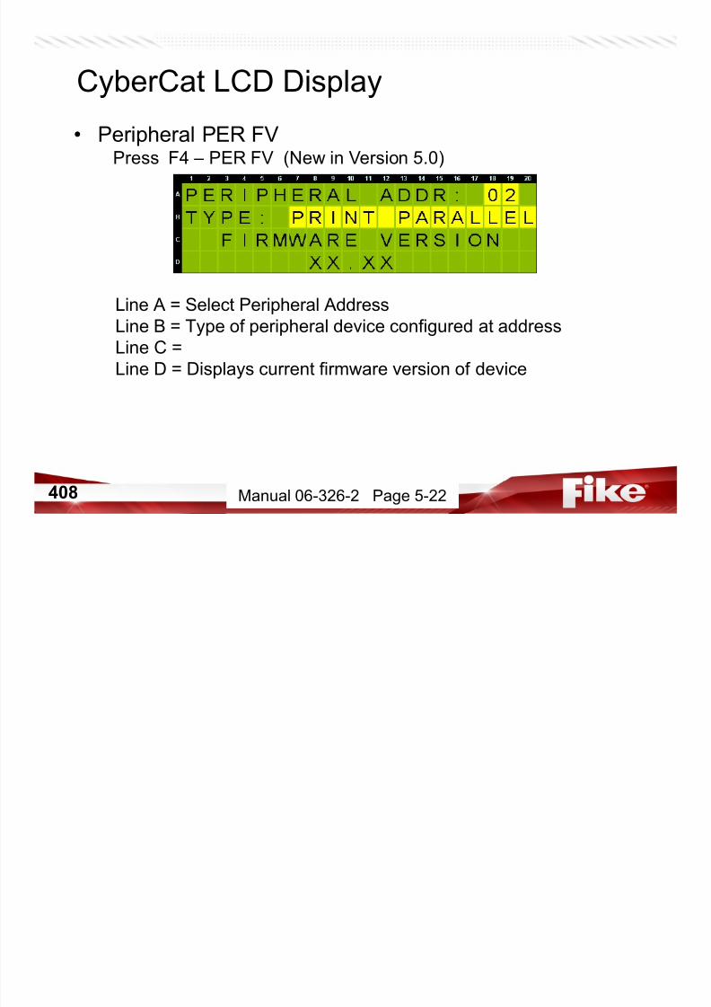
7/23/2019 CyberCat 2015 FULL Printout
http://slidepdf.com/reader/full/cybercat-2015-full-printout 408/429
409
CyberCat LCD Display
• Diagnostic Menu 5 (D5) – Press ESCAPE, then Press F6-MENU 5 (New in Version 6.0)
F1 = Page Status
F2 = Audio Priority Status
F3 = Play Message ID Status
F4 = FAAST Detector Status
F5 =
F6 = Diagnostics Menu 1
Manual 06-326-2 Page 5-16

7/23/2019 CyberCat 2015 FULL Printout
http://slidepdf.com/reader/full/cybercat-2015-full-printout 409/429
410
CyberCat LCD Display
• FAAST (D5.4) – Press F4 - FAAST (New in Version 6.10)
Line 1 = FAAST Address
Set address of FAAST Detector to view. It MUST be an address
of a FAAST detector to work.
Manual 06-326-2 Page 5-26

7/23/2019 CyberCat 2015 FULL Printout
http://slidepdf.com/reader/full/cybercat-2015-full-printout 410/429
411
CyberCat LCD Display
• FAAST (D5.4) – Press ENTER
It is reading the status of FAAST Detector at address on 1st Line
Manual 06-326-2 Page 5-26

7/23/2019 CyberCat 2015 FULL Printout
http://slidepdf.com/reader/full/cybercat-2015-full-printout 411/429
412
CyberCat LCD Display
• FAAST (D5.4) – FAAST STATUS (New in Version 6.10)
List of Status Fields on Next Screen
Manual 06-326-2 Page 5-26
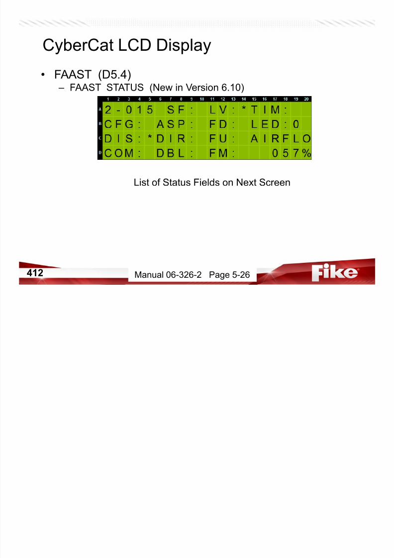
7/23/2019 CyberCat 2015 FULL Printout
http://slidepdf.com/reader/full/cybercat-2015-full-printout 412/429
413
FAAST Status Readings
Manual 06-326-2 Page 5-26
SF (Sensor Fault) – Sensor Fault has occurred
LV (Low Voltage) – Voltage to detector below minimum operating range
TIM (Time) – Detector’s internal time has not been set
CFG (Configuration Fault) – Detector has not been configured
ASP (Aspirator Fault) – Detector Aspirator has quit workingFD (Filter Door Open) – Filter Door has been removed and not replaced.
LED (Locate LED) – Shows whether N/A LED is on. Press F1 to toggle it on for locating
DIS (Disable) – Detector has been disabled *****Not Isolated
DIR (Drift Fault /IR Laser) - sensor has reached it’s allowable drift limit
FU (Filter Urgent) – Filter has been clogged for more than 72 hours
COM (Communication) Communication has failed and device not functioning properlyDBL (Drift Fault /Blue LED) – sensor has reached it’s allowable drift limit
FM (Filter Minor) – Filter is clogged and needs to be replaced
AIRFLO (Airflow) – Device airflow has drifted this percentage off normal. Over +/- 20% is fault.
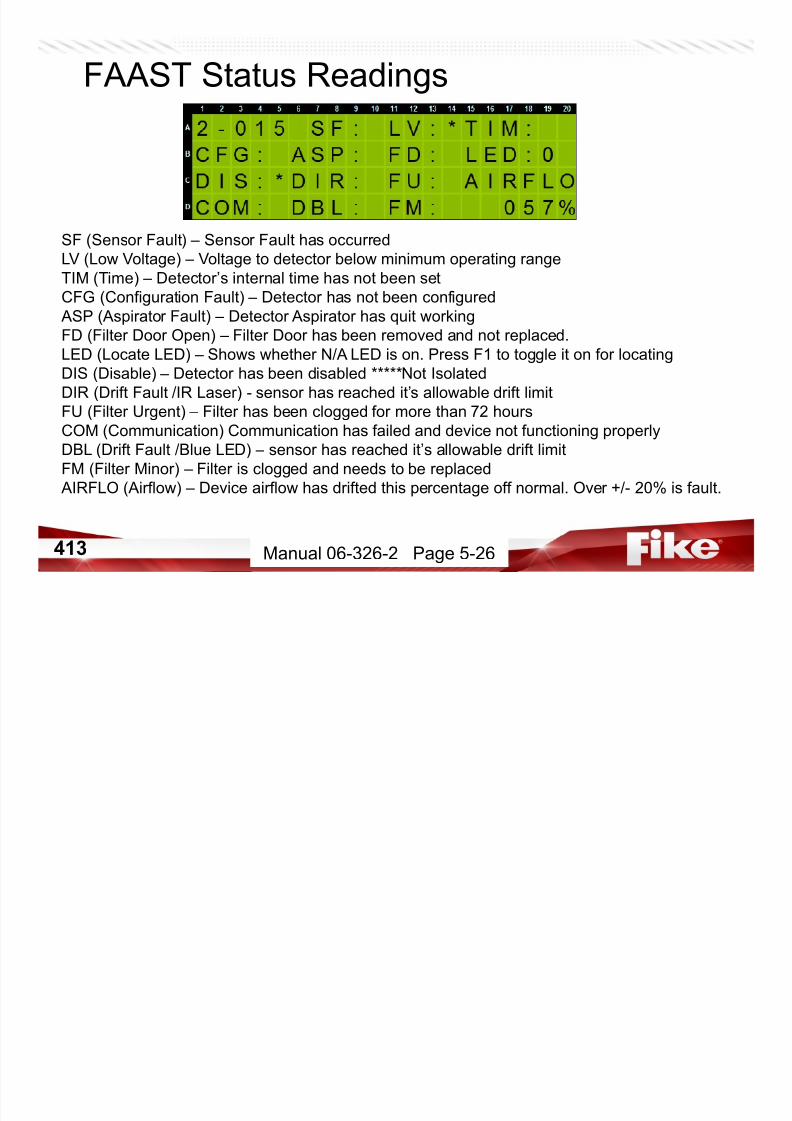
7/23/2019 CyberCat 2015 FULL Printout
http://slidepdf.com/reader/full/cybercat-2015-full-printout 413/429
414
CyberCat LCD Display
– If Fault is present, CyberCat history will show event.
This was caused by Airflow fault shown in previous screen
Manual 06-326-2 Page 5-26

7/23/2019 CyberCat 2015 FULL Printout
http://slidepdf.com/reader/full/cybercat-2015-full-printout 414/429
415
CyberCat LCD Display
• Diagnostic Menu 5 (D5) – Press ESCAPE twice back to MENU 5
F1 = Page Status
F2 = Audio Priority Status
F3 = Play Message ID Status
F4 = FAAST Detector Status
F5 =F6 = Diagnostics Menu 1
Manual 06-326-2 Page 5-16
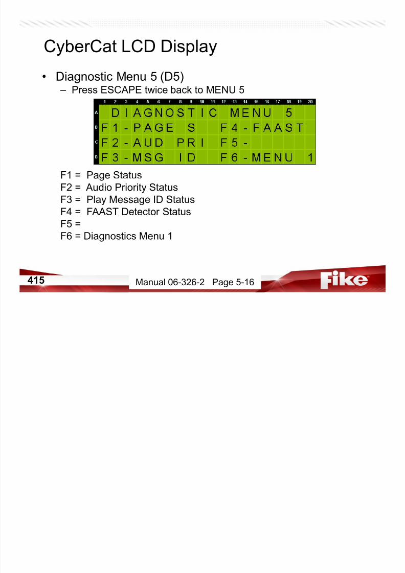
7/23/2019 CyberCat 2015 FULL Printout
http://slidepdf.com/reader/full/cybercat-2015-full-printout 415/429
416
• Diagnostic Menu 1 (D1) – Press F6 – to go all the way back to DIAGNOSTIC MENU 1
F1 = Perform diagnostics on addressable devices
F2 = Panel diagnostics – Ground Fault
F3 = Panel diagnostics
F4 = Turn on all panel LEDs for 4 seconds. Also turns all LCD
characters solid during this time. (Trouble LED flashes)F5 = Firmware CRC value
F6 = Go to Diagnostics Menu 2
CyberCat Service & Troubleshooting
Manual 06-326-2 Page 5-3

7/23/2019 CyberCat 2015 FULL Printout
http://slidepdf.com/reader/full/cybercat-2015-full-printout 416/429
417
CyberCat LCD Display
• Top Level Menu – Press ESCAPE until Top Level Menu screen appears
F1 = Access System Configuration Menus (Level 3 Password)
F2 = Event History Menus
F3 = Diagnostic Tools
F4 = Password Entry Screen
F5 = System Maintenance MenusF6 = Enable IR Communications by loop
Manual 06-326-2 Page 5-3

7/23/2019 CyberCat 2015 FULL Printout
http://slidepdf.com/reader/full/cybercat-2015-full-printout 417/429
418
CyberCat LCD Display
• System Status – Press ESCAPE until System Status screen appears
Line A = Firmware Version
Line B = 20 character custom logo
Line C = Current system time and date
Line D = Current # of Alarm, Supervisory, and Trouble Events
NOTE: Panel returns to this screen after 100 seconds of no activity.

7/23/2019 CyberCat 2015 FULL Printout
http://slidepdf.com/reader/full/cybercat-2015-full-printout 418/429
Manual 06-639

7/23/2019 CyberCat 2015 FULL Printout
http://slidepdf.com/reader/full/cybercat-2015-full-printout 419/429
420
Fike PhD (From Fike Forums)

7/23/2019 CyberCat 2015 FULL Printout
http://slidepdf.com/reader/full/cybercat-2015-full-printout 420/429
421
Fike PhD (From Fike Forums)
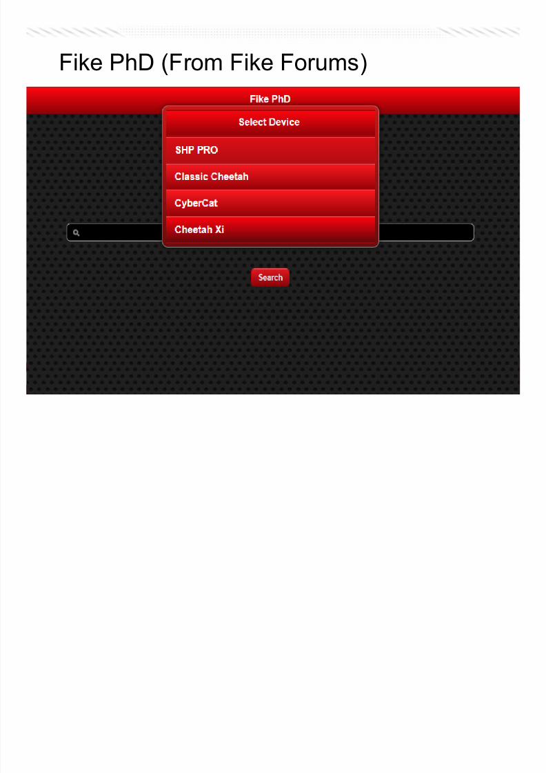
7/23/2019 CyberCat 2015 FULL Printout
http://slidepdf.com/reader/full/cybercat-2015-full-printout 421/429
422
Fike PhD (From Fike Forums)

7/23/2019 CyberCat 2015 FULL Printout
http://slidepdf.com/reader/full/cybercat-2015-full-printout 422/429
423
CyberCat DACT Reporting (Version 5.0)
Product UpdateSDC06-005 (UPDATED)
….these codes have been added to the list of codes sent over DACT

7/23/2019 CyberCat 2015 FULL Printout
http://slidepdf.com/reader/full/cybercat-2015-full-printout 423/429
424
CyberCat DACT Reporting
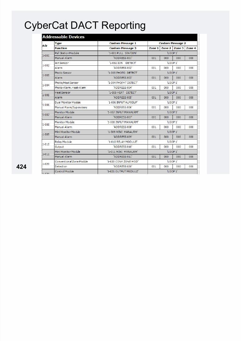
7/23/2019 CyberCat 2015 FULL Printout
http://slidepdf.com/reader/full/cybercat-2015-full-printout 424/429
425
• Voltages – Test Points
• TP1 = System ground/common
• TP2 = System voltage, +24VDC to TP1
– SLC Voltage• +24VDC, SLC + to SLC –
• Fluctuates with data traffic (22VDC to 27VDC**)
– Ground Fault Voltages• Measured TP1 to Chassis
• Level 1 Ground Fault Bias, Ideal = 2.17VDC
– Equates to 110-111 on Ground Fault Diagnostics menu
– Normal voltage range is 1.67VDC (ADC 85) to 2.35VDC (ADC 120)
• Level 2 Ground Fault Bias, Ideal = 5.00VDC
– Equates to 255 on Ground Fault Diagnostics menu
– Normal voltage range is 3.73VDC (ADC 190) to 5VDC (ADC 255)
CyberCat Service & Troubleshooting

7/23/2019 CyberCat 2015 FULL Printout
http://slidepdf.com/reader/full/cybercat-2015-full-printout 425/429
426
CyberCat DACT Reporting
ADC10-001…these codes have been added to the list of codes in
Technical Bulletin ADC06-005 in Tab 5.
Product Update ADC10-001

7/23/2019 CyberCat 2015 FULL Printout
http://slidepdf.com/reader/full/cybercat-2015-full-printout 426/429
427
WARNING ! ! ! ! ! ! ! ! !• Never Read a disabled
device or device with
Device Error Message
• Never…Never...Never
pull the configuration
from a panel while
devices are disabled!
• Build configuration
from scratch…don’tpull from NEW devices
and just modify.

7/23/2019 CyberCat 2015 FULL Printout
http://slidepdf.com/reader/full/cybercat-2015-full-printout 427/429
428
Questions?Ready for Exam?

7/23/2019 CyberCat 2015 FULL Printout
http://slidepdf.com/reader/full/cybercat-2015-full-printout 428/429
429
• Phone (888) 628-3453
• Customer Service Option 1
• Technical Support Option 2
• Fax (866) 211-9239

7/23/2019 CyberCat 2015 FULL Printout
http://slidepdf.com/reader/full/cybercat-2015-full-printout 429/429
430
Thank you for attending
CyberCat Training!!