d betriebsanleitung für regelventile baelz 334367 gb
TRANSCRIPT

baelz 356DN 15... 65
baelz 340-BDN 15...125
StänderYoke
ArcadeS41
baelz 340-BBDN 150... 300
baelz 347-BBDN 150
Fig. 1 Fig. 2
Fig. 3 Fig. 4
StänderYoke
ArcadeS21
- für Baelz-Regelventile mit elektrischem oder pneumatischem Stellantrieb - for Baelz control valves with electric or pneumatic actuators - pour des vannes de régulation Baelz avec servomoteur électrique ou pneumatique
1 | /34W. Baelz & Sohn GmbH & Co. · Koepffstrasse 5 · 74076 Heilbronn · Germany · www.baelz.de Seite | Page
MB
A_334-367_01_D
EF_M
J_3920
D Betriebsanleitung für Regelventile baelz 334...367GB Operating Instructions for control valves baelz 334...367 F Mode d'emploi pour les vannes de régulation baelz 334...367
D GB F MBA baelz 334...367
Technische Änderungen vorbehalten Schutzvermerk ISO 16016 beachtenTechnical specifications subject to change without notice Observe copyright protection ISO 16016Sous réserve de modifications techniques Respecter le droit de reproduction réservé ISO 16016
INHALTSVERZEICHNIS
1. Sicherheit 42. Lieferzustand 53. Transportieren und Heben 54. Kennzeichnung der Armaturen - Typenschilder 65. Einbau 76. Elektrischer Anschluss 87. Wartung 88. Wechsel der Spindeldichtung (V-Manschettensatz) 99. Praktische Hinweise zur Einbindung der Regelventile in die Rohrleitungen 910. Anhang Appendix Annexe 22
10.1 Einbaurichtung Direction of Installation Sens de montage 2210.2 Zulässige Einbaulage Correct Installation Montage correct 2210.3 Isolierung Insulation Isolation 2310.4 SchmierungbeiWiedermontageGreasinguponRefittingGraissagelorsduremontage 2310.5 WiedermontageundAnzugsdrehmomenteRefittingandtighteningtorquesRemontageetcouplesdeserrage 2410.6 Wechsel der Spindeldichtung Changing the Spindle Seal Remplacement des joints d'étanchéité de la tige 2510.7 Einbauarten Installation Examples Exemples de montage 33
TABLE OF CONTENTS
1. Safety notes 102. Scope of delivery 113. Transportation and lifting 114. Identificationofvalves-Nameplates 125. Installation 136. Electrical connection 147. Maintenance 148. Changing the spindle seal (V packing set) 159. Practical notes on integrating the control valves in pipelines 1510. Anhang Appendix Annexe 22
10.1 Einbaurichtung Direction of Installation Sens de montage 2210.2 Zulässige Einbaulage Correct Installation Montage correct 2210.3 Isolierung Insulation Isolation 2310.4 SchmierungbeiWiedermontageGreasinguponRefittingGraissagelorsduremontage 2310.5 WiedermontageundAnzugsdrehmomenteRefittingandtighteningtorquesRemontageetcouplesdeserrage 2410.6 Wechsel der Spindeldichtung Changing the Spindle Seal Remplacement des joints d'étanchéité de la tige 2510.7 Einbauarten Installation Examples Exemples de montage 33
2 | /34W. Baelz & Sohn GmbH & Co. · Koepffstrasse 5 · 74076 Heilbronn · Germany · www.baelz.de Seite | Page
D GB F MBA baelz 334...367

SOMMAIRE
1. Consignes de sécurité 162. Etat de livraison 173. Transport et levage 174. Marquage de vannes - Plaques signalétiques 185. Montage 196. Raccordement électrique 207. Maintenance 208. Remplacement du presse étoupe (jeu de garniture en V) 219. Remarques pratiques d'intégration des vannes dans les tuyauteries 2110. Anhang Appendix Annexe 22
10.1 Einbaurichtung Direction of Installation Sens de montage 2210.2 Zulässige Einbaulage Correct Installation Montage correct 2210.3 Isolierung Insulation Isolation 2310.4 SchmierungbeiWiedermontageGreasinguponRefittingGraissagelorsduremontage 2310.5 WiedermontageundAnzugsdrehmomenteRefittingandtighteningtorquesRemontageetcouplesdeserrage 2410.6 Wechsel der Spindeldichtung Changing the Spindle Seal Remplacement des joints d'étanchéité de la tige 2510.7 Einbauarten Installation Examples Exemples de montage 33
MB
A_334-367_01_D
EF_M
J_3920
3 | /34W. Baelz & Sohn GmbH & Co. · Koepffstrasse 5 · 74076 Heilbronn · Germany · www.baelz.de Seite | Page
D GB F MBA baelz 334...367

Diese Montage- und Betriebsanleitung enthält grundlegende Hinweise, die bei Aufstellung, Betrieb und Wartung zu beachten sind. Sie ist daher unbedingt vor Montage und Inbetriebnahme vom Monteur, sowie dem zuständigen Fachpersonal / Betreiber zu lesen. Sie muss ständig am Einsatzort der Anlage verfügbar sein. Diese Montage- und Betriebsanleitung bezieht sich auf Motorbetriebene Regelarmaturen.
Es sind nicht nur die unter diesem Abschnitt „Sicherheitshinweise“ aufgeführten, allgemeinen Sicherheits-hinweise zu beachten, sondern auch die unter den anderen Abschnitten eingefügten Hinweise.
1. SICHERHEIT
1.1 Allgemeines
1.2 Personalqualifikationund-schulung
Die in dieser Montage- und Betriebsanleitung enthaltenen Sicherheitshinweise, die bei Nichtbeachtung Gefährdungen für Personen hervorrufen können, sind mit dem allgemeinen Gefahrensymbol „Sicherheitszeichen nach DIN EN ISO 7010-W001" besonders gekennzeichnet.
Direkt an der Anlage angebrachte Hinweise wie z.B.- Richtungspfeil- Kennzeichnung für Fluidanschlüssemüssen unbedingt beachtet und in vollständig lesbarem Zustand gehalten werden.
DasPersonalfürBedienung,Wartung,InspektionundMontagemussdieentsprechendeQualifikationfürdiese Arbeiten aufweisen. Verantwortungsbereich, Zuständigkeit und die Überwachung des Personals müssen durch den Betreiber genau geregelt sein.
1.3 Gefahren bei Nichtbeachtung der Sicherheitshinweise
Die Nichtbeachtung der Sicherheitshinweise kann sowohl eine Gefährdung für Personen, als auch für die Umwelt und Anlage zur Folge haben. Die Nichtbeachtung der Sicherheitshinweise kann zum Verlust jeglicher Schadensersatzansprüche führen.
Im einzelnen kann Nichtbeachtung beispielsweise folgende Gefährdungen nach sich ziehen:• Versagen wichtiger Funktionen der Anlage• Versagen vorgeschriebener Methoden zur Wartung und Instandhaltung• Gefährdung von Personen durch elektrische und mechanische Einwirkungen
1.4 Sicherheitsbewusstes Arbeiten
1.5 Sicherheitshinweise für den Betreiber / Bediener
Die in dieser Montage- und Betriebsanleitung aufgeführten Sicherheitshinweise, die bestehenden nationalen Vorschriften zur Unfallverhütung, sowie eventuelle interne Arbeits-, Betriebs- und Sicherheitsvorschriften des Betreibers, sind zu beachten.
EinvorhandenerBerührungsschutzfürsichbewegendeTeiledarfbeisichinBetriebbefindlicherAnlagenicht entfernt werden.
Gefährdungen durch elektrische Energie sind auszuschließen (Einzelheiten hierzu siehe z.B. in den Vorschriften des VDE und der örtlichen Energieversorgungsunternehmen).
Achtung:
4 | /34W. Baelz & Sohn GmbH & Co. · Koepffstrasse 5 · 74076 Heilbronn · Germany · www.baelz.de Seite | Page
D MBA baelz 334...367
1.6 Sicherheitshinweise für Wartungs-, Inspektions- und Montagearbeiten
Der Betreiber hat dafür zu sorgen, dass alle Wartungs-, Inspektions- und Montagearbeiten von autorisiertem undqualifiziertemFachpersonalausgeführtwerden,dassichdurcheingehendesStudiumderMontage-undBetriebsanleitung ausreichend informiert hat.
Grundsätzlich sind Arbeiten an Armaturen und deren Antrieben nur im Stillstand durchzuführen. Bei Montagearbeiten darf der Kegel nicht unter Anpreßdruck auf dem Sitz gedreht werden. Die in der Montage- und Betriebsanleitung beschriebene Vorgehensweise zum Stillsetzen der Anlage muss unbedingt eingehalten werden.
Rückstände in Rohrleitungen und Armaturen (wie Schmutz, Schweißperlen usw.) führen zu Undichtigkeiten bzw. Beschädigungen.
Unmittelbar nach Abschluss der Arbeiten müssen alle Sicherheits- und Schutzeinrichtungen wieder angebracht, bzw. in Funktion gesetzt werden.
1.7 Eigenmächtiger Umbau und Ersatzteilherstellung
Umbau oder Veränderungen an Armaturen und deren Antrieben sind nur nach Absprache mit dem Hersteller zulässig. Originalersatzteile und vom Hersteller autorisiertes Zubehör dienen der Sicherheit. Die Verwendung anderer Teile kann die Haftung für die daraus entstehenden Folgen aufheben.
1.8 Unzulässige Betriebsweisen
Die Betriebssicherheit der gelieferten Armaturen ist nur bei bestimmungsgemäßer Verwendung gewährleistet. Die in den technischen Daten angegebenen Grenzwerte dürfen auf keinen Fall überschritten werden.
2. LIEFERZUSTAND
Die Lieferung erfolgt als fertig montiertes Stellgerät. Armatur und Antrieb sind durch den Ständer verbunden.
3. TRANSPORTIEREN UND HEBEN
3.1 Transportieren
Das Stellventil kann mithilfe von Hebezeugen wie z.B. einem Kran oder Gabelstapler transportiert werden.
• Stellventil für den Transport auf der Palette oder im Transportbehälter lassen.•StellventilvoräußerenEinflüssenwiez.B.Stößenschützen.•Lackierung,Oberflächenbeschichtungnichtbeschädigen.Beschädigungsofortbeseitigen.• Stellventil vor Nässe und Schmutz schützen.
3.2 Heben
Für den Einbau des Stellventils in die Rohrleitung können größere Ventile mithilfe von Hebezeugen wie z.B. einem Kran oder Gabelstapler angehoben werden.
Bei Betrieb mit hohen (> 50 °C) oder tiefen (< 0 °C) Medientemperaturen besteht Verletzungsgefahr bei Berührung der Armatur. Gegebenenfalls Warnhinweise oder Isolierschutz anbringen!
Achtung:
MB
A_334-367_01_D
EF_M
J_3920
5 | /34W. Baelz & Sohn GmbH & Co. · Koepffstrasse 5 · 74076 Heilbronn · Germany · www.baelz.de Seite | Page
D MBA baelz 334...367

Bedingungen für das Heben
• Anschlagmittel gegen Verrutschen und Abrutschen sichern.• Anschlagmittel so befestigen, dass sie nach dem Einbau in
die Rohrleitung wieder entfernt werden können.• Schwingen und Kippen des Stellventils vermeiden.• Bei Arbeitsunterbrechungen Last nicht über längeren
Zeitraum am Hebezeug in der Luft schweben lassen.• Sicherstellen, dass die Achse der Rohrleitung beim Heben
stets horizontal und die Achse des Antriebsständers stets vertikal bleibt (Fig. 5).
4. KENNZEICHNUNG DER ARMATUREN - TYPENSCHILDER
Fig. 5
Fig. 6 Armatur baelz 334, 335, 340, 342, 347, 365, 367
Fig. 7 Armatur baelz 344, 358, 359, 360
Fig. 8 Armatur baelz 356, 353, 354
6 | /34W. Baelz & Sohn GmbH & Co. · Koepffstrasse 5 · 74076 Heilbronn · Germany · www.baelz.de Seite | Page
D MBA baelz 334...367

UmBeschädigungenandenVentil-SitzflächenbeiTransportundLagerungzuverhindern,werdendieArmaturenin geschlossenem Zustand gelierfert. Abdeckkappen an den Flanschöffnungen, den Gewindetüllen oder an den Anschweißenden, sind vor dem Einbau zu entfernen. BeimEinbaumüssendieDichtungenandenAnschlussflanschengutzentriertsein.Das Ventilgehäuse aus Rotguss (baelz 334, 335) in Durchgangs- und Dreiwegeform mit Anschweißenden (Fig. 11, Seite 8) kann auf Grund der Sitz - Kegel - Konstruktion direkt in die Rohrleitung eingeschweißt werden ohne Flansche und ohne Verschraubungen. Dichtungsprobleme an den Rohrverbindungen treten somit nicht auf, da das Gehäuse fest in die Rohrleitung eingebaut wird.Die Rohrleitung ist so zu legen, dass schädliche Schub- und Biegekräfte von den Armaturengehäusen ferngehalten werden. Beim Lackieren der Rohrleitung dürfen Stopfbuchsschrauben, Spindeln und Kunststoffteile nichtangestrichenwerden.FallsnochBauarbeitenstattfinden,sinddieArmaturenzumSchutzgegenStaub,Sand oder Baumaterialstücke abzudecken (z.B. mit Plastikhülle). Die Rohrleitungen sind vorher zu spülen. Regelarmaturen ist grundsätzlich ein Schmutzfänger vorzuschalten (Fig. 9 und Fig. 10, Seite 8).Armaturenaufbauten wie Antriebe, Hauben, Kühlrohre dürfen nicht zur Aufnahme von äußeren Kräften wie z. B. Aufstiegshilfen, Anbindungspunkte für Hebezeuge etc. zweckentfremdet werden.
5. EINBAU
5.1 Einbaurichtung
5.2 Einsatzbedingungen
Die Einströmseite ist eindeutig auf dem Typenschild gekennzeichnet (siehe auch Fig. 24 - Fig. 28, Seite 22).
Type max. zul. Temperatur TS max. zul. Druck PS 334, 335 140° C 25 bar / 140° C 340(-2)-B... 240° C nach EN 1092-1, EN 1092-2 340-AI... 342(-2)-B 347(-2)-B... 347-AI... 344 353, 354 356... 360...-EM... 250° C nach EN 1092-1 365... 232° C nach ANSI B16.5 367... (ASME B16.34-2013)
Ventil "a" (siehe Fig. 11 und Fig. 13, Seite 8)
Type max. zul. Temperatur TS max. zul. Druck PS 340(-2)-BK... 350° C nach EN 1092-1, EN 1092-2 342(-2)-BK 347(-2)-BK... 344...-K 356...-K 358-K... 359-K... 340(-2)...-EMF...-HG 315° C nach EN 1092-1, EN 1092-2 347(-2)...-EMF...-HG 360...-K 365-K... 343° C nach ANSI B16.5 367-K... (ASME B16.34-2013)
Ventil "b" (siehe Fig. 12, Seite 8)
(Fig. 11)
(Fig. 13)
(Fig. 13)
(Fig. 13)
MB
A_334-367_01_D
EF_M
J_3920
7 | /34W. Baelz & Sohn GmbH & Co. · Koepffstrasse 5 · 74076 Heilbronn · Germany · www.baelz.de Seite | Page
D MBA baelz 334...367

5.3 Zulässige Einbaulage
5.4 Isolierung
Fig. 29 - Fig. 40, Seite 22
Fig. 41 - Fig. 43, Seite 23
Fig. 9 Fig. 10
Fig. 11 Fig. 12
bb
cc
Fig. 13
Antrieb "c" (siehe Fig. 11 - Fig. 13)
Der Anschluss darf nur von Fachpersonal vorgenommen werden.
6. ELEKTRISCHER ANSCHLUSS
Achtung:
7. WARTUNG
7.1 Wartung VentilDie Ventile sind wartungsfrei. Die Spindeldichtung ist lebensdauergeschmiert. Wird eine Spindeldichtung dennoch undicht, ist sie komplett auszuwechseln und die Ursache (Schmutz, Schweißperlen, andere Fremdkörper) zu beseitigen.
Bitte beachten Sie hierzu die separaten Betriebsanleitungen unserer elektrischen Antriebe.
c
a
TÜV-geprüfte Ventilausführungen: Type Größe max. zul. max. zul. Druck PS
Temp. TS
340-B DN15-65 PN 16 240° C
340-BK DN15-65 PN 16 310° C
12,3 bar bei 240º C16 bar bei 50º C10,8 bar bei 310º C16 bar bei 50º C
Sitz-Leckrate der Ventilausführungen:für Durchgangsventile und baelz 347, 353, 354, 367: 0,004 % Kvs für baelz 335, 342 Eckweg (B - AB): 2 % Kvsfür baelz 360...-EM...: 0,05 % KvsDie Standardleckrate ist bei baelz 0,004 % Kvs
Type Größe max. zul. max. zul. Druck PS Temp. TS
340-B DN15-65 PN 25 240° C
340-BK DN15-65 PN 25 310° C
19,3 bar bei 240º C25 bar bei 50º C16,9 bar bei 310º C25 bar bei 50º C
Type 373- Umgebungsbedingungen SchutzartE07 0°...+50°C / 0-75 % r.F. IP 42E45 -10°...+50°C / 0-75 % r.F. IP 65E63 -30°...+70°C IP 68E64 -20°...+60°C IP 67E65 -10°...+55°C / <95 % r.F. IP 66E66 -10°...+50°C / 0-75 % r.F. IP 65E88 -40°...+60°C / 0-75 % r.F. IP 68P... +80°C / 0-90 % r.F. *
* IP-Schutzart der Stellungsregler und anderer Zusatzgeräte für pneumatische Antriebe: IP 65 oder besser. Siehe Typenschilder oder Betriebsanleitung BA baelz 373-P.
8 | /34W. Baelz & Sohn GmbH & Co. · Koepffstrasse 5 · 74076 Heilbronn · Germany · www.baelz.de Seite | Page
D MBA baelz 334...367

7.2 Wartung Antrieb
Während der Wartung und Instandhaltung darf der Antrieb nicht elektrisch / pneumatisch betätigt werden.Achtung:
Bitte beachten Sie hierzu die separaten Betriebsanleitungen unserer elektrischen und pneumatischen Antriebe.
Bitte beachten Sie hierzu die separaten Betriebsanleitungen unserer elektrischen Antriebe mit Notstellfunktion bzw. Netzausfallsicherung!
Achtung:
8. WECHSEL DER SPINDELDICHTUNG (V-MANSCHETTENSATZ)Nach Abbau des Antriebes können Sie die Überwurfmutter bzw. Druckschraube mit V-Manschettensatz abschrauben. Wechseln Sie die V-Manschetten nur komplett mit Feder (Fig. 46, Seite 25 - Fig. 93, Seite 32). Zusätzliche Ersatzteilzeichnungen erhalten Sie auf Anfrage.Prüfen Sie die Kegelspindel sorgfältig auf Beschädigungen. Sollten Sie Rillen und Kratzern im Packungsbereich feststellen, wechseln Sie die Kegelspindel.
9. PRAKTISCHE HINWEISE ZUR EINBINDUNG DER REGELVENTILE IN DIE ROHRLEITUNGEN
Seiten 33 und 34 zeigen die am meisten verwendeten Einbauarten von Regelventilen in Rohrleitungen für Dampf und für Flüssigkeiten. Der richtige projektbezogene Einbau und der bei Nennmenge zulässige Druckabfall ∆pvdesRegelventilessindfürdieGütederRegelqualitätbestimmendeFaktoren.DieBilderaufdenSeiten 33 und 34 sollen helfen, diese beiden Punkte korrekt zu wählen. Bei Unklarheiten halten Sie bitte Rücksprache mit der Firma Bälz. Für Regelarmaturen gilt als Faustformel: Der Druckabfall über das Ventil ∆pv bei Nennmenge soll mindestens genauso groß sein wie der Druckabfall ∆pw im zugeordneten Verbraucher oder idealerweise 2 - 5 mal größer.Armaturen für Druckreduzierungen werden selbstverständlich entsprechend dem benötigten Druckabfall ausgelegt, wobei die einschlägigen Lärmschutzvorschriften zu beachten sind. Für Dreiwegeventile wird zwischen Mischventilen (Fig. 106 bis Fig. 109, Seite 34) und Umstellventilen (Fig. 111 bis Fig. 116, Seite 34) unterschieden. Bälz - Dreiwegeventile sind konstruktiv als Mischventile konzipiert. Werden diese Ventile als Umstellventile eingesetzt, darf der Druckabfall max. 0,6 bar betragen; für Anwendungen mit höheren Druckabfällen bietet Bälz auf Anfrage gerne Alternativlösungen.Für Anlagen entsprechend Fig. 111 und Fig. 116 empfehlen wir die Type baelz 347 (beide Wege - Leckage-Klasse 0,004% Kvs).Für alle anderen Varianten ist die Type baelz 342 (Weg B - Leckage-Klasse 2% Kvs) durchaus geeignet.
Legende:
Absperrventil
Schmutzfänger
Fig. 14
Fig. 19
Motor-Regelventil
Kondensatableiter
Fig. 15
Fig. 20
PneumatischesRegelventil
Rückschlagventil
Fig. 16
Fig. 21
Dreiwege-MotorRegelventil
Wärmetauscher
Fig. 17
Fig. 22
Dreiwege-MembranRegelventil
Pumpe
Fig. 18
Fig. 23
MB
A_334-367_01_D
EF_M
J_3920
9 | /34W. Baelz & Sohn GmbH & Co. · Koepffstrasse 5 · 74076 Heilbronn · Germany · www.baelz.de Seite | Page
D MBA baelz 334...367

These installation and operating instructions contain basic information which must be observed on installing, operationandmaintenance.Theymustthereforebereadbythefitteraswellastheresponsibletechnicalpersonnel/operator without fail before installation and start-up. They must be constantly available at the location of the plant. These installation and operating instructions refer to motor driven control valves.
Notonlythegeneralsafetynotesinthis"SafetyNotes"section,butalsospecificsafetynotesincludedinother sections should be observed.
1. SAFETY NOTES
1.1 General
1.2 Personnelqualificationandtraining
The safety notes contained in these installation and operating instructions, which can cause danger to personswhennotobserved,arespeciallyidentifiedwiththegeneralhazardsymbol"Safetysymbol"according to DIN EN ISO 7010-W001".
Indications directly attached to the system, such as- Direction arrow-Identificationforfluidconnectionsmust be observed without fail and kept in a completely legible condition.
Thepersonnelforoperation,maintenance,inspectionandinstallationmusthavethecorrespondingqualificationfor this work. Responsibility and supervision of the personnel must be regulated accurately by the operator.
1.3 Danger on non-observance of the safety notes
Non-observance of the safety notes can result in both danger for persons and also for the environment and plant. Non-observance of the safety notes lead to the loss of any claims for compensation.
In detail, non-observance can result in the following hazards, for instance:• Failure of important functions of the plant• Failureofspecifiedmethodsformaintenanceandrepair• Endangering persons by electrical and mechanical effects
1.4 Safety-conscious working
1.5 Safety notes for the operator / user
The safety notes listed in these installation and operating instructions, the existing national regulations for accident prevention as well as possible internal working, operating and safety regulations of the operator shall be complied with.
An existing guard for moving parts must not be removed when the plant is in operation.
Hazards due to electrical energy must be prevented (for details please refer to the regulations of the VDE and of the local power supply utility, for instance).
Caution:
10 | /34W. Baelz & Sohn GmbH & Co. · Koepffstrasse 5 · 74076 Heilbronn · Germany · www.baelz.de Seite | Page
GB MBA baelz 334...367

1.6 Safety notes for maintenance, inspection and installation work
The operator shall ensure that all maintenance, inspection and installation work is performed by authorized and qualifiedskilledpersonnelwhoarefamiliarwiththeinstallationandoperatinginstructions.
Workonvalvesandtheirdrivesshouldonlybecarriedoutatstandstill.Duringfittingwork,donotturntheplugin the valve seat whilst applying contact pressure.The procedure for shutting down the plant as described in the installation and operating instructions must be followed.
Residues in piping and valves (e.g. dirt, welding beads, etc.) cause leakage and / or damage to installations.
Immediatelyaftercompletionofthework,allsafetyandprotectivedevicesmustberefittedorputbackinto operation.
1.7 Unauthorized alterations and spare parts manufacture
Alterations to valves and their drives are permitted only after consultation with the manufacturer. Original spare parts and accessories authorized by the manufacturer serve to promote safety. The use of other parts can nullify theliabilityfortheresultingconsequences.
1.8 Inadmissible operating modes
Operating safety of the delivered valves is guaranteed only when they are used as directed. The limiting values stated in the technical data must not be exceeded under any circumstances.
2. SCOPE OF DELIVERY
Delivery is made as a complete unit, i.e. actuator, yoke and valve are one pre-assembled unit.
3. TRANSPORTATION AND LIFTING
3.1 Transportation
Thecontrolvalvecanbetransportedusingliftingequipment(e.g.craneorforklift).
• Leave the control valve on the pallet or in its transport container to transport it.•Protectthecontrolvalveagainstexternalinfluencessuchasimpacts.• Do not damage paint, surface coatings. Remove any damage immediately. • Protect the control valve against moisture and dirt.
3.2 Lifting
Toinstallthecontrolvalveintothepipeline,largevalvescanbeliftedusingliftingequipmente.g.acraneorforklift.
Mediums being transported at high (> 50 °C) or low (< 0 °C) temperatures can cause danger of injury upon contact with the valve. Apply clearly visible warning signs or insulation where necessary.
Caution:
MB
A_334-367_01_D
EF_M
J_3920
11 | /34W. Baelz & Sohn GmbH & Co. · Koepffstrasse 5 · 74076 Heilbronn · Germany · www.baelz.de Seite | Page
GB MBA baelz 334...367

4. IDENTIFICATION OF VALVES - NAMEPLATES
Lifting instructions
• Secure slings against slipping.• Make sure the slings can be removed from the valve once it has
been installed into the pipeline.• Prevent the control valve from tilting or tipping.• Do not leave loads suspended when interrupting work for longer
periods of time.• Make sure that the axis of the pipeline is always horizontal
during lifting and the axis of the yoke is always vertical (Fig. 5).
Fig. 5
Fig. 6 valve baelz 334, 335, 340, 342, 347, 365, 367
Fig. 7 valve baelz 344, 358, 359, 360
Fig. 8 valve baelz 356, 353, 354
12 | /34W. Baelz & Sohn GmbH & Co. · Koepffstrasse 5 · 74076 Heilbronn · Germany · www.baelz.de Seite | Page
GB MBA baelz 334...367

To prevent damage to valve seats during transport and storage, the valves are supplied in closed condition. Removeprotectivecapsonflangeopenings,threadedsleevesorweldingendsbeforeinstallation.
Wheninstalling,thesealsontheconnectingflangesmustbewellcentred.Due to its seat-plug design, the 2-way or 3-way type valve body made of red brass (baelz 334, 335) with welding endscanbeweldeddirectlyintothepipelinewithouttheuseofflangesorthreadedconnections.Thispreventssealingproblemsonthepipeconnectionsasthehousingisfirmlyinstalledinthepipeline.
The pipeline must be routed so as to keep damaging thrust and bending forces away from the valve housings. When painting the pipeline, do not paint gland screws, spindles and plastic parts. If construction work is still in progress, cover the valves to protect them from dust, sand or pieces of building material (e.g. with a plastic cover). Thepipelinesmusthavepreviouslybeenflushed.Alwaysfitastrainerupstreamofthecontrolvalve(Fig. 9 and Fig. 10, page 14).
Components of the valve assembly such as actuators, covers and cooling tubes must not be misused to support external loads such as climbing aids, attachment points for hoists, etc.
5. INSTALLATION
5.1 Installation note
5.2 Conditions of use
Theinflowsideisclearlymarkedonthenameplate(seealsoFig. 24 - Fig. 28, page 22).
Type max. admissible temp. TS max. admissible pressure PS 334, 335 140° C 25 bar / 140° C 340(-2)-B... 240° C acc. to EN 1092-1, EN 1092-2 340-AI... 342(-2)-B 347(-2)-B... 347-AI... 344 353, 354 356... 360...-EM... 250° C acc. to EN 1092-1 365... 232° C acc. to ANSI B16.5 367... (ASME B16.34-2013)
Valve "a" (see Fig. 11 and Fig. 13, page 14)
Type max. admissible temp. TS max. admissible pressure PS 340(-2)-BK... 350° C acc. to EN 1092-1, EN 1092-2 342(-2)-BK 347(-2)-BK... 344...-K 356...-K 358-K... 359-K... 340(-2)...-EMF...-HG 315° C acc. to EN 1092-1, EN 1092-2 347(-2)...-EMF...-HG 360...-K 365-K... 343° C acc. to ANSI B16.5 367-K... (ASME B16.34-2013)
Valve "b" (see Fig. 12, page 14)
(Fig. 11)
(Fig. 13)
(Fig. 13)
(Fig. 13)
MB
A_334-367_01_D
EF_M
J_3920
13 | /34W. Baelz & Sohn GmbH & Co. · Koepffstrasse 5 · 74076 Heilbronn · Germany · www.baelz.de Seite | Page
GB MBA baelz 334...367

Type Size max. temp. TS
340-B DN15-65 PN 16 240° C
340-BK DN15-65 PN 16 310° C
5.3 Correct installation position
5.4 Insulation
Fig. 9 Fig. 10
Fig. 11 Fig. 12
Actuator "c" (see Fig. 11 - Fig. 13)
Electricalfittingandconnectionshouldonlybecarriedoutbyqualifiedpersonnel.
6. ELECTRICAL CONNECTION
Caution:
7. MAINTENANCE
7.1 Valve maintenanceThe valves are maintenance-free. The spindle seal is permanently lubricated for life. Nevertheless, should a spindle seal develop leaks, it must be replaced completely and the cause eliminated (dirt, welding beads, other foreign bodies).
Please observe the separate Operating Instructions regarding our motorized actuators.
TÜV-tested valve types:
12.3 bar at 240º C16 bar at 50º C10.8 bar at 310º C16 bar at 50º C
Seat leakage rate of the valve types:for 2-way valves and baelz 347, 353, 354, 367: 0.004 % Kvsfor baelz 335, 342 angle way (B - AB): 2 % Kvsfor baelz 360...-EM...: 0.05 % KvsThestandardleakageclassificationforbaelzvalves is 0,004 % of Cv.
max. pressure PS
Type Size max. temp. TS
340-B DN15-65 PN 25 240° C
340-BK DN15-65 PN 25 310° C
19.3 bar at 240º C25 bar at 50º C16.9 bar at 310º C25 bar at 50º C
max. pressure PS
Fig. 13
Fig. 29 - Fig. 40, page 22
Fig. 41 - Fig. 43, page 23
Type 373- Environmental Conditions Ingress Protection Rating
E07 0°...+50°C / 0-75 % r.F. IP 42E45 -10°...+50°C / 0-75 % r.F. IP 65E63 -30°...+70°C IP 68E64 -20°...+60°C IP 67E65 -10°...+55°C / <95 % r.F. IP 66E66 -10°...+50°C / 0-75 % r.F. IP 65E88 -40°...+60°C / 0-75 % r.F. IP 68P... +80°C / 0- 90% r.F. *
bb
ccc
a
* IP-rating of positioners and other accessories for pneumatic actuators: IP 65 or better. See individual nameplates or operating instructions BA baelz 373-P.
14 | /34W. Baelz & Sohn GmbH & Co. · Koepffstrasse 5 · 74076 Heilbronn · Germany · www.baelz.de Seite | Page
GB MBA baelz 334...367

7.2 Actuator maintenance
8. CHANGING THE SPINDLE SEAL (V PACKING SET)After dismantling the drive, the pressure screw or the head piece with V packing set can be unscrewed.Change the V packings only complete with spring (Fig. 46, page 25 to Fig. 93, page 32). Additional replacementpartsdrawingscanbeprovidedonrequest.The spindle must be examined carefully for damage. If it has grooves or scratches in the packing area, change the spindle as well.
9. PRACTICAL NOTES ON INTEGRATING THE CONTROL VALVES IN PIPELINES
Pages 33 and 34 show the most common types of installation of control valves used in pipelines for steam andliquids.Thecorrectproject-relatedandthepermissiblepressuredropatnominalamount∆pv of the control valvearedeterminingfactorsforthecontrolquality.Thepicturesonpages33 and 34 are intended to help in choosing these two points correctly. If you are not clear please consult Baelz. The following rule of thumb applies for control valves: The pressure drop over the valve ∆pv at nominal amount should be at least exactly as large as the pressure drop ∆pw in the associated load or - which is better - 2 - 5 times larger.Valveforpressurereductionsandnaturallydesignedcorrespondingtotherequiredpressuredrop,wherebythe noise level allowed today must be taken into account primarily. For three-way valves a distinction is made between mixing valves (Fig. 106 to Fig. 109, page 34) and changeover valves (Fig. 111 to Fig. 116, page 34). Baelz three-way valves are designed as mixing valves. If these valves are used as changeover valves, the pressure drop may be max. 0.6 bar; please consult Baelz for higher pressure drops. For installation corresponding to Fig. 111 and Fig. 116werecommendtheTypebaelz347(leakageclassificationboth ways 0.004% of Cv).ForallotherversionstheTypebaelz342(wayBleakageclassification2%ofCv)isbyallmeanssuitable.
Do not electrically operate the actuator while performing maintenance or service procedures.Caution:
Please observe the separate Operating Instructions regarding Baelz motorized actuators.
Please take particular note of the separate Operating Instructions regarding our motorized actuators with fail-safe function!
Caution:
Legend:
Isolating valve
Strainer
Fig. 14
Motorized control valve
Steam trap
Fig. 15
Pneumatic control valve
Check valve
Fig. 16
3-way motorized con-trol valve
Heat exchanger
Fig. 17
Pneumatic 3-way control valve
Pump
Fig. 18
Fig. 19 Fig. 20 Fig. 21 Fig. 22 Fig. 23
MB
A_334-367_01_D
EF_M
J_3920
15 | /34W. Baelz & Sohn GmbH & Co. · Koepffstrasse 5 · 74076 Heilbronn · Germany · www.baelz.de Seite | Page
GB MBA baelz 334...367

Ces instructions de montage et de service contiennent les instructions fondamentales devant être respectées lors del'installation,del'utilisationetdelamaintenance.Ellesdoiventparconséquentimpérativementêtreluesparlemonteur et par le personnel responsable / l'utilisateur avant de procéder au montage et à la mise en service. Elles doivent toujours être présentes sur le lieu d'utilisation de l'installation. Ces instructions de montage et de service concernent les vannes de régulation commandées par moteur.Nonseulementlesconsignesdesécuritégénéralesindiquéesdansleparagraphe"Consignesdesécurité"doiventêtrerespectéesmaisaussilesremarquescontenuesdanslesautresparagraphes.
1. CONSIGNES DE SÉCURITÉ
1.1 Généralités
Attention:
Les consignes de sécurité contenues dans ces instructions de montage et de service qui, lorsqu'ellesne sont pas respectées, présentent un danger pour les personnes, sont marquées par le symbole de danger général "Signe de sécurité selon DIN EN ISO 7010-W001".
Lessymbolessetrouvantdirectementsurl'installationtelsque-flèchededirection-marquagedesraccordspourfluidesdoivent impérativement être respectés et toujours être conservés dans un état parfaitement lisible.
1.2 Qualificationetformationdupersonnel
Lepersonnelassurantl'opération,lamaintenance,l'inspectionetlemontagedoitêtrequalifiépourcestravaux.L'utilisateur doit établir exactement les régles concernant la responsabilité, la compétence et le contrôle du personnel.
1.3 Dangers dus à la non-observation des consignes de sécurité
Lanon-observationdesconsignesdesécuritérisquedemettreendangeraussibienlespersonnesquel'environnement et l'installation. La nonobservation des consignes de sécurité peut donner lieu à la perte de tout droit à la réparation du dommage.
Lanon-observationdesréglesdesécuritépeutparexempledonnerlieuauxrisquessuivants:- défaillance de fonctions importantes de l'installation- défaillance de méthodes de maintenance et de maintien en bon état-miseendangerdepersonnesenraisond'influencesélectriquesetmécaniques
1.4 Travail garantissant la sécurité
Ilfauttenircomptedesconsignesdesécuritéindiquéesdanscesinstructionsdemontageetdeservice,desprescriptionsnationalesenvigueurconcernantlaprévoyancecontrelesaccidentsainsiquedesprescriptionsdetravail, d'utilisation et de sécurité internes à l'entreprise.
1.5 Consignes de sécurité pour l'utilisateur / l'opérateurNepasôterlaprotectioncontrelesaccidentscorporelsdespiécesenmouvementlorsquel'installationestenservice.
Lesrisquesdusàl'énergieélectriquedoiventêtreexclus(pourdeplusamplesdétails,voirlesprescriptionsVDEet celles de l'entreprise d'électricité).
16 | /34W. Baelz & Sohn GmbH & Co. · Koepffstrasse 5 · 74076 Heilbronn · Germany · www.baelz.de Seite | Page
F MBA baelz 334...367
1.6 Consignes de sécurité pour les travaux de maintenance, d'inspection et de montage
L'utilisateurdoits'assurerquetouslestravauxdemaintenance,d'inspectionetdemontagesontexécutésparunpersonnelqualifiéetautoriséconnaissantlesinstructionsdemontageetdeservice.
Lestravauxréalisésauniveaudescorpsdevanneetdeleursservomoteursdoiventuniquementêtreentreprisàl'arrêt.Lorsdumontage,nepastournerleclapetdanslesiègedelavanneenappliquantunepressiondecontact. Le mode opératoire décrit dans les instructions de montage et de service doit impérativement être respecté.
Lesrésidusdanslatuyauterieetlesvannes(parexemplelasaleté,lesperlesdesoudure,etc.)provoquentdesfuites et des dommages aux installations.
Dèsl'achèvementdestravaux,touslesdispositifsdesécuritéetdeprotectiondoiventêtreremisenplaceouenservice.
1.7 Transformation non autorisée et fabrication de pièces de rechange
Toutetransformationoumodificationdescorpsdevannesetdeleursservomoteursdoituniquementêtreréaliséeaprèsavoirconsultélefabricant.Lespiècesderechangeoriginalesetlesaccessoiresautorisésparlefabricantassurentlasécurité.L'utilisationd'autrespiècespeutannulerlaresponsibilitépourlesconséquencesenrésultant.
1.8 Modes de service non admis
Lasécuritédefonctionnementdescorpslivrésn'estgarantiequ'encasd'utilisationconforme.Lesvaleurslimitesindiquéesdanslescaractéristiquestechniquesnedoiventenaucuncasêtredépassées.
2. ETAT DE LIVRAISON
La vanne de régulation est fournie vanne et servomoteur avec arcade montée pour former une seule unité.
3. TRANSPORT ET LEVAGE
3.1 Transport
Lavannederégulationpeutêtretransportéeàl'aided'appareilsdelevagetelsqu'unegrueouunchariotélévateur.
• Pour le transport, laisser la vanne de régulation sur la palette ou dans le conteneur de transport.•Protégerlavannederégulationcontretouteinfluenceextérieuretellequechocs.• Ne pas endommager la peinture, le revêtement des surfaces. Réparer immédiatement les dégâts éventuels.• Protéger la vanne de régulation contre l'humidité et les salissures.
3.2 Levage
Pour l'installation de la vanne de régulation dans la tuyauterie, des vannes de grandes dimensions peuvent être soulevéesál'aided'appareilsdelevagetelsqu'unegrueouunchariotélévateur.
Attention:
Lesfluidestransportésàdestempératuresélevées(>50°C)oubasses(<0°C)peuventprovoquerdesblessures lors de contact avec la vanne. Appliquer des panneaux d'avertissement clairement visibles ou d'isolation si nécessaire.
MB
A_334-367_01_D
EF_M
J_3920
17 | /34W. Baelz & Sohn GmbH & Co. · Koepffstrasse 5 · 74076 Heilbronn · Germany · www.baelz.de Seite | Page
F MBA baelz 334...367

Conditions de levage
• Empêcher un glissement des élingues.•Assurerquelesélinguespeuventêtreenlevéesdelavanneaprès
l'installation dans la tuyauterie.• Éviter une oscillation ou basculement de la vanne de régulation.• Lors d'une interruption de travail, ne pas laisser la charge
suspendue pendant une période de temps prolongée.•Assurerquelorsdulevagel'axedelatuyauteriesetrouvetoujours
en position horizontale et l'axe de la tige de clapet se trouve en position verticale (Fig. 5).
Fig. 5
4. MARQUAGE DE VANNES - PLAQUES SIGNALÉTIQUES
Fig. 6 Vanne baelz 334, 335, 340, 342, 347, 365, 367
Fig. 7 Vanne baelz 344, 358, 359, 360
Fig. 8 Vanne baelz 356, 353, 354
18 | /34W. Baelz & Sohn GmbH & Co. · Koepffstrasse 5 · 74076 Heilbronn · Germany · www.baelz.de Seite | Page
F MBA baelz 334...367

5. MONTAGE
5.1 Sens de montageLecôtéadmissionestclairementmarquésurlaplaquesignalétique(voiraussiFig. 24 - Fig. 28, page 22).
5.2 Conditions d'utilisation
Afind'évitertoutendommagementdessiègeslorsdutransportetdustockage,lesvannessontlivrésàl'étatfermé.Avantlemontage,enleverlescapuchonsdeprotectionsurlesbrides,lesemboutsfiletésoulesemboutsàsouder.Lors du montage, les joints d'étanchéité au niveau des brides de raccordement doivent être bien centrés.Grâceàsaconceptionsiège-clapet,lecorpsdevanneenlaitonrouge(baelz334,335)dutype2-voieset3-voiesavec embouts à souder peut être soudé directement dans la tuyauterie sans brides, sans raccords vissés. L'installationfixeducorpsdanslatuyauterieévitedesproblèmesd'étanchéitésurlesraccordsdestuyaux.Poserlatuyauterieenévitantlesforcesdetractionetdeflexionquipourraientendommagerlescorpsdevanne.Lorsquel'onpeintlatuyauterie,lesvisdepresse-étoupe,lestigesetlespiècesenmatièreplastiquenedoiventpas être peintes. En cas de travaux de construction en cours, les vannes doivent être protégées (p. ex. au moyen d'unebâcheplastique)contrelapoussière,lesableoulesmatériauxdeconstruction.Lestuyauteriesdoiventêtrerincéesaupréalable.Toujoursmonterunfiltreenamontdesvannesderégulation(Fig. 9 et Fig. 10, page 20).Lescomposantsdel'ensembledesvannestelsquelesactionneurs,lescapotsetlestubesderefroidissementnedoiventpasêtremalutiliséspoursupporterdeschargesexternestellesquedesaidesàl'escalade,despointsdefixationpourpalans,etc.
Type Temp. max. admissible TS Pression max. admissible PS 334, 335 140° C 25 bar / 140° C 340(-2)-B... 240° C selon EN 1092-1, EN 1092-2 340-AI... 342(-2)-B 347(-2)-B... 347-AI... 344 353, 354 356... 360...-EM... 250° C selon EN 1092-1 365... 232° C selon ANSI B16.5 367... (ASME B16.34-2013)
Vanne "a" (voir Fig. 11 et Fig. 13, page 20)
Type Temp. max. admissible TS Pression max. admissible PS 340(-2)-BK... 350° C selon EN 1092-1, EN 1092-2 342(-2)-BK 3478(-2)-BK... 344...-K 356...-K 358-K... 359-K... 340(-2)...-EMF...-HG 315° C selon EN 1092-1, EN 1092-2 347(-2)...-EMF...-HG 360...-K 365-K... 343° C selon ANSI B16.5 367-K... (ASME B16.34-2013)
Vanne "b" (voir Fig. 12, page 20)
(Fig. 11)
(Fig. 13)
(Fig. 13)
(Fig. 13)
MB
A_334-367_01_D
EF_M
J_3920
19 | /34W. Baelz & Sohn GmbH & Co. · Koepffstrasse 5 · 74076 Heilbronn · Germany · www.baelz.de Seite | Page
F MBA baelz 334...367
5.3 Position de montage correcte
5.4 Isolation
Fig. 9 Fig. 10
Fig. 11
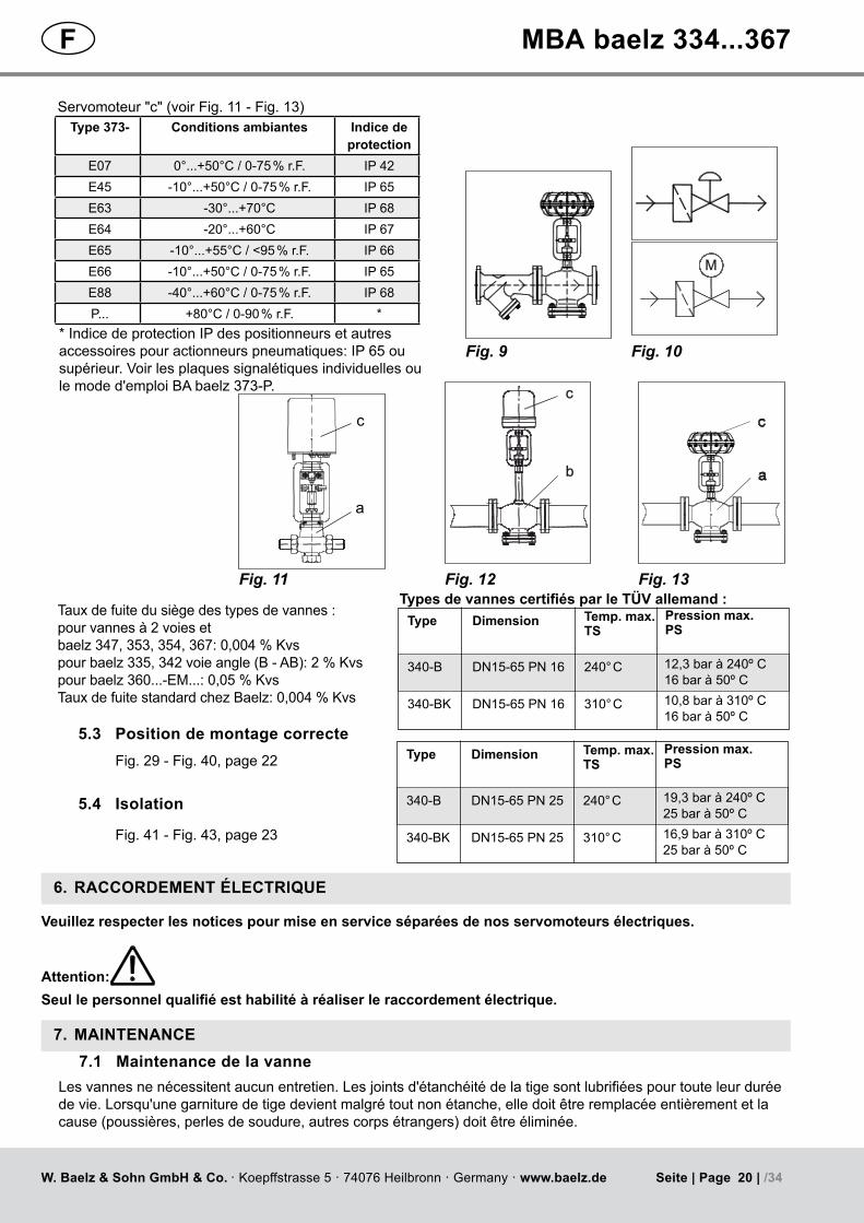
Servomoteur "c" (voir Fig. 11 - Fig. 13)
Seullepersonnelqualifiéesthabilitéàréaliserleraccordementélectrique.
6. RACCORDEMENT ÉLECTRIQUE
Attention:
7. MAINTENANCE7.1 Maintenance de la vanne
Lesvannesnenécessitentaucunentretien.Lesjointsd'étanchéitédelatigesontlubrifiéespourtouteleurduréedevie.Lorsqu'unegarnituredetigedevientmalgrétoutnonétanche,elledoitêtreremplacéeentièrementetlacause(poussières,perlesdesoudure,autrescorpsétrangers)doitêtreéliminée.
Veuillez respecter les notices pour mise en service séparées de nos servomoteurs électriques.
TypesdevannescertifiésparleTÜVallemand:Tauxdefuitedusiègedestypesdevannes:pour vannes à 2 voies et baelz 347, 353, 354, 367: 0,004 % Kvs pour baelz 335, 342 voie angle (B - AB): 2 % Kvspour baelz 360...-EM...: 0,05 % KvsTaux de fuite standard chez Baelz: 0,004 % Kvs
Type Dimension Temp. max. TS
340-B DN15-65 PN 16 240° C
340-BK DN15-65 PN 16 310° C
12,3 bar à 240º C16 bar à 50º C10,8 bar à 310º C16 bar à 50º C
Pression max. PS
Type Dimension Temp. max. TS
340-B DN15-65 PN 25 240° C
340-BK DN15-65 PN 25 310° C
19,3 bar à 240º C25 bar à 50º C16,9 bar à 310º C25 bar à 50º C
Pression max. PS
Fig. 12 Fig. 13
Fig. 29 - Fig. 40, page 22
Fig. 41 - Fig. 43, page 23
Type 373- Conditions ambiantes Indice de protection
E07 0°...+50°C / 0-75 % r.F. IP 42E45 -10°...+50°C / 0-75 % r.F. IP 65E63 -30°...+70°C IP 68E64 -20°...+60°C IP 67E65 -10°...+55°C / <95 % r.F. IP 66E66 -10°...+50°C / 0-75 % r.F. IP 65E88 -40°...+60°C / 0-75 % r.F. IP 68P... +80°C / 0-90 % r.F. *
bb
cc
c
a
* Indice de protection IP des positionneurs et autres accessoirespouractionneurspneumatiques:IP65ousupérieur.Voirlesplaquessignalétiquesindividuellesoule mode d'emploi BA baelz 373-P.
20 | /34W. Baelz & Sohn GmbH & Co. · Koepffstrasse 5 · 74076 Heilbronn · Germany · www.baelz.de Seite | Page
F MBA baelz 334...367

Lors des travaux de maintenance et d'entretien, le servomoteur ne doit pas être actionnés électriquement.Attention:
Veuillez respecter les notices pour mise en service séparées de nos servomoteurs électriques.
Dans ce contexte, veuillez respecter particulièrement les notices pour mise en service séparées de nos servomoteurs électriques avec fonction d’arrêt d’urgence !
Attention:
7.2 Maintenance du servomoteur
8. REMPLACEMENT DU PRESSE ÉTOUPE (JEU DE GARNITURE EN V)Aprèsavoirdémontéleservomoteur(1+2+3),lavisdepressionoulatête(4)peutêtredévissée,ycomprislejeudegarnitureenV.LesgarnituresenVnedoiventêtreremplacéesqu'avecleressort(Fig. 46, page 25 - Fig. 93, page 32).Desdessinssupplémentairesdespiècesderechangepeuventêtrefournissurdemande.Contrôlersoigneusementquelatigen'estpasendommagée.Lorsqu'elleprésentedesrainuresoudesstriesauniveau de la garniture, la tige doit également être remplacée.
9. REMARQUES PRATIQUES D'INTÉGRATION DES VANNES DANS LES TUYAUTERIESLes pages 33 et 34montrentlestypesdemontagedevannesderégulationlesplusfréquemmentutilisésdanslestuyauteriesàvapeuretàliquides.Lemontagecorrectetrépondantauxspécificitésduprojetainsiquela chute de pression ∆pvadmissibleàdébitnominalsontdesfacteursquifixentlaqualitédespropriétésderégulation.L'objectifdesfiguresreprésentéespages33 et 34 est d'aider à tenir compte correctement de ces deuxpoints.Encasdemanquedeclarté,n'hésitezpasàcontacterBaelz.Pourlesvannesderégulation,voiciquelleestlarégleempiriquevalable:Lachutedepressionvialavanne∆pv à débit nominal doit être au moins aussiimportantequelachutedepression∆pwdansleconsommateuraffectéou-cequiestpréférable-de2à5fois plus grande. Les vannes destinées à la réduction de pression devront naturellement être posées en fonction de la chute de pressionrequise.Toutefois,ilconvientdetenircomptedemanièreprioritaireduniveaudebruitactuellementadmis.Pourcequiestdesvannesàtroisvoies,onfaitunedistinctionentrelesvannesmélangeuses(Fig. 106 à Fig. 109, page 34) et les vannes de répartition (Fig. 111 à Fig. 116, page 34). Les vannes à trois voies baelzsontconçuessousformedevannesmélangeuses.Sicesvannessontutiliséesentantquevannesderépartition,lapressiondifférentiellemaximalen'estquede0,6bar.Pourdespressionsdifférentiellesplusélevées,veuillez vous adresser à Baelz. PourdesinstallationsconcernantlesfiguresFig. 111 et Fig. 116, nous recommandons le type baelz 347 (étanchéité des deux voies Kvs 0,004 %). Pour toutes les autres variantes, le type baelz 342 (étanchéité voie B Kvs 2 %) est tout à fait approprié.Légende :
Robinet d'isolement
Filtre
Fig. 14
Vanne de régulation électrique
Purgeur de vapeur
Fig. 15
Vanne de régulation pneumatique
Clapet anti-retour
Fig. 16
Vanne de régulation 3 voiesélectrique
Échangeurthermique
Fig. 17
Vanne de régulation 3 voiespneumatique
Pompe
Fig. 18
Fig. 19 Fig. 20 Fig. 21 Fig. 22 Fig. 23
MB
A_334-367_01_D
EF_M
J_3920
21 | /34W. Baelz & Sohn GmbH & Co. · Koepffstrasse 5 · 74076 Heilbronn · Germany · www.baelz.de Seite | Page
F MBA baelz 334...367

Typebaelz 344baelz 356...359
Typebaelz 334, 340, 365
Fig. 24 Fig. 25 Fig. 26 Fig. 27
Typebaelz 335, 342, 347, 353,
354, 367- Mischventil - Mixing valve - Vanne de mélange
Typebaelz 335, 342, 347, 353,
354, 367- Umstellventil - Change-over valve - Vanne de Répartition
10. ANHANG APPENDIX ANNEXE
Typebaelz 360
Fig. 28
Fig. 29 Fig. 30
Fig. 31
Fig. 32
10.1 Einbaurichtung Direction of Installation Sens de montage
10.2 Zulässige Einbaulage Correct Installation Montage correct
Type -K, -K-SS
Fig. 33 Fig. 34
Fig. 35
Fig. 36
Type -K, -K-SSzulässige Einbaulage auch ohne Kühlrohralsovalidforconfigurationswithoutcooling tubeégalementvalablepourlesconfigur-ations sans tube de refroidissement
Fig. 37
Fig. 38
Fig. 39 Fig. 40
22 | /34W. Baelz & Sohn GmbH & Co. · Koepffstrasse 5 · 74076 Heilbronn · Germany · www.baelz.de Seite | Page
D GB F MBA baelz 334...367

Fig. 41
Fig. 42
10.3 Isolierung Insulation Isolation
Type: -K, -KK, -K-SS
Fig. 43 baelz 334, 335
10.4 SchmierungbeiWiedermontageGreasinguponRefittingGraissage lors du remontage
Schneidkanten und Schraubverbindungen sind mit Montagepaste HT 1200, baelz 92200, zu versehen.Bestell-Nr. 92200-001
LippenderV-ManschettenunddieSpindeloberflächeimPackungsbereichsindmitHochleistungs-Fettpastebaelz92000-L55/3 zu versehen. Bestell-Nr. 92000-001
Bei Medieneinsätzen Lebensmittel, Trinkwasser und pharmazeutische Industrie ist Montagepaste baelz 92300 zu verwenden. Bestell-Nr. 92300-001
Cutting edges and threaded connections should be treated with HT 1200 assembly grease, baelz 92200.Order number 92200-001
The rims of the V-packing seals and the surface of the spindle in the vicinity of the packing should be treated with high temperature long-term grease baelz 92000-L55/3. Order number 9200-001
For processes involving foodstuffs or drinking water and in the pharmaceutical industry, assembly grease baelz 92300 should be used. Order number 92300-001
Bords tranchants et raccords vissés doivent être traités avec de la graisse de montage HT 1200, baelz 92200.Numéro de commande 92200-001
Les bords des joints d'étanchéité chevrons et la surface de la tige à proximité du joint doivent être traités avec de lagraisselubrifiantehautetempératurebaelz92000-L55/3.Numérodecommande9200-001
Pourlesprocédésimpliquantdesdenréesalimentaires,del'eaupotableoudesproduitspharmaceutiques,lagraisse de montage baelz 92300 doit être utilisée. Numéro de commande 92300-001
D
GB
F
MB
A_334-367_01_D
EF_M
J_3920
23 | /34W. Baelz & Sohn GmbH & Co. · Koepffstrasse 5 · 74076 Heilbronn · Germany · www.baelz.de Seite | Page
D GB F MBA baelz 334...367

10.5 WiedermontageundAnzugsdrehmomenteRefittingandtighteningtorquesRemontage et couples de serrage
Fig. 44 Fig. 45
ÜberwurfmutterValve glandécrou de raccord union
Druckschraubepressure insertpiècedepression
Ventil / valve / vanne Bauteil / component / composant Anzugsdrehmoment / tightening torque / couple de serrage (Nm)
334 / 335 Druckschraube/pressureinsert/piècedepression 80340 / 342 / 347-B Überwurfmutter / valve gland / écrou de raccord union 240
353 / 354 Überwurfmutter / valve gland / écrou de raccord union 240
340 / 347-B-EMF Überwurfmutter / valve gland / écrou de raccord union 240340 / 342 / 347-BK Überwurfmutter / valve gland / écrou de raccord union 180
340 / 342 / 347-BK-SS Überwurfmutter / valve gland / écrou de raccord union 180185 Überwurfmutter / valve gland / écrou de raccord union 80
334 / 335 / 471 Überwurfmutter / valve gland / écrou de raccord union 80356 (DN15-65) Überwurfmutter / valve gland / écrou de raccord union 100
AlleSchneidkantenundDichtflächenaufBeschädigungenprüfenundbeiBedarfaustauschenodernacharbeiten.DichtkantedesDichtrohrsundDruckringgroßzügigmit"Interflon-PasteHT1200"betupfen;GewindederÜberwurfmutter/Druckschraubeebenfallsmit"Interflon-PasteHT1200"befetten,SpindelaufGängigkeitprüfen,damit die Scheiben zentriert sind. Anschließend Spindel am Kegel festhalten, Überwurfmutter über Spindel stecken und von Hand auf Kühlrohr schrauben. Dann mit Drehmomentschlüssel zuerst 2 x leicht anziehen und um mindestens 90° wieder lösen. Anschließend mit Drehmomentschlüssel festziehen - Anzugsdrehmoment, siehe Tabelle unten.
Checkallcuttingedgesandsealingsurfacesfordamageandreplaceorre-finishasnecessary.Dabthesealingedgeoftheleak-tighttubeandthepressureringgenerouslywith"Interflon-PasteHT1200".Ensurethatthespindle turns easily, so that the washers and ring are centered. Then hold the plug to keep the spindle in position, slide the valve gland onto the spindle and screw it onto the cooling tube by hand.Usingatorquewrench,firstgentlytightentheconnectionandloosenitagainbyatleast90°.Dothistwice. Thentightenfullytothetorqueshowninthetablebelow.
Vérifiezquetouslesbordstranchantsettouteslessurfacesd'étanchéiténesontpasendommagésetremplacezlesourefaiteslafinitionsinécessaire.Tamponnezgénéreusementlebordd'étanchéitédutubeétancheetl'anneaudepressionavec"Interflon-PasteHT1200".Assurez-vousquelatigetournefacilement,desortequelesrondelles et l'anneau soient centrées. Ensuite, tenez le clapet pour maintenir la tige en place, faites glisser l'ecrou de raccord union sur la tige et serrez-le manuellement sur le tube de refroidissement.Avecuneclédynamométrique,resserrer légèrement la connexion et la desserrer à nouveau d'au moins 90 °. Faites ceci deux fois.Resserrerensuitecomplètementaveclacoupledeserrageindiquédansletableauci-dessous.
D
GB
F
Bitte beachten Sie hierzu die separaten Betriebsanleitungen unserer elektrischen Antriebe mit Notstellfunktion bzw. Netzausfallsicherung!
24 | /34W. Baelz & Sohn GmbH & Co. · Koepffstrasse 5 · 74076 Heilbronn · Germany · www.baelz.de Seite | Page
D GB F MBA baelz 334...367

Fig. 46
1
Fig. 47
21 mm*
2
Fig. 48
3
4
3
44
10.6 Wechsel der Spindeldichtung Changing the Spindle Seal Remplacement des joints d'étanchéité de la tige
21 mm*
* D – Einstellmaß vom Einschraubstück GB – Set position for threaded insert F–Cotederéférencepourl'insertfileté
4
* Einschraubstück
Fig. 49
Fig. 50
Fig. 51 Fig. 52 Fig. 53 Fig. 54
Achtung:Caution:Attention:
Bei Faltenbalgventilen (-BK-SS): Achten Sie darauf, dass beim Auf- bzw. Abbau des Antriebs die Spindeleinheit nicht verdreht wird, damit der Faltenbalg nicht geschädigt wird.For valves with bellows seal (-BK-SS): Care should be taken not to turn the spindle during assembly or disassembly of the actuator to avoid damage to the bellows seal.Pourdesvannesavecsouffletd'étanchéité(-BK-SS):Veuillezfaireattentionànepastournerlatigependantlemontageoudémontage,afindenepasendommagerlesouffletd'étanchéité.
Ø 10 mm - 15...125
Achtung:Caution:Attention:
Für eine sichere Demontage, beachten Sie bitte auch die Antriebsbetriebsanleitung!For safe disassembly, please also refer to the operating instructions for the actuator!Pour un démontage en toute sécurité, veuillez également consulter le mode d'emploi de l'actionneur !
MB
A_334-367_01_D
EF_M
J_3920
25 | /34W. Baelz & Sohn GmbH & Co. · Koepffstrasse 5 · 74076 Heilbronn · Germany · www.baelz.de Seite | Page
D GB F MBA baelz 334...367

baelz 354DN 32 - 125
baelz 340-BK baelz 342-BK baelz 347-BKDN 15 - 125
baelz 340-BK-SS baelz 342-BK-SS baelz 347-BK-SS DN 15 - 125
baelz 340-B baelz 342-Bbaelz 347-BDN 15 - 125
baelz 340-B-EMFbaelz 347-B-EMFDN 40 - 80
baelz 353DN 15 - 25
Best. Nr.: .........Ord. N°: ......... N° de commande : .........F
DGB
Spindeldichtung Ø 10Spindle seal Ø 10 Garniture de presse étoupe de la tige Ø 10
F
DGB
Spindeldichtung komplett Sealing - Spindle Presse - êtoupe complet F
DGB
baelz 334-1 baelz 335-1 DN ½ - 1 ½
Fig. 55
Fig. 56 Best. Nr.: 99335-010
1x1x1x
Fig. 57
Fig. 58 Best. Nr.: 91030-001
Fig. 59
Fig. 60 Best. Nr.: 91030-001
Fig. 61
Fig. 62 Best. Nr.: 91030-001
26 | /34W. Baelz & Sohn GmbH & Co. · Koepffstrasse 5 · 74076 Heilbronn · Germany · www.baelz.de Seite | Page
D GB F MBA baelz 334...367

Spindeldichtung Ø 10Spindle seal Ø 10 Garniture de presse étoupe de la tige Ø 10
F
DGB
Spindeldichtung komplett Sealing - Spindle Presse - êtoupe complet F
DGB
Fig. 63
baelz 344DN 32
Fig. 64 Best. Nr.: 91030-001
Fig. 65
baelz 344DN 40 - 80
Fig. 66 Best. Nr.: 91030-001
Best. Nr.: .........Ord. N°: ......... N° de commande : .........F
DGB
MB
A_334-367_01_D
EF_M
J_3920
27 | /34W. Baelz & Sohn GmbH & Co. · Koepffstrasse 5 · 74076 Heilbronn · Germany · www.baelz.de Seite | Page
D GB F MBA baelz 334...367

ØØ1100
ØØ2200
baelz 356DN 40 - 65
baelz 344-10-KDN 32-80 baelz 356-KDN 15 - 65
Spindeldichtung Ø 10Spindle seal Ø 10 Garniture de presse étoupe de la tige Ø 10
F
DGB
Spindeldichtung komplett Sealing - Spindle Presse - êtoupe complet F
DGB
Best. Nr.: .........Ord. N°: ......... N° de commande : .........F
DGB
baelz 358-Kbaelz 359-KDN 15 - 65
Fig. 67
baelz 356DN 15 -25
Fig. 68 Best. Nr.: 91030-001
Fig. 69
baelz 356DN 32
Fig. 70 Best. Nr.: 91030-001
1x
1x
1x
1x
1x
Fig. 71
Fig. 72 Best. Nr.: 91030-004
Fig. 73
Fig. 74 Best. Nr.: 91030-001
28 | /34W. Baelz & Sohn GmbH & Co. · Koepffstrasse 5 · 74076 Heilbronn · Germany · www.baelz.de Seite | Page
D GB F MBA baelz 334...367

Wechsel der Spindeldichtung - Spindel Ø 16 mm - Standard DN 50...125Changing the spindle seal - Spindle Ø 16 mm - Standard DN 50...125Remplacement des joints d'étanchéité de la tige - Tige Ø 16 mm - stand. DN 50...125
DGBF
1
2
3Fig. 75 Fig. 76
Fig. 77 Fig. 78
Fig. 79
Hinweis: Bei Antriebsspindeln mit Durchmesser 16 mm und 22 mm kommt eine Kupplung aus verzinktem Stahl, wie unten bei 2 abgebildet zum Einsatz.Note: A zinc plated steel coupling, as shown in 2 below, is used for actuator spindle diameters 16 mm and 22 mm.Remarque: Unraccordenacierzingué,commeindiquéen2ci-dessous,estutilisépourdestigesde servomoteurayantdesdiamètresde16mmet22mm.
MB
A_334-367_01_D
EF_M
J_3920
29 | /34W. Baelz & Sohn GmbH & Co. · Koepffstrasse 5 · 74076 Heilbronn · Germany · www.baelz.de Seite | Page
D GB F MBA baelz 334...367

Fig. 80
Best. Nr.: .........Ord. N°: ......... N° de commande : .........F
DGB
Spindeldichtung Ø 16Spindle seal Ø 16 Garniture de presse étoupe de la tige Ø 16
F
DGB
Spindeldichtung komplett Sealing - Spindle Presse - êtoupe complet F
DGB
baelz 340-B-EMFbaelz 347-B-EMFDN 100 - 125
baelz 360-EM-Cbaelz 360-EM-CCDN 50 - 125
baelz 344-VADN 100 - 125
baelz 340-B-EMFDN 100 - 125
Ø16
Ø20
Fig. 81 Best. Nr.: 91030-003
Fig. 82
Fig. 83 Best. Nr.: 91030-052
Fig. 84
Fig. 85 Best. Nr.: 91030-003
30 | /34W. Baelz & Sohn GmbH & Co. · Koepffstrasse 5 · 74076 Heilbronn · Germany · www.baelz.de Seite | Page
D GB F MBA baelz 334...367

Wechsel der Spindeldichtung - Spindel Ø 22 mm - Standard DN 150...300Changing the spindle seal - Spindle Ø 22 mm - Standard DN 150...300Remplacement des joints d'étanchéité de la tige - tige Ø 22 mm - stand. DN 150...300
DGBF
3
Hinweis: Bei Antriebsspindeln mit Durchmesser 16 mm und 22 mm kommt eine Kupplung aus verzinktem Stahl, wie unten bei 2 abgebildet zum Einsatz.Note: A zinc plated steel coupling, as shown in 2 below, is used for actuator spindle diameters 16 mm and 22 mm.Remarque: Unraccordenacierzingué,commeindiquéen2ci-dessous,estutilisépourdestigesde servomoteurayantdesdiamètresde16mmet22mm.
A A
A-A
2
1
Fig. 86 Fig. 87
MB
A_334-367_01_D
EF_M
J_3920
31 | /34W. Baelz & Sohn GmbH & Co. · Koepffstrasse 5 · 74076 Heilbronn · Germany · www.baelz.de Seite | Page
D GB F MBA baelz 334...367

Fig. 88
Fig. 89 Best. Nr.: 91030-101
Spindeldichtung komplett Sealing - Spindle Presse - êtoupe complet F
DGB
Spindeldichtung Ø 22Spindle seal Ø 22 Garniture de presse étoupe de la tige Ø 22
F
DGB
Best. Nr.: .........Ord. N°: ......... N° de commande : .........F
DGB
baelz 340-BB / AI-BBbaelz 347-BBbaelz 340-BB-EM / AI-BB-EMFbaelz 347-BB-EMDN 150 - 300 baelz 360-EM-C
baelz 360-EM-CCDN 150 - 200
baelz 340-BBK / AI-BBKbaelz 340-BBK-EMF / AI-BBK-EMFbaelz 347-BBKDN 150 - 300
baelz 340-BBK-SS / AI-BBK-SSbaelz 340-BBK-SS-EMFbaelz 347-BBK-SSDN 150 - 300
Fig. 90
Fig. 91 Best. Nr.: 91030-102
Fig. 92
Fig. 93 Best. Nr.: 91030-103
32 | /34W. Baelz & Sohn GmbH & Co. · Koepffstrasse 5 · 74076 Heilbronn · Germany · www.baelz.de Seite | Page
D GB F MBA baelz 334...367

MM
Fig. 94
Dampf
steam
vapeur
Flüssigkeit
liquid
liquide
Fig. 95 Fig. 96 Fig. 97
Fig. 98 Fig. 99
Fig. 100 Fig. 101
Fig. 102 Fig. 103 Fig. 104
10.7 Einbauarten Installation Examples Exemples de montage
MB
A_334-367_01_D
EF_M
J_3920
33 | /34W. Baelz & Sohn GmbH & Co. · Koepffstrasse 5 · 74076 Heilbronn · Germany · www.baelz.de Seite | Page
D GB F MBA baelz 334...367

Fig. 105
Mischventil
mixing valve
vanne mélangeuse
Umstellventil
changeover valve
vanne de répartition
∆p max. = 0,6 bar
Fig. 106 Fig. 107
Fig. 108 Fig. 109
Fig. 110 Fig. 111 Fig. 112
Fig. 113 Fig. 114 Fig. 115 Fig. 116
34 | /34W. Baelz & Sohn GmbH & Co. · Koepffstrasse 5 · 74076 Heilbronn · Germany · www.baelz.de Seite | Page
D GB F MBA baelz 334...367