d11-1 n en 2006 - i s systems - home€¦ · 7 sinamics s120 – the flexible, modular drive system...
TRANSCRIPT
sinamicsC
ata
log
Ne
ws
D 1
1.1
N •
May
20
06
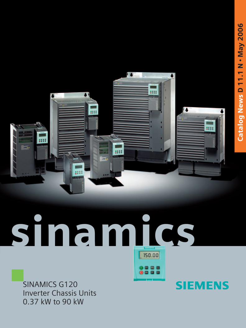
SINAMICS G120Inverter Chassis Units0.37 kW to 90 kW

Related catalogs
Additional documentation
You will find all information material, such as brochures, cata-logues, manuals and operating instructions for standard drive systems up-to-date on the Internet at the address
http://www.siemens.com/motors
You can order the listed documentation or download it in com-mon file formats (PDF, ZIP).
Catalog CA 01 – SD configurator selection aid
The SD configurator selection aid is available in combination with the CA 01 electronic catalog.
On CD 2 of the selection and configuring aids, you will find the SD configurator for low-voltage motors, inverters MICROMASTER 4, SINAMICS G110 and SINAMICS G120 inverter chassis units and frequency converters for distributed I/Os SIMATIC ET 200S FC including:• Dimension drawing generator for motors• Data sheet generator for motors and inverters• Starting calculation• 3D models in .stp format• Extensive documentation
Hardware and software requirements• PC with 500 MHz CPU or faster• Operating systems
– Windows 98/ME– Windows 2000– Windows XP– Windows NT 4.0
(Service Pack 6 or higher)• Internet Explorer 5.5 or higher• 256 MB work memory (minimum)• Screen resolution 800 x 600 pixels or higher (1024 x 768)
recommended• Small fonts• 150 MB spare hard disk space (after installation)• CD-ROM drive• Windows-compatible sound card• Windows-compatible mouse
Installation
You can install this catalog directly from the CD-ROM as a com-plete or partial version on your hard disk or in the network.
SINAMICS G110 D 11.1Inverter Chassis Units0.12 kW to 3 kW
Order No.:German: E86060-K5511-A111-A2English: E86060-K5511-A111-A2-7600
SINAMICS G130 D 11Drive Converter Chassis UnitsSINAMICS G150Drive Converter Cabinet UnitsOrder No.:German: E86060-K5511-A101-A3English: E86060-K5511-A101-A3-7600
MICROMASTER DA 51.2MICROMASTER 410/420/430/440Inverters0.12 kW to 250 kWOrder No.:German: E86060-K5151-A121-A5English: E86060-K5151-A121-A5-7600
MICROMASTER/COMBIMASTER DA 51.3MICROMASTER 411 InvertersCOMBIMASTER 411 Distributed Drive SolutionsOrder No.:German: E86060-K5251-A131-A2English: E86060-K5251-A131-A2-7600
Low-Voltage Motors D 81.1IEC Squirrel-Cage Motors Frame sizes 56 to 450
Order No.: German: E86060-K5581-A111-A1English: E86060-K5581-A111-A1-7600
Geared motors M 15Helical, Flat, Bevel-helical,Helical-worm and Worm Geared MotorsOrder No.:E86060-K1715-A101-A5(available in German only)
Geared motors M 15The catalog can be downloaded Newsfrom the Internet at:
http://www.siemens.com/gearedmotors
AC NEMA & IEC Motors D 81.2Further details available on the U.S./Internet at: Canada
http://www.sea.siemens.com/motors
Catalog CA 01 CA 01The Offline Mall of Automation and DrivesOrder No.:CD-ROM:E86060-D4001-A110-C4-7600DVD: E86060-D4001-A510-C4-7600
A&D Mall
Internet:http://www.siemens.com/automation/mall

s
The products contained in this catalogare also part of the CA 01 Catalog
Please contact your Siemens branchoffice for further information
© Siemens AG 2006
SINAMICS G120InverterChassis Units0.37 kW to 90 kW
Catalog NewsD 11.1 N · May 2006
The products and systems described in this catalog are produced/distributed in accordance with the requirements of a quality management system which has been certified to DIN EN ISO 9001 (Certificate Registration No. DE-000357 QM) and DIN EN ISO 14001 (Certificate Registration No. 0813420 UM and EMS 57390).The certificate isrecognized in all IQNet countries.
Introduction Welcome toAutomation and DrivesTotally Integrated AutomationThe SINAMICS drive familyThe members of the SINAMICS drive familySINAMICS G120 - The modular single drive for low to medium power ranges
1
SINAMICS G120Inverterchassis units
OverviewBenefitsApplicationDesignConfigurationTechnical dataSelection and ordering dataComponents
2
Engineering tools
OverviewSD configurator selection aidSIZER configuration toolSTARTER drive/commissio-ning softwareDrive ESengineering system
3
Servicesanddocumentation
OverviewTrainingSINAMICS G120training caseDocumentationReplacement fans forSINAMICS G120SPARESonWebService & Support
4
Appendix Siemens contacts worldwideA&D online servicesSubject indexIndex of order numbersTerms and conditions of sale and deliveryExport regulations
5

Siemens D 11.1 N · May 2006 Siemens D 11.1 N · May 2006
Welcome toAutomation and Drives
We would like to welcome you to Automation and Drives
and our comprehensive range of products, systems,
solutions and services for production and
process automation and building technology
worldwide.
With Totally Integrated Automation and Totally
Integrated Power, we deliver solution platforms based
on standards that offer you a considerable savings
potential.
Discover the world of our technology now. If you need
more detailed information, please contact one of your
regional Siemens partners.
They will be glad to assist you.
1/2 1/3

Siemens D 11.1 N · May 2006 Siemens D 11.1 N · May 2006
��������
��� �
� �
�������� ���
��������������
������������������� �������
�������������������������������
��� �
��� �
��� � ������� �� �����
��������������� ������� �
���������������������������� ��������
��������� �����
���� �� �� �����
�������� !����
�� �����
�������� ! ����� "������� �
�������� ��������� �� ����� ��#"��
$�%�����#�� ������� �� ����� ��#"��
������� "��&�� ��� '� ��#��"
������������(�����""��� ����#"��
��������)��� ��"��������� �����
��������*��*��� ����� �� ������
���+���#"��"'��)�����
��!��,-����
��!�������./��"��%���������� ��#"��
�����&������� �� �������&�� "���� �������$�+��
��&� ������
��!��,-�
� ��"������� �
����#�� ������
��)��!)������,������"
�� ��� ��)�-�������� ����#"��
��������������
��������� "��"
��&%�"����������
���������"��%���� '!
���!��!)���� ��� ����#"��
��)-����0��� ���)��������� ���
���!�!��� ��������� ���&�� ��#"��
*���
,����� ���� ����#
��1���21���� ���� ����#
���������� ������"'������� ��#"��
��)��������!���3� ��)�����
Totally Integrated Automation –innovations for more productivity
With the launch of Totally Integrated Automation, we were the first ones on the market to consistently implement the trend from equipment to an integrated automation solution, and have continuously improved the system ever since.
Whether your industry is process- and production-oriented or a hybrid, Totally Integrated Automation is a unique "common solution" platform that covers all the sectors.
Totally Integrated Automation is an integrated platform for the entire production line - from receiving to technical processing and production areas to shipping. Thanks to the system-
oriented engineering environment, integrated, open commu-nications as well as intelligent diagnostics options, your plant now benefits in every phase of the life cycle.
In fact, to this day we are the only company worldwide that can offer a control system based on an integrated platform for both the production and process industry.
1/4 1/5Siemens D 11.1 N · May 2006 Siemens D 11.1 N · May 2006

SINAMICSIntroduction
The SINAMICS drive family
1/6 Siemens D 11.1 N · May 2006
1
Application range of the SINAMICS drive family
Application
SINAMICS is the new family of Siemens drives designed for machine and plant engineering applications. SINAMICS offers solutions for all drive tasks:7 Simple pump and fan applications in the process industry.7 Complex single drives in centrifuges, presses, extruders,
elevators, as well as conveyor and transport systems.7 Drive line-ups in textile, plastic film and paper machines, as
well as in rolling mill plants.7 Highly dynamic servo drives for machine tools, as well as
packaging and printing machines.
Versions
Depending on the application, the SINAMICS range offers the ideal version for any drive task.7 SINAMICS G is designed for standard applications with asyn-
chronous (induction) motors. These applications have less stringent requirements regarding the dynamics and accuracy of the motor speed.
7 SINAMICS S handles complex drive tasks with synchro-nous/asynchronous (induction) motors and fulfills stringent requirements regarding:
- dynamics and accuracy- integration of extensive technological functions in the drive
control system
Platform concept and Totally Integrated Automation
All SINAMICS versions are based on a platform concept. Common hardware and software components, as well as standardized tools for design, configuration and commissioning tasks, ensure high-level integration across all components. SINAMICS handles a wide variety of drive tasks with no system gaps. The different SINAMICS versions can be easily combined with each other.
SINAMICS is part of the Siemens "Totally Integrated Automation" concept. Integrated SINAMICS systems covering configuration, data storage and communication at automation level, ensure low-maintenance solutions with the SIMATIC, SIMOTION and SINUMERIK control systems.
SINAMICS G SINAMICS S
Mixer/mills
Extrusion
Textiles
Pumps/fans/compressors
Conveyor systemsWoodworking Printing and paper
machines
Metal formingtechnology
Rolling mills
Packaging
Machine tools
G_D
211_
EN
_001
37

SINAMICSIntroduction
The SINAMICS drive family
1/7Siemens D 11.1 N · May 2006
1
SINAMICS as part of the Siemens modular automation system
Quality in accordance with DIN EN ISO 9001
SINAMICS conforms with the most exacting quality require-ments. Comprehensive quality assurance measures in all deve-lopment and production processes ensure a consistently high level of quality.
Of course, our quality assurance system is certified by an inde-pendent authority in accordance with DIN EN ISO 9001.
Suitable for global use
SINAMICS meets the requirements of relevant international stan-dards and regulations – from the EN standards through IEC stan-dards to UL and cULus regulations.
Tools
SIMOTION SCOUT
SIMATIC STEP 7
STARTER
SIZER
Automation systems
SIMATIC
SINAMICS
SIMOTION
Induction motors Synchronous motors
SINUMERIK
SINUMERIKSinuCom NC
G_D
21
1_E
N_0
01
38

SINAMICSIntroduction
The SINAMICS drive family
1/8 Siemens D 11.1 N · May 2006
1Tailored to the respective areas of application, SINAMICS is divided into the family members:
Low-voltage inverters (line supply <1000 V)7 SINAMICS G110 – the versatile drive for low power ranges7 SINAMICS G120 – the modular single drive for low to medium
power ranges7 SINAMICS G130 and SINAMICS G150 – the universal drive
solution for high-performance single drives7 SINAMICS S120 – the flexible, modular drive system for
demanding tasks7 SINAMICS S150 – the advanced drive solution for high-
performance single drives
Medium-voltage inverters (line supply >1000 V)7 SINAMICS GM150 – the universal drive solution for single
drives in the medium voltage range7 SINAMICS SM150 – the advanced drive solution for single
and multi-motor drives in the medium voltage range
The SINAMICS range is characterized by the following system properties:• uniform functionality based on platform concept• uniform engineering• high degree of flexibility and combination• wide range of performance• designed for global use• SINAMICS Safety Integrated• increased economy and effectivity • versatile interfacing facilities to host controllers• Totally Integrated Automation

SINAMICSIntroduction
The SINAMICS drive family
1/9Siemens D 11.1 N · May 2006
1SINAMICS ...
S12S120
100 MW30 MWS120G110 G150/S150G130 S120 GM150/SM150G120
G110 S150/SM150G130 G150/GM150 S120S120G120 S120S120
S120S120G110 S150 S120G130 G150/GM150 S120SM150G120
S120
SINAMICS for every output rating
SINAMICS for every power range
0.12 kW 1.5 MW
SINAMICS for every application
Coordinated drives/high-performance drivesHigh-performance single drivesSingle drives
Basic functionality
S120S120 S120 S120
Motion Control Performance
G_D
211_
EN
_000
98

SINAMICSIntroduction
The members of the SINAMICS family
1/10 Siemens D 11.1 N · May 2006
1SINAMICS Low-voltage inverters
SINAMICS G110 SINAMICS G120 SINAMICS G130/G150 SINAMICS S120
The versatile drive for low power ranges
The modular single drive for low to medium power ranges
The universal drive solution for high-performance single drives
The flexible, modular drive system for complex drive tasks
Main applications
• Machines and plants for industrial and commercial applications
• Machines and plants for industrial and commercial applications (mechanical engineering, auto-motive, textiles, chemicals, prin-ting, steel)
• Machines and plants in the pro-cess and production industry, wa-ter/waste, power stations, oil and gas, petrochemicals, chemical raw materials, paper, cement, stone, steel
• Machines and plants for industrial applications (packaging, plastics, textile, printing, wood, glass, ceramics, presses, paper, lifting equipment, semiconductors, automated assembly and testing equipment, handling)
Application examples
• Pumps and fans• Auxiliary drives• Conveyor belts• Billboards• Door/gate operating mechanisms• Centrifuges
• Pumps and fans• Compressors• Conveyor belts
• Pumps and fans• Compressors• Extruders and mixers• Mills
• Motion Control applications (e.g. positioning, synchronous operation, …)
• Technological applications
Benefits
• Compact• Flexible adaptation to different
applications• Simple, fast commissioning• Clear terminal layout• Optimum interaction with SIMATIC
and LOGO!
• Modular• Flexible expansion capability• Simple, fast commissioning• Regenerative feedback• Innovative cooling concept• Optimum interaction with
SIMOTION and LOGO!• SINAMICS Safety Integrated
• Space-saving• Low-noise• Simple, fast commissioning• SINAMICS G130: modular
components• SINAMICS G150: ready-to-
connect cabinet unit• Optimum interaction with SIMATIC
• For universal use• Flexible and modular• Scalable in terms of power,
function, number of axes, performance
• Simple, fast commissioning, auto-configuration
• Innovative system architecture• Scalable infeed/regenerative
feedback concept• Wide range of motors• Optimum interaction with
SIMOTION and SIMATIC• SINAMICS Safety Integrated

SINAMICSIntroduction
The members of the SINAMICS family
1/11Siemens D 11.1 N · May 2006
1SINAMICS Medium-voltage inverters
SINAMICS S150 SINAMICS GM150 SINAMICS SM150
The advanced drive solution for high-performance single drives
The drive solution for variable-speed drives The drive solution for high-performance variable-speed single and multi-motor drives
Main applications
• Machines and plants in the pro-cess and production industry, food, beverages and tobacco, automotive and steel industry, mining/open-cast mining, ship-building, lifting equipment/conveyors
• Machines and plants in the process industry • Machines and plants, e.g. steel manufacture and mining
Application examples
• Test bay drives• Centrifuges• Elevators and cranes• Cross cutters and shears• Conveyor belts• Presses• Cable winches
• Pumps and fans• Compressors• Extruders and mixers• Mills• Marine drives
• Rolling mills• Mine cages• Test stands• Conveyor belts
Benefits
• Four-quadrant operation as standard
• High control accuracy and dynamic response
• Almost no system perturbation, well below THD values in accor-dance with IEEE 519
• Tolerant to fluctuations in line voltage
• Option of power factor compensation
• Simple, fast commissioning• Ready-to-connect cabinet unit• Optimum interaction with SIMATIC
• Space-saving• Simple, fast commissioning• Ready-to-connect cabinet unit• Optimum interaction with SIMATIC
• Four-quadrant operation as standard• High efficiency and motor-friendly operation• High level of control accuracy and dynamic response• Almost no line harmonic distortions• Option of power factor compensation• Simple, fast commissioning• Ready-to-connect cabinet unit• Optimum interaction with SIMATIC

SINAMICSIntroductionSINAMICS G120 – The modular single drive for low to medium power ranges
1/12 Siemens D 11.1 N · May 2006
1
■ Overview
The new SINAMICS G120 frequency inverter has a modular structure (Power Module with Control Unit and BOP) and fea-tures numerous innovative functions, e.g. for safety (Safety Inte-grated), communication capability and energy recovery. With its various device versions (frame sizes FSA to FSF) in the power range of 0.37 kW to 90 kW it is suitable for a wide range of drive solutions.
■ Benefits
• Flexibility due to modularity. For a drive concept designed for the future - each innovative step can be performed simulta-neously in the same system.
• The safety functions make it easier for drives to be installed in safety-oriented, integrated automation and drive environ-ments.
• Communication capability via PROFIBUS• Increased ruggedness due to innovatice cooling concept and
paint finish of the electronic modules (longer service life)• Engineering and commissioning with standard tools SIZER
and STARTER• Simple device replacement and parameter cloning with
optional and pre-installed MMC card• Low-noise motor operation due to high pulse frequency• Compact, small design• Worldwide certifiation: in UL and CE, Safety Integrated
(IEC 61508/SIL2)
■ Application
SINAMICS G120 is ideal• as a universal drive in all industrial and commercial
applications• in the automotive, textiles, printing and chemical industries• for end-to-end applications, e.g. in conveyor systems
■ Design
The SINAMICS G120 is a modular frequency inverter for stan-dard drives. Each SINAMICS G120 comprises two operative units - the Power Module (PM) and the Control Unit (CU). For parameterization, operation and monitoring, a Basic Operator Panel (BOP) is available or via interface the STARTER commis-sioning software.
Different Control Units and Power Modules can be combined to create application and cost-optimized drive solutions. All Power Modules are suitable for use in safety-related applications. In connection with a Safety Control Unit, the drive becomes a Safety Integrated Drive. This features a fails-safe closed-loop control function for induction motors in different control modes (V/f, FCC, Vector Control with and without encoder).

SINAMICSIntroduction
SINAMICS G120 – The modular single drive for lowto medium power ranges
1/13Siemens D 11.1 N · May 2006
1■ Technical data
Electrical data
Line voltages; power ranges 380 to 480 V 3 AC, ±10%; 0.37 to 90 kW
Network types IT, TN, TT
Line frequency 50 Hz/60 Hz
Output frequency 0 to 650 Hz
Control methods • V/f control, linear (M~n)• V/f control, quadratic (M~n2)• V/f control, parameterizable• Sensorless Vector Control• Vector Control with encoder (closed-loop control circuit)• Torque control
Fixed frequencies 16, parameterizable
Digital inputs Up to 9 digital inputs, depending on the Control Unit, for fail-safe versions 2 fail-safe digital inputs, 24 V DC
Analog version: analog input 2 analog inputs, scalable from 0 to 10 V
Digital outputs 3 digital outputs
Communication interfaces RS485/USS (CU240S/CU240E – both available soon); PROFIBUS (CU240S DP);
PROFIsafe (CU240S DP-F); PROFINET (CU240S PN – available soon)
Functions
Software functions • Torque control, flying restart, slip compensation, automatic restart after interruption of operation due to power failure, free function blocks for logical and arithmetic operations
• Signal interconnection with BICO technology• Kinetic buffering, positioning deceleration ramp• Simple process control with internal high-quality PID controller• Parameterizable ramp-up times 0 to 650 s, ramp smoothing• Compund braking for controlled rapid deceleration• 3 switchable motor data sets
Protection functions Undervoltage, overvoltage, ground fault, stall protection, thermal motor protection I2t, inverter overtemperature, motor overtemperature
Safety Integrated function Yes
Connectable motors Induction motors
Mechanical data
Degree of protection IP20
Cooling method Innovative cooling concept; cooling of power electronics via heat sinks with external fan; open-loop and closed-loop control electronics cooled by convection
Standards
Compliance with standards CE, UL, cUL, C-tick, Safety Integrated IEC 61508/SIL2

SINAMICSIntroduction
Notes
1/14 Siemens D 11.1 N · May 2006
1

Siemens D 11.1 N · May 2006
22/2 SINAMICS G120
Inverter chassis units0.37 kW to 90 kW
2/2 Overview2/3 Benefits2/3 Application2/3 Design2/5 Configuration2/5 Technical data
2/6 CU240 Control Units 2/6 Overview2/7 Design2/8 Integration2/10 Technical data2/11 Selection and ordering data
2/12 Memory card for Control Units2/12 Overview2/12 Integration2/12 Selection and ordering data
2/13 PM240 Power Modules 2/13 Overview2/13 Integration2/16 Technical data2/21 Characteristics2/22 Selection and ordering data2/23 Dimension drawings
2/28 Line filters2/28 Overview2/28 Technical data2/29 Selection and ordering data
2/30 Line reactors2/30 Overview2/30 Integration2/30 Technical data2/31 Selection and ordering data
2/32 Recommendedline components
2/32 Overview2/32 Selection and ordering data
2/33 Braking resistors2/33 Overview2/33 Technical data2/34 Selection and ordering data
2/35 Output reactors2/35 Overview2/35 Technical data2/37 Selection and ordering data
2/38 BOP Basic Operator Panel 2/38 Overview2/38 Integration2/38 Selection and ordering data
2/39 PC-inverter connection kit2/39 Overview2/39 Selection and ordering data
2/40 Brake Relay2/40 Overview2/40 Integration2/40 Technical data2/40 Selection and ordering data
2/41 Safe Brake Relay2/41 Overview2/41 Integration2/41 Technical data2/41 Selection and ordering data
2/42 Adapter for mounting onDIN rail
2/42 Overview2/42 Selection and ordering data
2/43 Screen termination kit2/43 Overview2/43 Selection and ordering data
2/44 NEMA1 kit2/44 Overview2/44 Selection and ordering data
SINAMICS G120Inverter chassis units

SINAMICS G120Inverter chassis unitsSINAMICS G120 chassis units0.37 kW to 90 kW
2/2 Siemens D 11.1 N · May 2006
2
■ Overview
The new SINAMICS G120 series of frequency inverters is designed to provide precise and cost-effective speed/torque control of AC motors.
With different device versions (frame sizes FSA to FSF) in the power range of 0.37 kW to 90 kW, it is suitable for a wide variety of drive solutions.
Examples of SINAMICS G120, frame sizes FSA, FSB and FSC; each with Power Module, Control Unit and Basic Operator Panel
Examples of SINAMICS G120, frame sizes FSD, FSE and FSF; each with Power Module, Control Unit and Basic Operator Panel

SINAMICS G120Inverter chassis units
SINAMICS G120 chassis units0.37 kW to 90 kW
2/3Siemens D 11.1 N · May 2006
2
■ Overview (continued)
Modularity
SINAMICS G120 is a modular converter system comprising a variety of functional units. The two main units are• Control Unit (CU)• Power Module (PM)
The Control Unit controls and monitors the Power Module and the connected motor in several different modes. It supports communication with a local or central control and with moni-toring equipment or input/output terminals for a direct control function.
The Power Module supplies the motor in the power range 0.37 kW to 90 kW. The Power Module is controlled by a micro-processor in the Control Unit. State-of-the-art IGBT technology with pulse-width-modulated motor voltage and selectable pulse frequency is applied to achieve extremely reliable, flexible motor operation. An extensive range of protective functions afford a high degree of motor protection.
Furthermore, a large number of additional components are available, such as:• Basic Operator Panel (BOP) for parameterization, diagnostics,
control and copying of drive parameters• Line filter classes A and B• Line reactors • Braking resistors• Output reactors
Safety Integrated
The SINAMICS G120 inverter chassis units include versions for safety-oriented applications. All Power Modules are designed as intrinsically failsafe. A Safety Integrated Drive can be created by combining a Power Module with the relevant Failsafe Control Unit.
The SINAMICS G120 fail-safe frequency inverter provides four safety functions, certified in accordance with EN 954-1, Cat. 3 and IEC 61508 SIL 2:• Safe stop 1 (SS1)• Safely limited speed (SLS)• Safe brake control (SBC)• Safe torque off (STO)
Innovative cooling concept and paint finish of electronic modules
Significant increase in service life or useful life is achieved by the innovative cooling system and paint finish of the electronic modules. These features are based on the following principles:• Disposal of all heat losses via an external heat sink• Electronic modules not located in air duct• Standardized convection cooling of Control Unit• All cooling air is directed through the heat sink
STARTER drive/commissioning software
The STARTER drive/commissioning software supports the com-missioning and maintenance of SINAMICS G120 inverters. It provides operator guidance designed to simplify and speed up commissioning, combined with comprehensive, user-friendly functions for the relevant drive solution.
■ Benefits
• Modularity ensures flexibility for an advanced drive concept - Each innovative step of a component can improve the
existing drive system- Tailored to the customer, selectable and scalable- Only the required functions are purchased- Module replacement under voltage possible (hot swap)- Pluggable terminals- The modules can be easily replaced, which makes the
system extremely service-friendly• The safety functions make it easier to integrate drives into
safety-oriented machines or plants• Communication capability via PROFIBUS with PROFIdrive
Profil 4.0 - Reduced number of interfaces- Plant-wide engineering- Easy to handle
• Increased ruggedness due to innovative cooling concept and paint finish of the electronic modules
• Simple device replacement and time-saving parameter cloning with optional Basic Operator Panel or optional MMC memory card
• Low-noise motor operation due to high pulse frequency• Compact, space-saving design• Software parameters for easy adaptation to 50 Hz or 60 Hz
motors (IEC or NEMA motors)• 2/3-wire method (static/pulsed signals) for universal control via
digital inputs• Engineering and commissioning with standard engineering
tools such as SIZER, STARTER and Drive ES: ensures fast con-figuration and easy commissioning – with Drive ES Basic STARTER is integrated into STEP 7 resulting in centralized data storage and continuous communication
• Worldwide certification in accordance with CE, UL, cUL, c-tick and Safety Integrated in accordance with IEC 61508 SIL 2
■ Application
SINAMICS G120 is ideal• as a universal drive in all industrial and commercial
applications• in the automotive, textiles, printing and chemical industries• for end-to-end applications, e.g. in conveyor systems
■ Design
The SINAMICS G120 inverter chassis units are modular fre-quency inverters for standard drives. Each SINAMICS G120 comprises two operative units – the Power Module and Control Unit.
Power Modules
The following Power Modules are available for SINAMICS G120 inverter chassis units:
PM240 Power Modules
PM240 Power Modules feature an integrated brake chopper and are designed for drives without energy recovery. Generator energy produced during braking is converted to heat via exter-nally connected braking resistors.
PM250 Power Modules (available soon)
PM250 Power Modules use an innovative circuit design which allows line-commutated energy recovery to the supply. This in-novative circuit permits generator energy to be fed back into the supply system and therefore saves energy.

SINAMICS G120Inverter chassis unitsSINAMICS G120 chassis units0.37 kW to 90 kW
2/4 Siemens D 11.1 N · May 2006
2
■ Design (continued)
Control Units
The following Control Units and an MMC memory card are available as accessories for SINAMICS G120 inverter chassis units:
CU240 Control Units
The Control Unit performs closed-loop control functions for the inverter. In addition to control functions, the Control Unit can also perform other tasks which can be adapted to the relevant appli-cation by parameterization. Several versions of Control Units are available:• CU240S DP• CU240S DP-F• CU240S PN (available soon)• CU240S (available soon)• CU240E (available soon)
MMC memory card
The parameter settings for a converter are stored on the MMC memory card. When the plant is serviced, it is immediately ready for use again after, for example, replacement of the frequency inverter and transfer of the memory card data. The respective slot is located at the top of the Control Unit.
There is also a large number of components available for ex-panding the system, e.g. line-side power components, DC link components, load-side power components and supplementary system components.
Line-side power components
The following line-side power components are available for SINAMICS G120 inverter chassis units:
Line filters
The PM240 Power Module complies with a higher radio inter-ference class with one of the additional line filters.
Line reactors
A line reactor is needed for high system fault levels, partly to pro-tect the actual inverter against excessive harmonic currents, and thus against overload, and partly to limit the line harmonic distortions to the permitted values.
Recommended line components
This is a recommendation for further line-side components, such as fuses and circuit-breakers (line-side components must be dimensioned in accordance with IEC standards). Further infor-mation on the listed fuses and circuit-breakers can be found in Catalogs LV 1 and LV 1 T.
DC link components
The following DC link components are available for SINAMICS G120 inverter chassis units:
Braking resistors
Excess power in the DC link is dissipated via the braking resistor. The braking resistors are designed for use with PM240 Power Modules. These feature an integrated brake chopper (electronic switch).
Load-side power components
The following load-side power components are available for SINAMICS G120 inverter chassis units. During operation with an output reactor or a LC filter or sinusoidal filter, shielded motor ca-ble lengths are possible and the motor service life is increased:
Output reactors
Output reactors reduce the voltage loading on the motor win-dings. At the same time, the capacitive charge/discharge cur-rents, which place an additional load on the power section when long motor cables are used, are reduced.
LC filter and sinusoidal filter (available soon)
The LC filter/sinusoidal filter limits the rate of rise of voltage and the capacitive charge/discharge currents which usually occur with inverter operation. It is therefore not necessary to use an output reactor.
Availability as base components
The following line-side power components, DC link components and load-side power components are designed as base compo-nents in the corresponding frame sizes:
Supplementary system components
The following supplementary system components are available for SINAMICS G120 inverter chassis units:
BOP Basic Operator Panel
The BOP Basic Operator Panel can be plugged onto the Control Unit and can be used to commission drives, monitor drives in operation and input individual parameter settings. The BOP also provides a function for quick copying of parameters.
PC-inverter connection kit
For controlling and commissioning a converter directly from a PC if the appropriate software (STARTER) has been installed.The STARTER commissioning tool is supplied on CD-ROM in the scope of supply of the PC-inverter connection kit.
Brake Relay
The Brake Relay allows the Power Module to be connected to an electromechanical motor brake, thereby allowing the motor brake to be driven directly by the Control Unit.
Safe Brake Relay
The Safe Brake Relay allows the Power Module to be connected to an electromechanical motor brake, allowing the brake to be directly and safely controlled by the Control Unit in accordance with EN 954-1, safety category 3 and IEC 61508 SIL 2.
Size
FSA FSB FSC FSD FSE FSF
Line-side power components
Line filter class A ✓
Line filter class B ✓ ✓ ✓
Line reactors ✓ ✓ ✓ ✓ ✓
DC link components
Braking resistors ✓ ✓
Load-side power components
Output reactors ✓ ✓ ✓

SINAMICS G120Inverter chassis units
SINAMICS G120 chassis units0.37 kW to 90 kW
2/5Siemens D 11.1 N · May 2006
2
■ Design (continued)
Adapter for mounting on DIN rail
The adapter for DIN rail mounting can be used to mount inver-ters of frame size A and B on DIN rails (2 units with a center-to-center distance of 100 mm).
Screen termination kit
The screen termination kit makes it easier to bond the shields of supply and control cables, offers mechanical strain relief and thus ensures optimum EMC performance.
NEMA1 kit (available soon)
The SINAMICS G120 inverter chassis units are designed to comply with type "UL OPEN". The NEMA1 kit is required to obtain a type 1 NEMA housing compliant with NEMA1 directives (NEMA 250-2003).
■ Configuration
The following electronic configuration and engineering tools are available for SINAMICS G120 inverter chassis units:
SD configurator selection aid within the CA 01
The interactive catalog CA 01 – the offline mall of Siemens Auto-mation and Drives (A&D) – contains over 100000 products with approximately 5 million potential drive system product variants. The SD configurator has been developed to facilitate selection of the correct motor and/or inverter from the wide spectrum of A&D SD products. The configurator is integrated in this catalog with the selection and configuration tools as a "selection aid" on CD 2 "Configuring".
SIZER configuration tool
The SIZER PC tool provides an easy-to-use means of configur-ing the SINAMICS and MICROMASTER 4 drive family. It provides support when setting up the technologies involved in the hard-ware and firmware components required for a drive task. SIZER supports the complete configuration of the drive system, from simple single drives to complex multi-axis applications.
STARTER drive/commissioning software
The STARTER drive/commissioning software provides menu-guided assistance with commissioning, optimization and diag-nostics. STARTER is not only designed for use on SINAMICS drives but also for MICROMASTER4 units and SIMATIC ET 200S FC frequency inverter for distributed I/Os.
Drive ES engineering system
Drive ES is the engineering system used to integrate Siemens drive technology into the SIMATIC automation world easily, effi-ciently and cost-effectively in terms of communication, configu-ration and data management. The STEP 7 Manager user inter-face provides the basis for this procedure. A variety of software packages, i.e. Drive ES Basic, Drive ES SIMATIC and Drive ES PCS 7, is available for SINAMICS.
■ Technical data
Unless explicitly specified otherwise, the following technical data are valid for all the following components of the SINAMICS G120 inverter chassis unit.
1) In transport packaging.2) With shielded motor cable up to 25 m.
Mechanical data
Vibratory load
• Transport 1) Class 2M3 in acc. with EN 60068-2-6
• Operation Class 3M4 in acc. with EN 60068-2-610 Hz to 58 Hz: constant deflection 0.075 mm58 Hz to 200 Hz: constant accele-ration = 9.81 m/s2 (1 g)
Shock load
• Transport 1) Class 2M2 in acc. with EN 60068-2-27
• Operation Class 3M4 in acc. with EN 60068-2-2749 m/s2 (5 g)/30 ms
Ambient conditions
Protection class Class I (with protective conductor system) and class III (PELV) in acc. with EN 61800-5-1
Shock protection in acc. with EN 61800-5-1when used properly
Permissible ambient and coo-lant temperature (air) during operation for line-side power components and Power Modules
0 °C to +40 °C without derating, > 40 °C to +55 °C see derating characteristics
Permissible ambient and coo-lant temperature (air) during operation for Control Units, sup-plementary system components and DC link components
0 °C to +50 °Cwith CU240S DP-F: 0 °C to +45 °C up to 2000 m above sea level
Standards
Compliance with standards UL, cUL, CE, c-tick
CE mark in accordance with Low-Voltage Directive 73/23/EEC and Machinery Directive 98/37/EC
EMC directive
• Frame sizes FSB to FSF with integrated line filter class A
Category C2 2) in acc. with EN 61800-3 or class A in acc. with EN 55011
• Frame size FSA without inte-grated line filter and with addi-tional line filter class A
Category C2 2) in acc. with EN 61800-3 or class A in acc. with EN 55011
• Frame size FSA with additional line filter class A and with additional line filter class B
Category C2 2) in acc. with EN 61800-3 or class B in acc. with EN 55011
• Frame sizes FSB and FSC with integrated line filter class A and with additional line filter class B
Category C2 2) in acc. with EN 61800-3 or class B in acc. with EN 55011
Note:The EMC product standard EN 61800-3 does not directly refer to a frequency inverter, but to a PDS (Power Drive System), that covers beside the inverter the whole circuiting as well as the motor and cables. The inverters themselves are in general not subject to marking in accordance with the EMC directive.

SINAMICS G120Inverter chassis units
CU240 Control Units
2/6 Siemens D 11.1 N · May 2006
2
■ Overview
Example of CU240S DP-F Control Unit
The Control Unit performs closed-loop control functions for the inverter. In addition to control functions, the Control Unit can also perform other tasks which can be adapted to the relevant appli-cation by parameterization. Several versions of Control Units are available:• CU240S DP• CU240S DP-F

SINAMICS G120Inverter chassis units
CU240 Control Units
2/7Siemens D 11.1 N · May 2006
2
■ Design
Example of Control Unit CU240S DP without terminal cover, with pluggable terminals
Terminal No. Signal Features
Digital inputs (DI) – standard
5 to 8, 16, 17
DI0 to DI5 Freely programmable (isolated) 5.5 mA/24 V
40 to 42(for CU240SDP only)
DI6 to DI8 Freely programmable (isolated) 5.5 mA/24 V
Digital inputs (DI) – failsafe (for CU240S DP-F only)
60 to 64(for CU240SDP-F only)
FDI0AFDI0BFDI1AFDI1B
Failsafe digital inputs, 2 channels (redundant),freely programmable (isolated) 5.5 mA/24 V
Digital outputs (DO)
18 DO0, NC Relay output 1NC contact (0.5 A, 30 V DC)
19 DO0, NO Relay output 1NO contact (0.5 A, 30 V DC)
20 DO0, COM Relay output 1Common contact (0.5 A, 30 V DC)
21 DO1, NO Relay output 2NO contact (0.5 A, 30 V DC)
22 DO1, COM Relay output 2Common contact (0.5 A, 30 V DC)
23 DO2, NC Relay output 3NC contact (0.5 A, 30 V DC)
24 DO2, NO Relay output 3NO contact (0.5 A, 30 V DC)
25 DO2, COM Relay output 3Common contact (0.5 A, 30 V DC)
Analog inputs (AI)
3 AI0+ 0 V to 10 V, –10 V to +10 V, 0/2 V to 10 V or 0/4 mA to 20 mA
4 AI0–
10 AI1+ 0 V to 10 V, 0 mA to 20 mA
11 AI1–
Analog outputs (AO)
12 AO0+ Freely programmable (0/4 mA to 20 mA, 0/2 V to 10 V with 500 W load)
13 AO0– M
26 AO1+ Freely programmable (0/4 mA to 20 mA with 500 W load)
27 AO1– M
Encoder interfaces
70 ENC AP Encoder AP – channel A non-negating input
71 ENC AN Encoder AN – channel A negating input
72 ENC BP Encoder BP – channel B non-negating input
73 ENC BN Encoder BN – channel B negating input
74 ENC ZP Encoder ZP – zero pulse non-negating input
75 ENC ZN Encoder ZN – zero pulse negating input
PTC/KTY interface
14 PTC+ Positive PTC/KTY input
15 PTC- Negative PTC/KTY input
Power supply
33 ENC+supply
Isolated encoder power supply (+24 V with 100 mA, +5 V with 300 mA or > 30 V input by user), configured using DIP switches
9 U 24 V Isolated user power supply +24 V with 100 mA
28 U 0 V Isolated encoder power supply and user reference voltage
1 + 10 V Non-isolated, stabilized 10 V power supply for I/O – max. 10 mA
2 0 V Power supply reference
31 + 24 V 24 V power supply input
32 0 V 24 V power supply reference
Terminal No. Signal Features

SINAMICS G120Inverter chassis units
CU240 Control Units
2/8 Siemens D 11.1 N · May 2006
2
■ Integration
Connection diagram CU240S DP Control Unit
A
D
A/D
A/D
+ 10 V
0 V
ENC+
1
2
3 AI0+
4 AI0-
10 AI1+
11 AI1-
5 DI0
6 DI1
7 DI2
8 DI3
16 DI4
17 DI5
40 DI6
41 DI7
42 DI8
9 U24V
33
14 PTC+
15 PTC-
12 AO0+
13 AO0-
20 COM
18 NC
19 NO
25 COM
23 NC
24 NO
22 COM
21 NO
28 U0V
31 +24 V
32 0V
71 ENC AN
70 ENC AP
1
2 U0V
3 RxD/TxD-P
4 CNTR-P
5 DGND
6 VP
7 U24V
8 RxD/TxD-N
9 *
72 ENC BP
73 ENC BN
74 ENC ZP
75 ENC ZN
A
D
A
D
1
A
D
A
D26 AO1+
27 AO1-
1
DO1
DO2
DO0
(1) (2) (4) (8) (16) (32) (64)
AI0
AI1
0-20 mA
0-10 V
Bit
0
Bit
1
Bit
2
Bit
3
Bit
4
Bit
5
Bit
6
Power Module
PTC/KTY
JOG
FNI
PO
BOP
Control UnitCU240S DP
PROFIBUS address DIP switch
ON
General I/O DIP switch
ON
5 V
enc
oder
supp
ly
24 V
enc
oder
supp
ly
Enc
oder
Ate
rmin
atio
nE
ncod
er B
term
inat
ion
Enc
oder
Zte
rmin
atio
n
Enco
der i
nter
face
PRO
FIBU
Sin
terfa
ceD
-type
con
nect
or
Shield
Low voltage only(30 V, 500 mA)
G_D
011_
EN
_001
01
Fromexternalsource
* = Not connected
Dig
ital i
nput
s
BOP interface
PC connection(optional)
4.7 kOhm
0 to 20 mAmax. 500 Ohm
0 to 20 mAmax. 500 Ohm
Line

SINAMICS G120Inverter chassis units
CU240 Control Units
2/9Siemens D 11.1 N · May 2006
2
■ Integration (continued)
Connection diagram CU240S DP-F Control Unit
A
D
A/D
A/D
+ 10 V
0 V
ENC+
1
2
3 AI0+
4 AI0-
10 AI1+
11 AI1-
5 DI0
6 DI1
7 DI2
8 DI3
16 DI4
17 DI5
9 U24V60 DI1A61 DI1B62 DI2A63 DI2B
33
14 PTC+
15 PTC-
12 AO0+
13 AO0-
20 COM
18 NC
19 NO
25 COM
23 NC
24 NO
22 COM
21 NO
28 U0V
31 +24 V
32 0V
71 ENC AN
70 ENC AP
1
2 U0V
3 RxD/TxD-P
4 CNTR-P
5 DGND
6 VP
7 U24V
8 RxD/TxD-N
9 *
72 ENC BP
73 ENC BN
74 ENC ZP
75 ENC ZN
A
D
A
D
1
A
D
A
D26 AO1+
27 AO1-
1
DO1
DO2
DO0
PTC/KTY
(1) (2) (4) (8) (16) (32) (64)
AI0
AI1
0-20 mA
0-10 V
JOG
FNI
PO
Bit
0
Bit
1
Bit
2
Bit
3
Bit
4
Bit
5
Bit
6
Power Module
BOP
Control UnitCU240S DP-F
Power Module
PROFIBUS address DIP switch
ON
BOP interface
PC connection(optional)
General I/O DIP switch
ON
5 V
enc
oder
supp
ly
24 V
enc
oder
supp
ly
Enc
oder
Ate
rmin
atio
nE
ncod
er B
term
inat
ion
Enc
oder
Zte
rmin
atio
n
Enco
der i
nter
face
PRO
FIBU
Sin
terfa
ceD
-type
con
nect
or
Shield
Low voltage only(30 V, 500 mA)
G_D
011_
EN
_001
02a
Fromexternalsource
* = Not connected
Sta
ndar
ddi
gita
l inp
uts
Saf
ety
digi
tal i
nput
s
4.7 kOhm
0 to 20 mAmax. 500 Ohm
0 to 20 mAmax. 500 Ohm
Line
paired
paired

SINAMICS G120Inverter chassis units
CU240 Control Units
2/10 Siemens D 11.1 N · May 2006
2
■ Technical data
CU240S DP Control Unit6SL3244-0BA20-1PA0
CU240S DP-F Control Unit6SL3244-0BA21-1PA0
Electrical data
Operating voltage 24 V DC via the Power Module or an external 24 V DC supply
24 V DC via the Power Module or an external 24 V DC supply
Interfaces
Digital inputs – standard 9 6
Digital inputs – failsafe – 2
Digital outputs 3 3
Analog inputs 2 2
Both analog inputs can be configured as supplementary digital inputs if an additional function is required. Switching thresholds:0 � 1: Rated voltage 2 V1 � 0: Rated voltage 0.8 VAnalog inputs are protected against inputs in a voltage range of �30 V and have a common-mode voltage in the �15 V range.
Analog outputs 2 2
Analog outputs have short-circuit protection, but are not isolated. Maximum output voltage = 10 V in current mode,maximum output current = 20 mA in voltage mode.The reaction time should equal approximately 1 ms with a load of maximum 10 k� in voltage mode.
Bus interface PROFIBUS DP PROFIBUS DP, PROFIsafe
Encoder interfaces 1 1
PTC/KTY interface ✓ ✓
Brake Relay interface or Safe Brake Relay interface (connection via Power Module)
✓ ✓
MMC memory card slot ✓ ✓
RS232/USS interface (connection via PC-inverter connection kit)
✓ ✓
Safety functions
Integrated safety functions in accor-dance with Category 3 of EN 954-1 or in accordance with SIL2 of IEC 61508
– • Safe Stop 1 – SS1• Safely limited speed – SLS• Safe brake control – SBC• Safe torque off – STO
Open-loop and closed-loop control functions
V/f linear/quadratic/parameterizable ✓ ✓
V/f with flux current control (FCC) ✓ ✓
Vector Control, without encoder ✓ ✓
Vector Control with encoder ✓ ✓
Torque control, without encoder ✓ ✓
Torque control with encoder ✓ ✓

SINAMICS G120Inverter chassis units
CU240 Control Units
2/11Siemens D 11.1 N · May 2006
2
■ Technical data (continued)
■ Selection and ordering data
CU240S DP Control Unit6SL3244-0BA20-1PA0
CU240S DP-F Control Unit6SL3244-0BA21-1PA0
Software functions
Fixed frequencies 16, parameterizable 16, parameterizable
Signal interconnection with BICO technology
✓ ✓
Automatic restart after line failure or operation fault
✓ ✓
Positioning deceleration ramp ✓ ✓
Slip compensation ✓ ✓
Free function blocks for logical and arithmetic operations
✓ ✓
Kinetic buffering ✓ ✓
Ramp smoothing ✓ ✓
3 switchable drive data sets ✓ ✓
3 switchable command data sets (CDS) (manual/automatic)
✓ ✓
Flying restart ✓ ✓
JOG ✓ ✓
Controller (PID) ✓ ✓
Thermal motor protection ✓ ✓
Thermal inverter protection ✓ ✓
Vdcmax controller ✓ ✓
Setpoint input ✓ ✓
Motor identification ✓ ✓
Motor holding brake ✓ ✓
Braking functions• DC injection braking• compound braking• dynamic braking with integrated brake
chopper
✓ ✓
Mechanical data
Degree of protection IP20 IP20
Operating temperature -10 °C to +50 °C (14 °F to 122 °F) 0 °C to +45 °C (32 °F to 113 °F)
Relative humidity < 95% RH, condensation not permissible < 95% RH, condensation not permissible
Dimensions (W � H � D), mm 73 � 177 � 63 73 � 177 � 63
Weight, approx. kg 0.52 0.52
Communication Digital inputsStandard
Digital inputsFailsafe
Digital outputs Encoder interfaces
Designation Control UnitOrder No.
Standard
PROFIBUS DP 9 – 3 1 CU240S DP 6SL3244-0BA20-1PA0
Failsafe for Safety Integrated
PROFIBUS DP 6 2 3 1 CU240S DP-F 6SL3244-0BA21-1PA0

SINAMICS G120Inverter chassis units
Memory card for Control Units
2/12 Siemens D 11.1 N · May 2006
2
■ Overview
The parameter settings for an inverter are stored on the MMC memory card. When the plant is serviced, it is immediately ready for use again after, for example, replacement of the frequency inverter and transfer of the memory card data.• All parameter settings can be written from the MMC memory
card to the inverter or saved from the inverter to the MMC memory card.
• Up to 100 parameter sets can be stored.• Supports serial commissioning without using further commis-
sioning tools such as BOP and STARTER.• How the MMC memory card is commissioned can be defined
by the user (parameter p8458): - 0 = parameter set 0 is never automatically downloaded from
the MMC ("never")- 1 = parameter set 0 is downloaded once after PowerOn
("once“)- 2 = parameter set 0 is always downloaded once after
PowerOn ("always")
Note:The MMC memory card is not necessary for the running opera-tion and must not remain inserted.
■ Integration
Inserting the MMC memory card into the Control Unit
Control Unit with inserted MMC memory card
■ Selection and ordering data
Order No.
MMC memory card 6SL3254-0AM00-0AA0

SINAMICS G120Inverter chassis units
PM240 Power Modules
2/13Siemens D 11.1 N · May 2006
2
■ Overview
PM240 Power Modules feature an integrated brake chopper to which an external braking resistor can be connected via termi-nals DCP/R1 and R2 (see DC link components).
The DC link capacitance of the DC link is such that the PM240 Power Module provides sufficient control range for the DC link voltage and is easily capable of handling applications such as kinetic buffering (maintenance of DC link voltage through rege-nerative feedback to DC link of kinetic energy produced by the load) or controlled, safe deceleration after a power failure using kinetic energy produced by the load. Furthermore, several PM240 Power Modules can be electrically coupled by this method.
The PM240 Power Module is also designed for safety-sensitive applications. In conjunction with a Safety Control Unit, the drive can be turned into a Safety Integrated Drive (see Control Units).
The permissible cable lengths between converter and motor are limited depending on cable type. Longer cables can be used if output reactors are connected (see load-side power compo-nents).
Line reactors are available for minimization of line harmonic distortions (see line-side power components).
Frame size FSA of the PM240 Power Module is only available without integrated line filter of class A. A base filter for compli-ance with class A and another for compliance with class B are therefore provided (see line-side power components).
Frame sizes FSB and FSC of the PM240 Power Module are avai-lable both with and without integrated line filter of class A. For compliance with class B, PM240 Power Modules with integrated line filter of class A must be fitted additionally with a base filter of class B (see line-side power components).
Power Modules with integrated line filter of class A are suitable only for connection to TN supply systems. Power Modules with-out integrated line filter can be connected to grounded (TN, TT) and non-grounded (IT) supply systems.
■ Integration
PM240 Power Modules communicate with the Control Unit via the PM-IF interface.
PM240 Power Modules feature the following interfaces as standard:• DC link connections DCP/R1 and DC-N• Terminals DCP/R1 and R2 for connection of an external braking
resistor• PM-IF interface for connection of the PM240 Power Module
and Control Unit. The PM240 Power Module also supplies power to the Control Unit by means of an integrated power pack
• Motor connection made with screw terminals or screw studs• Drive circuit for the Safe Brake Relay or Brake Relay for contro-
ling a holding brake• 2 x PE (protective earth) connections

SINAMICS G120Inverter chassis units
PM240 Power Modules
2/14 Siemens D 11.1 N · May 2006
2
■ Integration (continued)
Connection diagram for PM240 Power Module
Availability as base components
Many system components for PM240 Power Modules are designed as base components, i.e. the component is mounted on the baseplate and the PM240 Power Module above it in a space-saving construction. Up to two base components can be mounted above one another.
The following line-side power components, DC link components and load-side power components are designed as base compo-nents in the corresponding frame sizes:
DCN
A B PE U2 V2 W2
R2
DCP/R1
W1/L3
V1/L2
U1/L1PE
PE
L3L2L1
=
3 ~
Control Unit
M
=
3 ~
3 ~
Power ModulePM240
PM-IF CPU
380 V to 480 V 3 AC
Brakingresistor
24 V DC brakevia Brake Relay
G_D
011_
EN
_001
00
Frame size
FSA FSB FSC FSD FSE FSF
Line-side power components
Line filter class A ✓
Line filter class B ✓ ✓ ✓
Line reactors ✓ ✓ ✓ ✓ ✓
DC link components
Braking resistors ✓ ✓
Load-side power components
Output reactors (motor reactors)
✓ ✓ ✓

SINAMICS G120Inverter chassis units
PM240 Power Modules
2/15Siemens D 11.1 N · May 2006
2
■ Integration (continued)
The following diagram shows the basic layout of a PM240 Power Module with line reactor as base component. The line-side reac-tors are equipped with terminals and the reactors at the Power Module end with a pre-assembled cable. In the final installation position, the line terminals are at the top on frame sizes FSA to FSC, and at the bottom on frame sizes FSD to FSE.
Basic layout of a PM240 Power Module with line reactor as base component
If a line filter is installed in addition to the line reactor on frame size FSA, the components must be arranged as shown in the diagram below. In this case, the line connection is below.
Power Modules of frame size FSB and higher are available with integrated line filters, an external line filter is then not required.
Power Module PM240 frame size FSA with line reactor and line filter
Power Module PM240 frame size FSA with line reactor and motor reactor
For configurations involving more than two base-type system components, e.g. line reactor + motor reactor + braking resistor, individual components must be mounted to the side of the Power Modules. In this case, the line and motor reactors must be installed under the Power Module and the braking resistor to the side.
Power supply
G_D
211_
EN
_000
78
LinereactorPower
Module
Power supply
Linefilter
G_D
211_
EN
_000
79
Linereactor
PowerModule
to the motor
Linereactor
G_D
211_
EN
_000
80
Motorreactor
PowerModule
Powersupply
Power supplyto the motor
Linefilter
G_D
211_
EN
_000
81
Linereactor
Motorreactor
PowerModule

SINAMICS G120Inverter chassis units
PM240 Power Modules
2/16 Siemens D 11.1 N · May 2006
2
■ Technical data
General technical data
Line operating voltage 380 V to 480 V 3 AC �10%
Input frequency 47 Hz to 63 Hz
Output frequency 0 Hz to 650 Hz
Pulse frequency 4 kHz, (standard), for higher pulse frequencies see derating data
Power factor 0.95
Converter efficiency 95% to 97%
Overload capability
• High overload(HO)
1.5 x rated output current (i.e. 150% overload) for 57 s with a cycle time of 300 s 2 � rated output current (i.e. 200% overload) for 3 s with a cycle time of 300 s
• Light overload(LO)
1.1 x rated output current (i.e. 110% overload) for 57 s with a cycle time of 300 s 1.5 � rated output current (i.e. 150% overload) for 3 s with a cycle time of 300 s
Electromagnetic compatibility Optional line filter class A or B in accordance with EN 55011 is available
Possible braking methods • DC injection braking• Compound braking• Dynamic braking with integrated brake chopper
Degree of protection IP20
Ambient temperature 0 °C to +40 °C without derating,> 40 °C to +55 °C see derating characteristics
Operating temperature
• High overload(HO)
0 °C to +50 °C (32 °F to 122 °F)
• Light overload(LO)
0 °C to +40 °C (32 °F to 104 °F)
Storage temperature –40 °C to +70 °C (–40 °F to +158 °F)
Relative humidity < 95% RH, condensation not permissible
Cooling Internal air cooling, power sections with increased air cooling by in-built fans
Installation altitude Up to 1000 m above sea level without power reduction, > 1000 m see derating characterics
Protective functions • Undervoltage• Overvoltage• Overload• Ground fault• Short-circuit• Stall prevention• Motor blocking protection• Motor overtermperature• Inverter overtemperature• Parameter interlock
Compliance with standards UL, cUL, CE, c-tick
CE mark In accordance with Low-Voltage Directive 73/23/EEC and Machinery Directive 98/37/EC
SINAMICS G120Inverter chassis units
PM240 Power Modules
2/17Siemens D 11.1 N · May 2006
2
■ Technical data (continued)
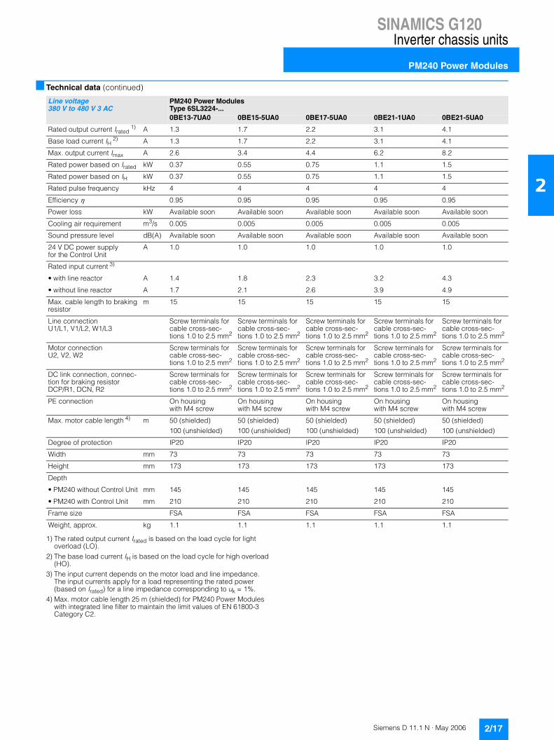
1) The rated output current Irated is based on the load cycle for light overload (LO).
2) The base load current IH is based on the load cycle for high overload (HO).
3) The input current depends on the motor load and line impedance. The input currents apply for a load representing the rated power (based on Irated) for a line impedance corresponding to uk = 1%.
4) Max. motor cable length 25 m (shielded) for PM240 Power Modules with integrated line filter to maintain the limit values of EN 61800-3 Category C2.
Line voltage380 V to 480 V 3 AC
PM240 Power ModulesType 6SL3224-...0BE13-7UA0 0BE15-5UA0 0BE17-5UA0 0BE21-1UA0 0BE21-5UA0
Rated output current Irated 1) A 1.3 1.7 2.2 3.1 4.1
Base load current IH 2) A 1.3 1.7 2.2 3.1 4.1
Max. output current Imax A 2.6 3.4 4.4 6.2 8.2
Rated power based on Irated kW 0.37 0.55 0.75 1.1 1.5
Rated power based on IH kW 0.37 0.55 0.75 1.1 1.5
Rated pulse frequency kHz 4 4 4 4 4
Efficiency � 0.95 0.95 0.95 0.95 0.95
Power loss kW Available soon Available soon Available soon Available soon Available soon
Cooling air requirement m3/s 0.005 0.005 0.005 0.005 0.005
Sound pressure level dB(A) Available soon Available soon Available soon Available soon Available soon
24 V DC power supply for the Control Unit
A 1.0 1.0 1.0 1.0 1.0
Rated input current 3)
• with line reactor A 1.4 1.8 2.3 3.2 4.3
• without line reactor A 1.7 2.1 2.6 3.9 4.9
Max. cable length to braking resistor
m 15 15 15 15 15
Line connectionU1/L1, V1/L2, W1/L3
Screw terminals for cable cross-sec-tions 1.0 to 2.5 mm2
Screw terminals for cable cross-sec-tions 1.0 to 2.5 mm2
Screw terminals for cable cross-sec-tions 1.0 to 2.5 mm2
Screw terminals for cable cross-sec-tions 1.0 to 2.5 mm2
Screw terminals for cable cross-sec-tions 1.0 to 2.5 mm2
Motor connectionU2, V2, W2
Screw terminals for cable cross-sec-tions 1.0 to 2.5 mm2
Screw terminals for cable cross-sec-tions 1.0 to 2.5 mm2
Screw terminals for cable cross-sec-tions 1.0 to 2.5 mm2
Screw terminals for cable cross-sec-tions 1.0 to 2.5 mm2
Screw terminals for cable cross-sec-tions 1.0 to 2.5 mm2
DC link connection, connec-tion for braking resistor DCP/R1, DCN, R2
Screw terminals for cable cross-sec-tions 1.0 to 2.5 mm2
Screw terminals for cable cross-sec-tions 1.0 to 2.5 mm2
Screw terminals for cable cross-sec-tions 1.0 to 2.5 mm2
Screw terminals for cable cross-sec-tions 1.0 to 2.5 mm2
Screw terminals for cable cross-sec-tions 1.0 to 2.5 mm2
PE connection On housing with M4 screw
On housing with M4 screw
On housing with M4 screw
On housing with M4 screw
On housing with M4 screw
Max. motor cable length 4) m 50 (shielded)100 (unshielded)
50 (shielded)100 (unshielded)
50 (shielded)100 (unshielded)
50 (shielded)100 (unshielded)
50 (shielded)100 (unshielded)
Degree of protection IP20 IP20 IP20 IP20 IP20
Width mm 73 73 73 73 73
Height mm 173 173 173 173 173
Depth
• PM240 without Control Unit mm 145 145 145 145 145
• PM240 with Control Unit mm 210 210 210 210 210
Frame size FSA FSA FSA FSA FSA
Weight, approx. kg 1.1 1.1 1.1 1.1 1.1

SINAMICS G120Inverter chassis units
PM240 Power Modules
2/18 Siemens D 11.1 N · May 2006
2
■ Technical data (continued)
1) The rated output current Irated is based on the load cycle for light overload (LO).
2) The base load current IH is based on the load cycle for high overload (HO).
3) The input current depends on the motor load and line impedance. The input currents apply for a load representing the rated power (based on Irated) for a line impedance corresponding to uk = 1%.
4) Max. motor cable length 25 m (shielded) for PM240 Power Modules with integrated line filter to maintain the limit values of EN 61800-3 Category C2.
Line voltage380 V to 480 V 3 AC
PM240 Power ModulesType 6SL3224-...0BE22-2UA00BE22-2AA0
0BE23-0UA00BE23-0AA0
0BE24-0UA00BE24-0AA0
0BE25-5UA00BE25-5AA0
0BE27-5UA00BE27-5AA0
Rated output current Irated 1) A 5.9 7.7 10.2 18 25
Base load current IH 2) A 5.9 7.7 10.2 13.2 19
Max. output current Imax A 11.8 15.4 20.4 26.4 38
Rated power based on Irated kW 2.2 3 4 7.5 11
Rated power based on IH kW 2.2 3 4 5.5 7.5
Rated pulse frequency kHz 4 4 4 4 4
Efficiency � 0.95 0.95 0.95 0.95 0.95
Power loss kW Available soon Available soon Available soon Available soon Available soon
Cooling air requirement m3/s 0.009 0.009 0.009 0.038 0.038
Sound pressure level dB(A) Available soon Available soon Available soon Available soon Available soon
24 V DC power supply for the Control Unit
A 1.0 1.0 1.0 1.0 1.0
Rated input current 3)
• with line reactor A 6.1 8 10.4 18.7 26
• without line reactor A 7.6 10.2 13.4 21.9 31.5
Max. cable length to braking resistor
m 15 15 15 15 15
Line connectionU1/L1, V1/L2, W1/L3
Screw terminals for cable cross-sec-tions 1.0 to 6 mm2
Screw terminals for cable cross-sec-tions 1.0 to 6 mm2
Screw terminals for cable cross-sec-tions 1.0 to 6 mm2
Screw terminals for cable cross-sec-tions 2.5 to 10 mm2
Screw terminals for cable cross-sec-tions 2.5 to 10 mm2
Motor connectionU2, V2, W2
Screw terminals for cable cross-sec-tions 1.0 to 6 mm2
Screw terminals for cable cross-sec-tions 1.0 to 6 mm2
Screw terminals for cable cross-sec-tions 1.0 to 6 mm2
Screw terminals for cable cross-sec-tions 2.5 to 10 mm2
Screw terminals for cable cross-sec-tions 2.5 to 10 mm2
DC link connection, connec-tion for braking resistor DCP/R1, DCN, R2
Screw terminals for cable cross-sec-tions 1.0 to 6 mm2
Screw terminals for cable cross-sec-tions 1.0 to 6 mm2
Screw terminals for cable cross-sec-tions 1.0 to 6 mm2
Screw terminals for cable cross-sec-tions 2.5 to 10 mm2
Screw terminals for cable cross-sec-tions 2.5 to 10 mm2
PE connection On housing with M5 screw
On housing with M5 screw
On housing with M5 screw
On housing with M5 screw
On housing with M5 screw
Max. motor cable length 4) m 50 (shielded)100 (unshielded)
50 (shielded)100 (unshielded)
50 (shielded)100 (unshielded)
50 (shielded)100 (unshielded)
50 (shielded)100 (unshielded)
Degree of protection IP20 IP20 IP20 IP20 IP20
Width mm 153 153 153 189 189
Height mm 270 270 270 334 334
Depth
• PM240 without Control Unit mm 165 165 165 185 185
• PM240 with Control Unit mm 230 230 230 250 250
Frame size FSB FSB FSB FSC FSC
Weight, approx. kg 4.0 4.0 4.0 7.0 7.0

SINAMICS G120Inverter chassis units
PM240 Power Modules
2/19Siemens D 11.1 N · May 2006
2
■ Technical data (continued)
1) The rated output current Irated is based on the load cycle for light overload (LO).
2) The base load current IH is based on the load cycle for high overload (HO).
3) The input current depends on the motor load and line impedance. The input currents apply for a load representing the rated power (based on Irated) for a line impedance corresponding to uk = 1%.
4) Max. motor cable length 25 m (shielded) for PM240 Power Modules with integrated line filter to maintain the limit values of EN 61800-3 Category C2.
Line voltage380 V to 480 V 3 AC
PM240 Power ModulesType 6SL3224-...0BE31-1UA00BE31-1AA0
0BE31-5UA00BE31-5AA0
0BE31-8UA00BE31-8AA0
0BE32-2UA00BE32-2AA0
0BE33-0UA00BE33-0AA0
Rated output current Irated 1) A 32 38 45 60 75
Base load current IH 2) A 26 32 38 45 60
Max. output current Imax A 52 64 76 90 124
Rated power based on Irated kW 15 18.5 22 30 37
Rated power based on IH kW 11 15 18.5 22 30
Rated pulse frequency kHz 4 4 4 4 4
Efficiency � 0.95 0.95 0.95 0.95 0.95
Power loss kW Available soon Available soon Available soon Available soon Available soon
Cooling air requirement m3/s 0.038 0.022 0.022 0.039 0.022
Sound pressure level dB(A) Available soon Available soon Available soon Available soon Available soon
24 V DC power supply for the Control Unit
A 1.0 1.0 1.0 1.0 1.0
Rated input current 3)
• with line reactor A 33 40 47 63 78
• without line reactor A 39 46 53 72 88
Max. cable length to braking resistor
m 15 15 15 15 15
Line connectionU1/L1, V1/L2, W1/L3
Screw terminals for cable cross-sec-tions 2.5 to 10 mm2
M6 stud, connectable cable cross-section 10 to 35 mm2
M6 stud, connectable cable cross-section 10 to 35 mm2
M6 stud, connectable cable cross-section 10 to 35 mm2
M6 stud, connectable cable cross-section 10 to 35 mm2
Motor connectionU2, V2, W2
Screw terminals for cable cross-sec-tions 2.5 to 10 mm2
M6 stud, connectable cable cross-section 10 to 35 mm2
M6 stud, connectable cable cross-section 10 to 35 mm2
M6 stud, connectable cable cross-section 10 to 35 mm2
M6 stud, connectable cable cross-section 10 to 35 mm2
DC link connection, connec-tion for braking resistor DCP/R1, DCN, R2
Screw terminals for cable cross-sec-tions 2.5 to 10 mm2
M6 stud, connectable cable cross-section 10 to 35 mm2
M6 stud, connectable cable cross-section 10 to 35 mm2
M6 stud, connectable cable cross-section 10 to 35 mm2
M6 stud, connectable cable cross-section 10 to 35 mm2
PE connection On housing with M5 screw
On housing with M6 screw
On housing with M6 screw
On housing with M6 screw
On housing with M6 screw
Max. motor cable length 4) m 50 (shielded)100 (unshielded)
50 (shielded)100 (unshielded)
50 (shielded)100 (unshielded)
50 (shielded)100 (unshielded)
50 (shielded)100 (unshielded)
Degree of protection IP20 IP20 IP20 IP20 IP20
Width mm 189 275 275 275 275
Height
• PM240 without integrated filter
mm 334 419 419 419 499
• PM240 with integrated filter
mm 334 512 512 512 635
Depth
• PM240 without Control Unit mm 185 204 204 204 204
• PM240 with Control Unit mm 250 260 260 260 260
Frame size FSC FSD FSD FSD FSE
Weight, approx.
• PM240 without integrated filter
kg 7.0 15.9 15.9 15.9 19.8
• PM240 with integrated filter kg 7.0 19.3 19.3 19.3 27.1

SINAMICS G120Inverter chassis units
PM240 Power Modules
2/20 Siemens D 11.1 N · May 2006
2
■ Technical data (continued)
1) The rated output current Irated is based on the load cycle for light overload (LO).
2) The base load current IH is based on the load cycle for high overload (HO).
3) The input current depends on the motor load and line impedance. The input currents apply for a load representing the rated power (based on Irated) for a line impedance corresponding to uk = 1%.
4) Max. motor cable length 25 m (shielded) for PM240 Power Modules with integrated line filter to maintain the limit values of EN 61800-3 Category C2.
Line voltage380 V to 480 V 3 AC
PM240 Power ModulesType 6SL3224-...0BE33-7UA00BE33-7AA0
0BE34-5UA00BE34-5AA0
0BE35-5UA00BE35-5AA0
0BE37-5UA00BE37-5AA0
Rated output current Irated 1) A 90 110 145 178
Base load current IH 2) A 75 90 110 145
Max. output current Imax A 150 180 220 290
Rated power based on Irated kW 45 55 75 90
Rated power based on IH kW 37 45 55 75
Rated pulse frequency kHz 4 4 4 4
Efficiency � 0.95 0.95 0.95 0.95
Power loss kW Available soon Available soon Available soon Available soon
Cooling air requirement m3/s 0.039 0.094 0.094 0.117
Sound pressure level dB(A) Available soon Available soon Available soon Available soon
24 V DC power supply for the Control Unit
A 1.0 1.0 1.0 1.0
Rated input current 3)
• with line reactor A 94 115 151 186
• without line reactor A 105 129 168 204
Max. cable length to braking resistor
m 15 15 15 15
Line connectionU1/L1, V1/L2, W1/L3
M6 stud, connectable cable cross-section 10 to 35 mm2
M8 stud, max. connec-table cable cross-section 1 x 120 mm2 or 2 x 50 mm2
M8 stud, max. connec-table cable cross-section 1 x 120 mm2 or 2 x 50 mm2
M8 stud, max. connec-table cable cross-section 1 x 120 mm2 or 2 x 50 mm2
Motor connectionU2, V2, W2
M6 stud, connectable cable cross-section10 to 35 mm2
M8 stud, max. connec-table cable cross-section 1 x 120 mm2 or 2 x 50 mm2
M8 stud, max. connec-table cable cross-section 1 x 120 mm2 or 2 x 50 mm2
M8 stud, max. connec-table cable cross-section 1 x 120 mm2 or 2 x 50 mm2
DC link connection, connec-tion for braking resistor DCP/R1, DCN, R2
M6 stud, connectable cable cross-section10 to 35 mm2
M8 stud, max. connec-table cable cross-section 1 x 120 mm2 or 2 x 50 mm2
M8 stud, max. connec-table cable cross-section 1 x 120 mm2 or 2 x 50 mm2
M8 stud, max. connec-table cable cross-section 1 x 120 mm2 or 2 x 50 mm2
PE connection On housing with M6 screw
On housing with M8 screw
On housing with M8 screw
On housing with M8 screw
Max. motor cable length 4) m 50 (shielded)100 (unshielded)
50 (shielded)100 (unshielded)
50 (shielded)100 (unshielded)
50 (shielded)100 (unshielded)
Degree of protection IP20 IP20 IP20 IP20
Width mm 275 350 350 350
Height
• PM240 without integrated filter
mm 499 634 634 634
• PM240 with integrated filter
mm 635 934 934 934
Depth
• PM240 without Control Unit mm 204 316 316 316
• PM240 with Control Unit mm 260 372 372 372
Frame size FSE FSF FSF FSF
Weight, approx.
• PM240 without integrated filter
kg 19.8 50.7 50.7 50.7
• PM240 with integrated filter kg 27.1 66.7 66.7 66.7

SINAMICS G120Inverter chassis units
PM240 Power Modules
2/21Siemens D 11.1 N · May 2006
2
■ Characteristics
Derating data
Pulse frequency
Ambient temperature Installation altitude
Line voltage Rated output Rated output current in Aat a switching frequency of
kW hp 4 kHz 6 kHz 8 kHz 10 kHz 12 kHz 14 kHz 16 kHz
400 V 3 AC 0.37 0.50 1.3 1.1 0.9 0.8 0.7 0.6 0.5
0.55 0.75 1.7 1.4 1.2 1.0 0.9 0.8 0.7
0.75 1.0 2.2 1.9 1.5 1.3 1.1 1.0 0.9
1.1 1.5 3.1 2.6 2.2 1.9 1.6 1.4 1.2
1.5 2.0 4.1 3.5 2.9 2.5 2.1 1.8 1.6
2.2 3.0 5.9 5.0 4.1 3.5 3.0 2.7 2.4
3.0 4.0 7.7 6.5 5.4 4.6 3.9 3.5 3.1
4.0 5.0 10.2 8.7 7.1 6.1 5.1 4.6 4.1
7.5 10 18.0 16.2 13.3 11.4 9.5 8.6 7.6
11.0 15 25.0 22.1 18.2 15.6 13.0 11.7 10.4
15.0 20 32.0 27.2 22.4 19.2 16.0 14.4 12.8
18.5 25 38.0 32.3 26.6 22.8 19.0 17.1 15.2
22.0 30 45.0 38.3 31.5 27.0 22.5 20.3 18.0
30.0 40 62.0 52.7 43.4 37.2 31.0 27.9 24.8
37.0 50 75.0 63.8 52.5 45.0 37.5 33.8 30.0
45.0 60 90.0 76.5 63.0 54.0 45.0 40.5 36.0
55.0 75 110.0 93.5 77.0 66.0 55.0 49.5 44.0
75.0 100 145.0 123.3 101.5 87.0 72.5 65.3 58.0
90.0 125 178.0 151.3 124.6 – – – –
0 20 3010 40-10 50 C° 60
75
%
50
25
100
High overloadLight overload
G_D
011_
EN
_001
03
Ambient temperature
Per
mis
sibl
eou
tput
cur
rent
80
100%
0 1000 2000 3000 4000m
70
90
60 G_D
011_
EN
_001
04Installation altitude above sea level
Per
mis
sibl
eou
tput
cur
rent
80
100%
0 1000 2000 3000 4000m
77
70
90
60
G_D
011_
EN
_001
05
Installation altitude above sea level
Per
mis
sibl
eou
tput
cur
rent

SINAMICS G120Inverter chassis units
PM240 Power Modules
2/22 Siemens D 11.1 N · May 2006
2
■ Selection and ordering data
1) Rated output based on rated output current Irated: The rated output current Irated is based on the load cycle for light overload (LO).
2) The rated output current Irated is based on the load cycle for light overload (LO). This current values are placed on the rating plate of the Power Module.
3) These output values are placed on the rating plate of the Power Module. The base load current IH is based on the load cycle for high overload (HO).
4) The base load current IH is based on the load cycle for high overload (HO).
Rated output 1) Rated output current 2)
Irated
Output based on base load current 3)
Base load current 4)
IH
Frame size
SINAMICS G120 PM240 Power Module without integrated line filterOrder No.
SINAMICS G120PM240 Power Module with integrated line filterOrder No.
kW hp A kW hp A
380 V to 480 V 3 AC
0.37 0.50 1.3 0.37 0.50 1.3 FSA 6SL3224-0BE13-7UA0 –
0.55 0.75 1.7 0.55 0.75 1.7 FSA 6SL3224-0BE15-5UA0 –
0.75 1.0 2.2 0.75 1.0 2.2 FSA 6SL3224-0BE17-5UA0 –
1.1 1.5 3.1 1.1 1.5 3.1 FSA 6SL3224-0BE21-1UA0 –
1.5 2.0 4.1 1.5 2.0 4.1 FSA 6SL3224-0BE21-5UA0 –
2.2 3.0 5.9 2.2 3.0 5.9 FSB 6SL3224-0BE22-2UA0 6SL3224-0BE22-2AA0
3.0 4.0 7.7 3.0 4.0 7.7 FSB 6SL3224-0BE23-0UA0 6SL3224-0BE23-0AA0
4.0 5.0 10.2 4.0 5.0 10.2 FSB 6SL3224-0BE24-0UA0 6SL3224-0BE24-0AA0
7.5 10 18 5.5 7.5 13.2 FSC 6SL3224-0BE25-5UA0 6SL3224-0BE25-5AA0
11.0 15 25 7.5 10 19 FSC 6SL3224-0BE27-5UA0 6SL3224-0BE27-5AA0
15.0 20 32 11.0 15 26 FSC 6SL3224-0BE31-1UA0 6SL3224-0BE31-1AA0
18.5 25 38 15.0 20 32 FSD 6SL3224-0BE31-5UA0 6SL3224-0BE31-5AA0
22 30 45 18.5 25 38 FSD 6SL3224-0BE31-8UA0 6SL3224-0BE31-8AA0
30 40 60 22 30 45 FSD 6SL3224-0BE32-2UA0 6SL3224-0BE32-2AA0
37 50 75 30 40 60 FSE 6SL3224-0BE33-0UA0 6SL3224-0BE33-0AA0
45 60 90 37 50 75 FSE 6SL3224-0BE33-7UA0 6SL3224-0BE33-7AA0
55 75 110 45 60 90 FSF 6SL3224-0BE34-5UA0 6SL3224-0BE34-5AA0
75 100 145 55 75 110 FSF 6SL3224-0BE35-5UA0 6SL3224-0BE35-5AA0
90 125 178 75 100 145 FSF 6SL3224-0BE37-5UA0 6SL3224-0BE37-5AA0

SINAMICS G120Inverter chassis units
PM240 Power Modules
2/23Siemens D 11.1 N · May 2006
2
■ Dimension drawings
PM240 Power Module frame size FSA
Fixing with 2 M4 studs, 2 M4 nuts, 2 M4 washers
Tightening torque: 2.5 Nm (22.1 lbf-in)
Required ventilation clearance at top and bottom: 100 mm (3.94 inches)
Required ventilation clearance at side: 30 mm (1.18 inches)
When the Control Unit is plugged in, the mounting depth increases by 65 mm (2.56 inches) and the total depth by 14 mm (0.55 inches).
All dimensions in mm (values in brackets are in inches).
PM240 Power Module frame size FSB
Fixing with 4 M4 studs, 4 M4 nuts, 4 M4 washers
Tightening torque: 2.5 Nm (22.1 lbf-in)
Required ventilation clearance at top and bottom: 100 mm (3.94 inches)
Required ventilation clearance at side: 40 mm (1.57 inches)
When the Control Unit is plugged in, the mounting depth increases by 65 mm (2.56 inches).
All dimensions in mm (values in brackets are in inches).
Drill pattern
G_D
011_
EN
_000
91
4.5 (0.18)
145 (5.71) 73 (2.87)
173
(6.8
1)
160
(6.3
)
Drill pattern
G_D011_EN_00092
133 (5.24)
4.8 (0.19)
165 (6.5) 153 (6.02)
270
(10.
63)
258
(10.
16)

SINAMICS G120Inverter chassis units
PM240 Power Modules
2/24 Siemens D 11.1 N · May 2006
2
■ Dimension drawings (continued)
PM240 Power Module frame size FSC
Fixing with 4 M5 studs, 4 M5 nuts, 4 M5 washers
Tightening torque: 2.5 Nm (22.1 lbf-in)
Required ventilation clearance at top and bottom: 100 mm (3.94 inches)
Required ventilation clearance at side: 50 mm (1.97 inches)
When the Control Unit is plugged in, the mounting depth increases by 65 mm (2.56 inches).
All dimensions in mm (values in brackets are in inches).
Drill pattern
G_D011_EN_0093
185 (7.28) 167 (6.57)
323
(12.
72)
189 (7.44)
334
(13.
15)
5.5 (0.22)

SINAMICS G120Inverter chassis units
PM240 Power Modules
2/25Siemens D 11.1 N · May 2006
2
■ Dimension drawings (continued)
PM240 Power Module frame size FSD without line filter
PM240 Power Module frame size FSD with integrated line filter class A
Fixing with 4 M6 studs, 4 M6 nuts, 4 M6 washers
Tightening torque: 6 Nm (53 lbf-in)
Required ventilation clearance at top and bottom: 300 mm (11.81 inches)
Required ventilation clearance at front: 28 mm (1.1 inches)
When the Control Unit is plugged in, the mounting depth increases by 56 mm (2.2 inches).
All dimensions in mm (values in brackets are in inches).
Drill pattern
G_D011_EN_00094
8.5 (0.33)
204 (8.03) 275 (10.83)
361
(14.
21)
419
(16.
5)
235 (9.25)
325
(12.
8)11
(0.4
3)Drill pattern
G_D011_EN_00095
235 (9.25)204 (8.03) 275 (10.83)
455
(17.
91)
512
(20.
16)
8.5 (0.33)
419
(16.
5)11
(0.4
3)

SINAMICS G120Inverter chassis units
PM240 Power Modules
2/26 Siemens D 11.1 N · May 2006
2
■ Dimension drawings (continued)
PM240 Power Module frame size FSE without line filter
PM240 Power Module frame size FSE with integrated line filter class A
Fixing with 4 M6 studs, 4 M6 nuts, 4 M6 washers
Tightening torque: 6 Nm (53 lbf-in)
Required ventilation clearance at top and bottom: 300 mm (11.81 inches)
Required ventilation clearance at front: 28 mm (1.1 inches)
When the Control Unit is plugged in, the mounting depth increases by 56 mm (2.2 inches).
All dimensions in mm (values in brackets are in inches).
Drill pattern
G_D011_EN_00096
235 (9.25)204 (8.03) 275 (10.83)
441
(17.
36)
499
(19.
65)
8.5 (0.33)
405
(15.
94)
11 (0
.43)
Drill pattern
G_D011_EN_00097
235 (9.25)204 (8.03) 275 (10.83)
577
(22.
72)
635
(25)
8.5 (0.33)
541
(21.
3)11
(0.4
3)

SINAMICS G120Inverter chassis units
PM240 Power Modules
2/27Siemens D 11.1 N · May 2006
2
■ Dimension drawings (continued)
PM240 Power Module frame size FSF without line filter
PM240 Power Module frame size FSF with integrated line filter class A
Fixing with 4 M8 studs, 4 M8 nuts, 4 M8 washers
Tightening torque: 13 Nm (115 lbf-in)
Required ventilation clearance at top and bottom: 350 mm (13.78 inches)
Required ventilation clearance at front: 28 mm (1.1 inches)
When the Control Unit is plugged in, the mounting depth increases by 56 mm (2.2 inches).
All dimensions in mm (values in brackets are in inches).
Drill pattern
G_D011_EN_00098
316 (12.44) 350 (13.78) 300 (11.81)
8.5 (0.33)
634
(24.
96)
598
(23.
54)
11 (0
.43)
Drill pattern
G_D011_EN_00099
316 (12.44) 350 (13.78) 300 (11.81)
8.5 (0.33)
934
(36.
77)
899
(35.
39)
11 (0
.43)

SINAMICS G120Inverter chassis units
Line filters
2/28 Siemens D 11.1 N · May 2006
2
■ Overview
The PM240 Power Module complies with a higher radio inter-ference class with one additional line filter.
Frame size FSA of the PM240 Power Module is only available without integrated line filter of class A. A base filter for compli-ance with class A and another for compliance with class B are therefore available.
Frame sizes FSB and FSC of the PM240 Power Module are avai-lable both with and without integrated line filter of class A. For compliance with class B, PM240 Power Modules with integrated line filter of class A must be fitted additionally with a base filter of class B.
■ Technical data
Line voltage380 V to 480 V 3 AC
Line filter class A6SE6400-2FA00-6AD0
Line filter class B6SE6400-2FB00-6AD0 6SL3203-0BE21-6SA0 6SL3203-0BD23-8SA0
Rated current A 6 6 10.2 39.4
Line connectionL1, L2, L3
2.5 mm2 screw terminals
2.5 mm2 screw terminals
2.5 mm2 screw terminals
4 mm2 screw terminals
Load connectionU, V, W
Shielded cable 3 x 2.5 mm2
0.4 m long
Shielded cable 3 x 2.5 mm2
0.4 m long
Shielded cable 3 x 2.5 mm2
0.4 m long
Shielded cable 3 x 4 mm2
0.4 m long
PE connection On housing with M4 stud On housing with M4 stud On housing with M4 stud On housing with M4 stud
Degree of protection IP20 IP20 IP20 IP20
Width mm 73 73 153 190
Height mm 200 200 296 362
Depth mm 42.5 42.5 50 55
Possible as base component Yes Yes Yes Yes
Weight, approx. kg 0.5 0.5 1.5 2.3
Suitable for Power Module
Type 6SL3224-0BE13-7UA06SL3224-0BE15-5UA06SL3224-0BE17-5UA06SL3224-0BE21-1UA06SL3224-0BE21-5UA0
6SL3224-0BE13-7UA06SL3224-0BE15-5UA06SL3224-0BE17-5UA06SL3224-0BE21-1UA06SL3224-0BE21-5UA0
6SL3224-0BE22-2UA06SL3224-0BE23-0AA06SL3224-0BE24-0AA0
6SL3224-0BE25-5AA06SL3224-0BE27-5AA06SL3224-0BE31-1AA0
Frame size FSA FSA FSB FSC

SINAMICS G120Inverter chassis units
Line filters
2/29Siemens D 11.1 N · May 2006
2
■ Selection and ordering data
Rated output SINAMICS G120 PM240 Power Module Line filter class Ain accordance with EN 55011
kW hp Type 6SL3224-... Frame size Order No.
380 V to 480 V 3 AC
0.37 0.50 0BE13-7UA0 FSA 6SE6400-2FA00-6AD0
0.55 0.75 0BE15-5UA0 FSA
0.75 1.0 0BE17-5UA0 FSA
1.1 1.5 0BE21-1UA0 FSA
1.5 2.0 0BE21-5UA0 FSA
Rated output SINAMICS G120 PM240 Power Module Line filter class Bin accordance with EN 55011
kW hp Type 6SL3224-... Frame size Order No.
380 V to 480 V 3 AC
0.37 0.50 0BE13-7UA0 FSA 6SE6400-2FB00-6AD0
0.55 0.75 0BE15-5UA0 FSA
0.75 1.0 0BE17-5UA0 FSA
1.1 1.5 0BE21-1UA0 FSA
1.5 2.0 0BE21-5UA0 FSA
2.2 3.0 0BE22-2AA0 FSB 6SL3203-0BE21-6SA0
3.0 4.0 0BE23-0AA0 FSB
4.0 5.0 0BE24-0AA0 FSB
7.5 10 0BE25-5AA0 FSC 6SL3203-0BD23-8SA0
11.0 15 0BE27-5AA0 FSC
15.0 20 0BE31-1AA0 FSC

SINAMICS G120Inverter chassis units
Line reactors
2/30 Siemens D 11.1 N · May 2006
2
■ Overview
A line reactor is needed for high system fault levels, partly to pro-tect the actual inverter against excessive harmonic currents, and thus against overload, and partly to limit the line harmonic distortions to the permitted values.
■ Integration
The line reactors for PM240 Power Modules of frame sizes FSA to FSE are designed as base components. The line reactor is attached to the mounting surface and the Power Module is mounted compactly on the line reactor. The cables to the Power Modules are already connected at the line reactor.
The line reactor is connected to the line supply through terminals.
■ Technical data
Line voltage380 V to 480 V 3 AC
Line reactor6SE6400-3CC00-2AD3 6SE6400-3CC00-4AD3 6SE6400-3CC00-6AD3 6SL3203-0CD21-0AA0
Rated current A 1.9 3.5 4.8 9
Power loss at 50 Hz/60 Hz, approx.
W Available soon Available soon Available soon Available soon
Line connection U1, V1, W1
6 mm2 screw terminals
6 mm2 screw terminals
6 mm2 screw terminals
6 mm2 screw terminals
Load connection Cable 4 x AWG16 (1.5 mm2) length approx. 0.38 m
Cable 4 x AWG16 (1.5 mm2) length approx. 0.38 m
Cable 4 x AWG16 (1.5 mm2) length approx. 0.38 m
Cable 4 x AWG16 (1.5 mm2) length approx. 0.46 m
PE connection On housing with M5 studs
On housing with M5 studs
On housing with M5 studs
On housing with M5 studs
Degree of protection IP20 IP20 IP20 IP20
Width mm 75.5 75.5 75.5 153
Height mm 200 200 200 290
Depth mm 50 50 50 70
Possible as base component Yes Yes Yes Yes
Weight, approx. kg 0.6 0.8 0.6 3.4
Suitable for Power Module Type 6SL3224-0BE13-7UA06SL3224-0BE15-5UA0
6SL3224-0BE17-5UA06SL3224-0BE21-1UA0
6SL3224-0BE21-5UA0 6SL3224-0BE22-2 . A06SL3224-0BE23-0 . A0
Frame size FSA FSA FSA FSB
Line voltage380 V to 480 V 3 AC
Line reactor6SL3203-0CD21-4AA0 6SL3203-0CD22-2AA0 6SL3203-0CD23-5AA0 6SL3203-0CJ24-5AA0
Rated current A 11.6 25 31.3 45.8
Power loss at 50 Hz/60 Hz, approx.
W Available soon Available soon Available soon Available soon
Line connection U1, V1, W1
6 mm2 screw terminals
6 mm2 screw terminals
6 mm2 screw terminals
16 mm2 screw terminals
Load connection Cable 4 x AWG16 (1.5 mm2) length approx. 0.46 m
Cable 4 x AWG10(2.5 mm2) length approx. 0.49 m
Cable 4 x AWG10 (2.5 mm2) length approx. 0.49 m
Cable 4 x 16 mm2 length approx. 0.70 m
PE connection On housing with M5 studs
On housing with M5 studs
On housing with M5 studs
On housing with M8 screw
Degree of protection IP20 IP20 IP20 IP20
Width mm 153 189 189 275
Height mm 290 371 371 455
Depth mm 70 50 50 84
Possible as base component Yes Yes Yes Yes
Weight, approx. kg 3.4 5.2 5.9 13
Suitable for Power Module Type 6SL3224-0BE24-0 . A0 6SL3224-0BE25-5 . A06SL3224-0BE27-5 . A0
6SL3224-0BE31-1 . A0 6SL3224-0BE31-5 . A06SL3224-0BE31-8 . A0
Frame size FSB FSC FSC FSD

SINAMICS G120Inverter chassis units
Line reactors
2/31Siemens D 11.1 N · May 2006
2
■ Technical data (continued)
■ Selection and ordering data
Line voltage380 V to 480 V 3 AC
Line reactor6SL3203-0CD25-3AA0 6SL3203-0CJ28-6AA0 6SE6400-3CC11-2FD0 6SE6400-3CC11-7FD0
Rated current A 53.6 86.9 129 183
Power loss at 50 Hz/60 Hz, approx.
W Available soon Available soon Available soon Available soon
Line connection U1, V1, W1
16 mm2 screw terminals
50 mm2 screw terminals
Flat connector for M10 cable lug
Flat connector for M10 cable lug
Load connection Cable 4 x 16 mm2
length approx. 0.70 mCable 4 x 35 mm2
length approx. 0.70 mFlat connector for M10 cable lug
Flat connector for M10 cable lug
PE connection On housing with M8 screw
On housing with M8 screw
On housing with M8 studs
On housing with M8 studs
Degree of protection IP20 IP20 IP00 IP00
Width mm 275 275 240 240
Height mm 455 577 228 228
Depth mm 84 94 141 141
Possible as base component Yes Yes No No
Weight, approx. kg 13 19 25 25
Suitable for Power Module Type 6SL3224-0BE32-2 . A0 6SL3224-0BE33-0 . A06SL3224-0BE33-7 . A0
6SL3224-0BE34-5 . A06SL3224-0BE35-5 . A0
6SL3224-0BE37-5 . A0
Frame size FSD FSE FSF FSF
Rated output SINAMICS G120 PM240 Power Module Line reactor
kW hp Type 6SL3224-... Frame size Order No.
380 V to 480 V 3 AC
0.37 0.50 0BE13-7UA0 FSA 6SE6400-3CC00-2AD3
0.55 0.75 0BE15-5UA0 FSA
0.75 1.0 0BE17-5UA0 FSA 6SE6400-3CC00-4AD3
1.1 1.5 0BE21-1UA0 FSA
1.5 2.0 0BE21-5UA0 FSA 6SE6400-3CC00-6AD3
2.2 3.0 0BE22-2 . A0 FSB 6SL3203-0CD21-0AA0
3.0 4.0 0BE23-0 . A0 FSB
4.0 5.0 0BE24-0 . A0 FSB 6SL3203-0CD21-4AA0
7.5 10 0BE25-5 . A0 FSC 6SL3203-0CD22-2AA0
11.0 15 0BE27-5 . A0 FSC
15.0 20 0BE31-1 . A0 FSC 6SL3203-0CD23-5AA0
18.5 25 0BE31-5 . A0 FSD 6SL3203-0CJ24-5AA0
22 30 0BE31-8 . A0 FSD
30 40 0BE32-2 . A0 FSD 6SL3203-0CD25-3AA0
37 50 0BE33-0 . A0 FSE 6SL3203-0CJ28-6AA0
45 60 0BE33-7 . A0 FSE
55 75 0BE34-5 . A0 FSF 6SE6400-3CC11-2FD0
75 100 0BE35-5 . A0 FSF
90 125 0BE37-5 . A0 FSF 6SE6400-3CC11-7FD0

SINAMICS G120Inverter chassis units
Recommended line components
2/32 Siemens D 11.1 N · May 2006
2
■ Overview
The following table lists recommendations for further line-side components, such as fuses and circuit-breakers (line-side com-ponents dimensioned in accordance with IEC standards). The specified circuit-breakers are UL-certified. Fuses of type 3NA3 are recommended for European countries. The 3NE1 fuses are UL-compliant (corresponds to U).
Further information on the listed fuses and circuit-breakers can be found in Catalogs LV 1 and LV 1 T.
■ Selection and ordering data
Rated output SINAMICS G120 PM240 Power Module Fuses Circuit-breakers
kW hp Type 6SL3224-... Frame size Type 3NA3Order No.
Type 3NE3 (U)Order No.
Order No.
380 V to 480 V 3 AC
0.37 0.50 0BE13-7UA0 FSA 3NA3803 UL-listed fuses such as the Class NON fuse series from Bussmann are required for North American countries.
3RV1021-1CA10
0.55 0.75 0BE15-5UA0 FSA 3RV1021-1DA10
0.75 1.0 0BE17-5UA0 FSA 3RV1021-1FA10
1.1 1.5 0BE21-1UA0 FSA 3RV1021-1GA10
1.5 2.0 0BE21-5UA0 FSA 3RV1021-1JA10
2.2 3.0 0BE22-2.A0 FSB 3NA3805 3RV1021-1KA10
3.0 4.0 0BE23-0.A0 FSB 3RV1021-4AA10
4.0 5.0 0BE24-0.A0 FSB 3NA3807 3RV1021-4BA10
7.5 10 0BE25-5.A0 FSC 3RV1031-4EA10
11.0 15 0BE27-5.A0 FSC 3RV1031-4FA10
15.0 20 0BE31-1.A0 FSC 3NA3812 3RV1031-4HA10
18.5 25 0BE31-5.A0 FSD 3NA3820 3NE1817-0 3RV1042-4KA10
22 30 0BE31-8.A0 FSD 3NA3822 3NE1818-0
30 40 0BE32-2.A0 FSD 3NA3824 3NE1820-0 3RV1042-4MA10
37 50 0BE33-0.A0 FSE 3NA3830 3NE1021-0 3VL1712-.DD33-....
45 60 0BE33-7.A0 FSE 3NA3832 3NE1022-0 3VL1716-.DD33-....
55 75 0BE34-5.A0 FSF 3NA3836 3NE1224-0 3VL3720-.DC36-....
75 100 0BE35-5.A0 FSF 3NA3140 3NE1225-0 3VL3725-.DC36-....
90 125 0BE37-5.A0 FSF 3NA3144 3NE1227-0 3VL4731-.DC36-....
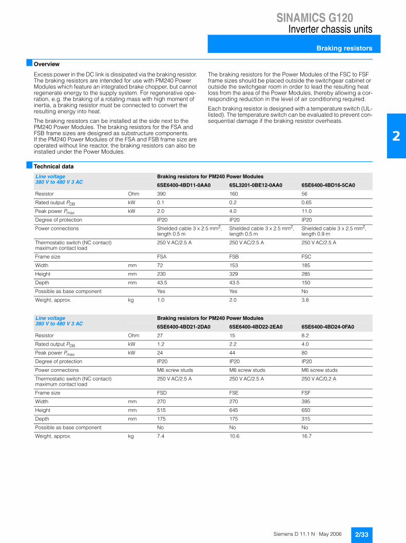
SINAMICS G120Inverter chassis units
Braking resistors
2/33Siemens D 11.1 N · May 2006
2
■ Overview
Excess power in the DC link is dissipated via the braking resistor. The braking resistors are intended for use with PM240 Power Modules which feature an integrated brake chopper, but cannot regenerate energy to the supply system. For regenerative ope-ration, e.g. the braking of a rotating mass with high moment of inertia, a braking resistor must be connected to convert the resulting energy into heat.
The braking resistors can be installed at the side next to the PM240 Power Modules. The braking resistors for the FSA and FSB frame sizes are designed as substructure components. If the PM240 Power Modules of the FSA and FSB frame size are operated without line reactor, the braking resistors can also be installed under the Power Modules.
The braking resistors for the Power Modules of the FSC to FSF frame sizes should be placed outside the switchgear cabinet or outside the switchgear room in order to lead the resulting heat loss from the area of the Power Modules, thereby allowing a cor-responding reduction in the level of air conditioning required.
Each braking resistor is designed with a temperature switch (UL-listed). The temperature switch can be evaluated to prevent con-sequential damage if the braking resistor overheats.
■ Technical data
Line voltage 380 V to 480 V 3 AC
Braking resistors for PM240 Power Modules
6SE6400-4BD11-0AA0 6SL3201-0BE12-0AA0 6SE6400-4BD16-5CA0
Resistor Ohm 390 160 56
Rated output PDB kW 0.1 0.2 0.65
Peak power Pmax kW 2.0 4.0 11.0
Degree of protection IP20 IP20 IP20
Power connections Shielded cable 3 x 2.5 mm2, length 0.5 m
Shielded cable 3 x 2.5 mm2, length 0.5 m
Shielded cable 3 x 2.5 mm2, length 0.9 m
Thermostatic switch (NC contact) maximum contact load
250 V AC/2.5 A 250 V AC/2.5 A 250 V AC/2.5 A
Frame size FSA FSB FSC
Width mm 72 153 185
Height mm 230 329 285
Depth mm 43.5 43.5 150
Possible as base component Yes Yes No
Weight, approx. kg 1.0 2.0 3.8
Line voltage 380 V to 480 V 3 AC
Braking resistors for PM240 Power Modules
6SE6400-4BD21-2DA0 6SE6400-4BD22-2EA0 6SE6400-4BD24-0FA0
Resistor Ohm 27 15 8.2
Rated output PDB kW 1.2 2.2 4.0
Peak power Pmax kW 24 44 80
Degree of protection IP20 IP20 IP20
Power connections M6 screw studs M6 screw studs M6 screw studs
Thermostatic switch (NC contact) maximum contact load
250 V AC/2.5 A 250 V AC/2.5 A 250 V AC/0,2 A
Frame size FSD FSE FSF
Width mm 270 270 395
Height mm 515 645 650
Depth mm 175 175 315
Possible as base component No No No
Weight, approx. kg 7.4 10.6 16.7

SINAMICS G120Inverter chassis units
Braking resistors
2/34 Siemens D 11.1 N · May 2006
2
■ Selection and ordering data
Rated output SINAMICS G120 PM240 Power Module Braking resistor
kW hp Type 6SL3224-... Frame Size Order No.
380 V to 480 V 3 AC
0.37 0.50 0BE13-7UA0 FSA 6SE6400-4BD11-0AA0
0.55 0.75 0BE15-5UA0 FSA
0.75 1.0 0BE17-5UA0 FSA
1.1 1.5 0BE21-1UA0 FSA
1.5 2.0 0BE21-5UA0 FSA
2.2 3.0 0BE22-2 . A0 FSB 6SL3201-0BE12-0AA0
3.0 4.0 0BE23-0 . A0 FSB
4.0 5.0 0BE24-0 . A0 FSB
7.5 10 0BE25-5 . A0 FSC 6SE6400-4BD16-5CA0
11.0 15 0BE27-5 . A0 FSC
15.0 20 0BE31-1 . A0 FSC
18.5 25 0BE31-5 . A0 FSD 6SE6400-4BD21-2DA0
22 30 0BE31-8 . A0 FSD
30 40 0BE32-2 . A0 FSD
37 50 0BE33-0 . A0 FSE 6SE6400-4BD22-2EA0
45 60 0BE33-7 . A0 FSE
55 75 0BE34-5 . A0 FSF 6SE6400-4BD24-0FA0
75 100 0BE35-5 . A0 FSF
90 125 0BE37-5 . A0 FSF

SINAMICS G120Inverter chassis units
Output reactors
2/35Siemens D 11.1 N · May 2006
2
■ Overview
Output reactors reduce the voltage loading on the motor win-dings. At the same time, the capacitive charge/discharge cur-rents, which place an additional load on the power section when long motor cables are used, are reduced.
The maximum permissible output frequency is 150 Hz when an output reactor is used – the pulse frequency must not exceed 4 kHz.
The output reactor must be installed as close as possible to the Power Module.
Output reactors are approved for use only in conjunction with "Vector" and "V/f control" modes.
■ Technical data
Line voltage380 V to 480 V 3 AC
Output reactor (for a 4 kHz pulse frequency)6SE6400-3TC00-4AD2 6SL3202-0AE21-0CA0
Rated current A 4 9.4
Power loss kW Available soon Available soon
Connection to the Power Module
Cable 4 x AWG16 (1.5 mm2)length approx. 0.3 m
Cable 4 x AWG14 (1.5 mm2)length approx. 0.4 m
Motor connection Screw terminals for cable cross-section 6 mm2 Screw terminals for cable cross-section 6 mm2
PE connection M5 stud M5 stud
Max. permissible cable length between output reactor and motor
m 100 (shielded)150 (unshielded)
100 (shielded)150 (unshielded)
Width mm 75.5 154
Height mm 200 270
Depth mm 110 70
Possible as base component
Yes Yes
Degree of protection IP00 IP00
Weight, approx. kg 2.0 4.4
Suitable for Power Module
Type 6SL3224-0BE13-7UA0
6SL3224-0BE15-5UA0
6SL3224-0BE17-5UA0
6SL3224-0BE21-1UA0
6SL32240BE21-5UA0
6SL3224-0BE22-2UA06SL3224-0BE22-2UA0
Rated output of the Power Module
kW 0.37 0.55 0.75 1.1 1.5 2.2
Rated current Irated of the Power Module
A 1.3 1.7 2.2 3.1 4.1 5.9
Frame size FSA FSA FSA FSA FSA FSB

SINAMICS G120Inverter chassis units
Output reactors
2/36 Siemens D 11.1 N · May 2006
2
■ Technical data (continued)
Line voltage380 V to 480 V 3 AC
Output reactor (for a 4 kHz pulse frequency)
6SL3202-0AE21-0CA0 6SL3202-0AJ23-2CA0 6SE6400-3TC05-4DD0
Rated current A 9.4 32 68
Power loss kW Available soon Available soon Available soon
Connection to the Power Module
Cable 4 x AWG14 (1.5 mm2)length approx. 0.4 m
Cable 4 x AWG14 (1.5 mm2)length approx. 0.35 m
Flat connection for M6 cable lug
Motor connection Screw terminals for cable cross-section 6 mm2
Screw terminals for cable cross-section 6 mm2
Flat connection for M6 cable lug
PE connection M5 stud M5 stud M6 screw
Max. permissible cable length between output reactor and motor
m 100 (shielded)150 (unshielded)
100 (shielded)150 (unshielded)
200 (shielded)300 (unshielded)
Width mm 154 189 225
Height mm 270 334 210
Depth mm 70 80 150
Possible as base component
Yes Yes No
Degree of protection IP00 IP00 IP00
Weight, approx. kg 4.4 9.1 10.7
Suitable for Power Module
Type 6SL3224-0BE23-0UA06SL3224-0BE23-0AA0
6SL3224-0BE24-0UA06SL3224-0BE24-0AA0
6SL3224-0BE25-5UA06SL3224-0BE25-5AA0
6SL3224-0BE27-5UA06SL3224-0BE27-5AA0
6SL3224-0BE31-1UA06SL3224-0BE31-1AA0
6SL3224-0BE31-5UA06SL3224-0BE31-5AA0
Rated output of the Power Module
kW 3.0 4.0 7.5 11.0 15 18.5
Rated current Irated of the Power Module
A 7.7 10 18 25 32 38
Frame size FSB FSB FSC FSC FSC FSD
Line voltage380 V to 480 V 3 AC
Output reactor (for a 4 kHz pulse frequency)
6SE6400-3TC03-8DD0
6SE6400-3TC05-4DD0
6SE6400-3TC08-0ED0
6SE6400-3TC07-5ED0
6SE6400-3TC14-5FD0
6SE6400-3TC15-4FD0
Rated current A 45 68 104 90 178 178
Power loss kW Available soon Available soon Available soon Available soon Available soon Available soon
Connection to the Power Module
Flat connection for M6 cable lug
Flat connection for M6 cable lug
Flat connection for M6 cable lug
Flat connection for M6 cable lug
Flat connection for M8 cable lug
Flat connection for M8 cable lug
Motor connection Flat connection for M6 cable lug
Flat connection for M6 cable lug
Flat connection for M6 cable lug
Flat connection for M6 cable lug
Flat connection for M8 cable lug
Flat connection for M8 cable lug
PE connection M6 screw M6 screw M6 screw M6 screw M8 screw M6 screw
Max. permissible cable length between output reactor and motor
m 200 (shielded)300 (unshielded)
200 (shielded)300 (unshielded)
200 (shielded)300 (unshielded)
200 (shielded)300 (unshielded)
200 (shielded)300 (unshielded)
200 (shielded)300 (unshielded)
Width mm 225 225 225 270 350 270
Height mm 210 210 210 248 321 248
Depth mm 179 150 150 209 288 209
Possible as base component
No No No No No No
Degree of protection IP00 IP00 IP00 IP00 IP00 IP00
Weight, approx. kg 16.1 10.7 10.4 24.9 51.5 24.0
Suitable for Power Module
Type 6SL3224-0BE31-8UA06SL3224-0BE31-8AA0
6SL3224-0BE32-2UA06SL3224-0BE32-2AA0
6SL3224-0BE33-0UA06SL3224-0BE33-0AA0
6SL3224-0BE33-7UA06SL3224-0BE33-7AA0
6SL3224-0BE34-5UA06SL3224-0BE34-5AA0
6SL3224-0BE35-5UA06SL3224-0BE35-5AA0
Rated output of the Power Module
kW 22 30 37 45 55 75
Rated current Irated of the Power Module
A 45 60 75 90 110 145
Frame size FSD FSD FSE FSE FSF FSF

SINAMICS G120Inverter chassis units
Output reactors
2/37Siemens D 11.1 N · May 2006
2
■ Technical data (continued)
■ Selection and ordering data
Line voltage380 V to 480 V 3 AC
Output reactor (for a 4 kHz pulse frequency)6SE6400-3TC14-5FD0
Rated current A 178
Power loss kW Available soon
Connection to the Power Module Flat connection for M8 cable lug
Motor connection Flat connection for M8 cable lug
PE connection M8 screw
Max. permissible cable length between output reactor and motor
m 200 (shielded)300 (unshielded)
Width mm 350
Height mm 321
Depth mm 288
Possible as base component No
Degree of protection IP00
Weight, approx. kg 51.5
Suitable for Power Module
Type 6SL3224-0BE37-5UA06SL3224-0BE37-5AA0
Rated output of the Power Module kW 75
Rated current Irated of the Power Module
A 178
Frame size FSF
Rated output SINAMICS G120 PM240 Power Module Output reactor
kW hp Type 6SL3224-... Frame size Order No.
380 V to 480 V 3 AC
0.37 0.50 0BE13-7UA0 FSA 6SE6400-3TC00-4AD2
0.55 0.75 0BE15-5UA0 FSA
0.75 1.0 0BE17-5UA0 FSA
1.1 1.5 0BE21-1UA0 FSA
1.5 2.0 0BE21-5UA0 FSA
2.2 3.0 0BE22-2 . A0 FSB 6SL3202-0AE21-0CA0
3.0 4.0 0BE23-0 . A0 FSB
4.0 5.0 0BE24-0 . A0 FSB
7.5 10 0BE25-5 . A0 FSC 6SL3202-0AJ23-2CA0
11.0 15 0BE27-5 . A0 FSC
15.0 20 0BE31-1 . A0 FSC
18.5 25 0BE31-5 . A0 FSD 6SE6400-3TC05-4DD0
22 30 0BE31-8 . A0 FSD 6SE6400-3TC03-8DD0
30 40 0BE32-2 . A0 FSD 6SE6400-3TC05-4DD0
37 50 0BE33-0 . A0 FSE 6SE6400-3TC08-0ED0
45 60 0BE33-7 . A0 FSE 6SE6400-3TC07-5ED0
55 75 0BE34-5 . A0 FSF 6SE6400-3TC14-5FD0
75 100 0BE35-5 . A0 FSF 6SE6400-3TC15-4FD0
90 125 0BE37-5 . A0 FSF 6SE6400-3TC14-5FD0

SINAMICS G120Inverter chassis units
BOP Basic Operator Panel
2/38 Siemens D 11.1 N · May 2006
2
■ Overview
The BOP Basic Operator Panel can be used to commission drives, monitor drives in operation and input individual para-meter settings.
Values and units are displayed via a 5-digit display.
One BOP can be used for several inverters. It is plugged directly onto the Control Unit.
The BOP provides a function for time-saving copying of para-meters. A parameter set of one inverter can be saved and then loaded to another inverter.
■ Integration
Control Unit with plugged in BOP Basic Operator Panel
■ Selection and ordering data
Order No.
BOP Basic Operator Panel 6SL3255-0AA00-4BA1

SINAMICS G120Inverter chassis units
PC-inverter connection kit
2/39Siemens D 11.1 N · May 2006
2
■ Overview
For controlling and commissioning an inverter directly from a PC if the appropriate software (STARTER) has been installed.
This is an isolated RS232 adapter board for a reliable point-to-point connection to a PC with a serial RS232 interface. A USB/RS232 adapter can be used as an alternative.
The scope of supply includes a 9-pole Sub-D connector and an RS232 standard cable (3 m) and the STARTER commissioning tool on CD-ROM.
With these, the inverter can be• parameterized (commissioning, optimization),• monitored (diagnostics) and• controlled (master control via STARTER for test purposes)
■ Selection and ordering data
Order No.
PC-inverter connection kit including a 9-pole Sub-D connector, a RS232 standard cable (3 m) and the STARTER commissioning tool on CD-ROM
6SL3255-0AA00-2AA1

SINAMICS G120Inverter chassis units
Brake Relay
2/40 Siemens D 11.1 N · May 2006
2
■ Overview
The Brake Relay allows the Power Module to be connected to an electromechanical motor brake, thereby allowing the motor brake to be driven directly by the Control Unit.
■ Integration
The Brake Relay has the following interfaces:• a switch contact (NO contact) to control the motor brake coil• a connection for the cable harness (CTRL) for connection to
the Power Module
The Brake Relay can be installed on the screen termination plate near the power terminals of the Power Module.
The supplied brake relay includes the cable harness for connec-tion with the Power Module.
■ Technical data
■ Selection and ordering data
Brake Relay
Switching capability of the NO contact Max. 440 V AC / 3.5 A30 V DC / 12 A
Max. connectable cross-section 2.5 mm2
Width 68 mm
Height 63 mm
Depth 33 mm
Degree of protection IP20
Weight, approx. 0.17 kg
Order No.
Brake Relay including cable harness for connection to PM240 Power Module
6SL3252-0BB00-0AA0

SINAMICS G120Inverter chassis units
Safe Brake Relay
2/41Siemens D 11.1 N · May 2006
2
■ Overview
The Safe Brake Relay allows the Power Module to be safely con-nected to an electromechanical motor brake, thereby allowing the brake to be directly and safely controlled by the Control Unit in accordance with EN 954-1, safety category 3 and IEC 61508 SIL 2.
■ Integration
The Safe Brake Relay has the following interfaces:• a switch contact (NO contact) to control the motor brake coil• a connection for a 24 V DC voltage supply• a connection for the cable harness (CTRL) for connection to
the Power Module
The Safe Brake Relay can be installed on the screen termination plate near the power terminals of the Power Module.
The supplied safe brake relay includes the cable harness for connection with the Power Module.
The 24 V DC coil of the motor brake is directly connected to the Safe Brake Relay. External overvoltage limiters are not required.
■ Technical data
■ Selection and ordering data
Safe Brake Relay
Supply voltage 20.4 V DC to 28.8 V DCRecommended rated value of the supply voltage 26 V DC(to compensate for the voltage drop along the feeder cable to the 24 V DC coil of the motor brake)
Max. permissible current requirement of the motor brake
Available soon
Max. current requirement (at 24 V DC) Available soon
Max. connectable cross-section 2.5 mm2
Width 68 mm
Height 63 mm
Depth 33 mm
Degree of protection IP20
Weight, approx. 0.17 kg
Order No.
Safe Brake Relay including cable harness for connection to PM240 Power Module
6SL3252-0BB01-0AA0

SINAMICS G120Inverter chassis units
Adapter for mounting on DIN rail
2/42 Siemens D 11.1 N · May 2006
2
■ Overview
The adapter for DIN rail attachment can be used to mount inver-ters of frame size FSA and FSB on DIN rails (2 units with a center-to-center distance of 100 mm).
Furthermore, the motor cable screen connection and other cable screens required for DIN rail mounting of inverters comply with the same standards for emissions and conducted emissions as if the inverter was directly installed in a control cabinet.
The adapter for inverter frame size FSA can be used to mount inverters singly or with matching line filter.
The adapter for inverter frame size FSB can be used to mount inverters with or without an integrated line filter.
■ Selection and ordering data
Adapter for mounting on DIN rail Order No.
for Power Module frame size FSA 6SL3262-1BA00-0BA0
for Power Module frame size FSB 6SL3262-1BB00-0BA0
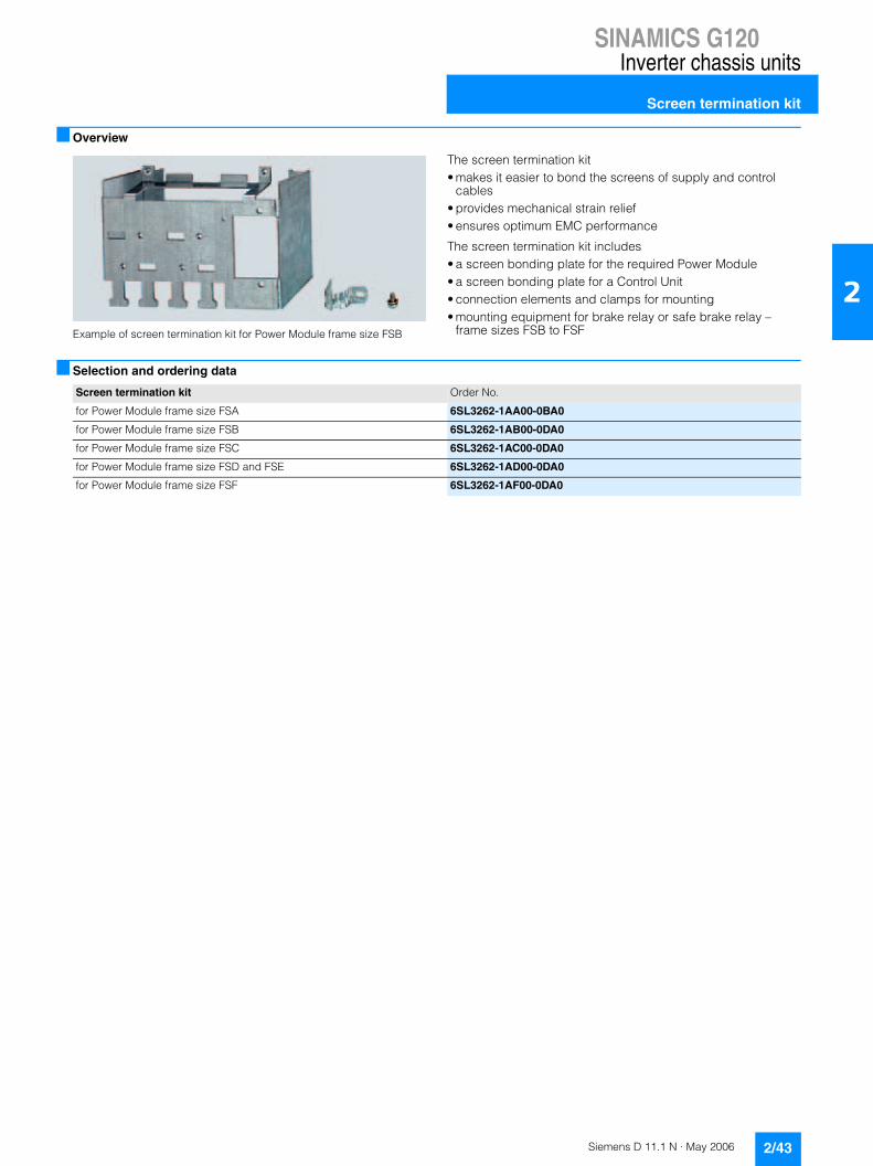
SINAMICS G120Inverter chassis units
Screen termination kit
2/43Siemens D 11.1 N · May 2006
2
■ Overview
Example of screen termination kit for Power Module frame size FSB
The screen termination kit• makes it easier to bond the screens of supply and control
cables• provides mechanical strain relief• ensures optimum EMC performance
The screen termination kit includes• a screen bonding plate for the required Power Module• a screen bonding plate for a Control Unit• connection elements and clamps for mounting• mounting equipment for brake relay or safe brake relay –
frame sizes FSB to FSF
■ Selection and ordering data
Screen termination kit Order No.
for Power Module frame size FSA 6SL3262-1AA00-0BA0
for Power Module frame size FSB 6SL3262-1AB00-0DA0
for Power Module frame size FSC 6SL3262-1AC00-0DA0
for Power Module frame size FSD and FSE 6SL3262-1AD00-0DA0
for Power Module frame size FSF 6SL3262-1AF00-0DA0

SINAMICS G120Inverter chassis units
NEMA1 kit
2/44 Siemens D 11.1 N · May 2006
2
■ Overview
The SINAMICS G120 inverter chassis units are designed to comply with type "UL OPEN". The NEMA1 kit is required to obtain a type 1 NEMA housing.
An inverter with the NEMA1 kit can be operated in accordance with NEMA1 directives (NEMA 250-2003):• Wall mounting without control cabinet in enclosed areas• Protection against falling dirt ingress• Personnel protection against accidental contact with housing
The NEMA1 kit comprises the following components:• Screen termination plate• Screening plate for the Control Unit• Cable duct• Cover hood• Cover
■ Selection and ordering data
NEMA1 kit (available soon) Order No.
for Power Module frame size FSA 6SL3262-1CA00-0BA0
for Power Module frame size FSB 6SL3262-1CB00-0DA0
for Power Module frame size FSC 6SL3262-1CC00-0DA0
for Power Module frame size FSD and FSE 6SL3262-1CD00-0DA0
for Power Module frame size FSF 6SL3262-1CF00-0DA0

Siemens D 11.1 N · May 2006
33/2 Engineering tools3/2 Overview
3/3 SD configurator selection aid3/3 Overview3/3 Selection and ordering data3/3 Further information
3/4 SIZER configuration tool3/4 Overview3/4 Selection and ordering data
3/5 STARTER drive/commisioning software
3/5 Overview3/5 Integration3/5 Selection and ordering data
3/6 Drive ES engineering system 3/6 Overview3/6 Selection and ordering data
SINAMICS G120Engineering tools

SINAMICS G120Engineering tools
Engineering tools
3/2 Siemens D 11.1 N · May 2006
3
■ Overview
The following electronic configuration and engineering tools are available for SINAMICS G120 inverter chassis units:
SD configurator selection aid
The interactive catalog CA 01 – the offline mall of Siemens Auto-mation and Drives (A&D) – contains over 100,000 products with approximately 5 million potential drive system product versions. The SD configurator has been developed to facilitate selection of the correct motor and/or inverter from the wide spectrum of A&D SD products. The configurator is integrated in this catalog with the selection and configuration tools as a "selection aid" on CD2 "Configuring".
SIZER configuration tool
The SIZER PC tool provides an easy-to-use means of configur-ing the SINAMICS and MICROMASTER 4 drive family. It provides support when setting up the technologies involved in the hard-ware and firmware components required for a drive task. SIZER supports the complete configuration of the drive system, from simple single drives to complex multi-axis applications.
STARTER drive/commissioning software
The STARTER drive/commissioning software provides menu-guided assistance with commissioning, optimization and diag-nostics. STARTER is not only designed for use on SINAMICS drives but also for MICROMASTER4 units and frequency inver-ters for distributed I/Os SIMATIC ET 200S FC.
Drive ES engineering system
Drive ES is the engineering system used to integrate Siemens drive technology into the SIMATIC automation world easily, effi-ciently and cost-effectively in terms of communication, configu-ration and data management. The STEP 7 Manager user inter-face provides the basis for this procedure. A variety of software packages, i.e. Drive ES Basic, Drive ES SIMATIC and Drive ES PCS 7, is available for SINAMICS.

SINAMICS G120Engineering tools
SD configurator selection aid
3/3Siemens D 11.1 N · May 2006
3
■ Overview
The interactive catalog CA 01 – the offline mall of Siemens Auto-mation and Drives (A&D) – contains over 100,000 products with approximately 5 million potential drive system product versions on CD2 "Configuring".
The SD configurator has been developed to facilitate selection of the correct motor and/or inverter from the wide spectrum of A&D SD products. It is integrated as a "selection help" in this catalog. The SD configurator is used to help locate the correct drive solution and delivers both the correct order number and relevant documentation.
It can display operating instructions, factory test certificates, terminal box documentations, etc. and generates data sheets, dimension drawings and a start-up calculation for the relevant products. It can also be used to identify a suitable inverter for the selected motor. 3D models in .stp format are also available.
The comprehensive aid system not only explains the program functions, but also provides access to detailed technical back-ground knowledge.
Product range
The SD configurator covers the product spectrum of low-voltage motors (energy-saving and increased-safety motors) with asso-ciated documentation and dimension drawings, low-voltage inverters in the MICROMASTER 4 range, SINAMICS G110 and G120 inverter chassis units and the frequency inverters for the distributed I/Os SIMATIC ET 200S FC.
Hardware and software requirements• PC with Pentium II or comparable processor• Operating systems
- Windows 98/ME- Windows 2000- Windows XP- Windows NT (Service Pack 5 and higher)
• At least 128 MB RAM user memory• 1024 � 768 graphics with over 256 colors/small fonts• CD-ROM drive• Windows-compatible sound card• Windows-compatible mouse
Installation
You can install this catalog on your hard disk or network directly from the CD-ROM/DVD as a light or full version.
■ Selection and ordering data
■ Further information
The interactive catalog CA 01 can be ordered from the relevant Siemens sales office or via Internet:
http://www.siemens.com/automation/CA01
Links to tips, tricks and downloads for functional or content updates can also be found at this address.
For technical advice and hotline support, you can also contact our hotline for catalog CA 01:
Tel.: +49 (0) 180 50 50 22 2
Email: [email protected]
Description Order No.
Interactive catalog CA 01 on CD-ROMincluding SD configurator selection aid,English
E86060-D4001-A110-C4-7600
Interactive catalog CA 01 on DVDincluding SD configurator selection aid,English
E86060-D4001-A510-C4-7600

SINAMICS G120Engineering tools
SIZER configuration tool
3/4 Siemens D 11.1 N · May 2006
3
■ Overview
The SIZER configuration tool provides an easy-to-use means of configuring the SINAMICS and MICROMASTER 4 drive families, as well as the SINUMERIK solution line CNC control and SIMOTION Motion Control. It provides technical support when sizing the hardware and firmware components required for a drive task. SIZER supports the complete configuration of the drive system, from simple single drives to complex multi-axis applications.
SIZER supports all of the engineering steps in a workflow:• selection of the line supply• motor design as a result of load configuration• calculation of the drive components• selection of the required accessories• selection of the line-side and motor-side power options
When SIZER was being designed, particular importance was placed on high usability and a universal, function-based ap-proach to the drive task. The extensive user guidance makes using the tool easy. Status information keeps you continually informed about the progress about the configuration process.
The SIZER user interface is available in German and English.
The drive configuration is saved in a project. In the project, the components and functions used are displayed in a hierarchical tree structure.
The project view permits the configuration of drive systems and the copying/inserting/modifying of drives already configured.
The configuration process produces the following results:• a parts list of the components required• technical data• characteristics• comments on line harmonic distortions• location diagram and dimension drawings
These results are displayed in a results tree and can be reused for documentation purposes.
User support is provided by the technological online help menu, which provides the following information:• detailed technical data• information about the drive systems and their components• decision-making criteria for the selection of components
Minimum hardware and software requirements
PG or PC with Pentium™ II 400 MHz (Windows™ 2000),Pentium™ III 500 MHz (Windows™ XP)
256 MB RAM (512 MB recommended)
At least 990 MB of free hard disk space
An additional 100 MB of free hard disk space on Windows system drive
Monitor resolution 1024 ��768 pixels
Windows™ 2000 SP2, XP Professional SP1, XP Home Edition SP1
Microsoft Internet Explorer 5.5 SP2
■ Selection and ordering data
Order No.
SINAMICS MICROMASTER SIZER configuration toolGerman/English
6SL3070-0AA00-0AG0
SIZER LD Snap-In SuiteExtension for medium-voltage systems,motors and DC invertersGerman/English
on request

SINAMICS G120Engineering tools
STARTER drive/commissioning software
3/5Siemens D 11.1 N · May 2006
3
■ Overview
The easy-to-use STARTER drive/commissioning software can be used for• commissioning• optimization and• diagnostics.
This software can be operated either as a standalone PC appli-cation or can be integrated into the SCOUT engineering system (on SIMOTION) or STEP 7 (with Drive ES Basic). The basic func-tions and handling are the same in both cases.
In addition to the SINAMICS drives, the current version of STARTER also supports MICROMASTER 4 devices and inverters for the distributed I/O system SIMATIC ET 200S FC.
The project wizards can be used to create the drives within the structure of the project tree.
First-time users are supported by solution-based dialog menu, with a standard graphics-based display maximizing clarity when setting the drive parameters.
First commissioning is guided by wizards, which make all the basic settings in the drive. This enables a drive to be up and run-ning after only setting a small number of parameters within the drive configuration process.
The individual settings required are made using graphics-based parameterization screenforms, which also display the mode of operation.
Examples of individual settings that can be made include:• terminals • bus interface• setpoint channel (e.g. fixed setpoints)• speed control (e.g. ramp-function generator, limits)• BICO interconnections• diagnostics
Experts can gain rapid access to the individual parameters via the expert list and do not have to navigate dialogs.
In addition, the following functions are available for optimization purposes:• self-optimization• trace (depending on drive)
Diagnostics functions provide information about:• control/status words• parameter status• operating conditions• communication states
Performance• Easy to use: only a small number of settings need to be made
for successful first commissioning: axis turning.• Solution-based dialog-based user guidance simplifies
commissioning.• Self-optimization functions reduce manual effort for optimiza-
tion.• The built-in trace function provides optimum support during
commissioning, optimization and troubleshooting.
Minimum hardware and software requirements
PG device or PC with Pentium™ II 400 MHz (Windows™ 2000),Pentium™ III 500 MHz (Windows™ XP)
256 MB RAM (512 MB recommended)
Monitor resolution 1024 ��768 pixels
Windows™ 2000 SP3, XP Professional SP1
Microsoft Internet Explorer 5.01
■ Integration
A PROFIBUS Communication Module and a connection cable are required to make the communication link between the PG/PC and a Control Unit.
For example, PROFIBUS Communication Module CP 5512 (PCMCIA type 2 card + adapter with 9-pole SUB-D socket for connection to PROFIBUS). For Windows 2000/XP Professional and PCMCIA 32)Order No.: 6GK1551-2AA00
and connection cable between CP 5512 and PROFIBUSOrder No.: 6ES7901-4BD00-0XA0
PC-inverter connection kits are available for MICROMASTER 4, SINAMICS G110 and SINAMICS G120 for a safe point-to-point connection to the PC.Order No. for MICROMASTER 4: 6SE6400-1PC00-0AA0(the scope of supply includes a 9-pole SUB-D connector and a RS232 standard cable, 3 m)
Order No. for SINAMICS G110 and SINAMICS G120: 6SL3255-0AA00-2AA1(the scope of supply includes a 9-pole SUB-D connector and a RS232 standard cable, 3 m, and the STARTER commissioning tool on CD-ROM)
■ Selection and ordering data
Order No.
STARTER commissioning tool for SINAMICS and MICROMASTERGerman / English / French / Italian
6SL3072-0AA00-0AG0

SINAMICS G120Engineering tools
Drive ES engineering system
3/6 Siemens D 11.1 N · May 2006
3
■ Overview
Drive ES is the engineering system used to integrate Siemens drive technology into the SIMATIC automation world easily, efficiently and cost-effectively in terms of communication, configuration and data management. The STEP 7 Manager user interface provides the basis for this procedure.
Various software packages are available for SINAMICS:• Drive ES Basic
for first-time users of the world of Totally Integrated Automation and the option for routing beyond network limits and the use of the SIMATIC teleservice.Drive ES Basic is the basic software program for setting the parameters of all drives online and offline.Drive ES Basic processes both the automation system and drives to be handled via the SIMATIC Manager user interface. Drive ES Basic is the starting point for common data archiving for complete projects and for extending the use of the SIMATIC teleservice to drives. Drive ES Basic provides the configuration tools for the new Motion Control functions slave-to-slave com-munication, equidistance and isochronous operation with PROFIBUS DP.
• Drive ES SIMATICsimple parameterization of the STEP 7 communication instead of programming. In order to use Drive ES SIMATIC, STEP 7 must be installed. It features a SIMATIC function block library, making the programming of the PROFIBUS interface in the SIMATIC CPU for the drives easy and secure.There is no need for separate, time-consuming programming of the data exchange between the SIMATIC CPU and the drive.All Drive ES users need to remember is:Copy – Modify – Download – Ready.Customized, fully-developed function blocks are copied from the library into user-specific projects.Frequently-used functions are set to run in program format: - Read out complete diagnostics buffer automatically from the
drive- Download complete parameter set automatically from the
SIMATIC CPU to the drive, e.g. in the event of a device being replaced
- Load part parameter set (e.g. in the event of a device being replaced) automatically from the SIMATIC CPU
- Read back, i.e. update, complete parameterization or part parameter sets from the drive into the SIMATIC CPU.
• Drive ES PCS 7integrates drives with the PROFIBUS interface into the SIMATIC PCS 7 process control system.Drive ES PCS 7 can only be used with SIMATIC PCS 7 version 5.0 and higher. Drive ES PCS 7 provides a function block li-brary with function blocks for the drives and the corresponding faceplates for the operator station, which enables the drives to be operated from the PCS 7 process control system.
For further information please visit us on the Internet at:
http://www.siemens.com/drivesolutions
■ Selection and ordering data
BasicDrive ESSIMATIC
Drive ES
G_D212_en_00070
Communication Configuration/Commissionin
Order No.
Drive ES Basic V 5.4• Configuration software for the integration of drives into Totally Integrated Automation• Requirement: STEP 7 V 5.3 and higher, SP3• Supply format: on CD-ROM – Ger., Eng., Fr., Sp., It. – with electronic documentation
Single-user license 6SW1700-5JA00-4AA0
Multi-user license, 60 pieces 6SW1700-5JA00-4AA1
Update service for single-user license 6SW1700-0JA00-0AB2
Update service for multi-user license 6SW1700-0JA00-1AB2
Upgrade from V 5.x to V 5.4 6SW1700-5JA00-4AA4
Drive ES SIMATIC V 5.4• Function block library for SIMATIC for the parameterization of communication with the drives• Requirement: STEP 7 V 5.3 and higher, SP3• Supply format: on CD-ROM – Ger., Eng., Fr., Sp., It. – with electronic documentation
Single-user license incl. 1 x runtime license 6SW1700-5JC00-4AA0
Runtime license 6SW1700-5JC00-1AC0
Update service for single-user license 6SW1700-0JC00-0AB2
Upgrade from V 5.x to V 5.4 6SW1700-5JC00-4AA4
Drive ES PCS 7 V 6.1• Function block library for PCS 7 for the integration of drives• Requirement: PCS 7 V 6.1 and higher• Supply format: on CD-ROM – Ger., Eng., Fr., Sp., It. – with electronic documentation
Single-user license incl. 1 x runtime license 6SW1700-6JD00-1AA0
Runtime license 6SW1700-5JD00-1AC0
Update service for single-user license 6SW1700-0JD00-0AB2
Upgrade from V 5.x to V 6.1 6SW1700-6JD00-1AA4

Siemens D 11.1 N · May 2006
44/2 Services and
documentation4/2 Overview
4/3 Training4/3 Overview4/4 Design4/4 Function
4/6 SINAMICS G120 training case4/6 Application4/6 Design4/6 Technical data4/6 Selection and ordering data
4/7 Documentation4/7 Overview
4/8 Replacement fans for SINAMICS G120
4/8 Overview4/8 Selection and ordering data
4/9 SPARESonWeb4/9 Overview
4/10 Service & Support4/10 Overview
SINAMICS G120Services anddocumentation

SINAMICS G120Services and documentation
Services and documentation
4/2 Siemens D 11.1 N · May 2006
4
■ Overview
The following services and documentation are available for SINAMICS G120 inverter chassis units:
Training
To use drive systems economically, specialists are required who can operate, program and service the devices. The training cen-ters of the Automation and Drives Group train your employees to master this innovative technology. Well-trained employees are motivated and implement optimal automation tasks with dedica-tion. SINAMICS product training is carried out using specially developed training equipment in training centers.
Training case
The modular SIDEMO case system also includes a training case for SINAMICS G120 which is designed for mobile use for sales and servicing. Many of the new innovative functions of the SINAMICS G120 system – especially the Safety Integrated func-tions – can be demonstrated with this case.
Documentation
A wide variety of manuals in different forms and versions is avai-lable for the components of the SINAMICS G120 chassis unit range. A multi-language package on CD-ROM is supplied with each Control Unit. This package contains all available manuals for SINAMICS G120 in a variety of languages. A Getting Started guide is supplied in hard copy form with every Power Module and Control Unit.
Replacement fans for SINAMICS G120
The Power Module fans are designed for extra long service life. Replacement fans can be ordered for special applications.
SPARESonWeb
SPARESonWeb is a web-based tool for selecting the spare parts available for the SINAMICS system. After you have registered and entered the serial number and order number, the spare parts available for the relevant unit are displayed.
Service & Support
At the end of the day, every detail has to be just right. This is why we offer a comprehensive range of professional service and support features. This enables you to make use of the solution best suited to your particular needs, be it fast access to informa-tion about technical issues via the Internet by means of our on-line support or a direct telephone connection to a contact who can deal with your questions or on-site support from our service team; a service agreement for the duration of a project; or even the handing over of all responsibility in all service matters. Your wish is our command.

SINAMICS G120Services and documentation
Training
4/3Siemens D 11.1 N · May 2006
4
■ Overview
Training is decisive for your success
SITRAIN – Siemens Training for Automation and Industrial Solu-tions – provides you with comprehensive support in solving your tasks.
Training by the market leader in automation, plant installation and plant support enables you to make your decisions with cer-tainty and full command. Especially where the optimum and effi-cient use of products and plants are concerned. You can elimi-nate deficiencies in existing plants, and exclude expensive faulty planning right from the beginning.
All in all, this represents an enormous gain for your com-pany: shortened commissioning times, optimized plant components, faster troubleshooting, reduced downtimes. In other words, increased profits and lower costs.
Top trainers
Our trainers know their topics in practice, and possess compre-hensive didactic experience. Course developers have a direct wire to product development, and directly pass on their know-ledge to the trainers.
Practical experience
The practical experience of our trainers makes it possible for them to pass on theoretical matter in a plausible manner. But since it is known that all theory is drab, we attach great impor-tance to practical exercises which can comprise up to half of of the course time. You can therefore immediately implement your new knowledge in practice. We train you on state-of-the-art methodically/didactically designed training equipment. You feel absolutely certain when trained in this manner.
Wide variety
With a total of approx. 300 local attendance courses, we train the complete range of A&D products and a large portion of the system solutions from I&S. Telecourses, teach-yourself software and seminars presented on the Web supplement our classical range of courses.
Close to our customer
The distance is short. You can find us approx. 60 times in Germany, and worldwide in 62 countries. You wish to have individual training instead of one of our 300 courses? Our solution: we will provide a program tailored exactly to your personal requirements. Training can be carried out in our training centers or at your company.
The right mixture: blended learning
Blended learning is understood to be the combination of various training media and sequences. For example, a local attendance course in a training center can be optimally supplemented by a teach-yourself program as preparation or follow-up. Further-more, SITRAIN utilizes supported online training for live instruc-tion on the Internet at agreed times.
The right mixture is the solution. Therefore blended learning can convey complex topics well, and train networked thin-king. Additional effect: reduced traveling costs and periods of absence through training sequences independent of loca-tion and time.
The international learning portal
Additional information is available on the Internet under:
http://www.siemens.com/sitrain
All training facilities at a glance: search in the worldwide range of courses at leisure, call up all course dates online, utilize the daily updated display of vacant course spaces - and register di-rectly.
Or let us advise you personally:
Course office, Infoline Germany Phone: +49 (0)1805-23 56 11 Fax: +49 (0)1805-23 56 12
... and request our latest training catalog on:
Language Order No.
ITC Catalog (paper version)
German E86060-K6850-A101-B6
Dates and price listincluding CD-ROM
German E86060-P6850-A101-D2
SITRAINonCD interac-tive course information system on CD-ROM
German/English
E86060-D6850-A100-C4-7400

SINAMICS G120Services and documentation
Training
4/4 Siemens D 11.1 N · May 2006
4
■ Design
SINAMICS G120 courses
The courses are modular in design and are intended for a variety of target groups as well as individual customer requirements. A training course on the subject of SINAMICS G120 service and commissioning offers the necessary depth of technical know-how.
SINAMICS G120 is also covered by various courses which deal more generally with the SINAMICS drive system.
The system overview of the SINAMICS drive family will acquaint decision-makers and sales personnel with the system very quickly.
All modules contain as many practical exercises as possible, in order to enable intensive and direct training on the drive system and with the tools in small groups.
■ Function
SINAMICS G120 commissioning and service (2 days)DR-G120-EXP
Description/learning target
The course is aimed primarily at configuration engineers, service personnel and commissioning engineers who require an indepth understanding of the SINAMICS G120 drive system for the pur-pose of configuration and initial commissioning. Based on com-missioning procedures with the STARTER commissioning tool, the course covers various inverter functions, closed-loop control optimization and BICO technology.
Target group
Decision-makers, sales personnel, commissioning engineers, configuration engineers, service and maintenance personnel
Content• Design of the SINAMICS G120 drive system• Commissioning and parameterization with the STARTER
commissioning tool• Inverter functions (flying restart, braking, closed-loop control)• Data storage• Flexible signal interconnection with BICO technology• Safety Integrated functions• Diagnostics and troubleshooting• Practical exercises using the training case
Title Target group Duration Course code
Decision-makers, sales personnel
Programmers Commissioning engineers, configuration engineers
Service personnel
Maintenance personnel
SINAMICS G120 commis-sioning and service
✔ ✔ ✔ ✔ 2 days DR-G120-EXP
SINAMICS system overview ✔ 2 days DR-SN-UEB
SINAMICS communication ✔ ✔ ✔ 3 days DR-SN-COM

SINAMICS G120Services and documentation
Training
4/5Siemens D 11.1 N · May 2006
4
SINAMICS system overview (2 days)DR-SN-UEB
Description/learning target
This course has been specially designed for sales personnel and decision-makers, who wish to attain a rapid overview of the SINAMICS drive concept and its position in the existing Siemens drive environment.
The system overview is supplemented by an introduction to the fundamentals of motor and inverter technology.
The SIZER configuration tool and the STARTER commissioning tool are presented and explained using short exercises.
Target group
Decision-makers and sales personnel
Content• SINAMICS system overview• Position with respect to existing drive systems• Fundamentals of inverter engineering and motors• SIZER configuration tool• STARTER commissioning tool• Simple commissioning of a drive• Practical exercises using the training case
SINAMICS communication (3 days)DR-SN-COM
Description/learning target
The course is appropriate for programmers and service person-nel who, as an extension to the DR-SNS-SI course, require fur-ther knowledge of the PROFIBUS and RS232 communications interfaces for STARTER and AOP30, as well as I/O terminals.
The focal point is PROFIBUS with the PROFIDrive V3 profile with routing, teleservice, and the functionalities associated with the equidistant bus cycle, isochronous mode with servo applica-tions, and direct OP access. Also described are the libraries of DriveES SIMATIC for cyclic and acyclic data exchange.
This knowledge is expanded by practical exercises using SINAMICS and SIMATIC S7 training cases with CPU 315-2 DP.
Target group
Commissioning engineers, configuration engineers, service personnel
Content• Overview of the PROFIBUS DP, RS232-PPI, CAN and I/O termi-
nals: function, topology, parameterization• Fundamentals of PROFIBUS with the PROFIDrive V3 profile• Basic functions on the PROFIBUS: routing, teleservice and
direct access• PROFIBUS for Motion Control with: equidistant bus cycle and
isochronous mode with Servo Control• Cyclic and acyclic data exchange with DriveES SIMATIC
components• Fault diagnostics of the drive via the bus system• Practical exercises on the SINAMICS S120 and SIMATIC S7
training cases with CPU 315-2 DP

SINAMICS G120Services and documentation
SINAMICS G120 training case
4/6 Siemens D 11.1 N · May 2006
4
■ Application
A training case has been developed for on-site training and demonstration of the SINAMICS G120 system. It can demon-strate and increase understanding of a wide range of SINAMICS G120 functions.
The case uses the CU240S DP-F as a Control Unit with which the PROFIBUS interface and safety functions can be demonstrated.
■ Design
• Drive system comprising: - CU240S DP-F Control Unit- PM240 Power Module frame size FSA, 0.37 kW- Basic Operator Panel (BOP)- Induction motor 1LA7060-4AB10- Encoder- Load equipment
• Control station with toggle switches and potentiometers• Power cable, PROFIBUS cable• Storage and carrying case (Tanos box made of hard plastic)
The training case is supplied ready for use. As an option, the case can be supplied with a Zarges box (robust hard shell case).
■ Technical data
■ Selection and ordering data
SINAMICS G120 training case
Input voltage 230 V 1 AC
Degree of protection in accordance with DIN VDE 0470 Part 1, EN 60529, IEC 529
IP00
Permissible ambient temperature
• Storage and transport –20 °C to +60 °C
• Operation +5 °C to +40 °C
Width 540 mm
Height 500 mm
Depth 400 mm
Weight, approx. 13 kg
Order No.
SINAMICS G120 training case with Tanos box 6ZB2480-0CD00
SINAMICS G120 training case with Zarges box 6ZB2480-0CD00-ZA01
AccessoryLine adapter 115 V 1 AC/230 V 1 AC 6AG1064-1AA02-0AA0

SINAMICS G120Services and documentation
Documentation
4/7Siemens D 11.1 N · May 2006
4
■ Overview
The following manuals are available:
1) The parameter settings for the Power Modules are integrated in the list manual for the Control Units.
Operating instructions
Operating instructions are a comprehensive collection of all information necessary for the normal and safe operation of products, process cells and complete plants (EN 62079).
Usage phases: Planning and configuration phase, implementa-tion phase, setup and commissioning phase, application phase, maintenance and service phase.
Languages: English and German.
Operating instructions (compact)
Operating instructions (compact) are a compressed collection of all information necessary for the normal and safe operation of products, process cells and complete plants (EN 62079).
Usage phases: Planning and configuration phase, implementa-tion phase, setup and commissioning phase, application phase, maintenance and service phase.
Languages: English, German, French, Italian and Spanish.
List manual
The list manual describes all parameters, function charts and faults/warnings for the product/system as well as their meanings and setting options. It contains parameter data and fault/warning descriptions with functional correlations.
Usage phases: Commissioning of components that have al-ready been connected, configuration of system functions and fault cause/diagnostics.
Languages: English and German.
Getting Started
The Getting Started guide provides information about getting started for the first-time user as well as references to additional information. It contains information about the basic steps to be taken during commissioning. Descriptions of more advanced procedures can be found in the other documentation.
Usage phases: Commissioning of components that have already been connected.
Languages: Multilingual in English, German, French, Italian and Spanish.
Manuals are available in the following forms:
Multi-language package on CD-ROM
A multi-language package on CD-ROM is supplied with every Control Unit. This package contains all available manuals in a variety of languages.
Paper documentation
A Getting Started guide is supplied in hard copy form with every Power Module and Control Unit.
Online version on Internet as download
The documentation is also available on the Internet under
http://www.siemens.com/sinamics-g120
Manuals
Operating instructions Operating instructions (compact)
List manual Getting Started
Control Units
CU240S ✓ ✓ ✓ ✓
Power Modules
PM240 ✓ ✓ – 1) ✓

SINAMICS G120Services and documentation
Replacement fans for SINAMICS G120
4/8 Siemens D 11.1 N · May 2006
4
■ Overview
The Power Module fans are designed for extra long service life. Replacement fans can be ordered for special applications.
■ Selection and ordering data
Rated output SINAMICS G120 PM240 Power Module Replacement fans
kW hp Type 6SL3224-... Frame size and number of fans Order No.
380 V to 480 V 3 AC
0.37 0.50 0BE13-7UA0 FSA, 1 fan 6SL3200-0SF01-0AA0(includes 1 replacement fan)0.55 0.75 0BE15-5UA0
0.75 1.0 0BE17-5UA0
1.1 1.5 0BE21-1UA0
1.5 2.0 0BE21-5UA0
2.2 3.0 0BE22-2 . A0 FSB, 2 fans 1)
3.0 4.0 0BE23-0 . A0
4.0 5.0 0BE24-0 . A0
7.5 10 0BE25-5 . A0 FSC, 2 fans 1) 6SL3200-0SF03-0AA0(includes 1 replacement fan)11.0 15 0BE27-5 . A0
15.0 20 0BE31-1 . A0
18.5 25 0BE31-5 . A0 FSD, 2 fans 6SL3200-0SF04-0AA0(includes 2 replacement fans)22 30 0BE31-8 . A0
30 40 0BE32-2 . A0
37 50 0BE33-0 . A0 FSE, 2 fans 6SL3200-0SF05-0AA0(includes 2 replacement fans)45 60 0BE33-7 . A0
55 75 0BE34-5 . A0 FSF, 2 fans 6SL3200-0SF06-0AA0(includes 2 replacement fans)75 100 0BE35-5 . A0
90 125 0BE37-5 . A0 6SL3200-0SF07-0AA0(includes 2 replacement fans)
1) Recommendation: Even if only one fan on the Power Module is defec-tive, it is advisable to replace both. In this case, the order quantity must be doubled.

SINAMICS G120Services and documentation
SPARESonWeb
4/9Siemens D 11.1 N · May 2006
4
■ Overview
SPARESonWeb - online spare parts catalog
SPARESonWeb is a web-based tool for selecting the spare parts available for the SINAMICS system. After you have registered and entered the serial number and order number, the spare parts available for the relevant unit are displayed.
The delivery state for specific orders can be displayed for all shipped SINAMICS products.
http://workplace.automation.siemens.com/sparesonweb

SINAMICS G120Services and documentation
Service & Support
4/10 Siemens D 11.1 N · May 2006
4
■ Overview
I
In the face of harsh competition you need optimum conditions to keep ahead all the time: a strong starting position, a sophisticated strategy and team for the necessary support – in every phase. Service & Support from Siemens provides this support with a complete range of different services for automation and drives.
In every phase: from planning and commissioning to mainte-nance and upgrading.
Our specialists know when and where to act to keep the produc-tivity and cost-effectiveness of your system running in top form.
Online supportThe comprehensive information system available round the clock via Internet ranging from Product Support and Service & Support services to Support Tools in the Shop.http://www.siemens.com/automation/service&support
Technical supportCompetent consulting in techni-cal questions covering a wide range of customer-oriented ser-vices for all our products and systems.
Phone: +49 (0)180 50 50 222Fax: +49 (0)180 50 50 223E-Mail:[email protected]
In the United States, call toll-free:Phone: +1 800 333 7421 Fax: +1 423 262 2200E-Mail: solutions.support @sea.siemens.com
In Canada, call:Phone: +1 888 303 3353E-Mail: [email protected]
In Asia:Phone: +86 10 6475 7575 Fax: +86 10 6474 7474E-Mail: [email protected]
Technical consultingSupport in the planning and designing of your project from detailed actual-state analysis, target definition and consulting on product and system ques-tions right to the creation of the automation solution. 1)
Configuration and software engineeringSupport in configuring and de-veloping with customer-oriented services from actual configura-tion to implementation of the automation project. 1)
Service on siteWith service on site we offer services for startup and mainte-nance, essential for ensuring system availability.
In Germany Phone: +49 (0)180 50 50 444 1)
In the United States, call toll-free:Phone: +1 800 333 7421
In Canada, call:Phone: +1 888 303 3353
Repairs and spare partsIn the operating phase of a ma-chine or automation system we provide a comprehensive repair and spare parts service ensu-ring the highest degree of ope-rating safety and reliability.
In Germany Phone: +49 (0)180 50 50 448 1)
In the United States, call toll-free:Phone: +1 800 241 4453
In Canada, call:Phone: +1 888 303 3353
Optimization and upgradingTo enhance productivity and save costs in your project we offer high-quality services in optimization and upgrading. 1)
1) For country-specific telephone numbers go to our Internet site at: http://www.siemens.com/automation/service&support

Siemens D 11.1 N · May 2006
55/2 Siemens contacts worldwide
5/3 A&D online services - Informa-tion and ordering possibilities on the Internet and on CD-ROM
5/3 A&D in the WWW5/3 Product selection using the Offline
Mall of Automation and Drives5/3 Easy shopping with the A&D Mall
5/4 Subject index
5/5 Index of order numbers
5/6 Terms and conditions of sale and delivery,Export regulations
SINAMICS G120Appendix

SINAMICS G120Appendix
Siemens contacts worldwide
5/2 Siemens D 11.1 N · May 2006
5
At
http://www.siemens.com/automation/partner
you can find details of Siemens contact partners worldwide responsible for particular technologies.
You can obtain in most cases a contact partner for• technical support,• spare parts/repairs,• service,• training,• sales or• consultation/engineering.
You start by selecting a• country,• product or• sector.
By further specifying the remaining criteria you will find exactly the right contact partner with his/her respective expertise.

SINAMICS G120Appendix
A&D online services – Information and orderingpossibilities on the Internet and on CD-ROM
5/3Siemens D 11.1 N · May 2006
5
■ A&D in the WWWA detailed knowledge of the range of products and services available is essential when planning and configuring automation systems. It goes without saying that this information must always be fully up-to-date.
The Siemens Automation and Drives Group (A&D) has therefore built up a comprehensive range of information in the World Wide Web, which offers quick and easy access to all data required.
Under the address
http://www.siemens.com/automation
you will find everything you need to know about products, systems and services.
■ Product selection using the Offline Mall of Automation and DrivesDetailed information together with convenient interactive functions: The Offline Mall CA 01 covers more than 80,000 products and thus provides a full summary of the Siemens Automation and Drives product base.
Here you will find everything that you need to solve tasks in the fields of automation, switchgear, installation and drives. All information is linked into a user interface which is easy to work with and intuitive.
After selecting the product of your choice you can order at the press of a button, by fax or by online link.
Information on the Offline Mall CA 01 can be found on the Inter-net under
http://www.siemens.com/automation/ca01
or on CD-ROM or DVD.
■ Easy shopping with the A&D Mall The A&D Mall is the virtual department store of Siemens AG on the Internet. Here you have access to a huge range of products presented in electronic catalogs in an informative and attractive way.
Data transfer via EDIFACT allows the whole procedure from selection through ordering to tracking of the order to be carried out online via the Internet.
Numerous functions are available to support you.
For example, powerful search functions make it easy to find the required products, which can be immediately checked for avai-lability. Customer-specific discounts and preparation of quotes can be carried out online as well as order tracking and tracing.
Please visit the A&D Mall on the Internet under:
http://www.siemens.com/automation/mall

SINAMICS G120Appendix
Subject index
5/4 Siemens D 11.1 N · May 2006
5
Part/PageAA&D in the WWW 5/3A&D Mall 5/3A&D online services - Information and ordering possibilities on the Internet and on CD-ROM 5/3Adapter for mounting on DIN rail 2/42Ambient conditions 2/5Ambient temperature 2/21Appendix 5Application 1/6, 1/12
BBase components 2/4, 2/14BOP Basic Operator Panel 2/38Brake Relay 2/40Braking resistors 2/33
CCommissioning course 4/4Communication course 4/5Configuration 4/10Connection diagrams of Control Unit 2/8, 2/9Connection kit 2/39Control Units 2/4Cooling concept 2/3CU240 Control Units 2/6
DDC link components 2/4Dimension drawings 2/23Documentation 4/2, 4/7Drive ES 2/5, 3/2, 3/6Drive ES engineering system 2/5, 3/2, 3/6
EEasy shopping with the A&D Mall 5/3Engineering tools 3, 3/2Export regulations 5/6
GGetting Started 4/7
IIndex of order numbers 5/5Installation altitude 2/21Interactive catalog CA01 3/3Inverter chassis units 2
LLine components 2/32Line filters 2/28Line reactors 2/30List manual 4/7Low-voltage inverters 1/8, 1/10
MMechanical data 2/5Medium-voltage inverters 1/8, 1/11Members of the SINAMICS family 1/10Memory card for Control Units 2/12Modularity 2/3
NNEMA1 kit 2/44
OOffline Mall 5/3Online support 4/10Operating istructions 4/7Optimization 4/10Output reactors 2/35
Part/PagePPaint-finish of the electronics modules 2/3PC-inverter connection kit 2/39Platform concept 1/6PM240 2/13PM240 Power Modules 2/13Power components 2/4Product selection using the Offline Mall of Automation and Drives 5/3
QQuality 1/7
RRecommended line components 2/32Repairs 4/10Replacement fans 4/2Replacement fans for SINAMICS G120 4/8
SSafe Brake Relay 2/41Safety Integrated 2/3Screen termination kit 2/43SD configurator 2/5, 3/2SD configurator selection aid 3/3Service & Support 4/2, 4/10Service course 4/4Service on site 4/10Services and documentation 4, 4/2Siemens contacts 5/2Siemens contacts worldwide 5/2SINAMICS chassis units 0.37 kW to 90 kW 2/2SINAMICS drive family 1/6SINAMICS family 1/10SINAMICS G120 - Application 1/12SINAMICS G120 - Benefits 1/12SINAMICS G120 - Design 1/12SINAMICS G120 - Overview 1/12SINAMICS G120 - Technical data 1/13SINAMICS G120 courses 4/4SINAMICS G120 training case 4/2, 4/6SIZER configuration tool 2/5, 3/2, 3/4Software engineering 4/10Spare parts 4/10Spare parts catalog 4/9SPARESonWeb 4/2, 4/9Standards 2/5STARTER drive/commissioning software 2/3, 2/5, 3/5Subject index 5/4System components, supplementary 2/4System overview course 4/5
TTechnical consulting 4/10Technical support 4/10Terms and conditions of sale and delivery 5/6The SINAMICS drive family 1/6Totally Integrated Automation 1/4Training 4/2, 4/3
UUpgrading 4/10
VVersions 1/6
WWelcome to Automation and Drives 1/2

SINAMICS G120Appendix
Index of order numbers
5/5Siemens D 11.1 N · May 2006
5
Part/Page3NA3NA31… Fuses 2/323NA38… Fuses 2/32
3NE3NE1… Fuses 2/32
3RV3RV1021-… Circuit-breakers 2/323RV1031-… Circuit-breakers 2/323RV1042-… Circuit-breakers 2/32
3VL3VL1… Circuit-breakers 2/323VL3… Circuit-breakers 2/323VL4… Circuit-breakers 2/32
6AG6AG1064-1AA02-0AA0 Accessories line adapter 4/6
6SE6SE6400-2F… Line filter 2/296SE6400-3CC00-… Line reactor 2/316SE6400-3CC11-… Line reactor 2/316SE6400-3TC… Output reactor 2/376SE6400-4BD… Braking resistor 2/34
6SL6SL3070-0AA00-0AG0 SIZER configuration tool 3/46SL3072-0AA00-0AG0 STARTER commissioning tool 3/56SL3200-0SF0… Replacement fan 4/86SL3201-0BE… Braking resistor 2/346SL3202-0A… Output reactor 2/376SL3203-0B… Line filter 2/296SL3203-0C… Line reactor 2/316SL3224-0BE… PM240 Power Module 2/226SL3244-0BA2… Control Unit 2/116SL3252-0BB00-0AA0 Brake Relay 2/406SL3252-0BB01-0AA0 Safe Brake Relay 2/416SL3254-0AM00-0AA0 MMC memory card 2/126SL3255-0AA00-2AA1 PC-inverter connection kit 2/396SL3255-0AA00-4BA1 BOP Basic Operator Panel 2/386SL3262-1AA00-0BA0… Screen termination kit 2/436SL3262-1B… Adapter for mounting on DIN rail 2/426SL3262-1C… NEMA1 kit 2/44
6SW6SW1700-… Drive ES Basic 3/6
6ZB6ZB2480-0CD00 SINAMICS G120 training case 4/6
SINAMICS G120AppendixTerms and conditions of sale and deliveryExport regulations
5/6 Siemens D 11.1 N · May 2006
5
■ Terms and conditions of sale and delivery
By using this catalog you can acquire hardware and software products described therein from the Siemens AG subject to the following terms. Please note! The scope, the quality and the con-ditions for supplies and services, including software products, by any Siemens entity having a registered office outside of Ger-many, shall be subject exclusively to the General Terms and Conditions of the respective Siemens entity.
For customers with a seat or registered office in GermanyThe “General Terms of Payment” as well as the “General Condi-tions for the Supply of Products and Services of the Electricaland Electronics Industry” shall apply.For software products, the “General License Conditions for Soft-ware Products for Automation and Drives for Customers with aSeat or registered Office in Germany” shall apply.
For customers with a seat or registered office outside of GermanyThe “General Terms of Payment” as well as the “General Condi-tions for Supplies of Siemens, Automation and Drives for Cus-tomers with a Seat or registered Office outside of Germany” shall apply.For software products, the “General License Conditions for Soft-ware Products for Automation and Drives for Customers with aSeat or registered Office outside of Germany” shall apply.
GeneralThe prices are in € (Euro) ex works, exclusive packaging.The sales tax (value added tax) is not included in the prices. It shall be debited separately at the respective rate according to the applicable legal regulations.In addition to the prices of products which include silver, plump, aluminum and/or copper, surcharges may be calculated if the respective limits of the notes are exceeded. The respective note (e.g. source: German newspaper “Handesblatt” in category “deutsche Edelmetalle” and “Metallverarbeiter”) for silver (“verarbeitetes Silber”), plump (“Blei in Kabeln”), aluminum (“Aluminium in Kabeln”) and copper (“Elektrolytkupfer”, “DEL-Notiz”) respectively, of the day the order or rather the on call or-der is received, is decisive for the calculation of the surcharges.Surcharges of copper shall be calculated for Drives at a note (“DEL-Notiz”) above EUR 225,00 / 100 kg and for chokes / trans-formers above EUR 150,00 / 100 kg.Surcharges shall be charged based on the quantities of the ma-terials which are contained in the relevant products.Prices are subject to change without prior notice. We will debit the prices valid at the time of delivery. The dimensions are in mm. In Germany, according to the Ger-man law on units in measuring technology, data in inches only apply to devices for export.Illustrations are not binding.Insofar as there are no remarks on the corresponding pages, - especially with regard to data, dimensions and weights given - these are subject to change without prior notice.
Comprehensive Terms and Conditions of Sale and Delivery are available free of charge from your local Siemens business office under the following Order Nos.:• 6ZB5310-0KR30-0BA0
(for customers based in the Federal Republic of Germany)• 6ZB5310-0KS53-0BA0
(for customers based outside of the Federal Republic of Germany)
or download them from the Internet:http://www.siemens.com/automation/mall (Germany: A&D Mall Online-Help System)
■ Export regulations
The products listed in this catalog/price list may be subject to European/German and/or US export regulations.Therefore, any export requiring a license is subject to approval by the competent authorities.According to current provisions, the following export regulations must be observed with respect to the products featured in this catalog/price list:
Even without a label or with an “AL: N” or “ECCN: N”, authoriza-tion may be required due to the final destination and purpose for which the goods are to be used.The deciding factors are the AL or ECCN export authorization indicated on order confirmations, delivery notes and invoices.Errors excepted and subject to change without prior notice.
A&D/VuL/En 06.03.06
AL Number of the German Export ListProducts marked other than “N” require an export license.In the case of software products, the export designations of the relevant data medium must also be generally adhered to.Goods labeled with an “AL not equal to N” are subject to a European or German export authori-zation when being exported out of the EU.
ECCN Export Control Classification NumberProducts marked other than “N” are subject to a reexport license to specific countries.In the case of software products, the exportdesignations of the relevant data medium must also be generally adhered to.Goods labeled with an “ECCN not equal to N” are subject to a US re-export authorization.
Siemens AGAutomation and DrivesStandard DrivesPostfach 31 8091050 ERLANGENFEDERAL REPUBLIC OF GERMANY
Order No.E86060-K5511-A111-A3-7600KG 0806 30.0 E 80 En/622236Printed in Germany
Responsible forTechnical content:Siemens AG, A&D SD SPA, ErlangenEditor:Siemens AG, A&D PT 5, Erlangen

Catalogs of theAutomation and Drives Group (A&D)
Further information can be obtained from our branch offices listedin the appendix or at www.siemens.com/automation/partner
A&D/3U/En 01.08.06
Automation and Drives CatalogInteractive catalog on CD-ROM and on DVD
• The Offline Mall of Automation and Drives CA 01
Automation Systems for Machine ToolsSINUMERIK & SIMODRIVE NC 60
SINUMERIK & SINAMICS NC 61
Drive SystemsVariable-Speed Drives
SINAMICS G130 Drive Converter Chassis Units, SINAMICS G150 Drive Converter Cabinet Units
D 11
SINAMICS G110 Inverter Chassis Units D 11.1
SINAMICS GM150/SINAMICS SM150 Medium-Voltage Converters
D 12
SINAMICS S120 Vector Control Drive System
D 21.1
SINAMICS S120 Servo Control Drive System D 21.2
SINAMICS S150 Drive Converter Cabinet Units D 21.3
Asynchronous Motors Standardline D 86.1
DC Motors DA 12
SIMOREG DC MASTER 6RA70 Digital Chassis Converters
DA 21.1
SIMOREG K 6RA22 Analog Chassis Converters DA 21.2
SIMOREG DC MASTER 6RM70 Digital Converter Cabinet Units
DA 22
SIMOVERT PM Modular Converter Systems DA 45
SIEMOSYN Motors DA 48
MICROMASTER 410/420/430/440 Inverters DA 51.2
MICROMASTER 411/COMBIMASTER 411 DA 51.3
SIMOVERT MASTERDRIVES Vector Control DA 65.10
SIMOVERT MASTERDRIVES Motion Control DA 65.11
Synchronous and asynchronous servomotors for SIMOVERT MASTERDRIVES
DA 65.3
SIMODRIVE 611 universal and POSMO DA 65.4
Low-Voltage Three-Phase-Motors
Squirrel-Cage Motors, Totally Enclosed, Fan-Cooled M 11
Automation Systems for Machine Tools SIMODRIVE NC 60
• Main Spindle/Feed Motors
• Converter Systems SIMODRIVE 611/POSMO
Automation Systems for Machine Tools SINAMICS NC 61
• Main Spindle/Feed Motors
• Drive System SINAMICS S120
Drive and Control Components for Hoisting Equipment HE 1
Electrical Installation TechnologyALPHA Small Distribution Boards and Distribution Boards
ET A1
PDF: ALPHA 8HP Molded-Plastic Distribution System ET A3
ALPHA FIX Terminal Blocks ET A5
BETA Modular Installation Devices ET B1
DELTA Switches and Socket Outlets ET D1
GAMMA Building Management Systems ET G1
Human Machine Interface Systems SIMATIC HMI ST 80
PDF: These catalogs are only available as pdf files.
Industrial Communication for Automation and Drives
CatalogIK PI
Low-VoltageControls and Distribution – SIRIUS, SENTRON, SIVACON
LV 1
Controls and Distribution – Technical InformationSIRIUS, SENTRON, SIVACON
LV 1 T
SIDAC Reactors and Filters LV 60
SIVENT Fans LV 65
SIVACON 8PS Busbar Trunking Systems LV 70
Motion Control System SIMOTION PM 10
Process Instrumentation and AnalyticsField Instruments for Process AutomationMeasuring Instruments for Pressure, Differential Pressure, Flow, Level and Temperature, Positioners and Liquid Meters
FI 01
PDF: Indicators for panel mounting MP 12
SIREC Recorders and Accessories MP 20
SIPART, Controllers and Software MP 31
SIWAREX Weighing Systems WT 01
Continuous Weighing and Process Protection WT 02
Process Analytical Instruments PA 01
PDF: Process Analytics, Components for the System Integration
PA 11
SIMATIC Industrial Automation SystemsSIMATIC PCS Process Control System ST 45
Products for Totally Integrated Automation and Micro Automation
ST 70
SIMATIC PCS 7 Process Control System ST PCS 7
Add-ons for the SIMATIC PCS 7 Process Control System
ST PCS 7.1
Migration solutions with the SIMATIC PCS 7 Process Control System
ST PCS 7.2
pc-based Automation ST PC
SIMATIC Control Systems ST DA
SIMATIC Sensors FS 10
SIPOS Electric ActuatorsElectric Rotary, Linear and Part-turn Actuators MP 35
Electric Rotary Actuators for Nuclear Plants MP 35.1/.2
Systems EngineeringPower supplies SITOP power KT 10.1
System cabling SIMATIC TOP connect KT 10.2
System SolutionsApplications and Products for Industry are part of the interactive catalog CA 01
TELEPERM M Process Control SystemPDF: AS 488/TM automation systems PLT 112

www.siemens.com/sinamics Subj
ect
to c
han
ges
|
Dis
po 1
84
04
|
KG
08
06
30
.0 E
80
EN
/ 6
22
23
6
| P
rin
ted
in G
erm
any
|
© S
iem
ens
AG
20
06
Order No. E86060-K5511-A111-A3-7600
The information provided in this brochure contains descriptions or characteristicsof performance which in case of actual use do not always apply as describedor which may change as a result of further development of the products. Anobligation to provide the respective characteristics shall only exist if expresslyagreed in the terms of contract. Availability and technical specifications aresubject to change without notice.
All product designations may be trademarks or product names of Siemens AGor supplier companies whose use by third parties for their own purposes couldviolate the rights of the owners.
Siemens AG
Automation and DrivesStandard DrivesPostfach 31 8091050 ERLANGENFEDERAL REPUBLIC OF GERMANY
www.siemens.com/automation