sinamics - 上海乃谐电气设备有限公司€¦ · 7 sinamics g110 – the versatile drive for...
TRANSCRIPT

D12_U1_U4.FH10 Thu May 11 08:00:06 2006 Seite 3
Probedruck
SINAMICS GM150SINAMICS SM150
Medium-Voltage Converters0.8 MVA to 28 MVA
Ca
talo
g D
12
• 2
00
6sinamics

Related catalogs
SINAMICS G110 D 11.1Inverter Chassis Units0.12 kW to 3 kW
Order No.:E86060-K5511-A111-A2 (German)E86060-K5511-A111-A2-7600 (English)
SINAMICS G130 D 11Drive Converter Chassis UnitsSINAMICS G150Drive Converter Cabinet UnitsOrder No.:E86060-K5511-A101-A3 (German)E86060-K5511-A101-A3-7600 (English)
SINAMICS S120 D 21.1Vector Control Drive System
Order No.:E86060-K5521-A111-A1 (German)E86060-K5521-A111-A1-7600 (English)
SINAMICS S120 D 21.2Servo Control Drive System
Order No.:E86060-K5521-A121-A1 (German)E86060-K5521-A121-A1-7600 (English)
SINAMICS S150 D 21.3Drive Converter Cabinet Units75 kW to 1200 kW
Order No.:E86060-K5521-A131-A1 (German)E86060-K5521-A131-A1-7600 (English)
Catalog CA 01 CA 01The Offline Mall of Automation and DrivesOrder No.:CD-ROM: E86060-D4001-A100-C4 (German)CD-ROM: E86060-D4001-A110-C4-7600 (English)DVD: E86060-D4001-A500-C4 (German)DVD: E86060-D4001-A510-C4-7600 (English)
A&D MallInternet:http://www.siemens.com/automation/mall
Trademarks
All product designations may be trademarks or product names of Siemens AG or supplier companies whose use by third parties for their own purposes could violate the rights of the owners.
������������ �� ��

s
© Siemens AG 2006
SINAMICS GM150SINAMICS SM150Medium-VoltageConverters0.8 MVA to 28 MVA
Catalog D 12 · 2006
Introduction 1
SINAMICS GM150• IGBT version 2
SINAMICS GM150• IGCT version
3
SINAMICS SM150
4
Description of options
5
Accessories
6
Configuration
7
Services and documentation
8
Appendix
9
The products and systems described in this catalog are produced/distributed in accordance with the requirements of a quality management system which has been certified to DIN EN ISO 9001 and DIN EN ISO 14001 (Certificate Registration No. 002241 QM UM).The certificate isrecognized in all IQNet countries.
Siemens D 12 · 2006 Siemens D 12 · 2006
Welcome toAutomation and Drives
We would like to welcome you to Automation and Drives
and our comprehensive range of products, systems,
solutions and services for production and
process automation and building technology
worldwide.
With Totally Integrated Automation and Totally
Integrated Power, we deliver solution platforms based
on standards that offer you a considerable savings
potential.
Discover the world of our technology now. If you need
more detailed information, please contact one of your
regional Siemens partners.
They will be glad to assist you.
1/2 1/3

Siemens D 12 · 2006 Siemens D 12 · 2006
��������
��� �
� �
�������� ���
��������������
������������������� �������
�������������������������������
��� �
��� �
��� � ������� �� �����
��������������� ������� �
���������������������������� ��������
��������� �����
���� �� �� �����
�������� !����
�� �����
�������� ! ����� "������� �
�������� ��������� �� ����� ��#"��
$�%�����#�� ������� �� ����� ��#"��
������� "��&�� ��� '� ��#��"
������������(�����""��� ����#"��
��������)��� ��"��������� �����
��������*��*��� ����� �� ������
���+���#"��"'��)�����
��!��,-����
��!�������./��"��%���������� ��#"��
�����&������� �� �������&�� "���� �������$�+��
��&� ������
��!��,-�
� ��"������� �
����#�� ������
��)��!)������,������"
�� ��� ��)�-�������� ����#"��
��������������
��������� "��"
��&%�"����������
���������"��%���� '!
���!��!)���� ��� ����#"��
��)-����0��� ���)��������� ���
���!�!��� ��������� ���&�� ��#"��
*���
,����� ���� ����#
��1���21���� ���� ����#
���������� ������"'������� ��#"��
��)��������!���3� ��)�����
Totally Integrated Automation –innovations for more productivity
With the launch of Totally Integrated Automation, we were the first ones on the market to consistently implement the trend from equipment to an integrated automation solution, and have continuously improved the system ever since.
Whether your industry is process- and production-oriented or a hybrid, Totally Integrated Automation is a unique "common solution" platform that covers all the sectors.
Totally Integrated Automation is an integrated platform for the entire production line - from receiving to technical processing
and production areas to shipping. Thanks to the system-oriented engineering environment, integrated, open commu-nications as well as intelligent diagnostics options, your plant now benefits in every phase of the life cycle.
In fact, to this day we are the only company worldwide that can offer a control system based on an integrated platform for both the production and process industry.
1/4 1/5Siemens D 12 · 2006 Siemens D 12 · 2006

IntroductionOverview
The SINAMICS drive family
1/6 Siemens D 12 · 2006
1
Applications of the SINAMICS drive family
Applications
SINAMICS is the new family of Siemens drives designed for machine and plant engineering applications. SINAMICS offers solutions for all drive tasks:7 Simple pump and fan applications in the process industry.7 Complex individual drives in centrifuges, presses, extruders,
elevators, as well as conveyor and transport systems.7 Drive line-ups in textile, plastic film and paper machines, as
well as in rolling mill plants.7 Highly dynamic servo drives for machine tools, as well as
packaging and printing machines.
Versions
Depending on the application, the SINAMICS range offers the ideal version for any drive task.7 SINAMICS G is designed for standard applications with asyn-
chronous motors. These applications have less stringent requirements regarding the dynamics and accuracy of the motor speed.
7 SINAMICS S handles complex drive tasks with synchronous/asynchronous motors and fulfills stringent requirements regarding: - dynamics and accuracy- integration of extensive technological functions in the drive
control system
Platform concept and Totally Integrated Automation
All SINAMICS versions are based on a platform concept. Joint hardware and software components, as well as standardized tools for design, configuration and commissioning tasks, ensure high-level integration across all components. SINAMICS han-dles a wide variety of drive tasks with no system gaps. The dif-ferent SINAMICS versions can be easily combined with each other.
SINAMICS is part of the Siemens “Totally Integrated Automation” concept. Integrated SINAMICS systems covering configuration, data storage and communication at automation level, ensure low-maintenance solutions with the SIMATIC and SIMOTION control system.
SINAMICS G SINAMICS S
Pumps/fansPackaging
Forming/shaping
Conveyor systems
Printing machines
Machine tools
Extrusion
Rolling mills
Textiles
G_D
212_
EN
_000
53

IntroductionOverview
The SINAMICS drive family
1/7Siemens D 12 · 2006
1
SINAMICS as part of the Siemens modular automation system
Quality in accordance with DIN EN ISO 9001
SINAMICS conforms with the most exacting quality require-ments. Comprehensive quality assurance measures in all devel-opment and production processes, ensure a consistently high level of quality.
Of course, our quality assurance system is certified by an independent authority in accordance with DIN EN ISO 9001.
SINUMERIKSIMATIC SIMOTION SINUMERIK
Asynchronous motors Synchronous motors
G_D
212_
EN
_000
77
Tools Automation systems
SIMATIC STEP 7
SIMOTION SCOUT
SIZER
STARTER
DRIVE ES
SINAMICS

IntroductionOverview
The SINAMICS drive family
1/8 Siemens D 12 · 2006
1
Tailored to the respective areas of application, SINAMICS is divided into the family members:7 SINAMICS G110 – the versatile drive for low power ranges7 SINAMICS G130 and SINAMICS G150 – the universal drive
solution for high-performance single drives7 SINAMICS S120 – the flexible, modular drive system for
demanding tasks7 SINAMICS S150 – the advanced drive solution for high-per-
formance single drives.
The SINAMICS range is characterized by the following system properties:• uniform functionality based on platform concept• uniform engineering• high degree of flexibility and combination• wide range of performance• designed for global use• SINAMICS Safety Integrated• increased economy and effectivity • versatile interfacing facilities to host controllers• Totally Integrated Automation
SINAMICS . . .
S120
S120
S120
SIN
AM
ICS
SIN
AM
ICS
SIN
AM
ICS
SIN
AM
ICS
SIN
AM
ICS
. . . for every output rating
. . . for every functionality
0.12 kW
Basic functionality Motion Control functionality
100 MW1.5 MW
General performance drives
High performance single drives Coordinated drives Servo drives
. . . for every application
G110
G110
G110
S120 G130 G150/S150
G150/GM150 S120G130 S150/SM150S120
G150/GM150 S120G130 S150
30 MW
GM150/SM150
SM150
G_
D0
12
_E
N_
00
03
2

IntroductionOverview
SINAMICS GM150/SINAMICS SM150Medium-Voltage Converters
1/9Siemens D 12 · 2006
1
■ Overview
The SINAMICS GM150 and SINAMICS SM150 converters are the expansion of the SINAMICS drive family in the medium volt-age range. They are supplied as ready-to-connect cabinet units.
Typical applications:• Pumps and fans• Compressors• Extruders and mixers• Mills• Marine drives
The inverters on the motor side (Motor Modules) have IGBT power semiconductors in the lower performance range to 10 MVA and IGCT power semiconductors in the upper perfor-mance range from 10 MVA to 28 MVA.
Typical applications:• Roller drives (cold, hot)• Hoisting drives• Test stands• Belt systems
Both the feed/feedback units on the mains side (Active Line Modules) and the inverters on the motor side are equipped with IGCT power semiconductors.
■ Benefits
7 Low-cost: all the way from planning to service7 Simple and uncomplicated in every regard: engineering,
integration, operation and diagnosis7 High availability: robust and reliable components, easy
assembly, high service-friendliness
SINAMICS GM150
Die Umrichter SINAMICS GM150 sind als Einzelantrieb für Anwendun-gen mit quadratischer und konstanter Lastkennlinie ohne Netzrückspeisung konzipiert.
SINAMICS SM150
SINAMICS SM150 converters are designed for demanding single and multi-motor applica-tions and meet the following requirements:• High dynamic response• Operation at low frequency• Four-quadrant operation
SINAMICS GM150 SINAMICS GM150 SINAMICS SM150IGBT IGCT IGCT
Line Module (rectifier on mains side)
• Basic Line Module, 12-pulse (two-quadrant operation)
Standard Standard –
• Basic Line Module, 24-pulse (two-quadrant operation)
Option for 2.3 kV to 4.16 kVStandard for 6 kV and 6.6 kV and parallel connection
Option –
• Active Line Module (four-quadrant operation)
– – Standard
Motor Module (rectifier on motor side)
Voltage range 2.3 kV to 6.6 kV 3.3 kV 3.3 kV
Performance range (typ.) 0.8 MVA to 10 MVA 10 MVA to 28 MVA 5 MVA to 28 MVA
Cooling method
• Air cooling Standard – –
• Water cooling Standard Standard Standard
Control modes
• Asynchronous motor Standard Standard Standard
• Synchronous motor, separately excited Option Option Option
• Synchronous motor, permanently excited – Option Option
Sinusoidal filter Option – –
DC bus configuration with several Motor Modules on one common DC bus
– – Standard

IntroductionOverview
Further members of the SINAMICS drive family
1/10 Siemens D 12 · 2006
1
■ Overview
SINAMICS G110 SINAMICS G130/G150 SINAMICS S120 SINAMICS S150
The versatile drive for low power ranges
The universal drive solution for high-performance single drives
The flexible, modular drive system for complex drive tasks
The advanced drive solution for high-performance single drives
Main applications
• Plant and machines for indus-trial and commercial applica-tions
• Plant and machines in the process and production in-dustry, water/waste, power stations, oil and gas, petro-chemicals, chemical raw materials, paper, cement, stone, steel
• Plant and machines for indus-trial applications (packaging, plastics, textile, printing, wood, glass, ceramics, presses, paper, lifting equip-ment, semiconductors, auto-mated assembly and testing equipment, handling)
• Plant and machines in the process and production in-dustry, food, beverages and tobacco, automotive and steel industry, mining/open-cast mining, shipbuilding, lifting equipment/conveyors
Application examples
• Pumps and fans• Auxiliary drives• Conveyor belts• Billboards• Door/gate operating
mechanisms• Centrifuges
• Pumps and fans• Compressors• Extruders and mixers• Mills
• Motion Control applications (e.g. positioning, synchro-nous operation, …)
• Technological applications
• Test bay drives• Centrifuges• Elevators and cranes• Cross cutters and shears• Conveyor belts• Presses• Cable winches
Highlights
• Compact• Flexible adaptation to differ-
ent applications• Simple, fast commissioning• Clear terminal layout• Optimum interaction with
SIMATIC and LOGO!
• Space-saving• Low-noise• Simple, fast commissioning• SINAMICS G130: modular
components• SINAMICS G150: ready-to-
connect cabinet unit• Optimum interaction with
SIMATIC
• For universal use• Flexible and modular• Scalable in terms of power,
function, number of axes, performance
• Simple, fast commissioning, auto-configuration
• Innovative system architec-ture
• Wide range of motors• Optimum interaction with
SIMOTION and SIMATIC• SINAMICS Safety Integrated
• Four-quadrant operation as standard
• High control accuracy and dynamic response
• Almost no system perturba-tion
• Tolerant to fluctuations in line voltage
• Option of power factor compensation
• Simple, fast commissioning• Ready-to-connect cabinet
unit• Optimum interaction with
SIMATIC

Siemens D 12 · 2006
22/2 Overview
2/2 Benefits
2/3 Design
2/6 Function
Selection and ordering data2/8 Air cooling, without sinusoidal filter2/9 Air cooling, with sinusoidal filter2/10 Water cooling, without sinusoidal
filter2/11 Water cooling, with sinusoidal filter
2/12 Options
2/17 Technical data2/17 General technical data2/18 Control properties2/19 Installation conditions and derating
data
Converter-related technical data2/21 Air cooling, without sinusoidal filter2/35 Air cooling, with sinusoidal filter2/49 Water cooling, without sinusoidal
filter2/62 Water cooling, with sinusoidal filter
SINAMICS GM150 as IGBT version

SINAMICS GM150Medium-Voltage Converters
IGBT version
2/2 Siemens D 12 · 2006
2 ■ Overview
SINAMICS GM150 as IGBT version (air-cooled)
SINAMICS GM150 converters as IGBT version can be optimally combined with Siemens converter motors. Sinusoidal filters are not required in this case. This ensures that the drive solution is particularly cost-effective, compact and efficient.
With the sinusoidal filter available as an optional extra, the con-verters offer the best conditions on the market for the operation of line motors. This makes them ideally suited for the retrofitting of existing systems from fixed-speed drives to speed-controlled drives.
SINAMICS GM150 converters as IGBT version offer economic drive solutions that can be matched to customers’ specific requirements by adding from the wide range of available com-ponents and options.
IGBT converters are available for the following voltages and outputs:
Global use
SINAMICS GM150 converters as IGBT version are manufac-tured to international standards and regulations, making them ideally suited for global use. These converters are also available in a UL-listed version and in a ship-going fom (meeting the requirements of all major classification organizations).
■ Benefits
7 Compact design and high flexibility in configuration ensures easy plant integration
7 Easy operation and observation on the convenient operator panel
7 Easy and reliable operation through integrated maintenance functions: the converter signals early and automatically if maintenance is required or components need to be ex-changed
7 High robustness and reliability thanks to the use of HV IGBT technology and fuseless assembly combined with intelligent reaction to external interference
7 Can be easily integrated into automation solutions due to PROFIBUS interface supplied as standard and analog and digital interfaces
7 High level of service-friendliness through innovative power unit design with plug-in Powercards and easy access to all components
Rated output voltage Performancewith air cooling with water cooling
kV MVA MVA
2.3 1.0 to 2.4 2.0 to 3.2
3.3 1.0 to 6.3 2.0 to 8.0
4.16 1.3 to 7.9 2.0 to 10.1
6.0 0.8 to 5.0 1.8 to 7.3
6.6 0.9 to 5.5 1.9 to 8.0
7.2 1.0 to 6.0 2.1 to 8.7

SINAMICS GM150Medium-Voltage Converters
IGBT version
2/3Siemens D 12 · 2006
2■ Design
SINAMICS GM150 converters as IGBT version are available with a 12-pulse or 24-pulse Basic Line Module.
The 12-pulse version is standard for smaller output ratings with voltages of 2.3 kV, 3.3 kV and 4.16 kV.
For greater output ratings and for voltages of 6.0 kV, 6.6 kV and 7.2 kV, two Basic Line Modules and two Motor Modules are con-nected in parallel with a common DC link or two Line Modules are connected in series (24-pulse Basic Line Modules).
The 24-pulse Basic Line Module is optionally available for smaller output ratings with voltages of 2.3 kV, 3.3 kV and 4.16 kV.
HV IGBT power semiconductors mounted on plug-in, easy to change Powercards are used in the Motor Modules.
Both line and motor connections can be optionally realized from underneath or above.
The converter cabinet unit consists of a section for the Basic Line Module, a section for the Motor Module and the control section.
SINAMICS GM150 as air-cooled IGBT version, internal configuration
Block diagram
Basic Line Module
Powercard
Motor Module Control
G_
D0
12
_E
N_
00
00
1
3
3
G_D
012_
EN
_000
02
MV motor
Motor Module(3-level NPC inverter)with HV-IGBT
Motor-side pts and cts
DC link withdry-type capacitors
Basic Line Module(diode rectifier)
Converter transformer
Circuit-breaker
2.3 kV to 36 kV 50/60 Hz 3 AC

SINAMICS GM150Medium-Voltage Converters
IGBT version
2/4 Siemens D 12 · 2006
2 ■ Design (continued)
The following wiring versions are available for SINAMICS GM150 as IGBT version.
Basic circuit, 12-pulse infeed
Output increased by parallel connection of Basic Line Modules and Motor Modules on the common DC bus for 2.3 kV to 4.16 kV(24-pulse infeed as standard)
24-pulse infeed through series connection of two Basic Line Modules: option N15, standard for 6.0 kV to 7.2 kV
Output increased by parallel connection of Motor Modules on the common DC bus for 6.0 kV to 7.2 kV(24-pulse infeed as standard)
3
3
G_
D0
12
_X
X_
00
00
3
1
G_
D0
12
_X
X_
00
00
6
33
3 3
3
3 3
3
G_
D0
12
_X
X_
00
00
4
2
G_D
012_X
X_00005
33
4
3 3

SINAMICS GM150Medium-Voltage Converters
IGBT version
2/5Siemens D 12 · 2006
2■ Design (standard)
Basic circuit with sinusoidal filter for operating line motors(option Y15)
Parallel connection with sinusoidal filter for operating line motorsfor 2.3 kV to 4.16 kV (option Y15)
Note: The motor cables are combined in the motor terminal box.
24-pulse infeed through series connection of two Basic Line Modules: option N15, standard for 6.0 kV to 7.2 kVin this case with sinusoidal filter for operating line motors (option Y15)
Parallel connection with sinusoidal filter for operating line motorsfor 6.0 kV to 7.2 kV (option Y15)
Note: The motor cables are combined in the motor terminal box.
3
G_
D0
12
_X
X_
00
00
7
3
5
33
G_
D0
12
_X
X_
00
00
8
33
7
3 3
3
G_D
012_X
X_00030
6
G_D
012_X
X_00033
33
8
33

SINAMICS GM150Medium-Voltage Converters
IGBT version
2/6 Siemens D 12 · 2006
2 ■ Function
Characteristic features
Software and protection functions
SINAMICS GM150 as IGBT version
Line Module (rectifier on mains side)
• Basic Line Module, 12-pulse (two-quadrant operation)
Standard
• Basic Line Module, 24-pulse (two-quadrant operation)
Option for 2.3 kV to 4.16 kVStandard for 6 kV to 7.2 kV and parallel connection
Motor Module (rectifier on motor side)
Voltage range 2.3 kV to 7.2 kV
Performance range (typ.) 0.8 MVA to 10 MVA
Cooling method
• Air cooling Standard
• Water cooling Standard
Control modes
• Asynchronous motor Standard
• Synchronous motor, separately excited
Option
Sinusoidal filter Option
SINAMICS GM150 as IGBT version
Description
Closed-loop control The machine-side closed-loop control has been expanded as a field-oriented transvector closed-loop control which can be operated as a speed or torque control as required. The transvector closed-loop control achieves the dynamics of a DC drive. This is made possible by the fact that the current components forming the torque and flux can be controlled precisely independently of each other. Prescribed torques can thus be observed and limited accurately. In the speed range from 1:10, the field-oriented closed-loop control does not require an actual speed value encoder.An actual speed value encoder is required in the following scenarios:• High dynamics requirements• Torque control/constant torque drives with setting range > 1:10• Very low speeds• Very high speed accuracy
Setpoint input The setpoint can be defined internally or externally; internally as a fixed, motorized potentiometer or jog set-point, externally via the PROFIBUS interface or an analog input of the customer terminal block. The internal fixed setpoints and the motorized potentiometer setpoint can be switched over or altered using control com-mands from all interfaces.
Ramp-function generator A user-friendly ramp-function generator with separately adjustable ramp-up and ramp-down times, together with variable smoothing times in the lower and upper speed ranges, improves the control response and there-fore prevents mechanical overloading of the drive train. The ramp-down ramps can be parameterized sepa-rately for emergency stop.
Vdc max controller The Vdc max controller automatically prevents overvoltages in the DC link if the set ramp-down ramp is too short, for example. This can also extend the set ramp-down time.
Kinetic buffering (KIP) Power supply failures are bridged to the extent permitted by the kinetic energy of the drive train. The speed drops depending on the moment of inertia and the load torque. The current speed setpoint is resumed when the power supply returns.
Automatic restart (option) The automatic restart switches the drive on again when the power is restored after a power failure or a general fault, and ramps up to the current speed setpoint.
Flying restart The flying restart function permits smooth connection of the converter to a rotating motor.
Diagnostics functions • Self-diagnosis of control hardware• Non-volatile memory for reliable diagnosis when the power supply fails• Monitoring of HV IGBTs with individual messages for each slot• User-friendly on-site operator panel with plain text messages
Operating hours and switching cycle counter
The operating hours of the fans are recorded and logged so that preventive maintenance or replacements can be performed. The switching cycles of the circuit-breaker are recorded and added together, to form the basis of preventive maintenance work.
Detecting the actual motor speed (option)
The SMC30 encoder module can be used to record the actual motor speed. The signals from the rotary pulse encoder are converted here and made available for evaluation via the DRIVE-CLiQ interface of the controller.
Operator protection The cabinet doors of the power sections are fitted with an electromagnetic lock. This prevents the cabinet doors being opened while hazardous voltages are connected inside the cabinet.

SINAMICS GM150Medium-Voltage Converters
IGBT version
2/7Siemens D 12 · 2006
2■ Function (continued)
Software and protection functions
AOP30 operator panel
The AOP30 operator panel is fitted into the cabinet door of the SINAMICS GM150 to enable operation, monitoring and commis-sioning.
It has the following features and characteristics:• Graphical LCD display with backlighting for plain-text display
and a bar display of process variables• LEDs for displaying the operational status• Help function describing causes of and remedies for faults
and alarms• Membrane keyboard with keypad for operational control of
a drive• Local/remote switchover for selecting the input point (priority
assigned to operator panel or customer’s terminal block / PROFIBUS)
• Numeric keypad for input of setpoint or parameter values• Function keys for prompted navigation in the menu• Two-stage safety strategy to protect against accidental or un-
authorized changes to settings. The keyboard lock disables operation of the drive from the operator panel, so that only parameter values and process variables can be displayed. A password can be used to prevent the unauthorized modifi-cation of converter parameters.
The operator panel languages - English, German, Spanish and Chinese - are stored on the CompactFlash Card of the Control Unit.
SINAMICS GM150 as IGBT version
Description
EMERGENCY-STOP button The converters are equipped as standard with an EMERGENCY-STOP button with protective collar which is fitted in the cabinet door. The contacts of the pushbutton are connected in parallel to the terminal block so they can can be integrated in a protection concept on the installation side. EMERGENCY STOP category 0 is set as standard for an uncontrolled shutdown (DIN EN 60204-1/VDE 0113-1 (IEC 60204-1)). The function includes voltage disconnection of the converter output through the circuit-breaker. The motor coasts in the process.EMERGENCY STOP category 1 is optionally available for a controlled shutdown.
Insulation monitoring The converters feature insulation monitoring of the whole galvanic network from the secondary side of the transformer to the stator windings of the motor.
Monitoring of the peripherals An extensive package of options for monitoring the peripherals (from the transformer and the motor through to the auxiliaries) is available. In addition it is possible to monitor the temperature by means of thermocouples or PT100 resistors.
Thermal overload protection A warning message is issued first when the overtemperature threshold responds. If the temperature rises fur-ther, either a shutdown is carried out or automatic influencing of the output current so that a reduction in the thermal load is achieved. Following elimination of the cause of the fault (e.g. improvement in the ventilation), the original operating values are automatically resumed.If air-cooled converters and filter mats are used, for example, the contamination of the filter mats is monitored and reported by means of measurements of differential pressures. In the case of water-cooled converters, the water temperature and flow rate are recorded at several points in the cooling circuit and evaluated. An exten-sive self-diagnosis protects the converter and reports faults.
Grounding switch (option) If grounding on the infeed or motor side is required for safety and protection reasons, a motorized grounding switch can be ordered.For safety reasons, the converter controller locks these grounding switches against activation while voltage is still present. The control is integrated into the protection and monitoring chain of the converter. The grounding switches are inserted automatically when the standard grounding switches of the DC link are inserted.
Capacitor trip device For applications in which the exiting circuit-breaker has no low-voltage coil and cannot be retrofitted there are capacitor trip devices for 110 to 120 V DC and for 230 V DC.They ensure that the circuit-breaker on the installation side can still be safely disconnected even if there is a power failure or the normal OFF command is not effective, e.g. because of a wire break.

SINAMICS GM150Medium-Voltage Converters
IGBT version
2/8 Siemens D 12 · 2006
2 ■ Selection and ordering data
Type rating
Shaft output
Rated output current
SINAMICS GM150as IGBT version,air cooling,without sinusoidal filter
Circuit versions (page 2/4)
kVA kW hp A Order No. Fig. No.
Output voltage 2.3 kV
1000 820 1000 250 6SL3810-2LM32-5AA0 $
1200 1000 1250 300 6SL3810-2LM33-0AA0 $
1400 1150 1500 350 6SL3810-2LM33-5AA0 $
1600 1300 1750 400 6SL3810-2LM34-0AA0 $
1800 1500 2000 450 6SL3810-2LM34-5AA0 $
2000 1650 2250 500 6SL3810-2LM35-0AA0 $
2200 1800 2500 550 6SL3810-2LM35-5AA0 $
2400 2000 2750 600 6SL3810-2LM36-0AA0 $
Output voltage 3.3 kV
1000 850 1000 180 6SL3810-2LN31-8AA0 $
1300 1050 1250 220 6SL3810-2LN32-2AA0 $
1500 1250 1500 260 6SL3810-2LN32-6AA0 $
1700 1400 2000 300 6SL3810-2LN33-0AA0 $
2000 1650 2250 350 6SL3810-2LN33-5AA0 $
2300 1900 2500 400 6SL3810-2LN34-0AA0 $
2600 2150 3000 450 6SL3810-2LN34-5AA0 $
2900 2400 3250 500 6SL3810-2LN35-0AA0 $
3100 2650 3500 550 6SL3810-2LN35-5AA0 $
3400 2850 3750 600 6SL3810-2LN36-0AA0 $
3800 3100 4000 2 � 330 6SL3810-2LN36-6AA0 &
4100 3400 4500 2 � 360 6SL3810-2LN37-2AA0 &
4600 3900 5000 2 � 405 6SL3810-2LN38-1AA0 &
5100 4300 6000 2 � 450 6SL3810-2LN38-8AA0 &
5700 4800 6500 2 � 500 6SL3810-2LN41-0AA0 &
6300 5300 7000 2 � 550 6SL3810-2LN41-1AA0 &
Output voltage 4.16 kV
1300 1000 1500 180 6SL3810-2LP31-8AA0 $
1600 1300 1750 220 6SL3810-2LP32-2AA0 $
1900 1550 2000 260 6SL3810-2LP32-6AA0 $
2200 1800 2500 300 6SL3810-2LP33-0AA0 $
2500 2100 3000 350 6SL3810-2LP33-5AA0 $
2900 2400 3250 400 6SL3810-2LP34-0AA0 $
3200 2700 3500 450 6SL3810-2LP34-5AA0 $
3600 3000 4000 500 6SL3810-2LP35-0AA0 $
4000 3300 4500 550 6SL3810-2LP35-5AA0 $
4300 3600 5000 600 6SL3810-2LP36-0AA0 $
4800 4000 5500 2 � 330 6SL3810-2LP36-6AA0 &
5200 4300 6000 2 � 360 6SL3810-2LP37-2AA0 &
5800 4900 6500 2 � 405 6SL3810-2LP38-1AA0 &
6500 5400 7000 2 � 450 6SL3810-2LP38-8AA0 &
7200 6000 8000 2 � 500 6SL3810-2LP41-0AA0 &
7900 6600 9000 2 � 550 6SL3810-2LP41-1AA0 &
Type rating
Shaft output
Rated output current
SINAMICS GM150as IGBT version,air cooling,without sinusoidal filter
Circuit versions (page 2/4)
kVA kW hp A Order No. Fig. No.
Output voltage 6.0 kV
800 700 900 80 6SL3810-2LQ30-8AA0 %
1000 850 1250 100 6SL3810-2LQ31-0AA0 %
1200 1050 1500 120 6SL3810-2LQ31-2AA0 %
1600 1300 1750 150 6SL3810-2LQ31-5AA0 %
1900 1550 2000 180 6SL3810-2LQ31-8AA0 %
2100 1750 2250 200 6SL3810-2LQ32-0AA0 %
2300 1950 2500 225 6SL3810-2LQ32-2AA0 %
2500 2100 2750 245 6SL3810-2LQ32-4AA0 %
2800 2350 3000 270 6SL3810-2LQ32-7AA0 %
3100 2550 3500 2 � 148 6SL3810-2LQ33-0AA0 (
3400 2800 3750 2 � 163 6SL3810-2LQ33-2AA0 (
3800 3200 4000 2 � 183 6SL3810-2LQ33-6AA0 (
4200 3500 4500 2 � 203 6SL3810-2LQ34-0AA0 (
4600 3900 5000 2 � 223 6SL3810-2LQ34-4AA0 (
5000 4200 5500 2 � 240 6SL3810-2LQ34-8AA0 (
Output voltage 6.6 kV
900 750 1000 80 6SL3810-2LR30-8AA0 %
1100 950 1250 100 6SL3810-2LR31-0AA0 %
1400 1150 1500 120 6SL3810-2LR31-2AA0 %
1700 1400 2000 150 6SL3810-2LR31-5AA0 %
2100 1700 2250 180 6SL3810-2LR31-8AA0 %
2300 1900 2500 200 6SL3810-2LR32-0AA0 %
2600 2150 2750 225 6SL3810-2LR32-2AA0 %
2800 2300 3000 245 6SL3810-2LR32-4AA0 %
3100 2600 3500 270 6SL3810-2LR32-7AA0 %
3400 2800 3750 2 � 148 6SL3810-2LR33-0AA0 (
3700 3100 4000 2 � 163 6SL3810-2LR33-2AA0 (
4200 3500 4500 2 � 183 6SL3810-2LR33-6AA0 (
4600 3900 5000 2 � 203 6SL3810-2LR34-0AA0 (
5100 4200 5500 2 � 223 6SL3810-2LR34-4AA0 (
5500 4600 6000 2 � 240 6SL3810-2LR34-8AA0 (
Output voltage 7.2 kV
1000 840 1000 80 6SL3810-2LS30-8AA0 %
1200 1050 1250 100 6SL3810-2LS31-0AA0 %
1500 1250 1500 120 6SL3810-2LS31-2AA0 %
1900 1550 2000 150 6SL3810-2LS31-5AA0 %
2200 1850 2500 180 6SL3810-2LS31-8AA0 %
2500 2100 2750 200 6SL3810-2LS32-0AA0 %
2800 2300 3000 225 6SL3810-2LS32-2AA0 %
3100 2500 3250 245 6SL3810-2LS32-4AA0 %
3400 2800 3500 270 6SL3810-2LS32-7AA0 %
3700 3100 4000 2 � 148 6SL3810-2LS33-0AA0 (
4100 3400 4500 2 � 163 6SL3810-2LS33-2AA0 (
4600 3800 5000 2 � 183 6SL3810-2LS33-6AA0 (
5100 4200 5500 2 � 203 6SL3810-2LS34-0AA0 (
5500 4600 6000 2 � 223 6SL3810-2LS34-4AA0 (
6000 5000 6500 2 � 240 6SL3810-2LS34-8AA0 (

SINAMICS GM150Medium-Voltage Converters
IGBT version
2/9Siemens D 12 · 2006
2■ Selection and ordering data (continued)
Type rating
Shaft output
Rated output current
SINAMICS GM150as IGBT version,air cooling,with sinusoidal filter
Circuit versions (page 2/5)
kVA kW hp A Order No. Fig. No.
Output voltage 2.3 kV
850 700 900 210 6SL3810-2LM32-5AA0–Z Y15 )
1000 800 1000 250 6SL3810-2LM33-0AA0–Z Y15 )
1150 950 1250 290 6SL3810-2LM33-5AA0–Z Y15 )
1300 1100 1500 330 6SL3810-2LM34-0AA0–Z Y15 )
1450 1200 1600 370 6SL3810-2LM34-5AA0–Z Y15 )
1650 1400 1750 420 6SL3810-2LM35-0AA0–Z Y15 )
1850 1500 2000 460 6SL3810-2LM35-5AA0–Z Y15 )
2000 1650 2250 500 6SL3810-2LM36-0AA0–Z Y15 )
Output voltage 3.3 kV
850 700 900 150 6SL3810-2LN31-8AA0–Z Y15 )
1100 900 1000 190 6SL3810-2LN32-2AA0–Z Y15 )
1250 1050 1250 220 6SL3810-2LN32-6AA0–Z Y15 )
1450 1200 1500 250 6SL3810-2LN33-0AA0–Z Y15 )
1700 1400 1750 300 6SL3810-2LN33-5AA0–Z Y15 )
1950 1600 2000 340 6SL3810-2LN34-0AA0–Z Y15 )
2250 1850 2500 390 6SL3810-2LN34-5AA0–Z Y15 )
2450 2000 2750 430 6SL3810-2LN35-0AA0–Z Y15 )
2650 2200 3000 460 6SL3810-2LN35-5AA0–Z Y15 )
2900 2450 3250 510 6SL3810-2LN36-0AA0–Z Y15 )
3250 2750 3500 570 6SL3810-2LN36-6AA0–Z Y15 +
3500 2900 4000 610 6SL3810-2LN37-2AA0–Z Y15 +
3900 3200 4500 680 6SL3810-2LN38-1AA0–Z Y15 +
4350 3600 5000 760 6SL3810-2LN38-8AA0–Z Y15 +
4850 4100 5500 850 6SL3810-2LN41-0AA0–Z Y15 +
5350 4500 6000 940 6SL3810-2LN41-1AA0–Z Y15 +
Output voltage 4.16 kV
1100 900 1250 150 6SL3810-2LP31-8AA0–Z Y15 )
1350 1150 1500 190 6SL3810-2LP32-2AA0–Z Y15 )
1600 1300 1750 220 6SL3810-2LP32-6AA0–Z Y15 )
1850 1550 2000 260 6SL3810-2LP33-0AA0–Z Y15 )
2100 1750 2250 290 6SL3810-2LP33-5AA0–Z Y15 )
2450 2000 2750 340 6SL3810-2LP34-0AA0–Z Y15 )
2650 2200 3000 370 6SL3810-2LP34-5AA0–Z Y15 )
3050 2500 3500 420 6SL3810-2LP35-0AA0–Z Y15 )
3400 2750 3750 470 6SL3810-2LP35-5AA0–Z Y15 )
3600 3000 4000 500 6SL3810-2LP36-0AA0–Z Y15 )
4050 3300 4500 560 6SL3810-2LP36-6AA0–Z Y15 +
4400 3600 5000 610 6SL3810-2LP37-2AA0–Z Y15 +
4900 4000 5500 680 6SL3810-2LP38-1AA0–Z Y15 +
5500 4500 6000 760 6SL3810-2LP38-8AA0–Z Y15 +
6050 5000 6750 840 6SL3810-2LP41-0AA0–Z Y15 +
6650 5500 7500 920 6SL3810-2LP41-1AA0–Z Y15 +
Special version “–Z”
The order code Y15 (sinusoidal filter) must be quoted in addition and requires plain text(see option descriptions, page 5/18).
Type rating
Shaft output
Rated output current
SINAMICS GM150as IGBT version,air cooling,with sinusoidal filter
Circuit versions (page 2/5)
kVA kW hp A Order No. Fig. No.
Output voltage 6.0 kV
650 550 700 64 6SL3810-2LQ30-8AA0–Z Y15 *
850 700 900 80 6SL3810-2LQ31-0AA0–Z Y15 *
1000 800 1000 96 6SL3810-2LQ31-2AA0–Z Y15 *
1250 1050 1250 120 6SL3810-2LQ31-5AA0–Z Y15 *
1500 1250 1500 144 6SL3810-2LQ31-8AA0–Z Y15 *
1650 1400 1750 160 6SL3810-2LQ32-0AA0–Z Y15 *
1850 1550 2000 180 6SL3810-2LQ32-2AA0–Z Y15 *
2050 1700 2250 196 6SL3810-2LQ32-4AA0–Z Y15 *
2250 1850 2500 216 6SL3810-2LQ32-7AA0–Z Y15 *
2450 2000 2750 236 6SL3810-2LQ33-0AA0–Z Y15 ,
2700 2250 3000 260 6SL3810-2LQ33-2AA0–Z Y15 ,
3050 2500 3250 292 6SL3810-2LQ33-6AA0–Z Y15 ,
3350 2800 3750 324 6SL3810-2LQ34-0AA0–Z Y15 ,
3700 3000 4000 356 6SL3810-2LQ34-4AA0–Z Y15 ,
4000 3300 4500 384 6SL3810-2LQ34-8AA0–Z Y15 ,
Output voltage 6.6 kV
700 550 700 60 6SL3810-2LR30-8AA0–Z Y15 *
850 700 900 75 6SL3810-2LR31-0AA0–Z Y15 *
1050 850 1000 90 6SL3810-2LR31-2AA0–Z Y15 *
1300 1050 1250 113 6SL3810-2LR31-5AA0–Z Y15 *
1550 1300 1500 135 6SL3810-2LR31-8AA0–Z Y15 *
1700 1400 1750 150 6SL3810-2LR32-0AA0–Z Y15 *
1950 1600 2000 169 6SL3810-2LR32-2AA0–Z Y15 *
2100 1750 2250 184 6SL3810-2LR32-4AA0–Z Y15 *
2300 1900 2500 203 6SL3810-2LR32-7AA0–Z Y15 *
2550 2100 2750 221 6SL3810-2LR33-0AA0–Z Y15 ,
2800 2400 3000 244 6SL3810-2LR33-2AA0–Z Y15 ,
3150 2600 3500 274 6SL3810-2LR33-6AA0–Z Y15 ,
3500 2800 4000 304 6SL3810-2LR34-0AA0–Z Y15 ,
3800 3200 4250 334 6SL3810-2LR34-4AA0–Z Y15 ,
4200 3500 4500 368 6SL3810-2LR34-8AA0–Z Y15 ,
Output voltage 7.2 kV
700 550 700 56 6SL3810-2LS30-8AA0–Z Y15 *
850 700 900 70 6SL3810-2LS31-0AA0–Z Y15 *
1050 850 1000 84 6SL3810-2LS31-2AA0–Z Y15 *
1300 1100 1250 105 6SL3810-2LS31-5AA0–Z Y15 *
1550 1300 1500 126 6SL3810-2LS31-8AA0–Z Y15 *
1750 1450 1750 140 6SL3810-2LS32-0AA0–Z Y15 *
1950 1650 2000 158 6SL3810-2LS32-2AA0–Z Y15 *
2150 1800 2250 172 6SL3810-2LS32-4AA0–Z Y15 *
2350 1950 2500 189 6SL3810-2LS32-7AA0–Z Y15 *
2600 2100 2750 207 6SL3810-2LS33-0AA0–Z Y15 ,
2850 2300 3000 228 6SL3810-2LS33-2AA0–Z Y15 ,
3200 2600 3500 256 6SL3810-2LS33-6AA0–Z Y15 ,
3550 2900 4000 284 6SL3810-2LS34-0AA0–Z Y15 ,
3900 3200 4500 312 6SL3810-2LS34-4AA0–Z Y15 ,
4300 3500 4750 343 6SL3810-2LS34-8AA0–Z Y15 ,

SINAMICS GM150Medium-Voltage Converters
IGBT version
2/10 Siemens D 12 · 2006
2 ■ Selection and ordering data (continued)
Type rating
Shaft output
Rated output current
SINAMICS GM150as IGBT version,water cooling,without sinusoidal filter
Circuit versions (page 2/4)
kVA kW hp A Order No. Fig. No.
Output voltage 2.3 kV
2000 1650 2250 500 6SL3815-2LM35-0AA0 $
2200 1800 2500 550 6SL3815-2LM35-5AA0 $
2400 2000 2750 610 6SL3815-2LM36-1AA0 $
2700 2250 3000 675 6SL3815-2LM36-7AA0 $
2900 2450 3250 740 6SL3815-2LM37-4AA0 $
3200 2650 3500 800 6SL3815-2LM38-0AA0 $
Output voltage 3.3 kV
2000 1650 2250 350 6SL3815-2LN33-5AA0 $
2300 1900 2500 400 6SL3815-2LN34-0AA0 $
2600 2150 3000 450 6SL3815-2LN34-5AA0 $
2900 2400 3250 500 6SL3815-2LN35-0AA0 $
3100 2650 3500 550 6SL3815-2LN35-5AA0 $
3500 2900 4000 610 6SL3815-2LN36-1AA0 $
3900 3200 4250 675 6SL3815-2LN36-7AA0 $
4200 3500 4500 740 6SL3815-2LN37-4AA0 $
4600 3800 5000 800 6SL3815-2LN38-0AA0 $
5100 4250 6000 2 � 445 6SL3815-2LN38-8AA0 &
5700 4750 6500 2 � 495 6SL3815-2LN41-0AA0 &
6300 5300 7000 2 � 550 6SL3815-2LN41-1AA0 &
6900 5700 7500 2 � 600 6SL3815-2LN41-2AA0 &
7400 6200 8000 2 � 650 6SL3815-2LN41-3AA0 &
8000 6700 9000 2 � 700 6SL3815-2LN41-4AA0 &
Output voltage 4.16 kV
2000 1700 2250 280 6SL3815-2LP32-8AA0 $
2200 1850 2500 310 6SL3815-2LP33-1AA0 $
2500 2100 2750 350 6SL3815-2LP33-5AA0 $
2900 2400 3000 400 6SL3815-2LP34-0AA0 $
3200 2700 3500 450 6SL3815-2LP34-5AA0 $
3600 3000 4000 500 6SL3815-2LP35-0AA0 $
4000 3300 4500 550 6SL3815-2LP35-5AA0 $
4400 3700 5000 610 6SL3815-2LP36-1AA0 $
4900 4100 5500 675 6SL3815-2LP36-7AA0 $
5300 4500 6000 740 6SL3815-2LP37-4AA0 $
5800 4800 6500 800 6SL3815-2LP38-0AA0 $
6400 5400 7000 2 � 445 6SL3815-2LP38-8AA0 &
7100 6000 8000 2 � 495 6SL3815-2LP41-0AA0 &
7900 6600 9000 2 � 550 6SL3815-2LP41-1AA0 &
8600 7300 9500 2 � 600 6SL3815-2LP41-2AA0 &
9400 7900 10000 2 � 650 6SL3815-2LP41-3AA0 &
10100 8500 11000 2 � 700 6SL3815-2LP41-4AA0 &
Type rating
Shaft output
Rated output current
SINAMICS GM150as IGBT version,water cooling,without sinusoidal filter
Circuit versions (page 2/4)
kVA kW hp A Order No. Fig. No.
Output voltage 6.0 kV
1800 1450 2000 170 6SL3815-2LQ31-7AA0 %
2100 1750 2250 200 6SL3815-2LQ32-0AA0 %
2400 2000 2500 230 6SL3815-2LQ32-3AA0 %
2700 2250 3000 260 6SL3815-2LQ32-6AA0 %
3000 2500 3500 290 6SL3815-2LQ33-0AA0 %
3400 2800 3750 325 6SL3815-2LQ33-2AA0 %
3700 3100 4000 360 6SL3815-2LQ33-6AA0 %
4100 3400 4500 390 6SL3815-2LQ33-8AA0 %
4500 3700 5000 2 � 215 6SL3815-2LQ34-3AA0 (
4900 4100 5500 2 � 235 6SL3815-2LQ34-7AA0 (
5500 4600 6000 2 � 265 6SL3815-2LQ35-3AA0 (
6100 5100 6500 2 � 292 6SL3815-2LQ35-8AA0 (
6700 5600 7000 2 � 320 6SL3815-2LQ36-4AA0 (
7300 6100 8000 2 � 350 6SL3815-2LQ37-0AA0 (
Output voltage 6.6 kV
1900 1600 2000 170 6SL3815-2LR31-7AA0 %
2300 1900 2500 200 6SL3815-2LR32-0AA0 %
2600 2200 3000 230 6SL3815-2LR32-3AA0 %
3000 2500 3250 260 6SL3815-2LR32-6AA0 %
3300 2800 3500 290 6SL3815-2LR33-0AA0 %
3700 3100 4000 325 6SL3815-2LR33-2AA0 %
4100 3400 4500 360 6SL3815-2LR33-6AA0 %
4500 3700 5000 390 6SL3815-2LR33-8AA0 %
4900 4100 5500 2 � 215 6SL3815-2LR34-3AA0 (
5400 4500 6000 2 � 235 6SL3815-2LR34-7AA0 (
6100 5100 6500 2 � 265 6SL3815-2LR35-3AA0 (
6700 5600 7000 2 � 292 6SL3815-2LR35-8AA0 (
7300 6100 8000 2 � 320 6SL3815-2LR36-4AA0 (
8000 6700 9000 2 � 350 6SL3815-2LR37-0AA0 (
Output voltage 7.2 kV
2100 1750 2250 170 6SL3815-2LS31-7AA0 %
2500 2100 2500 200 6SL3815-2LS32-0AA0 %
2900 2400 3000 230 6SL3815-2LS32-3AA0 %
3200 2700 3500 260 6SL3815-2LS32-6AA0 %
3600 3000 4000 290 6SL3815-2LS33-0AA0 %
4100 3400 4500 325 6SL3815-2LS33-2AA0 %
4500 3700 5000 360 6SL3815-2LS33-6AA0 %
4900 4100 5500 390 6SL3815-2LS33-8AA0 %
5400 4500 6000 2 � 215 6SL3815-2LS34-3AA0 (
5900 4900 6500 2 � 235 6SL3815-2LS34-7AA0 (
6600 5500 7000 2 � 265 6SL3815-2LS35-3AA0 (
7300 6100 8000 2 � 292 6SL3815-2LS35-8AA0 (
8000 6700 9000 2 � 320 6SL3815-2LS36-4AA0 (
8700 7300 10000 2 � 350 6SL3815-2LS37-0AA0 (

SINAMICS GM150Medium-Voltage Converters
IGBT version
2/11Siemens D 12 · 2006
2■ Selection and ordering data (continued)
Type rating
Shaft output
Rated output current
SINAMICS GM150as IGBT version,water cooling,with sinusoidal filter
Circuit versions (page 2/5)
kVA kW hp A Order No. Fig. No.
Output voltage 2.3 kV
1500 1250 1500 380 6SL3815-2LM35-0AA0–Z Y15 )
1650 1350 1750 410 6SL3815-2LM35-5AA0–Z Y15 )
1800 1500 2000 450 6SL3815-2LM36-1AA0–Z Y15 )
2050 1700 2250 510 6SL3815-2LM36-7AA0–Z Y15 )
2200 1850 2500 550 6SL3815-2LM37-4AA0–Z Y15 )
2400 2000 2750 600 6SL3815-2LM38-0AA0–Z Y15 )
Output voltage 3.3 kV
1550 1300 1750 270 6SL3815-2LN33-5AA0–Z Y15 )
1750 1450 2000 310 6SL3815-2LN34-0AA0–Z Y15 )
2000 1650 2250 350 6SL3815-2LN34-5AA0–Z Y15 )
2150 1800 2500 380 6SL3815-2LN35-0AA0–Z Y15 )
2350 1950 2750 410 6SL3815-2LN35-5AA0–Z Y15 )
2700 2250 3000 470 6SL3815-2LN36-1AA0–Z Y15 )
2950 2500 3250 520 6SL3815-2LN36-7AA0–Z Y15 )
3200 2700 3500 560 6SL3815-2LN37-4AA0–Z Y15 )
3500 2900 4000 610 6SL3815-2LN38-0AA0–Z Y15 )
3900 3250 4500 680 6SL3815-2LN38-8AA0–Z Y15 +
4350 3650 5000 760 6SL3815-2LN41-0AA0–Z Y15 +
4800 4000 5500 840 6SL3815-2LN41-1AA0–Z Y15 +
5250 4400 6000 920 6SL3815-2LN41-2AA0–Z Y15 +
5600 4700 6250 980 6SL3815-2LN41-3AA0–Z Y15 +
6050 5100 6500 1060 6SL3815-2LN41-4AA0–Z Y15 +
Output voltage 4.16 kV
1600 1300 1750 220 6SL3815-2LP32-8AA0–Z Y15 )
1750 1450 2000 240 6SL3815-2LP33-1AA0–Z Y15 )
1950 1600 2250 270 6SL3815-2LP33-5AA0–Z Y15 )
2250 1850 2500 310 6SL3815-2LP34-0AA0–Z Y15 )
2500 2100 2750 350 6SL3815-2LP34-5AA0–Z Y15 )
2800 2350 3000 390 6SL3815-2LP35-0AA0–Z Y15 )
3100 2600 3500 430 6SL3815-2LP35-5AA0–Z Y15 )
3450 2900 4000 480 6SL3815-2LP36-1AA0–Z Y15 )
3800 3200 4250 530 6SL3815-2LP36-7AA0–Z Y15 )
4100 3450 4500 570 6SL3815-2LP37-4AA0–Z Y15 )
4500 3800 5000 625 6SL3815-2LP38-0AA0–Z Y15 )
4950 4200 5500 690 6SL3815-2LP38-8AA0–Z Y15 +
5550 4600 6000 770 6SL3815-2LP41-0AA0–Z Y15 +
6150 5100 7000 850 6SL3815-2LP41-1AA0–Z Y15 +
6700 5600 7500 930 6SL3815-2LP41-2AA0–Z Y15 +
7350 6200 8000 1020 6SL3815-2LP41-3AA0–Z Y15 +
7950 6600 9000 1100 6SL3815-2LP41-4AA0–Z Y15 +
Special version “–Z”The order code Y15 (sinusoidal filter) must be quoted in addition and requires plain text(see option descriptions, page 5/18).
Type rating
Shaft output
Rated output current
SINAMICS GM150as IGBT version,water cooling,with sinusoidal filter
Circuit versions (page 2/5)
kVA kW hp A Order No. Fig. No.
Output voltage 6.0 kV
1400 1200 1500 136 6SL3815-2LQ31-7AA0–Z Y15 *
1650 1400 1750 160 6SL3815-2LQ32-0AA0–Z Y15 *
1900 1600 2000 184 6SL3815-2LQ32-3AA0–Z Y15 *
2150 1800 2250 208 6SL3815-2LQ32-6AA0–Z Y15 *
2400 2000 2500 232 6SL3815-2LQ33-0AA0–Z Y15 *
2700 2250 2750 260 6SL3815-2LQ33-2AA0–Z Y15 *
3000 2500 3000 288 6SL3815-2LQ33-6AA0–Z Y15 *
3250 2700 3500 312 6SL3815-2LQ33-8AA0–Z Y15 *
3600 3000 4000 344 6SL3815-2LQ34-3AA0–Z Y15 ,
3900 3300 4500 376 6SL3815-2LQ34-7AA0–Z Y15 ,
4400 3700 5000 424 6SL3815-2LQ35-3AA0–Z Y15 ,
4850 4100 5500 468 6SL3815-2LQ35-8AA0–Z Y15 ,
5300 4400 6000 512 6SL3815-2LQ36-4AA0–Z Y15 ,
5800 4900 6500 560 6SL3815-2LQ37-0AA0–Z Y15 ,
Output voltage 6.6 kV
1550 1300 1750 136 6SL3815-2LR31-7AA0–Z Y15 *
1850 1500 2000 160 6SL3815-2LR32-0AA0–Z Y15 *
2100 1750 2250 184 6SL3815-2LR32-3AA0–Z Y15 *
2400 2000 2750 208 6SL3815-2LR32-6AA0–Z Y15 *
2650 2200 3000 232 6SL3815-2LR33-0AA0–Z Y15 *
2950 2500 3250 260 6SL3815-2LR33-2AA0–Z Y15 *
3300 2750 3500 288 6SL3815-2LR33-6AA0–Z Y15 *
3550 3000 4000 312 6SL3815-2LR33-8AA0–Z Y15 *
3950 3300 4500 344 6SL3815-2LR34-3AA0–Z Y15 ,
4300 3600 4750 376 6SL3815-2LR34-7AA0–Z Y15 ,
4850 4000 5000 424 6SL3815-2LR35-3AA0–Z Y15 ,
5350 4500 6000 468 6SL3815-2LR35-8AA0–Z Y15 ,
5850 4900 6500 512 6SL3815-2LR36-4AA0–Z Y15 ,
6400 5400 7000 560 6SL3815-2LR37-0AA0–Z Y15 ,
Output voltage 7.2 kV
1700 1400 1750 136 6SL3815-2LS31-7AA0–Z Y15 *
2000 1650 2250 160 6SL3815-2LS32-0AA0–Z Y15 *
2300 1900 2500 184 6SL3815-2LS32-3AA0–Z Y15 *
2600 2150 2750 208 6SL3815-2LS32-6AA0–Z Y15 *
2900 2400 3000 232 6SL3815-2LS33-0AA0–Z Y15 *
3250 2700 3500 260 6SL3815-2LS33-2AA0–Z Y15 *
3600 3000 4000 288 6SL3815-2LS33-6AA0–Z Y15 *
3900 3250 4500 312 6SL3815-2LS33-8AA0–Z Y15 *
4300 3600 4750 344 6SL3815-2LS34-3AA0–Z Y15 ,
4700 3950 5000 376 6SL3815-2LS34-7AA0–Z Y15 ,
5300 4400 5500 424 6SL3815-2LS35-3AA0–Z Y15 ,
5850 4900 6000 468 6SL3815-2LS35-8AA0–Z Y15 ,
6400 5300 7000 512 6SL3815-2LS36-4AA0–Z Y15 ,
7000 5800 8000 560 6SL3815-2LS37-0AA0–Z Y15 ,

SINAMICS GM150Medium-Voltage Converters
IGBT version
2/12 Siemens D 12 · 2006
2 ■ Options
When ordering a converter with options, add “-Z” to the order number of the converter, followed by the order code(s) for the desired option(s).
Example:
6SL3810-2LM32-5AA0-Z+N15+L60+...
In the following tables, related options are arranged in groups. Whether the options can be combined or are mutually exclusive is indicated within these groups. A detailed description of the options can be found in the chapter Description of Options.
1) The options N20 and N21 cannot be combined with the option U01 (version of the converter for NAFTA with UL listing).2) The option N13 is available on request in connection with the option U01.
1) The options L48 and L49 are available on request with the option U01 (version of the converter for NAFTA with UL listing).
1) A TM31 Terminal Module is required for further processing and display of the signals or analog outputs (option G61).2) The option L95 cannot be combined with the option U01 (version of the converter for NAFTA with UL listing).
Input-side options N15 N20 N21 N13
24-pulse Basic Line Module N15 ✓ ✓ –
Capacitor trip device 110 to 120 V DC 1) N20 ✓ – ✓
Capacitor trip device 230 V DC 1) N21 ✓ – ✓
Circuit-breaker at converter input 2) (for 24-pulse Basic Line Module on request) N13 – ✓ ✓
Output-side options L08 Y15 L29
Output reactor L08 – ✓
Sinusoidal filter (plain text required) Y15 – ✓
Bidirectional synchronized bypass operation L29 ✓ ✓
Protective functions L48 L49 L60 M10
Grounding switch at converter input 1) (motorized) L48 ✓ ✓ ✓
Grounding switch at converter output 1) (motorized) L49 ✓ ✓ ✓
EMERGENCY STOP category 1 L60 ✓ ✓ ✓
Safety locking system M10 ✓ ✓ ✓
Temperature sensing and analysis (standard: 3 PT100 inputs) L80 L81 L82 L90 L91 L93 L95
2 thermistor motor protection relays for warnings and faults 1) L80 – – ✓ ✓ ✓ ✓
2 x 2 thermistor motor protection relays for warnings and faults 1) L81 – – ✓ ✓ ✓ ✓
3 x 2 thermistor motor protection relays for warnings and faults 1) L82 – – ✓ ✓ ✓ ✓
PT100 evaluation unit with 3 inputs 1) L90 ✓ ✓ ✓ – – –
2 PT100 evaluation units with 3 inputs each 1) L91 ✓ ✓ ✓ – – –
PT100 evaluation unit with 6 inputs, 2 analog outputs(outputs for display connected to controller) 1) L93 ✓ ✓ ✓ – – –
PT100 evaluation unit with 6 inputs for hazardous areas, 2 analog outputs(outputs for display connected to controller) 1) 2)
L95 ✓ ✓ ✓ – – –
✓ Options can be combined
– Options are mutually exclusive

SINAMICS GM150Medium-Voltage Converters
IGBT version
2/13Siemens D 12 · 2006
2■ Options (continued)
Enhanced protection for cabinet units in air-cooled version (standard: IP22) M11 M42
Dust protection M11 ✓
IP42 degree of protection M42 ✓
Enhanced protection for cabinet units in water-cooled version (standard: IP43)
IP54 degree of protection M54
Control of auxiliaries N30 N31 N32 N33 N35 N36 N37 N38
The contractor is switched on with the ON command at the converter and switched off with the OFF command (example: separate fans on the motor). The supply voltage for the auxiliary to be powered must be provided externally.
Controlled output for auxiliaries 3 AC 400 V, max. 4 kW N30 – – – ✓ ✓ ✓ ✓
Controlled output for auxiliaries 3 AC 400 V, max. 7 kW N31 – – – ✓ ✓ ✓ ✓
Controlled output for auxiliaries 3 AC 400 V, max. 11 kW N32 – – – ✓ ✓ ✓ ✓
Controlled output for auxiliaries 3 AC 400 V, max. 15 kW N33 – – – ✓ ✓ ✓ ✓
The contractor is switched off with the ON command at the converter and switched on with the OFF command (example: heater).The supply voltage for the auxiliary to be powered must be provided externally.
Controlled outgoing circuit for auxiliaries 1 230 V AC, max. 1 kW N35 ✓ ✓ ✓ ✓ – – –
Controlled outgoing circuit for auxiliaries 1 230 V AC, max. 2 kW N36 ✓ ✓ ✓ ✓ – – –
Controlled outgoing circuit for auxiliaries 1 230 V AC, max. 3 kW N37 ✓ ✓ ✓ ✓ – – –
Controlled outgoing circuit for auxiliaries 1 230 V AC, max. 4 kW N38 ✓ ✓ ✓ ✓ – – –
Ventilation version of air-cooled converter M61 M64
Redundant fan in power section M61 –
Converter prepared for connection to an external exhaust air system, with internal cabinet fan M64 –
Connection of power and signal cables (standard: power cable connected from below, signal cable connected directly to the terminals of the Terminal Modules)
M13 M78 M32 M33 M34
Power cable connected to converter input from above M13 ✓ ✓ ✓ ✓
Power cable connected to converter output from above M78 ✓ ✓ ✓ ✓
Customer terminal block with spring-loaded terminals for signal cables up to 2.5 mm2 M32 ✓ ✓ – ✓
Customer terminal block with screw-type terminals for signal cables up to 2.5 mm2 M33 ✓ ✓ – ✓
Auxiliary voltage and signal cable connected from above M34 ✓ ✓ ✓ ✓
Control and display instruments in the door of the control cabinet unit K20 K21 K22
Indicator lights and Start/Stop button in the cabinet door K20 – –
Display instruments in the cabinet door for voltage, current, speed and output as well as indicator lights and Start/Stop button
K21 – –
Display instruments in the cabinet door for current, speed, output and winding temperature as well as indicator lights and Start/Stop button
K22 – –
✓ Options can be combined
– Options are mutually exclusive

SINAMICS GM150Medium-Voltage Converters
IGBT version
2/14 Siemens D 12 · 2006
2 ■ Options (continued)
Interface modules for access to external bus systems (standard: PROFIBUS (slave)) G20 G21 G22 G23 G24 G25
CAN bus interface (CANopen, on request) G20 – – – – –
Modbus Plus interface G21 – – – – –
Modbus RTU slave interface G22 – – – – –
DeviceNet interface G23 – – – – –
PROFINET interface (on request) G24 – – – – –
Teleservice connection (on request) G25 – – – – –
Interface modules for additional customer connections and speed encoders G61 G62 G63 K50
Additional TM31 Terminal Module G61 ✓ ✓ ✓
Second additional TM31 Terminal Module G62 ✓ ✓ ✓
Additional TM15 Terminal Module G63 ✓ ✓ ✓
SMC30 speed encoder module K50 ✓ ✓ ✓
Isolation amplifiers for voltage isolation for optional analog inputs of the options G61, G62 E86 E87
2 isolation amplifiers for optional analog inputs E86 ✓
2 isolation amplifiers for optional analog outputs E87 ✓
Industry-specific options B00 M66
NAMUR terminal block B00 ✓
Shipworthiness with type certificate M66 ✓
Individual certification of the converters for use on ships (contains option M66) E11 E21 E31 E51 E61 E71
Shipworthiness with individual certificate from Germanische Lloyd (GL) E11 – – – – –
Shipworthiness with individual certificate from Lloyds Register (LR) E21 – – – – –
Shipworthiness with individual certificate from Bureau Veritas (BV), requires option Y75 (other auxiliary voltage infeed)
E31 – – – – –
Shipworthiness with individual certificate from Det Norske Veritas (DNV) E51 – – – – –
Shipworthiness with individual certificate from the American Bureau of Shipping (ABS) E61 – – – – –
Shipworthiness with individual certificate from the Chinese Classification Society (CCS) E71 – – – – –
✓ Options can be combined
– Options are mutually exclusive

SINAMICS GM150Medium-Voltage Converters
IGBT version
2/15Siemens D 12 · 2006
2■ Options (continued)
1) The options E01 and E02 are available on request with the option U01 (version of the converter for NAFTA with UL listing).
1) The equipment-specific documents (circuit diagrams etc.) are available only in English/German.
Functional options E01 E02 L32
Control of separately excited synchronous motors with slipring excitation 1) E01 – ✓
Control of separately excited synchronous motors with brushless RG excitation 1) E02 – ✓
Automatic restart L32 ✓ ✓
Documentation (standard: PDF format in English on CD-ROM) D00 D02 D15 D56 D72 D77 D78 D84 D92 Y10
Documentation in German D00 ✓ ✓ – – – – – – ✓
Circuit diagrams, terminal diagrams and dimension drawings in DXF format 1) D02 ✓ ✓ ✓ ✓ ✓ ✓ ✓ ✓ ✓
One set of printed documentation (can be ordered in multiples) D15 ✓ ✓ ✓ ✓ ✓ ✓ ✓ ✓ ✓
Documentation in Russian (on request) D56 – ✓ ✓ – – – – – ✓
Documentation in Italian (on request) D72 – ✓ ✓ – – – – – ✓
Documentation in French (on request) D77 – ✓ ✓ – – – – – ✓
Documentation in Spanish D78 – ✓ ✓ – – – – – ✓
Documentation in Chinese D84 – ✓ ✓ – – – – – ✓
Documentation in Japanese (on request) D92 – ✓ ✓ – – – – – ✓
Circuit diagrams with customer-specific text field (plain text required) 1) Y10 ✓ ✓ ✓ ✓ ✓ ✓ ✓ ✓ ✓
Rating plate language (standard: English/German) T58 T60 T80 T85 T90 T91
Rating plate in English/French T58 – – – – –
Rating plate in English/Spanish T60 – – – – –
Rating plate in English/Italian T80 – – – – –
Rating plate in English/Russian (on request) T85 – – – – –
Rating plate in English/Japanese (on request) T90 – – – – –
Rating plate in English/Chinese (on request) T91 – – – – –
Auxiliary voltage supply
Auxiliary voltage other than 3 AC 400 V (primary voltage and frequency must be indicated in plain text) Y75
✓ Options can be combined
– Options are mutually exclusive

SINAMICS GM150Medium-Voltage Converters
IGBT version
2/16 Siemens D 12 · 2006
2 ■ Options (continued)
1) The option F77 can be ordered only in connection with the option F73.
1) The option Y40 includes a cooling system which is adapted to the untreated water data according to the customer’s specifications.
1) The option L53 is available on request with the option U01 (version of the converter for NAFTA with UL listing).
Version for NAFTA (SINAMICS GM150 as air-cooled IGBT version; 2.3 kV, 3.3 kV and 4.16 kV)
U01
Version of converter for NAFTA with UL listing U01
Following options are included as standard in the option U01:
Safety locking system M10
Dust protection M11
Rating plate language English/French T58
Following options cannot be combined with the option U01:
Capacitor trip devices N20 and N21 –
PT100 evaluation unit with 6 inputs for hazardous areas, 2 analog outputs (outputs for display connected to controller) L95 –
Following options are available in combination with the option U01 on special request:
Circuit-breakers at converter input N13
Grounding switch L48 and L49
Control of separately excited synchronous motors E01 and E02
UPS for power supply from controller and closed-loop control L53
Converter acceptance inspections in presence of customer F03 F73 F77 F97
Visual acceptance of converter F03 – – –
Functional acceptance of converter with inductive load F73 – ✓ –
Acceptance inspection of the converter insulation test 1) F77 – ✓ –
Customer-specific converter acceptance inspections (on request) F97 – – –
Recooling unit (water-cooled converter, standard: recooling unit with redundant pumps and one high-grade steel plate heat exchanger)
W02 W11 W12 W14 W20 Y40
Recooling unit with redundant pumps and redundant high-grade steel plate heat exchangers W02 – – – ✓ –
Recooling unit with redundant pumps and one titanium plate heat exchanger W11 – – – ✓ –
Recooling unit with redundant pumps and redundant titanium plate heat exchangers W12 – – – ✓ –
Converter without recooling unit (provided on the installation side) W14 – – – – –
Untreated water connection from below W20 ✓ ✓ ✓ – ✓
Untreated water data deviating from the technical data 1) (on request) Y40 – – – – ✓
Miscellaneous options L50 L53 L55 Y09
Cabinet lighting and service socket in control section L50 ✓ ✓ ✓
UPS for power supply from controller and closed-loop control 1) L53 ✓ ✓ ✓
Anti-condensation heating for cabinet unit L55 ✓ ✓ ✓
Special paint finish to RAL .... (in a color other than RAL 7035; plain text required) Y09 ✓ ✓ ✓
✓ Options can be combined
– Options are mutually exclusive
SINAMICS GM150Medium-Voltage Converters
IGBT version
2/17Siemens D 12 · 2006
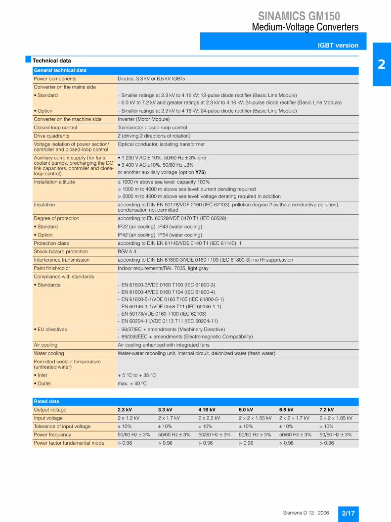
2■ Technical data
General technical data
Power components Diodes, 3.3 kV or 6.5 kV IGBTs
Converter on the mains side
• Standard - Smaller ratings at 2.3 kV to 4.16 kV: 12-pulse diode rectifier (Basic Line Module)- 6.0 kV to 7.2 kV and greater ratings at 2.3 kV to 4.16 kV: 24-pulse diode rectifier (Basic Line Module)
• Option - Smaller ratings at 2.3 kV to 4.16 kV: 24-pulse diode rectifier (Basic Line Module)
Converter on the machine side Inverter (Motor Module)
Closed-loop control Transvector closed-loop control
Drive quadrants 2 (driving 2 directions of rotation)
Voltage isolation of power section/controller and closed-loop control
Optical conductor, isolating transformer
Auxiliary current supply (for fans, coolant pumps, precharging the DC link capacitors, controller and close-loop control)
• 1 230 V AC � 10%, 50/60 Hz � 3% and• 3 400 V AC �10%, 50/60 Hz �3%or another auxiliary voltage (option Y75)
Installation altitude � 1000 m above sea level: capacity 100%> 1000 m to 4000 m above sea level: current derating required> 2000 m to 4000 m above sea level: voltage derating required in addition
Insulation according to DIN EN 50178/VDE 0160 (IEC 62103): pollution degree 2 (without conductive pollution), condensation not permitted
Degree of protection according to EN 60529/VDE 0470 T1 (IEC 60529):
• Standard IP22 (air cooling), IP43 (water cooling)
• Option IP42 (air cooling), IP54 (water cooling)
Protection class according to DIN EN 61140/VDE 0140 T1 (IEC 61140): 1
Shock-hazard protection BGV A 3
Interference transmission according to DIN EN 61800-3/VDE 0160 T100 (IEC 61800-3): no RI suppression
Paint finish/color Indoor requirements/RAL 7035, light gray
Compliance with standards
• Standards - EN 61800-3/VDE 0160 T100 (IEC 61800-3)- EN 61800-4/VDE 0160 T104 (IEC 61800-4)- EN 61800-5-1/VDE 0160 T105 (IEC 61800-5-1)- EN 60146-1-1/VDE 0558 T11 (IEC 60146-1-1)- EN 50178/VDE 0160 T100 (IEC 62103)- EN 60204-11/VDE 0113 T11 (IEC 60204-11)
• EU directives - 98/37/EC + amendments (Machinery Directive)- 89/336/EEC + amendments (Electromagnetic Compatibility)
Air cooling Air cooling enhanced with integrated fans
Water cooling Water-water recooling unit, internal circuit, deionized water (fresh water)
Permitted coolant temperature (untreated water)
• Inlet + 5 °C to + 35 °C
• Outlet max. + 40 °C
Rated data
Output voltage 2.3 kV 3.3 kV 4.16 kV 6.0 kV 6.6 kV 7.2 kV
Input voltage 2 x 1.2 kV 2 x 1.7 kV 2 x 2.2 kV 2 � 2 � 1.55 kV 2 � 2 � 1.7 kV 2 � 2 � 1.85 kV
Tolerance of input voltage � 10% � 10% � 10% � 10% � 10% � 10%
Power frequency 50/60 Hz � 3% 50/60 Hz � 3% 50/60 Hz � 3% 50/60 Hz � 3% 50/60 Hz � 3% 50/60 Hz � 3%
Power factor fundamental mode > 0.96 > 0.96 > 0.96 > 0.96 > 0.96 > 0.96

SINAMICS GM150Medium-Voltage Converters
IGBT version
2/18 Siemens D 12 · 2006
2 ■ Technical data (continued)
Note: The values specified under storage and transport apply to unpacked converters.
Operation of asynchronous motors Operation of separately excited synchronous motors
without speed encoder with speed encoder with speed encoder
without sinu- soidal filter
with sinu- soidal filter
without sinu- soidal filter
with sinu- soidal filter
without sinu- soidal filter
with sinu- soidal filter
Control properties
Operating range
• Lower limit of speed control range(% of rated motor speed)
5% 5% 0% 0% 0% 0%
• Max. permissible output frequency 250 Hz 66 Hz 250 Hz 66 Hz 90 Hz 66 Hz
• Field-shunting range 1:3 1:1,1 1:3 1:1,1 1:4 1:1,1
Stationary operation
• Speed accuracy(% of rated motor speed)
� 0,2%(from 5% rated speed)
� 0,2%(from 5% rated speed)
� 0,01% � 0,01% � 0,01% � 0,01%
• Torque accuracy(% of rated torque)
� 5%(from 5% rated speed)
� 5%(from 5% rated speed)
� 5% � 5% � 2% � 5%
Dynamic operation
• Torque rise time 5 ms 20 ms 5 ms 20 ms 5 ms 20 ms
Storage Transport Operation
Climatic ambient conditions
Ambient temperature + 5 °C to + 45 °C – 25 °C to + 70 °C + 5 °C to + 40 °C
Relative air humidity 5% to 95%(only slight condensation permit-ted; converter must be completely dry before commissioning)
5% to 75% 5% to 85%(condensation not permitted)
Other climatic conditions according to class
1K3 according to EN 60721-3-1 (IEC 60721-3-1)(icing not permitted)
2K2 according to EN 60721-3-2 (IEC 60721-3-2)
3K3 according to EN 60721-3-3 (IEC 60721-3-3)
Degree of pollution 2 without conductive pollution according to EN 50178/VDE 0160 (IEC 62103)
2 without conductive pollution according to EN 50178/VDE 0160 (IEC 62103)
2 without conductive pollution according to EN 50178/VDE 0160 (IEC 62103)
Mechanical ambient conditions
Dynamic stress
• Deflection 1.5 mm at 2 Hz to 9 Hz 3.5 mm at 2 Hz to 9 Hz 0.3 mm at 2 Hz to 9 Hz
• Acceleration 5 m/s2 at 9 Hz to 200 Hz 10 m/s2 at 9 Hz to 200 Hz15 m/s2 at 200 Hz to 500 Hz
1 m/s2 at 9 Hz to 200 Hz
Other mechanical conditions according to class (greater strength for ship compatibility)
1M2 according to EN 60721-3-1 (IEC 60721-3-1)
2M2 according to EN 60721-3-2 (IEC 60721-3-2)
3M1 according to EN 60721-3-3 (IEC 60721-3-3)
Other ambient conditions
Biological ambient conditions according to class
1B1 according to EN 60721-3-1 (IEC 60721-3-1)
2B1 according to EN 60721-3-2 (IEC 60721-3-2)
3B2 according to EN 60721-3-3 (IEC 60721-3-3)(without harmful flora)
Chemically active materials according to class
1C1 according to EN 60721-3-1 (IEC 60721-3-1)
2C1 according to EN 60721-3-2 (IEC 60721-3-2)
3C2 according to EN 60721-3-3 (IEC 60721-3-3)(no occurrence of salt mist)
Mechanically active materials according to class
1S1 according to EN 60721-3-1 (IEC 60721-3-1)
2S1 according to EN 60721-3-2 (IEC 60721-3-2)
3S1 according to EN 60721-3-3 (IEC 60721-3-3)(3S3 with water cooling and degree of protection IP54)

SINAMICS GM150Medium-Voltage Converters
IGBT version
2/19Siemens D 12 · 2006
2■ Technical data (continued)
Installation conditions and derating data
Current derating
If the converters are operated at installation altitudes > 1000 m above sea level or under ambient or coolant temperatures > 40 °C with air cooling or > 35 °C with water cooling, derating factors kH and kT must be taken into account for the rated cur-rent (DIN 43671).
Derating factor kT with air cooling
Derating factor kT with water cooling
Derating factor kH with air cooling
Derating factor kH with water cooling
For the permitted continuous current I: I � In � kH � kT
I: permitted continuous currentIn: rated current
Voltage derating
At installation altitudes > 2000 m, a voltage derating is required in addition to a current correction (EN 60664-1/VDE 0110 (IEC 60664-1)). This depends on the air and creepage distances in the unit.
Derating factor kU
10 20 30 405 45°C
Cor
rect
ion
fact
or
0.95
0.90
1.00
Coolant temperature
G_D
012_
EN
_000
25
k T
5 10 20 30 40 4535
Cor
rect
ion
fact
or
0.95
0.90
1.00
Untreated water inlet temperature
k T
°C
G_D
012_
EN
_000
26
kH
1000 2000 3000 40000 m
Cor
rect
ion
fact
or
G_D
012_
EN
_000
27
0.9
0.8
0.6
1.0
0.7
Installation altitude above sea level
1000 2000 3000 40000 m
Cor
rect
ion
fact
or
G_D
012_
EN
_000
28
k H 0.9
0.8
0.6
1.0
0.7
Installation altitude above sea level
k U
1000 2000 3000 40000 m
Cor
rect
ion
fact
or
G_D
012_
EN
_000
29
0.9
0.8
0.6
1.0
0.7
Installation altitude above sea level

SINAMICS GM150Medium-Voltage Converters
IGBT version
2/20 Siemens D 12 · 2006
2 ■ Technical data (continued)
The technical data from the following examples can be found on page 2/23 onwards.
Example 1
Converter 6SL3810-2LP33-0AA0 (air-cooled version)
Output voltage: 4.16 kV
Input voltage: 2 x 2.2 kV
Type rating: 2200 kVA, 300 A
Installation altitude: 3000 m
Max. ambient temperature: 30 °C- Derating factor kH = 0.84- Derating factor kT = 1.0- Derating factor kU = 0.9
I � In � 0.84 � 1.0 = In � 0.84
This means that a voltage derating of 10% is required in addition to a current correction of 16%.
The maximum available output current of the converter is 252 A.
The converter can still be operated at a line voltage of 2 x 3 1.98 kV AC.
The following applies for the water-cooled version:When determining the current derating factor, it is essential to consider the ambient temperature of the air as well as the tem-perature of the untreated water in the inlet, as components such as the link busbars are also subject to air cooling. This requires the factors kT and kH to be determined from the diagrams for air cooling as well as for water cooling. The smaller of the two prod-ucts (kT � kH) must be used as the current derating factor (see the following examples 2 and 3).
Example 2
Converter 6SL3815-2LN33-5AA0 (water-cooled version)
Output voltage: 3.3 kV
Input voltage: 2 x 1.7 kV
Type rating: 2000 kVA, 350 A
Installation altitude: 2000 m
Max. ambient temperature: 40 °C
Untreated water inlet temperature: 40 °C• Ambient temperature:
- Derating factor kH = 0.9- Derating factor kT = 1.0- Derating factor kU = 1.0
• Untreated water inlet temperature: - Derating factor kH = 0.925- Derating factor kT = 0.925- Derating factor kU = 1.0
The smaller value for kT � kH results in this case from the dia-grams for the untreated water in the inlet.
I � In � 0.925 � 0.925 = In � 0.856
A current derating of 14.4% is required.
The maximum available output current of the converter is 299 A.
Example 3
Converter 6SL3815-2LN33-5AA0 (water-cooled version)
Output voltage: 3.3 kV
Input voltage: 2 x 1.7 kV
Type rating: 2000 kVA, 350 A
Installation altitude: 2000 m
Max. ambient temperature: 43 °C
Untreated water inlet temperature: 30 °C• Ambient temperature
- Derating factor kH = 0.9- Derating factor kT = 0.955- Derating factor kU = 1.0
• Untreated water inlet temperature: - Derating factor kH = 0.925- Derating factor kT = 1.0- Derating factor kU = 1.0
The smaller value for kT � kH results in this case from the dia-grams for the ambient temperature.
I � In � 0.9 � 0.955 = In � 0.86
A current derating of 14% is required.
The maximum available output current of the converter is 301 A.

SINAMICS GM150Medium-Voltage Converters
IGBT versionAir cooling, without sinusoidal filter
2/21Siemens D 12 · 2006
2■ Technical data
SINAMICS GM150 as IGBT versionAir cooling, without sinusoidal filter
Type 6SL3810-2LM32-5AA0
6SL3810-2LM33-0AA0
6SL3810-2LM33-5AA0
6SL3810-2LM34-0AA0
Output voltage 2.3 kV
Type rating kVA 1000 1200 1400 1600
Shaft output 1) kW 820 1000 1150 1300
hp 1000 1250 1500 1750
Rated output current A 250 300 350 400
Input voltage kV 2 � 1.2 2 � 1.2 2 � 1.2 2 � 1.2
Rated input current 1) A 2 � 220 2 � 264 2 � 308 2 � 351
Power loss 2) kW 15 18 21 24
Efficiency 2) % 98.3 98.3 98.3 98.3
Max. AC current requirement 50/60 Hz, 230 V
A 10 10 10 10
Max. current requirement of auxiliary supply 3 AC 50/60 Hz 400 V 3)
A 27 27 27 27
Cooling air throughput m3/s 1.6 1.6 1.6 1.6
Sound pressure level LpA dB(A) 78 80 80 80
Measuring surface measurement Ls dB(A) 18 18 18 18
Cable cross-sections, line side, max. which can be connected per phase 4)
mm2
(DIN VDE)2 � 240 2 � 240 2 � 240 2 � 240
AWG/MCM(NEC, CEC)
2 � 500 MCM 2 � 500 MCM 2 � 500 MCM 2 � 500 MCM
Cable cross-sections, motor side, max. which can be connected per phase 4)
mm2
(DIN VDE)2 � 240 2 � 240 2 � 240 2 � 240
AWG/MCM(NEC, CEC)
2 � 500 MCM 2 � 500 MCM 2 � 500 MCM 2 � 500 MCM
PE connection, max. connection cross-section at enclosure with M12 screw 4)
mm2
(DIN VDE)2 � 240 2 � 240 2 � 240 2 � 240
AWG/MCM(NEC, CEC)
2 � 500 MCM 2 � 500 MCM 2 � 500 MCM 2 � 500 MCM
Degree of protection IP22 IP22 IP22 IP22
Dimensions (with doors and walls)
• Width mm 2420 2420 2420 2420
• Height mm 2570 2570 2570 2570
• Depth mm 1275 1275 1275 1275
Circuit version $ $ $ $
Weight kg 1750 1750 1750 1750
1) The figures for the rated input current and the output figures in hp and kW are approximate values which were determined for operation with asynchronous motors and for a typical value of the cos phi power factor and efficiency of the motor.The hp figures are based on the NEC and CEC directives for the North American market. The kW values are quoted in steps which can be divided by 50.Both approximate values need to be adapted to the motor which is actually used.
2) Without cooling system.3) Plus 20 A precharging current for 25 s.4) Figures refer to a subsystem; please refer to “Circuit Versions” for the
number of subsystems to be connected on the line and motor side.

SINAMICS GM150Medium-Voltage ConvertersIGBT versionAir cooling, without sinusoidal filter
2/22 Siemens D 12 · 2006
2 ■ Technical data (continued)
SINAMICS GM150 as IGBT versionAir cooling, without sinusoidal filter
Type 6SL3810-2LM34-5AA0
6SL3810-2LM35-0AA0
6SL3810-2LM35-5AA0
6SL3810-2LM36-0AA0
Output voltage 2.3 kV
Type rating kVA 1800 2000 2200 2400
Shaft output 1) kW 1500 1650 1800 2000
hp 2000 2250 2500 2750
Rated output current A 450 500 550 600
Input voltage kV 2 � 1.2 2 � 1.2 2 � 1.2 2 � 1.2
Rated input current A 2 � 395 2 � 444 2 � 494 2 � 539
Power loss 2) kW 27 28 31 34
Efficiency 2) % 98.3 98.4 98.4 98.4
Max. AC current requirement 50/60 Hz, 230 V
A 10 10 10 10
Max. current requirement of auxiliary supply 3 AC 50/60 Hz 400 V 3)
A 27 27 27 27
Cooling air throughput m3/s 1.6 1.6 1.6 1.6
Sound pressure level LpA dB(A) 78 80 80 80
Measuring surface measurement Ls dB(A) 18 18 18 18
Cable cross-sections, line side, max. which can be connected per phase 4)
mm2
(DIN VDE)2 � 240 2 � 240 2 � 240 2 � 240
AWG/MCM(NEC, CEC)
2 � 500 MCM 2 � 500 MCM 2 � 500 MCM 2 � 500 MCM
Cable cross-sections, motor side, max. which can be connected per phase 4)
mm2
(DIN VDE)2 � 240 2 � 240 2 � 240 2 � 240
AWG/MCM(NEC, CEC)
2 � 500 MCM 2 � 500 MCM 2 � 500 MCM 2 � 500 MCM
PE connection, max. connection cross-section at enclosure with M12 screw 4)
mm2
(DIN VDE)2 � 240 2 � 240 2 � 240 2 � 240
AWG/MCM(NEC, CEC)
2 � 500 MCM 2 � 500 MCM 2 � 500 MCM 2 � 500 MCM
Degree of protection IP22 IP22 IP22 IP22
Dimensions (with doors and walls)
• Width mm 2420 2420 2420 2420
• Height mm 2570 2570 2570 2570
• Depth mm 1275 1275 1275 1275
Circuit version $ $ $ $
Weight kg 1750 1750 1800 1800
1) The output figures in hp and kW are approximate values which were determined for operation with asynchronous motors and for a typical value of the cos phi power factor.The hp figures are based on the NEC and CEC directives for the North American market. The kW values are quoted in steps which can be divided by 50.Both approximate values need to be adapted to the motor which is actually used.
2) Without cooling system.3) Plus 20 A precharging current for 25 s.4) Figures refer to a subsystem; please refer to “Circuit Versions” for the
number of subsystems to be connected on the line and motor side.

SINAMICS GM150Medium-Voltage Converters
IGBT versionAir cooling, without sinusoidal filter
2/23Siemens D 12 · 2006
2■ Technical data (continued)
SINAMICS GM150 as IGBT versionAir cooling, without sinusoidal filter
Type 6SL3810-2LN31-8AA0
6SL3810-2LN32-2AA0
6SL3810-2LN32-6AA0
6SL3810-2LN33-0AA0
6SL3810-2LN33-5AA0
6SL3810-2LN34-0AA0
Output voltage 3.3 kV
Type rating kVA 1000 1300 1500 1700 2000 2300
Shaft output 1) kW 850 1050 1250 1400 1650 1900
hp 1000 1250 1500 2000 2250 2500
Rated output current A 180 220 260 300 350 400
Input voltage kV 2 � 1.7 2 � 1.7 2 � 1.7 2 � 1.7 2 � 1.7 2 � 1.7
Rated input current A 2 � 153 2 � 199 2 � 230 2 � 260 2 � 309 2 � 360
Power loss 2) kW 15 20 23 26 28 32
Efficiency 2) % 98.3 98.2 98.2 98.3 98.4 98.4
Max. AC current requirement 50/60 Hz, 230 V
A 10 10 10 10 10 10
Max. current requirement of auxiliary supply 3 AC 50/60 Hz 400 V 3)
A 27 27 27 27 27 27
Cooling air throughput m3/s 2.4 2.4 2.4 2.4 2.4 2.4
Sound pressure level LpA dB(A) 78 78 78 80 80 80
Measuring surface measurement Ls dB(A) 18 18 18 18 18 18
Cable cross-sections, line side, max. which can be connected per phase 4)
mm2
(DIN VDE)2 � 240 2 � 240 2 � 240 2 � 240 2 � 240 2 � 240
AWG/MCM(NEC, CEC)
2 � 500 MCM 2 � 500 MCM 2 � 500 MCM 2 � 500 MCM 2 � 500 MCM 2 � 500 MCM
Cable cross-sections, motor side, max. which can be connected per phase 4)
mm2
(DIN VDE)2 � 240 2 � 240 2 � 240 2 � 240 2 � 240 2 � 240
AWG/MCM(NEC, CEC)
2 � 500 MCM 2 � 500 MCM 2 � 500 MCM 2 � 500 MCM 2 � 500 MCM 2 � 500 MCM
PE connection, max. connection cross-section at enclosure with M12 screw 4)
mm2
(DIN VDE)2 � 240 2 � 240 2 � 240 2 � 240 2 � 240 2 � 240
AWG/MCM(NEC, CEC)
2 � 500 MCM 2 � 500 MCM 2 � 500 MCM 2 � 500 MCM 2 � 500 MCM 2 � 500 MCM
Degree of protection IP22 IP22 IP22 IP22 IP22 IP22
Dimensions (with doors and walls)
• Width mm 2420 2420 2420 2420 2420 2420
• Height mm 2570 2570 2570 2570 2570 2570
• Depth mm 1275 1275 1275 1275 1275 1275
Circuit version $ $ $ $ $ $
Weight kg 1900 1900 1900 1900 1900 1950
1) The output figures in hp and kW are approximate values which were determined for operation with asynchronous motors and for a typical value of the cos phi power factor.The hp figures are based on the NEC and CEC directives for the North American market. The kW values are quoted in steps which can be divided by 50.Both approximate values need to be adapted to the motor which is actually used.
2) Without cooling system.3) Plus 20 A precharging current for 25 s.4) Figures refer to a subsystem; please refer to “Circuit Versions” for the
number of subsystems to be connected on the line and motor side.

SINAMICS GM150Medium-Voltage ConvertersIGBT versionAir cooling, without sinusoidal filter
2/24 Siemens D 12 · 2006
2 ■ Technical data (continued)
SINAMICS GM150 as IGBT versionAir cooling, without sinusoidal filter
Type 6SL3810-2LN34-5AA0
6SL3810-2LN35-0AA0
6SL3810-2LN35-5AA0
6SL3810-2LN36-0AA0
Output voltage 3.3 kV
Type rating kVA 2600 2900 3100 3400
Shaft output 1) kW 2150 2400 2650 2850
hp 3000 3250 3500 3750
Rated output current A 450 500 550 600
Input voltage kV 2 � 1.7 2 � 1.7 2 � 1.7 2 � 1.7
Rated input current A 2 � 406 2 � 453 2 � 484 2 � 531
Power loss 2) kW 34 38 40 44
Efficiency 2) % 98.5 98.5 98.6 98.6
Max. AC current requirement 50/60 Hz, 230 V
A 10 10 10 10
Max. current requirement of auxiliary supply 3 AC 50/60 Hz 400 V 3)
A 27 27 27 27
Cooling air throughput m3/s 2.4 2.4 2.4 2.4
Sound pressure level LpA dB(A) 78 80 80 80
Measuring surface measurement Ls dB(A) 18 18 18 18
Cable cross-sections, line side, max. which can be connected per phase 4)
mm2
(DIN VDE)2 � 240 2 � 240 2 � 240 2 � 240
AWG/MCM(NEC, CEC)
2 � 500 MCM 2 � 500 MCM 2 � 500 MCM 2 � 500 MCM
Cable cross-sections, motor side, max. which can be connected per phase 4)
mm2
(DIN VDE)2 � 240 2 � 240 2 � 240 2 � 240
AWG/MCM(NEC, CEC)
2 � 500 MCM 2 � 500 MCM 2 � 500 MCM 2 � 500 MCM
PE connection, max. connection cross-section at enclosure with M12 screw 4)
mm2
(DIN VDE)2 � 240 2 � 240 2 � 240 2 � 240
AWG/MCM(NEC, CEC)
2 � 500 MCM 2 � 500 MCM 2 � 500 MCM 2 � 500 MCM
Degree of protection IP22 IP22 IP22 IP22
Dimensions (with doors and walls)
• Width mm 2420 2420 2420 2420
• Height mm 2570 2570 2570 2570
• Depth mm 1275 1275 1275 1275
Circuit version $ $ $ $
Weight kg 1950 1950 2000 2000
1) The output figures in hp and kW are approximate values which were determined for operation with asynchronous motors and for a typical value of the cos phi power factor.The hp figures are based on the NEC and CEC directives for the North American market. The kW values are quoted in steps which can be divided by 50.Both approximate values need to be adapted to the motor which is actually used.
2) Without cooling system.3) Plus 20 A precharging current for 25 s.4) Figures refer to a subsystem; please refer to “Circuit Versions” for the
number of subsystems to be connected on the line and motor side.

SINAMICS GM150Medium-Voltage Converters
IGBT versionAir cooling, without sinusoidal filter
2/25Siemens D 12 · 2006
2■ Technical data (continued)
SINAMICS GM150 as IGBT versionAir cooling, without sinusoidal filter
Type 6SL3810-2LN36-6AA0
6SL3810-2LN37-2AA0
6SL3810-2LN38-1AA0
6SL3810-2LN38-8AA0
6SL3810-2LN41-0AA0
6SL3810-2LN41-1AA0
Output voltage 3.3 kV
Type rating kVA 3800 4100 4600 5100 5700 6300
Shaft output 1) kW 3100 3400 3900 4300 4800 500
hp 4000 4500 5000 6000 6500 7000
Rated output current A 2 � 330 2 � 360 2 � 405 2 � 450 2 � 500 2 � 550
Input voltage kV 2 � (2 � 1.7) 2 � (2 � 1.7) 2 � (2 � 1.7) 2 � (2 � 1.7) 2 � (2 � 1.7) 2 � (2 � 1.7)
Rated input current A 2 � (2 � 297) 2 � (2 � 321) 2 � (2 � 360) 2 � (2 � 399) 2 � (2 � 446) 2 � (2 � 492)
Power loss 2) kW 49 53 60 66 74 82
Efficiency 2) % 98.6 98.6 98.5 98.6 98.5 98.5
Max. AC current requirement 50/60 Hz, 230 V
A 10 10 10 10 10 10
Max. current requirement of auxiliary supply 3 AC 50/60 Hz 400 V 3)
A 54 54 54 54 54 54
Cooling air throughput m3/s 4.7 4.7 4.7 4.7 4.7 4.7
Sound pressure level LpA dB(A) 85 85 85 85 85 85
Measuring surface measurement Ls dB(A) 19 19 19 19 19 19
Cable cross-sections, line side, max. which can be connected per phase 4)
mm2
(DIN VDE)2 � 240 2 � 240 2 � 240 2 � 240 2 � 240 2 � 240
AWG/MCM(NEC, CEC)
2 � 500 MCM 2 � 500 MCM 2 � 500 MCM 2 � 500 MCM 2 � 500 MCM 2 � 500 MCM
Cable cross-sections, motor side, max. which can be connected per phase 4)
mm2
(DIN VDE)2 � 240 2 � 240 2 � 240 2 � 240 2 � 240 2 � 240
AWG/MCM(NEC, CEC)
2 � 500 MCM 2 � 500 MCM 2 � 500 MCM 2 � 500 MCM 2 � 500 MCM 2 � 500 MCM
PE connection, max. connection cross-section at enclosure with M12 screw 4)
mm2
(DIN VDE)2 � 240 2 � 240 2 � 240 2 � 240 2 � 240 2 � 240
AWG/MCM(NEC, CEC)
2 � 500 MCM 2 � 500 MCM 2 � 500 MCM 2 � 500 MCM 2 � 500 MCM 2 � 500 MCM
Degree of protection IP22 IP22 IP22 IP22 IP22 IP22
Dimensions (with doors and walls)
• Width mm 4220 4220 4220 4220 4220 4220
• Height mm 2570 2570 2570 2570 2570 2570
• Depth mm 1275 1275 1275 1275 1275 1275
Circuit version & & & & & &
Weight kg 3500 3600 3600 3600 3700 3700
1) The output figures in hp and kW are approximate values which were determined for operation with asynchronous motors and for a typical value of the cos phi power factor.The hp figures are based on the NEC and CEC directives for the North American market. The kW values are quoted in steps which can be divided by 50.Both approximate values need to be adapted to the motor which is actually used.
2) Without cooling system.3) Plus 20 A precharging current for 25 s.4) Figures refer to a subsystem; please refer to “Circuit Versions” for the
number of subsystems to be connected on the line and motor side.

SINAMICS GM150Medium-Voltage ConvertersIGBT versionAir cooling, without sinusoidal filter
2/26 Siemens D 12 · 2006
2 ■ Technical data (continued)
SINAMICS GM150 as IGBT versionAir cooling, without sinusoidal filter
Type 6SL3810-2LP31-8AA0
6SL3810-2LP32-2AA0
6SL3810-2LP32-6AA0
6SL3810-2LP33-0AA0
6SL3810-2LP33-5AA0
6SL3810-2LP34-0AA0
Output voltage 4.16 kV
Type rating kVA 1300 1600 1900 2200 2500 2900
Shaft output 1) kW 1000 1300 1550 1800 2100 2400
hp 1500 1750 2000 2500 3000 3250
Rated output current A 180 220 260 300 350 400
Input voltage kV 2 � 2.2 2 � 2.2 2 � 2.2 2 � 2.2 2 � 2.2 2 � 2.2
Rated input current A 2 � 158 2 � 194 2 � 233 2 � 273 2 � 310 2 � 359
Power loss 2) kW 20 24 27 31 33 38
Efficiency 2) % 98.2 98.3 98.4 98.4 98.5 98.5
Max. AC current requirement 50/60 Hz, 230 V
A 10 10 10 10 10 10
Max. current requirement of auxiliary supply 3 AC 50/60 Hz 400 V 3)
A 27 27 27 27 27 27
Cooling air throughput m3/s 2.4 2.4 2.4 2.4 2.4 2.4
Sound pressure level LpA dB(A) 78 78 78 80 80 80
Measuring surface measurement Ls dB(A) 18 18 18 18 18 18
Cable cross-sections, line side, max. which can be connected per phase 4)
mm2
(DIN VDE)2 � 240 2 � 240 2 � 240 2 � 240 2 � 240 2 � 240
AWG/MCM(NEC, CEC)
2 � 500 MCM 2 � 500 MCM 2 � 500 MCM 2 � 500 MCM 2 � 500 MCM 2 � 500 MCM
Cable cross-sections, motor side, max. which can be connected per phase 4)
mm2
(DIN VDE)2 � 240 2 � 240 2 � 240 2 � 240 2 � 240 2 � 240
AWG/MCM(NEC, CEC)
2 � 500 MCM 2 � 500 MCM 2 � 500 MCM 2 � 500 MCM 2 � 500 MCM 2 � 500 MCM
PE connection, max. connection cross-section at enclosure with M12 screw 4)
mm2
(DIN VDE)2 � 240 2 � 240 2 � 240 2 � 240 2 � 240 2 � 240
AWG/MCM(NEC, CEC)
2 � 500 MCM 2 � 500 MCM 2 � 500 MCM 2 � 500 MCM 2 � 500 MCM 2 � 500 MCM
Degree of protection IP22 IP22 IP22 IP22 IP22 IP22
Dimensions (with doors and walls)
• Width mm 2420 2420 2420 2420 2420 2420
• Height mm 2570 2570 2570 2570 2570 2570
• Depth mm 1275 1275 1275 1275 1275 1275
Circuit version $ $ $ $ $ $
Weight kg 1900 1900 1900 1950 1950 1950
1) The output figures in hp and kW are approximate values which were determined for operation with asynchronous motors and for a typical value of the cos phi power factor.The hp figures are based on the NEC and CEC directives for the North American market. The kW values are quoted in steps which can be divided by 50.Both approximate values need to be adapted to the motor which is actually used.
2) Without cooling system.3) Plus 20 A precharging current for 25 s.4) Figures refer to a subsystem; please refer to “Circuit Versions” for the
number of subsystems to be connected on the line and motor side.

SINAMICS GM150Medium-Voltage Converters
IGBT versionAir cooling, without sinusoidal filter
2/27Siemens D 12 · 2006
2■ Technical data (continued)
SINAMICS GM150 as IGBT versionAir cooling, without sinusoidal filter
Type 6SL3810-2LP34-5AA0
6SL3810-2LP35-0AA0
6SL3810-2LP35-5AA0
6SL3810-2LP36-0AA0
Output voltage 4.16 kV
Type rating kVA 3200 3600 4000 4300
Shaft output 1) kW 2700 3000 3300 3600
hp 3500 4000 4500 5000
Rated output current A 450 500 550 600
Input voltage kV 2 � 2.2 2 � 2.2 2 � 2.2 2 � 2.2
Rated input current A 2 � 397 2 � 446 2 � 496 2 � 533
Power loss 2) kW 42 47 52 56
Efficiency 2) % 98.5 98.5 98.5 98.5
Max. AC current requirement 50/60 Hz, 230 V
A 10 10 10 10
Max. current requirement of auxiliary supply 3 AC 50/60 Hz 400 V 3)
A 27 27 27 27
Cooling air throughput m3/s 2.4 2.4 2.4 2.4
Sound pressure level LpA dB(A) 78 80 80 80
Measuring surface measurement Ls dB(A) 18 18 18 18
Cable cross-sections, line side, max. which can be connected per phase 4)
mm2
(DIN VDE)2 � 240 2 � 240 2 � 240 2 � 240
AWG/MCM(NEC, CEC)
2 � 500 MCM 2 � 500 MCM 2 � 500 MCM 2 � 500 MCM
Cable cross-sections, motor side, max. which can be connected per phase 4)
mm2
(DIN VDE)2 � 240 2 � 240 2 � 240 2 � 240
AWG/MCM(NEC, CEC)
2 � 500 MCM 2 � 500 MCM 2 � 500 MCM 2 � 500 MCM
PE connection, max. connection cross-section at enclosure with M12 screw 4)
mm2
(DIN VDE)2 � 240 2 � 240 2 � 240 2 � 240
AWG/MCM(NEC, CEC)
2 � 500 MCM 2 � 500 MCM 2 � 500 MCM 2 � 500 MCM
Degree of protection IP22 IP22 IP22 IP22
Dimensions (with doors and walls)
• Width mm 2420 2420 2420 2420
• Height mm 2570 2570 2570 2570
• Depth mm 1275 1275 1275 1275
Circuit version $ $ $ $
Weight kg 2000 2000 2000 2000
1) The output figures in hp and kW are approximate values which were determined for operation with asynchronous motors and for a typical value of the cos phi power factor.The hp figures are based on the NEC and CEC directives for the North American market. The kW values are quoted in steps which can be divided by 50.Both approximate values need to be adapted to the motor which is actually used.
2) Without cooling system.3) Plus 20 A precharging current for 25 s.4) Figures refer to a subsystem; please refer to “Circuit Versions” for the
number of subsystems to be connected on the line and motor side.

SINAMICS GM150Medium-Voltage ConvertersIGBT versionAir cooling, without sinusoidal filter
2/28 Siemens D 12 · 2006
2 ■ Technical data (continued)
SINAMICS GM150 as IGBT versionAir cooling, without sinusoidal filter
Type 6SL3810-2LP36-6AA0
6SL3810-2LP37-2AA0
6SL3810-2LP38-1AA0
6SL3810-2LP38-8AA0
6SL3810-2LP41-0AA0
6SL3810-2LP41-1AA0
Output voltage 4.16 kV
Type rating kVA 4800 5200 5800 6500 7200 7900
Shaft output 1) kW 4000 4300 4900 5400 6000 6600
hp 5500 6000 6500 7000 8000 9000
Rated output current A 2 � 330 2 � 360 2 � 405 2 � 450 2 � 500 2 � 550
Input voltage kV 2 � (2 � 2.2) 2 � (2 � 2.2) 2 � (2 � 2.2) 2 � (2 � 2.2) 2 � (2 � 2.2) 2 � (2 � 2.2)
Rated input current A 2 � (2 � 298) 2 � (2 � 323) 2 � (2 � 360) 2 � (2 � 403) 2 � (2 � 446) 2 � (2 � 490)
Power loss 2) kW 62 68 75 85 94 103
Efficiency 2) % 98.6 98.5 98.6 98.5 98.5 98.5
Max. AC current requirement 50/60 Hz, 230 V
A 10 10 10 10 10 10
Max. current requirement of auxiliary supply 3 AC 50/60 Hz 400 V 3)
A 54 54 54 54 54 54
Cooling air throughput m3/s 4.7 4.7 4.7 4.7 4.7 4.7
Sound pressure level LpA dB(A) 85 85 85 85 85 85
Measuring surface measurement Ls dB(A) 19 19 19 19 19 19
Cable cross-sections, line side, max. which can be connected per phase 4)
mm2
(DIN VDE)2 � 240 2 � 240 2 � 240 2 � 240 2 � 240 2 � 240
AWG/MCM(NEC, CEC)
2 � 500 MCM 2 � 500 MCM 2 � 500 MCM 2 � 500 MCM 2 � 500 MCM 2 � 500 MCM
Cable cross-sections, motor side, max. which can be connected per phase 4)
mm2
(DIN VDE)2 � 240 2 � 240 2 � 240 2 � 240 2 � 240 2 � 240
AWG/MCM(NEC, CEC)
2 � 500 MCM 2 � 500 MCM 2 � 500 MCM 2 � 500 MCM 2 � 500 MCM 2 � 500 MCM
PE connection, max. connection cross-section at enclosure with M12 screw 4)
mm2
(DIN VDE)2 � 240 2 � 240 2 � 240 2 � 240 2 � 240 2 � 240
AWG/MCM(NEC, CEC)
2 � 500 MCM 2 � 500 MCM 2 � 500 MCM 2 � 500 MCM 2 � 500 MCM 2 � 500 MCM
Degree of protection IP22 IP22 IP22 IP22 IP22 IP22
Dimensions (with doors and walls)
• Width mm 4220 4220 4220 4220 4220 4220
• Height mm 2570 2570 2570 2570 2570 2570
• Depth mm 1275 1275 1275 1275 1275 1275
Circuit version & & & & & &
Weight kg 3600 3600 3600 3700 3700 3700
1) The output figures in hp and kW are approximate values which were determined for operation with asynchronous motors and for a typical value of the cos phi power factor.The hp figures are based on the NEC and CEC directives for the North American market. The kW values are quoted in steps which can be divided by 50.Both approximate values need to be adapted to the motor which is actually used.
2) Without cooling system.3) Plus 20 A precharging current for 25 s.4) Figures refer to a subsystem; please refer to “Circuit Versions” for the
number of subsystems to be connected on the line and motor side.

SINAMICS GM150Medium-Voltage Converters
IGBT versionAir cooling, without sinusoidal filter
2/29Siemens D 12 · 2006
2■ Technical data (continued)
SINAMICS GM150 as IGBT versionAir cooling, without sinusoidal filter
Type 6SL3810-2LQ30-8AA0
6SL3810-2LQ31-0AA0
6SL3810-2LQ31-2AA0
6SL3810-2LQ31-5AA0
6SL3810-2LQ31-8AA0
Output voltage 6.0 kV
Type rating kVA 800 1000 1200 1600 1900
Shaft output 1) kW 700 850 1050 1300 1550
hp 900 1250 1500 1750 2000
Rated output current A 80 100 120 150 180
Input voltage kV 2 � 2 � 1.55 2 � 2 � 1.55 2 � 2 � 1.55 2 � 2 � 1.55 2 � 2 � 1.55
Rated input current A 2 � 2 � 67 2 � 2 � 84 2 � 2 � 101 2 � 2 � 135 2 � 2 � 162
Power loss 2) kW 12 15 18 24 27
Efficiency 2) % 98.3 98.3 98.3 98.3 98.4
Max. AC current requirement 50/60 Hz, 230 V
A 10 10 10 10 10
Max. current requirement of auxiliary supply 3 AC 50/60 Hz 400 V 3)
A 36 36 36 36 36
Cooling air throughput m3/s 2.8 2.8 2.8 2.8 2.8
Sound pressure level LpA dB(A) 80 80 80 80 80
Measuring surface measurement Ls dB(A) 19 19 19 19 19
Cable cross-sections, line side, max. which can be connected per phase 4)
mm2
(DIN VDE)2 � 240 2 � 240 2 � 240 2 � 240 2 � 240
AWG/MCM(NEC, CEC)
2 � 500 MCM 2 � 500 MCM 2 � 500 MCM 2 � 500 MCM 2 � 500 MCM
Cable cross-sections, motor side, max. which can be connected per phase 4)
mm2
(DIN VDE)2 � 240 2 � 240 2 � 240 2 � 240 2 � 240
AWG/MCM(NEC, CEC)
2 � 500 MCM 2 � 500 MCM 2 � 500 MCM 2 � 500 MCM 2 � 500 MCM
PE connection, max. connection cross-section at enclosure with M12 screw 4)
mm2
(DIN VDE)2 � 240 2 � 240 2 � 240 2 � 240 2 � 240
AWG/MCM(NEC, CEC)
2 � 500 MCM 2 � 500 MCM 2 � 500 MCM 2 � 500 MCM 2 � 500 MCM
Degree of protection IP22 IP22 IP22 IP22 IP22
Dimensions (with doors and walls)
• Width mm 3020 3020 3020 3020 3020
• Height mm 2570 2570 2570 2570 2570
• Depth mm 1275 1275 1275 1275 1275
Circuit version % % % % %
Weight kg 2300 2300 2300 2300 2350
1) The output figures in hp and kW are approximate values which were determined for operation with asynchronous motors and for a typical value of the cos phi power factor.The hp figures are based on the NEC and CEC directives for the North American market. The kW values are quoted in steps which can be divided by 50.Both approximate values need to be adapted to the motor which is actually used.
2) Without cooling system.3) Plus 20 A precharging current for 25 s.4) Figures refer to a subsystem; please refer to “Circuit Versions” for the
number of subsystems to be connected on the line and motor side.

SINAMICS GM150Medium-Voltage ConvertersIGBT versionAir cooling, without sinusoidal filter
2/30 Siemens D 12 · 2006
2 ■ Technical data (continued)
SINAMICS GM150 as IGBT versionAir cooling, without sinusoidal filter
Type 6SL3810-2LQ32-0AA0
6SL3810-2LQ32-2AA0
6SL3810-2LQ32-4AA0
6SL3810-2LQ32-7AA0
Output voltage 6.0 kV
Type rating kVA 2100 2300 2500 2800
Shaft output 1) kW 1750 1950 2100 2350
hp 2250 2500 2750 3000
Rated output current A 200 225 245 270
Input voltage kV 2 � 2 � 1.55 2 � 2 � 1.55 2 � 2 � 1.55 2 � 2 � 1.55
Rated input current A 2 � 2 � 181 2 � 2 � 198 2 � 2 � 215 2 � 2 � 241
Power loss 2) kW 29 32 33 36
Efficiency 2) % 98.5 98.4 98.5 98.6
Max. AC current requirement 50/60 Hz, 230 V
A 10 10 10 10
Max. current requirement of auxiliary supply 3 AC 50/60 Hz 400 V 3)
A 36 36 36 36
Cooling air throughput m3/s 2.8 2.8 2.8 2.8
Sound pressure level LpA dB(A) 80 82 82 82
Measuring surface measurement Ls dB(A) 19 19 19 19
Cable cross-sections, line side, max. which can be connected per phase 4)
mm2
(DIN VDE)2 � 240 2 � 240 2 � 240 2 � 240
AWG/MCM(NEC, CEC)
2 � 500 MCM 2 � 500 MCM 2 � 500 MCM 2 � 500 MCM
Cable cross-sections, motor side, max. which can be connected per phase 4)
mm2
(DIN VDE)2 � 240 2 � 240 2 � 240 2 � 240
AWG/MCM(NEC, CEC)
2 � 500 MCM 2 � 500 MCM 2 � 500 MCM 2 � 500 MCM
PE connection, max. connection cross-section at enclosure with M12 screw 4)
mm2
(DIN VDE)2 � 240 2 � 240 2 � 240 2 � 240
AWG/MCM(NEC, CEC)
2 � 500 MCM 2 � 500 MCM 2 � 500 MCM 2 � 500 MCM
Degree of protection IP22 IP22 IP22 IP22
Dimensions (with doors and walls)
• Width mm 3020 3020 3020 3020
• Height mm 2570 2570 2570 2570
• Depth mm 1275 1275 1275 1275
Circuit version % % % %
Weight kg 2350 2350 2350 2350
1) The output figures in hp and kW are approximate values which were determined for operation with asynchronous motors and for a typical value of the cos phi power factor.The hp figures are based on the NEC and CEC directives for the North American market. The kW values are quoted in steps which can be divided by 50.Both approximate values need to be adapted to the motor which is actually used.
2) Without cooling system.3) Plus 20 A precharging current for 25 s.4) Figures refer to a subsystem; please refer to “Circuit Versions” for the
number of subsystems to be connected on the line and motor side.

SINAMICS GM150Medium-Voltage Converters
IGBT versionAir cooling, without sinusoidal filter
2/31Siemens D 12 · 2006
2■ Technical data (continued)
SINAMICS GM150 as IGBT versionAir cooling, without sinusoidal filter
Type 6SL3810-2LQ33-0AA0
6SL3810-2LQ33-2AA0
6SL3810-2LQ33-6AA0
6SL3810-2LQ34-0AA0
6SL3810-2LQ34-4AA0
6SL3810-2LQ34-8AA0
Output voltage 6.0 kV
Type rating kVA 3100 3400 3800 4200 4600 5000
Shaft output 1) kW 2550 2800 3200 3500 3900 4200
hp 3500 3750 4000 4500 5000 5500
Rated output current A 2 � 148 2 � 163 2 � 183 2 � 203 2 � 223 2 � 240
Input voltage kV 2 � 2 � 1.55 2 � 2 � 1.55 2 � 2 � 1.55 2 � 2 � 1.55 2 � 2 � 1.55 2 � 2 � 1.55
Rated input current A 2 � 2 � 266 2 � 2 � 292 2 � 2 � 326 2 � 2 � 361 2 � 2 � 395 2 � 2 � 438
Power loss 2) kW 40 44 49 55 60 65
Efficiency 2) % 98.6 98.6 98.6 98.5 98.5 98.6
Max. AC current requirement 50/60 Hz, 230 V
A 10 10 10 10 10 10
Max. current requirement of auxiliary supply 3 AC 50/60 Hz 400 V 3)
A 54 54 54 54 54 54
Cooling air throughput m3/s 4.7 4.7 4.7 4.7 4.7 4.7
Sound pressure level LpA dB(A) 86 86 86 86 86 86
Measuring surface measurement Ls dB(A) 19 19 19 19 19 19
Cable cross-sections, line side, max. which can be connected per phase 4)
mm2
(DIN VDE)2 � 240 2 � 240 2 � 240 2 � 240 2 � 240 2 � 240
AWG/MCM(NEC, CEC)
2 � 500 MCM 2 � 500 MCM 2 � 500 MCM 2 � 500 MCM 2 � 500 MCM 2 � 500 MCM
Cable cross-sections, motor side, max. which can be connected per phase 4)
mm2
(DIN VDE)2 � 240 2 � 240 2 � 240 2 � 240 2 � 240 2 � 240
AWG/MCM(NEC, CEC)
2 � 500 MCM 2 � 500 MCM 2 � 500 MCM 2 � 500 MCM 2 � 500 MCM 2 � 500 MCM
PE connection, max. connection cross-section at enclosure with M12 screw 4)
mm2
(DIN VDE)2 � 240 2 � 240 2 � 240 2 � 240 2 � 240 2 � 240
AWG/MCM(NEC, CEC)
2 � 500 MCM 2 � 500 MCM 2 � 500 MCM 2 � 500 MCM 2 � 500 MCM 2 � 500 MCM
Degree of protection IP22 IP22 IP22 IP22 IP22 IP22
Dimensions (with doors and walls)
• Width mm 4220 4220 4220 4220 4220 4220
• Height mm 2570 2570 2570 2570 2570 2570
• Depth mm 1275 1275 1275 1275 1275 1275
Circuit version ( ( ( ( ( (
Weight kg 3550 3550 3650 3650 3650 3650
1) The output figures in hp and kW are approximate values which were determined for operation with asynchronous motors and for a typical value of the cos phi power factor.The hp figures are based on the NEC and CEC directives for the North American market. The kW values are quoted in steps which can be divided by 50.Both approximate values need to be adapted to the motor which is actually used.
2) Without cooling system.3) Plus 20 A precharging current for 25 s.4) Figures refer to a subsystem; please refer to “Circuit Versions” for the
number of subsystems to be connected on the line and motor side.

SINAMICS GM150Medium-Voltage ConvertersIGBT versionAir cooling, without sinusoidal filter
2/32 Siemens D 12 · 2006
2 ■ Technical data (continued)
SINAMICS GM150 as IGBT versionAir cooling, without sinusoidal filter
Type 6SL3810-2LR30-8AA0
6SL3810-2LR31-0AA0
6SL3810-2LR31-2AA0
6SL3810-2LR31-5AA0
6SL3810-2LR31-8AA0
Output voltage 6.6 kV
Type rating kVA 900 1100 1400 1700 2100
Shaft output 1) kW 750 950 1150 1400 1700
hp 1000 1250 1500 2000 2250
Rated output current A 80 100 120 150 180
Input voltage kV 2 � 2 � 1.7 2 � 2 � 1.7 2 � 2 � 1.7 2 � 2 � 1.7 2 � 2 � 1.7
Rated input current A 2 � 2 � 68 2 � 2 � 84 2 � 2 � 107 2 � 2 � 130 2 � 2 � 164
Power loss 2) kW 14 17 21 26 29
Efficiency 2) % 98.2 98.2 98.3 98.3 98.5
Max. AC current requirement 50/60 Hz, 230 V
A 10 10 10 10 10
Max. current requirement of auxiliary supply 3 AC 50/60 Hz 400 V 3)
A 36 36 36 36 36
Cooling air throughput m3/s 2.8 2.8 2.8 2.8 2.8
Sound pressure level LpA dB(A) 80 80 80 82 82
Measuring surface measurement Ls dB(A) 19 19 19 19 19
Cable cross-sections, line side, max. which can be connected per phase 4)
mm2
(DIN VDE)2 � 240 2 � 240 2 � 240 2 � 240 2 � 240
AWG/MCM(NEC, CEC)
2 � 500 MCM 2 � 500 MCM 2 � 500 MCM 2 � 500 MCM 2 � 500 MCM
Cable cross-sections, motor side, max. which can be connected per phase 4)
mm2
(DIN VDE)2 � 240 2 � 240 2 � 240 2 � 240 2 � 240
AWG/MCM(NEC, CEC)
2 � 500 MCM 2 � 500 MCM 2 � 500 MCM 2 � 500 MCM 2 � 500 MCM
PE connection, max. connection cross-section at enclosure with M12 screw 4)
mm2
(DIN VDE)2 � 240 2 � 240 2 � 240 2 � 240 2 � 240
AWG/MCM(NEC, CEC)
2 � 500 MCM 2 � 500 MCM 2 � 500 MCM 2 � 500 MCM 2 � 500 MCM
Degree of protection IP22 IP22 IP22 IP22 IP22
Dimensions (with doors and walls)
• Width mm 3020 3020 3020 3020 3020
• Height mm 2570 2570 2570 2570 2570
• Depth mm 1275 1275 1275 1275 1275
Circuit version % % % % %
Weight kg 2300 2300 2300 2300 2300
1) The output figures in hp and kW are approximate values which were determined for operation with asynchronous motors and for a typical value of the cos phi power factor.The hp figures are based on the NEC and CEC directives for the North American market. The kW values are quoted in steps which can be divided by 50.Both approximate values need to be adapted to the motor which is actually used.
2) Without cooling system.3) Plus 20 A precharging current for 25 s.4) Figures refer to a subsystem; please refer to “Circuit Versions” for the
number of subsystems to be connected on the line and motor side.

SINAMICS GM150Medium-Voltage Converters
IGBT versionAir cooling, without sinusoidal filter
2/33Siemens D 12 · 2006
2■ Technical data (continued)
SINAMICS GM150 as IGBT versionAir cooling, without sinusoidal filter
Type 6SL3810-2LR32-0AA0
6SL3810-2LR32-2AA0
6SL3810-2LR32-4AA0
6SL3810-2LR32-7AA0
Output voltage 6.6 kV
Type rating kVA 2300 2600 2800 3100
Shaft output 1) kW 1900 2150 2300 2600
hp 2500 2750 3000 3500
Rated output current A 200 225 245 270
Input voltage kV 2 � 2 � 1.7 2 � 2 � 1.7 2 � 2 � 1.7 2 � 2 � 1.7
Rated input current A 2 � 2 � 180 2 � 2 � 203 2 � 2 � 219 2 � 2 � 242
Power loss 2) kW 32 34 36 40
Efficiency 2) % 98.4 98.5 98.6 98.6
Max. AC current requirement 50/60 Hz, 230 V
A 10 10 10 10
Max. current requirement of auxiliary supply 3 AC 50/60 Hz 400 V 3)
A 36 36 36 36
Cooling air throughput m3/s 2.8 2.8 2.8 2.8
Sound pressure level LpA dB(A) 82 82 82 82
Measuring surface measurement Ls dB(A) 19 19 19 19
Cable cross-sections, line side, max. which can be connected per phase 4)
mm2
(DIN VDE)2 � 240 2 � 240 2 � 240 2 � 240
AWG/MCM(NEC, CEC)
2 � 500 MCM 2 � 500 MCM 2 � 500 MCM 2 � 500 MCM
Cable cross-sections, motor side, max. which can be connected per phase 4)
mm2
(DIN VDE)2 � 240 2 � 240 2 � 240 2 � 240
AWG/MCM(NEC, CEC)
2 � 500 MCM 2 � 500 MCM 2 � 500 MCM 2 � 500 MCM
PE connection, max. connection cross-section at enclosure with M12 screw 4)
mm2
(DIN VDE)2 � 240 2 � 240 2 � 240 2 � 240
AWG/MCM(NEC, CEC)
2 � 500 MCM 2 � 500 MCM 2 � 500 MCM 2 � 500 MCM
Degree of protection IP22 IP22 IP22 IP22
Dimensions (with doors and walls)
• Width mm 3020 3020 3020 3020
• Height mm 2570 2570 2570 2570
• Depth mm 1275 1275 1275 1275
Circuit version % % % %
Weight kg 2350 2350 2350 2350
1) The output figures in hp and kW are approximate values which were determined for operation with asynchronous motors and for a typical value of the cos phi power factor.The hp figures are based on the NEC and CEC directives for the North American market. The kW values are quoted in steps which can be divided by 50.Both approximate values need to be adapted to the motor which is actually used.
2) Without cooling system.3) Plus 20 A precharging current for 25 s.4) Figures refer to a subsystem; please refer to “Circuit Versions” for the
number of subsystems to be connected on the line and motor side.

SINAMICS GM150Medium-Voltage ConvertersIGBT versionAir cooling, without sinusoidal filter
2/34 Siemens D 12 · 2006
2 ■ Technical data (continued)
SINAMICS GM150 as IGBT versionAir cooling, without sinusoidal filter
Type 6SL3810-2LR33-0AA0
6SL3810-2LR33-2AA0
6SL3810-2LR33-6AA0
6SL3810-2LR34-0AA0
6SL3810-2LR34-4AA0
6SL3810-2LR34-8AA0
Output voltage 6.6 kV
Type rating kVA 3400 3700 4200 4600 5100 5500
Shaft output 1) kW 2800 3100 3500 3750 4250 4500
hp 3750 4000 4500 5000 5500 6000
Rated output current A 2 � 148 2 � 163 2 � 183 2 � 203 2 � 223 2 � 240
Input voltage kV 2 � 2 � 1.7 2 � 2 � 1.7 2 � 2 � 1.7 2 � 2 � 1.7 2 � 2 � 1.7 2 � 2 � 1.7
Rated input current A 2 � 2 � 266 2 � 2 � 289 2 � 2 � 328 2 � 2 � 359 2 � 2 � 398 2 � 2 � 437
Power loss 2) kW 44 48 55 60 66 72
Efficiency 2) % 98.6 98.5 98.5 98.5 98.6 98.5
Max. AC current requirement 50/60 Hz, 230 V
A 10 10 10 10 10 10
Max. current requirement of auxiliary supply 3 AC 50/60 Hz 400 V 3)
A 54 54 54 54 54 54
Cooling air throughput m3/s 4.7 4.7 4.7 4.7 4.7 4.7
Sound pressure level LpA dB(A) 86 86 86 86 86 86
Measuring surface measurement Ls dB(A) 19 19 19 19 19 19
Cable cross-sections, line side, max. which can be connected per phase 4)
mm2
(DIN VDE)2 � 240 2 � 240 2 � 240 2 � 240 2 � 240 2 � 240
AWG/MCM(NEC, CEC)
2 � 500 MCM 2 � 500 MCM 2 � 500 MCM 2 � 500 MCM 2 � 500 MCM 2 � 500 MCM
Cable cross-sections, motor side, max. which can be connected per phase 4)
mm2
(DIN VDE)2 � 240 2 � 240 2 � 240 2 � 240 2 � 240 2 � 240
AWG/MCM(NEC, CEC)
2 � 500 MCM 2 � 500 MCM 2 � 500 MCM 2 � 500 MCM 2 � 500 MCM 2 � 500 MCM
PE connection, max. connection cross-section at enclosure with M12 screw 4)
mm2
(DIN VDE)2 � 240 2 � 240 2 � 240 2 � 240 2 � 240 2 � 240
AWG/MCM(NEC, CEC)
2 � 500 MCM 2 � 500 MCM 2 � 500 MCM 2 � 500 MCM 2 � 500 MCM 2 � 500 MCM
Degree of protection IP22 IP22 IP22 IP22 IP22 IP22
Dimensions (with doors and walls)
• Width mm 4220 4220 4220 4220 4220 4220
• Height mm 2570 2570 2570 2570 2570 2570
• Depth mm 1275 1275 1275 1275 1275 1275
Circuit version ( ( ( ( ( (
Weight kg 3550 3550 3550 3650 3650 3650
1) The output figures in hp and kW are approximate values which were determined for operation with asynchronous motors and for a typical value of the cos phi power factor.The hp figures are based on the NEC and CEC directives for the North American market. The kW values are quoted in steps which can be divided by 50.Both approximate values need to be adapted to the motor which is actually used.
2) Without cooling system.3) Plus 20 A precharging current for 25 s.4) Figures refer to a subsystem; please refer to “Circuit Versions” for the
number of subsystems to be connected on the line and motor side.

SINAMICS GM150Medium-Voltage Converters
IGBT versionAir cooling, with sinusoidal filter
2/35Siemens D 12 · 2006
2■ Technical data (continued)
SINAMICS GM150 as IGBT versionAir cooling, with sinusoidal filter (option Y15)
Type 6SL3810-2LM32-5AA0
6SL3810-2LM33-0AA0
6SL3810-2LM33-5AA0
6SL3810-2LM34-0AA0
Output voltage 2.3 kV
Type rating kVA 850 1000 1150 1300
Shaft output 1) kW 700 800 950 1100
hp 900 1000 1250 1500
Rated output current A 210 250 290 330
Input voltage kV 2 � 1.2 2 � 1.2 2 � 1.2 2 � 1.2
Rated input current A 2 � 182 2 � 221 2 � 257 2 � 293
Power loss 2) kW 18 22 24 26
Efficiency 2) % 97.5 97.5 97.5 97.9
Max. AC current requirement 50/60 Hz, 230 V
A 10 10 10 10
Max. current requirement of auxiliary supply 3 AC 50/60 Hz 400 V 3)
A 33 33 33 33
Cooling air throughput m3/s 2.2 2.2 2.2 2.2
Sound pressure level LpA dB(A) 78 81 81 81
Measuring surface measurement Ls dB(A) 18 18 18 18
Cable cross-sections, line side, max. which can be connected per phase 4)
mm2
(DIN VDE)2 � 240 2 � 240 2 � 240 2 � 240
AWG/MCM(NEC, CEC)
2 � 500 MCM 2 � 500 MCM 2 � 500 MCM 2 � 500 MCM
Cable cross-sections, motor side, max. which can be connected per phase 4)
mm2
(DIN VDE)2 � 240 2 � 240 2 � 240 2 � 240
AWG/MCM(NEC, CEC)
2 � 500 MCM 2 � 500 MCM 2 � 500 MCM 2 � 500 MCM
PE connection, max. connection cross-section at enclosure with M12 screw 4)
mm2
(DIN VDE)2 � 240 2 � 240 2 � 240 2 � 240
AWG/MCM(NEC, CEC)
2 � 500 MCM 2 � 500 MCM 2 � 500 MCM 2 � 500 MCM
Degree of protection IP22 IP22 IP22 IP22
Dimensions (with doors and walls)
• Width mm 3340 3340 3340 3340
• Height mm 2570 2570 2570 2570
• Depth mm 1275 1275 1275 1275
Circuit version ) ) ) )
Weight kg 2800 2800 2800 2850
1) The output figures in hp and kW are approximate values which were determined for operation with asynchronous motors and for a typical value of the cos phi power factor.The hp figures are based on the NEC and CEC directives for the North American market. The kW values are quoted in steps which can be divided by 50.Both approximate values need to be adapted to the motor which is actually used.
2) Without cooling system.3) Plus 20 A precharging current for 25 s.4) Figures refer to a subsystem; please refer to “Circuit Versions” for the
number of subsystems to be connected on the line and motor side.

SINAMICS GM150Medium-Voltage ConvertersIGBT versionAir cooling, with sinusoidal filter
2/36 Siemens D 12 · 2006
2 ■ Technical data (continued)
SINAMICS GM150 as IGBT versionAir cooling, with sinusoidal filter (option Y15)
Type 6SL3810-2LM34-5AA0
6SL3810-2LM35-0AA0
6SL3810-2LM35-5AA0
6SL3810-2LM36-0AA0
Output voltage 2.3 kV
Type rating kVA 1450 1650 1850 2000
Shaft output 1) kW 1200 1400 1500 1650
hp 1600 1750 2000 2250
Rated output current A 370 420 460 500
Input voltage kV 2 � 1.2 2 � 1.2 2 � 1.2 2 � 1.2
Rated input current A 2 � 329 2 � 366 2 � 403 2 � 444
Power loss 2) kW 28 30 33 36
Efficiency 2) % 97.9 97.9 97.9 98.0
Max. AC current requirement 50/60 Hz, 230 V
A 10 10 10 10
Max. current requirement of auxiliary supply 3 AC 50/60 Hz 400 V 3)
A 33 33 33 33
Cooling air throughput m3/s 2.2 2.2 2.2 2.2
Sound pressure level LpA dB(A) 79 81 81 81
Measuring surface measurement Ls dB(A) 18 18 18 18
Cable cross-sections, line side, max. which can be connected per phase 4)
mm2
(DIN VDE)2 � 240 2 � 240 2 � 240 2 � 240
AWG/MCM(NEC, CEC)
2 � 500 MCM 2 � 500 MCM 2 � 500 MCM 2 � 500 MCM
Cable cross-sections, motor side, max. which can be connected per phase 4)
mm2
(DIN VDE)2 � 240 2 � 240 2 � 240 2 � 240
AWG/MCM(NEC, CEC)
2 � 500 MCM 2 � 500 MCM 2 � 500 MCM 2 � 500 MCM
PE connection, max. connection cross-section at enclosure with M12 screw 4)
mm2
(DIN VDE)2 � 240 2 � 240 2 � 240 2 � 240
AWG/MCM(NEC, CEC)
2 � 500 MCM 2 � 500 MCM 2 � 500 MCM 2 � 500 MCM
Degree of protection IP22 IP22 IP22 IP22
Dimensions (with doors and walls)
• Width mm 3340 3340 3340 3340
• Height mm 2570 2570 2570 2570
• Depth mm 1275 1275 1275 1275
Circuit version ) ) ) )
Weight kg 2850 2900 2950 2950
1) The output figures in hp and kW are approximate values which were determined for operation with asynchronous motors and for a typical value of the cos phi power factor.The hp figures are based on the NEC and CEC directives for the North American market. The kW values are quoted in steps which can be divided by 50.Both approximate values need to be adapted to the motor which is actually used.
2) Without cooling system.3) Plus 20 A precharging current for 25 s.4) Figures refer to a subsystem; please refer to “Circuit Versions” for the
number of subsystems to be connected on the line and motor side.

SINAMICS GM150Medium-Voltage Converters
IGBT versionAir cooling, with sinusoidal filter
2/37Siemens D 12 · 2006
2■ Technical data (continued)
SINAMICS GM150 as IGBT versionAir cooling, with sinusoidal filter (option Y15)
Type 6SL3810-2LN31-8AA0
6SL3810-2LN32-2AA0
6SL3810-2LN32-6AA0
6SL3810-2LN33-0AA0
6SL3810-2LN33-5AA0
Output voltage 3.3 kV
Type rating kVA 850 1100 1250 1450 1700
Shaft output 1) kW 700 900 1050 1200 1400
hp 900 1000 1250 1500 1750
Rated output current A 150 190 220 250 300
Input voltage kV 2 � 1.2 2 � 1.7 2 � 1.7 2 � 1.7 2 � 1.7
Rated input current A 2 � 130 2 � 171 2 � 197 2 � 223 2 � 261
Power loss 2) kW 19 22 24 28 31
Efficiency 2) % 97.4 97.5 97.9 97.8 97.9
Max. AC current requirement 50/60 Hz, 230 V
A 10 10 10 10 10
Max. current requirement of auxiliary supply 3 AC 50/60 Hz 400 V 3)
A 33 33 33 33 33
Cooling air throughput m3/s 3 3 3 3 3
Sound pressure level LpA dB(A) 79 79 79 81 81
Measuring surface measurement Ls dB(A) 18 18 18 18 18
Cable cross-sections, line side, max. which can be connected per phase 4)
mm2
(DIN VDE)2 � 240 2 � 240 2 � 240 2 � 240 2 � 240
AWG/MCM(NEC, CEC)
2 � 500 MCM 2 � 500 MCM 2 � 500 MCM 2 � 500 MCM 2 � 500 MCM
Cable cross-sections, motor side, max. which can be connected per phase 4)
mm2
(DIN VDE)2 � 240 2 � 240 2 � 240 2 � 240 2 � 240
AWG/MCM(NEC, CEC)
2 � 500 MCM 2 � 500 MCM 2 � 500 MCM 2 � 500 MCM 2 � 500 MCM
PE connection, max. connection cross-section at enclosure with M12 screw 4)
mm2
(DIN VDE)2 � 240 2 � 240 2 � 240 2 � 240 2 � 240
AWG/MCM(NEC, CEC)
2 � 500 MCM 2 � 500 MCM 2 � 500 MCM 2 � 500 MCM 2 � 500 MCM
Degree of protection IP22 IP22 IP22 IP22 IP22
Dimensions (with doors and walls)
• Width mm 3340 3340 3340 3340 3340
• Height mm 2570 2570 2570 2570 2570
• Depth mm 1275 1275 1275 1275 1275
Circuit version ) ) ) ) )
Weight kg 3050 3050 3100 3100 3100
1) The output figures in hp and kW are approximate values which were determined for operation with asynchronous motors and for a typical value of the cos phi power factor.The hp figures are based on the NEC and CEC directives for the North American market. The kW values are quoted in steps which can be divided by 50.Both approximate values need to be adapted to the motor which is actually used.
2) Without cooling system.3) Plus 20 A precharging current for 25 s.4) Figures refer to a subsystem; please refer to “Circuit Versions” for the
number of subsystems to be connected on the line and motor side.

SINAMICS GM150Medium-Voltage ConvertersIGBT versionAir cooling, with sinusoidal filter
2/38 Siemens D 12 · 2006
2 ■ Technical data (continued)
SINAMICS GM150 as IGBT versionAir cooling, with sinusoidal filter (option Y15)
Type 6SL3810-2LN34-0AA0
6SL3810-2LN34-5AA0
6SL3810-2LN35-0AA0
6SL3810-2LN35-5AA0
6SL3810-2LN36-0AA0
Output voltage 3.3 kV
Type rating kVA 1950 2250 2450 2650 2900
Shaft output 1) kW 1600 1850 2000 2200 2450
hp 2000 2500 2750 3000 3250
Rated output current A 340 390 430 460 510
Input voltage kV 2 � 1.7 2 � 1.7 2 � 1.7 2 � 1.7 2 � 1.7
Rated input current A 2 � 304 2 � 347 2 � 388 2 � 414 2 � 453
Power loss 2) kW 35 40 42 45 49
Efficiency 2) % 98.0 98.0 98.1 98.1 98.1
Max. AC current requirement 50/60 Hz, 230 V
A 10 10 10 10 10
Max. current requirement of auxiliary supply 3 AC 50/60 Hz 400 V 3)
A 33 33 33 33 33
Cooling air throughput m3/s 3 3 3 3 3
Sound pressure level LpA dB(A) 81 79 81 81 81
Measuring surface measurement Ls dB(A) 18 18 18 18 18
Cable cross-sections, line side, max. which can be connected per phase 4)
mm2
(DIN VDE)2 � 240 2 � 240 2 � 240 2 � 240 2 � 240
AWG/MCM(NEC, CEC)
2 � 500 MCM 2 � 500 MCM 2 � 500 MCM 2 � 500 MCM 2 � 500 MCM
Cable cross-sections, motor side, max. which can be connected per phase 4)
mm2
(DIN VDE)2 � 240 2 � 240 2 � 240 2 � 240 2 � 240
AWG/MCM(NEC, CEC)
2 � 500 MCM 2 � 500 MCM 2 � 500 MCM 2 � 500 MCM 2 � 500 MCM
PE connection, max. connection cross-section at enclosure with M12 screw 4)
mm2
(DIN VDE)2 � 240 2 � 240 2 � 240 2 � 240 2 � 240
AWG/MCM(NEC, CEC)
2 � 500 MCM 2 � 500 MCM 2 � 500 MCM 2 � 500 MCM 2 � 500 MCM
Degree of protection IP22 IP22 IP22 IP22 IP22
Dimensions (with doors and walls)
• Width mm 3340 3340 3640 3640 3640
• Height mm 2570 2570 2570 2570 2570
• Depth mm 1275 1275 1275 1275 1275
Circuit version ) ) ) ) )
Weight kg 3300 3300 3350 3400 3500
1) The output figures in hp and kW are approximate values which were determined for operation with asynchronous motors and for a typical value of the cos phi power factor.The hp figures are based on the NEC and CEC directives for the North American market. The kW values are quoted in steps which can be divided by 50.Both approximate values need to be adapted to the motor which is actually used.
2) Without cooling system.3) Plus 20 A precharging current for 25 s.4) Figures refer to a subsystem; please refer to “Circuit Versions” for the
number of subsystems to be connected on the line and motor side.

SINAMICS GM150Medium-Voltage Converters
IGBT versionAir cooling, with sinusoidal filter
2/39Siemens D 12 · 2006
2■ Technical data (continued)
SINAMICS GM150 as IGBT versionAir cooling, with sinusoidal filter (option Y15)
Type 6SL3810-2LN36-6AA0
6SL3810-2LN37-2AA0
6SL3810-2LN38-1AA0
6SL3810-2LN38-8AA0
6SL3810-2LN41-0AA0
6SL3810-2LN41-1AA0
Output voltage 3.3 kV
Type rating kVA 3250 3500 3900 4350 4850 5350
Shaft output 1) kW 2750 2900 3200 3600 4100 4500
hp 3500 4000 4500 5000 5500 6000
Rated output current A 570 610 680 760 850 940
Input voltage kV 2 � (2 � 1.7) 2 � (2 � 1.7) 2 � (2 � 1.7) 2 � (2 � 1.7) 2 � (2 � 1.7) 2 � (2 � 1.7)
Rated input current A 2 � (2 � 254) 2 � (2 � 274) 2 � (2 � 307) 2 � (2 � 340) 2 � (2 � 380) 2 � (2 � 420)
Power loss 2) kW 53 59 63 69 78 86
Efficiency 2) % 98.1 98.1 98.2 98.2 98.2 98.2
Max. AC current requirement 50/60 Hz, 230 V
A 10 10 10 10 10 10
Max. current requirement of auxiliary supply 3 AC 50/60 Hz 400 V 3)
A 66 66 66 66 66 66
Cooling air throughput m3/s 5.8 5.8 5.8 5.8 5.8 5.8
Sound pressure level LpA dB(A) 87 87 87 87 87 87
Measuring surface measurement Ls dB(A) 19 19 19 19 19 19
Cable cross-sections, line side, max. which can be connected per phase 4)
mm2
(DIN VDE)2 � 240 2 � 240 2 � 240 2 � 240 2 � 240 2 � 240
AWG/MCM(NEC, CEC)
2 � 500 MCM 2 � 500 MCM 2 � 500 MCM 2 � 500 MCM 2 � 500 MCM 2 � 500 MCM
Cable cross-sections, motor side, max. which can be connected per phase 4)
mm2
(DIN VDE)2 � 240 2 � 240 2 � 240 2 � 240 2 � 240 2 � 240
AWG/MCM(NEC, CEC)
2 � 500 MCM 2 � 500 MCM 2 � 500 MCM 2 � 500 MCM 2 � 500 MCM 2 � 500 MCM
PE connection, max. connection cross-section at enclosure with M12 screw 4)
mm2
(DIN VDE)2 � 240 2 � 240 2 � 240 2 � 240 2 � 240 2 � 240
AWG/MCM(NEC, CEC)
2 � 500 MCM 2 � 500 MCM 2 � 500 MCM 2 � 500 MCM 2 � 500 MCM 2 � 500 MCM
Degree of protection IP22 IP22 IP22 IP22 IP22 IP22
Dimensions (with doors and walls)
• Width mm 6060 6060 6060 6060 6660 6660
• Height mm 2570 2570 2570 2570 2570 2570
• Depth mm 1275 1275 1275 1275 1275 1275
Circuit version + + + + + +
Weight kg 5900 6300 6300 6300 6500 6500
1) The output figures in hp and kW are approximate values which were determined for operation with asynchronous motors and for a typical value of the cos phi power factor.The hp figures are based on the NEC and CEC directives for the North American market. The kW values are quoted in steps which can be divided by 50.Both approximate values need to be adapted to the motor which is actually used.
2) Without cooling system.3) Plus 20 A precharging current for 25 s.4) Figures refer to a subsystem; please refer to “Circuit Versions” for the
number of subsystems to be connected on the line and motor side.

SINAMICS GM150Medium-Voltage ConvertersIGBT versionAir cooling, with sinusoidal filter
2/40 Siemens D 12 · 2006
2 ■ Technical data (continued)
SINAMICS GM150 as IGBT versionAir cooling, with sinusoidal filter (option Y15)
Type 6SL3810-2LP31-8AA0
6SL3810-2LP32-2AA0
6SL3810-2LP32-6AA0
6SL3810-2LP33-0AA0
6SL3810-2LP33-5AA0
Output voltage 4.16 kV
Type rating kVA 1100 1350 1600 1850 2100
Shaft output 1) kW 900 1150 1300 1550 1750
hp 1250 1500 1750 2000 2250
Rated output current A 150 190 220 260 290
Input voltage kV 2 � 2.2 2 � 2.2 2 � 2.2 2 � 2.2 2 � 2.2
Rated input current A 2 � 133 2 � 163 2 � 195 2 � 225 2 � 262
Power loss 2) kW 24 25 29 33 38
Efficiency 2) % 97.5 97.9 97.9 98.0 98.0
Max. AC current requirement 50/60 Hz, 230 V
A 10 10 10 10 10
Max. current requirement of auxiliary supply 3 AC 50/60 Hz 400 V 3)
A 33 33 33 33 33
Cooling air throughput m3/s 3 3 3 3 3
Sound pressure level LpA dB(A) 79 79 79 81 81
Measuring surface measurement Ls dB(A) 18 18 18 18 18
Cable cross-sections, line side, max. which can be connected per phase 4)
mm2
(DIN VDE)2 � 240 2 � 240 2 � 240 2 � 240 2 � 240
AWG/MCM(NEC, CEC)
2 � 500 MCM 2 � 500 MCM 2 � 500 MCM 2 � 500 MCM 2 � 500 MCM
Cable cross-sections, motor side, max. which can be connected per phase 4)
mm2
(DIN VDE)2 � 240 2 � 240 2 � 240 2 � 240 2 � 240
AWG/MCM(NEC, CEC)
2 � 500 MCM 2 � 500 MCM 2 � 500 MCM 2 � 500 MCM 2 � 500 MCM
PE connection, max. connection cross-section at enclosure with M12 screw 4)
mm2
(DIN VDE)2 � 240 2 � 240 2 � 240 2 � 240 2 � 240
AWG/MCM(NEC, CEC)
2 � 500 MCM 2 � 500 MCM 2 � 500 MCM 2 � 500 MCM 2 � 500 MCM
Degree of protection IP22 IP22 IP22 IP22 IP22
Dimensions (with doors and walls)
• Width mm 3640 3640 3640 3640 3640
• Height mm 2570 2570 2570 2570 2570
• Depth mm 1275 1275 1275 1275 1275
Circuit version ) ) ) ) )
Weight kg 3300 3300 3300 3350 3350
1) The output figures in hp and kW are approximate values which were determined for operation with asynchronous motors and for a typical value of the cos phi power factor.The hp figures are based on the NEC and CEC directives for the North American market. The kW values are quoted in steps which can be divided by 50.Both approximate values need to be adapted to the motor which is actually used.
2) Without cooling system.3) Plus 20 A precharging current for 25 s.4) Figures refer to a subsystem; please refer to “Circuit Versions” for the
number of subsystems to be connected on the line and motor side.

SINAMICS GM150Medium-Voltage Converters
IGBT versionAir cooling, with sinusoidal filter
2/41Siemens D 12 · 2006
2■ Technical data (continued)
SINAMICS GM150 as IGBT versionAir cooling, with sinusoidal filter (option Y15)
Type 6SL3810-2LP34-0AA0
6SL3810-2LP34-5AA0
6SL3810-2LP35-0AA0
6SL3810-2LP35-5AA0
6SL3810-2LP36-0AA0
Output voltage 4.16 kV
Type rating kVA 2450 2650 3050 3400 3600
Shaft output 1) kW 2000 2200 2500 2750 3000
hp 2750 3000 3500 3750 4000
Rated output current A 340 370 420 470 500
Input voltage kV 2 � 2.2 2 � 2.2 2 � 2.2 2 � 2.2 2 � 2.2
Rated input current A 2 � 304 2 � 335 2 � 376 2 � 418 2 � 449
Power loss 2) kW 41 46 51 57 61
Efficiency 2) % 98.1 98.1 98.1 98.1 98.1
Max. AC current requirement 50/60 Hz, 230 V
A 10 10 10 10 10
Max. current requirement of auxiliary supply 3 AC 50/60 Hz 400 V 3)
A 33 33 33 33 33
Cooling air throughput m3/s 3 3 3 3 3
Sound pressure level LpA dB(A) 81 79 81 81 81
Measuring surface measurement Ls dB(A) 18 18 18 18 18
Cable cross-sections, line side, max. which can be connected per phase 4)
mm2
(DIN VDE)2 � 240 2 � 240 2 � 240 2 � 240 2 � 240
AWG/MCM(NEC, CEC)
2 � 500 MCM 2 � 500 MCM 2 � 500 MCM 2 � 500 MCM 2 � 500 MCM
Cable cross-sections, motor side, max. which can be connected per phase 4)
mm2
(DIN VDE)2 � 240 2 � 240 2 � 240 2 � 240 2 � 240
AWG/MCM(NEC, CEC)
2 � 500 MCM 2 � 500 MCM 2 � 500 MCM 2 � 500 MCM 2 � 500 MCM
PE connection, max. connection cross-section at enclosure with M12 screw 4)
mm2
(DIN VDE)2 � 240 2 � 240 2 � 240 2 � 240 2 � 240
AWG/MCM(NEC, CEC)
2 � 500 MCM 2 � 500 MCM 2 � 500 MCM 2 � 500 MCM 2 � 500 MCM
Degree of protection IP22 IP22 IP22 IP22 IP22
Dimensions (with doors and walls)
• Width mm 3640 3640 3640 3640 3640
• Height mm 2570 2570 2570 2570 2570
• Depth mm 1275 1275 1275 1275 1275
Circuit version ) ) ) ) )
Weight kg 3350 3400 3450 3450 3450
1) The output figures in hp and kW are approximate values which were determined for operation with asynchronous motors and for a typical value of the cos phi power factor.The hp figures are based on the NEC and CEC directives for the North American market. The kW values are quoted in steps which can be divided by 50.Both approximate values need to be adapted to the motor which is actually used.
2) Without cooling system.3) Plus 20 A precharging current for 25 s.4) Figures refer to a subsystem; please refer to “Circuit Versions” for the
number of subsystems to be connected on the line and motor side.

SINAMICS GM150Medium-Voltage ConvertersIGBT versionAir cooling, with sinusoidal filter
2/42 Siemens D 12 · 2006
2 ■ Technical data (continued)
SINAMICS GM150 as IGBT versionAir cooling, with sinusoidal filter (option Y15)
Type 6SL3810-2LP36-6AA0
6SL3810-2LP37-2AA0
6SL3810-2LP38-1AA0
6SL3810-2LP38-8AA0
6SL3810-2LP41-0AA0
6SL3810-2LP41-1AA0
Output voltage 4.16 kV
Type rating kVA 4050 4400 4900 5500 6050 6650
Shaft output 1) kW 3300 3600 4000 4500 5000 5500
hp 4500 5000 5500 6000 6750 7500
Rated output current A 560 610 680 760 840 920
Input voltage kV 2 � (2 � 2.2) 2 � (2 � 2.2) 2 � (2 � 2.2) 2 � (2 � 2.2) 2 � (2 � 2.2) 2 � (2 � 2.2)
Rated input current A 2 � (2 � 251) 2 � (2 � 272) 2 � (2 � 303) 2 � (2 � 340) 2 � (2 � 376) 2 � (2 � 413)
Power loss 2) kW 64 70 78 87 97 106
Efficiency 2) % 98.2 98.2 98.2 98.2 98.2 98.2
Max. AC current requirement 50/60 Hz, 230 V
A 10 10 10 10 10 10
Max. current requirement of auxiliary supply 3 AC 50/60 Hz 400 V 3)
A 66 66 66 66 66 66
Cooling air throughput m3/s 5.8 5.8 5.8 5.8 5.8 5.8
Sound pressure level LpA dB(A) 87 87 87 87 87 87
Measuring surface measurement Ls dB(A) 19 19 19 19 19 19
Cable cross-sections, line side, max. which can be connected per phase 4)
mm2
(DIN VDE)2 � 240 2 � 240 2 � 240 2 � 240 2 � 240 2 � 240
AWG/MCM(NEC, CEC)
2 � 500 MCM 2 � 500 MCM 2 � 500 MCM 2 � 500 MCM 2 � 500 MCM 2 � 500 MCM
Cable cross-sections, motor side, max. which can be connected per phase 4)
mm2
(DIN VDE)2 � 240 2 � 240 2 � 240 2 � 240 2 � 240 2 � 240
AWG/MCM(NEC, CEC)
2 � 500 MCM 2 � 500 MCM 2 � 500 MCM 2 � 500 MCM 2 � 500 MCM 2 � 500 MCM
PE connection, max. connection cross-section at enclosure with M12 screw 4)
mm2
(DIN VDE)2 � 240 2 � 240 2 � 240 2 � 240 2 � 240 2 � 240
AWG/MCM(NEC, CEC)
2 � 500 MCM 2 � 500 MCM 2 � 500 MCM 2 � 500 MCM 2 � 500 MCM 2 � 500 MCM
Degree of protection IP22 IP22 IP22 IP22 IP22 IP22
Dimensions (with doors and walls)
• Width mm 6660 6660 6660 6660 6660 6660
• Height mm 2570 2570 2570 2570 2570 2570
• Depth mm 1275 1275 1275 1275 1275 1275
Circuit version + + + + + +
Weight kg 6400 6400 6400 6500 6600 6600
1) The output figures in hp and kW are approximate values which were determined for operation with asynchronous motors and for a typical value of the cos phi power factor.The hp figures are based on the NEC and CEC directives for the North American market. The kW values are quoted in steps which can be divided by 50.Both approximate values need to be adapted to the motor which is actually used.
2) Without cooling system.3) Plus 20 A precharging current for 25 s.4) Figures refer to a subsystem; please refer to “Circuit Versions” for the
number of subsystems to be connected on the line and motor side.

SINAMICS GM150Medium-Voltage Converters
IGBT versionAir cooling, with sinusoidal filter
2/43Siemens D 12 · 2006
2■ Technical data (continued)
SINAMICS GM150 as IGBT versionAir cooling, with sinusoidal filter (option Y15)
Type 6SL3810-2LQ30-8AA0
6SL3810-2LQ31-0AA0
6SL3810-2LQ31-2AA0
6SL3810-2LQ31-5AA0
6SL3810-2LQ31-8AA0
Output voltage 6.0 kV
Type rating kVA 650 850 1000 1250 1500
Shaft output 1) kW 550 700 800 1050 1250
hp 700 900 1000 1250 1500
Rated output current A 64 80 96 120 144
Input voltage kV 2 � 2 � 1.55 2 � 2 � 1.55 2 � 2 � 1.55 2 � 2 � 1.55 2 � 2 � 1.55
Rated input current A 2 � 2 � 54 2 � 2 � 68 2 � 2 � 82 2 � 2 � 108 2 � 2 � 129
Power loss 2) kW 15 18 21 24 29
Efficiency 2) % 97.3 97.5 97.5 97.9 97.8
Max. AC current requirement 50/60 Hz, 230 V
A 10 10 10 10 10
Max. current requirement of auxiliary supply 3 AC 50/60 Hz 400 V 3)
A 42 42 42 42 42
Cooling air throughput m3/s 3.4 3.4 3.4 3.4 3.4
Sound pressure level LpA dB(A) 81 81 81 81 81
Measuring surface measurement Ls dB(A) 19 19 19 19 19
Cable cross-sections, line side, max. which can be connected per phase 4)
mm2
(DIN VDE)2 � 240 2 � 240 2 � 240 2 � 240 2 � 240
AWG/MCM(NEC, CEC)
2 � 500 MCM 2 � 500 MCM 2 � 500 MCM 2 � 500 MCM 2 � 500 MCM
Cable cross-sections, motor side, max. which can be connected per phase 4)
mm2
(DIN VDE)2 � 240 2 � 240 2 � 240 2 � 240 2 � 240
AWG/MCM(NEC, CEC)
2 � 500 MCM 2 � 500 MCM 2 � 500 MCM 2 � 500 MCM 2 � 500 MCM
PE connection, max. connection cross-section at enclosure with M12 screw 4)
mm2
(DIN VDE)2 � 240 2 � 240 2 � 240 2 � 240 2 � 240
AWG/MCM(NEC, CEC)
2 � 500 MCM 2 � 500 MCM 2 � 500 MCM 2 � 500 MCM 2 � 500 MCM
Degree of protection IP22 IP22 IP22 IP22 IP22
Dimensions (with doors and walls)
• Width mm 4240 4240 4240 4240 4240
• Height mm 2570 2570 2570 2570 2570
• Depth mm 1275 1275 1275 1275 1275
Circuit version * * * * *
Weight kg 4350 4350 4350 4350 4400
1) The output figures in hp and kW are approximate values which were determined for operation with asynchronous motors and for a typical value of the cos phi power factor.The hp figures are based on the NEC and CEC directives for the North American market. The kW values are quoted in steps which can be divided by 50.Both approximate values need to be adapted to the motor which is actually used.
2) Without cooling system.3) Plus 20 A precharging current for 25 s.4) Figures refer to a subsystem; please refer to “Circuit Versions” for the
number of subsystems to be connected on the line and motor side.

SINAMICS GM150Medium-Voltage ConvertersIGBT versionAir cooling, with sinusoidal filter
2/44 Siemens D 12 · 2006
2 ■ Technical data (continued)
SINAMICS GM150 as IGBT versionAir cooling, with sinusoidal filter (option Y15)
Type 6SL3810-2LQ32-0AA0
6SL3810-2LQ32-2AA0
6SL3810-2LQ32-4AA0
6SL3810-2LQ32-7AA0
Output voltage 6.0 kV
Type rating kVA 1650 1850 2050 2250
Shaft output 1) kW 1400 1550 1700 1850
hp 1750 2000 2250 2500
Rated output current A 160 180 196 216
Input voltage kV 2 � 2 � 1.55 2 � 2 � 1.55 2 � 2 � 1.55 2 � 2 � 1.55
Rated input current A 2 � 2 � 144 2 � 2 � 157 2 � 2 � 173 2 � 2 � 194
Power loss 2) kW 30 33 36 40
Efficiency 2) % 98.0 98.0 98.0 98.0
Max. AC current requirement 50/60 Hz, 230 V
A 10 10 10 10
Max. current requirement of auxiliary supply 3 AC 50/60 Hz 400 V 3)
A 42 42 42 42
Cooling air throughput m3/s 3.4 3.4 3.4 3.4
Sound pressure level LpA dB(A) 81 83 83 83
Measuring surface measurement Ls dB(A) 19 19 19 19
Cable cross-sections, line side, max. which can be connected per phase 4)
mm2
(DIN VDE)2 � 240 2 � 240 2 � 240 2 � 240
AWG/MCM(NEC, CEC)
2 � 500 MCM 2 � 500 MCM 2 � 500 MCM 2 � 500 MCM
Cable cross-sections, motor side, max. which can be connected per phase 4)
mm2
(DIN VDE)2 � 240 2 � 240 2 � 240 2 � 240
AWG/MCM(NEC, CEC)
2 � 500 MCM 2 � 500 MCM 2 � 500 MCM 2 � 500 MCM
PE connection, max. connection cross-section at enclosure with M12 screw 4)
mm2
(DIN VDE)2 � 240 2 � 240 2 � 240 2 � 240
AWG/MCM(NEC, CEC)
2 � 500 MCM 2 � 500 MCM 2 � 500 MCM 2 � 500 MCM
Degree of protection IP22 IP22 IP22 IP22
Dimensions (with doors and walls)
• Width mm 4240 4240 4240 4240
• Height mm 2570 2570 2570 2570
• Depth mm 1275 1275 1275 1275
Circuit version * * * *
Weight kg 4400 4400 4400 4600
1) The output figures in hp and kW are approximate values which were determined for operation with asynchronous motors and for a typical value of the cos phi power factor.The hp figures are based on the NEC and CEC directives for the North American market. The kW values are quoted in steps which can be divided by 50.Both approximate values need to be adapted to the motor which is actually used.
2) Without cooling system.3) Plus 20 A precharging current for 25 s.4) Figures refer to a subsystem; please refer to “Circuit Versions” for the
number of subsystems to be connected on the line and motor side.

SINAMICS GM150Medium-Voltage Converters
IGBT versionAir cooling, with sinusoidal filter
2/45Siemens D 12 · 2006
2■ Technical data (continued)
SINAMICS GM150 as IGBT versionAir cooling, with sinusoidal filter (option Y15)
Type 6SL3810-2LQ33-0AA0
6SL3810-2LQ33-2AA0
6SL3810-2LQ33-6AA0
6SL3810-2LQ34-0AA0
6SL3810-2LQ34-4AA0
6SL3810-2LQ34-8AA0
Output voltage 6.0 kV
Type rating kVA 2450 2700 3050 3350 3700 4000
Shaft output 1) kW 2000 2250 2500 2800 3000 3300
hp 2750 3000 3250 3750 4000 4500
Rated output current A 236 260 292 324 356 384
Input voltage kV 2 � 2 � 1.55 2 � 2 � 1.55 2 � 2 � 1.55 2 � 2 � 1.55 2 � 2 � 1.55 2 � 2 � 1.55
Rated input current A 2 � 2 � 214 2 � 2 � 235 2 � 2 � 262 2 � 2 � 290 2 � 2 � 318 2 � 2 � 352
Power loss 2) kW 42 46 52 57 63 64
Efficiency 2) % 98.1 98.1 98.1 98.1 98.1 98.2
Max. AC current requirement 50/60 Hz, 230 V
A 10 10 10 10 10 10
Max. current requirement of auxiliary supply 3 AC 50/60 Hz 400 V 3)
A 66 66 66 66 66 66
Cooling air throughput m3/s 5.8 5.8 5.8 5.8 5.8 5.8
Sound pressure level LpA dB(A) 88 88 88 88 88 88
Measuring surface measurement Ls dB(A) 19 19 19 19 19 19
Cable cross-sections, line side, max. which can be connected per phase 4)
mm2
(DIN VDE)2 � 240 2 � 240 2 � 240 2 � 240 2 � 240 2 � 240
AWG/MCM(NEC, CEC)
2 � 500 MCM 2 � 500 MCM 2 � 500 MCM 2 � 500 MCM 2 � 500 MCM 2 � 500 MCM
Cable cross-sections, motor side, max. which can be connected per phase 4)
mm2
(DIN VDE)2 � 240 2 � 240 2 � 240 2 � 240 2 � 240 2 � 240
AWG/MCM(NEC, CEC)
2 � 500 MCM 2 � 500 MCM 2 � 500 MCM 2 � 500 MCM 2 � 500 MCM 2 � 500 MCM
PE connection, max. connection cross-section at enclosure with M12 screw 4)
mm2
(DIN VDE)2 � 240 2 � 240 2 � 240 2 � 240 2 � 240 2 � 240
AWG/MCM(NEC, CEC)
2 � 500 MCM 2 � 500 MCM 2 � 500 MCM 2 � 500 MCM 2 � 500 MCM 2 � 500 MCM
Degree of protection IP22 IP22 IP22 IP22 IP22 IP22
Dimensions (with doors and walls)
• Width mm 6660 6660 6660 6660 6660 6660
• Height mm 2570 2570 2570 2570 2570 2570
• Depth mm 1275 1275 1275 1275 1275 1275
Circuit version , , , , , ,
Weight kg 7650 7650 7750 7750 7750 7750
1) The output figures in hp and kW are approximate values which were determined for operation with asynchronous motors and for a typical value of the cos phi power factor.The hp figures are based on the NEC and CEC directives for the North American market. The kW values are quoted in steps which can be divided by 50.Both approximate values need to be adapted to the motor which is actually used.
2) Without cooling system.3) Plus 20 A precharging current for 25 s.4) Figures refer to a subsystem; please refer to “Circuit Versions” for the
number of subsystems to be connected on the line and motor side.

SINAMICS GM150Medium-Voltage ConvertersIGBT versionAir cooling, with sinusoidal filter
2/46 Siemens D 12 · 2006
2 ■ Technical data (continued)
SINAMICS GM150 as IGBT versionAir cooling, with sinusoidal filter (option Y15)
Type 6SL3810-2LR30-8AA0
6SL3810-2LR31-0AA0
6SL3810-2LR31-2AA0
6SL3810-2LR31-5AA0
6SL3810-2LR31-8AA0
Output voltage 6.6 kV
Type rating kVA 700 850 1050 1300 1550
Shaft output 1) kW 550 700 850 1050 1300
hp 700 900 1000 1250 1500
Rated output current A 60 75 90 113 135
Input voltage kV 2 � 2 � 1.7 2 � 2 � 1.7 2 � 2 � 1.7 2 � 2 � 1.7 2 � 2 � 1.7
Rated input current A 2 � 2 � 55 2 � 2 � 68 2 � 2 � 86 2 � 2 � 105 2 � 2 � 131
Power loss 2) kW 16 18 23 26 30
Efficiency 2) % 97.3 97.6 97.5 97.8 98.0
Max. AC current requirement 50/60 Hz, 230 V
A 10 10 10 10 10
Max. current requirement of auxiliary supply 3 AC 50/60 Hz 400 V 3)
A 42 42 42 42 42
Cooling air throughput m3/s 3.4 3.4 3.4 3.4 3.4
Sound pressure level LpA dB(A) 81 81 81 83 83
Measuring surface measurement Ls dB(A) 19 19 19 19 19
Cable cross-sections, line side, max. which can be connected per phase 4)
mm2
(DIN VDE)2 � 240 2 � 240 2 � 240 2 � 240 2 � 240
AWG/MCM(NEC, CEC)
2 � 500 MCM 2 � 500 MCM 2 � 500 MCM 2 � 500 MCM 2 � 500 MCM
Cable cross-sections, motor side, max. which can be connected per phase 4)
mm2
(DIN VDE)2 � 240 2 � 240 2 � 240 2 � 240 2 � 240
AWG/MCM(NEC, CEC)
2 � 500 MCM 2 � 500 MCM 2 � 500 MCM 2 � 500 MCM 2 � 500 MCM
PE connection, max. connection cross-section at enclosure with M12 screw 4)
mm2
(DIN VDE)2 � 240 2 � 240 2 � 240 2 � 240 2 � 240
AWG/MCM(NEC, CEC)
2 � 500 MCM 2 � 500 MCM 2 � 500 MCM 2 � 500 MCM 2 � 500 MCM
Degree of protection IP22 IP22 IP22 IP22 IP22
Dimensions (with doors and walls)
• Width mm 4240 4240 4240 4240 4240
• Height mm 2570 2570 2570 2570 2570
• Depth mm 1275 1275 1275 1275 1275
Circuit version * * * * *
Weight kg 4350 4350 4350 4350 4350
1) The output figures in hp and kW are approximate values which were determined for operation with asynchronous motors and for a typical value of the cos phi power factor.The hp figures are based on the NEC and CEC directives for the North American market. The kW values are quoted in steps which can be divided by 50.Both approximate values need to be adapted to the motor which is actually used.
2) Without cooling system.3) Plus 20 A precharging current for 25 s.4) Figures refer to a subsystem; please refer to “Circuit Versions” for the
number of subsystems to be connected on the line and motor side.

SINAMICS GM150Medium-Voltage Converters
IGBT versionAir cooling, with sinusoidal filter
2/47Siemens D 12 · 2006
2■ Technical data (continued)
SINAMICS GM150 as IGBT versionAir cooling, with sinusoidal filter (option Y15)
Type 6SL3810-2LR32-0AA0
6SL3810-2LR32-2AA0
6SL3810-2LR32-4AA0
6SL3810-2LR32-7AA0
Output voltage 6.6 kV
Type rating kVA 1700 1950 2100 2300
Shaft output 1) kW 1400 1600 1750 1900
hp 1750 2000 2250 2500
Rated output current A 150 169 184 203
Input voltage kV 2 � 2 � 1.7 2 � 2 � 1.7 2 � 2 � 1.7 2 � 2 � 1.7
Rated input current A 2 � 2 � 143 2 � 2 � 163 2 � 2 � 176 2 � 2 � 195
Power loss 2) kW 31 35 38 40
Efficiency 2) % 98.0 98.0 98.0 98.1
Max. AC current requirement 50/60 Hz, 230 V
A 10 10 10 10
Max. current requirement of auxiliary supply 3 AC 50/60 Hz 400 V 3)
A 42 42 42 42
Cooling air throughput m3/s 3.4 3.4 3.4 3.4
Sound pressure level LpA dB(A) 83 83 83 83
Measuring surface measurement Ls dB(A) 19 19 19 19
Cable cross-sections, line side, max. which can be connected per phase 4)
mm2
(DIN VDE)2 � 240 2 � 240 2 � 240 2 � 240
AWG/MCM(NEC, CEC)
2 � 500 MCM 2 � 500 MCM 2 � 500 MCM 2 � 500 MCM
Cable cross-sections, motor side, max. which can be connected per phase 4)
mm2
(DIN VDE)2 � 240 2 � 240 2 � 240 2 � 240
AWG/MCM(NEC, CEC)
2 � 500 MCM 2 � 500 MCM 2 � 500 MCM 2 � 500 MCM
PE connection, max. connection cross-section at enclosure with M12 screw 4)
mm2
(DIN VDE)2 � 240 2 � 240 2 � 240 2 � 240
AWG/MCM(NEC, CEC)
2 � 500 MCM 2 � 500 MCM 2 � 500 MCM 2 � 500 MCM
Degree of protection IP22 IP22 IP22 IP22
Dimensions (with doors and walls)
• Width mm 4240 4240 4240 4240
• Height mm 2570 2570 2570 2570
• Depth mm 1275 1275 1275 1275
Circuit version * * * *
Weight kg 4400 4400 4400 4600
1) The output figures in hp and kW are approximate values which were determined for operation with asynchronous motors and for a typical value of the cos phi power factor.The hp figures are based on the NEC and CEC directives for the North American market. The kW values are quoted in steps which can be divided by 50.Both approximate values need to be adapted to the motor which is actually used.
2) Without cooling system.3) Plus 20 A precharging current for 25 s.4) Figures refer to a subsystem; please refer to “Circuit Versions” for the
number of subsystems to be connected on the line and motor side.

SINAMICS GM150Medium-Voltage ConvertersIGBT versionAir cooling, with sinusoidal filter
2/48 Siemens D 12 · 2006
2 ■ Technical data (continued)
SINAMICS GM150 as IGBT versionAir cooling, with sinusoidal filter (option Y15)
Type 6SL3810-2LR33-0AA0
6SL3810-2LR33-2AA0
6SL3810-2LR33-6AA0
6SL3810-2LR34-0AA0
6SL3810-2LR34-4AA0
6SL3810-2LR34-8AA0
Output voltage 6.6 kV
Type rating kVA 2550 2800 3150 3500 3800 4200
Shaft output 1) kW 2100 2400 2600 2800 3200 3500
hp 2750 3000 3500 4000 4250 4500
Rated output current A 221 244 274 304 334 368
Input voltage kV 2 � 2 � 1.7 2 � 2 � 1.7 2 � 2 � 1.7 2 � 2 � 1.7 2 � 2 � 1.7 2 � 2 � 1.7
Rated input current A 2 � 2 � 213 2 � 2 � 232 2 � 2 � 264 2 � 2 � 289 2 � 2 � 320 2 � 2 � 351
Power loss 2) kW 43 47 54 59 61 67
Efficiency 2) % 98.1 98.1 98.1 98.1 98.2 98.2
Max. AC current requirement 50/60 Hz, 230 V
A 10 10 10 10 10 10
Max. current requirement of auxiliary supply 3 AC 50/60 Hz 400 V 3)
A 66 66 66 66 66 66
Cooling air throughput m3/s 5.8 5.8 5.8 5.8 5.8 5.8
Sound pressure level LpA dB(A) 88 88 88 88 88 88
Measuring surface measurement Ls dB(A) 19 19 19 19 19 19
Cable cross-sections, line side, max. which can be connected per phase 4)
mm2
(DIN VDE)2 � 240 2 � 240 2 � 240 2 � 240 2 � 240 2 � 240
AWG/MCM(NEC, CEC)
2 � 500 MCM 2 � 500 MCM 2 � 500 MCM 2 � 500 MCM 2 � 500 MCM 2 � 500 MCM
Cable cross-sections, motor side, max. which can be connected per phase 4)
mm2
(DIN VDE)2 � 240 2 � 240 2 � 240 2 � 240 2 � 240 2 � 240
AWG/MCM(NEC, CEC)
2 � 500 MCM 2 � 500 MCM 2 � 500 MCM 2 � 500 MCM 2 � 500 MCM 2 � 500 MCM
PE connection, max. connection cross-section at enclosure with M12 screw 4)
mm2
(DIN VDE)2 � 240 2 � 240 2 � 240 2 � 240 2 � 240 2 � 240
AWG/MCM(NEC, CEC)
2 � 500 MCM 2 � 500 MCM 2 � 500 MCM 2 � 500 MCM 2 � 500 MCM 2 � 500 MCM
Degree of protection IP22 IP22 IP22 IP22 IP22 IP22
Dimensions (with doors and walls)
• Width mm 6660 6660 6660 6660 6660 6660
• Height mm 2570 2570 2570 2570 2570 2570
• Depth mm 1275 1275 1275 1275 1275 1275
Circuit version , , , , , ,
Weight kg 7650 7650 7650 7750 7750 7750
1) The output figures in hp and kW are approximate values which were determined for operation with asynchronous motors and for a typical value of the cos phi power factor.The hp figures are based on the NEC and CEC directives for the North American market. The kW values are quoted in steps which can be divided by 50.Both approximate values need to be adapted to the motor which is actually used.
2) Without cooling system.3) Plus 20 A precharging current for 25 s.4) Figures refer to a subsystem; please refer to “Circuit Versions” for the
number of subsystems to be connected on the line and motor side.

SINAMICS GM150Medium-Voltage Converters
IGBT versionWater cooling, without sinusoidal filter
2/49Siemens D 12 · 2006
2■ Technical data (continued)
SINAMICS GM150 as IGBT versionWater cooling, without sinusoidal filter
Type 6SL3815-2LM35-0AA0
6SL3815-2LM35-5AA0
6SL3815-2LM36-1AA0
6SL3815-2LM36-7AA0
6SL3815-2LM37-4AA0
6SL3815-2LM38-0AA0
Output voltage 2.3 kV
Type rating kVA 2000 2200 2400 2700 2900 3200
Shaft output 1) kW 1650 1800 2000 2250 2450 2650
hp 2250 2500 2750 3000 3250 3500
Rated output current A 500 550 610 675 740 800
Input voltage kV 2 � 1.2 2 � 1.2 2 � 1.2 2 � 1.2 2 � 1.2 2 � 1.2
Rated input current A 2 � 444 2 � 494 2 � 539 2 � 605 2 � 650 2 � 717
Power loss 2) 3) kW 28 31 34 35 38 42
Efficiency 3) % 98.4 98.4 98.4 98.5 98.5 98.5
Max. AC current requirement 50/60 Hz, 230 V
A 10 10 10 10 10 10
Max. current requirement of auxiliary supply 3 AC 50/60 Hz 400 V 4)
A 25 25 25 25 25 25
Cooling water throughput (untreated water/fresh water)
l/min 72 72 72 72 72 72
Sound pressure level LpA dB(A) 73 73 73 73 73 73
Measuring surface measurement Ls dB(A) 18 18 18 18 18 18
Cable cross-sections, line side, max. which can be connected per phase 5)
mm2
(DIN VDE)2 � 240 2 � 240 2 � 240 2 � 240 2 � 240 2 � 240
AWG/MCM(NEC, CEC)
2 � 500 MCM 2 � 500 MCM 2 � 500 MCM 2 � 500 MCM 2 � 500 MCM 2 � 500 MCM
Cable cross-sections, motor side, max. which can be connected per phase 5)
mm2
(DIN VDE)2 � 240 2 � 240 2 � 240 2 � 240 2 � 240 2 � 240
AWG/MCM(NEC, CEC)
2 � 500 MCM 2 � 500 MCM 2 � 500 MCM 2 � 500 MCM 2 � 500 MCM 2 � 500 MCM
PE connection, max. connection cross-section at enclosure with M12 screw 5)
mm2
(DIN VDE)2 � 240 2 � 240 2 � 240 2 � 240 2 � 240 2 � 240
AWG/MCM(NEC, CEC)
2 � 500 MCM 2 � 500 MCM 2 � 500 MCM 2 � 500 MCM 2 � 500 MCM 2 � 500 MCM
Degree of protection IP43 IP43 IP43 IP43 IP43 IP43
Dimensions (with doors and walls)
• Width mm 3620 3620 3620 3620 3620 3620
• Height mm 2280 2280 2280 2280 2280 2280
• Depth mm 1275 1275 1275 1275 1275 1275
Circuit version $ $ $ $ $ $
Weight kg 2600 2650 2650 2650 2700 2700
1) The output figures in hp and kW are approximate values which were determined for operation with asynchronous motors and for a typical value of the cos phi power factor.The hp figures are based on the NEC and CEC directives for the North American market. The kW values are quoted in steps which can be divided by 50.Both approximate values need to be adapted to the motor which is actually used.
2) Approx. 5% of the power loss is dissipated into the atmosphere.3) Without cooling system.4) Plus 20 A precharging current for 25 s.5) Figures refer to a subsystem; please refer to “Circuit Versions” for the
number of subsystems to be connected on the line and motor side.

SINAMICS GM150Medium-Voltage ConvertersIGBT versionWater cooling, without sinusoidal filter
2/50 Siemens D 12 · 2006
2 ■ Technical data (continued)
SINAMICS GM150 as IGBT versionWater cooling, without sinusoidal filter
Type 6SL3815-2LN33-5AA0
6SL3815-2LN34-0AA0
6SL3815-2LN34-5AA0
6SL3815-2LN35-0AA0
6SL3815-2LN35-5AA0
Output voltage 3.3 kV
Type rating kVA 2000 2300 2600 2900 3100
Shaft output 1) kW 1650 1900 2150 2400 2650
hp 2250 2500 3000 3250 3500
Rated output current A 350 400 450 500 550
Input voltage kV 2 � 1.7 2 � 1.7 2 � 1.7 2 � 1.7 2 � 1.7
Rated input current A 2 � 309 2 � 360 2 � 406 2 � 453 2 � 484
Power loss 2) 3) kW 28 32 34 38 40
Efficiency 3) % 98.4 98.4 98.5 98.5 98.6
Max. AC current requirement 50/60 Hz, 230 V
A 10 10 10 10 10
Max. current requirement of auxiliary supply 3 AC 50/60 Hz 400 V 4)
A 14 14 14 14 14
Cooling water throughput (untreated water/fresh water)
l/min 108 108 108 108 108
Sound pressure level LpA dB(A) 73 73 73 73 73
Measuring surface measurement Ls dB(A) 18 18 18 18 18
Cable cross-sections, line side, max. which can be connected per phase 5)
mm2
(DIN VDE)2 � 240 2 � 240 2 � 240 2 � 240 2 � 240
AWG/MCM(NEC, CEC)
2 � 500 MCM 2 � 500 MCM 2 � 500 MCM 2 � 500 MCM 2 � 500 MCM
Cable cross-sections, motor side, max. which can be connected per phase 5)
mm2
(DIN VDE)2 � 240 2 � 240 2 � 240 2 � 240 2 � 240
AWG/MCM(NEC, CEC)
2 � 500 MCM 2 � 500 MCM 2 � 500 MCM 2 � 500 MCM 2 � 500 MCM
PE connection, max. connection cross-section at enclosure with M12 screw 5)
mm2
(DIN VDE)2 � 240 2 � 240 2 � 240 2 � 240 2 � 240
AWG/MCM(NEC, CEC)
2 � 500 MCM 2 � 500 MCM 2 � 500 MCM 2 � 500 MCM 2 � 500 MCM
Degree of protection IP43 IP43 IP43 IP43 IP43
Dimensions (with doors and walls)
• Width mm 3620 3620 3620 3620 3620
• Height mm 2280 2280 2280 2280 2280
• Depth mm 1275 1275 1275 1275 1275
Circuit version $ $ $ $ $
Weight kg 2750 2800 2800 2800 2850
1) The output figures in hp and kW are approximate values which were determined for operation with asynchronous motors and for a typical value of the cos phi power factor.The hp figures are based on the NEC and CEC directives for the North American market. The kW values are quoted in steps which can be divided by 50.Both approximate values need to be adapted to the motor which is actually used.
2) Approx. 5% of the power loss is dissipated into the atmosphere.3) Without cooling system.4) Plus 20 A precharging current for 25 s.5) Figures refer to a subsystem; please refer to “Circuit Versions” for the
number of subsystems to be connected on the line and motor side.

SINAMICS GM150Medium-Voltage Converters
IGBT versionWater cooling, without sinusoidal filter
2/51Siemens D 12 · 2006
2■ Technical data (continued)
SINAMICS GM150 as IGBT versionWater cooling, without sinusoidal filter
Type 6SL3815-2LN36-1AA0
6SL3815-2LN36-7AA0
6SL3815-2LN37-4AA0
6SL3815-2LN38-0AA0
Output voltage 3.3 kV
Type rating kVA 3500 3900 4200 4600
Shaft output 1) kW 2900 3200 3500 3800
hp 4000 4250 4500 5000
Rated output current A 610 675 740 800
Input voltage kV 2 � 1.7 2 � 1.7 2 � 1.7 2 � 1.7
Rated input current A 2 � 547 2 � 609 2 � 656 2 � 719
Power loss 2) 3) kW 46 51 55 60
Efficiency 3) % 98.5 98.5 98.5 98.5
Max. AC current requirement 50/60 Hz, 230 V
A 10 10 10 10
Max. current requirement of auxiliary supply 3 AC 50/60 Hz 400 V 4)
A 25 25 25 25
Cooling water throughput (untreated water/fresh water)
l/min 108 108 108 108
Sound pressure level LpA dB(A) 73 73 73 73
Measuring surface measurement Ls dB(A) 18 18 18 18
Cable cross-sections, line side, max. which can be connected per phase 5)
mm2
(DIN VDE)2 � 240 2 � 240 2 � 240 2 � 240
AWG/MCM(NEC, CEC)
2 � 500 MCM 2 � 500 MCM 2 � 500 MCM 2 � 500 MCM
Cable cross-sections, motor side, max. which can be connected per phase 5)
mm2
(DIN VDE)2 � 240 2 � 240 2 � 240 2 � 240
AWG/MCM(NEC, CEC)
2 � 500 MCM 2 � 500 MCM 2 � 500 MCM 2 � 500 MCM
PE connection, max. connection cross-section at enclosure with M12 screw 5)
mm2
(DIN VDE)2 � 240 2 � 240 2 � 240 2 � 240
AWG/MCM(NEC, CEC)
2 � 500 MCM 2 � 500 MCM 2 � 500 MCM 2 � 500 MCM
Degree of protection IP43 IP43 IP43 IP43
Dimensions (with doors and walls)
• Width mm 3620 3620 3620 3620
• Height mm 2280 2280 2280 2280
• Depth mm 1275 1275 1275 1275
Circuit version $ $ $ $
Weight kg 2850 2850 2850 2850
1) The output figures in hp and kW are approximate values which were determined for operation with asynchronous motors and for a typical value of the cos phi power factor.The hp figures are based on the NEC and CEC directives for the North American market. The kW values are quoted in steps which can be divided by 50.Both approximate values need to be adapted to the motor which is actually used.
2) Approx. 5% of the power loss is dissipated into the atmosphere.3) Without cooling system.4) Plus 20 A precharging current for 25 s.5) Figures refer to a subsystem; please refer to “Circuit Versions” for the
number of subsystems to be connected on the line and motor side.

SINAMICS GM150Medium-Voltage ConvertersIGBT versionWater cooling, without sinusoidal filter
2/52 Siemens D 12 · 2006
2 ■ Technical data (continued)
SINAMICS GM150 as IGBT versionWater cooling, without sinusoidal filter
Type 6SL3815-2LN38-8AA0
6SL3815-2LN41-0AA0
6SL3815-2LN41-1AA0
6SL3815-2LN41-2AA0
6SL3815-2LN41-3AA0
6SL3815-2LN41-4AA0
Output voltage 3.3 kV
Type rating kVA 5100 5700 6300 6900 7400 8000
Shaft output 1) kW 4250 4750 5300 5700 6200 6700
hp 6000 6500 7000 7500 8000 9000
Rated output current A 2 � 445 2 � 495 2 � 550 2 � 600 2 � 650 2 � 700
Input voltage kV 2 � (2 � 1.7) 2 � (2 � 1.7) 2 � (2 � 1.7) 2 � (2 � 1.7) 2 � (2 � 1.7) 2 � (2 � 1.7)
Rated input current A 2 � (2 � 399) 2 � (2 � 446) 2 � (2 � 492) 2 � (2 � 539) 2 � (2 � 578) 2 � (2 � 625)
Power loss 2) 3) kW 66 74 82 90 96 104
Efficiency 3) % 98.6 98.5 98.5 98.5 98.5 98.5
Max. AC current requirement 50/60 Hz, 230 V
A 10 10 10 10 10 10
Max. current requirement of auxiliary supply 3 AC 50/60 Hz 400 V 4)
A 31 31 31 31 31 31
Cooling water throughput (untreated water/fresh water)
l/min 216 216 216 216 216 216
Sound pressure level LpA dB(A) 76 76 76 76 76 76
Measuring surface measurement Ls dB(A) 19 19 19 19 19 19
Cable cross-sections, line side, max. which can be connected per phase 5)
mm2
(DIN VDE)2 � 240 2 � 240 2 � 240 2 � 240 2 � 240 2 � 240
AWG/MCM(NEC, CEC)
2 � 500 MCM 2 � 500 MCM 2 � 500 MCM 2 � 500 MCM 2 � 500 MCM 2 � 500 MCM
Cable cross-sections, motor side, max. which can be connected per phase 5)
mm2
(DIN VDE)2 � 240 2 � 240 2 � 240 2 � 240 2 � 240 2 � 240
AWG/MCM(NEC, CEC)
2 � 500 MCM 2 � 500 MCM 2 � 500 MCM 2 � 500 MCM 2 � 500 MCM 2 � 500 MCM
PE connection, max. connection cross-section at enclosure with M12 screw 5)
mm2
(DIN VDE)2 � 240 2 � 240 2 � 240 2 � 240 2 � 240 2 � 240
AWG/MCM(NEC, CEC)
2 � 500 MCM 2 � 500 MCM 2 � 500 MCM 2 � 500 MCM 2 � 500 MCM 2 � 500 MCM
Degree of protection IP43 IP43 IP43 IP43 IP43 IP43
Dimensions (with doors and walls)
• Width mm 5420 5420 5420 5420 5420 5420
• Height mm 2280 2280 2280 2280 2280 2280
• Depth mm 1275 1275 1275 1275 1275 1275
Circuit version & & & & & &
Weight kg 4100 4200 4200 4200 4200 4200
1) The output figures in hp and kW are approximate values which were determined for operation with asynchronous motors and for a typical value of the cos phi power factor.The hp figures are based on the NEC and CEC directives for the North American market. The kW values are quoted in steps which can be divided by 50.Both approximate values need to be adapted to the motor which is actually used.
2) Approx. 5% of the power loss is dissipated into the atmosphere.3) Without cooling system.4) Plus 20 A precharging current for 25 s.5) Figures refer to a subsystem; please refer to “Circuit Versions” for the
number of subsystems to be connected on the line and motor side.

SINAMICS GM150Medium-Voltage Converters
IGBT versionWater cooling, without sinusoidal filter
2/53Siemens D 12 · 2006
2■ Technical data (continued)
SINAMICS GM150 as IGBT versionWater cooling, without sinusoidal filter
Type 6SL3815-2LP32-8AA0
6SL3815-2LP33-1AA0
6SL3815-2LP33-5AA0
6SL3815-2LP34-0AA0
6SL3815-2LP34-5AA0
6SL3815-2LP35-0AA0
Output voltage 4.16 kV
Type rating kVA 2000 2200 2500 2900 3200 3600
Shaft output 1) kW 1700 1850 2100 2400 2700 3000
hp 2250 2500 2750 3000 3500 4000
Rated output current A 280 310 350 400 450 500
Input voltage kV 2 � 2.2 2 � 2.2 2 � 2.2 2 � 2.2 2 � 2.2 2 � 2.2
Rated input current A 2 � 245 2 � 273 2 � 310 2 � 359 2 � 397 2 � 446
Power loss 2) 3) kW 28 31 33 38 42 47
Efficiency 3) % 98.4 98.4 98.5 98.5 98.5 98.5
Max. AC current requirement 50/60 Hz, 230 V
A 10 10 10 10 10 10
Max. current requirement of auxiliary supply 3 AC 50/60 Hz 400 V 4)
A 25 25 25 25 25 25
Cooling water throughput (untreated water/fresh water)
l/min 108 108 108 108 108 108
Sound pressure level LpA dB(A) 73 73 73 73 73 73
Measuring surface measurement Ls dB(A) 18 18 18 18 18 18
Cable cross-sections, line side, max. which can be connected per phase 5)
mm2
(DIN VDE)2 � 240 2 � 240 2 � 240 2 � 240 2 � 240 2 � 240
AWG/MCM(NEC, CEC)
2 � 500 MCM 2 � 500 MCM 2 � 500 MCM 2 � 500 MCM 2 � 500 MCM 2 � 500 MCM
Cable cross-sections, motor side, max. which can be connected per phase 5)
mm2
(DIN VDE)2 � 240 2 � 240 2 � 240 2 � 240 2 � 240 2 � 240
AWG/MCM(NEC, CEC)
2 � 500 MCM 2 � 500 MCM 2 � 500 MCM 2 � 500 MCM 2 � 500 MCM 2 � 500 MCM
PE connection, max. connection cross-section at enclosure with M12 screw 5)
mm2
(DIN VDE)2 � 240 2 � 240 2 � 240 2 � 240 2 � 240 2 � 240
AWG/MCM(NEC, CEC)
2 � 500 MCM 2 � 500 MCM 2 � 500 MCM 2 � 500 MCM 2 � 500 MCM 2 � 500 MCM
Degree of protection IP43 IP43 IP43 IP43 IP43 IP43
Dimensions (with doors and walls)
• Width mm 3620 3620 3620 3620 3620 3620
• Height mm 2280 2280 2280 2280 2280 2280
• Depth mm 1275 1275 1275 1275 1275 1275
Circuit version $ $ $ $ $ $
Weight kg 2750 2800 2800 2800 2850 2850
1) The output figures in hp and kW are approximate values which were determined for operation with asynchronous motors and for a typical value of the cos phi power factor.The hp figures are based on the NEC and CEC directives for the North American market. The kW values are quoted in steps which can be divided by 50.Both approximate values need to be adapted to the motor which is actually used.
2) Approx. 5% of the power loss is dissipated into the atmosphere.3) Without cooling system.4) Plus 20 A precharging current for 25 s.5) Figures refer to a subsystem; please refer to “Circuit Versions” for the
number of subsystems to be connected on the line and motor side.

SINAMICS GM150Medium-Voltage ConvertersIGBT versionWater cooling, without sinusoidal filter
2/54 Siemens D 12 · 2006
2 ■ Technical data (continued)
SINAMICS GM150 as IGBT versionWater cooling, without sinusoidal filter
Type 6SL3815-2LP35-5AA0
6SL3815-2LP36-1AA0
6SL3815-2LP36-7AA0
6SL3815-2LP37-4AA0
6SL3815-2LP38-0AA0
Output voltage 4.16 kV
Type rating kVA 4000 4400 4900 5300 5800
Shaft output 1) kW 3300 3700 4100 4500 4800
hp 4500 5000 5500 6000 6500
Rated output current A 550 610 675 740 800
Input voltage kV 2 � 2.2 2 � 2.2 2 � 2.2 2 � 2.2 2 � 2.2
Rated input current A 2 � 496 2 � 545 2 � 607 2 � 657 2 � 719
Power loss 2) 3) kW 52 57 64 69 75
Efficiency 3) % 98.5 98.5 98.5 98.5 98.6
Max. AC current requirement 50/60 Hz, 230 V
A 10 10 10 10 10
Max. current requirement of auxiliary supply 3 AC 50/60 Hz 400 V 4)
A 25 25 25 25 25
Cooling water throughput (untreated water/fresh water)
l/min 108 108 108 108 108
Sound pressure level LpA dB(A) 73 73 73 73 73
Measuring surface measurement Ls dB(A) 18 18 18 18 18
Cable cross-sections, line side, max. which can be connected per phase 5)
mm2
(DIN VDE)2 � 240 2 � 240 2 � 240 2 � 240 2 � 240
AWG/MCM(NEC, CEC)
2 � 500 MCM 2 � 500 MCM 2 � 500 MCM 2 � 500 MCM 2 � 500 MCM
Cable cross-sections, motor side, max. which can be connected per phase 5)
mm2
(DIN VDE)2 � 240 2 � 240 2 � 240 2 � 240 2 � 240
AWG/MCM(NEC, CEC)
2 � 500 MCM 2 � 500 MCM 2 � 500 MCM 2 � 500 MCM 2 � 500 MCM
PE connection, max. connection cross-section at enclosure with M12 screw 5)
mm2
(DIN VDE)2 � 240 2 � 240 2 � 240 2 � 240 2 � 240
AWG/MCM(NEC, CEC)
2 � 500 MCM 2 � 500 MCM 2 � 500 MCM 2 � 500 MCM 2 � 500 MCM
Degree of protection IP43 IP43 IP43 IP43 IP43
Dimensions (with doors and walls)
• Width mm 3620 3620 3620 3620 3620
• Height mm 2280 2280 2280 2280 2280
• Depth mm 1275 1275 1275 1275 1275
Circuit version $ $ $ $ $
Weight kg 2850 2850 2850 2850 2850
1) The output figures in hp and kW are approximate values which were determined for operation with asynchronous motors and for a typical value of the cos phi power factor.The hp figures are based on the NEC and CEC directives for the North American market. The kW values are quoted in steps which can be divided by 50.Both approximate values need to be adapted to the motor which is actually used.
2) Without cooling system.3) Plus 20 A precharging current for 25 s.4) Figures refer to a subsystem; please refer to “Circuit Versions” for the
number of subsystems to be connected on the line and motor side.

SINAMICS GM150Medium-Voltage Converters
IGBT versionWater cooling, without sinusoidal filter
2/55Siemens D 12 · 2006
2■ Technical data (continued)
SINAMICS GM150 as IGBT versionWater cooling, without sinusoidal filter
Type 6SL3815-2LP38-8AA0
6SL3815-2LP41-0AA0
6SL3815-2LP41-1AA0
6SL3815-2LP41-2AA0
6SL3815-2LP41-3AA0
6SL3815-2LP41-4AA0
Output voltage 4.16 kV
Type rating kVA 6400 7100 7900 8600 9400 10100
Shaft output 1) kW 5400 6000 6600 7300 7900 8500
hp 7000 8000 9000 9500 10000 11000
Rated output current A 2 � 445 2 � 495 2 � 550 2 � 600 2 � 650 2 � 700
Input voltage kV 2 � (2 � 2.2) 2 � (2 � 2.2) 2 � (2 � 2.2) 2 � (2 � 2.2) 2 � (2 � 2.2) 2 � (2 � 2.2)
Rated input current A 2 � (2 � 397) 2 � (2 � 440) 2 � (2 � 490) 2 � (2 � 533) 2 � (2 � 583) 2 � (2 � 627)
Power loss 2) 3) kW 83 92 103 112 122 131
Efficiency 3) % 98.5 98.5 98.5 98.5 98.5 98.5
Max. AC current requirement 50/60 Hz, 230 V
A 10 10 10 10 10 10
Max. current requirement of auxiliary supply 3 AC 50/60 Hz 400 V 4)
A 31 31 31 31 31 31
Cooling water throughput (untreated water/fresh water)
l/min 216 216 216 216 216 216
Sound pressure level LpA dB(A) 76 76 76 76 76 76
Measuring surface measurement Ls dB(A) 19 19 19 19 19 19
Cable cross-sections, line side, max. which can be connected per phase 5)
mm2
(DIN VDE)2 � 240 2 � 240 2 � 240 2 � 240 2 � 240 2 � 240
AWG/MCM(NEC, CEC)
2 � 500 MCM 2 � 500 MCM 2 � 500 MCM 2 � 500 MCM 2 � 500 MCM 2 � 500 MCM
Cable cross-sections, motor side, max. which can be connected per phase 5)
mm2
(DIN VDE)2 � 240 2 � 240 2 � 240 2 � 240 2 � 240 2 � 240
AWG/MCM(NEC, CEC)
2 � 500 MCM 2 � 500 MCM 2 � 500 MCM 2 � 500 MCM 2 � 500 MCM 2 � 500 MCM
PE connection, max. connection cross-section at enclosure with M12 screw 5)
mm2
(DIN VDE)2 � 240 2 � 240 2 � 240 2 � 240 2 � 240 2 � 240
AWG/MCM(NEC, CEC)
2 � 500 MCM 2 � 500 MCM 2 � 500 MCM 2 � 500 MCM 2 � 500 MCM 2 � 500 MCM
Degree of protection IP43 IP43 IP43 IP43 IP43 IP43
Dimensions (with doors and walls)
• Width mm 5420 5420 5420 5420 5420 5420
• Height mm 2280 2280 2280 2280 2280 2280
• Depth mm 1275 1275 1275 1275 1275 1275
Circuit version & & & & & &
Weight kg 4200 4200 4200 4200 4200 4200
1) The output figures in hp and kW are approximate values which were determined for operation with asynchronous motors and for a typical value of the cos phi power factor.The hp figures are based on the NEC and CEC directives for the North American market. The kW values are quoted in steps which can be divided by 50.Both approximate values need to be adapted to the motor which is actually used.
2) Approx. 5% of the power loss is dissipated into the atmosphere.3) Without cooling system.4) Plus 20 A precharging current for 25 s.5) Figures refer to a subsystem; please refer to “Circuit Versions” for the
number of subsystems to be connected on the line and motor side.

SINAMICS GM150Medium-Voltage ConvertersIGBT versionWater cooling, without sinusoidal filter
2/56 Siemens D 12 · 2006
2 ■ Technical data (continued)
SINAMICS GM150 as IGBT versionWater cooling, without sinusoidal filter
Type 6SL3815-2LQ31-7AA0
6SL3815-2LQ32-0AA0
6SL3815-2LQ32-3AA0
6SL3815-2LQ32-6AA0
Output voltage 6.0 kV
Type rating kVA 1800 2100 2400 2700
Shaft output 1) kW 1450 1750 2000 2250
hp 2000 2250 2500 3000
Rated output current A 170 200 230 260
Input voltage kV 2 � 2 � 1.55 2 � 2 � 1.55 2 � 2 � 1.55 2 � 2 � 1.55
Rated input current A 2 � 2 � 152 2 � 2 � 181 2 � 2 � 206 2 � 2 � 232
Power loss 2) 3) kW 27 29 34 35
Efficiency 3) % 98.3 98.5 98.4 98.5
Max. AC current requirement 50/60 Hz, 230 V
A 10 10 10 10
Max. current requirement of auxiliary supply 3 AC 50/60 Hz 400 V 4)
A 25 25 25 25
Cooling water throughput (untreated water/fresh water)
l/min 126 126 126 126
Sound pressure level LpA dB(A) 75 75 75 75
Measuring surface measurement Ls dB(A) 19 19 19 19
Cable cross-sections, line side, max. which can be connected per phase 5)
mm2
(DIN VDE)2 � 240 2 � 240 2 � 240 2 � 240
AWG/MCM(NEC, CEC)
2 � 500 MCM 2 � 500 MCM 2 � 500 MCM 2 � 500 MCM
Cable cross-sections, motor side, max. which can be connected per phase 5)
mm2
(DIN VDE)2 � 240 2 � 240 2 � 240 2 � 240
AWG/MCM(NEC, CEC)
2 � 500 MCM 2 � 500 MCM 2 � 500 MCM 2 � 500 MCM
PE connection, max. connection cross-section at enclosure with M12 screw 5)
mm2
(DIN VDE)2 � 240 2 � 240 2 � 240 2 � 240
AWG/MCM(NEC, CEC)
2 � 500 MCM 2 � 500 MCM 2 � 500 MCM 2 � 500 MCM
Degree of protection IP43 IP43 IP43 IP43
Dimensions (with doors and walls)
• Width mm 4220 4220 4220 4220
• Height mm 2280 2280 2280 2280
• Depth mm 1275 1275 1275 1275
Circuit version % % % %
Weight kg 3050 3100 3100 3100
1) The output figures in hp and kW are approximate values which were determined for operation with asynchronous motors and for a typical value of the cos phi power factor.The hp figures are based on the NEC and CEC directives for the North American market. The kW values are quoted in steps which can be divided by 50.Both approximate values need to be adapted to the motor which is actually used.
2) Approx. 5% of the power loss is dissipated into the atmosphere.3) Without cooling system.4) Plus 20 A precharging current for 25 s.5) Figures refer to a subsystem; please refer to “Circuit Versions” for the
number of subsystems to be connected on the line and motor side.

SINAMICS GM150Medium-Voltage Converters
IGBT versionWater cooling, without sinusoidal filter
2/57Siemens D 12 · 2006
2■ Technical data (continued)
SINAMICS GM150 as IGBT versionWater cooling, without sinusoidal filter
Type 6SL3815-2LQ33-0AA0
6SL3815-2LQ33-2AA0
6SL3815-2LQ33-6AA0
6SL3815-2LQ33-8AA0
Output voltage 6.0 kV
Type rating kVA 3000 3400 3700 4100
Shaft output 1) kW 2500 2800 3100 3400
hp 3500 3750 4000 4500
Rated output current A 290 325 360 390
Input voltage kV 2 � 2 � 1.55 2 � 2 � 1.55 2 � 2 � 1.55 2 � 2 � 1.55
Rated input current A 2 � 2 � 258 2 � 2 � 292 2 � 2 � 318 2 � 2 � 352
Power loss 2) 3) kW 39 44 48 53
Efficiency 3) % 98.5 98.6 98.5 98.6
Max. AC current requirement 50/60 Hz, 230 V
A 10 10 10 10
Max. current requirement of auxiliary supply 3 AC 50/60 Hz 400 V 4)
A 25 25 25 25
Cooling water throughput (untreated water/fresh water)
l/min 126 126 126 126
Sound pressure level LpA dB(A) 75 75 75 75
Measuring surface measurement Ls dB(A) 19 19 19 19
Cable cross-sections, line side, max. which can be connected per phase 5)
mm2
(DIN VDE)2 � 240 2 � 240 2 � 240 2 � 240
AWG/MCM(NEC, CEC)
2 � 500 MCM 2 � 500 MCM 2 � 500 MCM 2 � 500 MCM
Cable cross-sections, motor side, max. which can be connected per phase 5)
mm2
(DIN VDE)2 � 240 2 � 240 2 � 240 2 � 240
AWG/MCM(NEC, CEC)
2 � 500 MCM 2 � 500 MCM 2 � 500 MCM 2 � 500 MCM
PE connection, max. connection cross-section at enclosure with M12 screw 5)
mm2
(DIN VDE)2 � 240 2 � 240 2 � 240 2 � 240
AWG/MCM(NEC, CEC)
2 � 500 MCM 2 � 500 MCM 2 � 500 MCM 2 � 500 MCM
Degree of protection IP43 IP43 IP43 IP43
Dimensions (with doors and walls)
• Width mm 4220 4220 4220 4220
• Height mm 2280 2280 2280 2280
• Depth mm 1275 1275 1275 1275
Circuit version % % % %
Weight kg 3150 3150 3150 3150
1) The output figures in hp and kW are approximate values which were determined for operation with asynchronous motors and for a typical value of the cos phi power factor.The hp figures are based on the NEC and CEC directives for the North American market. The kW values are quoted in steps which can be divided by 50.Both approximate values need to be adapted to the motor which is actually used.
2) Approx. 5% of the power loss is dissipated into the atmosphere.3) Without cooling system.4) Plus 20 A precharging current for 25 s.5) Figures refer to a subsystem; please refer to “Circuit Versions” for the
number of subsystems to be connected on the line and motor side.

SINAMICS GM150Medium-Voltage ConvertersIGBT versionWater cooling, without sinusoidal filter
2/58 Siemens D 12 · 2006
2 ■ Technical data (continued)
SINAMICS GM150 as IGBT versionWater cooling, without sinusoidal filter
Type 6SL3815-2LQ34-3AA0
6SL3815-2LQ34-7AA0
6SL3815-2LQ35-3AA0
6SL3815-2LQ35-8AA0
6SL3815-2LQ36-4AA0
6SL3815-2LQ37-0AA0
Output voltage 6.0 kV
Type rating kVA 4500 4900 5500 6100 6700 7300
Shaft output 1) kW 3700 4100 4600 5100 5600 6100
hp 5000 5500 6000 6500 7000 8000
Rated output current A 2 � 215 2 � 235 2 � 265 2 � 292 2 � 320 2 � 350
Input voltage kV 2 � 2 � 1.55 2 � 2 � 1.55 2 � 2 � 1.55 2 � 2 � 1.55 2 � 2 � 1.55 2 � 2 � 1.55
Rated input current A 2 � 2 � 387 2 � 2 � 421 2 � 2 � 473 2 � 2 � 524 2 � 2 � 576 2 � 2 � 627
Power loss 2) 3) kW 59 64 72 79 87 95
Efficiency 3) % 98.5 98.5 98.5 98.5 98.5 98.5
Max. AC current requirement 50/60 Hz, 230 V
A 10 10 10 10 10 10
Max. current requirement of auxiliary supply 3 AC 50/60 Hz 400 V 4)
A 31 31 31 31 31 31
Cooling water throughput (untreated water/fresh water)
l/min 216 216 216 216 216 216
Sound pressure level LpA dB(A) 78 78 78 78 78 78
Measuring surface measurement Ls dB(A) 19 19 19 19 19 19
Cable cross-sections, line side, max. which can be connected per phase 5)
mm2
(DIN VDE)2 � 240 2 � 240 2 � 240 2 � 240 2 � 240 2 � 240
AWG/MCM(NEC, CEC)
2 � 500 MCM 2 � 500 MCM 2 � 500 MCM 2 � 500 MCM 2 � 500 MCM 2 � 500 MCM
Cable cross-sections, motor side, max. which can be connected per phase 5)
mm2
(DIN VDE)2 � 240 2 � 240 2 � 240 2 � 240 2 � 240 2 � 240
AWG/MCM(NEC, CEC)
2 � 500 MCM 2 � 500 MCM 2 � 500 MCM 2 � 500 MCM 2 � 500 MCM 2 � 500 MCM
PE connection, max. connection cross-section at enclosure with M12 screw 5)
mm2
(DIN VDE)2 � 240 2 � 240 2 � 240 2 � 240 2 � 240 2 � 240
AWG/MCM(NEC, CEC)
2 � 500 MCM 2 � 500 MCM 2 � 500 MCM 2 � 500 MCM 2 � 500 MCM 2 � 500 MCM
Degree of protection IP43 IP43 IP43 IP43 IP43 IP43
Dimensions (with doors and walls)
• Width mm 5420 5420 5420 5420 5420 5420
• Height mm 2280 2280 2280 2280 2280 2280
• Depth mm 1275 1275 1275 1275 1275 1275
Circuit version ( ( ( ( ( (
Weight kg 4100 4200 4200 4300 4300 4300
1) The output figures in hp and kW are approximate values which were determined for operation with asynchronous motors and for a typical value of the cos phi power factor.The hp figures are based on the NEC and CEC directives for the North American market. The kW values are quoted in steps which can be divided by 50.Both approximate values need to be adapted to the motor which is actually used.
2) Approx. 5% of the power loss is dissipated into the atmosphere.3) Without cooling system.4) Plus 20 A precharging current for 25 s.5) Figures refer to a subsystem; please refer to “Circuit Versions” for the
number of subsystems to be connected on the line and motor side.

SINAMICS GM150Medium-Voltage Converters
IGBT versionWater cooling, without sinusoidal filter
2/59Siemens D 12 · 2006
2■ Technical data (continued)
SINAMICS GM150 as IGBT versionWater cooling, without sinusoidal filter
Type 6SL3815-2LR31-7AA0
6SL3815-2LR32-0AA0
6SL3815-2LR32-3AA0
6SL3815-2LR32-6AA0
Output voltage 6.6 kV
Type rating kVA 1900 2300 2600 3000
Shaft output 1) kW 1600 1900 2200 2500
hp 2000 2500 3000 3250
Rated output current A 170 200 230 260
Input voltage kV 2 � 2 � 1.7 2 � 2 � 1.7 2 � 2 � 1.7 2 � 2 � 1.7
Rated input current A 2 � 2 � 147 2 � 2 � 180 2 � 2 � 203 2 � 2 � 234
Power loss 2) 3) kW 27 32 34 39
Efficiency 3) % 98.4 98.4 98.5 98.5
Max. AC current requirement 50/60 Hz, 230 V
A 10 10 10 10
Max. current requirement of auxiliary supply 3 AC 50/60 Hz 400 V 4)
A 25 25 25 25
Cooling water throughput (untreated water/fresh water)
l/min 126 126 126 126
Sound pressure level LpA dB(A) 75 75 75 75
Measuring surface measurement Ls dB(A) 19 19 19 19
Cable cross-sections, line side, max. which can be connected per phase 5)
mm2
(DIN VDE)2 � 240 2 � 240 2 � 240 2 � 240
AWG/MCM(NEC, CEC)
2 � 500 MCM 2 � 500 MCM 2 � 500 MCM 2 � 500 MCM
Cable cross-sections, motor side, max. which can be connected per phase 5)
mm2
(DIN VDE)2 � 240 2 � 240 2 � 240 2 � 240
AWG/MCM(NEC, CEC)
2 � 500 MCM 2 � 500 MCM 2 � 500 MCM 2 � 500 MCM
PE connection, max. connection cross-section at enclosure with M12 screw 5)
mm2
(DIN VDE)2 � 240 2 � 240 2 � 240 2 � 240
AWG/MCM(NEC, CEC)
2 � 500 MCM 2 � 500 MCM 2 � 500 MCM 2 � 500 MCM
Degree of protection IP43 IP43 IP43 IP43
Dimensions (with doors and walls)
• Width mm 4220 4220 4220 4220
• Height mm 2280 2280 2280 2280
• Depth mm 1275 1275 1275 1275
Circuit version % % % %
Weight kg 3050 3100 3100 3100
1) The output figures in hp and kW are approximate values which were determined for operation with asynchronous motors and for a typical value of the cos phi power factor.The hp figures are based on the NEC and CEC directives for the North American market. The kW values are quoted in steps which can be divided by 50.Both approximate values need to be adapted to the motor which is actually used.
2) Approx. 5% of the power loss is dissipated into the atmosphere.3) Without cooling system.4) Plus 20 A precharging current for 25 s.5) Figures refer to a subsystem; please refer to “Circuit Versions” for the
number of subsystems to be connected on the line and motor side.

SINAMICS GM150Medium-Voltage ConvertersIGBT versionWater cooling, without sinusoidal filter
2/60 Siemens D 12 · 2006
2 ■ Technical data (continued)
SINAMICS GM150 as IGBT versionWater cooling, without sinusoidal filter
Type 6SL3815-2LR33-0AA0
6SL3815-2LR33-2AA0
6SL3815-2LR33-6AA0
6SL3815-2LR33-8AA0
Output voltage 6.6 kV
Type rating kVA 3300 3700 4100 4500
Shaft output 1) kW 2800 3100 3400 3700
hp 3500 4000 4500 5000
Rated output current A 290 325 360 390
Input voltage kV 2 � 2 � 1.7 2 � 2 � 1.7 2 � 2 � 1.7 2 � 2 � 1.7
Rated input current A 2 � 2 � 258 2 � 2 � 289 2 � 2 � 320 2 � 2 � 352
Power loss 2) 3) kW 43 48 53 59
Efficiency 3) % 98.5 98.5 98.6 98.5
Max. AC current requirement 50/60 Hz, 230 V
A 10 10 10 10
Max. current requirement of auxiliary supply 3 AC 50/60 Hz 400 V 4)
A 25 25 25 25
Cooling water throughput (untreated water/fresh water)
l/min 126 126 126 126
Sound pressure level LpA dB(A) 75 75 75 75
Measuring surface measurement Ls dB(A) 19 19 19 19
Cable cross-sections, line side, max. which can be connected per phase 5)
mm2
(DIN VDE)2 � 240 2 � 240 2 � 240 2 � 240
AWG/MCM(NEC, CEC)
2 � 500 MCM 2 � 500 MCM 2 � 500 MCM 2 � 500 MCM
Cable cross-sections, motor side, max. which can be connected per phase 5)
mm2
(DIN VDE)2 � 240 2 � 240 2 � 240 2 � 240
AWG/MCM(NEC, CEC)
2 � 500 MCM 2 � 500 MCM 2 � 500 MCM 2 � 500 MCM
PE connection, max. connection cross-section at enclosure with M12 screw 5)
mm2
(DIN VDE)2 � 240 2 � 240 2 � 240 2 � 240
AWG/MCM(NEC, CEC)
2 � 500 MCM 2 � 500 MCM 2 � 500 MCM 2 � 500 MCM
Degree of protection IP43 IP43 IP43 IP43
Dimensions (with doors and walls)
• Width mm 4220 4220 4220 4220
• Height mm 2280 2280 2280 2280
• Depth mm 1275 1275 1275 1275
Circuit version % % % %
Weight kg 3100 3150 3150 3150
1) The output figures in hp and kW are approximate values which were determined for operation with asynchronous motors and for a typical value of the cos phi power factor.The hp figures are based on the NEC and CEC directives for the North American market. The kW values are quoted in steps which can be divided by 50.Both approximate values need to be adapted to the motor which is actually used.
2) Approx. 5% of the power loss is dissipated into the atmosphere.3) Without cooling system.4) Plus 20 A precharging current for 25 s.5) Figures refer to a subsystem; please refer to “Circuit Versions” for the
number of subsystems to be connected on the line and motor side.

SINAMICS GM150Medium-Voltage Converters
IGBT versionWater cooling, without sinusoidal filter
2/61Siemens D 12 · 2006
2■ Technical data (continued)
SINAMICS GM150 as IGBT versionWater cooling, without sinusoidal filter
Type 6SL3815-2LR34-3AA0
6SL3815-2LR34-7AA0
6SL3815-2LR35-3AA0
6SL3815-2LR35-8AA0
6SL3815-2LR36-4AA0
6SL3815-2LR37-0AA0
Output voltage 6.6 kV
Type rating kVA 4900 5400 6100 6700 7300 8000
Shaft output 1) kW 4100 4500 5100 5600 6100 6700
hp 5500 6000 6500 7000 8000 9000
Rated output current A 2 � 215 2 � 235 2 � 265 2 � 292 2 � 320 2 � 350
Input voltage kV 2 � 2 � 1.7 2 � 2 � 1.7 2 � 2 � 1.7 2 � 2 � 1.7 2 � 2 � 1.7 2 � 2 � 1.7
Rated input current A 2 � 2 � 383 2 � 2 � 422 2 � 2 � 476 2 � 2 � 523 2 � 2 � 570 2 � 2 � 625
Power loss 2) 3) kW 64 70 79 87 95 104
Efficiency 3) % 98.5 98.5 98.5 98.5 98.5 98.5
Max. AC current requirement 50/60 Hz, 230 V
A 10 10 10 10 10 10
Max. current requirement of auxiliary supply 3 AC 50/60 Hz 400 V 4)
A 31 31 31 31 31 31
Cooling water throughput (untreated water/fresh water)
l/min 216 216 216 216 216 216
Sound pressure level LpA dB(A) 78 78 78 78 78 78
Measuring surface measurement Ls dB(A) 19 19 19 19 19 19
Cable cross-sections, line side, max. which can be connected per phase 5)
mm2
(DIN VDE)2 � 240 2 � 240 2 � 240 2 � 240 2 � 240 2 � 240
AWG/MCM(NEC, CEC)
2 � 500 MCM 2 � 500 MCM 2 � 500 MCM 2 � 500 MCM 2 � 500 MCM 2 � 500 MCM
Cable cross-sections, motor side, max. which can be connected per phase 5)
mm2
(DIN VDE)2 � 240 2 � 240 2 � 240 2 � 240 2 � 240 2 � 240
AWG/MCM(NEC, CEC)
2 � 500 MCM 2 � 500 MCM 2 � 500 MCM 2 � 500 MCM 2 � 500 MCM 2 � 500 MCM
PE connection, max. connection cross-section at enclosure with M12 screw 5)
mm2
(DIN VDE)2 � 240 2 � 240 2 � 240 2 � 240 2 � 240 2 � 240
AWG/MCM(NEC, CEC)
2 � 500 MCM 2 � 500 MCM 2 � 500 MCM 2 � 500 MCM 2 � 500 MCM 2 � 500 MCM
Degree of protection IP43 IP43 IP43 IP43 IP43 IP43
Dimensions (with doors and walls)
• Width mm 5420 5420 5420 5420 5420 5420
• Height mm 2280 2280 2280 2280 2280 2280
• Depth mm 1275 1275 1275 1275 1275 1275
Circuit version ( ( ( ( ( (
Weight kg 4200 4200 4200 4300 4300 4300
1) The output figures in hp and kW are approximate values which were determined for operation with asynchronous motors and for a typical value of the cos phi power factor.The hp figures are based on the NEC and CEC directives for the North American market. The kW values are quoted in steps which can be divided by 50.Both approximate values need to be adapted to the motor which is actually used.
2) Without cooling system.3) Plus 20 A precharging current for 25 s.4) Figures refer to a subsystem; please refer to “Circuit Versions” for the
number of subsystems to be connected on the line and motor side.

SINAMICS GM150Medium-Voltage ConvertersIGBT versionWater cooling, with sinusoidal filter
2/62 Siemens D 12 · 2006
2 ■ Technical data (continued)
SINAMICS GM150 as IGBT versionWater cooling, with sinusoidal filter (option Y15)
Type 6SL3815-2LM35-0AA0
6SL3815-2LM35-5AA0
6SL3815-2LM36-1AA0
6SL3815-2LM36-7AA0
6SL3815-2LM37-4AA0
6SL3815-2LM38-0AA0
Output voltage 2.3 kV
Type rating kVA 1500 1650 1800 2050 2200 2400
Shaft output 1) kW 1250 1350 1500 1700 1850 2000
hp 1500 1750 2000 2250 2500 2750
Rated output current A 380 410 450 510 550 600
Input voltage kV 2 � 1.2 2 � 1.2 2 � 1.2 2 � 1.2 2 � 1.2 2 � 1.2
Rated input current A 2 � 331 2 � 364 2 � 397 2 � 453 2 � 491 2 � 540
Power loss 2) 3) kW 29 30 32 37 39 41
Efficiency 3) % 97.8 97.9 98.0 97.9 98.0 98.1
Max. AC current requirement 50/60 Hz, 230 V
A 10 10 10 10 10 10
Max. current requirement of auxiliary supply 3 AC 50/60 Hz 400 V 4)
A 31 31 31 31 31 31
Cooling water throughput (untreated water/fresh water)
l/min 112 112 112 112 112 112
Sound pressure level LpA dB(A) 74 74 74 74 74 74
Measuring surface measurement Ls dB(A) 18 18 18 18 18 18
Cable cross-sections, line side, max. which can be connected per phase 5)
mm2
(DIN VDE)2 � 240 2 � 240 2 � 240 2 � 240 2 � 240 2 � 240
AWG/MCM(NEC, CEC)
2 � 500 MCM 2 � 500 MCM 2 � 500 MCM 2 � 500 MCM 2 � 500 MCM 2 � 500 MCM
Cable cross-sections, motor side, max. which can be connected per phase 5)
mm2
(DIN VDE)2 � 240 2 � 240 2 � 240 2 � 240 2 � 240 2 � 240
AWG/MCM(NEC, CEC)
2 � 500 MCM 2 � 500 MCM 2 � 500 MCM 2 � 500 MCM 2 � 500 MCM 2 � 500 MCM
PE connection, max. connection cross-section at enclosure with M12 screw 5)
mm2
(DIN VDE)2 � 240 2 � 240 2 � 240 2 � 240 2 � 240 2 � 240
AWG/MCM(NEC, CEC)
2 � 500 MCM 2 � 500 MCM 2 � 500 MCM 2 � 500 MCM 2 � 500 MCM 2 � 500 MCM
Degree of protection IP43 IP43 IP43 IP43 IP43 IP43
Dimensions (with doors and walls)
• Width mm 4540 4540 4540 4540 4540 4540
• Height mm 2280 2280 2280 2280 2280 2280
• Depth mm 1275 1275 1275 1275 1275 1275
Circuit version ) ) ) ) ) )
Weight kg 3750 3850 3850 3900 3950 3950
1) The output figures in hp and kW are approximate values which were determined for operation with asynchronous motors and for a typical value of the cos phi power factor.The hp figures are based on the NEC and CEC directives for the North American market. The kW values are quoted in steps which can be divided by 50.Both approximate values need to be adapted to the motor which is actually used.
2) Approx. 5% of the power loss is dissipated into the atmosphere.3) Without cooling system.4) Plus 20 A precharging current for 25 s.5) Figures refer to a subsystem; please refer to “Circuit Versions” for the
number of subsystems to be connected on the line and motor side.

SINAMICS GM150Medium-Voltage Converters
IGBT versionWater cooling, with sinusoidal filter
2/63Siemens D 12 · 2006
2■ Technical data (continued)
SINAMICS GM150 as IGBT versionWater cooling, with sinusoidal filter (option Y15)
Type 6SL3815-2LN33-5AA0
6SL3815-2LN34-0AA0
6SL3815-2LN34-5AA0
6SL3815-2LN35-0AA0
Output voltage 3.3 kV
Type rating kVA 1550 1750 2000 2150
Shaft output 1) kW 1300 1450 1650 1800
hp 1750 2000 2250 2500
Rated output current A 270 310 350 380
Input voltage kV 2 � 1.7 2 � 1.7 2 � 1.7 2 � 1.7
Rated input current A 2 � 234 2 � 269 2 � 308 2 � 346
Power loss 2) 3) kW 29 32 36 40
Efficiency 3) % 97.8 97.9 98.0 98.0
Max. AC current requirement 50/60 Hz, 230 V
A 10 10 10 10
Max. current requirement of auxiliary supply 3 AC 50/60 Hz 400 V 4)
A 31 31 31 31
Cooling water throughput (untreated water/fresh water)
l/min 148 148 148 148
Sound pressure level LpA dB(A) 74 74 74 74
Measuring surface measurement Ls dB(A) 18 18 18 18
Cable cross-sections, line side, max. which can be connected per phase 5)
mm2
(DIN VDE)2 � 240 2 � 240 2 � 240 2 � 240
AWG/MCM(NEC, CEC)
2 � 500 MCM 2 � 500 MCM 2 � 500 MCM 2 � 500 MCM
Cable cross-sections, motor side, max. which can be connected per phase 5)
mm2
(DIN VDE)2 � 240 2 � 240 2 � 240 2 � 240
AWG/MCM(NEC, CEC)
2 � 500 MCM 2 � 500 MCM 2 � 500 MCM 2 � 500 MCM
PE connection, max. connection cross-section at enclosure with M12 screw 5)
mm2
(DIN VDE)2 � 240 2 � 240 2 � 240 2 � 240
AWG/MCM(NEC, CEC)
2 � 500 MCM 2 � 500 MCM 2 � 500 MCM 2 � 500 MCM
Degree of protection IP43 IP43 IP43 IP43
Dimensions (with doors and walls)
• Width mm 4540 4540 4540 4540
• Height mm 2280 2280 2280 2280
• Depth mm 1275 1275 1275 1275
Circuit version ) ) ) )
Weight kg 4000 4200 4200 4200
1) The output figures in hp and kW are approximate values which were determined for operation with asynchronous motors and for a typical value of the cos phi power factor.The hp figures are based on the NEC and CEC directives for the North American market. The kW values are quoted in steps which can be divided by 50.Both approximate values need to be adapted to the motor which is actually used.
2) Approx. 5% of the power loss is dissipated into the atmosphere.3) Without cooling system.4) Plus 20 A precharging current for 25 s.5) Figures refer to a subsystem; please refer to “Circuit Versions” for the
number of subsystems to be connected on the line and motor side.

SINAMICS GM150Medium-Voltage ConvertersIGBT versionWater cooling, with sinusoidal filter
2/64 Siemens D 12 · 2006
2 ■ Technical data (continued)
SINAMICS GM150 as IGBT versionWater cooling, with sinusoidal filter (option Y15)
Type 6SL3815-2LN35-5AA0
6SL3815-2LN36-1AA0
6SL3815-2LN36-7AA0
6SL3815-2LN37-4AA0
6SL3815-2LN38-0AA0
Output voltage 3.3 kV
Type rating kVA 2350 2700 2950 3200 3500
Shaft output 1) kW 1950 2250 2500 2700 2900
hp 2750 3000 3250 3500 4000
Rated output current A 410 470 520 560 610
Input voltage kV 2 � 1.7 2 � 1.7 2 � 1.7 2 � 1.7 2 � 1.7
Rated input current A 2 � 370 2 � 417 2 � 465 2 � 501 2 � 549
Power loss 2) 3) kW 42 45 50 54 60
Efficiency 3) % 98.1 98.1 98.1 98.1 98.1
Max. AC current requirement 50/60 Hz, 230 V
A 10 10 10 10 10
Max. current requirement of auxiliary supply 3 AC 50/60 Hz 400 V 4)
A 31 31 31 31 31
Cooling water throughput (untreated water/fresh water)
l/min 148 148 148 148 148
Sound pressure level LpA dB(A) 74 74 74 74 74
Measuring surface measurement Ls dB(A) 18 18 18 18 18
Cable cross-sections, line side, max. which can be connected per phase 5)
mm2
(DIN VDE)2 � 240 2 � 240 2 � 240 2 � 240 2 � 240
AWG/MCM(NEC, CEC)
2 � 500 MCM 2 � 500 MCM 2 � 500 MCM 2 � 500 MCM 2 � 500 MCM
Cable cross-sections, motor side, max. which can be connected per phase 5)
mm2
(DIN VDE)2 � 240 2 � 240 2 � 240 2 � 240 2 � 240
AWG/MCM(NEC, CEC)
2 � 500 MCM 2 � 500 MCM 2 � 500 MCM 2 � 500 MCM 2 � 500 MCM
PE connection, max. connection cross-section at enclosure with M12 screw 5)
mm2
(DIN VDE)2 � 240 2 � 240 2 � 240 2 � 240 2 � 240
AWG/MCM(NEC, CEC)
2 � 500 MCM 2 � 500 MCM 2 � 500 MCM 2 � 500 MCM 2 � 500 MCM
Degree of protection IP43 IP43 IP43 IP43 IP43
Dimensions (with doors and walls)
• Width mm 4840 4840 4840 4840 4840
• Height mm 2280 2280 2280 2280 2280
• Depth mm 1275 1275 1275 1275 1275
Circuit version ) ) ) ) )
Weight kg 4300 4300 4400 4400 4400
1) The output figures in hp and kW are approximate values which were determined for operation with asynchronous motors and for a typical value of the cos phi power factor.The hp figures are based on the NEC and CEC directives for the North American market. The kW values are quoted in steps which can be divided by 50.Both approximate values need to be adapted to the motor which is actually used.
2) Approx. 5% of the power loss is dissipated into the atmosphere.3) Without cooling system.4) Plus 20 A precharging current for 25 s.5) Figures refer to a subsystem; please refer to “Circuit Versions” for the
number of subsystems to be connected on the line and motor side.

SINAMICS GM150Medium-Voltage Converters
IGBT versionWater cooling, with sinusoidal filter
2/65Siemens D 12 · 2006
2■ Technical data (continued)
SINAMICS GM150 as IGBT versionWater cooling, with sinusoidal filter (option Y15)
Type 6SL3815-2LN38-8AA0
6SL3815-2LN41-0AA0
6SL3815-2LN41-1AA0
6SL3815-2LN41-2AA0
6SL3815-2LN41-3AA0
6SL3815-2LN41-4AA0
Output voltage 3.3 kV
Type rating kVA 3900 4350 4800 5250 5600 6050
Shaft output 1) kW 3250 3650 4000 4400 4700 5100
hp 4500 5000 5500 6000 6250 6500
Rated output current A 680 760 840 920 980 1060
Input voltage kV 2 � (2 � 1.7) 2 � (2 � 1.7) 2 � (2 � 1.7) 2 � (2 � 1.7) 2 � (2 � 1.7) 2 � (2 � 1.7)
Rated input current A 2 � (2 � 304) 2 � (2 � 340) 2 � (2 � 376) 2 � (2 � 411) 2 � (2 � 441) 2 � (2 � 477)
Power loss 2) 3) kW 62 69 77 84 90 97
Efficiency 3) % 98.2 98.2 98.2 98.2 98.2 98.2
Max. AC current requirement 50/60 Hz, 230 V
A 10 10 10 10 10 10
Max. current requirement of auxiliary supply 3 AC 50/60 Hz 400 V 4)
A 43 43 43 43 43 43
Cooling water throughput (untreated water/fresh water)
l/min 296 296 296 296 296 296
Sound pressure level LpA dB(A) 78 78 78 78 78 78
Measuring surface measurement Ls dB(A) 19 19 19 19 19 19
Cable cross-sections, line side, max. which can be connected per phase 5)
mm2
(DIN VDE)2 � 240 2 � 240 2 � 240 2 � 240 2 � 240 2 � 240
AWG/MCM(NEC, CEC)
2 � 500 MCM 2 � 500 MCM 2 � 500 MCM 2 � 500 MCM 2 � 500 MCM 2 � 500 MCM
Cable cross-sections, motor side, max. which can be connected per phase 5)
mm2
(DIN VDE)2 � 240 2 � 240 2 � 240 2 � 240 2 � 240 2 � 240
AWG/MCM(NEC, CEC)
2 � 500 MCM 2 � 500 MCM 2 � 500 MCM 2 � 500 MCM 2 � 500 MCM 2 � 500 MCM
PE connection, max. connection cross-section at enclosure with M12 screw 5)
mm2
(DIN VDE)2 � 240 2 � 240 2 � 240 2 � 240 2 � 240 2 � 240
AWG/MCM(NEC, CEC)
2 � 500 MCM 2 � 500 MCM 2 � 500 MCM 2 � 500 MCM 2 � 500 MCM 2 � 500 MCM
Degree of protection IP43 IP43 IP43 IP43 IP43 IP43
Dimensions (with doors and walls)
• Width mm 7260 7260 7860 7860 7860 7860
• Height mm 2280 2280 2280 2280 2280 2280
• Depth mm 1275 1275 1275 1275 1275 1275
Circuit version + + + + + +
Weight kg 6900 7000 7100 7100 7100 7300
1) The output figures in hp and kW are approximate values which were determined for operation with asynchronous motors and for a typical value of the cos phi power factor.The hp figures are based on the NEC and CEC directives for the North American market. The kW values are quoted in steps which can be divided by 50.Both approximate values need to be adapted to the motor which is actually used.
2) Approx. 5% of the power loss is dissipated into the atmosphere.3) Without cooling system.4) Plus 20 A precharging current for 25 s.5) Figures refer to a subsystem; please refer to “Circuit Versions” for the
number of subsystems to be connected on the line and motor side.

SINAMICS GM150Medium-Voltage ConvertersIGBT versionWater cooling, with sinusoidal filter
2/66 Siemens D 12 · 2006
2 ■ Technical data (continued)
SINAMICS GM150 as IGBT versionWater cooling, with sinusoidal filter (option Y15)
Type 6SL3815-2LP32-8AA0
6SL3815-2LP33-1AA0
6SL3815-2LP33-5AA0
6SL3815-2LP34-0AA0
6SL3815-2LP34-5AA0
6SL3815-2LP35-0AA0
Output voltage 4.16 kV
Type rating kVA 1600 1750 1950 2250 2500 2800
Shaft output 1) kW 1300 1450 1600 1850 2100 2350
hp 1750 2000 2250 2500 2750 3000
Rated output current A 220 240 270 310 350 390
Input voltage kV 2 � 2.2 2 � 2.2 2 � 2.2 2 � 2.2 2 � 2.2 2 � 2.2
Rated input current A 2 � 190 2 � 210 2 � 240 2 � 282 2 � 311 2 � 350
Power loss 2) 3) kW 30 31 35 41 43 48
Efficiency 3) % 97.8 97.9 98.0 98.0 98.1 98.1
Max. AC current requirement 50/60 Hz, 230 V
A 10 10 10 10 10 10
Max. current requirement of auxiliary supply 3 AC 50/60 Hz 400 V 4)
A 31 31 31 31 31 31
Cooling water throughput (untreated water/fresh water)
l/min 148 148 148 148 148 148
Sound pressure level LpA dB(A) 74 74 74 74 74 74
Measuring surface measurement Ls dB(A) 18 18 18 18 18 18
Cable cross-sections, line side, max. which can be connected per phase 5)
mm2
(DIN VDE)2 � 240 2 � 240 2 � 240 2 � 240 2 � 240 2 � 240
AWG/MCM(NEC, CEC)
2 � 500 MCM 2 � 500 MCM 2 � 500 MCM 2 � 500 MCM 2 � 500 MCM 2 � 500 MCM
Cable cross-sections, motor side, max. which can be connected per phase 5)
mm2
(DIN VDE)2 � 240 2 � 240 2 � 240 2 � 240 2 � 240 2 � 240
AWG/MCM(NEC, CEC)
2 � 500 MCM 2 � 500 MCM 2 � 500 MCM 2 � 500 MCM 2 � 500 MCM 2 � 500 MCM
PE connection, max. connection cross-section at enclosure with M12 screw 5)
mm2
(DIN VDE)2 � 240 2 � 240 2 � 240 2 � 240 2 � 240 2 � 240
AWG/MCM(NEC, CEC)
2 � 500 MCM 2 � 500 MCM 2 � 500 MCM 2 � 500 MCM 2 � 500 MCM 2 � 500 MCM
Degree of protection IP43 IP43 IP43 IP43 IP43 IP43
Dimensions (with doors and walls)
• Width mm 4840 4840 4840 4840 4840 4840
• Height mm 2280 2280 2280 2280 2280 2280
• Depth mm 1275 1275 1275 1275 1275 1275
Circuit version ) ) ) ) ) )
Weight kg 4200 4250 4250 4250 4300 4300
1) The output figures in hp and kW are approximate values which were determined for operation with asynchronous motors and for a typical value of the cos phi power factor.The hp figures are based on the NEC and CEC directives for the North American market. The kW values are quoted in steps which can be divided by 50.Both approximate values need to be adapted to the motor which is actually used.
2) Approx. 5% of the power loss is dissipated into the atmosphere.3) Without cooling system.4) Plus 20 A precharging current for 25 s.5) Figures refer to a subsystem; please refer to “Circuit Versions” for the
number of subsystems to be connected on the line and motor side.

SINAMICS GM150Medium-Voltage Converters
IGBT versionWater cooling, with sinusoidal filter
2/67Siemens D 12 · 2006
2■ Technical data (continued)
SINAMICS GM150 as IGBT versionWater cooling, with sinusoidal filter (option Y15)
Type 6SL3815-2LP35-5AA0
6SL3815-2LP36-1AA0
6SL3815-2LP36-7AA0
6SL3815-2LP37-4AA0
6SL3815-2LP38-0AA0
Output voltage 4.16 kV
Type rating kVA 3100 3450 3800 4100 4500
Shaft output 1) kW 2600 2900 3200 3450 3800
hp 3500 4000 4250 4500 5000
Rated output current A 430 480 530 570 625
Input voltage kV 2 � 2.2 2 � 2.2 2 � 2.2 2 � 2.2 2 � 2.2
Rated input current A 2 � 388 2 � 427 2 � 475 2 � 514 2 � 562
Power loss 2) 3) kW 53 58 61 66 72
Efficiency 3) % 98.1 98.1 98.2 98.2 98.2
Max. AC current requirement 50/60 Hz, 230 V
A 10 10 10 10 10
Max. current requirement of auxiliary supply 3 AC 50/60 Hz 400 V 4)
A 31 31 31 31 31
Cooling water throughput (untreated water/fresh water)
l/min 148 148 148 148 148
Sound pressure level LpA dB(A) 74 74 74 74 74
Measuring surface measurement Ls dB(A) 18 18 18 18 18
Cable cross-sections, line side, max. which can be connected per phase 5)
mm2
(DIN VDE)2 � 240 2 � 240 2 � 240 2 � 240 2 � 240
AWG/MCM(NEC, CEC)
2 � 500 MCM 2 � 500 MCM 2 � 500 MCM 2 � 500 MCM 2 � 500 MCM
Cable cross-sections, motor side, max. which can be connected per phase 5)
mm2
(DIN VDE)2 � 240 2 � 240 2 � 240 2 � 240 2 � 240
AWG/MCM(NEC, CEC)
2 � 500 MCM 2 � 500 MCM 2 � 500 MCM 2 � 500 MCM 2 � 500 MCM
PE connection, max. connection cross-section at enclosure with M12 screw 5)
mm2
(DIN VDE)2 � 240 2 � 240 2 � 240 2 � 240 2 � 240
AWG/MCM(NEC, CEC)
2 � 500 MCM 2 � 500 MCM 2 � 500 MCM 2 � 500 MCM 2 � 500 MCM
Degree of protection IP43 IP43 IP43 IP43 IP43
Dimensions (with doors and walls)
• Width mm 4840 4840 4840 4840 4840
• Height mm 2280 2280 2280 2280 2280
• Depth mm 1275 1275 1275 1275 1275
Circuit version ) ) ) ) )
Weight kg 4350 4350 4850 4850 4850
1) The output figures in hp and kW are approximate values which were determined for operation with asynchronous motors and for a typical value of the cos phi power factor.The hp figures are based on the NEC and CEC directives for the North American market. The kW values are quoted in steps which can be divided by 50.Both approximate values need to be adapted to the motor which is actually used.
2) Approx. 5% of the power loss is dissipated into the atmosphere.3) Without cooling system.4) Plus 20 A precharging current for 25 s.5) Figures refer to a subsystem; please refer to “Circuit Versions” for the
number of subsystems to be connected on the line and motor side.

SINAMICS GM150Medium-Voltage ConvertersIGBT versionWater cooling, with sinusoidal filter
2/68 Siemens D 12 · 2006
2 ■ Technical data (continued)
SINAMICS GM150 as IGBT versionWater cooling, with sinusoidal filter (option Y15)
Type 6SL3815-2LP38-8AA0
6SL3815-2LP41-0AA0
6SL3815-2LP41-1AA0
6SL3815-2LP41-2AA0
6SL3815-2LP41-3AA0
6SL3815-2LP41-4AA0
Output voltage 4.16 kV
Type rating kVA 4950 5550 6150 6700 7350 7950
Shaft output 1) kW 4200 4600 5100 5600 6200 6600
hp 5500 6000 7000 7500 8000 9000
Rated output current A 690 770 850 930 1020 1100
Input voltage kV 2 � (2 � 2.2) 2 � (2 � 2.2) 2 � (2 � 2.2) 2 � (2 � 2.2) 2 � (2 � 2.2) 2 � (2 � 2.2)
Rated input current A 2 � (2 � 311) 2 � (2 � 345) 2 � (2 � 383) 2 � (2 � 417) 2 � (2 � 456) 2 � (2 � 491)
Power loss 2) 3) kW 80 89 99 107 117 126
Efficiency 3) % 98.2 98.2 98.2 98.2 98.2 98.2
Max. AC current requirement 50/60 Hz, 230 V
A 10 10 10 10 10 10
Max. current requirement of auxiliary supply 3 AC 50/60 Hz 400 V 4)
A 43 43 43 43 43 43
Cooling water throughput (untreated water/fresh water)
l/min 296 296 296 296 296 296
Sound pressure level LpA dB(A) 78 78 78 78 78 78
Measuring surface measurement Ls dB(A) 19 19 19 19 19 19
Cable cross-sections, line side, max. which can be connected per phase 5)
mm2
(DIN VDE)2 � 240 2 � 240 2 � 240 2 � 240 2 � 240 2 � 240
AWG/MCM(NEC, CEC)
2 � 500 MCM 2 � 500 MCM 2 � 500 MCM 2 � 500 MCM 2 � 500 MCM 2 � 500 MCM
Cable cross-sections, motor side, max. which can be connected per phase 5)
mm2
(DIN VDE)2 � 240 2 � 240 2 � 240 2 � 240 2 � 240 2 � 240
AWG/MCM(NEC, CEC)
2 � 500 MCM 2 � 500 MCM 2 � 500 MCM 2 � 500 MCM 2 � 500 MCM 2 � 500 MCM
PE connection, max. connection cross-section at enclosure with M12 screw 5)
mm2
(DIN VDE)2 � 240 2 � 240 2 � 240 2 � 240 2 � 240 2 � 240
AWG/MCM(NEC, CEC)
2 � 500 MCM 2 � 500 MCM 2 � 500 MCM 2 � 500 MCM 2 � 500 MCM 2 � 500 MCM
Degree of protection IP43 IP43 IP43 IP43 IP43 IP43
Dimensions (with doors and walls)
• Width mm 7860 7860 7860 7860 7860 7860
• Height mm 2280 2280 2280 2280 2280 2280
• Depth mm 1275 1275 1275 1275 1275 1275
Circuit version + + + + + +
Weight kg 7100 7100 7200 7200 8200 8200
1) The output figures in hp and kW are approximate values which were determined for operation with asynchronous motors and for a typical value of the cos phi power factor.The hp figures are based on the NEC and CEC directives for the North American market. The kW values are quoted in steps which can be divided by 50.Both approximate values need to be adapted to the motor which is actually used.
2) 2) Approx. 5% of the power loss is dissipated into the atmosphere.3) 3) Without cooling system.4) 4) Plus 20 A precharging current for 25 s.5) 5) Figures refer to a subsystem; please refer to “Circuit Versions” for
the number of subsystems to be connected on the line and motor side.

SINAMICS GM150Medium-Voltage Converters
IGBT versionWater cooling, with sinusoidal filter
2/69Siemens D 12 · 2006
2■ Technical data (continued)
SINAMICS GM150 as IGBT versionWater cooling, with sinusoidal filter (option Y15)
Type 6SL3815-2LQ31-7AA0
6SL3815-2LQ32-0AA0
6SL3815-2LQ32-3AA0
6SL3815-2LQ32-6AA0
Output voltage 6.0 kV
Type rating kVA 1400 1650 1900 2150
Shaft output 1) kW 1200 1400 1600 1800
hp 1500 1750 2000 2250
Rated output current A 136 160 184 208
Input voltage kV 2 � 2 � 1.55 2 � 2 � 1.55 2 � 2 � 1.55 2 � 2 � 1.55
Rated input current A 2 � 2 � 121 2 � 2 � 144 2 � 2 � 166 2 � 2 � 187
Power loss 2) 3) kW 27 30 35 39
Efficiency 3) % 97.9 98.0 98.0 98.0
Max. AC current requirement 50/60 Hz, 230 V
A 10 10 10 10
Max. current requirement of auxiliary supply 3 AC 50/60 Hz 400 V 4)
A 31 31 31 31
Cooling water throughput (untreated water/fresh water)
l/min 166 166 166 166
Sound pressure level LpA dB(A) 76 76 76 76
Measuring surface measurement Ls dB(A) 19 19 19 19
Cable cross-sections, line side, max. which can be connected per phase 5)
mm2
(DIN VDE)2 � 240 2 � 240 2 � 240 2 � 240
AWG/MCM(NEC, CEC)
2 � 500 MCM 2 � 500 MCM 2 � 500 MCM 2 � 500 MCM
Cable cross-sections, motor side, max. which can be connected per phase 5)
mm2
(DIN VDE)2 � 240 2 � 240 2 � 240 2 � 240
AWG/MCM(NEC, CEC)
2 � 500 MCM 2 � 500 MCM 2 � 500 MCM 2 � 500 MCM
PE connection, max. connection cross-section at enclosure with M12 screw 5)
mm2
(DIN VDE)2 � 240 2 � 240 2 � 240 2 � 240
AWG/MCM(NEC, CEC)
2 � 500 MCM 2 � 500 MCM 2 � 500 MCM 2 � 500 MCM
Degree of protection IP43 IP43 IP43 IP43
Dimensions (with doors and walls)
• Width mm 5440 5440 5440 5440
• Height mm 2280 2280 2280 2280
• Depth mm 1275 1275 1275 1275
Circuit version * * * *
Weight kg 5150 5200 5200 5400
1) The output figures in hp and kW are approximate values which were determined for operation with asynchronous motors and for a typical value of the cos phi power factor.The hp figures are based on the NEC and CEC directives for the North American market. The kW values are quoted in steps which can be divided by 50.Both approximate values need to be adapted to the motor which is actually used.
2) Approx. 5% of the power loss is dissipated into the atmosphere.3) Without cooling system.4) Plus 20 A precharging current for 25 s.5) Figures refer to a subsystem; please refer to “Circuit Versions” for the
number of subsystems to be connected on the line and motor side.

SINAMICS GM150Medium-Voltage ConvertersIGBT versionWater cooling, with sinusoidal filter
2/70 Siemens D 12 · 2006
2 ■ Technical data (continued)
SINAMICS GM150 as IGBT versionWater cooling, with sinusoidal filter (option Y15)
Type 6SL3815-2LQ33-0AA0
6SL3815-2LQ33-2AA0
6SL3815-2LQ33-6AA0
6SL3815-2LQ33-8AA0
Output voltage 6.0 kV
Type rating kVA 2400 2700 3000 3250
Shaft output 1) kW 2000 2250 2500 2700
hp 2500 2750 3000 3500
Rated output current A 232 260 288 312
Input voltage kV 2 � 2 � 1.55 2 � 2 � 1.55 2 � 2 � 1.55 2 � 2 � 1.55
Rated input current A 2 � 2 � 207 2 � 2 � 235 2 � 2 � 255 2 � 2 � 283
Power loss 2) 3) kW 41 46 50 56
Efficiency 3) % 98.1 98.1 98.1 98.1
Max. AC current requirement 50/60 Hz, 230 V
A 10 10 10 10
Max. current requirement of auxiliary supply 3 AC 50/60 Hz 400 V 4)
A 31 31 31 31
Cooling water throughput (untreated water/fresh water)
l/min 166 166 166 166
Sound pressure level LpA dB(A) 76 76 76 76
Measuring surface measurement Ls dB(A) 19 19 19 19
Cable cross-sections, line side, max. which can be connected per phase 5)
mm2
(DIN VDE)2 � 240 2 � 240 2 � 240 2 � 240
AWG/MCM(NEC, CEC)
2 � 500 MCM 2 � 500 MCM 2 � 500 MCM 2 � 500 MCM
Cable cross-sections, motor side, max. which can be connected per phase 5)
mm2
(DIN VDE)2 � 240 2 � 240 2 � 240 2 � 240
AWG/MCM(NEC, CEC)
2 � 500 MCM 2 � 500 MCM 2 � 500 MCM 2 � 500 MCM
PE connection, max. connection cross-section at enclosure with M12 screw 5)
mm2
(DIN VDE)2 � 240 2 � 240 2 � 240 2 � 240
AWG/MCM(NEC, CEC)
2 � 500 MCM 2 � 500 MCM 2 � 500 MCM 2 � 500 MCM
Degree of protection IP43 IP43 IP43 IP43
Dimensions (with doors and walls)
• Width mm 5440 5440 5440 5440
• Height mm 2280 2280 2280 2280
• Depth mm 1275 1275 1275 1275
Circuit version * * * *
Weight kg 5450 5450 5450 5450
1) The output figures in hp and kW are approximate values which were determined for operation with asynchronous motors and for a typical value of the cos phi power factor.The hp figures are based on the NEC and CEC directives for the North American market. The kW values are quoted in steps which can be divided by 50.Both approximate values need to be adapted to the motor which is actually used.
2) Approx. 5% of the power loss is dissipated into the atmosphere.3) Without cooling system.4) Plus 20 A precharging current for 25 s.5) Figures refer to a subsystem; please refer to “Circuit Versions” for the
number of subsystems to be connected on the line and motor side.

SINAMICS GM150Medium-Voltage Converters
IGBT versionWater cooling, with sinusoidal filter
2/71Siemens D 12 · 2006
2■ Technical data (continued)
SINAMICS GM150 as IGBT versionWater cooling, with sinusoidal filter (option Y15)
Type 6SL3815-2LQ34-3AA0
6SL3815-2LQ34-7AA0
6SL3815-2LQ35-3AA0
6SL3815-2LQ35-8AA0
6SL3815-2LQ36-4AA0
6SL3815-2LQ37-0AA0
Output voltage 6.0 kV
Type rating kVA 3600 3900 4400 4850 5300 5800
Shaft output 1) kW 3000 3300 3700 4100 4400 4900
hp 4000 4500 5000 5500 6000 6500
Rated output current A 344 376 424 468 512 560
Input voltage kV 2 � 2 � 1.55 2 � 2 � 1.55 2 � 2 � 1.55 2 � 2 � 1.55 2 � 2 � 1.55 2 � 2 � 1.55
Rated input current A 2 � 2 � 311 2 � 2 � 338 2 � 2 � 379 2 � 2 � 421 2 � 2 � 462 2 � 2 � 503
Power loss 2) 3) kW 61 63 70 78 86 93
Efficiency 3) % 98.1 98.2 98.2 98.2 98.2 98.2
Max. AC current requirement 50/60 Hz, 230 V
A 10 10 10 10 10 10
Max. current requirement of auxiliary supply 3 AC 50/60 Hz 400 V 4)
A 43 43 43 43 43 43
Cooling water throughput (untreated water/fresh water)
l/min 296 296 296 296 296 296
Sound pressure level LpA dB(A) 80 80 80 80 80 80
Measuring surface measurement Ls dB(A) 19 19 19 19 19 19
Cable cross-sections, line side, max. which can be connected per phase 5)
mm2
(DIN VDE)2 � 240 2 � 240 2 � 240 2 � 240 2 � 240 2 � 240
AWG/MCM(NEC, CEC)
2 � 500 MCM 2 � 500 MCM 2 � 500 MCM 2 � 500 MCM 2 � 500 MCM 2 � 500 MCM
Cable cross-sections, motor side, max. which can be connected per phase 5)
mm2
(DIN VDE)2 � 240 2 � 240 2 � 240 2 � 240 2 � 240 2 � 240
AWG/MCM(NEC, CEC)
2 � 500 MCM 2 � 500 MCM 2 � 500 MCM 2 � 500 MCM 2 � 500 MCM 2 � 500 MCM
PE connection, max. connection cross-section at enclosure with M12 screw 5)
mm2
(DIN VDE)2 � 240 2 � 240 2 � 240 2 � 240 2 � 240 2 � 240
AWG/MCM(NEC, CEC)
2 � 500 MCM 2 � 500 MCM 2 � 500 MCM 2 � 500 MCM 2 � 500 MCM 2 � 500 MCM
Degree of protection IP43 IP43 IP43 IP43 IP43 IP43
Dimensions (with doors and walls)
• Width mm 7860 7860 7860 7860 7860 7860
• Height mm 2280 2280 2280 2280 2280 2280
• Depth mm 1275 1275 1275 1275 1275 1275
Circuit version , , , , , ,
Weight kg 8300 8400 8400 8500 8900 8900
1) The output figures in hp and kW are approximate values which were determined for operation with asynchronous motors and for a typical value of the cos phi power factor.The hp figures are based on the NEC and CEC directives for the North American market. The kW values are quoted in steps which can be divided by 50.Both approximate values need to be adapted to the motor which is actually used.
2) Approx. 5% of the power loss is dissipated into the atmosphere.3) Without cooling system.4) Plus 20 A precharging current for 25 s.5) Figures refer to a subsystem; please refer to “Circuit Versions” for the
number of subsystems to be connected on the line and motor side.

SINAMICS GM150Medium-Voltage ConvertersIGBT versionWater cooling, with sinusoidal filter
2/72 Siemens D 12 · 2006
2 ■ Technical data (continued)
SINAMICS GM150 as IGBT versionWater cooling, with sinusoidal filter (option Y15)
Type 6SL3815-2LR31-7AA0
6SL3815-2LR32-0AA0
6SL3815-2LR32-3AA0
6SL3815-2LR32-6AA0
Output voltage 6.6 kV
Type rating kVA 1550 1850 2100 2400
Shaft output 1) kW 1300 1500 1750 2000
hp 1750 2000 2250 2750
Rated output current A 136 160 184 208
Input voltage kV 2 � 2 � 1.7 2 � 2 � 1.7 2 � 2 � 1.7 2 � 2 � 1.7
Rated input current A 2 � 2 � 117 2 � 2 � 143 2 � 2 � 163 2 � 2 � 188
Power loss 2) 3) kW 29 33 37 41
Efficiency 3) % 97.8 98.0 98.0 98.1
Max. AC current requirement 50/60 Hz, 230 V
A 10 10 10 10
Max. current requirement of auxiliary supply 3 AC 50/60 Hz 400 V 4)
A 31 31 31 31
Cooling water throughput (untreated water/fresh water)
l/min 166 166 166 166
Sound pressure level LpA dB(A) 76 76 76 76
Measuring surface measurement Ls dB(A) 19 19 19 19
Cable cross-sections, line side, max. which can be connected per phase 5)
mm2
(DIN VDE)2 � 240 2 � 240 2 � 240 2 � 240
AWG/MCM(NEC, CEC)
2 � 500 MCM 2 � 500 MCM 2 � 500 MCM 2 � 500 MCM
Cable cross-sections, motor side, max. which can be connected per phase 5)
mm2
(DIN VDE)2 � 240 2 � 240 2 � 240 2 � 240
AWG/MCM(NEC, CEC)
2 � 500 MCM 2 � 500 MCM 2 � 500 MCM 2 � 500 MCM
PE connection, max. connection cross-section at enclosure with M12 screw 5)
mm2
(DIN VDE)2 � 240 2 � 240 2 � 240 2 � 240
AWG/MCM(NEC, CEC)
2 � 500 MCM 2 � 500 MCM 2 � 500 MCM 2 � 500 MCM
Degree of protection IP43 IP43 IP43 IP43
Dimensions (with doors and walls)
• Width mm 5440 5440 5440 5440
• Height mm 2280 2280 2280 2280
• Depth mm 1275 1275 1275 1275
Circuit version * * * *
Weight kg 5150 5200 5200 5400
1) The output figures in hp and kW are approximate values which were determined for operation with asynchronous motors and for a typical value of the cos phi power factor.The hp figures are based on the NEC and CEC directives for the North American market. The kW values are quoted in steps which can be divided by 50.Both approximate values need to be adapted to the motor which is actually used.
2) Approx. 5% of the power loss is dissipated into the atmosphere.3) Without cooling system.4) Plus 20 A precharging current for 25 s.5) Figures refer to a subsystem; please refer to “Circuit Versions” for the
number of subsystems to be connected on the line and motor side.

SINAMICS GM150Medium-Voltage Converters
IGBT versionWater cooling, with sinusoidal filter
2/73Siemens D 12 · 2006
2■ Technical data (continued)
SINAMICS GM150 as IGBT versionWater cooling, with sinusoidal filter (option Y15)
Type 6SL3815-2LR33-0AA0
6SL3815-2LR33-2AA0
6SL3815-2LR33-6AA0
6SL3815-2LR33-8AA0
Output voltage 6.6 kV
Type rating kVA 2650 2950 3300 3550
Shaft output 1) kW 2200 2500 2750 3000
hp 3000 3250 3500 4000
Rated output current A 232 260 288 312
Input voltage kV 2 � 2 � 1.7 2 � 2 � 1.7 2 � 2 � 1.7 2 � 2 � 1.7
Rated input current A 2 � 2 � 207 2 � 2 � 232 2 � 2 � 257 2 � 2 � 282
Power loss 2) 3) kW 45 50 56 61
Efficiency 3) % 98.1 98.1 98.1 98.1
Max. AC current requirement 50/60 Hz, 230 V
A 10 10 10 10
Max. current requirement of auxiliary supply 3 AC 50/60 Hz 400 V 4)
A 31 31 31 31
Cooling water throughput (untreated water/fresh water)
l/min 166 166 166 166
Sound pressure level LpA dB(A) 76 76 76 76
Measuring surface measurement Ls dB(A) 19 19 19 19
Cable cross-sections, line side, max. which can be connected per phase 5)
mm2
(DIN VDE)2 � 240 2 � 240 2 � 240 2 � 240
AWG/MCM(NEC, CEC)
2 � 500 MCM 2 � 500 MCM 2 � 500 MCM 2 � 500 MCM
Cable cross-sections, motor side, max. which can be connected per phase 5)
mm2
(DIN VDE)2 � 240 2 � 240 2 � 240 2 � 240
AWG/MCM(NEC, CEC)
2 � 500 MCM 2 � 500 MCM 2 � 500 MCM 2 � 500 MCM
PE connection, max. connection cross-section at enclosure with M12 screw 5)
mm2
(DIN VDE)2 � 240 2 � 240 2 � 240 2 � 240
AWG/MCM(NEC, CEC)
2 � 500 MCM 2 � 500 MCM 2 � 500 MCM 2 � 500 MCM
Degree of protection IP43 IP43 IP43 IP43
Dimensions (with doors and walls)
• Width mm 5440 5440 5440 5440
• Height mm 2280 2280 2280 2280
• Depth mm 1275 1275 1275 1275
Circuit version * * * *
Weight kg 5400 5450 5450 5450
1) The output figures in hp and kW are approximate values which were determined for operation with asynchronous motors and for a typical value of the cos phi power factor.The hp figures are based on the NEC and CEC directives for the North American market. The kW values are quoted in steps which can be divided by 50.Both approximate values need to be adapted to the motor which is actually used.
2) Approx. 5% of the power loss is dissipated into the atmosphere.3) Without cooling system.4) Plus 20 A precharging current for 25 s.5) Figures refer to a subsystem; please refer to “Circuit Versions” for the
number of subsystems to be connected on the line and motor side.

SINAMICS GM150Medium-Voltage ConvertersIGBT versionWater cooling, with sinusoidal filter
2/74 Siemens D 12 · 2006
2 ■ Technical data (continued)
SINAMICS GM150 as IGBT versionWater cooling, with sinusoidal filter (option Y15)
Type 6SL3815-2LR34-3AA0
6SL3815-2LR34-7AA0
6SL3815-2LR35-3AA0
6SL3815-2LR35-8AA0
6SL3815-2LR36-4AA0
6SL3815-2LR37-0AA0
Output voltage 6.6 kV
Type rating kVA 3950 4300 4850 5350 5850 6400
Shaft output 1) kW 3300 3600 4000 4500 4900 5400
hp 4500 4750 5000 6000 6500 7000
Rated output current A 344 376 424 468 512 560
Input voltage kV 2 � 2 � 1.7 2 � 2 � 1.7 2 � 2 � 1.7 2 � 2 � 1.7 2 � 2 � 1.7 2 � 2 � 1.7
Rated input current A 2 � 2 � 307 2 � 2 � 339 2 � 2 � 382 2 � 2 � 420 2 � 2 � 458 2 � 2 � 502
Power loss 2) 3) kW 63 69 78 86 93 102
Efficiency 3) % 98.2 98.2 98.2 98.2 98.2 98.2
Max. AC current requirement 50/60 Hz, 230 V
A 10 10 10 10 10 10
Max. current requirement of auxiliary supply 3 AC 50/60 Hz 400 V 4)
A 43 43 43 43 43 43
Cooling water throughput (untreated water/fresh water)
l/min 296 296 296 296 296 296
Sound pressure level LpA dB(A) 80 80 80 80 80 80
Measuring surface measurement Ls dB(A) 19 19 19 19 19 19
Cable cross-sections, line side, max. which can be connected per phase 5)
mm2
(DIN VDE)2 � 240 2 � 240 2 � 240 2 � 240 2 � 240 2 � 240
AWG/MCM(NEC, CEC)
2 � 500 MCM 2 � 500 MCM 2 � 500 MCM 2 � 500 MCM 2 � 500 MCM 2 � 500 MCM
Cable cross-sections, motor side, max. which can be connected per phase 5)
mm2
(DIN VDE)2 � 240 2 � 240 2 � 240 2 � 240 2 � 240 2 � 240
AWG/MCM(NEC, CEC)
2 � 500 MCM 2 � 500 MCM 2 � 500 MCM 2 � 500 MCM 2 � 500 MCM 2 � 500 MCM
PE connection, max. connection cross-section at enclosure with M12 screw 5)
mm2
(DIN VDE)2 � 240 2 � 240 2 � 240 2 � 240 2 � 240 2 � 240
AWG/MCM(NEC, CEC)
2 � 500 MCM 2 � 500 MCM 2 � 500 MCM 2 � 500 MCM 2 � 500 MCM 2 � 500 MCM
Degree of protection IP43 IP43 IP43 IP43 IP43 IP43
Dimensions (with doors and walls)
• Width mm 7860 7860 7860 7860 7860 7860
• Height mm 2280 2280 2280 2280 2280 2280
• Depth mm 1275 1275 1275 1275 1275 1275
Circuit version , , , , , ,
Weight kg 8400 8400 8800 8900 8900 8900
1) The output figures in hp and kW are approximate values which were determined for operation with asynchronous motors and for a typical value of the cos phi power factor.The hp figures are based on the NEC and CEC directives for the North American market. The kW values are quoted in steps which can be divided by 50.Both approximate values need to be adapted to the motor which is actually used.
2) Without cooling system.3) Plus 20 A precharging current for 25 s.4) Figures refer to a subsystem; please refer to “Circuit Versions” for the
number of subsystems to be connected on the line and motor side.

Siemens D 12 · 2006
33/2 Overview
3/2 Benefits
3/2 Design
3/6 Function
3/8 Selection and ordering data
3/8 Options
Technical data3/14 General technical data3/15 Control properties3/15 Ambient conditions3/16 Installation conditions and derating
data3/18 Converter-related technical data
SINAMICS GM150as IGCT version

SINAMICS GM150Medium-Voltage Converters
IGCT version
3/2 Siemens D 12 · 2006
3
■ Overview
SINAMICS GM150 as IGCT version
The water-cooled SINAMICS GM150 converters as IGCT version with IGCT Motor Modules are an addition to the SINAMICS GM150 converters as IGBT version in the upper performance range up to 28 MVA.
SINAMICS GM150 converters as IGCT version are optimally matched to Siemens motors.
SINAMICS GM150 converters as IGCT version offer economic drive solutions that can be matched to customers’ specific requirements by adding from the wide range of available com-ponents and options.
IGCT converters are available for the following voltage and out-puts:
Global use
SINAMICS GM150 converters as IGCT version are manufac-tured to international standards and regulations, making them ideally suited for global use. These converters are also available in ship-going form (meeting the requirements of all major classi-fication organizations).
■ Benefits
7 Compact design and high flexibility in configuration ensures easy plant integration
7 Easy operation and observation on the convenient operator panel
7 Easy and reliable operation through integrated maintenance functions: the converter signals early and automatically if maintenance is required or components need to be ex-changed
7 High robustness and reliability thanks to the use of IGCT power semiconductors in the high performance range and fuseless assembly combined with intelligent reaction to exter-nal interference
7 Can be easily integrated into automation solutions due to PROFIBUS interface supplied as standard and analog and digital interfaces
7 High level of service-friendliness through innovative power unit design with compact phase components and easy access to all components
■ Design
SINAMICS GM150 converters as IGCT version are available in the basic circuit with a 12-pulse or 24-pulse Basic Line Module (option).
For greater output ratings, two or three complete converter units with isolated DC links are operated in parallel.
Phase components in which IGCTs, diodes etc. are grouped together in one pressure stack are used in the Motor Modules.
The converter consists of cabinet units for the Basic Line Module and for the Motor Module. One of three phase components and the control section in the Motor Module cabinet unit are high-lighted in the illustration.
SINAMICS GM150 as IGCT version, internal configuration (without recooling unit)
Rated output voltage Performance
3.3 kV 10 MVA to 28 MVABasic Line Module
IGCT phase
module
Motor Module
Control
G_
D0
12
_E
N_
00
00
9

SINAMICS GM150Medium-Voltage Converters
IGCT version
3/3Siemens D 12 · 2006
3
■ Design (continued)
Block diagram
3
3
G_D
012_
EN
_000
10
MV motor
Motor-side pts and cts
Motor Module(3-level NPC inverter)with IGCT
DC link withdry-type capacitors
Basic Line Module(diode rectifier)
Converter transformer
Circuit-breaker
2.3 kV to 36 kV 50/60 Hz 3 AC

SINAMICS GM150Medium-Voltage Converters
IGCT version
3/4 Siemens D 12 · 2006
3
■ Design (continued)
The following wiring versions are available for SINAMICS GM150 as IGCT version.
Basic circuit12-pulse infeed
24-pulse infeed through series connection of two Basic Line Modules: option N15
3
3
G_
D0
12
_X
X_
00
011
9
33
3
G_
D0
12
_X
X_
00
01
2
10

SINAMICS GM150Medium-Voltage Converters
IGCT version
3/5Siemens D 12 · 2006
3
■ Design (continued)
Two converter units may be operated in parallel in order to increase the output 1)
24-pulse infeed possible
Three converter units may be operated in parallel in order to increase the output 1)
36-pulse infeed possible
33
3 3
G_
D0
12
_X
X_
00
01
4
11
333
333
G_
D0
12
_X
X_
00
01
5
12
1) Requires a motor with isolated winding systems

SINAMICS GM150Medium-Voltage Converters
IGCT version
3/6 Siemens D 12 · 2006
3
■ Function
Characteristic features
Software and protection functions
SINAMICS GM150 as IGCT version
Line Module (rectifier on mains side)
• Basic Line Module, 12-pulse (two-quadrant operation)
Standard
• Basic Line Module, 24-pulse (two-quadrant operation)
Option
Motor Module (rectifier on motor side)
Voltage range 3.3 kV
Performance range (typ.) 10 MVA to 28 MVA
Cooling method
• Water cooling Standard
Control modes
• Asynchronous motor Standard
• Synchronous motor, separately excited
Option
• Synchronous motor, permanently excited
Option
SINAMICS GM150 as IGCT version Description
Closed-loop control The machine-side closed-loop control has been expanded as a field-oriented transvector closed-loop control which can be operated as a speed or torque control as required. The transvector closed-loop control achieves the dynamics of a DC drive. This is made possible by the fact that the current components forming the torque and flux can be controlled precisely independently of each other. Prescribed torques can thus be observed and limited accurately. In the speed range from 1:10, the field-oriented closed-loop control does not require an actual speed value encoder.An actual speed value encoder is required in the following scenarios:• High dynamics requirements• Torque control/constant torque drives with setting range > 1:10• Very low speeds• Very high speed accuracy
Setpoint input The setpoint can be defined internally or externally; internally as a fixed, motorized potentiometer or jog set-point, externally via the PROFIBUS interface or an analog input of the customer terminal block. The internal fixed setpoints and the motorized potentiometer setpoint can be switched over or altered using control com-mands from all interfaces.
Ramp-function generator A user-friendly ramp-function generator with separately adjustable ramp-up and ramp-down times, together with variable smoothing times in the lower and upper speed ranges, improves the control response and there-fore prevents mechanical overloading of the drive train. The ramp-down ramps can be parameterized sepa-rately for emergency stop.
Vdc max controller The Vdc max controller automatically prevents overvoltages in the DC link if the set ramp-down ramp is too short, for example. This can also extend the set ramp-down time.
Kinetic buffering (KIP) Power supply failures are bridged to the extent permitted by the kinetic energy of the drive train. The speed drops depending on the moment of inertia and the load torque. The current speed setpoint is resumed when the power supply returns.
Automatic restart (option) The automatic restart switches the drive on again when the power is restored after a power failure or a general fault, and ramps up to the current speed setpoint.
Flying restart The flying restart function permits smooth connection of the converter to a rotating motor.
Diagnostics functions • Self-diagnosis of control hardware• Non-volatile memory for reliable diagnosis when the power supply fails• Monitoring of HV IGBTs with individual messages for each slot• User-friendly on-site operator panel with plain text messages
Operating hours and switching cycle counter
The operating hours of the fans are recorded and logged so that preventive maintenance or replacements can be performed. The switching cycles of the circuit-breaker are recorded and added together, to form the basis of preventive maintenance work.
Detecting the actual motor speed (option)
The SMC30 encoder module can be used to record the actual motor speed. The signals from the rotary pulse encoder are converted here and made available for evaluation via the DRIVE-CLiQ interface of the controller.
Operator protection The cabinet doors of the power sections are fitted with an electromagnetic lock. This prevents the cabinet doors being opened while hazardous voltages are connected inside the cabinet.

SINAMICS GM150Medium-Voltage Converters
IGCT version
3/7Siemens D 12 · 2006
3
■ Function (continued)
Software and protection functions
AOP30 operator panel
The AOP30 operator panel is fitted into the cabinet door of the SINAMICS GM150 to enable operation, monitoring and commis-sioning.
It has the following features and characteristics:• Graphical LCD display with backlighting for plain-text display
and a bar display of process variables• LEDs for displaying the operational status• Help function describing causes of and remedies for faults
and alarms• Membrane keyboard with keypad for operational control of a
drive• Local/remote switchover for selecting the input point (priority
assigned to operator panel or customer’s terminal block / PROFIBUS)
• Numeric keypad for input of setpoint or parameter values• Function keys for prompted navigation in the menu• Two-stage safety strategy to protect against accidental or un-
authorized changes to settings. The keyboard lock disables operation of the drive from the operator panel, so that only parameter values and process variables can be displayed. A password can be used to prevent the unauthorized modifi-cation of converter parameters.
The operator panel languages - English, German, French, Italian, Spanish and Chinese - are stored on the CompactFlash Card of the Control Unit.
SINAMICS GM150 as IGCT version Description
EMERGENCY-STOP button The converters are equipped as standard with an EMERGENCY-STOP button with protective collar which is fitted in the cabinet door. The contacts of the pushbutton are connected in parallel to the terminal block so they can can be integrated in a protection concept on the installation side. EMERGENCY STOP category 0 is set as standard for an uncontrolled shutdown (DIN EN 60204-1/VDE 0113-1 (IEC 60204-1)). The function includes voltage disconnection of the converter output through the circuit-breaker. The motor coasts in the process.EMERGENCY STOP category 1 is optionally available for a controlled shutdown.
Insulation monitoring The converters feature insulation monitoring of the whole galvanic network from the secondary side of the transformer to the stator windings of the motor.
Monitoring of the peripherals An extensive package of options for monitoring the peripherals (from the transformer and the motor through to the auxiliaries) is available. In addition it is possible to monitor the temperature by means of thermocouples or PT100 resistors.
Thermal overload protection A warning message is issued first when the overtemperature threshold responds. If the temperature rises fur-ther, either a shutdown is carried out or automatic influencing of the output current so that a reduction in the thermal load is achieved. Following elimination of the cause of the fault (e.g. improvement in the ventilation), the original operating values are automatically resumed.In the case of water-cooled converters, the water temperature and flow rate are recorded at several points in the cooling circuit and evaluated. An extensive self-diagnosis protects the converter and reports faults.
Grounding switch (option) If grounding on the infeed or motor side is required for safety and protection reasons, a motorized grounding switch can be ordered.For safety reasons, the converter controller locks these grounding switches against activation while voltage is still present. The control is integrated into the protection and monitoring chain of the converter. The grounding switches are inserted automatically when the standard grounding switches of the DC link are inserted.

SINAMICS GM150Medium-Voltage Converters
IGCT version
3/8 Siemens D 12 · 2006
3
■ Selection and ordering data
■ Options
When ordering a converter with options, add “-Z” to the order number of the converter, followed by the order code(s) for the desired option(s).
Example:
6SL3835-2LN41-8AA0-Z+N15+L60+...
In the following tables, related options are arranged in groups. Whether the options can be combined or are mutually exclusive is indicated within these groups. A detailed description of the options can be found in the chapter Description of Options.
Type rating Shaft output Rated output current SINAMICS GM150as IGCT version
Circuit ver-sions (pages 3/4 and 3/5)
kVA kW hp A Order No. Fig. No.
Output voltage 3.3 kV
10000 9000 12000 1750 6SL3835-2LN41-8AA0 -
16000 13000 18000 2 � 1400 6SL3835-2LN42-8AA0 /
19000 17000 23000 2 � 1660 6SL3835-2LN43-6AA0 /
24000 20000 27000 3 � 1400 6SL3835-2LN44-2AA0 0
28000 25000 33000 3 � 1630 6SL3835-2LN45-4AA0 0
Input-side options N15 N13
24-pulse Basic Line Module N15 –
Circuit-breaker at converter input (for 24-pulse Basic Line Module on request) N13 –
Output-side options
Output reactor L08
Protective functions L48 L49 L51 L52 L60 M10
Grounding switch at converter input (motorized) L48 ✓ ✓ ✓ ✓ ✓
Grounding switch at converter output (motorized) L49 ✓ ✓ ✓ ✓ ✓
Isolator at converter output L51 ✓ ✓ – ✓ ✓
Circuit-breaker at converter output L52 ✓ ✓ – ✓ ✓
EMERGENCY STOP category 1 L60 ✓ ✓ ✓ ✓ ✓
Safety locking system M10 ✓ ✓ ✓ ✓ ✓
✓ Options can be combined
– Options are mutually exclusive

SINAMICS GM150Medium-Voltage Converters
IGCT version
3/9Siemens D 12 · 2006
3
■ Options (continued)
1) A TM31 Terminal Module is required for further processing and display of the signals or analog outputs (option G61).2) Two TM31 Terminal Modules are required for further processing and display of the signals and analog outputs (options G61 and G62).
The options L94 and L96 cannot be combined with the option E86 (2 isolation amplifiers for optional analog inputs).
Temperature sensing and analysis (standard: 3 PT100 inputs) L80 L81 L82 L90 L91 L92 L93 L94 L95 L96
2 thermistor motor protection relays for warnings and faults 1) L80 – – ✓ ✓ ✓ ✓ ✓ ✓ ✓
2 x 2 thermistor motor protection relays for warnings and faults 1) L81 – – ✓ ✓ ✓ ✓ ✓ ✓ ✓
3 x 2 thermistor motor protection relays for warnings and faults 1) L82 – – ✓ ✓ ✓ ✓ ✓ ✓ ✓
PT100 evaluation unit with 3 inputs 1) L90 ✓ ✓ ✓ – – – – – –
2 PT100 evaluation units with 3 inputs each 1) L91 ✓ ✓ ✓ – – – – – –
3 PT100 evaluation units with 3 inputs each 1) L92 ✓ ✓ ✓ – – – – – –
PT100 evaluation unit with 6 inputs, 2 analog outputs(outputs for display connected to controller) 1) L93 ✓ ✓ ✓ – – – – – –
2 PT100 evaluation units each with 6 inputs and 2 analog outputs(outputs for display connected to controller) 2)
L94 ✓ ✓ ✓ – – – – – –
PT100 evaluation unit with 6 inputs for hazardous areas, 2 analog outputs(outputs for display connected to controller) 1)
L95 ✓ ✓ ✓ – – – – – –
2 PT100 evaluation units each with 6 inputs for hazardous areas and 2 analog outputs(outputs for display connected to controller) 2)
L96 ✓ ✓ ✓ – – – – – –
Control of auxiliaries N30 N31 N32 N33 N35 N36 N37 N38
The contractor is switched on with the ON command at the converter and switched off with the OFF command (example: separate fans on the motor). The supply voltage for the drive to be powered must be provided externally.
Controlled output for auxiliaries 3 AC 400 V, max. 4 kW N30 – – – ✓ ✓ ✓ ✓
Controlled output for auxiliaries 3 AC 400 V, max. 7 kW N31 – – – ✓ ✓ ✓ ✓
Controlled output for auxiliaries 3 AC 400 V, max. 11 kW N32 – – – ✓ ✓ ✓ ✓
Controlled output for auxiliaries 3 AC 400 V, max. 15 kW N33 – – – ✓ ✓ ✓ ✓
The contractor is switched off with the ON command at the converter and switched on with the OFF command (example: heater).The supply voltage for the drive to be powered must be provided externally.
Controlled outgoing circuit for auxiliaries 1 230 V AC, max. 1 kW N35 ✓ ✓ ✓ ✓ – – –
Controlled outgoing circuit for auxiliaries 1 230 V AC, max. 2 kW N36 ✓ ✓ ✓ ✓ – – –
Controlled outgoing circuit for auxiliaries 1 230 V AC, max. 3 kW N37 ✓ ✓ ✓ ✓ – – –
Controlled outgoing circuit for auxiliaries 1 230 V AC, max. 4 kW N38 ✓ ✓ ✓ ✓ – – –
✓ Options can be combined
– Options are mutually exclusive

SINAMICS GM150Medium-Voltage Converters
IGCT version
3/10 Siemens D 12 · 2006
3
■ Options (continued)
Connection of signal cables (standard: signal cable connected directly to the terminals of the Terminal Modules) M32 M33
Customer terminal block with spring-loaded terminals for signal cables up to 2.5 mm2 M32 –
Customer terminal block with screw-type terminals for signal cables up to 2.5 mm2 M33 –
Control and display instruments in the door of the control cabinet unit K20 K21 K22
Indicator lights and Start/Stop button in the cabinet door K20 – –
Display instruments in the cabinet door for voltage, current, speed and output as well as indicator lights and Start/Stop button
K21 – –
Display instruments in the cabinet door for current, speed, output and winding temperature as well as indicator lights and Start/Stop button
K22 – –
Interface modules for access to external bus systems (standard: PROFIBUS (slave)) G20 G21 G22 G23 G24 G25
CAN bus interface (CANopen, on request) G20 – – – – –
Modbus Plus interface G21 – – – – –
Modbus RTU slave interface G22 – – – – –
DeviceNet interface G23 – – – – –
PROFINET interface (on request) G24 – – – – –
Teleservice connection (on request) G25 – – – – –
Interface modules for additional customer connections and speed encoders G61 G62 G63 K50
Additional TM31 Terminal Module G61 ✓ ✓ ✓
Second additional TM31 Terminal Module G62 ✓ ✓ ✓
Additional TM15 Terminal Module G63 ✓ ✓ ✓
SMC30 speed encoder module K50 ✓ ✓ ✓
✓ Options can be combined
– Options are mutually exclusive
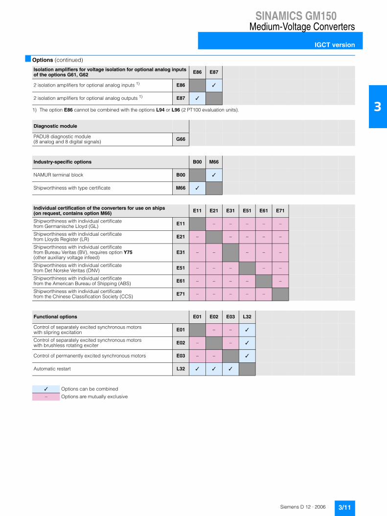
SINAMICS GM150Medium-Voltage Converters
IGCT version
3/11Siemens D 12 · 2006
3
■ Options (continued)
1) The option E86 cannot be combined with the options L94 or L96 (2 PT100 evaluation units).
Isolation amplifiers for voltage isolation for optional analog inputs of the options G61, G62 E86 E87
2 isolation amplifiers for optional analog inputs 1) E86 ✓
2 isolation amplifiers for optional analog outputs 1) E87 ✓
Diagnostic module
PADU8 diagnostic module (8 analog and 8 digital signals) G66
Industry-specific options B00 M66
NAMUR terminal block B00 ✓
Shipworthiness with type certificate M66 ✓
Individual certification of the converters for use on ships (on request, contains option M66) E11 E21 E31 E51 E61 E71
Shipworthiness with individual certificate from Germanische Lloyd (GL) E11 – – – – –
Shipworthiness with individual certificate from Lloyds Register (LR) E21 – – – – –
Shipworthiness with individual certificate from Bureau Veritas (BV), requires option Y75 (other auxiliary voltage infeed)
E31 – – – – –
Shipworthiness with individual certificate from Det Norske Veritas (DNV) E51 – – – – –
Shipworthiness with individual certificate from the American Bureau of Shipping (ABS) E61 – – – – –
Shipworthiness with individual certificate from the Chinese Classification Society (CCS) E71 – – – – –
Functional options E01 E02 E03 L32
Control of separately excited synchronous motors with slipring excitation E01 – – ✓
Control of separately excited synchronous motors with brushless rotating exciter E02 – – ✓
Control of permanently excited synchronous motors E03 – – ✓
Automatic restart L32 ✓ ✓ ✓
✓ Options can be combined
– Options are mutually exclusive

SINAMICS GM150Medium-Voltage Converters
IGCT version
3/12 Siemens D 12 · 2006
3
■ Options (continued)
1) The equipment-specific documents (circuit diagrams etc.) are available only in English/German.
Documentation (standard: PDF format in English on CD-ROM) D00 D02 D15 D56 D72 D77 D78 D84 D92 Y10
Documentation in German D00 ✓ ✓ – – – – – – ✓
Circuit diagrams, terminal diagrams and dimension drawings in DXF format 1) D02 ✓ ✓ ✓ ✓ ✓ ✓ ✓ ✓ ✓
One set of printed documentation (can be ordered in multiples) D15 ✓ ✓ ✓ ✓ ✓ ✓ ✓ ✓ ✓
Documentation in Russian (on request) D56 – ✓ ✓ – – – – – ✓
Documentation in Italian (on request) D72 – ✓ ✓ – – – – – ✓
Documentation in French (on request) D77 – ✓ ✓ – – – – – ✓
Documentation in Spanish D78 – ✓ ✓ – – – – – ✓
Documentation in Chinese D84 – ✓ ✓ – – – – – ✓
Documentation in Japanese (on request) D92 – ✓ ✓ – – – – – ✓
Circuit diagrams with customer-specific text field (plain text required) 1) Y10 ✓ ✓ ✓ ✓ ✓ ✓ ✓ ✓ ✓
Rating plate language (standard: English/German) T58 T60 T80 T85 T90 T91
Rating plate in English/French T58 – – – – –
Rating plate in English/Spanish T60 – – – – –
Rating plate in English/Italian T80 – – – – –
Rating plate in English/Russian (on request) T85 – – – – –
Rating plate in English/Japanese (on request) T90 – – – – –
Rating plate in English/Chinese (on request) T91 – – – – –
Auxiliary voltage supply
Auxiliary voltage other than 3 AC 400 V (primary voltage and frequency must be indicated in plain text) Y75
✓ Options can be combined
– Options are mutually exclusive

SINAMICS GM150Medium-Voltage Converters
IGCT version
3/13Siemens D 12 · 2006
3
■ Options (continued)
1) The option F77 can be ordered only in connection with the option F73.
1) The option Y40 includes a cooling system which is adapted to the untreated water data according to the customer’s specifications.
Converter acceptance inspections in presence of customer F03 F73 F77 F97
Visual acceptance of converter F03 – – –
Functional acceptance of converter with inductive load F73 – ✓ –
Acceptance inspection of the converter insulation test 1) F77 – ✓ –
Customer-specific converter acceptance inspections (on request) F97 – – –
Recooling unit (standard: recooling unit with redundant pumps and one high-grade steel plate heat exchanger) W02 W11 W12 W14 W20 Y40
Recooling unit with redundant pumps and redundant high-grade steel plate heat exchangers W02 – – – ✓ –
Recooling unit with redundant pumps and one titanium plate heat exchanger W11 – – – ✓ –
Recooling unit with redundant pumps and redundant titanium plate heat exchangers W12 – – – ✓ –
Converter without recooling unit (provided on the installation side) W14 – – – – –
Untreated water connection from below W20 ✓ ✓ ✓ – ✓
Untreated water data deviating from the technical data1) (on request) Y40 – – – – ✓
Miscellaneous options L50 L53 L55 Y09
Cabinet lighting and service socket in control section L50 ✓ ✓ ✓
UPS for power supply from controller and closed-loop control L53 ✓ ✓ ✓
Anti-condensation heating for cabinet unit L55 ✓ ✓ ✓
Special paint finish to RAL .... (in a color other than RAL 7035; plain text required) Y09 ✓ ✓ ✓
✓ Options can be combined
– Options are mutually exclusive

SINAMICS GM150Medium-Voltage Converters
IGCT version
3/14 Siemens D 12 · 2006
3
■ Technical data
General technical data
Power components Diodes/IGCTs
Converter on the mains side
• Standard 12-pulse diode rectifier (Basic Line Module)
• Option 24-pulse diode rectifier (Basic Line Module)
Converter on the machine side Inverter (Motor Module)
Closed-loop control Transvector closed-loop control
Drive quadrants 2 (driving 2 directions of rotation)
Voltage isolation of power section/controller and closed-loop control
Optical conductor, isolating transformer
Auxiliary current supply (for fans, coolant pumps, precharging the DC link capacitors, controller and close-loop control)
• 1 230 V AC � 10%, 50/60 Hz � 3% and• 3 400 V AC �10%, 50/60 Hz �3%or another auxiliary voltage (option Y75)
Installation altitude � 1000 m above sea level: capacity 100%> 1000 m to 4000 m above sea level: current derating required> 2000 m to 4000 m above sea level: voltage derating required in addition
Insulation according to DIN EN 50178/VDE 0160 (IEC 62103): pollution degree 2 (without conductive pollution), condensation not permitted
Degree of protection according to EN 60529/VDE 0470 T1 (IEC 60529): IP43
Protection class according to DIN EN 61140/VDE 0140 T1 (IEC 61140): 1
Shock-hazard protection BGV A 3
Interference transmission according to DIN EN 61800-3/VDE 0160 T100 (IEC 61800-3): no RI suppression
Paint finish/color Indoor requirements/RAL 7035, light gray
Compliance with standards
• Standards - EN 61800-3/VDE 0160 T100 (IEC 61800-3)- EN 61800-4/VDE 0160 T104 (IEC 61800-4)- EN 60146-1-1/VDE 0558 T11 (IEC 60146-1-1)- EN 50178/VDE 0160 T100 (IEC 62103)- EN 60204-11/VDE 0113 T11 (IEC 60204-11)
• EU directives - 98/37/EC + amendments (Machinery Directive)- 89/336/EEC + amendments (Electromagnetic Compatibility)
Water cooling Water-water recooling unit, internal circuit, deionized water (fresh water)
Permitted coolant temperature (untreated water)
• Inlet + 5 °C to + 35 °C
• Outlet max. + 40 °C
Rated data
Output voltage 3.3 kV
Input voltage 2 x 1.7 kV
Tolerance of input voltage � 10%
Power frequency 50/60 Hz � 3%
Power factor fundamental mode > 0.96

SINAMICS GM150Medium-Voltage Converters
IGCT version
3/15Siemens D 12 · 2006
3
■ Technical data (continued)
Note: The values specified under storage and transport apply to unpacked converters.
Operation of asynchronous motors Operation of separately excited synchronous motors
without speed encoder with speed encoder with speed encoder
Control properties
Operating range
• Lower limit of speed control range(% of rated motor speed)
5% 0% 0%
• Max. permissible output frequency 250 Hz 250 Hz 90 Hz
• Field-shunting range 1:3 1:3 1:4
Stationary operation
• Speed accuracy(% of rated motor speed)
� 0.2%(from 5% rated speed)
� 0.01% � 0.01%
• Torque accuracy(% of rated torque)
� 5%(from 5% rated speed)
� 5% � 2%
Dynamic operation
• Torque rise time 5 ms 5 ms 5 ms
Storage Transport Operation
Climatic ambient conditions
Ambient temperature – 25 °C to + 70 °C – 25 °C to + 70 °C + 5 °C to + 40 °C
Relative air humidity 5% to 95%(only slight condensation permit-ted; converter must be completely dry before commissioning)
5% to 75% 5% to 85%(condensation not permitted)
Other climatic conditions according to class
1K3 according to EN 60721-3-1 (IEC 60721-3-1)(icing not permitted)
2K2 according to EN 60721-3-2 (IEC 60721-3-2)
3K3 according to EN 60721-3-3 (IEC 60721-3-3)
Degree of pollution 2 without conductive pollution according to EN 50178/VDE 0160 (IEC 62103)
2 without conductive pollution according to EN 50178/VDE 0160 (IEC 62103)
2 without conductive pollution according to EN 50178/VDE 0160 (IEC 62103)
Mechanical ambient conditions
Dynamic stress
• Deflection 1.5 mm at 2 Hz to 9 Hz 3.5 mm at 2 Hz to 9 Hz 0.3 mm at 2 Hz to 9 Hz
• Acceleration 5 m/s2 at 9 Hz to 200 Hz 10 m/s2 at 9 Hz to 200 Hz15 m/s2 at 200 Hz to 500 Hz
1 m/s2 at 9 Hz to 200 Hz
Other mechanical conditions according to class (greater strength for ship compatibility)
1M2 according to EN 60721-3-1 (IEC 60721-3-1)
2M2 according to EN 60721-3-2 (IEC 60721-3-2)
3M1 according to EN 60721-3-3 (IEC 60721-3-3)
Other ambient conditions
Biological ambient conditions according to class
1B1 according to EN 60721-3-1 (IEC 60721-3-1)
2B1 according to EN 60721-3-2 (IEC 60721-3-2)
3B2 according to EN 60721-3-3 (IEC 60721-3-3)(without harmful flora)
Chemically active materials according to class
1C1 according to EN 60721-3-1 (IEC 60721-3-1)
2C1 according to EN 60721-3-2 (IEC 60721-3-2)
3C2 according to EN 60721-3-3 (IEC 60721-3-3)(no occurrence of salt mist)
Mechanically active materials according to class
1S1 according to EN 60721-3-1 (IEC 60721-3-1)
2S1 according to EN 60721-3-2 (IEC 60721-3-2)
3S1 according to EN 60721-3-3 (IEC 60721-3-3)

SINAMICS GM150Medium-Voltage Converters
IGCT version
3/16 Siemens D 12 · 2006
3
■ Technical data (continued)
Installation conditions and derating data
Current derating
If the converters are operated at installation altitudes > 1000 m above sea level or under coolant temperatures > 35 °C, derating factors kH and kT must be taken into account for the rated cur-rent (DIN 43671).
Derating factor kT with air cooling
Derating factor kT with water cooling
Derating factor kH with air cooling
Derating factor kH with water cooling
For the permitted continuous current I: I � In � kH � kT
I: permitted continuous currentIn: rated current
When determining the current derating factor, it is essential to consider the ambient temperature of the air as well as the tem-perature of the untreated water in the inlet, as components such as the link busbars are also subject to air cooling. This requires the factors kT and kH to be determined from the diagrams for air cooling as well as for water cooling. The smaller of the two products (kT � kH) must be used as the current derating factor (see the following example).
Voltage derating
At installation altitudes > 2000 m, a voltage derating is required in addition to a current correction (EN 60664-1/VDE 0110 (IEC 60664-1)). This depends on the air and creepage distances in the unit.
Derating factor kU
10 20 30 405 45°C
Cor
rect
ion
fact
or
0.95
0.90
1.00
Coolant temperatureG
_D01
2_E
N_0
0025
k T
5 10 20 30 40 4535
Cor
rect
ion
fact
or
0.95
0.90
1.00
Untreated water inlet temperature
k T
°C
G_D
012_
EN
_000
26
kH
1000 2000 3000 40000 m
Cor
rect
ion
fact
or
G_D
012_
EN
_000
27
0.9
0.8
0.6
1.0
0.7
Installation altitude above sea level
1000 2000 3000 40000 m
Cor
rect
ion
fact
or
G_D
012_
EN
_000
28
k H 0.9
0.8
0.6
1.0
0.7
Installation altitude above sea level
k U
1000 2000 3000 40000 m
Cor
rect
ion
fact
or
G_D
012_
EN
_000
29
0.9
0.8
0.6
1.0
0.7
Installation altitude above sea level

SINAMICS GM150Medium-Voltage Converters
IGCT version
3/17Siemens D 12 · 2006
3
■ Technical data (continued)
The technical data from the following examples can be found on page 3/16.
Example 1
Converter 6SL3835-2LN43-6AA0
Output voltage: 2 x 3.3 kV
Input voltage: 2 � (2 � 1.7 kV)
Type rating: 19000 kVA, 2 � 1660 A
Installation altitude: 2000 m
Max. ambient temperature: 35 °C
Untreated water inlet temperature: 40 °C• Ambient temperature:
- Derating factor kH = 0.9- Derating factor kT = 1.0- Derating factor kU = 1.0
• Untreated water inlet temperature: - Derating factor kH = 0.925- Derating factor kT = 0.925- Derating factor kU = 1.0
The smaller value for kT � kH results in this case from the dia-grams for the untreated water in the inlet.
I � In � 0.925 � 0.925 = In � 0.856
A current derating of 14.4% is required.
The maximum available output current of the converter is 1420 A per subsystem.
Example 2
Converter 6SL3835-2LN43-6AA0
Output voltage: 2 x 3.3 kV
Input voltage: 2 � (2 � 1.7 kV)
Type rating: 19000 kVA, 2 � 1660 A
Installation altitude: 2000 m
Max. ambient temperature: 45 °C
Untreated water inlet temperature: 30 °C• Ambient temperature:
- Derating factor kH = 0.9- Derating factor kT = 0.925- Derating factor kU = 1.0
• Untreated water inlet temperature: - Derating factor kH = 0.925- Derating factor kT = 1.0- Derating factor kU = 1.0
The smaller value for kT � kH results in this case from the dia-grams for the ambient temperature.
I � In � 0.9 � 0.925 = In � 0.833
A current derating of 16.7% is required.
The maximum available output current of the converter is 1382 A per subsystem.
Example 3
Converter 6SL3835-2LN43-6AA0
Output voltage: 2 x 3.3 kV
Input voltage: 2 � (2 � 1.7 kV)
Type rating: 19000 kVA, 2 � 1660 A
Installation altitude: 1000 m
Max. ambient temperature: 45 °C
Untreated water inlet temperature: 38 °C• Ambient temperature
- Derating factor kH = 1.0- Derating factor kT = 0.925- Derating factor kU = 1.0
• Untreated water inlet temperature: - Derating factor kH = 1.0- Derating factor kT = 0.955- Derating factor kU = 1.0
The smaller value for kT � kH results in this case from the dia-grams for the ambient temperature.
I � In � 1.0 � 0.925 = In � 0.925
A current derating of 7.5% is required.
The maximum available output current of the converter is 1536 A per subsystem.

SINAMICS GM150Medium-Voltage Converters
IGCT version
3/18 Siemens D 12 · 2006
3
■ Technical data
SINAMICS GM150 as IGCT versionWater cooling
Type 6SL3835-2LN41-8AA0
6SL3835-2LN42-8AA0
6SL3835-2LN43-6AA0
6SL3835-2LN44-2AA0
6SL3835-2LN45-4AA0
Output voltage 3.3 kV
Type rating kVA 10000 16000 19000 24000 28000
Shaft output 1) kW 9000 13000 17000 20000 2) 25000 2)
hp 12000 18000 23000 27000 2) 33000 2)
Rated output current A 1750 2 � 1400 2 � 1660 3 � 1400 3 � 1630
Input voltage kV 2 � 1.7 2 � (2 � 1.7) 2 � (2 � 1.7) 3 � (2 � 1.7) 3 � (2 � 1.7)
Rated input current 1) A 2 � 1550 2 � (2 � 1420) 2 � (2 � 1470) 3 � (2 � 1240) 3 � (2 � 1450)
Power loss 3) 4) kW 80 128 160 192 240
Efficiency 4) % 99.1 99.1 99.1 99.1 99.1
Max. AC current requirement 50/60 Hz, 230 V
A 3 6 6 9 9
Max. AC current requirement of auxiliary supply 3 50/60 Hz, 400 V
A 17 20 20 23 23
Precharging current requirement, temporary for approx. 25 s
A 20 40 40 60 60
Cooling water throughput (untreated water/fresh water)
l/min 205 410 410 615 615
Sound pressure level LpA dB(A) 75 77 77 79 79
Measuring surface measurement Ls dB(A) 22 23 23 24 24
Cable cross-sections, line side, max. which can be connected per phase 5)
mm2
(DIN VDE)6 � 240 6 � 240 6 � 240 6 � 240 6 � 240
AWG/MCM(NEC, CEC)
6 � 500 MCM 6 � 500 MCM 6 � 500 MCM 6 � 500 MCM 6 � 500 MCM
Cable cross-sections, motor side, max. which can be connected per phase5)
mm2
(DIN VDE)6 � 240 6 � 240 6 � 240 6 � 240 6 � 240
AWG/MCM(NEC, CEC)
6 � 500 MCM 6 � 500 MCM 6 � 500 MCM 6 � 500 MCM 6 � 500 MCM
PE connection, max. connection cross-section at enclosure with M12 screw 5)
mm2
(DIN VDE)2 � 120 2 � 120 2 � 120 2 � 120 2 � 120
AWG/MCM(NEC, CEC)
2 � 250 MCM 2 � 250 MCM 2 � 250 MCM 2 � 250 MCM 2 � 250 MCM
Degree of protection IP43 IP43 IP43 IP43 IP43
Dimensions (with doors and walls)
• Width mm 5300 9400 9400 14300 14800
• Height mm 2540 2540 2540 2540 2540
• Depth mm 1600 1600 1600 1600 1600
Circuit version - / / 0 0
Weight kg 5400 9800 9800 15000 15400
1) The figures for the rated input current and the output figures in hp and kW are approximate values which were determined for operation with asynchronous motors and for a typical value of the cos phi power factor and efficiency of the motor. The hp figures are based on the NEC and CEC directives for the North American market. The kW values are quoted in steps which can be divided by 1000. Both approximate values need to be adapted to the motor which is actually used.
2) The basic circuit version is based on a drive group in which the drives operate both as motors and generators (see circuit version). Energy is exchanged by means of the DC link. The specified power corresponds to the infeed power.
3) Approx. 5% of the power loss is dissipated into the atmosphere.4) Without cooling system.5) Figures refer to a subsystem; please refer to “Circuit Versions”
for the number of subsystems to be connected on the line and motor side.

Siemens D 12 · 2006
44/2 Overview
4/2 Benefits
4/2 Design
4/6 Function
4/8 Selection and ordering data
4/8 Options
Technical data4/14 General technical data4/15 Control properties4/15 Ambient conditions4/16 Installation conditions and derating
data4/18 Converter-related technical data
SINAMICS SM150

SINAMICS SM150Medium-Voltage Converters
SINAMICS SM150
4/2 Siemens D 12 · 2006
4
■ Overview
SINAMICS SM150
Water-cooled regenerative feedback SINAMICS SM150 convert-ers are available as single or multi-motor drives with the stan-dard medium voltage IGCT power semiconductors. With multi-motor drives, a common DC bus enables the direct exchange of energy in generator and motor applications.
IGCT converters are available for the following voltage and out-puts:
The rated output in the concrete application will depend on the necessary load cycle. The transient maximum outputs are 10.5 MVA, 20 MVA and 30 MVA.
Global use
SINAMICS SM150 converters are manufactured to international standards and regulations, making them ideally suited for global use. These converters are also available in ship-going form (meeting the requirements of all major classification organiza-tions).
■ Benefits
7 Compact design and high flexibility in configuration ensures easy plant integration
7 Easy operation and observation on the convenient operator panel
7 Easy and reliable operation through integrated maintenance functions: the converter signals early and automatically if maintenance is required or components need to be ex-changed
7 High robustness and reliability thanks to the use of IGCT power semiconductors in the high performance range and fuseless assembly combined with intelligent reaction to exter-nal interference
7 Can be easily integrated into automation solutions due to PROFIBUS interface supplied as standard and analog and digital interfaces
7 High level of service-friendliness through innovative power unit design with compact phase components and easy access to all components
7 Assists system cost effectiveness by enabling reactive power to be made available to other drives given suitable configura-tion
■ Design
Active Line Modules and Motor Modules share an almost identi-cal structure with both the single-motor and the multi-motor drive. Phase components in which IGCTs, diodes etc. are grouped together in one compact system are used in both.
Single-motor drive
With a single-motor drive, one Active Line Module and one Motor Module are connected “back-to-back” in the basic circuit by means of a DC link.
For greater output ratings, two or three complete converter units with isolated DC links are operated in parallel.
Multi-motor drive
With multi-motor drives, up to four power sections are operated on the common DC bus. In addition to the Active Line Module, three Motor Modules with three motors can be operated on the common DC bus with utilization of the direct exchange of energy.
The converter consists of cabinet units for the Active Line Mod-ule and for the Motor Module. One of three phase components and the control section in the Motor Module cabinet unit are highlighted in the illustration.
SINAMICS GM150, internal configuration (without recooling unit)
Rated output voltage
Max. continuous power(without overload capability)
Output(175% overload capability)
3.3 kV 10 MVA to 28 MVA 5 MVA to 17 MVA
Active Line Module
IGCT phase
module
Motor Module
Control
G_
D0
12
_E
N_
00
01
6

SINAMICS SM150Medium-Voltage Converters
SINAMICS SM150
4/3Siemens D 12 · 2006
4
■ Design (continued)
Block diagram
3
3
G_
D0
12
_E
N_
00
01
7
MV motor
Motor-side pts and cts
Motor Module(3-level NPC inverter)with IGCT
DC link withdry-type capacitors
Active Line Module(3-level NPC inverter)with IGCT
Converter transformer
Circuit-breaker
Line-side pts
Line-side cts
2.3 kV to 36 kV 50/60 Hz 3 AC

SINAMICS SM150Medium-Voltage Converters
SINAMICS SM150
4/4 Siemens D 12 · 2006
4
■ Design (continued)
The following wiring versions are available for SINAMICS SM150.
Basic circuit Two converter units may be operated in parallel in order to increase the output (with reduction of circuit feedbacks in addition) 1)
Three converter units may be operated in parallel in order to increase the output (with reduction of circuit feedbacks in addition) 1)
3
3
G_
D0
12
_X
X_
00
01
8
13
33
33
G_
D0
12
_X
X_
00
01
9
14
3
3
3 3
3 3
G_
D0
12
_X
X_
00
02
0
15
1) Requires a motor with isolated winding systems

SINAMICS SM150Medium-Voltage Converters
SINAMICS SM150
4/5Siemens D 12 · 2006
4
■ Design (continued)
DC bus configuration with two motors on common DC link DC bus configuration with three motors on common DC link
On the DC bus configurations with two or three motors, energy can be exchanged through the joint DC link by means of alter-nate operation as a motor and generator. This results in savings in the Active Line Module, the transformers and the circuit-breakers. These configurations are used mainly for single-stand cold rolling mills with a coiler and for transmission test stands.
3
33
G_
D0
12
_X
X_
00
02
1
16
3
333
G_
D0
12
_X
X_
00
02
2
17

SINAMICS SM150Medium-Voltage Converters
SINAMICS SM150
4/6 Siemens D 12 · 2006
4
■ Function
Characteristic features
Software and protection functions
SINAMICS SM150
Line Module (rectifier on mains side)
Active Line Module (four-quadrant operation)
Standard
Motor Module (rectifier on motor side)
Voltage range 3.3 kV
Performance range (typ.) 5 MVA to 28 MVA
Cooling method
• Water cooling Standard
Control modes
• Asynchronous motor Standard
• Synchronous motor, separately excited
Option
• Synchronous motor, permanently excited
Option
DC bus configuration with several Motor Modules on one common DC bus
Standard
SINAMICS SM150 Description
Closed-loop control The machine-side closed-loop control has been expanded as a field-oriented transvector closed-loop control which can be operated as a speed or torque control as required. The transvector closed-loop control achieves the dynamics of a DC drive. This is made possible by the fact that the current components forming the torque and flux can be controlled precisely independently of each other. Prescribed torques can thus be observed and limited accurately. In the speed range from 1:10, the field-oriented closed-loop control does not require an actual speed value encoder.An actual speed value encoder is required in the following scenarios:• High dynamics requirements• Torque control/constant torque drives with setting range > 1:10• Very low speeds• Very high speed accuracy
Setpoint input The setpoint can be defined internally or externally; internally as a fixed, motorized potentiometer or jog set-point, externally via the PROFIBUS interface or an analog input of the customer terminal block. The internal fixed setpoints and the motorized potentiometer setpoint can be switched over or altered using control com-mands from all interfaces.
Ramp-function generator A user-friendly ramp-function generator with separately adjustable ramp-up and ramp-down times, together with variable smoothing times in the lower and upper speed ranges, improves the control response and there-fore prevents mechanical overloading of the drive train. The ramp-down ramps can be parameterized sepa-rately for emergency stop.
Vdc max controller The Vdc max controller automatically prevents overvoltages in the DC link if the set ramp-down ramp is too short, for example. This can also extend the set ramp-down time.
Kinetic buffering (KIP) Power supply failures are bridged to the extent permitted by the kinetic energy of the drive train. The speed drops depending on the moment of inertia and the load torque. The current speed setpoint is resumed when the power supply returns.
Automatic restart (option) The automatic restart switches the drive on again when the power is restored after a power failure or a general fault, and ramps up to the current speed setpoint.
Flying restart The flying restart function permits smooth connection of the converter to a rotating motor.
Diagnostics functions • Self-diagnosis of control hardware• Non-volatile memory for reliable diagnosis when the power supply fails• Monitoring of HV IGBTs with individual messages for each slot• User-friendly on-site operator panel with plain text messages
Operating hours and switching cycle counter
The operating hours of the fans are recorded and logged so that preventive maintenance or replacements can be performed. The switching cycles of the circuit-breaker are recorded and added together, to form the basis of preventive maintenance work.
Operator protection The cabinet doors of the power sections are fitted with an electromagnetic lock. This prevents the cabinet doors being opened while hazardous voltages are connected inside the cabinet.

SINAMICS SM150Medium-Voltage Converters
SINAMICS SM150
4/7Siemens D 12 · 2006
4
■ Function (continued)
Software and protection functions
SIMATIC OP 177B operator panel
The SIMATIC OP 177B operator panel is fitted into the cabinet door of the SINAMICS SM150 to enable operation, monitoring and commissioning.
It has the following features and characteristics:• 5.7" STN touch display• Context-dependent operations by touch, permanently
available functions can be selected using individual keys• Non-volatile message buffer, no battery
English and German are available as operator panel languages.
SINAMICS SM150 Description
EMERGENCY-STOP button The converters are equipped as standard with an EMERGENCY-STOP button with protective collar which is fitted in the cabinet door. The contacts of the pushbutton are connected in parallel to the terminal block so they can can be integrated in a protection concept on the installation side. EMERGENCY STOP category 0 is set as standard for an uncontrolled shutdown (DIN EN 60204-1/VDE 0113-1 (IEC 60204-1)). The function includes voltage disconnection of the converter output through the circuit-breaker. The motor coasts in the process.EMERGENCY STOP category 1 is optionally available for a controlled shutdown.
Insulation monitoring The converters feature insulation monitoring of the whole galvanic network from the secondary side of the transformer to the stator windings of the motor.
Monitoring of the peripherals An extensive package of options for monitoring the peripherals (from the transformer and the motor through to the auxiliaries) is available. In addition it is possible to monitor the temperature by means of thermocouples or PT100 resistors.
Thermal overload protection A warning message is issued first when the overtemperature threshold responds. If the temperature rises fur-ther, either a shutdown is carried out or automatic influencing of the output current so that a reduction in the thermal load is achieved. Following elimination of the cause of the fault (e.g. improvement in the ventilation), the original operating values are automatically resumed.In the case of water-cooled converters, the water temperature and flow rate are recorded at several points in the cooling circuit and evaluated. An extensive self-diagnosis protects the converter and reports faults.
Grounding switch (option) If grounding on the infeed or motor side is required for safety and protection reasons, a motorized grounding switch can be ordered.For safety reasons, the converter controller locks these grounding switches against activation while voltage is still present. The control is integrated into the protection and monitoring chain of the converter. The grounding switches are inserted automatically when the standard grounding switches of the DC link are inserted.

SINAMICS SM150Medium-Voltage Converters
SINAMICS SM150
4/8 Siemens D 12 · 2006
4
■ Selection and ordering data
■ Options
When ordering a converter with options, add “-Z” to the order number of the converter, followed by the order code(s) for the desired option(s).
Example:
6SL3845-7NN41-8AA0-Z+L08+L60+...
In the following tables, related options are arranged in groups. Whether the options can be combined or are mutually exclusive is indicated within these groups. A detailed description of the options can be found in the chapter Description of Options.
Type rating Shaft output Rated output current SINAMICS SM150 Circuit ver-sions (pages 4/4 and 4/5)
kVA kW hp A Order No. Fig. No.
Output voltage 3.3 kV
10000 10000 13000 1750 6SL3845-7NN41-8AA0 1
19000 19000 25000 2 � 1660 6SL3845-7NN43-6AA0 2
28000 28000 36000 3 � 1630 6SL3845-7NN45-4AA0 3
10000 10000 13000 2 � 1750 1) 6SL3845-7NN41-8AB0 4
10000 10000 13000 3 � 1750 2) 6SL3845-7NN41-8AC0 5
Output-side options
Output reactor L08
Protective functions L48 L49 L51 L52 L60 M10
Grounding switch at converter input (motorized) L48 ✓ ✓ ✓ ✓ ✓
Grounding switch at converter output (motorized) L49 ✓ ✓ ✓ ✓ ✓
Isolator at converter output L51 ✓ ✓ – ✓ ✓
Circuit-breaker at converter output L52 ✓ ✓ – ✓ ✓
EMERGENCY STOP category 1 L60 ✓ ✓ ✓ ✓ ✓
Safety locking system M10 ✓ ✓ ✓ ✓ ✓
✓ Options can be combined
– Options are mutually exclusive
1) Configuration with two motors which operate on a joint DC link. By means of alternate operation as a motor and generator, energy is exchanged through the joint DC link. Differences in the energy balance are equalized through the infeed (active infeed).
2) Configuration with three motors which operate on a joint DC link. By means of alternate operation as a motor and generator, energy is exchanged through the joint DC link. Differences in the energy balance are equalized through the infeed (active infeed).

SINAMICS SM150Medium-Voltage Converters
SINAMICS SM150
4/9Siemens D 12 · 2006
4
■ Options (continued)
1) A TM31 Terminal Module is required for further processing and display of the signals or analog outputs (option G61).2) Two TM31 Terminal Modules are required for further processing and display of the signals and analog outputs (options G61 and G62).
The options L94 and L96 cannot be combined with the option E86 (2 isolation amplifiers for optional analog inputs).
Temperature sensing and analysis (standard: 3 PT100 inputs) L80 L81 L82 L90 L91 L92 L93 L94 L95 L96
2 thermistor motor protection relays for warnings and faults 1) L80 – – ✓ ✓ ✓ ✓ ✓ ✓ ✓
2 x 2 thermistor motor protection relays for warnings and faults 1) L81 – – ✓ ✓ ✓ ✓ ✓ ✓ ✓
3 x 2 thermistor motor protection relays for warnings and faults 1) L82 – – ✓ ✓ ✓ ✓ ✓ ✓ ✓
PT100 evaluation unit with 3 inputs 1) L90 ✓ ✓ ✓ – – – – – –
2 PT100 evaluation units with 3 inputs each 1) L91 ✓ ✓ ✓ – – – – – –
3 PT100 evaluation units with 3 inputs each 1) L92 ✓ ✓ ✓ – – – – – –
PT100 evaluation unit with 6 inputs, 2 analog outputs(outputs for display connected to controller) 1) L93 ✓ ✓ ✓ – – – – – –
2 PT100 evaluation units each with 6 inputs and 2 analog outputs(outputs for display connected to controller) 2)
L94 ✓ ✓ ✓ – – – – – –
PT100 evaluation unit with 6 inputs for hazardous areas, 2 analog outputs(outputs for display connected to controller) 1)
L95 ✓ ✓ ✓ – – – – – –
2 PT100 evaluation units each with 6 inputs for hazardous areas and 2 analog outputs(outputs for display connected to controller) 2)
L96 ✓ ✓ ✓ – – – – – –
Control of auxiliaries N30 N31 N32 N33 N35 N36 N37 N38
The contractor is switched on with the ON command at the converter and switched off with the OFF command (example: separate fans on the motor). The supply voltage for the drive to be powered must be provided externally.
Controlled output for auxiliaries 3 AC 400 V, max. 4 kW N30 – – – ✓ ✓ ✓ ✓
Controlled output for auxiliaries 3 AC 400 V, max. 7 kW N31 – – – ✓ ✓ ✓ ✓
Controlled output for auxiliaries 3 AC 400 V, max. 11 kW N32 – – – ✓ ✓ ✓ ✓
Controlled output for auxiliaries 3 AC 400 V, max. 15 kW N33 – – – ✓ ✓ ✓ ✓
The contractor is switched off with the ON command at the converter and switched on with the OFF command (example: heater).The supply voltage for the drive to be powered must be provided externally.
Controlled outgoing circuit for auxiliaries 1 230 V AC, max. 1 kW N35 ✓ ✓ ✓ ✓ – – –
Controlled outgoing circuit for auxiliaries 1 230 V AC, max. 2 kW N36 ✓ ✓ ✓ ✓ – – –
Controlled outgoing circuit for auxiliaries 1 230 V AC, max. 3 kW N37 ✓ ✓ ✓ ✓ – – –
Controlled outgoing circuit for auxiliaries 1 230 V AC, max. 4 kW N38 ✓ ✓ ✓ ✓ – – –
✓ Options can be combined
– Options are mutually exclusive

SINAMICS SM150Medium-Voltage Converters
SINAMICS SM150
4/10 Siemens D 12 · 2006
4
■ Options (continued)
1) The option E86 cannot be combined with the options L94 or L96 (2 PT100 evaluation units).
Connection of signal cables (standard: signal cable connected directly to the terminals of the Terminal Modules) M32 M33
Customer terminal block with spring-loaded terminals for signal cables up to 2.5 mm2 M32 –
Customer terminal block with screw-type terminals for signal cables up to 2.5 mm2 M33 –
Control and display instruments in the door of the control cabinet unit K20 K21 K22
Indicator lights and Start/Stop button in the cabinet door K20 – –
Display instruments in the cabinet door for voltage, current, speed and output as well as indicator lights and Start/Stop button
K21 – –
Display instruments in the cabinet door for current, speed, output and winding temperature as well as indicator lights and Start/Stop button
K22 – –
Interface modules for additional customer connections G61 G62 G63
Additional TM31 Terminal Module G61 ✓ ✓
Second additional TM31 Terminal Module G62 ✓ ✓
Additional TM15 Terminal Module G63 ✓ ✓
Isolation amplifiers for voltage isolation for optional analog inputs of the options G61, G62 E86 E87
2 isolation amplifiers for optional analog inputs 1) E86 ✓
2 isolation amplifiers for optional analog outputs 1) E87 ✓
Other interface modules G66 M10 G70 G71
PADU8 diagnostic module (8 analog and 8 digital signals) G66 ✓ ✓ ✓
Safety locking system M10 ✓ ✓ ✓
Pulse distributor for forwarding the speed encoder signal G70 ✓ ✓ ✓
Optical bus terminal (OBT) for PROFIBUS G71 ✓ ✓ ✓
✓ Options can be combined
– Options are mutually exclusive

SINAMICS SM150Medium-Voltage Converters
SINAMICS SM150
4/11Siemens D 12 · 2006
4
■ Options (continued)
1) The equipment-specific documents (circuit diagrams etc.) are available only in English/German.
Industry-specific options
NAMUR terminal block B00
Functional options E01 E02 E03 L32
Control of separately excited synchronous motors with slipring excitation E01 – – ✓
Control of separately excited synchronous motors with brushless rotating exciter E02 – – ✓
Control of permanently excited synchronous motors E03 – – ✓
Automatic restart L32 ✓ ✓ ✓
Documentation (standard: PDF format in English on CD-ROM) D00 D02 D15 D56 D72 D77 D78 D84 D92 Y10
Documentation in German D00 ✓ ✓ – – – – – – ✓
Circuit diagrams, terminal diagrams and dimension drawings in DXF format 1) D02 ✓ ✓ ✓ ✓ ✓ ✓ ✓ ✓ ✓
One set of printed documentation (can be ordered in multiples) D15 ✓ ✓ ✓ ✓ ✓ ✓ ✓ ✓ ✓
Documentation in Russian (on request) D56 – ✓ ✓ – – – – – ✓
Documentation in Italian (on request) D72 – ✓ ✓ – – – – – ✓
Documentation in French (on request) D77 – ✓ ✓ – – – – – ✓
Documentation in Spanish D78 – ✓ ✓ – – – – – ✓
Documentation in Chinese D84 – ✓ ✓ – – – – – ✓
Documentation in Japanese (on request) D92 – ✓ ✓ – – – – – ✓
Circuit diagrams with customer-specific text field (plain text required) 1) Y10 ✓ ✓ ✓ ✓ ✓ ✓ ✓ ✓ ✓
✓ Options can be combined
– Options are mutually exclusive

SINAMICS SM150Medium-Voltage Converters
SINAMICS SM150
4/12 Siemens D 12 · 2006
4
■ Options (continued)
1) The option F77 can be ordered only in connection with the option F73.
1) The option Y40 includes a cooling system which is adapted to the untreated water data according to the customer’s specifications.
Rating plate language (standard: English/German) T58 T60 T80 T85 T90 T91
Rating plate in English/French T58 – – – – –
Rating plate in English/Spanish T60 – – – – –
Rating plate in English/Italian T80 – – – – –
Rating plate in English/Russian (on request) T85 – – – – –
Rating plate in English/Japanese (on request) T90 – – – – –
Rating plate in English/Chinese (on request) T91 – – – – –
Converter acceptance inspections in presence of customer F03 F73 F77 F97
Visual acceptance of converter F03 – – –
Functional acceptance of converter with inductive load F73 – ✓ –
Acceptance inspection of the converter insulation test 1) F77 – ✓ –
Customer-specific converter acceptance inspections (on request) F97 – – –
Recooling unit (standard: recooling unit with redundant pumps and one high-grade steel plate heat exchanger)
W02 W11 W12 W14 Y40
Recooling unit with redundant pumps and redundant high-grade steel plate heat exchangers W02 – – – –
Recooling unit with redundant pumps and one titanium plate heat exchanger W11 – – – –
Recooling unit with redundant pumps and redundant titanium plate heat exchangers W12 – – – –
Converter without recooling unit (provided on the installation side) W14 – – – –
Untreated water data deviating from the technical data 1) (on request) Y40 – – – –
✓ Options can be combined
– Options are mutually exclusive

SINAMICS SM150Medium-Voltage Converters
SINAMICS SM150
4/13Siemens D 12 · 2006
4
■ Options (continued)
Miscellaneous options L50 L55 Y09
Cabinet lighting and service socket in control section L50 ✓ ✓
Anti-condensation heating for cabinet unit L55 ✓ ✓
Special paint finish to RAL .... (in a color other than RAL 7035; plain text required) Y09 ✓ ✓
✓ Options can be combined
– Options are mutually exclusive

SINAMICS SM150Medium-Voltage Converters
SINAMICS SM150
4/14 Siemens D 12 · 2006
4
■ Technical data
General technical data
Power components IGCTs
Converter on the mains side Regulated, self-commutating feed/feedback unit (Active Line Module)
Converter on the machine side Inverter (Motor Module)
Closed-loop control Transvector closed-loop control
Drive quadrants 4 (driving and braking per 2 directions of rotation)
Voltage isolation of power section/controller and closed-loop control
Optical conductor, isolating transformer
Auxiliary current supply (for fans, coolant pumps, precharging the DC link capacitors, controller and close-loop control)
• 1 230 V AC � 10%, 50/60 Hz � 3% and• 3 400 V AC ��10%, 50/60 Hz ��3%
Installation altitude � 1000 m above sea level: capacity 100%> 1000 m to 4000 m above sea level: current derating required> 2000 m to 4000 m above sea level: voltage derating required in addition
Insulation according to DIN EN 50178/VDE 0160 (IEC 62103): pollution degree 2 (without conductive pollution), condensation not permitted
Degree of protection according to EN 60529/VDE 0470 T1 (IEC 60529): IP43
Protection class according to DIN EN 61140/VDE 0140 T1 (IEC 61140): 1
Shock-hazard protection BGV A 3
Interference transmission according to DIN EN 61800-3/VDE 0160 T100 (IEC 61800-3): no RI suppression
Paint finish/color Indoor requirements/RAL 7035, light gray
Compliance with standards
• Standards - EN 61800-3/VDE 0160 T100 (IEC 61800-3)- EN 61800-4/VDE 0160 T104 (IEC 61800-4)- EN 60146-1-1/VDE 0558 T11 (IEC 60146-1-1)- EN 50178/VDE 0160 T100 (IEC 62103)- EN 60204-11/VDE 0113 T11 (IEC 60204-11)
• EU directives - 98/37/EC + amendments (Machinery Directive)- 89/336/EEC + amendments (Electromagnetic Compatibility)
Water cooling Water-water recooling unit, internal circuit, deionized water (fresh water)
Permitted coolant temperature (untreated water)
• Inlet + 5 °C to + 35 °C
• Outlet max. + 40 °C
Rated data
Output voltage 3.3 kV
Input voltage 3.3 kV
Tolerance of input voltage � 10%
Power frequency 50/60 Hz � 3%
Power factor fundamental mode 1

SINAMICS SM150Medium-Voltage Converters
SINAMICS SM150
4/15Siemens D 12 · 2006
4
■ Technical data (continued)
Note: The values specified under storage and transport apply to unpacked converters.
Operation of asynchronous motors Operation of separately excited synchronous motors
without speed encoder with speed encoder with speed encoder
Control properties
Operating range
• Lower limit of speed control range(% of rated motor speed)
5% 0% 0%
• Max. permissible output frequency 250 Hz 250 Hz 90 Hz
• Field-shunting range 1:3 1:3 1:4
Stationary operation
• Speed accuracy(% of rated motor speed)
� 0.2%(from 5% rated speed)
� 0.01% � 0.01%
• Torque accuracy(% of rated torque)
� 5%(from 5% rated speed)
� 5% � 2%
Dynamic operation
• Torque rise time 5 ms 5 ms 5 ms
Storage Transport Operation
Climatic ambient conditions
Ambient temperature – 25 °C to + 70 °C – 25 °C to + 70 °C + 5 °C to + 40 °C
Relative air humidity 5% to 95%(only slight condensation permit-ted; converter must be completely dry before commissioning)
5% to 75% 5% to 85%(condensation not permitted)
Other climatic conditions according to class
1K3 according to EN 60721-3-1 (IEC 60721-3-1)(icing not permitted)
2K2 according to EN 60721-3-2 (IEC 60721-3-2)
3K3 according to EN 60721-3-3 (IEC 60721-3-3)
Degree of pollution 2 without conductive pollution according to EN 50178/VDE 0160 (IEC 62103)
2 without conductive pollution according to EN 50178/VDE 0160 (IEC 62103)
2 without conductive pollution according to EN 50178/VDE 0160 (IEC 62103)
Mechanical ambient conditions
Dynamic stress
• Deflection 1.5 mm at 2 Hz to 9 Hz 3.5 mm at 2 Hz to 9 Hz 0.3 mm at 2 Hz to 9 Hz
• Acceleration 5 m/s2 at 9 Hz to 200 Hz 10 m/s2 at 9 Hz to 200 Hz15 m/s2 at 200 Hz to 500 Hz
1 m/s2 at 9 Hz to 200 Hz
Other mechanical conditions according to class (greater strength for ship compatibility)
1M2 according to EN 60721-3-1 (IEC 60721-3-1)
2M2 according to EN 60721-3-2 (IEC 60721-3-2)
3M1 according to EN 60721-3-3 (IEC 60721-3-3)
Other ambient conditions
Biological ambient conditions according to class
1B1 according to EN 60721-3-1 (IEC 60721-3-1)
2B1 according to EN 60721-3-2 (IEC 60721-3-2)
3B2 according to EN 60721-3-3 (IEC 60721-3-3)(without harmful flora)
Chemically active materials according to class
1C1 according to EN 60721-3-1 (IEC 60721-3-1)
2C1 according to EN 60721-3-2 (IEC 60721-3-2)
3C2 according to EN 60721-3-3 (IEC 60721-3-3)(no occurrence of salt mist)
Mechanically active materials according to class
1S1 according to EN 60721-3-1 (IEC 60721-3-1)
2S1 according to EN 60721-3-2 (IEC 60721-3-2)
3S1 according to EN 60721-3-3 (IEC 60721-3-3)

SINAMICS SM150Medium-Voltage Converters
SINAMICS SM150
4/16 Siemens D 12 · 2006
4
■ Technical data (continued)
Installation conditions and derating data
Current derating
If the converters are operated at installation altitudes > 1000 m above sea level or under coolant temperatures > 35 °C, derating factors kH and kT must be taken into account for the rated cur-rent (DIN 43671).
Derating factor kT with air cooling
Derating factor kT with water cooling
Derating factor kH with air cooling
Derating factor kH with water cooling
For the permitted continuous current I: I � In � kH � kT
I: permitted continuous currentIn: rated current
When determining the current derating factor, it is essential to consider the ambient temperature of the air as well as the tem-perature of the untreated water in the inlet, as components such as the link busbars are also subject to air cooling. This requires the factors kT and kH to be determined from the diagrams for air cooling as well as for water cooling. The smaller of the two products (kT � kH) must be used as the current derating factor (see the following example).
Voltage derating
At installation altitudes > 2000 m, a voltage derating is required in addition to a current correction (EN 60664-1/VDE 0110 (IEC 60664-1)). This depends on the air and creepage distances in the unit.
Derating factor kU
10 20 30 405 45°C
Cor
rect
ion
fact
or
0.95
0.90
1.00
Coolant temperatureG
_D01
2_E
N_0
0025
k T
5 10 20 30 40 4535
Cor
rect
ion
fact
or
0.95
0.90
1.00
Untreated water inlet temperature
k T
°C
G_D
012_
EN
_000
26
kH
1000 2000 3000 40000 m
Cor
rect
ion
fact
or
G_D
012_
EN
_000
27
0.9
0.8
0.6
1.0
0.7
Installation altitude above sea level
1000 2000 3000 40000 m
Cor
rect
ion
fact
or
G_D
012_
EN
_000
28
k H 0.9
0.8
0.6
1.0
0.7
Installation altitude above sea level
k U
1000 2000 3000 40000 m
Cor
rect
ion
fact
or
G_D
012_
EN
_000
29
0.9
0.8
0.6
1.0
0.7
Installation altitude above sea level

SINAMICS SM150Medium-Voltage Converters
SINAMICS SM150
4/17Siemens D 12 · 2006
4
■ Technical data (continued)
The technical data from the following examples can be found on page 4/16.
Example 1
Converter 6SL3845-7NN41-8AA0
Output voltage: 3.3 kV
Input voltage: 3.3 kV
Type rating: 10000 kVA, 1750 A
Installation altitude: 2000 m
Max. ambient temperature: 35 °C
Untreated water inlet temperature: 40 °C• Ambient temperature:
- Derating factor kH = 0.9- Derating factor kT = 1.0- Derating factor kU = 1.0
• Untreated water inlet temperature: - Derating factor kH = 0.925- Derating factor kT = 0.925- Derating factor kU = 1.0
The smaller value for kT � kH results in this case from the dia-grams for the untreated water in the inlet.
I � In � 0.925 � 0925 = In � 0.856
A current derating of 14.4% is required.
The maximum available output current of the converter is 1497 A.
Example 2
Converter 6SL3845-7NN41-8AA0
Output voltage: 3.3 kV
Input voltage: 3.3 kV
Type rating: 10000 kVA, 1750 A
Installation altitude: 2000 m
Max. ambient temperature: 43 °C
Untreated water inlet temperature: 37 °C• Ambient temperature:
- Derating factor kH = 0.9- Derating factor kT = 0.955- Derating factor kU = 1.0
• Untreated water inlet temperature: - Derating factor kH = 0.925- Derating factor kT = 0.97- Derating factor kU = 1.0
The smaller value for kT � kH results in this case from the dia-grams for the ambient temperature.
I � In � 0.9 � 0.955 = In � 0.86
A current derating of 14% is required.
The maximum available output current of the converter is 1504 A.

SINAMICS SM150Medium-Voltage Converters
Water cooling
4/18 Siemens D 12 · 2006
4
■ Technical data (continued)
SINAMICS SM150Water cooling
Type 6SL3845-7NN41-8AA0
6SL3845-7NN43-6AA0
6SL3845-7NN45-4AA0
6SL3845-7NN41-8AB0
6SL3845-7NN41-8AC0
Output voltage 3.3 kV
Type rating kVA 10000 19000 28000 10000 10000
Shaft output1) kW 10000 19000 28000 10000 2) 10000 2)
hp 13000 25000 36000 13000 2) 13000 2)
Rated output current A 1750 2 � 1660 3 � 1630 2 � 1750 3 � 1750
Input voltage kV 3.3 2 � 3.3 3 � 3.3 3.3 3.3
Rated input current 1) A 1770 2 � 1680 3 � 1650 1770 1770
Power loss 3) 4) kW 100 200 300 150 225
Efficiency 4) % 99.0 99.0 98.9 99.3 99.2
Max. AC current requirement 50/60 Hz, 230 V
A 6 12 18 9 12
Max. AC current requirement of auxiliary supply 3 50/60 Hz, 400 V
A 17 20 23 19 20
Precharging current requirement, temporary for approx. 25 s
A 20 40 60 22 24
Cooling water throughput (untreated water/fresh water)
l/min 325 650 975 435 650
Sound pressure level LpA dB(A) 75 77 79 76 77
Measuring surface measurement Ls dB(A) 22 23 24 22,5 23
Cable cross-sections, line side, max. which can be connected per phase 5)
mm2
(DIN VDE)6 � 240 6 � 240 6 � 240 6 � 240 6 � 240
AWG/MCM(NEC, CEC)
6 � 500 MCM 6 � 500 MCM 6 � 500 MCM 6 � 500 MCM 6 � 500 MCM
Cable cross-sections, motor side, max. which can be connected per phase 5)
mm2
(DIN VDE)6 � 240 6 � 240 6 � 240 6 � 240 6 � 240
AWG/MCM(NEC, CEC)
6 � 500 MCM 6 � 500 MCM 6 � 500 MCM 6 � 500 MCM 6 � 500 MCM
PE connection, max. connection cross-section at enclosure with M12 screw 5)
mm2
(DIN VDE)2 � 120 2 � 120 2 � 120 2 � 120 2 � 120
AWG/MCM(NEC, CEC)
2 � 250 MCM 2 � 250 MCM 2 � 250 MCM 2 � 250 MCM 2 � 250 MCM
Degree of protection IP43 IP43 IP43 IP43 IP43
Dimensions (with doors and walls)
• Width mm 6100 11200 16300 8900 11700
• Height mm 2540 2540 2540 2540 2540
• Depth mm 1600 1600 1600 1600 1600
Circuit version 1 2 3 4 5
Weight kg 6400 11800 17200 9300 12200
1) The figures for the rated input current and the output figures in hp and kW are approximate values which were determined for operation with synchronous motors, for the power factor cos phi = 1 and taking into account the efficiency of the motor.The hp figures are based on the NEC and CEC directives for the North American market.The kW values are quoted in steps which can be divided by 1000.Both approximate values need to be adapted to the motor which is actually use.
2) The basic circuit version is based on a drive group in which the drives operate both as motors and generators (see circuit version). Energy is exchanged by means of the DC link. The specified power corresponds to the infeed power.
3) Approx. 5% of the power loss is dissipated into the atmosphere.4) Without cooling system.5) Figures refer to a subsystem; please refer to “Circuit Versions”
for the number of subsystems to be connected on the line and motor side.

Siemens D 12 · 2006
55/2 B00
5/3 D00 to D92E01 to E03
5/4 E11 to E87F03 to F97
5/5 G20 to G62
5/6 G63 to G71
5/7 K20 to K50L08 and L21
5/8 L29 and L32
5/9 L48 to L51
5/10 L53 to L60
5/11 L80 to L87
5/12 L90 to L92
5/13 L93 and L94
5/14 L95 and L96
5/15 M10 to M34
5/16 M42 to M78
5/17 N13 to N22
5/18 N30 to N38
5/19 T58 to T91U01W02 to W20
5/20 Y09 to Y75
Description of options

Description of optionsSINAMICS GM150/SINAMICS SM150
Description of options
5/2 Siemens D 12 · 2006
5
■ Options
To enable the required description to be found more easily, the following option descriptions are sorted alphabetically by order codes. If an option is only available for certain converter config-urations, this is indicated in brackets after the option title.
B00
NAMUR terminal block
The terminal block is designed according to the requirements and directives of the standards association for measurement and control in the chemical industry (NAMUR recommendation NE37), i.e. fixed terminals are assigned to certain functions of the devices. The inputs and outputs assigned to the terminals comply with “Protective extra-low voltage PELV” requirements.
Options for PTC tripping units with PTB approval and PT100 evaluation units for use in areas at risk of explosion can be obtained in order to monitor the temperature of explosion-proof motors.
This terminal block and the associated functions are reduced to the required amount. In comparison to the NAMUR recommen-dation, optional terminals are not listed.
Configuration of the NAMUR terminal block
If PT100 resistance thermometers are fitted in the windings of the motor in order to protect the motor, PT100 evaluation units for hazardous areas are available with the options L95 and L96.
If a forced-ventilated machine is used due to the application (load torque/control range), controlled outgoing circuits fused by means of motor circuit-breakers are available with the options N30 to N33 to enable supply to an external fan. The incoming voltage supply for the external fan must be provided on the in-stallation side.
1U2, 1V2, 1W2
AC
DC
DC
AC
1U1, 1V1, 1W1 2U1, 2V1, 2W1
Circuit-breaker
Converter transformer
=.EB-X1:1
=.EB-X1:2
Auxiliary supply of auxiliary systems
400 V 3 AC (e. g. separately driven
fan) =.GC-X1:1
=.GC-X1:2
=.GC-X1:3
=.GC-X1:4
=.GC-X1:5
=.GC-X1:6
Auxiliary supply of auxiliary systems
230 V 1 AC (e. g. anti-condensation
heating of the motor)=.GC-X1:7
=.GC-X1:8
=.GC-X1:9
=.GC-X1:10
Motor connection
G_
D0
12
_E
N_
00
02
3
=.EA-Q11:1
=.EA-Q11:3
=.EA-Q11:5
Auxiliary power supply 230 V 1 AC
Auxiliary power supply 400 V 3 AC
Terminal No. Type Preassignment Comment
For signal lines that must meet “Protective extra-low voltage PELV” requirements
–A1–X2 1 M Reference con-ductor to 24 V DC infeed
–
2, 3 P24 24 V DC infeed With internal 1 A fuse
10 DI ON (dynamic) / ON/OFF(static)
–
11 DI OFF (dynamic) –
12 DI Faster –
13 DI Slower –
14 DI RESET –
15 DI Interlock –
16 DI Counterclockwise “0” signal for CW phase sequence “1” signal for CCW phase sequence
17, 18
PS disconnection EMERGENCY STOP sequence
30, 31
Ready to run Relay output (NO contact)
32, 33
Motor rotates Relay output (NO contact)
34 DO (NO) Fault Relay output (changeover contact)35 DO (COM)
36 DO (NC)
50/51 AI 0/4 mA to 20 mA
Speed setpoint –
60/61 AO 0/ 4 mA to 20 mA
Motor frequency –
62, 63 AO 0/ 4 mA to 20 mA
Motor current Motor current is default setting; can be reparameterized for other variables
For connecting the PTC sensor of the motor
–A1–X3 90/91 AI Connection of a PTC sensor
Motor current is default setting; can be reparameterized for other variables

Description of optionsSINAMICS GM150/SINAMICS SM150
Description of options
5/3Siemens D 12 · 2006
5
■ Options (continued)
D00 to D92
Documentation
The standard documentation is supplied in English on CD-ROM. The circuit diagrams/terminal diagrams are available only in English/German.
E01
Control of separately excited synchronous motors with slipring excitation (for exciter units see Accessories)
If the converter is to be used to control separately excited synchronous motors with slipring excitation, put the code E01 in the order. For slipring excitation, the exciter cabinet must also be ordered. It has its own order number.
Note: The converter and exciter cabinet must be ordered together.
Note: The option E01 is available on request with the option U01 (version of the converter for NAFTA with UL listing).
E02
Control of separately excited synchronous motors with brushless (RG) reverse field excitation (for exciter units see Accessories)
If the converter is to be used to control separately excited syn-chronous motors with brushless (RG) reverse field excitation, put the code E02 in the order. For brushless excitation, the exciter cabinet must also be ordered. It has its own order number.
Note: The converter and exciter cabinet must be ordered together.
Note: The option E02 is available on request with the option U01 (version of the converter for NAFTA with UL listing).
E03
Control of permanently excited synchronous motors (SINAMICS GM150 as IGCT version and SINAMICS SM150)
If the converter is to be used to control permanently excited syn-chronous motors, put the code E03 in the order.
Option Description
D00 Documentation in GermanUse the code D00 to obtain the documentation in German on CD-ROM.
D02 Circuit diagrams, terminal diagrams and dimension drawings in DXF formatDocuments such as circuit diagrams, terminal diagrams, the arrangement diagram and the dimension drawing with the code D02 are ordered in DXF format so that they can be processed in AutoCAD systems, for instance.
D15 One set of printed documentation (can be ordered in multiples)If documentation is also required on paper, this must be ordered using the code D15.
D56 Documentation in Russian (on request)Use the code D56 to obtain the documentation in Russian on CD-ROM.
D72 Documentation in Italian (on request)Use the code D72 to obtain the documentation in Italian on CD-ROM.
D77 Documentation in French (on request)Use the code D77 to obtain the documentation in French on CD-ROM.
D78 Documentation in SpanishUse the code D78 to obtain the documentation in Spanish on CD-ROM.
D84 Documentation in ChineseUse the code D84 to obtain the documentation in Chinese on CD-ROM.
D92 Documentation in Japanese (on request)Use the code D92 to obtain the documentation in Japanese on CD-ROM.

Description of optionsSINAMICS GM150/SINAMICS SM150
Description of options
5/4 Siemens D 12 · 2006
5
■ Options (continued)
E11 to E71 (SINAMICS GM150 as water-cooled IGBT version, SINAMICS GM150 as IGCT version on request)
Individual certification of the converter by the relevant certifying organizations, including the extensions described under the option M66
Note: It is not possible to combine several individual certificates.
E86
Isolation amplifiers for optional analog inputs
If an additional TM31 Terminal Module is provided to extend the customer’s interface and if the analog inputs of the TM31 are to be used for communication with a higher control level, two isola-tion amplifiers are available with the option E86. Multirange transformers are used (setting range: 0 V to 10 V; 0 mA to 20 mA or 4 mA to 20 mA).
Note: The option E86 cannot be combined with the option L94 (2 PT100 evaluation units, each with 6 inputs and 2 analog out-puts). The option E86 requires two additional TM31 Terminal Modules (options G61 and G62).
E87
Isolation amplifiers for optional analog outputs
If an additional TM31 Terminal Module is provided to extend the customer’s interface and if the analog outputs of the TM31 are to be used for communication with a higher control level, two isola-tion amplifiers are available with the option E87. Multirange transformers are used (setting range: 0 V to 10 V; 0 mA to 20 mA or 4 mA to 20 mA).
Note: The option E87 requires two additional TM31 Terminal Modules (options G61 and G62).
F03, F73, F77, F97
Converter acceptance inspections in presence of customer
Note: An acceptance inspection of exciter units according to the options F03, F73, F77 and F97 is possible only together with the converter which must be ordered simultaneously.
Option Description
E11 Shipworthiness with individual certificate from Germanische Lloyd (GL)includes option M66
E21 Shipworthiness with individual certificate from Lloyds Register (LR)includes option M66
E31 Shipworthiness with individual certificate from Bureau Veritas (BV)includes option M66, requires option Y75 (other auxiliary voltage than 3 AC 400 V)
E51 Shipworthiness with individual certificate from Det Norske Veritas (DNV)includes option M66
E61 Shipworthiness with individual certificate from the American Bureau of Shipping (ABS)includes option M66
E71 Shipworthiness with individual certificate from the Chinese Classification Society (CCS)includes option M66
Option Description
F03 Visual inspectionThe checks are carried out with the converter deenergized.• The following points should be included in the inspection:
- Check of degree of protection- Check of equipment (components)- Check of equipment identifier- Check of clearance and creepage distances- Check of cables- Check of customer documentation- Submitting the acceptance report
F73 Functional acceptance of the converter with inductive load (SINAMICS GM150 as IGBT version, others on request)After the visual inspection with the converter off, the converter is connected to rated voltage. Rated current flows in an inductive load at an output frequency of 5 Hz (without con-nector motor) on the converter output side.• The following points should be included in the inspection:
- Visual inspection as described for option F03 - Check of power supply- Check of protective and monitoring devices (simulation)- Check of fans (or cooling unit in the case of water cooling)- Precharging test- Functional test with inductive load at rated voltage and
rated current- Submitting the acceptance report
F77 Acceptance of the converter insulation test (SINAMICS GM150 as IGBT version, others on request)• The following points should be included in the inspection:
- High-voltage test- Measurement of insulation resistance
The insulation test can be ordered only in conjunction with the option F73.
F97 Customer-specific converter acceptance inspections (on request)If converter acceptance inspections are desired which are not covered by the options F03, F73 or F77, customer-spe-cific acceptance inspections/supplementary tests can be ordered on request using the order code F97 following tech-nical clarification.

Description of optionsSINAMICS GM150/SINAMICS SM150
Description of options
5/5Siemens D 12 · 2006
5
■ Options (continued)
G20 to G25
Access to other bus systems (SINAMICS GM150 as IGBT version)
In the standard version the SINAMICS GM150 and SINAMICS SM150 are equipped with a PROFIBUS interface (slave). Other interface modules are available on request.
G30
PROFIBUS master (SINAMICS GM150 with exciter unit, see Accessories)
SINAMICS GM150 converters can communicate as standard only as PROFIBUS slaves. A SIMATIC CPU with PROFIBUS master capability is used therefore in conjunction with a SINAMICS GM150 converter.
G61
Additional TM31 Terminal Module
One TM31 Terminal Module and two TM15 Terminal Modules for integrating warning and fault messages and drive signals and for communicating with a higher control level are already in-cluded in the standard version of the converter. If the number of signals to be monitored is not sufficient, the interface can also be extended by an additional Terminal Module. Additional digital in-puts and outputs and two analog inputs and outputs are avail-able with the TM31. These can be used e.g. for reading in tem-peratures (see the options L93 to L96).
The TM31 Terminal Module has:• 8 digital inputs• 4 bidirectional digital inputs and outputs• 2 relay outputs with changeover contact• 2 analog inputs• 2 analog outputs• 1 temperature sensor input (KTY84-130 or PTC)
If the analog inputs and outputs of the optional TM31 are to be used for communication with the control level, isolating trans-formers are available as an additional option.
G62
Second additional TM31 Terminal Module
A second TM31 Terminal Module can be ordered under code G62 provided that option G61 is chosen as well (see description under option G61).
Option Description
G20 CAN bus interface (CANopen, on request)
G21 Modbus Plus interface
G22 Modbus RTU slave interface
G23 DeviceNet interface
G24 PROFINET interface (on request)
G25 Teleservice connection (on request)
TM31 Terminal Module
Digital inputs
• Voltage – 3 V to + 30 V
• Low level (an open digital input is interpreted as “low”)
– 3 V to + 5 V
• High level 15 V to 30 V
• Current consumption (at 24 V DC)
Typ. 10 mA
• Signal propagation delays for digital inputs
L � H: approx. 50 �sH � L: approx. 100 �s
• Max. connectable cross section 1.5 mm2
Digital outputs (continued-short-circuit-proof)
• Voltage 24 V DC
• Max. load current per digital output 100 mA
• Max. total current of digital outputs 400 mA
• Max. connectable cross section 1.5 mm2
Analog inputs (a switch is used to toggle between voltage and current input)
• As voltage input
- Voltage range – 10 V to + 10 V
- Internal resistance Ri 100 kOhm
• As current input
- Current range 4 mA to 20 mA/– 20 mA to + 20 mA/ 0 mA to 20 mA
- Internal resistance Ri 250 Ohm
- Resolution 11 bit, + sign
• Max. connectable cross section 1.5 mm2
Analog outputs (continued-short-circuit-proof)
• Voltage range – 10 V to + 10 V
• Max. load current – 3 mA to + 3 mA
• Current range 4 mA to 20 mA, – 20 mA to + 20 mA, 0 mA to 20 mA
• Max. load resistance 500 Ohm for outputs in the range – 20 mA to + 20 mA
• Resolution 11 bit, + sign
• Max. connectable cross section 1.5 mm2
Relay outputs (change-over contacts)
• Max. load current 8 A
• Max. switching voltage 250 V AC, 30 V DC
• Max. switching power (at 250 V AC) 2000 VA (cos phi = 1)750 VA (cos phi = 0.4)
• Max. switching power (at 30 V DC) 240 W (ohmic load)
• Required minimum current 100 mA
• Max. connectable cross section 2.5 mm2

Description of optionsSINAMICS GM150/SINAMICS SM150
Description of options
5/6 Siemens D 12 · 2006
5
■ Options (continued)
G63
Additional TM15 Terminal Module
One TM31 Terminal Module and one TM15 Terminal Module for integrating warning and fault messages and drive signals and for communicating with a higher control level are already in-cluded in the standard version of the converter. The number of digital inputs and outputs can be expanded with an additional TM15 Terminal Module. This is recommended if, for instance, external signals are to be read in and processed or external components are to be controlled in addition to the standard customer’s terminal block.
The TM15 Terminal Module has:• 24 bidirectional digital inputs and outputs (voltage isolation in
three groups of eight channels each)• 24 green status LEDs for indicating the logical signal status of
the relevant terminal
G66
PADU8 diagnostic module (SINAMICS GM150 as IGCT version and SINAMICS SM150)
The PADU8 diagnostic module reads out up to eight analog sig-nals and up to eight digital signals from the gating and monitor-ing module of the power section and makes these available for diagnostic purposes or for further processing. The typical detec-tion cycle of all channels in parallel is 1 ms, enabling rapid signal characteristics to be detected and diagnosed simultaneously. The detected values are transferred to an evaluation system (e.g. notebook) either by optical conductors or by an RJ11 socket. All output data are available in parallel at the optical con-ductor output and at the RJ11 socket. This means that measure-ments can be taken in parallel at the RJ11 socket without dis-rupting the transfer of data at the optical conductor. With the option G66 a PADU8 diagnostic module is integrated in the con-trol section of each Motor Module.
G70
Pulse distributor for forwarding the speed encoder signal (SINAMICS SM150)
With this pulse distributor it is possible to split the encoder sig-nal. This possibility is used, for example, when speed list values from an HTL incremental encoder are required at various points for measured-value acquisition and processing.
The pulse distributor transfers the HTL incremental encoder sig-nals to two separate RS422 signal outputs. The inputs are elec-trically isolated from the outputs.
8-pole terminal strips are used for the connections.
G71
Optical bus terminal (OBT) for PROFIBUS (SINAMICS SM150)
The PROFIBUS OBT is a network component for use in optical PROFIBUS DP fieldbus networks. The individual bus stations are linked using two-phase plastic optical conductors, resulting automatically in voltage isolation and preventing potential differ-ences in very expansive installations from having any impact.
The OBT has three interfaces:Channel 1 is an electric RS485 interface which is configured as a 9-pole Sub D socket and establishes the link to the converter controller.Channels 2 and 3 form the optical interface. They are configured as a duplex socket and can be used for connection on the instal-lation side to higher-level systems.
TM15 Terminal Module
Digital inputs
• Voltage – 30 V to + 30 V
• Low level (an open digital input is interpreted as “low”)
– 30 V to + 5 V
• High level 15 V to 30 V
• Current consumption (at 24 V DC) 5 mA to 11 mA
• Signal propagation delays for digital inputs, typical
L � H: 50 �sH � L: 100 �s
• Max. connectable cross section 1.5 mm2
Digital outputs (continued-short-circuit-proof)
• Voltage 24 V DC
• Max. load current per digital output 0.5 A
• Output delay (ohmic load)
- Standard L � H: 50 �sH � L: 150 �s
- Maximum L � H: 100 �sH � L: 225 �s
• Max. total current of outputs (per group)
- Up to 60 °C 2 A
- Up to 50 °C 3 A
- Up to 40 °C 4 A
• Max. connectable cross section 1.5 mm2

Description of optionsSINAMICS GM150/SINAMICS SM150
Description of options
5/7Siemens D 12 · 2006
5
■ Options (continued)
K20
Indicator lights and Start/Stop button in the cabinet door
With option K20, five indicator lights that signal the operating status of the converter are provided in the cabinet door of the control section.• Fault (red)• Warning (yellow)• Operation (green)• Drive ready (white)• Local operation (white)
A Start button (green) and a Stop button (red) are installed in ad-dition in the cabinet door if option K20 is chosen. In Remote Mode these pushbuttons can be used to switch the drive ON and OFF. In Local Mode these pushbuttons are not active.
K21
Display instruments in the cabinet door for voltage, current, speed and output as well as indicator lights and Start/Stop button
To enable process variables to be displayed, analog display instruments that show the measurement parameter as a % are located in the cabinet door.• Motor current (0 to + 120%)• Motor speed (– 120% ... 0 ... 133; + 120%)• Calculated motor output (0 to + 120%)• Motor voltage (0 to + 120%)
Note: Option K21 includes option K20.
K22
Display instruments in the cabinet door for current, speed, output and winding temperature as well as indicator lights and Start/Stop button
To enable process variables to be displayed, analog display instruments that show the measurement parameter as a % are located in the cabinet door. The motor winding temperature is displayed as an absolute value in °C.• Motor current (0 to + 120%)• Motor speed (– 120% ... 0 ... 133; + 120%)• Calculated motor output (0 to + 120%)• Motor winding temperature (0 to 200 °C)
Note: Option K22 includes option K20.
K50
Sensor Module Cabinet-Mounted SMC30 (SINAMICS GM150, standard for SINAMICS SM150)
The SMC30 encoder module can be used to record the actual motor speed. The signals from the rotary pulse encoder are converted here and made available for evaluation via the DRIVE-CLiQ interface of the controller.
The following encoders are supported by the SMC30:• TTL encoders• HTL encoders
The maximum connectable conductor cross-section is 20 mm2.
L08
Output reactor
The output reactor is used to limit the capacitive charge-reversal currents of motor cables. This results in varying cable lengths according to the configuration of the power section (IGBT or IGCT technology).
The output reactor is located in an additional cabinet unit.
L21
Overvoltage protection AC (exciter unit, see Accessories)
Option L21 provides type SICROWBAR integrated overvoltage protection on the input side.
Converter Max. cable lengths
without output reactor (standard)
with output reactor 1) (option L08)
shielded unshielded 2) shielded unshielded 2)
Output voltage 2.3 kV to 7.2 kV
SINAMICSGM150 as IGBT version
up to 2 parallel cables: 100 m3 parallel cables: 80 m>3 parallel cables: not available
not available 1000 m not available
Output voltage 3.3 kV
SINAMICSGM150 as IGCT version
up to 2 parallel cables: 100 m3 parallel cables: on request4 parallel cables: on request
not available 500 m not available
SINAMICSSM150
up to 2 parallel cables: 50 m3 parallel cables: on request4 parallel cables: on request
not available 200 m not available
1) Distance from converter to motor according to current loading for max. 6 parallel three-wire EMC cables.
2) A sinusoidal filter (option Y15) must be provided if unshielded motor cables are used.

Description of optionsSINAMICS GM150/SINAMICS SM150
Description of options
5/8 Siemens D 12 · 2006
5
■ Options (continued)
L29
Bidirectional synchronized bypass mode (SINAMICS GM150 as IGBT version)
Option L29 offers synchronization with seamless (commutating) passing of the motor to the line and receiving of the motor from the line.
The converter synchronizes the motor to the existing line (phase relation, frequency and voltage). The motor is subsequently connected in parallel to the line by means of circuit-breaker S3 before the output-side circuit-breaker S2 opens.
Approx. 100 ms go by according to the response time constants of the two circuit-breakers (opening time and closing time). Within this period of time the motor commutates from the con-verter to the line. This ensures smooth passing of the motor to the line.
If the motor is to be subsequently taken from the line and oper-ated using the converter again, the commutation process is ex-ecuted in the reverse order. The converter is first run up no-load operation and its output voltage is adapted to the line voltage (= motor voltage) in its phase relation, frequency and amplitude. Then circuit-breaker S2 is closed before S3 is opened and the motor is isolated from the line.
This ensures that the motor is received smoothly by the con-verter so that it can be either operated under variable speed or shut down under control. Speed-controlled operation during run-ning up and shutting down does not produce any high starting and peak transient torques that could damage the mechanical connection or cause transient and pressure fluctuations in the process.
With option L29 a VSM10 Voltage Sensing Module is integrated into the converter. When combined with voltage transformers on the medium voltage side, the VSM10 detects the line voltage in phase relation, frequency and amplitude. It thus supplies the data for synchronization of the motor to the line and from the line to the converter. The converter control prepares the drive signals of the two circuit-breakers to be provided on the installation side.
Option L08 (output reactor) or option Y15 (sinusoidal filter) is also required for the decoupling of the converter output during the commutation process.
The S3 circuit-breaker must be configured to the motor as re-gards protection. If temperature sensors are fitted in the motor, these must be monitored on the installation side for the case of mains operation.
Attention: Option L29 is only possible if the converter output voltage is the same as the line voltage.
L32
Automatic restart
Option L32 enables the converter to be restarted after a power failure once the mains supply has been restored.
If such a restart is required for technical reasons, the conditions set out below must be taken into consideration.
The 3 AC 400 V and 1 AC 230 V auxiliary infeed supplies must not fail; this is so that the voltage supply to the fans and coolant pumps and to the controller and closed-loop control is main-tained.
If the main infeed fails, a pulse block is triggered and the DC link is supported through precharging for a short period. It is impor-tant to distinguish between two cases here:
Case A:
The circuit-breaker on the input side is still switched on.
When the medium voltage supply returns, the DC link voltage rises. This is detected by the closed-loop control and the control-ler. Operation is resumed when a threshold value is exceeded.
Case B:
The circuit-breaker on the input side has responded.
After a fixed time (which can be parameterized), the circuit-breaker receives an “ON command”. The response of the DC link voltage is then analyzed.
If the DC link voltage falls, the converter is disconnected.
If the DC link voltage rises, operation is resumed when a threshold value is exceeded.
Depending on the down times, load characteristic and moment of inertia, the drive may be “caught” again or the machine may need to be “excited” again first before operation can be resumed.
With option L32, a VSM10 Voltage Sensing Module that detects the voltage at the medium-voltage level before the circuit-breaker is fitted into the converter. Suitable voltage transformers need to be provided for that purpose at the medium-voltage level before the circuit-breaker. This enables the controller and closed-loop control to detect when the medium voltage returns after a power failure if the circuit-breaker on the input side has dropped out.
For safety reasons, a time limit is built in between the power failure and the maximum permitted line restoration time so that the drive cannot start up again uncontrolled.
A signal is issued in addition when restarting and can be used to generate an acoustic warning.
M
S1 S3
S2
G_
D0
12
_X
X_
00
02
4

Description of optionsSINAMICS GM150/SINAMICS SM150
Description of options
5/9Siemens D 12 · 2006
5
■ Options (continued)
L48
Grounding switch at converter input (motorized)
If grounding on the infeed side is required for safety and protec-tion reasons, a motorized grounding switch can be ordered un-der code L48. The number of grounding switches will depend on the configuration of the infeed supply (12-/24-pulse for SINAMICS GM150 or 6-pulse for SINAMICS SM150).
For safety reasons, the converter controller locks these ground-ing switches against activation while voltage is still present. The control is integrated into the protection and monitoring chain of the converter. The grounding switches are inserted automati-cally when the standard grounding switches of the DC link are inserted.
In the event of maintenance work on the converter, it must be ensured on the installation side that there is no external voltage present, e.g. auxiliary voltage for fans, the cooling system, controller and closed-loop control and any external outputs in the converter.
Attention: Option L48 increases the width of the cabinet unit by 600 mm.
Note: The option L48 is available on request with the option U01 (version of the converter for NAFTA with UL listing).
L49
Grounding switch at converter output (motorized)
With certain operating modes/configurations of the load ma-chine (e.g. drive group with gas turbines) or types of drive ma-chine (e.g. PEM), there can be operating statuses at which there is a risk that energy will be fed back into the converter from the motor. This can lead to dangerous voltages. In these cases a motorized grounding switch for the converter output side can be ordered under code L49. Where power sections are connected in parallel, the number of circuit-breakers will rise accordingly.
For safety reasons, the converter controller locks the grounding switch against activation while voltage is still present. The con-trol is integrated into the protection and monitoring chain of the converter. The grounding switches are inserted automatically when the standard grounding switches of the DC link are in-serted.
Attention: Option L49 increases the width of the cabinet unit by 600 mm.
Note: The option L49 is available on request with the option U01 (version of the converter for NAFTA with UL listing).
L50
Cabinet lighting and service socket in control section
If option L50 is chosen, a universal lamp and a service socket (Schuko version) are installed respectively in the cabinet panels of the control sections for Motor Modules and Active Line Mod-ules.
The voltage for the cabinet lighting and service socket (at termi-nal strip =.EG-X1) is supplied externally and must be fused to no more than 10 A. The cabinet lighting is switched on manually via a switch or automatically by an integrated motion detector. The mode is switch-selected.
Note: In conjunction with the option U01 (version of the converter for NAFTA with UL listing), the option L50 is configured with sup-ply voltage 120 V. In this case the service socket corresponds to the version for the USA.
L51
Isolator at the converter output (SINAMICS GM150 as IGCT version and SINAMICS SM150)
If isolation between the converter output and the drive motor is required for safety and protection reasons, a motorized isolator at the converter output can be ordered under code L51.
Attention: The additional cabinet on the converter makes the cabinet unit wider• in the basic circuit by 600 mm• in the parallel circuit by 2 � 600 mm
Terminal Meaning
=.EG–X1:1 L1 (230 V)
=.EG–X1:2 N
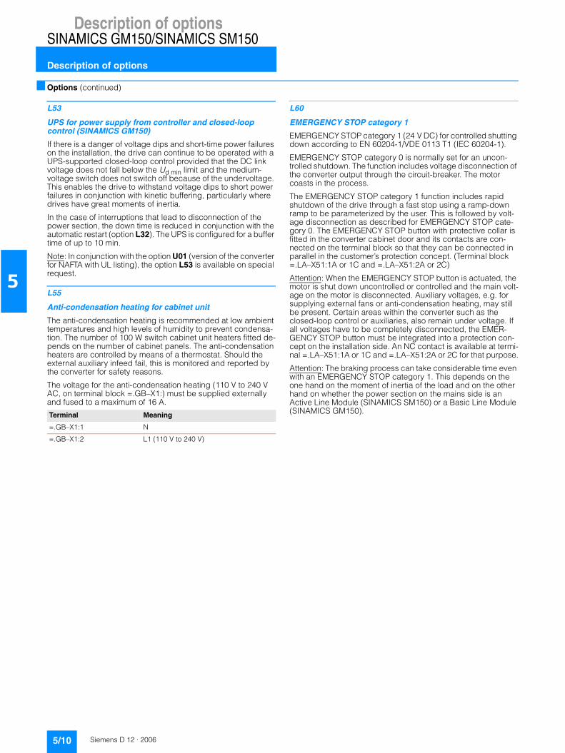
Description of optionsSINAMICS GM150/SINAMICS SM150
Description of options
5/10 Siemens D 12 · 2006
5
■ Options (continued)
L53
UPS for power supply from controller and closed-loop control (SINAMICS GM150)
If there is a danger of voltage dips and short-time power failures on the installation, the drive can continue to be operated with a UPS-supported closed-loop control provided that the DC link voltage does not fall below the Ud min limit and the medium-voltage switch does not switch off because of the undervoltage. This enables the drive to withstand voltage dips to short power failures in conjunction with kinetic buffering, particularly where drives have great moments of inertia.
In the case of interruptions that lead to disconnection of the power section, the down time is reduced in conjunction with the automatic restart (option L32). The UPS is configured for a buffer time of up to 10 min.
Note: In conjunction with the option U01 (version of the converter for NAFTA with UL listing), the option L53 is available on special request.
L55
Anti-condensation heating for cabinet unit
The anti-condensation heating is recommended at low ambient temperatures and high levels of humidity to prevent condensa-tion. The number of 100 W switch cabinet unit heaters fitted de-pends on the number of cabinet panels. The anti-condensation heaters are controlled by means of a thermostat. Should the external auxiliary infeed fail, this is monitored and reported by the converter for safety reasons.
The voltage for the anti-condensation heating (110 V to 240 V AC, on terminal block =.GB–X1:) must be supplied externally and fused to a maximum of 16 A.
L60
EMERGENCY STOP category 1
EMERGENCY STOP category 1 (24 V DC) for controlled shutting down according to EN 60204-1/VDE 0113 T1 (IEC 60204-1).
EMERGENCY STOP category 0 is normally set for an uncon-trolled shutdown. The function includes voltage disconnection of the converter output through the circuit-breaker. The motor coasts in the process.
The EMERGENCY STOP category 1 function includes rapid shutdown of the drive through a fast stop using a ramp-down ramp to be parameterized by the user. This is followed by volt-age disconnection as described for EMERGENCY STOP cate-gory 0. The EMERGENCY STOP button with protective collar is fitted in the converter cabinet door and its contacts are con-nected on the terminal block so that they can be connected in parallel in the customer’s protection concept. (Terminal block =.LA–X51:1A or 1C and =.LA–X51:2A or 2C)
Attention: When the EMERGENCY STOP button is actuated, the motor is shut down uncontrolled or controlled and the main volt-age on the motor is disconnected. Auxiliary voltages, e.g. for supplying external fans or anti-condensation heating, may still be present. Certain areas within the converter such as the closed-loop control or auxiliaries, also remain under voltage. If all voltages have to be completely disconnected, the EMER-GENCY STOP button must be integrated into a protection con-cept on the installation side. An NC contact is available at termi-nal =.LA–X51:1A or 1C and =.LA–X51:2A or 2C for that purpose.
Attention: The braking process can take considerable time even with an EMERGENCY STOP category 1. This depends on the one hand on the moment of inertia of the load and on the other hand on whether the power section on the mains side is an Active Line Module (SINAMICS SM150) or a Basic Line Module (SINAMICS GM150).Terminal Meaning
=.GB–X1:1 N
=.GB–X1:2 L1 (110 V to 240 V)

Description of optionsSINAMICS GM150/SINAMICS SM150
Description of options
5/11Siemens D 12 · 2006
5
■ Options (continued)
L80
2 thermistor protection relays for warnings and faults
Option L80 offers two thermistor protection relays (with PTB approval) for PTC thermistors (type A) for warning and discon-nection. The power supply for the relay and the evaluation is provided within the converter.
Attention: An additional TM31 Terminal Module (option G61) is required for further processing and display of the signals.
L81
2 x 2 thermistor protection relays for warnings and faults
Option L81 offers four thermistor protection relays (with PTB approval) for PTC thermistors (type A) for warning and discon-nection. The power supply for the relay and the evaluation is provided within the converter.
Attention: An additional TM31 Terminal Module (option G61) is required for further processing and display of the signals.
L82
3 x 2 thermistor protection relays for warnings and faults
Option L81 offers six thermistor protection relays (with PTB approval) for PTC thermistors (type A) for warning and discon-nection. The power supply for the relay and the evaluation is provided within the converter.
Attention: An additional TM31 Terminal Module (option G61) is required for further processing and display of the signals.
L87
Rotor ground-fault monitoring (exciter unit, see Accessories)
Option L87 provides integrated ground-fault monitoring for the rotor circuit.
Terminal Meaning (warning)
=.LF–A11:T1 Connection of sensor loop
=.LF–A11:T2 Connection of sensor loop
Terminal Meaning (disconnection)
=.LF–A12:T1 Connection of sensor loop
=.LF–A12:T2 Connection of sensor loop
Terminal Meaning (warning)
=.LF–A11:T1 Connection of sensor loop
=.LF–A11:T2 Connection of sensor loop
Terminal Meaning (disconnection)
=.LF–A12:T1 Connection of sensor loop
=.LF–A12:T2 Connection of sensor loop
Terminal Meaning (warning)
=.LF–A21:T1 Connection of sensor loop
=.LF–A21:T2 Connection of sensor loop
Terminal Meaning (disconnection)
=.LF–A22:T1 Connection of sensor loop
=.LF–A22:T2 Connection of sensor loop
Terminal Meaning (warning)
=.LF–A31:T1 Connection of sensor loop
=.LF–A31:T2 Connection of sensor loop
Terminal Meaning (disconnection)
=.LF–A32:T1 Connection of sensor loop
=.LF–A32:T2 Connection of sensor loop

Description of optionsSINAMICS GM150/SINAMICS SM150
Description of options
5/12 Siemens D 12 · 2006
5
■ Options (continued)
L90
PT100 evaluation unit with 3 inputs
The PT100 evaluation unit can monitor up to three sensors. The sensors can be connected using a two-wire or three-wire sys-tem. For all three sensors, the limits for warning and disconnec-tion must be set centrally.
The output relays are integrated into the internal fault and shut-down sequence of the converter. The signals can also be picked up in the installation side by means of two spare fault signaling relays.
Attention: An additional TM31 Terminal Module (option G61) is required for further processing and display of the signals.
In a two-wire system inputs xT1 and xT2 must be assigned and a bridge inserted between terminals xT2 and xT3.
L91
2 PT100 evaluation units with 3 inputs each
Each PT100 evaluation unit can monitor up to three sensors. For all three sensors, the limits for warning and disconnection must be set centrally.
The output relays are integrated into the internal fault and shut-down sequence of the converter. The signals can also be picked up in the installation side by means of two spare fault signaling relays.
Attention: An additional TM31 Terminal Module (option G61) is required for further processing and display of the signals.
The sensors can be connected using a two-wire or three-wire system. In a two-wire system inputs xT1 and xT2 must be as-signed and a bridge inserted between terminals xT2 and xT3.
L92
3 PT100 evaluation units each with 3 inputs (SINAMICS GM150 as IGCT version and SINAMICS SM150)
Each PT100 evaluation unit can monitor up to three sensors. For all three sensors, the limits for warning and disconnection must be set centrally.
The output relays are integrated into the internal fault and shut-down sequence of the converter. The signals can also be picked up in the installation side by means of two spare fault signaling relays.
Attention: An additional TM31 Terminal Module (option G61) is required for further processing and display of the signals.
The sensors can be connected using a two-wire or three-wire system. In a two-wire system inputs xT1 and xT2 must be as-signed and a bridge inserted between terminals xT2 and xT3.
Terminal Meaning
=.LJ–A11:1T1 to 1T3 PT100; sensor 1
=.LJ–A11:2T1 to 2T3 PT100; sensor 2
=.LJ–A11:3T1 to 3T3 PT100; sensor 3
Terminal Meaning
=.LJ–A11:1T1 to 1T3 PT100; sensor 1
=.LJ–A11:2T1 to 2T3 PT100; sensor 2
=.LJ–A11:3T1 to 3T3 PT100; sensor 3
Terminal Meaning
=.LJ–A12:1T1 to 1T3 PT100; sensor 1
=.LJ–A12:2T1 to 2T3 PT100; sensor 2
=.LJ–A12:3T1 to 3T3 PT100; sensor 3
Terminal Meaning
=.LJ–A11:1T1 to 1T3 PT100; sensor 1
=.LJ–A11:2T1 to 2T3 PT100; sensor 2
=.LJ–A11:3T1 to 3T3 PT100; sensor 3
Terminal Meaning
=.LJ–A12:1T1 to 1T3 PT100; sensor 1
=.LJ–A12:2T1 to 2T3 PT100; sensor 2
=.LJ–A12:3T1 to 3T3 PT100; sensor 3
Terminal Meaning
=.LJ–A21:1T1 to 1T3 PT100; sensor 1
=.LJ–A21:2T1 to 2T3 PT100; sensor 2
=.LJ–A21:3T1 to 3T3 PT100; sensor 3

Description of optionsSINAMICS GM150/SINAMICS SM150
Description of options
5/13Siemens D 12 · 2006
5
■ Options (continued)
L93
PT100 evaluation unit with 6 inputs and 2 analog outputs (outputs for display connected to controller)
The PT100 evaluation unit can monitor up to six sensors. The limit values can be programmed by the user for each channel.
In the standard setting, the measuring channels are divided into two groups of three channels each. With motors, for example, three PT100 can, therefore, be monitored in the stator windings and two PT100 in the motor bearings. Channels that are not used can be suppressed using appropriate parameter settings.
The output relays are integrated into the internal fault and shut-down sequence of the converter. The signals can also be picked up in the installation side by means of two spare fault signaling relays. Two freely programmable analog outputs (0/4 mA to 20 mA and 0/2 V to 10 V) are also available.
Attention: An additional TM31 Terminal Module (option G61) is required for further processing and display of the signals and analog outputs.
L94
2 PT100 evaluation units each with 6 inputs and 2 analog outputs (outputs for display connected to controller; SINAMICS GM150 as IGCT version and SINAMICS SM150)
Option L94 offers two PT100 evaluation units as described un-der option L93, enabling up to 12 sensors in total to be moni-tored.
Attention: Two TM31 Terminal Modules (options G61 and G62) are required for further processing and display of the signals and analog outputs.
Note: The option L94 cannot be combined with the option E86 (2 isolation amplifiers for optional analog inputs).
Terminal Meaning
=.LG–A11:T11 to T13 PT100; sensor 1; group 1
=.LG–A11:T21 to T23 PT100; sensor 2; group 1
=.LG–A11:T31 to T33 PT100; sensor 3; group 1
=.LG–A11:T41 to T43 PT100; sensor 1; group 2
=.LG–A11:T51 to T53 PT100; sensor 2; group 2
=.LG–A11:T61 to T63 PT100; sensor 3; group 2
The sensors can be connected to the PT100 evaluation unit using both a two-wire or three-wire system. In a two-wire system inputs Tx1 and Tx3 must be assigned. In a three-wire system, input Tx2 must also be connected (x = 1, 2 , ..., 6).
=.LG–A11:11/12/14 Relay output limit for group 1 reached (warning); changeover contact
=.LG–A11:21/22/24 Relay output limit for group 1 reached (fault); changeover contact
=.LG–A11:T1 (OUT 1) Analog output OUT 1; sensor group 1
=.LG–A11:I1 (OUT 1) Analog output OUT 1; sensor group 1
=.LG–A11:31/32/34 Relay output limit for group 2 reached (warning); changeover contact
=.LG–A11:41/42/44 Relay output limit for group 2 reached (fault); changeover contact
=.LG–A11:T2 (OUT 2) Analog output OUT 2; sensor group 2
=.LG–A11:I2 (OUT 2) Analog output OUT 2; sensor group 2
Terminal Meaning
=.LG–A21:T11 to T13 PT100; sensor 1; group 3
=.LG–A21:T21 to T23 PT100; sensor 2; group 3
=.LG–A21:T31 to T33 PT100; sensor 3; group 3
=.LG–A21:T41 to T43 PT100; sensor 1; group 4
=.LG–A21:T51 to T53 PT100; sensor 2; group 4
=.LG–A21:T61 to T63 PT100; sensor 3; group 4
The sensors can be connected to the PT100 evaluation unit using both a two-wire or three-wire system. In a two-wire system inputs Tx1 and Tx3 must be assigned. In a three-wire system, input Tx2 must also be connected (x = 1, 2 , ..., 6).
=.LG–A21:11/12/14 Relay output limit for group 3 reached (warning); changeover contact
=.LG–A21:21/22/24 Relay output limit for group 3 reached (fault); changeover contact
=.LG–A21:T1 (OUT 1) Analog output OUT 1; sensor group 3
=.LG–A21:I1 (OUT 1) Analog output OUT 1; sensor group 3
=.LG–A21:31/32/34 Relay output limit for group 4 reached (warning); changeover contact
=.LG–A21:41/42/44 Relay output limit for group 4 reached (fault); changeover contact
=.LG–A21:T2 (OUT 2) Analog output OUT 2; sensor group 4
=.LG–A21:I2 (OUT 2) Analog output OUT 2; sensor group 4

Description of optionsSINAMICS GM150/SINAMICS SM150
Description of options
5/14 Siemens D 12 · 2006
5
■ Options (continued)
L95
PT100 evaluation unit with 6 inputs for hazardous areas and 2 analog outputs (outputs for display connected to controller)
Six evaluation units are available for use in hazardous areas Zone 2, Zone 22 (non-conductive dusts) Div. 2 and safe areas (inherently safe input: [EEx ia] IIC). The resistance thermome-ters (PT100, PT500, PT1000) can be operated in a two-wire, three-wire or four-wire system. The six evaluation units are ar-ranged in two groups of three units each. For each group the warning and disconnect messages are arranged together and integrated into the warning and fault reporting chain of the con-verter. In each group a temperature reading is also led to an an-alog input of the converter so that it is available to the converter control for measurement and display purposes.
Attention: An additional TM31 Terminal Module (option G61) is required for further processing and display of the signals and analog outputs.
The sensors can be connected to the PT100 evaluation unit in either a two-wire, three-wire or four-wire system.In a two-wire system the inputs 10 and 12 must be assigned,in a three-wire system the inputs 10, 11 and 12 and in a four-wire system the inputs 10, 11, 12 and 14 must be assigned.Parameterization is done using software.
Note: The option L95 cannot be combined with the option U01 (version of the converter for NAFTA with UL listing).
L96
2 PT100 evaluation units each with 6 inputs for hazardous areas and 2 analog outputs (outputs for display connected to controller; SINAMICS GM150 as IGCT version and SINAMICS SM150)
Two times six evaluation units are available for use in hazardous areas Zone 2, Zone 22 (non-conductive dusts) Div. 2 and safe areas (inherently safe input: [EEx ia] IIC). The resistance ther-mometers (PT100, PT500, PT1000) can be operated in a two-wire, three-wire or four-wire system. The evaluation units are arranged in groups of three units each. For each group the warning and disconnect messages are arranged together and integrated into the warning and fault reporting chain of the con-verter. In each group a temperature reading is also led to an an-alog input of the converter so that it is available to the converter control for measurement and display purposes.
Attention: Two TM31 Terminal Modules (options G61 and G62) are required for further processing and display of the signals and analog outputs.
The sensors can be connected to the PT100 evaluation unit in either a two-wire, three-wire or four-wire system.In a two-wire system the inputs 10 and 12 must be assigned,in a three-wire system the inputs 10, 11 and 12 and in a four-wire system the inputs 10, 11, 12 and 14 must be assigned.Parameterization is done using software.
Terminal Meaning
=.LH–A11:10, 11, 12, 14 PT100; sensor 1; group 1
=.LH–A12:10, 11, 12, 14 PT100; sensor 2; group 1
=.LH–A13:10, 11, 12, 14 PT100; sensor 3; group 1
Terminal Meaning
=.LH–A21:10, 11, 12, 14 PT100; sensor 1; group 1
=.LH–A22:10, 11, 12, 14 PT100; sensor 2; group 1
=.LH–A23:10, 11, 12, 14 PT100; sensor 3; group 1
Terminal Meaning
=.LH–A31:10, 11, 12, 14 PT100; sensor 1; group 1
=.LH–A32:10, 11, 12, 14 PT100; sensor 2; group 1
=.LH–A33:10, 11, 12, 14 PT100; sensor 3; group 1
Terminal Meaning
=.LH–A41:10, 11, 12, 14 PT100; sensor 1; group 1
=.LH–A42:10, 11, 12, 14 PT100; sensor 2; group 1
=.LH–A43:10, 11, 12, 14 PT100; sensor 3; group 1

Description of optionsSINAMICS GM150/SINAMICS SM150
Description of options
5/15Siemens D 12 · 2006
5
■ Options (continued)
M10
Safety locking system
The safety locking system is based on the key transfer system from the company Castell and is used in addition to the electro-magnetic door locking system provided as standard. To obtain the coded key of the key exchange unit the medium-voltage switch must first be opened. The opened medium-voltage switch releases the key to the key exchange unit, which is used to release the keys to the converter cabinet doors of the power section that are stored here. This ensures that the converter is isolated from the medium voltage and that the medium voltage in the cabinet is no longer applied. As long as the cabinet doors are not closed again and the keys of the converter cabinet doors are not put back into the key exchange unit, the key for the me-dium voltage switch will not be released and the medium voltage switch cannot be activated again.
M11
Dust protection (SINAMICS GM150, air-cooled)
With option M11 the cabinet doors are fitted with additional filter mats to prevent the ingress of dangerous dust deposits on the power section components. The filter mats are fitted to the out-side of the doors, which means that they can be replaced during operation.
The degree of contamination of the filter mats is monitored constantly by a differential pressure process. A maintenance request is issued in plenty of time before the filter mats get clogged up.
When replacing the filter mats, it must be ensured that no dust gets into the cabinet unit through the air pulled in by the cabinet fans as they run.
M13
Power cable connected to the converter input from above (SINAMICS GM150 as IGBT version)
Given suitable installation conditions, option M13 enables the line-side power cable to be introduced into the cabinet unit from above.
Attention: Option M13 increases the width of the cabinet unit by 600 mm.
M32
Customer terminal block with spring-loaded terminals for signal cables up to 2.5 mm2
The signal cable is normally connected directly to the terminals of the TM31 or TM15 Terminal Modules. It must be remembered that the maximum connectable cross-section for TM31 and TM15 is limited to 1.5 mm2.
With option M32, the signals are led to a terminal block where connection is by means of spring-loaded terminals (applies also to optional Terminal Modules). In this case connection cross-sections of up to 2.5 mm2 are permitted.
M33
Customer terminal block with screw-type terminals for signal cables up to 2.5 mm2
The signal cable is normally connected directly to the terminals of the TM31 or TM15 Terminal Modules. It must be remembered that the maximum connectable cross-section for TM31 and TM15 is limited to 1.5 mm2.
With option M33, the signals are led to a terminal block where connection is by means of screw terminals (applies also to op-tional Terminal Modules). In this case connection cross-sections of up to 2.5 mm2 are permitted.
M34
Auxiliary voltage and signal cable connected from above (SINAMICS GM150 as IGBT version)
Given suitable installation conditions, option M34 enables the auxiliary infeed and the signal cable to be introduced into the cabinet unit from above.

Description of optionsSINAMICS GM150/SINAMICS SM150
Description of options
5/16 Siemens D 12 · 2006
5
■ Options (continued)
M42
IP42 degree of protection (SINAMICS GM150 as air-cooled IGBT version)
With option M42, the degree of protection of the air-cooled con-verters can be enhanced (IP22 is standard). Additional close-meshed grilles where the air comes in and goes out prevent the ingress of solid matter with diameters > 1.0 mm.
M54
IP54 degree of protection (SINAMICS GM150 as water-cooled IGBT version)
With option M54, the degree of protection of the water-cooled converters can be enhanced (IP43 is standard). Losses within the cabinet unit that cannot be dissipated directly through the coolant (thermal radiation) are dissipated by an additional inter-nal air circuit by means of an air-water heat exchanger.
M61
Redundant fan in the power section (SINAMICS GM150, air-cooled)
To improve system availability, it is possible to equip the con-verter with an additional redundantly operating fan. If a fan within the converter cabinet unit fails, this is immediately detected by the differential pressure detector in the cabinet and the redun-dant fan is activated by the converter controller without the con-verter and hence the drive system failing. This enables produc-tion down times or interruptions to be avoided and replacement of the faulty fan to be postponed until the next scheduled shut-down.
M64
Converter prepared for connection to an external exhaust air system, with internal cabinet fans (SINAMICS GM150, air-cooled)
Retaining the fans inside the cabinet unit ensures that the vol-ume of cool air required for cooling can be supplied without any major distribution faults occurring. If the exhaust air is led in a duct system over long sections or even around bends, the pres-sure drop that arises in this duct system must be compensated by additional fans within the exhaust air system. Suitable “flange connections” for connecting the converter to an external exhaust air system are located in the roof part of the cabinet unit.
M66
Shipworthiness with type certificate (SINAMICS GM150, water-cooled)
With option M66, the version of the converter meets the require-ments of the following classification organizations:• Lloyds Register• American Bureau of Shipping• Germanischer Lloyd• Bureau Veritas• Det Norske Veritas• Chinese Classification Society.
Option M66 includes a reinforced mechanical version of the cabinet unit, handrails below the operator panel and mechanical locking of the cabinet unit doors. The cabinet unit has IP44 pro-tection and contains a cabinet anti-condensation heater (option L55). It is supplied with a reinforced base frame which can be welded to the ship floor to ensure that the converter is securely located.
Note: The reinforced base frame increases the height of the con-verter by 100 mm.
Note: If the converter is used for a safety-relevant (“essential ser-vice”) drive on the ship, individual certification is also required (see options E11 to E71).
M78
Power cable connected to the converter output from above (SINAMICS GM150 as IGBT version)
Given suitable installation conditions, option M78 enables the motor-side power cable to be introduced into the cabinet unit from above.
Attention: Depending on the configuration, the width of the cabinet unit may increase.

Description of optionsSINAMICS GM150/SINAMICS SM150
Description of options
5/17Siemens D 12 · 2006
5
■ Options (continued)
N13
Circuit-breaker at converter input (SINAMICS GM150, for 24-pulse Basic Line Module on request)
Option N13 provides two integrated circuit-breakers. Option N13 is particularly important in the retrofit business where exist-ing circuit-breakers do not meet requirements (tripping times, low-voltage coil). The two circuit-breakers are installed below the Basic Line Module in the converter cabinet unit and are thus located on the secondary side of the line-side transformer.
Attention: On the 12-pulse IGBT version of the SINAMICS GM150 (small ratings at 2.3 kV, 3.3 kV and 4.16 kV), the two optional circuit-breakers are integrated with no change of cabinet width when the option N13 is chosen. For all other versions the cabinet width increases.
Note: In conjunction with the option U01 (version of the converter for NAFTA with UL listing) and for converters with a 24-pulse Ba-sic Line Module, the option N13 is available on special request.
N15
24-pulse Basic Line Module (SINAMICS GM150)
For particularly high requirements in respect of low circuit feed-backs, the power sections of voltage ranges 2.3 kV, 3.3 kV and 4.16 kV can be supplied with a 24-pulse Basic Line Module.
Converters of greater ratings with power sections connected in parallel and converters from the voltage ranges 6.0 kV and 6.6 kV can be operated even without this 24-pulse option. The converter transformer required at the medium-voltage level must be designed as a five-winding transformer, or else two two-tier transformers must be provided. Vector groups and winding displacements must be taken into account.
Attention: With the option N15 the width of the converter cabinet for SINAMICS GM150 as IGBT version increases by 600 mm.
N20
110 V to 120 V DC capacitor trip device (SINAMICS GM150 as IGBT version)
The capacitor trip device is used if the existing circuit-breaker has no low-voltage coil and cannot be retrofitted.
It is installed in the converter and has the following functions:• Monitoring of the auxiliary voltage supply of the circuit-breaker
on the installation side• Monitoring of the own internal voltage supply• Locking of the circuit-breaker in the ON position if there is
insufficient voltage
The capacitor trip device ensures that the customer’s circuit-breaker can still be safely disconnected even if there is a power failure or the normal OFF command is not effective, e.g. because of a wire break.
Note: The option N20 cannot be combined with the option U01 (version of the converter for NAFTA with UL listing).
N21
230 V DC capacitor trip device (SINAMICS GM150 as IGBT version)
The capacitor trip device is used if the existing circuit-breaker has no low-voltage coil and cannot be retrofitted.
It is installed in the converter and has the following functions:• Monitoring of the auxiliary voltage supply of the circuit-breaker
on the installation side• Monitoring of the own internal voltage supply• Locking of the circuit-breaker in the ON position if there is
insufficient voltage
The capacitor trip device ensures that the circuit-breaker on the installation side can still be safely disconnected even if there is a power failure or the normal OFF command is not effective, e.g. because of a wire break.
Note: The option N21 cannot be combined with the option U01 (version of the converter for NAFTA with UL listing).
N22
Circuit-breaker on input side (exciter unit, see Accessories)
When option N22 is chosen, a circuit-breaker which is controlled by the exciter unit itself is integrated on the input side. On the variants for brushless (RG) reverse field excitation this circuit-breaker is configured as a contactor, on the variants for slipring excitation as a disconnector.
Note: If this circuit-breaker is not available, an external circuit-breaker must be provided.

Description of optionsSINAMICS GM150/SINAMICS SM150
Description of options
5/18 Siemens D 12 · 2006
5
■ Options (continued)
N30 to N33
Controlled outgoing circuit for auxiliaries 3 AC 400 V/3 AC 480 V
An outgoing circuit for the operation of external auxiliary equip-ment, e.g. separate fans on the motor or pumps/oil supplies, is available in the converter. It is controlled and is fused by motor circuit-breakers. The voltage supply required for the drive must be provided from an external source.
Depending on the drive output that is required, four different outgoing circuits are available.
The contactor is switched on with the ON command at the converter and switched off with the OFF command.
Note: Other voltages are also possible according to the ratings in question.
Note: It is not possible to combine several options (N30 to N33).
N35 to N38
Controlled outgoing circuit for auxiliaries 1 AC 230 V/1 AC 120 V
A controlled outgoing circuit protected by miniature circuit-breakers is available in the converter for controlling external aux-iliaries, e.g. the anti-condensation heater for the motor. The in-feed required for the voltage supply, e.g. the anti-condensation heating, must be provided externally.
Depending on the output that is required, four different outgoing circuits are available.
The contactor is switched off with the ON command at the con-verter and switched on with the OFF command.
Note: It is not possible to combine several options (N35 to N38).
Option Description
N30 Controlled output for auxiliaries 3 AC 50 Hz 400 V, max. 5 kW (cos phi = 0.8; setting range of motor circuit-breaker from 7 A to 10 A)
N31 Controlled output for auxiliaries 3 AC 50 Hz 400 V, max. 7 kW (cos phi = 0.8; setting range of motor circuit-breaker from 14 A to 20 A)
N32 Controlled output for auxiliaries 3 AC 50 Hz 400 V, max. 11 kW (cos phi = 0.8; setting range of motor circuit-breaker from 20 A to 25 A)
N33 Controlled output for auxiliaries 3 AC 50 Hz 400 V, max. 16.5 kW (cos phi = 0.8; setting range of motor circuit-breaker from 28 A to 40 A)
Infeed of auxiliary voltage
Outgoing circuit for auxiliaries
Checkback auxiliaries ON
=GC–X1:1 L1 =GC–X1:4 L1 =GC–X2:1 Relay contact max. 60 V DC
=GC–X1:2 L2 =GC–X1:5 L2 =GC–X2:2
=GC–X1:3 L3 =GC–X1:6 L3
Option Description
N35 Controlled output for auxiliaries 1 AC 50 Hz 230 V, max. 1.2 kW or 1 AC 60 Hz 120 V, max. 1 kW
N36 Controlled output for auxiliaries 1 AC 50 Hz 230 V, max. 2.2 kW or 1 AC 60 Hz 120 V, max. 1.5 kW
N37 Controlled output for auxiliaries 1 AC 50 Hz 230 V, max. 3.5 kW or 1 AC 60 Hz 120 V, max. 2.1 kW
N38 Controlled output for auxiliaries 1 AC 50 Hz 230 V, max. 4.5 kW or 1 AC 60 Hz 120 V, max. 2.8 kW
Infeed of auxiliary voltage
Outgoing circuit for auxiliaries
Checkback auxiliaries ON
=GC–X1:7 L1 =GC–X1:9 L1 =GC–X2:3 Relay contact max. 60 V DC
=GC–X1:8 N =GC–X1:10
L2 =GC–X2:4

Description of optionsSINAMICS GM150/SINAMICS SM150
Description of options
5/19Siemens D 12 · 2006
5
■ Options (continued)
T58, T60, T80, T85, T90, T91
Rating plate languages
The rating plate is normally supplied in two languages (English/German). Other languages can be ordered using the codes below.
Note: It is not possible to combine several options (T58 to T91).
U01
Version of converter for NAFTA with UL listing
A version of the converter for the North American market is supplied with the option U01. It is approved and listed by the Underwriter Laboratories (UL).
The option U01 is available only for SINAMICS GM150 as an air-cooled IGBT version in the voltage classes 2.3 kV, 3.3 kV and 4.16 kV.• Following options are included as standard in the option U01:
- M10 (safety locking system)- M11 (dust protection)- T58 (rating plate in English/French)
In addition the converters as NAFTA version have an auxiliary voltage connection for 3 AC 480 V/1 AC 120 V. Both auxiliary voltages must be made available on the installation side.
In conjunction with the option U01, the option L50 (cabinet lighting and service socket in the control section) is configured with supply voltage 120 V. In this case the service socket corre-sponds to the version for the USA.• Following options cannotbe combined with the option U01:
- N20 and N21 (capacitor trip device)- L95 (PT100 evaluation unit with 6 inputs for hazardous
areas)• Following options are available in combination with the option
U01 on special request: - N13 (circuit-breaker at converter input)- L48 and L49 (grounding switch at converter input and out-
put)- E01 and E02 (control of separately excited synchronous
motors)- L53 (UPS for power supply from controller and closed-loop
control)
W02
Recooling unit with redundant pumps and redundant high-grade steel plate heat exchangers (with water cooling)
The recooling unit is used to dissipate the power loss from the converter and consists of two cooling circuits: the internal cool-ing circuit with deionized fresh water and the external untreated water circuit for dissipating the power loss. In the standard ver-sion the internal cooling circuit has two redundantly operating circulation pumps and one high-grade steel plate heat ex-changer. With option W02, a second high-grade steel plate heat exchanger is integrated to enable fully redundant operation.
W11
Recooling unit with redundant pumps and a titanium plate heat exchanger (with water cooling)
If the untreated water described in the technical data is not avail-able for the recooling unit, option W11 must be chosen. This is required in the case of aggressive untreated water such as sea-water, for instance. With option W11, a titanium plate heat ex-changer is installed instead of the high-grade steel plate heat exchanger. The three-way valve for preventing condensation and the necessary pipe connections are still made from high-grade steel.
Attention: When option W11 is chosen, the piping on the un-treated water side is made of high-grade steel, not titanium.
W12
Recooling unit with redundant pumps and redundant tita-nium plate heat exchangers (with water cooling)
With option W12, two fully redundantly operating titanium plate heat exchangers are integrated for the internal cooling circuit (other characteristics as described under option W11).
Attention: When option W12 is chosen, the piping on the un-treated water side is made of high-grade steel, not titanium.
W14
Converter without recooling unit, provided on the installa-tion side (with water cooling)
When option W14 is chosen, the water-cooled converter is sup-plied without a recooling unit. The necessary cooling system must be provided on the installation side.
Note: Option W14 reduces the width and weight of the cabinet (data available on request).
W20
Untreated water connection from underneath (SINAMICS GM150 as IGBT version)
Option W20 enables the untreated water for the recooling unit to be supplied from underneath through the floor by means of a flange connection. The necessary mating flanges are included as a pack with the recooling unit.
Note: With water-cooled IGBT converters, the untreated water is supplied to the recooling unit through the side panel from the left-hand side. With IGCT converters, the untreated water is normally supplied to the recooling unit from underneath.
Option Description
T58 Rating plate in English/French
T60 Rating plate in English/Spanish
T80 Rating plate in English/Italian
T85 Rating plate in English/Russian (on request)
T90 Rating plate in English/Japanese (on request)
T91 Rating plate in English/Chinese (on request)

Description of optionsSINAMICS GM150/SINAMICS SM150
Description of options
5/20 Siemens D 12 · 2006
5
■ Options (continued)
Y09
Special paint finish according to RAL....
Converters are normally supplied in RAL 7035 (light gray). A special color must be specified in plain text when ordering. In the case of the SINAMICS GM150 in air-cooled version, the fans are still finished in RAL 7035 even if the cabinet unit is in a spe-cial color.
Y10
Customized circuit diagrams
The circuit diagrams are given customized headers.
The data for the header must be given in plain text (up to three lines of 45 characters per line).
Y15
Sinusoidal filter (SINAMICS GM150 as IGBT version)
Sinusoidal filters are needed if the converter is used in the retrofit business, where existing motors have to be operated under speed control or where the operation of external motors is in-tended and where no special additional measures have been made for converter operation. Sinusoidal filters are also needed when unshielded motor cables are used.
The sinusoidal filters charge the motors with almost sinusoidal motor currents and voltages so that the operation of line motors is possible. Standard cables (without EMC shielding) can be used between the sinusoidal filter and the motor. The voltage harmonic distortion at an output frequency of 50 Hz is less than 5% when sinusoidal filters are used.
If the sinusoidal filter is used, the output of the converter must be reduced (see technical data).
It must also be remembered that only machines with a quadratic load characteristic (fluid machines) can be operated. Field-shunting operation is not permitted. Possible nominal output frequencies are limited to the range 30 Hz to max. 66 Hz. The frequency setting range is 1:10.
Note: The rated motor current, the motor current in the operating point and the motor no-load current must be given in plain text when ordering filters.
Attention: Option Y15 increases the width of the cabinet unit (for dimensions see Technical Data).
Y17
Line reactor (exciter unit, see Accessories)
With the option Y17 a line reactor is integrated to protect against excessive harmonic currents and to limit the circuit feedbacks. The exact values for the reactor must be given in plain text as they are dependent on the supplying network.
Y40
Untreated water data deviating from the catalog data (with water cooling, on request)
With option Y40, untreated water whose data does not conform to the technical data can also be used in water-cooled convert-ers (for specification, see the section Recooling Unit in the chap-ter Notes on Configuration). Deviations from the values indicated in the specification must be clarified in advance.
Y75
Auxiliary voltage other than 3 AC 400 V (SINAMICS GM150)
An auxiliary supply of 3 AC 400 V must be provided on the instal-lation side to supply voltage to the fans, controller and closed-loop control and protection and monitoring units and to pre-charge the DC link. If the auxiliary infeed supply on the installa-tion differs from this value, option Y75 for adjusting the voltage must be chosen. In this case the three-phase infeed supply which differs from the standard version is adapted with three individual transformers to the required voltage level. Tappings from 3 AC 200 V to 3 AC 690 V are available for this purpose. The auxiliary voltage and frequency available at the place of installation must be indicated in plain text so that the required matching transformers can be configured. The current required for the auxiliary infeed supply can be determined from the data for the current requirement at 3 AC 400 V (see Technical Data, Conversion to Existing Auxiliary Voltage).
Note: For isolated systems the maximum supply voltage is 3 AC 500 V.
Note: Access to the matching transformers is possible only from the rear of the converter.
Converter Max. cable lengths
without sinusoidal filter (standard)
with sinusoidal filter 1) (option Y15)
shielded unshielded shielded unshielded
Output voltage 2.3 kV to 7.2 kV
SINAMICS GM150 as IGBT version
up to 2 par-allel cables: 100 m3 parallel cables: 80 m>3 parallel cables: not available
not available 1000 m 1000 m
Infeed of auxiliary voltage
Supply voltage for
=.EA1-Q11:1 L1 Fans/coolant pumps, controller and close-loop control, protection and monitoring units, precharging the DC link
=.EA1-Q11:3 L2
=.EA1-Q11:5 L3
1) Distance from converter to motor according to current loading for max. 6 parallel three-wire EMC cables.

Siemens D 12 · 2006
88/2 Training8/2 Overview8/3 Design8/4 Description
8/6 Training case8/6 AOP30 Cabinet operator panel
8/7 Documentation
8/7 SPARESonWebOnline spare parts catalog
8/8 Service & Support
Servicesand documentation

Services and documentationSINAMICS GM150/SINAMICS SM150
Training
8/2 Siemens D 12 · 2006
8
■ Overview
Training is decisive for your success
SITRAIN® – the Siemens Training for Automation and Industrial Solutions – provides you with comprehensive support when solving your tasks.
Training by the market leader in automation, plant installation and plant support enables you to make your decisions with certainty and full command. Especially where the optimum and efficient use of products and plants are concerned. You can eliminate deficiencies in existing plants, and exclude expensive faulty planning right from the beginning.
All in all, this represents an enormous gain for your com-pany: Shortened startup times, optimized plant compo-nents, faster troubleshooting, reduced down times. In other words, increased profits and lower costs.
Top trainers
Our trainers know their topics in practice, and possess compre-hensive didactic experience. Course developers have a direct line to product development, and pass their knowledge directly on to the trainers.
Practical experience
The practical experience of our trainers makes it possible for them to pass on theoretical matter in a plausible manner. But since it is known that all theory is drab, we attach great impor-tance to practical exercises which can comprise up to half of of the course time. You can therefore immediately implement your new knowledge in practice. We train you on state-of-the-art me-thodically/didactically designed training equipment. You feel ab-solutely certain when trained in this manner.
Wide variety
With a total of approx. 300 local attendance courses, we train the complete range of A&D products and a large portion of the sys-tem solutions from I&S. Telecourses, teach-yourself software and seminars presented on the Web supplement our classical range of courses.
Close to customer
We are only a short distance away. You can find us approx. 60 times in Germany, and worldwide in 62 countries. You wish to have individual training instead of one of our 300 courses? Our solution: we will provide a program tailored exactly to your per-sonal requirements. Training can be carried out in our Training Centers or at your company.
The right mixture: blended learning
Blended learning is understood to be the combination of various training media and sequences. For example, a local attendance course in a Training Center can be optimally supplemented by a teach-yourself program as preparation or follow-up. Further-more, SITRAIN utilizes supported online training for live instruc-tion on the Internet at agreed times.
The right mixture is the solution. Therefore blended learning can convey complex topics well, and train networked think-ing. Additional effect: reduced traveling costs and periods of absence through training sequences independent of loca-tion and time.
The international training portal
You can find more information on the Internet at:
http://www.siemens.com/sitrain
All training facilities at a glance: search in the worldwide range of courses at leisure, call up all course dates online, utilize the daily updated display of vacant course spaces - and register directly.
Or let us advise you personally:
Course office, Infoline Germany Tel.: +49 (0)1805-23 56 11 Fax: +49 (0)1805-23 56 12
... and request our latest training catalog on:
Language Order No.
Catalog ITC (paper version)
German E86060-K6850-A101-B6
Dates and Price List including CD-ROM
German E86060-P6850-A101-D2
SITRAINonCD interactive course information system on CD-ROM
German/English E86060-D6850-A100-C4-7400
Overview of training worldwide
German/English E86060-K6899-A101-B5-7400

Services and documentationSINAMICS GM150/SINAMICS SM150
Training
8/3Siemens D 12 · 2006
8
■ Design
Courses for SINAMICS GM150/SM150
Here you will find an overview of the training courses available for the SINAMICS GM150/SM150.
The courses are modular in design and are intended for a variety of target groups as well as individual customer requirements.
The system overview will acquaint decision-makers and sales personnel with the system very quickly.
The planning course provides all the information you need to size the drive system.
The basic and follow-up courses are sure to provide all the tech-nical knowledge service engineers will need for servicing/start-ing up motion control applications, communication and cabinet-mounted units.
All modules contain as many practical exercises as possible, in order to enable intensive and direct training on the drive system and with the tools in small groups.
Title Target group Duration Course code
Decision-makers, sales
personnel
Project managers, members of
project teams
Programmers Commissioning engineers, configuring engineers
Servicing personnel
SINAMICS system overview ✓
2 days DR-SN-UEB
Configuring SINAMICS GM150/SM150 ✓ ✓
4 days DR-SNM-PRJ
Commissioning and servicing/diagnosis of SINAMICS GM150/SM150
✓ ✓5 days DR-SNM-SI
SINAMICS communication ✓ ✓ ✓
3 days DR-SN-COM
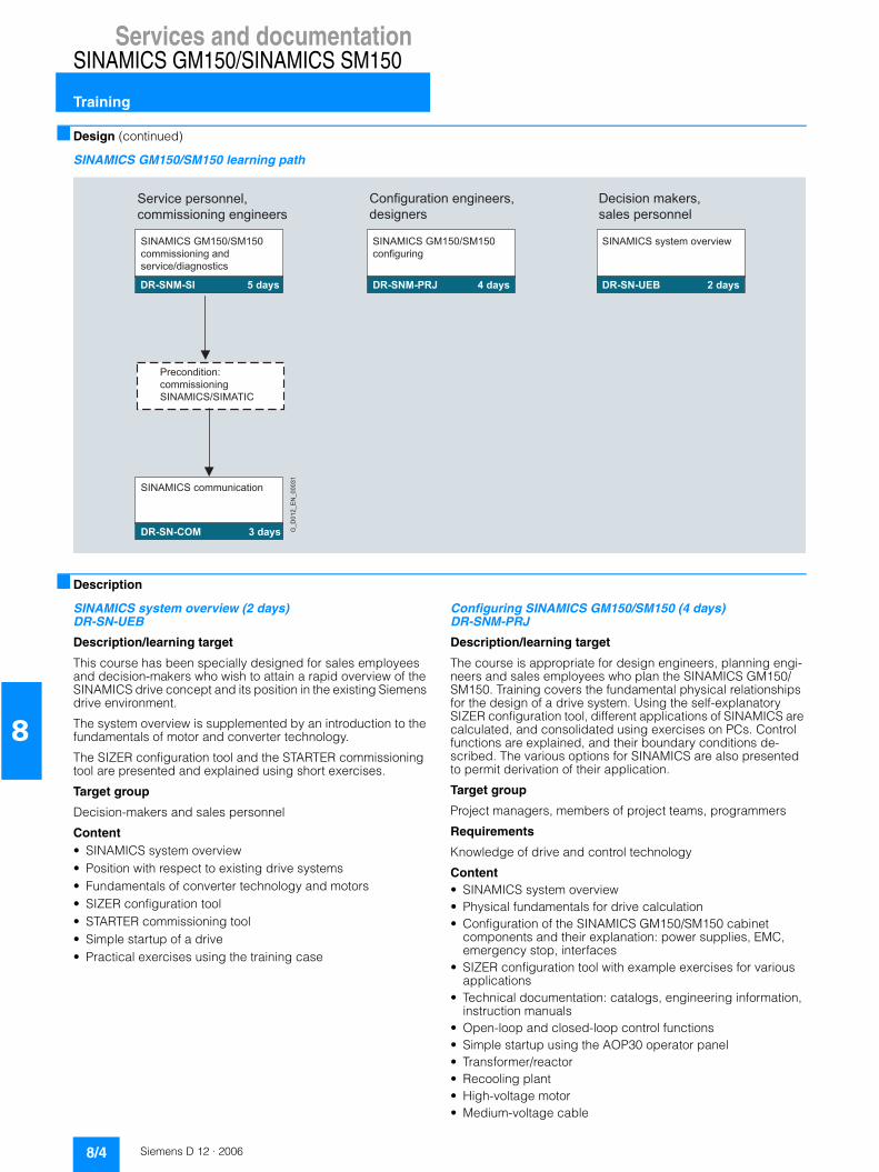
Services and documentationSINAMICS GM150/SINAMICS SM150
Training
8/4 Siemens D 12 · 2006
8
■ Design (continued)
SINAMICS GM150/SM150 learning path
■ Description
SINAMICS system overview (2 days)DR-SN-UEB
Description/learning target
This course has been specially designed for sales employees and decision-makers who wish to attain a rapid overview of the SINAMICS drive concept and its position in the existing Siemens drive environment.
The system overview is supplemented by an introduction to the fundamentals of motor and converter technology.
The SIZER configuration tool and the STARTER commissioning tool are presented and explained using short exercises.
Target group
Decision-makers and sales personnel
Content• SINAMICS system overview• Position with respect to existing drive systems• Fundamentals of converter technology and motors• SIZER configuration tool• STARTER commissioning tool• Simple startup of a drive• Practical exercises using the training case
Configuring SINAMICS GM150/SM150 (4 days)DR-SNM-PRJ
Description/learning target
The course is appropriate for design engineers, planning engi-neers and sales employees who plan the SINAMICS GM150/SM150. Training covers the fundamental physical relationships for the design of a drive system. Using the self-explanatory SIZER configuration tool, different applications of SINAMICS are calculated, and consolidated using exercises on PCs. Control functions are explained, and their boundary conditions de-scribed. The various options for SINAMICS are also presented to permit derivation of their application.
Target group
Project managers, members of project teams, programmers
Requirements
Knowledge of drive and control technology
Content• SINAMICS system overview• Physical fundamentals for drive calculation• Configuration of the SINAMICS GM150/SM150 cabinet
components and their explanation: power supplies, EMC, emergency stop, interfaces
• SIZER configuration tool with example exercises for various applications
• Technical documentation: catalogs, engineering information, instruction manuals
• Open-loop and closed-loop control functions• Simple startup using the AOP30 operator panel• Transformer/reactor• Recooling plant• High-voltage motor• Medium-voltage cable
G_
D0
12
_E
N_
00
03
1
Service personnel,
commissioning engineers
5 daysDR-SNM-SI
3 daysDR-SN-COM
SINAMICS GM150/SM150
commissioning and
service/diagnostics
4 daysDR-SNM-PRJ
SINAMICS GM150/SM150
configuring
2 daysDR-SN-UEB
SINAMICS system overview
Precondition:
commissioning
SINAMICS/SIMATIC
SINAMICS communication
Configuration engineers,
designers
Decision makers,
sales personnel

Services and documentationSINAMICS GM150/SINAMICS SM150
Training
8/5Siemens D 12 · 2006
8
■ Description (continued)
SINAMICS GM150/SM150 commissioning and servicing/diagnosis course (5 days) DR-SNM-SI
Description/learning target
Technical information about planning, configuration, commis-sioning and troubleshooting is provided in this course. Following an introduction to the hardware and documentation of the drive system, detailed information is given about software functions, the parameter structure and function diagrams. Practical exer-cises on training equipment and the STARTER commissioning tool consolidate this knowledge.
Target group
Commissioning engineers, configuring engineers, servicing personnel
Requirements
Knowledge of drive and control technology
Content• Components of the converters
- Rectifiers, DC link, inverter- Air/water cooling- Terminal Board/Terminal Module- Controller and closed-loop control- Control of IGBTs- Joint power supply
• Exercises on the simulator - Operation by means of AOP- Initial commissioning steps/test mode- Parameterization of converter with STARTER commissioning
tool- Upload/download functions, learning function- Setpoint channel
• Control of converter using PROFIBUS DP• Basic principle of closed-loop control (transvector control)• Circuit diagrams• Spare parts/maintenance
SINAMICS communication (3 days)DR-SN-COM
Description/learning target
The course is appropriate for programmers and servicing per-sonnel who, as an extension to the DR-SNS-SI course, require further knowledge on the PROFIBUS and RS232 communica-tions interfaces for STARTER and AOP30 as well as I/O termi-nals.
The focal point is PROFIBUS with the PROFIDrive V3 profile with routing, teleservice, and the functionalities associated with the equidistant bus cycle, isochrone mode with servo applications, and direct OP access. Also described are the libraries of DriveES SIMATIC for cyclic and acyclic data exchange.
Practical exercises on the SINAMICS and SIMATIC S7 training cases with CPU 315-2 DP deepen the knowledge conveyed.
Target group
Commissioning engineers, configuring engineers, servicing personnel
Content• Overview of the PROFIBUS DP, RS232-PPI and CAN inter-
faces and I/O terminals: function, topology, parameterization• Fundamentals of PROFIBUS with the PROFIDrive V3 profile• Basic functions on the PROFIBUS: routing, teleservice and
direct access• PROFIBUS for motion control with: equidistant bus cycle and
isochrone mode with servo control• Cyclic and acyclic data exchange with DriveES SIMATIC
modules• Fault diagnostics of the drive by means of the bus system• Practical exercises on the SINAMICS S120 and SIMATIC S7
training cases with CPU 315-2DP.
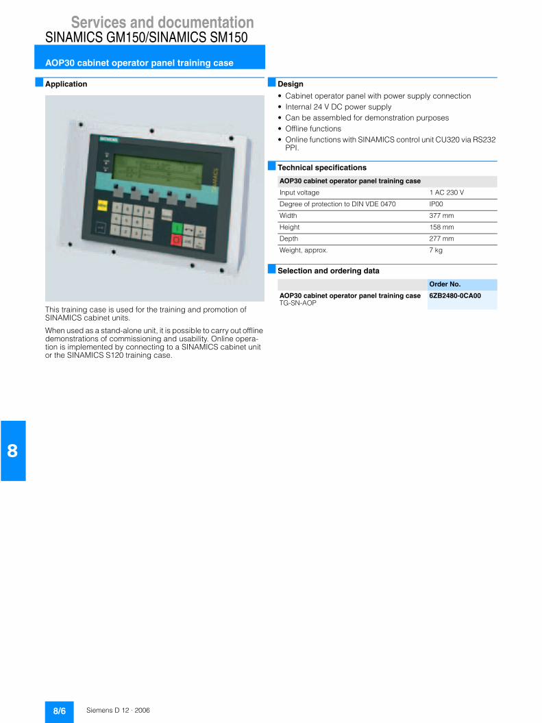
Services and documentationSINAMICS GM150/SINAMICS SM150
AOP30 cabinet operator panel training case
8/6 Siemens D 12 · 2006
8
■ Application
This training case is used for the training and promotion of SINAMICS cabinet units.
When used as a stand-alone unit, it is possible to carry out offline demonstrations of commissioning and usability. Online opera-tion is implemented by connecting to a SINAMICS cabinet unit or the SINAMICS S120 training case.
■ Design
• Cabinet operator panel with power supply connection• Internal 24 V DC power supply• Can be assembled for demonstration purposes• Offline functions• Online functions with SINAMICS control unit CU320 via RS232
PPI.
■ Technical specifications
■ Selection and ordering data
AOP30 cabinet operator panel training case
Input voltage 1 AC 230 V
Degree of protection to DIN VDE 0470 IP00
Width 377 mm
Height 158 mm
Depth 277 mm
Weight, approx. 7 kg
Order No.
AOP30 cabinet operator panel training caseTG-SN-AOP
6ZB2480-0CA00

Services and documentationSINAMICS GM150/SINAMICS SM150
SPARESonWeb
8/7Siemens D 12 · 2006
8
■ Overview
The documentation is supplied with the converter in PDF format on a CD-ROM as standard. It consists of the following sections:• Instruction Manual• List Manual (parameter lists and function diagrams)• Equipment-specific documents such as circuit diagrams,
dimension drawings, arrangement diagrams and terminal diagrams
• Additional instruction manuals (comprehensive component descriptions)
The documentation is in English. Further languages can be ordered if required (see option descriptions). The equipment-specific documents are available only in English/German.
Attention: Due to US embargo restrictions, the documentation cannot be supplied on CD-ROM to countries such as Iran, Syria, Cuba, Sudan or Libya, as Adobe Acrobat Reader is not permit-ted in these countries for reading PDF documents. The docu-mentation must be ordered in paper form when exporting con-verters to these countries (option D15).
■ Overview
SPARESonWeb - Online spare parts catalog
SPARESonWeb is a web-based tool for selecting the spare parts available for the SINAMICS system. After you have registered and entered the serial number and order number, the spare parts available for the relevant unit are displayed.
The delivery state for specific orders can be displayed for all shipped SINAMICS products.
http://workplace.automation.siemens.com/sparesonweb
Documentation

Services and documentationSINAMICS GM150/SINAMICS SM150
Service & Support
8/8 Siemens D 12 · 2006
8
.I
In the face of harsh competition you need optimum conditions to keep ahead all the time: A strong starting position. A sophisticated strategy and team for the necessary support - in every phase. Service & Support from Siemens provides this support with a complete range of different services for automation and drives.
In every phase: from planning and startup to maintenance and upgrading.
Our specialists know when and where to act to keep the produc-tivity and cost-effectiveness of your system running in top form.
■ Online supportThe comprehensive information system available round the clock via Internet ranging from Product Support and Service & Support services to Support Tools in the Shop.
http://www.siemens.com/automation/service&support
■ Technical supportCompetent consulting in techni-cal questions covering a wide range of customer-oriented ser-vices for all our products and systems.
Tel.: +49 (0)180 50 50 222Fax: +49 (0)180 50 50 223http://www.siemens.com/automation/support-request
■ Technical consultingSupport in the planning and de-signing of your project from de-tailed actual-state analysis, target definition and consulting on product and system ques-tions right to the creation of the automation solution. 1)
■ Configuration and software engineeringSupport in configuring and de-veloping with customer-oriented services from actual configura-tion to implementation of the automation project. 1)
■ Service on siteWith Service On Site we offer services for startup and mainte-nance, essential for ensuring system availability.
In Germany 0180 50 50 444 1)
■ Repairs and spare partsIn the operating phase of a ma-chine or automation system we provide a comprehensive repair and spare parts service ensur-ing the highest degree of oper-ating safety and reliability.
In Germany 0180 50 50 446 1)
■ Optimization and upgradingTo enhance productivity and save costs in your project we offer high-quality services in optimization and upgrading. 1)
■ Product registration
To guarantee our servicing performance (availability of spare parts, hotline function, readiness of personnel), we offer you product registration for our SINAMICS drive equipment. Feed-back on the final destination (installation/operation location) and naming of contact partners allows a servicing response without delay. The feedback can be made either using a feedback form (enclosed with each converter) or via the Internet:http://www.siemens.com/reg
1) For country-specific telephone numbers go to our Internet site at: http://www.siemens.com/automation/service&support

Siemens D 12 · 2006
99/2 Glossary
9/4 Siemens contacts worldwide
9/5 A&D online servicesA&D in the WWWProduct selection using theInteractive CatalogEasy Shopping with the A&D Mall
9/6 Index of order numbers
9/7 Subject index
9/8 Terms and conditions of sale and delivery
9/9 Export regulations
Appendix

AppendixSINAMICS GM150/SINAMICS SM150
Glossary
9/2 Siemens D 12 · 2006
9
■ Overview
Active infeed
Overall functionality of an infeed with � “Active Line Module”, including the required additional components (filters, switching devices, computing power portion of a � “Control Unit”, voltage detection, and so on).
For cabinet-mounted units, a � “Motor Module” can be used instead of the � “Active Line Module”.
Active Line Module
Regulated, self-commutating feed/feedback unit (with IGBTs in feed/feedback direction), which supplies a constant DC link voltage for the � “Motor Modules”.
Asynchronous motor
The asynchronous motor is an AC motor, which runs at a speed “lagging behind” the synchronous speed.
Asynchronous motors can be connected to the AC line both directly in a star or delta circuit and via a converter.
When combined with a converter, asynchronous motors form a “variable-speed drive system”.
Other commonly used terms: squirrel-cage motor, cage motor.
See also � “Synchronous motor”.
Basic infeed
Overall functionality of an infeed with � “Basic Line Module”, including the required additional components (filters, switching devices, etc.).
Basic Line Module
Unregulated line infeed unit (diode bridge or thyristor bridge, without feedback) for rectifying the line voltage for the DC link.
CompactFlash Card
Memory card for non-volatile storage of the drive software and corresponding parameters. The memory card can be plugged into the � “Control Unit” from the outside.
Control Unit
Central control module in which the closed-loop and open-loop control functions for one or more SINAMICS � “Line Modules” and/or � “Motor Modules” are implemented.
DC link
The component of the converter (or converter system) that connects the input converter (rectifier) and the output converter (one or more inverters).
With voltage source DC link converters like SINAMICS, a con-stant DC voltage is present in the DC link (rectified line voltage).
DRIVE-CLiQ
Abbreviation for “Drive Component Link with IQ”.
Communication system for connecting the various components of a SINAMICS drive system, e.g. � “Control Unit”, � “Line Modules”, � “Motor Modules”, motors and speed/position encoders.
In terms of hardware, DRIVE CLiQ is based on Standard Indus-trial Ethernet with twisted-pair cables. The DRIVE-CLiQ line pro-vides the transmit and receive signals, as well as the +24 V power supply.
Field weakening
Field weakening describes the reducing of the magnetizing cur-rent of an electric motor in order that the speed can be increased further when the rated voltage is reached.
Kinetic buffering
Kinetic buffering (KIP) is a software function, which can be used to bridge transient line failures (up to approx. 1 s or as long as the drive continues to turn). Kinetic buffering can usually only be used on drives that are primarily motor-driven. It requires a suffi-ciently large centrifugal mass, i.e., sufficient kinetic energy, on the part of the mechanical transmission element. During the line failure, KIP switches the machine to no-load operation or light re-generation (in order to cover the minor losses from the motor and inverter). Once the line supply has been restored, the machine switches back to standard motor-driven operation.
In order to use kinetic buffering, the technological conditions must be in place to allow the motor to coast or brakes for the duration of the line failure. In some applications with multi-motor drives, the speed ratios between the individual drives have to be maintained during kinetic buffering, in order to prevent the web from tearing or damage. In such cases, kinetic buffering may only be activated on one of the drives (usually the main drive). The reduced speed setpoint values must then be fed into the overall setpoint cascade.
Line Module
A Line Module is a power component that generates the DC link voltage for one or more � “Motor Modules” from a 3-phase line voltage.
The following types of Line Module are used in the SINAMICS system:
� “Basic Line Module” and � “Active Line Module”.

AppendixSINAMICS GM150/SINAMICS SM150
Glossary
9/3Siemens D 12 · 2006
9
■ Overview (continued)
Motor Module
A Motor Module is a power unit (DC-AC inverter) that provides the power supply for the connected motor.
Power is supplied through the � “DC link” of the drive line-up.
A Motor Module must be connected to a � “Control Unit” housing the open-loop and closed-loop control functions for the Motor Module via � “DRIVE-CLiQ”.
Non-Siemens motor
A motor is designated as a non-Siemens motor if its motor data is not known to the drive line-up, and it cannot be identified by means of its order number.
The motor data of an external motor is required for commission-ing. It must be entered manually in the corresponding parame-ters.
Output reactor
Reactor (inductance) at the converter or inverter output for re-ducing the capacitive charge/discharge currents in long power cables.
PROFIBUS
Standardized field bus to IEC 61158, Sections 2 to 6.
PROFIdrive
PROFIBUS profile specified for speed and position-controlled drives by the PROFIBUS user organization (German: PNO).
The latest version is the PROFIdrive V3 profile.
Sensor Module
Hardware module for evaluating speed/position encoder sig-nals.
Synchronous motor
Synchronous motors run at the same frequency with which they are operated: They do not have a slip (like � “Asynchronous motors”). Synchronous motors require different feedforward and feedback control concepts depending on their design to ensure that they can be operated with converters.
Synchronous motors are distinguished by the following features:• permanent-field/separately excited• with/without damping cage• with/without position encoder.
Synchronous motors are used for different reasons:• high drive dynamic response• high overload capability• high speed accuracy with exactly specified frequency
(SIEMOSYN motors).
Terminal Module
Terminal extension module for snapping onto the installation rail, for installation in the control cabinet.
In SINAMICS, Terminal Module TM31 is available with analog and digital I/O terminals.

AppendixSINAMICS GM150/SINAMICS SM150
Siemens Contacts Worldwide
9/4 Siemens D 12 · 2006
9
At
http://www.siemens.com/automation/partner
you can find details of Siemens contact partners worldwide responsible for particular technologies.
You can obtain in most cases a contact partner for• Technical Support,• Spare parts/repairs,• Service,• Training,• Sales or• Consultation/engineering.
You start by selecting a• Country,• Product or• Sector.
By further specifying the remaining criteria you will find exactly the right contact partner with his/her respective expertise.

AppendixSINAMICS GM150/SINAMICS SM150
A&D Online Services
9/5Siemens D 12 · 2006
9
■ A&D in the WWWA detailed knowledge of the range of products and services available is essential when planning and configuring automation systems. It goes without saying that this information must always be fully up-to-date.
The Siemens Automation and Drives Group (A&D) has therefore built up a comprehensive range of information in the World Wide Web, which offers quick and easy access to all data required.
Under the address
http://www.siemens.com/automation
you will find everything you need to know about products, systems and services.
■ Product selection using the Interactive CatalogDetailed information together with convenient interactive functions: The interactive catalog CA 01 covers more than 80,000 products and thus provides a full summary of the Siemens Automation and Drives product base.
Here you will find everything that you need to solve tasks in the fields of automation, switchgear, installation and drives. All information is linked into a user interface which is easy to work with and intuitive.
After selecting the product of your choice you can order at the press of a button, by fax or by online link.
Information on the interactive catalog CA 01 can be found in the Internet under
http://www.siemens.com/automation/ca01
or on CD-ROM or DVD.
■ Easy shopping with the A&D Mall The A&D Mall is the virtual department store of Siemens AG in the Internet. Here you have access to a huge range of products presented in electronic catalogs in an informative and attractive way.
Data transfer via EDIFACT allows the whole procedure from selection through ordering to tracking of the order to be carried out online via the Internet.
Numerous functions are available to support you.
For example, powerful search functions make it easy to find the required products, which can be immediately checked for avai-lability. Customer-specific discounts and preparation of quotes can be carried out online as well as order tracking and tracing.
Please visit the A&D Mall on the Internet under:
http://www.siemens.com/automation/mall

AppendixSINAMICS GM150/SINAMICS SM150
Index of order numbers
9/6 Siemens D 12 · 2006
9
■ Index of order numbersPart/Page
6SC8476-1... Accessories for replacing phase modules, IGCTs, diodes 6/2
6SL3810-2L... SINAMICS GM150 (IGBT) Air cooling 2/8, 2/9
6SL3815-2L... SINAMICS GM150 (IGBT) Water cooling 2/10, 2/11
6SL3835-2LN4... SINAMICS GM150 (IGCT) Water cooling 3/6
6SL3845-7NN4... SINAMICS SM150 Water cooling 4/6
6SY8101-0AB5. Accessories for grounding and short-circuiting the converter for commissioning and maintenance work 6/2
6ZB2480-0CA00 AOP30 cabinet operator panel training case 8/7
6ZB2480-0CC00 SINAMICS S150 simulator training case 8/6
E86060-... Training catalog 8/2

AppendixSINAMICS GM150/SINAMICS SM150
Subject index
9/7Siemens D 12 · 2006
9
■ Subject indexPart/Page
AAOP30 2/7, 3/6Design
SINAMICS GM150 (IGBT) 2/3SINAMICS GM150 (IGCT) 3/2SINAMICS SM150 4/2
Selection and ordering dataSINAMICS GM150 (IGBT) 2/8 to 2/11SINAMICS GM150 (IGCT) 3/6SINAMICS SM150 4/6
BAOP30 operator panel 2/7, 3/6Description of options 5
DDocumentation 8/7Services and documentation 8
EIntroduction 1
FFunction
SINAMICS GM150 (IGBT) 2/7SINAMICS GM150 (IGCT) 3/6SINAMICS SM150 4/6
KCorrection factors
SINAMICS GM150 (IGBT) 2/19SINAMICS GM150 (IGCT) 3/14SINAMICS SM150 4/14
NBenefits
SINAMICS GM150 (IGBT) 2/2SINAMICS GM150 (IGCT) 3/2SINAMICS SM150 4/2
Part/Page
OOptions 5
SINAMICS GM150 (IGBT) 2/12 to 2/16SINAMICS GM150 (IGCT) 3/7 to 3/11SINAMICS SM150 4/7 to 4/11
SOverview of interfaces 7Service & Support 8/8
SINAMICS GM150 (IGBT) 2SINAMICS GM150 (IGCT) 3SINAMICS SM150 4SINAMICS Overview 1/6
Wiring versions SINAMICS GM150 (IGBT) 2/5SINAMICS GM150 (IGCT) 3/4SINAMICS SM150 4/4
TAOP30 cabinet operator panel training case 8/7SINAMICS S150 simulator training case 8/6Technical data
SINAMICS GM150 (IGBT) 2/17 to 2/86SINAMICS GM150 (IGCT) 3/12 to 3/16SINAMICS SM150 4/12 to 4/16
Training 8/2
UOverview
SINAMICS 1/6SINAMICS GM150/SM150 1/10SINAMICS GM150 (IGBT) 2/2SINAMICS GM150 (IGCT) 3/2SINAMICS SM150 4/2
ZAccessories 6

AppendixSINAMICS GM150/SINAMICS SM150
Conditions of sale and delivery
9/8 Siemens D 12 · 2006
9
■ Terms and conditions of sale and delivery
By using this catalog you can acquire hardware and software products described therein from the Siemens AG subject to the following terms. Please note! The scope, the quality and the con-ditions for supplies and services, including software products, by any Siemens entity having a registered office outside of Ger-many, shall be subject exclusively to the General Terms and Conditions of the respective Siemens entity.
For customers with a seat or registered office in GermanyThe „General Terms of Payment“ as well as the „General Condi-tions for the Supply of Products and Services of the Electrical and Electronics Industry“ shall apply.For software products, the „General License Conditions for Soft-ware Products for Automation and Drives for Customers with a Seat or registered Office in Germany“ shall apply.
For customers with a seat or registered office outside of GermanyThe „General Terms of Payment“ as well as the „General Condi-tions for Supplies of Siemens, Automation and Drives for Cus-tomers with a Seat or registered Office outside of Germany“ shall apply.For software products, the „General License Conditions for Soft-ware Products for Automation and Drives for Customers with a Seat or registered Office outside of Germany“ shall apply.
GeneralThe prices are in € (Euro) ex works, exclusive packaging.The sales tax (value added tax) is not included in the prices. It shall be debited separately at the respective rate according to the applicable legal regulations.In addition to the prices of products which include silver, plump, aluminum and/or copper, surcharges may be calculated if the respective limits of the notes are exceeded. The respective note (e.g. source: German newspaper „Handesblatt“ in category „deutsche Edelmetalle“ and „Metallverarbeiter“) for silver („ver-arbeitetes Silber“), plump („Blei in Kabeln“), aluminum („Alumi-nium in Kabeln“) and copper („Elektrolytkupfer“, „DEL-Notiz“) respectively, of the day the order or rather the on call order is received, is decisive for the calculation of the surcharges.Surcharges of copper shall be calculated for Drives at a note („DEL-Notiz“) above EUR 225,00 / 100 kg and for chokes / trans-formers above EUR 150,00 / 100 kg.Surcharges shall be charged based on the quantities of the materials which are contained in the relevant products.Prices are subject to change without prior notice. We will debit the prices valid at the time of delivery. The dimensions are in mm. Illustrations are not binding.Insofar as there are no remarks on the corresponding pages, - especially with regard to data, dimensions and weights given - these are subject to change without prior notice.
Comprehensive Terms and Conditions of Sale and Delivery are available free of charge from your local Siemens business office under the following Order Nos.:• 6ZB5310-0KR30-0BA0
(for customers based in the Federal Republic of Germany)• 6ZB5310-0KS53-0BA0
(for customers based outside of theFederal Republic of Germany)
or download them from the Internet:http://www.siemens.com/automation/mall (Germany: A&D Mall Online-Help System)

AppendixSINAMICS GM150/SINAMICS SM150
Export regulations
9/9Siemens D 12 · 2006
9
■ Export regulations
The products listed in this catalog/price list may be subject to European/German and/or US export regulations.Therefore, any export requiring a license is subject to approval by the competent authorities.According to current provisions, the following export regulations must be observed with respect to the products featured in this catalog/price list:
Even without a label or with an “AL: N“ or “ECCN: N“, authoriza-tion may be required due to the final destination and purpose for which the goods are to be used.The deciding factors are the AL or ECCN export authorization indicated on order confirmations, delivery notes and invoices.Errors excepted and subject to change without prior notice.
A&D/VuL/En 17.03.05
AL Number of the German Export List.Products marked other than “N“ require an export license.In the case of software products, the export designations of the relevant data medium must also be generally adhered to.Goods labeled with an “AL not equal to N“ are subject to a European or German export authori-zation when being exported out of the EU.
ECCN Export Control Classification Number.Products marked other than “N“ are subject to a reexport license to specific countries.In the case of software products, the exportdesignations of the relevant data medium must also be generally adhered to.Goods labeled with an “ECCN not equal to N“ are subject to a US re-export authorization.

AppendixSINAMICS GM150/SINAMICS SM150
9/10 Siemens D 12 · 2006
9
Siemens AGAutomation and DrivesLarge DrivesPostfach 47 4390025 NUERNBERGFEDERAL REPUBLIC OF GERMANY
Order No.E86060-K5512-A101-A1-7600KG 0706 2.0 E 184 En/622163 Printed in Germany

Catalogs of theAutomation and Drives Group (A&D)
Further information can be obtained from our branch offices listedin the appendix or at www.siemens.com/automation/partner
A&D/3U/En 02.03.05
Automation and Drives CatalogInteractive catalog on CD-ROM
• The Offline Mall of Automation and Drives CA 01
Automation Systems for Machine ToolsSINUMERIK & SIMODRIVE NC 60
Drive SystemsVariable-Speed Drives
SINAMICS G130 Drive Converter Chassis Units, SINAMICS G150 Drive Converter Cabinet Units
D 11
SINAMICS G110 Inverter Chassis Units D 11.1
SINAMICS S120 Servo Control Drive System D 21.2
SINAMICS S150 Drive Converter Cabinet Units D 21.3
DC Motors DA 12
SIMOREG DC MASTER 6RA70 Digital Chassis Converters
DA 21.1
SIMOREG K 6RA22 Analog Chassis Converters DA 21.2
SIMOREG DC MASTER 6RM70 Digital Converter Cabinet Units
DA 22
SIMOVERT PM Modular Converter Systems DA 45
SIEMOSYN Motors DA 48
MICROMASTER 410/420/430/440 Inverters DA 51.2
MICROMASTER 411/COMBIMASTER 411 DA 51.3
SIMOVERT MV Medium-Voltage Drives DA 63
SIMOVERT MASTERDRIVES Vector Control DA 65.10
SIMOVERT MASTERDRIVES Motion Control DA 65.11
Synchronous and asynchronous servomotors for SIMOVERT MASTERDRIVES
DA 65.3
SIMODRIVE 611 universal and POSMO DA 65.4
Low-Voltage Three-Phase-Motors
Squirrel-Cage Motors, Totally Enclosed, Fan-Cooled M 11
Automation Systems for Machine Tools SIMODRIVE NC 60
• Main Spindle Motors
• Feed Motors
• Converter Systems SIMODRIVE 611/POSMO
Drive and Control Components for Hoisting Equipment HE 1
Electrical Installation TechnologyALPHA Small Distribution Boards and Distribution Boards
ET A1
PDF: ALPHA 8HP Molded-Plastic Distribution System ET A3
ALPHA FIX Terminal Blocks ET A5
BETA Modular Installation Devices ET B1
DELTA Switches and Outlets ET D1
GAMMA Building Management Systems ET G1
Factory Automation Sensors FS 10
Human Machine Interface Systems SIMATIC HMI ST 80
Industrial Communication for Automation and Drives
IK PI
PDF: These catalogs are only available as pdf files.
Low-Voltage Controls and Distribution CatalogLow-Voltage Switchgear – Controlgear for Industry LV 10
Power Distribution – Products and Systemsfor Low-Voltage Power Distribution
LV 30
SIDAC reactors and filters LV 60
SIVACON 8PS Busbar trunking systems CD, BD01, BD2 up to 1250 A
LV 70
Low-Voltage Controlgear, Switchgear and Systems LV 90
Motion Control System SIMOTION PM 10
Process Instrumentation and AnalyticsField Instruments for Process AutomationMeasuring Instruments for Pressure, Differential Pressure, Flow, Level and Temperature, Positioners and Liquid Meters
FI 01
PDF: Indicators for panel mounting MP 12
SIREC Recorders and Accessories MP 20
SIPART, Controllers and Software MP 31
SIWAREX Weighing Systems WT 01
Continuous Weighing and Process Protection WT 02
Gas Analysis Equipment for the Process Industry PA 10
PDF: Process Analytics, Components for the System Integration
PA 11
SIPAN Liquid Analysis PA 20
SIMATIC Industrial Automation SystemsSIMATIC PCS Process Control System ST 45
PDF: SIMATIC S5/505 Automation Systems ST 50
Products for Totally Integrated Automation and Micro Automation
ST 70
SIMATIC PCS 7 Process Control System ST PCS 7
PDF: Add-ons for the SIMATIC PCS 7 Process Control System
ST PCS 7.A
pc-based Automation ST PC
SIMATIC Control Systems ST DA
SIPOS Electric ActuatorsElectric Rotary, Linear and Part-turn Actuators MP 35
Electric Rotary Actuators for Nuclear Plants MP 35.1/.2
Systems EngineeringPower supplies SITOP power KT 10.1
System cabling SIMATIC TOP connect KT 10.2
System SolutionsApplications and Products for Industry are part of the interactive catalog CA 01
TELEPERM M Process Control SystemPDF: AS 488/TM automation systems PLT 112

D12_U1_U4.FH10 Thu May 11 08:00:06 2006 Seite 1
Probedruck
Siemens AG
Automation and DrivesLarge DrivesPostfach 474390025 NUERNBERGFEDERAL REPUBLIC OF GERMANY
http://www.siemens.com/sinamics
Token fee € 5.00
Order No. E86060-K5512-A101-A1-7600
The information provided in this catalog contains descriptionsor characteristics of performance which in case of actual usedo not always apply as described or which may change as aresult of further development of the products. An obligationto provide the respective characteristics shall only exist ifexpressly agreed in the terms of contract. Availability andtechnical specifications are subject to change without notice.

D12_U1_U4.FH10 Thu May 11 08:00:06 2006 Seite 2
Probedruck
Ca
talo
g D
12
. 2
00
6SI
NA
MIC
S G
M1
50
/SIN
AM
ICS
SM1
50