d20, d50, d60 & d80 series yers -...
TRANSCRIPT

Dean, a member of the Commercial Food Equipment Service Association, recommends usingCFESA Certified Technicians.
Price: $15.0024-Hour Service Hotline 1-800-551-8633
819-5922SEPTEMBER 2002
NON-CE &
Decathlon Series G
as FryersS
ervice & P
arts Manual
D20, D50, D60 & D80 Series

Please read all sections of this manual and retain for future reference.
This product has been certified as commercial cooking equipment and MUST be installed byprofessional personnel as specified. Installation, maintenance and repairs should be performed
by your FRYMASTER FACTORY AUTHORIZED SERVICE CENTER.
DANGERDo not store or use gasoline or other flammable vapors and liquids in the vicinity of this or any
other cooking appliance.
DANGERInstructions explaining procedures to be followed MUST be posted in a prominent location inthe event the operator detects a gas leak. This information can be obtained from the local gas
company or gas supplier.
WARNINGImproper installation, adjustment, alteration, service or maintenance can cause propertydamage, injury or death. Read the installation, operating and maintenance instructions
thoroughly before installing or servicing this equipment.
DANGERSafe and satisfactory operation of your equipment depends on proper installation. InstallationMUST conform with local codes, or in absence of local codes, with the National Fuel Gas Code,
ANSI Z223.1; The Natural Gas Installation Code, CAN/CGA-B149.1; The Propane InstallationCode, CAN/CGA-B149.2; or The latest edition of the National Electric Code, N.F.P.A. 70.
NOTICEIf, during the warranty period, the customer uses a part for this Enodis equipment other than an
unmodified new or recycled part purchased directly from Frymaster/Dean, or any of itsauthorized service centers, and/or the part being used is modified from its original
configuration, this warranty will be void. Further, Frymaster/Dean and its affiliates will not beliable for any claims, damages or expenses incurred by the customer which arise directly orindirectly, in whole or in part, due to the installation of any modified part and/or part received
from an unauthorized service center.
DANGERThe crumb tray in fryers equipped with a filter system must be emptied into a fireproof containerat the end of frying operations each day. Some food particles can spontaneously combust if leftsoaking in certain shortening material. Additional information can be obtained in the filtration
manual included with the system.
DANGERThe front ledge of the fryer is not a step. Do not stand on the fryer. Serious injury can result
from slips or contact with the hot oil.
WARNINGDrawings and photos used in this manual are intended to illustrate operational, cleaning andtechnical procedures and may not conform to on-site management operational procedures.
WARNINGNo structural material on the fryer should be altered or removed to accommodate placement ofthe fryer under a hood. Questions? Call the Frymaster/Dean Service Hotline at 1-800-551-8633.
This equipment is to be installed in compliance with the basic plumbing code of The BuildingOfficials and Code Administrators International, Inc. (BOCA) and the Food Service Sanitation
Manual of the Food and Drug Administration.
COMPUTERSFCC
This device complies with Part 15 of the FCC rules. Operation is subject to the following two conditions:1) This device may not cause harmful interference, and 2) This device must accept any interference
received, including interference that may cause undesired operation. While this device is a verified ClassA device, it has been shown to meet the Class B limits.
CANADAThis digital apparatus does not exceed the Class A or B limits for radio noise emissions as set out by the
ICES-003 standard of the Canadian Department of Communications.
Cet appareil numerique n’emet pas de bruits radioelectriques depassany les limites de classe A et Bprescrites dans la norme NMB-003 edictee par le Ministre des Communcations du Canada.
DANGERTHIS PRODUCT CONTAINS CHEMICALS KNOWN TO THE STATE OF CALIFORNIA TO CAUSE
CANCER AND/OR BIRTH DEFECTS OR OTHER REPRODUCTIVE HARM.Operation, installation, and servicing of this product could expose you to airborne particles ofglasswool or ceramic fibers, crystalline silica, and/or carbon monoxide. Inhalation of airborne
particles of glasswool or ceramic fibers is known to the State of California to cause cancer.Inhalation of carbon monoxide is known to the State of California to cause birth defects or other
reproductive harm.
WARNINGDo not bang fry baskets or other utensils on the fryer’s joiner strip. The strip is present to sealthe joint between the fry vessels. Banging fry baskets on the strip to dislodge shortening will
distort the strip, adversely affecting its fit. It is designed for a tight fit and should only beremoved for cleaning.

Decathlon Series Gas FryersService & Parts Manual
TABLE OF CONTENTS Page #
1. SERVICE PROCEDURES 1-1
1.1 Functional Description 1-1
1.2 Accessing Fryers for Service 1-7
1.3 Cleaning the Gas Valve Vent Tube (if applicable) 1-8
1.4 Adjusting Burner Manifold Gas Pressure 1-8
1.5 Adjusting the Pilot Flame 1-9
1.6 Calibrating the Thermatron Controller and Backup Thermostat 1-9
1.7 Replacing Fryer Components 1-11
1.8 Troubleshooting and Problem Isolation 1-30
1.9 Troubleshooting Guides 1-39
1.10 Wiring Diagrams 1-41
2. PARTS LIST 2-1
2.1 Decathlon D20 Primary Components 2-2
2.2 Decathlon D50 Primary Components 2-3
2.3 Decathlon D60 Primary Components 2-5
2.4 Decathlon D80 Primary Components 2-7
2.5 Control Panel Options, D60 Series 2-9
2.6 Optional Components and Controllers (CE and Domestic) 2-10
2.7 Transformers and Component Boxes- Multi-Batteried Decathlons 2-12
2.8 Oil Drain Manifold, Drain Flush and Drain Valve Components 2-13
2.9 Oil Return Manifold Components 2-15
2.10 Oil Return and Oil Flush Components 2-16
2.11 Under Fryer Filter (UFF) Components 2-18
2.12 Single Under Fryer Filter (SUFF) Components 2-20
2.13 Basket Lift Components (D50, D60 and D80 Series) 2-22
2.14 Trough, Holster and Cover Components- D60 and D80 Series 2-24

DECATHLON SERIES GAS FRYERSCHAPTER 1: SERVICE PROCEDURES
1-1
1.1 Functional Description
Decathlon Series gas fryers contain a welded steel frypot (stainless or cold-rolled) that is heated bygas flames diffused evenly through tubes built into the frypot.
Flames originate from orifices in a burner manifold positioned beneath cast-iron burners. Theburners are positioned in the tube openings, at the front of the frypot. The diameter of the orificesdiffers for natural (CE:G20/G25) and LP (CE:G31) gas as indicated in the accompanying table.
NON-CE (Altitudes of 2000 feet or less)EQUIPMENTPRESSUREMODEL INPUT
(BTU)GASTYPE
ORIFICEMM
(INCH)
ORIFICEPART NO. QTY
MBAR INCH W.C.
D20G 50 NATLP
2.18(#44)1.40(#54)
810-2050810-2324
22
1027.5
411
D50G 85 NATLP
2.08(#45)1.32(#55)
14-0067-45810-2441
44
1027.5
411
D50G(HP) 120 NATLP
2.53(#39)1.51(#53)
810-2048810-2059
44
1027.5
411
D50GDDHP 115 NATLP
2.44(#41)1.51(#53)
14-0067-41810-2059
44
1027.5
411
D60G 112 NATLP
2.08(#45)1.32(#55)
14-0067-45810-2441
55
1027.5
411
D60G(HP) 150 NATLP
2.53(#39)1.51(#53)
810-2048810-2059
55
1027.5
411
D80G 122 NATLP
2.26(#43)1.40(#54)
810-2049810-2324
55
1027.5
411
D80G(HP) 165 NATLP
2.58(#38)1.61(#52)
810-2062810-2063
55
1027.5
411
CE ONLY (Altitudes of 2000 feet or less)EQUIPMENTPRESSUREMODEL INPUT
(kW)GASTYPE
ORIFICEMM
(INCH)
ORIFICEPART NO.
QTY/COLOR MBAR INCH W.C.
D20G 15,0G20G25G31
2,402,401,51
810-2060810-2060810-2059
2/BLUE2/BLUE2/RED
10,015,027,0
4,06,010,8
D50G 30,0G20G25G31
2,402,401,51
810-2060810-2060810-2059
4/BLUE4/BLUE4/RED
10,015,027,0
4,06,010,8
D60G 37,5G20G25G31
2,402,401,51
810-2060810-2060810-2059
5/BLUE5/BLUE5/RED
10,015,027,0
4,06,010,8
D80G 37,5G20G25G31
2,402,401,51
810-2060810-2060810-2059
5/BLUE5/BLUE5/RED
10,015,027,0
4,06,010,8

DECATHLON SERIES GAS FRYERSCHAPTER 1: SERVICE PROCEDURES
1-2
1.1 Functional Description (cont.)
An electromechanical gas valve regulates gas flow to the manifold. Decathlon Series gas fryers areequipped with either a 120-volt valve system or a 24-volt valve system. Units may be configuredwith either a pilot ignition system (standing pilot) or an electronic ignition system.
Pilot System ConfigurationThe pilot system is comprised of the pilot orifice, pilot hood, and a thermopile. The pilot serves twopurposes. The first is to light the burner, the second is to heat the thermocouple (some systemsincorporate a thermopile). In operation, the thermocouple is in contact with the pilot flame andgenerates millivolts. The millivolt output energizes the gas valve pilot coil, which in turn opens thepilot valve. If the pilot flame is extinguished, voltage is lost to the gas valve pilot coil and the pilotvalve closes. The gas valve is constructed so that the main valve will not open if the pilot valve isnot open. The pilot flame must be manually lit when the fryer is first placed into operation. Aseparate 120-volt circuit, activated by the fryer ON/OFF switch, provides voltage through theelectronic thermostat controller to the gas valve main coil, which opens the main valve.
Electronic ThermostatController
High-LimitThermostat
Line Voltage
Line Voltage
The Pilot System120V
MELT CYCLE DISABLE
6 5
1
AC
1
3
AC
23A
2A
78
9
1AE
XT
PO
TP
RO
BE
1011
2
CO
MR
ELA
YN
O1213
NC14
Thermocouple/Thermopile
Pilot Coil
Main Coil
Gas Valve
Pilot
ON/OFFSwitch
Electronic Ignition Configuration
In units configured for electronic ignition, an ignition module connected to an ignitor assemblyreplaces the pilot system. The ignition module performs three important functions: it provides anignition spark, supplies voltage to the gas valve, and proofs the pilot flame.
The module contains a 60-second time delay circuit and a coil that activates the gas valve. Theignitor assembly consists of a spark plug, a pilot, and a flame sensor element.

DECATHLON SERIES GAS FRYERSCHAPTER 1: SERVICE PROCEDURES
1-3
Electronic Ignition Configuration (cont.)
At start-up the ON/OFF switch is placed in the "ON" position, supplying 12 VDC to the heat controlcircuitry in the controller or computer and to one side of the heat relay coil on the interface board. Ifresistance in the temperature probe indicates the temperature in the frypot is below 180°F (82°C),the current flows through a melt cycle circuit where a timer switch alternately closes for 3 secondsand opens for 24 seconds. If the temperature is 180°F (82°C) or above, the current flows through aheat circuit, bypassing the timer switch. In either case, current is supplied to the other leg of the heatrelay coil which then closes an electronic switch in the 24 VAC circuit to provide current to theignition module.
Circuitry in the ignition module sends 24 VAC current to the gas valve via a normally closed high-limit switch and a drain safety switch. Simultaneously, the module causes the ignitor to spark for upto 60 seconds to light the pilot flame. A flame sensor verifies that the pilot is lit by measuring theflow of microamps through the flame. If the pilot does not light (or is extinguished), current to theignition module is interrupted, preventing the main valve from opening, and the ignition module"locks out" until the power switch is turned "OFF", then back "ON".
A temperature probe monitors the temperature in the frypot. When the programmed setpointtemperature is reached, resistance in the probe causes the heat cycle circuitry in the controller tointerrupt current flow through the heat relay. This in turn interrupts the 24 VAC current to theignition module, resulting in closure of the gas valve.
Control Options
Decathlon Series gas fryers may be equipped with operating thermostat controls (optional backup-only; available with electronic thermostat or computer), electronic thermostat controller, or Compu-Fry computers.
In fryers equipped with electronic thermostat controllers, the fryer is turned on and off by means of arocker switch and the temperature is set by adjusting a potentiometer. An interface board is locatedin the component box (shield) behind the control panel (Compu-Fry equipped), or in a componentbox inside the cabinet (electronic thermostat controller-equipped).
Interface Boards
The interface board provides a link between the controller/computer and the fryer’s individualcomponents without requiring excessive wiring, and allows the controller to execute commandsfrom one central point. Two types of interface boards may be used in Decathlon Series gas fryers;the type used depends on the fryer configuration.
In units configured for electronic thermostat controllers, P/N 807-3566 (115V) or P/N 807-3722(208/230V) is used; in units configured for Compu-Fry computers, P/N 806-4549 is used.

DECATHLON SERIES GAS FRYERSCHAPTER 1: SERVICE PROCEDURES
1-4
Interface Boards (cont.)
IFB 807-3566 (115V) & IFB 807-3722 (208/230V): These interface boards are used in electronicthermostat controller-equipped Decathlon fryers.
MELT CYCLE DISABLE
6 5
1
AC
1
3
AC
23A
2A
78
9
1AE
XT
PO
TP
RO
BE
1011
2
CO
MR
ELA
YN
O1213
NC14Not used
Line voltage enters the interface board at terminals 1 and 3. The temperature controls(potentiometer) are connected to terminals 7, 8 and 9. The sensor probe circuit is connected toterminals 10 and 11. The high-limit and gas valve routes through terminal 12. Terminals 2 and 13are jumped out. Terminals 5 and 6 are the melt-cycle disable circuit. The melt cycle is enabledunless terminals 5 and 6 are jumped out.
INTERFACE BOARD P/N 807-3566 & 807-3722

DECATHLON SERIES GAS FRYERSCHAPTER 1: SERVICE PROCEDURES
1-5
Interface Boards (cont.)
IFB 806-4549. This interface board is used in computer-equipped Decathlon fryers.
GND
GNDGND
GND
GND
V1D
PWR
ALR
V1S
V2D
PWR
AD
AS
V2S
SOUND1
2
PWR
GVGV
PWR
4
8
12
14 13
9
5
1
K2
K4
4
6
8 7
5
3
2 1K1
4
6
8
5
3
2 1
5
4
11
10
1
8
9
7
12
11
10
F1
4
8
12
14 13
9
5
1
K3
3
2
1
6
5
4
9
8
7
24V
12V AIR
3
2
1
6 12
2 Amp
J3J1
BlowerMotor
3GND
7
2
3 6
4
5
7
8
9 12
11
10 13
14
15
J2
Note position ofPin 1 on J1.
Note position ofPin 1 on J3.
FREQUENTLY USED TEST POINTS FOR INTERFACE BOARD P/N 806-4549
Meter TestTest Setting Pins Results
12VAC Power to Controller 50VAC Scale 1 and 3 on J3 12-18
24VAC Power to Right Module 50VAC Scale 8 on J3 and GROUND 22-28
24VAC Power to Left Module 50VAC Scale 8 on J1 and GROUND 22-28
12VDC Power to Right BL Relay 50VDC Scale 7 on J2 and 9 or 12 on J3 12-18
12VDC Power to Left BL Relay 50VDC Scale 9 on J2 and 9 or 12 on J1 12-18
24VAC Power to Right High-Limit 50VAC Scale 7 on J3 and GROUND 22-28
24VAC Power to Left High-Limit 50VAC Scale 7 on J1 and GROUND 22-28
120VAC Power* 250VAC Scale 11 on J3 and GROUND 110-125
120VAC Power To 120VAC Gas Valve* 250VAC Scale 10 on J3 and GROUND 110-125
Probe Resistance (Right)** R x 1000 Ohms 2 on J3 and 4 on J3 ***
Probe Resistance (Left)** R x 1000 Ohms 2 on J1 and 4 on J1 ***
* Where Applicable
** Disconnect 15-pin harness from controller before testing probe circuit.
*** See Probe Resistance Charts in this chapter.
INTERFACE BOARD P/N 806-4549

DECATHLON SERIES GAS FRYERSCHAPTER 1: SERVICE PROCEDURES
1-6
Interface Boards (cont.)
CURRENT FLOW THROUGH INTERFACEBOARD 806-4549
2
5
8
11
J3
J21
2
4
5
6
7
8
9
10
11
12
13
14
15
2
5
11
J1
LEFT TWIN VAT SINGLE OR RIGHT TWIN-VAT
INTERFACE BOARD
12 VAC TO CPTR J3 PIN 3
GROUND GROUND
312 VAC RETURN J3 PIN 1
COMPUTER RT HT RELAY (K3)
COMPUTER LT HT RELAY (K2)
COMPUTER K4
NOT USED NOT USED
COMPUTER K1
RT ALARM OUT** ALR (RIGHT)
COMPUTER SOUND DEVICE
LT ALARM OUT* AD (LEFT)
COMPUTER J3 PIN 4
COMPUTER
COMPUTER J1 PIN 4
J1 PIN 2 & J3 PIN 2
J2 PIN 14 TEMP PROBE
24 VAC IN
AC COMMON
COMPUTER 12 VDC TO RELAYS
NOT USEDNOT USED
AC COMMON AC COMMON AC COMMON
PWR via K2
NOT USED NOT USED
J2 PIN 14TEMP PROBE
V2D
PWR
AD
AS
V2S
GND
V1D
PWR
ALR
V1S
GNDMOD 25V GROUND GROUND
MOD V2D
MOD 25V TERM
DRAIN SWITCH (OPT) J2 PIN 12
NOT USED NOT USED
NOT USED NOT USED
GROUND MOD 25V GROUND
J3 PIN 7 MOD V1D*
MOD 25V TERMJ3 PIN 8 via K2
DRAIN SWITCH (OPT)J2 PIN 10
MOD V1S**
*
* Twin Vat configurations** Single Vat configurations
J3 PIN 7
J1 PIN 7
J1 PIN 8 via K1
12K4 BASKET LIFT (UP)
10AC Hot to 120VAC GV
7MAIN GAS VALVE 24VACV1S OR V1D
via HLS
9K4 BASKET LIFT (DN)
4J2 PIN 13 TEMP PROBE
6NOT USED NOT USED
1J2 PIN 3 12 VAC XFMR PIN 12
3J2 PIN 1 12 VAC XFMR PIN 11
3NOT USED NOT USED
1NOT USEDNOT USED
6NOT USED NOT USED
4TEMP PROBE J2 PIN 15
9BASKET LIFT (DN) K1
7MAIN GAS VALVE V2Dvia HLS
824 VAC IN PWR via K1
12BASKET LIFT (UP) K1
10NOT USED NOT USED MAIN GAS VALVE 120VAC
via HLS
The board contains two heat relays (K2 and K3), and two basket lift relays (K1 and K4). NOTE: Onfactory-original units not equipped with basket lifts, the board will have no basket lift relaysinstalled. LEDs are provided to assist in troubleshooting.
P/N 806-4549 INTERFACE BOARDLED DIAGNOSTIC LIGHTS
12V Indicates 12 VAC from transformer24V Indicates 24 VAC from transformerGV Indicates 24 VAC to gas valve
PWR Indicates 24 VAC to PWR via K1 (L) or K2 (R or F)AIR Not Applicable to Decathlon Series Gas Fryers

DECATHLON SERIES GAS FRYERSCHAPTER 1: SERVICE PROCEDURES
1-7
Thermostats
Different types of thermostats are used in Decathlon Series gas fryers, depending on the fryers’configuration.
Fryers equipped with an optional backup operating-thermostat/electronic thermostat controller: Thetemperature is adjusted by changing the setting of the dial.
Fryers equipped with computer controls have a temperature probe. In this configuration, the proberesistance varies directly with the temperature. That is, as the temperature rises, so does resistance ata rate of approximately 2 ohms for every 1° (°F or °C). Circuitry in the computer monitors the proberesistance and controls burner firing when the resistance exceeds or falls below programmedtemperatures (setpoints). The temperatures are programmed by means of a keypad on the face of thecomputer.
All Decathlon Series gas fryers are equipped with a high-limit thermostat. In the event that the fryerfails to properly control the oil temperature, the high-limit thermostat prevents the fryer fromoverheating to flash point. The high-limit thermostat acts as a normally closed power switch thatopens when exposed to temperatures above 410°F [(210°C)- CE] to 450°F [(232°C)- non-CE]. CEand non-CE high-limits are not interchangeable.
1.2 Accessing Fryers for Servicing
DANGERMoving a fryer filled with cooking oil/shortening may cause spilling or splattering of
the hot liquid. Follow the draining instructions included with the fryer beforeattempting to relocate a fryer for servicing.
1. Shut off the gas supply to the unit. Unplug the power cords. Remove any attached restrainingdevices.
2. Disconnect the unit from the gas supply.
3. Relocate the fryer for service accessibility.
4. After servicing is complete, reconnect the unit to the gas supply, reattach restraining devices, andplug in the electrical cords.
DECATHLON SERIES GAS FRYERSCHAPTER 1: SERVICE PROCEDURES
1-8
1.3 Cleaning the Gas Valve Vent Tube (if applicable)
1. Set the fryer power switch and the gas valve to the "OFF" position.
2. Carefully unscrew the vent tube from the gas valve. NOTE: The vent tube may be straightenedfor ease in removal.
3. Pass a piece of ordinary binding wire (.052 inch diameter) through the tube to remove anyobstruction. Remove the wire and blow through the tube to ensure it is clear.
4. Reinstall tube and bend so that the opening is pointing downward.
1.4 Adjusting Burner Manifold Gas Pressure
WARNINGThis task should be performed by qualified service personnel only.
1. Ensure that the gas valve knob is in the "OFF" position.
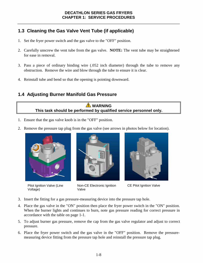
2. Remove the pressure tap plug from the gas valve (see arrows in photos below for location).
3. Insert the fitting for a gas pressure-measuring device into the pressure tap hole.
4. Place the gas valve in the "ON" position then place the fryer power switch in the "ON" position.When the burner lights and continues to burn, note gas pressure reading for correct pressure inaccordance with the table on page 1-1.
5. To adjust burner gas pressure, remove the cap from the gas valve regulator and adjust to correctpressure.
6. Place the fryer power switch and the gas valve in the "OFF" position. Remove the pressure-measuring device fitting from the pressure tap hole and reinstall the pressure tap plug.
Non-CE Electronic IgnitionValve
Pilot Ignition Valve (LineVoltage)
CE Pilot Ignition Valve

DECATHLON SERIES GAS FRYERSCHAPTER 1: SERVICE PROCEDURES
1-9
1.5 Adjusting the Pilot Flame
1.5.1 Main Pilot
1. Remove the cap from the pilot adjustment screw hole on the gas valve.
2. Using a small, flat-tipped screwdriver, turn the pilot adjusting screw counterclockwise toincrease length of flame or clockwise to decrease length of flame. Adjust to obtain a flame from1 inch to 1½ inches long.
3. Reinstall the pilot adjustment screw cap.
1.5.2 Trailing Pilot
1. Adjust the trailing pilot valve located on the burner manifold until a flame from 1 inch to 1½inches long is obtained.
1.6 Calibrating the Electronic Thermostat Controller and BackupOperating-Thermostat (optional)
1.6.1 Electronic Thermostat Controller
1. Fill the frypot to the lower OIL-LEVEL line with cooking oil/shortening. If solid shortening isused, it must be melted before starting the calibration procedure.
2. Ensure the fryer ON/OFF switch is in the "OFF" position, then light the pilot.
3. Place the fryer ON/OFF switch in the "ON" position. Set the electronic thermostat dial to 325°F(162°C).
4. Allow the oil/shortening to equilibrate at setpoint temperature. This is evident when the burnershave cycled on and off several times.
5. Insert a good grade thermometer or pyrometer into the frypot within 3 inches of the probe bulb.Ensure the tip of the thermometer/pyrometer does not touch the frypot burner-tube.
6. If the temperature on the thermometer is higher or lower than 325°F (162°C), the knob is out ofcalibration.
7. Calibrate the knob by first loosening the setscrew in the knob. After loosening setscrew, slowlyturn the knob to match the temperature reading of the thermometer. Tighten the setscrew,ensuring the knob does not move on the shaft during tightening.
8. Allow burners to cycle on and off several times, then recheck oil temperature as described in step#5. If the thermostat dial temperature matches the thermometer temperature, the thermostat iscalibrated. If not, repeat step #7.

DECATHLON SERIES GAS FRYERSCHAPTER 1: SERVICE PROCEDURES
1-10
1.6.1 Electronic Thermostat Controller (cont.)
9. After the calibration is complete, place the fryer power switch in the "OFF" position anddisconnect the fryer from the electrical supply.
1.6.2 Backup Thermostat (Optional)
1. Fill the frypot to the lower OIL-LEVEL line with cooking oil/shortening. If solid shortening isused, it must be melted before starting the calibration procedure.
2. Light the pilot.
3. Set the temperature control knob to 350°F (177°C).
4. Let the burners cycle on and off automatically three times in order for the cooking oil/shorteningtemperature to become uniform. If necessary, stir to get all shortening in the bottom of thefrypot melted.
5. Insert a good-grade thermometer or pyrometer probe into the oil/shortening, with the end nearthe fryer temperature-sensing probe.
NOTE: The temperature-sensing probe is mounted on the frypot tube.
6. When the burner starts for the fourth time, the thermometer/pyrometer reading should be withinthe range 335-360°F (168-182°C). If it is not, calibrate as follows:
a. Remove the thermostat knob by pulling straight out on the knob with a firm, steady pull.The temperature adjusting screw is located in the middle of the thermostat shaft.
b. Insert a small-bladed flat-tipped screwdriver into the adjusting screw. Turn the adjustingscrew in ¼-turn increments to adjust the temperature. Turning the screw clockwisedecreases the temperature; turning it counter-clockwise increases the temperature. DO NOTallow the thermostat shaft to turn while turning the adjusting screw.
c. Recheck the thermometer/pyrometer reading the next time the burner comes on.
d. Repeat steps 4.b. through 4.c. until the thermometer/pyrometer reading remains within therange 335-360°F (168-182°C) through several cycles. If calibration cannot be obtained forany reason, call a Factory Authorized Service Center for service.
e. Reinstall the thermostat knob.
7. Remove the thermometer or pyrometer.

DECATHLON SERIES GAS FRYERSCHAPTER 1: SERVICE PROCEDURES
1-11
1.7 Replacing Fryer Components
1.7.1 Replacing the Computer
1. Disconnect the fryer from the electrical supply.
2. Unscrew the two computer panel screws.The computer panel is hinged at the bottomand will swing open from the top.
3. Unplug the fryer wiring harness and groundwire from the back of the computer.
4. Remove the computer by lifting it from thehinge slots in the fryer control panel frame.
5. Reverse the procedure to install a newcomputer.
Computer panel in “down” position.
Disconnect the 15-pin connector and groundwire (arrows) from the computer.
Control panel frame with computer removed.

DECATHLON SERIES GAS FRYERSCHAPTER 1: SERVICE PROCEDURES
1-12
1.7.2 Replacing the Backup Thermostat (if applicable)
1. Disconnect the fryer from the electrical supply.
2. Drain cooking oil/shortening from frypot.
3. Remove thermostat knob.
4. Disconnect the wiring plug(s)from the component shield/control box.
5. Disconnect leads from terminal block.
6. Remove screws securing the thermostat bracket to fryer.
7. Follow Steps 5-7 in Section 1.7.4 (Replacing the High-Limit Thermostat) to remove thermostatfrom frypot.
8. Remove defective thermostat from the thermostat bracket and replace with a known goodthermostat. Use care not to damage the probe bulb and lead on the new thermostat.
9. Reverse the above steps to install the replacement.
CAUTIONThe Backup Thermostat Control must be calibrated after installation is complete.
Refer to Section 1.6.2 for calibration instructions.

DECATHLON SERIES GAS FRYERSCHAPTER 1: SERVICE PROCEDURES
1-13
1.7.3 Replacing the Temperature Probe (Computer-Equipped Fryers)
1. Disconnect the fryer from the electrical supply.
2. Drain cooking oil/shortening from the frypot. Allow the frypot to cool completely beforeproceeding.
3. Remove the fryer door for easier access to thetemperature probe. Lift door up, disengagerod from lower door bracket, and thenremove door.
4. Disconnect the probe harness connector(arrow). Use a pin pusher to remove plugfrom probe wires (probe side only). Retainthe plug for re-assembly on new probe.
5. Remove the appropriate burners to gainaccess to the temperature probe (see Steps20-22 for more detail).
Remove door for easier access to temperatureprobe.
Disconnect the two-pin probe harness connector(arrow).
Remove burners to gain access to temperatureprobe.

DECATHLON SERIES GAS FRYERSCHAPTER 1: SERVICE PROCEDURES
1-14
1.7.3 Replacing the Temperature Probe (Computer-Equipped Fryers-cont.)
6. Loosen and unscrew completely thecompression nut, then the pass-through nutfrom the frypot. Proceed to the next stepbefore removing probe from frypot.
Note: The temperature probe can beremoved through the top of the frypot asfollows: Ensure the two-pin connector hasbeen removed from the probe wiring harness(step 4, this section). Remove the harnessinsulation. The probe can be pulled throughthe frypot from the top (complete step 7, thissection, prior to removing probe).
7. Remove probe bracket and probe spring fromprobe inside frypot (bracket location andconfiguration will vary according to fryermodel). Retain mounting hardware forinstallation of new temperature probe.
8. Carefully remove the probe from the frypot.As the probe is removed, tilt the probe at anangle to facilitate removal (curved probesonly).
9. Reverse steps for installation of new probe.
IMPORTANT: When installing new probe,ensure probe is positioned properly with themounting hardware installed prior to tighteningthe compression nut. Once tightened, the probecannot be repositioned.
Loosen and unscrew completely the compressionnut (bottom arrow), then the pass-through nut (toparrow).
First remove the probe bracket (two screws), thenthe probe spring. Retain mounting hardware forinstallation of new probe.
First remove the probe bracket (two screws), thenthe probe spring. Retain mounting hardware forinstallation of new probe.
Removing old probe from frypot. (Frypot removedfrom fryer for clarity).
DECATHLON SERIES GAS FRYERSCHAPTER 1: SERVICE PROCEDURES
1-15
1.7.4 Replacing the High-Limit Thermostat
1. Turn fryer off and drain cooking oil/shortening from the frypot. Allow the frypot to coolcompletely before proceeding.
2. Perform steps 1-4 in Section 1.7.1, Replacing the Computer.
3. Remove fryer door for easier access (see Section 1.7.3, Step #3 for more detail).
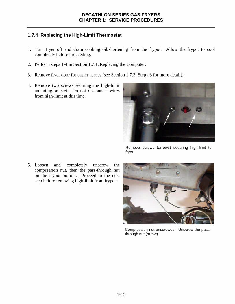
4. Remove two screws securing the high-limitmounting-bracket. Do not disconnect wiresfrom high-limit at this time.
5. Loosen and completely unscrew thecompression nut, then the pass-through nuton the frypot bottom. Proceed to the nextstep before removing high-limit from frypot.
Remove screws (arrows) securing high-limit tofryer.
Compression nut unscrewed. Unscrew the pass-through nut (arrow)

DECATHLON SERIES GAS FRYERSCHAPTER 1: SERVICE PROCEDURES
1-16
1.7.4 Replacing the High-Limit Thermostat (cont.)
6. Remove high-limit mounting bracket andhigh-limit spring inside frypot. Retainmounting hardware for installation of newhigh-limit.
7. Carefully pull high-limit capillary tube andbulb out of the frypot from the bottom.
Remove high-limit mounting hardware. Retainmounting hardware for installation of new high-limit. (Mounting hardware and location will varyaccording to fryer model.)
Remove high-limit capillary tube and bulb from thebottom of the frypot.

DECATHLON SERIES GAS FRYERSCHAPTER 1: SERVICE PROCEDURES
1-17
1.7.4 Replacing the High-Limit Thermostat (cont.)
8. Mark and disconnect wires at the high-limitin the component box.
9. Remove high-limit from fryer by pulling thecapillary tube and bulb through thecomponent box opening (arrow). (This mayrequire removal of the control panel frame.)
10. Reverse the above steps for high-limitinstallation.
IMPORTANT: When installing new high-limitor backup thermostat, ensure the capillary tubeand bulb are positioned properly with themounting hardware installed prior to tighteningthe compression nut. Once tightened, thecapillary tube cannot be repositioned.
Mark and disconnect high-limit wiring (arrows).(Reconnect wires to the same terminals on thereplacement high-limit.)
Pull the capillary tube and bulb up and through thecomponent box opening to remove old high-limit.Removing the control panel frame will facilitatehigh-limit removal. Replace control panel frameafter new high-limit has been installed.

DECATHLON SERIES GAS FRYERSCHAPTER 1: SERVICE PROCEDURES
1-18
1.7.5 Replacing Rocker Switches
1. Disconnect the fryer from the electrical supply.
2. If switches are located on front panel, remove the screws securing panel to fryer. Do not allowthe panel to hang on the switch wiring harness; use some type of support. If the switches arelocated in a control box within the fryer, remove the screws securing the switch panel to thecontrol box. Do not allow the switch panel to hang from the switch wiring harness.
3. Depress the retaining clips (see illustration below) and push the switch out of the slot. If there isa switch-guard present, retain it for installation of the replacement switch.
Depress clips on each end toremove switch from controlpanel.
When connec t ingwires to replacements w i t c h , p a s s t h ewi res th rough thes w i t c h g u a r d ( i fappl icable) beforeconnecting to switch.
4. Remove wires one at a time from the switch being removed and connect to the replacementswitch until all wires are transferred.
5. Reverse the above steps for reassembly.

DECATHLON SERIES GAS FRYERSCHAPTER 1: SERVICE PROCEDURES
1-19
1.7.6 Replacing the Gas Valve
DANGERDrain the frypot or remove the handle from the drain valve before proceeding further.
1. Disconnect fryer from electrical and gas supplies.
2. Disconnect the wires from the gas valve terminal block, marking each wire to facilitatereconnections. For 120VAC gas valves, disconnect the black wire from the high-limit, thenremove the bobtail connecting the white wire.
3. Remove the high-limit thermostat wire from the gas valve pilot coil (all but 120VACvalves).
4. Remove the pilot gas line fitting from the gas valve.
5. Remove the pipe union collars to the left and right of the gas valve and remove the valve.
6. Remove the pipefitting from the old gas valve and install on the replacement valve, usingLoctite™ PST567 or equivalent pipe thread sealant on threads. Do not apply sealant to thefirst two pipe threads. Doing so will clog and damage the gas valve.
7. Reverse steps 1-5 to install the replacement gas valve.
1.7.7 Replacing the Pilot Assembly
1. Remove the pilot tubing from the bottom of the pilot assembly.
2. If the pilot is an electronic ignition pilot, disconnect the ignition cable and the sense wire.
3. Remove the two pilot mounting screws from the pilot mounting-bracket and remove the pilot.
4. Reverse the procedure to replace the pilot assembly.
NOTE: The above procedure is applicable to standing, electronic ignition and trailingpilot assemblies.

DECATHLON SERIES GAS FRYERSCHAPTER 1: SERVICE PROCEDURES
1-20
1.7.8 Replacing the Frypot
1. Open fryer doors on fryer and remove filter pan (if applicable). Ensure computer and all powerswitches are off. Drain and dispose of or store oil/shortening from all frypots prior to movingfryer.
DANGERHot cooking oil/shortening will cause severe burns. Never attempt to move thisappliance when filled with hot cooking oil/shortening or to transfer hot cooking
oil/shortening from one container to another.
2. Turn gas valve off, then turn gas off at supply valve or meter. Disconnect supply line from gasmanifold at rear of fryer.
NOTE: If restraints are installed on the fryer, disconnect restraints prior todisconnecting the gas supply line.
3. Unplug fryer from electrical supply source.
4. Remove fryer door for access to cabinetry components. Lift door up, disengage rod from lowerdoor bracket, remove and set door aside.
5. Remove basket hanger from fluecap by lifting up and off of fryer.(Some units may have a built-influe deflector on the baskethanger). Units with basket liftswill require the removal of the liftarms prior to removing the baskethanger.
6. Carefully pry up capping stripwith a screwdriver or similar tool.Remove capping strip and setaside.
Removing basket hanger.
Removing capping strip.

DECATHLON SERIES GAS FRYERSCHAPTER 1: SERVICE PROCEDURES
1-21
1.7.8 Replacing the Frypot (cont.)
7. Locate all screws securing back panels. Screw location/orientation will vary according to fryermodel.
8. Remove back panels on fryer. Retain screws for re-assembly.
9. Remove screw securing back-panel brace to flue cap. Supportbrace with hand while removingscrew to prevent brace fromfalling away. Remove brace andset aside for reassembly.
Typical back-panel screw locations.
Removing back panel to flue cap brace (arrow).

DECATHLON SERIES GAS FRYERSCHAPTER 1: SERVICE PROCEDURES
1-22
1.7.8 Replacing the Frypot (cont.)
10. Remove screws securing flue-capbraces to frypot (a nut-driver withan extension or long screwdriveris required). Use care not to dropthe screws into the flues. If thishappens, the screws can beretrieved when the flue isremoved (Step 16). Use ascrewdriver or similar tool to freeflue cap from frypots. Removeflue cap by lifting up and off offryer.
11. Remove gas manifold pipe foraccess to gas manifold shield bydisconnecting at the unions.Ensure gas supply is shut off andsupply line is disconnected priorto removing. Set gas manifoldaside. Remove screws securinggas manifold shield. Removeshield to access oil-returnplumbing components connectedto the frypots.
NOTE: For units without built-infiltration skip the steps pertainingto removal/replacement of oil-return plumbing.
12. Remove cotter-pin from oil-returnactuator rod. Observe washerplacement prior to removing rodfrom the valve actuator (arrows).Disconnect actuator rod andremove washers. Set washersaside for later re-assembly.
Removing flue cap.
Removing gas manifold shield.
Disconnecting oil-return linkage from valve.

DECATHLON SERIES GAS FRYERSCHAPTER 1: SERVICE PROCEDURES
1-23
1.7.8 Replacing the Frypot (cont.)
13. Remove steel line from oil-returnvalve and nipple by looseningflare fittings on both ends. Holdbackup with an adjustable wrenchwhen removing fittings.
(Absorbent cloth or paper towelsshould be placed under the oilline prior to removal, to catch anyoil remaining in the lines.)
14. Unscrew both flare fittingscompletely prior to line removal.Remove oil-return line and setaside (see Step 15 if line does notdisengage easily).
15. Turning the oil-return valveslightly outward with a pipewrench or similar tool willfacilitate return-line removal.
Remove oil-return line after disconnecting flarenuts.
Turn the oil-return valve slightly outward to facilitateremoval of the oil-return line.
Holding backup while unscrewing flare nut onoil-return line.

DECATHLON SERIES GAS FRYERSCHAPTER 1: SERVICE PROCEDURES
1-24
1.7.8 Replacing the Frypot (cont.)
16. Remove four bolts securing flueto the frypot being removed.Remove the flue by sliding backand away until clear of frypot.Retrieve any screws dropped intothe flue during removal of the fluecap to frypot bracket.
17. Remove oil-return valve fromfrypot (see Step 15 for detail).Turn the valve assembly counter-clockwise to remove. If nippleremains in frypot, remove it also.Set aside for reassembly.
18. Remove drain extension fromelbow on drain valve. Set asidefor reassembly.
NOTE: Drain extensions willvary in shape and size accordingto fryer model.
19. If fryer is equipped with a frontdrain manifold, disconnectmanifold at slip-nut fitting andremove.
Removing bolts (arrows) securing flue to frypot.
Removing drain extension.
On front drain manifolds, disconnect the slip-nut fitting (arrow)to remove.

DECATHLON SERIES GAS FRYERSCHAPTER 1: SERVICE PROCEDURES
1-25
1.7.8 Replacing the Frypot (cont.)
20. Remove the burner shield.Loosen burner bolts (two perburner) that secure burners to theburner support rail.
NOTE: On most fryers, do notremove bolts from burners. Somefryers have an additional bracketthat warrants removal of theburner bolts.
21. Lift each burner upward to clearthe orifice, then slant the top ofthe burner inward to clear theburner-brace keyholes.
NOTE: On older Decathlonfryers, the right-center and centerburners cannot be removed untilthe trailing pilot assembly isremoved (explained in step 22).
22. On Decathlon fryers with aburner-mounted trailing pilot,loosen the bolts securing the pilotassembly to the burners andremove.
NOTE: Current production unitsdo not require removal of trailingpilot when removing burners.
Loosening burner bolts prior to burner removal.
Old-style trailing pilot bracket is mounted on burners.
Removing burners from fryer.
DECATHLON SERIES GAS FRYERSCHAPTER 1: SERVICE PROCEDURES
1-26
1.7.8 Replacing the Frypot (cont.)
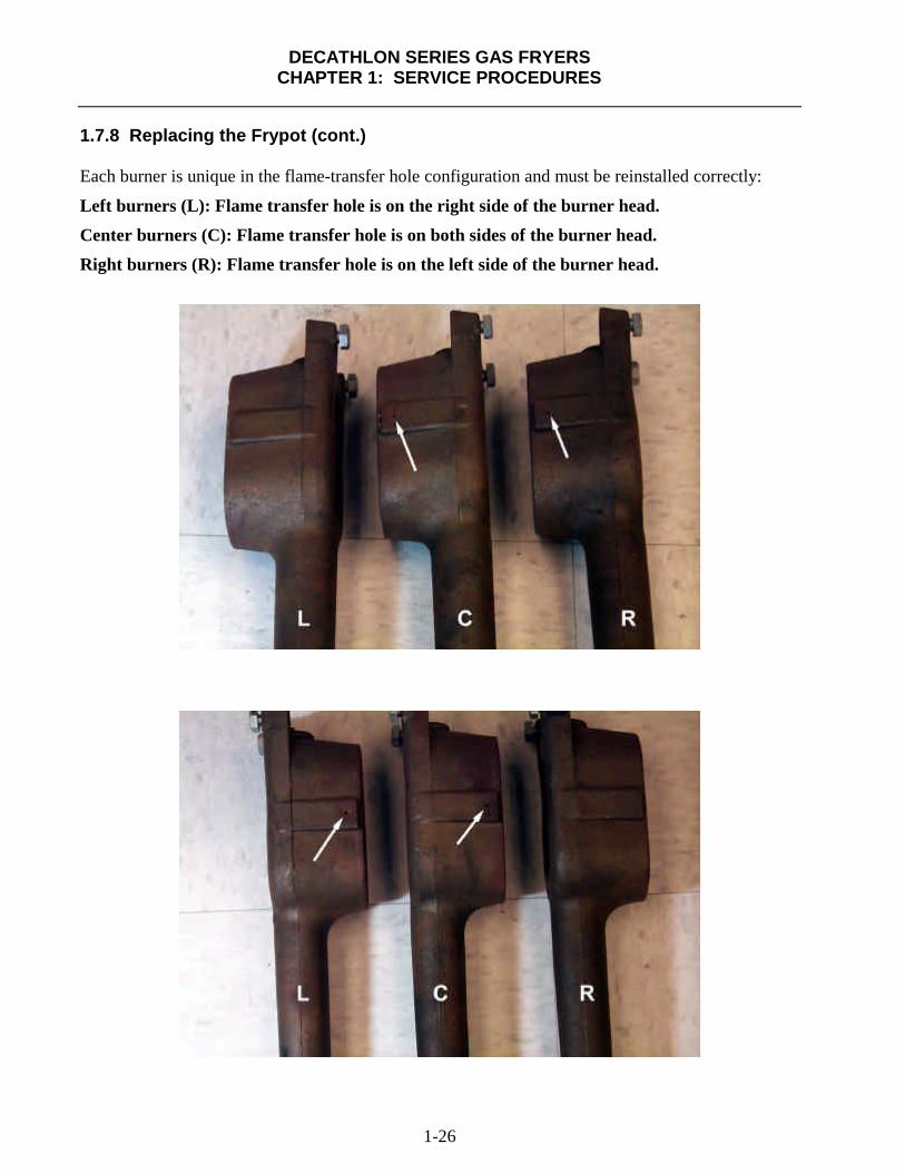
Each burner is unique in the flame-transfer hole configuration and must be reinstalled correctly:
Left burners (L): Flame transfer hole is on the right side of the burner head.
Center burners (C): Flame transfer hole is on both sides of the burner head.
Right burners (R): Flame transfer hole is on the left side of the burner head.

DECATHLON SERIES GAS FRYERSCHAPTER 1: SERVICE PROCEDURES
1-27
1.7.8 Replacing the Frypot (cont.)
23. Remove screw(s) securing theelectronic or standing pilotbracket to the frypot bracket.Reposition ignitor assembly downand away from frypot. Use carenot to bend, kink or damage theelectronic ignition lines andwiring.
NOTE: Remove the trailing pilotassembly on current productionmodels as follows: Disconnect thepilot supply line from the trailingpilot valve on the burnermanifold. Remove the mountingscrew(s) as described in Step 23,then remove trailing pilot.
24. Remove cotter pin from drainvalve linkage, then disconnectactuator rod from drain valveactuator.
25. Remove elbow (tee-fitting onfryers equipped with frontmanifold) and nipple from thedrain valve.
26. If ball-retainer nut breaks looseand unscrews from the valve,remove it from the elbow nippleand re-install in valve. Use carenot to damage the brass threadswhen removing from elbownipple, or when re-installing intodrain valve.
Removing electronic/standing pilot assembly.
Remove cotter pin (arrow), then disconnect theactuator rod.
Ball retainer nut (arrow) on drain valve.

DECATHLON SERIES GAS FRYERSCHAPTER 1: SERVICE PROCEDURES
1-28
1.7.8 Replacing the Frypot (cont.)
27. Remove the temperature probe from frypot. (see Section 1.7.3, Replacing Temperature Probe forspecific instructions.
28. Remove the high-limit (see Steps 5-7, Section 1.7.4- Replacing the High-Limit Thermostat) andbackup thermostat [see Section 1.7.2- Replacing Backup Thermostat (where applicable)] fromfrypot.
29. If the fryer is equipped withdrain-valve microswitches, markthe wires and microswitchterminals, then disconnect wiresfrom the switch. Secure the wiresto prevent damage when frypot isremoved.
30. Remove bolts from bracketssecuring burner manifold tofrypot. Leave the manifold inplace.
Left: Microswitch wires marked for removal (ensuremicroswitch terminals are marked the same as the wiresremoved). Right: Microswitch mounted to drain valve.
Removing bolts (arrows) from burner manifold supportbrackets (both sides). Leave the burner manifold in placeafter removing bolts.

DECATHLON SERIES GAS FRYERSCHAPTER 1: SERVICE PROCEDURES
1-29
1.7.8 Replacing the Frypot (cont.)
31. Using a sharp knife or box-cutter,cut the silicon seal between and infront of the two frypots (two-vator more). Use care not to scratchstainless steel surfaces.
32. Remove frypot from fryer bylifting up and out.
33. Position the frypot upside downon a suitable work surface.
34. Record position of the valve stemin relation to the frypot prior toremoving the drain valve. Ifequipped, remove microswitchesand mounting hardware fromvalve prior to removal. Using asuitable wrench, remove the drainvalve from the frypot. UseLoctite PST567 sealant wheninstalling drain valve onreplacement frypot.
35. Reverse the above steps to installreplacement frypot.
Lifting frypot from fryer.
Cutting frypot seal prior to frypot removal.
Removing drain valve from frypot.
DECATHLON SERIES GAS FRYERSCHAPTER 1: SERVICE PROCEDURES
1-30
1.8 Troubleshooting and Problem Isolation
This section is intended to provide technicians with a general knowledge of the broad problemcategories associated with this equipment, and the probable causes of each. With this knowledge, thetechnician should be able to isolate and correct any problem encountered.
Problems you are likely to encounter can be grouped into seven broad categories:
1. Ignition failures2. Improper burner functioning3. Improper temperature control4. Computer-related problems5. Filtration problems6. Leakage7. Basket lift malfunctions.
The probable causes of each category are discussed in the following sections. Troubleshootingguides are included in Section 1.9 to assist in identifying some of the more common problems.
1.8.1 Ignition Failures
Ignition failure occurs when the ignition module fails to sense a flame within the 60-second timedelay period and locks out. Turn the fryer off, locate and fix the problem, then turn fryer back on toclear the module lock.
There are three primary reasons for ignition failure, listed in order of probability:
1. Problems related to the gas and/or electrical power supplies.
2. Problems related to the electronic circuits.
3. Problems related to the gas valve.
Problems Related to the Gas and/or Electrical Power Supplies
The main indicators of this are that an entire battery of fryers fails to light. Verify that the quickdisconnect hose is properly connected, the fryer is connected to power, the main gas supply valve isopen, and the circuit breaker for the fryer electrical supply is not tripped. Some fryers are equippedwith a fryer reset-switch that must be reset each time the fryer is turned off.

DECATHLON SERIES GAS FRYERSCHAPTER 1: SERVICE PROCEDURES
1-31
Problems Related to the Electronic Circuits
If gas and electrical power are supplied to the fryer, the next most likely cause of ignition failure is aproblem in the 24 VAC circuit of fryers equipped with electronic ignition systems, or in the pilotsystem for those without electronic ignition. If the fryer is equipped with a SUFF/UFF filtrationsystem, first verify that the drain valve is fully closed. (The valve is equipped with a microswitchthat must be closed for power to reach the gas valve. Often, although the valve handle appears to bein the closed position, the microswitch is still open.) If the valve is fully closed, or the fryer does nothave a filtration system, refer to the troubleshooting guides in this chapter.
Problems Related to the Gas Valve
If the problem is not in the 24 VAC circuit or pilot system, it is most likely in the gas valve itself, butbefore replacing the gas valve refer to the troubleshooting guides in this chapter.
1.8.2 Improper Burner Functioning
With problems in this category, the burner ignites but exhibits abnormal characteristics such as"popping", incomplete lighting of burner, fluctuating flame intensity, and flames "rolling" out of thefryer.
"Popping" indicates delayed ignition. In this condition, the main gas valve is opening but the burneris not immediately lighting. When ignition does take place, the excess gas "explodes" into flame,rather than smoothly igniting.
The primary causes of popping are:
• Incorrect or fluctuating gas pressure
• Misdirected or weak pilot flame (main and/or trailing pilot)
• Clogged burner flame-transfer holes
• Clogged burner orifices
• Clogged burners
• Inadequate make-up air
• Heat damage to the controller or ignition module
• An out-of-adjustment ignitor or broken ignition wire
• A defective ignition module

DECATHLON SERIES GAS FRYERSCHAPTER 1: SERVICE PROCEDURES
1-32
1.8.2 Improper Burner Functioning (cont.)
If popping occurs only during peak operating hours, the problem may be incorrect or fluctuating gaspressure. Verify that the incoming gas pressure (pressure to the gas valve) is in accordance with theappropriate CE or Non-CE requirements listed in the Installation and Operation manual that camewith the fryer, and that the pressure remains constant throughout all hours of usage. Refer toAdjusting Burner Manifold Pressure in Section 1.4 if burner manifold pressure is suspected ofbeing incorrect.
If popping is consistent during all hours of operation, verify that the pilot is properly positionedabove the burner orifice and that the pilot pressure is correct. Correct pilot pressure is indicated by aflame 1 to 1½" long. Also verify that ignitor is properly adjusted (electrode tip 1/8" from pilot hoodcorner). Refer to Section 1.5 for pilot adjustment procedure.
Clogged burners, burner orifices and/or burner flame transfer holes (see Section 1.7.8, page 1-26 forreference) are also likely causes of delayed ignition. Clogged burners are indicated by uneven flameor partial flame on the burner face. Clogged orifices are indicated by no flame. Clogged burnerflame transfer holes prevent the outermost burners from lighting immediately with the middleburners (four- and five-tube frypots).
Another cause of popping is an insufficient air supply or drafts that are blowing the pilot flame awayfrom the burner. Check for "negative pressure" conditions in the kitchen area. If air is flowing intothe kitchen area, this indicates that more air is being exhausted than is being replenished and theburners may be starved for air.
If the fryer’s gas and air supplies are okay, the problem most likely is with one of the electricalcomponents. Examine the ignition module for signs of melting/distortion and/or discoloration due toexcessive heat build-up in the fryer. (This condition usually indicates improper flue performance.).Also, examine the controller for the same conditions. A melted or distorted ignition module isautomatically suspect and should be replaced, but unless the condition causing excessive heat in thefryer is corrected, the problem is likely to recur.
Next, ensure the ignition wire is tightly connected at both ends and examine it for obvious signs ofdamage. Again, if damage is due to excessive heat in the fryer, that problem must also be corrected.
Check for proper operation by disconnecting the wire from the ignitor, inserting the tip of ascrewdriver into the terminal, and holding it near the frame of the fryer as the power switch is placedin the "ON" position. A strong, blue spark should be generated for at least 60 seconds.
DANGERMAKE SURE YOU ARE HOLDING THE INSULATED HANDLE OF THE SCREWDRIVER
AND NOT THE BLADE. THE SPARKING CHARGE IS APPROXIMATELY 25,000VOLTS.
Ensure the gap setting of the ignitor is correct (electrode tip 1/8" from pilot hood corner).

DECATHLON SERIES GAS FRYERSCHAPTER 1: SERVICE PROCEDURES
1-33
1.8.2 Improper Burner Functioning (cont.)
Burners lighting on the left side only may be caused by a trailing pilot problem (four- and five-tubefrypots) or improper burner manifold pressure.
Fluctuating flame intensity is normally caused by either improper or fluctuating incoming gaspressure, but may also be the result of variations in the kitchen atmosphere. Verify incoming gaspressure in the same way as for "popping", discussed in the preceding paragraphs. Variations in thekitchen atmosphere are usually caused by air conditioning and/or ventilation systems starting andstopping during the day. As air conditioning/ventilation systems start and stop, the pressure in thekitchen may change from positive or neutral to negative, or vice versa. Changes in airflow patternsmay affect flame intensity.
Flames "rolling" out of the fryer are usually an indication of negative pressure in the kitchen. Air isbeing sucked out of the fryer enclosure and the flames are literally following the air. If negativepressure is not the cause, check for high burner-manifold gas pressure in accordance with theprocedures in Section 1.4. An obstructed flue, which prevents the fryer from properly exhausting,may also be the cause.
Excessively noisy burners, especially with flames visible above the flue opening, may indicate thatthe burner gas pressure is too high, the tube diffusers are defective or burned out, or it may simply bethat the gas valve vent-tube is blocked (if applicable). If the gas pressure is correct, the tubediffusers are intact and in good condition, and the vent-tube is unobstructed (if applicable), the gasvalve regulator is probably defective.
1.8.3 Improper Temperature Control
Temperature control, including the melt cycle, is a function of several interrelated components, eachof which must operate correctly. The principal component is the temperature probe. Dependingupon the specific configuration of the fryer, other components may include the interface board, thecomputer/controller itself, and the ignition module.
Improper temperature control problems can be categorized into melt cycle problems and failure tocontrol at setpoint.
Failure to Control at Setpoint
In fryers equipped with an electronic thermostat controller/optional backup operating-thermostat, theproblem will be with the thermostats themselves. Possible causes are that the thermostats are out ofcalibration or defective. Refer to Section 1.6 for instructions on calibrating the thermostats.
In fryers equipped with computers, the problem may be with the temperature probe, the interfaceboard, or the computer. Refer to the troubleshooting guides in this chapter.

DECATHLON SERIES GAS FRYERSCHAPTER 1: SERVICE PROCEDURES
1-34
1.8.4 Computer-Related Problems
Compu-Fry Features
Sensitivity or "Stretch and Shrink Time"
Sensitivity or stretch time is a programmable feature that increases or decreases the cook timecountdown based on variations in the oil temperature from the setpoint.
The sensitivity for each product button has 10 settings (0 through 9). A "0" sensitivity setting willdisable the feature (no change in cooking time), while a nine will provide the highest sensitivity ormost change. The correct sensitivity for any product is based on the product, its density, the setpointtemperature, and the customer’s own requirements.
Common Computer Complaints
Most problems concerning computers have to do with programming them. There are four commoncomplaints. The complaints, their causes, and corrective actions are:
1. Fryer constantly displays " ".
Cause: Setpoint incorrect or missing.
Corrective Action: Press 1 6 5 0, enter the correct setpoint using keypad, then press tolock in the setpoint.
2. Temperature is displayed in Celsius.
Cause: Computer is programmed to display in Celsius.
Corrective Action: Press 1 6 5 8.
3. Temperature is constantly displayed.
Cause: Computer is programmed for constant temperature display.
Corrective Action: Press 1 6 5 L.
4. Computer times down too slowly or too quickly.
Cause: Computer is compensating for oil temperature via the sensitivity setting.
Corrective Action: Reprogram sensitivity setting for each product in accordance withprogramming instructions in the Compu-Fry Operation and Programming manual, P/N 819-5865.

DECATHLON SERIES GAS FRYERSCHAPTER 1: SERVICE PROCEDURES
1-35
1.8.5 Filtration Problems
The majority of filtration problems arise from operator error. One of the most common errors isplacing the filter paper on the bottom of the filter pan rather than over the filter screen.
Whenever the complaint is "the pump is running, but no oil is being filtered", check the installationand size of the filter paper. Verify that the O-ring on the slip-connection is in good condition. Amissing or worn O-ring allows the pump to suck air, decreasing its efficiency.
If the pump motor overheats, its thermal overload will trip and the motor will not start until it isreset. If the pump motor does not start, press the red reset switch located on the rear of the motor.Also, reset the filter circuit breaker located under the fryer control panel. If the pump then starts,something caused the motor to overheat. Maybe several frypots were filtered one after the other andthe pump got hot. Letting the motor cool down for at least a half-hour is all that is required in thiscase. More often, the pump overheated for one of the following reasons:
• Shortening was solidified in the pan or filter lines.
• The operator attempted to filter unheated oil or shortening. Cold oil and shortening are thickerand cause the pump motor to work harder and overheat.
If the motor runs but the pump does not, there is a blockage in the pump. Incorrectly sized orinstalled paper allows food particles and sediment to pass through the filter pan and into the pump.When sediment enters the pump, the gears bind up causing the motor to overheat, tripping thethermal overload. Solidified shortening in the pump will produce the same result.
A pump seized by debris or hard shortening must be disassembled, cleaned and reassembled.
1. Disconnect power to the filter system.
2. Remove the front cover of the pump to access the gears inside, if the pump is accessible whilestill inside the cabinet. If the front cover is not accessible, the pump must be removed from thepump motor (remove input/output plumbing from the pump prior to removing pump). Removethree setscrews to disengage the pump from the motor.
Remove these bolts (6) toremove pump cover.
Remove debris or hardenedshortening to free gears.

DECATHLON SERIES GAS FRYERSCHAPTER 1: SERVICE PROCEDURES
1-36
1.8.5 Filtration Problems (cont.)
3. Prior to reassembly, the inside housing must be clean and free of any sediment or debris. Failureto completely clean the inside-housing and ring gear will cause gear binding after reassembly.
Incorrectly sized or installed paper will allow food particles and sediment to pass through and clogthe suction tube on the bottom of the filter carriage. Particles large enough to block the suction tubemay indicate that the crumb tray is not being used.
Pan blockage can also occur if shortening is left in the pan and allowed to solidify. Heater strips (ifequipped) on the oil return plumbing are designed to prevent solidification of shortening left in theplumbing. Heater strips will not melt or prevent solidification of shortening in the pan.
Blockage removal can be accomplished by forcing the item out with an auger or drain snake.Compressed air or other pressurized gases should not be used to force out the blockage.
The electronics of the SUFF/UFF filtration systems are simple and straightforward. Microswitches,attached to handles for each vat and wired in parallel, provide the 24 VAC required to activate thepump relay coil when the handles are moved to the ON position. The activated pump relay coil pullsin the pump motor switch, supplying power to the pump motor.
Filter systems equipped with oil-return heaters are wired into the 120 VAC source, which remainenergized as long as the unit is plugged in.
1.8.6 Leakage
Frypot leaks are almost always due to improperly sealed high-limit, thermostats/temperature probeand drain fittings. When installed or replaced, each of these components must be sealed with LoctitePST567 sealant or equivalent to prevent leakage. In very rare cases, a leak may develop along oneof the welded edges of the frypot, or where the tube is welded to the frypot. When this occurs, thefrypot must be repaired or replaced.
If the sides or ends of the frypot are coated with oil/shortening, the most likely cause is spillage overthe top of the frypot rather than leakage.
Frypot locations (indicated byarrows) where potential leaks couldoccur.

DECATHLON SERIES GAS FRYERSCHAPTER 1: SERVICE PROCEDURES
1-37
1.8.7 Basket Lift Malfunctions
1.8.7.1 Bell-Crank Basket Lifts
Most Decathlon Series gas fryers areequipped with a bell-crank stylebasket lift: A cam and bell crank areconnected to the basket lift arm by a flatmetal link. The cam is attached to adrive motor. The motor rotates the cam,thus raising or lowering the lift armlinked to the bell crank. A roller-activated microswitch is used to limittravel. When the roller in themicroswitch is in contact with the cam,the motor is energized. As the camrotates, the roller loses contact with thecam and the motor power circuit isbroken, de-energizing the motor.
Timing circuitry in the controllerinitiates and stops basket lift operation.When the product button is pressed, thetiming circuitry activates a coil in thebasket lift relay to supply power to themotor. The microswitch stops the motorat the lift’s lower travel limit and theswitch contacts are reversed. At the endof the programmed cooking time, thetiming circuit activates the coil oncemore and the lift rises until themicroswitch again loses contact withthe cam, opening the motor powercircuit and stopping the motor.
Problems with the bell-crank basket lift system can be grouped into two categories:
• Binding/jamming• Motor and gear problems
Binding/Jamming
Noisy, jerky or erratic movement of the lifts are usually due to lack of lubrication of the lift armconnection points. Apply a light coat of Lubriplate or similar lightweight white grease to theconnection points to correct the problem.
Back view of bell-crank basket lift.
Bell-crank basket-lift arms.

DECATHLON SERIES GAS FRYERSCHAPTER 1: SERVICE PROCEDURES
1-38
1.8.7.1 Bell-Crank Basket Lifts (cont.)
Motor Problems
If power is reaching the motor but the motor fails to run, the motor is burned out and must bereplaced.
1.8.7.2 Modular Basket Lifts
Older Decathlon Series fryers may be equippedwith modular basket lifts. The modular basketlift consists of a notched rod to which the basketlift arm is attached, a reversible-drive gear motor,and a pair of roller-activated microswitches. Thegear motor engages the notches in the rod,moving it up or down. Microswitches at theupper and lower limits of movement stop themotor when the basket is in the full up or fulldown position. Manual (push-button) controls, orthe computer controls voltage to the system.
Problems with the modular basket lift system canbe grouped into three categories:
• Binding/jamming• Motor and gear problems• Electronics problems
A
A
MODULAR BASKET LIFT
BLACKRED 1BRW 1
BLACKRED 2BRW2
SECTION A - A
Binding/Jamming
Noisy, jerky or erratic movement of the lifts is usually due to lack of lubrication of the rods and theirbushings. Apply a light coat of Lubriplate or similar lightweight white grease to the rod andbushings to correct the problem.
Another possible cause of binding is improper positioning of the motor, which prevents the gearfrom correctly engaging the teeth in the rod. To correct the problem, loosen the screws that hold themotor in place and move it forward or backward until the rod has just enough slack to be rotatedslightly.
Motor and Gear Problems
The most likely problem is erratic motion of the lift due to a worn drive gear. Failure to keep the liftrod and bushings properly lubricated will cause unnecessary wear of the gear. The problem iscorrected by replacing the worn gear.

DECATHLON SERIES GAS FRYERSCHAPTER 1: SERVICE PROCEDURES
1-39
Motor and Gear Problems (cont.)
If the lift cycles correctly but fails to remain in the up position, the problem is a failed motor brake.A failed motor brake cannot be repaired and requires replacement of the motor itself. If power isreaching the motor but the motor fails to run, the motor is burned out and must be replaced.
Electronic Problems
This category encompasses problems with the relays, microswitches, capacitors, resistors, interfaceboard, wiring, and controls.
Troubleshooting the electronics of the modular basket lift is simply a process of verifying currentflow through the components up to and including the motor. Using a multimeter set to the 250 VACrange, check the connections on both sides of the component for the presence of 120 VAC. Thesimplified wiring diagrams on the preceding pages identify the components and wiring connectionpoints.
1.9 Troubleshooting Guides
The following troubleshooting guides are intended to assist service technicians in quickly isolatingthe probable causes of equipment malfunctions by following a logical, step-by-step process.
1.9.1 General Troubleshooting
PROBLEM PROBABLE CAUSES CORRECTIVE ACTIONBurner won’t ignite.
Light in ON/OFF switchis not illuminated.
A. ON/OFF switch is off. A. Turn ON/OFF switch on.
ON/OFF switch is on,but the switch light is not
illuminated.
A. No voltage at switch. A. Ensure line voltage is present at theswitch.
A. Drain microswitch circuit (filter-equipped units) is open.
A. Ensure drain valve is fully closed andmicroswitch is functioning. Replacemicroswitch if defective.
B. Voltage is present at ON/OFF switch,but continuity of the switch in ONposition is not "0".
B. ON/OFF switch is defective. Replaceswitch with a known working switch.
C. Continuity of thermostat is not "0"(cooking oil/shortening temperature isat least 15°F below electronic/operating thermostat setting).
C. Thermostat(s) is/are defective.Replace defective thermostat with aknown working thermostat.
ON/OFF switch is on andthe switch light is
illuminated, but there isno output to gas valve.
D. Gas valve is suspect. D. Go to "No burner flame" section.

DECATHLON SERIES GAS FRYERSCHAPTER 1: SERVICE PROCEDURES
1-40
1.9.1 General Troubleshooting
A. Pilot does not stay lit (fryer is on andthermopile output is approximately400 millivolts and/or thermocouple isapproximately 25 millivolts.
A. Check high-limit switch. Switchcontinuity should be "0". If not, high-limit switch is defective. Replacehigh-limit switch.
B. Pilot does not stay lit (fryer is on andthermopile output is notapproximately 400 millivolts orthermocouple output is not 25millivolts.
B. Inspect thermocouple (units withoutinterface board) or thermopile (unitswith interface board) and replace ifdefective.
C. Pilot stays lit, and the high-limit andthermopile/thermocouple are knownworking, but burners fail to light.
C. Inspect gas valve and replace ifdefective.
D. Gas valve is known to be good, butthere is not 24 VAC (120VAC onsystems so equipped) at the gas valveterminals.
D. Inspect electronic/operatingthermostat sensor (while still infrypot) for damage. Replace if bent,dented or cracked. Inspect leads forfraying, burning, breaks and/or kinks.If found, remove and replacethermostat(s). Remove leads fromterminal block, allow oil to cool 15°F(8°C) below thermostat setting andcheck continuity. If continuity is not"0", then thermostat has failed.Replace thermostat(s).
No burner flame.
E. Continuity from terminal block to gasvalve electronic/operating thermostatwire is not "0".
E. Inspect wiring for breaks or shorts andrepair if necessary.
A. Incoming gas supply pressures are notwithin range [Natural- 6-14" W.C.(1.49-3.49 kPa); Propane- 11-14"W.C. (2.74-3.49 kPa)]
A. Inspect gas supply to fryer. Repairand/or replace faulty components(defective supply shut-off valves,incorrect piping size, etc.)
Fluctuating or erraticlighting of burner flame. B. Air in gas supply lines (new
installation).B. Allow unit to cycle on and off for
approximately 30 minutes to force airfrom gas manifold and lines.
Electronic/operatingthermostat will not adjust
to correct temperature.
A. Electronic/operating thermostat is outof calibration.
A. Calibrate electronic/operatingthermostat. Replace if calibration isnot possible.

DECATHLON SERIES GAS FRYERSCHAPTER 1: SERVICE PROCEDURES
1-41
1.10 Wiring Diagrams
Note: The diagrams in this section depict wiring as of the date of manual publication.It may not reflect design changes made to the equipment after publication. Refer tothe wiring diagram affixed to the unit when actually troubleshooting this equipment.
1.10.1 Decathlon Dual-vat, Current Configuration- Part 1 of 2
WHT
OPTIONALBOIL OUTSWITCH
6
6
48 OHMSRESISTOR
4321
CONNECTOR
AMP
4 PIN
1 32 4 PU
RB
LK
31 2 4 5
YE
LO
RG
PU
R
POT
YE
L
PU
R
BLU
53 421
120VACELECTRONICTHERMOSTATCONTROLLER
14
PUR
ORGYEL
WHTBLK
YELBLU
RED13
1211
910
8
2
WH
TB
RN
BR
N
37
1
OR
G
GR
NW
HT
BR
N
CONNECTOR
9 PINAMP
BLK
RE
D
C
4
WHTBRN
RED21 3 7
GR
N
5 6 8 9
421 3 75 6 8 9
GRN
SENSOR
HI TENSION
WH
T
115V 24V
GASVALVE
RED
BLU
IGNITOR
RED
WHT
BLU
MV/PVWHT
GR
N
CND
BRN
BLUE
WHT
MV
PV
SEN.
TH
THERMOSTAT
C.N.C.
IGNITION MODULE
IGNTR
HI-LIMIT
BR
N
POWER SWITCH PO
WE
R S
UP
PLY
115 V
GR
D
WHT
GRN
LIGHT
23
ORG
SPST
BR
N
WHT
BLK
2 AMP FUSE
LEFT FRYER8 7
WH
T
CONNECTOR-AMP2 PIN21
BLK
WHTSENSOR
TEMP.
21
To Right Fryer
To Right Fryer
805-1391Part 1 of 2

DECATHLON SERIES GAS FRYERSCHAPTER 1: SERVICE PROCEDURES
1-42
1.10.1 Decathlon Dual-vat, Current Configuration- Part 2 of 2
WHT
421 3
RESISTOR48 OHMS
CONNECTOR-AMP2 PIN
1 2 3 4 PU
RB
LK
21 3 54 6
14
YEL
WHTBLKORG
YELBLU
PUR
RED13
1211
910
8
2
WH
TB
RN
BR
N
37
1
YE
LO
RG
PU
R
POT
BLU
PU
R
YE
L
64 531 2
GR
N
BR
N
OR
G
WH
T
9 PINAMP
CONNECTOR
RE
D
BLK
C
BRNWHT
RED1 2 3 4
GR
N
65 7 98
1 2 3 4 65 7 98
GRN
VALVE
VALVEGAS
120 VAC
GAS VALVEALTERNATE
GAS
IGNITOR
LEADHI TENSION
WH
T
BLU
E
BR
N
SENSOR
HI TENSION
24V115V
WH
T
GASVALVE
RED
BLU
WHT
IGNITOR
RED
BLU
MV/PVWHT
GR
N
CND
BRN
BLUE
WHT
MV
PV
TH
SEN.
N.C. C.
IGNITION MODULE
IGNTR
HI-LIMITTHERMOSTAT
OR
G
ORG
IGNITION MODULE
GR
N
ALTERNATE
115V 24V24V
24V
PVGND
MV/PVMV
BR
NB
RN
805-1391Part 2 of 2
RIGHT FRYER
BLK
LIGHT
23
8 7
2 AMP FUSE
WHT
WH
T
21
BLK
WHTSENSOR
TEMP.
21
OPTIONALBOIL OUTSWITCH
4 PINAMP
CONNECTOR
BLKTo Left Fryer
To Left Fryer
120VACELECTRONICTHERMOSTATCONTROLLER

DECATHLON SERIES GAS FRYERSCHAPTER 1: SERVICE PROCEDURES
1-43
1.10.2 Decathlon Dual-vat, Computer Option (With Backup Operating-Thermostat)
Alte
rnat
e Th
erm
osta
t(O
R)
9-P
IN M
olex
Con
nect
or
4-P
IN M
olex
Con
nect
or
2-P
INC
onne
ctor
-A
mp
PO
T
ORGYELPUR
12
34
12
34
BRN
BR
N
BRN
RE
D
WH
T
GRN
WHT
1 873
2
109 11 1213
14
RE
D
WH
TB
LKO
RG
YE
LP
UR
1 21 2
WH
T
BLK
1 21 2
WH
T
BLK
Tem
pera
ture
Sen
sor
Tem
pera
ture
Sen
sor
Rig
ht F
ryer
w/C
asca
de F
ilter
Rob
erts
haw
Ther
mos
tat
Bac
k-up
12
34
56
78
9
12
34
56
78
9
12
34
56
78
9
9-P
IN M
olex
Con
nect
or
N. O
pen
Com
mon
GR
N
Gas
Val
ve
GRN
RE
D
WH
T
WH
T
RE
D
BLU
EB
RN
SE
NS
OR
IGN
ITO
R
24V
115V
HI T
EN
SIO
NIG
NTR SE
N.
TH PV
MV
MV
/PV
CN
D
Gas
Val
ve
120
VA
C
J31
23
45
67
89
1211
101
23
45
67
89
1211
10J1
Left
Frye
r
WH
T
BLK
Tem
pera
ture
Sen
sor
1 21 2
YE
L
YEL
YEL
RED
RED
BR
N
BR
N
12 V
AC
115
VA
C
WHT
24 V
AC
Coi
l
PURP
BRN
YE
L
WHT
PU
RP
BR
N
24 V
AC
115
VA
C
BRN
YE
L YEL
OR
G
PURP
IGN
TR SE
N.
TH PV
MV
MV
/PV
CN
D
Gas
Val
ve
GRN
RE
D
WH
T
WH
T
RE
D
BLU
EB
RN
SE
NS
OR
IGN
ITO
RH
I TE
NS
ION
24V
115V
WHT
ORG
OR
GO
RG
OR
G
ORG
WH
T
WH
T
BLK
Power Supply
115V
GR
N
GRD
Pow
er S
witc
hS
PS
T
OR
G
BR
NLi
ght
WH
T
GRD
GR
N
Power Supply
115 V
BLK
WH
T
Pow
er S
witc
hS
PD
T
RE
DY
EL
5 A
mp
Fuse
PURP
BRN
ORG
WHT
Pow
er S
witc
hS
PS
T
WH
T
BRN
BLK
Pow
er S
witc
hS
PS
T
ORG
Ligh
t
IGN
ITO
R
HI T
EN
SIO
NLE
AD
Gas
Val
ve
WHTBLUE
BRN
GRN
PV
MV
MV
/PV
GN
D
24V
24V
24V
115V
Alte
rnat
eIg
nitio
n M
odul
e
Hig
h-lim
itTh
erm
osta
tC
.N
.C.
Igni
tion
Mod
ule
Rig
ht F
ryer
C.B
.
Filte
r BR
N
OR
GC NO
NC
C NO
NC
BR
N
R2
R1
GR
N
Left
Frye
rORG
WHT
Igni
tion
Mod
ule
12
34
56
78
9
12
34
56
78
9
YE
L
YEL
Rob
erts
haw
Ther
mos
tat
Bac
k-up
9-P
IN M
olex
Con
nect
or
Hig
h-lim
itTh
erm
osta
t
C.
N.C
.
N. O
pen
Com
mon
Mot
or
PU
RP
Pum
p8G
PM
Inte
rfac
eB
oard
Inte
rfac
e B
oard
—S
ee P
age
1-42
for
enla
rged
view
4J3
87
R-H
EA
T
LED
4
RL-
3
R-G
V
LED
5
RP
WR
V1D
35
413
1411
J2
35
413
1411
PO
WE
R
AIR24
V
LED
3
31
57
84
2J1
L-H
EA
T
LED
2
RL-
1
12V
LED
6
L-G
V
LED
1
LP
WR
V2D
15 15
14 14
6 6
2 2
1 1
PO
WE
R
ON
/OFF
102
A
A
ON
/OFF
SD
F1
RL1
= 1
2VD
C 2
PS
TR
L2 =
12V
DC
SP
ST
(NO
T U
SE
D)
RL3
= 1
2VD
C 2
PS
TR
L4 =
12V
DC
SP
ST
(NO
T U
SE
D)
Sou
ndD
evic
e
Sou
nd:
Term
inal
#1
- Lou
dTe
rmin
al #
2 - M
ediu
mTe
rmin
al #
3 - L
ow
To T
erm
inal
Tab
on
Com
pute
r
RL1
PW
RP
WR
V1D
V2D
RL2
RL3
RL4
J1J3
MT
MT
87
2 3
87
2 3
Ligh
t8
72 3
120V
AC
ELE
CTR
ON
ICTH
ER
MO
STA
TC
ON
TRO
LLE
R

DECATHLON SERIES GAS FRYERSCHAPTER 1: SERVICE PROCEDURES
1-44
1.10.3 Decathlon Interface Board (Enlarged View)
RIG
HT
TEM
PP
RO
BE
4J3
87
R-H
EA
TLE
D 4
RL-
3
R-G
V
LED
5
RP
WR
V1D
35
413
1411
J2
35
413
1411
PO
WE
R
HE
AT
AIR
24V
LED
3
LEFT
TEM
PP
RO
BE
12V
LIN
EV
OLT
AG
E
31
57
84
2J1
L-H
EA
TLE
D 2
RL-
1
12V
LED
6
L-G
V
LED
1L
PW
R
V2D
15 15
14 14
6 6
2 2
1 1
PO
WE
R
ON
/OFF
102
T M
T MA
A
ON
/OFF
SD
F1
24V
C NO NC
C NO NC
R1
R2
RL1
= 1
2VD
C 2
PS
TR
L2 =
12V
DC
SP
ST
(NO
T U
SE
D)
RL3
= 1
2VD
C 2
PS
TR
L4 =
12V
DC
SP
ST
(NO
T U
SE
D)
Sou
ndD
evic
e
Sou
nd:
Term
inal
#1
- Lou
dTe
rmin
al #
2 - M
ediu
mTe
rmin
al #
3 - L
ow
To T
erm
inal
Tab
on
Com
pute
r
Inte
rfac
eB
oard
RL1
PW
RP
WR
V1D
V2D
RL2
RL3
RL4
J1J3

DECATHLON SERIES GAS FRYERSCHAPTER 1: SERVICE PROCEDURES
1-45
1.10.4 Single Decathlon With SUFF Filtration and Basket Lifts (PBI)
PV VA
LVE
GN
D (B
UR
NE
R)
IGN
ITE
R
HI T
EN
SIO
NLE
AD
GA
S
BRN
BLUEWHT
GR
N
ALT
ER
NA
TE IG
NIT
ION
MO
DU
LE
MV
/PV
LIN
E24
V
MV
WH
T
BLK
TH-T
R TR TH
SP
AR
K
IGN
ITIO
N M
OD
ULE
SE
N.
RE
DLI
NE
24V
GA
SV
ALV
E
GRN
SE
NS
OR
RE
D
BR
NB
LUE
WH
T
WH
T
IGN
ITE
RH
I TE
NS
ION
CN
D
MV MV
/PV
PV
THTRIGN
ALT
ER
NA
TE G
AS
SY
STE
M
12
34
56
78
29
1011
12
M M1 2 3 44321
LEFT
RIG
HT
PU
R
OR
G
WH
T
BLU RE
D
RE
D
BLK
WH
T
WH
T
N.C
.
N.O
.
CCN
.C.
N.O
.
4324 1321
32
19
28
76
54
1211
10
122
14
35
67
82
109
1111
13
24
56
78
92
1012
211 2
V1D
PW
R
J1
PW
R
V2D
J3
CO
MP
UTE
R IN
TER
FAC
E B
OA
RD
J1J3
TO T
ER
MIN
AL
TAB
ON
CO
MP
UTE
R
SO
UN
DD
EV
ICE
SO
UN
D:
TER
#1
LOU
DTE
R #
2 M
ED
TER
#3
LOW
WHT
WHT
WHT
WH
TW
HT
BLK
BLK
WH
T
BLK
BRN
BRN
BLK
BLK
RED
RED
RE
D
BLU
OR
G
PU
R
PUR
ORG
ORG
BRN
BLU
WHT
OR
G
THERMOCOUPLE
OP
TIO
NA
LD
RA
INS
WIT
CH
HI-L
IMIT
GA
SV
ALV
E
TRA
NS
FOR
ME
R12V
LIN
E
WH
TW
HT
PU
R
BLK
PO
WE
R C
OR
D
FUS
E
TEM
P.
SE
NS
OR
LIN
E24
V
TRA
NS
FOR
ME
R
C
N.O
.
N.C
.
OFF
PO
SIT
ION
OIL
RE
TUR
NM
ICR
O S
WIT
CH
CO
M
RE
D
NO
NC
SH
OW
N IN
WH
T
WH
T
YE
L
RE
D
YEL
PU
R
PU
R
FOR
CH
AN
GE
OF
RO
TATI
ON
INTE
RC
HA
NG
E
CB
LEA
DS
T5
AN
D T
8 O
N T
HE
MO
TOR
BLK
WH
T
MO
TOR
T2 T1T3T5T4T8
PUR
PU
MP
BY
PA
SS
SW
ITC
H
HE
AT
TAP
E -
25 W
ATT
FUS
E
GR
N
J B
OX
BLK
OP
TIO
NA
L FI
LTE
R
OP
TIO
NA
L B
/L
1 2 3
54 6
RED
BLU
PU
R
OR
G

DECATHLON SERIES GAS FRYERSCHAPTER 1: SERVICE PROCEDURES
1-46
1.10.5 Decathlon Basket Lifts- Typical Wiring
CR
WH
T
MO
TOR
SLI
FTLB
LUE
BLU
EN
C
UP
SW
ITC
HE
SLI
MIT
4
WH
T32
WH
T
432
DN
C
NO
RE
D
1
UP
NO
3 4
WH
T
OR
G2
1
WH
T
OR
G
3 42
TO F
RY
ER
DN
NC
PU
R1
PU
R1
TIM
ER
22
2
L.H
.
6 5
BLU
E
4
RE
D
OR
G
6 5
BLU
E
4
RE
D
OR
G
3P
UR
BLK
1
3P
UR
1B
LK
C
UP5
NC
6
TIM
ER
R.H
.
DN
C
NC
DN
CO
MM
ON
NO
UP4
CO
MM
ON
NO
13
WH
TW
HT
RE
D
1 2
120
VA
C
BLK
WHT

DECATHLON SERIES GAS FRYERSCHAPTER 1: SERVICE PROCEDURES
1-47
1.10.6 UFF Filtration- Typical Wiring
T3P2 T8
HE
AT
TAP
E -
25W
ATT
P/N
810
-210
0
MO
TOR
CO
VE
R P
LATE
P/N
807
-364
3
FUS
E H
OLD
ER
P/N
807
-132
1FU
SE
P/N
807
-359
2
LOW
VO
LTA
GE
SH
OW
N
BLK
WH
T#1
P/N
807
-353
85
AM
P-4
80V
JUC
TIO
N B
OX
P/N
807
-364
2
P1
BLK
JB
OX
P1
HIG
H V
OLT
AG
ES
HO
WN
AM
PC
ON
NE
CT
T2 P2T3T5T4T8
WH
T#1
21
T2 T5T4
120V
W/O
UT
XFO
RM
ER
BY
-PA
SS
SW
ITC
H
BLK
#2
BLK
CB
CIR
CU
IT B
RE
AK
ER
7 A
MP
-120
V
480V
PR
IM.
240V
SE
C.
H1
H3
H2
H4
21
ORGWHT#2
24V
BLK
OR
G
480V
AC
SH
OW
N
RE
DR
ED
PU
R
2 2
WH
T RH
FR
YE
RO
IL R
ETU
RN
12
RE
D
CO
M
OIL
RE
TUR
NLH
FR
YE
R8" LONG LEADS
PN
807
-142
0
WH
T21
21
8" LONG LEADS
8" LONG LEADS HO
SE
CO
NN
EC
TIO
NO
IL P
OLI
SH
ING
WH
EN
US
ED
NC
WH
T
CO
M
NC
NO
RE
D
12
12
WH
T
NO
11
WH
T
21
CO
M
NC
RE
D
NO
BLK
BLU
T1
12
T2
34
P/N
810
-116
4B
LOC
K
24V
NO
CO
M
36" L
ON
G L
EA
DS
230V
FIL
TER
CIR
CU
IT
230V
FIL
TER
CIR
CU
IT
P/N
807
-361
1
NC
R1
TRA
NS
FOR
ME
R/R
ELA
Y A
SS
YS
CF
OIL
RE
TUR
N
PO
WE
R
P/N
807
-219
6
SW
ITC
H
OP
TIO
NA
L
P/N
807
-357
7
FRY
ER
(S)
WH
EN
US
ED
FRO
M R
HA
DD
ON
AS
SY
OFF
PO
SIT
ION
SH
OW
N IN
MIC
RO
SW
ITC
H
FRY
ER
(S)
WH
EN
US
ED
AD
D O
N A
SS
YFR
OM
LE
FT
P/N
807
-210
4
SP
ST
WH
T
WH
T
YE
L
YE
L
75 V
A T
RA
NS
FOR
ME
R
P/N
807
-377
3
WH
T #2
WH
T #2
BLK
#2
FUS
E2
AM
P
YE
L
WH
T
WH
T
WH
T
WH
T
YE
L
OR
G
FOR
CH
AN
GE
OF
RO
TATI
ON
INTE
RC
HA
NG
ELE
AD
S T
5 A
ND
T8
ON
MO
TOR
GR
N
GR
N
GR
N
8051
376A
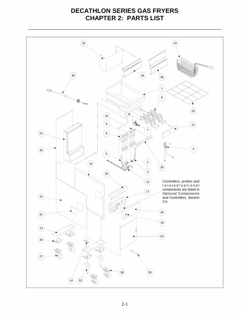
DECATHLON SERIES GAS FRYERSCHAPTER 2: PARTS LIST
2-1
28
33
27
34
14
13
15
1831
29
17
12
3
32
21 8
10
9
35
4
7
6
1
26
24
20
22
5
25
11
216
19
30 36
Controllers, probes andr e l a t e d / o p t i o n a lcomponents are listed inOptional Componentsand Controllers, Section2.6
23

DECATHLON SERIES GAS FRYERSCHAPTER 2: PARTS LIST
2-2
2.1 Decathlon D-20 Primary Components
ITEM PART # COMPONENT1 826-1874 Frypot- M/S- D20* 826-1875 Frypot- S/S- D20* 07003-4SK Frypot- S/S, With Basket Lift- D202 810-2167 Manifold, Gas- D203 810-2050 Orifice, Natural Gas- #44 (2.18 mm)* 810-2324 Orifice, LP Gas- #54 (1.40 mm)* 810-2060 Orifice, G20/G25 Gas- #42 (2.40 mm CE Only)* 810-2059 Orifice, G31 Gas- #53 (1.51 mm CE Only)4 810-2158 Pilot Burner- Natural (G20/25) Gas* 2149 Pilot Burner- LP (G31) Gas* 809-0766 Nut, Keps- 10-32 SS Hex* 809-0845 Screw, 10-32 x 3/8 Hex Slotted Head* 810-2437 Tube, Pilot Gas Supply- ¼ x 20"* 810-0703 Tube, Pilot Gas Supply- ¼ x 17-½ "5 200-1615 Manifold Support Bracket6 823-3330 Diffuser Assembly7 ? ? ? See Drain Manifold Components- Section 2-88 810-2151 Burner, Left Side9 N/A Burner, Center
10 810-2150 Burner, Right Side11 200-1331 Heat Shield12 807-3552 Gas Valve, Natural Gas, Electronic Ignition 24 VAC* 807-3628 Gas Valve, LP Gas, Electronic Ignition 24 VAC* 810-2156 Gas Valve, Natural Gas 120 VAC* 810-2323 Gas Valve, LP Gas 120 VAC* 807-2091 Gas Valve, G20/G25 Gas 24 VAC (CE ONLY)* 807-2127 Gas Valve, G31 Gas 24 VAC (CE ONLY)
13 200-1148 Channel, Front and Rear14 200-1675 Bracket, Lower Hinge15 211-3261 Side Panel, Left Side* 201-3268 Panel, Inner- Left Side (Multi-Batteried Units)
16 212-3261 Side Panel, Right Side* 202-3268 Panel, Inner- Right Side (Multi-Batteried Units)
17 824-1025 Wireway, Control Panel18 07-0132 Control Panel, Blank* 07-0132-1 Control Panel, One-Hole* 07-0132-2 Control Panel, Two-Hole
19 ? ? ? See Optional Components… - Section 2-620 210-3323 Topcap, D22021 106-1583SP Flue Assembly* 200-1342 Shield, Heat- Flue* 200-1344 Front, Flue Box* 200-1351 Rear, Flue Box* 200-3647 Deflector, Flue
22 823-3368 Flue Cap* Not Illustrated

DECATHLON SERIES GAS FRYERSCHAPTER 2: PARTS LIST
2-3
2.1 Decathlon D-20 Primary Components (cont.)
ITEM PART # COMPONENT23 106-2121SP Door Assembly, D20* 210-3266 Panel, Door- Outer* 200-3267 Panel, Door- Inner* 810-2105 Handle, Door- Chrome* 809-0918 Screw, 10-24 x ½" Slotted Head (Use With 810-2105)* 809-0191 Washer, ¼ Spring-Lock (Use With 810-2105)* 200-1301 Pin, Door* 810-0066 Magnetic Catch, Door
24 803-0022 Basket, Fry25 803-0327 Grid, Frypot26 200-3755SP Hanger, Basket- D20- Single System* 210-3911SP Hanger, Basket- D250/20 System
27 810-0356 Caster, Plate Mount- 5-inch w/o Brake* 810-2406 Caster, Single-Stud Mount- 5-inch w/o Brake
28 810-0357 Caster, Plate Mount- 5-inch with Brake* 810-2405 Caster, Single-Stud Mount- 5-inch with Brake* 826-1389 Screw, ¼-20 x ¾" Hex Head (For Plate-Mount Casters- Qty: 10)
29 813-0669 Drain Nipple, Extended- 1" Drain30 106-0913SP Cordset, 10'- Power31 210-2804 Cover, Outlet Duct32 200-3285 Panel, Structural Back- D20 (In Multi-Batteried Systems)* 200-1674 Panel, Structural Back- D220
33 810-2411 Leg (Black)34 823-3636 Leg Support Assembly35 823-3346 Bracket, Burner Mounting36 823-3715 Hanger, Basket- D20 Single- Chili’s Units Only
* Not Illustrated
2.2 Decathlon D-50 Primary Components
ITEM PART # COMPONENT1 826-1870 Frypot- M/S- D50* 826-1871 Frypot- S/S- D50* 826-1872 Frypot- M/S- D50 (With Basket Lift)* 826-1873 Frypot- S/S- D50 (With Basket Lift)* 826-1868 Frypot- M/S- DD50 (Deep Depth- Used in Fryer-Batteries With D60)* 826-1869 Frypot- S/S- DD50 (Deep Depth- Used in Fryer-Batteries With D60)2 810-2169 Manifold, Gas- D503 14-0067-45 Orifice, Natural Gas #45 (2.08 mm, Non-CE)- D50G* 810-2497 Orifice, LP Gas #55 (1.32 mm, Non-CE)- D50G* 810-2048 Orifice, Natural Gas #39 (2.53 mm, Non-CE)- D50GHP* 14-0067-41 Orifice, Natural Gas #41 (2.44 mm, Non-CE)- D50GDDHP* 810-2059 Orifice, LP and G31 Gas #53 [(1.51 mm, CE- All D Series) and
Non-CE- D50GHP, D50GDDHP)* 810-2060 Orifice, G20/G25 Gas (2.40 mm CE ONLY- All D Series)
* Not Illustrated

DECATHLON SERIES GAS FRYERSCHAPTER 2: PARTS LIST
2-4
2.2 Decathlon D-50 Primary Components (cont.)
ITEM PART # COMPONENT4 810-2032 Pilot Burner- Natural (G20/25) Gas* 810-2155 Pilot Burner- LP (G31) Gas* 809-0766 Nut, Keps- 10-32 SS Hex* 809-0845 Screw, 10-32 x 3/8 Hex Slotted Head* 810-2437 Tube, Pilot Gas Supply- ¼ x 20"* 810-0703 Tube, Pilot Gas Supply- ¼ x 17-½ "5 200-1615 Bracket, Manifold Support6 823-3522 Diffuser Assembly7 ? ? ? See Drain Manifold Components- Section 2-88 810-2151 Burner, Left Side9 810-2149 Burner, Center
10 810-2150 Burner, Right Side11 200-1330 Heat Shield12 807-3552 Gas Valve, Natural Gas, Electronic Ignition 24 VAC* 807-3628 Gas Valve, LP Gas, Electronic Ignition 24 VAC* 810-2156 Gas Valve, Natural Gas 120 VAC* 810-2323 Gas Valve, LP Gas 120 VAC* 807-2091 Gas Valve, G20/G25 Gas 24 VAC (CE ONLY)* 807-2127 Gas Valve, G31 Gas 24 VAC (CE ONLY)
13 200-1148 Channel, Front and Rear14 200-1675 Lower Hinge Bracket15 211-2787 Side Panel, Left Side16 212-2787 Side Panel, Right Side17 824-0961 Wireway, Control Panel18 210-3716 Control Panel, Blank* 210-2908 Control Panel, Two-Hole* 210-3747 Control Panel, Three-Hole* 210-3715 Control Panel, Three-Hole, Basket Lift Option
19 ? ? ? See Optional Components… - Section 2-620 210-1250 Top Cap- Single System* 824-0982 Top Cap- Double System* 824-0983 Top Cap- Triple System* 824-0984 Top Cap- Quad System
21 106-1742SP Flue Box Assembly* 200-2872 Shield, Heat- Flue* 200-1343 Front, Flue Box* 200-1350 Rear, Flue Box* 200-3651 Deflector, Flue
22 823-3338 Flue Cap, D50 & 15MC23 106-1754SP Door Assembly- D50* 210-2869 Panel, Door- Outer* 200-1379 Panel, Door- Inner* 810-2105 Handle, Door- Chrome* 806-0918 Screw, 10-24 x ½" Slotted Head (Use With 810-2105)* 809-0191 Washer, ¼ Spring-Lock (Use With 810-2105)* 200-1301 Pin, Door* 810-0066 Magnetic Catch, Door
* Not Illustrated

DECATHLON SERIES GAS FRYERSCHAPTER 2: PARTS LIST
2-5
2.2 Decathlon D-50 Primary Components (cont.)
ITEM PART # COMPONENT24 803-0022 Basket, Fry25 803-0277 Grid Assembly26 210-1595 Hanger, Basket- Single System* 200-3135 Hanger, Basket- Double System
27 810-0356 Caster, Plate Mount- 5-inch w/o Brake* 810-2281 Caster, Plate Mount- 5-inch w/o Brake- “Tile Safe” (Cracker Barrel)* 810-2406 Caster, Single-Stud Mount- 5-inch w/o Brake
28 810-0357 Caster, Plate Mount- 5-inch with Brake* 810-2280 Caster, Plate Mount- 5-inch with Brake- “Tile Safe” (Cracker Barrel)* 810-2405 Caster, Single-Stud Mount- 5-inch with Brake* 826-1389 Screw, ¼-20 x ¾" Hex Head (For Plate-Mount Casters- Qty: 10)
29 812-1226SP Drain Nipple, Extended- 1-¼" Drain30 106-0913SP Cordset, 10' Power31 210-1365 Cover, Outlet Duct32 200-1674 Back Panel, Rear33 810-2411 Leg (Black)34 823-3248 Leg Support Assembly35 200-1329 Burner Mounting Bracket36 823-3857 Hanger, Basket- Single- With Splash* 823-3672 Hanger, Basket- Single- With Splash & Upper/Lower Hanger* 823-3710 Hanger, Basket- Double System- (UFF) With Splash
* Not Illustrated
2.3 Decathlon D-60 Primary Components
ITEM PART # COMPONENT1 826-1876 Frypot- M/S- 1-½" Drain- D60* 60052-4 Frypot- S/S- 1-½" Drain- D60* 18064-3SK Frypot-M/S- 1-¼" Drain- D60* 18064-4SK Frypot- S/S- 1-¼" Drain- D60* 826-1819 Frypot- M/S- 1-¼" Drain- Non-Filtration- D60* 826-1802 Frypot- S/S- 1-¼" Drain- Non-Filtration- D60* 826-1806 Frypot- S/S- With Basket Lift- D60* 826-1826 Frypot- S/S- Cascade Filter- D60* 18128-2SK Frypot- S/S- Cascade Filter With Basket Lift- D602 810-2072 Gas Manifold (Weld Assembly)3 810-2048 Orifice, Natural Gas #39 (2.53 mm, Non-CE)* 810-2059 Orifice, LP Gas #53 (1.51 mm, CE and Non-CE)* 810-2060 Orifice, Nat. Gas G20/G25 (CE ONLY)4 810-2032 Pilot Burner- Natural (G20/25) Gas (Primary and Trailing)* 810-2155 Pilot Burner- LP (G31) Gas (Primary and Trailing)* 809-0766 Nut, Keps- 10-32 SS Hex (Primary and Trailing)* 809-0845 Screw, 10-32 x 3/8 Hex Slotted Head (Primary and Trailing)* 810-2437 Tube, Pilot Gas Supply- ¼ x 20"* 810-0703 Tube, Pilot Gas Supply- ¼ x 17-½"* 810-2138 Valve, Trailing Pilot- Adjustable (Trailing Pilot Only)
* Not Illustrated

DECATHLON SERIES GAS FRYERSCHAPTER 2: PARTS LIST
2-6
2.3 Decathlon D-60 Primary Components (cont.)
ITEM PART # COMPONENT5 200-1615 Manifold Support Bracket6 823-3181 Diffuser Assembly7 ? ? ? See Drain Manifold Components- Section 2-88 810-2151 Burner, Left Side9 810-2149 Burner, Center
10 810-2150 Burner, Right Side11 200-2746 Heat Shield12 807-3552 Gas Valve, Natural Gas, Electronic Ignition, 24 VAC* 807-3628 Gas Valve, LP Gas, Electronic Ignition, 24 VAC* 810-2156 Gas Valve, Natural Gas, 120 VAC* 810-2323 Gas Valve, LP Gas, 120 VAC* 807-2091 Gas Valve, G20/G25 Gas, 24 VAC (CE ONLY)* 807-2127 Gas Valve, G31 Gas, 24 VAC (CE ONLY)
13 200-2493 Channel, Front & Rear14 200-1675 Lower Hinge Bracket15 211-2532 Side Panel, Left Side16 212-2532 Side Panel, Right Side17 824-0951 Wireway, Control Panel18 ? ? ? See Control Panel Options- D60 Series- Section 2-519 ? ? ? See Optional Components… - Section 2-620 824-0987 Top Cap,* 210-2822 Top Cap, Two-Vat
21 106-0997SP Flue Box Assembly* 200-1339 Front, Flue Box* 200-1773 Back, Flue Box* 200-1325 Shield, Flue Box* 200-3649 Deflector, Flue
22 106-1703SP Flue Cap, Single System* 823-3516 Flue Cap, Double System
23 106-0759SP Door Assembly, With Liner* 210-1424 Panel, Door- Outer* 200-1185 Panel, Door- Inner* 810-2105 Handle, Door- Chrome* 806-0918 Screw, 10-24 x ½" Slotted Head (Use With 810-2105)* 809-0191 Washer, ¼ Spring-Lock (Use With 810-2105)* 200-1301 Pin, Door* 810-0066 Magnetic Catch, Door
24 803-0301 Fry Basket, 6 x 8-¾ x 16-¾"25 803-0149 Grid Assembly, Mesh-Type* 810-2235 Grid Assembly, Rack-Type
26 210-2779 Basket Hanger, Single System* 210-3142 Basket Hanger, Double System
27 810-0356 Caster, Plate Mount- 5-inch w/o Brake* 810-2406 Caster, Single-Stud Mount- 5-inch w/o Brake
28 810-0357 Caster, Plate Mount- 5-inch with Brake* 810-2405 Caster, Single-Stud Mount- 5-inch with Brake* 826-1389 Screw, ¼-20 x ¾" Hex Head (For Plate-Mount Casters- Qty: 10)
* Not Illustrated

DECATHLON SERIES GAS FRYERSCHAPTER 2: PARTS LIST
2-7
2.3 Decathlon D-60 Primary Components (cont.)
ITEM PART # COMPONENT29 812-1226SP Drain Nipple, Extended30 106-0913SP Cordset, 10'- Power31 210-1365 Cover, Outlet Duct32 200-1213 Upper Structural Back* 200-1327 Lower Structural Back
33 810-2411 Leg (Black)34 823-3248 Leg Support Assembly35 200-2065 Bracket, Burner Mounting
2.4 Decathlon D-80 Primary Components
ITEM PART # COMPONENT1 80018-3SK Frypot- M/S- 1-¼" Drain- D80 (After 10/99)* 80018-4SK Frypot- S/S- 1-¼" Drain- D80 (After 10/99)* 20004-3SK Frypot- M/S- 1-¼" Drain- D80 (Before 10/99)* 20004-4SK Frypot- S/S- 1-¼" Drain- D80 (Before 10/99)* 823-3395 Frypot- M/S- 1-½" Drain- D80* 823-3396 Frypot- S/S- 1-½" Drain- D802 810-2072 Gas Manifold (Weld Assembly)3 810-2049 Orifice, Natural Gas- #43 (2.26 mm, Non-CE) D80G* 810-2324 Orifice, LP Gas- #54 (1.40 mm, Non-CE) D80G* 810-2161 Orifice, Natural Gas- #38 (2.58 mm, Non-CE) D80GHP* 810-2131 Orifice, LP Gas- #52 (1.61 mm, Non-CE) D80GHP* 810-2060 Orifice, G20/G25 Gas (CE ONLY)* 810-2059 Orifice, G31 (CE ONLY)4 810-2032 Pilot Burner- Natural (G20/25) Gas (Primary and Trailing)* 810-2155 Pilot Burner- LP (G31) Gas (Primary and Trailing)* 809-0766 Nut, Keps- 10-32 SS Hex (Primary and Trailing)* 809-0845 Screw, 10-32 x 3/8 Hex Slotted Head (Primary and Trailing)* 810-2437 Tube, Pilot Gas Supply- ¼ x 20"* 810-0703 Tube, Pilot Gas Supply- ¼ x 17-½ "* 810-2138 Valve, Trailing Pilot- Adjustable (Trailing Pilot Only)5 200-1615 Manifold Support Bracket6 823-3513 Diffuser Assembly7 ? ? ? See Drain Manifold Components- Section 2-88 810-2151 Burner, Left Side9 810-2149 Burner, Center
10 810-2150 Burner, Right Side11 200-2707 Heat Shield12 807-3552 Gas Valve, Natural Gas, Electronic Ignition, 24 VAC* 807-3628 Gas Valve, LP Gas, Electronic Ignition, 24 VAC* 810-2156 Gas Valve, Natural Gas, 120 VAC* 810-2323 Gas Valve, LP Gas, 120 VAC* 807-2091 Gas Valve, G20/25 Gas, 24 VAC (CE ONLY)* 807-2127 Gas Valve, G(31) Gas, 24 VAC (CE ONLY)
* Not Illustrated

DECATHLON SERIES GAS FRYERSCHAPTER 2: PARTS LIST
2-8
2.4 Decathlon D-80 Primary Components (cont.)
ITEM PART # COMPONENT13 200-2686 Channel, Front and Rear14 200-1675 Lower Hinge Bracket15 211-2532 Side Panel, Left Side16 212-2532 Side Panel, Right Side17 824-0954 Wireway, Control Panel18 210-2778 Control Panel, 1-Hole* 210-2777 Control Panel, 2-Hole
19 ? ? ? See Optional Components… - Section 2-620 80-0006-1 Top Cap21 106-1442SP Flue Box Assembly* 200-1347 Front, Flue Box* 200-1349 Back, Flue Box* 200-1316 Shield, Flue Box* 200-3645 Deflector, Flue
22 823-3512 Flue Cap23 106-1698SP Door Assembly* 210-1151 Panel, Door- Outer* 200-2688 Panel, Door- Inner* 810-2105 Handle, Door- Chrome* 806-0918 Screw, 10-24 x ½" Slotted Head (Use With 810-2105)* 809-0191 Washer, ¼ Spring-Lock (Use With 810-2105)* 200-1301 Pin, Door* 810-0066 Magnetic Catch, Door
24 803-0301 Fry Basket, 6 x 8-¾ x 16-¾"25 810-2122 Grid Assembly26 200-3120 Hanger, Basket- Single System* 200-3119 Hanger, Basket- Double System
27 810-0356 Caster, Plate Mount- 5-inch w/o Brake* 810-2406 Caster, Single-Stud Mount- 5-inch w/o Brake
28 810-0357 Caster, Plate Mount- 5-inch with Brake* 810-2405 Caster, Single-Stud Mount- 5-inch with Brake* 826-1389 Screw, ¼-20 x ¾" Hex Head (For Plate-Mount Casters- Qty: 10)
29 812-1226SP Drain Nipple, Extended30 106-0913SP Cordset, Power31 210-1365 Cover, Outlet Duct32 200-2683 Back, Cabinet33 810-2411 Leg (Black)34 823-3248 Leg Support Assembly35 200-2734 Burner Mounting Bracket36 823-3649 Hanger, Basket- With Splash* 823-3349 Hanger, Basket- Double System- With Splash
* Not Illustrated

DECATHLON SERIES GAS FRYERSCHAPTER 2: PARTS LIST
2-9
2.5 Control Panel Options, D60 Series
1 2 3 4
5 6 7 8
9 10
ITEM PART # COMPONENT1 210-1167 Panel, Control- One-Hole (Left-Middle Location)2 210-1168 Panel, Control- Two-Hole (Two on Left Side)3 210-1169 Panel, Control- Three-Hole (Three on Left Side)4 210-1170 Panel, Control- One-Hole (Manual Timer Option)5 200-1171 Panel, Control- Two-Hole (Manual Timer Option)6 210-1172 Panel, Control- One-Hole (Lower-Left Location)7 210-1173 Panel, Control- Two-Hole (Manual Timer Option Plus Fuse Holder)8 210-1174 Panel, Control- Three-Hole (Two Upper Left, One Upper Right)9 210-1175 Panel, Control- Four-Hole
10 210-3021 Panel, Control- Indicator Light, Single Light

DECATHLON SERIES GAS FRYERSCHAPTER 2: PARTS LIST
2-10
2.6 Optional Components and Controllers (CE and Domestic)*
* Components are applicable to all Decathlon fryers covered in this manual unless otherwise noted.
1
2 3 4 5 6 7
98 10 11
12 13 14 15 16
17 18 19
20
21
22
23
24
25
26
ITEM PART # COMPONENT1 807-3515 Thermostat, Sunne (See Item #17 for Mounting Hardware)2 810-2035 Knob, Thermostat3 807-3563 Spark Module (Domestic and CE)4 807-1311 Pilot Assembly- Natural Gas- Electronic Ignition* 807-1553 Pilot Assembly- LP Gas- Electronic Ignition* 807-1315 Ignition Cable* 810-2437 Tube, Pilot Gas Supply - One Piece- ¼ x 20"* 807-1310 Flame Sensor
* Not Illustrated

DECATHLON SERIES GAS FRYERSCHAPTER 2: PARTS LIST
2-11
2.6 Optional Components and Controllers (CE and Domestic-cont.)
ITEM PART # COMPONENT5 210-3562 Panel, Control- Computer, D-50* 210-1256 Panel, Control- Computer, D-60* 210-1520 Panel, Control- Computer, D-806 806-4441 Computer, Compu-Fry III.57 823-3433 Bezel Assembly, Control Panel8 106-0802SP Face Plate/Potentiometer, 120 VAC- Electronic Thermostat* 820-0135 Face Plate, Electronic Thermostat* 106-0801SP Potentiometer, Electronic Thermostat* 816-0534 Knob, Control- Electronic Thermostat9 810-2033 Thermopile
10 810-1152 Thermocouple (CE ONLY)* 807-3550 Thermocouple
11 810-1153 ECO Connector (Honeywell Valves Only- CE ONLY)* 810-2398 ECO Connector (Robertshaw Valves Only- CE ONLY)
12 106-1757SP Probe Assembly, Temperature- Electronic Thermostat- D20 & D50* 106-1424SP Probe Assembly, Temperature- Electronic Thermostat- D60 & D80* 106-1541SP Probe Assembly (RTD), Temperature, Dean Computer* 810-2164 Spring, Space- Electronic Thermostat Probe* 210-1386 Clamp, Electronic Thermostat Probe
13 200-2042 Bracket, Pilot Thermocouple14 810-2401 Bracket, Thermopile15 810-1001 Piezo Ignitor (Trigger)* 200-1868 Piezo Bracket* 807-3540 Electrode, Piezo
16 807-3551 Transformer, Honeywell 120/24 VAC* 807-0855 Transformer, 120/12 VAC* 807-3571 Transformer, 120/24 VAC* 807-1999 Transformer, Dual CE (CE ONLY)
17 807-3560 High-Limit Thermostat- Manual Reset 410° F* 807-3680 High-Limit Thermostat- Manual Reset 450° F* 807-3559 High-Limit Thermostat- Manual Reset 435° F* 810-2046 Spring, Spacer- High Limit Capillary Bulb* 810-2047 Spring, Spacer- Thermostat Capillary Bulb* 210-1433 Clamp, Thermostat/High Limit Capillary Bulb
18 807-1321 Fuse Holder, Buss* 2747 Fuse Holder, Slot-head— Safety (CE ONLY)* 807-3592 Fuse 2A Slow-Blow (230V Systems)* 807-3750 Fuse 5A (120V Systems)
19 807-3651 Interface Board, Dean Computer Only20 807-0834 Relay, 12VDC 15A 1PDT (Basketlift)21 807-0833 Relay, 12VDC 5A 1PDT (Latching)22 807-3574 Switch, Power- Green Lens23 807-3580 Switch, Rocker- Manual Filter Power24 807-3579 Switch, Boil-Out- 6-Terminal25 807-3576 Switch, Fryer Reset (Momentary)* 810-0333 Insert, Blank- Switch
26 210-2786 Guard, Switch (Optional- For Items 22-25)* Not Illustrated

DECATHLON SERIES GAS FRYERSCHAPTER 2: PARTS LIST
2-12
2.7 Transformers & Component Boxes- Multi-Batteried Decathlons
Spark ModuleHousing: Fryers
#1 & #2
Spark Module/Component Housing:
Fryers #3 & #4
1
2
3
4
5
3
6
7
8
910
For switches, seeOptional Components
section.
For spark module, seeOptional Components
section.
11 12
ITEM PART # COMPONENT1 823-3242 Control Box (Fryers 3 & 4)2 210-1364 Plate, Face (For Item #1)3 200-1322 Bracket, Spark Module4 200-1326 Cover, Spark Module (Fryers 3 & 4)5 807-3551 Transformer6 200-2307 Bracket, Attachment- Spark Module Bracket (Fryers 1 & 2)7 824-0961 Wireway, Control Panel- D50* 824-0951 Wireway, Control Panel- D60* 824-1002 Wireway, Control Panel- D808 807-3851 Interface Board, Electronic Thermostat- 24 VAC* 807-3566 Interface Board, Electronic Thermostat- 120 VAC* 807-3722 Interface Board, Electronic Thermostat- 208/230 VAC9 200-3212 Housing, Electronic Thermostat- Two Cut-Outs
10 210-3214 Face Plate, Electronic Thermostat- Power/Boil-Out* 807-3536 Potentiometer, Electronic Thermostat* 816-0534 Knob, Electronic Thermostat Potentiometer
11 807-3680 High-Limit Thermostat- Manual Reset 450° F (Non-CE Only)* 807-3559 High-Limit Thermostat- Manual Reset 435° F* 807-3560 High-Limit Thermostat- Manual Reset 410° F (CE Only)
* Not Illustrated

DECATHLON SERIES GAS FRYERSCHAPTER 2: PARTS LIST
2-13
2.8 Oil Drain Manifold, Drain Flush and Drain Valve Components
1
To DrainValve
To DrainValve
To DrainValve
2 3
4
5
6
7
9
101112
13
14
8
15
17
18
19
20
21
22
23
16
24 25

DECATHLON SERIES GAS FRYERSCHAPTER 2: PARTS LIST
2-14
2.8 Oil Drain Manifold, Drain Flush and Drain Valve Components (cont.)
ITEM PART # COMPONENT1 823-3221 Elbow, with Bracket (Drain Valve Handle)2 823-3558 Drain Pipe, Left Side3 210-2311 Clamp, Center- Drain Pipe4 823-3441 Drain Pipe, Right Side5 813-0749 Tee, 1-½" NPT With Handle6 200-1840 Drain Manifold Tube7 813-0659 Pipe Cap, 1-½"8 809-0884 Nut, Slip Joint- 1-½"* 816-0544 O-ring (Slip-Joint Nut)9 813-0686 Bell Reducer, 1-½ x ½" NPT
10 810-1057 Flex Line, 5/8 x 13"11 813-0051 Coupling, ½" NPT12 813-0165 Elbow, Street- ½ x ½" 90°13 810-1668 Adapter, 5/8" O.D. x ½"- Male (Use With 810-1057 and 810-1069)* 810-1669 Adapter, 5/8" O.D. x ½"- Female (Use With 810-1057 and 810-1069)
14 810-1069 Flex Line, 5/8" x 29-½ "Drain Valve Components
15 106-1401 Bracket, Microswitch (Optional On Some Units)16 200-1617 Washer, Drain Valve (Use Without Microswitch)17 210-2029 Bracket, Activator- Microswitch18 200-1940 Handle (Actuator) , Drain Valve* 823-3440 Handle, Push/Pull- Drain (With Cap)* 809-0885 Washer, 3/8 x 1 x .083"* 809-0843 Cotter Pin* 816-0547 Cap, Vinyl-Red
19 807-2104 Microswitch (Optional On Some Units)20 809-0842 Nut, Nylock- #4-40 (Microswitch To Bracket)21 816-0220 Insulation, Microswitch22 200-1257 Retainer, Nut23 810-2127 Drain Valve, 1-½" Full Port (With Washers & Nut)24 810-2052 Drain Valve, 1-¼" (1" Standard Port)* 810-2128 Drain Valve, 1" (D20 Only)* 200-2371 Handle, Valve Lever (For 810-2128 Only)
25 810-2126 Drain Valve, 1-¼" Full-Port* Not Illustrated

DECATHLON SERIES GAS FRYERSCHAPTER 2: PARTS LIST
2-15
2.9 Oil Return Manifold Components
1
2
3
4
5
6
11
8
7
9
10
12
13
14
15
16
19
17
6
18 5
D460 Oil Return (Typical)
2
ITEM PART # COMPONENT1 813-0003 Tee, ½ x ½ x ½" NPT BM2 813-0022 Nipple, ½" NPT x Close BM3 813-0087 Nipple, ½ NPT x 1-½" BM4 813-0156 Plug, ½" NPT Hex Head BM5 813-0173 Union, ½" NPT BM6 813-0247 Nipple, ½ NPT x 3-½" BM7 813-0298 Nipple, ½ NPT x 2" BM8 813-0345 Elbow, ½" NPT 45° BM9 813-0368 Nipple, ½ NPT x 16" BM
10 813-0646 Nipple, ½ NPT x 5" BM

DECATHLON SERIES GAS FRYERSCHAPTER 2: PARTS LIST
2-16
2.9 Oil Return Manifold Components (cont.)
ITEM PART # COMPONENT11 813-0654 Nipple, ½ x 4" NPT BM12 813-0672 Nipple, ½ x 8" NPT BM13 813-0673 Nipple, ½ x 8-½" NPT BM14 810-2125 Oil Return Valve, 3/8"* 200-1143 Retainer, Oil Return Valve Nut* 809-0877 Nut, Oil Return Valve
15 813-0006 Bushing, Hex- ½ x 3/8" NPT BM16 813-0625 Nipple, 3/8" x Close NPT BM17 813-0165 Elbow, Street- ½ x ½" NPT 90° BM18 813-0634 Elbow, ½ x 3/8" NPT 90° BM19 813-0062 Elbow, ½" NPT 90° BM
* Not Illustrated
2.10 Oil Return and Oil Flush Components
1
12
11
14 15
13
2
3
4
5
6
7 8
9
10
16
17
Rear View

DECATHLON SERIES GAS FRYERSCHAPTER 2: PARTS LIST
2-17
2.10 Oil Return and Oil Flush Components (cont.)
ITEM PART # COMPONENT1 Microswitch Bracket Assembly, Oil Return* 201-1233 Bracket, Oil Return Microswitch- Left* 202-1233 Bracket, Oil Return Microswitch- Right* 810-2144 Spacer, Aluminum, 4-40- ¼ x 3/8"* 807-2104 Microswitch, Oil Return* 809-0846 Screw, 4-40 x 1" Slotted Head* 809-0842 Nut, Nylock- 4-40* 200-1341 Bracket, Microswitch Rod* 809-0360 Screw, #8 x 3/8 Hex Washer Slotted Head* 809-0803 Bolt, ¼-20 x ¾" Hex Head Grade 5* 809-0823 Nut, Nylock, ¼-20* 809-0070 Nut, ¼-20 Hex SS2 810-0697 Disconnect, Male- Suction Tube3 813-0608 Coupling, Full- ½" NPT BM4 823-3188 Suction Manifold Assembly5 813-0062 Elbow, 90° BM6 813-0515 Nipple, ½ NPT x 12" BM7 813-0173 Union, ½" NPT BM8 813-0251 Nipple, ½ NPT x 4-½" BM9 813-0672 Nipple, ½ NPT x 8" BM
10 Oil Suction Start Fitting* 813-0022 Nipple- ½" NPT x Close* 813-0156 Plug, ½" NPT Hex Head* 813-0003 Tee, ½" NPT BM
11 809-0885 Washer, 3/8 x 1 x .083"* 809-0843 Pin, Cotter- Plated
12 823-3344 Handle (Actuator), Oil Return Valve13 823-3187 Handle, Oil Return- Left Fryer-UFF System14 823-3198 Handle, Oil Return- Right Fryer-UFF System, 3rd & 4th Fryer* 823-3481 Handle, Oil Flush Valve
15 816-0548 Cap, Oil Return Handle- Yellow* 816-0549 Cap, Oil Flush Handle- Blue
16 810-2100 Motor, Pump- 120-230V17 810-2098 Pump, 8 GPM* 810-2252 Pump, 5 GPM
* Not Illustrated

DECATHLON SERIES GAS FRYERSCHAPTER 2: PARTS LIST
2-18
2.11 Under Fryer Filter (UFF) Components
2.11.1 D50 and D60 Series Fryers
1
2
3
4
5
6
7
89
10
11
12
ITEM PART # COMPONENT1 823-3576 Filter Pan- UFF 50* 823-3176 Filter Pan- UFF 602 809-0805 Screw, ¼-20 x ½"3 809-0822 Bolt, ¼-20 x ½" Steel4 809-0820 Nut, Oval Locking- ¼-205 210-2291 Insert, Caster6 810-2141 Caster, 2"-Swivel7 823-3574 Support Grid (Bottom Pan Screen)- UFF 50* 823-3365 Support Grid (Bottom Pan Screen)- UFF 608 803-0289 Filter Paper, 22 x 34"- UFF 50/60 (100 Sheets)9 823-3573 Hold-down Ring, Weighted- UFF 50* 823-3361 Hold-down Ring, Weighted- UFF 60
10 823-3175 Crumb Basket, UFF 50/6011 106-0752SP Lid Assembly, Front- UFF 50/6012 106-1755SP Lid Assembly, Rear- UFF 50* 106-0753SP Lid Assembly, Rear- UFF 60
* Not Illustrated

DECATHLON SERIES GAS FRYERSCHAPTER 2: PARTS LIST
2-19
2.11.2 D80 Series Fryers
1
23
4
5
6
7
8 12
910
11
ITEM PART # COMPONENT1 106-1584SP Filter Pan, UFF 802 823-3365 Support Grid (Bottom Pan Screen)3 803-0303 Filter Paper, 26 x 34" (100 Sheets)4 823-3439 Hold-Down Ring, Weighted5 823-3443 Crumb Basket6 106-1587SP Filter Pan Cover, Front7 106-1588SP Filter Pan Cover, Back8 809-0822 Bolt, ¼-20 x ½" Steel9 210-2291 Insert, Caster
10 809-0820 Nut, Oval Locking- ¼-2011 809-0805 Screw, ¼-20 x ½"12 810-2141 Caster, 2"

DECATHLON SERIES GAS FRYERSCHAPTER 2: PARTS LIST
2-20
2.12 Single Under Fryer Filter (SUFF) Components
2.12.1 D50 Series Fryers
1
23
45
6
7
8
12
910
11
ITEM PART # COMPONENT
1 823-3796 Filter Pan, SUFF 50* 813-0684 Plug, Hex Socket, 3/8" NPT* 813-0679 Plug, 1/8" SS Square Head (Female Disconnect)2 823-3790 Support Grid (Bottom Pan Screen)3 803-0317 Paper, Filter- 8-1/4 x 25-3/4"4 823-3795 Hold-Down Ring, Weighted5 823-3736 Crumb Basket6 823-3797 Filter Pan Cover, Front7 823-3798 Filter Pan Cover, Back8 809-0822 Bolt, ¼-20 x ½" Steel9 210-2291 Insert, Caster
10 809-0820 Nut, Oval Locking- ¼-2011 809-0805 Screw, ¼-20 x ½"12 810-2141 Caster, 2"
* Not Illustrated

DECATHLON SERIES GAS FRYERSCHAPTER 2: PARTS LIST
2-21
2.12.2 D60 and D80 Series Fryers
1
23
4
5
6
7
812
910
11
ITEM PART # COMPONENT
1 823-3774 Filter Pan, SUFF 60* 823-3821 Filter Pan, SUFF 80* 813-0684 Plug, Hex Socket, 3/8" NPT* 813-0679 Plug, 1/8" SS Square Head (Female Disconnect)2 823-3768 Support Grid (Bottom Pan Screen) SUFF 60/803 803-0289 Paper, Filter- 22 x 34" - SUFF 60/804 823-3770 Hold-down Ring, Weighted- SUFF 60* 823-3849 Hold-down Ring, Weighted- SUFF 805 823-3736 Crumb Basket- SUFF 60/806 823-3766 Filter Pan Cover, Front- SUFF 60* 823-3739 Filter Pan Cover, Front- SUFF 807 823-3767 Filter Pan Cover, Back- SUFF 60* 823-3741 Filter Pan Cover, Back- SUFF 808 809-0822 Bolt, ¼-20 x ½" Steel9 210-2291 Insert, Caster
10 809-0820 Nut, Oval Locking- ¼-2011 809-0805 Screw, ¼-20 x ½"12 810-2141 Caster, Swivel- 2"
* Not Illustrated

DECATHLON SERIES GAS FRYERSCHAPTER 2: PARTS LIST
2-22
2.13 Basket Lift Components (D50, D60 and D80 Series)
1
2
3
4
5
6
7
8
9
1011
12
13
14
15
16
17
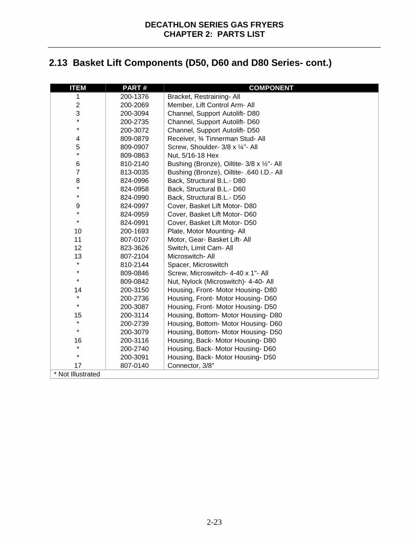
DECATHLON SERIES GAS FRYERSCHAPTER 2: PARTS LIST
2-23
2.13 Basket Lift Components (D50, D60 and D80 Series- cont.)
ITEM PART # COMPONENT1 200-1376 Bracket, Restraining- All2 200-2069 Member, Lift Control Arm- All3 200-3094 Channel, Support Autolift- D80* 200-2735 Channel, Support Autolift- D60* 200-3072 Channel, Support Autolift- D504 809-0879 Receiver, ¾ Tinnerman Stud- All5 809-0907 Screw, Shoulder- 3/8 x ¼"- All* 809-0863 Nut, 5/16-18 Hex6 810-2140 Bushing (Bronze), Oiltite- 3/8 x ½"- All7 813-0035 Bushing (Bronze), Oiltite- .640 I.D.- All8 824-0996 Back, Structural B.L.- D80* 824-0958 Back, Structural B.L.- D60* 824-0990 Back, Structural B.L.- D509 824-0997 Cover, Basket Lift Motor- D80* 824-0959 Cover, Basket Lift Motor- D60* 824-0991 Cover, Basket Lift Motor- D50
10 200-1693 Plate, Motor Mounting- All11 807-0107 Motor, Gear- Basket Lift- All12 823-3626 Switch, Limit Cam- All13 807-2104 Microswitch- All* 810-2144 Spacer, Microswitch* 809-0846 Screw, Microswitch- 4-40 x 1"- All* 809-0842 Nut, Nylock (Microswitch)- 4-40- All
14 200-3150 Housing, Front- Motor Housing- D80* 200-2736 Housing, Front- Motor Housing- D60* 200-3087 Housing, Front- Motor Housing- D50
15 200-3114 Housing, Bottom- Motor Housing- D80* 200-2739 Housing, Bottom- Motor Housing- D60* 200-3079 Housing, Bottom- Motor Housing- D50
16 200-3116 Housing, Back- Motor Housing- D80* 200-2740 Housing, Back- Motor Housing- D60* 200-3091 Housing, Back- Motor Housing- D50
17 807-0140 Connector, 3/8"* Not Illustrated

DECATHLON SERIES GAS FRYERSCHAPTER 2: PARTS LIST
2-24
2.14 Trough, Holster and Cover Components- D60 & D80 Series
1
2
3
4
ITEM PART # COMPONENT1 106-2668SP Holster Assembly, Vat Cover2 823-3384 Trough, Holster Assembly3 106-1447SP Cover, Vat- Full-Basket4 106-2585SP Cover, Vat- Twin-Basket* 810-2030 Handle, Vat Cover (Full and Twin)* 809-0107 Screw, 8-32 x 3/8 Round Slotted Head
* Not Illustrated

Dean, 8700 Line Avenue, PO Box 51000, Shreveport, Louisiana 71135-1000Shipping Address: 8700 Line Avenue, Shreveport, Louisiana 71106
TEL 1-318-865-1711 FAX (Parts) 1-310-327-3343 FAX (Tech Support) 1-318-219-7135
Price: $15.00PRINTED IN THE UNITED STATES
SERVICE HOTLINE1-800-551-8633 819-5922
SEPTEMBER 2002