d6.1.30: report on otaniemi semi urban trial...
TRANSCRIPT

- 1 - D6.1.30 Report on Otaniemi semi-urban trial results
CLEEN OY Eteläranta 10, P.O. BOX 10, FI-00131 HELSINKI, FINLAND www.cleen.fi
D6.1.30: Report on Otaniemi semi-urban trial results
Revision History
Edition Date Status Editor
v0.1 26.11.2013 Created S. Horsmanheimo
v0.2 05.12.2013 Outdoor measurements N. Maskey
v0.3 15.12.2013 Indoor measurement added S. Horsmanheimo, N. Maskey, L. Tuomimäki, P. Kemppi
v0.4 12.02.2014 CDF curves and scatter plots added
S. Horsmanheimo, N. Maskey, L. Tuomimäki
v0.5 15.03.2014 24-hour measurements added
S. Horsmanheimo, N. Maskey, L. Tuomimäki
v0.6 14.04.2014 Preface and conclusions added
S. Horsmanheimo, N. Maskey, L. Tuomimäki
v0.7 12.05.2014 Draft version Comments from other partners
v0.8 19.05.2014 Submitted draft version S. Horsmanheimo, N. Maskey, L. Tuomimäki
v.1.0 09.07.2014 Final S. Horsmanheimo, N. Maskey, L. Tuomimäki

- 2 - D6.1.30 Report on Otaniemi semi-urban trial results
CLEEN OY Eteläranta 10, P.O. BOX 10, FI-00131 HELSINKI, FINLAND www.cleen.fi
Abstract This report presents the results of Otaniemi trial. The objective was to study how different operators’ commercial 2G, 3G, and 4G as well as open WLAN networks could be used for remote control of medium voltage electric distribution networks in semi-urban area [1]. This work is a continuation to the analysis carried out in Raasepori and Koillismaa [2][3]. Those rural trials concentrated on redundancy in 2G and 3G networks, namely GSM-900 and UMTS-900, whereas this concentrates on GSM 900 MHz / 1800 MHz, UMTS 900 MHz / 2100 MHz, LTE 1800 MHz / 2600 MHz, and WLAN 2.4/5.0 GHz bands including both indoor and outdoor cases.
The Otaniemi region was selected as the trial area, because there is relatively high density of mobile users. Moreover, all main operators’ 2G/3G/4G networks are available as well as NSN’s LTE test network. The trial location was also convenient for performing 24-hour indoor measurements. More accurate coverage predictions were possible with an accurate 3D environment model constructed from aerial 3D lidar data.
The first part of the report concentrates on outdoor measurements, which were carried out with VTT’s and Viola Systems’ 2G/3G/4G measurement devices. The outdoor measurements were done in all operators’ all available networks including WLAN. The measurements focused merely on coverage, data rates, and redundancy. In addition, measurements were done also with NSN’s Clarinet and Aalto University’s NetRadar tools.
The second part of the report describes the indoor measurements. The indoor coverage measurements were carried out using a mobile robot. It provided locations for measurement samples, information about changes in the magnetic field along the measurement route as well as lidar/camera data to construct 3D interior models of the buildings. In order to see the effects of network load in commercial networks, 24-hour stationary indoor measurements were also conducted. The measurement sites were selected so that they would represent different indoor spaces: an area on the ground floor of a new office building, the basement of an old building far from communication masts, and a basement in an old building near communication masts. The emphasis was on coverage, interference, and latency of different radio access technologies.
The last part concentrates on the findings. The trial results indicated that the main bottlenecks for using wireless communication in grid communication are latency and reliability. Ways to solve the challenges were sought from the recent research publications concentrating on reliable virtual zero-latency machine-type of communications. The future work section describes the activities that are planned to be taken during the SGEM V project and beyond in order to fulfil resiliency, reliability, and low and constant latency requirements of grid communications.

- 3 - D6.1.30 Report on Otaniemi semi-urban trial results
CLEEN OY Eteläranta 10, P.O. BOX 10, FI-00131 HELSINKI, FINLAND www.cleen.fi
Table of Contents
Revision History ............................................................................................................................ 1 Abstract ......................................................................................................................................... 2 Table of Contents .......................................................................................................................... 3 1 Preface .................................................................................................................................... 4 2 Background ............................................................................................................................ 5 3 Measurement environment ................................................................................................... 6
3.1 Network planning tool – NPT............................................................................................... 7 3.2 Nemo measurement tool ..................................................................................................... 8 3.3 Viola Systems’ Arctic tool .................................................................................................... 9 3.4 NPT client ......................................................................................................................... 10 3.5 External tools .................................................................................................................... 11 3.6 Fault analysis .................................................................................................................... 11
4 Otaniemi trial ........................................................................................................................ 12 4.1 Outdoor measurement ...................................................................................................... 14
4.1.1 Coverage .................................................................................................................... 17 4.1.2 Interference ................................................................................................................ 19 4.1.3 Throughput ................................................................................................................. 22 4.1.4 Latency ....................................................................................................................... 25 4.1.5 Comparison of different terminals ............................................................................... 26 4.1.6 Network side monitoring ............................................................................................. 27
4.2 Indoor measurements ....................................................................................................... 29 4.2.1 Coverage .................................................................................................................... 35 4.2.2 Interference ................................................................................................................ 38 4.2.3 Latency ....................................................................................................................... 43
4.3 Indoor and outdoor analysis .............................................................................................. 52 4.4 Fault simulations ............................................................................................................... 55 4.5 Conclusion ........................................................................................................................ 56
5 Challenges ........................................................................................................................... 57 6 Future work .......................................................................................................................... 60 7 Abbreviations ....................................................................................................................... 61 8 References ........................................................................................................................... 64

- 4 - D6.1.30 Report on Otaniemi semi-urban trial results
CLEEN OY Eteläranta 10, P.O. BOX 10, FI-00131 HELSINKI, FINLAND www.cleen.fi
1 Preface This report was done as part of the Finnish national research project "Smart Grids and Energy Markets" SGEM FP V, and it was funded by Tekes – the Finnish Funding Agency for Technology and Innovation – and the project partners. The report was written by VTT and Viola Systems (Jyrki Penttonen and Lauri Helenius).
For the report, valuable contributions and comments were obtained from ABB (Antti Kostiainen), Fortum (Oleg Gulich) and NSN.

- 5 - D6.1.30 Report on Otaniemi semi-urban trial results
CLEEN OY Eteläranta 10, P.O. BOX 10, FI-00131 HELSINKI, FINLAND www.cleen.fi
2 Background This work is continuation to the study of the interdependency between communications and electricity distribution networks. The previous study concentrated on 2G and 3G networks in rural areas focusing on availability, redundancy, and fault resiliency [4][5]. Those studies were covering medium-voltage grid entities controlled by SCADA systems. High-voltage grid entities as well as low-voltage home metering devices were excluded from the study. To support the analysis, two trials were carried out in the Raasepori and Koillismaa regions. From both areas, information about electricity grids and storm outages were available. Locations for 2G and 3G communication sites were obtained by combining field measurements, NLS (the National Land Survey) mast information, and data from open Cell-ID repositories. The radio propagation environment for both cases was modelled in 3D so that the shadowing caused by large terrain shapes and vegetation was taken into account.
The simulations were used to assess how many of the grid entities remained remotely controllable in different fault scenarios. Figure 1 shows an example of outage analysis results in the Raasepori region. The histogram shows that the number of operating base stations (blue bars) and secondary substations (red bars) drops roughly at the same pace, but the redundancy level (green bars) decreases significantly slower. Neighbouring base stations offer coverage to the outage area enabling remote control of grid entities and connections to field crews. When the outage area significantly increases, the neighbouring base stations are not capable of providing coverage to the outage area. As a result, the percentage of remotely controllable grid entities drops drastically when 60 % of primary substations are down (the rightmost bars).
Figure 1. Resiliency of telecommunication networks in Raasepori against different types of faults.

- 6 - D6.1.30 Report on Otaniemi semi-urban trial results
CLEEN OY Eteläranta 10, P.O. BOX 10, FI-00131 HELSINKI, FINLAND www.cleen.fi
It was shown in previous work that 2G and 3G networks can tolerate small and medium-sized faults well in rural areas. In particular, high inherent redundancy is detected near towns and along main roads. Most grid entities are commonly located there. The redundancy of the UMTS-900 networks is smaller, because they were often used for providing additional capacity for GSM-900 networks. Moreover, during the trials 900 MHz UMTS technology was still being deployed by the mobile operators.
The analysis also indicated that the redundancy level depends on the terminal’s antenna properties (TX/RX gains, antenna height, and radiation pattern) as well as on the used applications. The UL direction is more limited due to the terminal’s lower transmission power. This difference is partly compensated with a base station’s higher Rx sensitivity level. Since field measurements are typically done to the DL direction, some additional margin is always needed when planning the communication links to the UL direction.
3 Measurement environment The core component in the measurement environment is Network Planning Tool (NPT), which is a measurement tool originally developed for mobile network planning. In the SGEM projects, the tool has been extended to include also the modelling of electricity distribution networks and different types of fault cases. Interdependency of these networks is established by creating links between communication masts and the closest secondary substations. After Hannu/Tapani storm in late year 2011, the tool was extended to support storm scenarios. The outage data from storms is vital, since it enables us to analyse both the breakdown and recovery of the electricity distribution and mobile communication networks. The storm simulations in Koillismaa (rural) were done with the year 2009 storm data and in Raasepori (semi-rural area) with the Hannu/Tapani storm data.
The measurement environment is depicted in Figure 2. The environment includes Nemo Outdoor, Viola Systems’ Arctic modules, NPT client, and Android phones. In addition, NSN’s Clarinet and Aalto University’s NetRadar can be used as the external measurement tools. The environment supports both real-time and offline measurements. Offline measurements were found more feasible for SGEM, because the data needs to be saved and post-processed. The real-time connections are merely used for QoS measurements. The measurements are used in three ways: for fine-tuning clutter parameters of coverage prediction models, for extracting radio parameters of base stations, and for validating the coverage and redundancy calculations. The location and timestamp for measurement samples are obtained from a GPS receiver (outdoors) or from a mobile robot (indoors).

- 7 - D6.1.30 Report on Otaniemi semi-urban trial results
CLEEN OY Eteläranta 10, P.O. BOX 10, FI-00131 HELSINKI, FINLAND www.cleen.fi
Figure 2. Architecture of the measurement environment.
3.1 Network planning tool – NPT
The NPT tool is used for computing coverage and redundancy rasters for different networks. The tool supports also the analysis of other parameters e.g. jitter, throughput, latency, interference, and connection success rates. The NPT tool supports various radio access technologies including WLAN, GSM, UMTS, LTE, and WiMAX. The locations of base stations are either imported from external site files or generated directly from measurements using the mast data obtained from National Land Survey of Finland. For coverage calculations, a 3D environment model is constructed including terrain height and clutter information. In urban and semi-urban scenarios also 3D buildings are used.
The tool includes a large number of propagation models that can be fine-tuned to the target environment with field measurements done with Nemo Outdoor, NPT client, or Arctic tool. The fine-tuning is operator and radio access technology specific. For Otaniemi trial, NPT’s functionalities were extended to support multiple operators, and coverage prediction of LTE and WLAN networks. In addition to that the handling of LTE measurements collected with Nemo Outdoor, Arctic modules, and NPT client was implemented.

- 8 - D6.1.30 Report on Otaniemi semi-urban trial results
CLEEN OY Eteläranta 10, P.O. BOX 10, FI-00131 HELSINKI, FINLAND www.cleen.fi
The structure of the electricity grid is imported from kml data files provided by ABB and Fortum. The fault simulations are done in NPT by running statistical or storm based fault simulations. The faults’ impacts on the electricity distribution and telecommunication networks can be assessed on a 3D map in NPT GUI or as graphs as the simulation progresses. For Otaniemi trial, the functionality to simulate also faults in telecommunication networks was added, since in urban areas, the feeder lines are merely underground and therefore storms’ effects on electricity grid are rather insignificant.
3.2 Nemo measurement tool
Figure 3. Nemo Outdoor measurement tool.
Nemo Outdoor presented in Figure 3 was used in SGEM measurements. It contains a laptop, two C7 phones, three wireless modules, and a GPS receiver. Those devices are connected to the laptop via USB ports. The terminals are used for collecting cellular network information from GSM (900/1800 MHz), UMTS (900/2100 MHz), LTE (800/1800/2600 MHz), and WLAN (2.4 GHz) networks. The WLAN measurements are done with Nemo Handy, which is running on one of the C7 terminals. The data collection rate of Nemo Outdoor is around three samples per second, and both serving and neighbouring cell information is obtained with location and time information. Nemo Outdoor saves the measurement data into files, which are later analysed with the NPT tool. Nemo Outdoor has also graphical user interface for monitoring KPIs (Key Performance Indicators) in real-time, but it does not have an interface for conveying this data to NPT for a real-time analysis.
Nemo Outdoor can measure different types of data traffic e.g. TCP, UDP, FTP, HTTP, streaming, and Iperf over UDP/TCP traffic loads as well as voice and video quality. The data traffic is

- 9 - D6.1.30 Report on Otaniemi semi-urban trial results
CLEEN OY Eteläranta 10, P.O. BOX 10, FI-00131 HELSINKI, FINLAND www.cleen.fi
generated with Iperf (traffic generator) or downloaded/uploaded from/to a server. We use mainly UDP traffic generated with Iperf for throughput and latency measurements.
3.3 Viola Systems’ Arctic tool
Figure 4. Arctic 2G/3G/4G measurement modules and antennas.
The Viola Systems’ 2G/3G/4G Arctic tool shown in Figure 4 was the other tool used in SGEM measurements. It contains three modems with external antennas. The antennas can be mounted outside e.g. a vehicle to provide better signal strength. The modems are connected to a laptop with USB cables. The modems are programmed to collect measurement samples from GSM, UMTS, and LTE networks periodically in every 2 seconds using AT commands. Both serving and neighbouring cell information are collected. The Arctic tool stores results into files, which are post-processed with NPT. The measurement samples do not contain location information. Therefore, a location of each sample is extracted from the Nemo Outdoor measurements based on the sample’s timestamp. The fact sheet of Viola Systems’ modules and antennas is shown in Table 1.
Table 1. The data sheet of Arctic modules.
Module Description
Arctic 3G Gateway 2622 One locked to 2G GSM
Another locked to 3G
Arctic LTE Gateway 2625 Locked to LTE

- 10 - D6.1.30 Report on Otaniemi semi-urban trial results
CLEEN OY Eteläranta 10, P.O. BOX 10, FI-00131 HELSINKI, FINLAND www.cleen.fi
2G: V-Torch VTGSMA-22 antenna Frequency: 824–960/1710–2170 MHz
Gain: 10 dBi, cable attenuation not included
Cable: LMR200, 2M
3G: Partco GSM02 antenna Frequency: 890–960/1710–2150 MHz
Gain: 5 dBi, cable attenuation not included
Cable: RG174, 3M
LTE: Telewell LTE/4G/3G antenna Frequency: 800, 900, 1800, 2100, 2600 MHz bands
Gain: 1.5 dBi (2600 MHz), cable attenuation included
Cable: RG174, 3M
3.4 NPT client
NPT client is used in real-time measurements. It is run on a laptop having three wireless modules as depicted in Figure 5. The wireless modules are connected to the laptop via USB ports. In the SGEM scenarios, each wireless module was monitoring different networks. As in the case of the Arctic tool, measurement samples are periodically retrieved (every 500 ms) from the wireless modules using AT commands. On the laptop, different manufacturers’ wireless modules, namely, Sierra Wireless, Huawei, and ZTE, are used in order to avoid conflicts in the driver level. Using the wireless modules, the NPT client can collect data simultaneously from UMTS, GSM, and LTE networks. The laptop’s clock time is used to provide uniform timestamps for all samples. The Sierra Wireless module includes an internal GPS receiver, which gives the location to the measurement sample. Additionally, the NPT client can gather information from WLAN network through laptop’s internal WLAN interface. It supports WLAN in both 2.4 GHz and 5.0 GHz bands. The NPT client can also be connected to Android phones via Sierra Wireless module’s Wi-Fi link in order to increase the number of measuring terminals.
Figure 5. A laptop running NPT client with modems and an Android phone.
- 11 - D6.1.30 Report on Otaniemi semi-urban trial results
CLEEN OY Eteläranta 10, P.O. BOX 10, FI-00131 HELSINKI, FINLAND www.cleen.fi
The NPT client laptop runs also a Qosmet server/client application. The Qosmet application is a passive measurement tool for measuring one-way end-to-end network QoS (Quality of Service) performance in the application level [6]. The application measures and computes accurate packet level statistics, which are used to analyse the quality of the data connections to both the UL and DL directions. Qosmet is radio access technology independent, so it can be used to measure QoS in WLAN, UMTS, GSM, and LTE networks. The Qosmet data does not include location information, so the location is afterwards added by NPT using e.g. Nemo measurements.
3.5 External tools
NetRadar is a mobile application developed at Aalto University to measure the quality of the mobile Internet connections [7]. It measures average latency, download and upload speeds, signal strength as well as the battery level of a terminal. NetRadar increases the data traffic gradually until a stabilized performance peak is achieved. The outcome of the performance measurements is presented as graphs in a web page. The application is free to download from the Internet and can be installed on any mobile device.
The other tool was NSN’s Clarinet that can be used for making network side measurements. The tool records L3 network parameters from all terminals connected to the network. The LTE parameters include e.g. RSRP, RSRQ, and TA (timing advance). TA indicates the travelling time between a terminal and a base station over the air interface, which gives an approximate location of the user from the base station. In the Otaniemi trial, the Clarinet tool was used to collect information from NetLeap (Otaniemi open innovation network), which is a joint initiative of NSN, Nokia, AppCampus, Microsoft, and Aalto University. It is a network built for the research and validation of new technologies, such as active antennas, self-organizing networks, liquid concepts, cognitive radio, robust mesh networks, and network virtualization. The network is not limited to the research on radio access and core networks. It also enables testing devices and mobile applications in a real environment with different traffic loads and QoS requirements. The NetLeap network contains 15 indoor and outdoor eNodeBs, which are managed and operated in NSN premises. The nodes are connected with high-speed optical-fiber links. The network is frequently updated with NSN’s new LTE features that are still in research and testing phase. The use of NetLeap network requires specific SIMs, which were obtained from NSN for the Otaniemi trial. Arctic and Nemo terminal measurements were filtered from Clarinet’s log files by NSN. As a result, the Clarinet data included only data from those terminals that were used in the trial.
3.6 Fault analysis
The measurement and prediction data are inputs to fault analysis. The complete fault analysis in NPT contains four stages that are depicted in Figure 6. In the first stage, electricity distribution and telecommunication networks are modelled on top of a 3D terrain model. The communication masts are connected to the nearest secondary substation. The lifetime of a mast’s battery backup can be adjusted for each mast separately. Ficora has defined regulations for backup times for communication masts both in rural and urban areas [8].
In the second stage, the field measurements are done to collect data for the coverage prediction model tuning and to retrieve detailed information about the base stations. Data is collected from different networks in parallel using multiple terminals.

- 12 - D6.1.30 Report on Otaniemi semi-urban trial results
CLEEN OY Eteläranta 10, P.O. BOX 10, FI-00131 HELSINKI, FINLAND www.cleen.fi
The third stage is performance analysis, during which the prediction models are fine-tuned with the measurement data. The coverage (on the left in Figure 6) is computed to all base stations. The coverage raster is not the most suitable for redundancy analysis. Therefore, also cell count rasters (on the right in Figure 6) are created.
The last stage is fault simulations. Both statistical or storm based fault scenarios can be executed and their effect to the electricity distribution and mobile communication networks can be assessed on a 3D map or in graphs. In the previous SGEM projects, the storm simulations have been done with the outage data from Raasepori and Koillismaa areas.
Figure 6. Analysis tool used for modelling the interdependencies between electricity distribution and communication networks.
4 Otaniemi trial Our objective was to study what types of requirements need to be considered when deploying wireless technologies for grid communications in urban and semi-urban environments. Our main interest was in LTE, because it has recently been deployed by mobile operators. LTE technology provides higher data rates and smaller latencies than former cellular technologies. These improvements are especially important for machine type communications. The urban and rural areas have significant differences. In rural area, air medium-voltage power lines are frequently used. These lines are more vulnerable to storms. In urban areas, the power lines are mostly underground. As a result, storms have smaller effect in urban areas. The structure of communication networks is also different. In rural areas, there are less radio access technologies available and typically high mast heights are used to provide large coverage. In urban areas, low mast heights and smaller cell sizes are used to offer capacity with higher data rates. Due to low
- 13 - D6.1.30 Report on Otaniemi semi-urban trial results
CLEEN OY Eteläranta 10, P.O. BOX 10, FI-00131 HELSINKI, FINLAND www.cleen.fi
mast heights, a communication link between a terminal and base station can be shadowed by e.g. buildings. Moreover, the data load in mobile networks fluctuates more in urban areas, which can effect on experienced data rates and latencies.
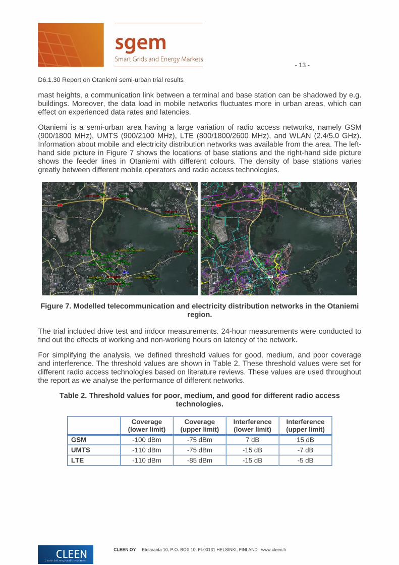
Otaniemi is a semi-urban area having a large variation of radio access networks, namely GSM (900/1800 MHz), UMTS (900/2100 MHz), LTE (800/1800/2600 MHz), and WLAN (2.4/5.0 GHz). Information about mobile and electricity distribution networks was available from the area. The left-hand side picture in Figure 7 shows the locations of base stations and the right-hand side picture shows the feeder lines in Otaniemi with different colours. The density of base stations varies greatly between different mobile operators and radio access technologies.
Figure 7. Modelled telecommunication and electricity distribution networks in the Otaniemi region.
The trial included drive test and indoor measurements. 24-hour measurements were conducted to find out the effects of working and non-working hours on latency of the network.
For simplifying the analysis, we defined threshold values for good, medium, and poor coverage and interference. The threshold values are shown in Table 2. These threshold values were set for different radio access technologies based on literature reviews. These values are used throughout the report as we analyse the performance of different networks.
Table 2. Threshold values for poor, medium, and good for different radio access technologies.
Coverage (lower limit)
Coverage (upper limit)
Interference (lower limit)
Interference (upper limit)
GSM -100 dBm -75 dBm 7 dB 15 dB
UMTS -110 dBm -75 dBm -15 dB -7 dB
LTE -110 dBm -85 dBm -15 dB -5 dB

- 14 - D6.1.30 Report on Otaniemi semi-urban trial results
CLEEN OY Eteläranta 10, P.O. BOX 10, FI-00131 HELSINKI, FINLAND www.cleen.fi
4.1 Outdoor measurement
We performed outdoor measurements in four operators’ different networks. We were using VTT’s and Viola Systems’ measurement tools as well as NSN’s Clarinet and Aalto University’s NetRadar tools. Viola Systems’ Arctic modules were used with external antennas on the measurement car’s roof. Figure 8 shows the measurement route. The numbered balloons (control points) in the figure indicate the drive direction. We drove the route twice – with and without data traffic. The measurement devices were locked on a specific radio access technology, namely GSM, UMTS, and LTE. The locking was not band specific, thereby all accessible frequency bands were measured. The locations and timestamps for measurement samples were obtained from a GPS device mounted on the dashboard of the measurement car.
Figure 8. The outdoor measurement route in the Otaniemi region. The measurement was performed with different operators’ SIMs.
WLAN measurements were done with Nemo Handy and Android phones. Nemo Handy was more suitable for drive test measurements, because it had higher sampling rate. Latency and throughput

- 15 - D6.1.30 Report on Otaniemi semi-urban trial results
CLEEN OY Eteläranta 10, P.O. BOX 10, FI-00131 HELSINKI, FINLAND www.cleen.fi
were measured using Nemo Outdoor and Aalto University’s NetRadar. NSN’s Clarinet tool was used to gather performance information from the network side. Our goal was to assess differences between terminal and network side measurements.
Figure 9 shows an example of measured signal strengths of one operator. In the figures, good coverage areas are indicated with green colour, medium ones with yellow colour, and poor ones with red colour. Similar pictures were constructed for all available operators. Since our main interest was to analyse the differences between radio access technologies rather than between operators, the operators are referenced in this report as Operator A, Operator B, Operator C, and Operator D.
The figure shows that GSM and UMTS coverage is very good in Otaniemi whereas some shadowed regions are detected in LTE coverage. Low GSM and UMTS coverage values are only measured next to HO locations. This is due to the fact that the network tries to keep the terminal connected to the same serving base station as long as possible in order to reduce signalling. After a HO occurs, the received power increases significantly, since a new serving cell has had a higher received value for some time. These locations are indicated in Figure 9 with filled red circles.
Figure 9. Measured received powers in GSM (upper left), UMTS (upper right), LTE (lower left), and WLAN (lower right) networks along the measurement route.

- 16 - D6.1.30 Report on Otaniemi semi-urban trial results
CLEEN OY Eteläranta 10, P.O. BOX 10, FI-00131 HELSINKI, FINLAND www.cleen.fi
For an operator, a HO can be problematic if it happens too early, too late, or to a wrong cell. It may cause the data connection to interrupt. The frequency of handovers also gives an indication about the base station density. The handovers of WLAN are not shown, since the route would otherwise be filled with red circles. In Otaniemi region, there is a very high density of WLAN APs and most of them are indoors. They have limited outdoor coverage, which can be observed in Figure 9.
In urban areas, the interference is typically considered more restrictive than the coverage. For example, the throughput depends on the interference level. Figure 10 shows the measured interference levels in GSM (C/I), UMTS (Ec/No), LTE (RSRQ), and WLAN (RXQUAL). Actually, RXQUAL is just an offset from respective RSSI levels. Therefore, it does not give any significant information about the interference level in WLAN.
The figure shows that only few places have poor signal-to-interference ratio. The high values suggest good network planning.
Figure 10. Measured interference levels in GSM (upper left), UMTS (upper right), LTE (lower left), and WLAN (lower right) networks along the measurement route.
The redundancy of base stations can be assessed by examining cell counts. Figure 11 shows the measured cell counts in different networks along the measurement route. The values show that on

- 17 - D6.1.30 Report on Otaniemi semi-urban trial results
CLEEN OY Eteläranta 10, P.O. BOX 10, FI-00131 HELSINKI, FINLAND www.cleen.fi
average there are more than 5 redundant cells in GSM as well as in UMTS. The counts were actually smaller than those obtained from the rural trials in Raasepori and Koillismaa. This is due to the fact that the mast heights are smaller. Buildings and terrain shapes are shadowing the connection. The smaller cell size offers better capacity with higher data rates. The cell counts in WLAN network are high next to residential and office buildings. Especially university students living in the north-east of Otaniemi are using WLAN APs extensively in their apartments. The result includes all APs, also those that are not publicly accessible. Naturally, reliability and security of local WLAN APs are major concerns that are preventing their large-scale use.
Figure 11. Measured cell counts in GSM (upper left), UMTS (upper right), LTE (lower left), and WLAN (lower right) networks along the measurement route.
In the next sub-chapters, CDF and scatter plots are used to analyse differences between operators in GSM, UMTS, and LTE networks with respect to coverage, interference, throughput, and latency.
4.1.1 Coverage
Figure 12 shows the received signal strength values of all available networks of three operators (Operator A, Operator B and Operator C) as cumulative distribution curves. The more right the

- 18 - D6.1.30 Report on Otaniemi semi-urban trial results
CLEEN OY Eteläranta 10, P.O. BOX 10, FI-00131 HELSINKI, FINLAND www.cleen.fi
curve is, the better the operator’s coverage is. The steeper the slope is, the more constant the operator’s coverage is. GSM coverage is analysed using RxLev values. All operators have sufficient coverage, since none of them has values below the lower threshold value (-100 dBm). Operators A and C have very similar CDF curves having approximately 95 % of the samples above the upper threshold value (-75 dBm). Operator B (green) has significantly lower RxLev values. It has about 70 % of its values above the upper threshold. The slopes of all operators are similar. The figure indicates that only Operator B has regions where GPRS data connections may suffer from reduced data rates.
Figure 12. Cumulative distribution function for received signal strength in GSM (RxLev_full), UMTS (RSCP), and LTE (RSRP).
The UMTS coverage is analysed using measured RSCP levels. The UMTS terminal has better receiver sensitivity. Therefore, the lower threshold value was set to -110 dBm. UMTS is currently the most dominant cellular technology in urban areas. None of the operators has values below the lower threshold value. Operator B has the best coverage. It has approximately 80 % of its values above the upper threshold level whereas Operator A only has approximately 55 %. Differences between Operator A and Operator C are rather small. Operator A has slightly steeper curve indicating more constant coverage. When we compare results to the GSM curves, we observe that Operator B had the lowest coverage in GSM whereas in UMTS it has the highest one. We can

- 19 - D6.1.30 Report on Otaniemi semi-urban trial results
CLEEN OY Eteläranta 10, P.O. BOX 10, FI-00131 HELSINKI, FINLAND www.cleen.fi
conclude that Operator B has been prioritizing UMTS over GSM more than the two other operators.
The CDF curves of different operators are shown in Figure 12. The figure includes also the results of LTE test network. The values are according to measured RSRP values. The lower threshold was set to -110 dBm, because an LTE terminal has relatively good receiver sensitivity. The upper threshold value was set to -85 dBm.
Figure 12 shows that there are more differences between operators than in GSM and UMTS. Operators A and D have a significant number of samples below the lower threshold, respectively 21 % and 60 %. Both operators are experiencing coverage gaps in the Otaniemi region. In contrast, Operators B and C have only few values below the lower threshold indicating constant coverage. Operator B has the best one having 70 % of its samples above the upper threshold. Operator C is the second best having 45 % of samples above the threshold. Operators A and D have respectively only 5 % and 15 %. The curves imply that operators have taken different strategies to exploit the LTE technology. Operator B is aiming at offering the LTE coverage in whole area, whereas Operator A uses LTE to complement hotspots in UMTS and GSM networks.
4.1.2 Interference
The link quality depends on the interference level. In urban areas, the interference is often considered more restrictive than the coverage. Figure 13 shows CDFs of different networks for all operators. Measured C/I (carrier per interference) values of different operators are used for assessing the interference level in GSM. High C/I values suggest less interfering cells and thereby good frequency planning. All operators have areas where the C/I values drop below the minimum threshold (7 dB). Operator C’s network is suffering the least from the interference (having the highest C/I values). It has only 1 % of values below the lower threshold. Its C/I curve is the steepest indicating constant low-interference along the whole route. 95 % of its values are above the upper threshold (15 dB). Respectively, Operator B has 5 % of the values below the lower threshold and 80 % above the upper threshold value. Operator A has a steeper slope than Operator B. Its interference level is more constant having less low and high C/I values.

- 20 - D6.1.30 Report on Otaniemi semi-urban trial results
CLEEN OY Eteläranta 10, P.O. BOX 10, FI-00131 HELSINKI, FINLAND www.cleen.fi
Figure 13. Cumulative distribution function for interference level in GSM (C/I), UMTS (Ec/No), and LTE (RSRQ).
The interference level in UMTS networks is analysed based on measured Ec/No levels. The value indicates how strong the received signal is compared to the sum of interference and noise. Interference is typically a dominating factor and therefore, the noise component is often considered negligible. The Ec/No value affects the used modulation technique (BPSK, QPSK, etc.) which in turn affects the maximum data rate.
Figure 13 shows CDF curves of measured Ec/No values for all operators. Operators A and B have similar curves indicating similar interference properties. 93 % of their values are above lower threshold level (-15 dB) and 85 % above the upper one (-7 dB). Operator C is likely to experience more interference. It has 75 % of values above the lower limit and 45 % above the upper level. The steepness of the curve shows that Operator C has significantly more deviation in measured Ec/No levels than Operators A and B, especially below -7 dB level. Operator C has some values below -30 dB. These values are actually outliers – measurement samples without Ec/No values. The number of outliers is so small that it has no impact on results.
The interference level in LTE networks was analysed using measured RSRQ levels. Figure 13 shows the differences between operators. We can see that differences are smaller than in case of coverage (RSRP). This indicates that interference is a less significant factor than the loss of

- 21 - D6.1.30 Report on Otaniemi semi-urban trial results
CLEEN OY Eteläranta 10, P.O. BOX 10, FI-00131 HELSINKI, FINLAND www.cleen.fi
coverage in LTE networks. None of the operators is clearly the best one, because the CDF curves are crossing. Operators B and C have over 95 % of RSRQ values above the lower threshold (-15 dB). Operator A has the least (roughly 90 %), but it has 40 % of the samples above the upper threshold level (-5 dB). The slope of operator A’s curve is the most gradual indicating fluctuations in interference levels. Operator D hast the steepest slope and thereby the most constant interference levels. It has about 3–4 % of samples below -30 dB. These values are actually outliers – locations where RSRQ value could not be measured. The outliers’ impact on result is negligible.
Figure 14 i) presents a scatter plot where x-axis shows C/I values and y-axis respective RxLev values for GSM. Operators are indicated with different colours. Region I (good) contains high RxLev and high C/I values. The region is neither coverage nor interference limited. Region II contains low RxLev and high C/I values. This region is coverage limited. On the contrary, Region III has high RxLev and low C/I values. The region is interference limited. Region IV has low RxLev and C/I values. It is both coverage and capacity limited. Figure 14 i) shows that none of the operators has interference problems. Operator C has the best network having most of its values in Region I. Operator A experiences some interference, because it has more samples in Region III than the others. Operator B has merely values in Regions II and IV. It suffers from low coverage.
Figure 14. A scatter plot of i) GSM (RxLev vs C/I values), ii) UMTS (RSCP vs Ec/No), and iii) LTE (RSRP vs RSRQ).

- 22 - D6.1.30 Report on Otaniemi semi-urban trial results
CLEEN OY Eteläranta 10, P.O. BOX 10, FI-00131 HELSINKI, FINLAND www.cleen.fi
Next, we examine a UMTS scatter plot in Figure 14 ii), where interference level (Ec/No) is plotted on the x-axis and coverage (RSCP) on y-axis. The graph shows that Operator B has its most values in Region I indicating a good network deployment. Operator C has more values in Region III than the other operators, which may indicate that its network deployment is not optimal. Operator A has its most values in Region IV and Region II. Operator A’s network is more coverage limited than the others. Compared to the GSM scatter plot, there are on average more samples in Region III. This is partly explained by more stringent requirements set for UMTS network to offer sufficient data rates.
Figure 14 iii) presents a scatter plot of RSRQ and RSRP values for LTE. Operator B has most values in Region I and is therefore best capable of achieving the stringent RSRP and RSRQ requirements. Operator A has also high RSRQ values, but most of its RSRP values are below the upper threshold of -85 dBm. Operators C and D have their values in Region III just outside the RSRQ threshold value. Operator A has the largest deviation in RSRQ values. Its values are widely scattered in Regions I, II, and IV. The figure shows that the number of high RSRP and low RSRQ values is very small. Therefore, none of the operators is suffering from interference. This may be due to the low penetration of LTE terminals.
4.1.3 Throughput
We were interested in learning about LTE networks’ performance with respect to throughput and latency. The throughput depends on e.g. selected modulation, MIMO usage, and bandwidth. LTE uses adaptive link modulation, which adjusts the modulation according to channel quality. The channel quality is measured by CQI (Channel Quality Indication). For it, data traffic needs to be generated during the measurement. A terminal makes the channel estimation and reports it to a base station with a CQI index. The values are between 1 and 15. Indexes 1–6 are allocated to QPSK, values 7–9 to 16-QAM, and values 10–15 to 64-QAM. Based on the modulation, expected data rates can be computed.
Figure 15 shows an example of CQI values measured along the route. High values are obtained next to base stations whereas low ones in shadowed regions. Near the base stations, 64QAM modulation is used. The yellow colour indicates places where the modulation changes to 16QAM. Further away from the base station, the modulation is changed to QPSK (blue colour). There are also gaps in shadowed regions indicating locations without a data connection.

- 23 - D6.1.30 Report on Otaniemi semi-urban trial results
CLEEN OY Eteläranta 10, P.O. BOX 10, FI-00131 HELSINKI, FINLAND www.cleen.fi
Figure 15. CQI values along the measurement route for Operator A.
Actual throughput levels were measured with NetRadar. A snapshot of a NetRadar measurement is shown in Figure 16. NetRadar increases the data traffic gradually until the stabilized performance peak is achieved. This takes about 5 seconds. The stabilized average level is shown in the figure with a red dashed line. The results show that data rates are well above the 2 Mbps (a requirement for control data) to both UL and DL directions.

- 24 - D6.1.30 Report on Otaniemi semi-urban trial results
CLEEN OY Eteläranta 10, P.O. BOX 10, FI-00131 HELSINKI, FINLAND www.cleen.fi
Figure 16. NetRadar statistics along the measurement route.
Figure 17 i) shows the measured download speeds along the route. The values are ranging from 1 Mbps up to 50 Mbps due to NetRadar’s feature to gradually increase the traffic. On the average, the offered download speed is almost 20 Mbps. Lower download speeds (dark blue) are found in small regions shadowed by buildings and terrain shapes. We can see that there are periodical gaps along the route. This is due to the fact that NetRadar is measuring latency, upload speed, and download speed in sequential order. These gaps and the gradually increased traffic prevent us from detecting small problematic hotspots. Therefore, we needed to analyse in parallel both NetRadar and Nemo Outdoor CQI measurements. Figure 17 ii) shows the distribution of downlink throughputs of Operator C measured by NetRadar. Nearly half of the measured data rates are 50 Mbps or more.

- 25 - D6.1.30 Report on Otaniemi semi-urban trial results
CLEEN OY Eteläranta 10, P.O. BOX 10, FI-00131 HELSINKI, FINLAND www.cleen.fi
Figure 17. Downlink speed measured by NetRadar in the measurement route for Operator C.
4.1.4 Latency
For the remote control, latency plays an important role. Latencies in different operators’ LTE networks were measured with Nemo and NetRadar. The latency was not measured in GSM, UMTS, or WLAN networks. The measured parameter was RTT (Round Trip Time), which indicates the time for a data packet to travel from a terminal to a given web server and back. Latency depends on the network load as well as the target web server used for the measurement. The latency value includes all delays along the path. In practice, delays to UL and DL directions vary, but in the analysis we were interested in the round-trip time. Figure 18 shows the latency CDF curves of different operators. Operator D had the lowest latency, around 50 ms. The values are rather constant. Only 1 % of the values are above 100 ms. Since Operator D’s network is a test network and the traffic load was low, the latency was lower compared to other operators. Operator C has most latency values around 60 ms. Also, higher RTT values were measured. Approximately 5 % of the values were above 100 ms. The highest latencies were measured in Operator B’s network. The average latency was around 70 ms. In addition, approximately 30 % of Operator B’s samples were above 100 ms. Operator A is not shown in the figure, because no RTT values were measured from its network.

- 26 - D6.1.30 Report on Otaniemi semi-urban trial results
CLEEN OY Eteläranta 10, P.O. BOX 10, FI-00131 HELSINKI, FINLAND www.cleen.fi
Figure 18. RTT values as CDF curve for different operators.
4.1.5 Comparison of different terminals
As stated earlier, a terminal and its antenna properties as well as antenna height affect the received power. Measurements in Otaniemi were performed with Nemo and Viola Systems’ terminals. Viola Systems’ Arctic 2G/3G/4G modules were using external outdoor antennas placed on the roof of the measurement car. The used external antennas were improving the reception in two ways. First, they have better receiver antenna gains than internal antennas used in the Nemo terminal. Secondly, the external antennas were mounted outside the car and therefore, the received signal was not attenuated by the car body. Nevertheless, we must keep in mind that antenna cables and metal surface of the car roof are causing some performance degradations.
Figure 19 shows the signal reception comparison between Nemo and Arctic terminals in GSM, UMTS, and LTE. The Arctic measures approximately 10 dB higher RxLev values than Nemo in the GSM network. In the Arctic measurement, there is a small number of measurement samples without RxLev values. Moreover, a maximum threshold value in Arctic module prevents to measure higher than -45 dBm values. Roughly 50 % of the Arctic samples are above -45 dBm. With the Nemo terminal, the corresponding percentage is 25 %.

- 27 - D6.1.30 Report on Otaniemi semi-urban trial results
CLEEN OY Eteläranta 10, P.O. BOX 10, FI-00131 HELSINKI, FINLAND www.cleen.fi
Figure 19. Comparison of Nemo and Arctic GSM, UMTS, and LTE measurements.
When we look at UMTS measurements, we see that the difference between terminals is rather constant around 15 dB. There are only few outliers in the Arctic UMTS measurements indicating locations where RSCP values could not be measured. In the Arctic UMTS measurement, there is no maximum threshold value.
In LTE network, the difference between Nemo and Arctic terminals varies more than in UMTS. Moreover, the sampling rate in Arctic was lower than in Nemo causing more stair-like effect to the curve. The difference is roughly 10 dB. The Nemo terminal curve starts from 4 %. This is due to the fact that the Nemo terminal has lost a connection to an LTE network and those samples are indicated with -140 dBm values. The Arctic module also has approximately 1 % of the samples without a value. The loss of LTE coverage is smaller due to a better antenna enabling longer link distances between a terminal and a serving base station.
4.1.6 Network side monitoring
We were interested in evaluating the differences between Nemo Outdoor and Clarinet measurements. Figure 20 shows the RSRP values measured by Clarinet in blue and by Nemo in red. The values are correlating well. The main difference is in the sampling rate, which was

- 28 - D6.1.30 Report on Otaniemi semi-urban trial results
CLEEN OY Eteläranta 10, P.O. BOX 10, FI-00131 HELSINKI, FINLAND www.cleen.fi
significantly lower in Clarinet. We must keep in mind that Nemo collects samples only from three terminals whereas Clarinet collects them from dozens or even hundreds of terminals.
Figure 20. Comparison between LTE measurements by Nemo and Clarinet.
The sampling rate for Clarinet was one sample in 10 seconds. This is done to reduce the signalling in the LTE network. In Nemo measurements, the sampling rate is one sample every 300 ms, and thereby Nemo was more suitable for drive test measurements. The evident advantage of Clarinet is that it is capable of monitoring all terminals and thus creates a situational picture of the LTE network enabling e.g. crowd sensing possibilities whereas the Nemo is only providing samples from a specific terminal and location at a given time. Figure 21 shows the samples measured with Clarinet (left) and Nemo (right) on a map along the measurement route.

- 29 - D6.1.30 Report on Otaniemi semi-urban trial results
CLEEN OY Eteläranta 10, P.O. BOX 10, FI-00131 HELSINKI, FINLAND www.cleen.fi
Figure 21. Comparison between LTE measurements by Nemo and Clarinet.
4.2 Indoor measurements
A significant number of indoor medium-voltage network entities are placed in buildings’ basements, where the radio environment changes greatly as walls, ceilings, and large objects are shadowing the radio signal and causing multi-path effects. In an indoor environment, the received signal typically experiences more reflections, penetrations, diffraction, and scattering than outdoors. Indoor coverage prediction is challenging, because there are no detailed information available about interiors including walls and ceilings – not to mention about materials or their thicknesses.
With the aid of indoor measurements, we wanted to find out how much indoor and outdoor radio environments vary and what types of requirements we need to consider when deploying indoor wireless connections for machine type communications. Is it feasible to use RTUs with embedded antennas, external antennas with antenna cables, or make Ethernet cable installations? We must take into account that legacy grid components are not always supporting Ethernet connections. We also wanted to find out whether electro-magnetic fields generated by grid entities are causing additional interference to wireless connections.
We performed indoor coverage measurements in three different sites in Otaniemi. The locations are displayed in Figure 22. The locations were chosen with the aid of a blueprint of the electricity distribution network. The sites represent different types of indoor environments. The first location is on the ground floor in a new office building (VTT Micronova building), the second one is in the basement of an old building (Aalto building) near base stations, and the third one is in the basement of a renovated building (Aalto Startup Sauna building) far from base stations.

- 30 - D6.1.30 Report on Otaniemi semi-urban trial results
CLEEN OY Eteläranta 10, P.O. BOX 10, FI-00131 HELSINKI, FINLAND www.cleen.fi
Figure 22. Indoor measurements with a mobile robot.
We repeated the same measurements that were performed outdoors. Measurements with Clarinet and NetRadar were excluded, because the Nemo tool was capable of providing adequate information for our analysis. We used a mobile robot to provide indoor location coordinates for measurement samples as well as to record changes in the magnetic field. The robot was equipped with a 2D lidar and a camera. Therefore, it was also possible to construct 2D/3D models from buildings’ interiors. The constructed interiors are illustrated as white regions with light grey backgrounds in Figure 22. The red lines show the measurement routes. The mobile robot was controlled manually over a wireless WLAN link although we could have used programmed routes with a list of turning points. This would have guaranteed the exact repeatability of the measurements. However, the trial sites had electricity switches on the floor level, and therefore, it was safer to rely on the manual control. The indoor route measurements were done with the Nemo tool, because there was not enough room on the rack of the mobile robot for the Arctic 2G/3G/4G modules. After the mobile robot had completed its route, a 5-minute stationary measurement was performed in parallel with the Arctic and Nemo tools in close proximity of grid entities. The measurement route was repeated four times – once in GSM, once in UMTS and twice in LTE networks.

- 31 - D6.1.30 Report on Otaniemi semi-urban trial results
CLEEN OY Eteläranta 10, P.O. BOX 10, FI-00131 HELSINKI, FINLAND www.cleen.fi
Figure 23 shows the mobile robot and its sensors. A laptop with the Nemo 2G/3G/4G/WLAN devices and a magnetometer were placed on the mobile robot’s rack. A camera and a 2D-lidar were mounted on the top of an adjustable tripod. The right-hand picture shows the mobile robot while measuring one of the sites.
Figure 23. A mobile robot used for providing indoor location and constructing a 2D/3D interior model.
The pictures on the left in Figure 24 show the indoor measurement routes on a 3D model of each building. On the right, the spaces (an electricity maintenance room) where we started and ended the measurement are displayed. The shown 3D building models include only external walls and roof structures. Therefore, the data gathered by the mobile robot was required to construct the interiors.

- 32 - D6.1.30 Report on Otaniemi semi-urban trial results
CLEEN OY Eteläranta 10, P.O. BOX 10, FI-00131 HELSINKI, FINLAND www.cleen.fi
Figure 24. The modelled buildings and stationary measurements in site locations.

- 33 - D6.1.30 Report on Otaniemi semi-urban trial results
CLEEN OY Eteläranta 10, P.O. BOX 10, FI-00131 HELSINKI, FINLAND www.cleen.fi
For the analysis, we used the same threshold values as in oudoor measurements. The values are shown in Table 2. Figure 25 shows an example of the received powers in GSM, UMTS, LTE, and WLAN networks in Micronova building. The GSM coverage is good in whole area and the number of cell changes is small. The coverage in UMTS gets weaker as we move deeper inside the building and closer to the electricity maintenance room. Indoor LTE coverage is rather weak along the measurement route. In Micronova, there is also moderate indoor WLAN coverage.
Figure 25. Measured received powers in GSM (upper left), UMTS (upper right), LTE (lower left), and WLAN (lower right) networks along the measurement route.

- 34 - D6.1.30 Report on Otaniemi semi-urban trial results
CLEEN OY Eteläranta 10, P.O. BOX 10, FI-00131 HELSINKI, FINLAND www.cleen.fi
Figure 26 shows the measured signal to interference levels in the same building in GSM, UMTS, GSM, and WLAN networks. For GSM, the interference level was good throughout the measurement route. At some locations, the UMTS interference was bad (low Ec/No values). The interference level (RSRQ) in LTE was medium along the whole route.
Figure 26. Measured interference levels in GSM (upper left), UMTS (upper right), LTE (lower left), and WLAN (lower right) networks along the measurement route.

- 35 - D6.1.30 Report on Otaniemi semi-urban trial results
CLEEN OY Eteläranta 10, P.O. BOX 10, FI-00131 HELSINKI, FINLAND www.cleen.fi
Figure 27 shows the detected cell counts, which indicate the indoor redundancy level in GSM, UMTS, LTE, and WLAN networks. The GSM’s redundancy was high near the entrance. It subsequently decreased as we approached closer to the indoor substation. The cell count in UMTS was low near the substation; there was only one serving cell (no redundancy). Consequently, a dominant cell actually lowers the number of detected neighboring cells in UMTS. In LTE, the cell count was low along the entire measurement route. The terminal was served by a single cell. Cell redundancy in WLAN was high, because Micronova is an office building with numerous WLAN hotspots.
Figure 27. Measured cell counts in GSM (upper left), UMTS (upper right), LTE (lower left), and WLAN (lower right) networks along the measurement route.
4.2.1 Coverage
First, we will examine indoor coverages in different networks. Figure 28 shows two very different indoor environments. Figure 28 i) shows the coverage on the ground floor of the new building and Figure 28 ii) in the basement of the old building.
In Figure 28 i), we can see that all operators are offering good GSM coverage. Actually, average received RxLev values are higher than the values measured outdoors (Figure 12). Only Operator B has some samples without coverage, approximately 2–3 %. Although its coverage is the lowest, it has still over 87 % of its samples above the upper threshold limit (-75 dBm). Operator C has the best indoor coverage. The slope of its CDF curve is very steep indicating a very constant coverage. Operator A has a slightly weaker coverage.

- 36 - D6.1.30 Report on Otaniemi semi-urban trial results
CLEEN OY Eteläranta 10, P.O. BOX 10, FI-00131 HELSINKI, FINLAND www.cleen.fi
Figure 28. GSM coverage i) on the ground floor of the office building and ii) in the basement of the old building.
The basement site gives very different results. Operator A has very good GSM coverage. Actually, its average RxLev values are similar to those measured on the ground floor case. This indicates the use of indoor base station(s). Operator B’s and Operator C’s coverage drops approximately 30 dB compared to the ground floor case. The basement is surrounded by thick steel reinforced concrete walls. Therefore, the signal gets significantly attenuated. We see from the figure that only a small number of Operator C’s values exceed the upper threshold value (-75 dBm). Operator B does not exceed the upper threshold value and has no coverage in 58% of time. Based on the figure, Operator C suffers slightly from low coverage. Operator B suffers most and low coverage can restrict the use of GPRS data connections.
Next, we examine indoor UMTS coverage in the same locations. The coverage is analysed based on the measured RSCP values. Figure 29 i) shows the UMTS indoor coverage on the ground floor of the new building and Figure 29 ii) in the basement of the old building. Again, CDF curves differ significantly. In the new building, we can observe that Operator A and Operator C have indoor cells. This can be detected by sudden changes in RSCP curves. Operator B does not have indoor cells, but on the average, it has the best and most consistent coverage. 75 % of its samples are above the upper threshold limit (-75 dBm). Operator A and Operator C exceed the threshold approximately 22 % and 26 % of the time. Based on the curves, we can say that Operator B has good coverage and Operator A and Operator C medium one. All operators are able to provide sufficient indoor coverage.

- 37 - D6.1.30 Report on Otaniemi semi-urban trial results
CLEEN OY Eteläranta 10, P.O. BOX 10, FI-00131 HELSINKI, FINLAND www.cleen.fi
Figure 29. UMTS coverage i) on the ground floor of the office building and ii) in the basement of the old building.
In the basement of the old building, the average RSCP value is roughly 20 dB lower. Operator A has the best and most constant UMTS coverage. It has all its values above the lower threshold value, but none above the upper threshold value (-75 dBm). Operator C has approximately 2–3 % of values above the upper threshold limit and roughly 8 % below the lower limit. Operator B has the weakest coverage. 28 % of the samples are without coverage and 65 % of the samples are below the lower limit. Figure 29 ii) indicates that Operator A and Operator C have medium coverage and Operator B a limited one.
We anticipated that the selected sites are challenging for LTE, because the technology is recently been deployed, and the frequency used (1800/2600 GHz) suffers more from the shadowing than GSM and UMTS. In addition, LTE technology is typically utilized in those places where the demand for high data rates is high – not near the electricity maintenance rooms.
The differences between operators are significant. Figure 30 i) shows the LTE coverage on the ground floor. Operator C has the best coverage. All its values are above the lower threshold limit (-110 dBm) and 20 % above the upper one (-85%). Operator B has also sufficient coverage exceeding the lower limit everywhere. Operator A and Operator D have very limited coverage. They both have approximately 40 % coverage. 15 % of Operator A’s and 30 % of Operator D’s samples are exceeding the lower threshold limit. The figure shows that both Operator B and Operator C have rather good indoor LTE coverage where as Operator A and Operator D are suffering from low coverage and thus are rather limited for grid communications.

- 38 - D6.1.30 Report on Otaniemi semi-urban trial results
CLEEN OY Eteläranta 10, P.O. BOX 10, FI-00131 HELSINKI, FINLAND www.cleen.fi
Figure 30. LTE coverage i) on the ground floor of the office building and ii) in the basement of the old building.
The basement site was challenging. Only Operator B and Operator C were able to provide coverage, but it was poor. Operator B has 25 % of its samples without coverage. The average RSCP values are about 25 dBm lower than on the ground floor of the office building. The lower threshold limit (-110 dBm) is exceeded by Operator B 7 % and Operator C 3 % of the time. Operator C has more constant RSRP values than Operator B.
4.2.2 Interference
Next, we studied C/I values in GSM networks. We tried to find out whether the interference differs between indoors and outdoors, and whether grid entities cause additional interference. Indoor cells often dominate, so they contribute higher C/I values. The electro-magnetic interference from grid entities and cables may cause additional noise that adversely lowers C/I values. Typically, these electro-magnetic disturbances can be neglected, because their levels are significantly smaller than the intra-interference of adjacent base stations. GSM is based on TDMA (Time Division Multiple Access) technology and its bandwidth is 200 kHz divided into time slots. The interfered frequency band is thus rather limited around 900 MHz and 1800 MHz bands.
Figure 31 i) shows the CDF curves of the measured C/I values in the office building. All operators have high C/I values. Over 90 % of their values are above the upper threshold limit (15 dB). Operator C has on average the highest C/I values indicating low interference level. The highest values are measured in Operator A’s network, but differences between the operators are rather small. Operator B and Operator C have very constant values whereas Operator A has the most deviation between 15 dB and 25 dB. The measured values are not showing any indication that grid entities are affecting the communication link quality.

- 39 - D6.1.30 Report on Otaniemi semi-urban trial results
CLEEN OY Eteläranta 10, P.O. BOX 10, FI-00131 HELSINKI, FINLAND www.cleen.fi
Figure 31. GSM interference (C/I) i) on the ground floor of the office building and ii) in the basement of the old building.
Next, we examine the situation in the basement in Figure 31 ii) where lower RxLev values were measured. Operator A had significantly better coverage than the other two operators. As we anticipated, Operator A has the highest C/I values exceeding the upper limit (15 dB) 90 % of the time. Operator B and Operator C have lower ones exceeding the upper limit around 10 % of the time. The C/I values are correlating well with the coverage values. No additional interference can be detected from bad network planning or from interference caused by grid entities.
As in the outdoor measurement case, we constructed scatter plots of C/I and RxLev values. Figure 32 i) shows that all operators have their samples in Region I and Region II in the office building case. Only few samples are found in Region IV. Operator A has highest values. Operator B is slightly worse. Operator C’s values are the most concentrated. In coverage and interference wise, all operators have sufficient GSM networks.
Figure 32. A scatter plot of C/I vs RxLev i) on the ground floor of the office building and ii) in the basement of the old building.

- 40 - D6.1.30 Report on Otaniemi semi-urban trial results
CLEEN OY Eteläranta 10, P.O. BOX 10, FI-00131 HELSINKI, FINLAND www.cleen.fi
Figure 32 ii) shows significant differences between operators in the basement case. Operator A has most of the samples in Region I whereas Operator B and Operator C have in Region IV. Thus, Operator B’s and C’s GSM networks are coverage limited.
Next, we study indoor interference in UMTS networks. The analysis is done using the measured Ec/No values. UMTS is using a direct spread WCDMA technology, which bandwidth is 5 MHz (effective 3.84 MHz). This band is divided among all users. Possible wide spectrum interference created by grid entities could affect the whole 5 MHz band. The used UMTS bands are 900 MHz and 2100 MHz. The former one is merely used in rural areas to provide also coverage.
Figure 33. Cumulative distribution function (Ec/No) i) on the ground floor of the office building and ii) in the basement of the old building.
Figure 33 i) shows the measured Ec/No values in the office building. 99 % of the samples are above the lower threshold (-15 dB). The highest average values are measured in Operator A’s network and the lowest ones in Operator B’s network. The upper limit (-7 dB) is exceeded by Operator A 85 %, Operator C 80 %, and Operator B 60 % of the time. None of the operators is suffering from interference and the Ec/No level can be considered good in all operators’ networks.
Once again, the basement case shows bigger differences between operators shown in Figure 33 ii). Operator A has the highest and most constant Ec/No values. 98 % of its values are above the upper threshold (-7 dB) value. Operator C is also good having 85 % of its samples above the upper limit. Operator B is significantly worse. Operator B has around 25 % of samples without values and 40% of the values are above the lower threshold limit. Operators A and C have good and Operator B poor Ec/No levels. The values are correlating with coverage. Thus, we did not detect any signs of bad network planning or additional interference from the grid components.
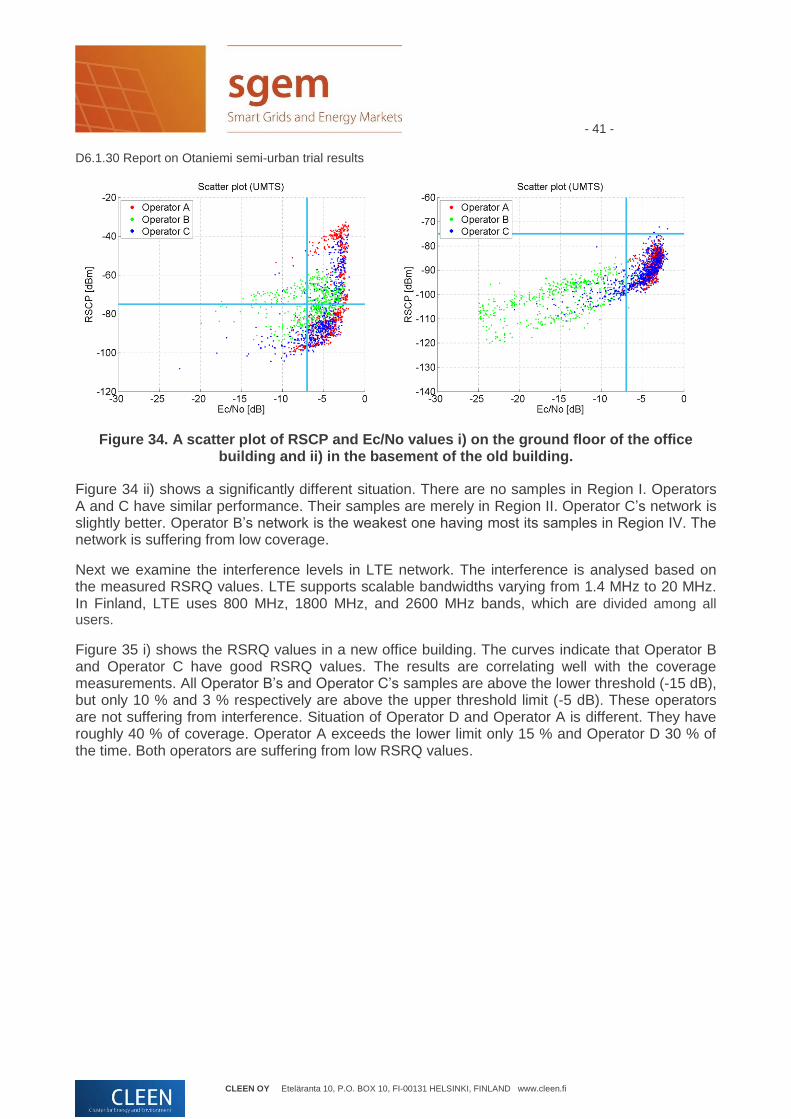
Next, we compare UMTS scatter plots created from Ec/No and RSCP values. Figure 34 i) shows clearly the effect of indoor base stations. Operator A and Operator C have two concentrations of samples – one (indoor base stations) in Region I and another in Region II (outdoor base stations). Operator B has most consistent values near the origin of the scatter plot. There are only a small number of samples in Region III and Region IV, so all operators have adequate UMTS networks.
- 41 - D6.1.30 Report on Otaniemi semi-urban trial results
CLEEN OY Eteläranta 10, P.O. BOX 10, FI-00131 HELSINKI, FINLAND www.cleen.fi
Figure 34. A scatter plot of RSCP and Ec/No values i) on the ground floor of the office building and ii) in the basement of the old building.
Figure 34 ii) shows a significantly different situation. There are no samples in Region I. Operators A and C have similar performance. Their samples are merely in Region II. Operator C’s network is slightly better. Operator B’s network is the weakest one having most its samples in Region IV. The network is suffering from low coverage.
Next we examine the interference levels in LTE network. The interference is analysed based on the measured RSRQ values. LTE supports scalable bandwidths varying from 1.4 MHz to 20 MHz. In Finland, LTE uses 800 MHz, 1800 MHz, and 2600 MHz bands, which are divided among all users.
Figure 35 i) shows the RSRQ values in a new office building. The curves indicate that Operator B and Operator C have good RSRQ values. The results are correlating well with the coverage measurements. All Operator B’s and Operator C’s samples are above the lower threshold (-15 dB), but only 10 % and 3 % respectively are above the upper threshold limit (-5 dB). These operators are not suffering from interference. Situation of Operator D and Operator A is different. They have roughly 40 % of coverage. Operator A exceeds the lower limit only 15 % and Operator D 30 % of the time. Both operators are suffering from low RSRQ values.

- 42 - D6.1.30 Report on Otaniemi semi-urban trial results
CLEEN OY Eteläranta 10, P.O. BOX 10, FI-00131 HELSINKI, FINLAND www.cleen.fi
Figure 35. Cumulative distribution function (RSRQ) i) on the ground floor of the office building and ii) in the basement of the old building.
In the case of the basement of the old building, there are only two operators’ LTE networks available. Figure 35 ii) shows that Operator C has better network interference-wise than Operator B. It seems that more consistent coverage (steeper slope) provides higher RSRQ values. None of the operators have values above the upper threshold limit. Operator B exceeds the lower limit 87 % and Operator C 18 % of the time. The values are in line with the RSRP values, so no additional interference or bad network planning can be detected based on the results.
As in the cases of GSM and UMTS, we constructed LTE scatter plots from RSRQ and RSRP values. Figure 36 i) shows a scatter plot of the ground floor of the office building where Operator B’s and Operator C’s values are concentrated near the origin, whereas Operator A’s and Operator D’s values are widely scattered in Region IV. The figure indicates that Operator B and Operator C have sufficient network performance whereas Operator A and Operator D are suffering from poor coverage.
Figure 36. A scatter plot of RSRQ vs RSRP i) on the ground floor of the office building and ii) in the basement of the old building.

- 43 - D6.1.30 Report on Otaniemi semi-urban trial results
CLEEN OY Eteläranta 10, P.O. BOX 10, FI-00131 HELSINKI, FINLAND www.cleen.fi
Figure 36 ii) shows a significantly different situation in the basement. The samples of two operators are mainly in Region IV indicating poor coverage in both networks. Operator C’s network is slightly better.
4.2.3 Latency
Latency is an important factor when remote control is planned to be deployed. Latency depends on network load, radio conditions, and the location of data server. We conducted 24-hour stationary measurements to assess the latencies and changes in radio conditions during office and out-of-office hours. For example, changing traffic loads in a UMTS network can cause cell breathing where the size of a cell shrinks when the traffic load increases in order to meet capacity requirements. The indoor stationary measurements were conducted in five locations. The sites are shown in Figure 37:
1. VTT Main building (Vuorimiehentie 5)
2. VTT Micronova (Tietotie 3)
3. Aalto building (Konemiehentie 2)
4. Aalto building (Otakaari 5)
5. Aalto Startup Sauna building (Betonimiehenkuja 3)

- 44 - D6.1.30 Report on Otaniemi semi-urban trial results
CLEEN OY Eteläranta 10, P.O. BOX 10, FI-00131 HELSINKI, FINLAND www.cleen.fi
1
2
3
4
5
Figure 37. The sites of 24-hour stationary measurements.
The measurements were carried out using two 2G/3G/4G modules with Nemo Outdoor in order to measure two operators’ networks in parallel. The operators were chosen based on the mobile robot measurements. A specific measurement script was run in Nemo for 24 hours to collect information. The script had four phases. In the first phase, it forced a vertical handover, namely a switch to another radio access technology. The switching was done between UMTS, LTE, and GSM networks as shown in Figure 38. After the switch, the script waited for a while to ensure that the handover was successful. In the second phase, the script measured radio parameters without traffic e.g. coverage and interference related parameters. In the third phase, the script started UDP traffic of 2 Mbps to the UL direction. The traffic was generated with Iperf and sent to VTT’s server. In the last phase, the script sent 10 ping commands to Google DNS server in order to measure average RTT. One cycle, presented in Figure 38, took approximately 5 minutes and it was repeated for 24 hours.

- 45 - D6.1.30 Report on Otaniemi semi-urban trial results
CLEEN OY Eteläranta 10, P.O. BOX 10, FI-00131 HELSINKI, FINLAND www.cleen.fi
Figure 38. A script used for measuring GSM, UMTS, and LTE networks for 24 hours.
We anticipated some deviation in received signal powers and in latency values. When we analysed the results, the deviation turned out to be bigger. The serving cell was changing during the 24-hour measurement and the variation in signal strength values was high. Similar results were obtained from all five locations. Moreover, in RTT values, there were latency concentrations as well as highly scattered values. To find out more about the phenomenon, the measurement samples were plotted in Matlab with base station specific colours. The outcome is shown in Figure 39 (GSM), Figure 40 (UMTS), and Figure 41 (LTE).

- 46 - D6.1.30 Report on Otaniemi semi-urban trial results
CLEEN OY Eteläranta 10, P.O. BOX 10, FI-00131 HELSINKI, FINLAND www.cleen.fi
Figure 39. RxLev and RTT values measured in GSM network.
Figure 40. RSCP and RTT values measured in UMTS network.
Figure 41. RSRP and RTT values measured in LTE network.

- 47 - D6.1.30 Report on Otaniemi semi-urban trial results
CLEEN OY Eteläranta 10, P.O. BOX 10, FI-00131 HELSINKI, FINLAND www.cleen.fi
After some research work, we found an explanation. First of all, the existence of multiple Cell-IDs is explained by the use of dual carriers. The dual carrier (DC) enables a terminal to receive on two different frequency channels (different bands) at the same time, thus doubling the downlink throughput.
In UMTS the bands were 900/2100, in LTE 1800/2600, and in GSM 900/1800. In addition, most masts are deployed with sectored cells and thus the serving cell can change between these sectors depending on e.g. load situation. Differences in RTT values can be explained by the ping messaging. The first ping takes significantly longer than the following ones, because during the first ping, a terminal must do an ARP request to find the route to the target server. After the first ping, the terminal caches the MAC address of the server. Moreover, there are two types of latencies in radio access networks: control plane (CP) and user plane (UP). The former one requires a state transition from idle to active, and therefore the latency is significantly longer, around 100 ms in LTE. The user plane latency does not require a state transition and thus, it is significantly shorter, around tens of milliseconds in LTE.
Since we were sending ping messages after the UDP traffic, we expected that the connection remains active and thus the control plane latency could be ruled out. Therefore, we only removed the first ping command’s value from RTT results. By doing so, we got more realistic picture about latencies in different networks during the data transfer.
We were also keen on knowing the differences between office and out-of-office hours. Figure 42 shows the average RTT values in different networks at different hour of the day. LTE has smallest latency around 30–40 ms. UMTS has also small latency, but during the hours 7–9, 12–15, and 16–19 the latencies increase over 100 ms. This reflects to the load changes in the UMTS network. GSM has the largest RTT values around 300 ms. The GSM network is also affected by traffic loads and thereby latencies over one second were measured during the peak load hours. Penetration of LTE mobile terminals is low, so the LTE network does not get congested. Latencies in LTE remained constant over the whole 24-hour measurement.

- 48 - D6.1.30 Report on Otaniemi semi-urban trial results
CLEEN OY Eteläranta 10, P.O. BOX 10, FI-00131 HELSINKI, FINLAND www.cleen.fi
Figure 42. RTT values in different networks over 24 hours.
Figure 43 shows the deviation and average RTT values in LTE. We can observe that the deviation is rather modest between 20 ms and 45 ms. Only one peak value around 90 ms was obtained, which is more likely to be an outlier or a CP latency value. The latency is very constant, which is very crucial when the wireless technology is deployed in remote control.

- 49 - D6.1.30 Report on Otaniemi semi-urban trial results
CLEEN OY Eteläranta 10, P.O. BOX 10, FI-00131 HELSINKI, FINLAND www.cleen.fi
Figure 43. LTE RTT Latency distribution over 24 hours.
When we compare the LTE results to UMTS depicted in Figure 44, we can see that in the UMTS network the latency values are fluctuating drastically. Even 5-second latencies were measured. The latency distribution seems to be larger during the load hours due to the re-sending of packets and increased network scheduling. As a result, occasional long latencies in UMTS especially during peak hours need to be considered when it is used for real-time remote control and monitoring.

- 50 - D6.1.30 Report on Otaniemi semi-urban trial results
CLEEN OY Eteläranta 10, P.O. BOX 10, FI-00131 HELSINKI, FINLAND www.cleen.fi
Figure 44. UMTS RTT Latency distribution over 24 hours.
When we examine the latency distributions of GSM, UMTS, and LTE in the same graph depicted in Figure 45, we can see that nearly 100 % of LTE and 90 % of UMTS RTT values are between 0 and 50 ms. In UMTS, 8 % of samples are less or equal to 100 ms and 3 % of samples are between 1 s and 5 s. They are most likely caused by congestion and re-sending of lost packets. Latencies in GSM network are the highest. About 80 % of samples are between 250 and 500 ms. This is very high compared to UMTS and LTE values. Similar observations were obtained from the other site measurements.

- 51 - D6.1.30 Report on Otaniemi semi-urban trial results
CLEEN OY Eteläranta 10, P.O. BOX 10, FI-00131 HELSINKI, FINLAND www.cleen.fi
Figure 45. RTT Latency distribution over 24 hours.
We also measured the success rate of packet data connections. The connection was changed roughly 500 times over the 24-hour measurement period. The connection establishment is done in three stages. The Nemo data measurement starts with an attach attempt (GAA) request. The successful attachment is acknowledged with an attachment connected (GAC) message. The attachment is not radio access technology specific, so the success rate was computed for each measurement site. After the device is attached, a packet activation attempt (PAA) request is sent. If it is successful, a packet session activated (PAC) message is received and measurement moves to the packet active state. The success rate of packet connection activation can be computed for each radio access technology. In the last stage, the data connection attempt (DAA) is sent in order to establish a data connection to a server. For TCP based protocols, this is recorded when socket connection is attempted, and for UDP protocols when the first UDP packet is sent. The success rate can be computed for each application protocol. It turned out that the data connection was always successful, so only attachment and packet success rates are shown in Figure 46. The attachment success rate was computed by dividing the number of successful attempts (GAC and PAC) with the number of attempts (GAA / PAA). The attachment stage can be considered very reliable, since the success rate is over 95 % in all the sites.

- 52 - D6.1.30 Report on Otaniemi semi-urban trial results
CLEEN OY Eteläranta 10, P.O. BOX 10, FI-00131 HELSINKI, FINLAND www.cleen.fi
Figure 46. Attachment and packet success rates in different indoor sites over 24 hours.
There is more variation in packet connection success rates. The right-hand side histogram shows the success rates of different radio access technologies. None of the radio access technologies is superior. We see that the location itself is affecting more on the reliability than the selected radio access technology. LTE has the best success rate in all other sites except site 1. There approximately 45 % of LTE packet connections failed due to low coverage. UMTS has the highest average packet connection success rate. Only at one site, the success rate is below 90 %. GSM has the most constant packet connection success rate. The percentage is above 80 % in all measurement sites.
4.3 Indoor and outdoor analysis
We constructed summary graphs to get a better understanding about the differences between indoor/outdoor spaces, used radio access technologies, operators, and even device types. The graph has three dimensions – namely, availability (received signal power) in the x axis, interference level (signal to interference ratio) in y axis, and redundancy (average number of detectable cells) – illustrated with the radius of a circle. The colours indicate different operators (A, B and C). A circle without a border line presents an outdoor measurement (OUTDOOR), a circle with a dotted line an indoor measurement on the ground level (1), and a circle with a dashed line an indoor measurement in the basement (2). The figures were created for GSM, UMTS, and LTE networks.
In GSM, the outdoor results and the indoor ground floor results are similar. The indoor redundancy is smaller, since the sizes of the circles are smaller than outdoors. The most prominent differences can be seen in the basement measurements surrounded by a dashed ellipsoid in Figure 47. Only Operator A has indoor cells. Its GSM coverage is similar to the outdoor coverage. Operator B and Operator C have significantly weaker coverage. Operator B has the lowest redundancy based on the size of the circle.

- 53 - D6.1.30 Report on Otaniemi semi-urban trial results
CLEEN OY Eteläranta 10, P.O. BOX 10, FI-00131 HELSINKI, FINLAND www.cleen.fi
Figure 47. GSM performance in different environments.
In the UMTS network case, there are more deviation in outdoor measurements with respect to coverage and interference. Operator B has significantly better coverage than Operator A and Operator C. The outdoor redundancy is the lowest in operator C’s networks. The indoor coverage is 10 dB lower on the ground floor and approximately 25 dB in the basement. Operator B’s network suffers significantly from poor coverage in the basement. As in case of GSM, the differences between operators’ UMTS networks are the biggest in the basement depicted with a surrounding dashed ellipsoid in Figure 48. The figure also shows that interference becomes naturally worse in the basement when the signal levels are low.
Figure 48. UMTS performance in different environments.

- 54 - D6.1.30 Report on Otaniemi semi-urban trial results
CLEEN OY Eteläranta 10, P.O. BOX 10, FI-00131 HELSINKI, FINLAND www.cleen.fi
According to the LTE measurements, two observations can be made. The outdoor coverage differences between the operators are greater than in GSM and UMTS networks. The differences between outdoor LTE networks are depicted with a dashed ellipsoid. Operators have clearly taken different strategies to deploy LTE. Operator B has the best outdoor LTE coverage and it uses LTE as the primary network technology. Operator C provides good outdoor coverage for all radio access technologies. Moreover, it has the best indoor LTE coverage. It is deploying indoor LTE cells in Otaniemi to provide additional coverage to hotspots. In contrast to Operator B, Operator A is relying merely on GSM and UMTS networks. It has the weakest outdoor and indoor LTE coverage. The differences in the basement are significant as depicted with a dotted ellipsoid in the figure.
Figure 49. LTE performance in different environments.
The biggest differences were detected between the basement and the ground floor cases. Therefore, we analysed them in details to get a more comprehensive picture about the availability. Figure 50 shows the coverage percentage obtained in the ground floor case (on the left). All operators have full UMTS coverage. The GSM coverage is almost complete for Operator A and Operator C. Operator B has coverage around 87 %. The significant differences are in LTE. Operator C has full-coverage whereas Operator B has around 80 % and Operator A around 50 %.
The coverage percentages change drastically when we examine the basement case (on the right in Figure 50). Operator A can provide full coverage for GSM and UMTS, but it does not have any LTE coverage in the basement. Operator B has very low GSM (9 %) and UMTS (55 %) coverage compared to the other operators. Nevertheless, it has the best LTE coverage (35 %). The graphs show that the differences between the locations are the most significant. Thus, in some cases, the location actually dictates the most feasible technology and operator. Although UMTS is currently the dominating technology, the importance of LTE is gradually increasing as LTE (new 800 MHz band) gets deployed. This will evidently make changes to the options used for remote control of grid entities.

- 55 - D6.1.30 Report on Otaniemi semi-urban trial results
CLEEN OY Eteläranta 10, P.O. BOX 10, FI-00131 HELSINKI, FINLAND www.cleen.fi
Figure 50. Coverage percentage of different operators.
4.4 Fault simulations
There was no storm data available from Otaniemi, because power lines are merely underground and thereby are not affected by fallen trees. For the calculations, we got the electricity grid structure of Otaniemi from ABB. It enabled us to simulate other types of faults in Otaniemi region. We extended the NPT tool to support also telecommunications related faults e.g. hardware failures in base stations. In addition, we got detailed information about two mobile operators’ network structures. Using them, a 3D model of Otaniemi with buildings and vegetation, and outdoor measurements, we computed coverage and redundancy rasters for GSM, UMTS, LTE, and WLAN networks. Figure 51 shows the base stations’ locations and antenna direction of the LTE network, the constructed 3D mode with buildings, and the coverage fine-tuned with the outdoor measurements. The modelled area is roughly 2 km x 2 km, so it was not fully suitable for large-scale fault simulations.
For the coverage prediction, both urban and suburban coverage prediction models were experimented. To select the suitable propagation model turned out to be challenging, because the received power values were changing drastically between different base stations and depending on the shadowing of the buildings. Indoor measurements were not used for the propagation model tuning, because enough information about buildings’ properties was not available.
We performed different fault simulations with Otaniemi model by causing both telecommunications and electricity distribution network faults. The simulations revealed that several base stations were connected to the same grid entity. A fault in that critical grid entity caused a coverage gap in the area. The gap could not be recovered by neighbouring cells, since they have limited coverage radii due to capacity requirements.
The indoor coverage estimation requires still more work, since the feasibility of using wireless communications depends on more factors e.g. the location of grid entity (on the ground floor or in the basement) and properties of the building (thickness of walls and materials). The use of buildings’ 3D interior information and indoor propagation models poses challenges respect to prediction accuracy and fine-tuning of the models. As a result, the measurements were found most appropriate way to assess different radio access technologies for grid communications.
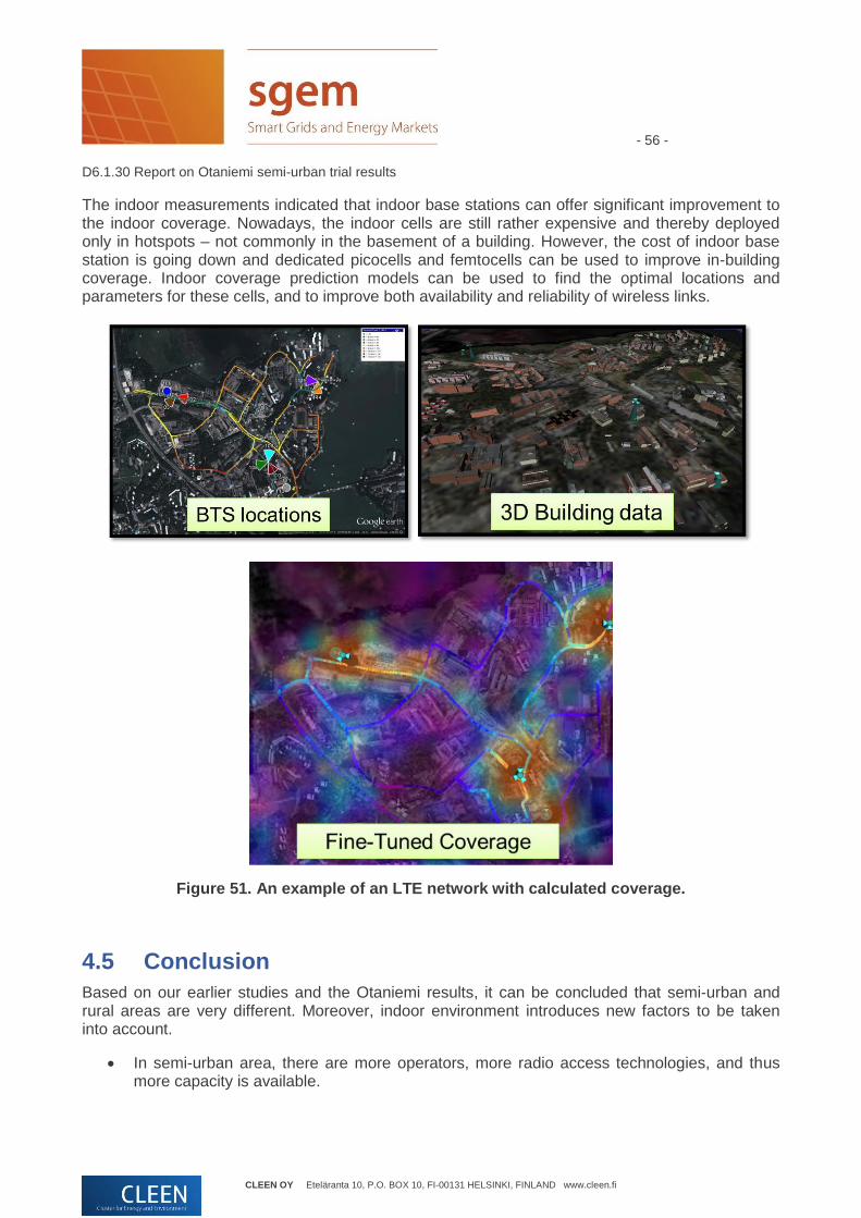
- 56 - D6.1.30 Report on Otaniemi semi-urban trial results
CLEEN OY Eteläranta 10, P.O. BOX 10, FI-00131 HELSINKI, FINLAND www.cleen.fi
The indoor measurements indicated that indoor base stations can offer significant improvement to the indoor coverage. Nowadays, the indoor cells are still rather expensive and thereby deployed only in hotspots – not commonly in the basement of a building. However, the cost of indoor base station is going down and dedicated picocells and femtocells can be used to improve in-building coverage. Indoor coverage prediction models can be used to find the optimal locations and parameters for these cells, and to improve both availability and reliability of wireless links.
Figure 51. An example of an LTE network with calculated coverage.
4.5 Conclusion
Based on our earlier studies and the Otaniemi results, it can be concluded that semi-urban and rural areas are very different. Moreover, indoor environment introduces new factors to be taken into account.
In semi-urban area, there are more operators, more radio access technologies, and thus more capacity is available.

- 57 - D6.1.30 Report on Otaniemi semi-urban trial results
CLEEN OY Eteläranta 10, P.O. BOX 10, FI-00131 HELSINKI, FINLAND www.cleen.fi
Changes in the radio environment are more vivid due to the shadowing of buildings and terrain. The heights of the base stations are smaller. The cell radius is made smaller to improve capacity. The base stations are merely placed on the rooftops of buildings.
The number of overlapping cells is smaller than in rural areas due to smaller cell sizes. In addition, buildings and other large obstacles obstruct the propagation of radio waves.
Coverage prediction is more challenging. It requires more detailed information about mobile networks’ structures as well as the surroundings. The modelling of buildings is required for estimating their shadowing factor.
Indoor coverage is highly dependent on the interiors, used radio access technology and operator’s installations. The place itself and interior have the greatest effect. Indoor cells can significantly improve the coverage and reliability.
Operators use different strategies to deploy radio access technologies especially indoors. Measurements are the best way to ensure sufficient quality e.g. latency. Quality tends to vary between office and out-of-office hours.
Based on the measurements, the most restrictive factor for remote control is the latency. LTE had the smallest latency deviation, which may be explained by the lighter architecture and still low penetration of LTE terminals.
Based on the measurements, grid entities with proper insulation are not causing noticeable interference to GSM, UMTS, or LTE networks.
Storms are not the main concern in urban areas, because the cables are mainly underground. However, hardware failures either in electricity distribution or mobile networks can cause coverage gaps, because smaller cell sizes are used. The smaller cell size reduces inherent redundancy. Neighbouring base stations are more restricted to provide additional coverage. Moreover, it is more likely in urban area to have several base stations (same or different radio access technology) connected to the same grid entity. Consequently, a failure of a critical grid entity shuts down more base stations than in rural areas.
5 Challenges The trial results indicated that one of the main bottlenecks for using wireless communication in grid communication is latency. The measured latencies were too long and varied too much. The combination of 4G/LTE technology and the IEC 61850 standard has been seen potential to fulfill the latency requirements for Smart Grid communications. In task 6.3, ABB, Emtele, Elenia, and Viola Systems conducted a trial, in which GOOSE traffic over LTE was experimented. The trial indicated that the latency distribution was high in UMTS, but the public LTE network with good coverage gave relatively stable 50–80 ms point-to-point delay [9]. The location of LTE antennas and the connection to fixed Internet had a big effect on the results.
The GOOSE protocol and the IEC 61850 standard were designed for very low point-to-point transactions in order to be used for protection purposes in distribution networks. They were originally intended for Ethernet based communications inside a substation. Due to the fast evolution in wireless communications, they have been increasingly applied to the grid automation and wider area communication. The IEC 61850 standard is very relevant for alleviating fault situations in the future smart grids, because a distant grid component needs to be quickly
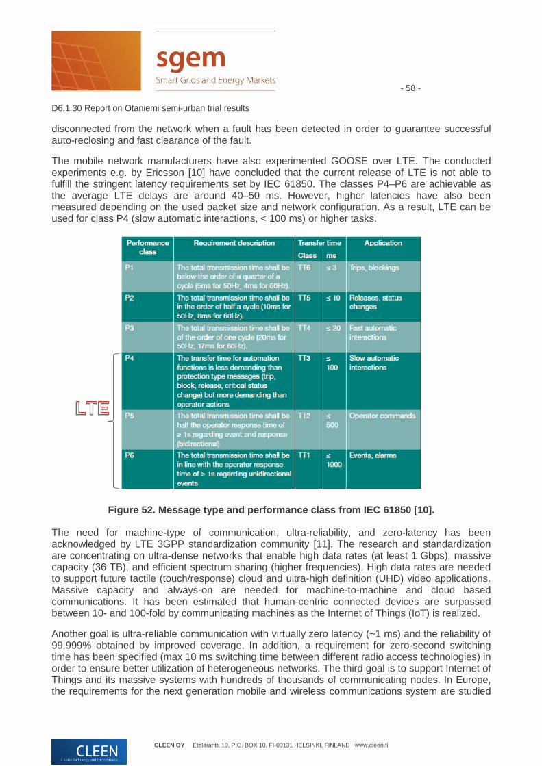
- 58 - D6.1.30 Report on Otaniemi semi-urban trial results
CLEEN OY Eteläranta 10, P.O. BOX 10, FI-00131 HELSINKI, FINLAND www.cleen.fi
disconnected from the network when a fault has been detected in order to guarantee successful auto-reclosing and fast clearance of the fault.
The mobile network manufacturers have also experimented GOOSE over LTE. The conducted experiments e.g. by Ericsson [10] have concluded that the current release of LTE is not able to fulfill the stringent latency requirements set by IEC 61850. The classes P4–P6 are achievable as the average LTE delays are around 40–50 ms. However, higher latencies have also been measured depending on the used packet size and network configuration. As a result, LTE can be used for class P4 (slow automatic interactions, < 100 ms) or higher tasks.
Figure 52. Message type and performance class from IEC 61850 [10].
The need for machine-type of communication, ultra-reliability, and zero-latency has been acknowledged by LTE 3GPP standardization community [11]. The research and standardization are concentrating on ultra-dense networks that enable high data rates (at least 1 Gbps), massive capacity (36 TB), and efficient spectrum sharing (higher frequencies). High data rates are needed to support future tactile (touch/response) cloud and ultra-high definition (UHD) video applications. Massive capacity and always-on are needed for machine-to-machine and cloud based communications. It has been estimated that human-centric connected devices are surpassed between 10- and 100-fold by communicating machines as the Internet of Things (IoT) is realized.
Another goal is ultra-reliable communication with virtually zero latency (~1 ms) and the reliability of 99.999% obtained by improved coverage. In addition, a requirement for zero-second switching time has been specified (max 10 ms switching time between different radio access technologies) in order to ensure better utilization of heterogeneous networks. The third goal is to support Internet of Things and its massive systems with hundreds of thousands of communicating nodes. In Europe, the requirements for the next generation mobile and wireless communications system are studied

- 59 - D6.1.30 Report on Otaniemi semi-urban trial results
CLEEN OY Eteläranta 10, P.O. BOX 10, FI-00131 HELSINKI, FINLAND www.cleen.fi
in METIS (Mobile and wireless communications Enablers for the Twenty-twenty Information Society) project [12].
In the United States, LTE has been chosen as the technology for the Next Generation Public Safety Network. Alcatel-Lucent is developing LTE based FirstNet [13] and respective services for public safety and critical infrastructure authorities. FirstNet is designed to provide a foundation for nationwide interoperability, enhanced situational awareness, coherent decision making, and smaller response times as well as secure communication for the authorities. The offered services include e.g. high-definition video, digital imaging, geographic information systems (GIS), web access, automatic vehicle location (AVL), voice over IP (VoIP), and interoperability with land mobile radio (LMR) systems.
Figure 53. Service provision in FirstNet [13].
FirstNet uses LTE as radio access network to offer an over-the-air link and EPC (Evolved Packet Core Solution) to enable network intelligence with essential signaling and transport control functions for secure, prioritized multimedia communications. The end-to-end network management across RAN and EPC will be used to simplify management and enhance performance for mission-critical traffic.
Table 3. Improvements offered by FirstNet [13].
Greater interoperability and enhanced interagency cooperation
Standardized protocols and interfaces
Built-in roaming capacities
Sophisticated quality of service (QoS) toolbox, including priority access mechanisms that authorize and prioritize communication and provide guaranteed and differentiated QoS to applications
Unprecedented broadband capabilities
High capacity, allowing a wide variety of applications that have rich multimedia content
Low latency, enabling real-time services (VoIP, video)
Much faster than 3G
Cost-effective communications Delivers a simplified all-IP architecture that lowers operating costs
Leverages a rich, open ecosystem from commercial networks
Complements existing narrowband radio networks
Makes private networks more economically feasible

- 60 - D6.1.30 Report on Otaniemi semi-urban trial results
CLEEN OY Eteläranta 10, P.O. BOX 10, FI-00131 HELSINKI, FINLAND www.cleen.fi
High reliability and security Supports a geographically redundant, IP-based architecture, reducing single points of failure
Supports encryption/ciphering on both control and user planes, enabling secure communications
Mobile backhaul solution Flexible, scalable and simplified IP/MPLS and packet microwave radio mobile backhaul solutions to enable delivery of increased mobile capacity and coverage with required QoS
Optimized for macro cell and small cell backhaul requirements
Supports all traffic types e.g. including TDM, Ethernet, and IP
Enables a converged network infrastructure
Internet multimedia subsystem (IMS)
Common session control layer for open standards based non-mission-critical Voice over LTE (VoLTE) on Band 14 LTE devices
Standards-based proximity enabled voice and messaging solution allowing first responders to roam the entire network without losing connectivity
Similar initiatives have also started in Europe. They focus on improving reliability of critical infrastructures. For example, an EU funded project “FM49 – Radio Spectrum for PPDR” under the Electronic Communications Committee (ECC) considers medium and long term (before year 2025) spectrum realizations by taking into account PPDR’s cross-border-communication issues and applications’ interoperability needs [14]. Moreover, EU Horizon 2020 Framework Programme consists of dedicated research topics related to the interoperable next generation broadband radio communication systems for public safety and security, and protection of ICT in critical infrastructures.
3GPP has started the work of supporting critical infrastructures and public safety [15]. Critical Communications Broadband Group (CCBG) and Working Group of the TETRA & Critical Communications Association (TCCA) have announced that LTE-based data services for mission critical communications will be available after 2018, and acceptable quality voice services over LTE for mission critical users after 2020 [16]. Despite this announcement, the United Kingdom has already stated that it seeks to replace TETRA with LTE as early as 2016 [17]. The main reason for the replacement is that the current TETRA-based system is narrowband and the emergency services are increasingly going broadband. The authorities have found LTE to be the most potential technology to provide good, reliable, and secure broadband services cost-effectively. Similar survey has been carried out in Aalto University whether to replace or complement VIRVE with commercial mobile networks e.g. LTE [18]. VIRVE is Finland's official public safety radio network based on a pan-European TETRA standard.
6 Future work The future work in the SGEM project and beyond concentrates on the further development of the measurement and analysis tool. We will search for solutions to improve resiliency, to speedup recovery, to increase reliability, and to lower latency in grid communications. Our goals are:
To continue the research on the discovery of critical components in telecommunications and electricity distribution networks with mathematical models. This work has already started in collaboration with the Academy of Finland funded FresCO (High-quality Measurement Infrastructure for Future Resilient Control Systems) project [19]. The objective is to develop models that could be implemented in NPT.

- 61 - D6.1.30 Report on Otaniemi semi-urban trial results
CLEEN OY Eteläranta 10, P.O. BOX 10, FI-00131 HELSINKI, FINLAND www.cleen.fi
To experiment and analyse GOOSE over LTE 800 MHz band using different types of data loads and packet sizes. This work is planned to be carried out in collaboration with ABB and Viola Systems. This work will also involve experiments to test parallel data connections using different radio access technologies.
To seek for available open data sources in order to improve the calculation models in NPT and to keep the data up-to-date. Data sources such as maps, vegetation, land usage, building information, traffic information, and meteorological data are investigated.
To apply learning algorithms, Self-Organizing Network functionalities [20], and proximity services (ProSe) to speed up the recovery and to enable more resilient grid communication. The learning algorithms with multiple radio access technologies have been experimented in heterogeneous networks [21] in e.g. Tekes funded projects Mercone (Multiaccess Experimentations in Real Converging Networks), Wiseciti (Wireless Community Services for Mobile Citizens), and Celtic-Plus funded Commune (COgnitive network ManageMent under UNcErtainty) projects. The future work includes also activities to exploit these results in grid communications.
To improve indoor coverage prediction by automating the selection of propagation models and by improving the modelling of indoors using interior data collected with the mobile robot. Currently, the interior data is not adequate for the coverage calculations. The data needs to be post-processed for the propagation models.
To extend city trial to cover larger areas including urban and suburban regions. This requires 3D building models from a vast area, which is rather challenging to obtain.
7 Abbreviations
AP Access Point
ARP Address Resolution Protocol
AT attention
AVL automatic vehicle location
BPSK Binary Phase Shift Keying
CCBG Critical Communications Broadband Group
CDF Cumulative distribution function
C/I Carrier per interference
CP control plane
CQI Channel Quality Indication
DAA Nemo Data connection attempt message
DC dual carrier
DL downlink
DNS Domain Name System
ECC Electronic Communications Committee
Ec/No energy per chip over the noise
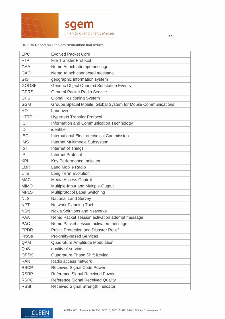
- 62 - D6.1.30 Report on Otaniemi semi-urban trial results
CLEEN OY Eteläranta 10, P.O. BOX 10, FI-00131 HELSINKI, FINLAND www.cleen.fi
EPC Evolved Packet Core
FTP File Transfer Protocol
GAA Nemo Attach attempt message
GAC Nemo Attach connected message
GIS geographic information system
GOOSE Generic Object Oriented Substation Events
GPRS General Packet Radio Service
GPS Global Positioning System
GSM Groupe Spécial Mobile, Global System for Mobile Communications
HO handover
HTTP Hypertext Transfer Protocol
ICT Information and Communication Technology
ID identifier
IEC International Electrotechnical Commission
IMS Internet Multimedia Subsystem
IoT Internet of Things
IP Internet Protocol
KPI Key Performance Indicator
LMR Land Mobile Radio
LTE Long Term Evolution
MAC Media Access Control
MIMO Multiple-Input and Multiple-Output
MPLS Multiprotocol Label Switching
NLS National Land Survey
NPT Network Planning Tool
NSN Nokia Solutions and Networks
PAA Nemo Packet session activation attempt message
PAC Nemo Packet session activated message
PPDR Public Protection and Disaster Relief
ProSe Proximity-based Services
QAM Quadrature Amplitude Modulation
QoS quality of service
QPSK Quadrature Phase Shift Keying
RAN Radio access network
RSCP Received Signal Code Power
RSRP Reference Signal Received Power
RSRQ Reference Signal Received Quality
RSSI Received Signal Strength Indicator

- 63 - D6.1.30 Report on Otaniemi semi-urban trial results
CLEEN OY Eteläranta 10, P.O. BOX 10, FI-00131 HELSINKI, FINLAND www.cleen.fi
RTT Round Trip Time
RTU Remote Terminal Unit
RX, Rx receiver
SCADA Supervisory Control And Data Acquisition
SGEM Smart Grids and Energy Markets
SIM Subscriber identity module
TA timing advance
TCCA TETRA & Critical Communications Association
TCP Transmission Control Protocol
TDM Time Division Multiplexing
TDMA Time Division Multiple Access
TETRA TErrestrial Trunked Radio
TX, Tx transmitter
UDP User Datagram Protocol
UHD ultra-high definition
UL uplink
UMTS Universal Mobile Telecommunications System
UP user plane
USB Universal Serial Bus
VoIP Voice over IP
VoLTE Voice over LTE
WCDMA Wideband Code Division Multiple Access
WLAN wireless local area network

- 64 - D6.1.30 Report on Otaniemi semi-urban trial results
CLEEN OY Eteläranta 10, P.O. BOX 10, FI-00131 HELSINKI, FINLAND www.cleen.fi
8 References
[1] J. Penttonen, Effect of Expanding Cell Radius and its Impact on Cellular Smart Grid Applications, Discussion paper, year 2011.
[2] S. Horsmanheimo, H. Kokkoniemi-Tarkkanen, L. Tuomimäki, P. Savolainen, J. Penttonen, P. Muszynski, D6.1.2: Survey report on interference sources in smart grid, SGEM FP2, December 2011.
[3] S. Horsmanheimo, L. Tuomimäki, N. Maskey, P. Savolainen, H. Kokkoniemi-Tarkkanen, S. Tomperi, J. Zidbeck, L. Helenius and J. Penttonen, D6.1.4: Smart Grid Communication Utilizing Public Cellular Networks, SGEM FP3, January 2013.
[4] S. Horsmanheimo, N. Maskey, H. Kokkoniemi-Tarkkanen, L. Tuomimäki, P. Savolainen, ”A tool for assessing interdependency of mobile communication and electricity distribution networks”. IEEE International Conference on Smart Grid Communications (SmartGridComm) 2013, 2013.
[5] S. Horsmanheimo, N. Maskey, H. Kokkoniemi-Tarkkanen, L. Tuomimäki, P. Savolainen, ”Evaluation of interdependencies between mobile communication and electricity distribution networks in fault scenarios”. Innovative Smart Grid Technologies – Asia (ISGT Asia), 2013.
[6] http://www.cnl.fi/qosmet.html
[7] https://www.netradar.org/
[8] Regulation 43 D/2010 on electronic protection of a telephone network, https://www.viestintavirasto.fi/attachments/maaraykset/Viestintavirasto43D2010M.pdf
[9] D6.3.1: Evaluation on 4G/LTE feasibility for grid automation and transfer trip application, 2014.
[10] Ericsson white paper, LTE for Utilities, Supporting Smart Grids, September 2013.
[11] http://whist.institut-telecom.fr/JBio2013/01-Osseiran.pdf
[12] https://www.metis2020.com/
[13] http://www.alcatel-lucent.com/public-safety/mobile-broadband-for-firstnet
[14] http://www.cept.org/ecc/groups/ecc/wg-fm/fm-49
[15] http://www.3gpp.org/IMG/pdf/2013_05_3gpp_ccw.pdf
[16] http://www.tandcca.com/about/article/19545
[17] http://urgentcomm.com/tetra/uk-seeks-replace-tetra-lte-early-2016
[18] http://www.virve.com/asiakascase/kannattaako_laajakaista/311/
[19] M. Kamali, M. Kolehmainen, M. Neovius, L. Petre, M. Ronkko, P. Sandvik, and S. Horsmanheimo, “On Proving Recoverability of Smart Electrical Grids”, 2014, TUCS publication series, http://tucs.fi/publications/view/?pub_id=tHoKaKoNePeRxSa13a.
[20] S. Hämäläinen, H. Sanneck, C. Sartori, “LTE Self-Organising Networks (SON): Network Management Automation for Operational Efficiency”, Wiley, 2011.
[21] S. Horsmanheimo, N. Maskey, H. Kokkoniemi-Tarkkanen, L. Tuomimäki, P. Savolainen, ”Learning Based Proactive Handovers in Heterogeneous Networks”. MONAMI 2013, 2013.