dacon inspection services inspection outside using ptnnt’s hand • externally on the 10 sample...
TRANSCRIPT

HDPE PIPELINE INSPECTION P R E S E N T A T I O N
DACON INSPECTION SERVICES

Who we are
Conventional and Advanced NDT and Inspection Services
Oil and Gas, Refinery, Petrochemical, Heavy Industry, Mining
Over 400 personnel including more than 300 inspectors
Thailand headquarters with International expertise since 1979

DACON INSPECTION SERVICES F O R A L L Y O U R I N S P E C T I O N N E E D S
Presentation Overview
HDPE used as Tailings Lines for mining
• Erosion in HDPE lines
• Dacon’s involvement
• HDPE Pipe Development
Inspection Accuracy • Data Comparison vs. Actual Condition
• Inaccuracy Contributions
• Remaining Thickness for H3
• Inspection Report for H3
• Remaining Thickness for H4 Hybrid
• Report on HDPE Hybrid line
• Inspection Report for H4 Hybrid
ILI Recovery at Sea
DACON INSPECTION SERVICES HDPE USE AS TAILINGS LINES FOR MINING

DACON INSPECTION SERVICES F O R A L L Y O U R I N S P E C T I O N N E E D S
Erosion in HDPE Pipes
Since mines started using HDPE lines for Tailings transport, erosion in the bottom of these lines have been an issue. A leak was found in 2005 and a program to inspect and verify the pipe condition before it becomes critical has since been in place.
DACON INSPECTION SERVICES F O R A L L Y O U R I N S P E C T I O N N E E D S
Dacon’s involvement
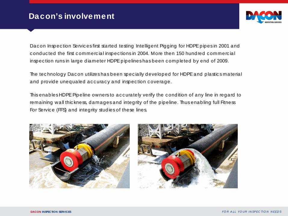
Dacon Inspection Services first started testing Intelligent Pigging for HDPE pipes in 2001 and conducted the first commercial inspections in 2004. More then 150 hundred commercial inspection runs in large diameter HDPE pipelines has been completed by end of 2009. The technology Dacon utilizes has been specially developed for HDPE and plastics material and provide unequaled accuracy and inspection coverage. This enables HDPE Pipeline owners to accurately verify the condition of any line in regard to remaining wall thickness, damages and integrity of the pipeline. Thus enabling full Fitness For Service (FFS) and integrity studies of these lines.

DACON INSPECTION SERVICES F O R A L L Y O U R I N S P E C T I O N N E E D S
HDPE Pipe Development
• Until 2006 Tailings Lines were 46.5” 85 mm HDPE
• From 2006 Tailings Lines were 48.0” 110 mm HDPE
Year Erosion groove width Approx. erosion rate 2005 - 2006 25 - 40 cm 3 mm/month
2006 - 2007 20 - 30 cm 5 mm/month
2008 10 - 25 cm 11 mm/month
Above values are approximate values based on multiple inspections and worst location

DACON INSPECTION SERVICES F O R A L L Y O U R I N S P E C T I O N N E E D S
INSPECTION ACCURACY
DACON INSPECTION SERVICES

DACON INSPECTION SERVICES F O R A L L Y O U R I N S P E C T I O N N E E D S
Inspection Accuracy
Location
Joint -1 Joint -2 Joint -3 Joint -4 Joint -5 Joint -6 Joint -7 Joint -8 Joint -9 Joint -10
Picture Manaul UTM Measurement
53 mm 54 mm 55 mm 52 mm 56 mm 51 mm 53 mm 53 mm 56 mm 55 mm
ILI Data* Meaasurement
58 mm 55 mm 56 mm 50 mm 56 mm 55 mm 50 mm 49 mm 58 mm 52 mm
Variation mm
-3 mm -1 mm -1 mm +2 mm 0 mm -4 mm +3 mm +4 mm -2 mm +3 mm
Based on what was learnt from the correlation between actual thickness and ILI data interpreted thickness, it is clear that the thickness accuracy is quite close to real world thickness. Some variations will always be encountered due to the physical configurations and/or damage/disfiguration to the pipe. The worst case variation in Line “A” using the highest and lowest
differentiation that was indicated in the above table will set a margin of error at: +/- 4 mm.

DACON INSPECTION SERVICES F O R A L L Y O U R I N S P E C T I O N N E E D S
Data Comparison vs. Actual Condition
Normally 3 ILI tools is used for each inspection, each of these generating over 80 million thickness measurements. These measurements are plotted in both 2D and 3D. Every one meter of pipe typically gets approx. 25 000 measurements.
Since 2007 a new inspection and analyzing software was introduced to ease the post inspection verification.

DACON INSPECTION SERVICES F O R A L L Y O U R I N S P E C T I O N N E E D S
Inaccuracy Contributors
There are several factors that contribute to making the data less compatible, these include: • Due to the curvature of the groove internally, most measurements have to be taken from
the outside using PTNNT’s hand
• Externally on the 10 sample joints there are quite severe scraping marks which also prevent measurements in many locations.
• The thinnest location in most joints is exactly at the joint. However, due to the external pipe overlap at the joint, combined with toe-in creep, measurements cannot always be made at the absolute thinnest point.
Left side: Illustration of the toe-in creep seen externally at a Joint 1. Red line indicates the straight line.
Left side: Internal joint, deflection of angles caused by erosion, exactly at joint itself.

DACON INSPECTION SERVICES F O R A L L Y O U R I N S P E C T I O N N E E D S
Remaining Thickness for H3
Average thickness from ILI 1, 2 & 3. Thickness in mm, distance in meter.
Individual ILI data overlaid. Thickness in mm, distance in meter.
DACON INSPECTION SERVICES F O R A L L Y O U R I N S P E C T I O N N E E D S
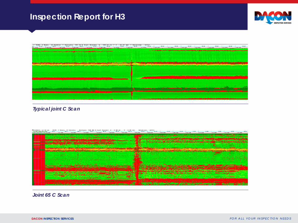
Inspection Report for H3
Typical joint C Scan
Joint 65 C Scan

DACON INSPECTION SERVICES F O R A L L Y O U R I N S P E C T I O N N E E D S
Inspection Report for H3
Typical B Scan of nominal groove. Typical B Scan secondary erosion
DACON INSPECTION SERVICES F O R A L L Y O U R I N S P E C T I O N N E E D S
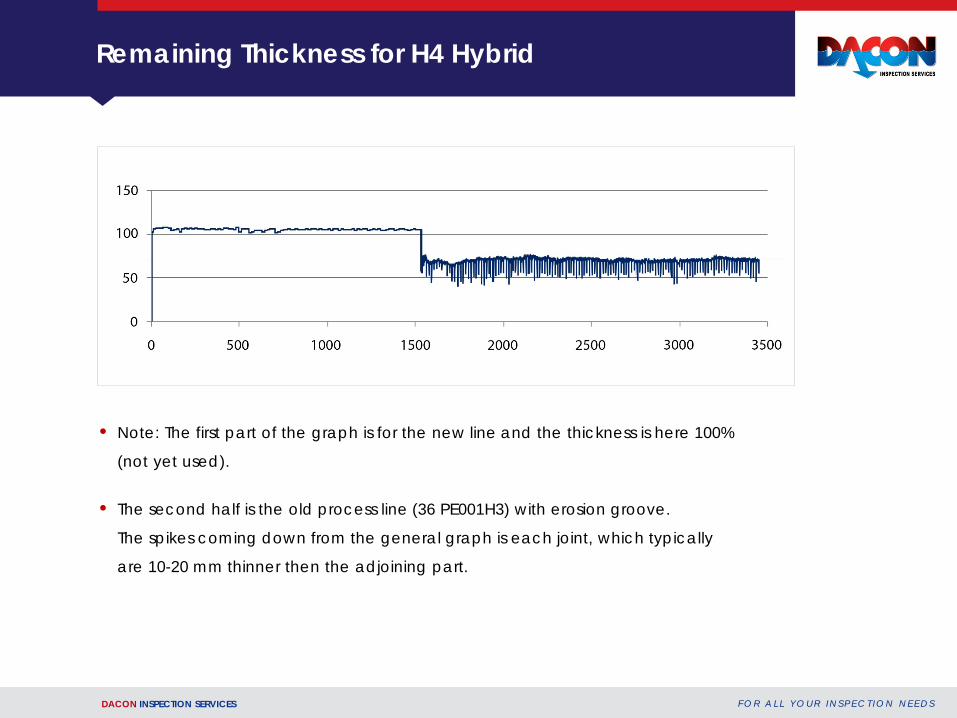
Remaining Thickness for H4 Hybrid
• Note: The first part of the graph is for the new line and the thickness is here 100%
(not yet used).
• The second half is the old process line (36 PE001H3) with erosion groove.
The spikes coming down from the general graph is each joint, which typically
are 10-20 mm thinner then the adjoining part.
DACON INSPECTION SERVICES F O R A L L Y O U R I N S P E C T I O N N E E D S
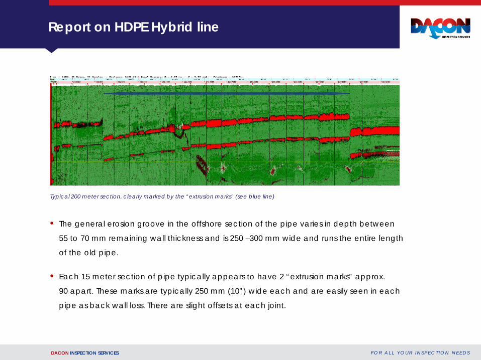
Report on HDPE Hybrid line
• The general erosion groove in the offshore section of the pipe varies in depth between
55 to 70 mm remaining wall thickness and is 250 –300 mm wide and runs the entire length
of the old pipe.
• Each 15 meter section of pipe typically appears to have 2 “extrusion marks” approx.
90 apart. These marks are typically 250 mm (10”) wide each and are easily seen in each
pipe as back wall loss. There are slight offsets at each joint.
Typical 200 meter section, clearly marked by the “extrusion marks” (see blue line)

DACON INSPECTION SERVICES F O R A L L Y O U R I N S P E C T I O N N E E D S
Inspection Report for H4 Hybrid
Typical B Scan (pipe cross section) with no erosion groove
Typical B with erosion groove
In both above cross section views back wall loss can be seen as red stripes.

DACON INSPECTION SERVICES
ILI RECOVERY AT SEA

DACON INSPECTION SERVICES F O R A L L Y O U R I N S P E C T I O N N E E D S
ILI Recovery at Sea
Current Method for ILI recovery at sea: Diver jumps into the sea to attach hoisting slings around the ILI. The ILI is then hoisted onto boat deck.