daqstation dx100/dx200 communication … user’s manual im 04l02a01-01e explains all functions and...
TRANSCRIPT

User’sManual
Yokogawa Electric Corporation
DAQSTATION DX100/DX200
Communication Interface
IM 04L02A01-17E7th Edition
* 4 L 2 A 1 1 7 E 0 7 *
iIM 04L02A01-17E
7th Edition: April 2008(YK)
All Rights Reserved, Copyright © 1999 Yokogawa Electric Corporation
ForwardThank you for purchasing the YOKOGAWA DAQSTATION DX100/DX200.
This Communication Interface User’s Manual contains information about the Ethernet/serial interface communication functions. To ensure correct use, please read thismanual thoroughly before operation. Keep this manual in a safe place for quick
reference in the event a question arises. The following five manuals, including this one,are provided as manuals for the DX100/DX200.
Manual Name Manual No. Description
DX100 User’s Manual IM 04L01A01-01E Explains all functions and procedures of theDX100 excluding the communication functions.
DX200 User’s Manual IM 04L02A01-01E Explains all functions and procedures of theDX200 excluding the communication functions.
DX100/DX200 IM 04L02A01-17E This manual. Explains the communicationCommunication functions of the Ethernet/serial interface.Interface User’s Manual
Fieldbus IM 04L02A01-18E Explains the communication functions of theCommunication FOUNDATION Fieldbus interface.Interface User’s Manual For models with /CF1 only.
DAQSTANDARD IM 04L41B01-61E Describes the functions and operatingUser’s Manual procedures of DAQSTANDARD.
Control of Pollution IM 04L01A01-92C Gives a description of pollution control.Caused by the Product
Notes• This manual describes the communication functions of the DX100/DX200 with the
style number “S4.”
• The contents of this manual are subject to change without prior notice as a result ofcontinuing improvements to the instrument’s performance and functions. The figuresgiven in this manual may differ from the actual screen.
• Every effort has been made in the preparation of this manual to ensure the accuracyof its contents. However, should you have any questions or find any errors, pleasecontact your nearest YOKOGAWA dealer as listed on the back cover of this manual.
• Copying or reproducing all or any part of the contents of this manual withoutYOKOGAWA’s permission is strictly prohibited.
• The TCP/IP software used in this product and the documentation for that TCP/IP
software are based in part on BSD Networking Software, Release 1 licensed from TheRegents of the University of California.
Trademarks• vigilantplant and DAQSTATION are registered trademarks of Yokogawa Electric
Corporation.• Microsoft and Windows are registered trademarks or trademarks of Microsoft
Corporation in the United States and/or other countries.• Adobe and Acrobat are registered trademarks or trademarks of Adobe Systems
Incorporated.
• Company and product names that appear in this manual are registered trademarks ortrademarks of their respective holders.
• The company and product names used in this manual are not accompanied by the
registered trademark or trademark symbols (® and ™).
Revisions• First edition: September 1999 • Fourth edition: May 2000• Second edition: October 1999 • Fifth edition: February 2001• Third edition: February 2000 • Sixth edition: February 2002
• Seventh edition: April 2008

ii IM 04L02A01-17E
How to Use this Manual
Structure of the ManualThe structure of this User’s Manual is as follows.
Chapter 1 Overview of the Communication FunctionsDescribes the relationship between the communication functions and the interface andprovides an outline of the communication functions.
Chapter 2 Using the Ethernet InterfaceDescribes the specifications and setup procedures of the Ethernet interface. Describes theFTP client function, Web server function, and e-mail transmission function. Also describeshow to display the log screen.
Chapter 3 Using the Serial Interface (Option)Describes the functions, specifications, and setup procedures of the serial interface (option).Two types of serial interfaces, RS-232 and RS-422/485 are available.
Chapter 4 Using the Modbus ProtocolDescribes the specifications and setup procedures of the Modbus protocol and the statusindication screen of the Modbus master.
Chapter 5 CommandsDescribes each command that can be used.
Chapter 6 ResponseDescribes the data format of the panel setup information and measured/computed data thatare output from this instrument.
Chapter 7 Status ReportDescribes the status information.
AppendixProvides an ASCII character code table, the flow of operation when outputting data from DX, alist of error messages, and the login process.
IndexProvides an index.
Conventions Used in this ManualUnit
• k Denotes 1000. Example: 5 kg, 100 kHz• K Denotes 1024. Example: 720 KB (Storage capacity of floppy disks)
SymbolsThe following symbols are used in this manual.
Affixed to the instrument. Indicates danger to personnel orinstrument and the operator must refer to the User’s Manual.
The symbol is used in the User’s Manual to indicate thereference.
WARNING Describes precautions that should be observed to prevent injury
or death to the user.
CAUTION Describes precautions that should be observed to prevent minor
or moderate injury, or damage to the instrument.
Note Provides important information for the proper operation of theinstrument.

iiiIM 04L02A01-17E
Displayed charactersAlphanumeric characters enclosed with [ ] refer to characters or setting values that are
displayed on the screen.
Symbols used on pages describing operating proceduresOn pages that describe the operating procedures in Chapter 2 through 4, the followingsymbols are used to distinguish the procedures from their explanations.
Explanation This section describes the setting parameters and the limitations
regarding the procedures.
Procedure Follow the steps indicated with numbers. The procedures are
given with the premise that the user is carrying out the steps for
the time. Depending on the operation, not all steps need to be
taken.
Revision HistoryEdition Addition and change to functions
7 Added explanations. Fixed explanations.
How to Use this Manual
iv IM 04L02A01-17E
Names and Uses of Parts
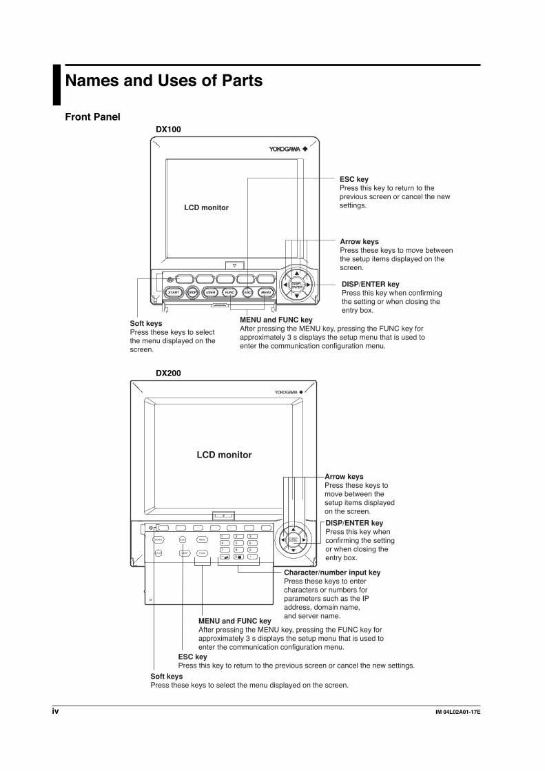
Front PanelDX100
DISP/ENTER
MENUESCFUNCUSERSTART STOP
Soft keysPress these keys to select the menu displayed on the screen.
DISP/ENTER keyPress this key when confirming the setting or when closing the entry box.
Arrow keysPress these keys to move betweenthe setup items displayed on thescreen.
MENU and FUNC keyAfter pressing the MENU key, pressing the FUNC key for approximately 3 s displays the setup menu that is used to enter the communication configuration menu.
ESC keyPress this key to return to the previous screen or cancel the new settings.LCD monitor
DX200
Soft keysPress these keys to select the menu displayed on the screen.
DISP/ENTER keyPress this key when confirming the setting or when closing the entry box.
Arrow keysPress these keys tomove between thesetup items displayedon the screen.
LCD monitor
START
STOP
ESC MENU1 2 3
DISP/ENTER
4 5 6
7 8
0
9USER FUNC
MENU and FUNC keyAfter pressing the MENU key, pressing the FUNC key for approximately 3 s displays the setup menu that is used to enter the communication configuration menu.
ESC keyPress this key to return to the previous screen or cancel the new settings.
Character/number input keyPress these keys to entercharacters or numbers forparameters such as the IPaddress, domain name, and server name.

vIM 04L02A01-17E
Rear PanelDX100
RS-232 interface connectorA serial communication connector provided on models with the optional code /C2.
RS-422/485 interface terminalSerial communication terminals provided on models with the optional code /C3.
Ethernet interface connectorA connector used for Ethernet communications. Comes standard with the instrument.
DX200
RS-232 interface connectorA serial communication connector provided on models with the optional code /C2.
RS-422/485 interface terminalSerial communication terminals provided on models with the optional code /C3.
Ethernet interface connectorA connector used for Ethernet communications. Comes standard with the instrument.
Names and Uses of Parts

vi IM 04L02A01-17E
Flow of Operation using the Operation KeysThis section will describe the basic flow of operation when changing the settings of the
recorder using the front panel keys.Settings related to communications are configured in the basic setting mode. Theprocedure used to enter the basic setting mode is described in the procedure for each
item. Basic setting mode cannot be entered while data acquisition is in progress or whilecomputation using the computation function (/M1 option) is in progress.
1. Press the arrow keys to move the cursor onto the desired parameter.
The parameter box containing the cursor is blue.
2. For parameters whose selections are shown at the bottom of the screen, press
the soft key under the desired selection. For parameters that need characters tobe entered in the entry box, press the [Input] soft key to display the entry box,enter the characters, and press the DISP/ENTER key.
Parameter selections(Selection example for [DNS On/Off]Press either the [On] or [Off] soft key.)
Parameter entry box(Example of the entry box for the IP address)
• The boxes containing parameters that have not been changed are displayed in
white.• The boxes containing parameters that have been changed are displayed in
yellow.
The boxes containing parameters that have been changed are displayed in yellow.The boxes containing parameters that have not been changed are displayed in white.
3. Set other parameters as well according to steps 1 and 2.4. The operation is different when you are confirming or canceling the new
changes (parameter boxes in yellow). See below.• When confirming the new changes
Press the DISP/ENTER key. The new changes are confirmed and the yellow
parameter boxes change to white. The cursor returns to the parameter at theupper left portion of the screen (the first parameter on the screen). However,if the new change is not valid, then the parameter box turns red.
Parameters for which the new changes that are not valid are displayed in red.
Names and Uses of Parts

viiIM 04L02A01-17E
Names and Uses of Parts
• When canceling the new changesPress the ESC key. A window appears for you to confirm the cancellation.
Selecting “YES” and pressing the DISP/ENTER key cancels the new settingsand the screen returns to the previous screen.Selecting “No” and pressing the DISP/ENTER key does not cancel the new
settings and the screen returns to the original screen.
5. To activate the new settings in the basic setting mode, the settings must be
stored. Pressing the [End] soft key in the basic setting menu* displays a dialogbox that asks you whether or not the new settings are to be stored.To store the settings, select [Yes]. To not store the settings, select [No]. To
return to the basic setting menu, select [Cancel] by pressing the arrow key, andpress the [DISP/ENTER] key.* The basic setting menu is the menu that is displayed when the ESC key is pressed
several times after the basic setting parameters are changed.

viii IM 04L02A01-17E
Contents
Forward ................................................................................................................................... i
How to Use this Manual .................................................................................................................. ii
Names and Uses of Parts .............................................................................................................. iv
Chapter 1 Overview of the Communication Functions1.1 The Relationship between the Communication Functions
and the Ethernet/Serial Interface ...................................................................................... 1-1
1.2 Explanation of the Functions ............................................................................................. 1-2
Chapter 2 Using the Ethernet Interface2.1 Ethernet Interface Specifications ...................................................................................... 2-1
2.2 Connecting the Ethernet Interface .................................................................................... 2-2
2.3 Configuring the Ethernet Interface .................................................................................... 2-3
2.4 Checking the Connection Status of the Ethernet Interface ............................................... 2-9
2.5 Setting the FTP Client (Automatic Transfer of Display/Event/Report Data Files) ........... 2-10
2.6 Performing the FTP Test ................................................................................................. 2-16
2.7 Setting the Login/Timeout for Ethernet Communications ................................................ 2-17
2.8 Displaying the Log Screen of the Error, Communication, and FTP................................. 2-22
2.9 Setting the Web Server Function .................................................................................... 2-26
2.10 Using the Monitor Page and Operator Page ................................................................... 2-31
2.11 Setting the E-Mail Transmission Function ....................................................................... 2-38
2.12 Performing an E-Mail Transmission Test ......................................................................... 2-47
2.13 Starting/Stopping E-Mail Transmissions ......................................................................... 2-48
Chapter 3 Using the Serial Interface (Option)3.1 Serial Interface (Option) Specifications ............................................................................. 3-1
3.2 RS-232 Interface Connector Pin Arrangement and Signal Names, the Connection
Procedure, and Handshaking............................................................................................ 3-2
3.3 RS-422/485 Interface Pin Arrangement and Signal Names
and the Connection Procedure ......................................................................................... 3-5
3.4 The Bit Structure of One Character and the Operation of the Receive Buffer .................. 3-9
3.5 Configuring the Serial Interface ....................................................................................... 3-10
Chapter 4 Using the Modbus Protocol4.1 Modbus Protocol Specifications ........................................................................................ 4-1
4.2 Register Assignments (Modbus Slave) ............................................................................. 4-2
4.3 Modbus Error Response (Modbus Slave) ......................................................................... 4-3
4.4 Setting the Configuration that is Used When the Modbus Protocol is Used ..................... 4-4
4.5 Setting the Modbus Master Function ................................................................................ 4-7
4.6 Checking the Operating Status of the Modbus Master Function..................................... 4-13
ixIM 04L02A01-17E
Chapter 5 Commands5.1 Command Syntax .............................................................................................................. 5-1
5.2 A List of Commands .......................................................................................................... 5-3
5.3 Input Range Parameter ..................................................................................................... 5-7
5.4 Setting Commands (Setting) ............................................................................................. 5-9
5.5 Setting Commands (Control) ........................................................................................... 5-17
5.6 Basic Setting Commands ................................................................................................ 5-20
5.7 Output Commands (Control) ........................................................................................... 5-29
5.8 Output Commands (Setup, measured, and computed data output) ............................... 5-29
5.9 Output Commands (RS-422/485 Dedicated Commands) ............................................... 5-32
5.10 Maintenance/Test Commands (Available when using the maintenance/test server function
via Ethernet communications) ......................................................................................... 5-33
5.11 Instrument Information Output Commands (Available when using the instrument
information server function via Ethernet communications) ............................................. 5-34
Chapter 6 Response6.1 Response Syntax .............................................................................................................. 6-1
6.2 Output Format of ASCII Data ............................................................................................ 6-6
6.3 Output Format of BINARY Data ...................................................................................... 6-20
6.4 Output Format of Instrument Information ........................................................................ 6-25
Chapter 7 Status Report7.1 Status Information and Filter ............................................................................................. 7-1
7.2 The Bit Structure of the Status Information ....................................................................... 7-2
AppendixAppendix 1 ASCII Character Codes ........................................................................................App-1
Appendix 2 Output Flow of Internal Memory Data ..................................................................App-2
Appendix 3 Output Flow of the File or the File List in the External Storage Medium ..............App-4
Appendix 4 Output Flow of FIFO Data ....................................................................................App-6
Appendix 5 Data Dropout (Modbus Master) ............................................................................App-8
Appendix 6 A List of Error Messages ......................................................................................App-9
Appendix 7 Login Process.....................................................................................................App-16
Index Index-1
1
2
3
4
5
6
7
App
Index
Contents

1-1IM 04L02A01-17E
Overview
of th
e Co
mm
un
ication
Fu
nctio
ns
1
Chapter 1 Overview of the Communication Functions
1.1 The Relationship between the CommunicationFunctions and the Ethernet/Serial Interface
The Ethernet interface comes as standard equipment with the instrument. The serial
interface (RS-232, RS-422/485) is available as an option.
In order to use the various communication functions of the DX, the Ethernet or serial
communications must be configured beforehand.
The following figure illustrates the relationship between the communication functions of
the DX and the Ethernet/serial interface. To use the communication functions of the DXover the Ethernet/serial interface, protocols* that exist between the function and theinterface must be followed.
* A protocol is a set of rules that govern the communication between two computers over a line
or network.
PC
Connect the DX and the PC via the serial cable
Connect the DX and the PC via the Ethernet cable
Modbus slave
Modbus master
Setting/Measurement server
Maintenance/Test server
FTP server
Web server
FTP client
Email client
Instrument information server
Login (User authorization/grant access rights)
Upper protocolModbus protocol
Proprietary protocol for the DX
FTPHTTP SMTP
Lower protocolSerial communication control
TCP
IP
InterfaceSerial interface (RS-232, RS-422/485)
Ethernet interface (10BASE-T)
UDP
The communication functions of the DX
Application
FTP (File Transfer Protocol)TCP (Transmission Control Protocol)UDP (User Datagram Protocol)IP (Internet Protocol)HTTP (Hyper Text Transfer Protocol)SMTP (Simple Mail Transfer Protocol)
When you use the serial interface, select one of the following protocols.
• Proprietary protocol for the DX• Modbus slave protocol• Modbus master protocol
1-2 IM 04L02A01-17E
1.2 Explanation of the Functions
Describes an outline of the communication functions of the DX.
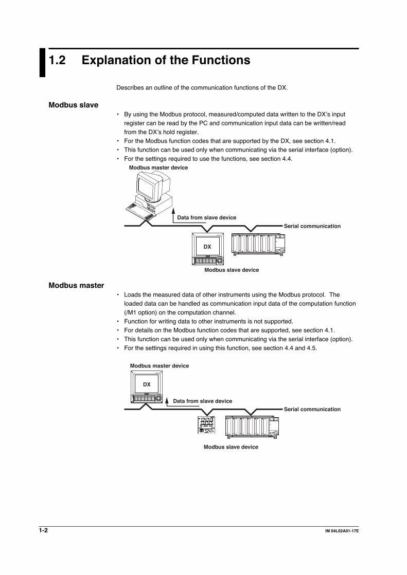
Modbus slave• By using the Modbus protocol, measured/computed data written to the DX’s input
register can be read by the PC and communication input data can be written/read
from the DX’s hold register.• For the Modbus function codes that are supported by the DX, see section 4.1.• This function can be used only when communicating via the serial interface (option).
• For the settings required to use the functions, see section 4.4.
DX
Data from slave device
Modbus master device
Modbus slave device
Serial communication
Modbus master• Loads the measured data of other instruments using the Modbus protocol. The
loaded data can be handled as communication input data of the computation function
(/M1 option) on the computation channel.• Function for writing data to other instruments is not supported.• For details on the Modbus function codes that are supported, see section 4.1.
• This function can be used only when communicating via the serial interface (option).• For the settings required in using this function, see section 4.4 and 4.5.
DX
Data from slave device
Modbus master device
Modbus slave device
Serial communication

1-3IM 04L02A01-17E
Overview
of th
e Co
mm
un
ication
Fu
nctio
ns
1
1.2 Explanation of the Functions
Setting/Measurement server• This function can be used to set almost all of the settings that can be configured using
the front panel keys. However, the power switch cannot be turned ON/OFF. Theuser name/password for communications, user name/password for key login, and thedestination of the FTP client function cannot be configured.
• The following types of data can be output.• Measured/computed data.• Data in the internal memory or files in the external storage medium.
• Setup information and the status byte.• A log of operation errors and communicationsThe measured/computed data can be output in binary or ASCII format to a PC. For
other types of data, ASCII format is used. For the data output format, see chapter 6.The communication commands that can be used through this function are settingcommands (see sections 5.4 and 5.5), basic setting commands (see sections 5.6),
and output commands (see sections 5.7 to 5.9).• This function can be used when communicating via the Ethernet or the serial
(optional) interface.
• For the configuration when using Ethernet communications, see sections 2.3 and 2.7.For the configuration when using serial communications, see section 3.5.
Maintenance/Test server• Connection information, network information, and other information regarding
Ethernet communications can be output.
• The communication commands that can be used through this function aremaintenance/test commands (see section 5.10).
• This function can be used only when communicating via the Ethernet interface.
• For the configuration required to use this function, see sections 2.3 and 2.7.
FTP server• You can use a PC to access the DX via FTP. You can perform operations such as
retrieving directory and file lists from the external storage medium of the DX andtransferring and deleting files.
• This function can be used only when communicating via the Ethernet interface.• For the configuration required to use this function, see sections 2.3 and 2.7.
DX
Files on the external storage medium
PC
Ethernet
FTP server
1-4 IM 04L02A01-17E
1.2 Explanation of the Functions
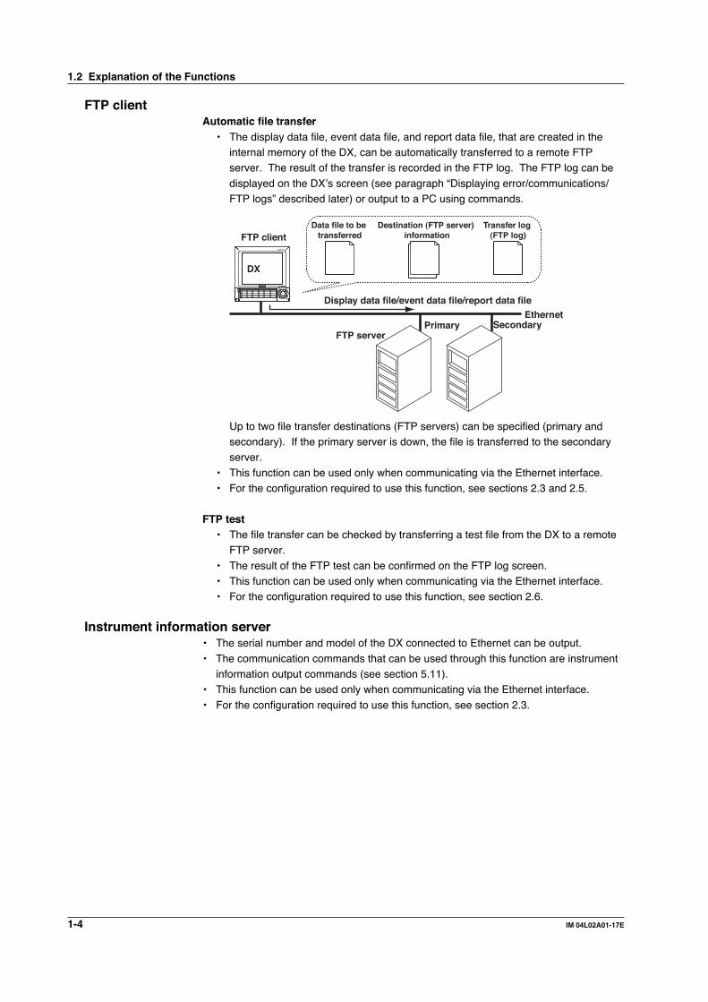
FTP clientAutomatic file transfer
• The display data file, event data file, and report data file, that are created in theinternal memory of the DX, can be automatically transferred to a remote FTPserver. The result of the transfer is recorded in the FTP log. The FTP log can be
displayed on the DX’s screen (see paragraph “Displaying error/communications/FTP logs” described later) or output to a PC using commands.
DX
Display data file/event data file/report data file
FTP serverPrimary Secondary
Ethernet
Destination (FTP server) information
Transfer log (FTP log)
Data file to be transferredFTP client
Up to two file transfer destinations (FTP servers) can be specified (primary andsecondary). If the primary server is down, the file is transferred to the secondaryserver.
• This function can be used only when communicating via the Ethernet interface.• For the configuration required to use this function, see sections 2.3 and 2.5.
FTP test• The file transfer can be checked by transferring a test file from the DX to a remote
FTP server.
• The result of the FTP test can be confirmed on the FTP log screen.• This function can be used only when communicating via the Ethernet interface.• For the configuration required to use this function, see section 2.6.
Instrument information server• The serial number and model of the DX connected to Ethernet can be output.
• The communication commands that can be used through this function are instrumentinformation output commands (see section 5.11).
• This function can be used only when communicating via the Ethernet interface.
• For the configuration required to use this function, see section 2.3.

1-5IM 04L02A01-17E
Overview
of th
e Co
mm
un
ication
Fu
nctio
ns
1Login• This function can be used only when communicating via the Ethernet interface and
when using the setting/measurement server, maintenance/test server, and the FTPserver functions.
• For the configuration required to use this function, see sections 2.3 and 2.7.
• For a description of the login process of the setting/measurement server andmaintenance/test server, see appendix 7.
User authorizationThis function allows only registered users to access the DX in order to prevent invalidaccess from the network.
• Up to seven names can be registered. You will also specify the access authority(see below) when registering the name.
• There are limitations on the number of simultaneous connections or
simultaneous uses of the DX from the PC (see section 2.1).
Granting access authorityThis function provides access authority (user level) to operate the DX for theregistered users. For example, this prevents user B (user level) from changing themeasurement conditions that were set by user A (administrator level).
• There are two user levels on the DX, user and administrator.• One administrator and six users can be registered.
• Administrator
An administrator has the authority to use all setting/measurement serverfunctions, maintenance/test server functions, and FTP server functions.
• User
A user has limited authority to use the setting/measurement server functions,maintenance/test server functions, and FTP server functions. For the limitationof commands, see section 5.2.
• Limitations on the use of the setting/measurement serverThe user cannot change settings that would change the DX’s operation.Measurement and setup data can be output.
• Limitations on the use of the maintenance/test serverThe user cannot disconnect a connection between another PC and the DX.The connection between the PC that the user is operating and the DX can
be disconnected.• Limitations on the use of the FTP server
You cannot save files to the external storage medium of the DX or delete
files on it. Files can be retrieved from the server.
Communication timeoutThis function drops the connection if no data transfer is detected between the PC andthe DX over a predetermined period of time. This applies to data transfer at theapplication level only (see section 1.1). For example, this function prevents a PC from
being connected to the DX indefinitely which would prohibit other users from makingnew connections for data transfer.
1.2 Explanation of the Functions

1-6 IM 04L02A01-17E
Web server• This function can be used only when communicating via the Ethernet interface.
• The DX screen can be displayed on the browser applications of Microsoft InternetExplorer.
• The following two screens are available:
• Monitor page: Screen dedicated for monitoring.• Operator page: You can switch the DX screen. You can also modify and write
messages.
You can set access control (user name and password) on each page.
Switches screens
Arrow keys andthe DISP/ENTER key
Menu• Refreshes the screen• Displays the alarm summary• Displays the measured /computed data• Displays logs• Modifies and writes messages
Selects the screen sizeRefreshes the screen automatically
• The screen can be updated at a constant period (approximately 30 s).
• The following information can be displayed.• Alarm summary• Measured and computed values of all channels
• Logs (message log, error log, key login/logout log, FTP file transfer log, e-maillog, and Web operation log)
• For the procedure in setting the Web server function, see section 2.9.
• For operations on the monitor page and operator page, see section 2.10.
E-mail transmissionThis function can be used only when communicating via the Ethernet interface.• Transmitting e-mail messages
E-mail can be automatically transmitted at the following times. You can specify two
groups of destinations and specify the destination for each item. In addition, you canset a header string for each item.• When alarm is active/released
Notifies the alarm information.• During recovery from a power failure
Notifies the time of the power failure and the time of recovery.
• When memory end is detected (See “Fail/Memory End Function (/F1 Option)”in this section)Notifies the detection of memory end.
• When an error related to the external storage medium and FTP client occursNotifies the error code and message when an error is detected on the external
1.2 Explanation of the Functions

1-7IM 04L02A01-17E
Overview
of th
e Co
mm
un
ication
Fu
nctio
ns
1storage medium or when the data cannot be saved as the free space on thestorage medium is insufficient. In addition, notifies the error code and message
such as when data transfer fails using the FTP client function.• At the specified time
Transmits an e-mail message when the specified time is reached. It can be used
to confirm that the system including the network and the e-mail transmissionfunction is working properly. You can specify the reference time and the e-mailtransmission interval for each destination.
• When report is created (only on models with the optional computationfunction (/M1)Transmits the report.
For the procedure in setting the e-mail transmission function, see section 2.11.For the e-mail transmission format, see section 2.13.
For the procedure to start/stop e-mail transmission, see section 2.13.
From: [email protected]: Sat, 23 Dec 2000 01:00:09 +0900 (JST)Subject: (DX) Periodic_dataTo: [email protected]
LOOP1Scheduled
Periodic data.<Host name>DX
<Time>Dec.23 01:00:01
Subject
An example of the scheduled e-mail
Header 1Header 2
• Testing e-mail transmission• You can send a test message from the DX to the destination to check e-mail
transmissions.• You can confirm the result of the e-mail transmission test on the e-mail log screen.• For the procedure in using this function, see section 2.12.
Other functionsConfirming the connection status of the Ethernet interface
• The connection status of the Ethernet interface can be confirmed on the rear paneland on the screen of the DX.
• For the display position and the meaning of the indicator, see section 2.4.
Keepalive (Extended function of TCP)• This function forcibly drops the connection if there are no responses to the test
packets that are sent periodically at the TCP level.• For the configuration required to use this function, see sections 2.3 and 2.7.
Displaying error/communications/FTP/Web operation/E-mail logs• The operation log can be displayed on the following log screens.
• Error log screen: Operation errors
• Communication log screen: Communication input/output• FTP log screen: A log of file transfers that were executed using the FTP client
function
• Web operation log screen: Record of operations of the Web server function• E-mail log screen: Record of e-mail transmissions.
• For the configuration required to use this function, see section 2.8.
1.2 Explanation of the Functions

2-1IM 04L02A01-17E
Usin
g th
e Eth
ernet In
terface
2
2.1 Ethernet Interface Specifications
Basic SpecificationsElectrical and mechanical specifications Conforms to IEEE 802.3
(Ethernet frames conform to the DIX specifications.)
Transmission medium type 10BASE-T
Protocol TCP, IP, UDP, ICMP, ARP
The maximum number of connections and the number of simultaneous usesThe following table indicates the number of simultaneous uses (number of users thatcan use the function simultaneously), the maximum number of connections, and the
port number for each function.
Function Maximum Number Number of Port Number*1
of Connections Simultaneous Uses (Fixed)Administrator User
Setting/ 3 1 2*2 34260/tcpmeasurementserver
Maintenance/ 1 1 1*2 34261/tcptest server
FTP server 2 2 2*2 21/tcp
Instrument – – – 34264/udpinformationserver
*1 Port numbers are fixed.*2 There are user limitations. For details, see “Granting Access Authority” in section 1.2.
Chapter 2 Using the Ethernet Interface
2-2 IM 04L02A01-17E
2.2 Connecting the Ethernet Interface
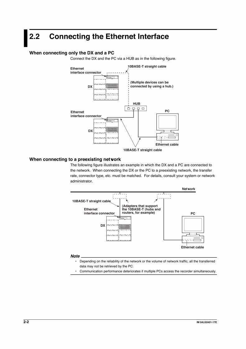
When connecting only the DX and a PCConnect the DX and the PC via a HUB as in the following figure.
PC
Ethernet cable
HUB
10BASE-T straight cable
10BASE-T straight cableEthernetinterface connector
Ethernetinterface connector
DX
DX
(Multiple devices can beconnected by using a hub.)
When connecting to a preexisting networkThe following figure illustrates an example in which the DX and a PC are connected tothe network. When connecting the DX or the PC to a preexisting network, the transferrate, connector type, etc. must be matched. For details, consult your system or network
administrator.
PC
Ethernet cable
10BASE-T straight cable
Network
Ethernetinterface connector
DX
(Adapters that supportthe 10BASE-T (hubs androuters, for example)
Note• Depending on the reliability of the network or the volume of network traffic, all the transferred
data may not be retrieved by the PC.
• Communication performance deteriorates if multiple PCs access the recorder simultaneously.
2-3IM 04L02A01-17E
Usin
g th
e Eth
ernet In
terface
2
2.3 Configuring the Ethernet Interface
ExplanationThe following configurations must be made in order to use the Ethernet communicationfunctions of the DX.
Setting the IP address, subnet mask, default gateway, and DNSConfirm the settings such as the IP address, subnet mask, default gateway, and DNSwith the administrator of the system or network on which the recorder is to be used.
• IP address• Set the IP address to assign to the DX. The default setting is “0.0.0.0.”
• The IP address is used to distinguish between the various devices connected tothe Internet when communicating using the TCP/IP protocol. The address is a32-bit value normally expressed with four values (0 to 255), each separated by a
period as in 192.168.111.24.• Subnet mask
• Specify the mask that is used to determine the network address from the IP
address. The default setting is “0.0.0.0.”• Set this value according to the system or the network to which the DX belongs.
In some cases, this setting may not be necessary.
• Default gateway• Set the IP address of the gateway (router, etc.) used to communicate with other
networks. The default setting is “0.0.0.0.”
• Set this value according to the system or the network to which the DX belongs.In some cases, this setting may not be necessary.
• DNS (Domain Name System)You must set the DNS, if you are using a host name to specify the destinationserver of the file transfer on an FTP client or the server of the e-mail recipient.* The DNS is a system that correlates the host name/domain name to the IP address. The
host name/domain name can be used instead of the IP address when accessing the
network. The DNS server manages the database that contains the host name/domain
name and IP address correlation.
• DNS server
• Set the IP address of the DNS server. The default setting is “0.0.0.0.”• Up to two DNS servers can be specified (primary and secondary). If the
primary DNS server is down, the secondary server is used to search the host
name/domain name and IP address.• Host name
Set the DX’s host name using up to 64 alphanumeric characters.
• Domain name• Set the network domain name to which the DX belongs using up to 64
alphanumeric characters.
• When the destination server of the file transfer or the server of the e-mailrecipient is looked up using the DNS server, this domain name is appendedto the host name as a possible domain name if it is omitted . The destination
name (server name) becomes the “FTP server name” (see section 2.5) or the“SMTP server name” (see section 2.11).

2-4 IM 04L02A01-17E
• Domain suffixIf the IP address corresponding to the “domain name,” described in the previous
paragraph, is not found on the DNS server, then it may be that the system isconfigured to use another domain name. In this case, the domain suffix isspecified, so that this domain name is searched after the “domain name”
specified in the previous paragraph is searched.• Set the domain suffix using up to 64 alphanumeric characters.• Up to two domain suffixes can be specified (primary and secondary).
Selecting the communication interface used to output the data in the internalmemory and the files on the external storage medium
• Using output commands (ME/MI/MO commands), select the communicationinterface used to output the data in the internal memory (display data, event data,TLOG data, manual sampled data, and report data) and the files on the external
storage medium. Since these commands cannot be used on Ethernetcommunications and serial communications simultaneously, you must select eitherone.
• When using Ethernet communications, select [Ethernet].
Storing the settingsTo activate the settings made in the basic setting mode, the settings must be saved.Otherwise, the settings return to the previous values.
2.3 Configuring the Ethernet Interface

2-5IM 04L02A01-17E
Usin
g th
e Eth
ernet In
terface
2
2.3 Configuring the Ethernet Interface
ProcedureFor the basic flow of operations, see “Flow of Operation using the Operation Keys” onpage vi. For the procedures related to entering character strings and values, see theDX100/DX200 User’s Manual (IM04L01A01-01E/IM04L02A01-01E).
1. Press the MENU key to display the setting menu.2. Press the FUNC key for approximately 3 s to display the basic setting menu.3. Press the [#10 (Communication)](DX100) or [#6 (Communication)](DX200) soft
key to display the communication function setting menu.4. Press the [#1 (Ethernet (IP Address))](DX100) or [#1 (Ethernet, Serial)](DX200)
soft key to display the communication (Ethernet, serial) menu.
DX200 Communication (Ethernet, Serial) menuDX100 Communication (Ethernet) menu
These setting items appears on the models with the serial communication function (/C2, /C3).
Setting the IP address5. Press the arrow key to move the cursor to the [IP-address] box.
6. Press the [Input] soft key to display the entry box.
7. Enter the IP address of the DX in the entry box.
8. Press the DISP/ENTER key. The entered value is set in the [IP-address] box.
Setting the subnet maskSet this value according to the system or the network to which the DX belongs. If thissetting is not necessary, go to “Setting the default gateway.”9. Press the arrow key to move the cursor to the [Subnet mask] box.
10. Press the [Input] soft key to display the entry box.

2-6 IM 04L02A01-17E
2.3 Configuring the Ethernet Interface
11. In the entry box, enter the subnet mask of the network to which the DX belongs.
12. Press the DISP/ENTER key. The entered value is set in the [Subnet mask] box.
Setting the default gatewaySet this value according to the system or the network to which the DX belongs. If this
setting is not necessary, go to “Setting the DNS (Domain Name System).”13. Press the arrow key to move the cursor to the [Default gateway] box.
14. Press the [Input] soft key to display the entry box.
15. In the entry box, enter the IP address of the default gateway of the network to
which the DX belongs.
16. Press the DISP/ENTER key. The entered value is set in the [Default gateway]
box.For DX100, confirm the new settings pressing the DISP/ENTER key. To cancel,press the ESC key.For detailed operations regarding confirmation and cancellation, see “Flow of Operation
using the Operation Keys” on page vi.
Setting the DNS (Domain Name System)Set the DNS, if you are using a host name to specify the destination server of the file
transfer on an FTP client or the server of the e-mail recipient.If the DNS is not going to be used, go to step 39 (for models with the serialcommunication function) or step 41 (for models without the serial communication
function).For DX100, when settings are confirmed by procedure 16, press the ESC key toreturn to the communication function setting menu, and then press the [#2 (Ethernet
(DNS))] soft key to display the communication (DNS) menu.• Select whether or not to use the DNS (ON/OFF)17. Press the arrow key to move the cursor to the [DNS On/Off] box.
18. Press either the [On] or [Off] soft key. When using the DNS, select [ON] andperform steps 19 through 38. Otherwise, select [Off] (you can skip steps 19through 38).
• Setting the primary DNS server address19. Press the arrow key to move the cursor to the [Primary] box under server search
order.
20. Press the [Input] soft key to display the entry box.
21. Enter the primary DNS server address in the entry box.

2-7IM 04L02A01-17E
Usin
g th
e Eth
ernet In
terface
2
2.3 Configuring the Ethernet Interface
22. Press the DISP/ENTER key. The entered value is set in the [Primary] box.
• Setting the secondary DNS server addressSet this value when using the secondary DNS server in the system or the networkto which the DX belongs. If this setting is not necessary, go to step 25.
23. Press the arrow key to move the cursor to the [Secondary] box under serversearch order.
24. Set the secondary DNS server address using the same method from steps 20
through 22.
• Setting the DX's host name25. Press the arrow key to move the cursor to the [Host name] box.
26. Press the [Input] soft key to display the entry box.
27. Enter the DX's host name in the entry box.
28. Press the DISP/ENTER key. The entered string/value is set in the [Host name]box.
• Setting the domain name to which the DX belongs29. Press the arrow key to move the cursor to the [Domain name] box.
30. Press the [Input] soft key to display the entry box.
31. Enter the DX's domain name in the entry box.
32. Press the DISP/ENTER key. The entered string/value is set in the [Domainname] box.
• Setting the primary domain suffixSet this value when the domain suffix is necessary. Otherwise, go to step 39 (for
models with the serial communication function) or step 41 (for models without
the serial communication function).33. Press the arrow key to move the cursor to the [Primary] box under Domain suffix
search order.
34. Press the [Input] soft key to display the entry box.

2-8 IM 04L02A01-17E
35. Enter the primary domain suffix in the entry box.
36. Press the DISP/ENTER key. The entered value is set in the [Primary] box.
• Setting the secondary domain suffixSet this value when the secondary domain suffix exists. If this setting is not
necessary, go to step 39 (for models with the serial communication function) orstep 41 (for models without the serial communication function).
37. Press the arrow key to move the cursor to the [Secondary] box under Domain
suffix search order.
38. Set the secondary domain suffix in the same fashion as in steps 34 to 36.
Selecting the communication interface used to output the data in the internalmemory and the files on the external storage mediumThe “Memory output” is displayed when the serial communication function is specified.
39. Press the arrow key to move the cursor to the [Memory out] box.
40. Press either the [Ethernet] or the [Serial] soft key. Press the [Ethernet] soft keywhen using Ethernet communications.
Confirming/Canceling the new settings41. To confirm the new settings, press the DISP/ENTER key. To cancel, press the
ESC key.For detailed operations regarding confirmation and cancellation, see “Flow of Operation
using the Operation Keys” on page vi.
Storing the new settings-42. Press the ESC key several times to display the basic setting menu.43. Pressing the [End] soft key to display a dialog box which you select whether or
not to store the new settings.
44. Select the [Yes] to store the new settings, the [No] to discard them, or the[Cancel] to return to the basic setting menu by pressing the arrow key. Then,press the DISP/ENTER key.
2.3 Configuring the Ethernet Interface
2-9IM 04L02A01-17E
Usin
g th
e Eth
ernet In
terface
2
2.4 Checking the Connection Status of theEthernet Interface
Checking the connection status using the rear panelThe connection status of the Ethernet interface can be confirmed with the indicator thatis located to the upper right of the Ethernet connector on the DX.
Indicator Connection Status of the Ethernet Interface
On (green) The Ethernet interface is electrically connected.
Blinking (green) Transmitting data
Off The Ethernet interface is not electrically connected.
(Rear Panel)
Indicator
Checking the connection using the recorder's screenChecking using the status display of the screen
The connection status of the Ethernet interface can be checked using the indicatorlocated on the right hand side of the status display section of the basic setting menu.The basic setting menu is displayed by pressing the FUNC key for approximately 3 s
after pressing the MENU key to display the setting menu.
Indicator Connection Status of the Ethernet Interface
On (green) The Ethernet interface is electrically connected.
Off The Ethernet interface is not electrically connected.
(Rear Panel) Indicator
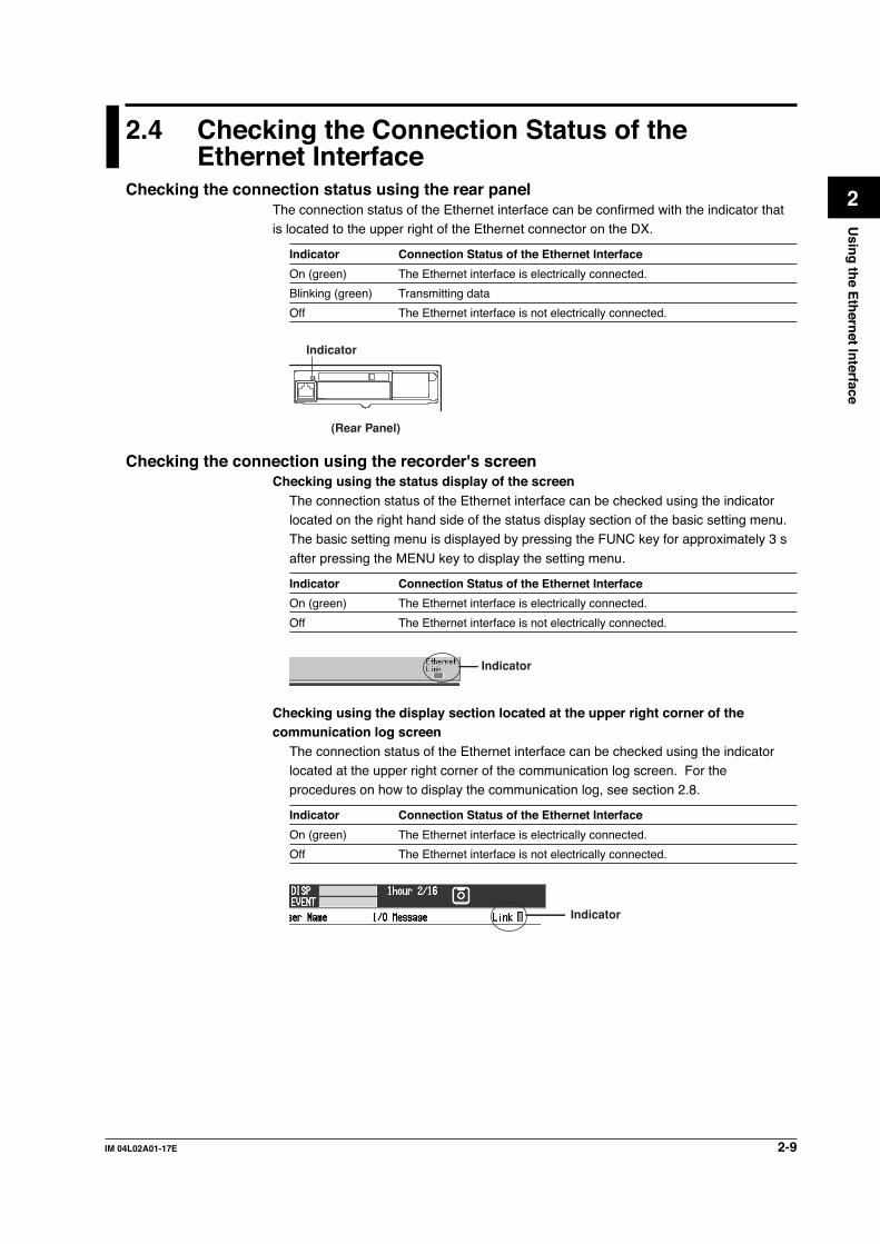
Checking using the display section located at the upper right corner of thecommunication log screen
The connection status of the Ethernet interface can be checked using the indicatorlocated at the upper right corner of the communication log screen. For theprocedures on how to display the communication log, see section 2.8.
Indicator Connection Status of the Ethernet Interface
On (green) The Ethernet interface is electrically connected.
Off The Ethernet interface is not electrically connected.
Indicator

2-10 IM 04L02A01-17E
2.5 Setting the FTP Client (Automatic Transfer ofDisplay/Event/Report Data Files)
ExplanationBy setting this function, the display/event and report data files that are created in the
internal memory can be automatically transferred using FTP when the files are created.Note that the Ethernet interface must be configured beforehand (see section 2.3).
Selecting the files to transfer• You can select whether or not to automatically transfer the display/event data file
and the report data file. The default setting is “Off.”
• When the method to save the data is set to “Auto,” the data files are automaticallytransferred at appropriate times to the FTP destination described in the nextsection.
• Display data file: Data files are automatically transferred at auto save intervals
or at the specified date and time.
• Event data file: Data files are automatically transferred when data length of
data is written or at every specified date and time*.* Auto transfer at every specified date and time is allowed only during the “free” mode.
For information on the “free” mode, see the DX100/DX200 User’s Manual
(IM04L01A01-01E/IM04L02A01-01E).
• Report data file: Automatically transferred when reports are created.
Note• For details related to saving data to the external storage medium and the auto save interval,
see the DX100/DX200 User’s Manual (IM04L01A01-01E/IM04L02A01-01E).
• When the method to save the data is set to “Manual,” auto transfer does not take place. You
can still output the display/event/report data files using commands.
• For the format of the report data file, see the DX100/DX200 User’s Manual (IM04L01A01-
01E/IM04L02A01-01E). However, the report data file to be transferred is divided by every
timeout.
• If a file with the same name is detected at the destination, the file is transferred with the last
character (8th character) of the file name changed. For details on the file name, see section
8.1 in the DX100/DX200 User's Manual IM04L01A01-01E/IM04L02A01-01E.
Example: If the file to be transferred named “X0212000.DDS” exists at the destination, the file
name is changed to “X0212001.DDS” before it is transferred.
(However, if the firmware version number of the DX is less than 4.05, the above
behavior does not apply. In this case, the file is overwritten without any warning
messages.)
Setting the FTP connectionConfirm the settings such as the primary and secondary FTP servers, port number,login name, password, account, PASV mode, and initial path with your system or
network administrator.
• Setting the primary and secondary serversSpecify the primary and secondary file transfer destinations (FTP servers) asdescribed in the previous close. When the primary FTP server is down, the dataare transferred to the secondary FTP server.
2-11IM 04L02A01-17E
Usin
g th
e Eth
ernet In
terface
2
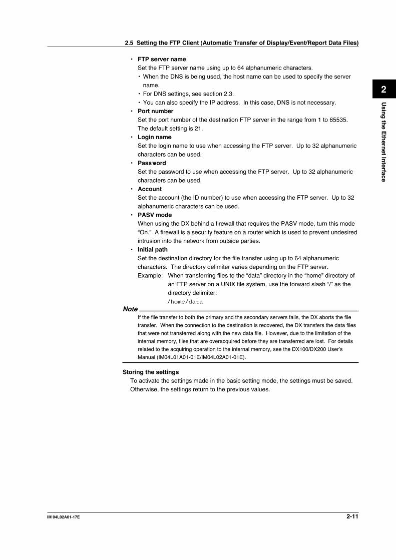
• FTP server nameSet the FTP server name using up to 64 alphanumeric characters.
• When the DNS is being used, the host name can be used to specify the servername.
• For DNS settings, see section 2.3.
• You can also specify the IP address. In this case, DNS is not necessary.• Port number
Set the port number of the destination FTP server in the range from 1 to 65535.
The default setting is 21.• Login name
Set the login name to use when accessing the FTP server. Up to 32 alphanumeric
characters can be used.• Password
Set the password to use when accessing the FTP server. Up to 32 alphanumeric
characters can be used.• Account
Set the account (the ID number) to use when accessing the FTP server. Up to 32
alphanumeric characters can be used.• PASV mode
When using the DX behind a firewall that requires the PASV mode, turn this mode
“On.” A firewall is a security feature on a router which is used to prevent undesiredintrusion into the network from outside parties.
• Initial pathSet the destination directory for the file transfer using up to 64 alphanumericcharacters. The directory delimiter varies depending on the FTP server.Example: When transferring files to the “data” directory in the “home” directory of
an FTP server on a UNIX file system, use the forward slash “/” as thedirectory delimiter:/home/data
NoteIf the file transfer to both the primary and the secondary servers fails, the DX aborts the file
transfer. When the connection to the destination is recovered, the DX transfers the data files
that were not transferred along with the new data file. However, due to the limitation of the
internal memory, files that are overacquired before they are transferred are lost. For details
related to the acquiring operation to the internal memory, see the DX100/DX200 User’s
Manual (IM04L01A01-01E/IM04L02A01-01E).
Storing the settingsTo activate the settings made in the basic setting mode, the settings must be saved.Otherwise, the settings return to the previous values.
2.5 Setting the FTP Client (Automatic Transfer of Display/Event/Report Data Files)

2-12 IM 04L02A01-17E
ProcedureFor the basic flow of operations, see “Flow of Operation using the Operation Keys” onpage vi. For the procedures related to entering character strings and values, see theDX100/DX200 User’s Manual (IM04L01A01-01E/IM04L02A01-01E).
1. Press the Menu key to display the setting menu.2. Press the FUNC key for approximately 3 s to display the basic setting menu.
3. Press the [#10 (Communication)](DX100) or [#6 (Communication)](DX100/DX200) soft key to display the communication function setting menu.
4. Press the [#3 (FTP transfer file)](DX100) or [#2 (FTP Client)](DX200) soft key to
display the Communication (FTP client) menu.
DX200 Communication (FTP client)DX100 Communication (FTP tramsfer file)
Selecting the files to be transferred• Selecting whether or not to transfer the display and event data files (ON/OFF)5. Press the arrow key to move the cursor to the [Disp&Event data] box.
6. Press either the [On] or [Off] soft key.
• Selecting whether or not to transfer the report data file (ON/OFF)7. Press the arrow key to move the cursor to the [Report] box.
8. Press either the [On] or [Off] soft key.
For DX100, confirm the new settings pressing the DISP/ENTER key. To cancel,
press the ESC key.For detailed operations regarding confirmation and cancellation, see “Flow of Operation
using the Operation Keys” on page vi.
2.5 Setting the FTP Client (Automatic Transfer of Display/Event/Report Data Files)

2-13IM 04L02A01-17E
Usin
g th
e Eth
ernet In
terface
2
Setting the primary FTP serverFor DX100, when settings are confirmed by procedure 8, press the ESC key to return
to the communication function setting menu, and then press the [#4 (FTP connection)]soft key to display the communication (FTP connection) menu.9. Press the arrow key to move the cursor to the [FTP connection] box.
10. Press the [Primary] soft key.
• Setting the FTP server name11. Press the arrow key to move the cursor to the [FTP server name] box.
12. Press the [Input] soft key to display the entry box.
13. Enter the primary FTP server name in the entry box. Generally, the IP addressis entered. However, if DNS is being used, the FTP server's host name can alsobe specified.
14. Press the DISP/ENTER key. The entered string/value is set in the [FTP servername] box.
• Setting the FTP server’s port number15. Press the arrow key to move the cursor to the [Port number] box.
16. Press the [Input] soft key to display the entry box.
17. Enter the port number of the primary FTP server in the entry box.
18. Press the DISP/ENTER key. The entered value is set in the [Port number] box.
• Setting the login name used when accessing the FTP server19. Press the arrow key to move the cursor to the [Login name] box.
20. Press the [Input] soft key to display the login name entry box.
2.5 Setting the FTP Client (Automatic Transfer of Display/Event/Report Data Files)

2-14 IM 04L02A01-17E
21. Enter the login name that is used when accessing the primary FTP server in theentry box.
22. Press the DISP/ENTER key. The entered string/value is set in the [Login name]box.
• Setting the password used when accessing the FTP server23. Press the arrow key to move the cursor to the [Password] box.
24. Press the [Input] soft key to display the entry box.
25. Enter the password that is used when accessing the primary FTP server in theentry box.
26. Press the DISP/ENTER key. The entered string/value is set in the [Password]box.
• Setting the account used when accessing the FTP server27. Press the arrow key to move the cursor to the [Account] box.
28. Press the [Input] soft key to display the entry box.
29. Enter the account that is used when accessing the primary FTP server in theentry box.
30. Press the DISP/ENTER key. The entered string/value is set in the [Account]box.
• Enabling (On)/Disabling (Off) the PASV mode31. Press the arrow key to move the cursor to the [PASV mode] box.
32. Press either the [On] or [Off] soft key.
• Setting the initial path (file transfer destination directory)33. Press the arrow key to move the cursor to the [Initial path] box.
2.5 Setting the FTP Client (Automatic Transfer of Display/Event/Report Data Files)

2-15IM 04L02A01-17E
Usin
g th
e Eth
ernet In
terface
2
34. Press the [Input] soft key to display the entry box.
35. Enter the file transfer destination directory in the entry box.
36. Press the DISP/ENTER key. The entered string/value is set in the [Initial path]
box.
Setting the secondary FTP serverSet the secondary FTP server when specifying a secondary file transfer destination.If you are not using the secondary FTP server, go to step 40.37. Press the arrow key to move the cursor to the [FTP connection] box.
38. Press the [Secondary] soft key.
39. Set the secondary FTP server using the same method from steps 11 through
36.
Confirming/Canceling the new settings40. To confirm the new settings, press the DISP/ENTER key. To cancel, press the
ESC key.For detailed operations regarding confirmation and cancellation, see “Flow of Operation
using the Operation Keys” on page vi.
Storing the new settings41. Press the ESC key several times to display the basic setting menu.42. Pressing the [End] soft key to display a dialog box which you select whether or
not to store the new settings.
43. Select the [Yes] to store the new settings, the [No] to discard them, or the[Cancel] to return to the basic setting menu by pressing the arrow key. Then,press the DISP/ENTER key.
2.5 Setting the FTP Client (Automatic Transfer of Display/Event/Report Data Files)

2-16 IM 04L02A01-17E
2.6 Performing the FTP Test
ExplanationYou can check whether or not files can be transferred via the Ethernet interface bytransferring a test file from the DX to the FTP server that was configured in section 2.5.
Items to check before performing this test• Correctly connect the Ethernet cable. For the connection procedures, see section
2.2.
• Check that the Ethernet interface configuration is correct. For the procedures, seesection 2.3 and 2.5.
When configuring Ethernet related settings, check them with the administrator of the
system or network on which the DX is to be used.
Checking the FTP test results• When you perform the FTP test, the test file is transferred to the initial path on the
destination FTP server that was specified in section 2.5. After the FTP testcompletes, check whether or not the test file was received on the FTP server
• The result of the FTP test can be confirmed by displaying the FTP log (displayed
on the DX200 (see section 2.8)) or Web browser screen (see section 2.10) or by
outputting the result using the FL command (see section 5.8).
ProcedurePerforming the FTP test.
1. Press the FUNC key to display the FUNC menu. The construction of the FUNCmenu varies depending on the basic settings and options.
2. Press the [FTP test] soft key to display a menu used to select the destination onwhich the FTP test to be performed.
3. Press either the [Primary] or [Secondary] soft key. The FTP test is performedon the specified FTP server.

2-17IM 04L02A01-17E
Usin
g th
e Eth
ernet In
terface
2
2.7 Setting the Login/Timeout for EthernetCommunications
ExplanationBy setting the login and timeout, you can achieve the following:
• Prevent invalid access to the DX from the network.• Grant authority in operating the DX via Ethernet communications.• Disconnect connections when there are no data transfers over a predetermined
time period.Note that the Ethernet interface must be configured beforehand (see section 2.3).
Enabling/Disabling the login functionIf the login function is enabled, only users that are registered can login to the DX.
User registration• Selecting the user level
Select either of the user levels, administrator or user.
• Administrator (admin)One administrator can be registered. An administrator has the authority to useall setting/measurement server, maintenance/test server, and the FTP server
functions.• User (user1 to user6)
Six user can be registered. A user has limited authority to use the setting/
measurement server functions, maintenance/test server functions, and FTPserver functions. For the limitation of commands, see section 5.2.• Limitations on the use of the setting/measurement server
The user cannot change settings that would change the DX’s operation.
Measurement and setup data can be output.• Limitations on the use of the maintenance/test server
The user cannot disconnect a connection between another PC and the DX.
The connection between the PC that the user is operating and the DX can bedisconnected.
• Limitations on the use of the FTP server
You cannot save files to the external storage medium of the DX or delete fileson it. Files can be retrieved from the server.
• Selecting whether or not to register the user (On/Off)• On
Registers the user. You can specify the user name and password for the login.
• OffDoes not register the user.
• Setting the user name• Set the user name using up to 16 alphanumeric characters.• Each user name must be unique.
• Since the word “quit” is reserved as a command on the instrument, the username “quit” is not allowed.
• Setting the passwordSet the password using up to 6 alphanumeric characters.

2-18 IM 04L02A01-17E
Note• The relationship between the login function and the user name that is used when accessing
the DX is as follows.
• When the login function is set to “Enable”
• The registered user name and password can be used to login to the DX.
• The user level is the level that was specified when the user name was registered.
• When the login function is set to “Disable”
• The user name “admin” can be used to login to the DX as an administrator. Password
is not necessary.
• The user name “user” can be used to access the DX as a user. Password is not
necessary.
• When the DX is an FTP server, the user name “anonymous” has a special role.
• When the login function is set to “Enable”
• If a user name “anonymous” is registered in the DX, this user name can be used to
login to the DX.
• Password is not necessary (login is possible regardless of whether or not the password
is specified).
• The user level is the level of the user who specified the user name “anonymous.”
• When the login function is set to “Disable”
• The user name “anonymous” can be used to login to the DX.
• Password is not necessary (login is possible regardless of whether or not the password
is specified).
• The user level is “User.”
• There are limitations on the number of simultaneous connections or simultaneous uses of the
DX from the PC (see section 2.1).
• For a description of the login process of the setting/measurement server and maintenance/
test server, see appendix 7.
Communication timeout• Enabling/Disabling the timer (ON/OFF)
• OnThe connection is dropped if no data transfer is detected over a predetermined
period of time. This applies to data transfer at the application level only (seesection 1.1).
• OffCommunication timeout is disabled.
• Setting the timeout timeWhen the communication timeout is enabled and if no data transfer is detected
over the time period specified here, the connection is dropped.Range: 1 to 120 minutes
Enabling/Disabling keepalive (On/Off)• On
If there is no response to the test packet that is periodically transmitted (every 30 s)
at the TCP level, the connection is dropped.• Off
Keepalive is disabled.
Storing the settingsTo activate the settings made in the basic setting mode, the settings must be saved.
Otherwise, the settings return to the previous values.
2.7 Setting the Login/Timeout for Ethernet Communications

2-19IM 04L02A01-17E
Usin
g th
e Eth
ernet In
terface
2
ProcedureFor the basic flow of operations, see “Flow of Operation using the Operation Keys” onpage vi. For the procedures related to entering character strings and values, see theDX100/DX200 User’s Manual (IM04L01A01-01E/IM04L02A01-01E).
1. Press the Menu key to display the setting menu.2. Press the FUNC key for approximately 3 s to display the basic setting menu.3. Press the [#10 (Communication)](DX100) or [#6 (Communication)](DX200) soft
key to display the communication function setting menu.4. Press the [#5 (Control (Login, Timeout))](DX100) or [#3 (Control (Login,
Timeout))](DX200) soft key to display the Communication (Control -Login, Time
out-) menu.
DX200 Communication (Control -Login, Time out)DX100 Communication (Control (Login, Time out))
Enabling/Disabling the login function of the DX5. Press the arrow key to move the cursor to the [Use/Not] box under Ethernet
login.
6. Press either the [Use] or [Not] soft key. If you select [Use], go to step 7. If you
select [Not], go to step 20.
Registering users• Selecting the user level for the registered user7. Press the arrow key to move the cursor to the [Level] box.
8. Press one of the keys from [admin] to [user6] to select the user level. To set theuser level to administrator, select [admin]. To set the user level to user, select[user1] to [user6].
2.7 Setting the Login/Timeout for Ethernet Communications

2-20 IM 04L02A01-17E
• Selecting whether or not to register the user (On/Off)9. Press the arrow key to move the cursor to the [On/Off] box under Level.
10. Press either the [On] or [Off] soft key. If you select [On], go to step 11. If you
select [Off], go to step 19.
• Setting the user name11. Press the arrow key to move the cursor to the [User name] box.
12. Press the [Input] soft key to display the entry box.
13. In the box, enter the user name for the user at the specified level.
14. Press the DISP/ENTER key. The entered string/value is set in the [User name]box.
• Setting the password15. Press the arrow key to move the cursor to the [Password] box.
16. Press the [Input] soft key to display the entry box.
17. In the box, enter the password for the user.
18. Press the DISP/ENTER key. The entered string/value is set in the [Password]
box.19. To register another user, repeat steps 7 to 18.
Setting the communication timeout• Enabling/Disabling communication timeout (On/Off)20. Press the arrow key to move the cursor to the [On/Off] box under
communication timeout.
21. Press either the [On] or [Off] soft key. If you select [On], go to step 22. If youselect [Off], go to step 26.
2.7 Setting the Login/Timeout for Ethernet Communications

2-21IM 04L02A01-17E
Usin
g th
e Eth
ernet In
terface
2
• Setting the communication timeout time22. Press the arrow key to move the cursor to the [Time] box.
23. Press the [Input] soft key to display the entry box.
24. In the box, enter the communication timeout time.
25. Press the DISP/ENTER key. The entered value is set in the [Time] box.
Enabling/Disabling keepalive (On/Off)26. Press the arrow key to move the cursor to the [On/Off] box under keepalive.
27. Press either the [On] or [Off] soft key.
Confirming/Canceling the new settings28. To confirm the new settings, press the DISP/ENTER key. To cancel, press the
ESC key.For detailed operations regarding confirmation and cancellation, see “Flow of Operation
using the Operation Keys” on page vi.
Storing the new settings29. Press the ESC key several times to display the basic setting menu.30. Pressing the [End] soft key to display a dialog box which you select whether or
not to store the new settings.
31. Select the [Yes] to store the new settings, the [No] to discard them, or the
[Cancel] to return to the basic setting menu by pressing the arrow key. Then,press the DISP/ENTER key.
2.7 Setting the Login/Timeout for Ethernet Communications
2-22 IM 04L02A01-17E
2.8 Displaying the Log Screen of the Error,Communication, and FTP
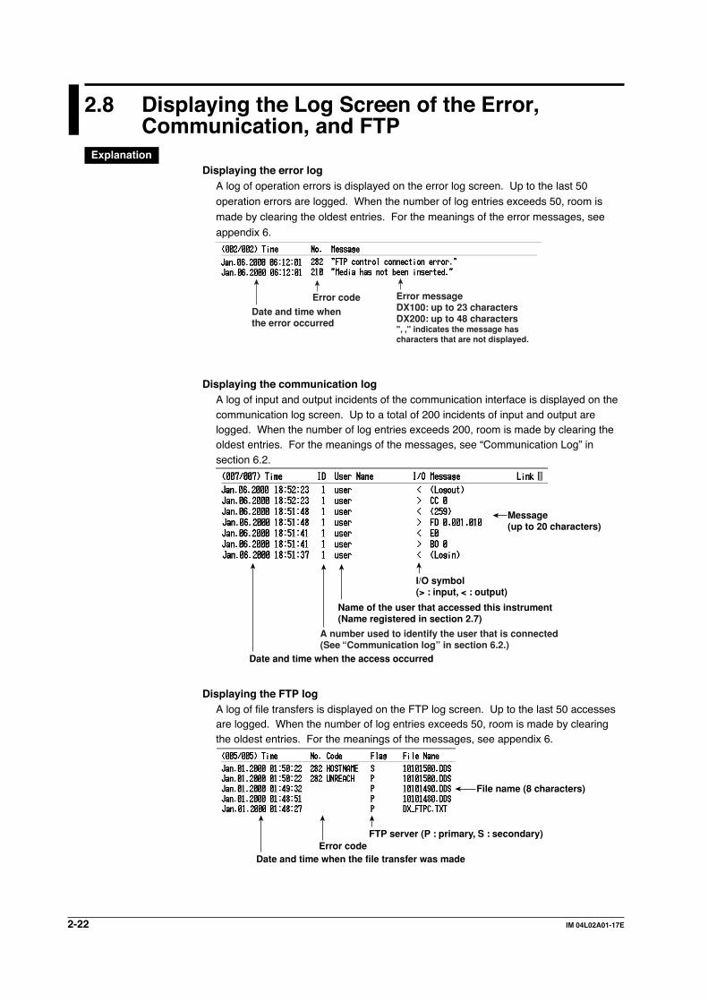
ExplanationDisplaying the error log
A log of operation errors is displayed on the error log screen. Up to the last 50operation errors are logged. When the number of log entries exceeds 50, room ismade by clearing the oldest entries. For the meanings of the error messages, see
appendix 6.
Date and time when the error occurred
Error code Error message DX100: up to 23 charactersDX200: up to 48 characters", ," indicates the message has characters that are not displayed.
Displaying the communication logA log of input and output incidents of the communication interface is displayed on thecommunication log screen. Up to a total of 200 incidents of input and output arelogged. When the number of log entries exceeds 200, room is made by clearing theoldest entries. For the meanings of the messages, see “Communication Log” insection 6.2.
Date and time when the access occurred
Name of the user that accessed this instrument(Name registered in section 2.7)
I/O symbol(> : input, < : output)
Message (up to 20 characters)
A number used to identify the user that is connected(See “Communication log” in section 6.2.)
Displaying the FTP logA log of file transfers is displayed on the FTP log screen. Up to the last 50 accessesare logged. When the number of log entries exceeds 50, room is made by clearingthe oldest entries. For the meanings of the messages, see appendix 6.
Date and time when the file transfer was madeError code
FTP server (P : primary, S : secondary)
File name (8 characters)

2-23IM 04L02A01-17E
Usin
g th
e Eth
ernet In
terface
2
Displaying the Web operation logYou can display a log (record) of the operations carried out using the Web screen on
the Web operation log screen. Up to 50 previous operations are logged. Logs thatexceed 50 operations are cleared from the oldest ones. For the meaning of themessages, see “Web Operation Log” in section 6.2.
OperationError code (see appendix 6)TypeDate/time
Displaying the e-mail logYou can display a log (record) of e-mail transmissions on the e-mail log screen. Up to
50 previous e-mail transmissions are logged. Logs that exceed 50 transmissions arecleared from the oldest ones. For the meaning of the messages, see “E-mail Log” insection 6.2.
Recipient address
Error code (see appendix 6)Recipient No.
Mail typeDate/time
Note• In addition to these logs, there is also a key login log. For details regarding the key login log
screen, see the DX100/DX200 User’s Manual (IM04L01A01-01E/IM04L02A01-01E).• The error/communication/FTP/Web operation/e-mail log data can be output. For the data
output format, see section 6.2.
2.8 Displaying the Log Screen of the Error, Communication, and FTP

2-24 IM 04L02A01-17E
ProcedureDisplaying the error log
1. Press the FUNC key to display the FUNC menu. The construction of the FUNCmenu varies depending on the basic settings and options.
2. Press the [Log] soft key to display the log screen menu.
3. Press the [Error] soft key to display the error log screen.
Displaying the communication log1. Press the FUNC key to display the FUNC menu. The construction of the FUNC
menu varies depending on the basic settings and options.
2. Press the [Log] soft key to display the log screen menu.
3. Press the [Commu] soft key to display the communication log screen.
Displaying the FTP log1. Press the FUNC key to display the FUNC menu. The construction of the FUNC
menu varies depending on the basic settings and options.
2. Press the [Log] soft key to display the log screen menu.
3. Press the [FTP] soft key to display the FTP log screen.
Displaying the Web operation log1. Press the FUNC key to display the FUNC menu. The construction of the FUNC
menu varies depending on the basic settings and options.
2. Press the [Log] soft key to display the log screen menu.
3. Press the [Web] soft key to display the Web operation log screen.
2.8 Displaying the Log Screen of the Error, Communication, and FTP

2-25IM 04L02A01-17E
Usin
g th
e Eth
ernet In
terface
2
2.8 Displaying the Log Screen of the Error, Communication, and FTP
Displaying the e-mail log1. Press the FUNC key to display the FUNC menu. The construction of the FUNC
menu varies depending on the basic settings and options.
2. Press the [Log] soft key to display the log screen menu.
3. Press the [E-Mail] soft key to display the e-mail log screen.

2-26 IM 04L02A01-17E
2.9 Setting the Web Server Function
Explanation
Enabling/Disabling the Web server functionSelect Use or Not (don’t use).
Page type (type of screen to be displayed)• Monitor
• The screen displayed on the DX is displayed.• The following information can be displayed.
• Alarm summary• Measured and computed values of all channels• Logs (message log, error log, key login log, FTP log, e-mail log, and Web operation
log)• For screen examples, see section 2.10.
• OperatorThe following operations can be carried out in addition to the functions available onthe monitor page.• Switch the screen on the DX by specifying the screen type (trend, digital, or bar
graph) and group.• Operate the DISP/ENTER key and arrow keys on the DX.• Set and write a message on the DX.
• For screen examples, see section 2.10.
Monitor page• Selecting whether or not to use the monitor page
• OnDisplay the monitor page on the browser.
• OffDo not use the monitor page.
• Selecting whether or not to use the access control• On
Use the access control. You must enter the user name and password to displaythe monitor page.
• OffDo not use the access control.
• Setting the user nameEnter the user name using up to 16 alphanumeric characters.
• Setting the passwordSet the password using up to six alphanumeric characters.
Operator page• Selecting whether or not to use the operator page
• OnDisplay the operator page on the browser.
• OffDo not use the operator page.
2-27IM 04L02A01-17E
Usin
g th
e Eth
ernet In
terface
2
• Selecting whether or not to use command input• On
Use the command to set and write messages.• Off
Do not use the command to set and write messages.
• Selecting whether or not to use the access control• On
Use the access control. You must enter the user name and password to display
the operator page.• Off
Do not use the access control.
• Setting the user nameEnter the user name using up to 16 alphanumeric characters.
• Setting the passwordSet the password using up to six alphanumeric characters.
Saving the settingsTo activate the settings that have been changed in the basic setting mode, the settingsmust be saved. Otherwise, the settings that existed before the change are activated.
Setting the time difference from GMTSee “Setting the Time Zone” in the DX100/DX200 User’s Manual (IM 04L01A01-01E/IM04L02A01-01E).
2.9 Setting the Web Server Function

2-28 IM 04L02A01-17E
2.9 Setting the Web Server Function
ProcedureFor the basic flow of operations, see “Flow of Operation using the Operation Keys” onpage vi. For the procedures related to entering character strings and values, see theDX100/DX200 User’s Manual (IM04L01A01-01E/IM04L02A01-01E).
1. Press the MENU key to display the setting menu.2. Press the FUNC key for approximately 3 s to display the basic setting menu.
3. Press the [#11 (Web,E-Mail)](DX100) or [#7 (Web,E-Mail)](DX200) soft key todisplay the Web and e-mail setting menu.
4. Press the [#1 (Web)] soft key to display the Web menu.
Web menu (DX100) Web menu (DX200)
Enabling/Disabling the Web server function5. Press the arrow key to move the cursor to the [Use/Not] box.
6. Press either the [Use] or [Not] soft key. If you select [Use], go to step 7. If you
select [Not], go to step 28.
Page type (type of screen to be displayed)7. Press the arrow key to move the cursor to the [Page type] box.
8. Press either the [Operator] or [Monitor] soft key. If you select [Operator], go to
step 9. If you select [Monitor], go to step 23.
Operator page• Selecting whether or not to use the operator page
9. Press the arrow key to move the cursor to the [On/Off] box.

2-29IM 04L02A01-17E
Usin
g th
e Eth
ernet In
terface
2
10. Press either the [On] or [Off] soft key. If you select [On], go to step 11. If youselect [Off], go to step 28.
• Selecting whether or not to use command input11. Press the arrow key to move the cursor to the [Command] box.
12. Press either the [On] or [Off] soft key.
• Selecting whether or not to use the access control13. Press the arrow key to move the cursor to the [Access control] box.
14. Press either the [On] or [Off] soft key. If you select [On], go to step 15. If youselect [Off], go to step 28.
• Setting the user name15. Press the arrow key to move the cursor to the [User name] box.
16. Press the [Input] soft key to display the entry box.
17. In the box, enter the user name.
18. Press the DISP/ENTER key. The entered string/value is set in the [User name]
box.
• Setting the password19. Press the arrow key to move the cursor to the [Password] box.
20. Press the [Input] soft key to display the entry box.
2.9 Setting the Web Server Function
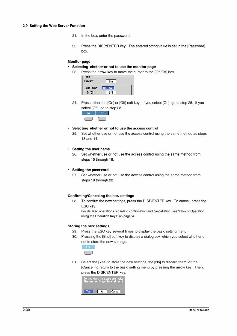
2-30 IM 04L02A01-17E
21. In the box, enter the password.
22. Press the DISP/ENTER key. The entered string/value is set in the [Password]box.
Monitor page• Selecting whether or not to use the monitor page
23. Press the arrow key to move the cursor to the [On/Off] box.
24. Press either the [On] or [Off] soft key. If you select [On], go to step 25. If you
select [Off], go to step 28.
• Selecting whether or not to use the access control25. Set whether use or not use the access control using the same method as steps
13 and 14.
• Setting the user name26. Set whether use or not use the access control using the same method from
steps 15 through 18.
• Setting the password27. Set whether use or not use the access control using the same method from
steps 19 through 22.
Confirming/Canceling the new settings28. To confirm the new settings, press the DISP/ENTER key. To cancel, press the
ESC key.For detailed operations regarding confirmation and cancellation, see “Flow of Operation
using the Operation Keys” on page vi.
Storing the new settings29. Press the ESC key several times to display the basic setting menu.30. Pressing the [End] soft key to display a dialog box which you select whether or
not to store the new settings.
31. Select the [Yes] to store the new settings, the [No] to discard them, or the
[Cancel] to return to the basic setting menu by pressing the arrow key. Then,press the DISP/ENTER key.
2.9 Setting the Web Server Function

2-31IM 04L02A01-17E
Usin
g th
e Eth
ernet In
terface
2
2.10 Using the Monitor Page and Operator Page
ExplanationThis section describes how to display the monitor page and operator page and the
operation on each page.
Browser application that can be usedOperations have been confirmed on the following browsers.
Microsoft Internet Explorer 4.0 to 5.5
Setting the URLSet the URL (Uniform Resource Locator) appropriately according to the networkenvironment that you are using. You can access the DX by setting the URL as follows:
• http://host name.domain name/file name• http: Protocol used to access the server. HTTP (HyperText Transfer Protocol).• Host name.domain name: Host name and domain name of the DX. You can also
use the IP address in place of the host name and domain name.• File name: File name of the monitor page and operator page of the DX.
File name of the monitor page: monitor.htmFile name of the operator page: operator.htmIf the file name is left out, the monitor page is specified. If the monitor page is notused, however, the operator page is specified.
ExampleTo display the operator page using Internet Explorer on a PC in the same domain as
the DX (the domain name, host name, and IP address are taken to be “good.co.jp,”“DX,” and “192.168.1.100,” respectively).
Address: http://DX.good.co.jp/operator.htm or
Address: http://192.168.1.100/operator.htm
Contents on the monitor page
Menu• Refreshes the screen• Displays the alarm summary• Displays the measured /computed data• Displays logs
Selects the screen sizeRefreshes the screen automatically

2-32 IM 04L02A01-17E
• Screen displayed by the DX200• When the DX is in the operation mode*, the screen displayed on the DX (trend,
digital, bar graph, overview, alarm summary, message summary, memorysummary, report, or historical trend) is displayed on the monitor page.
• When the DX is in the setting mode* or basic setting mode*, the monitor pagecannot be displayed. An error message is displayed.* For details on the operation mode, setting mode and basic setting mode, see the DX100/
DX200 User’s Manual (IM04L01A01-01E/IM04L02A01-01E).
NoteA character “°” that is set on the DX is displayed as a character “^” on the Web browser
screen.
• Refreshing the monitor pageThe monitor page can be refreshed automatically or manually.• Auto refresh ON
The monitor page is refreshed at a refresh rate of approximately 30 s.• Auto refresh OFF
Monitor page is not automatically refreshed. You can refresh the page manually.
However, the page cannot be refreshed in approximately 30 seconds after thepage refreshment.
• Zooming in or out of the screenThe DX screen that is displayed on the monitor page can be reduced to 75% in size(DX200) or expanded to 200% (DX100).
• Displaying the alarm summaryDisplays the alarm summary. Click Refresh to refresh the data.
Refreshes the page.
• Displaying measured/computed dataDisplays the measured/computed data of all channels (excludes measurementchannels set to skip and computation channels set to Off). Click Refresh to refreshthe data.
• Displaying the logDisplays the message log, error log, FTP log, key login log, Web operation log, and e-mail log. Click Refresh to refresh the data.
2.10 Using the Monitor Page and Operator Page

2-33IM 04L02A01-17E
Usin
g th
e Eth
ernet In
terface
2
Message log
Selects log type.Refreshes screen.
Error log
FTP log
Key login log
E-mail log
Web operation log
2.10 Using the Monitor Page and Operator Page

2-34 IM 04L02A01-17E
Contents of the operator page
Switches screens
Arrow keys and the DISP/ENTER key
Menu• Refreshes the screen• Displays the alarm summary• Displays the measured
/computed data• Displays logs• Sets and writes messages
Selects the screen sizeRefreshes the screen automatically
The size of the DX200’s screen is reduced to 75%.
On the operator page, the following operations can be carried out in addition to theinformation available on the monitor page.
• Switching trend, digital, and bar graph displaysSwitch the screen on the DX by specifying the group that will display the trend,numerical, or bar graph display.
• Operating the DX using the DISP/ENTER key and arrow keys on the operatorpageWhen the DX is in the operation mode, you can use the DISP/ENTER key and arrow
keys on the operator page to carry out the same operations as the DISP/ENTER keyand arrow keys on the DX.
• Setting and writing messagesSets the message string for messages 1 through 8 on the DX (16 alphanumericcharacters) and, at the same time, display them on the trend display and write them tothe internal memory. Existing messages are overwritten.
2.10 Using the Monitor Page and Operator Page
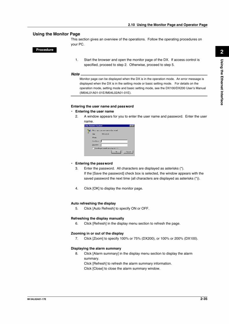
2-35IM 04L02A01-17E
Usin
g th
e Eth
ernet In
terface
2
Using the Monitor PageThis section gives an overview of the operations. Follow the operating procedures on
your PC.
Procedure
1. Start the browser and open the monitor page of the DX. If access control isspecified, proceed to step 2. Otherwise, proceed to step 5.
NoteMonitor page can be displayed when the DX is in the operation mode. An error message is
displayed when the DX is in the setting mode or basic setting mode. For details on the
operation mode, setting mode and basic setting mode, see the DX100/DX200 User’s Manual
(IM04L01A01-01E/IM04L02A01-01E).
Entering the user name and password• Entering the user name
2. A window appears for you to enter the user name and password. Enter the username.
• Entering the password3. Enter the password. All characters are displayed as asterisks (*).
If the [Save the password] check box is selected, the window appears with the
saved password the next time (all characters are displayed as asterisks (*)).
4. Click [OK] to display the monitor page.
Auto refreshing the display5. Click [Auto Refresh] to specify ON or OFF.
Refreshing the display manually6. Click [Refresh] in the display menu section to refresh the page.
Zooming in or out of the display7. Click [Zoom] to specify 100% or 75% (DX200), or 100% or 200% (DX100).
Displaying the alarm summary8. Click [Alarm summary] in the display menu section to display the alarm
summary.Click [Refresh] to refresh the alarm summary information.
Click [Close] to close the alarm summary window.
2.10 Using the Monitor Page and Operator Page

2-36 IM 04L02A01-17E
Displaying measured/computed data9. Click [All channels] in the display menu section to display the measured/
computed data.Click [Refresh] to refresh the measured/computed data.Click [Close] to close the measured/computed data window.
Displaying the log10. Click [Log] in the display menu section to display the log.
Click the box used to select the log type. The selected type of log is displayed.Click [Refresh] to refresh the log information.Click [Close] to close the log window.
Using the Operator PageThis section gives an overview of the operations. Follow the operating procedures on
your PC.
Procedure
1. Start the browser and open the operator page of the DX.
NoteOperator page can be displayed when the DX is in the operation mode. An error message is
displayed when the DX is in the setting mode or basic setting mode. For details on the
operation mode, setting mode and basic setting mode, see the DX100/DX200 User’s Manual
(IM04L01A01-01E/IM04L02A01-01E).
The following operations are the same as the monitor page. See “Using the MonitorPage.”
• Entering the user name and password• Auto refreshing the display• Refreshing the display manually• Zooming in or out of the display• Displaying the alarm summary• Displaying measured/computed data• Displaying the log
The followings are the operations only on the operator page.
Setting/modifying and writing messagesWhen the command for writing messages is enabled (see section 2.9), [Message]appears on the menu.
11. Click [Message] in the menu section to display the Message operate window.
Selects message.
Enters message.Cancels message entered.Sets and write message.
Displays the response from the DX
2.10 Using the Monitor Page and Operator Page

2-37IM 04L02A01-17E
Usin
g th
e Eth
ernet In
terface
2
12. Click the message number button to select the message.
13. Enter the message string in the message box and click [Set & Write]. Themessage on the DX is set and the message appears on the trend display on theDX. The message is also written to the internal memory.
To cancel the operation, click [Cancel].
Note• The message is displayed on the trend display and written to the internal memory only when
the data acquisition to the internal memory is in progress on the DX (The message is set
regardless of whether or not the data acquisition to the internal memory is in progress).
• The response to the message setting and writing operations is displayed in the command
response section.
Switching trend, digital, and bar graph displays14. Click [Select group] of the trend, digital, or bar graph display in the display
switch section to select the group. The DX screen changes to the specified
display. The operator page is also refreshed.
Operating using the DISP/ENTER key and arrow keys15. Click the [DISP/ENTER] key or arrow keys that are displayed on the operator
page to operate the DX in the same fashion as the corresponding keys on theDX. The operator page is also refreshed.
2.10 Using the Monitor Page and Operator Page

2-38 IM 04L02A01-17E
2.11 Setting the E-Mail Transmission Function
ExplanationTo use the e-mail transmission function, set the following parameters in addition to thosedescribed in section 2.3.
Basic settings of e-mail• SMTP* server name
Set the SMTP server name (up to 64 alphanumeric characters) or the IP address of
the SMTP server.* Simple Mail Transfer Protocol
• Port numberSet the port number to use. The default value is 25.
• Recipient 1Set the transmission destination of the e-mail message using up to 150 alphanumericcharacters. You can specify multiple addresses. To specify multiple addresses,
delimit the addresses using spaces.• Recipient 2
Set the transmission destination of the e-mail message using up to 150 alphanumeric
characters. You can specify multiple addresses. To specify multiple addresses,delimit the addresses using spaces.
• SenderSet the e-mail address using up to 64 alphanumeric characters. If the address is notset, the first address set in the recipient box is used as the sender’s address instead.
Settings for transmitting alarm information• Recipient 1, Recipient 2
Turns On/Off for each recipient.
• OnTransmits e-mail messages to the recipient.
• OffDoes not transmit e-mail messages to the recipient.
• Alarm number of which the alarm information is to be transmitted via the e-mail message (alarm 1, alarm 2, alarm 3, and alarm 4)You can turn On/Off the function for each alarm number. This setting is common toall channels.• On
If any one of the alarms corresponding to the relevant alarm number on allchannels changes (alarm occurrence or release), an e-mail message istransmitted.
• OffThe alarm information of the alarm number is not transmitted.
• Contents of the transmitted mail• Add instantaneous values
• OnAdds to the e-mail message the instantaneous values of all channels existing at
the time when the alarm condition changed.• Off
The instantaneous values are not added to the e-mail message.
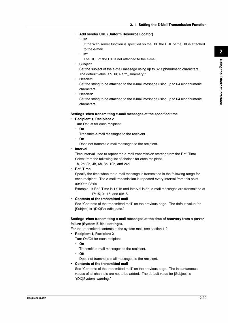
2-39IM 04L02A01-17E
Usin
g th
e Eth
ernet In
terface
2
• Add sender URL (Uniform Resource Locator)• On
If the Web server function is specified on the DX, the URL of the DX is attachedto the e-mail.
• OffThe URL of the DX is not attached to the e-mail.
• SubjectSet the subject of the e-mail message using up to 32 alphanumeric characters.
The default value is “(DX)Alarm_summary.”• Header1
Set the string to be attached to the e-mail message using up to 64 alphanumeric
characters.• Header2
Set the string to be attached to the e-mail message using up to 64 alphanumeric
characters.
Settings when transmitting e-mail messages at the specified time• Recipient 1, Recipient 2
Turn On/Off for each recipient.• On
Transmits e-mail messages to the recipient.• Off
Does not transmit e-mail messages to the recipient.
• IntervalTime interval used to repeat the e-mail transmission starting from the Ref. Time.Select from the following list of choices for each recipient.
1h, 2h, 3h, 4h, 6h, 8h, 12h, and 24h• Ref. Time
Specify the time when the e-mail message is transmitted in the following range for
each recipient. The e-mail transmission is repeated every Interval from this point.00:00 to 23:59Example: If Ref. Time is 17:15 and Interval is 8h, e-mail messages are transmitted at
17:15, 01:15, and 09:15.• Contents of the transmitted mail
See “Contents of the transmitted mail” on the previous page. The default value for
[Subject] is “(DX)Periodic_data.”
Settings when transmitting e-mail messages at the time of recovery from a powerfailure (System E-Mail settings).For the transmitted contents of the system mail, see section 1.2.• Recipient 1, Recipient 2
Turn On/Off for each recipient.• On
Transmits e-mail messages to the recipient.
• OffDoes not transmit e-mail messages to the recipient.
• Contents of the transmitted mailSee “Contents of the transmitted mail” on the previous page. The instantaneousvalues of all channels are not to be added. The default value for [Subject] is“(DX)System_warning.”
2.11 Setting the E-Mail Transmission Function

2-40 IM 04L02A01-17E
Settings when transmitting e-mail messages at the time of report creation (formodels with the computation function /M1)• Recipient 1, Recipient 2
Turn On/Off for each recipient.• On
Transmits e-mail messages to the recipient.• Off
Does not transmit e-mail messages to the recipient.
• Contents of the transmitted mailSee “Contents of the transmitted mail” on page 2-38. The instantaneous values of allchannels are not to be added. The default value for [Subject] is “(DX)Report_data.”
Saving the settingsTo activate the settings that have been changed in the basic setting mode, the settings
must be saved. Otherwise, the settings that existed before the change are activated.
NoteA character “°” that is set on the DX is displayed as a character “^” on the Web browser
screen.
2.11 Setting the E-Mail Transmission Function

2-41IM 04L02A01-17E
Usin
g th
e Eth
ernet In
terface
2
ProcedureFor the basic flow of operations, see “Flow of Operation using the Operation Keys” onpage vi. For the procedures related to entering character strings and values, see theDX100/DX200 User’s Manual (IM04L01A01-01E/IM04L02A01-01E).
1. Press the MENU key to display the setting menu.2. Press the FUNC key for approximately 3 s to display the basic setting menu.
3. Press the [#11 (Web,E-Mail)](DX100) or [#7 (Web,E-Mail)](DX200) soft key todisplay the Web and e-mail setting menu.
Basic settings of e-mail4. Press the [#2 (Basic E-Mail settings)] soft key to display the Web menu.
Basic E-Mail settings (DX100) Basic E-Mail settings (DX200)
• SMTP* server name5. Press the arrow key to move the cursor to the [SMTP server name] box.
6. Press the [Input] soft key to display the entry box.
7. In the box, enter the SMTP server name.
8. Press the DISP/ENTER key. The entered string/value is set in the [SMTPserver name] box.
• Port number9. Press the arrow key to move the cursor to the [Port number] box.
10. Press the [Input] soft key to display the entry box.
2.11 Setting the E-Mail Transmission Function
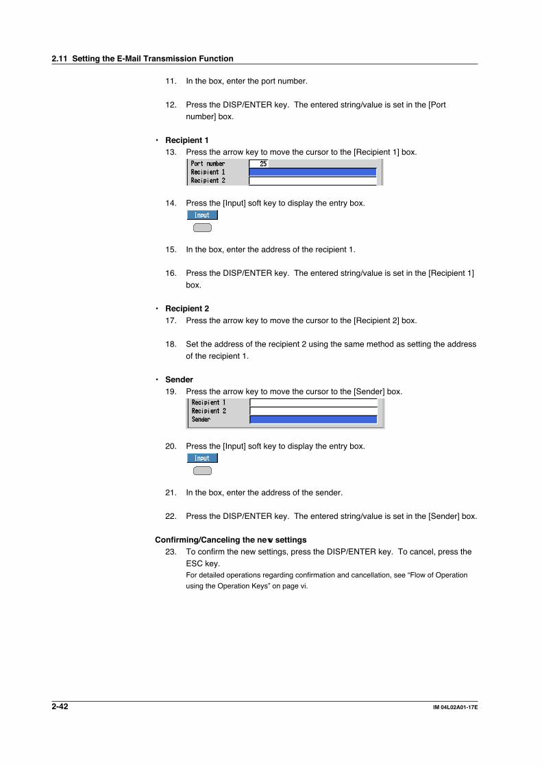
2-42 IM 04L02A01-17E
11. In the box, enter the port number.
12. Press the DISP/ENTER key. The entered string/value is set in the [Portnumber] box.
• Recipient 113. Press the arrow key to move the cursor to the [Recipient 1] box.
14. Press the [Input] soft key to display the entry box.
15. In the box, enter the address of the recipient 1.
16. Press the DISP/ENTER key. The entered string/value is set in the [Recipient 1]
box.
• Recipient 217. Press the arrow key to move the cursor to the [Recipient 2] box.
18. Set the address of the recipient 2 using the same method as setting the address
of the recipient 1.
• Sender19. Press the arrow key to move the cursor to the [Sender] box.
20. Press the [Input] soft key to display the entry box.
21. In the box, enter the address of the sender.
22. Press the DISP/ENTER key. The entered string/value is set in the [Sender] box.
Confirming/Canceling the new settings23. To confirm the new settings, press the DISP/ENTER key. To cancel, press the
ESC key.For detailed operations regarding confirmation and cancellation, see “Flow of Operation
using the Operation Keys” on page vi.
2.11 Setting the E-Mail Transmission Function

2-43IM 04L02A01-17E
Usin
g th
e Eth
ernet In
terface
2
[Alarm E-Mail], [Scheduled E-Mail], [System E-Mail], [Report E-Mail]24. Press the ESC key to display the Web, e-mail setting menu. Press the soft key
to display the setting menu to be set.[Alarm E-Mail]: Go to step 25.[Scheduled E-Mail]: Go to step 42.
[System E-Mail]: Go to step 54.[Report E-Mail]: Go to step 59.
• [Alarm E-Mail settings]• Recipient 1, Recipient 225. Press the arrow key to move the cursor to the [Recipient 1] box or the [Recipient
2] box.
26. Press either the [On] or [Off] soft key.
• Alarm number of which the alarm information is to be transmitted via the e-mail message
27. Press the arrow key to move the cursor to one of the [Alarm 1] through [Alarm 4]boxes.
28. Press either the [On] or [Off] soft key.
• Add instantaneous values29. Press the arrow key to move the cursor to the [Include instantaneous value]
(DX100) or [Include INST] (DX200) box.
30. Press either the [On] or [Off] soft key.
• Add sender URL (Uniform Resource Locator)31. Press the arrow key to move the cursor to the [Include source URL] box.
32. Press either the [On] or [Off] soft key.
2.11 Setting the E-Mail Transmission Function

2-44 IM 04L02A01-17E
• Subject33. Press the arrow key to move the cursor to the [Subject] box.
34. Press the [Input] soft key to display the entry box.
35. In the box, enter the subject.
36. Press the DISP/ENTER key. The entered string/value is set in the [Subject]box.
• Header37. Press the arrow key to move the cursor to either the [Header 1] box or the
[Header 2] box.
38. Press the [Input] soft key to display the entry box.
39. In the box, enter the character strings.
40. Press the DISP/ENTER key. The entered string/value is set in the [Header] box.
Confirming/Canceling the new settings41. To confirm the new settings, press the DISP/ENTER key. To cancel, press the
ESC key.For detailed operations regarding confirmation and cancellation, see “Flow of Operation
using the Operation Keys” on page vi.
• [Scheduled E-Mail]
• Recipient 1, Recipient 242. Set the address of the recipient 1 and 2 using the same method as steps 25 and
26.
• Interval43. Press the arrow key to move the cursor to the [Interval] box.
44. Press one of the soft keys from [1h] to [24h] to select the interval.
2.11 Setting the E-Mail Transmission Function

2-45IM 04L02A01-17E
Usin
g th
e Eth
ernet In
terface
2
• Ref. Time45. Press the arrow key to move the cursor to the [Ref. Time] box.
46. Press the [Input] soft key to display the entry box.
47. In the box, enter the reference time.
48. Press the DISP/ENTER key. The entered string/value is set in the [Ref. Time]
box.
• Add instantaneous values49. Set whether add or not the instantaneous values to the e-mail message using
the same method as steps 29 and 30.
• Add sender URL (Uniform Resource Locator)50. Set whether add or not the sender URL to the e-mail message using the same
method as steps 31 and 32.
• Subject51. Set the subject using the same method from steps 33 through 36.
• Header52. Set the header using the same method from steps 37 through 40.
Confirming/Canceling the new settings53. To confirm the new settings, press the DISP/ENTER key. To cancel, press the
ESC key.For detailed operations regarding confirmation and cancellation, see “Flow of Operation
using the Operation Keys” on page vi.
• [System E-Mail]• Recipient 1, Recipient 254. Set the address of the recipient 1 and 2 using the same method as steps 25 and
26.
• Add sender URL (Uniform Resource Locator)55. Set whether add or not the sender URL to the e-mail message using the same
method as steps 31 and 32.
• Subject56. Set the subject using the same method from steps 33 through 36.
• Header57. Set the header using the same method from steps 37 through 40.
2.11 Setting the E-Mail Transmission Function
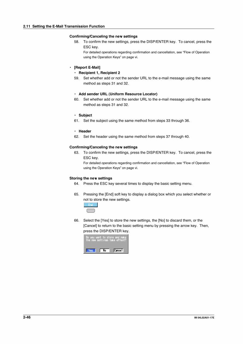
2-46 IM 04L02A01-17E
Confirming/Canceling the new settings58. To confirm the new settings, press the DISP/ENTER key. To cancel, press the
ESC key.For detailed operations regarding confirmation and cancellation, see “Flow of Operation
using the Operation Keys” on page vi.
• [Report E-Mail]• Recipient 1, Recipient 259. Set whether add or not the sender URL to the e-mail message using the same
method as steps 31 and 32.
• Add sender URL (Uniform Resource Locator)60. Set whether add or not the sender URL to the e-mail message using the same
method as steps 31 and 32.
• Subject61. Set the subject using the same method from steps 33 through 36.
• Header62. Set the header using the same method from steps 37 through 40.
Confirming/Canceling the new settings63. To confirm the new settings, press the DISP/ENTER key. To cancel, press the
ESC key.For detailed operations regarding confirmation and cancellation, see “Flow of Operation
using the Operation Keys” on page vi.
Storing the new settings64. Press the ESC key several times to display the basic setting menu.
65. Pressing the [End] soft key to display a dialog box which you select whether ornot to store the new settings.
66. Select the [Yes] to store the new settings, the [No] to discard them, or the[Cancel] to return to the basic setting menu by pressing the arrow key. Then,
press the DISP/ENTER key.
2.11 Setting the E-Mail Transmission Function

2-47IM 04L02A01-17E
Usin
g th
e Eth
ernet In
terface
2
2.12 Performing an E-Mail Transmission Test
ExplanationYou can transmit a test e-mail message to recipient 1 or recipient 2 that you specified insection 2.11 to confirm whether or not e-mail messages can be transmitted.Items to check before performing this test• Connect the Ethernet cable correctly. For the connection procedure, see section 2.2.• Check that the Ethernet interface settings are correct. For the procedure, see section
2.3 or 2.5.
• Check that the e-mail settings are correct. For the procedure, see section 2.11.When setting the Ethernet interface or e-mail, check the settings with your system ornetwork administrator.
Checking the results of the e-mail transmission test• The result of the e-mail transmission test can be confirmed by displaying the e-mail
log (displayed on the DX (see section 2.8)) or Web browser screen (see section 2.10)or by outputting the result using the FL command (see section 5.8).
• If an error message is displayed on the DX, see appendix 5, “A List of Error
Messages.”
Contents of the test e-mail messageThe figure below shows the contents of the test e-mail message.From: [email protected]: Sat, 23 Dec 2000 07:25:20 +0900 (JST)Subject: (DX) Test_mailTo: [email protected]
Test mail.<Host name>DX
<Time>Dec.23 07:25:20
ProcedurePerforming e-mail transmission test
1. Press the FUNC key. The FUNC menu appears. The structure of the FUNCmenu varies depending on the basic settings and options.
2. Press the E-Mail test soft key. A menu appears for you to select the recipientfor the e-mail transmission test.
3. Press the Recipient 1 or Recipient 2 soft key. The e-mail transmission test isexecuted for the selected recipient.

2-48 IM 04L02A01-17E
2.13 Starting/Stopping E-Mail Transmissions
ExplanationStarting/Stopping e-mail transmissions• If the e-mail transmission is started, the e-mail transmission function is activated.• If the e-mail transmission is stopped, the e-mail transmission function is disabled.
The e-mail messages that have not been transmitted are cleared.
Note• If the DX enters the basic setting mode while the e-mail transmission is started, the e-mail
transmission is stopped. If the DX returns to the operation mode from the basic setting mode,
the condition that existed before entering the basic setting mode is resumed.
• If a e-mail transmission fails, the DX retransmits the e-mail twice at intervals of 30 seconds. If
all of the transmission fail, the mail is discarded.
Contents of the e-mail messageThe figure below shows an example of an e-mail message.
From: [email protected]: Sat, 23 Dec 2000 23:00:09 +0900 (JST)Subject: (DX) Report_dataTo:[email protected], [email protected]
LOOP1 DAILYRAW MATERIAL
Hourly report.<Host name>DX
Dec.23 23:00:00<CH>01<Ave>-0.226<Max>0.698<Min>-0.972<Sum>-1.537000E+01<Unit>V
<CH>02<Ave>-0.225<Max>0.700<Min>-0.971
.
Report e-mail
Subject
Header1
Date/timeChannel no.Report data
Header2
From: [email protected]: Sat, 23 Dec 2000 01:00:09 +0900 (JST)Subject: (DX) Periodic_dataTo: [email protected]
LOOP1Scheduled
Periodic data.<Host name>DX
<Time>Dec.23 01:00:01
Scheduled e-mail
Subject
Header1
Date/time
Header2
From: [email protected]: Sat, 23 Dec 2000 07:31:58 +0900 (JST)Subject: (DX) System_warningTo: [email protected], [email protected]
LOOP1RAW MATERIAL
Power failure.<Host name>DX
<Power fail>Dec.23 07:30:12<Power on>Dec.23 07:31:32
System e-mail (power recoery)
Subject
Header1
Message
Details
Header2
From: [email protected]: Sun, 24 Dec 2000 13:08:23 +0900 (JST)Subject: (DX) Alarm_summaryTo: [email protected], [email protected]
LOOP1TEMPERATURE
Alarm summary.<Host name>DX
<CH>03<Type>1R<On>Dec.24 13:05:16<Off>Dec.24 13:08:17
<Inst. value>Dec.24 13:08:1701=-0.312V02=-0.267V03=-0.245V
.
.29=-0.645V30=-0.649V
Access the following URL in order to look athttp://DX.good.co.jp/
Alarm e-mail
Subject
Header1
Alarm no./typeChannel no.
Alarm date/time
Sender URL
Header2
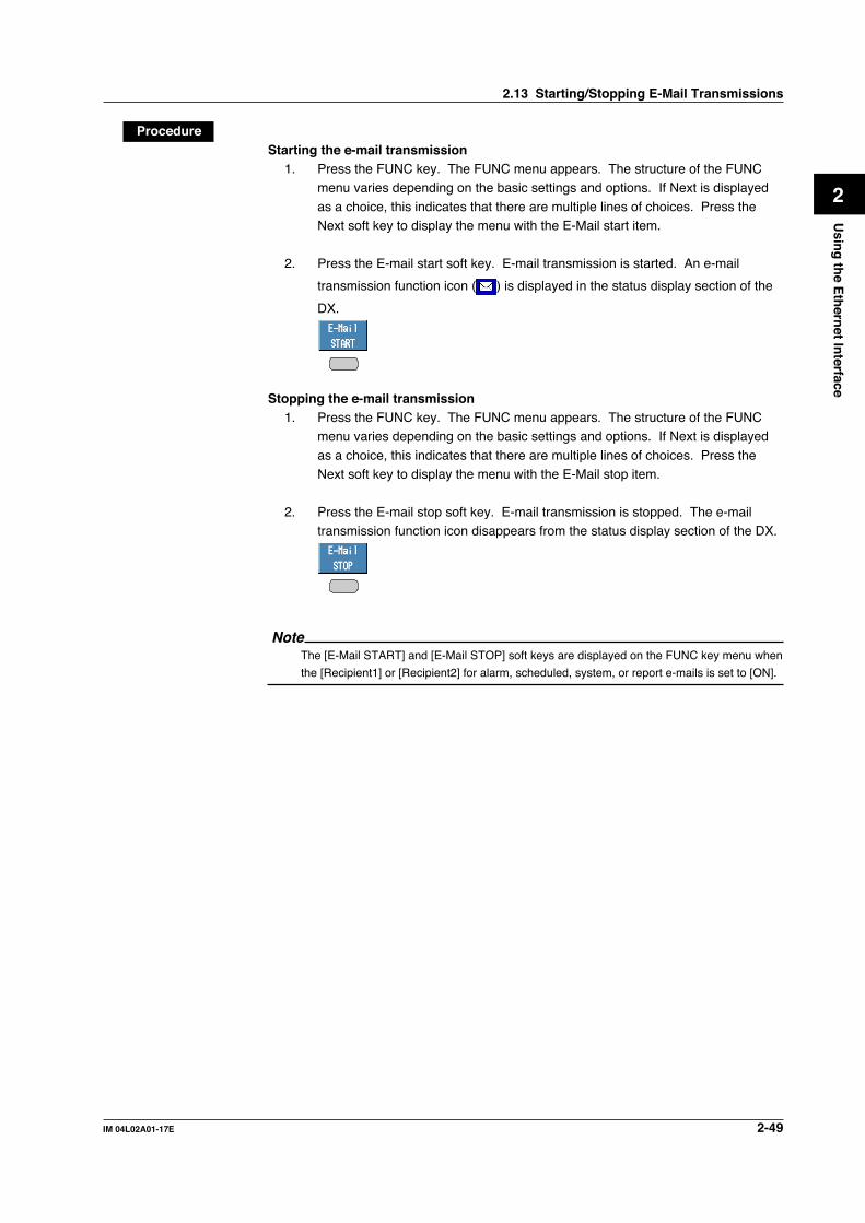
2-49IM 04L02A01-17E
Usin
g th
e Eth
ernet In
terface
2
2.13 Starting/Stopping E-Mail Transmissions
ProcedureStarting the e-mail transmission
1. Press the FUNC key. The FUNC menu appears. The structure of the FUNCmenu varies depending on the basic settings and options. If Next is displayed
as a choice, this indicates that there are multiple lines of choices. Press theNext soft key to display the menu with the E-Mail start item.
2. Press the E-mail start soft key. E-mail transmission is started. An e-mail
transmission function icon ( ) is displayed in the status display section of the
DX.
Stopping the e-mail transmission1. Press the FUNC key. The FUNC menu appears. The structure of the FUNC
menu varies depending on the basic settings and options. If Next is displayed
as a choice, this indicates that there are multiple lines of choices. Press theNext soft key to display the menu with the E-Mail stop item.
2. Press the E-mail stop soft key. E-mail transmission is stopped. The e-mailtransmission function icon disappears from the status display section of the DX.
NoteThe [E-Mail START] and [E-Mail STOP] soft keys are displayed on the FUNC key menu when
the [Recipient1] or [Recipient2] for alarm, scheduled, system, or report e-mails is set to [ON].

3-1IM 04L02A01-17E
Usin
g th
e Serial In
terface (Op
tion
)
3
3.1 Serial Interface (Option) Specifications
The specifications for the two types of serial interfaces (RS-232 and RS-422/485) on theDX are given below.
RS-232 Interface SpecificationsConnector type D-Sub 9 pin plug
Electrical, mechanical Conforms to the EIA-574 standard (for the 9-pin interface of thespecifications EIA-232 (RS-232) standard)
Connection Point-to-point
Communication Half-duplex
Synchronization Start-stop synchronization
Baud rate Select from 1200, 2400, 4800, 9600, 19200, or 38400[bps]
Start bit 1 bit (fixed)
Data length Select 7 or 8 bits(Select 8 bits when outputting data in binary format.)
Parity Select odd, even, or none
Stop bit 1 bit (fixed)
Hardware handshaking Select whether to fix the CA and CB signals to TRUE or to use thesignal for flow control.
Software handshaking Select whether to use the X-ON and X-OFF signals to control thetransmitted data only or both the transmitted and received data.X-ON (ASCII 11H), X-OFF (ASCII 13H)
Received buffer size 2047 bytes
RS-422/485 Interface SpecificationsTerminal block type 6 point, terminal block, terminal screws: ISO M4/nominal length 6 mm
Electrical, mechanical Conforms to EIA-422 (RS-422) and EIA-485 (RS-485) standardsspecifications
Connection Multidrop Four-wire type 1 : 32Two-wire type 1 : 31
Communication Half-duplex
Synchronization Start-stop synchronization
Baud rate Select from 1200, 2400, 4800, 9600, 19200, or 38400[bps]
Start bit 1 bit (fixed)
Data length Select 7 or 8 bits
Parity Select odd, even, or none
Stop bit 1 bit (fixed)
Received buffer size 2047 bytes
Escape sequence Open and close
Electric characteristics FG, SG, SDB, SDA, RDB, RDA (six points)SG, SDB, SDA, RDB, and RDA terminals and the internal circuit of theDX is functionally isolated.FG terminal is the frame ground.
Communication distance Up to 1.2 km
Terminator External: recommended resistance 120 Ω, 1/2 W
Chapter 3 Using the Serial Interface (Option)
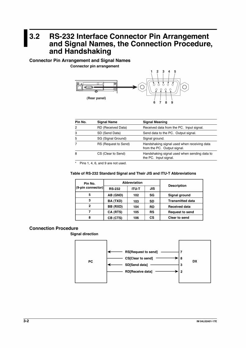
3-2 IM 04L02A01-17E
3.2 RS-232 Interface Connector Pin Arrangementand Signal Names, the Connection Procedure,and Handshaking
Connector Pin Arrangement and Signal NamesConnector pin arrangement
2 1 3 4 5
6 7 98(Rear panel)
Pin No. Signal Name Signal Meaning
2 RD (Received Data) Received data from the PC. Input signal.
3 SD (Send Data) Send data to the PC. Output signal.
5 SG (Signal Ground) Signal ground.
7 RS (Request to Send) Handshaking signal used when receiving datafrom the PC. Output signal.
8 CS (Clear to Send) Handshaking signal used when sending data tothe PC. Input signal.
* Pins 1, 4, 6, and 9 are not used.
Table of RS-232 Standard Signal and Their JIS and ITU-T Abbreviations
Pin No.(9-pin connector)
Abbreviation
RS-232Description
ITU-T JIS
5
3
2
8
7
AB (GND)
BA (TXD)
BB (RXD)
CB (CTS)
CA (RTS)
102 SG
103
104
106
105
SD
RD
CS
RS
Signal ground
Transmitted data
Request to send
Received data
Clear to send
Connection ProcedureSignal direction
PC DX
RS[Request to send]
SD[Send data]
RD[Receive data] 2
3
8
7
CS[Clear to send]

3-3IM 04L02A01-17E
Usin
g th
e Serial In
terface (Op
tion
)
3
Connection example
SDRDRSCSSG
SDRDRS
SG
• OFF-OFF/XON-XONPC DX
SDRDRSCSSG
SDRDRS
SG
• XON-RS(XON-RTS)PC DX
SDRDRSCSSG
SDRDRS
SG
• CS-RS(CTS-RTS)PC DX
CS
CS
CS
2 3
8 7
5
2 3
8 7
5
2 3
8 7
5
The RS on the PC side and the CSon the instrument side do not needto be connected for control. However, we recommend that theybe connected so that the cablecan be connected in either direction.
HandshakingWhen using the RS-232 interface for transferring data, it is necessary for equipment onboth sides to agree on a set of rules to ensure the proper transfer of data. The set of
rules is called handshaking. Because there are many handshaking methods that can beused between the instrument and the PC, one must make sure that the same method ischosen by both the DX and the PC. You can choose any of the four methods shown in
the following table.
Data Transmission Control(Control used to send data to a PC)
Data Reception Control(Control used to receive data from a PC)
Softwarehandshaking
Softwarehandshaking
Table of Handshaking Methods ( indicates that it is supported)
OFF-OFF
XON-XON
XON-RS
CS-RS
Handshaking method
Stopstransmissionwhen X-OFFis received. Resumewhen X-ONis received.
Stops transmission when CB (CTS)is false. Resume whenit is true.
Nohandshaking
Nohandshaking
Send X-OFF when thereceived databuffer is 3/4thfilled. SendX-ON when thereceived databuffer becomes1/4th filled.
Set CA (RTS) toFalse when thereceived data bufferis 3/4th filled. Set toTrue when thereceived data bufferbecomes 1/4th filled.
Hardwarehandshaking
Hardwarehandshaking
OFF-OFF• Data transmission control
There is no handshaking between the DX and the PC. The X-OFF and X-ON
signals are treated as data, and the CS signal is ignored.• Data reception control
There is no handshaking between the DX and the PC. When the received buffer
becomes full, all overflow data are discarded.The RS signal is fixed to True.
3.2 RS-232 Interface Connector Pin Arrangement and Signal Names, the Connection Procedure, and Handshaking

3-4 IM 04L02A01-17E
XON-XON• Data transmission control
Software handshaking is performed between the DX and the PC. When an X-OFFcode is received while sending data to the PC, the DX stops the data transmission.When it receives the next X-ON code, it resumes the data transmission. The CS
signal received from the PC is ignored.• Data reception control
Software handshaking is performed between the DX and the PC. When the
amount of used space in the received buffer reaches 1537 bytes, the X-OFF codeis transmitted. When the amount of used space in the received buffer falls to 511bytes, X-ON code is transmitted. The RS signal is fixed to True.
XON-RS• Data transmission control
Software handshaking is performed between the DX and the PC. When an X-OFFcode is received while sending data to the PC, the DX stops the data transmission.When it receives the next X-ON code, it resumes the data transmission. CS signal
from the PC is ignored.• Data reception control
Hardware handshaking is performed between the DX and the PC. When the
amount of used space in the received buffer reaches 1537 bytes, the RS signal isset to “False.” When the amount of used space in the received buffer falls to 511bytes, the RS signal is set to “True.”
CS-RS• Data transmission control
Hardware handshaking is performed between the DX and the PC. When the CSsignal becomes False while sending data to the PC, the DX stops the datatransmission. When the CS signal becomes True, it resumes the data
transmission. X-OFF is treated as data.• Data reception control
Hardware handshaking is performed between the DX and the PC. When the
amount of used space in the received buffer reaches 1537 bytes, the RS signal isset to “False.” When the amount of used space in the received buffer falls to 511bytes, the RS signal is set to “True.”
Note• The PC program must be designed so that the received buffers of both the DX and the PC do
not become full.
• When using XON-XON, output the data in ASCII format.
3.2 RS-232 Interface Connector Pin Arrangement and Signal Names, the Connection Procedure, and Handshaking

3-5IM 04L02A01-17E
Usin
g th
e Serial In
terface (Op
tion
)
3
3.3 RS-422/485 Interface Pin Arrangement andSignal Names and the Connection Procedure
Pin Arrangement and Signal Names
(Rear panel) FG SG SDB SDA RDB RDA
FG (Frame Ground) Case ground of the DX.
SG (Signal Ground) Signal ground.
SDB (Send Data B) Send data B (+).
SDA (Send Data A) Send data A (−).
RDB (Received Data B) Received data B (+).
RDA (Received Data A) Received data A (−).
Connection ProcedureCable
There are two types of cables available, the four-wire cable and the two-wire cable(used only for the Modbus protocol). The cable should meet the followingspecifications.
Cable Twisted-pair cable3 pairs 24 AWG or more (four-wire), 2 pair 24AWG or more (two-wire)
Characteristic impedance 100 Ω
Capacitance 50 pF/m
Cable length Up to 1.2 km*
* The transmission distance of the RS-422/485 interface is not the straight-line distance, butrather the total length of the (twisted-pair shielded) cable.
Cable connection procedureAs shown in the figure below, attach a crimp-style terminal with an isolating sleeve for
4-mm screws to the end of the cable. Keep the section that is exposed from theshielded cable to 5 cm or less.
FG SG SDB SDA RDB RDA
Shield potential
Two-wire
Shield
FG SG SDB SDA RDB RDA
Shield potential
Four-wire
Shield
WARNINGTo prevent electric shock, turn OFF the power when connecting cables.
Note• As shown on the next page, connect the RD pin to the SD (TD) pin on the PC (converter) side
and the SD pin to the RD pin on the PC side.
• The two-wire cable can be used only when using the Modbus protocol.
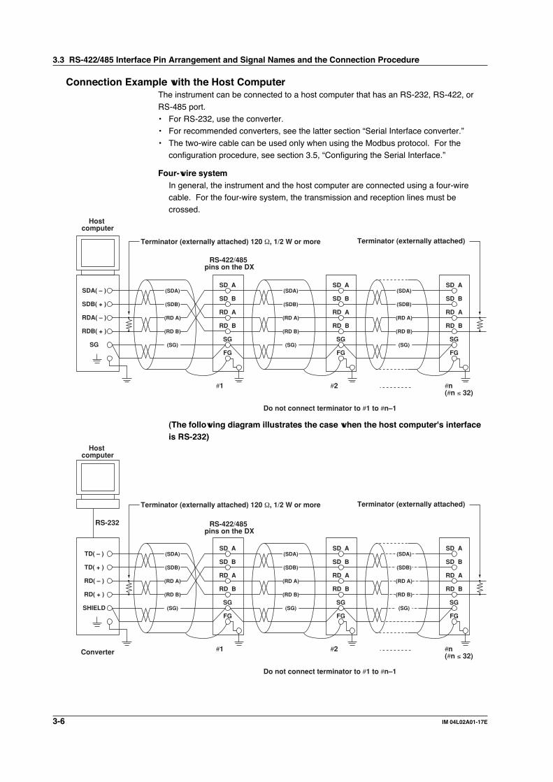
3-6 IM 04L02A01-17E
Connection Example with the Host ComputerThe instrument can be connected to a host computer that has an RS-232, RS-422, or
RS-485 port.• For RS-232, use the converter.• For recommended converters, see the latter section “Serial Interface converter.”
• The two-wire cable can be used only when using the Modbus protocol. For theconfiguration procedure, see section 3.5, “Configuring the Serial Interface.”
Four-wire systemIn general, the instrument and the host computer are connected using a four-wirecable. For the four-wire system, the transmission and reception lines must becrossed.
Terminator (externally attached) 120 Ω, 1/2 W or more
#1
Do not connect terminator to #1 to #n–1
RS-422/485 pins on the DX
#2 #n(#n ≤ 32)
Terminator (externally attached)
Host computer
SG
RDB( + )
RDA( – )
SDB( + )
SDA( – )
FG
SG
RD B
RD A
SD B
SD A
(SG)
(RD B)
(RD A)
(SDB)
(SDA)
FG
SG
RD B
RD A
SD B
SD A
(SG)
(RD B)
(RD A)
(SDB)
(SDA)
FG
SG
RD B
RD A
SD B
SD A
(SG)
(RD B)
(RD A)
(SDB)
(SDA)
(The following diagram illustrates the case when the host computer's interfaceis RS-232)
Terminator (externally attached) 120 Ω, 1/2 W or more
#1
Do not connect terminator to #1 to #n–1
RS-422/485 pins on the DX
#2 #n(#n ≤ 32)
Terminator (externally attached)
SHIELD
RD( + )
RD( – )
TD( + )
TD( – )
FG
SG
RD B
RD A
SD B
SD A
Host computer
Converter
(SG)
(RD B)
(RD A)
(SDB)
(SDA)
FG
SG
RD B
RD A
SD B
SD A
(SG)
(RD B)
(RD A)
(SDB)
(SDA)
FG
SG
RD B
RD A
SD B
SD A
(SG)
(RD B)
(RD A)
(SDB)
(SDA)
RS-232
3.3 RS-422/485 Interface Pin Arrangement and Signal Names and the Connection Procedure
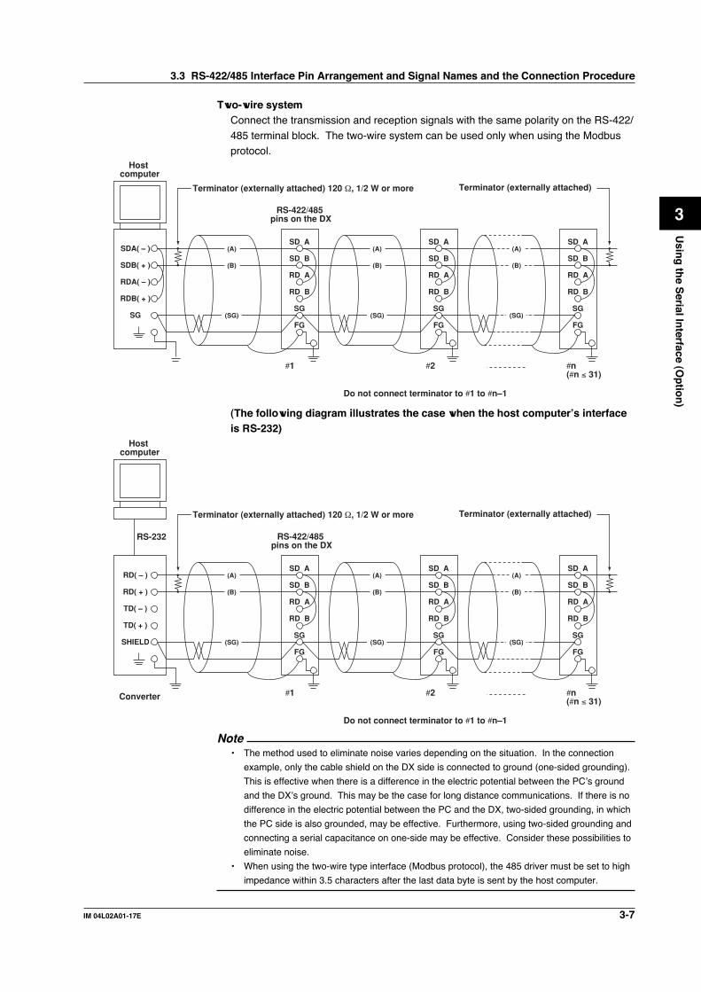
3-7IM 04L02A01-17E
Usin
g th
e Serial In
terface (Op
tion
)
3
Two-wire systemConnect the transmission and reception signals with the same polarity on the RS-422/
485 terminal block. The two-wire system can be used only when using the Modbusprotocol.
Terminator (externally attached) 120 Ω, 1/2 W or more
#1
Do not connect terminator to #1 to #n–1
RS-422/485 pins on the DX
#2 #n(#n ≤ 31)
Terminator (externally attached)
Host computer
SG
RDB( + )
RDA( – )
SDB( + )
SDA( – )
FG
SG
RD B
RD A
SD B
SD A
(SG)
(B)
(A)
(B)
(A)
FG
SG
RD B
RD A
SD B
SD A
(SG)
FG
SG
RD B
RD A
SD B
SD A
(SG)
(B)
(A)
(The following diagram illustrates the case when the host computer’s interfaceis RS-232)
Terminator (externally attached) 120 Ω, 1/2 W or more
#1
Do not connect terminator to #1 to #n–1
RS-422/485 pins on the DX
#2 #n(#n ≤ 31)
Terminator (externally attached)
FG
SG
RD B
RD A
SD B
SD A
(SG)
(B)
(A)
(B)
(A)
FG
SG
RD B
RD A
SD B
SD A
(SG)
FG
SG
RD B
RD A
SD B
SD A
(SG)
(B)
(A)
SHIELD
TD( + )
TD( – )
RD( + )
RD( – )
Host computer
Converter
RS-232
Note• The method used to eliminate noise varies depending on the situation. In the connection
example, only the cable shield on the DX side is connected to ground (one-sided grounding).
This is effective when there is a difference in the electric potential between the PC’s ground
and the DX’s ground. This may be the case for long distance communications. If there is no
difference in the electric potential between the PC and the DX, two-sided grounding, in which
the PC side is also grounded, may be effective. Furthermore, using two-sided grounding and
connecting a serial capacitance on one-side may be effective. Consider these possibilities to
eliminate noise.
• When using the two-wire type interface (Modbus protocol), the 485 driver must be set to high
impedance within 3.5 characters after the last data byte is sent by the host computer.
3.3 RS-422/485 Interface Pin Arrangement and Signal Names and the Connection Procedure

3-8 IM 04L02A01-17E
Serial Interface ConverterRecommended converter: SYSMEX RA CO.,LTD./MODEL RC-770X, LINE EYE/SI-
30FA, YOKOGAWA/ML2* The recommended converters are subject to change due to termination of production by the
manufacturer or for other reasons.
CAUTIONSome converters not recommended by Yokogawa have FG and SG pins thatare not isolated. In this case, do not connect anything to the FG and SG pins as
shown in the diagram on the previous page. This can generate a potentialdifference, especially for long distance communications, and can damage theinstrument or cause communication abnormalities. For converters that do not
have the SG pin, they can be used without using the signal ground. For details,see the manual that came with the converter.
On some non-recommended converters, the signal polarity may be reversed (A/B or+/– indication). In this case, reverse the connection.
For a two-wire system, the host computer must control the transmission driver of theconverter in order to prevent collisions of transmit and received data. When using the
recommended converter, the driver is controlled using the RS (RTS) signal on the RS-232.
When the instrument that support only the RS-422 interface exist in the systemWhen using the four-wire type interface, up to 32 DXs can be connected to a singlehost computer. However, this may not be true if the instrument that support only the
RS-422 interface exist in the system.
When YOKOGAWA's recorders that support only the RS-422 interface exist inthe system
The maximum number of connection is 16. Some of YOKOGAWA’s conventionalrecorders (HR2400 and µR, for example) only support the RS-422 driver. In this
case, only up to 16 units can be connected.
NoteIn the RS-422 standard, 10 is the maximum number of connections that are allowed on one
port (for a four-wire system).
TerminatorWhen using a multidrop connection (including a point-to-point connection), connect aterminal resistance to the DX on the end of the chain. Do not connect a terminal
resistance to a DX in the middle of the chain. In addition, turn the terminator on thehost computer ON (see the computer's manual). If a converter is being used, turn ONits terminator. An external terminator must be attached to the recommended
converter. However, there are converters that have built-in terminations.Select the appropriate terminator (120 Ω), indicated in the figure, according to thecharacteristic impedance of the line, the installation conditions of the instruments, and
so on.
3.3 RS-422/485 Interface Pin Arrangement and Signal Names and the Connection Procedure

3-9IM 04L02A01-17E
Usin
g th
e Serial In
terface (Op
tion
)
3
3.4 The Bit Structure of One Character and theOperation of the Receive Buffer
The Bit Structure of One CharacterThe serial interface on the DX communicates using start-stop synchronization. With thestart-stop synchronization, a start bit is added every time a character is transmitted. Thestart bit is followed by the data bits, parity bit, and stop bit. (See the figure below.)
Data bits(7 or 8 bits)
1 character
Stop bit (1 or 2 bits)Parity bit(Even, odd, or none)Start bit
Circuit idle state
Circuit back to idle state(dotted line) or the start bit of the next data (solid line)
Receive Buffer and Received DataThe data received from the computer are first placed in the receive buffer of the DX.Depending on the available free space in the receive buffer, the received data are
processed as shown in the figure below. When the receive buffer becomes FULL,overflow data are discarded.
2047 bytes
Amount of used space is 1537 bytes Free
When handshaking is used, the DX stops data reception when data in the buffer cannot be processed fast enough and the amount of used space reaches 1537 bytes.
Amount of used space is 511 bytes Free
After the data reception is stopped as described above, data in the buffer continues to be passed to the internal program. When the amount of used space falls to 511 bytes, it resumes data reception.
Amount of used space is FULL
If the buffer becomes full in spite of the handshaking control, all overflow data are discarded.

3-10 IM 04L02A01-17E
3.5 Configuring the Serial Interface
ExplanationSelecting the baud rate
Select the baud rate from the following list.1200, 2400, 4800, 9600, 19200, 38400
Selecting the data lengthSelect the data length from the following list. Make sure to select 8 bits when
outputting data in binary format.7, 8
Selecting the parity checkSelect the parity check from the following list.Odd, Even, None
Selecting the handshaking methodSelect the handshaking method from the following list. This setting is valid only for
the RS-232 interface.Off:Off, XON:XON, XON:RS, CS:RS
Selecting the addressSelect the address from the following values. This setting is valid for the RS-422/485interface and the Modbus protocol.
1 to 32
Selecting the “Normal” protocolWhen using the “Normal” protocol to communicate via RS-232 or RS-422/485, select[Normal].
Selecting the communication interface used to output the data in the internalmemory and the files on the external storage medium
• Using output commands (ME/MI/MO commands), select the communication
interface used to output the data in the internal memory (display data, event data,TLOG data, manual sampled data, and report data) and the files on the externalstorage medium. Since Ethernet communications and serial communications
cannot be used simultaneously, you must select either one.• When using serial communications, select [Serial].
Storing the settingsTo activate the settings made in the basic setting mode, the settings must be saved.Otherwise, the settings return to the previous values.

3-11IM 04L02A01-17E
Usin
g th
e Serial In
terface (Op
tion
)
3
ProcedureFor the basic flow of operations, see “Flow of Operation using the Operation Keys” onpage vi.
1. Press the MENU key to display the setting menu.2. Press the FUNC key for approximately 3 s to display the basic setting menu.3. Press the [#10 (Communication)](DX100) or [#6 (Communication)](DX200) soft
key to display the communication function setting menu.4. Press the [#6 (Serial, Memory out)](DX100) or [#1 (Ethernet, Serial)](DX200)
soft key to display the communication (Serial) menu.
DX200 Communication (Ethernet, Serial) menuDX100 Communication (Serial, Memory out) menu
Selecting the baud rate5. Press the arrow keys to move the cursor to the [Baud rate] box.
6. Press one of the soft keys from [1200] to [38400] to select the baud rate.
Selecting the data length7. Press the arrow key to move the cursor to the [Data length] box.
8. Press the [7] or [8] soft key to select the data length.
3.5 Configuring the Serial Interface

3-12 IM 04L02A01-17E
Selecting the parity9. Press the arrow keys to move the cursor to the [Parity] box.
10. Press one of the soft keys from [Odd] to [None] to select the parity check.
Selecting the handshaking(Valid only for the RS-232 interface.)11. Press the arrow keys to move the cursor to the [Handshaking] box.
12. Press one of the soft keys from [Off:Off] to [CS:RS] to select the handshakingmethod.
Selecting the address(Valid for the RS-422/485 interface and the Modbus protocol)13. Press the arrow keys to move the cursor to the [Address] box.
14. Press one of the soft keys from [1] to [32] to select the address.
Setting the protocol to “Normal”15. Press the arrow keys to move the cursor to the [Protocol] box.
16. Press the [Normal] soft key.
3.5 Configuring the Serial Interface
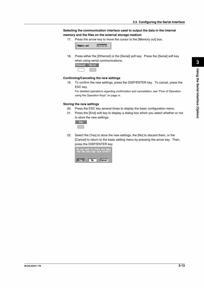
3-13IM 04L02A01-17E
Usin
g th
e Serial In
terface (Op
tion
)
3
Selecting the communication interface used to output the data in the internalmemory and the files on the external storage medium
17. Press the arrow key to move the cursor to the [Memory out] box.
18. Press either the [Ethernet] or the [Serial] soft key. Press the [Serial] soft keywhen using serial communications.
Confirming/Canceling the new settings19. To confirm the new settings, press the DISP/ENTER key. To cancel, press the
ESC key.For detailed operations regarding confirmation and cancellation, see “Flow of Operation
using the Operation Keys” on page vi.
Storing the new settings20. Press the ESC key several times to display the basic configuration menu.21. Press the [End] soft key to display a dialog box which you select whether or not
to store the new settings.
22. Select the [Yes] to store the new settings, the [No] to discard them, or the[Cancel] to return to the basic setting menu by pressing the arrow key. Then,
press the DISP/ENTER key
3.5 Configuring the Serial Interface
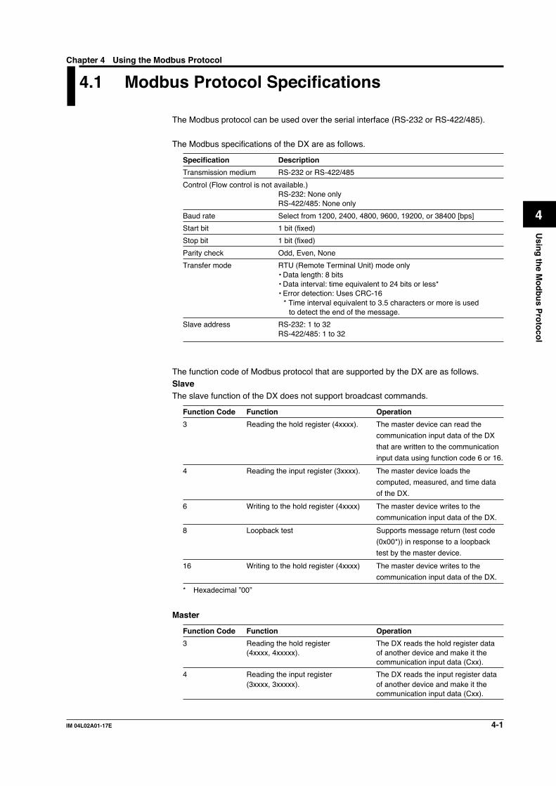
4-1IM 04L02A01-17E
Usin
g th
e Mo
db
us P
roto
col
4
4.1 Modbus Protocol Specifications
The Modbus protocol can be used over the serial interface (RS-232 or RS-422/485).
The Modbus specifications of the DX are as follows.
Specification Description
Transmission medium RS-232 or RS-422/485
Control (Flow control is not available.)RS-232: None onlyRS-422/485: None only
Baud rate Select from 1200, 2400, 4800, 9600, 19200, or 38400 [bps]
Start bit 1 bit (fixed)
Stop bit 1 bit (fixed)
Parity check Odd, Even, None
Transfer mode RTU (Remote Terminal Unit) mode only• Data length: 8 bits• Data interval: time equivalent to 24 bits or less*• Error detection: Uses CRC-16
* Time interval equivalent to 3.5 characters or more is usedto detect the end of the message.
Slave address RS-232: 1 to 32RS-422/485: 1 to 32
The function code of Modbus protocol that are supported by the DX are as follows.SlaveThe slave function of the DX does not support broadcast commands.
Function Code Function Operation
3 Reading the hold register (4xxxx). The master device can read the
communication input data of the DX
that are written to the communication
input data using function code 6 or 16.
4 Reading the input register (3xxxx). The master device loads the
computed, measured, and time data
of the DX.
6 Writing to the hold register (4xxxx) The master device writes to the
communication input data of the DX.
8 Loopback test Supports message return (test code
(0x00*)) in response to a loopback
test by the master device.
16 Writing to the hold register (4xxxx) The master device writes to the
communication input data of the DX.
* Hexadecimal ”00”
Master
Function Code Function Operation
3 Reading the hold register The DX reads the hold register data(4xxxx, 4xxxxx). of another device and make it the
communication input data (Cxx).
4 Reading the input register The DX reads the input register data(3xxxx, 3xxxxx). of another device and make it the
communication input data (Cxx).
Chapter 4 Using the Modbus Protocol

4-2 IM 04L02A01-17E
4.2 Register Assignments (Modbus Slave)
The register assignments of the Modbus protocol are given below. The data in theregister do not contain unit and decimal position information. The unit and decimal
position information must be set to the Modbus master (host) beforehand.A binary value is put into the registers with the MSB (Most Significant Bit) first.
Input register Data
30001 Measured data of CH01: :30030 Measured data of CH30
• The corresponding registers: 30001 to 30002 on the DX102. 30001 to 30004 on theDX104. 30001 to 30006 on the DX106. 30001 to 30012 on the DX112. 30001 to 30004 onthe DX204. 30001 to 30008 on the DX208. 30001 to 30010 on the DX210. 30001 to30020 on the DX220. 30001 to 30030 on the DX230.
• Measured data is a “16-bit signed integer.” Values are the same as the measured data inbinary format (see section 6.3).
31001 Alarm status of the measured data of CH01: :31030 Alarm status of the measured data of CH30
• The corresponding registers: 31001 to 31002 on the DX102. 31001 to 31004 on theDX104. 31001 to 31006 on the DX106. 31001 to 31012 on the DX112. 31001 to 31004on the DX204. 31001 to 31008 on the DX208. 31001 to 31010 on the DX210. 31001 to31020 on the DX220. 31001 to 31030 on the DX230.
• Alarm status is a “16-bit unsigned integer.” Values are the same as the alarm status inbinary format (see section 6.3). The register holds the data in the order as A2A1A4A3.
32001 Computed data of CH31 (upper word)32002 Computed data of CH31 (lower word)32003 Computed data of CH32 (upper word): :32060 Computed data of CH60 (lower word)
• The corresponding registers: 32001 to 32016 on the DX102/DX104/DX204/DX208. 32001to 32024 on the DX106/DX112.. 32001 to 32060 on the DX210/DX220/DX230.
• These registers are for models with the computation function option /M1.• Computed data is a “32-bit signed integer.” Two registers are assigned per a computed
data. Values are the same as the computed data in binary format (see section 6.3).
33001 Alarm status of the Computed data of CH31: :33030 Alarm status of the Computed data of CH60
• The corresponding registers: 33001 to 33008 on the DX102/DX104/DX204/DX208. 33001to 33012 on the DX106/DX112. 33001 to 33030 on the DX210/DX220/DX230.
• These registers are for models with the computation function option /M1.• Alarm status is a “16-bit unsigned integer.” Values are the same as the alarm status in
binary format (see section 6.3). The register holds the data in the order as A2A1A4A3.
39001 Year (4 digits)39002 Month39003 Day39004 Hour39005 Minute39006 Second39007 Millisecond39008 Summer/Winter time
Hold register Data
40001 Communication input data of C01: :40030 Communication input data of C30
A value in the range from –32768 to 32767 can be written in the hold register.For DX100, the hold register is from 40001 to 40012 (from C01 to C12.)

4-3IM 04L02A01-17E
Usin
g th
e Mo
db
us P
roto
col
4
4.3 Modbus Error Response (Modbus Slave)
When using the Modbus slave function, the DX returns the error codes below to themaster device. For the error messages related to communications that the DX displays,
see appendix 6.
Code Meaning Cause
1 Bad function code Requested a function that is not supported. Forsupported functions, see section 4.1, “ModbusProtocol Specifications.”
2 Bad register number Tried to read/write to a register that has nocorresponding channel.
3 Bad number of registers The number of specified registers is zero.
7 Cannot be executed. Tried to read a computation register from a modelthat has no computation option.
However, no response is returned for the following cases.
• CRC error• Errors other than the ones shown above.

4-4 IM 04L02A01-17E
4.4 Setting the Configuration that is Used Whenthe Modbus Protocol is Used
ExplanationSelecting the baud rate
Select the baud rate from the following list.1200, 2400, 4800, 9600, 19200, 38400
Selecting the parity checkSelect the parity check from the following list.Odd, Even, None
Selecting the slave address (valid when Modbus slave function is engaged)Select the address from the following values.
1 to 32
Selecting the “Modbus” protocolWhen communicating using the “Modbus” protocol, select [Modbus].
Selecting the communication interface used to output the data in the internalmemory and the files on the external storage medium
Select [Ethernet], if you use output commands (ME/MI/MO commands) to output thedata in the internal memory (display data, event data, TLOG data, manual sampled
data, and report data) and the files on the external storage medium. Selecting [Serial]has no effect.
Storing the settingsTo activate the settings made in the basic setting mode, the settings must be saved.Otherwise, the settings return to the previous values.
NoteWhen using the Modbus protocol, setting the data length and handshaking produces no
effect.
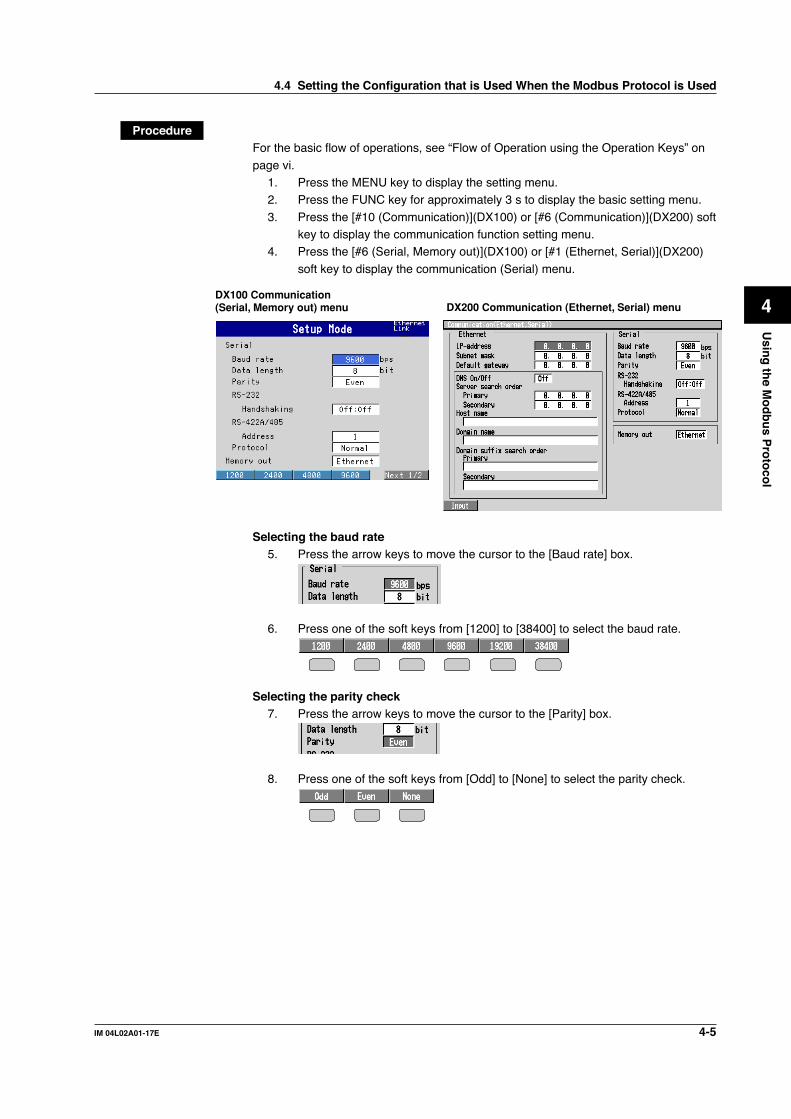
4-5IM 04L02A01-17E
Usin
g th
e Mo
db
us P
roto
col
4
ProcedureFor the basic flow of operations, see “Flow of Operation using the Operation Keys” on
page vi.1. Press the MENU key to display the setting menu.2. Press the FUNC key for approximately 3 s to display the basic setting menu.
3. Press the [#10 (Communication)](DX100) or [#6 (Communication)](DX200) softkey to display the communication function setting menu.
4. Press the [#6 (Serial, Memory out)](DX100) or [#1 (Ethernet, Serial)](DX200)
soft key to display the communication (Serial) menu.
DX200 Communication (Ethernet, Serial) menuDX100 Communication (Serial, Memory out) menu
Selecting the baud rate5. Press the arrow keys to move the cursor to the [Baud rate] box.
6. Press one of the soft keys from [1200] to [38400] to select the baud rate.
Selecting the parity check7. Press the arrow keys to move the cursor to the [Parity] box.
8. Press one of the soft keys from [Odd] to [None] to select the parity check.
4.4 Setting the Configuration that is Used When the Modbus Protocol is Used

4-6 IM 04L02A01-17E
Selecting the slave address (valid when Modbus slave function is engaged)9. Press the arrow keys to move the cursor to the [Address] box.
10. Press one of the soft keys from [1] to [32] to select the address.
Setting the protocol to “Modbus”11. Press the arrow keys to move the cursor to the [Protocol] box.
12. Press the [Modbus] soft key when using the Modbus slave function.Press the [Modbus-M] soft key when using the Modbus master function.
Selecting the communication interface used to output the data in the internalmemory and the files on the external storage medium
13. Press the arrow key to move the cursor to the [Memory out] box.
14. Press the [Ethernet] soft key when transferring data via Ethernet. Pressing the[Serial] soft key has no effect.
Confirming/Canceling the new settings15. To confirm the new settings, press the DISP/ENTER key. To cancel, press the
ESC key.For detailed operations regarding confirmation and cancellation, see “Flow of Operation
using the Operation Keys” on page vi.
Storing the new settings16. Press the ESC key several times to display the basic setting menu.17. Pressing the [End] soft key to display a dialog box which you select whether or
not to store the new settings.
18. Select the [Yes] to store the new settings, the [No] to discard them, or the
[Cancel] to return to the basic setting menu by pressing the arrow key. Then,
press the DISP/ENTER key.
4.4 Setting the Configuration that is Used When the Modbus Protocol is Used

4-7IM 04L02A01-17E
Usin
g th
e Mo
db
us P
roto
col
4
4.5 Setting the Modbus Master Function
ExplanationSelecting the read cycleThe cycle at which data is read from other devices. Select the read cycle from thefollowing:
125 ms, 250 ms, 500 ms, 1 s, 5 s, 2 s, 10 s
Selecting the timeout timeIf there is no response from the specified slave device after transmitting a command fromthe DX over the time specified here (timeout time), the DX repeats the operation ofsending the command the specified number of retrials (see below) and waiting. If there
is no response from the slave device after the specified number of retrials, the DX stopssending commands to the slave device.
X
Command sending is stopped.
Operation when there is no response from the slave device (the number of retrials is set to 2)
: Commands are sent to the slave device at the read cycle.
: The slave device responds. : The slave devide does not respond.
X X
The slave device responds to the retrial.
Time
Retrials
X X X
Time
Retrials
Select the timeout time from the following:125 ms, 250 ms, 500 ms, 1 s, 5 s, 2 s, 10 s, and 1 min
Selecting the number of retrialsThe number of times to retransmit the command when there is no response from thespecified slave device. If there is no response from the slave device after the specified
number of retrials, the DX stops sending commands to the slave device. Select thenumber of retrials from the following:Off (0), 1, 2, 3, 4, 5, 10 and 20
Setting the commandThe commands are used to read data from slave devices at the read cycle, and put them
to the communication input data of the DX. Data from the consecutive registers with thesame type of data in a slave device, can be read and put to the consecutivecommunication input data of the DX using a command.
• Turning On/Off the commandTurn On the command registration line to be used. Up to eight commands can beregistered.

4-8 IM 04L02A01-17E
• Read channel (start CH, end CH)Specify which communication input data will be assigned the data that is read from
the slave device (DX100: C01 to C12, DX200: C01 to C30).Communication inputdata of the DX(Modbus master)
Registers in slavedevice A
Registers in slavedevice B
C01
C02
C30
3000130002
•
3000130002
(Two registers are usedfor a 32-bit datum)
• AddressSpecify the address of the slave device from the following:
1 to 247
• RegisterSpecify the register number of the slave device. 32-bit data is assigned to tworegisters. Thus, specify the smaller register number (see “Type” below).Input register: 30001 to 39999, 300001 to 365535
Hold register: 40001 to 49999, 400001 to 465535
• TypeSpecify the type of data that is assigned to the Modbus register of the slave device(the DX reads all data as floating point data).• INT16
Specify this parameter when a “16-bit signed integer” is assigned to the Modbusregister.Communication inputdata of the DX
Modbusregister
16-bit signed integerCxx
• UINT16Specify this parameter when a “16-bit unsigned integer” is assigned to the Modbus
register.
• INT32_BSpecify this parameter when a “32-bit signed integer” is assigned to the Modbusregister in the order upper 16 bits followed by the lower 16 bits.Specify the smaller register number (the higher register number in this case) in
Register.Communication input data of the DX
Modbus register
Cxx (Upper 16 bits)
(Lower 16 bits)32-bit signed integer
• INT32_LSpecify this parameter when a “32-bit signed integer” is assigned to the Modbusregister in the order lower 16 bits followed by the upper 16 bits.Specify the smaller register number (the lower register number in this case) in
Register.Communication input data of the DX
Modbus register
Cxx (Lower 16 bits)
(Upper 16 bits)32-bit signed integer
4.5 Setting the Modbus Master Function

4-9IM 04L02A01-17E
Usin
g th
e Mo
db
us P
roto
col
4
• UINT32_BSpecify this parameter when a “32-bit unsigned integer” is assigned to the Modbus
register in the order upper 16 bits followed by the lower 16 bits.Specify the smaller register number (the higher register number in this case) inRegister.
• UINT32_LSpecify this parameter when a “32-bit unsigned integer” is assigned to the Modbus
register in the order lower 16 bits followed by the upper 16 bits.Specify the smaller register number (the lower register number in this case) inRegister.
• FLOAT_BSpecify this parameter when a “32-bit floating-point data” is assigned to the
Modbus register in the order upper 16 bits followed by the lower 16 bits.Specify the smaller register number (the higher register number in this case) inRegister.
• FLOAT_LSpecify this parameter when a “32-bit floating-point data” is assigned to the
Modbus register in the order lower 16 bits followed by the upper 16 bits.Specify the smaller register number (the lower register number in this case) inRegister.
Setting ExampleIf you set as shown in the figure below, the DX reads an “INT16” value from register
30001 to put it to C01, and an “INT16” value from register 30002 to C02.
Displaying the read dataThe data that is read can be displayed by writing a computing equation using C01through C30 (C01 to C12 for DX100) on a computation channel (/M1 option). The
decimal position and the unit are specified by the slave device. Convert the read valueto a value with an appropriate unit using the computation equation (see an examplebelow). For information on the use of the computation channel, see the DX100/DX200
User’s Manual (IM04L01A01-01E/IM04L02A01-01E).
ExampleAssigns the communication input data C01 to the computation channel 31.Read an “INT16” value from register 30001 of the slave device with the address “1,” toput it to the communication input data C01 of the DX. Change the value to have two
digits of decimal fraction (multiply 0.01) and a unit “V.”• Command
First communication data: 01, Address: 1, Register: 30001, Type: INT16
• Computation channelComputation equation for Channel 31: C01*K01Unit: V
Constant: K01=0.01
4.5 Setting the Modbus Master Function
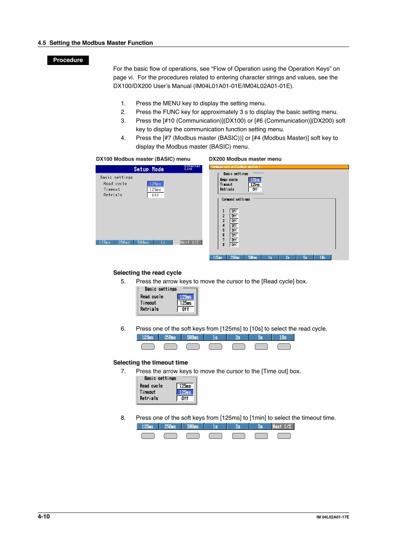
4-10 IM 04L02A01-17E
ProcedureFor the basic flow of operations, see “Flow of Operation using the Operation Keys” onpage vi. For the procedures related to entering character strings and values, see theDX100/DX200 User’s Manual (IM04L01A01-01E/IM04L02A01-01E).
1. Press the MENU key to display the setting menu.2. Press the FUNC key for approximately 3 s to display the basic setting menu.
3. Press the [#10 (Communication)](DX100) or [#6 (Communication)](DX200) softkey to display the communication function setting menu.
4. Press the [#7 (Modbus master (BASIC))] or [#4 (Modbus Master)] soft key to
display the Modbus master (BASIC) menu.
DX100 Modbus master (BASIC) menu DX200 Modbus master menu
Selecting the read cycle5. Press the arrow keys to move the cursor to the [Read cycle] box.
6. Press one of the soft keys from [125ms] to [10s] to select the read cycle.
Selecting the timeout time7. Press the arrow keys to move the cursor to the [Time out] box.
8. Press one of the soft keys from [125ms] to [1min] to select the timeout time.
4.5 Setting the Modbus Master Function

4-11IM 04L02A01-17E
Usin
g th
e Mo
db
us P
roto
col
4
Selecting the number of retrials9. Press the arrow keys to move the cursor to the [Retrials] box.
10. Press one of the soft keys from [Off] to [20] to select the address.
For DX100, confirm the new settings pressing the DISP/ENTER key. To cancel,press the ESC key.For detailed operations regarding confirmation and cancellation, see “Flow of Operation
using the Operation Keys” on page vi.
Setting the commandFor DX100, when settings are confirmed by procedure 10, press the ESC key
to return to the communication function setting menu, and then press the [#8(Modbus master (COMMAND))] soft key to display the command setting menu.
11. Press the arrow keys to move the cursor to the [On/Off] box.
12. Press either the [On] or [Off] soft key. If you select [On], go to step 13. If youselect [Off], go to step 24.
• Communication input data (First, Last)13. Press the arrow key to move the cursor to the [First channel] box.
14. Press one of the soft keys from [C01] to [C12] (DX100) or [C01] to [C30]
(DX200) to select the first communication input data.
15. Set the last communication input data using the same method as steps 13 and14.
• Slave address16. Press the arrow key to move the cursor to the [Address] box.
4.5 Setting the Modbus Master Function

4-12 IM 04L02A01-17E
17. Press the [Input] soft key to display the entry box.
18. Enter the slave address in the entry box.
• Register19. Press the arrow key to move the cursor to the [Register] box.
20. Press the [Input] soft key to display the entry box.
21. Enter the slave address in the entry box
• Type22. Press the arrow key to move the cursor to the [Type] box.
23. Press one of the soft keys from [INT16] to [FLOAT_L] to select the register type.
Confirming/Canceling the new settings24. To confirm the new settings, press the DISP/ENTER key. To cancel, press the
ESC key.For detailed operations regarding confirmation and cancellation, see “Flow of Operation
using the Operation Keys” on page vi.
Storing the new settings25. Press the ESC key several times to display the basic setting menu.
26. Pressing the [End] soft key to display a dialog box which you select whether or
not to store the new settings.
27. Select the [Yes] to store the new settings, the [No] to discard them, or the[Cancel] to return to the basic setting menu by pressing the arrow key. Then,press the DISP/ENTER key.
4.5 Setting the Modbus Master Function

4-13IM 04L02A01-17E
Usin
g th
e Mo
db
us P
roto
col
4
4.6 Checking the Operating Status of the ModbusMaster Function
ExplanationMODBUS STATUS screenYou can check the operating status of the Modbus master function on the MODBUSSTATUS screen.
Communication conditions
Address and registerof the slave device
Communication inputdata of the DX
Status codeStatus lamp
Communication conditionThe communication status is displayed through the status lamp and the detail code.
Status Lamp Detail Code Meaning
Green GOOD Communication is operating normally.Yellow Retrying.Red Communication is suspended as it is not recovered after the
specified number of retrials.
NONE No response from the slave device.FUNC The slave device cannot execute the command from the DX.REGI The slave device does not have the specified register.ERR There is an error in the response data from the slave device.(Space) The detail code is not displayed until the status is confirmed
when communication is started.
Resuming command transmissionThrough key operation, you can resume command transmission to the slave device towhich the command transmission is stopped (indicated by a red status lamp).
Data while retrying/when command transmission is stoppedWhile retrying, the communication input data (Cxx) is held at the latest value. Whencommand transmission is stopped, the communication input data turns to be an error
data. In this case, computation channels display “+ .”
Data dropoutData dropout occurs when commands 1 through 8 cannot be completed in a read cycle.The communication input data (Cxx) is held at the previous value. Take measures suchas making the read cycle longer or reducing the number of commands.

4-14 IM 04L02A01-17E
ProcedureDisplaying the MODBUS STATUS screen
1. Press the FUNC key. The FUNC menu appears. The structure of the FUNCmenu varies depending on the basic settings and options.
2. Press the [Modbus master] soft key. The Modbus status screen appears.
Data dropoutWhen a data dropout occurs, the message “Data dropout” is displayed on the MODBUSSTATUS screen.
Press the right arrow key to clear the message.
Resuming command transmission to the slave device to which commandtransmission is stopped due to timeout
1. Using the up and down arrow keys, select the command corresponding to theslave device to which transmission will be resumed.
A message “Push [right arrow] key to refresh” appears.
2. Press the right arrow key to start command transmission to the specified slavedevice.
4.6 Checking the Operating Status of the Modbus Master Function
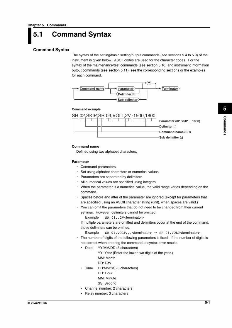
5-1IM 04L02A01-17E
Co
mm
and
s
5
Chapter 5 Commands
5.1 Command Syntax
Command SyntaxThe syntax of the setting/basic setting/output commands (see sections 5.4 to 5.9) of the
instrument is given below. ASCII codes are used for the character codes. For thesyntax of the maintenance/test commands (see section 5.10) and instrument informationoutput commands (see section 5.11), see the corresponding sections or the examples
for each command.
Command name Parameter
?
Terminator
Delimiter
Sub delimiter
SR 02,SKIP;SR 03,VOLT,2V,-1500,1800Parameter (02 SKIP ... 1800)
Delimiter (,)
Command name (SR)
Sub delimiter (;)
Command example
Command nameDefined using two alphabet characters.
Parameter• Command parameters.• Set using alphabet characters or numerical values.• Parameters are separated by delimiters.
• All numerical values are specified using integers.• When the parameter is a numerical value, the valid range varies depending on the
command.
• Spaces before and after of the parameter are ignored (except for parameters thatare specified using an ASCII character string (unit), when spaces are valid.)
• You can omit the parameters that do not need to be changed from their current
settings. However, delimiters cannot be omitted.Example SR 01,,2V<terminator>
If multiple parameters are omitted and delimiters occur at the end of the command,
those delimiters can be omitted.Example SR 01,VOLT,,,<terminator> → SR 01,VOLT<terminator>
• The number of digits of the following parameters is fixed. If the number of digits is
not correct when entering the command, a syntax error results.• Date YY/MM/DD (8 characters)
YY: Year (Enter the lower two digits of the year.)
MM: MonthDD: Day
• Time HH:MM:SS (8 characters)
HH: HourMM: MinuteSS: Second
• Channel number: 2 characters• Relay number: 3 characters

5-2 IM 04L02A01-17E
Query• A question mark is used to specify a query.
• By placing a query after a command or parameter, the setting information of thecorresponding command can be queried. Some commands cannot executequeries. For the query syntax of each command, see sections 5.4 to 5.7.
Example 1 SR[ p1]? SR? or SR p1? can be executed.Example 2 SA[ p1[,p2]]? SA?, SA p1? or SA p1,p2? can be executed.
Delimiter• A comma is used as a delimiter.• Parameters are separated by delimiters.
Sub delimiter• A semicolon is used as a sub delimiter.
• By separating each command with a sub delimiter, up to 10 commands can bespecified one after another. However, the following commands and queries cannotbe specified one after another. Use them independently.
• Output commands other than BO, CS, and IF commands.• YO command• Queries
* If there are consecutive sub delimiters, they are considered to be single. In addition, sub
delimiters at the front and at the end are ignored.
Example ;SR01,VOLT;;;SR02,VOLT;<terminator> is taken to be
SR01,VOLT;SR02,VOLT<terminator>.
Terminator (Terminating character)Use either of the following two characters for the terminator.
• CR + LF (0DH 0AH in ASCII code.)• LF (0AH in ASCII code.)
Note• Do not specify a channel or relay number that is not available on the DX. An error will occur.
• The total data length from the first character to the terminator must be less than 2047 bytes.
• Commands are not case sensitive (with the exception of user-specified character strings).
• All the commands that are listed using sub delimiters are executed even if one of the
commands is erroneous.
• Spaces that are inserted before and after a parameter are ignored. However, if spaces are
inserted before a command, after a sub delimiter, or after a query, an error occurs.
ResponseThe DX returns a response (affirmative/negative response) to a command that is
delimited by a single terminator*. The controller should follow the one command to oneresponse format. When the command-response rule is not followed, the operation is notguaranteed. For the response syntax, see section 6.1.
* Commands dedicated to RS-422/485 (see section 5.9) and instrument information output
commands (section 5.11) are exceptions.
5.1 Command Syntax

5-3IM 04L02A01-17E
Co
mm
and
s
5
5.2 A List of Commands
Setting Commands
Command Command Function Execution Administrator User Page
Type Name Mode
Setting
SR Sets the input range Operation mode Yes No 5-9
SO Sets the computing equation Operation mode Yes No 5-10
SA Sets the alarm Operation mode Yes No 5-10
SD Sets the date and time Operation mode Yes No 5-11
SW Sets the display update rate/auto-save interval Operation mode Yes No 5-11
SZ Sets the zone Operation mode Yes No 5-11
SP Sets the partial expanded display Operation mode Yes No 5-12
ST Sets the tag Operation mode Yes No 5-12
SX Sets the group Operation mode Yes No 5-12
SL Sets the trip line Operation mode Yes No 5-12
SG Sets the message Operation mode Yes No 5-13
SH Sets the file header Operation mode Yes No 5-13
SE Sets the display direction, background color, Operation mode Yes No 5-13
trend line width, trip line width, number
of grids, scroll time, and scale digit
SB Sets the number of scale divisions, base Operation mode Yes No 5-13
position of the bar graph,
and the display position of the trend scale
SV Sets the moving average of the measured channel Operation mode Yes No 5-13
SF Sets the filter Operation mode Yes No 5-14
SC Sets the channel display color Operation mode Yes No 5-14
SQ Sets the LCD brightness and the screen Operation mode Yes No 5-14
backlight saver
SY Sets the 4 screen display (only for DX200) Operation mode Yes No 5-14
SU Sets the USER key Operation mode Yes No 5-15
SK Sets the computation constant Operation mode Yes No 5-15
SI Sets the rolling average of the computation Operation mode Yes No 5-15
channel
SJ Sets the TLOG timer Operation mode Yes No 5-15
SS Set the date and time at which to switch the Operation mode Yes No 5-16
daylight savings time
FR Sets the acquiring interval to the FIFO buffer Operation mode Yes No 5-16
BA Sets the application name, the supervisor name, Operation mode Yes No 5-16
and the manager name
BB Sets the batch number, the lot number, Operation mode Yes No 5-17
automatic increment of the lot number, and the
displayed information
BC Sets the comment number and the character Operation mode Yes No 5-17
string
BD Sets the alarm delay time Operation mode Yes No 5-17
Yes: Command usable
No : Command not usable

5-4 IM 04L02A01-17E
Note• There are two execution modes on the DX. If you attempt to execute a command in a
mode that is different from the specification, a syntax error occurs. Use the DS command to
switch to the execution mode, then set or control the DX. Query commands can be executed
in either mode.
• Basic setting mode
Measurement/computation is stopped and settings are changed in this mode.
• Operation mode
As a general rule, commands other than those for the basic setting mode described above
are used in this mode.
• The administrator and user specifications in the table indicate the user level that is specified
using the login function for Ethernet communications. For details, see section 1.2.
Command Command Function Execution Administrator User Page
Type Name Mode
Control
UD Switches the screen Operation mode Yes No 5-17
PS Starts/stops measurements Operation mode Yes No 5-18
AK Confirms the alarm status (alarm acknowledge) Operation mode Yes No 5-18
EV Manual sample, manual trigger, snapshot, Operation mode Yes No 5-19
saving the display data, saving the event data
MS Writes the message (display and save) Operation mode Yes No 5-19
TL Starts/stops/resets computation (MATH)/ Operation mode Yes No 5-19
Clears the computation dropout status display
DS Switches execution modes All modes Yes No 5-19
(operation/basic setting)
LO Loads the setting data for setting commands Operation mode Yes No 5-19
LI Saves the setting data Operation mode Yes No 5-19
CM Sets the communication input data Operation mode Yes No 5-20
EM Starts/stops the e-mail transmission function Operation mode Yes No 5-20
KE Key operation command Operation mode Yes No 5-20
Yes: Command usable
No : Command not usable
Basic Setting Commands• In order to activate the settings that are changed using the basic setting
commands, the settings must be saved using the XE command. Make sure tosave the settings with the XE command before changing from the basic settingmode to the operation mode. Otherwise, new settings will not be activated.
• The settings that are returned in response to a query in the basic setting mode willcontain the new settings even if they are not saved with the XE command.However, the new settings will not be activated until they are saved. In order toactivate the new settings, the XE command must be issued as described earlier. Ifthe settings are not saved or cleared using the XE command and the executionmode is changed from the basic setting mode to the operation mode, the settingsthat are returned in response to a query will contain the settings that existed beforethey were changed.
Note• The settings that are changed using the YA/YK/YN/YQ/YS /YG/YL/YM command are
activated after saving the new settings using the XE command and rebooting the DX.
• When executing the YO command, the communication is disconnected.
5.2 A List of Commands

5-5IM 04L02A01-17E
Co
mm
and
s
5
Command Function Execution Administrator User Page
Name Mode
XA Sets alarm related settings Basic setting mode Yes No 5-20
XI Sets the A/D integral time Basic setting mode Yes No 5-21
XB Sets the burn out Basic setting mode Yes No 5-21
XJ Sets the RJC Basic setting mode Yes No 5-21
XV Sets the scan interval Basic setting mode Yes No 5-21
XT Selects the temperature unit Basic setting mode Yes No 5-21
XS Sets the channels to display the trend Basic setting mode Yes No 5-21
and acquire the data
XM Sets the conditions used to acquire Basic setting mode Yes No 5-21
display/event data to the internal memory or
save the data to the external storage medium
XU Sets the channel identification display, Basic setting mode Yes No 5-22
memory alarm time, language, whether or
not to use the partial expanded display
function and the batch function
XR Sets the remote action Basic setting mode Yes No 5-22
XQ Sets the timer Basic setting mode Yes No 5-23
RO Sets the report type and generation time Basic setting mode Yes No 5-23
RM Sets the report channel Basic setting mode Yes No 5-24
XO Selects the communication interface used to Basic setting mode Yes No 5-24
output data residing in the internal memory
(display, event, TLOG, manual sampled, and
report data) and files on the external storage
medium using output commands (ME/MI/MO commands)
XH Sets whether or not to use the key login, Basic setting mode Yes No 5-24
auto logout, and user ID functions
XE Sets whether or not to store the basic settings Basic setting mode Yes No 5-24
XG Sets the time zone Basic setting mode Yes No 5-25
XP Sets the date and time for the memory timeup Basic setting mode Yes No 5-25
YA Sets the IP address, subnet mask, and default Basic setting mode Yes No 5-25
gateway
YK Sets keepalive Basic setting mode Yes No 5-25
YN Sets the DNS Basic setting mode Yes No 5-25
YQ Sets the communication timeout Basic setting mode Yes No 5-26
YS Sets the serial interface Basic setting mode Yes No 5-26
YO Loads setting data Basic setting mode Yes No 5-26
YI Saves setting data Basic setting mode Yes No 5-26
YC Clears the measured/computed data, initializes Basic setting mode Yes No 5-26
setup data
YT Sets the FTP transfer timing Basic setting mode Yes No 5-26
YG Sets whether or not to use the Web server Basic setting mode Yes No 5-27
function
YL Sets the Modbus master Basic setting mode Yes No 5-27
YM Sets the commands for Modbus master Basic setting mode Yes No 5-27
YU Sets the contents of the e-mail Basic setting mode Yes No 5-27
YV Sets the recipient’s address Basic setting mode Yes No 5-28
YW Sets the sender’s address Basic setting mode Yes No 5-28
YX Sets the SMTP server Basic setting mode Yes No 5-28
Yes: Command usable
No : Command unusable
5.2 A List of Commands

5-6 IM 04L02A01-17E
Output Commands
Command Command Function Execution Administrator User Page
Type Name Mode
control
BO Sets the output byte order All modes Yes Yes 5-29
CS Sets the checksum (This command can be used All modes Yes Yes 5-29
only during serial communications)
IF Sets the status filter All modes Yes Yes 5-29
CC Disconnects an Ethernet connection All modes Yes Yes 5-29
(This command can be used only during
Ethernet communications)
Setup, measured, and computed data output
FC Outputs screen image data All modes Yes Yes 5-29
FE Outputs setup data All modes Yes Yes 5-29
FD Outputs the most recent measured/computed data Operation mode Yes Yes 5-30
FF Outputs FIFO data Operation mode Yes Yes 5-30
FL Outputs logs, alarm summary, and message summary All modes Yes Yes 5-30
IS Outputs status information All modes Yes Yes 5-31
FU Outputs user level All modes Yes Yes 5-31
ME Outputs data saved in the external storage Operation mode Yes No 5-31
medium (Either Ethernet or serial
communication can be used)
MI Outputs display data and event data acquired Operation mode Yes No 5-31
in the internal memory (Either Ethernet or
serial communication can be used)
MO Outputs TLOG data, manual sampled data, Operation mode Yes No 5-32
and report data acquired in the internal memory
(Either Ethernet or serial communication can
be used)
RS-422/485 dedicated commands
Esc O Opens the instrument All modes Yes Yes 5-32
Esc C Closes the instrument All modes Yes Yes 5-32
Yes: Command usable
No : Command unusable
Maintenance/Test Commands (Available when using the maintenance/test serverfunction via Ethernet communications)
Command Function Administrator User Page
close Disconnects the connection between other devices Yes No 5-33
con Outputs connection information Yes Yes 5-33
eth Outputs Ethernet statistical information Yes Yes 5-33
help Outputs help Yes Yes 5-33
net Outputs network statistical information Yes Yes 5-33
quit Disconnects the connection of the device being operated Yes Yes 5-34
Yes: Command usable
No : Command unusable
Instrument Information Output Commands (Available when using the instrumentinformation server function via Ethernet communications)
Parameter Function Page
all Outputs all information that are output using the parameters below 5-34
serial Outputs the serial number 5-34
model Outputs the manufacturer, model, and firmware version 5-34
host Outputs the host name 5-34
ip Outputs the IP address 5-34
5.2 A List of Commands

5-7IM 04L02A01-17E
Co
mm
and
s
5
5.3 Input Range Parameter
The following tables show which measurement ranges of the instrument correspond tothe input types of the SR command (input range setting command), VOLT, TC, RTD, DI,
and SQRT. The table also shows the ranges for the upper and lower limits of the span.
DC Voltage (VOLT), Square Root (SQRT)
Measurement Parameter for the Value of the Upper and Value of the Upper andRange SR Command Lower Limits of the Span Lower Limits of the SR
(Upper and Lower Limits Commandof the Measurement Range)
20 mV 20 mV –20.00 to 20.00 mV –2000 to 200060 mV 60 mV –60.00 to 60.00 mV –6000 to 6000200 mV 200 mV –200.0 to 200.0 mV –2000 to 20002 V 2 V –2.000 to 2.000 V –2000 to 20006 V 6 V –6.000 to 6.000 V –6000 to 600020 V 20 V –20.00 to 20.00 V –2000 to 200050 V 50 V –50.00 to 50.00 V –5000 to 5000
Thermocouple (TC)
Measurement Parameter for the Value of the Upper and Value of the Upper andRange SR Command Lower Limits of the Span Lower Limits of the SR
(Upper and Lower Limits Commandof the Measurement Range)
R R 0.0 to 1760.0 °C 0 to 17600S S 0.0 to 1760.0 °C 0 to 17600B B 0.0 to 1820.0 °C 0 to 18200K K –200.0 to 1370.0 °C –2000 to 13700E E –200.0 to 800.0 °C –2000 to 8000J J –200.0 to 1100.0 °C –2000 to 11000T T –200.0 to 400.0 °C –2000 to 4000N N 0.0 to 1300.0 °C 0 to 13000W W 0.0 to 2315.0 °C 0 to 23150L L –200.0 to 900.0 °C –2000 to 9000U U –200.0 to 400.0 °C –2000 to 4000
Resistance Temperature Detector (RTD)
Measurement Parameter Value of the Upper Value of the UpperRange for the SR and Lower Limits of and Lower Limits of
Command the Span (Upper and the SR CommandLower Limits of theMeasurement Range)
Pt100 PT –200.0 to 600.0 °C –2000 to 6000JPt100 JPT –200.0 to 550.0 °C –2000 to 5500Cu10 (GE)* CU1 –200.0 to 300.0 °C –2000 to 3000Cu10 (L&N)* CU2 –200.0 to 300.0 °C –2000 to 3000Cu10 (WEED)* CU3 –200.0 to 300.0 °C –2000 to 3000Cu10 (BAILEY)* CU4 –200.0 to 300.0 °C –2000 to 3000Cu10 α = 0.00392 at 20 °C* CU5 –200.0 to 300.0 °C –2000 to 3000Cu10 α = 0.00393 at 20 °C* CU6 –200.0 to 300.0 °C –2000 to 3000Cu25 α = 0.00425 at 0 °C* CU25 –200.0 to 300.0 °C –2000 to 3000
* Measurement range that can be specified on models with the Cu10, Cu25 resistancetemperature detector option /N1.

5-8 IM 04L02A01-17E
Digital Input (DI)
Measurement Parameter for the Value of the Upper and Value of the Upper andRange SR Command Lower Limits of the Span Lower Limits of the SR
(Upper and Lower Limits Commandof the Measurement Range)
Voltage LEVEL 0 or 1*1 0 or 1Contact CONT 0 or 1*2 0 or 1
*1: “0” when less than 2.4 V, “1” when greater than or equal to 2.4 V.*2: “0” when contact is OFF, “1” when contact is ON.
NoteFor the measurement accuracy of each measurement range, see the DX100/DX200 User’s
Manual (IM04L01A01-01E/IM04L02A01-01E)
5.3 Input Range Parameter
5-9IM 04L02A01-17E
Co
mm
and
s
5
5.4 Setting Commands (Setting)
5.4 Setting Commands(Setting)
SR Sets the input range
When setting channels to skipSyntax SR p1,p2<terminator>
p1 Channel number (DX100: 01 to 12,
DX200: 01 to 30)
p2 Range mode (SKIP)
Query SR[ p1]?
Example Skips channel 01.
SR 01,SKIP
Description • This command cannot be specified while
measurement/computation is in progress or
while a report is being created.
• Measurements are not made on channels that
are set to SKIP.
When setting the channels to voltage,thermocouple, RTD, or digital inputSyntax SR p1,p2,p3,p4,p5<terminator>
p1 Channel number (DX100: 01 to 12,
DX200: 01 to 30)
p2 Input type
VOLT DC VOLTAGE
TC Thermocouple
RTD Resistance temperature detector
DI Digital input
p3 Measurement range
p4 Lower limit of span
p5 Upper limit of span
Query SR[ p1]?
Example Set the input type for channel 01 to
thermocouple type R, span lower limit to
0°C, and span upper limit to 1760.0°C.
SR 01,TC,R,0,17600
Description • This command cannot be specified while
measurement/computation is in progress or
while a report is being created.
• Set parameters p3, p4, and p5 according to
the table in section 5.3.
• For parameters p4 and p5, enter a value
using 5 digits or less excluding the decimal.
The decimal position is fixed to the position
indicated in the table in section 5.3.
When computing the difference between channelsSyntax SR p1,p2,p3,p4,p5,p6,p7<terminator>
p1 Channel number (DX100: 01 to 12,
DX200: 01 to 30)
p2 Range mode (DELTA)
p3 Input type
VOLT DC VOLTAGE
TC Thermocouple
RTD Resistance temperature detector
DI Digital input
p4 Measurement range
p5 Lower limit of span
p6 Upper limit of span
p7 Reference channel (DX100: 01 to 12,
DX200: 01 to 30)
Query SR[ p1]?
Example Set the range mode of channel 10 to the
difference computation between channels
with the reference channel set to 01 and
set the input type to TC. Set the range
to R. Set the span lower limit to 10.0°C
and span upper limit to 100.0°C.
SR 10,DELTA,TC,R,100,1000,01
Description • This command cannot be specified while
measurement/computation is in progress or
while a report is being created.
• Set parameters p4, p5, and p6 according to
the table in section 5.3.
• For parameters p5 and p6, enter a value
using 5 digits or less, excluding the decimal.
The decimal position is fixed to the position
indicated in the table in section 5.3.
When setting the scalingSyntax SR p1,p2,p3,p4,p5,p6,p7,p8,p9,p10
<terminator>
p1 Channel number (DX100: 01 to 12,
DX200: 01 to 30)
p2 Range mode (SCALE)
p3 Input type
VOLT DC VOLTAGE
TC Thermocouple
RTD Resistance temperature detector
DI Digital input
p4 Measurement range
p5 Lower limit of span
p6 Upper limit of span
p7 Scaling lower limit (-30000 to 30000)
p8 Scaling upper limit (-30000 to 30000)
p9 Scaling decimal position (0 to 4)
p10 Unit (Up to 6 characters)
Query SR[ p1]?
Example Convert the DC voltage measured on
channel 02 to a DC current. Set the
measurement range to 6 V, span lower
limit to 1 V, span upper limit to 5 V,
scaling lower limit to 1.00 A, and
scaling upper limit to 5.00 A.
SR 02,SCALE,VOLT,6V,1000,5000,100,500,2,A
Description • This command cannot be specified while
measurement/computation is in progress or
while a report is being created.
• Set parameters p4, p5, and p6 according to
the table in section 5.3.

5-10 IM 04L02A01-17E
• For parameters p5 and p6, enter a value
using 5 digits or less excluding the decimal.
The decimal position is fixed to the position
indicated in the table in section 5.3.
• For parameters p7, p8, and p9, either set all
three parameters or omit all three parameters.
When setting the square rootSyntax SR p1,p2,p3,p4,p5,p6,p7,p8,p9<terminator>
p1 Channel number (DX100: 01 to 12,
DX200: 01 to 30)
p2 Range mode (SQRT)
p3 Measurement range
p4 Lower limit of span
p5 Upper limit of span
p6 Scaling lower limit
(-30000 to 30000)
p7 Scaling upper limit
(-30000 to 30000)
p8 Scaling decimal position (0 to 4)
p9 Unit (Up to 6 characters)
Query SR[ p1]?
Example Convert the DC voltage measured on
channel 01 to the amount of flow using
the square root computation. Set the
measurement range to 6 V, span lower
limit to 1 V, span upper limit to 5 V,
scaling lower limit to 10.0 m3/s, and
scaling upper limit to 100.0 m3/s.
SR 01,SQRT,6V,1000,5000,100,1000,1,m3/S
Description • This command cannot be specified while
measurement/computation is in progress or
while a report is being created.
• Set parameters p3, p4, and p5 according to
the table in section 5.3.
• For parameters p4 and p5, enter a value
using 5 digits or less excluding the decimal.
The decimal position is fixed to the position
indicated in the table in section 5.3.
• For parameters p6, p7, and p8, either set all
three parameters or omit all three parameters.
SO Sets the computing equationSyntax SO p1,p2,p3,p4,p5,p6,p7<terminator>
p1 Computation channel number (DX100: 31
to 42, DX200: 31 to 60)
p2 Turn ON/OFF computation
p3 Computing equation (Up to 40
characters)
p4 Lower limit of span(–9999999 to
99999999)
p5 Upper limit of span(–9999999 to
99999999)
p6 Decimal position of span (0 to 4)
p7 Unit (Up to 6 characters)
Query SO[ p1]?
Example Set the computation channel to 31, the
computation to ON, the computing equation
to the sum of channel 01 and 02, span
lower limit to –10.0000, span upper limit
to 15.0000, and the unit to V.
SO 31,ON,01+02,–100000,150000,4,V
Description • This command can be used on models with
the computation function option /M1.
• This command cannot be specified while
measurement/computation is in progress or
while a report is being created.
• For computing equations, see the DX100/
DX200 User’s Manual.
• For parameters p4 and p5, enter a value
using 7 digits or less ,excluding the decimal,
for negative numbers and 8 digits or less for
positive numbers.
• For parameters p4, p5, and p6, either set all
three parameters or omit all three parameters.
SA Sets the alarm
When not using the alarmSyntax SA p1,p2,p3<terminator>
p1 Channel number (DX100: 01 to 12 or 31
to 42, DX200: 01 to 30)
p2 Alarm number (1 to 4)
p3 Alarm ON/OFF state (OFF)
Query SA[ p1[,p2]]?
Example Set off the alarm number 1 of channel 10.
SA 10,1,OFF
Description Computation channels (DX100: 31 to 42, DX200:
31 to 60) can be configured on products with the
computation function option /M1.
When using the alarmSyntax SA p1,p2,p3,p4,p5,p6,p7<terminator>
p1 Channel number (DX100: 01 to 12 or 31
to 42, DX200: 01 to 30)
p2 Alarm number (1 to 4)
p3 Alarm ON/OFF state (ON)
p4 Alarm type
H Upper limit alarm
L Lower limit alarm
h Difference upper-limit alarm
l Difference lower-limit alarm
R Upper limit on rate-of-change alarm
r Lower limit on rate-of-change alarm
T Delay upper limit alarm
t Delay lower limit alarm
(Upper and lower case letters are
distinguished.)
p5 Alarm value
p6 Relay setting
ON Relay setting ON
OFF Relay setting OFF
5.4 Setting Commands (Setting)
5-11IM 04L02A01-17E
Co
mm
and
s
5
p7 Relay number (DX100: I01 to I06,
DX200: I01 to I06/ I11 to I16/ I21 to
I26, I31 to I36)
Query SA[ p1[,p2]]?
Example Set an upper limit alarm (alarm value =
1000) in alarm number 1 of channel 02,
and activate relay number 1 when an alarm
occurs.
SA 02,1,ON,H,1000,ON,I01
Description • When the input range setting (SR command)
is set to SKIP, p3 cannot be turned ON.
• When the computation channel setting (SO
command) is turned OFF, p3 cannot be
turned ON.
• The alarm settings are all turned OFF for the
following cases.
• When the input type is changed (VOLT,
TC······).
• When the measurement range is changed.
• When the span and scaling values are
changed during scaling display (includes
changing the decimal position).
• When the computation channel is turned
ON/OFF or when the computing equation
or the span value is changed on the
computation channel.
• The h and l settings of p4 are valid only when
the measurement range is set to computation
between channels.
• If p4 is set to R or r, set the interval for the
upper/lower limit on the rate-of-change using
the XA command.
• If p4 is set to T or t, set the alarm delay time
for the delay upper/lower limit alarm using the
BD command.
• For the range of alarm values of p5, see the
table in section 5.3.
• Set the alarm value of a computation channel
within the range of the span.
• For the alarm value of p5, enter a value using
5 digits or less, excluding the decimal. For
computation channels, enter a value using 8
digits or less, excluding the decimal.
• An error occurs if a number of a relay that is
not installed is specified in p7. For the
procedures used to set the relay numbers,
see the DX100/DX200 User’s Manual.
• Computation channels (DX100: 31 to 42,
DX200: 31 to 60) can be configured on
products with the computation function option
/M1.
• For computation channels, the alarm types
that can be specified are only H (upper limit
alarm), L (lower limit alarm), T (delay upper
limit alarm), and t (delay lower limit alarm).
• For computation channels, the alarm
hysteresis is fixed to zero. Use the XA
command to set the alarm hysteresis.
SD Sets the date and timeSyntax SD p1,p2<terminator>
p1 Date (YY/MM/DD fixed form)
YY Year (00 to 99)
MM Month (01 to 12)
DD Day (01 to 31)
p2 Time (HH/MM/SS fixed form)
HH Hour (00 to 23)
MM Minute (00 to 59)
SS Second (00 to 59)
Query SD?
Example Set the internal clock to 13:00:00,
October 1, 1999.
SD 99/10/01,13:00:00
Description The form of p1 and p2 is fixed to 8 characters.
Use the following form. Do not enter spaces in
between the digits, as an error will occur.
p1 = YY/MM/DD (Lower two digits of the year/
month/day)
p2 = HH:MM:SS (Hour:minute:second)
SW Sets the display update rate/auto-save interval
Syntax SW p1,p2<terminator>
p1 Display update rate (15s, 30s, 1MIN,
2MIN, 5MIN, 10MIN, 20MIN, 30MIN, 1H,
2H, 4H, 10H)
p2 Auto-save interval (10MIN, 20MIN,
30MIN, 1H, 2H, 3H, 4H, 6H, 8H, 12H,
1DAY, 2DAY, 3DAY, 5DAY, 7DAY, 10DAY,
14DAY, 31DAY)
Query SW?
Example Set the display update rate to one minute
and the auto-save interval to 10 minutes.
SW 1MIN,10MIN
Description • This command cannot be specified while
measurement is in progress.
• The selectable auto-save interval (p2) varies
depending on the display update rate (p1)
setting. For details, see the DX100/DX200
User’s Manual.
• 15S and 30S of p1 apply only to models
DX102, DX104, DX204, and DX208.
• The p2 setting is valid when the saving
method to the external storage medium is set
to auto using the XM command (p1 of the XM
command is set to AUTO).
SZ Sets the zoneSyntax SZ p1,p2,p3<terminator>
p1 Channel number (DX100: 01 to 12 or 31
to 42, DX200: 01 to 30)
p2 Zone lower limit (0 to 95)[%]
5.4 Setting Commands (Setting)
5-12 IM 04L02A01-17E
p3 Zone upper limit (5 to 100)[%]
Query SZ[ p1]?
Example Display channel 02 in a zone between 30%
and 50%.
SZ 02,30,50
Description • Computation channels (DX100: 31 to 42,
DX200: 31 to 60) can be configured on
products with the computation function option
/M1.
• The total display width of the screen in the
direction of the amplitude is taken to be 100%.
• The zone width must be at least 5%.
• Set the parameters for the zone upper and
lower limits so that the upper limit is greater
than the lower limit.
SP Sets the partial expandeddisplay
Syntax SP p1,p2,p3,p4<terminator>
p1 Channel number (DX100: 01 to 12 or 31
to 42, DX200: 01 to 30)
p2 Enable/disable (ON/OFF) the partial
expansion setting.
p3 Boundary position (1 to 99)[%]
p4 Boundary value
Query SP[ p1]?
Example Partially expand the display of channel
01. Set the boundary position to 25% and
the boundary value to 1.00 V.
SP 01,ON,25,100
Description • Computation channels (DX100: 31 to 42,
DX200: 31 to 60) can be configured on
products with the computation function option
/M1.
• When the input range setting (SR command)
is set to SKIP, p2 cannot be turned ON.
• When the computation channel setting (SO
command) is turned OFF, p2 cannot be
turned ON.
• The range of the upper and lower limits of the
span (scaling upper and lower limits when
scaling is enabled) is taken to be 100% for
parameter p3.
• Parameter p4 can be set in the range (span
upper limit –1) to (span lower limit +1). If
scaling is enabled, the range is (scaling upper
limit –1) to (scaling lower limit +1).
• The decimal position and the number of digits
become the same as the span and scaling
settings (see the SR command).
• This command cannot be specified unless the
partial expanded display function (p4) of the
XU command is set to USE.
• This command cannot be specified if the
partial expanded display range does not exist
(when the span width is set to 1, for example).
ST Sets the tagSyntax ST p1,p2<terminator>
p1 Channel number (DX100: 01 to 12 or 31
to 42, DX200: 01 to 30)
p2 Tag (Up to 16 characters)
Query ST[ p1]?
Example Set the tag of channel 02 to TAG2.
ST 02,TAG2
Description • For the characters that can be used for the
tags, see appendix 1, “ASCII Character
Codes.” Note that semicolons and commas
cannot be used.
• Computation channels (DX100: 31 to 42,
DX200: 31 to 60) can be configured on
products with the computation function option
/M1.
SX Sets the groupSyntax SX p1,p2,p3<terminator>
p1 Group number (1 to 4)
p2 Group name (Up to 16 characters)
p3 Channel construction
Query SX[ p1]?
Example Set channels 01, 03, 04 to 06 to group
number 1, and group name is GROUP2.
SX 1,GROUP2,01.03.04-06
Set the channel configuration by using
periods "." to separate each channel or
by using a hyphen "-" to specify a range
of channels.
Description • An error occurs if a number of a channel that
is not installed in the instrument is specified.
• An error occurs if a number of a computation
channel that is not provided on the instrument
is specified.
• For the characters that can be used for the
group name, see appendix 1, “ASCII
Character Codes.” Note that semicolons and
commas cannot be used.
SL Sets the trip lineSyntax SL p1,p2,p3,p4,p5<terminator>
p1 Group number (1 to 4)
p2 Number of trip line (1 to 4)
p3 Turn ON/OFF the trip line display
p4 Display position (0 to 100)[%]
p5 Display color (RED, GREEN, BLUE,
B.VIOLET, BROWN, ORANGE, Y.GREEN,
LIGHTBLUE, VIOLET, GRAY, LIME, CYAN,
DARKBLUE, YELLOW, LIGHTGRAY, PURPLE)
Query SL[ p1[,p2]]?
Example Display trip line 1 in red for group 1.
SL 1,1,ON,RED
Description The total display width of the screen in the
direction of the amplitude is taken to be 100%.
5.4 Setting Commands (Setting)

5-13IM 04L02A01-17E
Co
mm
and
s
5
SG Sets the messageSyntax SG p1,p2<terminator>
p1 Message number (1 to 8)
p2 Message (Up to 16 characters)
Query SG[ p1]?
Example Set character string "MESSAGE1" in
message number 1.
SG 1,MESSAGE1
Description For the characters that can be used for the
message, see appendix 1, “ASCII Character
Codes.” Note that semicolons and commas
cannot be used.
SH Sets the file headerSyntax SH p1,p2,p3<terminator>
p1 Header for the files saved to the
external storage medium (Up to 32
characters)
p2 Directory (Up to 8 characters)
p3 Data to be saved to the external
storage medium (UNSAVE, ALL)
Query SH?
Example Add a header, DATA1 and save the file to
the DATAFILE directory. Save only the
data in the internal memory that has not
been saved.
SH DATA1,DATAFILE,UNSAVE
Description • “Data to be saved to the external storage
medium” includes the display, event, TLOG,
manual sampled, and report data.
• Parameter p3 is valid when the saving method
to the external storage medium is set to
manual using the XM command (parameter
p1 of the XM command is set to MANUAL).
SE Sets the display direction,background color, trend linewidth, trip line width, number ofgrids, scroll time, and scale digit
Syntax SE p1,p2,p3,p4,p5,p6,p7,p8<terminator>
p1 Display direction of the trend
waveform (HORIZONTAL, VERTICAL,
HORIZON2)
p2 Display direction of the bar graph
waveform (HORIZONTAL, VERTICAL)
p3 Background color (WHITE, BLACK)
p4 The line width of the trend (1 to
3)[dot]
p5 The width of the trip line (1 to
3)[dot]
p6 Number of grids (4 to 12, AUTO)
p7 The time interval (scroll time) for
switching displayed group (5s, 10s,
20s, 30s, 1min)
p8 Scale digit (NORMAL, FINE)
Query SE?
Example Set the display direction of the trend
waveform to horizontal, the direction of
the bar graph to vertical, the background
color to white, the line width of the
trend to 1 dot, the width of the trip
line to 2 dots, the number of grids to
10, the time interval for switching
displayed group to 20s, and the scale
digit to NORMAL.
SE HORIZONTAL,VERTICAL,WHITE,1,2,10,20s,
NORMAL
SB Sets the number of scaledivisions, base position of thebar graph, and the displayposition of the trend scale
Syntax SB p1,p2,p3,p4<terminator>
p1 Channel number (DX100: 01 to 12 or 31
to 42, DX200: 01 to 30)
p2 Number of scale divisions (4 to 12,
C10)
p3 Base position of the bar graph
display (NORMAL, CENTER)
p4 Position of the scale for the trend
display (OFF, DX100: 1 to 6, DX200: 1
to 10)
Query SB[ p1]?
Example Set the number of scale divisions of the
bar graph of channel 02 to 5, and display
the bar graph from the span lower limit
(scaling lower limit if scaling is
enabled). Display the scale at the third
position.
SB 02,5,NORMAL,3
Description • Computation channels (DX100: 31 to 42,
DX200: 31 to 60) can be configured on
products with the computation function option
/M1.
• The base position (p3) is valid when the
display direction of the bar graph is set to
HORIZONTAL. Use the SE command to set
the display direction of the bar graph.
SV Sets the moving average of themeasured channel
Syntax SV p1,p2<terminator>
p1 Channel number (DX100: 01 to 12,
DX200: 01 to 30)
p2 Number of times to measure the moving
average (OFF, 2 to 16) [times]
Query SV[ p1]?
Example Set the number of times to measure the
moving average on channel 02 to 12.
SV 02,12
Description This command can be used on models DX106,
DX112, DX210, DX220, and DX230.
5.4 Setting Commands (Setting)

5-14 IM 04L02A01-17E
SF Sets the filterSyntax SF p1,p2<terminator>
p1 Channel number (DX100: 01 to 04,
DX200: 01 to 08)
p2 Filter (OFF, 2S, 5S, 10S)
Query SF[ p1]?
Example Set the filter on channel 02 to 2 s.
SF 02,2s
Description • An error occurs if a channel number other
than those shown above is specified.
• This command can be used on models
DX102, DX104, DX204 and DX208.
SC Sets the channel display colorSyntax SC p1,p2<terminator>
p1 Channel number (DX100: 01 to 12 or 31
to 42, DX200: 01 to 30)
p2 Display color (RED, GREEN, BLUE,
B.VIOLET, BROWN, ORANGE, Y.GREEN,
LIGHTBLUE, VIOLET, GRAY, LIME, CYAN,
DARKBLUE, YELLOW, LIGHTGRAY, PURPLE)
Query SC[ p1]?
Example Set the display color of channel 02 to
blue.
SC 02,BLUE
Description Computation channels (DX100: 31 to 42, DX200:
31 to 60) can be configured on products with the
computation function option /M1.
SQ Sets the LCD brightness and thescreen backlight saver
When the screen backlight saver function is OFFSyntax SQ p1,p2<terminator>
p1 LCD brightness (DX100: 1 to 8, DX200:
1 to 4)
p2 Screen backlight saver function ON/
OFF (OFF)
Query SQ?
Example Set the LCD brightness to 2 and the
screen backlight saver function to OFF.
SQ 2,OFF
When the screen backlight saver function is ONSyntax SQ p1,p2,p3,p4<terminator>
p1 LCD brightness (DX100: 1 to 8, DX200:
1 to 4)
p2 Screen backlight saver function ON/
OFF (ON)
p3 Time after which to enable the screen
saver function (1MIN, 2MIN, 5MIN,
10MIN, 30MIN, 1H)
p4 Factors that causes the screen to
return from the saver mode (KEY,
KEY+ALM)
Query SQ?
Example Set the LCD brightness to 2, the screen
backlight saver function to ON, the time
after which to enable the screen
backlight saver function to 1MIN, and the
factor that causes the screen to return
from the saver mode to KEY.
SQ 2,ON,1MIN,KEY
SY Sets the 4 screen display (onlyfor DX200)
Syntax SY p1,p2,p3,p4,p5,p6,p7,p8,p9,
p10<terminator>
p1 Four screen display number (1 to 4)
p2 Four screen display name (Up to 16
characters)
p3 The display item of the upper left
quadrant of the divided screen
(screen 1)
TREND Trend display
DIGITAL Digital display
BAR Bar graph display
OVERVIEW Overview display
(Alarm indicator)
ALARM Alarm summary display
MESSAGE Message summary display
MEMORY Memory summary display
MEDIA Medium summary display
p4 The group number (1 to 4) to display
in the upper left quadrant of the
divided screen (screen 1)
p5 The display item of the lower left
quadrant of the divided screen
(screen 2), same as the selections
for p3.
p6 The group number (1 to 4) to display
in the lower left quadrant of the
divided screen (screen 2)
p7 The display item of the upper right
quadrant of the divided screen
(screen 3), same as the selections
for p3.
p8 The group number (1 to 4) to display
in the upper right quadrant of the
divided screen (screen 3)
p9 The display item of the lower right
quadrant of the divided screen
(screen 4), same as the selections
for p3.
p10 The group number (1 to 4) to display
in the lower right quadrant of the
divided screen (screen 4)
Query SY?
Example Set the four screen display number to 1,
four screen display name to 4DISPLAY1,
the display item of screen 1 to trend
display, the group number to display in
screen 1 to 1, the display item of screen
5.4 Setting Commands (Setting)

5-15IM 04L02A01-17E
Co
mm
and
s
5
2 to digital display, the group number to
display in screen 2 to 2, the display
item of screen 3 to bar graph display,
the group number to display in screen 3
to 3, the display item of screen 4 to
message summary display, and the group
number to display in screen 4 to 4,
SY 1,4DISPLAY1,TREND,1,DIGITAL,2,BAR,3,
MESSAGE,4
Description The p4, p6, p8, and p10 parameters are valid
when p3, p5, p7, and p9 are set to a display
other the OVERVIEW, respectively.
SU Sets the USER keySyntax SU p1<terminator>
p1 Key action
NONE No action
ALARM ACK Alarm acknowledge
MANUAL SAMPLE
Manual sampling
TRIGGER External trigger input
(Event data)
MESSAGE1 Write message 1
MESSAGE2 Write message 2
MESSAGE3 Write message 3
MESSAGE4 Write message 4
MESSAGE5 Write message 5
MESSAGE6 Write message 6
MESSAGE7 Write message 7
MESSAGE8 Write message 8
SNAPSHOT Snapshot of the screen
MATH START/STOP
Start/Stop MATH
MATH RESET Reset MATH
Query SU?
Example Set the key action to the snapshot of the
screen.
SU SNAPSHOT
SK Sets the computation constantSyntax SK p1,p2<terminator>
p1 Computation constant number (DX100:
K01 to K12, DX200: K01 to K30)
p2 Constant (Up to 11 characters)
The range is –9.9999E+29 to –1.0000E
–30, 0, and 1.0000E–30 to 9.9999E+29.
(The + sign of "E+" can be omitted.)
Query SK[ p1]?
Example Set constant 1.0000E-10 for computation
constant number K01.
SK K01,1.0000E-10
Description • This command can be used on models with
the computation function option /M1.
• This command cannot be specified while
measurement/computation is in progress or
while a report is being created.
SI Sets the rolling average of thecomputation channel
When the rolling average of a computationchannel is OFFSyntax SI p1,p2<terminator>
p1 Computation channel number (DX100: 31
to 42, DX200: 31 to 60)
p2 Rolling average ON/OFF (OFF)
Query SI[ p1]?
Example Turn OFF the rolling average of
computation channel number 31.
SI 31,OFF
Description This command can be used on models with the
computation function option /M1.
When the rolling average of a computationchannel is ONSyntax SI p1,p2,p3,p4<terminator>
p1 Computation channel number (DX100: 31
to 42, DX200: 31 to 60)
p2 Rolling average ON/OFF (ON)
p3 Sampling interval (1S, 2S, 3S, 4S,
5S, 6S, 10S, 12S, 15S, 20S, 30S,
1MIN, 2MIN, 3MIN, 4MIN, 5MIN, 6MIN,
10MIN, 12MIN, 15MIN, 20MIN, 30MIN,
1H)
p4 Number of samples (1 to 64)
Query SI[ p1]?
Example Turn the rolling average of computation
channel 31 ON, set the sampling interval
to 1 minute, and the number of samples to
20.
SI 31,ON,1MIN,20
Description This command can be used on models with the
computation function option /M1.
SJ Sets the TLOG timerSyntax SJ p1,p2,p3<terminator>
p1 Computation channel number (DX100: 31
to 42, DX200: 31 to 60)
p2 Timer (1 to 3)
p3 Conversion of the time unit for TLOG.
SUM computation
OFF No conversion.
/S Convert to a physical amount in
unit of seconds that are
integrated.
/MIN Convert to a physical amount in
unit of minutes that are
integrated.
/H Convert to a physical amount in
unit of hours that are
integrated.
Query SJ[ p1]?
Example Set timer 1 to computation channel number
31. No conversion of time unit.
SJ 31,1
5.4 Setting Commands (Setting)

5-16 IM 04L02A01-17E
Description • This command can be used on models with
the computation function option /M1.
• This command cannot be specified while
computation is in progress.
• About p3
In the sum computation, sampled data are
summed over the scan interval. However,
when a physical value is measured over a
period of time, the actual value may not match
the computed result. (This is due to the fact
that the scan interval and the time unit are
different.) In these cases, set p3 to the same
unit as the time unit of the physical value.
The summed value is calculated according to
the following converting equation depending
on the parameter.
OFF ∑(measured value)
/S ∑(measured value) x scan interval
/MIN ∑(measured value) x scan interval/
60
/HOUR ∑(measured value) x scan interval/
3600
The scan interval unit is in seconds.
SS Sets the date and time at whichto switch the daylight savingstime
When the switching the daylight savings time isOFFSyntax SS p1,p2<terminator>
p1 Summer time or winter time (SUMMER,
WINTER)
p2 Enable/disable (ON/OFF) the switching
(OFF)
Query SS[ p1]?
Example Set the summer time is OFF.
SS SUMMER,OFF
Description This command can be used on models with the
display language code “-2.”
When the switching the daylight savings time isONSyntax SS p1,p2,p3<terminator>
p1 Summer time or winter time (SUMMER,
WINTER)
p2 Enable/disable (ON/OFF) the switching
(ON)
p3 Date and time (yy/mm/dd hh fixed
form. Insert a space between dd and
hh.)
yy Year (00 to 99)
mm Month (01 to 12)
dd Day (01 to 31)
hh Hour (00 to 23)
Query SS[ p1]?
Example Set the summer time to the 23rd hour of
June 30, 2000.
SS SUMMER,ON,00/06/30 23
(The 23rd hour of June 30, 2000 is set to
0 hour of July 1, 2000.)
Description This command can be used on models with the
display language code “-2.”
FR Sets the acquiring interval to theFIFO buffer
Syntax FR p1<terminator>
p1 FIFO acquiring interval (125MS,
250MS, 500MS, 1S, 2S)
Query FR?
Example Set the FIFO acquiring interval to 1 s.
FR 1S
Description • 125 MS, 250 MS, and 500 MS apply only to
models DX102, DX104, DX204, and DX208.
• Set the acquiring interval to a value greater
than the scan interval.
• If the scan interval is set to a value less than
the acquiring interval using the XV command
or from the screen, the acquiring interval is
automatically set equal to the scan interval.
• The DX has a circular FIFO buffer. The
measured/computed values are acquired to
the internal memory at predetermined time
intervals from the time the power is turned
ON, and the data are output when a FF
command is received. The previous output
position is held for each connection and is
updated when the next set of data is output
with the FF command. Using this
functionality, data can be collected without
data dropouts if the PC reads the data in the
circular buffer before the data are
overacquired. This compensates for the
communication time differences that result
from periodically retrieving data from the DX
at a rate determined by the processing power
of the measurement PC. For the output flow
of FIFO data, see appendix 4.
BA Sets the application name, thesupervisor name, and themanager name
Syntax BA p1,p2,p3<terminator>
p1 Application name (Up to 16
characters)
p2 Supervisor name (Up to 16 characters)
p3 Manager name (Up to 16 characters)
Query BA?
Example Set the application name to "A", the
supervisor name to "B", and the manager
name to "c."
BA A,B,C
Description This command can be used on models with the
batch function option /BT1.
5.4 Setting Commands (Setting)

5-17IM 04L02A01-17E
Co
mm
and
s
5
BB Sets the batch number, the lotnumber, automatic increment ofthe lot number, and thedisplayed information
Syntax BB p1,p2,p3,p4<terminator>
p1 Batch number (Up to 16 characters)
p2 Lot number (0 to 9999)
p3 Enable/disable automatic increment of
the lot number (ON, OFF)
p4 Displayed information (BATCH, TIME)
Query BB?
Example Set the batch number to "LOT", the lot
number to "2", enable automatic increment
of the lot number, and set the displayed
information to "BATCH."
BB LOT,2,ON,BATCH
Description This command can be used on models with the
batch function option /BT1.
BC Sets the comment number andthe character string
Syntax BC p1,p2<terminator>
p1 Comment number (1 to 3)
p2 Character string (Up to 32
characters)
Query BC?
Example Set the character string "COMMENT" to the
comment number 1.
BC 1,COMMENT
Description This command can be used on models with the
batch function option /BT1.
BD Sets the alarm delay time
Syntax BD p1,p2<terminator>
p1 Channel number (01 to 60)
p2 Alarm delay time (1 to 3600)[s]
Query BD[ p1]?
Example Set the alarm delay time for channel 01
to 120 s.
BD 01,120
5.5 Setting Commands(Control)
UD Switches the screen.
When switching the screen back to the screen thatexisted before settings were changed using thecommunication commands.Syntax UD p1<terminator>
p1 Switching the screen (0)
Example Switch the screen back to the screen that
existed before settings were changed
using communication commands.
UD 0
When changing to 1 screen displaySyntax UD p1,p2,p3<terminator>
p1 Switching the screen (1)
p2 Display item
TREND Trend display
DIGITAL Digital display
BAR Bar graph display
OVERVIEW Overview display
(Alarm indicator)
ALARM Alarm summary display
MESSAGE Message summary display
MEMORY Memory summary display
p3 Group number (1 to 4)
Example Set the display to 1 screen display,
display the trend, and set the group
number to 4.
UD 1,TREND,4
When switching to 4 screen display (only forDX200)Syntax UD p1,p2,p3,p4,p5,p6,p7,p8,p9<terminator>
p1 Switching the screen (2)
p2 The display item of the upper left
quadrant of the divided screen
(screen 1)
TREND Trend display
DIGITAL Digital display
BAR Bar graph display
OVERVIEW Overview display
(Alarm indicator)
ALARM Alarm summary display
MESSAGE Message summary display
MEMORY Memory summary display
p3 The group number (1 to 4) to display
in the upper left quadrant of the
divided screen (screen 1)
p4 The display item of the lower left
quadrant of the divided screen
(screen 2), same as the selections
for p2.
5.4 Setting Commands (Setting)/5.5 Setting Commands (Control)

5-18 IM 04L02A01-17E
p5 The group number (1 to 4) to display
in the lower left quadrant of the
divided screen (screen 2)
p6 The display item of the upper right
quadrant of the divided screen
(screen 3), same as the selections
for p2.
p7 The group number (1 to 4) to display
in the upper right quadrant of the
divided screen (screen 3)
p8 The display item of the lower right
quadrant of the divided screen
(screen 4), same as the selections
for p2.
p9 The group number (1 to 4) to display
in the lower right quadrant of the
divided screen (screen 4)
Example Set the screen to four screen display,
the display item of screen 1 to trend
display, the group number to display in
screen 1 to 1, the display item of screen
2 to digital display, the group number to
display in screen 2 to 2, the display
item of screen 3 to bar graph display,
the group number to display in screen 3
to 3, the display item of screen 4 to
message summary display, and the group
number to display in screen 4 to 4,
UD 2,TREND,1,DIGITAL,2,BAR,3,MESSAGE,4
Description The p3, p5, p7, and p9 parameters are valid
when p2, p4, p6, and p8 are set to a display
other the OVERVIEW, respectively.
When displaying the 4 screen display set with theSY command (only for DX200)Syntax UD p1,p2<terminator>
p1 Switching the screen (3)
p2 4 screen display number (0 to 4)
0 Set the screen to the 4 screen
display of which parameter p1 was
set to 2 with the UD command.
This setting (p1 = 3, p2 = 0) is
valid only when the 4 screen
display is enabled by setting p1
to 2 beforehand.
1 Display the screen of 4 screen
display number 1 that was
specified with the SY command.
2 Display the screen of 4 screen
display number 2 that was
specified with the SY command.
3 Display the screen of 4 screen
display number 3 that was
specified with the SY command.
4 Display the screen of 4 screen
display number 4 that was
specified with the SY command.
Example Display the screen of 4 screen display
number 1 that was specified with the SY
command.
UD 3,1
When turning ON or OFF automatic switching ofthe displayed groups, switching to all channeldisplay from group display or vice versa, turningON or OFF the scales, and turning ON or OFF thenumerical section on the trend screenSyntax UD p1,p2,p3,p4,p5<terminator>
p1 Switching the screen (4)
p2 Enables/disables automatic switching
of the displayed groups (ON, OFF)
p3 Switches all channel display and
group display (ALL, GROUP)
p4 Turns the scale display ON/OFF (ON/
OFF)
p5 Turns the numerical display section
ON/OFF (ON, OFF)
Example Enables the automatic switching of the
displayed groups, switches to group
display from all channel display, turns
ON the scale display, and turns OFF the
numerical section.
UD 4,ON,GROUP,ON,OFF
Description • Parameter p2 is valid on the trend, digital, or
bar graph screens. Automatically switches
the displayed groups. Use the SE command
to set the switching interval (scroll time).
• Parameters p3 and p4 are valid on the trend
screen.
• Parameter p5 is valid on the trend screen or
on the trend screen on the 4 screen display.
PS Starts/Stops measurementsSyntax PS p1<terminator>
p1 Starts/Stops measurements
0 Start
1 Stop
Example Start measurement.
PS 0
Description Acquires the display, event, and report data to
the internal memory when the measurement is
started.
AK Confirms the alarm status(alarm acknowledge)
Syntax AK p1<terminator>
p1 Executes alarm acknowledge (0)
Example Confirm the current held condition of the
alarm (executes alarm acknowledge).
AK 0
5.5 Setting Commands (Control)

5-19IM 04L02A01-17E
Co
mm
and
s
5
EV Manual sample, Manual trigger,snapshot, saving display data,and saving event data
Syntax EV p1<terminator>
p1 Operation type
0 Perform manual sampling.
1 Activate manual trigger.
2 Snapshot.
3 Save the display data to the
storage medium.
4 Save the event data to the
storage medium.
Example Perform manual sampling.
EV 1
Description • EV3 is valid when display data are being
acquired to the internal memory, and the
DX100/DX200 is set to store the data to the
external storage medium using auto save.
The display data residing in the internal
memory can be stored to the external storage
medium at arbitrary times.
• EV4 is valid when event data are being
acquired to the internal memory in the free
mode, and the DX100/DX200 is set to store
the data to the external storage medium using
auto save. The event data residing in the
internal memory can be stored to the external
storage medium at arbitrary times.
MS Writes the message (display andsave)
Syntax MS p1<terminator>
p1 Message number (1 to 8)
Example Write the message of message number 8.
MS 8
Description This command displays the message to the
screen and writes the message into the display
data and event data.
TL Starts/stops/resets computation(MATH)/Clears the computationdropout status display
Syntax TL p1<terminator>
p1 Operation type
0 Start computation
1 Stop computation
2 Reset computation
3 Clear the computation dropout
status display
Example Start computation.
TL 0
Description • This command cannot be executed while
setup data are being saved or loaded.
• This command can be used on models with
the computation function option /M1.
DS Switches execution modes(operation/basic setting)
Syntax DS p1<terminator>
p1 Execution modes
0 Operation mode
1 Basic setting mode
Example Set the mode to basic setting mode.
DS 1
Description • The setting p1 to 1 cannot be specified while
measurement/computation is in progress,
while the external storage medium is being
formatted, or while data are being saved to
the external storage medium.
• The setting p1 to 0 cannot be specified while
the external storage medium is being
formatted or while data are being saved to the
external storage medium.
• In order to activate the settings that are
changed using the basic setting commands,
the settings must be saved using the XE
command. Make sure to save the settings
with the XE command before changing from
the basic setting mode to the operation mode.
Otherwise, new settings will not be activated.
LO Loads the setting data forsetting commands
Syntax LO p1<terminator>
p1 File name (Up to 8 characters)
Example Load the setting data of setting commands
from the setup file SETFILE1 (.PNL
extension).
LO SETFILE1
Description • This command cannot be used to load the
setting data of the basic setting commands.
In order to load the setting data of both setting
and basic setting commands, use the YO
command.
• This command cannot be specified on models
that do not have an external storage device or
when a medium is not inserted into the drive.
LI Saves the setting dataSyntax LI p1<terminator>
p1 File name (Up to 8 characters)
Example Save the setting data of both setting and
basic setting commands to the file
SETFILE2.
LI SETFILE2
Description • A file extension “.PNL” is attached to the
saved file. This command is equivalent to the
YI command.
• This command cannot be specified on models
that do not have an external storage device or
when a medium is not inserted into the drive.
5.5 Setting Commands (Control)
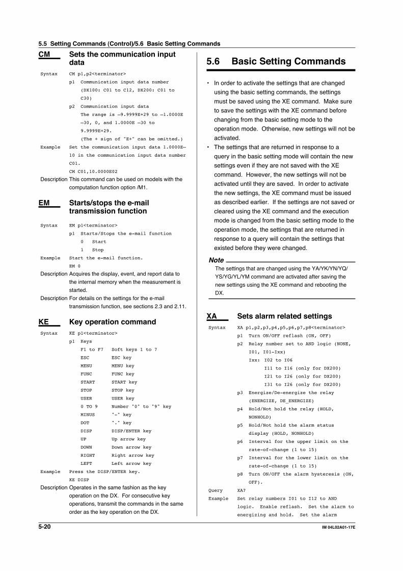
5-20 IM 04L02A01-17E
CM Sets the communication inputdata
Syntax CM p1,p2<terminator>
p1 Communication input data number
(DX100: C01 to C12, DX200: C01 to
C30)
p2 Communication input data
The range is –9.9999E+29 to –1.0000E
–30, 0, and 1.0000E –30 to
9.9999E+29.
(The + sign of "E+" can be omitted.)
Example Set the communication input data 1.0000E–
10 in the communication input data number
C01.
CM C01,10.0000E02
Description This command can be used on models with the
computation function option /M1.
EM Starts/stops the e-mailtransmission function
Syntax EM p1<terminator>
p1 Starts/Stops the e-mail function
0 Start
1 Stop
Example Start the e-mail function.
EM 0
Description Acquires the display, event, and report data to
the internal memory when the measurement is
started.
Description For details on the settings for the e-mail
transmission function, see sections 2.3 and 2.11.
KE Key operation commandSyntax KE p1<terminator>
p1 Keys
F1 to F7 Soft keys 1 to 7
ESC ESC key
MENU MENU key
FUNC FUNC key
START START key
STOP STOP key
USER USER key
0 TO 9 Number "0" to "9" key
MINUS "-" key
DOT "." key
DISP DISP/ENTER key
UP Up arrow key
DOWN Down arrow key
RIGHT Right arrow key
LEFT Left arrow key
Example Press the DISP/ENTER key.
KE DISP
Description Operates in the same fashion as the key
operation on the DX. For consecutive key
operations, transmit the commands in the same
order as the key operation on the DX.
5.6 Basic Setting Commands
• In order to activate the settings that are changed
using the basic setting commands, the settings
must be saved using the XE command. Make sure
to save the settings with the XE command before
changing from the basic setting mode to the
operation mode. Otherwise, new settings will not be
activated.
• The settings that are returned in response to a
query in the basic setting mode will contain the new
settings even if they are not saved with the XE
command. However, the new settings will not be
activated until they are saved. In order to activate
the new settings, the XE command must be issued
as described earlier. If the settings are not saved or
cleared using the XE command and the execution
mode is changed from the basic setting mode to the
operation mode, the settings that are returned in
response to a query will contain the settings that
existed before they were changed.
NoteThe settings that are changed using the YA/YK/YN/YQ/
YS/YG/YL/YM command are activated after saving the
new settings using the XE command and rebooting the
DX.
XA Sets alarm related settingsSyntax XA p1,p2,p3,p4,p5,p6,p7,p8<terminator>
p1 Turn ON/OFF reflash (ON, OFF)
p2 Relay number set to AND logic (NONE,
I01, I01-Ixx)
Ixx: I02 to I06
I11 to I16 (only for DX200)
I21 to I26 (only for DX200)
I31 to I26 (only for DX200)
p3 Energize/De-energize the relay
(ENERGIZE, DE_ENERGIZE)
p4 Hold/Not hold the relay (HOLD,
NONHOLD)
p5 Hold/Not hold the alarm status
display (HOLD, NONHOLD)
p6 Interval for the upper limit on the
rate-of-change (1 to 15)
p7 Interval for the lower limit on the
rate-of-change (1 to 15)
p8 Turn ON/OFF the alarm hysteresis (ON,
OFF).
Query XA?
Example Set relay numbers I01 to I12 to AND
logic. Enable reflash. Set the alarm to
energizing and hold. Set the alarm
5.5 Setting Commands (Control)/5.6 Basic Setting Commands

5-21IM 04L02A01-17E
Co
mm
and
s
5
status display to hold. Set the interval
for the upper limit on the rate-of-change
to 10 and the interval for the lower
limit on the rate-of-change to 12.
Enable alarm hysteresis.
XA ON,I01-I12,ENERGIZE,HOLD,HOLD,10,12,ON
Description • The interval is set in units of the scan interval.
The XV command is used to set the scan
interval.
• The hysteresis setting does not apply to
computation channels.
XI Sets the A/D integral timeSyntax XI p1<terminator>
p1 A/D integral time (AUTO, 50HZ, 60HZ,
100MS)
Query XI?
Example Set the A/D integral time to 50 Hz.
XI 50HZ
Description 100 MS is available only on models DX106,
DX112, DX210, DX220, and DX230.
XB Sets the burn outSyntax XB p1,p2<terminator>
p1 Channel number (DX100: 01 to 12,
DX200: 01 to 30)
p2 Burn out procedure (OFF, UP, DOWN)
Query XB[ p1]?
Example Set to UP (+ overflow) when channel 01
burns out.
XB 01,UP
XJ Sets the RJC
When using the internal compensation circuitSyntax XJ p1,p2<terminator>
p1 Channel number (DX100: 01 to 12,
DX200: 01 to 30)
p2 Reference junction compensation
selection (INTERNAL)
Query XJ[ p1]?
Example Set the RJC of channel 01 to the internal
compensation circuit.
XJ 01,INTERNAL
When using an external RJCSyntax XJ p1,p2,p3<terminator>
p1 Channel number (DX100: 01 to 12,
DX200: 01 to 30)
p2 Reference junction compensation
selection (EXTERNAL)
p3 External RJC value (–20000 to 20000)
Query XJ[ p1]?
Example Set the reference junction compensation
of channel 02 to external and set the
compensation value to 0 µV.
XJ 02,EXTERNAL,0
Description The unit of p3 is µV.
XV Sets the scan intervalSyntax XV p1<terminator>
p1 Scan interval
Select from 125MS or 250MS on models
DX102, DX104, DX204, and DX208.
Select from 1S or 2S on models DX106,
DX112, DX210, DX220, and DX230.
Query XV?
Example Set the scan interval to 1s.
XV 1S
Description When the A/D integration time (p1 of XI
command) is set to 100 MS on models DX106,
DX112, DX210, DX220, and DX230, the scan
interval can only be set to 2 s.
XT Selects the temperature unitSyntax XT p1<terminator>
p1 Temperature unit
C Celsius (°C)
F Fahrenheit (°F)
Query XT?
Example Set the temperature unit to Fahrenheit.
XT F
Description This command can be used on models with the
display language code “-2”.
XS Sets the channels to display thetrend and acquire the data
Syntax XS p1,p2<terminator>
p1 Channel number (DX100: 01 to 12 or 31
to 42, DX200: 01 to 60)
p2 Enable/disable (ON, OFF) displaying
the trend and acquiring the data
Query XS[ p1]?
Example Enable displaying the trend and acquiring
the data on channel 01.
XS 01,ON
Description Computation channels (DX100: 31 to 42, DX200:
31 to 60) can be configured on products with the
computation function option /M1.
XM Sets the conditions used toacquire display/event data to theinternal memory or save thedata to the external storagemedium
Syntax XM p1,p2,p3,p4,p5,p6,p7,p8,p9,p10
<terminator>
p1 Saving method to the external storage
medium (AUTO, MANUAL)
p2 Data type (DISPLAY, EVENT, E+D)
p3 Sample rate of event data (125MS,
250MS, 500MS, 1S, 2S, 10S, 30S, 60S,
120S)
5.6 Basic Setting Commands

5-22 IM 04L02A01-17E
p4 Event mode (FREE, TRIGGER, ROTATE)
p5 Number of block
When p2 is set to EVENT 1, 2, 4, 8, 16
When p2 is set to E+D 1, 2, 4
p6 Event data length (3MIN, 5MIN, 10MIN,
20MIN, 30MIN, 1H, 2H, 3H, 4H, 6H, 8H,
12H, 1DAY, 2DAY, 3DAY, 5DAY, 7DAY,
10DAY, 14DAY, 31DAY)
p7 Pretrigger (0, 5, 25, 50, 75, 95,
100) [%]
p8 Turn ON/OFF manual trigger (ON, OFF)
p9 Turn ON/OFF external trigger (ON,
OFF)
p10 Turn ON/OFF alarm trigger (ON, OFF)
Query XM?
Example Set the saving method to the external
storage medium to auto, the data types to
both display data and event data, the
sample rate to 10 s, the event mode to
TRIGGER, the number of blocks to 1, the
event data length to 30 minutes, the pre-
trigger to 50%, the manual trigger to ON,
the external trigger to ON, and the alarm
trigger to ON.
XM AUTO,E+D,10S,TRIGGER,1,30MIN,50,ON,ON,
ON
Description • The setting of p6 is valid when p1 is AUTO
and p4 is FREE.
• Parameters p3 through p10 are valid when p2
is set to EVENT or E+D.
• When p2 is set to E+D, p4 cannot be set to
FREE.
• Parameter p3 can be set to 125MS, 250MS,
or 500MS on models DX102, DX104, DX204,
or DX208.
• The settings of p5 to p10 are valid when p4 is
TRIGGER or ROTATE.
• The event data length selection (p5) varies
depending on the p3 setting and the number
of channels that are measuring and
computing. For details, see the DX100/
DX200 User’s Manual.
XU Sets the channel identificationdisplay, memory alarm time,language, whether or not to usethe partial expanded displayfunction, and whether or not touse the batch function
Syntax XU p1,p2,p3,p4,p5<terminator>
p1 The display used to identify the
measurement/computation channels
(TAG, CHANNEL)
p2 Memory alarm time (1H, 2H, 5H, 10H,
20H, 50H, 100H)
p3 Language (ENGLISH, JAPANESE, GERMAN,
FRENCH)
p4 Use/Not use partial expanded display
function (USE, NOT)
p5 Use/Not use batch function (USE, NOT)
Query XU?
Example Set the display used to identify the
measurement/computation channels to
channel numbers, the memory alarm length
to 1 hour, the language to English, use
the partial expansion function and the
batch function.
XU CHANNEL,1H,ENGLISH,USE,USE
Description • The memory alarm time (p2) is valid on
models with the FAIL/Memory End output
relay option /F1.
• The SP command cannot be specified unless
the partial expanded display function (p4) of
the XU command is set to USE.
• Parameter p5 (use/not use the batch function)
is valid on models with the optional /BT1
batch function.
XR Sets the remote actionSyntax XR p1,p2<terminator>
p1 Remote number (1 to 8)
p2 Remote action
NONE No action
ALARM ACK Alarm acknowledge
MEMORY START/STOP
Start/stop measurement
MANUAL SAMPLE
Manual sampling
TRIGGER External trigger input
(event data)
MESSAGE1 Write message 1
MESSAGE2 Write message 2
MESSAGE3 Write message 3
MESSAGE4 Write message 4
MESSAGE5 Write message 5
MESSAGE6 Write message 6
MESSAGE7 Write message 7
MESSAGE8 Write message 8
PANEL1 LOAD
Load setting 1
PANEL2 LOAD
Load setting 2
PANEL3 LOAD
Load setting 3
MATH START/STOP
Start/stop MATH
MATH RESET Reset MATH
TIME ADJUST
Adjust time
Query XR[ p1]?
Example Set the remote action of remote number 1
to writing message 1.
XR 1,MESSAGE1
5.6 Basic Setting Commands

5-23IM 04L02A01-17E
Co
mm
and
s
5
XQ Sets the timer.
When not using the timerSyntax XQ p1,p2<terminator>
p1 Timer number (1 to 3)
p2 Timer type (OFF)
Query XQ[ p1]?
Example Turn the number 1 timer OFF.
XQ 1,OFF
Description This command can be used on models with the
computation function option /M1.
When using the absolute timerSyntax XQ p1,p2,p3,p4,p5,p6<terminator>
p1 Timer number (1 to 3)
p2 Timer type (ABSOLUTE)
p3 Interval (1MIN, 2MIN, 3MIN, 4MIN,
5MIN, 6MIN, 10MIN, 12MIN, 15MIN,
20MIN, 30MIN, 1H, 2H, 3H, 4H, 6H, 8H,
12H, 24H)
p4 Reference Time (hh fixed form)
hh Hour (00 to 23)
p5 Reset/not reset the integrated value
when the timer expires. (ON/OFF)
p6 Action to take when the timer expires
(OFF, DATA SAVE)
Query XQ[ p1]?
Example Set an absolute timer to timer number 1.
Set the sampling interval to 30 minutes,
the reference time to 7 O'clock, reset
the integrated value when the timer
expires, and set no action when the timer
expires.
XQ 1,ABSOLUTE,30MIN,07,ON,NONE
Description • This command can be used on models with
the computation function option /M1.
• The timer expires at the interval specified by
parameter 3 from the time specified by p4,
and performs the operation set with
parameters p5 and p6.
When using the relative timerSyntax XQ p1,p2,p3,p4,p5<terminator>
p1 Timer number (1 to 3)
p2 Timer type (RELATIVE)
p3 Interval (hh:mm fixed form)
hh Hour (00 to 24)
mm Minute (00 to 59)
Set in the range 00:01 to 24:00
p4 Reset/not reset the integrated value
when the timer expires. (ON/OFF)
p5 Action to take when the timer expires
(OFF, DATA SAVE)
Query XQ[ p1]?
Example Set a relative timer to timer number 1.
Set the sampling interval to 1 hour 15
minutes, reset the integrated value when
the timer expires, and set no action when
the timer expires.
XQ 1,RELATIVE,01:15,ON,NONE
Description • This command can be used on models with
the computation function option /M1.
• The timer expires at the interval specified by
parameter p3 from the time the instrument is
turned ON, the timer is reset, and when the
timer setting is OFF, and performs the
operation set with parameters p4 and p5.
RO Sets the report type andgeneration time.
When report type is set to noneSyntax RO p1<terminator>
p1 Report type (OFF)
Query RO?
Example Set report to none.
RO OFF
Description This command can be used on models with the
computation function option /M1.
For hourly, daily, and daily + monthly reportsSyntax RO p1,p2,p3<terminator>
p1 Report type (HOUR, DAY, DAY+MONTH)
p2 Date of creation (dd fixed form)
dd Day (01 to 28)
p3 Time of creation (h h fixed form)
hh hour (00 to 23)
Query RO?
Example Create a daily report at 9 o'clock
everyday (Parameter p2 is invalid in this
example).
RO DAY,05,09
Description This command can be used on models with the
computation function option /M1.
For daily+weekly reportsSyntax RO p1,p2,p3<terminator>
p1 Report type (DAY+WEEK)
p2 Day of creation (SUN, MON, TUE, WED,
THU, FRI, SAT)
p3 Time of creation (hh fixed form)
hh hour (00 to 23)
Query RO?
Example Create a daily report at 9 o'clock
everyday, and a weekly report every
Tuesday.
RO DAY+WEEK,TUE,09
Description This command can be used on models with the
computation function option /M1.
5.6 Basic Setting Commands

5-24 IM 04L02A01-17E
RM Sets the report channel
When not using the report channelSyntax RM p1,p2<terminator>
p1 Report channel number (DX100: 01 to
12, DX200: 01 to 30)
p2 Use/Not use the report channel (OFF)
Query RM[ p1]?
Example Set the report channel of number 1 to
unused.
RM 01,OFF
Description This command can be used on models with the
computation function option /M1.
When using the report channelSyntax RM p1,p2,p3,p4<terminator>
p1 Report channel number (DX100: 01 to
12, DX200: 01 to 30)
p2 Use/Not use the report channel (ON)
p3 The measurement/computation channel
number for which to create reports
(DX100: 01 to 12 or 31 to 42, DX200:
01 to 30)
p4 Summation conversion of the waveform
on which integration is to be
performed.
OFF no conversion
/S Convert as though the physical
values are integrated in units
of seconds.
/MIN Convert as though the physical
values are integrated in units
of minutes.
/H Convert as though the physical
values are integrated in units
of hours.
/DAY Convert as though the physical
values are integrated in units
of days.
Query RM[ p1]?
Example Use the report channel number 1. Set the
measurement/computation channel number
for which to create reports to 01, and
the summation conversion of the waveform
on which integration is to be performed
to 1 s.
RM 01,ON,01,/S
Description • This command can be used on models with
the computation function option /M1.
• About p4
Because the sampled data are integrated over
each scan interval, the physical value
integrated over a given period of time may be
different from the actual integrated value. This
occurs if the given period is not equal to the
scan interval. In these cases, set p4 to the
unit of the integration time desired. The
integrated value is found according to the
following conversion equations that depend
on the p4 parameter.
OFF ∑(Measured value)
/S ∑(Measured value) X scan interval
/MIN ∑(Measured value) X scan
interval/60
/HOUR ∑(Measured value) X scan
interval/3600
/DAY ∑(Measured value) X scan
interval/86400
The unit of the scan interval is seconds.
XO Selects the communicationinterface used to output dataresiding in the internal memory(display, event, TLOG, manualsampled, and report data) andfiles on the external storagemedium using outputcommands (ME/MI/MOcommands)
Syntax XO p1<terminator>
p1 Communication type
ETHERNET
SERIAL
Query XO?
Example Set the communication interface to
Ethernet (the communication interface is
used to output data in the internal
memory and files on the external storage
medium using the ME/MI/MO commands).
XO ETHERNET
Description The p1 parameter can be set on models with the
serial interface option /C2 or /C3.
XH Sets whether or not to use thekey login, auto logout, and userID functions
Syntax XH p1,p2,p3<terminator>
p1 Use/not use the key login function
(USE, NOT)
p2 Use/not use the auto logout function
(ON, OFF)
p3 Use/not use the User ID function
(USE, NOT)
Query XH?
Example Use the key login, auto logout, and user
ID functions.
XH USE,ON,USE
XE Sets whether or not to store thebasic settings
Syntax XE p1<terminator>
p1 Store or discard the settings (STORE,
ABORT)
5.6 Basic Setting Commands

5-25IM 04L02A01-17E
Co
mm
and
s
5
Example Store the basic settings.
XE STORE
Description In order to activate the settings that are changed
using the basic setting commands, the settings
must be saved using the XE command. Make
sure to save the settings with the XE command
before changing from the basic setting mode to
the operation mode. Otherwise, new settings will
not be activated.
XG Sets the time zoneSyntax XG p1<terminator>
p1 The offset time from GMT (-1200 to
1200)
Upper two digits Hours (00 to 12)
Lower two digits Minutes (00 to 59)
Example Set the offset time to 9 hours lead.
XG 0900
Description This command can be used on models with the
computation function option /M1.
XP Sets the data and time for thememory timeup
When the memory timeup is set to noneSyntax XP p1<terminator>
p1 Timeup type (OFF)
Query XP?
Example Set the memory timeup to none.
XP OFF
When the timeup type is set to “HOUR”, “DAY”, or“MONTH”Syntax XP p1,p2,p3<terminator>
p1 Timeup type (HOUR, DAY, MONTH)
p2 Date of timeup (dd fixed form)
dd Day (01 to 28)
p3 Time of timeup (hh fixed form)
hh hour (00 to 23)
Query XP?
Example The memory timeup occurs at 9 o'clock
everyday (Parameter p2 is invalid in this
example).
XP DAY,05,09
When the timeup type is set to “WEEK”Syntax XP p1,p2,p3<terminator>
p1 Timeup type (WEEK)
p2 Day of timeup (SUN, MON, TUE, WED,
THU, FRI, SAT)
p3 Time of timeup (hh fixed form)
hh hour (00 to 23)
Query XP?
Example The memory timeup occurs at 9 o'clock
every Tuesday.
XP WEEK,TUE,09
YA Sets the IP address, subnetmask, and default gateway
Syntax YA p1,p2,p3<terminator>
p1 IP address (0.0.0.0 to
255.255.255.255)
p2 Subnet mask
(0.0.0.0 to 255.255.255.255)
p3 Default gateway
(0.0.0.0 to 255.255.255.255)
Query YA?
Example Set the IP address to 192.168.111.24,
subnet mask to 255.255.255.0, and default
gateway to 0.0.0.0.
YA 192.168.111.24,255.255.255.0,0.0.0.0
Description The settings specified by this command take
effect the next time the DX is turned ON.
YK Sets keepaliveSyntax YK p1<terminator>
p1 Enable/Disable keepalive (ON, OFF)
Query YK?
Example Disable keepalive
YK OFF
Description The settings specified by this command take
effect the next time the DX is turned ON.
YN Sets the DNS.
When not using the DNSSyntax YN p1<terminator>
p1 Use/Not use the DNS (OFF)
Query YN?
Example Do not use the DNS.
YN OFF
Description The settings specified by this command take
effect the next time the DX is turned ON.
When using the DNSSyntax YN p1,p2,p3,p4,p5,p6,p7<terminator>
p1 Use/Not use the DNS (ON)
p2 Address of the primary DNS server
(0.0.0.0 to 255.255.255.255)
p3 Address of the secondary DNS server
(0.0.0.0 to 255.255.255.255)
p4 Host name (Up to 64 characters)
p5 Domain name (Up to 64 characters)
p6 Domain suffix 1 (Up to 64 characters)
p7 Domain suffix 2 (Up to 64 characters)
Query YN?
Example Use the DNS server at 192.168.0.1.
YN 192.168.0.1
Description The settings specified by this command take
effect the next time the DX is turned ON.
5.6 Basic Setting Commands

5-26 IM 04L02A01-17E
YQ Sets the communication timeout
When not using the timeoutSyntax YQ p1<terminator>
p1 Enable/Disable communication timeout
(OFF)
Query YQ?
Example Disable timeout.
YQ OFF
Description The settings specified by this command take
effect the next time the DX is turned ON.
When using the timeoutSyntax YQ p1,p2<terminator>
p1 Enable/Disable communication timeout
(ON)
p2 Timeout time (1 to 120) [minutes]
Query YQ?
Example Enable communication timeout and set the
timeout period to 3 min.
YQ ON,3
Description The settings specified by this command take
effect the next time the DX is turned ON.
YS Sets the serial interfaceSyntax YS p1,p2,p3,p4,p5,p6<terminator>
p1 Baud rate (1200, 2400, 4800, 9600,
19200, 38400)
p2 Data length (7, 8)
p3 Parity check (NONE, ODD, EVEN)
p4 Handshaking (OFF:OFF, XON:XON,
XON:RS, CS:RS)
p5 RS-422/485 address (01 to 32)
p6 Protocol (NORMAL, MODBUS)
Query YS?
Example Set the baud rate to 9600, the data
length to 8, the parity check to ODD,
handshaking to OFF:OFF, the RS-422/485
address to 02, and the protocol to
NORMAL.
YS 9600,8,ODD,OFF:OFF,02,NORMAL
Description • The settings specified by this command take
effect the next time the DX is turned ON.
• This command can be used on models with
the serial interface option /C2 or /C3.
YO Loads setting dataSyntax YO p1<terminator>
p1 Name of the source file (Up to 8
characters)
Example Load the setting data of both setting and
basic setting commands from the setup
file SETFILE1 (.PNL extension).
YO SETFILE1
Description • This command loads the setting data of both
setting and basic setting commands. To load
only the setting data of setting commands,
use the LO command.
• This command cannot be specified on models
that do not have an external storage device or
when a medium is not inserted into the drive.
• When executing this command, the
communication is disconnected.
YI Saves setting dataSyntax YI p1<terminator>
p1 Name of the destination file (Up to 8
characters)
Example Save the setting data of both setting and
basic setting commands to the file
SETFILE2.
YI SETFILE2
Description • A file extension “.PNL” is attached to the
saved file. This command is equivalent to the
LI command.
• This command cannot be specified on models
that do not have an external storage device or
when a medium is not inserted into the drive.
YC Clears the measured/computeddata, initializes setup data
Syntax YC p1<terminator>
p1 Type of data to be cleared or
initialized
0 Clear all measured/computed data
and initialize the setup data of
the setting mode and basic
setting mode.
1 Clear all measured/computed data
and initialize the setup data of
the setting mode.
2 Clear all measured/computed data.
Example Clear all measured/computed data.
YC 2
Description • The measured/computed data indicates the
data residing in the internal memory of the
DX.
• This command cannot be specified while the
external storage medium is being formatted.
YT Sets the FTP transfer timingSyntax YT p1,p2<terminator>
p1 Auto transfer when display and event
data files are created (ON, OFF)
p2 Auto transfer when report data files
are created (ON, OFF)
Query YT?
Example Auto transfer the display and event data
files. Do not transfer the report data
file.
YT ON,OFF
5.6 Basic Setting Commands

5-27IM 04L02A01-17E
Co
mm
and
s
5
Description • When the method to save the data to the
external storage medium is set to “Auto,” the
data files are automatically transferred when
they are created. For the methods to save the
data to the external storage medium, see the
DX100/DX200 User’s Manual.
YG Sets whether or not to use theWeb server
Syntax YG p1<terminator>
p1 Use/Not Web server (USE, NOT)
Query YG?
Example Use Web server.
YG USE
Description • For details on the settings for the Web server,
see sections 2.3 and 2.9.
• The settings specified by this command take
effect the next time the DX is turned ON.
YL Sets the Modbus masterSyntax YL p1,p2,p3<terminator>
p1 Read cycle (125MS, 250MS, 500MS, 1S,
2S, 5S, 10S)
p2 Timeout time (125MS, 250MS, 500MS,
1S, 2S, 5S, 10S, 1MIN)
p3 Number of retrials
(OFF, 1, 2, 3, 4, 5, 10, 20)
Query YL?
Example Set the read cycle to 500, timeout time
to 250MS, and number of retrials to 2.
YL 500MS,250MS,2
Description • This command is valid when the serial
interface protocol is set to “Modbus-M.” For
the procedure in setting the serial interface,
see section 4.4.
• The settings specified by this command take
effect the next time the DX is turned ON.
YM Sets the commands for Modbusmaster
When the command is not usedSyntax YM p1,p2<terminator>
p1 Registration number (1 to 8)
p2 Command ON/OFF (OFF)
Query YM[p1]?
Example Set the command registration number 1 to
OFF.
YM 1,OFF
When the command is usedSyntax YM p1,p2,p3,p4,p5,p6,p7<terminator>
p1 Registration number (1 to 8)
p2 Command ON/OFF (ON)
p3 First channel number (DX100: C01 to
C12, DX200: C01 to C30)
p4 Last channel number (DX100: C01 to
C12, DX200: C01 to C30)
p5 Slave device address number (1 to
247)
p6 Register number (30001 to 39999,
40001 to 49999, 300001 to 365535,
400001 to 465535)
p7 Data type (INT16, UINT16, INT32_B,
INT32_L, UINT32_B, UINT32_L, FLOAT_B,
FLOAT_L)
Query YM?
Example Take a 32-bit signed integer assigned to
registers 30003 (upper 16 bits) and 30004
(lower 16 bits) in slave device (address
number is 5) to the communication input
data channel C02.
YM 2,ON,C02,C02,5,30003,INT32_B
Description • This command is valid when the serial
interface protocol is set to “Modbus-M.” For
the procedure in setting the serial interface,
see section 4.4.
• The settings specified by this command take
effect the next time the DX is turned ON.
YU Sets the contents of the e-mailWhen setting the alarm mailSyntax YU p1,p2,p3,p4,p5,p6,p7,p8,p9,p10,p11,p12
<terminator>
p1 Type (ALARM)
p2 Recipient 1 (ON, OFF)
p3 Recipient 2 (ON, OFF)
p4 Alarm No.1 (ON, OFF)
p5 Alarm No.2 (ON, OFF)
p6 Alarm No.3 (ON, OFF)
p7 Alarm No.4 (ON, OFF)
p8 Instantaneous values (ON, OFF)
p9 URL of the DX (ON, OFF)
p10 Subject (Up to 32 characters)
p11 Header 1 (Up to 64 characters)
p12 Header 2 (Up to 64 characters)
Query YU[p1]?
Example Send alarm mails from alarm no. 1 to 4,
to the recipient 1. Attach the
instantaneous values but the URL. Set
the subject and the header 1 to "ALM" and
"LP2" respectively.
YU ALARM,ON,OFF,ON,ON,ON,ON,ON,OFF,ALM
,LP2
When setting the scheduled mailSyntax YU p1,p2,p3,p4,p5,p6,p7,p8,p9,p10,p11,p12
<terminator>
p1 Type (TIME)
p2 Recipient 1 (ON, OFF)
p3 Interval for recipient 1 (1H, 2H, 3H,
4H, 6H, 8H, 12H, 24H)
5.6 Basic Setting Commands

5-28 IM 04L02A01-17E
p4 Time to send mail to recipient 1
(HH:MM)
p5 Recipient 2 (ON, OFF)
p6 Interval for recipient 2 (1H, 2H, 3H,
4H, 6H, 8H, 12H, 24H)
p7 Time to send mail to recipient 2
(HH:MM)
p8 Instantaneous values (ON, OFF)
p9 URL of the DX (ON, OFF)
p10 Subject (Up to 32 characters)
p11 Header 1 (Up to 64 characters)
p12 Header 2 (Up to 64 characters)
Query YU[p1]?
Example Send scheduled mails to the recipient 1
at 17:15 everyday. Do not attach the
instantaneous values. Attach the URL.
Set the subject and the header 1 to
"GOOD" and "LP2" respectively.
YU TIME,ON,24H,17:15,OFF,,,OFF,ON,GOOD
,LP2
When setting the system mailSyntax YU p1,p2,p3,p4,p5,p6,p7<terminator>
p1 Type (SYSTEM)
p2 Recipient 1 (ON, OFF)
p3 Recipient 2 (ON, OFF)
p4 URL of the DX (ON, OFF)
p5 Subject (Up to 32 characters)
p6 Header 1 (Up to 64 characters)
p7 Header 2 (Up to 64 characters)
Query YU[p1]?
Example Send system mails to the recipient 1 with
the URL of the DX attached. Set the
subject and the header 1 to "SystemAlart"
and "LP2" respectively.
YU SYSTEM,ON,OFF,ON,SystemAlart,LP2
When setting the report mailSyntax YU p1,p2,p3,p4,p5,p6,p7<terminator>
p1 Type (REPORT)
p2 Recipient 1 (ON, OFF)
p3 Recipient 2 (ON, OFF)
p4 URL of the DX (ON, OFF)
p5 Subject (Up to 32 characters)
p6 Header 1 (Up to 64 characters)
p7 Header 2 (Up to 64 characters)
Query YU[p1]?
Example Send report mails to the recipient 1 with
the URL of the DX attached. Set the
subject and the header 1 to "Report" and
"LP2" respectively.
YU REPORT,ON,OFF,ON,Report,LP2
Description • For details on the system mail, see section
1.2.
• The report mail can be used on models with
the computation function option /M1.
• For details on the settings for the e-mail
transmission function, see sections 2.3 and
2.11.
YV Sets the recipient’s addressSyntax YV p1,p2<terminator>
p1 Recipient
1 Recipient 1
2 Recipient 2
p2 Addresses (Up to 150 characters)
Query YV[p1]?
Example Set the addresses for the recipient 1 to
"[email protected]" and "[email protected]."
YV 1,[email protected] [email protected]
Description • To specify multiple addresses, delimit the
addresses using spaces.
• For details on the settings for the e-mail
transmission function, see sections 2.3 and
2.11.
YW Sets the sender’s addressSyntax YW p1<terminator>
p1 Sender’s address (Up to 64
characters)
Query YW[p1]?
Example Set the sender’s addresses to "DX210."
YW DX210
Description For details on the settings for the e-mail
transmission function, see sections 2.3 and 2.11.
YX Sets the SMTP serverSyntax YX p1,p2<terminator>
p1 SMTP server’s name (Up to 64
characters)
p2 Port number (0 to 65535)
Query YX?
Example Set the SMTP server’s name to
"mhs.good.co.jp" and the port number to
"25."
YX 1,mhs.good.co.jp,25
Description For details on the settings for the e-mail
transmission function, see sections 2.3 and 2.11.
5.6 Basic Setting Commands

5-29IM 04L02A01-17E
Co
mm
and
s
5
5.7 Output Commands(Control)
BO Sets the output byte orderSyntax BO p1<terminator>
p1 Byte order
0 Sends MSB first.
1 Sends LSB first.
Query BO?
Example Output MSB first
BO 0
Description This command is used to specify the byte order
for the numerical data during binary output.
CS Sets the checksumSyntax CS p1<terminator>
p1 Use/not use checksum
0 Not use
1 Use
Query CS?
Example Use the checksum.
CS 1
Description This command can be used only during serial
communications.
IF Sets the status filterSyntax IF p1<terminator>
p1 Status filter value
(0.0.0.0 to 255.255.255.255)
Query IF?
Example Set the status value to 1.0.4.0.
IF 1.0.4.0
Description For details, see chapter 7.
CC Disconnects an Ethernetconnection
Syntax CC p1<terminator>
p1 Disconnect the connection (0)
Example Disconnect the connection.
CC 0
Description This command can be used only during Ethernet
communications.
NoteInitialization of BO/CS/IF Command Settings
• For Serial Communications
Settings entered using the BO/CS/IF commands revert to
their initial values (output byte order, checksum = 0,
status filter = 000.000.000.000) when the DX is reset
(when the power is turned OFF then ON, or the user exits
the basic setting mode).
If the DX is reset, you must restore these settings.
• For Ethernet Communications
Settings entered using the BO/IF commands revert to
their initial values when the connection to the DX is cut.
After reconnecting the DX, you must reenter the settings.
5.8 Output Commands (Setup,measured, and computeddata output)
FC Outputs screen image dataSyntax FC p1<terminator>
p1 Outputs screen image data (GET)
Example Outputs screen image data from the DX.
FC GET
Description Obtains the screen image data of the current
screen and outputs the data in PNG format.
FE Outputs setup dataSyntax FE p1,p2,p3<terminator>
p1 Output data type
0 Setup data of the setting
commands
1 Decimal position and unit
information
2 Setup data of the basic setting
commands
3 Decimal and unit information of
the most recent TLOG value
4 Setting data file
p2 First channel number (DX100: 01 to 12
or 31 to 42, DX200: 01 to 30)
p3 Last channel number (DX100: 01 to 12
or 31 to 42, DX200: 01 to 30)
Example Output the setup data of the setting
commands of channel 1 through 5 from the
instrument.
FE 0,01,05
Description • Set the parameters for the first and last
channel numbers so that the last channel
number is greater than or equal to the first
channel number.
• The settings of p2 and p3 are valid when p1 =
0, 1, 2, and 3.
5.7 Output Commands (Control)/5.8 Output Commands (Setup, measured, and computed data output)

5-30 IM 04L02A01-17E
FD Outputs the most recentmeasured/computed data
Syntax FD p1,p2,p3<terminator>
p1 Output data type
0 Output the most recent measured/
computed data in ASCII format
1 Output the most recent measured/
computed data in binary format.
4 Output the most recent TLOG data
in ASCII format.
5 Output the most recent TLOG data
in binary format.
p2 First channel number (DX100: 01 to 12
or 31 to 42, DX200: 01 to 30)
p3 last channel number (DX100: 01 to 12
or 31 to 42, DX200: 01 to 30)
Example Output the most recent measured/computed
data from channel 1 to 5 in ASCII format.
FD 0,01,05
Description • The most recent measured/computed data
indicates the most recent measured/computed
data residing in the internal memory when the
DX receives the FD command.
• Set the parameters for the first and last
channel numbers so that the last channel
number is greater than or equal to the first
channel number.
FF Outputs FIFO dataSyntax FF p1,p2,p3,p4<terminator>
p1 Operation type
GET Output the data starting
from the next to the
previous read position
RESEND Retransmit the previous
output
RESET Set the read position to the
most recent acquire position
GETNEW Output the newest data
p2 First channel number (DX100: 01 to 12
or 31 to 42, DX200: 01 to 30)
p3 last channel number (DX100: 01 to 12
or 31 to 42, DX200: 01 to 30)
p4 The upper limit of number of blocks
that are to be loaded (1 to 120)
1 to 240 for models DX102, DX104,
DX204 and DX208
1 to 60 for models DX106, DX112,
DX210, DX220, and DX230
If the measured/computed data is less
than the specified number of blocks,
only the available data are
transmitted.
Example Output two blocks of FIFO data from
channels 1 to 10.
FF GET,01,10,2
Description • The FIFO buffer is of a circular type which
overacquires from the oldest data when it is
full. The FR command is used to set the
acquiring interval.
• There are two types of output method, GET
and GETNEW.
GET
Output the specified number of blocks (p4) of
FIFO data starting from the next to the
previous read position (block). Make sure to
read the data within the following buffer period
to prevent data dropouts.
• For models DX102, DX104, DX204, and
DX208
FIFO buffer length: 240 intervals (scan
interval)
Maximum buffer period: 240 x (acquiring
period)
• For models DX106, DX112, DX210,
DX220, and DX230
FIFO buffer length: 60 intervals (scan
interval)
Maximum buffer period: 60 x (acquiring
period)
GETNEW
Output the specified number of blocks (p4) of
FIFO data back starting from the recent
acquire position (block).
• Parameters p2 and p4 are valid when p1 is
set to GET or GETNEW.
• If p4 is omitted, all the data of all blocks
acquired in the FIFO buffer are output.
• Set the parameters for the first and last
channel numbers so that the last channel
number is greater than or equal to the first
channel number.
• For the output flow of FIFO data, see
appendix 4.
FL Outputs communication logSyntax FL p1,p2<terminator>
p1 Log type
COM Communication
FTPC FTP client
ERR Operation error
KEY Key login
p2 Maximum read length of the log
When p1 is COM: 1 to 200
When p1 is some type other than COM:
1 to 50
Example Output the ten most recent operation
error logs.
FL ERR,10
Description • Outputs the log that is saved in the DX.
• If p2 is omitted, all written logs are output.
5.8 Output Commands (Setup, measured, and computed data output)

5-31IM 04L02A01-17E
Co
mm
and
s
5
IS Outputs status informationSyntax IS p1<terminator>
p1 Output status information (0)
Example Output status information.
IS 0
Description The output status can be masked using the
status filter (IF command).
FU Outputs user levelSyntax FU p1<terminator>
p1 Output user information (0)
Example Output user information.
FU 0
Description Outputs the information of the user currently
connected to the DX.
ME Outputs data saved in theexternal storage medium
Syntax ME p1,p2,p3<terminator>
p1 Operation type
DIR Output the file list
GET Output (first time)
NEXT Output (succeeding times),
this parameter is used to
output the remaining data
when the first output
operation is not adequate.
RESEND Retransmit the previous
output
DEL Delete
DIRNEXT Outputs the succeeding file
list after the file list is
output using the DIR command.
The number of output lists is
the p3 value specified with
the DIR command. If this
command is executed after all
lists have been output, only
the free space of the storage
medium is output.
p2 File name (Up to 26 characters)
Specify with a full path.
p3 The maximum number of file lists to
be output (1 to 100). All file lists
in the specified directory are output
when p3 is omitted.
Example • Output the list of all files in the
root directory.
ME DIR,/
• Output 10 files of the file list of the
root directory.
ME DIR,/,10
• Output the list of all files in the
DATA0 directory.
ME DIR,/DATA0/*.*
• Output the list of all display data
files in the DATA0 directory.
ME DIR,/DATA0/*.DDS
• Output the data in the file
72615100.DDS in the DATA0 directory.
ME GET,/DATA0/72615100.DDS
Description • Parameter p2 is valid when p1 is set to DIR,
GET, or DEL.
• Parameter p3 is valid when p1 is set to DIR.
• This command can be used to output data
over the communication interface (Ethernet or
serial) that was selected with the XO
command.
• If an error occurs during data transmission,
(p1=) RESEND can be used to retransmit the
data.
MI Outputs display data and eventdata acquired in the internalmemory
Syntax MI p1,p2,p3,p4<terminator>
p1 Operation type
DIR Put the data on standby for
communication output and
output data list
GET Output (first time)
NEXT Output (succeeding times),
This parameter is used to
output the remaining data
when first output operation
is not adequate.
RESEND Retransmit the previous
output
SIZE Output the data size
(capacity)
p2 Output data type
DISPLAY Display data
EVENT Event data
p3 Block number (1 to 16)
p4 Output format (FILE, DATA)
Example Output the data in block number 1
containing display data using the file
output format.
MI GET,DISPLAY,1,FILE
Description • Parameter p2 is valid when p1 is set to DIR,
GET, or SIZE.
• Parameters p3 and p4 are valid when p1 is
set to GET or SIZE.
• This command can be used to output data
over the communication interface (Ethernet or
serial) that was selected with the XO
command.
• This command outputs the data that have
been put on standby using (p1=) DIR using
(p1=) GET. Make sure to put the data on
standby using DIR before outputting the data
using GET.
5.8 Output Commands (Setup, measured, and computed data output)

5-32 IM 04L02A01-17E
MO Outputs TLOG data, manualsampled data, and report dataacquired in the internal memory
Syntax MO p1,p2,p3<terminator>
p1 Operation type
DIR Put the data on standby for
communication output and
output data list
GET Output (first time)
NEXT Output (succeeding times),
This parameter is used to
output the remaining data
when first output operation
is not adequate.
RESEND Retransmit the previous
output
SIZE Output the data size
(capacity)
p2 Output data type
TLOG TLOG data
MANUAL Manual sampling data
REPORT Report
p3 Block number
When p2 is TLOG 1 to 16
When p2 is MANUAL 1 to 50
When p2 is REPORT 1 to 40
Example Output the data in block number 1
containing TLOG data from the instrument.
MO GET,TLOG,1
Description • Parameter p2 is valid when p1 is set to DIR,
GET, or SIZE.
• Parameter p3 is valid when p1 is set to GET
or SIZE.
• This command can be used to output data
over the communication interface (Ethernet or
serial) that was selected with the XO
command.
• This command outputs the data that have
been put on standby using (p1=) DIR using
(p1=) GET. Make sure to put the data on
standby using DIR before outputting the data
using GET.
5.9 Output Commands (RS-422/485 DedicatedCommands)
ESC O Opens the instrumentThe ASCII code of ESC is 1BH. See appendix 1.
Syntax ESC O p1<terminator>
p1 Instrument's address (01 to 32)
Example Open the instrument at address 01, and
enable all commands.
ESC O01
Description • Specifies the address of the device with which
to communicate.
• Only one instrument can be opened at any
given time.
• When an instrument is opened with the ESC
O command, any other instrument that is
currently open is automatically closed.
• When this command is received correctly, the
DX transmits the data “ESC 0 .”
• Normally, either CR+LF or LF can be used as
terminators for communication commands.
However, the terminator for this command
must be CR+LF.
ESC C Closes the instrumentThe ASCII code of ESC is 1BH. See appendix 1.
Syntax ESC C p1<terminator>
p1 Instrument's address (01 to 32)
Example Close the instrument with the address 01.
ESC C01
Description • Clears the current connection with the
instrument.
• When this command is received correctly, the
DX transmits the data “ESC C .”
• Normally, either CR+LF or LF can be used as
terminators for communication commands.
However, the terminator for this command
must be CR+LF.
5.8 Output Commands/5.9 Output Commands (RS-422/485 Dedicated Commands)
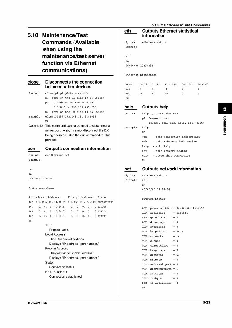
5-33IM 04L02A01-17E
Co
mm
and
s
5
5.10 Maintenance/TestCommands (Availablewhen using themaintenance/test serverfunction via Ethernetcommunications)
close Disconnects the connectionbetween other devices
Syntax close,p1,p2:p3<terminator>
p1 Port on the DX side (0 to 65535)
p2 IP address on the PC side
(0.0.0.0 to 255.255.255.255)
p3 Port on the PC side (0 to 65535)
Example close,34159,192.168.111.24:1054
E0
Description This command cannot be used to disconnect a
server port. Also, it cannot disconnect the DX
being operated. Use the quit command for this
purpose.
con Outputs connection informationSyntax con<terminator>
Example
con
EA
00/00/00 12:34:56
Active connections
Proto Local Address Foreign Address State
TCP 192.168.111. 24:34159 192. 168.111. 24:1053 ESTABLISHED
TCP 0. 0. 0. 0:34155 0. 0. 0. 0: 0 LISTEN
TCP 0. 0. 0. 0:34159 0. 0. 0. 0: 0 LISTEN
TCP 0. 0. 0. 0:34150 0. 0. 0. 0: 0 LISTEN
EN
TCP
Protocol used.
Local Address
The DX's socket address.
Displays “IP address : port number.”
Foreign Address
The destination socket address.
Displays “IP address : port number.”
State
Connection status
ESTABLISHED
Connection established
eth Outputs Ethernet statisticalinformation
Syntax eth<terminator>
Example
eth
EA
00/00/00 12:34:56
Ethernet Statistics
Name In Pkt In Err Out Pkt Out Err 16 Coll
lo0 0 0 0 0 0
mb0 74 0 64 0 0
EN
help Outputs helpSyntax help [,p1]<terminator>
p1 Command name
(close, con, eth, help, net, quit)
Example help
EA
con - echo connection information
eth - echo Ethernet information
help - echo help
net - echo network status
quit - close this connection
EN
net Outputs network informationSyntax net<terminator>
Example net
EA
00/00/00 12:34:56
Network Status
APP: power on time = 00/00/00 12:34:56
APP: applalive = disable
APP: genedrops = 0
APP: diagdrops = 0
APP: ftpsdrops = 0
TCP: keepalive = 30 s
TCP: connects = 14
TCP: closed = 0
TCP: timeoutdrop = 0
TCP: keepdrops = 0
TCP: sndtotal = 53
TCP: sndbyte = 0
TCP: sndrexmitpack = 0
TCP: sndrexmitbyte = 1
TCP: rcvtotal = 0
TCP: rcvbyte = 0
DLC: 16 collisions = 0
EN
5.10 Maintenance/Test Commands

5-34 IM 04L02A01-17E
TCP: keepalive
Keepalive check cycle
TCP: connects
Total number of established
connections.
TCP: closed
Total number of dropped connections.
TCP: timeoutdrop
Total number of dropped connections
due to TCP retransmission timeout.
When the transmitted packet (the unit
of transmitted data) is not received,
the packet is automatically
retransmitted at a predetermined time
interval. If the packet is not
received after 14 retransmissions,
timeout occurs and the connection is
dropped.
TCP: keepdrops
Total number of dropped connections
due to TCP keepalive timeout.
TCP: sndtotal
Total number of transmitted packets.
TCP: sndbyte
Total number of transmitted bytes.
TCP: sndrexmitpack
Total number of retransmitted
packets.
TCP: sndrexmitbyte
Total number of retransmitted bytes.
TCP: rcvtotal
Total number of received packets.
TCP: rcvbyte
Total number of received bytes.
DLC: 16 collisions
Number of collision incidents. A
collision occurs when two or more
devices on the network attempt to
transmit simultaneously. The
tendency for collisions to occur
increases when the network is
congested. 16 collisions would mean
16 consecutive collision incidents.
quit Disconnects the connection ofthe device being operated
Syntax quit<terminator>
5.11 Instrument InformationOutput Commands(Available when using theinstrument informationserver function viaEthernet communications)
The instrument information server function interprets
one UDP packet to be one command and returns a
single packet (containing the DX’s information) in
response to the command.
Port number 34264/udp (see section
2.1)
Transfer data ASCII
Received buffer length 128
Transmit buffer length 512Maximum number 32of parameters
In the command packet, parameters corresponding to
the desired information are placed one after another.
Parameter Description
all Outputs all information that is output using the
parameters below (serial, model,
host, ip).
serial Outputs the serial number.
model Outputs the manufacturer, model, and
firmware version.
host Outputs the host name (the host name
specified in section 2.3).
ip Outputs the IP address (the IP address
specified in section 2.3).
Example Query the IP address and host name. (Of
the two frames below, the top frame
represents the command packet, the bottom
frame represents e response packet.)
ip host
EAip = 192.168.111.24host = DX200-1EN
Description • Separate each parameter with one or more
blanks (space, tab, carriage return, line feed).
• Parameters are not case sensitive.
• Undefined parameters will be ignored.
• Parameters beyond the 32nd parameter are
ignored.
5.10 Maintenance/Test Commands / 5.11 Instrument Information Output Commands

6-1IM 04L02A01-17E
Resp
on
se
6
Chapter 6 Response
6.1 Response Syntax
The following table shows the types of responses for the various commands described inthe previous chapter.The DX returns a response (affirmative/negative response) to a command that isseparated by a single delimiter. The controller should follow the one command to oneresponse format. When the command-response rule is not followed, the operation is notguaranteed.
Command Response Command Type Affirmation NegationSetting command Setting Control Basic setting commandOutput command Control Setup, measured, and ASCII output computed data output BINARY output RS422/485 dedicated Dedicated response No response
Function
Setting/Measurement server
Affirmative response
Single negative response or Multiple negative responses
* For the responses to the instrument information server function, see section 6.4.
NoteThe “CRLF” used in this section denotes carriage return line feed.
Affirmative ResponseWhen the command is processed correctly, an affirmative response is returned.Syntax
E0CRLF
ExampleE0
Single Negative ResponseWhen the command is not processed correctly, a single negative response is returned.Syntax
E1_nnn_mmm···mCRLF
nnn Error number (001 to 999)
mmm···m Message (Variable length, one line)
_ Space
ExampleE1 001 "Syntax error"
Multiple Negative Responses• If there is an error in any one of the multiple commands that are separated by sub
delimiters, multiple negative response are returned.• The response is generated for each erroneous command.• If there are multiple commands that have errors, the negative responses are
separated by commas.• The error position number is assigned to the series of commands in order starting with
“1” assigned to the first command.Syntax
E2_ee:nnnCRLF (When there is only one error)
E2_ee:nnn,ee:nnn,···,ee:nnnCRLF (When there are multiple errors)
ee Error position (01 to 10)
nnn Error number (001 to 999)
_ Space
ExampleE2 02:001

6-2 IM 04L02A01-17E
ASCII OutputThe following types of ASCII data are available. For the data formats, see section 6.2.
Setting data, basic setting data, decimal position/unit information, measured/computed data, communication log, FTP log, operation error log, key login log, Weboperation log, e-mail log, alarm summary, message summary, status information, file
list, data list, and user levelSyntax
EACRLF
···············CRLF
:
···············CRLF
···············CRLF
ENCRLF
BINARY OutputConceptual diagram
'E' 'B' CR LF
BINARY data
ASCII
BINARY
Data length
Data sum
Flag ID Header sum
1 byte
BINARY header(12 bytes)
BINARY data
BINARY footer(2 bytes)
EBCRLFIndicates that the data are BINARY.
Data lengthThe byte value of “flag + identifier + header sum + BINARY data + data sum.”
Header sumThe sum value of “data length + flag + identifier.”
BINARY dataFor the output format of various data types, see section 6.3.
Data sumThe sum value of “BINARY data.”
NoteThe data length of the BINARY header section is output according to the byte order specified
with the BO command.
6.1 Response Syntax
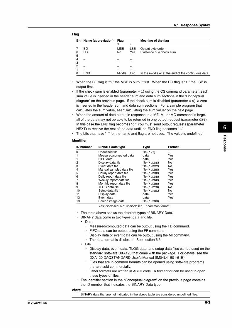
6-3IM 04L02A01-17E
Resp
on
se
6
Flag
Bit Name (abbreviation) Flag Meaning of the flag0 1
7 BO MSB LSB Output byte order6 CS No Yes Existence of a check sum5 – – –4 – – –3 – – –2 – – –1 – – –0 END Middle End In the middle or at the end of the continuous data
• When the BO flag is “0,” the MSB is output first. When the BO flag is “1,” the LSB isoutput first.
• If the check sum is enabled (parameter = 1) using the CS command parameter, eachsum value is inserted in the header sum and data sum sections in the “Conceptualdiagram” on the previous page. If the check sum is disabled (parameter = 0), a zerois inserted in the header sum and data sum sections. For a sample program thatcalculates the sum value, see “Calculating the sum value” on the next page.
• When the amount of data output in response to a ME, MI, or MO command is large,all of the data may not be able to be returned in one output request (parameter GET).In this case the END flag becomes “0.” You must send output requests (parameterNEXT) to receive the rest of the data until the END flag becomes “1.”
• The bits that have “–” for the name and flag are not used. The value is undefined.
Identifier
ID number BINARY data type Type Format
0 Undefined file file (*.*) –1 Measured/computed data data Yes1 FIFO data data Yes2 Display data file file (*.DDS) No3 Event data file file (*.DEV) No4 Manual sampled data file file (*.DMN) Yes5 Hourly report data file file (*.DHR) Yes6 Daily report data file file (*.DDR) Yes7 Weekly report data file file (*.DWR) Yes8 Monthly report data file file (*.DMR) Yes9 TLOG data file file (*.DTG) No10 Setup data file file (*.PNL) No11 Display data data Yes12 Event data data Yes13 Screen image data file (*.PNG) –
Yes: disclosed, No: undisclosed, –: common format
• The table above shows the different types of BINARY Data.• BINARY data come in two types, data and file.
• Data• Measured/computed data can be output using the FD command.• FIFO data can be output using the FF command.• Display data or event data can be output using the MI command.• The data format is disclosed. See section 6.3.
• File• Display data, event data, TLOG data, and setup data files can be used on the
standard software DXA120 that came with the package. For details, see theDXA120 DAQSTANDARD User’s Manual (IM04L41B01-61E).
• Files that are in common formats can be opened using software programsthat are sold commercially.
• Other formats are written in ASCII code. A text editor can be used to openthese types of files.
• The identifier section in the “Conceptual diagram” on the previous page containsthe ID number that indicates the BINARY Data type.
NoteBINARY data that are not indicated in the above table are considered undefined files.
6.1 Response Syntax
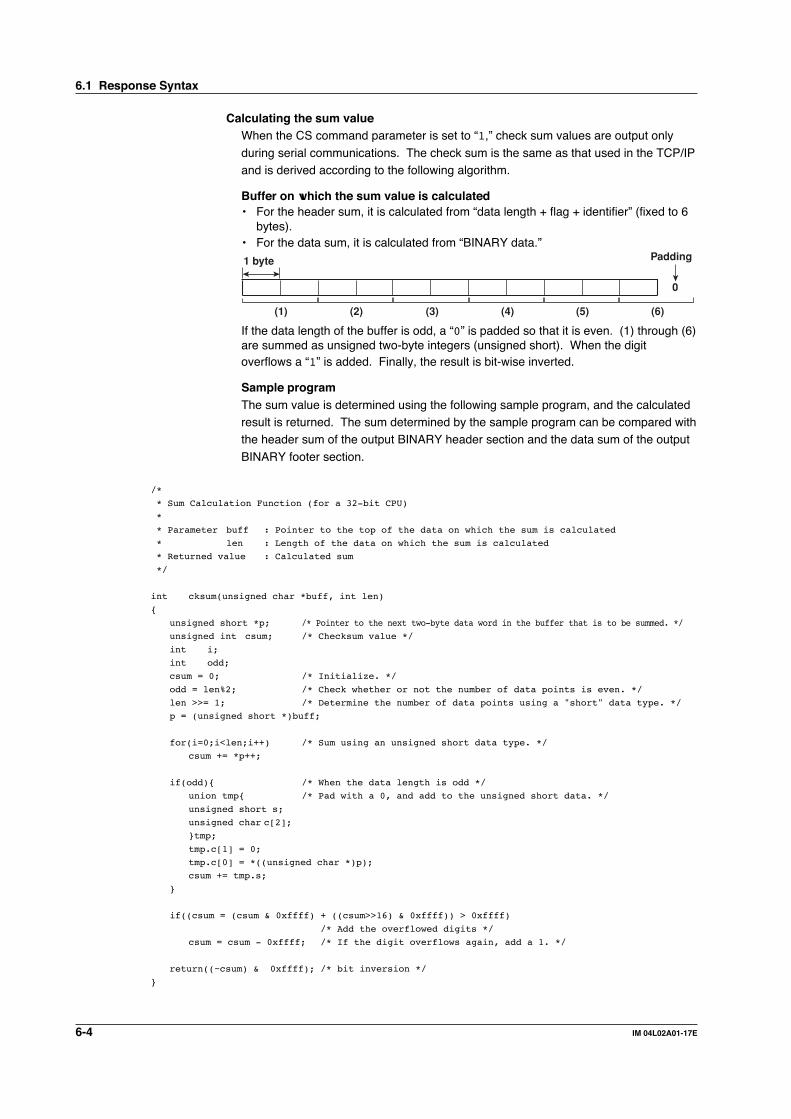
6-4 IM 04L02A01-17E
Calculating the sum valueWhen the CS command parameter is set to “1,” check sum values are output only
during serial communications. The check sum is the same as that used in the TCP/IPand is derived according to the following algorithm.
Buffer on which the sum value is calculated• For the header sum, it is calculated from “data length + flag + identifier” (fixed to 6
bytes).• For the data sum, it is calculated from “BINARY data.”
1 byte
0
(1) (2) (3) (4) (6)(5)
Padding
If the data length of the buffer is odd, a “0” is padded so that it is even. (1) through (6)are summed as unsigned two-byte integers (unsigned short). When the digitoverflows a “1” is added. Finally, the result is bit-wise inverted.
Sample programThe sum value is determined using the following sample program, and the calculatedresult is returned. The sum determined by the sample program can be compared withthe header sum of the output BINARY header section and the data sum of the output
BINARY footer section.
/*
* Sum Calculation Function (for a 32-bit CPU)
*
* Parameter buff : Pointer to the top of the data on which the sum is calculated
* len : Length of the data on which the sum is calculated
* Returned value : Calculated sum
*/
int cksum(unsigned char *buff, int len)
unsigned short *p; /* Pointer to the next two-byte data word in the buffer that is to be summed. */
unsigned int csum; /* Checksum value */
int i;
int odd;
csum = 0; /* Initialize. */
odd = len%2; /* Check whether or not the number of data points is even. */
len >>= 1; /* Determine the number of data points using a "short" data type. */
p = (unsigned short *)buff;
for(i=0;i<len;i++) /* Sum using an unsigned short data type. */
csum += *p++;
if(odd) /* When the data length is odd */
union tmp /* Pad with a 0, and add to the unsigned short data. */
unsigned short s;
unsigned char c[2];
tmp;
tmp.c[1] = 0;
tmp.c[0] = *((unsigned char *)p);
csum += tmp.s;
if((csum = (csum & 0xffff) + ((csum>>16) & 0xffff)) > 0xffff)
/* Add the overflowed digits */
csum = csum - 0xffff; /* If the digit overflows again, add a 1. */
return((~csum) & 0xffff); /* bit inversion */
6.1 Response Syntax
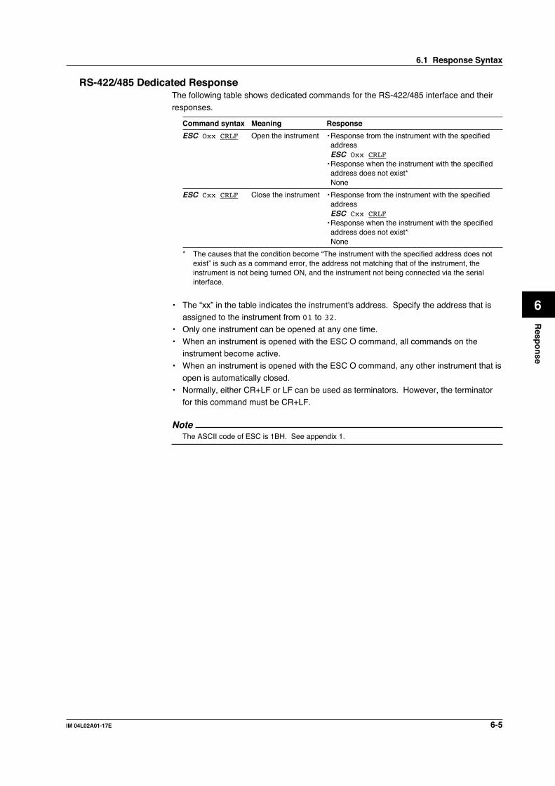
6-5IM 04L02A01-17E
Resp
on
se
6
RS-422/485 Dedicated ResponseThe following table shows dedicated commands for the RS-422/485 interface and their
responses.
Command syntax Meaning Response
ESC Oxx CRLF Open the instrument • Response from the instrument with the specifiedaddressESC Oxx CRLF
• Response when the instrument with the specifiedaddress does not exist*None
ESC Cxx CRLF Close the instrument • Response from the instrument with the specifiedaddressESC Cxx CRLF
• Response when the instrument with the specifiedaddress does not exist*None
* The causes that the condition become “The instrument with the specified address does notexist” is such as a command error, the address not matching that of the instrument, theinstrument is not being turned ON, and the instrument not being connected via the serialinterface.
• The “xx” in the table indicates the instrument's address. Specify the address that isassigned to the instrument from 01 to 32.
• Only one instrument can be opened at any one time.
• When an instrument is opened with the ESC O command, all commands on theinstrument become active.
• When an instrument is opened with the ESC O command, any other instrument that is
open is automatically closed.• Normally, either CR+LF or LF can be used as terminators. However, the terminator
for this command must be CR+LF.
NoteThe ASCII code of ESC is 1BH. See appendix 1.
6.1 Response Syntax

6-6 IM 04L02A01-17E
6.2 Output Format of ASCII Data
The following types of ASCII data are available. The format for each type is described inthis section.
• Setting data/basic setting data• Decimal position/unit information• Measured/computed data
• Communication log• FTP log• Operation error log
• Key login log• Web operation log• E-mail log
• Alarm summary• Message summary• Status information
• File list• Data list• User level
NoteThe “CRLF” used in this section denotes carriage return line feed.
Setting data/basic setting data• The FE command is used to output the data.• The setting/basic setting data are output in the order of the listed commands in the
table in section 5.2, “A List of Commands.” However, the setting information for the
following commands is not output.• Setting command (Setting)
SD/FR command
• Setting command (control)All commands from UD to CM
• Basic setting command
XE, YO, YI, and YC commands• The output format of the setting/basic setting data conforms to the syntax of each
command.
• Some commands are output in multiple lines. (Example: Commands that arespecified for each channel.)
SyntaxThe two-character command name and the succeeding parameters are output in thefollowing syntax.
EACRLF
ttsss···sCRLF
··············
ENCRLF
tt Command name (SR, SA···, XA, XI···)
sss···s Setting, basic setting data (variable length, one line)

6-7IM 04L02A01-17E
Resp
on
se
6
ExampleEA
SR01,VOLT,20mV,0,20
SR02,VOLT,20mV,0,20
···················
EN
Decimal Position/Unit Information• The FE command is used to output the data.
SyntaxThe data are output in the following syntax.EACRLF
s_kccuuuuuu,ppCRLF
··················
ENCRLF
s Data status
N : Normal
D : Differential input
S : Skip (When the measurement range is set to SKIP for a
measurement channel or when the channel is turned
OFF for a computation channel)
k Channel type
0 : Measurement channel
A : Computation channel
cc Channel number
01 to 60
uuuuuu Unit information (6 characters, left-justified)
mV____ : mV
V_____ : V
^C____ : °C
xxxxxx : (user-defined character string)
pp Decimal position (00 to 04)
No decimal (00000) for 00.
One digit below the decimal (0000.0) for 01.
Two digits below the decimal (000.00) for 02.
Three digits below the decimal (00.000) for 03.
Four digits below the decimal (0.0000) for 04.
_ Space
ExampleEA
N 001mV ,01
N 002mV ,01
EN
6.2 Output Format of ASCII Data

6-8 IM 04L02A01-17E
Measured/Computed Data• The FD command is used to output the data.
SyntaxThe measured/computed data are output in the following syntax along with the date
and time information for each channel.EACRLF
DATE_yy/mo/ddCRLF
TIME_hh:mi:ss.mmmtCRLF
s_kcca1a2a3a4uuuuuufdddddE-ppCRLF
····························
ENCRLF
yy Year (00 to 99)
mo Month (01 to 12)
dd Day (01 to 31)
hh Hour (00 to 23)
mi Minute (00 to 59)
ss Second (00 to 59)
mmm Millisecond (000 to 999. A period is placed between
seconds and milli-seconds.)
t Summer time or winter time
S: summer time
(Space): winter time
s Data status
N : Normal
D : Differential input
S : Skip
O : Over
E : Error
k Channel type
0 : Measurement channel
A : Computation channel
cc Channel number
01 to 60
a1a2a3a4 a1 Alarm status (level 1)
a2 Alarm status (level 2)
a3 Alarm status (level 3)
a4 Alarm status (level 4)
(Each status is set to H, L, h, l, R, r, T, t, or space.)
(H : upper limit alarm, L : lower limit alarm, h :
difference upper-limit alarm, l : difference lower-limit
alarm, R : upper limit on rate-of-change alarm, r : lower
limit on rate-of-change alarm, T : delay upper limit
alarm, t : delay lower limit alarm, space : no alarm)
uuuuuu Unit information (6 characters, left-justified)
mV____: mV
V_____: V
^C____: °C
xxxxxx: (user-defined character string)
6.2 Output Format of ASCII Data

6-9IM 04L02A01-17E
Resp
on
se
6
f Sign (+, -)
ddddd Mantissa (00000 to 99999, 5 digits)
• 8 digits for computed data.
• For abnormal data (data status is E) or data of which
the mantissa or the exponent exceeds the range (data
status is O), the mantissa is set to 99999 (99999999 for
computed data).
pp Exponent (00 to 04)
_ Space
ExampleEA
DATE 99/02/23
TIME 19:56:32.500
N 001h mV +12345E-03
N 002 mV -67890E-01
S 003
EN
Note• Data for non-existing channels are not output (not even the channel number).
• For channels set to skip, output values from alarm status to exponent are spaces.
Communication Log• The FL command is used to output the data.• A log of setting/basic setting/output commands and responses is output. Up to 200
logs are retained. Logs that exceed 200 are cleared from the oldest data.
SyntaxEACRLF
yy/mo/dd_hh:mi:ss_n_uuu···ufd_mmm···mCRLF
······································
ENCRLF
yy Year (00 to 99)
mo Month (01 to 12)
dd Day (01 to 31)
hh Time (00 to 23)
mi Minute (00 to 59)
ss Second (00 to 59)
n Connection ID. A number used to identify the user that is
connected.
0 : serial
1 to 3 : Ethernet
uuu···u User name (16 characters)
f Multiple command flag
(Space) : single
* : multiple
If multiple commands are separated by sub delimiters and
output at once, “*” is displayed. The multiple commands
are divided at each sub delimiter and stored as
6.2 Output Format of ASCII Data

6-10 IM 04L02A01-17E
individual logs (1 log for 1 command and 1 log for 1
response).
d Input/Output
> : input
< : output
mmm···m Message (up to 20 characters)
• The communication log contains only the error number
and not the error message section..
• Normally, the transfer data are transmitted as they are,
but in some cases, a special message is output. The
special messages are shown below.
Reception
(Over length) : Command length exceeded.
(Over number) : Number of commands exceeded
(Serial error) : Received an error character through
serial communications.
Transmission
(ddd byte) : data output (ddd is the number of data
points)
(Login) : login
(Logout) : logout
(Disconnected) : Forced disconnection (occurs when the
connection was disconnected when transmitting data using
Ethernet)
(Time out) : Timeout, keepalive, TCP retransmission,
etc.)
E1 nnn : single negative response. nnn is the error
number.
E2 ee:nnn : multiple negative response.ee is the error
position, nnn is the error number.
_ Space
ExampleThe following example shows the log when multiple commands separated by sub
delimiters, “B01;???;CS1,” are transmitted. The commands are separated andoutput in order with the multiple command flags “*.”EA
99/05/11 12:31:11 1 user *> BO1
99/05/11 12:31:11 1 user *< E0
99/05/11 12:31:11 1 user *> ???
99/05/11 12:31:11 1 user *< E2 01:124
99/05/11 12:31:11 1 user *> CS1
99/05/11 12:31:11 1 user *< E0
EN
6.2 Output Format of ASCII Data

6-11IM 04L02A01-17E
Resp
on
se
6
FTP Log• The FL command is used to output the data.
• The FTP client log is output. Up to 50 file transfer logs are retained. Logs thatexceed 50 are cleared from the oldest log.
• For the meanings of the error codes, see the DX100/DX200 User's Manual
(IM04L01A01-01E/IM04L02A01-01E).
SyntaxEACRLF
yy/mo/dd_hh:mi:ss_nnn_xxxxxxxxx_k_ffffffff_eeeCRLF
···································
ENCRLF
yy Year (00 to 99)
mo Month (01 to 12)
dd Day (01 to 31)
hh Hour (00 to 23)
mi Minute (00 to 59)
ss Second (00 to 59)
nnn Error number (001 to 999)
xxxxxxxxx Detailed code (9 characters)
k Server type (FTP destination)
P : Primary
S : Secondary
ffffffff File name (8 characters)
eee Extension (3 characters)
_ Space
ExampleEA
99/07/26 10:00:00 P 72610000 DDR
99/07/27 10:00:00 P 72710000 DDR
99/07/28 10:00:00 123 HOSTADDR P 72810000 DDR
99/07/29 10:00:00 123 HOSTADDR P 72910000 DDR
EN
6.2 Output Format of ASCII Data

6-12 IM 04L02A01-17E
Operation Error Log• The FL command is used to output the data.
• The operation error log is output. Up to 50 operation error logs are retained. Logsthat exceed 50 are cleared from the oldest log.
• Other communication messages (400 to 999) and status messages (500 to 599) are
not output.• For the meanings of the error codes, see the DX100/DX200 User’s Manual
(IM04L01A01-01E/IM04L02A01-01E).
SyntaxEACRLF
yy/mo/dd_hh:mi:ss_nnn_uuu···uCRLF
································
ENCRLF
yy Year (00 to 99)
mo Month (01 to 12)
dd Day (01 to 31)
hh Hour (00 to 23)
mi Minute (00 to 59)
ss Second (00 to 59)
nnn Error code (001 to 999)
uuu···u Error message (Up to 80 characters)
_ Space
ExampleEA
99/05/11 12:20:00 212 "Format error."
99/05/11 12:30:00 217 "Unknown file type."
EN
Key Login Log• The FL command is used to output the data.• A log of users that have logged in and logged out is output. Up to 50 login/logout logs
are retained. Logs that exceed 50 are cleared from the oldest log.• If the power goes down while logged in, you will be logged out. However, it will not be
recorded as a logout.
• User number and user name are not output at the time of the logout.
SyntaxEACRLF
yy/mo/dd_hh:mi:ss_xxx_nn_uuu···uCRLF
···································
ENCRLF
yy Year (00 to 99)
mo Month (01 to 12)
dd Day (01 to 31)
hh Hour (00 to 23)
mi Minute (00 to 59)
ss Second (00 to 59)
xxx Login or logout (In_, Out), left-justified
nn User number (01 to 07)
uuu···u User name (16 characters)
_ Space
6.2 Output Format of ASCII Data

6-13IM 04L02A01-17E
Resp
on
se
6
ExampleEA
99/05/11 12:20:00 In 01 administrator
99/05/11 12:30:00 Out
99/05/11 12:20:00 In 03 user
99/05/11 12:30:00 Out
EN
Web Operation Log• The FL command is used to output the data.• The log of operations on the operator page is output. Up to 50 logs are retained.
Logs that exceed 50 are cleared from the oldest log.
SyntaxEACRLF
yy/mo/dd_hh:mm:ss_ffffff_eee_???···?CRLF
···································
ENCRLF
yy Year (00 to 99)
mo Month (01 to 12)
dd Day (01 to 31)
hh Hour (00 to 23)
mm Minute (00 to 59)
ss Second (00 to 59)
ffffff Operation code
SCREEN : Switching screens
KEY : Key operation
MSG : Setting/writing message
eee Error code
All space : succeeded
001 to 999 : Error code
???···? Detailed operation code
When ffffff=SCREEN
yy/mo/dd_hh:mm:ss_ffffff_eee_ddddd_nnCRLF
ddddd : Screen
TREND : Trend screen
DIGIT : Digital screen
BAR : Bar graph screen
nn : Group number (01 to 04)
When ffffff=KEY
yy/mo/dd_hh:mm:ss_ffffff_eee_kkkkkCRLF
kkkkk : Key
DISP : The DISP/ENTER key
UP : The up arrow key
DOWN : The down arrow key
LEFT : The left arrow key
RIGHT : The right arrow key
6.2 Output Format of ASCII Data

6-14 IM 04L02A01-17E
When ffffff=MSG
yy/mo/dd_hh:mm:ss_ffffff_eee_nn_mmm···mCRLF
nn : Message number (01 to 08)
mm···m : Message (Up to 16 characters)
_ Space
ExampleEA
01/02/11 12:20:00 SCREEN 275 TREND 01
01/02/11 12:21:00 SCREEN BAR 01
01/02/11 12:30:00 KEY UP
01/02/11 12:31:00 KEY RIGHT
01/02/11 12:40:00 MSG 05 Hello-Hello
01/02/11 12:41:00 MSG 05 Hello-Hello
EN
E-Mail Log• The FL command is used to output the data.• The log of e-mail transmission is output. Up to 50 logs are retained. Logs that
exceed 50 are cleared from the oldest log.
SyntaxEACRLF
yy/mo/dd_hh:mm:ss_fffff_eee_n_uuu···uCRLF
···································
ENCRLF
yy Year (00 to 99)
mo Month (01 to 12)
dd Day (01 to 31)
hh Hour (00 to 23)
mm Minute (00 to 59)
ss Second (00 to 59)
fffff E-mail type
ALARM : Mail at the alarm occurrence/release
TIME : Mail at the scheduled time
REPORT : Mail at the report creation
FAIL : Mail at the recovery from the power failure
FULL : Mail at the memory end
TEST : Test mail
ERROR : Error message mail
eee Error code
All space : Succeeded
001 to 999 : Error code
n Recipient code
1 : Recipient 1
2 : Recipient 2
+ : Recipient 1 and Recipient 2
uuu···u Recipient’s e-mail address (Up to 30 characters)
_ Space
6.2 Output Format of ASCII Data

6-15IM 04L02A01-17E
Resp
on
se
6
ExampleEA
01/05/11 12:20:00 ALARM + notice
01/05/11 12:30:00 REPORT 375 1 user1 user2
EN
Alarm Summary• The FL command is used to output the data.• The alarm summary is output. Up to 120 alarms are retained. Alarms that exceed
120 are cleared from the oldest alarm.
SyntaxEACRLF
yy/mo/dd_hh:mm:ss_kcc_ls_YY/MO/DD_HH:MM:SSCRLF
···································
ENCRLF
yy/mo/dd_hh:mm:ss Alarm occurrence time
yy Year (00 to 99)
mo Month (01 to 12)
dd Day (01 to 31)
hh Hour (00 to 23)
mi Minute (00 to 59)
ss Second (00 to 59)
k Channel type
0 : Measurement channel
A : Computation channel
cc Channel number
01 to 60
l Alarm number (1 to 4)
s Alarm type (H,h,L,l,R,r,T,t)
01 to 60
YY/MO/DD_HH:MM:SS Alarm release time
YY Year (00 to 99)
MO Month (01 to 12)
DD Day (01 to 31)
HH Hour (00 to 23)
MM Minute (00 to 59)
SS Second (00 to 59)
_ Space
ExampleEA
01/05/11 12:20:00 001 1L 01/05/11 12:25:00
01/05/11 12:30:00 A31 3t
EN
6.2 Output Format of ASCII Data

6-16 IM 04L02A01-17E
Message Summary• The FL command is used to output the data.
• The message summary is output. Up to 100 messages are retained. Messages thatexceed 100 are cleared from the oldest message.
SyntaxEACRLF
yy/mo/dd_hh:mm:ss_nn_mmm···m_uuu···uCRLF
···································
ENCRLF
yy Year (00 to 99)
mo Month (01 to 12)
dd Day (01 to 31)
hh Hour (00 to 23)
mi Minute (00 to 59)
ss Second (00 to 59)
nn Message number (01 to 08)
mmm···m Message (16 characters. Spaces are embedded when the
number of characters is less than 16.)
uuu···u User name (Up to 16 characters. Output when the key login
function is engaged.)
_ Space
ExampleEA
01/05/11 12:20:00 01 Hello-Hello superstar
01/05/11 12:20:00 03 0123456789abcdef kokoko
EN
Status Information• The IS command is used to output the data.
• The operation status of the DX is output.• For details related to the status information, see section 7.2, “The Bit Structure of the
Status Information.”
SyntaxEACRLF
ddd.ccc.bbb.aaaCRLF
ENCRLF
aaa Status information 1 (000 to 255)
bbb Status information 2 (000 to 255)
ccc Status information 3 (000 to 255)
ddd Status information 4 (000 to 255)
ExampleEA
000.000.032.000
EN
6.2 Output Format of ASCII Data

6-17IM 04L02A01-17E
Resp
on
se
6
File List• The ME command is used to output the data.
• The file list and the file data sizes of the specified directory on the DX’s externalstorage medium are output.
SyntaxEACRLF
ffffffff_eee_ssssssss_yy/mo/dd_hh:mi:ss_llllllllllCRLF
······················································
zzzzzzz_Kbyte_freeCRLF
ENCRLF
ffffffff File name (8 characters)
When this is a directory, the characters <DIR> is shown
at the position displaying the file data size.
eee Extension (3 characters)
ssssssss Data size of the file (_______0 to 99999999) [byte]
yy Year (00 to 99)
mo Month (01 to 12)
dd Day (01 to 31)
hh Hour (00 to 23)
mi Minute (00 to 59)
ss Second (00 to 59)
zzzzzzz Free space on the medium (______0 to 9999999)
llllllllll ID number(_________0 to 9999999999)
• This becomes a numerical value only when the file
extension is DEV or DDS. This value is specific to the
file and is the same as the ID number of the block in
the internal memory from which the file originates.
• This becomes a space when the file extension is not DEV
or DDS.
• This becomes a “0” if the file was saved using another
instrument.
_ Space
ExampleEA
XV1 DEV 124 99/02/24 20:07:12 12310
XV1 PNL 1204 99/01/19 01:52:37
DATA <DIR> 99/01/19 01:23:64
523 Kbytes free
EN
6.2 Output Format of ASCII Data
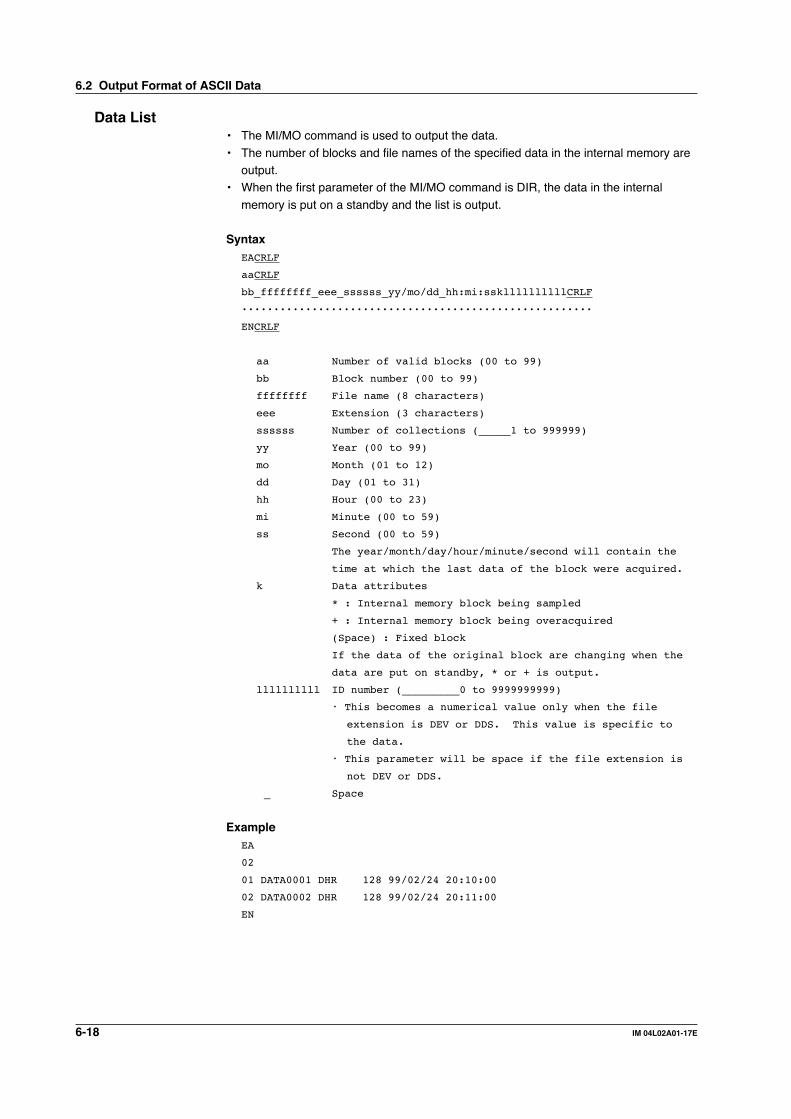
6-18 IM 04L02A01-17E
Data List• The MI/MO command is used to output the data.
• The number of blocks and file names of the specified data in the internal memory areoutput.
• When the first parameter of the MI/MO command is DIR, the data in the internal
memory is put on a standby and the list is output.
SyntaxEACRLF
aaCRLF
bb_ffffffff_eee_ssssss_yy/mo/dd_hh:mi:sskllllllllllCRLF
·······················································
ENCRLF
aa Number of valid blocks (00 to 99)
bb Block number (00 to 99)
ffffffff File name (8 characters)
eee Extension (3 characters)
ssssss Number of collections (_____1 to 999999)
yy Year (00 to 99)
mo Month (01 to 12)
dd Day (01 to 31)
hh Hour (00 to 23)
mi Minute (00 to 59)
ss Second (00 to 59)
The year/month/day/hour/minute/second will contain the
time at which the last data of the block were acquired.
k Data attributes
* : Internal memory block being sampled
+ : Internal memory block being overacquired
(Space) : Fixed block
If the data of the original block are changing when the
data are put on standby, * or + is output.
llllllllll ID number (_________0 to 9999999999)
• This becomes a numerical value only when the file
extension is DEV or DDS. This value is specific to
the data.
• This parameter will be space if the file extension is
not DEV or DDS.
_ Space
ExampleEA
02
01 DATA0001 DHR 128 99/02/24 20:10:00
02 DATA0002 DHR 128 99/02/24 20:11:00
EN
6.2 Output Format of ASCII Data

6-19IM 04L02A01-17E
Resp
on
se
6
User Level• The FU command is used to output the data.
• User name, user level, and other information are output.
SyntaxEACRLF
p_l_uuu···uCRLF
ENCRLF
p Physical layer
E : Ethernet
S : RS-232 or RS-422/485
l User level
A : Administrator
U : User
uuu···u User name (up to 16 characters)
_ Space
ExampleEA
E A admin
EN
6.2 Output Format of ASCII Data

6-20 IM 04L02A01-17E
6.3 Output Format of BINARY Data
This section describes the output format of the BINARY data that is disclosed. For otherBINARY data, see “Identifier” on page 6-3.
• Measured/computed data and FIFO data• Display data• Event data
The measured and computed data are output as “16-bit signed integer” and “32-bit signedinteger,” respectively. These integers can be understood as physical values by addingthe decimal point and the unit. The decimal position is obtained using FE command.
Typical Examples to obtain physical values
Binary value Decimal position code Physical value(Integer) (Measured/computed value)
10000 0 10000
10000 1 1000.0
10000 2 100.00
10000 3 10.000
10000 4 1.0000
NoteThe “CRLF” used in this section denotes carriage return line feed.
Measured/computed data and FIFO data• The FD command is used to output the measured/computed data.
• The FF command is used to output the FIFO data.• The ID number of the output format is “1.” See “Identifier” on page 6-3.
2 bytes
BINARY data(The BINARY data section on the “Conceptual diagram” on page 6-2.)
Number of bytesNumber of blocks
2 bytes
Block 1· · ·
Block n
Number of blocksThis is the number of blocks.
Number of bytesThis is the size of one block in bytes.
Block
YearMeasured/Computed
Month Day Hour Minute Millisecond S/W time* FlagSecond
1 byte 1 byte 1 byte 1 byte 1 byte 1 byte 2 bytes 1 byte 1 byte
4 bytes
Channel A2A1 A4A3 Measured data
· · ·
· · ·
Computed data
· · ·
· · ·
· · ·
· · ·
A4A3
· · ·
· · ·
· · ·
· · ·
A2A1
· · ·
· · ·
· · ·
· · ·
Channel
· · ·
· · ·
· · ·
· · ·
Measured/Computed
· · ·
· · ·
* Summer time or Winter time

6-21IM 04L02A01-17E
Resp
on
se
6
• FlagThe meaning of the flags are given on the table below. The flags are valid duringFIFO data output. The flags are undefined for other cases.
Bit Flag Meaning of the flag0 1
7 No Yes Indicates that the screen snap shot was executed.6 – –5 – –4 – –3 – –2 No Yes Indicates that the decimal position or unit information was changed during
measurement.1 No Yes Indicates that the FIFO acquiring interval was changed with the FR
command during measurement.0 No Yes Indicates that the internal process took too much time (computation, for
example) and that the measurement could not keep up at the specified scaninterval.
The flags that have “–” for the flag column are not used. The value is undefined.
• Block member
Name BINARY value
Year 0 to 99Month 1 to 12Day 1 to 31
Hour 0 to 23Minute 0 to 59Second 0 to 59Millisecond 0 to 999
Summer, Winter 0: Winter time, 1: Summer time
Measurement, 00H : measurement, 80H : computationComputation
Channel 01 to 60
Alarm status* A1 (Bit 0 to 3) A2 (Bit 4 to 7) 0 to 8 A3 (Bit 0 to 3) A4 (Bit 4 to 7)
* BINARY value 0 to 8 is entered in the upper and lower 4 bits of a byte (8 bits) for the alarmstatus. The binary values 0 to 8 correspond to H (upper limit alarm), L (lower limit alarm), h(difference upper-limit alarm), l (difference lower-limit alarm), R (upper limit on rate-of-changealarm), r (lower limit on rate-of-change alarm), T (delay upper limit alarm), and t (delay lowerlimit alarm) as follows:0: no alarm, 1: H, 2: L, 3: h, 4: l, 5: R, 6: r, 7: T, and 8: t.
Special data valueThe measured/computed data take on the following values under special conditions.
Special data value Measured data Computed data
+ over 7FFFH 7FFF7FFFH– over 8001H 8001H8001HSkip 8002H 8002H8002HError 8004H 8004H8004HUndefined 8005H 8005H8005H
NoteThe number of blocks, number of bytes, and measured/computed data are output according
to the byte order specified with the BO command.
6.3 Output Format of Binary Data

6-22 IM 04L02A01-17E
Display Data• The MI command is used to output the FIFO data.
• The ID number of the output format is “11.” See “Identifier” on page 6-3.
HeaderBlock 1
Block n
BINARY data(The BINARY data section on the “Conceptual diagram” on page 6-2.)
· · ·
HeaderSyntax
aaaaaa,ddd,ffffggg,ttttttCRLF
DATE_yy/mo/ddCRLF
TIME_hh:mi:ss.mmmtCRLF
s_kccuuuuuu,ppCRLF
··················
s_kccuuuuuu,ppCRLF
aaaaaa Number of data points (6 digits), Matches the number
of blocks, n, in the above figure.
ddd Number of channels (3 digits)
ffff Sampling interval value (4 digits)
ggg Sampling interval unit (3 characters, left
justified)
tttttt Data number of the trigger position (6 digits,
counting starts with 0.)
For display data, this value is the number of the
last display data.
yy Year (00 to 99)
mo Month (01 to 12)
dd Day (01 to 31)
hh Hour (00 to 23)
mi Minute (00 to 59)
ss Second (00 to 59)
mmm Millisecond (000 to 999)
t Summer time or winter time
S : summer time
(Space) : winter time
s Data status
N : Normal
D : Differential input
k Channel type
0 : Measurement channel
A : Computation channel
cc Channel number
01 to 60
uuuuuu Unit information (6 characters, left-justified)
mV____ : mV
V_____ : V
^C____ : °Cxxxxxx : (user-defined character string)
pp Decimal position (00 to 04)
No decimal (00000) for 00.
One digit below the decimal (0000.0) for 01.
Two digits below the decimal (000.00) for 02.
Three digits below the decimal (00.000) for 03.
Four digits below the decimal (0.0000) for 04.
_ Space
6.3 Output Format of Binary Data
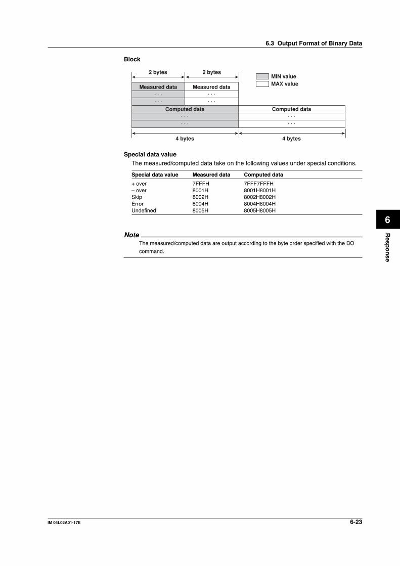
6-23IM 04L02A01-17E
Resp
on
se
6
Block
2 bytes
Measured data· · ·· · ·
Computed data· · ·· · ·
2 bytes
4 bytes 4 bytes
MIN valueMAX value
Computed data· · ·· · ·
Measured data· · ·· · ·
Special data valueThe measured/computed data take on the following values under special conditions.
Special data value Measured data Computed data
+ over 7FFFH 7FFF7FFFH– over 8001H 8001H8001HSkip 8002H 8002H8002HError 8004H 8004H8004HUndefined 8005H 8005H8005H
NoteThe measured/computed data are output according to the byte order specified with the BO
command.
6.3 Output Format of Binary Data

6-24 IM 04L02A01-17E
Event Data• The MI command is used to output the FIFO data.
• The ID number of the output format is “12.” See “Identifier” on page 6-3.
HeaderBlock 1
· · ·Block n
BINARY data(The BINARY data section on the “Conceptual diagram” on page 6-2.)
HeaderSame as the “Header” for the display data.
Block
2 bytes
4 bytes
Computed data· · ·· · ·
Measured data· · ·
Special data valueThe measured/computed data take on the following values under special conditions.
Special data value Measured data Computed data
+ over 7FFFH 7FFF7FFFH– over 8001H 8001H8001HSkip 8002H 8002H8002HError 8004H 8004H8004HUndefined 8005H 8005H8005H
NoteThe measured/computed data are output according to the byte order specified with the BO
command.
Manual sampled Data• The ME or MO command is used to output the data.• The ID number of the output format is “4.” See “Identifier” on page 6-3.• For the data format, see the DX100/DX200 User’s Manual (IM04L01A01-01E/
IM04L02A01-01E).
Report Data (hourly, daily, weekly, monthly data)• The ME or MO command is used to output the data.• The ID number of the output format is “5,” “6,” “7,” and “8” for hourly data, daily data,
weekly data, and monthly data, respectively. See “Identifier” on page 6-3.
• For the data format, see the DX100/DX200 User’s Manual (IM04L01A01-01E/IM04L02A01-01E).
6.3 Output Format of Binary Data

6-25IM 04L02A01-17E
Resp
on
se
6
6.4 Output Format of Instrument Information
This section describes the instrument information output format of the instrumentinformation server.
NoteThe “CRLF” used in this section denotes carriage return line feed.
ResponseThe parameters of the packet that are returned as a response are lined up according to
the following format.EACRLF
(Parameter 1)_=_(value of parameter 1)CRLF
(Parameter 2)_=_(value of parameter 2)CRLF
·····································
ENCRLF
• The parameter values are output in the order specified by the command parameter.• The output order of the parameters when “all” is specified is not constant.
• Even if the same parameters are specified numerous times, only the firstoccurrence is output.
• Lower-case characters are used for the parameters.
• “_” indicates a space.
The following table shows the parameter types.
Parameter Output information
all All information that are output using the parameters belowserial Serial numbermodel Manufacturer, model, and firmware versionhost Host nameip IP address
Output ExampleSeveral output examples are indicated below.
Packet Parameter Sent as Commands Response
The “all” parameter can be used to output all information for parameters serial, model, host, and ip.all EA
serial = 12V636848model = YOKOGAWA,DX200,1.01host = DX200-1ip = 192.168.111.24EN
Parameters are not case sensitive.ip HoSt EA
ip = 192.168.111.24host = DX200-1EN
Even if the same parameters are specified numerous times, only the first occurrence is output.host ip host ip host model EA
host = DX200-1ip = 192.168.111.24model = YOKOGAWA,DX200,1.01EN
Undefined parameters are ignored.(Space) EA
EN
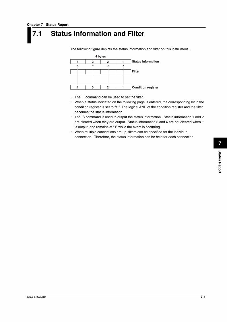
7-1IM 04L02A01-17E
Statu
s Rep
ort
7
Chapter 7 Status Report
7.1 Status Information and Filter
The following figure depicts the status information and filter on this instrument.
Status information
Filter
Condition register
4 bytes
4 3 2 1
4 3 2 1
• The IF command can be used to set the filter.• When a status indicated on the following page is entered, the corresponding bit in the
condition register is set to “1.” The logical AND of the condition register and the filterbecomes the status information.
• The IS command is used to output the status information. Status information 1 and 2
are cleared when they are output. Status information 3 and 4 are not cleared when itis output, and remains at “1” while the event is occurring.
• When multiple connections are up, filters can be specified for the individual
connection. Therefore, the status information can be held for each connection.

7-2 IM 04L02A01-17E
7.2 The Bit Structure of the Status Information
The following four groups of status information are output in response to a statusinformation output request using the IS command. For the output format, see “StatusInformation” in section 6.2, “Output Format of ASCII Data.”
Status Information 1
Bit Name Description
0 A/D conversion complete Set to “1” when the A/D conversion of themeasurement is complete.
1 Medium access complete Set to “1” when the display, event, manualsampled, report, TLOG, or screen image data fileare finished being saved to the external storagemedium.Set to "1" when setting data is successfully savedor loaded.
2 Report generation complete Set to “1” when report generation is complete.3 Timeout Set to “1” when the timer expires.4 – –5 – –6 – –7 – –
Status Information 2
Bit Name Description
0 Measurement drop Set to “1” when the measurement process couldnot keep up.
1 Decimal/unit information Set to “1” when the decimal/unit information ischange changed.
2 Command error Set to “1” when there is a command syntax error.3 Execution error Set to “1” when an error occurs during command
execution.4 – –5 – –6 – –7 – –
Status Information 3
Bit Name Description
0 – –1 – –2 Memory end Set to “1” when the free space in the internal
memory or the external storage medium is low(see section 1.8 of the DX100/DX200 User’sManual).
3 – –4 – –5 – –6 – –7 – –
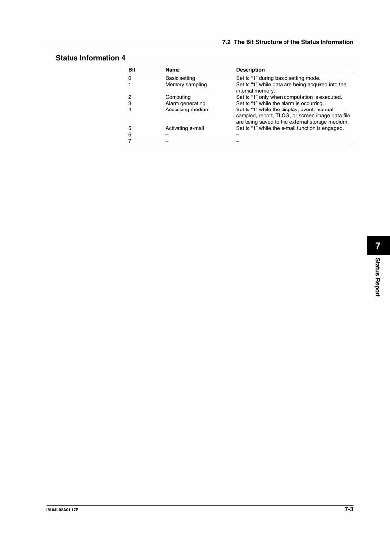
7-3IM 04L02A01-17E
Statu
s Rep
ort
7
Status Information 4
Bit Name Description
0 Basic setting Set to “1” during basic setting mode.1 Memory sampling Set to “1” while data are being acquired into the
internal memory.2 Computing Set to “1” only when computation is executed.3 Alarm generating Set to “1” while the alarm is occurring.4 Accessing medium Set to “1” while the display, event, manual
sampled, report, TLOG, or screen image data fileare being saved to the external storage medium.
5 Activating e-mail Set to “1” while the e-mail function is engaged.6 – –7 – –
7.2 The Bit Structure of the Status Information

App-1IM 04L02A01-17E
Ap
pen
dix
App
Appendix
Appendix 1 ASCII Character Codes
0
1
2
3
4
5
6
7
8
9
A
B
C
D
E
F
0
LF
CR
1
ESC
2
SP
#
%
&
(
)
*
+
,
–
.
/
3
0
1
2
3
4
5
6
7
8
9
:
;
?
4
@
A
B
C
D
E
F
G
H
I
J
K
L
M
N
O
5
P
Q
R
S
T
U
V
W
X
Y
Z
°
_
6
a
b
c
d
e
f
g
h
i
j
k
l
m
n
o
7
p
q
r
s
t
u
v
w
x
y
z
8 9 A B C D E F
Upper 4 bits
Low
er 4
bits
NoteDelimiter (,), sub delimiter (;), query symbol (?), and terminator (CR, LF) cannot beused for parameters.

App-2 IM 04L02A01-17E
Appendix 2 Output Flow of Internal Memory Data
Display Data Example
MI DIR,DISPLAY
NO
*1
YES
Put the internal memory data in standby for communication output and view the data list.
END
Send command
Are there more data?
Command description
Command to send
Received response data
EA0201 10102400 DDS···02 10102500 DDS···ENA
Receive response
MI GET,DISPLAY,2,FILE *2
Send command
BINARY (see pages 6-2 and 6-22)
BINARY (see pages 6-2 and 6-22)
ASCII (see page 6-18)
BINARY headerBINARY data
BINARY footer
Receive response
MI NEXT *3
*4
Send command
BINARY headerBINARY data
BINARY footer
Receive response
*1 to *3 See the next page*4 When bit 0 of the BINARY header flag is 0 : More data exist.
1 : Data transmission is complete.
Output the second block from the list to a file (file name 10102500.DDS)
Output subsequent data
START

App-3IM 04L02A01-17E
Ap
pen
dix
App
Event data (Set *1, *2, and *3 in the previous figure to the following commands)*1 : MI DIR,EVENT Output the list.
*2 : MI GET,EVENT,2,FILE Output the data of the second block to a file.*3 : MI NEXT If there are subsequent data, output the data.
Manual sampled data (Set *1 and *2 in the previous figure to the followingcommands)
*1 : MO DIR,MANUAL
*2 : MO GET,MANUAL,2Since manual sampled data can be transmitted in one session, *3 is not necessary.
Report data (Set *1 and *2 in the previous figure to the following commands)*1 : MO DIR,REPORT*2 : MO GET,REPORT,2
Since report data can be transmitted in one session, *3 is not necessary.
TLOG data (Set *1, *2, and *3 in the previous figure to the following commands)*1 : MO DIR,TLOG*2 : MO GET,TLOG,2*3 : MO NEXT
Appendix 2 Output Flow of Internal Memory Data
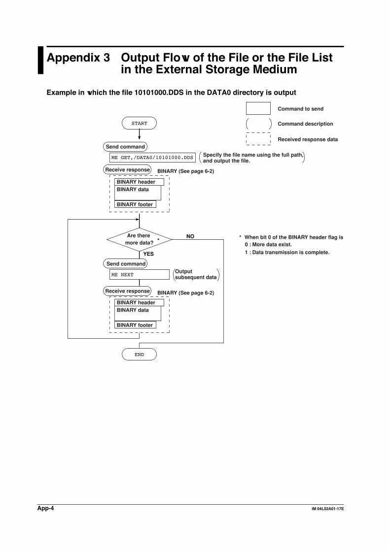
App-4 IM 04L02A01-17E
Appendix 3 Output Flow of the File or the File Listin the External Storage Medium
Example in which the file 10101000.DDS in the DATA0 directory is output
ME GET,/DATA0/10101000.DDS
NO
START
YES
END
Send command
Are there more data?
Receive response
Receive response
BINARY headerBINARY data
BINARY footer
ME NEXT
*
Send command
BINARY headerBINARY data
BINARY footer
* When bit 0 of the BINARY header flag is 0 : More data exist.
1 : Data transmission is complete.
Specify the file name using the full path, and output the file.
Command description
Command to send
Received response data
Output subsequent data
BINARY (See page 6-2)
BINARY (See page 6-2)

App-5IM 04L02A01-17E
Ap
pen
dix
App
Example in which the file list belonging to directory DATA0 is output 10 files at a time
ME DIR,/DATA0/,10
ME DIRNEXT
NO
START
YES
END
Send command
Are there more file lists?
Receive response
Receive response
*
Send command
* When the number of output file lists is smaller than the maximum number of file lists specified by the ME DIR command (10 in this example), one can conclude that there are no more file lists.
Output command for the first file listSpecify the number of file lists to be output when issuing this command.
Command description
Command to send
Received response data
Output subsequent file lists
ASCII (See page 6-17)
ASCII (See page 6-17)
EA........................................xxxKbyte freeEN
EA........................................xxxKbyte freeEN
File lists
File lists
Appendix 3 Output Flow of the File or the File List in the External Storage Medium

App-6 IM 04L02A01-17E
Appendix 4 Output Flow of FIFO Data
Overview of the FIFO BufferThe DX has a dedicated internal memory for outputting measured/computed data. Thismemory is structured as a FIFO (First-In-First-Out). Measured/computed data areconstantly acquired to the internal memory at the specified acquiring interval (FIFO
acquiring interval, set with the FR command). By using this function, it is possible toread measured/computed data that have been saved at the specified intervalsregardless of the frequency at which the PC periodically reads the measured/computed
data.
The following example shows the case when the acquiring interval is 1 s and the
capacity of the FIFO memory is for 8 intervals.
Most recent acquire position : WP
Block1
3
4
5
6
7
2
Block8
Previous read position : RP1
Current read position : RP2
• Acquiring of the measured/computed data• The measured/computed data are acquired to the internal memory at 1 s intervals.
• Measured/computed data are acquired to blocks 1 through 8 in order. Afteracquiring to block 8, the next acquiring operation returns to block 1.
• Reading the measured/computed data (FF GET command)Outputs the data from the next to the previous read position (RP1) to the most recentacquire position (WP).
In this example, more than 2 s has elapsed from the previous read operation.Therefore, data in blocks 5 and 6 are output.
• Reading the measured/computed data (FF GETNEW command)Output the specified number of blocks of FIFO data back starting from the recentacquire position (WP).
In this example, if you specify the number of blocks to “5,” data in blocks 2 to 6 areoutput.
The capacity of the FIFO memory (FIFO buffer data length) that is allocated variesdepending on the model.
DX102/DX104/DX204/DX208: 240 intervals (30 s at a acquiring interval of 125 ms)
DX106/DX112/DX210/DX220/DX230: 60 intervals (60 s at a acquiring interval of 1 s)
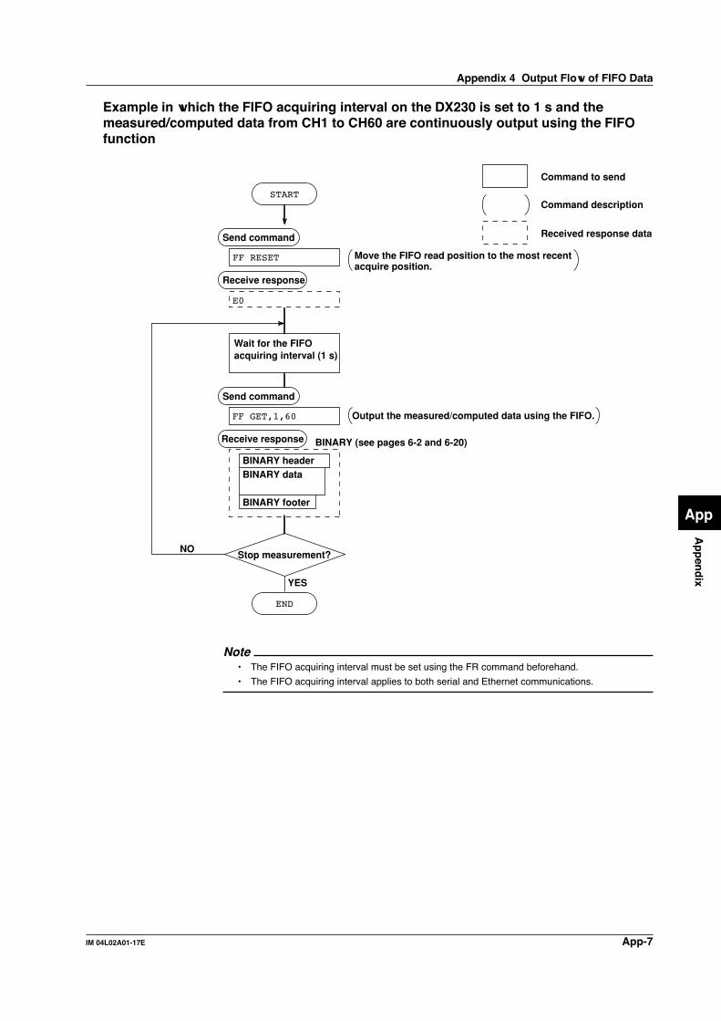
App-7IM 04L02A01-17E
Ap
pen
dix
App
Example in which the FIFO acquiring interval on the DX230 is set to 1 s and themeasured/computed data from CH1 to CH60 are continuously output using the FIFOfunction
BINARY headerBINARY data
BINARY footer
FF RESET
YES
NO
END
Send command
Stop measurement?
Receive response
E0
FF GET,1,60
Send command
Receive response
Wait for the FIFO acquiring interval (1 s)
Move the FIFO read position to the most recent acquire position.
Command description
Command to send
Received response data
Output the measured/computed data using the FIFO.
START
BINARY (see pages 6-2 and 6-20)
Note• The FIFO acquiring interval must be set using the FR command beforehand.
• The FIFO acquiring interval applies to both serial and Ethernet communications.
Appendix 4 Output Flow of FIFO Data

App-8 IM 04L02A01-17E
Appendix 5 Data Dropout (Modbus Master)
If the DX does not have received the response from the slave device corresponding to
the command it transmitted until the time for the next command transmission, datadropout occurs. Take appropriate measures referring to the figures below.
Read cycle
Data dropout(Slave2 and 3)
Data dropout(Slave3)
Slave device1
Slave device2
Slave device3
GG
G G
G
G G G
G Y G
G
G G G
G G G
G G
G
Read cycle
(Retrial)
: Status lamp, G: Green, Y: Yellow, R: Red
: Response from slave device
: Command from the DX
Data dropout(Slave2 and 3) Data dropout
(Slave2 and 3)
Slave device 2 disconnected
Slave device1
Slave device2
Slave device3
Read cycle
Timeout time
Data dropout(Slave2 and 3)
Slave device1
Slave device2
Slave device3
Y R
R
Timeout time
G Y
Timeout time
1. When slave deice takes time to respond
2. When slave device does not respond
3. When slave device is disconnected (Number of retrials is set to "1")

App-9IM 04L02A01-17E
Ap
pen
dix
App
Appendix 6 A List of Error Messages
The list of error codes and messages is given below.
Errors Related to Parameter Settings• Setting Errors
Code Message Explanation/Countermeasures/Ref. section
1 System error. Contact your nearest YOKOGAWA dealer.
2 Incorrect date or time setting. See section 3.7.*1
3 A disabled channel is selected. See sections 5.4, 5.6, and 5.8.
4 Incorrect function parameter. See sections 5.4 to 5.11.
5 The input numerical value exceeds the set range. Enter a proper value.
6 Incorrect input character string. Enter a proper character string.
7 Too many characters. Enter specified number of characters.
8 Incorrect input mode. See section 5.4.
9 Incorrect input range code. See section 5.4.
21 Cannot set an alarm for a skipped channel. See section 5.4.
22 The upper and lower span limits are equal. See sections 5.1 to 5.7.*1
23 The upper and lower scale limits are equal. See sections 5.5 and 5.6.*1
30 The partial boundary value exceeds the range of the span. See section 7.11.*1
31 Partial expansion display is set ON for a SKIPPED channel. See section 5.4.
35 The upper and lower limits of the display band are equal. See section 7.9.*1
36 The lower limit of the display band is greater than the upper limit. See section 7.9.*1
37 The display band is narrower than 4% of the entire display. See section 7.9.*1
40 Incorrect group set character string. See section 7.6.*1
41 There is no specified input channel. See sections 5.4, 5.6, and 5.8.
42 Exceeded the number of channels which can be set. See sections 5.4, 5.6, and 5.8.
43 A channel number cannot repeat in a group. See section 7.6.*1
45 There is no character string saved in the clipboard. Copy a character string to the clipboard.
46 The character string saved in the clipboard is too long. Paste a character string with the specified numberof characters.
61 There is no channel specified by the MATH expression. See section 11.4.*1
62 MATH expression grammar is incorrect. See section 11.2.*1
63 MATH expression sequence is incorrect. See section 11.2.*1
64 MATH upper and lower span values are equal. See section 11.4.*1
70 The range of the MATH constant is exceeded. See section 11.4.*1
71 Set range of the MATH constant is exceeded. See section 11.6.*1
81 All space or ‘quit’ string cannot be specified. See section 10.6.*1
83 Duplicate used combination of user ID and password. See section 10.6*1 (when /BT1 is equipped).
85 The login password is incorrect. See section 10.5.*1
86 The key-lock release password is incorrect. See section 10.3.*1
87 This key is locked. See section 10.3.*1
88 This function is locked. See section 10.3.*1
89 Press [FUNC] key to login. See section 10.5.*1
90 No permission to enter to the SETUP mode. See sections 10.5 and 10.6.*1
91 Password is incorrect. See sections 10.3 and 10.5.*1
92 Press [ESC] key to change to the operation mode. Press the ESC key.
93 String including space or all space cannot be specified. Spaces are not allowed in the Web user name andpassword.
94 More than one address cannot be specified. Multiple addresses cannot be specified. Only asingle sender is allowed.

App-10 IM 04L02A01-17E
Code Message Explanation/Countermeasures/Ref. section
100 IP address doesn’t belong to class A, B, or C. See section 5.6.
101 The result of the masked IP address is all 0s or 1s. See section 5.6.
102 SUBNET mask is incorrect. See section 5.6.
103 The net part of default gateway is not equal to that of IP address. See section 5.6.
104 FTP client failed because the memory mode is ‘manual’. See section 5.6.
*1 See the DX100/DX200 User’s Manual (IM04L01A01-01E, IM04L02A01-01E).
• Execution Errors
Code Message Explanation/Countermeasures/Ref. section
150 This action is not possible because sampling is in progress. See sections 8.5 and 8.6.*1
151 This action is not possible during sampling or calculating. See sections 8.5, 8.6, and 11.3.*1
152 This action is not possible because saving is in progress. Wait till the saving ends.
153 This action is not possible because formatting is in progress. Wait till the formatting ends.
155 The message is not written while sampling is stopped. See sections 8.5 and 8.6.*1
160 Cannot load the specified data. Change the memory setting. See sections 4.5, 9.3, and 9.4.*1
*1 See the DX100/DX200 User’s Manual (IM04L01A01-01E, IM04L02A01-01E).
Operation Errors• Errors related to external storage medium
Code Message Explanation/Countermeasures/Ref. section
200 Operation aborted because an error was found in media. Check the storage medium.
201 Not enough free space on media. Use another storage medium.
202 Media is read-only. Release the write protection.
210 Media has not been inserted. Insert a storage medium into the drive.
211 Media is damaged or not formatted. Use another storage medium or carry out formatting.
212 Format error. Try formatting again or use another storage medium.
213 The file is read-only. Access to other files or make the file write-enable.
214 There is no file or directory. See section 5.8.
215 Exceeded the allowable number of files. Delete files or change storage medium.
216 The file or directory name is incorrect. See sections 8.9 and 9.1.*1
217 Unknown file type. Access to other files.
218 Directory exists. Delete the directory or change directory name. See section 8.9.*1
219 Invalid file or directory operation. Cannot handle files and directories in the 2nd anddeeper layers.
220 The file is already in use. Try again later. Wait till file is free.
230 There is no setting file. Access to other files.
231 Abnormal setting exists in file. Access to other files.
*1 See the DX100/DX200 User’s Manual (IM04L01A01-01E, IM04L02A01-01E).
Appendix 6 A List of Error Messages

App-11IM 04L02A01-17E
Ap
pen
dix
App
• Errors related to historical trend
Code Message Explanation/Countermeasures/Ref. section
232 There is no available data. This message may appear when recalling historicaltrend. Access to other files.
233 The specified historical data do not exist. This message may appear when recalling historicaltrend. See section 4.5.
234 The specified channel is not assigned to the display group. This message may appear when switching to trendor bar graph from overview.See sections 4.4 and 7.6.
• Errors related to e-mail and Web server
Code Message Explanation/Countermeasures/Ref. section
260 IP address is not set or ethernet function is not available. The IP address is not specified. Check the IPaddress.
261 SMTP server is not found. Occurs when the SMTP server is specified byname.• Check the DNS setting.• Check the SMTP server name.
262 Cannot initiate E-mail transmission. • The host name of the DX is not correct. Checkthe host name.• The port number for SMTP server is not correct.Check the port number.
263 Sender’s address rejected by the server. Check the sender’s address.
264 Some recipients’ addresses are invalid. Check the recipient’s address.
265 SMTP protocol error. May occur if a network failure (cable problems,duplicate addresses, network device failure, and soon) occurs in the middle of the e-mail transmission.
266 Ethernet cable is not connected. Check the cable connection.
267 Could not connect to SMTP server. • Check to see that the SMTP server is connectedto the network.• If the SMTP server name is specified using an IPaddress, check to see that the IP address is correct.
268 E-mail transmission request failed. Contact your nearest YOKOGAWA dealer.
269 E-mail transfer error. May occur if a network failure (cable problems,duplicate addresses, network device failure, and soon) occurs in the middle of the e-mail transmission.
275 The current image cannot be output to the Web. The setup screen cannot be output to the Web.This message is displayed on the Web screen.
276 Image data currently being created. Unable to perform key operation.Try again a little later.This message is displayed on the Web screen.
277 Could not output screen to Web. Failed to create the image.This message is displayed on the Web screen.
Appendix 6 A List of Error Messages

App-12 IM 04L02A01-17E
• Errors related to FTP clientFor information regarding the FTP client function of the DX100/DX200, see the DX100/
DX200 Communication Interface User’s Manual (IM04L02A01-17E).
Code Message
280 IP address is not set or FTP function is not available.Further details are provided by the character string that appears after error code 280.
Character String and Details
HOSTADDRThe DX’s IP address has not been specified.Check the IP address.
DORMANTInternal processing error.*1
LINKData link is disconnected.Check the cable connection.
281 FTP mail box operation error.Further details are provided by the character string that appears after error code 281.
Character String and Details
MAILInternal processing error.*1
STATUSInternal processing error.*1
TIMEOUTInternal processing error.*1
PRIORITYInternal processing error.*1
NVRAMInternal processing error.*1
282 FTP control connection error.Further details are provided by the character string that appears after error code 282.
Character String and Details
HOSTNAMEFailed the DNS lookup (search the IP address corresponding to the host name).Check the DNS setting and the destination host name.
TCPIPInternal processing error.*1
UNREACHFailed to connect to a control connection server.Check the address setting and that the server is running.
OOBINLINEInternal processing error.*1
NAMEInternal processing error.*1
CTRLThe control connection does not exist.Check that the server does not drop the connection and that it responds within the propertime period.
IACFailed to respond in the TELNET sequence.Check that the server does not drop the connection and that it responds within the propertime period.
ECHOFailed to transmit data on the control connection.Check that the server does not drop the connection and that it responds within the propertime period.
REPLYFailed to receive data on the control connection.Check that the server does not drop the connection and that it responds within the propertime period.
SERVERThe server is not in a condition to provide the service.Check that the server is in a condition in which service can be provided.
Appendix 6 A List of Error Messages

App-13IM 04L02A01-17E
Ap
pen
dix
App
Code Message
283 FTP command was not accepted.Further details are provided by the character string that appears after error code 283.
Character String and Details
USERFailed user name verification.Check the user name setting.
PASSFailed password verificationCheck the password setting.
ACCTFailed account verification.Check the account setting.
TYPEFailed to change the transfer type.Check that the server supports the binary transfer mode.
CWDFailed to change the directory.Check the initial path setting.
PORTFailed to set the transfer connection.Check that the security function is disabled.
PASVFailed to set the transfer connection.Check that the server supports PASV commands.
SCANFailed to read the transfer connection settings.Check that proper response to the PASV command is received from the server.
284 FTP transfer setting error.Further details are provided by the character string that appears after error code 284.
Character String and Details
MODEInternal processing error.*1
LOCALInternal processing error.*1
REMOTEThe destination file name is not correct.Check that you have the authority to create or overwrite files.
ABORTFile transfer abort was requested by the server.Check the server for the reason for the abort request.
Appendix 6 A List of Error Messages

App-14 IM 04L02A01-17E
Code Message
285 FTP data connection error.Further details are provided by the character string that appears after error code 285.
Character String and Details
SOCKETFailed to create a socket for the transfer connection.*2
BINDFailed the transfer connection command.*2
CONNECTFailed the transfer connection.*2
LISTENFailed the transfer connection reception.*2
ACCEPTFailed to accept the transfer connection.*2
SOCKNAMEInternal processing error.*2
RECVFailed to receive data over the transfer connection.*2
SENDFailed to send data over the transfer connection.*2
286 FTP file transfer error.Further details are provided by the character string that appears after error code 286.
Character String and Details
READInternal processing error.*1
WRITEInternal processing error.*1
*1 Contact your nearest YOKOGAWA dealer.*2 These errors may occur if the network experiences trouble during the data transmission (bad
cable connection, duplicate addresses, network equipment failure).
NoteThe FTP client function on the DX100/DX200 has a timer function that drops the connection if
there is no data transfer for two minutes. If the server does not respond within this time
period, the transfer fails.
Communication Errors• Errors during Setting and Basic Setting Modes, Output Communication Command
Execution, and Setup Data Loading
Code Message
300 Command is too long.
301 Too many number of commands delimited with ‘;’.
302 This command has not been defined.
303 Data request command can not be enumerated with sub-delimiter.
350 Command is not permitted to the current user level.
351 This command cannot be specified in the current mode.
352 The option is not installed.
353 This command cannot be specified in the current setting.
354 This command is not available during sampling or calculating.
Appendix 6 A List of Error Messages

App-15IM 04L02A01-17E
Ap
pen
dix
App
• Memory Access Errors during Setting and Basic Setting Modes and OutputCommunication Command Execution
An English error message is returned via the communication interface. It is notdisplayed on the screen.
Code Message
360 Output interface must be chosen from Ethernet or RS by using ‘XO’ command.
361 The memory data is not saved for the communication output.
362 There are no data to send ‘NEXT’ or ‘RESEND’.
363 All data have already been transferred.
• Maintenance and Test Communication Command ErrorsAn English error message is returned via the communication interface. It is notdisplayed on the screen.
Code Message
390 Command error.
391 Delimiter error.
392 Parameter error.
393 No permission.
394 No such connection.
395 Use ‘quit’ to close this connection.
396 Failed to disconnect.
397 No TCP control block.
• Other Communication ErrorsAn English error message is returned via the communication interface. It is notdisplayed on the screen.
Code Message
400 Input username.
401 Input password.
402 Select username from ‘admin’ or ‘user’.
403 Login incorrect, try again!
404 No more login at the specified level is acceptable.
420 Connection has been lost.
421 The number of simultaneous connection has been exceeded.
422 Communication has timed-out.
Appendix 6 A List of Error Messages

App-16 IM 04L02A01-17E
Appendix 7 Login Process
You log into the DX from your PC to use the functionality of the setting/measurementserver and the maintenance/test server via the Ethernet interface. If you complete the
process successfully up to login complete in the following figure, the commands inchapter 5 become functional.When using the Ethernet login function of the DX
E1 403
E1 403
Yes
No
No
No
No No
No
E1 404
E1 421
Disconnect communications
Connect communications
E1 422
E1 420
Disconnect communications
Disconnect communications
E1 401
E0
E1 400
1
1
1
1
End
Decision
Transition
Code (for a description of codes and messages, see page App-15)
Within the number of connections*1
Within 2 minutes?
Within 2 minutes?
User name
Entered "quit"?
Password
Verification match?
Within the number of simultaneous
uses?*3
Login complete
Increment retry count
Wait 5 s
Within three retries?*2
Within three retries?*2
Start
User entry
Response from the DX (message omitted)For a description of the response format, see section 6.1.
*1 Connections cannot exceed the maximum number of connections (see section 2.1).*2 If you attempt to log in using a wrong password four consecutive times, the communication is
dropped (the number of login retries is three).*3 If you attempt to log in causing the number of simultaneous use at the Administrator or User
level to be exceeded (see section 2.1) four consecutive times, the communication is dropped
(even if the password is correct).

App-17IM 04L02A01-17E
Ap
pen
dix
App
When not using the Ethernet login function of the DXLogin as “admin” or “user.”
• You can log into the DX as an administrator by accessing the DX using the user name“admin.”
• You can log into the DX as a user by accessing the DX using the user name “user.”
E1 403
Yes
No
No
No
No No
No
E1 404
E1 421
E1 422
E1 420 E0
E1 402
1
1
1
1
Disconnect communications
Disconnect communications
Disconnect communications
Connect communications
Within the number of connections*1
Within 2 minutes?
User name
Entered "quit"?
Verification match?
Within the number of simultaneous
uses?*3
Login complete
Within three retries?*2
Within three retries?*2
Increment retry count
Appendix 7 Login Process

Index-1IM 04L02A01-17E
Index
Ind
ex
Index
Aaccess control ................................................................... 2-27account ............................................................................. 2-11address .............................................................. 3-10, 4-4, 4-6administrator .............................................................. 1-5, 2-17affirmative response ............................................................ 6-1arrow key .............................................................................. ivASCII character code ..................................................... App-1authority .............................................................................. 1-5automatic file transfer .......................................................... 1-4automatic transfer of data files .......................................... 2-10
Bbasic setting command .............................................. 5-4, 5-20basic setting mode .............................................................. 5-4baud rate .................................................................... 3-10, 4-4BINARY data section .......................................................... 6-2BINARY data type ............................................................... 6-3BINARY footer section ........................................................ 6-2BINARY header section ...................................................... 6-2bit structure ......................................................................... 3-9bit structure of the status information .................................. 7-2block (display data) ........................................................... 6-23block (event data) ............................................................. 6-24block (measured/computed/FIFO data) ............................ 6-20block member ................................................................... 6-21BO flag ................................................................................ 6-3browser ............................................................................. 2-31
Ccable ................................................................................... 3-5cable connection procedure ................................................ 3-5calculating the sum value .................................................... 6-4canceling operation .............................................................. viicarriage return code ....................................................... App-1character/number input key .................................................. ivchecking the connection status ........................................... 2-9command
AK ............................................................................... 5-18all ................................................................................ 5-34BA ............................................................................... 5-16BB ............................................................................... 5-17BC ............................................................................... 5-17BD ............................................................................... 5-17BO .............................................................................. 5-29CC .............................................................................. 5-29close ........................................................................... 5-33CM .............................................................................. 5-20con .............................................................................. 5-33CS ............................................................................... 5-29DS ............................................................................... 5-19EM .............................................................................. 5-20ESC C ......................................................................... 5-32ESC O ........................................................................ 5-32eth ............................................................................... 5-33EV ............................................................................... 5-19FC ............................................................................... 5-29FD ............................................................................... 5-30FE ............................................................................... 5-29FF ............................................................................... 5-30
FL ............................................................................... 5-30FR ............................................................................... 5-16FU ............................................................................... 5-31help ............................................................................. 5-33host ............................................................................. 5-34IF ................................................................................ 5-29ip ................................................................................. 5-34IS ................................................................................ 5-31KE ............................................................................... 5-20LI ................................................................................. 5-19LO ............................................................................... 5-19ME .............................................................................. 5-31MI ................................................................................ 5-31MO .............................................................................. 5-32model .......................................................................... 5-34MS .............................................................................. 5-19net ............................................................................... 5-33PS ............................................................................... 5-18quit .............................................................................. 5-34RM .............................................................................. 5-24RO .............................................................................. 5-23SA ............................................................................... 5-10SB ............................................................................... 5-13SC ............................................................................... 5-14SD ............................................................................... 5-11SE ............................................................................... 5-13serial ........................................................................... 5-34SF ............................................................................... 5-14SG .............................................................................. 5-13SH ............................................................................... 5-13SI ................................................................................ 5-15SJ ............................................................................... 5-15SK ............................................................................... 5-15SL ............................................................................... 5-12SO .............................................................................. 5-10SP ............................................................................... 5-12SQ .............................................................................. 5-14SR ................................................................................. 5-9SS ............................................................................... 5-16ST ............................................................................... 5-12SU ............................................................................... 5-15SV ............................................................................... 5-13SW .............................................................................. 5-11SX ............................................................................... 5-12SY ............................................................................... 5-14SZ ............................................................................... 5-11TL ............................................................................... 5-19UD .............................................................................. 5-17XB ............................................................................... 5-21XE ............................................................................... 5-24XG .............................................................................. 5-25XH ............................................................................... 5-24XI ................................................................................ 5-21XJ ............................................................................... 5-21XM .............................................................................. 5-21XO .............................................................................. 5-24XP ............................................................................... 5-25XQ .............................................................................. 5-23XR ............................................................................... 5-22XS ............................................................................... 5-21XT ............................................................................... 5-21XU ............................................................................... 5-22XV ............................................................................... 5-21YA ............................................................................... 5-25
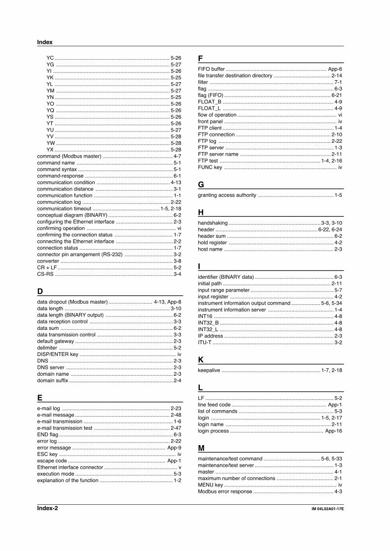
Index-2 IM 04L02A01-17E
Index
YC ............................................................................... 5-26YG .............................................................................. 5-27YI ................................................................................ 5-26YK ............................................................................... 5-25YL ............................................................................... 5-27YM .............................................................................. 5-27YN ............................................................................... 5-25YO .............................................................................. 5-26YQ .............................................................................. 5-26YS ............................................................................... 5-26YT ............................................................................... 5-26YU ............................................................................... 5-27YV ............................................................................... 5-28YW .............................................................................. 5-28YX ............................................................................... 5-28
command (Modbus master) ................................................ 4-7command name .................................................................. 5-1command syntax ................................................................. 5-1command-response ............................................................ 6-1communication condition .................................................. 4-13communication distance ..................................................... 3-1communication function ...................................................... 1-1communication log ............................................................ 2-22communication timeout .............................................. 1-5, 2-18conceptual diagram (BINARY) ............................................ 6-2configuring the Ethernet interface ....................................... 2-3confirming operation ............................................................. viconfirming the connection status ........................................ 1-7connecting the Ethernet interface ....................................... 2-2connection status ................................................................ 1-7connector pin arrangement (RS-232) ................................. 3-2converter ............................................................................. 3-8CR + LF ............................................................................... 5-2CS-RS ................................................................................. 3-4
Ddata dropout (Modbus master) .............................. 4-13, App-8data length ........................................................................ 3-10data length (BINARY output) .............................................. 6-2data reception control ......................................................... 3-3data sum ............................................................................. 6-2data transmission control .................................................... 3-3default gateway ................................................................... 2-3delimiter .............................................................................. 5-2DISP/ENTER key .................................................................. ivDNS .................................................................................... 2-3DNS server ......................................................................... 2-3domain name ...................................................................... 2-3domain suffix ....................................................................... 2-4
Ee-mail log .......................................................................... 2-23e-mail message ................................................................. 2-48e-mail transmission ............................................................. 1-6e-mail transmission test .................................................... 2-47END flag .............................................................................. 6-3error log ............................................................................. 2-22error message ................................................................ App-9ESC key ................................................................................ ivescape code ................................................................... App-1Ethernet interface connector .................................................. vexecution mode ................................................................... 5-3explanation of the function .................................................. 1-2
FFIFO buffer ..................................................................... App-6file transfer destination directory ....................................... 2-14filter ..................................................................................... 7-1flag ...................................................................................... 6-3flag (FIFO) ......................................................................... 6-21FLOAT_B ............................................................................ 4-9FLOAT_L ............................................................................ 4-9flow of operation .................................................................... vifront panel ............................................................................. ivFTP client ............................................................................ 1-4FTP connection ................................................................. 2-10FTP log ............................................................................. 2-22FTP server .......................................................................... 1-3FTP server name .............................................................. 2-11FTP test ..................................................................... 1-4, 2-16FUNC key ............................................................................. iv
Ggranting access authority .................................................... 1-5
Hhandshaking ............................................................... 3-3, 3-10header ...................................................................... 6-22, 6-24header sum ......................................................................... 6-2hold register ........................................................................ 4-2host name ........................................................................... 2-3
Iidentifier (BINARY data) ...................................................... 6-3initial path .......................................................................... 2-11input range parameter ......................................................... 5-7input register ....................................................................... 4-2instrument information output command .................... 5-6, 5-34instrument information server ............................................. 1-4INT16 .................................................................................. 4-8INT32_B .............................................................................. 4-8INT32_L .............................................................................. 4-8IP address ........................................................................... 2-3ITU-T ................................................................................... 3-2
Kkeepalive .................................................................... 1-7, 2-18
LLF ........................................................................................ 5-2line feed code ................................................................. App-1list of commands ................................................................. 5-3login ........................................................................... 1-5, 2-17login name ........................................................................ 2-11login process ................................................................ App-16
Mmaintenance/test command ....................................... 5-6, 5-33maintenance/test server ...................................................... 1-3master ................................................................................. 4-1maximum number of connections ....................................... 2-1MENU key ............................................................................. ivModbus error response ....................................................... 4-3
Index-3IM 04L02A01-17E
Index
Ind
ex
Modbus master ................................................................... 1-2Modbus protocol ................................................................. 4-4Modbus protocol specification ...................................... 4-1, 4-7Modbus slave ...................................................................... 1-2MODBUS STATUS screen ............................................... 4-13monitor page ..................................................................... 2-26monitor page (contents) .................................................... 2-31multiple negative responses ............................................... 6-1
Nname of part .......................................................................... ivnegative response ............................................................... 6-1Normal protocol ................................................................. 3-10number of bytes ................................................................ 6-20number of simultaneous uses ............................................. 2-1
OOFF-OFF ............................................................................ 3-3operation mode ................................................................... 5-4operator page .................................................................... 2-26output command ................................................................. 5-6output command (control) ................................................. 5-29output command (RS-422/485 dedicated commands) ..... 5-32output command (setup, measured, and computed) ........ 5-29output flow of FIFO data ................................................ App-6output flow of internal memory data ............................... App-2output flow of the file ...................................................... App-4output flow of the file list ................................................. App-5output format (alarm summary) ......................................... 6-15output format (communication log) ..................................... 6-9output format (data list) ..................................................... 6-18output format (decimal position/unit information) ................ 6-7output format (display BINARY data) ................................ 6-22output format (e-mail log) .................................................. 6-14output format (event BINARY data) .................................. 6-24output format (FIFO BINARY data) ................................... 6-20output format (file list) ....................................................... 6-17output format (FTP log) ..................................................... 6-11output format (key login log) ............................................. 6-12output format (manual sampled data) ............................... 6-24output format (measured/computed BINARY data) .......... 6-20output format (measured/computed data) ........................... 6-8output format (message summary) ................................... 6-16output format (operation error log) .................................... 6-12output format (report data) ................................................ 6-24output format (setting data/basic setting data) .................... 6-6output format (status information) ..................................... 6-16output format (user level) .................................................. 6-19output format (web operation log) ..................................... 6-13output format of ASCII data ................................................ 6-6output format of BINARY data .......................................... 6-20output format of instrument information ............................ 6-25
Pparameter ............................................................................ 5-1parameter (instrument information) ................................... 6-25parity check ................................................................ 3-10, 4-4password ............................................... 2-11, 2-17, 2-26, 2-27PASV mode ...................................................................... 2-11pin arrangement (RS-422/485) ........................................... 3-5port number ...................................................... 2-1, 2-11, 2-38primary ....................................................................... 2-3, 2-10protocol ............................................................................... 1-1
Qquery ................................................................................... 5-2
Rread cycle ............................................................................ 4-7rear panel ............................................................................... vreceive buffer ...................................................................... 3-9recipient ............................................................................ 2-38refreshing the monitor page .............................................. 2-32register assignments ........................................................... 4-2response ............................................................................. 5-2response (instrument information) .................................... 6-25response syntax .................................................................. 6-1resuming command transmission ..................................... 4-13retrials ................................................................................. 4-7revision history ...................................................................... iiiRS-232 interface connector ................................................... vRS-232 interface specification ............................................ 3-1RS-232 standard ................................................................. 3-2RS-422/485 dedicated response ........................................ 6-5RS-422/485 interface specification ..................................... 3-1RS-422/485 interface terminal ............................................... v
Ssecondary .................................................................. 2-3, 2-10sender ............................................................................... 2-38sender URL ....................................................................... 2-39serial interface converter ..................................................... 3-8serial interface specification ................................................ 3-1setting command ................................................................. 5-3setting command (control) ....................................... 5-17, 5-20setting command (setting) ................................................... 5-9setting/measurement server ............................................... 1-3signal direction .................................................................... 3-2signal name (RS-232) ......................................................... 3-2signal name (RS-422/485) .................................................. 3-5single negative response .................................................... 6-1slave .................................................................................... 4-1SMTP server ..................................................................... 2-38soft key .................................................................................. ivspace code ..................................................................... App-1special data value ............................................................. 6-21special message ............................................................... 6-10starting/stopping e-mail transmissions .............................. 2-48status information ................................................................ 7-1status report ........................................................................ 7-1storing operation .................................................................. viisub delimiter ........................................................................ 5-2subnet mask ........................................................................ 2-3
Tterminator ............................................................. 3-1, 3-8, 5-2time difference from GMT ................................................. 2-27time out ............................................................................... 1-5timeout time ............................................................... 2-18, 4-7type (Modbud resister data) ................................................ 4-8types of ASCII data ............................................................. 6-6
UUDP .................................................................................... 1-1UINT16 ................................................................................ 4-8UINT32_B ........................................................................... 4-9
Index

Index-4 IM 04L02A01-17E
UINT32_L ............................................................................ 4-9URL ................................................................................... 2-31use of part ............................................................................. ivuser ............................................................................ 1-5, 2-17user authorization ............................................................... 1-5user level ........................................................................... 2-17user name ...................................................... 2-17, 2-26, 2-27user registration ................................................................ 2-17
Wweb operation log .............................................................. 2-23web server .......................................................................... 1-6
XXON-RS .............................................................................. 3-4XON-XON ........................................................................... 3-4
Index