data interface control document - archive.eso.org · european organisation for astronomical...
TRANSCRIPT

European Organisation for Astronomical Research in the Southern Hemisphere
European Southern Observatory Headquarters Garching
Karl-Schwarzschild-Straße 2 85748 Garching bei München
www.eso.org
Programme: GEN
Project/WP: Observation Metadata Management
Data Interface Control Document
Document Number: ESO-044156
Document Version: 6
Document Type: Specification (SPE)
Released On: 2016-06-21
Document Classification: Public
Prepared by: Dobrzycki, Adam
Validated by: Russell, Adrian
Approved by: Kaufer, Andreas
Name

Data Interface Control Document
Doc. Number: ESO-044156
Doc. Version: 6
Released on: 2016-06-21
Page: 2 of 73
Document Classification: Public
Authors
Name Affiliation
Change Record from previous Version Issue Date Section
affected Changes
0.0 16 Mar 1995 All First draft
0.91 25 Jul 1995 All Review release
0.92 13 Oct 1995 WCS Added RADECSYS
1.0/7 17 Aug 1996 All ESO review
1.0/8 15 Nov 1997 All First release
1.1 25 Nov 1997 All NOV97 release
2.0/2 25 Jun 2001 All Second release
2.0/3 20 Aug 2001 All Minor corrections
2.0/4 21 May 2002 All Release 2.0
3 1 Feb 2005 All Release 3
4 8 Apr 2008 All “Guidelines” replaced with RFC2119 Multi-HDU files support Spectral WCS added Tile compression added Opslog filename convention Other minor corrections
5 8 July 2011 All External data products Compound file types Specs for header dumps Guidelines for instrument names ARC category deprecated Archive file name convention Other clarifications/corrections
6 All Long string keyword values exclusion Common science keywords Time keywords End of support for encapsulated non-FITS files Gain units Alt/az convention Error and data quality cross-referencing Requirements for unit syntax Editorial clarifications/corrections

Data Interface Control Document
Doc. Number: ESO-044156
Doc. Version: 6
Released on: 2016-06-21
Page: 3 of 73
Document Classification: Public
Contents
1. Introduction ..................................................................................................................... 6
1.1 Purpose and scope .................................................................................................. 6
1.2 Applicable Documents ............................................................................................. 6
1.3 Reference Documents ............................................................................................. 7
1.4 Glossary ................................................................................................................... 8
1.5 Abbreviations and acronyms .................................................................................. 10
1.6 Conventions used in this document ....................................................................... 11
1.7 Acknowledgements ................................................................................................ 12
1.8 Release notes ........................................................................................................ 12
2. Overview ....................................................................................................................... 13
3. Data structures .............................................................................................................. 14
3.1 Raw observation and processed frames ................................................................ 14
3.1.1 FITS files ....................................................................................................... 14
3.1.1.1 Storage Format ........................................................................................... 14
3.1.1.2 Ordering of HDUs ....................................................................................... 15
3.1.1.3 Headers ...................................................................................................... 15
3.1.1.4 File names .................................................................................................. 16
3.1.2 Text dumps of FITS headers ........................................................................ 16
3.2 Log files .................................................................................................................. 16
3.3 Observation preparation data and VLT parameter files ......................................... 17
3.4 Compound file types .............................................................................................. 17
3.4.1 TAR (“Tape Archive”) files ............................................................................ 17
4. Keyword Description ..................................................................................................... 18
4.1 Primary FITS keywords .......................................................................................... 18
4.2 Coordinate system keywords ................................................................................. 23
4.2.1 Pixel coordinates .......................................................................................... 23
4.2.2 Celestial coordinates in imaging data ........................................................... 25
4.2.3 Spectral coordinates ..................................................................................... 26
4.2.4 Coordinate transformation uncertainties ....................................................... 27
4.2.5 Example of use of alternate coordinate systems .......................................... 27
4.3 Keywords in tile-compressed files .......................................................................... 28
4.4 Hierarchical keywords ............................................................................................ 29
4.4.1 The domain name structure .......................................................................... 29
4.4.1.1 Categories .................................................................................................. 30
4.4.1.2 Subsystems ................................................................................................ 31
4.4.1.3 Parameters ................................................................................................. 32
4.4.2 Hierarchical keyword categories ................................................................... 34
4.4.2.1 Category Data Product (DPR) .................................................................... 34

Data Interface Control Document
Doc. Number: ESO-044156
Doc. Version: 6
Released on: 2016-06-21
Page: 4 of 73
Document Classification: Public
4.4.2.2 Category Observation (OBS) ...................................................................... 37
4.4.2.3 Category Template (TPL) ........................................................................... 38
4.4.2.4 Category General (GEN) ............................................................................ 38
4.4.2.5 Category Telescope (TEL) ......................................................................... 38
4.4.2.6 Category Adapter (ADA) ............................................................................. 39
4.4.2.7 Category Instrument (INS) .......................................................................... 39
4.4.2.8 Category Detector (DET) ............................................................................ 42
4.4.2.9 Category Observation Control Software (OCS) .......................................... 45
4.4.2.10 Category Delay Lines (DEL) .................................................................... 45
4.4.2.11 Category Coudé Optics (COU) ................................................................ 45
4.4.2.12 Category Interferometric Supervisor Software (ISS) ................................ 45
4.4.2.13 Category Adaptive Optics System (AOS) ................................................ 45
4.4.2.14 Category Simulator (SIM) ......................................................................... 45
4.4.2.15 Category Process (PRO) ......................................................................... 45
4.4.2.16 Category Quality Control (QC) ................................................................. 45
4.4.2.17 Category Laser Guide Star (LGS) ............................................................ 46
4.5 Keywords containing date/time information ........................................................... 46
4.6 Errors and statistics parameters ............................................................................ 46
4.7 Data products ......................................................................................................... 46
4.7.1 Products generated at ESO .......................................................................... 47
4.7.2 Science Data Products ................................................................................. 47
5. Logging ......................................................................................................................... 49
5.1 Log File format ....................................................................................................... 49
5.1.1 Action records ............................................................................................... 51
5.1.2 Parameter records ........................................................................................ 51
5.1.3 Parameter arrays .......................................................................................... 51
5.1.4 Unforeseen event records ............................................................................ 52
5.1.5 Alarm records ............................................................................................... 52
5.1.6 Comment records ......................................................................................... 52
5.2 Event source mask ................................................................................................. 52
5.3 Log file names ........................................................................................................ 52
6. VLT parameter files ....................................................................................................... 54
6.1 Parameter File format ............................................................................................ 54
6.1.1 Parameter File header .................................................................................. 54
7. Data Interface Dictionaries ............................................................................................ 56
7.1 Format specification ............................................................................................... 56
7.2 DID Identification Record ....................................................................................... 56
7.3 DID Parameter Records ......................................................................................... 57

Data Interface Control Document
Doc. Number: ESO-044156
Doc. Version: 6
Released on: 2016-06-21
Page: 5 of 73
Document Classification: Public
8. Physical Units ............................................................................................................... 60
8.1 Allowed units .......................................................................................................... 60
8.2 Unit keyword syntax ............................................................................................... 61
9. Naming convention for optical components .................................................................. 63
9.1 Identification scheme ............................................................................................. 63
9.2 Usage of the OPTIi keywords ................................................................................ 63
9.3 Naming scheme ..................................................................................................... 64
9.3.1 Filters ............................................................................................................ 64
9.3.2 Grisms .......................................................................................................... 64
9.3.3 Gratings ........................................................................................................ 64
9.3.4 Wollaston prisms .......................................................................................... 65
9.3.5 Retarder plates ............................................................................................. 65
9.3.6 Fabry-Pérot etalons ...................................................................................... 65
10. Instrument Identifiers and File Names ................................................................... 66
10.1 File names for frames ................................................................................... 66
10.1.1 FITS files used internally within the Data Flow System .............................. 67
10.1.2 Archive file names ...................................................................................... 67
10.2 File names for files used internally within the VLT Control Software (VCS) . 68
10.3 File names for template scripts and signature files ....................................... 69
APPENDIX (1): Mandatory header keywords .................................................................... 70
Basic keywords ............................................................................................................. 70
Primary header ....................................................................................................... 70
Extension header ................................................................................................... 71
Category “Telescope” ................................................................................................... 71
Category “Instrument” ................................................................................................... 71
Category “Detector” ...................................................................................................... 72
Category “Adapter” ....................................................................................................... 73
Category “Observation Block” ....................................................................................... 73
Category “Template” ..................................................................................................... 73
Raw file categories (originally “Data Product”) .............................................................. 73
Keywords related to tile compression ........................................................................... 73
Keywords in ESO Pipeline Processed Data .................................................................. 73

Data Interface Control Document
Doc. Number: ESO-044156
Doc. Version: 6
Released on: 2016-06-21
Page: 6 of 73
Document Classification: Public
1. Introduction
1.1 Purpose and scope
This document summarises the ESO official data interface specification. This specification applies to all data structures produced or used by the ESO optical telescopes since 1997. A description of the term Data Interface is given in Chapter 2 below, together with a summary of when and how such an interface is used.
The data structures mentioned in this document reflect the concepts and objects developed for the VLT Data Flow System (DFS) as implemented in the VLT2009 release of the VLT Common Software.
This document is issued and maintained by the ESO Data Interface Control Board (DICB). The DICB Terms of Reference are given in [AD1].
This document is meant as a technical reference and therefore the intended main audience is engineers and/or scientists who develop software to produce, analyse or handle data files conforming to this specification.
The detailed data interface specifications are described in data dictionaries. There is one dictionary for each context, i.e. instrument, telescope system, observatory, etc.
The DICB issues and maintains a dictionary (ESO-VLT-DIC.PRIMARY-FITS) containing the definitions of all non-hierarchical keywords used anywhere at ESO. A template for Instrument Control Software (ICS) dictionaries (ESO-VLT-DIC.XXX_ICS) is also available. All new ICS instrument dictionaries should be based on this one. The format of the ESO Data Dictionaries is given in Chapter 7.
In addition to data dictionaries, the Data Interface Control Board also releases and maintains specifications describing the layout of FITS frames and other file structures used by the observatory.
Examples in this document have been included for explanatory purposes only. The authoritative reference for keyword specifications are the ESO Data Dictionaries.
The on-line version of this document and other DICB information are located on the ESO Archive server at http://archive.eso.org/DICB/.
Requests for changes or additions to this document or any of the ESO Data Dictionaries must be submitted to the Data Interface Control Board for consideration ([email protected]). Please refer to [AD1] for details.
1.2 Applicable Documents
[AD1] ESO. Terms of Reference of the ESO Data Interface Control Board, ESO-044278 (GEN-TRE-ESO-19400-1138/2), December 2010. https://pdm.eso.org/kronodoc/HQ/ESO-044278
[AD2] ESO. Data Flow for VLT/VLTI Instruments, Deliverables Specification, ESO-037611 (VLT-SPE-ESO-19000-1618/3), February 2011. https://pdm.eso.org/kronodoc/HQ/ESO-037611
[AD3] ESO. VLT On-line Data Flow, Requirement Specification, ESO-222621 (VLT-SPE-ESO-19000-0749/1.11), June 1996. https://pdm.eso.org/kronodoc/HQ/ESO-222621

Data Interface Control Document
Doc. Number: ESO-044156
Doc. Version: 6
Released on: 2016-06-21
Page: 7 of 73
Document Classification: Public
[AD4] FITS Working Group, Commission 5: Documentation and Astronomical Data, International Astronomical Union. Definition of the Flexible Image Transport System (FITS), Version 3.0, July 2008. http://fits.gsfc.nasa.gov/fits_standard.html.
[AD5] N. Zarate and P. Greenfield. FITS Header Inheritance Convention, April 2007. Available at http://fits.gsfc.nasa.gov/registry/inherit.html.
[AD6] International Organization for Standardization, Geneva, Switzerland. ISO 8601:2004. Data elements and interchange formats — Information interchange — Representation of dates and times, December 2004. Available from ESO Library or (for a fee) at http://www.iso.org/iso/iso8601
[AD7] R. L. Seaman, W. D. Pence, and A. H. Rots. FITS Checksum Proposal, May 2002. Available at http://fits.gsfc.nasa.gov/registry/checksum.html
[AD8] R. L. White, P. Greenfield, W. Pence, D. Tody, and R. Seaman. Tiled Image Convention for Storing Compressed Images in FITS Binary Tables, November 2006. Available at http://fits.gsfc.nasa.gov/registry/tilecompression.html.
[AD9] International Organization for Standardization, Geneva, Switzerland. ISO 80000. Quantities and Units, 2006-2009. Available (for a fee) from http://www.iso.org/
[AD10] Units in the VO, Version 1.0, IVOA Recommendation, 23 May 2014. Available at http://ivoa.net/documents/VOUnits/
1.3 Reference Documents
[RD1] S. Bradner. RFC 2119: Key words for use in RFCs to Indicate Requirement Levels, March 1997. http://dx.doi.org/10.17487/RFC2119
[RD2] Optical Research Associates. Code V Reference Manual, Version 8.0, February 1995.
[RD3] ESO. VLTI Data Interface Control Document, Version 1.0, ESO-222452 (VLT-SPE-ESO-15000-2764/1.0), May 2002. https://pdm.eso.org/kronodoc/HQ/ESO-222452
[RD4] ESO. VLT Science Operations Plan, ESO-223389 (VLT-PLA-ESO-10000-0441/2.0), December 1997. https://pdm.eso.org/kronodoc/HQ/ESO-223389
[RD5] IEEE Std 1003.1, 2004 Edition. The Open Group Technical Standard. Base Specifications, Issue 6.
[RD6] E. W. Greisen and M. R. Calabretta. Representations of world coordinates in FITS. Astronomy & Astrophysics, 395:1061–1075, December 2002. http://dx.doi.org/10.1051/0004-6361:20021326
[RD7] M. R. Calabretta and E. W. Greisen. Representations of celestial coordinates in FITS. Astronomy & Astrophysics, 395:1077–1122, December 2002. http://dx.doi.org/10.1051/0004-6361:20021327
[RD8] E. W. Greisen, M. R. Calabretta, F. G. Valdes, and S. L. Allen. Representations of spectral coordinates in FITS. Astronomy & Astrophysics, 446:747–771, February 2006. http://dx.doi.org/10.1051/0004-6361:20053818
[RD9] A. H. Rots, et al., Representations of time coordinates in FITS. Astronomy & Astrophysics, 574:A36, February 2015. http://dx.doi.org/10.1051/0004-6361/201424653

Data Interface Control Document
Doc. Number: ESO-044156
Doc. Version: 6
Released on: 2016-06-21
Page: 8 of 73
Document Classification: Public
[RD10] ESO. ESO Science Data Products Standard, ESO-044286 (GEN-SPE-ESO-33000-5335/5), January 2013. https://pdm.eso.org/kronodoc/HQ/ESO-044286
[RD11] ESO. VLT Paranal Network / Computers / Consoles Specification, ESO-043663 (VLT-SPE-ESO-17100-3439/10), December 2015. https://pdm.eso.org/kronodoc/HQ/ESO-043663
[RD12] ESO. INS Common Software, Specification, ESO-043174 (VLT-SPE-ESO-17240-0385/6), June 2012. https://pdm.eso.org/kronodoc/HQ/ESO-043174
[RD13] ESO. INS Common Software, Common Software for Templates, User Manual, ESO-043556 (VLT-MAN-ESO-17240-2240/6), March 2009. https://pdm.eso.org/kronodoc/HQ/ESO-043556
[RD14] ESO. FITS format description for pipeline products with data, error and data quality information, ESO-202163 (VLT-SPE-ESO-19500-5667), July 2012. https://pdm.eso.org/kronodoc/HQ/ESO-202163
1.4 Glossary
Calibration Frame A frame used in the process of data reduction to remove instrument or atmospheric signature from observations. Also a frame taken to obtain information about the performance of hardware components, e.g. telescope, instrument or detector.
Calibration Product (also called Master Calibration) A pipeline-processed frame made of an input set of raw calibration frames. It typically provides instrument signature (like detector read noise level, fixed-pattern noise, dispersion relation etc.).
Data Interface Set of definitions that describe the contents of data files (see Chapter 2 for a detailed discussion).
(VLT) Data Flow System The system that handles the flow of scientific and calibration data and information for the ESO VLT. It includes subsystems for proposal handling, observation handling, science archiving, data pipeline and quality control (see [AD2] and [AD3]).
Data File/Frame This term describes all data files resulting from the execution of ESO observing programmes or files created by pipeline processing. Data files include: raw observation frames, processed (by pipelines) frames, observatory calibrations, etc.
Flexible Image Transport System (FITS) A standard data format widely used in the astronomical community. FITS is defined in [AD4]. A FITS file consists of one or more Header+Data Units (HDUs), where the first HDU is called the Primary HDU or Primary Array. Any number of additional HDUs may follow the primary array; these additional HDUs are called FITS extensions. Three types of extensions are currently defined by the FITS standard: images (N-dimensional data arrays), binary or ASCII tables; ESO utilises the first two only. Each HDU consists of an ASCII header unit and an (optional) data unit. The primary HDU must be of image type, but can contain no data. The header part consists of parameter keyword=value records. The FITS header describes the structure of the data part and also includes the description of the performed observation.
FITS Keyword A string consisting of groups of maximum 8 alphanumeric characters, separated by blanks, used in FITS headers to encode parameter information related to the data formatted in the FITS file.
Data Interface Control Document
Doc. Number: ESO-044156
Doc. Version: 6
Released on: 2016-06-21
Page: 9 of 73
Document Classification: Public
Log File A computer readable file containing log records. Log files are written by handlers that receive log requests from distributed applications running in the on-line environment. Typically, log handlers will record major normal operations as well as unforeseen events and errors. The format of log files is defined in Section 5.1.
Observation Block The smallest schedulable observational unit for the ESO VLT. An observation block contains a sequence of high-level operations, called templates that need to be performed sequentially and without interruption in order to ensure the scientific usefulness of an observation. Observation blocks must include only one target acquisition template.
Observation (Raw) Frame The data file containing the result of an observation. In general, different instrument modes produce different observation frames.
Observing Programme A list of observation descriptions and targets to be observed to achieve a scientific aim. Observing programmes are proposed by a Principal Investigator and are granted observing time by a time allocation committee (e.g. the ESO OPC). For the VLT, observing programmes will be formulated during Phase 2 Proposal Preparation in terms of Observation Blocks. Observation Programme may consist of one or more Observing Runs.
Observing Run Observation or set of observations, performed in unique telescope/instrument configuration, constituting a logical unit item of the Observing Programme, as specified by the proposer.
Phase 2 Proposal Preparation Detailed preparation of observations. This phase is used by astronomers who have been granted observing time in order to provide the detailed observation setup for each target within their Observing Programme.
Phase 3 Process of preparation, validation and ingestion of science data products (SDPs) for storage in the ESO science archive facility, and subsequent data publication to the scientific community. SDPs are produced by 1) principal investigators of ESO observing programmes, and 2) ESO pipelines as part of the quality control (QC) process or from specific, dedicated, re-processing projects for homogeneous raw data sets. ESO’s policies governing Phase 3 are specific to the type of observing programme. Phase 3 is mandatory for ESO Public Surveys and for ESO Large Programmes; voluntary for other ESO programmes.
Pipeline The software system used to process VLT raw data into calibration or science products. Pipelines consist of recipes which typically process a certain type of raw data. Pipelines require infrastructure for classification, grouping and association of data. They are running in on-line mode on Paranal, and in off-line mode by the Data Processing and Quality Control group in Garching. The main purpose of pipelines is the extraction of instrument quality information and the extraction (calibration data) or removal (science data) of instrument signature. Pipelines are also used by science users for the reduction of science data.
Quality Control The VLT Quality Control process comprises the following tasks: visual checks of observed science and calibration data, checks of ambient conditions for science observations against user-specified constraints, checking the formal correctness of the data files, creating master calibration data, extracting quality parameters for quality assessment of data files and of the instrument status, populating the master calibration archive and performing instrument trend analysis.
Quality Control (QC) Level 0 Quality control during or immediately after the execution of the observation. Involves monitoring of ambient parameters (e.g. seeing, humidity)

Data Interface Control Document
Doc. Number: ESO-044156
Doc. Version: 6
Released on: 2016-06-21
Page: 10 of 73
Document Classification: Public
against user constraints, and checking of flux levels. QC level 0 is typically done on-site.
Quality Control (QC) Level 1 Off-line quality control using the pipeline. Involves extraction of QC1 parameters (e.g. read noise, grating position, zero points) and comparison to reference and historical data (trending). Initial QC Level 1 is done on-site. The final QC1 is done by the Data Processing and Quality Control Group of the Back-End Operations Department of the ESO Data Management and Operations Division.
Processed Frame The result of a pipeline data processing applied to either raw science or calibration frames.
Setup File A computer readable file containing configuration information for either telescope, instrument, detector, etc.
Template High level operation procedure. Templates provide the means to group commonly used procedures in a well-defined and standardised unit. Templates have input parameters described by a template signature, and produce results that can serve as input to other templates. As an example, an Acquisition Template takes target coordinates and produces, through an interactive procedure, the precise positions used later, e.g. to place the slit.
VLT Control Software (VCS) The software tools and systems that are directly involved in the control of VLT instruments, telescopes and related hardware. It enables and performs the acquisition of scientific data. VLT Control Software should not be confused with VLT Common Software.
1.5 Abbreviations and acronyms
ASCII American Standard Code for Information Interchange
APEX Atacama Pathfinder Experiment
CCD Charge Coupling Device
DEC Declination
DET Detector Subsystem
DFS (VLT) Data Flow System
DIC Data Interface Control
DICB (ESO) Data Interface Control Board
DID Data Interface Dictionary
DMO (ESO) Data Management and Operations Division
ESO European Southern Observatory
FITS Flexible Image Transport System
HDU FITS Header + Data Unit
INS Instrument Subsystem
LCU (VCS) Local Control Unit
NTT (ESO) New Technology Telescope
OPC Observing Programmes Committee

Data Interface Control Document
Doc. Number: ESO-044156
Doc. Version: 6
Released on: 2016-06-21
Page: 11 of 73
Document Classification: Public
PI/CO-I Principal Investigator/Co-Investigator
QC1 Quality Control Level 1
RA Right Ascension
RCS Revision Control System
SDP Science Data Product
TCS Telescope Control Software
UTC Universal Time Coordinated
UTF-8 Unicode Transformation Format (8-bit)
VCS VLT Control Software
VLT (ESO) Very Large Telescope
VLTI (ESO) Very Large Telescope Interferometer
WCS World Coordinate System
1.6 Conventions used in this document
The following conventions are used throughout this document:
The key words “must”, “must not”, “required”, “shall”, “shall not”, “should”, “should not”, “recommended”, “may”, and “optional” in this document are to be interpreted as described in RFC 2119 [RD1].
Keyword names appear in monotype font (e.g. NAXIS).
Keyword data types are given in the tables of FITS keywords (e.g. Table 13) in the leftmost column with the following codes:
(L) Boolean/logical (I) integer (S) character or string (R) double precision
Character strings in keyword values are left justified. Trailing spaces are not significant.
Angles are measured in degrees, the convention for optical elements is summarised below:
Grism Angle The angle of grisms is defined as the angle between the grooves and the alignment pin on the front face of the instrument. The alignment pin is duplicated on the rotator and the instrument.
Slit Angle The angle of a slit is defined as the angle between the slit and the alignment pin on the front face of the instrument. The alignment pin is duplicated on the rotator and the instrument.

Data Interface Control Document
Doc. Number: ESO-044156
Doc. Version: 6
Released on: 2016-06-21
Page: 12 of 73
Document Classification: Public
Figure 1: Conventions for angles related to the projected sky plane.
Angles that relate to the projected sky along the light path are measured with a right-hand orientation as shown in Figure 1. The position angle γ is measured East of North. Two tilt angles are needed to describe elements that are not perpendicular to the optical axis: α and β. They give respectively the tilt against the plane perpendicular to the optical axis along the celestial East-West axis and along the celestial North-South axis.
Other angles follow the conventions given in [RD2].
1.7 Acknowledgements
The following persons have contributed to the definition of the Data Interface specification: M.Albrecht, E.Allaert, D.Baade, P.Baksai, P.Ballester, S.Bogun, N.Delmotte, A.Dobrzycki, P.Grosbøl, P.Hammersley, R.Hanuschik, H.-U.Käufl, J.Knudstrup, B.Leibundgut, C.Melo, A.Modigliani, F.Ochsenbein, B.Pirenne, J.Retzlaff, G.Rupprecht, R.Siebenmorgen, R.Slijkhuis, A.Smette, A.Szostak, A.Wicenec and A.Zijlstra.
Much appreciated comments/suggestions have been received from G.Andreoni, A.Balestra, P.Benvenuti, P.Biereichel, C.Cumani, A.Kaufer, M.Kiekebusch, N.Kornweibel, C.Lidman, A.Longinotti, R.Mathar, J.Melnick, A.Micol, M.Péron, E.Pompei, P.Quinn, G.Raffi, R.Schmutzer, J.Schwarz, J.Spyromilio, J.Stegmeier, M.Sterzik and W.Zeilinger.
1.8 Release notes
The current release of this document is issued to document the features implemented in the VLT Common Software VLT2015 release. There are, however, issues that have been discussed and agreed upon by the Data Interface Control Board, but which are not yet fully implemented in the software.
Any comments to this document will be greatly appreciated. Please send them to [email protected].
N
light path
E
aN
E
gN
light path
E
b
Data Interface Control Document
Doc. Number: ESO-044156
Doc. Version: 6
Released on: 2016-06-21
Page: 13 of 73
Document Classification: Public
2. Overview
Well defined data specifications are fundamental for the operation of large observing facilities. In a Data Flow System, data structures and parameters are used by a large number of people and systems at different places and times. Ensuring that parameters are given the same meaning and are used in a coherent way throughout the observatory is essential for a seamless flow. In fact, in the context of the Paranal Observatory, in which several diverse instruments will be offered to the community, the task of defining, maintaining and controlling data flow structures and parameters becomes a key to the success of science operations.
The data interface of the observatory comprises the definition of:
All data files that ESO delivers to or receives from its users community, and
Data and parameters that are exchanged across modules of the VLT Control Software and the Data Flow System.
Among other, such data structures include observation input data, acquisition data, instrumentation characteristics, and setup files and parameters.
The specifications included in the data interface give the syntax rules (file formats) and the semantic conventions (names, meaning, physical units) used to generate and handle data files. In order to ensure stability and consistency in the long term, data interface specifications are put under configuration control. This is achieved by defining and maintaining data dictionaries that define in detail all parameters used in a given context, e.g. for a given instrument (see Chapter 7). Changes and additions to these dictionaries are made only after all parties involved (instrumentation, data acquisition software, reduction software, archive, observatory operations) have screened the request and its execution throughout the data system is coordinated. The vehicle used at ESO to implement this is the Data Interface Control Board, a committee that brings together representatives from all groups involved (see the DICB Terms of Reference, [AD1]). The Data Interface Control Board reviews new specifications and/or additions and changes to them, validates data files during the commissioning of instruments and their modes and coordinates the implementation schedule of data files.
The present document describes the specifications for the structure of the data frames (Chapter 3), the use of keywords in ESO FITS files (Chapter 4), the content of the log files (Chapter 5), the VLT parameter files (Chapter 6) and the structure and contents of the data dictionaries (Chapter 7). The ESO usage convention for physical units is given in Chapter 8. The naming convention for optical components is given in Chapter 9. The rules for instrument identifiers and propagation of those identifiers, as well as ESO file naming conventions are given in Chapter 10.

Data Interface Control Document
Doc. Number: ESO-044156
Doc. Version: 6
Released on: 2016-06-21
Page: 14 of 73
Document Classification: Public
3. Data structures
The general philosophy followed in the definition of data files created at ESO can be summarised as follows:
Frame headers contain only information that is relevant to data reduction and analysis and are recorded in astronomy-oriented units, such as arcseconds for slit widths, etc. (see Chapter 8).
Frame headers contain the hierarchical keywords (Section 4.4).
A number of log files record all information relevant to science operations; in particular, telescope operations, instrumental configuration, standard reduction steps and atmospheric conditions are recorded (see Section 3.2).
A number of auxiliary files/tables provide a user-friendly view of the data harvest both at the telescope and at home during post-observation data analysis.
This section describes the rules and guidelines applicable to data files covered in this document.
3.1 Raw observation and processed frames
The ESO data acquisition system and pipeline processing deliver observations in FITS format (see [AD4]). They shall conform to the following rules:
3.1.1 FITS files
3.1.1.1 Storage Format
Raw observation frames: Each observation frame includes data from one exposure. Multiple-window and multiple-chip data shall be stored in different image extensions of the same FITS file, with the data pixels belonging to one window/chip stored in one image extension. In those cases the primary Header-Data Unit (HDU) data array shall remain empty (NAXIS=0).
Exceptions to this requirement may be granted by the Data Interface Control Board following the request from the instrument and/or software team if considerations such as hardware or system setup, system performance, data transfer or data storage make following this requirement impractical. If this request is approved, all individual files must still comply to the rules set forth in this document.
It is recommended that the data from single chip instruments be stored in the primary HDU of the FITS file. This also applies to cases in which the file contains extensions with supporting data/information. An example of this situation is a file consisting of a data image and, e.g., exposure map, detector map, listing of MOS slits, etc. In this case, the data image should be stored in the primary HDU, and the supporting data in the extension HDUs. If this recommendation is not followed (for example to use consistent approach to data formats in instruments with settable number of chips) then primary HDU must not contain data (NAXIS=0) and the HDU with the data should be the first extension HDU.
Note: The data description for VLTI frames is given in a separate document, [RD3].
Processed frames: A processed frame may contain data from one or more exposures. If the frame contains one HDU with scientific data it is recommended that this HDU be the primary HDU of the frame, and all supporting data be stored in the extensions. If this recommendation is not followed (for example to use consistent approach to data formats
Data Interface Control Document
Doc. Number: ESO-044156
Doc. Version: 6
Released on: 2016-06-21
Page: 15 of 73
Document Classification: Public
when pipeline data products may contain variable number of HDUs with scientific data) then primary HDU must not contain data (NAXIS=0) and the HDU with the scientific data should be the first extension HDU.
3.1.1.2 Ordering of HDUs
Non-test multi-HDU FITS files, i.e. files created in the process of regular observatory operations in supported instrument configuration, must have extension HDUs ordered in a sequence that is pre-defined for each such configuration.
This requirement applies to files delivered to the end-users; internal data flow (in particular data acquisition process) can, for efficiency reasons, use uncontrolled HDU order.
It is recommended, but not required, that extensions HDUs be ordered in an intuitively easy sequence (e.g. row-by-row with the first extension containing data from the “top-left” chip).
Any auxiliary and/or optional HDUs shall follow the HDUs containing data.
3.1.1.3 Headers
The headers of FITS files delivered by ESO shall consist of the following groups of keywords: primary keywords, world coordinate system (WCS) keywords, ESO hierarchical keywords, selected operations log entries and, optionally, comments. Each of these keyword groups is described in detail in the following sections.
Unless the keyword is explicitly defined to reflect the requested setup value, the keyword value shall reflect the actual setting of the parameter or function.
If a FITS file consists of more than one HDU, and the primary data array is empty (i.e. for multi-window or multi-chip data), then keywords related to the data in a particular extension shall be written into the header of that extension, while keywords describing the dataset as a whole shall be written into the primary header and shall be assumed to apply to the extensions as well (this concept is known as “keyword inheritance”). Keyword inheritance shall apply by default, unless explicitly specified otherwise by setting Boolean keyword INHERIT in the extension HDU to ‘F’. See [AD5]. It is recommended that all extension headers contain this keyword.
Keyword inheritance must not be used for keywords directly related to the data contained in the extension HDUs (e.g. an instrument consisting of two identical chips should write keywords from the DET category into the extension HDUs, even though they could be put into the primary HDU and inherited).
The required FITS keywords (SIMPLE, NAXIS, etc.) and the commentary keywords are not inherited.
If a keyword appears both in the primary header and in the extension header, then the value in the extension header shall only apply in the extension.
If a file modification results in a change of an inherited keyword, then such change shall appear only in the header of the extension HDU and not in the primary header. I.e. the inherited keyword shall appear in the extension header with its new value and the primary header value shall remain unchanged.
At acquisition time, the FITS header of a given frame is assembled by the instrument Observation Software (OS) by collecting the contributions to the header from the different subsystems (TCS, INS, DET, etc). Each of these subsystems may contribute primary and/or hierarchical keywords.

Data Interface Control Document
Doc. Number: ESO-044156
Doc. Version: 6
Released on: 2016-06-21
Page: 16 of 73
Document Classification: Public
Only optical elements intersecting the light path in a given exposure shall be recorded in the header.
Header records should be ordered such that primary keywords are listed first (at the header top), followed by hierarchical keywords (see Section 4.4) sorted by category in the following order: DPR, OBS, TPL, GEN, TEL, ADA, INS, DET, any other category.
3.1.1.4 File names
The file names of FITS frames shall contain extension .fits. For historical reasons it is permitted, but not recommended, to use .tfits as a file name extension for FITS files for which all non-empty HDUs are binary tables.
Filenames of files utilising tile compression shall use extension .fits.fz.
3.1.2 Text dumps of FITS headers
This format may be used for:
Internal metadata transfer;
External display of the contents of FITS headers.
Files used for the above purposes shall follow all rules applicable to FITS frames as described in the present document, with the following changes:
The entire data parts of all HDUs, including the padding, shall be discarded;
Unix end-of-line characters (‘\n’) shall be inserted at the end of each eighty-character header card;
The trailing spaces in the resulting records can, but do not have to, be preserved.
The file names of text dumps of FITS headers should preserve the original frame’s file name, with .[t]fits extension replaced or amended with .hdr.
The files shall follow UTF-8 encoding.
3.2 Log files
The following log files are produced during telescope operations:
The Operations Log: records all major operations performed and their results (e.g. telescope presets, instrument operations, detector readouts and possible preprocessing); the operations log starts every day at noon (UTC) and includes actions, acknowledgements, events and comments throughout the night.
The Configuration Log: records the overall configuration in effect during operations such as pointing models, mounted filters, adaptive and active optics parameters; configuration log entries are written at the start of operations (usually at the beginning of the night) to record the configuration in place, and during operations when configuration parameters change.
The Conditions Log: records main meteorological and seeing measurements, both ambient and within the dome; typically, ambient conditions would be checked by sensors periodically and their readings recorded in the log every n minutes.
The QC1 Log: records all Quality Control parameters determined by the pipeline.
All log files shall be stored and archived in the VLT Archive Facility. From there they shall be available for engineering monitoring and any other needs. Some log records may also

Data Interface Control Document
Doc. Number: ESO-044156
Doc. Version: 6
Released on: 2016-06-21
Page: 17 of 73
Document Classification: Public
be included in the headers – this is governed by the class attribute of a keyword in the corresponding dictionary (see Section 7.3 for details).
By convention, all keywords that identify the configuration in place during a given night should be recorded in the Configuration Log at the beginning of the night and whenever the configuration changes.
A detailed description of log files is given in Chapter 5.
3.3 Observation preparation data and VLT parameter files
The preparation of observations, also called Phase 2 Proposal Preparation, is supported by tools that assist the user in defining target and instrument requirements (see [RD4]). This information is grouped in units called Observation Blocks.
The format and syntax of the VLT Parameter Files is used by the VLT Control Software (VCS) to store Setup files.
The format of VLT Parameter Files is described in Chapter 6.
3.4 Compound file types
3.4.1 TAR (“Tape Archive”) files
The TAR format may be used to combine sets of logically related files for the purpose of operational transfer, archiving and external delivery.
The TAR file structure must conform to the specifications described in [RD5]. Where applicable, the individual components of a TAR file must follow the standards described in the present document.
The TAR files shall use ‘.tar’ as the filename extension. For each type of TAR files, the relation between its components and the naming convention must be properly documented and submitted to the DIC Board for approval.

Data Interface Control Document
Doc. Number: ESO-044156
Doc. Version: 6
Released on: 2016-06-21
Page: 18 of 73
Document Classification: Public
4. Keyword Description
This chapter describes keywords used by ESO in FITS headers, log files and other data files. The main purpose here is to provide the overall structure of the keywords and their value/usage conventions. The precise specification for each keyword is given in separate data dictionaries (see Chapter 7).
Some of the keywords will be used only in headers, some in headers and setup files and again some other only in log files. The specification of where a keyword is included is given through the data dictionaries (see Section 7.3).
A list of mandatory keywords is given in the Appendix. Keywords are mandatory in the sense that they must be included if the information contained in them is applicable to the file in question; for example, RA and DEC keywords are not mandatory in a bias frame.
4.1 Primary FITS keywords
The FITS format, header syntax and standard keywords are described in [AD4]. In addition to the required FITS standard keywords, ESO uses a set of primary keywords in its data file headers. For those keywords, ESO follows common conventions for value formats and units. A dictionary containing the definitions of those primary keywords (ESO-VLT-
DIC.PRIMARY-FITS) is available from the DICB.
Table 1: Primary FITS keywords used at ESO in primary HDU and extensions
Type Keyword Example Explanation
Primary HDU
(L) SIMPLE T Standard FITS (NOST-100-2.0)
(I) BITPIX 16 # bits storing pix values
(I) NAXIS 2 # of axes in frame
(I) NAXIS1 2080 # of pixels/row
(I) NAXIS2 2048 # of rows (also # of scan lines)
(L) EXTEND T Extensions may be present
(R) BZERO 32768.0 value = fits-value*BSCALE+BZERO
(R) BSCALE 1.0 value = fits-value*BSCALE+BZERO
(S) BUNIT 'adu' Physical unit of array values
(I) BLANK 0 Value used for NULL pixels
(S) ORIGIN 'ESO-PARANAL' Observatory
(S) DATE '2001-08-19T09:34:52.676' Date the file was written
(R) DATAMAX 43212.0000000 Maximal pixel value
(R) DATAMIN 323.0000000 Minimal pixel value
(S) TELESCOP 'ESO-VLT-U3' ESO Telescope Name
(S) INSTRUME 'FORS1' Instrument used
(S) OBJECT 'NGC1234' Target as given by the user
(R) RA 21.955217 Pointing (deg) (J2000.0)
(R) DEC -1.88210 Pointing (deg) (J2000.0)
(R) EQUINOX 2000. Standard FK5
(R) RADECSYS 'FK5' Reference system

Data Interface Control Document
Doc. Number: ESO-044156
Doc. Version: 6
Released on: 2016-06-21
Page: 19 of 73
Document Classification: Public
Type Keyword Example Explanation
(R) EXPTIME 100.000 Exposure time (s)
(R) AIRMASS 1.145 Averaged airmass
(R) MJD-OBS 52140.39805498 MJD at exposure start (d)
(S) DATE-OBS '2001-08-19T09:33:11.950' Exposure start
(R) MJD-END 52140.39874943 MJD at exposure end (d)
(S) DATE-END '2001-08-19T09:34:11.950' Exposure end
(S) TIMESYS 'UTC' Time system used
(R) UTC 34391.000 UTC at start (s)
(R) LST 9766.777 LST at start (s)
(S) PI-COI 'SCIENTIST' Name of the PI/Co-I
(S) FILTER ‘V’ Filter name
(S) DISPELEM ‘LR_blue’ Dispersion element name
(S) OBSERVER 'OBSERVER' Name of the observer
(S) ORIGFILE 'FORS1-IMG231.19.fits' Original file name
(S) ARCFILE 'FORS1.2001-08-19T09:33:11.951.fits' Archive file name
(S) CHECKSUM 'ITIUTOMIUNUTOM' HDU checksum
(S) DATASUM '142857142857’ Data unit checksum
COMMENT Free comment
Extension HDU
(S) XTENSION 'IMAGE' FITS Extension first keyword
(I) BITPIX 8 # bits storing pix values
(I) NAXIS 2 # of axes in frame
(I) NAXIS1 2080 # of pixels/row
(I) NAXIS2 2048 # of rows (also # of scan lines)
(I) PCOUNT 0 Parameter count
(I) GCOUNT 1 Group count
(S) EXTNAME 'WIN1.CHIP1.OUT1' FITS Extension name
(S) CHECKSUM 'AKJOTSIFTEROPEIN' HDU checksum
(S) DATASUM '2718281828459045' Data unit checksum
(L) INHERIT T Inherit primary HDU
Keyword values can be decimal integers, double precision floating-point numbers (allowed notations: 1., 1.0, 1.E+00, 1E+00; note that exponent indicator “E” must be uppercase), strings (enclosed within single quotes, i.e. ‘string’) or Boolean, in which case the value can be either T (true) or F (false).
The total length of the keyword value must not exceed space available in a single keyword card in the value area (i.e. to the right of the “= “ separator). ESO-supported software may truncate entries exceeding the available space or outright reject attempts at storing them;1 ESO shall bear no responsibility for recovery of information lost in the process.
Values of the mandatory FITS keywords SIMPLE, BITPIX and NAXIS, and, if applicable, NAXISn, XTENSION, PCOUNT, GCOUNT and EXTEND must be written
1 In particular, files generated at ESO shall not utilise the “CONTINUE” keyword convention.

Data Interface Control Document
Doc. Number: ESO-044156
Doc. Version: 6
Released on: 2016-06-21
Page: 20 of 73
Document Classification: Public
in FITS fixed format (see Section 4.2 of [AD4]), i.e. right-flushed to column 30 on the FITS header card.
EXTEND set to T is mandatory in the header of the primary HDU if the file contains extensions. It is not mandatory in single-HDU files, but it is recommended to include this keyword and to set it to T also in this case. This keyword must immediately follow NAXIS and (if applicable) NAXISn keywords.
BZERO and BSCALE give, respectively, the offset and the scale factor for data pixels when required. The principal use for those keywords is to store unsigned 16-bit integer data in HDUs with BITPIX=16, in which case BZERO=32768.0 and BSCALE=1.0 are specified. Note that BZERO and BSCALE are, per FITS Standard requirement, always interpreted as floating point numbers.
BUNIT describes the physical unit of the array value. The value of this keyword should conform to the recommendations outlined in Chapter 8.
EXTNAME is a string used to distinguish different HDUs of the same type in the FITS file. Within the same file, the values in all occurrences of this keyword must be unique. It is specifically permitted to use EXTNAME in the primary HDU. It is recommended that EXTNAME value uniquely describe the detector/chip/window combination used.
ORIGIN specifies the site where the file was generated. ESO uses either ‘ESO-
LASILLA’ or ‘ESO-PARANAL’ for data obtained at respective observatories, and ‘APEX’ for data obtained with the APEX telescope. ‘ESO-GARCHING’ shall be used for simulation data produced in Garching.
DATE gives the UTC date when the FITS file was created. The value string for date uses the YYYY-MM-DDThh:mm:ss.sss format, following the FITS standard restriction of the ISO 8601 format (see [AD6] and Section 4.4.2.1 of [AD4]). Note that the value
of Value for TELESCOP Telescope
ESO-NTT ESO 3.5-m New Technology Telescope
ESO-3.6 ESO 3.6-m Telescope
MPG/ESO-2.2 MPI 2.2-m Telescope
ESO-1.5 ESO 1.5-m Telescope
DK-1.5 Danish 1.5-m Telescope
NL-0.9 Dutch 90-cm Telescope
ESO-CAT ESO Coudé 1.4 Auxiliary Telescope
ESO-1.0 ESO 1.0-m Telescope
ESO-VLT-Ui ESO VLT, Unit Telescope i
ESO-VLT-Uijkl ESO VLT, incoherent combination of Unit Telescopes ijkl
ESO-VLTI-Uijkl ESO VLT, coherent combination of Unit Telescopes ijkl
ESO-VLTI-Amnop ESO VLT, coherent combination of Auxiliary Telescopes mnop
ESO-VLTI-Uijkl-Amnop ESO VLT, coherent combination of UTs ijkl and Auxiliary Telescopes mnop
ESO-VLTI-Sij ESO VLT, coherent combination of test siderostat telescopes ij
ESO-VST ESO VLT Survey Telescope
ESO-VISTA ESO 4-meter Visible and Infrared Telescope for Astronomy
Sky Monitor All-Sky Monitor of the Paranal Observatory (MASCOT)
APEX-12m Atacama Pathfinder Experiment
Data Interface Control Document
Doc. Number: ESO-044156
Doc. Version: 6
Released on: 2016-06-21
Page: 21 of 73
Document Classification: Public
this keyword describes the file, not the observation.
DATAMAX and DATAMIN give the maximal and minimal pixel value across the image (excluding special values, i.e. BLANK).
TELESCOP provides a standard designation of ESO telescope. See Table 2 for allowed values.
Table 2: Usage of the TELESCOP keyword at ESO
INSTRUME provides a designation of the instrument used (see Chapter 10). The complete identification of the instrument is described in the Instrument category (see Section 4.4.2.7); the instrument mode used, when several observing modes are available, is also to be found in this category.
OBJECT is either the target designation (as given by the astronomer) for science exposures or the exposure type for non-science frames. It should contain the value of OBS.TARG.NAME for observations of celestial objects and the value of DPR.TYPE for all other exposures.
RADECSYS gives the frame of reference for the equatorial coordinate system. ESO telescopes use ‘FK5’ for mean place coordinates system; moving to ICRS is planned.
RA and DEC report the telescope pointing in mean places of equinox given in EQUINOX. RA is given in degrees without applying any cos(δ) factor.
EQUINOX contains the epoch of the mean equator and equinox of the coordinate system used to express the WCS mapping. This keyword shall have the value of 2000.0 for data referred to FK5. This keyword must not be present in the data referred to ICRS.
EXPTIME provides the exposure time in seconds; it may have decimals. When the exposure is made of several periods, time is the sum of the exposure periods, and not the difference between end and start of exposure.
Subintegrations, i.e. multiple exposures before readout of the detector, are described by the DIT and NDIT parameters, see Section 4.4.2.8.
For several IR instruments, where the end raw product is an averaged (rather then cumulative) exposure, EXPTIME describes the averaged exposure time.
AIRMASS should give the average airmass for the optical axis during the exposure computed for the time while the shutter is open.
MJD-OBS is the modified Julian Date (JD-2400000.5) of the start of the observation. Two resolutions will be supported depending on the capabilities of the instrument: seconds and milliseconds. Five decimals are required for an accuracy of one second and eight decimals for one millisecond. The reference frame for MJD-OBS at ESO is UTC (unless keyword TIMESYS specifies otherwise) and is given as known to the detector control system local control unit (LCU). The time on the LCU is synchronised with the observatory time system via the Network Time Protocol (ntp).
DATE-OBS gives the date in which the exposure was started. The value string for date uses the restricted ISO 8601 format, YYYY-MM-DDThh:mm:ss.sss. This

Data Interface Control Document
Doc. Number: ESO-044156
Doc. Version: 6
Released on: 2016-06-21
Page: 22 of 73
Document Classification: Public
keyword repeats the value of MJD-OBS and is included mainly for human readability. The reference frame for this keyword is the same as for MJD-OBS.
MJD-END is the modified Julian Date (JD-2400000.5) of the end of the observation. Analogous to MJD-OBS.
DATE-END gives the date in which the exposure was ended, in the restricted ISO 8601 format, YYYY-MM-DDThh:mm:ss.sss. Analogous to DATE-OBS.
TIMESYS lists the standard abbreviation of the principal time system used for the time-related keywords and the data. This keyword must be present only if the system used is other than UTC. Allowed values are listed in Table 2 of [RD9].
UTC and LST give the time in seconds elapsed since midnight of the start of the exposure as known to TCS. The time on TCS is synchronised with the observatory time system via a dedicated time module. In principle, UTC and LST should correspond, within one second accuracy, to the UTC time given by the detector control LCU in MJD-OBS. In practice, MJD-OBS, UTC and LST are to provide for a redundant consistency check mechanism in case of malfunction.
PI-COI The PI or Co-I’s initials followed by his/her surname. The primary keyword should repeat the value OBS.PI-COI.NAME.
FILTER If applicable, the string containing the designation of the filter used during the
observation.
DISPELEM If applicable, the string containing the designation of the dispersing element
(grating, grism) used during the observation.
OBSERVER The observer’s initials followed by his/her surname.
ORIGFILE records the original file name, as assigned at the instrument workstation.
ARCFILE provides the name under which the file is stored in the archive.
CHECKSUM provides a Cyclic Redundant Check (CRC) calculation for each HDU. It uses the ASCII encoded 1’s complement algorithm, see [AD7].
DATASUM gives the checksum calculated for the data sections only. For data-less records this keyword should be set to ‘0’. See [AD7].
COMMENT reports any comments associated with this frame.
The following keywords are used exclusively in FITS extensions:
XTENSION indicates start of an extension block in the FITS file. This keyword is mandatory for an extension header and must not appear in the primary header. Possible values are: ‘TABLE’ for ASCII tables, ‘BINTABLE’ for binary tables and ‘IMAGE’ for image extensions.
PCOUNT is mandatory in the extension header. It contains the number of bytes that follow the table in the associated extension data. In image and standard binary table extensions it must be set to 0. For variable-length-array binary tables (e.g. tile-compressed FITS files) it will be non-zero. This keyword must immediately follow NAXIS and NAXISn keywords.
GCOUNT is mandatory in the extension header, and should always be set to 1. This keyword must immediately follow the PCOUNT keyword.

Data Interface Control Document
Doc. Number: ESO-044156
Doc. Version: 6
Released on: 2016-06-21
Page: 23 of 73
Document Classification: Public
INHERIT is used to indicate that the keywords from the header of the primary HDU should be inherited into the extension.
The following keywords are mandatory in extensions:
TFIELDS is a non-negative integer showing the number of fields in the table. This keyword must immediately follow the GCOUNT keyword.
TFORMn, with the integer index n ranging from 1 to the value of the TFIELDS keyword, show the format of individual fields in the table. The format of the values of those keywords must follow the rules specified in the FITS Standard document [AD4], Section 7.3.1).
TTYPEn, with the integer index n ranging from 1 to the value of the TFIELDS keyword, show the unique and case-insensitive names of the individual fields in the table.
4.2 Coordinate system keywords
The coordinate system keywords used at ESO follow the World Coordinate System (WCS) as described in [AD4]. Keywords CRVALna, CRPIXna, CDn_ma, CTYPEna and, optionally, CUNITna, CRDERna and CSYERna describe the coordinate system frame on which the data pixels are to be interpreted.
The WCS keywords must be included in every HDU containing data.
Indexes m and n are natural numbers beginning with 1 and no greater than the value of the NAXIS keyword (but can be smaller, e.g. when the frame is a cube containing a series of 2-d images with identical coordinates).
The CDn_ma keywords replace CDELTna, CROTAna and PCnnnmmm, CDELTi and CROTAi, the use of which is deprecated in files generated at ESO. However, use of CDELTna keywords with either CROTAna or PCn_ma keywords, as described in [AD4], remains allowed in External Data Products.
No file shall utilise more than one rotation/skew convention (i.e. it is not allowed to use both the CD matrix and the CDELT keywords).
As necessary, each HDU may contain one or more alternate coordinate systems (see below). The alternate systems are labelled with suffix a at the end of the keyword name. The suffix can be empty (i.e. no suffix) or an uppercase letter, ranging from A to Z. The WCS suffixes can be used out of order, i.e. the presence of WCS keywords with suffix B does not require that the file also has a system with suffix A.
It is recommended that the WCS suffices used are, if possible, related to the coordinate systems they describe, e.g. suffix P can be used for pixel coordinates, suffix S for spectral coordinates, etc. (see below).
The WCS keywords with no suffix provide what is considered the principal coordinate system for the data. The principal system may be a copy of one of the suffixed systems.
Three commonly used WCS coordinate systems are described below. The full list can be found in [RD6], [RD7] and [RD8].
4.2.1 Pixel coordinates
The usage of detector coordinate system is shown in Table 3 and explained below. The example shows WCS keywords without suffix.

Data Interface Control Document
Doc. Number: ESO-044156
Doc. Version: 6
Released on: 2016-06-21
Page: 24 of 73
Document Classification: Public
Note that coordinates in FITS frames refer to the centre of pixels, i.e. pixel 1 would integrate flux between 0.5 and 1.5 if the chip had uniform sensitivity.
Table 3: Usage of WCS keywords for pixel coordinates
Type Keyword Example Explanation
(S) CTYPE1 'PIXEL’ TAN projection used
(S) CTYPE2 ‘PIXEL’ TAN projection used
(R) CRPIX1 315.0 Reference pixel in X
(R) CRPIX2 325.0 Reference pixel in Y
(R) CRVAL1 1020.0 RA at reference pixel in degrees
(R) CRVAL2 1025.0 DEC at reference pixel in degrees
(S) CUNIT1 'pixel' Unit of coordinate transformation (optional, default: pixels)
(S) CUNIT2 'pixel' Unit of coordinate transformation (optional, default: pixels)
(R) CD1_1 1.0 One image pixel per detector pixel
(R) CD2_1 0.0 No rotation, no skew
(R) CD1_2 0.0 No rotation, no skew
(R) CD2_2 1.0 One image pixel per detector pixel
(R) CSYER1 0.00014 (optional) systematic error of 0.5 arcsec
(R) CSYER2 0.00014 (optional) systematic error of 0.5 arcsec
(R) CRDER1 0.00056 (optional) random error of 2 arcsec
(R) CRDER2 0.00056 (optional) random error of 2 arcsec
CRVALn give the reference pixel of the full detector matrix. When possible, it is recommended to define the reference pixel (possibly with fraction if the accuracy is achieved) at the point where the telescope’s optical axis intersects the detector.
CRPIXn give the position of the reference pixel of the detector matrix (CRVALn) relative to the coordinate frame of the readout window. Figure 2 illustrates the use of CRPIXn and CRVALn for a window readout. When the complete detector is read out, CRPIX1/CRPIX2 are equal to CRVAL1/CRVAL2, i.e. 8.5 and 5.5 respectively. In the case a window only is readout, and CRPIX1=-2.5 and CRPIX2=2.5, while CRVAL1/CRVAL2 remain the same.

Data Interface Control Document
Doc. Number: ESO-044156
Doc. Version: 6
Released on: 2016-06-21
Page: 25 of 73
Document Classification: Public
Figure 2: Use of WCS keywords in a window readout
CDn_m give the elements of the coordinate translation matrix. For the detector coordinate system no rotation is applied, hence the non-diagonal elements of the matrix are 0. CD1_1 and CD2_2 give the number of detector pixels per data pixel in x- and y-direction, respectively. They are also known as the binning factors.
CTYPEn gives the coordinate system for CRPIXn. For raw frames CTYPEn is the string ‘PIXEL’, indicating that coordinate system refers to detector pixels.
Coordinate keywords shall describe the coordinate system for each chip. In case of a multi-chip instrument the coordinate keywords are therefore written to the header of each of the image extensions.
4.2.2 Celestial coordinates in imaging data
In order to obtain celestial coordinates for a given image, a mapping is required between the sky and the physical layout of the detector while making use of the VLT field astrometric calibration and detector orientation.
1 16
1
10
1 4
1
6
Ref.pixel
(8.5,5.5)
Detector (16x10)

Data Interface Control Document
Doc. Number: ESO-044156
Doc. Version: 6
Released on: 2016-06-21
Page: 26 of 73
Document Classification: Public
Table 4: Usage of WCS keywords in imaging data
Type Keyword Example Explanation
(S) CTYPE1 'RA---TAN' TAN projection used
(S) CTYPE2 'DEC--TAN' TAN projection used
(R) CRPIX1 1029.2 Reference pixel in X
(R) CRPIX2 1017.8 Reference pixel in Y
(R) CRVAL1 21.95522 RA at reference pixel in degrees
(R) CRVAL2 -1.88210 DEC at reference pixel in degrees
(S) CUNIT1 'deg ' Unit of coordinate transformation (optional, default: degrees)
(S) CUNIT2 'deg ' Unit of coordinate transformation (optional, default: degrees)
(R) CD1_1 -0.00277 10.0 arcsec per pixel
(R) CD2_1 0.00000 No rotation, no skew
(R) CD1_2 0.00000 No rotation, no skew
(R) CD2_2 0.00277 10.0 arcsec per pixel
(R) CSYER1 0.00014 (optional) systematic error of 0.5 arcsec
(R) CSYER2 0.00014 (optional) systematic error of 0.5 arcsec
(R) CRDER1 0.00056 (optional) random error of 2 arcsec
(R) CRDER2 0.00056 (optional) random error of 2 arcsec
With the help of WCS keywords, analysis software can establish the celestial coordinates corresponding to any pixel in the frame. In the general case, WCS keywords will account for translation, rotation, mirroring and projection functions to accurately describe the mapping. However, in the case of the VLT it is expected that a simple tangential projection will provide the required transformation under normal conditions.
When the mapping has been applied, the coordinate system keywords have to be interpreted differently according to the value of CTYPEn (see [RD6], [RD7] and [RD8] for details).
Table 4 gives the ESO usage for WCS keywords when they describe the mapping of detector pixels to celestial coordinates. The example shows WCS keywords without suffix.
It is recommended that raw imaging data include mapping to celestial coordinates in the WCS keywords whenever this information is available with reasonable accuracy, utilising the CRDERn and CSYERn keywords (see below) when appropriate.
The CDn_m keywords express the transformation matrix to correct for scaling, rotation and skew (please refer to the FITS standard document [AD4] and WCS documents [RD6], [RD7] and [RD8] for more information).
4.2.3 Spectral coordinates
The wavelength solution for spectroscopic data may be presented with the help of the WCS keywords.
Table 5 shows the usage for WCS keywords in spectral data. The example shows the mapping of detector pixels to a simple case of longslit spectrum dispersed linearly along the x-axis of the detector, binned by 2 in the cross-dispersion direction.

Data Interface Control Document
Doc. Number: ESO-044156
Doc. Version: 6
Released on: 2016-06-21
Page: 27 of 73
Document Classification: Public
Table 5: Usage of WCS keywords in spectroscopic data
Type Keyword Example Explanation
(S) CTYPE1 ‘WAVE’ Wavelength in X
(S) CTYPE2 ‘PIXEL’ Pixel coordinates in Y
(R) CRPIX1 1.0 Reference pixel in X
(R) CRPIX2 1.0 Reference pixel in Y
(R) CRVAL1 2164.546 Wavelength in reference pixel in nm
(R) CRVAL2 1.0 Y at reference pixel
(S) CUNIT1 'nm' Unit of coordinate transformation
(S) CUNIT2 'pixel' Unit of coordinate transformation
(R) CD1_1 0.0104268 nm/pixel
(R) CD2_1 0.00000 No rotation, no skew
(R) CD1_2 0.00000 No rotation, no skew
(R) CD2_2 2.0 Binned by 2 in Y direction
(R) CSYER1 0.00014 (optional) systematic error of 0.0005 nm
(R) CRDER1 0.00056 (optional) random error of of 0.0001 nm
Other tranformations are possible (logarithmic, velocity, etc.), depending on the value of the CTYPEn keyword (see [RD6], [RD7] and [RD8] for details).
It is recommended that raw spectroscopic data include mapping to spectral coordinates in the WCS keywords whenever this information is available with reasonable accuracy, utilising the CRDERn and CSYERn keywords (see below) when appropriate.
4.2.4 Coordinate transformation uncertainties
If random or systematic errors in coordinate are known, they should be recorded in keywords CRDERn and CSYERn, respectively, in units shown in relevant CUNITn keyword. They give a representative average value of the error over the range of the coordinate in the data file. The total error in the coordinate would be given by summing the two errors in quadrature.
4.2.5 Example of use of alternate coordinate systems
Table 6 shows the use of alternate coordinate systems in a single file. Three hypothetical coordinate systems are shown, labeled with:
P: “pixel” coordinates. In this example the WCS keywords show that the data are unbinned in the x-direction and binned by 2 in the Y-direction.
F: “focal plane” coordinates. In this example the WCS keywords map the location of the considered chip on the detector’s focal plane, with millimetres as units.
S: “spectral” coordinates. In this example the WCS keywords show a linear wavelength solution with 0.0104268 nanometres per pixel in the x-direction and binning by 2 in the y-direction. The wavelength coordinate has a known systematic error of ~20 pixels and an unknown random error.

Data Interface Control Document
Doc. Number: ESO-044156
Doc. Version: 6
Released on: 2016-06-21
Page: 28 of 73
Document Classification: Public
Table 6: Sample use of alternate WCS keyword sets in spectroscopic data
COMMENT ##### pixel coordinates ##### CTYPE1P = 'PIXEL ' / Coordinate system of x-axis CTYPE2P = 'PIXEL ' / Coordinate system of x-axis CUNIT1P = 'pixel ' / Units of x-axis CUNIT2P = 'pixel ' / Units of y-axis CRPIX1P = 1.0 / Reference pixel in x CRPIX2P = 1.0 / Reference pixel in y CRVAL1P = 1.0 / Value in reference pixel in nm CRVAL2P = 1.0 / Value in reference pixel CD1_1P = 1.0 / unbinned in x-direction CD1_2P = 0.0 / no rotation, no skew CD2_1P = 0.0 / no rotation, no skew CD2_2P = 2.0 / binned by 2 in y-direction COMMENT ##### focal plane coordinates ##### CTYPE1F = 'LINEAR ' / Coordinate system of x-axis CTYPE2F = 'LINEAR ' / Coordinate system of x-axis CUNIT1F = 'mm ' / Units of x-axis CUNIT2F = 'mm ' / Units of y-axis CRPIX1F = 1.0 / Reference pixel in x CRPIX2F = 1.0 / Reference pixel in y CRVAL1F = 105.894 / Value in reference pixel in mm CRVAL2F = 15.25 / Value in reference pixel in mm CD1_1F = 0.027 / mm per pixel CD1_2F = 0.0 / no rotation, no skew CD2_1F = 0.0 / no rotation, no skew CD2_2F = 0.027 / mm per pixel COMMENT ##### spectroscopic coordinates ##### CTYPE1S = 'WAVE ' / Coordinate system of x-axis CTYPE2S = 'PIXEL ' / Coordinate system of x-axis CUNIT1S = 'nm ' / Units of x-axis CUNIT2S = 'pixel ' / Units of y-axis CRPIX1S = 1.0 / Reference pixel in x CRPIX2S = 1.0 / Reference pixel in y CRVAL1S = 2164.546 / Value in reference pixel in nm CRVAL2S = 1.0 / Value in reference pixel CD1_1S = 0.0104268 / nm per pixel CD1_2S = 0.0 / no rotation, no skew CD2_1S = 0.0 / no rotation, no skew CD2_2S = 2.0 / binned by 2 in y-direction CSYER1S = 0.22 / syst.err ca.20 pixels COMMENT ##### principal system, equal to spectr.coords ##### CTYPE1 = 'WAVE ' / Coordinate system of x-axis CTYPE2 = 'PIXEL ' / Coordinate system of x-axis CUNIT1 = 'nm ' / Units of x-axis CUNIT2 = 'pixel ' / Units of y-axis CRPIX1 = 1.0 / Reference pixel in x CRPIX2 = 1.0 / Reference pixel in y CRVAL1 = 2164.546 / Value in reference pixel in nm CRVAL2 = 1.0 / Value in reference pixel CD1_1 = 0.0104268 / nm per pixel CD1_2 = 0.0 / no rotation, no skew CD2_1 = 0.0 / no rotation, no skew CD2_2 = 2.0 / binned by 2 in y-direction CSYER1 = 0.22 / syst.err ca.20 pixels
In the example, the spectral coordinates are also the principal coordinates of the frame and are therefore repeated in the WCS keywords without suffix.
4.3 Keywords in tile-compressed files
For transfer and storage of some image data, ESO utilises FITS “tile compression.” ESO tile-compressed files shall follow the convention described in [AD8]; this reference contains definitions and descriptions of all keywords mandatory in such files. Those keywords are also listed in the Appendix.

Data Interface Control Document
Doc. Number: ESO-044156
Doc. Version: 6
Released on: 2016-06-21
Page: 29 of 73
Document Classification: Public
4.4 Hierarchical keywords
The FITS Format standard has been used largely by the astronomical community primarily as a format to transfer data. When it comes to use FITS as format to also archive observational data, the first question that arises is how to use FITS keywords to describe the parameters (instrumental, temporal, etc.) that define the configuration leading to the actual observation. In the absence of a widely accepted semantic standard, some communities have developed their own conventions. In the Optical and the Infrared astronomy communities, however, different projects have diverged quite considerably, making the re-use of software packages for data reduction across observatories difficult.
One of the main drawbacks of FITS keywords is that they, being limited to names of 8 uppercase characters, do not provide enough name space to describe the sometimes hundreds of parameters required to describe the configuration of modern observing facilities.
ESO uses hierarchical keywords as a means to manage a structure of domain names, i.e. to group keywords that belong to the same logical entity. More generally, hierarchical keywords in FITS implement a domain naming convention allowing the definition of context-dependent keywords2. The advantage of hierarchical keywords is that they provide readable headers and support an easy to manage data interface based on context instead of managing keywords with cryptic names.
The main disadvantage of hierarchical keywords is that they do not follow the generic FITS standard and therefore generic FITS software may not be able to interpret parameters recorded in this way. This effectively limits the choice of software packages that ESO users can utilise.
It is important to note that hierarchical keywords are legal in FITS ([AD4], Sec.4.1.2.3). The convention is registered in the Registry of FITS Conventions maintained by the FITS Working Group of the IAU (http://fits.gsfc.nasa.gov/fits_registry.html).
4.4.1 The domain name structure
A hierarchical keyword starts by convention with HIERARCH and is followed by words describing each a domain except the last one before the = sign, which describes the parameter being reported.
Hierarchical keyword names must consist of digits ‘0’ through ‘9’ and upper case Latin alphabetic characters ‘A’ through ‘Z’. They may contain dash ‘−‘ and underscore ‘_’ characters is allowed, but it is generally not recommended. The components of hierarchical keywords must be separated with a single ASCII space character.
The general scheme of hierarchical keyword used by ESO is:
HIERARCH ESO category [subsystem(s)] parameter = value / comment
Examples of this scheme are:
HIERARCH ESO DET WIN1 STRX = 3 / Lower left pixel in X HIERARCH ESO INS FILT1 NAME = 'OIII/3000' / Filter name HIERARCH ESO OBS NAME = 'NGC1275 ' / Observation block name
In the examples DET, INS, OBS are categories, WIN1 and FILT1 are subsystems and STRX and NAME are parameters (see next sections).
2 Another example of a domain name management is the very well-known structure of Internet network addresses (e.g. host.domain.country), except that here the hierarchy is reversed: from general (broad) to specific (narrow).

Data Interface Control Document
Doc. Number: ESO-044156
Doc. Version: 6
Released on: 2016-06-21
Page: 30 of 73
Document Classification: Public
Throughout this document, the full hierarchical FITS keywords as described above will be used interchangeably with the “short FITS keywords”, where the HIERARCH ESO prefix is omitted and subsystems, categories and parameters of hierarchical keywords are connected by dots ‘.’ rather than spaces. For example, INS.FILT1.NAME is equivalent to HIERARCH ESO INS FILT1 NAME.
4.4.1.1 Categories
The parameters are classified in a small number of broad categories. Seventeen such categories are presently defined, and designated by a 2- or 3-letter abbreviation:
DPR (originally DATA PRODUCT) describes the category and purpose of the data file. It is defined for raw files only3.
OBS (OBSERVATION) provides parameters that relate to the parent observation block to which this frame belongs.
TPL (TEMPLATE) gives information on parameters for templates.
GEN (GENERAL) provides parameters that relate to the observatory.
TEL (TELESCOPE) describes the telescope setup, e.g. position and tracking.
ADA (ADAPTER) includes all descriptive parameters, when an adapter and/or a rotator is located between the telescope and the instrument.
INS (INSTRUMENT) describes any element along the optical path between the telescope (or the adapter) and the detector.
DET (DETECTOR) describes the detector setting parameters.
OCS (OBSERVATION CONTROL SOFTWARE) describes parameters used by the Observation Software (OS).
DEL (DELAY LINE) describes the VLTI delay lines (1 through 8).
COU (COUDE) describes the VLTI coudé optics.
ISS (INTERFEROMETRIC SUPERVISOR SOFTWARE) describes the VLTI supervisor software.
AOS (ADAPTIVE OPTICS SYSTEM) describes Adaptive Optics Systems.
PAF (PARAMETER FILE) describes VLT Parameter File header information.
SIM (SIMULATOR) describes simulator information like assumptions taken for the simulation process, e.g. sky emissivity or source brightness.
PRO (PROCESS) describe data processing parameters, it is defined in products files only.
QC (QUALITY CONTROL) contains results of the quality control process performed by the pipeline.
For each category there is one or more dedicated dictionary that contains the definitions of all keywords belonging to this category.
A category designation can be appended with an integer index. This should be done only in cases where there are more than one logical blocks of keywords belonging to the relevant
3 The mnemonic for this category – DPR – is kept for historical reasons. ESO definition of data products specifically excludes raw frames.

Data Interface Control Document
Doc. Number: ESO-044156
Doc. Version: 6
Released on: 2016-06-21
Page: 31 of 73
Document Classification: Public
category. An example of this situation is a frame obtained with FLAMES+UVES, where both components require separate categories. It is permitted to use indexed and non-indexed categories in the same file (i.e. INS together with INS1).
A detailed description of each category is given in subsequent sections.
4.4.1.2 Subsystems
A subsystem keyword identifies a component in a category and can consist of zero or more words, which as a rule should not consist more than four characters. Subsystems commonly used by ESO are listed in Table 7.
Table 7: List of commonly used subsystem keywords
Subsystem Meaning
ACTO Active Optics
ADAO Adaptive Optics
ADC Atmospheric Dispersion Corrector
AIRM Airmass parameters
AMBI Observatory ambient conditions
CAT Target catalog
CHIP Detector chip
COMP Control computer
DLMT Delay line metrology
DOME Anything related to the telescope enclosure
DROT Derotator
DPOL Depolarizer assembly
DPOR Depolarizer rotator
DPOS Depolarizer slide
EXP Exposure
FILT Filter
FOCU Focus
FRAM Frame type
GRAT Grating
GRIS Grism
GRP Group of some kind
GUID Guiding system
LAMP Any kind of lamp
MIRR Instrument mirror
MOS Multiple Object Spectrum details
OPTI Optical element inserted in the light path
OUT Detector readout Output
PRIS Prism
PROG Observing Programme (accepted proposal)
REDU Data reduction
ROT Rotating device
RETA2 Half-wave retarder plate
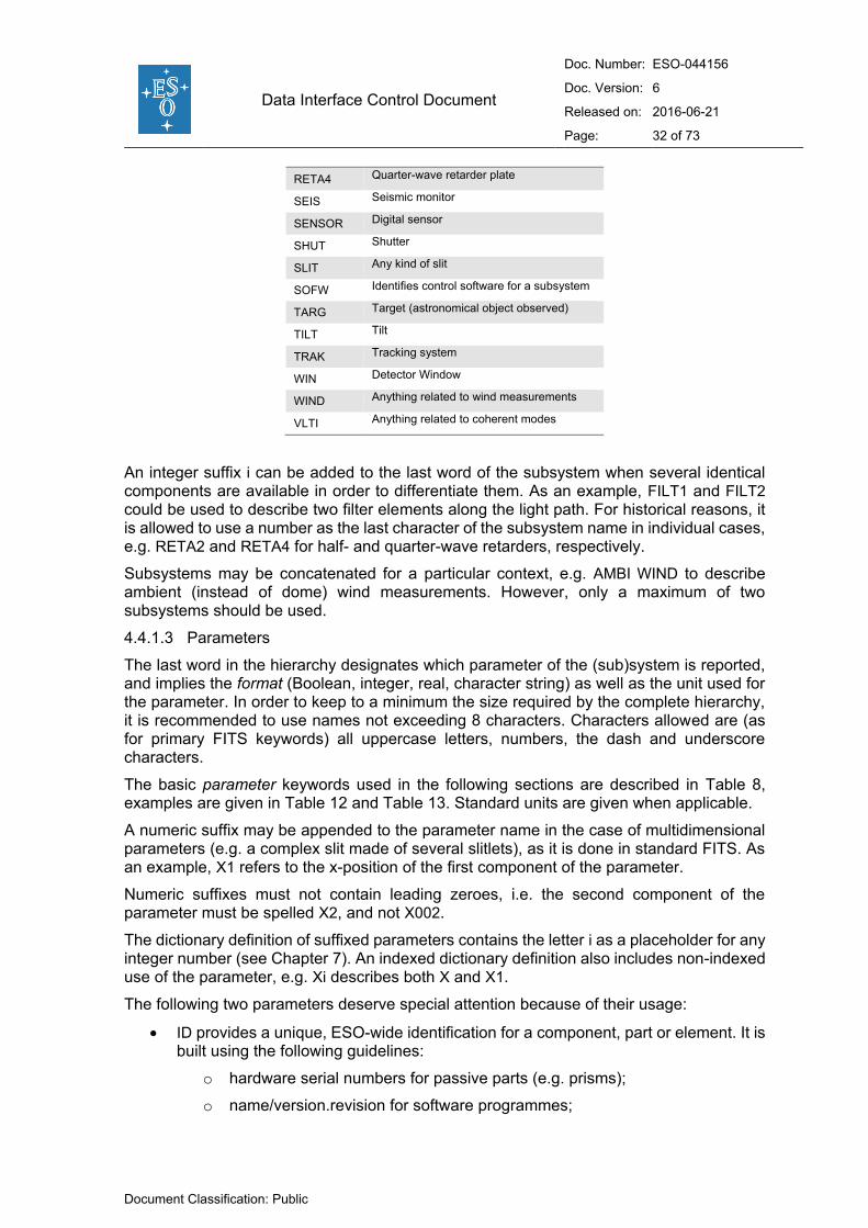
Data Interface Control Document
Doc. Number: ESO-044156
Doc. Version: 6
Released on: 2016-06-21
Page: 32 of 73
Document Classification: Public
RETA4 Quarter-wave retarder plate
SEIS Seismic monitor
SENSOR Digital sensor
SHUT Shutter
SLIT Any kind of slit
SOFW Identifies control software for a subsystem
TARG Target (astronomical object observed)
TILT Tilt
TRAK Tracking system
WIN Detector Window
WIND Anything related to wind measurements
VLTI Anything related to coherent modes
An integer suffix i can be added to the last word of the subsystem when several identical components are available in order to differentiate them. As an example, FILT1 and FILT2 could be used to describe two filter elements along the light path. For historical reasons, it is allowed to use a number as the last character of the subsystem name in individual cases, e.g. RETA2 and RETA4 for half- and quarter-wave retarders, respectively.
Subsystems may be concatenated for a particular context, e.g. AMBI WIND to describe ambient (instead of dome) wind measurements. However, only a maximum of two subsystems should be used.
4.4.1.3 Parameters
The last word in the hierarchy designates which parameter of the (sub)system is reported, and implies the format (Boolean, integer, real, character string) as well as the unit used for the parameter. In order to keep to a minimum the size required by the complete hierarchy, it is recommended to use names not exceeding 8 characters. Characters allowed are (as for primary FITS keywords) all uppercase letters, numbers, the dash and underscore characters.
The basic parameter keywords used in the following sections are described in Table 8, examples are given in Table 12 and Table 13. Standard units are given when applicable.
A numeric suffix may be appended to the parameter name in the case of multidimensional parameters (e.g. a complex slit made of several slitlets), as it is done in standard FITS. As an example, X1 refers to the x-position of the first component of the parameter.
Numeric suffixes must not contain leading zeroes, i.e. the second component of the parameter must be spelled X2, and not X002.
The dictionary definition of suffixed parameters contains the letter i as a placeholder for any integer number (see Chapter 7). An indexed dictionary definition also includes non-indexed use of the parameter, e.g. Xi describes both X and X1.
The following two parameters deserve special attention because of their usage:
ID provides a unique, ESO-wide identification for a component, part or element. It is built using the following guidelines:
o hardware serial numbers for passive parts (e.g. prisms);
o name/version.revision for software programmes;
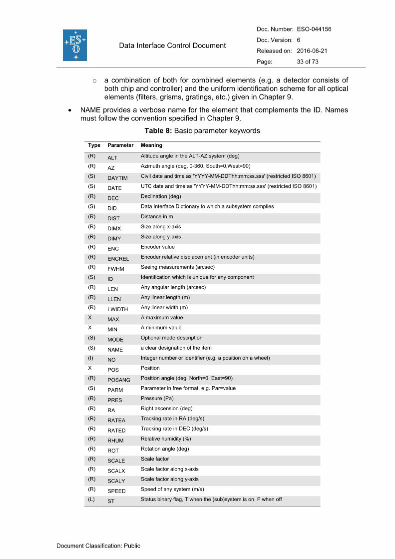
Data Interface Control Document
Doc. Number: ESO-044156
Doc. Version: 6
Released on: 2016-06-21
Page: 33 of 73
Document Classification: Public
o a combination of both for combined elements (e.g. a detector consists of both chip and controller) and the uniform identification scheme for all optical elements (filters, grisms, gratings, etc.) given in Chapter 9.
NAME provides a verbose name for the element that complements the ID. Names must follow the convention specified in Chapter 9.
Table 8: Basic parameter keywords
Type Parameter Meaning
(R) ALT Altitude angle in the ALT-AZ system (deg)
(R) AZ Azimuth angle (deg, 0-360, South=0,West=90)
(S) DAYTIM Civil date and time as 'YYYY-MM-DDThh:mm:ss.sss' (restricted ISO 8601)
(S) DATE UTC date and time as 'YYYY-MM-DDThh:mm:ss.sss' (restricted ISO 8601)
(R) DEC Declination (deg)
(S) DID Data Interface Dictionary to which a subsystem complies
(R) DIST Distance in m
(R) DIMX Size along x-axis
(R) DIMY Size along y-axis
(R) ENC Encoder value
(R) ENCREL Encoder relative displacement (in encoder units)
(R) FWHM Seeing measurements (arcsec)
(S) ID Identification which is unique for any component
(R) LEN Any angular length (arcsec)
(R) LLEN Any linear length (m)
(R) LWIDTH Any linear width (m)
X MAX A maximum value
X MIN A minimum value
(S) MODE Optional mode description
(S) NAME a clear designation of the item
(I) NO Integer number or identifier (e.g. a position on a wheel)
X POS Position
(R) POSANG Position angle (deg, North=0, East=90)
(S) PARM Parameter in free format, e.g. Par=value
(R) PRES Pressure (Pa)
(R) RA Right ascension (deg)
(R) RATEA Tracking rate in RA (deg/s)
(R) RATED Tracking rate in DEC (deg/s)
(R) RHUM Relative humidity (%)
(R) ROT Rotation angle (deg)
(R) SCALE Scale factor
(R) SCALX Scale factor along x-axis
(R) SCALY Scale factor along y-axis
(R) SPEED Speed of any system (m/s)
(L) ST Status binary flag, T when the (sub)system is on, F when off

Data Interface Control Document
Doc. Number: ESO-044156
Doc. Version: 6
Released on: 2016-06-21
Page: 34 of 73
Document Classification: Public
(S) STATUS Status of the system
(R) TEMP Temperature of any system (K)
(R) TILTA Tilt angle around the East-West axis (deg). See Figure 1.
(R) TILTB Tilt angle around the North-South axis (deg). See Figure 1.
(R) TIME Elapsed Time (seconds)
(S) TYPE Type or class of component
(S) UNIT Unit (see Chapter 8)
(R) UTC Universal Time Coordinated (seconds since midnight)
(R) WIDTH Any angular width (arcsec)
(R) WLEN Wavelength (nm)
(R) X Position along x-axis (m)
(R) Y Position along y-axis (m)
(R) ZENITH Zenithal distance (deg)
As a rule, a component change/replacement or a subsystem upgrade should be reflected in the ID parameter, but not in the NAME parameter.
4.4.2 Hierarchical keyword categories
4.4.2.1 Category Data Product (DPR)
The category includes parameters related to the raw data files and their contents. As mentioned earlier, the name of this category is kept for historical reasons.
DPR keywords are set by instrument template software (sequencer scripts).
Table 9: List of allowed DPR.CATG values
Value Explanation
SCIENCE Any scientific object
CALIB Any calibration source
ACQUISITION Any exposure taken to verify telescope pointing
TECHNICAL Any exposure taken to verify instrument performance/setup (see text)
TEST Any exposure taken to test instrument performance/setup/software/conditions (see text)
OTHER Any other exposure
DPR.CATG, DPR.TYPE and DPR.TECH provide unique high level description of the observation in terms of its purpose and technique. Note that only certain combinations of these keyword values are meaningful. It is the task of the template designer to characterise the observation making use of a suitable combination of values.
DPR.CATG gives the observation category. It must take one of the values given in Table 9.
DPR.CATG=’TEST’ is to be used to identify frames taken during instrument or software tests. The frames are allowed to use relaxed header rules: except for valid entries in FITS mandatory keywords and in MJD-OBS and INS.ID (and DPR.CATG, naturally), those frames are not under obligation to follow any header/data rules specified in this document. However, the responsibility for proper description of those frames for any future use lies entirely with the individual/group taking the data.

Data Interface Control Document
Doc. Number: ESO-044156
Doc. Version: 6
Released on: 2016-06-21
Page: 35 of 73
Document Classification: Public
DPR.CATG=’TECHNICAL’ is to be used for frames taken to verify instrument setup and/or performance, which are obtained in operational setup, and are under obligation to conform to the standards set forth in this document. Examples of such frames are: focus tests, shutter errors, ccd linearity, charge transfer efficiency, etc. In contrast to calibration frames (DPR.CATG=’CALIB’), these frames are not used to calibrate scientific data or to routinely measure the state and health of the instrument. Technical data are typically acquired rarely, during technical nights.
DPR.TYPE gives the type of observation/exposure.
Table 10: DPR.TYPE: examples of principal values (first group), qualifiers (second group) and instrument-specific qualifiers (third group)
Value Explanation
OBJECT any observation of an unspecified object
STD any observation of a standard calibration source
ASTROMETRY astrometric standard field
BIAS readout frame
DARK dark exposure (shutter closed)
FLAT any flat field exposure
SKY any sky background measurement
LAMP any lamp exposure
DOME any exposure using the dome
SCREEN any exposure using an illuminated screen
FLUX flux standard (spectroscopy and photometry)
PSF-CALIBRATOR reference star for PSF calibration
WAVE any (instrument-internal) wavelength calibration
FOCUS any focus exposure
SLIT any non-spectroscopic exposure using a slit
FIBER any exposure using fibers
FMTCHK any arc-lamp exposure to obtain first-order guesses for dispersion sol. (UVES)
ORDERDEF any flat-field exposure to derive order and background positions (UVES)
OzPoz exposures taken using the Fibre Positioner (FLAMES)
DPR.TECH gives the technique used during the observation.
DPR.TYPE and DPR.TECH can each store more than one value; it is recommended to limit the number of entries to at most three. The values should be separated with commas, with no blank spaces. This provides the means to describe a wide range of observations. If more than one value is present, the entries should as a rule follow the “general-to-specific” order, i.e. the first entry should be a general term describing the type or technique, followed by qualifiers describing more specific details (e.g. ‘FLAT,LAMP’ and ‘FLAT,SKY’ should be used instead of ‘LAMP,FLAT’ or ‘SKY,FLAT’).

Data Interface Control Document
Doc. Number: ESO-044156
Doc. Version: 6
Released on: 2016-06-21
Page: 36 of 73
Document Classification: Public
Table 11: DPR.TECH: examples of principal values (first group), qualifiers (second group) and instrument-specific qualifiers (third group)
Value Explanation
IMAGE Any picture
SPECTRUM Sngle-order spectrum
ECHELLE Cross-dispersed spectrum
MOS Frame with spectra of several objects
MXU Frame with spectra of several objects using a pre-manufactured mask
IFU Integral Field Unit observation
POLARIMETRY Polarimetric exposure
CORONOGRAPHY Coronography exposure
INTERFEROMETRY Coherent exposure with more than one telescope beam
TEL-THROUGH Telescope through-focus sequence
INS-THROUGH Instrument through-focus sequence
WEDGE Focus wedge frame
HARTMANN Hartmann focus test
ABSORPTION-CELL Absorption lines included (e.g. iodine cell)
DRIFTSCAN Drift scanning exposure
FABRY-PEROT Exposure using Fabry-Pérot technique
WOLLASTON Wollaston polarimetry
WIRE_GRID Wire grid polarimetry
DIRECT Qualifier indicating direct imaging/spectroscopy
CHOPPING Exposure utilising M2 chopping
NODDING Exposure utilising telescope nodding
CHOPNOD Exposure utilising both chopping and nodding
JITTER Exposure utilising source jittering technique
SLIC#<i> Observation using image slicer #i (UVES)
HIT High time resolution mode (FORS)
FILTERCURVE Spectroscopic flatfield with a narrowband filter included (FORS)
SPIDER Exposure using SkySpider (SINFONI)
Table 10 and Table 11 list commonly used values for DPR.TYPE and DPR.TECH keywords, respectively. Note: the tables do not show complete lists of allowed values, since development of new instruments and new observation techniques will quickly render obsolete any list claiming to be complete.
The tables are intended as guidelines showing what type of information is included in the keywords. In both tables, the first groups of values show the commonly used principal observation types or techniques, and those values will usually be the first entries in the DPR.TYPE or DPR.TECH value strings. Second groups of values show examples of qualifiers to the types or techniques. Third groups show few examples of instrument-specific qualifiers.

Data Interface Control Document
Doc. Number: ESO-044156
Doc. Version: 6
Released on: 2016-06-21
Page: 37 of 73
Document Classification: Public
New values for the DPR keywords must be submitted for approval to the DIC Board.
As examples, a twilight sky flat is described with:
DPR CATG = 'CALIB' DPR TYPE = 'FLAT,SKY' DPR TECH = 'IMAGE'
and a jittered NACO polarimetry observation of a scientific target with the Wollaston prism is described with:
DPR CATG = 'SCIENCE' DPR TYPE = 'OBJECT' DPR TECH = 'POLARIMETRY,WOLLASTON,JITTER'
4.4.2.2 Category Observation (OBS)
This category refers to Observation Block and frame identification and timing, and may apply to any kind of observation.
OBS keywords are set by the Observation Handling Subsystem through its Phase 2 Proposal Preparation tool (P2PP). OBS keywords are added untouched to the header by the instrument OS software.
Subsystems in this category are:
PI-COI contains information about the programme PI/CoI:
o OBS.PI-COI.NAME is intended to contain the name of the programme PI/CoI,
o OBS.PI-COI.ID a numeric ID which was assigned to the PI/CoI by ESO.
PROG provides details about the observing programme.
The following keywords have a special meaning and usage convention:
OBS.PROG.ID is the identification code assigned to each observing run by the Observing Programme Committee (OPC) in the format ‘tpp.c-nnnn(r)’, where:
o p is programme type: 0pp Normal Science Programme 1pp Large Programme 2pp Director’s Discretionary Time Programme 3pp Short Programme (obsolete as of this writing) 4pp Calibration Programme 5pp Monitoring Programme
o pp is the period number. Period number set to 60 indicates a technical programme, used for calibration,
o c is the programme scientific category as defined by the ESO OPC (currently A to D),
o nnnn is the running number,
o r is the observing run identifier, an uppercase letter.
This keyword allows the archive facility to assign ownership to the data and consequently to enforce proprietary rights of observations. This keyword must be present in all science, calibration and acquisition data files.
TARG contains information about the target that was observed. OBS.TARG.NAME gives the name of the target package which was used for the preparation of the OB with P2PP.
Data Interface Control Document
Doc. Number: ESO-044156
Doc. Version: 6
Released on: 2016-06-21
Page: 38 of 73
Document Classification: Public
Other keywords in this category are:
OBS.ID contains a unique numeric id which was assigned to the observation block by the Observation Handling Subsystem.
OBS.NAME contains the name of the observation block itself.
OBS.OBSERVER is intended to contain the name of the observer.
OBS.START gives the exact start time of the OB in the restricted ISO 8601 format.
OBS.TPLNO gives the template sequence number within the observation block. The first template in the observation block shall have the OBS.TPLNO value of 1.
4.4.2.3 Category Template (TPL)
TPL keywords are set by the instrument template software (sequencer scripts).
This category describes parameters needed by VLT observing templates. It includes the following header keywords:
TPL.ID and TPL.NAME to identify the observing template to which this frame belongs;
TPL.NEXP which gives the total number of exposures expected for this template;
TPL.EXPNO which gives the current exposure number within this template; the first exposure in a template shall have the TPL.EXPNO value of 1;
TPL.START which gives the exact start time of the template in the restricted ISO 8601 format;
Other template specific information such as loop parameters or parameters computed during the template execution.
4.4.2.4 Category General (GEN)
This category describes observatory information. GEN keywords are added to the header by the Data Pipeline Software and are found principally in the processed frames.
Subsystems in this category are:
AMBI describes observatory ambient conditions such as temperature (TEMP), relative humidity (RHUM), wind speed and direction (WIND), seeing (FWHM, full width at half maximum at 0.5 μm), airmass parameters (AIRM), seismic events (SEIS) and atmospheric coherent time (COTI).
4.4.2.5 Category Telescope (TEL)
TEL keywords are set by the Telescope Control Software (TCS).
Subsystems in this category are:
ACTO details Active Optics characteristics.
ADC details Atmospheric Dispersion Corrector characteristics. This subsystem may be embedded in the INS category if the corrector is part of the instrument.
AIRM gives airmass values at start and end of the observation.
AMBI gives ambient parameters as received from the ambient server.
CHOP gives parameters related to telescope chopping.

Data Interface Control Document
Doc. Number: ESO-044156
Doc. Version: 6
Released on: 2016-06-21
Page: 39 of 73
Document Classification: Public
DOME details dome conditions such as temperature (TEMP), wind speed and direction (WIND).
FOCU gives details of the focal length, scale and focal station.
M1/M2 give details about M1 and M2 status and general active optics information.
PARANG gives parallactic angles at start and end of the observation.
TARG gives details about the observation target.
TRAK describes tracking parameters.
TEL.DATE shall give the installation date of the telescope control software system.
TEL.ID shall give the revision number of the telescope control software.
4.4.2.6 Category Adapter (ADA)
ADA keywords are set by the Telescope Control Software (TCS).
Subsystems used in this category are:
GUID which gives guiding system information such as guide probe location and status;
ABSROT which describes absolute adapter rotation angles. The reference frame is defined in the dictionary for the adapter.
4.4.2.7 Category Instrument (INS)
INS keywords are set by the Instrument Control Software (ICS) or by the Observation Support Software (OS). For each instrument exists at least one dictionary. For some instruments there exist separate ICS and OS dictionaries.
A template for ICS dictionaries (ESO-VLT-DIC.XXX_ICS) is available from the Data Interface Control Board.
Many subsystem keywords are used in this category. In some cases, a possible integer suffix i will be required when several similar subsystems can be mounted.
A suffix shall be appended to a given subsystem name, if more than one instance of this subsystem are available for the instrument, even if the second instance is not mounted. For example, if a given instrument has two filter wheels, but a filter is selected in only one of them (and the other is set to an open position) then the subsystem describing this filter should be FILT1.
The dictionary definition of parameters with suffixed subsystem names contains the letter i as a placeholder for any integer number (see Chapter 7). An indexed dictionary definition also includes non-indexed use of the parameter, e.g. KWDi describes both KWD and KWD1.
Table 12: Example of the INS category
Type Keyword Example Explanation
(S) INS ID 'UVES ' Instrument ID
(S) INS DID 'ESO-VLT-DIC.UVES_ICS-1.73' Data dictionary for INS
(S) INS SOFW ID '$Revision: 1.73 $' Instrument SW
(S) INS SOFW MODE 'NORMAL ' Simulation mode
(S) INS PATH 'RED ' Optical path used

Data Interface Control Document
Doc. Number: ESO-044156
Doc. Version: 6
Released on: 2016-06-21
Page: 40 of 73
Document Classification: Public
(S) INS MODE 'RED ' Instrument mode used
(S) INS MIRR1 ID 'FREE ' Mirror unique ID
(S) INS MIRR1 NAME 'FREE ' Mirror common name
(I) INS MIRR1 NO 1 Mirror slide position
(S) INS MECH1 ID 'lpin1 ' General mechanical device unique ID
(S) INS MECH1 NAME 'Filt. Locking Pin' General mechanical device common name
(S) INS OPTI1 ID 'PS3 ' General optical device unique ID
(S) INS OPTI1 NAME 'M5BM10B ' General optical device common name
(I) INS OPTI1 NO 3 Slot number
(S) INS SLIT1 NAME 'FREE ' Slit common name
(I) INS SLIT1 NO 1 Slide position
(S) INS DROT MODE 'ELEV ' Instrument derotator mode
(R) INS DROT RA 84442.230 RA (J2000.0) pointing (hhmmss.sss)
(R) INS DROT DEC -544231.750 DEC (J2000.0) pointing ([-]ddmmss.sss)
(R) INS DROT POSANG 0.0000 Position angle (deg)
(R) INS DROT BEGIN 155.7380 Physical position at start (deg)
(S) INS DPOL MODE 'OFF ' Instrument depolarizer mode
(S) INS DPOS NAME 'OUT ' Instrument depolarizer slide posit
(I) INS DPOS NO 1 Depolarizer slide position
(S) INS FILT1 ID 'FREE ' Filter unique id
(S) INS FILT1 NAME 'FREE ' Filter common name
(I) INS FILT1 NO 13 Filter wheel position index
(S) INS OPTI2 ID 'DIAPHR.27MM' General Optical device unique ID
(S) INS OPTI2 NAME 'OVRSIZ ' General Optical device common name
(I) INS OPTI2 NO 3 Slot number
(S) INS MIRR2 ID 'RED#1 ' Mirror unique ID
(S) INS MIRR2 NAME 'RED ' Mirror common name
(I) INS MIRR2 NO 1 Mirror slide position
(S) INS SHUT1 NAME 'Telescope shutter' Shutter name
(L) INS SHUT1 ST T Shutter open
(R) INS SLIT3 WID 0.30 Slit width (arcsec)
(R) INS SLIT3 LEN 8.90 Slit length (arcsec)
(S) INS FILT3 ID 'BS4 ' Filter unique id
(S) INS FILT3 NAME 'SHP700 ' Filter common name
(I) INS FILT3 NO 4 Filter wheel position index
(S) INS DET6 NAME 'Red exp. meter PMT' Detector name
(R) INS DET6 CTTOT 3. Total counts during exposure
(R) INS DET6 UIT 1.000 User defined Integration time
(S) INS GRAT2 ID 'CD#3 ' Grating unique ID
(S) INS GRAT2 NAME 'CD#3 ' Grating common name
(R) INS PIXSCALE 0.182 Pixel scale
(R) INS GRAT2 X 2048.0 X pixel for central wavelength
(R) INS GRAT2 Y 2048.0 Y pixel for central wavelength
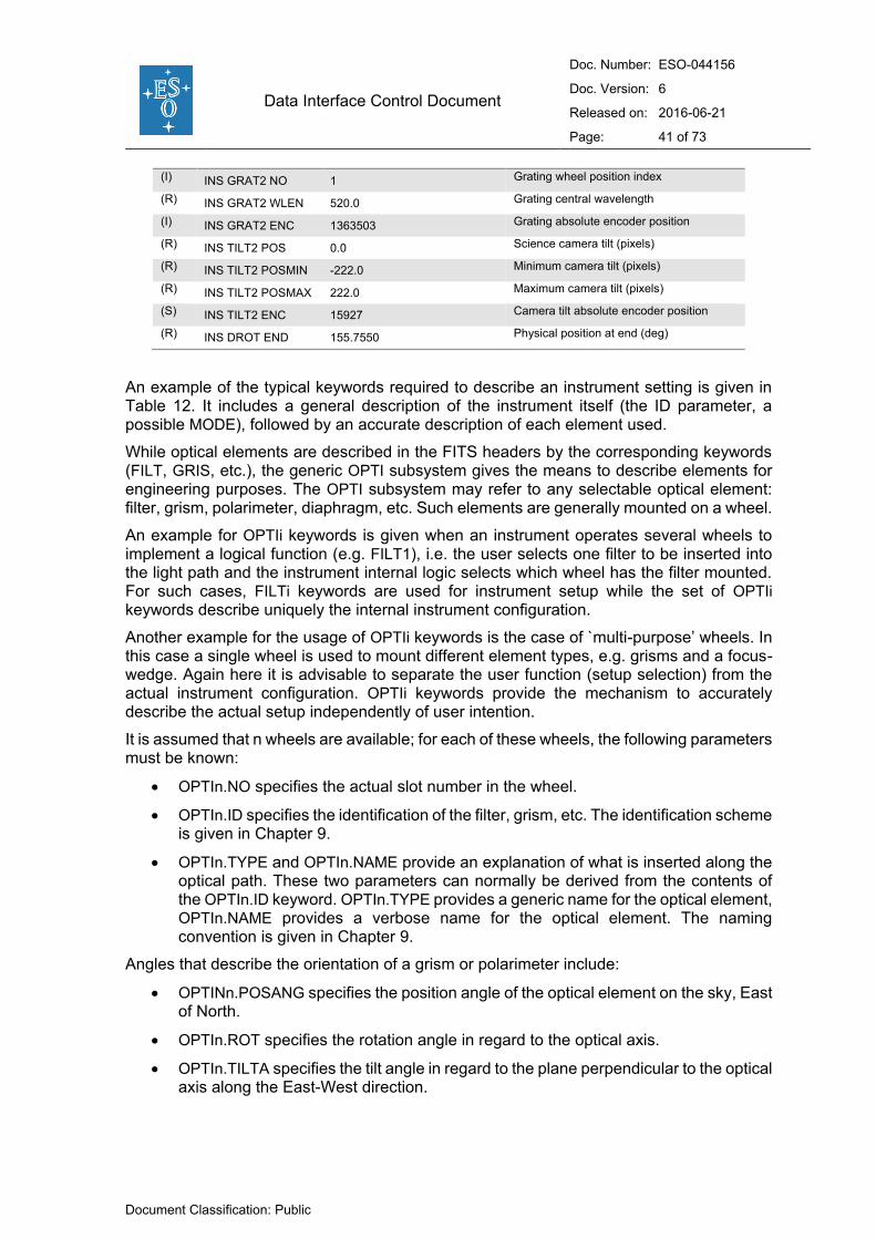
Data Interface Control Document
Doc. Number: ESO-044156
Doc. Version: 6
Released on: 2016-06-21
Page: 41 of 73
Document Classification: Public
(I) INS GRAT2 NO 1 Grating wheel position index
(R) INS GRAT2 WLEN 520.0 Grating central wavelength
(I) INS GRAT2 ENC 1363503 Grating absolute encoder position
(R) INS TILT2 POS 0.0 Science camera tilt (pixels)
(R) INS TILT2 POSMIN -222.0 Minimum camera tilt (pixels)
(R) INS TILT2 POSMAX 222.0 Maximum camera tilt (pixels)
(S) INS TILT2 ENC 15927 Camera tilt absolute encoder position
(R) INS DROT END 155.7550 Physical position at end (deg)
An example of the typical keywords required to describe an instrument setting is given in Table 12. It includes a general description of the instrument itself (the ID parameter, a possible MODE), followed by an accurate description of each element used.
While optical elements are described in the FITS headers by the corresponding keywords (FILT, GRIS, etc.), the generic OPTI subsystem gives the means to describe elements for engineering purposes. The OPTI subsystem may refer to any selectable optical element: filter, grism, polarimeter, diaphragm, etc. Such elements are generally mounted on a wheel.
An example for OPTIi keywords is given when an instrument operates several wheels to implement a logical function (e.g. FILT1), i.e. the user selects one filter to be inserted into the light path and the instrument internal logic selects which wheel has the filter mounted. For such cases, FILTi keywords are used for instrument setup while the set of OPTIi keywords describe uniquely the internal instrument configuration.
Another example for the usage of OPTIi keywords is the case of `multi-purpose’ wheels. In this case a single wheel is used to mount different element types, e.g. grisms and a focus-wedge. Again here it is advisable to separate the user function (setup selection) from the actual instrument configuration. OPTIi keywords provide the mechanism to accurately describe the actual setup independently of user intention.
It is assumed that n wheels are available; for each of these wheels, the following parameters must be known:
OPTIn.NO specifies the actual slot number in the wheel.
OPTIn.ID specifies the identification of the filter, grism, etc. The identification scheme is given in Chapter 9.
OPTIn.TYPE and OPTIn.NAME provide an explanation of what is inserted along the optical path. These two parameters can normally be derived from the contents of the OPTIn.ID keyword. OPTIn.TYPE provides a generic name for the optical element, OPTIn.NAME provides a verbose name for the optical element. The naming convention is given in Chapter 9.
Angles that describe the orientation of a grism or polarimeter include:
OPTINn.POSANG specifies the position angle of the optical element on the sky, East of North.
OPTIn.ROT specifies the rotation angle in regard to the optical axis.
OPTIn.TILTA specifies the tilt angle in regard to the plane perpendicular to the optical axis along the East-West direction.

Data Interface Control Document
Doc. Number: ESO-044156
Doc. Version: 6
Released on: 2016-06-21
Page: 42 of 73
Document Classification: Public
OPTIn.TILTB specifies the tilt angle in regard to the plane perpendicular to the optical axis along the North-South direction.
All angles are expressed in degrees, and measured according to the conventions given in Section 1.6.
For example:
INS.OPTI3.TYPE = 'FILTER' / Optical element used INS.OPTI3.NO = 7 / Position of wheel used INS.OPTI3.ID = '#590' / ID of the element INS.OPTI3.NAME = 'OIII/3000' / Name of the element
would describe filter ‘#590’ (OIII/3000) being mounted on wheel 3 in position 7.
SOFW identifies the detector control software and gives related parameters (see the log example in Section 5.1).
A MECH subsystem provides a generic way of storing information about the state of mechanical devices (e.g. clamp/lock/brake mechanisms).
MECHn.ID specifies the identification of the device.
MECHn.TYPE and MECHn.NAME can normally be derived from the contents of the MECHn.ID keyword. MECHn.TYPE provides the generic name, while MECHn.NAME provides the verbose name of the device.
MECHn.ST and MECHn.STAT provide – if applicable – a Boolean and string descriptions of the status of the device.
MECHn.SWSIM provides a Boolean indicator showing if the status of the device is software-simulated.
For example:
INS.MECH1.ID = 'lpin1 ' / Mechanical device ID INS.MECH1.NAME = 'Filt. Locking PiOut' / Mechanical device name INS.MECH1.ST = T / Device Status INS.MECH1.STAT = 'In ' / Device Status INS.MECH1.SWSIM = F / Simulated if T
would describe the status of a locking pin.
INS.DATE shall give the installation date of the instrument control software system.
INS.ID shall include the revision number of the instrument control software (see Chapter 10).
4.4.2.8 Category Detector (DET)
DET keywords are set by the Detector Control Software (DCS) for optical instruments and by the Instrument Control Software for infrared instruments.
Subsystems used in this category are:
CHIP describes each CCD chip when an array of CCDs is exposed.
EXP describes exposure parameters.
FRAM describes the frame type.
OUT describes the outputs used for read-out. This subsystem includes the description of detector orientation.
PARM gives unspecified detector parameters.
READ gives readout parameters.

Data Interface Control Document
Doc. Number: ESO-044156
Doc. Version: 6
Released on: 2016-06-21
Page: 43 of 73
Document Classification: Public
SHUT gives shutter parameters.
SOFW identifies the detector control software and gives related parameters (see the log example in Section 5.1).
WIN describes read-out window(s) parameters.
Keywords from the DET.CHIP hierarchy (NX, NY, etc.) refer to the physical chip.
The subsystem OUTi should carry an index, even if only one output is used. DET.OUTPUTS shall provide the number of outputs used. Note that the pixel area which is covered by each output is not a setup parameter but instead a static configuration of the detector chip. It is the task of the detector controller to assemble the selected window(s) properly.
Keywords from the DET.OUTi hierarchy relate to the image pixels produced by the relevant output.
The outputs shall be counted per chip, not over the entire instrument, i.e. there shall be subsystems DET.OUT1, DET.OUT2, ... for each chip.
DET.OUTi.NX and DET.OUTi.NY, respectively, should contain the number of image pixels that are read out through port i, including any prescan and overscan pixels.
The subsystem WINi should carry an index, even if only one window is used.
WINi includes parameters that define the readout region used on the CCD: the location of the window on the chip (offset position), its size, and the binning factors used. The horizontal axis is named X, and the vertical axis Y.
Let us assume that the window is defined with its lower left corner at position (i0,j0), a size Δi×Δj, and binning factors (fi,fj); the largest window has the values (1,1) for the start position, and binning factors (1,1). The window is described by:
NX and NY, which give the number of pixels, i.e. Δi=NX×fi and Δj=NY×fj. The pixels in the pre- and overscan areas are included. The values are obviously identical to those given in NAXIS1 and NAXIS2;
BINX and BINY give the binning factors fi and fj, respectively;
STRX and STRY represent the start position of the window, i.e. i0 and j0, respectively.
Table 13: Sample DET category keywords
Type Keyword Example Explanation
(S) DET ID 'CCD FIERA - Rev 2.69' Detector system Id
(S) DET NAME 'ccdF - fors' Name of detector system
(S) DET DID 'ESO-VLT-DIC.CCDDCS-1.3' Dictionary
(I) DET BITS 16 Bits per pixel readout
(R) DET RA 53.19183333 Apparent 03:32:46.0 RA
(R) DET DEC -27.69388611 Apparent -27:41:37.9 DEC
(S) DET SOFW MODE 'Normal ' CCD sw operational mode
(I) DET CHIPS 1 # of chips in detector array
(S) DET CHIP1 ID 'CCID20-14-5-6' Detector chip identification
(S) DET CHIP1 NAME 'MIT/LL mosaic' Detector chip name
(S) DET CHIP1 DATE '2000-04-01T12:34:56.789' Date of installation

Data Interface Control Document
Doc. Number: ESO-044156
Doc. Version: 6
Released on: 2016-06-21
Page: 44 of 73
Document Classification: Public
(R) DET CHIP1 GAIN 1.1 Gain setting (e-/adu)4
(I) DET CHIP1 X 1 X location in array
(I) DET CHIP1 Y 1 Y location in array
(I) DET CHIP1 NX 2048 # of pixels along X
(I) DET CHIP1 NY 2049 # of pixels along Y
(R) DET CHIP1 PSZX 24.0 Size of pixel in X
(R) DET CHIP1 PSZY 24.0 Size of pixel in Y
(I) DET EXP NO 911 Unique exposure ID number
(S) DET EXP TYPE 'Dark ' Exposure type
(I) DET EXP DUMDIT 0 # of dummy readouts
(R) DET EXP RDTTIME 33.026 Image readout time (s)
(R) DET EXP XFERTIM 33.094 Image transfer time (s)
(S) DET READ MODE 'normal ' Readout method
(S) DET READ SPEED 'normal ' Readout speed
(S) DET READ CLOCK 'ABCD,1x1,high' Readout clock pattern used
(I) DET OUTPUTS 1 # of outputs
(I) DET OUTREF 0 Reference output
(S) DET OUT1 ID 'A ' Output ID
(S) DET OUT1 NAME 'A ' Description of output
(I) DET OUT1 CHIP 1 Chip to which the output belongs
(I) DET OUT1 X 1 X location of output
(I) DET OUT1 Y 1 Y location of output
(I) DET OUT1 NX 2048 Valid pixels along X
(I) DET OUT1 NY 500 Valid pixels along Y
(I) DET OUT1 PRSCX 0 Prescan region in X
(I) DET OUT1 OVSCX 0 Overscan region in X
(R) DET OUT1 CONAD 1.46 Conversion from ADUs to e- (e-/adu)
(R) DET OUT1 RON 5.16 Readout noise per output (e-)
(R) DET OUT1 GAIN 0.68 Gain setting (adu/e-)4
(I) DET FRAM ID 1 Image sequential number
(S) DET FRAM TYPE 'Dark ' Type of frame
(I) DET WIN1 STRX 1 Lower left pixel in X
(I) DET WIN1 STRY 500 Lower left pixel in Y
(I) DET WIN1 NX 2048 # of pixels along X
(I) DET WIN1 NY 500 # of pixels along Y
(I) DET WIN1 BINX 1 Binning factor along X
(I) DET WIN1 BINY 1 Binning factor along Y
(I) DET WIN1 NDIT 1 # of subintegrations
(R) DET WIN1 UIT1 0.000000 User defined subint. time (s)
(R) DET WIN1 DIT1 0.019151 Actual subint. time (s)
4 We draw the reader’s attention to the fact that for historical reasons (different control software) the units of GAIN for OUTn and CHIPn hierarchies are different: adu/e- in the former, e-/adu in the latter.

Data Interface Control Document
Doc. Number: ESO-044156
Doc. Version: 6
Released on: 2016-06-21
Page: 45 of 73
Document Classification: Public
(R) DET WIN1 DKTM 0.0192 Dark current time (s)
(S) DET SHUT TYPE 'Iris ' Type of shutter
(S) DET SHUT ID 'fors shutter' Shutter unique identifier
(R) DET SHUT TMOPEN 0.000 Time taken to open shutter (s)
(R) DET SHUT TMCLOS 0.000 Time taken to close shutter (s)
In the cases in which several outputs are used to read-out the chip and disjoint windows are read, the subsystem combination must be used.
DET.FRAM subsystem shall provide the description of the frame type.
DET.ID shall provide the name and revision number of the detector control software.
4.4.2.9 Category Observation Control Software (OCS)
OCS keywords are set by the instrument’s Observation Software. They are accordingly defined in the dictionaries of the different instruments.
This category includes parameters that are created by the OS upon creation of a frame.
4.4.2.10 Category Delay Lines (DEL)
DEL keywords are set by the VLTI Control Software.
This category includes parameters that relate to the VLTI delay lines.
4.4.2.11 Category Coudé Optics (COU)
COU keywords are set by the VLTI Control Software.
This category includes parameters that relate to the VLTI coudé optics.
4.4.2.12 Category Interferometric Supervisor Software (ISS)
ISS keywords are set by the VLTI Interferometric Supervisor Software.
This category includes parameters that relate to the VLTI telescope setup.
4.4.2.13 Category Adaptive Optics System (AOS)
AOS keywords are set by the Control Software, Observation Software or Real time Control Software of Adaptive Optics Systems (e.g. NAOS).
4.4.2.14 Category Simulator (SIM)
SIM keywords are set by the Quality Control subsystem. Currently this category is only used by NAOS.
This category includes parameters that relate to the simulation process, in particular those for which the simulator needs assumptions. Examples are sky emissivity in the infrared, object brightness or assumptions regarding the point spread function.
4.4.2.15 Category Process (PRO)
PRO keywords are set by the Data Pipeline Software.
This category includes parameters used during a standard reduction process. This keyword category is found principally in the processed frames.
4.4.2.16 Category Quality Control (QC)
QC keywords are also set by the Data Pipeline Software.

Data Interface Control Document
Doc. Number: ESO-044156
Doc. Version: 6
Released on: 2016-06-21
Page: 46 of 73
Document Classification: Public
This category includes parameters describing results of the Quality Control process performed by the pipeline. This category is found principally in the processed frames.
4.4.2.17 Category Laser Guide Star (LGS)
This category includes parameters describing the settings of the Laser Guide Star Facility, including Four Laser Guide Star Facility (“4LGSF”).
4.5 Keywords containing date/time information
All string-valued keywords storing date/time information shall use the restricted ISO 8601 format: ‘YYYY-MM-DDThh:mm:ss.sss’ (e.g. ‘2007-12-31T12:34:56.789’), or ‘YYYY-MM-DD’
when only date is shown (e.g. ‘2007-12-31’). See [AD6] and Section 4.4.2.1 of [AD4].
4.6 Errors and statistics parameters
In some cases, it is important to provide, in addition to the parameter value being reported, also an error, range or some other statistical property. The convention for such cases is to provide auxiliary parameters whose names share the first 5 characters with their root parameter name and end with one of the strings given below:
ERR error bars (e.g. FWHMERR), i.e. the uncertainty of the root parameter value in both directions ( + and –);
MIN/MAX minimum and maximum values (e.g. RHUMMIN, TEMPMAX) during a given period of time (e.g. during the exposure);
RMS root mean square of the parameter values during a given period of time;
AVG average of the parameter values during a given period of time;
SD standard deviation of the parameter values during a given period of time;
PTV peak-to-valley variation of the root parameter values during a given period of time.
The unit of the ERR, MIN, MAX, AVG, SD and PTV parameter is always the same as the root parameter.
In case of enumerated parameters, (e.g. TEMP1) the index suffix shall be added at the end (TEMPMAX1 in this example).
4.7 Data products
This section describes requirements for processed files. This category contains:
Reduced calibration frames, generated by ESO using supported pipelines (the so-called “Master Calibrations”).
Science Data Products (SDPs), which contain fully reduced and calibrated scientific data. There are two sub-categories of SDPs
o Originating from intra-ESO processing using ESO-supported pipelines.
o Processed and contributed by ESO users. Principal Investigators of ESO Large Programmes are required to deliver their final data products (processed images and spectra, catalogues) to ESO Archive at the time of publication of their results. This category also includes high-level products from Public Surveys with ESO survey telescopes.

Data Interface Control Document
Doc. Number: ESO-044156
Doc. Version: 6
Released on: 2016-06-21
Page: 47 of 73
Document Classification: Public
The following provides specifications for content of Data Products.
4.7.1 Products generated at ESO
This subsection is relevant for all products generated at ESO, i.e. Master Calibrations and products resulting from the runs of ESO-supported pipelines.
Keyword specifications described in the preceding sections shall also apply to ESO-generated products, with the following additional requirements:
The files shall contain the Boolean keyword PRO.SCIENCE which shall be set to T for science files and F for all other files. Archived files generated prior to the introduction of this requirement shall assume the value of this keyword of F.
The files shall not contain keywords from the DPR category, i.e. keywords described in Section 4.4.2.1.
The files shall contain the PRO.TECH keyword, which shall contain the value from the DPR.TECH keyword in the original file.
The following keywords from the PRO dictionary:
PIPEFILE PRO.DID PRO.REC1.ID PRO.REC1.DRS.ID PRO.REC1.PIPE.ID PRO.DATANCOM PRO.CATG DATAMD5
are mandatory in processed science and calibration frames.
At least one of the two following keywords: PRO.REC1.RAW.NAME or PRO.REC1.CAL1.NAME shall be present in, respectively, processed science and calibration frames. They must be accompanied by the corresponding PRO.REC1.RAW.CATG or PRO.REC1.CAL1.CATG keyword.
4.7.2 Science Data Products
This subsection describes the general interface requirements for Science Data Products, both generated at ESO with the use of ESO-supported pipelines and delivered to ESO via the Phase 3 process.
Because it is not possible to account for all possible types of SDPs, the present document describes only requirements for the generic metadata describing the products. Detailed requirements for SDPs are described in [RD10]. This document is available from the ESO Phase 3 website, http://www.eso.org/sci/observing/phase3.html. In case the products are not covered in the web site the users should contact the ESO Archive Science Group via email at [email protected], with the subject of “Phase 3: (...)”.
All SDPs must contain all applicable FITS generic keywords from those described in Section 4.1 and shown in Table 1.
SDPs must contain appropriate WCS keywords (see Section 4.2) when applicable. It is strongly recommended that the CDn_m matrix is used to describe pixel scale and rotation, but it is allowed to use other supported WCS conventions (CDELTn+PCn_m or CDELTn+CROTAn). Only one WCS convention shall be used in each file.
If possible, SDPs shall contain provenance information, i.e. information allowing for identification of observations or files from which the SDP has been derived. If relevant,

Data Interface Control Document
Doc. Number: ESO-044156
Doc. Version: 6
Released on: 2016-06-21
Page: 48 of 73
Document Classification: Public
SDPs must contain association information, i.e. identifiers of products associated to the SDP.
SDPs containing HDUs storing error and data quality information shall use keywords SCIDATA, ERRDATA and QUALDATA to store the values of EXTNAME of HDUs containing science, error and quality information, respectively. See [RD14].
It is specifically noted that SDPs use the e-/adu unit for the GAIN keyword (cf. footnote 4 on page 47).

Data Interface Control Document
Doc. Number: ESO-044156
Doc. Version: 6
Released on: 2016-06-21
Page: 49 of 73
Document Classification: Public
5. Logging
The log database defines all information that characterises the environment in which a specific observation was obtained. It represents the logbook of telescope operation. It uniquely associates a scheduled observing programme to a set of acquired exposures.
The log database includes night reports and the log files defined in Section 3.2.
The log files will record a number of actions and parameters which are defined in the corresponding dictionaries. In addition, log files may temporarily include any number of parameter records to be used e.g. for troubleshooting purposes.
The log file format is designed to allow an accurate trace of VLT operations. Every log record is uniquely identified by the logging source (given through the source mask, see below) and its date/time stamp. This design allows to merge all log records in the log database independently of how many log files where created. The unique source mask also permits to trace the parallel operation of two instruments, e.g. one doing science exposures while the other is used to acquire calibration frames.
5.1 Log File format
The log files shall follow UTF-8 encoding.
A log file consists of maximum 250 byte long records terminated with a newline character (‘\n’), however, keywords and values (see below) must be written within the first 72 characters. The restriction to 72 characters is due to the need to be able to include relevant log records in the FITS headers of observations.
Log records have the general format:
hh:mm:ss> keyword / comments [<srcmask>]
or:
hh:mm:ss>/ comments [<srcmask>]
where:
hh:mm:ss is the time stamp, consisting of the time (UTC). hh:mm:ss.sss may be used if a higher time resolution is required;
keyword is a hierarchical keyword (or set of words) which explains what happened (action keyword) or identifies the reported parameter (followed by = value). Note that the words HIERARCH ESO are omitted here.
comments explain the keyword reported, and
<srcmask> is the event source identification mask (“source mask”; see Section 5.2).
A log file always starts at noon (UTC). The first record of a log is a date stamp record in the following format:
12:00:00> DATE = 'YYYY-MM-DD' / Weekday Month Day, Year [source]
A date stamp record must also be the first record written on the log after midnight (UTC).
The following classes of records can be found in a log:
Action records reporting an action initiated by the observer/operator; typical examples are opening and closing operations, or moving the telescope. An action record starts with an action keyword (a verb starting with a dash); it cannot have any associated value, but may be followed by parameter record(s) like the telescope slew at the end of the log example

Data Interface Control Document
Doc. Number: ESO-044156
Doc. Version: 6
Released on: 2016-06-21
Page: 50 of 73
Document Classification: Public
shown below. Subsystem names are taken from Table 7. See Section 5.1.1 for the record syntax.
Parameter records These can be meteorological parameters (wind speed, dome temperature), seeing conditions, or the status of some instrument. The parameter name is normally followed by a value. Such parameters are either acquired periodically (e.g. the dome temperature), or recorded as a result of a given action. See Section 5.1.2 for the record syntax.
Unforeseen event records reporting unexpected events, like the failure of a lamp or the loss of synchronisation between modules. See Section 5.1.4 for the record syntax.
Alarm event records reporting alarm conditions. See Section 5.1.5 for the record syntax.
Comments inserted by the PI/Co-I or science operations staff. See Section 5.1.6 for the record syntax.
Typical examples of what can be found in the log file are given below.
12:00:00> DATE = '1995-03-31' / Fri Mar 31, 1995 [wemmi] 12:46:19>-START COMP / Computer restarted [wemmi] 12:46:19> COMP ID = 'HP RTE-A V5' / Operating system identifier [wemmi] 12:46:19> COMP NAME = 'NTI' / Network node identifier [wemmi] 12:46:19> TEL ID = 'ESONTT' / Control NTT telescope [wemmi] 12:47:35>-START OBS SOFW EMMI / EMMI observ. prog. started [wemmi] 12:47:35> OBS SOFW ID = 'OBST-V4.2' / Programme name-version [wemmi] 12:47:35> OBS SOFW MODE = 'NORMAL' / Hw enabled for OBST [wemmi] 12:47:48>-START INS SOFW EMMI / EMMI control prog. started [wemmi] 12:47:48> INS SOFW ID = 'EMMI-V4.1' / Programme name-version [wemmi] 12:47:48> INS SOFW MODE = 'NORMAL' / Hw enabled for EMMI [wemmi] 12:47:48>-START DET SOFW EMMI RED / CCD control prog. started [wemmiR] 12:47:48> DET SOFW ID = 'CCDR-V4.2' / Programme name-version [wemmiR] 12:47:48> DET SOFW MODE = 'NORMAL' / Hw enabled for CCDR [wemmiR] 12:47:49>-START DET SOFW EMMI BLUE / CCD control prog. started [wemmiB] 12:47:49> DET SOFW ID = 'CCDB-V4.2' / Programme name-version [wemmiB] 12:47:49> DET SOFW MODE = 'NORMAL' / Hw enabled for CCDB [wemmiB] 12:47:54>/UNFORESEEN: Error while initialising EMMI Red CCD [wemmi] 12:47:57>/UNFORESEEN: Error while initialising EMMI Blue CCD [wemmi] 12:47:57>-STOP ADA B LAMP-0 / Calibration lamp switched off. [wemmiB] 12:48:50>-STOP ADA B LAMP-0 / Calibration lamp switched off. [wemmiB] 12:50:17>-START DET EMMI RED / Start wiping CCD EMMI RED [wemmiR] 12:50:17>-START EMMI CALIBRATION / Start cal. procedure [wemmi] 12:50:17>-START ADA B OPTI / Calibration unit moved in [wemmiB] 12:50:17>-CLOSE EMMI CAL SHUT-ALL / Close all cal. shutters [wemmi] 12:50:18>-CLOSE ADA B SHUT-0 / Calibration shutter closed. [wemmiB] 12:50:18>-STOP EMMI CAL LAMP-ALL / Switch off all cal. lamps [wemmi] 12:50:18>-STOP ADA B LAMP-0 / Calibration lamp switched off. [wemmiB] 12:50:19>-START EMMI CAL LAMP14 / Switch on cal. lamp [wemmi] 12:50:19>-START ADA B LAMP14 / Calibration lamp switched on. [wemmiB] 12:50:19>-OPEN EMMI CAL SHUT14 / Open cal. shutter [wemmi] 12:50:20>-OPEN ADA B SHUT14 / Calibration shutter open. [wemmiB] 12:51:16>-START EXPO EMMI RED / Start exp. on CCD EMMI RED [wemmiR] 12:51:16> EXPO EMMI RED NO = 3107 / Exp. num. on CCD EMMI RED [wemmiR] 12:53:17>-STOP EXPO EMMI RED / Stop exp. on CCD EMMI RED [wemmiR] 12:53:17>-READ DET EMMI RED / Reading CCD EMMI RED [wemmiR] 12:55:01>/UNFORESEEN: Failed image transfer to host [wemmiR] 12:55:08>/RECOVERY: Image transfer to host recovered [wemmiR] 12:55:08>-STOP TRANS DET EMMI RED / Transf. OK from CCD EMMI RED [wemmiR] 12:55:08> DET PARM(1) = -8.05, 3.00, 23.52 / DET: VLO1, VHI1, VDD1 [wemmiR] 12:55:08> DET PARM(4) = -4.06, 5.99, 13.77 / DET: HLO1, HHI1, VDR1 [wemmiR] 12:55:08> DET PARM(7) = -0.36, 12.00, 0.31 / DET: RLO1, RHI1, VGS1 [wemmiR] 12:55:08> DET PARM(10)=-14.73, 14.80, 27.34 / DET: -15V, +15V, +30V [wemmiR] 12:55:15>-CLOSE EMMI CAL SHUT14 / Close cal. shutter [wemmi] 12:55:15>-CLOSE ADA B SHUT14 / Calibration shutter closed. [wemmiB] 12:55:15>-STOP EMMI CAL LAMP14 / Switch off cal. lamp [wemmi] 12:55:18>-STOP ADA B LAMP14 / Calibration lamp switched off. [wemmiB] 22:56:12>-MOVE TEL PRESET NTT / Initiate new tel position [wt5tcs] 22:57:37> TEL RA = 67.265296 / RA (deg) after move [wt5tcs]
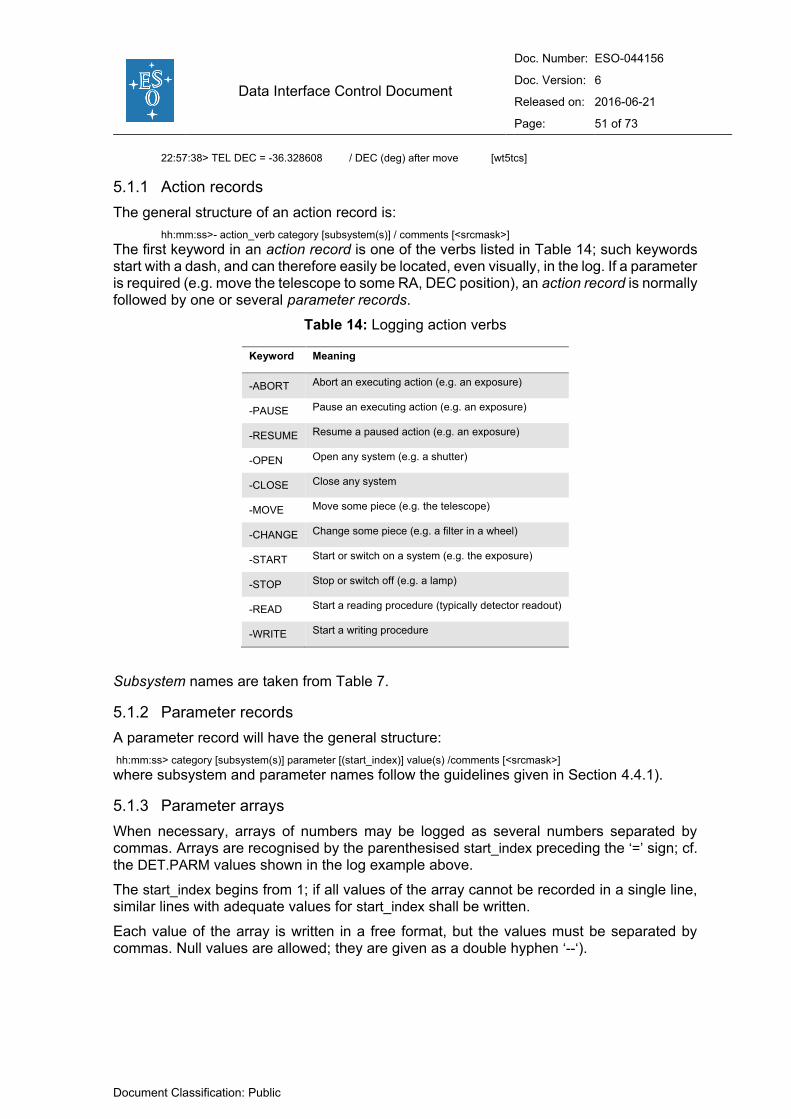
Data Interface Control Document
Doc. Number: ESO-044156
Doc. Version: 6
Released on: 2016-06-21
Page: 51 of 73
Document Classification: Public
22:57:38> TEL DEC = -36.328608 / DEC (deg) after move [wt5tcs]
5.1.1 Action records
The general structure of an action record is:
hh:mm:ss>- action_verb category [subsystem(s)] / comments [<srcmask>]
The first keyword in an action record is one of the verbs listed in Table 14; such keywords start with a dash, and can therefore easily be located, even visually, in the log. If a parameter is required (e.g. move the telescope to some RA, DEC position), an action record is normally followed by one or several parameter records.
Table 14: Logging action verbs
Keyword Meaning
-ABORT Abort an executing action (e.g. an exposure)
-PAUSE Pause an executing action (e.g. an exposure)
-RESUME Resume a paused action (e.g. an exposure)
-OPEN Open any system (e.g. a shutter)
-CLOSE Close any system
-MOVE Move some piece (e.g. the telescope)
-CHANGE Change some piece (e.g. a filter in a wheel)
-START Start or switch on a system (e.g. the exposure)
-STOP Stop or switch off (e.g. a lamp)
-READ Start a reading procedure (typically detector readout)
-WRITE Start a writing procedure
Subsystem names are taken from Table 7.
5.1.2 Parameter records
A parameter record will have the general structure:
hh:mm:ss> category [subsystem(s)] parameter [(start_index)] value(s) /comments [<srcmask>]
where subsystem and parameter names follow the guidelines given in Section 4.4.1).
5.1.3 Parameter arrays
When necessary, arrays of numbers may be logged as several numbers separated by commas. Arrays are recognised by the parenthesised start_index preceding the ‘=’ sign; cf. the DET.PARM values shown in the log example above.
The start_index begins from 1; if all values of the array cannot be recorded in a single line, similar lines with adequate values for start_index shall be written.
Each value of the array is written in a free format, but the values must be separated by commas. Null values are allowed; they are given as a double hyphen ‘--‘).

Data Interface Control Document
Doc. Number: ESO-044156
Doc. Version: 6
Released on: 2016-06-21
Page: 52 of 73
Document Classification: Public
5.1.4 Unforeseen event records
The log files also include the record of events that are considered unforeseen by the control software. Such events are typically the failure of a calibration lamp or loss of time synchronisation.
The record format is:
hh:mm:ss>/UNFORESEEN: succinct description of the event [<srcmask>]
Recovery records are used to signal the success of an action in response to an unforeseen event, they have the format:
hh:mm:ss>/RECOVERY: description of the recovery measure [<srcmask>]
In some cases it may be desirable to be able to match a recovery log entry to its corresponding unforeseen event. This can be done by filtering log records with the source mask, under the assumption that one single subsystem is issuing only few of such events at a given time.
5.1.5 Alarm records
Alarm events are recorded in the log with the following format:
hh:mm:ss>/ALARM: succinct description of the alarm event [<srcmask>]
5.1.6 Comment records
Two different comment record formats are provided. They have the following structure:
hh:mm:ss>/ free-format comment up to 50 characters
or
hh:mm:ss>/COMMENT NN free-format comment, possibly spanning several lines
where NN is a two letter code OB, SA or NA, which stand for the observer, staff/service astronomer or night assistant, respectively.
5.2 Event source mask
The format for the source mask is:
[<host-name><attribute-1><attribute-2><attribute-3>]
where
<host-name> is the node name of the workstation or LCU on which the event originates (instrument workstation, telescope workstation, detector LCU, etc.). In test environment, where the node name may be different from the target node name, the target node name should be used. The list of VLT host names is given in [RD11].
<Attribute-i> are three characters available to generate unique source masks within the same host-used by OS, ICS and DCS to identify multiple instrument arms.
The source mask is mandatory for all reporting systems.
5.3 Log file names
The names of operations log files shall follow the following scheme:
<host-name>.YYYY-MM-DD.ops.log
where <host-name> is the node name of the computer generating the log file and YYYY-
MM-DD stands for the date of the beginning of the night (for example: wvisir.2007-04-
01.ops.log).

Data Interface Control Document
Doc. Number: ESO-044156
Doc. Version: 6
Released on: 2016-06-21
Page: 53 of 73
Document Classification: Public
The names of the log files containing Quality Control Level 1 parameters generated on-site shall follow the following scheme:
QC1_<instrument>.YYYY-MM-DD.ops.log
where <instrument> identifies the relevant instrument and YYYY-MM-DD stands for the date of the beginning of the night (for example: QC1_VISIR.2007-04-01.ops.log).

Data Interface Control Document
Doc. Number: ESO-044156
Doc. Version: 6
Released on: 2016-06-21
Page: 54 of 73
Document Classification: Public
6. VLT parameter files
The Parameter File (PAF) format is used by different systems to store values of various properties used in the given context. The format is described in detail below.
In particular, observation preparation tools provide the means to create and edit Observation Blocks as the basic unit of an executable sequence of Templates. Each template, in turn, requires a given input configuration or parameter list, described by a so-called template signature. These parameters are stored in the PAF format. Any template corresponds with a certain predefined mode of observation, and has consequently a Reference Setup File attached to it. Reference setup-files list the default configuration of all elements in the light path, and are also written in the parameter file format.
Observation blocks include information on the programme that owns the block, scheduling requirements and links to other blocks. They also include or refer via the templates to Setup Files for setting target positions, instrument and detector configurations, all of which can be re-used in a number of observations, e.g. when a list of target pointings are to be observed with the same instrumental configuration.
From the observation block information, the VLT Control Software (VCS) will eventually generate setup-commands for its own operations. Doing so it will complement the information contained in the reference setup-file corresponding with the running template.
6.1 Parameter File format
Many VLT files containing control information are written in the Parameter File Format. This is the case for, e.g., setup-files, instrument configuration files and template parameter files. These files consist of a mandatory header and parameter records. Their syntax is optimised for fast parsing by the VLT Control Software and therefore it differs from other formats described in this document (see [RD12]).
A parameter record is written with the following syntax:
<short FITS keyword> <value>; [# comment]
where:
<short FITS keyword> is as described in Section 4.4, i.e. categories and parameters of hierarchical keywords are connected by dots ‘.’ rather than spaces and the HIERARCH ESO prefix is not used.
<value> can be one of the values defined in Section 4.1, however, strings must be enclosed in double rather than single quotes, i.e. ”string”. The value part must be finished with a semicolon ‘;’ and must be given on the same line.
Optional comments can be included at the end of a line by prefixing them with the hash sign (‘#’).
The files shall follow UTF-8 encoding.
6.1.1 Parameter File header
The header consists of a number of records identifying the purpose and type of the parameter file. Header records are mandatory. Parameter header records are grouped in the category.
Table 15 gives an example of a parameter file header.
Table 15: Parameter file keywords

Data Interface Control Document
Doc. Number: ESO-044156
Doc. Version: 6
Released on: 2016-06-21
Page: 55 of 73
Document Classification: Public
PAF.HDR.START; # Marks start of header PAF.TYPE "Template Signature"; # Type of parameter file PAF.ID "@(#) $Id: VIMOS_img_obs_Jitter.tsf,v 1.5 2001/08/06$"; PAF.NAME "VIMOS_img_obs_Jitter"; # Name of PAF PAF.DESC "Jitter image"; # Short description of PAF PAF.CRTE.NAME "vmmgr"; # Name of creator PAF.CRTE.DAYTIM "2001-08-06T14:17:49"; # Civil Time for creation PAF.LCHG.NAME "vmmgr"; # Author of par. file PAF.LCHG.DAYTIM "2001-08-06T14:17:49"; # Timestamp of last change PAF.CHCK.NAME "vmmgr"; # Name of appl. checking PAF.CHCK.DAYTIM "2001-08-06T14:17:49"; # Time for checking PAF.CHCK.CHECKSUM "hcHjjc9ghcEghc9g"; # Checksum for the PAF PAF.HDR.END; # End of PAF Header #---------------------------------------------------------------------- TPL.INSTRUM "VIMOS"; # Instrument TPL.MODE "imaging"; # Mode of observation TPL.VERSION "@(#) $Revisions: 1.5 $";# Version of the template TPL.ID "VIMOS_img_obs_Jitter"; # Template signature ID TPL.REFSUP "VIMOS_img_Generic.ref"; # Reference Setup File TPL.PRESEQ "VIMOS_img_obs_Jitter"; # Sequencer script TPL.GUI ""; # Template GUI panel TPL.TYPE "science"; # Keyword type TPL.EXECTIME "computed"; # Expected execution time TPL.RESOURCES ""; # Required resources #---------------------------------------------------------------------- TPL.PARAM "DET.WIN1.UIT1"; # Next template parameter DET.WIN1.UIT1.TYPE "number"; # Keyword type DET.WIN1.UIT1.RANGE "0.001..100000"; # Valid range DET.WIN1.UIT1.DEFAULT "Nodefault"; # Default value DET.WIN1.UIT1.LABEL "Exposure time"; # Label used in P2PP DET.WIN1.UIT1.MINIHELP "Exposure time for each subframe";# Short help
The keyword PAF.TYPE identifies the kind of parameter file. It must take one of following the values:
"Reference Setup" "Instrument Setup" "Detector Setup" "Telescope Setup" "Reference Configuration" "Configuration" "Ambient Data" "Template Signature" "OB Description" "Pipeline Result".
It is also possible to write a verbose description of the parameter file within the header. This description must be written as a number of description lines:
PAF.DESC <description heading>; PAF.DESC <description line 2>; PAF.DESC . . . PAF.DESC . . .
The keyword PAF.CHCK.CHECKSUM provides a way by which the parameter files are protected against changes. The checksum is computed and written by the checking application according to the algorithm given in Section 4.4.
The header always starts with a keyword PAF.HDR.START and finishes with PAF.HDR.END.
In the case of “Reference Setup” files, the header can be followed by the protected region, which is a list of setup parameters which should not be overridden in this particular mode of observation. This region starts with a PAF.PROT.START keyword and finishes with PAF.PROT.END.

Data Interface Control Document
Doc. Number: ESO-044156
Doc. Version: 6
Released on: 2016-06-21
Page: 56 of 73
Document Classification: Public
7. Data Interface Dictionaries
The ESO Data Interface Dictionaries (DID) include the specification of all parameters used in a particular context. A specific dictionary is defined by its scope, e.g. a given instrument, observatory site, etc.
In the course of the history of a given system, e.g. an instrument, the data interface for that system may change as new keywords become necessary or modifications to old ones are made. In order to keep an archive of keywords, Data Interface Dictionaries are maintained under configuration control.
Data Interface Dictionaries are submitted for approval to the ESO Data Interface Control Board. The Board maintains all dictionaries and amendments to them.
7.1 Format specification
The Data Interface Dictionary contains a DID Identification Record as the first record of the document and as many parameter description records as needed. A record is a set of lines each containing a field name and its value formatted in the following way (lines are restricted to maximum 80 characters):
<field name>: <field value>
Field name and value are separated by one or more ASCII space or tab characters. Records are separated by one or more empty lines. Comment lines can be included if starting with a hash sign (‘#’).
When the dictionary is stored as a file on a computer system, the file name should be equal to the dictionary name (see below).
The files shall follow UTF-8 encoding.
7.2 DID Identification Record
The DID identification record includes the following fields, all of which are mandatory:
Dictionary Name: ESO-VLT-DIC.<scope> Scope: <scope identifier> Source: <source identifier> Version Control: <configuration control version number> Revision: <version number> Date: <YYYY-MM-DD> Status: <release status> Description: <free text revision history, possibly spanning more than one line>
Fields Revision, Date, Status and Description must be repeated for each revision of the dictionary.
The following rules apply to the fields:
The Dictionary Name is built as:
ESO-VLT-DIC.<scope>-<version>
e.g. ESO-VLT-DIC.FORS-1.34, ESO-VLT-DIC.TEL-2.5, etc.;
The <scope identifier> identifier describes to which part of the overall data system the dictionary applies;
The <source identifier> must be the name of the person, organisation or consortium submitting the dictionary;

Data Interface Control Document
Doc. Number: ESO-044156
Doc. Version: 6
Released on: 2016-06-21
Page: 57 of 73
Document Classification: Public
The <version> control number should be automatically assigned by the configuration control software. This is accomplished by inserting the RCS tag “@(#) $Id$”;
The Revision number and date is assigned by the source;
The Date in which the DID is effective is assigned by the Data Interface Control Board;
The Status must be either draft, submitted or released;
The Description text may span over more than one line but it cannot include empty lines. It is recommended that it contain the revision history.
Example DID identification record:
Dictionary Name: ESO-VLT-DIC.PRO Scope: PRO Source: ESO DFS/DMD Version Control: "@(#) $Id: ESO-VLT-DIC.PRO,v 1.12 2001/06/21 13:55:08 vltsccm Exp $" Revision: 1.10 Date: 2001-03-07 Status: submitted Description: Date field made ISO 8601 conform Revision: 1.11 Date: 2001-03-12 Status: submitted Description: Index j renamed to i DATAMIN, DATAMAX removed Revision: 1.12 Date: 2001-03-23 Status: submitted Description: keywords PRO DATAMEAN, PRO DATAMEDI and PRO DATASIG renamed for DICD compliance
7.3 DID Parameter Records
Parameter records include the following fields, all of which are mandatory:
Parameter Name: [<category> [<subsystem>] ]<parameter> Class: <class identifier>[|<class identifier>] Context: <context identifier>[|<context identifier>] Type: <the type of the parameter> Value Format: <format> Unit: <unit as a text string> Comment Format: <standard comment> Description: <free text description of this parameter, possibly spanning several lines>
The following rules apply to the fields:
The values for Parameter Name must consist of digits ‘0’ through ‘9’ and upper case Latin alphabetic characters ‘A’ through ‘Z’. . Use of dash ‘−‘ and underscore ‘_’ characters is allowed, but not recommended. If the value contains <category> or <category> and <subsystem>, they must be separated by single ASCII space character.
The <subsystem> and <parameter> elements of the Parameter Name may contain a suffix i, which is a placeholder for an integer describing multi-dimensional subsystems or parameters.
The Class must be any combination of the following separated with ‘|’:
setup keyword appears in a setup operation header keyword appears in science headers prim-header keyword appears in a primary header unit
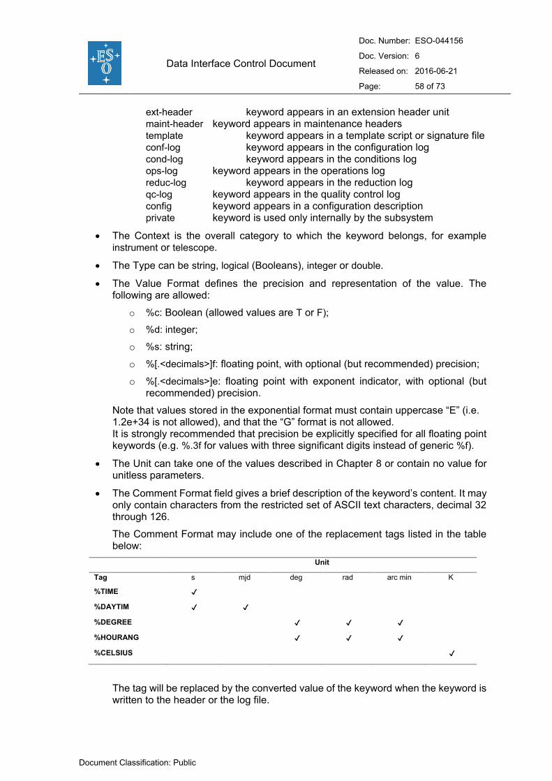
Data Interface Control Document
Doc. Number: ESO-044156
Doc. Version: 6
Released on: 2016-06-21
Page: 58 of 73
Document Classification: Public
ext-header keyword appears in an extension header unit maint-header keyword appears in maintenance headers template keyword appears in a template script or signature file conf-log keyword appears in the configuration log cond-log keyword appears in the conditions log ops-log keyword appears in the operations log reduc-log keyword appears in the reduction log qc-log keyword appears in the quality control log config keyword appears in a configuration description private keyword is used only internally by the subsystem
The Context is the overall category to which the keyword belongs, for example instrument or telescope.
The Type can be string, logical (Booleans), integer or double.
The Value Format defines the precision and representation of the value. The following are allowed:
o %c: Boolean (allowed values are T or F);
o %d: integer;
o %s: string;
o %[.<decimals>]f: floating point, with optional (but recommended) precision;
o %[.<decimals>]e: floating point with exponent indicator, with optional (but recommended) precision.
Note that values stored in the exponential format must contain uppercase “E” (i.e. 1.2e+34 is not allowed), and that the “G” format is not allowed. It is strongly recommended that precision be explicitly specified for all floating point keywords (e.g. %.3f for values with three significant digits instead of generic %f).
The Unit can take one of the values described in Chapter 8 or contain no value for unitless parameters.
The Comment Format field gives a brief description of the keyword’s content. It may only contain characters from the restricted set of ASCII text characters, decimal 32 through 126.
The Comment Format may include one of the replacement tags listed in the table below:
Unit
Tag s mjd deg rad arc min K
%TIME ✔
%DAYTIM ✔ ✔
%DEGREE ✔ ✔ ✔
%HOURANG ✔ ✔ ✔
%CELSIUS ✔
The tag will be replaced by the converted value of the keyword when the keyword is written to the header or the log file.
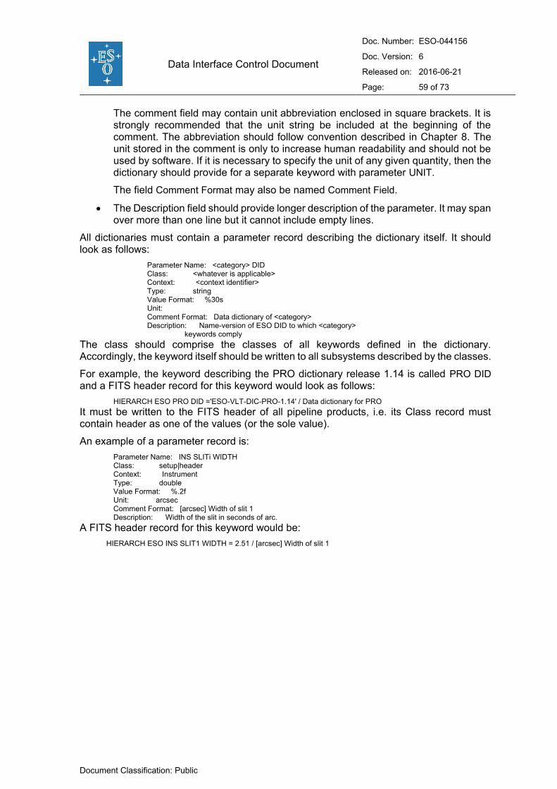
Data Interface Control Document
Doc. Number: ESO-044156
Doc. Version: 6
Released on: 2016-06-21
Page: 59 of 73
Document Classification: Public
The comment field may contain unit abbreviation enclosed in square brackets. It is strongly recommended that the unit string be included at the beginning of the comment. The abbreviation should follow convention described in Chapter 8. The unit stored in the comment is only to increase human readability and should not be used by software. If it is necessary to specify the unit of any given quantity, then the dictionary should provide for a separate keyword with parameter UNIT.
The field Comment Format may also be named Comment Field.
The Description field should provide longer description of the parameter. It may span over more than one line but it cannot include empty lines.
All dictionaries must contain a parameter record describing the dictionary itself. It should look as follows:
Parameter Name: <category> DID Class: <whatever is applicable> Context: <context identifier> Type: string Value Format: %30s Unit: Comment Format: Data dictionary of <category> Description: Name-version of ESO DID to which <category> keywords comply
The class should comprise the classes of all keywords defined in the dictionary. Accordingly, the keyword itself should be written to all subsystems described by the classes.
For example, the keyword describing the PRO dictionary release 1.14 is called PRO DID and a FITS header record for this keyword would look as follows:
HIERARCH ESO PRO DID ='ESO-VLT-DIC-PRO-1.14' / Data dictionary for PRO
It must be written to the FITS header of all pipeline products, i.e. its Class record must contain header as one of the values (or the sole value).
An example of a parameter record is:
Parameter Name: INS SLITi WIDTH Class: setup|header Context: Instrument Type: double Value Format: %.2f Unit: arcsec Comment Format: [arcsec] Width of slit 1 Description: Width of the slit in seconds of arc.
A FITS header record for this keyword would be:
HIERARCH ESO INS SLIT1 WIDTH = 2.51 / [arcsec] Width of slit 1
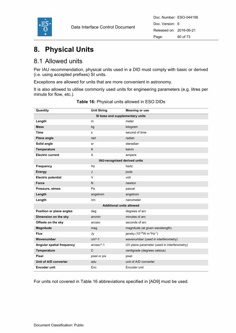
Data Interface Control Document
Doc. Number: ESO-044156
Doc. Version: 6
Released on: 2016-06-21
Page: 60 of 73
Document Classification: Public
8. Physical Units
8.1 Allowed units
Per IAU recommendation, physical units used in a DID must comply with basic or derived (i.e. using accepted prefixes) SI units.
Exceptions are allowed for units that are more convenient in astronomy.
It is also allowed to utilise commonly used units for engineering parameters (e.g. litres per minute for flow, etc.).
Table 16: Physical units allowed in ESO DIDs
Quantity Unit String Meaning or use
SI base and supplementary units
Length m meter
Mass kg kilogram
Time s second of time
Plane angle rad radian
Solid angle sr steradian
Temperature K kelvin
Electric current A ampere
IAU-recognised derived units
Frequency Hz hertz
Energy J joule
Electric potential V volt
Force N newton
Pressure, stress Pa pascal
Length angstrom angstrom
Length nm nanometer
Additional units allowed
Position or plane angles deg degrees of arc
Dimension on the sky arcmin minutes of arc
Offsets on the sky arcsec seconds of arc
Magnitude mag magnitude (at given wavelength)
Flux Jy jansky (10-26W m-2Hz-1)
Wavenumber cm^-1 wavenumber (used in interferometry)
Angular spatial frequency arcsec^-1 UV plane parameter (used in interferometry)
Temperature C centigrade (degrees celsius)
Pixel pixel or pix pixel
Unit of A/D converter adu unit of A/D converter
Encoder unit Enc Encoder unit
For units not covered in Table 16 abbreviations specified in [AD9] must be used.

Data Interface Control Document
Doc. Number: ESO-044156
Doc. Version: 6
Released on: 2016-06-21
Page: 61 of 73
Document Classification: Public
8.2 Unit keyword syntax
The following rules must be followed when constructing the value of a keyword intended to
describe a physical unit (e.g. BUNIT, TUNITi).
These rules are a restricted set of the IVOA rules described in [AD10].5
It is strongly recommended that these rules be also followed when constructing the unit
descriptor in the FITS keyword comment (i.e. the free text following the “/” delimiter in the
keyword card).
Multiplication shall be represented by a dot “.”, with no spaces on either side of it.
Example: ‘N.m’.
Division shall be represented by the forward slash, “/”, with no spaces on either side
of it. Example: ‘km/s’.
Raising to power shall be represented with two asterisks, “**”, with no spaces on
either side of them. Example: ‘cm**2’.
Exponents must be either integers or rational fractions. Negative exponents or
rational fractions must be enclosed in brackets, “(” and “)”, with no spaces on either
side of them. Examples: ‘cm**(-2)’ or ‘s**(1/2)’. Not allowed: ‘cm**(-2.0)’ or ‘s**(0.5)’.
Rational fractions must be reduced to lowest terms. Example: ‘s**(-1/2)’. Not
allowed: ‘s**(-2/4)’.
Only one minus sign is allowed in the exponent and it must be the first character
following the first left parenthesis. Examples: ‘kg**(-1/2)’ or ‘cm**(-2)’. Not allowed:
‘kg**(1/(-2))’ or ‘s**((-1)/(-2))’.
Outside of exponents, slash may only be used once in the unit string and only to
describe a simple division of two units. Example: ‘km/s’. Not allowed: ‘km/s/Mpc’ or
‘km/(s.Mpc)’.
The unit string may contain one scaling factor. If present, this factor must be an
integer (positive or negative) power of ten, must be at the beginning of the unit, and
must be immediately (i.e. no separator such as space or multiplication sign) followed
by the physical unit. Factors of ‘1’ or ‘10**0’ are specifically not allowed. Factor of
101 must be represented as ‘10’. Example: ‘10**8m/s’.
Scaling factors other than integer powers of ten are not allowed. Such scaling factors
must be either accounted for in the data or stored in the BSCALE keyword.
Though their use is discouraged, the following mathematical functions are allowed
in unit strings. The function arguments must be enclosed in parentheses “(” and “)”,
with no spaces on either side of them. The arguments must comply to all above
rules.
5 To avoid confusion, it is stressed that IVOA rules are recommendations, while the rules described in the present document, a restricted subset of IVOA rules, are requirements.
Data Interface Control Document
Doc. Number: ESO-044156
Doc. Version: 6
Released on: 2016-06-21
Page: 62 of 73
Document Classification: Public
o Exponent of argument arg: ‘exp(arg)’
o Natural (base e) logarithm of arg: ‘ln(arg)’
o Common (base 10) logarithm of arg: ‘log(arg)’
o Note: use of “sqrt” is specifically not allowed; instead, ‘arg**(1/2)’ must be
used.
The following are examples of properly formatted compound physical units:
‘km/s’
‘km.s**(-1).Mpc**(-1)’
‘10**(-23)erg.s**(-1).cm**(-2).Hz**(-1)’
‘log(Hz)’

Data Interface Control Document
Doc. Number: ESO-044156
Doc. Version: 6
Released on: 2016-06-21
Page: 63 of 73
Document Classification: Public
9. Naming convention for optical components
This section describes how optical components in use at the VLT telescopes are named and identified.
Such identifiers are used:
By astronomers when selecting a particular observing configuration;
By operations staff when setting up the requested optical elements for the upcoming night;
By operations staff when operating instruments and performing service observations;
By VCS when writing FITS keywords into the data headers;
By pipeline software when performing standard data reduction;
By astronomers when reducing data off-line;
By archive users who prepare archive research programmes.
Astronomers are likely to use names while the observatory staff will mostly use identifiers. The convention described in this section was developed with the aim of facilitating all of the tasks mentioned above while at the same time maintaining the discipline needed in order to handle the few hundred elements that will be used at the VLT.
This naming convention will be applied to all VLT instruments.
9.1 Identification scheme
All optical elements, i.e. filters, grisms, etc., in use at any VLT, NTT or other VLT compliant instruments shall have a unique identifier and a verbose name.
Verbose names are recorded in the keyword NAME (e.g. FILT.NAME, GRIS.NAME or OPTIi.NAME) and follow the scheme described in Section 9.3.
Identifiers are typically sequential numbers which are given to each element when acquired. These identifiers are recorded in the keyword ID, e.g. FILT.ID, GRIS.ID or OPTIi.ID (see Section 4.4.2 for more details). The serves as the reference to the full characterisation file (e.g. transmission and efficiency curves of filters and grisms etc.) which is the authoritative source of information for each component.
The identifier serves as unique label for each individual piece of hardware. For example, the observatory utilises several K filters; all observations with any of these filters will have FILT.NAME set ‘K’ with FILT.ID identifying the specific physical filter used.
Identifiers of elements that cease to exist (e.g. a broken filter) shall be retained in order to ensure the historical validity of the Science Archive.
Instrument Consortia preparing Data Interface Dictionaries must foresee at most 10 characters space for the ID keywords and 30 characters for the NAME keywords.
9.2 Usage of the OPTIi keywords
OPTIi keywords are used to setup the internal functions of the instrument and to record instrument engineering parameters usually on the operations and configurations logs (see description in Section 4.4.2).
Data Interface Control Document
Doc. Number: ESO-044156
Doc. Version: 6
Released on: 2016-06-21
Page: 64 of 73
Document Classification: Public
The allowed OPTIi values are: MIRROR, FABRYPEROT, FILTER, SLIT, GRISM, MASK, GRATING, FOCUSWEDGE, ECHELLE, HARTMANN, WOLLASTON, RETARDER,
BEAMSPLITTER, DICHROIC, FIBER, LENS, PRISM and FREE (nothing mounted in the slot).
Additions to the above list need to be submitted for approval to the DIC Board.
9.3 Naming scheme
This section describes the scheme applied when assigning a name to optical elements.
Optical elements shall have a technical name that describes its major physical characteristics and may have a short, commonly used conventional name.
Technical names describe the element independently of its context (camera or instrument). The basic rule for technical names is to prefix the name with a four letter mnemonic of the element in question followed by some of its optical characteristics.
Conventional names are typically used in user interfaces and recorded in the relevant NAME keyword in the frame header.
Except for slit widths, the values for wavelengths and other characteristics should be rounded to the nearest integer (see below).
9.3.1 Filters
Filters will be characterised by:
Technical names:
o FILT_<central wawelength in nm>_<FWHM in nm> for general filters (at arbitrary wavelengths);
o FILT_VARi for variable filters; i is the serial number;
o FILT_<50% wavelength in nm>_<cuton/-off> for long-/shortpass filters; <cuton/-off> is L for longpass filters or S for shortpass filters;
o FILT_ND_<optical density> for neutral density filters, where <optical density> is equal to the negative logarithm of fractional transmittance (i.e. for a free filter this quantity would be equal to 0.0).
o FILT_BANDSTOP_<central wawelength in nm>_<FWHM in nm> for band-stop (incl. notch) filters.
Conventional names, used as values in all “filter name” keywords:
o The commonly known name, e.g. K, OG590, OIII/3000, when applicable;
o The system and the name within that system, e.g. U_BESS, U_STRM;
9.3.2 Grisms
Grisms will be characterised by:
GRIS_<#grooves/mm><characteristic letter>, where <characteristic letter> indicates the approximate central wavelength (e.g. R, B).
9.3.3 Gratings
Gratings will be characterised by:

Data Interface Control Document
Doc. Number: ESO-044156
Doc. Version: 6
Released on: 2016-06-21
Page: 65 of 73
Document Classification: Public
GRAT_<#grooves/mm><characteristic letter>, where <characteristic letter> indicates the approximate blaze wavelength (e.g. R, B) or none if the grating is unblazed;
ECHE_<#grooves/mm><characteristic letter>, where <characteristic letter> indicates the approximate wavelength of use (e.g. R, B).
9.3.4 Wollaston prisms
Wollaston prisms will be characterised by:
WOLL_<separation angle in arcmin>
9.3.5 Retarder plates
Retarder plates will be characterised by:
RETA2 for lambda/2 plates,
RETA4 for lambda/4 plates.
9.3.6 Fabry-Pérot etalons
Fabry-Pérot etalons will be characterised by:
FPET_<finesse>, where <finesse> is the dimensionless number characterising the resolving power of the Fabry-Pérot interferometer.
Slits
Fixed width slits (e.g. in a punched plate) will be characterised by:
SLIT_<width in arcsec> where <width in arcsec> is given with one decimal digit (e.g. 1.5 or 0.5).
Variable width slits, such as those on a decker or with a motorised function, will be named SLIT_DECKER or SLIT_FUNCTION.

Data Interface Control Document
Doc. Number: ESO-044156
Doc. Version: 6
Released on: 2016-06-21
Page: 66 of 73
Document Classification: Public
10. Instrument Identifiers and File Names
This chapter describes conventions to be utilised in ESO Data Flow in recording names of instruments installed on ESO telescopes.
ESO recognises the following instrument identifiers:
Common instrument name The name given to the instrument by the Instrument Consortium (examples: “OmegaCAM”, “HAWK-I”).
While no specific requirements are put on those names, a recommended good practice is that these names follow the ESO Instrument Identifier convention listed below.
ESO Instrument Identifier This identifier shall be between 4 and 8 characters long and contain only uppercase letters A-Z and digits 0-9. It shall be generated from the common instrument name (examples: “OMEGACAM”, “HAWKI”).
ESO Instrument Identifier shall be stored in the configuration keyword INS.CON.ID. This keyword shall be the sole source for names used further in the system. In particular, it shall be used in template names, operation log names and filenames on the instrument workstations.
This identifier shall also be stored in the INSTRUME keyword (see Sec. 4.1).
The ESO Instrument Identifier as it appears in INS.CON.ID and its uniqueness shall be finalised as part of the Preliminary Design Review for new instruments.
ESO Instrument Identifier may be followed by forward slash sign (`/’) and the revision number of the instrument control software (example: “XSHOOTER/1.57”).
This identifier shall be stored in keyword INS.ID (see Sec. 4.4.2.7).
OLAS_ID The environment variable OLAS_ID shall be set to the value of INS.CON.ID or to first five characters of this value, whichever is shorter.
Instruments which entered operations prior to the introduction of the above requirements and which do not follow them (e.g. VIRCAM and NAOS+CONICA) are allowed to maintain their current naming schemes.
10.1 File names for frames
The names of frames are used by a variety of persons at different times, e.g.:
The astronomer/operator to manage the data obtained during the run;
The Data Flow Operations team to track programme completion and quality control the exposure levels;
The Science Archive Operations team to check safe storage of the data, to maintain the data holdings and to service requests for archive data;
The User Support team to answer queries from users after observations.
The Phase 3 data providers and the Phase 3 support scientists, to track provenance.
The requirements for file names from various users are vastly different, therefore ESO adopts several schemes for naming the data frames.
Data Interface Control Document
Doc. Number: ESO-044156
Doc. Version: 6
Released on: 2016-06-21
Page: 67 of 73
Document Classification: Public
10.1.1 FITS files used internally within the Data Flow System
The requirements for file names for Data Flow Operations can be summarised as follows:
File names must be unique through the history of the VLT;
File names should be easy to check against logs;
File names should be easy to recreate in the case of directory/disk/media corruption (e.g. after being moved to “lost+found” directory);
File names should allow being grouped into “nights” without additional information.
The scheme chosen for FITS file names is based on the time of start of exposure (given through the MJD-OBS keyword). This scheme has the following advantages:
The names are easy to create and recreate using the MJD-OBS value;
The “night” directory can be automatically generated together with the filename (i.e. with one system call);
It does not require extra processes or procedures;
It is easily expandable to both VLT Common Software and DFS;
The names are easy to check in the operations log (START.EXP event);
The data re-play (in Garching) is straightforward.
In this scheme the file names take the form (using the restricted ISO 8601 format for the time tag):
<OLAS_ID>.YYYY-MM-DDThh:mm:ss.sss.fits
Combination of timetag with OLAS_ID value ensures the uniqueness of the name.
Examples:
FORS2.2000-12-19T09:57:51.333.fits (MJD-OBS=51897.41517746);
UVES.2000-03-14T09:14:24.988.fits (MJD-OBS=51617.38501143).
FITS files generated by the pipeline should follow a similar scheme:
r.<INS-PREFIX>.YYYY-MM-DDThh:mm:ss.sss_<iiii>.[t]fits
or:
r.<INS-PREFIX>.YYYY-MM-DDThh:mm:ss.sss_tpl_<iiii>.[t]fits
The first case refers to a FITS file that was created by a pipeline recipe as a result of a single input frame, the second case describes a file which results from the reduction of a set of frames created by an observation template. <iiii> is a four-digit integer (with leading zeros) which is automatically created by the pipeline.
10.1.2 Archive file names
ESO Archive configuration requires that frames are stored under unique names, independently from other considerations. In practical terms it means that a new version of any file must have a name different from the old version. This requirement is incompatible with the general scheme described in Section 10.1.1 above, and therefore it is necessary to maintain a separate filename scheme for archive storage.
Data Interface Control Document
Doc. Number: ESO-044156
Doc. Version: 6
Released on: 2016-06-21
Page: 68 of 73
Document Classification: Public
In all cases, the original file name must be preserved in the Archive database. All FITS frames, which are renamed for the purpose of archiving, must preserve the original name as a value of a header keyword appropriate for the file type.
The following describes the archive filename convention:
Raw FITS frames shall use the scheme as described in Section 10.1.1, i.e.
<OLAS_ID>.<TIME-TAG>.fits
where:
<OLAS_ID> is the value of the environment variable OLAS_ID;
<TIME-TAG> describes the value of the MJD-OBS keyword expressed in the restricted ISO 8601 format.
FITS files generated by pipeline processing within the ESO Data Flow, shall use the scheme
<PIPELINE-PREFIX>.<INS-PREFIX>.<ARC-TIME-TAG>.fits
where:
<PIPELINE-PREFIX> can be `S’ for science files and `M’ for calibration files (`M’ stands for `Master Calibration’, which is how these files were historically called).
<INS-PREFIX> is the ESO Instrument Identifier;
<ARC-TIME-TAG> denotes the archive ingestion date, in restricted ISO 8601 format.
Other processed frames, originating from both internal and external sources, shall use the scheme:
ADP.<ARC-TIME-TAG>.[.<EXT>]6
where:
<ARC-TIME-TAG> denotes the archive ingestion date, in restricted ISO 8601 format;
<EXT> is the (optional) file extension, in lowercase (fits, tar, jpg, etc.).
There is no instrument designation in processed Data Products because, unlike the first two types of frames, it is possible for such products to be derived from data from more than one instrument.
Operation logs shall use file names as described in Section 5.3.
All other file types must have their naming conventions approved by the DIC Board.
10.2 File names for files used internally within the VLT Control Software (VCS)
The scheme is described in [RD13].
6 Prefix ‘ADP’ is used for historical reasons; it is not intended to contain any information about frame’s quality or provenance.

Data Interface Control Document
Doc. Number: ESO-044156
Doc. Version: 6
Released on: 2016-06-21
Page: 69 of 73
Document Classification: Public
10.3 File names for template scripts and signature files
The scheme is described in [RD13].

Data Interface Control Document
Doc. Number: ESO-044156
Doc. Version: 6
Released on: 2016-06-21
Page: 70 of 73
Document Classification: Public
APPENDIX (1): Mandatory header keywords
This appendix lists mandatory header keywords. These keywords are mandatory in the sense that they must be present in the header when applicable, i.e. when the parameter in question plays a role in the acquisition of the frame. Parameters not used for the exposure should not appear in the header even though they are listed below (e.g. the TEL keywords should not be included in bias frames).
Keywords directly describing the data part of an HDU – such as WCS keywords, keywords describing pre- and overscan regions, keyword defining windows, etc. – should be stored in the header of the relevant HDU. Other keywords should be stored in the header of the primary HDU.
Values of the mandatory FITS header keywords: SIMPLE, BITPIX and NAXIS, and, if applicable, NAXISn, XTENSION, PCOUNT, GCOUNT and EXTEND must be written in FITS fixed format (i.e. right-flushed to header card column 30).
It is strongly recommended that headers of FITS files be used primarily for storing parameters relevant to scientific analysis of data. Storing parameters not relevant for scientific analysis (such as purely engineering or technical) should be avoided. It is recommended to store such parameters in extension HDUs and/or to record them in relevant logs.
Basic keywords
Primary header
SIMPLE = T / Standard FITS format BITPIX = %d / # of bits storing pix values NAXIS = %d / # of axes in frame NAXISn = %d / # of pixels along n-th axis EXTEND = T / Extensions may be present BZERO = %f / real=fits-value*BSCALE+BZERO BSCALE = %f / real=fits-value*BSCALE+BZERO BLANK = %d / Value used for NULL pixels INSTRUME= %s / Instrument used TELESCOP= %s / ESO Telescope designation OBJECT = %s / Target description OBSERVER= %s / Name of observer ORIGIN = %s / ESO PI-COI = %s / Name(s) of proposer(s) EXPTIME = %f / [s] Exposure time RA = %.6f / [deg] %HOURANG RA (J2000.0) pointing DEC = %.5f / [deg] %DEGREE DEC (J2000.0) pointing EQUINOX = %.0f / [y] Standard FK5 RADECSYS= %s / FK5 DATE = %s / Date this file was written MJD-OBS = %.8f / [d] Observation start %DAYTIM DATE-OBS= %s / Observations start MJD-END = %.8f / [d] Observation end %DAYTIM DATE-END= %s / Observation end TIMESYS = %s / Time system used LST = %.3f / [s] %TIME LST at start UTC = %.3f / [s] %TIME UTC at start CTYPEn = %s / Coordinate system CRVALn = %f / Coordinate value of ref pixel CRPIXn = %f / Ref pixel in n-th axis CDn_m = %f / Transformation matrix element CUNITn = %s / Unit of coordinate CHECKSUM= %s / HDU checksum DATASUM = %s / Data unit checksum
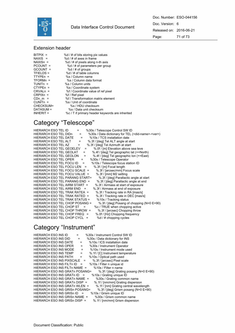
Data Interface Control Document
Doc. Number: ESO-044156
Doc. Version: 6
Released on: 2016-06-21
Page: 71 of 73
Document Classification: Public
Extension header
BITPIX = %d / # of bits storing pix values NAXIS = %d / # of axes in frame NAXISn = %d / # of pixels along n-th axis PCOUNT = %d / # of parameters per group GCOUNT = %d / # of groups TFIELDS = %d / # of table columns TTYPEn = %s / Column name TFORMn = %s / Column data format TUNITn = %s / Column units CTYPEn = %s / Coordinate system CRVALn = %f / Coordinate value of ref pixel CRPIXn = %f / Ref pixel CDn_m = %f / Transformation matrix element CUNITn = %s / Unit of coordinate CHECKSUM= %s / HDU checksum DATASUM = %s / Data unit checksum INHERIT = %c / T if primary header keywords are inherited
Category “Telescope” HIERARCH ESO TEL ID = %30s / Telescope Control SW ID HIERARCH ESO TEL DIDn = %30s / Data dictionary for TEL (<did-name>-<ver>) HIERARCH ESO TEL DATE = %10s / TCS installation date HIERARCH ESO TEL ALT = %.3f / [deg] Tel ALT angle at start HIERARCH ESO TEL AZ = %.3f / [deg] Tel Azimuth at start HIERARCH ESO TEL GEOELEV = %.0f / [m] Elevation above sea leve HIERARCH ESO TEL GEOLAT = %.4f / [deg] Tel geographic lat (+=North) HIERARCH ESO TEL GEOLON = %.4f / [deg] Tel geographic lon (+=East) HIERARCH ESO TEL OPER = %30s / Telescope Operator HIERARCH ESO TEL FOCU ID = %10s / Telescope focus station ID HIERARCH ESO TEL FOCU LEN = %.3f / [m] Focal length HIERARCH ESO TEL FOCU SCALE = %.3f / [arcsec/mm] Focus scale HIERARCH ESO TEL FOCU VALUE = %.3f / [mm] M2 setting HIERARCH ESO TEL PARANG START= %.3f / [deg] Parallactic angle at start HIERARCH ESO TEL PARANG END = %.3f / [deg] Parallactic angle at end HIERARCH ESO TEL AIRM START = %.3f / Airmass at start of exposure HIERARCH ESO TEL AIRM END = %.3f / Airmass at end of exposure HIERARCH ESO TEL TRAK RATEA = %.3f / Tracking rate in RA [mas/s] HIERARCH ESO TEL TRAK RATED = %.3f / Tracking rate in DEC [mas/s] HIERARCH ESO TEL TRAK STATUS = %10s / Tracking status HIERARCH ESO TEL CHOP POSANG = %.3f / [deg] Posang of chopping (N=0 E=90) HIERARCH ESO TEL CHOP ST = %c / TRUE when chopping active HIERARCH ESO TEL CHOP THROW = %.3f / [arcsec] Chopping throw HIERARCH ESO TEL CHOP FREQ = %.0f / [Hz] Chopping frequency HIERARCH ESO TEL CHOP CYCL = %d / # chopping cycles
Category “Instrument” HIERARCH ESO INS ID = %30s / Instrument Control SW ID HIERARCH ESO INS DID = %30s / Data dictionary for INS HIERARCH ESO INS DATE = %10s / ICS installation date HIERARCH ESO INS OPER = %30s / Instrument Operator HIERARCH ESO INS MODE = %10s / Instrument mode used HIERARCH ESO INS TEMP = %.1f / [C] Instrument temperature HIERARCH ESO INS PATH = %10s / Optical path used HIERARCH ESO INS PIXSCALE = %.3f / [arcsec] Pixel scale HIERARCH ESO INS FILTn ID = %10s / Filter n unique id HIERARCH ESO INS FILTn NAME = %10s / Filter n name HIERARCH ESO INS GRATn POSANG= %.3f / [deg] Grating posang (N=0 E=90) HIERARCH ESO INS GRATn ID = %10s / Grating unique ID HIERARCH ESO INS GRATn NAME = %30s / Grating common name HIERARCH ESO INS GRATn DISP = %.1f / [nm/mm] Grating dispersion HIERARCH ESO INS GRATn WLEN = %.1f / [nm] Grating central wavelength HIERARCH ESO INS GRISn POSANG= %.3f / [deg] Grism posang (N=0 E=90) HIERARCH ESO INS GRISn ID = %10s / Grism unique ID HIERARCH ESO INS GRISn NAME = %30s / Grism common name HIERARCH ESO INS GRISn DISP = %.1f / [nm/mm] Grism dispersion

Data Interface Control Document
Doc. Number: ESO-044156
Doc. Version: 6
Released on: 2016-06-21
Page: 72 of 73
Document Classification: Public
HIERARCH ESO INS GRISn WLEN = %.1f / [nm] Grism central wavelength HIERARCH ESO INS OPTIn POSANG= %.3f / [deg] Position angle (N=0 E=90) HIERARCH ESO INS OPTIn ID = %10s / OPTIn unique ID HIERARCH ESO INS OPTIn NAME = %10s / OPTIn name HIERARCH ESO INS OPTIn NO = %d / OPTIn slot number HIERARCH ESO INS OPTIn TYPE = %10s / OPTIn element HIERARCH ESO INS MOS SETUP = %30s / MOS setup HIERARCH ESO INS MOSn POSANG = %.5f / [deg] MOSn posang (N=0 E=90) HIERARCH ESO INS MOSn WID = %.2f / [arcsec] MOSn slit width HIERARCH ESO INS MOSn LEN = %.2f / [arcsec] MOSn slit length HIERARCH ESO INS MOSn RA = %.8f / [deg] RA of slit HIERARCH ESO INS MOSn DEC = %.8f / [deg] DEC of slit HIERARCH ESO INS SLIT WID = %.2f / [arcsec] SLIT width HIERARCH ESO INS SLIT LEN = %.2f / [arcsec] SLIT length HIERARCH ESO INS SLIT POSANG = %.3f / [deg] SLIT posang (N=0 E=90) HIERARCH ESO INS SLIT RA = %.8f / [deg] RA of slit HIERARCH ESO INS SLIT DEC = %.8f / [deg] DEC of slit HIERARCH ESO INS LAMPn NAME = %10s / Lamp name HIERARCH ESO INS LAMPn EXPTIM= %.3f / [s] Lamp exp time
Category “Detector” HIERARCH ESO DET DID = %30s / Data dictionary for DET HIERARCH ESO DET ID = %30s / Detector Control SW ID HIERARCH ESO DET NAME = %10s / Name of detector system HIERARCH ESO DET CCDS = %d / # of CCDs in detector array HIERARCH ESO DET OUTPUTS = %d / # of outputs HIERARCH ESO DET OUTREF = %d / reference output HIERARCH ESO DET OUTn CHIP = %s / Chip to which output belongs HIERARCH ESO DET OUTn CONAD = %.2f / [e-/adu] Conversion from ADUs to e- HIERARCH ESO DET OUTn GAIN = %.2f / [adu/e-] Gain HIERARCH ESO DET OUTn ID = %30s / Detector identification HIERARCH ESO DET OUTn PRSCX = %d / Prescan region in X HIERARCH ESO DET OUTn PRSCY = %d / Prescan region in Y HIERARCH ESO DET OUTn OVSCX = %d / Overscan region in X HIERARCH ESO DET OUTn OVSCY = %d / Overscan region in Y HIERARCH ESO DET OUTn RON = %.2f / Readout noise HIERARCH ESO DET OUTn X = %d / X location of output HIERARCH ESO DET OUTn Y = %d / Y location of output HIERARCH ESO DET CHIPn DATE = %30s / Date of installation HIERARCH ESO DET CHIPn ID = %30s / Detector chip identification HIERARCH ESO DET CHIPn INDEX = %d / Chip index HIERARCH ESO DET CHIPn NAME = %16s / Detector chip name HIERARCH ESO DET CHIPn NX = %d / # of pixels along X HIERARCH ESO DET CHIPn NY = %d / # of pixels along Y HIERARCH ESO DET CHIPn PSZX = %.1f / [mu] Size of pixel in X HIERARCH ESO DET CHIPn PSZY = %.1f / [mu] Size of pixel in Y HIERARCH ESO DET CHIPn X = %d / X location in array HIERARCH ESO DET CHIPn XGAP = %.6f / Gap between chips along X HIERARCH ESO DET CHIPn Y = %d / Y location in array HIERARCH ESO DET CHIPn YGAP = %.6f / Gap between chips along Y HIERARCH ESO DET EXP TYPE = %s / Type of exp as known to the CCD sw HIERARCH ESO DET EXP ID = %d / Unique exposure ID number HIERARCH ESO DET EXP DUMDIT = %d / # of dummy readouts HIERARCH ESO DET READ MODE = %10s / Readout method HIERARCH ESO DET READ SPEED = %10s / Readout speed HIERARCH ESO DET READ CLOCK = %10s / Readout clock pattern used HIERARCH ESO DET FRAM ID = %d / Image sequential number HIERARCH ESO DET WINn ST = T / Windowing enabled HIERARCH ESO DET WINn STRX = %d / Lower left pixel in X HIERARCH ESO DET WINn STRY = %d / Lower left pixel in Y HIERARCH ESO DET WINn NX = %d / # of pixels along X HIERARCH ESO DET WINn NY = %d / # of pixels along Y HIERARCH ESO DET BINX = %d / Binning factor in X HIERARCH ESO DET BINY = %d / Binning factor along Y HIERARCH ESO DET NDIT = %d / # of subintegrations HIERARCH ESO DET DITn = %.3f / [s] actual subintegration time HIERARCH ESO DET UITi = %.3f / [s] requested subintegration time

Data Interface Control Document
Doc. Number: ESO-044156
Doc. Version: 6
Released on: 2016-06-21
Page: 73 of 73
Document Classification: Public
Category “Adapter” HIERARCH ESO ADA POSANG = %.5f / [deg] Position angle at start HIERARCH ESO ADA ABSROT START= %.5f / [deg] Abs rot angle at exp start HIERARCH ESO ADA ABSROT END = %.5f / [deg] Abs rot angle at exposure end HIERARCH ESO ADA GUID STATUS = %10s / Status of autoguider HIERARCH ESO ADA GUID RA = %.5f / [deg] %HOURANG Guide star RA J2000.0 HIERARCH ESO ADA GUID DEC = %.5f / [deg] %DEGREE Guide star DEC J2000.0
Category “Observation Block” HIERARCH ESO OBS DID = %30s / Data dictionary for OBS HIERARCH ESO OBS ID = %d / Observation block id HIERARCH ESO OBS NAME = %30s / Observation block name HIERARCH ESO OBS GRP = %30s / linked blocks HIERARCH ESO OBS PROG ID = %20s / ESO programme identification HIERARCH ESO OBS TPLNO = %d / Template seq # in OB
Category “Template” HIERARCH ESO TPL DID = %30s / Data dictionary for TPL HIERARCH ESO TPL ID = %30s / Template ID HIERARCH ESO TPL NAME = %30s / Template name HIERARCH ESO TPL START = %s / TPL start time HIERARCH ESO TPL SEQNO = %d / Template seq # within OBS HIERARCH ESO TPL NEXP = %d / Number of exposures within template HIERARCH ESO TPL EXPNO = %d / Exposure number within template
Raw file categories (originally “Data Product”) HIERARCH ESO DPR CATG = %30s / Observation category HIERARCH ESO DPR TYPE = %30s / Observation type HIERARCH ESO DPR TECH = %30s / Observation technique
Keywords related to tile compression ZIMAGE = T / extension contains compressed image ZTENSION= %s / original extension type ZBITPIX = %d / data type of original image ZNAXIS = %d / dimension of original image ZNAXIS1 = %d / length of original image axis ZNAXIS2 = %d / length of original image axis ZPCOUNT = %d / original PCOUNT keyword ZGCOUNT = %d / original GCOUNT keyword ZTILE1 = %d / size of compressed tiles ZTILE2 = %d / size of compressed tiles ZCMPTYPE= %s / compression algorithm ZNAME1 = %s / compression block size ZVAL1 = %d / pixels per block ZHECKSUM= %s / orignal HDU checksum ZDATASUM= %s / original data unit checksum
Keywords in ESO Pipeline Processed Data PIPEFILE = %s / Pipeline output file name DATAMD5 = %s / MD5 checksum HIERARCH ESO PRO DID = %s / Data dictionary for PRO HIERARCH ESO PRO RECn ID = %s / Pipeline recipe (unique) identifier HIERARCH ESO PRO RECn DRS ID = %s / Data Reduction System identifier HIERARCH ESO PRO RECn PIPE ID = %s / Pipeline (unique) identifier HIERARCH ESO PRO DATANCOM = %d / Number of combined frames HIERARCH ESO PRO CATG = %s / Category of pipeline product HIERARCH ESO PRO SCIENCE = %c / Scientific product if T
---End of document---