data perspective in process choreographies: modeling...
TRANSCRIPT

Data Perspective in Process Choreographies: Modelingand Execution
Andreas Meyer1, Luise Pufahl1, Kimon Batoulis1, Sebastian Kruse1, ThorbenLindhauer1, Thomas Stoff1, Dirk Fahland2, and Mathias Weske1
1 Hasso Plattner Institute at the University of Potsdam{Andreas.Meyer,Luise.Pufahl,Mathias.Weske}@hpi.uni-potsdam.de
{Firstname.Lastname}@student.hpi.uni-potsdam.de2 Eindhoven University of Technology
Abstract. Process choreographies are part of daily business. While the correctordering of exchanged messages can be modeled and enacted with current choreog-raphy techniques, no approach exists to describe and enact a choreography’s dataperspective. This paper describes an entirely model-driven approach for BPMNto include the data perspective while maintaining control flow aspects by utiliz-ing a recent concept to enact data dependencies in internal processes. This workintroduces few concepts that suffice to model data retrieval, data transformation,message exchange, and correlation. We present a modeling guideline to derivelocal process models from a given choreography; their operational semanticsallows to correctly enact the entire choreography from the derived models only.We implemented our approach by extending the camunda BPM platform with ourapproach and show its feasibility by realizing all service interaction patterns usingonly model-based concepts.
Keywords: Process Modeling, Data Modeling, Process Choreographies, ProcessEnactment, BPMN, SQL
1 Introduction
Customer
Supplier
Request
MessageQuote
Message
Fig. 1. Request for quotechoreography.
In daily business, organizations interact with each other, forinstance, concluding contracts or exchanging information.Fig. 1 describes an interaction between a customer and asupplier with respect to a request for a quote. The customersends the request to a chosen supplier which internally pro-cesses it and sends the resulting quote as response whichin turn is then handled internally by the customer. An in-teraction between business processes of multiple organizations via message exchangeis called process choreography [30]. The industry standard BPMN (Business ProcessModeling and Notation) [18] provides the following means and steps to model processchoreographies. A choreography diagram describes the order of message exchangesbetween multiple participants from a global view, called global choreography model.The message exchanges are then refined into send and receive activities distributed over

2 Meyer et al.
the different participants. This can be captured in collaboration diagrams describinghow each participant’s public process interacts with other participants [2], also calledlocal choreography model. Deriving a local choreography from a global choreographyis a non-trivial step; various techniques are required [7] including locally enforcing theorder of globally specified message exchanges.
Typically, these two choreography models are used to globally agree on a contractabout the messages exchanged and their order. In the request for quote example, bothparticipants agreed that first the customer may send a request to the supplier which isthen answered with a quote by the supplier. Based on the agreement, each participanthas to implement its public process as a private process describing the executable partof this participant including the interactions with other participants as described inthe choreography; this private process is called a process orchestration [13]. Existingapproaches for deriving an orchestration for each participant from a choreography, suchas the Public-to-Private approach [2], only cover the control-flow perspective of thecontract: ensuring the correct order of messages. In the following, we address the correctcontents of messages.
As messages are used to exchange data between the participants, the data perspec-tive plays a crucial role for a successful process choreography realization. Generally,organizations store their data in local databases where other choreography participantsdo not have access to. These databases follow local data schemes which differ amongthe organizations. However, the interacting organizations want to communicate andtherefore have to provide the information to be sent in a format which is understood atthe receiving side. Thus, an agreed exchange message format has to be part of the globalcontract mentioned above. For a successful process choreography, it has to be ensuredthat messages to be sent are provided correctly and that received messages are processedcorrectly based on the global contract. In more detail, three challenges arise:
C1—Data heterogeneity. Interacting participants, such as our customer and supplier,each implement their own data schema for handling their private data. For sending amessage to another participant, this local data has to be transformed into a message therecipient can understand. In turn, the received message has to be transformed into thelocal data schema to allow storing and processing by the recipient.C2—Correlation. A participant may interact with multiple instances of another processat the same time. Therefore, messages arriving at the receiver side need to be correlatedto the correct process instance to allow successful interaction.C3—1:n communication. In choreographies, there may be multiple participants of thesame type, e.g., multiple suppliers, a customer sends a request for quote to. Thus, individ-ual processes need to communicate with a multitude of (external) uniform participants.
Current choreography modeling languages such as BPMN do not provide modeling con-cepts to solve C1-C3. Instead, each participant manually implements message creationand processing for their private process, which is error-prone, hard to maintain, andeasily results in incompatibilities to other participants in the choreography.
In this paper, we describe a model-driven approach to include the data perspectivewithin the process choreography modeling while maintaining existing control flowaspects to realize process choreographies. We utilize the industry standard BPMN and

Data Perspective in Process Choreographies: Modeling and Execution 3
extend its choreography modeling by few but essential concepts for the data perspective.We describe a modeling guideline that shows how to utilize the new concepts forderiving the data perspective of a private orchestration model that is consistent to apublic choreography model (the contract). We introduce operational semantics for thenew modeling concepts which makes the orchestration models executable, and thusallows running the entire choreography purely model-based.
The remainder of this paper is structured as follows. Section 2 discusses the require-ments derived from above challenges. Subsequently, we explain the modeling guidelinein Section 3 followed by the operational semantics allowing to execute the modeledchoreographies directly from process model information in Section 4. In Section 5, wediscuss our implementation and its feasibility for implementing all service interactionpatterns purely model-based [3]. Section 6 is devoted to related work and Section 7concludes the paper.
2 Requirements
The challenges C1-C3 described above give rise to specific requirements for integratingthe data perspective in process choreography modeling and execution. We discuss theserequirements and their possible realization in the following.
R1—Content of message. Messages contain data of different types exchanged betweenparticipants. The involved participants have to commonly agree on the types of data andtheir format they want to exchange.R2—Local storage. The participants create and process data used for communicationwith other participants in their private processes. This needs to be stored and madeavailable in their local databases.R3—Message provision. As the data provided in a message is local to the sender, thedata must be adapted to the agreed format such that the recipient can interpret themessage content.R4—Message routing. Multiple parties may wait for a message at a certain point intime. This requires to route the message to the correct recipient.R5—Message correlation. After being received by a participant, the message needs tobe correlated to the activity instance which is capable to process the message content.R6—Message processing. Activities receiving messages have to extract data from themessage and to transform it into the local data format usable within their processes.
Requirements R1, R2, R3, and R6 are basic features to realize C1; R4 and R5 originatein C3; and R5 also addresses C2.
Languages such as WSDL [25] use data modeling to specify message formats; weadopt these ideas to address R1. Requirements R2, R3, and R6 concern the processing ofdata in an orchestration. The approach in [14] allows to model and enact data dependen-cies in BPMN processes for create, read, update, and delete operations on multiple dataobjects – even in case of complex object relationships. For this, annotations on BPMNdata objects are automatically transformed into SQL queries (R2). Further, data queryinglanguages such as XQuery [28] allow to implement data transformations between a

4 Meyer et al.
message and a local data model. In the following, we combine these approaches tospecify message extraction (R3) and message storage (R6) in a purely model-basedfashion. Languages such as BPEL [17] and BPMN [18] correlate a message to a processinstances based on key attributes in the message; we adopt this idea to address R5.The next sections describe how to model process choreographies including the dataperspective so that data stored locally at the sender’s side can be transmitted and storedin the receiver’s local data model consistent with the global contract.
Requirement R4, the actual transmission of messages from sender to receiver, isabstracted from in choreography and process models and also not discussed in this paper.One can use standard technologies such as middleware or web services to realize thecommunication between the process engines of participants.
3 Modeling Guideline
This section introduces a few concepts that allow implementing the data perspective of aprocess choreography in an entirely model-based approach. We present these conceptsembedded in a modeling guideline for devising private orchestration models consistentto a public choreography model; Section 4 presents the execution semantics for ourchoreography models.
Fig. 2 illustrates our modeling guideline which has a global level, where the publiccontract is defined, and a local level, where the local process implementations can befound. We assume that the choreography partners have already specified a collaborationdiagram that shows how each participant’s public process interacts with the other partici-pants and ensures local enforceability of control-flow [2]; see Fig. 2 (top). To support dataexchange between participants, we propose that this public contract is supplemented witha global data model in which the partners specify the business objects to be exchanged;see Fig. 2 (top middle). Next, we follow and extend the P2P approach [2] to move fromthe global to the local level: each participant separately defines a local data model anda schema mapping between their local and the global data model and implements theprivate process conforming to their public process in the global collaboration diagram.Next, we describe the details of the global contract followed by the local level both alongour modeling guideline.
1 Global Collaboration
Diagram
2 Global Data Model
3 Message Definition
3 Private Process Model 3 Private Process Model
1 Local Data Model 1 Local Data Model
2 S
chem
aM
appin
g
Glo
bal Level
Local Level
2 Schema
Map
ping
Fig. 2. Modeling guideline.

Data Perspective in Process Choreographies: Modeling and Execution 5
GlobalQCollaborationQDiagram
PrivateQProcessQModel
Cus
tom
erSendQ
requestReceiveQquote
Supp
lier
ReceiveQrequest
SendQquote
Cus
tom
er
Supplier
SendQrequest
ReceiveQquote
Request[created]
pk:Qr_id
Request[sent]
pk:Qr_id
Quote[received]
pk:Qq_idfk:Qr_id
[new]CO:QRequest
QuoteQItem[received]
pk:Qqi_idfk:Qq_id
III
[new]
Global_RequestCI: Global_Request.r_id
Global_QuoteCI: Global_Request.r_id
Request Message
Quote MessageG
loba
lQLe
vel
Loca
lQLe
velQof
QCus
tom
er
CreateQrequest
[new]
Global_QuoteCI:QGlobal_Request.r_id
Global_RequestCI:QGlobal_Request.r_id
QuoteDetails
[received]pk:Qqd_idfk:Qq_id
[new]
Fig. 3. Global choreography model and local process model of the customer.
On the global level, all choreography parties together define the following artifacts:
Global collaboration diagram: The global collaboration diagram describes the controlflow layer of the choreography, i.e., it describes which messages are exchanged in whichorder on a conceptual level. Exemplary, the left part of Fig. 3 shows the collaborationdiagram of the Request for quote choreography sketched in the introduction. It includespublic processes with all necessary send and receive tasks for each participant, thecustomer and the supplier.
Global data model: Messages are used to exchange data. In choreography modelinglanguages such as WS-CDL [10] or BPEL4Chor [6], the data carried by a messageis described technically by attribute names and data types for each message individ-ually [25]. Instead, we propose that the interacting parties first agree on data objectsthey want to share and document this in a global data model, for instance using XSD(http://www.w3.org/standards/xml/schema). In our example, customerand supplier have agreed on three data objects, Global Request, Global Quote, andGlobal Articles, as shown in the upper part of Fig.5. Each object has a unique identifierattribute (e.g., r id for Global Request) and some have a foreign key attribute (e.g., r idfor Global Quote) to express relationships.
Message Definition: Then, message types are specified by referring to business objectsdefined in the global data model. We assume that each message carries exactly one globaldata object; nested objects allow placing complex data object hierarchies within onemessage. Further, we adopt key-based correlation [17, 18] for messages: each messagecontains a set of key/value pairs that allow identifying the correct process instance onthe receiver side; each key is an attribute of some data object in the global data model.For example, Request Message of Fig. 3 (left) refers to the Global Request object andQuote Message refers to Global Quote which has multiple Global Article objects. AQuote Message will contain a Global Quote object and all its Global Article objects.Both messages use attribute r id of Global Request as correlation key.
-name : String
-CI : List<String>
-d : DataObject
Message
(from Common)
Fig. 4. Message class.
Altogether, a message can be declared as a tuple m =(name,CI, d), where name is the message type, the correlationinformation CI ⊆ K × V is a set of key/value pairs, and d is theactual data object in the message. To model this tuple, BPMN mustbe extended as shown in the UML class of Fig. 4. Originally, each

6 Meyer et al.
message contains a string identifying its name, i.e., the message type. We add correlationinformation as a list of strings, each denoting one key/value pair, and the payload as adata object.
Then, each participants locally creates the following artifacts, based on the globalcontract:
-r_id
-date
Global_Request -q_id
-r_id
-totalPrice
-deliveryDate
Global_Quote-a_id
-q_id
-type
-quantity
-price
Global_Article
1 *1 1
Glo
bal Level
Local Level
Local Data Model of Customer
Global Data Model
-q_id
-r_id
-state
-g_r_id
-g_q_id
Quote
-deliveryDate
-totalPrice
-state
-q_id
-qd_id
Quote Details
1 1
-date
-state
-r_id
Request
1 *-qi_id
-q_id
-itemPrice
-quantity
-type
-state
-g_q_id
-g_qi_id
Quote Item
1 1
Fig. 5. Schema mapping for customer.
Local Data Model: Each participantdefines a local data model which de-scribes the classes of data objectshandled by the private process. Forexample, the local data model of theCustomer has four classes Request,Quote, Quote Details, and QuoteItem; see Fig. 5 (bottom). We pro-pose to also use the local data modelto design the schema for the databasewhere the objects are stored and accessed during the process execution. There are somerequirements to the local data model wrt. the global data model as described next.
Schema Mapping: A schema mapping defines how attributes of local classes map toattributes of global classes, and allows to automate a data transformation between globalobjects contained in messages and local data objects. For this paper, we consider a simpleattribute-to-attribute schema mapping which injectively maps each attribute of a globalobject to an attribute of a local object as shown in Fig. 5. Note that the attributes ofobject Global Quote are distributed over objects Quote and Quote Details. The localimplementation can hide private data in a local attribute by not mapping it to a globalattribute (the mapping is not bijective), e.g., the state attributes of each local class. Localdata model and schema mapping must ensure that primary and foreign keys are managedlocally to avoid data inconsistency: when a local object can be created from a receivedglobal object, key attributes of the global object must map to non-key attributes ofthe local objects. For example, the local Quote shall be created from a Global Quoteobject, thus Quote gets the attributes g q id and g r id to store the primary key q id andthe foreign key r id of Global Quote for local use. Typically, these keys are used forcorrelation.
Executable private process: Based on the global collaboration diagram, each participantdesigns their private process by enriching their public process with activities that are notpublicly visible. In addition, each process (and each subprocess) gets assigned a caseobject; instantiating the process also creates a new instance of this case object that usesas primary key value the process instance id [14]. Fig. 3 (right) shows the private processmodel of the customer. First, activity Create request creates and prepares a new instanceof the case object Request (see “CO” in the top left corner of the process). The schemamapping defines which local data objects are required to derive the payload d and thecorrelation information CI for a message to be sent; this is included in the process modelby associating the required data objects as input to the send task. In our example inFig.3, activity Send request creates a Request Message containing a Global Request. Thecorresponding local Request object is associated to Send request as input. Correspond-

Data Perspective in Process Choreographies: Modeling and Execution 7
Customer
Supplier
Receive
request
Send
quote
Quote
[created]
pk: q_idfk: r_id
[new]
Create
quote
Request
[received]
pk: r_id
[new]
Global_Request
CI: Global_Request.r_id
Article
[selected]
pk: a_idfk: q_id
[new]
Global_Quote
CI: Global_
Request.r_id
Local Level of Supplier
III
CO: Request
Request
[received]
pk: r_id
-r_id
-g_r_id
-state
-date
Request
-a_id
-q_id
-state
-articleType
-quantity
-articlePrice
Article
1
*
1 1
-q_id
-r_id
-state
-price
-deliveryDate
Quote
Fig. 6. Private process model and local data model of the supplier.
ingly, we associate the local data objects into which the payload of a received messagecan be transformed as output data objects of a receive task. The last activity modeledin the customer process receives the Quote Message. The payload of this message istransformed into data objects Quote, Quote Details, and the multi-instance data objectQuote Item all being associated as output to the receive task. The process designer hasto specify whether the receive task creates new or updates existing data objects. Weuse the data annotations described in [14] to express operations and dependencies oflocal objects. In the given example, the message payload is used to create new dataobjects only as indicated by the identifier new in the upper part of each object. Local dataschema, schema mapping, and private process together define the local choreography ofthe participant.
Fig.6 shows the private process model and the local data model of the second partici-pant – the Supplier. Here, each attribute of a local class directly maps to a correspondingattribute with an equivalent name in the corresponding global class. For instance, at-tribute price of class Global Article maps to to attribute articlePrice of class Article,attribute r id of class Global Request maps to attribute g r id of class Request, and soon. The private process has three activities: After receiving the Global Request, which isstored as Request object in state received, the supplier processes the request and createsthe Quote. Sending the Global Quote message requires data objects Quote and Articleto set the payload and Request to set the correlation identifier Global Request.r id.
This modeling guideline proposes a logical order in which the artifacts should becreated based on dependencies between them. However, situations may arise where adifferent order (or iterations) are required. In any case, by refining the public processinto a private one and by defining local data model and schema mapping as described, aprocess modeler always obtains a local choreography that is consistent with the globalcontract. In the next section, we show how to make the local choreography executable,thus achieving a correct implementation by design.
4 Executing Data-annotated Process Choreographies
In the previous section, we showed how to model executable process choreographies withrespect to the data layer. This section introduces the execution semantics to automaticallygenerate as well as correlate messages and to persist them using the modeling concepts

8 Meyer et al.
introduced in the previous section. First, we start with an overview based on our examplebefore we dive into details in Sections 4.2 to 4.4.
4.1 Overview of Choreography Execution
Supplier
Send
quote
Quote
[created]
pk: q_id
CO: Request
Data-
base
Customer
Receive
quote
Quote Item
[received]
pk: qi_idfk: q_id
[new]
...
Data-
base
1. Retrieval
of data
2. Transfor-
mation
of data
6. Transfor-
mation
of data
3. Send
message
Global_Quote
CI: Global_Request.r_id
Process Engine of Supplier
Correlation
mechanism
Process Engine of Customer
7. Storage
of data
5. Correlation
of message
4. Receive
message
Request
[received]
pk: qd_id
Article
[selected]
pk: a_id
CO: Request
fk: r_id
fk: q_id fk: q_id
Quote
[received]
pk: q_idfk: r_id
[new]
III III
Quote
Details
[received]pk: qd_idfk: q_id
[new]
...
Quote Message
Fig. 7. Approach overview.
Fig. 7 shows the implementation of the second interaction between a supplier and acustomer in which the supplier sends a quote to the customer. It comprises seven stepsnumbered accordingly in the figure and satisfying the requirements raised in Section 2:(1) The required data objects are retrieved from the supplier’s database (satisfyingrequirement R2) and (2) transformed to the message (satisfying R1 & R3), which is(3) sent from the supplier and (4) received at the customer’s side (satisfying R4). Thereceived message is then (5) correlated to the corresponding activity instance (satisfyingR5), where the message (6) gets transformed into data objects (satisfying R1 & R6)which are then (7) stored in the customer’s database (satisfying R2 again).
The send task labeled Send quote creates and sends the message. As described in [14],the input data objects specify the data objects and their states required to start activityexecution. In this paper, the input data objects to send tasks additionally describe the localdata required to create the message to be sent. Therefore, in step 1, they are retrievedfrom the local database before step 2 transforms this information into the correspondingmessage based on the given schema mapping. Here, the objects Quote and Article (asmulti instance data object) are utilized to create the message’s payload Global Quotewhich is a hierarchical object consisting of a number of Global Articles (see global datamodel in Fig.5). Further, the specified correlation identifier Global Request.r id is addedto message based on the input data object Request. This is needed by the customer tocorrelate the message to its correct scope instance (process or sub-process instance).After preparing the message, the actual sending to the recipient is executed by the sendtask (step 3). The execution of the send and getting the message to the correct recipient isdone by inter-engine communication in lower layers, e.g., by web services or middleware,which is not discussed in this paper.
Analogously, the retrieval of the message at the recipients side, here the customer, ismanaged by the same underlying layer (step 4). Next, the message needs to be correlated
Data Perspective in Process Choreographies: Modeling and Execution 9
Quote
r_id = 6
state = created
q_id = 30
price = 4149.75€
deliveryDate = 13.12.2013
Article
q_id = 30
state = selected
a_id = 16
articleType = laptop
quantity = 3
articlePrice = 1349.95€
Article
q_id = 30
state = selected
a_id = 17
articleType = dvd spindle
quantity = 10
articlePrice = 9.99€
Request
g_r_id = 21
state = received
r_id = 6
date = 25.11.2013
send receive
Quote Details
q_id = 53
state = received
qd_id = 32
totalPrice = 4149.75€
deliveryDate = 13.12.2013
Quote
r_id = 21
state = received
q_id = 53
g_q_id = 30
Quote Item
q_id = 53
state = received
qi_id = 42
type = dvd spindle
quantity = 10
itemPrice = 9.99€
g_qi_id = 17
g_q_id = 30
Quote Item
q_id = 53
state = received
qi_id = 41
type = laptop
quantity = 3
itemPrice = 1349.95€
g_qi_id = 16
g_q_id = 30
Global_Quote
CI: Global_Request.r_id = 21
Global_Article
q_id = 30
a_id = 16
type = laptop
quantity = 3
price = 1349.95€
Global_Article
q_id = 30
a_id = 17
type = dvd spindle
quantity = 10
price = 9.99€
Global_Quote
r_id = 21
q_id = 30
totalPrice = 4149.75€
deliveryDate = 13.12.2013
(a) Supplier database.
Quote
r_id = 6
state = created
q_id = 30
price = 4149.75€
deliveryDate = 13.12.2013
Article
q_id = 30
state = selected
a_id = 16
articleType = laptop
quantity = 3
articlePrice = 1349.95€
Article
q_id = 30
state = selected
a_id = 17
articleType = dvd spindle
quantity = 10
articlePrice = 9.99€
Request
g_r_id = 21
state = received
r_id = 6
date = 25.11.2013
send receiveQuote Item
q_id = 53
state = received
qi_id = 41
type = laptop
quantity = 3
itemPrice = 1349.95€
g_qi_id = 16
g_q_id = 30
Quote Item
q_id = 53
state = received
qi_id = 42
type = dvd spindle
quantity = 10
itemPrice = 9.99€
g_qi_id = 17
g_q_id = 30
Quote
r_id = 21
state = received
q_id = 53
g_r_id = 21
g_q_id = 30
Quote Details
q_id = 53
state = received
qd_id = 32
totalPrice = 4149.75€
deliveryDate = 13.12.2013
Global_Quote
CI: Global_Request.r_id = 21
Global_Article
q_id = 30
a_id = 16
type = laptop
quantity = 3
price = 1349.95€
Global_Article
q_id = 30
a_id = 17
type = dvd spindle
quantity = 10
price = 9.99€
Global_Quote
r_id = 21
q_id = 30
totalPrice = 4149.75€
deliveryDate = 13.12.2013
Quote
Message
(b) Message.
QuotevItem
q_id = 53state = received
qi_id = 41
typev=vlaptopquantityv=v3
itemPricev=v1349.95€
g_qi_idv=v16g_q_idv=v30
QuotevItem
q_id = 53state = received
qi_id = 42
typev=vdvdvspindlequantityv=v10
itemPricev=v9.99€
g_qi_idv=v17g_q_idv=v30
Quote
r_id = 21state = received
q_id = 53
g_r_idv=v21g_q_idv=v30
QuotevDetails
q_id = 53state = received
qd_id = 32
totalPricev=v4149.75€deliveryDatev=v13.12.2013
(c) Customer database.
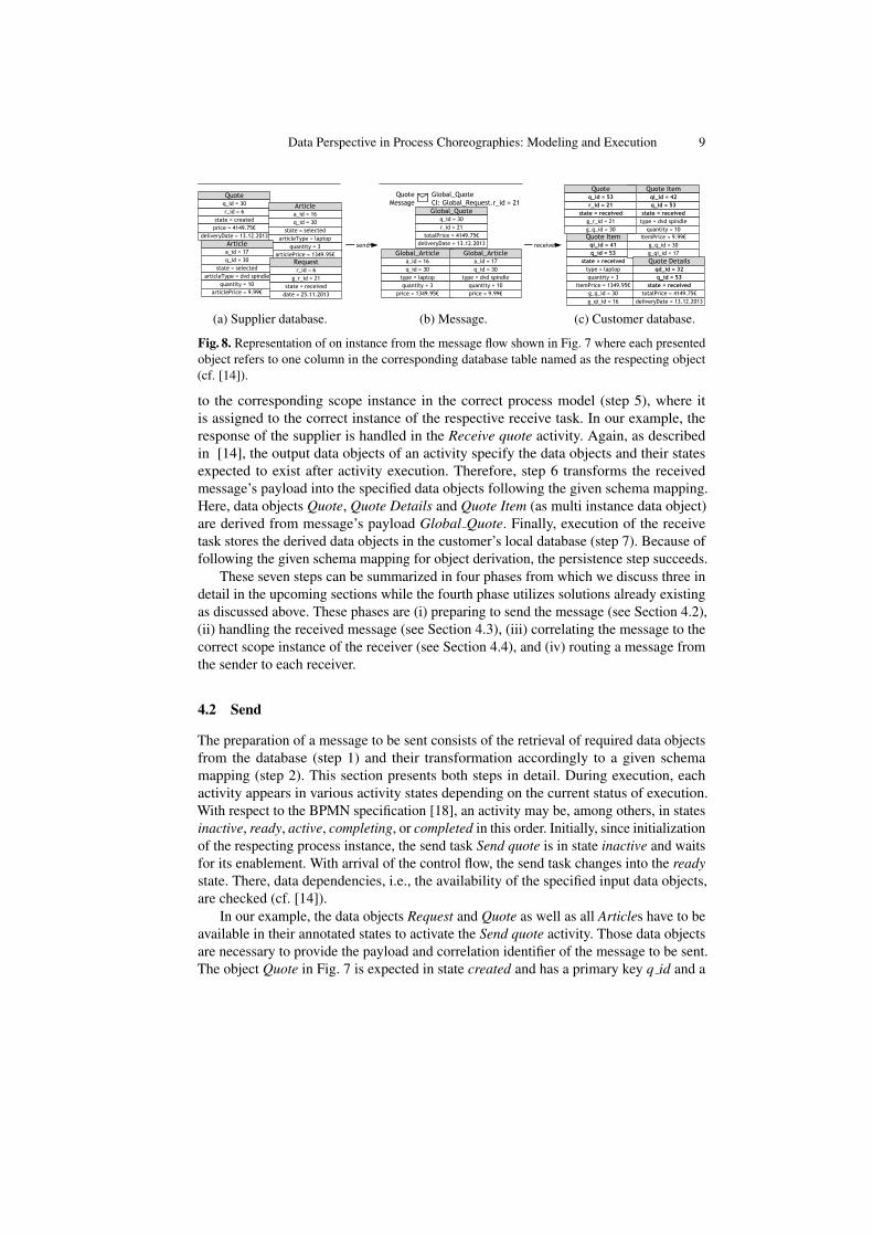
Fig. 8. Representation of on instance from the message flow shown in Fig. 7 where each presentedobject refers to one column in the corresponding database table named as the respecting object(cf. [14]).
to the corresponding scope instance in the correct process model (step 5), where itis assigned to the correct instance of the respective receive task. In our example, theresponse of the supplier is handled in the Receive quote activity. Again, as describedin [14], the output data objects of an activity specify the data objects and their statesexpected to exist after activity execution. Therefore, step 6 transforms the receivedmessage’s payload into the specified data objects following the given schema mapping.Here, data objects Quote, Quote Details and Quote Item (as multi instance data object)are derived from message’s payload Global Quote. Finally, execution of the receivetask stores the derived data objects in the customer’s local database (step 7). Because offollowing the given schema mapping for object derivation, the persistence step succeeds.
These seven steps can be summarized in four phases from which we discuss three indetail in the upcoming sections while the fourth phase utilizes solutions already existingas discussed above. These phases are (i) preparing to send the message (see Section 4.2),(ii) handling the received message (see Section 4.3), (iii) correlating the message to thecorrect scope instance of the receiver (see Section 4.4), and (iv) routing a message fromthe sender to each receiver.
4.2 Send
The preparation of a message to be sent consists of the retrieval of required data objectsfrom the database (step 1) and their transformation accordingly to a given schemamapping (step 2). This section presents both steps in detail. During execution, eachactivity appears in various activity states depending on the current status of execution.With respect to the BPMN specification [18], an activity may be, among others, in statesinactive, ready, active, completing, or completed in this order. Initially, since initializationof the respecting process instance, the send task Send quote is in state inactive and waitsfor its enablement. With arrival of the control flow, the send task changes into the readystate. There, data dependencies, i.e., the availability of the specified input data objects,are checked (cf. [14]).
In our example, the data objects Request and Quote as well as all Articles have to beavailable in their annotated states to activate the Send quote activity. Those data objectsare necessary to provide the payload and correlation identifier of the message to be sent.The object Quote in Fig. 7 is expected in state created and has a primary key q id and a

10 Meyer et al.
foreign key r id pointing to the Request. Based thereon, the following guard for checkingthe availability of object Quote is created: (SELECT COUNT (q id) FROM QuoteWHERE r id = $ID AND state = created) ≥ 1. This SQL query returnsthe number of Quote entries in the local database that are in state ‘created’ and relatedvia foreign key r id to the case object instance Request of the current process instance(identified by $ID); there has to be at least one [14]. In [14], the case object is introducedas the object which drives the execution of a process and all other data objects are relatedto this one. The case object relates to the process instance by its primary key.
In Fig. 8a, an extract of the supplier database is illustrated with each table representingone entry in the Request, Quote, and Article tables respectively. Assuming that thecurrently running process instance has the identifier $ID = 6 and no other entry inthe Quote table refers to this identifier, above SQL statement returns value 1 indicatingavailability of the required data object. Analogously, the other input data objects arechecked for availability.
If all data dependencies are fulfilled, the message to be sent gets prepared by retriev-ing the required data objects from the local database followed by the transformationstep building the actual message. For retrieval, we adapt the SQL statements from [15]by changing SELECT COUNT to SELECT * and removing the quantity expectation ≥1. Thus, object Quote is retrieved by statement SELECT * FROM Quote WHEREr id = $ID AND state = created. Each specified data object is retrieved anal-ogously and then transformed into its global representation following the given schemamapping, e.g., object Quote is transformed into object Global Quote. In our example,we utilize the schema mapping explained in Section 3. As object Global Quote is a hier-archical data object, also all related Article objects are transformed into correspondingGlobal Articles. Here, there are two such objects indicated by the foreign key q id =30. After transformation, all three global objects are added the payload of the message tobe sent by the corresponding sent task. The correlation information Global Request.r id= 21 is taken from attribute g r id of the local object Request as specified in the schemamapping as well. After completing the message creation and adding the correlationidentifier, the state of the send task changes from ready to active indicating processingof the activity. The work performed by a send task is to initiate the actual send of theprepared message shown in Fig. 8b.
4.3 Receive
After a received message has been correlated to the corresponding instance (see Sec-tion 4.4) it can be processed by basically reversing the two steps for sending a message.First, the objects in the message are transformed into the local data model (step 6 inFig. 7) followed by storing them in the local database (step 7). A receive task can onlyreceive a message while it is in state active. Succeeding with the message receipt triggersthe change of activity state active to state completing for the receive task. In this activitystate, steps 6 and 7 from Fig. 7 take place.
The transformation, again, follows the given schema mapping; see Fig. 5 for details.Thus, Global Quote and its hierarchical depending Global Articles, the payload of themessage in our example, is mapped to the data objects Quote, Quote Details, and QuoteItem (as multi instance data object) by filling the respecting attributes. The data objects

Data Perspective in Process Choreographies: Modeling and Execution 11
to be used are specified by the output data objects to the receive task (likewise the inputdata objects for the send task). Thereby, primary keys and foreign keys of newly createdobjects as well as their states are not yet set (consider them empty for now). For instance,the local object Quote gets attributes r id and g q id set to 30 and 21 respectively whileattributes state and q id are still undefined. This information is added to the data objectswhile persistence mechanisms take place, i.e., in step 7. Step 7 is only triggered uponcompletion of the transformation step comprising that all data objects were created orupdated successfully with message information. Thereby, new information overwritesprobably existing one.
Setting the missing information (primary and foreign keys as well as states) andstoring the data objects in the local database utilizes the concepts from [14]. Thereby wedifferentiate between creating a new table entry (INSERT) and updating an existing one(UPDATE):
INSERT: Data objects, which representation in the process model contains a [new] anno-tation in the upper left corner, are supposed to be newly created. In the given example, allobjects being output to the receive task shall be created. In [15], patterns and correspond-ing SQL queries are provided to insert a new data object into the local database. Here,only the information given in the data object representation, i.e., primary key, foreign key,and state, are regarded, e.g., , INSERT INTO Quote (q id, r id, state)VALUES (DEFAULT, $ID, received) for the Quote object with $ID = 21 be-ing the current process instance id. In this paper, we extend these queries by adding the in-formation extracted from the received message based on the local data model such that thecomplete query for the Quote object looks as follows: INSERT INTO Quote (q id,r id, state, g q id) VALUES (DEFAULT, $ID, received, 30).
Analogously, the INSERT-statements are created for the other output data objects.For instance, object Quote Details gets the remaining information, totalPrice and deliv-eryDate, from the Global Quote object. Fig. 8c visualizes the customer database afterinserting all data object extracted from the received message. Please note, the order ofstoring the data objects into the local database is important as, for instance, one objectmay relate to another object via foreign key relationship. In this case, the second objectmust have been stored first to ensure that the key value is known to be added for the firstobject. In our example, object Quote Details has a foreign key relationship to objectQuote such that is must be inserted after object Quote.
We assume that the foreign key relationships between the output data objects of areceive task form a directed acyclic graph over the respecting data objects. It impliesthat these relations have a partial order and that it is possible to insert referenced dataobjects before the ones that reference them. Then, this directed acyclic graph describesthe insertion order from leaf to root node.so that first the Quote object and then the QuoteDetails and the Quote Item objects are inserted. When the graph is completely traversed,the receive task has finally reached the completed state.UPDATE: The representation of an output data object to be updated has no additionalannotation in the process model. Again, we utilize the SQL queries provided for variousupdate patterns from [14] and extend them to update the information retrieved in themessage as well. For each such data object, the local data model specifies the attributes

12 Meyer et al.
to be updated, i.e., overwritten with the values provided in the received message. As-suming that object Quote is updated instead of inserted, then the following UPDATEstatement would apply: UPDATE Quote SET state = received, g q id =30 WHERE r id = $ID;. As primary key and foreign key cannot be updated basedon message information (see above), they are note included in the created SQL queries.In the given example, a specific update ordering is not necessary as the keys do notchange. However, there do exist patterns where the foreign key is set by such query.In these cases, the ordering gets important and is enforced as discussed above for theINSERT-statements. In contrast to the INSERT-statements, updates cannot be applied todata collections, i.e., multi instance data objects, because in is not clear which informa-tion would belong to which object of the collection as they are not distinct in the processinstance. Assigning explicit ids would solve this issue but is out of scope for this paper.
We also allow combinations of inserts and updates for one receive task, if the limitationsof both operations are considered, i.e., the insertion order for the newly created dataobjects and no update on data collections.
4.4 Correlation
Before a message can be handled, it has to be assigned to its receiving instance which isalso known as correlation handling. The standard approach is key-based correlation [17,18], where some attributes of the data model are designed as correlation keys. Anincoming message is correlated to a process instance when both store the same value forall correlation keys in the message; any two instances must be distinct on their correlationvalues. We first consider the case when an instance has all keys initialized already andthen discuss how to initialize a key.
All keys initialized. Our approach refines key-based correlation by making correlationkeys part of the global data model. On the one hand, each message m = (name,CI, d)explicitly defines a number of correlations keys CI , where each key d2 .a ∈ CI pointsto some attribute a of some global data object d2 (not necessarily d). For example,the message of Fig. 8b has the correlation key Global Request.r id while its payloadis of type Global Quote (as specified in Fig. 3). On the other hand, each participantdefines a local data model, where each correlation key attribute d2 .a of m is mappedto a local attribute f(d2 .a) = d ′
2 .b of some local data object d′2. Each process instance$ID has its own case object instance and related object instances; message m correlatesto $ID when the value of each d2 .a ∈ CI matches the value of the correspondingf(d2 .a) of some data object related to instance $ID. For example, the Customer mapsGlobal Request.r id to Request.r id (see Fig. 5). Thus, the message of Fig. 8b can becorrelated to a process instance where the case object has Request.r id = 21.
Formally, the correlation information of a message m = (name,CI, d) is a setCI = {(k1, v1), . . . , (kn, vn)} of key/value pairs, where each key ki = di.ai is anattribute ai of a global data object di. A participant’s schema mapping f maps eachkey to a local attribute f(di.ai) = d′i.a
′i. The value of the correlation attribute d′i.a
′i can
be extracted with respect to the case object c of the receiving instance $ID as follows.Object d′i relates to c via foreign key relations. Thus, we can build an SQL query joiningthe tables that store d′i and c, select only the entries where the primary key of c equals

Data Perspective in Process Choreographies: Modeling and Execution 13
$ID, and finally extract the value of attribute d′i.a′i; see [15]. Let e(d′i.a
′i, c,$ID) denote
the results of this query. By ensuring that in the local data model the relations from c tod′i are only 1:1, the extracted value e(d′i.a
′i, c,$ID) = v is uniquely defined. Now, m
correlates to an instance $ID of a process with case object c iff for each (ki, vi) ∈ CIholds e(f(ki), c, $ID) = vi. This definition can be refined to not only consider the caseobject of the entire process, but also the case object and instance id of the scope thatencloses the active task that can receive m.
Initializing correlation keys. When sending a message m, then its correlation keys areautomatically initialized by extracting for each global correlation attribute ki the corre-sponding value e(f(ki), c, $ID) = vi from the sender’s local data model. Technically,this can be done in the same way as extracting the payload of m, see Section 4.2. Fromthis point on, all process instances receiving a message with correlation key ki have toagree on the value vi. The only exception is when e(f(ki), c, $ID) =⊥ is still undefinedat the receiving instance. By initializing the local attribute f(ki) to value vi, we canmake $ID a matching instance for m. Thus, we generalize the above condition: mcorrelates to an instance $ID of a process with case object c iff for each (ki, vi) ∈ CIholds if e(f(ki), c, $ID) 6=⊥ then e(f(ki), c, $ID) = vi. When receiving m, the localkey attribute f(ki) can be initialized for $ID to value vi by generating an SQL updatestatement as discussed in Section 4.3.
5 Evaluation
We implemented our approach by extending the camunda Modeler, a modeling toolsupporting BPMN, and the camunda BPM Platform, a process engine for BPMN processmodels. The modeling tool was extended with the annotations for messages and dataobjects described in Section 3; message types of the global data model are specified inXSD and a simple editor allows to create an attribute-wise schema mapping from theglobal to the local data model. Once a private choreography model has been completed,the user can automatically generate XQuery expressions (http://www.w3.org/TR/xquery/)at the send and receive tasks to transform between local and global data model (Section 4).The engine was extended with a messaging endpoint for sending and receiving messagesin XML format to correlate messages, to read and write local data objects by generatingSQL queries from process models, and to process messages as described in Section 4.As the concepts in this paper, also our implementation does not address R4 (messagerouting); in particular if the receiving task is not in state active to receive the incomingmessage, the message will be discarded. Making the process layer compatible with errorhandling of the message transport layer is beyond the scope of this paper.
To demonstrate the feasibility of our approach, we implemented the service inter-action patterns [3] which capture basic forms of message-based interaction. In thefollowing, we briefly describe each pattern and how it can be realized using the proposedapproach. Thereby, we reuse the pattern classification into single-transmission bilateral,single-transmission multilateral, multi-transmission, and routing interaction patterns tostructure this section.

14 Meyer et al.
5.1 Single-Transmission Bilateral Interaction Patterns
Patterns in this category describe the interaction of two participants A and B that eachsend/receive one message.
P1 Send and P2 Receive. Participant A sends a message which has to be received byparticipant B. The challenges are to generate and send a message, to correlate a messagebased on an initialized or uninitialized key, and to process a received message.
Fig. 9 shows the pattern for A sending a message to B. Thereby the local objectRequestA is transformed into the global object Request P1 and the correlation keyRequest P1.request id is set from the primary key requestID of RequestA.
Fig. 9. Pattern P1: send.
Fig. 10 shows the pattern for B receiving the message from A. Thereby the messagebeing received creates a new process instance; the global object Request P1 is mappedto the local object RequestB with its own primary key; the correlation informationin Request P1.request id is mapped to an attribute RequestB.requestID fromA. Thiscorrelation key is initialized upon receipt.
P3 Send/Receive. Participant A sends a request to B and receives a response. Thechallenge is to correlate the response message to the instance of A that sent the message.
Fig. 11 shows the pattern for A sending a message to B and then awaiting the corre-sponding response. Correlation of the response to the request is achieved by including inthe response message the correlation information Request P3.request id that was sentto B in the request message. This way, only responses that match the request will bereceived. As the correlation key Request P3.request id is initialized from the primarykey RequestA.requestId, the received response can be transformed into the local objectResponseA that has requestId as foreign key pointing to RequestA.
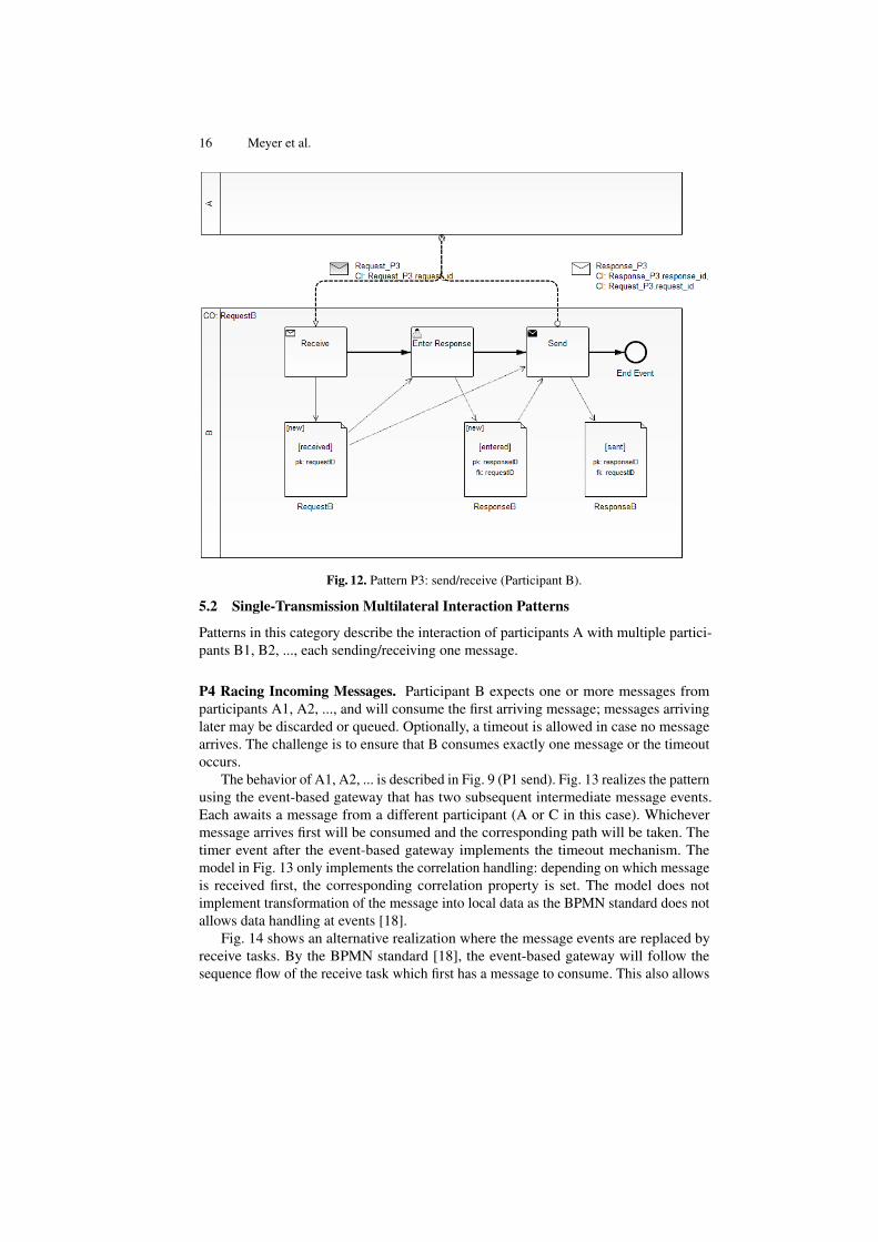
Fig. 12 shows the pattern for B receiving the message from A and producing aresponse. Thereby the message being received creates a new process instance; theglobal object Request P3 is mapped to the local object RequestB with its own primarykey; the correlation information in Request P3.request id is mapped to an attributeRequestB.requestID fromA. This correlation key is initialized upon receipt and used againwhen generating the response message Response P3 from the local object ResponseB.

Data Perspective in Process Choreographies: Modeling and Execution 15
Fig. 10. Pattern P2: receive.
Fig. 11. Pattern P3: send/receive (Participant A).
16 Meyer et al.
Fig. 12. Pattern P3: send/receive (Participant B).
5.2 Single-Transmission Multilateral Interaction Patterns
Patterns in this category describe the interaction of participants A with multiple partici-pants B1, B2, ..., each sending/receiving one message.
P4 Racing Incoming Messages. Participant B expects one or more messages fromparticipants A1, A2, ..., and will consume the first arriving message; messages arrivinglater may be discarded or queued. Optionally, a timeout is allowed in case no messagearrives. The challenge is to ensure that B consumes exactly one message or the timeoutoccurs.
The behavior of A1, A2, ... is described in Fig. 9 (P1 send). Fig. 13 realizes the patternusing the event-based gateway that has two subsequent intermediate message events.Each awaits a message from a different participant (A or C in this case). Whichevermessage arrives first will be consumed and the corresponding path will be taken. Thetimer event after the event-based gateway implements the timeout mechanism. Themodel in Fig. 13 only implements the correlation handling: depending on which messageis received first, the corresponding correlation property is set. The model does notimplement transformation of the message into local data as the BPMN standard does notallows data handling at events [18].
Fig. 14 shows an alternative realization where the message events are replaced byreceive tasks. By the BPMN standard [18], the event-based gateway will follow thesequence flow of the receive task which first has a message to consume. This also allows

Data Perspective in Process Choreographies: Modeling and Execution 17
Fig. 13. Pattern P4: racing incoming messages (Participant B), with message events.
to transform data. However, by the time of our research the camunda BPM platform didnot support receive tasks after and event-based gateway and thus this pattern could notbe executed.
P5 One-to-Many Send, P7 One-to-Many Send/Receive. In P5, Participant A sendsout a request to multiple participants B1, B2, ..., so that each participant receives onerequest. In P7, each participant B1, B2, ... then sends a reply to its request. The challengeis to generate multiple messages with different correlation information and to thencorrelate the incoming responses to the original request.
Fig. 15 realizes the behavior of A for P7 (and thus also for P5). First, we generate aseparate instance of data object SubRequestA for each request that is going to be sent.The number of requests to be generated is set in the process variable numSubRequests.Then, for each instance of SubRequestA, we create a new instance of the multi-instancesubprocess; each handling one instance of SubRequestA as case object. This case objectis mapped to the global data object Request P3; the primary key subRequestID ofSubRequestA is mapped to the correlation information Request P3.request id. Thus,each message carries a different correlation information. This correlation informationis also set for the subprocess instance from which the message is sent making thesubprocess instances distinguishable. Participant B can handle the message as describedin Fig. 12 and send the response. The response is correlated by A to the receive activityin the subprocess instance which has the matching correlation information. The receivedglobal Response P3 is transformed to the local object ResponseB which is related to thetop-level case object RequestA.

18 Meyer et al.
Fig. 14. Pattern P4: racing incoming messages (Participant B), with receive tasks.
Fig. 15. Pattern P5 and Pattern P7: one-to-many send/receive.

Data Perspective in Process Choreographies: Modeling and Execution 19
This pattern also shows that the global data model used for Pattern P3 using Re-quest P3 and Response P3 can be implemented in very different ways. In P3, ParticipantA sends just one message, whereas in P7, Participant A sends multiple messages todifferent recipients. The recipient process B (Fig. 12) cannot distinguish these twoimplementations as each request is handled by a different instance of B.
P6 One-from-Many Receive. In P6, participant A receives from an unknown numberof participants B1, B2, B3, ... one message per participant. The sent messages logicallycorrespond to each other and thus have to be correlated to the same instance of A. Thechallenge is to dynamically let the first message set the correlation information basedon which the other messages are correlated to that instance. A message with a differentcorrelation information has to be correlated to a different instance. Pattern P6 is notcovered by Fig. 15 as there the correlation information is set by A, whereas in P6, thecorrelation information is distributedly set by B1, B2, etc.
The model in Fig. 16 realizes P6 for instances of A that are already running. Theprocess uses DocumentA as case object. The subprocess is used to receive multiplemessages containing a global object Message P6. The contents of this global object istransformed to the local DataObjectA; the correlation information conversation numberis mapped to the attribute DocumentA.number of the case object. For each receivemessage, a new instance of DataObjectA is created. The first received message willinitialize the correlation key DocumentA.number for the entire process. All subsequentmessages that have the same key will be correlated to that instance. The subprocess hastwo termination criteria: receiving a certain number of messages and a timeout condition.The criterion on the received number of messages had to be implemented manually.
Fig. 16. Pattern P6: one-from-many receive (running instance).
The model in Fig. 16 realizes P6 for the situation when a new instance of A has tobe created to receive the messages. Both receive activities can receive the same kindof messages. The first incoming message will be consumed by the instantiating receive

20 Meyer et al.
task which also sets the correlation information. All subsequent messages that have thesame correlation information will be routed to that instance. A message with a differentcorrelation information causes the creation of a new process instance.
Fig. 17. Pattern P6: one-from-many receive (create instance)
5.3 Multi-Transmission Interaction Patterns
Patterns in this category describe scenarios where participant A directly exchangesmultiple messages with one or more participants B1, B2, ...
P8 Multi-Responses. In P8, participant A sends a request to participant B and thenreceives one or more responses from B until a certain condition (based on received dataor a timeout) holds. The challenge is to correlate each response of B to the instance of Athat sent the request.
Fig. 18 and 19 realize Pattern P8 for participants A and B, respectively. A cre-ates a global Request P8 object from their local RequestA object; the primary keyRequestA.requestID serves as correlation key.
The message is received by B (Fig. 19) which can generate one or more responsesin a loop. Each response carries again RequestA.requestID as correlation identifier;its value is retrieved from the local object RequestB that was created when receivingRequest P8. When the response arrives at A, the correlation key only matches thecorrelation information of the sending instance that receives multiple messages until atimeout occurs (or an upper bound of messages has been received). Note that the upperbound of messages is not derived from the model shown in Fig. 18, but implementedmanually.
In general, P8 allows that B may respond with different message types. This canbe achieved for B by replacing in the model of Fig. 19 the send activity with a blockof alternative send activities (a pair of XOR-gateways enclosing one send activity for

Data Perspective in Process Choreographies: Modeling and Execution 21
Fig. 18. Pattern P8: multi-responses (Partner A).
Fig. 19. Pattern P8: multi-responses (Partner B).

22 Meyer et al.
each message type). The XOR-gateway chooses the corresponding type by followinga specific path based on the kind of information entered. For A, replace in Fig. 18 thereceive activity with an event-based gateway followed by an intermediate message eventor receive activity for each message type as shown in Fig. 13 and Fig. 14.
P9 Contingent Requests. In P9, participant A sends a request to participant B whoshall send a response. If B’s response does not arrive on time, then A will resend therequest to another participant C, now expecting a response from C and discarding anyresponse from B. If C’s response does not arrive on time, the pattern is iterated withanother participant D and so on until some response is received.
The challenges in P9 are (1) to pick a different recipient each time a request is sentand (2) to ensure that at any point in time only the response to the latest request isconsidered as valid. The model in Fig. 20 realizes this pattern as follows. Regarding (1),activity Pick Recipient stores the recipient’s endpoint URL in a process variable; thisvariable is read when sending a message. Regarding (2), the case object RequestA has asingle child object SubRequestA that is the case object of the subprocess. SubRequestAis mapped to the global object Request P3 and the primary key subRequestID is mappedto the correlation identifier Request P3.request id. The response Response P3 uses thesame correlation identifier. For instance, the process of Fig. 12 can receive the requestand send a corresponding response.
Fig. 20. Pattern P9: contingent requests (Partner A).
As SubRequestA is the case object of the subprocess, the correlation key is only validfor the instance of the subprocess from which the message was sent. When the timeoutoccurs, the instance terminates and all its correlation information is removed. Then, theSubRequestA instance for this request is deleted by task clear subrequest before creating anew one. This ensures that at any point in time RequestA has a unique child SubRequestA.

Data Perspective in Process Choreographies: Modeling and Execution 23
The new child is used in the next iteration of the send/receive until a response arrives. Asthe correlation information is attached to the subprocess, only responses arriving duringthe lifetime of the sending subprocess instance will be correlated to the process.
P10 Atomic Multicast Notification. In P10, participant A sends a request to multipleparticipants B1, B2, ..., Bm; of these between nmin and nmax participants have to respondwithin a certain time interval. If less than nmin participants or more than nmax participantsrespond, then all participants of B1, B2, ..., Bm who already did respond have to benotified, e.g., by a cancellation message. In other words, this pattern has conditionaltransactional properties: from all the participants that do respond to A, either all continuesuccessfully, or all are notified with a cancellation message. Which case occurs dependson the total number of responses received by A.
The challenges in this pattern are to compute the number of received responses anddepending on the outcome to either succeed or to notify all participants who did respondwith a cancellation message.
The models in Fig. 21 and 22 realize this pattern. In Fig. 21, activity Enter Datagenerates the local RequestA data object. The subsequent service task then generatesmultiple SubRequestA objects from the contents of RequestA (the corresponding handlingof attributes has been implemented manually). For each SubRequestA, an instance of thefirst multi-instance subprocess is created in which the SubRequestA is transformed into aglobal Request P10 object with SubRequestA.requestID as correlation identifier. WhenA receives a response, the SubRequestA object moves to state received; the contents ofthe response is stored in the object SubResponseA. When A did not receive a responseuntil the timeout occurs, then task clear request deletes the SubRequestA object forwhich there was no response. The multi-instance subprocess completes when for eachSubRequestA either the response arrived (and hence SubRequestA is in state received) orthe timeout occurred (and hence SubRequestA has been deleted).
Thus, when reaching task evaluate, the case object RequestA of A has exactly oneSubRequestA object instance for each received response. The task itself executes an SQLquery to retrieve the number n of SubRequestA object instances that are associated tothe case object and sets the process variable sendCancel to false iff nmin ≤ n ≤ nmax.If sendCancel is false, the pattern terminates (or could be extended to interact with theresponding partners). If sendCancel is true, the second multi-instance subprocess isstarted creating one instance for each SubRequestA object instance associated to thecase object. The subprocess instance carries the correlation key of the SubRequestAobject, i.e., Request P10.request id which is mapped to SubRequestA.subRequestID.This correlation key is used in the cancellation message which can then be correlatedexactly the instance that responded to the original request.
Participant B shown in Fig. 22 generates a response for the request using the samecorrelation information as in the response. After that, B waits at the event-based gatewayfor either the cancellation message to arrive or a timeout to occur after which nocancellation message from A will arrive.
Note that Fig. 21 and Fig. 22 realize P10 using model-based concepts only, exceptfor generating contents of the subrequests, and for aggregating the number of receivedresponses into a variable. These had to be defined manually.

24 Meyer et al.
Fig. 21. Pattern P10: atomic multicast notification (Partner A).

Data Perspective in Process Choreographies: Modeling and Execution 25
Fig. 22. Pattern P10: atomic multicast notification (Partner B).
5.4 Routing Interaction Patterns
Patterns in this category describe scenarios where participant A sends messages toparticipants it does not know yet via an intermediate participant B; Participant B routesmessages received from A to participants C,D,...
P11 Request with Referral. In P11, Participant A sends B a request that containsthe address of a participant it would like to contact. Participant B takes the recipientinformation from this message and forwards the request to the right recipient. Thechallenges in this pattern are to forward a message to another recipient and to set therecipient’s address from data in the message.
The processes in Fig. 23, 24, and 25 realize this pattern. In Fig. 23, A generatesthe local RequestA which also contains an attribute endPoint to which the request shallfinally be routed; the local object RequestA is transformed into the global AtoB P11which is sent to B.
In Fig. 24, B receives the global object AtoB P11 and stores it in the local objectRequestB including the attribute endPoint. The subsequent service task retrieves thevalue of RequestB.endPoint and stores it in a local variable endPoint. The subsequentsend task generates the global object BtoC P11 from the stored RequestB and sends it tothe URL in the variable endPoint.
The process at that URL finally receives the request as shown in the process modelin Fig. 25.
The models can be extended to not only send a single endpoint URL but a list ofURLs which B can then process one-by-one. Note that setting the process variableendPoint from the attribute of RequestB is not supported by our approach and had to beimplemented manually.

26 Meyer et al.
Fig. 23. Pattern P11: request with referral (Partner A).
Fig. 24. Pattern P11: request with referral (Partner B).

Data Perspective in Process Choreographies: Modeling and Execution 27
Fig. 25. Pattern P11: request with referral (Partner C).
P12 Relayed Request. In P12, participant A sends a request to B which is forwardedto C; the response of C is then sent directly to A and not via B. The challenge in thispattern is to provide C with the right correlation information so that the response from Ccan be correlated to the right instance of A.
The models in Fig. 26, 27, and 28 realize this pattern. Here, participants A, B, andC first agreed that the message from A to B carries correlation information to identifythe sending instance of A (via correlation key AtoB P12.id from a). This correlationinformation is included in the message sent from B to C so that C can use the informationin the final response CtoA P12. The control and message flow are then straightforward.In Fig. 26, participant A sends the request with the correlation key AtoB P12.id from athat has been set from the local attribute RequestA.requestID and expects a responsemessage CtoA P12 having the same correlation information. In other words, the value ofAtoB P12.id from a in CtoA P12 has to match the attribute requestID of the case objectRequestA.
In Fig. 24, participant B receives the request from A and stores it in the localRequestB; in particular, attribute AtoB P12.id from a is stored in the attribute Re-questB.idFromA. The entire request is sent to C in the global object BtoC P12 which hasthe attributes id from a (mapped from RequestB.idFromA) and id from b (mapped fromRequestB.requestID). Thus, the correlation information of A is forwarded to C althoughthe message BtoC P12 only carries BtoC P12.id from b as correlation key.
In Fig. 28, participant C receives the forwarded request from B and stores it in thelocal object RequestC; the attribute BtoC P12.id from a is mapped to RequestC.idFromA.Then C generates a response which is transformed to the global object CtoA P12. Themessage also gets the correlation key AtoB P12.id from a for which the value is mappedfrom RequestC.idFromA. Thus the final response contains the expected correlationinformation for the sending instance.

28 Meyer et al.
Fig. 26. Pattern P12: relayed request (Partner A).
Fig. 27. Pattern P12: relayed request (Partner B).
P13 Dynamic Routing. In P13, Participant A sends a request to B which forwards therequest to participant C or D depending on the contents of the message. This patterndiffers from P11 in that C and D are known to B at design time and that the condition towhom to send the message is defined within B and not by A. The challenge here is tomake an internal choice in B based on the contents of a received message.
The models in Fig. 29, 30, and 31 realize this pattern. In Fig 29, Participant Agenerates a RequestA which is transformed into the global AtoB P13 and then sent to B.
Participant B receives the message and transforms AtoB P13 into the local RequestBwhich has an attribute requestText (mapped from AtoB P13.request text). The subsequentuser task does not do anything. The XOR gateway’s outgoing arcs are annotated witha condition comparing attribute requestText of the case object RequestB to a value.Depending on the value, a different path is taken leading to an activation of a differentsend task to which RequestB is forwarded.

Data Perspective in Process Choreographies: Modeling and Execution 29
Fig. 28. Pattern P12: relayed request (Partner C).
Fig. 29. Pattern P13: dynamic routing (Partner A).
This matches pattern A2 of [15] which translates to the following behavior: whenreaching the XOR gateway, an SQL query SELECT requestText FROM RequestBWHERE requestID = $ID is generated to retrieve the value of the attribute men-tioned at the outgoing arc(s) in order to evaluate the guard expressions. Technically, westore the result of the query in a local process variable which is then used to evaluate theexpression.
The participant C or D (shown in Fig. 31) to which the request was sent by B receivesthe forwarded request and processes it locally.
Our implementation and the implemented patterns are available at http://bpt.hpi.uni-potsdam.de/Public/BPMNData.
6 Related Work
In this section, we briefly discuss approaches related to the concepts presented in thispaper. Thereby, we focus on communication between distributed partners, the transfor-mation of data, and message correlation. The service interaction patterns discussed in [3]

30 Meyer et al.
Fig. 30. Pattern P13: dynamic routing (Partner B).
Fig. 31. Pattern P13: Dynamic Routing (Partner C and D).
describe a set of recurrent process choreography scenarios occurring in industry. There-fore, they are a major source to validate choreography support of a modeling language.Besides BPMN [18] as used in this paper as basis, there exist multiple solutions to copewith process choreographies. Most prominent are BPMN4Chor [5], Let’s Dance [33],BPEL4Chor [6], and WS-CDL [27]. From these, only BPEL4Chor and WS-CDL realizeoperational semantics to handle message exchange by reusing respectively adapting theconcepts defined in BPEL [17]. However, message transformation to achieve interoper-ability between multiple participants is done with imperative constructs meaning that theprocess engineer has to manually write these transformations and that she has to ensuretheir correctness. Additionally, BPEL4Chor and WS-CDL are not model-driven as theapproach introduced in this paper.
Apart from process and service domains, distributed systems [22] describe thecommunication between IT systems via pre-specified interfaces similar to the globalcontract discussed in this paper. Usually, the corresponding data management is done by

Data Perspective in Process Choreographies: Modeling and Execution 31
distributed databases [19] and their enhancements to data integration systems [12, 23]as well as parallel database systems [8] or is done by peer-to-peer systems [9, 24]. Thedatabase solution allows many participants to share data by working with a global schemawhich hides the local databases, but unlike our approach, the participants work on thesame database or some replication of it. Peer-to-peer systems take the database systemsto a decentralized level and include mechanisms to deal with very dynamic situationsas participants change rapidly. In process choreographies, the participants are knownand predefined such that a centralized solution as presented in this paper saves overheadas, in the worst case, the decentralized approach requires a schema mapping for eachcommunication between two participants instead of only one mapping per participant tothe global schema. The transformation of data between two participants can be achievedvia schema mapping and matching [20,21], a mediator [31], an adapter [32], or ontology-based integration [4, 16, 29]. For instance, [4] utilizes OWL [26] ontologies, which aresimilar to our global data model, and mappings from port types to attributes via XPathexpressions to transform data between web services. In this paper, we utilize schemamatching due to the close integration of database support for data persistence.
Returning to the process domain, there exist fundamental works describing theimplementation of process choreographies [1, 7] with [1] ensuring correctness for inter-process communication. These works only describe the control flow side although thedata part is equally important as messages contain the actual artifacts exchanged. [11]introduces a data-aware collaboration approach including formal correctness criteria.They define the data perspective using data-aware interaction nets, a proprietary notation,instead of a widely accepted one as BPMN, the industry standard for process modeling,used as basis in this paper.
7 Conclusion
In this paper, we presented an approach allowing to model and enact the data perspectiveof process choreographies entirely model-driven. Thereby, we utilized the industrystandard BPMN and extended the model-driven data dependency enactment approachcatered for process orchestrations with concepts for process choreographies. Based onchallenges of data heterogeneity, correlation, and 1:n communication, we identified a setof six requirements covering the retrieval of data from the sender’s local database, thedata transformation into a global data schema all participants agreed upon, the correlationof a message to the correct activity instance, the transformation from the global to thereceiver’s local database schema, and the storage of the data there. The message routingbetween participants is out of scope of this paper by adapting existing technologiesas, for instance, web services. In this paper, we describe a modeling guideline withthe artifacts required to automatically execute the mentioned steps from these only.Furthermore, we describe the corresponding operational semantics and provide detailsabout our implementation. Our approach has been implemented; we could implement allservice interaction patterns of [3] except for dynamically setting URLs of recipients andevaluating data conditions over aggregations of data objects; both are outside the scopeof this paper and deserve future work. Also the integration of process layer and messagetransport layer (in particular wrt. handling message transport errors) is outside the scope

32 Meyer et al.
of this paper. The current approach only utilizes tasks to send and receive messages.However, BPMN also supports message events to which the discussed concepts couldbe applied as well by overcoming BPMN’s limitation that events cannot transformand correlate data objects. In future work, we plan to provide an integrated formalverification technique for model-driven data enactment in process orchestrations andchoreographies.
References
1. van der Aalst, W.M.P., Lohmann, N., Massuthe, P., Stahl, C., Wolf, K.: Multiparty contracts:Agreeing and implementing interorganizational processes. Comput. J. 53(1), 90–106 (2010)
2. van der Aalst, W.M.P., Weske, M.: The p2p approach to interorganizational workflows. In:CAiSE. pp. 140–156. Springer (2001)
3. Barros, A., Dumas, M., ter Hofstede, A.H.M.: Service interaction patterns. In: BusinessProcess Management. pp. 302–318. Springer (2005)
4. Bowers, S., Ludascher, B.: An ontology-driven framework for data transformation in scientificworkflows. In: Data Integration in the Life Sciences. pp. 1–16. Springer (2004)
5. Decker, G., Barros, A.: Interaction modeling using bpmn. In: BPM Workshops. pp. 208–219.Springer (2008)
6. Decker, G., Kopp, O., Leymann, F., Weske, M.: Bpel4chor: Extending bpel for modelingchoreographies. In: ICWS. pp. 296–303. IEEE (2007)
7. Decker, G., Weske, M.: Interaction-centric modeling of process choreographies. InformationSystems 36(2), 292–312 (2011)
8. DeWitt, D., Gray, J.: Parallel database systems: the future of high performance databasesystems. Communications of the ACM 35(6), 85–98 (1992)
9. Halevy, A.Y., Ives, Z.G., Suciu, D., Tatarinov, I.: Schema mediation in peer data managementsystems. In: Data Engineering. pp. 505–516. IEEE (2003)
10. Kavantzas, N., Burdett, D., Ritzinger, G., Fletcher, T., Lafon, Y., Barreto, C.: Web serviceschoreography description language version 1.0. W3C candidate recommendation 9 (2005)
11. Knuplesch, D., Pryss, R., Reichert, M.: Data-aware interaction in distributed and collaborativeworkflows: Modeling, semantics, correctness. In: CollaborateCom. pp. 223–232. IEEE (2012)
12. Lenzerini, M.: Data integration: A theoretical perspective. In: Symposium on Principles ofDatabase Systems. pp. 233–246. ACM (2002)
13. Mendling, J., Hafner, M.: From ws-cdl choreography to bpel process orchestration. Journal ofEnterprise Information Management 21(5), 525–542 (2008)
14. Meyer, A., Pufahl, L., Fahland, D., Weske, M.: Modeling and Enacting Complex DataDependencies in Business Processes. In: BPM. pp. 171–186. Springer (2013)
15. Meyer, A., Pufahl, L., Fahland, D., Weske, M.: Modeling and Enacting Complex DataDependencies in Business Processes. Tech. Rep. 74, HPI at the University of Potsdam (2013)
16. Noy, N.F.: Semantic integration: a survey of ontology-based approaches. ACM Sigmod Record33(4), 65–70 (2004)
17. OASIS: Web Services Business Process Execution Language, Version 2.0 (April 2007)18. OMG: Business Process Model and Notation (BPMN), Version 2.0 (January 2011)19. Ozsu, M.T., Valduriez, P.: Principles of Distributed Database Systems. Springer (2011)20. Rahm, E., Bernstein, P.A.: A survey of approaches to automatic schema matching. The VLDB
Journal 10(4), 334–350 (2001)21. Shvaiko, P., Euzenat, J.: A survey of schema-based matching approaches. Journal on Data
Semantics IV 3730, 146–171 (2005)

Data Perspective in Process Choreographies: Modeling and Execution 33
22. Tanenbaum, A.S., van Steen, M.: Distributed Systems: Principles and Paradigms. PrenticeHall (2006)
23. Tomasic, A., Raschid, L., Valduriez, P.: Scaling access to heterogeneous data sources withdisco. Knowledge and Data Engineering, IEEE Transactions on 10(5), 808–823 (1998)
24. Valduriez, P., Pacitti, E.: Data management in large-scale p2p systems. In: High PerformanceComputing for Computational Science (VECPAR), pp. 104–118. Springer (2005)
25. W3C: Web Services Description Language (WSDL) 1.1 (March 2001)26. W3C: OWL Web Ontology Language (February 2004)27. W3C: Web Services Choreography Description Language, Version 1.0 (November 2005)28. W3C: XQuery 1.0: An XML Query Language (Second Edition) (December 2010)29. Wache, H., Voegele, T., Visser, U., Stuckenschmidt, H., Schuster, G., Neumann, H., Hubner,
S.: Ontology-based integration of information-a survey of existing approaches. In: IJCAIworkshop: ontologies and information sharing. pp. 108–117 (2001)
30. Weske, M.: Business Process Management: Concepts, Languages, Architectures. SecondEdition. Springer (2012)
31. Wiederhold, G.: Mediators in the architecture of future information systems. Computer 25(3),38–49 (1992)
32. Yellin, D.M., Strom, R.E.: Protocol specifications and component adaptors. ACM Transactionson Programming Languages and Systems (TOPLAS) 19(2), 292–333 (1997)
33. Zaha, J.M., Barros, A., Dumas, M., ter Hofstede, A.H.M.: Let’s dance: A language for servicebehavior modeling. In: OTM Conferences, pp. 145–162. Springer (2006)