data replication in p2p systems
TRANSCRIPT

Data Replication in P2P Systems
Vidal Martins
To cite this version:
Vidal Martins. Data Replication in P2P Systems. Reseaux et telecommunications [cs.NI].Universite de Nantes, 2007. Francais. <tel-00481828>
HAL Id: tel-00481828
https://tel.archives-ouvertes.fr/tel-00481828
Submitted on 7 May 2010
HAL is a multi-disciplinary open accessarchive for the deposit and dissemination of sci-entific research documents, whether they are pub-lished or not. The documents may come fromteaching and research institutions in France orabroad, or from public or private research centers.
L’archive ouverte pluridisciplinaire HAL, estdestinee au depot et a la diffusion de documentsscientifiques de niveau recherche, publies ou non,emanant des etablissements d’enseignement et derecherche francais ou etrangers, des laboratoirespublics ou prives.

UNIVERSITE DE NANTES FACULTE DES SCIENCES ET DES TECHNIQUES
_____
ÉCOLE DOCTORALE STIM « SCIENCES ET TECHNOLOGIES DE L’INFORMATION ET DES MATÉRIAUX »
Anée 2007
Data Replication in P2P Systems
_______
THESE DE DOCTORAT Discipline : Informatique
Spécialité : Bases de Données
Présentée Et soutenue publiquement par
Vidal MARTINS Le 24 mai 2007, devant le jury ci dessous
Président Christine Collet, Professeur, Institut National Polytechnique Grenoble Rapporteurs Anne-Marie Kermarrec, Directeur de Recherche, INRIA Philippe Pucheral, Professeur, Université de Versailles-Saint-Quentin Examinateurs Gilles Muller, Professeur, Ecole des Mines de Nantes Esther Pacitti, Maître de conférences, Université de Nantes Patrick Valduriez, Directeur de recherche, INRIA
Directeur de thèse : Patrick Valduriez Encadrante de thèse : Esther Pacitti
E.D 366-301


Abstract. This thesis addresses data replication in P2P systems. Its approach is motivated by the advances in distri-
buted collaborative applications and their specific needs in terms of data replication, data consistency, scalability, and
high availability. Using the example of a P2P Wiki application, we show that the replication requirements of colla-
borative applications are: high-level of autonomy, multi-master replication, semantic conflict detection and resolu-
tion, eventual consistency among replicas, weak network assumptions, and data type independence. Although opti-
mistic replication addresses most of these requirements, existing solutions are unsuitable for P2P networks since they
are either centralized or do not take into account the network limitations. On the other hand, existing P2P replication
solutions do not satisfy all such requirements simultaneously. In particular, none of them provide eventual consis-
tency among replicas along with weak network assumptions. This thesis aims to provide a scalable and highly availa-
ble reconciliation solution for P2P collaborative applications by developing a reconciliation protocol that assures
eventual consistency among replicas and takes into account data access costs. This goal is accomplished in five steps.
First, we present existing optimistic replication solutions and P2P replication strategies and analyze their advantages
and disadvantages. This analysis allows us to identify the functionalities and properties that our solution should pro-
vide. Second, we design a replication service for APPA (Atlas Peer-to-Peer Architecture). In a third step, we elabo-
rate an algorithm for distributed semantic reconciliation called DSR, which can be executed in different distributed
environments (e.g. cluster, Grid, P2P). A fourth step is to turn DSR into a reconciliation protocol for P2P networks
called P2P-reconciler. Finally, the fifth step produces a new version of P2P-reconciler, called P2P-reconciler-TA,
which exploits topology-aware P2P networks in order to improve reconciliation performance. We validated our solu-
tions and evaluated their performance through experimentation and simulation. The results showed that our replica-
tion solution yields high availability, excellent scalability, with acceptable performance and limited overhead.
Résumé. Cette thèse porte sur la réplication de données dans les systèmes pair-à-pair (P2P). Elle est motivée par
l’importance croissante des applications de collaboration répartie et leurs besoins spécifiques en termes de réplication
de données, cohérence de données, passage à l’échelle, et haute disponibilité. En employant comme exemple un Wiki
P2P, nous montrons que les besoins de réplication pour les applications collaborative sont : haut niveau d’autonomie,
réplication multi-maître, détection et résolution de conflit basé sur sémantique, cohérence éventuelle parmi des
répliques, hypothèses faibles de réseau, et indépendance des types de données. Bien que la réplication optimiste
adresse la plupart de ces besoins, les solutions existantes sont peu applicables aux réseaux P2P puisqu’elles sont
centralisées ou ne tiennent pas compte des limitations de réseau. D’autre part, les solutions existantes de réplication
P2P ne répondent pas à toutes ces exigences simultanément. En particulier, aucune d’elles ne fournit la cohérence
éventuelle parmi des répliques avec des hypothèses faibles de réseau. Cette thèse vise à fournir une solution de
réconciliation fortement disponible et qui passe à l’échelle pour des applications de collaboration P2P en développant
un protocole de réconciliation qui assure la cohérence éventuelle parmi des répliques et tient compte des coûts
d’accès aux données. Cet objectif est accompli en cinq étapes. D’abord, nous présentons des solutions existantes pour
la réplication optimiste et des stratégies de réplication P2P et nous analysons leurs avantages et inconvénients. Cette
analyse nous permet d'identifier les fonctionnalités et les propriétés que notre solution doit fournir. Dans une
deuxième étape, nous concevons un service de réplication pour le système APPA (en anglais, Atlas Peer-to-Peer
Architecture). Troisièmement, nous élaborons un algorithme pour la réconciliation sémantique répartie appelée DSR,
qui peut être exécuté dans différents environnements répartis (par ex. grappe, grille, ou P2P). Dans une quatrième
étape, nous faisons évoluer DSR en protocole de réconciliation pour des réseaux P2P appelé P2P-reconciler.
Finalement, la cinquième étape produit une nouvelle version de P2P-reconciler, appelée P2P-reconciler-TA, qui
exploite les réseaux P2P conscients de leur topologie (en anglais, topology-aware) afin d’améliorer les performances
de la réconciliation. Nous avons validé nos solutions et évalué leurs performances par l’expérimentation et la
simulation. Les résultats ont montré que notre solution de réplication apporte haute disponibilité, excellent passage à
l’échelle, avec des performances acceptables et surcharge limitée.
Keywords: Data replication, semantic reconciliation, eventual consistency, peer-to-peer
Discipline: Informatics No : E.D 366-301


Année 2007
Data Replication in P2P Systems
THESE DE DOCTORAT Discipline : Informatique
Spécialité : Bases de Données
Présentée Et soutenue publiquement par
Vidal MARTINS


vii
ACKNOWLEDGEMENTS I am very grateful to the Pontifical University Catholic of Paraná (PUCPR) for funding my Ph.D. studies for three years. In PUCPR, I am especially thankful to the following people who directly collaborated to make it possible the accomplishment of this research work: Edson Emilio Scalabrin, Flávio Bortolozzi, Laudelino, Marcos Schmeil, and Robert Carlisle Burnett. In addition, I wish to thank other people in PUCPR who were ready to help me if necessary: Alcides Calsavara, Carlos Alberto Maziero, Edgard Jamhour, and Manoel Camillo de Oliveira Penna Neto.
I am also very thankful to Patrick Valduriez and Esther Pacitti who received me at University of Nantes and gave me all I needed to carry out my research: interesting opportunities, appropriate re-sources, skilled advices, attention, motivation, tolerance, and experience sharing. Other people at Univer-sity of Nantes also helped me to achieve my objectives with different kinds of support and I would like to acknowledge all of them: Christine Brunet, Elodie Lize, Gerson Sunye, Marie-Andry Pivaut, Patricia Serrano Alvarado, and Philippe Lamarre.
Elaborating a Ph.D. thesis in a foreign country is not easy for several reasons. In order to overcome the associated difficulties it is very important to count on friends who sometimes seem to be part of the family. I want to express intense gratitude to my new friends who made it easier to face the challenges of such “adventure”: Alexandre de Assis Bento Lima, Antoine Pigeau, Cédric Coulon, Claudia Agostinho, Eduardo Almeida, Jorge Arnulfo Quiane Ruiz, Mariana, Reza Akbarinia, Siloé Souza, and Stephanie Pinçon. I would also like to thank Jorge Roberto Manjarrez Sanchez, Manal El-Dick, and Sandra Lemp for their friendship.
I especially want to thank my mother and my father for encouraging me and providing unconditional support. I also wish to express intense gratitude to my mother- and my father-in-law for all support they provided during this period, including financial support, and for being with us when my daughter was born. It is a privilege to have a family like mine.
Finally, I want to dedicate this work to my wife, Juliana Vermelho Martins, my son, Felipe Vermelho Martins, and my daughter, Ana Luíza Vermelho Martins, without whose support, encouragement, toler-ance, and love, I would have been lost. They provided the balance that allowed me remaining healthy and motivated even in the hardest periods. I love them very much.


ix
CONTENTS
RESUME ÉTENDU ................................................................................................................................... 1
1 INTRODUCTION .......................................................................................................................... 21
1.1 MOTIVATION ........................................................................................................................... 21 1.2 CONTRIBUTIONS ...................................................................................................................... 23 1.3 ORGANIZATION OF THE THESIS ................................................................................................ 24
2 DATA REPLICATION IN P2P SYSTEMS ................................................................................. 27
2.1 BASIC CONCEPTS ..................................................................................................................... 27 2.1.1 Single-master vs. multi-master .................................................................................... 28 2.1.2 Full replication vs. partial replication ........................................................................ 29 2.1.3 Synchronous vs. asynchronous ................................................................................... 29
2.1.3.1 Synchronous propagation ........................................................................................... 30 2.1.3.2 Asynchronous propagation ......................................................................................... 31 2.1.3.3 Summary .................................................................................................................... 34
2.2 OPTIMISTIC REPLICATION PARAMETERS .................................................................................. 35 2.2.1 Operation storage ....................................................................................................... 35 2.2.2 Operation relationships .............................................................................................. 35 2.2.3 Propagation frequency ............................................................................................... 36 2.2.4 Conflict detection and resolution ................................................................................ 37 2.2.5 Reconciliation ............................................................................................................. 37
2.2.5.1 IceCube ...................................................................................................................... 38 2.2.5.2 Harmony .................................................................................................................... 39 2.2.5.3 IceCube vs. Harmony ................................................................................................. 41
2.2.6 Summary ..................................................................................................................... 43 2.3 P2P SYSTEMS .......................................................................................................................... 43
2.3.1 P2P Networks ............................................................................................................. 44 2.3.1.1 Unstructured ............................................................................................................... 44 2.3.1.2 Structured ................................................................................................................... 45 2.3.1.3 Super-peer .................................................................................................................. 45 2.3.1.4 Comparing P2P networks ........................................................................................... 46
2.3.2 Replication solutions in P2P systems .......................................................................... 47 2.3.2.1 Napster ....................................................................................................................... 47 2.3.2.2 JXTA .......................................................................................................................... 48 2.3.2.3 Gnutella ...................................................................................................................... 49 2.3.2.4 Chord ......................................................................................................................... 50 2.3.2.5 CAN ........................................................................................................................... 51 2.3.2.6 Tapestry ..................................................................................................................... 52 2.3.2.7 Pastry ......................................................................................................................... 53 2.3.2.8 Freenet ....................................................................................................................... 54 2.3.2.9 PIER ........................................................................................................................... 54 2.3.2.10 OceanStore ................................................................................................................. 55 2.3.2.11 PAST .......................................................................................................................... 56 2.3.2.12 P-Grid......................................................................................................................... 56
2.4 CONCLUSION ........................................................................................................................... 58

Contents
x
3 REPLICATION SUPPORT IN APPA ......................................................................................... 61
3.1 OVERVIEW OF APPA ............................................................................................................... 61 3.2 DATA REPLICATION IN APPA SYSTEM ..................................................................................... 65
3.2.1 KSR service ................................................................................................................. 66 3.2.2 PDM service ................................................................................................................ 67
3.2.2.1 Replica placement using multiple hash functions ....................................................... 67 3.2.2.2 Updates and replica consistency ................................................................................. 68 3.2.2.3 Properties .................................................................................................................... 68
3.2.3 CCM service ................................................................................................................ 70 3.2.4 Replication service ...................................................................................................... 71 3.2.5 Data replication at work ............................................................................................. 73 3.2.6 PDM service vs. Replication service ........................................................................... 76
3.3 THE APPA API ........................................................................................................................ 76 3.4 CONCLUSION ........................................................................................................................... 79
4 BASIC P2P RECONCILIATION ................................................................................................. 81
4.1 OVERVIEW ............................................................................................................................... 82 4.2 DETAILED PRESENTATION OF P2P-RECONCILER ...................................................................... 82
4.2.1 Reconciliation objects ................................................................................................. 83 4.2.2 P2P-reconciler protocol.............................................................................................. 84
4.2.2.1 Notation for the algorithms ......................................................................................... 85 4.2.2.2 DSR algorithm ............................................................................................................ 86
4.2.3 P2P-reconciler at work ............................................................................................. 101 4.2.4 Dealing with nodes’ dynamic behavior ..................................................................... 103
4.3 DHT COST MODEL ................................................................................................................. 107 4.3.1 Lookup cost ............................................................................................................... 107 4.3.2 Direct cost ................................................................................................................. 109 4.3.3 DHT cost management .............................................................................................. 109
4.4 P2P-RECONCILER NODE ALLOCATION .................................................................................... 111 4.4.1 Determining the number of reconcilers..................................................................... 111 4.4.2 P2P-reconciler cost model ........................................................................................ 115 4.4.3 Nodes allocation ....................................................................................................... 115 4.4.4 Reconciliation cost management ............................................................................... 117 4.4.5 Algorithms for cost-based node allocation ............................................................... 118
4.5 PROOFS .................................................................................................................................. 126 4.5.1 Eventual consistency ................................................................................................. 126 4.5.2 High availability ....................................................................................................... 128 4.5.3 Correctness ............................................................................................................... 130
4.6 CONCLUSION ........................................................................................................................... 81

Contents
xi
5 TOPOLOGY-AWARE RECONCILIATION ........................................................................... 133
5.1 CAN NETWORKS ................................................................................................................... 133 5.1.1 Basic CAN ................................................................................................................. 133 5.1.2 Useful optimizations for P2P-reconciler-TA ............................................................ 134
5.1.2.1 Multiple hash functions ............................................................................................ 134 5.1.2.2 Topology-aware overlay construction ...................................................................... 134 5.1.2.3 Uniform partitioning ................................................................................................ 135
5.2 DEFINITIONS .......................................................................................................................... 135 5.3 HOW P2P-RECONCILER-TA WORKS ....................................................................................... 137
5.3.1 Computing provider node’s QoN .............................................................................. 138 5.3.2 Managing provider candidature ............................................................................... 139 5.3.3 Selecting provider nodes ........................................................................................... 140 5.3.4 Notifying providers selection .................................................................................... 141 5.3.5 Conclusion ................................................................................................................ 142
5.4 DETAILED ALGORITHMS FOR NODE ALLOCATION .................................................................. 142 5.5 PROOFS .................................................................................................................................. 153 5.6 CONCLUSION ......................................................................................................................... 153
6 VALIDATION .............................................................................................................................. 155
6.1 EXPERIMENTAL AND SIMULATION PLATFORMS...................................................................... 155 6.2 NETWORK INDEPENDENCE ..................................................................................................... 155
6.2.1 APPA over JXTA ....................................................................................................... 156 6.2.2 APPA over Chord and CAN ...................................................................................... 158
6.3 SIMULATION OF P2P NETWORKS ........................................................................................... 158 6.3.1 Building a P2P network with SimJava ...................................................................... 159 6.3.2 Establishing variable latencies and bandwidths ....................................................... 159
6.4 PERFORMANCE MODEL .......................................................................................................... 163 6.5 EXPERIMENTAL RESULTS ....................................................................................................... 164
6.5.1 DSR ........................................................................................................................... 165 6.5.2 P2P-reconciler .......................................................................................................... 166 6.5.3 P2P-reconciler-TA .................................................................................................... 169
6.6 CONCLUSION ......................................................................................................................... 173
7 CONCLUSION ............................................................................................................................. 175
7.1 SUMMARY ............................................................................................................................. 175 7.1.1 Survey of data replication in P2P systems ................................................................ 175 7.1.2 APPA replication service .......................................................................................... 176 7.1.3 DSR algorithm .......................................................................................................... 177 7.1.4 P2P-reconciler protocol ........................................................................................... 177 7.1.5 P2P-reconciler-TA protocol ..................................................................................... 178 7.1.6 Validation ................................................................................................................. 178
7.2 FUTURE WORK ....................................................................................................................... 179
BIBLIOGRAPHY .................................................................................................................................. 181
APPENDIX A – REPLICATION INTERFACES .............................................................................. 193


1
RÉSUMÉ ÉTENDU
1. Introduction
Les applications de collaboration répartie sont de plus en plus répandues, profitant des progrès constants des technologies reparties (grille, pair-à-pair, et traitement mobile). Comme exemple de telles applications, considérons un Wiki de deuxième génération qui travaille sur un réseau pair-à-pair (P2P) et supporte des utilisateurs dans l’élaboration et l’entretien des documents partagés d’une façon collaborative et asynchrone. Considérons également que chaque document est un fichier XML probablement lié à d’autres documents. Un tel Wiki permet de gérer de manière collaborative un seul document (par ex., un article scientifique partagé par ses auteurs) aussi bien que des documents composés et intégrés (par ex., une encyclopédie ou une base de connaissance au sujet de l’utilisation d’un logiciel libre). Bien que le nombre d’utilisateurs qui mettent à jour en parallèle un document d soit habituellement petit, la taille du réseau de collaboration qui maintient d en termes de nombre de nœuds peut être grande. Par exemple, le document d pourrait appartenir à la base de connaissance du club Mandriva, qui est maintenu par plus de 25.000 membres [Man07] ou il pourrait appartenir à Wikipedia, une encyclopédie de contenu libre maintenue par plus de 75.000 contributeurs actifs [Wik07].
Beaucoup d’utilisateurs ont fréquemment besoin d’accéder et de mettre à jour des informations même s’ils sont déconnectés du réseau, par exemple dans un avion, un train ou un autre environnement qui ne fournit pas de communication réseau appropriée. Ceci exige que les utilisateurs tiennent des répliques locales des documents partagés. Ainsi, un Wiki P2P a besoin de la réplication multi-maître pour assurer la disponibilité de données n’importe quand. Dans l’approche multi-maître, les mises à jour faites hors ligne ou en parallèle sur différentes répliques du même objet peuvent causer des divergences et des conflits parmi les répliques, qui doivent alors être réconciliés. Afin de résoudre les conflits, la solution de réconciliation peut profiter de la sémantique de l’application comme illustré dans l’Exemple 1. Pour des raisons de simplicité, et sans perte de généralité, cet exemple traite un seul document élaboré par trois auteurs. Le document est un article scientifique structuré en arbre. Chaque nœud (élément) dans la structure arborescente correspond à une section de l’article et garde le nom de l’auteur responsable.
L’Exemple 1a montre la structure initiale de l’article tandis que l’Exemple 1b montre les mises à jour conflictuelles (en gris) faites sur la structure initiale. Dans l’Exemple 1b Esther essaye de déplacer la section Préliminaires vers Papier changeant de ce fait le chemin de Préliminaires de Papier/Solu-tion/Préliminaires en Papier/Préliminaires tandis que Manal essaye d’insérer deux thèmes sous Préliminaires en employant le chemin Papier/Solution/Préliminaires. Si l’opération de déplacement est accomplie avant les opérations d’insertion, le chemin de la section Préliminaires change de sorte que les opérations d’insertion ne trouvent pas l’élément Préliminaires, et ces insertions sont donc perdues. Nous pouvons automatiquement résoudre ce problème en proposant la sémantique d’application suivante : les opérations de mise à jour précèdent les opérations de déplacement. Dans l’Exemple 1, selon cette sémantique, le Thème 1 et le Thème 2 sont insérés dans le chemin Papier/Solution/Préliminaires, et le sous-arbre entier sous Préliminaires est déplacé de telle manière que les intentions des deux utilisateurs (Esther et Manal) soient préservées.
Dans l’Exemple 1a, un autre conflit a lieu si Vidal essaye de supprimer Préliminaires tandis qu’en parallèle Manal essaye de mettre à jour le contenu associé aux Préliminaires. Dans ce cas-ci, il est

2 Résumé Étendu
impossible de préserver les intentions des deux utilisateurs comme nous l’avons fait précédemment, c.-à-d. une opération sera préservée et l’autre sera jetée. En tenant compte de la sémantique de l’application, nous pouvons préserver l’opération qui serait probablement maintenue par les utilisateurs ; en revanche, si nous ne considérons pas la sémantique de l’application, soit nous gardons ce conflit pour le résoudre manuellement plus tard, soit nous le résolvons de manière aléatoire. Ainsi, afin de se comporter automatiquement comme les utilisateurs le feraient probablement, nous proposons la sémantique d’application suivante: le responsable ascendant a une priorité plus élevée que le responsable descendant. Par exemple, selon cette sémantique, la suppression de Préliminaires serait préservée et sa mise à jour serait jetée car Vidal, qui propose la suppression, est responsable ascendant par rapport à Manal (c.-à-d. Vidal est responsable d’un élément dans l’arbre – l’élément Solution – qui est ascendant aux Préliminaires). Comme dans le monde réel, nous tirons profit de la hiérarchie des auteurs pour résoudre les conflits. Naturellement, il vaut mieux parfois préserver l’opération soumise par le responsable descendant. Pour faire face à cette situation, nous améliorons notre sémantique d’application comme suit : il est possible de réappliquer les mises à jour rejetées si la résolution basée sur la priorité n’est pas satisfaisante. Une telle sémantique peut être facilement mise en œuvre en permettant aux utilisateurs de retrouver les opérations déjà rejetées et d’essayer à nouveau l’exécution de certaines de ces opérations, s’ils le veulent.
Exemple 1. Production d’un papier d’une façon collaborative
La sémantique associée à un rédacteur collaborative P2P peut être plus riche que la sémantique
discutée précédemment. Cependant, nous avons rendu l’exemple délibérément simple pour prouver qu’en tirant profit de la sémantique de l’application pendant la réconciliation, nous pouvons éliminer de faux conflits de mise à jour (par ex., les opérations d’insertion et de déplacement sur le même élément ne sont pas vraiment conflictuelles) et nous pouvons résoudre les vrais conflits d’une façon automatique comme les utilisateurs le feraient.
Évidemment, la cohérence mutuelle parmi des répliques ne peut pas être assurée en présence de mises à jour déconnectées. Cependant, une application collaborative comme Wiki P2P doit compter sur la cohérence éventuelle, c.-à-d. les états des répliques doivent converger de telle manière que si les
Papier Esther
Introduction Esther
Travaux Relatifs Manal
Solution Vidal
Validation Vidal
Conclusion Manal
Préliminaires Manal
Contribution Vidal
Papier Esther
Solution Vidal
Préliminaires Manal
Contribution Vidal
Thème 1 Manal
Thème 2 Manal
Préliminaires Manal
(b) Des conflits de mise à jour (a) La structure initialle

Résumé Étendu 3
utilisateurs cessent de soumettre des mises à jour (par ex., l’édition collaborative d’un papier scientifique se termine), toutes les répliques obtiennent le même état final.
Pour gérer l’information, les utilisateurs se servent de différents appareils tels que ordinateur portable, PDA et téléphone portable, qui peuvent être supportés par des réseaux de qualité variable. En conséquence, la solution de réplication ne doit pas faire d’hypothèses fortes au sujet du réseau. De plus, une application collaborative comme Wiki P2P peut gérer différents types de données (par ex., des documents XML, des tables relationnelles, etc.), et la solution de réplication doit être indépendante des types de données.
A partir de l’exemple de Wiki P2P, nous pouvons récapituler les besoins de réplication pour les applications collaborative comme suit : haut niveau d’autonomie, réplication multi-maître, détection et résolution de conflit basée sur sémantique, cohérence éventuelle parmi des répliques, hypothèses faibles concernant le réseau, et indépendance des types de données.
La réplication optimiste adresse la plupart de ces besoins en permettant la mise à jour asynchrone des répliques de sorte que les applications puissent progresser même si quelques nœuds sont déconnectés ou en panne. En conséquence, les utilisateurs peuvent collaborer de manière asynchrone. Cependant, les solutions optimistes existantes sont peu applicables aux réseaux P2P puisqu’elles sont centralisées ou ne tiennent pas compte des limitations du réseau. Les approches centralisées sont inadéquates en raison de leur disponibilité limitée et de leur vulnérabilité aux fautes et aux partitions du réseau. D’autre part, les latences variables et les largeurs de bande, typiques des réseaux P2P, peuvent fortement influencer les performances de réconciliation puisque les temps d’accès aux données peuvent changer de manière significative de nœud à nœud. Par conséquent, afin d’établir une solution appropriée de réconciliation P2P, des techniques optimistes de réplication doivent être revues.
Motivé par ce besoin, cette thèse a pour objectif de fournir une solution fortement disponible de réconciliation et qui passe à l’échelle pour des applications de collaboration P2P. Pour ce faire, nous proposons un protocole de réconciliation qui assure la cohérence éventuelle parmi des répliques et tient compte des coûts d’accès aux données. Nous atteignons notre objectif en cinq étapes. D’abord nous présentons les solutions existantes pour la réplication optimiste et les stratégies de réplication P2P et nous analysons leurs avantages et inconvénients. Cette analyse nous permet d’identifier les fonctionnalités et les propriétés que notre solution doit fournir. Dans une deuxième étape, nous proposons un service de réplication pour APPA (en anglais, Atlas Peer-to-Peer Architecture). Troisièmement, nous élaborons un algorithme de réconciliation sémantique repartie appelé Distributed Semantic Reconciler (DSR), qui peut être exécuté dans différents environnements répartis (par ex., grappe, grille, P2P). Dans une quatrième étape, nous faisons évoluer DSR en un protocole de réconciliation pour des réseaux P2P appelé P2P-reconciler. Finalement, dans une cinquième étape, nous proposons une nouvelle version de P2P-reconciler, appelée P2P-reconciler-TA, qui exploite les réseaux P2P conscient de leur topologies (en anglais, topology-aware) afin d’améliorer les performances de réconciliation. Nous présentons maintenant les résultats principaux de notre travail de recherche.
2. Réplication de données en P2P
La réplication de données a pour objectif de maintenir plusieurs copies d’objets de données, appelées les répliques, sur des sites séparés [SS05]. Un objet est l'unité minimale de réplication dans un système répliqué. Par exemple, dans une base de données relationnelle, si les tables sont entièrement répliquées

4 Résumé Étendu
alors les tables correspondent aux objets. Cependant, s'il est possible de répliquer différents tuples, alors les tuples correspondent aux objets. D'autres exemples d’objets sont les documents XML, les fichiers typés, les fichiers multimédia, etc. Une réplique est une copie d’un objet stocké sur un site. Nous appelons l’état l’ensemble de valeurs associées à un objet ou à une réplique à un moment donné. En outre, nous employons l’ordinateur et le nœud comme synonymes de site.
Mettre à jour un objet avec plusieurs répliques et conserver égaux les états de ces répliques après la mise à jour est un problème difficile à résoudre. En effet, plusieurs solutions de réplication admettent que les différentes répliques d’un seul objet maintiennent différents états pendant un moment. Cette différence peut être due au retard lié à la propagation des mises à jour ou à la présence des mises à jour conflictuelles sur des répliques distinctes, qui doivent alors être réconciliées. Ainsi, deux répliques sont dites mutuellement cohérentes si leurs états sont égaux à un moment donné. En revanche, deux répliques sont divergentes si leurs états sont différents en raison de l’exécution parallèle des mises à jour conflictuelles. Finalement, une réplique n'est pas fraîche si son état ne reflète pas toutes les mises à jour validées à cause de retards de propagation (dans ce cas-ci, il n’y a pas des mises à jour conflictuelles).
La réplication optimiste suppose que les conflits sont rares ou ne se produisent pas. Ainsi, la propagation de mise à jour est faite en arrière-plan et des divergences de répliques peuvent surgir. Puisque les mises à jour conflictuelles sont réconciliées plus tard, l’application doit tolérer un certain niveau de divergence parmi des répliques. Cela est acceptable pour beaucoup d’applications (par ex., service de nom Internet, systèmes mobiles de base de données, développement collaborative de logiciel, etc.). Cependant, les solutions optimistes existantes sont peu applicables aux réseaux P2P puisqu’elles sont centralisées ou ne tiennent pas compte des limitations du réseau. C’est pourquoi nous nous inspirons de la réplication optimiste pour proposer une solution de réplication adaptée aux systèmes P2P. Nous adressons les applications P2P collaborative dans lesquelles les données partagées sont distribués à travers des pairs dans le réseau. Puisque ces pairs peuvent arriver et partir à tout moment, nous avons besoin de la réplication de données pour fournir la haute disponibilité. Une telle solution de réplication doit satisfaire aux besoins suivants : indépendance de type de données, réplication multi-maître, détection et résolution sémantique de conflit, cohérence éventuelle, haut niveau d'autonomie, et hypothèses faibles de réseau.
Nous avons comparé plusieurs solutions de réplication P2P existantes basées sur ces besoins. Clairement, aucune d’entre elles ne satisfait entièrement ces besoins. En particulier, aucune solution existante n’assure la cohérence éventuelle parmi des répliques avec des hypothèses faibles de réseau. La solution que nous proposons satisfait tous les besoins indiqués ci-dessus. Elle est basée sur la réplication optimiste pour plusieurs raisons. Premièrement, la réplication optimiste améliore la disponibilité puisque les données ne sont pas bloquées pendant les mises à jour. En second lieu, les algorithmes optimistes peuvent passer à l’échelle avec un grand nombre de répliques puisqu'ils exigent peu de synchronisation parmi des nœuds. Troisièmement, cette approche fournit excellentes performances car les mises à jour sont localement appliquées dès que soumises (les divergences parmi les répliques dues aux mises à jour parallèles sont résolues plus tard). Finalement, les utilisateurs peuvent collaborer de manière asynchrone, et donc l'application peut progresser malgré des échecs ou des jonctions et des départs dynamiques. Le seul inconvénient de la réplication optimiste est que la cohérence mutuelle ne peut pas être assurée. Cependant, nous adressons des applications qui tolèrent cette limitation.

Résumé Étendu 5
3. Support à la réplication dans APPA
Nous proposons une solution pour la réplication de données dans des réseaux P2P qui assure la cohérence éventuelle parmi des répliques. Une telle solution est établie dans le contexte d’APPA. APPA est un système de gestion des données qui fournit passage à l’échelle, disponibilité et performance pour les applications P2P avancées qui doivent traiter des données sémantiquement riches (par ex., documents XML, tables relationnelles, etc.) en employant un langage de requête de haut niveau comme SQL. Le service de réplication est placé dans la couche supérieure de l’architecture d’APPA. L’architecture d’APPA fournit une interface de programmation d’application (API) pour permettre aux applications P2P collaborative de tirer profit de la réplication de données. La conception de l’architecture établit également l’intégration du service de réplication avec d’autres services d’APPA au moyen d’interfaces de service. Cette section présente l’architecture d’APPA, et décrit le service de réplication proposé pour APPA.
APPA
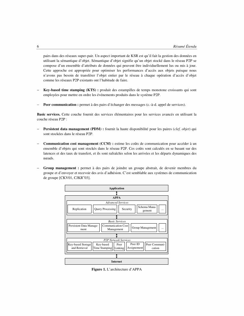
APPA a une architecture en couches basée sur des services. Sans compter les avantages traditionnels d’employer les services (encapsulation, réutilisation, portabilité, etc.), ceci permet à APPA d’être indépendant du réseau et ainsi il peut être mis en œuvre sur différents réseaux P2P structuré, par exemple Distributed Hash Table (DHT), et super-pair. La raison principale de ce choix est de pouvoir exploiter les progrès rapides et continus dans des réseaux P2P. Une autre raison est qu’il est peu probable qu’une seule architecture de réseau P2P puisse adresser les besoins spécifiques de nombreuses applications différentes. Évidemment, différentes réalisations offriront différents compromis entre exécution, tolérance aux fautes, passage à l’échelle, qualité de service, etc. Par exemple, la tolérance aux fautes peut être plus haute dans des DHTs parce qu’aucun nœud n’est un seul point d’échec. D’autre part, grâce à des serveurs d’index, les réseaux super-pair permettent un traitement plus efficace des requêtes. En outre, différents réseaux P2P peuvent être combinés afin d’exploiter leurs avantages relatifs, par exemple la DHT pour la recherche basée sur clés et le super-pair pour une recherche plus complexe. La Figure 1 montre l’architecture d’APPA, qui se compose de trois couches de services : services de réseau P2P (en anglais, P2P network services), services de base (en anglais, Basic services) et services avancés (en anglais, Advanced services).
P2P network services. Cette couche fournit l’indépendance de réseau à travers les services qui sont communs à différents réseaux P2P :
− Peer id assignment : attribue une identification unique à un pair en utilisant une méthode spécifique,
par exemple une combinaison de l’identification de super-pair et d’un compteur dans un réseau super-pair.
− Peer linking : lie un pair à quelques autres pairs, par exemple en localisant une zone dans CAN [RFHK+01].
− Key-based storage and retrieval (KSR) : stocke et retrouve une paire (clef, objet) dans le réseau P2P, par exemple par le hachage sur tous les pairs dans des réseaux DHT ou en utilisant des super-
6 Résumé Étendu
pairs dans des réseaux super-pair. Un aspect important de KSR est qu’il fait la gestion des données en utilisant la sémantique d’objet. Sémantique d’objet signifie qu’un objet stocké dans le réseau P2P se compose d’un ensemble d’attributs de données qui peuvent être individuellement lus ou mis à jour. Cette approche est appropriée pour optimiser les performances d’accès aux objets puisque nous n’avons pas besoin de transférer l’objet entier par le réseau à chaque opération d’accès d’objet comme les réseaux P2P existants ont l’habitude de faire.
− Key-based time stamping (KTS) : produit des estampilles de temps monotone croissants qui sont employées pour mettre en ordre les événements produits dans le système P2P.
− Peer communication : permet à des pairs d’échanger des messages (c.-à-d. appel de services).
Basic services. Cette couche fournit des services élémentaires pour les services avancés en utilisant la couche réseau P2P :
− Persistent data management (PDM) : fournit la haute disponibilité pour les paires (clef, objet) qui
sont stockées dans le réseau P2P.
− Communication cost management (CCM) : estime les coûts de communication pour accéder à un ensemble d’objets qui sont stockés dans le réseau P2P. Ces coûts sont calculés en se basant sur des latences et des taux de transfert, et ils sont rafraîchis selon les arrivées et les départs dynamiques des nœuds.
− Group management : permet à des pairs de joindre un groupe abstrait, de devenir membres du groupe et d’envoyer et recevoir des avis d’adhésion. C’est semblable aux systèmes de communication de groupe [CKV01, CJKR+03].
Figure 1. L’architecture d’APPA
APPA
Advanced Services
Replication Query Processing Security Schema Mana-
gement ...
Basic Services
Persistent Data Manage-ment
Communication Cost Management Group Management ...
P2P Network Services
Key-based Storage and Retrieval
Key-based Time Stamping
Peer Linking
Peer ID Assignement
Peer Communi-cation
Application
Internet

Résumé Étendu 7
Advanced services. Cette couche fournit des services avancés pour le partage des données sémantiquement riches : gestion de schéma, réplication [MAPV06, MP06, MPJV06], traitement de requêtes [AMPV06b, APV06], sécurité, etc. en employant des services de base.
Réplication de données dans le système APPA
Le service de réplication d’APPA [MAPV06, MP06, MPJV06] est intégré aux services PDM (en anglais, Persistent Data Management) et KSR (en anglais, Key-based Storage and Retrieval) afin de stocker et retrouver des objets utilisés pendant la réconciliation d’une façon fortement disponible. PDM tire profit de multiples fonctions de hachage pour placer avec précision des répliques d’objets dans le réseau P2P. Avec PDM, il est possible de verrouiller et de déverrouiller une paire (k, objet) répliquée dans le réseau P2P. En plus de PDM, le service de réplication est intégré au service CCM (en anglais, Communication Cost Management), qui estime les coûts de communication pour l’accès aux objets qui sont stockés dans le réseau P2P. Ces coûts sont estimés en tenant compte des latences et des taux de transfert aussi bien que le comportement dynamique des nœuds qui peuvent rejoindre ou quitter le réseau à tout moment. L’intégration du service de réplication d’APPA avec PDM et CCM est faite à l’aide d’interfaces de service.
Afin de permettre aux applications de collaboration P2P de tirer profit du service de réplication d’APPA, nous avons défini une interface de programmation d’application (API) qui fonctionne de façon abstraite comme une façade pour le système APPA avec des invocations de service.
Nous prouvons l’indépendance réseau d’APPA par le déploiement d’APPA sur un réseau de super-pair (JXTA) et sur deux réseaux structurés distincts (Chord et CAN). JXTA fournit un bon support pour les services réseau P2P d’APPA. Les fonctionnalités fournies par les services d’APPA peer id assignement, peer linking et peer communication sont déjà disponibles dans la couche du noyau JXTA. Ainsi, APPA réutilise simplement les fonctionnalités correspondantes de JXTA. En revanche, JXTA ne fournit pas un service équivalent à KSR pour le stockage et la récupération de données basé sur clés. Ainsi, nous avons développé KSR sur Meteor [Met06] qui est un service JXTA en logiciel libre. Les services avancés d’APPA, comme la réplication et le traitement de requêtes, sont fournis en tant que services de la communauté JXTA. L’avantage principal d’APPA est que seulement sa couche réseau P2P dépend de la plateforme de JXTA. Ainsi, APPA est portable et peut être employé au-dessus d’autres plateformes en remplaçant les services de la couche réseau P2P. Chord [SMKK+01] et CAN (en anglais, Content Addressable Network) [RFHK+01] sont deux des plus connues DHTs. Chord est une DHT simple et efficace qui peut retrouver un objet, qui est stocké dans un certain nœud dans le réseau, en exécutant O(log n) sauts de routage, où n est le nombre de nœuds. Il est possible de prouver que son mécanisme de recherche est robuste face aux échecs et aux connections fréquents de nœuds, et il peut répondre à des requêtes même si le système change sans interruption. CAN est basé sur un espace logique multidimensionnel de coordonnées cartésiennes qui est divisé dans des hyper-rectangles appelés les zones. Chaque nœud dans le système est responsable d’une zone. Des données sont hachées et associées à un point dans l'espace cartésien, et elles sont stockées dans le nœud dont la zone contient les coordonnées du point. Dans CAN, des données stockées peuvent être recherchées en exécutant O(dn1/d) sauts de routage, où n est le nombre de nœuds et d est le nombre de dimensions de l’espace de coordonnées cartésiennes.

8 Résumé Étendu
La validation du service de réplication d’APPA est faite sur la plateforme Grid5000 [Gri06]. Grid5000 vise à établir une plateforme expérimentale fortement reconfigurable et contrôlable de grille, recueillant 9 sites géographiquement distribués en France avec un total de 5000 nœuds. Dans chaque site, les nœuds sont situés dans le même secteur géographique et communiquent par des liens Gigabit Ethernet comme une grappe. Les communications entre les grappes sont faites par le réseau universitaire français (RENATER). Les nœuds de Grid5000 sont accessibles par l’OAR batch scheduler à partir d’une interface centrale d’utilisateur partagée par tous les utilisateurs de la grille. Un système capable de croiser les grappes, OARGrid, est actuellement en déploiement et en test. Les répertoires locaux des utilisateurs sont montés avec Network File System (NFS) sur chacune des grappes de l’infrastructure. Ainsi, des données peuvent être directement accédées dans une grappe. Les transferts de données entre les grappes doivent être gérés par les utilisateurs. La capacité de stockage à l'intérieur de chaque grappe est de quelques centaines de gigaoctets. Plus de 600 nœuds sont impliqués dans Grid5000. De plus, afin d'étudier le passage à l’échelle du service de réplication d’APPA avec de plus grands nombres de nœuds qui sont reliés par des liens aux latences et aux largeurs de bande variables, nous avons développé des simulateurs en utilisant Java et SimJava [HM98], un paquetage de simulation pour des événement discrets basé sur les processus. Des simulations ont été exécutées sur un Pentium IV d’Intel avec un processeur de 2.6 gigahertz, et 1 gigaoctet de mémoire centrale, exécutant le système d’exploitation Windows XP. Les résultats de performances obtenus à partir du simulateur sont compatibles par rapport à ceux du prototype du service de réplication.
Dans la version destinée à la plateforme Grid5000, chaque pair contrôle de multiples tâches en parallèle (par ex., le routage de messages dans la DHT, l’exécution d’une étape de DSR, etc.) en employant le multithreading et d’autres mécanismes associés (par ex., les sémaphores). En outre, les pairs communiquent l’un avec l’autre à l’aide de sockets et le protocole User Datagram Protocol (UDP) selon le type de message. Pour avoir une topologie proche de vrais réseaux P2P dans cette plateforme de grille, nous déterminons les voisins des pairs et nous permettons que chaque pair communique seulement avec ses voisins dans le réseau P2P. Bien que le Grid5000 fournisse une communication rapide et fiable, qui n'est pas habituellement le cas pour des systèmes P2P, elle permet de valider l'exactitude des algorithmes repartis d’APPA et d’évaluer le passage à l’échelle des services d’APPA. Nous avons déployé APPA sur cette plateforme parce que c'était le plus grand réseau disponible pour exécuter nos expériences d’une façon contrôlable. D'autre part, le simulateur se conforme au modèle de SimJava en ce qui concerne le traitement parallèle de tâches et la communication parmi les pairs. Il est important de noter que, dans notre simulateur, seulement la topologie du réseau P2P et les communications parmi les pairs sont simulées et que de véritables services d’APPA sont déployés sur le réseau simulé.
4. Réconciliation sémantique répartie
L'algorithme DSR [MPV05] utilise le cadre action-contrainte proposé pour le système IceCube [KRSD01, PSM03, SBK04] pour capturer la sémantique de l'application et résoudre des conflits de mise à jour. Cependant, DSR est tout à fait différent d'IceCube car il adopte des hypothèses différentes et fournit des solutions réparties. Dans IceCube, un seul nœud centralisé prend des actions de mise à jour de tous les autres nœuds pour produire un ordonnancement global. Ce nœud peut être un goulot d'étranglement. D'ailleurs, si le nœud qui fait la réconciliation tombe en panne, le système entier de réplication peut être bloqué jusqu'au rétablissement. En revanche, DSR est une solution repartie qui tire

Résumé Étendu 9
profit du traitement parallèle pour fournir la haute disponibilité et le passage à l’échelle. Nous supposons un réseau qui peut tomber en panne composé de nœuds qui peuvent joindre et partir à tout moment et nous faisons face à ce comportement dynamique. Nous supposons également des nœuds avec des latences et des largeurs de bande variables, ce qui implique que les coûts d'accès aux données peuvent changer de manière significative d’un nœud à l’autre et avoir un fort impact sur les performances de la réconciliation.
Nous supposons que DSR est employé dans le contexte d'une communauté virtuelle qui exige un niveau élevé de collaboration et compte sur un nombre raisonnable de nœuds (typiquement des centaines ou même des milliers d'utilisateurs qui coopèrent) [WIO97]. Puisque l'algorithme DSR fait partie du service de réplication d'APPA, il convient aux réseaux P2P structurés aussi bien qu’aux réseaux super-pair comme discuté dans la section 3. Cependant, nous nous concentrons maintenant sur les DHTs pour deux raisons. D'abord, il est beaucoup plus difficile de contrôler les coûts de communication dans des réseaux P2P structurés que dans des réseaux super-pair. En second lieu, les DHTs sont les représentantes principales des réseaux P2P structurés. Ainsi, dorénavant le réseau P2P que nous considérons se compose d'un ensemble de nœuds qui sont organisés comme une table de hachage répartie [RFHK+01, SMKK+01].
Dans notre solution, un objet est l'unité minimale de la réplication dans un système. Par exemple, dans une base de données relationnelle, si des tables sont entièrement répliquées alors les tables correspondent aux objets ; cependant, s'il est possible de répliquer différents tuples, alors ces tuples correspondent à des objets. D'autres exemples d’objets sont des documents XML, des fichiers typés, des fichiers multimédias, etc. Nous appelons un item d’objet un élément constitutif de l'objet (par ex., un tuple dans une table relationnelle ou un élément dans un document XML). Une réplique est une copie d'un objet stocké dans un site tandis qu'un item de réplique est une copie d'un item d’objet. Nous appelons l'état l'ensemble de valeurs liées à un objet ou à une réplique à un moment donné. En outre, nous employons l'ordinateur et le nœud comme synonymes de site dans tout ce travail. En conclusion, nous supposons de la réplication multi-maître des données d'application, c.-à-d. des répliques multiples d'un objet R, nommés R1, R2..., Rn, sont stockées dans différents nœuds qui peuvent lire ou écrire R1, R2..., Rn. Des mises à jour conflictuelles sont prévues, mais nous supposons que l'application tolère un certain niveau de divergence entre les répliques jusqu'à la réconciliation.
Nous avons structuré l'algorithme DSR en 5 étapes reparties pour maximiser le traitement parallèle et pour assurer l'indépendance entre les activités parallèles. Cette structure améliore les performances et la disponibilité de la réconciliation (c.-à-d. si un nœud tombe en panne, l'activité qu'il était en train d’exécuter est attribuée à un autre nœud disponible).
Avec DSR, la réplication de données se passe comme suit. D'abord, les nœuds exécutent des actions locales pour mettre à jour une réplique d'un objet tout en respectant des contraintes définies par l'utilisateur. Puis, ces actions (avec les contraintes associées) sont stockées dans la DHT basé sur l’identifiant de l'objet. Enfin, les nœuds réconciliateurs retrouvent des actions et des contraintes dans la DHT et produisent un ordonnancement global en réconciliant des actions conflictuelles en se basant sur la sémantique de l'application. Cette réconciliation est effectuée en 5 étapes réparties et l’ordonnancement global est localement exécuté dans chaque nœud, assurant de ce fait la cohérence éventuelle [SBK04, SS05].
Dans cette approche, nous distinguons trois types de nœuds : le nœud de réplique, qui tient une réplique locale ; le nœud réconciliateur, qui est un nœud de réplique qui participe à la réconciliation repartie ; et le nœud fournisseur, qui est un nœud dans la DHT qui stocke des données consommées ou produites par les nœuds réconciliateurs (par ex., le nœud qui tient l’ordonnancement s'appelle le fournisseur d’ordonnancement).

10 Résumé Étendu
Nous concentrons le travail de réconciliation dans un sous-ensemble de nœuds (les nœuds réconciliateurs) pour maximiser les performances. Si nous ne limitons pas le nombre de nœuds réconciliateurs, les problèmes suivants ont lieu. D'abord, les nœuds fournisseurs et le réseau entier deviennent surchargés à cause d’un grand nombre de messages visant à accéder au même sous-ensemble d’objets dans la DHT pendant un intervalle très court de temps. Ensuite, les nœuds avec de hautes latences et de faibles bandes passantes peuvent gaspiller beaucoup de temps avec le transfert de données, compromettant de ce fait le temps de réconciliation. Notre stratégie ne crée pas des déséquilibres dans la charge des nœuds réconciliateurs car les activités de réconciliation ne sont pas des processus intensifs.
L’algorithme DSR
Nous présentons maintenant l’algorithme DSR plus en détails. D’abord, nous introduisons les objets de réconciliations nécessaires à DSR, puis nous décrivons brièvement leurs 5 étapes. Nous utilisons l’Exemple 2 pour supporter notre discussion. Dans cet exemple, une action est notée an
i, où n est le nœud qui a exécuté l’action et i est l’identifiant de l’action. T est un objet répliqué, dans ce cas, une table relationnelle. K est l’attribut clé de T. A et B sont deux autres attributs de T. T1, T2, et T3 sont des répliques de T. Et parcel est une contrainte définie par l’utilisateur qui impose une exécution atomique pour a3
1 et a3
2.
a11: update T1 set A=a1 where K=k1
a21: update T2 set A=a2 where K=k1
a31: update T3 set B=b1 where K=k1
a32: update T3 set A=a3 where K=k2
Parcel(a31, a3
2)
Exemple 2. Exemple pour supporter la description de DSR
Les données gérées par DSR pendant la réconciliation sont retenues par les objets de réconciliation qui sont stockés dans la DHT basé sur les identifiants d’objet. Pour permettre le stockage et la récupération des objets de réconciliation, chaque objet de réconciliation a un identifiant unique. P2P-reconciler utilise les objets de réconciliation suivants.
− Journal d’actions R (noté LR): il maintient toutes les actions qui essayent de mettre à jour n’importe
quelle réplique de l’objet R (dans l’Exemple 2, toutes les mises à jour sur les tuples de T exécutées sur T1, T2 ou T3 sont stockées dans LT). Il est à noter qu’une action est d’abord stockée localement dans le nœud de la réplique puis dans le nœud fournisseur qui tient LR. Dans l’Exemple 2, seulement un journal d’action est impliqué (LT) car un seul objet est répliqué (T). Le journal d’action sert de données d’entrée pour la réconciliation.
− Ensemble de clusters (noté CS): un cluster contient un ensemble d’actions reliées par des contraintes et les clusters peuvent être mis en ordre indépendamment les un des autres lorsque l’ordonnancement global est produit. Tous les clusters produits pendant la réconciliation sont stockés dans l’objet ensemble de clusters.
Résumé Étendu 11
− Sommaire d’actions (noté AS): il capture les dépendances sémantiques entre les actions, lesquelles sont décrites par des contraintes. De plus, le sommaire d’actions contient les rapports entre des actions et des clusters de façon à ce que chaque rapport décrit une appartenance d’une action (une action est membre d’un ou de plusieurs clusters). Une appartenance d’une action est une paire de valeurs (an
i, Cj), où ani représente une action à être réconciliée, et Cj indique un cluster auquel an
i appartient.
− Ordonnancement (noté S): il contient une liste ordonnée d’actions, laquelle est composée des clusters d’actions ordonnées. Donc, nous dénotons un objet de réconciliation ordonnancement comme S = S1 ⊕ S2 … ⊕ Sn, où chaque Si représente une sous-liste d’actions ordonnées qui viennent du cluster Ci et ⊕ signifie concaténation.
Le service d’APPA appelé PDM assure la disponibilité des objets de réconciliation. La vivacité du protocole P2P-reconciler s’appuie sur celui de la DHT.
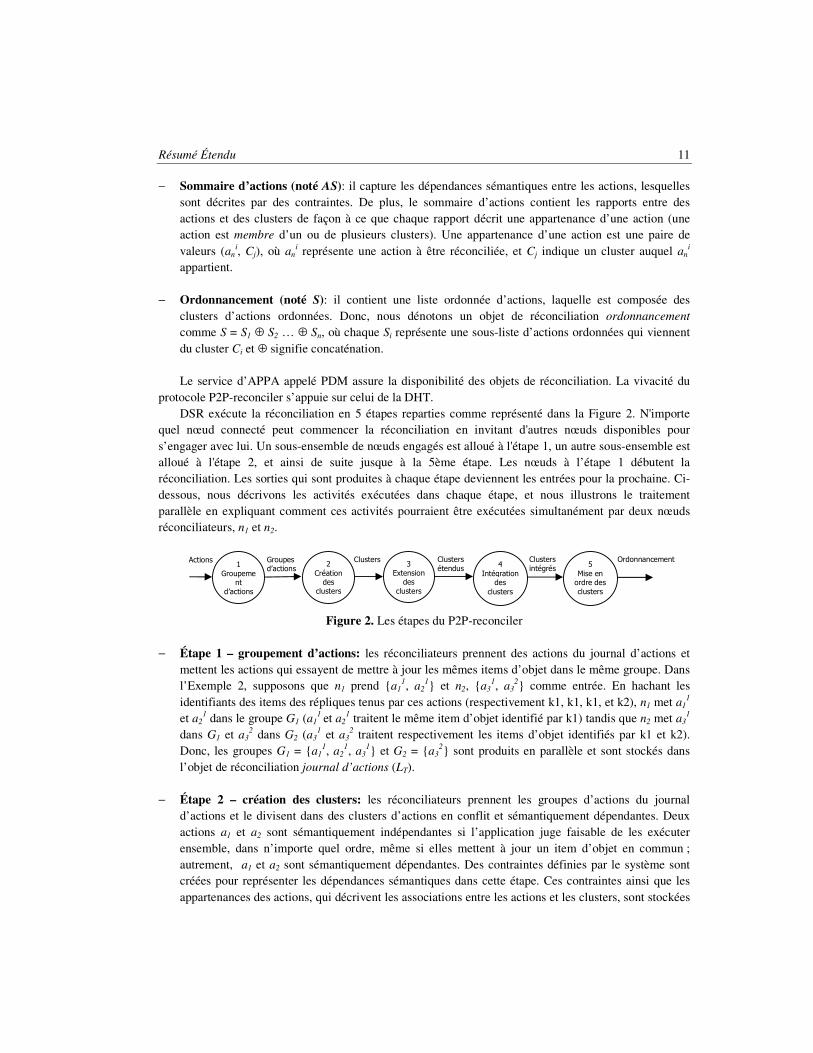
DSR exécute la réconciliation en 5 étapes reparties comme représenté dans la Figure 2. N'importe quel nœud connecté peut commencer la réconciliation en invitant d'autres nœuds disponibles pour s’engager avec lui. Un sous-ensemble de nœuds engagés est alloué à l'étape 1, un autre sous-ensemble est alloué à l'étape 2, et ainsi de suite jusque à la 5ème étape. Les nœuds à l’étape 1 débutent la réconciliation. Les sorties qui sont produites à chaque étape deviennent les entrées pour la prochaine. Ci-dessous, nous décrivons les activités exécutées dans chaque étape, et nous illustrons le traitement parallèle en expliquant comment ces activités pourraient être exécutées simultanément par deux nœuds réconciliateurs, n1 et n2.
Figure 2. Les étapes du P2P-reconciler
− Étape 1 – groupement d’actions: les réconciliateurs prennent des actions du journal d’actions et mettent les actions qui essayent de mettre à jour les mêmes items d’objet dans le même groupe. Dans l’Exemple 2, supposons que n1 prend {a1
1, a21} et n2, {a3
1, a32} comme entrée. En hachant les
identifiants des items des répliques tenus par ces actions (respectivement k1, k1, k1, et k2), n1 met a11
et a21 dans le groupe G1 (a1
1 et a21 traitent le même item d’objet identifié par k1) tandis que n2 met a3
1
dans G1 et a32 dans G2 (a3
1 et a32 traitent respectivement les items d’objet identifiés par k1 et k2).
Donc, les groupes G1 = {a11, a2
1, a31} et G2 = {a3
2} sont produits en parallèle et sont stockés dans l’objet de réconciliation journal d’actions (LT).
− Étape 2 – création des clusters: les réconciliateurs prennent les groupes d’actions du journal d’actions et le divisent dans des clusters d’actions en conflit et sémantiquement dépendantes. Deux actions a1 et a2 sont sémantiquement indépendantes si l’application juge faisable de les exécuter ensemble, dans n’importe quel ordre, même si elles mettent à jour un item d’objet en commun ; autrement, a1 et a2 sont sémantiquement dépendantes. Des contraintes définies par le système sont créées pour représenter les dépendances sémantiques dans cette étape. Ces contraintes ainsi que les appartenances des actions, qui décrivent les associations entre les actions et les clusters, sont stockées
1 Groupeme
nt d’actions
Actions Groupes d’actions
Clusters Clusters étendus
Clusters intégrés
Ordonnancement 2
Création des
clusters
3 Extension
des clusters
4 Intégration
des clusters
5 Mise en ordre des clusters

12 Résumé Étendu
dans le sommaire d’actions ; les clusters produits dans cette étape sont stockés dans l’ensemble de clusters. Dans l’Exemple 2, considérons que n1 prend G1 et n2 prend G2 comme entrée. Dans ce cas, n1 divise G1 dans les clusters C1 = {a1
1, a21} (une contrainte définie par le système
mutuallyExclusive(a11, a2
1) est produite pour représenter la dépendance sémantique entre a11 et a2
1) et C2 = {a3
1}. En même temps, n2 transforme G2 en cluster C3 = {a32}. Tous ces clusters sont stockés
dans l’objet de réconciliation ensemble de clusters (CS). De plus, n1 stocke dans le sommaire d’actions (AS) la contrainte mutuallyExclusive(a1
1, a21) ainsi que les appartenances suivantes: {(a1
1, C1), (a2
1, C1), (a31, C2)}. De la même manière, n2 stocke dans AS cet ensemble d’appartenances: {(a3
2, C3)}.
− Étape 3 – extension des clusters: des contraintes définies par l’utilisateur ne sont pas prises en compte dans la création des clusters (par ex., bien que a3
1 et a32 appartiennent à parcel, l’étape
précédente ne les met pas dans le même cluster, parce qu’elles ne mettent pas à jour un item d’objet en commun). Donc, dans cette étape, les réconciliateurs étendent les clusters en ajoutant de nouvelles actions en conflit, selon les contraintes définies par l’utilisateur. Ces extensions mènent à de nouveaux rapports entre actions et clusters, lesquels sont représentés par de nouvelles appartenances d’actions. Les nouvelles appartenances sont stockées dans le sommaire d’actions. Dans l’Exemple 2, supposons que n1 prend C1 = {a1
1, a21} comme entrée tandis que n2 prend C2 = {a3
1} et C3 = {a32}
(chaque nœud traite 2 actions). Alors, n1 se rend compte que C1 n’a pas besoin d’extensions, parce que leur actions ne concernent pas des contraintes définies par l’utilisateur. En parallèle, à cause de la contrainte de parcel, n2 étend C2 et C3 comme suit: C2 = C2 ∪ {a3
2}, et C3 = C3 ∪ {a31}. De plus, n2
met à jour le sommaire d’actions avec ces appartenances d’actions: {(a32, C2), (a3
1, C3)}.
− Étape 4 – intégration des clusters: l’extension des clusters mène à la superposition des clusters (une superposition a lieu quand l’intersection de deux clusters produit un ensemble non nul d’actions). Dans cette étape, les réconciliateurs mélangent les clusters superposés. Dans l’Exemple 2, considérons que n1 prend {(a3
1, C2), (a31, C3), (a3
2, C2), (a32, C3)} comme entrée tandis que n2 prend
{(a11, C1), (a2
1, C1)} (chaque nœud traite les appartenances de 2 actions). Donc n1 se rend compte que a3
1 est un membre de C2 et C3, ainsi n1 les mélange comme suit: C4 = C2 ∪ C3 = {a31, a3
2}. En même temps, n2 se rend compte que a1
1 et a21 n’ont qu’une appartenance, ainsi n2 ne fait pas d’intégrations.
A ce point, les clusters deviennent mutuellement indépendants, c'est-à-dire qu’il n’y a pas de contraintes qui concernent des actions de clusters distincts.
− Étape 5 – Mise en ordre des clusters: dans cette étape, les réconciliateurs prennent des clusters de l’ensemble de clusters et mettent en ordre les actions des clusters. Les actions ordonnées associées à chaque cluster sont stockées dans l’objet de réconciliation ordonnancement (S); la concaténation de toutes les actions ordonnées des clusters compose l’ordonnancement global qui est exécuté par tous les nœuds de répliques. Dans l’Exemple 2, supposons que n1 prend C1 comme entrée tandis que n2 prend C4. Alors, n1 produit la sous-liste d’actions ordonnées S1 = [a1
1], parce que les actions de C1 sont mutuellement exclusives. En parallèle, n2 produit la sous-liste d’actions ordonnées S4 = [a3
1, a32],
parce que les actions de C4 sont impliquées dans une contrainte parcel. L’ordonnancement global est S = S1 ⊕ S4 = [a1
1, a31, a3
2].
À chaque étape, l'algorithme DSR profite du parallélisme de données, c.-à-d. plusieurs nœuds exécutent simultanément des activités indépendantes sur un sous-ensemble distinct d'actions (par ex., la

Résumé Étendu 13
mise en ordre de différents clusters). Aucun critère centralisé n'est appliqué pour partager les actions. En effet, à chaque fois qu'un ensemble de nœuds réconciliateurs demande des données d'un fournisseur, le nœud fournisseur fournit naïvement aux réconciliateurs une quantité à peu près identique de données (le nœud fournisseur sait le nombre maximal de réconciliateurs parce qu'il reçoit cette information du nœud qui lance la réconciliation).
Évaluation de performances
L'évaluation de performances du DSR a prouvé qu'il surpasse la réconciliation centralisée en réconciliant un grand nombre d'actions. En outre, il fournit un plus grand degré de disponibilité, de passage à l’échelle, et de tolérance aux fautes que son similaire centralisé. D'ailleurs, il passe à l’échelle très bien jusqu'à 128 nœuds réconciliateurs. Puisque le nombre de nœuds réconciliateurs ne limite pas le nombre de nœuds de réplique, il s’agit d’un très bon résultat.
5. Protocole de base pour la réconciliation P2P
P2P-reconciler transforme l'algorithme DSR en protocole de réconciliation en développant des fonctionnalités additionnelles que DSR ne fournit pas. D'abord, il propose une stratégie pour calculer le nombre de nœuds qui devraient participer à la réconciliation afin d'éviter des surcharges de messages et assurer de bonnes performances [MAPV06, MPV06a]. En second lieu, il propose un algorithme réparti pour choisir les meilleurs nœuds réconciliateurs basés sur les coûts d'accès aux données, qui sont calculés selon les latences de réseau et les taux de transfert [MP06, MPJV06]. Ces coûts changent dynamiquement pendant que les nœuds joignent et partent du réseau, mais notre solution fait face à un tel comportement dynamique. Troisièmement, il garantit la cohérence éventuelle parmi des répliques en dépit de jonctions et départs autonomes des nœuds [MAPV06, MP06, MPV06a, MPJV06]. En outre, nous avons formellement montré que P2P-reconciler assure la cohérence éventuelle, est fortement disponible, et fonctionne correctement en présence des fautes. Nous présentons maintenant un résumé de ces fonctionnalités additionnelles.
Calcul du nombre de réconciliateurs
Au début de la réconciliation, un sous-ensemble de nœuds de répliques doit être alloué aux étapes de P2P-reconciler afin de procéder comme nœuds réconciliateurs. Cette allocation est dynamique car elle dépend du contexte de réconciliation (c.-à-d. le nombre d’actions à réconcilier, les propriétés du réseau, etc.). Puisque P2P-reconciler est réparti et parallèle, nous pouvons augmenter le nombre de nœuds réconciliateurs pour réduire le temps de réconciliation. Cependant, à mesure que nous augmentons le nombre de réconciliateurs, nous augmentons également le nombre de messages échangés et le travail effectué par les nœuds fournisseur. En conséquence, au delà d'une limite donnée, l'augmentation du nombre de réconciliateurs produit l'effet inverse : le temps de réconciliation augmente. Afin de calculer cette limite, qui représente le nombre maximal de réconciliateurs par étape, nous réalisons les activités suivantes.

14 Résumé Étendu
− D'abord, nous configurons le contexte de réconciliation en installant quelques paramètres (par ex., le
nombre d’actions, le nombre de nœuds de répliques connectés, le nombre de nœuds réconciliateurs, des latences minimales et maximales du réseau, des largeurs de bande passante du réseau), puis nous simulons la réconciliation plusieurs fois pour obtenir un échantillon de résultats de réconciliation. Pour chaque simulation, nous changeons les topologies du réseau logique et physique, ou l'ensemble d'actions à réconcilier, ou toutes les deux, en respectant toujours les valeurs de paramètres. Une simulation marche localement dans un seul nœud. Un aspect important du simulateur est que seulement la communication réseau est simulée (tout le reste est fait par le protocole P2P-reconciler que nous avons implémenté).
− En second lieu, nous recherchons une équation y = f(x) qui décrit le comportement de la réconciliation en exécutant une régression polynomiale [KKMN98] avec les données de l'échantillon. Cette équation nous permet de prévoir le temps de réconciliation de n’importe quelle réconciliation dans le même contexte. La variable indépendante x est le nombre de nœuds réconciliateurs tandis que la variable dépendante y est le temps de réconciliation.
− Troisièmement, nous calculons l’équation dérivée y’= f’(x) ; cette équation dérivée nous permet de trouver quelle valeur de x produit la valeur minimale de y. Le point (x, y) où y est minimal s’appelle point minimal.
− En conclusion, nous calculons le point minimal, qui représente le nombre de réconciliateurs qui réduit au minimum le temps de réconciliation dans le contexte donné.
Plus le nombre d'actions à réconcilier est grand et plus la vitesse du réseau est haute, plus le nombre maximal de réconciliateurs par étape est grand.
Modèle de coût de communication
Un réseau DHT est habituellement établi sur l'Internet, qui se compose des nœuds avec des latences et des largeurs de bande variables. En conséquence, les coûts de réseau impliqués dans des accès aux données stockées dans la DHT peuvent changer de manière significative d’un nœud à l’autre et avoir un impact fort sur les performances de réconciliation. Ainsi, des coûts de réseau devraient être considérés pour exécuter la réconciliation efficacement. Dans cette section, nous proposons un modèle de base pour le calcul des coûts de communication dans les DHTs. A partir de ce modèle, nous pouvons établir des modèles de coût personnalisés (par ex., nous avons élaboré un modèle de coût personnalisé pour choisir des nœuds réconciliateurs à P2P-reconciler).
Dans le modèle de coût de base, nous définissons des coûts de communication (dorénavant coûts) en termes de latence et temps de transfert, et nous supposons des liens avec des latences et des largeurs de bande variables. Afin d'exploiter la largeur de bande, le comportement de l’application en termes de transfert de données devrait être connu. Puisque ce comportement est spécifique à l'application, nous exploitons la largeur de bande dans les modèles personnalisés de plus haut niveau.
La plupart des opérations d'accès aux données stockées dans la DHT se composent d'une recherche, pour trouver l'adresse du nœud n qui tient l'information demandée, suivie d’une communication directe

Résumé Étendu 15
avec n [HHLT+03]. Dans l'étape de recherche, plusieurs sauts peuvent être exécutés selon les voisinages des nœuds. Par conséquent, notre modèle de coût pour les DHTs se fonde sur trois métriques : coût de recherche, coût d’accès direct, et coût de transfert. Le coût de recherche, noté lc(n, id), est le temps de latence passé dans une opération de recherche lancée par le nœud n pour trouver la donnée élémentaire identifiée par id. De même, coût d’accès direct, noté dc(ni, nj), est le temps de latence passé pour que le nœud ni accède directement le nœud nj. Et le coût de transfert, noté tc(ni, nj, d), est le temps passé pour transférer la donnée élémentaire d à partir du nœud ni vers le nœud nj, qui est calculé basé sur la taille de d et la largeur de bande entre les nœuds ni et nj.
Coût de recherche
Les coûts de recherche changent dynamiquement pendant que les nœuds joignent et partent du réseau P2P. Nous montrons maintenant comment calculer les coûts de recherche et traiter les changements dynamiques.
Le nœud n pourrait facilement calculer le coût de recherche lc(n, id) en exécutant l'opération de recherche et en mesurant le temps associé. Cependant, cette approche surcharge le nœud qui répond à l'opération de recherche puisqu’il reçoit beaucoup de messages de recherche. En outre, le réseau est surchargé. Pour éviter ces problèmes, nous proposons que chaque nœud calcule ses coûts de recherche par accroissement, en tirant profit de l'information de coût maintenue par ses voisins. Avec cette approche, un nœud n garde seulement les coûts de recherche pour accéder à quelques identifiants (c.-à-d. un identifiant pour chaque objet de réconciliation). De plus, n garde les coûts d’accès direct à quelques nœuds (c.-à-d. les voisins de n). Il serait impraticable et non recommandable de garder des informations sur tous les nœuds ou sur l’espace d’identifiants entier. Notre approche est faisable parce que dans une DHT un nœud n recherche un identifiant id en communiquant avec le voisin du n qui est le plus proche de l'identifiant.
Nous illustrons notre solution avec un exemple. Dans la Figure 3a, soit n4 un nœud qui répond des opérations de recherche intéressées par l’id=x ; les flèches indiquent la route d’une opération de recherche (par ex., si le nœud n2 recherche x, il suit la route : n2 → n3 → n4) ; un nombre au-dessus d'une flèche indique la latence entre les nœuds associés. Dans cet exemple, le coût de recherche lc(n2, x) est 100 (c.-à-d. 40 + 60), et lc(n1, x) est 150 (c.-à-d. 50 + 40 + 60). Au lieu d'exécuter l'opération de recherche pour calculer lc(n1, x), n1 peut demander à n2 de calculer lc(n2, x) et ajouter à ce coût la latence entre n1 et n2 (c.-à-d. lc(n1, x) = lc(n2, x) + 50). Les avantages de cette approche par accroissement sont localité et éviter la surcharge du réseau.
Figure 3. Le calcul du coût de recherche Des jonctions et départs changent les voisinages des nœuds et, par conséquent, les routes des
messages de recherche. Ainsi, des coûts de recherche doivent être rafraîchis. Cependant, nous devrions
(b)
n1 n2 n3 n4 50
80
60
lc(n1,x)=170 lc(n2,x)=120 40
Limite de Coût = 110 n5
n1 n2 n3 n4 50 40 60
(a)
lc(n1,x)=150 lc(n2,x)=100

16 Résumé Étendu
éviter le rafraîchissement aux nœuds éloignés pour éviter la surcharge du réseau. Pour faire face à ce problème, nous donnons deux définitions.
− Limite de coût : c'est le coût maximal acceptable pour rechercher un identifiant. Le sens de coût
acceptable dépend de l'application. Par exemple, dans le cas de P2P-reconciler, qui choisit un sous-ensemble de nœuds de répliques pour procéder comme nœuds réconciliateurs, il n'est pas acceptable que le coût de recherche d'un réconciliateur particulier dépasse le coût moyen de recherche du réseau P2P entier, parce que le nombre de réconciliateurs est habituellement beaucoup plus petit que le nombre de nœuds de répliques.
Jonctions et départ pertinents : une jonction ou un départ est pertinent pour un nœud n s’il change le coût de recherche associé à un identifiant par lequel n est intéressé, telle que le vieux ou nouveau coût de recherche ne dépasse pas la limite de coût. Les nœuds rafraîchissent leurs coûts de recherche seulement en présence de jonction ou départ pertinent.
Nous illustrons notre approche pour le rafraîchissement des coûts de recherche avec un exemple. Dans la Figure 3b, prenons une limite de coût de 110 ; et considérons que n5 joint la DHT de la Figure 3a remplaçant n3 dans la route vers l’id=x. La jonction de n5 est pertinente seulement au nœud n2 car n2 met à jour lc(n2, x) en changeant sa valeur de 100 (une valeur qui ne dépasse pas la limite de coût) à 120. En revanche, la jonction de n5 n'est pas pertinente à n3 et à n4 puisque les coûts de recherche associés restent égaux. Cette jonction n'est pas pertinente à n1 non plus, parce que tous les deux, l’ancien coût de recherche (c.-à-d. 150) et le nouveau (c.-à-d. 170), dépassent la limite de coût. Ainsi, n1, n3 et n4 ne participent pas à l'opération de rafraîchissement.
Coût d’accès direct
Les coûts d’accès direct changent dynamiquement pendant que les nœuds joignent et quittent le réseau P2P. Nous montrons maintenant comment calculer les coûts d’accès direct et traiter les changements dynamiques.
Nous définissons d'abord le home(id) comme le nœud fournisseur qui tient l'identifiant id. Le coût d’accès direct dc(n, home(id)) représente le temps de latence passé pour que le nœud n accède directement au home(id). Ce coût peut être calculé de manière exacte ou estimé. Avec l'approche exacte, n mesure la latence entre n et home(id). En revanche, avec l'approche estimée, n mesure les latences entre n et un sous-ensemble de nœuds, puis calcule la valeur moyenne correspondante, qui représente la latence estimée entre n et home(id). L'approche exacte est précise, mais elle peut surcharger le home(id) puisque ce nœud devient un point central d'accès pour beaucoup de nœuds. D'autre part, l'approche estimée n’a pas besoin d’accéder le home(id), évitant de ce fait sa surcharge, mais elle n'est pas précise. Nous comparons les deux approches et, en raison de la petite différence entre leurs temps de réconciliation (c.-à-d. 7%), nous considérons que l’approche estimée mérite d’être utilisée pour éviter des problèmes de surcharge.
Il est à noter que l'approche estimée a besoin d'un sous-ensemble de nœuds pour estimer la latence entre n et home(id). Ce sous-ensemble devrait être composé des voisins de n pour les DHTs dont les voisinages ne se fondent pas sur des distances physiques parmi les nœuds (par ex., Chord) puisque, dans ce cas-ci, l'estimation n'est pas biaisée et l'information requise est déjà disponible à n (coût zéro). Cependant, si la DHT est consciente de l’emplacement (en anglais, location-aware), c.-à-d. les voisins de

Résumé Étendu 17
n sont plus près de n que d'autres nœuds (par ex., CAN avec des optimisations), l'utilisation des voisins de n mèneraient à une estimation biaisée. Dans ce cas, le sous-ensemble de nœuds devrait être aléatoirement choisi parmi une liste de démarrage (liste de nœuds qui sont probablement connectés ; en anglais, bootstrap list).
Des jonctions et départs peuvent changer le home(id). Ainsi, les coûts d’accès direct doivent également être rafraîchis. Dans notre solution, dc(n, home(id)) est rafraîchi au nœud n à chaque fois que le home(id) change et le coût de recherche associée (c.-à-d. lc(n, id)) est plus petit que la limite de coût. Pour calculer la valeur rafraîchie, nous employons la même stratégie utilisée pour calculer la valeur initiale. Le principe de cette approche est d’éviter l'exécution des opérations de rafraîchissement aux nœuds éloignés lointains, et son avantage est d’éviter la surcharge du réseau.
Allocation de nœuds
L'allocation de nœuds est la première étape du protocole P2P-reconciler. Elle vise à choisir pour chaque étape suivante un ensemble de nœuds réconciliateurs qui peuvent effectuer la réconciliation avec de bonnes performances. Nous définissons maintenant un nouvel objet de réconciliation requis dans l'allocation de nœud, puis nous décrivons comment les nœuds réconciliateurs sont choisis.
Nous définissons coûts de communication, noté CC, comme l’objet de réconciliation qui stocke les coûts d'étape du nœud estimés par chaque nœud de réplique et employés pour choisir des réconciliateurs avant le début de la réconciliation. Le nœud dans la DHT qui maintient CC à un moment donné s'appelle fournisseur de coût ; il est responsable d’allouer les réconciliateurs. L'allocation fonctionne comme suit. Les nœuds de répliques estiment localement les coûts pour exécuter chaque étape de P2P-reconciler, selon le modèle de coût de P2P-reconciler, et fournissent ces informations au fournisseur de coût. Le nœud qui commence la réconciliation calcule le nombre maximal de réconciliateurs par étape (maxRec), comme décrit dans la section 0, et demande au fournisseur de coût d’allouer au maximum maxRec nœuds réconciliateurs par étape de P2P-reconciler. En conséquence, le fournisseur de coût choisit les meilleurs nœuds pour chaque étape et informe à ces nœuds les étapes de P2P-reconciler qu'ils doivent exécuter.
Dans notre solution, la gestion de coût est faite parallèlement à la réconciliation. D'ailleurs, elle est optimisée par rapport à l’utilisation du réseau puisque les nœuds de répliques n'envoient pas des messages au fournisseur de coût, informant leurs coûts estimatifs, si les coûts d'étape du nœud dépassent les coûts maximaux acceptables obtenue à partir de la limite de coût. Pour ces raisons, le fournisseur de coût ne devient pas un goulot d'étranglement.
Évaluation de performances
P2P-reconciler a été évalué avec des méthodes distinctes d’allocation de nœuds réconciliateurs. Les résultats expérimentaux ont prouvé que la réconciliation avec l'allocation basée sur le coût surpasse l'approche aléatoire par un facteur de 26. De plus, le nombre de nœuds connectés n'est pas important pour déterminer les performances de réconciliation due au fait que la DHT passe à l’échelle et les réconciliateurs sont aussi proches que possible des objets de réconciliation. Par ailleurs, la taille des actions a de l’impact sur le temps de réconciliation dans une échelle logarithmique. En conclusion, P2P-reconciler restreint la surcharge du système puisqu'il calcule des coûts de communication en employant

18 Résumé Étendu
des informations locales et il limite la portée de la propagation des événements (par ex., jonction ou départ).
6. Réconciliation consciente de la topologie
P2P-reconciler-TA [EMP07] est une nouvelle version du protocole P2P-reconciler qui vise à exploiter les réseaux P2P conscients de leurs topologies (en anglais, topology-aware P2P networks) pour améliorer les performances de réconciliation. Les réseaux P2P conscients de leurs topologies établissent les voisinages parmi les nœuds basés sur des latences de sorte que les nœuds qui sont proches les uns des autres en termes de latence dans le réseau physique soient aussi des voisins dans le réseau P2P logique. Pour cette raison, des messages sont routés plus efficacement sur les réseaux conscients de leurs topologies. L'algorithme DSR n'est pas affecté par la topologie du réseau. Cependant, un autre algorithme est nécessaire pour le choix des nœuds qui participent à la réconciliation. Par conséquent, nous appelons cette nouvelle version de notre protocole de réconciliation P2P-reconciler-TA, où TA veut dire conscient de la topologie (de l’anglais, topology-aware).
Plusieurs réseaux P2P conscients de leurs topologies pourraient être employés pour valider notre approche telle que Pastry [RD01a], Tapestry [ZHSR+04, ZKJ01], CAN [RFHK+01], etc. Nous avons choisi CAN parce qu'il permet de construire le réseau P2P logique conscient de sa topologie d'une façon assez simple. De plus, il est facile de mettre en œuvre son mécanisme de routage, bien que moins efficace que d'autres réseaux P2P conscients de leurs topologies (par ex., le chemin de routage moyen dans CAN est habituellement plus long que dans d'autres réseaux P2P structurés).
Les protocoles P2P-reconciler et P2P-reconciler-TA tirent profit de l'algorithme DSR pour réconcilier des actions conflictuelles. Cependant, ils sont complètement différents par rapport à l’allocation de nœuds réconciliateurs. P2P-reconciler-TA choisit d'abord les nœuds fournisseurs qui sont proches les uns des autres et sont entourés par un nombre acceptable de réconciliateurs potentiels. Puis, il transforme des réconciliateurs potentiels en réconciliateurs candidats. Au fur et à mesure que la topologie du réseau change suite à des jonctions, départs, et échecs de nœuds, P2P-reconciler-TA change également les nœuds fournisseurs choisis et les réconciliateurs candidats associés. Ainsi, les fournisseurs et les réconciliateurs candidats choisis changent d'une façon dynamique et auto-organisée selon l'évolution de la topologie du réseau. P2P-reconciler-TA choisit des nœuds réconciliateurs à partir de l'ensemble de réconciliateurs candidats en appliquant une approche heuristique qui réduit rigoureusement l'espace de recherche tandis que préserve les meilleures options. En outre, ce protocole également assure la cohérence éventuelle parmi des répliques, rend la réconciliation fortement disponible même pour les réseaux très dynamiques, et fonctionne correctement en présence d’échecs. Les preuves sont identiques aux preuves correspondantes du protocole de P2P-reconciler.
Les résultats expérimentaux ont prouvé que P2P-reconciler-TA sur CAN surpasse P2P-reconciler par un facteur de 2. C'est un excellent résultat si nous considérons que P2P-reconciler est déjà un protocole efficace et CAN n'est pas le réseau P2P conscient de topologie le plus efficace (par ex., Pastry et Tapestry sont plus efficaces que CAN). P2P-reconciler-TA exploite d'une manière très appropriée les réseaux conscients de topologie puisque ses meilleures performances sont obtenues quand le degré de proximité parmi les nœuds en termes de latence est le plus haut. De plus, il passe à l’échelle au fur et à mesure que le nombre de nœuds connectés augmente. En conclusion, l'approche heuristique de P2P-reconciler-TA pour choisir les nœuds réconciliateurs est très efficace.

Résumé Étendu 19
7. Conclusion
Dans cette section, nous récapitulons nos contributions principales et discutons des futures directions de recherche dans le cadre de la réplication de données pour les systèmes P2P.
Résumé des contributions
Dans ce travail, nous fournissons une solution de réconciliation pour des applications P2P collaborative en développant des protocoles de réconciliation qui assurent la cohérence éventuelle parmi des répliques et tiennent compte des coûts d'accès aux données. Ceci a été accompli dans cinq étapes. D’abord, nous avons présenté des solutions existantes pour la réplication optimiste et des stratégies de réplication P2P et nous avons analysé leurs avantages et inconvénients. Cette analyse nous a permit d’identifier les fonctionnalités et les propriétés que notre solution devrait fournir. En second lieu, nous avons conçu un service de réplication pour APPA. Dans une troisième étape, nous avons élaboré un algorithme pour la réconciliation sémantique repartie appelée DSR, qui peut être exécuté dans différents environnements repartis (par ex., grappe, grille, P2P). Une quatrième étape a transformé DSR en protocole de réconciliation pour des réseaux P2P appelé P2P-reconciler. Finalement, la cinquième étape a produit une nouvelle version de P2P-reconciler, appelée P2P-reconciler-TA, qui exploite les réseaux P2P conscients de topologie afin d'améliorer les performances de réconciliation.
Nous avons validé nos algorithmes par la création d’un prototype et d’un simulateur. Le prototype sur le réseau Grid5000 nous a permis de vérifier l'exactitude de notre solution de réplication et de calibrer le simulateur. D'autre part, le simulateur a permis d’évaluer le comportement de notre solution sur des réseaux plus grands. Il est important de noter que, dans notre simulateur, la communication réseau est le seul aspect simulé. L'évaluation de performances a prouvé que notre solution fournit des niveaux élevés de parallélisme grâce à la réconciliation sémantique et apporte haute disponibilité, excellent passage à l’échelle, avec des performances acceptables et des surcharges limitées. De plus, les résultats du simulateur sont cohérents par rapport aux résultats du prototype.
Les performances du service de réplication d'APPA a été évaluée basé sur un test de performances proposé par IceCube. Nous avons aussi commencé le développement d’une application réelle qui tire profit du service de réplication d'APPA afin de compléter notre procédure de validation. Cette application est un P2P Wiki de deuxième génération, comme discuté dans l'introduction, et elle est développée dans le cadre du projet RNTL Xwiki Concerto.
Travaux futurs
Bien que notre travail ait fourni une solution pour réconcilier des mises à jour en conflit dans les systèmes P2P tout en assurant la cohérence éventuelle parmi des répliques, le passage à l’échelle et la haute disponibilité, des problèmes ouverts demeurent et des directions importantes de recherche peuvent être explorées. Nous présentons ci-dessous une liste de travaux que nous avons l'intention d'effectuer.
− Tolérance aux fautes : nous avons montré que nos protocoles sont corrects même en présence
d’échecs. Cependant, nous n’avons pas étudié l'impact des échecs sur les performances de

20 Résumé Étendu
réconciliation. Nous prévoyons de raffiner nos études de performances en incluant des aspects de tolérance aux fautes afin de mieux caractériser les propriétés de notre solution.
− Généralisation d'allocation basée sur coût : un réseau P2P est habituellement établi sur l'Internet, qui se compose de nœuds avec des latences et des largeurs de bande variables. En conséquence, les coûts réseau impliqués dans l'accès aux données P2P peuvent changer de manière significative de nœud à nœud et avoir un impact fort sur les performances d'un processus reparti. Ainsi, des coûts réseau devraient être considérés pour exécuter ce processus efficacement. Dans cette thèse, nous avons proposé un modèle général de coût pour faire face à ce problème, mais nous avons validé un tel modèle dans le contexte particulier de la procédure de réconciliation. Puisque l’allocation de nœuds est un composant des systèmes répartis, utile dans beaucoup de différents contextes, nous avons l'intention d'approfondir notre travail et de fournir une solution efficace, qui passe à l’échelle, et tolérante aux fautes pour l’allocation de nœuds dans le contexte général des processus P2P dont les propriétés soient expérimentées et prouvées.
− Généralisation du mécanisme de gestion des conflits d'accès : nous avons prouvé que le service PDM d’APPA peut être employé pour verrouiller et déverrouiller une paire (k, objet) répliquée dans le réseau P2P. Un tel mécanisme de gestion de conflits d'accès est un composant pour le partage réparti de ressource, la synchronisation de processus, etc. Par conséquent, comme pour l'allocation de nœud basée sur coût, ce mécanisme mérite d’être expérimenté et prouvé dans le contexte général des systèmes P2P.
− Modèle multi-variable du comportement de la réconciliation : notre approche pour déterminer le nombre de nœuds réconciliateurs cherche une équation y = f(x) qui décrit le comportement de la réconciliation dans un contexte donné (c.-à-d. nombre d’actions à réconcilier, latences et largeurs de bande du réseau, nombre de nœuds connectés, etc.). Une telle équation est obtenue en exécutant une régression polynomiale sur un échantillon de réconciliations simulées et permet de prévoir le temps de réponse de n'importe quelle réconciliation dans le même contexte. La variable indépendante x représente le nombre de réconciliateurs alloués tandis que la variable dépendante y représente le temps de réconciliation. Bien que précis, ce modèle basé sur juste une variable indépendante (c.-à-d. nombre de réconciliateurs) exige un ensemble d'équations pour décrire le comportement de réconciliation. Par exemple, si nous devons traiter des journaux d'actions contenant jusqu'à 10.000 actions, nous pouvons définir 5 classes des tailles de journal (par ex., 0-2000, 2001-4000, 4001-6000, 6001-8000, et 8001-10.000) et déterminer l'équation correspondant à chaque classe. Une approche plus souple serait un modèle basé sur deux variables indépendantes (c.-à-d. z = f(x, y), où z est le temps de réconciliation, x est le nombre de réconciliateurs, et y est le nombre d'actions à réconcilier). Un tel modèle est décrit dans un espace tridimensionnel, et permet de représenter le comportement entier de réconciliation avec seulement une équation.

21
CHAPTER 1
1 Introduction
1.1 Motivation
Distributed collaborative applications are getting common as a result of rapid progress in distributed technologies (grid, peer-to-peer, and mobile computing). As an example of such applications, consider a second generation Wiki that works over a peer-to-peer (P2P) network and supports users on the elabora-tion and maintenance of shared documents in a collaborative and asynchronous manner. Consider also that each document is an XML file possibly linked to other documents. Therefore, such a Wiki allows collaboratively managing a single document (e.g. a scientific paper shared by a few of authors) as well as composed, integrated documents (e.g. an encyclopedia or a knowledge base concerning the use of an open source operating system). Although the number of users that update in parallel a document d is usually small, the size of the collaborative network that holds d in terms of number of nodes may be large. For instance, the document d could belong to the knowledge base of the Mandriva Club, which is maintained by more than 25,000 members [Man07] or it could belong to Wikipedia, a free content encyc-lopedia maintained by more than 75,000 active contributors [Wik07].
Many users frequently need to access and update information even if they are disconnected from the network, e.g. in an aircraft, a train or another environment that does not provide good network connec-tion. This requires that users hold local replicas of shared documents. Thus, a P2P Wiki has need for multi-master replication to assure data availability at anytime. In the multi-master approach, updates made offline or in parallel on different replicas of the same data may cause replica divergence and con-flicts, which should be reconciled. In order to resolve conflicts, the reconciliation solution can take advan-tage of application semantic as illustrated in Example 1. For simplicity, and without loss of generality, this example deals with a single document elaborated by three authors. The document is a scientific paper organized as a tree. Each node (element) in the tree structure corresponds to a section of the paper and holds the name of the responsible author.
Example 1a shows the initial structure of the paper whereas Example 1b shows conflicting updates (in gray) over the initial structure. In Example 1b Esther tries to move the Background section under Paper thereby changing the Background path from Paper/Solution/Background to Paper/Background while Manal tries to insert two topics under Background using the path Paper/Solution/Background. If the move operation is accomplished before the insert operations, the Background’s path changes so that the insert operations do not find the Background element, and therefore such inserts are lost. We can automatically solve this problem by introducing the following application semantic: update operations precede move operations. In Example 1, according to this semantic, Topic 1 and Topic 2 are inserted in the path Paper/Solution/Background, and then the entire subtree under Background is moved in such a way that the intents of both users (Esther and Manal) are preserved.
In Example 1a, another conflict takes place if Vidal tries to delete Background while in parallel Man-al tries to update the contents associated with Background. In this case, it is impossible to preserve the

22 Chapter 1- Erro! Use a guia Início para aplicar Titre 1 ao texto que deverá aparecer aqui.
intents of both users as we previously did, i.e. an operation will be preserved and the other one will be discarded. By taking into account the application semantic, we can preserve the operation that would likely be held by the users; in contrast, if we do not consider the application semantic, either we keep this conflict to be manually solved later or we randomly resolve the conflict. Thus, in order to automatically behave as users would likely do, we introduce the following application semantic: ancestral responsible has higher priority than descendent responsible. For instance, according to this semantic, the deletion of Background would be preserved and its update would be discarded since Vidal, who proposes the dele-tion, is ancestral responsible wrt. Manal (i.e. Vidal is responsible for an element in the tree – the Solution element – that is Background’s ancestral). As in the real world, we take advantage of the authors’ hie-rarchy to decide conflicts. Of course, sometimes it is better to preserve the operation submitted by the descendent responsible. To cope with this situation, we improve our application semantic as follows: it is possible to reapply discarded updates if the priority-based resolution is not satisfactory. Such semantic can be easily implemented by allowing users to retrieve the discarded operations and try again to execute some of these operations, if they want.
Example 1. Producing a paper in a collaborative manner The semantic associated with a P2P collaborative editor can be richer than the simple semantic that
we have just discussed. However, we made the example deliberately simple only to show that, by taking advantage of the application semantic on the reconciliation, we can eliminate spurious update conflicts (e.g. insert and move operations over the same element are not really conflicting operations) and we can resolve the real existing conflicts in an automatic manner as users would likely do.
Obviously, mutual consistency among replicas cannot be assured in the presence of disconnected up-dates. However, a collaborative application as the P2P Wiki must count on eventual consistency, i.e. replicas’ states must converge in such a way that if users stop to submit updates (e.g. the collaborative edition of a scientific paper terminates) all replicas eventually have the same final state.
To manage information, users take advantage of different devices such as notebooks, PDAs and port-able phones, which can be supported by networks of variable quality. As a result, it is not acceptable that the replication solution make strong assumptions about the network.
Paper Esther
Introduction Esther
Related Work Manal
Solution Vidal
Validation Vidal
Conclusion Manal
Background Manal
Contribution Vidal
Paper Esther
Solution Vidal
Background Manal
Contribution Vidal
Topic 1 Manal
Topic 2 Manal
Background Manal
(b) Conflicting updates (a) Initial structure

Chapter 1 - Erro! Use a guia Início para aplicar Titre 1 ao texto que deverá aparecer aqui. 23
Finally, a collaborative application like the P2P Wiki may handle different data types (e.g. XML documents, relational tables, etc.), and therefore the replication solution needs to be independent of data types.
Hence, we can summarize the replication requirements of collaborative applications as follows: high-level of autonomy, multi-master replication, semantic-based conflict detection and resolution, eventual consistency among replicas, weak assumptions about the network, and data type independence.
Optimistic replication addresses most of these requirements by allowing asynchronous updating of replicas so that applications can progress even though some nodes are disconnected or have failed. As a result, users can collaborate asynchronously. However, existing optimistic solutions are unsuitable for P2P networks since they are either centralized or do not take into account the network limitations. Centra-lized approaches are inappropriate due to their limited availability and vulnerability to failures and parti-tions from the network. On the other hand, variable latencies and bandwidths, typically found in P2P networks, may strongly impact the reconciliation performance since data access times may vary signifi-cantly from node to node. Therefore, in order to build a suitable P2P reconciliation solution, optimistic replication techniques must be revisited. Motivated by this need, this thesis has aimed at providing a scal-able and highly available reconciliation solution for P2P collaborative applications by developing a re-conciliation protocol that assures eventual consistency among replicas and takes into account data access costs.
1.2 Contributions
This work has been done in the context of the Atlas Peer-to-Peer Architecture (APPA) project in the Atlas INRIA project-team at LINA. The architecture of APPA is described in [AMPV04, AM06, AMPV06a, AMPV06b, MAPV06, AM07]. The distinctive aspect of APPA is its independence of the underlying P2P network. Its layered service-based architecture can be implemented over different structured (e.g. DHT) and super-peer P2P networks. For replacing the P2P network, it is only necessary to adapt a few services placed in the architecture’s lower layer. The main reason for this choice is to be able to exploit rapid and continuing progress in P2P networks. Another reason is that it is unlikely that a single P2P network de-sign will be able to address the specific requirements of many different applications.
Within the APPA project, the objective of this thesis has been to provide a solution for reconciling asynchronous, parallel updates on replicated data that is shared in a P2P system while assuring eventual consistency among replicas as well as scalability and high availability for the replication mechanism. In this thesis, we make the following contributions.
First, we present existing optimistic replication solutions and P2P replication strategies and analyze their advantages and disadvantages [MPV06b]. This analysis allows us to identify the functionalities and properties that our solution should provide.
The second contribution is the design of a replication service for APPA [MAPV06, MP06, MPJV06]. This service is placed in the upper layer of APPA architecture. The APPA architecture provides an appli-cation programming interface (API) to make it easy for P2P collaborative applications to take advantage of data replication. The architecture design also establishes the integration of the replication service with other APPA services by means of service interfaces. With such integration, the APPA replication service can store and retrieve replication data as well as manage communication costs during reconciliation.

24 Chapter 1- Erro! Use a guia Início para aplicar Titre 1 ao texto que deverá aparecer aqui.
The third contribution is an algorithm for distributed semantic reconciliation called DSR [MPV05]. DSR reconciles conflicting updates based on the application semantic by applying a distributed, parallel approach. It provides highly available reconciliation by taking advantage of parallel processing, i.e. if a computing node fails during reconciliation, another node that works in parallel take over the responsibili-ty of the faulty node. DSR can be executed in different distributed environments (e.g. cluster, Grid, P2P).
The fourth contribution is turning the DSR algorithm into a reconciliation protocol for P2P networks, called P2P-reconciler, by developing additional functionalities that DSR does not provide. First, we pro-pose a strategy for computing the number of nodes that should participate in reconciliation in order to avoid message overhead and assure good performance [MAPV06, MPV06a]. Second, we propose a dis-tributed algorithm for selecting the best reconciler nodes (i.e. nodes that participate in reconciliation) based on data access costs, which are computed according to network latencies and transfer rates [MP06, MPJV06]. These costs change dynamically as nodes join and leave the network, but our solution copes with such dynamic behavior. Third, we guarantee eventual consistency among replicas despite the nodes’ autonomous connections and disconnections [MAPV06, MP06, MPV06a, MPJV06]. We formally prove in this thesis that our optimistic multi-master replication solution assures eventual consistency, is highly available, and works correctly in the presence of failures.
Some P2P networks take into account the distance among nodes in terms of latency times for estab-lishing the network topology. As a result, messages can be routed more efficiently since nodes’ neighbors are physically close. We refer to this kind of network as topology-aware P2P networks. Thus, our fifth contribution is to exploit topology-aware P2P networks in order to improve the reconciliation perfor-mance. The distributed semantic reconciliation algorithm is not affected by the network topology; howev-er, another algorithm is necessary for selecting nodes that participate in reconciliation. Hence, we call this new version of our reconciliation protocol P2P-reconciler-TA, where TA stands for topology-aware [EMP07].
We validated our algorithms through implementation and simulation. The implementation over a real network enables us to verify the correctness of our replication solution and calibrate the simulator. On the other hand, the simulation allows evaluating the behavior of our solution over large-scale networks. In the simulator, the only simulated aspects are the network topology and network communication, i.e. every-thing else is the real reconciliation protocol. The APPA architecture was implemented over a super-peer network (JXTA) and two structured P2P networks (Chord and CAN). The experimental results show that our replication solution yields high availability, excellent scalability, with acceptable performance and limited overhead.
1.3 Organization of the thesis
The thesis is structured as follows. Chapter 2 introduces basic concepts concerning data replication. Then, it discusses optimistic replication solutions that provide good properties for dynamic environments. Af-terwards, it presents P2P systems and the associated replication strategies. Finally, it shows that no P2P system satisfies the collaborative applications’ requirements stated above wrt. data replication.
Chapter 3 introduces the APPA architecture and proposes a replication service for APPA. It focuses on the main APPA services that directly support our replication solution, namely KSR (Key-based Sto-rage and Retrieval), PDM (Persistent Data Management), and CCM (Communication Cost Management). The KSR and PDM services allow storing and retrieving data used during reconciliation in a highly avail-

Chapter 1 - Erro! Use a guia Início para aplicar Titre 1 ao texto que deverá aparecer aqui. 25
able manner. The CCM service estimates the communication costs for accessing data objects that are stored in the P2P network by taking into account latencies and transfer rates as well as the dynamic beha-vior of nodes that join and leave the network at will.
Chapter 4 describes the P2P-reconciler protocol in details. First, it provides an overview of how P2P-reconciler works. Then, it focuses on the distributed semantic reconciliation algorithm (DSR) and also describes how to deal with the dynamic behavior of nodes. The third part of this chapter introduces a cost model for computing data access costs over a DHT network. These costs are taken into account for select-ing reconciler nodes. Next, the fourth part of this chapter presents in details P2P-reconciler node alloca-tion based on data access costs. Finally, it formally proves the main properties of the P2P-reconciler pro-tocol, namely eventual consistency, high availability, and correctness.
Chapter 5 is dedicated to the P2P-reconciler-TA protocol, which exploits topology-aware P2P net-works to improve reconciliation performance. Since we validate the P2P-reconciler-TA protocol over a topology-aware CAN network, the first part of this chapter recalls the basic aspects of CAN, and then introduces the CAN optimizations of which we take advantage. Its second part presents the involved algorithms by focusing on node allocation that represents the innovative aspect of P2P-reconciler-TA.
Chapter 6 provides the validation of our contributions. First, it introduces the experimental and simu-lation platforms. Then, it discusses the implementation of the APPA architecture over distinct P2P net-works, which shows that network-independence is feasible. The third part of this chapter describes in details how we simulate large P2P networks by explaining the construction of the network and the com-putation of variable latencies and bandwidths. Finally, the fourth part of this chapter presents the perfor-mance model and the experimental results.
Chapter 7 concludes this thesis and discusses future directions of research.


27
CHAPTER 2
2 Data Replication in P2P Systems
This chapter proposes a survey of data replication in P2P systems. We present an overview of data repli-cation, focusing on the optimistic approach that provides good properties for dynamic environments. We also introduce the P2P systems and the replication solutions they implement. In particular, we show that current P2P systems do not provide eventual consistency among replicas in the presence of updates, which is the main concern of this thesis.
2.1 Basic concepts
Data replication consists of maintaining multiple copies of data objects, called replicas, on separate sites [SS05]. An object is the minimal unit of replication in a system. For instance, in a replicated relational database, if tables are entirely replicated then tables correspond to objects; however, if it is possible to replicate individual tuples, then tuples correspond to objects. Other examples of objects include XML documents, typed files, multimedia files, etc. A replica is a copy of an object stored in a site. We call state the set of values associated with an object or a replica at a given time. In addition, we use computer and node as synonyms of site throughout this thesis.
Data replication is very important in the context of distributed systems for several reasons. First, rep-lication improves the system availability by removing single points of failures (objects are accessible from multiple sites). Second, it enhances the system performance by reducing the communication over-head (objects can be located closer to their access points) and increasing the system throughput (multiple sites serve the same object simultaneously). Finally, replication improves the system scalability as it sup-ports the growth of the system with acceptable response times.
A relevant issue concerning data replication is how to manage updates. Gray et al. [GHOS96] classify the replica control mechanisms according to two parameters: where updates take place (i.e. which replicas can be updated), and when updates are propagated to all replicas. According to the first parameter (i.e. where), replication protocols can be classified as single-master or multi-master solutions, as described in subsection 2.1.1. According to the second parameter (i.e. when), update propagation strategies are divided into synchronous (eager) and asynchronous (lazy) approaches, as described in subsection 2.1.3. The repli-ca control mechanisms are also affected by the way in which replicas are distributed over the network (replica placement). Subsection 2.1.2 discusses the full and partial replication alternatives.
Update an object with multiple replicas and preserve equal replica states after the update is a chal-lenging problem. Indeed, several replication solutions allow that different replicas of a single object hold different states for a while. This difference can be caused by the delay associated with the update propa-gation or by the presence of conflicting updates on distinct replicas, which must be reconciled. Thus, we say that two replicas are mutually consistent if they hold equal states at a given time. In contrast, we say that two replicas are divergent if they hold different states due to the parallel execution of conflicting

28 Chapter 2 - Erro! Use a guia Início para aplicar Titre 1 ao texto que deverá aparecer aqui.
updates. Finally, a replica is not fresh if its state does not reflect all validated updates due to the propaga-tion delay (in this case, conflicting updates are prevented).
2.1.1 Single-master vs. multi-master
A replica of an object can be classified as primary copy or secondary copy according to its updating ca-pabilities. A primary copy accepts read and write operations and is held by a master site. A secondary copy accepts only read operations and is held by a slave site.
In the single-master approach, there is only a single primary copy for each replicated object. In this case, every update is first applied to the primary copy at the master site, and then it is propagated towards the secondary copies held by the slave sites. Due to the interaction between master and slave sites, this approach is also known as master/slave replication. Centralizing updates at a single copy avoids concur-rent updates on different sites, thereby simplifying the concurrency control. In addition, it assures that one site has the up-to-date values for an object. However, this centralization introduces a potential bottleneck and a single point of failure. Therefore, a failure in a master site blocks update operations, and thus limits data availability. Figure 4 shows an example of single-master replication with one primary copy and two secondary copies.
Figure 4. Single-master replication; R is a primary copy and r a secondary copy
Figure 5. Multi-master replication; R is a primary copy
In the multi-master approach, multiple sites hold primary copies of the same object. All these copies
can be concurrently updated, wherefrom the multi-master technique is also known as update anywhere. Distributing updates avoids bottlenecks and single points of failures, thereby improving data availability. However, in order to assure data consistency, the concurrent updates to different copies must be coordi-nated or a reconciliation algorithm must be applied to solve replica divergences. On the one hand, coordi-nating distributed updates can lead to expensive communication, and on the other hand reconciliation solutions can be complex. Figure 5 shows an example of multi-master replication.
Table 1 summarizes the concepts introduced in this subsection.
Compared aspect Single-master Multi-master Distinguishing feature One primary copy Multiple primary copies Synonymous Master/slave Update anywhere Distributed concurrency control Not applied Coordination , Reconciliation Up-to-date values at Primary copy Unknown copy Update approach Centralized Distributed Update blocking Master site down All master sites down (if using reconciliation) Possible bottleneck Yes No
Table 1. Single-master vs. multi-master
R
R R
w(R) w(R) w(R)
read-only r R
read-only r
w(R)

Chapter 2 - Erro! Use a guia Início para aplicar Titre 1 ao texto que deverá aparecer aqui. 29
2.1.2 Full replication vs. partial replication
Replica placement over the network directly affects the replica control mechanisms. In this subsection, we discuss the basic alternative approaches for replica placement: full replication and partial replication.
Full replication consists of storing a copy of every shared object at all participating sites. This ap-proach provides simple load balancing since all sites have the same capacities, and maximal availability as any site can replace any other site in case of failure. Figure 6 presents the full replication of two objects named R and S respectively over three sites.
Figure 6. Example of full replication with two objects R and S
Figure 7. Example of partial replication with two objects R and S
With partial replication, each site holds a copy of a subset of shared objects, so that the objects repli-
cated at one site may be different of the objects replicated at another site, as shown in Figure 7. This ap-proach expends less storage space and reduces the number of messages needed to update replicas since updates are only propagated towards the affected sites (i.e. sites holding primary or secondary copies of the updated objects). Thus, updates produce reduced load for the network and sites. However, if related objects are stored at different sites, the propagation protocol becomes more complex as the replica place-ment must be taken into account. In addition, this approach limits load balance possibilities since certain sites are not able to execute a particular set of transactions.
Table 2 summarizes the concepts introduced in this subsection.
Compared aspect Full replication Partial replication
Distinguishing feature All sites hold copies of all shared objects
Each site holds a copy of a subset of shared objects
Load balancing Simple Complex Availability Maximal Less Storage space May be expensive Reduced Communication costs May be expensive Reduced
Table 2. Full replication vs. partial replication
2.1.3 Synchronous vs. asynchronous
In distributed database systems, data access is done via transactions. A transaction is a sequence of read, write operations followed by a commit. If the transaction does not complete successfully, we say that it aborts. A transaction that updates a replicated object must be propagated to all sites that hold replicas of
R1 S
s R2
Site 1
Site 2 Site 3
R1 S1 R3 S3
R2 S2
Site 1
Site 2
Site 3

30 Chapter 2 - Erro! Use a guia Início para aplicar Titre 1 ao texto que deverá aparecer aqui.
this object in order to keep its replicas consistent. Such update propagation can be done within the trans-action boundaries or after the transaction commit. The former is called synchronous, and the latter, asyn-chronous propagation. In this subsection, we discuss these propagation approaches.
2.1.3.1 Synchronous propagation
The synchronous update propagation approaches (a.k.a. eager) apply the changes to all replicas within the context of the transaction that initiates the updates, as shown in Figure 8. As a result, when the transaction commits, all replicas have the same state. This is achieved by using concurrency control mechanisms like two-phase-locking (2PL) [OV99] or timestamp based algorithms. In addition, a commitment protocol like two-phase-commit (2PC) [OV99] can be run to provide atomicity (either all transaction’s operations are completed or none of them are). Thus, synchronous propagation enforces mutual consistency among replicas. Bernstein et al. [BHG87] define this consistency criteria as one-copy-serializability, i.e. despite the existence of multiple copies, an object appears as one logical copy (one-copy-equivalence), and a set of accesses to the object on multiple sites is equivalent to serially execute these accesses on a single site.
Figure 8. Principle of synchronous propagation Early solutions [AD76, Sto79] use synchronous single-master approaches to assure one-copy-
serializability. However, most of the algorithms avoid this centralized solution and follow the multi-master approach by accessing a sufficient number of copies. For instance, in the ROWA (read-one/write-all) approach [BHG87], read operations are done locally while write operations access all copies. ROWA is not fault-tolerant since the update processing stops whenever a copy is not accessible. ROWAA (read-one/write-all-available) [BG84, GSC+83] overcomes this limitation by updating only the available copies. Another alternative are quorum protocols [Gif79, JM87, PL88, Tho79], which can succeed as long as a quorum of copies agrees on executing the operation. Other solutions combine ROWA/ROWAA with quorum protocols [ES83, ET89].
More recently, Kemme and Alonso [KA00] proposed new protocols for eager replication that take advantage of group communication systems to avoid some performance limitations of the existing proto-cols. Group communication systems [CKV01] provide group maintenance, reliable message exchange, and message ordering primitives between groups of nodes. The basic mechanism behind the new proto-cols is to first perform a transaction locally, deferring and batching writes to remote replicas until transac-tion commit time. At commit time all updates (the write set) are sent to all replicas using a total order multicast which guarantees that all nodes receive all write sets in exactly the same order. As a result, no two-phase commit protocol is needed and no deadlock can occur. Following this approach, Jiménez-Peris et al. [JPAK03] show that the ROWAA approach, instead of quorums, is the best choice for a large range of applications requiring data replication in cluster environments. Next, in [LKPJ05] the most crucial bottlenecks of the existing protocols are identified, and optimizations are proposed to alleviate these prob-lems, making one-copy-serializability feasible in WAN environments of medium size.
r
R r
1) T:w(R)
3) commit
2) propagate w(R)

Chapter 2 - Erro! Use a guia Início para aplicar Titre 1 ao texto que deverá aparecer aqui. 31
The main advantage of the synchronous propagation is to avoid divergences among replicas. This enables local reads since transactions surely take up-to-date values. The drawback is that the transaction has to update all replicas before committing. If one replica is unavailable, this can block the transaction, making synchronous propagation unsuitable for dynamic networks. In addition, the transaction response times and the communication costs increase with the number of replicas and, for these reasons, this ap-proach does not scale beyond a few tens of sites.
2.1.3.2 Asynchronous propagation
The asynchronous update propagation approaches (a.k.a. lazy) do not change all replicas within the con-text of the transaction that initiates the updates. Indeed, the initial transaction commits as soon as possi-ble, and afterwards the updates are propagated to all replicas, as shown in Figure 9. Asynchronous repli-cation solutions can be classified as optimistic or non-optimistic according to their assumptions concern-ing conflicting updates. In general, optimistic asynchronous replication relies on the optimistic assump-tion that conflicting updates will occur only rarely, if at all. Updates are therefore propagated in the back-ground, and occasional conflicts are fixed after they happen. In contrast, non-optimistic asynchronous replication assumes that update conflicts are likely to occur and implements propagation mechanisms that prevent conflicting updates.
Figure 9. Principle of asynchronous propagation An advantage of the asynchronous propagation is that the update does not block due to unavailable
replicas, which improves data availability. In addition, communication is not needed to coordinate con-current updates, thereby reducing the transaction response times and improving the system scalability. In particular, the optimistic asynchronous replication is more flexible than other approaches as the system can choose the appropriate time to propagate updates and the application can progress over a dynamic network in which nodes can connect and disconnect at any time. Its main drawback is that replicas may diverge, and then local reads are not guaranteed to return up-to-date values. The non-optimistic asyn-chronous replication is not as flexible as the optimistic approach, but it provides up-to-date values for local reads with high probability.
2.1.3.2.1 Non-optimistic approaches
The goal of non-optimistic asynchronous solutions is to use lazy replication while still providing one-copy-serializability. Chundi et al. [CRR96] have shown that serializability cannot be guaranteed in every case. To circumvent this problem, it is necessary to restrict the placement of primary and secondary cop-ies across the system. The main idea is to define the set of allowed configurations using graphs, so that nodes represent sites and there is a non-directed edge between two sites if one holds the primary copy and
R
R R
1) T:w(R)
2) commit
3) propagate w(R)

32 Chapter 2 - Erro! Use a guia Início para aplicar Titre 1 ao texto que deverá aparecer aqui.
the other a secondary copy of a given object. If this graph is acyclic, serializability can be guaranteed by simply propagating updates sometime after transaction commits [CRR96].
Pacitti et al. [PSM98, PMS99, PS00] have enhanced these initial results by allowing certain cyclic configurations. The replication algorithm assumes that the network provides FIFO reliable multicast, there is an upper bound on the time needed to multicast a message from a node to any other node (noted Max), and local clocks are ε-synchronized (i.e. the difference between any two correct clocks is not high-er than ε). As a result, a transaction is propagated in at most Max + ε units of time and chronological and total orderings can be assured with no coordination among sites. Experimental results show that such approach assures a consistency level equivalent to one-copy-serializability for normal workloads, and for burst workloads the consistency level is still quite close to one-copy-serializability. Coulon et al. [CPV05] have extended this solution to work properly in the context of partial replication.
Breitbart et al. [BKRS+99] propose alternative solutions. The first one requires acyclic directed con-figuration graphs (edges are directed from primary copy to secondary copy). The second solution, in contrast, allows cyclic graphs, and applies lazy propagation along acyclic paths while eager replication is used whenever there are cycles.
Since these approaches use lazy update propagation, the state of a replica can be somewhat stale with respect to committed (validated) transactions. Thus, the associated consistency criterion is freshness, which is defined as the distance between two replicas wrt. validated transactions.
2.1.3.2.2 Optimistic approaches
Contrasting with non-optimistic approaches, optimistic replication does not aim to provide one-copy-se-rializability. Indeed, it assumes that conflicts are rare or do not happen. Thus, update propagation is made in background and replica divergences may arise. Conflicting updates are reconciled later, which means that the application must tolerate some level of divergence among replicas. This is acceptable for a large range of applications (e.g. DNS Internet name service, mobile database systems, collaborative software development, etc.). We now introduce some optimistic solutions that will be discussed in the following.
− DNS: Domain Name System is the standard hierarchical name service for the Internet [AL01]. Names
for a particular zone (a subtree in the name space) are managed by a single master site that maintains the authoritative database for that zone and optional slave sites that copy the database from the mas-ter. The master and slaves can answer queries from remote sites.
− LOCUS: it is a distributed operating system [PPRS+83, WPEK+83] composed of a replicated file system. The file system uses version vectors to order updates on distinct replicas of the same object. A version vector [PPRS+83, Fid88, Mat89] is an array of timestamps that allows detecting update conflicts. For LOCUS, any two concurrent updates to the same object are in conflict. It automatically resolves conflicts by taking two versions of the object and creating a new one.
− TSAE: Time-Stamped Anti Entropy uses real-time clocks to order operations [Gol92]. Basically, sites exchange vector clocks (i.e. arrays of timestamps) and acknowledge vectors in order to learn about the progress of others, so that a site i is able to determine which operations have surely been received by all sites at a given time. As a result, site i can safely execute these operations in the timestamp or-

Chapter 2 - Erro! Use a guia Início para aplicar Titre 1 ao texto que deverá aparecer aqui. 33
der and delete them. TSAE does not perform any conflict detection or resolution. It only needs to agree on the set of operations and their order.
− Ramsey and Csirmaz’s file system: Ramsey and Csirmaz formally study the semantic of a simple file system that supports few operation types, including create, remove, and edit [RC01]. For every possible pair of concurrent operations, they define a rule that specifies how the operations interact and may be ordered. Non concurrent operations are executed in the submission order.
− Unison: it is a file synchronizer that reconciles two replicas of a file or directory [PV04, Uni06] based only on the current states of the replicas (i.e. it does not use operation logs). Unison takes into account the semantic of the file system when trying to merge two replicas. Non-conflicting updates are automatically propagated, but nothing is done with conflicting updates. Thus, after reconciliation replicas may hold different states.
− CVS: Concurrent Versions System is a version control system that lets users edit a group of files collaboratively and retrieve old versions on demand [CP+01, Ves03]. A central site stores the reposi-tory that contains authoritative copies of the files and the associated changes. Users create private copies (replicas) of the files and modify them concurrently. After that, users commit private copies to the repository. CVS automatically merges changes of distinct users on the same file if there is no overlap. Otherwise, user must resolve conflicts manually.
− OT: Operational Transformation was developed for collaborative editors [EG89, SYZC96, SE98, SJZY+98, VCFS00]. OT assumes that a user applies commands immediately at the local site, and then propagates these commands to other sites. As a result, all sites perform the same set of opera-tions but possibly in different orders. The goal of OT is to preserve the intention of operations and as-sure replica convergence. This is achieved by defining for every pair of concurrent operations a re-writing rule. In [PC98] it is proved the correctness of OT for a shared spreadsheet. Molli et al. [MOSI03] extend the OT approach to support a replicated file system. Ferrié et al. [FVC04] deal with undo operations in the context of OT by providing a general undo algorithm based on the defini-tion of a generic undo-fitted transformation
− Harmony: the Harmony system is a generic framework for reconciling disconnected updates to hete-rogeneous, replicated XML data [PSG04, FGMP+05, Har06]. For instance, Harmony is used to re-concile the bookmarks of multiple web browsers (Mozilla, Safari, OmniWeb, Internet Explorer, and Camino). This application allows bookmarks and bookmark folders to be added, deleted, edited, and reorganized by different users on disconnected machines. Similar to Unison, Harmony takes only rep-lica states and it does not resolve update conflicts.
− Bayou: it is a research mobile database system that lets a user replicate a database on a mobile com-puter, modify it while disconnected, and synchronize with any other replica of the database that the user happens to find [TTPD+95, PSTT+97]. In Bayou, each operation has attached a dependency check and a merge procedure. The dependency check is run to verify if the operation conflicts with others whereas the merge procedure is executed to repair the replica state in case of conflict. In Bayou, a single primary site decides which operations should be committed or aborted and notifies other sites about the sequence in which operations must be executed. Anyway, Bayou remains differ-

34 Chapter 2 - Erro! Use a guia Início para aplicar Titre 1 ao texto que deverá aparecer aqui.
ent from single-master systems as it allows any site to submit operations and propagate them, letting users to quickly see the operations effects. In single-master systems, only the master can submit up-dates.
− IceCube: it is a general-purpose reconciliation system that exploits the application semantic to re-solve conflicting updates [KRSD01, PSM03, SBK04]. In IceCube, update operations are called ac-tions and they are stored in logs. IceCube captures the application semantic by means of constraints between actions, and treats reconciliation as an optimization problem where the goal is to find the largest set of actions that do not violate the stated constraints.
− Distributed log-based reconciliation: Chong and Hamadi [CH06] propose distributed algorithms for log-based reconciliation also based on the action-constraint framework introduced by IceCube. Thus, actions and constraints are partitioned amongst a set of nodes that locally compute the largest set of non conflicting actions, and then combine these local solutions into a global consistent distri-buted solution. This approach requires an ordering between nodes that share constraints.
Most of these optimistic replication systems assure eventual consistency [SBK04, SS05] among rep-licas. Eventual consistency can be formally defined based on the concept of schedule equivalence. A schedule is an ordered list of operations. Two schedules are equivalent when, starting from the same ini-tial state, they produce the same final state. Notice that a final state does not include tentative operations (i.e. operations not yet committed), but only committed ones. If a schedule contains commutative opera-tions, swapping their order preserves the equivalence. Therefore, a replicated object is eventually consis-tent when it meets the following conditions, assuming that all replicas start from the same initial state:
− At any time, for each replica, there is a prefix of the schedule that is equivalent to a prefix of the
schedule of every other replica. It is called committed prefix for the replica.
− The committed prefix of each replica grows monotonically over time.
− For every submitted operation α, either α or ¬α will eventually be included in the committed prefix, where ¬α denotes an aborted operation.
− All non aborted operations in the committed prefix can be successfully executed.
2.1.3.3 Summary
Table 3 summarizes the characteristics of synchronous and asynchronous update propagation strategies.

Chapter 2 - Erro! Use a guia Início para aplicar Titre 1 ao texto que deverá aparecer aqui. 35
Compared aspect Synchronous Asynchronous
Non-optimistic Optimistic Distinguishing fea-ture
All replicas change in the same update transaction
Commit as soon as possi-ble, then propagation
Commit, then back-ground propagation
Synonymous Eager propagation Lazy propagation Consistency criterion One-copy-serializability Freshness Eventual consistency
Local reads Return up-to-date values Return up-to-date values with high probability
No guarantees
Distributed Concur-rency control
Yes No No
Scalability A few tens of sites A few hundreds of sites Larger number of sites Environment LAN and cluster LAN, cluster, and WAN Anywhere
Table 3. Synchronous propagation vs. asynchronous propagation
2.2 Optimistic replication parameters
In the previous section, we introduced some optimistic solutions for managing replicated objects. In order to compare these solutions, we now abstract their main characteristics by defining five parameters: opera-tion storage, operation relationships, propagation frequency, conflict detection and resolution, and recon-ciliation. We describe these parameters by providing alternative values and presenting examples of opti-mistic solutions that implement each alternative. At the end of the section we present a comparative table.
2.2.1 Operation storage
An operation is a prescription to update an object. Many optimistic replication systems store operations in log files, and then propagate these operations to other sites to assure replica consistency (e.g. Bayou [TTPD+95, PSTT+97] and IceCube [KRSD01, PSM03, SBK04]). Such systems are called operation-transfer systems. In contrast, other systems deal with the consistency problem by propagating the updated state of a replica to other sites (e.g. DNS [AL01], Unison [PV04, Uni06], and Harmony [PSG04, FGMP+05, Har06]). Such systems are called state-transfer systems. In this case, replica divergences can be resolved as follows: in single-master models, the state of the secondary copy is completely replaced by the updated state of the primary copy; in multi-master models, the states associated to different replicas are compared in order to identify and resolve divergences, if possible. Thus, we classify optimistic solu-tions according to the policy for storing operations as follows. Persistent operations: operations are stored somewhere (e.g. log file) to be propagated later. Transient operations: operations are discarded just after execution.
2.2.2 Operation relationships
Operation relationships represent implicit or explicit associations between operations. Based on operation relationships we can detect update conflicts and resolve them by arranging operations in a convenient

36 Chapter 2 - Erro! Use a guia Início para aplicar Titre 1 ao texto que deverá aparecer aqui.
sequence. Four types of relations between operations are especially meaningful for optimistic replication systems: happens-before, concurrency, explicit constraint, and implicit constraint.
− Happens-before: the concept of happens-before is an implementable partial ordering that intuitively
captures the relations between distributed events [Lam78]. Let α and β be two operations executed respectively at sites i and j. Operation α happens before β when: (i) i = j and α was submitted before β; or (ii) i ≠ j and β is submitted after j has received and executed α; or (iii) i ≠ j and β is submitted after j has received and executed α; or (iv) for some operation γ, α happens before γ and γ happens before β.
− Concurrency: if neither α nor β happens before the other, they are said to be concurrent.
− Explicit constraint: an explicit constraint is an invariant dynamically introduced in the system to represent the application semantic. For instance, in Bayou [TTPD+95, PSTT+97] dependency checks are dynamically associated with operations, thus playing the role of explicit constraints. IceCube [KRSD01, PSM03, SBK04] supports several types of explicit constraints, including dependence (α executes only after β does), implication (if α executes, so does β), choice (either α or β may be ap-plied, but not both), and so forth. In IceCube, constraints can be provided by several sources: the us-er, the application, a data type, or the system.
− Implicit constraint: an implicit constraint is an invariant statically introduced in the system to represent the application semantic; this means, an implicit constraint is embedded in the reconci-liation engine, such that users and applications cannot dynamically change the associated semantic. For instance, the replication system proposed by Ramsey and Csirmaz [RC01] implements the se-mantic of a distributed file system using implicit constraints. Harmony [PSG04, FGMP+05, Har06] implements the semantic of tree structures by means of implicit constraints in order to reconcile di-vergent XML documents.
2.2.3 Propagation frequency
Propagation is the exchange of operations or replica states among sites in order to assure replica consis-tency. The frequency of operation or state exchanges relies on the degree of synchrony adopted by the propagation strategy, which can be pulling, hybrid or pushing. Each site in a pull-based system takes new operations or states by pulling other sites, either on demand (e.g. CVS [CP+01, Ves03]) or periodically (e.g. DNS [AL01]). In push-based systems, a site with new updates proactively sends them to others as soon as possible (e.g. LOCUS [PPRS+83, WPEK+83]). Hybrid systems combine pull and push behaviors (e.g. TSAE [Gol92]). In general, the quicker the propagation happens, the lower the degree of replica divergence and the rate of conflict. Therefore, push-based propagation provides the best degree of replica consistency.

Chapter 2 - Erro! Use a guia Início para aplicar Titre 1 ao texto que deverá aparecer aqui. 37
2.2.4 Conflict detection and resolution
Without site coordination, multiple users may update replicas of the same object at the same time. Such concurrent updates may raise update conflicts. An operation α is in conflict if α cannot be successfully executed according to the order established in the schedule to which α belongs. Thus, conflict detection consists of recognizing conflicts in a schedule, while conflict resolution refers to change the schedule in order to remove conflicts. We express the conflict parameter in the following tuple format: conflict = <detection, resolution>.
We classify conflict detection policies as none, concurrency-based and semantic-based. In systems with none policy (e.g. DNS [AL01]) conflicts are ignored. Indeed, any potentially conflicting operation is simply overwritten by a newer operation causing lost updates. Systems with concurrency-based policy (e.g. LOCUS [PPRS+83, WPEK+83]) declare a conflict between two operations based on the timing of operation submission. Finally, systems that know operations’ semantic (e.g. Bayou [TTPD+95, PSTT+97] and IceCube [KRSD01, PSM03, SBK04]) can exploit that to reduce conflicts. For instance, in a room-booking application, two concurrent reservation requests for the same room object could be granted as long as their duration does not overlap. Concurrency-based policies are simpler and generic but cause more conflicts, while semantic-based policies are more flexible but application-specific. In this thesis, we focus on semantic-based conflict detection in order to reduce conflicts.
Conflict resolution can be either manual or automatic. In the manual approach, the offending opera-tion is removed from the schedule, and two versions of the object are presented to the user, who must create a new, merged version and resubmit the operation. CVS [CP+01, Ves03] is a system that uses this strategy. In contrast, automatic approaches do not require the user intervention. There are several strate-gies to automatically resolve conflicts. For example, Bayou [TTPD+95, PSTT+97] executes a merge pro-cedure every time a conflict happens in order to repair the replica state. In file systems, an application-specific procedure takes two versions of an object and creates a new one. For instance, concurrent updates on a mail folder file can be resolved by computing the union of the messages from two replicas.
2.2.5 Reconciliation
Optimistic replication allows parallel update of replicas of a single object so that applications can pro-gress even though some nodes are disconnected or have failed. This enables asynchronous collaboration among users. However, such parallel updates may cause conflicts and replica divergence. Reconciliation is the activity that brings divergent replicas back to a mutual consistent state. Different reconciliation stra-tegies can be established according to the type of input information and the criterion for ordering updates. We express the reconciliation parameter in the following tuple format: reconciliation = <input,ordering>.
The input information handled by a reconciliation engine can be the updated state of replicas or the update operations. Thus, we call state-based reconciler a reconciliation engine that takes the states of re-plicas at a given time and tries to make them as similar as possible. Harmony [PSG04, FGMP+05, Har06] and Unison [PV04, Uni06] are representatives of this class. On the other hand, we call operation-based reconciler a reconciliation engine that accesses all operations performed on each replica and builds a common sequence of operations. Bayou [TTPD+95, PSTT+97] and IceCube [KRSD01, PSM03, SBK04] belong to this category.

38 Chapter 2 - Erro! Use a guia Início para aplicar Titre 1 ao texto que deverá aparecer aqui.
The criterion used for ordering reconciled updates can be based on semantic properties or some or-dinal information associated with updates. Therefore, we call ordinal reconciler a reconciliation engine that tries to preserve at least the submission order of updates based on information about when, where, and by whom updates were performed. Timestamp-based ordering, as implemented by TSAE [Gol92], is the most popular example of this strategy. Version vectors also provide total order among object states in the absence of concurrent updates, as used in LOCUS [PPRS+83, WPEK+83]. On the other hand, we call semantic reconciler a reconciliation engine that exploits semantic properties associated with updates to reduce conflicts. For instance, Ramsey and Csirmaz [RC01] order file system operations according to the file system semantic. Collaborative editors [EG89, SYZC96, PC98, SE98, SJZY+98, VCFS00] adapt ope-rations performed on replicas of the same object to allow different orderings per replica while preserving the operations’ intentions. IceCube [KRSD01, PSM03, SBK04] captures the application semantic by means of constraints between actions (operations), and orders such actions avoiding constraint violation.
In the next subsections we describe IceCube and Harmony, respectively the major representatives of
operation-based and state-based reconciliation engines. In addition, we compare these solutions according to our optimistic replication parameters.
2.2.5.1 IceCube
IceCube [KRSD01, PSM03, SBK04] describes the application semantic by means of constraints between actions. An action is defined by the application programmer and represents an application-specific opera-tion (e.g. a write operation on a file or document, or a database transaction). A constraint is the formal representation of an application invariant (e.g. an update cannot follow a delete). Constraints are classi-fied as follows:
− User-defined constraint1: user and application can create user-defined constraints to make their
intents explicit. The predSucc(a1, a2) constraint establishes causal ordering between actions (i.e. ac-tion a2 executes only after a1 has succeeded); the parcel(a1, a2) constraint is an atomic (all-or-nothing) grouping (i.e. either a1 and a2 execute successfully or none does); the alternative(a1, a2) con-straint provides choice of at most one action (i.e. either a1 or a2 is executed, but not both).
− System-defined constraint2: it describes a semantic relation between classes of concurrent actions. The bestOrder(a1, a2) constraint indicates the preference to schedule a1 before a2 (e.g. an application for account management usually prefers to schedule credits before debits); the mutuallyExclusive(a1, a2) constraint states that either a1 or a2 can be executed, but not both.
Let us illustrate user- and system-defined constraints with Example 2. In this example, an action is noted an
i, where n indicates the node that has executed the action and i is the action identifier. T is a repli-cated object, in this case, a relational table; K is the key attribute for T; A and B are any two attributes of T. T1, T2, and T3 are replicas of T. Consider that the actions in Example 1 (with the associated constraints) are concurrently produced by nodes n1, n2 and n3, and should be reconciled.
1 User-defined constraint is called log constraint by IceCube. We prefer user-defined to emphasize the user intent. 2 System-defined constraint is called object constraint in IceCube. We use system-defined to contrast with user intents.

Chapter 2 - Erro! Use a guia Início para aplicar Titre 1 ao texto que deverá aparecer aqui. 39
a1
1: update T1 set A=a1 where K=k1 a2
1: update T2 set A=a2 where K=k1 a3
1: update T3 set B=b1 where K=k1 a3
2: update T3 set A=a3 where K=k2 Parcel(a3
1, a32)
Example 2. Conflicting actions on T In Example 2, actions a1
1 and a21 try to update the same data item (i.e. T’s tuple identified by k1) over
different replicas. The IceCube reconciliation engine realizes this conflict and asks the application for the semantic relationship involving a1
1 and a21. As a result, the application analyzes the intents of both ac-
tions, and, as they are really in conflict (i.e. n1 and n2 try to set the same attribute with distinct values), the application produces a mutuallyExclusive(a1
1, a21) system-defined constraint to properly represent this
semantic dependency. Notice that from the point of view of the reconciliation engine a31 also conflicts
with a11 and a2
1 (i.e. all these actions try to update the same data item). However, by analyzing actions’ intents, the application realizes that a3
1 is semantically independent of a11 and a2
1 as a31 tries to update
another attribute (i.e. B). Therefore, in this case no system-defined constraints are produced. Actions a31
and a32 are involved in a parcel user-defined constraint, so they are semantically related.
The aim of reconciliation is to take a set of actions with the associated constraints and produce a schedule, i.e. a list of ordered actions that do not violate constraints. In order to reduce the schedule pro-duction complexity, the set of actions to be ordered is divided into subsets called clusters. A cluster is a subset of actions related by constraints that can be ordered independently of other clusters. Therefore, the global schedule is composed by the concatenation of clusters’ ordered actions. To order a cluster, Ice-Cube performs iteratively the following operations:
− Select the action with the highest merit from the cluster and put it into the schedule. The merit of an
action is a value that represents the estimated benefit of putting it into the schedule (the larger the number of actions that can take part in a schedule containing an
i is, the larger the merit of ani will be).
If more than one action has the highest merit (different actions may have equal merits), the reconcil-iation engine selects randomly one of them.
− Remove the selected action from the cluster.
− Remove from the cluster the remaining actions that conflict with the selected action.
This iteration ends when the cluster becomes empty. As a result, cluster’s actions are ordered. Indeed, several alternative orderings may be produced until finding the best one.
2.2.5.2 Harmony
The Harmony system [PSG04, FGMP+05, Har06] is a generic framework for reconciling disconnected updates to heterogeneous, replicated XML data. For example, an instance of Harmony that reconciles calendars on multiple formats (Palm Datebook, Unix ical, and iCalendar) is in daily use within the group responsible for the Harmony project. Another application that has been built on top of Harmony is a
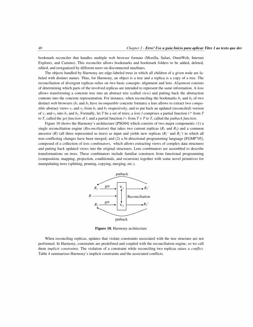
40 Chapter 2 - Erro! Use a guia Início para aplicar Titre 1 ao texto que deverá aparecer aqui.
bookmark reconciler that handles multiple web browser formats (Mozilla, Safari, OmniWeb, Internet Explorer, and Camino). This reconciler allows bookmarks and bookmark folders to be added, deleted, edited, and reorganized by different users on disconnected machines.
The objects handled by Harmony are edge-labeled trees in which all children of a given node are la-beled with distinct names. Thus, for Harmony, an object is a tree and a replica is a copy of a tree. The reconciliation of divergent replicas relies on two basic concepts: alignment and lens. Alignment consists of determining which parts of the involved replicas are intended to represent the same information. A lens allows transforming a concrete tree into an abstract tree (called view) and putting back the abstraction contents into the concrete representation. For instance, when reconciling the bookmarks b1 and b2 of two distinct web browsers (b1 and b2 have incompatible concrete formats) a lens allows to extract two compa-tible abstract views v1 and v2 from b1 and b2 respectively, and to put back an updated (reconciled) version of v1 and v2 into b1 and b2. Formally, let T be a set of trees; a lens l comprises a partial function l↗ from T to T, called the get function of l, and a partial function l↘ from T × T to T, called the putback function.
Figure 10 shows the Harmony’s architecture [PSG04] which consists of two major components: (1) a single reconciliation engine (Reconciliation) that takes two current replicas (R1 and R2) and a common ancestor (R) (all three represented as trees) as input and yields new replicas (R1’ and R2’) in which all non-conflicting changes have been merged; and (2) a bi-directional programming language [FGMP+05], composed of a collection of lens combinators, which allows extracting views of complex data structures and putting back updated views into the original structures. Lens combinators are assembled to describe transformations on trees. These combinators include familiar constructs from functional programming (composition, mapping, projection, conditionals, and recursion) together with some novel primitives for manipulating trees (splitting, pruning, copying, merging, etc.).
Figure 10. Harmony architecture When reconciling replicas, updates that violate constraints associated with the tree structure are not
performed. In Harmony, constraints are predefined and coupled with the reconciliation engine, so we call them implicit constraints. The violation of a constraint while reconciling two replicas raises a conflict. Table 4 summarizes Harmony’s implicit constraints and the associated conflicts.
V1
V2
get
get
R1
R2
R1’
R2’
Reconciliation
putback
putback
R

Chapter 2 - Erro! Use a guia Início para aplicar Titre 1 ao texto que deverá aparecer aqui. 41
Implicit Constraints Conflicts A tree node cannot be deleted in one replica and updated in the other (update means adding a new child to the tree node or to one of its descendants)
Delete/Create
A subtree cannot be entirely delete in one replica and partially deleted in the other Delete/Delete Different subtrees cannot hold the same place in a tree Create/Create Corresponding subtrees reached by edges labeled @ must be identical Atomicity
Table 4. Harmony’s implicit constraints and the associated conflicts The Harmony’s reconciler algorithm works as follows. Let R1 and R2 be two replicas under reconcili-
ation. Pairs of tree nodes (nR1, nR2) that correspond to each other in both replicas are recursively visited and checked with respect to their current state. If nR1 is equal to nR2 (i.e. nR1 and nR2 are already synchro-nized) or they are different, but a conflict between nR1 and nR2 is detected, the reconciler algorithm keeps nR1 and nR2 unchanged in the respective replicas. Otherwise, i.e. nR1 and nR2 are different and free of con-flict, updates are applied to one or both replicas in order to yield nR1 = nR2. In addition, the output replicas are checked against an intended schema in order to avoid the return of ill-formed structures. With this approach, the Harmony’s semantic reconciler satisfies the following specification requirements:
− Never back out changes.
− Never make up contents.
− Stop at conflicting paths leaving replicas in their current states.
− Always leave the replicas in a well-typed form (safety condition).
− Propagate as many changes as possible without violating above rules (maximality condition).
2.2.5.3 IceCube vs. Harmony
Both IceCube and Harmony aim at reconciling divergent replicas based on semantic. However, they achieve this common goal in quite different manners. Table 5 shows the distinguishing features of these solutions according to our optimistic replication parameters.
The first striking difference between IceCube and Harmony is that the former is generic (it can han-dle any kind of object) and flexible (the user and application can dynamically specify constraints), while the latter is specific for tree structures and inflexible (it only deals with implicit constraints).
Since Harmony is a state-based reconciler, it detects conflicts between replicas only by comparing their current states, i.e. the operations that have yielded replicas divergent are not available for the recon-ciliation engine (user intents are unknown). As a result, Harmony does not resolve conflicts; it only re-conciles non-conflicting divergences. IceCube is an operation-based reconciler; thus, it can access all operations performed on each replica, understand user intents, and try to construct a common sequence of operations. In order to resolve conflicts, IceCube may undo some operations. Therefore, Harmony never undoes user changes, but it does not assure replica convergence. In contrast, IceCube assures that replicas always achieve a common final state, but it may undo some user changes to resolve conflicts.

42 Chapter 2 - Erro! Use a guia Início para aplicar Titre 1 ao texto que deverá aparecer aqui.
It is important to note that, in its current version, Harmony is only a framework for reconciling two divergent trees, which offers a programming language and a reconciliation engine. It is not a complete replication protocol (or service), since it does not address the following issues:
− How to manage multiple (more than two) replicas of a tree
− Who should reconcile divergent replicas? A single site (centralized approach) or each involved site (distributed approach)
− When and who should start the reconciliation
− Is Harmony suitable for WANs? Notice that the reconciler must access the entire state of divergent replicas; state transfer of large objects in WANs may raise performance problems.
− How would Harmony behave on failure-prone dynamic environments in which sites can connect and disconnect at any time
IceCube Harmony
Object Application-specific (e.g. XML document, relational table, etc.)
Tree (e.g. XML document, file system, web browser bookmarks, etc.)
Operation Storage
Persistent operations (i.e. actions and con-straints are stored in logs)
Transient operations (i.e. update operations are not available)
Operation Relationship
Explicit constraints between actions; Constraints are dynamically created by the users and reconciliation engine
Implicit constraints for tree structures; Constraints are embedded in the reconcili-ation engine
Propagation Periodical pull-based operation transfer On demand state transfer Conflict De-tection and Resolution
Semantic-based conflict detection; Automatic conflict resolution (optimiza-tion);
Semantic-based conflict detection; Manual conflict resolution (conflicting tree nodes are not reconciled);
Reconciliation
Operation-based semantic approach; Takes actions and constraints from several local logs and builds a global schedule that is applied to all replicas
State-based semantic approach; Reconciles the corresponding tree nodes of two replicas whose divergent contents do not violate implicit constraints
Consistency Eventual consistency No guarantees
Table 5. IceCube vs. Harmony Despite these current limitations, the Harmony’s framework offers the fundamental components ne-
cessary to build a complete replication protocol. Therefore, we consider a generic and flexible solution that assures eventual consistency, as IceCube, more suitable for the applications in which we are interest-ed. However, appropriate adaptations on the specific and inflexible approach of Harmony can rend it equally useful for our intents.

Chapter 2 - Erro! Use a guia Início para aplicar Titre 1 ao texto que deverá aparecer aqui. 43
2.2.6 Summary
In this thesis we are especially interested in optimistic replication approaches as they provide good prop-erties for dynamic environments in which nodes can connect and disconnect at any time. In order to easily compare different proposals, we have abstracted the main characteristics of optimistic replication solu-tions by defining 5 parameters. Table 6 summarizes such parameters and presents the solutions we have discussed throughout Section 2.2.
SYSTEM OBJECT OPERATION RELATIONSHIP PROPAGATION CONFLICT RECONCILIATION CONSISTENCY
DNS Database Transient Push/pull None Temporal LOCUS File Transient Hb & conc. Push Conc. – Aut. St-b; ordinal Eventual TSAE Database Persistent Hb & conc. Push/pull None Op-b; ordinal Eventual R&C File Persistent Impl. const. Sem. – Aut. Op-b; semantic Eventual Unison File Transient Impl. const. On demand Sem. – Man. St-b; semantic No guarantees CVS File Persistent Impl. const. On demand Conc. – Man. Op-b Eventual Harmony Tree Transient Impl. const. On demand Sem. – Man. St-b; semantic No guarantees Bayou Database Persistent Expl. const. On demand Sem. – Aut. Op-b; semantic Eventual IceCube Any Persistent Expl. const. On demand Sem. – Aut. Op-b; semantic Eventual DLR Any Persistent Expl. const. On demand Sem. – Aut. Op-b; semantic Eventual
Table 6. Comparing optimistic replication solutions. In column “System”, R&C stands for Ramsey & Csirmaz’s file system and DLR stands for Distributed log-based reconciliation. In column “Relationship”, Hb stands for happens-before, conc. stands for concurrency, Impl. const. stands for implicit constraint, and Expl. const. stands for explicit constraint. In column “Conflict”, Conc. denotes conflict detection based on concurrency and Sem., conflict detection based on semantic while Aut. and Man. denote respec-tively automatic and manual conflict resolution. Finally, in column “Reconciliation”, St-b and Op-b de-notes respectively standard-based and operation-based.
2.3 P2P Systems
Data management in distributed systems has been traditionally achieved by distributed database systems [OV99] which enable users to transparently access and update several databases in a network using a high-level query language (e.g. SQL). Transparency is achieved through a global schema which hides the local databases’ heterogeneity. In its simplest form, a distributed database system is a centralized server that supports a global schema and implements distributed database techniques (query processing, transac-tion management, consistency management, etc.). This approach has proved effective for applications that can benefit from centralized control and full-fledge database capabilities, e.g. information systems. How-ever, it cannot scale up to more than tens of databases. Data integration systems [TV00, TRV98] extend the distributed database approach to access data sources on the Internet with a simpler query language in read-only mode. Parallel database systems [Val93] also extend the distributed database approach to im-prove performance (transaction throughput or query response time) by exploiting database partitioning using a multiprocessor or cluster system. Although data integration systems and parallel database systems can scale up to hundreds of data sources or database partitions, they still rely on a centralized global schema and strong assumptions about the network.
In contrast, P2P systems adopt a completely decentralized approach to resource management. By dis-tributing data storage, processing, and bandwidth across autonomous peers in the network, they can scale

44 Chapter 2 - Erro! Use a guia Início para aplicar Titre 1 ao texto que deverá aparecer aqui.
without the need for powerful servers. P2P systems have been successfully used for sharing computation, e.g. Seti@home [SWBC+97, Set06] and Genome@home [LSP03, Gen06], communication, e.g. ICQ [Icq06] and Jabber [Jab03], internet service support, e.g. P2P multicast systems [RHKS01, CDKR02, LRSS02, CJKR+03, BKRS+04] and security applications [KR02, JWZ03, VAS04], or data, e.g. Gnutella [Gnu06, JAB01, Jov00], Kazaa [Kaz06] and PeerDB [OST03, SOTZ03]. We focus in this thesis on P2P data management. Popular examples of P2P systems such as Gnutella and Kazaa have millions of users sharing petabytes of data over the Internet. Although very useful, these systems are quite simple (e.g. file sharing), support limited functions (e.g. keyword search) and use simple techniques (e.g. resource loca-tion by flooding) which have performance problems. In order to overcome these limitations, recent works have concentrated on supporting advanced applications which must deal with semantically rich data (e.g. XML documents, relational tables, etc.) using a high-level SQL-like query language, e.g. ActiveXML [ABCM+03], Edutella [NWQD+02, NSS03], Piazza [HIMT03, TIMH+03], PIER [HHLT+03]. To deal with the dynamic behavior of peers that can join and leave the system at any time, the P2P systems rely on the fact that popular data get massively duplicated.
In this section we present P2P systems in details. We first introduce and compare the P2P networks that support P2P systems (subsection 2.3.1). Then, we discuss the main existing solutions for data replica-tion in P2P systems (subsection 2.3.2).
2.3.1 P2P Networks
All P2P systems rely on a P2P network to operate. This network is built on top of the physical network (typically the Internet), and therefore is referred to as an overlay network. The degree of centralization and the topology of the overlay network tightly affect the nonfunctional properties of the P2P system, such as fault-tolerance, self-maintainability, performance, scalability, and security. For simplicity, we consider three main classes: unstructured, structured, and super-peer networks.
2.3.1.1 Unstructured
In unstructured P2P networks, the overlay network is created in a nondeterministic (ad hoc) manner and the data placement is completely unrelated to the overlay topology. Each peer knows its neighbors, but does not know the resources they have.
Searching mechanisms can be simple and expensive, such as flooding the network with queries until the desired data is located, or more sophisticated and efficient including the following approaches: (1) Lv et al. [LCCL+02] suggested multiple parallel random walks, where each node chooses a neighbor at ran-dom and propagates the request only to it; (2) Yang and Garcia-Molina [YG02] proposed selecting the neighbors to which forward queries based on their past history, as well as the use of local indices for pointing data stored at nodes located within a radius from itself; (3) in [KGZ02], each peer selects a sub-set of its neighbors to which propagate requests according to their performance in recent queries; (4) the Gia System [CRBL+03] addresses efficiency by dynamically adapting the network topology, so that most nodes are ensured to be at a short distance from high capacity nodes, which are able to provide answers to a very large number of queries; and (5) in [CG02], Crespo and Garcia-Molina use routing indices to pro-vide a list of neighbors that are most likely to be “in the direction” of the content corresponding to the query.

Chapter 2 - Erro! Use a guia Início para aplicar Titre 1 ao texto que deverá aparecer aqui. 45
There is no restriction on the manner to describe the desired data (query expressiveness), i.e. key look-up, SQL-like query, and other approaches can be used. Fault-tolerance is very high since all peers provide equal functionality and are able to replicate data. In addition, each peer is autonomous to decide which data it stores. However, the main problems of unstructured networks are scalability and incom-pleteness of query results. Searching mechanisms based on flooding are general but do not scale up to a large number of peers. Also, the incompleteness of the results can be high since some peers containing relevant data or their neighbors may not be reached because they are either off-line.
Examples of P2P systems supported by unstructured networks include Gnutella [Jov00, JAB01, Gnu06], Kazaa [Kaz06], and FreeHaven [DFM00]. Since Gnutella is the major representative of this category, it will be described later on.
2.3.1.2 Structured
Structured networks have emerged to solve the unscalability problem faced by unstructured networks. They achieve this goal by tightly controlling the overlay topology and data placement. Data (or pointers to them) are placed at precisely specified locations and mappings between data and their locations (e.g. a file identifier is mapped to a peer address) are provided in the form of a distributed routing table.
Distributed hash table (DHT) is the main representative of this P2P network class. A DHT provides a hash table interface with primitives put(key,value) and get(key), where key is an object identifier, and each peer is responsible for storing the values (object contents) corresponding to a certain range of keys. Each peer also knows a certain number of other peers, called neighbors, and holds a routing table that associates its neighbors’ identifiers to the corresponding addresses. Most DHT data access operations consist of a lookup, for finding the address of the peer p that holds the requested object, followed by di-rect communication with p. In the lookup step, several hops may be performed according to nodes’ neighborhoods.
Queries can be efficiently routed since the routing scheme allows one to find a peer responsible for a key in O(log N), where N is the number of peers in the network. Because a peer is responsible for storing the values corresponding to its range of keys, autonomy is limited. Furthermore, DHT queries are typical-ly limited to exact match keyword search. Active research is on-going to extend the DHT capabilities to deal with more general queries such as range queries and join queries [HHLT+03].
Examples of P2P systems supported by structured networks include Chord [SMKK+01], CAN [RFHK+01], Tapestry [ZHSR+04], Pastry [RD01a], Freenet [CMHS+02], PIER [HHLT+03], OceanStore [KBCC+00], Past [RD01b], and P-Grid [ACDD+03, AHA03]. Freenet is often qualified as loosely struc-tured system because the nodes of its P2P network can produce an estimate (not with certainty) of which node is most likely to store certain object [AS04]. They use a chain mode propagation approach, where each node makes a local decision about to which node to send the request message next. P-Grid is not supported by a DHT either. It is based on a virtual distributed search tree. All these P2P systems are de-scribed later on.
2.3.1.3 Super-peer
Unstructured and structured P2P networks are considered “pure” because all their peers provide equal functionalities. In contrast, super-peer networks are hybrid between client-server systems and pure P2P

46 Chapter 2 - Erro! Use a guia Início para aplicar Titre 1 ao texto que deverá aparecer aqui.
networks. Like client-server systems, some peers, the super-peers, act as dedicated servers for some other peers and can perform complex functions such as indexing, query processing, access control, and meta-data management. Using only one super-peer reduces to client-server with all the problems associated with a single server. Like pure P2P networks, super-peers can be organized in a P2P fashion and commu-nicate with one another in sophisticated ways, thereby allowing the partitioning or replication of global information across all super-peers. Super-peers can be dynamically elected (e.g. based on bandwidth and processing power) and replaced in the presence of failures.
In a super-peer network, a requesting peer simply sends the request, which can be expressed in a high-level language, to its responsible super-peer. The super-peer can then find the relevant peers either directly through its index or indirectly using its neighbor super-peers.
The main advantages of super-peer networks are efficiency and quality of service (i.e. the user-perceived efficiency, e.g. completeness of query results, query response time, etc.). The time needed to find data by directly accessing indices in a super-peer is quite smaller than flooding the network. In addi-tion, super-peer networks exploit and take advantage of peers’ different capabilities in terms of CPU power, bandwidth, or storage capacity as super-peers take on a large portion of the entire network load. In contrast, in pure P2P networks all nodes are equally loaded regardless of their capabilities. Access control can also be better enforced since directory and security information can be maintained at the super-peers. However, autonomy is restricted since peers cannot log in freely to any super-peer. Fault-tolerance is typically low since super-peers are single points of failure for their sub-peers (dynamic replacement of super-peers can alleviate this problem).
Examples of P2P systems supported by super-peer networks include Napster [Nap06], Publius [WAL00], Edutella [NSS03, NWQD+02], and JXTA [Jxt06]. A more recent version of Gnutella also relies on super-peers [AS04]. Napster and JXTA are described later on.
2.3.1.4 Comparing P2P networks
From the perspective of data management, the main requirements of a P2P network are [DGY03]: auton-omy, query expressiveness, efficiency, quality of service, fault-tolerance, and security. We describe these requirements in the following, and then we compare the P2P networks previously discussed based on such requirements.
− Autonomy: an autonomous peer should be able to join or leave the system at any time without re-
striction. It should also be able to control the data it stores and which other peers can store its data, e.g. some other trusted peers.
− Query expressiveness: the query language should allow the user to describe the desired data at the appropriate level of detail. The simplest form of query is key look-up which is only appropriate for finding files. Keyword search with ranking of results is appropriate for searching documents. But for more structured data, an SQL-like query language is necessary.
− Efficiency: the efficient use of the P2P network resources (bandwidth, computing power, storage) should result in lower cost and thus higher throughput of queries, i.e. a higher number of queries can be processed by the P2P system in a given time.

Chapter 2 - Erro! Use a guia Início para aplicar Titre 1 ao texto que deverá aparecer aqui. 47
− Quality of service: refers to the user-perceived efficiency of the P2P network, e.g. completeness of query results, data consistency, data availability, query response time, etc.
− Fault-tolerance: efficiency and quality of services should be provided despite the occurrence of peers failures. Given the dynamic nature of peers which may leave or fail at any time, the only solu-tion is to rely on data replication.
− Security: the open nature of a P2P network makes security a major challenge since one cannot rely on trusted servers. Wrt. data management, the main security issue is access control which includes enforcing intellectual property rights on data contents.
Table 7 summarizes how the requirements for data management are possibly attained by the three main classes of P2P networks. This is a rough comparison to understand the respective merits of each class. For instance, “high” means it can be high. Obviously, there is room for improvement in each class of P2P networks. For instance, fault-tolerance can be made higher in super-peer by relying on replication and fail-over techniques.
Requirements Unstructured Structured Super-peer Autonomy high low moderate Query expressiveness “high” low “high” Efficiency low high high QoS low high high Fault-tolerance high high low Security low low high
Table 7. Comparison of P2P networks
2.3.2 Replication solutions in P2P systems
P2P systems allow decentralized data sharing by distributing data storage across all peers of a P2P net-work. Since these peers can join and leave the system at any time, the shared data may become unavaila-ble. To cope with this problem, P2P systems replicate data over the P2P network. In this subsection, we present the main existing P2P systems from the perspective of data management and we discuss the cor-responding data replication solutions.
2.3.2.1 Napster
Napster [Nap06] is a P2P system supported by a super-peer network that relies on central servers to me-diate node interactions, as represented in Figure 11. Every peer that shares files connects to a super-peer and publishes the files it holds. The super-peer, in turn, keeps connection information (e.g. IP address, connection bandwidth) and a list of files provided by each peer. In order to retrieve a file from the overall P2P network, a peer sends a request (noted query in Figure 11) to the super-peer, which searches for matches in its index and returns a list of peers that hold the desired file (noted reply in Figure 11). The

48 Chapter 2 - Erro! Use a guia Início para aplicar Titre 1 ao texto que deverá aparecer aqui.
peer that has submitted the query then opens direct connections with one or more peers belonging to the super-peer reply and downloads the desired file.
Napster relies on replication for improving files availability and enhancing performance, but it does not implement a particular replication solution. Indeed, replication occurs naturally as nodes request and copy files from one another. This is referred to as passive replication. Napster is simple to implement and efficient for locating files, but it has two main limitations. First, it stores only static data (e.g. music files). Second, super-peers constitute single points of failure and are vulnerable to malicious attack.
Figure 11. Super-peer network
2.3.2.2 JXTA
JXTA [Jxt06] is an open source application framework for P2P computing. JXTA protocols aim to estab-lish a network overlay on top of the Internet and non-IP networks, allowing peers to directly interact and self-organize independently of their physical network. JXTA technology leverages open standards like XML, Java technology, and key operating system concepts. By using existing, proven technologies and concepts, the objective is to yield a peer-to-peer system that is familiar to developers.
JXTA’s architecture is organized in three layers as shown in Figure 12: JXTA core, JXTA services, and JXTA applications. The core layer provides minimal and essential primitives that are common to P2P networking. The services layer includes network services that may not be absolutely necessary for a P2P network to operate, but are common or desirable in the P2P environment. The applications layer provides integrated applications that aggregate services, and, usually, provide user interface. There is no rigid boundary between the applications layer and the services layer.
Figure 12. JXTA architecture
JXTA Applicati-ons
JXTA Services
JXTA Core
Any Peer on the Expanded Web
Sun JXTA
Sevices
· Indexing · Searching · File Sharing
JXTA Community Services
Peer Monitoring Peer Pipes Peer Groups
Security
JXTA Community Applications JXTA Shell
Peer
Commands
Sun JXTA Applications
Super-peer
Peer Peer
Peer Peer
file
query
reply
download

Chapter 2 - Erro! Use a guia Início para aplicar Titre 1 ao texto que deverá aparecer aqui. 49
In JXTA, all shared resources are described by advertisements. Advertisements are language-neutral metadata structures defined as XML documents. Peers use advertisements to publish their resources. Some special super-peers, which are called rendezvous peers, are responsible for indexing and locating the advertisements. JXTA does not address data replication.
2.3.2.3 Gnutella
Gnutella [Jov00, JAB01, Gnu06] is a P2P file sharing system built on top of the IP network service. Its overlay network is unstructured. In order to obtain a shared file, the node that requests the file (henceforth requestor) must perform three tasks: join the Gnutella network, search the desired file, and download it. To join the Gnutella network, the requestor connects to a set of nodes already joined (a bootstrap list is available in databases such as gnutellahosts.com) and sends them a request to announce themselves. Each of these nodes then sends back a message containing its IP and port as well as the number and size of its shared files; in addition, it propagates the announcement request to its neighbors.
Once joined, the requestor can search the desired file as illustrated in Figure 13. In this figure, we use numbers before messages to indicate the time in which they are exchanged (e.g. all messages preceded by 1 are exchanged at the same time t1). The searching mechanism starts with a query message q sent by the requestor to its neighbors (1:q in Figure 13a) and distributed throughout the network by flooding (2:q and 3:q in Figure 13a). Replies to q are routed back along the opposite path through which q arrived. A reply of a host that can satisfy q is called query hit (noted qh) and contains the IP, port, and speed of the host. When the requestor receives a query hit message (qh in Figure 13b), it directly connects to the node that holds the desired file and performs the download. In order to improve efficiency and preserve network bandwidth, duplicated messages are detected and dropped. In addition, the message spread is limited to a maximum number of hops.
Figure 13. Gnutella: an example of the searching mechanism. (a) The requestor node submits a query q that is propagated by flooding. (b) When the requestor receives a query hit qh, it connects to the node that holds the desired file and download it.
As Napster, Gnutella implements passive replication, i.e. a file is only replicated at nodes requesting
the file. To improve locality of data, as well as availability and performance, active replication methods were proposed (e.g. [LCCL+02]) in which files may be proactively replicated at arbitrary nodes. Howev-er, Gnutella keeps on a major limitation, namely it only deals with static files.
Requestor
1:q 2:q
2:q
1:q 2:q
3:q
2:q
Requestor
5:qh 4:qh
4:qh
(a) (b)
File File
download
5:qh

50 Chapter 2 - Erro! Use a guia Início para aplicar Titre 1 ao texto que deverá a
2.3.2.4 Chord
Chord [SMKK+01] is a P2P routing and location system on top of a DHT overlay network. Chord uses consistent hashing [KLLL+97] for mapping data keys to nodes responsible for them. The consistent hash function assigns each node and key an m-bit identifier using a base hash function such as SHA-1 [Fip95]. The identifier length m must be large enough to make the probability of two nodes or keys hashing to the same identifier negligible. A node’s identifier is chosen by hashing the node’s IP address, while a key identifier is produced by hashing the key. The term “key” is used to refer to both the original key and its image under the hash function, as the meaning is clear from the context. Similarly, the term “node” refers to both the node and its identifier under the hash function.
All node identifiers are ordered in a circle modulo 2m. Figure 14 shows an example with m = 3 and three connected nodes (0, 1, and 3). Key k is assigned to the first node whose identifier is equal to or follows k in the identifier space. This node is called the successor of k and noted successor(k). For in-stance, in Figure 14 the successor of identifier 1 is node 1, so key 1 should be located at node 1. Similar-ly, key 2 should be located at node 3, and key 6 at node 0. The use of consistent hashing tends to balance load as each node receives roughly the same number of keys.
In order to efficiently locate keys, each node n holds additional routing information in the form of a finger table. This table has at most m entries. The ith entry of the n’s finger table points to the successor of the identifier [(n + 2i-1) mod 2m], where 1 ≤ i ≤ m. For instance, consider the node 0 (n = 0) in Figure 15. The entries in its finger table are computed as follows:
− i = 1: successor [(0 + 20) mod 23] → successor (1) = 1
− i = 2: successor [(0 + 21) mod 23] → successor (2) = 3
− i = 3: successor [(0 + 22) mod 23] → successor (4) = 0
Figure 14. Chord: an example of an identifier circle
Figure 15. Chord: an example of lookup operation
To illustrate the lookup operation in Chord, let k be a searched key. The principle is to find the node
that precedes the successor(k), noted predecessor(k), and request from predecessor(k) the identifier of its successor (every node knows its successor and predecessor in the circle). For instance, in Figure 15 con-sider that node 1 looks for the key k = 6, which is stored at node 0. Using the lookup principle, node 1 finds the predecessor(6), which is node 3, and then request its successor; node 3, in turn, replies that its
finger table start succ.
1 2 4
1 3 0 0
1
2
3
4
5
6
7
6
keys
finger table start succ.
2 3 5
3 3 0
finger table start succ.
4 5 7
0 0 0
1
keys
2
keys
sucessor(2)=3
sucessor(6)=0
0
1
2
3
4
5
6
7 1
sucessor(1)=1
2
6

Chapter 2 - Erro! Use a guia Início para aplicar Titre 1 ao texto que deverá aparecer aqui. 51
successor is node 0 and terminates the lookup operation. This principle is implemented in practice by accessing the column succ. of the finger table (see Figure 15), as follows. The node that starts the query (i.e. n = 1) finds in its finger table the node n’ with the highest identifier such that n’ is located between n and k in the circle (i.e. n’ = 3 since 3 is the highest node identifier in the column succ. of node 1’s finger table that is located between 1 and 6 in the circle). If such a node exists, the query is forwarded to n’, which now becomes n and performs the same lookup operation. Otherwise, the node that currently holds the query returns its successor in the circle as the successor(k). Using the finger table, both the amount of routing information held by each node and the time required for resolving lookups are O(log N) for a network with N connected nodes.
Chord does not implement data replication; it delegates this responsibility for the application. How-ever, it proposes that the application implements replication by storing the object under several keys de-rived from the data’s application level identifier. Knezevic et al. [KWR05] realizes this purpose assuring that in case of concurrent updates on the same replicated object only one peer completes the operation. In addition, missing replicas are proactively recreated within refreshment rounds. This approach gives prob-abilistic guarantees on accessing correct data at any point in time. Akbarinia et al. [AMPV06a] use mul-tiple hash functions to produce several key identifiers from a single key. They allow updating replicas of the same object in parallel and rely on timestamps to automatically resolve conflicts. This approach pro-vides probabilistic guarantees of consistency among replicas; however, conflicting updates might cause lost updates. For instance, consider the scenario where two nodes take in parallel the current version of a given object and update it thereafter. The one that gets the highest timestamp will overwrite the update performed by the other. A problem related to this approach is to determine how many hash functions should be used to replicate an object. Xia et al. [XCK06] discuss this problem and propose a solution. A major limitation of Chord is that the user cannot control data placement.
2.3.2.5 CAN
CAN (Content Addressable Network) [RFHK+01] relies on a structured P2P network that resembles a hash table. It uses a virtual d-dimensional Cartesian coordinate space to store and retrieve (key, value) pairs. This coordinate space is completely logical as it is not related to any physical coordinate system. At any point in time, the entire coordinate space is dynamically partitioned among all nodes in the system, so that each node owns a distinct zone that represents a segment of the entire space. Figure 16a shows a 2-dimensional [0, 1] × [0, 1] coordinate space partitioned among 5 nodes. The zone A, for instance, is com-prised between 0 and 0.5 along the X-axis and between 0.5 and 1 along the Y-axis. To store a pair (k1, v1), key k1 is deterministically mapped onto a point P in the coordinate space using a uniform hash function, and then (k1, v1) is stored at the node that owns the zone to which P belongs. Any node can retrieve the entry (k1, v1) by applying the same deterministic hash function to map k1 onto point P. If this point is not owned by the requesting node or its neighbors, the request must be routed through the CAN infrastructure until it reaches the node in whose zone P lays. Intuitively, routing in CAN works by following the straight line path through the Cartesian space from source to destination coordinates. For instance, in Figure 16, for node A to achieve the point P, the corresponding request must be routed through zones A, B, and E.
A CAN node maintains a coordinate routing table that holds the IP address and virtual coordinate zone of each of its neighbors (it is similar to Chord’s finger table). Two nodes are neighbors in a d-dimen-sional coordinate space if their coordinate spans overlap along d – 1 dimensions and are adjacent along one dimension. For example, in Figure 16a, node E is neighbor of nodes B and D. When a new node

52 Chapter 2 - Erro! Use a guia Início para aplicar Titre 1 ao texto que deverá aparecer aqui.
joins the system (e.g. node F in Figure 16b), it must take on its own portion of the coordinate space. This is achieved by splitting the zone of an existing node in half and assigning one half to the joining node. In addition, the neighbors of the splitting zone must be notified in order to update their routing tables.
Figure 16. CAN: (a) Example of a 2-d coordinate space divided into 5 zones; (b) Join operation For a d-dimensional space partitioned into N equal zones, the average routing path length is
(d/4)(N1/d), and each node holds 2d neighbors. It means that for a d-dimensional space, CAN can grow the number of nodes (and hence zones) without increasing per node state while the path length grows as O(N1/d). Notice that, if the number of dimensions is set as d = (log2 N)/2, CAN could achieve the same properties of other algorithms, such as Chord, i.e. path length O(log N) and O(log N) neighbors. However, maintaining the number of neighbors independent of the network size (i.e. d independent of N) provides better scalability, and it is therefore appropriate for very large networks with frequent topology changes.
Concerning replication, CAN proposes two approaches [RFHK+01]. The first one is to use m hash functions to map a single key onto m points in the coordinate space, and, accordingly, replicate a single (key, value) pair at m distinct nodes in the network (similar to Chord’s solution). The second approach represents an optimization over the basic design of CAN that consists of node n proactively pushing out popular keys towards its neighbors when n finds it is being overloaded by requests for these keys. In this approach, replicated keys should have an associated time-to-live field to automatically undo the effect of replication at the end of the overloaded period. In addition, it assumes immutable (read-only) contents. Similar to Chord, the main limitation of CAN is that the user cannot control data placement.
2.3.2.6 Tapestry
Tapestry [ZHSR+04, ZKJ01] is an extensible P2P system that provides decentralized object location and routing on top of a structured overlay network. It routs messages to logical endpoints (i.e. endpoints who-se identifiers are not associated with physical location), such as nodes or object replicas. This enables message delivery to mobile or replicated endpoints in the presence of instability in the underlying infra-structure. In addition, Tapestry takes latency into account to establish nodes’ neighborhoods. The location and routing mechanisms of Tapestry work as follows. Let O be an object identified by id. The insertion of O in the P2P network involves two nodes: the server node (noted ns) and the root node (noted nr). The server node holds O while the root node holds a mapping in the format (id, ns) indicating that the object identified by id (i.e. O) is stored at node ns. The root node is dynamically determined by a globally con-sistent deterministic algorithm. Figure 17a shows that when O is inserted into ns, ns publishes the O’s
(a) (b)
E’s neighbour set: {B,D,F} F’s neighbour set: {D,E}
A C
D
B E • P0
0 0.5 1.0
0.5
1.0
0.75
F
0.75
A C
D
B E • P0
0 0.5 1.0
0.5
1.0
0.75
E’s neighbour set: {B,D}

Chapter 2 - Erro! Use a guia Início para aplicar Titre 1 ao texto que deverá aparecer aqui. 53
identifier to its root node by routing a message from ns to nr containing the mapping (id, ns). This map-ping is stored at all nodes along the message path. During a location query (e.g. id? in Figure 17a), the message that looks for id is initially routed towards nr, but it may be stopped before achieving nr once a node containing the mapping (id, ns) is found. For routing a message destined to id’s root, each node forwards this message to its neighbor whose logical identifier is the most similar to id [PRR97].
Figure 17. Tapestry: object publishing and replication Tapestry does not implement object replication directly, but it offers the entire infrastructure needed
to take advantage of replicas, as shown in Figure 17b. Each node in the graph represents a peer in the P2P network and contains the peer’s logical identifier in the hexadecimal format. In this example, two replicas O1 and O2 of the object O (e.g. a book file) are inserted into distinct peers (O1 → 4228 and O2 → AA93). The identifier of O1 is equal to O2 (i.e. 4378 in hexadecimal) as O1 and O2 are replicas of the same object (i.e. O). When O1 is inserted into its server node (i.e. 4228), the mapping (4378, 4228) is routed from node 4228 to node 4377 (the root node for O1’s identifier). Notice that as the message approaches the root node, the object and the node identifiers become more and more similar. In addition, the mapping (4378, 4228) is stored at all nodes along the message path. The insertion of O2 follows the same procedure. In Figure 17b, if node E791 looks for a replica of O, the associated message routing stops at node 4361. Therefore, applications can replicate data across multiple server nodes and rely on Tapestry to direct requests to nearby replicas.
2.3.2.7 Pastry
Pastry [RD01a] is a P2P infrastructure intended for supporting a variety of P2P applications like global file sharing, file storage, group communication, and naming systems, which is built on top of a structured overlay network. Each node in the Pastry network has a 128-bit node identifier (noted nodeId), so that the nodeId space ranges from 0 to 2128 – 1. Node identifiers are ordered in a circle like Chord identifiers. Data placement in Pastry is also similar to Chord, i.e. an object identified by key is stored at the node whose nodeId is closest to key. Contrasting with Chord, Pastry takes latency into account to establish nodes’ neighborhoods. For routing a message that looks for key, each node forwards this message to its neighbor whose nodeId is the most similar to key [PRR97]. Thus, the routing mechanism of Pastry is comparable to
(id,ns)
ns
nr
insert(id,O)
id?
(id,ns) (id,ns)
id? ns
4228 43FE
4377
4361 4A6D
57EC
AA93
4664
E791 4378? 4378?
4378?
4B4F
AA93
AA93
437A
(a) Object publishing (b) Replica management
insert(4378,O1)
insert(4378,O2)
α α
α
α
β β β
β (4228,4378) α (AA93,4378)
Obj ID O id
Obj ID O1 4378
Obj ID O2 4378

54 Chapter 2 - Erro! Use a guia Início para aplicar Titre 1 ao texto que deverá aparecer aqui.
the Tapestry’s counterpart. In addition, the application is notified at each Pastry node along the message route, and may perform application-specific computations related to the message.
Pastry does not implement object replication directly, but it provides functionalities that enable an application on top of Pastry to easily take advantage of replicas. First, Pastry can route a message that looks for key to the k nodes whose nodeIds are closest to key. As a result, a file storage application, for instance, can assign a key to a file (e.g. using a hash function on file’s name and owner) and store replicas of this file on the k Pastry nodes with nodeIds closest to key. Second, Pastry’s notification mechanisms allow keeping such replicas available despite node failures and node arrivals, using only local coordina-tion among nodes with adjacent nodeIds.
2.3.2.8 Freenet
Freenet [CMHS+02] is a distributed information storage system focused on privacy and security issues. It does not explicitly try to guarantee permanent data storage. Concerning the underlying P2P network, Freenet is often qualified as loosely structured network because the policies it employs to determine the network topology and data placement are not deterministic.
To add a new file, a user sends an insert message to the system, which contains the file and its as-signed location-independent globally unique identifier (GUID). The file is then stored in some set of nodes. During the file’s lifetime, it might migrate to or be replicated on other nodes. To retrieve the file, a user sends out a request message containing the GUID key. When the request reaches one of the nodes where the file is stored, that node passes the data back to the request’s originator.
Every node in Freenet maintains a routing table that lists the addresses of other nodes and the GUID keys it thinks they hold. When a node receives a query, if it holds the requested file, it returns this file with a tag identifying itself as the data holder. Otherwise, the node forwards the request to the node in its table with the closest key to the one requested, and so forth. If the request is successful, each node in the chain passes the file back upstream and creates a new entry in its routing table associating the data holder with the requested key. Depending on its distance from the holder, each node might also cache a copy locally. An insert message follows the same path that a request for the same key would take, sets the routing table entries in the same way, and stores the file in the same nodes. Thus, new files are placed where queries would look for them.
Data replication occurs as a side effect of search and insert operations. Searches replicate data along the query paths (upstream). In the case of an update (which can only be done by the data’s owner) the update is routed downstream based on keys similarities. Since the routing is heuristic and the network may change without notifying peers that come online about the updates they have lost, consistency is not guaranteed.
2.3.2.9 PIER
PIER [HHLT+03] is a massively distributed query engine built on top of a CAN distributed hash table (DHT). It intends to bring database query processing facilities to widely distributed environments. PIER is a three-tier system organized as shown in Figure 18. Applications (at the higher-level) interact with PIER’s Query Processor (at the middle-level) which utilizes an underlying DHT (at the lower-level) for data storage and retrieval. An instance of each DHT and PIER Query Processor component runs on every

Chapter 2 - Erro! Use a guia Início para aplicar Titre 1 ao texto que deverá aparecer aqui. 55
participating node. The objects stored in the DHT are tuples of relational tables. The object key used by the hash function is composed of three elements: the table name, an attribute of the tuple (usually the primary key), and a random number to uniquely identify objects whose preceding values are equals. PIER does not address replication.
Figure 18. PIER architecture
2.3.2.10 OceanStore
OceanStore [KBCC+00] is a data management system designed to provide continuous access to persistent information. It relies on Tapestry [ZHSR+04] and assumes an infrastructure composed of untrusted po-werful servers, which are connected by high-speed links. For security reasons, data are protected through redundancy and cryptographic techniques. To improve performance, data is allowed to be cached any-where, anytime.
OcesanStore allows concurrent updates on replicated objects; it relies on reconciliation to assure data consistency and avoid many of the problems inherent with wide-area locking. Figure 19 illustrates the update management in OceanStore. In this example, R is a replicated object whereas Ri and ri denote respectively a primary and a secondary copy of R. Nodes n1 and n2 are concurrently updating R. Such updates are managed as follows. Nodes that hold primary copies of R, henceforth the master group of R, are responsible for ordering updates. So, n1 and n2 perform tentative updates on their local secondary replicas and send these updates to the master group of R as well as to other random secondary replicas (Figure 19a). The tentative updates are ordered by the master group based on timestamps assigned by n1 and n2; at the same time, these updates are epidemically propagated among secondary replicas (Figure 19b). Once the master group obtains an agreement, the result of updates is multicast to secondary replicas (Figure 19c), which contains both tentative3 and committed data.
Replica management adjusts the number and location of replicas in order to service requests more ef-ficiently. By monitoring the system load, OceanStore detects when a replica is overwhelmed and creates additional replicas on nearby nodes to alleviate load. Conversely, these additional replicas are eliminated when they fall into disuse. Although OceanStore is a very interesting solution, it makes strong assump-tions about the network and the capabilities of nodes that are not realistic for P2P environments.
3 Tentative data is data that the primary replicas have not yet committed.
Network Monitoring
Other User Apps
Query Opt-mizer
Catalog Manager
Core Relational Execution Engine
Provider Overlay Routing
Storage Mana-ger
Applications
PIER
DHT

56 Chapter 2 - Erro! Use a guia Início para aplicar Titre 1 ao texto que deverá aparecer aqui.
Figure 19. OceanStore: concurrent updates. (a) Nodes n1 and n2 send updates to the master group of R and to several random secondary replicas. (b) The master group of R orders updates while secondary replicas propagate them epidemically. (c) After the master group agreement, the result of updates is mul-ticast to secondary replicas.
2.3.2.11 PAST
PAST [RD01b] is a P2P file storage system that relies on Pastry [RD01a] to provide strong persistency and high availability of immutable (read-only) files in the Internet. The PAST system offers the following operations: insert, lookup, and reclaim. The insert operation stores a file at a user-specified number k of distinct nodes within the PAST network. The lookup operation reliably retrieves a copy of the desired file if it exists in PAST and if at least one of the k nodes that store the file is reachable via Internet. The file is normally retrieved from a live node “near” (in terms of latency) the PAST node issuing the lookup. Final-ly, the reclaim operation reclaims the storage occupied by the k copies of a file. Once the operation com-pletes, PAST no longer guarantees the success of lookup operations. Reclaim is different from delete because the file may remain available for a while. Replica management in PAST is based on Pastry’s functionalities.
2.3.2.12 P-Grid
P-Grid [ACDD+03, AHA03] is a peer-to-peer data management system based on a virtual distributed search tree, similarly structured as distributed hash tables. Figure 20a shows a simple example of data placement in P-Grid. In this example, data keys are composed of 3 bits and they are grouped according to their bit prefix. For instance, all keys with prefix 00 (i.e. 000 and 001) belong to the same path of the tree (i.e. 00), and therefore are gathered on the same group. Each peer in P-Grid is associated with a tree path and is responsible for the group of keys corresponding to this path. For example, in Figure 20a, peers p1 and p6 are associated with path 00, and thus hold keys 000 and 001. For fault tolerance, multiple peers can be responsible for the same path (e.g. paths 00 and 10), thereby holding replicas of the same objects.
R1 R2
R3 R4
r5 r6 r7 r8 r9
r10 r11 r12 r13
r14 r15 r16
r18
r17
r19
(a)
n1 n2
R1 R2
R3 R4
r5 r6 r7 r8 r9
r10 r11 r12 r13
r14 r15 r16
r18
r17
r19
(b)
n1 n2
(c)
R1 R2
R3 R4
r5 r6 r7 r8 r9
r10 r11 r12 r13
r14 r15 r16
r18
r17
r19
n1 n2

Chapter 2 - Erro! Use a guia Início para aplicar Titre 1 ao texto que deverá aparecer aqui. 57
Figure 20. P-Grid example Figure 20b illustrates query routing in P-Grid. For each bit in the path of a peer pi, pi stores a refer-
ence to at least one peer that is responsible for the other side of the binary tree at that level. For instance, since p6 is associated with path 00, p6 has an entry in its routing table for the prefix 1 (the other side of the tree at first level) and another entry for the prefix 01 (the other side of the tree at second level). Thus, if a peer receives a binary query string that it cannot satisfy, it must forward the query to a peer that is closer to the result. In Figure 20b, p6 forwards queries starting with 1 to p5, because p5 is associated with prefix 1 in the p6’s routing table (first entry). For example, if p6 receives a query q looking for 100, it forwards q to p5 that, in turn, forwards q to p4, which replies q.
Notice that the peer’s path is not associated with the peer’s identifier. Indeed, peer paths are acquired and changed dynamically through negotiation with other peers as part of the network maintenance proto-col. Thus, a decentralized and self-organizing process builds the P-Grid’s routing infrastructure which is adapted to a given distribution of data keys stored by peers. This process also addresses uniform load distribution of data storage and uniform replication of data to support uniform availability.
To address updates of replicated objects, P-Grid employs rumor spreading and provides probabilistic guarantees for consistency. The update propagation scheme has a push phase and a pull phase as de-scribed in the following. When a peer p receives a new update to a replicated object R, p pushes the up-date to a subset of peers that hold replicas of R that, in turn, propagate it to other peers holding replicas of R, and so forth. Peers that have been disconnected and get connected again, peers that do not receive updates for a long time, or peers that receive a pull request but are not sure to have the latest update, enter the pull phase to reconcile. In this phase, multiple peers are contacted and the most up to date among them is chosen to provide the object content.
The main assumptions of the update algorithm are:
− Peers are mostly offline.
− Conflicts are rare and their resolution is not necessary in general.
− Consecutive updates are distributed sparsely.
− The typical number of replicas is substantially higher than assumed normally for distributed databas-es but substantially lower than the total network size.
0 1
00 01 10 11
000 001 010 011 100 101 110 111
p1 p6 p2 p3 p4 p5
Keys
Paths
Nodes
(a) Data placement (b) Query routing
Path 00 Path 01 Path 10 Path 11
Prefix Peer 1
01 p5 p2
Prefix Peer 1
00 p4 p6
Prefix Peer 0
10 p6 p4
Prefix Peer 0
11 p2 p5
Prefix Peer 0
11 p6 p5
p1 p6 p2 p3
1 p4 p5
100?
Prefix Peer 1
01 p3 p2

58 Chapter 2 - Erro! Use a guia Início para aplicar Titre 1 ao texto que deverá aparecer aqui.
− Replicas within a logical partition of the data space are connected among each other and each replica knows a minimal fraction of the complete set of replicas.
− The connectivity among replicas is high and the connectivity graph is random.
2.4 Conclusion
We address P2P collaborative applications in which shared data are distributed across peers in the net-work. Since these peers can join and leave at any time, we need data replication to provide high availa-bility. Such replication solution must satisfy the following requirements: data type independence, multi-master replication, semantic conflict detection, eventual consistency, high level of autonomy, and weak network assumptions. These requirements are justified as follows:
− Data type independence: different collaborative applications may share different data types (e.g.
relational tables, XML documents, files, etc.); thus, the replication solution should be generic wrt. the underlying data type.
− High level of autonomy: users that collaborate should be able to store local replicas of the objects they handle in order to maximize data availability. This enables asynchronous collaboration despite disconnections or system failures. They should also be able to control which other users can store its data.
− Multi-master replication: each user that holds a local replica of an object should be able to update it asynchronously. Updates on replicas of the same object should be later reconciled to resolve diver-gences among replicas.
− Semantic conflict detection: asynchronous, parallel updates on different replicas of an object may raise conflicts. By exploiting the operations’ semantic, the conflict rate should be reduced.
− Eventual consistency: replicas can diverge somewhat, but successive reconciliations should conti-nually reduce the divergence level. In particular, if an object stops to receive updates (e.g. the colla-borative edition of an XML document terminates), all its replicas should eventually achieve an equal final state.
− Weak network assumptions: users can take advantage of any type of computer to collaborate. In addition, the quality of the underlying network can vary considerably. Thus, the replication solution should not state strong assumptions concerning the physical network (or the infrastructure as a whole, e.g. powerful servers connected by fast and reliable links).
Table 8 compares all P2P replication solutions previously discussed based on our requirements. Clearly, none of the P2P systems in this table fully satisfy our requirements. In particular, none of them provide eventual consistency among replicas along with weak network assumptions, which is the main concern of this thesis. The distributed log-based reconciliation algorithms proposed by Chong and Hama-

Chapter 2 - Erro! Use a guia Início para aplicar Titre 1 ao texto que deverá aparecer aqui. 59
di [CH06] addresses most of our requirements, but this solution is unsuitable for P2P systems as it does not take into account the dynamic behavior of peers and network limitations. Operational transformation also addresses eventual consistency among replicas, but this approach is specific for collaborative edition and it assumes synchronous collaboration (i.e. concurrent updates of replicas). The solution we propose in the next chapters satisfies all requirements stated above. It is based on optimistic replication for several reasons. First, optimistic replication improves availability since data are not blocked during updates. Second, optimistic algorithms can scale to a large number of replicas since they require little synchroniza-tion among nodes. Third, this approach provides high performance as updates are locally applied as soon as submitted (divergences among replicas due to parallel updates are resolved later). Finally, users can asynchronously collaborate, and therefore the application can progress in spite of failures or dynamic connections and disconnections. The drawback of optimistic replication is that mutual consistency cannot be assured. However, the applications we address tolerate this limitation.
P2P System4
P2P Network
Data Type
Autonomy Replication Type
Conflict Detection
Consistency Network Assump.
Napster Super-peer File Moderate Static data – – Weak JXTA Super-peer Any High – – – Weak Gnutella Unstructured File High Static data – – Weak
Chord Structured (DHT) Any Low Single-master Multi-master
Concurrency None
Probabilistic Probabilistic
Weak
CAN Structured (DHT) Any Low Static data Multi-master
– None
– Probabilistic
Weak
Tapestry Structured (DHT) Any High – – – Weak Pastry Structured (DHT) Any Low – – – Weak Freenet Structured File Moderate Single-master None No guarantees Weak PIER Structured (DHT) Tuple Low – – – Weak OceanStore Structured (DHT) Any High Multi-master Concurrency Eventual Strong PAST Structured (DHT) File Low Static data – – Weak P-Grid Structured File High Multi-master None Probabilistic Weak
Table 8. Comparing replication solutions in P2P systems
4 For Chord and CAN, we consider the replication approaches explained in Section 2.3.2.4. Although Tapestry and Pastry provide facilities for managing replicas, they do not implement replication solutions.


61
CHAPTER 3
3 Replication Support in APPA
This thesis proposes a solution for data replication in P2P networks that assures eventual consistency among replicas. Such solution is built in the context of APPA (Atlas Peer-to-Peer Architecture). APPA is a data management system that provides scalability, availability and performance for P2P advanced ap-plications, which must deal with semantically rich data (e.g. XML documents, relational tables, etc.) using a high-level SQL-like query language. The replication service is placed in the upper layer of APPA architecture; the APPA architecture provides an application programming interface (API) to make it easy for P2P collaborative applications to take advantage of data replication. The architecture design also es-tablishes the integration of the replication service with other APPA services by means of service interfac-es. This chapter introduces the APPA architecture, and then describes the proposed APPA replication service. It is organized as follows. Section 3.1 gives an overview of APPA architecture. Section 3.2 intro-duces APPA services that directly support data replication, namely KSR (Key-based Storage and Retriev-al), PDM (Persistent Data Management), and CCM (Communication Cost Management). The KSR and PDM services allow storing and retrieving data objects used during reconciliation in a highly available manner. The CCM service estimates the communication costs for accessing objects that are stored in the P2P network by taking into account latencies and transfer rates as well as the dynamic behavior of nodes that join and leave the network at will. In addition, this section describes in details the APPA replication service. Section 3.3 presents the APPA API and discusses how to develop an application (e.g. a P2P Wi-ki) with this API. Finally, Section 3.4 concludes this chapter.
3.1 Overview of APPA
APPA has a layered service-based architecture. Besides the traditional advantages of using services (en-capsulation, reuse, portability, etc.), this enables APPA to be network-independent so it can be imple-mented over different structured (e.g. DHT) and super-peer P2P networks. The main reason for this choice is to be able to exploit rapid and continuing progress in P2P networks. Another reason is that it is unlikely that a single P2P network design will be able to address the specific requirements of many dif-ferent applications. Obviously, different implementations will yield different trade-offs between per-formance, fault-tolerance, scalability, quality of service, etc. For instance, fault-tolerance can be higher in DHTs because no node is a single point of failure. On the other hand, through index servers, super-peer networks enable more efficient query processing. Furthermore, different P2P networks could be combi-ned in order to exploit their relative advantages, e.g. DHT for key-based search and super-peer for more complex searching. Figure 21 shows the APPA architecture, which is composed of three layers of ser-vices: P2P network services, basic services and advanced services.

62 Chapter 3 - Erro! Use a guia Início para aplicar Titre 1 ao texto que deverá aparecer aqui.
P2P network services. This layer provides network independence with services that are common to dif-ferent P2P networks:
− Peer id assignment: assigns a unique id to a peer using a specific method, e.g. a combination of
super-peer id and counter in a super-peer network.
− Peer linking: links a peer to some other peers, e.g. by locating a zone in CAN.
− Key-based storage and retrieval (KSR): stores and retrieves a (key, object) pair in the P2P network, e.g. through hashing over all peers in DHT networks or using super-peers in super-peer networks. An important aspect of KSR is that it allows managing data using object semantic. Object semantic means that an object stored in the P2P network consists of a set of data attributes which can be ac-cessed individually for read or write purposes. This approach is appropriate for optimizing object access performance since we do not need to transfer the entire object through the network at each ob-ject access operation as the existing P2P networks use to do.
− Key-based time stamping (KTS): generates monotonically increasing timestamps which are used for ordering the events occurred in the P2P system.
− Peer communication: enables peers to exchange messages (i.e. service calls).
Basic services. This layer provides elementary services for the advanced services using the P2P network layer:
− Persistent data management (PDM): provides high availability for the (key, object) pairs which are
stored in the P2P network.
− Communication cost management: estimates the communication costs for accessing a set of objects that are stored in the P2P network. These costs are computed based on latencies and transfer rates, and they are refreshed according to the dynamic connections and disconnections of nodes.
− Group management: allows peers to join an abstract group, become members of the group and send and receive membership notifications. This is similar to group communication systems [CKV01, CJ-KR+03].
Advanced services. This layer provides advanced services for semantically rich data sharing including schema management, replication [MAPV06, MP06, MPJV06], query processing [AMPV06b, APV06], security, etc. using the basic services.

Chapter 3 - Erro! Use a guia Início para aplicar Titre 1 ao texto que deverá aparecer aqui. 63
Figure 21. APPA architecture Figure 22 shows the APPA architecture based on a DHT network. In this case, the three service lay-
ers are completely distributed over all peers. Thus, each peer needs to manage P2P data in addition to its local data.
Figure 22. APPA architecture with DHT Figure 23 shows the APPA architecture based on a super-peer network. In this case, super-peers pro-
vide P2P network services and basic services while peers provide only the advanced services.
Figure 23. APPA architecture with super-peer
APPA
Advanced Services
Replication Query Processing Security Schema Mana-
gement ...
Basic Services
Persistent Data Manage-ment
Communication Cost Management Group Management ...
P2P Network Services
Key-based Storage and Retrieval
Key-based Time Stamping
Peer Linking
Peer ID Assignement
Peer Communi-cation
Application
Internet

64 Chapter 3 - Erro! Use a guia Início para aplicar Titre 1 ao texto que deverá aparecer aqui.
P2P computing has attracted a lot of attention in the data management community. Many systems have been developed for managing shared data in P2P networks. However, they are typically dependent on the network (i.e. unstructured, structured or super-peer) for which they have been designed and cannot be easily used in other P2P networks as shown in the following:
− Edutella [NWQD+02] is a P2P system for data management in super-peer networks. In Edutella, a
small percentage of nodes, i.e. super-peers, are responsible for indexing the shared data and routing the queries. The super-peers are assumed to be highly available with very good computing capacity. Super-peers are arranged in a hypercube topology, according to the HyperCuP protocol [SSDN02]. When a peer connects to Edutella, it should register at one of the super-peers. Upon registration, the peer provides to the super-peer its RDF-based metadata [CLS01]. Edutella provides services such as query processing based on RDF metadata, mapping between the metadata of different peers to enable interoperability between them, and annotation service for annotating materials stored anywhere with-in the Edutella network. The main difference between APPA and Edutella is that Edutella can only be implemented on top of a super-peer network whereas APPA can be built on both super-peer and structured networks.
− PeerDB [SOTZ03] is a P2P system designed with the objective of high level data management in unstructured P2P networks. It exploits mobile agents for flooding the query to the peers such that their hop-distance from the query originator is less than a specified value, i.e. TTL (Time-To-Live). Then, the query answers are gathered by the mobile agents and returned back to the query originator. The architecture of PeerDB consists of three layers, namely the P2P layer that provides P2P capabili-ties (e.g. facilitates exchange of data and resource discovery), the agent layer that exploits agents as the workhorse, and the object management layer (which is also the application layer) that provides the data storage and processing capabilities.
− PIER [HHLT+03] is a massively distributed query engine built on top of a distributed hash table (its current version implements CAN [RFHK+01]), which intends to bring database query processing fa-cilities to widely distributed environments. Like APPA, PIER also has a layered architecture. The main difference between PIER and APPA is that APPA’s basic and advanced services run on top of any kind of super-peer and structured P2P network whereas PIER is dependent on DHTs.
− OceanStore [KBCC+00] is a data management system designed to provide continuous access to per-sistent information. It relies on Tapestry [ZHSR+04] and assumes an infrastructure composed of un-trusted powerful servers, which are connected by high-speed links. There are two main differences between OceanStore and APPA. First, OceanStore depends on a specific overlay location and routing infrastructure (i.e. Tapestry) whereas the basic and advanced services of APPA may be deployed over any super-peer or structured overlay network. Second, OceanStore assumes an infrastructure with powerful servers and high-speed links while APPA does not state strong assumptions regarding the network.
− P-Grid [ACDD+03] is a peer-to-peer lookup system based on a virtual distributed search tree, similar-ly structured as standard distributed hash tables. On top of P-Grid’s lookup system, other self-orga-nizing services are implemented (e.g. identity, adaptive media dissemination, trust management). Un-

Chapter 3 - Erro! Use a guia Início para aplicar Titre 1 ao texto que deverá aparecer aqui. 65
like APPA, which is independent of the overlay network, P-Grid relies on a virtual distributed search tree.
− Like P-Grid, other structured P2P systems usually provide a basic lookup infrastructure on top of which other services and applications may be deployed. For instance, over Chord’s lookup system, we find services as i3 [LRSS02], a large-scale reliable multicast, and applications such as CFS (Co-operative File System) [DKKM+01], a peer-to-peer read-only storage system that enables file storage and retrieval. Likewise, on top of the Pastry [RD01a] we find PAST [RD01b], a large-scale peer-to-peer persistent storage utility that manages data storage and caching, and SCRIBE [CDKR02], an ap-plication-level implementation of multicast for highly dynamic groups.
Grid and P2P computing are now converging [FI03]. Grid technology has been successful at provid-ing high-level resource sharing services for virtual organizations, typically formed by geographically distributed institutions and companies [FKT01]. Examples of dynamic virtual organizations include home users of a large image editing application, schools involved in a joint project, or small businesses orga-nized as a federation. In these examples, the members may wish to collaborate simply using their individ-ual machines without relying on a centralized Web site and database. As Grid technology is evolving to support large-scale virtual organizations, e.g. with very large numbers of members, the requirements for data management get harder. Important challenges have been to scale up to large numbers of nodes and support autonomic and dynamic behavior. To some extent, these requirements have been addressed by P2P systems which adopt a completely decentralized approach to data sharing. Therefore, Grids can take advantage of P2P techniques to support large-scale, dynamic virtual organizations. On the other hand, P2P systems can exploit Grid techniques to support high-level services and deal with semantically rich data.
In order to be able to construct various kinds of virtual organizations, solutions should be indepen-dent of the underlying P2P network. Specific P2P data management systems (e.g. P-Grid [ACDD+03], Edutella [NWQD+02], PeerDB [SOTZ03], etc.) have been developed for managing shared data in P2P networks, but they cannot easily address the requirements of dynamic Grids since these P2P systems are typically dependent on the network for which they have been designed. One of the distinguishing features of APPA is its network-independent architecture, so it can be implemented over different overlay net-works. Furthermore, APPA can support all the requirements specified by OGSA-P2P [OGSA06], the Open Grid Services Architecture that supports the specific features of P2P, namely scale up, dynamic data discovery, data availability, group support, location awareness, security, and connectivity.
3.2 Data replication in APPA system
We now focus on data replication by discussing four APPA services directly involved in replication, namely Key-based Storage and Retrieval (KSR), Persistent Data Management (PDM), Communication Cost Management (CCM), and Replication service. We first introduce such services individually, and afterwards we present how they work together by discussing some typical scenarios. Since PDM takes advantage of replication to assure high data availability, we also compare the Replication service with PDM to clearly establish their different capabilities and roles.

66 Chapter 3 - Erro! Use a guia Início para aplicar Titre 1 ao texto que deverá aparecer aqui.
3.2.1 KSR service
The objective of the KSR service is to allow storing and retrieving (key, object) pairs in the P2P network, e.g. through hashing over all peers in DHT networks or using super-peers in super-peer networks. KSR works with any type of data including complex objects. For this reason, it applies the object semantic, i.e. an object consists of a set of data attributes that can be individually accessed for read and write purposes. In this section, we describe KSR policies for managing object storage and retrieval as well as the object access operations that KSR provides for APPA’s basic services.
Object storage and retrieval with KSR is configurable by using policies. Currently, two policies are available: serialization and storage. Serialization refers to the way in which the object is formatted for persistent storage. KSR offers two alternatives: (1) XML serialization, which transforms the object into an XML document before storing it in the P2P network; and (2) Java serialization, which uses Java’s stan-dard mechanisms for serialization. XML serialization is the default policy. Concerning object storage, KSR also offers two alternatives: (1) Whole storage, which records the object as a unique entry in the P2P network; and (2) Divided storage, which divides the object according to its attributes and records each attribute as a distinct entry in the P2P network (this approach requires XML serialization). The default policy is whole storage.
The KSR service maps a key k to a node n using a hash function h. We call n the responsible for k wrt. h, and denote it by rsp(k, h). A node may be responsible for k wrt. a hash function h1 but not respon-sible for k wrt. another hash function h2. There is a set of hash functions H that can be used for mapping the keys to nodes. Thus, each KSR operation described below is associated with a hash function h∈H so that, given the operation op, the hash function h, and the key k, op is executed on object associated with k at rsp(k, h). We now present the main operations supported by KSR.
− storeObject(k, h, object): stores object in the P2P network at node rsp(k, h).
− updateAttribute(k, h, atb, val): sets the value of the attribute atb to val for the object identified by k that is stored at rsp(k, h).
− updateAttributeSet(k, h, {(atb1, val1), (atb2, val2), …}): for each pair (atb, val) in the set of attri-butes, this operation sets the value of the attribute atb to val for the object identified by k that is stored at rsp(k, h).
− deleteObject(k, h): deletes the object identified by k from the node rsp(k, h).
− getObject(k, h): retrieves the object identified by k from rsp(k, h).
− getAttribute(k, h, atb): retrieves the attribute atb of the object identified by k from rsp(k, h).
− getAttributeSet(k, h, {atb1, atb2, …}): for each attribute atb in the set of attributes, retrieves atb from the object identified by k that is stored at rsp(k, h).
− lookup(k, h): returns rsp(k, h).

Chapter 3 - Erro! Use a guia Início para aplicar Titre 1 ao texto que deverá aparecer aqui. 67
3.2.2 PDM service
One of the main characteristics of the systems we address is the dynamic behavior of nodes which can join and leave the system frequently, at any time. When a node gets offline, the objects it stores becomes unavailable. To improve object persistence, we can rely on object replication by storing (k, object) pairs at several nodes. If one node is unavailable, the object can still be retrieved from other nodes that hold a replica. However, replicas are replaceable only if they are mutually consistent. Therefore, the main goal of the APPA’s PDM service is to provide high availability for (k, object) pairs that are stored in the P2P network while assuring mutual consistency among replicas. It achieves this objective as follows:
− PDM uses multiple hash functions to determine which nodes should store replicated objects as de-
scribed in [AM07].
− The number of replicas is not large (i.e. less than 25, typically around 10).
− Missing replicas are proactively recreated.
− Updates follow a dynamic single-master model, i.e. updates are submitted to a master replica, but the master can dynamically change with time due to disconnections or failures.
− The master replica propagates updates using reliable FIFO multicast.
In this section, we first introduce the use of multiple hash functions to guide replica placement, then we discuss how PDM service updates replicated objects while assuring replica consistency, and finally we present two PDM properties that are required by the APPA’s Replication service.
3.2.2.1 Replica placement using multiple hash functions
We explained in Section 3.2.1 that KSR operations are associated with a hash function h∈H so that, given an operation op, a hash function h, and a key k, op is executed on the object associated with k at the node responsible for k wrt. h (i.e. rsp(k, h)). To improve object availability, the PDM service stores each (k, object) pair at several nodes using a set of hash functions Hr ⊂ H. The set Hr is called the set of replica-tion hash functions. The number of replication hash functions, i.e. |Hr|, can be different for distinct net-works. For instance, in a P2P network with low nodes’ availability, object availability can be increased using a high value of |Hr| (e.g. 20)5. In addition, missing replicas are proactively recreated from existing replicas by using the following complementary methods.
− The node rsp(k, hi) responsible for k with respect to hi∈Hr periodically tries to access other replicas of
(k, object) based on distinct hash functions of Hr; whenever rsp(k, hi) detects a missing replica, e.g. at node rsp(k, hj), rsp(k, hi) recreates the missing replica at rsp(k, hj) using rsp(k hi)’s local values. The frequency of such proactive recovery of missing replicas depends on nodes’ availability.
5 Xia et al. [XCK06] discuss how to determine the number of hash functions and propose a dynamic solution.

68 Chapter 3 - Erro! Use a guia Início para aplicar Titre 1 ao texto que deverá aparecer aqui.
− When a node responsible for k, e.g. rsp(k, hi), receives a request involving the (k, object) pair and realizes that it does not hold such pair (e.g. rsp(k, hi) has just assumed the responsibility for k due to a recent change on the overlay network topology), rsp(k, hi) recreates a copy of (k, object) pair from a replica available at some rsp(k, hj) such that hi∈Hr, hj∈Hr, and hi≠hj.
3.2.2.2 Updates and replica consistency
In this section, we first present our assumptions concerning updates in the PDM service, then we describe how an update operation works, and finally we discuss replica consistency.
We assume that the number of replicas for a given (k, object) pair is less than 25 even in a highly dy-namic network; typically this number is close to 10. We also assume a dynamic single-master model in which a single replica of (k, object) receives all updates associated with k. The master replica is stored at rsp(k, hm), where hm∈Hr denotes the hash function that maps the master copy (hm can be statically or dynamically chosen). The node rsp(k, hm) can change with time due to disconnections or failures. Secon-dary copies of (k, object) are stored at rsp(k, hi) for all hi∈Hr such that hi ≠ hm. Finally, we assume that replica updates are propagated using reliable FIFO multicast [CKV01]. This means, messages from the same sender arrive in the order in which they were sent (FIFO) and there are no gaps in the FIFO order (reliable), i.e. no missing messages. In order to implement multicast, we can take advantage of group communication systems [CKV01, KA00, JPAK03, LKPJ05] or P2P multicast systems [RHKS01, CDKR02, LRSS02, CJKR+03, BKRS+04]. Concerning group communication, Lin et al. [LKPJ05] show that one-copy-serializability is feasible in WAN environments of medium size.
Since the PDM service aims at providing high availability for (k, object) pairs stored in the P2P net-work, it can be seen as an extension of KSR, and therefore it supports the same update operations (i.e. storeObject, deleteObject, getObject, etc.). An update in PDM proceeds as follows. A node that wishes to update the object object associated with the key k submits the update operation op to the PDM service. The PDM service then delivers op to rsp(k, hm) that, in turn, propagates op via multicast to all nodes that hold copies of (k, object). Once the responsibility for keys in the P2P network dynamically changes as nodes disconnect or fail, there is always a node rsp(k, hm) associated with the key k. PDM easily manages concurrent updates on replicated objects due to the use of single-master replication. With this replication model, local concurrency control mechanisms can be applied at rsp(k, hm), i.e. coordination among nodes responsible for k is not required.
The PDM service assures mutual consistency among replicas of (k, object) pairs. This is feasible be-cause the number of replicas is limited and we take advantage of multicasting to propagate updates. Since the multicast mechanisms assure reliable FIFO delivery of updates propagated by the master node (i.e. rsp(k, hm)), all nodes that hold replicas of object will apply the same set of updates in the same order.
3.2.2.3 Properties
Two properties of the PDM service are especially interesting for the APPA advanced services that rely on PDM, namely lock ability and high availability. We describe these properties in the following.
Property 2.1 (Lock Ability) PDM service can be used to implement lock and unlock operations over a replicated (k, object) pair stored in the P2P network.

Chapter 3 - Erro! Use a guia Início para aplicar Titre 1 ao texto que deverá aparecer aqui. 69
The lock operation grants exclusive access right over a shared object object to a requestor node n. On the other hand, the unlock operation revokes such exclusive access right. If n locks object, only n should unlock it. However, n may fail or disconnect before performing the unlock operation, thereby holding object forever locked. To cope with this problem, we allow that n delegates the responsibility for unlock-ing to other nodes. In addition, the system that controls the object sharing can enforce the unlock opera-tion. Thus, in order to enable locking and unlocking a replicated (k, object) pair that is stored in the P2P network, three guarantees must be provided. First, if a node locks the (k, object) pair, all replicas of (k, object) have to become locked. Second, if several nodes try to lock the (k, object) pair concurrently, only one node should succeed. Third, an object cannot remain forever locked. The PDM service provides these guarantees as follows. By applying single-master replication, PDM delivers all update operations at the master node rsp(k, hm), which uses local concurrency control mechanisms to easily order concurrent oper-ations. This assures that a single node succeeds in case of concurrent lock. In addition, the master node employs multicast mechanisms to propagate updates towards secondary replicas of (k, object), thereby assuring mutual consistency among replicas. This guarantees that all replicas of (k, object) hold the same state after lock and unlock operations. Finally, the node n that tries to lock (k, object) as well as the node rsp(k,hm) that holds the master replica may disconnect or fail. To face these situations, when n performs a lock it must provide its node identifier (n), a keyword used for unlock delegation (noted keyword) and the required duration of the lock (noted ttl – time to live). Based on such information, the lock/unlock resi-liency can be implemented as follows:
− n fails or disconnects before unlocking: another node n’ to which n has provided the keyword un-
locks (k, object) at appropriate time by providing the associated keyword; or rsp(k,hm) unlocks (k, ob-ject) after the ttl expiration.
− rsp(k, hm) fails or disconnects before unlocking: rsp(k, hm) is automatically replaced by a new rsp(k, hm). Recall that responsibility for keys in the P2P network dynamically changes as nodes dis-connect or fail; recall also that PDM proactively recreates missing replicas.
− rsp(k, hm) fails or disconnects before acknowledging n: in this scenario, rsp(k, hm) propagates the lock operation towards (k, object) replicas successfully, but it quits the network before ack-nowledging n, and then n realizes a failure. As a result, n can abdicate the lock operation or try again. If n abdicates, the unlock will be enforced after the ttl expiration; otherwise (i.e. n tries the lock again), n is informed by the new rsp(k, hm) that (k, object) is already locked for n and proceeds nor-mally.
− The ttl expires before concluding the associated mutually exclusive operation: any node that holds the keyword can extend the ttl time before its expiration in order to assure the successful opera-tion ending.
Property 2.2 (High availability) PDM provides high availability for (k, object) pairs stored in the P2P network.
We consider that a (k, object) pair is highly available if it can be successfully retrieved from the P2P net-work with high probability. In order to analyze such probability we must take into account that the PDM

70 Chapter 3 - Erro! Use a guia Início para aplicar Titre 1 ao texto que deverá aparecer aqui.
service frequently recovers missing replicas. We call recovery interval the time interval between two successive recoveries. Thus, let p be a value between 0 and 1 that indicates the probability of a node re-sponsible for k leaving the network in a recovery interval due to a disconnection or failure. Since the retrieval of the (k, object) pair fails only if all its replicas are unavailable, the probability of faulty retriev-al is || rHpP = whereas the probability of successful retrieval is 1 – P. If a node leaves the network in a recovery interval with a high probability of 50% (p = 0.5), only 7 replicas (|Hr| = 7) are necessary to assure more than 99% of probability of successful retrieval. By computing 1 – P with parameters p = 0.5 and Hr = 7, we obtain 0.9921875, which means a probability of 99.22% of successful retrieval. If we consider very high probabilities of node departure in a recovery interval (e.g. 0.75 and 0.8), the number of replicas needed to assure more than 99% of probability of successful retrieval remains quite reasonable (respectively 17 and 21).
3.2.3 CCM service
The CCM service estimates the communication costs for accessing a set of objects that are stored in the P2P network. These costs are computed based on latency and transfer rates, and they are refreshed ac-cording to the dynamic connections and disconnections of nodes. The way in which such costs are com-puted and refreshed relies on the P2P network. For instance, the message routing over DHTs is based on nodes’ neighborhoods whereas in super-peer networks nodes take advantage of indices held by super-peers. Therefore, in this section we describe the CCM framework, a generic framework for estimating costs, which consists of two service interfaces as well as the expected interaction between services that implement such interfaces. In Chapter 4, we provide an implementation of the CCM framework for DHT networks.
Figure 24 shows the CCM framework. According to this framework, the CCM service implements the ICcmService interface in order to provide communication costs to an application on top of it (e.g. an APPA’s advanced service). In addition, the CCM service uses the ICcmApplication interface to notify the associated application of cost changes. On the other hand, the application interested in communication costs implements the ICcmApplication interface in order to handle cost changes and uses the ICcmService interface to retrieve refreshed costs whenever necessary.
Figure 24. CCM framework
<<Interface>> ICcmService
getLookupCost(k, h) getDirectCost(k, h) getTransferRate()
<<Interface>> ICcmApplication
costChange()
CCMService
CCMApplication
implements
uses
Basic services
Advanced services

Chapter 3 - Erro! Use a guia Início para aplicar Titre 1 ao texto que deverá aparecer aqui. 71
The ICcmService interface provides the following operations: (1) getLookupCost(k, h) returns the es-timated cost for finding rsp(k, h), i.e. the node responsible for k wrt. h; (2) getDirectCost(k, h) returns the estimated cost for directly accessing rsp(k, h); and (3) getTransferRate() returns the node’s data transfer rate (useful for computing data transfer costs). Every node in the P2P network should estimate someway its data access costs. For instance, a node n of a super-peer network could compute the lookup cost as the latency between n and its super-peer since the super-peer is able to directly inform where the desired object is stored. For estimating the same cost in DHTs is much more complex since the routing mechan-isms are not as simple as in super-peer networks. The ICcmApplication interface provides a single opera-tion: costChange(). Whenever the CCM service detects a cost change due to a network topology change, CCM notifies the application on top of it that it holds new costs.
Therefore, according to the CCM framework the cost management typically works as follows.
− The network topology changes due to a node connection or disconnection.
− The CCM service re-estimates costs at each affected node based on the new topology.
− The CCM service notifies the cost change to the application on top of it via ICcmApplication.
− The application calls back the CCM service via ICcmService to retrieve refreshed costs.
3.2.4 Replication service
Data replication is largely used to improve data availability and performance in distributed systems. In APPA, PDM is a low-level service that employs data replication to improve the availability of pairs (key, object) stored in the network. Usually, we take advantage of such service to manage system data (e.g. data indices, schema mappings, update logs, etc.). APPA provides a higher-level service for addressing the replication of application data, which solves update conflicts by taking into account application semantic. This service, called Replication service, is an optimistic solution [SS05] that allows the asynchronous updating of replicas so that applications can progress even though some nodes are disconnected or have failed. As a result, users can collaborate asynchronously. However, concurrent updates may cause replica divergence and conflicts, which should be reconciled. We now briefly introduce the replication service, which is discussed in details on Chapters 4 and 5.
We assume that the Replication service is used in the context of a virtual community which requires a high level of collaboration and relies on a reasonable number of nodes (typically hundreds or even thou-sands of interacting users) [WIO97]. With Replication service, data replication proceeds as follows. First, nodes execute local actions to update replicas while respecting user-defined constraints. Then, these ac-tions (with the associated constraints) are stored in the P2P network using the PDM service. Finally, re-conciler nodes retrieve actions and constraints from the P2P network and produce a global schedule by reconciling conflicting actions based on the application semantic. This schedule is locally executed at every node, thereby assuring eventual consistency [SBK04, SS05].
The Replication service distinguishes three types of nodes: the replica node, which holds local repli-cas; the reconciler node, which is a replica node that participates in distributed reconciliation; and the provider node, which is a node in the P2P network that holds data consumed or produced by the reconci-

72 Chapter 3 - Erro! Use a guia Início para aplicar Titre 1 ao texto que deverá aparecer aqui.
lers (e.g. the node that holds the schedule is called schedule provider). In practice, a single node may play all these roles simultaneously.
We concentrate the reconciliation work in a subset of nodes (the reconciler nodes) in order to maxim-ize performance. If we do not limit the number of reconcilers, the P2P network may become overloaded due to a large number of messages aiming to access the same subset of objects in a very short time inter-val. In addition, nodes with high-latencies and low-bandwidths can waste a lot of time with data transfer, thereby hurting the reconciliation time. Thus, the best reconciler nodes are allocated according to commu-nication costs provided by the CCM service. Our strategy does not create improper imbalances in the load of reconciler nodes as reconciliation activities are not processing intensive.
Figure 25 shows part of the interfaces involved in replication. These interfaces are elaborated in the next chapters and completely described in Appendix A. For now, we can see that the application aiming to take advantage of APPA’s Replication service must use the IProvider interface to store its local actions and user-defined constraints in the P2P network (respectively the operations storeActions(log) and store-UserDefinedConstraints(cnt)) and also it must use the IReplica interface to start the reconciliation (opera-tion startReconciliation()). In addition, the user application must be able to apply global schedules by implementing the IApplication interface (operation applySchedule(sch)). On the other hand, the APPA’s Replication service must use the IApplication interface in order to delegate to the user application the responsibility for applying global schedules. In addition, the Replication service must implement the IReplica, IProvider, and IReconciler interfaces to carry out the reconciliation. In Table 9, we describe each operation of Figure 25 grouped by interface.
Figure 25. Replication service interfaces
<<Interface>> IApplication
applySchedule(sch) …
<<Interface>> IReplica
startReconciliation() computeMaxRec(ctx) …
<<Interface>> IReconciler
reconcile(allocation)
Application
Advanced Services <<Interface>>
IProvider
storeActions(log) storeUserDefinedConstraints(cnt) startReconciliation(mr,schid,kw) lock(n,kw,ttl) updateReconciliationCosts(nsc) allocateReconcilerNodes(mr) storeOrderedActions(sch) unlock(kw) …
UserApplication
ReplicationService
implements
uses

Chapter 3 - Erro! Use a guia Início para aplicar Titre 1 ao texto que deverá aparecer aqui. 73
Interface Operation Description
IApplication applySchedule(sch) applies definitely the update actions of sch to local replicas; sch stands for schedule
IReplica computeMaxRec(ctx)
computes the maximal number of reconciler nodes based on the reconciliation context (i.e. number of actions to be recon-ciled, network latencies and bandwidths, etc.); ctx stands for context
startReconciliation() launches the reconciliation; this operation can be executed at any node
IProvider
allocateReconcilerNodes(mr)
selects replica nodes with the lowest communication costs to proceed as reconcilers and notifies this selection to the in-volved nodes; mr is an input parameter denoting the maximal number of reconcilers to be allocated
lock(n, kw, ttl)
locks a shared object stored in the P2P network in order to assure mutually exclusive reconciliation (i.e. one reconciliation at a time); n is the identifier of the node that performs the lock operation; kw is a keyword produced by n aiming to delegate to other nodes the right for unlocking the locked object and extending the ttl; ttl stands for time-to-live and allows that the system automatically performs the unlock operation in case of failure
startReconciliation(mr, schid, kw)
notifies the beginning of reconciliation to provider nodes and supplies some information that provider nodes can need during reconciliation; mr is the maximal number of reconcilers; schid is the identifier of the global schedule that are going to be produced; and kw is the keyword needed to unlock the shared object that assures mutual exclusion or to extend the ttl (time-to-live) associated with the lock
storeActions(log) stores into the P2P network the actions executed to update local replicas; log is the set of actions to be stored
storeOrderedActions(sch) stores the subset of ordered actions sch into the P2P network storeUserDefinedConstraints(cnt) stores the user-defined constraints cnt into the P2P network
unlock(kw) unlocks the shared object that assures mutual exclusion among reconciliations
updateReconciliationCosts(nsc) updates the reconciliation costs estimated by a node n to per-form the reconciliation protocol; nsc stands for node step costs
IReconciler reconcile(allocation) notifies a node n that it is selected to proceed as reconciler; the allocation parameter provides details about the work that n should perform during reconciliation
Table 9. Replication service interfaces
3.2.5 Data replication at work
We have introduced the APPA’s services individually. We now present how they work together by dis-cussing three typical scenarios. First, we illustrate the storage of actions in the P2P network, which in-volves the following services: Replication, PDM, and KSR. Then, we show how communication costs are managed, which involves all discussed services (i.e. Replication, CCM, PDM, and KSR). Finally, we present the reconciliation itself, which is associated with the previous scenarios as it selects the reconciler nodes based on communication costs and retrieves the actions that are stored in the P2P network to re-concile them. We use UML sequence diagrams [BRJ98] to represent the interactions among services.

74 Chapter 3 - Erro! Use a guia Início para aplicar Titre 1 ao texto que deverá aparecer aqui.
In Figure 26, we consider three peers: pi, pm, and pk. In this scenario, pi runs the user application (IApplication interface), the Replication service (IProvider interface), and the PDM service (IPdmService interface); pm runs another instance of PDM service, and it is responsible for the master replica of the object A that will hold the actions; pk runs an instance of the KSR service (IKsrSevice interface) and it belongs to the set of peers that will hold secondary replicas of A. The action storage works as follows. The application requests the action storage (storeActions(log)) to a local instance of the Replication ser-vice which, in turn, delegates this task to a local instance of the PDM service (updateAttribute(logid, hm, actions, log)). Next, the pi’s PDM service delivers the request to the pm’s PDM service because pm holds the master replica of A. Finally, the pm’s PDM service multicasts the update to all peers that hold replicas of A (e.g. pk); in these nodes, it is the KSR service that actually updates the associated replica of A.
Figure 26. Storing actions in the P2P network In Figure 27, we also consider three peers: pi, pm, and pj. In this scenario, pi runs an instance of the
CCM service (ICcmService interface), an instance of the Replication service (ICcmApplication interface), and it is the peer that realizes a cost change due to a topology change; pm runs an instance of the Replica-tion service (IProvider interface), an instance of the PDM service (IPdmService interface), and it is re-sponsible for the object C that holds the estimated communication costs; pj runs an instance of the KSR service (IKsrSevice interface) and it belongs to the set of peers that will hold secondary replicas of C. The communication costs management works as follows. The CCM service at pi realizes a cost change and notifies locally the Replication service (costChange()). As a result, the Replication service calls back the CCM service to retrieve the new communication costs (getLookupCost(k,h) and getDirectCost(k,h)); it also retrieves the transfer rate (getTransferRate()) and re-estimates reconciliation costs (reestimate-Costs()). Afterwards, pi provides its estimated costs to the provider node that holds the master replica of C, i.e. pm (updateReconciliationCosts(nsc)); this node then store the estimated costs of pi into de P2P network following the same sequence explained in the previous scenario.
pi:IApplication pi:IProvider pi:IPdmService
pk:IKsrService
storeActions(log) updateAttribute(logid, hm, actions, log)
pm:IPdmService
updateAttribute(logid, hm, actions, log)
updateAttribute(logid, hk, actions, log)

Chapter 3 - Erro! Use a guia Início para aplicar Titre 1 ao texto que deverá aparecer aqui. 75
Figure 27. Managing communication costs In Figure 28, we consider five peers: pi, psemaphore, pcosts, pj, and pschedule. In this scenario, pi runs the
Replication service as a replica node (IReplica interface) and receives the request for reconciliation (star-tReconciliation()); psemaphore runs another instance of the Replication service (IProvider interface) and it is the provider node for the semaphore object used for locking; pcosts also runs the Replication service as a provider node (IProvider interface) and it holds the object C used for storing estimated reconciliation costs; pj runs the Replication service and it belongs to the set of reconciler nodes (IReconciler interface); pschedule is a provider node that holds the resulting global schedule. The reconciliation works as follow. Peer pi receives a request for reconciliation (startReconciliation()), and then it locally computes the max-imal number of reconciler nodes (computeMaxRec(ctx)) based on the reconciliation context (ctx). Next, pi locks semaphore to assure mutually exclusive reconciliation (lock(n,kw,ttl)). Afterwards, pi notifies the beginning of reconciliation to pschedule by providing amongst other parameters the keyword (kw) for un-locking (startReconciliation(mr,schid,kw)). Finally, pi requests that pcosts allocates mr reconciler nodes (allocateReconcilerNodes(mr)). As a result, pcosts selects the best reconciler nodes based on communica-tion costs and notifies the selected nodes (reconcile(allocation)). Reconciler nodes then successively store ordered actions into pschedule (* storeOrderedActions(sch)). When the global schedule is ready (i.e. all actions are ordered), pschedule unlocks semaphore using the associated keyword (unlock(kw)).
Figure 28. Reconciliation
pi:IReplica psemaphore:IProvider pcosts:IProvider
pschedule:IProvider
reconcile(allocation)
pj:IReconciler
unlock(kw)
*storeOrderedActions(sch)
lock(n,kw,ttl) schid,kw)
allocateReconcilerNodes(mr)
startRecon-ciliation() computeMaxRec(ctx)
startReconciliation(mr,schid,kw)
pi:ICcmService pi:ICcmApplication pm:IProvider
pj:IKsrService
costChange()
updateReconciliation-Costs(nsc)
pm:IPdmService
updateAttribute(k, hm, stepCosts, nsp) updateAttribute(k,
h, stepCosts, nsp)
getLookupCost(k,h)
getDirectCost(k,h) getTransferRate()
reestimateCosts()
*

76 Chapter 3 - Erro! Use a guia Início para aplicar Titre 1 ao texto que deverá aparecer aqui.
3.2.6 PDM service vs. Replication service
The PDM and Replication services have a common characteristic: both take advantage of data replication to assure high data availability. In order to make clear their different roles in the APPA architecture and their distinct capabilities, we now compare these services according to the criteria shown in Erro! Auto-referência de indicador não válida..
The main objective of PDM service is to support APPA’s advanced services. As a result, PDM usual-ly stores system data like indices, schema mappings, update logs, and so forth. In contrast, the Recon-ciliation service supports user applications and, accordingly, it replicates data shared in the context of collaborative applications. In order to provide high data availability for APPA’s advanced services, PDM relies on a few of replicas (typically around 10) that are precisely placed on the P2P network to assure efficient data access. The user applications we address, on the other hand, aims at providing asynchronous collaboration among users, which implies a larger number of replicas stored locally at user machines. While PDM can apply single-master replication to easily assure mutual consistency among a small num-ber of replicas, the Replication service must implement multi-master replication as it aims to allow unre-stricted updates on a larger number of local (and possibly disconnected) replicas. In this scenario, the better the Replication service can do is to assure eventual consistency among replicas, which is enough to the applications we address. The PDM’s simple replication approach provides high availability for system data and allows locking replicated objects. On the other hand, the distributed semantic reconciliation approach of the Replication service provides high availability for application data as each user holds local replicas of the shared data; in addition, the Replication service allows that a collaborative application scales very well since a large number of users can cooperate asynchronously by accessing local replicas.
PDM Service Reconciliation Service Target applications APPA advanced services Collaborative applications Data type System data Application data Number of replicas Limited (typically 10) Unlimited Replica placement System defined User defined Replication model Single-master Multi-master Consistency guarantees Mutual consistency Eventual consistency Main properties Lock ability
High availability Scalability High availability
Table 10. PDM service vs. Reconciliation service
3.3 The APPA API
The APPA API is an application programming interface that makes it easy for a P2P collaborative appli-cation to take advantage of data replication. By using this API, the application invokes the APPA services while abstracts the APPA architecture. Thus, the APPA API works as a façade for the APPA system, which receives service invocations, and then dispatches such invocations internally. In this section, we present the APPA API and we discuss how it can be used to integrate the APPA replication service with a P2P Wiki.

Chapter 3 - Erro! Use a guia Início para aplicar Titre 1 ao texto que deverá aparecer aqui. 77
Figure 29 shows the general architecture of a Wiki. The web browser provides the user interface needed to produce and maintain wiki documents. The wiki engine implements the wiki semantic, which includes user authentication, access rights control, document access, document rendering, document up-date in memory, and so forth. The data storage is responsible for searching documents and making them persistent by interacting with a file system or database management system.
Figure 29. General architecture of a Wiki Figure 30 presents the use of APPA API to integrate a P2P Wiki with the APPA system. Notice that
the general architecture of the wiki is similar to Figure 29 with three additional components: a log file, invocations to the APPA API, and the implementation of the IApplication interface. The log file locally stores tentative update actions and constraints. For instance, if the wiki documents are built in XML, tentative update actions are the insertion, deletion, update, and move of XML elements. An example of constraint, as discussed in the motivating application of Chapter 1, is: update operations precede move operations.
Wiki
Web Browser
Wiki Engine
Data Storage
Wiki Documents

78 Chapter 3 - Erro! Use a guia Início para aplicar Titre 1 ao texto que deverá aparecer aqui.
Figure 30. A P2P Wiki integrated with APPA system Parallel updates on distinct replicas of a single document cause replica divergences. Our goal is to as-
sure replica convergence in spite of such parallel updates. We achieve this goal by means of three me-chanisms: publication of local logs, reconciliation of published logs, and synchronization of replica states. Publication of local log means to store into the P2P network the update actions and constraints present in the local log in order to share this information with other collaborators. The reconciliation of published logs resolves conflicting updates and produces a global schedule that, when applied to all replicas, will lead them to a common, convergent state. And the synchronization of replica states consists of locally applying the global schedules produced by means of reconciliations as well as publishing local logs for future reconciliation. The APPA replication service assures replica convergence by enforcing synchroni-zation at every connection and disconnection. In addition, peers are free for performing replica synchro-nization at any time. The APPA API provides the following operations to implement this approach:
− join(): it connects an instance of the P2P Wiki to the P2P network that supports the collaboration; this
operation triggers a replica synchronization that applies on the local replicas the global schedules produced while the peer was disconnected, if any exists. In addition, the replica synchronization re-quests that the P2P Wiki publishes the local log. In practice, when the P2P Wiki invokes the join op-eration of the APPA API, the APPA replication service calls back the P2P Wiki by invoking the fol-lowing operations: IApplication.applySchedule() and IApplication.publishLog().
− leave(): it disconnects an instance of the P2P Wiki from the P2P network that supports the collabora-tion; this operation triggers a replica synchronization that applies on the local replicas the global schedules produced while the peer was connected, if any exists. In addition, the replica synchroniza-tion requests that the P2P Wiki publishes the local log. In practice, when the P2P Wiki invokes the leave operation of the APPA API, the APPA replication service calls back the P2P Wiki by invoking the following operations: IApplication.applySchedule() and IApplication.publishLog().
Appa System
Wiki Documents
Log
P2P Wiki
Web Browser
Wiki Engine
Data Storage
Replication Service
Peer Linking
APPA API
IReplica
IProvider
IConnection
IApplication
implements
uses
interface

Chapter 3 - Erro! Use a guia Início para aplicar Titre 1 ao texto que deverá aparecer aqui. 79
− synchronize(): it performs replica synchronization on demand, which involves applying available global schedules and publishing the local log. In practice, when the P2P Wiki invokes the synchron-ize operation of the APPA API, the APPA replication service calls back the P2P Wiki by invoking the following operations: IApplication.applySchedule() and IApplication.publishLog(). The synchron-ize operation requires that the P2P Wiki is connected to the P2P network.
− storeActions(log): it stores into the P2P network the update actions present in the local log; this op-eration is part of the publication of local log that takes place at every connection, disconnection, and synchronization on demand.
− storeUserDefinedConstraints(cnt): it stores into the P2P network the user-defined constraints present in the local log; this operation is part of the publication of local log that takes place at every connection, disconnection, and synchronization on demand.
− startReconciliation(): this operation launches the reconciliation of update actions already published but not yet reconciled. If the reconciliation is successfully started, a new global schedule sch is pro-duced. Let R1 be a replica of the object R and nR1 is the node that holds R1. The schedule sch will be automatically applied on R1 in the next connection or disconnection of nR1; alternatively, sch may be applied on R1 if nR1 is connected when sch is produced and nR1 performs synchronization on demand before disconnecting.
The APPA system requires that the P2P Wiki implement a few of functionalities to take advantage of the APPA replication service. These functionalities are specified in the IApplication interface since from the perspective of APPA system, P2P Wiki is an APPA application. These functionalities are:
− applySchedule(sch): during replica synchronization, the APPA replication service requests that the
P2P Wiki applies global schedules produced by previous reconciliations. Thus, the P2P Wiki must be able to receive a schedule sch and update the involved local wiki documents by applying over them the actions included in sch and by undoing the actions that were discarded during reconciliation.
− publishLog(): as wiki documents are updated, the P2P Wiki must produce a local log containing the associated update actions and constraints. Thus, when the APPA replication service performs a repli-ca synchronization and requests to the P2P Wiki the publication of local log (i.e. publishLog()), the P2P Wiki must be able to transfer the local actions and constraints that it holds in log to the APPA system. In practice, when the APPA replication service invokes IApplication.publishLog(), the P2P Wiki must call back the APPA API by invoking the following operations: storeActions(log) and storeUserDefinedConstraints(cnt).
− checkDependency(a1, a2): the APPA replication service is able to realize that two actions a1 and a2 are trying to update the same element of a wiki document, but, in this case, it is not able to realize whether such actions are really in conflict. Therefore, the APPA replication service requests to the P2P Wiki to check a potential conflict between a1 and a2. If the potential conflict is confirmed, the P2P Wiki must return the corresponding constraint to the APPA replication service.

80 Chapter 3 - Erro! Use a guia Início para aplicar Titre 1 ao texto que deve
3.4 Conclusion
In this chapter, we presented the second contribution of this thesis: the design of a replication service for APPA. The distinctive feature of APPA is its independence of the underlying P2P network. Thanks to a layered service-based design, APPA can be implemented over different structured (e.g. DHT) and super-peer P2P networks. For replacing the P2P network, it is only necessary to adapt a few of services placed in the architecture’s lower layer. The main reason for this choice is to be able to exploit rapid and con-tinuing progress in P2P networks. Another reason is that it is unlikely that a single P2P network design will be able to address the specific requirements of many different applications. Beyond network-independence, APPA can also be used as an infrastructure for Grid computing. Grid and P2P computing are now converging; while Grids can take advantage of P2P techniques to support highly dynamic sys-tems, P2P systems can exploit Grid techniques to support high-level services and deal with semantically rich data.
The APPA replication service proposed here is integrated to the PDM (Persistent Data Management) and KSR (Key-based Storage and Retrieval) services in order to store and retrieve data objects used dur-ing reconciliation in a highly available manner. PDM takes advantage of multiple hash functions to pre-cisely place object replicas in the P2P network. With PDM, it is possible to implement the lock and un-lock operations over a replicated (k, object) pair stored in the P2P network. In addition to PDM, the repli-cation service is integrated to the CCM service (Communication Cost Management), which estimates the communication costs for accessing objects that are stored in the P2P network. These costs are estimated by taking into account latencies and transfer rates as well as the dynamic behavior of nodes that can join and leave the network at any time. The integration of APPA replication service with PDM and CCM is made by means of service interfaces that were discussed in this chapter and defined in Appendix A.
In order to make it easy for P2P collaborative applications to take advantage of the APPA replication service, we have defined an application programming interface (API) that abstracts the APPA architecture and works as a façade for the APPA system as a whole by receiving service invocations and internally dispatching such invocations. We illustrated how to develop a collaborative application with this API by discussing the integration of a P2P Wiki with the APPA system.

81
CHAPTER 4
4 Basic P2P Reconciliation
In this chapter, we propose a new reconciliation protocol designed for P2P networks called P2P-reconciler [MAPV06, MP06, MPJV06]. It employs the action-constraint framework introduced by Ice-Cube [KRSD01, PSM03, SBK04] to capture the application semantic and resolve update conflicts. How-ever, P2P-reconciler is quite different from IceCube as it adopts distinctive assumptions and provides innovative solutions. In IceCube, a single centralized node takes update actions from all other nodes for producing a global schedule. This node may be a bottleneck. Moreover, if the reconciler node fails, the whole replication system may be blocked until recovery. In contrast, P2P-reconciler is a distributed solu-tion that takes advantage of parallel processing to provide high availability and scalability. We assume a failure-prone network composed of nodes that can connect and disconnect at any time and we cope with this dynamic behavior. We also assume nodes with variable latencies and bandwidths, which implies that data access costs may vary significantly from node to node and have a strong impact on the reconciliation performance. The main contributions of the P2P-reconciler are:
− A distributed algorithm for semantic reconciliation in P2P networks, called DSR.
− A cost model for computing the P2P-reconciler reconciliation costs.
− A strategy for determining the appropriate number of reconciler nodes.
− A distributed algorithm for selecting the best reconciler nodes based on reconciliation costs.
− Proofs for the main properties of our solution (i.e. consistency, availability and correctness).
− And experimental results obtained from a prototype and a simulator that we have built.
This chapter is organized as follows. Section 4.1 introduces the P2P-reconciler protocol by presenting our assumptions and definitions as well as a high level description of the protocol. Section 4.2 presents P2P-reconciler in details focusing on the DSR algorithm. Section 4.3 introduces a model for computing the data access costs at the P2P network level. Section 4.4 elaborates on top of such model the P2P-reconciler cost model; in addition, it presents our strategy for determining the optimal number of reconci-lers, noted k, and describes a dynamic algorithm for selecting the best k reconciler nodes based on costs. Section 4.5 proves the main properties of our solution, namely eventual consistency, high availability, and correctness. Finally, Section 0 concludes this chapter.

82 Chapter 4 - Erro! Use a guia Início para aplicar Titre 1 ao texto que deverá aparecer aqui.
4.1 Overview
We assume that P2P-reconciler is used in the context of a virtual community which requires a high level of collaboration and relies on a reasonable number of nodes (typically hundreds or even thousands of interacting users) [WIO97]. Since the P2P-reconciler protocol is part of the APPA’s advanced Replication service, it is suitable for super-peer and structured P2P networks as discussed in Chapter 3. However, we focus on distributed hash tables (DHT) in this thesis for two reasons. First, it is much more difficult to manage communication costs over structured P2P networks than super-peers. Second, DHTs are the main representatives of structured P2P networks. Thus, from now on the P2P network we consider consists of a set of nodes which are organized as a distributed hash table [RFHK+01, SMKK+01]. In our solution, the replicated object is generic, i.e. it can be a relational table, an XML document, etc. We call object item a component of the object, e.g. a tuple in a relational table or an element in an XML document. A replica is a copy of an object (e.g. copy of a relational table or XML document) while a replica item is a copy of an object item (e.g. a copy of a tuple or XML element). We assume multi-master replication of application data, i.e. multiple replicas of an object R, noted R1, R2, …, Rn, are stored in different nodes which can read or write R1, R2, …, Rn. Conflicting updates are expected, but it is assumed that the application tolerates some level of replica divergence until reconciliation.
We have structured the P2P reconciliation in 6 distributed steps to maximize parallel computing and assure independence between parallel activities. This structure improves reconciliation performance and availability (i.e. if a node fails, the activity it was executing is assigned to another available node).
With P2P-reconciler, data replication proceeds as follows. First, nodes execute local actions to update a replica of an object while respecting user-defined constraints. Then, these actions (with the associated constraints) are stored in the DHT based on the object’s identifier. Finally, reconciler nodes retrieve ac-tions and constraints from the DHT and produce a global schedule by reconciling conflicting actions based on the application semantic. This reconciliation is performed in 6 distributed steps and the global schedule is locally executed at every node, thereby assuring eventual consistency [SBK04, SS05].
In this protocol, we distinguish three types of nodes: the replica node, which holds a local replica; the reconciler node, which is a replica node that participates in distributed reconciliation; and the provider node, which is a node in the DHT that holds data consumed or produced by the reconcilers (e.g. the node that holds the schedule is called schedule provider).
We concentrate the reconciliation work in a subset of nodes (the reconciler nodes) in order to maxim-ize performance. If we do not limit the number of reconcilers, the following problems take place. First, provider nodes and the network as a whole become overloaded due to a large number of messages aiming to access the same subset of DHT data in a very short time interval. Second, nodes with high-latencies and low-bandwidths can waste a lot of time with data transfer, thereby hurting the reconciliation time. Our strategy does not create improper imbalances in the load of reconciler nodes as reconciliation activi-ties are not processing intensive.
4.2 Detailed presentation of P2P-reconciler
We now present P2P-reconciler in details. We first introduce the reconciliation objects necessary to P2P-reconciler. Then, we briefly describe the six steps of the reconciliation protocol. Next, we provide detai-led algorithms for implementing this protocol focusing on DSR, the distributed semantic reconciliation

Chapter 4 - Erro! Use a guia Início para aplicar Titre 1 ao texto que deverá aparecer aqui. 83
algorithm (i.e. steps from 2 to 6). Afterwards, we illustrate this protocol at work over a Chord DHT. Fi-nally, we show how we deal with replica consistency in the presence of frequent joins and leaves.
We use Example 3 to support our discussion. In this example, an action is noted ani, where n is the
node that has executed the action and i is the action identifier. T is a replicated object, in this case, a rela-tional table. K is the key attribute of T. A and B are any two other attributes of T. T1, T2, and T3 are repli-cas of T. And parcel is a user-defined constraint that imposes atomic execution for a3
1 and a32.
a1
1: update T1 set A=a1 where K=k1 a2
1: update T2 set A=a2 where K=k1 a3
1: update T3 set B=b1 where K=k1 a3
2: update T3 set A=a3 where K=k2 Parcel(a3
1, a32)
Example 3. Example for supporting the description of P2P-reconciler
4.2.1 Reconciliation objects
Data managed by P2P-reconciler during reconciliation are held by reconciliation objects that are stored in the DHT giving the object identifier. To enable the storage and retrieval of reconciliation objects, each reconciliation object has a unique identifier. P2P-reconciler uses the following reconciliation objects:
− Action log R (noted LR): it holds all actions that try to update any replica of the object R (in Example
3, all updates on T’s tuples performed on T1, T2 or T3 are stored in LT). Notice that an action is first stored locally in the replica node and afterwards in the provider node that holds LR. In Example 3, on-ly one action log is involved (LT) because a single object is replicated (T). The action log makes up the input for reconciliation.
− Clusters set (noted CS): recall that a cluster contains a set of actions related by constraints, and can be ordered independently from other clusters when producing the global schedule. All clusters pro-duced during reconciliation are stored in the clusters set reconciliation object.
− Action summary (noted AS): it captures semantic dependencies among actions, which are described by means of constraints. In addition, the action summary holds relationships between actions and clusters so that each relationship describes an action membership (an action is a member of one or more clusters). An action membership is a pair of values (an
i, Cj), where ani represents an action to be
reconciled, and Cj indicates a cluster to which ani belongs.
− Schedule (noted S): it contains an ordered list of actions, which is composed from the concatenation of clusters’ ordered actions. Thus, we denote a schedule reconciliation object as S = S1 ⊕ S2 … ⊕ Sn, where each Si represents the sub-list of ordered actions coming from the cluster Ci and ⊕ means con-catenation.
APPA’s PDM service assures reconciliation objects’ availability as discussed in Chapter 3. The live-ness of the P2P-reconciler protocol relies on the DHT liveness.

84 Chapter 4 - Erro! Use a guia Início para aplicar Titre 1 ao texto que deverá aparecer aqui.
4.2.2 P2P-reconciler protocol
P2P-reconciler executes reconciliation in 6 distributed steps as shown in Figure 31. Any connected node can start reconciliation by inviting other available nodes to engage with it. In the 1st step (node allo-cation), a subset of engaged nodes is allocated to step 2, another subset is allocated to step 3, and so forth until the 6th step. Nodes at step 2 start reconciliation. The outputs produced at each step become the input to the next one. In the following, we describe the activities performed in each step, and we illustrate paral-lel processing by explaining how these activities could be executed simultaneously by two reconciler nodes, n1 and n2.
Figure 31. P2P-reconciler steps
− Step 1 – node allocation: a subset of connected replica nodes is selected to proceed as reconciler nodes based on communication costs (Section 4.4 describes this step in details).
− Step 2 – actions grouping: reconcilers take actions from the action log and put actions that try to update common object items into the same group. In Example 3, suppose that n1 takes {a1
1, a21} and
n2, {a31, a3
2} as input. By hashing the identifiers of the replica items handled by these actions (respec-tively k1, k1, k1, and k2), n1 puts a1
1 and a21 into the group G1 (a1
1 and a21 handle the same object
item identified by k1) whereas n2 put a31 into G1 and a3
2 into G2 (a31 and a3
2 handle respectively the object items identified by k1 and k2). Thus, groups G1 = {a1
1, a21, a3
1} and G2 = {a32} are produced
in parallel and are stored in the action log reconciliation object (LT).
− Step 3 – clusters creation: reconcilers take action groups from the action log and split them into clusters of semantically dependent conflicting actions (two actions a1 and a2 are semantically inde-pendent if the application judges safe to execute them together, in any order, even if they update a common object item; otherwise, a1 and a2 are semantically dependent); system-defined constraints are created to represent the semantic dependencies detected in this step; these constraints and the ac-tion memberships that describe the association between actions and clusters are included in the action summary; clusters produced in this step are stored in the clusters set. In Example 3, consider that n1 takes G1 and n2 takes G2 as input. In this case, n1 splits G1 into clusters C1 = {a1
1, a21} (a mutuallyEx-
clusive(a11, a2
1) system-defined constraint is produced to represent the semantic dependency between a1
1 and a21) and C2 = {a3
1}; at the same time, n2 turns G2 into cluster C3 = {a32}. All these clusters are
stored in the clusters set reconciliation object (CS). In addition, n1 stores in the action summary (AS) the mutuallyExclusive(a1
1, a21) constraint and the following memberships: {(a1
1, C1), (a21, C1), (a3
1, C2)}. Similarly, n2 stores in AS this set of memberships: {(a3
2, C3)}.
− Step 4 – clusters extension: user-defined constraints are not taken into account in clusters creation (e.g. although a3
1 and a32 belong to a parcel, the previous step does not put them into the same clus-
ter, because they do not update a common object item). Thus, in this step, reconcilers extend clusters by adding to them new conflicting actions, according to user-defined constraints. These extensions
4 Clusters Extension
5 Clusters
Integration
3 Clusters Creation
2 Actions Grouping
6 Clusters Ordering
Actions Action Groups
Clusters Extended Clusters
Integrated Clusters
Schedule 1
Node Allocation
Comm. Costs

Chapter 4 - Erro! Use a guia Início para aplicar Titre 1 ao texto que deverá aparecer aqui. 85
lead to new relationships between actions and clusters, which are represented by new action member-ships; the new memberships are included in the action summary. In Example 3, assume that n1 takes C1 = {a1
1, a21} as input whereas n2 takes C2 = {a3
1} and C3 = {a32} (each node deals with 2 actions).
Then, n1 realizes that C1 does not need extensions, because its actions are not involved in user-defined constraints; in parallel, due to the parcel constraint, n2 extends C2 and C3 as follows: C2 = C2 ∪ {a3
2}, and C3 = C3 ∪ {a31}. In addition, n2 updates the action summary with these action member-
ships: {(a32, C2), (a3
1, C3)}.
− Step 5 – clusters integration: clusters extensions lead to cluster overlapping (an overlap occurs when the intersection of two clusters results a non-null set of actions); in this step, reconcilers bring together overlapping clusters. In Example 3, consider that n1 takes {(a3
1, C2), (a31, C3), (a3
2, C2), (a32,
C3)} as input whereas n2 takes {(a11, C1), (a2
1, C1)} (each node deals with the memberships of 2 ac-tions). Thus, n1 realizes that a3
1 is a member of C2 and C3, so n1 integrates them as follows: C4 = C2 ∪ C3 = {a3
1, a32}; at the same time, n2 realizes that a1
1 and a21 have just one membership, so n2 does not
perform integrations. At this point, clusters become mutually-independent, i.e. there are no con-straints involving actions of distinct clusters.
− Step 6 – clusters ordering: in this step, reconcilers take clusters from the clusters set and order clus-ters’ actions; the ordered actions associated with each cluster are stored in the schedule reconciliation object (S); the concatenation of all clusters’ ordered actions makes up the global schedule that is ex-ecuted by all replica nodes. In Example 3, suppose that n1 takes C1 as input whereas n2 takes C4. As a result, n1 produces the sub-list of ordered actions S1 = [a1
1], because C1 actions are mutually exclu-sive; in parallel, n2 produces the sub-list of ordered actions S4 = [a3
1, a32], because C4 actions are in-
volved in a parcel constraint. The global schedule is S = S1 ⊕ S4 = [a11, a3
1, a32].
At every step, the P2P-reconciler protocol takes advantage of data parallelism, i.e. several nodes per-form simultaneously independent activities on a distinct subset of actions (e.g. ordering of different clus-ters). No centralized criterion is applied to partition actions. Indeed, whenever a set of reconciler nodes requests data from a provider, the provider node naively supplies reconcilers with about the same amount of data (the provider node knows the maximal number of reconcilers because it receives this information from the node that launches reconciliation). We now present the algorithms associated with each step.
4.2.2.1 Notation for the algorithms
In this section, we introduce the notation that we employ in the P2P-reconciler algorithms. A function or procedure call is presented in the form node.foo(), where node indicates the node in which the function/ procedure foo() is being invoked and executed. We use provider(ro) to denote the provider node that holds the reconciliation object ro. In addition, we employ n to designate the local node in which an algo-rithm executes. Thus, provider(LR).foo() and n.foo() are valid calls (we omit n in local invocations).
A node can deal with distinct events in the same step of the P2P-reconciler protocol (e.g. in step 2, an action log provider receives requests for providing actions and also for storing groups of actions). In this case, we organize the algorithm as a collection of event handlers, each one formatted as follows: Upon <event>: <handler>. The word upon marks the beginning of the event handler; <event> identifies the

86 Chapter 4 - Erro! Use a guia Início para aplicar Titre 1 ao texto que deverá aparecer aqui.
event to be handled (e.g. a function call or the time to automatically trigger a procedure); <handler> is the algorithm that handles the <event>, i.e. <handler> must be run whenever <event> happens.
There are some data items that appear in various algorithms. In order to avoid the repetitive definition of such data items, we list them in alphabetical order in Table 11. We refer to a sub-item of a composed data structure as follows: item.sub-item (e.g. ct.type refers to the sub-item type of the item ct). Some algo-rithms depend on arrays, so we assume that the first index of an array is 0. In addition, we use * before an array index i (e.g. x[*i]) to denote that the index is a value computed from i.
Finally, we use // to include comments in the body of the algorithm.
Notation Description Relation a Update action a ∈ A
aid Action’s identifier am Action membership in the form (aid, Ci
id). am ∈ AM A Set of actions Aid A’s identifier AM Set of action memberships AS Action summary reconciliation object ct Constraint between two actions in the form (ai, aj, type) ct ∈ CT
ct.type Constraint type C Set of clusters Ci Cluster of actions Ci ∈ C Cid C’s identifier Ci
id Ci’s identifier Ci.clusters Set of clusters’ identifiers included in Ci
Cj.container Identifier of the cluster that contains Cj CS Clusters set reconciliation object CT Set of constraints G Set of action groups
Gi Group containing actions that try to update an object item whose hashed identifier is i
Gi ∈ G
Gid G’s identifier L Set of action logs LR Action log of R LR ∈ L
maxRec Maximum number of reconciler nodes R A replicated object
Table 11. Data definitions for P2P-reconciler algorithms
4.2.2.2 DSR algorithm
In this section, we present the DSR algorithm which implements the distributed semantic reconciliation of conflicting actions. DSR comprises steps from 2 to 6 of the P2P-reconciler protocol. The step 1, which is responsible for allocating reconciler nodes, is described in Section 4.4. For clarity reasons, we use two algorithms for describing each DSR step. The first algorithm shows the reconcilers activities while the second one presents the providers activities. In practice, any node in the P2P network can behave as re-conciler or provider.

Chapter 4 - Erro! Use a guia Início para aplicar Titre 1 ao texto que deverá aparecer aqui. 87
Step 2 – actions grouping
Algorithm 1 shows how reconciler nodes group actions that are potentially in conflict (step 2 of the P2P-reconciler protocol). Notice in line 1 that a reconciler may deal with more than one action log. The set of action logs assigned to a particular reconciler is determined based on communication costs as explained in Sections 4.3 and 4.4. Observe also that the reconciler requests a set of actions (line 2), groups these ac-tions by hashing the identifiers of the updated replica items (lines from 4 to 14), stores these groups in the corresponding action log (line 15), and requests more actions (line 16). It means that a reconciler can execute step 2 repetitively while provider nodes have sets of actions to supply (line 3).
Algorithm 2 shows how a provider node works in the second step of the P2P-reconciler protocol. Its main activities are: supplying subsets of actions to reconciler nodes; storing the resulting groups of ac-tions; and monitoring the subsets of actions not yet grouped in order to redistribute them to other respon-sive reconcilers, if necessary (e.g. in case of failures at reconciler nodes or network). The provider node performs these activities by dealing with four types of events that are described in the following:
− startReconciliation(maxRec): the node that starts the reconciliation provokes a startReconciliation
event at the provider node by sending it a message that contains the maximum number of reconcilers (maxRec). As a result, the provider node naively split its action log into maxRec subsets of actions (line 2). Each of these subsets is associated with an element of the array actionSetState that works as a map for indicating which subsets of actions are already grouped and which ones are not yet. Based on this knowledge, the provider node reassigns to other reconcilers the subset of actions that are not grouped in the expected delay. Thus, actionSetState[Aid] can hold the following values: PENDING (the associated subset of actions is neither grouped nor assigned to a reconciler), PROCESSING (the subset of actions is not yet grouped, but it is assigned to a reconciler), or PROCESSED (the subset of actions is already grouped). The provider node initially assigns pending to all subsets of actions (line 3), and then distributes them to reconcilers (line 4).
− getSubsetOfActions(): this event is raised by a reconciler node that requests a subset of actions to be grouped. The provider node n can reply the request in three different ways. First, n can provide an empty set of actions, which indicates that step 2 is over for n as all subsets of actions are already grouped (lines 7-8). Second, n can put the request in a queue because at the time of the request arriv-al, although step 2 is still running, no subset of actions can be provided to the reconciler node. This happens if the request arrives before the splitting of the action log or at a time in which no subset of actions is pending (lines 9-10). Finally, n can reply the request by providing a pending subset of ac-tions and changing its state from PENDING to PROCESSING (lines 11-15).
− storeGroups(G, Aid): this event is raised by a reconciler for storing action groups in the provider
node n. In this event, G is the set of action groups to be stored and Aid is the identifier of the subset of actions taken from n to produce G. Based on Aid, n can discard duplicated requests for storing G, which may occur due to the assignment of A to more than one reconciler when n mistakenly infers from long delays the occurrence of failures or disconnections. Thus, only groups belonging to non duplicated requests are stored in the action log (lines 19-21). As a result of this event, the provider node can also realize the end of step 2 that corresponds to the time in which all subsets of actions be-

88 Chapter 4 - Erro! Use a guia Início para aplicar Titre 1 ao texto que deverá aparecer aqui.
come grouped. At this time, the provider node replies all queued requests indicating that there are no more actions to be grouped (lines 22-24).
− redistributionTime(): in order to circumvent failures and disconnections during reconciliation, the assignment of subsets of actions to reconcilers may occur in multiple cycles, i.e. assuming that c1 → c2 → … → cn is a sequence of assignment cycles, subsets of actions that are not successfully grouped in cycle ci are reassigned to other reconcilers at ci+1. This cyclic redistribution procedure stops only when all subsets of actions are grouped. Thus, RedistributionTime() is a temporal event raised by the provider node at the beginning of each assignment cycle. The duration of a cycle is the time esti-mated to terminate the second step of the P2P-reconciler protocol (for details on this estimation see Section 4.4.1). In each cycle, the following activities are performed. First, subsets of actions with PROCESSING state are returned to the PENDING state, because it is possible that the associated reconci-ler nodes have failed or disconnected (line 28). Then, pending subsets of actions are redistributed to reconciler nodes that have queued requests (lines 29-34) in the previous cycle.
Algorithm 1: Actions grouping from the perspective of reconciler nodes
Input L: set of action logs that node n can access with acceptable costs
Function RIID(a, LR): returns the set of replica item identifiers belonging to R that a tries to update
Begin
1: 2: 3: 4: 5: 6: 7: 8: 9:
10: 11: 12: 13: 14: 15: 16: 17: 18:
foreach LR ∈ L do A ← provider(LR).getSubsetOfActions() while A ≠ ∅ do G ← ∅ foreach a ∈ A do foreach id ∈ RIID(a, LR) do
i ← hash(id)
if (Gi ∉ G) then Create Gi as ∅
G ← G ∪ Gi endif
Gi ← Gi ∪ { a } endfor endfor provider(LR).storeGroups(G, Aid) A ← provider(LR).getSubsetOfActions() endwhile endfor
End
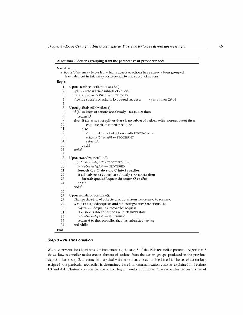
Chapter 4 - Erro! Use a guia Início para aplicar Titre 1 ao texto que deverá aparecer aqui. 89
Algorithm 2: Actions grouping from the perspective of provider nodes
Variable actionSetState: array to control which subsets of actions have already been grouped. Each element in this array corresponds to one subset of actions
Begin
1:
2: 3: 4: 5: 6:
7: 8: 9:
10: 11: 12: 13: 14: 15: 16: 17: 18: 19: 20: 21: 22: 23: 24: 25: 26: 27: 28: 29: 30: 31: 32: 33: 34:
Upon startReconciliation(maxRec):
Split LR into maxRec subsets of actions Initialize actionSetState with PENDING Provide subsets of actions to queued requests //as in lines 29-34 Upon getSubsetOfActions(): if (all subsets of actions are already PROCESSED) then
return Ø else if (LR is not yet split or there is no subset of actions with PENDING state) then
enqueue the reconciler request else A ← next subset of actions with PENDING state actionSetState[Aid] ← PROCESSING return A endif endif Upon storeGroups(G, Aid): if (actionSetState[Aid] ≠ PROCESSED) then actionSetState[Aid] ← PROCESSED
foreach Gi ∈ G do Store Gi into LR endfor if (all subsets of actions are already PROCESSED) then foreach queuedRequest do return Ø endfor endif endif Upon redistributionTime(): Change the state of subsets of actions from PROCESSING to PENDING
while (∃ queuedRequests and ∃ pendingSubsetsOfActions) do request ← dequeue a reconciler request A ← next subset of actions with PENDING state actionSetState[Aid] ← PROCESSING return A to the reconciler that has submitted request endwhile
End
Step 3 – clusters creation
We now present the algorithms for implementing the step 3 of the P2P-reconciler protocol. Algorithm 3 shows how reconciler nodes create clusters of actions from the action groups produced in the previous step. Similar to step 2, a reconciler may deal with more than one action log (line 1). The set of action logs assigned to a particular reconciler is determined based on communication costs as explained in Sections 4.3 and 4.4. Clusters creation for the action log LR works as follows. The reconciler requests a set of

90 Chapter 4 - Erro! Use a guia Início para aplicar Titre 1 ao texto que deverá aparecer aqui.
groups (G) from the LR provider (line 2) and, for each group Gi belonging to G (line 5), it checks depen-dencies among couples of actions (lines 6-21). Actions that are completely independent of others remain alone in a cluster (lines 7-12) while related actions are put in a common cluster (lines 13-21). Every time an action is inserted in a cluster, the associated action membership is created (lines 9-11 and 18-19). In addition, system-defined constraints are created to represent action dependencies discovered in this step (lines 14-17). All action memberships, constraints, and clusters produced for the set of groups G are then stored at the corresponding providers (lines 24-25). At the end of clusters creation for G, the reconciler requests another set of groups (line 26) and repeats step 3. Similar to step 2, reconciler nodes remain executing step 3 while provider nodes have sets of groups to supply.
Algorithm 3: Clusters creation from the perspective of reconciler nodes
Input L: set of action logs that node n can access with acceptable costs
Begin
1: 2: 3: 4: 5: 6: 7: 8: 9:
10: 11: 12: 13: 14: 15: 16: 17: 18: 19: 20: 21: 22: 23: 24: 25: 26: 27: 28:
foreach LR ∈ L do G ← provider(LR).getGroups(null)
while G ≠ ∅ do
C ← ∅, AM ← ∅ foreach Gi ∈ G do foreach ak ∈ Gi do Let Cj be the cluster of which ak is member if (ak is not yet member of a cluster) then Create Cj as { ak }
C ← C ∪ Cj
AM ← AM ∪ { (ak, Cj) } endif foreach al ∈ Gi, where l ≠ k do type ← application.checkDependency(ak, al) if (type ≠ commutative) then
ct ← (ak, al, type)
CT ← CT ∪ { ct } am ← (al, Cj)
AM ← AM ∪ { am } endif endfor endfor endfor provider(AS).storeMembershipsAndConstraints(AM, CT, Gid) provider(CS).storeClusters(C, Gid) G ← provider(LR).getGroups(Gid) endwhile endfor
End

Chapter 4 - Erro! Use a guia Início para aplicar Titre 1 ao texto que deverá aparecer aqui. 91
Algorithm 4: Clusters creation from the perspective of provider nodes
Variables groupSetState: array to control which sets of groups have already been clustered membAndConstStored: array to control which memberships/constraints have already been stored in AS clustersStored: array to control which clusters have already been stored in CS
Begin
1: 2: 3: 4: 5:
6: 7: 8: 9:
10: 11: 12: 13: 14: 15: 16: 17: 18: 19: 20: 21: 22: 23: 24: 25: 26: 27: 28: 29: 30: 31: 32: 33: 34: 35: 36: 37: 38: 39:
Upon startReconciliation(maxRec): //n locally stores the value of maxRec Upon storeGroups(G, Aid): if (all subsets of actions are already PROCESSED) then Create maxRec sets of groups using LR groups Initialize groupSetState with PENDING
Provide sets of groups to queued requests //as in lines 23-28 endif Upon getGroups(Gid):
if (Gid ≠ null) then groupSetState[Gid] ← PROCESSED endif
if (all sets of groups are already PROCESSED) then foreach queuedRequest do return Ø endfor return Ø else if (sets of groups are not created or there is no set of groups with PENDING state) then
enqueue the reconciler request else G ← next set of groups with PENDING state groupSetState[Gid] ← PROCESSING return G endif endif Upon resdistributionTime(): Change the state of sets of groups from PROCESSING to PENDING
while (∃ queuedRequests and ∃ pendingSetsOfGroups) do request ← dequeue a reconciler request G ← next set of groups with PENDING state groupSetState[Gid] ← PROCESSING return G to the reconciler that has submitted request endwhile Upon storeMembershipsAndConstraints(AM, CT, Gid): if (not membAndConstStored[Gid]) then membAndConstStored[Gid] ← true
foreach am ∈ AM do Store am into AS endfor
foreach ct ∈ CT do Store ct into AS endfor endif Upon storeClusters(C, Gid): if (not clustersStored[Gid]) then clustersStored[Gid] ← true foreach Cj ∈ C do Store Cj into CS endfor endif
End

92 Chapter 4 - Erro! Use a guia Início para aplicar Titre 1 ao texto que deverá aparecer aqui.
Algorithm 4 shows how the provider nodes work in the third step of the P2P-reconciler protocol. Three types of providers are involved: action log providers (e.g. LR, LT), the action summary provider (AS), and the clusters set provider (CS). At the beginning of reconciliation, all providers receive the max-imum number of reconcilers (maxRec) from the node that launches the reconciliation (line 1).
An action log provider, in particular, performs the following activities: at the beginning of step 3 (i.e. when all subsets of actions become grouped), the action log provider divides its action groups into ma-xRec sets of groups and distributes these sets of groups to reconciler nodes (lines 3-7); it also manages requests for sets of groups by putting these requests into a queue, if necessary, similarly to the previous step (lines 9-20); finally, an action log provider monitors the sets of groups not yet clustered in order to redistribute them to other reconcilers in subsequent cycles, if necessary, also similarly to step 2 (lines 5, 9, 16-18, and 22-28). Notice however that in step 3 the reconciler node includes Gid (the identifier of the set of groups that it has just clustered) in the request for a new subset of groups in order to acknowledge the successful processing of G to the action log provider (lines 8-9).
The action summary provider stores action memberships and constraints received from the reconciler nodes into AS reconciliation object and discards duplicated requests, if any exists (lines 29-34).
Similarly, the clusters set provider stores clusters received from the reconciler nodes into CS reconcil-iation object and discards duplicated requests, if any exists (lines 35-39).
Step 4 – clusters extension
We now present the algorithms for implementing the step 4 of the P2P-reconciler protocol. Algorithm 5 shows how a reconciler node extends clusters of actions produced in the previous step. Initially, the re-conciler retrieves the set of user-defined constraints UDC from the action summary (line 1). This task runs in parallel with steps 2 and 3. After that, the reconciler performs clusters extensions as follows. First, it requests a set of clusters C from the clusters set provider (line 2). Then, for each cluster Ci belonging to C, the reconciler determines a set of actions A that conflicts with actions in Ci according to the user-defined constraints (lines 5-7). Afterwards, each conflicting action in A is added to Ci and the correspond-ing action membership is created (lines 8-12). Finally, the action memberships produced in this step are stored in the action summary provider (line 15) and the extended clusters are stored in the clusters set provider (line 16). At the end of clusters extension for C, the reconciler requests another set of clusters (line 17) and repeats step 4. Similar to steps 2 and 3, reconciler nodes remain executing step 4 while the clusters set provider remains supplying sets of clusters.
Algorithm 6 shows how the provider nodes work in the fourth step of the P2P-reconciler protocol. Two provider nodes are involved: the clusters set provider (CS) and the action summary provider (AS). Recall that at the beginning of reconciliation, all provider nodes receive the maximum number of reconci-lers (maxRec) from the node that launches the reconciliation (line 1).
The clusters set provider performs the following activities: at the beginning of step 4 (i.e. when all sets of groups become clustered), it divides its clusters into maxRec sets of clusters and distributes these sets to reconciler nodes (lines 3-8); the clusters set provider also manages requests for sets of clusters by putting these requests into a queue, if necessary, similarly to the previous steps (lines 10-20 and 35-37); it stores extended clusters received from the reconciler nodes into CS reconciliation object and discards duplicated requests, if any exists (lines 31-34); finally, the clusters set provider monitors the sets of clus-ters not yet extended in order to redistribute them to other reconcilers in subsequent cycles, if necessary, also similarly to steps 2 and 3 (lines 6, 16-18, 22-29, and 32-33).

Chapter 4 - Erro! Use a guia Início para aplicar Titre 1 ao texto que deverá aparecer aqui. 93
The action summary provider stores action memberships received from the reconciler nodes into AS reconciliation object and discards duplicated requests, if any exists (lines 40-44).
Algorithm 5: Clusters extension from the perspective of reconciler nodes
Variable UDC: set of user defined constraints stored in the AS reconciliation object
Function CA(a, UDC): returns a set of conflicting actions wrt. a according to constraints in UDC
Begin
1: 2: 3: 4: 5: 6: 7: 8: 9:
10: 11: 12: 13: 14: 15: 16: 17: 18:
UDC ← provider(AS).getUserDefinedConstraints() C ← provider(CS).getClusters() while C ≠ ∅ do AM ← ∅ foreach Ci ∈ C do foreach ak ∈ Ci do A ← CA(ak, UDC)
foreach al ∈ A do
Ci ← Ci ∪ { al } am ← (al, Ci)
AM ← AM ∪ { am } endfor endfor endfor provider(AS).storeMemberships(AM, Cid) provider(CS).storeExtendedClusters(C, Cid) C ← provider(CS).getClusters() endwhile
End

94 Chapter 4 - Erro! Use a guia Início para aplicar Titre 1 ao texto que deverá aparecer aqui.
Algorithm 6: Clusters extension from the perspective of provider nodes
Variables clusterSetState: array to control which sets of clusters have already been extended membershipStored: array to control which memberships have already been stored in AS
Begin
1: 2: 3: 4: 5: 6: 7: 8: 9:
10: 11: 12: 13: 14: 15: 16: 17: 18: 19: 20: 21: 22: 23: 24: 25: 26: 27: 28: 29: 30: 31: 32: 33: 34: 35: 36: 37: 38: 39: 40: 41: 42: 43: 44:
Upon startReconciliation(maxRec): // n locally stores the value of maxRec Upon storeClusters(C, Gid): if (all sets of groups are already PROCESSED) then Create maxRec sets of clusters using CS clusters Initialize clusterSetState with PENDING, and membershipStored with false Provide sets of clusters to queued requests //as in lines 24-29 endif Upon getClusters(): if (all sets of clusters are already PROCESSED) then
return Ø else if (sets of clusters are not created or there is no set of clusters with PENDING state) then enqueue the reconciler request else C ← next set of clusters with PENDING state clusterSetState[Cid] ← PROCESSING return C endif endif Upon resdistributionTime(): Change the state of sets of clusters from PROCESSING to PENDING
while (∃ queuedRequests and ∃ pendingSetsOfClusters) do request ← dequeue a reconciler request C ← next set of clusters with PENDING state clusterSetState[Cid] ← PROCESSING return C to the reconciler that has submitted request endwhile Upon storeExtendedClusters(C, Cid):
if (clusterSetState[Cid] ≠ PROCESSED) then clusterSetState[Cid] ← PROCESSED
foreach Cj ∈ C do Store Cj into CS endfor
if (all sets of clusters are already PROCESSED) then foreach queuedRequest do return Ø endfor end-if endif Upon storeMemberships(AM, Cid): if (not membershipStored[Cid]) then membershipStored[Cid] ← true
foreach am ∈ AM do Store am into AS endfor endif
End

Chapter 4 - Erro! Use a guia Início para aplicar Titre 1 ao texto que deverá aparecer aqui. 95
Step 5 – clusters integration
We now present the algorithms for implementing the step 5 of the P2P-reconciler protocol. Algorithm 7 shows how a reconciler node integrates extended clusters that overlap. First, the reconciler requests a set of memberships MBS from the action summary provider (line 1). Each membership of this set (noted mbs) is a data structure containing an action identifier ak and an array of clusters identifiers (noted cid) to which ak belongs. Thus, for each membership mbs, if the action mbs.ak is member of more than one clus-ter (i.e. mbs.cid.size() > 1), then mbs.ak causes the overlap of all clusters referred in cid and, as a result, all these clusters are requested to be integrated (lines 4-9). For optimization reasons, we integrate two clus-ters Ci and Cj by creating a new cluster Ck whose content is the identifiers of Ci and Cj (i.e. Ck = {Ci
id, Cj
id}). Thus, the reconciler node requests the clusters set provider for creating such new clusters (line 10). At the end of clusters integration for MBS, the reconciler requests another set of memberships (line 11) and repeats step 5. Similar to steps 2, 3, and 4, reconciler nodes remain executing step 5 while the action summary provider remains supplying sets of memberships.
Algorithm 7: Clusters integration from the perspective of reconciler nodes
Variables cid: array of clusters identifiers
mbs: data structure containing ak (action identifier) and cid (array of clusters to which ak belongs) MBS: set of mbs, i.e. set of actions and their memberships MBSid: MBS’ identifier ir: integration request formatted as (Ciid, Cjid) IR: set of integration requests
Begin
1: 2: 3: 4: 5: 6: 7: 8: 9:
10: 11: 12:
MBS ← provider(AS).getActionMemberships(null)
while MBS ≠ ∅ do
IR ← ∅ foreach mbs ∈ MBS do for i = 1 to (mbs.cid.size() – 1) do ir ← (mbs.cid[i-1], mbs.cid[i])
IR ← IR ∪ { ir } endfor endfor provider(CS).integrateClusters(IR, MBSid) MBS ← provider(AS).getActionMemberships(MBSid) endwhile
End
Algorithm 8 shows how the provider nodes work in the fifth step of the P2P-reconciler protocol. Two
provider nodes are involved: the action summary provider (AS) and the clusters set provider (CS). The general behavior of provider nodes in this step is similar to the previous steps. It means that maxRec is locally stored (line 1); action memberships are divided into sets of memberships at the beginning of the step (lines 3-8) and distributed to reconcilers in successive cycles (lines 6-7, 11, and 25-32); requests for sets of memberships are managed by using a queue (lines 12-23 and 27-32); and duplicated requests for integrating extended clusters, if any exists, are discarded (lines 34-38).

96 Chapter 4 - Erro! Use a guia Início para aplicar Titre 1 ao texto que deverá aparecer aqui.
Algorithm 8: Clusters integration from the perspective of provider nodes
Variables MBS: set of actions and their memberships
MBSid: MBS’ identifier IR: set of integration requests membershipSetState: array to control which sets of memberships have already produced irs integrationSetProcessed: array to control which clusters integrations have already been done in CS
Procedure integrateClusters(IR): integrates clusters according to Algorithm 9
Begin
1: 2: 3: 4: 5:
6: 7: 8: 9:
10:
11: 12: 13: 14: 15:
16: 17: 18: 19: 20:
21: 22: 23: 24: 25: 26: 27: 28: 29: 30: 31: 32: 33: 34: 35: 36: 37: 38:
Upon startReconciliation(maxRec): //n locally stores the value of maxRec Upon storeMemberships(AM, Cid): if (all sets of clusters are already PROCESSED) then Create maxRec sets of action memberships using AS memberships Initialize membershipSetState with PENDING, and integrationSetProcessed with false Provide sets of memberships to queued requests //as in lines 27-32 endif Upon getActionMemberships(MBSid):
if (MBSid ≠ null) then membershipSetState[MBSid] ← PROCESSED endif
if (all sets of memberships are already PROCESSED) then foreach queuedRequest do return Ø endfor return Ø else if (sets of memberships are not yet created or
there is no set of memberships with PENDING state) then enqueue the reconciler request else MBS ← next set of memberships with PENDING state membershipSetState[MBSid] ← PROCESSING return MBS endif
endif Ø
Upon resdistributionTime():
Change the state of sets of memberships from PROCESSING to PENDING
while (∃ queuedRequests and ∃ pendingSetsOfMemberships) do request ← dequeue a reconciler request
MBS ← next set of memberships with PENDING state membershipSetState[MBSid] ← PROCESSING return MBS to the reconciler that has submitted request endwhile Upon integrateClusters(IR, MBSid): if (not integrationSetProcessed[MBSid]) then integrationSetProcessed[MBSid] ← true integrateClusters(IR) endif
End

Chapter 4 - Erro! Use a guia Início para aplicar Titre 1 ao texto que deverá aparecer aqui. 97
An interesting aspect of this step is how to deal with duplicated requests for integrating clusters when they concern different sets of memberships. For instance, consider that ai and aj belong to both clusters Ck and Cl (i.e. AM ⊂ {(ai, Ck) (a
i, Cl) (aj, Ck) (a
j, Cl)}). Consider also that two different reconcilers n1 and n2 take the associated memberships in order to integrate clusters (e.g. n1 takes (ai, [Ck, Cl]) and n2 takes (aj, [Ck, Cl])). According to Algorithm 7, n1 requests the integration of Ck and Cl as well as n2 does. Although both requests have the same objective, they concern distinct sets of memberships and, consequently, they are not evaluated as duplicated in line 35 of Algorithm 8. To deal with this problem, we implement the integrateClusters procedure (line 37) as shown in Algorithm 9.
Algorithm 9: Procedure integrateClusters(IR)
Variable ir: integration request formatted as (Ciid, Cjid)
Begin
1: 2: 3: 4: 5: 6: 7: 8: 9:
10: 11: 12: 13: 14: 15: 16: 17: 18: 19: 20: 21: 22: 23: 24: 25: 26: 27: 28: 29:
foreach ir ∈ IR do Ci ← the cluster stored in CS whose identifier is equal to ir.Ciid Cj ← the cluster stored in CS whose identifier is equal to ir.Cjid if (Ci.container ≠ Cj.container or Ci.container = null) then Create Ck if (Ci.container = null) then Ck.clusters ← Ck.clusters ∪ { Ciid } Ci.container ← Ckid else Ci’ ← the cluster identified by Ci.container Ck.clusters ← Ck.clusters ∪ Ci’.clusters
foreach Clid ∈ Ci’.clusters do Cl.container ← Ckid endfor endif if (CJ.container = null) then Ck.clusters ← Ck.clusters ∪ { CJid } CJ.container ← Ckid else CJ’ ← the cluster identified by CJ.container Ck.clusters ← Ck.clusters ∪ CJ’.clusters
foreach Clid ∈ CJ’.clusters do Cl.container ← Ckid endfor endif Insert Ck into CS endif endfor
End
The principle of our solution is to efficiently realize that the integration required by a request r2 is al-
ready satisfied due to the execution of a previous request r1, and then discard r2. Two clusters Ci and Cj are already integrated if they belong to the same container cluster, e.g. Ck. In this case, any subsequent request for integrating Ci and Cj can be immediately discarded. However, if Ci and Cj belong to distinct

98 Chapter 4 - Erro! Use a guia Início para aplicar Titre 1 ao texto que deverá aparecer aqui.
container clusters (e.g. Ci.container = Ck and Cj.container = Cl) or Ci and Cj are not associated with con-tainers (i.e. Ci.container = null and Cj.container = null), then they are not integrated and the correspond-ing request must be processed. Thus, the integrateClusters procedure (Algorithm 9) works as follows. It receives as input a set of integration requests IR and, for each request ir belonging to IR (line 1), it checks whether ir may be discarded or not (lines 2-4). If the integration request ir must be processed, a new clus-ter Ck is created (line 5) to be the container of ir.Ci and ir.Cj. Afterwards, Ci is included in Ck (lines 6-15) as well as Cj (lines 17-26), such that all references between container and contained clusters are consis-tent. Finally, Ck is inserted into the clusters set reconciliation object (line 27).
Step 6 – clusters ordering
We now present the algorithms for implementing the step 6 of the P2P-reconciler protocol. Algorithm 10 shows how a reconciler node orders integrated clusters of actions. Initially, the reconciler requests a set of integrated clusters C from the clusters set provider (line 1). Then, the reconciler orders each cluster Ci belonging to C (line 4) as follows. First, the reconciler estimates the schedule weight associated with Ci (line 5); the larger the number of actions from Ci in the schedule, the larger the schedule weight asso-ciated with Ci. Afterwards, the reconciler produces various tentative schedules from Ci (lines 6-24) and selects the best one, i.e. the schedule with the highest weight (lines 19-22), to compose the final global schedule (line 25). The production of tentative schedules for Ci stops when a solution whose schedule weight is greater than or equal to the estimated weight is found, or after a predefined number of attempts (lines 5-8 and 18-23). Finally, the reconciler stores the ordered actions into the schedule provider (line 27). At the end of clusters ordering for C, the reconciler requests another set of integrated clusters (line 28) and repeats step 6. Similar to steps 2, 3, 4, and 5, reconciler nodes remain executing step 6 while the clusters set provider remains supplying sets of integrated clusters.
Two aspects of Algorithm 10 deserve more details: how to estimate the schedule weight (line 5) and how to identify the action with the highest merit in a cluster (line 12). Both issues depend on the concept of action weight. Each action is associated with a value called weight that indicates its importance in the application context. By default, all actions are equally important and then have weight 1. The merit of scheduling an action a belonging to the cluster Ci is the sum of weights of all other actions in Ci that can be scheduled after a without violating constraints. For estimating the best schedule weight associated with Ci, we represent Ci as a graph in which vertices are actions and there is a directed arc from the vertex ai to aj if the insertion of ai in the schedule enforces the removal of aj. Our goal is then to eliminate the mini-mum number of vertices such that the graph becomes completely disconnected. We achieve this goal by eliminating with priority the vertices whose actions have lower merits.
Algorithm 11 shows how the provider nodes work in the sixth step of the P2P-reconciler protocol. Two provider nodes are involved: the clusters set provider (CS) and the schedule provider (S). The gener-al behavior of provider nodes in this step is similar to the previous steps. It means that maxRec is locally stored (line 1); integrated clusters are divided into sets of integrated clusters at the beginning of the step (lines 3-8) and these sets are distributed to reconcilers in successive cycles (lines 6-7, 19-21, and 25-32); requests for sets of integrated clusters are managed by using a queue (lines 10-23 and 27-32); and dupli-cated requests for storing ordered actions in the schedule reconciliation object, if any exists, are discarded (lines 34-38).

Chapter 4 - Erro! Use a guia Início para aplicar Titre 1 ao texto que deverá aparecer aqui. 99
Algorithm 10: Clusters ordering from the perspective of reconciler nodes
Input maxAttempts: maximum number of attempts to find the best ordering for a cluster
Variables esw: estimated schedule weight (the schedule weight is the sum of the schedule actions’ weights) rsw: real schedule weight bestRsw: the best rsw found SCHi: schedule obtained from Ci bestSCHi: the best schedule corresponding to Ci SCH: concatenation of schedules corresponding to various clusters
Operator
⊕: concatenation
Functions ESW(Ci): returns the estimated schedule weight for the best schedule of Ci CONFLICT(a, Ci): returns the set of actions in Ci that conflicts with a based on constraints
Begin
1: 2: 3: 4: 5: 6: 7: 8: 9:
10: 11: 12: 13: 14: 15: 16: 17: 18: 19: 20: 21: 22: 23: 24: 25: 26: 27: 28: 29:
C ← provider(CS).getIntegratedClusters(null)
while C ≠ ∅ do
SCH ← ∅ foreach Ci ∈ C do esw ← ESW(Ci) bestRsw ← -∞ attempts ← 0 while (bestRsw < esw and attempts < maxAttempts) do SCHi ← null
Cj ← Ci repeat a ← the action with the highest merit in Cj SCHi.insert(a) Cj ← Cj \ { a } A ← CONFLICT(a, Cj) Cj ← Cj \ A
until (Cj = ∅) rsw ← SCHi.weight() if (rsw > bestRsw) then bestRsw ← rsw bestSCHi ← SCHi endif attempts ← attempts + 1 endwhile
SCH ← SCH ⊕ bestSCHi endfor provider(S).storeOrderedActions(SCH, Cid) C ← provider(CS).getIntegratedClusters(Cid) Endwhile
End

100 Chapter 4 - Erro! Use a guia Início para aplicar Titre 1 ao texto que deverá aparecer aqui.
Algorithm 11: Clusters ordering from the perspective of provider nodes
Variables MBS: set of actions and their memberships MBSid: MBS’ identifier IR: set of integration requests SCHi: schedule obtained from Ci SCH: concatenation of schedules corresponding to various clusters clusterSetState: array to control which sets of integrated clusters have already been ordered
Begin
1: 2:
3: 4: 5: 6: 7: 8: 9:
10: 11: 12: 13: 14: 15: 16: 17: 18: 19: 20: 21: 22: 23: 24: 25: 26: 27: 28: 29: 30: 31: 32: 33: 34: 35: 36: 37: 38:
Upon startReconciliation(maxRec): //n locally stores the value of maxRec Upon integrateClusters(IR, MBSid): if (all sets of memberships are already PROCESSED) then Create maxRec sets of integrated clusters using CS integrated clusters Initialize clusterSetState with PENDING
Provide sets of integrated clusters to queued requests //as in lines 27-32 endif Upon getIntegratedClusters(Cid):
if (Cid ≠ null) then clusterSetState[Cid] ← PROCESSED endif if (all sets of integrated clusters are already PROCESSED) then
foreach queuedRequest do return Ø endfor return Ø else if (sets of integrated clusters are not yet created or there is no set of integrated clusters with PENDING state) then enqueue the reconciler request else C ← next set of integrated clusters with PENDING state clusterSetState[Cid] ← PROCESSING return C endif
endif Ø
Upon resdistributionTime(): Change the state of sets of integrated clusters from PROCESSING to PENDING
while (∃ queuedRequests and ∃ pendingSetsOfIntegratedClusters) do
request ← dequeue a reconciler request C ← next set of integrated clusters with PENDING state clusterSetState[Cid] ← PROCESSING
return C to the reconciler that has submitted request endwhile Upon storeOrderedActions(SCH, Cid): if (clusterSetState[Cid] ≠ PROCESSED) then clusterSetState[Cid] ← PROCESSED foreach SCHi ∈ SCH do Store SCHi into S endfor endif
End

Chapter 4 - Erro! Use a guia Início para aplicar Titre 1 ao texto que deverá aparecer aqui. 101
4.2.3 P2P-reconciler at work
In this section, we illustrate the execution of the P2P-reconciler protocol with multiple replicated objects over a Chord DHT network. For simplicity, and without loss of generality, we consider only 2 objects (T and U), the first 3 steps of the protocol, and a few nodes at work. Figure 32 shows 12 nodes and their respective roles in the reconciliation protocol. All of them are replica nodes. Reconciliation objects are stored at provider nodes according to the hashed values associated with the reconciliation object identifi-ers (e.g. Chord maps a hashed value v to the first node that has an identifier equal to or greater than v in the circle of ordered node identifiers). In this example, we assume that Chord maps the hashed values of the action log identifiers to nodes 1 (action log U) and 15 (action log T); using the same principle, the schedule, the clusters set, and the action summary are mapped respectively to nodes 7, 8, and 0. Finally, node 9 is responsible for allocating reconcilers.
Figure 32. P2P-reconciler at work. Any node can start the reconciliation by triggering the step 1 of P2P-reconciler at the appropriate
node (e.g. node 9), which selects the best reconcilers and notifies them of the steps they should perform. In our example, node 9 selects nodes 2 and 13 to execute step 2, nodes 5 and 12 to perform step 3, and nodes 6 and 10 to run step 4 (details about node allocation are provided in Section 4.4).
Nodes 2 and 13 start the step 2 of reconciliation by retrieving actions from the action logs (stored at nodes 1 and 15) in order to arrange them in groups of actions on common object items. Data flows be-longing to step 2 are represented by solid lines in Figure 32. At the same time, nodes 5 and 12 begin step 3 by requesting action groups from nodes 1 and 15, respectively; these requests are held in queues at nodes 1 and 15 while action groups are under construction. When the action groups associated with repli-cas T and U are stored at the corresponding action logs, the requests for groups, previously queued, can be replied, and the step 3 can proceed. In Figure 32, dashed lines represent data flows belonging to step 3. In this step, reconcilers 5 and 12 take groups from the action logs U and T, respectively, and produce in parallel the associated clusters that are stored at node 8. As a result of clusters storage, step 4 can proceed.
1
5
8 9
12
13
15
Action Summary
Action Log U
Reconciler (Step 2)
Reconciler (Step 3)
Node Allocation
Action Log T
7
10
Reconciler (Step 3)
Schedule
Groups
Actions
2
Actions
Groups
Groups Groups
Clusters
Clusters Set
6
0
Reconciler (Step 4)
Reconciler (Step 4)
Reconciler (Step 2)

102 Chapter 4 - Erro! Use a guia Início para aplicar Titre 1 ao texto que deverá aparecer aqui.
Thus node 8 replies requests for clusters that nodes 6 and 10 have previously queued. And so forth, until the end of step 6.
Notice that each reconciler works on independent data (e.g. when executing step 4, nodes 6 and 10 receive distinct clusters from node 8). To assure this independence, provider nodes segment the data they hold based on the maximum number of reconcilers, noted maxRec (e.g. node 8 creates maxRec subsets of clusters).
We now explain how P2P-reconciler deals with conflicting actions involving multiple replicated ob-jects. Our solution assumes that a copy of an action that updates multiple objects is stored at every asso-ciated action log (recall that there is an action log for each object). For clarity, we demonstrate our ap-proach using an example. Let oi represent an object item, where o denotes the replicated object to which the object item belongs, and i is the object item identifier (e.g. t1 is the object item 1 belonging to the replicated object T). In addition, let an
i.OI denote the set of object items updated by the action ani (e.g.
ani.OI = {t1, u1} means that action an
i updates the object items t1 and u1). Finally, consider that actions a11,
a21, and a3
1 should be reconciled, where: a11.OI = {t1}, a2
1.OI = {t1, u1}, and a31.OI = {u1}. For simplicity,
we assume that updates on the same object item are in conflict. In this scenario, the action log T (noted LT) holds a1
1 and a copy of a21 since both actions try to update
T (i.e. LT = {a11, a2
1}). Similarly, the action log U (noted LU) holds a copy of a21, and the action a3
1 be-cause both actions try to update U (i.e. LU = {a2
1, a31}). In order to demonstrate that our solution works
properly with multiple replicated objects, we have to show that P2P-reconciler puts the 3 actions of our example into the same cluster, and, as a result, these actions are ordered together.
In step 2 (actions grouping), node 13 takes {a11, a2
1} from LT and creates the group Gt1 = {a11, a2
1} by hashing the identifier of the updated object items from T (in this case, both actions update t1). In parallel, and using the same approach, node 2 takes {a2
1, a31} from LU and produces Gu1 = {a2
1, a31} by hashing
the identifier of the updated object items from U (in this case, both actions update u1). In step 3 (clusters creation), node 12 takes the group Gt1 and produces the cluster C1 = {a1
1, a21} as
a11 and a2
1 are in conflict; in addition, node 12 inserts the following memberships in the action summary: {(a1
1, C1), (a21, C1)}. In parallel, and using the same approach, node 5 takes the group Gu1 and produces
the cluster C2 = {a21, a3
1}; it also inserts the following memberships in the action summary: {(a21, C2),
(a31, C2)}. Notice that at the end of step 3 the action a2
1 is member of the clusters C1 and C2 (see the memberships in bold) due to a conflict on t1 (detected by node 12) and another on u1 (detected by node 5).
In step 5 (clusters integration) the reconciler that receives a21’s memberships from the action sum-
mary (i.e. {(a21, C1), (a2
1, C2)}) realizes that a21 causes an overlap between C1 and C2; then, the reconciler
brings together these clusters, producing C3 = C1 ∪ C2 = {a11, a2
1, a31}. Therefore, at this point we can
claim that P2P-reconciler works properly with multiple replicated objects. Notice in Figure 32 that the increase on the number of replicated objects leads to the increase on the
parallelism of steps 2 and 3 as the associated data flows (actions and groups) involve distinct reconciler nodes (e.g. replica T involves nodes 12, 13, and 15 whereas replica U involves nodes 1, 2, and 5). In con-trast, steps 4, 5, and 6 do not profit from the increase on the number of replicated objects since all clusters are stored together at node 8 as well as all memberships are stored at node 0. Experimental results show that the scalability of P2P-reconciler is not hurt by this feature because it works with an optimal number of reconcilers. However, in a future work we intend to study possible improvements on reconciliation performance by fragmenting the clusters set and the action summary reconciliation objects. In this ap-proach, we plan to assign a unique identifier to every fragment in order to store them at distinct provider nodes. There is a trade-off associated with this fragmentation: as we increase the number of fragments we

Chapter 4 - Erro! Use a guia Início para aplicar Titre 1 ao texto que deverá aparecer aqui. 103
reduce the load of provider nodes, but, on the other hand, we augment the number of network messages needed to retrieve data from reconciliation objects.
4.2.4 Dealing with nodes’ dynamic behavior
The dynamic behavior of nodes, which frequently join and leave the P2P network, could lead to the fol-lowing problems: (1) no guarantees that all replicas eventually converge to the same state as several nodes do not participate of reconciliation; and (2) abnormal end of reconciliation due to a large number of disconnections or system failures during reconciliation. In this subsection, we explain how P2P-reconciler deals with both problems.
Algorithm 12: Replica synchronization
Variables H: schedule history reconciliation object, noted H = [S1id, S2id, …, Skid] Slid: identifier of the last schedule locally applied at the replica node sidList: ordered list of schedule identifiers SCH: a complete schedule produced by reconciling conflicting actions
localLogs: set of local action logs (e.g. localLogs = {LR’, LT’, LU’, …}) UDC: set of user defined constraints locally stored in the replica node
Functions H.SUCCESSOR(Slid): returns the sub-list of schedule identifiers that succeed Slid in H ID(log): returns the identifier of the reconciliation object corresponding to log
Begin
1: 2: 3: 4: 5: 6: 7: 8: 9:
10: 11: 12:
sidList ← provider(H).SUCCESSOR(Slid) Sid ← sidList.first() while Sid ≠ null do SCH ← provider(Sid).getSchedule() Apply actions belonging to SCH to local replicas Sid ← sidList.next() endwhile
foreach log ∈ localLogs do Lid ← ID(log) provider(Lid).storeActions(log) endfor provider(AS).storeUserDefinedConstraints(UDC)
End
We first discuss how to assure replica convergence. Whenever distributed reconciliation takes place,
a new global schedule is produced and it should be applied by all nodes in order to update their local replicas and assure data consistency. However, some nodes cannot immediately apply the global schedule because either they are disconnected or they do not know that a new schedule is available (e.g. they do not participate of reconciliation). To solve this problem, we must assure that all nodes eventually update its local replicas. Another problem concerns actions and constraints produced by disconnected nodes and not yet stored in the P2P network. We must assure that all actions are eventually reconciled by taking into account all associated constraints.

104 Chapter 4 - Erro! Use a guia Início para aplicar Titre 1 ao texto que deverá aparecer aqui.
Our solution relies on a new reconciliation object called schedule history and noted H, which stores a chronological sequence of schedule identifiers produced by successive reconciliations (H = [S1
id, …, Sk
id]). Replicas held by a replica node n are up to date if the identifier of the last schedule locally executed at n is equal to Sk
id. P2P-reconciler assures replica convergence by enforcing replica nodes to frequently synchronize their
replicas. Replica synchronization consists of applying schedules and storing local actions in the P2P net-work. Replica nodes are free for performing replica synchronization whenever they wish, but this is au-tomatically enforced at every connection and disconnection. Algorithm 12 shows how replica synchro-nization works. Each node locally stores the identifier of the last schedule it has locally executed (noted Sl
id). In addition, every node knows the schedule history’s unique identifier. Thus, whenever a node n disconnects or reconnects, it proceeds as follows: (1) n retrieves from the schedule history provider an ordered list of schedule identifiers that succeed Sl
id in H (line 1); (2) for each schedule identifier Sid in this list, n retrieves the associated schedule SCH from the provider node that holds Sid and applies actions of SCH to the local replicas (lines 2-7); (3) actions locally produced by n and not yet stored in the P2P net-work are put into the corresponding action logs for later reconciliation (lines 8-11); (4) user-defined con-straints locally produced by n and not yet stored in the P2P network are also put into the action summary (line 12).
Algorithm 13: Handling reconciliation crash in the node that launches the reconciliation
Input ROID: set of reconciliation object identifiers, except the H identifier
Variables H: schedule history reconciliation object, noted H = [S1id, S2id, …, Skid] Sk+1id: identifier of the schedule that will be produced during reconciliation kw: keyword produced by n and used to delegate unlock and extend_ttl operations ttl: stands for time-to-live and determines the duration of the lock
Begin
1: 2: 3: 4:
5: 6: 7: 8:
Upon startReconciliation(): Sk+1id ← provider(H).lock(n, kw, ttl) if (Sk+1id ≠ null) then //Lock is granted; no other schedule is being produced Compute maxRec
foreach roid ∈ ROID do provider(roid).startReconciliation(maxRec, Sk+1id, kw) endfor Select and notify reconciler nodes provider(H).reconciliationSuccessfullyStarted() endif
End
We now explain how to cope with abnormal end of reconciliation. The principle of our solution is to
assure an exclusive reconciliation at a time by taking advantage of the lock ability property of the APPA’s PDM service (for details on this property see Chapter 3). In addition, we automatically undo updates on reconciliation objects in case of abnormal end so that new attempts of reconciliation can be launched after recovery. We assume synchronous network communication for the subset of messages that cannot be lost in our protocol.
Only the node that launches the reconciliation (noted nstart) and provider nodes are concerned for handling a reconciliation crash. Algorithm 13 shows how P2P-reconciler deals with reconciliation crash from the perspective of nstart. Whenever nstart launches reconciliation the startReconciliation event is lo-

Chapter 4 - Erro! Use a guia Início para aplicar Titre 1 ao texto que deverá aparecer aqui. 105
cally raised (line 1). As a result, nstart immediately tries to lock the schedule history in order to assure exclusive execution of reconciliation (line 2). If the H state is UNLOCKED (i.e. there is no reconciliation in progress), then the lock in granted (H’s state becomes LOCKED) and the H provider produces a new sche-dule identifier, noted Sk+1
id, which is returned to nstart. Otherwise, nstart receives null as reply. Thus, if the lock is granted (line 3), nstart computes the number of reconcilers (line 4), informs provider nodes that reconciliation is starting (line 5), allocates the reconciler nodes (line 6), and finally notifies H provider that reconciliation has successfully started (line 7). If this notification does not reach the H provider in an appropriate delay, it infers that reconciliation inception has failed and proactively unlocks H.
Algorithm 14 shows how P2P-reconciler deals with reconciliation crash from the perspective of pro-vider nodes. These nodes perform the following activities: save a few of information for undoing updates on reconciliation objects in case of failure; detect the abnormal end of reconciliation; undo updates as a result of reconciliation crash; and unlock the schedule history whatever the end of reconciliation (i.e. normal or abnormal). We describe such activities in the following.
− Preparing to undo updates: each provider node must save some information at the beginning of
reconciliation in order to be able to undo the reconciliation updates over reconciliation objects, if ne-cessary. For instance, the clusters set provider should know which clusters were produced during re-conciliation in order to eliminate these clusters in case of abnormal end. Thus, the node that launches the reconciliation notifies all provider nodes of the reconciliation inception by raising the event star-tReconciliation (line 1) with parameters maxRec (number of reconcilers), Sk+1
id (identifier of the schedule that will be produced), and kw (keyword for unlocking H). As a result, each provider node locally stores Sk+1
id (line 2) and prepares the recovery of the reconciliation objects it holds (line 3). Since reconciliation objects are placed in the DHT according to the hashed value of their identifiers, each provider node usually holds only one reconciliation object.
− Detecting reconciliation crash: by assuming a highly available DHT, we are not concerned with failures at provider nodes. Therefore, only failures at reconciler nodes or the node that launches the reconciliation (nstart) may cause a reconciliation crash. If nstart fails before ending the start procedure, it does not notify the successful reconciliation inception to the H provider, i.e. the event reconcilia-tionSuccessfullyStarted (line 5) is not raised, and then the H’s state does not change from LOCKED to RECONCILING (line 6). In this case, the reconciliation crash will be detected by the H provider when it realizes that the estimated reconciliation time has expired (event endReconciliationTime at line 8) and the H’s state has not changed (line 9). On the other hand, if nstart succeeds, H’s state becomes RECON-
CILING (lines 5-6) and we are sure that the reconciliation has successfully started. In this case, if the reconciliation crashes, this means that all reconciler nodes allocated to a step i of the P2P-reconciler protocol have failed before the end of step i, and then the crash is detected by a provider node that supplies data sets for reconcilers at step i. The provider node detects the abnormal end of reconcilia-tion by realizing that there are data sets to be distributed (lines 14-15), but there are neither queued requests (line 16) nor alive reconcilers (lines 19 and 21) to take these data sets. The absence of recon-cilers is detected as follows. The variable reconcilersWereAlive receives false at the beginning of each distribution cycle (line 20); during the cycle, this variable receives true each time a reconciler takes a data set (lines 17-18 and 27-28); so, at the end of the cycle, if reconcilersWereAlive remains false, this means that no data set was taken during the cycle, and then the provider node realizes the crash.

106 Chapter 4 - Erro! Use a guia Início para aplicar Titre 1 ao texto que deverá aparecer aqui.
Algorithm 14: Handling reconciliation crash from the perspective of provider nodes
Variables RO: set of reconciliation objects locally stored ROID: set of reconciliation object identifiers, except the H identifier H: schedule history reconciliation object, noted H = [S1id, S2id, …, Skid] SCH: concatenation of schedules corresponding to various clusters reconcilersWereAlive: indicates whether reconcilers were alive in the previous cycle kw: keyword needed for unlocking H or extending the lock’s ttl
Begin
1: 2: 3: 4: 5:
6: 7: 8: 9:
10:
11: 12: 13: 14: 15: 16: 17: 18: 19: 20: 21: 22: 23: 24: 25: 26: 27: 28: 29: 30: 31: 32: 33: 34: 35: 36: 37:
Upon startReconciliation(maxRec, Sk+1id, kw):
ROID ← ROID ∪ { Sk+1id }
foreach ro ∈ RO do ro.prepareForUndo() endfor
Upon reconciliationSuccessfullyStarted(): Assign RECONCILING to H’s state
Upon endReconciliationTime(): if (H is locked) then
foreach roid ∈ ROID do provider(roid).cancelReconciliation(Sk+1id) endfor H.undo(Sk+1id) endif
Upon redistributionTime(): Change the state of data sets from PROCESSING to PENDING
if (∃ queuedRequests) then
reconcilersWereAlive ← true Reply queued requests with pending data sets else if (reconcilersWereAlive) then reconcilersWereAlive ← false else
foreach roid ∈ ROID do provider(roid).cancelReconciliation(Sk+1id) endfor provider(H).cancelLock(Sk+1id, kw) endif endif Upon getDataSet(): reconcilersWereAlive ← true Upon cancelReconciliation(Sk+1id):
foreach ro ∈ RO do ro.undo(Sk+1id) endfor Upon cancelLock(Sk+1id, kw):
if (Sk+1id = H.lastSchedule() and kw = H.lockKeyword()) then H.undo(Sk+1id) endif Upon storeOrderedActions(SCH, Cid): if (all sets of integrated clusters are already PROCESSED) then provider(H).unlock(kw) endif
End

Chapter 4 - Erro! Use a guia Início para aplicar Titre 1 ao texto que deverá aparecer aqui. 107
− Recovering reconciliation objects: this operation consists of cleaning request queues and undoing the updates performed on reconciliation objects by the reconciliation that has just crashed. It is ex-ecuted whenever nstart (lines 10-11) or a provider node (lines 22-23) detects a reconciliation crash. Consider now the very unlikely, but possible, situation in which nstart and a provider node detects the crash at the same time. In this case, both nodes launch the recovery mechanism in parallel. We allow discarding duplicated messages for recovering by providing the schedule identifier Sk+1
id as parameter for the undo procedures (lines 11 and 30-34).
− Unlocking schedule history: if reconciliation succeeds, the schedule provider unlocks H (lines 36-37); otherwise, the recovery mechanism assures such unlock (lines 11 and 23). Notice that in case of crash, the H’s unlock is the last operation to be carried out (lines 10-11 and 22-23).
4.3 DHT cost model
A DHT network is usually built on top of the Internet, which consists of nodes with variable latencies and bandwidths. As a result, the network costs involved in DHT data accesses may vary significantly from node to node and have a strong impact in the reconciliation performance. Thus, network costs should be considered to perform reconciliation efficiently. In this section, we propose a basic cost model for compu-ting communication costs in DHTs. On top of it, we can build customized cost models (e.g. in Section 4.4 we elaborate a customized cost model for selecting reconciler nodes to P2P-reconciler).
In the basic cost model, we define communication costs (henceforth costs) in terms of latency and transfer times, and we assume links with variable latencies and bandwidths. In order to exploit bandwidth, the application behavior in terms of data transfer should be known. Since this behavior is application-specific, we exploit bandwidth in higher-level customized models.
Most DHT data access operations consist of a lookup, for finding the address of the node n that holds the requested information, followed by direct communication with n [HHLT+03]. In the lookup step, several hops may be performed according to nodes’ neighborhoods. Therefore, our DHT cost model relies on three metrics: lookup cost, direct cost, and transfer cost. The lookup cost, noted lc(n, id), is the latency time spent in a lookup operation launched by node n to find the data item identified by id. Similarly, di-rect cost, noted dc(ni, nj), is the latency time spent by node ni to directly access nj. And the transfer cost, noted tc(ni, nj, d), is the time spent to transfer the data item d from node ni to node nj, which is computed based on d’s size and the bandwidth between ni and nj.
4.3.1 Lookup cost
Lookup costs change dynamically as nodes join and leave the P2P network. In this subsection, we show how to compute lookup costs and deal with dynamic changes.
Node n could easily compute the lookup cost lc(n, id) by executing the lookup operation and measur-ing the associated time. However, this approach overloads the node that replies the lookup operation as it receives a lot of lookup messages. Furthermore, the network is overloaded. To avoid these problems, we propose that each node computes its lookup costs incrementally, by taking advantage of cost information held by its neighbors. With this approach, a node n only keeps the lookup costs to a few of identifiers (i.e.

108 Chapter 4 - Erro! Use a guia Início para aplicar Titre 1 ao texto que deverá aparecer aqui.
one identifier for each reconciliation object); in addition, n keeps the direct costs to a few of nodes (i.e. n’s neighbors). It would be unfeasible and not recommendable to keep information about the full identifi-er space or all nodes. Our approach is feasible because in a DHT a node n looks for an identifier id by communicating with the n’s neighbor that is closest to id.
We illustrate our solution with an example. In Figure 33a, let n4 be a node that replies lookup opera-tions searching for id=x; let arrows indicate the route of a lookup operation (e.g. if n2 looks for x it makes this route: n2 → n3 → n4); let a number over an arrow be the latency between the associated nodes. In this example, the lookup cost lc(n2, x) is 100 (i.e. 40 + 60), and lc(n1, x) is 150 (i.e. 50 + 40 + 60). Instead of executing the lookup operation to compute lc(n1, x), n1 can ask n2 for lc(n2, x) and add to this cost the latency between n1 and n2 (i.e. lc(n1, x) = lc(n2, x) + 50). The advantage of this incremental approach is locality and to avoid network overload.
Figure 33. Computing lookup costs Joins and leaves change the neighborhoods of nodes and, accordingly, the routes of lookup messages.
As a result, lookup costs must be refreshed. However, we should avoid the refreshment at distant nodes to avoid network overload. To cope with this problem, we introduce two definitions.
− Cost limit: it is the maximal acceptable cost for looking up an identifier. The meaning of acceptable
cost relies on the application on top of DHT. For instance, in the case of P2P-reconciler, which se-lects a subset of replica nodes to proceed as reconciler nodes, it is not acceptable that the lookup cost of a particular reconciler overtakes the average lookup cost of the P2P network as a whole, because the number of reconcilers is usually very smaller than the number of replica nodes.
− Relevant joins and leaves: a join or leave is relevant for a node n if it changes the cost for looking up an identifier in which n is interested, such that the old or the new lookup cost does not overtake cost limit. Nodes refresh their lookup costs only in the presence of relevant joins and leaves.
We illustrate our approach for refreshing lookup costs with an example. In Figure 33b, let cost limit be 110; and consider that n5 joins the DHT of Figure 33a taking the place of n3 in the route towards id=x. The join of n5 is relevant only to n2 as n2 updates lc(n2, x) from 100 (a value that does not overtake cost limit) to 120. In contrast, the join of n5 is not relevant to n3 and n4 since the associated lookup costs re-main unchanged. This join is not relevant to n1 either, because both, the old lookup cost (i.e. 150) and the new one (i.e. 170), overtake cost limit. Thus, n1, n3 and n4 do not participate in the refresh operation.
(b)
n1 n2 n3 n4 50
80
60
lc(n1,x)=170 lc(n2,x)=120 40
Cost Limit = 110 n5
n1 n2 n3 n4 50 40 60
(a)
lc(n1,x)=150 lc(n2,x)=100

Chapter 4 - Erro! Use a guia Início para aplicar Titre 1 ao texto que deverá aparecer aqui. 109
4.3.2 Direct cost
Direct costs change dynamically as nodes join and leave the P2P network. In this subsection, we show how to compute direct costs and deal with dynamic changes.
We first define home(id) as the provider node that holds the identifier id. The direct cost dc(n, home(id)) represents the latency time spent by node n to directly access home(id). This cost can be exact-ly computed or estimated. With the exact approach, n measures the latency between n and home(id). In contrast, with the estimated approach, n measures the latencies between n and a subset of nodes and then computes the corresponding average value, which represents the estimated latency between n and home(id). The exact approach is precise, but it can overload home(id) as it becomes a central point of access for a lot of nodes. On the other hand, the estimated approach does not rely on accessing home(id), thereby avoiding its overload, but it is not precise. We compare both approaches in the validation chapter.
Notice that the estimated approach requires a subset of nodes to estimate the latency between n and home(id). This subset should be n’s neighbors for DHTs whose neighborhoods do not rely on physical distances among nodes (e.g. Chord) since, in this case, estimation is not biased and the information needed is already available at n (cost zero). However, if the DHT is location-aware, i.e. n’s neighbors are closer to n than other nodes (e.g. CAN with design improvements), the use of n’s neighbors would lead to a biased estimation. Thus, in this case, the subset of nodes should be randomly selected from a bootstrap list (list of nodes that are likely connected).
Joins and leaves may change the home(id). Thus, direct costs must also be refreshed. In our solution, dc(n, home(id)) is refreshed at node n whenever home(id) changes and the associated lookup cost (i.e. lc(n, id)) is smaller than cost limit. To compute the refreshed value, we use the same strategy employed for computing the initial value. The principle of this approach is to avoid the execution of refreshment operations at far distant nodes, and its advantage is to avoid network overload.
4.3.3 DHT cost management
In this section, we present a detailed algorithm for implementing the APPA’s Communication Cost Man-agement service (CCM) in the context of DHT networks. This algorithm keeps up to date the lookup and direct costs for accessing reconciliation objects in DHT while takes into account the dynamic behavior of nodes. It is based on the CCM framework that was introduced in Chapter 3, i.e. the CCM service uses the ICcmApplication interface to notify the Replication service of cost changes, which, in turn, uses the ICcmService interface to retrieve refreshed data access costs from the CCM service.
The main activities that a node n must perform to manage costs are: compute the initial values of loo-kup and direct costs when n joins the P2P network; detect neighborhood changes and, accordingly, re-fresh n’s costs as well as propagate them; and refresh n’s costs based on propagated changes that reach n. Node n performs these activities by dealing with three types of events that are shown in Algorithm 15 and described in the following:
− join(): whenever n connects to the P2P network, the join event happens (line 1). As a result, for each
reconciliation object ro identified by roid that the P2P-reconciler protocol uses, n computes lc(n, roid), i.e. the lookup cost to find home(roid), and also dc(n, home(roid)), i.e. the direct cost to access home(roid) (lines 2-6).

110 Chapter 4 - Erro! Use a guia Início para aplicar Titre 1 ao texto que deverá aparecer aqui.
Algorithm 15: Managing dynamic DHT costs
Input costLimit: maximal acceptable cost for looking up an identifier ROID: set of reconciliation object identifiers, except H
Variables n’: array of nodes that are neighbors of n c: index in n’ of the neighbor that has changed due to a join or leave
roid: reconciliation object identifier lkpCosts: array of lookup costs for node n dirCosts: array of direct costs for node n
Functions LAT(n, n’[i]): returns the latency between the node n and its neighbor n’[i] ROM(n’[c]): returns the set of roid that have been moved to or removed from n’[c] due to a join or leave PRED(n, roid): returns the set of nodes that directly route lookup(roid) requests to n
Begin
1: 2: 3: 4: 5: 6: 7: 8: 9:
10: 11: 12: 13: 14: 15: 16: 17: 18: 19: 20: 21: 22: 23: 24: 25: 26: 27: 28: 29: 30: 31: 32: 33:
Upon join():
foreach roid ∈ ROID do i ← the index of the n’s neighbor that is closest to roid lkpCosts[*roid] ← n’[i].lkpCosts[*roid] + LAT(n, n’[i])
dirCosts[*roid] ← estimate dc(n, home(roid)) endfor Upon neighborChange(c):
foreach roid ∈ ROID that n accesses by routing lookup requests to n’[c] do lkpCosts[*roid] ← n’[c].lkpCosts[*roid] + LAT(n, n’[c])
if (roid ∈ ROM(n’[c]) and lkpCosts[*roid] ≤ costLimit) then dirCosts[*roid] ← estimate dc(n, home(roid)); refreshDirCost ← true else refreshDirCost ← false endif ICcmApplication.costChange()
foreach np ∈ PRED(n, roid) do np.costChange(roid, lkpCosts[*roid], refreshDirCost) endfor endfor Upon costChange(roid, lkpCost, refreshDirCost): if (cost change is relevant) then
i ← the index of the n’s neighbor that is closest to roid lkpCosts[*roid] ← lkpCost + LAT(n, n’[i])
if (refreshDirCost and lkpCosts[*roid] ≤ costLimit) then
dirCosts[*roid] ← estimate dc(n, home(roid)) endif ICcmApplication.costChange()
foreach np ∈ PRED(n, roid) do np.costChange(roid, lkpCosts[*roid], refreshDirCost) endfor endif
End

Chapter 4 - Erro! Use a guia Início para aplicar Titre 1 ao texto que deverá aparecer aqui. 111
− neighborChange(c): whenever a neighbor of n changes due to a join, leave, or failure, the event neighborChange happens indicating which entry of the n’s routing table was affected, i.e. c (line 8). If n looks for some reconciliation object by routing lookup operations through its neighbor n’[c], cost refreshment must take place. Thus, for each reconciliation object accessed through n’[c] and identi-fied by roid (line 9), n first refreshes the associated lookup cost and, if necessary, n also refreshes the associated direct cost (lines 10-15). Recall that the direct cost for accessing home(roid) should be re-freshed only if home(roid) changes and the lookup cost lc(n, roid) is less than or equal to cost limit. Second, n notifies the application on top of DHT that the cost has changed (line 16). Finally, n propa-gates the refreshed lookup cost lc(n, roid) to the nodes that directly route requests lookup(roid) to n. In this propagation, n also indicates whether the direct cost for accessing home(roid) should be refreshed (lines 17-20).
− costChange(roid, lkpCost, refreshDirCost): this event happens when node n receives a message
whose purpose is to notify that costs associated with roid have changed due to a join or leave (line 22). Node n handles this event as follows. If this join or leave is relevant, as defined in Section 4.3.1, n recalculates lookup and direct costs associated with roid (lines 23-28), notifies the application on top of the DHT that the cost has changed (line 29), and proceeds a new propagation cycle (lines 30-32). The propagation stops at nodes that judge the join or leave irrelevant.
Notice that Algorithm 15 deals with communication costs at the DHT level, i.e. only lookup and di-rect costs are concerned. Transfer costs, which are application-specific, are managed by the application on top of DHT.
4.4 P2P-reconciler node allocation
The first step of P2P-reconciler aims to select the best replica nodes to proceed as reconcilers in order to maximize performance. The number of reconcilers has a strong impact on the reconciliation time. Thus, this section concerns the estimation of the optimal number of reconcilers per step as well as the allocation of the best nodes. We first present how to determine the maximal number of reconciler nodes. Then, we introduce the P2P-reconciler cost model for computing the cost of each reconciliation step. Next, we describe how the cost provider node selects reconcilers based on P2P-reconciler cost model. Afterwards, we present our approach for managing the dynamic behavior of P2P-reconciler costs. Finally, we provide detailed algorithms for implementing node allocation based on dynamic communication costs.
4.4.1 Determining the number of reconcilers
At the beginning of reconciliation, a subset of replica nodes must be allocated to P2P-reconciler steps in order to proceed as reconciler nodes. This allocation is dynamic as it depends on the reconciliation con-text (i.e. number of actions to be reconciled, network properties, etc.). Since P2P-reconciler is distributed and parallel, we can increase the number of reconciler nodes to reduce the reconciliation time. However, as we increase the number of reconcilers we also increase the number of exchanged messages and the work performed by provider nodes. As a result, beyond a given bound, increasing the number of reconci-

112 Chapter 4 - Erro! Use a guia Início para aplicar Titre 1 ao texto que deverá aparecer aqui.
lers yields the opposite effect: the reconciliation time augments. In order to compute this bound, that represents the maximal number of reconcilers per step, we perform the following activities.
− First, we configure the reconciliation context by setting up some parameters (e.g. number of actions,
number of connected replica nodes, number of reconciler nodes, minimal and maximal network la-tencies, network bandwidths), and then we simulate reconciliation several times, taking as a result a reconciliation sample. For each simulation, we change the topology of the physical and overlay net-works or the set of actions to be reconciled or both, always respecting the parameters’ values. A si-mulation runs locally in a single node. An important aspect is that only network communication is simulated (everything else is done by the actual P2P-reconciler protocol).
− Second, we search an equation y = f(x) that describes the reconciliation behavior by performing a polynomial regression [KKMN98] with sample’s data. This equation allows us to forecast the recon-ciliation time of any reconciliation in the same context. The independent variable x is the number of reconciler nodes whereas the dependent variable y is the reconciliation time.
− Third, we compute the derivative equation y’ = f’(x); this derivative equation enables us to find which value of x produces the minimal value of y. The point (x, y) where y is minimal is called minimal point.
− Finally, we calculate the minimal point, which represents the number of reconcilers that minimizes the reconciliation time in the given context.
The larger the number of actions to be reconciled and the higher the network speed are, the larger the maximal number of reconcilers per step. We now illustrate our approach to compute the number of recon-cilers per step by means of an example. The reconciliation context considered is: 10,000 actions on aver-age, a network with 1Mbps of bandwidth and 150ms of latency, and 1024 connected replica nodes. Figure 34 shows a sample corresponding to this context. A point (x, y) in the graph represents the reconciliation time (y) obtained with a given allocation (x). The curve in the graph is described by the equation 1.
F(x) = -0.026x
3 + 0.985x2 – 6.740x + 70.803 (1)
Equation 1 was computed by means of a polynomial regression. Once the curve is determined, we
want to know whether it aids in predicting y, and if so, to what extent. A measure that helps to answer this question is the correlation coefficient (r in Figure 34), which indicates the degree of association between the variables in the model (i.e. x and y). A perfect correlation is denoted by r = 1. The standard error (S in Figure 34) evaluates the variability of sample values, and it is used to compute r. Since the correlation coefficient of our equation is quite close to 1, we know that this equation is appropriate to describe the reconciliation behavior.
Notice that the x value for the minimal point is situated between 0 and 5. In order to compute the ex-act value of x in this point, we first calculate the derivative equation f’(x) based on equation 1, i.e.:
f’(x) = – 0.078x2 + 1.970x – 6.740 (2)

Chapter 4 - Erro! Use a guia Início para aplicar Titre 1 ao texto que deverá aparecer aqui. 113
Since f’(x) (equation 2) is a second-order polynomial, the curve described by f(x) has exactly one mi-nimal point and one maximal point, which correspond to the roots of f’(x). By computing these roots, we find x1 = 4.08 (the minimal point), and x2 = 21.18 (the maximal point). Thus, the number of reconciler nodes per step that minimizes the time for reconciling 10,000 actions using a 1Mbps network with 150ms of latency is 4 (i.e. x1 rounded). This value becomes the maximal number of reconcilers per step.
Notice that the only information needed to compute the maximal number of reconcilers per step is the equation y’ = f’(x); after determining this equation, sample’s data are disposable. Therefore, in order to obtain this equation, a node n proceeds as follows. First, n requests the equation’s coefficients from its neighbors. If no neighbor can provide this information, n locally produces a reconciliation sample and compute the associated equation, which is stored at n for future reuse.
S = 4.23744298r = 0.99229281
Number of reconciler nodes per step
Rec
onci
liati
on T
ime
(s)
0 5 10 15 20 2540.0
60.0
80.0
100.0
120.0
140.0
Figure 34. Polynomial regression for 10,000 actions Algorithm 16 shows how the node that starts the reconciliation, noted nstart, computes the maximal
number of reconcilers per step (i.e. maxRec). First, nstart looks for an existing equation that corresponds to the input context (lines 1-3). If such equation is not found (line 4), nstart produces a set of action logs and a set of P2P networks, and then simulates the reconciliation several times by combining these logs and networks while varies the number of reconcilers (lines 5-16). The sample resulting of these simulations is used in a polynomial regression for computing an equation that corresponds to the input context. This equation and the associated context are saved for future use (lines 17-18). Finally, the maxRec is calcu-lated as the minimal point of the equation that describes the reconciliation behavior in the input context (line 21).

114 Chapter 4 - Erro! Use a guia Início para aplicar Titre 1 ao texto que deverá aparecer aqui.
Algorithm 16: Computation of maxRec
Input context: context of the reconciliation, which is composed of numActions, actAvgSize, netBw, netLat numActions: number of actions to be reconciled in the form of an interval
actAvgSize: average size of actions to be reconciled netBw: network bandwidth in the form of an interval netLat: network latency in the form of an interval interval: min and max representing respectively the minimum and maximum values of a range
Variables n’: array of nodes that are neighbors of nstart numRec: number of reconciler nodes allocated for each step of a simulated reconciliation t: time to reconcile a set of actions with the associated constraints equation: composed data item containing degree and an array of coefficients (noted coefficient[i]) CTEQ: set of pairs (context, equation), where equation describes the reconciliation behavior under context LOG: set of action logs, each log containing numActions actions with average size actAvgSize NET: set of networks, each one with distinct latencies and bandwidths RS: set of pairs (numRec, t) that makes up a reconciliation sample
Functions EQ(context, CTEQ): returns the equation associated with context in CTEQ or null (if none exists) MINPOINT(equation): returns the minimal point of equation FINDEQ(context, n’): returns an equation that matches context from one of the nstart’s neighbors or null PL(numActions, actAvgSize): produces a set of action logs, each one containing numActions actions PN(netLat, netBw): produces a set of networks, each one with distinct latencies and bandwidths POLREG(RS): performs a polynomial regression on RS and returns the associated equation RECONCILE(log, net, numRec): returns the time to reconcile log over the net with numRec reconcilers
Begin
1: 2: 3: 4: 5: 6: 7: 8: 9:
10: 11: 12: 13: 14: 15: 16: 17: 18: 19: 20: 21: 22:
equation ← EQ(context, CTEQ) if (equation = null) then equation ← FINDEQ(context, n’) if (equation = null) then LOG ← PL(numActions, actAvgSize) NET ← PN(netLat, netBw)
RS ← ∅ foreach log ∈ LOG do foreach net ∈ NET do for i ← 0 to 6 do numRec ← 2i t ← RECONCILE(log, net, numRec)
RS ← RS ∪ { (numRec, t) } endfor endfor endfor equation ← POLREG(RS)
CTEQ ← CTEQ ∪ { (context, equation) } endif endif maxRec ← MINPOINT(equation) return maxRec
End

Chapter 4 - Erro! Use a guia Início para aplicar Titre 1 ao texto que deverá aparecer aqui. 115
4.4.2 P2P-reconciler cost model
The P2P-reconciler cost model is built on top of the DHT cost model by taking into account each recon-ciliation step and defining a new metric: node step cost. The node step cost, noted cost(i, n), is the sum of lookup, direct access, and transfer costs estimated by node n for executing step i of P2P-reconciler proto-col. By analyzing the P2P-reconciler behavior in terms of lookup, direct access, and data transfer opera-tions at every step, we produced a cost formula for each step of P2P-reconciler, which are shown in Table 12. There is no formula associated with step 1, because it is not performed by reconciler nodes.
Step i Cost(i, n)
2 lc(n, LR) + 2×dc(n, nLR) + tc(nLR, n, actSet) + lc(n, LR) + dc(n, nLR) + tc(n, nLR, grpSet)
3 lc(n, LR) + 3×dc(n, nLR) + tc(nLR, n, grpSet) + lc(n, CS) + 2×dc(n, nCS) +
tc(n, nCS, [cluSet + cluIds]) + lc(n, AS) + dc(n, nAS) + tc(n, nAS, [sdcSet + m3Set])
4 lc(n, CS) + 3×dc(n, nCS) + tc(nCS, n, cluSet) + 2×lc(n,AS) + 3×dc(n, nAS) + tc(n, nAS, m4Set)
5 lc(n, AS) + 3×dc(n, nAS) + tc(nAS, n, mSet) + lc(n, CS) + dc(n, nCS) + tc(n, nCS, ovlCluSet)
6 lc(n, CS) + 3×dc(n, nCS) + tc(nCS, n, itgCluSet) + lc(n, AS) + 2×dc(n, nAS) +
tc(nAS, n, sumActSet) + lc(n, S) + dc(n,nS) + tc(n, nS, ordActSet)
Table 12. P2P-reconciler cost model As an example, let us explain cost(2, n). In the second step of P2P-reconciler (i=2), node n takes ac-
tions from the action log R (LR) and arranges them in groups of actions that try to update common object items; these groups are stored at LR. Thus, the first term in the associated formula (lc(n,LR)) represents the lookup cost for finding LR provider. The second term (2×dc(n,nLR)) corresponds to the direct costs for taking actions from LR provider (request and reply). The third term (tc(nLR, n, actSet) stands for the trans-fer cost of the action set from nLR to n. The fourth term (lc(n,LR)) represents the lookup cost for finding again LR provider. The fifth term (dc(n,nLR)) corresponds to the direct cost for storing groups in LR pro-vider (only request). And the last term (tc(n, nLR, grpSet)) stands for the transfer cost of the action groups produced in this step from n to nLR. Similarly, all formulas can be explained.
4.4.3 Nodes allocation
Node allocation is the first step of P2P-reconciler protocol. It aims to select for every succeeding step a set of reconciler nodes that can perform reconciliation with good performance. In this subsection, we define a new reconciliation object needed in node allocation, we describe how reconciler nodes are cho-sen, and we illustrate that with an example.
We define communication costs, noted CC, as a reconciliation object that stores the node step costs estimated by every replica node and used to choose reconcilers before starting reconciliation. The node in DHT that holds CC at a given time is called cost provider, and it is responsible for allocating reconcilers. The allocation works as follows. Replica nodes locally estimate the costs for executing every P2P-reconciler step, according to the P2P-reconciler cost model, and provide this information to the cost pro-vider. The node that starts reconciliation computes the maximal number of reconcilers per step (maxRec), as described in Section 4.4.1, and asks the cost provider for allocating at most maxRec reconciler nodes

116 Chapter 4 - Erro! Use a guia Início para aplicar Titre 1 ao texto que deverá aparecer aqui.
per P2P-reconciler step. As a result, the cost provider selects the best nodes for each step and notifies these nodes of the P2P-reconciler steps they should execute.
In our solution, the cost management is done in parallel with reconciliation. Moreover, it is network optimized since replica nodes do not send messages to cost provider, informing their estimated costs, if the node step costs overtake the maximal acceptable costs obtained base on cost limit. For these reasons, the cost provider does not become a bottleneck.
DHT costs per node
Reconciliation objects
LR AS CS S
lc(n0, id) 0 685 1085 1036 dc(n0, home(id)) 43 162 222 218
lc(n1, id) 832 0 1361 1069
dc(n1, home(id)) 163 282 193 185
lc(n2, id) 974 1101 0 1483 dc(n2, home(id)) 146 28 351 351
lc(n3, id) 1159 729 976 0 dc(n3, home(id)) 163 283 183 175
Table 13. Lookup and direct costs based on the DHT cost model. Each column holds a reconciliation object and each cell provides a specific lookup or direct cost (e.g. the cell in the 1st line and 2nd column indicates that n0 spends 685ms to lookup AS whereas the cell in the 2nd line and 2nd column indicates that a direct access between n0 and home(AS) costs 162ms.
We now illustrate the allocation algorithm using an example. Table 13 shows the lookup and direct
costs of 4 nodes belonging to a Chord DHT network [SMKK+01] with 1024 connected nodes. In a DHT, a node that is close to a reconciliation object (e.g. n0 is close to LR) may be far distant of others (e.g. n0 is far distant of CS and S). As a result, a node that is suitable for a P2P-reconciler step may not be worth in other steps. For this reason, every P2P-reconciler step has its own set of reconcilers.
Table 14 presents the transfer costs associated with the same nodes of Table 13. For simplicity, we assumed in this example that all links between reconciler nodes and provider nodes have 1Mbps of band-width. The sizes of transferred data items are estimated based on the number of actions to be reconciled, the average action size, and the number of reconciler nodes.
Data item Description Size (Mbits) Cost (ms) actSet Set of actions 1.202 1202 grpSet Set of action groups 0.343 343 cluSet Set of clusters 0.336 336 cluIds Clusters’ identifiers 0.120 120 sdcSet Set of system-defined constraints 0.343 343 m3Set Set of memberships (produced at step 3) 0.801 801 m4Set Set of memberships (produced at step 4) 0.183 183 mSet Set of all memberships 0.435 435 ovlCluSet Set of overlapping clusters 0.336 336 itgCluSet Set of integrated clusters 0.267 267 sumActSet Set of summary actions 4.166 4166 ordActSet Set of ordered actions 0.305 305
Table 14. Transfer costs with 1Mbps of bandwidth

Chapter 4 - Erro! Use a guia Início para aplicar Titre 1 ao texto que deverá aparecer aqui. 117
Table 15 shows the estimated costs that the cost provider receives from the replica nodes. These costs
are computed by applying on the P2P-reconciler cost model (Table 12) the lookup and direct costs of the DHT cost model (Table 13) and the transfer costs (Table 14). We show in bold the less expensive cost associated with each P2P-reconciler step. Thus, in our example, if the maximal number of reconcilers per step is 1, the cost provider selects as reconciler for each P2P-reconciler step the node of Table 15 whose cost is in bold (i.e. Step2 = {n0}, Step3 = {n0}, Step4 = {n1}, Step5 = {n2}, Step6 = {n3}), and notifies its decision to these nodes.
Nodes P2P-reconciler steps (i)
2 3 4 5 6
n0 1674 4449 4126 3249 8752
n1 3698 5294 3305 3171 8496
n2 3931 5187 3858 2307 8782
n3 4352 5946 4351 3508 7733
Table 15. Node step costs
4.4.4 Reconciliation cost management
The costs estimated by replica nodes for executing P2P-reconciler steps change as a result of disconnec-tions and reconnections. To cope with this dynamic behavior and assure reliable cost estimations, a repli-ca node ni works as follows:
− Initialization: whenever ni joins the system, ni estimates its costs for executing every P2P-reconciler
step. If these costs do not overtake the maximal acceptable costs obtained based on cost limit, ni sup-plies the cost provider with this information.
− Refreshment: while ni is connected, the join or leave of another node nj may invalidate ni’s estimated costs due to routing changes. Thus, if the join or leave of nj is relevant to ni, ni recomputes its P2P-reconciler estimated costs and refreshes them at the cost provider.
− Termination: when ni leaves the system, if the cost provider holds ni’s estimated costs (this happens if ni’s costs are smaller than the maximal acceptable costs obtained based on cost limit), ni notifies its departure to the cost provider.
P2P-reconciler computes the cost limit based on these parameters: the expected average latency of the network (e.g. 150ms for the Internet), and the expected average number of hops to lookup a reconcili-ation object (e.g. log(N)/2 for a Chord DHT, where N represents the number of connected nodes and can be established as 15% of the community size).

118 Chapter 4 - Erro! Use a guia Início para aplicar Titre 1 ao texto que deverá aparecer aqui.
4.4.5 Algorithms for cost-based node allocation
In this section, we present detailed algorithms for implementing the step 1 of the P2P-reconciler protocol. As previously discussed, this step consists of determining the optimal number of reconciler nodes based on the reconciliation context, and then selecting the best reconcilers according to communication costs, which change dynamically as nodes join and leave the network. Thus, node allocation involves replica nodes, which are responsible for estimating reconciliation costs as well as launching reconciliation, and the cost provider, which holds cost estimates and chooses reconcilers. For clarity reasons, we divide node allocation algorithms into two viewpoints: that of replica nodes and that of cost provider. In practice, any node in the P2P network can behave as replica node or cost provider.
Algorithm 17 shows the allocation of reconciler nodes from the perspective of replica nodes. The main activities of a replica node n are: estimating reconciliation costs for each step of P2P-reconciler; refreshing these costs according to dynamic changes on the network topology; removing n’s estimated costs from the cost provider on n departure in order to avoid the allocation of n while it is disconnected; starting reconciliation; and executing the reconciliation steps to which n is allocated. Node n performs these activities by dealing with five types of events that are described in the following:
− join(): this event happens whenever a replica node n connects to the P2P network (line 1). As a re-
sult, n estimates its reconciliation costs for each step of the P2P-reconciler and, if at least one cost is acceptable, n informs its costs to the cost provider node (lines 2-5). Algorithm 18 presents in details how to estimate reconciliation costs.
− ICcmApplication.costChange(): this event is raised by the APPA’s CCM service whenever it de-tects a relevant join, leave or failure (line 7). Recall that changes in the DHT topology may cause changes in communication costs. The replica node n handles this event by re-estimating its reconcil-iation costs (lines 8-9) and, if relevant changes have occurred, by refreshing its cost information at provider node (lines 10-15). Notice that cost changes are not propagated in this algorithm. Indeed, it is the APPA’s CCM service (Algorithm 15) that looks after cost changes propagation.
− leave(): this event takes place whenever a replica node n properly disconnects from the P2P network (line 17). In this case, if n realizes that the cost provider holds information about n’s reconciliation costs, n removes this information from the cost provider (lines 18-20). Node n can also disconnect from the P2P network due to a failure. However, we do not provide a special event handler for re-freshing costs held by the cost provider in the presence of node failures, because our solution natural-ly copes with this problem as follows. If n is a faulty node and the cost provider selects n as reconci-ler, it will realize that n is not connected when trying to notify n of its allocation; in this case, the cost provider replaces n by another node and removes n’s cost estimates (see Algorithm 19 that shows the cost provider perspective). When n reconnects, n refreshes its reconciliation costs by handling the join() event.
− startReconciliation(): this event occurs whenever reconciliation is launched at node n (line 22). As a result, n tries to lock the schedule history in order to assure exclusive execution (line 23). If the lock is granted (line 24), n records the identifier of the schedule that will be produced (line 25), computes the number of reconcilers (line 26), notifies the beginning of reconciliation to provider nodes (line

Chapter 4 - Erro! Use a guia Início para aplicar Titre 1 ao texto que deverá aparecer aqui. 119
27), requests cost provider for allocating reconciler nodes (line 28), and finally notifies the H provid-er that the reconciliation has successfully started (line 29).
− reconcile(allocation): this event is raised by the cost provider for notifying the node n that it is se-lected as reconciler (line 31). The parameter allocation indicates which steps of P2P-reconciler n should perform. Node n then executes reconciliation steps according to allocation (line 32).

120 Chapter 4 - Erro! Use a guia Início para aplicar Titre 1 ao texto que deverá aparecer aqui.
Algorithm 17: Allocation of reconciler nodes from the perspective of replica nodes
Input costLimit: maximal acceptable cost for looking up an identifier ROID: set of reconciliation object identifiers, except H and CC identifiers
Variables i: identifier of a reconciliation step allocation: array of reconciliation steps to which node n is allocated as reconciler nsc: node step costs, which is composed of node and stpCosts node: identifier of a replica node stpCosts : matrix of costs to execute each P2P-reconciler step according to node estimates CC: communication costs reconciliation object kw: keyword produced by n and used to delegate unlock and extend_ttl operations ttl: stands for time-to-live and determines the duration of the lock
Functions ERC(ROID): estimate reconciliation costs for each step of P2P-reconciler and returns nsc MAC(costLimit, i): returns the maximal acceptable cost for step i of P2P-reconciler based on costLimit
Begin
1: 2: 3: 4: 5: 6: 7: 8:
9: 10: 11: 12:
∃13: 14: 15: 16:
17: 18:
∃19:
20: 21: 22: 23: 24:
25: 26: 27: 28: 29:
30: 31: 32:
Upon join(): nsc ← ERC(ROID) //ERC is described in Algorithm 18
if (∃ nsc.stpCosts[i, j] ≤ MAC(costLimit, i)) then //at least one step cost is acceptable provider(CC).updateReconciliationCosts(nsc) endif Upon ICcmApplication.costChange(): nsc’ ← nsc nsc ← ERC(ROID)
if (∃ nsc.stpCosts[i, j] ≤ MAC(costLimit, i)) then //at least one acceptable cost in nsc provider(CC).updateReconciliationCosts(nsc)
else if (∃ nsc’.stpCosts[i, j] ≤ MAC(costLimit, i)) then //the cost provider holds n’s costs
provider(CC).removeReconciliationCosts(n) endif endif Upon leave():
if (∃ nsc.stpCosts[i, j] ≤ MAC(costLimit, i)) then //the cost provider holds n’s costs provider(CC).removeReconciliationCosts(n) endif
Upon startReconciliation(): Sk+1id ← provider(H).lock(n, kw, ttl) if (Sk+1id ≠ null) then //Lock is granted; no other schedule is being produced
ROID ← ROID ∪ { Sk+1id } Compute maxRec //according to Algorithm 16
foreach roid ∈ ROID do provider(roid).startReconciliation(maxRec, Sk+1id, kw) endfor provider(CC).allocateReconcilerNodes(maxRec, ROID) provider(H).reconciliationSuccessfullyStarted() endif Upon reconcile(allocation):
foreach i in allocation do Perform step i of P2P-reconciler endfor
End

Chapter 4 - Erro! Use a guia Início para aplicar Titre 1 ao texto que deverá aparecer aqui. 121
Algorithm 17 needs to estimate reconciliation costs (ERC function) following node joins (line 2) and relevant topology changes (line 9). Algorithm 18 presents in details how to estimate such costs. Basically, this estimation is done as follows. Node n first retrieves lookup and direct costs for accessing recon-ciliation objects from the APPA’s CCM service via ICcmService interface (lines 1-4). Then, n computes reconciliation costs for steps 2 and 3 taking into account multiple action logs (lines 5-11). These costs are estimated according to the P2P-reconciler cost model introduced in Section 4.4.2 (see Table 12). Finally, n computes reconciliation costs for steps 4, 5, and 6 using the same cost model (lines 12-16).
Algorithm 18: Function ERC(ROID)
Input ROID: set of reconciliation object identifiers, except H and CC identifiers
Variables i: identifier of a reconciliation step nsc: node step costs, which is composed of node and stpCosts
node: identifier of a replica node stpCosts : matrix of costs to execute each P2P-reconciler step according to node estimates lkpCosts: array of lookup costs for node n dirCosts: array of direct costs for node n
Begin
1: 2: 3: 4: 5: 6: 7: 8: 9:
10: 11: 12: 13: 14: 15: 16:
foreach roid ∈ ROID do lkpCosts[*roid] ← ICcmService.getLookupCost(roid) dirCosts[*roid] ← ICcmService.getDirectCost(roid) endfor nsc.node ← n for i ← 2 to 3 do foreach LRid ∈ ROID do Compute cost(i, n) for LRid by applying the P2P-reconciler cost model //Table 12 nsc.stpCosts[i, *LRid] ← cost(i, n) endfor endfor for i ← 4 to 6 do Compute cost(i, n) by applying the P2P-reconciler cost model //Table 12 nsc.stpCosts[i, 0] ← cost(i, n) endfor return nsc
End

122 Chapter 4 - Erro! Use a guia Início para aplicar Titre 1 ao texto que deverá aparecer aqui.
Algorithm 19 shows the allocation of reconciler nodes from the perspective of the cost provider. The main activities of the cost provider are storing estimated reconciliation costs and selecting reconciler nodes according to these costs. It performs these activities by dealing with three types of events that are described in the following:
− updateReconciliationCosts(nsc): this event is raised by a replica node n in order to update its recon-
ciliation costs with values provided in the parameter nsc, which stands for node step costs (line 1). As a result, the cost provider removes stale costs associated with n, if any exists (lines 2-5), and then stores nsc (line 6).
− removeReconciliationCosts(n): the node n raises this event as a result of n’s departure or a topolo-gy change that makes n’s costs unacceptable (line 8). The cost provider then removes the reconcilia-tion costs associated with n from its set of estimated costs (lines 9-12).
− allocateReconcilerNodes(maxRec, ROID): the node that launches reconciliation raises this event by providing maxRec and ROID, respectively the number of reconcilers to be allocated and the set of re-conciliation object identifiers concerned (line 14). The cost provider handles this event by iteratively selecting and notifying reconciler nodes until the required number of reconcilers (i.e. maxRec) is suc-cessfully notified (lines 15-19). This means, notifications not delivered (i.e. those in NTFfailed set) are replaced by new notifications. In addition, notifications successfully delivered are gathered into NTFdone set in order to avoid duplicated deliveries.

Chapter 4 - Erro! Use a guia Início para aplicar Titre 1 ao texto que deverá aparecer aqui. 123
Algorithm 19: Allocation of reconciler nodes from the perspective of cost provider
Variables maxRec: maximal number of reconcilers ROID: set of reconciliation object identifiers, except H and CC identifiers nsc: node step costs, which is composed of node and stpCosts node: identifier of a replica node stpCosts : matrix of costs to execute each P2P-reconciler step according to node estimates NSC: set of node step costs stored in CC (the communication costs reconciliation object) NTF: set of allocation notifications to be delivered NTFdone: set of allocation notifications that were successfully delivered NTFfailed: set of allocation notifications that were not delivered (subset of NTF)
Functions GETNSC(NSC, node): returns the nsc associated with node in NSC or null (if none exists) selectReconcilers(maxRec, ROID, NTFdone): returns a set of notifications excluding those in NTFdone
Procedure notifyReconcilers(NTF, NTFdone, NTFfailed): delivers notifications belonging to NTF
Begin
1: 2: 3: 4: 5: 6: 7: 8: 9:
10: 11: 12: 13: 14: 15: 16: 17: 18: 19:
Upon updateReconciliationCosts(nsc): nsc’ ← GETNSC(NSC, nsc.node) if (nsc’ ≠ null) then NSC ← NSC \ { nsc’ } endif
NSC ← NSC ∪ { nsc } Upon removeReconciliationCosts(n):
nsc’ ← GETNSC(NSC, n) if (nsc’ ≠ null) then NSC ← NSC \ { nsc’ } endif Upon allocateReconcilerNodes(maxRec, ROID): NTFdone ← Ø repeat NTF ← selectReconcilers(maxRec, ROID, NTFdone) //Algorithm 20 notifyReconcilers(NTF, NTFdone, NTFfailed) //Algorithm 22 until NTFfailed = Ø
End

124 Chapter 4 - Erro! Use a guia Início para aplicar Titre 1 ao texto que deverá aparecer aqui.
Algorithm 20 details how the cost provider selects reconciler nodes while avoiding duplicated notifi-cations. It first selects the best reconcilers for steps 2 and 3 taking into account multiple action logs. The associated allocation notifications are stored in the NTF set that is initially empty (lines 1-7). The cost provider then selects the best reconcilers for steps 4, 5, and 6, and produces the corresponding notifi-cations (lines 8-11). Finally, it removes from NTF all notifications that have already been successfully delivered in previous allocation attempts in order to avoid duplicated notifications. Successful notifica-tions are gathered in the NTFdone set (line 12).
Algorithm 20: Function selectReconcilers(maxRec, ROID, NTFdone)
Input maxRec: maximal number of reconcilers ROID: set of reconciliation object identifiers, except H and CC identifiers NTFdone: set of allocation notifications that were successfully delivered
Variables i: identifier of a reconciliation step CC: communication costs reconciliation object, which contains NSC RN: set of reconciler nodes that are selected according to their reconciliation costs NTF: set of allocation notifications to be delivered
Function BEST(CC,i,LRid,maxRec): returns a set of maxRec nodes from CC with the lower costs for step i and log LR
Procedure addNotification(RN,i,LRid,NTF): add notifications of step allocation (i.e. (i, LRid)) to NTF for nodes in RN
Begin
1: 2: 3: 4: 5: 6: 7: 8: 9:
10: 11: 12: 13:
NTF ← Ø for i ← 2 to 3 do
foreach LRid ∈ ROID do RN ← BEST(CC, i, LRid, maxRec) addNotification(RN, i, LRid, NTF) //Algorithm 21 endfor endfor for i ← 4 to 6 do RN ← BEST(CC, i, null, maxRec) addNotification(RN, i, null, NTF) //Algorithm 21 endfor NTF ← NTF \ NTFdone return NTF
End
In order to allocate reconciler nodes, the cost provider must produce and deliver allocation notifica-
tions. Algorithm 21 shows how such notifications are produced. It receives four input parameters: (1) the set RN of selected reconciler nodes; (2) the step i to which reconcilers of RN are selected; (3) the identifi-er LR
id of an action log that should be accessed by the reconcilers of RN during step 2 or 3; and (4) the NTF set that stores the notifications. Notice that a node n can be allocated to more than one step and, in the particular case of steps 2 and 3, n can deal with more than one action log. For these reasons, our solu-tion first tries to retrieve from NTF an existing notification associated with n, and then, if none exists, it creates a new notification. Thus, the notifications are produced as follows. For each node of RN (line 1), the cost provider retrieves from NTF the notification associated with node, if it exists, or creates a new

Chapter 4 - Erro! Use a guia Início para aplicar Titre 1 ao texto que deverá aparecer aqui. 125
notification (lines 2-7). Afterwards, if node is not yet allocated to step i, the cost provider creates a new step allocation that assigns step i to node (lines 8-13). Finally, if LR
id is not null (i.e. this allocation refers to step 2 or 3), the cost provider adds LR
id to the set of action logs that node should access (lines 14-16).
Algorithm 21: Procedure addNotification(RN, i, LRid, NTF)
Inputs RN: set of reconciler nodes that are selected according to their reconciliation costs i: identifier of a reconciliation step LRid: identifier of the action log LR that nodes belonging to RN can access with acceptable cost
Input/Output NTF: set of allocation notifications to be delivered
Variables ntf: allocation notification, which is composed of node and allocation allocation: set of stpAllocation stpAllocation: step allocation, which is composed of a step identifier (step) and a set of action logs (L)
Functions GETNTF(NTF, node): returns the ntf associated with node in NTF or null (if none exists) GETALLOC(ntf, i): returns the stpAllocation associated with step i in ntf or null (if none exists)
Begin
1: 2: 3: 4: 5: 6: 7: 8: 9:
10: 11: 12: 13: 14: 15: 16: 17:
foreach node ∈ RN do ntf ← GETNTF(NTF, node) if (ntf = null) then ntf ← new allocation notification ntf.node ← node NTF ← NTF ∪ { ntf } endif stpAlloaction ← GETALLOC(ntf, i) if (stpAllocation = null) then stpAllocation ← new step allocation stpAllocation.step ← i ntf.allocation ← ntf.allocation ∪ stpAllocation endif if (LRid ≠ null) then stpAllocation.L ← stpAllocation.L ∪ LRid end-if endfor
End
We now describe how the cost provider delivers the allocation notifications stored in the NTF set and
assures the replacement of non responsive nodes. Algorithm 22 shows that the set of notifications to be delivered (NTF) is provided as input parameter along with the set of notifications that have already been successfully delivered in previous attempts (NTFdone). Thus, for each notification ntf belonging to NTF (line 2), the cost provider tries to deliver ntf (line 3). If this operation succeeds, ntf is added to NTFdone thereby avoiding duplicated delivery in the future (lines 4-5). Otherwise, the cost provider discards the estimates related to ntf.node that it locally holds in CC – the communication costs reconciliation object – (lines 6-7), and adds ntf to the set of notifications not delivered, i.e. NTFfailed (line 8). Thanks to the outputs of the notifyReconcilers procedure (i.e. NTFdone and NTFfailed), the cost provider can avoid

126 Chapter 4 - Erro! Use a guia Início para aplicar Titre 1 ao texto que deverá aparecer aqui.
duplicated delivery of notifications and replace failed notifications. Moreover, since non responsive nodes are removed from the set of node step costs (NSC) stored in CC, these nodes are no longer considered by the cost provider in the allocation procedure.
Algorithm 22: Procedure notifyReconcilers(NTF, NTFdone, NTFfailed)
Input NTF: set of allocation notifications to be delivered
Input/Output NTFdone: set of allocation notifications that were successfully delivered
Output NTFfailed: set of allocation notifications that were not delivered (subset of NTF)
Variables nsc: node step costs, which is composed of node and step costs NSC: set of nsc stored in CC (the communication costs reconciliation object) ntf: allocation notification, which is composed of node and allocation node: identifier of a replica node allocation: set of stpAllocation stpAllocation: step allocation, which is composed of a step identifier (i) and a set of action logs (L)
Function GETNSC(NSC, node): returns the nsc associated with node in NSC or null (if none exists)
Begin
1: 2: 3: 4: 5:
6: 7: 8: 9:
10:
NTFfailed ← Ø
foreach ntf ∈ NTF do ntf.node.reconcile(ntf.allocation) if (ntf successfully delivered) then
NTFdone ← NTFdone ∪ { ntf } else NSC ← NSC \ { GETNSC(NSC, ntf.node) }
NTFfailed ← NTFfailed ∪ { ntf } endif endfor
End
4.5 Proofs
This section contains the proofs that P2P-reconciler assures eventual consistency among replicas, provi-des highly available reconciliation for dynamic networks, and works correctly in the presence of failures.
4.5.1 Eventual consistency
We first prove that P2P-reconciler assures eventual consistency among replicas. This proof assumes that the reconciliation objects stored in DHT are available according to the high availability property of the APPA’s PDM service. In addition, we assume that P2P-reconciler is used in the context of a virtual community. Members of a virtual community have common interests and actively participate on colla-

Chapter 4 - Erro! Use a guia Início para aplicar Titre 1 ao texto que deverá aparecer aqui. 127
borative applications. However, they can leave the community at any time thereby ceasing forever their participation. Thus, the active nodes involved in a collaborative application may change with time.
Definition 4.1 (active node) A node is active with respect to a collaborative application if it is connected to the application or “temporarily” disconnected. A temporary disconnection can be caused by a failure or a transient pause on the collaboration, and therefore it is followed by at least one more reconnection.
Lemma 4.1 All active nodes apply reconciled actions to the local replicas in the same order.
Proof We first show that reconciled actions coming from different executions of the P2P-reconciler protocol are ordered.
− Each execution of the P2P-reconciler produces a schedule. Since a schedule is an ordered list of ac-
tions that do not violate constraints, actions of the same schedule are ordered.
− Assume now that S1 → S2 → … → Sk is a sequence of schedules produced by the P2P-reconciler protocol respectively at times t1, t2, …, tk. Since it is disallowed to launch parallel executions of P2P-reconciler, t1 < t2 < … < tk, and then we use the execution sequence to order schedules. This ordering is stored in the schedule history reconciliation object in the form of an ordered list of schedule iden-tifiers (i.e. H = [S1
id, S2id, …, Sk
id]). If schedules are ordered and reconciled actions inside every sche-dule are also ordered, then all reconciled actions produced by distinct executions of the P2P-reconciler are ordered.
Since all active nodes apply reconciled actions to its local replicas according to the order established in the schedule history H, all active nodes apply reconciled actions in the same order. □
Lemma 4.2 All active nodes eventually apply all reconciled actions to their local replicas.
Proof We have to show that if all active nodes stop the production of update actions so that at time ti the P2P-reconciler concludes its last reconciliation (i.e. at ti all actions are reconciled), then there is a time tj, tj > ti, at which all active nodes will have applied all schedules produced by the P2P-reconciler proto-col. Let H be the schedule history (noted H = [S1
id, S2id, …, Sk
id]), n be an active node, and Slid be the iden-
tifier of the last schedule locally applied by n (n knows Slid). P2P-reconciler works as follows. Whenever
n connects, it locally applies all schedules that succeed Slid in the H’s ordered list in order to refresh its
local replicas with actions that were reconciled while n was disconnected. In addition, n repeats this re-freshment operation whenever n disconnects in order to apply actions that were reconciled while it was connected, if any exists. Since n is an active node, it is either connected or temporarily disconnected (i.e. it will reconnect at least one more time) at time ti. Thus, if n is connected at time ti, n will apply all sche-dules produces by the P2P-reconciler when it disconnects at time td (td > ti). However, if n is disconnected at time ti, n will apply all schedules when it reconnects at time tr (tr > ti). Consider now that the set TFS (Times at which Final Sates were achieved) holds all times tr and td associated with all active nodes. Since no more update actions are produced after ti, the time tj at which all active nodes will have applied all schedules produced by the P2P-reconciler protocol is the maximal value belonging to TFS. □

128 Chapter 4 - Erro! Use a guia Início para aplicar Titre 1 ao texto que deverá aparecer aqui.
Theorem 4.1 The P2P-reconciler protocol assures eventual consistency among replicas that are stored in active nodes of a collaborative application.
Proof In this proof we assume that all replicas R1, R2, …, Ri, of the object R have the same initial state. Thus, we have to show that the same set of reconciled actions is applied to all such replicas in the same order. If R1, R2, …, Ri are held by active nodes of a collaborative application, all reconciled actions are eventually applied to these replicas (Lemma 4.2) in the same order (Lemma 4.1). □
4.5.2 High availability
We now prove that P2P-reconciler provides highly available reconciliation for dynamic networks in which nodes can join or leave at any time. This proof assumes that the number of connected replica nodes with acceptable costs for executing P2P-reconciler is at least equal to the number of required reconciler nodes despite the network dynamic behavior. It also assumes that the reconciliation objects stored in DHT are available according to the high availability property of the APPA’s PDM service.
Lemma 4.3 P2P-reconciler actually allocates the required number of reconciler nodes even in the pres-ence of failures or disconnections.
Proof By taking only reconciliation costs into account, P2P-reconciler could select faulty or discon-nected nodes to proceed as reconcilers, thereby starting the reconciliation with a reduced number of no-des. We have to show that the actual number of reconcilers at the time where reconciliation starts corres-ponds to the required number. In the P2P-reconciler protocol, the cost provider node holds estimated reconciliation costs provided by replica nodes whose costs do not overtake a given bound; the cost pro-vider then takes these costs into account to select the best reconcilers. If a node n normally disconnects from the network, n removes its estimated costs from the cost provider and, as a result, n is no longer a candidate to become reconciler. In contrast, if a node n with low reconciliation costs fails, n does not remove its estimated costs from the cost provider. In this case, if the cost provider selects n, it will realize that n is not connect at the time in which it tries to notify n’s allocation and, as a result, it replaces n by another node. Since properly disconnect nodes are no longer considered reconciler candidates and faulty selected nodes are automatically replaced, the P2P-reconciler actually allocates the required number of reconcilers in spite of failures or disconnections. □
Lemma 4.4 A reconciliation step “i” terminates properly if at least one reconciler node allocated to step “i” works properly until the end of “i”.
Proof P2P-reconciler protocol is composed of one allocation step (step 1) followed by five reconci-liation steps (steps from 2 to 6). We have to show that if at least one reconciler node works properly until the end of each step from 2 to 6, the reconciliation as a whole succeeds. We first show that one reconciler is enough to successfully terminate step 2, and then we generalize the main principles for other steps.
− In step 2, reconciler nodes take actions from the action log providers and store back groups of poten-
tially conflicting actions. On the one side, reconcilers remain requesting actions and storing back groups until the action log provider indicates that there are no more actions to group. On the other

Chapter 4 - Erro! Use a guia Início para aplicar Titre 1 ao texto que deverá aparecer aqui. 129
side, the action log provider supplies actions to reconcilers and waits for the corresponding acknowl-edgements that indicate the successful processing of such actions. These acknowledgements are car-ried by requests for storing groups. After a given delay, actions that were not acknowledged are redi-stributed to reconcilers that have requested more actions. This redistribution repeats until all actions have been acknowledged. In addition, the action log provider discards duplicated requests for storing groups, if any exists. Suppose now that only a reconciler n works properly during step 2. In this case, n repeatedly requests actions and stores back the associated groups until the action log provider indi-cates the end of actions and, as a result, step 2 terminates successfully.
− The general principles applied on step 2 (i = 2) are described as follows. Let maxRec be the maximal number of reconcilers per step. Step i is divided into k cycles, where 1 ≤ k ≤ maxRec. At each cycle, all reconcilers that still work properly request inputs from provider nodes and give back the asso-ciated acknowledgements in order to indicate the successful processing of inputs. This goal is achieved with no additional network traffic as the acknowledgments are inserted in the regular mes-sages of the P2P-reconciler protocol. Provider nodes on the other hand discard duplicated update re-quests, if any exists, and control the end of step cycles. Because of the number of inputs to be distri-buted is equal to maxRec, if all reconcilers work properly in step i, i only needs one cycle to success-fully terminate. However, if only one reconciler works properly during step i, maxRec cycles need to be performed until the end of step i.
Since all steps from 2 to 6 apply the general principles explained above, every reconciliation step i terminates properly if at least one reconciler node works properly until the end of i. □
Theorem 4.2 The P2P-reconciler protocol provides highly available distributed reconciliation in spite of nodes disconnections or failures.
Proof We have to show that once reconciliation starts, it terminates successfully with high probability despite nodes disconnections or failures. We first show how to compute the probability of terminating reconciliation successfully.
− Let maxRec be the number of required reconcilers per step and k be the actual number of reconcilers
initially allocated to execute the step i of the P2P-reconciler protocol. From Lemma 4.3, k = maxRec. Let p(n) be a value between 0 and 1 that indicates the probability of node n leaving the network dur-ing reconciliation due to a deliberate disconnection or failure. According to Lemma 4.4, step i fails only if all k nodes allocated to step i leave the network during its execution. Thus, step i fails with probability P(i) = p(n1) × p(n2) × … × p(nk) or, assuming p(n) equal for all nodes, P(i) = (p(n))k.
− The reconciliation as a whole fails if any reconciliation step fails. Thus, reconciliation fails with
probability ∑ ==
6
2)(
iiPP and it succeeds with probability 1 – P.
If a node leaves the network during reconciliation with 50% of probability, i.e. p(n) = 0.5, only 10 re-conciler nodes per step (i.e. k = 10) are needed to assure more than 99% of probability that reconciliation terminates successfully. By computing 1 – P with these parameters we get 1 – (5 × 0.510) = 0.995117, which means a probability of 99.51% of successful termination. If we consider a very high probability of

130 Chapter 4 - Erro! Use a guia Início para aplicar Titre 1 ao texto que deverá aparecer aqui.
departure during reconciliation, e.g. 80% (i.e. p(n) = 0.8), P2P-reconciler needs a still reasonable number of reconcilers per step (i.e. k = 28) to assure that reconciliation succeeds with more than 99% of probabil-ity (in this case, 1 – P = 0.990328, which means a probability of 99,03% of successful termination). Since P2P-reconciler needs a reasonable number of reconciler nodes per step (i.e. less than 30 nodes) for assur-ing that reconciliation succeeds with high probability (i.e. more than 99%) in a very dynamic network (a node leaves the network during reconciliation with 80% of probability), P2P-reconciler protocol provides highly available distributed reconciliation in spite of nodes disconnections or failures. □
4.5.3 Correctness
We prove in this section that P2P-reconciler is correct as it assures eventual consistency among replicas even in the presence of failures. This proof assumes that the reconciliation objects stored in DHT are available according to the high availability property of the APPA’s PDM service. It also assumes syn-chronous network communication for supporting the subset of messages that the P2P-reconciler protocol cannot lose. We use nstart to denote the node that starts the reconciliation.
Lemma 4.5 The P2P-reconciler protocol is resilient to failure on the nstart node.
Proof The nstart node is responsible for locking the schedule history, notifying the start of reconciliation to provider nodes, and requesting the cost provider for allocating reconciler nodes. Thus, if nstart fails while launching the reconciliation, the following problems could happen: (1) the schedule history could remain forever locked; and (2) the provider nodes could wait forever for reconciler requests. We have to show that the P2P-reconciler protocol avoids such problems. In our solution, provider nodes are able to estimate the time required to perform the reconciliation. As a result, if a provider node n realizes that it is inactive for a long time wrt. the estimated reconciliation time, n infers that the reconciliation has crashed and initiates a recovery procedure, which first notifies the abnormal end of reconciliation to other provi-der nodes, and then requests that the schedule history provider unlocks the schedule history. Notice that any provider node is able to detect the reconciliation crash and perform the recovery procedure. For this reason, there is no problem if n fails while recovering. In this case, another provider node will detect the crash later on and repeat the recovery procedure; duplicated notifications of crash and duplicated requests for unlock the schedule history are discarded. Since provider nodes no longer wait for requests and the schedule history is unlocked, the P2P-reconciler protocol is resilient to failure on the nstart node. □
Lemma 4.6 The P2P-reconciler protocol is resilient to failure on the cost provider node.
Proof The cost provider node is responsible for selecting and notifying reconciler nodes. Thus, if cost provider fails, the following problems could happen: (1) none reconciler node is allocated; or (2) only a subset of selected nodes is notified of allocation. We have to show that reconciliation can be normally restarted after the cost provider failure. In practice, problem 1 is equivalent to nstart failure, i.e. if none reconciler is allocated, the schedule history could remain forever locked and the provider nodes could wait forever for reconciler requests. We proved in Lemma 4.5 that the P2P-reconciler protocol works properly in this case. On the other hand, if some reconcilers are already notified when the cost provider fails, two scenarios are possible: (a) the reconciliation succeeds even with the reduced number of allo-cated reconcilers; or (b) the reconciliation crashes at time tc due to the lack of reconcilers. In the latter

Chapter 4 - Erro! Use a guia Início para aplicar Titre 1 ao texto que deverá aparecer aqui. 131
case, it is likely that the reconciliation objects have been updated. Thus, the recovery procedure works as follows. The provider node n that detects the reconciliation crash notifies this fact to other provider nodes, which, in turn, undo updates performed on reconciliation objects up to time tc, and then quit the recon-ciliation. In addition, n requests that the schedule history provider unlocks the schedule history. As ex-plained in the proof of Lemma 4.5, there is no problem if n fails while performing the recovery procedure. Since provider nodes undo updates on reconciliation objects before quitting the reconciliation and the schedule history is unlocked, the reconciliation can be normally restarted and, as a result, the P2P-reconciler protocol is resilient to failure on the cost provider node. □
Lemma 4.7 The P2P-reconciler protocol is resilient to failures on reconciler nodes.
Proof We have to show that after a reconciler failure either the reconciliation terminates correctly or it can be normally restarted later on. Let n be the faulty reconciler node. We directly infer from Lemma 4.4 that if n is not the last alive reconciler of a reconciliation step then the reconciliation terminates correctly. Otherwise, the reconciliation crashes due to the lack of reconcilers for concluding the step to which n is allocated. We proved in Lemma 4.6 that in this case the reconciliation can be normally restarted. Since after a reconciler failure either the reconciliation terminates correctly or it can be normally restarted, the P2P-reconciler protocol is resilient to failures on reconciler nodes. □
Theorem 4.3 The P2P-reconciler protocol is correct even in the presence of failures.
Proof The execution of P2P-reconciler protocol involves four types of nodes: the node that starts the reconciliation (nstart), the cost provider, the reconciler nodes, and other nodes that hold reconciliation objects in DHT. Since we assume available reconciliation objects, we do not discuss failures at nodes that hold these objects. Thus, we have only to show that the P2P-reconciler protocol is resilient to failures on nstart, cost provider, and reconciler nodes. This is proved respectively in Lemmas 4.5, 4.6, and 4.7. □
4.6 Conclusion
In this chapter, we presented our third and fourth contributions, respectively the DSR algorithm and the P2P-reconciler protocol. The DSR algorithm employs the action-constraint framework introduced by IceCube to capture application semantic and resolve update conflicts. It is organized in five steps: actions grouping, clusters creation, clusters extension, clusters integration and clusters ordering. In the first step, actions coming from any node that try to update common object items are put into the same group due to potential conflicts. The second step then splits every group into one or more clusters in such a way that each cluster holds only conflicting actions. The third step extends existing clusters by adding new con-flicting actions according to user-defined constraints. Such extensions may lead to cluster overlappings. Thus, the fourth step brings together overlapping clusters. At this point, clusters become mutually-independent, i.e. there are no constraints involving actions of distinct clusters. So, the fifth final step or-ders clusters’ actions thereby producing a schedule. At every step, the DSR algorithm takes advantage of data parallelism, i.e. several nodes perform simultaneously independent activities on a distinct subset of actions (e.g. ordering of different clusters).

132 Chapter 4 - Erro! Use a guia Início para aplicar Titre 1 ao texto que deverá aparecer aqui.
P2P-reconciler turns the DSR algorithm into a full reconciliation protocol by developing additional functionalities that DSR does not provide. First, it proposes a strategy for computing the number of nodes that should participate in reconciliation in order to avoid message overhead and assure good performance. Second, it proposes a distributed algorithm for selecting the best reconciler nodes based on data access costs, which are computed according to network latencies and transfer rates. These costs change dynami-cally as nodes join and leave the network, but the P2P-reconciler copes with such dynamic behavior. Third, it guarantees eventual consistency among replicas despite the nodes’ autonomous connections and disconnections. In addition, we have formally proved that P2P-reconciler assures eventual consistency, is highly available, and works correctly in the presence of failures.

133
CHAPTER 5
5 Topology-aware Reconciliation
In this chapter, we present P2P-reconciler-TA, a new version of the P2P-reconciler protocol that aims at exploiting topology-aware P2P networks to improve reconciliation performance. Topology-aware P2P networks establish the nodes’ neighborhoods based on latencies so that nodes that are close from each other in terms of latency in the physical network become neighbors in the overlay network. For this rea-son, messages are routed more efficiently on topology-aware networks. P2P-reconciler and P2P-reconciler-TA perform distributed semantic reconciliation in the same way; however, they are completely different wrt. node allocation. Therefore, we focus on the innovative aspect of P2P-reconciler-TA, namely the allocation of nodes involved in reconciliation.
Several topology-aware P2P networks could be used to validate our approach such as Pastry [RD01a], Tapestry [ZHSR+04, ZKJ01], CAN [RFHK+01], etc. We chosen CAN because it allows build-ing the topology-aware overlay network in a relatively simple manner. In addition, its routing mechanism is easy to implement, although less efficient than other topology-aware P2P networks (e.g. the average routing path length in CAN is usually grater than in other structured P2P networks).
The rest of this chapter is organized as follows. Section 5.1 recalls the basic aspects of CAN and presents some useful optimizations of which we take advantage when exploiting topology-aware overlay networks. Section 5.2 defines various terms that we use in our solution. Section 5.3 describes how P2P-reconciler-TA works. Section 5.4 presents detailed algorithms for implementing P2P-reconciler-TA node allocation. Section 5.5 proves the main properties of P2P-reconciler-TA, i.e. eventual consistency, high availability, and correctness. Experimental results are provided in the validation chapter. Finally, Section 5.6 concludes this chapter.
5.1 CAN networks
We evaluated P2P-reconciler-TA over topology-aware CAN networks. In this Section, we recall the basic aspects of CAN, and then we present the optimizations of which we take advantage, namely data place-ment based on multiple hash functions, construction of the overlay network based on the topology-aware approach, and uniform partitioning.
5.1.1 Basic CAN
As explained in Chapter 2, CAN is based on a logical d-dimensional Cartesian coordinate space, which is partitioned into hyper-rectangles, called zones. Each node in the system is responsible for a zone. In order to store a (key, data) pair, a hash function generates the coordinates (x, y) from key, and then the (key, data) pair is stored at the node whose zone contains the (x, y) coordinates. Each node maintains informa-

134 Chapter 5 - Erro! Use a guia Início para aplicar Titre 1 ao texto que deverá aparecer aqui.
tion about all its neighbors, i.e. 2×d neighbors. The lookup operation is implemented by forwarding the message along a path that approximates the straight line in the coordinate space from the sender to the node storing the data. Whenever a node n joins the network, it is associated with a random point P of the space, and then the node nP responsible for this point must share its zone and also its data with n. On the other hand, if a node n fails or leaves the network, one of the n’s neighbors takes the responsibility for n’s data and merges the associated zones. In this case, only the immediate neighbors of n must be notified of the topology change in order to update their routing tables.
5.1.2 Useful optimizations for P2P-reconciler-TA
CAN proposes several optimizations to improve its performance, scalability, and fault-tolerance. In the context of the P2P-reconciler-TA protocol, we are particularly interested in three of them: data placement based on multiple hash functions, topology-aware overlay construction, and uniform partitioning. We summarize such optimizations in the following.
5.1.2.1 Multiple hash functions
In order to improve data availability, k different hash functions can be used to associate a key with k points of the Cartesian coordinate space and, accordingly, to replicate a single (key, data) pair into k dis-tinct nodes. As a result, a node can access the closest replica of (key, data) in the coordinate space. By using this approach, we can have several provider nodes for a single reconciliation object, and then we can select the most efficient node to interact with reconcilers during reconciliation in order to improve performance. Since nodes can join and leave the network frequently, this selection must be dynamically refreshed according to topology changes.
5.1.2.2 Topology-aware overlay construction
This approach aims at building an overlay network topology that looks like the physical network topolo-gy. It assumes that there is a set of well-known machines playing the role of landmarks over the Internet. Each node measures its network distance wrt. each landmark, and then orders the landmarks in the as-cending order of distances. For m landmarks, we have m! possible orderings. As a result, the coordinate space is divided into m! portions, each one associated with an ordering. From now on, when a node n joins the CAN network, n is associated with a random point of the portion whose landmark ordering matches the n’s landmark ordering. Since nodes that are physically close produce the same landmark ordering, such nodes are associated with the same portion of the coordinate space.
Figure 35 shows an example of topology-aware overlay construction. We have 3 landmarks (i.e. l1, l2, and l3) and, accordingly, the CAN coordinate space is divided into 6 portions (3! = 6). Since nodes n1, n2, and n3 are physically close (see Figure 35a), such nodes produce the same landmark ordering, i.e. l3<l1< l2. As a result, n1, n2, and n3 are placed in the same portion of the coordinate space, and they take distinct neighbor zones (see Figure 35b). The same approach applies to other nodes. Notice that such approach is not perfect. For instance, node n10 is closer to n3 than n5 in the physical network whereas the opposite situation is observed in the overlay network. Other mechanisms can be used for building better overlay

Chapter 5 - Erro! Use a guia Início para aplicar Titre 1 ao texto que deverá aparecer aqui. 135
networks from the perspective of topology-awareness, as those of Pastry and Tapestry, but such mechan-isms are more sophisticated and complex. Thus, in the context of CAN, nodes that are neighbors on the overlay network are likely close on the Internet. As a result, most of communications involve nodes that are physically and logically close, thereby reducing message routing times. By exploiting nodes’ physical proximity, we can choose the best provider and reconciler nodes to participate in the reconciliation.
(a) Physical network
(b) Overlay network
Figure 35. Topology-aware overlay construction
5.1.2.3 Uniform partitioning
Up to now, we supposed random partitioning of the coordinate space into zones. This approach produces zones of different volumes (e.g. in Figure 35b, the n2’s zone is quite smaller than n7’s zone). However, uniform partitioning is required for providing load balance since the volume of the zone assigned to a node corresponds to the storage load of this node (data are distributed over the coordinate space by a uniform hash function). In Figure 35b, n7 supports a greater load than n2 as n7 stores more data. In order to face this problem, CAN proposes background techniques for assuring uniform partitioning. This is particularly interesting because in topology-aware overlay construction certain orderings are more fre-quent than others thereby producing non-uniform partitioning and unbalanced load.
5.2 Definitions
In this Section, we define some terms used to present the P2P-reconciler-TA protocol. As P2P-reconciler, P2P-reconciler-TA stores data produced or consumed during reconciliation in the following reconcilia-tion objects: action log (LR), clusters set (CS), action summary (AS), schedule (S), schedule history (H), and communication costs (CC). There is an action log associated with every replicated application object (e.g. if we replicate two relational tables R and T, we have two action logs LR and LT). These objects are stored according to their unique identifiers into provider nodes. For availability reasons, we produce k copies of each reconciliation object and store these copies into different providers. As a result, for each
x
n4
n2
n1
n10
n9
n6
n5
n7 n8
n3
y
portion
x
n4
n2
n3
n1 n10
n9
n6
n5
n7
n8
l1 l2
l3
y
landmark
node

136 Chapter 5 - Erro! Use a guia Início para aplicar Titre 1 ao texto que deverá aparecer aqui.
reconciliation object we can access the most efficient provider node that stores a copy of such object. We note this terms as follows:
− RO: set of reconciliation objects {CS, AS, S, H, CC, LR, LT, …}.
− ro: a reconciliation object belonging to RO (e.g. CS, LR, etc.).
− roi: the replica i of the reconciliation object ro (e.g. CS1 is the replica 1 of CS), where 1 ≤ i ≤ k; the coordinates (xi, yi) are associated with roi and determines the roi placement over the CAN coordinate space; roi is stored at the provider node proi whose zone includes (xi, yi).
− roid: unique identifier associated with ro.
− Pro: set of k providers proi that store replicas of the reconciliation object ro.
− best(Pro): the most efficient provider node holding a copy of ro (i.e. the best node from Pro).
We apply various criteria to select the best provider nodes. One of such criteria establishes that a pro-vider node should not be isolated in the network, i.e. it should be close to a certain number of neighbors that are able to become reconcilers, and therefore are called potential reconcilers. The physical proximity in terms of latency is not enough; a potential reconciler should also be able to access provider’s data by an acceptable cost. Thus, such a potential reconciler is considered a good neighbor of the associated provider node. We now present metrics and terms applied in provider node selection:
− accessCost(n, p): the cost for a node n accessing data stored at the provider node p in terms of laten-
cy and transfer times. The transfer time relies on the message size, which is usually variable. For simplicity, we consider a message of fixed size (e.g. 4 Kb). Equation 5.1 shows that the accessCost(n, p) is computed as the latency between n and p (noted latency(n, p)) plus the time to transfer the mes-sage msg from p to n (noted tc(p, n, msg)).
accessCost(n, p) = latency(n, p) + tc(p, n, msg) (5.1)
− maxAccessCost: the maximal acceptable cost for any node accessing data stored in provider nodes; if accessCost(n, p) > maxAccessCost, n is considered far away from p, and therefore it is not a good neighbor of p.
− potRec(p): number of potential reconcilers that are good neighbors of p.
− minPotRec: minimal number of potential reconcilers required around a provider node p in order to accept p as a candidate provider; if potRec(p) < minPotRec, p is considered isolated in the network.
− candidate provider: any provider node p with potRec(p) ≥ minPotRec is considered a candidate in the provider selection.

Chapter 5 - Erro! Use a guia Início para aplicar Titre 1 ao texto que deverá aparecer aqui. 137
− QoN(p): quality of network around the provider node p. It is defined as the average access cost asso-ciate with good neighbors of p, and it is computed by Equation 5.2. In this equation, ni represents a good neighbor of p.
∑=
=)(Re
1
),()(Re
1)(
pcpot
ii pnaccessCost
pcpotpQoN (5.2)
Another criterion for selecting a provider node is its proximity of other providers. During a reconcili-
ation step, a reconciler node often needs to access various reconciliation objects. By approximating pro-vider nodes we reduce the associated access costs. Thus, our problem is to select a group of nodes that are as close as possible to each other in the physical network to play the roles of providers and reconcilers. We now define some terms applied in reconciler selection:
− candidate reconcilers (Rcand): set of nodes that are candidate to become reconcilers. This set is de-
termined after the selection of provider nodes. It includes all nodes that are good neighbors of se-lected providers and that are considered potential reconcilers due to their acceptable access costs.
− step: a reconciliation stage.
− cost(step, n): cost for reconciler n performing step (as in P2P-reconciler protocol).
− nrstep: desirable number of reconcilers for executing the reconciliation step step.
Therefore, the objective of P2P-reconciler-TA wrt. node allocation is to find the following sets:
− P: the set of selected providers such that
P = {pCS, pAS, pS, pLR, pLT, …}; ∀ro, pro = best(Pro) (5.3)
− Rstep: set of reconcilers selected for executing the step step of the reconciliation such that
∀step, Rstep ⊂ Rcand (5.4)
∀r1∈Rstep, ∀r2∈(Rcand \ Rstep), cost(step, r1) < cost(step, r2) (5.5)
5.3 How P2P-reconciler-TA works
P2P-reconciler-TA is a new version of the P2P-reconciler protocol that takes advantage of topology-aware networks to improve reconciliation performance. Its innovative aspect is the selection of provider and reconciler nodes according to the network topology. Other aspects like those listed in the following remain as in the original P2P-reconciler protocol:

138 Chapter 5 - Erro! Use a guia Início para aplicar Titre 1 ao texto que deverá aparecer aqui.
− Data replication proceeds as follows. First, nodes execute local actions to update a replica of an ob-ject while respecting user-defined constraints. Then, these actions (with the associated constraints) are stored in the DHT based on the object’s identifier. Finally, reconciler nodes retrieve actions and constraints from the DHT and produce a global schedule by reconciling conflicting actions based on the application semantic. The reconciliation is done using the DSR algorithm.
− The schedule history reconciliation object (H) allows ordering schedules produced by distinct execu-tions of the reconciliation protocol. In addition, H remains locked during reconciliation to assure mu-tual exclusion; H is always unlocked even in case of failure.
− At every connection or disconnection, a node n refreshes its local replicas by applying schedules produced after the last n’s refreshment. Also, n stores in the DHT all actions that it has produced while disconnected.
− The number of allocated reconcilers at the beginning of reconciliation is equal to the number of re-quired reconcilers since disconnected nodes are not considered in the allocation procedure and faulty nodes are automatically replaced.
− Several reconcilers perform in parallel the same step of the reconciliation protocol so that the activity of a faulty node can be taken over by another responsive node. As a result, if at least one reconciler works properly until the end of a reconciliation step, such step terminates properly.
− Provider nodes can detect reconciliation crash and, in this case, updates on reconciliation objects are undone. As a result, the reconciliation can be normally restarted later on.
We now focus on node allocation. P2P-reconciler-TA selects provider nodes and candidate reconci-lers as follows. Every provider node regularly evaluates its network quality and, according to the number of potential reconcilers around it, the provider announces or cancels its candidature to the cost provider node. The cost provider, in turn, manages candidatures by monitoring which providers have the best net-work quality. Whenever the best providers change, the cost provider performs a new selection and noti-fies its decision to provider nodes. Following this notification, provider nodes inform their good neigh-bors whether they are candidate reconcilers or not. With the selection of new providers, current estimated reconciliation costs are discarded and new estimations are produced by the new candidate reconcilers. Thus, selected provider nodes and candidate reconcilers are dynamically changing according to the evolu-tion of the network topology. We now detail each step of node allocation.
5.3.1 Computing provider node’s QoN
A provider node computes its network quality by using Equation 5.2 and the input data supplied by its good neighbors. Good neighbors introduce themselves to the provider nodes as follows. Consider that node n has just joined the network. For each reconciliation object ro ∈ RO, n looks for the closest node that can provide ro, noted pro, and if accessCost(n, pro) is acceptable, n introduces itself to pro as a good neighbor by informing accessCost(n, pro). Node n finds the closest pro as follows. First, n uses the k hash functions to obtain the k coordinates (xi, yi) corresponding to each replica roi. Then, n computes the Carte-

Chapter 5 - Erro! Use a guia Início para aplicar Titre 1 ao texto que deverá aparecer aqui. 139
sian distance between n’s coordinates and each (xi, yi) coordinates. Finally, the closest pro is the one whose zone includes the closest (xi, yi) coordinates. The closest pro is called the n’s reference provider wrt. ro. Figure 36 illustrates how node n1 finds its reference provider wrt. the action summary reconcilia-tion object (AS). In this example, there are 5 replicas of AS distributed over the CAN coordinate space; AS2 is the closest replica and it is held by the provider node p2. Thus, if the accessCost(n1, p2) is accepta-ble, n1 introduces itself to p2 as good neighbor by providing accessCost(n1, p2).
Provider nodes and the associated potential reconcilers cope with the dynamic behavior of the P2P network as follows. A provider node dynamically refreshes its QoN based on its good neighbors’ joins, leaves, and failures. Joins and leaves are notified by the good neighbors whereas failures are detected by the provider node based on the expiration of a ttl (time-to-live) field. On the other hand, a good neighbor dynamically changes a reference provider pro whenever pro gives up the responsibility for ro. If pro dis-connects or transfers ro to another provider, pro notifies these events to its good neighbors. However, if pro fails its good neighbors detect such failure and change the corresponding reference provider. Failure detection can happen in two ways. First, when the good neighbor n tries to refresh its accessCost(n, pro) it realizes the absence of pro. Second, when n receives from the CCM service a notification of cost change wrt. pro, n enforces the refreshment of accessCost(n, pro), and then realizes the absence of pro.
Figure 36. Finding the reference provider for AS
5.3.2 Managing provider candidature
The network quality associated with a provider node dynamically changes as its potential reconcilers (i.e. good neighbors) join, leave, or fail. Thus, a provider node often refreshes its candidature to provider se-lection as follows. When the neighborhood situation of the provider node p switches from isolated (i.e. p has a few of potential reconcilers around it) to surrounded (i.e. potRec(p) ≥ minPotRec) p announces its candidature to the cost provider. In contrast, when p switches from surrounded to isolated, p cancels its candidature. Finally, if p’s QoN varies while it remains surrounded of potential reconcilers, p updates the QoN value associated with its candidature at cost provider. Figure 37 illustrates this activity by showing all AS providers with their good neighbors over the physical network. Supposing that minPotRec is 4, only providers that have at least 4 potential reconcilers around them announce their candidature (i.e. p1,
n1
p2
p3
p1
p5
p4 AS1
AS2 AS5
AS3
AS4

140 Chapter 5 - Erro! Use a guia Início para aplicar Titre 1 ao texto que deverá aparecer aqui.
p3, and p5). The same approach is applied to the providers of other reconciliation objects (i.e. CS, S, LR, LT, etc.).
Figure 37. Managing provider candidature
5.3.3 Selecting provider nodes
Since reconciliation objects are replicated in the DHT, for each reconciliation object, P2P-reconciler-TA must select the best provider node to proceed as the master site. Despite the limited number of replicas (typically around 10) the research space is quite large as the combination of provider nodes must be taken into account. Recall that a reconciler accesses various providers in the same step so that a provider node p1 that separately looks efficient may become a bad choice when combined with other provider nodes due to high latencies between p1 and the others. Thus, the size of the research space can be computed as ro, where r is the number of replicas for each reconciliation object and o is the number of objects involved in the reconciliation. For instance, consider a scenario with a single action log (LR) and the typical number of replicas for each reconciliation object (10); in this scenario, the involved reconciliation objects are {LR, AS, CS, S} and, accordingly, r = 10, o = 4, and the research space size is 104 (i.e. 1,000,000 of possibili-ties). We aim at drastically reducing the research space of best providers while preserving the best alter-natives in the reduced search space. This allows us to efficiently select provider nodes. In order to achieve this goal, we select provider nodes by applying the heuristic illustrated in Figure 38. First, we select the best(PAS) and the best(PCS) (Figure 38a). These nodes must be as close as possible from each other be-cause AS and CS are the most accessed reconciliation objects and both are often retrieved in the same step. Afterwards, we select the best(PLR) and the best(PS) based on the pair (best(PAS), best(PCS)) pre-viously selected (Figure 38b); best(PLR) must be as close as possible to the best(PAS) since a reconciler accesses both best(PLR) and best(PAS) in the same step whereas best(PS) must be as close as possible to the best(PCS) for the same reason. Figure 38c shows the selected providers of our illustrative scenario (i.e. pAS1, pCS3, pS1, and pLR5).
p
p
p
p
p AS1
AS2 AS5
AS3
AS4

Chapter 5 - Erro! Use a guia Início para aplicar Titre 1 ao texto que deverá aparecer aqui. 141
(a) Selecting (AS, CS) pair (b) Selecting LR and S providers (c) Selected providers
Figure 38. Selecting provider nodes All candidate providers have at least minPotRec potential reconcilers around them. However, the
network quality (QoN) may vary a lot from one provider to another. Therefore, instead of consider all candidates we begin the selection by filtering, for each reconciliation object, the k best providers in terms of QoN. Afterwards, we evaluate only the distances among these filtered candidates. For instance, in the scenario of Figure 38 each reconciliation object has 5 replicas and, accordingly, 5 possible candidate providers. However, only 2 candidates per reconciliation object were filtered (i.e. {(pAS1, pAS3), (pCS3, pCS4), (pS1, pS2), (pLR1, pLR5)}). In this example, k = 2 and the filtered candidate providers are those with the best QoN among the available candidates. For selecting the pair (best(PAS), best(PCS)), the cost provider sends the set of filtered CS providers (i.e. FCS = {pCS3, pCS4}) to each filtered AS provider (i.e. FAS = {pAS1, pAS3}). Afterwards, each pASi ∈ FAS computes the latency between pASi and each pCSj ∈ FCS, noted latency(pASi, pCSj), and returns these latencies to the cost provider in the following tuple format: <pASi, pCSj, latency(pASi, pCSj)>. The cost provider merges such tuples arranging them in ascending order of latency. Finally, the cost provider retrieves the first tuple (i.e. the one with the smallest latency) and designates the associated pair of providers (i.e. (pASi, pCSj)) as selected providers. The same approach is used to select the best(PLR), which should be close to the best(pAS), as well as to select the best(PS), which should be close to the best(PCS).
The candidate providers filtered to participate of the provider selection can vary with time due to the following reasons: (1) the QoNs associated with provider candidatures are frequently updated; (2) new candidatures may be announced at any time; and (3) existing candidatures may be canceled at any time. In order to face this dynamic behavior of candidatures, the cost provider automatically launches a new provider selection whenever the set of filtered candidates changes.
5.3.4 Notifying providers selection
Changing the selected provider nodes has two major effects: (1) it changes the set of candidate reconci-lers; and (2) it invalidates all estimated reconciliation costs. To cope with this situation, the cost provider automatically discards all estimated reconciliation costs; in addition, it notifies the result of provider se-lection to the provider nodes. The provider nodes, in turn, proceed as follows. If the provider p switches from selected to unselected, p notifies its good neighbors that from now on they are no longer candidate
AS1 p CS3
p AS5
p LR1
p S2
p p CS4
p S1
p LR5
p CS4
AS1 p CS3
p AS5
p LR1
p S2
p
p S1
p LR5
AS1 p CS3
p AS5
p LR1
p S2
p p CS4
p S1
p LR5

142 Chapter 5 - Erro! Use a guia Início para aplicar Titre 1 ao texto que deverá aparecer aqui.
reconcilers (i.e. p’s good neighbors become potential candidates). In contrast, if the provider p switches from unselected to selected, p notifies its good neighbors that from now on they are candidate reconcilers. These candidate reconcilers estimate reconciliation costs and inform such costs to the cost provider.
5.3.5 Conclusion
The node allocation strategy of P2P-reconciler-TA yields the following features:
− One selected provider per reconciliation object.
− For each provider, an acceptable number of good neighbors that can proceed as reconciler nodes.
− The best network quality around selected providers compared with other candidates.
− Physical proximity among selected providers.
− Physical proximity among candidate reconcilers and selected providers.
− Dynamic and self-organized configuration intended for improve performance.
5.4 Detailed algorithms for node allocation
In this Section, we present detailed algorithms for implementing node allocation. For clarity, we divided the algorithms into three groups: activities performed by reconciler nodes; activities executed by provider nodes in general; and activities performed by the cost provider in particular. The cost provider is the node responsible for selecting the best providers and the best reconciler nodes based on communication costs. In practice, this division does not exist since any node can play all these roles simultaneously.
Algorithm 23 shows the node allocation from the perspective of reconciler nodes. Reconciler nodes are involved only in two steps of node allocation as shown in the following.
− Computing provider node’s QoN: in this allocation step, the reconciler deals with events produced
by the reconciler itself and by provider nodes. We first describe how the reconciler handles its own events. Whenever a potential reconciler n joins the network, n looks for its reference providers and updates the corresponding network qualities (lines 1-2). Node n repeats this operation periodically to notify its reference providers that it remains active (lines 4-5). When n leaves the network (line 7), it notifies such departure to all its reference providers (lines 8-10) and, if n is a candidate reconciler, it also removes its estimated reconciliation costs from the cost provider (line 11), thereby avoiding the selection of n while it is disconnected. We now describe how the reconciler handles events produced by provider nodes. Whenever a reference provider pref leaves the network, pref notifies its departure to all its good neighbors. Supposing that n is a good neighbor of pref, n receives such notification (line 13) and enforces the replacement of pref (line 14). Another important event is the detection of pref fail-ure, which works as follows. When the CCM service notifies a cost change to n (line 16), n identifies

Chapter 5 - Erro! Use a guia Início para aplicar Titre 1 ao texto que deverá aparecer aqui. 143
to which replica of reconciliation object this change refers (lines 17-18). If such replica is held by the reference provider pref, the cost change may indicate that pref has failed, and therefore n enforces the replacement of pref (line 19). However, if a selected provider psel holds such replica and n is a candi-date reconciler then n refreshes its estimated reconciliation costs (lines 20-23).
− Notifying providers selection: recall that a selected provider node turns its good neighbors into candidate reconcilers whereas an unselected provider node turns its good neighbors into potential re-concilers. Therefore, whenever a reconciler n receives a notification that indicates new selected pro-viders (line 25), n updates its reconciler candidature accordingly (lines 26-33). If n becomes candi-date reconciler it refreshes its estimated reconciliation costs (lines 29-30).
Algorithm 24 details how the reconciler node n updates the network quality of its reference provider pro associated with the reconciliation object ro. First, n looks for the closest node that can provide ro (lines 1-2), and then computes the accessCost(n, pro) (lines 3-4). If accessCost(n, pro) is acceptable, n introduces itself to pro as a good neighbor by informing accessCost(n, pro) (lines 5-7). However, if such access cost has just become unacceptable, n quits the set of pro’s good neighbors (lines 8-13).

144 Chapter 5 - Erro! Use a guia Início para aplicar Titre 1 ao texto que deverá aparecer aqui.
Algorithm 23: Node allocation from the perspective of reconciler nodes
Variables ROID: set of reconciliation object identifiers, except H and CC identifiers roid: reconciliation object identifier prv[]: array of reference providers – one reference provider for each reconciliation object prvNotified[]: for each reference provider, this array indicates whether it is notified of node’s QoN listSelectedPrv: provider nodes that are selected to proceed as master sites listSelectedPrvHf: each element indicates the hash function associated with a selected provider candidate: indicates whether the node is a candidate reconciler or not
Function RSP(roid, h): returns the node responsible for roid wrt. h
Procedure updateQoN(roid): updates the quality of network of the reference provider associated with roid
Begin
1: 2: 3: 4: 5: 6: 7: 8: 9:
10: 11: 12: 13: 14: 15: 16: 17: 18: 19: 20: 21: 22: 23: 24: 25: 26: 27: 28: 29: 30: 31: 32: 33:
Upon ICcmApplicationDht.join():
foreach roid ∈ ROID do updateQoN(roid) endfor Upon TTL_Expiration ():
foreach roid ∈ ROID do updateQoN(roid) endfor Upon ICcmApplicationDht.leave():
foreach roid ∈ ROID do if (prvNotified[*roid]) then prv[*roid].removeGoodNeighbor(n, roid) endif endfor Remove reconciliation costs from cost provider, if necessary //as in P2P-reconciler Upon IReconcilerTopologyAware.changeReferenceProvider (roid): updateQoN(roid) Upon ICcmApplication.costChange(): roid ← identifier of the reconciliation object whose cost has changed h ← hash function associated with the replica whose cost has changed if (RSP(roid, h) is reference provider) then changeReferenceProvider(roid) endif if (candidate and RSP(roid, h) is selected provider) then //From now on, as in P2P-reconciler Estimate reconciliation costs per step Update or remove reconciliation costs at the cost provider according to such estimates endif Upon IReconcilerTopologyAware.setCandidate(listSelectedPrv, listSelectedPrvHf): //Check whether at least one of the node’s reference provider has been selected
if (∀refPrv ∈ prv[], ∀selPrv ∈ listSelectedPrv, ∃ refPrv = selPrv) then
candidate ← true Estimate reconciliation costs per step based on listSelectedPrvHf //as in P2P-reconciler Update reconciliation costs at cost provider //as in P2P-reconciler else candidate ← false endif
End

Chapter 5 - Erro! Use a guia Início para aplicar Titre 1 ao texto que deverá aparecer aqui. 145
Algorithm 24: Procedure updateQoN(roid)
Input roid: Identifier of the reconciliation object whose associated QoN must be updated
Variables HF: set of hash functions h: hash function belonging to HF prv[]: array of reference providers – one reference provider for each reconciliation object prvNotified[]: array for controlling which reference providers received the QoN notification accessCost[]: array of access costs – one access cost for each reference provider msgSize: message size considered for computing transfer costs maxAccessCost: maximal acceptable cost for transferring a message with msgSize from RSP(roid, h) to n ttl: time-to-live establishes the validity time of the associated information
Functions RSP(roid, h): returns the node responsible for roid wrt. h
CLOSEST_XY(n,roid,HF): returns the h ∈ HF which provides the closest coordinates for roid wrt. n’s zone
Begin
1:
2: 3: 4: 5: 6:
7: 8: 9:
10: 11: 12: 13:
h ← CLOSEST_XY(n, roid, HF)
prv[*roid] ← RSP(roid, h) transferCost ← msgSize / ICcmService.getTransferRate() accessCost[*roid] ← ICcmService.getDirectCost(roid, h) + transferCost if (accessCost[*roid] ≤ maxAccessCost) then prv[*roid].updateQoN(n, roid, accessCost[*roid], ttl)
prvNotified[*roid] ← true else if (prvNotified[*roid]) then prv[*roid].removeGoodNeighbor(n, roid)
prvNotified[*roid] ← false endif endif
End

146 Chapter 5 - Erro! Use a guia Início para aplicar Titre 1 ao texto que deverá aparecer aqui.
Algorithm 25 shows the node allocation from the perspective of provider nodes. Provider nodes are involved in all steps of node allocation as shown in the following.
− Computing provider node’s QoN: whenever a potential reconciler n notifies its access cost to a
provider node p (line 1), the provider node locally records such notification (lines 2-7), and then up-dates p’s candidature (line 8), which briefly consists of refreshing p’s QoN and notifying the new QoN to the cost provider. On the other hand, whenever n loses the status of potential reconciler (i.e. n leaves the network or accessCost(n, p) becomes greater than maxAccessCost) (line 9), the provider node p removes the n’s notification of good neighbor, and then updates p’s candidature (line 12), which briefly consists of refreshing p’s QoN and, depending on current number of p’s good neigh-bors, updating or removing p’s candidature at cost provider. Every time p refreshes its QoN, p dis-cards expired notifications of potential reconcilers because such expirations indicate node failures with high probability.
− Managing provider candidature: new provider candidatures are created as a side effect of compu-ting QoN. Hence, all events directly related to candidature management that we describe here deals with candidatures exclusion. A provider node p may submit multiple candidatures being one candida-ture for each ro replica that p holds. Multiple candidatures are rare because a provider node usually holds only one ro replica, but this might happen. So, whenever a provider node p leaves the network (line 13), p removes all candidatures it has submitted (lines 14-15). Also, whenever p divides its zone with another node n that has just joined, and then transfers to n a range of keys noted keyRange (line 16), p removes all candidatures associated with ro keys belonging to keyRange. Finally, whenever a node n merges its zone with the zone of a faulty provider node p (line 18), n removes all candidatures associated with ro keys included in the p’s zone (line 19).
− Selecting provider nodes: a provider node p contributes to the providers selection step by computing and ordering the latency between p and a set of other provider nodes specified by the cost provider. Thus, whenever the cost provider requests such ordering (line 20), the provider node p does it (lines 21-24).
− Notifying providers selection: whenever the cost provider supplies a list of new selected providers to p (line 25), p updates its situation (line 26-27) and, if such situation has changed (from selected to unselected or vice-versa), p resets the reconciler candidature of its good neighbors (lines 28-34).
Algorithm 26 details how a provider node p manages its candidature associated with a replica of the reconciliation object identified by roid. Basically, p removes expired notifications of good neighbors (line 2) and, if p is surrounded of potential reconcilers (line 3), p refreshes its QoN (lines 4-5); otherwise, if p has just become isolated wrt roid, p removes the associated candidature (lines 6-10).
A range of keys migrates from a provider node p to a neighbor of p, noted n, whenever p leaves the network or n joins. This range of keys may include one or more replicas of reconciliation objects. So, Algorithm 27 details how to remove candidatures associated with a range of migrating keys. Basically, for each replica of reconciliation object roi that is quitting p (line 1), p removes the associated provider candidature (line 2) and notifies the corresponding potential reconcilers that they should change the refer-ence provider associated with roi (lines 3-8).

Chapter 5 - Erro! Use a guia Início para aplicar Titre 1 ao texto que deverá aparecer aqui. 147
Algorithm 25: Node allocation from the perspective of provider nodes
Variables roid: reconciliation object identifier GNN_roid: set of good neighbor notifications associated with a replica of the reconciliation object roid listSelectedPrv: provider nodes that are selected to proceed as master sites listSelectedPrvHf: each element indicates the hash function associated with a selected provider previouslySelected: indicates whether the node was a selected provider before the last selection currentlySelected: indicates whether the node became a selected provider in the last selection
Function GETGNN(node, GNN_ roid): returns the good neighbor notification of node included in GNN_roid
Procedures manageCandidature(): update or remove provider candidature according to the current QoN removeCandidature(keyRange): remove candidature of providers responsible for keys in keyrange
Begin
1: 2: 3: 4: 5: 6: 7: 8: 9:
10: 11: 12: 13: 14: 15: 16: 17: 18: 19: 20: 21: 22: 23: 24: 25: 26: 27: 28: 29: 30: 31: 32: 33: 34:
Upon IProviderTopologyAware.updateQoN(node, roid, accessCost, ttl): gnn ← GETGNN(node, GNN_ roid) if (gnn = null) then gnn ← new goodNeighborNotification(node)
GNN_ roid ← GNN_roid ∪ { gnn } endif gnn.accessCost ← accessCost; gnn.ttl ← ttl manageCandidature(GNN_roid) Upon IProviderTopologyAware.removeGoodNeighbor(node, roid) gnn ← GETGNN(node, GNN_roid) GNN_ roid ← GNN_ roid \{ gnn } manageCandidature(GNN_roid) Upon ICcmApplicationDht.leave(): keyRange ← the range of keys for which n is responsible removeCandidature(keyRange) Upon ICcmApplicationDht.transferKeys(keyRange): removeCandidature(keyRange) Upon ICcmServiceDht.faultyProviderReplaced(keyRange):
foreach (roid, h) ∈ keyRange do provider(CC).removeCandidateProvider(roid, h) endfor Upon IProviderTopologyAware.orderProviders(listPrv):
foreach p ∈ listPrv do latency ← LAT(n, p); orderedListPrv.insertOrderedByLatency(n, p, latency) endfor return orderedListPrv Upon IProviderTopologyAware.setMasterProviders(listSelectedPrv, listSelectedPrvHf): previouslySelected ← currentlySelected
if (n ∈ listSelectedPrv) then currentlySelected ← true else currentlySelected ← false endif
if (previouslySelected ≠ currentlySelected) then foreach GNN_roid do
foreach gnn ∈ GNN_roid with gnn.ttl not expired do gnn.node.setCandidate(listselectedPrv, listselectedPrvHf) endfor endfor endif
End

148 Chapter 5 - Erro! Use a guia Início para aplicar Titre 1 ao texto que deverá aparecer aqui.
Algorithm 26: Procedure manageCandidature(GNN_roid)
Input GNN_roid: set of good neighbor notifications associated with a replica of the reconciliation object roid
Variables minPotRec: minimal number of potential reconcilers required for submitting a provider candidature QoN: quality of network around the provider node CC: communication costs reconciliation object roid: reconciliation object identifier for which node n is responsible h: node n is responsible for roid with respect to the hash function h
Begin
1: 2: 3: 4: 5: 6: 7: 8: 9:
10:
previousNumberOfGoodNeighbors = |GNN_roid| Remove expired notifications from GNN_roid if (|GNN_roid | ≥ minPotRec) then QoN ← computeQoN(GNN_roid) provider(CC).updateCandidateProvider(n, roid, h, QoN) else if (previousNumberOfGoodNeighbors ≥ minPotRec) then provider(CC).removeCandidateProvider(roid, h) endif endif
End
Algorithm 27: Procedure removeCandidature(keyRange)
Input keyRange: range of keys that is being transferred to a new provider
Variables roid: reconciliation object identifier h: node n is responsible for roid with respect to the hash function h CC: communication costs reconciliation object GNN: set of good neighbor notifications associated with a replica of a reconciliation object
Begin
1: 2: 3: 4: 5: 6: 7: 8:
foreach (roid, h) ∈ keyRange do provider(CC). removeCandidateProvider(roid, h) GNN ← set of good neighbor notifications associated with (roid, h) Remove expired notifications from GNN
foreach node ∈ GNN do node.changeReferenceProvider(roid) endfor endfor
End

Chapter 5 - Erro! Use a guia Início para aplicar Titre 1 ao texto que deverá aparecer aqui. 149
Algorithm 28 shows the node allocation from the perspective of the cost provider. All events that cost provider deals with are related to the provider candidature management. While handling these events, the cost provider selects new provider nodes (Algorithm 30) and notifies the selection result to candidate providers (Algorithm 29). Therefore, we present in the following only events related to the candidature management step.
− Managing provider candidature: whenever a provider node p notifies its QoN to the cost provider
(line 1), the cost provider refreshes the p’s candidature (lines 2-7) and changes the selected providers if necessary (line 8). Similarly, whenever p removes its candidature (line 10-12), the cost provider changes the selected providers if necessary (line 13).
Algorithm 29 details how the cost provider changes the selected provider nodes. First, for each re-conciliation object, the cost provider filters the k candidate providers with the best QoN and checks whether the best candidates have changed (lines 1-3). In case of change on the set of best candidates, it performs a provider selection (line 4) and checks whether the selected providers have changed (line 5). If the cost provider realizes that the set of selected providers has also changed, it discards all estimated re-conciliation costs (line 7) and notifies the selection result to provider nodes (lines 8-14).
Algorithm 30 details how the cost provider selects new provider nodes. It first filters from the candi-date providers k action summary providers and k clusters set providers with the best network quality (lines 1-3). Then, it selects best(PAS) and best(PCS) from the filtered providers so that the latency between such nodes is minimal (lines 4-11). Following the same approach, the cost provider selects best(PS) from a set of k filtered schedule providers so that the latency between best(PS) and the best(PCS) previously selected is minimal (lines 13-18). Finally, for each action log LR, the cost provider selects best(PLR) from a set of k filtered action log providers so that the latency between best(PLR) and best(PAS) is minimal (lines 20-27).

150 Chapter 5 - Erro! Use a guia Início para aplicar Titre 1 ao texto que deverá aparecer aqui.
Algorithm 28: Node allocation from the perspective of cost provider
Variables p: identifier of the candidade provider that is updating its QoN roid: reconciliation object identifier held by p h: provider p is responsible for roid with respect to the hash function h QoN: quality of network around the candidate provider p CP: set of candidate providers for the reconciliation object identified by roid cp: candidate provider belonging to CP
Function GETCP(p, CP): returns the candidate provider identified by p from CP
Procedure reviewMasterProviders(): selects new master providers according to new QoNs
Begin
1: 2: 3: 4: 5: 6: 7: 8: 9:
10: 11: 12: 13:
Upon IProviderTopologyAware.updateCandidateProvider(p, roid, h, QoN): cp ← GETCP(p, CP) if (cp = null) then cp ← new candidateProvider(p, roid, h)
CP ← CP ∪ { cp } endif cp.QoN ← QoN
reviewMasterProviders() Upon IProviderTopologyAware.removeCandidateProvider(roid, h) cp ← GETCP(p, CP) CP ← CP \ { cp }
reviewMasterProviders()
End

Chapter 5 - Erro! Use a guia Início para aplicar Titre 1 ao texto que deverá aparecer aqui. 151
Algorithm 29: Procedure reviewMasterProviders()
Variables ROID: set of reconciliation object identifiers, except H and CC identifiers roid: reconciliation object identifier k: number of filtered candidate providers per reconciliation object previousBCP: set of the best candidate providers previously filtered from the set of candidate providers currentBCP: set of the best candidate providers currently filtered from the set of candidate providers currentSelectedPrv: provider nodes that are currently selected to proceed as master sites newSelectedPrv: provider nodes that will be selected to proceed as master sites newSelectedPrvHf: each element indicates the hash function associated with a new selected provider HF: set of hash functions h: hash function belonging to HF
Functions
BCP(k, ROID): ∀roid ∈ ROID, returns the k candidate providers with the best QoN RSP(roid, h): returns the node responsible for roid wrt. h
Procedure selectProviders(newSelectedPrv, newSelectedPrvHf): select the best provider nodes from candidates
Begin
1: 2: 3: 4: 5: 6: 7: 8: 9:
10: 11: 12: 13: 14:
previousBCP ← currentBCP currentBCP ← BCP(k, ROID) if (previousBCP ≠ currentBCP) then selectProviders(newSelectedPrv, newSelectedPrvHf) if (newSelectedPrv ≠ currentSelectedPrv) then currentSelectedPrv ← newSelectedPrv Discard all estimated reconciliation costs
foreach roid ∈ ROID do
foreach h ∈ HF do RSP(roid, h).setMasterProviders(newSelectedPrv, newSelectedPrvHf) endfor endfor endif endif
End

152 Chapter 5 - Erro! Use a guia Início para aplicar Titre 1 ao texto que deverá aparecer aqui.
Algorithm 30: Procedure selectProviders(newSelectedPrv, newSelectedPrvHf)
Outputs newSelectedPrv: provider nodes that will be selected to proceed as master sites newSelectedPrvHf: each element indicates the hash function associated with a new selected provider
Variables ROID: set of reconciliation object identifiers, except H and CC identifiers roid: reconciliation object identifier h: hash function k: number of filtered candidate providers per reconciliation object
Function BCP(k, roid): returns the k best candidate providers for the reconciliation object identified by roid
Begin
1: 2: 3: 4: 5: 6: 7: 8: 9:
10: 11: 12: 13: 14: 15: 16: 17: 18: 19: 20:
21: 22: 23: 24: 25:
26: 27:
//Select the best pair of providers for AS and CS reconciliation objects listBestAS ← BCP(k, ASid) listBestCS ← BCP(k, CSid)
foreach pAS ∈ listBestAS do listBestPairAS_CS.insertOrderedByLatency(pAS.orderProviders(listBestCS)) endfor bestPairAS_CS ← listBestPairAS_CS.first() bestAS ← bestPairAS_CS.pAS bestCS ← bestPairAS_CS.pCS newSelectedPrv.append({ bestAS.node, bestCS.node }) newSelectedPrvHf.append({ bestAS.h, bestCS.h }) //Select the best S provider
listBestS ← BCP(k, Sid) listBestS ← bestCS.node.orderProviders(listBestS) bestS ← listBestS.first() newSelectedPrv.append({ bestS.node }) newSelectedPrvHf.append({ bestS.h })
//Select the best LR providers
foreach LRid ∈ ROID do listBestLR ← BCP(k, LRid) listBestLR ← bestAS.node.orderProviders(listBestLR)
bestLR ← listBestLR.first() newSelectedPrv.append({ bestLR.node }) newSelectedPrvHf.append({ bestLR.h }) endfor
End

Chapter 5 - Erro! Use a guia Início para aplicar Titre 1 ao texto que deverá aparecer aqui. 153
5.5 Proofs
This section contains the proofs that the P2P-reconciler-TA protocol assures eventual consistency among replicas, provides highly available reconciliation for dynamic networks, and works correctly in the pres-ence of failures. Theorem 5.1 The P2P-reconciler-TA protocol assures eventual consistency among replicas that are stored in active nodes of a collaborative application.
Proof The proofs are identical to the corresponding proofs of the P2P-reconciler protocol. □ Theorem 5.2 The P2P-reconciler-TA protocol provides highly available distributed reconciliation in spite of nodes disconnections or failures.
Proof The proofs are identical to the corresponding proofs of the P2P-reconciler protocol. □
Theorem 5.3 The P2P-reconciler-TA protocol is correct even in the presence of failures.
Proof The proofs are identical to the corresponding proofs of the P2P-reconciler protocol. □
5.6 Conclusion
In this chapter, we presented our fifth contribution, namely the P2P-reconciler-TA protocol. P2P-reconciler-TA is a new version of the P2P-reconciler protocol that aims at exploiting topology-aware P2P networks to improve reconciliation performance. Topology-aware P2P networks establish the nodes’ neighborhoods based on latencies so that nodes that are close from each other in terms of latency in the physical network become neighbors in the overlay network. For this reason, messages are routed more efficiently on topology-aware networks.
P2P-reconciler and P2P-reconciler-TA perform distributed semantic reconciliation in the same way (i.e. both protocols take advantage of the DSR algorithm to reconcile conflicting actions); however, they are completely different wrt. node allocation. P2P-reconciler-TA first selects provider nodes that are close from each other and are surrounded by an acceptable number of potential reconcilers. Then, it turns po-tential reconcilers into candidate reconcilers. As the network topology changes due to joins, leaves, and failures, P2P-reconciler-TA also changes the selected provider nodes and the associated candidate recon-cilers. Thus, selected providers and candidate reconcilers vary in a dynamic and self-organized manner according to the evolution of the network topology. P2P-reconciler-TA efficiently selects reconciler nodes from the set of candidate reconcilers by applying a heuristic approach that reduces drastically the search space while preserves the best alternatives. Furthermore, this protocol also assures eventual consis-tency among replicas, provides highly available reconciliation for dynamic networks, and works correctly in the presence of failures. The proofs are identical to the corresponding proofs of the P2P-reconciler protocol.


155
CHAPTER 6
6 Validation
We validated and evaluated the performance of APPA’s replication service through experimentation and simulation. The experimentation over Grid5000 was useful to validate services and calibrate our simula-tor. The simulator allowed us to scale up to high numbers of nodes. In this chapter, we first describe the experimental and simulation platforms. Then, we show that APPA’s network-independence is feasible by discussing its implementation over three different P2P networks (i.e. JXTA, Chord, and CAN). Next, we present in details how we simulate large P2P networks. Afterwards, we introduce our performance model. Finally, we report the main performance evaluation results observed during our tests.
6.1 Experimental and simulation platforms
We validated the APPA replication service over the Grid5000 platform [Gri06]. Grid5000 aims at build-ing a highly reconfigurable, controllable and monitorable experimental Grid platform, gathering 9 sites geographically distributed in France featuring a total of 5000 nodes. Within each site, the nodes are lo-cated in the same geographic area and communicate through Gigabyte Ethernet links as clusters. Com-munications between clusters are made through the French academic network (RENATER). Grid5000’s nodes are accessible through the OAR batch scheduler from a central user interface shared by all the users of the Grid. A cross-clusters super-batch system, OARGrid, is currently being deployed and tested. The home directories of the users are mounted with NFS on each of the infrastructure’s clusters. Data can thus be directly accessed inside a cluster. Data transfers between clusters have to be handled by the users. The storage capacity inside each cluster is a couple of hundreds of gigabytes. Now more than 600 nodes are involved in Grid5000.
To have a topology close to P2P overlay networks, we determine the nodes’ neighbors and we allow that every node communicate only with its neighbors in the overlay network. Additionally, in order to study the scalability of APPA’s services with larger numbers of nodes, we implemented simulators using Java and SimJava [HM98] (a process based discrete event simulation package). Simulations were ex-ecuted on an Intel Pentium IV with a 2.6 GHz processor, and 1 GB of main memory, running the Win-dows XP operating system.
6.2 Network independence
The distinguishing feature of APPA system is its network-independence. This means, in order to replace the underlying P2P network only services in the P2P network layer need to be adapted; APPA’s basic and advanced services remain unchanged. To prove the APPA’s network-independence, we implemented

156 Chapter 6 - Erro! Use a guia Início para aplicar Titre 1 ao texto que deverá aparecer aqui.
APPA over a super-peer network (JXTA) and two distinct structured networks (Chord and CAN). In this section, we discuss such implementations.
6.2.1 APPA over JXTA
JXTA (JuXTAposition) is an open network computing platform designed for P2P computing [Jxt06]. JXTA provides various services and abstractions for implementing P2P applications. JXTA protocols aim to establish a network overlay on top of the Internet and non-IP networks, allowing nodes to directly interact and self-organize independently of their physical network. JXTA technology leverages open standards like XML, Java technology, and key operating system concepts. By using existing, proven technologies and concepts, the objective is to yield a P2P system that is familiar to developers.
JXTA’s architecture is organized in three layers (see Figure 39): JXTA core, JXTA services, and JXTA applications. The core layer provides minimal and essential primitives that are common to P2P networking. The services layer includes network services that may not be absolutely necessary for a P2P network to operate, but are common or desirable in the P2P environment. The applications layer provides integrated applications that aggregate services, and, usually, provide user interface. There is no rigid boundary between the applications layer and the services layer
JXTA Services
JXTA Applications
JXTA Core
Any Connected Device
Peer Groups
JXTA Community Applications
Sun JXTA Applications
JXTA Community Services Sun JXTA Services
Indexing
Discover
Search
Membership
APPA
GISP
Advanced Services
Basic Services
P2P Network
Replication Query Processing ...
Key-based Storage and Retrieval
Peer Linking
Peer ID Assignment
JXTA Shell
Peer Commands
Peer Advertisements
Peer Pipes Peer Monitoring
Security Peer IDs
Figure 39. APPA prototype within JXTA Figure 39 shows the architecture of the APPA prototype within JXTA. JXTA provides a good sup-
port for the APPA’s P2P Network services. The functionality provided by APPA’s peer id assignment, peer linking, and peer communication services are already available in the JXTA core layer. Thus, APPA simply uses JXTA’s corresponding functionality. In contrast, JXTA does not provide an equivalent ser-
Meteor

Chapter 6 - Erro! Use a guia Início para aplicar Titre 1 ao texto que deverá aparecer aqui. 157
vice for key-based storage and retrieval (KSR). Thus, we implemented KSR on top of Meteor [Met06] which is an open-source JXTA service. APPA’s advanced services, like replication and query processing, are provided as JXTA community services. The key advantage of APPA implementation is that only its P2P network layer depends on the JXTA platform. Thus, APPA is portable and can be used over other platforms by replacing the services of the P2P network layer.
The current version of APPA prototype requires a platform that supports Java, version 1.5 or later, and it is implemented on top of JXTA version 2.3.3. Building APPA also requires the following specific libraries:
− Apache Ant: Ant [Ant06] is a Java-based build tool, similar to Make, but much easier to use. With
Ant, we make it easy to install the APPA prototype by providing Ant tasks for compiling the APPA project, creating the distribution file (appa.jar), setting the APPA environment, creating the APPA documentation (APPA API), and installing other required libraries.
− Meteor: Meteor [Met06] is an open-source JXTA service used to implement the APPA KSR service.
− Apache Log4j: Log4j [Log06] is a logging library written in Java. With Log4j, we enable logging at runtime without modifying the application binary. The Log4j library is designed so that these state-ments can remain in shipped code without incurring a heavy performance cost. Logging behavior can be controlled by editing a configuration file without touching the application binary.
− XStream: XStream [Xst06] is a simple library to serialize objects to XML and back again.
− Bouncy Castle: Bouncy Castle [Bc06] is an encryption library.
Implementing on top of JXTA is relatively easy, since the JXTA framework provides several services with well-defined interfaces. However, the services of this framework are not easy to adapt. For instance, if one wishes to implement the Chord protocol over JXTA either she builds a completely new JXTA service or she adapts the corresponding service on JXTA core (e.g. Théodoloz’s master thesis [The04]). Building a new Chord service is easier to implement, but it has the inconvenience of making co-exist two independent lookup systems, namely the new Chord service and the original JXTA lookup system. On the other hand, adapting a JXTA core service is difficult as the JXTA framework does not provide variation points in its implementation. As a result, this approach requires understanding and changing the entire associated source code.
We also experienced small problems during the implementation of APPA because JXTA and its ser-vices are incomplete for large scale deployment. Thus, we used JDF [Jdf06], the JXTA Distributed Framework, for deploying an instance of the APPA prototype on several nodes of the Grid5000 platform. JDF simplifies the deployment process, but it is not compatible with the last version of JXTA. Thus, we installed two versions of the JXTA platform in the cluster and we switched between these versions de-pending on the context (i.e. for JDF, the oldest version; for the APPA prototype, the most recent version). In addition, JDF contains some errors that must be fixed through a script file. Notice that these problems do not affect final users as it concerns only the deployment for tests.

158 Chapter 6 - Erro! Use a guia Início para aplicar Titre 1 ao texto que deverá aparecer aqui.
6.2.2 APPA over Chord and CAN
In addition to JXTA and to further validate APPA’s network independence, we have implemented AP-PA’s services over two of the most known DHTs: Chord and CAN. Most of the APPA’s services can be easily implemented over Chord and CAN, in particular the KSR service.
Chord [SMKK+01] is a simple and efficient DHT. It can lookup a data, which is stored at some node in the network, in O(log n) routing hops where n is the number of nodes. A Chord node requires informa-tion about log (n) other nodes for efficient routing. Chord has an effective algorithm for maintaining this information in a dynamic environment. Its lookup mechanism is provably robust in the face of frequent node failures and re-joins, and it can answer queries even if the system is continuously changing.
CAN (Content Addressable Network) [RFHK+01] is based on a logical d-dimensional Cartesian coordinate space, which is partitioned into hyper-rectangles, called zones. Each node in the system is responsible for a zone, and a node is identified by the boundaries of its zone. A data is hashed to a point in the coordinate space, and it is stored at the node whose zone contains the point’s coordinates. Each node maintains information about all its neighbors, i.e. 2×d neighbors. The lookup operation is imple-mented by forwarding the message along a path that approximates the straight line in the coordinate space from the sender to the node storing the data. In CAN, a stored data can be retrieved in O(dn1/d) where n is the number of nodes.
In order to support our experiments over the Grid5000 platform and the simulated networks produced with SimJava, we have implemented the main functionalities of both DHTs Chord and CAN. In the im-plementation intended for the Grid5000 platform, each peer manages multiple tasks in parallel (e.g. routing DHT messages, executing a DSR step, etc.) by using multithreading and other associated mechan-isms (e.g. semaphores); in addition, peers communicate with each other by means of sockets and UDP depending on the message type. To have a topology close to real P2P overlay networks in this Grid plat-form, we determine the peers’ neighbors and we allow that every peer communicate only with its neigh-bors in the overlay network. Although the Grid5000 provides fast and reliable communication, which usually is not the case for P2P systems, it allows to validate the accuracy of APPA distributed algorithms and to evaluate the scalability of APPA services. We have deployed APPA over this platform because it was the largest network available to perform our experiments in a controllable manner. On the other hand, the implementation of the simulator conforms to the SimJava model with respect to parallel processing and peers communication.
The performance of APPA’s services over Chord corresponds qualitatively with their performance over CAN. However, there are some quantitative differences in performance because of inherent differ-ences in the protocols of Chord and CAN. For example, the KSR service is more efficient over Chord than CAN. In contrast, communicating messages between neighbors, which is supported by the CCM service, is more efficient over CAN because in CAN the nodes’ neighborhood can be organized according to communication latencies.
6.3 Simulation of P2P networks
One of the main objectives of the APPA system is scalability. In order to evaluate scalability, we need to test APPA’s services over large P2P networks. Furthermore, nodes in the network must be linked by variable latencies and bandwidths. It is very hard to build a real and, at the same time, controllable P2P

Chapter 6 - Erro! Use a guia Início para aplicar Titre 1 ao texto que deverá aparecer aqui. 159
network with such characteristics. We therefore take advantage of simulation to evaluate the scalability of APPA’s services. Indeed, in the simulator, only the P2P network topology and peer communications are simulated; full-fledged APPA services are deployed on top of this simulated network. In this section, we first show how to build a P2P network using SimJava [HM98], and then we introduce our strategy to provide variable latencies and bandwidths that is inspired by BRITE [Bri06].
6.3.1 Building a P2P network with SimJava
SimJava is a discrete event, process oriented simulation package for Java. A system is considered to be a set of interacting processes or entities as they are referred to in SimJava. These entities are connected together by ports and communicate with each other by passing events as illustrated in Figure 40. Each entity runs in its own thread. A central system class controls all the threads, advances the simulation time, and delivers the events. The progress of the simulation is recorded through trace messages produced by the entities and saved in a file.
Figure 40. SimJava system SimJava provides an extensive API to make it possible sophisticated simulations, but we focus in this
section on the following operations: link_ports and sim_schedule. The former links the ports of two enti-ties so that events can be scheduled whereas the latter sends an event from an entity to another through a linked port. The sim_schedule operation relies on these parameters: the port to send the event through (destination), how long from the current simulation time the event should be sent (delay), the event type (tag), and the data to be sent with the event (data).
Therefore, to build a P2P network using SimJava we instantiate a certain number of entities (an entity corresponds to a peer), each of them having at least one port to receive events and one port to send events. We link the entities’ ports according to the neighborhoods established in the overlay network. For in-stance, if peers p1 and p2 are neighbors in the overlay network then the associated ports are linked to ena-ble communications between p1 and p2 through sim_schedule operations. The delay assigned to sim_schedule is variable according to the model described in the next section. Full-fledged services are deployed at every peer (entity) on top of the network layer implemented with SimJava.
6.3.2 Establishing variable latencies and bandwidths
P2P networks are typically built on top of the Internet, which consists of computing nodes connected by links of variable latencies and bandwidths. In order to properly simulate a real P2P network, the simulator should reproduce this link heterogeneity. Our solution is inspired by BRITE [Bri06] and works basically as follows. Nodes are placed in a 2-dimentional Cartesian coordinate space, called plane, and then a net-work bandwidth is assigned to each node according to a Pareto distribution (low bandwidths are more
Peer1 Peer2
Entity Port Entity
Event

160 Chapter 6 - Erro! Use a guia Início para aplicar Titre 1 ao texto que deverá aparecer aqui.
frequently assigned than high bandwidths). Whenever two nodes ni and nj needs to communicate, we determine the latency and bandwidth of the associated link as follows: the latency is proportional to the geometrical distance between ni and nj on the plane whereas the bandwidth is the minimum value between the bandwidths associated with ni and nj. Given the link’s latency and bandwidth, we can compute the total time spent in a communication between ni and nj. We now describe this approach in details using an example to illustrate the most important aspects.
Example 4 shows a P2P network with four nodes. The plane (Example 4a) holds four nodes so that it is possible to compute the geometrical distance between any pair of nodes. The larger the geometrical distance is the larger the associated latency time. Notice that, if two nodes are close on the plane (e.g. n4 and n6) this only means that the link between such nodes has low latency; the closeness on the plane does not imply physical closeness in the real world. On the other hand, the overlay network (Example 4b) establishes nodes neighborhoods and, as a result, determines message routes. For instance, in Example 4b the node n4 communicates with n0 (lookup(1) message) to find out the node that holds the key 1 (request-response), and then n4 communicates directly with n1 (get(1) message) to retrieve the desired data item (request-response). Thus, the latency associated with the retrieval of key 1 by node n4 is [2×lat(n4, n0) + 2×lat(n4, n1)], where “2×” denotes “request-response” and lat(ni, nj) denotes the latency between nodes ni and nj according to the geometrical distance between them on the plane.
0
2
4
6
8
10
0 2 4 6 8 10
(a) Plane
(b) Overlay network
Example 4. Simulating variable latencies In order to compute the latency among nodes on the plane, we take two parameters: minimal latency,
noted lmin, and maximal latency, noted lmax. The amplitude of these parameters is computed as lmax – lmin, noted lamp[lmin, lmax], and it is expressed in milliseconds. Based on lamp we can determine the network type. For instance, a network with lamp[5, 10] = 5ms could correspond to a local network whereas another net-work with lamp[10, 200] = 190ms could represent the Internet. Given two nodes, ni and nj, we compute the associated latency as a function of the geometrical distance between ni and nj on the plane and the speci-fied lamp. The geometrical distance is noted gd(ni, nj) and computed by Equation 1 whereas the latency is computed by Equation 2.
22 )()(),( ijijji yyxxnngd −+−= (1)
( )),(),0,0(
),(),(
maxmaxmin yxgd
nngdllnnlat ji
ampji ×+= (2)
2
0
1
3
4
5
6
7
Interv Succ [2,3) [3,5) [5,2)
4 4 6
lookup(1)
get(1)
n0
n1
n4
Interv Succ [5,6) [6,0) [0,5)
6 6 0
Interv Succ [7,0) [0,2) [2,7)
0 0 4
Interv Succ [1,2) [2,4) [4,1)
1 4 4
n6
n6 n4
n1
n0

Chapter 6 - Erro! Use a guia Início para aplicar Titre 1 ao texto que deverá aparecer aqui. 161
In Equation 1, xi and yi represent the coordinates of node ni on the plane; xj and yj are the coordinates
of nj. In Equation 2, xmax and ymax denote the maximal possible values for x and y (e.g. in Example 4a xmax=10 and ymax=10). The first term of Equation 2 (lmin) assigns a minimal value for latency whereas the second term adds it some milliseconds that varies from 0 to lamp. It is 0 when ni and nj have the same coordinates as gd(ni, nj) = 0 and, as a result, the ratio [gd(ni, nj) / gd((0,0), (xmax, ymax))] = 0; on the other hand, the number of added milliseconds is equal to lamp whenever the geometrical distance between ni and nj on the plane is maximal since gd(ni, nj) = gd((0,0), (xmax, ymax)) and, consequently, the ratio [gd(ni, nj) / gd((0,0), (xmax, ymax))] = 1; on the other cases, the number of added milliseconds is a fraction of lamp. Hence, if the second term of Equation 2 is 0, lat(ni, nj) = lmin; if this term is lamp, lat(ni, nj) = lmin + lamp = lmax; otherwise, lmin < lat(ni, nj) < lmax. Our method for computing variable latencies thus assure that given the parameters lmin and lmax the latency between any two nodes on the plane is greater than or equal to lmin and less than or equal to lmax. By properly configuring lmin and lmax we can simulate different types of physical networks (e.g. clusters, local area networks, Internet, etc.). Table 16 shows geometrical distances and latencies associated with nodes of Example 4 for a physical network with lamp[10, 200].
Nodei (ni) Nodej (nj) gd(ni, nj) lat(ni, nj) i (xi, yi) j (xj, yj)
0 4.6, 5.6 1 4.7, 7.6 2.1 37.8 0 4.6, 5.6 4 1.4, 9.1 4.8 74.4 0 4.6, 5.6 6 0.9, 9.4 5.3 81.8 1 4.7, 7.6 4 1.4, 9.1 3.6 58.4 1 4.7, 7.6 6 0.9, 9.4 4.2 66.0 4 1.4, 9.1 6 0.9, 9.4 0.6 17.7
Table 16. Distances and latencies in Example 4 Based on the simulated physical network latencies we can calculate the communication time to route
a message in the overlay network. In Example 4b, the overlay network is a Chord DHT [SMKK+01]. In order to access a data item d identified by id and stored in the DHT, a node n proceeds as follows:
− If n holds id or n is predecessor of the node that holds id in the circle, then n directly reads d, because
n knows where d is stored. For instance, in Example 4b, n0 directly reads the data item d whose id=1, because n0 is predecessor of n1 and n1 holds id=1; according to Table 16 (first line), the latency time for this operation is 75.6ms (37.8ms for request plus 37.8ms for reply). Node n1 also directly reads d, because n1 holds id; this local operation has 0ms as latency time.
− If n is neither successor nor predecessor of id, then n access d in two steps. First, n looks for the pre-decessor of id in the circle (noted npred,id), because npred,id knows the successor of id (noted, nsucc,id) and provides this information to n. Then, n directly reads d from nsucc,id. To execute the lookup operation, nodes rely on finger tables that map intervals of identifiers to successor nodes in the circle, as shown in Example 4b. For instance, n4 is neither predecessor nor successor of id=1; thus, before reading the associated data item, n4 must look for npred,1 who provides n with nsucc,1. In n4’s finger table (third line), the node that is closest of id=1 as its predecessor is n0; thus, n4 sends a lookup message to n0. Since n0 is the predecessor of the searched id in the circle, n0 provides n4 with n1. Then, n4 directly reads d from n1. According to the simulated physical network, the latency time involved in the lookup

162 Chapter 6 - Erro! Use a guia Início para aplicar Titre 1 ao texto que deverá aparecer aqui.
and direct access of id=1 by n4 on the DHT overlay network is 265.6ms (2 x 74.4ms for lookup oper-ation – 2nd line of Table 16; plus 2 x 58.4ms for direct access of d – 4th line of Table 16).
An important aspect of a DHT overlay network is that the node closest to a data item di stored at ni is usually different from the node closest to a data item dj stored at nj. For instance, Table 17 shows in as-cendant order the time needed for every node in Example 4 accessing data items identified by id=1 and id=5 on DHT. Clearly, nodes that are closest to id=1 (i.e., n1 and n0) are different from nodes that are closest to id=5 (i.e., n6 and n4). That is why we need a distinct set of reconciler nodes for each reconcilia-tion step (recall that each reconciliation step deals with distinct reconciliation objects).
Identifier 1 Identifier 5
Lookup Direct Access Total Lookup Direct Access Total n1 0 0 0 n6 0 0 0 n0 0 75.6 75.6 n4 0 35.4 35.4 n4 148.8 116.8 265.6 n1 116.8 132.0 248.8 n6 163.6 132.0 295.6 n0 148.8 163.6 312.4
Table 17. Latency times for accessing identifiers 1 and 5 in Example 4 Since latencies are computed according to the geometrical distances among nodes on the plane, node
placement has a significant influence on latency values that are typically found in a given simulated net-work. As BRITE [Bri06], we place nodes on the plane in one of two ways: random or heavy-tailed. Heavy-tailed distributions (also known as power-law distributions) have been observed in many natural phenomena including both physical and sociological phenomena. An example is the geographic distribu-tion of people around the world. Most places in the world are completely empty or barely populated while there are a relatively small number of geographical locations which are very densely populated. In the Internet, heavy-tailed distributions have been observed in the context of traffic characterization and topo-logical properties. When node placement is random, each node is placed in a randomly selected location of the plane. On the other hand, when the placement is heavy-tailed, we first divide the plane into squares; then, each of these squares is assigned a number of nodes drawn from a heavy-tailed distribution; finally, for each square, we randomly place as many nodes as determined in the previous step. In this approach, we use the Pareto distribution which is the simplest heavy-tailed distribution. Figure 41 shows some ex-amples of node placement using the random (1×1) and the heavy-tailed (3×3, 5×5, and 10×10) approach-es for a set of 1024 nodes.

Chapter 6 - Erro! Use a guia Início para aplicar Titre 1 ao texto que deverá aparecer aqui. 163
0
10
20
30
40
50
60
70
80
90
100
0 10 20 30 40 50 60 70 80 90 100
1×1 = 1 square
0
10
20
30
40
50
60
70
80
90
0 10 20 30 40 50 60 70 80 90
3×3 = 9 squares
0
10
20
30
40
50
60
70
80
90
100
0 10 20 30 40 50 60 70 80 90 100
5×5 = 25 squares
0
10
20
30
40
50
60
70
80
90
100
0 10 20 30 40 50 60 70 80 90 100
10×10 = 100 squares
Figure 41. Examples of node placement
6.4 Performance model
We evaluated the performance of DSR, P2P-reconciler, and P2P-reconciler-TA. Our performance model takes into account the strategy for selecting provider and reconciler nodes, the action log size (i.e. the number of actions to be reconciled), and the network topology. Some parameters are applicable to all evaluated algorithms whereas other parameters are protocol-specific. Table 18 summarizes such parame-ters arranging them in three groups: general parameters, parameters that are specific for the P2P-reconciler protocol, and parameters specific for P2P-reconciler-TA.
In all experiments, we need to determine the number of actions to be reconciled, noted Nb-Actions. The network topology must also be set before any experiment. The network topology is defined by the number of connected nodes, noted Nb-Nodes, the bandwidth of the links among these nodes, noted Bandwidth, the average link latency, noted Avg-Latency, and the associated standard deviation, noted Sd-Latency. Indeed, we provide the minimal and maximal latencies corresponding to the type of network we intend to simulate (e.g. cluster, Grid, Internet, etc.), and after the node placement we compute the result-ing average latency and the associate standard deviation. For topologies with variable bandwidths, the bandwidth values follow a Pareto distribution (low bandwidths are more frequently assigned than high bandwidths). We produced 3 different networks for each set of parameter values. We also produced 3

164 Chapter 6 - Erro! Use a guia Início para aplicar Titre 1 ao texto que deverá aparecer aqui.
action logs for each action log size. By combining different action logs with different networks for the same set of parameter values, we generate several distinct reconciliation scenarios that avoid over fitted results.
The P2P-reconciler protocol has only one specific parameter, namely the strategy for selecting recon-ciler nodes; this parameter is called Allocation. We define three allocation strategies: random selection (RDM); cost-based selection using precise costs for direct communication (CB/P); and cost-based selec-tion using estimated costs for direct communication (CB/E). Recall from Chapter 4 that the precise ap-proach may overload provider nodes and the network as a whole whereas the estimated approach, al-though not precise, avoids overloads. For every allocation strategy, all experiments use the optimal num-ber of reconcilers.
The P2P-reconciler-TA protocol has specific parameters for node allocation and network simulation. Concerning node allocation, three strategies are possible: random selection of provider and reconciler nodes (RDM), cost-based selection of reconciler nodes only (REC), and cost-based selection of both provider and reconciler nodes (PRV-REC). Recall from Chapter 3 that the PDM service replicates each reconciliation object a limited number of times (typically around 10) to assure high availability. Hence, each reconciliation object has various candidate provider nodes. In the latter allocation strategy (i.e. PRV-REC), the parameter Nb-Providers specifies how many candidate providers should be considered for each reconciliation object in order to select an efficient set of provider nodes. We adopt such a heuristic ap-proach to reduce the research space, thereby avoiding an exhaustive research. With respect to the network simulation, P2P-reconciler-TA requires two additional parameters: Nb-Squares and Nb-Landmarks. Nb-Squares determines the number of squares on the plane in which nodes are placed, and it affects nodes closeness in terms of latency. P2P-reconciler-TA was conceived to take advantage of nodes closeness in the physical network. Nb-Landmarks determines the number of landmarks used to establish nodes neigh-borhoods in a CAN network as explained in Chapter 5.
Parameter Definition Values
General
Nb-Actions Number of actions to be reconciled 106 – 10000 Nb-Nodes Number of connected nodes 1024 – 32768 Bandwidth Network bandwidth Kbps: 64, 128, 256, 512
Mbps: 1, 2, 8, 10, 20 Avg-Latency Average latency (in ms) 51 – 263 Sd-Latency Standard deviation of latencies (in ms) 15 – 96
P2P-reconciler Allocation Strategy for selecting reconciler nodes CB/P; CB/E; RDM
P2P-reconciler-TA
Allocation Strategy for selecting providers and reconcilers RDM; REC; PRV-REC Nb-Providers Number of candidate providers per rec. object 3 – 8 Nb-Squares Number of squares in the plane 1 – 100 Nb-Landmarks Number of landmarks 1 – 5
Table 18. Performance parameters
6.5 Experimental results
We now present our experimental results. We first show the performance of the DSR algorithm. Then, we discuss the evaluation of the P2P-reconciler protocol. Finally, we present the evaluation of the P2P-reconciler-TA protocol.

Chapter 6 - Erro! Use a guia Início para aplicar Titre 1 ao texto que deverá aparecer aqui. 165
6.5.1 DSR
We evaluated the performance of DSR algorithm according to the following criteria: response time (i.e., the time needed to reconcile a set of conflicting actions), and scalability (i.e., up to how many reconciler nodes DSR can scale with an acceptable response time). For baseline comparison, we confront DSR and IceCube results. However, we cannot expect huge improvements in DSR response times by the following reasons: (1) DSR depends on network communication while IceCube runs locally in a central node; and (2) reconciliation requires a certain amount of sequential operations. According to Amdahl’s law [Qui93], a small number of sequential operations can significantly limit the speedup achievable by parallel processing (e.g. 10% of sequential operations imply a maximum speedup of 10, no matter the number of processors used). Therefore, the major advantages of DSR over IceCube are associated with distributed processing, i.e. DSR provides a greater degree of availability, scalability and fault-tolerance.
We based our performance evaluation on the IceCube’s benchmark [PSM03] and we set up applica-tion parameters as IceCube. We implemented a DSR prototype using Java programming language to run on a cluster of the Grid5000 platform [Gri06]. Although a cluster provides fast and reliable communica-tion, which usually is not the case for P2P networks, it allows to validate the accuracy of DSR and eva-luate its performance and scalability. Additionally, in order to study the DSR behavior with larger num-bers of nodes, we implemented a simulator using Java and SimJava [HM98].
In the first test, we measured the DSR reconciliation time using our prototype (DSR-Prototype curve) and our simulator (DSR-Simulator curve). The results are shown in Figure 42. DSR shows very good response time since it outperforms the centralized solution (IceCube curve) when reconciling a large number of actions. As expected, the larger the number of actions is the more efficient the distributed algorithm. The similarity between DSR-Prototype and DSR-Simulator curves indicates that our simulator is well calibrated.
0
500
1000
1500
2000
2500
3000
1005 2004 4003 6002 8001 10000
Number of Actions
Tim
e to
so
luti
on
(m
s)
IceCube
DSR-Prototype
DSR-Simulator
Figure 42. Response time vs. number of actions In the second test, we measured the DSR scalability with a variable workload, which grows propor-
tionally to the number of reconciler nodes (10 distinct actions per node). The results are shown in Figure 43. DSR simulated scalability (DSR-Simulator curve) is very good up to 128 reconciler nodes which is consistent with our beliefs and assumptions. Indeed, the number of reconciler nodes can not grow indefi-nitely due to communication overhead. The choice of the number and which nodes should be reconciler is given by taking into account several parameters such as network characteristics (latency, bandwidth),

166 Chapter 6 - Erro! Use a guia Início para aplicar Titre 1 ao texto que deverá aparecer aqui.
number of actions to reconcile, and number of connected nodes. Another reason to consider the scalability results very good is the fact that the number of reconciler nodes does not limit the number of replica nodes (recall that reconciler nodes represent a subset of replica nodes). DSR real scalability, assessed executing the prototype on the cluster (DSR-Prototype), indicates that simulator results (DSR-Simulator) are reliable, because both curves are similar.
0
500
1000
1500
2000
2500
3000
8 16 32 64 128
Number of Nodes
Tim
e (m
s)
DSR-Simulator 10a/n
DSR-Prototype 10a/n
Figure 43. Scale-up with variable load
6.5.2 P2P-reconciler
P2P-reconciler turns the DSR algorithm into a full reconciliation protocol by proposing a strategy for computing the number of reconciler nodes, an algorithm for selecting the best reconcilers based on dy-namic communication costs, and guaranteeing eventual consistency among replicas despite the nodes frequent connections and disconnections. To validate and study the performance of the P2P-reconciler protocol, we implemented it and simulated the overlay P2P network based on Chord. In this section, we present the P2P-reconciler performance evaluation.
Our first experiment studies the reconciliation performance of the distinct allocation methods (i.e. CB/P, CB/E, and RDM) with variable latencies and constant bandwidth. For this experiment, we defined 4 network topologies and produced 12 network instances that are different only wrt. latency parameters (all topologies have Bandwidth = 1Mbps and Nb-Nodes = 1024). We used 3 action logs with Nb-Actions=1005. Figure 44 shows the reconciliation performance using precise costs (CB/P), estimated costs (CB/E), and random allocation (RDM). In 3 topologies, the cost-based approaches (i.e. CB/P and CB/E) are equivalent and more efficient than the random approach. In the best case, which corresponds to a typical Internet scenario, the CB/P reduces the reconciliation time of RDM in 37% whereas CB/E pro-vides a performance improvement of 30% (recall that this approach reduces network load and avoids the overload of provider nodes, but it is not precise). Due to the small difference between CB/P and CB/E (i.e. 7%), we consider the estimated approach worth to avoid overload problems.

Chapter 6 - Erro! Use a guia Início para aplicar Titre 1 ao texto que deverá aparecer aqui. 167
0
5
10
15
20
25
30
51/15 95/33 174/57 263/96
Average latency / standard deviation R
eco
nci
liatio
n T
ime
(s) CB/P
CB/E
RDM
Figure 44. Reconciliation time varying latencies The second experiment aims to evaluate the behavior of the cost-based approach as the number of ac-
tions increases. In this evaluation, we configured the network with variable latencies, constant bandwidth (1 Mbps), and 1024 connect nodes. The number of actions varies from 106 to 10,000. Figure 45 shows that the reconciliation time using cost-based selection of reconciler nodes (CB/P-1-1024) remains advan-tageous wrt. the random approach (RDM-1-1024) as the number of actions increases.
0
10
20
30
40
50
60
70
0 2000 4000 6000 8000 10000
Number of actions
Rec
on
cilia
tio
n t
ime
(s)
CB/P-1-1024
RDM-1-1024
Figure 45. Reconciliation time varying the number of actions The third experiment studies the reconciliation performance with variable bandwidths. Values be-
tween 64Kbps and 20 Mbps were assigned to connected nodes according to the Pareto distribution (low bandwidths are more frequently assigned than high bandwidths). We also varied the number of actions to be reconciled in order to observe the scalability of P2P- reconciler. Figure 46 shows that the inclusion of transfer costs in the P2P-reconciler cost model is advantageous in scenarios with variable bandwidths, as is the case of the Internet. The performance improvement provided by the cost-based approaches (CB/P 1024 and CB/E 1024) wrt. the random approach (RDM 1024) achieved a factor of 26 in Figure 46; recall that in Figure 44 we show the same performance improvement varying only latencies, and the corres-ponding factor is 1.6. The scalability also improved since in Figure 46 the reconciliation times using cost-based approaches (CB/P 1024 and CB/E 1024) are represented by straight lines. In addition, the perfor-mance of the precise and the estimated cost-based approaches are quite similar (although the correspond-ing lines overlap in the scale of Figure 46, there is a difference of about 10%).

168 Chapter 6 - Erro! Use a guia Início para aplicar Titre 1 ao texto que deverá aparecer aqui.
0
100
200
300
400
500
0 2000 4000 6000 8000 10000
Number of Actions
Re
con
cili
ati
on
tim
e (
s)
RDM 1024
CB/P 1024
CB/E 1024
Figure 46. Reconciliation time varying actions and bandwidths Finally, we deepen the investigation of P2P-reconciler scalability by means of two experiments. In
the first one, we studied the impact of the number of connected nodes on the reconciliation time (the larger the number of nodes is, the larger the average number of hops to lookup an identifier in the DHT). The network had variable latencies and bandwidths; 10,000 actions were reconciled. We varied the num-ber of connected nodes from 1024 to 32768. Recall from the motivating application (i.e. the P2P Wiki) that, although the number of users updating a single data object in parallel is usually small, the size of the collaborative network to which this object belongs may be large (e.g. more than 25,000 users maintaining the Mandriva Club knowledge base, and more than 75,000 active contributors maintaining the Wikipedia encyclopedia). Figure 47 represents the reconciliation time with a straight line, which means an excellent scalability wrt. the number of connected nodes. In the second experiment, we studied the impact of the action size on the reconciliation time, by varying it from 10 bytes to 1024 bytes. Figure 48 shows that this result is also quite good since an increase of two orders of magnitude on the action size produced a cor-responding increase of about 2.6 times on the reconciliation time (from 20s to 52s).
1
10
100
0 5000 10000 15000 20000 25000 30000 35000
Number of connected nodes
Re
con
cilia
tio
n t
ime
(s)
Figure 47. Reconciliation time varying the number of nodes Liveness is an important issue in dynamic systems. P2P-reconciler provides a greater degree of avail-
ability, scalability and fault-tolerance than the centralized solution. In contrast, since P2P-reconciler de-pends on network communication, its reconciliation time (e.g. 20s for 10,000 actions in a network with variable latencies and bandwidths) is worse than the centralized counterpart (e.g. about 3s for 10,000 actions). However, 20s remains an acceptable time for reconciling 10,000 actions in a P2P network. The

Chapter 6 - Erro! Use a guia Início para aplicar Titre 1 ao texto que deverá aparecer aqui. 169
centralized solution, although more efficient than P2P-reconciler, is unsuitable for P2P networks due to its low availability in dynamic environments.
1
10
100
0 200 400 600 800 1000 1200
Action size (bytes)
Re
conc
iliat
ion
tim
e (s
)
Figure 48. Reconciliation time varying action size
6.5.3 P2P-reconciler-TA
P2P-reconciler-TA is a new version of the P2P-reconciler protocol that aims at exploiting topology-aware P2P networks to improve reconciliation performance. Topology-aware P2P networks establish the nodes’ neighborhoods based on latencies so that nodes that are close from each other in terms of latency in the physical network become neighbors in the overlay network. For this reason, messages are routed more efficiently on topology-aware networks. P2P-reconciler and P2P-reconciler-TA perform distributed se-mantic reconciliation in the same way; however, they are completely different wrt. node allocation. In this section, we present the P2P-reconciler-TA performance evaluation.
Our first experiment studies the reconciliation performance of the distinct allocation methods (i.e. RDM, REC, and PRV-REC) over CAN P2P networks with variable degrees of topology-awareness. Re-call from Chapter 5 that CAN networks use landmarks to identify nodes that are close in the physical network and, accordingly, establish the overlay network neighborhoods. The larger the number of land-marks used, the larger the number of portions into which the CAN coordinate space is subdivided. There-fore, different numbers of landmarks lead to different distributions of nodes over the CAN coordinate space, thereby producing distinct degrees of topology-awareness. For this experiment, we set Nb-Nodes = 1024 and we used variable bandwidths. Different network topologies are obtained by varying the number of landmarks; Nb-Landmarks = 1 corresponds to basic CAN whereas Nb-Landmarks > 1 denotes topolo-gy-aware CAN networks. We used 3 action logs with Nb-Actions = 1005. Figure 49 shows that the selec-tive approaches (i.e. REC and PRV-REC) are more efficient than the random approach (i.e. RDM) as they provide a performance improvement of approximately 70%, that is, the selective approaches outperform the random counterpart by a factor greater than 3. Figure 50 shows that the PRV-REC approach is more resilient to variations on the overlay topology than the REC approach as it takes into account different choices of provider nodes. This is an important feature because the neighborhoods of a topology-aware overlay network do not reflect precisely the neighborhoods of the underlying physical network.

170 Chapter 6 - Erro! Use a guia Início para aplicar Titre 1 ao texto que deverá aparecer aqui.
0
5
10
15
20
1 2 3 4 5
Number of landmarks
Reconcili
ation t
ime (
s)
PRV-REC REC RDM
Figure 49. Reconciliation time varying Nb-Landmarks
5000
5500
6000
6500
7000
0 1 2 3 4 5 6
Number of landmarks
Reconcili
ation t
ime (
ms)
PRV-REC REC
Figure 50. Reconciliation time varying Nb-Landmarks The second experiment aims to evaluate the behavior of the PRV-REC allocation approach in the
presence of distinct degrees of closeness among nodes. Such distinct degrees of closeness are produced by varying the parameter Nb-Squares. Recall from Figure 41 that as Nb-Squares increases, the latency among nodes placed into the same square decreases since they are distributed over a smaller space; in contrast, the latency among nodes of different squares increases due to the larger distances between squares. Since reconciliation objects are stored according to a hash function, it is expected that the recon-ciliation involves various squares. This suggests that the best performance is achieved when both the intra-square and inter-square latencies are relatively low. We can therefore expect that moderate numbers of squares are more efficient than small or large numbers. For this experiment, we used variable band-widths, Nb-Nodes = 1024, and Nb-Landmarks = 3. The action log size was 1005 (i.e. Nb-Actions = 1005). As expected, Figure 51 shows that the PRV-REC allocation approach of P2P-reconciler-TA protocol is more efficient with a moderate number of squares. For this reason, we claim that P2P-reconciler-TA exploits in a very appropriate way the topology-aware P2P networks.

Chapter 6 - Erro! Use a guia Início para aplicar Titre 1 ao texto que deverá aparecer aqui. 171
0
1500
3000
4500
6000
0 20 40 60 80 100 120
Number of squares
Reconcili
ation t
ime (
ms)
Figure 51. Reconciliation time varying Nb-Squares The third experiment aims to observe the scalability of P2P- reconciler-TA by studying the impact of
the number of connected nodes on the reconciliation time (the larger the number of nodes is, the larger the average number of hops needed to lookup an identifier in the DHT). We configured the network with variable bandwidths, Nb-Landmarks = 3, Nb-Squares = 16, and we varied the number of connected nodes (Nb-Nodes) from 1024 to 4096. Recall from the motivating application (i.e. the P2P Wiki) that, although the number of users updating a single data object in parallel is usually small, the size of the collaborative network to which this object belongs may be large (e.g. more than 25,000 users maintaining the Mandriva Club knowledge base, and more than 75,000 active contributors maintaining the Wikipedia encyclope-dia). The number of reconciled actions (Nb-Actions) was 1005. Figure 52 represents the reconciliation time with a straight line, which means an excellent scalability wrt. the number of connected nodes.
0
5
10
0 1000 2000 3000 4000 5000
Number of connected nodes
Reconcili
ation tim
e (
s)
Figure 52. Reconciliation time varying the Nb-Nodes Recall from Chapter 3 that reconciliation objects are replicated and stored in the DHT according to
multiple hash functions in order to assure high availability. As a result, for each reconciliation object, P2P-reconciler-TA must select the best provider node. Despite the limited number of replicas (typically around 10) the research space is quite large since the combination of provider nodes must be taken into account. We aim at drastically reducing the research space of best providers while preserving the best alternatives in the reduced search space. This allows us to efficiently select provider nodes. So, our forth

172 Chapter 6 - Erro! Use a guia Início para aplicar Titre 1 ao texto que deverá aparecer aqui.
experiment studies the selection of provider nodes by varying the number of candidate providers per reconciliation object. The candidates are chosen according to their network quality. Figure 53 shows that our heuristic achieves the best performance with small numbers of candidates (Nb-Providers = 3 or 4). This is an excellent result since the smaller the number of candidates is, the smaller the research space (e.g. Nb-Providers = 3 with 4 involved reconciliation objects results a research space of size 34 = 81).
0
5
10
2 4 6 8
Candidate providers per reconciliation object
Re
co
ncili
atio
n t
ime
(s)
Figure 53. Reconciliation time varying Nb-Providers The main motivation for proposing P2P-reconciler-TA is to improve the performance of P2P-
reconciler by taking advantage of topology-aware networks. Thus, our last experiment compares the per-formance of P2P-reconciler and P2P-reconciler-TA while running both protocols in the same context (i.e. number of actions to reconcile, number of connected nodes, network bandwidths and latencies, etc.). Figure 54 shows that P2P-reconciler-TA over CAN outperforms P2P-reconciler by a factor of 2 (i.e. a performance improvement of 50%). This is an excellent result since CAN is less efficient than other to-pology-aware P2P networks (e.g. Pastry and Tapestry) for message routing as explained in Chapter 5.
0
5
10
15
20
0 2000 4000 6000 8000 10000
Number of actions
Re
co
ncilia
tio
n tim
e (
s)
P2P-reconciler P2P-reconciler-TA
Figure 54. Reconciliation time varying the number of actions

Chapter 6 - Erro! Use a guia Início para aplicar Titre 1 ao texto que deverá aparecer aqui. 173
6.6 Conclusion
In order to validate our reconciliation solution, we built a prototype and a simulator of the APPA replica-tion service. The prototype was useful to calibrate the simulator while the simulator allowed us to scale up to high numbers of nodes. Indeed, the only simulated aspect of our simulator is the P2P network; on top of the network, we run full-fledged versions of the services we proposed. In this chapter, we first described our experimental (Grid5000) and simulation (SimJava) platforms. Afterwards, we showed that network-independence (the distinguishing feature of the APPA architecture) is feasible by implementing APPA atop JXTA, Chord and CAN. Before presenting experimental results, we discussed how to simu-late P2P networks with variable bandwidths and latencies among nodes and we presented our perfor-mance model. Finally, we executed several performance tests to evaluate the DSR algorithm and the associated P2P-reconciler and P2P-reconciler-TA protocols. Our main results are presented in the follow-ing.
− DSR outperforms the centralized reconciliation when reconciling a large number of actions. In addi-
tion, it provides a greater degree of availability, scalability, and fault-tolerance than its centralized counterpart. Moreover, it scales very well up to 128 reconciler nodes. Since the number of reconciler nodes does not limit the number of replica nodes, this is a very good result. Finally, the performance results obtained from the simulator are consistent with those of the prototype.
− P2P-reconciler was evaluated with distinct methods for allocating reconciler nodes. The experimental results showed that the reconciliation with cost-based allocation outperforms the random approach by a factor of 26. In addition, the number of connected nodes is not important to determine the reconcili-ation performance due to the DHT scalability and the fact that reconcilers are as close as possible to the reconciliation objects. Furthermore, the action size impacts the reconciliation time in a logarith-mic scale. Finally, P2P-reconciler provides limited overhead since it computes communication costs by using local information and it restricts the scope of event propagation (e.g. joins or leaves).
− P2P-reconciler-TA improves the P2P-reconciler performance by exploiting topology-aware P2P networks. The experimental results showed that P2P-reconciler-TA over CAN outperforms P2P-reconciler by a factor of 2. This is an excellent result if we consider that P2P-reconciler is already an efficient protocol and CAN is not the most efficient topology-aware P2P network (e.g. Pastry and Tapestry are more efficient than CAN). P2P-reconciler-TA exploits in a very appropriate way the to-pology-aware networks since its best performance is achieved when the degree of closeness among nodes in terms of latency is the highest. It is also scalable wrt. the number of connected nodes. Final-ly, P2P-reconciler-TA efficiently selects reconciler nodes by using a heuristic approach that reduces drastically the research space while preserves the best alternatives.


175
CHAPTER 7
7 Conclusion
In this chapter, we summarize our main contributions and discuss future directions of research in replica-tion in P2P systems.
7.1 Summary
This thesis addresses data replication in P2P systems. Its approach has been motivated by the advances in distributed collaborative applications and their specific needs in terms of data replication, data consisten-cy, scalability, and high availability. By using as an example a P2P Wiki, we have shown that the replica-tion requirements of collaborative applications are: high-level of autonomy, multi-master replication, semantic conflict detection, eventual consistency among replicas, weak network assumptions, and data type independence. Although optimistic replication addresses most of these requirements, existing solu-tions are unsuitable for P2P networks since they are either centralized or do not take into account the network limitations. On the other hand, existing P2P replication solutions do not satisfy all such require-ments simultaneously. In particular, none of them provide eventual consistency among replicas along with weak network assumptions. The aim of this thesis has been to provide a scalable and highly availa-ble reconciliation solution for P2P collaborative applications by developing a reconciliation protocol that assures eventual consistency among replicas and takes into account data access costs. This goal has been accomplished in five steps. First, we have presented existing optimistic replication solutions and P2P replication strategies and we have analyzed their advantages and disadvantages. This analysis allowed us to identify the functionalities and properties that our solution should provide. Second, we have designed a replication service for APPA (Atlas Peer-to-Peer Architecture). In a third step, we have elaborated an algorithm for distributed semantic reconciliation called DSR, which can be executed in different distri-buted environments (e.g. cluster, Grid, P2P). A fourth step has turned DSR into a reconciliation protocol for P2P networks called P2P-reconciler. Finally, the fifth step has produced a new version of P2P-reconciler, called P2P-reconciler-TA, which exploits topology-aware P2P networks in order to improve reconciliation performance.
7.1.1 Survey of data replication in P2P systems
Data replication consists of maintaining multiple copies of data objects, called replicas, on separate sites. Update an object with multiple replicas and preserve equal replica states after the update is a challenging problem. Indeed, several replication solutions allow that different replicas of a single object hold different states for a while. This difference can be caused by the delay associated with the update propagation or by the presence of conflicting updates on distinct replicas, which must be reconciled. Thus, two replicas are

176 Chapter 7 - Erro! Use a guia Início para aplicar Titre 1 ao texto que deverá aparecer aqui
said mutually consistent if they hold equal states at a given time. In contrast, two replicas are divergent if they hold different states due to the parallel execution of conflicting updates. Finally, a replica is not fresh if its state does not reflect all committed updates due to the propagation delay (in this case, conflicting updates are prevented).
Optimistic replication assumes that conflicts are rare or do not happen. Thus, update propagation is made in background and replica divergences may arise. Conflicting updates are reconciled later, which means that the application must tolerate some level of divergence among replicas. This is acceptable for a large range of applications (e.g. DNS Internet name service, mobile database systems, collaborative soft-ware development, etc.). However, the existing optimistic solutions are not applicable for P2P networks since they are centralized or do not take into account the network limitations. Thus, inspired by optimistic replication techniques, we have proposed a new P2P replication solution. We address P2P collaborative applications in which shared data are distributed across peers in the network. Since these peers can join and leave at any time, we need data replication to provide high availability. Such replication solution must satisfy the following requirements: data type independence, multi-master replication, semantic con-flict detection and resolution, eventual consistency, high level of autonomy, and weak network assump-tions.
We have compared several P2P replication solutions based on such requirements. Clearly, none of them fully satisfies our requirements. In particular, none of them provides eventual consistency among replicas along with weak network assumptions, which is the main concern of this thesis. The solution we propose satisfies all requirements stated above. It is based on optimistic replication for several reasons. First, optimistic replication improves availability since data are not blocked during updates. Second, op-timistic algorithms can scale to a large number of replicas since they require little synchronization among nodes. Third, this approach provides high performance as updates are locally applied as soon as submitted (divergences among replicas due to parallel updates are resolved later). Finally, users can asynchronously collaborate, and therefore the application can progress in spite of failures or dynamic connections and disconnections. The only drawback of optimistic replication is that mutual consistency cannot be assured. However, the applications we address tolerate this limitation.
7.1.2 APPA replication service
An important contribution of this thesis is the design of a replication service for APPA. The distinctive feature of APPA is its independence of the underlying P2P network. Thanks to a layered service-based design, APPA can be implemented over different structured (e.g. DHT) and super-peer P2P networks. For replacing the P2P network, it is only necessary to adapt a few of services placed in the architecture’s lower layer. The main reason for this choice is to be able to exploit rapid and continuing progress in P2P networks. Another reason is that it is unlikely that a single P2P network design will be able to address the specific requirements of many different applications. We have proved APPA’s network-independence by implementing such architecture over a super-peer network (JXTA) and two distinct structured networks (Chord and CAN). Beyond network-independence, APPA can also be used as an infrastructure for Grid computing. Grid and P2P computing are now converging; while Grids can take advantage of P2P tech-niques to support highly dynamic systems, P2P systems can exploit Grid techniques to support high-level services and deal with semantically rich data.
The APPA replication service is integrated to the PDM (Persistent Data Management) and KSR (Key-based Storage and Retrieval) services in order to store and retrieve data objects used during recon-

Chapter 7 - Erro! Use a guia Início para aplicar Titre 1 ao texto que deverá aparecer aqui. 177
ciliation in a highly available manner. PDM takes advantage of multiple hash functions to precisely place object replicas in the P2P network. With PDM, it is possible to implement the lock and unlock operations over a replicated (k, object) pair stored in the P2P network. In addition to PDM, the replication service is integrated to the CCM service (Communication Cost Management), which estimates the communication costs for accessing objects that are stored in the P2P network. These costs are estimated by taking into account latencies and transfer rates as well as the dynamic behavior of nodes that can join and leave the network at any time. The integration of APPA replication service with PDM and CCM is made by means of service interfaces that are defined in Appendix A.
In order to make it easy for P2P collaborative applications to take advantage of the APPA replication service, we have defined an application programming interface (API) that abstracts the APPA architecture and works as a façade for the APPA system as a whole by receiving service invocations and internally dispatching such invocations. We illustrated how to develop a collaborative application with this API by discussing the integration of a P2P Wiki with the APPA system.
7.1.3 DSR algorithm
The DSR algorithm implements distributed semantic reconciliation of conflicting actions in 5 steps: ac-tions grouping, clusters creation, clusters extension, clusters integration and clusters ordering. In the first step, actions coming from any node that try to update common object items are put into the same group due to potential conflicts. The second step then splits every group into one or more clusters in such a way that each cluster holds only conflicting actions. The third step extends existing clusters by adding new conflicting actions according to user-defined constraints. Such extensions may lead to cluster overlap-pings. Thus, the fourth step brings together overlapping clusters. At this point, clusters become mutually-independent, i.e. there are no constraints involving actions of distinct clusters. So, the fifth final step or-ders clusters’ actions thereby producing a schedule. At every step, the DSR algorithm takes advantage of data parallelism, i.e. several nodes perform simultaneously independent activities on a distinct subset of actions (e.g. ordering of different clusters).
The performance evaluation of DSR has shown that it outperforms the centralized reconciliation when reconciling a large number of actions. In addition, it provides a greater degree of availability, scala-bility, and fault-tolerance than its centralized counterpart. Moreover, it scales very well up to 128 reconci-ler nodes. Since the number of reconciler nodes does not limit the number of replica nodes, this is a very good result.
7.1.4 P2P-reconciler protocol
P2P-reconciler turns the DSR algorithm into a reconciliation protocol by developing additional functio-nalities that DSR does not provide. First, it proposes a strategy for computing the number of nodes that should participate in reconciliation in order to avoid message overhead and assure good performance. Second, it proposes a distributed algorithm for selecting the best reconciler nodes based on data access costs, which are computed according to network latencies and transfer rates. These costs change dynami-cally as nodes join and leave the network, but our solution copes with such dynamic behavior. Third, it guarantees eventual consistency among replicas despite the nodes’ autonomous connections and discon-nections. In addition, it has been formally proved that P2P-reconciler assures eventual consistency, is

178 Chapter 7 - Erro! Use a guia Início para aplicar Titre 1 ao texto que deverá aparecer aqui.
highly available, and works correctly in the presence of failures. P2P-reconciler was evaluated with dis-tinct methods for allocating reconciler nodes.
The experimental results have shown that the reconciliation with cost-based allocation outperforms the random approach by a factor of 26. In addition, the number of connected nodes is not important to determine the reconciliation performance due to the DHT scalability and the fact that reconcilers are as close as possible to the reconciliation objects. Furthermore, the action size impacts the reconciliation time in a logarithmic scale. Finally, P2P-reconciler provides limited overhead since it computes communica-tion costs by using local information and it restricts the scope of event propagation.
7.1.5 P2P-reconciler-TA protocol
P2P-reconciler-TA is a new version of the P2P-reconciler protocol that aims at exploiting topology-aware P2P networks to improve reconciliation performance. Topology-aware P2P networks establish the nodes’ neighborhoods based on latencies so that nodes that are close from each other in terms of latency in the physical network become neighbors in the overlay network. For this reason, messages are routed more efficiently on topology-aware networks. P2P-reconciler and P2P-reconciler-TA perform distributed se-mantic reconciliation in the same way (i.e. by taking advantage of the DSR algorithm); however, they are completely different wrt. node allocation. P2P-reconciler-TA first selects provider nodes that are close from each other and are surrounded by an acceptable number of potential reconcilers. Then, it turns po-tential reconcilers into candidate reconcilers. As the network topology changes due to joins, leaves, and failures, P2P-reconciler-TA also changes the selected provider nodes and the associated candidate recon-cilers. Thus, selected providers and candidate reconcilers vary in a dynamic and self-organized manner according to the evolution of the network topology. P2P-reconciler-TA selects reconciler nodes from the set of candidates by applying a heuristic approach that reduces drastically the search space while pre-serves the best alternatives. Furthermore, the P2P-reconciler-TA also assures eventual consistency among replicas, provides highly available reconciliation for dynamic networks, and works correctly in the pres-ence of failures. The proofs are identical to the corresponding proofs of the P2P-reconciler protocol.
The experimental results have shown that P2P-reconciler-TA over CAN outperforms P2P-reconciler by a factor of 2. This is an excellent result if we consider that P2P-reconciler is already an efficient proto-col and CAN is not the most efficient topology-aware P2P network (e.g. Pastry and Tapestry are more efficient than CAN). P2P-reconciler-TA exploits in a very appropriate way the topology-aware networks since its best performance is achieved when the degree of closeness among nodes in terms of latency is the highest. It is also scalable wrt. the number of connected nodes. Finally, P2P-reconciler-TA efficiently selects reconciler nodes from the set of candidate reconcilers.
7.1.6 Validation
We validated our algorithms through implementation and simulation. The implementation over a real network of Grid5000 enabled us to verify the correctness of our replication solution and calibrate the simulator. On the other hand, the simulation allowed evaluating the behavior of our solution over larger networks. It is important to note that, in our simulator, the network communication is the only simulated aspect, i.e. everything else consist of real implementation of our algorithms. In order to clarify our simu-lation method we discussed in details how to build a P2P network with SimJava and how to establish

Chapter 7 - Erro! Use a guia Início para aplicar Titre 1 ao texto que deverá aparecer aqui. 179
variable latencies and bandwidths that are similar to those found in a real network. The performance eval-uation has shown that the simulator results are consistent with prototype results.
The APPA replication service has been evaluated based on a benchmark proposed by IceCube. We are now building a real application that takes advantage of the APPA replication service in order to com-plement our validation procedure. This application is a second generation P2P Wiki, as discussed in the introductory chapter, and it is being developed in the context of the RNTL Xwiki Concerto project.
7.2 Future work
Although this thesis has provided a solution for reconciling update conflicts in P2P systems while assur-ing eventual consistency among replicas, scalability and high-availability, there are still several open issues and important directions of future work. We present in the following a non-exhaustive list of work that we intend to carry out.
− Fault-tolerance: we have proved that our protocols are correct even in the presence of failures.
However, we have not studied the impact of failures on the reconciliation performance. We plan to refine our performance studies by including fault-tolerance aspects in order to better characterize the properties of our solution.
− Generalization of cost-based allocation: a P2P network is usually built on top of the Internet, which consists of nodes with variable latencies and bandwidths. As a result, the network costs involved in P2P data access may vary significantly from node to node and have a strong impact in the perfor-mance of a distributed process. Thus, network costs should be considered to perform this process ef-ficiently. In this thesis, we have proposed a general cost model to face this problem, but we have va-lidated such model in the particular context of the reconciliation process. Since node allocation is a building block of distributed systems, useful in many different contexts, we intend to deepen our work and provide an efficient, scalable, and fault-tolerant solution whose properties are experimented and proved in the general context of P2P processes.
− Generalization of the concurrency control mechanism: we have shown that the APPA’s PDM service can be used to implement lock and unlock operations over a replicated (k, object) pair stored in the P2P network (lock ability property). Such a concurrency control mechanism is a building block for distributed resource sharing, process synchronization, etc. Therefore, similar to the cost-based node allocation, this mechanism merits to be experimented and proved in the general context of P2P processes.
− Multivariable model of the reconciliation behavior: our approach for determining the number of reconciler nodes searches an equation y = f(x) that describes the reconciliation behavior in a given context (i.e. number of actions to be reconciled, network latencies and bandwidths, number of con-nected nodes, etc.). Such equation is obtained by performing a polynomial regression on a sample of simulated reconciliations and allows forecasting the response time of any reconciliation in the same context. The independent variable x is the number allocated reconcilers whereas the dependent varia-ble y is the reconciliation time. Although accurate, this model based on just one independent variable

180 Chapter 7 - Erro! Use a guia Início para aplicar Titre 1 ao texto que deverá aparecer aqui.
(i.e. number of reconcilers) requires a set of equations to describe the reconciliation behavior. For in-stance, if we must deal with action logs containing up to 10,000 actions, we can define 5 classes of log sizes (e.g. 0-2000, 2001-4000, 4001-6000, 6001-8000, and 8001-10,000) and determine the equa-tion corresponding to each class. A more flexible approach would be a model based on two indepen-dent variables (i.e. z = f(x, y), where z is the reconciliation time, x is the number of reconcilers, and y is the number of actions to be reconciled). Such model is depicted in a three-dimensional space, and allows representing the entire reconciliation behavior with just one equation.

181
BIBLIOGRAPHY
[ABCM+03] S. Abiteboul, A. Bonifati, G. Cobena, I. Manolescu, and T. Milo. Dynamic XML docu-ments with distribution and replication. In Proc. of the ACM SIGMOD Int. Conf. on Man-agement of Data, pages 527-538, San Diego, California, June 2003.
[ACDD+03] K. Aberer, P. Cudré-Mauroux, A. Datta, Z. Despotovic, M. Hauswirth, M. Punceva, and R. Schmidt. P-Grid: a self-organizing structured P2P system. ACM SIGMOD Record, 32(3):29-33, September 2003.
[AD76] P.A. Alsberg and J.D. Day. A principle for resilient sharing of distributed resources. In Proc. of the Int. Conf. on Software Engineering, pages 562-570, San Francisco, Califor-nia, October 1976.
[AHA03] D. Anwitaman, M. Hauswirth, and K. Aberer. Updates in highly unreliable, replicated peer-to-peer systems. In Proc. of the IEEE Int. Conf. on Distributed Computing Systems (ICDCS), page 76-85, Washington, District of Columbia, May 2003.
[AL01] P. Albitz and C. Liu. DNS and BIND. 4th Ed., O’Reilly, January 2001.
[AM06] R. Akbarinia and V. Martins. Data management in the APPA P2P system. In Proc. of the Int. Workshop on High-Performance Data Management in Grid Environments (HPDGr-id), Rio de Janeiro, Brazil, July 2006.
[AM07] R. Akbarinia and V. Martins. Data management in the APPA system. Journal of Grid Computing, to appear, 2007.
[AMPV04] R. Akbarinia, V. Martins, E. Pacitti, and P. Valduriez. Replication and query processing in the APPA data management system. In Proc. of the Int. Workshop on Distributed Data and Structures (WDAS), Lausanne, Switzerland, July 2004.
[AMPV06a] R. Akbarinia, V. Martins, E. Pacitti, and P. Valduriez. Global Data Management (Chapter Design and implementation of Atlas P2P architecture). 1st Ed., IOS Press, July 2006.
[AMPV06b] R. Akbarinia, V. Martins, E. Pacitti, and P. Valduriez. Top-k query processing in the APPA P2P system. In Proc. of the Int. Conf. on High Performance Computing for Com-putational Science (VecPar), Rio de Janeiro, Brazil, July 2006.
[Ant06] Ant. http://ant.apache.org/.
[APV06] R. Akbarinia, E. Pacitti, and P. Valduriez. Reducing network traffic in unstructured P2P systems using top-k queries. Distributed and Parallel Databases, 19(2-3):67-86, May 2006.

182 Bibliography
[ARM97] G. Alonso, B. Reinwald, and C. Mohan. Distributed data management in workflow envi-ronments. In Proc. of the Int. Workshop on Research Issues in Data Engineering (RIDE), Birmingham, United Kingdom, April 1997.
[AS04] S. Androutsellis-Theotokis and D. Spinellis. A survey of peer-to-peer content distribution technologies. ACM Computing Surveys, 36(4):335-371, December 2004.
[Bc06] Bouncy Castle. http://www.bouncycastle.org/.
[BG84] P.A. Bernstein and N. Goodman. An algorithm for concurrency control and recovery in replicated distributed databases. ACM Transactions on Database Systems, 9(4):596-615, December 1984.
[BHG87] P.A. Bernstein, V. Hadzilacos, and N. Goodman. Concurrency Control and Recovery in Database Systems. 1st Ed., Addison-Wesley, February 1987.
[BKRS+04] A. Bhargava, K. Kothapalli, C. Riley, C. Scheideler, and M. Thober. Pagoda: a dynamic overlay network for routing, data management, and multicasting. In Proc. of the ACM Symp. on Parallelism in Algorithms and Architectures (SPAA), pages 170-179, Barcelona, Spain, June 2004.
[BKRS+99] Y. Breitbart, R. Komondoor, R. Rastogi, S. Seshadri, and A. Silberschatz. Update propa-gation protocols for replicated databases. In Proc. of the ACM SIGMOD Int. Conf. on Management of Data, pages 97-108, Philadelphia, Pennsylvania, June 1999.
[BM93] E. Bertino and L. Martino. Object-Oriented Database Systems: Concepts and Architec-tures. 1st Ed., Addison-Wesley, 1993.
[Bri06] BRITE. http://www.cs.bu.edu/brite/.
[BRJ98] G. Booch, J. Rumbaugh, and I. Jacabson. The Unified Modeling Language User Guide. 1st Ed., Addison-Wesley, October 1998.
[CDKR02] M. Castro, P. Druschel, A-M. Kermarrec, and A. Rowstron. SCRIBE: a large-scale and decentralized application-level multicast infrastructure. IEEE Journal on Selected Areas in Communication (JSAC), 20(8):1489-1499, October 2002.
[CG02] A. Crespo, and H. Garcia-Molina. Routing indices for peer-to-peer systems. In Proc. of the IEEE Int. Conf. on Distributed Computing Systems (ICDCS), pages 23-33, Vienna, Austria, July 2002.
[CH06] Y.L. Chong and Y. Hamadi. Distributed log-based reconciliation. In Proc. of the Euro-pean Conference on Artificial Intelligence (ECAI), pages 108-112, Riva del Garda, Italy, September 2006.
[CJKR+03] M. Castro, M.B. Jones, A-M. Kermarrec, A. Rowstron, M. Theimer, H. Wang, and A. Wolman. An evaluation of scalable application-level multicast built using peer-to-peer overlays. In Proc. of the Annual Joint Conf. of the IEEE Computer and Communications Societies (INFOCOM), pages 1510-1520, San Francisco, California, April 2003.

Bibliography 183
[CK88] H. Chou and W. Kim. Versions and change notification in an object-oriented database system. In Proc. of the ACM/IEEE Conf. on Design Automation, pages 275-281, Los Alamitos, California, June 1988.
[CKV01] G. Chockler, I. Keidar, and R. Vitenberg. Group communication specifications: a com-prehensive study. ACM Computing Surveys, 33(4):427-469, December 2001.
[CLS01] K.S. Candan, H. Liu, and R. Suvarna. Resource description framework: metadata and its applications. ACM SIGKDD Explorations Newsletter, 3(1):6-19, July 2001.
[CMHS+02] I. Clarke, S. Miller, T.W. Hong, O. Sandberg, and B. Wiley. Protecting free expression online with Freenet. IEEE Internet Computing, 6(1):40-49, January 2002.
[CP+01] P. Cederqvist, R. Pesch, et al. Version management with CVS. Available at http://www.cvshome.org/docs/manual.
[CPV05] C. Coulon, E. Pacitti, and P. Valduriez. Consistency management for partial replication in a high performance database cluster. In Proc. of the IEEE Int. Conf. on Parallel and Dis-tributed Systems (ICPADS), pages 809-815, Fukuoka, Japan, July 2005.
[CRBL+03] Y. Chawathe, S. Ratnasamy, L. Breslau, N. Lanham, and S. Shenker. Making Gnutella-like P2P systems scalable. In Proc. of the ACM SIGCOMM Conf. on Applications, Tech-nologies, Architectures, and Protocols for Computer Communications, pages 407-418, Karlsruhe, Germany, August 2003.
[CRR96] P. Chundi, D.J. Rosenkrantz, and S.S. Ravi. Deferred updates and data placement in dis-tributed databases. In Proc. of the Int. Conf. on Data Engineering (ICDE), pages 469-476, New Orleans, Louisiana, February 1996.
[DFM00] R. Dingledine, M. Freedman, and D. Molnar. The FreeHaven project: distributed ano-nymous storage service. In Proc. of the Workshop on Design Issues in Anonymity and Unobservability, pages 67-95, Berkeley, California, July 2000.
[DGY03] N. Daswani, H. Garcia-Molina, and B. Yang. Open problems in data-sharing peer-to-peer systems. In Proc. of the Int. Conf. on Database Theory (ICDT), pages 1-15, Siena, Italy, January 2003.
[DKKM+01] F. Dabek, M.F. Kaashoek, D. Karger, R. Morris, and I. Stoica. Wide-area cooperative storage with CFS. In Proc. of the ACM SIGOPS Symp. on Operating Systems Principles (SOSP), pages 202-215, Banff, Canada, October 2001.
[EG89] C.A. Ellis and S.J. Gibbs. Concurrency control in groupware systems. In Proc. of the ACM SIGMOD Int. Conf. on Management of Data, pages 399-407, Portland, Oregon, May 1989.
[EMP07] M. El Dick, V. Martins, and E. Pacitti. A topology-aware approach for distributed data reconciliation in P2P networks. Submitted for publication, 2007.

184 Bibliography
[ES83] D.L. Eager and K.C. Sevcik. Achieving robustness in distributed database systems. ACM Transactions on Database Systems, 8(3):354-381, September 1983.
[ET89] A. El Abbadi and S. Toueg. Maintaining availability in partitioned replicated databases. ACM Transactions on Database Systems, 14(2):264-290, June 1989.
[FGMP+05] J.N. Foster, M.B. Greenwald, J.T. Moore, B.C. Pierce, and A. Schmitt. Combinators for bi-directional tree transformations: a linguistic approach to the view update problem. In Proc. of the ACM Symp. on Principles of Programming Languages (POPL), pages 233-246, Long Beach, California, January 2005.
[FI03] I.T. Foster and A. Iamnitchi. On death, taxes, and the convergence of peer-to-peer and grid computing. In Proc. of the Int. Workshop on P2P Systems (IPTPS), pages 118-128, Berkeley, California, February 2003.
[Fid88] C.J. Fidge. Timestamps in message-passing systems that preserve the partial ordering. In Proc. of the Australian Computer Science Conference, pages 55-66, University of Queen-sland, Australia, February 1988.
[Fip95] FIPS 180-1. Secure Hash Standard. U.S. Department of Commerce/NIST, National Tech-nical Information Service, Springfield, Virginia, April 1995.
[FKT01] I.T. Foster, C. Kesselman, and S. Tuecke. The anatomy of the Grid: enabling scalable virtual organizations. Journal of High Performance Computing Applications, 15(3):200-222, Fall, 2001.
[FVC04] J. Ferrié, N. Vidot, M. Cart. Concurrent undo operations in collaborative environments using operational transformation. In Proc. of the Int. Conf. on Cooperative Information Systems (CoopIS), pages 155-173, Agia Napa, Cyprus, October 2004.
[Gen06] Genome@Home. http://genomeathome.stanford.edu/.
[GHOS96] J. Gray, P. Helland, P.E. O’Neil, and D. Shasha. The dangers of replication and a solu-tion. In Proc. of the ACM SIGMOD Int. Conf. on Management of Data, pages 173-182, Montreal, Canada, June 1996.
[Gif79] D.K. Gifford. Weighted voting for replicated data. In Proc. of the ACM SIGOPS Symp. on Operating Systems Principles (SOSP), pages 150-162, Pacific Grove, California, Decem-ber 1979.
[Gnu06] Gnutella. http://www.gnutelliums.com/.
[Gol92] R.A. Golding. Weak-consistency group communication and membership. PhD thesis, University of California, Santa Cruz, California, December 1992.
[Gri06] Grid5000 Project. http://www.grid5000.fr.

Bibliography 185
[GSC+83] N. Goodman, D. Skeen, A. Chan, U. Dayal, S. Fox, and D.R. Ries. A recovery algorithm for a distributed database system. In Proc. of the ACM Symp. on Principles of Database Systems (PODS), pages 8-15, Atlanta, Georgia, March 1983.
[Har06] Harmony. http://www.seas.upenn.edu/~harmony/.
[HHLT+03] R. Huebsch, J. Hellerstein, N. Lanham, B. Thau Loo, S. Shenker, and I. Stoica. Querying the Internet with PIER. In Proc. of Int. Conf. on Very Large Databases (VLDB), pages 321-332, Berlin, Germany, September 2003.
[HIMT03] A. Halevy, Z. Ives, P. Mork, and I. Tatarinov. Piazza: data management infrastructure for semantic web applications. In Proc. of the Int. World Wide Web Conference (WWW), pages 556-567, Budapest, Hungary, May 2003.
[HM98] F. Howell and R. McNab. SimJava: a discrete event simulation package for Java with applications in computer systems modeling. In Proc. of the Int. Conf. on Web-based Mod-eling and Simulation, San Diego, California, January 1998.
[Icq06] ICQ. http://www.icq.com/.
[JAB01] M. Jovanovic, F. Annexstein, and K. Berman. Scalability issues in large peer-to-peer networks: a case study of Gnutella. Technical report, ECECS Department, University of Cincinnati, Cincinnati, Ohio, January 2001.
[Jab03] Jabber. http://www.jabber.org/.
[Jdf06] JDF. http://jdf.jxta.org/.
[JM87] S. Jajodia and D. Mutchler. Dynamic voting. In Proc. of the ACM SIGMOD Int. Conf. on Management of Data, pages 227-238, San Francisco, California, May 1987.
[Jov00] M. Jovanovic. Modelling large-scale peer-to-peer networks and a case study of Gnutella. Master’s thesis, Department of Electrical and Computer Engineering and Computer Science, University of Cincinnati, Cincinnati, Ohio, June 2000.
[JPAK03] R. Jiménez-Peris, M. Patiño-Martínez, G. Alonso, and B. Kemme. Are quorums an alter-native for data replication? ACM Transactions on Database Systems, 28(3):257-294, Sep-tember, 2003.
[JWZ03] R. Janakiraman, M. Waldvogel, and Q. Zhang. Indra: a peer-to-peer approach to network intrusion detection and prevention. In Proc. of the IEEE Int. Workshops on Enabling Technologies: Infrastructure for Collaborative Enterprises (WETICE), page 226-231, Linz, Austria, June 2003.
[Jxt06] JXTA. http://www.jxta.org/.
[KA00] B. Kemme and G. Alonso. A new approach to developing and implementing eager data-base replication protocols. ACM Transactions on Database Systems, 25(3):333-379, Sep-tember, 2000.

186 Bibliography
[Kaz06] Kazaa. http://www.kazaa.com/.
[KBCC+00] J. Kubiatowicz, D. Bindel, Y. Chen, S. Czerwinski, P. Eaton, D. Geels, R. Gummadi, S. Rhea, H. Weatherspoon, W. Weimer, C. Wells, B. Zhao. OceanStore: an architecture for global-scale persistent storage. In Proc. of the ACM Int. Conf. on Architectural Support for Programming Languages and Operating Systems (ASPLOS), pages 190-201, Cam-bridge, Massachusetts, November 2000.
[KBHO+88] L. Kawell Jr., S. Beckhart, T. Halvorsen, R. Ozzie, and I. Greif. Replicated document management in a group communication system. In Proc. of the ACM Int. Conf. on Com-puter Supported Cooperative Work (CSCW), pages 205-216, Portland, Oregon, Septem-ber 1988.
[KGZ02] V. Kalogeraki, D. Gunopoulos, D. Zeinalipour-Yazti. A local search mechanism for peer-to-peer networks. In Proc. of the ACM Int. Conf. on Information and Knowledge Man-agement (CIKM), pages 300-307, McLean, Virginia, November 2002.
[KKMN98] D.G. Kleinbaum, L.L. Kupper, K.E. Muller, and A. Nizam. Applied Regression Analysis and Multi-variable Methods. 3rd Ed., Duxbury Press, January 1998.
[KLLL+97] D. Karger, E. Lehman, F. Leighton, M. Levine, D. Lewin, and R. Panigrahy. Consistent hashing and random trees: distributed caching protocols for relieving hot spots on the World Wide Web. In Proc. of the ACM Symp. on Theory of Computing, pages 654-663, El Paso, Texas, May 1997.
[KR02] A.V.M. Keromytis and D. Rubenstein. SOS: secure overlay services. In Proc. of the ACM SIGCOMM Conf. on Applications, Technologies, Architectures, and Protocols for Com-puter Communications, pages 61-72, Pittsburgh, Pennsylvania, August 2002.
[KRSD01] A-M. Kermarrec, A. Rowstron, M. Shapiro, and P. Druschel. The IceCube approach to the reconciliation of diverging replicas. In Proc. of the ACM Symp. on Principles of Dis-tributed Computing (PODC), pages 210-218, Newport, Rhode Island, August 2001.
[KS92] J.J. Kistler and M. Satyanarayanan. Disconnected operation in Coda file system. ACM Transactions on Computer Systems, 10(1):3-25, February 1992.
[KWR05] P. Knezevic, A. Wombacher, and T. Risse. Enabling high data availability in a DHT. In Proc. of the Int. Workshop on Grid and Peer-to-Peer Computing Impacts on Large Scale Heterogeneous Distributed Database Systems (GLOBE’05), pages 363-367, Copenhagen, Denmark, August 2005.
[Lam78] L. Lamport. Time, clocks, and the ordering of events in a distributed system. Communica-tions of the ACM, 21(7):558-565, July 1978.
[LCCL+02] Q. Lv, P. Cao, E. Cohen, K. Li, and S. Shenker. Search and replication in unstructured peer-to-peer networks. In Proc. of the ACM Int. Conf. on Supercomputing (ICS), pages 84-95, New York, New York, June 2002.

Bibliography 187
[LKPJ05] Y. Lin, B. Kemme, M. Patiño-Martínez, and R. Jiménez-Peris. Consistent data replica-tion: is it feasible in WANs? In Proc. of the European Conf. on Parallel Computing (Eu-ro-Par), pages 633-643, Lisbon, Portugal, September 2005.
[Log06] Log4j. http://logging.apache.org/log4j/.
[LRSS02] K. Lakshminarayanan, A. Rao, I. Stoica, and S. Shenker. Flexible and robust large scale multicast using i3. Technical report CSD-02-1187, University of California, Berkeley, California, June 2002.
[LSP03] S. Larson, C. Snow, and V. Pande. Modern Methods in Computational Biology. (Chapter Folding@Home and Genome@Home: Using distributed computing to tackle previously intractable problems in computational biology). Horizon Press, 2003.
[Man07] Mandriva. http://club.mandriva.com/xwiki/.
[MAPV06] V. Martins, R. Akbarinia, E. Pacitti, and P. Valduriez. Reconciliation in the APPA P2P system. In Proc. of the IEEE Int. Conf. on Parallel and Distributed Systems (ICPADS), pages 401-410, Minneapolis, Minnesota, July 2006.
[Mat89] F. Mattern. Virtual time and global states of distributed systems. In Proc. of the Int. Workshop on Parallel and Distributed Algorithms, pages 216-226, Elsevier Science Pub-lishers B.V., North-Holland, October 1989.
[Met06] Meteor. http://meteor.jxta.org/.
[MOSI03] P. Molli, G. Oster, H. Skaf-Molli, A. Imine. Using the transformational approach to build a safe and generic data synchronizer. In Proc. of the ACM SIGGROUP Int. Conf. on Sup-porting Group Work (GROUP), pages 212-220, Sanibel Island, Florida, November 2003.
[MP06] V. Martins and E. Pacitti. Dynamic and distributed reconciliation in P2P-DHT networks. In Proc. of the European Conf. on Parallel Computing (Euro-Par), pages 337-349, Dres-den, Germany, September 2006.
[MPJV06] V. Martins, E. Pacitti, R. Jimenez-Peris, and P. Valduriez. Scalable and available recon-ciliation in P2P networks. In Proc. of the Journées Bases de Données Avancées (BDA), Lille, France, October 2006.
[MPV05] V. Martins, E. Pacitti, and P. Valduriez. Distributed semantic reconciliation of replicated data. IEEE France and ACM SIGOPS France - Journées Francophones sur la Cohérence des Données en Univers Réparti (CDUR), Paris, France, November 2005.
[MPV06a] V. Martins, E. Pacitti, and P. Valduriez. A dynamic distributed algorithm for semantic reconciliation. In Proc. of the Int. Workshop on Distributed Data & Structures (WDAS), Santa Clara, California, January 2006.
[MPV06b] V. Martins, E. Pacitti, and P. Valduriez. Survey of data replication in P2P systems. Tech-nical Report 6083, INRIA, Rennes, France, December 2006.

188 Bibliography
[Nap06] Napster. http://www.napster.com/.
[NSS03] W. Nejdl, W. Siberski, and M. Sintek. Design issues and challenges for RDF- and sche-ma-based peer-to-peer systems. ACM SIGMOD Record, 32(3):41-46, September 2003.
[NWQD+02] W. Nejdl, B. Wolf, C. Qu, S. Decker, M. Sintek, A. Naeve, M. Nilsson, M. Palmer, and T. Risch. Edutella: a P2P networking infrastructure based on RDF. In Proc. of the Int. World Wide Web Conference (WWW), pages 604-615, Honolulu, Hawaii, May 2002.
[OGSA06] OGSA P2P Research Group. http://www.ggf.org/4_GP/ogsap2p.htm.
[OST03] B. Ooi, Y. Shu, and K-L. Tan. Relational data sharing in peer-based data management systems. ACM SIGMOD Record, 32(3):59-64, September 2003.
[OV99] T. Özsu and P. Valduriez. Principles of Distributed Database Systems. 2nd Ed., Prentice Hall, January 1999.
[Pal02] PalmSource. Introduction to conduit development. Available at http://www.palmos.com/ dev/support/docs/.
[PC98] C. Palmer and G. Cormack. Operation transforms for a distributed shared spreadsheet. In Proc. of the ACM Int. Conf. on Computer Supported Cooperative Work (CSCW), pages 69-78, Seattle, Washington, November 1998.
[PL88] J.F. Pâris and D.E. Long. Efficient dynamic voting algorithms. In Proc. of the Int. Conf. on Data Engineering (ICDE), pages 268-275, Los Angeles, California, February 1988.
[PMS99] E. Pacitti, P. Minet, and E. Simon. Fast algorithms for maintaining replica consistency in lazy master replicated databases. In Proc. of the Int. Conf. on Very Large Data Bases (VLDB), pages 126-137, Edinburgh, Scotland, September 1999.
[PPRS+83] D.S. Parker, G. Popek, G. Rudisin, A. Stoughton, B. Walker, E. Walton, J. Chow, D. Edwards, S. Kiser, and C. Kline. Detection of mutual inconsistency in distributed sys-tems. In IEEE Transactions on Software Engineering, 9(3):240-247, May 1983.
[PRR97] C.G. Plaxton, R. Rajaraman, and A.W. Richa. Accessing nearby copies of replicated objects in a distributed environment. In Proc. of the ACM Symp. on Parallel Algorithms and Architectures (SPAA), pages 311-320, Newport, Road Island, June 1997.
[PS00] E. Pacitti and E. Simon. Update propagation strategies to improve freshness in lazy mas-ter replicated databases. VLDB Journal, 8(3-4):305-318, 2000.
[PSG04] B.C. Pierce, A. Schmitt, and M.B. Greenwald. Bringing Harmony to optimism: an expe-riment in synchronizing heterogeneous tree-structured data. Technical report MS-CIS-03-42, Department of Computer and Information Science, University of Pennsylvania, Phila-delphia, Pennsylvania, February 2004.

Bibliography 189
[PSM03] N. Preguiça, M. Shapiro, and C. Matheson. Semantics-based reconciliation for collabora-tive and mobile environments. In Proc. of the Int. Conf. on Cooperative Information Sys-tems (CoopIS), pages 38-55, Catania, Italy, November 2003.
[PSM98] E. Pacitti, E. Simon, and R.N. Melo. Improving data freshness in lazy master schemes. In Proc. of the Int. Conf. on Distributed Computing Systems (ICDCS), pages 164-171, Ams-terdam, The Netherlands, May 1998.
[PSTT+97] K. Petersen, M.J. Spreitzer, D.B. Terry, M.M. Theimer, and A.J. Demers. Flexible update propagation for weakly consistent replication. In Proc. of the ACM Symp. on Operating Systems Principles (SOSP), pages 288-301, St. Malo, France, October 1997.
[PV04] B.C. Pierce and J. Vouillon. What’s in Unison? A formal specification and reference implementation of a file synchronizer. Technical report MS-CIS-03-36, Department of Computer and Information Science, University of Pennsylvania, Philadelphia, Pennsylva-nia, February 2004.
[Qui93] M.J. Quinn. Parallel Computing: Theory and Practice. 2nd Ed., McGraw-Hill, September 1993.
[RC01] N. Ramsey and E. Csirmaz. An algebraic approach to file synchronization. In Proc. of the ACM SIGSOFT Int. Symp. on Foundations of Software Engineering (FSE), pages 175-185, Vienna, Austria, September 2001.
[RD01a] A. Rowstron and P. Druschel. Pastry: scalable, distributed object location and routing for large-scale peer-to-peer systems. In Proc. of the IFIP/ACM Int. Conf. on Distributed Sys-tems Platforms (Middleware), pages 329-350, Heidelberg, Germany, November 2001.
[RD01b] A. Rowstron and P. Druschel. Storage management and caching in PAST, a large-scale, persistent peer-to-peer storage utility. In Proc. of the ACM Symp. on Operating Systems Principles (SOSP), pages 188-201, Banff, Canada, October 2001.
[RFHK+01] S. Ratnasamy, P. Francis, M. Handley, R. Karp, and S. Shenker. A scalable content-addressable network. In Proc. of the ACM SIGCOMM Conf. on Applications, Technolo-gies, Architectures, and Protocols for Computer Communications, pages: 161-172, San Diego, California, August 2001.
[RGK96] M. Rabinovich, N.H. Gehani, and A. Kononov. Scalable update propagation in epidemic replicated databases. In Proc. of the Int. Conf. on Extending Database Technology (EDBT), pages 207-222, Avignon, France, March 1996.
[RHKS01] S. Ratnasamy, M. Handley, R. Karp, and S. Shenker. Application-level multicast using content-addressable networks. In Proc. of the Int. Workshop on Networked Group Com-munication (NGC), pages 14-29, London, United Kingdom, November 2001.
[SBK04] M. Shapiro, K. Bhargavan, N. Krishna. A constraint-based formalism for consistency in replicated systems. In Proc. of the Int. Conf. on Principles of Distributed Systems (OPO-DIS), Grenoble, France, December 2004.

190 Bibliography
[Sci94] E. Sciore. Versioning and configuration management in an object-oriented data model. VLDB Journal, 3(1):77-106, January 1994.
[SE98] C. Sun and C. Ellis. Operational transformation in real-time group editors: issues, algo-rithms, and achievements. In Proc. of the ACM Int. Conf. on Computer Supported Coop-erative Work (CSCW), pages 59-68, Seattle, Washington, November 1998.
[Set06] Seti@home. http://setiathome.ssl.berkeley.edu.
[SJZY+98] C. Sun, X. Jia, Y. Zhang, Y. Yang, and D. Chen. Achieving convergence, causality-preservation, and intention preservation in real-time cooperative editing systems. ACM Transactions on Computer-Human Interaction, 5(1):63-108, March 1998.
[SMKK+01] I. Stoica, R. Morris, D.R. Karger, M.F. Kaashoek, and H. Balakrishnan. Chord: a scalable peer-to-peer lookup service for internet applications. In Proc. of the ACM SIGCOMM Conf. on Applications, Technologies, Architectures, and Protocols for Computer Com-munications, pages 149-160, San Diego, California, August 2001.
[SOTZ03] W. Siong Ng, B. Ooi, K-L. Tan, and A. Zhou. PeerDB: A P2P-based system for distri-buted data sharing. In Proc. of the Int. Conf. on Data Engineering (ICDE), March 2003.
[SS05] Y. Saito and M. Shapiro. Optimistic replication. ACM Computing Surveys, 37(1):42-81, March 2005.
[SSDN02] M. Schlosser, M. Sintek, S. Decker, and W. Nejdl. HyperCuP: hypercubes, ontologies and efficient search on P2P networks. In Proc. of the Int. Workshop on Agents and Peer-to-Peer Computing (AP2PC), pages 112-124, Bologna, Italy, July 2002.
[Sto79] M. Stonebraker. Concurrency control and consistency of multiple copies of data in distri-buted Ingres. IEEE Transactions on Software Engineering, 5(3):188-194, May 1979.
[SWBC+97] W. Sullivan III, D. Werthimer, S. Bowyer, J. Cobb, D. Gedye, and D. Anderson. A new major SETI project based on project Serendip data and 100,000 personal computers. In Proc. of the Int. Conf. on Bioastronomy, Bologna, Italy, 1997.
[SYZC96] C. Sun, Y. Yang, Y. Zhang, and D. Chen. A consistency model and supporting schemes for real-time cooperative editing systems. In Proc. of the Australian Computer Science Conference, pages 582-591, Melbourne, Australia, January 1996.
[The04] N. Théodoloz. DHT-based routing and discovery in JXTA. Master Thesis, École Polytechnique Fédérale de Lausanne, 2004.
[Tho79] R.H. Thomas. A majority consensus approach to concurrency control for multiple copy databases. ACM Transactions on Database Systems, 4(2):180-209, June 1979.
[TIMH+03] I. Tatarinov, Z.G. Ives, J. Madhavan, A. Halevy, D. Suciu, N. Dalvi, X. Dong, Y. Ka-diyska, G. Miklau, and P. Mork. The Piazza peer data management project. ACM SIG-MOD Record, 32(3):47-52, September 2003.

Bibliography 191
[TRV98] A. Tomasic, L. Raschid, and P. Valduriez. Scaling access to heterogeneous data sources with DISCO. IEEE Transactions on Knowledge and Data Engineering, 10(5):808-823, September 1998.
[TTPD+95] D.B. Terry, M.M. Theimer, K. Petersen, A.J. Demers, M.J. Spreitzer, and C.H. Hauser. Managing update conflicts in Bayou, a weakly connected replicated storage system. In Proc. of the ACM Symp. on Operating Systems Principles (SOSP), pages 172-183, Coop-er Mountain, Colorado, December 1995.
[TV00] A. Tanaka and P. Valduriez. The Ecobase environmental information system: applica-tions, architecture and open issues. ACM SIGMOD Record, 3(5-6), 2000.
[Uni06] Unison. http://www.cis.upenn.edu/~bcpierce/unison/.
[Val93] P. Valduriez. Parallel database systems: open problems and new issues. Distributed and Parallel Databases, 1(2):137-165, April 1993.
[VAS04] V. Vlachos, S. Androutsellis-Theotokis, and D. Spinellis. Security applications of peer-to-peer networks. Computer Networks Journal, 45(2):195-205, June 2004.
[VCFS00] N. Vidot, M. Cart, J. Ferrie, and M. Suleiman. Copies convergence in a distributed real-time collaborative environment. In Proc. of the ACM Int. Conf. on Computer Supported Cooperative Work (CSCW), pages 171-180, Philadelphia, Pennsylvania, December 2000.
[Ves03] J. Vesperman. Essential CVS. 1st Ed., O’Reilly, June 2003.
[WAL00] M. Waldman, R. AD, and C. LF. Publius: a robust, tamper-evident, censorship-resistant, web publishing system. In Proc. of the USENIX Security Symposium, pages 59-72, Den-ver, Colorado, August 2000.
[Wik07] Wikipedia. http://wikipedia.org/.
[WIO97] S. Whittaker, E. Issacs, and V. O’Day. Widening the net: workshop report on the theory and practice of physical and network communities. ACM SIGCHI Bulletin, 29(3):27-30, July 1997.
[WPEK+83] B. Walker, G. Popek, R. English, C. Kline, and G. Thiel. The LOCUS distributed operat-ing system. In Proc. of the ACM Symp. on Operating Systems Principles (SOSP), pages 49-70, Breton Woods, New Hampshire, October 1983.
[XCK06] Y. Xia, S. Chen, and V. Korgaonkar. Load balancing with multiple hash functions in peer-to-peer networks. In Proc. of the IEEE Int. Conf. on Parallel and Distributed Sys-tems (ICPADS), pages 411-420, Minneapolis, Minnesota, July 2006.
[Xst06] XStream. http://xstream.codehaus.org/.
[YG02] B. Yang, H. Garcia-Molina. Improving search in peer-to-peer networks. In Proc. of the IEEE Int. Conf. on Distributed Computing Systems (ICDCS), pages 5-14., Vienna, Aus-tria, July 2002.

192 Bibliography
[ZHSR+04] B.Y. Zhao, L. Huang, J. Stribling, S.C. Rhea, A.D. Joseph, and J.D. Kubiatowicz. Tape-stry: a resilient global-scale overlay for service deployment. IEEE Journal on Selected Areas in Communications (JSAC), 22(1):41-53, January 2004.
[ZKJ01] B.Y. Zhao, J.D. Kubiatowicz, and A.D. Joseph. Tapestry: an infrastructure for fault-tolerant wide-area location and routing. Technical Report CSD-010-1141, University of California, Berkeley, California, April 2001.

193
APPENDIX A – REPLICATION INTERFACES
<<Interface>> IApplication
applySchedule(sch) publishLog() checkDependency(a1,a2)
<<Interface>> IReplica
startReconciliation() synchronize() computeMaxRec(ctx) findEquation(ctx)
<<Interface>> IReconciler
reconcile(allocation)
<<Interface>> IPdmService
storeObject(k,h,obj) updateAttribute(k,h,atb,val) updateAttributeSet(k,h,{(atb1,val1)…}) deleteObject(k,h) getObject(k,h) getAttribute(k,h,atb) getAttributeSet((k,h,{atb1, atb2, …}) lookup(k,h)
<<Interface>> IKsrService
storeObject(k,h,obj) updateAttribute(k,h,atb,val) updateAttributeSet(k,h,{(atb1,val1)…}) deleteObject(k,h) getObject(k,h) getAttribute(k,h,atb) getAttributeSet((k,h,{atb1, atb2, …}) lookup(k,h)
Application
Advanced Services
Advanced Services
Basic Services
Basic Services
P2P Network Services
<<Interface>> IProvider
startReconciliation(mr,schid,kw) cancelReconciliation(schid) <<Action log>> <<Action summary>> <<Clusters set>> <<Schedule>> <<Schedule history>> <<Communication costs>>
<<Interface>> IProviderTopologyAware
updateQoN(n,roid,accessCost,ttl) removeGoodNeighbor(n,roid) orderProviders(listPrv) setMasterProviders(selPrv,selHf) <<Communication costs>> updateCandidateProvider(p,roid,h,QoN) removeCandidateProvider(roid,h)
<<Interface>> ICcmApplication
costChange()
<<Interface>> ICcmApplicationDht
join() leave() transferKey(keyRange)
<<Interface>> ICcmService
getLookupCost(k,h) getDiretectCost(k,h) getTransferRate()
<<Interface>> ICcmServiceDht
join() leave() neighborChange(idxNeighbor) costChange(k,lkpCost,refreshDirCost) faultyProviderReplaced(keyRange)
<<Interface>> IReconcilerTopologyAware
setCandidate(selPrv,selHf) changeReferenceProvider(roid)

194 Appendix A – Replication Interfaces
IApplication
Method Summary void applySchedule(Action[] sch)
Apply definitely the update actions of the schedule sch to the local replicas Constraint checkDependency(Action a1, Action a2)
Return the type of dependency between actions a1 and a2, if any exists void publishLog()
Store local actions and constraints into the P2P network
IReplica Method Summary int computeMaxRec(Context ctx)
Compute the maximal number of reconciler nodes based on the reconciliation context (number of actions to be reconciled, network latencies and bandwidths, etc.)
float[] findEquation(Context ctx) Return the coefficients of an equation that describes the behavior of the reconciliation protocol in the context ctx, if such equation exists
void startReconciliation() Launch the reconciliation; this operation can be executed at any node
void synchronize() Apply available schedules and publish local log
IProvider This interface is graphically represented by using stereotypes in order to reduce its physical size. We now indicate which methods are hidden behind each stereotype:
− Action log: storeActions, getSubsetOfActions, storeGroups, getGroups
− Action summary: storeMembershipsAndConstraints, storeMemberships, storeUserDefinedCon-straints, getActionMemberships, getUserDefinedConstraints
− Clusters set: storeClusters, getClusters, storeExtendedClusters, integrateClusters, getIntegratedClus-ters
− Schedule: storeOrderedActions, getSchedule
− Schedule history: successor, reconciliationSuccessfulyStarted, lock, extendLock, cancelLock, un-lock
− Communication costs: updateReconciliationCosts, removeReconciliationCosts, allocateReconciler-Nodes

Appendix A – Replication Interfaces 195
Method Summary void allocateReconcilerNodes(int maxRec, String[] ROID)
Select replica nodes with the lowest communication costs to proceed as reconcilers and notify this selection to the involved nodes; maxRec is the maximal number of reconcilers to be allocated and ROID is a set of reconciliation object identifiers
void cancelLock(String schid, String kw) Roll back the schedule history in order to annul the attempt of producing the sche-dule identified by schid
void cancelReconciliation(String schid) Roll back reconciliation objects locally stored in order to annul the attempt of pro-ducing the schedule identified by schid
void extendLock(String kw, float ttl) Extend the duration of a lock by defining a new ttl (time-to-live)
SetOfMemberships getActionMemberships(long MBSid) Return a set of action memberships not yet processed and mark as processed the set of action memberships identified by MBSid
SetOfClusters getClusters() Return a set of clusters to be extended
SetOfGroups getGroups(long Gid) Return a set of groups not yet processed and mark as processed the set of groups identified by Gid
SetOfClusters getIntegratedClusters(long Cid) Return a set of integrated clusters not yet processed and mark as processed the set of integrated clusters identified by Cid
Schedule getSchedule() Return a schedule
SetOfActions getSubsetOfActions() Return a subset of actions to be grouped
SetOfConstraints getUserDefinedConstraints() Return the user-defined constraints that are involved in the reconciliation
void integrateClusters(SetOfIntegrationRequirements IR, long MBSid) Integrate clusters according to the IR requirements if such requirements are not duplicated (i.e. MBSid is not yet processed)
String lock(String node, String kw, float ttl) Lock the schedule history in order to assure mutually exclusive reconciliation; node is the identifier of the node that requests the lock; kw is a keyword produced by node in order to delegate to other nodes the right for unlocking the schedule history and extending the associated ttl; ttl stands for time-to-live and allows that the APPA system unlocks the schedule history in case of failure. When the lock operation is successful it returns the identifier of the next schedule
void reconciliationSuccesfullyStarted() Notify the schedule history provider that the reconciliation has successfully started
void removeReconciliationCosts(String node) Remove from the cost provider the reconciliation costs associated with node

196 Appendix A – Replication Interfaces
void startReconciliation(int maxRec, String schid, String kw) Notify the beginning of reconciliation to a provider node by supplying additional information that can be used during reconciliation; maxRec is the maximal number of reconcilers; schid is the identifier of the global schedule that are going to be produced; and kw is the keyword needed to unlock the schedule history or to ex-tend the ttl (time-to-live) associated with the lock
void storeActions(SetOfActions log) Store tentative actions into an action log reconciliation object
void storeClusters(SetOfClusters C, long Gid) Store clusters into the clusters set reconciliation object if this request is not dupli-cated (i.e. Gid is not yet processed)
void storeExtendedClusters(SetOfClusters C, long Cid) Store extended clusters into the clusters set reconciliation object if this request is not duplicated (i.e. Cid is not yet processed)
void storeGroups(SetOfGroups G, long Aid) Store groups of actions into an action log reconciliation object if this request is not duplicated (i.e. Aid is not yet processed)
void storeMemberships(SetOfMemberships AM, long Cid) Store action memberships into the action summary reconciliation object if this request is not duplicated (i.e. Cid is not yet processed)
void storeMembershipsAndConstraints(SetOfMemberships AM, SetOfConstraints CT, long Gid) Store action memberships and system-defined constraints into the action summary reconciliation object if this request is not duplicated (i.e. Gid is not yet processed)
void storeOrderedActions(Action[] sch, long Cid) Store the ordered list of actions sch into the schedule reconciliation object if this request is not duplicated (i.e. Cid is not yet processed)
void storeUserDefinedConstraints(SetOfConstraints UDC) Store the user-defined constraints UDC into the action summary
String[] successor(String schid) Return a list of schedule identifiers that succeeds schid in the schedule history
void unlock(String kw) Unlock the schedule history by using the keyword (kw) associated with the corres-ponding lock
void updateReconciliationCosts(NodeStepCosts nsc) Update the reconciliation costs estimated by a given node to perform each step of the reconciliation protocol

Appendix A – Replication Interfaces 197
IProviderTopologyAware Method Summary OrderedList orderProviders(String[] listPrv)
For each provider node p in listPrv, the node n computes the latency between n and p, and then orders provider nodes according to such latencies
void removeCandidateProvider(String roid, int h) Remove the node responsible for roid wrt. the hash function h (noted rsp(roid, h)) from the list of candidate providers due to the failure of rsp(roid, h)
void removeGoodNeighbor(String node, Strind roid) Remove node from the set of good neighbors of a given provider
void setMasterProviders(List listSelectedPrv, List listSelectedPrvHf) The provider node n checks whether n is in the list of selected providers (listSelec-tedPrv) or not, and then sets its state accordingly
void updateCandidateProvider(String node, String roid, int h, float QoN) Update at the cost provider the quality of network associated with a candidate provider
void updateQoN(String node, String roid, float accessCost, float ttl) Compute the quality of network of a given provider node according to notifications from surrounding reconcilers
IReconciler Method Summary void reconcile(Allocation allocation)
Notify a replica node n that it is selected to proceed as reconciler; allocation indicates which steps of the reconciliation protocol n should perform
IReconcilerTopologyAware Method Summary void changeReferenceProvider(String roid)
Notify a reconciler node that it should change its reference provider associated with the reconciliation object identified by roid due to a topology change
void setCandidate(List listSelectedPrv, List listSelectedPrvHf) A node becomes a candidate reconciler when it is close to a selected provider node. So, this operation defines whether a given node is candidate reconciler or not wrt. the se-lected providers in listSelectedPrv
ICcmApplication Method Summary void costChange()
Notification received from the CCM service indicating that communication costs have changed

198 Appendix A – Replication Interfaces
ICcmApplicationDht Method Summary void join()
Notification received from the CCM service indicating that the node has just joined void leave()
Notification received from the CCM service indicating that the node is going to leave the network
void transferKey(Range keyRange) Notify that the node is transferring a range of keys to another node
ICcmService Method Summary float getDirectCost(String k, int h)
Return the estimated cost for directly accessing the node responsible for k wrt. h; k is the key and h indicates which hash function should be used from a set of hash functions
float getLookupCost(String k, int h) Return the estimated cost for finding the node responsible for k wrt. h; k is the key and h indicates which hash function should be used from a set of hash functions
int getTransferRate() Return the node’s data transfer rate (useful for computing data transfer costs)
ICcmServiceDht Method Summary void costChange(String k, float lkpCost, boolean refreshDirCost)
Notification received from a neighbor node indicating that the cost for finding the ob-ject identified by k has changed to lkpCost; this notification also indicates whether it is necessary to refresh the cost for directly accessing k (refreshDirCost) or not
void faultyProviderReplaced(Range keyRange) Notify that the node has just taken the range of keys keyRange from a faulty node
void join() Notification received from the Peer Linking service indicating that the node has just joined
void leave() Notification received from the Peer Linking service indicating that the node is going to leave the network
void neighborChange(int idxNeighbor) Notification received from the Peer Linking service indicating that a neighbor of the node has just changed; idxNeighbor indicates the location of such neighbor in the routing table

Appendix A – Replication Interfaces 199
IPdmService We describe this interface based on the following definitions:
− k: key that identifies an object
− h: hash function that maps k to a node of the P2P network
− rsp(k,h): the node responsible for k wrt. h
Method Summary void deleteObject(String k, int h)
Delete the object identified by k from rsp(k,h) Object getAttribute(String k, int h, int atb)
Retrieve the attribute atb of the object identified by k from rsp(k,h) AttributeSet getAttributeSet(string k, int h, int[] atb)
For each attribute atb in the set of attributes, this operation retrieves the value asso-ciated with atb from the object identified by k that is stored at rsp(k,h)
Object getObject(String k, int h) Retrieve the object identified by k from rsp(k,h)
String lookup(String k, int h) Return a reference to rsp(k,h)
void storeObject(String k, int h, Object obj) Store obj in the P2P network at rsp(k,h); k is the obj’s key
void updateAttibute(String k, int h, int atb, Object val) Set the value of the attribute atb to val for the object identified by k that is stored at rsp(k,h)
void updateAttibuteSet(String k, int h, AttributeSet attSet) For each pair (atb, val) in attSet, this operation sets the value of the attribute atb to val for the object identified by k that is stored at rsp(k,h)
IKsrService Since the PDM service and the KSR service provide the same operations (the only difference is the way in which they implement such operations), we do not describe the IKsrService interface.