data sheet circuit breakers for transformer protection ms132-t · pdf filecircuit breakers for...
TRANSCRIPT
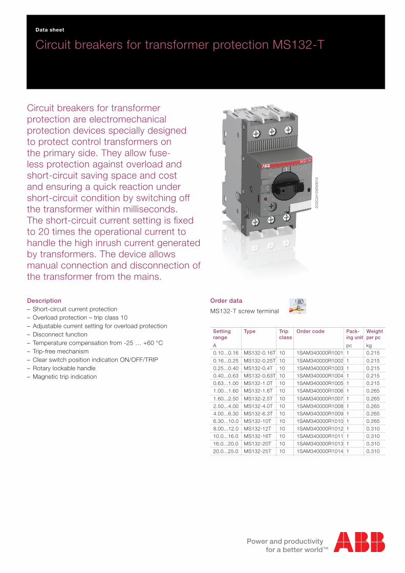
Description – Short-circuit current protection – Overload protection – trip class 10 – Adjustable current setting for overload protection – Disconnect function – Temperature compensation from -25 … +60 °C – Trip-free mechanism – Clear switch position indication ON/OFF/TRIP – Rotary lockable handle – Magnetic trip indication
Order data
MS132-T screw terminal
Setting range
A
Type Trip class
Order code Pack-ing unit
pc
Weight per pc
kg0.10...0.16 MS132-0.16T 10 1SAM340000R1001 1 0.215
0.16...0.25 MS132-0.25T 10 1SAM340000R1002 1 0.2150.25...0.40 MS132-0.4T 10 1SAM340000R1003 1 0.2150.40...0.63 MS132-0.63T 10 1SAM340000R1004 1 0.2150.63...1.00 MS132-1.0T 10 1SAM340000R1005 1 0.2151.00...1.60 MS132-1.6T 10 1SAM340000R1006 1 0.265
1.60...2.50 MS132-2.5T 10 1SAM340000R1007 1 0.2652.50...4.00 MS132-4.0T 10 1SAM340000R1008 1 0.2654.00...6.30 MS132-6.3T 10 1SAM340000R1009 1 0.2656.30...10.0 MS132-10T 10 1SAM340000R1010 1 0.2658.00...12.0 MS132-12T 10 1SAM340000R1012 1 0.31010.0...16.0 MS132-16T 10 1SAM340000R1011 1 0.31016.0...20.0 MS132-20T 10 1SAM340000R1013 1 0.31020.0...25.0 MS132-25T 10 1SAM340000R1014 1 0.310
Circuit breakers for transformer protection are electromechanical protection devices specially designed to protect control transformers on the primary side. They allow fuse-less protection against overload and short-circuit saving space and cost and ensuring a quick reaction under short-circuit condition by switching off the transformer within milliseconds. The short-circuit current setting is fixed to 20 times the operational current to handle the high inrush current generated by transformers. The device allows manual connection and disconnection of the transformer from the mains.
Circuit breakers for transformer protection MS132-TData sheet
2CD
C24
1030
V00
13
2 - 2CDC131058D0201
Functional description2C
DC
2420
31F0
013
1
2
3
4
5
6
7
2-1
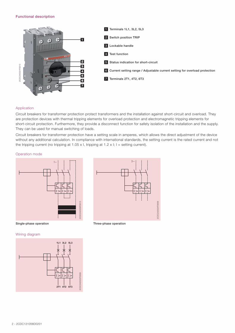
1 Terminals 1L1, 3L2, 5L3
2 Switch position TRIP
3 Lockable handle
4 Test function
5 Status indication for short-circuit
6 Current setting range / Adjustable current setting for overload protection
7 Terminals 2T1, 4T2, 6T3
Application
Circuit breakers for transformer protection protect transformers and the installation against short-circuit and overload. They are protection devices with thermal tripping elements for overload protection and electromagnetic tripping elements for short-circuit protection. Furthermore, they provide a disconnect function for safety isolation of the installation and the supply. They can be used for manual switching of loads.
Circuit breakers for transformer protection have a setting scale in amperes, which allows the direct adjustment of the device without any additional calculation. In compliance with international standards, the setting current is the rated current and not the tripping current (no tripping at 1.05 x I, tripping at 1.2 x I; I = setting current).
Operation mode
2CD
C24
2029
F001
3
Single-phase operation
2CD
C24
2024
F000
9
Three-phase operation
Wiring diagram
1L1 3L2 5L3
2T1 4T2 6T3
2CD
C24
2025
F000
9
2CDC131058D0201 - 3
Resistance and power loss per pole
Type Setting range Resistance per pole Power loss per pole
lower value A
upper value A
Ω
at lower value W
at upper value W
MS132-0.16T 0.10 0.16 58.920 0.6 1.5MS132-0.25T 0.16 0.25 23.390 0.6 1.5MS132-0.4T 0.25 0.40 9.199 0.6 1.5MS132-0.63T 0.40 0.63 3.817 0.6 1.5MS132-1.0T 0.63 1.00 1.496 0.6 1.5MS132-1.6T 1.00 1.60 0.606 0.6 1.6MS132-2.5T 1.60 2.50 0.251 0.6 1.6MS132-4.0T 2.50 4.00 0.096 0.6 1.5MS132-6.3T 4.00 6.30 0.046 0.7 1.8MS132-10T 6.30 10.00 0.017 0.7 1.7MS132-12T 8.00 12.00 0.014 0.9 2.0MS132-16T 10.00 16.00 0.009 0.9 2.3MS132-20T 16.00 20.00 0.004 1.0 1.6MS132-25T 20.00 25.00 0.003 1.2 1.9
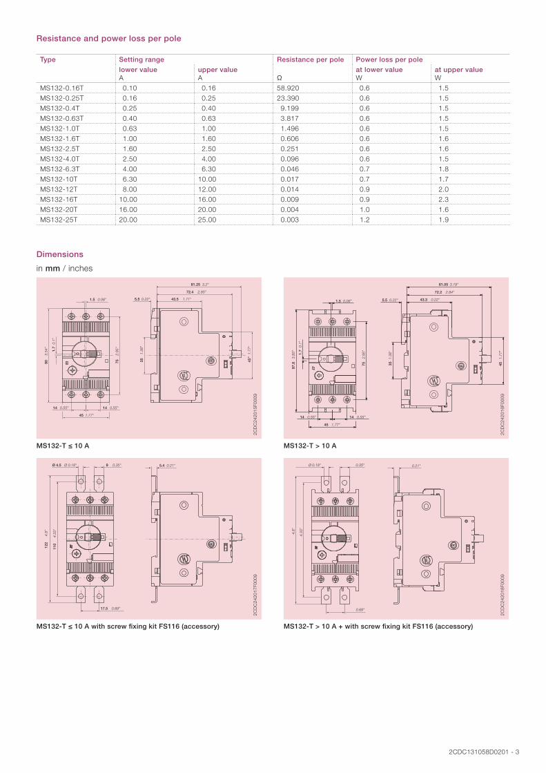
Dimensions
in mm / inches
1.3
8"
0.1
"
3.5
4"
2.9
5"
0.22" 0.06"
0.55"
1.77"
0.55"
2.85"
3.2"
1.71"
1.7
7"
35
1.7
90
75
5.51.5
14
45
14
72.4
81.25
43.5
45"
2CD
C24
2015
F000
9
MS132-T ≤ 10 A
0.06" 0.22" 0.22"
2.84"
3.19"
0.1"
3.85
"
1.77
"
0.55" 0.55"
1.77"
2.95
"
1.38
"
1.5 5.5 43.3
72.2
81.05
1.7
97.8
45
14 14
45
75
35
2CD
C24
2016
F000
9
MS132-T > 10 A
0.35"Ø 0.18" 0.21"
4.3
3"
4.8
"
0.69"
9 Ø 4.5 5.4
110
122
17.5
2CD
C24
2017
F000
9
MS132-T ≤ 10 A with screw fixing kit FS116 (accessory)
0.21"0.35" Ø 0.18"
4.33
"
4.8"
0.69"
2CD
C24
2018
F000
9
MS132-T > 10 A + with screw fixing kit FS116 (accessory)

4 - 2CDC131058D0201
Technical data IEC/EN
Data at TA = 40 °C and at rated values, if nothing else indicated
Main circuit
1L1-3L2-5L3
2T1-4T2-6T3
Rated operational voltage Ue 690 V AC-
Setting range - thermal overload protection see table “Order data” on page 1Rated operational current Ie see table belowRated operational current DC-5 Ie
3 conducting paths in series up to 250 V
-
Rated instantaneous short-circuit current setting Ii see table belowRated service short-circuit breaking capacity Ics see table “Short-circuit breaking capacity and
back-up fuses” on page 6Rated ultimate short-circuit breaking capacity Icu
Rated service short-circuit breaking capacity DC Ics
3 conducting paths in series up to 250 V
-
Trip class see table “Order data” on page 1Rated frequency 50/60 HzNumber of poles 3Resistance per pole see table “Resistance and power loss per pole”
on page 3Power loss per pole
Isolation data
Rated impulse withstand voltage Uimp 6 kV
Rated insulation voltage Ui 690 V
Pollution degree 3
Electrical connection MS132T ≤ 10 A MS132T ≥ 12 A
Connecting capacity solid 1/2 x 1 ... 4 mm² 1/2 x 1 ... 2.5 mm²
1/2 x 2.5 ... 6 mm²
stranded 1/2 x 1 ... 4 mm² 1/2 x 1 ... 2.5 mm²
1/2 x 2.5 ... 6 mm²
flexible with ferrule 1/2 x 0.75 ... 2.5 mm² 1/2 x 0.75 ... 6 mm²
flexible with ferrule insulated 1/2 x 0.75 ... 2.5 mm² 1/2 x 0.75 ... 6 mm²
flexible without ferrule 1/2 x 0.75 ... 2.5 mm² 1/2 x 1 ... 2.5 mm²
1/2 x 2.5 ... 6 mm²
Stripping length 9 mm 10 mm
Tightening torques 0.8 ... 1.2 Nm 2 Nm
Connection screw M3.5
(Pozidriv 2)
M4
(Pozidriv 2)
Type Rated instantaneous short-circuit current setting li
Rated operational current le
A AMS132-0.16T 3.20 0.16MS132-0.25T 5.00 0.25MS132-0.4T 8.00 0.40MS132-0.63T 12.6 0.63MS132-1.0T 20.0 1.00MS132-1.6T 32.0 1.60MS132-2.5T 50.0 2.50MS132-4.0T 80.0 4.00MS132-6.3T 126 6.30MS132-10T 200 10.0MS132-12T 240 12.0MS132-16T 320 16.0MS132-20T 400 20.0MS132-25T 500 25.0

2CDC131058D0201 - 5
General data
Mechanical durability 100000
Electrical durability 50000
Duty time 100 %
Operating frequency without early tripping -
Dimensions (W x H x D) see drawing “Dimensions” on page 3
Weight see table “Order data” on page 1
Mounting DIN-rail (EN 60715)
Mounting position position 1-6 (optional for single mounting)
Group mounting -
Minimum distance to other units same type horizontal 0 mm
vertical 150 mm
Minimum distance to electrical conductive board horizontal, up to 400 V 0 mm
horizontal, up to 690 V > 1.5 mm
vertical 75 mm
Degree of protection housing / main circuit terminals IP20 / IP10
Utilization category A
Maximum operating altitude up to 2000 m
Maximum operating frequency 170 cycles/h
Electromagnetic compatibility
Electromagnetic compatibility not applicable
Environmental data
Ambient air temperature
Operation open - compensated -25 ... +60 °C
open -25 ... +70 °C
enclosed (IB132) 0 ... +40 °C
Storage -50 ... +80 °C
Ambient air temperature compensation acc. to IEC/EN 60947-4-1
Vibration (sinusoidal) acc. to IEC/EN 60068-2-6 (Fc) 5g / 3 ... 150 Hz
Shock (half-sine) acc. to IEC/EN 60068-2-27 (Ea) 25g / 11 ms
Standards / directives
Product standard IEC/EN 60947-1
IEC/EN 60947-2
IEC/EN 60947-4-1
UL/CSA 60947-4-1
Low Voltage Directive 2006/95/EC
EMC Directive 2004/108/EC
RoHS Directive 2002/95/EC
6 - 2CDC131058D0201
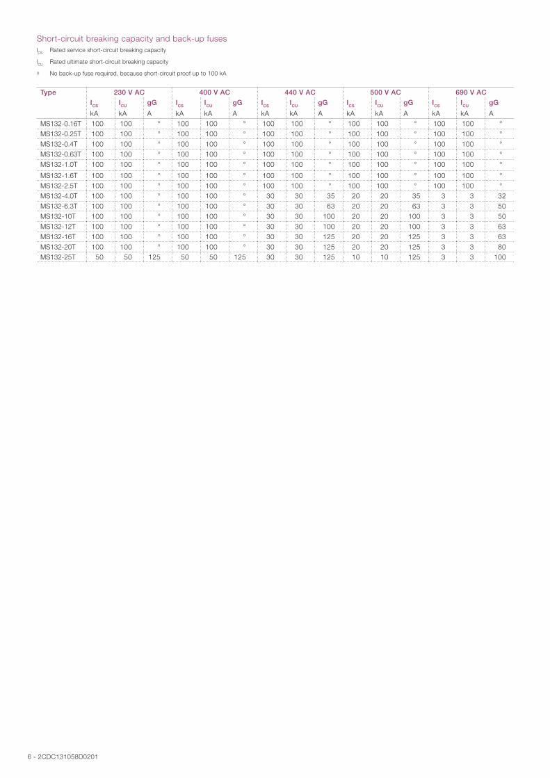
Short-circuit breaking capacity and back-up fuseslCS Rated service short-circuit breaking capacity
lCU Rated ultimate short-circuit breaking capacity
o No back-up fuse required, because short-circuit proof up to 100 kA
Type 230 V AC 400 V AC 440 V AC 500 V AC 690 V AC
ICS
kA
ICU
kA
gG
A
ICS
kA
ICU
kA
gG
A
ICS
kA
ICU
kA
gG
A
ICS
kA
ICU
kA
gG
A
ICS
kA
ICU
kA
gG
AMS132-0.16T 100 100 ° 100 100 ° 100 100 ° 100 100 ° 100 100 °MS132-0.25T 100 100 ° 100 100 ° 100 100 ° 100 100 ° 100 100 °MS132-0.4T 100 100 ° 100 100 ° 100 100 ° 100 100 ° 100 100 °MS132-0.63T 100 100 ° 100 100 ° 100 100 ° 100 100 ° 100 100 °MS132-1.0T 100 100 ° 100 100 ° 100 100 ° 100 100 ° 100 100 °
MS132-1.6T 100 100 ° 100 100 ° 100 100 ° 100 100 ° 100 100 °MS132-2.5T 100 100 ° 100 100 ° 100 100 ° 100 100 ° 100 100 °MS132-4.0T 100 100 ° 100 100 ° 30 30 35 20 20 35 3 3 32MS132-6.3T 100 100 ° 100 100 ° 30 30 63 20 20 63 3 3 50MS132-10T 100 100 ° 100 100 ° 30 30 100 20 20 100 3 3 50MS132-12T 100 100 ° 100 100 ° 30 30 100 20 20 100 3 3 63MS132-16T 100 100 ° 100 100 ° 30 30 125 20 20 125 3 3 63MS132-20T 100 100 ° 100 100 ° 30 30 125 20 20 125 3 3 80MS132-25T 50 50 125 50 50 125 30 30 125 10 10 125 3 3 100
2CDC131058D0201 - 7
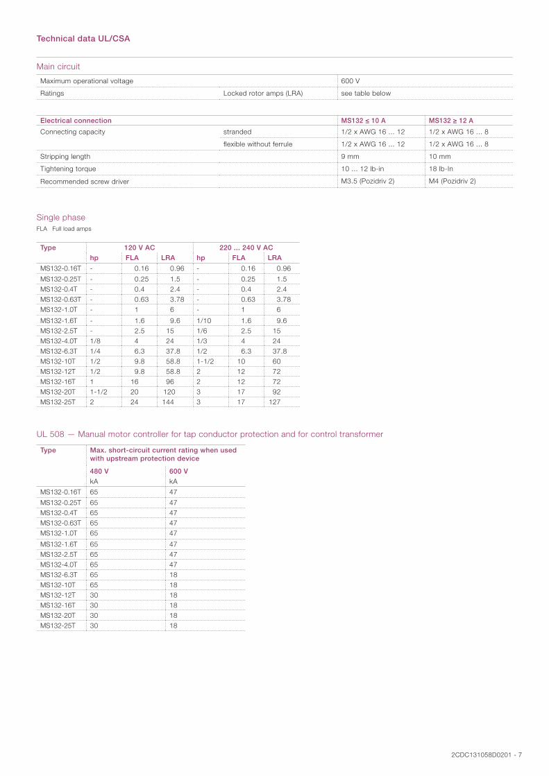
Technical data UL/CSA
Main circuit
Maximum operational voltage 600 V
Ratings Locked rotor amps (LRA) see table below
Electrical connection MS132 ≤ 10 A MS132 ≥ 12 A
Connecting capacity stranded 1/2 x AWG 16 ... 12 1/2 x AWG 16 ... 8
flexible without ferrule 1/2 x AWG 16 ... 12 1/2 x AWG 16 ... 8
Stripping length 9 mm 10 mm
Tightening torque 10 ... 12 lb-in 18 lb-In
Recommended screw driver M3.5 (Pozidriv 2) M4 (Pozidriv 2)
Single phaseFLA Full load amps
Type 120 V AC 220 ... 240 V AC
hp FLA LRA hp FLA LRA
MS132-0.16T - 0.16 0.96 - 0.16 0.96
MS132-0.25T - 0.25 1.5 - 0.25 1.5 MS132-0.4T - 0.4 2.4 - 0.4 2.4 MS132-0.63T - 0.63 3.78 - 0.63 3.78 MS132-1.0T - 1 6 - 1 6
MS132-1.6T - 1.6 9.6 1/10 1.6 9.6 MS132-2.5T - 2.5 15 1/6 2.5 15 MS132-4.0T 1/8 4 24 1/3 4 24 MS132-6.3T 1/4 6.3 37.8 1/2 6.3 37.8 MS132-10T 1/2 9.8 58.8 1-1/2 10 60 MS132-12T 1/2 9.8 58.8 2 12 72 MS132-16T 1 16 96 2 12 72 MS132-20T 1-1/2 20 120 3 17 92 MS132-25T 2 24 144 3 17 127
UL 508 — Manual motor controller for tap conductor protection and for control transformer
Type Max. short-circuit current rating when used with upstream protection device
480 V 600 V
kA kA
MS132-0.16T 65 47
MS132-0.25T 65 47MS132-0.4T 65 47MS132-0.63T 65 47MS132-1.0T 65 47
MS132-1.6T 65 47MS132-2.5T 65 47MS132-4.0T 65 47MS132-6.3T 65 18MS132-10T 65 18MS132-12T 30 18MS132-16T 30 18MS132-20T 30 18MS132-25T 30 18
ABB STOTZ-KONTAKT GmbHEppelheimer Straße 82 69123 Heidelberg, Germany Phone: +49 (0) 6221 7 01-0 Fax: +49 (0) 6221 7 01-13 25 E-Mail: [email protected]
You can find the address of your local sales organization on the ABB home page http://www.abb.com/contacts -> Low Voltage Products and Systems
Contact us
Note:We reserve the right to make technical changes or modify the contents of this document without prior notice. With regard to purchase orders, the agreed particulars shall prevail. ABB AG does not accept any responsibility whatsoever for potential errors or possible lack of information in this document.
We reserve all rights in this document and in the subject matter and illustrations contained therein. Any reproduction, disclosure to third parties or utilization of its contents – in whole or in parts – is forbidden without prior written consent of ABB AG.
Copyright© 2016 ABB All rights reserved
Do
cum
ent
nu
mb
er 2
CD
C13
1058
D02
01 (0
3.20
16)