dcp pocket for tdra6000 -...
TRANSCRIPT
1
DCP Pocket for
TDRA6000 Gerald Koeck / Commercial Support
November 2011
2
DCP Pocket for TDRA6000
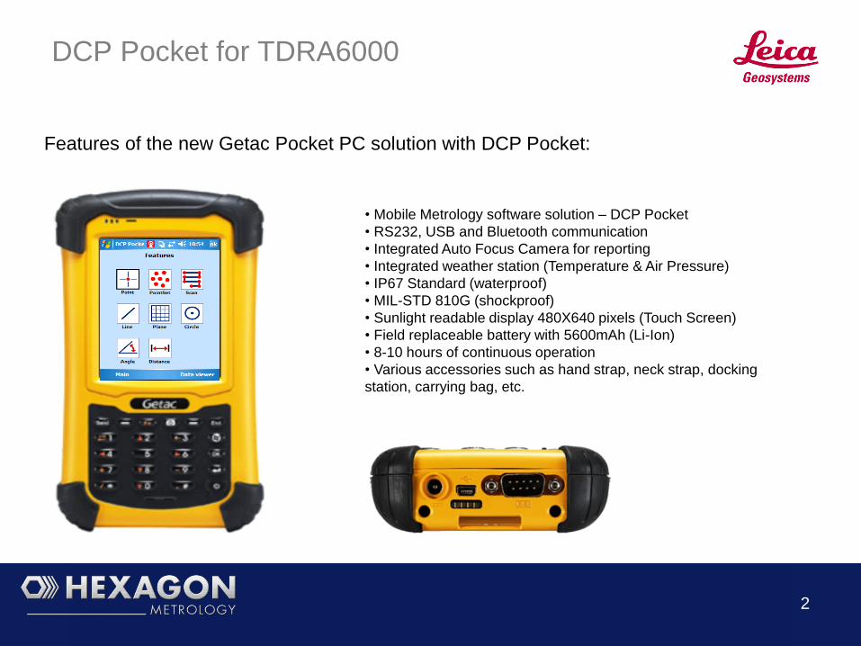
Features of the new Getac Pocket PC solution with DCP Pocket:
• Mobile Metrology software solution – DCP Pocket
• RS232, USB and Bluetooth communication
• Integrated Auto Focus Camera for reporting
• Integrated weather station (Temperature & Air Pressure)
• IP67 Standard (waterproof)
• MIL-STD 810G (shockproof)
• Sunlight readable display 480X640 pixels (Touch Screen)
• Field replaceable battery with 5600mAh (Li-Ion)
• 8-10 hours of continuous operation
• Various accessories such as hand strap, neck strap, docking
station, carrying bag, etc.
3
DCP Pocket - Communication
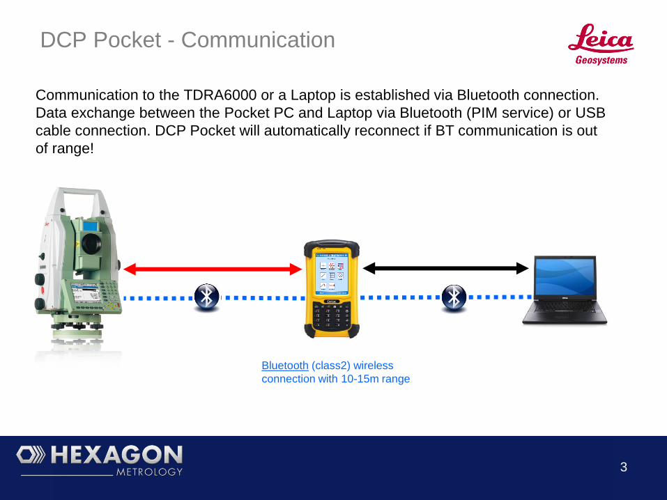
Communication to the TDRA6000 or a Laptop is established via Bluetooth connection.
Data exchange between the Pocket PC and Laptop via Bluetooth (PIM service) or USB
cable connection. DCP Pocket will automatically reconnect if BT communication is out
of range!
Bluetooth (class2) wireless
connection with 10-15m range

4
DCP Pocket – Main Menu
Job Setup – File handling and measurement default settings
Coordinate Systems – Alignments, Move Station and
Coordinate System Management
Features – Feature based measurements and Scanning
Data Exchange – Jobfile Import/Export via Bluetooth
Data Viewer – Data viewer for measurement data
Instrument Steering – Remote controlled instrument steering

5
DCP Pocket – Job Setup
Open – Opens an existing jobfile
New – Create a new jobfile (with active alignment import option)
Settings – Measurement default settings
Continue – Continues directly to the alignment menu
Connect – Establishes BT communication to selected sensor
BT Status – BT communication status (auto connect)

6
DCP Pocket – Job Settings
2 Face – Option for manual and automatic 2 Face measurements
CS – Left and Right Handed Coordinate Systems are supported
Average – Number of points used for averaged coordinates
Overwrite – An warning will be shown if overwriting coordinates
Offset – Active Offset values will be shown with every recording
Increment – Point ID`s are automatically incremented

7
DCP Pocket – Coordinate Systems
Best Fit – Best-Fit alignment to multiple points or circle centers
3-2-1 – Plane – Line – Point alignment with gravity option
Move Station – Move station process with gravity option
CS Manager – Managing and activating Coordinate Systems

8
DCP Pocket – Best-Fit Alignment
Best-Fit – Routine will calculate a Best-Fit alignment with RMS deviations based on Nominals (Ship Coordinate System)
and Actuals/Measured (Instrument Coordinate System).
9
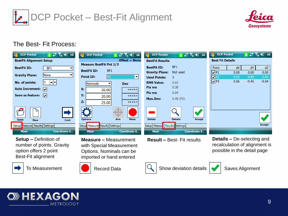
DCP Pocket – Best-Fit Alignment
Setup – Definition of
number of points. Gravity
option offers 2 point
Best-Fit alignment
Measure – Measurement
with Special Measurement
Options. Nominals can be
imported or hand entered
Result – Best- Fit results Details – De-selecting and
recalculation of alignment is
possible in the detail page
To Measurement Saves Alignment Record Data Show deviation details
The Best- Fit Process:

10
DCP Pocket – 321 Alignment
3-2-1 Alignment – Routine will calculate the alignment to the ship coordinate system based on plane and line directions
and an origin point with known XYZ coordinates. Gravity based alignments are possible.

11
DCP Pocket – 321 Alignment (1/2)
The 321 Alignment process will guide the user through the Plane, Line and Origin
Point measurement. Example of the Plane measurement process:
Setup – Definition of
Alignment. Status view of
alignment features
Plane Setup – Definition
of plane points and
selection of gravity option
Measure – Guided
measurement of plane
points
Results – Display of the
plane alignment feature
To Plane Setup Saves feature and
returns to Alignment
Setup page
To Measurement Plane point recording

12
DCP Pocket – 321 Alignment (2/2)
The status of the required alignment features is shown every time a feature
measurement has been completed:
Setup – Plane
measurement complete
with green status
Setup – Plane and Line
measurement complete
with green status
Setup – All alignment
features are measured
(green status). Origin
coordinates X,Y,Z are
displayed for verification
Alignment features are
stored and can be
reviewed in the Data
Viewer
Saves and activates
alignment
13
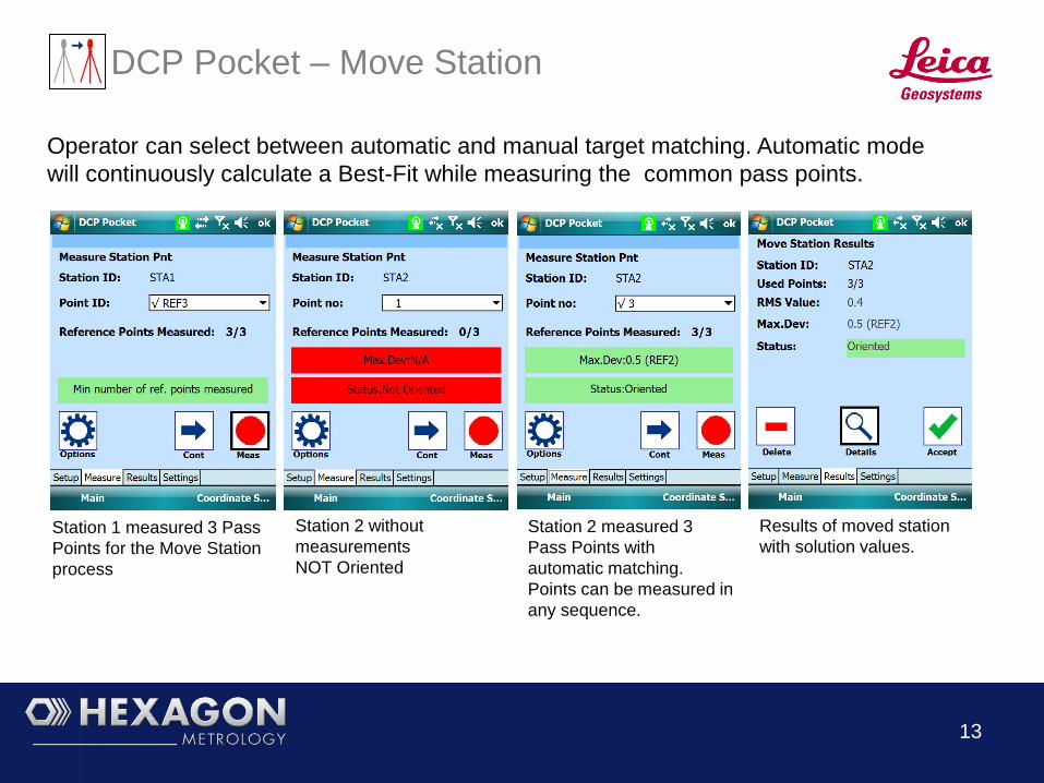
DCP Pocket – Move Station
Operator can select between automatic and manual target matching. Automatic mode
will continuously calculate a Best-Fit while measuring the common pass points.
Station 1 measured 3 Pass
Points for the Move Station
process
Station 2 without
measurements
NOT Oriented
Station 2 measured 3
Pass Points with
automatic matching.
Points can be measured in
any sequence.
Results of moved station
with solution values.
14
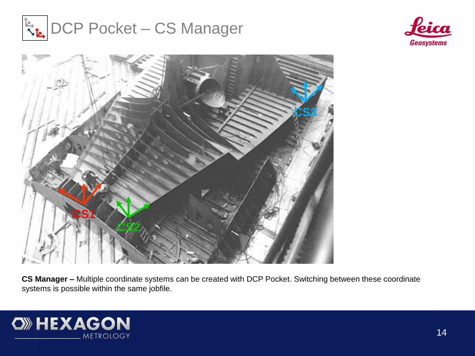
DCP Pocket – CS Manager
CS Manager – Multiple coordinate systems can be created with DCP Pocket. Switching between these coordinate
systems is possible within the same jobfile.
CS1 CS2
CS3
15
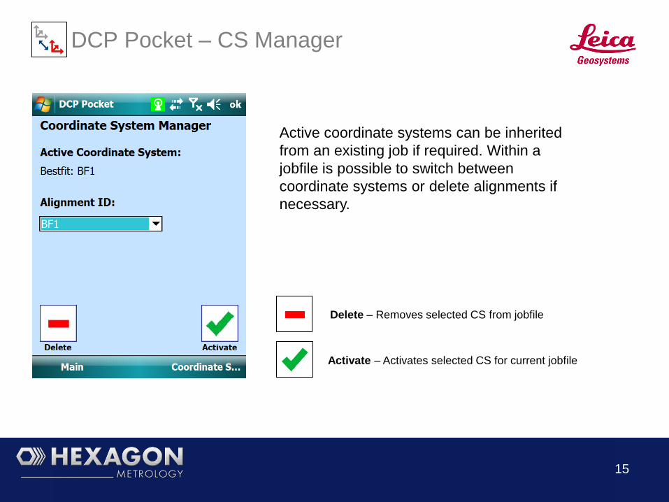
DCP Pocket – CS Manager
Active coordinate systems can be inherited
from an existing job if required. Within a
jobfile is possible to switch between
coordinate systems or delete alignments if
necessary.
Delete – Removes selected CS from jobfile
Activate – Activates selected CS for current jobfile

16
DCP Pocket - Features
Point – Point measurement or point construction
Point Set – Measurement of a Point Set with a specified RMS
Scan – Area or plane scan (reflectorless mode)
Line – Line measurement or line construction (scan option)
Plane – Plane measurement (scan option)
Circle – Circle measurement
Angle – Angle analysis (line-line / plane-line)
Distance – Distance analysis (points, planes, lines, circle centers)
17
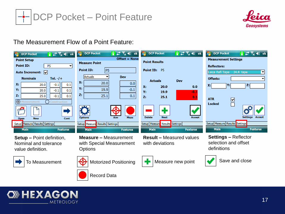
DCP Pocket – Point Feature
Setup – Point definition,
Nominal and tolerance
value definition.
Measure – Measurement
with Special Measurement
Options
Result – Measured values
with deviations
Settings – Reflector
selection and offset
definitions
To Measurement Motorized Positioning
Record Data
Measure new point
The Measurement Flow of a Point Feature:
Save and close

18
DCP Pocket – Point Feature Construction
The construction of Midpoints between Line-Line and Point-Point can be calculated
with the Point Feature function:
Setup – Select Construction
Mode
Construction – Select the
construction features
Results – Shows the calculated
Midpoint
Save and close To Feature selection
19
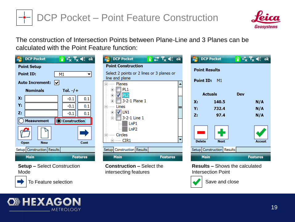
DCP Pocket – Point Feature Construction
The construction of Intersection Points between Plane-Line and 3 Planes can be
calculated with the Point Feature function:
Setup – Select Construction
Mode
Construction – Select the
intersecting features
Results – Shows the calculated
Intersection Point
Save and close To Feature selection
20
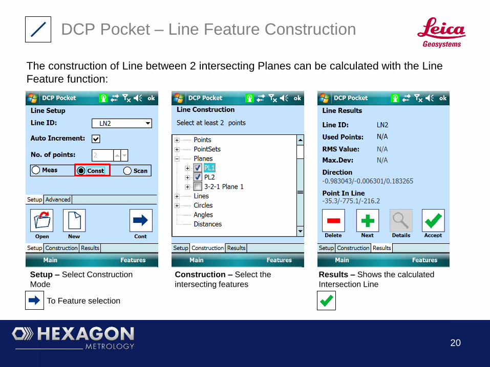
DCP Pocket – Line Feature Construction
The construction of Line between 2 intersecting Planes can be calculated with the Line
Feature function:
Setup – Select Construction
Mode
Construction – Select the
intersecting features
Results – Shows the calculated
Intersection Line
To Feature selection

21
DCP Pocket – Special Measurement Modes
Special Measurement options are available in all measurement and alignment modes:
Hidden Point – Linear Hidden Point measurement
Circle Center – Circle center measurement
Separate Recording – Separate recording of DIST and REC
X or Y or Z – Single or Dual Coordinate measurement
Vision Mode – Line of sight intersection point (measured or
selected plane)

22
DCP Pocket – Special Measurement Modes (1/3)
In many cases the nominal positions are not directly visible (hidden) or can not be
measured in a conventional way. Special Measurement will cover most these cases.
Hidden Point measurement with a linear device.
Separate Recording of X, Y and/or Z values in case of a
missing edge or corner point.
Point 1/5
Point 2/5
Point 3/5
Point 4/5
Point 5/5
XYZ Result
XYZ Result
Z
X
Y
23
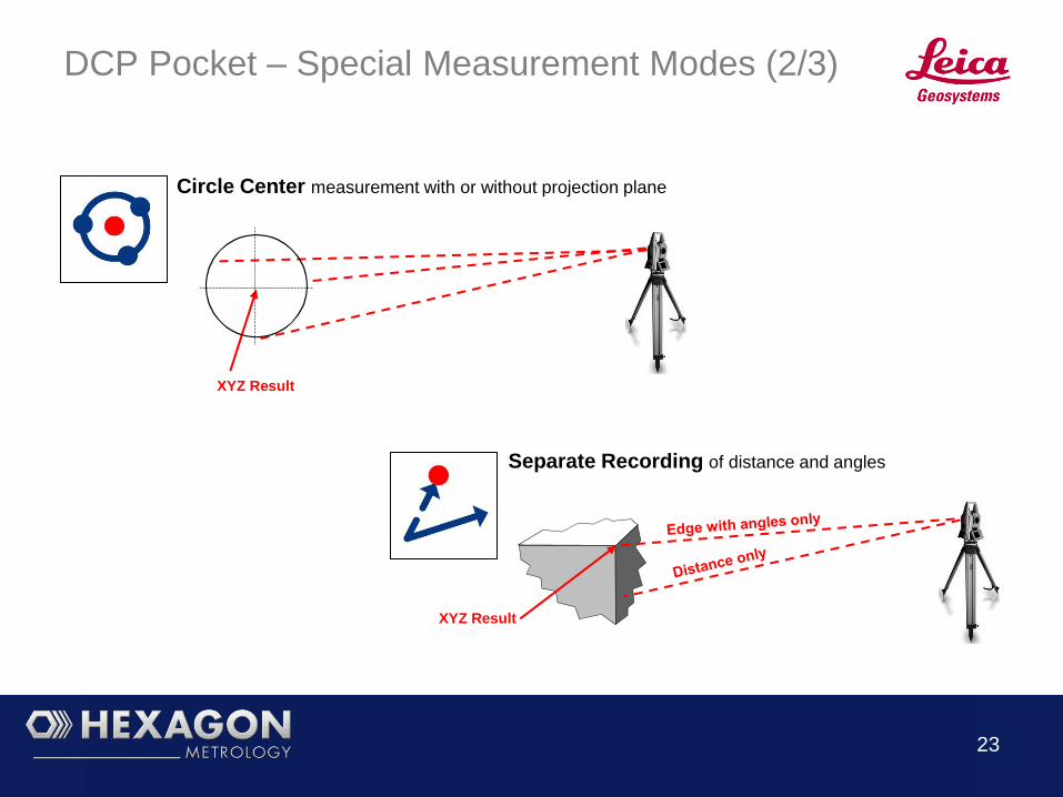
DCP Pocket – Special Measurement Modes (2/3)
Circle Center measurement with or without projection plane
Separate Recording of distance and angles
XYZ Result
XYZ Result

24
DCP Pocket – Special Measurement Modes (3/3)
Vision Point measurement with intersection plane (e.g. circle hole)
A Vision Point result is created when the line of sight is intersecting
the selected/measured plane. Basically a mixture of separate
recording or a feature measurement with a projection plane.

25
DCP Pocket – Circle Feature
Circle Best- Fit – Routine calculates planar and radial deviations of the measured circle feature.

26
DCP Pocket – Circle Feature
Advanced Setup –
Tolerances and Nominal
values can be defined or
imported from DCP Project
Setup – Circle
measurement definition
Result – Circle results with
deviations
Details – Circle point
deviations
To Measurement Show circle points with
deviations
The measurement flow for Line and Plane is identical
Save and close

27
DCP Pocket – Plane Feature
Plane Best- Fit – Routine calculates planar deviations, origin and plane direction

28
DCP Pocket – Plane Feature
Setup – Tolerances and
Nominal values can be
defined or imported from
DCP Project
Measurement –
Measurement of plane
points
Result – Plane results with
deviations
Details – Planar deviations
in detail
To Measurement Show Plane point
deviations
Plane Features can be measured, constructed or scanned:
Save and close Record Data

29
DCP Pocket – Scanning
Scanning – Routine offers reflectorless scanning of surfaces with user definable boundary and point spacing.

30
DCP Pocket – Measurement Flow Scanning
Setup – Definition of Scan
Resolution (Grid size) and
measurement of Boundary
Points
Measurement – Display of
# Scan Points
Measurement – Progress
Bar
Results – Scan Point
Cloud Data.
Start Scanning
Process Record Boundary Pts.
The measurement of a Line or Plane is scan in reflectorless mode:

31
DCP Pocket – Point Set
Point Set – A set of points with nominal coordinates can be measured in the optional automatic mode. Automatic
measurements are ideal for repetitive measurements or positioning of components.

32
DCP Pocket – Point Set
Setup – Definition of
number of points and
common tolerance.
Measurement – Selection
of Automatic Mode.
Measurement –
Deviations of each point
are shown for 1 second
Results – Point Set
Deviations
To Measurement Page
Point Sets can be measured automatically and are typically imported from DCP Project:
Mode Selection

33
DCP Pocket – Angle Feature
Angle Feature – Calculation from existing features or direct measurement of angle features.

34
DCP Pocket – Angle Feature
Setup –Nominal angle
value can be hand entered
or imported from DCP
Project
Measurement –
Measurement of angle
feature points
Result – Angle Result
To Measurement
Angle features can be measured or constructed:
Save and close Record Data

35
DCP Pocket – Distance Feature
Distance Feature – Calculation from measured features or direct measurement of 3D distances.

36
DCP Pocket – Distance Feature
Setup – Nominal distance
value can be hand entered
or imported from DCP
Project
Measurement –
Measurement of distance
feature points
Result – Distance Result
To Measurement
Distance features can be measured or constructed:
Save and close Record Data

37
DCP Pocket – Data Viewer
Tree style display of feature
groups
Laser Pointer to identify
selected feature on the object.
Tolerance based background color
of features. Display of Nominal and
Actual data with deviations.
Origin coordinate, unit vector and
used feature points are included
for data review.

38
DCP Pocket – Data Exchange (1/4)
Select the corresponding Workstation with activated PIM
(Bluetooth Data Synchronization) from the list.
Transferring Job Files from DCP Pocket to a PC :
Select the files for data transfer to the workstation.
A notification will be
displayed at your
workstation once the job
files have been received.

A notification will be displayed
once the data has been
transmitted to the Pocket PC.
39
DCP Pocket – Data Exchange (2/4)
Transferring Job Files from a PC to DCP Pocket:
Select a job file and send it to the
corresponding Pocket PC.

40
DCP Pocket – Data Exchange (3/4)
Select the corresponding Workstation with activated PIM
(Bluetooth Data Synchronization) from the list.
Transferring Job Files from DCP Pocket to a PC :
Select the files for data transfer to the workstation
Select on the BT Device
utility the “Receive a File”
option
A notification will be displayed at your
workstation once the job files have been
received

41
DCP Pocket – Data Exchange (4/4)
Transferring Job Files from a PC to DCP Pocket:
Select a job file and send it to the
corresponding Pocket PC
A notification will be
displayed once the data
has been transmitted to the
Pocket PC
Select on the BT
Device utility the “Send
a File” option
Select the Pocket PC device
42
DCP Project for
DCP Pocket and DCP05
43
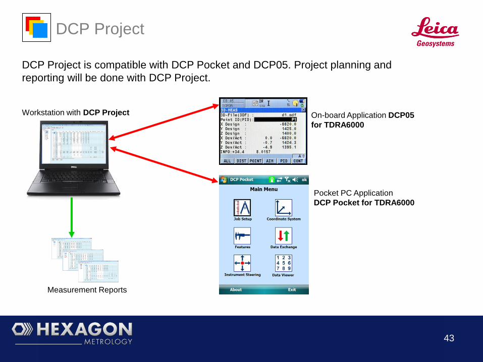
DCP Project
DCP Project is compatible with DCP Pocket and DCP05. Project planning and
reporting will be done with DCP Project.
On-board Application DCP05
for TDRA6000
Pocket PC Application
DCP Pocket for TDRA6000
Workstation with DCP Project
Measurement Reports

44
DCP Project – Data Tree
The tree structured data viewer offers convenient reviewing and planning of the complete
measurement task.
45
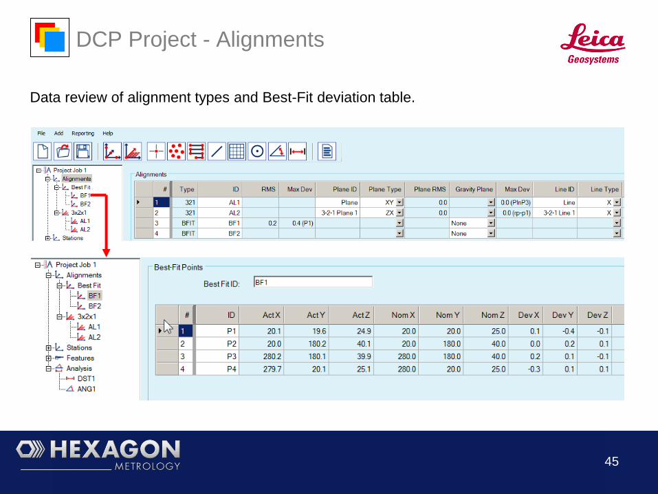
DCP Project - Alignments
Data review of alignment types and Best-Fit deviation table.
46
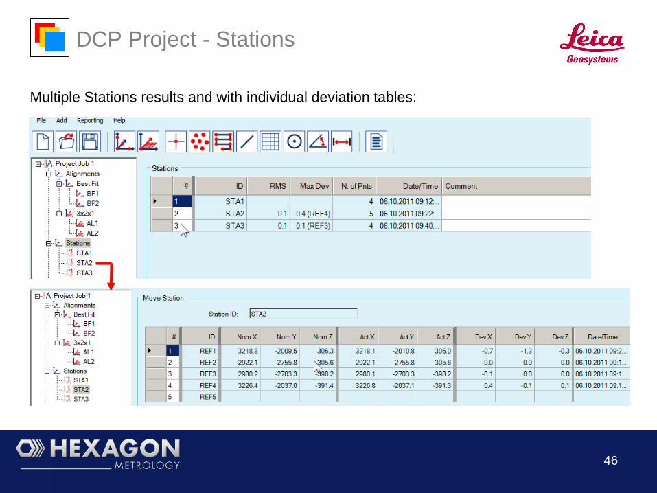
DCP Project - Stations
Multiple Stations results and with individual deviation tables:

47
DCP Project - Features
Point features with deviation table:
48
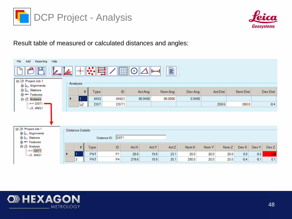
DCP Project - Analysis
Result table of measured or calculated distances and angles:

49
DCP Project - Reports
All or individual data groups can be reported:
50
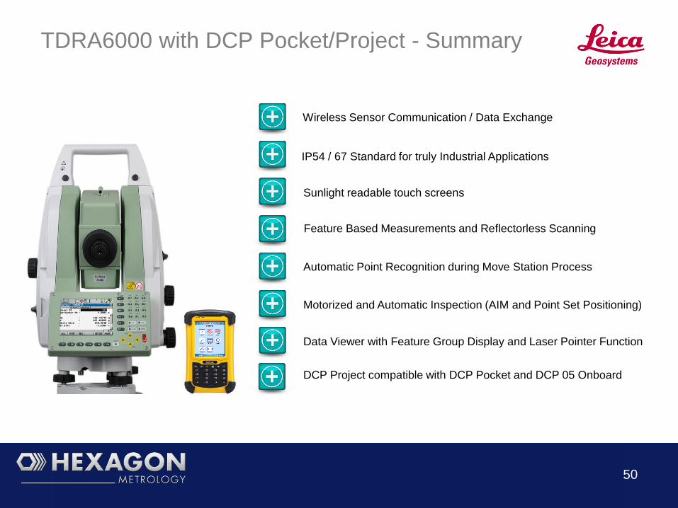
TDRA6000 with DCP Pocket/Project - Summary
Wireless Sensor Communication / Data Exchange
IP54 / 67 Standard for truly Industrial Applications
Feature Based Measurements and Reflectorless Scanning
Sunlight readable touch screens
Motorized and Automatic Inspection (AIM and Point Set Positioning)
Data Viewer with Feature Group Display and Laser Pointer Function
Automatic Point Recognition during Move Station Process
DCP Project compatible with DCP Pocket and DCP 05 Onboard
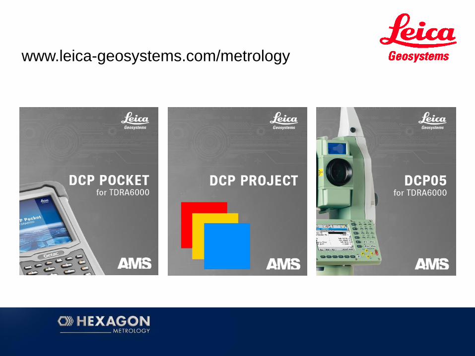
www.leica-geosystems.com/metrology