d.e. cartridge style filter - cody pools fileimportant safety instructions read and follow all...
TRANSCRIPT

IMPORTANT SAFETY INSTRUCTIONSREAD AND FOLLOW ALL INSTRUCTIONS
SAVE THESE INSTRUCTIONS
Installation and User's Guide
Quad D.E.®
D.E. Cartridge Style Filter
© 2011 Pentair Water Pool and Spa, Inc. All rights reserved.
This document is subject to change without notice.
1620 Hawkins Ave., Sanford, NC 27330 • (800) 831-7133 • (919) 566-800010951 West Los Angeles Ave., Moorpark, CA 93021 • (800) 831-7133 • (805) 553-5000
Trademarks and Disclaimers: Pentair Pool Products®, Because reliability matters most®, Quad D.E.®, High Flow™, and Pentair Water Pool and Spa®
are trademarks and/or registered trademarks of Pentair Water Pool and Spa, Inc. and/or its affiliated companies in the United States and/or othercountries. Baquacil® and Baqua® are registered trademarks of Arch UK Biocides Limited. Unless noted, names and brands of others that may beused in this document are not used to indicate an affiliation or endorsement between the proprietors of these names and brands and Pentair WaterPool and Spa, Inc. Those names and brands may be the trademarks or registered trademarks of those parties or others.
P/N 178658 Rev. E 5/19/11
Customer ServiceIf you have questions about ordering Pentair Water Pool and Spa ("Pentair") replacement parts,and pool products, please use the following contact information:
Customer Service / Technical Support (8 A.M. to 5 P.M. — Eastern and Pacific Times)
Phone: (800) 831-7133
Fax: (800) 284-4151
Sanford, North Carolina (8 A.M. to 5 P.M. — Eastern Time)
Phone: (919) 566-8000
Fax: (919) 566-8920
Moorpark, California (8 A.M. to 5 P.M. — Pacific Time)
Phone: (805) 553-5000 (Ext. 5591)
Fax: (805) 553-5515
Web site
visit www.pentairpool.com or www.staritepool.com to find information about Pentair products
Patent Pending
i
Quad D.E.® Filter Installation and User’s Guide
Table of Contents
Important Warning and Safety Instructions ......................................................................... ii
Section 1: Introduction .....................................................................................................1
Quad D.E.® Filter Overview ..................................................................................... 1
General Features.....................................................................................................2
Section 2: Installation ....................................................................................................... 3
Installing the Quad D.E.® Filter ................................................................................3
General Information .................................................................................................3
Section 3: Filter Operation ............................................................................................... 5
Filter Operation Information ..................................................................................... 5
Filter Clamp Installation ........................................................................................... 6
Section 4: System Restart Instructions .......................................................................... 7
Preparing Diatomite .................................................................................................8
Coating the Filter Elements with D.E. ......................................................................8
Section 5: Maintenance .....................................................................................................9
Manually Cleaning the Quad D.E.® Filter ................................................................. 9
Replacing Filter Cartridge Style Elements ...............................................................10
Cleaning the Filter using a Separation Tank System ............................................... 10
Cleaning Filter Elements ..........................................................................................11
Cleaning the Internal Air Bleed Tube ........................................................................ 12
Cleaning the High Flow™ Manual Air Relief Valve .................................................. 12
Section 6: Troubleshooting ..............................................................................................13
Section 7: Replacement Parts ..........................................................................................15
Section 8: Technical Data.................................................................................................. 16
Head Loss Comparison Curves .............................................................................. 16
Flow Rate information ..............................................................................................16
ii
Quad D.E.® Filter Installation and User’s Guide
IMPORTANT WARNING AND SAFETY INSTRUCTIONS
Consumer Information and SafetyThe Quad D.E.® Filters are designed and manufactured to provide many years of safe and reliable service when installed,operated and maintained according to the information in this manual and the installation codes referred to in latersections. Throughout the manual, safety warnings and cautions are identified by the “ “ symbol. Be sure to read andcomply with all of the warnings and cautions.
WARNING — Do not operate the filter until you have read and understand clearly all the operating instructionsand warning messages for all equipment that is a part of the pool circulating system. Thefollowing instructions are intended as a guide for initially operating the filter in a general poolinstallation, however each installation may have unique conditions where the starting procedurecould be different. Failure to follow all operating instructions and warning messages can resultin severe injury, death, or property damage.
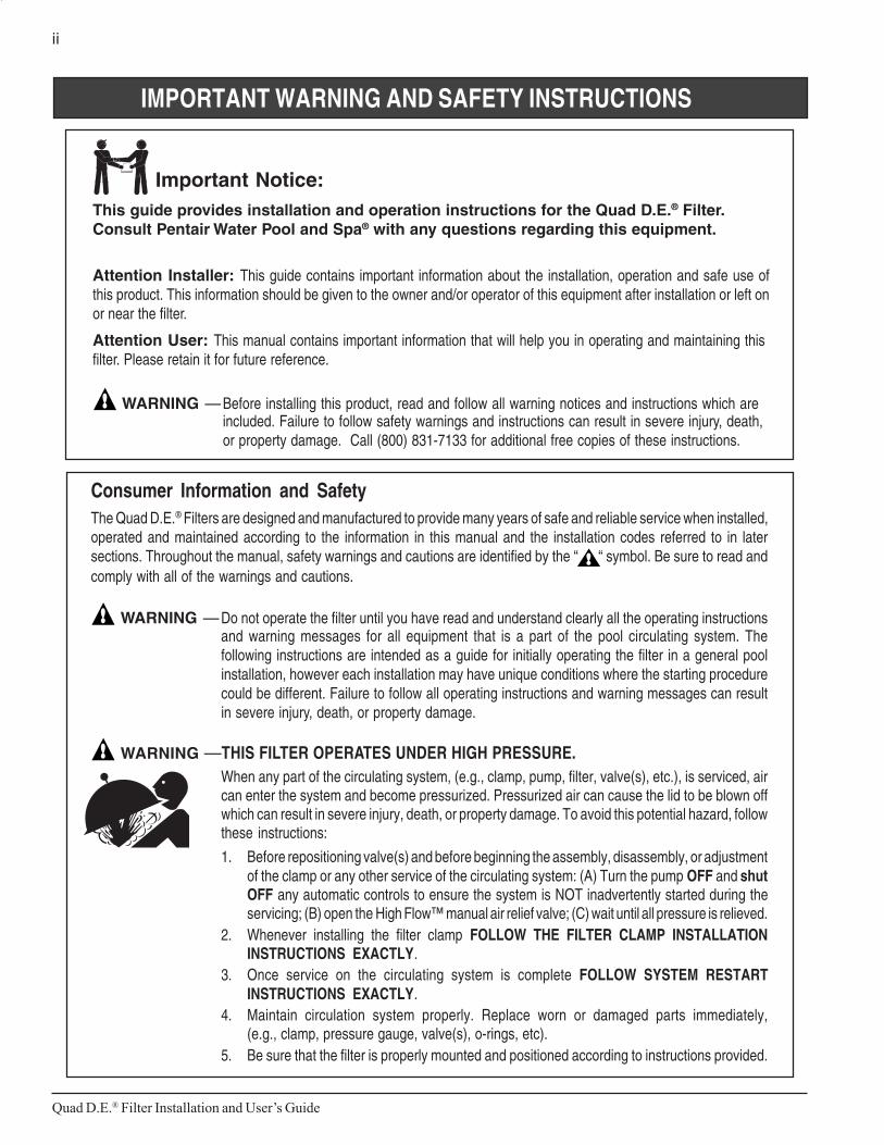
WARNING —THIS FILTER OPERATES UNDER HIGH PRESSURE.When any part of the circulating system, (e.g., clamp, pump, filter, valve(s), etc.), is serviced, aircan enter the system and become pressurized. Pressurized air can cause the lid to be blown offwhich can result in severe injury, death, or property damage. To avoid this potential hazard, followthese instructions:
1. Before repositioning valve(s) and before beginning the assembly, disassembly, or adjustmentof the clamp or any other service of the circulating system: (A) Turn the pump OFF and shutOFF any automatic controls to ensure the system is NOT inadvertently started during theservicing; (B) open the High Flow™ manual air relief valve; (C) wait until all pressure is relieved.
2. Whenever installing the filter clamp FOLLOW THE FILTER CLAMP INSTALLATIONINSTRUCTIONS EXACTLY.
3. Once service on the circulating system is complete FOLLOW SYSTEM RESTARTINSTRUCTIONS EXACTLY.
4. Maintain circulation system properly. Replace worn or damaged parts immediately,(e.g., clamp, pressure gauge, valve(s), o-rings, etc).
5. Be sure that the filter is properly mounted and positioned according to instructions provided.
Important Notice:This guide provides installation and operation instructions for the Quad D.E.® Filter.Consult Pentair Water Pool and Spa® with any questions regarding this equipment.
Attention Installer: This guide contains important information about the installation, operation and safe use ofthis product. This information should be given to the owner and/or operator of this equipment after installation or left onor near the filter.
Attention User: This manual contains important information that will help you in operating and maintaining thisfilter. Please retain it for future reference.
WARNING — Before installing this product, read and follow all warning notices and instructions which areincluded. Failure to follow safety warnings and instructions can result in severe injury, death,or property damage. Call (800) 831-7133 for additional free copies of these instructions.
Head
Body
Upper
Arm
Upper
Arm
Leg Joint
Leg Joint
Leg Joint
Leg Joint
Head
Body
Upper
Arm
Leg Joint
Leg Joint
Leg Joint
Leg Joint
iii
Quad D.E.® Filter Installation and User’s Guide
IMPORTANT WARNING AND SAFETY INSTRUCTIONS
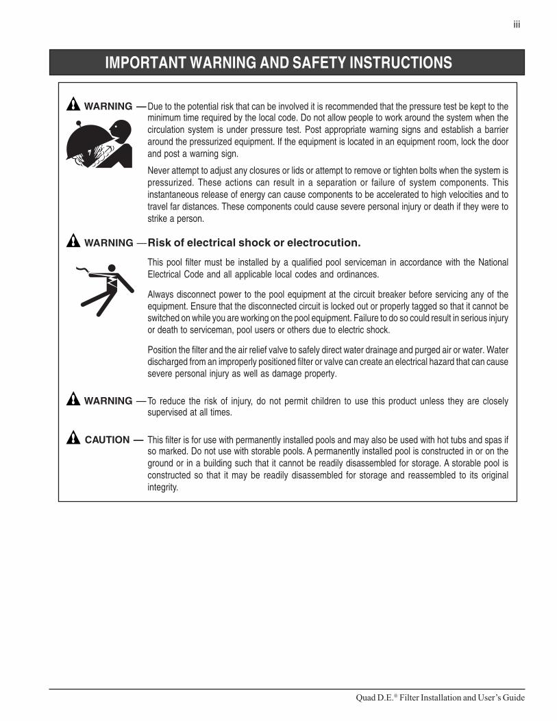
WARNING — Due to the potential risk that can be involved it is recommended that the pressure test be kept to theminimum time required by the local code. Do not allow people to work around the system when thecirculation system is under pressure test. Post appropriate warning signs and establish a barrieraround the pressurized equipment. If the equipment is located in an equipment room, lock the doorand post a warning sign.
Never attempt to adjust any closures or lids or attempt to remove or tighten bolts when the system ispressurized. These actions can result in a separation or failure of system components. Thisinstantaneous release of energy can cause components to be accelerated to high velocities and totravel far distances. These components could cause severe personal injury or death if they were tostrike a person.
WARNING —Risk of electrical shock or electrocution.
This pool filter must be installed by a qualified pool serviceman in accordance with the NationalElectrical Code and all applicable local codes and ordinances.
Always disconnect power to the pool equipment at the circuit breaker before servicing any of theequipment. Ensure that the disconnected circuit is locked out or properly tagged so that it cannot beswitched on while you are working on the pool equipment. Failure to do so could result in serious injuryor death to serviceman, pool users or others due to electric shock.
Position the filter and the air relief valve to safely direct water drainage and purged air or water. Waterdischarged from an improperly positioned filter or valve can create an electrical hazard that can causesevere personal injury as well as damage property.
WARNING — To reduce the risk of injury, do not permit children to use this product unless they are closelysupervised at all times.
CAUTION — This filter is for use with permanently installed pools and may also be used with hot tubs and spas ifso marked. Do not use with storable pools. A permanently installed pool is constructed in or on theground or in a building such that it cannot be readily disassembled for storage. A storable pool isconstructed so that it may be readily disassembled for storage and reassembled to its originalintegrity.

iv
Quad D.E.® Filter Installation and User’s Guide
IMPORTANT WARNING AND SAFETY INSTRUCTIONS
General Installation Information
The following information should be read carefully since it outlines the proper manner of care and operation for yourfilter system. You can expect maximum efficiency and life from your filtration system by following these instructions andtaking the necessary preventative care.
• Have a trained pool professional perform all pressure tests.
• Do not connect the system to a high pressure or city water system.
• Trapped air in the system can create a hazardous condition. BE SURE to purge all air from thesystem before operating or testing equipment.
• DO NOT pressure test with compressed air!
• Check local codes for restrictions on backwash to waste piping, separation tank requirements andspent D.E. disposal requirements.
• DO NOT use more than the recommended amount of D.E. in your filter. To do so can cause a buildupof D.E. and “bridging” between the elements which will plug the filter.
• Piping must conform to local/state plumbing and sanitary codes.
• Support piping independently to prevent strains on filter or valve.
• Fittings restrict flow; for best efficiency, use the fewest possible fittings.
• A check valve installed ahead of the filter inlet will prevent contaminants from draining back into thepool.
• A check valve installed between the filter and heater will prevent hot water from backing up into thefilter and deforming the internal components.
• To allow recirculation during precoat, (if precoat pot is used), install a recirculation line with shut-offbetween pad return line and pump suction.
• All wiring, grounding and bonding of associated equipment must meet local and/or National ElectricalCode standards.

1
Quad D.E.® Filter Installation and User’s Guide
Section 1Introduction
Quad D.E.® Cartridge Style Filter Overview
The crystal clarity of D.E. with cartridge convenienceDiatomaceous earth (D.E.) filters have always been recognized for providing the cleanest pool water. Andcartridge filters are popular for their convenience and easy-cleaning features. Now, Pentair has found a wayto bring you the best of both.
The new Quad D.E. Cartridge Filter features four easily accessible and removable cartridges. When waterpasses through these cartridges, microscopic impurities like dirt, algae, and some forms of bacteria are filteredout, giving you water that really sparkles.
The four-cartridge design greatly increases the filter’s internal surface area, meaning much greater cleaningcapacity per cycle without an increase in canister size. And cleaning couldn’t be easier. In fact, you havethree options...backwash and recharge like a traditional D.E. filter, remove and rinse off the cartridges, orsimply remove the lid, leave the cartridges in place, open the drain plug, and rinse.
You’ll even save money – water flows through the Quad D.E. so efficiently that with the correct pump youuse less energy.
The highest water clarity with the lowest amount of fussThe Quad D.E. combination of diatomaceous earth (D.E.) in a convenient cartridge design means betterperformance and longer periods between cleanings. Because D.E. removes the tiniest of contaminants –particles as small as five microns – you can count on clean, crystal-clear water for years to come.
Quad D.E.® Filter
2
Quad D.E.® Filter Installation and User’s Guide
General Features
• Four large-capacity cartridges provide maximum filter surface area for greater dirt-trapping capacity andlonger periods between cleanings.
• Unique internal flow path ensures optimum filtration and backwashing efficiency.
• Chemical resistant, fiberglass reinforced polypropylene tank for exceptional strength and long life.
• Tension Control™ clamp for secure closure.
• 2” plumbing connections for simple and secure maximum flow.
• Conveniently located 2” drain for easy and efficient clean-out and 100% draining.
Additional Features:
• High Flow™ manual air relief valve and continuous internal air relief work together to maintain efficientfiltration and prevent over-pressurization.
• Durable 8 oz. polypropylene cartridge media has superslick surfaces, making them easier to clean thanconventional cartridge filters.
• Easily removable cartridge elements to simplify maintenance and save you time.
3
Quad D.E.® Filter Installation and User’s Guide
Section 2Installation
The following general information describes how to install the Quad D.E.® Filter.
Note: Before installing this product, read and follow all warning notices and instructions starting on page ii.
Installing the Quad D.E.® FilterOnly a qualified service person should install the Quad D.E. Filter.
General Information
1. The filter should be mounted on a level concrete slab. Position the filter so that instructions, warnings andthe pressure gauge are visible to the operator. It also should be positioned so that the piping connections,control valve and drain port are convenient and accessible for servicing and winterizing.
2. Install electrical controls (e.g., on/off switches, timers, control systems, etc.) at least five (5) feet from thefilter. This will allow you enough room to stand clear of the filter during system start up.
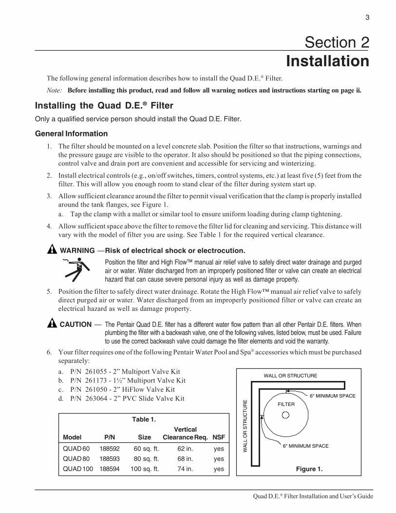
3. Allow sufficient clearance around the filter to permit visual verification that the clamp is properly installedaround the tank flanges, see Figure 1.a. Tap the clamp with a mallet or similar tool to ensure uniform loading during clamp tightening.
4. Allow sufficient space above the filter to remove the filter lid for cleaning and servicing. This distance willvary with the model of filter you are using. See Table 1 for the required vertical clearance.
WARNING —Risk of electrical shock or electrocution.
Position the filter and High Flow™ manual air relief valve to safely direct water drainage and purgedair or water. Water discharged from an improperly positioned filter or valve can create an electricalhazard that can cause severe personal injury as well as damage property.
5. Position the filter to safely direct water drainage. Rotate the High Flow™ manual air relief valve to safelydirect purged air or water. Water discharged from an improperly positioned filter or valve can create anelectrical hazard as well as damage property.
CAUTION — The Pentair Quad D.E. filter has a different water flow pattern than all other Pentair D.E. filters. Whenplumbing the filter with a backwash valve, one of the following valves, listed below, must be used. Failureto use the correct backwash valve could damage the filter elements and void the warranty.
6. Your filter requires one of the following Pentair Water Pool and Spa® accessories which must be purchasedseparately:a. P/N 261055 - 2” Multiport Valve Kitb. P/N 261173 - 1½” Multiport Valve Kitc. P/N 261050 - 2” HiFlow Valve Kitd. P/N 263064 - 2” PVC Slide Valve Kit
Figure 1.
Table 1.
VerticalModel P/N Size Clearance Req. NSF
QUAD 60 188592 60 sq. ft. 62 in. yes
QUAD 80 188593 80 sq. ft. 68 in. yes
QUAD 100 188594 100 sq. ft. 74 in. yes
4
Quad D.E.® Filter Installation and User’s Guide
General Information, cont.’d.
7. Make all plumbing connections in accordance with local plumbing and building codes. Check local codesfor restrictions on backwash to waste piping, separation tank requirements and spent D.E. disposalrequirements.
8. Filter plumbing connections are provided with an o-ring seal. To avoid damage to the o-rings, use only asilicone base lubricant on the o-rings. Do not use pipe joint compound, glue or solvent on the bulkheadconnections.
WARNING — THIS FILTER OPERATES UNDER HIGH PRESSURE.Never subject this filter to pressure in excess of the maximum working pressure - even when conductinghydrostatic pressure tests. Pressures above the maximum working p.s.i. pressure can cause the lidto be blown off, which can result in severe injury, death or property damage.
9. Remove the plug from the top of the filter lid and install the pressure gauge before use.
10. The maximum working pressure of this filter is 50 psi. Never subject this filter to pressure in excess of thisamount - even when conducting hydrostatic pressure tests. Pressures above 50 psi can cause the lid to beblown off, which can result in severe injury, death or property damage.
When performing hydrostatic pressure tests or when testing for external leaks of the completed filtration andplumbing system, ensure that the maximum pressure that the filtration system will be subjected to DOESNOT EXCEED THE MAXIMUM WORKING PRESSURE OF ANY OF THE COMPONENTS CONTAINEDWITHIN THE SYSTEM. In most cases, the maximum working pressure will be stated on each component ofthe system.
If doubt exists as to the pressure to which the system will be subjected, install an ASME approved automaticPressure Relief or Pressure Regulator in the circulation system for the lowest working pressure of any of thecomponents in the system.
5
Quad D.E.® Filter Installation and User’s Guide
Section 3Filter Operation
This section describes how the Quad D.E.® operates.
General Filter Information
WARNING — THIS FILTER OPERATES UNDER HIGH PRESSURE. When any part of the circulating system,(e.g., clamp, pump, filter, valve(s), etc.), is serviced, air can enter the system and become pressurized.Pressurized air can cause the lid to be blown off which can result in severe injury, death, or propertydamage. To avoid this potential hazard, follow these instructions:
1. Before repositioning valve(s) and before beginning the assembly, disassembly, or adjustmentof the clamp or any other service of the circulating system: (A) Turn the pump OFF and shut OFFany automatic controls to ensure the system is NOT inadvertently started during the servicing;(B) open the High Flow™ manual air relief valve; (C) wait until all pressure is relieved.
2. Whenever installing the filter clamp FOLLOW THE FILTER CLAMP INSTALLATIONINSTRUCTIONS EXACTLY.
3. Once service on the circulating system is complete FOLLOW SYSTEM RESTARTINSTRUCTIONS EXACTLY.
4. Maintain circulation system properly. Replace worn or damaged parts immediately, (e.g., clamp,pressure gauge, valve(s), o-rings, etc).
5. Be sure that the filter is properly mounted and positioned according to instructions provided.
1. This filter operates under pressure. When clamped properly and operated without air in the water system,this filter will operate in a safe manner.
2. The maximum working pressure of this filter is 50 psi. Never subject this filter to pressure in excess of thisamount - even when conducting hydrostatic pressure tests. Pressures above 50 psi can cause the lid to beblown off, which can result in severe injury, death or property damage.
When performing hydrostatic pressure tests or when testing for external leaks of the completed filtrationand plumbing system, ensure that the Maximum Pressure that the filtration system will be subjected toDOES NOT EXCEED THE MAXIMUM WORKING PRESSURE OF ANY OF THE COMPONENTSCONTAINED WITHIN THE SYSTEM. In most cases, the maximum working pressure will be stated oneach component of the system.
If doubt exists as to the pressure to which the system will be subjected, install an ASME approved automaticPressure Relief or Pressure Regulator in the circulation system for the lowest working pressure of any ofthe components in the system.
3. The pressure gauge is the primary indicator of how the filter is operating. Maintain your pressure gaugein good working order.
4. Never operate filter in excess of three (3) minutes without use of diatomaceous earth. Diatomaceous earthis the substance that filters the water, the filter cloth merely supports the diatomaceous earth. Operatingwithout diatomaceous earth will damage filter elements and shorten filtering cycles.
6
Quad D.E.® Filter Installation and User’s Guide
Clamp Installation
These instructions MUST BE FOLLOWED EXACTLY to prevent the lid from blowing off during systemrestart or later operation.
1. Perform the following steps before working on any part of the circulating system, e.g., clamp, pump, filter,valve(s), etc.
a. Turn the pump off and shut off any automatic controls to ensure that the system is not inadvertentlystarted during servicing.
b. Open the High Flow™ manual air relief valve until it snaps into the full open position (this only requiresa quarter turn counter clockwise).
c. Wait until all pressure is relieved. Never attempt to assemble, disassemble or adjust the filterclamp while there is any pressure in the filter.
2. Be certain the o-ring is in position in the lower tank half. Press the filter lid over the lower tank halfsandwiching the o-ring in between.
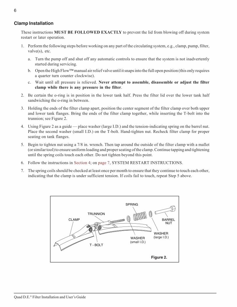
3. Holding the ends of the filter clamp apart, position the center segment of the filter clamp over both upperand lower tank flanges. Bring the ends of the filter clamp together, while inserting the T-bolt into thetrunnion; see Figure 2.
4. Using Figure 2 as a guide — place washer (large I.D.) and the tension-indicating spring on the barrel nut.Place the second washer (small I.D.) on the T-bolt. Hand-tighten nut. Recheck filter clamp for properseating on tank flanges.
5. Begin to tighten nut using a 7/8 in. wrench. Then tap around the outside of the filter clamp with a mallet(or similar tool) to ensure uniform loading and proper seating of the clamp. Continue tapping and tighteninguntil the spring coils touch each other. Do not tighten beyond this point.
6. Follow the instructions in Section 4; on page 7, SYSTEM RESTART INSTRUCTIONS.
7. The spring coils should be checked at least once per month to ensure that they continue to touch each other,indicating that the clamp is under sufficient tension. If coils fail to touch, repeat Step 5 above.
Figure 2.

7
Quad D.E.® Filter Installation and User’s Guide
Section 4System Restart Instructions
This section describes how to restart the Quad D.E.® filter system.
System Restart Instructions
WARNING — THIS FILTER OPERATES UNDER HIGH PRESSURE. When any part of the circulating system,(e.g., clamp, pump, filter, valve(s), etc.), is serviced, air can enter the system and become pressurized.Pressurized air can cause the lid to be blown off which can result in severe injury, death, or propertydamage. To avoid this potential hazard, follow these instructions:
1. Open the High Flow™ manual air relief valve until it snaps into the full open position (this onlyrequires a quarter turn counter clockwise). Opening this valve rapidly releases air trapped in the filter.
2. Stand clear of the filter tank, then start the pump.
3. Close the High Flow™ manual air relief valve after a steady stream of water appears.
4. The system is not working properly if:
a. A solid stream of water does not appear within 30 seconds after the pump's inlet basket fills with water. b. The pressure gauge indicates pressure before water out-flow appears.
If either condition exists, shut off the pump immediately, open valves in the water return line to relievepressure, and clean the air relief valve; see Section 3; on page 5, FILTER OPERATION. If the problempersists, call Customer Service at (800) 831-7133.
8
Quad D.E.® Filter Installation and User’s Guide
Preparing Diatomite
Your filter requires diatomaceous earth (D.E. or diatomite) for proper filtration and operation. Your filterelements must be precoated with this material in order to protect their surfaces and provide the most efficientfiltering action. Refer to Table 2 for the proper quantity to use with your filter. We recommend the use of D.E.which is sold and labeled for use with swimming pools and spas. These grades of D.E. typically have amedian particle size of 34 microns, which is ideal for most applications.
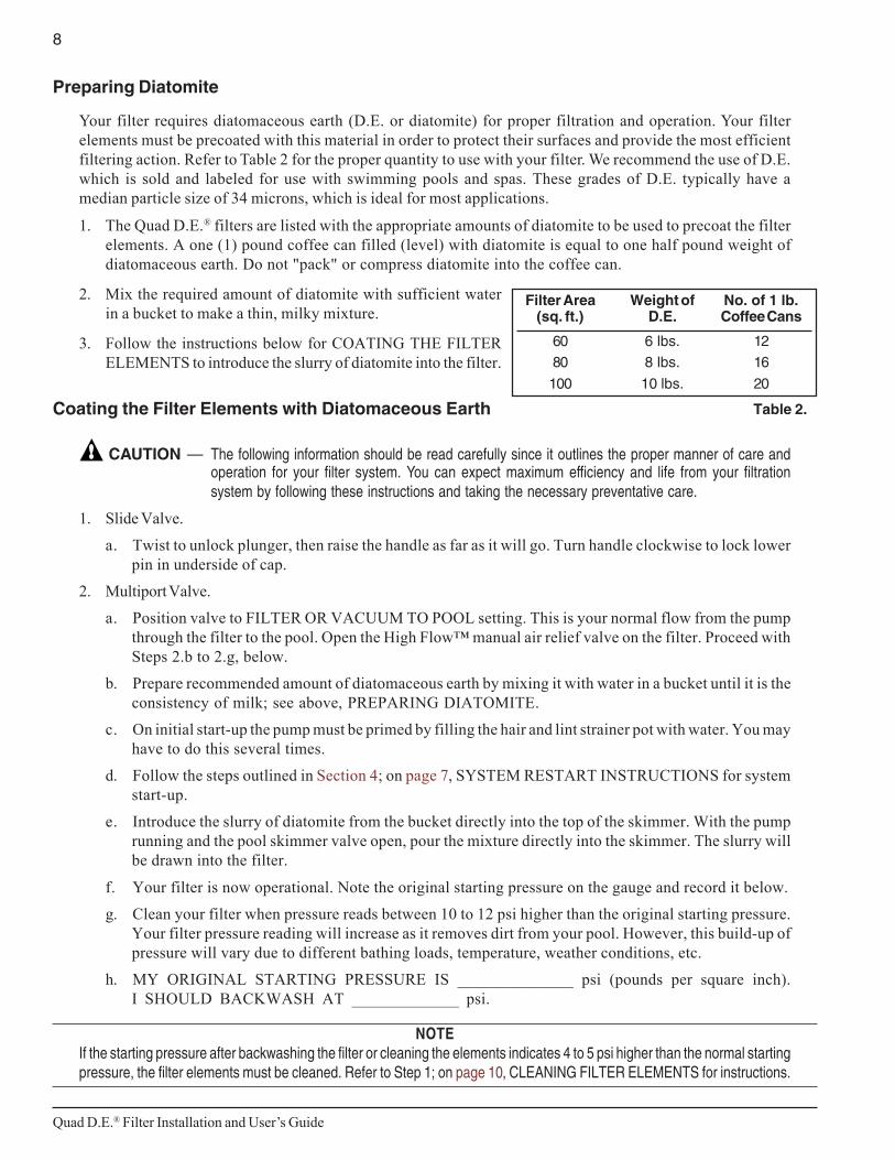
1. The Quad D.E.® filters are listed with the appropriate amounts of diatomite to be used to precoat the filterelements. A one (1) pound coffee can filled (level) with diatomite is equal to one half pound weight ofdiatomaceous earth. Do not "pack" or compress diatomite into the coffee can.
2. Mix the required amount of diatomite with sufficient waterin a bucket to make a thin, milky mixture.
3. Follow the instructions below for COATING THE FILTERELEMENTS to introduce the slurry of diatomite into the filter.
Coating the Filter Elements with Diatomaceous Earth
CAUTION — The following information should be read carefully since it outlines the proper manner of care andoperation for your filter system. You can expect maximum efficiency and life from your filtrationsystem by following these instructions and taking the necessary preventative care.
1. Slide Valve.
a. Twist to unlock plunger, then raise the handle as far as it will go. Turn handle clockwise to lock lowerpin in underside of cap.
2. Multiport Valve.
a. Position valve to FILTER OR VACUUM TO POOL setting. This is your normal flow from the pumpthrough the filter to the pool. Open the High Flow™ manual air relief valve on the filter. Proceed withSteps 2.b to 2.g, below.
b. Prepare recommended amount of diatomaceous earth by mixing it with water in a bucket until it is theconsistency of milk; see above, PREPARING DIATOMITE.
c. On initial start-up the pump must be primed by filling the hair and lint strainer pot with water. You mayhave to do this several times.
d. Follow the steps outlined in Section 4; on page 7, SYSTEM RESTART INSTRUCTIONS for systemstart-up.
e. Introduce the slurry of diatomite from the bucket directly into the top of the skimmer. With the pumprunning and the pool skimmer valve open, pour the mixture directly into the skimmer. The slurry willbe drawn into the filter.
f. Your filter is now operational. Note the original starting pressure on the gauge and record it below.
g. Clean your filter when pressure reads between 10 to 12 psi higher than the original starting pressure.Your filter pressure reading will increase as it removes dirt from your pool. However, this build-up ofpressure will vary due to different bathing loads, temperature, weather conditions, etc.
h. MY ORIGINAL STARTING PRESSURE IS ______________ psi (pounds per square inch).I SHOULD BACKWASH AT _____________ psi.
NOTEIf the starting pressure after backwashing the filter or cleaning the elements indicates 4 to 5 psi higher than the normal startingpressure, the filter elements must be cleaned. Refer to Step 1; on page 10, CLEANING FILTER ELEMENTS for instructions.
Filter Area Weight of No. of 1 lb.(sq. ft.) D.E. Coffee Cans
60 6 lbs. 1280 8 lbs. 16
100 10 lbs. 20
Table 2.

9
Quad D.E.® Filter Installation and User’s Guide
Section 5Maintenance
Cleaning the Quad D.E.® Filter Manually
1. Turn the pump off, shut off any automatic controls to ensure that the system is not inadvertently startedduring servicing.
2. Automatic skimmer should have Vari-Flo trimmer valve set to 100% skimmer. This will close off the main drainline. If there is a separate skimmer line and main drain line plumbed to the pump, close the main drain valve.
3. Open the filter High Flow™ manual air relief valve, and the waste drain valve or plug if your system hasone. Disconnect air relief valve drain hose if installed.
4. Remove the pump’s hair and lint strainer pot lid and clean the basket. Replace basket and secure lid. Followthe instructions provided with your pump.
5. Never attempt to assemble, disassemble or adjust the filter clamp while there is pressure in thefilter. Release the tank clamp assembly and remove tank lid.
6. Ensure the internal air bleed assembly is in place and free of diatomite or debris, see page 12, CLEANINGTHE INTERNAL AIR BLEED TUBE.
7. Remove top manifold and cartridge style elements separately.8. Using a garden hose without a nozzle, direct water spray at cartridge style elements to dislodge and wash
away accumulated foreign matter. Flush each cartridge inside and out.
WARNING — Please heed all manufacturers' posted instructions, warnings and cautions when using Baquacil® orBaqua® Clean.
NOTESpecial care must be taken when cleaning filter cartridge style elements used in a swimming pool or spa using Baquacil® as a sanitizer. Becauseof the way Baquacil® works, the filter element must be cleaned more thoroughly and more frequently than in a chlorine system. If extreme careis not taken to completely remove all residue from the filter media a buildup will occur. This buildup will significantly shorten the life of the filterelement.
Baquacil® is a mild coagulant which combines bacterial cells as well as other small particles contributed by the environment, bathers, etc. intoparticles large enough to be trapped by the filter. In comparison with all other trapped contaminants in a typical pool or spa the amount of bacterialcells that are deposited on the filter is minimal. The resulting deposit is a gray sticky film which can only be removed with Baqua® Clean. If TSPor any TSP-type cleaner is used prior to stripping the film, the cleaner and the gray film will combine to form a gum-like substance. Once thisoccurs, the substance cannot be removed from the media and the filter cartridge must be replaced.
9. Lift bottom manifold out of the tank and flush off any debris.10. Direct water spray to wash out the inside of the tank body. Water and debris will drain out through the open
drain port.11. Check gasket around outer lip of bottom plate. Gasket must be firmly and evenly set in place. Do not use
petroleum base lubricants to avoid damage to the gasket.12. Place bottom manifold, 4 cartridge style elements, top manifold and air relief tube in place. Make sure the
spring and standpipe assembly are retained on the top manifold. Ensure the air relief tube stays in an uprightposition. This is essential for the maximum air removal from inside the tank.
13. Be certain the o-ring is in position in the lower tank half. Press the filter lid over the lower tank half andsandwich the o-ring in between.
14. Replace tank top and carefully follow instructions on page 6, CLAMP INSTALLATION INSTRUCTIONS.15. Replace drain plug and reinstall air relief valve drain hose if used.
10
Quad D.E.® Filter Installation and User’s Guide
Replacing Filter Cartridge Style Elements
Filter cartridge style element life will vary with pool conditions such as bather load, wind, dust, etc.You can expect an average cartridge life of 3 years under normal conditions.
1. To replace cartridge style elements follow steps in Section 5; on page 9, CLEANING FILTERMANUALLY, eliminating step 8.
Cleaning your Filter using a System with a Separation Tank
1. Before working on any part of the circulating system, clamp, pump, filter, valve(s), etc., perform thefollowing steps.a. Turn the entire pool/spa system off to ensure that the system is not inadvertently started during
servicing.b. Open the High Flow™ manual air relief valve.c. Wait until all pressure is relieved. Never attempt to assemble, disassemble or adjust the filter
clamp while there is pressure in the filter.2. Turn skimmer to full skim position and close main drain line.3. Remove pump lid and clean basket. Replace basket and secure lid.4. Valve Procedures.
a. Slide Valve.(1) Push the handle on the valve down with slight twisting motion as far as it will go. Lock upper pin in
cap. Open High Flow™ manual air relief valve on filter. Proceed with steps b(1) to b(9) on page 11.(2) Open the High Flow™ manual air relief valve until it snaps into the full open position
(this only requires a quarter turn counter-clockwise). Opening this valve rapidly releasesair trapped in the filter.
(3) Stand clear of the filter tank, then start the pump.(4) Close the High Flow™ manual air relief valve after a steady stream of water appears.(5) When water flows clear in sight glass or discharge line, shut off pump.(6) Position the Slide valve to the normal FILTER setting by raising the handle and twisting it to the
locked position.(7) Open High Flow™ manual air relief valve on top of separation tank, wait for water to stop draining
from air relief.(8) Loosen Separation Tank clamp and lift off Separation Tank lid.(9) Remove bag and dispose of diatomite in trash can. Replace clean bag and set bag in seat (curved
portion of Separation Tank). Make sure the top of the bag is below the inlet to prevent earth fromgoing back into pool, one double bag is furnished with Separation Tank.
NOTEFilter waste and diatomite are trapped by the heavy-duty double lined Separation Tank bag. Contents are to be placed ina waste or trash container, clean the bag and re-insert in the Separation Tank. DO NOT LEAVE THE SEPARATION TANKBAG EXPOSED IN THE SUN. The manufacturer cannot assume any responsibility for torn, or damaged bags, if left in thesun to dry.
(10) Replace Separation Tank lid and secure Separation Tank lid clamp. Follow instructions on page 6,CLAMP INSTALLATION INSTRUCTIONS.
(11) Leave valve in normal FILTER position.(12) Follow instructions in Section 4; on page 7, SYSTEM RESTART INSTRUCTIONS to start up filter.(13) Introduce the recommended amount of diatomite per Section 4; on page 8, COATING THE
FILTER ELEMENTS. Your filter is now in operation.

11
Quad D.E.® Filter Installation and User’s Guide
Cleaning your Filter using a System with a Separation Tank, cont’d.
b. Multiport Rotary Valve.After completing Steps 1 to 3 of this section; on page 10, perform the following steps:
(1) Position the valve to the BACKWASH setting.(2) Open the High Flow™ manual air relief valve until it snaps into the full open position
(this only requires a quarter turn counter-clockwise). Opening this valve rapidly releasesair trapped in the filter.
(3) Stand clear of the filter tank, then start the pump.(4) Close the High Flow™ manual air relief valve after a steady stream of water appears and run
in the BACKWASH mode for 1 minute.(5) Stop the pump, set the filter valve to FILTER and run for 20 seconds, then stop the pump.
(6) Repeat the BACKWASH/FILTER cycle 3 times.
(7) When the sight glass shows a clear flow of water, shut off the pump.(8) Position Multiport Rotary valve to the CLOSED setting.(9) Follow section 4.a – Slide Valve on page 10.
Cleaning Filter Elements
For a more thorough cleaning of the individual elements, perform the following steps:
1. Cleaning with water:a. Using a garden hose, thoroughly flush off all contaminated diatomite from the filter element surfaces.
2. Cleaning with muriatic acid:
WARNING — Working with muriatic acid can be dangerous. When cleaning elements always wear rubber glovesand eye protection. Add acid to water, do not add water to acid. Splashing or spilling acid can causesevere personal injury and/or property damage.
a. A stiffening of the fabric caused by mineral deposits is usually referred to as "liming up". It usually isdue to deposits of either magnesium or calcium or both. Removal of these deposits may beaccomplished by soaking the filter elements in six (6) parts water to one (1) part hydrochloric acid(muriatic acid).
b. Wear rubber gloves and eye protection when mixing the solution, and handling or rinsing the filterelements.
c. Soak for at least four (4) hours in a plastic tub or pail.d. Rinse filter elements thoroughly in tap water.
12
Quad D.E.® Filter Installation and User’s Guide
Cleaning the Internal Air Bleed Tube
1. Rinse the air bleed tube with water to clean away built-up debris. Normally, this is all that is necessary toproperly clean the tube.
Cleaning the High Flow™ Manual Air Relief Valve
1. Turn the pump off and shut off any automatic controls to ensure that the system is not inadvertentlystarted during servicing.
2. OPEN THE HIGH FLOW™ MANUAL AIR RELIEF VALVE UNTIL IT SNAPS INTO THEFULL OPEN POSITION, THEN WAIT UNTIL ALL PRESSURE IS RELIEVED.
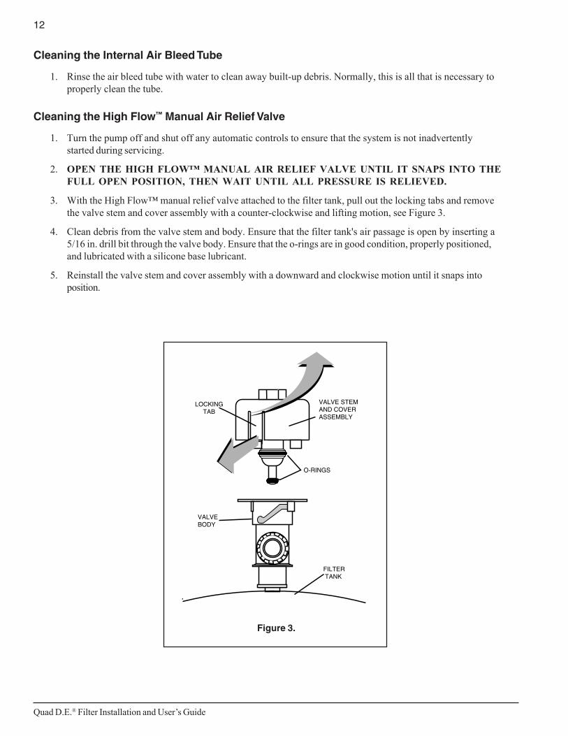
3. With the High Flow™ manual relief valve attached to the filter tank, pull out the locking tabs and removethe valve stem and cover assembly with a counter-clockwise and lifting motion, see Figure 3.
4. Clean debris from the valve stem and body. Ensure that the filter tank's air passage is open by inserting a5/16 in. drill bit through the valve body. Ensure that the o-rings are in good condition, properly positioned,and lubricated with a silicone base lubricant.
5. Reinstall the valve stem and cover assembly with a downward and clockwise motion until it snaps intoposition.
Figure 3.
13
Quad D.E.® Filter Installation and User’s Guide
Section 6Troubleshooting
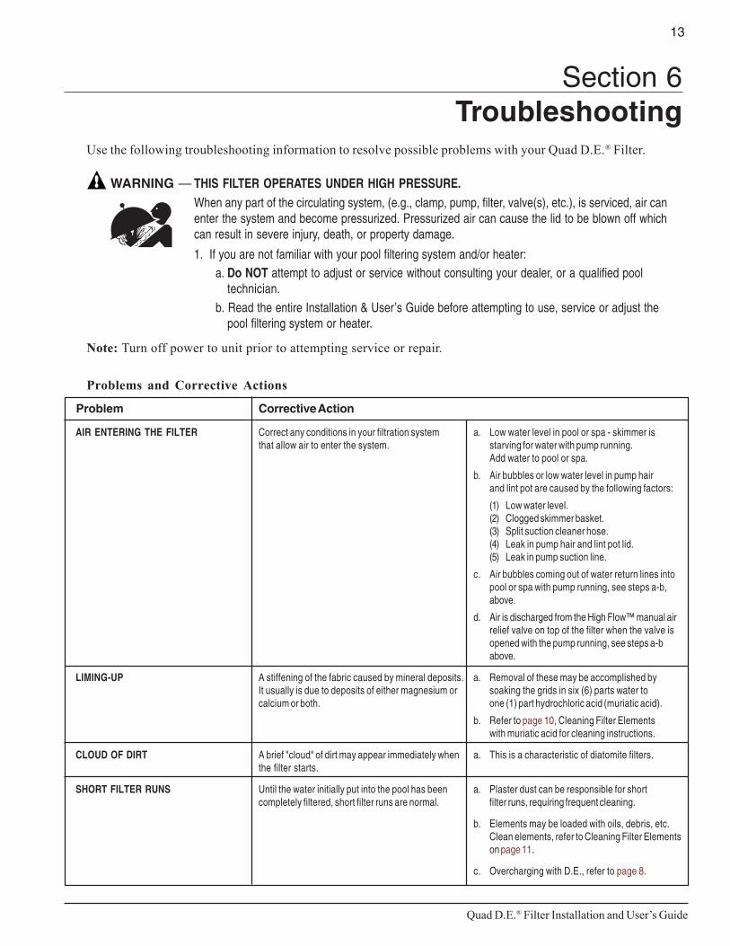
Use the following troubleshooting information to resolve possible problems with your Quad D.E.® Filter.
WARNING — THIS FILTER OPERATES UNDER HIGH PRESSURE.When any part of the circulating system, (e.g., clamp, pump, filter, valve(s), etc.), is serviced, air canenter the system and become pressurized. Pressurized air can cause the lid to be blown off whichcan result in severe injury, death, or property damage.
1. If you are not familiar with your pool filtering system and/or heater:a. Do NOT attempt to adjust or service without consulting your dealer, or a qualified pool
technician.b. Read the entire Installation & User’s Guide before attempting to use, service or adjust the
pool filtering system or heater.
Note: Turn off power to unit prior to attempting service or repair.
Problems and Corrective Actions
Problem Corrective Action
AIR ENTERING THE FILTER Correct any conditions in your filtration system a. Low water level in pool or spa - skimmer isthat allow air to enter the system. starving for water with pump running.
Add water to pool or spa.
b. Air bubbles or low water level in pump hairand lint pot are caused by the following factors:
(1) Low water level.(2) Clogged skimmer basket.(3) Split suction cleaner hose.(4) Leak in pump hair and lint pot lid.(5) Leak in pump suction line.
c. Air bubbles coming out of water return lines intopool or spa with pump running, see steps a-b,above.
d. Air is discharged from the High Flow™ manual airrelief valve on top of the filter when the valve isopened with the pump running, see steps a-babove.
LIMING-UP A stiffening of the fabric caused by mineral deposits. a. Removal of these may be accomplished byIt usually is due to deposits of either magnesium or soaking the grids in six (6) parts water tocalcium or both. one (1) part hydrochloric acid (muriatic acid).
b. Refer to page 10, Cleaning Filter Elementswith muriatic acid for cleaning instructions.
CLOUD OF DIRT A brief "cloud" of dirt may appear immediately when a. This is a characteristic of diatomite filters.the filter starts.
SHORT FILTER RUNS Until the water initially put into the pool has been a. Plaster dust can be responsible for shortcompletely filtered, short filter runs are normal. filter runs, requiring frequent cleaning.
b. Elements may be loaded with oils, debris, etc.Clean elements, refer to Cleaning Filter Elementson page 11.
c. Overcharging with D.E., refer to page 8.
14
Quad D.E.® Filter Installation and User’s Guide
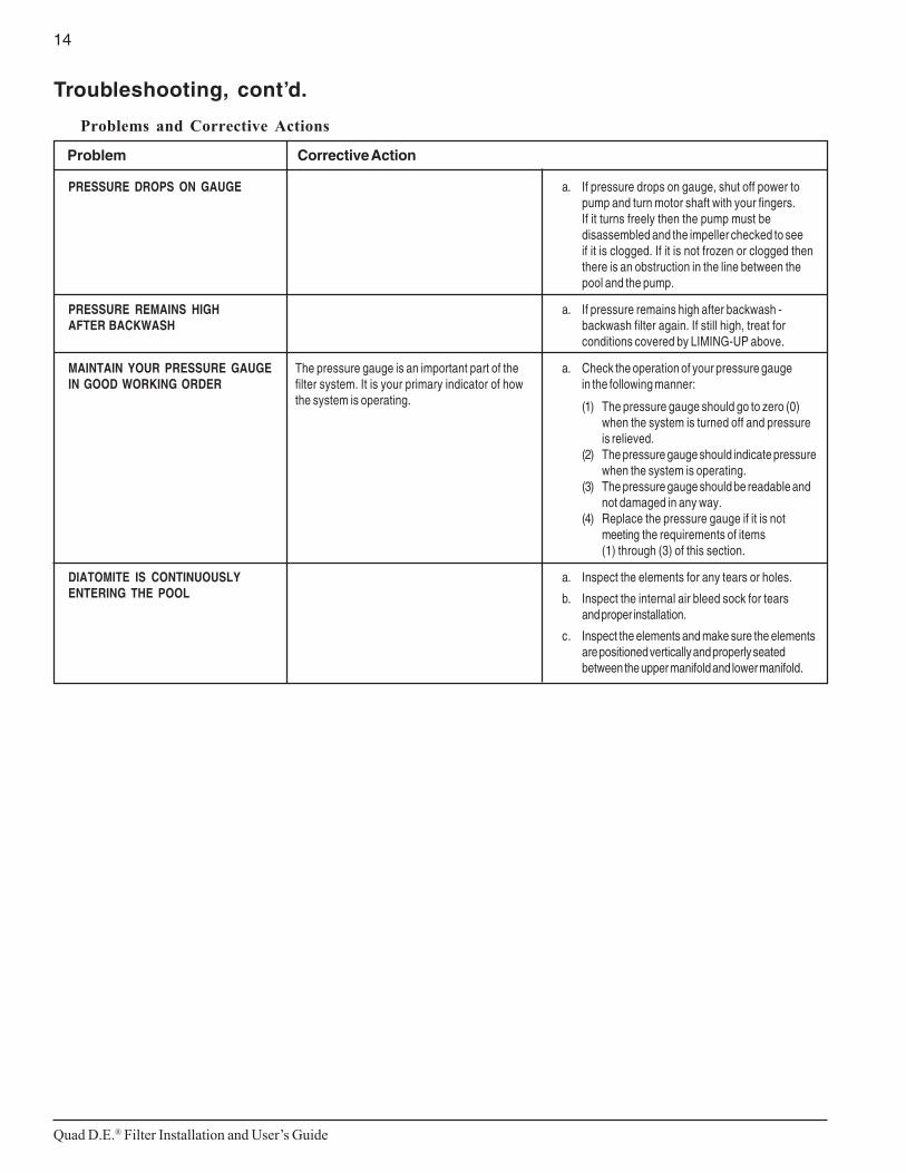
Troubleshooting, cont’d.
Problems and Corrective Actions
Problem Corrective Action
PRESSURE DROPS ON GAUGE a. If pressure drops on gauge, shut off power topump and turn motor shaft with your fingers.If it turns freely then the pump must bedisassembled and the impeller checked to seeif it is clogged. If it is not frozen or clogged thenthere is an obstruction in the line between thepool and the pump.
PRESSURE REMAINS HIGH a. If pressure remains high after backwash -AFTER BACKWASH backwash filter again. If still high, treat for
conditions covered by LIMING-UP above.
MAINTAIN YOUR PRESSURE GAUGE The pressure gauge is an important part of the a. Check the operation of your pressure gaugeIN GOOD WORKING ORDER filter system. It is your primary indicator of how in the following manner:
the system is operating. (1) The pressure gauge should go to zero (0)when the system is turned off and pressureis relieved.
(2) The pressure gauge should indicate pressurewhen the system is operating.
(3) The pressure gauge should be readable andnot damaged in any way.
(4) Replace the pressure gauge if it is notmeeting the requirements of items(1) through (3) of this section.
DIATOMITE IS CONTINUOUSLY a. Inspect the elements for any tears or holes.ENTERING THE POOL b. Inspect the internal air bleed sock for tears
and proper installation.
c. Inspect the elements and make sure the elementsare positioned vertically and properly seatedbetween the upper manifold and lower manifold.
15
Quad D.E.® Filter Installation and User’s Guide
Section 7Replacement Parts
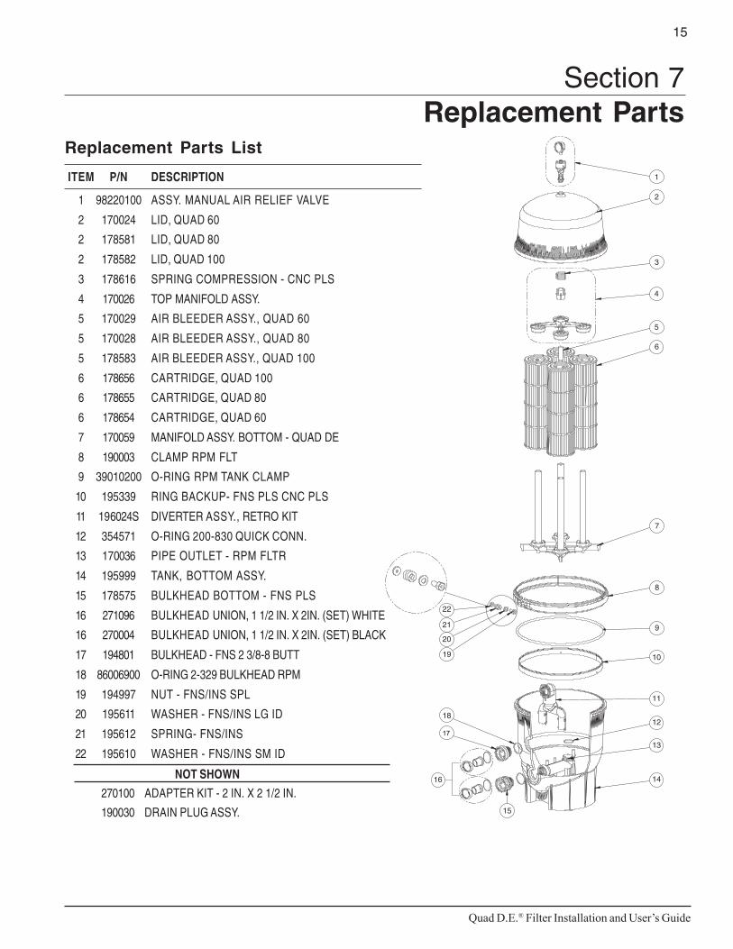
Replacement Parts List
ITEM P/N DESCRIPTION
1 98220100 ASSY. MANUAL AIR RELIEF VALVE
2 170024 LID, QUAD 60
2 178581 LID, QUAD 80
2 178582 LID, QUAD 100
3 178616 SPRING COMPRESSION - CNC PLS
4 170026 TOP MANIFOLD ASSY.
5 170029 AIR BLEEDER ASSY., QUAD 60
5 170028 AIR BLEEDER ASSY., QUAD 80
5 178583 AIR BLEEDER ASSY., QUAD 100
6 178656 CARTRIDGE, QUAD 100
6 178655 CARTRIDGE, QUAD 80
6 178654 CARTRIDGE, QUAD 60
7 170059 MANIFOLD ASSY. BOTTOM - QUAD DE
8 190003 CLAMP RPM FLT
9 39010200 O-RING RPM TANK CLAMP
10 195339 RING BACKUP- FNS PLS CNC PLS
11 196024S DIVERTER ASSY., RETRO KIT
12 354571 O-RING 200-830 QUICK CONN.
13 170036 PIPE OUTLET - RPM FLTR
14 195999 TANK, BOTTOM ASSY.
15 178575 BULKHEAD BOTTOM - FNS PLS
16 271096 BULKHEAD UNION, 1 1/2 IN. X 2IN. (SET) WHITE
16 270004 BULKHEAD UNION, 1 1/2 IN. X 2IN. (SET) BLACK
17 194801 BULKHEAD - FNS 2 3/8-8 BUTT
18 86006900 O-RING 2-329 BULKHEAD RPM
19 194997 NUT - FNS/INS SPL
20 195611 WASHER - FNS/INS LG ID
21 195612 SPRING- FNS/INS
22 195610 WASHER - FNS/INS SM ID
1
22
13
10
8
9
6
16
5
1812
4
2
7
21
15
3
11
20
19
14
17
NOT SHOWN
270100 ADAPTER KIT - 2 IN. X 2 1/2 IN.
190030 DRAIN PLUG ASSY.
16
Quad D.E.® Filter Installation and User’s Guide
Section 8 Technical Data
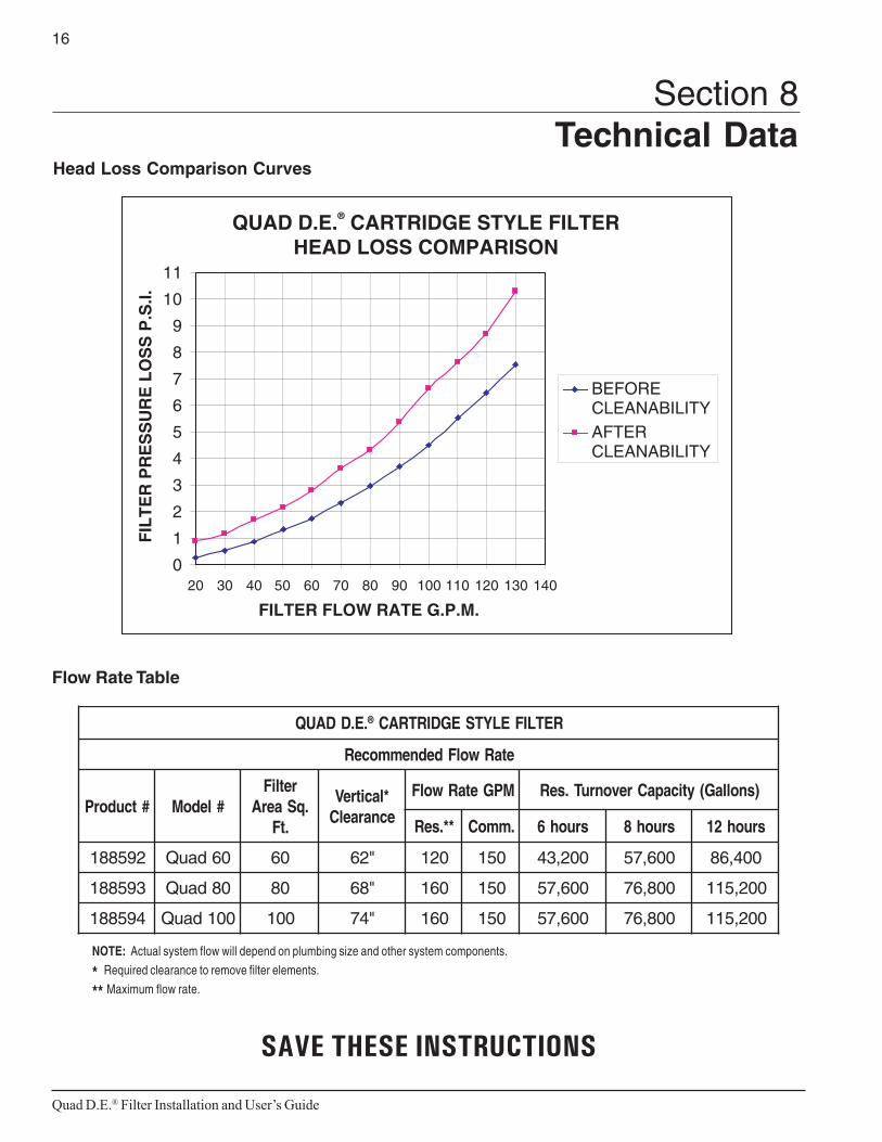
Head Loss Comparison Curves
SAVE THESE INSTRUCTIONS
QUAD D.E.® CARTRIDGE STYLE FILTERHEAD LOSS COMPARISON
0
1
2
3
4
5
6
7
8
9
10
11
20 30 40 50 60 70 80 90 100 110 120 130 140
FILTER FLOW RATE G.P.M.
FIL
TE
R P
RE
SS
UR
E L
OS
S P
.S.I.
BEFORECLEANABILITYAFTERCLEANABILITY
.E.DDAUQ ® RETLIFELYTSEGDIRTRAC
etaRwolFdednemmoceR
#tcudorP #ledoMretliF
.qSaerA.tF
*lacitreVecnaraelC
MPGetaRwolF )snollaG(yticapaCrevonruT.seR
**.seR .mmoC sruoh6 sruoh8 sruoh21
295881 06dauQ 06 "26 021 051 002,34 006,75 004,68
395881 08dauQ 08 "86 061 051 006,75 008,67 002,511
495881 001dauQ 001 "47 061 051 006,75 008,67 002,511
Flow Rate Table
NOTE: Actual system flow will depend on plumbing size and other system components.
* Required clearance to remove filter elements.
** Maximum flow rate.

NOTES

P/N 178658 Rev. E 5/19/11