deadly medicine - ushmm.org
TRANSCRIPT

Deadly MedicineE X H I B I T A S S E M B L Y M A N U A L


1
Before Getting Started
North America: Ireland/Europe: United Kingdom:1-800-732-9395 + 353-98-66011(Day) 0399-734215
+ 353-1-283-0800 (Evening) Germany:Ask for call sign “Nomadic” 0180-2304311
Proper Care & Maintenance of your Nomadic Display• Store display upright at room temperature• Do not subject to extreme heat or cold• Do not leave display in direct sunlight or trunk of auto• Return display to room temperature before handling• Avoid extreme bending of Panels or permanent creasing will occur• Use fabric brush to remove dust from FabriColor Panels
Whether your business takes you around the corner or around the globe, you can depend on the Nomadic 24-Hour toll free LifeLine for peace of mind. Our LifeLine helps Nomadic customers solve the frustrating, unexpected, and often urgent situations that arise on the road. Help is at the touch of your fingertips by dialing the Nomadic service center nearest you. You will get a return call from an experienced Nomadic staff member within 15 minutes.
It is important to follow each step in the order indicated in this manual. If you need additional assistance or have any questions, please call your nearest Nomadic LifeLine.
Before Getting Started
1

Table of Contents
Exhibit Overview............................................................................................................ 3Exhibit Map .................................................................................................................. 4-5Image Panels ............................................................................................................... 6-9
Cases ........................................................................................................................... 10
Frames ......................................................................................................................... 11Frame Setup ..................................................................................................................11Adding Panels and Endcaps ........................................................................................ 13
AV .................................................................................................................................. 14Shelf Setup ................................................................................................................... 14Monitor Bracket Setup ............................................................................................. 15-1637” Monitor Stand Setup ............................................................................................... 17
Unit Guides .................................................................................................................. 18Orion ........................................................................................................................ 18-20Gateway .................................................................................................................. 21-24Tuscana ................................................................................................................... 25-26Neptune ................................................................................................................... 27-28 Dismantling Instructions ........................................................................................... 29
2

Panel # Structure type Flat or Round end cap AV Type of back
panel needed
SECTION 11.0 Orion Round - graphic1.1 Gateway Flat - -1.2 Gateway Flat Yes 17” fabricSECTION 22.0 Tuscana Round - graphic2.1 Orion Flat - -2.2 Orion Flat - -2.3 Gateway Flat - -SECTION 33.0 Tuscana Round - graphic3.1 Gateway Flat Yes 20” fabric3.2 Gateway Flat Yes 20” fabric3.3 Gateway Flat - -3.4 Orion Flat - -3.5 Orion Flat - -3.6 Orion Flat - -3.7 Gateway Flat Yes 20” fabric3.8 Gateway Flat - -SECTION 44.0 Tuscana Round - graphic4.1 Gateway Flat - -4.2 Orion Flat Yes 15” fabric4.3 Neptune Round - fabric4.4 Orion Flat - -4.5 Gateway Flat - -4.6 Gateway Flat - -4.7 Gateway Flat Yes 15” fabric4.8 Orion Flat - -4.9 Gateway Flat Yes 15” fabric4.10 Orion Flat - -SECTION 55.0 Neptune Round - fabric
Extrusion stand for 36” monitor
SECTION 66.0 Gateway Flat - -6.1 Tuscana Round - graphic6.2 Tuscana Flat - -
Deadly Medicine Exhibit Overview
3

Gateway 1.1
Gateway 4.1 Gateway 4.5 Gateway 4.6 Gateway 4.7AV with 15”Monitor
Fabric panels on back
Gateway 4.9AV with xx15”Monitor
Fabric panels on back
Gateway 6.0
Gateway 1.2AV with 17”Monitor
Fabric panels on back
Gateway 2.3
Gateway 3.1AV with 20”Monitor
Fabric panels on back
Gateway 3.2AV with 20”Monitor
Fabric panels on back
Gateway 3.7AV with 20”Monitor
Fabric panels on back
Gateway 3.8Gateway 3.3
Orion 1.0Graphic panels on both sides
Orion 2.1 Orion 2.2
Orion 3.4 Orion 3.5 Orion 3.6
Orion 4.2AV with 15”Monitor
Fabric panels on back
Orion 4.4 Orion 4.8 Orion 4.10
37” Theater Monitorwith Stand
Tuscana 6.1Graphic panels on both sides
Tuscana 3.0Graphic panels on both sides
Tuscana 2.0Graphic panels on both sides
Tuscana 4.0Graphic panels on both sides
Tuscana 6.2
Neptune 4.3Fabric panels on back
Neptune 5.0Fabric panels on back
Exhibit Key
Roller Case
Monitor Case
Display with flat endcaps
Display with round endcaps
SEC TION 1 SEC TION 2
SEC TION 3
SEC TION 4
SEC TION 5 SEC TION 6
Deadly Medicine Exhibit Overview
4

Gateway 1.1
Gateway 4.1 Gateway 4.5 Gateway 4.6 Gateway 4.7AV with 15”Monitor
Fabric panels on back
Gateway 4.9AV with xx15”Monitor
Fabric panels on back
Gateway 6.0
Gateway 1.2AV with 17”Monitor
Fabric panels on back
Gateway 2.3
Gateway 3.1AV with 20”Monitor
Fabric panels on back
Gateway 3.2AV with 20”Monitor
Fabric panels on back
Gateway 3.7AV with 20”Monitor
Fabric panels on back
Gateway 3.8Gateway 3.3
Orion 1.0Graphic panels on both sides
Orion 2.1 Orion 2.2
Orion 3.4 Orion 3.5 Orion 3.6
Orion 4.2AV with 15”Monitor
Fabric panels on back
Orion 4.4 Orion 4.8 Orion 4.10
37” Theater Monitorwith Stand
Tuscana 6.1Graphic panels on both sides
Tuscana 3.0Graphic panels on both sides
Tuscana 2.0Graphic panels on both sides
Tuscana 4.0Graphic panels on both sides
Tuscana 6.2
Neptune 4.3Fabric panels on back
Neptune 5.0Fabric panels on back
Exhibit Key
Roller Case
Monitor Case
Display with flat endcaps
Display with round endcaps
SEC TION 1 SEC TION 2
SEC TION 3
SEC TION 4
SEC TION 5 SEC TION 6
5
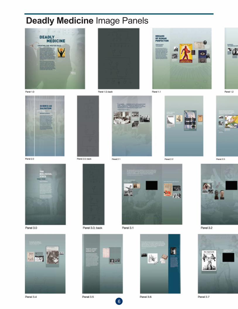
Deadly Medicine Image Panels
6

7
NOTEPanel Numbering is as follows:
Each booth has been assigned a number, from Unit 1.0 through 6.2as shown on the preceeding layout chart. The panels provided for each unit are numbered on the reverse side, and install in ascending order from left to right. The first set of numbers on the back of each panel corresponds to the Unit’s number followed by its order on that unit, left to right.

Deadly Medicine Image Panels cont.
8

9

Rolluxe Case: To open lid set yourcombination at “000”.
Press red button and lift latch torelease side latches and remove the top.
Using the Rolluxe Case2 • Quick Set Up
Opening Your Case:
Visual glossary of parts: Hub
Stud
Strut
Rolluxe Case top serves as a built-in step stool to facilitate hanging and adjusting graphics.
Using the Rolluxe Case
10

03• Frames
Frame Set Up
Instand Classic Frame Instand Plus Frame
Instand Frame Types:
All Instand Frames set-up the same way:
Place frame on floor with red studs facing front.
Grasp two center hubs and liftframe open to shoulder height.Handle frame at hubs.
Press front and back hubs in the center of the frame until Instandlocks into position. (Front and backhubs do not meet.) *
*Note: Once frame is expanded, the row of red hubs (or red studs) should be on the floor facing forward
REMEMBER –Read the complete instructions about your Instand product before assembling. If you need additional assistance or have any questions, please call the nearest Nomadic LifeLine.
Instand Frames
11

04 • Frames
Frame Set Up
Unfold connected strut . . . …and connect bottom two sectionsby joining as illustrated.
Slide bottom of connected strutonto the red stud at the bottom ofthe frame.
Snap next two connectors ontostuds on frame.
Covering Your Instand with Fabric or Graphics:
NOTE -Install the internal monitor shelf for the 7 units with AV systems before hanging the fabric panels on the back. For detailed instructions on setting up AV brackets, monitors and shelves, refer to the AV section of this manual.
Attach struts to front and rear sidesof curved frames. Attach struts tofront and rear of straight frames.
Frame Setup
12

05 • Panels
Hang all top panels and full sizepanels first. Lift onto studs atopframe. It is easiest with these panels to hook both sides at the same time.
Gradually release downward to bondmagnets. Be careful to keep the panelin a U shape and not to bend or kink
Adding PanelsSee labels affixed to back of panels for placement
Bow end cap and quarter roundpanel. Lift onto studs atop front and back sides of frame. Slidehands along length of panel to bond magnets.
Hang hinged panels onto studs attop of frame. Hook one side thenthe other. Slide hands along lengthof panel to bond magnets.
Adding Panels
13
AV Flashplayer ShelfAV Setup • 06
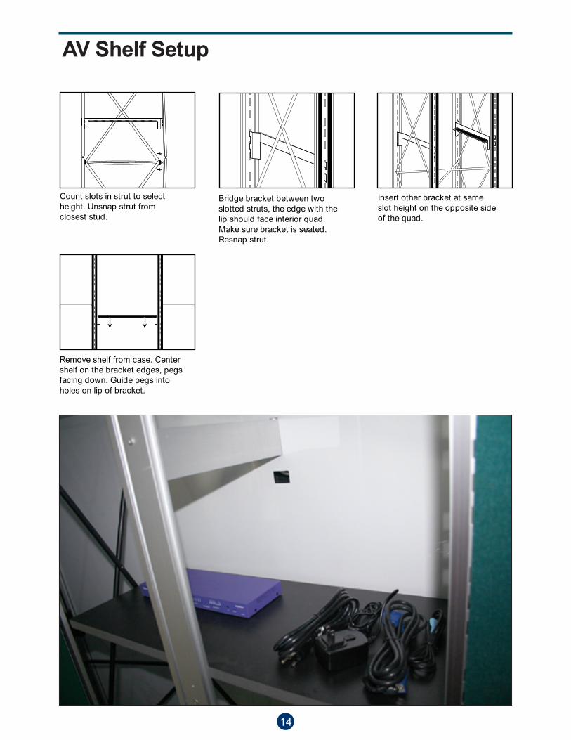
Bridge bracket between twoslotted struts, the edge with thelip should face interior quad.Make sure bracket is seated.Resnap strut.
Insert other bracket at sameslot height on the opposite sideof the quad.
Remove shelf from case. Centershelf on the bracket edges, pegsfacing down. Guide pegs intoholes on lip of bracket.
Count slots in strut to selectheight. Unsnap strut from closest stud.
AV Shelf Setup
14
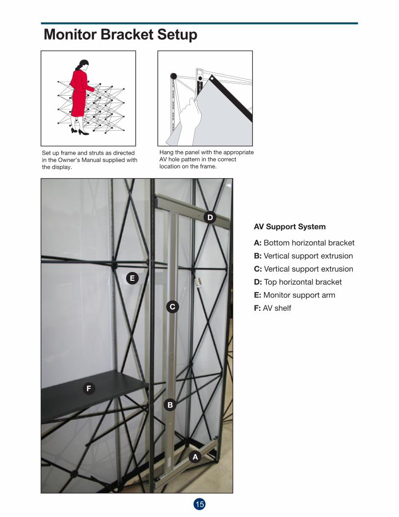
Monitor Bracket Setup
Set up frame and struts as directedin the Owner’s Manual supplied withthe display.
Hang the panel with the appropriate AV hole pattern in the correct location on the frame.
B
A
D
C
E
F
A: Bottom horizontal bracket
B: Vertical support extrusion
C: Vertical support extrusion
D: Top horizontal bracket
E: Monitor support arm
F: AV shelf
AV Support System
15

From the back side of the display, install the bracket(s) in the appropriate location. Use the slots in the struts as guides to identify the correct height and locationof bracket A. The bottom of the horizontal bracket should be aligned with the slot that is second-from-bottomslot on the strut.
Attach the two vertical extrusions, bysliding the In-Line connector into the internal channel on both vertical extrusions making sure to line up all of the screw holes. Use the hex wrench provided to ensure a secure connection, by inserting the wrench into the screw head and twisting clock-wise.
Use the hex wrench provided to ensure a secure connection, by inserting the wrench into the screw head and twisting clock-wise.
B
C
Make sure that the screws on bothB & C extrusions are secure.
C B
A
Secure vertical support extrusion (B.) to bracket (A.)
B
Install top bracket using the same process used for the bottom bracket. Once the bracket is installed, secure the top of the vertical extrusion by inserting the hex key into the set screw on the vertical extrusion and turning in a clockwise direction until extrusion is locked in place.
A
D
C
Install the monitor bracket on the support arm (E) by using the hexwrench provided, making sure the lock is fully engaged in the vertical channel of the bracket.
Secure the monitor support arm using the hex wrench provided in your kit. (Make sure lock is fully engaged before releasing your grip on the arm. Failure to secure the unit could possibly result in damage to the panel.)
E
E
16

3
3
1
1
1
2
22
A
C
D
B
A
D
C
E
Loosen thread screw (C) and slide vertical connector (B) out of Vertical extrusion (A). Re-secure with thread screw (C) on both sides of extrusion. Slide vertical extrusion (D) onto the certical connector (B) and secure using threaded screw (E) on both sides of extrusion.
Feed black threaded screw (A) through small hole in baseplace (B). Align vertical extrusion (D) with Baseplate connector (C) inside, over hole in baseplate. Thread screw (A) into baseplate connector. Turn screw slockwise until tight.
Note: Shape of the baseplate is different but installation remains the same.
B
B
A
A
D
D
C
C
E
17
37” Monitor Stand Setup

Orion Unit Guide
18
Quick Reference GuideOrion Kit
Graphic Panel Specifications • xxv
Nomadic
Revised: April 2, 2007
Minimum Document Size*(with Bleed)
Width: 124.75” x Height: 91.75”3169mm x 2331mm
(50% with Bleed)Width: 62.375” x Height: 45.875”
1584.5mm x 1166mm
(25% with Bleed)Width: 31.1875” x Height: 22.9375”
792.25mm x 583mm
Finished SizeWidth: 122.75” x Height: 89.75”
3118mm x 2280mm
*Your document size should encompass thecrops and bleed area.
89.75î2280mm
122.75î3118mm
3m
3m
1'13/4''/0.4m
7'11/2''/2.2m
7'93/4''/2.4m
30.6875î780mm
30.6875î780mm
30.6875î780mm
30.6875î780mm
EndCap
EndCap
FrontFront
Orion Kit Plus Configuration
NOITAVELENALP ROOLF
5'11/2'' / 1.6m with flat endcaps

Orion 1.02 - roller cases2 - graphic panels2 - round graphic end caps2 - fabric back panels
Orion 3.4 2 - roller cases2 - graphic panels2 - flat graphic end caps2 - fabric back panels
Orion 2.2 2 - roller cases2 - graphic panels2 - flat graphic end caps2 - fabric back panels
Orion 2.1 2 - roller cases2 - graphic panels2 - flat graphic end caps2 - fabric back panels
Orion Unit Guide
19
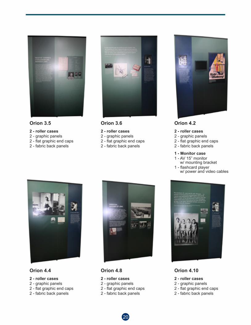
Orion 4.22 - roller cases2 - graphic panels2 - flat graphic end caps2 - fabric back panels
1 - Monitor case1 - AV 15” monitor w/ mounting bracket1 - flashcard player w/ power and video cables
Orion 4.102 - roller cases2 - graphic panels2 - flat graphic end caps2 - fabric back panels
Orion 3.62 - roller cases2 - graphic panels2 - flat graphic end caps2 - fabric back panels
Orion 3.52 - roller cases2 - graphic panels2 - flat graphic end caps2 - fabric back panels
Orion 4.82 - roller cases2 - graphic panels2 - flat graphic end caps2 - fabric back panels
Orion 4.42 - roller cases2 - graphic panels2 - flat graphic end caps2 - fabric back panels
20 21
Quick Reference GuideGateway Kit
Graphic Panel Specifications • xxvi
Nomadic
Revised: April 2, 2007
Minimum Document Size*(with Bleed)
Width: 155.4375” x Height: 91.75”3951mm x 2331mm
(50% with Bleed)Width: 77.71875” x Height: 45.875”
1975mm x 1166mm
(25% with Bleed)Width: 38.859375” x Height: 22.9375”
988mm x 583mm
Finished SizeWidth: 153.4375” x Height: 89.75”
3900mm x 2280mm
*Your document size should encompass thecrops and bleed area.
89.75”2280mm
153.4375”3900mm
30.6875”780mm
30.6875”780mm
30.6875”780mm
30.6875”780mm
30.6875”780mm
1'13/4''/0.4m
9'8''/3m
7'93/4''/2.4m3m
3m
FrontEndCap
EndCap
FrontFront
Gateway Kit Plus Configuration

Gateway Unit Guide
21
Quick Reference GuideGateway Kit
Graphic Panel Specifications • xxvi
Nomadic
Revised: April 2, 2007
Minimum Document Size*(with Bleed)
Width: 155.4375” x Height: 91.75”3951mm x 2331mm
(50% with Bleed)Width: 77.71875” x Height: 45.875”
1975mm x 1166mm
(25% with Bleed)Width: 38.859375” x Height: 22.9375”
988mm x 583mm
Finished SizeWidth: 153.4375” x Height: 89.75”
3900mm x 2280mm
*Your document size should encompass thecrops and bleed area.
89.75”2280mm
153.4375”3900mm
30.6875”780mm
30.6875”780mm
30.6875”780mm
30.6875”780mm
30.6875”780mm
1'13/4''/0.4m
9'8''/3m
7'93/4''/2.4m3m
3m
FrontEndCap
EndCap
FrontFront
Gateway Kit Plus Configuration
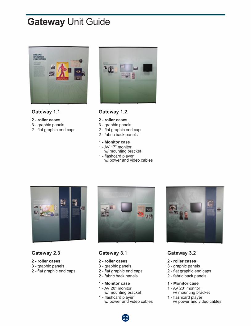
Gateway 2.32 - roller cases3 - graphic panels2 - flat graphic end caps
Gateway 1.12 - roller cases3 - graphic panels2 - flat graphic end caps
Gateway 3.12 - roller cases3 - graphic panels2 - flat graphic end caps2 - fabric back panels
1 - Monitor case1 - AV 20” monitor w/ mounting bracket1 - flashcard player w/ power and video cables
Gateway 1.22 - roller cases3 - graphic panels2 - flat graphic end caps2 - fabric back panels
1 - Monitor case1 - AV 17” monitor w/ mounting bracket1 - flashcard player w/ power and video cables
Gateway 3.22 - roller cases3 - graphic panels2 - flat graphic end caps2 - fabric back panels
1 - Monitor case1 - AV 20” monitor w/ mounting bracket1 - flashcard player w/ power and video cables
Gateway Unit Guide
22
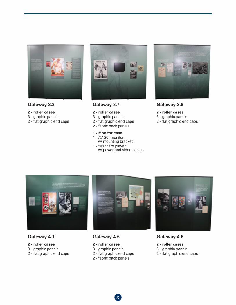
Gateway 4.62 - roller cases3 - graphic panels2 - flat graphic end caps
Gateway 3.82 - roller cases3 - graphic panels2 - flat graphic end caps
Gateway 4.52 - roller cases3 - graphic panels2 - flat graphic end caps2 - fabric back panels
Gateway 3.72 - roller cases3 - graphic panels2 - flat graphic end caps2 - fabric back panels
1 - Monitor case1 - AV 20” monitor w/ mounting bracket1 - flashcard player w/ power and video cables
Gateway 4.12 - roller cases3 - graphic panels2 - flat graphic end caps
Gateway 3.32 - roller cases3 - graphic panels2 - flat graphic end caps
23
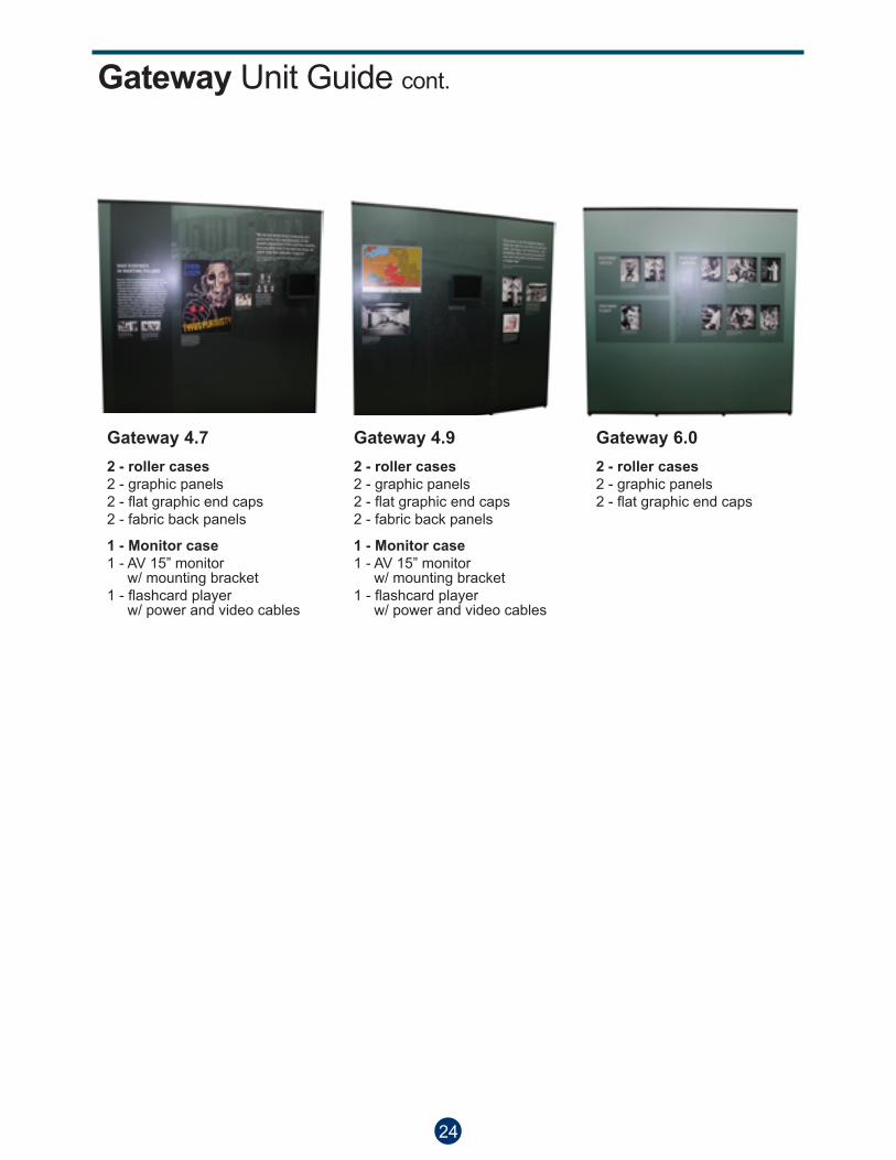
Gateway 6.02 - roller cases2 - graphic panels2 - flat graphic end caps
Gateway 4.92 - roller cases2 - graphic panels2 - flat graphic end caps2 - fabric back panels
1 - Monitor case1 - AV 15” monitor w/ mounting bracket1 - flashcard player w/ power and video cables
Gateway 4.72 - roller cases2 - graphic panels2 - flat graphic end caps2 - fabric back panels
1 - Monitor case1 - AV 15” monitor w/ mounting bracket1 - flashcard player w/ power and video cables
Gateway Unit Guide cont.
24 25
Quick Reference GuideTuscana Kit
Graphic Panel Specifications • xxv
Nomadic
Revised: May 16, 2008
Minimum Document Size*(with Bleed)
Width: 94.0625” x Height: 91.75”2391mm x 2331mm
(50% with Bleed)Width: 47.03125” x Height: 45.875”
1196mm x 1166mm
(25% with Bleed)Width: 23.515625” x Height: 22.9375”
598mm x 583mm
Finished SizeWidth: 92.0625” x Height: 89.75”
2340mm x 2280mm
*Your document size should encompass thecrops and bleed area.
89.75î2280mm
92.0625î2340mm
30.6875î780mm
30.6875î780mm
30.6875î780mm
1'13/4''/0.4m
7'93/4''/2.4m
4'8''/1.4m
3m
3m
EndCap
EndCap
Front
Tuscana Kit Plus Configuration
FLOOR PLAN ELEVATION

Tuscana Unit Guide
25
Quick Reference GuideTuscana Kit
Graphic Panel Specifications • xxv
Nomadic
Revised: May 16, 2008
Minimum Document Size*(with Bleed)
Width: 94.0625” x Height: 91.75”2391mm x 2331mm
(50% with Bleed)Width: 47.03125” x Height: 45.875”
1196mm x 1166mm
(25% with Bleed)Width: 23.515625” x Height: 22.9375”
598mm x 583mm
Finished SizeWidth: 92.0625” x Height: 89.75”
2340mm x 2280mm
*Your document size should encompass thecrops and bleed area.
89.75î2280mm
92.0625î2340mm
30.6875î780mm
30.6875î780mm
30.6875î780mm
1'13/4''/0.4m
7'93/4''/2.4m
4'8''/1.4m
3m
3m
EndCap
EndCap
Front
Tuscana Kit Plus Configuration
FLOOR PLAN ELEVATION

Tuscana 2.01 - roller case1 - graphic panel on both sides2 - round graphic end caps
Tuscana 6.11 - roller case1 - graphic panel on both sides2 - round graphic end caps
Tuscana 4.01 - roller case1 - graphic panel on both sides2 - round graphic end caps
Tuscana 3.01 - roller case1 - graphic panel on both sides2 - round graphic end caps
Tuscana 6.21 - roller case1 - graphic panel2 - flat graphic end caps
Tuscana Unit Guide
26 27
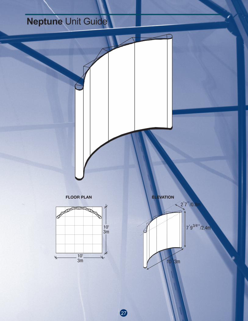
2'7''/0.8m
7'93/4''/2.4m
10'/3m
Quick Reference GuideNeptune Kit
Graphic Panel Specifications • xviii
Nomadic
Revised: September 5, 2007
Minimum Document Size*(with Bleed)
Width: 149.75” x Height: 91.75”3801mm x 2331mm
(50% with Bleed)Width: 74.875” x Height: 45.875”
1901mm x 1166mm
(25% with Bleed)Width: 37.4375” x Height: 22.9375”
951mm x 583mm
Finished SizeWidth: 147.75” x Height: 89.75”
3750mm x 2280mm
*Your document size should encompass thecrops and bleed area.
89.75”2280mm
147.75”3750mm
15”381mm
29.4375”747mm
29.4375”747mm
29.4375”747mm
15”381mm
3m
3m
29.4375”747mm
Front FrontFrontEndCap
EndCap
Front
Neptune Kit Classic Configuration
FLOOR PLAN ELEVATION
Neptune Unit Guide
27
2'7''/0.8m
7'93/4''/2.4m
10'/3m
Quick Reference GuideNeptune Kit
Graphic Panel Specifications • xviii
Nomadic
Revised: September 5, 2007
Minimum Document Size*(with Bleed)
Width: 149.75” x Height: 91.75”3801mm x 2331mm
(50% with Bleed)Width: 74.875” x Height: 45.875”
1901mm x 1166mm
(25% with Bleed)Width: 37.4375” x Height: 22.9375”
951mm x 583mm
Finished SizeWidth: 147.75” x Height: 89.75”
3750mm x 2280mm
*Your document size should encompass thecrops and bleed area.
89.75”2280mm
147.75”3750mm
15”381mm
29.4375”747mm
29.4375”747mm
29.4375”747mm
15”381mm
3m
3m
29.4375”747mm
Front FrontFrontEndCap
EndCap
Front
Neptune Kit Classic Configuration
FLOOR PLAN ELEVATION

Neptune 5.02 - roller cases4 - graphic panels2 - round graphic end caps4 - fabric back panels
1 - Monitor case1 - AV 37” monitor with mounting bracket1 - flashcard player with power and video cables1 - Extrusion stand
Neptune 4.32 - roller cases4 - graphic panels2 - round graphic end caps4 - fabric back panels
Neptune Unit Guide
28

Repacking • 10
Gently remove and roll up all surface graphics, monitors and shelving.
Refer to diagrams insidecase to repack contents.
Twist strut to unsnap from frame.Lift top section of strut up androtate down. Remove all lights.
Fold lengthwise ensuring that pegsat top of strut face inward. Placeconnected struts upside down incase.
Push on middle hub at back of framewhile pushing on corresponding fronthub. Instand will sink to the floor.Handle frame at hubs.
Dismantling Instructions
Lift bottom of strut off bottom stud.
Pull strut sections apart.
Remove all accessories:
Remove and roll up FabriColor and Photomural Strips:
Remove Magnetic Struts and Collapse Frames:
Put rolled panels into case one at a timeand one inside another. The top stiffenerof one panel should touch the bottomstiffener of the previous panel. StackEndcaps two high.
Slip individual panels and endcaps into plastic sleeves. Roll Panels with the graphic/fabric side facing out.
Dismantling Instructions
29

January 2009, V1.0