debugging techniques for locating defects in software
TRANSCRIPT

Clemson UniversityTigerPrints
All Dissertations Dissertations
12-2010
Debugging Techniques for Locating Defects inSoftware ArchitecturesKyungsoo ImClemson University, [email protected]
Follow this and additional works at: https://tigerprints.clemson.edu/all_dissertations
Part of the Computer Sciences Commons
This Dissertation is brought to you for free and open access by the Dissertations at TigerPrints. It has been accepted for inclusion in All Dissertations byan authorized administrator of TigerPrints. For more information, please contact [email protected].
Recommended CitationIm, Kyungsoo, "Debugging Techniques for Locating Defects in Software Architectures" (2010). All Dissertations. 619.https://tigerprints.clemson.edu/all_dissertations/619

Debugging Techniques for Locating Defects inSoftware Architectures
A Dissertation
Presented to
the Graduate School of
Clemson University
In Partial Fulfillment
of the Requirements for the Degree
Doctor of Philosophy
Computer Science
by
Kyungsoo Im
December 2010
Accepted by:
Dr. John D. McGregor, Committee Chair
Dr. Jason O. Hallstrom
Dr. Wayne Goddard
Dr. A. Wayne Madison

Abstract
The explicit design of the architecture for a software product is a well estab-
lished part of development projects. As the software architecture descriptions are
becoming larger and more complex, there is more likelihood of defects being present
in the software architecture. Studies have shown that a defect in the software ar-
chitecture that has propagated to the development phase is very expensive to fix.
To prevent such propagation of defects, this research proposes to provide debugging
support for software architecture design.
Debugging is commonly used in programming languages to effectively find the
cause of a failure and locate the error to provide a fix. The same should be accom-
plished in software architectures to debug architecture failures. Without debugging
support, the software architect is unable to quickly locate and determine the source
of an error.
In our work, we define a process for debugging software architecture and pro-
vide analysis techniques to locate defects in a software architecture that fails to meet
functional and non-functional requirements. We have implemented the techniques and
provide an evaluation of the techniques based on examples using an industry stan-
dard architecture definition language, Architecture Analysis and Design Language
(AADL).
ii

Dedication
To my mother Youngsoon Ji and my father Chungun Im.
iii

Acknowledgments
I would like to thank my advisor, Dr. John D. McGregor, for his guidance,
mentorship, and support throughout my PhD studies. I would also like to thank Dr.
Jason O. Hallstrom, Dr. Wayne Goddard, and Dr. A. Wayne Madison for serving as
members of my committee. Thanks to all the students in the Software Engineering
seminar (during multiple semesters) for providing valuable feedbacks to my research
presentations. And most importantly, I would like to thank my family for their love,
encouragement, and support.
iv

Table of Contents
Title Page . . . . . . . . . . . . . . . . . . . . . . . . . . . . . . . . . . . i
Abstract . . . . . . . . . . . . . . . . . . . . . . . . . . . . . . . . . . . . ii
Dedication . . . . . . . . . . . . . . . . . . . . . . . . . . . . . . . . . . . iii
Acknowledgments . . . . . . . . . . . . . . . . . . . . . . . . . . . . . . . iv
List of Tables . . . . . . . . . . . . . . . . . . . . . . . . . . . . . . . . . vii
List of Figures . . . . . . . . . . . . . . . . . . . . . . . . . . . . . . . . . viii
1 Introduction . . . . . . . . . . . . . . . . . . . . . . . . . . . . . . . . 1
1.1 Problem Statement . . . . . . . . . . . . . . . . . . . . . . . . . . . . 41.2 Research Approach . . . . . . . . . . . . . . . . . . . . . . . . . . . . 51.3 Contributions . . . . . . . . . . . . . . . . . . . . . . . . . . . . . . . 71.4 Dissertation Organization . . . . . . . . . . . . . . . . . . . . . . . . 7
2 Background . . . . . . . . . . . . . . . . . . . . . . . . . . . . . . . . 9
2.1 Software Architecture . . . . . . . . . . . . . . . . . . . . . . . . . . . 92.2 Program Debugging . . . . . . . . . . . . . . . . . . . . . . . . . . . . 112.3 Model-Based Diagnosis . . . . . . . . . . . . . . . . . . . . . . . . . . 122.4 Architecture Analysis and Design Language (AADL) . . . . . . . . . 132.5 Software Architecture Scenario . . . . . . . . . . . . . . . . . . . . . . 152.6 Software Architecture Analysis . . . . . . . . . . . . . . . . . . . . . . 152.7 Software Architecture Simulation . . . . . . . . . . . . . . . . . . . . 17
3 Software Architecture Debugging . . . . . . . . . . . . . . . . . . . 22
3.1 Differences in Program Debugging and Software Architecture Debugging 273.2 Software Architecture Debugging Process . . . . . . . . . . . . . . . . 303.3 Case Studies . . . . . . . . . . . . . . . . . . . . . . . . . . . . . . . . 333.4 Summary . . . . . . . . . . . . . . . . . . . . . . . . . . . . . . . . . 36
4 Debugging Defects Related to Functional Requirements . . . . . . 37
v

4.1 Software Architecture Scenario Editor . . . . . . . . . . . . . . . . . . 374.2 Debugging Structural Defects . . . . . . . . . . . . . . . . . . . . . . 394.3 Debugging Behavioral Defects . . . . . . . . . . . . . . . . . . . . . . 444.4 Summary . . . . . . . . . . . . . . . . . . . . . . . . . . . . . . . . . 53
5 Debugging Defects Related to Non-Functional Requirements . . . 54
5.1 Quality Attributes in Software Architectures . . . . . . . . . . . . . . 545.2 Debugging Quality Attribute Properties . . . . . . . . . . . . . . . . 565.3 Non-Conformance to an Architectural Pattern . . . . . . . . . . . . . 635.4 Summary . . . . . . . . . . . . . . . . . . . . . . . . . . . . . . . . . 74
6 Related Work . . . . . . . . . . . . . . . . . . . . . . . . . . . . . . . 76
6.1 Software Architecture Debugging . . . . . . . . . . . . . . . . . . . . 766.2 Debugging Software Design . . . . . . . . . . . . . . . . . . . . . . . 776.3 Software Architecture Slicing . . . . . . . . . . . . . . . . . . . . . . . 786.4 Software Architecture Conformance . . . . . . . . . . . . . . . . . . . 79
7 Conclusions and Future Work . . . . . . . . . . . . . . . . . . . . . . 80
Appendices . . . . . . . . . . . . . . . . . . . . . . . . . . . . . . . . . . . 82
A AADL Description of Bulletin Board System . . . . . . . . . . . . . . 83B AADL Description of DrawBridge . . . . . . . . . . . . . . . . . . . . 87C AADL Description of CTAS . . . . . . . . . . . . . . . . . . . . . . . 90
Bibliography . . . . . . . . . . . . . . . . . . . . . . . . . . . . . . . . . . 101
vi

List of Tables
2.1 Intension Locality Thesis from [13] . . . . . . . . . . . . . . . . . . . 10
3.1 Software Architectural Defects . . . . . . . . . . . . . . . . . . . . . . 23
4.1 Software Architectural Relationships . . . . . . . . . . . . . . . . . . 454.2 DrawBridge System LOC Comparison . . . . . . . . . . . . . . . . . 484.3 CTAS System LOC Comparison . . . . . . . . . . . . . . . . . . . . . 504.4 DisplaySystem LOC Comparison . . . . . . . . . . . . . . . . . . . . 52
5.1 Simple Dependency Structure Matrix Example . . . . . . . . . . . . . 66
vii

List of Figures
1.1 Illustration of Increase in Cost of Fixing a Defect Depending on DefectIntroduced Time and Defect Detected Time [38] . . . . . . . . . . . 4
2.1 Debugging at Program Level . . . . . . . . . . . . . . . . . . . . . . . 122.2 Generated Petri Net From an AADL Description . . . . . . . . . . . 182.3 Simulation of an AADL Description Using ADeS Simulator . . . . . . 19
3.1 Software Architecture Design Process . . . . . . . . . . . . . . . . . . 223.2 Software Architecture Defects with respect to Requirements and Model 243.3 Software Architecture Definition Tool Chain . . . . . . . . . . . . . . 263.4 Simple Program with a Fault from [30] . . . . . . . . . . . . . . . . . 283.5 Overview of Software Architecture Debugging Process . . . . . . . . . 31
4.1 Generated Software Architecture Scenario Editor . . . . . . . . . . . 384.2 Screenshot of AADL Debugger . . . . . . . . . . . . . . . . . . . . . . 414.3 Graph Showing Explicit Relationships of an AADL Model . . . . . . 434.4 DrawBridge System . . . . . . . . . . . . . . . . . . . . . . . . . . . . 474.5 DrawBridge System Defect Location . . . . . . . . . . . . . . . . . . 494.6 DrawBridge System Resulting Slice . . . . . . . . . . . . . . . . . . . 494.7 CTAS System . . . . . . . . . . . . . . . . . . . . . . . . . . . . . . . 504.8 CTAS System Defect Location . . . . . . . . . . . . . . . . . . . . . . 514.9 CTAS System Resulting Slice . . . . . . . . . . . . . . . . . . . . . . 514.10 DisplaySystem . . . . . . . . . . . . . . . . . . . . . . . . . . . . . . . 524.11 DisplaySystem Resulting Slice . . . . . . . . . . . . . . . . . . . . . . 53
5.1 Confidentiality and Integrity Attribute Values . . . . . . . . . . . . . 585.2 Example of End-to-End Flows with Actor’s Access Levels . . . . . . . 595.3 Confidentiality and Integrity Analysis Plug-in . . . . . . . . . . . . . 605.4 Markings of Scenarios and its Places of Violations . . . . . . . . . . . 605.5 Responsibility Relationship Modeled in ArchE . . . . . . . . . . . . . 635.6 Responsibility Relationship Graph of Figure 5.5 . . . . . . . . . . . . 645.7 DSM Constructed from a Detailed Architecture Model of a Client-
Server Pattern . . . . . . . . . . . . . . . . . . . . . . . . . . . . . . . 675.8 DSM After Clustering . . . . . . . . . . . . . . . . . . . . . . . . . . 675.9 Original DSM Clustering Algorithm . . . . . . . . . . . . . . . . . . . 68
viii

5.10 Clustered DSM of BBS System Injected with Fault . . . . . . . . . . 715.11 Clustered DSM of Fault-Free Three-Tier Layered Architecture of BBS
System . . . . . . . . . . . . . . . . . . . . . . . . . . . . . . . . . . . 725.12 Clustered DSM of CTAS . . . . . . . . . . . . . . . . . . . . . . . . . 735.13 Re-clustered DSM of CTAS . . . . . . . . . . . . . . . . . . . . . . . 74
ix

Chapter 1
Introduction
Software architecture is a high-level design that describes the overall structure
of a system [5]. A software architecture contains software elements, the externally
visible properties of those elements, and the relationships among them [5]. It is often
the first software artifact created from the requirements document in large software
systems. A software architecture should satisfy all the functional requirements as
stated in the requirements document and also satisfy the quality attributes or non-
functional requirements for the system. The software architecture is the place where
high-level design decisions are made and serves as the blueprint for developers to
follow.
A simple software architecture example is a client-server architecture. The
elements in the architecture are the client, server, and network. The visible properties
of the client are ports to send requests to server and receive data from server. The
visible properties of the server are ports to receive requests from client and send data
to the client. The visible property of the network is a specified network-type that
is used to communicate between the client and server. The relationships among the
elements are that the client is able to send requests to the server and receive data
1

sent by the server. Also, the server is able to receive requests from the client and send
data to the client. The requests and data are sent and received through the network.
Having a well-constructed software architecture has numerous advantages.
The software architecture can be used as the main communication vehicle among
every stakeholder of a software system [5]. It will help with understanding of the
chosen design and determine if all stakeholders’ interests have been met. Also, early
design analysis can be performed based on the software architecture [5]. There are
currently ways to analyze and predict software architecture behavior before imple-
menting the system. Once a well-constructed software architecture is formed, the
developers will have a concrete blueprint to follow in implementing the system.
In [28], Jackson states that “software is built on abstractions” and picking
the right abstractions for the system will dictate the quality of the implemented
product, and a system built on flawed concepts can only result in a flawed product.
He states that the “core of software development is the design of abstractions”, and an
abstraction is a structure. In software development, abstractions are designed first and
then code implementation follows. However, because abstractions are not something
that can be run or checked by a compiler, there is usually a number of flawed and
overlooked concepts present initially. By the time developers have to implement the
code, only then are the flaws discovered and abstractions have to be redesigned. One
major cause of this problem is due to not using a formal representation to describe the
abstractions, which has the consequence of the inability to analyze the abstraction. As
such, the current trend in industry is to use a formal software architecture description
language to represent the abstraction of the entire system.
A formal software architecture description language, or Architecture Descrip-
tion Language (ADL), is used to write software architecture descriptions which cap-
ture the software architecture of a system. With the increased use of software ar-
2

chitecture in software projects, there have been releases of several ADLs including
AADL[59], xADL[68], Wright[66], Rapide[50], ACME[2], and MetaH[42]. Each ADL
provides its own syntax and modeling components. An ADL can provide syntax
checking, simple analysis of the architecture description, type checking, visualization,
and simulation capabilities.
A software architecture needs to address all the requirements of a system. If
the software architecture fails to do so, or if a design decision was a poor decision,
the implemented software will not satisfy the original functional and non-functional
requirements, which translates to having defects in the software leading to failures of
software executions. Once such software failures are detected after implementation, it
is very costly to correct the defects that caused the failure, since the architecture must
be re-designed and the implementation changed to conform to the new architecture.
Studies have shown that fixing an architecture defect during system test can cost up to
fifteen times as much compared to fixing it during software architecture construction,
and cost as much as hundred times to fix after product deployment [38]. Figure 1.1
illustrates this problem, where the cost of fixing a defect increases by a large margin
if the defect is propagated down to later phases of development.
Defects in a software architecture can be difficult to locate. A single archi-
tecture defect often affects the architecture in several widely separated places. As
software products become larger and more complex so do their architectures. There
is an increasing likelihood of defects being present and those defects require more
effort to isolate. For instance, in [34], the authors used an example software archi-
tecture in a course for three years before discovering a defect within the architecture.
For this reason and others there is a need for a systematic approach to locate defects
within software architectures.
In this research, we focus on localizing the defects found in a software archi-
3
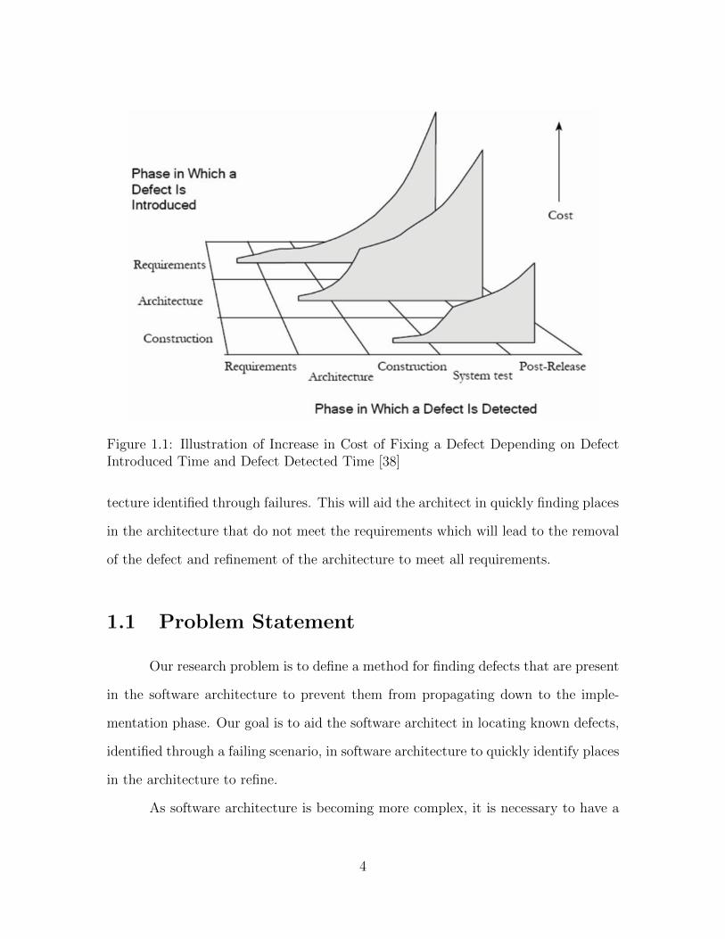
Figure 1.1: Illustration of Increase in Cost of Fixing a Defect Depending on DefectIntroduced Time and Defect Detected Time [38]
tecture identified through failures. This will aid the architect in quickly finding places
in the architecture that do not meet the requirements which will lead to the removal
of the defect and refinement of the architecture to meet all requirements.
1.1 Problem Statement
Our research problem is to define a method for finding defects that are present
in the software architecture to prevent them from propagating down to the imple-
mentation phase. Our goal is to aid the software architect in locating known defects,
identified through a failing scenario, in software architecture to quickly identify places
in the architecture to refine.
As software architecture is becoming more complex, it is necessary to have a
4

clear definition, processes, and techniques for debugging software architecture. For
example, the Avionics Display System has 21, 000 lines of ADL code to describe its
architecture [60]. Trying to find a defect in such a large software architecture is a
daunting task without any debugging support.
This research addresses these issues by providing answers to the following
problems.
• How can the different types of architectural defects be classified?
• How can you locate or localize a defect in a software architecture?
1.2 Research Approach
Given a software architecture and a set of known defects, our goal is to aid the
architect in locating those defects. To accomplish this task, we will first start with
scenarios that describe a specific task of the system. In the software architecture
discipline, scenarios are used frequently to evaluate and analyze its architecture [32].
Scenarios are constructed based on all possible uses of the system. A scenario can
be simulated on an instantiation of the software architecture and the architect can
determine whether the scenario has passed or failed. A scenario is said to have passed
if, after executing the actions for the specified scenario, the end state matches the
expected result. A scenario is said to have failed if any of the actions specified in
the scenario cannot be performed by the software architecture, or if the state of the
system after executing the scenario doesn’t match the expected end state. Once a
scenario has failed, the software architecture is said to contain a defect. At this point,
the debugging process starts to identify the error and reveal defects.
Our goal is to provide debugging techniques that can reveal architectural de-
5

fects failing to meet both functional and non-functional requirements. These defects
can occur at two distinct levels in a software architecture. Firstly, structural defects
are static-level defects in a software architecture. These are defects typically caused
by an incorrect specification of an architecture and they can usually be pinpointed
to a specific point in the architecture. Secondly, behavioral defects are dynamic-level
defects in a software architecture that may be identified through a simulation run
of the specified architecture based on a specific scenario. These types of defects are
usually identified through interactions of data and events among components. These
types of defects usually may not be pinpointed to a specific place in the architecture,
but can be localized to a region in the architecture specification and could possibly
be in multiple places.
We also provide some definitions of terms we will use in this dissertation.
The IEEE Standard Glossary of Software Engineering Terminology [7] provides the
following definitions to the corresponding terms.
• Error - The difference between a computed, observed, or measured value or
condition and the true, specified, or theoretically correct value or condition.
• Defect - An incorrect program code. [69]
• Failure - An incorrect result. The inability of a system or component to perform
its required functions within specified performance requirements.
By applying these definitions to the software architecture level, we define the
following terms for use throughout this dissertation.
• Software Architectural Error - The difference between the actual behavior and
expected behavior in running a scenario through a software architecture.
6

• Software Architectural Defect - An incorrect or inappropriate architectural spec-
ification, behavior, or design.
• Software Architecture Failure - Inability of a software architecture to meet a
functional or nonfunctional requirement.
1.3 Contributions
The contribution of this research is a systematic and general debugging method
in which a software architect can locate known defects in the specified architecture.
We will accomplish this by providing the following as outcomes of our research.
• What it means to debug a software architecture and a process for debugging a
software architecture.
• Techniques to debug defects in a software architecture failing to meet functional
requirements.
• Techniques to debug defects in a software architecture failing to meet non-
functional requirements.
To validate our approach, we will use case studies of examples with software
architecture descriptions containing defects and illustrate locating those defects.
1.4 Dissertation Organization
The remainder of this dissertation is organized as follows. Chapter 2 provides
the background information that is helpful for understanding our work. Chapter 3
describes our software architecture debugging process. Chapter 4 describes our debug-
ging techniques to locate defects failing to meet functional requirements. Chapter 5
7

describes our debugging techniques to locate defects failing to meet non-functional
requirements. Chapter 6 analyzes related work in the field of software architecture
debugging. Finally, Chapter 7 provides conclusions of our work and proposes future
work.
8

Chapter 2
Background
In this chapter, we provide background material that is relevant to our work.
Specifically, we provide an overview of software architecture, debugging related work
in code, overview of the Architecture Analysis and Design Language (AADL) which
we will use in our work, and software architecture scenario analysis, and simulation.
2.1 Software Architecture
A software architecture is a high-level design that describes the overall struc-
ture of a system, containing software elements, the externally visible properties of
those elements, and the relationships among them [5]. From the requirements of a
software system, the software architecture is the first artifact to be built, followed
by detailed design and implementation [8]. Software architecture reflects the design
decisions made to satisfy specific non-functional requirements as well as to define the
structure and behavior of a software system.
The earliest software architectures can be seen as drawings that consist of
boxes and arrows between the boxes. Common software architecture patterns such
9

as client-server, model-view-controller, pipes and filters, etc. were usually drawn
out in boxes and arrows without any other information about the software system.
These boxes and arrows captured only highly simplified structure with such high-level
abstraction that it was not useful in assessing if the functional and non-functional
requirements were met. The architecture was too simplified to support the creation
of a detailed design. Hence, several architecture description languages (ADL) have
been developed, as mentioned in Chapter 1, to allow detailed description of software
architectures.
Software architectures are commonly used in large scale projects in domains
such as avionics and automotive industry. In such projects, it is not uncommon for
a software architecture description to be thousands of lines or more. Additionally, in
an ultra-large-scale system (ULS) [48] consisting of systems of systems, the software
architecture will be large and will be created by multiple teams of architects. Finding
a defect in such a large architecture is both time consuming and non-trivial.
As software architectures are increasingly used, there is occasionally some
confusion between the terms software architecture and software design and sometimes
the two terms are used interchangeably. So Eden et al. [13] have used the Intension
and Locality thesis to clearly define the distinction among architecture, design, and
implementation, which is shown in Table 2.1.
Architecture Intensional Non-localDesign Intensional Local
Implementation Extensional Local
Table 2.1: Intension Locality Thesis from [13]
Eden et al. defines an intensional specification as abstract specifications that
“can be formally characterized by the use of logic variables that range over an un-
bounded domain” and a non-local specification as an abstract specification that “per-
10

vade all parts of the system as opposed to being limited to some part” [13]. When a
specification is intensional, it is said to have “infinitely-many possible instances” of
it and otherwise the specification is extensional [13]. A specification is local if “it can
be satisfied in some corner of our program without this being affected in how the rest
of the program is like” [13].
Similarly, Perry and Wolf characterizes the differences between architecture
and design in [49]. They characterize architecture as being “concerned with the
selection of architectural elements, their interactions, and the constraints on those el-
ements and their interactions necessary to provide a framework in which to satisfy the
requirements”. Design is characterized as being “concerned with the modularization
and detailed interfaces of the design elements, their algorithms and procedures, and
the data types needed to support the architecture and to satisfy the requirements”.
2.2 Program Debugging
Program debugging is defined as the process of “diagnosing the precise nature
of a known error and then correcting it.” [45] This process is started when the
software is observed to not meet its requirements. Its purpose is to “locate and fix
the offending code responsible for a symptom violating a known specification.” [20]
Debugging starts with a known error. Test cases are usually run first to de-
termine if any error exists. The error must reveal a failure of the program in order
for debugging to start. Once a failure is observed, the location of the defect is found
through debugging. This sequence is shown in Figure 2.1.
A number of debugging techniques and tools exist for debugging at the pro-
gram code level. In debugging tools, common features include accessing state informa-
tion, tracing backward, setting breakpoints, and stepping forward. Most debugging
11

Figure 2.1: Debugging at Program Level
techniques and techniques to aid debugging narrows down the search space to facil-
itate finding defects in the program. In delta debugging, a systematic technique is
used to automatically narrow down the difference between a passing and a failing run
of a program until a minimal set remains [69]. Automated fault localization technique
such as [31], shows lines of code that are suspected, with good reason, of containing
a defect by running systematic tests with passing and failing runs. Program slicing is
performed to narrow down to a subset of the program that is relevant to the failure
[64], hence the sliced program contains the defect to be found.
2.3 Model-Based Diagnosis
Model-based diagnosis (MBD) provides an approach to locating faults in a
system. Reiter [52] presents a theory of diagnosis that can be used to diagnose faults
in a system. Given a description of a system and an observed behavior of the system
that conflicts with the intended behavior, a diagnosis can be computed to locate faulty
components in the system that may be the source of incorrect behavior. Reiter defines
a diagnosis as “a conjecture that some minimal set of components are faulty”, which
he refers to as “The Principle of Parsimony” [52]. Diagnostic algorithms are provided
12

to find the minimal set of faulty components that cause the abnormal behavior.
The general concept and theory of model-based diagnosis can be applied to
debugging software architectures. A software architecture is a formal description
of a system and given an incorrect observed behavior, a diagnosis on the software
architecture can be performed to locate the faulty components. Model-based di-
agnosis technique has previously been successfully applied to debugging hardware
designs [65] [16] and debugging Java programs [37].
2.4 Architecture Analysis and Design Language
(AADL)
Architecture Analysis and Design Language (AADL) is an architecture defi-
nition language (ADL) that is based on 15 years of ADL experience from DARPA
(Defense Advanced Research Projects Agency) [61]. It is currently a standard of the
Society of Automotive Engineers and is used widely in several organizations [61] such
as: Rockwell, Honeywell, ESA, Lockheed Martin, SEI, General Dynamics, Airbus,
Axlog, European Space Agency, Ellidiss, Dassault, EADS, High Integrity Systems,
Ford, Toyota, Eaton, Smith Industries, ENST, Boeing, and Raytheon.
An AADL model can be thought of as an hierarchical tree of components.
There are two types of components – software and execution platform. These
components can be composed using a System declaration. The components are
linked using Connections to represent communication of data and control between
components.
Below provides brief descriptions of major AADL specifications as described
in the AADL reference manual [59].
13

• Software components.
– Data: Represents a data type in source text. Defines a representation and
interpretation for instances of data in the source text.
– Subprogram: Represents an execution entrypoint in source text.
– Thread: Represents a sequential flow of control that executes instructions
– Thread Group: Represents an organizational component to logically group
threads contained in processes.
– Process: Represents a virtual address space.
• Execution platform components.
– Processor: Represents an execution platform component that is capable of
scheduling and executing threads.
– Memory: Represents an execution platform component that stores binary
images.
– Bus: Represents an execution platform component that can exchange con-
trol and data between memories, processors, and devices.
– Device: Represents an execution platform component that interfaces with
the external environment.
• System component represents an assembly of interacting application software,
execution platform, and system components.
Once an architecture model has been defined, it can be used as the basis for
simulating a system built from the architecture. An architecture simulator is defined
that is specific to its syntax and semantics. In a simulation, software components
14

are simulated as they describe the execution flows that occur in the architecture.
Tools such as ADeS [1] and Ocarina toolset [21] provide the architect with simulation
capabilities in which the behavior of AADL architecture descriptions can be observed,
and they are described in more detail in section 2.7.
2.5 Software Architecture Scenario
In the software architecture discipline, scenarios are used frequently to evaluate
and analyze its architecture [32]. Scenarios are constructed to describe all possible
uses of the system. A scenario can be run through an instantiation of the software
architecture and reveal if the scenario has passed or failed. A scenario is said to have
passed if after executing the actions for the specified scenario, there is no error and
the end state matches the expected result. A scenario is said to have failed if any of
the actions specified in the scenario cannot be performed by the software architecture
or if the state after executing the scenario doesn’t match the expected end state.
Once a scenario has failed, the software architecture is said to have a failure. At this
point, the debugging process starts to identify and reveal defects.
2.6 Software Architecture Analysis
Once a sufficient level of detail is available in the software architecture, the
architect may elect to analyze the software architecture. The purpose of software
architecture analysis is to confirm that the modeled architecture conforms to the
functional and non-functional requirements. There are two widely utilized methods
to perform software architecture analysis.
• ADL specific analysis tools
15
• Software architecture questioning techniques
First, by utilizing ADL specific analysis tools, the modeled software archi-
tecture can be analyzed quickly. In some ADL’s such as AADL, there are built-in
analysis tools that can find out specific information from a given architecture such as
schedulability, flow latency, and checking security levels. These are used to quickly
analyze the static properties of the architecture. Some ADL’s have simulation capa-
bilities, which allows analysis of the architecture in terms of functional behavior as
well as runtime quality attributes. Through the use of simulation, the behavior of
the software architecture can be analyzed.
Second, by using software architecture questioning techniques, the software
architecture is probed from many different perspectives by different stakeholders.
ATAM (Architecture Tradeoff Analysis Method) [5] is a widely used architecture
questioning technique which is effective in answering how specific quality attributes
are satisfied and how an architectural decision will impact the trade off between
qualities. In ATAM, scenarios that express important quality attributes are used
to drive the architecture analysis. Each scenario is run against the architecture to
find out how the architecture satisfies a specific quality attribute. In particular, the
architect explains how an architectural decision contributes in satisfying a specific
quality attribute. In analyzing the architectural decisions through quality attribute
scenarios, the following can be identified as a result.
• Tradeoff points: An architectural decision may impact one quality attribute
positively and another negatively.
• Set of risks: An architectural decision could possibly result in unintended con-
sequences.
16

• Risk themes: Based on the risks discovered, a risk theme identifies an architecture-
wide weakness that could hinder the satisfaction of a specific quality attribute.
Through the outcomes of ATAM, the architect gains knowledge regarding what
kind of risks the architecture contains and which quality attributes are not met ac-
cording to the requirements.
After the analysis is complete, the result will show whether the software ar-
chitecture fails to meet certain functional or non-functional requirements. In such an
event, architects would have to manually find where in the architecture the defect is
located in order to fix it. Such manual process may take days in a substantially large
software architecture. Architecture analysis techniques are better at determining that
a software architecture fails to meet certain requirement than they are at determining
what portion of the architecture fails to measure up. Software architecture debug-
ging techniques will be of great help in such cases to more easily locate defects in the
architecture.
2.7 Software Architecture Simulation
An execution sequence through a software architecture can be simulated to
know if it has passed or failed a scenario. There are four general ways in which a soft-
ware architecture can be simulated. The first approach is to generate an executable
program from the software architecture description. In this case, the generated pro-
gram must fully describe the software architecture. Then executing a specific scenario
using the generated program should yield the same result as executing the scenario
on the software architecture. This code generation approach has been used in UML
model execution [47], [15], [11] to generate Java code from UML models and has
shown to work successfully. The second approach is to generate executable simula-
17

tion code that can be run in an off-the-shelf simulation engine. This approach has
been used in [14] to transform a software architecture description into an executable
simulation code that runs on the adevs simulation engine.
The third approach is to transform a software architecture description into
another representation which can then be simulated. In [17], behavioral aspects of
a software architecture are described in Colored Petri Nets, which can be simulated.
There are other tools such as the Ocarina tool suite [43] to generate a Petri Net from
the AADL description. Figure 2.2 shows a generated Petri Net from an AADL de-
scription that describes the software architecture of the MPC spacecraft, as described
in [21]. A subset of its AADL description was used as an example to generate the
Petri Net.
Figure 2.2: Generated Petri Net From an AADL Description
The fourth approach is to use a simulator that comes with the software ar-
chitecture description language. Not all software architecture description languages
come with a simulator. Using the simulator that is specific to the software architec-
ture description language makes it easier to map a location in the simulation to the
location in the architecture description. For instance, AADL models can be simulated
18

Figure 2.3: Simulation of an AADL Description Using ADeS Simulator
using the ADeS simulator [1] and a simulation run is shown in Figure 2.3.
ADeS is a tool to simulate the behavior of system architectures described with
the AADL language [1]. As shown in Figure 2.3, a simulation run in ADeS displays
simulation related information in three views: instances attributes, event manager,
and console. The instances-attributes view displays the attributes of the currently
simulated object. The event-manager view displays the events stack of the simulation.
The console view displays the simulation log as the simulation is run.
During a simulation of any of the above four approaches, a failed execution
sequence can be detected in two ways.
• Stalled simulation: When the simulation can no longer execute the next step in
the sequence, it will fail to progress.
19

• Mismatch between actual and expected outcome: The result gathered at the
end of simulation differs from the expected result of a scenario.
In general, a stalled simulation is an indication of a structural defect while a mismatch
on the expected outcome is an indication of a behavioral defect.
The simulator will provide a detailed simulation trace that contains a list of
events that were executed, time of execution, initial state when executing the event,
and ending state after executing the event. This execution trace of a simulation can
be used to check if the simulation run conforms to an expected behavior. If there is
a difference in behavior, a behavioral defect exists.
In the third approach for simulation described above, having another repre-
sentation of the software architecture can have its advantages. When a software
architecture is described in Colored Petri Nets (CPN) representation, as in [17], the
Colored Petri Net can not only be simulated but it can be analyzed in the follow-
ing ways. First, [17] describes a technique to evaluate non-functional qualities, or
quality attributes, of a software architecture by analyzing its CPN representation. If
the analysis result shows that a specific non-functional quality is not met, then its
analysis results can aid debugging to find which parts in the architecture description
contributes to not meeting a specific quality attribute.
Second, with the CPN representation of a software architecture, existing CPN
analysis techniques can be applied such as deadlock analysis. Many CPN tools can
perform behavioral verification, such as CPN-AMI [46], which can identify an erro-
neous execution on a CPN [21], if one exists. For debugging purposes, an erroneous
execution path on a CPN is of interest as this gives a starting point for trying to
analyze the root cause that led to the failure. Then a mapping must be made from
the CPN back to the software architecture model to show which parts of the software
20

architecture contain the defect.
21

Chapter 3
Software Architecture Debugging
In this dissertation, we provide techniques to help locate defects in the software
architecture. This chapter will outline our approach. We first describe our definitions
and assumptions about the problem and present our approach to the problem in
detail.
Figure 3.1: Software Architecture Design Process
Figure 3.1 shows a high-level view of an end-to-end architecture design pro-
cess. Software architecture definition includes making high-level design decisions and
produces a model created using some formalism and documentation. Architecture
evaluation compares the architecture to the system requirements and identifies re-
quirements the architecture fails to satisfy. The evaluation technique may be a man-
22

ual examination by stakeholders [5] or a more automated process executing some type
of prototype. Failures identified during evaluation provide feedback to architecture
definition. We view architecture debugging as a feedback mechanism that informs
architecture definition of possible changes to the architecture that would repair the
defects found during architecture evaluation.
A software architectural failure is defined as the inability of a software archi-
tecture to meet a functional or nonfunctional requirement. A software architectural
failure is caused by a defect in the software architecture, which may be an incorrect or
inappropriate architectural specification, behavior, or design. Table 3.1 shows some
examples of architectural defects that we have collected from literature and our own
experiences.
Structural Defects Behavioral Defects
Syntactic defects Receive unexpected event [58]Directional defects on connections, flows [53] Expected event not sent [58]Missing or unintended connections, flows, Missing activityand ports [58]Data type mismatches Extraneous activityUnused components Concurrency issues
Execution on incorrect operational modePre/Post conditions violations [53]
Static Quality Attribute Defects Dynamic Quality Attribute Defects
Non conformance to architectural Failure to meet dynamic nonfunctionalpattern or style [33] requirements such as performance and security.Failure to meet static nonfunctionalrequirements such as modifiability
Table 3.1: Software Architectural Defects
A structural defect is an infeasibility of some execution sequence that prevents
what should be a valid execution sequence from being enabled. A behavioral defect
is an anomaly in which a combination of execution sequences taken through the ar-
chitecture, given an input, leads to an incorrect state or result, thereby not satisfying
23

a requirement. A quality attribute defect occurs when certain quality attribute prop-
erties of the architecture [27] are not achieved during an execution sequence of an
input.
Figure 3.2 summarizes the types of defects depending on a scenario’s feasi-
bility in executing on the architecture model and its validity to the requirements.
An execution sequence that is feasible in the model and the result satisfies a valid
requirement, then its scenario has passed without uncovering a defect. An execution
sequence that is feasible in the model but results in an invalid requirement is said
to potentially contain either a behavioral defect or quality attribute defect. An ex-
ecution sequence that is infeasible in the model but the execution was in respect to
a valid requirement, is said to contain a structural defect. An execution sequence
that is infeasible in the model and results in an invalid requirement is said to have
an incorrect architecture where the model is incomplete, input was incorrect, or the
model was not designed for the current set of requirements.
Figure 3.2: Software Architecture Defects with respect to Requirements and Model
Given a software architecture which has experienced failures during some type
of symbolic analysis, our goal is to expose the defects that caused the failures and to
suggest repairs to the architecture. We assume that we have the set of scenarios that
drove the evaluation and for each we have an indication of whether the scenario was
24

supported by the architecture or not. Software architecture debugging techniques are
applied to the architecture representation to locate candidate defects. The architect
is presented with these candidates and determines which, if any, are actual defects.
This information is fed back into the architecture definition to correct the defects.
Architecture evaluation and analysis is performed after software architecture
models reach a suitable level of maturity. This is because in the current state, ar-
chitecture evaluation is performed manually taking too much time to be applied too
often due to the following reasons.
• Lack of automated tools
• Architecture analysis is too dependent on the specific ADL and only focuses on
analyzing one aspect of the model (such as schedulability of threads, or flow
latency)
• Utilizing architecture simulation may be unsuccessful because most simulators
have requirements about the level of detail that an architecture model must
include before a simulation can be run
Taking these restrictions into account, our debugging process should be sufficiently
general to handle varying levels of detail included in the architecture model, leverage
a more automated method than architecture evaluation, and the process itself should
be applicable to any ADL.
In our work we assume that a software architecture is defined as outlined in
[24][39], where the architecture definition starts with a conceptual architecture model,
then a detailed architecture is modeled using an ADL, and finally the software archi-
tecture model is executed through simulation. Figure 3.3 shows this general approach
used in designing software architectures. Through iterative design and refinement uti-
lizing information from the separate levels, we gain a rigorous architecture model as
25

an end product. The debugging process is performed during architecture design to
eliminate as many defects as possible. The following paragraphs summarize the tools
we use in each level of architecture definition.
Figure 3.3: Software Architecture Definition Tool Chain
The conceptual model of the software architecture is defined by using responsibility-
driven design to identify system responsibilities that are required to realize the require-
ment scenarios. One way to prepare the conceptual model is to use the architecture
expert tool, ArchE [57]. The conceptual model provides the initial structure that
must be followed in detailed architecture design.
The detailed software architecture model is defined using the Architecture
26

Analysis and Design Language (AADL). We use the OSATE IDE [59] to construct
the AADL model.
To execute software architecture models, there are several options including
manual tracing, ADL specific simulators, and generation of prototype code that rep-
resents the architecture model using tools such as Ocarina [43]. Failures are identified
through some execution of the architecture model. Since our debugging process starts
with a given failure, we have no limitation on which method is used to execute the
architecture model.
3.1 Differences in Program Debugging and Soft-
ware Architecture Debugging
Debugging, for both programs and software architectures, is defined as an
activity that starts once an error is observed in some representation of a system
and the goal is to locate the defect so that it can be repaired. In this section, we
will describe the differences between program debugging and software architecture
debugging and how we handle those differences. To facilitate understanding, we will
first illustrate the debugging process in program debugging and later for software
architecture debugging.
Consider the faulty program shown in Figure 3.4 from [30]. The existence
of a failure was discovered through running several test cases and one or more of
the test cases produced errors. At that point, program debugging starts to look for
the location of defect. In this small example, a manual trace of a failed test case
(x=3,y=1,z=5) suffices to find that line 7 contains the defect. But in large programs,
a manual trace is infeasible and likely to take too much time. So there are several
27

mid ( ) {i n t x , y , z , m;
1 read ( ‘ Enter 3 nums : ’ , x , y , z ) ;2 m = z ;3 i f (y<z )4 i f (x<y )5 m = y ;6 e l s e i f (x<z )7∗ m = y ;8 e l s e9 i f (x>y )10 m = y ;11 e l s e i f (x>z )12 m = x ;13 p r i n t ( ‘ Middle number i s : ’ , m) ;
}
Figure 3.4: Simple Program with a Fault from [30]
tools (e.g. IDE debugger), debugging techniques (e.g. Program slicing [64]), and fault
localization methods (e.g. Tarantula [31]) that help programmers to quickly locate
defects within code. These tools help by using the initial failure data to iteratively
probe and isolate the failure until the source of the problem is identified. Once the
location of a defect is found, a programmer modifies one or more statements and
executes the test suite again. Error-free execution of the test suite confirms that the
bug has been fixed.
In software architecture debugging, the concept is the same; that is, our goal
is to help the architect find the location of the defect, but there are several differences
that separate program debugging and software architecture debugging.
First, software architectures are not defined to the level of concrete input
and output values as are programs. We cannot assign arbitrary input values and
execute a software architecture to output an exact result. Input and output values
will be of broader types such as an event, data type, or architectural element. And to
28

run an architecture for a given scenario, we have to rely on manual traces, software
architecture simulation, or output from architecture analysis and evaluation (e.g.
ATAM [5]). All of these activities take a considerable amount of time compared to
quickly running a test suite in a program; so our debugging process should minimize
the need to rerun scenarios.
Second, the granularity is different. In program debugging, a defect is con-
tained within a statement or a small set of statements. In software architecture, a
defect can be a single port, connector, or component or it may be a set of these
elements that are not necessarily explicitly connected. The size of a defect depends
partly on the detail provided in the software architecture description and partly the
nature of the defect. We would like to be able to perform certain types of analyses re-
gardless of how complete the architecture definition is. In architecture debugging, we
want to accommodate varying degrees of detail such that as more details are included
in the architecture, the debugging investigation can be more detailed.
Last, the risks associated with modifying the architecture when correcting the
defect are greater. In program debugging, once a defect is found it can be repaired
and a test suite can be run to verify that the defect was fixed. In addition, control
flow and data flow analysis can be used to discover any impact due to the change. In
software architecture debugging, once a defect is found, the change made to correct
the defect may affect unforeseen areas and negatively affect other aspects of the soft-
ware architecture. So we need to verify whether the modified architecture matches
the architect’s original intent of the system, such as conforming to a pattern or style
and meeting certain non-functional properties. A single change can have a far broader
impact on an architecture compared to a change made in a program. A misguided
change in an architecture could directly result in no longer meeting several require-
ments. For example, if a defect found was a missing connection, wiring a connection
29

to fix the defect without the appropriate amount of analysis may not be the correct
solution. We need to consider (1) if the new connection introduces any violation to
a pattern or style used, (2) whether any new paths are now possible in the modi-
fied architecture and discover any suspicious interactions that are introduced, and
(3) whether the modified architecture still holds the same quality attribute values
or whether some quality attributes have been negatively affected. Only with this
information can the architect make an informed decision on how to repair a defect.
3.2 Software Architecture Debugging Process
In this section, we describe our software architecture debugging process [26].
Figure 3.5 shows a high-level overview. As a first step in trying to locate the defects,
we first need to know that a defect exists and under what conditions the defect is
revealed. We assume that a detailed software architecture has been created and a
specific execution sequence, or a scenario, was executed on the architecture model
and yielded a failure. The execution of the scenario may have been achieved through
manual execution, or simulation during the architecture-evaluation phase. Thus, the
failure is known suggesting that a defect must exist in the software architecture,
and our approach will help locate that defect. The architecture debugging process
takes this failure report as input, which describe the scenarios that were used during
evaluation and the symptoms that indicated failure.
We must first confirm the failure to verify that it has arisen because of a fault
in the architecture model. To do so, we map the failed execution sequence to the
architecture model to get the subset of the architecture model containing the defect.
If the mapping is not possible or the mapping results in an unconnected graph, then
the defect is a false positive. Once we confirm that we don’t have a false positive,
30
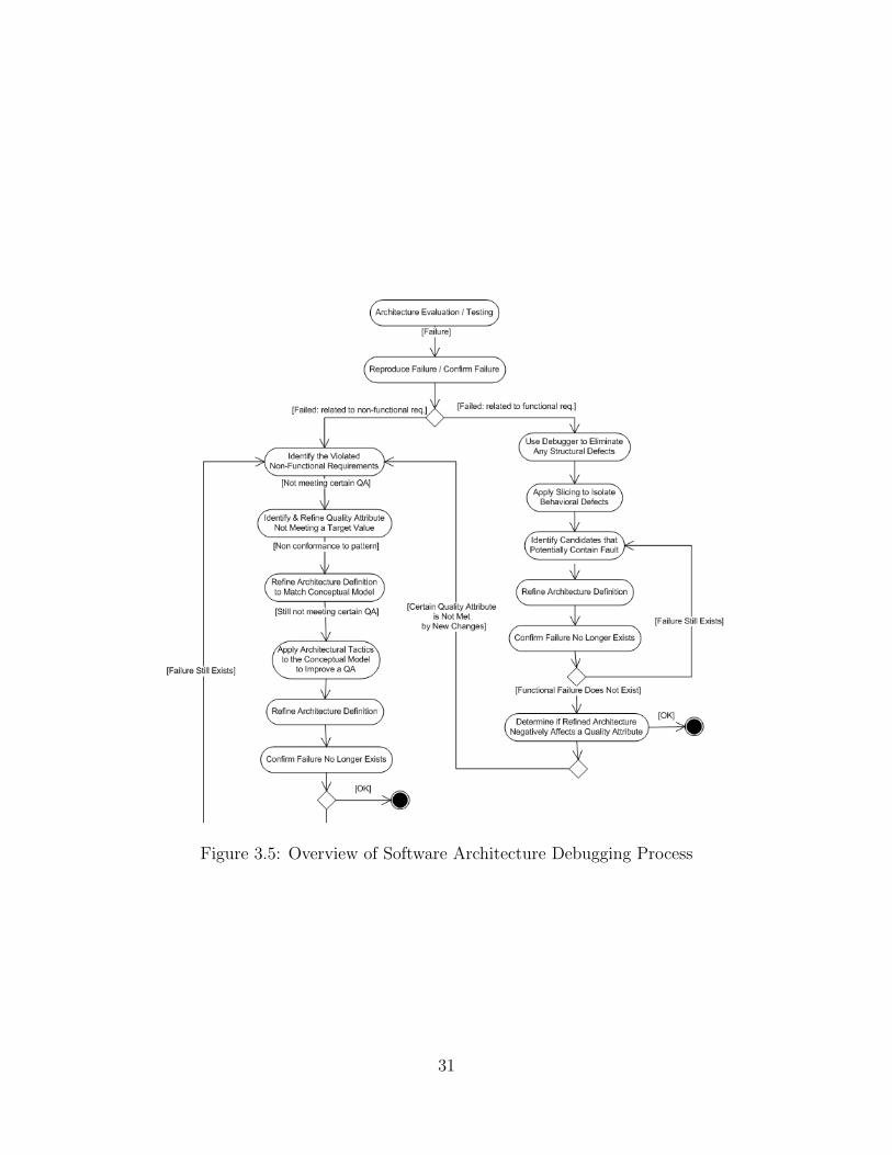
Figure 3.5: Overview of Software Architecture Debugging Process
31

debugging process begins to locate the defect contained in the software architecture.
The debugging techniques used to isolate a defect depends on the type of defect
that is present, which is the reason for the defects classification shown in Table 3.1.
There are two broad distinctions in the type of defects: one relating to functional
requirements and one relating to non-functional requirements. An architect can dis-
tinguish the two types of defects depending on the result of running an architectural
scenario. A scenario not running to completion is due to a defect related to a func-
tional requirement, while a scenario running to completion but failing to attain some
quality level is due to a defect related to a non-functional requirement.
If the observed architectural failure is related to a functional requirement,
then the architect would first use the software architecture debugger to eliminate any
structural defects. The details of this debugger are described in section 4.2. After
eliminating any structural defects, if the failure still exists, then the architect applies
software architecture slicing to isolate behavioral defects. Software architecture slicing
is described in section 4.3. The purpose of slicing the software architecture is to
narrow the search space for finding the defect. Once the search space is narrowed,
the architect identifies candidates that potentially contain a fault. The architecture
definition is refined to eliminate the suspected candidate and the scenario is rerun
to verify that the failure no longer occurs. If the failure still occurs, the architect
would move on to the next identified candidate and repeat the process. If no failure
is detected, then a failure related to a functional requirement is no longer present.
If the observed architectural failure is related to a non-functional requirement,
then the architect would first identify which quality attribute is not meeting required
levels and refine the property values as described in section 5.2. Quality attributes
may also not meet the required levels if an intended architectural pattern, or con-
ceptual model, is not correctly applied. Since an architectural pattern itself imposes
32

design decisions that either improves or degrades a quality attribute, it is always rec-
ommended to check for architectural pattern conformance, when the architect knows
which pattern was intended. Software architecture pattern conformance is described
in section 5.3.
If the intended pattern does not conform to the actual pattern used in the
software architecture, then the architect identifies the places of mismatch and the ar-
chitecture definition is refined to match the intended pattern. If the intended pattern
conforms to the actual pattern found in the software architecture, and certain quality
attribute is still not meeting the required levels, then there must be a defect in the
conceptual model. In this case, the architect would identify responsibilities in the
conceptual model that affect the quality attribute of interest. Then architectural tac-
tics can be applied to the conceptual model to improve the specific quality attribute
which is not being met. A tactic is defined as a “design decision that influences the
control of a quality attribute response” [5]. A tactic is used when a particular quality
attribute is to be improved but it can also affect other quality attributes negatively.
For example, redundancy is a tactic that can be used to improve availability but can
reduce maintainability and security. More detailed listings of tactics can be found in
[5]. The DSM clustering method described in section 5.3 can be used to identify the
responsibilities in the conceptual model, and the architect decides which tactic should
be applied to improve certain quality. Lastly the architecture definition is refined to
match the new conceptual model.
3.3 Case Studies
In validating our work, we will provide case-based examples in debugging
identified software architectural defects. We will apply our debugging techniques to
33

several example architecture models that contain different types of defects. Our goal
is to show that our debugging techniques can locate each known defect in a software
architecture and demonstrate their effectiveness.
For our evaluation, we will use example architecture models gathered from
both our experiences and the public domain and inject different types of defects. The
examples used are available from [22]. Fault injection is a technique used to introduce
faults inside the software system to achieve the following. One, the software system
can be observed on how it handles the fault during run time and what impact it
causes [63]. Two, since an injected fault in a system is exactly known, fault removal
techniques can be applied to show its effectiveness in finding the injected fault [9].
We apply fault injection to achieve the latter, in which we use fault injection as a
method for validating our debugging techniques.
Once faults are injected, we will apply our debugging techniques to the archi-
tecture model containing defects and determine if all defects are successfully found.
The sections below describe the example software architectures that we use.
3.3.1 Bulletin Board System
The Bulletin Board System is used as an example in [43] and we use its ex-
tended version as a case study. The Bulletin Board System consists of the following
components.
• clients or users of the system can make a request to the server
• server processes the request according to its business rules and can make queries
to the database layer to obtain relevant data, and send back results to the client
• database server stores data and retrieves data upon request by the server
34

The system uses a three-tier layered architecture and the components of the
three tiers are the presentation tier (clients), application tier (server), and the data
tier (database server). Each tier can communicate only with its adjacent upper tier
and each tier can be developed and maintained independently.
In this case study, we inject a fault to break the three-tier layered pattern. We
force the presentation tier to communicate with the data tier, when the presentation
tier should only communicate with the application tier.
3.3.2 Drawbridge
The drawbridge example is a software architecture model of a drawbridge using
AADL and it has been studied in [36]. When a sensor senses that a boat needs to cross
a river, the highway drawbridge is raised. Before the drawbridge is raised, warning
lights begin and road gates are closed. Then the bridge segment (A and B) on each
side of the road is raised. If any failure is detected as the drawbridge is raised, the
system should yield to a fail-safe component that will handle failures.
In this case study, we inject a defect that sets the operational mode incorrectly.
There are three operational modes in this system: IdleMode, ProgressMode, and
FailureMode. What should be in a ProgressMode is set incorrectly to be in IdleMode.
3.3.3 Clemson Traveler Assistant System (CTAS)
Clemson Traveler Assistant System (CTAS) [40] is a software architecture
model designed and implemented by students of a graduate computer science class,
CPSC 875 - Software Architecture, at Clemson University. The CTAS is an itinerary
planning system that allows a traveler to plan the routes and modes of transportation
needed to travel from one point to another. It executes on a variety of platforms,
35

including a wireless handheld device, and allows travelers to periodically update their
information and reconsider their itineraries. Using the CTAS should result in as
efficient a trip as is possible given the conditions at the time of travel.
In this case study, we inject a fault to cause extraneous activity. When data
becomes available to be displayed, we purposely send a request to retrieve new data
which will cause a refresh of the previous data displayed.
3.3.4 Avionics Display System
This is a detailed AADL model of an Avionics Display System with 21,000
lines of AADL. This is an example model provided by SAE AADL that is available
for download at [60] and we use a modified version [22] of this example. This model
was supplied by Rockwell Collins and it models an IMA cockpit display system using
Rockwell Collins’ proprietary switched Ethernet LAN.
In this case study, we inject a fault that introduces an unintended connection
between two components. Due to its large size, we randomly chose a place in the
model to introduce this defect.
3.4 Summary
In this chapter, we have classified the defect types that can appear in a soft-
ware architecture and described our debugging process to locate those defects. As
previously mentioned, there are two broad defect types: one relating to functional
requirements and one relating to non-functional requirements. Debugging techniques
to locate both types of defects are described in the following chapters and they are
tested using the case studies presented in this chapter.
36

Chapter 4
Debugging Defects Related to
Functional Requirements
Defects related to functional requirements include structural and behavioral
defects. To debug these types of defects, we need to reduce the search space of the
architecture model to help in narrowing down the source of the defect.
4.1 Software Architecture Scenario Editor
As previously mentioned, we assume a set of failing scenarios are available for
use in our debugging process. We have developed a scenario editor that can be used
by architects to easily create, edit, and reuse architectural scenarios and integrate
them into our debugging process.
The software architecture scenario editor, shown in Figure 4.1, is generated for
each input AADL model. This is made possible through using the Eclipse Modeling
Framework (EMF) and its Ecore model to specify the current AADL model. When
any change is made to the AADL model, a new Ecore model is created by extracting
37
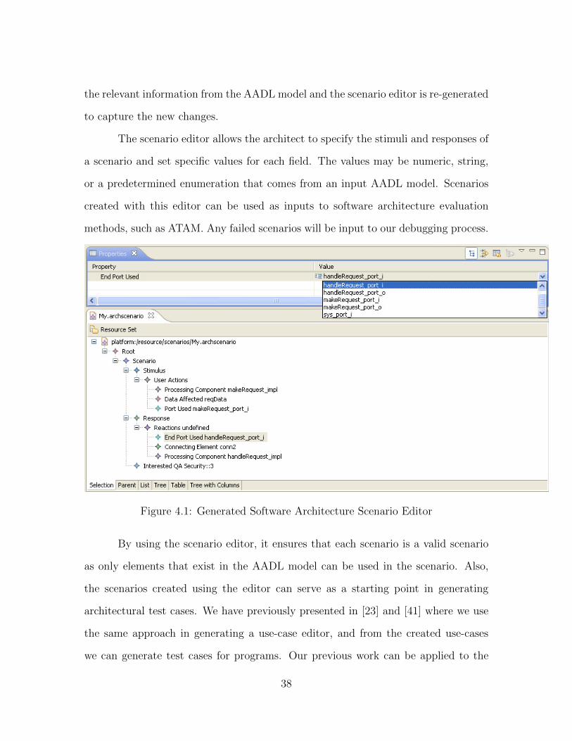
the relevant information from the AADL model and the scenario editor is re-generated
to capture the new changes.
The scenario editor allows the architect to specify the stimuli and responses of
a scenario and set specific values for each field. The values may be numeric, string,
or a predetermined enumeration that comes from an input AADL model. Scenarios
created with this editor can be used as inputs to software architecture evaluation
methods, such as ATAM. Any failed scenarios will be input to our debugging process.
Figure 4.1: Generated Software Architecture Scenario Editor
By using the scenario editor, it ensures that each scenario is a valid scenario
as only elements that exist in the AADL model can be used in the scenario. Also,
the scenarios created using the editor can serve as a starting point in generating
architectural test cases. We have previously presented in [23] and [41] where we use
the same approach in generating a use-case editor, and from the created use-cases
we can generate test cases for programs. Our previous work can be applied to the
38

architecture level, but it is out of scope of this research.
4.2 Debugging Structural Defects
To support the debugging activity during the detailed architecture definition
process, we built a debugger tool specific to AADL, using the Eclipse Debugging
Framework. The debugger is intended to locate structural defects in the software
architecture to reveal structural inconsistencies.
The Eclipse Debugging Framework provides a framework for building and in-
tegrating debuggers. It defines a set of Java interfaces that models the debug artifacts
(such as threads, stack, and variables) and also debug actions (such as suspending,
stepping, resuming, and terminating). The implementation of the debugger is left to
the developer but it provides a basic debugger user interface [67].
We have separated the debugger into two parts: the debug interface and the
AADL interpreter. The debug interface listens for commands from the architect
using the debugger and sends the debug command to the AADL interpreter. The
AADL interpreter then maps the command received to the action that needs to be
performed in the current state and returns the result back to the interface to display
to the architect.
The debug interface has the following commands available for the architect:
start, terminate, step, and resume.
• Start command first analyzes the AADL model under debug and looks at the
specified scenario file. A scenario file is specified in AADL using the properties
of the system component as follows.
39
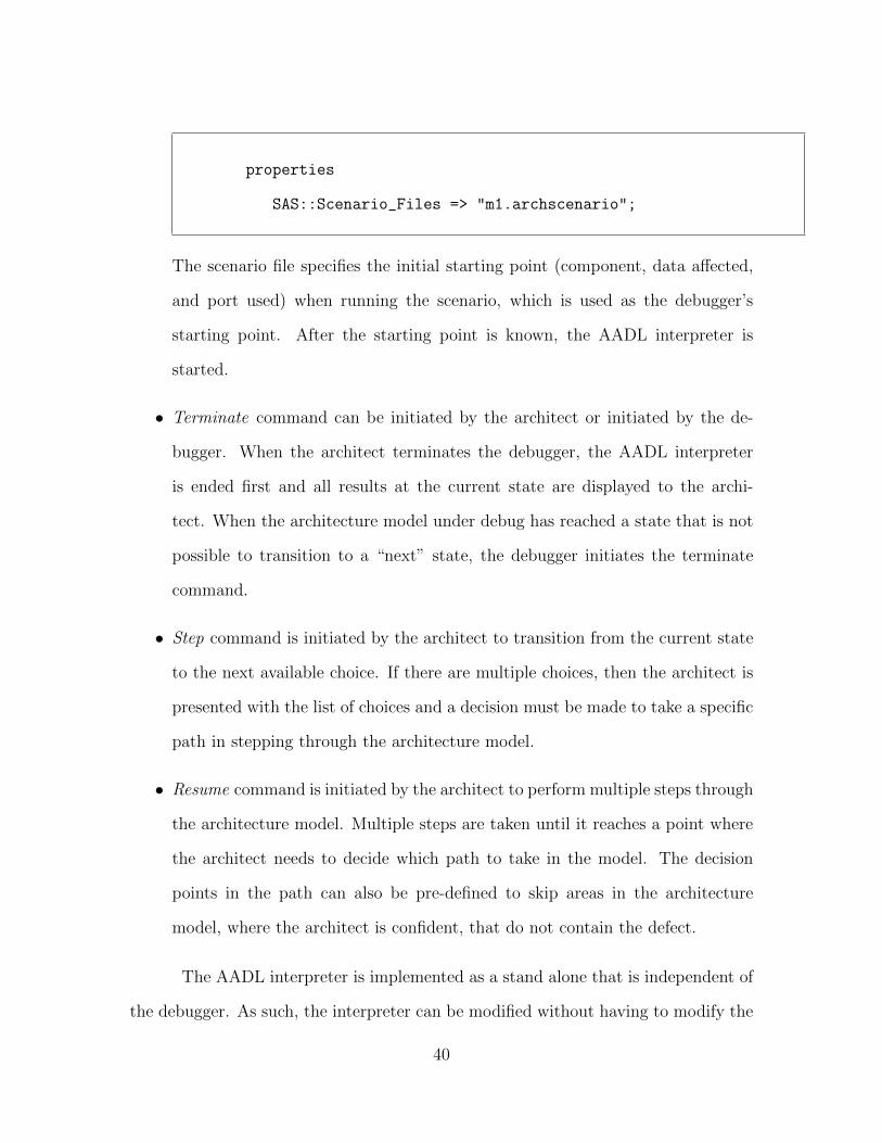
properties
SAS::Scenario_Files => "m1.archscenario";
The scenario file specifies the initial starting point (component, data affected,
and port used) when running the scenario, which is used as the debugger’s
starting point. After the starting point is known, the AADL interpreter is
started.
• Terminate command can be initiated by the architect or initiated by the de-
bugger. When the architect terminates the debugger, the AADL interpreter
is ended first and all results at the current state are displayed to the archi-
tect. When the architecture model under debug has reached a state that is not
possible to transition to a “next” state, the debugger initiates the terminate
command.
• Step command is initiated by the architect to transition from the current state
to the next available choice. If there are multiple choices, then the architect is
presented with the list of choices and a decision must be made to take a specific
path in stepping through the architecture model.
• Resume command is initiated by the architect to perform multiple steps through
the architecture model. Multiple steps are taken until it reaches a point where
the architect needs to decide which path to take in the model. The decision
points in the path can also be pre-defined to skip areas in the architecture
model, where the architect is confident, that do not contain the defect.
The AADL interpreter is implemented as a stand alone that is independent of
the debugger. As such, the interpreter can be modified without having to modify the
40

Figure 4.2: Screenshot of AADL Debugger
debug interface. It listens to the debug commands sent from the debugger, processes
the commands, and sends back the result. The interpreter is implemented using
the OSATE (Open Source AADL Tool Environment) toolset that provides a set of
architecture definition and analysis tools. Using OSATE we can analyze a given
AADL input to extract all the explicit relationships that are present in the model for
the purpose of debugging structural defects. The relationships we extract in the model
are: event transfer, data transfer, event data transfer, flow of information within a
component, and transfer of data and control between executing components. Based
on the relationships discovered, and given a starting point in the architecture model,
the debugger can now debug the structural defects by stepping through the explicit
relationships and checking whether the end result matches the expected result in the
41

scenario.
The rationale for making this debugger is so that architects can easily and
frequently run the debugger while defining the detailed architecture model to quickly
locate any structural defects. Using the debugger, as shown in Figure 4.2, an architect
can select a starting point, step through the architecture model and dynamically
direct a trace through the model. When there is no “next” available choice to step
to or a step results in tracing to an unexpected place this identifies the defect. In
addition, we have extended the OSATE toolset to create a plugin that will generate a
graphical output from a given AADL model showing all explicit relationships, defined
in Table 4.1, to help visualize the model and aid in debugging, as shown in Figure 4.3.
One of the benefits of such visualization is that architects can quickly locate unused
elements and some missing connections. Another benefit is that we can do a quick
comparison between the original visualization and the visualization after making a
change to the architecture to remove a structural defect, so that the architect can
quickly recognize which parts have been affected.
An example in discovering a missing connection is presented with the draw-
bridge example. The debugger is used to allow the architect to step through the
architecture and it is determined that a structural defect is present, because when
the drawbridge “RaiseSegmentB” is asked to be raised there is no possible transition
from “RaiseSegmentB” component to the “FailSafe” component when a failure is de-
tected, as shown in Figure 4.2 and Figure 4.3. Other structural defects can be found
similarly using the debugger and they are not shown here as the process is exactly
the same.
42

Figure 4.3: Graph Showing Explicit Relationships of an AADL Model
43

4.3 Debugging Behavioral Defects
We have developed an architecture slicing technique to scope down the prob-
lem of locating behavioral defects in architectures. In our approach, an architecture
slice needs to include all elements in the architecture that can potentially affect the
performance of a scenario. Once a slice is obtained, the architect has a much smaller
portion of the architecture model to examine for defects.
Software architecture slicing is applying the general principles of program slic-
ing to software architectures. Our approach to using architecture slicing for debugging
identifies the following relationships in addition to the control and data flow relation-
ship used in [70].
• Inheritance Relationship: Components can inherit from other components and
slices with inherited components should include all derived architectural ele-
ments and properties.
• Operational Modes: The path taken through an architecture may vary depend-
ing upon which operational mode is active. The operational mode should be
included as a slicing criterion as it determines which parts are active.
• Property Values: Some architectural elements may have property values spec-
ified that are related to achieving a specific quality attribute. For instance, as
in our previous work [25], the value of the security property may be specified
in certain elements of an AADL model. This value may be combined with the
security values in other elements and used to compute a value for the security
property and compared to the non-functional requirement concerning security
to determine if the requirement is met. Such property values should be included
as a slicing criterion to include only parts that can affect this value.
44

Static Dynamic
Implicit Relationship Property Values Operational ModesExplicit Relationship Inheritance Control and Data Flow
Table 4.1: Software Architectural Relationships
We can further categorize the software architectural relationships as shown
in Table 4.1. Inheritance and control and data flow are explicit relationships as
their relationships are visible through connectors. Property values and operational
modes are implicit relationships as their relationships to an architectural element are
not stated using a visible architectural construct. Property values and inheritance are
static relationships as they do not depend on execution time values to determine if the
relationship exists or not. Operational modes and control and data flow are dynamic
relationships since execution time values are required to know which relationship to
navigate.
By considering the above additional relationships present in software architec-
tures, our slicing technique can reduce the portion of the architecture to inspect and
correctly include the necessary information to aid in locating the defect.
An architecture slice is a subset of the original architecture model that includes
only the parts affected by a specified slicing criterion. It may be seen as extracting a
subset of the behavior of a software architecture [70]. For our purposes in debugging,
we apply a “forward slicing” algorithm and the slicing criterion is retrieved from an
architectural scenario that includes the starting component and the enabling port.
The architecture slicing algorithm is as follows.
1. Define the slicing criterion which requires at least a starting
component and an enabling port. Operational mode and
property value can be included in the slicing criterion to get a
subset of the architecture related to those relationships. In our
45

case, the slicing criterion is extracted from the scenario.
2. For all possible connections (through event transfer, data transfer,
event data transfer, flow of information within a component, and
transfer of data and control between components) from the starting
port to other components do
3. Include the new component and receiving port
4. Determine the internal connections within the component to
include by identifying the information flows for the given
data type and event type of interest. Any elements not related
to the receiving port and its received data or event are removed
5. Determine any inherited properties, if so include them
6. If operational modes are present, there are potentially new
connections that are enabled which are not the same ones as in 2.
When operational mode is specified, only include information flows
and connections enabled by the specified operational mode
7. If properties are present, only include information flows and
connections that can affect the specified property value
8. End
We have implemented the architecture slicing algorithm by extending the OS-
ATE (Open Source AADL Tool Environment) to create a plugin. The slicing algo-
rithm has been run on several AADL models and we describe a few of the case studies
in the next section.
Once a slice has been obtained, the architect will have a smaller subset of the
architecture to investigate in finding the defect. In addition, the sliced architecture
can be run through the AADL debugger mentioned in section 4.2 to dynamically
46

direct a trace through the sliced architecture.
4.3.1 DrawBridge Case Study
Figure 4.4: DrawBridge System
The graphical view of the DrawBridge system is shown in Figure 4.4 and
its description is mentioned in section 3.3. The DrawBridge system has 3 opera-
tional modes: IdleMode, ProgressMode, and FailureMode. Sensor starts at IdleMode.
Warnings are initiated and bridges are raised in ProgressMode. If failure is detected
47

in raising a bridge segment, it enters FailureMode. After bridges are raised, they are
lowered by initiating warnings in ProgressMode. And finally, it enters the IdleMode
in the Sensor component.
We inject a defect due to incorrect operational mode on a connection. When
bridge SegmentA is raised and it needs to be lowered by going back to the WarnA
component, the operation mode is incorrectly set to IdleMode when it should be
in ProgressMode. To locate the defect, we slice the AADL model according to the
following slicing criterion.
Component WarnA
Port i
Operational Mode ProgressMode
AADL File LOC
Original DrawBridge.aadl 115Resulting DrawBridgeSlice.aadl 53
Table 4.2: DrawBridge System LOC Comparison
The resulting slice shows only the necessary parts of the architecture that
are enabled by the operational mode specified in the slicing criterion. As a result,
this allows the architect to focus on a smaller subset to narrow down the defect into
a specific location. Table 4.2 shows the original LOC and the sliced LOC for the
DrawBridge system.
For this case study, the resulting slice shows there is no enabling transition from
RaiseSegmentA o to WarnA i under the ProgressMode as shown in Figure 4.5 and
Figure 4.6. This was due to the operational mode being incorrectly set to IdleMode
which can be corrected by modifying it to the correct operational mode.
48
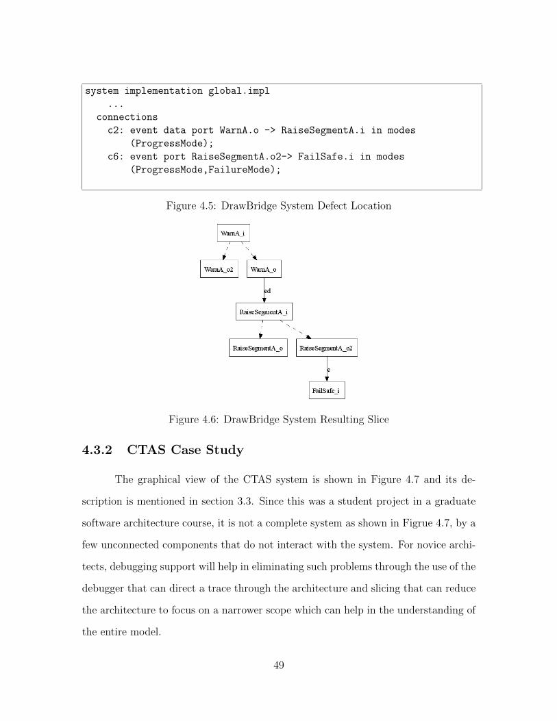
system implementation global.impl
...
connections
c2: event data port WarnA.o -> RaiseSegmentA.i in modes
(ProgressMode);
c6: event port RaiseSegmentA.o2-> FailSafe.i in modes
(ProgressMode,FailureMode);
Figure 4.5: DrawBridge System Defect Location
Figure 4.6: DrawBridge System Resulting Slice
4.3.2 CTAS Case Study
The graphical view of the CTAS system is shown in Figure 4.7 and its de-
scription is mentioned in section 3.3. Since this was a student project in a graduate
software architecture course, it is not a complete system as shown in Figrue 4.7, by a
few unconnected components that do not interact with the system. For novice archi-
tects, debugging support will help in eliminating such problems through the use of the
debugger that can direct a trace through the architecture and slicing that can reduce
the architecture to focus on a narrower scope which can help in the understanding of
the entire model.
49

Figure 4.7: CTAS System
AADL File LOC
Original CTAS.aadl 661Resulting CTAS Slice.aadl 157
Table 4.3: CTAS System LOC Comparison
In this CTAS system, once a user establishes a profile in the system the data
is written to a database. Based on the new profile, matching or similar information
found in the database is then output to the view. We inject a fault here to cause
extraneous activity where after the data is sent to displayToBrowser, it then initiates
an activity to requestData that will ultimately cause a refresh of the displayToBrowser
view, which is an unnecessary activity.
A slice of this model was obtained by using the following as the slicing criterion.
The original LOC and the sliced LOC for the CTAS system is shown in Table 4.3.
Component model
Port inputToEstablishProfile
Since the failure observed is an unwanted refresh of the view, we need to find
all places that can send data to the view starting from the port specified in the slicing
50

criteria. From the slice, it is easy to find such places and locate the defect as shown
in Figure 4.8 and Figure 4.9.
process view
...
flows
getRequestData: flow path displayToBrowser -> requestData;
Figure 4.8: CTAS System Defect Location
Figure 4.9: CTAS System Resulting Slice
4.3.3 DisplaySystem Case Study
The graphical view of the DisplaySystem is shown in 4.10 and its description
is mentioned in section 3.3. It models a cockpit display system, implemented by
Rockwell Collins, and it is the largest publicly available AADL model to date with
21,000 LOC. Due to its size, the components and connections in Figure 4.10 are
too small to recognize. As software systems increase in complexity and size, and its
51

current trend in building for ultra large scale systems (ULS) consisting of systems of
systems, the software architecture is also bound to increase in size and complexity. As
such they are increasingly becoming harder to debug due to its size and presence of
different types of defects, and architecture slicing is one efficient way to help architects
in debugging such large architecture models.
Figure 4.10: DisplaySystem
In this case study, a defect was injected into the model by introducing an
unintended connection between two components, thereby causing extraneous activity.
To locate the defect, we obtained a slice of the model by using the following as the
slicing criterion.
Component CDUProcessorSoftware
Port CDUDispEICASCmdstoRIMFDSWLOutSocket
The resulting slice is shown in Figure 4.11 where the search space has been
reduced to a much smaller space and the architect can easily locate the defect, which
is an unintended connection to
ProcessorNodeCDU CDUDisplayManager5HzProgressMsnPageTextfromCDULSWL.
AADL File LOC
Original DisplaySystem.aadl 12153Resulting DisplaySystem Slice.aadl 746
Table 4.4: DisplaySystem LOC Comparison
52

Figure 4.11: DisplaySystem Resulting Slice
4.4 Summary
In this chapter, we have described our techniques to debug defects related to
functional requirements. Specifically, we described a software architecture scenario
editor to create scenarios, software architecture debugger to debug structural defects,
and a software architecture slicing algorithm to debug behavioral defects. Through
the use of these tools, architects can more easily locate portions of the architecture
that fail to meet functional requirements. Once defects related to functional require-
ments have been eliminated, defects related to non-functional requirements should be
located, which is described in the next chapter.
53

Chapter 5
Debugging Defects Related to
Non-Functional Requirements
Defects related to non-functional requirements include failure to meet required
quality attribute levels and non-conformance to specific architectural patterns. In the
following sections, we describe how one might debug these two types of failures related
to non-functional requirements in a software architecture.
5.1 Quality Attributes in Software Architectures
As mentioned previously, one use of a software architecture is to provide the
means for an early evaluation and it is often difficult to analyze whether the modeled
software architecture satisfies some targeted quality attributes. Questioning tech-
niques such as ATAM (Architecture Tradeoff Analysis Method) [5] can be used to
analyze whether a specific non-functional requirement is met by the software archi-
tecture. However, such techniques are better at determining a failure to meet a quality
requirement than they are at determining what portion of the architecture fails to
54

measure up.
We continue to use the scenario-based approach here. The scenarios that have
been defined by the architect using the editor mentioned in section 4.1 are refined by
adding quality attributes of interest, which is the property value specified in AADL,
to be used in debugging for non-functional requirements. There are seven general
quality attributes [27] that can be present in a software architecture:
• Confidentiality: Allowing only authorized users to access the confidential data
or perform protected operations of a software system. [27]
• Integrity: Disallowing unauthorized data changes. [27]
• Availability: Measure of system’s operating uptime. [29]
• Maintainability: Measure of a system’s ability to be modified. [27]
• Reliability: Measure of how likely a system is to give a correct response. [44]
• Safety: Measure of system not resulting in a hazard. [35]
• Performance: Measure of system’s responsiveness. [5]
All of these quality attributes can be measured on an interval scale although
the significance of a value is left to be decided by the architect. For confidentiality
and integrity, an authorization based scheme can be defined in which the values of
authorization levels can be specified to determine if a scenario meets a confidentiality
or integrity requirement. For availability, reliability, and safety a percentage value can
be used to describe how much a system is available, reliable, or safe for a given sce-
nario. For maintainability, man-hours unit can be used to compute if a given scenario
can make a modification within a certain number of man-hours. For performance,
55

time units can be used to compute whether a given scenario can respond within a
certain time.
The quality attributes can be specified in a software architecture through the
use of property values. Using the specified property values, we can implement a
tool-based technique to quickly analyze a quality attribute of interest in the software
architecture. We describe our technique for finding where an architecture fails to
meet its quality attribute using confidentiality and integrity as an example to analyze
an architecture model for violations of security properties.
5.2 Debugging Quality Attribute Properties
Our approach to debugging confidentiality and integrity relies on our approach
for measuring confidentiality and integrity. We measure confidentiality and integrity
using a technique that requires only factual knowledge of the architecture and the
products to be produced from the architecture. The architect assigns a value to
the read and write authorization property of each element in the architecture that
indicates the authorization level required to read and write the data maintained within
the element. This information should be available from the authorization scheme that
is used by the organization defining the architecture and from the data confidentiality
requirements. The use of an authorization scheme aids in controlling access to a
resource and determining what access level is required to get to the resource, and is
reported to be useful in the security domain [6]. This approach can be applied to
either the logical or physical architecture.
A reasoning framework for confidentiality, used in ArchE, traverses paths
through the architecture for a set of scenarios [27]. For each scenario the actor
exercising the scenario has an authorization level that is compared to the allowable
56

authorization of the architectural elements along the scenario path. As long as the
authorization levels of the elements are less than the authorization level for the actor,
the scenario maintains confidentiality.
A second method of measuring confidentiality measures whether a breach of
confidentiality “will” occur [18]. This is usually expressed as a risk or probability
of occurrence. In this approach, a risk value is assigned to each node where the
possibility of as breach is located. This results in a more complex measure that
requires judgment about likelihoods of attack. This is addressed by using attack
patterns from the literature, but as types of attacks change, the evaluation of a
specific architecture would change as well.
We have chosen our approach, based on facts about the product requirements,
because our purpose is to give actionable advice to architects. The second approach
attempts to address factors – the behavior of humans – that are beyond the control of
the architect. It is the case that the risk-based approach can tell the architect which
of the confidentiality breaches will be most costly, but only if the actual pattern of
attacks is the same as the assumed pattern. We believe the simplicity of our measure
and its factual basis gives the most guidance to architects with the minimum of
assumptions about the architecture model.
The meaning of any quality attribute is tied to the context in which the mea-
sure is collected and the technique for collecting it. Confidentiality and integrity are
both used to define security but are often discussed in two very different contexts.
Our definition of confidentiality and our method for collecting a measure is based on
whether a breach in confidentiality “can” occur, and likewise for integrity. We exam-
ine the paths through the product that correspond to scenarios of use and determine
whether any of the activities along the path can be accessed by a user who does not
have sufficient authorization. This results in a fairly simple, Boolean result that is
57

based on facts defined in the product requirements.
The security requirement of a software system is specified during requirements
elicitation. The security quality attribute goals should be defined in terms of concrete
values for confidentiality and integrity. We have defined an AADL Property Set that
allows the specification of the authorization levels for each architectural element.
property set CUSE is
readAuthorization: aadlinteger 1 .. 9
applies to (all);
writeAuthorization: aadlinteger 1 .. 9
applies to (all);
end CUSE;
Figure 5.1: Confidentiality and Integrity Attribute Values
The ordinal scale represents the access level that is required to invoke the
read or write operations in a particular component in the software architecture. The
authorization scale is used during the design of the software architecture in AADL.
Any thread that reads or writes data should possess an authorization property value
greater than the authorization level of the architecture element.
For our purposes, we define a scenario in AADL using an end-to-end flow.
An end-to-end flow is defined as a “logical flow of information from a source to a
destination through a sequence of threads that process and possibly transform the
information” [59]. Using the flow we describe a use case scenario, which defines an
actor’s activities and authorization level as shown in Figure 5.2, and determine if the
sequence of activities are allowable by checking the access levels specified in the path
traveled by the flow.
We have built a prototype tool in which architects using our approach can
easily analyze whether a given confidentiality or integrity non-functional requirement
58

process implementation exp.impl
subcomponents
T1: thread prod.default;
T2: thread recv.default;
T3: thread recv.alt;
connections
conn1: data port T1.pd -> T2.pd;
conn2: event port T2.pe -> T1.pe;
conn3: data port T1.pd -> T3.pd;
flows
ETE1: end to end flow
T1.fs1 -> conn1 -> T2.fsink {
CUSE::readAuthorization => 3;
};
ETE2: end to end flow
T1.fs1 -> conn3 -> T3.fsink {
CUSE::writeAuthorization => 7;
};
ETE3: end to end flow
T2.fs1 -> conn2 -> T1.fp1
-> conn3 -> T3.fsink {
CUSE::readAuthorization => 4;
};
end exp.impl;
Figure 5.2: Example of End-to-End Flows with Actor’s Access Levels
is satisfied. The tool is built as an AADL plug-in and, when invoked on an AADL
model, any end-to-end flow specified in the model is traversed and contributes to the
output in Figure 5.3, which identifies any access level violations. If a violation is
found, detailed information is given to aid the architect in identifying the location
of the violation. The results are given in a table format, as in Figure 5.4, to help in
comparing among the scenarios.
Although we have only shown our approach using confidentiality and integrity,
failures related to other non-functional requirements can be found as well following
our approach. The difference is how the quality attribute’s value is calculated. Con-
59

Figure 5.3: Confidentiality and Integrity Analysis Plug-in
Figure 5.4: Markings of Scenarios and its Places of Violations
fidentiality and integrity used an authorization scheme where the authorization levels
are checked each time as it moves through a sequence of activities in a scenario.
Maintainability and performance use measures of man-hours and latency and their
property values are accumulated through a sequence of activities, and finally checked
to determine whether the end result satisfies the non-functional requirement. Avail-
ability, reliability, and safety are represented by a percentage of its system’s uptime,
probability of giving a correct result, and probability of not resulting in a hazard,
respectively. The property values of each component are multiplied through a se-
quence of activities, and finally checked if the end result satisfies the non-functional
requirement.
60

Once the tool has informed the architect that a confidentiality or integrity
violation has occurred, the architect will then have to find its cause in order to fix
or refine the software architecture model to meet its quality attribute requirements.
The cause of a confidentiality or integrity violation can surface in the following ways.
• Scenario error: A scenario described through an end-to-end flow may not contain
the correct or intended sequence of activities to be performed.
• Access level is too high: An authorization level may be set to be higher than
intended.
• Scenario actor’s level is too low: An authorization level given to an actor of a
scenario may be too low to perform the activities in a scenario.
The architect will, based on the output from the tool:
• examine the location of the violation in the AADL model,
• identify the elements that do not match with the authorization level of the user
of the flow,
• modify individual elements, perhaps by dividing them or modifying the required
authorization levels,
• revise the AADL model by eliminating some of the new elements that result
from the division.
The same scenarios are run against the revised model and this process is repeated
until the desired quality attribute value is supported by the software architecture
model.
In large software architectures, locating the places of violations in the model
can be difficult. Also, instead of blindly changing the violating property values, the
61

architect may need to know the context in which the property values are used and from
that identify what the actual defect is. To do so, architecture slicing is used where in
addition to the required slicing criterion the property attribute of interest is also used
as a slicing criterion, as described in section 4.3. As an example, we used the CTAS
model described in section 3.3 and listed in Appendix C. We sliced this model with the
required criterion of “controller” component with its “outputToModel” port and the
optional criterion, “Telematics::security”, to specify the property attribute of interest.
The resulting slice includes only components “model” and “view” as they are the
only components from the slicing criterion that can affect the “Telematics::security”
attribute. Given a scenario and its security levels, the architect can examine the
sliced architecture to find which activities are not allowed due to insufficient security
level.
The location of property values that violate the non-functional requirement
can be found using these two tool operations. Eliminating the defect can be as
simple as modifying the property value or the architectural element containing the
property value. It could also be as complicated as changing the architecture model
through use of tactics such as dividing an element to allow the execution of a task for
two different types of users. However, the one defect type that this approach cannot
locate is the case where the current detailed model does not match the conceptual
model. We are interested in this because a quality attribute of a software architecture
is dictated by the conceptual model of the architecture. For example, a conceptual
model that has its responsibilities in serial cannot increase its performance without
breaking up some of them into parallel connections. If the conceptual model had
responsibilities in parallel, and our detailed model implemented them in serial, then
the defect is that there isn’t a match with the conceptual model and the performance
quality attribute obviously does not meet the non-functional requirement as well.
62

In our work, we view the conceptual model as a pattern that must be followed
in the detailed design to achieve a certain level of quality attribute. And to locate the
places of mismatch between the detailed and conceptual model, we use a clustering
technique as described in the following section.
5.3 Non-Conformance to an Architectural Pattern
In our software architecture definition tool chain, previously shown in Figure
3.3 in Chapter 3, an architect first takes the requirements of a system and builds a
conceptual software architecture that models this system. At the conceptual architec-
ture level, requirement scenarios are used to create quality attribute scenarios, which
describe a series of system actions that require a certain level of quality attribute
[39]. Then responsibility driven design is used to identify the system responsibilities
that are needed to realize the scenarios [39] [32]. The responsibility relationship sys-
tem can be modeled in ArchE, shown in Figure 5.5 and its corresponding graph in
Figure 5.6.
Figure 5.5: Responsibility Relationship Modeled in ArchE
The resulting responsibility relationship graph shown in Figure 5.6 is then used
to model the detailed architecture, in AADL, to provide an architecture description
that satisfy the requirements of the system. It is important to note that for our
63

Figure 5.6: Responsibility Relationship Graph of Figure 5.5
purposes, this responsibility relationship graph created is a collection of architectural
pattern instances with some glue connectors that may not correspond to a standard
pattern. What is represented in the responsibility relationship graph should be ap-
plied when creating the detailed architecture description. From this simple example,
it is clear that the responsibility graph represents a standard client server architec-
tural pattern. But in a more complicated conceptual architecture model, the entire
responsibility relationship graph will usually not correspond to a single standard ar-
chitectural pattern, but rather it will be a combination of standard architectural
patterns and domain specific architectural patterns that satisfy the requirements in
a given domain.
The detailed software architecture design using AADL should conform to the
architectural patterns specified through ArchE since the pattern already has been
evaluated at the conceptual level and expert architects have selected it to be the
pattern that, when applied, will satisfy the given problem. The importance of confor-
mance checking is identified in [3] [54], in which the implemented system is checked
against the software architecture model. However, there is no previous work on
conformance checking a software architecture model against a software architectural
pattern.
To debug non conformance of an architectural model to a pattern, we verify
whether it matches the pattern rules defined in a reference model that defines the ar-
chitectural pattern. For our purposes, the reference model is the ArchE responsibility
graph. We use dependency analysis to map components of the architecture to corre-
64

sponding responsibilities that are present in the reference architecture model. Once
the mapping is established and a discrepancy is found we present it to the architect
as a possible source of failure.
Architects may want to perform an architectural conformance check in the
following situations:
• As the software architecture evolves over time, there is a potential for archi-
tecture erosion1. An architect would use architectural conformance check to
quickly verify if the initial architectural pattern stills holds after revisions and
quickly locate places of violation, if any.
• An architect can use architectural conformance checks as an aid to understand-
ing the entire architecture of the system and to discover the patterns used.
• In cases when an architect knows a certain pattern must not be used, architec-
tural conformance checks can be used as a way to find if certain anti-patterns
are used.
Given a set of responsibilities, which may be connected to represent a pat-
tern, when implemented in the detailed architecture model there exist two types of
connections. Inner connections are connections between modules inside a respon-
sibility. Outer connections are connections between the responsibilities realized by
connections from a module in one responsibility to another module in a different
responsibility. Inner connections are strongly coupled as the modules inside a respon-
sibility are highly dependent on each other to perform the task of that responsibility.
Outer connections between responsibilities are loosely coupled as each responsibility
is responsible for one logical task and have little dependency with others.
1Architecture erosion is when violations exist in the architecture, and they “lead to an increasein problems in the system and contribute to the increasing brittleness of the system” [49].
65

The detailed software architecture model is developed by representing the re-
lationships among the responsibilities defined in the conceptual model. If the detailed
software architecture model matches the responsibilities and the relationships present
in the conceptual model, then we say there is pattern conformance. The problem is
to identify which parts in the detailed architecture belong to each responsibility in
the conceptual model since this mapping often is not documented during the initial
construction of the detailed model. Our goal is to organize the detailed architecture
model into largely disjoint clusters and identify the responsibilities in order to find
conformance to a pattern. The goal is to group responsibilities that have strong cou-
pling into clusters and separate clusters that represent separate responsibilities in the
conceptual model.
We first take a detailed software architecture model and build a Dependency
Structure Matrix (DSM). A dependency structure matrix is a square matrix and the
cells in the matrix show the connection strength or dependency between the modules.
Looking at the simple DSM as an example shown in Table 5.1, the X in column 1
shows that Module1 depends on Module3, or Module3 provides to Module1. If the
dependency strength is known, a numeric value may be used instead of an X.
Module1 Module2 Module3
Module1 -Module2 -Module3 X -
Table 5.1: Simple Dependency Structure Matrix Example
Given a software architecture represented in AADL, we can build a DSM repre-
sentation as follows. We first extract all the ports that are present in the architecture
(data, event, and data event ports). The rows and column labels of the DSM are the
extracted ports. Then find all connections (data, event, and data event connections)
66

that exist between the ports, which represent a control and/or data transfer. Mark
the connections into the corresponding cell of the DSM. A mark inside a cell of a DSM
means that a module has a connection (transfer of data and/or control) to another
module.
From the DSM, our goal is to identify modules that are dependent on each
other and group them into clusters. A detailed architecture model of a simple client
server can be represented by a DSM as shown in Figure 5.7. Based on the interactions
that are present between modules in the DSM, two clusters can be identified as in
Figure 5.8.
Figure 5.7: DSM Constructed from a Detailed Architecture Model of a Client-ServerPattern
Figure 5.8: DSM After Clustering
Since our premise is that modules inside the same responsibility have high
inter-dependencies between them, our goal is to cluster the DSM into highly cohesive
clusters. After clusters have been identified we map by hand each cluster to the
corresponding responsibility to determine whether there is a match to a pattern. In
67

this example, there are two clusters that match the client-server pattern but there is
only a one-way communication when it should be a two-way communication.
To cluster a given DSM into modules of high interactivity, we apply the clus-
tering algorithm described in [62]. The clustering algorithm is shown in Figure 5.9.
1. Initially, each element in the DSM is
placed in its own cluster
2. Calculate the initial total coordination cost
3. Loop while system < stable limit
4. Loop size x times
5. Pick an element in the DSM
6. Calculate bids and select best bid
7. Calculate new total coordination cost
(assuming selected element is now a
member of the cluster with highest bid)
8. If new total coordination cost is
lower than its old value, accept the bid
and update clusters
9. system = system+1
10. End loop
Figure 5.9: Original DSM Clustering Algorithm
The algorithm essentially tries to minimize the total coordination cost. The
total coordination cost is calculated with the following equations [62].
Coordination Cost =�
IntraClusterCost +�
ExtraClusterCost
where the coordination cost is the sum of all cost of interaction occurring inside a
cluster and the sum of all cost of interaction occurring outside of any clusters.
IntraClusterCost = (DSM(j,k) + DSM(k,j)) * ClusterSize(y)powcc
ExtraClusterCost = (DSM(j,k) + DSM(k,j)) * DSMSizepowcc
where DSM(j,k), DSM(k,j) denotes the interaction between elements j and k, Clus-
68

terSize(y) is the number of elements in cluster y, DSMSize is the total number of
elements in the DSM, and powcc is a constant that penalizes the size of clusters as
they increase.
The total coordination cost is at the highest when every element is a cluster
of itself. As elements with strong interactions are grouped into the same cluster,
the total coordination cost becomes lower. A bid is calculated using the number of
interactions between an element and a cluster to determine how strongly a cluster
interacts with the selected element. In each execution of the loop, the clustering that
results in a lower total coordination cost is selected and this is repeated until the
total coordination cost has no improvement. The equation to calculate a bid from
each cluster is shown as follows [62].
ClusterBidj =(inout)powdep
(ClusterSizej)powbid
where for a cluster j, inout is the sum of DSM interactions of the chosen element
with each of the elements in cluster j, powdep is a constant to emphasize interactions,
powbid is a constant to penalize the size of the cluster.
We applied the original algorithm on several architecture models modeled in
AADL that used the MVC pattern, layered pattern, and models of unknown pat-
terns to analyze how well the algorithm would perform. Initial results have been
encouraging in that clusters have been discovered as intended and mostly match the
conceptual architectural model. However, there are some limitations with the original
algorithm.
The original algorithm resulted in many modules ending up as a single cluster
containing itself only. This is due to the algorithm trying to limit the membership of
a module to single cluster. However, for our purposes, we would like the algorithm to
produce a more fuzzy result by not restricting elements from having multiple mem-
69

berships in clusters. Because the algorithm cannot always exactly group the correct
modules into a cluster, a fuzzy clustering result is preferred to have the architect
decide where it should belong for modules with multiple membership.
The original algorithm limits multiple memberships of modules by using pe-
nalization. The DSM adds an additional entry for the module contained in multiple
clusters. So a module that belongs to two clusters will increase the size of the DSM
by one, because that module will show up twice in the matrix. Due to the addition
of entries into the DSM and increasing its size, the calculated total coordination cost
is also increased. This makes the algorithm unlikely to accept modules with multiple
memberships in clusters due to the increased cost.
We have modified the original algorithm such that we do not penalize for
modules belonging to multiple clusters. We do not increase the DSM size and its
entries by modules of multiple memberships. This will then not increase the calculated
total coordination cost just because a module belongs to multiple clusters. This will
produce fuzzy clustering where modules belonging to multiple clusters are shown in
the DSM, provided that clustering yielded the lowest total coordination cost.
Once the DSM with clusters has been produced, the architect will look at
modules with multiple memberships and decide where each should belong. Then the
architect can specify the modules that should belong to the same cluster and rerun the
algorithm. This is possible when the architect already has some knowledge of which
elements should belong together as a component. That information is leveraged to
produce a better decomposition into clusters. Likewise, the architect can also mark
specific elements to be excluded from clusters. Some components may be used as a
common component by many which obstruct the clustering process. Excluding known
common components will produce a better result. This process of clustering the DSM
is repeated until the architect can identify the separate responsibilities represented
70

by the clusters.
We have used the modified clustering algorithm on the same AADL example
models used for the original algorithm and we show two representative examples with
the results below. The first case study was using the BBS system, which is intended
to use the three-tier layered pattern but a fault was injected that breaks the pattern
as mentioned in Chapter 3.3. We created a DSM as mentioned above and used it
as input to the modified clustering algorithm. The output is a DSM that shows the
clustered modules, shown in Figure 5.10.
Figure 5.10: Clustered DSM of BBS System Injected with Fault
In a layered architecture, what we expect to see is that each cluster to com-
municate with only its immediate cluster. However, Figure 5.10 shows that the third
cluster communicates with both the first and second cluster. We modify the archi-
tecture definition based on this information and correct the connection that breaks
the layered pattern. The DSM of the modified architecture model is created and
clustered again, shown in Figure 5.11.
Looking at the clustered DSM, there are three identified clusters and one
71

Figure 5.11: Clustered DSM of Fault-Free Three-Tier Layered Architecture of BBSSystem
module, 9, belongs to two clusters. The architect looks at the module with multiple
membership and decides where it should really belong based on the knowledge of the
detailed architecture model. Once the architect decides that module 9 should belong
to the middle cluster in Figure 5.11, then the resulting clusters show that the de-
tailed architecture model contains three clusters and they match the intended layered
pattern architecture. Each cluster matches to the conceptual model’s responsibilities
namely the presentation layer, application layer, and database server.
The second case study was using the CTAS (Clemson Traveler Assistant Sys-
tem) described in section 3.3. This architecture model was developed by a student
team in a graduate software architecture course at Clemson University and they were
instructed to follow the Model-View-Controller pattern. The clustered DSM is shown
in Figure 5.12.
The clustered DSM shows six clusters and at first glance there is no apprar-
ent resemblance to the intended architectural pattern. The CTAS model has some
72

Figure 5.12: Clustered DSM of CTAS
incomplete parts where some modules are rarely used, which is due to its reliance
on a framework architecture. As such, for the rarely used modules there exists little
coupling with other modules that make up a single responsibility. This is the cause
for the seemingly unrelated clusters shown in Figure 5.12.
In cases such as this, where the architecture model lacks in detail, the architect
can use existing knowledge to help improve the clustering. When an architect knows
some modules should belong to the same cluster, he can specify a connection strength
between the two to help the clustering algorithm to try and group them into the
same cluster. With the CTAS example, we have added a connection strength to
five modules that were identified as obvious modules that should belong to the same
cluster. Figure 5.13 shows the resulting clustered DSM.
The re-clustered DSM of CTAS shows a better resemblance to matching the
three responsibilities of model, view and controller. However, it shows five clusters
and manual inspection is needed to match it to the three responsibilities. The first
three clusters have some overlapping modules but after limiting those to single cluster
73

Figure 5.13: Re-clustered DSM of CTAS
membership the three clusters can be matched to each of the three separate responsi-
bilities. For the last two clusters, they are examined individually and can be identified
to belong to one of the three clusters.
Although the DSM clustering method is useful in identifying pattern confor-
mance there is one limitation to our approach, which is the lack of automation. Once
the DSM is clustered, a manual inspection is needed to identify a match. While this
is still useful and better than current approaches, a more automated approach should
be investigated in the future.
5.4 Summary
In this chapter, we have described our techniques to debug defects related to
non-functional requirements. Specifically, we described tools that can quickly identify
and locate places having quality attribute values that cannot be satisfied by a given
scenario. We have also described our approach to check for non-conformance to a
74

software architectural pattern. Through the use of a combination of our debugging
techniques, architects can build a more rigorous architecture model with as many
defects eliminated before implementing the system.
75

Chapter 6
Related Work
6.1 Software Architecture Debugging
Balzer’s work [4] appears to be the only work that directly investigates the
topic of software architecture debugging. Balzer focuses on providing access to the
software architectural behavior, which he describes as the exchange of data and con-
trol between components in the software architecture. By providing access to the data
and control that are passing through all connectors, he claims that it is “analogous to
the power that our debuggers have given us for subroutine organizations to trace calls
to these subroutines, time their execution, and/or insert breakpoints into these calls
or their returns.” [4] The paper describes how to instrument the connectors in the
software architecture to gain access to the data and control between the components.
However, it does not show how these can be used for actual debugging to find the
location of a defect.
Our work differs from Balzer’s work as we focus on debugging techniques to
locate software architectural defects. Balzer claims that “elevating system develop-
ment from the module to the architecture level requires a corresponding elevation in
76
our tools for instrumenting, monitoring, and debugging systems.” [4] We agree with
this claim and believe our research contributes to elevating debugging to the software
architecture level.
6.2 Debugging Software Design
Many have recognized the importance of debugging software designs as a cost
effective way to minimize defects early which results in lower debugging costs in later
phases of development. As the software design gets more complicated and increasing
in size, debugging its design has also grown more sophisticated. We take a closer look
at existing work that applies debugging to UML models to find defects during the
design phase. Although UML is a detailed level design language for modeling soft-
ware, some concepts and techniques in debugging UML can be applied to debugging
software architectures.
UML has been used predominantly in designing software systems. As UML
designs increase in size and complexity, so does the probability of bugs being present
and the difficulty in finding the bugs. To facilitate locating the bugs in UML designs,
several debugging techniques have been introduced, as described below.
Schumann provides a technique to debug UML sequence diagrams that can
detect conflicts with a given domain theory and give the location of the conflict [56].
It also provides a technique to detect conflicts between a UML statechart and a UML
sequence diagram.
Dotan and Kirshin introduce a custom debugging tool (UML Model Debugger)
to debug UML activity diagrams and UML state machines [12]. The tool allows
debugging of UML activity and state machine diagrams by providing functions such
as stepping into a transition, setting break points, and viewing attributes of the
77

current object.
Del Mar Gallardo et al. proposes the use of model checking in UML designs
for debugging purposes [10]. It describes model checking UML statecharts and UML
sequence diagrams to discover design bugs.
Although the goal is the same as ours, UML related work take a simplistic view
of debugging where most defects are structural and relating to functional requirements
only. Our approach takes a more complete view of debugging for both functional and
non-functional defects which can include structural, behavioral, and quality attribute
type defects.
6.3 Software Architecture Slicing
Software architecture slicing was introduced in [70] as a technique to extract
reusable software architectures given an architectural slicing criteria of a given set
of ports or connectors, which carry control and data flow relationships. Since this
architecture slicing technique’s aim is to extract reusable parts of an architecture,
it is not suitable for use in the context of software architecture debugging for the
following reasons:
• the resulting slice may be larger than necessary to isolate a defect if the defect
is contained in the resulting slice
• the resulting slice may not contain the defect because it only tries to slice
reusable components and uses only control and data flow relationships.
78

6.4 Software Architecture Conformance
Software architecture conformance is an active research area. In most ap-
proaches such as in [19], [51], and [54], source code is analyzed and its dependencies
are used to map to a design pattern or a software architecture. These approaches
often require the software developer’s input in identifying the design pattern used in
the implementation or its software architecture.
In another approach, a tool called Lattix [55] takes source code as input and
uses a dependency structure matrix and uses DSM algorithms to reorganize the DSM.
It is usually used to find architectural patterns that are present in the source code.
All these approaches require an implemented system first and its implemen-
tation is analyzed to map to a higher level design, such as an architectural pattern
or software architecture. Our work focuses on mapping the software architecture,
designed using a formal architecture description language, to the conceptual archi-
tecture level because most defects related to non-functional requirements are present
at the conceptual level. We do not require or assume that the implementation is
available.
79
Chapter 7
Conclusions and Future Work
Defects should be eliminated as soon as possible in the software architecture
to minimize the cost of debugging and repair in later stages of software development.
Defects in software architecture can be difficult to locate but are easier to fix than
in a fully implemented system. This research defines a method to provide debug-
ging support in order to find defects in software architectures defined using a formal
architecture description language, AADL. A systematic and general software archi-
tecture debugging process is presented with debugging techniques to locate defects
related to both functional and non-functional requirements which includes structural,
behavioral, and quality attribute type defects. Our work is intended to complement
existing architecture definition and evaluation techniques and aid the architect in
locating defects.
By providing debugging support for software architectures, software architects
can quickly identify portions of the architecture to refine and gain confidence that
defects have been minimized before moving on to the implementation phase. This
results in minimizing the number of defects that can propagate down to the imple-
mentation level from the software architecture. Additionally, with debugging support
80

more architects may be encouraged to formally describe their software architecture
using a modern software architecture description language, such as AADL, to take
advantage of its debugging capabilities.
A number of research issues remain to be resolved. Recalling the software ar-
chitecture definition tool chain, in Figure 3.3, there are three separate levels consisting
of the conceptual architecture model, detailed architecture model, and the executable
architecture. We envision an automated approach to map defects and any changes
from one level to the other providing a feedback loop that the architects can leverage
to more easily define software architectures that are correct and robust. The ability
to move freely between the levels, with little to no manual intervention, will improve
the debugging of software architectures.
81

Appendices
82

Appendix A AADL Description of Bulletin Board
System
package Commons
public
data bbs_msg
end bbs_msg;
end Commons;
package Commons::Subprograms
public
subprogram bbs_program
features
ingoing_msg : in parameter Commons::bbs_msg;
outgoing_msg : out parameter Commons::bbs_msg;
properties
source_language => Ada95;
source_name => "Repository.BBS_Program";
end bbs_program;
subprogram post_program
features
outgoing_msg : out parameter Commons::bbs_msg;
properties
source_language => Ada95;
source_name => "Repository.Post_Program";
end post_program;
subprogram get_program
features
ingoing_msg : in parameter Commons::bbs_msg;
properties
source_language => Ada95;
source_name => "Repository.Get_Program";
end get_program;
end Commons::Subprograms;
thread black_board_server
features
req_penpal : in event data port Commons::bbs_msg;
bcast_penpal : out event data port Commons::bbs_msg;
properties
Dispatch_Protocol => Aperiodic;
end black_board_server;
thread implementation black_board_server.i
calls {
up : subprogram Commons::Subprograms::bbs_program;
};
connections
parameter req_penpal -> up.ingoing_msg;
parameter up.outgoing_msg -> bcast_penpal;
83

end black_board_server.i;
process db_retrieve
features
req : in event data port Commons::bbs_msg;
result : out event data port Commons::bbs_msg;
end db_retrieve;
process implementation db_retrieve.i
end db_retrieve.i;
process db_backup
features
init : in event data port Commons::bbs_msg;
bup : out event data port Commons::bbs_msg;
end db_backup;
process implementation db_backup.i
end db_backup.i;
process db_distribute
features
init : in event data port Commons::bbs_msg;
done : out event data port Commons::bbs_msg;
end db_distribute;
process implementation db_distribute.i
end db_distribute.i;
process bbs_server_check
features
req : in event data port Commons::bbs_msg;
result : out event data port Commons::bbs_msg;
end bbs_server_check;
process implementation bbs_server_check.i
end bbs_server_check.i;
process bbs_server_handle
features
p_req : in event data port Commons::bbs_msg;
p_bcast1 : out event data port Commons::bbs_msg;
p_bcast2 : out event data port Commons::bbs_msg;
end bbs_server_handle;
process implementation bbs_server_handle.i
subcomponents
t_bbs : thread black_board_server;
connections
event data port p_req -> t_bbs.req_penpal;
event data port t_bbs.bcast_penpal -> p_bcast1;
event data port t_bbs.bcast_penpal -> p_bcast2;
84
end bbs_server_handle.i;
process bbs_server_sort
features
input : in event data port Commons::bbs_msg;
output : out event data port Commons::bbs_msg;
end bbs_server_sort;
process implementation bbs_server_sort.i
end bbs_server_sort.i;
thread penpalReq
features
penpalpost : out event data port Commons::bbs_msg;
properties
Dispatch_Protocol => Periodic;
Period => 300 Ms;
end penpalReq;
thread implementation penpalReq.i
calls {
up : subprogram Commons::Subprograms::post_program;
};
connections
parameter up.outgoing_msg -> penpalpost;
end penpalReq.i;
thread penpalGet
features
inbox : in event data port Commons::bbs_msg;
properties
Dispatch_Protocol => Aperiodic;
end penpalGet;
thread implementation penpalGet.i
calls {
up : subprogram Commons::Subprograms::get_program;
};
connections
parameter inbox -> up.ingoing_msg;
end penpalGet.i;
process bbs_client_initiate
features
p_init : in event data port Commons::bbs_msg;
p_out : out event data port Commons::bbs_msg;
end bbs_client_initiate;
process implementation bbs_client_initiate.i
end bbs_client_initiate.i;
process bbs_client_send
85

features
p_inbox : in event data port Commons::bbs_msg;
p_penpalpost : out event data port Commons::bbs_msg;
end bbs_client_send;
process implementation bbs_client_send.i
subcomponents
t_receiver : thread penpalGet;
t_sender : thread penpalReq;
connections
event data port p_inbox -> t_receiver.inbox;
event data port t_sender.penpalpost -> p_penpalpost;
end bbs_client_send.i;
process bbs_client_save
features
p_in : in event data port Commons::bbs_msg;
p_redo : out event data port Commons::bbs_msg;
end bbs_client_save;
process implementation bbs_client_save.i
end bbs_client_save.i;
system bbs_sys
end bbs_sys;
system implementation bbs_sys.impl
subcomponents
bbs_c1 : process bbs_client_initiate.i;
bbs_c2 : process bbs_client_send.i;
bbs_c3 : process bbs_client_save.i;
bbs_s1 : process bbs_server_check.i;
bbs_s2 : process bbs_server_sort.i;
bbs_s3 : process bbs_server_handle.i;
db1 : process db_retrieve;
db2 : process db_backup;
db3 : process db_distribute;
connections
event data port bbs_c1.p_out -> bbs_c2.p_inbox;
event data port bbs_c2.p_penpalpost -> bbs_c3.p_in;
event data port bbs_c3.p_redo -> bbs_c1.p_init;
event data port bbs_c1.p_out -> bbs_s1.req;
event data port bbs_c2.p_penpalpost -> bbs_s2.input;
event data port bbs_c3.p_redo -> bbs_s3.p_req;
event data port bbs_s1.result -> bbs_s2.input;
event data port bbs_s2.output -> bbs_s3.p_req;
event data port bbs_s3.p_bcast1 -> bbs_s1.req;
event data port bbs_s2.output -> db2.init;
event data port bbs_c1.p_out -> db1.req;
event data port db1.result -> db3.init;
event data port db3.done -> db1.req;
end bbs_sys.impl;
86

Appendix B AADL Description of DrawBridge
data reqData
end reqData;
property set MY is
Scenario_Files: list of aadlstring applies to (all);
end MY;
process FailSafe
features
i: in event port;
end FailSafe;
process implementation FailSafe.impl
end FailSafe.impl;
process RaiseSegmentA
features
i: in out event data port reqData;
o: out event port;
o2: out event port;
flows
flow1: flow path i -> o;
flow2: flow path i -> o2;
end RaiseSegmentA;
process implementation RaiseSegmentA.impl
end RaiseSegmentA.impl;
process RaiseSegmentB
features
i: in event data port reqData;
o: out event port;
o2: out event port;
flows
flow1: flow path i -> o;
flow2: flow path i -> o2;
end RaiseSegmentB;
process implementation RaiseSegmentB.impl
end RaiseSegmentB.impl;
process WarnA
features
i: in event port;
o2: out event data port reqData;
o: out event data port reqData;
flows
flow1: flow path i -> o;
flow2: flow path i -> o2;
87

end WarnA;
process implementation WarnA.impl
end WarnA.impl;
process WarnB
features
i: in event port;
o2: out event data port reqData;
o: out event data port reqData;
flows
flow1: flow path i -> o;
flow2: flow path i -> o2;
end WarnB;
process implementation WarnB.impl
end WarnB.impl;
process Sensor
features
i: in event data port reqData;
o: out event port;
flows
flow1: flow path i -> o;
end Sensor;
process implementation Sensor.impl
end Sensor.impl;
system global
end global;
system implementation global.impl
subcomponents
Sensor: process Sensor.impl in modes (IdleMode);
WarnA: process WarnA.impl in modes (IdleMode, ProgressMode);
WarnB: process WarnB.impl in modes (IdleMode, ProgressMode);
RaiseSegmentA: process RaiseSegmentA.impl in modes (IdleMode, ProgressMode, FailureMode);
RaiseSegmentB: process RaiseSegmentB.impl in modes (IdleMode, ProgressMode, FailureMode);
FailSafe: process FailSafe.impl in modes (ProgressMode, FailureMode);
connections
c1: event port Sensor.o -> WarnA.i in modes (IdleMode);
c12: event port Sensor.o -> WarnB.i in modes (IdleMode);
c2: event data port WarnA.o -> RaiseSegmentA.i in modes (ProgressMode);
c21: event data port WarnA.o2 -> Sensor.i in modes (IdleMode);
c3: event data port WarnB.o -> RaiseSegmentB.i in modes (ProgressMode);
c31: event data port WarnB.o2 -> Sensor.i in modes (IdleMode);
c4: event port RaiseSegmentA.o -> WarnA.i in modes (IdleMode);
c5: event port RaiseSegmentB.o -> WarnB.i in modes (ProgressMode);
c6: event port RaiseSegmentA.o2 -> FailSafe.i in modes (ProgressMode, FailureMode);
c7: event port RaiseSegmentB.o2 -> FailSafe.i in modes (ProgressMode, FailureMode);
modes
88

IdleMode: initial mode;
ProgressMode: mode;
FailureMode: mode;
IdleMode -[ Sensor.o ]-> ProgressMode;
ProgressMode -[ RaiseSegmentA.o2 ]-> FailureMode;
ProgressMode -[ RaiseSegmentB.o2 ]-> FailureMode;
ProgressMode -[ RaiseSegmentA.o ]-> IdleMode;
ProgressMode -[ RaiseSegmentB.o ]-> IdleMode;
properties
MY::Scenario_Files => "My1.archscenario";
end global.impl;
89

Appendix C AADL Description of CTAS
property set Telematics is
latency: aadlreal applies to (all);
reliability: aadlreal applies to (all);
transportModes: enumeration (car, train, bigBus, airplane) applies to (all);
itineraryCriteria: enumeration (cost, distance, time) applies to (all);
availability: aadlreal 0.95 .. 0.99
applies to (all);
usability: aadlinteger 1 .. 9
applies to (all);
modifiability: aadlinteger 1 .. 9
applies to (all);
reusability: aadlinteger 1 .. 9
applies to (all);
performance: aadlinteger 1 .. 9
applies to (all);
extensibility: aadlinteger 1 .. 9
applies to (all);
security: aadlinteger 1 .. 9
applies to (all);
end Telematics;
port group clientServer
features
-- connections to the outside world
getInfo: in data port;
requestInfo: out event data port;
end clientServer;
port group serverClient
features
-- connections from the outside world
getInfo: out data port;
requestInfo: in event data port;
inverse of clientServer
end serverClient;
data Name
properties
Source_Data_Size => 300 B;
end Name;
data Position
properties
Source_Data_Size => 200 B;
end Position;
data Transportation
properties
Source_Data_Size => 50 B;
90

end Transportation;
data Itinerary
properties
Telematics::reliability => 0.95;
end Itinerary;
data UserInput
properties
Source_Data_Size => 200 KB;
end UserInput;
data Events
properties
Source_Data_Size => 200 KB;
end Events;
data userProfile
features
computeItinerary: subprogram computeItinerary;
end userProfile;
data implementation userProfile.default
end userProfile.default;
subprogram computeItinerary
features
currentPosition: in parameter Position;
destination: in parameter Position;
itinerary: out parameter Itinerary;
properties
Telematics::latency=>1.0;
Telematics::availability => 0.99;
Telematics::reliability => 0.85;
Telematics::usability => 6;
Telematics::modifiability => 7;
Telematics::reusability => 6;
Telematics::performance => 5;
Telematics::extensibility => 4;
Telematics::security => 3;
end computeItinerary;
subprogram changeTransportationMode
features
currentPosition: in parameter Position;
destination: in parameter Position;
itinerary: out parameter Itinerary;
transportation: out parameter Transportation;
properties
Telematics::latency=>5.0;
Telematics::reliability=>0.70;
Telematics::availability=>0.95;
91

Telematics::security=>1;
end changeTransportationMode;
subprogram establishProfile
features
newName: in parameter Name;
newHome: in parameter Position;
newWork: in parameter Position;
properties
telematics::latency=>5.0;
telematics::reliability=>0.9;
telematics::availability=>0.95;
telematics::security=>1;
end establishProfile;
subprogram deleteProfile
features
name: in parameter Name;
properties
Telematics::latency=>3.0;
Telematics::reliability=>0.99;
Telematics::availability=>0.95;
Telematics::security=>1;
end deleteProfile;
subprogram modifyProfile
features
changedName: in parameter Name;
changedHome: in parameter Position;
changedWork: in parameter Position;
properties
telematics::latency=>1.0;
telematics::reliability=>0.95;
telematics::availability=>0.99;
telematics::security=>1;
end modifyProfile;
subprogram requestNewItinerary
features
currentPosition: in parameter Position;
destination: in parameter Position;
itinerary: out parameter Itinerary;
properties
Telematics::latency=>3.0;
Telematics::reliability=>0.95;
Telematics::usability=>2;
Telematics::security=>1;
end requestNewItinerary;
subprogram refreshItinerary
features
currentPosition: in parameter Position;
92

destination: in parameter Position;
itinerary: out parameter Itinerary;
properties
Telematics::latency=>1.0;
Telematics::reliability=>0.99;
Telematics::usability=>1;
Telematics::security=>1;
end refreshItinerary;
subprogram getExistingItinerary
features
currentPosition: in parameter Position;
destination: in parameter Position;
itinerary: out parameter Itinerary;
properties
Telematics::latency=>1.0;
Telematics::reliability=>0.99;
Telematics::usability=>7;
Telematics::security=>1;
end getExistingItinerary;
port group databaseConnection
features
saveData: in data port;
properties
Telematics::reliability=>0.99;
Telematics::latency=>5.0;
Telematics::security=>3;
end databaseConnection;
process controller
features
input: in event data port;
outputToView: out event data port;
outputToModel: out event data port;
inputStylus: in event data port;
inputMiniKeyboard: in event data port;
inputHardware: in event data port;
flows
flowToModel: flow path controller.input -> controller.outputToModel;
flowToView: flow path controller.input -> controller.outputToView;
end controller;
process implementation controller.default
subcomponents
driver: thread driverWatcher.default;
properties
Telematics::availability => 0.98;
Telematics::reliability => 0.90;
Telematics::usability => 6;
Telematics::modifiability => 6;
Telematics::reusability => 5;
93

Telematics::performance => 5;
Telematics::extensibility => 4;
end controller.default;
thread driverWatcher
properties
Dispatch_Protocol => Periodic;
Period => 200 ms;
end driverWatcher;
thread implementation driverWatcher.default
end driverWatcher.default;
thread dispatcher
properties
Dispatch_Protocol => Periodic;
Period => 200 ms;
end dispatcher;
thread implementation dispatcher.default
end dispatcher.default;
data Keystrokes
properties
Telematics::latency => 0.5;
end Keystrokes;
data Stylus
properties
Telematics::latency => 0.5;
end Stylus;
data Events
properties
Source_Data_Size => 200 KB;
end Events;
data stateChange
properties
Source_Data_Size => 200 KB;
end stateChange;
subprogram interpretEvent
features
inputStyles: in parameter Stylus;
inputKeyboard: in parameter Keystrokes;
inputEvent: in parameter Events;
stateChange: out parameter stateChange;
properties
telematics::latency=>1.0;
telematics::reliability=>0.9;
telematics::availability=>0.95;
94

telematics::security=>1;
end interpretEvent;
process model
features
register: in event data port;
unregister: in event data port;
notifyViews: out event data port;
outputToView: out event data port;
inputToDeleteProfile: in event data port;
inputToEstablishProfile: in event data port;
inputToModifyProfile: in event data port;
inputToEditItinerary: in event data port;
inputToRequestNewItinerary: in event data port;
inputToRefreshItinerary: in event data port;
inputToGetExistingItinerary: in event data port;
connectToWorld: port group clientServer;
connectToDatabase: port group databaseConnection;
flows
propagateEstablishProfile: flow path
inputToEstablishProfile->connectToDatabase {Telematics::latency=>2.0;
Telematics::reliability=>0.95; telematics::availability=>0.95;
telematics::security=>2; };
propagateDeleteProfile: flow path inputToDeleteProfile->connectToDatabase
{Telematics::latency=>3.0; Telematics::reliability=>0.99;
telematics::availability=>0.95; telematics::security=>1; };
propagateModifyProfile: flow path inputToModifyProfile->connectToDatabase
{Telematics::latency=>2.0; Telematics::reliability=>0.95;
telematics::availability=>0.95; telematics::security=>2; };
propagateItineraryData1: flow path
inputToGetExistingItinerary->connectToDatabase {Telematics::latency=>5.0;
Telematics::reliability=>0.97; telematics::availability=>0.98;
telematics::security=>2; };
propagateItineraryData2: flow path
inputToRequestNewItinerary->connectToWorld {Telematics::latency=>2.0;
Telematics::reliability=>0.99; telematics::availability=>0.99;
telematics::security=>2; };
propagateItineraryData3: flow path inputToRefreshItinerary->connectToWorld
{Telematics::latency=>2.0; Telematics::reliability=>0.95;
telematics::availability=>0.98; telematics::security=>1; };
output1: flow path connectToDatabase -> outputToView;
output2: flow path connectToWorld -> outputToView;
properties
Telematics::latency=>15.0;
Telematics::availability => 0.97;
Telematics::reliability => 0.95;
Telematics::usability => 2;
Telematics::modifiability => 5;
Telematics::reusability => 5;
Telematics::performance => 3;
Telematics::extensibility => 5;
Telematics::security => 2;
95

end model;
process implementation model.simple
modes
fresh: initial mode;
stale: mode;
end model.simple;
process implementation model.distributed
modes
fresh: initial mode;
stale: mode;
end model.distributed;
process user
features
generateStylusEvent: out event data port;
generateKeyboardEvent: out event data port;
userInput: in event data port;
flows
f1: flow path userInput -> generateStylusEvent;
f2: flow path userInput -> generateKeyboardEvent;
end user;
process implementation user.default
end user.default;
data userProfile
properties
Telematics::security => 1;
end userProfile;
process view
features
-- registers with the model
initialize: out event data port;
-- requests the data from the model
requestData: out event data port;
-- receives the notification from model
notify: in event data port;
-- port for the data from the model & controller
inputData: in event data port;
displayToBrowser: port group toBrowser;
displayToScreen: port group toScreen;
flows
getRequestData: flow path displayToBrowser -> requestData;
outputDisplay: flow path inputData->displayToBrowser
{Telematics::latency=>2.0; Telematics::reliability=>0.99;
telematics::availability=>0.98; telematics::security=>2; };
outputDisplay2: flow path inputData->displayToScreen
{Telematics::latency=>2.0; Telematics::reliability=>0.99;
telematics::availability=>0.98; telematics::security=>1; };
96

newData: flow path notify -> requestData;
properties
Telematics::latency=>10.0;
end view;
subprogram getNotify
features
notify: out parameter;
end getNotify;
subprogram getNewData
features
newData: out parameter;
end getNewData;
subprogram getChangeFromController
features
newChange: out parameter;
end getChangeFromController;
subprogram interpretData
features
input: in parameter;
result: out parameter;
end interpretData;
subprogram display
features
toScreen: in parameter;
end display;
-- thread for the interface with the model
-- handles the notification and getting the data
thread interfaceWithModel
features
notification: out event data port;
getNewData: out event data port;
end interfaceWithModel;
--thread to display view
thread displayData
features
dataToDisplay: out event data port;
end displayData;
-- thread to listen to controller
thread receiveNewChange
features
stateChange: out event data port;
end receiveNewChange;
thread implementation interfaceWithModel.others
97

calls {
notifications: subprogram getNotify;
getData: subprogram getNewData;
};
connections
parameter notifications.notify -> notification;
parameter getData.newData -> getNewData;
modes
upToDate: initial mode;
outOfData: mode;
end interfaceWithModel.others;
thread implementation receiveNewChange.others
calls {
change: subprogram getChangeFromController;
};
connections
parameter change.newChange -> stateChange;
end receiveNewChange.others;
thread implementation displayData.others
calls {
newData: subprogram getNewData;
interpret: subprogram interpretData;
display: subprogram display;
};
connections
parameter newData.newData->interpret.input;
parameter interpret.result->display.toScreen;
end displayData.others;
process implementation view.default
modes
upToDate: initial mode;
outOfData: mode;
properties
Telematics::availability => 0.99;
Telematics::reliability => 0.90;
Telematics::usability => 8;
Telematics::modifiability => 7;
Telematics::reusability => 4;
Telematics::performance => 3;
Telematics::extensibility => 2;
Telematics::security => 1;
end view.default;
process implementation view.PalmPilot
modes
upToDate: initial mode;
outOfData: mode;
properties
Telematics::availability => 0.99;
98

Telematics::reliability => 0.90;
Telematics::usability => 8;
Telematics::modifiability => 7;
Telematics::reusability => 4;
Telematics::performance => 3;
Telematics::extensibility => 2;
Telematics::security => 1;
end view.PalmPilot;
process implementation view.MSCE
modes
upToDate: initial mode;
outOfData: mode;
properties
Telematics::availability => 0.99;
Telematics::reliability => 0.90;
Telematics::usability => 8;
Telematics::modifiability => 7;
Telematics::reusability => 4;
Telematics::performance => 3;
Telematics::extensibility => 2;
Telematics::security => 1;
end view.MSCE;
port group toBrowser
features
dataToDisplay: in data port;
properties
Telematics::reliability=>0.99;
Telematics::latency=>5.0;
Telematics::security=>1;
end toBrowser;
port group toScreen
features
dataToDisplay: in data port;
properties
Telematics::reliability=>0.98;
Telematics::latency=>10.0;
Telematics::security=>1;
end toScreen;
system global
features
-- connections to the outside world
getInfo: in data port;
requestInfo: out event data port;
end global;
system implementation global.impl
subcomponents
model: process model.simple;
99

view: process view.default;
controller: process controller.default;
user: process user.default;
connections
c1: event data port view.initialize -> model.register;
c2: event data port model.outputToView -> view.inputData;
c3: event data port model.notifyViews -> view.notify;
c4: event data port controller.outputToView -> view.inputData;
c5: event data port controller.outputToModel ->
model.InputToEstablishProfile;
c6: event data port controller.outputToModel ->
model.inputToDeleteProfile;
c7: event data port controller.outputToModel ->
model.inputToModifyProfile;
c8: event data port controller.outputToModel ->
model.inputToEditItinerary;
c9: event data port controller.outputToModel ->
model.inputToRequestNewItinerary;
c10: event data port controller.outputToModel ->
model.inputToRefreshItinerary;
c11: event data port controller.outputToModel ->
model.inputToGetExistingItinerary;
c12: event data port user.generateStylusEvent -> controller.input;
c13: event data port user.generateKeyboardEvent -> controller.input;
c14: event data port view.requestData -> view.inputData;
c15: event data port model.outputToView -> view.notify;
properties
Telematics::availability => 0.99;
Telematics::reliability => 0.90;
Telematics::usability => 8;
Telematics::modifiability => 7;
Telematics::reusability => 5;
Telematics::performance => 4;
Telematics::extensibility => 4;
Telematics::security => 2;
end global.impl;
100

Bibliography
[1] ADeS : a simulator for AADL, 2008. http://www.axlog.fr/aadl/ades_en.
html.
[2] Acme, 2008. http://www.cs.cmu.edu/∼acme/.
[3] Jonathan Aldrich, Craig Chambers, and David Notkin. Archjava: connectingsoftware architecture to implementation. In ICSE ’02: Proceedings of the 24thInternational Conference on Software Engineering, pages 187–197, New York,NY, USA, 2002. ACM.
[4] R. Balzer. Instrumenting, Monitoring, & Debugging Software Architectures.Report from Information Sciences Institute, http://www. isi. edu/software-sciences/papers/instrumenting-software-architectures. doc, 386, 1997.
[5] L. Bass, P.C. Clements, and R. Kazman. Software Architecture in Practice.Addison-Wesley, Reading, MA, 2003.
[6] Matt Bishop and Carrie Gates. Defining the insider threat. In CSIIRW ’08:Proceedings of the 4th annual workshop on Cyber security and information intel-ligence research, pages 1–3, New York, NY, USA, 2008.
[7] IEEE Standards Board. IEEE Standard Glossary of Software Engineering Ter-minology. lEEE Std 610.121990, September 1990.
[8] Jan Bosch. Design and Use of Software Architectures: Adopting and Evolving aProduct-Line Approach. Addison-Wesley Professional, May 2000.
[9] Y. Crouzet, H. Waeselynck, B. Lussier, and D. Powell. The SESAME Experi-ence: from Assembly Languages to Declarative Models. In Proceedings of the2nd Workshop on Mutation Analysis (Mutation2006), Raleigh, NC, November,volume 7, 2006.
[10] M. del Mar Gallardo, P. Merino, and E. Pimentel. Debugging UML designs withmodel checking. Journal of Object Technology, 1(2):101–117, 2002.
101

[11] T. Dinh-Trong, N. Kawane, S. Ghosh, R. France, and A.A. Andrews. A Tool-Supported Approach to Testing UML Design Models. 10th IEEE InternationalConference on Engineering of Complex Computer Systems (ICECCS), June,2005.
[12] D. Dotan and A. Kirshin. Debugging and testing behavioral UML models. 2007.
[13] A.H. Eden and R. Kazman. Architecture, design, implementation. In Proceedingsof the 25th international conference on Software engineering, pages 149–159.IEEE Computer Society, 2003.
[14] George Edwards, Chiyoung Seo, and Nenad Medvidovic. Model interpreterframeworks: A foundation for the analysis of domain-specific software architec-tures. Journal of Universal Computer Science (JUCS), Special Issue on SoftwareComponents, Architectures and Reuse, 2008.
[15] G. Engels, R. Hticking, S. Sauer, and A. Wagner. UML Collaboration Diagramsand Their Transformation to Java. UML’99-the unified modeling language: be-yond the standard: second international conference, Fort Collins, CO, USA,October 28-30, 1999: proceedings, 1999.
[16] G. Friedrich, M. Stumptner, and F. Wotawa. Model-based diagnosis of hardwaredesigns. Artificial Intelligence, 111(1-2):3–39, 1999.
[17] Kimiyuki Fukuzawa and Motoshi Saeki. Evaluating software architectures bycoloured petri nets. In SEKE ’02: Proceedings of the 14th international confer-ence on Software engineering and knowledge engineering, pages 263–270, NewYork, NY, USA, 2002. ACM.
[18] Lars Grunske. Transformational patterns for the improvement of safety proper-ties in architectural specifications. In Proc. of the Second Nordic Conference onPattern Languages of Programs (VikingPLoP 03), Bergen/Norge, 2003, pages3–5, 2003.
[19] G.Y. Guo, J.M. Atlee, and R. Kazman. A software architecture reconstructionmethod. In Software architecture: TC2 first Working IFIP Conference on Soft-ware Architecture (WICSA1): 22-24 February 1999, San Antonio, Texas, USA,page 15. Kluwer Academic Pub, 1999.
[20] B. Hailpern and P. Santhanam. Software debugging, testing, and verification.IBM Systems Journal, Volume 41, Number 1, pages 4–12, 2002.
[21] Jerome Hugues, Bechir Zalila, Laurent Pautet, and Fabrice Kordon. From theprototype to the final embedded system using the ocarina aadl tool suite. Trans.on Embedded Computing Sys., 7(4):1–25, 2008.
102

[22] Kyungsoo Im. Debugging software architectures, 2010.http://www.cs.clemson.edu/ kyungsi/DSA/index.html.
[23] Kyungsoo Im, Tacksoo Im, and John D. McGregor. Automating test case defi-nition using a domain specific language. In Proceedings of the 46th Annual ACMSoutheast Conference (ACMSE 2008), 2008.
[24] Kyungsoo Im and John D. McGregor. Debugging software architectures. InFourth SEI Software Architecture Technology User Network Workshop (SATURN2008), 2008.
[25] Kyungsoo Im and John D. McGregor. Debugging support for security propertiesof software architectures. In Proc. 5th Annual Workshop on Cyber Security andInformation Intelligence Research, 2009.
[26] Kyungsoo Im and John D. McGregor. Locating defects in software architecturesthrough debugging. In 19th International Conference on Software En- gineeringand Data Engineering (SEDE 2010), 2010.
[27] Tacksoo Im and John D. McGregor. Toward a reasoning framework for depend-ability. In DSN 2008 Workshop on Architecting Dependable Systems, 2008.
[28] D. Jackson. Software Abstractions: logic, language, and analysis. The MITPress, 2006.
[29] F. Jay and R. Mayer. IEEE standard glossary of software engineering terminol-ogy. IEEE Std, 610:1990, 1990.
[30] J. Jones, M. J. Harold, and J. Stasko. Visualization of test information toassist fault localization. In Proc. 24th International Conference on SoftwareEngineering, 2002.
[31] James A. Jones and Mary Jean Harrold. Empirical evaluation of the tarantulaautomatic fault-localization technique. In ASE ’05: Proceedings of the 20thIEEE/ACM international Conference on Automated software engineering, pages273–282, New York, NY, USA, 2005. ACM.
[32] R. Kazman, G. Abowd, L. Bass, and P. Clements. Scenario-based analysis ofsoftware architecture. Software, IEEE, 13(6):47–55, 1996.
[33] J. S. Kim and D. Garlan. Analyzing Architectural Styles with Alloy. ISSTA2006 workshop on Role of Software Architecture for Testing and Analysis, 2006.
[34] J. Kramer and J. Magee. Exposing the skeleton in the coordination closet.Coordination 97, Berlin, pages 18–31, 1997.
103

[35] N.G. Leveson. Safeware: system safety and computers. ACM New York, NY,USA, 1995.
[36] H. Liu and D. P. Gluch. Formal verification of aadl behavior models: A feasibilityinvestigation. In Proc. 47th Annual Southeast Regional Conference, 2009.
[37] C. Mateis, M. Stumptner, and F. Wotawa. Debugging of Java programs using amodel-based approach. In Proceedings of the Tenth International Workshop onPrinciples of Diagnosis, 1999.
[38] Steve McConnell. Code Complete, Second Edition. Microsoft Press, Redmond,WA, USA, 2004.
[39] John D. McGregor. Jot: Journal of object technology - pay me now or payme more later, 2008. http://www.jot.fm/issues/issue_2008_05/column1/
index.html.
[40] John D. McGregor, Felix Bachmann, Len Bass, Philip Bianco, and MarkKlein. Using ArchE in the Classroom: One Experience. TECHNICAL NOTECMU/SEI-2007-TN-001, 2007.
[41] John D. McGregor and Kyungsoo Im. The implications of variation for testingin a software product line. In Proceedings of the 4th International Workshop onSoftware Product Line Testing (SPLiT 2007), 2007.
[42] MetaH, 2008. http://www.htc.honeywell.com/metah/.
[43] Ocarina: An AADL model processing suite, 2008. http://ocarina.enst.fr/.
[44] J.D. Musa, A. Iannino, and K. Okumoto. Software reliability: measurement,prediction, application. McGraw-Hill, Inc. New York, NY, USA, 1987.
[45] Glenford J. Myers. Software Reliability: Principles and Practices. Wiley, 1edition, September 1976.
[46] CPN-AMI : Petri net based CASE environment, 2008.http://move.lip6.fr/software/CPNAMI/.
[47] U. A. Nickel, J. Niere, J. P. Wadsack, and A. Zndorf. Roundtrip engineering withfujaba. In Proceedings of the 2nd Workshop on Software Engineering, August2000.
[48] Linda Northrop, Peter H Feiler, Bill Pollak, and Daniel Pipitone. Ultra-Large-Scale Systems: The Software Challenge of the Future. Software EngineeringInstitute, Carnegie Mellon University, Pittsburgh, PA, USA, 2006.
104

[49] D.E. Perry and A.L. Wolf. Foundations for the study of software architecture.ACM SIGSOFT Software Engineering Notes, 17(4):40–52, 1992.
[50] The Stanford Rapide Project, 2008. http://pavg.stanford.edu/rapide/.
[51] G. Rasool and N. Asif. Software Architecture Recovery. International Journalof Computer, Information, and Systems Science, and Engineering, 1(3), 2007.
[52] R. Reiter. A Theory of Diagnosis from First Principles. Artificial Intelligence,32(1):57–95, 1987.
[53] Roshanak Roshandel. Understanding tradeoffs among different architecturalmodeling approaches, June 2004.
[54] Jacek Rosik, Andrew Le Gear, Jim Buckley, and Muhammad Ali Babar. An in-dustrial case study of architecture conformance. In ESEM ’08: Proceedings of theSecond ACM-IEEE international symposium on Empirical software engineeringand measurement, pages 80–89, New York, NY, USA, 2008. ACM.
[55] N. Sangal, E. Jordan, V. Sinha, and D. Jackson. Using dependency models tomanage complex software architecture. In Proceedings of the 20th annual ACMSIGPLAN conference on Object-oriented programming, systems, languages, andapplications, page 176. ACM, 2005.
[56] J. Schumann. Automatic Debugging Support for UML Designs. Arxiv preprintcs/0011017, 2000.
[57] Carnegie Mellon Software Engineering Institute. Architecture expert (arche)tool, 2008. http://www.sei.cmu.edu/architecture/arche.html.
[58] J. Stafford, D. Richardson, and A. Wolf. Aladdin: A Tool for Architecture-Level Dependence Analysis of Software Systems. University of Colorado, Dept.of Computer Science, Tech. Rep. CU-CS-858-98, 1998.
[59] SAE AADL Standard. Architecture analysis and design language, 2008.http://aadl.info/.
[60] SAE AADL Standard. Example models, 2008. http://la.sei.cmu.edu/aadl/currentsite/examplemodel.html.
[61] Rasmus A. Srensen and Jasper M. Nygaard. On the Use of AADL for System En-gineering. Technical Paper, System Engineering Study Group at the EngineeringCollege of Aarhus, Denmark, 2007.
[62] R.E. Thebeau. Knowledge management of system interfaces and interactionsfrom product development processes. Massachusetts Institute of Technology,2001.
105

[63] J. Voas. Fault injection for the masses. Computer, 30(12):129–130, 1997.
[64] Mark Weiser. Program slicing. In ICSE ’81: Proceedings of the 5th internationalconference on Software engineering, pages 439–449, Piscataway, NJ, USA, 1981.IEEE Press.
[65] F. Wotawa. Debugging VHDL designs using model-based reasoning. ArtificialIntelligence in Engineering, 14(4):331–351, 2000.
[66] Wright, 2008. http://www.cs.cmu.edu/ able/wright/.
[67] D. Wright and B. Freeman-Benson. How to write an eclipse debugger, 2004.http://www.eclipse.org/articles/index.html.
[68] xADL, 2008. http://www.isr.uci.edu/projects/xarchuci/.
[69] Andreas Zeller. Why Programs Fail: A Guide to Systematic Debugging. MorganKaufmann, October 2005.
[70] J. Zhao. A slicing-based approach to extracting reusable software architectures.In Proc. Fourth European Software Maintenance and Reengineering, 2000.
106