decserver 700 - vnetek.comvnetek.com/.../uploads/2015/03/decserver-700-series-user-manual.pdfthis...
TRANSCRIPT
Part Number: EK-DSRVW-MG. B01
DECserver 700
Site Preparation and Maintenance
(Hardware Owner’s Manual)
NOTICE — Class A Computing Device:This equipment generates, uses, and may emit radio frequency energy. The equipmenthas been type tested and found to comply with the limits for a Class A computing de-vice pursuant to Subpart J of Part 15 of FCC Rules, which are designed to providereasonable protection against such radio frequency interference.
Operation of this equipment in a residential area may cause interference; in whichcase, the user at his own expense will be required to take whatever means are neces-sary to correct the interference.

Part Number: EK-DSRVW-MG. B01
DECserver 700
Site Preparation and Maintenance (Hardware Owner’s Manual)
February 1993
This manual, in conjunction with the DECserver 700 HardwareInstallation Card, describes how to install the DECserver 700network access server and how to verify its operation. Thismanual also describes the controls and indicators. This manualis intended for the hardware installer and the network manager.
Supersession/Update Information: This is a revised manual.
Software Version: DECserver Network Access Software V1.0
This manual applies to Version 1.0 of the DECserver NetworkAccess Software and all subsequent maintenance releases upto the next major product release.
This manual was produced by Telecommunications and Networks Publications.
EK-DSRVW-MG. B01
The information in this document is subject to change without notice and should not be construed asa commitment by Digital Equipment Corporation. Digital Equipment Corporation assumes no re-sponsibility for any errors that may appear in this document.,
Copyright 1993 by Digital Equipment Corporation All Rights Reserved
The following are trademarks of Digital Equipment Corporation: DEC, DECconnect, DECnet, DECserver, DELNI, DEMPR, DESTA, ThinWire, UNIBUS, VAX, and the Digital logo.
iii
Contents
Preface
Hardware Overview
1.1 Models 1–1. . . . . . . . . . . . . . . . . . . . . . . . . . . . . . . . . . . . . . . . . . . . 1.2 Controls, Indicators, and Connectors 1–3. . . . . . . . . . . . . . . . . . . . . 1.3 Understand the Software Loading 1–6. . . . . . . . . . . . . . . . . . . . . . . 1.3.1 Loading from Flash RAM 1–6. . . . . . . . . . . . . . . . . . . . . . . . . . . 1.3.2 Loading from the Network 1–6. . . . . . . . . . . . . . . . . . . . . . . . . .
Checking the Site
2.1 Physical Requirements 2–1. . . . . . . . . . . . . . . . . . . . . . . . . . . . . . . . 2.2 Environmental Requirements 2–2. . . . . . . . . . . . . . . . . . . . . . . . . . . 2.3 Electrical Requirements 2–3. . . . . . . . . . . . . . . . . . . . . . . . . . . . . . .
iv
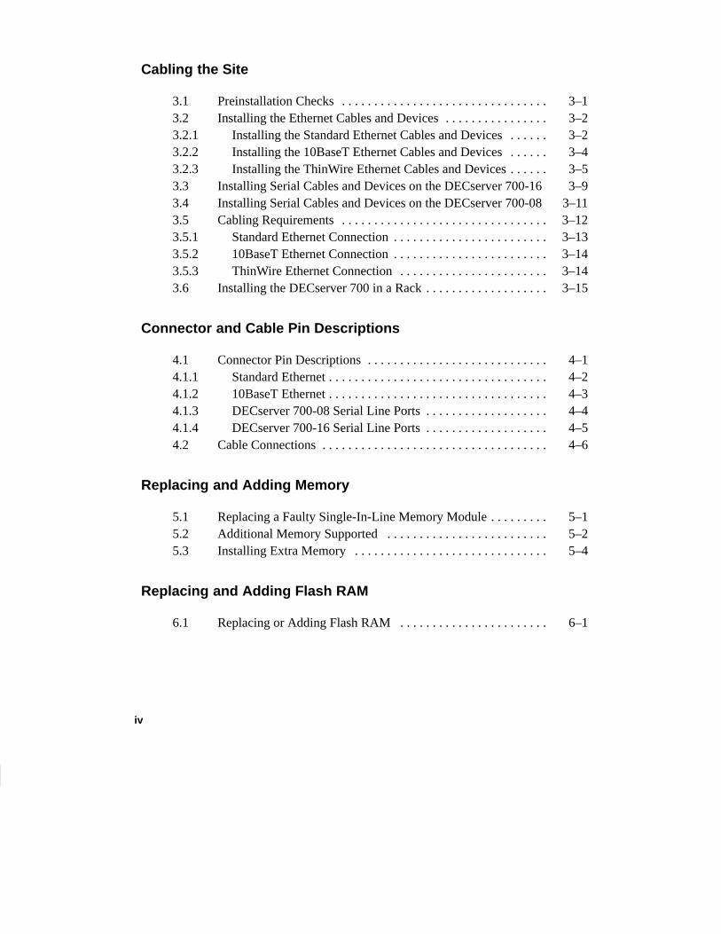
Cabling the Site
3.1 Preinstallation Checks 3–1. . . . . . . . . . . . . . . . . . . . . . . . . . . . . . . . 3.2 Installing the Ethernet Cables and Devices 3–2. . . . . . . . . . . . . . . . 3.2.1 Installing the Standard Ethernet Cables and Devices 3–2. . . . . . 3.2.2 Installing the 10BaseT Ethernet Cables and Devices 3–4. . . . . . 3.2.3 Installing the ThinWire Ethernet Cables and Devices 3–5. . . . . . 3.3 Installing Serial Cables and Devices on the DECserver 700-16 3–93.4 Installing Serial Cables and Devices on the DECserver 700-08 3–113.5 Cabling Requirements 3–12. . . . . . . . . . . . . . . . . . . . . . . . . . . . . . . . 3.5.1 Standard Ethernet Connection 3–13. . . . . . . . . . . . . . . . . . . . . . . . 3.5.2 10BaseT Ethernet Connection 3–14. . . . . . . . . . . . . . . . . . . . . . . . 3.5.3 ThinWire Ethernet Connection 3–14. . . . . . . . . . . . . . . . . . . . . . . 3.6 Installing the DECserver 700 in a Rack 3–15. . . . . . . . . . . . . . . . . . .
Connector and Cable Pin Descriptions
4.1 Connector Pin Descriptions 4–1. . . . . . . . . . . . . . . . . . . . . . . . . . . . 4.1.1 Standard Ethernet 4–2. . . . . . . . . . . . . . . . . . . . . . . . . . . . . . . . . . 4.1.2 10BaseT Ethernet 4–3. . . . . . . . . . . . . . . . . . . . . . . . . . . . . . . . . . 4.1.3 DECserver 700-08 Serial Line Ports 4–4. . . . . . . . . . . . . . . . . . . 4.1.4 DECserver 700-16 Serial Line Ports 4–5. . . . . . . . . . . . . . . . . . . 4.2 Cable Connections 4–6. . . . . . . . . . . . . . . . . . . . . . . . . . . . . . . . . . .
Replacing and Adding Memory
5.1 Replacing a Faulty Single-In-Line Memory Module 5–1. . . . . . . . . 5.2 Additional Memory Supported 5–2. . . . . . . . . . . . . . . . . . . . . . . . . 5.3 Installing Extra Memory 5–4. . . . . . . . . . . . . . . . . . . . . . . . . . . . . .
Replacing and Adding Flash RAM
6.1 Replacing or Adding Flash RAM 6–1. . . . . . . . . . . . . . . . . . . . . . .
v
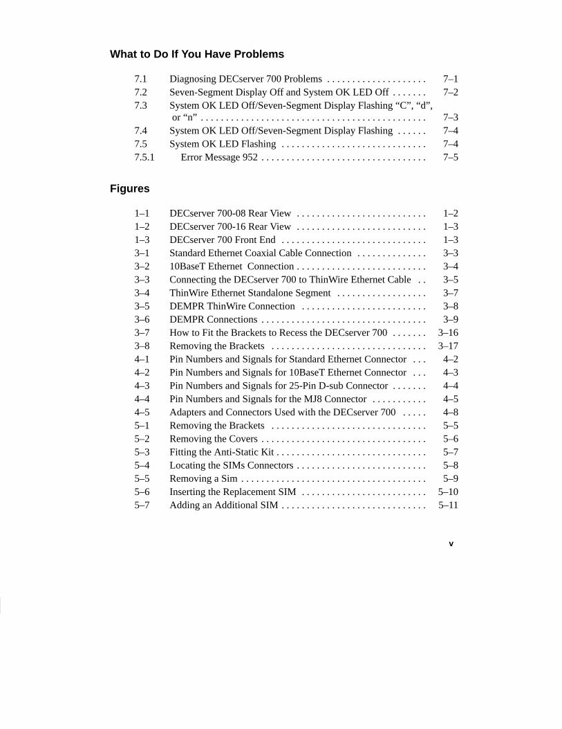
What to Do If You Have Problems
7.1 Diagnosing DECserver 700 Problems 7–1. . . . . . . . . . . . . . . . . . . . 7.2 Seven-Segment Display Off and System OK LED Off 7–2. . . . . . . 7.3 System OK LED Off/Seven-Segment Display Flashing “C”, “d”,
or “n” 7–3. . . . . . . . . . . . . . . . . . . . . . . . . . . . . . . . . . . . . . . . . . . . . 7.4 System OK LED Off/Seven-Segment Display Flashing 7–4. . . . . . 7.5 System OK LED Flashing 7–4. . . . . . . . . . . . . . . . . . . . . . . . . . . . . 7.5.1 Error Message 952 7–5. . . . . . . . . . . . . . . . . . . . . . . . . . . . . . . . .
Figures
1–1 DECserver 700-08 Rear View 1–2. . . . . . . . . . . . . . . . . . . . . . . . . . 1–2 DECserver 700-16 Rear View 1–3. . . . . . . . . . . . . . . . . . . . . . . . . . 1–3 DECserver 700 Front End 1–3. . . . . . . . . . . . . . . . . . . . . . . . . . . . . 3–1 Standard Ethernet Coaxial Cable Connection 3–3. . . . . . . . . . . . . . 3–2 10BaseT Ethernet Connection 3–4. . . . . . . . . . . . . . . . . . . . . . . . . . 3–3 Connecting the DECserver 700 to ThinWire Ethernet Cable 3–5. . 3–4 ThinWire Ethernet Standalone Segment 3–7. . . . . . . . . . . . . . . . . . 3–5 DEMPR ThinWire Connection 3–8. . . . . . . . . . . . . . . . . . . . . . . . . 3–6 DEMPR Connections 3–9. . . . . . . . . . . . . . . . . . . . . . . . . . . . . . . . . 3–7 How to Fit the Brackets to Recess the DECserver 700 3–16. . . . . . . 3–8 Removing the Brackets 3–17. . . . . . . . . . . . . . . . . . . . . . . . . . . . . . . 4–1 Pin Numbers and Signals for Standard Ethernet Connector 4–2. . . 4–2 Pin Numbers and Signals for 10BaseT Ethernet Connector 4–3. . . 4–3 Pin Numbers and Signals for 25-Pin D-sub Connector 4–4. . . . . . . 4–4 Pin Numbers and Signals for the MJ8 Connector 4–5. . . . . . . . . . . 4–5 Adapters and Connectors Used with the DECserver 700 4–8. . . . . 5–1 Removing the Brackets 5–5. . . . . . . . . . . . . . . . . . . . . . . . . . . . . . . 5–2 Removing the Covers 5–6. . . . . . . . . . . . . . . . . . . . . . . . . . . . . . . . . 5–3 Fitting the Anti-Static Kit 5–7. . . . . . . . . . . . . . . . . . . . . . . . . . . . . . 5–4 Locating the SIMs Connectors 5–8. . . . . . . . . . . . . . . . . . . . . . . . . . 5–5 Removing a Sim 5–9. . . . . . . . . . . . . . . . . . . . . . . . . . . . . . . . . . . . . 5–6 Inserting the Replacement SIM 5–10. . . . . . . . . . . . . . . . . . . . . . . . . 5–7 Adding an Additional SIM 5–11. . . . . . . . . . . . . . . . . . . . . . . . . . . . .
vi
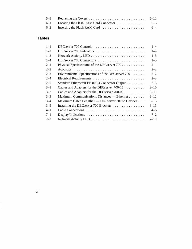
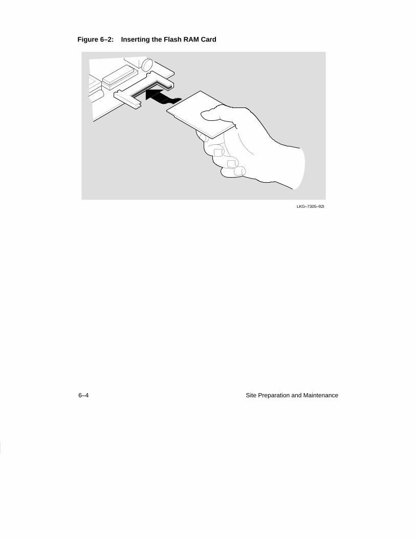
5–8 Replacing the Covers 5–12. . . . . . . . . . . . . . . . . . . . . . . . . . . . . . . . . 6–1 Locating the Flash RAM Card Connector 6–3. . . . . . . . . . . . . . . . . 6–2 Inserting the Flash RAM Card 6–4. . . . . . . . . . . . . . . . . . . . . . . . .
Tables
1–1 DECserver 700 Controls 1–4. . . . . . . . . . . . . . . . . . . . . . . . . . . . . . 1–2 DECserver 700 Indicators 1–4. . . . . . . . . . . . . . . . . . . . . . . . . . . . . 1–3 Network Activity LED 1–5. . . . . . . . . . . . . . . . . . . . . . . . . . . . . . . . 1–4 DECserver 700 Connectors 1–5. . . . . . . . . . . . . . . . . . . . . . . . . . . . 2–1 Physical Specifications of the DECserver 700 2–1. . . . . . . . . . . . . . 2–2 Acoustics 2–2. . . . . . . . . . . . . . . . . . . . . . . . . . . . . . . . . . . . . . . . . . 2–3 Environmental Specifications of the DECserver 700 2–2. . . . . . . . 2–4 Electrical Requirements 2–3. . . . . . . . . . . . . . . . . . . . . . . . . . . . . . . 2–5 Standard Ethernet/IEEE 802.3 Connector Output 2–3. . . . . . . . . . . 3–1 Cables and Adapters for the DECserver 700-16 3–10. . . . . . . . . . . . 3–2 Cables and Adapters for the DECserver 700-08 3–11. . . . . . . . . . . . 3–3 Maximum Communications Distances — Ethernet 3–12. . . . . . . . . . 3–4 Maximum Cable Lengths1 — DECserver 700 to Devices 3–13. . . . 3–5 Installing the DECserver 700 Brackets 3–15. . . . . . . . . . . . . . . . . . . 4–1 Cable Connections 4–6. . . . . . . . . . . . . . . . . . . . . . . . . . . . . . . . . . . 7–1 Display/Indications 7–2. . . . . . . . . . . . . . . . . . . . . . . . . . . . . . . . . . 7–2 Network Activity LED 7–10. . . . . . . . . . . . . . . . . . . . . . . . . . . . . . . .
vii
Preface
Intended Audience
This manual, in conjunction with the DECserver 700 Hardware Installation Card, isintended for the hardware installer. The installer is responsible for ensuring that thehardware is installed and tested. The DECserver 700 Hardware Installation Cardshows how to install the DECserverTM 700 when the site is verified and the cablesand devices are in place. This manual shows how to verify the site, install cables anddevices, and troubleshoot the DECserver 700. The person installing the DECserver700 software can then verify the system installation.
Structure of This Manual
This manual contains the following chapters:
• Chapter 1 — Provides an overview of the DECserver 700 features.
• Chapter 2 — Describes how to verify the site before installing the DECserver700.
• Chapter 3 — Describes how to cable the site.
• Chapter 4 — Describes connector pins for the various server connectors andalso describes various cables, adapters, and accessories used with the DEC-server 700.
• Chapter 5 — Shows how to install extra memory and replace faulty memory .
• Chapter 6 — Shows how to update a DS700 with Flash RAM.
• Chapter 7 — Shows how to troubleshoot the DECserver 700.
viiiDigital Confidential
Associated Documents
• DECserver 700 Hardware Installation Card
Shows how to install the DECserver 700 when the site is verified and thecables and devices are in place.
• DECserver Network Access Software Installation (op-sys)
Explains how to install the DECserver 700 distribution software, how to es-tablish downline load hosts, and how to verify the DECserver 700 systeminstallation. In the title, (op-sys) is the name of the load host operating sys-tem.
• Network Access Server Problem Solving
Describes the software tools and techniques available to troubleshoot theserver and also describes all error messages.
• Network Access Server Management
Provides the procedures to perform various DECserver 700 management tasks.
• Network Access Server Commands
Lists and describes all the DECserver 700 software commands.
• DECconnect System Planning and Configuration Guide
Information on cabling and configuring of local area networks and usingDECconnect system products.
• The Ethernet: A Local Area Network: Data Link Layer and Physical LayerSpecification
Lists standard Ethernet connectors and their signal specifications.

1–1
1Hardware Overview
The DECserver 700 connects devices (such as printers, terminals, PCs, and mo-dems) to local area networks (LANs). The DECserver 700 is Ethernet/IEEE802.3-based and supports standard Ethernet/IEEE 802.3 and 10BaseT Ethernet/IEEE 802.3 directly, and ThinWireTM Ethernet/IEEE 802.3 through an adapter. TheDECserver 700 can be installed on a desktop or in a 19-inch rack. The DECserver700 supports Flash RAM capability and other nonvolatile forms of memory. Thiscapability can be ordered separately and installed on the DECserver 700 in the field.
The DECserver 700 can download the software image from the network or from theFlash RAM option if installed. The Flash RAM option allows for a boot/power upwithout having to download the image through the network. The DECserver 700 willsupport up to 8 Mbytes of memory with the use of two single-in-line modules(SIMs). These SIMs can be installed as memory updates by the customer.
There are two DECserver 700 models:
• DECserver 700-08
• DECserver 700-16
1.1 Models
The DECserver 700-08 supports EIA-232-D/V.24/V.28 full modem control on eight25-pin male D-connectors. Use this model to connect devices that require full du-plex, asynchronous control (for example: modems).
1–2 Site Preparation and Maintenance
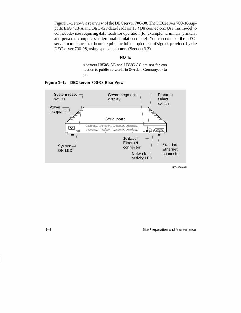
Figure 1–1 shows a rear view of the DECserver 700-08. The DECserver 700-16 sup-ports EIA-423-A and DEC 423 data-leads on 16 MJ8 connectors. Use this model toconnect devices requiring data-leads for operation (for example: terminals, printers,and personal computers in terminal emulation mode). You can connect the DEC-server to modems that do not require the full complement of signals provided by theDECserver 700-08, using special adapters (Section 3.3).
NOTE
Adapters H8585-AB and H8585-AC are not for con-nection to public networks in Sweden, Germany, or Ja-pan.
Figure 1–1: DECserver 700-08 Rear View
LKG-5569-91I
Powerreceptacle
Seven-segmentdisplay
Ethernetselectswitch
StandardEthernetconnector
SystemOK LED
10BaseTEthernetconnector
System resetswitch
Networkactivity LED
Serial ports
1–3Hardware Overview
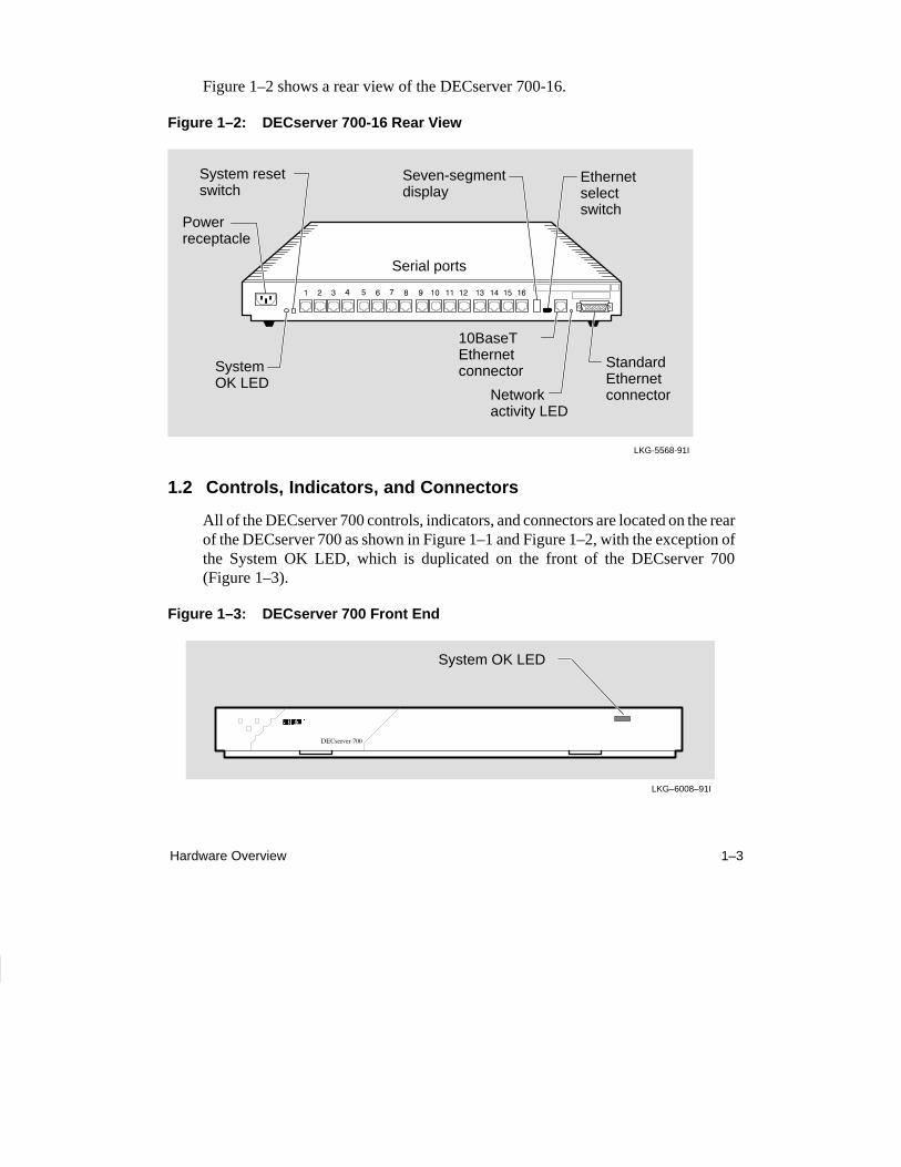
Figure 1–2 shows a rear view of the DECserver 700-16.
Figure 1–2: DECserver 700-16 Rear View
LKG-5568-91I
Powerreceptacle
Seven-segmentdisplay
Ethernetselectswitch
StandardEthernetconnector
SystemOK LED
10BaseTEthernetconnector
System resetswitch
Networkactivity LED
Serial ports
1.2 Controls, Indicators, and Connectors
All of the DECserver 700 controls, indicators, and connectors are located on the rearof the DECserver 700 as shown in Figure 1–1 and Figure 1–2, with the exception ofthe System OK LED, which is duplicated on the front of the DECserver 700(Figure 1–3).
Figure 1–3: DECserver 700 Front End
LKG–6008–91I
System OK LED
1–4 Site Preparation and Maintenance
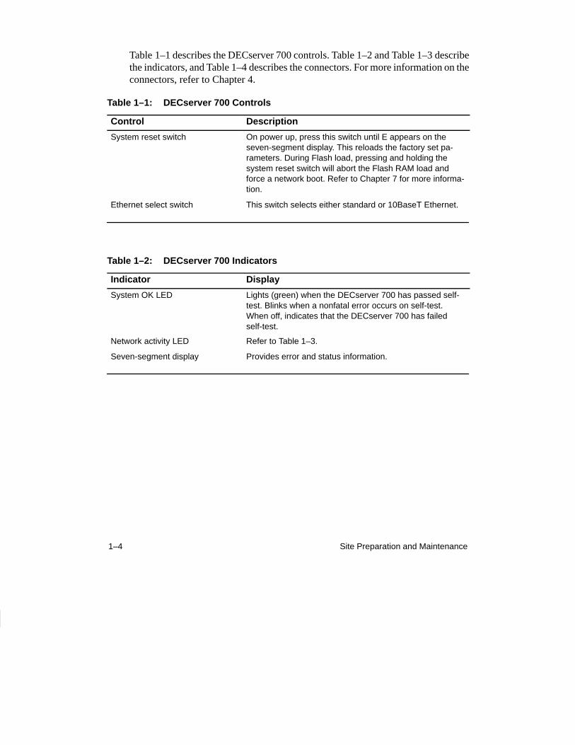
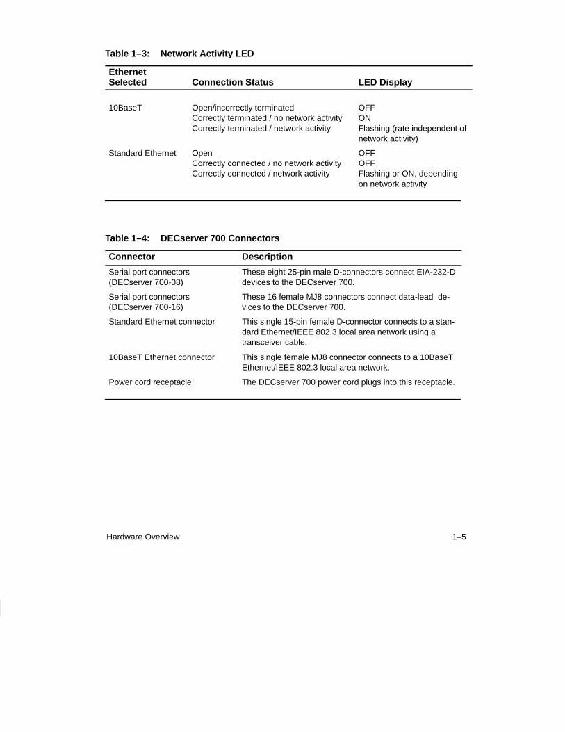
Table 1–1 describes the DECserver 700 controls. Table 1–2 and Table 1–3 describethe indicators, and Table 1–4 describes the connectors. For more information on theconnectors, refer to Chapter 4.
Table 1–1: DECserver 700 Controls
Control Description
System reset switch On power up, press this switch until E appears on theseven-segment display. This reloads the factory set pa-rameters. During Flash load, pressing and holding the system reset switch will abort the Flash RAM load andforce a network boot. Refer to Chapter 7 for more informa-tion.
Ethernet select switch This switch selects either standard or 10BaseT Ethernet.
Table 1–2: DECserver 700 Indicators
Indicator Display
System OK LED Lights (green) when the DECserver 700 has passed self-test. Blinks when a nonfatal error occurs on self-test.When off, indicates that the DECserver 700 has failedself-test.
Network activity LED Refer to Table 1–3.
Seven-segment display Provides error and status information.
1–5Hardware Overview
Table 1–3: Network Activity LED
Ethernet Selected Connection Status LED Display
10BaseT Open/incorrectly terminatedCorrectly terminated / no network activityCorrectly terminated / network activity
OFFONFlashing (rate independent ofnetwork activity)
Standard Ethernet OpenCorrectly connected / no network activityCorrectly connected / network activity
OFFOFFFlashing or ON, dependingon network activity
Table 1–4: DECserver 700 Connectors
Connector Description
Serial port connectors(DECserver 700-08)
These eight 25-pin male D-connectors connect EIA-232-Ddevices to the DECserver 700.
Serial port connectors(DECserver 700-16)
These 16 female MJ8 connectors connect data-lead de-vices to the DECserver 700.
Standard Ethernet connector This single 15-pin female D-connector connects to a stan-dard Ethernet/IEEE 802.3 local area network using atransceiver cable.
10BaseT Ethernet connector This single female MJ8 connector connects to a 10BaseTEthernet/IEEE 802.3 local area network.
Power cord receptacle The DECserver 700 power cord plugs into this receptacle.
1–6 Site Preparation and Maintenance
1.3 Understand the Software Loading
This section describes the two methods that the DECserver 700 access to load thesoftware.
1.3.1 Loading from Flash RAM
Once the DECserver 700 completes self-tests, the DECserver 700 checks for FlashRAM. If there is a valid Flash RAM, the DECserver 700 begins the boot sequence toload the software from Flash RAM. The seven-segment display will display threehorizontal segments during this loading process.
If the DECserver 700 does not have Flash RAM, the DECserver 700 proceeds to anetwork load.
If a device is connected to the console port, the DECserver 700 can display statusmessages while the boot sequence is running. Status messages indicate the Ethernetaddress of the DECserver 700, the name of the load image it is looking for, and thestage of the boot process it is in.
1.3.2 Loading from the Network
If you do not want to load the software from Flash RAM, you can press the systemreset switch during load from Flash RAM. When the system reset switch is pressed,the Flash RAM load will be aborted and the software is downline loaded from a loadhost.
When the DECserver 700 notices the system reset switch depressed during loadfrom Flash RAM, it will rapidly blink the LED to acknowledge the pressed systemreset switch (this may take several seconds). Once the LED begins rapidly blinking,you may release the system reset switch and the firmware will go on to a networkboot sequence. For more information on display codes for Flash RAM, refer to sec-tion 7.7.
2–1
2Checking the Site
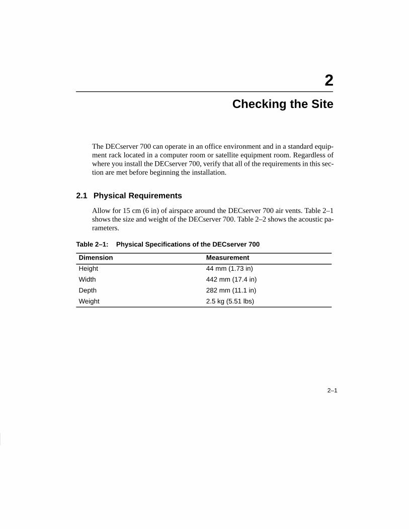
The DECserver 700 can operate in an office environment and in a standard equip-ment rack located in a computer room or satellite equipment room. Regardless ofwhere you install the DECserver 700, verify that all of the requirements in this sec-tion are met before beginning the installation.
2.1 Physical Requirements
Allow for 15 cm (6 in) of airspace around the DECserver 700 air vents. Table 2–1shows the size and weight of the DECserver 700. Table 2–2 shows the acoustic pa-rameters.
Table 2–1: Physical Specifications of the DECserver 700
Dimension Measurement
Height 44 mm (1.73 in)
Width 442 mm (17.4 in)
Depth 282 mm (11.1 in)
Weight 2.5 kg (5.51 lbs)

2–2 Site Preparation and Maintenance
Table 2–2: Acoustics
Parameter Measurement
LWAd1 4.1 bels (LWA = 3.8 bels)
LpAm (bystander)1 27 dBA
1Preliminary declared values per ISO 9296 and ISO 7779. Current values are available from Digital representatives.
2.2 Environmental Requirements
Environmental requirements for temperature and humidity must be within theranges shown in Table 2–3.
Table 2–3: Environmental Specifications of the DECserver 700
Parameter Minimum Maximum
Temperature 1
Operating 5°C (41°F) 50°C (122°F)
Nonoperating – 40°C (– 40°F) 66°C (151°F)
Maximum rate of temperature change per hour
20°C (36°F)
Altitude
Operating 2438 m (8000 ft)
Nonoperating 4876 m (16000 ft)
Relative humidity
Operating (noncondensing) 10% 95%
Nonoperating (noncondensing) 10% 95%
1For high altitude sites, decrease the operating temperature specification by 1.8°C for each 1000 m (1°F for each 1000 ft) above sea level.
2–3Checking the Site
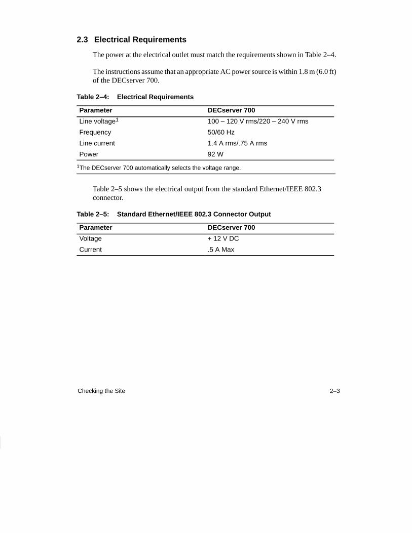
2.3 Electrical Requirements
The power at the electrical outlet must match the requirements shown in Table 2–4.
The instructions assume that an appropriate AC power source is within 1.8 m (6.0 ft)of the DECserver 700.
Table 2–4: Electrical Requirements
Parameter DECserver 700
Line voltage1 100 – 120 V rms/220 – 240 V rms
Frequency 50/60 Hz
Line current 1.4 A rms/.75 A rms
Power 92 W
1The DECserver 700 automatically selects the voltage range.
Table 2–5 shows the electrical output from the standard Ethernet/IEEE 802.3 connector.
Table 2–5: Standard Ethernet/IEEE 802.3 Connector Output
Parameter DECserver 700
Voltage + 12 V DC
Current .5 A Max

3–1
3Cabling the Site
This chapter shows you how to install the cables and associated devices used by theDECserver 700.
3.1 Preinstallation Checks
Before beginning the DECserver 700 installation, use the following checklist tomake sure that the site preparation is complete:
• Arrangements have been made to connect the DECserver 700 Ethernet port toan Ethernet interface device (if required). For standard Ethernet, the devicecan be a DELNITM network concentrator or an Ethernet transceiver. For Thin-Wire Ethernet, the device can be a DEMPRTM, DESPR, or ThinWire segment.For 10BaseT Ethernet, the device can be a DETPR.
• The Ethernet interface device is installed and the required cabling is in place,tested, and tagged.
• The rack-mount kit is installed (if required) as described in the DECserver700 Hardware Installation Card.
• Cables of appropriate length are available for connecting the DECserver 700to the Ethernet interface device.
• The devices (terminals, modems, personal computers, hosts) are ready to beconnected.
• Cables of appropriate length and type are available for connection of serialdevices.
3–2 Site Preparation and Maintenance
• One terminal (asynchronous, DEC423 or EIA-232-D compatible) is availablefor hardware testing and system verification.
3.2 Installing the Ethernet Cables and Devices
You can connect the DECserver 700 to:
• Standard Ethernet/IEEE 802.3 network
• 10BaseT Ethernet/IEEE 802.3 network
• ThinWire Ethernet/IEEE 802.3 network using an external media access unit(MAU) such as a DESTATM
3.2.1 Installing the Standard Ethernet Cables and Devices
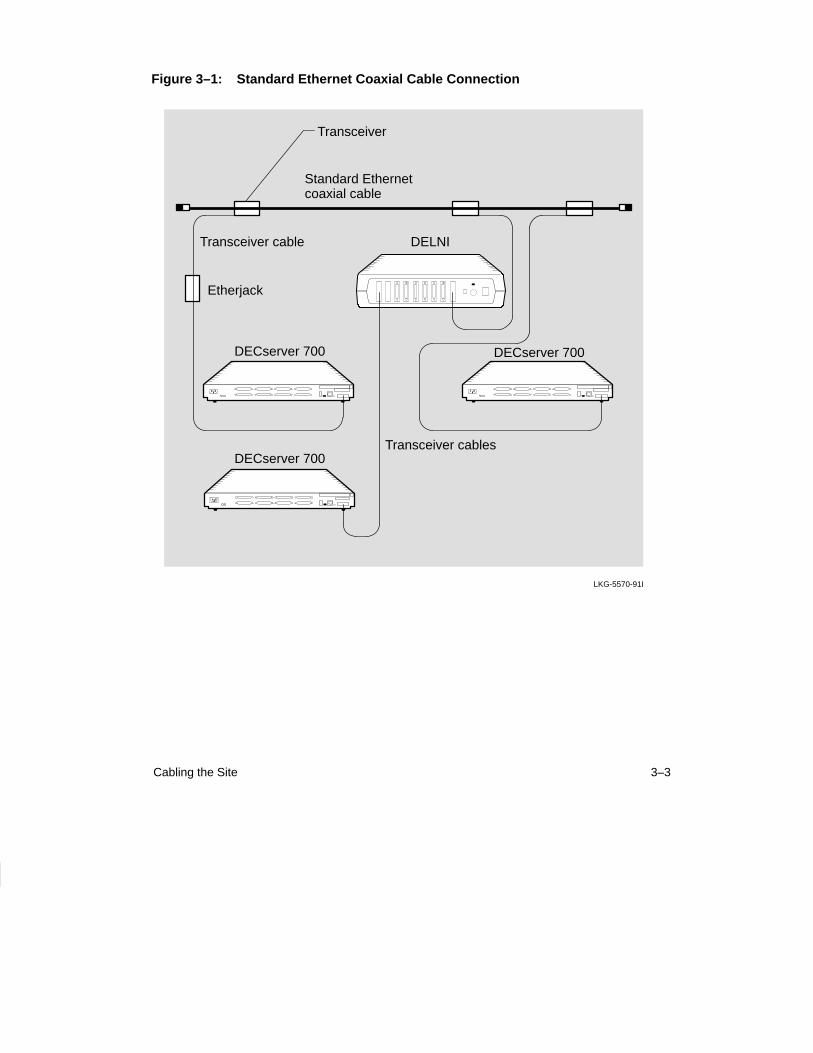
You can connect the DECserver 700 to the standard Ethernet/IEEE 802.3 network(Figure 3–1) by connecting to:
• Another transceiver cable section. (You connect to another section by using aEtherjack Junction Box.)
• A DELNI local area network.
• A transceiver on a standard Ethernet coaxial cable for Digital EquipmentCorporation baseband networks.
3–3Cabling the Site
Figure 3–1: Standard Ethernet Coaxial Cable Connection
LKG-5570-91I
Standard Ethernetcoaxial cable
Transceiver cable
Etherjack
Transceiver cables
DELNI
DECserver 700
Transceiver
DECserver 700
DECserver 700
3–4 Site Preparation and Maintenance
3.2.2 Installing the 10BaseT Ethernet Cables and Devices
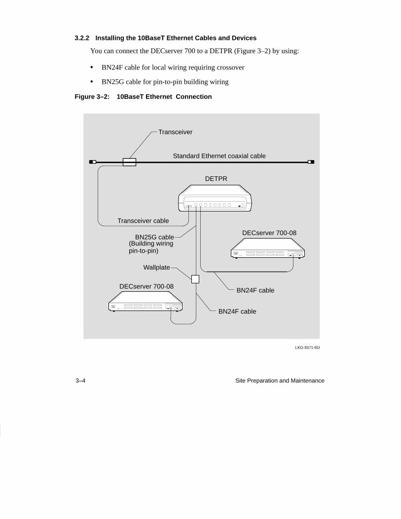
You can connect the DECserver 700 to a DETPR (Figure 3–2) by using:
• BN24F cable for local wiring requiring crossover
• BN25G cable for pin-to-pin building wiring
Figure 3–2: 10BaseT Ethernet Connection
LKG-5571-91I
Transceiver cable
BN24F cable
DETPR
Standard Ethernet coaxial cable
Transceiver
BN24F cable
BN25G cable(Building wiringpin-to-pin)
Wallplate
DECserver 700-08
DECserver 700-08
3–5Cabling the Site
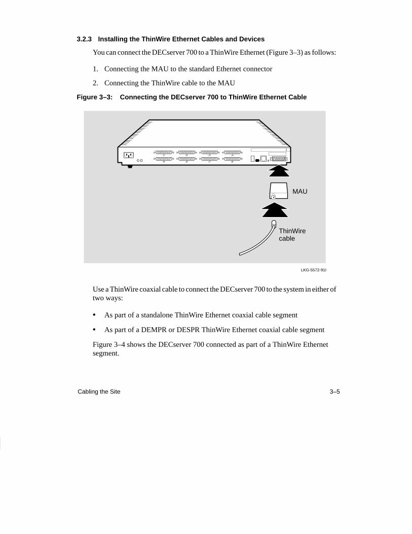
3.2.3 Installing the ThinWire Ethernet Cables and Devices
You can connect the DECserver 700 to a ThinWire Ethernet (Figure 3–3) as follows:
1. Connecting the MAU to the standard Ethernet connector
2. Connecting the ThinWire cable to the MAU
Figure 3–3: Connecting the DECserver 700 to ThinWire Ethernet Cable
LKG-5572-91I
MAU
ThinWirecable
Use a ThinWire coaxial cable to connect the DECserver 700 to the system in either oftwo ways:
• As part of a standalone ThinWire Ethernet coaxial cable segment
• As part of a DEMPR or DESPR ThinWire Ethernet coaxial cable segment
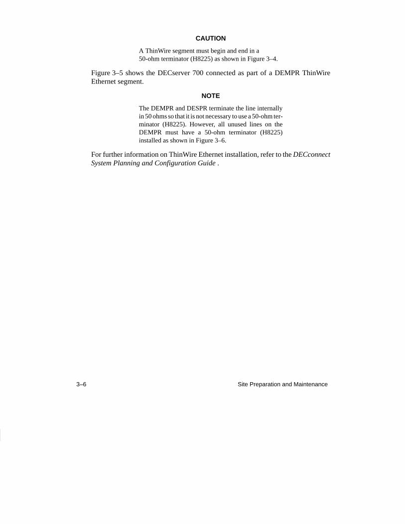
Figure 3–4 shows the DECserver 700 connected as part of a ThinWire Ethernet segment.
3–6 Site Preparation and Maintenance
CAUTION
A ThinWire segment must begin and end in a 50-ohm terminator (H8225) as shown in Figure 3–4.
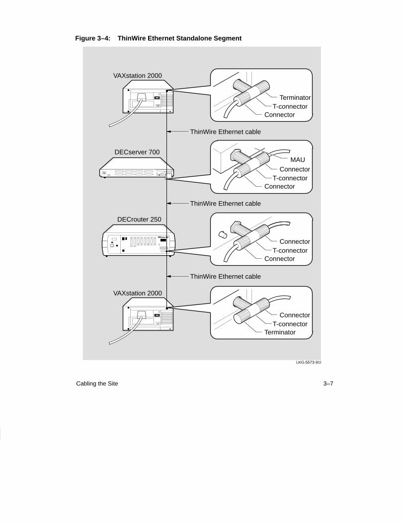
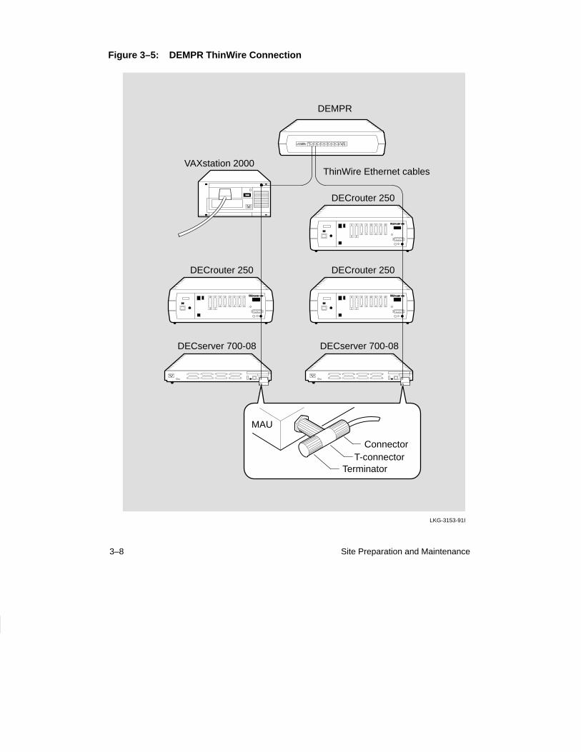
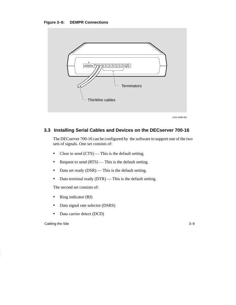
Figure 3–5 shows the DECserver 700 connected as part of a DEMPR ThinWireEthernet segment.
NOTE
The DEMPR and DESPR terminate the line internallyin 50 ohms so that it is not necessary to use a 50-ohm ter-minator (H8225). However, all unused lines on theDEMPR must have a 50-ohm terminator (H8225)installed as shown in Figure 3–6.
For further information on ThinWire Ethernet installation, refer to the DECconnectSystem Planning and Configuration Guide .
3–7Cabling the Site
Figure 3–4: ThinWire Ethernet Standalone Segment
LKG-5573-91I
DECserver 700
VAXstation 2000
ThinWire Ethernet cable
ThinWire Ethernet cable
ThinWire Ethernet cable
TerminatorT-connector
Connector
ConnectorT-connector
Connector
MAU
VAXstation 2000
ConnectorT-connector
Terminator
DECrouter 250
T-connectorConnector
Connector
3–8 Site Preparation and Maintenance
Figure 3–5: DEMPR ThinWire Connection
LKG-3153-91I
DEMPR
DECrouter 250
VAXstation 2000ThinWire Ethernet cables
DECrouter 250
DECrouter 250
ConnectorT-connector
Terminator
MAU
DECserver 700-08 DECserver 700-08
3–9Cabling the Site
Figure 3–6: DEMPR Connections
LKG-2596-91I
Terminators
ThinWire cables
3.3 Installing Serial Cables and Devices on the DECserver 700-16
The DECserver 700-16 can be configured by the software to support one of the twosets of signals. One set consists of:
• Clear to send (CTS) — This is the default setting.
• Request to send (RTS) — This is the default setting.
• Data set ready (DSR) — This is the default setting.
• Data terminal ready (DTR) — This is the default setting.
The second set consists of:
• Ring indicator (RI)
• Data signal rate selector (DSRS)
• Data carrier detect (DCD)
3–10 Site Preparation and Maintenance
• Data terminal ready (DTR)
Before installing cables to the DECserver 700 ports, you must verify with the personmanaging the DECserver 700 what modem signals are supported. This informationis necessary to determine what cables to use. For more information on the signals,refer to the Network Access Server Management manual.
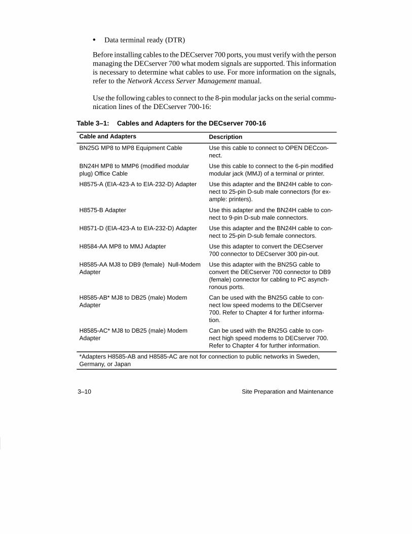
Use the following cables to connect to the 8-pin modular jacks on the serial commu-nication lines of the DECserver 700-16:
Table 3–1: Cables and Adapters for the DECserver 700-16
Cable and Adapters Description
BN25G MP8 to MP8 Equipment Cable Use this cable to connect to OPEN DECcon-nect.
BN24H MP8 to MMP6 (modified modularplug) Office Cable
Use this cable to connect to the 6-pin modifiedmodular jack (MMJ) of a terminal or printer.
H8575-A (EIA-423-A to EIA-232-D) Adapter Use this adapter and the BN24H cable to con-nect to 25-pin D-sub male connectors (for ex-ample: printers).
H8575-B Adapter Use this adapter and the BN24H cable to con-nect to 9-pin D-sub male connectors.
H8571-D (EIA-423-A to EIA-232-D) Adapter Use this adapter and the BN24H cable to con-nect to 25-pin D-sub female connectors.
H8584-AA MP8 to MMJ Adapter Use this adapter to convert the DECserver700 connector to DECserver 300 pin-out.
H8585-AA MJ8 to DB9 (female) Null-ModemAdapter
Use this adapter with the BN25G cable toconvert the DECserver 700 connector to DB9(female) connector for cabling to PC asynch-ronous ports.
H8585-AB* MJ8 to DB25 (male) ModemAdapter
Can be used with the BN25G cable to con-nect low speed modems to the DECserver700. Refer to Chapter 4 for further informa-tion.
H8585-AC* MJ8 to DB25 (male) ModemAdapter
Can be used with the BN25G cable to con-nect high speed modems to DECserver 700.Refer to Chapter 4 for further information.
*Adapters H8585-AB and H8585-AC are not for connection to public networks in Sweden,Germany, or Japan
3–11Cabling the Site
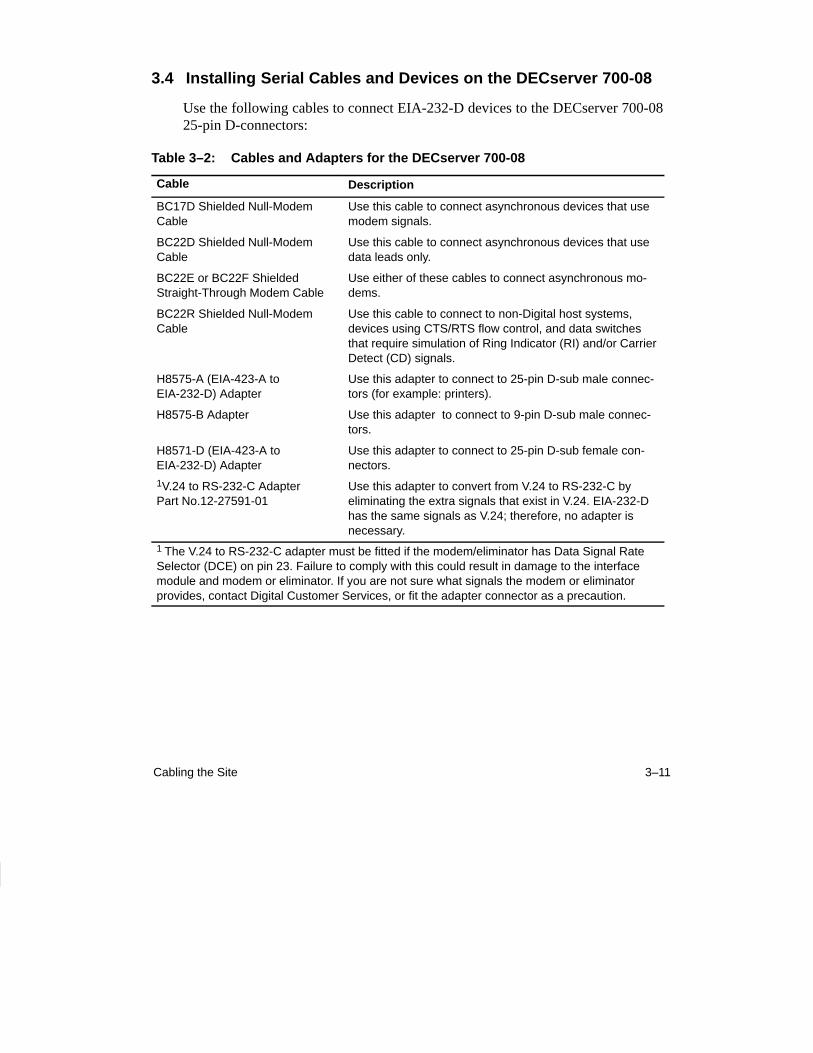
3.4 Installing Serial Cables and Devices on the DECserver 700-08
Use the following cables to connect EIA-232-D devices to the DECserver 700-0825-pin D-connectors:
Table 3–2: Cables and Adapters for the DECserver 700-08
Cable Description
BC17D Shielded Null-ModemCable
Use this cable to connect asynchronous devices that usemodem signals.
BC22D Shielded Null-ModemCable
Use this cable to connect asynchronous devices that usedata leads only.
BC22E or BC22F ShieldedStraight-Through Modem Cable
Use either of these cables to connect asynchronous mo-dems.
BC22R Shielded Null-ModemCable
Use this cable to connect to non-Digital host systems,devices using CTS/RTS flow control, and data switchesthat require simulation of Ring Indicator (RI) and/or CarrierDetect (CD) signals.
H8575-A (EIA-423-A toEIA-232-D) Adapter
Use this adapter to connect to 25-pin D-sub male connec-tors (for example: printers).
H8575-B Adapter Use this adapter to connect to 9-pin D-sub male connec-tors.
H8571-D (EIA-423-A toEIA-232-D) Adapter
Use this adapter to connect to 25-pin D-sub female con-nectors.
1V.24 to RS-232-C AdapterPart No.12-27591-01
Use this adapter to convert from V.24 to RS-232-C byeliminating the extra signals that exist in V.24. EIA-232-Dhas the same signals as V.24; therefore, no adapter isnecessary.
1 The V.24 to RS-232-C adapter must be fitted if the modem/eliminator has Data Signal RateSelector (DCE) on pin 23. Failure to comply with this could result in damage to the interfacemodule and modem or eliminator. If you are not sure what signals the modem or eliminatorprovides, contact Digital Customer Services, or fit the adapter connector as a precaution.
3–12 Site Preparation and Maintenance
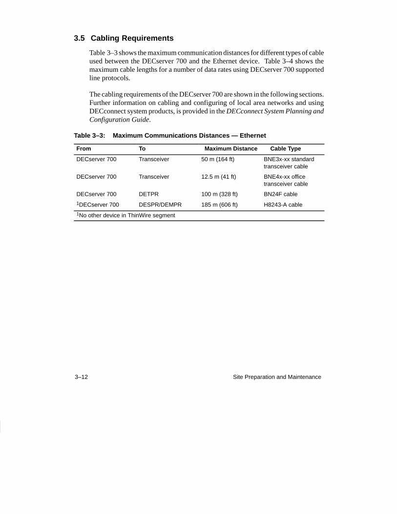
3.5 Cabling Requirements
Table 3–3 shows the maximum communication distances for different types of cableused between the DECserver 700 and the Ethernet device. Table 3–4 shows themaximum cable lengths for a number of data rates using DECserver 700 supportedline protocols.
The cabling requirements of the DECserver 700 are shown in the following sections.Further information on cabling and configuring of local area networks and usingDECconnect system products, is provided in the DECconnect System Planning andConfiguration Guide.
Table 3–3: Maximum Communications Distances — Ethernet
From To Maximum Distance Cable Type
DECserver 700 Transceiver 50 m (164 ft) BNE3x-xx standardtransceiver cable
DECserver 700 Transceiver 12.5 m (41 ft) BNE4x-xx officetransceiver cable
DECserver 700 DETPR 100 m (328 ft) BN24F cable
1DECserver 700 DESPR/DEMPR 185 m (606 ft) H8243-A cable
1No other device in ThinWire segment
3–13Cabling the Site
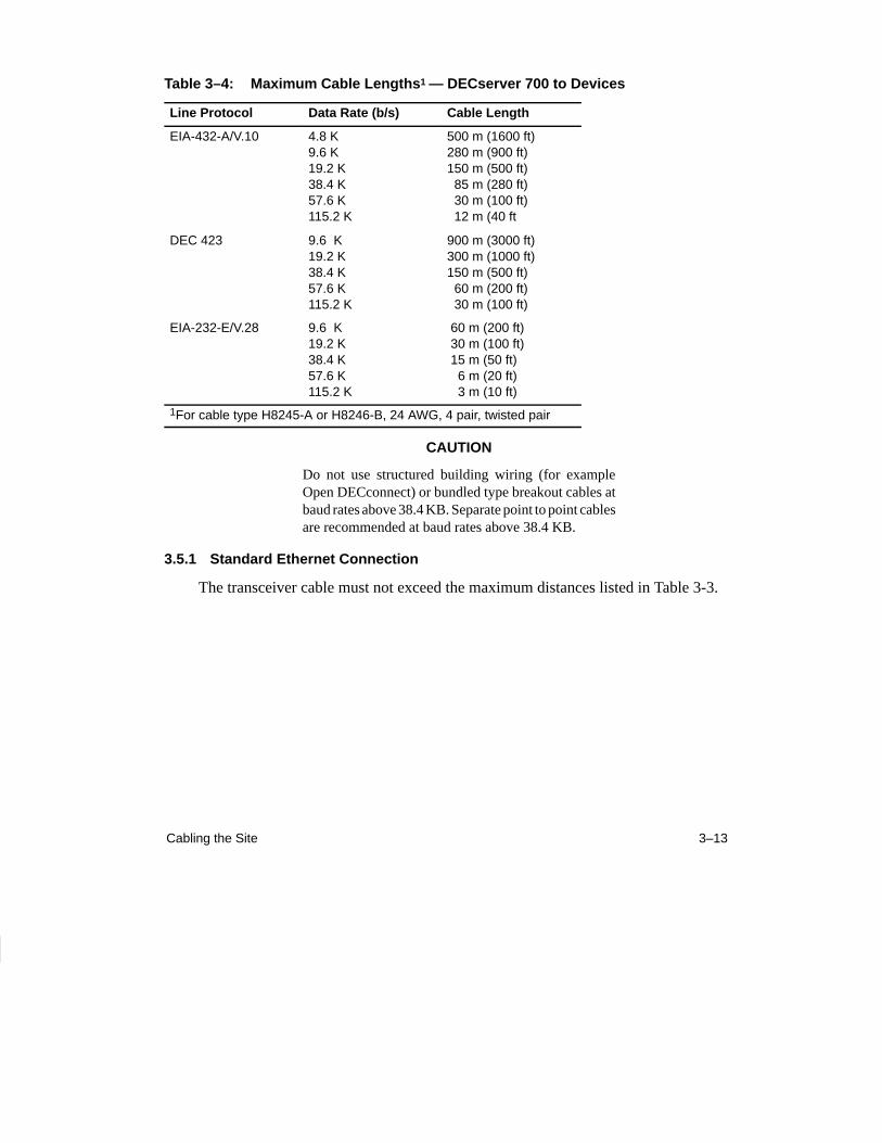
Table 3–4: Maximum Cable Lengths 1 — DECserver 700 to Devices
Line Protocol Data Rate (b/s) Cable Length
EIA-432-A/V.10 4.8 K9.6 K19.2 K38.4 K57.6 K115.2 K
500 m (1600 ft)280 m (900 ft)150 m (500 ft) 85 m (280 ft) 30 m (100 ft) 12 m (40 ft
DEC 423 9.6 K19.2 K38.4 K57.6 K115.2 K
900 m (3000 ft)300 m (1000 ft)150 m (500 ft) 60 m (200 ft) 30 m (100 ft)
EIA-232-E/V.28 9.6 K19.2 K38.4 K57.6 K115.2 K
60 m (200 ft) 30 m (100 ft) 15 m (50 ft) 6 m (20 ft) 3 m (10 ft)
1For cable type H8245-A or H8246-B, 24 AWG, 4 pair, twisted pair
CAUTION
Do not use structured building wiring (for exampleOpen DECconnect) or bundled type breakout cables atbaud rates above 38.4 KB. Separate point to point cablesare recommended at baud rates above 38.4 KB.
3.5.1 Standard Ethernet Connection
The transceiver cable must not exceed the maximum distances listed in Table 3-3.
3–14 Site Preparation and Maintenance
3.5.2 10BaseT Ethernet Connection
The 10BaseT Ethernet installation must conform to the following configurationrules:
• The twisted-pair cable must not exceed the maximum distance listed in Table 3-3.
• No other signal should be used in the same cable sheath. For example, voiceand data signals cannot be run within the same sheath.
• Unshielded twisted-pair cable must remain at least 30.48 cm (12 in) from anytype of high-voltage power device or electrical noise source.
3.5.3 ThinWire Ethernet Connection
The ThinWire cable segment must conform to the following configuration rules:
• The maximum cable segment length must not exceed 185 m (606 ft).
• There must be a 50-ohm terminator at each end of the cable segment, unlessthe cable ends in a DEMPR or DESPR. Both these devices have built in50-ohm terminators.
• There must be only one ground per cable segment.
• There must be at least 0.5 m (19 in) between T-connectors.
• The maximum number of stations, between terminators, must not exceed 30stations.
• ThinWire cable segments must not be configured in a loop.
• ThinWire cable segments must not have any branch segments.
3–15Cabling the Site
3.6 Installing the DECserver 700 in a Rack
You can rack mount the DECserver 700 any one of four ways (Table 3–5) dependingon how you install the brackets.
Table 3–5: Installing the DECserver 700 Brackets
DECserver 700 Installation Bracket Installation
1. Flush with rear facing outward Flush with rear
2. Recessed 2.54 cm (1 in) with rear facing outward Forward 2.54 cm (1 in) from rear
3. Flush with front facing outward Flush with front
4. Recessed 2.54 cm (1 in) with front facing outward Forward 2.54 cm (1 in) from rear
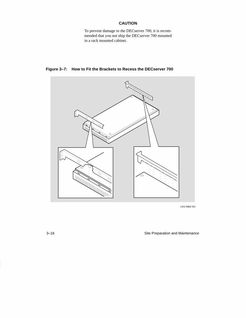
Figure 3–7 shows how to install the brackets in order to recess the DECserver 700.
Figure 3–8 shows how to remove the brackets.
CAUTION
The DECserver 700 can be wall mounted. If the DEC-server is installed on a wall, the DECserver 700 must beinstalled with the port connectors pointing up or point-ing down. Digital Equipment Corporation does not sup-ply wall mounting hardware for the DECserver 700.
3–16 Site Preparation and Maintenance
CAUTION
To prevent damage to the DECserver 700, it is recom-mended that you not ship the DECserver 700 mountedin a rack mounted cabinet.
Figure 3–7: How to Fit the Brackets to Recess the DECserver 700
LKG-5962-91l
3–17Cabling the Site
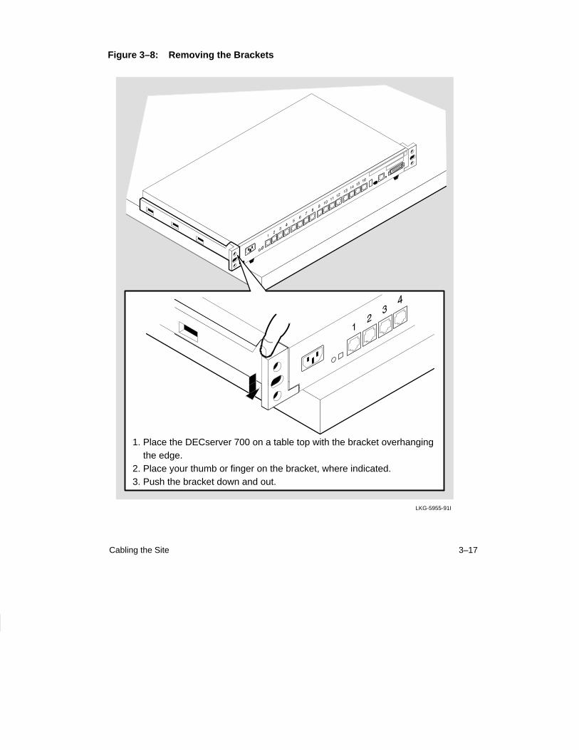
Figure 3–8: Removing the Brackets
LKG-5955-91I
1. Place the DECserver 700 on a table top with the bracket overhanging the edge.2. Place your thumb or finger on the bracket, where indicated.3. Push the bracket down and out.

4–1
4Connector and Cable Pin Descriptions
This chapter describes the pins of the DECserver 700 hardware connectors and thecables used to interface to the DECserver 700 hardware. Wiring diagrams of the indi-vidual cables are included to help you in troubleshooting and cable building.
4.1 Connector Pin Descriptions
This section describes the pins for the following DECserver 700 connectors:
• Standard Ethernet/IEEE 802.3 transceiver interface
• 10BaseT Ethernet/IEEE 802.3 transceiver interface
• DECserver 700-08 serial port connectors
• DECserver 700-16 serial port connectors
4–2 Site Preparation and Maintenance
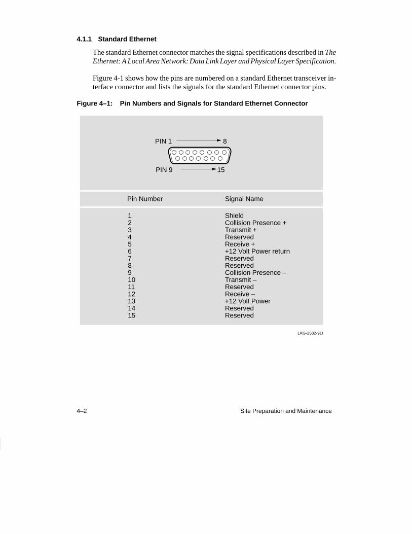
4.1.1 Standard Ethernet
The standard Ethernet connector matches the signal specifications described in TheEthernet: A Local Area Network: Data Link Layer and Physical Layer Specification.
Figure 4-1 shows how the pins are numbered on a standard Ethernet transceiver in-terface connector and lists the signals for the standard Ethernet connector pins.
Figure 4–1: Pin Numbers and Signals for Standard Ethernet Connector
PIN 1 8
PIN 9 15
Pin Number Signal Name
123456789101112131415
ShieldCollision Presence +Transmit +ReservedReceive ++12 Volt Power returnReservedReservedCollision Presence –Transmit –ReservedReceive –+12 Volt PowerReservedReserved
LKG-2582-91I

Connector and Cable Pin Descriptions 4–3
4.1.2 10BaseT Ethernet
The 10BaseT Ethernet connector is an 8-pin modular jack (MJ8). Figure 4-2 showshow the pins are numbered on a 10BaseT Ethernet connector and lists the signals forthe 10BaseT Ethernet connector.
Figure 4–2: Pin Numbers and Signals for 10BaseT Ethernet Connector
PIN 1 8
Pin Number Signal Name
12345678
Transmit +Transmit –Receive +ReservedReservedReceive –ReservedReserved
LKG-5511-91I
4–4 Site Preparation and Maintenance
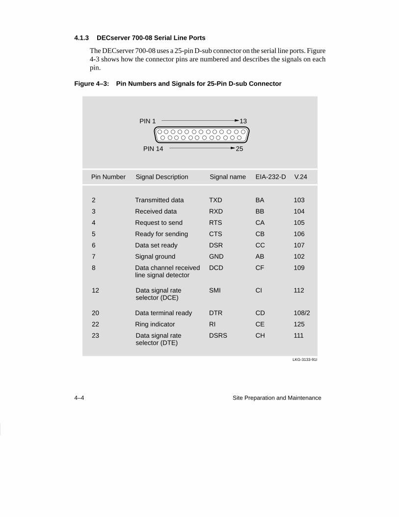
4.1.3 DECserver 700-08 Serial Line Ports
The DECserver 700-08 uses a 25-pin D-sub connector on the serial line ports. Figure4-3 shows how the connector pins are numbered and describes the signals on eachpin.
Figure 4–3: Pin Numbers and Signals for 25-Pin D-sub Connector
PIN 1 13
PIN 14 25
Pin Number Signal Description
2
3
4
5
6
7
8
12
20
22
23
LKG-3133-91I
Transmitted data
Received data
Request to send
Ready for sending
Data set ready
Signal ground
Data channel receivedline signal detector
Data signal rateselector (DCE)
Data terminal ready
Ring indicator
Data signal rateselector (DTE)
TXD
RXD
RTS
CTS
DSR
GND
DCD
SMI
DTR
RI
DSRS
BA
BB
CA
CB
CC
AB
CF
CI
CD
CE
CH
103
104
105
106
107
102
109
112
108/2
125
111
Signal name EIA-232-D V.24
Connector and Cable Pin Descriptions 4–5
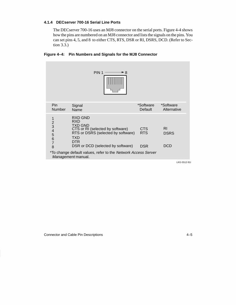
4.1.4 DECserver 700-16 Serial Line Ports
The DECserver 700-16 uses an MJ8 connector on the serial ports. Figure 4-4 showshow the pins are numbered on an MJ8 connector and lists the signals on the pins. Youcan set pins 4, 5, and 8 to either CTS, RTS, DSR or RI, DSRS, DCD. (Refer to Sec-tion 3.3.)
Figure 4–4: Pin Numbers and Signals for the MJ8 Connector
PIN 1 8
Pin Number
SignalName
12345678
RXD GNDRXDTXD GND
TXDDTRDSR or DCD (selected by software)
LKG-5512-91I
*Software Default
RTS or DSRS (selected by software)CTS or RI (selected by software) CTS
RTS
DSR
*Software Alternative
RIDSRS
DCD
*To change default values, refer to the Network Access Server Management manual.
4–6 Site Preparation and Maintenance
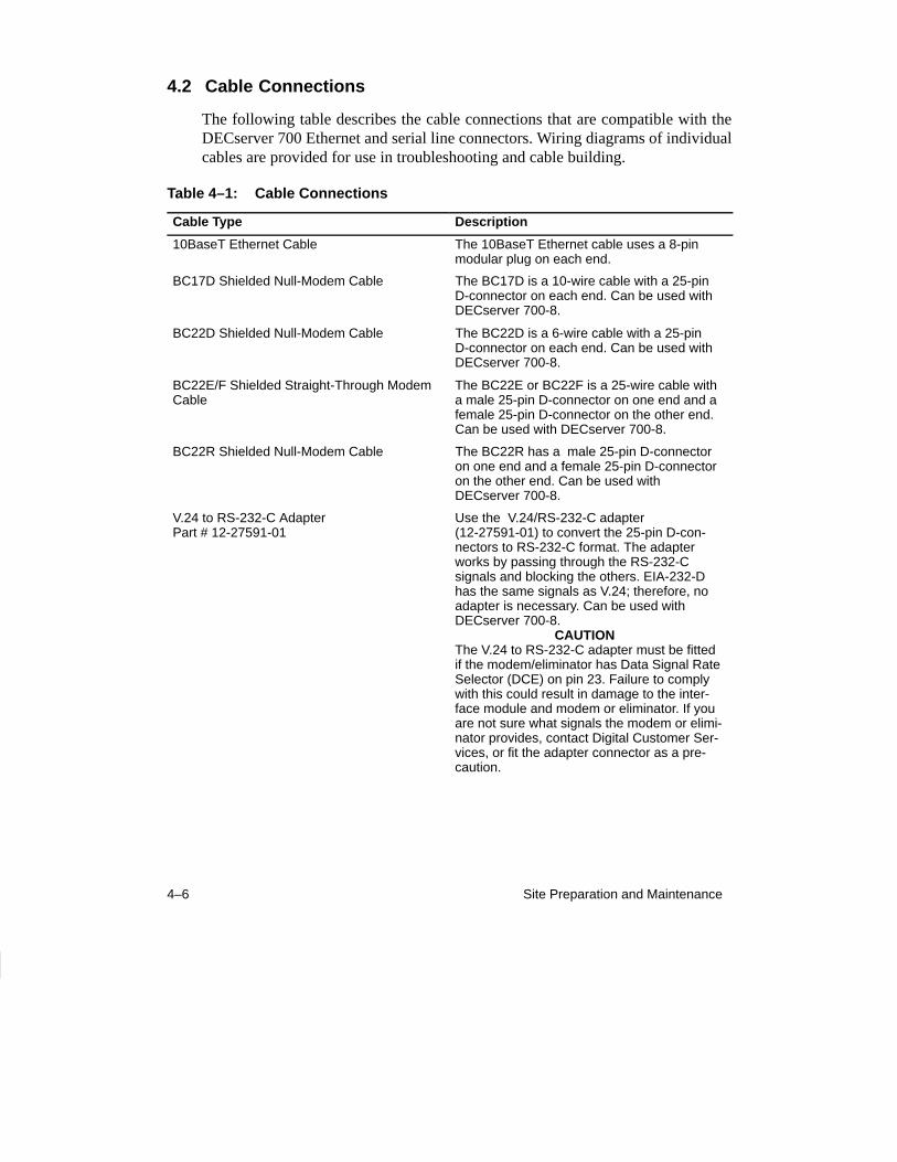
4.2 Cable Connections
The following table describes the cable connections that are compatible with theDECserver 700 Ethernet and serial line connectors. Wiring diagrams of individualcables are provided for use in troubleshooting and cable building.
Table 4–1: Cable Connections
Cable Type Description
10BaseT Ethernet Cable The 10BaseT Ethernet cable uses a 8-pinmodular plug on each end.
BC17D Shielded Null-Modem Cable The BC17D is a 10-wire cable with a 25-pinD-connector on each end. Can be used withDECserver 700-8.
BC22D Shielded Null-Modem Cable The BC22D is a 6-wire cable with a 25-pinD-connector on each end. Can be used withDECserver 700-8.
BC22E/F Shielded Straight-Through ModemCable
The BC22E or BC22F is a 25-wire cable witha male 25-pin D-connector on one end and afemale 25-pin D-connector on the other end.Can be used with DECserver 700-8.
BC22R Shielded Null-Modem Cable The BC22R has a male 25-pin D-connectoron one end and a female 25-pin D-connectoron the other end. Can be used with DECserver 700-8.
V.24 to RS-232-C AdapterPart # 12-27591-01
Use the V.24/RS-232-C adapter(12-27591-01) to convert the 25-pin D-con-nectors to RS-232-C format. The adapterworks by passing through the RS-232-C signals and blocking the others. EIA-232-Dhas the same signals as V.24; therefore, no adapter is necessary. Can be used with DECserver 700-8. CAUTIONThe V.24 to RS-232-C adapter must be fittedif the modem/eliminator has Data Signal RateSelector (DCE) on pin 23. Failure to complywith this could result in damage to the inter-face module and modem or eliminator. If youare not sure what signals the modem or elimi-nator provides, contact Digital Customer Ser-vices, or fit the adapter connector as a pre-caution.
Connector and Cable Pin Descriptions 4–7
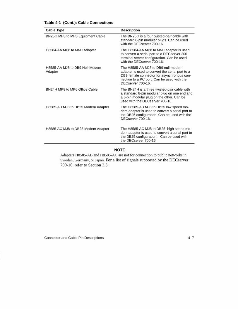
Table 4-1 (Cont.): Cable Connections
Cable Type Description
BN25G MP8 to MP8 Equipment Cable The BN25G is a four twisted-pair cable withstandard 8-pin modular plugs. Can be usedwith the DECserver 700-16.
H8584-AA MP8 to MMJ Adapter The H8584-AA MP8 to MMJ adapter is usedto convert a serial port to a DECserver 300terminal server configuration. Can be usedwith the DECserver 700-16.
H8585-AA MJ8 to DB9 Null-Modem Adapter
The H8585-AA MJ8 to DB9 null-modemadapter is used to convert the serial port to aDB9 female connector for asynchronous con-nection to a PC port. Can be used with theDECserver 700-16.
BN24H MP8 to MP6 Office Cable The BN24H is a three twisted-pair cable witha standard 8-pin modular plug on one end anda 6-pin modular plug on the other. Can beused with the DECserver 700-16.
H8585-AB MJ8 to DB25 Modem Adapter The H8585-AB MJ8 to DB25 low speed mo-dem adapter is used to convert a serial port tothe DB25 configuration. Can be used with theDECserver 700-16.
H8585-AC MJ8 to DB25 Modem Adapter The H8585-AC MJ8 to DB25 high speed mo-dem adapter is used to convert a serial port tothe DB25 configuration. Can be used withthe DECserver 700-16.
NOTEAdapters H8585-AB and H8585-AC are not for connection to public networks inSweden, Germany, or Japan. For a list of signals supported by the DECserver700-16, refer to Section 3.3.
4–8 Site Preparation and Maintenance
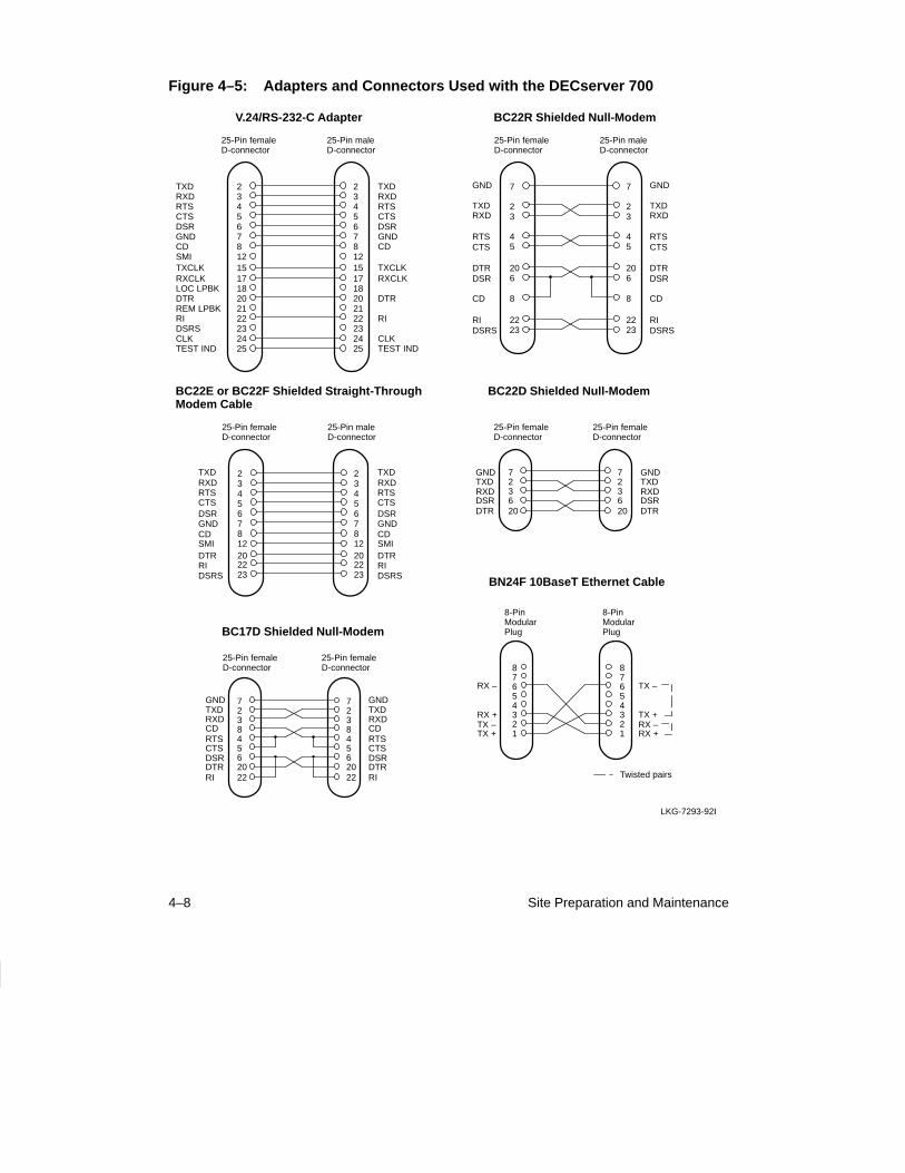
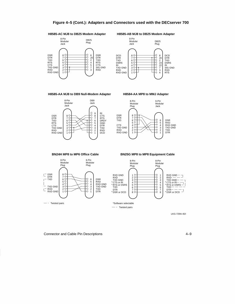
Figure 4–5: Adapters and Connectors Used with the DECserver 700
234567812
25-Pin femaleD-connector
15
25-Pin maleD-connector
23456781215
1718202122232425
1718202122232425
TXDRXDRTSCTSDSRGNDCDSMITXCLKRXCLKLOC LPBKDTRREM LPBKRIDSRSCLKTEST IND
TXDRXDRTSCTSDSRGNDCD
TXCLKRXCLK
DTR
RI
CLKTEST IND
7
23
45
TXD
RTSCTS
25-Pin femaleD-connector
GND
RXD
25-Pin maleD-connector
7
23
45
8 8CD
TXD
RTSCTS
GND
RXD
CD
206
DTRDSR
206
DTRDSR
2223
RIDSRS
2223
RIDSRS
234567812
RTS
GNDCDSMI
25-Pin femaleD-connector
TXDRXD
CTSDSR
25-Pin maleD-connector
234567812
202223
202223
DTR
DSRSRI
RTS
GNDCDSMI
TXDRXD
CTSDSR
DTR
DSRSRI
7236
TXDRXDDSR
25-Pin femaleD-connector
20DTR
GND
25-Pin femaleD-connector
723620
TXDRXDDSRDTR
GND
723845620
RXD
CTSDSRDTR
25-Pin femaleD-connector
22RI
GNDTXD
CDRTS
RXD
CTSDSRDTRRI
GNDTXD
CDRTS
25-Pin femaleD-connector
72384562022
TX –
87654321
87654321
TX +RX –RX +
RX –
RX +TX –TX +
8-PinModularPlug
8-PinModularPlug
Twisted pairs
V.24/RS-232-C Adapter BC22R Shielded Null-Modem
BC22E or BC22F Shielded Straight-Through Modem Cable
BC22D Shielded Null-Modem
BC17D Shielded Null-Modem
BN24F 10BaseT Ethernet Cable
LKG-7293-92I
Connector and Cable Pin Descriptions 4–9
Figure 4–5 (Cont.): Adapters and Connectors used with the DECserver 700
LKG-7294–92I
87654321
24573
8-PinModularJack
DB25Plug
DSRDTRTXD
TXD GNDRXDRXD GND
TXDRTSCTSSIG GNDRXD
CTS
620
DSRDTR
RTS
87654321
22322734
8-PinModularJack
DB25Plug
DCDDTRTXD
TXD GNDRXDRXD GND
TXDDSRSRISIG GNDRXDRTS
RI
820
DCDDTR
DSRS
87654321
654321
8-PinModularJack
DB9Jack
DSRDTRTXD
TXD GNDRXDRXD GND
DRDYGNDDTRTXDRXDDCD
CTS
987
RICTSRTS
RTS
87654321
654321
8-PinModularPlug
6-PinModularJack
DSRDTRTXD
TXD GNDRXDRXD GND
DSRRXDRXD GNDTXD GNDTXDDTR
CTS
87654321
654321
8-PinModularPlug
6-PinModularPlug
DSRDTRTXD
TXD GNDRXDRXD GND
DSRRXDRXD GNDTXD GNDTXDDTR
Twisted pairs
12345678
8-PinModularPlug
8-PinModularPlug
12345678
*Software selectable
RXD GNDRXDTXD GNDCTS or RIRTS or DSRSTXDDTRDSR or DCD
**
*
RXD GNDRXDTXD GNDCTS or RIRTS or DSRSTXDDTRDSR or DCD
**
*
Twisted pairs
H8585-AC MJ8 to DB25 Modem Adapter H8585-AB MJ8 to DB25 Modem Adapter
H8585-AA MJ8 to DB9 Null-Modem Adapter H8584-AA MP8 to MMJ Adapter
BN24H MP8 to MP6 Office Cable BN25G MP8 to MP8 Equipment Cable

5–1
5Replacing and Adding Memory
This chapter shows how to replace a faulty single-in-line memory module (SIM) andadd additional memory.
CAUTION
SIMs are sensitive to static and and are packed in anti-static packaging. Electro Static Discharge (ESD) cancause failure of electronic components and can reducethe long term reliability of the DECserver 700. DigitalEquipment Corporation recommends you use the anti-static kit (Part No. 29-26246-00) or ESD wrist strap(Part No. 12-36157-01) when handling SIMs.
5.1 Replacing a Faulty Single-In-Line Memory Module
To replace a SIM:
1. Disconnect all cables from the DECserver 700.
2. Remove the DECserver 700 brackets, if fitted (Figure 5–1).
3. Remove the DECserver 700 cover (Figure 5–2).
4. Fit the anti-static kit (Figure 5–3).
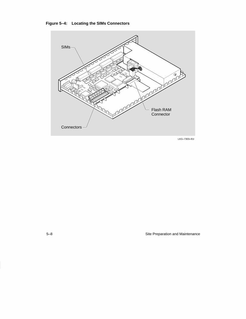
5. Locate the SIM connectors (Figure 5–4).
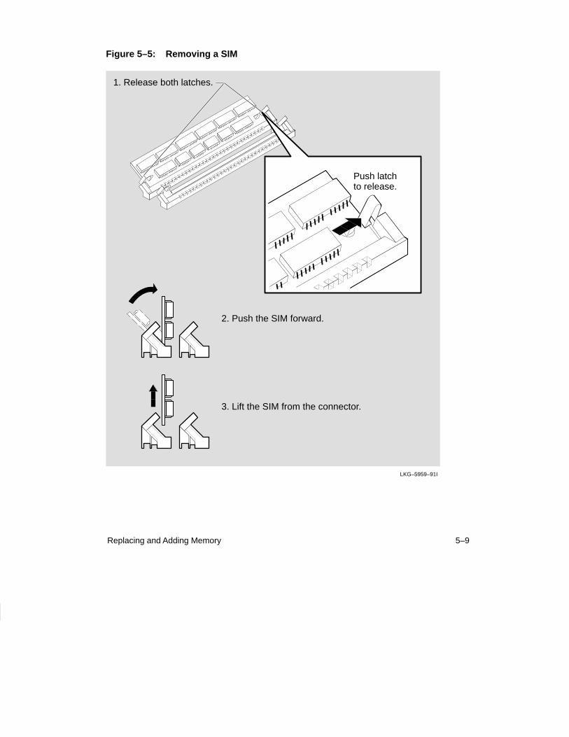
6. Remove the faulty SIM (Figure 5–5).
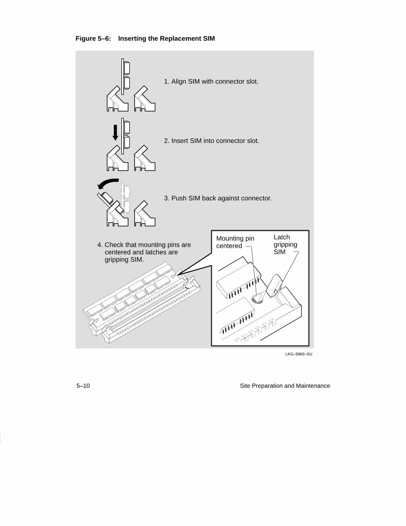
7. Insert the replacement SIM in the connector (Figure 5–6).
5–2 Site Preparation and Maintenance
8. Remove the anti-static kit.
9. Replace the cover (Figure 5–8).
10. Connect a terminal to the DECserver 700 (Section 7.5).
11. Reconnect the cables and test the DECserver 700 (refer to the DECserver 700Hardware Installation Card).
NOTE
If the SIM memory is faulty, the DECserver 700 flashes“C” if the faulty SIM is in connector 1 and “d” if thefaulty SIM is in connector 2. If you install the wrongtype SIM, the DECserver 700 flashes “n”. Remove orreplace the SIM to repair the DECserver 700.
12. Check status message 960 to verify memory size:
Local –960– Available memory 4 Mbytes
5.2 Additional Memory Supported
You can increase the memory of your DECserver 700 by adding extra single-in-linememory modules (SIMs). The DECserver 700 contains 4 Mbytes of SIM memory.However, future releases of DECserver 700 software may contain additional func-tions that require more SIM memory. You can install the additional SIM memory onsite. Adding an additional 1 Mbyte will increase the memory to 5 Mbytes and addingan additional 4 Mbytes SIM will increase the memory to the maximum of 8 Mbytes.
The DECserver 700 supports:
• 1 Mbyte SIMs (256K x 36) DEC Part No 20-35191-05,Order Number MS40-WA
• 4 Mbytes SIMs (1M x 36) DEC Part No 20-37656-05, Order Number MS40-WB
There are two SIM connectors on the DECserver 700 printed circuit board. One ofthe connectors contains the factory installed 4 Mbytes SIM (Figure 5–4).
5–3Replacing and Adding Memory
The DECserver 700 supports only SIMs with the following access times:
• 80 nano seconds
• 70 nano seconds
The DECserver 700 supports only SIMs in the following configurations:
• 4 Mbytes (one 4 Mbytes SIM in any connector)
• 5 Mbytes (one 1 Mbyte in one connector and one 4 Mbytes in the other con-nector)
• 8 Mbytes (one 4 Mbytes SIM per connector)
NOTE
The DECserver 700 supports only 36 bit wide SIMs. Ifyou are not using Digital Equipment Corporation SIMsMS40-WA or MS40-WB, check the specification ofyour SIM to verify that it is 36 bit wide. SIMs that arenot 36 bit wide will not work but may not be detected bythe DECserver 700 diagnostics.
5–4 Site Preparation and Maintenance
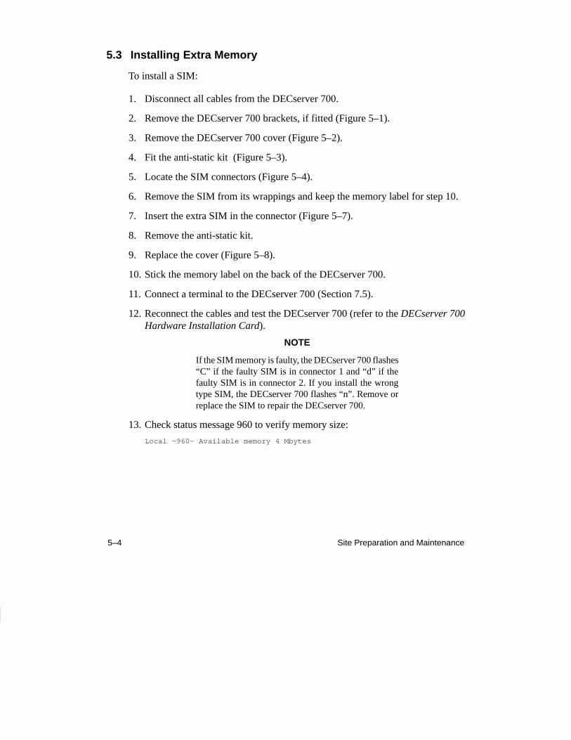
5.3 Installing Extra Memory
To install a SIM:
1. Disconnect all cables from the DECserver 700.
2. Remove the DECserver 700 brackets, if fitted (Figure 5–1).
3. Remove the DECserver 700 cover (Figure 5–2).
4. Fit the anti-static kit (Figure 5–3).
5. Locate the SIM connectors (Figure 5–4).
6. Remove the SIM from its wrappings and keep the memory label for step 10.
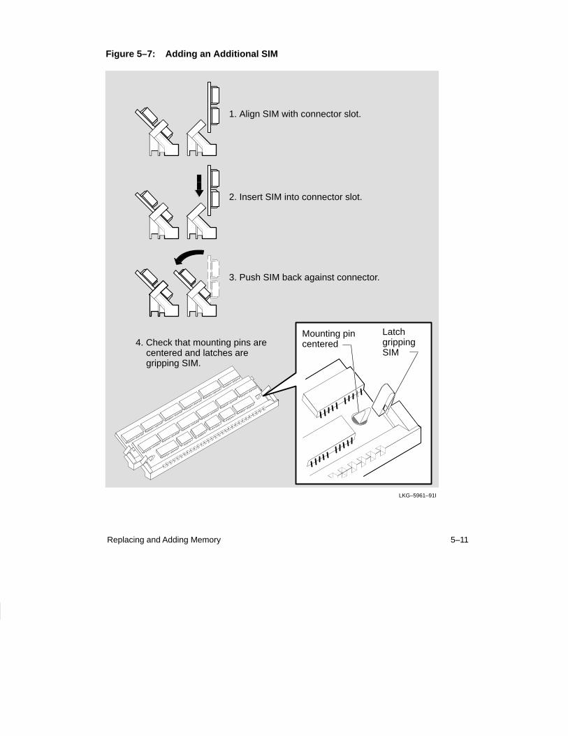
7. Insert the extra SIM in the connector (Figure 5–7).
8. Remove the anti-static kit.
9. Replace the cover (Figure 5–8).
10. Stick the memory label on the back of the DECserver 700.
11. Connect a terminal to the DECserver 700 (Section 7.5).
12. Reconnect the cables and test the DECserver 700 (refer to the DECserver 700Hardware Installation Card).
NOTE
If the SIM memory is faulty, the DECserver 700 flashes“C” if the faulty SIM is in connector 1 and “d” if thefaulty SIM is in connector 2. If you install the wrongtype SIM, the DECserver 700 flashes “n”. Remove orreplace the SIM to repair the DECserver 700.
13. Check status message 960 to verify memory size:
Local –960– Available memory 4 Mbytes
5–5Replacing and Adding Memory
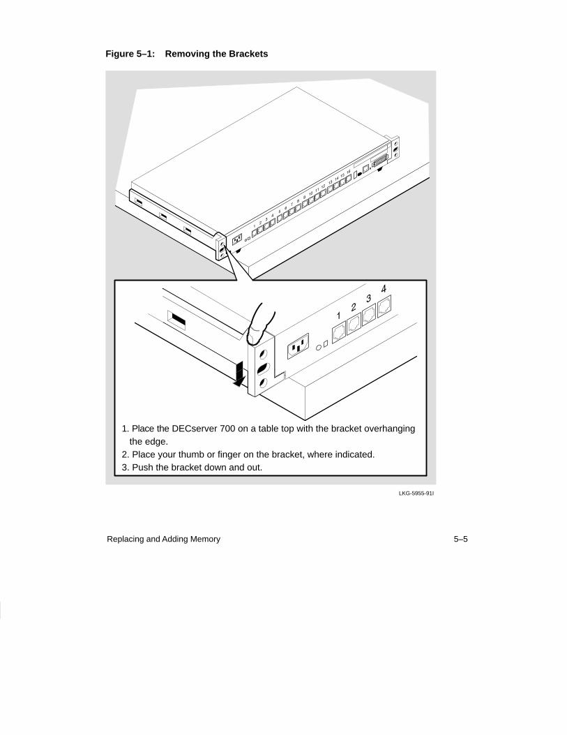
Figure 5–1: Removing the Brackets
LKG-5955-91I
1. Place the DECserver 700 on a table top with the bracket overhanging the edge.2. Place your thumb or finger on the bracket, where indicated.3. Push the bracket down and out.
5–6 Site Preparation and Maintenance
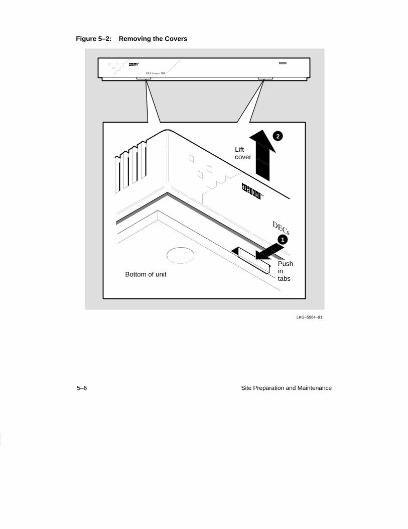
Figure 5–2: Removing the Covers
1
2
Bottom of unit
Liftcover
Pushintabs
LKG–5964–91I
5–7Replacing and Adding Memory
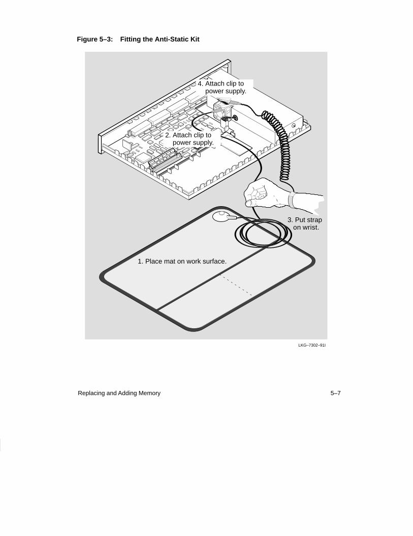
Figure 5–3: Fitting the Anti-Static Kit
LKG–7302–91I
1. Place mat on work surface.
3. Put strap on wrist.
2. Attach clip topower supply.
4. Attach clip topower supply.
5–8 Site Preparation and Maintenance
Figure 5–4: Locating the SIMs Connectors
SIMs
Connectors
LKG–7303–91I
Flash RAMConnector
5–9Replacing and Adding Memory
Figure 5–5: Removing a SIM
LKG–5959–91I
Push latchto release.
1. Release both latches.
2. Push the SIM forward.
3. Lift the SIM from the connector.
5–10 Site Preparation and Maintenance
Figure 5–6: Inserting the Replacement SIM
LKG–5960–91I
3. Push SIM back against connector.
1. Align SIM with connector slot.
Mounting pincentered
Latch grippingSIM
2. Insert SIM into connector slot.
4. Check that mounting pins are centered and latches are gripping SIM.
5–11Replacing and Adding Memory
Figure 5–7: Adding an Additional SIM
LKG–5961–91I
3. Push SIM back against connector.
1. Align SIM with connector slot.
Mounting pincentered
Latch grippingSIM
2. Insert SIM into connector slot.
4. Check that mounting pins are centered and latches are gripping SIM.
5–12 Site Preparation and Maintenance
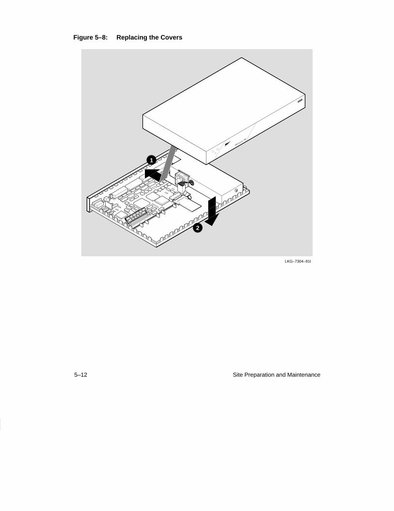
Figure 5–8: Replacing the Covers
LKG–7304–91I
1
2
6–1
6Replacing and Adding Flash RAM
This chapter shows how to replace or update a DECserver 700 Flash RAM Card.
NOTE
Electrostatic Discharge (ESD) can cause failure of elec-tronic components and can reduce the long term reli-ability of the DECserver 700. Digital EquipmentCorporation recommends you use the anti-static kit(Part No. 29-26246-00) or ESD wrist strap (Part No.12-36157-01) when installing a Flash RAM Card.
6.1 Replacing or Adding Flash RAM
To replace or install the Flash RAM Card:
1. Disconnect all cables from the DECserver 700.
2. Remove the DECserver 700 brackets, if fitted (Figure 5–1).
3. Remove the DECserver 700 cover (Figure 5–2).
4. Fit the anti-static kit (Figure 5–3).
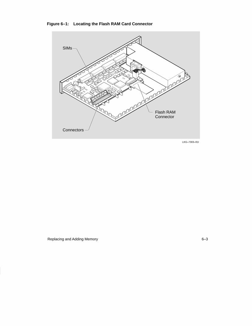
5. Locate the Flash RAM connector or remove the faulty Flash RAM Card (Figure 6-1).
6–2 Site Preparation and Maintenance
6. Insert the replacement or Flash RAM Card update in the connector (Figure 6-2).
NOTE
The Flash RAM socket is keyed. Ensure that you followthe instructions located on the Flash RAM card wheninstalling.
7. Remove the anti-static kit.
8. Replace the cover (Figure 5–8).
9. Connect a terminal to the DECserver 700 (Section 7.5).
10. Reconnect the cables and test the DECserver 700 (refer to the DECserver 700Hardware Installation Card).
11. Check the status of the Flash RAM card by using the SHOW MEMORY CONFIGURATION command.
Example
Local> SHOW MEMORY CONFIGURATION
Dynamic RAM: 4M bytes
Non-Volatile RAM: 32K bytes
Flash RAM: Installed: Yes Total size: 4M bytes Boot block: Valid Load image: Name: WWENG1 Size: 967756 bytes Version: DECserver 700-16 V1.0 BL34A-2C
NOTE
If Flash RAM is installed, but its boot block is invalid,then the total memory size will be displayed as zero.
Your Flash RAM can also be updated with the INITIALIZE command. This commandcopies the load image to Flash RAM. For more information about the SHOW MEMORYCONFIGURATION or the INITIALIZE command, refer to the Network Access ServerManagement or Network Access Server Commands manual.
6–3Replacing and Adding Memory
Figure 6–1: Locating the Flash RAM Card Connector
SIMs
Connectors
LKG–7303–91I
Flash RAMConnector
6–4 Site Preparation and Maintenance
Figure 6–2: Inserting the Flash RAM Card
LKG–7305–92I
7–1
7What to Do If You Have Problems
This chapter helps you identify and correct problems you may encounter during andafter the installation of the DECserver 700 hardware. The troubleshooting proce-dures are for diagnosing and correcting hardware-related problems only.
Notify the network manager if the troubleshooting procedures indicate the problemis software related or if the procedures do not correct the problem. Additional soft-ware troubleshooting information is provided in the Network Access Server ProblemSolving manual.
Use the following to diagnose and troubleshoot the DECserver 700 problems:
• Seven-segment display
• System OK LED
• Console port messages
A full list of seven-segment display codes are shown at the end of this chapter. Referto the Network Access Server Management manual for the procedure to configure aterminal to receive console port messages.
7.1 Diagnosing DECserver 700 Problems
Compare the state of the seven-segment display and the System OK LED with thoseshown in Table 7-1 and go to the section indicated for information on corrective action.
7–2 Site Preparation and Maintenance
NOTE
On power up, the seven-segment display will show an“8”. Allow about 3 minutes to elapse before determin-ing the state of the display.
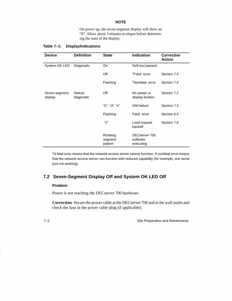
Table 7–1: Display/Indications
Device Definition State Indication CorrectiveAction
System OK LED Diagnostic On
Off
Flashing
Self-test passed
1Fatal error
1Nonfatal error
Section 7.4
Section 7.5
Seven-segmentdisplay
Status/diagnostic
Off
“C”, “d”, “n”
Flashing
“3”
Rotating segment pattern
No power or display broken
SIM failure
Fatal error
Load requestbackoff
DECserver 700software executing
Section 7.2
Section 7.3
Section 6.4
Section 7.6
1A fatal error means that the network access server cannot function. A nonfatal error meansthat the network access server can function with reduced capability (for example, one serialport not working).
7.2 Seven-Segment Display Off and System OK LED Off
Problem
Power is not reaching the DECserver 700 hardware.
Correction: Secure the power cable at the DECserver 700 and at the wall outlet andcheck the fuse in the power cable plug (if applicable).
7–3What to Do If You Have Problems
Correction: Check the wall outlet using another appliance or light, or plug the DEC-server 700 power cord into another outlet. If power is not available at the wall outlet,check the wall outlet’s circuit breaker.
Correction: Check the power cord by substituting another one. If the first powercord is defective, replace it.
Problem
The DECserver 700 hardware is defective.
Correction: Notify the network manager that the DECserver 700 must be returnedto Digital Equipment Corporation for repair or replacement. Refer to the NetworkAccess Server Problem Solving manual for information about returning the unit toDigital Equipment Corporation.
7.3 System OK LED Off/Seven-Segment Display Flashing “C”, “d”,or “n”
Problem
The DECserver 700 single-in-line memory (SIM) is faulty.
Correction: If the seven-segment display is flashing “C”, replace the SIM in con-nector 1. If the seven-segment display is flashing “d”, replace the SIM in connector2. If no SIM or the wrong type of SIM is installed, the seven-segment display flashes“n”. Refer to Section 5.1 for the procedure to replace a faulty SIM.
NOTE
If the SIM is found to be faulty, return the SIM to DigitalEquipment Corporation.
7–4 Site Preparation and Maintenance
7.4 System OK LED Off/Seven-Segment Display Flashing
Problem
A hardware error occurred that makes the DECserver 700 nonoperational.
Correction: There is no corrective procedure for this problem except for SIM fail-ure (refer to note). Notify the network manager that the DECserver 700 must be re-turned to Digital Equipment Corporation for repair or replacement. Refer to theNetwork Access Server Problem Solving manual for information about returning theunit to Digital Equipment Corporation.
7.5 System OK LED Flashing
If the System OK LED is flashing after power up, it indicates that the DECserver 700has a nonfatal problem detected during self-test. The error message on the consoleterminal shows the primary problem.
To isolate and diagnose the problem, do the following:
1. Connect a console terminal to the console port (default port is port 1) of theDECserver 700, then power up the terminal. Refer to the Network AccessServer Management manual for procedure to set up the console port.
2. Configure the terminal to operate with a speed of 9600 bits per second and acharacter size of 8 bits (no parity). (Refer to the specific terminal user’s guideif you need help setting up the terminal parameters.)
3. Unplug the DECserver 700 power cord at the wall outlet, then reinsert it.
4. Read the error message that appears on the terminal display.
The following sections list the error messages that occur in conjunction with SystemOK LED flashing. Locate the section that describes the displayed error message andfollow the recommended corrective action.
7–5What to Do If You Have Problems
7.5.1 Error Message 952
Local –952– Enter ^P to repeat self-test
Problem
An error was detected on the Ethernet port.
Correction: The DECserver 700 displays this error message with error message941. Refer to Section 7.5.3 for the correct action.
7.5.2 Error Message 922
Local –922– Port hardware error on port n
Problem
The specified port has failed self-test.
Correction: There is no corrective procedure for this condition. Notify the networkmanager that the DECserver 700 must be returned to Digital Equipment Corporationfor repair or for replacement. Refer to the Network Access Server Problem Solvingmanual for information about returning the unit to Digital Equipment Corporation.
7.5.3 Error Message 941
Local –941– Transceiver loopback error
Problem
The Ethernet port has failed self-test.
Correction: Standard Ethernet/ ThinWire Ethernet – Disconnect the cables or MAUfrom the standard Ethernet connector and insert a loopback connector part number12-22196-02. Test the hardware again by pulling out the power cord and reinsertingit. If this corrects the problem, the fault is external to the DECserver 700. If this failsto correct the problem, notify the network manager that the DECserver 700 must bereturned to Digital Equipment Corporation for repair or for replacement. Refer to theNetwork Access Server Problem Solving manual for information about returning theunit to Digital Equipment Corporation. If the DECserver 700 passes self-test, thenthe problem lies in the cables or equipment connected to the DECserver 700.
7–6 Site Preparation and Maintenance
Correction: 10BaseT Ethernet – 10BaseT Ethernet cannot be checked by using aloopback connector on the DECserver 700. Replace the cables and device that isconnected to the DECserver 700. If this corrects the problem, the fault is external tothe DECserver 700. If this fails to correct the problem, notify the network managerthat the DECserver 700 must be returned to Digital Equipment Corporation for re-pair or for replacement. Refer to the Network Access Server Problem Solving manualfor information about returning the unit to Digital Equipment Corporation. If theDECserver 700 passes self-test, then the problem lies in the cables or equipment con-nected to the DECserver 700.
7.5.4 Error Message 967
Local –967– Parameter checksum error detected in NVRAM
Problem
Self-test has detected a checksum error in nonvolatile random-access memory(NVRAM) parameters.
Correction: Reset the DECserver 700 to the factory settings by pulling out the pow-er cord and reinserting it while pressing the system reset switch until E shows on theseven-segment display. If this fails to correct the problem, notify the network man-ager that the DECserver 700 must be returned to Digital Equipment Corporation forrepair or for replacement. Refer to the Network Access Server Problem Solving manual for information about returning the unit to Digital Equipment Corporation.
7.6 Seven-Segment Display Has a “3”
If the seven-segment display has a “3” after power up, the DECserver 700 has adownline loading problem. To isolate and diagnose the problem, do the following:
1. Connect a terminal to the console port of the DECserver 700, then power upthe terminal.
2. Configure the terminal to operate with a speed of 9600 bits per second and acharacter size of 8 bits (no parity). (Refer to the specific terminal user’s guideif you need help setting up the terminal parameters.)
3. Initialize the DECserver 700 by pressing Ctrl/P on your console terminal.
4. Read the message that appears on the terminal display.
7–7What to Do If You Have Problems
Section 7.6.1 and Section 7.6.2 describe the messages that might appear on the termi-nal.
7.6.1 Downline Load Starts, Then Fails
The following sequence of messages appears on the console terminal at various timeintervals:
Local –953– [IP] Attempting to locate load host, [ETHERNET]Local –953– [MOP] Attempting to locate load host, [ISO8802]Local –953– [MOP] Attempting to locate load host, [ETHERNET]Local –955– [MOP] host xx-xx-xx-xx-xx-xx LOCATED [ETHERNET]Local –956– [MOP] Requesting load from host xx-xx-xx-xx-xx-xxLocal –912– [MOP] Load failure, timeout
Problem
The host system failed to complete the downline load to the DECserver 700.
Correction: Copy the error message exactly as it appears on the console terminaldisplay and notify the network manager. For more information, refer to the NetworkAccess Server Problem Solving manual.

7–8 Site Preparation and Maintenance
7.6.2 Downline Load Does Not Start
The following sequence of messages appears on the console terminal at various timeintervals:
Local –953– [IP] Attempting to locate load host, [ETHERNET]Local –953– [MOP] Attempting to locate load host, [ISO8802]Local –953– [MOP] Attempting to locate load host, [ETHERNET]Local –951– network access server will retry operation in n seconds
Problem
Load hosts not responding to the DECserver 700 downline load request within theallotted timeout period.
Correction: Copy the error message exactly as it appears on the console terminaldisplay and notify the network manager. For more information, refer to the NetworkAccess Server Problem Solving manual.
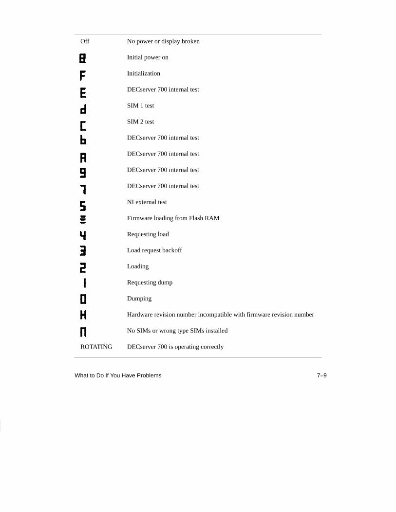
7.7 Seven-Segment Display Codes
The following page lists and describes the codes that will be displayed during theserver internal self-test when the DECserver 700 goes through a power up and ini-tialization.
7–9What to Do If You Have Problems
Off No power or display broken
Initial power on
Initialization
DECserver 700 internal test
SIM 1 test
SIM 2 test
DECserver 700 internal test
DECserver 700 internal test
DECserver 700 internal test
DECserver 700 internal test
NI external test
Firmware loading from Flash RAM
Requesting load
Load request backoff
Loading
Requesting dump
Dumping
Hardware revision number incompatible with firmware revision number
No SIMs or wrong type SIMs installed
ROTATING DECserver 700 is operating correctly
7–10 Site Preparation and Maintenance
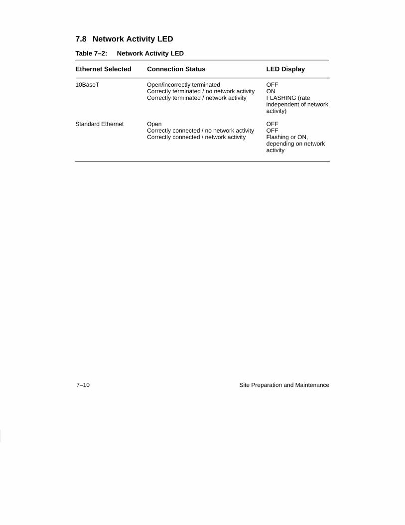
7.8 Network Activity LED
Table 7–2: Network Activity LED
Ethernet Selected Connection Status LED Display
10BaseT Open/incorrectly terminated OFFCorrectly terminated / no network activity ONCorrectly terminated / network activity FLASHING (rate
independent of networkactivity)
Standard Ethernet Open OFFCorrectly connected / no network activity OFFCorrectly connected / network activity Flashing or ON,
depending on network activity

DECserver 700 Site Preparation and Maintenance
(Hardware Owner’s Manual) EK-DSRVW-MG. B01
READER’S COMMENTS
What do you think of this manual? Your comments and suggestions will help us to improve the qualityand usefulness of our publications.
Please rate this manual:
Poor ExcellentAccuracy 1 2 3 4 5Readability 1 2 3 4 5Examples 1 2 3 4 5Organization 1 2 3 4 5Completeness 1 2 3 4 5
Did you find errors in this manual? If so, please specify the error(s) and page number(s).
General comments:
Suggestions for improvement:
Name Date
Title Department
Company Street
City State/Country Zip Code

DO NOT CUT – FOLD HERE AND TAPE
NO POSTAGE NECESSARY IF MAILED IN THEUNITED STATES
BUSINESS REPLY LABELFIRST CLASS PERMIT NO. 33 MAYNARD MASS.
POSTAGE WILL BE PAID BY ADDRESSEE
Telecommunications andNetworks Publications550 King StreetLittleton, MA 01460–1289
DO NOT CUT – FOLD HERE

Printed in U.S.A.